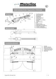
TIPS FOR DRAINAGE 10 A and BIf the drainage of the installation cannot be connected up tothe main drains, it may be possible to make use of a drainagepit. The floor must be permeable to water, and the cover ofthe motor housing should be protected against heavy rainfallor surface water with silicone sealant. The drainage pit shouldbe dug out so as to be appreciably lower than the bottom ofthe motor housing, and its capacity should exceed that of themotor housing. The pit should be filled with coarse rubble orgravel, and should be tiled to keep out sediment and waterfrom the top and sides. Facilities should be provided to leadany water getting into the motor housing to this drainage pit.ASSEMBLY OF THE SUB-110 ARMWe will assume here that the arm is already mounted and thebearing ball (greased) is in its proper location.TIP: Many parts have extremely small fitting tolerances inorder to ensure long, continuous operation. Some strengthwill be needed to mount the parts. A PVC hammer and goodtools are essential.1. Plug the short motor arm onto the motor and fix it with boltand nut (figure 2).2. Mount the gate CLOSED end stop. Don’t completely tightenthe bolts yet so that the gate can still move (figure 2).3. Mount the gate OPEN end stop. Don’t tighten the bolts to100% yet but allow some movement (figure 4A).4. Place motor in box. The motor shaft should point outwardsin the entrance. Install motor power cable and lead itupwards and out of the box to the distribution box. Do notdistribute power in this box; moisture! (figure 10A&B).5. Tighten motor with the four bolts (figure 3).6. Position connecting arm, secure with bolts and washers. Inthe connecting arm are plain bronze bearings with verytight fits (figure 4A).Setting of the end stops:The stops cannot be set until the motor has been connectedto the control board.Caution: The motor is very powerful and can causedamage to the box and the gate system if it is notswitched off at the correct time.IT IS ESSENTIAL TO NEVER TOUCH THE BOX WHILETHE DRIVE IS IN MOTION.1. Close the gate as far as the required position or to thefloor stop. Turn the end stop so that the bolt and the fittingmeet the connecting arm accurately. Set with the nut andthen tighten ALL parts (figure 4A).2. Open the gate as far as the required position or to the floorstop. Turn the end stop so that the connecting arm isaccurately met at right angles (90°). Set with the nut andthen tighten ALL parts (figure 4A).ELECTRICAL CONNECTIONSSee instructions CB124!1SAFETY MEASURESAn automatically operated wing gate should alwaysbe further protected with the aid of flashing lights,contact strips and photoelectric barriers. In anycase, take care to comply with the relevantstandards and regulations.FINAL REMARKSArrange the handover of the wing gate opener with yourcustomer Make sure that persons will operate the gate arefamiliar with its functions and can operate them withoutproblems. Have your customer practice operating the gateuntil they are fully acquainted with all the following:• Main switch.• Rules of operation (e.g. do not drive through while the gateis still opening).• Additional safety features (photoelectric barrier, contactstrip, flashing lights, etc.).• Switch to manual operation in case of power failure.• Provide the customer with a full set of instructions. Informhim to keep them in a safe place and read them whenpossible.• Reference a checklist, so that you have a record ofwhich functions have been explained and of any points notdealt with.OPTIONAL ACCESSORIES 11See also the LiftMaster product catalogue:Gate Opener CatalogDeclaration of ConformityThe undersigned, hereby declare that the equipment specified, and all accessories,conforms to the Directives and Standards stated.Model: ..............................................................................................................SUB324MEN55014, EN61000-3, EN61000-4, ETS 300 683, EN 300 220-3, EN60335-1, andEN60335-2-103en-32004/108/EC2006/95/EC1999/5/ECDeclaration of IncorporationA power door operator, in combination with a door must be installed and maintainedaccording to all the Manufacturer’s instructions, to meet the provisions of MachineryDirective, 2006/42/EC.Harry NaumannManager, Regulatory AffairsChamberlain GmbHAlfred-Nobel-Str. 4D-66793 SaarwellingenJuly, 2008
LEES EERST DEZE BELANGRIJKE VEILIGHEIDSVOORSCHRIFTENDeze waarschuwingstekens betekenen Opgepast! en staan voor voorschriften betreffende persoonlijke veiligheidof materiële schade. Lees deze voorschriften aandachtig.Deze hekopener is ontworpen en getest om veilig te functioneren mits hij geïnstalleerd en bediend wordt metstrikte inachtneming van onderstaande veiligheidsvoorschriften.Het niet opvolgen van onderstaande instructies kan ernstig lichamelijk letsel of materiële schade tot gevolghebben.nl-1BELANGRIJKE AANWIJZINGEN VOORVEILIGE MONTAGEZorg dat het hek goed uitgebalanceerd is.Klemmenhet heken moeten gerepareerd worden.Probeer niet deze onderdelen zelf los te maken,te verplaatsen of bij te stellen. Laat dit door eenhekspecialist doen.Draag geen ringen, horloge of losse kledingtijdens de installatie of het onderhoud van dehekopener.Installatie en bedrading moeten overeenkomen metde plaatselijk geldende bouw- enelektriciteitsvoorschriften. Sluit hetelektriciteitssnoer uitsluitend aan op een goedgeaard net.Personen die de aandrijving monteren,onderhouden of bedienen, moeten dezeinstructies opvolgen.Na de installatie moet worden gecontroleerd, ofhet mechanisme op de juiste wijze ingesteld is endat de opener, het beveiligingssysteem en dehandzender, indien aanwezig, correct functioneren.Het aangedreven deel kan zich ongecontroleerdbewegen, bijv. door een mechanisch defect,wanneer de handzender wordt gebruiktLET OP - VERKEERDE MONTAGE KANERNSTIG LETSEL VEROORZAKEN!Verwijder alle aan het hek bevestigde touwenvoordat u de hekopener installeert, om ernstiglichamelijk letsel door verstrikt raken te voorkomen.Schakel de electriciteit naar de hekopener uitvoordat u reparaties uitvoert of beschermingenverwijdert.OPGEPAST! Stel de opener uitsluitend in werkingals het hek volledig in het zicht is, vrij vanobstakels en als de opener goed is afgesteld.Laat kinderen niet in de buurt van het hek spelen.Bij openers die door een schakelaar met UITvoorinstellingmoeten worden gestuurd, moet hetbesturingsbedieningsgedeelte in het directe zichtveldvan het aangedreven onderdeel, maar op afstand vanbewegende delen en op een hoogte van min. 1,5 mworden gemonteerd. Opmerking: De minimumhoogtevan 1,5 m geldt niet voor besturingsbedieningselementenmet UIT-voorinstelling die door eensleutel of iets dergelijks worden bestuurd.Bewaar deze montage-instructie op een goedbereikbare plaats, zodat snel raadplegen ervanmogelijk is.Tijdens de bediening van een besturing met UITvoorinstellingdient u ervoor te zorgen dat anderepersonen uit de buurt van het apparaat wordengehouden.Inhoud:Veiligheidsvoorschriften: pagina 1Technische gegevens: pagina 1Garantie: pagina 1Inhoud van de verpakking: pagina 2Voor u begint: pagina 2Montage van de opener: pagina 2, afbeeldingen 1 -9Elektrische Aansluiting: pagina 2, afbeeldingVeiligheid: pagina 3Bediening: pagina 3Tot slot: pagina 3Toebehoren: pagina 3, afbeelding 111TECHNISCHE GEGEVENSNominale spanningNominaal vermogenNominale stroomMotortoerentalCycli (vollast)BedrijfstemperatuurBeschermklasseBeschermingsklasseGewicht (alleen motor)BesturingHandzenderZendfrequentieFotocelSignaallampSleutelschakelaarBuitenantenneMaximale vleugellengteMax. vleugelgewichtV (DC)WAtpmED°CIPkg24V482,025007min-25/+75I6710optioneeloptioneeloptioneeloptioneeloptioneeloptioneeloptioneel3,5m300kg/2,5mGARANTIEChamberlain GmbH garandeert de eerste koper die het product in de detailhandel aankoopt (eerste"detailhandelklant") dat het, gerekend vanaf de datum van aankoop een gehele periode van 24maanden (2 jaren) lang vrij is van iedere materiaalschade resp. fabricagefouten. Deze garantie geldtvoor het besturingselectronica. Bij ontvangst van het product heeft de eerste detailhandelklant deplicht, dit op zichtbare beschadigingen te controleren.Voorwaarden: De onderhavige garantie is het enige rechtsmiddel waarop de koper zich juridisch bijschade die verband houdt met een defect onderdeel resp. product resp. daaruit voortvloeit, kan beroepen.De onderhavige garantie is uitsluitend beperkt tot reparatie resp. vervanging van de onderdelen van ditproduct waarvan beschadiging wordt geconstateerd.De onderhavige garantie geldt niet voor schade die niet aan gebreken maar aan het onjuist gebruiktoegeschreven moeten worden (d.w.z. met inbegrip van ieder gebruik dat niet nauwkeurig overeenstemtmet de instructies resp. aanwijzingen van de firma Chamberlain GmbH met betrekking tot de installatie,het gebruik en de verzorging, alsmede het verzuim om tijdig de vereiste reparatie- enafstelwerkzaamheden uit te voeren, resp. de uitvoering van aanpassingen of wijzigingen aan dit product).De garantie dekt ook niet de arbeidskosten voor het uitbouwen resp. het weer inbouwen van eengerepareerd resp. vervangen apparaat of de vervangende accu's daarvan. Een product in het kader van degarantie waarvan wordt vastgesteld dat het materiaalschade resp. fabricagefouten vertoont, wordt voor deeigenaar zonder kosten van reparatie resp. vervangende onderdelen gerepareerd resp. vervangen, zulks terbeoordeling aan Chamberlain GmbH. Mocht het product tijdens de garantietermijn defect blijken te zijn,neemt u dan contact op met het bedrijf waar u het oorspronkelijk heeft gekocht.De garantie laat onverlet de rechten die de koper heeft in het kader van nationale wetten of bepalingen dievan toepassing zijn of de rechten tegenover de detailhandelaar, welke voor de koper voortvloeien uit deverkoop/koopovereenkomst. Indien er geen nationale wetten resp. EU-wetten bestaan die van toepassingzijn, is deze garantie het enige, exclusieve rechtsmiddel dat de koper ter beschikking staat en nochChamberlain GmbH noch de filialen of handelaren van deze firma zijn aansprakelijk voor enigerlei nevenofgevolgschade op grond van welke expliciete of stilzwijgende garantie met betrekking tot dit product ook.Noch vertegenwoordigers noch enige andere personen zijn gerechtigd, namens Chamberlain GmbHenige andersluidende verantwoording in verbinding met de verkoop van dit product op zich te nemen.


