BlackandDecker Sega A Scure- Cs355 - Type 1 - Instruction Manual (Inglese)
BlackandDecker Sega A Scure- Cs355 - Type 1 - Instruction Manual (Inglese)
BlackandDecker Sega A Scure- Cs355 - Type 1 - Instruction Manual (Inglese)
Create successful ePaper yourself
Turn your PDF publications into a flip-book with our unique Google optimized e-Paper software.
ENGLISH<br />
(Original instructions)<br />
u Regularly clear the ventilation slots when working in dusty<br />
conditions. If it should become necessary to clean the<br />
slots, remember to unplug the tool first.<br />
u Always store cutting discs well-protected and in a dry<br />
place, out of reach of children.<br />
u Warning!Use of this tool can generate dust containing<br />
chemicals known to cause cancer, birth defects or other<br />
reproductive harm. Use appropriate respiratory protection.<br />
6<br />
Warning! Only use a chop saw wheel with a<br />
maximum thickness of 3 mm and a maximum<br />
diameter of 355mm.<br />
Warning! The cutting wheel will continue to rotate after the<br />
tool has been switched off.<br />
u Use only reinforced wheels rated 4300 rpm or higher.<br />
u Always wear eye protection, use guards, clamp work in<br />
vise, use proper respiratory protection.<br />
The following factors are of influence to noise production:<br />
u the material to be cut<br />
u the type of the cutting disc<br />
u the feed force<br />
u Warning!Take appropriate measures for the protection of<br />
hearing.<br />
Residual risks<br />
The following risks are inherent to the use of these<br />
machines:<br />
u injuries caused by touching the rotating parts<br />
u injuries caused by disruption of the cutting disc<br />
These risks are most evident:<br />
u within the range of operation<br />
u within the range of the rotating machine parts<br />
In spite of the application of the relevant safety regulations<br />
and the implementation of safety devices, certain residual<br />
risks cannot be avoided. These are:<br />
u Impairment of hearing.<br />
u Risk of accidents caused by the uncovered parts of the<br />
rotating cutting disc.<br />
u Risk of injury when changing the disc.<br />
u Risk of squeezing fingers when opening the guards.<br />
Electrical safety<br />
Your tool is double insulated; therefore no earth<br />
wire is required. Always check that the mains<br />
#<br />
voltage corresponds to the voltage on the rating<br />
plate. Never attempt to replace the charger unit<br />
with a regular mains plug.<br />
u If the supply cord is damaged, it must be replaced by the<br />
manufacturer or an authorised Black & Decker Service<br />
Centre in order to avoid a hazard.<br />
Voltage drops<br />
Inrush currents cause short-time voltage drops.<br />
Under unfavourable power supply conditions, other<br />
equipment may be affected.<br />
If the system impedance of the power supply is lower<br />
than 0.12 Ω, disturbances are unlikely to occur.<br />
Warning Symbols<br />
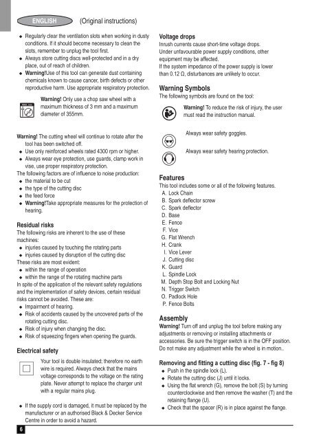
The following symbols are found on the tool:<br />
:<br />
O<br />
N<br />
Warning! To reduce the risk of injury, the user<br />
must read the instruction manual.<br />
Always wear safety goggles.<br />
Always wear safety hearing protection.<br />
Features<br />
This tool includes some or all of the following features.<br />
A. Lock Chain<br />
B. Spark deflector screw<br />
C. Spark deflector<br />
D. Base<br />
E. Fence<br />
F. Vice<br />
G. Flat Wrench<br />
H. Crank<br />
I. Vice Lever<br />
J. Cutting disc<br />
K. Guard<br />
L. Spindle Lock<br />
M. Depth Stop Bolt and Locking Nut<br />
N. Trigger Switch<br />
O. Padlock Hole<br />
P. Fence Bolts<br />
Assembly<br />
Warning! Turn off and unplug the tool before making any<br />
adjustments or removing or installing attachments or<br />
accessories. Be sure the trigger switch is in the OFF position.<br />
Do not make any adjustment while the wheel is in motion..<br />
Removing and fitting a cutting disc (fig. 7 - fig 8)<br />
u Push in the spindle lock (L).<br />
u Rotate the cutting disc (J) until it locks.<br />
u Using the flat wrench (G), remove the bolt (S) by turning<br />
counterclockwise and then remove the washer (T) and the<br />
retaining flange (U).<br />
u Check that the spacer (R) is in place against the flange.


