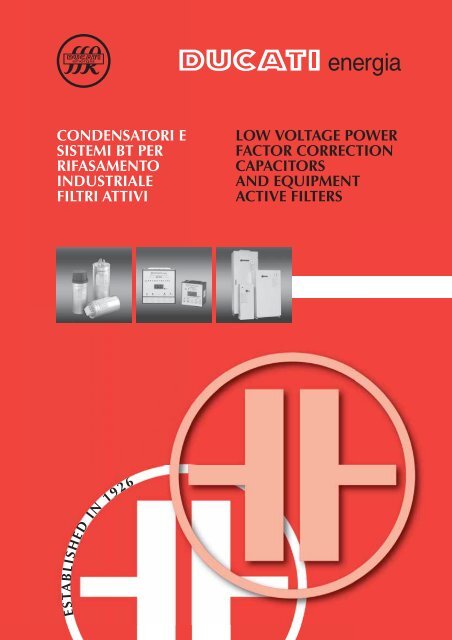
Ducati Low Voltage Power Factor Capacitor Catalogue

You also want an ePaper? Increase the reach of your titles
YUMPU automatically turns print PDFs into web optimized ePapers that Google loves.
CONDENSATORI E<br />
SISTEMI BT PER<br />
RIFASAMENTO<br />
INDUSTRIALE<br />
FILTRI ATTIVI<br />
LOW VOLTAGE POWER<br />
FACTOR CORRECTION<br />
CAPACITORS<br />
AND EQUIPMENT<br />
ACTIVE FILTERS<br />
ESTABLISHED IN 1926
Gamma Prodotti<br />
Product Range<br />
La gamma dei prodotti <strong>Ducati</strong> Energia è riassunta nella tabella sottostante (legenda definizioni pag 8):<br />
The table below summarizes the range of products currently manufactured by <strong>Ducati</strong> Energia (key to definitions page 8):<br />
TIPOLOGIA DI PRODOTTO/PRODUCT TYPE Standard Life & Extra Duty Long Life<br />
CONDENSATORI<br />
CAPACITORS<br />
Condensatori Monofase<br />
Single-phase <strong>Capacitor</strong>s<br />
Condensatori Trifase<br />
Three-phase <strong>Capacitor</strong>s<br />
FLOPPY CAP<br />
416.30.xxxx<br />
MODULOXD<br />
416.46.xxxx<br />
MONO<br />
416.53.xxxx<br />
MODULO50<br />
416.47.xxxx<br />
SISTEMI DI<br />
RIFASAMENTO FISSI<br />
FIXED POWER FACTOR<br />
CORRECTION EQUIPMENT<br />
Unità trifase modulare<br />
custodia plastica<br />
Three-phase modular<br />
unit with plastic case<br />
Unità trifase con sezionatore<br />
e struttura metallica<br />
Three-phase unit with metallic<br />
case and switch<br />
DUCATI F50<br />
(230V)<br />
415.01.4xxx<br />
DUCATI F50<br />
(415 - 450 - 525V)<br />
415.04.7xxx<br />
DUCATI F120<br />
(415 - 450 - 525V)<br />
415.04.8xxx<br />
Struttura a moduli<br />
Modules structure<br />
DUCATI 18-M<br />
(230 - 415V)<br />
415.04.0xxx<br />
DUCATI 200-M / DUCATI 400-M<br />
(415 - 450 - 525V)<br />
415.04.0xxx<br />
APPARECCHIATURE DI<br />
RIFASAMENTO<br />
AUTOMATICHE<br />
AUTOMATIC POWER<br />
FACTOR<br />
CORRECTION EQUIPMENT<br />
Struttura a cassetti<br />
Rack structure<br />
Struttura a moduli con<br />
sistemi di filtro<br />
Modules structure with<br />
filtring system<br />
DUCATI 1600-R<br />
(415 - 450 - 525V)<br />
415.04.1xxx<br />
DUCATI 170-ML<br />
(400V)<br />
415.04.2xxx<br />
Struttura a cassetti con<br />
sistemi di filtro<br />
Rack structure with<br />
filtering system<br />
DUCATI 1000-RL<br />
(400V)<br />
415.04.2xxx<br />
FILTRI ARMONICI ATTIVI<br />
ACTIVE HARMONIC FILTERS<br />
DUCATI ACTISINE<br />
(400 - 480V +15% -20%)<br />
415.14.2xxx<br />
CASSETTI<br />
CHASSIS<br />
Cassetti<br />
Chassis<br />
Cassetti con<br />
connessioni a barre<br />
Chassis with<br />
bus bar<br />
Cassetti con reattanze<br />
Chassis with reactors<br />
Cassetti con connessioni<br />
a sbarre e reattanze<br />
Chassis with<br />
bus bar and reactors<br />
C160 / C160-MINI<br />
(415 - 450 - 525V)<br />
415.04.9xxx<br />
C200-B<br />
(400 - 525V)<br />
415.04.9xxx<br />
C100-L / C50 -L-MINI<br />
(400V)<br />
415.04.9xxx<br />
C100-LB<br />
(400V)<br />
415.04.9xxx<br />
REGOLATORI DI POTENZA REATTIVA<br />
REACTIVE POWER CONTROLLERS<br />
CONTATTORI<br />
CONTACTORS<br />
SEZIONATORI<br />
ISOLATING SWITCHES<br />
FUSIBILI<br />
FUSES<br />
Serie REGO<br />
415.98.xxxx<br />
12,5 ÷ 60 KVAR 400 V<br />
315.99.xxxx<br />
40 ÷ 1600 A 415 V<br />
315.99.xxxx<br />
25 ÷ 160 A NH00<br />
315.99.xxxx<br />
REATTANZE TRIFASE<br />
THREE-PHASE REACTORS<br />
P=7% (189Hz)<br />
315.99.xxxx<br />
P=12,5% (141Hz)<br />
315.99.xxxx<br />
2
INDICE<br />
CONTENTS<br />
Informazioni<br />
Gamma Prodotti<br />
Tecnologia dei condensatori<br />
Tecnologia dei condensatori in PPMh<br />
Definizioni<br />
Informazioni Generali sul rifasamento<br />
Scelta e Calcolo del Sistema di Rifasamento<br />
Condensatori<br />
Condensatori Monofase<br />
Serie FLOPPY CAP<br />
Serie MONO<br />
Condensatori Trifase<br />
Serie MODULOXD<br />
MODULOXD 60 Hz Ratings<br />
Serie MODULO50<br />
DUCATI F50<br />
Regolatori di Potenza Reattiva REGO<br />
Contattori<br />
Sezionatori<br />
Fusibili<br />
Reattanze di sbarramento<br />
Apparecchiature di Rifasamento<br />
Automatiche e Fisse<br />
DUCATI F120<br />
DUCATI 18-M<br />
DUCATI 200-M<br />
DUCATI 400-M<br />
DUCATI 1600-R<br />
Apparecchiature automatiche con sistemi di filtro<br />
DUCATI 170-ML<br />
DUCATI 1000-RL<br />
Filtri armonici attivi<br />
DUCATI ActiSine<br />
Cassetti<br />
DUCATI C160<br />
DUCATI C160-MINI<br />
DUCATI C200-B<br />
DUCATI C50-L-MINI<br />
DUCATI C100-L<br />
DUCATI C100-LB<br />
2<br />
2<br />
4<br />
5<br />
6<br />
9<br />
12<br />
17<br />
17<br />
19<br />
20<br />
21<br />
23<br />
24<br />
25<br />
26<br />
29<br />
32<br />
34<br />
38<br />
40<br />
43<br />
45<br />
47<br />
51<br />
57<br />
61<br />
67<br />
69<br />
73<br />
77<br />
77<br />
81<br />
83<br />
84<br />
85<br />
86<br />
87<br />
88<br />
Information<br />
Product Range<br />
<strong>Capacitor</strong>s technology<br />
<strong>Capacitor</strong>s technology PPMh/MKPh<br />
Definitions<br />
General information about power factor correction<br />
Choice and sizing of a power factor correction system<br />
<strong>Capacitor</strong>s<br />
Single-phase <strong>Capacitor</strong>s<br />
FLOPPY CAP Series<br />
MONO Series<br />
Three-phase <strong>Capacitor</strong>s<br />
MODULOXD Series<br />
MODULOXD 60 Hz Ratings<br />
MODULO50 Series<br />
DUCATI F50<br />
REGO Reactive <strong>Power</strong> Controllers<br />
Contactors<br />
Isolating switches<br />
Fuses<br />
Blocking reactors<br />
Automatic and Fixed <strong>Power</strong><br />
<strong>Factor</strong> Correction Equipment<br />
DUCATI F120<br />
DUCATI 18-M<br />
DUCATI 200-M<br />
DUCATI 400-M<br />
DUCATI 1600-R<br />
Automatic equipment with filter system<br />
DUCATI 170-ML<br />
DUCATI 1000-RL<br />
Active harmonic filters<br />
DUCATI ActiSine<br />
Chassis<br />
DUCATI C160<br />
DUCATI C160-MINI<br />
DUCATI C200-B<br />
DUCATI C50-L-MINI<br />
DUCATI C100-L<br />
DUCATI C100-LB
Tecnologia<br />
dei condensatori<br />
<strong>Capacitor</strong>s<br />
Technology<br />
INTRODUZIONE<br />
<strong>Ducati</strong> nasce nel 1926 introducendo per prima in Italia, e fra<br />
le prime al mondo, condensatori per le apparecchiature di<br />
radiotrasmissione prodotte da Guglielmo Marconi.<br />
Da questa tradizione, che ha sempre visto <strong>Ducati</strong><br />
all’avanguardia nella tecnologia di elementi capacitivi, si è<br />
giunti all’utilizzo innovativo del film PPM e PPMh.<br />
Le prestazioni superiori e le dimensioni ridotte rispetto alle<br />
ormai obsolete soluzioni in carta e olio e in gas, rendono i<br />
condensatori prodotti in PPM/PPMh il nuovo standard di<br />
riferimento per il rifasamento industriale.<br />
Tutti i condensatori prodotti da <strong>Ducati</strong> Energia sono dotati di<br />
un dispositivo di protezione conforme alle norme EN 60831-<br />
1/2. Questa protezione è stata ottenuta attraverso una<br />
particolare tecnologia costruttiva, che in caso di guasto<br />
disconnette i collegamenti per sovra-pressione, lasciando<br />
integro l’isolamento verso la custodia e impedendo che il<br />
condensatore possa scoppiare o bruciare.<br />
Il dispositivo è stato studiato e dimensionato al fine di<br />
rendere più efficace e tempestivo l’intervento sia con basse<br />
sia ad alte correnti di cortocircuito (fino a 10.000 A).<br />
INTRODUCTION<br />
<strong>Ducati</strong> was founded in 1926 and was the first company in<br />
Italy, and among the first in the world, to introduce capacitors<br />
for the radiobroadcasting equipment produced by Guglielmo<br />
Marconi.<br />
Building upon this tradition, which has always seen <strong>Ducati</strong> in<br />
the forefront of capacitor technology, the company has<br />
developed the innovative PPM and PPMh film.<br />
Superior performance and reduced dimensions compared to<br />
the by now obsolete paper and oil and gas solutions make<br />
PPM/PPMh capacitors the new standard of reference for<br />
industrial power factor correction systems.<br />
All the capacitors manufactured by <strong>Ducati</strong> Energia feature a<br />
protection device conforming to standards EN 60831-1/2. This<br />
protection has been achieved by means of a special<br />
engineering technology: if a fault occurs the connections will be<br />
broken due to overpressure, leaving the insulation of the case<br />
intact and preventing the capacitor from exploding or burning.<br />
The device has been designed and dimensioned to ensure<br />
more efficient, prompt operation with both low and high short<br />
circuit currents (up to 10,000 A).<br />
TECNOLOGIA PPM / MKP<br />
La tecnologia del polipropilene metallizzato (PPM), consiste<br />
nel depositare per evaporazione sotto vuoto un sottilissimo<br />
strato di metallo su un lato del film di polipropilene.<br />
Gli elementi capacitivi costruiti con questa tecnologia<br />
vengono ottenuti avvolgendo due film di polipropilene. Le<br />
armature del condensatore sono costituite dalla<br />
metallizzazione dei due film e il dielettrico dal film di<br />
polipropilene stesso.<br />
Pregio principale dei condensatori con armatura<br />
metallizzata è di essere autorigenerabili, di essere capaci<br />
cioè, di ripristinare le proprietà elettriche al verificarsi di un<br />
corto circuito fra le armature.<br />
In conseguenza del ridotto spessore dell’armatura, la<br />
corrente di corto circuito nella zona circostante il guasto, è in<br />
grado di vaporizzare la metallizzazione, estinguendo<br />
automaticamente il corto circuito, senza un’apprezzabile<br />
riduzione di capacità o dispendio d'energia.<br />
GAMMA STANDARD LIFE E EXTRA DUTY<br />
In questi condensatori l’agente impregnante è rappresentato<br />
da un particolare tipo di resina. <strong>Ducati</strong> Energia ha messo a<br />
punto una composizione di resina ecocompatibile ad alta<br />
stabilità dielettrica, che consente di rimuovere totalmente<br />
ogni possibile rischio di presenza di molecole d’aria e acqua<br />
all’interno del condensatore. Fanno parte di questa tipologia<br />
i condensatori appartenenti alle famiglie:<br />
➣ condensatori monofase serie FLOPPY CAP 416.30 (SL)<br />
➣ condensatori trifase serie MODULO XD 416.46 (XD)<br />
PPM / MKP TECHNOLOGY<br />
Metallized polypropylene technology (PPM – MKP) utilizes a<br />
vacuum evaporation technique to deposit an extremely thin<br />
layer of metal on one side of the polypropylene film.<br />
The capacitor elements built using this technology are<br />
obtained by winding two polypropylene films. The capacitor<br />
plates consist in the metallized surface of the two films and<br />
the dielectric is the propylene film itself.<br />
The main advantage of capacitors with metallized plates is<br />
their self-healing capacity. This means that they are capable<br />
of restoring their electrical properties following the<br />
occurrence of a short circuit between the plates.<br />
Due to the reduced thickness of the plates, the short circuit<br />
current generated in the area of a fault is capable of<br />
vaporizing the metal coating; the short circuit is thereby<br />
automatically extinguished without an appreciable reduction<br />
in capacitance or expenditure of energy.<br />
STANDARD LIFE AND EXTRA DUTY SERIES<br />
In these capacitors the impregnating agent is a special type<br />
of resin. <strong>Ducati</strong> Energia has developed an ecofriendly resin<br />
composition displaying high dielectric stability, which<br />
completely eliminates every possible risk of air and water<br />
molecules being present inside the capacitor. This category<br />
includes the capacitors belonging to the families:<br />
➣ Series FLOPPY CAP<br />
➣ Series MODULO XD<br />
416.30 single-phase capacitors (SL)<br />
416.46 three-phase capacitors (XD)<br />
4
Tecnologia dei<br />
condensatori<br />
in PPMh<br />
<strong>Capacitor</strong><br />
Technology<br />
PPMh/MKPh<br />
TECNOLOGIA PPMh/MKPh<br />
La continua ricerca nei laboratori <strong>Ducati</strong> Energia ha portato<br />
allo sviluppo di un film in polipropilene con una speciale<br />
metallizzazione, al fine di favorire il processo di<br />
autorigenerazione e diminuire le perdite dielettriche.<br />
L’innovativa metallizzazione permette al polipropilene uno<br />
stress minore durante il funzionamento, quindi mantiene le<br />
caratteristiche dielettriche per un tempo notevolmente più<br />
lungo e allo stesso tempo consente prestazioni notevolmente<br />
superiori sia in termini di corrente che di tensione.<br />
TECHNOLOGY PPMh/MKPh<br />
The continuous research conducted in <strong>Ducati</strong> Energia<br />
laboratories has led to the development of a polypropylene<br />
film with a special metallization, whose purpose is to favour<br />
the self-healing process and reduce dielectric losses.<br />
Thanks to this innovative metallization treatment, the<br />
polypropylene is subjected to less stress during operation.<br />
Therefore it maintains its dielectric properties for a<br />
significantly longer time while delivering significantly better<br />
performance in terms of both current and voltage.<br />
GAMMA LONG LIFE<br />
Questa innovativa gamma di condensatori per il rifasamento<br />
industriale con elementi avvolti con film PPMh, si impone per<br />
affidabilità, prestazioni e compattezza.<br />
La più efficace autorigenerazione e le ridotte perdite<br />
dielettriche permettono di ottenere durata e prestazioni in<br />
tensione e corrente paragonabili ai condensatori in carta e<br />
olio con ingombri ridotti.<br />
Fanno parte di questa tipologia i condensatori appartenenti<br />
alle famiglie:<br />
LONG LIFE SERIES<br />
This innovative range of industrial power factor correction<br />
capacitors featuring elements wound with PPMh film<br />
sets new standards of reliability, performance and<br />
compactness.<br />
More effective self-healing and reduced dielectric losses<br />
make it possible to obtain a lifespan and performances in<br />
terms of voltage and current that are comparable to those of<br />
paper and oil capacitors while reducing size.<br />
<strong>Capacitor</strong>s of this type belong to the families:<br />
➣ condensatori monofase serie MONO 416.53<br />
➣ Series MONO<br />
416.53 single-phase capacitors<br />
➣ condensatori trifase serie MODULO50 416.47<br />
➣ Series MODULO50 416.47 three-phase capacitors<br />
5
Definizioni<br />
Definitions<br />
Tensione nominale (Un)<br />
È il valore massimo efficace della tensione alternata sinusoidale<br />
per la quale il condensatore è stato progettato.<br />
Potenza nominale (Qn)<br />
È la potenza reattiva erogata dal condensatore con tensione e<br />
frequenza nominale applicate.<br />
Capacità nominale (Cn)<br />
È il valore che permette di erogare la potenza nominale,<br />
applicando ai terminali la tensione e frequenza nominale.<br />
Corrente nominale (In)<br />
È il valore efficace della corrente alternata che circola nel<br />
condensatore quando alla capacità nominale si applica la<br />
tensione e frequenza nominale.<br />
CONDIZIONI D’ESERCIZIO<br />
A differenza della maggior parte delle apparecchiature<br />
elettriche, i condensatori per rifasamento, ogni volta che sono<br />
energizzati, operano in continuità a pieno carico, o a carichi che<br />
si discostano da questo valore solo come conseguenza delle<br />
variazioni di tensione e di frequenza.<br />
Le sovrasollecitazioni ed i surriscaldamenti abbreviano la vita di un<br />
condensatore e perciò le condizioni di esercizio (cioè temperatura,<br />
tensione e corrente) devono essere attentamente controllate<br />
affinché si possa ottenere il risultato ottimale in termini di vita.<br />
Tensione<br />
I condensatori sono realizzati, secondo quanto prescritto dalle<br />
norme EN 60831-1/2 che regolamentano la costruzione, le prove,<br />
l’installazione e l’applicazione e che indicano i seguenti valori<br />
massimi per le sovratensioni applicabili ai condensatori:<br />
+10% per 8 ore ogni 24 ore<br />
+15% per 30 minuti ogni 24 ore<br />
+20% per 5 minuti<br />
+30% per 1 minuto<br />
Le sovratensioni maggiori del 15% non si dovranno verificare<br />
più di 200 volte nell’arco di vita del condensatore.<br />
Sovente quando si presume nel servizio la presenza di<br />
condizioni di sovraccarico, ad esempio in presenza di moderato<br />
carico armonico, è comune l’uso di condensatori<br />
sovradimensionati in tensione.<br />
In tal caso la potenza resa alla tensione di esercizio risulterà<br />
ridotta rispetto a quella di targa. È opportuno nella pratica<br />
valutare la riduzione subita dalla potenza resa sulla base del<br />
rapporto fra tensione di esercizio e tensione nominale.<br />
Rated voltage (Un)<br />
This is the maximum effective value of the alternating sinusoidal<br />
voltage for which the capacitor was designed.<br />
Rated power (Qn)<br />
This is the reactive power delivered by the capacitor at the rated<br />
voltage and frequency applied.<br />
Rated capacitance (Cn)<br />
This is the value which permits delivery of the rated power<br />
applying the rated voltage and frequency to the terminals.<br />
Rated current (In)<br />
This is the effective value of the alternating current that<br />
circulates through the capacitor when the rated voltage and<br />
frequency are applied at the rated capacitance.<br />
OPERATING CONDITIONS<br />
Unlike most electrical equipment, power factor correction<br />
capacitors, each time they are energized, continuously operate<br />
at full load or at loads which differ from this value only as a<br />
consequence of variations in voltage and frequency.<br />
Overstressing and overheating shorten the lifespan of the<br />
capacitor. For this reason the operating conditions (temperature,<br />
voltage and current) must be carefully controlled in order to<br />
obtain optimum results as regards the lifespan of the capacitor.<br />
<strong>Voltage</strong><br />
The capacitors are produced in accordance with standards EN<br />
60831-1/2, which regulate their manufacture, testing,<br />
installation and application of capacitors, indicating the following<br />
maximum overvoltages:<br />
+10% for 8 hours every 24 hours<br />
+15% for 30 minutes every 24 hours<br />
+20% for 5 minutes<br />
+30% for 1 minute.<br />
Overvoltages in excess of 15% should not occur more than 200<br />
times during the life of a capacitor.<br />
When overload conditions may be assumed to occur during<br />
service – in the presence of a moderate harmonic load for<br />
example – it is common to use capacitors that are oversized in<br />
terms of voltage.<br />
In such cases the output power at the operating voltage will be<br />
reduced in comparison with the rated load. It is advisable to<br />
evaluate the reduction occurring in the output power on the<br />
basis of the ratio between the operating voltage and the rated<br />
voltage.<br />
dove:<br />
U e<br />
Q resa<br />
= Tensione di esercizio<br />
= Potenza resa a Ue<br />
where:<br />
U e<br />
Q resa<br />
= Operating voltage<br />
= Output power at Ue<br />
La tabella seguente riporta la potenza resa da un condensatore<br />
da 100 kvar impiegato su rete a 400 V avente tensione nominale<br />
rispettivamente di 415, 450, 525V.<br />
The table below shows the power output by a 100 kvar capacitor<br />
used on a 400 V network having a rated voltage respectively of<br />
415, 450 and 525V.<br />
U n [V] 415 450 525<br />
Q resa [kVAr] 93 79 58<br />
Temperatura<br />
La temperatura del condensatore durante il funzionamento è il<br />
parametro che insieme alla tensione ha la maggiore influenza<br />
sulla durata di vita del condensatore.<br />
Esso deve essere posto sempre in posizione dove l’aria di<br />
raffreddamento possa circolare liberamente, evitando<br />
l’irraggiamento di superfici riscaldate di altri componenti.<br />
Temperature<br />
The temperature of the capacitor during operation is the<br />
parameter that, along with the voltage, has the greatest<br />
influence on the lifespan of a capacitor.<br />
It is important that the capacitor always be placed in a position<br />
where cooling air can freely circulate and away from the radiant<br />
heat of hot surfaces of other components.<br />
6
Definizioni - Definitions<br />
Quando i condensatori siano posti in armadi chiusi, si devono<br />
prevedere fessure di ventilazione che consentano un facile<br />
scambio di aria tra interno ed esterno dell’armadio. Quando<br />
viceversa il grado di protezione dell’armadio non consenta<br />
questo scambio, gli spazi interni devono essere molto più ampi<br />
e la collocazione dei condensatori deve essere studiata<br />
attentamente affinché opportuni canali consentano la<br />
circolazione dell’aria di raffreddamento che deve essere forzata<br />
con opportuni ventilatori. In linea generale la temperatura<br />
dell’aria di raffreddamento all’interno dell’armadio non deve<br />
differire di più di 5°C rispetto all’aria esterna al quadro.<br />
Temperatura dell’aria di raffreddamento<br />
È la temperatura dell’aria di raffreddamento misurata nel punto<br />
più caldo del banco di condensatori, alle condizioni di regime, a<br />
metà fra due condensatori o sulla superficie di uno di essi.<br />
Categoria di temperatura dell’aria ambiente<br />
Rappresenta la gamma di temperatura dell’aria di<br />
raffreddamento, nell’ambito della quale il condensatore è<br />
progettato per funzionare. Secondo la norma sono previste 4<br />
categorie rappresentate da un numero ed una lettera o da due<br />
numeri come in tabella.<br />
When capacitors are placed in closed cabinets it is necessary to<br />
have air vents which allow for an easy exchange of air between<br />
the interior and exterior of the cabinet. Where the degree of<br />
protection of the cabinet does not permit such an exchange to<br />
take place, the positioning of the capacitors must be carefully<br />
planned so as to provide the necessary channels for the<br />
circulation of cooling air. In this case, suitable fans will have to be<br />
installed to force cooling air through the cabinet. As a rule, the<br />
temperature of the cooling air inside the cabinet should not differ<br />
from the outside air temperature by more than 5°C.<br />
Cooling air temperature<br />
This is the temperature of the cooling air measured at the<br />
hottest point of the capacitor bank, under working conditions,<br />
halfway between two capacitors or on the surface of one of<br />
them.<br />
Ambient temperature class<br />
This represents the range of cooling air temperatures in which<br />
the capacitor is designed to operate. There are 4 standard<br />
categories represented by a number and a letter or by two<br />
numbers as shown in the table.<br />
Temperatura dell’aria ambiente / Category Ambient air temperature<br />
Categoria / Category<br />
Valore medio più alto in un periodo di: / Highest mean over any period of:<br />
Max<br />
24 H 1 ANNO / 1 YEAR<br />
-25/A -25 + 40 °C 40 30 20<br />
-25/B -25 + 45 °C 45 35 25<br />
-25/C -25 + 50 °C 50 40 30<br />
-25/D -25 + 55 °C 55 45 35<br />
Il primo numero rappresenta la temperatura minima dell’aria di<br />
raffreddamento alla quale il condensatore può essere<br />
energizzato. La lettera o il secondo numero rappresentano il<br />
limite superiore della gamma di temperatura e precisamente il<br />
valore max. indicato in tabella.<br />
Tensione residua<br />
È la tensione che permane ai capi del condensatore dopo la<br />
disinserzione dei condensatori dalla rete. Questa tensione deve<br />
essere estinta onde evitare condizioni di pericolo per<br />
l’operatore. Tutti i condensatori devono essere dotati di<br />
dispositivi di scarica, chiamati di sicurezza, che riducono la<br />
tensione residua a un valore inferiore a 75 V dopo 3 minuti.<br />
Occorre però ricordare che i condensatori non possono essere<br />
energizzati se ai loro capi è presente una tensione residua<br />
maggiore del 10%. Particolare attenzione deve essere quindi<br />
posta nell’uniformare i tempi di scarica dei condensatori con i<br />
tempi di intervento dei dispositivi di comando (Regolatori). Nel<br />
caso in cui i tempi di ritardo dei regolatori siano più brevi dei<br />
tempi di scarica del condensatore, si devono prevedere ulteriori<br />
dispositivi di scarica affinché l’inversione avvenga con una<br />
tensione residua non superiore al 10%.<br />
Massima corrente<br />
Come previsto dalla norma EN 60831-1/2, i condensatori sono<br />
adatti a un funzionamento permanente con valore efficace della<br />
corrente pari ad 1,3 volte il valore di corrente alla tensione e<br />
frequenze nominali (escluso i transitori).<br />
Tenendo conto della tolleranza di capacità, la massima corrente<br />
può arrivare a 1.5 In, valore al quale ci si deve riferire nel<br />
dimensionamento della linea corrente dei dispositivi di comando<br />
e di protezione. Questo fattore di sovracorrente può essere<br />
determinato dall’effetto combinato di armoniche, sovratensioni e<br />
tolleranza di capacità.<br />
Max corrente di picco all’inserzione<br />
Si verificano sovracorrenti transitorie di ampiezza elevata e ad<br />
alta frequenza quando i condensatori vengono inseriti nel<br />
circuito e specialmente quando una batteria di condensatori<br />
viene inserita in parallelo ad altre già energizzate.<br />
Può essere quindi necessario ridurre queste sovracorrenti<br />
transitorie a valori accettabili per il condensatore e per il<br />
contattore utilizzato, inserendo i condensatori attraverso<br />
opportuni dispositivi (resistenze o reattori) nel circuito di<br />
alimentazione della batteria.<br />
The first number represents the minimum cooling air<br />
temperature at which the capacitor can be energized (- 25°C; on<br />
request -40°C). The letter or second number represents the<br />
upper limit of the temperature range and precisely. the max.<br />
value indicated in the table.<br />
Residual voltage<br />
This is the voltage that remains after the capacitor is<br />
disconnected from the network. This voltage must be<br />
eliminated in order to avoid exposing the operator to dangerous<br />
conditions. All three-phase capacitors are equipped with<br />
discharge devices that reduce residual voltage to less than 75<br />
V in 3 minutes.<br />
It is important to bear in mind that the capacitors cannot be<br />
energized if there is a residual voltage of more than 10%<br />
across them. Particular care must thus be taken to harmonise<br />
the capacitor discharge times with the response times of the<br />
control devices (<strong>Power</strong> control relays). In cases where the lag<br />
time of the controllers is shorter than the capacitor discharge<br />
time, additional discharge devices must be provided so that<br />
the connection will occur with a residual voltage not<br />
exceeding 10%.<br />
Max current<br />
In accordance with standard EN 60831-1/2, the capacitors are<br />
designed to function continuously at an effective current that is<br />
1.3 times the current at the rated voltage and frequency.<br />
Bearing in mind the capacitance tolerance, the maximum<br />
current may reach 1.5 ln, value to which it is necessary to refer<br />
in the sizing of the lines of control and protection devices. This<br />
overcurrent factor can be determined by the combined effect of<br />
harmonics, overvoltages and capacitance tolerance.<br />
Max inrush current<br />
Transient overcurrents having elevated amplitudes and high<br />
frequencies occur when the capacitors are switched in to the<br />
circuit. This is especially true when a capacitor bank is put in a<br />
parallel connection with other already energized banks.<br />
It may therefore be necessary to reduce these transient<br />
overcurrents to values acceptable both for the capacitor and<br />
the contactor used by connecting the capacitor using suitable<br />
devices (resistors or reactors) in the power circuit of the<br />
bank.<br />
7
Definizioni - Definitions<br />
Il valore di picco delle sovracorrenti causate da operazioni di<br />
manovra deve essere limitato al valore massimo di 200 In<br />
(valore di cresta del 1° ciclo).<br />
Protezione e sicurezza<br />
Per una sicura protezione, gli elementi capacitivi che<br />
costituiscono le unità sono individualmente corredati del<br />
dispositivo di sicurezza a sovrappressione.<br />
La sua funzione è di interrompere il corto circuito quando, alla<br />
fine della sua vita il condensatore non riesce più ad<br />
autorigenerarsi. Il dispositivo sfrutta la pressione che si sviluppa<br />
internamente con il deterioramento del film per effetto del<br />
surriscaldamento dovuto al corto circuito, per interrompere i<br />
collegamenti del terminale.<br />
Da notare che un fusibile esterno non è altrettanto affidabile in<br />
quanto la corrente di corto circuito essendo fortemente limitata<br />
dalla metallizzazione, è largamente variabile.<br />
Tutti condensatori sono costruiti con materiali compatibili con<br />
l’ambiente, conformi alle norme EN 60831-1/2.<br />
Qualità<br />
L’attenzione massima alla qualità del prodotto e del servizio al<br />
cliente, è una costante nella storia della DUCATI ed è il fattore<br />
principale che ne ha reso noto il nome in tutto il mondo.<br />
L’azienda è sempre stata fra le prime in Italia e, nel suo campo,<br />
in Europa ad adottare le normative e le procedure più moderne<br />
per garantire il livello massimo di qualità ed affidabilità dei<br />
prodotti.<br />
Il SISTEMA QUALITÀ della <strong>Ducati</strong> Energia spa, sezione<br />
condensatori, descritti nel Manuale della Qualità è stato fra i<br />
primi in Italia ad essere approvato dal BSI secondo le procedure<br />
ISO 9002 (EN 29002): Certificato di Registrazione N. FM22004.<br />
È approvato dal CSQ secondo le norme ISO 9001.<br />
Tutto ciò è stato ottenuto grazie a processi produttivi fortemente<br />
integrati ed automatizzati, a macchine e tecnologie<br />
completamente nuove e innovative, a metodologie del controllo<br />
del processo produttivo basate su accurate specifiche e sulla<br />
responsabilizzazione degli operatori a tutti i livelli.<br />
I condensatori, i sistemi e i regolatori sono conformi alle<br />
disposizioni delle Direttive Comunitarie 73/23 e 93/68 (“Direttive<br />
sulla Bassa Tensione”), 89/336 e 92/31 (“Compatibilità<br />
Elettromagnetica”).<br />
La Norma Armonizzata europea di riferimento è la EN 60831-1<br />
e la EN 60831-2.<br />
La quasi totalità dei modelli è certificata da istituti internazionali<br />
e tutti sono costruiti con gli stessi criteri di assoluto rispetto delle<br />
normative indicate. Il tasso di guasto è (solo per i condensatori)<br />
300 su 10 9 componenti x ore (affidabilità secondo le norme DIN<br />
40040)<br />
The crest value of overcurrents caused during switching<br />
operations must be limited to a maximum of 100 ln (crest value<br />
of the 1st cycle).<br />
Protection and safety<br />
To ensure protection, the capacitor elements making up the unit<br />
are individually fitted with an overpressure safety device.<br />
The function of this device is to interrupt a short circuit when the<br />
capacitor reaches the end of its useful life and is no longer able<br />
to regenerate itself. This device breaks the connections of the<br />
terminal by exploiting the internal pressure that builds during the<br />
film’s decomposition, which results from the overheating caused<br />
by the short circuit.<br />
It should be noted that an external fuse is not as reliable since<br />
the short circuit current, being strongly limited by the metallized<br />
surface, may vary widely.<br />
All the capacitors are built with environmentally friendly<br />
materials conforming to standards EN 60831-1/2.<br />
Quality<br />
Utmost attention to product quality and customer service are<br />
constants in DUCATI’s history and the main factors contributing<br />
to its success worldwide.<br />
<strong>Ducati</strong> has always been one of the first companies in its field, in<br />
Italy and in Europe, to adopt the most modern standards and<br />
procedures in order to assure the highest level of product quality<br />
and reliability.<br />
The QUALITY SYSTEM of <strong>Ducati</strong> Energia SpA, capacitor<br />
division, as described in the Quality Manual, was one of the first<br />
in Italy to be approved by the BSI in accordance with ISO 9002<br />
(EN 29002) procedures: Certificate of Registration N. FM22004.<br />
All this has been achieved thanks to fully automated and<br />
integrated production processes, completely new and innovative<br />
machines, production process control methods based on<br />
accurate specifications and the assigning of responsibility to<br />
operators at all levels.<br />
<strong>Capacitor</strong>s, systems and relays comply with the requirements<br />
set forth in EC Directives 73/23 and 93/68 (“<strong>Low</strong> <strong>Voltage</strong><br />
Directive”), 89/336 and 92/31 (“Electromagnetic Compatibility<br />
Directive”).<br />
The harmonized European standards of reference are EN<br />
60831-1 and EN 60831-2.<br />
Nearly all models are certified by international institutes and all<br />
are manufactured in full compliance with the requirements of<br />
said standards. The failure rate (for capacitors only) is 300 per<br />
109 components x hours (reliability according to DIN 40040).<br />
Legenda definizioni apparecchiature<br />
X = tipo di funzionamento:<br />
X = type of operation:<br />
nnnn potenza massima:<br />
nnnn = maximum power:<br />
Y = tipo di modularità:<br />
Y = type of modular configuration:<br />
Z = tipo di realizzazione:<br />
Z = type of construction:<br />
= tipo di condensatore<br />
W = type of capacitor<br />
DUCATI X nnnn YZW<br />
Key to equipment definitions<br />
niente = apparecchiature automatica<br />
no indication = automatic equipment<br />
F = rifasamento fisso – F = fixed power factor correction<br />
C = cassetto / chassis – C = chassis<br />
cifra che esprime la potenza massima in kVAR di quella serie<br />
digits expressing the maximum power in kVAr of that particular series<br />
R = modularità con rack – R = rack-type<br />
M = modularità con moduli – M = modules<br />
niente = senza induttanze<br />
no indication = without reactors<br />
L = con induttanze di blocco armonico – L = with harmonic filter reactors<br />
B = trifase con connessione a sbarre – B = three-phase capacitors with bus bar<br />
niente = condensatore monofase<br />
no indication = single-phase capacitor<br />
T = condensatore trifase – T = three-phase capacitor<br />
8
Informazioni Generali<br />
sul rifasamento<br />
General Information<br />
about power<br />
factor correction<br />
PERCHÉ INSTALLARE UN SISTEMA<br />
DI RIFASAMENTO<br />
Molti sono gli obiettivi da porsi durante il progetto di un impianto<br />
elettrico: oltre la sicurezza e l’affidabilità di funzionamento è<br />
molto importante il corretto utilizzo dell’energia elettrica. Ogni<br />
circuito, ogni apparecchiatura, deve essere concepita per dare il<br />
massimo rendimento globale nella trasformazione dalla fonte di<br />
energia al lavoro utilizzato.<br />
Fra le azioni che consentono di ottimizzare l’utilizzo dell’energia<br />
elettrica, si annovera fra le più importanti il rifasamento degli<br />
impianti elettrici.<br />
Quantificando questo aspetto dal punto di vista dell’Ente<br />
fornitore dell’energia elettrica, portare il fattore di potenza medio<br />
di funzionamento della rete da 0.7 a 0.9 significa:<br />
➣ ridurre i costi di circa il 40% per le perdite ohmiche nella rete;<br />
➣ aumentare del 30% la potenzialità degli impianti di<br />
produzione e distribuzione.<br />
Queste cifre parlano da sole, significa risparmiare centinaia di<br />
migliaia di tonnellate di combustibile e rendere disponibili alcune<br />
centrali e centinaia di cabine di trasformazione.<br />
La maggiorazione dei costi per basso fattore di potenza viene<br />
quindi applicata per far fronte ai costi aggiuntivi che l’ente<br />
fornitore deve subire a causa della inefficienza del prelievo di<br />
energia.<br />
E’ noto che gli utilizzatori di energia elettrica funzionanti in<br />
corrente alternata (se si escludono le resistenze per il<br />
riscaldamento) assorbono dalla rete oltre l’energia attiva, che<br />
trasformano in lavoro meccanico, luce,calore ecc..., anche una<br />
energia reattiva induttiva la cui funzione principale è quella di<br />
generare i campi magnetici necessari al funzionamento delle<br />
macchine elettriche.<br />
Il fattore di potenza rapporto tra la potenza attiva e la potenza<br />
apparente (somma vettoriale di potenza attiva e reattiva) è<br />
quindi un indice della qualità di un impianto, poiché tanto più<br />
basso è il fattore di potenza tanto più elevata è la componente<br />
reattiva induttiva in rapporto a quella attiva. E’ possibile,<br />
installando dei condensatori di potenza o dei sistemi automatici<br />
di rifasamento, produrre, dove è necessario, l’energia reattiva. I<br />
condensatori assorbono una corrente sfasata di 180° rispetto a<br />
quella reattiva induttiva; le due correnti si sommano<br />
algebricamente, per cui, a monte del punto di installazione del<br />
condensatore, circola una corrente reattiva pari alla differenza<br />
fra quella induttiva e quella capacitiva.<br />
Lo scambio avviene fra condensatore e utilizzatore, per cui si<br />
usa dire che il condensatore fornisce energia reattiva<br />
all’utilizzatore.<br />
WHY INSTALL A POWER FACTOR<br />
CORRECTION SYSTEM<br />
There are many objectives to be pursued in the planning of an<br />
electrical system. In addition to safety and reliability, it is very<br />
important to ensure that electricity is properly used. Each circuit,<br />
each piece of equipment, must be designed so as to guarantee<br />
the maximum global efficiency in transforming the source of<br />
energy into work.<br />
Among the measures that enable electricity use to be optimized,<br />
improving the power factor of electrical systems is undoubtedly<br />
one of the most important.<br />
If we quantify this aspect from the utility company’s point of view,<br />
raising the average operating power factor of the network from<br />
0.7 to 0.9 means:<br />
➣ cutting costs due to ohmic losses in the network by 40%;<br />
➣ increasing the potential of production and distribution plants<br />
by 30%.<br />
These figures speak for themselves: it means saving hundreds<br />
of thousands of tons of fuel and making several power plants<br />
and hundreds of transformer rooms available.<br />
In the case of low power factors utility companies charge higher<br />
rates in order to cover the additional costs they must incur due<br />
to the inefficiency of the system that taps energy.<br />
It is a well-known fact that electricity users relying on alternating<br />
current – with the exception of heating elements – absorb from<br />
the network not only the active energy they convert into<br />
mechanical work, light, heat, etc. but also an inductive reactive<br />
energy whose main function is to activate the magnetic fields<br />
necessary for the functioning of electric machines.<br />
The power factor is thus the ratio between active power and<br />
apparent power (vectorial sum of active and reactive power), an<br />
indicator of the quality of a facility’s electric system since the<br />
lower the power factor is, the higher the inductive reactive<br />
component will be in relation to the active component. It is<br />
possible to produce reactive energy, where necessary, by<br />
installing power capacitors or automatic power factor correction<br />
systems. <strong>Capacitor</strong>s absorb a current that is 180% out of phase<br />
with the inductive reactive current; the two currents are<br />
algebraically summed together so that circulating upstream<br />
from the point of installation of the capacitor is a reactive current<br />
that is equal to the difference between the inductive and<br />
capacitive currents.<br />
The exchange occurs between the capacitor and user; this is<br />
why we say that the capacitor supplies reactive energy to the<br />
user.<br />
Potenza attiva/Active <strong>Power</strong><br />
Potenza reattiva/Reactive <strong>Power</strong><br />
Potenza attiva/Active <strong>Power</strong><br />
Potenza reattiva/Reactive <strong>Power</strong><br />
9
Informazioni Generali - General Information<br />
COME EFFETTUARE IL RIFASAMENTO<br />
In teoria la soluzione tecnicamente più appropriata è quella di<br />
porre su ciascun carico il proprio condensatore di rifasamento<br />
da inserire con l’interruttore di macchina.<br />
In pratica ciò pone, nella maggior parte dei casi, problemi di tipo<br />
economico e tecnico, poiché si richiede l’installazione di una<br />
gran quantità di condensatori di piccola potenza, i quali sono<br />
distribuiti negli ambienti più disparati senza la possibilità di alcun<br />
tipo di controllo nel tempo. I benefici di risparmio delle perdite<br />
nei cavi sono trascurabili rispetto a quelle nel trasformatore di<br />
alimentazione. Questa soluzione è quindi proponibile solo nei<br />
grandi impianti o dove vi siano carichi di grande potenza.<br />
Il rifasamento più appropriato è quindi quello che prevede<br />
l’installazione di una batteria automatica sulle barre del quadro<br />
di distribuzione e, se necessario, dei banchi di condensatori fissi<br />
per il rifasamento del trasformatore, dei motori asincroni e di<br />
eventuali carichi che assorbono potenza reattiva di notevole<br />
entità.<br />
L’automatismo della batteria ha la funzione di inserire la<br />
capacità necessaria alle esigenze del carico nel preciso<br />
momento in cui necessita.<br />
HOW TO CORRECT THE POWER FACTOR<br />
Theoretically speaking, when you must choose where to locate the<br />
capacitive power the most appropriate solution from a technical<br />
standpoint would be to assign each load its own power factor<br />
correction capacitor, to be switched on together with the machine.<br />
In practice, however, this entails excessive costs and technical<br />
problems in most cases, since it requires the installation of a<br />
larger number of low-power capacitors distributed in many<br />
different points, which cannot be effectively monitored over time;<br />
plus little benefit is to be derived from reducing losses in the<br />
cables, negligible compared to those in the power transformer.<br />
Therefore, this solution is only feasible in large plants or where<br />
there are very high power loads.<br />
The most appropriate power factor correction system thus<br />
consists in the installation of an automatic capacitor bank on the<br />
bus bars of the distribution panel and, if necessary, fixed<br />
capacitor banks for correcting the power factor of the<br />
transformer, asynchronous motors and any loads absorbing<br />
large quantities of reactive power.<br />
The automatic system of the capacitor bank has the task of<br />
switching in the necessary capacitance according to the load<br />
requirements at each given moment.<br />
Impianto con rifasamento<br />
automatico centralizzato<br />
Plant with automatic centralized<br />
power factor correction.<br />
L’EFFETTO DELLE ARMONICHE<br />
NEGLI IMPIANTI ELETTRICI<br />
Si definisce armonica una delle componenti ottenute dalla<br />
scomposizione nella serie di Fourier di un’onda periodica. Si<br />
definisce inoltre ordine di un’armonica il rapporto tra la<br />
frequenza di un’armonica e la frequenza fondamentale<br />
dell’onda periodica considerata<br />
Nel caso di onda con andamento perfettamente sinusoidale<br />
(come dovrebbe essere la tensione fornita dagli enti distributori),<br />
risulta presente solo l’armonica fondamentale d’ordine 1, che in<br />
Europa ha frequenza di 50 Hz.<br />
Applicando una tensione sinusoidale ad un carico, la corrente<br />
circolante risulta anche essa sinusoidale solo in presenza di<br />
carichi con “caratteristiche lineari”.<br />
In presenza di un carico “non lineare”, l’andamento della<br />
corrente si discosta dal caso ideale, e una scomposizione<br />
secondo Fourier dell’onda presenterebbe un numero di<br />
armoniche tanto più elevato (in numero e ampiezza), quanto più<br />
è distorta la forma d’onda.<br />
L’utilizzo sempre più frequente in ambito industriale di carichi<br />
non lineari (inverter, lampade a scarica, saldatrici, alimentatori<br />
tipo switching, ecc.) creano elevate distorsioni nella forma<br />
d’onda della corrente circolante.<br />
THE EFFECT OF HARMONICS<br />
IN ELECTRICAL SYSTEMS<br />
A harmonic is defined as one of the components obtained from<br />
the breakdown of a periodic wave in the Fourier series. The<br />
order of a harmonic is further defined as the ratio between the<br />
frequency of the harmonic and the fundamental frequency of<br />
the periodic wave considered.<br />
In the case of a perfectly sinusoidal waveform (as should<br />
characterize the voltage supplied by the utility) only the<br />
fundamental harmonic of the first order will be present, which in<br />
Europe has a frequency of 50 Hz.<br />
If a sinusoidal voltage is applied to a load, the circulating current<br />
will also have a sinusoidal waveform only in the presence of<br />
loads with “linear characteristics”.<br />
In the presence of a “non-linear” load the current waveform<br />
will deviate from the ideal pattern and breaking down the<br />
wave according to the Fourier theorem will show evidence of<br />
harmonics whose number and amplitude will increase with<br />
the degree of distortion in the current waveform.<br />
The increasingly frequent use of non-linear loads in<br />
industrial facilities (inverters, fluorescent lamps, welders,<br />
etc.) creates elevated distorsions in the waveform of<br />
circulating current.<br />
10
Informazioni Generali - General Information<br />
Alcuni tipi di carichi comportano una distorsione “caratteristica”<br />
nella corrente assorbita.<br />
È il caso dei convertitori ac/dc, per quali teoricamente la<br />
corrente assorbita presenta solo armoniche d’ordine<br />
h = mp±1<br />
dove m è un numero intero diverso da 0 (quindi 1, 2, 3, 4, ...) e<br />
p è il numero di interruttori statici del ponte. Pertanto un<br />
convertitore con reazione esafase (p=6) genera armoniche<br />
caratteristiche di ordine 5 e 7 (m=1), 11 e 13 (m=2), 17 e 19<br />
(m=3), ecc.; mentre un convertitore con reazione dodecafase<br />
(p=12) genera armoniche caratteristiche di ordine 11 e 13<br />
(m=1), 23 e 25 (m=2).<br />
This is true in the case of ac/dc converters, for which the<br />
input current theoretically displays only harmonics of the<br />
order<br />
h = mp±1<br />
where m is an integer other than 0 (thus 1, 2, 3, 4, ...) and p is the<br />
number of solid-state switches of the bridge. Therefore, a<br />
converter with six-phase reaction (p=6) generates characteristic<br />
harmonics of the 5 th and 7 th order (m=1), 11 th and 13 th order<br />
(m=2), 17 th and 19 th order (m=3) etc., whereas a converter with<br />
twelve-phase reaction (p=12) generates characteristic harmonics<br />
of the 11 th and 13 th order (m=1), 23 rd and 25 th order (m=2).<br />
Il parametro utilizzato per determinare il livello di distorsione<br />
armonica presente in una rete elettrica è il THD I % (Total<br />
Harmonic Distorsion), definito come:<br />
The parameter used to determine the level of harmonic<br />
distortion presents in an electrical network is THD I % (Total<br />
Harmonic Distortion), defined as:<br />
dove I 1 è il valore efficace della fondamentale e I k sono i valori<br />
efficaci delle armoniche di ordine k.<br />
La presenza di armoniche di corrente nell’impianto sono<br />
pertanto indice di una distorsione (rispetto alla sinusoide) della<br />
forma d’onda della corrente stessa.<br />
Questo comporta l’aumento delle perdite per effetto Joule ed<br />
effetto pelle nei cavi, l’aumento delle perdite per isteresi e per<br />
correnti parassite nel ferro dei trasformatori e dei motori.<br />
Inoltre a causa delle impedenze equivalenti dei cavi, anche<br />
l’andamento della tensione nella rete può esserne influenzato.<br />
Inserendo condensatori di rifasamento in rete, si crea una<br />
condizione di risonanza parallelo tra la capacità equivalente dei<br />
condensatori e l’induttanza equivalente dell’impianto (di solito<br />
approssimabile dall’induttanza equivalente del trasformatore) in<br />
corrispondenza della frequenza f r .<br />
Indicando con Scc la potenza di corto circuito dell’impianto<br />
(espressa in kVA) nel punto di installazione dei condensatori, con<br />
Q la potenza reattiva installata (espressa in kvar) e con f 1 la<br />
frequenza della rete, si trova la frequenza di risonanza parallelo f r :<br />
where I 1 is the effective value of the fundamental and I k<br />
represents the effective values of harmonics of order k.<br />
The presence of current harmonics in the system is therefore an<br />
indication of a distortion (deviation from a sinusoidal pattern) in<br />
the waveform of the current itself.<br />
This results in increased losses due to the Joule effect and the<br />
skin effect in the cables and increased losses due to hysteresis<br />
and parasite currents in the iron of transformers and motors. In<br />
addition, because of the equivalent cable impedances, the<br />
mains voltage may also be distorted.<br />
Installing power factor correction capacitors in the network<br />
serves to create a condition of parallel resonance between the<br />
equivalent capacitance of the capacitors and the equivalent<br />
inductance of the system (which may usually be approximated<br />
by calculating the equivalent inductance of the transformer) in<br />
correspondence to a frequency f r .<br />
Where Scc indicates the short circuit power of the system<br />
(expressed in MVA) at the point where the capacitors are<br />
connected and Q is the installed reactive power (expressed in<br />
Mvar), the parallel resonance frequency f r is thus determined:<br />
La potenza di corto circuito S cc dell’impianto può essere<br />
approssimata dalla potenza di corto circuito del trasformatore<br />
MT/ BT, che, indicata con S cct , è data da:<br />
The short circuit power S cc of the system may be approximated<br />
by calculating the short circuit power of the MV/LV transformer,<br />
indicated as S cct , which is given as:<br />
dove A è la potenza nominale del trasformatore (espressa in<br />
kVA) e Vcc% è la tensione di corto circuito percentuale del<br />
trasformatore.<br />
Le armoniche in tensione, presenti nell’impianto, di frequenza<br />
prossima alla frequenza di risonanza parallelo f r vengono<br />
esaltate. Per tale motivo, ai capi dei condensatori viene a crearsi<br />
una tensione risultante estremamente elevata, che provoca una<br />
forte accelerazione dell’invecchiamento del dielettrico e quindi<br />
la rapida fine della vita del condensatore. Per la soluzione di<br />
rifasamento da adottare in questi casi, si rimanda al capitolo<br />
successivo.<br />
where A is the rated power of the transformer (expressed in<br />
MVA) and Vcc% is the percentage short circuit voltage of the<br />
transformer.<br />
The voltage harmonics present in the system - having a<br />
frequency close to the parallel resonance frequency f r - are<br />
amplified. For this reason, an extremely high voltage comes to<br />
be created at the capacitor terminals, which causes the<br />
dielectric to age rapidly and hence significantly shortens the<br />
lifespan of the capacitor. For the power factor solution to be<br />
adopted in such cases, see the section below.<br />
11
Scelta e<br />
dimensionamento del<br />
sistema di rifasamento<br />
Choice and Sizing<br />
of a <strong>Power</strong> <strong>Factor</strong><br />
Correction System<br />
Il calcolo della batteria di condensatori da installare in un<br />
impianto è semplice: noti il cosϕ dell’impianto privo di<br />
rifasamento ed il cosϕ che si vuole ottenere, si ricava<br />
mediante pochi calcoli la potenza reattiva necessaria al<br />
raggiungimento del fattore di potenza voluto.<br />
Il fattore di potenza può essere molto diverso fra due utenze,<br />
perché dipende dal tipo di apparecchiature installate e da<br />
come sono utilizzate.<br />
Ad esempio, i motori asincroni, di gran lunga i più diffusi<br />
hanno un fattore di potenza molto variabile in funzione del<br />
carico del motore e del tipo di costruzione dello stesso, fino<br />
a valori estremamente bassi a vuoto.<br />
Considerazioni analoghe si possono fare per i trasformatori.<br />
Per tutti questi tipi di macchine elettriche si impiega spesso<br />
un rifasamento fisso in corrispondenza del motore o del<br />
trasformatore. Altre e notevoli differenze presentano<br />
applicazioni elettriche come lampade, forni, saldatrici e<br />
convertitori.<br />
Calculating the dimensions of the capacitor bank you need to<br />
install in your system is very simple: note the cosϕ of the system<br />
without power factor correction and the cosϕ you want to obtain<br />
and it will take just a few calculations to derive the reactive<br />
power necessary in order to reach the target power factor.<br />
The power factor can differ greatly between two users<br />
because it depends both on the type of equipment installed<br />
and how it is used.<br />
For example, asynchronous motors – by far the most widely<br />
used, though brushless motors actuated by static AC/DC or<br />
AC/AC converters have been gaining popularity in recent<br />
years – have a power factor that varies greatly according to<br />
the motor load and type of construction and can reach very<br />
low values in the absence of loads.<br />
Similar observations may be made with respect to transformers.<br />
For all these types of electric machines, recourse is often made<br />
to fixed power factor correction at the motor or transformer level.<br />
Other significant differences can be seen in electrical<br />
equipment such as lamps, furnaces, welders and converters.<br />
CALCOLO DELLA POTENZA REATTIVA<br />
NECESSARIA AL RIFASAMENTO<br />
P = potenza attiva impianto<br />
cosϕ 0 = cosϕ impianto senza rifasamento<br />
cosϕ 1 = cosϕ a cui si vuole portare l’impianto<br />
Q c = potenza reattiva sistema di rifasamento da installare<br />
K = dati cosϕ 0 e cosϕ 1 si ricava dalla tabella seguente<br />
Q c = P · (tanϕ 0 - tanϕ 1 ) = P · K<br />
Qualora non fosse noto il valore di cosϕ che caratterizza<br />
l’impianto, si può ricavare tale parametro a partire dai dati<br />
riportati sulle fatture di fornitura dell’energia elettrica, oppure<br />
letti direttamente dal contatore (1 (2 .<br />
Nota la potenza attiva [kW] P e la potenza reattiva [kVAr]<br />
Q dell’impianto, oppure l’energia attiva [kWh] e l’energia<br />
reattiva [kVArh] prelevate, si applica la relazione<br />
Q / P = tanϕ<br />
Il valore di tanϕ così ricavato può essere usato assieme alla<br />
tabella a pagina 13 per calcolare la potenza reattiva del<br />
rifasamento necessario a correggere il fattore di potenza al<br />
valore richiesto.<br />
(1 Per la lettura dei parametri dal contatore, bisogna tenere presente<br />
quanto segue:<br />
• In caso di lettura delle potenze attiva e reattiva, assicurarsi che<br />
la lettura sia fatta in corrispondenza del funzionamento a pieno<br />
carico degli impianti<br />
(2 Per il monitoraggio dei parametri elettrici si consiglia l’installazione<br />
di uno o più Analizzatori di Rete, che forniscono informazioni<br />
dettagliate su tutti i parametri elettrici che caratterizzano gli<br />
impianti e gli utilizzatori. <strong>Ducati</strong> Energia offre una gamma<br />
completa di Analizzatori di Rete e Sistemi di Monitoraggio.<br />
CALCULATION OF REACTIVE POWER<br />
NECESSARY FOR POWER FACTOR<br />
CORRECTION<br />
P = active power of the system<br />
cosϕ 0 = cosϕ of system without power factor correction<br />
cosϕ 1 = target cosϕ<br />
Q c = reactive power of PFC system to be installed<br />
K = given cosϕ 0 and cosϕ 1 K is derived from the table below<br />
Qc = P · (tanϕ 0 - tanϕ 1 ) = P · K<br />
If the system’s cosϕ value should be unknown, the calculation<br />
of the reactive power necessary for the compensation can<br />
be done starting from the data found on the energy utility’s<br />
bills or read directly from the utility’s energy meter (1 (2 .<br />
Knowing the active power [kW] P and the reactive power<br />
[kVAr] Q of the system, or the active energy [kWh] and the<br />
reactive energy [kVArh], the following formula can be used<br />
Q / P = tanϕ<br />
The tanϕ value thus calculated can be used with the table<br />
on page 13 to calculate the reactive power of the PFC<br />
equipment necessary to correct the PF to the desired<br />
value.<br />
(1 If the data is read directly from the energy meter, please note the<br />
following:<br />
• If the readings refer to the active and reactive powers, please<br />
make sure that they are carried out in correspondence to the<br />
system’s full-load operation.<br />
(2 For the monitoring of the system’s electrical parameters we<br />
suggest the installation of one or more Network Analysers,<br />
providing measurements of all parameters characterising the<br />
system and the loads. <strong>Ducati</strong> Energia offers a comprehensive<br />
range of Energy Analysers and Monitoring Systems.<br />
12
Dimensionamento del rifasamento - PFC Sizing<br />
Coefficiente K per cui vanno moltiplicati i kW relativi alla<br />
potenza attiva consumata per determinare i kVAr<br />
necessari per il rifasamento (cosϕ 0 è il f.d.p. iniziale,<br />
cosϕ 1 , è il f.d.p. ottenibile con il rifasamento). Valore<br />
consigliato cosϕ finale = 0,95 (colonna in grigio).<br />
Coefficient K by which to multiply the active energy<br />
consumed in kW in order to determine the kVAr<br />
necessary for correcting the power factor (cosϕ 0 is the<br />
initial PF, cosϕ 1 , is the PF obtainable with correction).<br />
Recommended final cosϕ = 0.95 (grayed column).<br />
Coeficente K<br />
Valori iniziali<br />
Cosϕ desiderato<br />
tgϕ cosϕ 0,85 0,86 0,87 0,88 0,89 0,90 0,91 0,92 0,93 0,94 0,95 0,96 0,97 0,98 0,99 1,00<br />
3,18 0,30 2,560 2,586 2,613 2,640 2,667 2,695 2,724 2,754 2,785 2,817 2,851 2,888 2,929 2,977 3,037 3,180<br />
3,07 0,31 2,447 2,474 2,500 2,527 2,555 2,583 2,611 2,641 2,672 2,704 2,738 2,775 2,816 2,864 2,924 3,067<br />
2,96 0,32 2,341 2,367 2,394 2,421 2,448 2,476 2,505 2,535 2,565 2,598 2,632 2,669 2,710 2,758 2,818 2,961<br />
2,86 0,33 2,241 2,267 2,294 2,321 2,348 2,376 2,405 2,435 2,465 2,498 2,532 2,569 2,610 2,657 2,718 2,861<br />
2,77 0,34 2,146 2,173 2,199 2,226 2,254 2,282 2,310 2,340 2,371 2,403 2,437 2,474 2,515 2,563 2,623 2,766<br />
2,68 0,35 2,057 2,083 2,110 2,137 2,164 2,192 2,221 2,250 2,281 2,313 2,348 2,385 2,426 2,473 2,534 2,676<br />
2,59 0,36 1,972 1,998 2,025 2,052 2,079 2,107 2,136 2,166 2,196 2,229 2,263 2,300 2,341 2,388 2,449 2,592<br />
2,51 0,37 1,891 1,918 1,944 1,971 1,999 2,027 2,055 2,085 2,116 2,148 2,182 2,219 2,260 2,308 2,368 2,511<br />
2,43 0,38 1,814 1,841 1,867 1,894 1,922 1,950 1,979 2,008 2,039 2,071 2,105 2,143 2,184 2,231 2,292 2,434<br />
2,36 0,39 1,741 1,768 1,794 1,821 1,849 1,877 1,905 1,935 1,966 1,998 2,032 2,069 2,110 2,158 2,219 2,361<br />
2,29 0,40 1,672 1,698 1,725 1,752 1,779 1,807 1,836 1,865 1,896 1,928 1,963 2,000 2,041 2,088 2,149 2,291<br />
2,22 0,41 1,605 1,631 1,658 1,685 1,712 1,740 1,769 1,799 1,829 1,862 1,896 1,933 1,974 2,022 2,082 2,225<br />
2,16 0,42 1,541 1,567 1,594 1,621 1,648 1,676 1,705 1,735 1,766 1,798 1,832 1,869 1,910 1,958 2,018 2,161<br />
2,10 0,43 1,480 1,506 1,533 1,560 1,587 1,615 1,644 1,674 1,704 1,737 1,771 1,808 1,849 1,897 1,957 2,100<br />
2,04 0,44 1,421 1,448 1,474 1,501 1,529 1,557 1,585 1,615 1,646 1,678 1,712 1,749 1,790 1,838 1,898 2,041<br />
1,98 0,45 1,365 1,391 1,418 1,445 1,472 1,500 1,529 1,559 1,589 1,622 1,656 1,693 1,734 1,781 1,842 1,985<br />
1,93 0,46 1,311 1,337 1,364 1,391 1,418 1,446 1,475 1,504 1,535 1,567 1,602 1,639 1,680 1,727 1,788 1,930<br />
1,88 0,47 1,258 1,285 1,311 1,338 1,366 1,394 1,422 1,452 1,483 1,515 1,549 1,586 1,627 1,675 1,736 1,878<br />
1,83 0,48 1,208 1,234 1,261 1,288 1,315 1,343 1,372 1,402 1,432 1,465 1,499 1,536 1,577 1,625 1,685 1,828<br />
1,78 0,49 1,159 1,186 1,212 1,239 1,267 1,295 1,323 1,353 1,384 1,416 1,450 1,487 1,528 1,576 1,637 1,779<br />
1,73 0,50 1,112 1,139 1,165 1,192 1,220 1,248 1,276 1,306 1,337 1,369 1,403 1,440 1,481 1,529 1,590 1,732<br />
1,69 0,51 1,067 1,093 1,120 1,147 1,174 1,202 1,231 1,261 1,291 1,324 1,358 1,395 1,436 1,484 1,544 1,687<br />
1,64 0,52 1,023 1,049 1,076 1,103 1,130 1,158 1,187 1,217 1,247 1,280 1,314 1,351 1,392 1,440 1,500 1,643<br />
1,60 0,53 0,980 1,007 1,033 1,060 1,088 1,116 1,144 1,174 1,205 1,237 1,271 1,308 1,349 1,397 1,458 1,600<br />
1,56 0,54 0,939 0,965 0,992 1,019 1,046 1,074 1,103 1,133 1,163 1,196 1,230 1,267 1,308 1,356 1,416 1,559<br />
1,52 0,55 0,899 0,925 0,952 0,979 1,006 1,034 1,063 1,092 1,123 1,156 1,190 1,227 1,268 1,315 1,376 1,518<br />
1,48 0,56 0,860 0,886 0,913 0,940 0,967 0,995 1,024 1,053 1,084 1,116 1,151 1,188 1,229 1,276 1,337 1,479<br />
1,44 0,57 0,822 0,848 0,875 0,902 0,929 0,957 0,986 1,015 1,046 1,079 1,113 1,150 1,191 1,238 1,299 1,441<br />
1,40 0,58 0,785 0,811 0,838 0,865 0,892 0,920 0,949 0,979 1,009 1,042 1,076 1,113 1,154 1,201 1,262 1,405<br />
1,37 0,59 0,749 0,775 0,802 0,829 0,856 0,884 0,913 0,942 0,973 1,006 1,040 1,077 1,118 1,165 1,226 1,368<br />
1,33 0,60 0,714 0,740 0,767 0,794 0,821 0,849 0,878 0,907 0,938 0,970 1,005 1,042 1,083 1,130 1,191 1,333<br />
1,30 0,61 0,679 0,706 0,732 0,759 0,787 0,815 0,843 0,873 0,904 0,936 0,970 1,007 1,048 1,096 1,157 1,299<br />
1,27 0,62 0,646 0,672 0,699 0,726 0,753 0,781 0,810 0,839 0,870 0,903 0,937 0,974 1,015 1,062 1,123 1,265<br />
1,23 0,63 0,613 0,639 0,666 0,693 0,720 0,748 0,777 0,807 0,837 0,870 0,904 0,941 0,982 1,030 1,090 1,233<br />
1,20 0,64 0,581 0,607 0,634 0,661 0,688 0,716 0,745 0,775 0,805 0,838 0,872 0,909 0,950 0,998 1,058 1,201<br />
1,17 0,65 0,549 0,576 0,602 0,629 0,657 0,685 0,714 0,743 0,774 0,806 0,840 0,877 0,919 0,966 1,027 1,169<br />
1,14 0,66 0,519 0,545 0,572 0,599 0,626 0,654 0,683 0,712 0,743 0,775 0,810 0,847 0,888 0,935 0,996 1,138<br />
1,11 0,67 0,488 0,515 0,541 0,568 0,596 0,624 0,652 0,682 0,713 0,745 0,779 0,816 0,857 0,905 0,966 1,108<br />
1,08 0,68 0,459 0,485 0,512 0,539 0,566 0,594 0,623 0,652 0,683 0,715 0,750 0,787 0,828 0,875 0,936 1,078<br />
1,05 0,69 0,429 0,456 0,482 0,509 0,537 0,565 0,593 0,623 0,654 0,686 0,720 0,757 0,798 0,846 0,907 1,049<br />
1,02 0,70 0,400 0,427 0,453 0,480 0,508 0,536 0,565 0,594 0,625 0,657 0,692 0,729 0,770 0,817 0,878 1,020<br />
0,99 0,71 0,372 0,398 0,425 0,452 0,480 0,508 0,536 0,566 0,597 0,629 0,663 0,700 0,741 0,789 0,849 0,992<br />
0,96 0,72 0,344 0,370 0,397 0,424 0,452 0,480 0,508 0,538 0,569 0,601 0,635 0,672 0,713 0,761 0,821 0,964<br />
0,94 0,73 0,316 0,343 0,370 0,396 0,424 0,452 0,481 0,510 0,541 0,573 0,608 0,645 0,686 0,733 0,794 0,936<br />
0,91 0,74 0,289 0,316 0,342 0,369 0,397 0,425 0,453 0,483 0,514 0,546 0,580 0,617 0,658 0,706 0,766 0,909<br />
0,88 0,75 0,262 0,289 0,315 0,342 0,370 0,398 0,426 0,456 0,487 0,519 0,553 0,590 0,631 0,679 0,739 0,882<br />
0,86 0,76 0,235 0,262 0,288 0,315 0,343 0,371 0,400 0,429 0,460 0,492 0,526 0,563 0,605 0,652 0,713 0,855<br />
0,83 0,77 0,209 0,235 0,262 0,289 0,316 0,344 0,373 0,403 0,433 0,466 0,500 0,537 0,578 0,626 0,686 0,829<br />
0,80 0,78 0,183 0,209 0,236 0,263 0,290 0,318 0,347 0,376 0,407 0,439 0,474 0,511 0,552 0,599 0,660 0,802<br />
0,78 0,79 0,156 0,183 0,209 0,236 0,264 0,292 0,320 0,350 0,381 0,413 0,447 0,484 0,525 0,573 0,634 0,776<br />
0,75 0,80 0,130 0,157 0,183 0,210 0,238 0,266 0,294 0,324 0,355 0,387 0,421 0,458 0,499 0,547 0,608 0,750<br />
0,72 0,81 0,104 0,131 0,157 0,184 0,212 0,240 0,268 0,298 0,329 0,361 0,395 0,432 0,473 0,521 0,581 0,724<br />
0,70 0,82 0,078 0,105 0,131 0,158 0,186 0,214 0,242 0,272 0,303 0,335 0,369 0,406 0,447 0,495 0,556 0,698<br />
0,67 0,83 0,052 0,079 0,105 0,132 0,160 0,188 0,216 0,246 0,277 0,309 0,343 0,380 0,421 0,469 0,530 0,672<br />
0,65 0,84 0,026 0,053 0,079 0,106 0,134 0,162 0,190 0,220 0,251 0,283 0,317 0,354 0,395 0,443 0,503 0,646<br />
0,62 0,85 0,026 0,053 0,080 0,107 0,135 0,164 0,194 0,225 0,257 0,291 0,328 0,369 0,417 0,477 0,620<br />
0,59 0,86 0,027 0,054 0,081 0,109 0,138 0,167 0,198 0,230 0,265 0,302 0,343 0,390 0,451 0,593<br />
0,57 0,87 0,027 0,054 0,082 0,111 0,141 0,172 0,204 0,238 0,275 0,316 0,364 0,424 0,567<br />
0,54 0,88 0,027 0,055 0,084 0,114 0,145 0,177 0,211 0,248 0,289 0,337 0,397 0,540<br />
0,51 0,89 0,028 0,057 0,086 0,117 0,149 0,184 0,221 0,262 0,309 0,370 0,512<br />
0,48 0,90 0,029 0,058 0,089 0,121 0,156 0,193 0,234 0,281 0,342 0,484<br />
0,46 0,91 0,030 0,060 0,093 0,127 0,164 0,205 0,253 0,313 0,456<br />
0,43 0,92 0,031 0,063 0,097 0,134 0,175 0,223 0,284 0,426<br />
0,40 0,93 0,032 0,067 0,104 0,145 0,192 0,253 0,395<br />
0,36 0,94 0,034 0,071 0,112 0,160 0,220 0,363<br />
0,33 0,95 0,037 0,078 0,126 0,186 0,329<br />
0,29 0,96 0,041 0,089 0,149 0,292<br />
0,25 0,97 0,048 0,108 0,251<br />
0,20 0,98 0,061 0,203<br />
0,14 0,99 0,142<br />
13
Dimensionamento del rifasamento - PFC Sizing<br />
RIFASAMENTO DEI TRASFORMATORI<br />
MT/BT<br />
E’ sempre opportuno prevedere un rifasamento fisso dei<br />
trasformatori MT/BT, in quanto anche se funzionanti a vuoto<br />
(ad es. durante la notte), assorbono potenza reattiva che<br />
deve essere compensata.<br />
Il calcolo esatto della potenza capacitiva necessaria può<br />
essere realizzato utilizzando la seguente formula:<br />
Q = I o % · P n / 100<br />
I o = corrente a vuoto (fornita dal costruttore dei trasformatori)<br />
P n = potenza nominale del trasformatore<br />
In alternativa non disponendo dei dati richiesti può essere<br />
utilizzata la tabella di seguito indicata, differenziata per<br />
tipologia di trasformatore con caratteristica di perdite<br />
NORMALI.<br />
CORRECTING THE POWER FACTOR<br />
OF MV/LV TRANSFORMERS<br />
It is always a good idea to ensure a power factor correction<br />
for MV/LV transformers, since even when they are operating<br />
loadless (e.g. during the night) they absorb reactive power,<br />
which must be compensated.<br />
The exact capacitor power necessary may be calculated<br />
using the formula below:<br />
I o<br />
Q = I o % · P n / 100<br />
= loadless current<br />
(specified by the transformer manufacturer)<br />
P n = rated power of the transformer<br />
Alternatively, if the required data is not available, you can<br />
refer to the table below, which differentiates among types of<br />
transformers with NORMAL losses.<br />
Potenza trasformatore Trasformatori in olio Trasformatori in resina<br />
<strong>Power</strong> transformer Oil transformer Resin transformer<br />
KVA kvar kvar<br />
10 1 1,5<br />
20 2 1,7<br />
50 4 2<br />
75 5 2,5<br />
100 5 2,5<br />
160 7 4<br />
200 7,5 5<br />
250 8 7,5<br />
315 10 7,5<br />
400 12,5 8<br />
500 15 10<br />
630 17,5 12,5<br />
800 20 15<br />
1000 25 17,5<br />
1250 30 20<br />
1600 35 22<br />
2000 40 25<br />
2500 50 35<br />
3150 60 50<br />
RIFASAMENTO DEI MOTORI ASINCRONI<br />
TRIFASE<br />
Uno dei carichi più ricorrenti, è il motore asincrono trifase. La<br />
tabella seguente riporta la potenza rifasante nel caso di<br />
motore a gabbia.<br />
Per motori con rotore avvolto, si consiglia una<br />
maggiorazione del 5%.<br />
POWER FACTOR CORRECTION OF<br />
THREE-PHASE ASYNCHRONOUS MOTORS<br />
One of the most commonly occurring loads is the threephase<br />
asynchronous motor. The table below shows the<br />
power factor correction in the case of squirrel-cage motors.<br />
An additional 5% is recommended for motors with wound<br />
armatures.<br />
La tabella fornisce, a titolo indicativo, i valori della potenza<br />
delle batterie di condensatori da installare in funzione della<br />
potenza dei motori.<br />
The table shows the approximate powers of the capacitor<br />
banks to be installed according to motor power.<br />
14
Dimensionamento del rifasamento - PFC Sizing<br />
Potenza reattiva da installare - Motore trifase: 230/400V<br />
Reactive power to be installed - Three-phase motor: 230/400V<br />
Potenza nominale<br />
Rated power<br />
Velocità di rotazione (g/min.)<br />
Rotation speed (rpm)<br />
(kW) (Cv) 3000 1500 1000 750<br />
22 30 6 8 9 10<br />
30 40 7.5 10 11 12.5<br />
37 50 9 11 12.5 16<br />
45 60 11 13 14 17<br />
55 75 13 17 18 21<br />
75 100 17 22 25 28<br />
90 125 20 25 27 30<br />
110 150 24 29 33 37<br />
132 180 31 36 38 43<br />
160 218 35 41 44 52<br />
200 274 43 47 53 61<br />
250 340 52 57 63 71<br />
280 385 57 63 70 79<br />
355 482 67 76 86 98<br />
400 544 78 82 97 106<br />
450 610 87 93 107 117<br />
SEZIONE MINIMA CAVI ALIMENTAZIONE<br />
APPARECCHIATURE RIFASAMENTO<br />
MINIMUM CABLE CROSS SECTION FOR<br />
EQUIPMENT POWER SUPPLY<br />
Tensione di rete 400V – 50Hz – 3F<br />
Main voltage 400V – 50Hz – 3F<br />
Sezione minima dei cavi<br />
suggerita per fase 1<br />
Qn In (mm 2 )<br />
kVAr (A) minimum cablecross-section<br />
suggested for phase 1<br />
(mm 2 )<br />
5 7 2.5<br />
10 14 4<br />
15 22 6<br />
20 29 10<br />
30 43 16<br />
40 58 16<br />
50 72 35<br />
100 144 70<br />
200 288 185 opp./or 2x70<br />
300 433 2 x 150<br />
400 576 2 x 240<br />
500 722 3 x 185<br />
600 864 3 x 240<br />
700 1010 4 x 240<br />
800 1154 4 x 240<br />
900 1300 6 x 185<br />
1000 1443 6 x 240<br />
(1) = Valori riferiti a cavi unipolari in PVC posati in aria libera non<br />
distanziati su mensole orizzontali. Per altri tipi di cavi e/o posa fare<br />
riferimento alle norme IEC 60364-5, CEI 64-8 e tabella UNEL<br />
35024/1.<br />
(1) = Values reported for single-core PVC cables in free air laid not<br />
separated on horizontal shelves. For other types of cables and/or<br />
installation refer to IEC 60364-5, CEI 64-8 and table UNEL<br />
35024/1.<br />
15
Dimensionamento del rifasamento - PFC Sizing<br />
CRITERIO DI SCELTA DELLE<br />
APPARECCHIATURE AUTOMATICHE<br />
IN FUNZIONE<br />
DELLE CONDIZIONI IMPIANTISTICHE<br />
Determinata la potenza massima necessaria tramite le<br />
indicazioni dei paragrafi precedenti, la scelta della tipologia<br />
dell’apparecchiatura da adottare deve essere fatte in base<br />
alle condizioni della rete elettrica e alle tipologie del carico<br />
presenti.<br />
La tabella di scelta seguente, realizzata in base a<br />
considerazioni impiantistiche di carattere generale (pertanto<br />
non può essere utilizzata a fini di progettazione), vuole<br />
essere una indicazione del sistema di rifasamento<br />
generalmente adatto alle condizioni più frequenti: impianti<br />
elettrici con tensione di rete 400V - 50Hz caratterizzati dalla<br />
presenza di carichi distorcenti con spettro composto da<br />
armoniche di 5°, 7°, 11° e 13° ordine.<br />
CRITERIA FOR CHOOSING<br />
AUTOMATIC EQUIPMENT<br />
ACCORDING TO NETWORK<br />
CONDITIONS<br />
Once the maximum necessary power has been determined<br />
as directed in the previous sections, the choice of which type<br />
of equipment to adopt must be based on the conditions of<br />
the electrical network and the types of loads present.<br />
The selection table below, drawn up on the basis of general<br />
plant characteristics (and thus not usable for planning<br />
purposes), aims to provide an indication of the power<br />
factor correction system generally suited to the most<br />
frequently encountered conditions; electrical systems with<br />
mains voltage of 400V-50Hz, characterized by the presence<br />
of distorting loads with a spectrum composed of 5th, 7th,<br />
11th and 13th harmonics.<br />
THD I < 12% THD I < 20% THD I < 27% THD I ≥ 27%<br />
(THD I (MAXC) < 50%) (THD I (MAXC) < 70%) (THD I (MAXC) < 85%) (THD I (MAXC) ≥ 85%)<br />
Apparecchiature Apparecchiature Apparecchiature Apparecchiature<br />
con condensatori a con condensatori a con condensatori a con<br />
400 –415V* 450V 525V sistema di filtro<br />
Equipment with Equipment with Equipment with Equipment with<br />
capacitors at capacitors at capacitors at with filter<br />
400 - 415V* at 450V 525V systems<br />
* = Eccetto per <strong>Ducati</strong> 18-M THD I
Condensatori monofase<br />
Single-phase <strong>Capacitor</strong>s<br />
FLOPPY CAP - STANDARD LIFE<br />
MONO - LONG LIFE<br />
Questi condensatori trovano il loro impiego principale nel<br />
rifasamento e come tali sono dotati di dispositivo di<br />
protezione a sovrapressione, conforme alle normative EN<br />
60831-1/2, come descritto nel paragrafo “Tecnologia dei<br />
condensatori”.<br />
Sono costituiti dalle seguenti due serie:<br />
These capacitors are primarily used for power factor<br />
correction and for this reason they are equipped with an<br />
overpressure device conforming to standards EN 60831-1/2,<br />
as described in the section “<strong>Capacitor</strong> Technology”.<br />
The range comprises the following two series:<br />
Serie FLOPPY CAP<br />
I condensatori della serie FLOPPY CAP - STANDARD LIFE<br />
sono realizzati utilizzando custodie metalliche. I coperchi<br />
sono in materiale plastico autoestinguente (Classe V2 in<br />
accordo allo standard UL 94 per la classificazione<br />
sull’infiammabilità). La chiusura del condensatore è<br />
realizzata mediante bordatura della custodia sul coperchio,<br />
soluzione che garantisce una perfetta ermeticità per<br />
assicurare il corretto funzionamento del dispositivo di<br />
sicurezza a sovrapressione<br />
L’adozione di un contenitore isolante posto tra l’elemento<br />
capacitivo e la custodia metallica, unitamente al bloccaggio<br />
dell’elemento capacitivo in resina, rendono il condensatore<br />
estremamente sicuro dal punto di vista elettrico (isolamento<br />
verso massa) che di insensibilità alle vibrazioni.<br />
FLOPPY CAP Series<br />
The capacitors making up the FLOPPY CAP - STANDARD<br />
LIFE series are housed in metal cases. The lids are made<br />
of self-extinguishing plastic (Class V2 under the<br />
inflammability classification of standard UL 94). The<br />
capacitor is sealed closed by overlapping the case over the<br />
lid, a solution that guarantees perfect airtightness, which is<br />
necessary to ensure the efficiency of the overpressure<br />
safety device.<br />
The placement of an insulating container between the<br />
capacitor element and the metal case, combined with the<br />
embedding of the capacitor element in resin, makes the<br />
capacitor extremely safe from an electrical point of view<br />
(ground insulation) and insensitive to vibrations.<br />
Serie MONO<br />
I condensatori della nuova serie MONO - LONG LIFE<br />
vengono realizzati utilizzando elementi avvolti con il nuovo<br />
film PPMh e introdotto in custodie e coperchio metallico. Le<br />
parti vengono assemblate mediante aggraffatura, al fine di<br />
garantire la perfetta ermeticità del sistema ed il corretto<br />
funzionamento del dispositivo di sicurezza a sovrapressione.<br />
MONO Series<br />
The capacitors making up the new series MONO - LONG<br />
LIFE are manufactured using elements wound with the new<br />
PPMh film and housed in metal cases with metal lids. The<br />
parts are assembled by crimping to ensure perfect<br />
airtightness of the system and efficient operation of the<br />
overpressure safety device.<br />
17
Condensatori monofase - Monophase <strong>Capacitor</strong>s<br />
L’utilizzo della tecnologia di impregnazione in resina rende il<br />
condensatore estremamente performante nei termini di<br />
dissipazione termica e della durata di vita, oltre che<br />
consentire un ottimo isolamento verso massa.<br />
Questa serie è utilizzata per la realizzazione di quasi tutti i<br />
sistemi di rifasamento <strong>Ducati</strong> Energia (fissi o automatici),<br />
dotati di condensatori monofase. Infatti le caratteristiche<br />
sopra descritte rendono questi condensatori particolarmente<br />
adatti in utenze particolarmente gravose sia come ore di<br />
impiego sia come inquinamento armonico.<br />
The use of resin impregnation technology greatly enhances<br />
the capacitor’s performance in terms of heat dissipation as<br />
well as ensuring a long life and excellent ground insulation.<br />
This series is used in practically all <strong>Ducati</strong> Energia power<br />
factor correction systems (fixed or automatic) which rely on<br />
single-phase capacitors. In fact, the above-described<br />
characteristics make these capacitors especially suitable for<br />
continuous duty under highly demanding conditions in<br />
harmonic rich environments.<br />
Caratteristiche generali condensatori monofase<br />
General characteristics of single-phase capacitors<br />
SERIE FLOPPY CAP MONO<br />
SERIES 416.30. 416.53.<br />
Frequenza nominale 50 Hz (utilizzabile su rete a 60 Hz) 50 Hz (utilizzabile su rete a 60 Hz)<br />
Rated frequency 50 Hz (suitable for 60 Hz network) 50 Hz (suitable for 60 Hz network)<br />
Tolleranza di capacità -5 +10% -5 +10%<br />
Capacitance tolerance<br />
Perdite dielettriche ≤ 0.3 W/kVAr ≤ 0.2 W/kVAr<br />
Dielectric losses<br />
Altitudine ≤ 2000m s.l.m. ≤ 2000m s.l.m.<br />
Altitude ≤ 2000m a.s.l. ≤ 2000m a.s.l.<br />
Servizio Continuo Continuo<br />
Duty Continuous Continuous<br />
Gamma di tensione 230 ÷ 550V 400 ÷ 525V<br />
<strong>Voltage</strong> range<br />
Grado di protezione IP 00 IP 00<br />
Protection rating<br />
Tensione di prova (AC) tra terminali 2.15 U n x 2 s 2.15 U n x 2 s<br />
est voltage (AC) between terminals<br />
Tensione di prova tra terminali e custodia<br />
Test voltage (AC) between terminals and case<br />
3kV x 10 s<br />
3kV x 10 s<br />
Resistenza di scarica NO NO<br />
Discarge resistence<br />
Classe di temperatura -25/D -25/D<br />
Temperature class<br />
Terminali Doppio faston Doppio faston<br />
(perno M5 per Q ≥ 8.33 kVAr)<br />
Terminals Double faston Double faston<br />
(M5 bolt for Q ≥ 8.33 kVAr)<br />
Massima corrente di picco<br />
ammessa all’inserzione 100 I n 200 I n<br />
Max inrush current<br />
Sovraccarico max In 2 x In 4 x In<br />
Max overload In<br />
Vita attesa ≥ 60000h – 25/D ≥ 110000h – 25/D<br />
Life expectancy ≥ 80000h – 25/C ≥ 130000h – 25/C<br />
Max dV/dt ≤ 25 V / μs ≤ 100 V / μs<br />
Max dV/dt<br />
Norme<br />
Standards<br />
Approvazioni<br />
Approvals<br />
IEC 831 – 1/2 IEC 831 – 1/2<br />
(escluse le versioni a 500-550V)<br />
(excluding 500-550V models)<br />
(escluse le versioni Un >440V)<br />
(excluding Un >440V models)<br />
* con PN modificato 416.84.xxx<br />
* with modified PN 416.84.xxx<br />
18
FLOPPY CAP<br />
Serie FLOPPY CAP - PPM DRY<br />
Un Qn In C DxH Pezzi/Pcs Part n. Dim.<br />
(V) (kVAr) (A) (µF) (mm) x box 416.30. box<br />
230<br />
0,83 3,6 50,2 45x122 25 0764 A<br />
1,67 7,2 100 60x137 25 0564 A<br />
1,67 4,2 33,2 50x122 25 3964 B<br />
400<br />
2,50 6,3 50 55x132 25 4064 A<br />
3,33 8,3 66,3 60x137 25 3764 A<br />
4,17 10,4 83 60x137 25 5064 A<br />
1,67 4,0 30,9 50x122 25 3264 A<br />
415<br />
2,50 6,0 46,2 55x132 25 3464 A<br />
3,33 8,0 61,6 60x137 25 3664 A<br />
4,17 10,0 77,1 60x137 25 5264 A<br />
1,67 3,7 26,3 50x132 25 6464 A<br />
450<br />
2,50 5,6 39,3 55x132 25 6164 A<br />
3,33 7,4 52,4 60x137 25 6264 A<br />
4,17 9,3 65,6 60x137 25 5364 A<br />
1,67 3,3 21,3 50x132 25 8664 A<br />
500<br />
2,50 5 31,8 55x132 25 7664 A<br />
3,33 6,6 42,4 60x137 25 7964 A<br />
4,17 8,3 53,1 60x137 25 5664 A<br />
1,67 3 17,6 45x132 25 8164 B<br />
550<br />
2,50 4,5 26,3 55x132 25 7464 A<br />
3,33 6,1 35,1 60x137 25 7764 A<br />
4,17 7,6 43,9 60x137 25 8064 A<br />
Funzionamento del dispositivo a sovrappressione.<br />
Operation of the overpressure protection device.<br />
Dimensione scatole / Standard box dimensions:<br />
Peso / Weight: 9 Kg.<br />
A = 195 x 390 x 255 mm.<br />
B = 195 x 390 x 200 mm.<br />
Viti e codoli<br />
Screws and studs<br />
M12<br />
Coppia di fissaggio<br />
Fixing torque<br />
11 Nm<br />
Cappellotto IP54 / Terminal cover IP54<br />
Codice diam. Confezioni<br />
Code (mm) Packages<br />
316. n. pz. per box<br />
23.0860 45 100<br />
23.1070 50 200<br />
52.3350 55 72<br />
52.3355 60 60<br />
Cappellotto di protezione (IP54 quando usato opportunamente)<br />
Terminal cover (IP54 when properly used)<br />
Per consentire il corretto intervento del dispositivo di protezione a sovrapressione, è necessario prevedere uno spazio libero, di<br />
almeno 20 mm, al di sopra dell’elemento e utilizzare conduttori flessibili per il collegamento.<br />
To enable the overpressure protection device to operate efficiently, it is necessary to leave a gap of at least 20 mm. above the element<br />
and use flexible leads for the connection.<br />
19
MONO<br />
Serie MONO - PPMh DRY<br />
Un Qn In C DxH Pezzi/Pcs Part n.<br />
(V) (kVAr) (A) (µF) (mm) x box 416.53.<br />
1,67 4,2 33,2 45x115 40 1100<br />
2,50 6,3 49,8 50x115 28 1150<br />
3,33 8,3 66,3 50x150 28 1200<br />
400<br />
4,17 10,4 83,0 55x150 28 1250<br />
5,00 12,5 99,5 60x150 25 1300<br />
6,66 16,7 132,6 60x165 18 1350<br />
8,33 20,8 165,8 65x165 18 1400*<br />
10,00 25,0 198,9 75x170 12 1410*<br />
1,67 4,0 30,9 45x115 40 2100<br />
2,50 6,0 46,2 50x115 28 2150<br />
3,33 8,0 61,6 50x150 28 2200<br />
415<br />
4,17 10,0 77,1 55x150 28 2250<br />
5,00 12,0 92,5 60x150 25 2300<br />
6,66 16,0 123,2 60x165 18 2350<br />
8,33 20,1 154,0 65x165 18 2400*<br />
10,00 24,1 184,8 75x170 6 2410*<br />
1,67 3,7 26,3 45x115 40 3100<br />
2,50 5,6 39,3 50x115 28 3150<br />
3,33 7,4 52,4 50x150 28 3200<br />
450<br />
4,17 9,3 65,6 55x150 28 3250<br />
5,00 11,1 78,6 60x150 25 3300<br />
6,66 18,8 104,7 60x165 18 3350<br />
8,33 18,5 131,0 65x165 18 3400*<br />
10,00 22,2 157,2 75x170 6 3410*<br />
1,67 3,2 19,3 45x115 40 4100<br />
2,50 4,8 28,9 50x115 28 4150<br />
3,33 6,3 38,5 50x150 28 4200<br />
525<br />
4,17 7,9 48,2 55x150 28 4250<br />
5,00 9,5 57,8 60x150 25 4300<br />
6,66 12,7 77,0 60x165 18 4350<br />
8,33 15,9 96,2 65x165 18 4400*<br />
10,00 19,0 115,5 75x170 6 4410*<br />
Q ≤ 6.66 kVAr<br />
* = Disponibilità e caratteristiche da confermare<br />
Availability and specification to be confirmed<br />
Dimensione scatole / Standard box dimensions: 195x390x255 mm<br />
Peso / Weight: 9 Kg.<br />
Cappellotto IP54 / Terminal cover IP54<br />
Codice diam. Confezioni<br />
Code (mm) Packages<br />
316. n. pz. per box<br />
23.0860 45 100<br />
23.1070 50 200<br />
52.3350 55 72<br />
52.3355 60 60<br />
52.3360 65 60<br />
52.3370 75 36<br />
Q > 6.66 kVAr<br />
Viti e codoli Coppia di fissaggio<br />
Screws and studs Fixing torque<br />
M 5<br />
3 Nm<br />
M 12<br />
11 Nm<br />
Cappellotto di protezione (IP54 quando usato opportunamente)<br />
Terminal cover (IP54 when properly used)<br />
Per consentire il corretto intervento del dispositivo di protezione a sovrapressione, è necessario prevedere uno spazio libero, di<br />
almeno 30 mm, al di sopra dell’elemento e utilizzare conduttori flessibili per il collegamento.<br />
To enable the overpressure protection device to operate efficiently, it is necessary to leave a gap of at least 30 mm. above the element<br />
and use flexible leads for the connection.<br />
20
Condensatori trifase<br />
Three-phase <strong>Capacitor</strong>s<br />
MODULO XD - EXTRA DUTY<br />
MODULO50 - LONG LIFE<br />
I condensatori delle serie MODULO sono impiegati per il<br />
rifasamento statico e automatico di una grande varietà di<br />
applicazioni industriali. La configurazione interna è la stessa<br />
per tutta la gamma della serie, con tre elementi capacitivi<br />
collegati internamente a triangolo.<br />
Il sistema di protezione a sovrapressione è stato appositamente<br />
dimensionato per mantenere sempre la massima sicurezza in<br />
termini di protezione verso massa e rischio d’accensione<br />
d’arco anche in condizioni di alta densità di energia.<br />
Serie MODULO XD<br />
Nei condensatori MODULO XD - EXTRA DUTY, impregnati<br />
in resina, i tre elementi sono inseriti in un contenitore di<br />
plastica che assicura insieme con gli agenti impregnanti, un<br />
doppio livello di isolamento tra il nucleo interno e il<br />
contenitore metallico.<br />
Per garantire un perfetto riempimento nel processo di<br />
resinatura, l’ operazione viene effettuata prima dell’inserimento<br />
in custodia, per potere realizzare un controllo visivo e<br />
dimensionale della distribuzione ed uniformità del processo di<br />
resinatura.<br />
Grazie all’innovazione tecnologica del film PPM autorigenerante<br />
ed alla nuova costruzione meccanica MODULO<br />
XD raggiunge un’ampia gamma di potenza 1,5÷30 kVAr e<br />
tensioni 230÷1000 V.<br />
Serie MODULO50<br />
I condensatori della serie MODULO50 - LONG LIFE vengono<br />
realizzati utilizzando tre elementi avvolti con il film PPMh e<br />
introdotti in custodie metalliche.<br />
Le parti vengono assemblate mediante aggraffatura, al fine di<br />
garantire la perfetta ermeticità del sistema ed il corretto<br />
funzionamento del dispositivo di sicurezza a sovrapressione.<br />
L’utilizzo della tecnologia di impregnazione in olio e il<br />
posizionamento dei singoli elementi all’interno delle custodie<br />
rende il condensatore estremamente performante nei<br />
termini di dissipazione termica e della durata di vita, oltre<br />
che consentire un ottimo isolamento verso massa.<br />
The capacitors making up the MODULO series are used for<br />
static and automatic power factor correction of a wide range<br />
of industrial application. All series models share the same<br />
internal configuration, with three capacitor elements wired<br />
internally in a delta connection.<br />
The overpressure protection system is specifically dimensioned<br />
so as to constantly ensure maximum safety in terms of ground<br />
protection and protection against the risk of arcing, even in<br />
conditions where there is a high energy density.<br />
MODULO XD Series<br />
In MODULO XD - EXTRA DUTY capacitors, resinimpregnated,<br />
the three elements are housed in a plastic<br />
container which, together with the impregnating agents,<br />
assures dual insulation between the wound cores and metal<br />
enclosure.<br />
To guarantee perfect filling during the resin impregnation<br />
process, the process itself is carried out prior to the<br />
elements being placed in the enclosure; in this way the<br />
distribution and uniformity of the impregnation can be<br />
subjected to a complete visual and dimensional inspection.<br />
Thanks to the technological innovation of self-healing PPM<br />
film and new mechanical construction MODULO XD<br />
achieved wide range of power 1,5÷30 kVAr and voltage<br />
230÷1000 V.<br />
MODULO50 Series<br />
The capacitors making up the series MODULO50 - LONG<br />
LIFE are obtained using three elements wound with the PPMh<br />
and positionated inside metal case.<br />
The parts are assembled by crimping to ensure perfect<br />
airtightness of the system and efficient operation of the<br />
overpressure safety device.<br />
The use of vegetable oil impregnation technology and<br />
positioning of the individual elements inside the case assure<br />
extremely high capacitor performance in terms of heat<br />
dissipation, as well as ensuring a long life and excellent<br />
ground insulation.<br />
21
Condensatori trifase - Threephase <strong>Capacitor</strong>s<br />
Le serie MODULO XD e MODULO50 sono utilizzate per la<br />
realizzazione di tutti i sistemi di rifasamento <strong>Ducati</strong> Energia<br />
(fissi o automatici), dotati di condensatori trifase. Infatti le<br />
caratteristiche sopra descritte rendono questi condensatori<br />
particolarmente adatti in utenze gravose sia come ore di<br />
impiego sia come inquinamento armonico.<br />
The series MODULO XD and MODULO50 areis used in all<br />
<strong>Ducati</strong> Energia power factor correction systems (fixed or<br />
automatic) which rely on three-phase capacitors. In fact, the<br />
above-described characteristics make these capacitors<br />
especially suitable for continuous duty under highly<br />
demanding conditions in harmonic rich environments.<br />
Caratteristiche generali condensatori trifase<br />
General characteristics of three-phase capacitors<br />
SERIE MODULO XD MODULO50<br />
SERIES 416.46. 416.47.<br />
Frequenza nominale 50 Hz (utilizzabile su rete a 60 Hz) 50 Hz (utilizzabile su rete a 60 Hz)<br />
Rated frequency 50 Hz (suitable for 60 Hz network) 50 Hz (suitable for 60 Hz network)<br />
Tolleranza di capacità –5+10% -5 +10%<br />
Capacitance tolerance<br />
Perdite dielettriche ≤ 0.2W/kVAr ≤ 0.2W/kVAr<br />
Dielectric losses<br />
Altitudine ≤ 2000m s.l.m ≤ 2000m s.l.m.<br />
Altitude ≤ 2000m a.s.l. ≤ 2000m a.s.l.<br />
Servizio Continuo Continuo<br />
Duty Continuous Continuous<br />
Gamma di tensione 230 ÷ 1000V 400 ÷ 690V<br />
<strong>Voltage</strong> range<br />
Grado di protezione IP20 (IP54 su richiesta) IP 20 (IP 54 su richiesta)<br />
Protection rating IP 20 (IP 54 on request) IP 20 (IP 54 on request)<br />
Tensione di prova (AC) tra terminali 2.15 U n x 2” 2.15 U n x 2”<br />
Test voltage (AC) between terminals<br />
Resistenza di scarica (escluso 690÷1000 V) Esterna (50V dopo 60”) Esterna (50V dopo 60’’)<br />
Discarge resistance (excluded 690÷1000 V) External (50V after 60”) External (50V after 60’’)<br />
Tensione di prova tra terminali<br />
e Custodia 3kV x 10” (U n ≤ 660V) 3kV x 10” (U n ≤ 660V)<br />
Test voltage between terminals and case 6kV x 10” (U n > 660V) 6kV x 10” (U n > 660V)<br />
Classe di temperatura -25/D -25/D<br />
Temperature class<br />
Terminali Terminali a vite Terminali a vite<br />
Terminals Screw terminals Screw terminals<br />
Massima corrente di picco<br />
ammessa all’inserzione 200 I n 200 I n<br />
Max inrush current<br />
Sovraccarico max In 4 x In 4 x In<br />
Max overload In<br />
Vita attesa ≥ 110000 – 25/D ≥ 110000 – 25/D<br />
Life expectancy ≥ 130000 – 25/C ≥ 130000 – 25/C<br />
Max dV/dt 100 V / μs 100 V / μs<br />
Max dV/dt<br />
Norme IEC 831 – 1/2 IEC 831 – 1/2<br />
Standards<br />
Approvazioni<br />
Approvals<br />
22
MODULO XD<br />
Serie MODULO XD - PPM DRY<br />
Un Qn In Cn DxH Pezzi/Pcs Part n. Dim.<br />
V / Hz kVAR A µF mm x box 416.46. box<br />
1,5 3,6 3x23 65x165 14 0020 E<br />
2,5 6,0 3x39 65x165 14 0030 E<br />
5 12 3x77 75x255 6 0050 F<br />
240 (60Hz) 7,5 18 3x115 85x255 6 0080 F<br />
10 24,1 3x154 100x255 6 0100 G<br />
12,5 30,2 3x192 100x255 6 0150 H<br />
15 36,1 3x230 116x255 4 0200 H<br />
1,5 2,2 3x9,9 65x165 14 1020 E<br />
2,5 3,6 3x17 65x165 14 1030 E<br />
5 7,2 3x33 75x165 12 1050 E<br />
7,5 10,8 3x49 75x255 6 1080 F<br />
400<br />
10 14,4 3x66 75x255 6 1100 F<br />
12,5 18,0 3x83 85x255 6 1150 F<br />
15 21,7 3x100 90x255 6 1200 F<br />
20 28,9 3x133 100x255 6 1260 G<br />
25 36,1 3x166 116x255 4 1310 H<br />
30 43,3 3x199 116x290 4 1360 H<br />
1,5 2,1 3x9,2 65x165 14 2020 E<br />
2,5 3,5 3x15 65x165 14 2030 E<br />
5 7,0 3x31 75x165 12 2050 E<br />
7,5 10,4 3x46 75x255 6 2080 F<br />
415<br />
10 13,9 3x62 75x255 6 2100 F<br />
12,5 17,4 3x77 85x255 6 2150 F<br />
15 20,9 3x92 90x255 6 2200 F<br />
20 27,8 3x123 100x255 6 2260 G<br />
25 34,8 3x154 116x255 4 2310 H<br />
30 41,7 3x185 116x290 4 2360 H<br />
1,5 2,0 3x8,2 65x165 14 3023 E<br />
2,5 3,3 3x14 65x165 14 3033 E<br />
5 6,6 3x27 75x165 12 3053 E<br />
7,5 9,8 3x41 75x255 6 3083 F<br />
440<br />
10 13,1 3x35 75x255 6 3103 F<br />
12,5 16,4 3x69 85x255 6 3153 F<br />
15 19,7 3x82 90x255 6 3203 F<br />
20 26,2 3x26 100x255 6 3263 G<br />
25 32,8 3x33 116x255 4 3313 H<br />
30 39,4 3x164 116x290 4 3363 H<br />
1,5 1,9 3x7,9 65x165 14 3020 E<br />
2,5 3,2 3x13 65x165 14 3030 E<br />
5 6,4 3x26 75x165 12 3050 E<br />
7,5 9,6 3x39 75x255 6 3080 F<br />
450<br />
10 12,8 3x52 75x255 6 3100 F<br />
12,5 16,0 3x66 85x255 6 3150 F<br />
15 19,2 3x79 90x255 6 3200 F<br />
20 25,7 3x10⁴ 100x255 6 3260 G<br />
25 32,1 3x131 116x255 4 3310 H<br />
30 38,5 3x157 116x290 4 3360 H<br />
1,5 1,7 3x6,3 65x165 14 4020 E<br />
2,5 2,9 3x10,5 65x165 14 4030 E<br />
5 5,8 3x21 75x165 12 4050 E<br />
7,5 8,7 3x32 75x255 6 4080 F<br />
500<br />
10 11,5 3x43 75x255 6 4100 F<br />
12,5 14,4 3x53 85x255 6 4150 F<br />
15 17,3 3x64 90x255 6 4200 F<br />
20 23,1 3x85 100x255 6 4260 G<br />
25 28,9 3x10⁶ 116x255 4 4310 H<br />
30 34,6 3x127 116x290 4 4360 H<br />
1,5 1,6 3x5,1 65x165 14 5020 E<br />
2,5 2,6 3x8,5 65x165 14 5030 E<br />
5 5,2 3x17 75x165 12 5050 E<br />
7,5 7,9 3x25 75x255 6 5080 F<br />
550<br />
10 10,5 3x34 75x255 6 5100 F<br />
12,5 13,1 3x43 85x255 6 5150 F<br />
15 15,7 3x52 90x255 6 5200 F<br />
20 21,0 3x70 100x255 6 5260 G<br />
25 26,2 3x87 116x255 4 5310 H<br />
30 31,5 3x10⁵ 116x290 4 5360 H<br />
10 8,4 3x22 75x255 6 6100 F<br />
12,5 10,5 3x28 85x255 6 6150 F<br />
690*<br />
15 12,6 3x33 90x255 6 6200 F<br />
20 16,7 3x45 100x255 6 6260 G<br />
25 20,9 3x56 116x255 4 6310 H<br />
30 25,1 3x67 116x290 4 6360 H<br />
10 7,2 3x17 75x255 6 8100 F<br />
12,5 9,0 3x21 85x255 6 8150 F<br />
800*<br />
15 10,8 3x25 90x255 6 8200 F<br />
20 14,4 3x33 100x255 6 8260 G<br />
25 18,0 3x41 116x255 4 8310 H<br />
30 21,7 3x50 116x290 4 8360 H<br />
* Senza resistenza di scarica / Without discharge resistance<br />
Dimensione scatole / Standard box dimensions:<br />
E = 195x390x255 mm G = 225x340x270 mm<br />
F = 185x290x270 mm H = 330x340x225 mm<br />
Peso / Weight: 10 ÷ 12 Kg.<br />
Viti e codoli<br />
Screws and studs<br />
Screws<br />
M 12<br />
Cappellotto IP54 / Terminal cover IP54<br />
Codice diam. Confezioni<br />
Code (mm) Packages<br />
316.52 n. pz. per box<br />
.3360 65 60<br />
.3370 75 36<br />
.3338 85 30<br />
.3339 90 30<br />
.3340 100 30<br />
.3341 116 30<br />
Coppia di fissaggio<br />
Fixing torque<br />
1,5 Nm<br />
11 Nm<br />
CAPPELLOTTO<br />
TERMINAL COVER<br />
CONDENSATORE<br />
CAPACITOR<br />
Cappellotto di protezione<br />
(IP54 quando usato opportunamente)<br />
Terminal cover<br />
(IP54 when properly used)<br />
Per consentire il corretto intervento del<br />
dispositivo di protezione a sovrapressione, è<br />
necessario prevedere uno spazio libero, di<br />
almeno 30 mm, al di sopra dell’elemento e<br />
utilizzare conduttori flessibili per il<br />
collegamento.<br />
To enable the overpressure protection device<br />
to operate efficiently, it is necessary to leave a<br />
gap of at least 30 mm. above the element and<br />
use flexible leads for the connection.<br />
23
MODULO XD 60Hz Ratings<br />
Tabella condensatori trifase per reti a 60Hz / Three-phase cylindrical capacitors 60 Hz Network Table<br />
SERIE MODULO XD - PPM DRY - 60 Hz RATINGS<br />
Un Qn In Cn DxH Pcs Part n. Dim.<br />
(V) (kVAr) (A) (µF) (mm) x box 416.46. box<br />
1,5 3,6 3x23,1 65x165 14 0020 E<br />
2,5 6,0 3x38,5 65x165 14 0030 E<br />
5 12,0 3x77 75x255 6 0050 F<br />
240 7,5 18,0 3x115 85x255 6 0080 F<br />
10 24,1 3x154 100x255 6 0100 G<br />
12,5 30,2 3x192 100x255 6 0150 H<br />
15 36,1 3x230 116x255 4 0200 H<br />
1,8 2,6 3x9,9 65x165 14 1020 E<br />
3 4,3 3x17 65x165 14 1030 E<br />
6 8,7 3x33 75x165 12 1050 F<br />
9 13,0 3x49 75x255 6 1080 F<br />
400 12 17,3 3x66 75x255 6 1100 F<br />
15 21,7 3x83 85x255 6 1150 F<br />
18 26,0 3x100 90x255 6 1200 F<br />
24 34,6 3x133 100x255 6 1260 G<br />
30 43,3 3x166 116x255 4 1310 H<br />
1,8 2,5 3x9,2 65x165 14 2020 E<br />
3 4,2 3x15 65x165 14 2030 E<br />
6 8,3 3x31 75x165 12 2050 F<br />
9 12,5 3x46 75x255 6 2080 F<br />
415 12 16,7 3x62 75x255 6 2100 F<br />
15 20,9 3x77 85x255 6 2150 F<br />
18 25,0 3x92 90x255 6 2200 F<br />
24 33,4 3x123 100x255 6 2260 G<br />
30 41,7 3x154 116x255 4 2310 H<br />
1,8 2,4 3x8,2 65x165 14 3023 E<br />
3 3,9 3x14 65x165 14 3033 E<br />
6 7,9 3x27 75x165 12 3053 F<br />
9 11,8 3x41 75x255 6 3083 F<br />
440 12 15,7 3x55 75x255 6 3103 F<br />
15 19,7 3x69 85x255 6 3153 F<br />
18 23,6 3x82 90x255 6 3203 F<br />
24 31,5 3x26 100x255 6 3283 G<br />
30 39,4 3x33 116x255 4 3313 H<br />
1,8 2,3 3x7,9 65x165 14 3020 E<br />
3 3,8 3x13 65x165 14 3030 E<br />
6 7,7 3x26 75x165 12 3050 F<br />
9 11,5 3x39 75x255 6 3080 F<br />
450 12 15,4 3x52 75x255 6 3100 F<br />
15 19,2 3x66 85x255 6 3150 F<br />
18 23,1 3x79 90x255 6 3200 F<br />
24 30,8 3x10⁴ 100x255 6 3260 G<br />
30 38,5 3x131 116x255 4 3310 H<br />
1,7 2,0 3x6,3 65x165 14 4020 E<br />
2,8 3,4 3x10,5 65x165 14 4030 E<br />
5,5 6,6 3x21 75x165 12 4050 E<br />
8,3 10,0 3x32 75x255 6 4080 F<br />
480<br />
11 13,2 3x43 75x255 6 4100 F<br />
13,8 16,6 3x53 85x255 6 4150 F<br />
16,6 20,0 3x64 90x255 6 4200 F<br />
22,1 26,6 3x85 100x255 6 4260 G<br />
27,6 33,2 3x10⁶ 116x255 4 4310 H<br />
33,2 39,9 3x127 116x290 4 4360 H<br />
1,6 1,8 3x5,1 65x165 14 5020 E<br />
2,7 3,0 3x8,5 65x165 14 5030 E<br />
5,5 6,0 3x17 75x165 12 5050 E<br />
525<br />
8,2 9,0 3x25 75x255 6 5080 F<br />
11 12,1 3x34 75x255 6 5100 F<br />
13,7 15,1 3x43 85x255 6 5150 F<br />
16,4 18,0 3x52 90x255 6 5200 F<br />
21,9 24,1 3x70 100x255 6 5260 G<br />
27,3 30,0 3x87 116x255 4 5310 H<br />
32,8 36,1 3x10⁵ 116x290 4 5360 H<br />
12 10,0 3x22 75x255 6 6100 F<br />
15 12,6 3x28 85x255 6 6150 F<br />
690* 18 15,1 3x33 90x255 6 6200 F<br />
24 20,1 3x45 100x255 6 6260 G<br />
30 25,1 3x56 116x255 4 6310 H<br />
12 8,7 3x17 75x255 6 8100 F<br />
15 10,8 3x21 85x255 6 8150 F<br />
800* 18 13,0 3x25 90x255 6 8200 F<br />
24 17,3 3x33 100x255 6 8260 G<br />
30 21,7 3x41 116x255 4 8310 H<br />
* Senza resistenza di scarica / Without discharge resistance<br />
Dimensione scatole / Standard box dimensions:<br />
E = 195x390x255 mm G = 225x340x270 mm<br />
F = 185x290x270 mm H = 330x340x225 mm<br />
Peso / Weight: 10 ÷ 12 Kg.<br />
Viti e codoli<br />
Screws and studs<br />
Screws<br />
M 12<br />
Cappellotto IP54 / Terminal cover IP54<br />
Codice diam. Confezioni<br />
Code (mm) Packages<br />
316.52 n. pz. per box<br />
.3360 65 60<br />
.3370 75 36<br />
.3338 85 30<br />
.3339 90 30<br />
.3340 100 30<br />
.3341 116 30<br />
Coppia di fissaggio<br />
Fixing torque<br />
1,5 Nm<br />
11 Nm<br />
CAPPELLOTTO<br />
TERMINAL COVER<br />
CONDENSATORE<br />
CAPACITOR<br />
Cappellotto di protezione<br />
(IP54 quando usato opportunamente)<br />
Terminal cover<br />
(IP54 when properly used)<br />
Per consentire il corretto intervento del<br />
dispositivo di protezione a sovrapressione, è<br />
necessario prevedere uno spazio libero, di<br />
almeno 30 mm, al di sopra dell’elemento e<br />
utilizzare conduttori flessibili per il<br />
collegamento.<br />
To enable the overpressure protection device<br />
to operate efficiently, it is necessary to leave a<br />
gap of at least 30 mm. above the element and<br />
use flexible leads for the connection.<br />
24
MODULO50<br />
Serie MODULO50 - PPMh OIL<br />
Un Qn In C DxH Pezzi/Pcs Part n. Dim.<br />
(V) (kVAr) (A) (µF) (mm) x box 416.47. box<br />
5 7,2 3x33 65x200 14 1050 E<br />
7.5 10,8 3x50 65x200 14 1080 E<br />
10 14,4 3x66 75x200 6 1100 F<br />
400<br />
12,5 18,0 3x83 75x200 6 1150 F<br />
15 21,6 3x100 85x200 6 1200 F<br />
20 28,8 3x133 90x240 6 1260 F<br />
25 36,0 3x166 100x240 6 1310 G<br />
30 43,3 3x199 116x240 4 1360 H<br />
5 6,9 3x31 65x200 14 2050 E<br />
7.5 10,4 3x46 65x200 14 2080 E<br />
10 13,9 3x62 75x200 6 2100 F<br />
415<br />
12,5 17,3 3x77 75x200 6 2150 F<br />
15 20,8 3x92 85x200 6 2200 F<br />
20 27,8 3x123 90x240 6 2260 F<br />
25 34,7 3x154 100x240 6 2310 G<br />
30 41,7 3x185 116x240 4 2360 H<br />
5 6,6 3x27 65x200 14 3053 E<br />
7.5 9,8 3x41 65x200 14 3083 E<br />
10 13,1 3x55 75x200 6 3103 F<br />
440<br />
12,5 16,4 3x69 75x200 6 3153 F<br />
15 19,7 3x82 85x200 6 3203 F<br />
20 26,2 3x110 90x240 6 3263 F<br />
25 32,8 3x137 100x240 6 3313 G<br />
30 39,4 3x164 116x240 4 3363 H<br />
5 6,4 3x26 65x200 14 3050 E<br />
7.5 9,6 3x39 65x200 14 3080 E<br />
10 12,8 3x52 75x200 6 3100 F<br />
450<br />
12,5 16,0 3x66 75x200 6 3150 F<br />
15 19,2 3x79 85x200 6 3200 F<br />
20 25,6 3x10⁵ 90x240 6 3260 F<br />
25 32,0 3x131 100x240 6 3310 G<br />
30 38,4 3x157 116x240 4 3360 H<br />
5 5,5 3x19 65x200 14 4050 E<br />
7.5 8,2 3x29 65x200 14 4080 E<br />
10 11,0 3x39 75x200 6 4100 F<br />
525<br />
12,5 13,7 3x48 75x200 6 4150 F<br />
15 16,5 3x58 85x200 6 4200 F<br />
20 21,9 3x77 90x240 6 4260 F<br />
25 27,4 3x96 100x240 6 4310 G<br />
30 32,9 3x116 116x240 4 4360 H<br />
10 8,3 3x22 75x200 6 6100 F<br />
12,5 10,4 3x28 75x200 6 6150 F<br />
690*<br />
15 12,5 3x33 85x200 6 6200 F<br />
20 16,7 3x45 90x240 6 6260 F<br />
25 20,9 3x56 100x240 6 6310 G<br />
30 25,1 3x67 116x240 4 6360 H<br />
* Senza resistenza di scarica / Without discharge resistance<br />
Dimensione scatole / Standard box dimensions:<br />
E = 195x390x255 mm G = 225x340x270 mm<br />
F = 185x290x270 mm H = 330x340x225 mm<br />
Peso / Weight: 10 ÷ 12 Kg.<br />
Viti e codoli<br />
Screws and studs<br />
Screws<br />
M 12<br />
Cappellotto IP54 / Terminal cover IP54<br />
Codice diam. Confezioni<br />
Code (mm) Packages<br />
316.52 n. pz. per box<br />
.3360 65 60<br />
.3370 75 36<br />
.3338 85 30<br />
.3339 90 30<br />
.3340 100 30<br />
.3341 116 30<br />
Coppia di fissaggio<br />
Fixing torque<br />
1,5 Nm<br />
11 Nm<br />
CAPPELLOTTO<br />
TERMINAL COVER<br />
CONDENSATORE<br />
CAPACITOR<br />
Cappellotto di protezione<br />
(IP54 quando usato opportunamente)<br />
Terminal cover<br />
(IP54 when properly used)<br />
Per consentire il corretto intervento del<br />
dispositivo di protezione a sovrapressione, è<br />
necessario prevedere uno spazio libero, di<br />
almeno 30 mm, al di sopra dell’elemento e<br />
utilizzare conduttori flessibili per il<br />
collegamento.<br />
To enable the overpressure protection device<br />
to operate efficiently, it is necessary to leave a<br />
gap of at least 30 mm. above the element and<br />
use flexible leads for the connection.<br />
25
Serie DUCATI F50<br />
unità trifase modulare<br />
con custodia di plastica<br />
DUCATI F50 Series<br />
three-phase modular<br />
unit with plastic case<br />
DUCATI F50 - LONG LIFE 4In<br />
Le unità DUCATI F50, grazie alla loro modularità, si rendono<br />
particolarmente adatti per il rifasamento fisso dei trasformatori<br />
e per il rifasamento locale dei motori. Trovano altresì impiego<br />
nella realizzazione di sistemi automatici di rifasamento.<br />
Il condensatore trifase DUCATI F50 è realizzato con 3<br />
condensatori monofase collegati a triangolo, I condensatori<br />
utilizzati appartengono alla famiglia LONG LIFE per le<br />
tensioni di 415-450-525V, mentre per le versioni con tensione<br />
nominale di 230V è utilizzata la famiglia STANDARD LIFE.<br />
L’involucro esterno in materiale isolante, (Classe V2 in<br />
accordo allo standard UL 94 per la classificazione<br />
sull’infiammabilità) elimina l’esigenza di prevedere il<br />
collegamento di terra di protezione.<br />
La facilità di montaggio attraverso particolari “piedini” lo<br />
rendono un condensatore universale.<br />
Al fine di non surriscaldare le barrette di parallello, non<br />
superare la corrente di 75 A per l’unità ottenuta assiemando<br />
più moduli.<br />
Le unità di potenza oltre 5 kVAr a 230 V e 20 kVAr a 415-<br />
450-525 V, vengono fornite assiemate solo su specifica<br />
ordinazione.<br />
The modular design of DUCATI F50 units makes them<br />
especially suitable for fixed transformer power factor<br />
correction systems and local power factor correction of<br />
motors. They can likewise be used to construct automatic<br />
power factor correction systems.<br />
The DUCATI F50 three-phase capacitor consists of 3 delta<br />
connected single-phase capacitors. The capacitors used<br />
belong to the LONG LIFE series for voltages of 415-450-<br />
525V, whereas for versions with a voltage rating of 230V the<br />
STANDARD LIFE family is used.<br />
The enclosure is made of insulating material (Class V2<br />
according to the inflammability classification of standard<br />
UL94) and hence eliminates the need to provide a safety<br />
ground connection.<br />
Assembly is made easy thanks to the small “feet” used to<br />
join the modules, which make this a universal capacitor.<br />
To prevent the parallel bars from overheating, it is important<br />
not to exceed 75 A per unit when assembling modules.<br />
Units rated for more than 5 kVAr at 230 V and 20 kVAr at<br />
415-450-525 V are supplied assembled only on request.<br />
26
<strong>Ducati</strong> F50<br />
Caratteristiche generali<br />
General characteristics<br />
SERIE / SERIES DUCATI F50 / 230V DUCATI F50 / 415-450-525V<br />
Frequenza nominale 50 Hz (utilizzabile su rete a 60 Hz) 50 Hz (utilizzabile su rete a 60 Hz)<br />
Rated frequency 50 Hz (suitable for 60 Hz network) 50 Hz (suitable for 60 Hz network)<br />
Tolleranza di capacità -5 +10% -5 +10%<br />
Capacitance tolerance<br />
Perdite (dielettriche) ≤ 0.5 W/kVAr ≤ 0.2 W/kVAr<br />
Losses (dielectric)<br />
Altitudine ≤ 2000m s.l.m. ≤ 2000m s.l.m.<br />
Altitude ≤ 2000m a.s.l. ≤ 2000m a.s.l.<br />
Servizio Continuo Continuo<br />
Duty Continuous Continuous<br />
Collegamento Triangolo Triangolo<br />
Connection Delta Delta<br />
Resistenze di scarica Interne Interne<br />
Discharge resistors Internal Internal<br />
Grado di protezione IP 40 IP 40<br />
Protection rating<br />
Tensione di prova (AC) tra terminali 2.15 U n x 2” 2.15 U n x 2”<br />
Test voltage (AC) between terminals<br />
Tensione di prova tra terminali e custodia 3kV x 10” 3kV x 10”<br />
Test voltage between terminals and case<br />
Classe di temperatura -25/D -25/D<br />
Temperature class<br />
Terminali Perno 3 x M8 Perno 3 x M8<br />
Terminals Pins 3 x M8 Pins 3 x M8<br />
Massima corrente di picco ammessa all’inserzione ≤ 100 I n ≤ 200 I n<br />
Max inrush current<br />
Sovraccarico max In 2 x In 4 x In<br />
Max overload In<br />
Classe di vita ≥ 60000 – 25/D ≥ 110000 – 25/D<br />
Life expectancy ≥ 80000 – 25/C ≥ 130000 – 25/C<br />
Max dV/dt ≤ 25V / μs ≤ 100V / μs<br />
Max dV/dt<br />
Norme EN 60831 – 1/2 EN 60831 – 1/2<br />
Standards<br />
DUCATI F50<br />
27
<strong>Ducati</strong> F50<br />
DUCATI F50 / 230V<br />
Un Qn In C L Part n.<br />
(V) (kVAr) (A) (µF) (mm) 415.01.<br />
2,5 6,3 3x50 79 (1) 4110<br />
5 12,6 3x100 79 (1) 4120<br />
7,5 18,8 3x150 148 (2) 4130<br />
230 10 25,1 3x201 148 (2) 4140<br />
12,5 31,4 3x251 217 (3) 4150<br />
15 37,7 3x301 217 (3) 4160<br />
20 50,2 3x401 286 (4) 4180<br />
25 62,8 3x501 355 (5) 4190<br />
DUCATI F50 / 415-450-525V LONG LIFE 4In<br />
Un Qn In C L Part n.<br />
(V) (kVAr) (A) (µF) (mm) 415.04.<br />
5 7,0 3x31 79 (1) 7010<br />
10 13,9 3x62 79 (1) 7015<br />
12,5 17,4 3x77 79 (1) 7018<br />
15 20,9 3x92 79 (1) 7020<br />
415 20 27,9 3x123 79 (1) 7025<br />
25 34,8 3x154 148 (2) 7030<br />
30 41,8 3x185 148 (2) 7035<br />
40 55,7 3x247 148 (2) 7040<br />
50 69,6 3x308 217 (3) 7045<br />
5 6,4 3x26 79 (1) 7110<br />
10 12,8 3x52 79 (1) 7115<br />
12,5 16,1 3x66 79 (1) 7118<br />
15 19,3 3x79 79 (1) 7120<br />
450 20 25,7 3x10⁵ 79 (1) 7125<br />
25 32,1 3x131 148 (2) 7130<br />
30 38,5 3x157 148 (2) 7135<br />
40 51,4 3x210 148 (2) 7140<br />
50 64,2 3x262 217 (3) 7145<br />
5 5,5 3x19 79 (1) 7210<br />
10 11,0 3x39 79 (1) 7215<br />
12,5 13,8 3x48 79 (1) 7218<br />
15 16,5 3x58 79 (1) 7220<br />
525<br />
20 22,0 3x77 79 (1) 7225<br />
25 27,5 3x96 148 (2) 7230<br />
30 33,0 3x116 148 (2) 7235<br />
40 44,0 3x154 148 (2) 7240<br />
50 55,1 3x193 217 (3) 7245<br />
60 66,1 3x231 217 (3) 7250<br />
Kit di parallelo part. n. 415.69.9910<br />
Kit for unit parallel part. n. 415.69.9910<br />
28
REGO<br />
regolatori<br />
di potenza reattiva<br />
REGO<br />
reactive<br />
power controllers<br />
I regolatori automatici di potenza reattiva sono sistemi a<br />
microprocessore che gestiscono automaticamente le<br />
batterie di condensatori per compensare la potenza reattiva<br />
assorbita dal carico.<br />
La nuova serie REGO digitale, oltre ad una elevata<br />
affidabilità e precisione nella compensazione della potenza<br />
reattiva, si presenta con un’interfaccia utente, per la<br />
configurazione e la programmazione, estremamente intuitiva<br />
e adatta a tutte le applicazioni. Il nuovo microprocessore<br />
consente inoltre una migliore gestione delle innovative<br />
funzioni implementate, tra cui la facilità di installazione, in<br />
quanto viene richiesto come unico parametro il valore<br />
del rapporto del TA.<br />
Le versioni disponibili sono:<br />
- con 5 relè di uscita nelle dimensioni 96 x 96 mm<br />
- con 7 oppure 12 relè di uscita dimensioni 144 x 144 mm<br />
- con 12 transistor di uscita (fast switching), dimensioni<br />
144x144 mm<br />
L’inserzione e la disinserzione delle batterie di condensatori<br />
avviene quando la potenza reattiva capacitiva necessaria ad<br />
elevare il cosϕ del carico al valore impostato sul regolatore,<br />
supera il 70% della potenza della prima batteria per il tempo<br />
corrispondente al ritardo programmato.<br />
Questi regolatori, oltre alle funzioni classiche assolvono<br />
anche funzioni di misura, protezione e acquisizione dati per<br />
trasmissione e memorizzazione sul PC (solo per i modelli<br />
REGO7-12 e RAPID).<br />
I modelli REGO 7-12 e RAPID possono inoltre scambiare<br />
dati in rete con altri strumenti prodotti da DUCATI ENERGIA.<br />
Automatic reactive power control relays are microprocessor<br />
controlled systems that automatically manage capacitor<br />
banks to compensate for the reactive power absorbed by the<br />
load.<br />
The new digital REGO series not only offers high reliability<br />
and accuracy in reactive power compensation but also a<br />
user interface for configuration and programming, which is<br />
extremely intuitive and suitable for all applications.<br />
The new microprocessor also permits a better<br />
management of the innovative functions implemented,<br />
including easy installation, as just the CT value<br />
parameter is requested.<br />
The following versions are available:<br />
- with 5 output relays, dimensions 96 x 96 mm<br />
- with 7 or 12 output relays, dimensions 144 x 144 mm<br />
- with 12 output transistor (fast switching), dimensions<br />
144x144 mm<br />
<strong>Capacitor</strong> banks are switched on and off when the capacitive<br />
reactive power required to raise the load cosj to the value set<br />
on the controller exceeds 70% of the power of the first bank<br />
for a time corresponding to the set delay.<br />
In addition to the standard functions, these control relays<br />
also perform measurement and protection functions and<br />
acquire data to be transmitted and stored in a PC (only<br />
models REGO7-12 and RAPID). The REGO 7-12 and<br />
RAPID models can also exchange data with other networkconnected<br />
DUCATI ENERGIA instruments.<br />
29
REGO<br />
Le caratteristiche più innovative del REGO sono:<br />
- Unico parametro da impostare in fase di installazione:<br />
rapporto del TA (esempio 1000/5: impostare 200).<br />
- Verso di corrente del TA automaticamente adattato ai riferimenti<br />
interni del regolatore.<br />
- Regolazione lineare del cosϕ da 0,8 induttivo a 0,8 capacitivo.<br />
- Regolazione automatica C/k.<br />
- Comando Manuale delle batterie in totale indipendenza<br />
della misura effettuata in linea.<br />
- Inibizione dei relè di uscita non impiegati.<br />
- Impostazione per rifasamento di generatori asincroni.<br />
- Impostazione dei tempi di intervento da 0,5 a 300 sec.<br />
Impostazione del tempo di scarica da 5 a 255 sec.<br />
- REGO RAPID: tempo di intervento da 100 ms a 5 sec.<br />
Tempo di scarica non necessario.<br />
- Nr. 3 logiche di inserzione/disinserzione batterie, con riconoscimento<br />
automatico:<br />
- Logica Universale Geometrica (1:2:4), permette di ottenere<br />
un numero elevato di gradini minimizzando il numero di<br />
batterie;<br />
- Logica Lineare Circolare (1:1:1), utilizzabile quando le batterie<br />
sono tutte uguali, il comando dei relè di uscita avviene<br />
con sequenza circolare, ottenendo una distribuzione più uniforme<br />
delle manovre sui contattori;<br />
- Logica Lineare Semicircolare (1:2:2), intermedie fra le precedenti<br />
consente di ottenere un numero di gradini più elevato<br />
rispetto alla logica (1:1:1).<br />
I modelli REGO tramite il display sul frontale visualizzano:<br />
- Cosϕ di linea;<br />
- Corrente di linea;<br />
- Tensione di rete;<br />
- Potenza attiva in linea;<br />
- Potenza reattiva in linea;<br />
- Distorsione della corrente del TA (THD I );<br />
- n. di manovre effettuate da ogni contattore;<br />
- n. di interventi degli allarmi;<br />
- Potenze dei singoli gradini;<br />
- Temperatura interna quadro nella zona vicina al regolatore.<br />
Il SISTEMA DI PROTEZIONE a salvaguardia del<br />
rifasamento comprende:<br />
- Allarme da sovratensione, attiva anche quando nessuna<br />
batteria è inserita, protegge il regolatore da sovratensioni<br />
maggiori di quelle ammesse, di durata superiore ai 30<br />
secondi;<br />
- Protezione da sovratemperatura, attiva anche quando<br />
nessuna batteria è inserita, interviene quando la<br />
temperatura in prossimità del regolatore supera il limite<br />
impostato per almeno 15 secondi;<br />
- Protezione da sovraccarico armonico, protegge i<br />
condensatori da sovraccarico armonico eccessivo;<br />
- Allarme per mancato rifasamento, segnala che il cosj è<br />
stato inferiore a quello impostato per un tempo maggiore di<br />
due ore con tutte le batterie inserite;<br />
- Protezione da mancanza di tensione, diseccita i relè<br />
quando la tensione manca per più di due periodi. Al suo<br />
ritorno il regolatore riprenderà a funzionare sotto il controllo<br />
automatico.<br />
A meno dell’ultima protezione, l’intervento delle protezioni<br />
può essere riportato a distanza per mezzo di un contatto<br />
pulito. Tutte le protezioni (tranne l'ultima) sono di default<br />
autoripristinabili (il regolatore riprende il funzionamento<br />
dopo 30 minuti di standby in condizione di allarme), e<br />
possono essere eventualmente inibite.<br />
The most innovative features of REGO are:<br />
- Sole parameter to be set up during installation: CT<br />
ratio (i.e 1000/5 : set 200).<br />
- CT circulation direction is automatically adjusted to control<br />
relay internal data.<br />
- Cosϕ linear setting from 0.8 IND to 0.8 CAP.<br />
- C/k automatic setting.<br />
- Banks manual control, regardless of the line value measured.<br />
- Inhibition of the unused output relays.<br />
- Setting for power factor correction of asynchronous generators.<br />
- Operating time setting from 0.5 to 300 sec.<br />
Discharge time setting from 5 to 255 sec.<br />
- REGO RAPID: operating time from 100 ms to 5 sec.<br />
Discharge time not needed<br />
- 3 logics to connect/disconnect banks, with automatic<br />
detection:<br />
- Universal geometric logic (1:2:4), in which it is possible to<br />
obtain a high number of steps, while minimising the number<br />
of banks;<br />
- Circular and linear logic (1:1:1), in which the output relays<br />
are controlled in a circular sequence, thus allowing a more<br />
even distribution of operations on contacts and considerably<br />
reducing maintenance required;<br />
- Semicircular and linear logic (1:2:2), in which it is possible<br />
to obtain a higher number of steps than the logic (1:1:1).<br />
The REGO family shows on its front display:<br />
- Line Cosϕ;<br />
- Line current;<br />
- Mains voltage;<br />
- Line active power;<br />
- Line reactive power;<br />
- CT current crest factor (THD I );<br />
- Counter of operations performed by each output<br />
relay;<br />
- Number of alarm conditions;<br />
- <strong>Power</strong>s of individual steps;<br />
- Internal panel inside temperature, in the area around<br />
the power control relay.<br />
The PROTECTION SYSTEM of the power factor correction<br />
system includes:<br />
- Overvoltage alarm activated even when no capacitor<br />
bank is switched on; it protects the control relay from more<br />
than 30 seconds’ exposure to overvoltages exceeding the<br />
allowed limit;<br />
- Overtemperature protection which is active even when<br />
no capacitor bank is switched on; it is tripped when the air<br />
temperature around the control relay exceeds the set limit<br />
for at least 15 seconds;<br />
- Harmonic overload protection, which protects the<br />
capacitors from excessive harmonic overloads;<br />
- <strong>Power</strong> factor correction fault alarm, which signals that<br />
the cosj has remained below the set value for more than<br />
two hours with all banks switched on;<br />
- No voltage protection, which cuts out relays when there<br />
is no voltage for more than two periods. When power is<br />
restored, the controller will resume operation under<br />
automatic control.<br />
All protections with the exception of the latter can be<br />
remotely controlled through a clean contact.<br />
All protections (except the last one) are default<br />
self-resettable (the controller will start again after<br />
30 minutes’ standby in a status of alert), and can be<br />
inhibited.<br />
30
REGO<br />
I modelli REGO 7-12 - RAPID hanno una porta RS-485 ed<br />
utilizzano il protocollo di comunicazione “Duc Bus”. È<br />
disponibile un software dedicato in ambiente Windows<br />
(WARPNET) per il monitoraggio dello stato di funzionamento<br />
del regolatore.<br />
INDICAZIONI LUMINOSE sono presenti sul fronte dei<br />
regolatori per segnalare:<br />
- Presenza tensione;<br />
- Batterie inserite;<br />
- Necessità di inserimento/disinserimento condensatori;<br />
- LED allarme;<br />
- Impostazione funzionamento manuale.<br />
Le grandezze misurate e l’intervento delle protezioni sono<br />
segnalate dal display.<br />
CARATTERISTICHE GENERALI<br />
Tensione di ingresso: 220/240V - 380/415V<br />
Tolleranza della tensione di ingresso: ± 10%<br />
Frequenza:<br />
50/60 Hz<br />
Potenza assorbita<br />
REGO 7-12 - RAPID:<br />
15 VA max<br />
REGO 5:<br />
6 VA max<br />
Alimentazione amperometrica (TA): …/5A<br />
Consumo amperometrico REGO 7-12: 0,5 VA max<br />
REGO 5: 0,25 VA max<br />
REGORAPID 1,5 VA max<br />
Portata relè di uscita:<br />
1500 VA - 250 Vac<br />
Portata transistor di uscita:<br />
30mA-24V<br />
Portata relè allarme remoto:<br />
NC (6 A - 250 Vac)<br />
Temperatura ambiente di funzionamento: – 40/+60°C<br />
Grado di protezione frontale: IP 40<br />
Terminali REGO 7-12 - RAPID: morsetti a molla 2,5 mm 2<br />
REGO 5: morsetti a vite estraibile 2,5 mm 2<br />
Dimensioni (mm) REGO 5: 96 x 96 x 65 mm.<br />
REGO 7-12-RAPID: 144 x 144 x 60 mm.<br />
Foratura REGO 5:<br />
91 x 89 mm.<br />
REGO 7-12 - RAPID: 138 x 138 mm.<br />
Custodia:<br />
materiale plastico autoestinguente<br />
Fissaggio:<br />
con 4 setti di pressione<br />
Collegamento con PC solo REGO 7-12-RAPID: porta seriale RS 485<br />
Peso REGO5: 0.735 kg<br />
REGO7:<br />
0.795 kg<br />
REGO12-RAPID:<br />
0.875 kg<br />
Norme: EN 61010 - 1<br />
EN 50081 - 1<br />
EN 50082 - 2<br />
Caratteristiche Tecniche e Costruttive<br />
REGO 7-12 - RAPID versions have an RS-485 serial port<br />
and use “DUC BUS” protocol. A dedicated software in<br />
Windows environment is available (WARPNET) it allows the<br />
user to monitor the relay's performance.<br />
DISPLAY LIGHTS on control relays indicate:<br />
- <strong>Voltage</strong>;<br />
- Banks on;<br />
- <strong>Capacitor</strong>s connection/disconnection required;<br />
- Alarm LED.<br />
- Setting manual.<br />
Measurements and tripped protections are shown on the<br />
display.<br />
GENERAL CHARACTERISTICS<br />
<strong>Voltage</strong> input : 220/240V - 380/415V<br />
<strong>Voltage</strong> tolerance : ± 10%<br />
Frequency :<br />
50/60 Hz<br />
<strong>Voltage</strong> consumption<br />
REGO 7-12 RAPID:<br />
15 VA max<br />
REGO 5 :<br />
6 VA max<br />
Current input (by C.T.) :<br />
…/5A<br />
Current consumption REGO 7-12 : 0,5 VA max<br />
REGO 5 : 0,25 VA max<br />
REGORAPID 1,5 VA max<br />
Switching contacts :<br />
1500 VA - 250 Vac<br />
Switching transistor :<br />
30mA-24V<br />
Contact for remote alarm indication : NC (6 A - 250 Vac)<br />
Ambient temperature range : – 40/+60°C<br />
Front protection degree : IP 40<br />
Connection REGO 7-12 - RAPID: spring terminal blocks 2,5 mm 2<br />
REGO 5 : extractible screw connectors 2,5 mm 2<br />
Dimensions (mm) REGO 5 : 96 x 96 x 65 mm.<br />
REGO 7-12-RAPID: 144 x 144 x 60 mm.<br />
Drilling REGO 5 :<br />
91 x 89 mm.<br />
REGO 7-12 - RAPID: 138 x 138 mm.<br />
Casing :<br />
plastic material autoextinguishing<br />
Fixing :<br />
by means of 4 pressure buffles<br />
PC connection REGO 7-12-RAPID: RS 485 serial port<br />
weight: REGO 5:<br />
0,735 Kg<br />
REGO 7:<br />
0,795 Kg<br />
REGO 12-RAPID:<br />
0,875 Kg<br />
Standards : EN 61010 - 1<br />
EN 50081 - 1<br />
EN 50082 - 2<br />
Technical and manufacturing characteristics<br />
Part n. Tipo Sequenza Tensione Frequency Tempo intervento<br />
415.98. Type Sequence <strong>Voltage</strong> Frequency switching time<br />
V Hz sec.<br />
1:1:1<br />
.5040 REGO 5 1:2:2 220/240-380/415 50/60 0.5÷300”<br />
1:2:4<br />
1:1:1<br />
.7040 REGO 7 1:2:2 220/240-380/415 50/60 0.5÷300”<br />
1:2:4<br />
1:1:1<br />
.9040 REGO 12 1:2:2 220/240-380/415 50/60 0.5÷300”<br />
1:2:4<br />
1:1:1<br />
.9060 REGO RAPID 1:2:2 220/240-380/415 50/60 0.1÷5”<br />
1:2:4<br />
31
Contattori<br />
Contactors<br />
Nella scelta dei contattori per gestire l’inserzione di<br />
condensatori a scopo di compensazione dell’energia reattiva<br />
presente in rete occorre tener presente alcuni aspetti:<br />
- all'eccitazione, il condensatore viene collegato in parallelo<br />
alla rete induttiva, e attraverso il circuito oscillante prodotto<br />
dal collegamento del condensatore alla rete, si ottiene il<br />
passaggio di una corrente a frequenza elevata da 3 a 15 kHz<br />
che può risultare 160 volte superiore alla corrente In per una<br />
durata di 1 o 2 ms.<br />
- la presenza di correnti armoniche e la tolleranza sulla<br />
tensione di rete determina il passaggio continuo nel circuito<br />
di una corrente pari a circa 1,3 volte la corrente nominale In<br />
del condensatore.<br />
- a causa delle tolleranze ammesse dalla casa produttrice, la<br />
potenza esatta di un condensatore può risultare superiore di<br />
1,10 volte rispetto alla potenza nominale.<br />
Il contattore adottato deve pertanto essere in grado di<br />
operare con:<br />
- una corrente di picco elevata ma di breve durata in fase di<br />
chiusura.<br />
- una corrente in chiusura che può risultare superiore di 1,43<br />
volte rispetto alla corrente nominale del condensatore.<br />
I contattori proposti da <strong>Ducati</strong> Energia sono costruiti<br />
specificatamente per operare in queste condizioni. Per<br />
condizioni particolari di impiego (corrente all'inserzione più<br />
elevata, valore di correnti armoniche superiore), rivolgersi ai<br />
nostri servizi tecnici.<br />
When choosing switching contactors for capacitors used to<br />
compensate the reactive power present in the network, you<br />
should bear several aspects in mind:<br />
- on being energized the capacitor is connected in parallel<br />
to the inductive network and the oscillating circuit produced<br />
by connecting the capacitor to the network will result<br />
in the passage of a high-frequency current (from 3 to 15<br />
kHz), which may be 160 times greater than the In current<br />
for 1 or 2 ms.<br />
- the presence of harmonic currents and the tolerance with<br />
respect to mains voltage determine the continuous passage,<br />
within the circuit, of a current whose value is around<br />
1.3 times greater than the rated current In of the capacitor.<br />
- Because of the tolerances allowed by the manufacturer,<br />
the exact power of a capacitor may be 1.10 times greater<br />
than the rated power.<br />
The contactor employed must therefore be capable of working<br />
with:<br />
- an elevated, albeit transient, peak current during the closing<br />
phase.<br />
- a closing current that may be 1.43 times greater than the<br />
rated current of the capacitor.<br />
The contactors offered by <strong>Ducati</strong> Energia are specifically<br />
engineered to work in these conditions. In the event of particular<br />
conditions of use (higher switch-on current, higher<br />
harmonic current values) you should contact our technical<br />
service department.<br />
32
Contattori<br />
La protezione da cortocircuito è generalmente garantita da<br />
fusibili gG di taglia da 1,5 a 1,8 In del condensatore.<br />
Tabella di selezione<br />
Selezionare il tipo di contattore in base alle tensione<br />
d’impiego e alla potenza (in kVAr) effettiva del banco<br />
capacitivo gestito<br />
Norme:<br />
IEC Pub. 947-4-1 (1990)<br />
IEC Pub. 947-1 (1988)<br />
Short circuit protection is generally assured by gG fuses with<br />
current ratings from 1.5 to 1.8 times the capacitor In.<br />
Selection table<br />
Select the type of contactor based on the working voltage<br />
and effective power (in kVAr) of the capacitor bank to be<br />
controlled<br />
Standars:<br />
IEC Pub. 947-4-1 (1990)<br />
IEC Pub. 947-1 (1988)<br />
kVAr 50/60 Hz<br />
∂≤ 55°C (1)<br />
Contatti ausiliari<br />
Auxiliary contacts<br />
Massima frequenza Operativa<br />
Maximum operating frequency<br />
Vita elettrica con carico nominale<br />
Electric life with rated load<br />
Part n.<br />
315.99.<br />
200V 400V<br />
240V 440V<br />
NA NC Operazioni all’ora Operazioni<br />
1143 6.7 12,5 1 1 240 200.000<br />
1142 10 20 1 1 240 100.000<br />
1141 15 25 1 1 240 100.000<br />
1140 20 40 1 2 100 100.000<br />
1139 40 60 1 2 100 100.000<br />
Bobina 230Vac 50/60Hz per tutte le taglie / 230 Vac 50/60Hz coil for all sizes<br />
(1) = temperatura media in 24h come da normativa IEC 70 e 851<br />
(1) = average temperature over 24h as per standards IEC 70 and 851<br />
Attenzione: I condensatori devono essere completamente scaricati prima dell’eccitazione con i contattori in chiusura<br />
(tensione max, ai morsetti < 50V).<br />
Warning: The capacitors must be completely discharged before being energized by closing contacts (max voltage at terminals < 50 V).<br />
12.5 - 20 - 25 kVAr 40 - 60 kVAr<br />
A<br />
(mm)<br />
B<br />
(mm)<br />
C<br />
(mm)<br />
D<br />
(mm)<br />
E<br />
(mm)<br />
F<br />
(mm)<br />
12.5 kVAr 130 117 80 74 45 35<br />
20 kVAr 140 130 93 84 56 40<br />
25 kVAr 140 135 98 84 56 40<br />
G<br />
(mm)<br />
H<br />
(mm)<br />
I<br />
(mm)<br />
L<br />
(mm)<br />
40 kVAr 180 150 114 75<br />
60 kVAr 200 157 125 85<br />
33
Sezionatori<br />
Isolating switches<br />
Il sistema modulare permette di<br />
unire tre sezionatori monofase<br />
aggiungendo il polo neutro per<br />
ottenere un sistema trifase più<br />
neutro a 4 cavi. Per questo essi<br />
risultano i più adatti e i più<br />
economici per applicazioni<br />
quali:<br />
– sezionatori per alimentazioni<br />
principali posti tra<br />
trasformatori e blindo barre,<br />
– sistemi di distribuzione in<br />
corrente alternata o<br />
discontinua,<br />
– azionamento motori e<br />
inserzione condensatori di<br />
rifasamento,<br />
– interruttori di sicurezza per<br />
reti in corrente alternata o<br />
discontinua.<br />
La loro flessibilità di installazione offre numerosi vantaggi per<br />
l’uso in quadri di rifasamento o per singoli montaggi. Sono<br />
abbastanza compatti da occupare uno spazio limitato ma, al<br />
tempo stesso, sono in grado di assicurare un’installazione<br />
ottimale di agevole e sicura manutenzione.<br />
Sono stati già impiegati con successo da diverse aziende,<br />
diventando scelta esclusiva di ogni utilizzatore, sia nelle<br />
centrali di generazione, sia nelle applicazioni civili, nel<br />
settore delle comunicazioni o in quello industriale<br />
specializzato nell’acciaio, nel chimico, nel cemento, nelle<br />
auto, nell’attrezzistica.<br />
La maniglia dei sezionatori ha una prolunga di manovra che<br />
può essere adattata alla misura necessaria. Ciò permette il<br />
montaggio dello stesso sezionatore in installazioni di diversa<br />
profondità, senza aggiunte o modifiche alle chiusure. Il<br />
sistema di montaggio a quattro fori sulla porta di chiusura<br />
permette di adeguare la posizione angolare della leva<br />
indipendentemente dalla modalità di montaggio del<br />
sezionatore stesso.<br />
Tali caratteristiche consentono di risparmiare tempo e<br />
agevolano la facilità di installazione, oltre a ridurre i costi.<br />
La porta interbloccata impedisce l’apertura sulla posizione<br />
ON, evitando all’utilizzatore spiacevoli inconvenienti.<br />
Opzionalmente è possibile richiedere la fornitura di tre<br />
lucchetti di blocco di manovra. L’utilizzo di un’adeguata<br />
guarnizione insieme alla maniglia aumenta la possibilità di<br />
ingresso del livello di protezione fino all’IP54.<br />
Modular arrangement also<br />
eliminates need for matching<br />
standard 3 pole switch to<br />
specific installation requirement<br />
by adding neutral pole in 3<br />
phase 4 wire AC system or<br />
looping poles for DC system.<br />
Hence these switches are most<br />
suitable & economical switch for<br />
all application like:<br />
– Main Service Entrance Switch<br />
from Transformers & Busbars,<br />
– AC or DC <strong>Power</strong> Distribution<br />
System,<br />
– Switching & Isolating Motors,<br />
– Switching & Isolating<br />
<strong>Capacitor</strong>s,<br />
– Switching & Isolating<br />
Industrial Control Equipment,<br />
– AC or DC Safety Switch.<br />
Their mounting flexibility offers numerous matchless benefits<br />
for use in power distribution boards or for mountings. They<br />
are compact enough to occupy small panel space yet<br />
allowing installation as per convenience and rendering it safe<br />
for maintenance.<br />
They have been used succesfully in almost every industry,<br />
becoming the exclusive choice of every discerning user, be it<br />
<strong>Power</strong> Plants, Building segments, Telecommunication field or<br />
industries like Steel, Chemical, Cement, Automobile,<br />
Machine Tools etc.<br />
The handle in the switch disconnectors has a telescopic<br />
shaft. The handle & shaft assembly adjust to wide depth of the<br />
panel so there is no need to place a braket below the switch<br />
while aligning it with enclosure door. It permits installation of<br />
the same switch in installations of different depth, without any<br />
modification or addition to the enclosures. Four hole handle<br />
fixing on the door permits last minute rotation of the switch<br />
inside the panel by 90 degrees on either side as per<br />
convenience, again without any modification to the door.<br />
These time saving features increase the ease and flexibility<br />
of installation and also reduce installation cost.<br />
Door interlocking prevents opening in the ON position,<br />
guarding the operator againist an accidental mishap. As a<br />
standard 3 padlocks are provides in the OFF position to<br />
prevent closing the circuit during maintenance work. They<br />
can also be provided for the ON position. Using a suitable<br />
gasket alongwith handle enhances ingress protection level<br />
to IP54.<br />
Caratteristiche<br />
Normative di riferimento –<br />
IEC 60947 Pt.3 e<br />
IS 13947 Pt.3<br />
Tensione nominale (Ue) V 415<br />
Frequenza nominale Hz 50 / 60<br />
Grado inquinamento della rete IEC / IC – 3<br />
Massima temperatura ambiente °C 55<br />
Grado protezione IP (montato) – IP 54<br />
Numero di poli – 3P / 4P<br />
Common Characteristics<br />
Conformity to Standards –<br />
IEC 60947 Pt.3 &<br />
IS 13947 Pt.3<br />
Rated Operational <strong>Voltage</strong> (Ue) V 415<br />
Rated Operational Frequency Hz 50 / 60<br />
Pollution Degree as per IEC / IC – 3<br />
Ambient / Cubicle Service Temp. °C 55<br />
IP Level after mounting – IP 54<br />
Number of Poles<br />
(4th Pole always 100% rated in 4 Pole switches)<br />
– 3P / 4P<br />
34
Sezionatori - Isolating switch<br />
CARATTERISTICHE TECNICHE<br />
TECHNICAL CHARACTERISTICS<br />
Part n. 315.99. .0200 .0201 .0202 .0203 .0204<br />
Corrente nominale<br />
Rated current- LONG LIFE<br />
Tensione nominale<br />
Rated voltage<br />
Massima tensione di funzionamento<br />
Max operating voltage<br />
Frequenza nominale<br />
Rated frequency<br />
Numero di poli<br />
Number of poles<br />
Tensione di isolamento<br />
Insulation voltage<br />
40 63 80 125 160<br />
V 415 415 415 415 415<br />
V 690 690 690 690 690<br />
Hz 50/60 50/60 50/60 50/60 50/60<br />
3/4<br />
V 750 750 750 750 750<br />
Corrente nominale di funzionamento<br />
Rated operational current<br />
Potenza reattiva nominale<br />
Rated capacitor power<br />
Corrente di cortocircuito lcw (1 sec)<br />
Rated short time withstand current lcw (1 sec)<br />
Numero massimo di manovre<br />
Mechanical endurance<br />
Dimensione cavo<br />
Terminals for cable lug size<br />
Serraggio terminale<br />
Tightening torque<br />
A 40 63 80 125 160<br />
kvar 20 35 45 70 80<br />
kA 1 1 1,5 2,5 5<br />
cycles 25000 25000 25000 25000 25000<br />
Sq mm 16 25 25 70 95<br />
Nm 2 2 4 6 6<br />
35
Sezionatori - Isolating switch<br />
CARATTERISTICHE TECNICHE<br />
TECHNICAL CHARACTERISTICS<br />
Part n. 315.99. .0205 .0206 .0207 .0208<br />
Corrente nominale<br />
Rated current<br />
Tensione nominale<br />
Rated voltage<br />
Massima tensione di funzionamento<br />
Max operating voltage<br />
Frequenza nominale<br />
Rated frequency<br />
Numero di poli<br />
Number of poles<br />
Tensione di isolamento<br />
Insulation voltage<br />
250 400 630 800<br />
V 415 415 415 415<br />
V 690 690 690 690<br />
Hz 50/60 50/60 50/60 50/60<br />
3/4<br />
V 1000 1000 1000 1000<br />
Corrente nominale di funzionamento<br />
Rated operational current<br />
Potenza reattiva nominale<br />
Rated capacitor power<br />
Corrente di cortocircuito lcw (1 sec)<br />
Rated short time withstand current lcw (1 sec)<br />
Numero massimo di manovre<br />
Mechanical endurance<br />
Dimensione cavo<br />
Terminals for cable lug size<br />
Serraggio terminale<br />
Tightening torque<br />
A 250 400 630 800<br />
kvar 125 200 315 400<br />
kA 8 17 17 17<br />
cycles 10000 10000 10000 10000<br />
Sq mm 120 300 400 640<br />
Nm 12 25 45 45<br />
Rating<br />
A B L P Q S T<br />
3P 4P 3P 4P<br />
250A 211 257 205 151 197 46 25 4 11<br />
400A 211 257 205 151 197 46 25 4 11<br />
630A 244 306 223 183 245 62 40 5 13,5<br />
800A 260 330 223 199 269 70 40 5 13,5<br />
36
Sezionatori - Isolating switch<br />
CARATTERISTICHE TECNICHE<br />
TECHNICAL CHARACTERISTICS<br />
Part n. 315.99. .0209 .0210 .0211<br />
Corrente nominale<br />
Rated current<br />
Tensione nominale<br />
Rated voltage<br />
Massima tensione di funzionamento<br />
Max operating voltage<br />
Frequenza nominale<br />
Rated frequency<br />
Numero di poli<br />
Number of poles<br />
Tensione di isolamento<br />
Insulation voltage<br />
1000 1250 1600<br />
V 415 415 415<br />
V 690 690 690<br />
Hz 50/60 50/60 50/60<br />
3/4<br />
V 1000 1000 1000<br />
Corrente nominale di funzionamento<br />
Rated operational current<br />
Potenza reattiva nominale<br />
Rated capacitor power<br />
Corrente di cortocircuito lcw (1 sec)<br />
Rated short time withstand current lcw (1 sec)<br />
Numero massimo di manovre<br />
Mechanical endurance<br />
Dimensione cavo<br />
Terminals for cable lug size<br />
Serraggio terminale<br />
Tightening torque<br />
A 1000 1250 1600<br />
kvar 500 630 800<br />
kA 50 50 50<br />
cycles 10000 10000 10000<br />
Sq mm – – –<br />
Nm 70 70 70<br />
Rating<br />
A L P S<br />
3P 4P 3P 4P<br />
1000A 343 423 278 358 80 12<br />
1250A 343 423 278 358 80 12<br />
1600A 461 600 396 535 139 16<br />
37
Fusibili<br />
Fuses<br />
FUSIBILI NH gL-gG<br />
I fusibili NH sono la più affidabile ed economica protezione<br />
per linee e installazioni elettriche contro piccoli sovraccarichi<br />
di corrente e corto circuiti di elevata intensità.<br />
Per la tensione nominale di 500V è stata raggiunta la<br />
capacità di rottura di 120kA, mentre per la tensione nominale<br />
di 660V, la capacità di rottura è di 100kA.<br />
I valori standard di corrente nominale vanno da 25A a 160A.<br />
La linea dei cavi è protetta al meglio dal fusibile gL-gG.<br />
L’intervento del fusibile in caso di un piccolo sovraccarico è<br />
lenta, ma è molto rapida in caso di corto circuito.<br />
In seguito a test di verifica regolarmente ripetuti, le<br />
caratteristiche di fusione si sono dimostrate eccezionalmente<br />
stabili e la tolleranza sull’asse della corrente è entro ±10%.<br />
La selettività è garantita in relazione alla corrente nominale<br />
nella proporzione di 1:1.6, sia in caso di sovraccarico che in<br />
caso di corto circuito.<br />
NH FUSELINKS gL-gG<br />
NH Fuselinks are used as the most reliable and economical<br />
protection of cable lines and installation lines againist small<br />
overloads of current and high short-circuits.<br />
At rated voltage of 500A, the breaking capacity is 120kA, and<br />
at rated voltage of 660V, the breaking capacity is 100kA.<br />
The standard rated currents extend from 25A to 160A.<br />
The cable lineis optimally protected by gL-gG fuselink.<br />
In case of small overloads the operating time of the fuselink<br />
is longer, but in case of a short circuit it is very quick.<br />
Cyclic tests have proved that fuselinks melting<br />
characteristics are very stable and tolerance on the current<br />
axis can be up to ±10%. Selectivity is assured in rated<br />
current proportion 1:1.6 both in case of overloads and short<br />
circuits.<br />
38
Fusibili - Fuses<br />
CARATTERISTICHE<br />
Tensione<br />
500 V<br />
Potere di interruzione<br />
120 KA<br />
Norme di riferimento<br />
DIN VDE 0636/201<br />
IEC 60269.2.1<br />
CHARACTERISTICS<br />
<strong>Voltage</strong><br />
500 V<br />
Breaking capacity<br />
120 KA<br />
Standards<br />
DIN VDE 0636/201<br />
IEC 60269.2.1<br />
Part n.<br />
315.99.<br />
Tipo<br />
Type<br />
Corrente nominale<br />
Rated current<br />
Potenza dissipata<br />
<strong>Power</strong> loss<br />
I 2 r<br />
0590 NH00 25A 2,5 2600<br />
0591 NH00 50A 3,0 10500<br />
0593 NH00 80A 4,6 35000<br />
0594 NH00 100A 5,4 45800<br />
0595 NH00 125A 5,8 70000<br />
0596 NH00 160A 8,3 122000<br />
NH1<br />
NH2<br />
Disponibile su richiesta / Available on demand<br />
Disponibile su richiesta / Available on demand<br />
NHOOC<br />
NHOO<br />
79<br />
52<br />
40<br />
78,8<br />
52<br />
43<br />
21<br />
49,5<br />
28<br />
NH-BASE TERMOPLASTICA<br />
NH TERMOPLASTIC BASE<br />
CARATTERISTICHE<br />
Tensione<br />
690 V<br />
Norme di riferimento<br />
IEC 269<br />
DIN VDE 636<br />
DIN 43620<br />
CHARACTERISTICS<br />
<strong>Voltage</strong><br />
690 V<br />
Standards<br />
IEC 269<br />
DIN VDE 636<br />
DIN 43620<br />
Part n. 315.99.0610<br />
39
Reattanze<br />
di sbarramento<br />
Blocking<br />
reactors<br />
Nella scelta dell’impianto di rifasamento per reti industriali in<br />
cui sono presenti correnti armoniche (generate tipicamente<br />
dall’utilizzo di carichi non lineari quali raddrizzatori,<br />
saldatrici, ecc.) occorre prestare particolare attenzione al<br />
fatto che possono prodursi effetti di risonanza. Come gia<br />
trattato a pag. 10 questo fenomeni si verificano perché, visti<br />
dal lato bassa tensione, i condensatori connessi alla rete<br />
formano con l’induttanza del trasformatore e della rete<br />
stessa, un circuito oscillante. Se la presenza di un’armonica<br />
presente nel circuito coincide con la frequenza propria del<br />
circuito oscillante, questo entra in risonanza. Si può arrivare<br />
a sovracorrenti elevate, tali da causare un sovraccarico<br />
dell’impianto con danneggiamento dei condensatori ed<br />
intervento dei dispositivi di protezione.<br />
Per evitare questi pericolosi fenomeni occorre porre in serie<br />
ai condensatori opportune induttanze.<br />
In questo modo si ottiene un circuito oscillante in serie che<br />
sarà dimensionato in modo da avere una frequenza di<br />
risonanza inferiore alla armonica più critica presente<br />
(normalmente la 5a).<br />
Il dispositivo di compensazione introdotto risulta induttivo a<br />
tutte le frequenze superiori a quella dell’accordo scelto, cosi<br />
da non provocare alcun ulteriore tipo di risonanza.<br />
Il risultato è un parziale assorbimento della componete<br />
armonica critica e un effetto di sbarramento rispetto alla rete<br />
a monte che contiene le armoniche<br />
Il parametro che definisce l’induttanza è il grado<br />
d’induttanza p definito come<br />
When choosing a power factor correction system for<br />
industrial networks characterized by the presence of<br />
harmonics (typically generated by use of non-linear loads<br />
such as rectifiers, welders, etc.), you should pay particular<br />
attention to the fact that resonance effects may be produced.<br />
As previously explained on page 10 such phenomena occur<br />
because, seen from the low voltage side, the capacitors<br />
connected to the network form an oscillating circuit with the<br />
inductance of the transformer and of the network itself. If a<br />
harmonic present in the circuit coincides with the frequency<br />
of the oscillating circuit, the latter will go into resonance.<br />
Elevated overcurrents may result, causing system overloads<br />
which damage the capacitors and trip the safety devices.<br />
To avoid such dangerous phenomena, suitable inductances<br />
must be placed in series with the capacitors.<br />
In this way a series oscillating circuit will be obtained that will<br />
be sized so as to have a resonance frequency below the<br />
range of the most critical harmonic present (normally the<br />
5th).<br />
The compensation device introduced will be inductive at all<br />
frequencies above the chosen tuning frequency so that no<br />
further type of resonance will be generated.<br />
The result is a partial absorption of the critical harmonic<br />
component and a blocking effect vis-à-vis the upstream<br />
supply network containing harmonics.<br />
The parameter that defines inductance is the degree of<br />
inductance p where<br />
40
Reattanze di sbarramento - Blocking Reactors<br />
Quindi la reattanza dell’induttanza X L si ottiene dalla<br />
reattanza del condensatore X C alla frequenza nominale f (1)<br />
moltiplicata per il grado d’induttanza p.<br />
Noto p è possibile conoscere la frequenza di risonanza f R<br />
del circuito oscillante serie formato da induttanza e<br />
trasformatori, con la formula<br />
Therefore the inductive reactance XL is obtained by<br />
multiplying the capacitive reactance XC at the nominal<br />
frequency f(1) by the degree of inductance p.<br />
Once p is known, it is possible to derive the resonant<br />
frequency fR of the series oscillating circuit formed by<br />
inductance and transformers, by means of the formula<br />
f R = f (1)<br />
.<br />
1<br />
p%<br />
L’introduzione della reattanza comporta anche altri effetti:<br />
➣ la tensione ai capi del<br />
condensatore aumento ad un valore pari a<br />
U C = tensione sui condensatori in volt<br />
U = tensione di rete in volt<br />
p = grado dell’induttanza<br />
➣ La potenza reattiva resa dall’insieme reattanze +<br />
condensatori è diversa da quella resa dai soli<br />
condensatori<br />
Nella scelta dei componenti da utilizzare in una<br />
apparecchiatura di rifasamento dotata di reattanze di<br />
sbarramento occorre quindi conoscere le caratteristiche<br />
della rete elettrica in cui l’apparecchiatura andrà installata, e<br />
l’influenza che la reattanza utilizzata avrà sui condensatori.<br />
Quest’ultimi dovranno possedere le appropriate<br />
caratteristiche per operare con la necessaria affidabilità nel<br />
sistema.<br />
<strong>Ducati</strong> Energia è in grado di fornire le reattanze e i<br />
condensatori adatti alle condizioni d’utilizzo più frequenti.<br />
Introduction of the reactance also brings about other effects:<br />
➣ the voltage at the capacitor<br />
terminals will increase to a value of<br />
UC = voltage on the capacitors<br />
U = mains voltage<br />
p = degree of inductance<br />
➣ The reactive power delivered by the combination of<br />
reactors + capacitors is different from that delivered by<br />
capacitors on their own.<br />
When choosing the components to be used in power factor<br />
correction equipment with blocking reactors, you must thus<br />
know the characteristics of the power network in which the<br />
equipment will be installed and the impact that the reactor<br />
used will have on the capacitors.<br />
The capacitors must possess appropriate characteristics in<br />
order to operate reliably in the system.<br />
<strong>Ducati</strong> Energia can supply reactors and capacitors to suit<br />
the most frequent conditions of use.<br />
41
Reattanze - Reactors P=7%<br />
Reattanze trifase p = 7%<br />
Caratteristiche Tecniche<br />
- Tensione di rete 400V 50Hz<br />
- Alimentazione: trifase + PE<br />
- Distorsione armonica in corrente ammessa in modo<br />
continuativo:<br />
2% In a 150 Hz<br />
35% In a 250 Hz<br />
15% In a 350 Hz<br />
-Frequenza di accordo: 189 Hz<br />
- Isolamento: 660 V<br />
- Linearità fino a 1,8 Ip/In<br />
- Fattore di merito: Q > 20<br />
- Valore induzione alla In: < 0.8Tesla<br />
- Materiali in classe H<br />
- Protezione termica attraverso termistore con contatto NC.<br />
Three-phase reactors p = 7%<br />
Technical Specifications<br />
- Mains voltage 400V 50Hz<br />
-<strong>Power</strong> supply: three-phase + PE<br />
- Continuous current harmonic distortion allowed:<br />
2% In at 150 Hz<br />
35% In at 250 Hz<br />
15% In at 350 Hz<br />
-Tuning frequency: 189 Hz<br />
-Insulation: 660 V<br />
- Linearity up to 1.8 Ip/In<br />
-Figure of merit: Q > 20<br />
-Induction value at In: < 0.8Tesla<br />
- Class H materials<br />
- Thermal protection via thermistor with NC contact.<br />
Part n.<br />
315.99.<br />
Potenza resa<br />
<strong>Power</strong> output<br />
(kVAr)<br />
Induttanza<br />
Inductance<br />
(mH)<br />
I RMS<br />
(A)<br />
Dimensioni (mm)<br />
Size (mm)<br />
A B C D E F G H<br />
Peso<br />
Weight<br />
1005 10 3 x 3,84 16,3 150 180 110 82 110 180 M* 20 9.5 3 x 62 4200<br />
1010 12,5 3 x 3,07 20,4 150 180 120 92 120 180 M* 20 11 3 x 77 4080+4100<br />
1012 15 3 x 2.55 26.8 200 240 130 85 118 166 9 20 13 3 x 94 4100+4150<br />
1015 20 3 x 1,91 32,7 200 240 130 88 118 165 9 20 13 3 x 123 4100+4260<br />
1020 25 3 x 1,53 40,8 200 240 140 98 128 165 9 20 15 3 x 154 4200+4260<br />
1025 40 3 x 0,96 65,2 200 240 140 98 128 205 9 20 21 3 x 247 3x4260<br />
1030 50 3 x 0,77 81,6 200 240 150 113 143 220 9 20 25 3 x 308 3x4310<br />
(Kg)<br />
C<br />
teorica<br />
theorical<br />
(µF)<br />
Condensatori<br />
proposti<br />
Proposed<br />
capacitors<br />
416.46.xxxx<br />
Reattanze trifase p = 12,5%<br />
Caratteristiche Tecniche<br />
- Tensione di rete 400V 50Hz<br />
- Alimentazione: trifase + PE<br />
- Distorsione armonica in corrente ammessa in modo<br />
continuativo: 20% In a 150 Hz<br />
35% In a 250 Hz<br />
15% In a 350 Hz<br />
-Frequenza di accordo: 141 Hz<br />
- Isolamento: 660 V<br />
- Linearità fino a 1,8 Ip/In<br />
- Fattore di merito: Q > 20<br />
- Valore induzione alla IN: < 0.8Tesla<br />
- Materiali in classe H<br />
- Protezione termica attraverso termistore con contatto NC.<br />
Three-phase reactors p = 12.5%<br />
Technical specifications<br />
- Mains voltage 400V 50Hz<br />
-<strong>Power</strong> supply: three-phase + PE<br />
- Continuous current harmonic distortion allowed:<br />
20% In at 150 Hz<br />
35% In at 250 Hz;<br />
15% In at 350 Hz<br />
-Tuning frequency: 141 Hz<br />
-Insulation: 660 V<br />
- Linearity up to 1.8 Ip/In<br />
-Figure of merit: Q > 20<br />
-Induction value at IN: < 0.8Tesla<br />
- Class H materials<br />
- Thermal protection via thermistor with NC contact.<br />
Part n.<br />
315.99.<br />
Potenza resa<br />
<strong>Power</strong> output<br />
(kVAr)<br />
Induttanza<br />
Inductance<br />
(mH)<br />
I RMS<br />
(A)<br />
Dimensioni (mm)<br />
Size (mm)<br />
A B C D E F G H<br />
Peso<br />
Weight<br />
1105 10 3 x 7,28 16,7 200 240 130 88 118 165 9 20 13 3 x 58 5080+5100<br />
1110 12,5 3 x 5,82 20,9 200 240 140 98 128 165 7 20 15 3 x 73 5100+5150<br />
1112 15 3 x 4,85 25,1 200 240 140 98 128 205 7 20 20 3 x 87 5310<br />
1115 20 3 x 3,64 33,4 200 240 140 98 128 205 7 20 21 3 x 116 5150+5260<br />
1120 25 3 x 2,91 41,8 200 240 150 113 143 220 9 20 25 3 x 145 5150+5360<br />
1125 40 3 x 1,82 66,8 250 300 165 120 160 285 9 25 39 3 x 232 (2x5260)+5310<br />
1130 50 3 x 1,46 83,6 250 300 175 130 170 285 9 25 45 3 x 290 4x5260<br />
(Kg)<br />
C<br />
teorica<br />
theorical<br />
(µF)<br />
Condensatori<br />
proposti<br />
Proposed<br />
capacitors<br />
416.46.xxxx<br />
42
Apparecchiature<br />
di rifasamento<br />
automatiche e fisse<br />
Automatic and fixed<br />
power factor<br />
correction<br />
NOTE PER L’INSTALLAZIONE<br />
Come richiesto dalle norme vigenti, occorre prevedere un<br />
opportuno mezzo di protezione contro il cortocircuito ed il<br />
sovraccarico (interruttore magnetotermico o terna di<br />
fusibili) a protezione della linea di alimentazione<br />
dell’apparecchiatura di rifasamento. I mezzi di protezione<br />
dovranno essere dimensionati per correnti capacitive (circa<br />
1,3 volte la corrente nominale dell’apparecchiatura) e<br />
tenendo conto della corrente di cortocircuito di breve<br />
durata prevista nel punto di installazione e sostenibile dalle<br />
apparecchiature di rifasamento.<br />
INSTALLATION NOTE<br />
As required by the regulations in force, it is necessary to<br />
ensure an appropriate protection against short-circuit and<br />
overload (via magnetic/thermic circuit breaker or fuses) for<br />
the line supplying the PFC equipments. The protection<br />
must be dimensioned for capacitive currents (approx. 1,3<br />
times the equipment’s nominal current) and taking into<br />
account the short-time short-circuit current values<br />
expected in the point of installation and sustainable by the<br />
PFC equipment.<br />
43
CRITERIO DI SCELTA DELLE<br />
APPARECCHIATURE AUTOMATICHE<br />
E FISSE<br />
Per l’utilizzo e le avvertenze su questa tabella si rimanda a<br />
pag. 16 di questo catalogo.<br />
CRITERIA FOR CHOOSING<br />
AUTOMATIC<br />
AND FIXED EQUIPMENT<br />
For use and warning aon this table, please refer to page 16<br />
of this catalogue.<br />
THD I < 12% THD I < 20% THD I < 27% THD I ≥ 27%<br />
(THD I (MAXC) < 50%) (THD I (MAXC) < 70%) (THD I (MAXC) < 85%) (THD I (MAXC) ≥ 85%)<br />
Apparecchiature Apparecchiature Apparecchiature Apparecchiature<br />
con condensatori a con condensatori a con condensatori a con<br />
400 –415V* 450V 525V sistema di filtro<br />
Equipment with Equipment with Equipment with Equipment with<br />
capacitors at capacitors at capacitors at with filter<br />
400 - 415V* at 450V 525V systems<br />
* = Eccetto per <strong>Ducati</strong> 18-M THD I
Serie DUCATI F120<br />
unità trifase con sezionatore<br />
e struttura metallica<br />
DUCATI F120 Series<br />
fixed power factor<br />
correction unit<br />
DUCATI F120 - LONG LIFE 4In<br />
Le unità DUCATI F120 sono progettate e realizzate per il<br />
rifasamento fisso di utenze ad assorbimento costante.<br />
Caratteristiche Generali<br />
- Tensione nominale della rete di alimentazione: 400V 50Hz<br />
(altri valori a richiesta)<br />
- Alimentazione: trifase + PE<br />
- Corrente di cortocircuito (1s): 8÷13kA<br />
(80kA condizionati da fusibile a monte)<br />
- Classe di temperatura: -15 +40 °C<br />
- 0 +55 °C su richiesta (IP30)<br />
- Umidità relativa: 70% max. a 20 °C<br />
- Ingresso cavi dall’alto direttamente sui morsetti del<br />
sezionatore generale<br />
- Norme: CEI EN 61921<br />
Struttura Meccanica<br />
- La struttura di base è realizzata in lamiera di acciaio<br />
zincata bianco dello spessore di 15/10; le piastre di<br />
fissaggio dei componenti hanno spessore di 12/10.<br />
- I componenti interni sono accessibili a mezzo involucro<br />
interbloccato con il sezionatore generale.<br />
- La struttura esterna in carpenteria di lamiera d’acciaio è<br />
verniciata con trattamento di pulitura , sgrassaggio , ciclo di<br />
fosfatazione , vernice dello spessore di 50 µm a base di<br />
polveri epossidiche colore RAL 7032.<br />
- Nella parte inferiore e superiore sono presenti apposite<br />
feritoie per agevolare e consentire una facile ventilazione<br />
naturale. Il grado di protezione di tali aperture è IP30.<br />
Modalità d’installazione<br />
- Per interno, a muro, in ambiente ventilato e non polveroso,<br />
al riparo dalla luce diretta del sole.<br />
- Ingresso cavi dall’alto.<br />
Sezionatore Generale<br />
- Sezionatore omnipolare, con blocco porta e del tipo a<br />
velocità indipendente da quella di manovra dell’operatore.<br />
- Corrente nominale del sezionatore 1,43 volte la corrente di<br />
esercizio a 400 V.<br />
Collegamenti Interni<br />
-Cablaggi realizzati con cavi tipo N07VK.<br />
DUCATI F120 units are designed and built for fixed power<br />
factor improvement in situations where user loads are<br />
practically constant.<br />
General Characteristics<br />
- Rated voltage of power mains: 400V 50Hz (other values on<br />
request)<br />
-<strong>Power</strong> supply: three-phase + ground<br />
- Short circuit current (1s): 8÷13kA<br />
(80kA fused condional)<br />
- Temperature class: -15 +40 °C<br />
- 0 +55 °C on request (IP30)<br />
- Relative humidity: 70% max at 20 °C<br />
-Cable inlet from top directly to main disconnecting switch<br />
terminals<br />
- Standards: CEI EN 61921<br />
Mechanical Structure<br />
- The basic structure is made of white galvanized steel sheet<br />
with thickness 15/10; the component fastening plates have<br />
thickness 12/10.<br />
- The internal components are accessible through the shell<br />
interlocked with the main disconnecting switch.<br />
- The outer steel structural work is painted with cleaning<br />
treatment, degreasing, phosphating, 50 µm thickness paint<br />
with epoxy powder colour RAL 7032.<br />
- Special slits at the top and bottom assist natural ventilation.<br />
The protection rating of these openings is IP30.<br />
Installation<br />
- Indoors, wall-mounted, in ventilated, non-dusty<br />
environment, away from direct sunlight.<br />
-Cable inlet from top.<br />
Main Disconnecting Switch<br />
- Unipolar disconnecting switch, with door lock, speed<br />
independent of operator manoeuvring speed.<br />
- Rated current of disconnecting switch 1.43 times the 400V<br />
operating current.<br />
Internal Connections<br />
- Wired with N07VK type cables.<br />
45
<strong>Ducati</strong> F120<br />
Fusibili<br />
-A valle del sezionatore sono presenti una o più terne di<br />
fusibili, posti a protezione delle batterie di condensatori.<br />
-I fusibili sono del tipo NH-00 con caratteristica GL.<br />
Condensatori<br />
- Elementi monofase serie MONO - LONG LIFE collegati a<br />
triangolo.<br />
- Tensione nominale 415-450-525V<br />
Dispositivi di protezione<br />
- Ogni batteria di condensatori é dotata di dispositivi di scarica<br />
atti a ridurre la tensione residua al di sotto del 10% della<br />
tensione nominale del condensatore in circa 30 secondi.<br />
Collaudo 100%<br />
Su ogni apparecchiatura prodotta sono effettuate le seguenti<br />
prove e controlli:<br />
- Controllo visivo e dimensionale.<br />
- Controllo funzionamento meccanico.<br />
-Prova di tensione applicata verso massa sui circuiti di<br />
potenza: 3kV per 1 minuto.<br />
- Controllo funzionamento elettrico a 400V.<br />
Fuses<br />
-Downstream of the disconnecting switch are one or more<br />
triads of fuses, installed to protect the capacitor banks.<br />
- The fuses are NH-00 type with GL characteristic.<br />
<strong>Capacitor</strong>s<br />
- Single-phase elements series MONO - LONG LIFE in<br />
delta connection.<br />
- Rated voltage 415-450-525V.<br />
Safety devices<br />
- Each capacitor bank is equipped with discharge devices<br />
for reducing the residual voltage to less than 10% of the<br />
rated voltage of the capacitor in approximately 30 seconds.<br />
100% Testing<br />
The following tests and checks are run on every automatic<br />
device manufactured:<br />
-Visual and dimensional check.<br />
- Mechanical operation check.<br />
- Applied voltage test to earth on power circuits: 3kV for 1<br />
minute.<br />
- Electrical operation check at 400V.<br />
DUCATI F120 Un cond = 415V<br />
DUCATI F120 Un cap = 415V<br />
Part n. Qn Q (400V) In In sez. LxPxH Peso<br />
415.04. (kVAr) (kVAr) (A) (A) (mm) (kg)<br />
8005 5 4,6 7 40 400x270x400 15<br />
8007 10 9,3 13 40 400x270x400 15<br />
8010 20 18,6 27 40 400x270x400 17<br />
8015 40 37,2 54 80 400x270x400 17<br />
8020 60 55,7 80 160 400x270x400 21<br />
8025 80 74,3 107 160 400x270x600 30<br />
8030 100 92,9 134 250 400x270x1000 32<br />
8035 120 111,5 161 250 400x270x1000 33<br />
DUCATI F120 Un cond = 450V<br />
DUCATI F120 Un cap = 450V<br />
Part n. Qn Q (400V) In In sez. LxPxH Peso<br />
415.04. (kVAr) (kVAr) (A) (A) (mm) (kg)<br />
8105 5 4,0 6 40 400x270x400 15<br />
8107 10 7,9 11 40 400x270x400 15<br />
8110 20 15,8 23 40 400x270x400 17<br />
8115 40 31,6 46 80 400x270x400 17<br />
8120 60 47,4 68 160 400x270x400 21<br />
8125 80 63,2 91 160 400x270x600 30<br />
8130 100 79,0 114 250 400x270x1000 32<br />
8135 120 94,8 137 250 400x270x1000 33<br />
DUCATI F120 Un cond = 525V<br />
DUCATI F120 Un cap = 525V<br />
Part n. Qn Q (400V) In In sez. LxPxH Peso<br />
415.04. (kVAr) (kVAr) (A) (A) (mm) (kg)<br />
8205 5 2,9 4 40 400x270x400 15<br />
8207 10 5,8 8 40 400x270x400 15<br />
8210 20 11,6 17 40 400x270x400 17<br />
8215 40 23,2 34 80 400x270x400 17<br />
8220 60 34,8 50 160 400x270x400 21<br />
8225 80 46,4 67 160 400x270x600 30<br />
8230 100 58,0 84 250 400x270x1000 32<br />
8235 120 69,7 101 250 400x270x1000 33<br />
46
Serie DUCATI 18-M<br />
unità rifasamento<br />
automatico<br />
DUCATI 18-M Series<br />
automatic power factor<br />
correction unit<br />
DUCATI 18-M - STANDARD LIFE<br />
DUCATI 18-M - STANDARD LIFE IP54<br />
Caratteristiche Generali<br />
- Gamma di potenza: 2.5÷50 kVAr (230V) -<br />
5÷17.5 kVAR (400V).<br />
- Tensione di rete (impiego): standard 230-400 V (altre<br />
tensioni su richiesta).<br />
-Frequenza nominale: 50 Hz (60 Hz a richiesta).<br />
- Corrente di cortocircuito (1s): 8÷13kA<br />
(80kA condizionati da fusibile a monte)<br />
- Altitudine: ≤ 2000 m s.l.m.<br />
- Umidità relativa: 70% max. a 20 °C<br />
-Servizio: continuo.<br />
- Classe di temperatura ambiente: -5 + 40 °C<br />
(su richiesta + 55 °C)<br />
- Norme: CEI EN 61921<br />
Caratteristiche Elettriche<br />
- Linea di alimentazione: Trifase + PE<br />
(solo per la versione per rete a 400V)<br />
- Segnale Amperometrico: da TA in linea .../5A<br />
- Segnale Voltmetrico: prelevato internamente.<br />
Struttura Meccanica<br />
- La struttura di base è realizzata in lamiera di acciaio<br />
zincata bianco dello spessore di 15/10; le piastre di<br />
fissaggio dei componenti hanno spessore di 12/10.<br />
- I componenti interni sono accessibili a mezzo involucro<br />
interbloccato con il sezionatore generale.<br />
- La struttura esterna in carpenteria di lamiera d’acciaio è<br />
verniciata con trattamento di pulitura , sgrassaggio , ciclo di<br />
fosfatazione , vernice dello spessore di 50 µm a base di<br />
polveri epossidiche colore RAL 7032.<br />
- Nella parte inferiore e superiore sono presenti apposite<br />
feritoie per agevolare e consentire una facile ventilazione<br />
naturale. Il grado di protezione di tali aperture è IP30 (IP54<br />
con filtri e ventilazione forzata).<br />
General Characteristics<br />
-<strong>Power</strong> range: 2.5÷50 kVAr (230V) - 5÷17.5 kVAR (400V).<br />
- Mains voltage (working voltage): standard 230-400 V<br />
(other voltages on request).<br />
- Rated frequency: 50 Hz (60 Hz on request).<br />
- Short circuit current (1s): 8÷13kA<br />
(80kA fused condional)<br />
- Altitude: ≤ 2000 m a.s.l.<br />
- Relative humidity: 70% max. at 20 °C<br />
-Duty: continuous.<br />
-Ambient temperature class: -5 + 40 °C<br />
(on request + 55 °C)<br />
- Standards: CEI EN 61921<br />
Electrical Characteristics<br />
-<strong>Power</strong> supply line: Three-phase + ground<br />
(for 400V mains version only)<br />
- Relay current input signal: from CT on line .../5A<br />
- Relay voltage input signal: picked up internally.<br />
Mechanical Structure<br />
- The basic structure is made of white galvanized steel sheet<br />
with thickness 15/10; the component fastening plates have<br />
thickness 12/10.<br />
- The internal components are accessible through the shell<br />
interlocked with the main disconnecting switch.<br />
- The outer steel structural work is painted with cleaning<br />
treatment, degreasing, phosphating, 50 µm thickness paint<br />
with epoxy powder colour RAL 7032.<br />
- Special slits at the top and bottom assist natural ventilation.<br />
The protection rating of these openings is IP30 (IP54 with<br />
filters and forced ventilation).<br />
47
<strong>Ducati</strong> 18-M<br />
Modalità d’installazione<br />
- Per interno, a muro, in ambiente ventilato e non polveroso,<br />
al riparo dalla luce diretta del sole.<br />
- Ingresso cavi dall’alto<br />
Installation<br />
- Indoors, wall-mounted, in ventilated, non-dusty<br />
environment, away from direct sunlight.<br />
-Cable inlet from top.<br />
Sezionatore Generale<br />
- Sezionatore omnipolare, con blocco porta e del tipo a<br />
velocità indipendente da quella di manovra dell’operatore.<br />
- Corrente nominale del sezionatore 1,45 volte la corrente di<br />
esercizio a 400 V.<br />
Disconnecting Switch<br />
- Omnipolar switch with door lock, switching time<br />
independent of operator’s maneuvering speed.<br />
- The rated current of the switch is 1.45 times the operating<br />
current at 400 V.<br />
Collegamenti Interni<br />
-Cablaggi realizzati con cavi tipo N07VK.<br />
Internal Connections<br />
- N07VK type cables are used for all the wiring.<br />
Fusibili<br />
-A valle del sezionatore sono presenti una o più terne di<br />
fusibili, posti a protezione delle batterie di condensatori.<br />
-I fusibili sono del tipo NH-00 con caratteristica GL.<br />
Fuses<br />
- One or more triads of fuses are installed downstream from<br />
the disconnecting switch to protect the capacitor banks.<br />
- The fuses are of the NH-00 GL type.<br />
Contattori<br />
- Adatti al comando di carichi capacitivi, inseriti all’esterno<br />
del triangolo formato dagli elementi capacitivi monofase,<br />
dotati di un blocchetto trifase di contatti anticipati per<br />
l’inserzione dei dispositivi di limitazione della corrente<br />
all’inserzione.<br />
- Tensione della bobina 230V, 50-60Hz.<br />
Contactors<br />
- Designed for controlling capacitive loads, connected<br />
outside the delta formed by the single-phase capacitor<br />
elements, equipped with an inrush current limiting<br />
device.<br />
- Coil voltage 230V, 50-60Hz.<br />
Condensatori<br />
- Elementi monofase serie FLOPPY CAP - STANDARD<br />
LIFE collegati a triangolo.<br />
- Tensione nominale 230-415V<br />
<strong>Capacitor</strong>s<br />
- Single-phase elements series FLOPPY CAP - STANDARD<br />
LIFE in delta connection.<br />
- Rated voltage 230-415V<br />
Dispositivi di protezione<br />
- Ogni batteria di condensatori é dotata di dispositivi di<br />
scarica atti a ridurre la tensione residua al di sotto del 10%<br />
della tensione nominale del condensatore in circa 30<br />
secondi .<br />
Protection devices<br />
- Each capacitor bank is equipped with discharge devices<br />
capable of reducing the residual voltage to below 10% of<br />
the rated capacitor voltage in about 30 seconds.<br />
Regolatore<br />
- Tipo REGO 5<br />
<strong>Power</strong> control relay<br />
- Type REGO 5<br />
Collaudo 100%<br />
Su ogni apparecchiatura automatica prodotta sono<br />
effettuate le seguenti prove e controlli:<br />
- Controllo visivo e dimensionale.<br />
- Controllo funzionamento meccanico.<br />
-Prova di tensione applicata verso massa sui circuiti di<br />
potenza: 3kV per 1 minuto.<br />
- Controllo funzionamento elettrico a 400V, con controllo<br />
della capacità totale delle batterie di condensatori installate<br />
sull’apparecchiatura automatica.<br />
Screening inspection 100%<br />
Each automatic system manufactured undergoes the<br />
following tests and inspections:<br />
-Visual and dimensional inspection.<br />
- Check on mechanical efficiency.<br />
-Insulation test, 3kV for 1 min., between phases and<br />
ground.<br />
- Check on electrical efficiency at 400V, with verification of<br />
the total capacitance of the capacitors installed in the<br />
automatic system.<br />
48
<strong>Ducati</strong> 18-M IP30<br />
DUCATI 18-M<br />
Un - Cond = 415V<br />
DUCATI 18-M<br />
Un - Cap= 415V<br />
THD I MAX-C % ≤ 30% THD I % ≤ 7% Un 400V - 50Hz<br />
THD I MAX-C % ≤ 30% THD I % ≤ 7% Un 400V - 50Hz<br />
Q Potenza Batteria / Bank <strong>Power</strong> Un<br />
Part n. Qn (400V) 1a 2a 3a 4a 5a In In sez. LxPxH Cond. Peso<br />
415.04 kVAr kVAr kVAr kVAr kVAr kVAr KVAr (A) (A) (mm) (V) (kg)<br />
0010 5 4,7 0,7 1,4 2,9 7 40 400x270x400 415 15<br />
0015 7,5 7,0 1,1 2,1 4,3 10 40 400x270x400 415 15<br />
0020 10 9,3 1,4 2,9 5,7 13 40 400x270x400 415 16<br />
0025 12,5 11,6 2,5 5 5 17 40 400x270x400 415 16<br />
0030 17,5 16,3 2,5 5 10 23 40 400x270x400 415 16<br />
DUCATI 18-M<br />
Un - Cond = 230V<br />
DUCATI 18-M<br />
Un - Cap= 230V<br />
THD I MAX-C % ≤ 50% THD I % ≤ 12% Un 230V - 50Hz<br />
THD I MAX-C % ≤ 50% THD I % ≤ 12% Un 230V - 50Hz<br />
Q Potenza Batteria / Bank <strong>Power</strong> Un<br />
Part n. Qn (400V) 1a 2a 3a 4a 5a In In sez. LxPxH Cond. Peso<br />
415.04 kVAr kVAr kVAr kVAr kVAr kVAr KVAr (A) (A) (mm) (V) (kg)<br />
0410 2,5 - 0,4 0,7 1,4 6 40 400x270x400 230 15<br />
0415 5 - 0,7 1,4 2,9 13 40 400x270x400 230 15<br />
0420 10 - 2,5 2,5 5 25 40 400x270x400 230 15<br />
0425 12,5 - 2,5 5 5 31 63 400x270x400 230 15<br />
0430 17,5 - 2,5 5 10 44 125 400x270x600 230 30<br />
0435 25 - 5 10 10 63 125 400x270x600 230 30<br />
0440 30 - 5 5 10 10 75 250 400x270x1000 230 55<br />
0445 40 - 5 5 10 10 10 100 250 400x270x1200 230 60<br />
0450 50 - 5 5 10 10 20 126 250 400x270x1400 230 65<br />
B = 384 (230V 2,5÷12,5kVAr - 400V 5÷17,5kVAr)<br />
584 (230V 17,5÷25kVAr)<br />
984 (230V 30VAr)<br />
1184 (230V 40kVAr)<br />
1384 (230V 50kVAr)<br />
49
<strong>Ducati</strong> 18-M IP54<br />
DUCATI 18-M IP54<br />
Un - Cond = 415V<br />
DUCATI 18-M IP54<br />
Un - Cap= 415V<br />
THD I MAX-C % ≤ 30% THD I % ≤ 7% Un 400V - 50Hz<br />
THD I MAX-C % ≤ 30% THD I % ≤ 7% Un 400V - 50Hz<br />
Q Potenza Batteria / Bank <strong>Power</strong> Un<br />
Part n. Qn (400V) 1a 2a 3a 4a 5a In In sez. LxPxH Cond. Peso<br />
415.04 kVAr kVAr kVAr kVAr kVAr kVAr KVAr (A) (A) kVAr (V) (kg)<br />
0011 5 4,7 0,7 1,4 2,9 7 40 500x250x700 415 39<br />
0016 7,5 7,0 1,1 2,1 4,3 10 40 500x250x700 415 39<br />
0021 10 9,3 1,4 2,9 5,7 13 40 500x250x700 415 39<br />
0026 12,5 11,6 2,5 5 5 17 40 500x250x700 415 40<br />
0031 17,5 16,3 2,5 5 10 23 40 500x250x700 415 40<br />
DUCATI 18-M IP54<br />
Un - Cond = 230V<br />
DUCATI 18-M IP54<br />
Un - Cap= 230V<br />
THD I MAX-C % ≤ 50% THD I % ≤ 12% Un 230V - 50Hz<br />
THD I MAX-C % ≤ 50% THD I % ≤ 12% Un 230V - 50Hz<br />
Q Potenza Batteria / Bank <strong>Power</strong> Un<br />
Part n. Qn (400V) 1a 2a 3a 4a 5a In In sez. LxPxH Cond. Peso<br />
415.04 kVAr kVAr kVAr kVAr kVAr kVAr KVAr (A) (A) kVAr (V) (kg)<br />
0411 2,5 - 0,4 0,7 1,4 6 40 500x250x700 230 39<br />
0416 5 - 0,7 1,4 2,9 13 40 500x250x700 230 39<br />
0421 10 - 2,5 2,5 5 25 40 500x250x700 230 39<br />
0426 12,5 - 2,5 5 5 31 63 500x250x700 230 39<br />
0431 17,5 - 2,5 5 10 44 125 500x250x700 230 54<br />
0436 25 - 5 10 10 63 125 500x250x700 230 54<br />
0441 30 - 5 5 10 10 75 250 600x300x1000 230 92<br />
0446 40 - 5 5 10 10 10 100 250 600x300x1200 230 103<br />
0451 50 - 5 5 10 10 20 126 250 600x300x1400 230 114<br />
Fissaggio a parete<br />
Wall mounting<br />
H<br />
2,5 ÷ 25 KVAR 230V<br />
5 ÷ 17,5 KVAR 415V<br />
25 ÷ 50 KVAR 230V<br />
50
Serie DUCATI 200-M<br />
unità rifasamento<br />
automatico<br />
DUCATI 200-M Series<br />
automatic power factor<br />
correction unit<br />
DUCATI 200-M - LONG LIFE 4In<br />
DUCATI 200-M - LONG LIFE 4In IP54<br />
Caratteristiche Generali<br />
- Gamma di potenza: 20÷200 kVAr<br />
- Tensione di rete (impiego): 400 V (altre tensioni su<br />
richiesta).<br />
-Frequenza nominale: 50 Hz (60 Hz a richiesta).<br />
- Corrente di cortocircuito (1s): 8÷13kA<br />
(80kA condizionati da fusibile a monte)<br />
- Altitudine: ≤ 2000 m s.l.m.<br />
- Umidità relativa: 70% max. a 20 °C<br />
-Servizio: continuo.<br />
- Classe di temperatura ambiente: -5 + 40°C<br />
(su richiesta + 55 °C)<br />
- Norme: CEI EN 61921<br />
Caratteristiche Elettriche<br />
- Linea di alimentazione: Trifase + PE<br />
- Segnale Amperometrico: da TA in linea .../5A<br />
- Segnale Voltmetrico: prelevato internamente.<br />
Struttura Meccanica<br />
- La struttura di base è realizzata in lamiera di acciaio<br />
zincata bianco dello spessore di 15/10; le piastre di<br />
fissaggio dei componenti hanno spessore di 12/10.<br />
- I componenti interni sono accessibili a mezzo involucro<br />
interbloccato con il sezionatore generale.<br />
- La struttura esterna in carpenteria di lamiera d’acciaio è<br />
verniciata con trattamento di pulitura , sgrassaggio , ciclo di<br />
fosfatazione , vernice dello spessore di 50 µm a base di<br />
polveri epossidiche colore RAL 7032.<br />
- Nella parte inferiore e superiore sono presenti apposite<br />
feritoie per agevolare e consentire una facile ventilazione<br />
naturale. Il grado di protezione di tali aperture è IP30 (IP54<br />
con filtri e ventilazione forzata).<br />
General Characteristics<br />
-<strong>Power</strong> range: 20÷200 kVAr<br />
- Mains voltage (working voltage): 400 V (other voltages on<br />
request).<br />
- Rated frequency: 50 Hz (60 Hz on request).<br />
- Short circuit current (1s): 8÷13kA<br />
(80kA fused condional)<br />
- Altitude: ≤ 2000 m a.s.l.<br />
- Relative humidity: 70% max. at 20 °C<br />
-Duty: continuous.<br />
-Ambient temperature class: -5 + 40 °C<br />
(on request + 55 °C)<br />
- Standards: CEI EN 61921<br />
Electrical Characteristics<br />
-<strong>Power</strong> supply line: Three-phase + ground<br />
- Relay current input signal: from CT on line .../5A<br />
- Relay voltage input signal: picked up internally.<br />
Mechanical Structure<br />
- The basic structure is made of white galvanized steel sheet<br />
with thickness 15/10; the component fastening plates have<br />
thickness 12/10.<br />
- The internal components are accessible through the shell<br />
interlocked with the main disconnecting switch.<br />
- The outer steel structural work is painted with cleaning<br />
treatment, degreasing, phosphating, 50 µm thickness paint<br />
with epoxy powder colour RAL 7032.<br />
- Special slits at the top and bottom assist natural ventilation.<br />
The protection rating of these openings is IP30 (IP54 with<br />
filters and forced ventilation).<br />
51
<strong>Ducati</strong> 200-M<br />
Modalità d’installazione<br />
- Per interno, a muro, in ambiente ventilato e non polveroso,<br />
al riparo dalla luce diretta del sole.<br />
- Ingresso cavi dall’alto<br />
Sezionatore Generale<br />
- Sezionatore omnipolare, con blocco porta e del tipo a<br />
velocità indipendente da quella di manovra dell’operatore.<br />
- Corrente nominale del sezionatore 1,45 volte la corrente di<br />
esercizio a 400 V.<br />
Collegamenti Interni<br />
-Cablaggi realizzati con cavi tipo N07VK.<br />
Fusibili<br />
-A valle del sezionatore sono presenti una o più terne di<br />
fusibili, posti a protezione delle batterie di condensatori.<br />
-I fusibili sono del tipo NH-00 con caratteristica GL.<br />
Contattori<br />
- Adatti al comando di carichi capacitivi, inseriti all’esterno<br />
del triangolo formato dagli elementi capacitivi monofase,<br />
dotati di un blocchetto trifase di contatti anticipati per<br />
l’inserzione dei dispositivi di limitazione della corrente<br />
all’inserzione.<br />
- Tensione della bobina 230V, 50-60Hz.<br />
Condensatori<br />
- Elementi monofase serie MONO - LONG LIFE collegati a<br />
triangolo.<br />
- Tensione nominale 230-415V<br />
Dispositivi di protezione<br />
- Ogni batteria di condensatori é dotata di dispositivi di<br />
scarica atti a ridurre la tensione residua al di sotto del 10%<br />
della tensione nominale del condensatore in circa 30<br />
secondi .<br />
Regolatore<br />
- Tipo REGO 5<br />
Collaudo 100%<br />
Su ogni apparecchiatura automatica prodotta sono<br />
effettuate le seguenti prove e controlli:<br />
- Controllo visivo e dimensionale.<br />
- Controllo funzionamento meccanico.<br />
-Prova di tensione applicata verso massa sui circuiti di<br />
potenza: 3kV per 1 minuto.<br />
- Controllo funzionamento elettrico a 400V, con controllo<br />
della capacità totale delle batterie di condensatori installate<br />
sull’apparecchiatura automatica.<br />
Installation<br />
- Indoors, wall-mounted, in ventilated, non-dusty<br />
environment, away from direct sunlight.<br />
-Cable inlet from top.<br />
Disconnecting Switch<br />
- Omnipolar switch with door lock, switching time<br />
independent of operator’s maneuvering speed.<br />
- The rated current of the switch is 1.45 times the operating<br />
current at 400 V.<br />
Internal Connections<br />
- N07VK type cables are used for all the wiring.<br />
Fuses<br />
- One or more triads of fuses are installed downstream from<br />
the disconnecting switch to protect the capacitor banks.<br />
- The fuses are of the NH-00 GL type.<br />
Contactors<br />
- Designed for controlling capacitive loads, connected<br />
outside the delta formed by the single-phase capacitor<br />
elements, equipped with an inrush current limiting<br />
device.<br />
- Coil voltage 230V, 50-60Hz.<br />
<strong>Capacitor</strong>s<br />
- Single-phase elements series MONO - LONG LIFE in<br />
delta connection.<br />
- Rated voltage 230-415V<br />
Protection devices<br />
- Each capacitor bank is equipped with discharge devices<br />
capable of reducing the residual voltage to below 10% of<br />
the rated capacitor voltage in about 30 seconds.<br />
<strong>Power</strong> control relay<br />
- Type REGO 5<br />
Screening inspection 100%<br />
Each automatic system manufactured undergoes the<br />
following tests and inspections:<br />
-Visual and dimensional inspection.<br />
- Check on mechanical efficiency.<br />
-Insulation test, 3kV for 1 min., between phases and<br />
ground.<br />
- Check on electrical efficiency at 400V, with verification of<br />
the total capacitance of the capacitors installed in the<br />
automatic system.<br />
B = 384 (20÷50kVAr)<br />
584 (60÷80kVAr)<br />
984 (90÷100kVAr)<br />
1184 (120÷160kVAr)<br />
1384 (180÷200kVAr)<br />
52
<strong>Ducati</strong> 200-M<br />
DUCATI 200-M<br />
Un - Cond = 415V<br />
DUCATI 200-M<br />
Un - Cap= 415V<br />
THD I MAX-C % ≤ 50% THD I % ≤ 12% Un 400V - 50Hz<br />
THD I MAX-C % ≤ 50% THD I % ≤ 12% Un 400V - 50Hz<br />
Q<br />
Potenza Batteria / Bank <strong>Power</strong><br />
Part n. Qn (400V) 1a 2a 3a 4a 5a In In sez. LxPxH Peso<br />
415.04 kVAr kVAr kVAr kVAr kVAr kVAr KVAr (A) (A) (mm) (kg)<br />
0035 20 18 5 5 10 27 63 400x270x400 17<br />
0040 25 23 5 10 10 34 63 400x270x400 17<br />
0045 35 32 5 10 20 47 80 400x270x400 18<br />
0050 40 37 10 10 20 54 80 400x270x400 18<br />
0055 50 46 10 20 20 67 80 400x270x400 19<br />
0060 60 55 10 10 20 20 80 125 400x270x600 30<br />
0065 70 65 10 20 20 20 94 125 400x270x600 35<br />
0070 80 74 10 10 20 40 107 125 400x270x600 35<br />
0075 90 83 10 20 20 40 121 250 400x270x1000 40<br />
0080 100 92 10 10 20 20 40 134 250 400x270x1000 45<br />
0085 120 111 10 10 20 40 40 161 250 400x270x1200 50<br />
0090 140 130 20 40 40 40 188 400 400x270x1200 55<br />
0095 160 148 20 20 40 40 40 215 400 400x270x1200 60<br />
0100 180 167 20 40 40 40 40 241 400 400x270x1400 65<br />
0105 200 185 20 20 40 40 80 268 400 400x270x1400 70<br />
DUCATI 200-M<br />
Un - Cond = 450V<br />
DUCATI 200-M<br />
Un - Cap= 450V<br />
THD I MAX-C % ≤ 70% THD I % ≤ 20% Un 400V - 50Hz<br />
THD I MAX-C % ≤ 70% THD I % ≤ 20% Un 400V - 50Hz<br />
Q<br />
Potenza Batteria / Bank <strong>Power</strong><br />
Part n. Qn (400V) 1a 2a 3a 4a 5a In In sez. LxPxH Peso<br />
415.04 kVAr kVAr kVAr kVAr kVAr kVAr KVAr (A) (A) (mm) (kg)<br />
0210 20 15 5 5 10 23 63 400x270x400 17<br />
0215 25 19 5 10 10 29 63 400x270x400 17<br />
0220 35 27 5 10 20 40 80 400x270x400 18<br />
0225 40 31 10 10 20 46 80 400x270x400 18<br />
0230 50 39 10 20 20 57 80 400x270x400 19<br />
0235 60 47 10 10 20 20 68 125 400x270x600 30<br />
0240 70 55 10 20 20 20 80 125 400x270x600 35<br />
0245 80 63 10 10 20 40 91 125 400x270x600 35<br />
0250 90 71 10 20 20 40 103 250 400x270x1000 40<br />
0255 100 79 10 10 20 20 40 114 250 400x270x1000 45<br />
0260 120 94 10 10 20 40 40 137 250 400x270x1200 50<br />
0265 140 110 20 40 40 40 160 400 400x270x1200 55<br />
0270 160 126 20 20 40 40 40 182 400 400x270x1200 60<br />
0275 180 142 20 40 40 40 40 205 400 400x270x1400 65<br />
0280 200 158 20 20 40 40 80 228 400 400x270x1400 70<br />
53
<strong>Ducati</strong> 200-M<br />
DUCATI 200-M<br />
Un - Cond = 525V<br />
DUCATI 200-M<br />
Un - Cap= 525V<br />
THD I MAX-C % ≤ 85% THD I % ≤ 27% Un 400V - 50Hz<br />
THD I MAX-C % ≤ 85% THD I % ≤ 27% Un 400V - 50Hz<br />
Q<br />
Potenza Batteria / Bank <strong>Power</strong><br />
Part n. Qn (400V) 1a 2a 3a 4a 5a In In sez. LxPxH Peso<br />
415.04 kVAr kVAr kVAr kVAr kVAr kVAr KVAr (A) (A) (mm) (kg)<br />
0310 20 11 5 5 10 17 63 400x270x400 17<br />
0315 25 14 5 10 10 21 63 400x270x400 17<br />
0320 35 20 5 10 20 29 80 400x270x400 18<br />
0325 40 23 10 10 20 34 80 400x270x400 18<br />
0330 50 29 10 20 20 42 80 400x270x400 19<br />
0335 60 34 10 10 20 20 50 125 400x270x600 30<br />
0340 70 40 10 20 20 20 59 125 400x270x600 35<br />
0345 80 46 10 10 20 40 67 125 400x270x600 35<br />
0350 90 52 10 20 20 40 75 250 400x270x1000 40<br />
0355 100 58 10 10 20 20 40 84 250 400x270x1000 45<br />
0360 120 69 10 10 20 40 40 101 250 400x270x1200 50<br />
0365 140 81 20 40 40 40 117 400 400x270x1200 55<br />
0370 160 92 20 20 40 40 40 134 400 400x270x1200 60<br />
0375 180 104 20 40 40 40 40 151 400 400x270x1400 65<br />
0380 200 116 20 20 40 40 80 168 400 400x270x1400 70<br />
54
<strong>Ducati</strong> 200-M IP54<br />
DUCATI 200-M IP54<br />
Un - Cond = 415V<br />
DUCATI 200-M IP54<br />
Un - Cap= 415V<br />
THD I MAX-C % ≤ 50% THD I % ≤ 12% Un 400V - 50Hz<br />
THD I MAX-C % ≤ 50% THD I % ≤ 12% Un 400V - 50Hz<br />
Q<br />
Potenza Batteria / Bank <strong>Power</strong><br />
Part n. Qn (400V) 1a 2a 3a 4a 5a In In sez. LxPxH Peso<br />
415.04 kVAr kVAr kVAr kVAr kVAr kVAr KVAr (A) (A) (mm) (kg)<br />
0036 20 18 5 5 10 27 63 500x250x700 41<br />
0041 25 23 5 10 10 34 63 500x250x700 41<br />
0046 35 32 5 10 20 47 80 500x250x700 42<br />
0051 40 37 10 10 20 54 80 500x250x700 42<br />
0056 50 46 10 20 20 67 80 500x250x700 43<br />
0061 60 55 10 10 20 20 80 125 500x250x700 54<br />
0067 70 65 10 20 20 20 94 125 500x250x700 59<br />
0071 80 74 10 10 20 40 107 125 500x250x700 59<br />
0076 90 83 10 20 20 40 121 250 600x300x1000 77<br />
0081 100 92 10 10 20 20 40 134 250 600x300x1000 82<br />
0086 120 111 10 10 20 40 40 161 250 600x300x1000 93<br />
0091 140 130 20 40 40 40 188 400 600x300x1000 98<br />
0096 160 148 20 20 40 40 40 215 400 600x300x1200 109<br />
0101 180 167 20 40 40 40 40 241 400 600x300x1400 114<br />
0106 200 185 20 20 40 40 80 268 400 600x300x1400 119<br />
DUCATI 200-M IP54<br />
Un - Cond = 450V<br />
DUCATI 200-M IP54<br />
Un - Cap= 450V<br />
THD I MAX-C % ≤ 70% THD I % ≤ 20% Un 400V - 50Hz<br />
THD I MAX-C % ≤ 70% THD I % ≤ 20% Un 400V - 50Hz<br />
Q<br />
Potenza Batteria / Bank <strong>Power</strong><br />
Part n. Qn (400V) 1a 2a 3a 4a 5a In In sez. LxPxH Peso<br />
415.04 kVAr kVAr kVAr kVAr kVAr kVAr KVAr (A) (A) (mm) (kg)<br />
0211 20 15 5 5 10 23 63 500x250x700 41<br />
0216 25 19 5 10 10 29 63 500x250x700 41<br />
0221 35 27 5 10 20 40 80 500x250x700 42<br />
0226 40 31 10 10 20 46 80 500x250x700 42<br />
0231 50 39 10 20 20 57 80 500x250x700 43<br />
0236 60 47 10 10 20 20 68 125 500x250x700 54<br />
0241 70 55 10 20 20 20 80 125 500x250x700 59<br />
0246 80 63 10 10 20 40 91 125 500x250x700 59<br />
0251 90 71 10 20 20 40 103 250 600x300x1000 77<br />
0256 100 79 10 10 20 20 40 114 250 600x300x1000 82<br />
0261 120 94 10 10 20 40 40 137 250 600x300x1200 93<br />
0266 140 110 20 40 40 40 160 400 600x300x1200 98<br />
0271 160 126 20 20 40 40 40 182 400 600x300x1200 109<br />
0276 180 142 20 40 40 40 40 205 400 600x300x1400 114<br />
0281 200 158 20 20 40 40 80 228 400 600x300x1400 119<br />
55
<strong>Ducati</strong> 200-M IP54<br />
DUCATI 200-M IP54<br />
Un - Cond = 525V<br />
DUCATI 200-M IP54<br />
Un - Cap= 525V<br />
THD I MAX-C % ≤ 85% THD I % ≤ 27% Un 400V - 50Hz<br />
THD I MAX-C % ≤ 85% THD I % ≤ 27% Un 400V - 50Hz<br />
Q<br />
Potenza Batteria / Bank <strong>Power</strong><br />
Part n. Qn (400V) 1a 2a 3a 4a 5a In In sez. LxPxH Peso<br />
415.04 kVAr kVAr kVAr kVAr kVAr kVAr KVAr (A) (A) (mm) (kg)<br />
0311 20 11 5 5 10 17 63 500x250x700 41<br />
0316 25 14 5 10 10 21 63 500x250x700 41<br />
0321 35 20 5 10 20 29 80 500x250x700 42<br />
0326 40 23 10 10 20 34 80 500x250x700 42<br />
0331 50 29 10 20 20 42 80 500x250x700 43<br />
0336 60 34 10 10 20 20 50 125 500x250x700 54<br />
0341 70 40 10 20 20 20 59 125 500x250x700 59<br />
0346 80 46 10 10 20 40 67 125 500x250x700 59<br />
0351 90 52 10 20 20 40 75 250 600x300x1000 77<br />
0356 100 58 10 10 20 20 40 84 250 600x300x1000 82<br />
0361 120 69 10 10 20 40 40 101 250 600x300x1200 93<br />
0366 140 81 20 40 40 40 117 400 600x300x1200 98<br />
0371 160 92 20 20 40 40 40 134 400 600x300x1200 109<br />
0376 180 104 20 40 40 40 40 151 400 600x300x1400 114<br />
0381 200 116 20 20 40 40 80 168 400 600x300x1400 119<br />
Fissaggio a parete<br />
Wall mounting<br />
H<br />
20 ÷ 80 KVAR<br />
90 ÷ 200 KVAR<br />
56
Serie DUCATI 400-M<br />
unità rifasamento<br />
automatico<br />
DUCATI 400-M Series<br />
automatic power factor<br />
correction unit<br />
DUCATI 400-M - LONG LIFE 4In<br />
Caratteristiche Generali<br />
- Gamma di potenza: 60÷100 kVAr (230V) -<br />
220÷400 kVAr (415V - 450V - 525V)<br />
- Tensione di rete (impiego): standard 230-400 V (altre<br />
tensioni su richiesta)<br />
-Frequenza nominale: 50 Hz (60 Hz su richiesta)<br />
- Corrente di cortocircuito (1s): 13÷25kA<br />
(80kA condizionati da fusibile a monte)<br />
- Altitudine: ≤ 2000 m slm<br />
- Umidità relativa: 70% max. a 20 °C<br />
-Servizio: continuo<br />
- Classe di temperatura ambiente: -5 + 40°C<br />
(su richiesta + 55 °C)<br />
- Norme: CEI EN 61921<br />
Caratteristiche Elettriche<br />
- Linea di alimentazione: trifase + PE<br />
- Segnale Amperometrico: da TA in linea .../5A (non fornito)<br />
- Segnale Voltmetrico: prelevato internamente<br />
Struttura Meccanica<br />
- La struttura di base è realizzata in lamiera di acciaio zincata<br />
bianco dello spessore di 20/10; le piastre interne modulari<br />
di fissaggio componenti hanno spessore di 12/10. Il<br />
basamento di sostegno e fissaggio ha spessore 20/10<br />
- Fissaggio al pavimento.<br />
- La struttura esterna in carpenteria di lamiera d’acciaio è<br />
verniciata con trattamento di pulitura, sgrassaggio, ciclo di<br />
fosfatazione, vernice dello spessore di 50 µm a base di<br />
polveri epossidiche colore RAL 7032.<br />
- Interno accessibile tramite portella interbloccata con il<br />
sezionatore generale.<br />
General Characteristics<br />
-<strong>Power</strong> range: 60÷100 kVAr (230V) -<br />
220÷400 kVAr (415V - 450V - 525V)<br />
- Mains voltage (orking voltage): standard 230-400 V (other<br />
voltages on request )<br />
- Rated frequency: 50 Hz (60 Hz on request)<br />
- Short circuit current (1s): 13÷25kA<br />
(80kA fused condional)<br />
- Altitude: ≤ 2000 m a.s.l.<br />
- Relative humidity: 70% max. at 20°C<br />
-Duty: continuous<br />
-Ambient temperature class: -5 + 40°C<br />
(on request + 55 °C)<br />
- Standards: CEI EN 61921<br />
Electrical Characteristics<br />
-<strong>Power</strong> supply line: three-phase + ground<br />
- Relay current input signal: from CT on line .../5A (not<br />
included<br />
- Relay voltage input signal: picked up internally<br />
Mechanical Structure<br />
- The basic structure is made of white galvanized steel sheet<br />
with thickness 20/10; the component internal modular<br />
fastening plates have thickness 12/10. The supporting and<br />
fastening base has thickness 20/10.<br />
- Floor mounted.<br />
- Enclosure made of sheet steel subjected to a cleaning and<br />
degreasing treatment and phosphatizing cycle, 50 µmthick<br />
coat of epoxy powder paint. Color RAL 7032.<br />
- Internal components accessible through a door interlocked<br />
with the main disconnecting switch.<br />
57
<strong>Ducati</strong> 400-M<br />
- Ventilazione forzata ottenuta tramite ventola (300m3 ora),<br />
posizionata nella parte sulla parte superiore della struttura<br />
- Ingresso cavi dall’alto direttamente sui morsetti del<br />
sezionatore<br />
- Grado di protezione è IP30 (IP40 su richiesta).<br />
Modalità d’installazione<br />
- Per interno, a pavimento, in ambiente ventilato e non polveroso,<br />
al riparo dalla luce diretta del sole.<br />
- Ingresso cavi dall’alto direttamente sui morsetti dei sezionatori<br />
Sezionatore Generale<br />
- Sezionatore tripolare, con blocco porta e del tipo a velocità<br />
indipendente da quella di manovra dell’operatore.<br />
- Corrente nominale del sezionatore 1,45 volte la corrente di<br />
esercizio a 400 V.<br />
Collegamenti Interni<br />
- Sistema di distribuzione interno realizzato con cavo tipo<br />
N07V-K<br />
Fusibili<br />
-A valle del sezionatore sono presenti più terne di fusibili,<br />
posti a protezione delle batterie di condensatori.<br />
-I fusibili sono del tipo NH-00 con caratteristica GL.<br />
Contattori<br />
- Adatti al comando di carichi capacitivi, inseriti all’esterno<br />
del triangolo formato dagli elementi capacitivi monofase,<br />
dotati di un blocchetto trifase di contatti anticipati per<br />
l’inserzione dei dispositivi di limitazione della corrente<br />
all’inserzione.<br />
- Tensione della bobina 230V, 50-60Hz.<br />
Condensatori<br />
- Elementi monofase serie MONO - LONG LIFE collegati a<br />
triangolo (serie FLOPPY CAP - STANDARD LIFE per la<br />
versione a 230V).<br />
- Tensione nominale 230-415-450-525V<br />
Dispositivi di protezione<br />
- Ogni batteria di condensatori é dotata di dispositivi di<br />
scarica atti a ridurre la tensione residua al di sotto del 10%<br />
della tensione nominale del condensatore in circa 30<br />
secondi .<br />
Regolatore<br />
- Tipo REGO 5<br />
Collaudo 100%<br />
Su ogni apparecchiatura automatica prodotta sono<br />
effettuate le seguenti prove e controlli:<br />
- Controllo visivo e dimensionale.<br />
- Controllo funzionamento meccanico.<br />
-Prova di tensione applicata verso massa sui circuiti di<br />
potenza: 3kV per 1 minuto.<br />
- Controllo funzionamento elettrico a 400V, con controllo<br />
della capacità totale delle batterie di condensatori installate<br />
sull’apparecchiatura automatica.<br />
- Forced ventilation by means of a fan (300 m3/h) positioned<br />
on the top part of the structure<br />
- Top cable entry with direct connection to switch terminals.<br />
- Protection rating is IP30 (IP40 on request).<br />
Installation<br />
- Indoors, on the floor, in a well-ventilated, non-dusty room,<br />
away from direct sunlight.<br />
-Cable inlet from top directly to main disconnecting switch<br />
terminals<br />
Disconnecting Switch<br />
- Three-pole switche with door lock, switching time<br />
independent of operator’s maneuvering speed.<br />
- The rated current of the switch is 1.45 times the operating<br />
current at 400 V.<br />
Internal Connections<br />
- Internal distribution system wired with N07V-K type cables.<br />
Fuses<br />
- One or more triads of fuses are installed downstream from<br />
the disconnecting switch to protect the capacitor banks.<br />
- The fuses are of the NH-00 GL type.<br />
Contactors<br />
- Designed for controlling capacitive loads, connected<br />
outside the delta formed by the single-phase capacitor<br />
elements, equipped with an inrush current limiting<br />
device.<br />
- Coil voltage 230V, 50-60Hz.<br />
<strong>Capacitor</strong>s<br />
- Single-phase elements series MONO - LONG LIFE in<br />
delta connection (series FLOPPY CAP - STANDARD LIFE<br />
for 230V version).<br />
- Rated voltage 230-415-450-525V<br />
Protection devices<br />
- Each capacitor bank is equipped with discharge devices<br />
capable of reducing the residual voltage to below 10% of<br />
the rated capacitor voltage in about 30 seconds.<br />
<strong>Power</strong> control relay<br />
- Type REGO 5<br />
Screening inspection 100%<br />
Each automatic system manufactured undergoes the<br />
following tests and inspections:<br />
-Visual and dimensional inspection.<br />
- Check on mechanical efficiency.<br />
-Insulation test, 3kV for 1 min., between phases and<br />
ground.<br />
- Check on electrical efficiency at 400V, with verification of<br />
the total capacitance of the capacitors installed in the<br />
automatic system.<br />
58
<strong>Ducati</strong> 400-M<br />
DUCATI 400-M<br />
Un - Cond = 415V<br />
DUCATI 400-M Un - Cap= 415V<br />
THD I MAX-C % ≤ 50% THD I % ≤ 12% Un 400V - 50Hz<br />
THD I MAX-C % ≤ 50% THD I % ≤ 12% Un 400V - 50Hz<br />
Q<br />
Potenza Batteria / Bank <strong>Power</strong><br />
Part n. Qn (400V) 1a 2a 3a 4a 5a In In sez. LxPxH Peso<br />
415.04 kVAr kVAr kVAr kVAr kVAr kVAr KVAr (A) (A) (mm) (kg)<br />
0510N 220 204 20 40 40 40 80 295 630 800x400x1470 115<br />
0515N 240 223 20 20 40 80 80 322 630 800x400x1470 120<br />
0520N 260 241 20 40 40 80 80 349 630 800x400x1470 125<br />
0525N 280 260 40 40 40 80 80 375 630 800x400x1470 130<br />
0527N 300 278 20 40 80 80 80 402 630 800x400x1470 135<br />
0530N 320 297 40 40 80 80 80 429 800 800x400x1470 140<br />
0535N 360 334 40 80 80 80 80 483 800 800x400x1470 145<br />
0540N 400 371 80 80 80 80 80 536 800 800x400x1470 150<br />
DUCATI 400-M Un - Cond = 450V<br />
DUCATI 400-M<br />
Un - Cap= 450V<br />
THD I MAX-C % ≤ 70% THD I % ≤ 20% Un 400V - 50Hz<br />
THD I MAX-C % ≤ 70% THD I % ≤ 20% Un 400V - 50Hz<br />
Q<br />
Potenza Batteria / Bank <strong>Power</strong><br />
Part n. Qn (400V) 1a 2a 3a 4a 5a In In sez. LxPxH Peso<br />
415.04 kVAr kVAr kVAr kVAr kVAr kVAr KVAr (A) (A) (mm) (kg)<br />
0610N 220 173 20 40 40 40 80 251 630 800x400x1470 115<br />
0615N 240 189 20 20 40 80 80 274 630 800x400x1470 120<br />
0620N 260 205 20 40 40 80 80 297 630 800x400x1470 125<br />
0625N 280 221 40 40 40 80 80 319 630 800x400x1470 130<br />
0627N 300 237 20 40 80 80 80 342 630 800x400x1470 135<br />
0630N 320 252 40 40 80 80 80 365 800 800x400x1470 140<br />
0635N 360 284 40 80 80 80 80 411 800 800x400x1470 145<br />
0640N 400 316 80 80 80 80 80 456 800 800x400x1470 150<br />
DUCATI 400-M Un - Cond = 525V<br />
DUCATI 400-M<br />
Un - Cap= 525V<br />
THD I MAX-C % ≤ 85% THD I % ≤ 27% Un 400V - 50Hz<br />
THD I MAX-C % ≤ 85% THD I % ≤ 27% Un 400V - 50Hz<br />
Q<br />
Potenza Batteria / Bank <strong>Power</strong><br />
Part n. Qn (400V) 1a 2a 3a 4a 5a In In sez. LxPxH Peso<br />
415.04 kVAr kVAr kVAr kVAr kVAr kVAr KVAr (A) (A) (mm) (kg)<br />
0710N 220 127 20 40 40 40 80 184 630 800x400x1470 115<br />
0715N 240 139 20 20 40 80 80 201 630 800x400x1470 120<br />
0720N 260 150 20 40 40 80 80 218 630 800x400x1470 125<br />
0725N 280 162 40 40 40 80 80 235 630 800x400x1470 130<br />
0727N 300 174 20 40 80 80 80 251 630 800x400x1470 135<br />
0730N 320 185 40 40 80 80 80 268 800 800x400x1470 140<br />
0735N 360 209 40 80 80 80 80 302 800 800x400x1470 145<br />
0740N 400 232 80 80 80 80 80 335 800 800x400x1470 150<br />
59
<strong>Ducati</strong> 400-M<br />
DUCATI 400-M<br />
Un - Cond = 230V<br />
DUCATI 400-M<br />
Un - Cap= 230V<br />
THD I MAX-C % ≤ 50% THD I % ≤ 12% Un 230V - 50Hz<br />
THD I MAX-C % ≤ 50% THD I % ≤ 12% Un 230V - 50Hz<br />
Q<br />
Potenza Batteria / Bank <strong>Power</strong><br />
Part n. Qn (400V) 1a 2a 3a 4a 5a In In sez. LxPxH Peso<br />
415.04 kVAr kVAr kVAr kVAr kVAr kVAr KVAr (A) (A) (mm) (kg)<br />
0810N 60 - 10 10 10 10 20 151 630 800x400x1470 130<br />
0815N 70 - 10 10 10 20 20 176 630 800x400x1470 135<br />
0820N 80 - 10 10 20 20 20 201 630 800x400x1470 140<br />
0825N 90 - 10 20 20 20 20 226 630 800x400x1470 145<br />
0830N 100 - 20 20 20 20 20 251 630 800x400x1470 150<br />
HALES FOR FLOOR FIXING<br />
FORI PER IL FISSAGGIO AL SUOLO<br />
DUCATI 400-M<br />
60
Serie DUCATI 1600-R<br />
unità rifasamento<br />
automatico<br />
DUCATI 1600-R Series<br />
automatic power factor<br />
correction unit<br />
DUCATI 1600-R - LONG LIFE 4In<br />
Caratteristiche Generali<br />
- Gamma di potenza: 240÷1600 kVAr<br />
- Tensione di rete (impiego): standard 400 V (altre tensioni<br />
su richiesta)<br />
- Frequenza nominale: 50 Hz (60 Hz su richiesta)<br />
- Corrente di cortocircuito (1s): 50kA<br />
- Altitudine: ≤ 2000 m slm<br />
- Umidità relativa: 70% max. a 20°C<br />
- Servizio: continuo<br />
- Classe di temperatura ambiente: -5+40°C<br />
(su richiesta + 55 °C)<br />
- Norme: CEI EN 61921<br />
Caratteristiche Elettriche<br />
- Linea di alimentazione: trifase + PE<br />
- Segnale Amperometrico: da TA in linea .../5A<br />
- Segnale Voltmetrico: prelevato internamente<br />
Struttura Meccanica<br />
- La struttura interna modulare a cassetto è realizzata in<br />
lamiera di acciaio zincata bianco dello spessore di 15/10 la<br />
struttura 20/10 e per lo zoccolo 30/10, basamento di<br />
sostegno con possibilità di passaggio dei cavi.<br />
- Fissaggio al pavimento.<br />
- La struttura esterna in carpenteria di lamiera d’acciaio è<br />
verniciata con trattamento di pulitura, sgrassaggio, ciclo di<br />
fosfatazione, vernice dello spessore di 50 µm a base di<br />
polveri epossidiche colore RAL 7032.<br />
- Interno accessibile tramite portella interbloccata con il<br />
sezionatore generale.<br />
- Ventilazione forzata ottenuta tramite torrino di estrazione<br />
posizionato nella parte superiore della struttura.<br />
- Ingresso cavi dall’alto (dal basso a richiesta con un<br />
aumento delle dimensioni) direttamente sui morsetti dei<br />
sezionatori (un sezionatore per ogni colonna).<br />
General Characteristics<br />
- <strong>Power</strong> range: 240÷1600 kVAr<br />
- Mains voltage (working voltage): standard 400 V (other<br />
voltages on request )<br />
- Rated frequency: 50 Hz (60 Hz on request)<br />
- Short circuit current (1s): 50kA<br />
- Altitude: ≤ 2000 m a.s.l.<br />
- Relative humidity: 70% max. at 20°C<br />
- Duty: continuous<br />
- Ambient temperature class: -5 + 40°C<br />
(on request + 55 °C)<br />
- Standards: CEI EN 61921<br />
Electrical Characteristics<br />
- <strong>Power</strong> supply line: three-phase + ground<br />
- Relay current input signal: from CT on line .../5A<br />
- Relay voltage input signal: picked up internally<br />
Mechanical Structure<br />
- The internal modular chassis-type structure is<br />
manufactured from white galvanized sheet steel with a<br />
thickness of 15/10, for the structure 20/10 and for the base<br />
30/10, supporting base with possibility of cable passthrough.<br />
- Floor mounted.<br />
- Enclosure made of sheet steel subjected to a cleaning and<br />
degreasing treatment and phosphatizing cycle, 50 µmthick<br />
coat of epoxy powder paint. Color RAL 7032.<br />
- Internal components accessible through a door interlocked<br />
with the main disconnecting switch.<br />
- Forced ventilation obtained using a exhaust fan positioned<br />
on the top part of the structure.<br />
- Top cable entry (bottom entry on request, with dimensions<br />
changing) with direct connection to switch terminals (one<br />
switch per column).<br />
61
<strong>Ducati</strong> 1600-R<br />
- Il grado di protezione è IP30 (IP superiori su richiesta).<br />
Modalità dʼinstallazione<br />
- Per interno, a pavimento, in ambiente ventilato e non<br />
polveroso, al riparo dalla luce diretta del sole.<br />
Sezionatore Generale<br />
- Sezionatore tripolare per ogni colonna, con blocco porta e<br />
del tipo a velocità indipendente da quella di manovra<br />
dell’operatore.<br />
- Corrente nominale del sezionatore 1,45 volte la corrente di<br />
esercizio a 400 V.<br />
Collegamenti Interni<br />
- Sistema di distribuzione interno realizzato con cavo tipo<br />
N07V-K<br />
Fusibili<br />
- A valle dei sezionatore sono presenti più terne di fusibili,<br />
posti a protezione delle batterie di condensatori.<br />
- I fusibili sono del tipo NH-00 con caratteristica GL.<br />
Contattori<br />
- Adatti al comando di carichi capacitivi, inseriti all’esterno<br />
del triangolo formato dagli elementi capacitivi monofase,<br />
dotati di un blocchetto trifase di contatti anticipati per<br />
l’inserzione dei dispositivi di limitazione della corrente<br />
all’inserzione.<br />
- Tensione della bobina 230V, 50-60Hz.<br />
Condensatori<br />
- Elementi monofase serie MONO - LONG LIFE collegati a<br />
triangolo (a richiesta elementi trifase serie MODULO XD).<br />
- Tensione nominale 415-450-525V<br />
Dispositivi di protezione<br />
- Ogni batteria di condensatori é dotata di dispositivi di<br />
scarica atti a ridurre la tensione residua al di sotto del 10%<br />
della tensione nominale del condensatore in circa 30<br />
secondi.<br />
Regolatore<br />
- Tipo REGO 7-12<br />
Collaudo 100%<br />
Su ogni apparecchiatura automatica prodotta sono<br />
effettuate le seguenti prove e controlli:<br />
- Controllo visivo e dimensionale.<br />
- Controllo funzionamento meccanico.<br />
- Prova di tensione applicata verso massa sui circuiti di<br />
potenza: 3kV per 1 minuto.<br />
- Controllo funzionamento elettrico a 400V, con controllo<br />
della capacità totale delle batterie di condensatori installate<br />
sull’apparecchiatura automatica.<br />
- The protection rating is IP30 (higher IP ratings on request).<br />
Installation<br />
- Indoors, on the floor, in a well-ventilated, non-dusty room,<br />
away from direct sunlight.<br />
Disconnecting Switch<br />
- Three-pole switch for each column, with door lock,<br />
switching time independent of operator’s maneuvering<br />
speed.<br />
- The rated current of the switch is 1.45 times the operating<br />
current at 400 V.<br />
Internal Connections<br />
- Internal distribution system wired with N07V-K type cables<br />
Fuses<br />
- One or more triads of fuses are installed downstream from<br />
the disconnecting switch to protect the capacitor banks.<br />
- The fuses are of the NH-00 GL type.<br />
Contactors<br />
- Designed for controlling capacitive loads, connected<br />
outside the delta formed by the single-phase capacitor<br />
elements, equipped with an inrush current limiting<br />
device.<br />
- Coil voltage 230V, 50-60Hz.<br />
<strong>Capacitor</strong>s<br />
- Single-phase elements series MONO - LONG LIFE in<br />
delta connection (on request three-phase elements series<br />
MODULO XD).<br />
- Rated voltage 415-450-525V<br />
Protection devices<br />
- Each capacitor bank is equipped with discharge devices<br />
capable of reducing the residual voltage to below 10% of<br />
the rated capacitor voltage in about 30 seconds.<br />
<strong>Power</strong> control relay<br />
- Type REGO 7-12<br />
Screening inspection 100%<br />
Each automatic system manufactured undergoes the<br />
following tests and inspections:<br />
- Visual and dimensional inspection.<br />
- Check on mechanical efficiency.<br />
- Insulation test, 3kV for 1 min., between phases and<br />
ground.<br />
- Check on electrical efficiency at 400V, with verification of<br />
the total capacitance of the capacitors installed in the<br />
automatic system.<br />
62
<strong>Ducati</strong> 1600-R<br />
DUCATI 1600-R<br />
Un - Cond = 415V<br />
DUCATI 1600-R<br />
Un - Cap= 415V<br />
THD I MAX-C % ≤ 50% THD I % ≤ 12% Un 400V - 50Hz<br />
THD I MAX-C % ≤ 50% THD I % ≤ 12% Un 400V - 50Hz<br />
Qn<br />
kVAr<br />
Q<br />
(400)<br />
kVAr<br />
Potenza Batteria kVAr<br />
Bank <strong>Power</strong> kVAr<br />
1 2 3 4 5 6 7 8 9 10 11 12<br />
In<br />
(A)<br />
In sez.<br />
(A) Part n.<br />
415.04.<br />
Ingresso cavi dallʼalto<br />
Top cable entry<br />
LxPxH (mm)<br />
Peso<br />
Weight<br />
(kg)<br />
Part n.<br />
415.04.<br />
Ingresso cavi dal basso<br />
Bottom cable entry<br />
LxPxH (mm)<br />
Peso<br />
Weight<br />
(kg)<br />
240 223 40 40 40 40 40 40 322 630 1010 800x600x1600 265 1010B 800x600x1600 265<br />
280 260 40 40 40 40 40 40 40 375 630 1012 800x600x1600 270 1012B 800x600x1600 270<br />
320 297 40 40 40 40 40 40 80 429 630 1015 800x600x1600 275 1015B 800x600x1600 275<br />
360 334 40 40 40 40 40 80 80 483 1000 1017 800x600x1600 285 1017B 800x600x2100 295<br />
400 371 40 40 40 40 80 80 80 536 1000 1020 800x600x1600 290 1020B 800x600x2100 298<br />
440 408 40 40 40 80 80 80 80 590 1000 1022 800x600x1600 295 1022B 800x600x2100 300<br />
480 445 40 40 80 80 80 80 80 644 1000 1025 800x600x1600 300 1025B 800x600x2100 305<br />
520 483 40 40 40 80 80 80 80 80 697 1250 1027 800x600x2100 310 1027B 800x600x2100 310<br />
560 520 40 40 80 80 80 80 80 80 751 1250 1030 800x600x2100 315 1030B 800x600x2100 315<br />
600 557 40 40 40 80 80 80 80 80 80 805 1250 1032 800x600x2100 320 1032B 800x600x2100 320<br />
640 594 40 40 80 80 80 80 80 80 80 858 1250 1035 800x600x2100 325 1035B 800x600x2100 325<br />
680 631 40 40 40 80 80 80 80 80 80 80 912 1600 1037 800x600x2100 335 1037B 1600x600x2100 580<br />
720 668 40 40 80 80 80 80 80 80 80 80 965 1600 1040 800x600x2100 345 1040B 1600x600x2100 582<br />
800 743 40 40 80 80 80 80 80 80 80 80 80 1073 1600 1045 800x600x2100 350 1045B 1600x600x2100 585<br />
880 817 40 40 80 80 80 80 80 80 80 80 80 80 1180 1000+1000 1050 1600x600x2100 580 1050B 1600x600x2100 588<br />
960 891 80 80 80 80 80 80 80 80 80 80 80 80 1287 1000+1000 1055 1600x600x2100 590 1055B 1600x600x2100 590<br />
1040 966 80 80 80 80 80 80 80 80 80 80 80 160 1395 1000+1250 1060 1600x600x2100 605 1060B 1600x600x2100 605<br />
1120 1040 80 80 80 80 80 80 80 80 80 80 160 160 1502 1000+1250 1065 1600x600x2100 615 1065B 1600x600x2100 615<br />
1200 1114 80 80 80 80 80 80 80 80 80 160 160 160 1609 1250+1250 1070 1600x600x2100 630 1070B 1600x600x2100 630<br />
1280 1189 80 80 80 80 80 80 80 80 160 160 160 160 1716 1250+1250 1075 1600x600x2100 635 1075B 1600x600x2100 635<br />
1360 1263 80 80 80 80 80 80 80 160 160 160 160 160 1824 1250+1600 1080 1600x600x2100 650 1080B 2400x600x2100 850<br />
1440 1337 80 80 80 80 80 80 160 160 160 160 160 160 1931 1250+1600 1085 1600x600x2100 665 1085B 2400x600x2100 855<br />
1520 1412 80 80 80 80 80 160 160 160 160 160 160 160 2038 1600+1600 1090 1600x600x2100 680 1090B 2400x600x2100 860<br />
1600 1486 80 80 80 80 160 160 160 160 160 160 160 160 2145 1600+1600 1095 1600x600x2100 700 1095B 2400x600x2100 865<br />
Nota:<br />
Note:<br />
IP54 a richiesta (stesse dimensioni della tabella sopra riportata)<br />
IP54 on demand (same dimensions of the above table)<br />
63
<strong>Ducati</strong> 1600-R<br />
DUCATI 1600-R<br />
Un - Cond = 450V<br />
DUCATI 1600-R<br />
Un - Cap = 450V<br />
THD I MAX-C % ≤ 70% THD I % ≤ 20% Un 400V - 50Hz<br />
THD I MAX-C % ≤ 70% THD I % ≤ 20% Un 400V - 50Hz<br />
Qn<br />
kVAr<br />
Q<br />
(400)<br />
kVAr<br />
Potenza Batteria kVAr<br />
Bank <strong>Power</strong> kVAr<br />
1 2 3 4 5 6 7 8 9 10 11 12<br />
In<br />
(A)<br />
In sez.<br />
(A) Part n.<br />
415.04.<br />
Ingresso cavi dallʼalto<br />
Top cable entry<br />
LxPxH (mm)<br />
Peso<br />
Weight<br />
(kg)<br />
Part n.<br />
415.04.<br />
Ingresso cavi dal basso<br />
Bottom cable entry<br />
LxPxH (mm)<br />
Peso<br />
Weight<br />
(kg)<br />
240 189 40 40 40 40 40 40 274 630 1110 800x600x1600 265 1110B 800x600x1600 265<br />
280 221 40 40 40 40 40 40 40 319 630 1112 800x600x1600 270 1112B 800x600x1600 270<br />
320 252 40 40 40 40 40 40 80 365 630 1115 800x600x1600 275 1115B 800x600x1600 275<br />
360 284 40 40 40 40 40 80 80 411 1000 1117 800x600x1600 285 1117B 800x600x2100 295<br />
400 316 40 40 40 40 80 80 80 456 1000 1120 800x600x1600 290 1120B 800x600x2100 298<br />
440 347 40 40 40 80 80 80 80 502 1000 1122 800x600x1600 295 1122B 800x600x2100 300<br />
480 379 40 40 80 80 80 80 80 547 1000 1125 800x600x1600 300 1125B 800x600x2100 305<br />
520 410 40 40 40 80 80 80 80 80 593 1250 1127 800x600x2100 310 1127B 800x600x2100 310<br />
560 442 40 40 80 80 80 80 80 80 639 1250 1130 800x600x2100 315 1130B 800x600x2100 315<br />
600 474 40 40 40 80 80 80 80 80 80 684 1250 1132 800x600x2100 320 1132B 800x600x2100 320<br />
640 505 40 40 80 80 80 80 80 80 80 730 1250 1135 800x600x2100 325 1135B 800x600x2100 325<br />
680 537 40 40 40 80 80 80 80 80 80 80 776 1600 1137 800x600x2100 335 1137B 1600x600x2100 580<br />
720 568 40 40 80 80 80 80 80 80 80 80 821 1600 1140 800x600x2100 345 1140B 1600x600x2100 582<br />
800 632 40 40 80 80 80 80 80 80 80 80 80 912 1600 1145 800x600x2100 350 1145B 1600x600x2100 585<br />
880 695 40 40 80 80 80 80 80 80 80 80 80 80 1004 1000+1000 1150 1600x600x2100 580 1150B 1600x600x2100 588<br />
960 758 80 80 80 80 80 80 80 80 80 80 80 80 1095 1000+1000 1155 1600x600x2100 590 1155B 1600x600x2100 590<br />
1040 821 80 80 80 80 80 80 80 80 80 80 80 160 1186 1000+1250 1160 1600x600x2100 605 1160B 1600x600x2100 605<br />
1120 884 80 80 80 80 80 80 80 80 80 80 160 160 1277 1000+1250 1165 1600x600x2100 615 1165B 1600x600x2100 615<br />
1200 948 80 80 80 80 80 80 80 80 80 160 160 160 1369 1250+1250 1170 1600x600x2100 630 1170B 1600x600x2100 630<br />
1280 1011 80 80 80 80 80 80 80 80 160 160 160 160 1460 1250+1250 1175 1600x600x2100 635 1175B 1600x600x2100 635<br />
1360 1074 80 80 80 80 80 80 80 160 160 160 160 160 1551 1250+1600 1180 1600x600x2100 650 1180B 2400x600x2100 850<br />
1440 1137 80 80 80 80 80 80 160 160 160 160 160 160 1642 1250+1600 1185 1600x600x2100 665 1185B 2400x600x2100 855<br />
1520 1201 80 80 80 80 80 160 160 160 160 160 160 160 1733 1600+1600 1190 1600x600x2100 680 1190B 2400x600x2100 860<br />
1600 1264 80 80 80 80 160 160 160 160 160 160 160 160 1825 1600+1600 1195 1600x600x2100 700 1195B 2400x600x2100 865<br />
Nota:<br />
Note:<br />
IP54 a richiesta (stesse dimensioni della tabella sopra riportata)<br />
IP54 on demand (same dimensions of the above table)<br />
64
<strong>Ducati</strong> 1600-R<br />
DUCATI 1600-R<br />
Un - Cond = 525V<br />
DUCATI 1600-R<br />
Un - CAP = 525V<br />
THD I MAX-C % ≤ 85% THD I % ≤ 27% Un 400V - 50Hz<br />
THD I MAX-C % ≤ 85% THD I % ≤ 27% Un 400V - 50Hz<br />
Qn<br />
kVAr<br />
Q<br />
(400)<br />
kVAr<br />
Potenza Batteria kVAr<br />
Bank <strong>Power</strong> kVAr<br />
1 2 3 4 5 6 7 8 9 10 11 12<br />
In<br />
(A)<br />
In sez.<br />
(A) Part n.<br />
415.04.<br />
Ingresso cavi dallʼalto<br />
Top cable entry<br />
LxPxH (mm)<br />
Peso<br />
Weight<br />
(kg)<br />
Part n.<br />
415.04.<br />
Ingresso cavi dal basso<br />
Bottom cable entry<br />
LxPxH (mm)<br />
Peso<br />
Weight<br />
(kg)<br />
240 139 40 40 40 40 40 40 201 630 1210 800x600x1600 265 1210B 800x600x1600 265<br />
280 162 40 40 40 40 40 40 40 235 630 1212 800x600x1600 270 1212B 800x600x1600 270<br />
320 185 40 40 40 40 40 40 80 268 630 1215 800x600x1600 275 1215B 800x600x1600 275<br />
360 209 40 40 40 40 40 80 80 302 1000 1217 800x600x1600 285 1217B 800x600x2100 295<br />
400 232 40 40 40 40 80 80 80 335 1000 1220 800x600x1600 290 1220B 800x600x2100 298<br />
440 255 40 40 40 80 80 80 80 369 1000 1222 800x600x1600 295 1222B 800x600x2100 300<br />
480 278 40 40 80 80 80 80 80 402 1000 1225 800x600x1600 300 1225B 800x600x2100 305<br />
520 301 40 40 40 80 80 80 80 80 436 1250 1227 800x600x2100 310 1227B 800x600x2100 310<br />
560 325 40 40 80 80 80 80 80 80 469 1250 1230 800x600x2100 315 1230B 800x600x2100 315<br />
600 348 40 40 40 80 80 80 80 80 80 503 1250 1232 800x600x2100 320 1232B 800x600x2100 320<br />
640 371 40 40 80 80 80 80 80 80 80 536 1250 1235 800x600x2100 325 1235B 800x600x2100 325<br />
680 394 40 40 40 80 80 80 80 80 80 80 570 1600 1237 800x600x2100 335 1237B 1600x600x2100 580<br />
720 418 40 40 80 80 80 80 80 80 80 80 603 1600 1240 800x600x2100 345 1240B 1600x600x2100 582<br />
800 464 40 40 80 80 80 80 80 80 80 80 80 670 1600 1245 800x600x2100 350 1245B 1600x600x2100 585<br />
880 510 40 40 80 80 80 80 80 80 80 80 80 80 737 1000+1000 1250 1600x600x2100 580 1250B 1600x600x2100 588<br />
960 557 80 80 80 80 80 80 80 80 80 80 80 80 804 1000+1000 1255 1600x600x2100 590 1255B 1600x600x2100 590<br />
1040 603 80 80 80 80 80 80 80 80 80 80 80 160 871 1000+1250 1260 1600x600x2100 605 1260B 1600x600x2100 605<br />
1120 650 80 80 80 80 80 80 80 80 80 80 160 160 938 1000+1250 1265 1600x600x2100 615 1265B 1600x600x2100 615<br />
1200 696 80 80 80 80 80 80 80 80 80 160 160 160 1005 1250+1250 1270 1600x600x2100 630 1270B 1600x600x2100 630<br />
1280 743 80 80 80 80 80 80 80 80 160 160 160 160 1072 1250+1250 1275 1600x600x2100 635 1275B 1600x600x2100 635<br />
1360 789 80 80 80 80 80 80 80 160 160 160 160 160 1140 1250+1600 1280 1600x600x2100 650 1280B 2400x600x2100 850<br />
1440 835 80 80 80 80 80 80 160 160 160 160 160 160 1207 1250+1600 1285 1600x600x2100 665 1285B 2400x600x2100 855<br />
1520 882 80 80 80 80 80 160 160 160 160 160 160 160 1274 1600+1600 1290 1600x600x2100 680 1290B 2400x600x2100 860<br />
1600 928 80 80 80 80 160 160 160 160 160 160 160 160 1341 1600+1600 1295 1600x600x2100 700 1295B 2400x600x2100 865<br />
Nota:<br />
Note:<br />
IP54 a richiesta (stesse dimensioni della tabella sopra riportata)<br />
IP54 on demand (same dimensions of the above table)<br />
65
<strong>Ducati</strong> 1600-R<br />
Fissaggio a pavimento<br />
Floor fixing<br />
DUCATI 1600-R<br />
66
Apparecchiature<br />
automatiche<br />
con sistemi di filtro<br />
Automatic equipment<br />
with filter system<br />
Alle varie batterie di condensatori di queste apparecchiature<br />
è posto in serie un reattore trifase con nucleo in ferro, la cui<br />
funzione è di controllare la componente armonica circolante<br />
evitando il verificarsi di risonanze.<br />
La frequenza propria di risonanza del gruppo è di 189 Hz. Le<br />
apparecchiature sono quindi idonee ad essere utilizzate<br />
tipicamente negli impianti dove sono presenti convertitori a<br />
SCR a ponte totalcontrollato generanti armoniche di 5° - 7°<br />
- 11° - 13° livello ecc...<br />
Devono essere usate dopo opportune verifiche qualora per il<br />
tipo di carichi si suppongono presenti armoniche di 3° livello.<br />
Il dimensionamento in corrente del reattore, basato sulla<br />
componente fondamentale e sulla componente armonica di<br />
5° livello di funzionamento permanente e di sovraccarico per<br />
brevi periodi, è tale da consentire il corretto funzionamento<br />
del sistema anche nelle più gravose condizioni di carico<br />
armonico in rete (30% di 5ª) senza che il valore di induttanza<br />
subisca variazioni superiori ai limiti di tolleranza.<br />
La componente armonica che circolerà nei gruppi LC<br />
dipende, oltre che dal carico che genera le armoniche,<br />
anche dalla potenza di cortocircuito nel punto di<br />
installazione della batteria ed è pertanto opportuno, in fase<br />
di studio, fare le seguenti verifiche:<br />
A three-phase iron-core reactor is connected in series with<br />
the various capacitor banks in this equipment. The reactor<br />
controls the harmonic component circulating, to prevent any<br />
resonance.<br />
The unit resonance frequency is 190 Hz. This makes the<br />
equipment ideal for use in systems with fully-controlled SCR<br />
bridge converters generating 5 th - 7 th – 11 th - 13 th etc. level<br />
harmonics.<br />
The equipment must be used after the appropriate tests if<br />
the type of loads suggests that there are 3rd level harmonics<br />
present. The current rating of the reactor, based on the<br />
fundamental component and on the permanent operating<br />
and brief overloads 5th level harmonic component, allows<br />
correct system operation even under the most difficult mains<br />
harmonic load conditions (30% of the 5 th ), keeping the<br />
inductance within the tolerances.<br />
The harmonic component which will circulate in the LC units<br />
depends not just on the load generated by the harmonics,<br />
but also on the short-circuit power at the point where the<br />
bank is installed. Therefore, check the following:<br />
S CC1<br />
––––––––– > 60<br />
Q<br />
PGAKW<br />
––––––––– < 3<br />
Q<br />
PGAKVA<br />
––––––––– < 4<br />
Q<br />
S CC1<br />
––––––––– > 60<br />
Q<br />
PGAKW<br />
––––––––– < 3<br />
Q<br />
PGAKVA<br />
––––––––– < 4<br />
Q<br />
67
Dove:<br />
-S CC1 = potenza di cortocircuito in KVA nel punto di<br />
installazione della batteria. Se il valore non è noto, ci si può<br />
riferire approssimativamente alla potenza di cortocircuito di<br />
trasformatori:<br />
Where:<br />
-S CC1 = short-circuit power in KVA at the bank installation<br />
point. If the value is unknown, the short-circuit power of the<br />
transformers may be used:<br />
dove A è la potenza nominale del trasformatore (espressa<br />
in kVA) e Vcc% è la tensione di corto circuito percentuale<br />
del trasformatore.<br />
- PGAKW = potenza attiva del convertitore (es. motori)<br />
- PGAKVA = Potenza apparente del convertitore (es. UPS)<br />
- Q = Potenza resa dal banco dei condensatori in kVAr<br />
Qualora i valori suddetti siano superati è opportuno<br />
effettuare valutazioni più precise per evitare il<br />
surriscaldamento dei reattori.<br />
where A is the transformer rated power (in kVA) and Vdc%<br />
is the transformer’s percentage short-circuit voltage.<br />
- PGAKW = active power of the converter (e.g.: motors)<br />
- PGAKVA = apparent power of the converter (e.g.: UPS)<br />
- Q = power output of the capacitor bank in kVAr<br />
If the above values are exceeded, more precise evaluations<br />
are required to prevent the reactors from overheating.<br />
68
Serie DUCATI 170-ML<br />
unità rifasamento<br />
automatico con reattanze<br />
DUCATI 170-ML Series<br />
automatic power factor<br />
correction unit with reactors<br />
DUCATI 170-ML - LONG LIFE 4In<br />
Caratteristiche Generali<br />
- Gamma di potenza: 25,5 ÷170 kVAr<br />
- Tensione di rete: 400 V ( altre tensioni su richiesta )<br />
- Frequenza nominale: 50 Hz ( 60 Hz su richiesta)<br />
- Altitudine: ≤ 2000 m slm<br />
- Umidità relativa: 70% max. a 20 °C<br />
- Servizio: continuo<br />
- Classe di temperatura ambiente: -5 + 40 °C<br />
- Norme: CEI EN 61921<br />
Caratteristiche Elettriche<br />
- Linea di alimentazione: trifase + PE<br />
- Corrente di cortocircuito (1s): 8÷13kA<br />
(80kA condizionati da fusibile a monte)<br />
- Segnale Amperometrico: da TA in linea .../5A (non fornito)<br />
- Segnale Voltmetrico: prelevato internamente<br />
Struttura Meccanica<br />
- La struttura di base è realizzata in lamiera di acciaio<br />
zincata bianco dello spessore di 20/10; le piastre interne<br />
modulari di fissaggio componenti hanno spessore di 12/10.<br />
Il basamento di sostegno e fissaggio ha spessore 20/10<br />
- Fissaggio al pavimento.<br />
- La struttura esterna in carpenteria di lamiera d’acciaio è<br />
verniciata con trattamento di pulitura , sgrassaggio , ciclo di<br />
fosfatazione , vernice dello spessore di 50 µm a base di<br />
polveri epossidiche colore RAL 7032.<br />
- Interno accessibile tramite portella interbloccata con il<br />
sezionatore generale.<br />
- Ventilazione forzata ottenuta tramite ventola (300m3 ora),<br />
posizionata nella parte sulla parte superiore della struttura<br />
- Il grado di protezione è IP30 (IP superiori su richiesta).<br />
Main Features<br />
- <strong>Power</strong> range: 25.5 - 170 kVAr<br />
- Mains voltage: 400V (other voltages on request)<br />
- Rated frequency: 50 Hz (60 Hz on request)<br />
- Altitude: ≤ 2000 m a.s.l.<br />
- Relative humidity: 70% max. at 20 °C<br />
- Duty: continuous<br />
- Ambient temperature: -5 + 40 °C<br />
- Standards: IEC EN 61921<br />
Electrical Specifications<br />
- <strong>Power</strong> line: three-phases + PE<br />
- Short circuit current (1s): 8÷13kA<br />
(80kA fused condional)<br />
- Amperometric signal: from CT in line .../5A (not included)<br />
- <strong>Voltage</strong> signal: picked up internally<br />
Mechanical Structure<br />
- The basic structure is made of white galvanized sheet steel<br />
20/10 thick; the modular internal component mounting<br />
plates are 12/10 thick.<br />
The support and fixing base is 20/10 thick.<br />
- Secured to floor.<br />
- The outer sheet steel structure is painted with cleaning,<br />
degreasing, phosphate coat treatment, using 50 µm thick<br />
paint with an epoxy powder base, color RAL 7032.<br />
- Access to the inside is through a door with interlocking<br />
connection to the main disconnecting switch.<br />
- Forced ventilation obtained using a fan (300 m3/hour)<br />
located in the upper part of the structure.<br />
- Protection level IP30 (higher IP optional).<br />
69
<strong>Ducati</strong> 170-ML<br />
Modalità dʼinstallazione<br />
- Per interno, a pavimento, in ambiente ventilato e non<br />
polveroso, al riparo dalla luce diretta del sole.<br />
- Ingresso cavi dall’alto direttamente sui morsetti del<br />
sezionatore<br />
Method of Installation<br />
- Indoor, on the floor, in a well-ventilated and dust-free<br />
environment, protected from direct sunlight.<br />
- Top cable entry with direct connection to the terminals of<br />
the disconnecting switches.<br />
Sezionatore Generale<br />
- Sezionatore tripolare, con blocco porta e del tipo a velocità<br />
indipendente da quella di manovra dell’operatore.<br />
- Corrente nominale del sezionatore 1,45 volte la corrente di<br />
esercizio a 400 V.<br />
Main Disconnecting Switch<br />
- Three-pole disconnecting switch, with door lock and speed<br />
independent of operator movement.<br />
- Disconnecting switch rated current 1.45 times the<br />
operating current at 400V.<br />
Collegamenti Interni<br />
- Sistema di distribuzione interno realizzato con cavo tipo<br />
N07V-K<br />
Internal Connections<br />
- Internal distribution system using N07V-K type cable.<br />
Fusibili<br />
- A valle del sezionatore sono presenti più terne di fusibili,<br />
posti a protezione delle batterie di condensatori.<br />
- I fusibili sono del tipo NH-00 con caratteristica GL.<br />
Fuses<br />
- Downstream of the disconnecting switches there are<br />
several triads of fuses, protecting the capacitor banks.<br />
- The fuses are of the NH-00 GL type.<br />
Contattori<br />
- Adatti al comando di carichi capacitivi , inseriti all’esterno<br />
del triangolo formato dagli elementi capacitivi monofase,<br />
dotati di un blocchetto trifase di contatti anticipati per<br />
l’inserzione dei dispositivi di limitazione della corrente<br />
all’inserzione.<br />
- Tensione della bobina 230V, 50-60Hz.<br />
Contactors<br />
- Suitable for controlling capacitive loads, inserted outside<br />
the delta connection formed by the single-phase capacitive<br />
elements, having a three-phase advance breaker block for<br />
inrush current limiting devices.<br />
- Coil voltage 230V, 50-60Hz.<br />
Condensatori<br />
- Elementi monofase serie MONO - LONG LIFE collegati a<br />
triangolo.<br />
- Tensione nominale 480-525V (in base alla frequenza di<br />
accordo).<br />
<strong>Capacitor</strong>s<br />
- Single-phase elements series MONO - LONG LIFE in<br />
delta connection.<br />
- Rated voltage 480-525V (according to tuning frequency).<br />
Dispositivi di protezione<br />
- Ogni batteria di condensatori é dotata di dispositivi di scarica<br />
atti a ridurre la tensione residua al di sotto del 10% della<br />
tensione nominale del condensatore in circa 30 secondi.<br />
Protection devices<br />
- Each capacitor bank has discharge devices designed to<br />
reduce the residual voltage below 10% of the capacitor’s<br />
rated voltage in approximately 30 seconds.<br />
Regolatore<br />
- Tipo REGO 5<br />
Regulator<br />
- REGO 5 type.<br />
Reattori di filtro armonico<br />
- frequenza di accordo: 189 Hz<br />
- linearità fino a 2 Ip/In<br />
- distorsione armonica in corrente ammessa in modo<br />
continuativo: 30% In a 250 Hz; 15% In a 350 Hz<br />
- fattore di merito: Q > 20<br />
- materiali in classe H<br />
- sovratemperatura di funzionamento: 60 °C<br />
- protezione termica attraverso termistore con contatto NC.<br />
Harmonic filter reactors<br />
- tuning frequency: 189 Hz<br />
- linearity up to 2 Ip/In<br />
- continuous current harmonic distortion allowed: 30% In at<br />
250 Hz; 15% In at 350 Hz<br />
- Q-factor: Q > 20<br />
- materials in class H<br />
- operating overtemperature: 60 °C<br />
- thermal protection using a thermistor with NC contact.<br />
70
<strong>Ducati</strong> 170-ML<br />
Collaudo 100%<br />
Su ogni apparecchiatura automatica prodotta sono<br />
effettuate le seguenti prove e controlli:<br />
- Controllo visivo e dimensionale.<br />
- Controllo funzionamento meccanico.<br />
- Prova di tensione applicata verso massa sui circuiti di<br />
potenza: 3kV per 1 minuto.<br />
- Controllo funzionamento elettrico a 400V, con controllo<br />
della capacità totale delle batterie di condensatori installate<br />
sull’apparecchiatura automatica.<br />
100% Testing<br />
All automatic equipment produced is subject to the following<br />
tests and inspections:<br />
- Visual and dimensional inspection.<br />
- Mechanical operation test.<br />
- Insulation test, 3kV applied between phases and ground for<br />
1 minute.<br />
- Test of electrical efficiency at 400V, with a check of total<br />
capacitance of the capacitor banks installed on the<br />
automatic equipment.<br />
DUCATI 170-RL Un - Cond = 480V FILTRI 189Hz (*)<br />
THD I % ≤ 80% (*) THD V % ≤ 6% (*) Un 400V - 50Hz<br />
DUCATI 170-RL Un - Cap = 480V FILTER 189Hz (*)<br />
THD I % ≤ 80% (*) THD V % ≤ 6% (*) Un 400V - 50Hz<br />
Q Potenza Batteria / Bank <strong>Power</strong> Peso<br />
Part n. Qn (400V) 1a 2a 3a 4a 5a In In sez. LxPxH Weight<br />
415.04. kVAr kVAr kVAr kVAr kVAr kVAr KVAr (A) (A) (mm) (kg)<br />
2110N 25,5 25,5 8,5 8,5 8,5 - - 37 160 800x400x1470 170<br />
2115N 34 34 8,5 8,5 17 - - 49 160 800x400x1470 170<br />
2120N 42,5 42,5 8,5 17 17 - - 61 160 800x400x1470 175<br />
2125N 59,5 59,5 8,5 17 34 - - 86 160 800x400x1470 185<br />
2130N 68 68 17 17 34 - - 98 160 800x400x1470 185<br />
2135N 85 85 17 34 34 - - 123 250 800x400x1470 190<br />
2140N 102 102 17 17 34 34 - 147 250 800x400x1470 220<br />
2145N 119 119 17 34 34 34 - 172 250 800x400x1470 220<br />
2150N 136 136 17 17 34 34 34 196 400 800x400x1470 240<br />
2155N 153 153 17 34 34 34 34 221 400 800x400x1470 245<br />
2160N 170 170 34 34 34 34 34 245 400 800x400x1470 250<br />
* Altri valori a richiesta<br />
Other values on request<br />
71
<strong>Ducati</strong> 170-ML<br />
HALES FOR FLOOR FIXING<br />
FORI PER IL FISSAGGIO AL SUOLO<br />
DUCATI 170-ML<br />
72
Serie DUCATI 1000-RL<br />
unità rifasamento<br />
automatico<br />
DUCATI 1000-RL Series<br />
automatic power factor<br />
correction unit<br />
DUCATI 1000-RL - LONG LIFE 4In<br />
Caratteristiche Generali<br />
- Gamma di potenza: 150÷1000 kVAr<br />
- Tensione di rete ( impiego ): standard 400 V ( altre tensioni<br />
su richiesta )<br />
- Frequenza nominale: 50 Hz ( 60 Hz su richiesta)<br />
- Altitudine: ≤ 2000 m slm<br />
- Umidità relativa: 70% max. a 20 °C<br />
- Servizio: continuo<br />
- Classe di temperatura ambiente: -5+40°C<br />
(su richiesta + 55 °C)<br />
- Norme: CEI EN 61921.<br />
Caratteristiche Elettriche<br />
- Linea di alimentazione: trifase + PE<br />
- Corrente di cortocircuito (1s): 50kA<br />
- Segnale Amperometrico: da TA in linea .../5A<br />
- Segnale Voltmetrico: prelevato internamente<br />
Struttura Meccanica<br />
- La struttura interna modulare a cassetto è realizzata in<br />
lamiera di acciaio zincata bianco dello spessore di 15/10; la<br />
struttura 20/10 e per lo zoccolo 30/10, basamento di<br />
sostegno con possibilità di passaggio dei cavi.<br />
- Fissaggio al pavimento.<br />
- La struttura esterna in carpenteria di lamiera d’acciaio è<br />
verniciata con trattamento di pulitura , sgrassaggio , ciclo di<br />
fosfatazione , vernice dello spessore di 50 µm a base di<br />
polveri epossidiche colore RAL 7032.<br />
- Interno accessibile tramite portella interbloccata con il<br />
sezionatore generale.<br />
- Ventilazione forzata ottenuta tramite torrino di estrazione,<br />
posizionate nella parte superiore della struttura.<br />
- Ingresso cavi dall’alto (dal basso a richiesta con aumento<br />
Main Features<br />
- <strong>Power</strong> range: 150 - 1000 kVAr<br />
- Mains (operating) voltage: standard 400V (other voltages<br />
on request)<br />
- Rated frequency: 50 Hz (60 Hz on request)<br />
- Altitude: ≤ 2000 m a.s.l.<br />
- Relative humidity: 70% max. at 20 °C<br />
- Duty: continuous<br />
- Ambient temperature: -5+40°C<br />
(on request + 55 °C)<br />
- Standards: CEI EN 61921<br />
Electrical Specifications<br />
- <strong>Power</strong> line: three-phases + PE<br />
- Short circuit current (1s): 50kA<br />
- Amperometric signal: from CT in line .../5A<br />
- <strong>Voltage</strong> signal: picked up internally<br />
Mechanical Structure<br />
- The modular chassis style internal structure is made of<br />
white galvanized sheet steel with 15/10 thickness; the<br />
structure is 20/10 thick and the base 30/10; the supporting<br />
base allows cable entry.<br />
- Secured to floor.<br />
- The outer sheet steel structure is painted with cleaning,<br />
degreasing, phosphate coat treatment, using 50 µm thick<br />
paint with an epoxy powder base, color RAL 7032.<br />
- Access to the inside is through a door with interlocking<br />
connection to the main disconnecting switch.<br />
- Forced ventilation obtained using a exhaust fan located in<br />
the upper part of the structure.<br />
- Top cable entry (bottom cable entry optional, with<br />
dimensions changing) with direct connection to the<br />
73
<strong>Ducati</strong> 1000-RL<br />
delle dimensioni) direttamente sui morsetti dei sezionatori<br />
(un sezionatore per ogni colonna).<br />
- Il grado di protezione è IP30 (IP superiori su richiesta).<br />
terminals of the disconnecting switches (one switch per<br />
column).<br />
- Protection level IP30 (higher IP optional).<br />
Modalità dʼinstallazione<br />
- Per interno, a pavimento, in ambiente ventilato e non<br />
polveroso, al riparo dalla luce diretta del sole.<br />
Method of Installation<br />
- Inside, on the floor, in a well-ventilated and dust-free<br />
environment, protected from direct sunlight.<br />
Sezionatore Generale<br />
- Sezionatore tripolare per ogni colonna, con blocco porta e<br />
del tipo a velocità indipendente da quella di manovra<br />
dell’operatore.<br />
- Corrente nominale del sezionatore 1,45 volte la corrente di<br />
esercizio a 400 V.<br />
Main Disconnecting Switch<br />
- Three-pole disconnecting switch for each column, with<br />
door lock and speed independent of operator movement.<br />
- Disconnecting switch rated current 1.45 times the<br />
operating current at 400 V.<br />
Collegamenti Interni<br />
- Sistema di distribuzione interno realizzato con cavo tipo<br />
N07V-K<br />
Internal Connections<br />
- Internal distribution system using N07V-K type cable.<br />
Fusibili<br />
- A valle del sezionatore sono presenti più terne di fusibili,<br />
posti a protezione delle batterie di condensatori.<br />
- I fusibili sono del tipo NH-00 con caratteristica GL.<br />
Fuses<br />
- Downstream of the disconnecting switches there are<br />
several triads of fuses, protecting the capacitor banks.<br />
- The fuses are of the NH-00 GL type.<br />
Contattori<br />
- Adatti al comando di carichi capacitivi, inseriti all’esterno del<br />
triangolo formato dagli elementi capacitivi monofase, dotati<br />
di un blocchetto trifase di contatti anticipati per l’inserzione<br />
dei dispositivi di limitazione della corrente all’inserzione.<br />
- Tensione della bobina 230V, 50-60Hz.<br />
Contactors<br />
- Suitable for controlling capacitive loads, inserted outside<br />
the delta connection formed by the single-phase capacitive<br />
elements, having a three-phase advance breaker block for<br />
inrush current limiting devices.<br />
- Coil voltage 230V, 50-60Hz.<br />
Condensatori<br />
- Elementi monofase serie MONO - LONG LIFE collegati a<br />
triangolo (a richiesta elementi trifase serie MODULO XD).<br />
- Tensione nominale 480-525V (in base alla frequenza di<br />
accordo)<br />
<strong>Capacitor</strong>s<br />
- Single-phase elements series MONO - LONG LIFE in<br />
delta connection (on request three-phase elements series<br />
MODULO XD).<br />
- Rated voltage 480-525V (according to tuning frequency)<br />
Reattori di filtro armonico<br />
- frequenza di accordo: 189 Hz<br />
- linearità fino a 2 Ip/In<br />
- distorsione armonica in corrente ammessa in modo<br />
continuativo: 30% In a 250 Hz; 15% In a 350 Hz<br />
- fattore di merito: Q > 20<br />
- materiali in classe H<br />
- sovratemperatura di funzionamento: 60 °C<br />
- protezione termica attraverso termistore con contatto NC.<br />
Harmonic filter reactors<br />
- tuning frequency: 189 Hz<br />
- linearity up to 2 Ip/In<br />
- continuous current harmonic distortion allowed: 30% In at<br />
250 Hz; 15% In at 350 Hz<br />
- Q-factor: Q > 20<br />
- materials in class H<br />
- operating overtemperature: 60 °C<br />
- thermal protection using a thermistor with NC contact.<br />
Dispositivi di protezione<br />
- Ogni batteria di condensatori é dotata di dispositivi di scarica<br />
atti a ridurre la tensione residua al di sotto del 10% della<br />
tensione nominale del condensatore in circa 30 secondi.<br />
Protection devices<br />
- Each capacitor bank has discharge devices designed to<br />
reduce the residual voltage below 10% of the capacitor’s<br />
rated voltage in approximately 30 seconds.<br />
Regolatore<br />
- Tipo REGO 7-12<br />
Regulator<br />
- REGO 7-12 type<br />
74
<strong>Ducati</strong> 1000-RL<br />
Collaudo 100%<br />
Su ogni apparecchiatura automatica prodotta sono<br />
effettuate le seguenti prove e controlli:<br />
- Controllo visivo e dimensionale.<br />
- Controllo funzionamento meccanico.<br />
- Prova di tensione applicata verso massa sui circuiti di<br />
potenza: 3kV per 1 minuto.<br />
- Controllo funzionamento elettrico a 400V, con controllo<br />
della capacità totale delle batterie di condensatori installate<br />
sull’apparecchiatura automatica.<br />
100% Testing<br />
All automatic equipment produced is subject to the following<br />
tests and inspections:<br />
- Visual and dimensional inspection.<br />
- Mechanical operation test.<br />
- Insulation test, 3kV applied between phases and ground<br />
for 1 minute.<br />
- Test of electrical efficiency at 400V, with a check of total<br />
capacitance of the capacitor banks installed on the<br />
automatic equipment.<br />
DUCATI 1000-RL Un - Cond = 480V FILTRI 189Hz (*)<br />
THD I % ≤ 80% (*) THD V % ≤ 6% (*) Un 400V - 50Hz<br />
DUCATI 1000-RL Un - Cap = 480V FILTER 189Hz (*)<br />
THD I % ≤ 80% (*) THD V % ≤ 6% (*) Un 400V - 50Hz<br />
Qn<br />
kVAr<br />
Q<br />
(400)<br />
kVAr<br />
Potenza Batteria kVAr<br />
Bank <strong>Power</strong> kVAr<br />
1 2 3 4 5 6 7 8 9 10 11 12<br />
In<br />
(A)<br />
In sez.<br />
(A) Part n.<br />
415.04.<br />
Ingresso cavi dallʼalto<br />
Top cable entry<br />
LxPxH (mm)<br />
Peso<br />
Weight<br />
(kg)<br />
Part n.<br />
415.04.<br />
Ingresso cavi dal basso<br />
Bottom cable entry<br />
LxPxH (mm)<br />
Peso<br />
Weight<br />
(kg)<br />
150 150 25 25 50 50 217 630 2010 800x600x1600 360 2010B 800x600x1600 360<br />
175 175 25 50 50 50 253 630 2015 800x600x1600 365 2015B 800x600x1600 365<br />
200 200 50 50 50 50 289 630 2020 800x600x1600 370 2020B 800x600x1600 370<br />
200 200 25 25 50 50 50 289 630 2023 800x600x1600 400 2023B 800x600x2100 460<br />
250 250 50 50 50 50 50 361 630 2025 800x600x1600 410 2025B 800x600x2100 465<br />
300 300 50 50 50 50 50 50 433 630 2030 800x600x1600 445 2030B 800x600x2100 475<br />
350 350 50 50 50 50 50 50 50 505 1000 2035 800x600x2100 485 2035B 800x600x2100 485<br />
400 400 50 50 50 50 50 50 50 50 577 1000 2040 800x600x2100 520 2040B 800x600x2100 520<br />
500 500 50 50 50 50 50 50 50 50 50 50 722 1000 2045 800x600x2100 595 2045B 1600x600x2100 885<br />
600 600 50 50 50 50 50 50 50 50 50 50 50 50 866 630+630 2050 1600x600x2100 890 2050B 1600x600x2100 890<br />
700 700 50 50 50 50 50 50 50 50 50 50 100 100 1010 630+1000 2055 1600x600x2100 965 2055B 1600x600x2100 965<br />
800 800 50 50 50 50 50 50 50 50 100 100 100 100 1155 1000+1000 2060 1600x600x2100 1045 2060B 1600x600x2100 1045<br />
900 900 50 50 50 50 50 50 100 100 100 100 100 100 1299 1000+1000 2065 1600x600x2100 1110 2065B 2400x600x2100 1350<br />
1000 1000 50 50 50 50 100 100 100 100 100 100 100 100 1443 1000+1000 2070 1600x600x2100 1190 2070B 2400x600x2100 1430<br />
Nota: IP54 a richiesta (stesse dimensioni della tabella sopra riportata)<br />
Note: IP54 on demand (same dimensions of the above table)<br />
* Altri valori a richiesta<br />
Other values on request<br />
75
<strong>Ducati</strong> 1000-RL<br />
Fissaggio a pavimento<br />
Floor fixing<br />
DUCATI 1000-RL<br />
76
Serie DUCATI ActiSine<br />
filtri armonici attivi<br />
DUCATI ActiSine Series<br />
active harmonic filters<br />
Caratteristiche Generali<br />
- Gamma di potenza: 35 – 120A<br />
fino a 8 unità<br />
collegabili in parallelo<br />
(max. 960A)<br />
- Tensione di rete: 400 V +15% -20%<br />
480 V +15% -20%<br />
- Frequenza di rete: 50 / 60 Hz<br />
- Altitudine: ≤ 1000m slm<br />
- Umidità relativa: ≤ 95%<br />
- Servizio: continuo<br />
- Classe di temperatura<br />
ambiente: +0 °C +40 °C<br />
- Norme: EN60146<br />
Caratteristiche Elettriche<br />
- Alimentazione: trifase<br />
trifase + neutro<br />
- Compensazione armonica: da 2a a 51esima;<br />
configurabile<br />
- Rifasamento: configurabile<br />
- Tempo di risposta: < 20ms<br />
- Corrente all'avvio: < I nominale<br />
- Sovraccarico: 1,2 In<br />
- Segnale Amperometrico: da TA ../1A<br />
(../5A a richiesta)<br />
- Posizione TA: monte / valle del filtro<br />
Struttura Meccanica<br />
- Ingresso cavi: dal basso<br />
- Montaggio: a pavimento<br />
- Colore: RAL7032<br />
- Ventilazione: forzata; torrino di<br />
estrazione ad<br />
elevata portata<br />
- Protezione: IP30<br />
Main Characteristics<br />
- <strong>Power</strong> range: 35 – 120A<br />
up to 8 units can be<br />
connected in parallel<br />
(max. 960A)<br />
- Rated voltage: 400 V +15% -20%<br />
480 V +15% -20%<br />
- Rated frequency: 50 / 60 Hz<br />
- Altitude: ≤ 1000m a.s.l.<br />
- Humidity: ≤ 95%<br />
- Duty: continuous<br />
- Ambient<br />
temperature: +0 °C +40 °C<br />
- Standards: EN60146<br />
Electrical Characteristics<br />
- Supply: 3-phase 3 wires<br />
3-phase 4 wires<br />
- Harmonic compensation from 2nd to 51st order;<br />
configurable<br />
- <strong>Power</strong> <strong>Factor</strong> Correction: configurable<br />
- Response Time: < 20ms<br />
- Startup Current: < I nominal<br />
- Overload: 1,2 In<br />
- Current signal: from CT ../1A<br />
(../5A on request)<br />
- CT position: load or source side<br />
Mechanical Structure<br />
- Cable entry: bottom<br />
- Mounting: floor mounting<br />
- Colour: RAL7032<br />
- Ventilation: forced; high capacity<br />
extraction fans<br />
- Protection level: IP30<br />
77
DUCATI ActiSine<br />
Funzionamento del filtro / Filter Operation<br />
ActiSine rileva in tempo reale le correnti armoniche e le<br />
elimina ATTIVAMENTE compensandole con correnti<br />
uguali ed opposte.<br />
La compensazione attiva è:<br />
• EFFICACE: le prestazioni non dipendono dalle<br />
caratteristiche della rete e il dimensionamento è semplice<br />
ed univoco.<br />
• AFFIDABILE: perché si adatta automaticamente e<br />
istantaneamente alle condizioni di funzionamento e non<br />
può essere sovraccaricata<br />
Principali Caratteristiche<br />
Massima Efficacia: la tecnologia attiva ActiSine garantisce<br />
risultati eccellenti (THD residuo < 3%) indipendentemente<br />
dalle caratteristiche della rete. TUTTA la corrente nominale<br />
può essere dedicata alla compensazione armonica.<br />
Istantaneo: ActiSine è dotato di un controller DSP (Digital<br />
Signal Processor) in grado di assicurare una risposta in<br />
TEMPO REALE (< 20 ms, cioè entro una periodo della<br />
tensione di rete).<br />
Dimensionamento Univoco: il dimensionamento del filtro<br />
avviene a partire da una semplice misura armonica ed è<br />
univoco, perché dipende esclusivamente dall'entità delle<br />
correnti armoniche.<br />
ActiSine measures and eliminates harmonic currents in<br />
real-time by compensating them with equal and opposed<br />
currents.<br />
Active compensation is:<br />
• EFFECTIVE: its performance is independent from the<br />
network's characteristics and dimensioning is simple and<br />
straightforward.<br />
• RELIABLE: because it automatically and instantaneously<br />
adapts to the loads' operation and cannot be overloaded.<br />
Main Features<br />
Maximum Efficacy: ActiSine active filter technology guarantees<br />
excellent results (residual THD < 3%) independently from<br />
the network's characteristics. The FULL rated current can be<br />
dedicated to harmonic current compensation.<br />
Instantaneous Response: ActiSine is equipped with a DSP<br />
controller (Digital Signal Processor), assuring a REAL TIME<br />
response (< 20ms, within a cycle of the mains voltage).<br />
Straightforward Dimensioning: ActiSine is dimensioned<br />
basing on a simple harmonic measurement and is univocal,<br />
because it depends exclusively on the harmonic currents.<br />
78
DUCATI ActiSine<br />
Nessun rischio di sovraccarico: ActiSine non può essere<br />
sovraccaricato. Nel caso in cui le correnti armoniche<br />
dovessero superare quelle per cui è stato dimensionato, il<br />
sistema limita la propria azione alla sua corrente nominale,<br />
filtrando la massima parte possibile di armoniche.<br />
Flessibilità e scalabilità: ActiSine abbina una struttura<br />
modulare alla capacità di affiancare fino ad 8 unità in<br />
parallelo, per raggiungere potenze molto elevate. Queste<br />
caratteristiche assicurano la massima scalabilità in fase di<br />
installazione e l'espandibilità del sistema.<br />
Filtraggio del Neutro: le armoniche di 3° ordine (e in modo<br />
minore di ordine 9°, 15°, …, 6n+3) generate da carichi<br />
distorcenti mono-fase (PC, fotocopiatrici, ballast elettronici) si<br />
sommano nel neutro, sovraccaricandolo. ActiSine è<br />
disponibile in versione trifase + neutro, in grado di filtrare<br />
efficacemente anche queste armoniche.<br />
Selettività e Rifasamento: con le impostazioni di fabbrica,<br />
ActiSine agisce su tutte le armoniche, fino alla 51esima. Dal<br />
menù utente può però essere impostata l'eliminazione<br />
prioritaria di armoniche selezionate dall'utente (fino a 12),<br />
concentrando su di esse l'azione correttiva. ActiSine può<br />
inoltre essere impostato per utilizzare parte della corrente<br />
nominale per rifasare il carico e può però essere utilizzato in<br />
combinazione con i sistemi di rifasamento tradizionali –<br />
basati su banchi di condensatori – purché dotati di reattanze<br />
anti-risonanza.<br />
Semplicità di Installazione e Utilizzo: l'installazione di<br />
ActiSine è semplice e flessibile perché viene collegato in<br />
parallelo ai carichi da filtrare e i TA per la misura delle correnti<br />
possono essere installati a monte o a valle del filtro (controllo<br />
ad anello chiuso o aperto). La messa in servizio è immediata,<br />
grazie alle impostazioni di default ed automatiche.<br />
L'interfaccia utente è semplice, immediata e completamente<br />
in ITALIANO.<br />
No risk of overload: ActiSine cannot be overloaded. If the<br />
harmonic currents should exceed the value for which the<br />
filter is dimensioned, the system will limit its action to its<br />
nominal current, filtering the maximum possible amount of<br />
harmonics.<br />
Flexibility and expandability: ActiSine combines a modular<br />
structure with the possibility of connecting up to 8 units in<br />
parallel, in order to obtain very high powers. These<br />
characteristics ensure the maximal flexibility during<br />
installation and the expandability of the system.<br />
Neutral Filtering: harmonics of 3rd order (and order 9th,<br />
15th, …, 6n+3) generated by single-phase distorting loads<br />
(PCs, copying machines, electronic ballasts) add up in the<br />
neutral cables, overloading them. ActiSine is available as<br />
three-phase + neutral version, capable of effectively<br />
canceling these harmonics.<br />
Selectivity and <strong>Power</strong> <strong>Factor</strong> Correction: with its default<br />
settings ActiSine acts on all harmonics up to the 51st. The<br />
user can also set up to 12 harmonics on which to<br />
concentrate the filtering action. Moreover, ActiSine can be<br />
set to use part of its current to correct the load's power factor<br />
and can be used together with traditional capacitor-based<br />
PFC equipment, as long as they are equipped with detuning<br />
reactors.<br />
Easy to Install and Operate: the installation is simple and<br />
flexible because ActiSine is connected in parallel to the loads<br />
to be filtered and the CTs for the current measurement can<br />
be mounted up- or down-stream (closed- or open-loop<br />
control). The startup is immediate thanks to default and<br />
automatic settings. The user interface is simple and<br />
straightforward.<br />
79
DUCATI ActiSine<br />
DUCATI Active Filter Un = 400 V +15-20% 50/60 Hz<br />
DUCATI Active Filter Un = 400 V +15-20% 50/60 Hz<br />
Gamma di potenza:<br />
35 – 120A<br />
Armoniche filtrate: 2° - 51°<br />
<strong>Power</strong> range:<br />
Harmonic orders:<br />
35 – 120A<br />
2nd – 51st<br />
Part n.<br />
415.14<br />
I - L1/L2/L3<br />
(Arms)<br />
I - neutro / neutral<br />
(Arms)<br />
3 fasi – 3 fili / 3 phases – 3 wires<br />
LxPxH<br />
(mm)<br />
Peso / Weight<br />
(kg)<br />
2001 35 - 600x1000x800 75<br />
2002 60 - 600x1000x800 120<br />
2003 90 - 600x1000x1600 190<br />
2004 120 - 600x1000x1600 235<br />
3 fasi – 4 fili / 3 phases – 4 wires<br />
2005 35 105 600x1000x800 75<br />
2006 60 180 600x1000x800 120<br />
2007 90 270 600x1000x1600 190<br />
2008 120 360 600x1000x1600 235<br />
DUCATI Active Filter Un = 480 V +15-20% 50/60 Hz<br />
DUCATI Active Filter Un = 480 V +15-20% 50/60 Hz<br />
Gamma di potenza:<br />
30 – 100A<br />
Armoniche filtrate: 2° - 51°<br />
<strong>Power</strong> range:<br />
Harmonic orders:<br />
30 – 100A<br />
2nd – 51st<br />
Part n.<br />
415.14<br />
I - L1/L2/L3<br />
(Arms)<br />
I - neutro / neutral<br />
(Arms)<br />
3 fasi – 3 fili / 3 phases – 3 wires<br />
LxPxH<br />
(mm)<br />
Peso / Weight<br />
(kg)<br />
2011 30 - 600x1000x800 85<br />
2012 50 - 600x1000x800 130<br />
2013 75 - 600x1000x1600 200<br />
2014 100 - 600x1000x1600 245<br />
3 fasi – 4 fili / 3 phases – 4 wires<br />
2015 30 90 600x1000x800 85<br />
2016 50 150 600x1000x800 130<br />
2017 75 225 600x1000x1600 200<br />
2018 100 300 600x1000x1600 245<br />
80
Cassetti<br />
Chassis<br />
L’attuale gamma di cassetti prodotti da <strong>Ducati</strong> Energia<br />
prevede due famiglie:<br />
C160 gamma di potenza 20÷160 kVAr<br />
C160 – MINI gamma di potenza 20÷160 kVAr<br />
C200 – B gamma di potenza 75÷200 kVAr<br />
C50–L–MINIgamma di potenza 25÷50 kVAr,<br />
dotati di reattori di blocco armoniche<br />
C100 – L gamma di potenza 25÷100 kVAr,<br />
dotati di reattori di blocco armoniche<br />
C100 – LB gamma di potenza 25÷100 kVAr,<br />
dotati di reattori di blocco armoniche<br />
Con il loro impiego è possibile realizzare sistemi automatici<br />
di rifasamento utilizzando carpenterie esistenti o particolari.<br />
Ogni cassetto contiene fino a 4 batterie di condensatori.<br />
Ogni batteria comprende, opportunamente cablati:<br />
• fusibili di protezione<br />
• contattori<br />
• condensatori<br />
• dispositivi di scarica<br />
• reattanze di blocco (solo su C50-L-MINI, C100–L e C100-LB)<br />
Caratteristiche Generali<br />
- Tensione di rete (impiego): 400V (altre tensioni su richiesta).<br />
- Frequenza nominale: 50 Hz (60 Hz a richiesta).<br />
- Altitudine: ≤ 2000 m s.l.m.<br />
- Umidità relativa: 70% max. a 20 °C<br />
- Servizio: continuo.<br />
- Classe di temperatura ambiente: -5 +40 °C<br />
- Norme: CEI EN 61921.<br />
Caratteristiche Elettriche<br />
- Linea di alimentazione: Trifase + PE<br />
Struttura Meccanica<br />
- La struttura è realizzata in lamiera di acciaio zincato.<br />
The current range of <strong>Ducati</strong> Energia chassis includes two<br />
series:<br />
C160 power range 20÷160 kVAr<br />
C160 – MINI power range 20÷160 kVAr<br />
C200 – B power range 75÷200 kVAr<br />
C50–L–MINIpower range 25÷50 kVAr,<br />
equipped with harmonic blocking reactors<br />
C100 – L power range 25÷100 kVAr,<br />
equipped with harmonic blocking reactors<br />
C100 – LB power range 25÷100 kVAr,<br />
equipped with harmonic blocking reactors<br />
These can be used to create automatic power factor<br />
correction systems with existing or special structures.<br />
Each chassis holds up to 4 capacitor banks<br />
Each bank includes ready-wired:<br />
• fuses<br />
• contactors<br />
• capacitors<br />
• discharge devices<br />
• harmonic blocking reactors (on C50-L-MINI, C100–L and 100-LB)<br />
Main Features<br />
- Main (operating) voltage: 400V (other voltages on request).<br />
- Rated frequency: 50 Hz (60 Hz on request).<br />
- Altitude: ≤ 2000 m a.s.l.<br />
- Relative humidity: 70% max. at 20 °C<br />
- Duty: continuous.<br />
- Ambient temperature: -5 +40 °C<br />
- Standards: IEC EN 61921.<br />
Electrical Specifications<br />
- <strong>Power</strong> line: Three-phase + PE<br />
Mechanical Structure<br />
- The structure is made of galvanized sheet steel.<br />
81
Cassetti - Chassis<br />
Modalità dʼinstallazione<br />
- Per interno, orizzontale.<br />
Collegamenti Interni<br />
- Cablaggi realizzati con cavi tipo N07VK.<br />
Fusibili<br />
- Terne di fusibili poste a protezione di ciascuna coppia di<br />
batterie di condensatori.<br />
- Fusibili tipo NH-00 con caratteristica GL.<br />
Contattori<br />
- Adatti al comando di carichi capacitivi , inseriti all’esterno del<br />
triangolo formato dagli elementi capacitivi monofase, dotati<br />
di un blocchetto trifase di contatti anticipati per l’inserzione<br />
dei dispositivi di limitazione della corrente all’inserzione.<br />
- Tensione della bobina 230V, 50-60Hz.<br />
Condensatori<br />
- Elementi monofase serie MONO - LONG LIFE collegati a<br />
triangolo per C160, C160-MINI, C50-L-MINI, C100-L<br />
- Elementi trifase serie MODULO XD per C200-B e C100-<br />
LB (a richiesta fornibili anche per le serie C160, C160-<br />
MINI e C100-L)<br />
- Tensione nominale<br />
415-450-525V per famiglia C160<br />
400-525V per la famiglia C200-B<br />
480-525V per famiglia C50-L-MINI, C100-L e C100-LB<br />
(in base alla frequenza di accordo)<br />
Installation method<br />
- Indoor, horizontal.<br />
Internal Connections<br />
- Connections use N07VK cables.<br />
Fuses<br />
- Triads of fuses protect each pair of capacitor banks.<br />
- The fuses are of the NH-00 GL type.<br />
Contactors<br />
- Suitable for controlling capacitive loads, inserted outside<br />
the delta connection formed by the single-phase capacitive<br />
elements, having a three-phase advance breaker block for<br />
inrush current limiting devices.<br />
- Coil voltage 230V, 50-60Hz.<br />
<strong>Capacitor</strong>s<br />
- Single-fase elements series MONO - LONG LIFE in delta<br />
connection for C160, C160-MINI, C50-L-MINI, C100-L<br />
- Three-phase elements series MODULO XD for C200-B<br />
and C100-LB (on request they can be supplied also for<br />
C160, C160-MINI and C100-L series)<br />
- Rated voltage<br />
415-450-525V for C160 family<br />
400-525V for C200-B family<br />
480-525V for C50-L-MINI, C100-L and C100-LB family<br />
(according to the tuning frequency)<br />
Dispositivi di protezione<br />
- Ogni batteria di condensatori é dotata di dispositivi di scarica<br />
atti a ridurre la tensione residua al di sotto del 10% della<br />
tensione nominale del condensatore in circa 30 secondi.<br />
Collaudo 100%<br />
Su ogni apparecchiatura automatica prodotta sono<br />
effettuate le seguenti prove e controlli:<br />
- Controllo visivo e dimensionale.<br />
- Controllo funzionamento meccanico.<br />
- Prova di tensione applicata verso massa sui circuiti di<br />
potenza: 3kV per 1 minuto.<br />
- Controllo funzionamento elettrico a 400V, con controllo<br />
della capacità totale delle batterie di condensatori installate<br />
sull’apparecchiatura automatica.<br />
Reattori di filtro armonico (solo per C50–L-Mini, C100–L<br />
e C100–LB)<br />
- frequenza di accordo: 189 Hz<br />
- linearità fino a 2 Ip/In<br />
- distorsione armonica in corrente ammessa in modo<br />
continuativo: 30% In a 250 Hz; 15% In a 350 Hz<br />
- fattore di merito: Q > 20<br />
- materiali in classe H<br />
- sovratemperatura di funzionamento: 60 °C<br />
- protezione termica attraverso termistore con contatto NC.<br />
Protection devices<br />
- Each capacitor bank has discharge devices designed to<br />
reduce the residual voltage below 10% of the capacitor’s<br />
rated voltage in approximately 30 seconds.<br />
100% Testing<br />
All automatic equipment produced is subject to the following<br />
tests and inspections:<br />
- Visual and dimensional inspection.<br />
- Mechanical operation test.<br />
- Insulation test, 3kV applied between phases and ground<br />
for 1 minute.<br />
- Test of electrical efficiency at 400V, with a check of total<br />
capacitance of the capacitor banks installed on the<br />
automatic equipment..<br />
Harmonic filter reactors (only for C50–L-Mini, C100–L<br />
and C100–LB)<br />
- tuning frequency: 189 Hz<br />
- linearity up to 2 Ip/In<br />
- continuous current harmonic distortion allowed: 30% In at<br />
250 Hz; 15% In at 350 Hz<br />
- Q-factor: Q > 20<br />
- materials in class H<br />
- operating overtemperature: 60 °C<br />
- thermal protection using a thermistor with NC contact.<br />
82
<strong>Ducati</strong> C160<br />
DUCATI C160<br />
DUCATI C160<br />
DUCATI C160<br />
Un - Cond = 415V<br />
DUCATI C160<br />
Un - Cap = 415V<br />
THD I MAX-C % ≤ 50% THD I % ≤ 12% Un 400V - 50Hz<br />
THD I MAX-C % ≤ 50% THD I % ≤ 12% Un 400V - 50Hz<br />
Q Potenza Batteria / Bank <strong>Power</strong> Potenza Dissipata Peso<br />
Part n. Qn (400V) 1a 2a 3a 4a In Dissipated <strong>Power</strong> Weight<br />
415.04. kVAr kVAr kVAr kVAr kVAr kVAr (A) (W) (kg)<br />
9010 20 18 10 10 - - 27 24 20<br />
9015 40 37 10 10 10 10 54 47 22<br />
9020 60 55 10 10 20 20 80 72 22<br />
9025 80 74 20 20 20 20 107 102 23<br />
9030 100 92 20 20 20 40 134 127 23<br />
9035 120 111 20 20 40 40 161 157 23<br />
9040 140 130 20 40 40 40 188 190 24<br />
9045 160 148 40 40 40 40 215 226 24<br />
DUCATI C160<br />
Un - Cond = 450V<br />
DUCATI C160<br />
Un - Cap = 450V<br />
THD I MAX-C % ≤ 70% THD I % ≤ 20% Un 400V - 50Hz<br />
THD I MAX-C % ≤ 70% THD I % ≤ 20% Un 400V - 50Hz<br />
Q Potenza Batteria / Bank <strong>Power</strong> Potenza Dissipata Peso<br />
Part n. Qn (400V) 1a 2a 3a 4a In Dissipated <strong>Power</strong> Weight<br />
415.04. kVAr kVAr kVAr kVAr kVAr kVAr (A) (W) (kg)<br />
9110 20 15 10 10 23 20 20<br />
9115 40 31 10 10 10 10 46 41 22<br />
9120 60 47 10 10 20 20 68 60 22<br />
9125 80 63 20 20 20 20 91 84 23<br />
9130 100 79 20 20 20 40 114 107 23<br />
9135 120 94 20 20 40 40 137 130 23<br />
9140 140 110 20 40 40 40 160 155 24<br />
9145 160 126 40 40 40 40 182 183 24<br />
DUCATI C160<br />
Un - Cond = 525V<br />
DUCATI C160<br />
Un - Cap = 525V<br />
THD I MAX-C % ≤ 85% THD I % ≤ 27% Un 400V - 50Hz<br />
THD I MAX-C % ≤ 85% THD I % ≤ 27% Un 400V - 50Hz<br />
Q Potenza Batteria / Bank <strong>Power</strong> Potenza Dissipata Peso<br />
Part n. Qn (400V) 1a 2a 3a 4a In Dissipated <strong>Power</strong> Weight<br />
415.04. kVAr kVAr kVAr kVAr kVAr kVAr (A) (W) (kg)<br />
9210 20 11 10 10 - - 17 16 20<br />
9215 40 23 10 10 10 10 34 32 22<br />
9220 60 34 10 10 20 20 50 44 22<br />
9225 80 46 20 20 20 20 67 59 23<br />
9230 100 58 20 20 20 40 84 79 23<br />
9235 120 69 20 20 40 40 101 94 23<br />
9240 140 81 20 40 40 40 117 110 24<br />
9245 160 92 40 40 40 40 134 127 24<br />
83
<strong>Ducati</strong> C160-MINI<br />
DUCATI C160 – MINI<br />
DUCATI C160-MINI Un - cond = 415V<br />
THD I MAX-C % ≤ 35% THD I % ≤ 10% Un 400V - 50Hz<br />
DUCATI C160 – MINI<br />
DUCATI C160-MINI Un - Cap = 415V<br />
THD I MAX-C % ≤ 35% THD I % ≤ 10% Un 400V - 50Hz<br />
Q Potenza Batteria / Bank <strong>Power</strong> Potenza Dissipata Peso<br />
Part n. Qn (400V) 1a 2a 3a 4a In Dissipated <strong>Power</strong> Weight<br />
415.04. kVAr kVAr kVAr kVAr kVAr kVAr (A) (W) (kg)<br />
3010 20 18 10 10 - - 27 24 19<br />
3015 40 37 10 10 10 10 54 47 21<br />
3020 60 55 10 10 20 20 80 72 21<br />
3025 80 74 20 20 20 20 107 102 22<br />
3030 100 92 20 20 20 40 134 127 22<br />
3035 120 111 20 20 40 40 161 157 22<br />
3040 140 130 20 40 40 40 188 190 23<br />
3045 160 148 40 40 40 40 215 226 23<br />
DUCATI C160-MINI Un - cond = 450V<br />
THD I MAX-C % ≤ 65% THD I % ≤ 18% Un 400V - 50Hz<br />
DUCATI C160-MINI Un - Cap = 450V<br />
THD I MAX-C % ≤ 65% THD I % ≤ 18% Un 400V - 50Hz<br />
Q Potenza Batteria / Bank <strong>Power</strong> Potenza Dissipata Peso<br />
Part n. Qn (400V) 1a 2a 3a 4a In Dissipated <strong>Power</strong> Weight<br />
415.04. kVAr kVAr kVAr kVAr kVAr kVAr (A) (W) (kg)<br />
3110 20 15 10 10 23 20 19<br />
3115 40 31 10 10 10 10 46 41 21<br />
3120 60 47 10 10 20 20 68 60 21<br />
3125 80 63 20 20 20 20 91 84 22<br />
3130 100 79 20 20 20 40 114 107 22<br />
3135 120 94 20 20 40 40 137 130 22<br />
3140 140 110 20 40 40 40 160 155 23<br />
3145 160 126 40 40 40 40 182 183 23<br />
DUCATI C160-MINI Un - cond = 525V<br />
THD I MAX-C % ≤ 80% THD I % ≤ 25% Un 400V - 50Hz<br />
DUCATI C160-MINI Un - cond = 525V<br />
THD I MAX-C % ≤ 80% THD I % ≤ 25% Un 400V - 50Hz<br />
Q Potenza Batteria / Bank <strong>Power</strong> Potenza Dissipata Peso<br />
Part n. Qn (400V) 1a 2a 3a 4a In Dissipated <strong>Power</strong> Weight<br />
415.04. kVAr kVAr kVAr kVAr kVAr kVAr (A) (W) (kg)<br />
3210 20 11 10 10 - - 17 16 19<br />
3215 40 23 10 10 10 10 34 32 21<br />
3220 60 34 10 10 20 20 50 44 21<br />
3225 80 46 20 20 20 20 67 59 22<br />
3230 100 58 20 20 20 40 84 79 22<br />
3235 120 69 20 20 40 40 101 94 22<br />
3240 140 81 20 40 40 40 117 110 23<br />
3245 160 92 40 40 40 40 134 127 23<br />
84
<strong>Ducati</strong> C200-B<br />
DUCATI C200 – B<br />
DUCATI C200 – B<br />
DUCATI C200-B<br />
Un - Cond = 400V<br />
DUCATI C200-B<br />
Un - Cap = 400V<br />
THD I MAX-C % ≤ 50% THD I % ≤ 12% Un 400V - 50Hz<br />
THD I MAX-C % ≤ 50% THD I % ≤ 12% Un 400V - 50Hz<br />
Q Potenza Batteria / Bank <strong>Power</strong> Potenza Dissipata Peso<br />
Part n. Qn (400V) 1a 2a 3a 4a In Dissipated <strong>Power</strong> Weight<br />
415.04. kVAr kVAr kVAr kVAr kVAr kVAr (A) (W) (kg)<br />
4010 75 75 25 50 108 98 30<br />
4015 100 100 25 25 50 144 128 33<br />
4020 100 100 50 50 144 119 32<br />
4025 125 125 25 50 50 180 159 37<br />
4030 150 150 25 25 50 50 217 195 41<br />
4035 150 150 50 50 50 217 185 40<br />
4040 175 175 25 50 50 50 253 226 44<br />
4045 200 200 50 50 50 50 289 257 47<br />
DUCATI C200-B<br />
Un - Cond = 525V<br />
DUCATI C200-B<br />
Un - Cap = 525V<br />
THD I MAX-C % ≤ 85% THD I % ≤ 27% Un 400V - 50Hz<br />
THD I MAX-C % ≤ 85% THD I % ≤ 27% Un 400V - 50Hz<br />
Q Potenza Batteria / Bank <strong>Power</strong> Potenza Dissipata Peso<br />
Part n. Qn (400V) 1a 2a 3a 4a In Dissipated <strong>Power</strong> Weight<br />
415.04. kVAr kVAr kVAr kVAr kVAr kVAr (A) (W) (kg)<br />
4110 75 43 25 50 63 47 30<br />
4115 100 58 25 25 50 84 66 33<br />
4120 100 58 50 50 84 63 32<br />
4125 125 72 25 50 50 105 80 37<br />
4130 150 87 25 25 50 50 126 100 41<br />
4135 150 87 50 50 50 126 95 40<br />
4140 175 101 25 50 50 50 147 114 44<br />
4145 200 116 50 50 50 50 168 133 47<br />
85
<strong>Ducati</strong> C50-L-MINI<br />
DUCATI C50 – L – MINI<br />
DUCATI C50 – L – MINI<br />
DUCATI C50-L-MINI Un - Cond = 480V FILTRI 189Hz (*)<br />
THD I % ≤ 80% (*) THD V % ≤ 6% (*) Un 400V - 50Hz<br />
DUCATI C50-L-MINI Un - Cap = 480V FILTER 189Hz (*)<br />
THD I % ≤ 80% (*) THD V % ≤ 6% (*) Un 400V - 50Hz<br />
Q Potenza Batteria / Bank <strong>Power</strong> Potenza Dissipata Peso<br />
Part n. Qn (400V) 1a 2a 3a 4a In Dissipated <strong>Power</strong> Weight<br />
415.04. kVAr kVAr kVAr kVAr kVAr kVAr (A) (W) (kg)<br />
3310 25 25 12,5 12,5 - - 36 244 29<br />
3315 37,5 37,5 12,5 25 - - 54 293 31<br />
3320 50 50 25 25 - - 72 342 43<br />
3325 50 50 50 - - - 72 337 38<br />
* Altri valori a richiesta<br />
Other values on request<br />
86
<strong>Ducati</strong> C100-L<br />
DUCATI C100 – L<br />
DUCATI C100 – L<br />
DUCATI C100-L Un - Cond = 480V FILTRI 189Hz (*)<br />
THD I % ≤ 80% (*) THD V % ≤ 6% (*) Un 400V - 50Hz<br />
DUCATI C100-L Un - Cap = 480V FILTER 189Hz (*)<br />
THD I % ≤ 80% (*) THD V % ≤ 6% (*) Un 400V - 50Hz<br />
Q Potenza Batteria / Bank <strong>Power</strong> Potenza Dissipata Peso<br />
Part n. Qn (400V) 1a 2a 3a 4a In Dissipated <strong>Power</strong> Weight<br />
415.04. kVAr kVAr kVAr kVAr kVAr kVAr (A) (W) (kg)<br />
9310 25 25 12,5 12,5 - - 36 244 30<br />
9315 37,5 37,5 12,5 25 - - 54 293 32<br />
9320 50 50 25 25 - - 72 342 44<br />
9325 75 75 25 50 - - 108 412 60<br />
9330 100 100 50 50 - - 144 452 74<br />
* Altri valori a richiesta<br />
Other values on request<br />
87
<strong>Ducati</strong> C100-LB<br />
DUCATI C100 – LB<br />
DUCATI C100 – LB<br />
DUCATI C100-LB Un - Cond = 480V FILTRO 189Hz (*)<br />
THD I % ≤ 80% (*) THD V % ≤ 6% (*) Un 400V - 50Hz<br />
DUCATI C100-LB Un - Cap = 480V FILTER 189Hz (*)<br />
THD I % ≤ 80% (*) THD V % ≤ 6% (*) Un 400V - 50Hz<br />
Q Potenza Batteria / Bank <strong>Power</strong> Potenza Dissipata Peso<br />
Part n. Qn (400V) 1a 2a 3a 4a In Dissipated <strong>Power</strong> Weight<br />
415.04. kVAr kVAr kVAr kVAr kVAr kVAr (A) (W) (kg)<br />
4210 25 25 12,5 12,5 36 243 65<br />
4215 37,5 37,5 12,5 25 54 293 70<br />
4220 50 50 25 25 72 341 75<br />
4225 62,5 62,5 12,5 50 90 352 85<br />
4230 75 75 25 50 108 411 90<br />
4235 100 100 50 50 144 451 100<br />
* Altri valori a richiesta<br />
Other values on request<br />
88
Note di riferimento -<br />
Avvertenze<br />
Reference Notes -<br />
Warnings<br />
I condensatori e le apparecchiature automatiche di<br />
rifasamento devono essere installati in ambiente ben areato.<br />
L’aria deve poter circolare liberamente attraverso le fessure<br />
di ventilazione.<br />
La temperatura ambiente deve essere contenuta e conforme<br />
a quanto specificato dalla normativa CEI EN 60831-1/2.<br />
Quando nell’impianto da rifasare siano presenti sistemi di<br />
conversione statica CA/CC, ad esempio per l’azionamento di<br />
motori in corrente continua, gruppi di continuità, ecc., questi<br />
generano correnti armoniche della fondamentale che<br />
possono determinare sovraccarichi sia di corrente che di<br />
tensione inammissibili per i condensatori.<br />
La DUCATI energia è in grado di fornire apparecchiature<br />
adeguatamente protette adatte ad essere utilizzate in questi<br />
impianti oltre che sistemi per l’eliminazione delle componenti<br />
armoniche.<br />
Quando i condensatori vengono utilizzati in apparecchiature<br />
automatiche, avere cura di verificare che i tempi di intervento<br />
del regolatore siano superiori al tempo di scarica dei<br />
condensatori. In caso contrario prevedere adatte resistenze<br />
di scarica.<br />
Evitare l’uso di collegamenti rigidi per i condensatori cilindrici<br />
in modo che l’intervento del dispositivo a sovrapressione<br />
non sia impedito. Per lo stesso motivo lasciare almeno 3 cm<br />
fra i terminali e qualsiasi superficie al di sopra del<br />
condensatore superiore.<br />
Per le apparecchiature automatiche controllare l’integrità dei<br />
resistori di precarica ogni 10.000 manovre o almeno una<br />
volta all’anno.<br />
Pianificare la sostituzione dei contattori ogni 100.000<br />
manovre.<br />
La garanzia decade per gli inconvenienti derivanti da<br />
funzionamento:<br />
- In presenza di eccessivi sovraccarichi armonici (>1.3 In,<br />
>1.1 Un).<br />
- Contatti elettrici dei contattori usurati o resistori di precaria<br />
interotti.<br />
The capacitors and the automatic power factor correction<br />
equipment must be installed in well-ventilated areas.<br />
The air should be able to circulate freely through the air<br />
vents. The ambient temperature must comply with EN<br />
60831-1/2 standards.<br />
When the system subject to power factor correction has<br />
AC/DC static conversion systems (e.g. for the operation of<br />
DC motors, uninterrupted power systems, etc.), harmonic<br />
currents are generated and may cause either current or<br />
voltage overloads which the capacitors are unable to<br />
withstand.<br />
DUCATI energia can provide properly protected equipment<br />
suitable for use in such systems as well as filter systems<br />
designed to eliminate harmonic components.<br />
When the capacitors are used in automatic equipment, be<br />
sure to check that the regulator response time is greater<br />
than the capacitor discharge time. If this is not the case,<br />
suitable discharge resistors should be installed.<br />
The use of rigid connections should be avoided with<br />
cylindrical capacitors in order to avoid blocking the<br />
intervention of the overpressure device. For this reason at<br />
least 3 cm should be left between the terminals and any<br />
surface above the upper capacitor.<br />
In the automatic equipment the integrity of the pre-charging<br />
resistors should be checked every 10.000 operations or at<br />
least once a year.<br />
Plan to replace the contactors every 100.000 operations.<br />
The guarantee does not cover problems arising from<br />
operation:<br />
- in the presence of excessive harmonic overloads (>1.3 In,<br />
>1.1 Un.)<br />
- Contactors with worn-out electrical contacts or interrupted<br />
pre-charging resistors.<br />
89
Dimensionamento del rifasamento - PFC Sizing<br />
CRITERIO DI SCELTA DELLE<br />
APPARECCHIATURE AUTOMATICHE<br />
IN FUNZIONE<br />
DELLE CONDIZIONI IMPIANTISTICHE<br />
Determinata la potenza massima necessaria tramite le<br />
indicazioni dei paragrafi precedenti, la scelta della tipologia<br />
dell’apparecchiatura da adottare deve essere fatte in base<br />
alle condizioni della rete elettrica e alle tipologie del carico<br />
presenti.<br />
La tabella di scelta seguente, realizzata in base a<br />
considerazioni impiantistiche di carattere generale (pertanto<br />
non può essere utilizzata a fini di progettazione), vuole<br />
essere una indicazione del sistema di rifasamento<br />
generalmente adatto alle condizioni più frequenti: impianti<br />
elettrici con tensione di rete 400V - 50Hz caratterizzati dalla<br />
presenza di carichi distorcenti con spettro composto da<br />
armoniche di 5°, 7°, 11° e 13° ordine.<br />
CRITERIA FOR CHOOSING<br />
AUTOMATIC EQUIPMENT<br />
ACCORDING TO NETWORK<br />
CONDITIONS<br />
Once the maximum necessary power has been determined<br />
as directed in the previous sections, the choice of which type<br />
of equipment to adopt must be based on the conditions of<br />
the electrical network and the types of loads present.<br />
The selection table below, drawn up on the basis of general<br />
plant characteristics (and thus not usable for planning<br />
purposes), aims to provide an indication of the power<br />
factor correction system generally suited to the most<br />
frequently encountered conditions; electrical systems with<br />
mains voltage of 400V-50Hz, characterized by the presence<br />
of distorting loads with a spectrum composed of 5th, 7th,<br />
11th and 13th harmonics.<br />
THD I < 12% THD I < 20% THD I < 27% THD I ≥ 27%<br />
(THD I (MAXC) < 50%) (THD I (MAXC) < 70%) (THD I (MAXC) < 85%) (THD I (MAXC) ≥ 85%)<br />
Apparecchiature Apparecchiature Apparecchiature Apparecchiature<br />
con condensatori a con condensatori a con condensatori a con<br />
400 –415V* 450V 525V sistema di filtro<br />
Equipment with Equipment with Equipment with Equipment with<br />
capacitors at capacitors at capacitors at with filter<br />
400 - 415V* at 450V 525V systems<br />
* = Eccetto per <strong>Ducati</strong> 18-M THD I
CONVERSIONE POTENZA NOMINALE<br />
IN POTENZA RESA A 400V<br />
RATED POWER TO CONVERTION<br />
TO REAL OUTPUT POWER AT 400V<br />
Qn<br />
Qr<br />
415 400<br />
1,5 1,4<br />
1,67 1,6<br />
2,5 2,3<br />
3,33 3,1<br />
4,17 3,9<br />
5 4,6<br />
6,66 6,2<br />
7,5 7,0<br />
kVAR 8,33 7,7<br />
10 9,3<br />
12,5 11,6<br />
15 13,9<br />
20 18,6<br />
25 23,2<br />
30 27,9<br />
40 37,2<br />
50 46,5<br />
60 55,7<br />
Qn<br />
Qr<br />
450 400<br />
1,5 1,2<br />
1,67 1,3<br />
2,5 2,0<br />
3,33 2,6<br />
4,17 3,3<br />
5 4,0<br />
6,66 5,3<br />
7,5 5,9<br />
kVAR 8,33 6,6<br />
10 7,9<br />
12,5 9,9<br />
15 11,9<br />
20 15,8<br />
25 19,8<br />
30 23,7<br />
40 31,6<br />
50 39,5<br />
60 47,4<br />
Qn<br />
Qr<br />
525 400<br />
1,5 0,9<br />
1,67 1,0<br />
2,5 1,5<br />
3,33 1,9<br />
4,17 2,4<br />
5 2,9<br />
6,66 3,9<br />
7,5 4,4<br />
kVAR 8,33 4,8<br />
10 5,8<br />
12,5 7,3<br />
15 8,7<br />
20 11,6<br />
25 14,5<br />
30 17,4<br />
40 23,2<br />
50 29,0<br />
60 34,8<br />
91
CONDENSATORI E<br />
SISTEMI BT PER<br />
RIFASAMENTO<br />
INDUSTRIALE<br />
FILTRI ATTIVI<br />
LOW VOLTAGE POWER<br />
FACTOR CORRECTION<br />
CAPACITORS<br />
AND EQUIPMENT<br />
ACTIVE FILTERS<br />
Per la continua evoluzione della nostra tecnologia, ci riserviamo il diritto di cambiare le suddette specifiche senza preavviso.<br />
Due to the continual develompent of our technology, we reserve the right to change the above specifications.<br />
Via M.E. Lepido, 182 - 40132 Bologna - Italy<br />
Tel. +39 051 6411511 - Fax +39 051 402040<br />
www.ducatienergia.com - E-mail: commri@ducatienergia.com<br />
PRINTED IN ITALY - 7.000 - 02/2011