Ducati Low Voltage Power Factor Capacitor Catalogue

Create successful ePaper yourself
Turn your PDF publications into a flip-book with our unique Google optimized e-Paper software.
Definizioni - Definitions<br />
Quando i condensatori siano posti in armadi chiusi, si devono<br />
prevedere fessure di ventilazione che consentano un facile<br />
scambio di aria tra interno ed esterno dell’armadio. Quando<br />
viceversa il grado di protezione dell’armadio non consenta<br />
questo scambio, gli spazi interni devono essere molto più ampi<br />
e la collocazione dei condensatori deve essere studiata<br />
attentamente affinché opportuni canali consentano la<br />
circolazione dell’aria di raffreddamento che deve essere forzata<br />
con opportuni ventilatori. In linea generale la temperatura<br />
dell’aria di raffreddamento all’interno dell’armadio non deve<br />
differire di più di 5°C rispetto all’aria esterna al quadro.<br />
Temperatura dell’aria di raffreddamento<br />
È la temperatura dell’aria di raffreddamento misurata nel punto<br />
più caldo del banco di condensatori, alle condizioni di regime, a<br />
metà fra due condensatori o sulla superficie di uno di essi.<br />
Categoria di temperatura dell’aria ambiente<br />
Rappresenta la gamma di temperatura dell’aria di<br />
raffreddamento, nell’ambito della quale il condensatore è<br />
progettato per funzionare. Secondo la norma sono previste 4<br />
categorie rappresentate da un numero ed una lettera o da due<br />
numeri come in tabella.<br />
When capacitors are placed in closed cabinets it is necessary to<br />
have air vents which allow for an easy exchange of air between<br />
the interior and exterior of the cabinet. Where the degree of<br />
protection of the cabinet does not permit such an exchange to<br />
take place, the positioning of the capacitors must be carefully<br />
planned so as to provide the necessary channels for the<br />
circulation of cooling air. In this case, suitable fans will have to be<br />
installed to force cooling air through the cabinet. As a rule, the<br />
temperature of the cooling air inside the cabinet should not differ<br />
from the outside air temperature by more than 5°C.<br />
Cooling air temperature<br />
This is the temperature of the cooling air measured at the<br />
hottest point of the capacitor bank, under working conditions,<br />
halfway between two capacitors or on the surface of one of<br />
them.<br />
Ambient temperature class<br />
This represents the range of cooling air temperatures in which<br />
the capacitor is designed to operate. There are 4 standard<br />
categories represented by a number and a letter or by two<br />
numbers as shown in the table.<br />
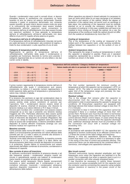
Temperatura dell’aria ambiente / Category Ambient air temperature<br />
Categoria / Category<br />
Valore medio più alto in un periodo di: / Highest mean over any period of:<br />
Max<br />
24 H 1 ANNO / 1 YEAR<br />
-25/A -25 + 40 °C 40 30 20<br />
-25/B -25 + 45 °C 45 35 25<br />
-25/C -25 + 50 °C 50 40 30<br />
-25/D -25 + 55 °C 55 45 35<br />
Il primo numero rappresenta la temperatura minima dell’aria di<br />
raffreddamento alla quale il condensatore può essere<br />
energizzato. La lettera o il secondo numero rappresentano il<br />
limite superiore della gamma di temperatura e precisamente il<br />
valore max. indicato in tabella.<br />
Tensione residua<br />
È la tensione che permane ai capi del condensatore dopo la<br />
disinserzione dei condensatori dalla rete. Questa tensione deve<br />
essere estinta onde evitare condizioni di pericolo per<br />
l’operatore. Tutti i condensatori devono essere dotati di<br />
dispositivi di scarica, chiamati di sicurezza, che riducono la<br />
tensione residua a un valore inferiore a 75 V dopo 3 minuti.<br />
Occorre però ricordare che i condensatori non possono essere<br />
energizzati se ai loro capi è presente una tensione residua<br />
maggiore del 10%. Particolare attenzione deve essere quindi<br />
posta nell’uniformare i tempi di scarica dei condensatori con i<br />
tempi di intervento dei dispositivi di comando (Regolatori). Nel<br />
caso in cui i tempi di ritardo dei regolatori siano più brevi dei<br />
tempi di scarica del condensatore, si devono prevedere ulteriori<br />
dispositivi di scarica affinché l’inversione avvenga con una<br />
tensione residua non superiore al 10%.<br />
Massima corrente<br />
Come previsto dalla norma EN 60831-1/2, i condensatori sono<br />
adatti a un funzionamento permanente con valore efficace della<br />
corrente pari ad 1,3 volte il valore di corrente alla tensione e<br />
frequenze nominali (escluso i transitori).<br />
Tenendo conto della tolleranza di capacità, la massima corrente<br />
può arrivare a 1.5 In, valore al quale ci si deve riferire nel<br />
dimensionamento della linea corrente dei dispositivi di comando<br />
e di protezione. Questo fattore di sovracorrente può essere<br />
determinato dall’effetto combinato di armoniche, sovratensioni e<br />
tolleranza di capacità.<br />
Max corrente di picco all’inserzione<br />
Si verificano sovracorrenti transitorie di ampiezza elevata e ad<br />
alta frequenza quando i condensatori vengono inseriti nel<br />
circuito e specialmente quando una batteria di condensatori<br />
viene inserita in parallelo ad altre già energizzate.<br />
Può essere quindi necessario ridurre queste sovracorrenti<br />
transitorie a valori accettabili per il condensatore e per il<br />
contattore utilizzato, inserendo i condensatori attraverso<br />
opportuni dispositivi (resistenze o reattori) nel circuito di<br />
alimentazione della batteria.<br />
The first number represents the minimum cooling air<br />
temperature at which the capacitor can be energized (- 25°C; on<br />
request -40°C). The letter or second number represents the<br />
upper limit of the temperature range and precisely. the max.<br />
value indicated in the table.<br />
Residual voltage<br />
This is the voltage that remains after the capacitor is<br />
disconnected from the network. This voltage must be<br />
eliminated in order to avoid exposing the operator to dangerous<br />
conditions. All three-phase capacitors are equipped with<br />
discharge devices that reduce residual voltage to less than 75<br />
V in 3 minutes.<br />
It is important to bear in mind that the capacitors cannot be<br />
energized if there is a residual voltage of more than 10%<br />
across them. Particular care must thus be taken to harmonise<br />
the capacitor discharge times with the response times of the<br />
control devices (<strong>Power</strong> control relays). In cases where the lag<br />
time of the controllers is shorter than the capacitor discharge<br />
time, additional discharge devices must be provided so that<br />
the connection will occur with a residual voltage not<br />
exceeding 10%.<br />
Max current<br />
In accordance with standard EN 60831-1/2, the capacitors are<br />
designed to function continuously at an effective current that is<br />
1.3 times the current at the rated voltage and frequency.<br />
Bearing in mind the capacitance tolerance, the maximum<br />
current may reach 1.5 ln, value to which it is necessary to refer<br />
in the sizing of the lines of control and protection devices. This<br />
overcurrent factor can be determined by the combined effect of<br />
harmonics, overvoltages and capacitance tolerance.<br />
Max inrush current<br />
Transient overcurrents having elevated amplitudes and high<br />
frequencies occur when the capacitors are switched in to the<br />
circuit. This is especially true when a capacitor bank is put in a<br />
parallel connection with other already energized banks.<br />
It may therefore be necessary to reduce these transient<br />
overcurrents to values acceptable both for the capacitor and<br />
the contactor used by connecting the capacitor using suitable<br />
devices (resistors or reactors) in the power circuit of the<br />
bank.<br />
7