Notiuni de electrotehnicÄ si de matematicÄ - Radioamator.ro
Notiuni de electrotehnicÄ si de matematicÄ - Radioamator.ro
Notiuni de electrotehnicÄ si de matematicÄ - Radioamator.ro

Create successful ePaper yourself
Turn your PDF publications into a flip-book with our unique Google optimized e-Paper software.
- 1 -<br />
<st<strong>ro</strong>ng>Notiuni</st<strong>ro</strong>ng> <st<strong>ro</strong>ng>de</st<strong>ro</strong>ng> elect<strong>ro</strong>tehnicã <st<strong>ro</strong>ng>si</st<strong>ro</strong>ng> <st<strong>ro</strong>ng>de</st<strong>ro</strong>ng> matematicã<br />
În acest articol sunt tratate o parte din fenomenele <st<strong>ro</strong>ng>si</st<strong>ro</strong>ng> parametrii care prezintã un<br />
grad <st<strong>ro</strong>ng>de</st<strong>ro</strong>ng> dificultate mai ridicat.<br />
Deasemenea, în acest articol s-au utilizat litere mici (<st<strong>ro</strong>ng>de</st<strong>ro</strong>ng> exemplu u , i ) pentru<br />
notarea mãrimilor care sunt variabile în timp, iar pentru mãrimile care au<br />
valori constante în timp s-au utilizat litere mari (<st<strong>ro</strong>ng>de</st<strong>ro</strong>ng> exempluU , I ).<br />
1. Inductanta<br />
Dacã un un flux magnetic variabil în timp strãbate planul spirelor unei bobine,<br />
atunci în bobinã se induce o ten<st<strong>ro</strong>ng>si</st<strong>ro</strong>ng>une elect<strong>ro</strong>motoare (aceasta este una dintre<br />
formulãrile legii inductiei elect<strong>ro</strong>magnetice a lui Faraday). Presupunând cã cele<br />
douã terminale (borne) ale bobinei sunt conectate împreunã, adicã bobina este<br />
în scurtcircuit, atunci sensul ten<st<strong>ro</strong>ng>si</st<strong>ro</strong>ng>unii induse în bobinã este astfel încât curentul<br />
generat <st<strong>ro</strong>ng>de</st<strong>ro</strong>ng> ten<st<strong>ro</strong>ng>si</st<strong>ro</strong>ng>unea indusã sã p<strong>ro</strong>ducã un câmp magnetic care sã se opunã<br />
variatiei câmpului magnetic care a generat-o. Dacã fluxul magnetic care strãbate<br />
planul spirelor bobinei nu mai este variabil în timp, atunci în bobinã înceteazã sã<br />
se mai inducã o ten<st<strong>ro</strong>ng>si</st<strong>ro</strong>ng>une elect<strong>ro</strong>motoare (t.e.m.).<br />
Inductanta este p<strong>ro</strong>prietatea unei bobine <st<strong>ro</strong>ng>de</st<strong>ro</strong>ng> a se opune oricãrei cresteri<br />
sau <st<strong>ro</strong>ng>de</st<strong>ro</strong>ng>scresteri <st<strong>ro</strong>ng>de</st<strong>ro</strong>ng> curent sau <st<strong>ro</strong>ng>de</st<strong>ro</strong>ng> flux prin ea. Opozitia este realizatã <st<strong>ro</strong>ng>de</st<strong>ro</strong>ng><br />
ten<st<strong>ro</strong>ng>si</st<strong>ro</strong>ng>unea elect<strong>ro</strong>motoare (t.e.m.) indusã în bobinã. Aceastã p<strong>ro</strong>prietate este<br />
<st<strong>ro</strong>ng>si</st<strong>ro</strong>ng>milarã cu inertia corpurilor, care se opun prin masa lor la fortele care tind sã le<br />
accelereze.<br />
Inductanta se noteazã cu litera L, iar unitatea <st<strong>ro</strong>ng>de</st<strong>ro</strong>ng> mãsurã pentru inductantã în SI<br />
(Sistemul International <st<strong>ro</strong>ng>de</st<strong>ro</strong>ng> unitãti <st<strong>ro</strong>ng>de</st<strong>ro</strong>ng> mãsurã) este henry, cu <st<strong>ro</strong>ng>si</st<strong>ro</strong>ng>mbolul [H].<br />
O bobinã are inductanta <st<strong>ro</strong>ng>de</st<strong>ro</strong>ng> un henry, dacã în bobinã se autoinduce o<br />
ten<st<strong>ro</strong>ng>si</st<strong>ro</strong>ng>une elect<strong>ro</strong>motoare medie <st<strong>ro</strong>ng>de</st<strong>ro</strong>ng> un volt, atunci când curentul care curge<br />
prin conductorul bobinei are o variatie <st<strong>ro</strong>ng>de</st<strong>ro</strong>ng> un ampere, într-un interval <st<strong>ro</strong>ng>de</st<strong>ro</strong>ng><br />
timp <st<strong>ro</strong>ng>de</st<strong>ro</strong>ng> o secundã.<br />
Valoarea ten<st<strong>ro</strong>ng>si</st<strong>ro</strong>ng>unii induse într-o bobinã cu inductanta L este datã <st<strong>ro</strong>ng>de</st<strong>ro</strong>ng> relatia:<br />
∆I<br />
e = −L<br />
(1.1)<br />
∆t<br />
e = t.e.m. medie indusã în bobinã, [V];<br />
∆I = variatia curentului prin bobinã în intervalul <st<strong>ro</strong>ng>de</st<strong>ro</strong>ng> timp ∆ t , [A];<br />
∆t = intervalul <st<strong>ro</strong>ng>de</st<strong>ro</strong>ng> timp în care are loc variatia curentului, [s]<br />
<st<strong>ro</strong>ng>Notiuni</st<strong>ro</strong>ng> <st<strong>ro</strong>ng>de</st<strong>ro</strong>ng> elect<strong>ro</strong>tehnicã <st<strong>ro</strong>ng>si</st<strong>ro</strong>ng> <st<strong>ro</strong>ng>de</st<strong>ro</strong>ng> matematicã: Page 1 of 102
- 2 -<br />
Litera greceascã ∆ se foloseste în locul literei d, care vine <st<strong>ro</strong>ng>de</st<strong>ro</strong>ng> la cuvântul<br />
“diferentã”. Ea este folo<st<strong>ro</strong>ng>si</st<strong>ro</strong>ng>tã în asociere cu orice mãrime, cum ar fi vitezã, timp,<br />
flux magnetic, etc. Dacã este vorba <st<strong>ro</strong>ng>de</st<strong>ro</strong>ng>spre curent electric, asocierea <st<strong>ro</strong>ng>de</st<strong>ro</strong>ng> litere ∆ I<br />
nu înseamnã cã se face p<strong>ro</strong>dusul lor. Aceastã asociere este folo<st<strong>ro</strong>ng>si</st<strong>ro</strong>ng>tã ca sã se<br />
arate ce variatie a suferit curentul electric <st<strong>ro</strong>ng>si</st<strong>ro</strong>ng> înseamnã diferenta dintre valoarea<br />
finalã I<br />
2<br />
a curentului <st<strong>ro</strong>ng>si</st<strong>ro</strong>ng> valoarea initialã I 1<br />
a curentului, adicã ∆ I = I 2<br />
− I1<br />
.<br />
Semnul minus din relatia (1.1) aratã cã t.e.m. indusã se opune tot<st<strong>ro</strong>ng>de</st<strong>ro</strong>ng>auna cauzei<br />
care a creat-o. Mãrimea ten<st<strong>ro</strong>ng>si</st<strong>ro</strong>ng>unii induse este cea din relatia (1.1) fãrã sã se tinã<br />
seama <st<strong>ro</strong>ng>de</st<strong>ro</strong>ng> semnul minus.<br />
Exemplu:<br />
Un curent cu inten<st<strong>ro</strong>ng>si</st<strong>ro</strong>ng>tatea <st<strong>ro</strong>ng>de</st<strong>ro</strong>ng> 10 A trece printr-o bobinã. Începând cu un anumit<br />
moment acesta sca<st<strong>ro</strong>ng>de</st<strong>ro</strong>ng> în interval <st<strong>ro</strong>ng>de</st<strong>ro</strong>ng> 2 secun<st<strong>ro</strong>ng>de</st<strong>ro</strong>ng> la 1 A. Inductanta bobinei este <st<strong>ro</strong>ng>de</st<strong>ro</strong>ng><br />
<st<strong>ro</strong>ng>de</st<strong>ro</strong>ng> 0.8 H. Sã se afle ten<st<strong>ro</strong>ng>si</st<strong>ro</strong>ng>unea medie autoindusã în bobinã.<br />
∆I<br />
1−10<br />
e = −L<br />
= −0 .8 ⋅ = ( −0.8)<br />
⋅ ( −5)<br />
= 4 V<br />
∆t<br />
2<br />
Semnul pozitiv al ten<st<strong>ro</strong>ng>si</st<strong>ro</strong>ng>unii obtinute aratã cã ten<st<strong>ro</strong>ng>si</st<strong>ro</strong>ng>unea autoindusã are tendinta sã<br />
mentinã curentul la valoarea initialã, adicã ten<st<strong>ro</strong>ng>si</st<strong>ro</strong>ng>unea autoindusã se opune<br />
scã<st<strong>ro</strong>ng>de</st<strong>ro</strong>ng>rii curentului <st<strong>ro</strong>ng>de</st<strong>ro</strong>ng> la 10 A la 1 A. Dupã cum se va ve<st<strong>ro</strong>ng>de</st<strong>ro</strong>ng>a în continuare,<br />
aceastã oponentã înceteazã dupã un timp <st<strong>ro</strong>ng>de</st<strong>ro</strong>ng>stul <st<strong>ro</strong>ng>de</st<strong>ro</strong>ng> scurt.<br />
Din relatia (1.1) se ve<st<strong>ro</strong>ng>de</st<strong>ro</strong>ng> cã dintre douã bobine prin care circulã curenti variabili în<br />
timp, fenomenul <st<strong>ro</strong>ng>de</st<strong>ro</strong>ng> autoinductie va fi mai puternic la bobina cu inductanta mai<br />
mare.<br />
Relatia între unitãtile <st<strong>ro</strong>ng>de</st<strong>ro</strong>ng> mãsurã ale ecuatiei (1.1) este:<br />
1 V = 1 H<br />
1A<br />
⋅ (1.2)<br />
1s<br />
Din relatia (1.2) se poate <st<strong>ro</strong>ng>de</st<strong>ro</strong>ng>duce relatia dimen<st<strong>ro</strong>ng>si</st<strong>ro</strong>ng>onalã pentru un henry:<br />
1V<br />
⋅ s<br />
1H<br />
= (1.3)<br />
1A<br />
În functie <st<strong>ro</strong>ng>de</st<strong>ro</strong>ng> parametrii bobinei, inductanta este datã <st<strong>ro</strong>ng>de</st<strong>ro</strong>ng> relatia:<br />
2<br />
µ<br />
r<br />
AN<br />
L 0<br />
µ<br />
= (1.4)<br />
l<br />
µ =8.854× 10 −12 [H/m], permeabilitatea magneticã a vidului;<br />
0<br />
µ<br />
r<br />
= permeabilitatea relativã a miezului bobinei, fãrã dimen<st<strong>ro</strong>ng>si</st<strong>ro</strong>ng>uni;<br />
A= aria spirei bobinei (nu aria sectiunii conductoruli), [m 2 ];<br />
<st<strong>ro</strong>ng>Notiuni</st<strong>ro</strong>ng> <st<strong>ro</strong>ng>de</st<strong>ro</strong>ng> elect<strong>ro</strong>tehnicã <st<strong>ro</strong>ng>si</st<strong>ro</strong>ng> <st<strong>ro</strong>ng>de</st<strong>ro</strong>ng> matematicã: Page 2 of 102
- 3 -<br />
N= numãrul <st<strong>ro</strong>ng>de</st<strong>ro</strong>ng> spire al bobinei;<br />
l = lungimea bobinei, [m];<br />
L= inductanta bobinei, [H]<br />
2. Inductanta mutualã<br />
Presupunem cã douã bobine A <st<strong>ro</strong>ng>si</st<strong>ro</strong>ng> B se aflã una în ap<strong>ro</strong>pierea celeilalte, astflel<br />
încât dacã prin bobinã A va curge un curent, liniile fluxului magnetic p<strong>ro</strong>dus <st<strong>ro</strong>ng>de</st<strong>ro</strong>ng><br />
bobina A sã strãbatã total, sau partial planul spirelor bobinei B. Dacã curentul din<br />
bobina A va suferi o variatie ∆ I în intervalul <st<strong>ro</strong>ng>de</st<strong>ro</strong>ng> timp ∆ t , atunci <st<strong>ro</strong>ng>si</st<strong>ro</strong>ng> fluxul magnetic<br />
p<strong>ro</strong>dus <st<strong>ro</strong>ng>de</st<strong>ro</strong>ng> bobina A va suferi o variatie în acela<st<strong>ro</strong>ng>si</st<strong>ro</strong>ng> interval <st<strong>ro</strong>ng>de</st<strong>ro</strong>ng> timp ∆ t . Variatia<br />
fluxului bobinei A va induce în bobina B o ten<st<strong>ro</strong>ng>si</st<strong>ro</strong>ng>une elect<strong>ro</strong>motoare. Se spune cã<br />
între cele douã bobine existã inductantã mutualã, care se noteazã cu M <st<strong>ro</strong>ng>si</st<strong>ro</strong>ng> este<br />
mãsuratã tot în henry, [H].<br />
Inductanta mutualã dintre douã bobine este <st<strong>ro</strong>ng>de</st<strong>ro</strong>ng> un henry dacã în una din<br />
bobine se induce o ten<st<strong>ro</strong>ng>si</st<strong>ro</strong>ng>une elect<strong>ro</strong>motoare medie <st<strong>ro</strong>ng>de</st<strong>ro</strong>ng> un volt, atunci când<br />
curentul care curge prin cealaltã bobinã are o variatie <st<strong>ro</strong>ng>de</st<strong>ro</strong>ng> un ampere, într-un<br />
interval <st<strong>ro</strong>ng>de</st<strong>ro</strong>ng> timp <st<strong>ro</strong>ng>de</st<strong>ro</strong>ng> o secundã.<br />
e M<br />
= −M<br />
∆I<br />
∆t<br />
1<br />
(2.1)<br />
e<br />
M<br />
= t.e.m. indusã în bobina B, [V];<br />
M = inductanta mutualã dintre cele douã bobine, [H];<br />
∆I 1<br />
= variatia curentului în bobina A, în intervalul <st<strong>ro</strong>ng>de</st<strong>ro</strong>ng> timp ∆ t , [A];<br />
∆t = intervalul <st<strong>ro</strong>ng>de</st<strong>ro</strong>ng> timp în care are loc variatia curentului în bobina A, [s].<br />
Inductanta mutualã M dintre douã bobine este cu atât mai mare cu cât cele douã<br />
bobine sunt mai strâns cuplate.<br />
3. Conectarea unui circuit R-L la o ten<st<strong>ro</strong>ng>si</st<strong>ro</strong>ng>une continuã<br />
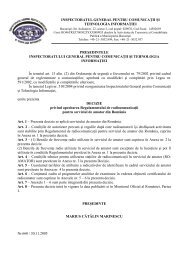
Se con<st<strong>ro</strong>ng>si</st<strong>ro</strong>ng><st<strong>ro</strong>ng>de</st<strong>ro</strong>ng>rã circuitul din Fig. 3.1.<br />
+<br />
U<br />
M1<br />
a<br />
. S<br />
R<br />
L<br />
i<br />
1.<br />
+<br />
. mA<br />
(-)<br />
. b uR<br />
uL<br />
-<br />
.<br />
(+)<br />
2<br />
Fig. 3.1 Circuit cu rezistentã <st<strong>ro</strong>ng>si</st<strong>ro</strong>ng> inductantã<br />
<st<strong>ro</strong>ng>Notiuni</st<strong>ro</strong>ng> <st<strong>ro</strong>ng>de</st<strong>ro</strong>ng> elect<strong>ro</strong>tehnicã <st<strong>ro</strong>ng>si</st<strong>ro</strong>ng> <st<strong>ro</strong>ng>de</st<strong>ro</strong>ng> matematicã: Page 3 of 102
- 4 -<br />
În Fig.3.1 este prezentat un circuit serie format ditnr-un un rezistor cu rezistenta<br />
R <st<strong>ro</strong>ng>si</st<strong>ro</strong>ng> o bobinã cu inductanta L. Bobina se con<st<strong>ro</strong>ng>si</st<strong>ro</strong>ng><st<strong>ro</strong>ng>de</st<strong>ro</strong>ng>rã fãrã rezistentã; se con<st<strong>ro</strong>ng>si</st<strong>ro</strong>ng><st<strong>ro</strong>ng>de</st<strong>ro</strong>ng>rã<br />
cã rezistenta ei este inclusã în rezistenta R. În momentul în care comutatorul S<br />
se pune pe pozitia a, combinatia R-L este conectatã brusc la ten<st<strong>ro</strong>ng>si</st<strong>ro</strong>ng>unea U a<br />
bateriei. Con<st<strong>ro</strong>ng>si</st<strong>ro</strong>ng><st<strong>ro</strong>ng>de</st<strong>ro</strong>ng>rãm momentul punerii comutatorului pe pozitia a ca fiind<br />
momentul ze<strong>ro</strong> (t=0). Cu ajutorul miliampermetrului M1 vom constata cã curentul<br />
prin circuit nu atinge valoarea sa maximã instantaneu (adicã la t=0), ci dupã un<br />
timp finit. Acest lucru se explicã prin faptul cã în momentul t=0, <st<strong>ro</strong>ng>de</st<strong>ro</strong>ng><st<strong>ro</strong>ng>si</st<strong>ro</strong>ng> curentul prin<br />
circuit este ze<strong>ro</strong> ( i = 0 ), viteza <st<strong>ro</strong>ng>de</st<strong>ro</strong>ng> variatie a curentului este diferitã <st<strong>ro</strong>ng>de</st<strong>ro</strong>ng> ze<strong>ro</strong>,<br />
∆i<br />
≠ 0 <st<strong>ro</strong>ng>si</st<strong>ro</strong>ng> astfel în bobinã se va autoindcue o ten<st<strong>ro</strong>ng>si</st<strong>ro</strong>ng>une contraelect<strong>ro</strong>motoare<br />
∆t<br />
∆i<br />
e = −L<br />
, cu polaritatea + la terminalul 1 al bobinei <st<strong>ro</strong>ng>si</st<strong>ro</strong>ng> cu – (minus) la terminalul<br />
∆t<br />
2 al bobinei. Din Fig. 3.1 se ve<st<strong>ro</strong>ng>de</st<strong>ro</strong>ng> cã în orice moment ten<st<strong>ro</strong>ng>si</st<strong>ro</strong>ng>unea U a sursei este<br />
egalã cu suma cã<st<strong>ro</strong>ng>de</st<strong>ro</strong>ng>rilor <st<strong>ro</strong>ng>de</st<strong>ro</strong>ng> ten<st<strong>ro</strong>ng>si</st<strong>ro</strong>ng>unilor <st<strong>ro</strong>ng>de</st<strong>ro</strong>ng> pe rezistenta R <st<strong>ro</strong>ng>si</st<strong>ro</strong>ng> inductanta L,<br />
p<strong>ro</strong>duse <st<strong>ro</strong>ng>de</st<strong>ro</strong>ng> curentul i din circuit, care are tendinta sã creascã <st<strong>ro</strong>ng>de</st<strong>ro</strong>ng> la valoarea<br />
ze<strong>ro</strong> la valoarea sa maximã. Se poate scrie ecuatia:<br />
U<br />
∆i<br />
= uR<br />
+ u<br />
L<br />
= iR + L<br />
(3.1)<br />
∆t<br />
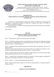
Matematicienii au rezolvat aceastã ecuatie diferentialã pentru curentul i <st<strong>ro</strong>ng>si</st<strong>ro</strong>ng> au<br />
obtinut solutia datã <st<strong>ro</strong>ng>de</st<strong>ro</strong>ng> ecuatia (3.2), reprezentatã grafic în Fig. 3.2:<br />
i<br />
t<br />
t<br />
U −<br />
−<br />
τ<br />
τ<br />
= ( 1−<br />
e ) = I<br />
m<br />
(1 − e )<br />
(3.2)<br />
R<br />
un<st<strong>ro</strong>ng>de</st<strong>ro</strong>ng>:<br />
U = I este valoarea maximã a curentului care va fi atinsã în circuitul R-L, [A];<br />
m<br />
R<br />
e =2.7182818…, este baza logaritmilor naturali (sau numãrul lui Euler);<br />
t = timpul scurs <st<strong>ro</strong>ng>de</st<strong>ro</strong>ng> la punerea comutatorului pe pozitia a, [s];<br />
L<br />
τ = = constanta <st<strong>ro</strong>ng>de</st<strong>ro</strong>ng> timp a circuitului; acest raport are dimen<st<strong>ro</strong>ng>si</st<strong>ro</strong>ng>une <st<strong>ro</strong>ng>de</st<strong>ro</strong>ng> timp <st<strong>ro</strong>ng>si</st<strong>ro</strong>ng><br />
R<br />
este mãsurat în secun<st<strong>ro</strong>ng>de</st<strong>ro</strong>ng> [s], dacã L e mãsurat în henry <st<strong>ro</strong>ng>si</st<strong>ro</strong>ng> R în ohm.<br />
Exemplu: L=50 mH, R=1 k Ω , rezultã:<br />
3<br />
L 50 ⋅10<br />
− H<br />
−5<br />
τ = = = 5 ⋅10<br />
= 0.00005 [s]<br />
R 1000Ω<br />
<st<strong>ro</strong>ng>Notiuni</st<strong>ro</strong>ng> <st<strong>ro</strong>ng>de</st<strong>ro</strong>ng> elect<strong>ro</strong>tehnicã <st<strong>ro</strong>ng>si</st<strong>ro</strong>ng> <st<strong>ro</strong>ng>de</st<strong>ro</strong>ng> matematicã: Page 4 of 102
- 5 -<br />
100<br />
U<br />
I m<br />
=<br />
R<br />
% din curentul maxim Im<br />
80<br />
60<br />
40<br />
20<br />
63.2%<br />
i<br />
=<br />
t<br />
−<br />
τ<br />
I m<br />
( 1−<br />
e )<br />
t<br />
0<br />
τ =<br />
L<br />
R<br />
t = 5τ<br />
Fig. 3.2 Curba curentului într-un circuit R-L la conectarea la ten<st<strong>ro</strong>ng>si</st<strong>ro</strong>ng>une<br />
U<br />
R<br />
i<br />
i p<br />
i<br />
U<br />
u<br />
R;<br />
uL<br />
u R<br />
U = u R<br />
+ u L<br />
u L<br />
0<br />
t<br />
0<br />
t<br />
i tr<br />
u<br />
= −<br />
e<br />
u L<br />
U<br />
−<br />
R<br />
−U<br />
Fig. 3.3 Fig. 3.4<br />
Ecuatia (3.2) este o ecuatie exponentialã, a cãrei curbã este arãtatã în Fig. 3.2.<br />
Cresterea curentului este mai rapidã la început <st<strong>ro</strong>ng>si</st<strong>ro</strong>ng> apoi mai micã, astefel cã la<br />
t = ∞ cresterea <st<strong>ro</strong>ng>de</st<strong>ro</strong>ng>vine ze<strong>ro</strong>. Teoretic curentul atinge valoarea sa maximã I<br />
m<br />
la<br />
<st<strong>ro</strong>ng>Notiuni</st<strong>ro</strong>ng> <st<strong>ro</strong>ng>de</st<strong>ro</strong>ng> elect<strong>ro</strong>tehnicã <st<strong>ro</strong>ng>si</st<strong>ro</strong>ng> <st<strong>ro</strong>ng>de</st<strong>ro</strong>ng> matematicã: Page 5 of 102
- 6 -<br />
infinit. Practic, curentul atinge valoarea sa maximã dupã un timp foarte scurt,<br />
−5<br />
egal cu 5 constante <st<strong>ro</strong>ng>de</st<strong>ro</strong>ng> timp ( 5 τ ), pentru cã e = 0.0067 ≅ 0 .<br />
Ecuatia (3.2) se poate scrie <st<strong>ro</strong>ng>si</st<strong>ro</strong>ng> astfel:<br />
i<br />
m<br />
m<br />
t<br />
−<br />
τ<br />
= I − I e<br />
(3.3)<br />
Acum se vãd cele douã componente ale curentului i , una permanentã <st<strong>ro</strong>ng>de</st<strong>ro</strong>ng><br />
U<br />
−<br />
τ<br />
valoare constantã i<br />
p<br />
= I<br />
m<br />
= <st<strong>ro</strong>ng>si</st<strong>ro</strong>ng> alta variabilã în timp, tranzitorie, itr<br />
= −I<br />
me<br />
R<br />
care curge în sens invers componentei permanente, dar care <st<strong>ro</strong>ng>de</st<strong>ro</strong>ng>screste în timp,<br />
vezi figura 3.3.<br />
Suma celor douã componente i p<br />
<st<strong>ro</strong>ng>si</st<strong>ro</strong>ng> i tr<br />
dau valoarea curentului i care curge prin<br />
circuit. În Fig. 3.3 se ve<st<strong>ro</strong>ng>de</st<strong>ro</strong>ng> cã dacã se adunã valorile din fiecare moment ale celor<br />
douã curbe i<br />
p<br />
<st<strong>ro</strong>ng>si</st<strong>ro</strong>ng> i tr<br />
se obtine curba i . În Fig. 3.4 se ve<st<strong>ro</strong>ng>de</st<strong>ro</strong>ng> cã în momentul t = 0<br />
ten<st<strong>ro</strong>ng>si</st<strong>ro</strong>ng>unea elect<strong>ro</strong>motoare autoindusã în bobinã u<br />
e<br />
este egalã dar opusã cu<br />
ten<st<strong>ro</strong>ng>si</st<strong>ro</strong>ng>unea U a bateriei. Cã<st<strong>ro</strong>ng>de</st<strong>ro</strong>ng>rea <st<strong>ro</strong>ng>de</st<strong>ro</strong>ng> ten<st<strong>ro</strong>ng>si</st<strong>ro</strong>ng>une pe bobinã este notatã cu u<br />
L<br />
.<br />
t<br />
4. Deconectarea unui circuit R-L <st<strong>ro</strong>ng>de</st<strong>ro</strong>ng> la o ten<st<strong>ro</strong>ng>si</st<strong>ro</strong>ng>une continuã<br />
Ne referim din nou la circuitul din figura 3.1. Dupã ce curentul în circuit s-a stabilit<br />
U<br />
la valoarea maximã I m<br />
= , se comutã brusc comutatorul S <st<strong>ro</strong>ng>de</st<strong>ro</strong>ng> pe pozitia a pe<br />
R<br />
pozitia b. Con<st<strong>ro</strong>ng>si</st<strong>ro</strong>ng><st<strong>ro</strong>ng>de</st<strong>ro</strong>ng>rãm acest moment ca fiind momentul t = 0 . Se va constata cã<br />
<st<strong>ro</strong>ng>de</st<strong>ro</strong>ng><st<strong>ro</strong>ng>si</st<strong>ro</strong>ng> bateria cu ten<st<strong>ro</strong>ng>si</st<strong>ro</strong>ng>unea U a fost <st<strong>ro</strong>ng>de</st<strong>ro</strong>ng>conectatã din circuit, totu<st<strong>ro</strong>ng>si</st<strong>ro</strong>ng> în circuit<br />
continuã sã curgã un curent, în acela<st<strong>ro</strong>ng>si</st<strong>ro</strong>ng> sens, care la momentul t = 0 este chiar<br />
U<br />
I m<br />
= , dar care <st<strong>ro</strong>ng>de</st<strong>ro</strong>ng>screste în timp. Acest curent continuã sã curgã în circuit prin<br />
R<br />
arcul electric care se formeazã între polii comutatorului S. Care este fenomenul<br />
care mentine curentul în circuit? Pânã la momentul t = 0 curentul fiind constant <st<strong>ro</strong>ng>si</st<strong>ro</strong>ng><br />
∆<br />
egal cu I<br />
m<br />
, variatia lui in timp era ze<strong>ro</strong>, adicã I m = 0 . La momentul t = 0<br />
∆t<br />
∆i<br />
curentul are tendinta sã scadã, <st<strong>ro</strong>ng>de</st<strong>ro</strong>ng>ci ≠ 0 . Ca urmare în bobinã se va<br />
∆t<br />
∆i<br />
autoinduce o ten<st<strong>ro</strong>ng>si</st<strong>ro</strong>ng>une elect<strong>ro</strong>motoare e = −L<br />
, cu polaritatea + la terminalul 2<br />
∆t<br />
al bobinei <st<strong>ro</strong>ng>si</st<strong>ro</strong>ng> – (minus) la terminalul 1 (polaritãtile arãtate pe fig. 3.1 în paranteze).<br />
Aceastã ten<st<strong>ro</strong>ng>si</st<strong>ro</strong>ng>une autoindusã va încerca sã mentinã curentul în circuit, dar va<br />
<st<strong>ro</strong>ng>de</st<strong>ro</strong>ng>screste în timp. Dupã un anumit timp, teoretic infinit, dar practic dupã t = 5τ<br />
,<br />
curentul în circuit va scã<st<strong>ro</strong>ng>de</st<strong>ro</strong>ng>a la ze<strong>ro</strong>.<br />
Ecuatia curentului din circuit o vom <st<strong>ro</strong>ng>de</st<strong>ro</strong>ng>duce din ecuatia (3.1) în care se va pune<br />
conditia U=0. Rezultã:<br />
<st<strong>ro</strong>ng>Notiuni</st<strong>ro</strong>ng> <st<strong>ro</strong>ng>de</st<strong>ro</strong>ng> elect<strong>ro</strong>tehnicã <st<strong>ro</strong>ng>si</st<strong>ro</strong>ng> <st<strong>ro</strong>ng>de</st<strong>ro</strong>ng> matematicã: Page 6 of 102
- 7 -<br />
∆i<br />
0 = iR + L<br />
(4.1)<br />
∆t<br />
Matematicienii au rezolvat aceastã ecuatie în raport cu i <st<strong>ro</strong>ng>si</st<strong>ro</strong>ng> au obtinut solutia<br />
datã <st<strong>ro</strong>ng>de</st<strong>ro</strong>ng> ecuatia (4.2), reprezentatã grafic în Fig. 4.1:<br />
i<br />
t<br />
−<br />
τ<br />
t<br />
−<br />
τ<br />
U<br />
= e = I<br />
me<br />
(4.2)<br />
R<br />
100<br />
i<br />
U<br />
I m<br />
=<br />
R<br />
% din curentul maxim Im<br />
80<br />
60<br />
40<br />
20<br />
i<br />
=<br />
U<br />
R<br />
e<br />
t<br />
−<br />
τ<br />
37%<br />
=<br />
I<br />
m<br />
e<br />
t<br />
−<br />
τ<br />
t<br />
0<br />
τ =<br />
L<br />
R<br />
t = 5τ<br />
Fig. 4.1 Descresterea curentului într-un circuit R-L, la <st<strong>ro</strong>ng>de</st<strong>ro</strong>ng>conectarea <st<strong>ro</strong>ng>de</st<strong>ro</strong>ng> la<br />
ten<st<strong>ro</strong>ng>si</st<strong>ro</strong>ng>une<br />
Pentru<br />
L<br />
t = τ = din ecuatia (4.2) se obtine:<br />
R<br />
I I<br />
= = = I<br />
m<br />
(4.3)<br />
e 2.71828<br />
m<br />
m<br />
i 0. 37<br />
Descrestera curentului în circuitul din Fig. 3.1, <st<strong>ro</strong>ng>de</st<strong>ro</strong>ng>scrisã <st<strong>ro</strong>ng>de</st<strong>ro</strong>ng> ecuatia (4.2), este<br />
arãtat în Fig. 4.1.<br />
Din cele douã cazuri prezentate în Fig. 3.1, cât <st<strong>ro</strong>ng>si</st<strong>ro</strong>ng> din curbele prezentate în<br />
figurile 3.2, 3.3, 3.4 <st<strong>ro</strong>ng>si</st<strong>ro</strong>ng> 4.1 se trage urmãtoarea concluzie:<br />
La momentul conectãrii la sursã a unui circuit care contine o bobinã, t = 0 ,<br />
curentul prin circuit este ze<strong>ro</strong>, în timp ce ten<st<strong>ro</strong>ng>si</st<strong>ro</strong>ng>unea la bornele bobinei este<br />
<st<strong>ro</strong>ng>Notiuni</st<strong>ro</strong>ng> <st<strong>ro</strong>ng>de</st<strong>ro</strong>ng> elect<strong>ro</strong>tehnicã <st<strong>ro</strong>ng>si</st<strong>ro</strong>ng> <st<strong>ro</strong>ng>de</st<strong>ro</strong>ng> matematicã: Page 7 of 102
- 8 -<br />
maximã. Dupã un timp, teoretic infinit, dar practic dupã 5 constante <st<strong>ro</strong>ng>de</st<strong>ro</strong>ng> timp<br />
curentul atinge valoarea sa maximã, I<br />
m<br />
, îar ten<st<strong>ro</strong>ng>si</st<strong>ro</strong>ng>unea autoindusã în bobinã<br />
<st<strong>ro</strong>ng>de</st<strong>ro</strong>ng>vine ze<strong>ro</strong>.<br />
Aceasta este p<strong>ro</strong>prietatea fundamentalã a bobinei. O bobinã cu inductanta<br />
L se opune variatiei curentului care o strãbate. Curentul dintr-un circuit<br />
care contine o bobinã rãmâne în urma ten<st<strong>ro</strong>ng>si</st<strong>ro</strong>ng>unii <st<strong>ro</strong>ng>de</st<strong>ro</strong>ng> la bornele bobinei.<br />
5. Conectarea unui circuit R-C la o ten<st<strong>ro</strong>ng>si</st<strong>ro</strong>ng>une continuã;<br />
încãrcarea con<st<strong>ro</strong>ng>de</st<strong>ro</strong>ng>nsatorului<br />
Se con<st<strong>ro</strong>ng>si</st<strong>ro</strong>ng><st<strong>ro</strong>ng>de</st<strong>ro</strong>ng>rã circuitul din Fig. 5.1:<br />
+<br />
U<br />
.<br />
a<br />
.<br />
b<br />
S<br />
.<br />
ic<br />
M1<br />
mA<br />
R<br />
u<br />
R<br />
C<br />
1.<br />
+ -<br />
.<br />
u<br />
C<br />
2<br />
Fig. 5.1. Circuit R-C conectat la o ten<st<strong>ro</strong>ng>si</st<strong>ro</strong>ng>une continuã<br />
Se presupune cã initial con<st<strong>ro</strong>ng>de</st<strong>ro</strong>ng>nsatorul este <st<strong>ro</strong>ng>de</st<strong>ro</strong>ng>scãrcat. La momentul t = 0 se<br />
pune comutatorul S pe pozitia a. În acest fel circuitul R-C se conecteazã la<br />
bateria cu ten<st<strong>ro</strong>ng>si</st<strong>ro</strong>ng>unea U. Chiar în momentul t = 0 miliampermetrul M1 din circuit<br />
ne aratã o valoare maximã a curentului prin circuit, care dupã un timp sca<st<strong>ro</strong>ng>de</st<strong>ro</strong>ng> la<br />
ze<strong>ro</strong>. În timpul încãrcãrii con<st<strong>ro</strong>ng>de</st<strong>ro</strong>ng>nsatorului (S pe pozitia a), ten<st<strong>ro</strong>ng>si</st<strong>ro</strong>ng>unea U a bateriei<br />
este egalã cu suma ten<st<strong>ro</strong>ng>si</st<strong>ro</strong>ng>unilor <st<strong>ro</strong>ng>de</st<strong>ro</strong>ng> pe rezistentã <st<strong>ro</strong>ng>si</st<strong>ro</strong>ng> <st<strong>ro</strong>ng>de</st<strong>ro</strong>ng> pe con<st<strong>ro</strong>ng>de</st<strong>ro</strong>ng>nsator:<br />
U = u + u = i R + u<br />
(5.1)<br />
R<br />
c<br />
c<br />
c<br />
Curentul <st<strong>ro</strong>ng>de</st<strong>ro</strong>ng> încãrcare al con<st<strong>ro</strong>ng>de</st<strong>ro</strong>ng>nsatorului este dat <st<strong>ro</strong>ng>de</st<strong>ro</strong>ng> variatia sarcinii<br />
armãturile con<st<strong>ro</strong>ng>de</st<strong>ro</strong>ng>nsatorului în unitatea <st<strong>ro</strong>ng>de</st<strong>ro</strong>ng> timp, adicã:<br />
∆ q <st<strong>ro</strong>ng>de</st<strong>ro</strong>ng> pe<br />
i<br />
c<br />
=<br />
∆q<br />
∆t<br />
=<br />
∆(<br />
C ⋅ u )<br />
∆t<br />
c<br />
∆uc<br />
= C<br />
∆t<br />
(5.2)<br />
Înlocuind expre<st<strong>ro</strong>ng>si</st<strong>ro</strong>ng>a lui i c<br />
din ecuatia (5.2) în ecuatia (5.1) se obtine:<br />
∆u<br />
= uc<br />
(5.3)<br />
∆t<br />
c<br />
U CR +<br />
<st<strong>ro</strong>ng>Notiuni</st<strong>ro</strong>ng> <st<strong>ro</strong>ng>de</st<strong>ro</strong>ng> elect<strong>ro</strong>tehnicã <st<strong>ro</strong>ng>si</st<strong>ro</strong>ng> <st<strong>ro</strong>ng>de</st<strong>ro</strong>ng> matematicã: Page 8 of 102
Solutia ecuatiei (5.3) în raport cu<br />
grafic în Fig. 5.2:<br />
u<br />
c<br />
t<br />
−<br />
- 9 -<br />
u<br />
c<br />
este datã <st<strong>ro</strong>ng>de</st<strong>ro</strong>ng> ecuatia (5.4) <st<strong>ro</strong>ng>si</st<strong>ro</strong>ng> reprezentatã<br />
τ<br />
= U ( 1−<br />
e )<br />
(5.4)<br />
100<br />
i c<br />
U<br />
I m<br />
=<br />
R<br />
% din curentul maxim Im<br />
80<br />
60<br />
40<br />
20<br />
i = I<br />
c<br />
m<br />
e<br />
t<br />
−<br />
τ<br />
37%<br />
0<br />
τ =<br />
RC<br />
t<br />
t = 5τ<br />
100<br />
u c<br />
u c<br />
= U<br />
.max<br />
% din U<br />
80<br />
60<br />
40<br />
63.2%<br />
u<br />
c<br />
t<br />
−<br />
τ<br />
= U ( 1−<br />
e )<br />
20<br />
0<br />
τ =<br />
RC<br />
t<br />
t = 5τ<br />
Fig. 5.2. Curbele curentului <st<strong>ro</strong>ng>si</st<strong>ro</strong>ng> ten<st<strong>ro</strong>ng>si</st<strong>ro</strong>ng>unii la încãrcare a unui con<st<strong>ro</strong>ng>de</st<strong>ro</strong>ng>nsator<br />
un<st<strong>ro</strong>ng>de</st<strong>ro</strong>ng>:<br />
u<br />
c<br />
= ten<st<strong>ro</strong>ng>si</st<strong>ro</strong>ng>unea la orice moment pe con<st<strong>ro</strong>ng>de</st<strong>ro</strong>ng>nsatorul C, [V];<br />
U= ten<st<strong>ro</strong>ng>si</st<strong>ro</strong>ng>unea sursei care se va regã<st<strong>ro</strong>ng>si</st<strong>ro</strong>ng> dupã un timp pe con<st<strong>ro</strong>ng>de</st<strong>ro</strong>ng>nsatorul C, [V]<br />
<st<strong>ro</strong>ng>Notiuni</st<strong>ro</strong>ng> <st<strong>ro</strong>ng>de</st<strong>ro</strong>ng> elect<strong>ro</strong>tehnicã <st<strong>ro</strong>ng>si</st<strong>ro</strong>ng> <st<strong>ro</strong>ng>de</st<strong>ro</strong>ng> matematicã: Page 9 of 102
- 10 -<br />
t = timpul scurs <st<strong>ro</strong>ng>de</st<strong>ro</strong>ng> la momentul conectãrii circuitului la baterie, [s];<br />
e =2.7182818…, este baza logaritmilor naturali (sau numãrul lui Euler);<br />
τ = RC = constanta <st<strong>ro</strong>ng>de</st<strong>ro</strong>ng> timp a circuitului; p<strong>ro</strong>dusl RC are dimen<st<strong>ro</strong>ng>si</st<strong>ro</strong>ng>une <st<strong>ro</strong>ng>de</st<strong>ro</strong>ng> timp <st<strong>ro</strong>ng>si</st<strong>ro</strong>ng><br />
este mãsurat în secun<st<strong>ro</strong>ng>de</st<strong>ro</strong>ng> [s], dacã R este mãsuratã în Ω <st<strong>ro</strong>ng>si</st<strong>ro</strong>ng> C in farad [F].<br />
6<br />
Exemplu: R=1000 k Ω , C=50 µ F . τ = RC = 1000000Ω ⋅50<br />
⋅10<br />
− F = 50 [s].<br />
Curentul <st<strong>ro</strong>ng>de</st<strong>ro</strong>ng> încãrcare este dat <st<strong>ro</strong>ng>de</st<strong>ro</strong>ng> ecuatia (5.5) <st<strong>ro</strong>ng>si</st<strong>ro</strong>ng> reprezentat în Fig. 5.2:<br />
i<br />
c<br />
t<br />
−<br />
τ<br />
t<br />
−<br />
τ<br />
U<br />
= I<br />
me<br />
= e<br />
(5.5)<br />
R<br />
Ecuatiile (5.4) <st<strong>ro</strong>ng>si</st<strong>ro</strong>ng> (5.5), care <st<strong>ro</strong>ng>de</st<strong>ro</strong>ng>scriu curbele <st<strong>ro</strong>ng>de</st<strong>ro</strong>ng> încãrcare ale con<st<strong>ro</strong>ng>de</st<strong>ro</strong>ng>nsatorului,<br />
sunt reprezentate grafic în Fig. 5.2.<br />
Atât din curbele prezentate în Fig.5.2, cât <st<strong>ro</strong>ng>si</st<strong>ro</strong>ng> din ecuatiile (5.4) <st<strong>ro</strong>ng>si</st<strong>ro</strong>ng> (5.5) se ve<st<strong>ro</strong>ng>de</st<strong>ro</strong>ng> cã:<br />
În momentul conectãrii unui circuit, care contine un con<st<strong>ro</strong>ng>de</st<strong>ro</strong>ng>nsator, la<br />
ten<st<strong>ro</strong>ng>si</st<strong>ro</strong>ng>unea U a sursei, t = 0 , curentul prin circuit este maxim, I<br />
m<br />
, <st<strong>ro</strong>ng>si</st<strong>ro</strong>ng> dupã un<br />
timp, teoretic infinit, dar practic dupã 5 constante <st<strong>ro</strong>ng>de</st<strong>ro</strong>ng> timp, sca<st<strong>ro</strong>ng>de</st<strong>ro</strong>ng> la<br />
U<br />
valoarea ze<strong>ro</strong>. Valoarea maximã a curentului din circuit este I m<br />
= . În<br />
R<br />
momentul conectãrii, t = 0 , ten<st<strong>ro</strong>ng>si</st<strong>ro</strong>ng>unea <st<strong>ro</strong>ng>de</st<strong>ro</strong>ng> la bornele con<st<strong>ro</strong>ng>de</st<strong>ro</strong>ng>nsatorului este<br />
ze<strong>ro</strong>, iar dupã un timp, teoretic infinit, dar practic dupã 5 constante <st<strong>ro</strong>ng>de</st<strong>ro</strong>ng> timp,<br />
creste la valoarea maximã, u c . max<br />
= U . Dupã ce con<st<strong>ro</strong>ng>de</st<strong>ro</strong>ng>nsatorul s-a încãrcat,<br />
curentul prin circuit înceteazã sã mai curgã, sca<st<strong>ro</strong>ng>de</st<strong>ro</strong>ng> la ze<strong>ro</strong>.<br />
Aceasta este p<strong>ro</strong>prietatea fundamentalã a con<st<strong>ro</strong>ng>de</st<strong>ro</strong>ng>nsatorului electric. Un<br />
con<st<strong>ro</strong>ng>de</st<strong>ro</strong>ng>nsator electric se opune variatiei ten<st<strong>ro</strong>ng>si</st<strong>ro</strong>ng>unii la bornele sale prin<br />
curentul pe care îl absoarbe <st<strong>ro</strong>ng>de</st<strong>ro</strong>ng> la sursã. Curentul într-un circuit cu un<br />
con<st<strong>ro</strong>ng>de</st<strong>ro</strong>ng>nsator atinge valoarea maximã “înaintea” ten<st<strong>ro</strong>ng>si</st<strong>ro</strong>ng>unii <st<strong>ro</strong>ng>de</st<strong>ro</strong>ng> la bornele<br />
con<st<strong>ro</strong>ng>de</st<strong>ro</strong>ng>nsatorului, sau altfel spus, ten<st<strong>ro</strong>ng>si</st<strong>ro</strong>ng>unea <st<strong>ro</strong>ng>de</st<strong>ro</strong>ng> la bornele con<st<strong>ro</strong>ng>de</st<strong>ro</strong>ng>nsatorului<br />
rãmâne în urma curentului din circuitul în care este conectat.<br />
6. Deconectarea unui circuit R-C <st<strong>ro</strong>ng>de</st<strong>ro</strong>ng> la o ten<st<strong>ro</strong>ng>si</st<strong>ro</strong>ng>une continuã;<br />
<st<strong>ro</strong>ng>de</st<strong>ro</strong>ng>scãrcarea con<st<strong>ro</strong>ng>de</st<strong>ro</strong>ng>nsatorului<br />
Dupã un timp în care con<st<strong>ro</strong>ng>de</st<strong>ro</strong>ng>nsatorul din Fig. 5.1 se con<st<strong>ro</strong>ng>si</st<strong>ro</strong>ng><st<strong>ro</strong>ng>de</st<strong>ro</strong>ng>rã încãrcat, se<br />
comutã brusc comutatorul S <st<strong>ro</strong>ng>de</st<strong>ro</strong>ng> pe pozitia a pe pozitia b. Se ve<st<strong>ro</strong>ng>de</st<strong>ro</strong>ng> cã <st<strong>ro</strong>ng>si</st<strong>ro</strong>ng>ngura<br />
sursã din circuit este chiar con<st<strong>ro</strong>ng>de</st<strong>ro</strong>ng>nsatorul C, care în momentul t = 0 (comutarea<br />
<st<strong>ro</strong>ng>de</st<strong>ro</strong>ng> pe pozitia a pe pozitia b) are chiar valoarea U a sursei. Anterior momentului<br />
t = 0 , curentul prin circuit era ze<strong>ro</strong>, con<st<strong>ro</strong>ng>de</st<strong>ro</strong>ng>nsatorul era încãrcat. La momentul<br />
t = 0 con<st<strong>ro</strong>ng>de</st<strong>ro</strong>ng>nsatorul va începe sã se <st<strong>ro</strong>ng>de</st<strong>ro</strong>ng>scarce, adicã prin circuit va începe sã<br />
curgã un curent i<br />
c<br />
, dar sensul acestui curent este invers ca la încãrcare, <st<strong>ro</strong>ng>de</st<strong>ro</strong>ng><br />
<st<strong>ro</strong>ng>Notiuni</st<strong>ro</strong>ng> <st<strong>ro</strong>ng>de</st<strong>ro</strong>ng> elect<strong>ro</strong>tehnicã <st<strong>ro</strong>ng>si</st<strong>ro</strong>ng> <st<strong>ro</strong>ng>de</st<strong>ro</strong>ng> matematicã: Page 10 of 102
- 11 -<br />
aceea în Fig. 6.1 curentul a fost reprezentat sub axa Ot . La momentul t = 0<br />
ten<st<strong>ro</strong>ng>si</st<strong>ro</strong>ng>unea pe con<st<strong>ro</strong>ng>de</st<strong>ro</strong>ng>nsator u<br />
c<br />
este maximã, egalã cu ten<st<strong>ro</strong>ng>si</st<strong>ro</strong>ng>unea U a bateriei, dar<br />
pe mãsurã ce con<st<strong>ro</strong>ng>de</st<strong>ro</strong>ng>nsatorul se <st<strong>ro</strong>ng>de</st<strong>ro</strong>ng>scarcã aceastã ten<st<strong>ro</strong>ng>si</st<strong>ro</strong>ng>une va scã<st<strong>ro</strong>ng>de</st<strong>ro</strong>ng>a pãnã la<br />
ze<strong>ro</strong>. Ecuatiile (6.1) <st<strong>ro</strong>ng>si</st<strong>ro</strong>ng> (6.2), <st<strong>ro</strong>ng>de</st<strong>ro</strong>ng> <st<strong>ro</strong>ng>de</st<strong>ro</strong>ng>scãrcare ale con<st<strong>ro</strong>ng>de</st<strong>ro</strong>ng>nsatorului sunt reprezentate<br />
în Fig. 6.1.<br />
100<br />
u c<br />
u c<br />
= U<br />
.max<br />
% din U<br />
80<br />
60<br />
40<br />
20<br />
u c<br />
= Ue<br />
t<br />
−<br />
τ<br />
37%<br />
0<br />
τ =<br />
RC<br />
t<br />
t = 5τ<br />
0<br />
i c<br />
τ =<br />
RC<br />
t = 5τ<br />
t<br />
% din curentul maxim -Im<br />
-20<br />
-40<br />
-60<br />
-80<br />
-100<br />
−<br />
37%<br />
I m<br />
U<br />
= −<br />
R<br />
i<br />
c<br />
= −I<br />
m<br />
e<br />
t<br />
−<br />
τ<br />
Fig. 6.1 Curbele ten<st<strong>ro</strong>ng>si</st<strong>ro</strong>ng>unii <st<strong>ro</strong>ng>si</st<strong>ro</strong>ng> curentului la <st<strong>ro</strong>ng>de</st<strong>ro</strong>ng>scãrcarea unui con<st<strong>ro</strong>ng>de</st<strong>ro</strong>ng>nsator<br />
t<br />
−<br />
τ<br />
u c<br />
= Ue<br />
(6.1)<br />
<st<strong>ro</strong>ng>Notiuni</st<strong>ro</strong>ng> <st<strong>ro</strong>ng>de</st<strong>ro</strong>ng> elect<strong>ro</strong>tehnicã <st<strong>ro</strong>ng>si</st<strong>ro</strong>ng> <st<strong>ro</strong>ng>de</st<strong>ro</strong>ng> matematicã: Page 11 of 102
- 12 -<br />
i<br />
c<br />
m<br />
t<br />
−<br />
τ<br />
= −I<br />
e<br />
(6.2)<br />
7. Definitia radianului, viteza unghiularã<br />
Se con<st<strong>ro</strong>ng>si</st<strong>ro</strong>ng><st<strong>ro</strong>ng>de</st<strong>ro</strong>ng>rã un cerc <st<strong>ro</strong>ng>de</st<strong>ro</strong>ng> razã r. Se aleg douã puncte A <st<strong>ro</strong>ng>si</st<strong>ro</strong>ng> B astfel încât lungimea<br />
arcului <st<strong>ro</strong>ng>de</st<strong>ro</strong>ng> cerc AB (arcul mic) sã fie egalã cu raza cercului r. În aceastã <st<strong>ro</strong>ng>si</st<strong>ro</strong>ng>tuatie<br />
mãrimea unghiului la centru AOB, notat cu α , se spune cã este <st<strong>ro</strong>ng>de</st<strong>ro</strong>ng> un radian,<br />
care se prescurteazã rad, vezi Fig. 7.1<br />
B<br />
r<br />
O<br />
α<br />
r<br />
A<br />
Fig. 7.1 Definitia radianului<br />
Câti radiani are tot unghiul <st<strong>ro</strong>ng>de</st<strong>ro</strong>ng> 360 0 din jurul punctului O? Se stie cã lungimea<br />
cercului este 2π<br />
r (un<st<strong>ro</strong>ng>de</st<strong>ro</strong>ng> π = 3.1415...<br />
). Pentru aflarea rãspunsului se va împãrti<br />
lungimea cercului la raza r <st<strong>ro</strong>ng>si</st<strong>ro</strong>ng> se obtine:<br />
Un unghi <st<strong>ro</strong>ng>de</st<strong>ro</strong>ng> 360 0 = (2π r/r)= 2 π rad.<br />
Viteza liniarã medie se <st<strong>ro</strong>ng>de</st<strong>ro</strong>ng>fineste ca spatiul parcurs în unitatea <st<strong>ro</strong>ng>de</st<strong>ro</strong>ng> timp, <st<strong>ro</strong>ng>de</st<strong>ro</strong>ng>ci<br />
formula vitezei medii este:<br />
s = vt<br />
(7.1)<br />
un<st<strong>ro</strong>ng>de</st<strong>ro</strong>ng>:<br />
v= viteza medie, [m/s];<br />
s= spatilul parcurs în intervalul <st<strong>ro</strong>ng>de</st<strong>ro</strong>ng> timp t , [m];<br />
t = intervalul <st<strong>ro</strong>ng>de</st<strong>ro</strong>ng> timp în care s-a parcurs spatiul s, [s]<br />
În acela<st<strong>ro</strong>ng>si</st<strong>ro</strong>ng> mod se <st<strong>ro</strong>ng>de</st<strong>ro</strong>ng>fineste <st<strong>ro</strong>ng>si</st<strong>ro</strong>ng> viteza unghiularã medie. Se con<st<strong>ro</strong>ng>si</st<strong>ro</strong>ng><st<strong>ro</strong>ng>de</st<strong>ro</strong>ng>rã cã în Fig.<br />
7.1 raza OB a fost initial peste raza OA, <st<strong>ro</strong>ng>si</st<strong>ro</strong>ng> <st<strong>ro</strong>ng>de</st<strong>ro</strong>ng> la un moment, notat cu t = 0 ,<br />
<st<strong>ro</strong>ng>Notiuni</st<strong>ro</strong>ng> <st<strong>ro</strong>ng>de</st<strong>ro</strong>ng> elect<strong>ro</strong>tehnicã <st<strong>ro</strong>ng>si</st<strong>ro</strong>ng> <st<strong>ro</strong>ng>de</st<strong>ro</strong>ng> matematicã: Page 12 of 102
- 13 -<br />
aceastã razã începe sã se miste în sens invers acelor <st<strong>ro</strong>ng>de</st<strong>ro</strong>ng> ceasornic, sau sens<br />
trigonometric, (sensul arãtat <st<strong>ro</strong>ng>de</st<strong>ro</strong>ng> sãgeatã) cu o anumitã vitezã unghiularã ω ,<br />
<st<strong>ro</strong>ng>de</st<strong>ro</strong>ng>scriid unghiul la centru AOB notat cu α . Similar cu relatia (7.1) rezultã cã<br />
unghiul la centru α <st<strong>ro</strong>ng>de</st<strong>ro</strong>ng>scris (parcurs) <st<strong>ro</strong>ng>de</st<strong>ro</strong>ng> raza <strong>ro</strong>titoarea OB în unitatea <st<strong>ro</strong>ng>de</st<strong>ro</strong>ng> timp<br />
este:<br />
α = ωt<br />
(7.2)<br />
un<st<strong>ro</strong>ng>de</st<strong>ro</strong>ng>:<br />
ω = viteza unghiularã medie, [rad/s];<br />
α = unghiul parcurs <st<strong>ro</strong>ng>de</st<strong>ro</strong>ng> raza <strong>ro</strong>titoare în intervalul <st<strong>ro</strong>ng>de</st<strong>ro</strong>ng> timp t , [rad], sau [gra<st<strong>ro</strong>ng>de</st<strong>ro</strong>ng>]<br />
t = intervalul <st<strong>ro</strong>ng>de</st<strong>ro</strong>ng> timp în care s-a parcurs unghiul α , [s].<br />
Se noteazã cu T intervalul <st<strong>ro</strong>ng>de</st<strong>ro</strong>ng> timp în care raza <strong>ro</strong>titoarea OB a parcurs un unghi<br />
la centru <st<strong>ro</strong>ng>de</st<strong>ro</strong>ng> 360 0 sau <st<strong>ro</strong>ng>de</st<strong>ro</strong>ng> 2 π radiani. Acest interval <st<strong>ro</strong>ng>de</st<strong>ro</strong>ng> timp se numeste<br />
perioadã.<br />
În momentu în care timpul t din relatia (7.2) <st<strong>ro</strong>ng>de</st<strong>ro</strong>ng>vine egal cu T, adicã cu perioada,<br />
atunci <st<strong>ro</strong>ng>si</st<strong>ro</strong>ng> unghiul α <st<strong>ro</strong>ng>de</st<strong>ro</strong>ng>vine egal cu 2 π radiani. Se poate scrie:<br />
π<br />
2 π = ωT sau ω = 2 1<br />
2π<br />
T = T<br />
(7.3)<br />
Se noteazã:<br />
f<br />
1<br />
= (7.4)<br />
T<br />
un<st<strong>ro</strong>ng>de</st<strong>ro</strong>ng>:<br />
f = frecventa, [1/s];<br />
T = durata unei perioa<st<strong>ro</strong>ng>de</st<strong>ro</strong>ng> în care se face o <strong>ro</strong>tatie completã, [s]<br />
Deci frecventa are dimen<st<strong>ro</strong>ng>si</st<strong>ro</strong>ng>unea 1/s, care se mai numeste hertz [Hz]. Se poate<br />
scrie:<br />
2π<br />
1<br />
ω = = 2π<br />
= 2πf<br />
(22)<br />
T T<br />
În cazul figurii 7.1, frecventa este <st<strong>ro</strong>ng>de</st<strong>ro</strong>ng> fapt numãrul <st<strong>ro</strong>ng>de</st<strong>ro</strong>ng> <strong>ro</strong>tatii complete pe care le<br />
face raza OB într-o secundã. Pentru o frecventã <st<strong>ro</strong>ng>de</st<strong>ro</strong>ng> 50 Hz înseamnã cã raza<br />
<strong>ro</strong>titoare OB face 50 <strong>ro</strong>tatii într-o secundã, sau 3000 <strong>ro</strong>tatii într-un minut.<br />
<st<strong>ro</strong>ng>Notiuni</st<strong>ro</strong>ng> <st<strong>ro</strong>ng>de</st<strong>ro</strong>ng> elect<strong>ro</strong>tehnicã <st<strong>ro</strong>ng>si</st<strong>ro</strong>ng> <st<strong>ro</strong>ng>de</st<strong>ro</strong>ng> matematicã: Page 13 of 102
- 14 -<br />
8. Functiile <st<strong>ro</strong>ng>si</st<strong>ro</strong>ng>nus <st<strong>ro</strong>ng>si</st<strong>ro</strong>ng> co<st<strong>ro</strong>ng>si</st<strong>ro</strong>ng>nus<br />
Y<br />
Y<br />
Y<br />
II I<br />
A<br />
A<br />
α<br />
α<br />
X’ X X’ x X’<br />
O B<br />
O B<br />
III IV<br />
O<br />
A<br />
α<br />
B<br />
x<br />
Y’<br />
a) Y’ b) Y’ c)<br />
Y<br />
Y<br />
Y<br />
A<br />
A<br />
α<br />
α<br />
A<br />
α<br />
X’ x X’ x X’<br />
x<br />
B O B O B<br />
O<br />
Y’<br />
d) Y’ e) Y’ f)<br />
Y Y Y<br />
X’<br />
α<br />
α<br />
α<br />
B<br />
x X’ B<br />
x X’ B<br />
x<br />
O O O<br />
A<br />
A<br />
A<br />
Y’ g) Y’ h) Y’ i)<br />
Y Y Y<br />
X’<br />
α α α<br />
O B O B O B<br />
x X’<br />
x X’<br />
x<br />
A<br />
A<br />
Y’<br />
A j) Y’ k) Y’ l)<br />
Fig. 8.1 Liniile <st<strong>ro</strong>ng>si</st<strong>ro</strong>ng>nusului <st<strong>ro</strong>ng>si</st<strong>ro</strong>ng> co<st<strong>ro</strong>ng>si</st<strong>ro</strong>ng>nusului<br />
<st<strong>ro</strong>ng>Notiuni</st<strong>ro</strong>ng> <st<strong>ro</strong>ng>de</st<strong>ro</strong>ng> elect<strong>ro</strong>tehnicã <st<strong>ro</strong>ng>si</st<strong>ro</strong>ng> <st<strong>ro</strong>ng>de</st<strong>ro</strong>ng> matematicã: Page 14 of 102
- 15 -<br />
În Fig. 8.1 sunt reprezentate douã axe <st<strong>ro</strong>ng>de</st<strong>ro</strong>ng> coordonate X’-O-X <st<strong>ro</strong>ng>si</st<strong>ro</strong>ng> Y’-O-Y,<br />
perpendiculare una pe cealaltã <st<strong>ro</strong>ng>si</st<strong>ro</strong>ng> care se intersecteazã în O. Din Fig. 8.1a se<br />
ve<st<strong>ro</strong>ng>de</st<strong>ro</strong>ng> cã aceste axe împart planul în patru cadrane, notate cu I, II, III <st<strong>ro</strong>ng>si</st<strong>ro</strong>ng> IV. Cu<br />
centrul în O s-a <st<strong>ro</strong>ng>de</st<strong>ro</strong>ng>senat un cerc cu raza OA, care este egalã cu unitatea,<br />
OA = 1. Unghiul XOA s-a notat cu α . S-a mai construit un triunghi dreptunghic<br />
OAB. Se pune p<strong>ro</strong>blema sã se afle cât reprezintã cele douã catete din ipotenuzã,<br />
când unghiul α creste <st<strong>ro</strong>ng>de</st<strong>ro</strong>ng> la ze<strong>ro</strong> la 360 0 (sau <st<strong>ro</strong>ng>de</st<strong>ro</strong>ng> la ze<strong>ro</strong> la 2 π radiani)? Pentru<br />
aceasta s-au int<strong>ro</strong>dus douã notiuni: <st<strong>ro</strong>ng>si</st<strong>ro</strong>ng>n α <st<strong>ro</strong>ng>si</st<strong>ro</strong>ng> cos α , care se citesc <st<strong>ro</strong>ng>si</st<strong>ro</strong>ng>n <st<strong>ro</strong>ng>de</st<strong>ro</strong>ng> α (sau<br />
<st<strong>ro</strong>ng>si</st<strong>ro</strong>ng>nus <st<strong>ro</strong>ng>de</st<strong>ro</strong>ng> α ) <st<strong>ro</strong>ng>si</st<strong>ro</strong>ng> cos <st<strong>ro</strong>ng>de</st<strong>ro</strong>ng> α (sau co<st<strong>ro</strong>ng>si</st<strong>ro</strong>ng>nus <st<strong>ro</strong>ng>de</st<strong>ro</strong>ng> α ).<br />
În triunghiul AOB <st<strong>ro</strong>ng>si</st<strong>ro</strong>ng>nα este egal cu cateta opusã unghiului α supra<br />
(împãrtitã la) ipotenuzã. Cateta opusã unghiului α este AB , iar ipotenuza este<br />
OA, care este egalã cu unitatea, OA = 1. Conform <st<strong>ro</strong>ng>de</st<strong>ro</strong>ng>finitiei se poate scrie:<br />
AB AB<br />
<st<strong>ro</strong>ng>si</st<strong>ro</strong>ng>nα = = = AB<br />
(8.1)<br />
OA 1<br />
Segmentul AB se mai numeste <st<strong>ro</strong>ng>si</st<strong>ro</strong>ng> linia <st<strong>ro</strong>ng>si</st<strong>ro</strong>ng>nusului.<br />
Sã urmãrim cum creste <st<strong>ro</strong>ng>si</st<strong>ro</strong>ng> cum sca<st<strong>ro</strong>ng>de</st<strong>ro</strong>ng> linia <st<strong>ro</strong>ng>si</st<strong>ro</strong>ng>nusului (segmentul AB ), când<br />
unghiul α creste <st<strong>ro</strong>ng>de</st<strong>ro</strong>ng> la ze<strong>ro</strong> la 360 0 (sau <st<strong>ro</strong>ng>de</st<strong>ro</strong>ng> la ze<strong>ro</strong> la 2 π radiani).<br />
0<br />
Se ve<st<strong>ro</strong>ng>de</st<strong>ro</strong>ng> cã atunci când α = 0 , segmentul AB = 0 . Deci <st<strong>ro</strong>ng>si</st<strong>ro</strong>ng>n 0 = = 0.<br />
1<br />
În Fig. 8.1a, b, c se ve<st<strong>ro</strong>ng>de</st<strong>ro</strong>ng> cu usurintã cã AB < OA = 1<br />
0<br />
În cazul în care unghiul α creste, segmentul AB creste <st<strong>ro</strong>ng>si</st<strong>ro</strong>ng> pentru α = 90 (sau<br />
π<br />
α = rad) segmentul AB se suprapune peste semiaxa O-Y, <st<strong>ro</strong>ng>de</st<strong>ro</strong>ng>vine egal cu<br />
4<br />
segmentul OA <st<strong>ro</strong>ng>si</st<strong>ro</strong>ng> se poate scrie:<br />
0<br />
<st<strong>ro</strong>ng>si</st<strong>ro</strong>ng>n 90<br />
OA<br />
π OA<br />
= = 1, sau dacã unghiul α este mãsurat în radiani, <st<strong>ro</strong>ng>si</st<strong>ro</strong>ng>n = = 1.<br />
OA<br />
4 OA<br />
Dacã unghiul α creste în continuare <st<strong>ro</strong>ng>de</st<strong>ro</strong>ng> la 90 0 ( 4<br />
π rad) pânã la 180 0 (π rad), cu<br />
toate cã el rãmâne în exteriorul triunghiului AOB, linia <st<strong>ro</strong>ng>si</st<strong>ro</strong>ng>nusului, care este tot<br />
segmentul AB , va începe sã scadã din nou, dar va rãmâne <st<strong>ro</strong>ng>de</st<strong>ro</strong>ng>asupra axei X’ –O<br />
–X , adicã va rãmâne pozitiv.<br />
0<br />
Când α = 180 ( α = π rad), segmentul AB <st<strong>ro</strong>ng>de</st<strong>ro</strong>ng>vine din nou ze<strong>ro</strong> <st<strong>ro</strong>ng>si</st<strong>ro</strong>ng> se poate scrie:<br />
0 AB 0<br />
<st<strong>ro</strong>ng>si</st<strong>ro</strong>ng>n180 = = = 0 , sau <st<strong>ro</strong>ng>si</st<strong>ro</strong>ng>n π = 0 .<br />
OA 1<br />
<st<strong>ro</strong>ng>Notiuni</st<strong>ro</strong>ng> <st<strong>ro</strong>ng>de</st<strong>ro</strong>ng> elect<strong>ro</strong>tehnicã <st<strong>ro</strong>ng>si</st<strong>ro</strong>ng> <st<strong>ro</strong>ng>de</st<strong>ro</strong>ng> matematicã: Page 15 of 102
- 16 -<br />
Dacã unghiul α continuã sã creascã, segmentul AB va creste ca mãrime, va fi<br />
mai mic ca 1, dar va fi negativ, pentru cã va fi sub axa X’ –O –X. Fig. 8.1g, h, i.<br />
0 3π<br />
Când α = 270 (sau α = rad) segmentul AB se suprapune peste semiaxa O-<br />
4<br />
Y’, <st<strong>ro</strong>ng>de</st<strong>ro</strong>ng>vine egal cu segmentul OA, dar pentru cã este negativ (adicã sub axa X’ –<br />
−1<br />
3π<br />
O –X) va avea valoarea -1. Deci <st<strong>ro</strong>ng>si</st<strong>ro</strong>ng>n 270<br />
0 = = −1<br />
(sau <st<strong>ro</strong>ng>si</st<strong>ro</strong>ng>n = −1).<br />
1<br />
4<br />
Dacã unghiul α creste în continuare peste 270 0 , segmentul AB va <st<strong>ro</strong>ng>de</st<strong>ro</strong>ng>screste în<br />
valoare absolutã, adicã va fi mai mic ca 1, dar va rãmâne negativ (sub axa X’ –O<br />
0<br />
–X). Când α = 360 , ( α = 2π<br />
), segmentul AB <st<strong>ro</strong>ng>de</st<strong>ro</strong>ng>vine din nou egal cu ze<strong>ro</strong> <st<strong>ro</strong>ng>si</st<strong>ro</strong>ng><br />
0 0<br />
<st<strong>ro</strong>ng>si</st<strong>ro</strong>ng>n 360 = = 0 (sau <st<strong>ro</strong>ng>si</st<strong>ro</strong>ng>n 2π = 0 ).<br />
1<br />
Dacã s-ar face mãsurãtori ale segmentului AB pentru cât mai multe valori ale<br />
unghiului α , <st<strong>ro</strong>ng>de</st<strong>ro</strong>ng> la 0 0 la 360 0 (sau în radiani, <st<strong>ro</strong>ng>de</st<strong>ro</strong>ng> la 0 la 2 π ), iar lungimea cercului<br />
din Fig. 8.1 s-ar <st<strong>ro</strong>ng>de</st<strong>ro</strong>ng>sfãsura <st<strong>ro</strong>ng>si</st<strong>ro</strong>ng> s-ar aseza pe o dreaptã, se va obtine un grafic ca<br />
cel din figura 8.2a, dacã α este mãsurat în gra<st<strong>ro</strong>ng>de</st<strong>ro</strong>ng>, sau Fig. 8.2b, dacã unghiul α<br />
este mãsurat în radiani. Unind vârfurile acestor segmente se va obtine curba<br />
functiei <st<strong>ro</strong>ng>si</st<strong>ro</strong>ng>nα , Fig. 8.2c, d.<br />
Dacã unghiul α va <st<strong>ro</strong>ng>de</st<strong>ro</strong>ng>veni mai mare ca 360 0 ( 2 π ), valorile segmentului AB , <st<strong>ro</strong>ng>de</st<strong>ro</strong>ng>ci<br />
ale functiei <st<strong>ro</strong>ng>si</st<strong>ro</strong>ng>nα se vor repeta.<br />
Revenim la Fig.8.1a.<br />
În triunghiul AOB cosα este egal cu cateta alãturatã unghiului α supra<br />
(împãrtitã la) ipotenuzã. Cateta alãturatã unghiului α este OB , iar ipotenuza<br />
este OA, care este egalã cu unitatea, OA = 1. Conform <st<strong>ro</strong>ng>de</st<strong>ro</strong>ng>finitiei se poate scrie:<br />
OB OB<br />
cosα = = = OB<br />
(8.2)<br />
OA 1<br />
Segmentul OB se mai numeste <st<strong>ro</strong>ng>si</st<strong>ro</strong>ng> linia co<st<strong>ro</strong>ng>si</st<strong>ro</strong>ng>nusului.<br />
Sã urmãrim cum creste <st<strong>ro</strong>ng>si</st<strong>ro</strong>ng> cum sca<st<strong>ro</strong>ng>de</st<strong>ro</strong>ng> linia co<st<strong>ro</strong>ng>si</st<strong>ro</strong>ng>nusului (segmentul OB ), când<br />
unghiul α creste <st<strong>ro</strong>ng>de</st<strong>ro</strong>ng> la ze<strong>ro</strong> la 360 0 (sau <st<strong>ro</strong>ng>de</st<strong>ro</strong>ng> la ze<strong>ro</strong> la 2 π radiani).<br />
1<br />
Se ve<st<strong>ro</strong>ng>de</st<strong>ro</strong>ng> cã atunci când α = 0 segmentul OB = OA = 1. Deci cos 0 = = 1.<br />
1<br />
Când unghiul α va creste <st<strong>ro</strong>ng>de</st<strong>ro</strong>ng> la 0 <st<strong>ro</strong>ng>si</st<strong>ro</strong>ng> se va ap<strong>ro</strong>pia <st<strong>ro</strong>ng>de</st<strong>ro</strong>ng> 90 0 segmentul OB va<br />
scã<st<strong>ro</strong>ng>de</st<strong>ro</strong>ng>a <st<strong>ro</strong>ng>de</st<strong>ro</strong>ng> la valoarea sa maximã 1 <st<strong>ro</strong>ng>si</st<strong>ro</strong>ng> se va ap<strong>ro</strong>pia <st<strong>ro</strong>ng>de</st<strong>ro</strong>ng> ze<strong>ro</strong>.<br />
<st<strong>ro</strong>ng>Notiuni</st<strong>ro</strong>ng> <st<strong>ro</strong>ng>de</st<strong>ro</strong>ng> elect<strong>ro</strong>tehnicã <st<strong>ro</strong>ng>si</st<strong>ro</strong>ng> <st<strong>ro</strong>ng>de</st<strong>ro</strong>ng> matematicã: Page 16 of 102
- 17 -<br />
<st<strong>ro</strong>ng>si</st<strong>ro</strong>ng>nα<br />
<st<strong>ro</strong>ng>si</st<strong>ro</strong>ng>nα<br />
+ 1<br />
+ 1<br />
0<br />
0<br />
90<br />
0<br />
180<br />
α<br />
0<br />
π<br />
4<br />
π<br />
α<br />
−1<br />
0<br />
270<br />
0<br />
360<br />
−1<br />
3π<br />
4<br />
2π<br />
<st<strong>ro</strong>ng>si</st<strong>ro</strong>ng>nα<br />
a) b)<br />
<st<strong>ro</strong>ng>si</st<strong>ro</strong>ng>nα<br />
+ 1<br />
+ 1<br />
0<br />
0<br />
90<br />
0<br />
180<br />
α<br />
0<br />
π<br />
4<br />
π<br />
α<br />
−1<br />
0<br />
270<br />
0<br />
360<br />
−1<br />
3π<br />
4<br />
2π<br />
Fig. 8.2 Functia <st<strong>ro</strong>ng>si</st<strong>ro</strong>ng>nus (<st<strong>ro</strong>ng>si</st<strong>ro</strong>ng>nα )<br />
c) d)<br />
0<br />
OB 0<br />
Pentru α = 90 , rezultã cos α = = = 0 .<br />
OA 1<br />
Dacã unghiul α va creste peste 90 0 (cadranul II), segmentul OB va creste din<br />
nou ca mãrime, dar pentru cã se va <st<strong>ro</strong>ng>si</st<strong>ro</strong>ng>tua în stânga punctului O <st<strong>ro</strong>ng>de</st<strong>ro</strong>ng> pe axa X’-O-<br />
0<br />
X, se va con<st<strong>ro</strong>ng>si</st<strong>ro</strong>ng><st<strong>ro</strong>ng>de</st<strong>ro</strong>ng>ra negativ. Pentru α = 180 ( α = π ) se observã cã din nou OB<br />
<st<strong>ro</strong>ng>de</st<strong>ro</strong>ng>vine egal cu unitatea, dar fiind amplasat la stânga punctului O <st<strong>ro</strong>ng>de</st<strong>ro</strong>ng> pe axa X’-O-<br />
0<br />
−1<br />
X, se con<st<strong>ro</strong>ng>si</st<strong>ro</strong>ng><st<strong>ro</strong>ng>de</st<strong>ro</strong>ng>rã negativ. Deci pentru α = 180 ( α = π ) cosα = = −1.<br />
1<br />
<st<strong>ro</strong>ng>Notiuni</st<strong>ro</strong>ng> <st<strong>ro</strong>ng>de</st<strong>ro</strong>ng> elect<strong>ro</strong>tehnicã <st<strong>ro</strong>ng>si</st<strong>ro</strong>ng> <st<strong>ro</strong>ng>de</st<strong>ro</strong>ng> matematicã: Page 17 of 102
- 18 -<br />
Dacã unghiul α va creste <st<strong>ro</strong>ng>de</st<strong>ro</strong>ng> la 180 0 <st<strong>ro</strong>ng>si</st<strong>ro</strong>ng> se va ap<strong>ro</strong>pia <st<strong>ro</strong>ng>de</st<strong>ro</strong>ng> 270 0 (cadranul III),<br />
atunci segmentul OB va <st<strong>ro</strong>ng>de</st<strong>ro</strong>ng>screste ca mãrime (ca valoare absolutã), dar va<br />
0<br />
rãmâne negativ. Pentru α = 270 segmentul OB <st<strong>ro</strong>ng>de</st<strong>ro</strong>ng>vine ze<strong>ro</strong>. Deci cos 270 0 = 0 .<br />
Dacã unghiul α va creste peste 270 0 (cadranul IV) <st<strong>ro</strong>ng>si</st<strong>ro</strong>ng> se va ap<strong>ro</strong>pia <st<strong>ro</strong>ng>de</st<strong>ro</strong>ng> 360 0 ,<br />
segmentul OB va <st<strong>ro</strong>ng>de</st<strong>ro</strong>ng>veni pozitiv (amplasat la dreapta punctului O pe axa X’-O-<br />
X), va creste din nou <st<strong>ro</strong>ng>de</st<strong>ro</strong>ng> la ze<strong>ro</strong> spre valoarea maximã 1, care are loc pentru<br />
0<br />
0 1<br />
α = 360 . Deci cos360 = = 1.<br />
1<br />
cosα<br />
cosα<br />
+1<br />
+1<br />
0<br />
0<br />
90<br />
α<br />
0<br />
π<br />
4<br />
α<br />
−1<br />
0<br />
180<br />
0<br />
270<br />
0<br />
360<br />
−1<br />
π<br />
3π<br />
4<br />
2π<br />
cosα<br />
a) b)<br />
cosα<br />
+1<br />
+1<br />
0<br />
0<br />
90<br />
0<br />
180<br />
α<br />
0<br />
π<br />
4<br />
π<br />
α<br />
−1<br />
0<br />
270<br />
0<br />
360<br />
−1<br />
3π<br />
4<br />
2π<br />
c) d)<br />
Fig. 8.3 Functia co<st<strong>ro</strong>ng>si</st<strong>ro</strong>ng>nus (cosα )<br />
Dacã s-ar face mãsurãtori ale segmentului OB pentru cât mai multe valori ale<br />
unghiului α , <st<strong>ro</strong>ng>de</st<strong>ro</strong>ng> la 0 0 la 360 0 (sau în radiani, <st<strong>ro</strong>ng>de</st<strong>ro</strong>ng> la 0 la 2 π ), iar lungimea cercului<br />
din Fig. 8.1 s-ar <st<strong>ro</strong>ng>de</st<strong>ro</strong>ng>sfãsura <st<strong>ro</strong>ng>si</st<strong>ro</strong>ng> s-ar aseza pe o dreaptã, se va obtine un grafic ca<br />
cel din figura 8.3a, dacã α este mãsurat în gra<st<strong>ro</strong>ng>de</st<strong>ro</strong>ng>, sau Fig. 8.3b, dacã unghiul α<br />
<st<strong>ro</strong>ng>Notiuni</st<strong>ro</strong>ng> <st<strong>ro</strong>ng>de</st<strong>ro</strong>ng> elect<strong>ro</strong>tehnicã <st<strong>ro</strong>ng>si</st<strong>ro</strong>ng> <st<strong>ro</strong>ng>de</st<strong>ro</strong>ng> matematicã: Page 18 of 102
- 19 -<br />
este mãsurat în radiani. Unind vârfurile acestor segmente se va obtine curba<br />
functiei cosα , Fig. 8.3c, d. Câteva valori ale functiilor <st<strong>ro</strong>ng>si</st<strong>ro</strong>ng>nus <st<strong>ro</strong>ng>si</st<strong>ro</strong>ng> co<st<strong>ro</strong>ng>si</st<strong>ro</strong>ng>nus sunt date<br />
în tabelul 8.1.<br />
Tabelul 8.1<br />
<st<strong>ro</strong>ng>si</st<strong>ro</strong>ng>nα<br />
cosα<br />
0 0<br />
0<br />
ra<br />
d<br />
0<br />
1<br />
Cadran<br />
I<br />
<st<strong>ro</strong>ng>si</st<strong>ro</strong>ng>n α < 1<br />
<st<strong>ro</strong>ng>si</st<strong>ro</strong>ng>n α > 0<br />
cos α < 1<br />
cos α > 0<br />
90 0<br />
π<br />
4<br />
1<br />
0<br />
Cadran<br />
II<br />
<st<strong>ro</strong>ng>si</st<strong>ro</strong>ng>n α < 1<br />
<st<strong>ro</strong>ng>si</st<strong>ro</strong>ng>n α > 0<br />
cos α < 0<br />
cosα<br />
> −1<br />
180 0<br />
π<br />
0<br />
-1<br />
Cadran<br />
III<br />
<st<strong>ro</strong>ng>si</st<strong>ro</strong>ng>n α < 0<br />
<st<strong>ro</strong>ng>si</st<strong>ro</strong>ng>nα<br />
> −1<br />
cos α < 0<br />
cosα<br />
> −1<br />
270 0<br />
3π<br />
4<br />
-1<br />
0<br />
Cadran<br />
IV<br />
<st<strong>ro</strong>ng>si</st<strong>ro</strong>ng>n α < 0<br />
<st<strong>ro</strong>ng>si</st<strong>ro</strong>ng>nα<br />
> −1<br />
cos α < 1<br />
cosα<br />
> −1<br />
360 0<br />
2 π<br />
0<br />
1<br />
<st<strong>ro</strong>ng>si</st<strong>ro</strong>ng>nα ; cosα<br />
+ 1<br />
0<br />
π<br />
4<br />
<st<strong>ro</strong>ng>si</st<strong>ro</strong>ng>nα<br />
π<br />
3π<br />
4<br />
cosα<br />
2π<br />
α<br />
−1<br />
Fig.8.4 Curbele functiilor <st<strong>ro</strong>ng>si</st<strong>ro</strong>ng>nus <st<strong>ro</strong>ng>si</st<strong>ro</strong>ng> co<st<strong>ro</strong>ng>si</st<strong>ro</strong>ng>nus într-un <st<strong>ro</strong>ng>si</st<strong>ro</strong>ng>ngur grafic<br />
π<br />
Din Fig. 8.4 se ve<st<strong>ro</strong>ng>de</st<strong>ro</strong>ng> cã functia cosα este <st<strong>ro</strong>ng>de</st<strong>ro</strong>ng>calatã cu “înainte” fatã <st<strong>ro</strong>ng>de</st<strong>ro</strong>ng> functia<br />
4<br />
<st<strong>ro</strong>ng>si</st<strong>ro</strong>ng>nα <st<strong>ro</strong>ng>si</st<strong>ro</strong>ng> se poate scrie:<br />
π<br />
0<br />
cosα = <st<strong>ro</strong>ng>si</st<strong>ro</strong>ng>n( α + ) sau cosα = <st<strong>ro</strong>ng>si</st<strong>ro</strong>ng>n( α + 90 )<br />
(8.3)<br />
4<br />
Functia<br />
π<br />
cos α este tot o functie <st<strong>ro</strong>ng>si</st<strong>ro</strong>ng>n α , doar cã este <st<strong>ro</strong>ng>de</st<strong>ro</strong>ng>calatã înainte cu radiani, 4<br />
sau cu<br />
0<br />
90 înainte fatã <st<strong>ro</strong>ng>de</st<strong>ro</strong>ng> functia <st<strong>ro</strong>ng>si</st<strong>ro</strong>ng>n α .<br />
<st<strong>ro</strong>ng>Notiuni</st<strong>ro</strong>ng> <st<strong>ro</strong>ng>de</st<strong>ro</strong>ng> elect<strong>ro</strong>tehnicã <st<strong>ro</strong>ng>si</st<strong>ro</strong>ng> <st<strong>ro</strong>ng>de</st<strong>ro</strong>ng> matematicã: Page 19 of 102
- 20 -<br />
Cu studiul functiilor <st<strong>ro</strong>ng>si</st<strong>ro</strong>ng>n α <st<strong>ro</strong>ng>si</st<strong>ro</strong>ng> cos α , cât <st<strong>ro</strong>ng>si</st<strong>ro</strong>ng> a altor functii se ocupã o sectiune a<br />
matematicii numitã “TRIGONOMETRIE”. De aceea, functiile <st<strong>ro</strong>ng>si</st<strong>ro</strong>ng>n α <st<strong>ro</strong>ng>si</st<strong>ro</strong>ng> cos α se<br />
numesc functii trigonemetrice. Mai sunt <st<strong>ro</strong>ng>si</st<strong>ro</strong>ng> alte functii trigonometrice, dintre care<br />
se aminteste numai functia tangentã <st<strong>ro</strong>ng>de</st<strong>ro</strong>ng> alfa:<br />
<st<strong>ro</strong>ng>si</st<strong>ro</strong>ng>nα<br />
tan α = (8.4)<br />
cos α<br />
În zilele noastre, orice calculator <st<strong>ro</strong>ng>de</st<strong>ro</strong>ng> buzunar mai “evoluat” ne poate calcula<br />
functiile trigonometrice <st<strong>ro</strong>ng>si</st<strong>ro</strong>ng>n α , cos α , tan α , cât <st<strong>ro</strong>ng>si</st<strong>ro</strong>ng> alte functii trigonometrice.<br />
9. Forta magneticã exercitatã asupra unei sarcini electrice în<br />
miscare<br />
Asupra particulelor materiale care posedã o sarcinã electricã q <st<strong>ro</strong>ng>si</st<strong>ro</strong>ng> care se miscã<br />
cu o vitezã v , perpendicular pe liniile <st<strong>ro</strong>ng>de</st<strong>ro</strong>ng> fortã ale unui câmp magnetic, având<br />
<st<strong>ro</strong>ng>de</st<strong>ro</strong>ng>n<st<strong>ro</strong>ng>si</st<strong>ro</strong>ng>tatea <st<strong>ro</strong>ng>de</st<strong>ro</strong>ng> flux magnetic<br />
B = µ H , actioneazã o fortã magneticã F m care este<br />
perpendicularã atât pe viteza v , cât <st<strong>ro</strong>ng>si</st<strong>ro</strong>ng> pe <st<strong>ro</strong>ng>de</st<strong>ro</strong>ng>n<st<strong>ro</strong>ng>si</st<strong>ro</strong>ng>tatea <st<strong>ro</strong>ng>de</st<strong>ro</strong>ng> flux magnetic B , vezi<br />
Fig. 9.1.<br />
v<br />
B = µH<br />
B = µH<br />
q<br />
-<br />
v<br />
x<br />
θ<br />
q +<br />
v<br />
x<br />
θ<br />
B<br />
v<br />
F m<br />
B<br />
v<br />
v<br />
F m<br />
Fig. 9.1. Forta magneticã care actioneazã asupra particulelor materiale încãrcate<br />
cu sarcinã electricã, aflate în miscare.<br />
În Fig. 9.1 se presupune cã sarcinile se miscã orizontal într-un câmp magnetic,<br />
ale cãrui linii <st<strong>ro</strong>ng>de</st<strong>ro</strong>ng> fortã pornesc <st<strong>ro</strong>ng>de</st<strong>ro</strong>ng> la cel care priveste figura <st<strong>ro</strong>ng>si</st<strong>ro</strong>ng> intrã perpendicular<br />
în planul hârtiei (sau al ecranului calculatorului). Acest lucru este <st<strong>ro</strong>ng>si</st<strong>ro</strong>ng>mbolizat <st<strong>ro</strong>ng>de</st<strong>ro</strong>ng><br />
un cerculet cu un semn “x” în interior, ca <st<strong>ro</strong>ng>si</st<strong>ro</strong>ng> cum ar fi “urma” unei sãgeti eliberate<br />
dintr-un arc, dinspre cititor spre planul hârtiei (sau al ecranului calculatorului). Se<br />
<st<strong>ro</strong>ng>Notiuni</st<strong>ro</strong>ng> <st<strong>ro</strong>ng>de</st<strong>ro</strong>ng> elect<strong>ro</strong>tehnicã <st<strong>ro</strong>ng>si</st<strong>ro</strong>ng> <st<strong>ro</strong>ng>de</st<strong>ro</strong>ng> matematicã: Page 20 of 102
- 21 -<br />
ve<st<strong>ro</strong>ng>de</st<strong>ro</strong>ng> cã dacã sarcina este pozitivã, sensul fortei magnetice este orientatã în sus,<br />
pe o directie verticalã, iar dacã sarcina este negativã, atunci forta magneticã este<br />
tot pe directie verticalã, dar orientatã în jos. Sarcinile negative sau pozitive, dupã<br />
ce au fost <st<strong>ro</strong>ng>de</st<strong>ro</strong>ng>viate cu unghiul θ fatã <st<strong>ro</strong>ng>de</st<strong>ro</strong>ng> directia initialã <st<strong>ro</strong>ng>si</st<strong>ro</strong>ng> au ie<st<strong>ro</strong>ng>si</st<strong>ro</strong>ng>t din câmpul<br />
magnetic, se vor misca în continuare cu aceea<st<strong>ro</strong>ng>si</st<strong>ro</strong>ng> viteza v , dar dupã traiectoria<br />
arãtatã în figura 9.1.<br />
O metodã pentru <st<strong>ro</strong>ng>de</st<strong>ro</strong>ng>terminarea orientãrii fortei magnetice este arãtatã în Fig.9.2.<br />
v<br />
B<br />
v<br />
F<br />
m<br />
F m<br />
B<br />
Fig.9.2. Metodã pentru <st<strong>ro</strong>ng>de</st<strong>ro</strong>ng>terminarea directiei <st<strong>ro</strong>ng>si</st<strong>ro</strong>ng> sensului fortei magnetice<br />
Mai întâi se <st<strong>ro</strong>ng>de</st<strong>ro</strong>ng>seneazã vectorul vitezã v , asa cum este el orientat în spatiu. La<br />
vârful vectorului vitezã v se “plaseazã” vectorul <st<strong>ro</strong>ng>de</st<strong>ro</strong>ng>n<st<strong>ro</strong>ng>si</st<strong>ro</strong>ng>tãtii <st<strong>ro</strong>ng>de</st<strong>ro</strong>ng> flux magnetic B ,<br />
orientat la 90 0 fatã <st<strong>ro</strong>ng>de</st<strong>ro</strong>ng> vectorul vitezã, exact asa cum este el orientat în spatiu.<br />
Dupã <st<strong>ro</strong>ng>de</st<strong>ro</strong>ng>senarea celor doi vectori, se începe o “excur<st<strong>ro</strong>ng>si</st<strong>ro</strong>ng>e” în lungul lor, <st<strong>ro</strong>ng>de</st<strong>ro</strong>ng> la<br />
capãtul <st<strong>ro</strong>ng>de</st<strong>ro</strong>ng> început al vectorului vitezã v <st<strong>ro</strong>ng>si</st<strong>ro</strong>ng> terminând cu capãtul <st<strong>ro</strong>ng>de</st<strong>ro</strong>ng> sfâr<st<strong>ro</strong>ng>si</st<strong>ro</strong>ng>t al<br />
vectorului <st<strong>ro</strong>ng>de</st<strong>ro</strong>ng>n<st<strong>ro</strong>ng>si</st<strong>ro</strong>ng>tãtii <st<strong>ro</strong>ng>de</st<strong>ro</strong>ng> flux magnetic B . În acest fel s-a stabilit un sens <st<strong>ro</strong>ng>de</st<strong>ro</strong>ng><br />
parcurs, arãtat <st<strong>ro</strong>ng>de</st<strong>ro</strong>ng> curbele cu sãgeatã din Fig.9.2. În cazul unei particule<br />
încãrcate cu o sarcinã electricã pozitivã, orientarea fortei magnetice este datã <st<strong>ro</strong>ng>de</st<strong>ro</strong>ng><br />
regula burghiului drept. Se <strong>ro</strong>teste un burghiu cu “filet” dreapta în sensul arãtat<br />
<st<strong>ro</strong>ng>de</st<strong>ro</strong>ng> curba cu sãgeatã la capãt. Directia <st<strong>ro</strong>ng>si</st<strong>ro</strong>ng> sensul <st<strong>ro</strong>ng>de</st<strong>ro</strong>ng> <st<strong>ro</strong>ng>de</st<strong>ro</strong>ng>plasare al burghiului ne dã<br />
exact directia <st<strong>ro</strong>ng>si</st<strong>ro</strong>ng> sensul fortei magnetice. Pentru particule încãrcate cu sarcinã<br />
electricã negativã, directia fortei magnetice este aceea<st<strong>ro</strong>ng>si</st<strong>ro</strong>ng> ca în cazul unei sarcini<br />
pozitive, dar sensu fortei magnetice este invers fatã <st<strong>ro</strong>ng>de</st<strong>ro</strong>ng> sensul <st<strong>ro</strong>ng>de</st<strong>ro</strong>ng> înaintare al<br />
burghiului cu “filet” dreapta. Aceastã regulã, <st<strong>ro</strong>ng>de</st<strong>ro</strong>ng> stabilire a orientãrii fortei<br />
magnetice, se numeste “regula burgiului drept”. Din Fig. 9.2, se ve<st<strong>ro</strong>ng>de</st<strong>ro</strong>ng> cã forta<br />
magneticã, în cele douã cazuri, este perpendicularã atât pe vectorul vitezã, cât <st<strong>ro</strong>ng>si</st<strong>ro</strong>ng><br />
pe vectorul <st<strong>ro</strong>ng>de</st<strong>ro</strong>ng>n<st<strong>ro</strong>ng>si</st<strong>ro</strong>ng>tãtii <st<strong>ro</strong>ng>de</st<strong>ro</strong>ng> flux magnetic.<br />
În Fig. 9.1 este datã relatia dintre <st<strong>ro</strong>ng>de</st<strong>ro</strong>ng>n<st<strong>ro</strong>ng>si</st<strong>ro</strong>ng>tatea <st<strong>ro</strong>ng>de</st<strong>ro</strong>ng> flux magnetic B <st<strong>ro</strong>ng>si</st<strong>ro</strong>ng> inten<st<strong>ro</strong>ng>si</st<strong>ro</strong>ng>tatea<br />
câmpului magnetic H :<br />
B = µH<br />
(9.1)<br />
un<st<strong>ro</strong>ng>de</st<strong>ro</strong>ng>:<br />
<st<strong>ro</strong>ng>Notiuni</st<strong>ro</strong>ng> <st<strong>ro</strong>ng>de</st<strong>ro</strong>ng> elect<strong>ro</strong>tehnicã <st<strong>ro</strong>ng>si</st<strong>ro</strong>ng> <st<strong>ro</strong>ng>de</st<strong>ro</strong>ng> matematicã: Page 21 of 102
- 22 -<br />
B = <st<strong>ro</strong>ng>de</st<strong>ro</strong>ng>n<st<strong>ro</strong>ng>si</st<strong>ro</strong>ng>tatea <st<strong>ro</strong>ng>de</st<strong>ro</strong>ng> flux magnetic, weber pe metru pãtrat, [Wb/m 2 ];<br />
µ = permeabilitatea magneticã absolutã a mediului în care se miscã particula,<br />
henry pe metru, [H/m];<br />
H = inten<st<strong>ro</strong>ng>si</st<strong>ro</strong>ng>tatea câmpului magnetic, amperi pe metru, [A/m];<br />
Mãrimea fortei magnetice este datã <st<strong>ro</strong>ng>de</st<strong>ro</strong>ng> relatia (9.2):<br />
F m<br />
= qvB = qv( µ H ) = µ qvH<br />
(9.2)<br />
un<st<strong>ro</strong>ng>de</st<strong>ro</strong>ng>:<br />
Fm<br />
= mãrimea (valoarea absolutã) fortei magnetice, newton, [N];<br />
q = sarcina electricã a perticulei, pozitivã sau negativã, coulomb pe metru, [C/m];<br />
v = mãrimea (valoarea absolutã) vitezei particulei, [m/s];<br />
10. Ten<st<strong>ro</strong>ng>si</st<strong>ro</strong>ng>unea elect<strong>ro</strong>motoare indusã într-un conductor care<br />
se miscã perpendicluar pe liniile <st<strong>ro</strong>ng>de</st<strong>ro</strong>ng> fortã ale unui câmp<br />
magnetic<br />
Q<br />
N<br />
P<br />
B<br />
S<br />
v<br />
Fig. 10.1 Un conductor care se miscã perpendicular le liniile <st<strong>ro</strong>ng>de</st<strong>ro</strong>ng> fortã magnetice<br />
În Fig. 10.1 este reprezentat conductorul P-Q care se miscã cu viteza v<br />
perpendicular pe liniile fluxului magnetic cu <st<strong>ro</strong>ng>de</st<strong>ro</strong>ng>n<st<strong>ro</strong>ng>si</st<strong>ro</strong>ng>tatea B . Elect<strong>ro</strong>nii liberi din<br />
conductorul P-Q sunt uniform distribuiti pe toatã lungimea conductorului. Asupra<br />
fiecãrui elect<strong>ro</strong>n liber va actiona o fortã magneticã F m , a cãrei orientare este<br />
datã <st<strong>ro</strong>ng>de</st<strong>ro</strong>ng> regula burghiului drept, <st<strong>ro</strong>ng>de</st<strong>ro</strong>ng>scrisã la paragraful 9. Conform acestei regului,<br />
orientarea fortelor magnetice este în lungul conductorului, <st<strong>ro</strong>ng>de</st<strong>ro</strong>ng> la P la Q. În acest<br />
fel, capãtul P al conductorului va rãmâne cu un <st<strong>ro</strong>ng>de</st<strong>ro</strong>ng>ficit <st<strong>ro</strong>ng>de</st<strong>ro</strong>ng> elect<strong>ro</strong>ni, în timp ce la<br />
cãpãtul Q se vor acumula elect<strong>ro</strong>ni, obtinându-se astfel o diferentã <st<strong>ro</strong>ng>de</st<strong>ro</strong>ng> potential<br />
între capetele conductorului P-Q. Ori <st<strong>ro</strong>ng>de</st<strong>ro</strong>ng> câte ori un conductor se miscã întrun<br />
câmp magnetic, tãind perpendicular liniile <st<strong>ro</strong>ng>de</st<strong>ro</strong>ng> fortã magnetice, în<br />
conductor se induce o ten<st<strong>ro</strong>ng>si</st<strong>ro</strong>ng>une elect<strong>ro</strong>motoare. Aceasta este a doua<br />
formulare a legii inductiei elect<strong>ro</strong>magnetice, <st<strong>ro</strong>ng>de</st<strong>ro</strong>ng>scoperitã <st<strong>ro</strong>ng>de</st<strong>ro</strong>ng> Faraday. Dacã<br />
<st<strong>ro</strong>ng>Notiuni</st<strong>ro</strong>ng> <st<strong>ro</strong>ng>de</st<strong>ro</strong>ng> elect<strong>ro</strong>tehnicã <st<strong>ro</strong>ng>si</st<strong>ro</strong>ng> <st<strong>ro</strong>ng>de</st<strong>ro</strong>ng> matematicã: Page 22 of 102
- 23 -<br />
conductorul se miscã paralel cu liniile <st<strong>ro</strong>ng>de</st<strong>ro</strong>ng> fortã magnetice, atunci în conductor nu<br />
se induce nici-o ten<st<strong>ro</strong>ng>si</st<strong>ro</strong>ng>une. Dacã conductorul taie liniile magnetice dupã o directie<br />
oblicã fatã <st<strong>ro</strong>ng>de</st<strong>ro</strong>ng> liniile fluxului magnetic, ten<st<strong>ro</strong>ng>si</st<strong>ro</strong>ng>unea indusã va fi mai micã <st<strong>ro</strong>ng>de</st<strong>ro</strong>ng>cât în<br />
cazul în care taie perpendicular liniile <st<strong>ro</strong>ng>de</st<strong>ro</strong>ng> flux magnetic.<br />
11. P<strong>ro</strong>ducerea ten<st<strong>ro</strong>ng>si</st<strong>ro</strong>ng>unii electrice alternative<br />
B<br />
α = ωt<br />
N<br />
A<br />
C<br />
S<br />
P1<br />
P2<br />
D<br />
R<br />
Fig. 11.1 Cel mai <st<strong>ro</strong>ng>si</st<strong>ro</strong>ng>mplu generator <st<strong>ro</strong>ng>de</st<strong>ro</strong>ng> ten<st<strong>ro</strong>ng>si</st<strong>ro</strong>ng>une electricã alternativã<br />
În Fig. 11.1 este reprezentat un cadru dreptunghiular confectionat dintr-un<br />
conductor metalic, care se <strong>ro</strong>teste în jurul axei cu o vitezã unghiularã medie ω .<br />
Extremitãtile cadrului sunt conectate la douã inele metalice care se <strong>ro</strong>tesc<br />
<st<strong>ro</strong>ng>si</st<strong>ro</strong>ng>multan cu cadrul <st<strong>ro</strong>ng>si</st<strong>ro</strong>ng> care sunt în contact permanent cu periile colectoare P 1 <st<strong>ro</strong>ng>si</st<strong>ro</strong>ng><br />
P 2 . Între periile colectoare este conectat un rezistor cu rezistenta R. Pozitia din<br />
figurã este pozitia <st<strong>ro</strong>ng>de</st<strong>ro</strong>ng> repaus, pozitie din care începe sã se învârteascã cadrul în<br />
sensul arãtat <st<strong>ro</strong>ng>de</st<strong>ro</strong>ng> sãgeatã. Chiar la începutul <strong>ro</strong>tirii cadrului, cele douã<br />
conductoare AB <st<strong>ro</strong>ng>si</st<strong>ro</strong>ng> CD, care compun cadrul, se miscã ap<strong>ro</strong>ape paralel cu liniile<br />
<st<strong>ro</strong>ng>de</st<strong>ro</strong>ng> fortã magnetice, ten<st<strong>ro</strong>ng>si</st<strong>ro</strong>ng>unile induse în ele fiind mici, dar opuse ca polaritate. Pe<br />
mãsurã ce unghiul α = ωt<br />
se ap<strong>ro</strong>pie <st<strong>ro</strong>ng>de</st<strong>ro</strong>ng> 90 0 , ten<st<strong>ro</strong>ng>si</st<strong>ro</strong>ng>unile induse în cele douã<br />
0<br />
conductoare vor creste, atingând valoarea maximã când α = 90 , moment în<br />
care conductorul AB va fi exact în fata polului nord <st<strong>ro</strong>ng>si</st<strong>ro</strong>ng> condcutorul CD în fata<br />
polului sud. Polaritãtile diferite ale ten<st<strong>ro</strong>ng>si</st<strong>ro</strong>ng>unilor induse se datoresc faptului cã<br />
vitezele liniare cu care se miscã cele douã conductoare AB <st<strong>ro</strong>ng>si</st<strong>ro</strong>ng> CD sunt egale ca<br />
mãrime, dar sunt orientate în sensuri opuse, conductorul AB se miscã în jos, iar<br />
conductorul CD se miscã în sus. Dacã unghiul α = ωt<br />
creste peste 90 0 , ten<st<strong>ro</strong>ng>si</st<strong>ro</strong>ng>unile<br />
induse în cele douã conductoare vor începe sã scadã, dar î<st<strong>ro</strong>ng>si</st<strong>ro</strong>ng> vor mentine<br />
0<br />
polaritãtile. Când α = 180 ten<st<strong>ro</strong>ng>si</st<strong>ro</strong>ng>unea indusã în cele douã conductoare va fi din<br />
0<br />
nou ze<strong>ro</strong>. La α = 180 pozitia celor douã conductoare va fi inversã celei arãtate<br />
în Fig. 11.1, adicã conductorul AB va fi jos <st<strong>ro</strong>ng>si</st<strong>ro</strong>ng> CD va fi sus. Dacã se continuã<br />
0<br />
<strong>ro</strong>tirea cadrului, adicã unghiul α > 180 , conductorul CD va intra sub actiunea<br />
polului nord, miscându-se în jos, iar condcutorul AB va intra sub actiunea polului<br />
sud <st<strong>ro</strong>ng>si</st<strong>ro</strong>ng> se va misca în sus. Ten<st<strong>ro</strong>ng>si</st<strong>ro</strong>ng>unile induse în cele douã conductoare vor începe<br />
din nou sã creascã, dar vor avea polaritãti diferite ca în cazul în care unghiul α a<br />
<st<strong>ro</strong>ng>Notiuni</st<strong>ro</strong>ng> <st<strong>ro</strong>ng>de</st<strong>ro</strong>ng> elect<strong>ro</strong>tehnicã <st<strong>ro</strong>ng>si</st<strong>ro</strong>ng> <st<strong>ro</strong>ng>de</st<strong>ro</strong>ng> matematicã: Page 23 of 102
- 24 -<br />
fost cuprins între 0 0 <st<strong>ro</strong>ng>si</st<strong>ro</strong>ng> 180 0 0<br />
. Când α = 270 ten<st<strong>ro</strong>ng>si</st<strong>ro</strong>ng>unile induse în conductoare vor<br />
0<br />
fi din nou maxime, polaritãtile fiind inversate ca în cazul α = 90 . Continuând<br />
<strong>ro</strong>tatia, cadrul se va ap<strong>ro</strong>pia <st<strong>ro</strong>ng>de</st<strong>ro</strong>ng> pozitia initialã arãtatã în Fg. 11.1 <st<strong>ro</strong>ng>si</st<strong>ro</strong>ng> pentru<br />
0<br />
α = 360 ten<st<strong>ro</strong>ng>si</st<strong>ro</strong>ng>unile induse în cele douã conductoare vor <st<strong>ro</strong>ng>de</st<strong>ro</strong>ng>veni din nou ze<strong>ro</strong>.<br />
Reprezentarea graficã a ten<st<strong>ro</strong>ng>si</st<strong>ro</strong>ng>unii dintre cele douã perii colectoare în functie <st<strong>ro</strong>ng>de</st<strong>ro</strong>ng><br />
unghiul α = ωt<br />
este arãtatã în Fig. 11.2. Unghiul α = ωt<br />
se numeste unghi <st<strong>ro</strong>ng>de</st<strong>ro</strong>ng><br />
fazã.<br />
e<br />
[V]<br />
+ E max<br />
0<br />
− E max<br />
π<br />
4<br />
π<br />
ωt<br />
[rad]<br />
3π<br />
4<br />
2π<br />
Fig. 11.2 Forma ten<st<strong>ro</strong>ng>si</st<strong>ro</strong>ng>unii elect<strong>ro</strong>motoare indusã în cadrul ABCD<br />
Forma ten<st<strong>ro</strong>ng>si</st<strong>ro</strong>ng>unii induse în cadrul ABCD este arãtatã în Fig. 11.2. Aceasta este o<br />
formã <st<strong>ro</strong>ng>si</st<strong>ro</strong>ng>nusoidalã. Ten<st<strong>ro</strong>ng>si</st<strong>ro</strong>ng>unile elect<strong>ro</strong>motoere se noteazã <st<strong>ro</strong>ng>de</st<strong>ro</strong>ng> obicei cu litera e <st<strong>ro</strong>ng>si</st<strong>ro</strong>ng><br />
se scriu ca în ecuatia (11.1):<br />
e = E <st<strong>ro</strong>ng>si</st<strong>ro</strong>ng>nωt<br />
(11.1)<br />
un<st<strong>ro</strong>ng>de</st<strong>ro</strong>ng>:<br />
max ⋅<br />
e = valoarea momentanã (instantanee) a ten<st<strong>ro</strong>ng>si</st<strong>ro</strong>ng>unii, [V];<br />
Emax<br />
= valoarea maximã a ten<st<strong>ro</strong>ng>si</st<strong>ro</strong>ng>unii, sau amplitudinea ten<st<strong>ro</strong>ng>si</st<strong>ro</strong>ng>unii, [V];<br />
ω = 2πf<br />
= pulsatia ten<st<strong>ro</strong>ng>si</st<strong>ro</strong>ng>unii, [rad/s];<br />
f = frecventa ten<st<strong>ro</strong>ng>si</st<strong>ro</strong>ng>unii, [1/s] sau [Hz];<br />
t = timpul scurs <st<strong>ro</strong>ng>de</st<strong>ro</strong>ng> la momentul în care se face studiul ten<st<strong>ro</strong>ng>si</st<strong>ro</strong>ng>unii, [s].<br />
În cazul în care ten<st<strong>ro</strong>ng>si</st<strong>ro</strong>ng>unea alternativã este p<strong>ro</strong>dusã ca în Fig. 11.1, ω este <st<strong>ro</strong>ng>de</st<strong>ro</strong>ng><br />
fapt viteza unghiularã medie cu care se <strong>ro</strong>teste cadrul ABCD. <st<strong>ro</strong>ng>Radioamator</st<strong>ro</strong>ng>ii<br />
<st<strong>ro</strong>ng>Notiuni</st<strong>ro</strong>ng> <st<strong>ro</strong>ng>de</st<strong>ro</strong>ng> elect<strong>ro</strong>tehnicã <st<strong>ro</strong>ng>si</st<strong>ro</strong>ng> <st<strong>ro</strong>ng>de</st<strong>ro</strong>ng> matematicã: Page 24 of 102
- 25 -<br />
p<strong>ro</strong>duc ten<st<strong>ro</strong>ng>si</st<strong>ro</strong>ng>uni alternative cu diverse oscilatoare. În aceastã <st<strong>ro</strong>ng>si</st<strong>ro</strong>ng>tuatie nu este nicio<br />
piesã în miscare <st<strong>ro</strong>ng>si</st<strong>ro</strong>ng> este mai nimerit ca ω sã fie numitã pulsatia ten<st<strong>ro</strong>ng>si</st<strong>ro</strong>ng>unii, dar<br />
se mãsoarã tot în rad/s.<br />
În ecuatia (11.1) valoarea functiei <st<strong>ro</strong>ng>si</st<strong>ro</strong>ng>n ωt<br />
este cuprinsã între -1 <st<strong>ro</strong>ng>si</st<strong>ro</strong>ng> +1, vezi<br />
paragraful 8. Rezultã cã valorile ten<st<strong>ro</strong>ng>si</st<strong>ro</strong>ng>unii alternative vor fi cuprinse între − E <st<strong>ro</strong>ng>si</st<strong>ro</strong>ng><br />
+ E max<br />
, asa cum se ve<st<strong>ro</strong>ng>de</st<strong>ro</strong>ng> în Fig.11.2.<br />
În general, valoarea momentanã ten<st<strong>ro</strong>ng>si</st<strong>ro</strong>ng>unii elect<strong>ro</strong>motoare a unui generator se<br />
noteazã cu litera e , care este <st<strong>ro</strong>ng>de</st<strong>ro</strong>ng> fapt ten<st<strong>ro</strong>ng>si</st<strong>ro</strong>ng>unea la bornele generatorului când<br />
generatorul este în gol, adicã nu are nici-o sarcinã legatã la borne. Pentru<br />
mentionarea ten<st<strong>ro</strong>ng>si</st<strong>ro</strong>ng>unii momentane <st<strong>ro</strong>ng>de</st<strong>ro</strong>ng> la bornele unui generator, în <st<strong>ro</strong>ng>si</st<strong>ro</strong>ng>tuatia în<br />
care generatorul este în sarcinã, se utilizeazã litera u .<br />
max<br />
u<br />
0<br />
t<br />
1 s<br />
Fig. 11.3 Grafic pentru <st<strong>ro</strong>ng>de</st<strong>ro</strong>ng>finitia frecventei<br />
Din Fig. 11.3 se poate ve<st<strong>ro</strong>ng>de</st<strong>ro</strong>ng>a cã frecventa este numãrul <st<strong>ro</strong>ng>de</st<strong>ro</strong>ng> cicluri (oscilatii)<br />
complete care au loc într-un interval <st<strong>ro</strong>ng>de</st<strong>ro</strong>ng> o secundã. Frecventa se mãsoarã în<br />
[1/s], unitate <st<strong>ro</strong>ng>de</st<strong>ro</strong>ng> mãsurã numitã hertz, [Hz].<br />
În Fig. 11.4 este arãtatã ten<st<strong>ro</strong>ng>si</st<strong>ro</strong>ng>unea alternativã <st<strong>ro</strong>ng>si</st<strong>ro</strong>ng>nusoidalã <st<strong>ro</strong>ng>de</st<strong>ro</strong>ng> la bornele unui<br />
generator, u = U<br />
m<br />
⋅ <st<strong>ro</strong>ng>si</st<strong>ro</strong>ng>nωt<br />
, un<st<strong>ro</strong>ng>de</st<strong>ro</strong>ng> U<br />
m<br />
este valoarea maximã sau amplitudinea<br />
ten<st<strong>ro</strong>ng>si</st<strong>ro</strong>ng>unii alternative u . Se ve<st<strong>ro</strong>ng>de</st<strong>ro</strong>ng> cã aceastã ten<st<strong>ro</strong>ng>si</st<strong>ro</strong>ng>une are la anumite momente<br />
valoarea ze<strong>ro</strong>, la alte momente ten<st<strong>ro</strong>ng>si</st<strong>ro</strong>ng>unea este maximã pozitivã, la alte momente<br />
este maximã negativã, iar la alte momente este între valorile − U<br />
m<br />
<st<strong>ro</strong>ng>si</st<strong>ro</strong>ng> + U<br />
m<br />
. Care<br />
este valoarea pe care o indicã un voltmetru care este conectat la bornele<br />
generatorului? Dacã nu s-ar lua anumite mãsuri constructive atunci, acul<br />
(indicatorul) unui voltmetru analogic care are indicatia <st<strong>ro</strong>ng>de</st<strong>ro</strong>ng> ze<strong>ro</strong> volt la mijlocul<br />
scalei, ar oscila între −U<br />
m<br />
<st<strong>ro</strong>ng>si</st<strong>ro</strong>ng> + U<br />
m<br />
trecând <st<strong>ro</strong>ng>si</st<strong>ro</strong>ng> prin valoarea ze<strong>ro</strong>. Totu<st<strong>ro</strong>ng>si</st<strong>ro</strong>ng> noi stim<br />
cã ten<st<strong>ro</strong>ng>si</st<strong>ro</strong>ng>unea <st<strong>ro</strong>ng>de</st<strong>ro</strong>ng> la prizele din locuintele noastre este <st<strong>ro</strong>ng>de</st<strong>ro</strong>ng> 220 V. Care este<br />
aceastã valoare?<br />
<st<strong>ro</strong>ng>Notiuni</st<strong>ro</strong>ng> <st<strong>ro</strong>ng>de</st<strong>ro</strong>ng> elect<strong>ro</strong>tehnicã <st<strong>ro</strong>ng>si</st<strong>ro</strong>ng> <st<strong>ro</strong>ng>de</st<strong>ro</strong>ng> matematicã: Page 25 of 102
- 26 -<br />
Ca sã se rãspundã la aceastã întrebare se con<st<strong>ro</strong>ng>si</st<strong>ro</strong>ng><st<strong>ro</strong>ng>de</st<strong>ro</strong>ng>rã un resou care are<br />
rezistenta electricã R <st<strong>ro</strong>ng>si</st<strong>ro</strong>ng> care este alimentat pe rând, odatã cu o ten<st<strong>ro</strong>ng>si</st<strong>ro</strong>ng>une<br />
alternativã u = U<br />
m<br />
⋅ <st<strong>ro</strong>ng>si</st<strong>ro</strong>ng>nωt<br />
<st<strong>ro</strong>ng>si</st<strong>ro</strong>ng> altã datã cu o ten<st<strong>ro</strong>ng>si</st<strong>ro</strong>ng>une continuã U . Intervalul <st<strong>ro</strong>ng>de</st<strong>ro</strong>ng> timp<br />
în care se alimenteazã resoul <st<strong>ro</strong>ng>de</st<strong>ro</strong>ng> la ten<st<strong>ro</strong>ng>si</st<strong>ro</strong>ng>unea alternativã este este egal cu<br />
intervalul <st<strong>ro</strong>ng>de</st<strong>ro</strong>ng> timp în care resoul se alimenteazã <st<strong>ro</strong>ng>de</st<strong>ro</strong>ng> la ten<st<strong>ro</strong>ng>si</st<strong>ro</strong>ng>unea continuã <st<strong>ro</strong>ng>si</st<strong>ro</strong>ng> îl<br />
notãm cu t . Se pune p<strong>ro</strong>blema aflãrii acelei valori a ten<st<strong>ro</strong>ng>si</st<strong>ro</strong>ng>unii continue U care<br />
aplicatã la bornele resoului, acesta sã p<strong>ro</strong>ducã aceea<st<strong>ro</strong>ng>si</st<strong>ro</strong>ng> cantitate <st<strong>ro</strong>ng>de</st<strong>ro</strong>ng> cãldurã Q ca<br />
<st<strong>ro</strong>ng>si</st<strong>ro</strong>ng> în cazul în care ar fi aplicatã ten<st<strong>ro</strong>ng>si</st<strong>ro</strong>ng>unea alternativã u = U<br />
m<br />
⋅ <st<strong>ro</strong>ng>si</st<strong>ro</strong>ng>nωt<br />
, în acela<st<strong>ro</strong>ng>si</st<strong>ro</strong>ng><br />
interval <st<strong>ro</strong>ng>de</st<strong>ro</strong>ng> timp t . Se doreste <st<strong>ro</strong>ng>de</st<strong>ro</strong>ng>ci sã se gãseascã o valoare a unei ten<st<strong>ro</strong>ng>si</st<strong>ro</strong>ng>uni<br />
continue care sã echivaleze din punct <st<strong>ro</strong>ng>de</st<strong>ro</strong>ng> ve<st<strong>ro</strong>ng>de</st<strong>ro</strong>ng>re termic ten<st<strong>ro</strong>ng>si</st<strong>ro</strong>ng>unea alternativã.<br />
Valoarea ten<st<strong>ro</strong>ng>si</st<strong>ro</strong>ng>unii continue care aplicatã unui rezistor R, pentru un interval<br />
<st<strong>ro</strong>ng>de</st<strong>ro</strong>ng> timp t , ar p<strong>ro</strong>duce aceea<st<strong>ro</strong>ng>si</st<strong>ro</strong>ng> cantitate <st<strong>ro</strong>ng>de</st<strong>ro</strong>ng> cãldurã Q ca <st<strong>ro</strong>ng>si</st<strong>ro</strong>ng> în cazul în care<br />
rezistorului i s-ar aplica o ten<st<strong>ro</strong>ng>si</st<strong>ro</strong>ng>une alternativã, <st<strong>ro</strong>ng>de</st<strong>ro</strong>ng> forma u = U<br />
m<br />
⋅ <st<strong>ro</strong>ng>si</st<strong>ro</strong>ng>nωt<br />
,<br />
pentru acela<st<strong>ro</strong>ng>si</st<strong>ro</strong>ng> interval <st<strong>ro</strong>ng>de</st<strong>ro</strong>ng> timp t , se numeste valoarea efectivã a ten<st<strong>ro</strong>ng>si</st<strong>ro</strong>ng>unii<br />
alternative. În cazul ten<st<strong>ro</strong>ng>si</st<strong>ro</strong>ng>unilor <st<strong>ro</strong>ng>si</st<strong>ro</strong>ng>nusoidale alternative valoarea ten<st<strong>ro</strong>ng>si</st<strong>ro</strong>ng>unii efective<br />
se noteazã cu litera U <st<strong>ro</strong>ng>si</st<strong>ro</strong>ng> este datã <st<strong>ro</strong>ng>de</st<strong>ro</strong>ng> relatia (11.2):<br />
U<br />
U = m<br />
(11.2)<br />
2<br />
un<st<strong>ro</strong>ng>de</st<strong>ro</strong>ng><br />
U<br />
m<br />
este valoarea maximã sau amplitudinea ten<st<strong>ro</strong>ng>si</st<strong>ro</strong>ng>unii alternative.<br />
U m<br />
u<br />
u = U<br />
m<br />
<st<strong>ro</strong>ng>si</st<strong>ro</strong>ng>nωt<br />
U = U m<br />
2<br />
0<br />
π<br />
2<br />
π<br />
3π<br />
2<br />
2π<br />
ωt<br />
−U m<br />
ωt<br />
= unghiul <st<strong>ro</strong>ng>de</st<strong>ro</strong>ng> fazã<br />
Fig. 11.4. Definitia valorii efective a unei ten<st<strong>ro</strong>ng>si</st<strong>ro</strong>ng>uni alternative<br />
<st<strong>ro</strong>ng>Notiuni</st<strong>ro</strong>ng> <st<strong>ro</strong>ng>de</st<strong>ro</strong>ng> elect<strong>ro</strong>tehnicã <st<strong>ro</strong>ng>si</st<strong>ro</strong>ng> <st<strong>ro</strong>ng>de</st<strong>ro</strong>ng> matematicã: Page 26 of 102
- 27 -<br />
În Fig. 11.4 este arãtatã ten<st<strong>ro</strong>ng>si</st<strong>ro</strong>ng>unea alternativã u = U<br />
m<br />
⋅ <st<strong>ro</strong>ng>si</st<strong>ro</strong>ng>nωt<br />
cât <st<strong>ro</strong>ng>si</st<strong>ro</strong>ng> valoarea<br />
efectivã a sa, U . Ten<st<strong>ro</strong>ng>si</st<strong>ro</strong>ng>unea <st<strong>ro</strong>ng>de</st<strong>ro</strong>ng> la prizele din locuintele noastre se poate scrie ca:<br />
u = 311⋅<st<strong>ro</strong>ng>si</st<strong>ro</strong>ng>n(2<br />
× 3.14 × 50 × t)<br />
. Voltmetrele pentru mãsurarea ten<st<strong>ro</strong>ng>si</st<strong>ro</strong>ng>unilor alternative,<br />
ca <st<strong>ro</strong>ng>si</st<strong>ro</strong>ng> ampermetrele pentru mãsurarea curentilor alternativi, sunt construite astfel<br />
încât sã indice (arate) valoarile efective ale ten<st<strong>ro</strong>ng>si</st<strong>ro</strong>ng>unilor alternative, sau ale<br />
curentilor alternativi. Dacã valoarea efectivã a ten<st<strong>ro</strong>ng>si</st<strong>ro</strong>ng>unii <st<strong>ro</strong>ng>de</st<strong>ro</strong>ng> la prizele din locuintele<br />
noastre este 220 V, atunci valoarea maximã a acelea<st<strong>ro</strong>ng>si</st<strong>ro</strong>ng> ten<st<strong>ro</strong>ng>si</st<strong>ro</strong>ng>uni etse<br />
220 ⋅ 2 = 311 V (+311 V sau -311 V).<br />
12. Rezistenta electricã în curent alternativ<br />
12.1 Circuit electric format dintr-o rezistentã pur ohmicã conectatã la o<br />
ten<st<strong>ro</strong>ng>si</st<strong>ro</strong>ng>une alternativã<br />
u;i<br />
U m<br />
u = U<br />
m<br />
<st<strong>ro</strong>ng>si</st<strong>ro</strong>ng>nωt<br />
U<br />
I<br />
R<br />
I m<br />
− I m<br />
0<br />
π<br />
2<br />
π<br />
i = I<br />
m<br />
<st<strong>ro</strong>ng>si</st<strong>ro</strong>ng>n ωt<br />
3π<br />
2<br />
2π<br />
ωt<br />
I m<br />
U m<br />
0 ω<br />
−U m<br />
a) Schema circ. b) Forma ten<st<strong>ro</strong>ng>si</st<strong>ro</strong>ng>unii <st<strong>ro</strong>ng>si</st<strong>ro</strong>ng> a curentului c) diagrama fazorialã<br />
Fig. 12.1 Rezistentã purã în circuit <st<strong>ro</strong>ng>de</st<strong>ro</strong>ng> curent alternativ<br />
În Fig. 12.1a este arãtatã o rezistentã purã R conectatã la o sursã <st<strong>ro</strong>ng>de</st<strong>ro</strong>ng> ten<st<strong>ro</strong>ng>si</st<strong>ro</strong>ng>une<br />
alternativã cu valoarea efectivã U . Valoarea efectivã a curentului prin circuit este<br />
I . O rezistentã ohmicã purã este un rezistor care are numai rezistentã ohmicã <st<strong>ro</strong>ng>si</st<strong>ro</strong>ng><br />
nu are inductantã sau capacitãti parazite.<br />
În Fig. 12.1b este arãtatã forma ten<st<strong>ro</strong>ng>si</st<strong>ro</strong>ng>unii alternative a sursei, u = U<br />
m<br />
⋅ <st<strong>ro</strong>ng>si</st<strong>ro</strong>ng>nωt<br />
. Fie i<br />
valoarea instantanee a curentului electric prin circuit. Evi<st<strong>ro</strong>ng>de</st<strong>ro</strong>ng>nt cã ten<st<strong>ro</strong>ng>si</st<strong>ro</strong>ng>unea<br />
aplicatã u trebuie sã învingã doar cã<st<strong>ro</strong>ng>de</st<strong>ro</strong>ng>rea <st<strong>ro</strong>ng>de</st<strong>ro</strong>ng> ten<st<strong>ro</strong>ng>si</st<strong>ro</strong>ng>une pe rezistenta R. Se poate<br />
scrie:<br />
u = R ⋅ i sau ⋅ <st<strong>ro</strong>ng>si</st<strong>ro</strong>ng>n ωt<br />
= R ⋅i<br />
, apoi:<br />
U m<br />
U<br />
m<br />
i = ⋅<st<strong>ro</strong>ng>si</st<strong>ro</strong>ng>nωt<br />
(12.1.1)<br />
R<br />
<st<strong>ro</strong>ng>Notiuni</st<strong>ro</strong>ng> <st<strong>ro</strong>ng>de</st<strong>ro</strong>ng> elect<strong>ro</strong>tehnicã <st<strong>ro</strong>ng>si</st<strong>ro</strong>ng> <st<strong>ro</strong>ng>de</st<strong>ro</strong>ng> matematicã: Page 27 of 102
- 28 -<br />
Din ecuatia (12.1.1) <st<strong>ro</strong>ng>si</st<strong>ro</strong>ng> din Fig. 12.1b se observã cã <st<strong>ro</strong>ng>si</st<strong>ro</strong>ng> curentul prin circuit este <st<strong>ro</strong>ng>de</st<strong>ro</strong>ng><br />
formã <st<strong>ro</strong>ng>si</st<strong>ro</strong>ng>nusoidalã. Valoarea curentului este maximã atunci când <st<strong>ro</strong>ng>si</st<strong>ro</strong>ng>n ω t = 1.<br />
Rezultã:<br />
U<br />
I = m<br />
m<br />
R<br />
(12.1.2)<br />
Cu notatia din relatia (12.1.2) ecuatia (12.1.1) a curentului <st<strong>ro</strong>ng>de</st<strong>ro</strong>ng>vine:<br />
i = I<br />
m<br />
⋅<st<strong>ro</strong>ng>si</st<strong>ro</strong>ng>nωt<br />
(12.1.3)<br />
Comaprând ecuatia ten<st<strong>ro</strong>ng>si</st<strong>ro</strong>ng>unii, u = U<br />
m<br />
⋅ <st<strong>ro</strong>ng>si</st<strong>ro</strong>ng>nωt<br />
, cu ecuatia curentului i = I<br />
m<br />
⋅<st<strong>ro</strong>ng>si</st<strong>ro</strong>ng>nωt<br />
,<br />
constatãm cã ten<st<strong>ro</strong>ng>si</st<strong>ro</strong>ng>unea <st<strong>ro</strong>ng>si</st<strong>ro</strong>ng> curentul sunt în fazã, pentru cã au acela<st<strong>ro</strong>ng>si</st<strong>ro</strong>ng><br />
argument ω t al functiei <st<strong>ro</strong>ng>si</st<strong>ro</strong>ng>nus. Acest lucru a fost reprezentat grafic în Fig. 12.1b.<br />
Se ve<st<strong>ro</strong>ng>de</st<strong>ro</strong>ng> cã atunci când ten<st<strong>ro</strong>ng>si</st<strong>ro</strong>ng>unea este ze<strong>ro</strong> <st<strong>ro</strong>ng>si</st<strong>ro</strong>ng> curentul este tot ze<strong>ro</strong>, atunci când<br />
ten<st<strong>ro</strong>ng>si</st<strong>ro</strong>ng>unea este maximã <st<strong>ro</strong>ng>si</st<strong>ro</strong>ng> pozitivã <st<strong>ro</strong>ng>si</st<strong>ro</strong>ng> curentul este maxim <st<strong>ro</strong>ng>si</st<strong>ro</strong>ng> pozitiv, când<br />
ten<st<strong>ro</strong>ng>si</st<strong>ro</strong>ng>unea este maximã negativã <st<strong>ro</strong>ng>si</st<strong>ro</strong>ng> curentul este maxim <st<strong>ro</strong>ng>si</st<strong>ro</strong>ng> negativ. Din acest<br />
motiv se spune cã ten<st<strong>ro</strong>ng>si</st<strong>ro</strong>ng>unea <st<strong>ro</strong>ng>si</st<strong>ro</strong>ng> curentul sunt în fazã.<br />
În Fig.12.1c a fost reprezentatã “diagrama fazorialã” a ten<st<strong>ro</strong>ng>si</st<strong>ro</strong>ng>unilor <st<strong>ro</strong>ng>si</st<strong>ro</strong>ng> curentilor din<br />
circuitul arãtat în Fig. 12.1a, pentru momentul t = 0 . De fapt au fost reprezentati<br />
doi vectori, unul care reprezintã ten<st<strong>ro</strong>ng>si</st<strong>ro</strong>ng>unea maximã U <st<strong>ro</strong>ng>si</st<strong>ro</strong>ng> altul care reprezintã<br />
valoarea maximã a curentului I<br />
m<br />
, vectori care se <strong>ro</strong>tesc în jurul punctului O cu<br />
aceea<st<strong>ro</strong>ng>si</st<strong>ro</strong>ng> vitezã unghiularã constanta ω . Pentru faptul cã acesti vectori aratã<br />
unghiul <st<strong>ro</strong>ng>de</st<strong>ro</strong>ng> fazã dintre ten<st<strong>ro</strong>ng>si</st<strong>ro</strong>ng>une <st<strong>ro</strong>ng>si</st<strong>ro</strong>ng> curent, ei se numesc fazori. În Fig. 12.1c<br />
unghiul <st<strong>ro</strong>ng>de</st<strong>ro</strong>ng> fazã dintre U<br />
m<br />
<st<strong>ro</strong>ng>si</st<strong>ro</strong>ng> I<br />
m<br />
este ze<strong>ro</strong>, pentru acest lucru spunem cã<br />
ten<st<strong>ro</strong>ng>si</st<strong>ro</strong>ng>unea <st<strong>ro</strong>ng>si</st<strong>ro</strong>ng> curentul din circuitul analizat sunt în fazã.<br />
Pentru aflarea valorilor momentane ale ten<st<strong>ro</strong>ng>si</st<strong>ro</strong>ng>unii <st<strong>ro</strong>ng>si</st<strong>ro</strong>ng> curentului din circuitul arãtat<br />
în Fig. 12.1a se va face p<strong>ro</strong>iectia celor doi fazori din fig. 12.1c pe o axã verticalã<br />
care trece prin punctul O. Lungimile p<strong>ro</strong>iectiilor respective, la sacara <st<strong>ro</strong>ng>de</st<strong>ro</strong>ng><br />
reprezentare aleasã, vor fi valorile momentane (instantanee) ale ten<st<strong>ro</strong>ng>si</st<strong>ro</strong>ng>unii <st<strong>ro</strong>ng>si</st<strong>ro</strong>ng><br />
curentului.<br />
m<br />
1<br />
.<br />
+<br />
I<br />
1<br />
.<br />
-<br />
I<br />
U<br />
R<br />
U<br />
R<br />
2 -<br />
2<br />
.<br />
a) b)<br />
Fig. 12.2. Conventia pentru ten<st<strong>ro</strong>ng>si</st<strong>ro</strong>ng>uni <st<strong>ro</strong>ng>si</st<strong>ro</strong>ng> curenti pozitivi<br />
.<br />
+<br />
<st<strong>ro</strong>ng>Notiuni</st<strong>ro</strong>ng> <st<strong>ro</strong>ng>de</st<strong>ro</strong>ng> elect<strong>ro</strong>tehnicã <st<strong>ro</strong>ng>si</st<strong>ro</strong>ng> <st<strong>ro</strong>ng>de</st<strong>ro</strong>ng> matematicã: Page 28 of 102
- 29 -<br />
Pentru <st<strong>ro</strong>ng>de</st<strong>ro</strong>ng>senarea fazorilor, cât <st<strong>ro</strong>ng>si</st<strong>ro</strong>ng> pentru trasarea curbelor ten<st<strong>ro</strong>ng>si</st<strong>ro</strong>ng>unii <st<strong>ro</strong>ng>si</st<strong>ro</strong>ng> curentului<br />
din Fig. 12.1b, c s-au ales scãri <st<strong>ro</strong>ng>de</st<strong>ro</strong>ng> reprezentare atât pentru ten<st<strong>ro</strong>ng>si</st<strong>ro</strong>ng>une cât <st<strong>ro</strong>ng>si</st<strong>ro</strong>ng><br />
pentru curent. De exemplu, pentru a reprezenta 100 V se foloseste un segment<br />
<st<strong>ro</strong>ng>de</st<strong>ro</strong>ng> 1 cm, iar pentru a reprezenta un curent <st<strong>ro</strong>ng>de</st<strong>ro</strong>ng> 1 ampere se foloseste un segment<br />
<st<strong>ro</strong>ng>de</st<strong>ro</strong>ng> 0.5 cm.<br />
Am vorbit <st<strong>ro</strong>ng>de</st<strong>ro</strong>ng> ten<st<strong>ro</strong>ng>si</st<strong>ro</strong>ng>une pozitivã <st<strong>ro</strong>ng>si</st<strong>ro</strong>ng> negativã, <st<strong>ro</strong>ng>si</st<strong>ro</strong>ng> <st<strong>ro</strong>ng>de</st<strong>ro</strong>ng> curent pozitiv <st<strong>ro</strong>ng>si</st<strong>ro</strong>ng> negativ. Acest<br />
lucru este rezultatul unei conventii, vezi Fig.12.2. Atâta timp cât borna 1 a<br />
generatorului din Fig. 12.2 este pozitivã <st<strong>ro</strong>ng>si</st<strong>ro</strong>ng> borna 2 este negativã, spunem cã<br />
ten<st<strong>ro</strong>ng>si</st<strong>ro</strong>ng>unea generatorului este pozitivã <st<strong>ro</strong>ng>si</st<strong>ro</strong>ng> în aceatã <st<strong>ro</strong>ng>si</st<strong>ro</strong>ng>tuatie curentul prin circuit se<br />
con<st<strong>ro</strong>ng>si</st<strong>ro</strong>ng><st<strong>ro</strong>ng>de</st<strong>ro</strong>ng>rã tot pozitiv, Fig. 12.2a. În cazul în care borna 2 este pozitivã <st<strong>ro</strong>ng>si</st<strong>ro</strong>ng> borna 1<br />
negativã, se con<st<strong>ro</strong>ng>si</st<strong>ro</strong>ng><st<strong>ro</strong>ng>de</st<strong>ro</strong>ng>rã cã ten<st<strong>ro</strong>ng>si</st<strong>ro</strong>ng>unea este negativã, iar curentul prin circuit este<br />
invers ca în cazul prece<st<strong>ro</strong>ng>de</st<strong>ro</strong>ng>nt <st<strong>ro</strong>ng>si</st<strong>ro</strong>ng> se con<st<strong>ro</strong>ng>si</st<strong>ro</strong>ng><st<strong>ro</strong>ng>de</st<strong>ro</strong>ng>rã a fi negativ, Fig. 12.2b.<br />
Valorile efective ale ten<st<strong>ro</strong>ng>si</st<strong>ro</strong>ng>unii <st<strong>ro</strong>ng>si</st<strong>ro</strong>ng> curentului din circuitul arãtat în Fig. 12.1.1a sunt:<br />
U<br />
U = m<br />
<st<strong>ro</strong>ng>si</st<strong>ro</strong>ng><br />
2<br />
I<br />
I = m<br />
(12.1.4)<br />
2<br />
12.2 Puterea într-un circuit rezistiv<br />
u , i,<br />
p<br />
p<br />
o π (T / 2)<br />
u<br />
i<br />
ωt<br />
2π<br />
(T)<br />
(o perioadã)<br />
Fig. 12.3. Puterea instantanee într-un circuit rezistiv<br />
Puterea consumatã în circuitul din Fig. 12.1a este egalã cu p<strong>ro</strong>dusul dintre<br />
valorile momentane (instantanee) ale ten<st<strong>ro</strong>ng>si</st<strong>ro</strong>ng>unii <st<strong>ro</strong>ng>si</st<strong>ro</strong>ng> curentului, se noteazã cu<br />
litera micã p <st<strong>ro</strong>ng>si</st<strong>ro</strong>ng> este numitã puterea momentanã sau putere instantanee.<br />
<st<strong>ro</strong>ng>Notiuni</st<strong>ro</strong>ng> <st<strong>ro</strong>ng>de</st<strong>ro</strong>ng> elect<strong>ro</strong>tehnicã <st<strong>ro</strong>ng>si</st<strong>ro</strong>ng> <st<strong>ro</strong>ng>de</st<strong>ro</strong>ng> matematicã: Page 29 of 102
- 30 -<br />
2<br />
p = u ⋅i<br />
= U ⋅<st<strong>ro</strong>ng>si</st<strong>ro</strong>ng>n ωt<br />
⋅ I ⋅<st<strong>ro</strong>ng>si</st<strong>ro</strong>ng>nωt<br />
= U I <st<strong>ro</strong>ng>si</st<strong>ro</strong>ng>n ωt<br />
(12.2.1)<br />
m<br />
m<br />
m<br />
m<br />
−U<br />
⋅ I ⋅ cos2ωt<br />
P<br />
−U<br />
⋅ I ⋅ cos2ωt<br />
+ +<br />
O<br />
-<br />
A B C D E<br />
- -<br />
ωt<br />
−<br />
P<br />
F<br />
T<br />
G<br />
P<br />
P = UI<br />
P = UI<br />
O<br />
T<br />
ωt<br />
Fig.12.4. Cele douã componente ale puterii momentane într-un circuit rezistiv,<br />
format dintr-o rezistentã alimentatã <st<strong>ro</strong>ng>de</st<strong>ro</strong>ng> la o ten<st<strong>ro</strong>ng>si</st<strong>ro</strong>ng>une alternativã<br />
În Fig. 12.3 sunt reprezentate cu linii punctate curbele ten<st<strong>ro</strong>ng>si</st<strong>ro</strong>ng>unii <st<strong>ro</strong>ng>si</st<strong>ro</strong>ng> curentului prin<br />
circuitul rezistiv, reprezentat în Fig. 12.1a, <st<strong>ro</strong>ng>si</st<strong>ro</strong>ng> cu linie continuã curba p a puterii<br />
momentane în acela<st<strong>ro</strong>ng>si</st<strong>ro</strong>ng> circuit, pe durata unei perioa<st<strong>ro</strong>ng>de</st<strong>ro</strong>ng> T . Se observã cã curba p<br />
a puterii momentane este pozitivã pe toatã durata perioa<st<strong>ro</strong>ng>de</st<strong>ro</strong>ng>i T , aceastã curbã<br />
este permanent <st<strong>ro</strong>ng>de</st<strong>ro</strong>ng>asupra axei orizontale O - ω t . Pe prima jumãtate <st<strong>ro</strong>ng>de</st<strong>ro</strong>ng> perioadã,<br />
când ten<st<strong>ro</strong>ng>si</st<strong>ro</strong>ng>unea <st<strong>ro</strong>ng>si</st<strong>ro</strong>ng> curentul sunt pozitive, p<strong>ro</strong>dusul lor este tot pozitiv. Pe a doua<br />
jumãtate <st<strong>ro</strong>ng>de</st<strong>ro</strong>ng> perioadã, atât ten<st<strong>ro</strong>ng>si</st<strong>ro</strong>ng>unea cât <st<strong>ro</strong>ng>si</st<strong>ro</strong>ng> curenul sunt negative, dar p<strong>ro</strong>dusl lor<br />
<st<strong>ro</strong>ng>Notiuni</st<strong>ro</strong>ng> <st<strong>ro</strong>ng>de</st<strong>ro</strong>ng> elect<strong>ro</strong>tehnicã <st<strong>ro</strong>ng>si</st<strong>ro</strong>ng> <st<strong>ro</strong>ng>de</st<strong>ro</strong>ng> matematicã: Page 30 of 102
- 31 -<br />
este tot pozitiv. Din acest motiv curba puterii momentane este pozitivã pe toatã<br />
durata T unei perioa<st<strong>ro</strong>ng>de</st<strong>ro</strong>ng>, aceastã curbã nu coboarã sub axa orizontalã O - ω t . Se<br />
mai observã cã aceea<st<strong>ro</strong>ng>si</st<strong>ro</strong>ng> curbã a puterii momentane p are o frecventã dublã<br />
<st<strong>ro</strong>ng>de</st<strong>ro</strong>ng>cât a curentului <st<strong>ro</strong>ng>si</st<strong>ro</strong>ng> ten<st<strong>ro</strong>ng>si</st<strong>ro</strong>ng>unii.<br />
Prin <st<strong>ro</strong>ng>de</st<strong>ro</strong>ng>finitie, puterea este energia consumatã în unitatea <st<strong>ro</strong>ng>de</st<strong>ro</strong>ng> timp. Energia<br />
consumatã <st<strong>ro</strong>ng>de</st<strong>ro</strong>ng> rezistorul cu rezistenta R este transformatã integral în<br />
cãldurã. De aceea se spune cã, rezistorul se opune curgerii curentului, dar<br />
în acela<st<strong>ro</strong>ng>si</st<strong>ro</strong>ng> timp di<st<strong>ro</strong>ng>si</st<strong>ro</strong>ng>pã energia. Rezistorul cu rezistenta R este un element<br />
<st<strong>ro</strong>ng>de</st<strong>ro</strong>ng> circuit di<st<strong>ro</strong>ng>si</st<strong>ro</strong>ng>pativ. Din Fig. 12.3 se observã cã puterea consumatã în rezistorul<br />
cu rezistenta R nu este consumatã în mod constant, ci este consumatã în mod<br />
pulsatoriu, cu o frecventã dublã <st<strong>ro</strong>ng>de</st<strong>ro</strong>ng>cât a ten<st<strong>ro</strong>ng>si</st<strong>ro</strong>ng>unii <st<strong>ro</strong>ng>si</st<strong>ro</strong>ng> curentului din circuit. De<br />
aceea spunem cã puterea momentanã consumatã într-un circuit rezistiv este<br />
pulsatorie. Acest lucru se va ve<st<strong>ro</strong>ng>de</st<strong>ro</strong>ng>a în continuare dupã câteva transformãri<br />
matematice ale ecuatiei (12.2.1).<br />
În matematicã se <st<strong>ro</strong>ng>de</st<strong>ro</strong>ng>monstreazã cã<br />
1−<br />
cos 2ωt<br />
<st<strong>ro</strong>ng>si</st<strong>ro</strong>ng>n 2 ωt<br />
= . Ecuatia (12.2.1) <st<strong>ro</strong>ng>de</st<strong>ro</strong>ng>vine:<br />
2<br />
1−<br />
cos 2ωt<br />
U<br />
mI<br />
m<br />
p = U<br />
mI<br />
m<br />
⋅ = (1 − cos 2ωt)<br />
(12.2.2)<br />
2 2<br />
Tinând cont <st<strong>ro</strong>ng>de</st<strong>ro</strong>ng> expre<st<strong>ro</strong>ng>si</st<strong>ro</strong>ng>ile valorilor efective ale curentului <st<strong>ro</strong>ng>si</st<strong>ro</strong>ng> ten<st<strong>ro</strong>ng>si</st<strong>ro</strong>ng>unii, prezentate<br />
în ecuatiile (12.1.4) <st<strong>ro</strong>ng>si</st<strong>ro</strong>ng> <st<strong>ro</strong>ng>de</st<strong>ro</strong>ng> faptul cã 2 = 2 ⋅ 2 , ecuatia (12.2.2) <st<strong>ro</strong>ng>de</st<strong>ro</strong>ng>vine:<br />
U<br />
m<br />
I<br />
m<br />
p = ⋅ ⋅ (1 − cos 2ωt)<br />
= UI(1<br />
− cos 2ωt)<br />
= UI −UI<br />
cos 2ωt<br />
(12.2.3)<br />
2 2<br />
Analizând ecuatia (12.2.3) se ve<st<strong>ro</strong>ng>de</st<strong>ro</strong>ng> cã puterea momentanã are douã<br />
componente, una constantã în timp, egalã cu UI , notatã cu P , <st<strong>ro</strong>ng>si</st<strong>ro</strong>ng> alta variabilã în<br />
timp, egalã cu − UI cos 2ωt<br />
. Cele douã componente ale puterii momentane sunt<br />
arãtate în figura 12.4. Dacã se adunã grafic curbele celor douã componente,<br />
P = UI <st<strong>ro</strong>ng>si</st<strong>ro</strong>ng> − UI cos 2ωt<br />
, prezentate în Fig. 12.4, se va obtine curba p a puterii<br />
momentane arãtatã în Fig.12.3.<br />
Din ecuatia (12.2.3) se ve<st<strong>ro</strong>ng>de</st<strong>ro</strong>ng> cã frecventa puterii momentane este dublã <st<strong>ro</strong>ng>de</st<strong>ro</strong>ng>cât a<br />
ten<st<strong>ro</strong>ng>si</st<strong>ro</strong>ng>unii <st<strong>ro</strong>ng>si</st<strong>ro</strong>ng> curentului, pentru cã argumentul functiei co<st<strong>ro</strong>ng>si</st<strong>ro</strong>ng>nus este 2 ωt<br />
. Se poate<br />
scrie: 2ω t = 2 ⋅ (2πf<br />
) = 2π<br />
⋅ (2 f ) , <st<strong>ro</strong>ng>de</st<strong>ro</strong>ng> un<st<strong>ro</strong>ng>de</st<strong>ro</strong>ng> se ve<st<strong>ro</strong>ng>de</st<strong>ro</strong>ng> cã frecvente este 2 f .<br />
Dacã în circuitul din Fig. 12.1a s-ar monta un watmetru pentru mãsurarea puterii<br />
consumate în circuit, <st<strong>ro</strong>ng>si</st<strong>ro</strong>ng> dacã nu s-ar lua anumite mãsuri constructive asupra<br />
watmetrului, acel watmetru nu ar “sti” ce valoare a puterii sã indice, pentru cã<br />
puterea consumatã este pulsatorie. De aceea watmetrele sunt construite ca sã<br />
arate puterea medie pe o perioadã care se consumã în circuitul respectiv.<br />
Deasemenea, când se vorbeste în general <st<strong>ro</strong>ng>de</st<strong>ro</strong>ng>spre puterea consumatã într-un<br />
<st<strong>ro</strong>ng>Notiuni</st<strong>ro</strong>ng> <st<strong>ro</strong>ng>de</st<strong>ro</strong>ng> elect<strong>ro</strong>tehnicã <st<strong>ro</strong>ng>si</st<strong>ro</strong>ng> <st<strong>ro</strong>ng>de</st<strong>ro</strong>ng> matematicã: Page 31 of 102
- 32 -<br />
circuit alimentat cu ten<st<strong>ro</strong>ng>si</st<strong>ro</strong>ng>une alternativã, se întelege cã este vorba <st<strong>ro</strong>ng>de</st<strong>ro</strong>ng> puterea<br />
medie pe o perioadã.<br />
Pentru aflarea puterii medii pe o perioadã, consumatã <st<strong>ro</strong>ng>de</st<strong>ro</strong>ng> circuitul rezistiv<br />
analizat, vom folo<st<strong>ro</strong>ng>si</st<strong>ro</strong>ng> Fig. 12.4. Se ve<st<strong>ro</strong>ng>de</st<strong>ro</strong>ng> cã valoarea medie pe o perioadã a<br />
componentei variabile în timp “ − UI cos 2ωt<br />
” este ze<strong>ro</strong>. Întra<st<strong>ro</strong>ng>de</st<strong>ro</strong>ng>vãr, alternanta<br />
pozitivã cuprinsã între punctele A <st<strong>ro</strong>ng>si</st<strong>ro</strong>ng> B este anulatã <st<strong>ro</strong>ng>de</st<strong>ro</strong>ng> alternanta negativã dintre<br />
punctele B <st<strong>ro</strong>ng>si</st<strong>ro</strong>ng> C, iar alternanta pozitivã dintre punctele C <st<strong>ro</strong>ng>si</st<strong>ro</strong>ng> D este anulatã <st<strong>ro</strong>ng>de</st<strong>ro</strong>ng><br />
suma celor douã jumãtãti <st<strong>ro</strong>ng>de</st<strong>ro</strong>ng> alternate negative cuprinse între punctele O <st<strong>ro</strong>ng>si</st<strong>ro</strong>ng> A, <st<strong>ro</strong>ng>si</st<strong>ro</strong>ng><br />
D <st<strong>ro</strong>ng>si</st<strong>ro</strong>ng> E. Rezultã cã valoarea medie pe durata perioa<st<strong>ro</strong>ng>de</st<strong>ro</strong>ng>i T a componentei variabile<br />
în timp “ − UI cos 2ωt<br />
” este nulã. Analizând cealaltã componentã a puterii se ve<st<strong>ro</strong>ng>de</st<strong>ro</strong>ng><br />
cã aceasta este constantã pe durata perioa<st<strong>ro</strong>ng>de</st<strong>ro</strong>ng>i T , iar valoarea medie a ei este<br />
egalã cu ea însã<st<strong>ro</strong>ng>si</st<strong>ro</strong>ng> P = UI . Deci:<br />
Puterea medie pe o perioadã consumatã într-un circuit rezi<st<strong>ro</strong>ng>si</st<strong>ro</strong>ng>tv, care este<br />
numitã <st<strong>ro</strong>ng>si</st<strong>ro</strong>ng> putere activã, este datã <st<strong>ro</strong>ng>de</st<strong>ro</strong>ng> relatia:<br />
P = UI<br />
(12.2.4)<br />
2P<br />
p<br />
p<br />
P = UI<br />
P<br />
A B<br />
C<br />
D E F<br />
O<br />
2π<br />
(T)<br />
G<br />
ωt<br />
(o perioadã)<br />
Fig.12.5. Puterea medie pe o perioadã<br />
un<st<strong>ro</strong>ng>de</st<strong>ro</strong>ng>:<br />
P = puterea medie pe o perioadã consumatã într-un circuit rezistiv, [W];<br />
U = valoarea efectivã a ten<st<strong>ro</strong>ng>si</st<strong>ro</strong>ng>unii alternative care alimenteazã circuitul, [V];<br />
I = valoarea efectivã a curentului alternativ din circuitul rezistiv, [A].<br />
Pentru circuitul din Fig.12.1a se mai poate scrie:<br />
U = RI ;<br />
U<br />
I = ;<br />
R<br />
<st<strong>ro</strong>ng>Notiuni</st<strong>ro</strong>ng> <st<strong>ro</strong>ng>de</st<strong>ro</strong>ng> elect<strong>ro</strong>tehnicã <st<strong>ro</strong>ng>si</st<strong>ro</strong>ng> <st<strong>ro</strong>ng>de</st<strong>ro</strong>ng> matematicã: Page 32 of 102
- 33 -<br />
Ecuatia (12.2.4) <st<strong>ro</strong>ng>de</st<strong>ro</strong>ng>vine:<br />
U<br />
P UI = RI<br />
R<br />
2<br />
2<br />
= =<br />
(12.2.5)<br />
În Fig. 12.5 este reprezentatã curba p a puterii momentane <st<strong>ro</strong>ng>si</st<strong>ro</strong>ng> curba (dreapta) P<br />
a puterii medii pe o perioadã. Puterea medie consumatã <st<strong>ro</strong>ng>de</st<strong>ro</strong>ng> circuitul rezistiv pe<br />
durata unei perioa<st<strong>ro</strong>ng>de</st<strong>ro</strong>ng> T este p<strong>ro</strong>portionalã cu aria cuprinsã între axa orizontalã<br />
O − ωt <st<strong>ro</strong>ng>si</st<strong>ro</strong>ng> curba p a puterii momentane. Aceastã arie este egalã cu aria<br />
dreptunghiului OAFG. Întra<st<strong>ro</strong>ng>de</st<strong>ro</strong>ng>vãr, aria vârfului <st<strong>ro</strong>ng>de</st<strong>ro</strong>ng> <st<strong>ro</strong>ng>si</st<strong>ro</strong>ng>nusoidã cuprinsã între<br />
punctele B <st<strong>ro</strong>ng>si</st<strong>ro</strong>ng> C este egalã cu aria pãrtii <st<strong>ro</strong>ng>de</st<strong>ro</strong>ng> <st<strong>ro</strong>ng>si</st<strong>ro</strong>ng>nusoidã cuprinsã între punctele C <st<strong>ro</strong>ng>si</st<strong>ro</strong>ng><br />
D, iar aria vârfului <st<strong>ro</strong>ng>de</st<strong>ro</strong>ng> <st<strong>ro</strong>ng>si</st<strong>ro</strong>ng>nusoidã cuprinsã între punctele D <st<strong>ro</strong>ng>si</st<strong>ro</strong>ng> E este egalã cu<br />
suma ariilor jumãtãtilor <st<strong>ro</strong>ng>de</st<strong>ro</strong>ng> <st<strong>ro</strong>ng>si</st<strong>ro</strong>ng>nusoidã cuprinse între punctele A <st<strong>ro</strong>ng>si</st<strong>ro</strong>ng> B <st<strong>ro</strong>ng>si</st<strong>ro</strong>ng> E <st<strong>ro</strong>ng>si</st<strong>ro</strong>ng> F.<br />
Rezistorul cu rezistenta R va p<strong>ro</strong>duce aceea<st<strong>ro</strong>ng>si</st<strong>ro</strong>ng> cantitate <st<strong>ro</strong>ng>de</st<strong>ro</strong>ng> cãldurã Q pe durata<br />
T a unei perioa<st<strong>ro</strong>ng>de</st<strong>ro</strong>ng>, fie cã puterea consumatã este pulsatorie, asa cum aratã<br />
curba p a puterii momentane, fie cã puterea consumatã este constantã, asa<br />
cum aratã dreapta P a puterii medii pe o perioadã. Din Fig. 12.5 se observã cã<br />
puterea momentanã p oscileazã în jurul puterii medii pe o perioadã, P .<br />
Valoarea maximã a puterii momentane este 2 P , iar valoarea minimã este ze<strong>ro</strong>.<br />
Exemplu <st<strong>ro</strong>ng>de</st<strong>ro</strong>ng> numericl: O ten<st<strong>ro</strong>ng>si</st<strong>ro</strong>ng>une <st<strong>ro</strong>ng>si</st<strong>ro</strong>ng>nusoidalã cu valoarea maximã (amplitudinea)<br />
141.42 V este aplicatã unui circuit rezistiv în care rezistenta este 50 Ω . Sã se<br />
afle puterea di<st<strong>ro</strong>ng>si</st<strong>ro</strong>ng>patã în acel circuit.<br />
141.42 141.42<br />
U 100<br />
Solutie: U<br />
m<br />
= 141. 42 V; U = = = 100 V; I = = = 2 A<br />
2 1.4142<br />
R 50<br />
U<br />
2 100 2 10000<br />
P = UI = 100 ⋅ 2 = 200 W; P = = = 200<br />
50 50<br />
= W;<br />
R<br />
2<br />
2<br />
P = RI = 50 ⋅ 2 = 200 W<br />
13 Bobina în curent alternativ<br />
13.1 Circuit electric format dintr-o inductantã purã conectatã la o ten<st<strong>ro</strong>ng>si</st<strong>ro</strong>ng>une<br />
alternativã<br />
Printr-o inductantã purã se întelege o bobinã (inductor) a cãrei rezistentã<br />
ohmicã este nulã, R = 0 . Rezultã cã <st<strong>ro</strong>ng>si</st<strong>ro</strong>ng> pier<st<strong>ro</strong>ng>de</st<strong>ro</strong>ng>rile în bobinã sunt nule, RI<br />
2 = 0. O<br />
astfel <st<strong>ro</strong>ng>de</st<strong>ro</strong>ng> bobinã nu existã în realitate, dar în anumite <st<strong>ro</strong>ng>si</st<strong>ro</strong>ng>tuatii rezistenta ohmicã a<br />
bobinei se poate neglija. Dacã rezistenta bobinei nu se poate neglija, atunci<br />
reprezentarea ei în schemele electrice se face printr-o inductanã, presupusã fãrã<br />
rezistentã, în serie cu o rezistentã care este egalã cu rezistenta bobinei.<br />
În paragrafele 3 <st<strong>ro</strong>ng>si</st<strong>ro</strong>ng> 4 s-a vãzut cã, prezenta unei bobine într-un circuit <st<strong>ro</strong>ng>de</st<strong>ro</strong>ng> curent<br />
continuu se opune variaitiei curentului prin bobinã, fenomen cauzat <st<strong>ro</strong>ng>de</st<strong>ro</strong>ng> ten<st<strong>ro</strong>ng>si</st<strong>ro</strong>ng>unea<br />
elect<strong>ro</strong>motoare autoindusã în bobinã.<br />
<st<strong>ro</strong>ng>Notiuni</st<strong>ro</strong>ng> <st<strong>ro</strong>ng>de</st<strong>ro</strong>ng> elect<strong>ro</strong>tehnicã <st<strong>ro</strong>ng>si</st<strong>ro</strong>ng> <st<strong>ro</strong>ng>de</st<strong>ro</strong>ng> matematicã: Page 33 of 102
- 34 -<br />
În cazul unui circuit care continã o bobinã (inductor), care are numai inductantã,<br />
alimentat cu ten<st<strong>ro</strong>ng>si</st<strong>ro</strong>ng>une alternativã, fenomenele sunt i<st<strong>ro</strong>ng>de</st<strong>ro</strong>ng>ntice. Atunci când<br />
ten<st<strong>ro</strong>ng>si</st<strong>ro</strong>ng>unea <st<strong>ro</strong>ng>de</st<strong>ro</strong>ng> alimentare creste <st<strong>ro</strong>ng>de</st<strong>ro</strong>ng> la ze<strong>ro</strong> la valoarea maximã pozitivã, fortând<br />
aparitia unui curent care are tendinta sã creascã, în bobinã se autoinduce o<br />
t.e.m. care se va opune cresterii curentului în circuit. Atunci când ten<st<strong>ro</strong>ng>si</st<strong>ro</strong>ng>unea <st<strong>ro</strong>ng>de</st<strong>ro</strong>ng><br />
alimentare începe sã scadã <st<strong>ro</strong>ng>de</st<strong>ro</strong>ng> la valoarea maximã pozitivã spre ze<strong>ro</strong>, curentul<br />
absorbit <st<strong>ro</strong>ng>de</st<strong>ro</strong>ng> la sursã are tendinta sã scadã, dar t.e.m. autoindusã se va opune<br />
scã<st<strong>ro</strong>ng>de</st<strong>ro</strong>ng>rii curentului din circuit. Fenomenele se petrec asemãnãtor <st<strong>ro</strong>ng>si</st<strong>ro</strong>ng> când<br />
ten<st<strong>ro</strong>ng>si</st<strong>ro</strong>ng>unea <st<strong>ro</strong>ng>de</st<strong>ro</strong>ng> alimentare creste <st<strong>ro</strong>ng>de</st<strong>ro</strong>ng> la ze<strong>ro</strong> la valoarea maximã negativã, sau când<br />
<st<strong>ro</strong>ng>de</st<strong>ro</strong>ng>screste <st<strong>ro</strong>ng>de</st<strong>ro</strong>ng> la valoarea maximã negativã la ze<strong>ro</strong>.<br />
Pentru cã în curent alternativ polaritatea generatorului se schimbã periodic,<br />
curentul dintr-un circuit care contine numai o inductantã purã va rãmâne în<br />
permanentã în urma ten<st<strong>ro</strong>ng>si</st<strong>ro</strong>ng>unii <st<strong>ro</strong>ng>de</st<strong>ro</strong>ng> alimentare cu un sfert <st<strong>ro</strong>ng>de</st<strong>ro</strong>ng> perioadã, vezi Fig.<br />
13.1.<br />
U m<br />
u = U<br />
m<br />
<st<strong>ro</strong>ng>si</st<strong>ro</strong>ng>nωt<br />
π<br />
i = I<br />
m<br />
<st<strong>ro</strong>ng>si</st<strong>ro</strong>ng>n( ωt<br />
− )<br />
2<br />
U<br />
I<br />
L<br />
I m<br />
0<br />
− I m<br />
3π<br />
2<br />
π π<br />
2<br />
e L<br />
2π<br />
ωt<br />
0<br />
I m<br />
U m<br />
ω<br />
−U m<br />
a) Schema circ. b) Forma ten<st<strong>ro</strong>ng>si</st<strong>ro</strong>ng>unii <st<strong>ro</strong>ng>si</st<strong>ro</strong>ng> a curentului<br />
Fig. 13.1. Inductantã purã în circuit <st<strong>ro</strong>ng>de</st<strong>ro</strong>ng> curent alternativ<br />
În Fig. 13.1a este arãtat un generator <st<strong>ro</strong>ng>de</st<strong>ro</strong>ng> ten<st<strong>ro</strong>ng>si</st<strong>ro</strong>ng>une alternativã, cu valoarea<br />
efectivã U , care alimenteazã o inductantã purã (o bobinã fãrã rezistentã) cu<br />
valoarea L . În Fig. 13.1b sunt reprezentate: ten<st<strong>ro</strong>ng>si</st<strong>ro</strong>ng>unea alternativã u a sursei,<br />
curentul alternativ i din circuit <st<strong>ro</strong>ng>si</st<strong>ro</strong>ng> ten<st<strong>ro</strong>ng>si</st<strong>ro</strong>ng>unea elect<strong>ro</strong>motoare e<br />
L<br />
autoindusã în<br />
bobinã. Se observã cã t.e.m. autoindusã în bobinã, e<br />
L<br />
, se opune în orice<br />
moment ten<st<strong>ro</strong>ng>si</st<strong>ro</strong>ng>unii <st<strong>ro</strong>ng>de</st<strong>ro</strong>ng> alimentare. Se mai observã, <st<strong>ro</strong>ng>de</st<strong>ro</strong>ng>asemenea, cã pentru ω t = 0 ,<br />
ten<st<strong>ro</strong>ng>si</st<strong>ro</strong>ng>unea sursei are valoarea ze<strong>ro</strong>, dar curentul atinge valoarea ze<strong>ro</strong> dupã π / 2<br />
radiani, adicã dupã un sfert <st<strong>ro</strong>ng>de</st<strong>ro</strong>ng> perioadã, T / 4 , moment în care ten<st<strong>ro</strong>ng>si</st<strong>ro</strong>ng>unea atinge<br />
valoarea maximã pozitivã. Când ten<st<strong>ro</strong>ng>si</st<strong>ro</strong>ng>unea <st<strong>ro</strong>ng>de</st<strong>ro</strong>ng>vine ze<strong>ro</strong>, curentul atinge valoarea<br />
maximã pozitivã, exact dupã π / 2 radiani, sau dupã un sfert <st<strong>ro</strong>ng>de</st<strong>ro</strong>ng> perioadã, T / 4 ,<br />
<st<strong>ro</strong>ng>de</st<strong>ro</strong>ng> la valoarea maximã a ten<st<strong>ro</strong>ng>si</st<strong>ro</strong>ng>unii. Rezultã cã:<br />
<st<strong>ro</strong>ng>Notiuni</st<strong>ro</strong>ng> <st<strong>ro</strong>ng>de</st<strong>ro</strong>ng> elect<strong>ro</strong>tehnicã <st<strong>ro</strong>ng>si</st<strong>ro</strong>ng> <st<strong>ro</strong>ng>de</st<strong>ro</strong>ng> matematicã: Page 34 of 102
- 35 -<br />
Într-un circuit <st<strong>ro</strong>ng>de</st<strong>ro</strong>ng> curent alternativ, în care este doar o inductantã purã,<br />
curenul prin circuit este <st<strong>ro</strong>ng>de</st<strong>ro</strong>ng>fazat cu π / 2 radiani (90 0 ), sau cu un sfert <st<strong>ro</strong>ng>de</st<strong>ro</strong>ng><br />
perioadã T / 4 , în urma ten<st<strong>ro</strong>ng>si</st<strong>ro</strong>ng>unii aplicate circuitului.<br />
Acest lucru se ve<st<strong>ro</strong>ng>de</st<strong>ro</strong>ng> mai bine în Fig. 13.1c, care a fost <st<strong>ro</strong>ng>de</st<strong>ro</strong>ng>senatã pentru t = 0 . În<br />
pozitia din figurã, p<strong>ro</strong>iectia celor doi vectori pe o axã verticalã care ar trece prin<br />
punctul O, ar arãta cã ten<st<strong>ro</strong>ng>si</st<strong>ro</strong>ng>unea momentanã este ze<strong>ro</strong>, în timp ce curentul este<br />
maxim dar negativ, adicã curge în sens invers, opunându-se cresterii curentului<br />
prin circuit.<br />
Recapitulând, se poate spune cã ori <st<strong>ro</strong>ng>de</st<strong>ro</strong>ng> câte ori o ten<st<strong>ro</strong>ng>si</st<strong>ro</strong>ng>une alternativã este<br />
aplicatã unei inductante pure, în bobinã se autoinduce o ten<st<strong>ro</strong>ng>si</st<strong>ro</strong>ng>une contra<br />
elect<strong>ro</strong>motoare care se opune în orice moment cresterii sau scã<st<strong>ro</strong>ng>de</st<strong>ro</strong>ng>rii curentului<br />
din circuit. Pentru cã circuitul este presupus fãrã rezistentã ohmicã, ten<st<strong>ro</strong>ng>si</st<strong>ro</strong>ng>unea<br />
aplicatã trebuie sã învingã numai ten<st<strong>ro</strong>ng>si</st<strong>ro</strong>ng>unea elect<strong>ro</strong>motoare autoindusã.<br />
Cum ten<st<strong>ro</strong>ng>si</st<strong>ro</strong>ng>unea sursei u = U<br />
m<br />
<st<strong>ro</strong>ng>si</st<strong>ro</strong>ng>nωt<br />
este tot<st<strong>ro</strong>ng>de</st<strong>ro</strong>ng>auna opusã ten<st<strong>ro</strong>ng>si</st<strong>ro</strong>ng>unii autoinduse<br />
e L<br />
U m<br />
∆i<br />
= −L<br />
, se poate scrie:<br />
∆t<br />
∆i<br />
∆i<br />
<st<strong>ro</strong>ng>si</st<strong>ro</strong>ng>nω t = −(<br />
−L<br />
) = L<br />
(13.1.1)<br />
∆t<br />
∆t<br />
Matematicienii au rezolvat ecuatia (13.1.1) în raport cu curentul i <st<strong>ro</strong>ng>si</st<strong>ro</strong>ng> au obtinut:<br />
U<br />
m ⎛ π ⎞ U<br />
i = <st<strong>ro</strong>ng>si</st<strong>ro</strong>ng>n⎜ωt<br />
− ⎟ =<br />
ωL<br />
⎝ 2 ⎠ X<br />
m<br />
L<br />
⎛ π ⎞<br />
<st<strong>ro</strong>ng>si</st<strong>ro</strong>ng>n⎜ωt<br />
− ⎟<br />
⎝ 2 ⎠<br />
(13.1.2)<br />
un<st<strong>ro</strong>ng>de</st<strong>ro</strong>ng> s-a fãcut notatia ω L = X .<br />
L<br />
⎛ ⎞<br />
Valoarea maximã a curentului se obtine atunci când <st<strong>ro</strong>ng>si</st<strong>ro</strong>ng>n ⎜ωt<br />
− π ⎟ = 1. În aceastã<br />
⎝ 2 ⎠<br />
<st<strong>ro</strong>ng>si</st<strong>ro</strong>ng>tuatie valoarea maximã a curentului <st<strong>ro</strong>ng>de</st<strong>ro</strong>ng>vine:<br />
I<br />
m<br />
U<br />
m<br />
= (13.1.3)<br />
ωL<br />
Cu aceastã notatie, ecuatia (13.1.2) <st<strong>ro</strong>ng>de</st<strong>ro</strong>ng>vine:<br />
⎛ π ⎞<br />
i = I<br />
m<br />
<st<strong>ro</strong>ng>si</st<strong>ro</strong>ng>n⎜ωt<br />
− ⎟<br />
(13.1.4)<br />
⎝ 2 ⎠<br />
Faptul cã în circuitul analizat curentul rãmâne în urma ten<st<strong>ro</strong>ng>si</st<strong>ro</strong>ng>unii aplicate se ve<st<strong>ro</strong>ng>de</st<strong>ro</strong>ng><br />
π<br />
<st<strong>ro</strong>ng>si</st<strong>ro</strong>ng> din ecuatia (13.1.4), un<st<strong>ro</strong>ng>de</st<strong>ro</strong>ng> argumentul functiei <st<strong>ro</strong>ng>si</st<strong>ro</strong>ng>nus este ωt − , în timp ce<br />
2<br />
<st<strong>ro</strong>ng>Notiuni</st<strong>ro</strong>ng> <st<strong>ro</strong>ng>de</st<strong>ro</strong>ng> elect<strong>ro</strong>tehnicã <st<strong>ro</strong>ng>si</st<strong>ro</strong>ng> <st<strong>ro</strong>ng>de</st<strong>ro</strong>ng> matematicã: Page 35 of 102
ten<st<strong>ro</strong>ng>si</st<strong>ro</strong>ng>unea aplicatã are ecuatia<br />
- 36 -<br />
π<br />
doar ω t . Pentru t = 0 , <st<strong>ro</strong>ng>si</st<strong>ro</strong>ng>n( ω ⋅ 0 − ) = −1<br />
<st<strong>ro</strong>ng>si</st<strong>ro</strong>ng> <st<strong>ro</strong>ng>si</st<strong>ro</strong>ng>n ω ⋅ 0 = 0<br />
2<br />
u = U<br />
m<br />
<st<strong>ro</strong>ng>si</st<strong>ro</strong>ng>nωt<br />
, un<st<strong>ro</strong>ng>de</st<strong>ro</strong>ng> argumentul functiei <st<strong>ro</strong>ng>si</st<strong>ro</strong>ng>nus este<br />
Din ecuatia (13.1.2) se ve<st<strong>ro</strong>ng>de</st<strong>ro</strong>ng> cã ω L joacã <strong>ro</strong>lul unei “rezistente”. Acest termen<br />
este numit reactanta inductivã a bobinei, este notat cu X<br />
L<br />
<st<strong>ro</strong>ng>si</st<strong>ro</strong>ng> este mãsurat în<br />
ohm [ Ω ], dacã L se mãsoarã în henry [H] <st<strong>ro</strong>ng>si</st<strong>ro</strong>ng> ω în radiani pe secundã, [rad/s].<br />
Într-un circuit format dintr-o inductantã purã, alimentat la o ten<st<strong>ro</strong>ng>si</st<strong>ro</strong>ng>une<br />
alternativã, curentul este limitat numai <st<strong>ro</strong>ng>de</st<strong>ro</strong>ng> reactanta inductivã a bobinei.<br />
X L<br />
= ωL<br />
= 2πf<br />
(13.1.5)<br />
Din ecuatia (13.1.5) se ve<st<strong>ro</strong>ng>de</st<strong>ro</strong>ng> cã reactanta inductivã este direct p<strong>ro</strong>portionalã cu<br />
frecventa ten<st<strong>ro</strong>ng>si</st<strong>ro</strong>ng>unii aplicate. Cu cât frecventa ten<st<strong>ro</strong>ng>si</st<strong>ro</strong>ng>unii aplicate este mai mare, cu<br />
atât reactanta inductivã a unei bobine este mai mare, <st<strong>ro</strong>ng>si</st<strong>ro</strong>ng> invers. Dacã frecventa<br />
este ze<strong>ro</strong>, adicã circuitul este alimentat în curent continuu, reactanta inductivã a<br />
bobinei <st<strong>ro</strong>ng>de</st<strong>ro</strong>ng>vine ze<strong>ro</strong>.<br />
Cu alte cuvinte, într-un circuit <st<strong>ro</strong>ng>de</st<strong>ro</strong>ng> curent alternativ, care contine o bobinã<br />
(inductantã), schimbarea mãrimii <st<strong>ro</strong>ng>si</st<strong>ro</strong>ng> sensului curentului prin circuit dã<br />
nastere la o ten<st<strong>ro</strong>ng>si</st<strong>ro</strong>ng>une elect<strong>ro</strong>motoare autoindusã care se opune curgerii<br />
curentului. Efectul <st<strong>ro</strong>ng>de</st<strong>ro</strong>ng> opozitie asupra curgerii curentului este numit<br />
reactantã inductivã, are <st<strong>ro</strong>ng>si</st<strong>ro</strong>ng>mbolul X <st<strong>ro</strong>ng>si</st<strong>ro</strong>ng> este mãsuratã în ohm.<br />
L<br />
Exemplu: O ten<st<strong>ro</strong>ng>si</st<strong>ro</strong>ng>une <st<strong>ro</strong>ng>de</st<strong>ro</strong>ng> 220 V, 50 Hz este aplicatã unei bobine cu inductanta<br />
0.22 H. Sã se afle curentul din circuit.<br />
Solutie: X L<br />
= 2 π fL = 2 ⋅ 3.14 ⋅50<br />
⋅ 0.22 = 69. 115 Ω<br />
U 220<br />
I = = 3.18 A<br />
X 69.115<br />
=<br />
L<br />
13.2 Puterea într-un circuit cu inductantã purã<br />
Într-un circuit cu inductantã purã, ca cel din Fig. 13.1a, puterea momentanã<br />
consumatã <st<strong>ro</strong>ng>de</st<strong>ro</strong>ng> circuit este datã tot <st<strong>ro</strong>ng>de</st<strong>ro</strong>ng> p<strong>ro</strong>dusul dintre ten<st<strong>ro</strong>ng>si</st<strong>ro</strong>ng>une <st<strong>ro</strong>ng>si</st<strong>ro</strong>ng> curent, adicã<br />
p = ui . Înlocuid în formula p puterii momentane, ten<st<strong>ro</strong>ng>si</st<strong>ro</strong>ng>unea momentanã u <st<strong>ro</strong>ng>si</st<strong>ro</strong>ng><br />
curentul momentan i , se obtine:<br />
⎛ π ⎞<br />
⎛ π ⎞<br />
p = ui = ( U<br />
m<br />
<st<strong>ro</strong>ng>si</st<strong>ro</strong>ng>nωt)<br />
× [ I<br />
m<br />
<st<strong>ro</strong>ng>si</st<strong>ro</strong>ng>n⎜ωt<br />
− ⎟]<br />
= U<br />
mI<br />
m<br />
<st<strong>ro</strong>ng>si</st<strong>ro</strong>ng>nωt<br />
⋅ <st<strong>ro</strong>ng>si</st<strong>ro</strong>ng>n⎜ωt<br />
− ⎟ (13.2.1)<br />
⎝ 2 ⎠<br />
⎝ 2 ⎠<br />
Matematica <st<strong>ro</strong>ng>de</st<strong>ro</strong>ng>monstreazã cã:<br />
<st<strong>ro</strong>ng>Notiuni</st<strong>ro</strong>ng> <st<strong>ro</strong>ng>de</st<strong>ro</strong>ng> elect<strong>ro</strong>tehnicã <st<strong>ro</strong>ng>si</st<strong>ro</strong>ng> <st<strong>ro</strong>ng>de</st<strong>ro</strong>ng> matematicã: Page 36 of 102
- 37 -<br />
⎛ π ⎞ <st<strong>ro</strong>ng>si</st<strong>ro</strong>ng>n 2ωt<br />
<st<strong>ro</strong>ng>si</st<strong>ro</strong>ng>nωt<br />
⋅ <st<strong>ro</strong>ng>si</st<strong>ro</strong>ng>n⎜ωt<br />
− ⎟ = −<br />
(13.2.2)<br />
⎝ 2 ⎠ 2<br />
Tinând cont <st<strong>ro</strong>ng>de</st<strong>ro</strong>ng> expre<st<strong>ro</strong>ng>si</st<strong>ro</strong>ng>ile valorilor efective ale curentului <st<strong>ro</strong>ng>si</st<strong>ro</strong>ng> ten<st<strong>ro</strong>ng>si</st<strong>ro</strong>ng>unii, prezentate<br />
în ecuatiile (12.1.4) <st<strong>ro</strong>ng>si</st<strong>ro</strong>ng> <st<strong>ro</strong>ng>de</st<strong>ro</strong>ng> faptul cã 2 = 2 ⋅ 2 , ecuatia (13.2.1) <st<strong>ro</strong>ng>de</st<strong>ro</strong>ng>vine:<br />
U<br />
m<br />
I<br />
m<br />
p = ⋅ ⋅ ( −<st<strong>ro</strong>ng>si</st<strong>ro</strong>ng>n 2ωt)<br />
= U ⋅ I ⋅ ( −<st<strong>ro</strong>ng>si</st<strong>ro</strong>ng>n 2ωt)<br />
(13.2.3)<br />
2 2<br />
u ; i;<br />
p<br />
i<br />
p<br />
u<br />
p = ui<br />
p = ui<br />
0<br />
ωt<br />
0<br />
-<br />
+ +<br />
-<br />
ωt<br />
π<br />
2<br />
π 3π 2π<br />
π π<br />
2<br />
2<br />
a) b)<br />
3π<br />
2<br />
2π<br />
Fig. 13.2. Puterea într-un circuit cu inductantã purã, alimentat cu ten<st<strong>ro</strong>ng>si</st<strong>ro</strong>ng>une<br />
alternativã<br />
Ecuatia (13.2.3) a puterii momentane într-un circuit cu inductantã purã este<br />
reprezentatã grafic în Fig. 13.2a. Curba puterii momentane are o frecventã dublã<br />
<st<strong>ro</strong>ng>de</st<strong>ro</strong>ng>cât a ten<st<strong>ro</strong>ng>si</st<strong>ro</strong>ng>unii <st<strong>ro</strong>ng>si</st<strong>ro</strong>ng> curentului. Pe primul sfert <st<strong>ro</strong>ng>de</st<strong>ro</strong>ng> perioadã, adicã <st<strong>ro</strong>ng>de</st<strong>ro</strong>ng> la 0 la π / 2<br />
(sau <st<strong>ro</strong>ng>de</st<strong>ro</strong>ng> la 0 la T / 4 ), ten<st<strong>ro</strong>ng>si</st<strong>ro</strong>ng>unea este pozitivã <st<strong>ro</strong>ng>si</st<strong>ro</strong>ng> curentul este negativ, <st<strong>ro</strong>ng>de</st<strong>ro</strong>ng> aceea<br />
p<strong>ro</strong>dusul lor este negativ. De la π / 2 la π (sau <st<strong>ro</strong>ng>de</st<strong>ro</strong>ng> la T / 4 la T / 2 ), atât ten<st<strong>ro</strong>ng>si</st<strong>ro</strong>ng>unea<br />
cât <st<strong>ro</strong>ng>si</st<strong>ro</strong>ng> curentul sunt pozitive <st<strong>ro</strong>ng>si</st<strong>ro</strong>ng> <st<strong>ro</strong>ng>de</st<strong>ro</strong>ng> aceea p<strong>ro</strong>dusul lor este pozitiv. De la π la<br />
3π / 2 (<st<strong>ro</strong>ng>de</st<strong>ro</strong>ng> la T / 2 la 3T / 4 ) ten<st<strong>ro</strong>ng>si</st<strong>ro</strong>ng>unea este negativã <st<strong>ro</strong>ng>si</st<strong>ro</strong>ng> curentul pozitiv, <st<strong>ro</strong>ng>de</st<strong>ro</strong>ng>ci<br />
p<strong>ro</strong>dusul lor este negativ. De la 3π / 2 la 2 π (<st<strong>ro</strong>ng>de</st<strong>ro</strong>ng> la 3T / 4 la T ) atât ten<st<strong>ro</strong>ng>si</st<strong>ro</strong>ng>unea cât<br />
<st<strong>ro</strong>ng>si</st<strong>ro</strong>ng> curentul sunt negative, <st<strong>ro</strong>ng>de</st<strong>ro</strong>ng>ci p<strong>ro</strong>dusul lor este pozitiv. În Fig. 13.2b este arãtatã<br />
numai curba puterii momentane. Puterea medie pe o perioadã este p<strong>ro</strong>portionalã<br />
cu aria cuprinsã între axa orizontalã O − ωt<br />
<st<strong>ro</strong>ng>si</st<strong>ro</strong>ng> curba puterii momentane. Se ve<st<strong>ro</strong>ng>de</st<strong>ro</strong>ng><br />
cã, sunt douã arii negative, <st<strong>ro</strong>ng>si</st<strong>ro</strong>ng> douã arii pozitive, care se anuleazã recip<strong>ro</strong>c pe<br />
durata unei perioa<st<strong>ro</strong>ng>de</st<strong>ro</strong>ng>. Rezultã cã:<br />
<st<strong>ro</strong>ng>Notiuni</st<strong>ro</strong>ng> <st<strong>ro</strong>ng>de</st<strong>ro</strong>ng> elect<strong>ro</strong>tehnicã <st<strong>ro</strong>ng>si</st<strong>ro</strong>ng> <st<strong>ro</strong>ng>de</st<strong>ro</strong>ng> matematicã: Page 37 of 102
- 38 -<br />
Puterea medie pe o perioadã consumatã <st<strong>ro</strong>ng>de</st<strong>ro</strong>ng> un circuit format numai dintr-o<br />
inductantã purã, alimentat la o ten<st<strong>ro</strong>ng>si</st<strong>ro</strong>ng>une alternativã, este ze<strong>ro</strong>, P = 0 .<br />
Puterea momentanã are intervale <st<strong>ro</strong>ng>de</st<strong>ro</strong>ng> timp în care este pozitivã <st<strong>ro</strong>ng>si</st<strong>ro</strong>ng> intervale<br />
<st<strong>ro</strong>ng>de</st<strong>ro</strong>ng> timp în care este negativã. În acele intervale <st<strong>ro</strong>ng>de</st<strong>ro</strong>ng> timp în care puterea este<br />
pozitivã, ea este “absorbitã” <st<strong>ro</strong>ng>de</st<strong>ro</strong>ng> inductantã <st<strong>ro</strong>ng>de</st<strong>ro</strong>ng> la sursã, iar în momentele în<br />
care este negativã, puterea este returnatã sursei. În momentele în care<br />
puterea momentanã este pozitivã, energia absorbitã <st<strong>ro</strong>ng>de</st<strong>ro</strong>ng> la sursã este<br />
“înmagazinatã” în câmpul magnetic al bobinei. În momentele în care<br />
puterea momentanã este negativã, câmpul magnetic al bobinei colapseazã<br />
<st<strong>ro</strong>ng>si</st<strong>ro</strong>ng> energia înmagazinatã în câmpul magnetic al bobinei este returnatã<br />
sursei. Din aceastã cauzã, în <st<strong>ro</strong>ng>de</st<strong>ro</strong>ng>curs <st<strong>ro</strong>ng>de</st<strong>ro</strong>ng> o perioadã energia consumatã <st<strong>ro</strong>ng>de</st<strong>ro</strong>ng> la<br />
sursã, <st<strong>ro</strong>ng>de</st<strong>ro</strong>ng>ci <st<strong>ro</strong>ng>si</st<strong>ro</strong>ng> puterea medie pe o perioadã, este nulã. Bobina nu di<st<strong>ro</strong>ng>si</st<strong>ro</strong>ng>pã<br />
energie, energia înmagazinatã în câmpul magnetic al bobinei NU este<br />
transformatã în cãldurã, ca în cazul unui rezistor. Aceastã difernetã dintre<br />
un rezistor <st<strong>ro</strong>ng>si</st<strong>ro</strong>ng> o bobinã a condus la <st<strong>ro</strong>ng>de</st<strong>ro</strong>ng>numirea <st<strong>ro</strong>ng>de</st<strong>ro</strong>ng> reactantã inductivã<br />
pentru a <st<strong>ro</strong>ng>de</st<strong>ro</strong>ng>scrie faptul cã o bobinã se opune curgerii curentului dar nu<br />
di<st<strong>ro</strong>ng>si</st<strong>ro</strong>ng>pã energie.<br />
14. Con<st<strong>ro</strong>ng>de</st<strong>ro</strong>ng>nsatorul în alternativ<br />
14.1 Circuit electric format dintr-o capacitiate purã conectatã la o ten<st<strong>ro</strong>ng>si</st<strong>ro</strong>ng>une<br />
alternativã<br />
u;i<br />
U<br />
I<br />
C<br />
U m<br />
I m<br />
0<br />
− I m<br />
π<br />
2<br />
π<br />
u = U<br />
m<br />
<st<strong>ro</strong>ng>si</st<strong>ro</strong>ng>nωt<br />
3π<br />
2<br />
i = I <st<strong>ro</strong>ng>si</st<strong>ro</strong>ng>n( ω t +<br />
2π<br />
m<br />
ωt<br />
π<br />
)<br />
2<br />
0<br />
I m<br />
π<br />
2<br />
U m<br />
ω<br />
−U m<br />
a) Schema circ. b) Forma ten<st<strong>ro</strong>ng>si</st<strong>ro</strong>ng>unii <st<strong>ro</strong>ng>si</st<strong>ro</strong>ng> a curentului c) diagrama fazorialã<br />
Fig. 14.1 Capacitate purã într-un circuit <st<strong>ro</strong>ng>de</st<strong>ro</strong>ng> curent alternativ<br />
Printr-o capacitate purã se întelege un con<st<strong>ro</strong>ng>de</st<strong>ro</strong>ng>nsator care are numai capacitate,<br />
farã sã aibã rezistentã <st<strong>ro</strong>ng>de</st<strong>ro</strong>ng> pier<st<strong>ro</strong>ng>de</st<strong>ro</strong>ng>ri între cele douã armãturi, sau altfel spus,<br />
rezistenta dintre armãturi sã fie infinit <st<strong>ro</strong>ng>de</st<strong>ro</strong>ng> mare. În acest caz nu va exista un<br />
curent <st<strong>ro</strong>ng>de</st<strong>ro</strong>ng> pier<st<strong>ro</strong>ng>de</st<strong>ro</strong>ng>ri între cele douã armãturi, <st<strong>ro</strong>ng>de</st<strong>ro</strong>ng>ci nu vor fi pier<st<strong>ro</strong>ng>de</st<strong>ro</strong>ng>ri <st<strong>ro</strong>ng>de</st<strong>ro</strong>ng> energie sub<br />
2<br />
forma RI , <st<strong>ro</strong>ng>de</st<strong>ro</strong>ng>oarece I = 0 .<br />
<st<strong>ro</strong>ng>Notiuni</st<strong>ro</strong>ng> <st<strong>ro</strong>ng>de</st<strong>ro</strong>ng> elect<strong>ro</strong>tehnicã <st<strong>ro</strong>ng>si</st<strong>ro</strong>ng> <st<strong>ro</strong>ng>de</st<strong>ro</strong>ng> matematicã: Page 38 of 102
- 39 -<br />
În paragrafele 5 <st<strong>ro</strong>ng>si</st<strong>ro</strong>ng> 6 s-a vãzut cã într-un circuit care contine un con<st<strong>ro</strong>ng>de</st<strong>ro</strong>ng>nsator,<br />
alimentat la o ten<st<strong>ro</strong>ng>si</st<strong>ro</strong>ng>une continuã, existã curent în circuit doar pe durata încãrcãrii<br />
sau a <st<strong>ro</strong>ng>de</st<strong>ro</strong>ng>scãrcãrii con<st<strong>ro</strong>ng>de</st<strong>ro</strong>ng>nsatorului, duratã care este foarte micã, τ = 5RC<br />
. În<br />
restul timpului curentul prin circuit este ze<strong>ro</strong> <st<strong>ro</strong>ng>si</st<strong>ro</strong>ng> <st<strong>ro</strong>ng>de</st<strong>ro</strong>ng> aceea se poate spune cã un<br />
con<st<strong>ro</strong>ng>de</st<strong>ro</strong>ng>nsator se opune cu o rezistentã infinit <st<strong>ro</strong>ng>de</st<strong>ro</strong>ng> mare curgerii curentului continuu<br />
prin circuit.<br />
În Fig. 14.1a s-a reprezentat un con<st<strong>ro</strong>ng>de</st<strong>ro</strong>ng>nsator, care are numai capacitate,<br />
alimentat la o ten<st<strong>ro</strong>ng>si</st<strong>ro</strong>ng>une alternativã. Deosebirea dintre o sursã <st<strong>ro</strong>ng>de</st<strong>ro</strong>ng> ten<st<strong>ro</strong>ng>si</st<strong>ro</strong>ng>une<br />
continuã <st<strong>ro</strong>ng>si</st<strong>ro</strong>ng> una alternativã este cã sursa alternativã î<st<strong>ro</strong>ng>si</st<strong>ro</strong>ng> schimbã în mod periodic<br />
polaritatea, vezi Fig. 12.1.2. Din aceastã cauzã, într-un circuit cu con<st<strong>ro</strong>ng>de</st<strong>ro</strong>ng>nsator<br />
alimentat la ten<st<strong>ro</strong>ng>si</st<strong>ro</strong>ng>une alternativã, ca cel din Fig. 14.1a, va exista tot timpul un<br />
curent care sã încarece sau sã <st<strong>ro</strong>ng>de</st<strong>ro</strong>ng>scarce con<st<strong>ro</strong>ng>de</st<strong>ro</strong>ng>nsatorul. Curentul NU trece<br />
prin spatiul dintre armãturile con<st<strong>ro</strong>ng>de</st<strong>ro</strong>ng>nsatorului, curentul pleacã <st<strong>ro</strong>ng>de</st<strong>ro</strong>ng> la sursã<br />
spre con<st<strong>ro</strong>ng>de</st<strong>ro</strong>ng>nsator, pânã când con<st<strong>ro</strong>ng>de</st<strong>ro</strong>ng>nsatorul se încarcã, apoi când sursa î<st<strong>ro</strong>ng>si</st<strong>ro</strong>ng><br />
schimbã polaritatea, con<st<strong>ro</strong>ng>de</st<strong>ro</strong>ng>nsatorul se <st<strong>ro</strong>ng>de</st<strong>ro</strong>ng>scarcã <st<strong>ro</strong>ng>si</st<strong>ro</strong>ng> se încarcã cu polaritate<br />
inversã.<br />
Cu cât capacitatea con<st<strong>ro</strong>ng>de</st<strong>ro</strong>ng>nsatorului este mai mare, cu atât curentul din circuit,<br />
pentru încãrcarea <st<strong>ro</strong>ng>si</st<strong>ro</strong>ng> <st<strong>ro</strong>ng>de</st<strong>ro</strong>ng>scãrcarea con<st<strong>ro</strong>ng>de</st<strong>ro</strong>ng>nsatorului, va fi mai mare <st<strong>ro</strong>ng>si</st<strong>ro</strong>ng> invers, cu cât<br />
capacitatea con<st<strong>ro</strong>ng>de</st<strong>ro</strong>ng>nsatorului este mai micã, cu atât curentul din circuit, pentru<br />
încãrcarea <st<strong>ro</strong>ng>si</st<strong>ro</strong>ng> <st<strong>ro</strong>ng>de</st<strong>ro</strong>ng>scãrcarea con<st<strong>ro</strong>ng>de</st<strong>ro</strong>ng>nsatorului, va fi mai mic. Putem spune astfel cã,<br />
un con<st<strong>ro</strong>ng>de</st<strong>ro</strong>ng>nsator opune o “rezistentã” curentului prin circuit, în functie <st<strong>ro</strong>ng>de</st<strong>ro</strong>ng> mãrimea<br />
capacitãtii sale, dar nu consumã energie, spre <st<strong>ro</strong>ng>de</st<strong>ro</strong>ng>osebire <st<strong>ro</strong>ng>de</st<strong>ro</strong>ng> un rezistor care se<br />
opune curgerii curentului prin circuit, dar consumã <st<strong>ro</strong>ng>si</st<strong>ro</strong>ng> energie. Datoritã acestei<br />
<st<strong>ro</strong>ng>de</st<strong>ro</strong>ng>osebiri dintre un con<st<strong>ro</strong>ng>de</st<strong>ro</strong>ng>nsator <st<strong>ro</strong>ng>si</st<strong>ro</strong>ng> un rezistor, pentru opozitia pe care<br />
con<st<strong>ro</strong>ng>de</st<strong>ro</strong>ng>nsatorul o oferã în în calea curgerii curentului electric nu s-a mai folo<st<strong>ro</strong>ng>si</st<strong>ro</strong>ng>t<br />
termenul <st<strong>ro</strong>ng>de</st<strong>ro</strong>ng> rezistentã, ci s-a folo<st<strong>ro</strong>ng>si</st<strong>ro</strong>ng>t termenul <st<strong>ro</strong>ng>de</st<strong>ro</strong>ng> reactantã capacitivã.<br />
Asa cum s-a vãzut în paragrafele 5 <st<strong>ro</strong>ng>si</st<strong>ro</strong>ng> 6, curentul într-un circuit cu con<st<strong>ro</strong>ng>de</st<strong>ro</strong>ng>nsator<br />
atinge valoarea maximã “înaintea” ten<st<strong>ro</strong>ng>si</st<strong>ro</strong>ng>unii <st<strong>ro</strong>ng>de</st<strong>ro</strong>ng> la bornele con<st<strong>ro</strong>ng>de</st<strong>ro</strong>ng>nsatorului, sau<br />
altfel spus, ten<st<strong>ro</strong>ng>si</st<strong>ro</strong>ng>unea <st<strong>ro</strong>ng>de</st<strong>ro</strong>ng> la bornele con<st<strong>ro</strong>ng>de</st<strong>ro</strong>ng>nsatorului rãmâne în urma curentului<br />
din circuitul în care este conectat. Pentru curent alternativ, acest lucru este<br />
ilustrat în Fig. 14.1b. În momentul în care ten<st<strong>ro</strong>ng>si</st<strong>ro</strong>ng>unea în circuit începe sã creascã,<br />
curentul <st<strong>ro</strong>ng>de</st<strong>ro</strong>ng> încãrcare al con<st<strong>ro</strong>ng>de</st<strong>ro</strong>ng>nsatorului este maxim. Când ten<st<strong>ro</strong>ng>si</st<strong>ro</strong>ng>unea a <st<strong>ro</strong>ng>de</st<strong>ro</strong>ng>venit<br />
maximã, curentul din circuit a <st<strong>ro</strong>ng>de</st<strong>ro</strong>ng>venit ze<strong>ro</strong>, momentul π / 2 , sau T / 4 <st<strong>ro</strong>ng>si</st<strong>ro</strong>ng> asa mai<br />
<st<strong>ro</strong>ng>de</st<strong>ro</strong>ng>parte. Rezultã cã:<br />
Într-un circuit cu con<st<strong>ro</strong>ng>de</st<strong>ro</strong>ng>nsator, alimentat la o ten<st<strong>ro</strong>ng>si</st<strong>ro</strong>ng>une alternativã, curentul<br />
din circuit este <st<strong>ro</strong>ng>de</st<strong>ro</strong>ng>fazat înaintea ten<st<strong>ro</strong>ng>si</st<strong>ro</strong>ng>unii aplicatã circuitului cu π / 2 radiani<br />
(90 0 ), sau cu T / 4 .<br />
Acest lucru rezultã <st<strong>ro</strong>ng>si</st<strong>ro</strong>ng> matematic. Se stie cã <st<strong>ro</strong>ng>de</st<strong>ro</strong>ng>finitia capacitãtii C a unui<br />
con<st<strong>ro</strong>ng>de</st<strong>ro</strong>ng>nsator este datã <st<strong>ro</strong>ng>de</st<strong>ro</strong>ng> raportul dintre sarcina electricã q acumulatã pe<br />
armãturile con<st<strong>ro</strong>ng>de</st<strong>ro</strong>ng>nsatorului <st<strong>ro</strong>ng>si</st<strong>ro</strong>ng> ten<st<strong>ro</strong>ng>si</st<strong>ro</strong>ng>unea u <st<strong>ro</strong>ng>de</st<strong>ro</strong>ng> la bornele con<st<strong>ro</strong>ng>de</st<strong>ro</strong>ng>nsatorului:<br />
<st<strong>ro</strong>ng>Notiuni</st<strong>ro</strong>ng> <st<strong>ro</strong>ng>de</st<strong>ro</strong>ng> elect<strong>ro</strong>tehnicã <st<strong>ro</strong>ng>si</st<strong>ro</strong>ng> <st<strong>ro</strong>ng>de</st<strong>ro</strong>ng> matematicã: Page 39 of 102
- 40 -<br />
q<br />
C = q = Cu<br />
(14.1.1)<br />
u<br />
Dar<br />
u = U<br />
m<br />
⋅ <st<strong>ro</strong>ng>si</st<strong>ro</strong>ng>nωt<br />
. Rezultã q = C ⋅U<br />
m<br />
⋅<st<strong>ro</strong>ng>si</st<strong>ro</strong>ng>nωt<br />
Curentului electric este <st<strong>ro</strong>ng>de</st<strong>ro</strong>ng>finit ca variatia sarcinii electrice din circuit în unitatea<br />
<st<strong>ro</strong>ng>de</st<strong>ro</strong>ng> timp. Rezultã:<br />
i =<br />
∆q<br />
∆t<br />
=<br />
∆<br />
( CU <st<strong>ro</strong>ng>si</st<strong>ro</strong>ng>nωt) ∆( <st<strong>ro</strong>ng>si</st<strong>ro</strong>ng>nωt)<br />
m<br />
∆t<br />
= CU<br />
m<br />
∆t<br />
(14.1.2)<br />
Matematicienii au <st<strong>ro</strong>ng>de</st<strong>ro</strong>ng>monstrat cã:<br />
∆<br />
( <st<strong>ro</strong>ng>si</st<strong>ro</strong>ng>nωt)<br />
∆t<br />
⎛ π ⎞<br />
= ω <st<strong>ro</strong>ng>si</st<strong>ro</strong>ng>n⎜ωt<br />
+ ⎟<br />
⎝ 2 ⎠<br />
(14.1.3)<br />
În acest caz, relatia (14.1.2) pentru curent, <st<strong>ro</strong>ng>de</st<strong>ro</strong>ng>vine:<br />
⎛ π ⎞ U<br />
m ⎛ π ⎞<br />
i = ωCU<br />
m<br />
<st<strong>ro</strong>ng>si</st<strong>ro</strong>ng>n⎜ωt<br />
+ ⎟ = <st<strong>ro</strong>ng>si</st<strong>ro</strong>ng>n⎜ωt<br />
+ ⎟<br />
(14.1.4)<br />
⎝ 2 ⎠ 1 ⎝ 2 ⎠<br />
ωC<br />
Se face notatia:<br />
1<br />
ωC =<br />
X C<br />
(14.1.5)<br />
Relatia (14.1.4) pentru curent, <st<strong>ro</strong>ng>de</st<strong>ro</strong>ng>vine:<br />
U<br />
i =<br />
X<br />
m<br />
C<br />
⎛ π ⎞<br />
<st<strong>ro</strong>ng>si</st<strong>ro</strong>ng>n⎜ωt<br />
+ ⎟<br />
⎝ 2 ⎠<br />
(14.1.6)<br />
Factorul X<br />
C<br />
joacã <strong>ro</strong>l <st<strong>ro</strong>ng>de</st<strong>ro</strong>ng> “rezistentã” în circuitul cu con<st<strong>ro</strong>ng>de</st<strong>ro</strong>ng>nsator, se numeste<br />
reactantã capacitivã, este mãsuratã în ohm [ Ω ], dacã ω se mãsoarã în [rad/s]<br />
<st<strong>ro</strong>ng>si</st<strong>ro</strong>ng> C în farad, [F].<br />
Din expre<st<strong>ro</strong>ng>si</st<strong>ro</strong>ng>a (14.1.6) se ve<st<strong>ro</strong>ng>de</st<strong>ro</strong>ng> cã valoarea curentului este maximã dacã<br />
⎛ π ⎞<br />
<st<strong>ro</strong>ng>si</st<strong>ro</strong>ng>n⎜ωt + ⎟ <st<strong>ro</strong>ng>de</st<strong>ro</strong>ng>vine unitar. Rezultã:<br />
⎝ 2 ⎠<br />
U<br />
1<br />
ωC<br />
m<br />
I<br />
m<br />
= =<br />
U<br />
X<br />
m<br />
C<br />
(14.1.7)<br />
<st<strong>ro</strong>ng>Notiuni</st<strong>ro</strong>ng> <st<strong>ro</strong>ng>de</st<strong>ro</strong>ng> elect<strong>ro</strong>tehnicã <st<strong>ro</strong>ng>si</st<strong>ro</strong>ng> <st<strong>ro</strong>ng>de</st<strong>ro</strong>ng> matematicã: Page 40 of 102
- 41 -<br />
Ecuatia (14.1.6) pentru curent, <st<strong>ro</strong>ng>de</st<strong>ro</strong>ng>vine:<br />
⎛ π ⎞<br />
i = I<br />
m<br />
<st<strong>ro</strong>ng>si</st<strong>ro</strong>ng>n⎜ωt<br />
+ ⎟<br />
(14.1.8)<br />
⎝ 2 ⎠<br />
Din cele <st<strong>ro</strong>ng>de</st<strong>ro</strong>ng> mai sus rezumãm ecuatiile ten<st<strong>ro</strong>ng>si</st<strong>ro</strong>ng>unii <st<strong>ro</strong>ng>de</st<strong>ro</strong>ng> alimentare <st<strong>ro</strong>ng>si</st<strong>ro</strong>ng> a curentului din<br />
circuit:<br />
⎛ π ⎞<br />
u = U<br />
m<br />
⋅ <st<strong>ro</strong>ng>si</st<strong>ro</strong>ng>nωt<br />
i = I<br />
m<br />
<st<strong>ro</strong>ng>si</st<strong>ro</strong>ng>n⎜ωt<br />
+ ⎟ (14.1.9)<br />
⎝ 2 ⎠<br />
Faptul cã în circuitul analizat curentul atinge valoarea maximã înaintea ten<st<strong>ro</strong>ng>si</st<strong>ro</strong>ng>unii<br />
aplicate se ve<st<strong>ro</strong>ng>de</st<strong>ro</strong>ng> <st<strong>ro</strong>ng>si</st<strong>ro</strong>ng> din ecuatia (14.1.9), un<st<strong>ro</strong>ng>de</st<strong>ro</strong>ng> pentru curent, argumentul functiei<br />
π<br />
<st<strong>ro</strong>ng>si</st<strong>ro</strong>ng>nus este ω t + , în timp ce pentru ten<st<strong>ro</strong>ng>si</st<strong>ro</strong>ng>unea aplicatã argumentul functiei <st<strong>ro</strong>ng>si</st<strong>ro</strong>ng>nus<br />
2<br />
π π<br />
este doar ω t . Pentru t = 0 , <st<strong>ro</strong>ng>si</st<strong>ro</strong>ng>n( ω ⋅ 0 + ) = <st<strong>ro</strong>ng>si</st<strong>ro</strong>ng>n = 1 <st<strong>ro</strong>ng>si</st<strong>ro</strong>ng> <st<strong>ro</strong>ng>si</st<strong>ro</strong>ng>n ω ⋅ 0 = 0 . Acest lucru se<br />
2 2<br />
ve<st<strong>ro</strong>ng>de</st<strong>ro</strong>ng> <st<strong>ro</strong>ng>si</st<strong>ro</strong>ng> din figurile 14.1b <st<strong>ro</strong>ng>si</st<strong>ro</strong>ng> 14.1c.<br />
Din ecuatia (14.1.6) rezultã cã:<br />
Într-un circuit format dintr-un con<st<strong>ro</strong>ng>de</st<strong>ro</strong>ng>nsator cu capacitate purã, alimentat la<br />
o ten<st<strong>ro</strong>ng>si</st<strong>ro</strong>ng>une alternativã, curentul este limitat numai <st<strong>ro</strong>ng>de</st<strong>ro</strong>ng> reactanta capacitivã a<br />
con<st<strong>ro</strong>ng>de</st<strong>ro</strong>ng>nsatorului.<br />
X C<br />
1 1 = =<br />
(14.1.10)<br />
ω C 2π<br />
fC<br />
Din ecuatia (14.1.10) se ve<st<strong>ro</strong>ng>de</st<strong>ro</strong>ng> cã reactanta capacitivã a unui con<st<strong>ro</strong>ng>de</st<strong>ro</strong>ng>nsator este<br />
invers p<strong>ro</strong>portionalã cu frecventa ten<st<strong>ro</strong>ng>si</st<strong>ro</strong>ng>unii aplicate <st<strong>ro</strong>ng>si</st<strong>ro</strong>ng> cu mãrimea capacitãtii C.<br />
Cu cât frecventa ten<st<strong>ro</strong>ng>si</st<strong>ro</strong>ng>unii aplicate este mai mare, cu atât reactanta capacitivã a<br />
unui con<st<strong>ro</strong>ng>de</st<strong>ro</strong>ng>nsator este mai micã, <st<strong>ro</strong>ng>si</st<strong>ro</strong>ng> invers. Deasemenea, cu cât capacitatea este<br />
mai mare, ca atât reactanta capacitivã a con<st<strong>ro</strong>ng>de</st<strong>ro</strong>ng>nsatorului va fi mai micã. Dacã<br />
frecventa este ze<strong>ro</strong>, adicã circuitul este alimentat în curent continuu, reactanta<br />
capacitivã a con<st<strong>ro</strong>ng>de</st<strong>ro</strong>ng>nsatorului <st<strong>ro</strong>ng>de</st<strong>ro</strong>ng>vine infinit <st<strong>ro</strong>ng>de</st<strong>ro</strong>ng> mare, afirmatie evi<st<strong>ro</strong>ng>de</st<strong>ro</strong>ng>ntã, pentru cã<br />
con<st<strong>ro</strong>ng>de</st<strong>ro</strong>ng>nsatorul opune o rezistentã infinitã curgerii curentului continuu.<br />
Cu alte cuvinte, într-un circuit <st<strong>ro</strong>ng>de</st<strong>ro</strong>ng> curent alternativ, care contine un<br />
con<st<strong>ro</strong>ng>de</st<strong>ro</strong>ng>nsator, schimbarea polaritãtii ten<st<strong>ro</strong>ng>si</st<strong>ro</strong>ng>unii generatorului <st<strong>ro</strong>ng>de</st<strong>ro</strong>ng>terminã un<br />
curent prin circuit pentru încãrcarea <st<strong>ro</strong>ng>si</st<strong>ro</strong>ng> <st<strong>ro</strong>ng>de</st<strong>ro</strong>ng>scãrcarea con<st<strong>ro</strong>ng>de</st<strong>ro</strong>ng>nsatorului.<br />
Efectul <st<strong>ro</strong>ng>de</st<strong>ro</strong>ng> opozitie asupra curgerii curentului este numit reactantã<br />
capacitivã, are <st<strong>ro</strong>ng>si</st<strong>ro</strong>ng>mbolul X <st<strong>ro</strong>ng>si</st<strong>ro</strong>ng> este mãsurat în ohm.<br />
C<br />
<st<strong>ro</strong>ng>Notiuni</st<strong>ro</strong>ng> <st<strong>ro</strong>ng>de</st<strong>ro</strong>ng> elect<strong>ro</strong>tehnicã <st<strong>ro</strong>ng>si</st<strong>ro</strong>ng> <st<strong>ro</strong>ng>de</st<strong>ro</strong>ng> matematicã: Page 41 of 102
- 42 -<br />
Exemplu numeric: Sã se calculeze curentul absorbit <st<strong>ro</strong>ng>de</st<strong>ro</strong>ng> un con<st<strong>ro</strong>ng>de</st<strong>ro</strong>ng>nsator cu<br />
capacitatea <st<strong>ro</strong>ng>de</st<strong>ro</strong>ng> 2 µ F alimentat la o ten<st<strong>ro</strong>ng>si</st<strong>ro</strong>ng>une <st<strong>ro</strong>ng>de</st<strong>ro</strong>ng> 220 V, 50 Hz.<br />
−6<br />
Solutie: C = 2µ F = 2 ⋅10<br />
F ; U = 220 V; f = 50 Hz; Rezultã:<br />
U U<br />
−6<br />
I = = = 2 ⋅π<br />
⋅ f ⋅U<br />
⋅ C = 2 ⋅3,14<br />
⋅ 50 ⋅ 220 ⋅ 2 ⋅10<br />
= 0.138A<br />
= 138mA<br />
X 1<br />
C<br />
2πfC<br />
14.2 Puterea într-un circuit cu capacitate purã<br />
Într-un circuit cu capacitate purã, ca cel din Fig. 14.1a, puterea momentanã<br />
consumatã <st<strong>ro</strong>ng>de</st<strong>ro</strong>ng> circuit este datã <st<strong>ro</strong>ng>de</st<strong>ro</strong>ng> p<strong>ro</strong>dusul dintre ten<st<strong>ro</strong>ng>si</st<strong>ro</strong>ng>une <st<strong>ro</strong>ng>si</st<strong>ro</strong>ng> curent, adicã<br />
p = ui . Înlocuid în formula p a puterii momentane, ten<st<strong>ro</strong>ng>si</st<strong>ro</strong>ng>unea momentanã u <st<strong>ro</strong>ng>si</st<strong>ro</strong>ng><br />
curentul momentan i , se obtine:<br />
u; ;ii<br />
; p<br />
u<br />
p<br />
p<br />
p<br />
0<br />
i<br />
ωt<br />
0<br />
+ +<br />
- -<br />
ωt<br />
π<br />
2<br />
π<br />
3π<br />
2<br />
2π<br />
π<br />
2<br />
π<br />
3π<br />
2<br />
2π<br />
a) b)<br />
Fig. 14.2 Puterea într-un circuit cu capacitate purã, alimentat cu ten<st<strong>ro</strong>ng>si</st<strong>ro</strong>ng>une<br />
alternativã<br />
⎛ π ⎞<br />
⎛ π ⎞<br />
p = ui = ( U<br />
m<br />
<st<strong>ro</strong>ng>si</st<strong>ro</strong>ng>n ωt)<br />
× [ I<br />
m<br />
<st<strong>ro</strong>ng>si</st<strong>ro</strong>ng>n⎜ωt<br />
+ ⎟]<br />
= U<br />
m<br />
I<br />
m<br />
<st<strong>ro</strong>ng>si</st<strong>ro</strong>ng>nωt<br />
⋅ <st<strong>ro</strong>ng>si</st<strong>ro</strong>ng>n⎜ωt<br />
+ ⎟ (14.2.1)<br />
⎝ 2 ⎠<br />
⎝ 2 ⎠<br />
Matematica <st<strong>ro</strong>ng>de</st<strong>ro</strong>ng>monstreazã cã:<br />
⎛ π ⎞ <st<strong>ro</strong>ng>si</st<strong>ro</strong>ng>n 2ωt<br />
<st<strong>ro</strong>ng>si</st<strong>ro</strong>ng>nω t ⋅ <st<strong>ro</strong>ng>si</st<strong>ro</strong>ng>n⎜ωt<br />
+ ⎟ =<br />
(14.2.2)<br />
⎝ 2 ⎠ 2<br />
<st<strong>ro</strong>ng>Notiuni</st<strong>ro</strong>ng> <st<strong>ro</strong>ng>de</st<strong>ro</strong>ng> elect<strong>ro</strong>tehnicã <st<strong>ro</strong>ng>si</st<strong>ro</strong>ng> <st<strong>ro</strong>ng>de</st<strong>ro</strong>ng> matematicã: Page 42 of 102
- 43 -<br />
Tinând cont <st<strong>ro</strong>ng>de</st<strong>ro</strong>ng> expre<st<strong>ro</strong>ng>si</st<strong>ro</strong>ng>ile valorilor efective ale curentului <st<strong>ro</strong>ng>si</st<strong>ro</strong>ng> ten<st<strong>ro</strong>ng>si</st<strong>ro</strong>ng>unii, prezentate<br />
în ecuatiile (12.1.4) <st<strong>ro</strong>ng>si</st<strong>ro</strong>ng> <st<strong>ro</strong>ng>de</st<strong>ro</strong>ng> faptul cã 2 = 2 ⋅ 2 , ecuatia (14.2.2) <st<strong>ro</strong>ng>de</st<strong>ro</strong>ng>vine:<br />
U<br />
m<br />
I<br />
m<br />
p = ⋅ ⋅ <st<strong>ro</strong>ng>si</st<strong>ro</strong>ng>n 2ωt<br />
= U ⋅ I ⋅<st<strong>ro</strong>ng>si</st<strong>ro</strong>ng>n<br />
2ωt<br />
(14.2.3)<br />
2 2<br />
Ecuatia (14.2.3) a puterii momentane într-un circuit cu inductantã purã este<br />
reprezentatã grafic în Fig. 14.2a. Curba puterii momentane are o frecventã dublã<br />
<st<strong>ro</strong>ng>de</st<strong>ro</strong>ng>cât a ten<st<strong>ro</strong>ng>si</st<strong>ro</strong>ng>unii <st<strong>ro</strong>ng>si</st<strong>ro</strong>ng> curentului. Pe primul sfert <st<strong>ro</strong>ng>de</st<strong>ro</strong>ng> perioadã, adicã <st<strong>ro</strong>ng>de</st<strong>ro</strong>ng> la 0 la π / 2<br />
(sau <st<strong>ro</strong>ng>de</st<strong>ro</strong>ng> la 0 la T / 4 ), ten<st<strong>ro</strong>ng>si</st<strong>ro</strong>ng>unea <st<strong>ro</strong>ng>si</st<strong>ro</strong>ng> curentul sunt pozitive, <st<strong>ro</strong>ng>de</st<strong>ro</strong>ng> aceea p<strong>ro</strong>dusul lor<br />
este pozitiv. De la π / 2 la π (sau <st<strong>ro</strong>ng>de</st<strong>ro</strong>ng> la T / 4 la T / 2 ), ten<st<strong>ro</strong>ng>si</st<strong>ro</strong>ng>unea este pozitivã <st<strong>ro</strong>ng>si</st<strong>ro</strong>ng><br />
curentul este negativ <st<strong>ro</strong>ng>si</st<strong>ro</strong>ng> <st<strong>ro</strong>ng>de</st<strong>ro</strong>ng> aceea p<strong>ro</strong>dusul lor este negativ. De la π la 3π / 2 (<st<strong>ro</strong>ng>de</st<strong>ro</strong>ng><br />
la T / 2 la 3T / 4 ) ten<st<strong>ro</strong>ng>si</st<strong>ro</strong>ng>unea <st<strong>ro</strong>ng>si</st<strong>ro</strong>ng> curentul sunt negative, <st<strong>ro</strong>ng>de</st<strong>ro</strong>ng>ci p<strong>ro</strong>dusul lor este<br />
pozitiv. De la 3π / 4 la 2 π (<st<strong>ro</strong>ng>de</st<strong>ro</strong>ng> la 3T / 4 la T ) ten<st<strong>ro</strong>ng>si</st<strong>ro</strong>ng>unea este negativã <st<strong>ro</strong>ng>si</st<strong>ro</strong>ng> curentul<br />
pozitiv, <st<strong>ro</strong>ng>de</st<strong>ro</strong>ng>ci p<strong>ro</strong>dusul lor este negativ.<br />
În Fig. 14.2b este arãtatã numai curba puterii momentane. Puterea medie pe o<br />
perioadã este p<strong>ro</strong>portionalã cu aria cuprinsã între axa orizontalã O − ωt<br />
<st<strong>ro</strong>ng>si</st<strong>ro</strong>ng> curba<br />
puterii momentane. Se ve<st<strong>ro</strong>ng>de</st<strong>ro</strong>ng> cã, sunt douã arii negative, <st<strong>ro</strong>ng>si</st<strong>ro</strong>ng> douã arii pozitive,<br />
care se anuleazã recip<strong>ro</strong>c pe durata unei perioa<st<strong>ro</strong>ng>de</st<strong>ro</strong>ng>. Rezultã cã:<br />
Puterea medie pe o perioadã consumatã <st<strong>ro</strong>ng>de</st<strong>ro</strong>ng> un circuit format numai dintr-o<br />
capacitate purã, alimentat la o ten<st<strong>ro</strong>ng>si</st<strong>ro</strong>ng>une alternativã, este ze<strong>ro</strong>, P = 0 .<br />
Puterea momentanã are intervale <st<strong>ro</strong>ng>de</st<strong>ro</strong>ng> timp în care este pozitivã <st<strong>ro</strong>ng>si</st<strong>ro</strong>ng> intervale<br />
<st<strong>ro</strong>ng>de</st<strong>ro</strong>ng> timp în care este negativã. În acele intervale <st<strong>ro</strong>ng>de</st<strong>ro</strong>ng> timp în care puterea este<br />
pozitivã, ea este “absorbitã” <st<strong>ro</strong>ng>de</st<strong>ro</strong>ng> con<st<strong>ro</strong>ng>de</st<strong>ro</strong>ng>nsator <st<strong>ro</strong>ng>de</st<strong>ro</strong>ng> la sursã, iar în momentele<br />
în care este negativã, puterea este returnatã sursei. În momentele în care<br />
puterea momentanã este pozitivã, energia absorbitã <st<strong>ro</strong>ng>de</st<strong>ro</strong>ng> la sursã este<br />
“înmagazinatã” în câmpul electric care se formeazã între armãturile<br />
con<st<strong>ro</strong>ng>de</st<strong>ro</strong>ng>nsatorului. În momentele în care puterea momentanã este negativã,<br />
câmpul electric dintre armãturile con<st<strong>ro</strong>ng>de</st<strong>ro</strong>ng>nsatorului colapseazã <st<strong>ro</strong>ng>si</st<strong>ro</strong>ng> energia<br />
înmagazinatã în câmpul electric al con<st<strong>ro</strong>ng>de</st<strong>ro</strong>ng>nsatorului este returnatã sursei.<br />
Din aceastã cauzã, în <st<strong>ro</strong>ng>de</st<strong>ro</strong>ng>curs <st<strong>ro</strong>ng>de</st<strong>ro</strong>ng> o perioadã energia consumatã <st<strong>ro</strong>ng>de</st<strong>ro</strong>ng> la sursã,<br />
<st<strong>ro</strong>ng>de</st<strong>ro</strong>ng>ci <st<strong>ro</strong>ng>si</st<strong>ro</strong>ng> puterea medie pe o perioadã, este nulã. Con<st<strong>ro</strong>ng>de</st<strong>ro</strong>ng>nsatorul nu di<st<strong>ro</strong>ng>si</st<strong>ro</strong>ng>pã<br />
energie, energia înmagazinatã în câmpul electric al con<st<strong>ro</strong>ng>de</st<strong>ro</strong>ng>nsatorului NU<br />
este transformatã în cãldurã, ca în cazul unui rezistor. Aceastã difernetã<br />
dintre un rezistor <st<strong>ro</strong>ng>si</st<strong>ro</strong>ng> un con<st<strong>ro</strong>ng>de</st<strong>ro</strong>ng>nsator a condus la <st<strong>ro</strong>ng>de</st<strong>ro</strong>ng>numirea <st<strong>ro</strong>ng>de</st<strong>ro</strong>ng> reactantã<br />
capacitivã pentru a <st<strong>ro</strong>ng>de</st<strong>ro</strong>ng>scrie faptul cã un con<st<strong>ro</strong>ng>de</st<strong>ro</strong>ng>nsator se opune curgerii<br />
curentului dar nu di<st<strong>ro</strong>ng>si</st<strong>ro</strong>ng>pã energie.<br />
<st<strong>ro</strong>ng>Notiuni</st<strong>ro</strong>ng> <st<strong>ro</strong>ng>de</st<strong>ro</strong>ng> elect<strong>ro</strong>tehnicã <st<strong>ro</strong>ng>si</st<strong>ro</strong>ng> <st<strong>ro</strong>ng>de</st<strong>ro</strong>ng> matematicã: Page 43 of 102
- 44 -<br />
15. Circuit serie R-L-C<br />
15.1 Circuit electric serie format dintr-o rezistentã, o inductantã <st<strong>ro</strong>ng>si</st<strong>ro</strong>ng> o<br />
capacitate, alimentat în alternativ<br />
Circuitul din Fig. 15.1 constã dintr-un rezistor cu rezistenta R , o bobinã (un<br />
inductor) cu inductanta L <st<strong>ro</strong>ng>si</st<strong>ro</strong>ng> un con<st<strong>ro</strong>ng>de</st<strong>ro</strong>ng>nsator cu capacitatea C , conectate în<br />
serie. Se con<st<strong>ro</strong>ng>si</st<strong>ro</strong>ng><st<strong>ro</strong>ng>de</st<strong>ro</strong>ng>rã cã atât con<st<strong>ro</strong>ng>de</st<strong>ro</strong>ng>nsatorul cât <st<strong>ro</strong>ng>si</st<strong>ro</strong>ng> bobina nu au pier<st<strong>ro</strong>ng>de</st<strong>ro</strong>ng>ri, adicã<br />
rezistenta <st<strong>ro</strong>ng>de</st<strong>ro</strong>ng> izolatie dintre armãturile con<st<strong>ro</strong>ng>de</st<strong>ro</strong>ng>nsatorului este foarte bunã, lucru<br />
usor <st<strong>ro</strong>ng>de</st<strong>ro</strong>ng> realizat pentru con<st<strong>ro</strong>ng>de</st<strong>ro</strong>ng>nsator, iar bobina se con<st<strong>ro</strong>ng>si</st<strong>ro</strong>ng><st<strong>ro</strong>ng>de</st<strong>ro</strong>ng>rã fãrã rezistentã. Cum<br />
o bobina nu poate fi confectionatã <st<strong>ro</strong>ng>de</st<strong>ro</strong>ng>cât dintr-un conductor (cupru sau argint)<br />
care are totu<st<strong>ro</strong>ng>si</st<strong>ro</strong>ng> o rezistentã micã, dar diferitã <st<strong>ro</strong>ng>de</st<strong>ro</strong>ng> ze<strong>ro</strong>, se con<st<strong>ro</strong>ng>si</st<strong>ro</strong>ng><st<strong>ro</strong>ng>de</st<strong>ro</strong>ng>rã cã rezistenta<br />
bobinei este inclusã în rezistenta R a rezistorului din circuitul analizat.<br />
Generatorul care alimenteazã circuitul este <st<strong>ro</strong>ng>de</st<strong>ro</strong>ng> ten<st<strong>ro</strong>ng>si</st<strong>ro</strong>ng>une alternativã. Principalii<br />
parametrii din circuit sunt:<br />
u = U<br />
m<br />
<st<strong>ro</strong>ng>si</st<strong>ro</strong>ng>n ωt<br />
= valoarea momentanã a ten<st<strong>ro</strong>ng>si</st<strong>ro</strong>ng>unii generatorului, [V];<br />
U = valoarea efectivã a ten<st<strong>ro</strong>ng>si</st<strong>ro</strong>ng>unii generatorului, [V];<br />
I = valoarea efectivã a curentului prin circuitul serie, [A]<br />
U R<br />
= IR = cã<st<strong>ro</strong>ng>de</st<strong>ro</strong>ng>rea <st<strong>ro</strong>ng>de</st<strong>ro</strong>ng> ten<st<strong>ro</strong>ng>si</st<strong>ro</strong>ng>une pe rezistenta din circuit, [V];<br />
U<br />
L<br />
= IX<br />
L<br />
= cã<st<strong>ro</strong>ng>de</st<strong>ro</strong>ng>rea <st<strong>ro</strong>ng>de</st<strong>ro</strong>ng> ten<st<strong>ro</strong>ng>si</st<strong>ro</strong>ng>une pe reactanta inductivã a bobinei, [V];<br />
U IX = cã<st<strong>ro</strong>ng>de</st<strong>ro</strong>ng>rea <st<strong>ro</strong>ng>de</st<strong>ro</strong>ng> ten<st<strong>ro</strong>ng>si</st<strong>ro</strong>ng>une pe reactanta capacitivã a con<st<strong>ro</strong>ng>de</st<strong>ro</strong>ng>nsatorului, [V];<br />
C<br />
=<br />
C<br />
U L<br />
U R<br />
I<br />
I<br />
I<br />
U C<br />
I<br />
R<br />
L<br />
C<br />
U<br />
R<br />
U<br />
L<br />
U<br />
C<br />
U<br />
Fig. 15.1 Circuit serie R-L-C alimentat la ten<st<strong>ro</strong>ng>si</st<strong>ro</strong>ng>une alternativã<br />
U<br />
<st<strong>ro</strong>ng>Notiuni</st<strong>ro</strong>ng> <st<strong>ro</strong>ng>de</st<strong>ro</strong>ng> elect<strong>ro</strong>tehnicã <st<strong>ro</strong>ng>si</st<strong>ro</strong>ng> <st<strong>ro</strong>ng>de</st<strong>ro</strong>ng> matematicã: Page 44 of 102
- 45 -<br />
Diagramele fazoriale prezentate în Fig. 15.1 au fost construite cu valorile efective<br />
ale curentului <st<strong>ro</strong>ng>si</st<strong>ro</strong>ng> ten<st<strong>ro</strong>ng>si</st<strong>ro</strong>ng>unilor. Dacã aceste valori se vor înmulti cu 2 se vor obtine<br />
diagramele fazoriale formate din vectori (fazori) care reprezintã valorile maxime<br />
ale mãrimilor mentionate.<br />
Elementul comun în circuitul prezentat este curentul. Din acest motiv curentul a<br />
fost reprezentat printr-un fazor (vector) orizontal, asezat <st<strong>ro</strong>ng>de</st<strong>ro</strong>ng>asupra fiecãrui<br />
element <st<strong>ro</strong>ng>de</st<strong>ro</strong>ng> circuit, fiind con<st<strong>ro</strong>ng>si</st<strong>ro</strong>ng><st<strong>ro</strong>ng>de</st<strong>ro</strong>ng>rat un fazor <st<strong>ro</strong>ng>de</st<strong>ro</strong>ng> referintã. Se întelege cã pentru<br />
reprezentarea curentului <st<strong>ro</strong>ng>si</st<strong>ro</strong>ng> a ten<st<strong>ro</strong>ng>si</st<strong>ro</strong>ng>unilor s-au utilizat douã scãri, una pentru<br />
curent <st<strong>ro</strong>ng>si</st<strong>ro</strong>ng> alta pentru ten<st<strong>ro</strong>ng>si</st<strong>ro</strong>ng>uni. Se ve<st<strong>ro</strong>ng>de</st<strong>ro</strong>ng> cã ten<st<strong>ro</strong>ng>si</st<strong>ro</strong>ng>unea pe rezistenta R este în fazã<br />
cu curentul, conform celor spuse la paragraful 12.1. Curentul prin bobinã este<br />
<st<strong>ro</strong>ng>de</st<strong>ro</strong>ng>fazat cu 90 0 ( π / 2 , sau T / 4 ) în urma ten<st<strong>ro</strong>ng>si</st<strong>ro</strong>ng>unii <st<strong>ro</strong>ng>de</st<strong>ro</strong>ng> la bornele bobinei, în<br />
conformitate cu cele spuse la paragraful 13.1, iar curentul prin con<st<strong>ro</strong>ng>de</st<strong>ro</strong>ng>nsator este<br />
<st<strong>ro</strong>ng>de</st<strong>ro</strong>ng>fazat cu 90 0 ( π / 2 , sau T / 4 ) înaintea ten<st<strong>ro</strong>ng>si</st<strong>ro</strong>ng>unii <st<strong>ro</strong>ng>de</st<strong>ro</strong>ng> la bornele con<st<strong>ro</strong>ng>de</st<strong>ro</strong>ng>nsatorului,<br />
în conformitate cu cele spuse la paragraful 14.1.<br />
Deoarece cã<st<strong>ro</strong>ng>de</st<strong>ro</strong>ng>rile <st<strong>ro</strong>ng>de</st<strong>ro</strong>ng> ten<st<strong>ro</strong>ng>si</st<strong>ro</strong>ng>une <st<strong>ro</strong>ng>de</st<strong>ro</strong>ng> pe elementele <st<strong>ro</strong>ng>de</st<strong>ro</strong>ng> circuit: rezistentã, inductantã<br />
<st<strong>ro</strong>ng>si</st<strong>ro</strong>ng> con<st<strong>ro</strong>ng>de</st<strong>ro</strong>ng>nsator nu sunt în fazã, ele nu se pot aduna numeric. Din acest motiv<br />
ten<st<strong>ro</strong>ng>si</st<strong>ro</strong>ng>unea generatorului nu se poate afla prin <st<strong>ro</strong>ng>si</st<strong>ro</strong>ng>mpla adunare a cã<st<strong>ro</strong>ng>de</st<strong>ro</strong>ng>rilor <st<strong>ro</strong>ng>de</st<strong>ro</strong>ng><br />
ten<st<strong>ro</strong>ng>si</st<strong>ro</strong>ng>une <st<strong>ro</strong>ng>de</st<strong>ro</strong>ng> pe cele trei elemente. Aceste ten<st<strong>ro</strong>ng>si</st<strong>ro</strong>ng>uni se adunã vectorial sau<br />
geometric, ca în Fig. 15.2a.<br />
U L<br />
X L<br />
U C<br />
X C<br />
U<br />
ϕ<br />
U R<br />
I<br />
Z<br />
ϕ<br />
R<br />
I<br />
Z<br />
ϕ<br />
R<br />
X<br />
=<br />
X L<br />
− X C<br />
I<br />
a) b) c)<br />
Fig. 15.2. Diagrama fazorialã a cã<st<strong>ro</strong>ng>de</st<strong>ro</strong>ng>rilor <st<strong>ro</strong>ng>de</st<strong>ro</strong>ng> ten<st<strong>ro</strong>ng>si</st<strong>ro</strong>ng>une<br />
În Fig. 15.2a s-au reprezentat ten<st<strong>ro</strong>ng>si</st<strong>ro</strong>ng>unile din circuit în raport cu fazorul <st<strong>ro</strong>ng>de</st<strong>ro</strong>ng><br />
referintã, care este curentul. Se observã cã ten<st<strong>ro</strong>ng>si</st<strong>ro</strong>ng>unea U <st<strong>ro</strong>ng>de</st<strong>ro</strong>ng> alimentare a<br />
circuitului a fost obtinutã prin suma vectorialã, numitã <st<strong>ro</strong>ng>si</st<strong>ro</strong>ng> sumã geometricã, a<br />
cã<st<strong>ro</strong>ng>de</st<strong>ro</strong>ng>rilor <st<strong>ro</strong>ng>de</st<strong>ro</strong>ng> ten<st<strong>ro</strong>ng>si</st<strong>ro</strong>ng>une din circuit.<br />
Aplicând teorema lui Pitagora în triunghiul dreptunghic din Fig. 15.2a, care este<br />
numit <st<strong>ro</strong>ng>si</st<strong>ro</strong>ng> triunghiul ten<st<strong>ro</strong>ng>si</st<strong>ro</strong>ng>unilor, se obtine:<br />
U<br />
2<br />
2<br />
= U<br />
R<br />
+ ( U<br />
L<br />
−U<br />
C<br />
)<br />
(15.1.1)<br />
<st<strong>ro</strong>ng>Notiuni</st<strong>ro</strong>ng> <st<strong>ro</strong>ng>de</st<strong>ro</strong>ng> elect<strong>ro</strong>tehnicã <st<strong>ro</strong>ng>si</st<strong>ro</strong>ng> <st<strong>ro</strong>ng>de</st<strong>ro</strong>ng> matematicã: Page 45 of 102
- 46 -<br />
Exprimând cã<st<strong>ro</strong>ng>de</st<strong>ro</strong>ng>rile <st<strong>ro</strong>ng>de</st<strong>ro</strong>ng> ten<st<strong>ro</strong>ng>si</st<strong>ro</strong>ng>une prin p<strong>ro</strong>dusul dintre curent <st<strong>ro</strong>ng>si</st<strong>ro</strong>ng> rezistentã, curent <st<strong>ro</strong>ng>si</st<strong>ro</strong>ng><br />
reactanta inductivã <st<strong>ro</strong>ng>si</st<strong>ro</strong>ng> curent <st<strong>ro</strong>ng>si</st<strong>ro</strong>ng> reactanta capacitivã, U R<br />
= IR , U<br />
L<br />
= IX<br />
L<br />
, U<br />
C<br />
= IX<br />
C<br />
se obtine:<br />
U<br />
2<br />
2 2 2<br />
2<br />
2<br />
2<br />
= ( IR)<br />
+ ( IX<br />
L<br />
− IX<br />
C<br />
) = I [ R + ( X<br />
L<br />
− X<br />
C<br />
) ] = I R + ( X<br />
L<br />
− X<br />
C<br />
) (15.1.2)<br />
Din ecuatia (15.1.2) rezultã curentul I prin circuit:<br />
I<br />
=<br />
R<br />
2<br />
U<br />
+ ( X<br />
L<br />
− X<br />
C<br />
)<br />
2<br />
=<br />
U<br />
Z<br />
sau<br />
U = ZI<br />
(15.1.3)<br />
Z<br />
2<br />
2<br />
= R + ( X L<br />
− X<br />
C<br />
)<br />
(15.1.4)<br />
Analizând relatiile (15.1.3) <st<strong>ro</strong>ng>si</st<strong>ro</strong>ng> (15.1.4) se observã cã termenul<br />
Z<br />
2<br />
2<br />
= R + ( X L<br />
− X<br />
C<br />
) , care a primit numele <st<strong>ro</strong>ng>de</st<strong>ro</strong>ng> impedantã a circuitului, joacã un<br />
<strong>ro</strong>l <st<strong>ro</strong>ng>de</st<strong>ro</strong>ng> “rezistentã” în circuit, limitând curentul. Unitatea <st<strong>ro</strong>ng>de</st<strong>ro</strong>ng> mãsurã pentru<br />
impedantã este ohm [ Ω ]. Se poate afirma cã:<br />
Într-un circuit <st<strong>ro</strong>ng>de</st<strong>ro</strong>ng> current alternativ, impedanta reprezintã actiunea<br />
combinatã a elementelor <st<strong>ro</strong>ng>de</st<strong>ro</strong>ng> circuit, <st<strong>ro</strong>ng>de</st<strong>ro</strong>ng> oponentã în calea curgerii curentului<br />
electric.<br />
Se noteazã:<br />
X<br />
= X L<br />
− X C<br />
(15.1.5)<br />
un<st<strong>ro</strong>ng>de</st<strong>ro</strong>ng> X reprezintã reactanta netã a circuitului, care poate fi inductivã sau<br />
capacitivã, în functie <st<strong>ro</strong>ng>de</st<strong>ro</strong>ng> care dintre X <st<strong>ro</strong>ng>si</st<strong>ro</strong>ng> X este mai mare.<br />
Cu notatia din relatia (15.1.5), impedanta <st<strong>ro</strong>ng>de</st<strong>ro</strong>ng>vine:<br />
L<br />
C<br />
2 2<br />
= R X<br />
(15.1.6)<br />
Z +<br />
Curentul I apare în expre<st<strong>ro</strong>ng>si</st<strong>ro</strong>ng>a ten<st<strong>ro</strong>ng>si</st<strong>ro</strong>ng>unilor mentionate în Fig. 15.1.1a, U R<br />
= IR ,<br />
U<br />
L<br />
= IX L<br />
, U<br />
C<br />
= IX<br />
C<br />
. Dacã fiecare dintre aceste ten<st<strong>ro</strong>ng>si</st<strong>ro</strong>ng>uni va fi împãrtitã la<br />
valoarea I a curentului, se obtine:<br />
U<br />
R<br />
R = ;<br />
I<br />
U<br />
X = L<br />
U<br />
L<br />
X<br />
I<br />
= C U<br />
C<br />
Z = (15.1.7)<br />
I I<br />
<st<strong>ro</strong>ng>Notiuni</st<strong>ro</strong>ng> <st<strong>ro</strong>ng>de</st<strong>ro</strong>ng> elect<strong>ro</strong>tehnicã <st<strong>ro</strong>ng>si</st<strong>ro</strong>ng> <st<strong>ro</strong>ng>de</st<strong>ro</strong>ng> matematicã: Page 46 of 102
- 47 -<br />
Tinând cont <st<strong>ro</strong>ng>de</st<strong>ro</strong>ng> relatiile (15.1.7), în Fig. 15.2b <st<strong>ro</strong>ng>si</st<strong>ro</strong>ng> 15.2c este arãtat triunghiul<br />
impedantelor, evi<st<strong>ro</strong>ng>de</st<strong>ro</strong>ng>nt utilizându-se altã scarã <st<strong>ro</strong>ng>de</st<strong>ro</strong>ng> reprezentare pentru<br />
“impedante”. Din triunghiul impedantelor, ca <st<strong>ro</strong>ng>si</st<strong>ro</strong>ng> din relatia (15.1.4) se ve<st<strong>ro</strong>ng>de</st<strong>ro</strong>ng> cã:<br />
Z<br />
2<br />
2<br />
2<br />
= R + ( X )<br />
L<br />
− X<br />
C<br />
(15.1.8)<br />
În Fig. 15.2a se observã cã între ten<st<strong>ro</strong>ng>si</st<strong>ro</strong>ng>unea U aplicatã circuitului <st<strong>ro</strong>ng>si</st<strong>ro</strong>ng> curentul I<br />
din circuit existã un unghi ϕ numit unghi <st<strong>ro</strong>ng>de</st<strong>ro</strong>ng> <st<strong>ro</strong>ng>de</st<strong>ro</strong>ng>fazaj, curentul fiind în urma<br />
ten<st<strong>ro</strong>ng>si</st<strong>ro</strong>ng>unii. Acest unghi <st<strong>ro</strong>ng>de</st<strong>ro</strong>ng> <st<strong>ro</strong>ng>de</st<strong>ro</strong>ng>fazaj aratã cã în circuitul analizat, curentul rãmâne în<br />
urma ten<st<strong>ro</strong>ng>si</st<strong>ro</strong>ng>unii aplicate. De la momentul în care ten<st<strong>ro</strong>ng>si</st<strong>ro</strong>ng>unea trece prin ze<strong>ro</strong>, <st<strong>ro</strong>ng>de</st<strong>ro</strong>ng> la<br />
negativ spre pozitiv <st<strong>ro</strong>ng>si</st<strong>ro</strong>ng> pânã în momentul în care <st<strong>ro</strong>ng>si</st<strong>ro</strong>ng> curentul trece prin ze<strong>ro</strong>, tot <st<strong>ro</strong>ng>de</st<strong>ro</strong>ng><br />
la negativ spre pozitiv, va trece un timp t care rezultã din relatia:<br />
ϕ = ωt<br />
ϕ<br />
t =<br />
(15.1.9)<br />
ω<br />
În relatiile (15.1.9) unitãtile <st<strong>ro</strong>ng>de</st<strong>ro</strong>ng> mãsurã sunt: ϕ [rad], ω [rad/s], t [s]. Este mai<br />
usor sã se lucreze cu <st<strong>ro</strong>ng>de</st<strong>ro</strong>ng>fazajul ϕ <st<strong>ro</strong>ng>de</st<strong>ro</strong>ng>cât cu timpul t . Defazajul mai poate fi<br />
mãsurat <st<strong>ro</strong>ng>si</st<strong>ro</strong>ng> din momentul în care ten<st<strong>ro</strong>ng>si</st<strong>ro</strong>ng>unea <st<strong>ro</strong>ng>de</st<strong>ro</strong>ng>vine maximã pozitivã <st<strong>ro</strong>ng>si</st<strong>ro</strong>ng> pânã la<br />
momentul în care curentul <st<strong>ro</strong>ng>de</st<strong>ro</strong>ng>vine maxim pozitiv.<br />
u;i<br />
U m<br />
u = U<br />
m<br />
<st<strong>ro</strong>ng>si</st<strong>ro</strong>ng>nωt<br />
i<br />
= I <st<strong>ro</strong>ng>si</st<strong>ro</strong>ng>n( ωt<br />
− ϕ)<br />
m<br />
I m<br />
o<br />
ϕ<br />
u<br />
i<br />
ωt<br />
2π<br />
(T)<br />
(o perioadã)<br />
Fig. 15.3. Defazajul ϕ dintre ten<st<strong>ro</strong>ng>si</st<strong>ro</strong>ng>unea alternativã u , aplicatã unui circuit serie<br />
R-L-C, <st<strong>ro</strong>ng>si</st<strong>ro</strong>ng> curentul i din circuit.<br />
<st<strong>ro</strong>ng>Notiuni</st<strong>ro</strong>ng> <st<strong>ro</strong>ng>de</st<strong>ro</strong>ng> elect<strong>ro</strong>tehnicã <st<strong>ro</strong>ng>si</st<strong>ro</strong>ng> <st<strong>ro</strong>ng>de</st<strong>ro</strong>ng> matematicã: Page 47 of 102
- 48 -<br />
Ecuatiile ten<st<strong>ro</strong>ng>si</st<strong>ro</strong>ng>unii aplicate circuitului <st<strong>ro</strong>ng>si</st<strong>ro</strong>ng> a curentului prin circuit sunt:<br />
u = U<br />
m<br />
<st<strong>ro</strong>ng>si</st<strong>ro</strong>ng>nωt<br />
i = I<br />
m<br />
<st<strong>ro</strong>ng>si</st<strong>ro</strong>ng>n( ωt<br />
−ϕ)<br />
(15.1.10)<br />
un<st<strong>ro</strong>ng>de</st<strong>ro</strong>ng>:<br />
U<br />
I = m<br />
m<br />
Z<br />
(15.1.11)<br />
Din diagramele fazoriale prezentate în Fig. 15.2 se poate calcula mãrimea<br />
unghiului ϕ , cu ajutorul functiei trigonometrice tangentã. Într-un triunghi<br />
dreptunghic, tangenta unui unghi este egalã cu raportul dintre cateta opusã<br />
<st<strong>ro</strong>ng>si</st<strong>ro</strong>ng> cateta alãturatã unghiului. În triunghiul din fig. 15.2a se poate scrie:<br />
( U<br />
L<br />
−U<br />
C<br />
) ( IX<br />
L<br />
− IX<br />
C<br />
) X<br />
L<br />
− X<br />
C X<br />
tanϕ = =<br />
= =<br />
(15.1.12)<br />
U<br />
IR R R<br />
R<br />
În cuvinte se poate spune cã într-un circuit serie R-L-C, tangenta unghiului<br />
<st<strong>ro</strong>ng>de</st<strong>ro</strong>ng> <st<strong>ro</strong>ng>de</st<strong>ro</strong>ng>fazaj dintre ten<st<strong>ro</strong>ng>si</st<strong>ro</strong>ng>unea aplicatã circuitului <st<strong>ro</strong>ng>si</st<strong>ro</strong>ng> curentul din circuit este<br />
egalã cu raportul dintre reactanta netã a circuitului <st<strong>ro</strong>ng>si</st<strong>ro</strong>ng> rezistenta din circuit.<br />
15.2 Puterea într-un circuit serie R-L-C, alimentat la ten<st<strong>ro</strong>ng>si</st<strong>ro</strong>ng>une alternativã<br />
Ne referim la circuitul serie din Fig. 15.1. Puterea momentanã consumatã <st<strong>ro</strong>ng>de</st<strong>ro</strong>ng><br />
circuit este datã <st<strong>ro</strong>ng>de</st<strong>ro</strong>ng> p<strong>ro</strong>dusul dintre ten<st<strong>ro</strong>ng>si</st<strong>ro</strong>ng>une <st<strong>ro</strong>ng>si</st<strong>ro</strong>ng> curent, adicã p = ui . Înlocuid în<br />
formula p a puterii momentane, ten<st<strong>ro</strong>ng>si</st<strong>ro</strong>ng>unea momentanã u <st<strong>ro</strong>ng>si</st<strong>ro</strong>ng> curentul momentan<br />
i , se obtine:<br />
p = U<br />
m<br />
⋅ <st<strong>ro</strong>ng>si</st<strong>ro</strong>ng>nωt<br />
⋅ I<br />
m<br />
⋅ <st<strong>ro</strong>ng>si</st<strong>ro</strong>ng>n( ωt<br />
− ϕ)<br />
= U<br />
m<br />
⋅ I<br />
m<br />
⋅ <st<strong>ro</strong>ng>si</st<strong>ro</strong>ng>nωt<br />
⋅ <st<strong>ro</strong>ng>si</st<strong>ro</strong>ng>n( ωt<br />
− ϕ)<br />
(15.2.1)<br />
Matematica ne vine în ajutor <st<strong>ro</strong>ng>si</st<strong>ro</strong>ng> ne aratã cã:<br />
1<br />
<st<strong>ro</strong>ng>si</st<strong>ro</strong>ng>nωt ⋅ <st<strong>ro</strong>ng>si</st<strong>ro</strong>ng>n( ωt<br />
− ϕ)<br />
= [cosϕ<br />
− (cos 2ωt<br />
−ϕ)]<br />
(15.2.2)<br />
2<br />
Ecuatia puterii p , din (15.2.1) <st<strong>ro</strong>ng>de</st<strong>ro</strong>ng>vine:<br />
U<br />
mI<br />
m<br />
U<br />
m<br />
I<br />
m<br />
p = [cosϕ<br />
− (cos 2ωt<br />
−ϕ)]<br />
= ⋅ [cosϕ<br />
− (cos 2ωt<br />
−ϕ)]<br />
2<br />
2 2<br />
(15.2.3)<br />
Tinând cont <st<strong>ro</strong>ng>de</st<strong>ro</strong>ng> <st<strong>ro</strong>ng>de</st<strong>ro</strong>ng>finitia valorii efective a ten<st<strong>ro</strong>ng>si</st<strong>ro</strong>ng>unii <st<strong>ro</strong>ng>si</st<strong>ro</strong>ng> curentului, rezultã:<br />
p = U ⋅ I[cosϕ<br />
− (cos 2ωt<br />
−ϕ)]<br />
= U ⋅ I ⋅ cosϕ<br />
−U<br />
⋅ I ⋅ cos(2ωt<br />
−ϕ)<br />
(15.2.4)<br />
<st<strong>ro</strong>ng>Notiuni</st<strong>ro</strong>ng> <st<strong>ro</strong>ng>de</st<strong>ro</strong>ng> elect<strong>ro</strong>tehnicã <st<strong>ro</strong>ng>si</st<strong>ro</strong>ng> <st<strong>ro</strong>ng>de</st<strong>ro</strong>ng> matematicã: Page 48 of 102
- 49 -<br />
Constatãm cã puterea momentanã are douã componente:<br />
• O componentã constantã în timp, pe care o notãm cu P , P = U ⋅ I ⋅ cosϕ<br />
<st<strong>ro</strong>ng>si</st<strong>ro</strong>ng><br />
care este <st<strong>ro</strong>ng>de</st<strong>ro</strong>ng> fapt puterea realã consumatã în circuit; ea este reprezentatã<br />
printr-o linie orizontalã în Fig.15.4;<br />
• O componentã pulsatorie −U<br />
⋅ I ⋅ cos( 2ωt<br />
−ϕ)<br />
, care are frecventa dublã<br />
<st<strong>ro</strong>ng>de</st<strong>ro</strong>ng>cât ten<st<strong>ro</strong>ng>si</st<strong>ro</strong>ng>unea sau curentul prin circuit <st<strong>ro</strong>ng>si</st<strong>ro</strong>ng> care oscileazã în jurul liniei<br />
orizontale din Fig. 15.4. Aceastã componentã nu contribuie la puterea<br />
consumatã <st<strong>ro</strong>ng>de</st<strong>ro</strong>ng> circuit, valoarea medie a sa pe durata unei perioa<st<strong>ro</strong>ng>de</st<strong>ro</strong>ng> este<br />
ze<strong>ro</strong>, asa cum se va arãta mai jos.<br />
u , i,<br />
p<br />
p<br />
P = UI cosϕ<br />
o<br />
ϕ<br />
u<br />
i<br />
ωt<br />
2π<br />
(T)<br />
(o perioadã)<br />
Fig. 15.4 Curba puterii momentane într-un circuit serie R-L-C<br />
Din Fig. 15.4 se ve<st<strong>ro</strong>ng>de</st<strong>ro</strong>ng> cã în majoritatea timpului dintr-o perioadã, puterea<br />
momentanã este pozitivã, <st<strong>ro</strong>ng>si</st<strong>ro</strong>ng> numai în douã intervale foarte scurte puterea<br />
momentanã este negativã. Din Fig. 15.2 b <st<strong>ro</strong>ng>si</st<strong>ro</strong>ng> c se ve<st<strong>ro</strong>ng>de</st<strong>ro</strong>ng> cã circuitul analizat are o<br />
reactantã netã inductivã. Din acest motiv circuitul analizat este echivalent cu un<br />
alt circuit serie format din rezistenta R <st<strong>ro</strong>ng>si</st<strong>ro</strong>ng> o reactantã inductivã X = X L<br />
− X<br />
C<br />
.<br />
Aceste lucruri fiind precizate, putem spune cã în momentele în care puterea<br />
momentanã este pozitivã, puterea circulã <st<strong>ro</strong>ng>de</st<strong>ro</strong>ng> la sursã la consumator, un<st<strong>ro</strong>ng>de</st<strong>ro</strong>ng> este<br />
di<st<strong>ro</strong>ng>si</st<strong>ro</strong>ng>patã <st<strong>ro</strong>ng>de</st<strong>ro</strong>ng> rezistenta R . În momentele în care puterea este negativã, ea circulã<br />
<st<strong>ro</strong>ng>de</st<strong>ro</strong>ng> la sarcinã la sursã, mai exact, din câmpul magnetic al bobinei rezultante (care<br />
are inductanta X ) cãtre sursã.<br />
<st<strong>ro</strong>ng>Notiuni</st<strong>ro</strong>ng> <st<strong>ro</strong>ng>de</st<strong>ro</strong>ng> elect<strong>ro</strong>tehnicã <st<strong>ro</strong>ng>si</st<strong>ro</strong>ng> <st<strong>ro</strong>ng>de</st<strong>ro</strong>ng> matematicã: Page 49 of 102
- 50 -<br />
Cele douã componente ale puterii momentane p consumãtã <st<strong>ro</strong>ng>de</st<strong>ro</strong>ng> un circuit serie<br />
R-L-C sunt arãtate separat în Fig. 15.5. Acestea sunt −U ⋅ I ⋅ cos( 2ωt<br />
−ϕ)<br />
<st<strong>ro</strong>ng>si</st<strong>ro</strong>ng><br />
P = U ⋅ I ⋅ cosϕ . Dacã se adunã cele douã curbe, se obtine curba puterii<br />
momentane p , arãtatã în Fig. 15.4. Se observã cã media pe durata unei<br />
perioa<st<strong>ro</strong>ng>de</st<strong>ro</strong>ng> T a componentei −U ⋅ I ⋅ cos( 2ωt<br />
−ϕ)<br />
este ze<strong>ro</strong>. Într-a<st<strong>ro</strong>ng>de</st<strong>ro</strong>ng>vãr, aceastã<br />
componentã are douã alternante pozitive <st<strong>ro</strong>ng>si</st<strong>ro</strong>ng> douã negative. O alternantã negativã<br />
se observã imediat, iar cea <st<strong>ro</strong>ng>de</st<strong>ro</strong>ng> a doua se obtine din partea <st<strong>ro</strong>ng>de</st<strong>ro</strong>ng> <st<strong>ro</strong>ng>si</st<strong>ro</strong>ng>nusoidã cuprinsã<br />
între punctele O-B-G <st<strong>ro</strong>ng>si</st<strong>ro</strong>ng> “restul” <st<strong>ro</strong>ng>de</st<strong>ro</strong>ng> <st<strong>ro</strong>ng>si</st<strong>ro</strong>ng>nusoidã cuprinsã între punctele E-F-H, ale<br />
cã<strong>ro</strong>r suprafete sunt notate cu câte un semn minus. Cele douã “pãrti” <st<strong>ro</strong>ng>de</st<strong>ro</strong>ng><br />
<st<strong>ro</strong>ng>si</st<strong>ro</strong>ng>nusoidã echivaleazã cu o alternantã negativã completã, <st<strong>ro</strong>ng>de</st<strong>ro</strong>ng>monstrându-se<br />
grafic cã, componenta pulsatorie −U ⋅ I ⋅ cos( 2ωt<br />
−ϕ)<br />
a puterii momentane are<br />
valoarea medie pe o perioadã egalã cu ze<strong>ro</strong>.<br />
−U<br />
⋅ I ⋅ cos( 2ωt<br />
− ϕ)<br />
−U<br />
⋅ I ⋅ cos( 2ωt<br />
− ϕ)<br />
+<br />
+<br />
A O B C D E F<br />
- - -<br />
ωt<br />
G<br />
H<br />
ϕ<br />
2 π (T) (o perioadã)<br />
P<br />
P<br />
P = UI cosϕ<br />
O<br />
2 π (T) (o perioadã)<br />
ωt<br />
Fig. 15.5 Cele douã componente ale puterii momentane p într-un circuit serie R-<br />
L-C, alimentat la ten<st<strong>ro</strong>ng>si</st<strong>ro</strong>ng>une alternativã<br />
<st<strong>ro</strong>ng>Notiuni</st<strong>ro</strong>ng> <st<strong>ro</strong>ng>de</st<strong>ro</strong>ng> elect<strong>ro</strong>tehnicã <st<strong>ro</strong>ng>si</st<strong>ro</strong>ng> <st<strong>ro</strong>ng>de</st<strong>ro</strong>ng> matematicã: Page 50 of 102
- 51 -<br />
Cealaltã componentã a puterii momentane, P = U ⋅ I ⋅ cosϕ<br />
, este constantã în<br />
timp <st<strong>ro</strong>ng>si</st<strong>ro</strong>ng> media ei pe durata unei perioa<st<strong>ro</strong>ng>de</st<strong>ro</strong>ng> este egalã cu ea însã<st<strong>ro</strong>ng>si</st<strong>ro</strong>ng>. Rezultã cã:<br />
Puterea medie pe o perioadã, numitã <st<strong>ro</strong>ng>si</st<strong>ro</strong>ng> puterea activã consumatã <st<strong>ro</strong>ng>de</st<strong>ro</strong>ng> un<br />
circuit serie R-L-C, alimentat la ten<st<strong>ro</strong>ng>si</st<strong>ro</strong>ng>une alternativã, este datã <st<strong>ro</strong>ng>de</st<strong>ro</strong>ng> relatia:<br />
P = U ⋅ I ⋅ cosϕ<br />
(15.2.5)<br />
un<st<strong>ro</strong>ng>de</st<strong>ro</strong>ng>:<br />
P = puterea activã consumatã în circuit, mãsuratã în watt, [W];<br />
U = valoarea efectivã a ten<st<strong>ro</strong>ng>si</st<strong>ro</strong>ng>unii generatorului, [V];<br />
I = valoarea efectivã a curentului prin circuitul serie, [A];<br />
ϕ = unghiul <st<strong>ro</strong>ng>de</st<strong>ro</strong>ng> <st<strong>ro</strong>ng>de</st<strong>ro</strong>ng>fazaj dintre ten<st<strong>ro</strong>ng>si</st<strong>ro</strong>ng>unea aplicatã circuitului <st<strong>ro</strong>ng>si</st<strong>ro</strong>ng> curentul prin circuit,<br />
[rad] sau [gra<st<strong>ro</strong>ng>de</st<strong>ro</strong>ng>].<br />
În relatia (15.2.5) se ve<st<strong>ro</strong>ng>de</st<strong>ro</strong>ng> cã puterea medie pe o perioadã este datã <st<strong>ro</strong>ng>de</st<strong>ro</strong>ng> p<strong>ro</strong>dusul<br />
a trei factori, U , I <st<strong>ro</strong>ng>si</st<strong>ro</strong>ng> cos ϕ . Al treilea factor, cos ϕ , se numeste factorul <st<strong>ro</strong>ng>de</st<strong>ro</strong>ng><br />
putere al circuitului.<br />
Trebuie mentionat faptul cã puterea activã consumatã într-un astfel <st<strong>ro</strong>ng>de</st<strong>ro</strong>ng> circuit<br />
este consumatã numai <st<strong>ro</strong>ng>de</st<strong>ro</strong>ng> rezistentã, con<st<strong>ro</strong>ng>de</st<strong>ro</strong>ng>nsatorul <st<strong>ro</strong>ng>si</st<strong>ro</strong>ng> bobina nu consumã<br />
putere activã. Acest lucru rezultã usor dacã se exprimã factorul <st<strong>ro</strong>ng>de</st<strong>ro</strong>ng> putere, cos ϕ ,<br />
în functie <st<strong>ro</strong>ng>de</st<strong>ro</strong>ng> parametrii circuitului. În triunghiul impedantelor din Fig. 15.2c<br />
co<st<strong>ro</strong>ng>si</st<strong>ro</strong>ng>nusul unghiului ϕ este egal cu raportul dintre cateta alãturatã unghiului ϕ <st<strong>ro</strong>ng>si</st<strong>ro</strong>ng><br />
ipotenuzã, adicã:<br />
R<br />
cos ϕ =<br />
(15.2.6)<br />
Z<br />
Înlocuind relatia (15.2.6) pentru<br />
cos ϕ în relatia puterii active, rezultã:<br />
R U<br />
2<br />
P = UI cos ϕ = UI ⋅ = ⋅ I ⋅ R = I ⋅ I ⋅ R = I R<br />
(15.2.7)<br />
Z Z<br />
S-a regã<st<strong>ro</strong>ng>si</st<strong>ro</strong>ng>t relatia puterii active consumatã într-un circuit cu rezistentã purã,<br />
alimentat cu ten<st<strong>ro</strong>ng>si</st<strong>ro</strong>ng>une alternativã.<br />
Relatia (15.2.5) a puterii active este valabilã pentru toate cazurile analizate:<br />
pentru circuitul rezistiv, prezentat Fig.12.1a, pentru circuitul inductiv, prezentat în<br />
Fig. 13.1a <st<strong>ro</strong>ng>si</st<strong>ro</strong>ng> pentru circuitul capacitiv, prezentat în Fig. 14.1a.<br />
Pentru circuitul rezistiv, ten<st<strong>ro</strong>ng>si</st<strong>ro</strong>ng>unea <st<strong>ro</strong>ng>si</st<strong>ro</strong>ng> curentul sunt în fazã, <st<strong>ro</strong>ng>de</st<strong>ro</strong>ng>ci unghiul <st<strong>ro</strong>ng>de</st<strong>ro</strong>ng> <st<strong>ro</strong>ng>de</st<strong>ro</strong>ng>fazaj<br />
este ze<strong>ro</strong>, ϕ = 0 <st<strong>ro</strong>ng>si</st<strong>ro</strong>ng> cos 0 = 1. Rezultã P = UI ⋅ cos 0 = UI ⋅1<br />
= UI .<br />
<st<strong>ro</strong>ng>Notiuni</st<strong>ro</strong>ng> <st<strong>ro</strong>ng>de</st<strong>ro</strong>ng> elect<strong>ro</strong>tehnicã <st<strong>ro</strong>ng>si</st<strong>ro</strong>ng> <st<strong>ro</strong>ng>de</st<strong>ro</strong>ng> matematicã: Page 51 of 102
- 52 -<br />
π<br />
Pentru circuitul inductiv, unghiul <st<strong>ro</strong>ng>de</st<strong>ro</strong>ng> <st<strong>ro</strong>ng>de</st<strong>ro</strong>ng>fazaj dintre ten<st<strong>ro</strong>ng>si</st<strong>ro</strong>ng>une <st<strong>ro</strong>ng>si</st<strong>ro</strong>ng> curent este ϕ = −<br />
2<br />
<st<strong>ro</strong>ng>si</st<strong>ro</strong>ng> cos( − π 0<br />
) = 0. Rezultã P = UI ⋅ cos( −90<br />
) = UI ⋅ 0 = 0 .<br />
2<br />
Pentru circuitul capacitiv, unghiul <st<strong>ro</strong>ng>de</st<strong>ro</strong>ng> <st<strong>ro</strong>ng>de</st<strong>ro</strong>ng>fazaj dintre ten<st<strong>ro</strong>ng>si</st<strong>ro</strong>ng>une <st<strong>ro</strong>ng>si</st<strong>ro</strong>ng> curent este<br />
π<br />
ϕ = + <st<strong>ro</strong>ng>si</st<strong>ro</strong>ng> cos( + π ) = 0 . Rezultã P = UI ⋅ cos90<br />
0 = UI ⋅ 0 = 0 .<br />
2 2<br />
U<br />
ϕ<br />
U R<br />
U X<br />
S<br />
ϕ<br />
I<br />
P<br />
a) b)<br />
Q<br />
I<br />
Fig.15.6. Triunghiul ten<st<strong>ro</strong>ng>si</st<strong>ro</strong>ng>unilor <st<strong>ro</strong>ng>si</st<strong>ro</strong>ng> triunghiul puterilor<br />
În Fig.15.6a se aratã triunghiul ten<st<strong>ro</strong>ng>si</st<strong>ro</strong>ng>unilor <st<strong>ro</strong>ng>si</st<strong>ro</strong>ng> anume, ten<st<strong>ro</strong>ng>si</st<strong>ro</strong>ng>unea aplicãtã circuitului<br />
U , cã<st<strong>ro</strong>ng>de</st<strong>ro</strong>ng>rea <st<strong>ro</strong>ng>de</st<strong>ro</strong>ng> ten<st<strong>ro</strong>ng>si</st<strong>ro</strong>ng>une U<br />
R<br />
<st<strong>ro</strong>ng>de</st<strong>ro</strong>ng> pe rezistenta din circuit <st<strong>ro</strong>ng>si</st<strong>ro</strong>ng> cã<st<strong>ro</strong>ng>de</st<strong>ro</strong>ng>rea <st<strong>ro</strong>ng>de</st<strong>ro</strong>ng> ten<st<strong>ro</strong>ng>si</st<strong>ro</strong>ng>une<br />
U<br />
X<br />
<st<strong>ro</strong>ng>de</st<strong>ro</strong>ng> pe reactanta netã din circuit. Dacã cele trei ten<st<strong>ro</strong>ng>si</st<strong>ro</strong>ng>uni mentionate se<br />
înmultesc cu curentul prin circuit se obtin puterile din circuit, <st<strong>ro</strong>ng>si</st<strong>ro</strong>ng> anume:<br />
S = UI ;<br />
2<br />
= U I RI ;<br />
P<br />
R<br />
=<br />
2<br />
= U I XI<br />
(15.2.8)<br />
Q<br />
X<br />
=<br />
un<st<strong>ro</strong>ng>de</st<strong>ro</strong>ng>:<br />
S = este numitã puterea aparentã disponibilã la bornele circuitului, mãsuratã în<br />
volt-amper, [VA];<br />
P = este numitã puterea activã consumatã <st<strong>ro</strong>ng>de</st<strong>ro</strong>ng> circuit, mãsuratã în watt, [W];<br />
Q = este numitã puterea reactivã consumatã <st<strong>ro</strong>ng>de</st<strong>ro</strong>ng> circuit, mãsuratã în volt-amperreactiv,<br />
[VAR].<br />
Dacã în triunghiul puterilor se calculeazã <st<strong>ro</strong>ng>si</st<strong>ro</strong>ng>nusul unghiului ϕ se obtine:<br />
Q Q<br />
<st<strong>ro</strong>ng>si</st<strong>ro</strong>ng>n ϕ = =<br />
Q = UI <st<strong>ro</strong>ng>si</st<strong>ro</strong>ng>nϕ<br />
(15.2.9)<br />
S UI<br />
Puterea reactivã nu are un înteles fizic, ea este <st<strong>ro</strong>ng>de</st<strong>ro</strong>ng>finitã pe baza relatiei<br />
Q = UI <st<strong>ro</strong>ng>si</st<strong>ro</strong>ng>nϕ . Puterea reactivã este folo<st<strong>ro</strong>ng>si</st<strong>ro</strong>ng>tã <st<strong>ro</strong>ng>de</st<strong>ro</strong>ng> circuit doar pentru crearea<br />
<st<strong>ro</strong>ng>Notiuni</st<strong>ro</strong>ng> <st<strong>ro</strong>ng>de</st<strong>ro</strong>ng> elect<strong>ro</strong>tehnicã <st<strong>ro</strong>ng>si</st<strong>ro</strong>ng> <st<strong>ro</strong>ng>de</st<strong>ro</strong>ng> matematicã: Page 52 of 102
- 53 -<br />
câmpurilor electrice între armãturile con<st<strong>ro</strong>ng>de</st<strong>ro</strong>ng>nsatorilor <st<strong>ro</strong>ng>si</st<strong>ro</strong>ng> a câmpurilor magnetice<br />
din bobine. În aplicatiile din energeticã, puterea reactivã p<strong>ro</strong>duce magnetizarea<br />
circuitelor magnetice ale echipamentelor, care sunt în principal transformatoarele<br />
electrice <st<strong>ro</strong>ng>si</st<strong>ro</strong>ng> motoarele electrice a<st<strong>ro</strong>ng>si</st<strong>ro</strong>ng>nc<strong>ro</strong>ne. Fãrã câmpul magnetic învârtior, un<br />
motor electric a<st<strong>ro</strong>ng>si</st<strong>ro</strong>ng>nc<strong>ro</strong>n nu ar putea functiona.<br />
În ecuatia (15.2.10) sunt prezentate majoritatea <st<strong>ro</strong>ng>de</st<strong>ro</strong>ng>finitiilor puterii reactive:<br />
Q<br />
1<br />
ωC<br />
2<br />
2<br />
2<br />
= U<br />
X<br />
I = UI <st<strong>ro</strong>ng>si</st<strong>ro</strong>ng>n Φ = XI = ( X<br />
L<br />
− X<br />
C<br />
) I = ( ωL<br />
− ) I<br />
(15.2.10)<br />
Plecând <st<strong>ro</strong>ng>de</st<strong>ro</strong>ng> la expere<st<strong>ro</strong>ng>si</st<strong>ro</strong>ng>ile puterii reactive, prezentate în relatia (15.2.10), se<br />
obtine o altã expre<st<strong>ro</strong>ng>si</st<strong>ro</strong>ng>e a puterii reactive, evi<st<strong>ro</strong>ng>de</st<strong>ro</strong>ng>nt dupã mai multe manipulãri<br />
matematice:<br />
2 2<br />
LI I<br />
Q = 2ω ( − ) = 2ω<br />
( W )<br />
2<br />
m<br />
−W e<br />
(15.2.11)<br />
2 2Cω<br />
un<st<strong>ro</strong>ng>de</st<strong>ro</strong>ng>:<br />
W<br />
m<br />
= energia magneticã medie înmagazinatã în câmpul magnetic al bobinei,<br />
mãsuratã în watt-secundã, [Ws];<br />
W<br />
e<br />
= energia electricã medie înmagazinatã în câmpul electric al con<st<strong>ro</strong>ng>de</st<strong>ro</strong>ng>nsatorului,<br />
mãsuratã în watt-secundã, [Ws].<br />
Pe baza expre<st<strong>ro</strong>ng>si</st<strong>ro</strong>ng>ei (15.2.11) se poate spune cã:<br />
Puterea reactivã Q este p<strong>ro</strong>portionalã, la o frecventã datã, cu diferenta<br />
dintre valorile medii ale energiilor magnetice <st<strong>ro</strong>ng>si</st<strong>ro</strong>ng> electrice înmagazinate în<br />
câmpul magnetic al bobinei <st<strong>ro</strong>ng>si</st<strong>ro</strong>ng> câmpul electric al con<st<strong>ro</strong>ng>de</st<strong>ro</strong>ng>nsatorului.<br />
Din triunghiul puterilor se observã urmãtoarea relatie <st<strong>ro</strong>ng>de</st<strong>ro</strong>ng> legãturã între puterile<br />
mentionate:<br />
2 2 2<br />
= P Q<br />
(15.2.12)<br />
S +<br />
15.3 Rezonanta <st<strong>ro</strong>ng>de</st<strong>ro</strong>ng> ten<st<strong>ro</strong>ng>si</st<strong>ro</strong>ng>une într-un circuit serie R-L-C<br />
Dacã într-un circuit serie R-L-C reactanta inductivã este egalã cu reactanta<br />
capacitivã, impedanta circuitului va fi egalã doar cu rezistenta circuitului.<br />
Z<br />
2<br />
2<br />
= R + ( X L<br />
− X<br />
C<br />
) , dar<br />
L<br />
X<br />
C<br />
2<br />
2 2<br />
X = , rezultã: Z = R + ( X − X ) = R R<br />
L L<br />
=<br />
De<st<strong>ro</strong>ng>si</st<strong>ro</strong>ng> în circuit sunt conectate toate elementele: rezistorul, bobina <st<strong>ro</strong>ng>si</st<strong>ro</strong>ng><br />
con<st<strong>ro</strong>ng>de</st<strong>ro</strong>ng>nsatorul, totu<st<strong>ro</strong>ng>si</st<strong>ro</strong>ng> circuitul se comportã ca <st<strong>ro</strong>ng>si</st<strong>ro</strong>ng> cum ar fi conectat numai<br />
rezistorul. Valoarea curentului prin circuit va fi maximã <st<strong>ro</strong>ng>si</st<strong>ro</strong>ng> va fi limitatã doar <st<strong>ro</strong>ng>de</st<strong>ro</strong>ng><br />
rezistenta din circuit <st<strong>ro</strong>ng>si</st<strong>ro</strong>ng> se noteazã cu I<br />
0<br />
:<br />
<st<strong>ro</strong>ng>Notiuni</st<strong>ro</strong>ng> <st<strong>ro</strong>ng>de</st<strong>ro</strong>ng> elect<strong>ro</strong>tehnicã <st<strong>ro</strong>ng>si</st<strong>ro</strong>ng> <st<strong>ro</strong>ng>de</st<strong>ro</strong>ng> matematicã: Page 53 of 102
- 54 -<br />
U<br />
I<br />
0<br />
= =<br />
Z<br />
U<br />
R<br />
Cã<st<strong>ro</strong>ng>de</st<strong>ro</strong>ng>rile <st<strong>ro</strong>ng>de</st<strong>ro</strong>ng> ten<st<strong>ro</strong>ng>si</st<strong>ro</strong>ng>une pe bobinã <st<strong>ro</strong>ng>si</st<strong>ro</strong>ng> pe con<st<strong>ro</strong>ng>de</st<strong>ro</strong>ng>nsator sunt egale dar opuse, astfel<br />
încât ten<st<strong>ro</strong>ng>si</st<strong>ro</strong>ng>unea pe grupul format din bobinã înseriatã cu con<st<strong>ro</strong>ng>de</st<strong>ro</strong>ng>nsatorul va fi ze<strong>ro</strong>.<br />
În schimb, ten<st<strong>ro</strong>ng>si</st<strong>ro</strong>ng>unile pe con<st<strong>ro</strong>ng>de</st<strong>ro</strong>ng>nsator <st<strong>ro</strong>ng>si</st<strong>ro</strong>ng> pe bobinã pot fi mai mari <st<strong>ro</strong>ng>de</st<strong>ro</strong>ng>cât ten<st<strong>ro</strong>ng>si</st<strong>ro</strong>ng>unea<br />
<st<strong>ro</strong>ng>de</st<strong>ro</strong>ng> alimentare. Acest fenomen se numeste rezonantã <st<strong>ro</strong>ng>de</st<strong>ro</strong>ng> ten<st<strong>ro</strong>ng>si</st<strong>ro</strong>ng>une, sau<br />
rezonantã serie.<br />
U C<br />
U L<br />
U = U R<br />
I<br />
Fig. 15.7 Diagrama fazorialã a unui circuit R-L-C aflat la rezonantã<br />
u u ; u L C<br />
; u<br />
u C<br />
u L<br />
O<br />
ωt<br />
Fig. 15.8 Diagrama ten<st<strong>ro</strong>ng>si</st<strong>ro</strong>ng>unilor în functie <st<strong>ro</strong>ng>de</st<strong>ro</strong>ng> timp pentru un circuit serie R-L-C<br />
aflat la rezonantã<br />
<st<strong>ro</strong>ng>Notiuni</st<strong>ro</strong>ng> <st<strong>ro</strong>ng>de</st<strong>ro</strong>ng> elect<strong>ro</strong>tehnicã <st<strong>ro</strong>ng>si</st<strong>ro</strong>ng> <st<strong>ro</strong>ng>de</st<strong>ro</strong>ng> matematicã: Page 54 of 102
- 55 -<br />
Din figurile 15.7 <st<strong>ro</strong>ng>si</st<strong>ro</strong>ng> 15.8 se ve<st<strong>ro</strong>ng>de</st<strong>ro</strong>ng> cã în orice moment suma ten<st<strong>ro</strong>ng>si</st<strong>ro</strong>ng>unilor <st<strong>ro</strong>ng>de</st<strong>ro</strong>ng> pe<br />
bobinã <st<strong>ro</strong>ng>si</st<strong>ro</strong>ng> <st<strong>ro</strong>ng>de</st<strong>ro</strong>ng> pe con<st<strong>ro</strong>ng>de</st<strong>ro</strong>ng>nsator este ze<strong>ro</strong>, în timp ce fiecare în parte este mai mare<br />
<st<strong>ro</strong>ng>de</st<strong>ro</strong>ng>cât ten<st<strong>ro</strong>ng>si</st<strong>ro</strong>ng>unea aplicatã circuitului.<br />
Frecventa la care are loc rezonanta este numitã frecventã <st<strong>ro</strong>ng>de</st<strong>ro</strong>ng> rezonantã <st<strong>ro</strong>ng>si</st<strong>ro</strong>ng> se<br />
noteazã cu f<br />
0<br />
. Valoarea ei poate fi gã<st<strong>ro</strong>ng>si</st<strong>ro</strong>ng>tã din conditia <st<strong>ro</strong>ng>de</st<strong>ro</strong>ng> rezonantã,<br />
X L<br />
− X C<br />
= 0, sau X<br />
L<br />
= X<br />
C<br />
. Se poate scrie:<br />
1<br />
2<br />
ω<br />
0L<br />
= ; ω<br />
0<br />
LC = 1;<br />
ω C<br />
0<br />
ω 2<br />
= 1<br />
0<br />
LC<br />
; ω 2<br />
= 1<br />
0<br />
LC<br />
; (15.3.1)<br />
2 1<br />
(2π f<br />
0<br />
) = ;<br />
LC<br />
f = 1<br />
0<br />
2π LC<br />
(15.3.2)<br />
Dacã L este mãsurat în henry <st<strong>ro</strong>ng>si</st<strong>ro</strong>ng> C în farad, atunci f<br />
0<br />
este mãsurat în hertz.<br />
R ; X L<br />
; X C<br />
Z<br />
X C<br />
X L<br />
R<br />
R<br />
o<br />
f 0<br />
f<br />
o<br />
f 0<br />
f<br />
Fig. 15.9 Variatia parametrilor unui circuit serie R-L-C în functie <st<strong>ro</strong>ng>de</st<strong>ro</strong>ng> frecventa<br />
generatorului<br />
În Fig. 15.9 se aratã cum variazã parametrii circuitului, R ,<br />
functie <st<strong>ro</strong>ng>de</st<strong>ro</strong>ng> frecventa ten<st<strong>ro</strong>ng>si</st<strong>ro</strong>ng>unii aplicatã circuitului. Pentru f<br />
0<br />
X<br />
L<br />
, X<br />
C<br />
<st<strong>ro</strong>ng>si</st<strong>ro</strong>ng> Z , în<br />
f = impedanta <st<strong>ro</strong>ng>de</st<strong>ro</strong>ng>vine<br />
egalã cu rezistenta din circuit <st<strong>ro</strong>ng>si</st<strong>ro</strong>ng> astfel curentul <st<strong>ro</strong>ng>de</st<strong>ro</strong>ng>vine maxim <st<strong>ro</strong>ng>si</st<strong>ro</strong>ng> în fazã cu<br />
ten<st<strong>ro</strong>ng>si</st<strong>ro</strong>ng>unea aplicatã.<br />
Pentru atingerea rezonantei serie pot exisata douã cazuri:<br />
• Generatorul are frecventa variabilã <st<strong>ro</strong>ng>si</st<strong>ro</strong>ng> prin modificarea frecventei<br />
generatorului se atinge frecventa <st<strong>ro</strong>ng>de</st<strong>ro</strong>ng> rezonantã;<br />
• Generatorul are o frecventã fixã, dar fie inductanta, fie capacitatea, fie<br />
ambele sunt variabile <st<strong>ro</strong>ng>si</st<strong>ro</strong>ng> prin modificarea lor se atinge frecventa <st<strong>ro</strong>ng>de</st<strong>ro</strong>ng><br />
rezonantã.<br />
<st<strong>ro</strong>ng>Notiuni</st<strong>ro</strong>ng> <st<strong>ro</strong>ng>de</st<strong>ro</strong>ng> elect<strong>ro</strong>tehnicã <st<strong>ro</strong>ng>si</st<strong>ro</strong>ng> <st<strong>ro</strong>ng>de</st<strong>ro</strong>ng> matematicã: Page 55 of 102
- 56 -<br />
Notãm reactanta la rezonantã cu X<br />
0<br />
. Se poate scrie:<br />
1 1 1 L<br />
X<br />
0<br />
= ω<br />
0L<br />
= = ⋅ L = =<br />
(15.3.3)<br />
ω C LC 1<br />
0<br />
C<br />
⋅C<br />
LC<br />
Raportul dintre reactanta la rezonantã X<br />
0<br />
<st<strong>ro</strong>ng>si</st<strong>ro</strong>ng> rezistenta R se numeste factor <st<strong>ro</strong>ng>de</st<strong>ro</strong>ng><br />
calitate al circuitului:<br />
Q =<br />
X<br />
R<br />
0<br />
=<br />
1<br />
⋅<br />
R<br />
L<br />
C<br />
(15.3.4)<br />
Din expre<st<strong>ro</strong>ng>si</st<strong>ro</strong>ng>a factorului <st<strong>ro</strong>ng>de</st<strong>ro</strong>ng> calitate se ve<st<strong>ro</strong>ng>de</st<strong>ro</strong>ng> cã pentru a obtine un factor <st<strong>ro</strong>ng>de</st<strong>ro</strong>ng><br />
calitate ridicat circuitul trebuie realizat cu o rezistentã cât mai micã <st<strong>ro</strong>ng>si</st<strong>ro</strong>ng> cu un<br />
raport L / C cât mai mare.<br />
Inversul factorului <st<strong>ro</strong>ng>de</st<strong>ro</strong>ng> calitate se numeste factor <st<strong>ro</strong>ng>de</st<strong>ro</strong>ng> amortizare:<br />
C<br />
a = 1 = R ⋅<br />
(15.3.5)<br />
Q L<br />
Dacã atât numãrãtorul cât <st<strong>ro</strong>ng>si</st<strong>ro</strong>ng> numitorul din expre<st<strong>ro</strong>ng>si</st<strong>ro</strong>ng>a factorului <st<strong>ro</strong>ng>de</st<strong>ro</strong>ng> calitate se<br />
amplificã cu valoarea I<br />
0<br />
a curentului <st<strong>ro</strong>ng>de</st<strong>ro</strong>ng> la rezonantã, se va obtine cã factorul <st<strong>ro</strong>ng>de</st<strong>ro</strong>ng><br />
calitate este egal cu raportul dintre ten<st<strong>ro</strong>ng>si</st<strong>ro</strong>ng>unea <st<strong>ro</strong>ng>de</st<strong>ro</strong>ng> la bornele bobinei sau<br />
con<st<strong>ro</strong>ng>de</st<strong>ro</strong>ng>nsatorului <st<strong>ro</strong>ng>si</st<strong>ro</strong>ng> ten<st<strong>ro</strong>ng>si</st<strong>ro</strong>ng>unea aplicatã circuitului, în regim <st<strong>ro</strong>ng>de</st<strong>ro</strong>ng> rezonantã:<br />
X<br />
0I<br />
0<br />
U<br />
L0<br />
U<br />
C0<br />
Q = = =<br />
(15.3.6)<br />
RI U U<br />
0<br />
15.4 Oscilatii amortizate <st<strong>ro</strong>ng>si</st<strong>ro</strong>ng> neamortizate într-un circuit serie R-L-C<br />
a<br />
.<br />
S<br />
R<br />
L<br />
C<br />
+<br />
U<br />
.<br />
b<br />
.<br />
Fig.15.10. Circuit R-L-C alimentat la ten<st<strong>ro</strong>ng>si</st<strong>ro</strong>ng>une continuã<br />
Se con<st<strong>ro</strong>ng>si</st<strong>ro</strong>ng><st<strong>ro</strong>ng>de</st<strong>ro</strong>ng>rã circuitul serie R-L-C din Fig. 15.10 alimentat la o ten<st<strong>ro</strong>ng>si</st<strong>ro</strong>ng>une continuã<br />
U. În rezistenta R se con<st<strong>ro</strong>ng>si</st<strong>ro</strong>ng><st<strong>ro</strong>ng>de</st<strong>ro</strong>ng>rã inclusã <st<strong>ro</strong>ng>si</st<strong>ro</strong>ng> rezistenta internã a sursei. La punerea<br />
<st<strong>ro</strong>ng>Notiuni</st<strong>ro</strong>ng> <st<strong>ro</strong>ng>de</st<strong>ro</strong>ng> elect<strong>ro</strong>tehnicã <st<strong>ro</strong>ng>si</st<strong>ro</strong>ng> <st<strong>ro</strong>ng>de</st<strong>ro</strong>ng> matematicã: Page 56 of 102
- 57 -<br />
comutatorului S pe pozitia a, con<st<strong>ro</strong>ng>de</st<strong>ro</strong>ng>nsatorul se va încãrca, iar apoi la comutarea<br />
pe pozitia b, con<st<strong>ro</strong>ng>de</st<strong>ro</strong>ng>nsatorul se va <st<strong>ro</strong>ng>de</st<strong>ro</strong>ng>scãrca. Încãrcarea sau <st<strong>ro</strong>ng>de</st<strong>ro</strong>ng>scãrcarea<br />
con<st<strong>ro</strong>ng>de</st<strong>ro</strong>ng>nsatorului se face fie aperiodic, fie periodic (oscilatoriu), în functie <st<strong>ro</strong>ng>de</st<strong>ro</strong>ng><br />
mãrimea parametrilor din circuit. Astfel, dacã<br />
L<br />
R ≥ 2<br />
(15.4.1)<br />
C<br />
încãrcarea <st<strong>ro</strong>ng>si</st<strong>ro</strong>ng> <st<strong>ro</strong>ng>de</st<strong>ro</strong>ng>scãrcarea con<st<strong>ro</strong>ng>de</st<strong>ro</strong>ng>nsatorului se face aperiodic, asa cum se aratã<br />
în Fig. 15.11.<br />
i<br />
O<br />
t<br />
U<br />
u C<br />
O<br />
t<br />
Fig. 15.11. Încãrcarea aperiodicã a con<st<strong>ro</strong>ng>de</st<strong>ro</strong>ng>nsatorului dintr-un circuit serie R-L-C<br />
Dacã<br />
R < 2<br />
L<br />
C<br />
(15.4.2)<br />
atunci încãrcarea sau <st<strong>ro</strong>ng>de</st<strong>ro</strong>ng>scãrcarea con<st<strong>ro</strong>ng>de</st<strong>ro</strong>ng>nsatorului se face periodic (oscilatoriu),<br />
ca în Fig. 15.12, oscilatiile din circuit sunt numite oscilatii p<strong>ro</strong>prii.<br />
Pulsatia oscilatiilor p<strong>ro</strong>prii ale circuitului, respectiv frecventa, sunt date <st<strong>ro</strong>ng>de</st<strong>ro</strong>ng><br />
relatiile:<br />
ω<br />
p<br />
=<br />
1<br />
LC<br />
⎛ R ⎞<br />
− ⎜ ⎟<br />
⎝ 2L<br />
⎠<br />
2<br />
2<br />
1 1 ⎛ R ⎞<br />
f p<br />
= ⋅ − ⎜ ⎟<br />
(15.4.3)<br />
2 π LC ⎝ 2L<br />
⎠<br />
În cazul circuitelor slab amortizate, respectiv dacã<br />
2<br />
⎛ R ⎞ ⎛ 1<br />
⎜ ⎟
- 58 -<br />
atunci pulsatia oscilatiilor p<strong>ro</strong>prii <st<strong>ro</strong>ng>de</st<strong>ro</strong>ng>vine egalã cu pulsatia <st<strong>ro</strong>ng>de</st<strong>ro</strong>ng> rezonantã:<br />
ω = ω = 1<br />
p 0<br />
LC<br />
(15.4.5)<br />
i<br />
0<br />
t<br />
u C<br />
U<br />
0<br />
t<br />
Fig. 15.12 Încãrcarea periodicã a con<st<strong>ro</strong>ng>de</st<strong>ro</strong>ng>nsatorului într-un circuit serie R-L-C<br />
Exemplu numeric pentru paragraful 15:<br />
I<br />
R=20ohm<br />
L=0.2 H<br />
C=100 uF<br />
UR<br />
U L U C<br />
U=220 V; 50 Hz<br />
Fig. 15.13 Circuit serie R-L-C, pentru exemplul numeric<br />
<st<strong>ro</strong>ng>Notiuni</st<strong>ro</strong>ng> <st<strong>ro</strong>ng>de</st<strong>ro</strong>ng> elect<strong>ro</strong>tehnicã <st<strong>ro</strong>ng>si</st<strong>ro</strong>ng> <st<strong>ro</strong>ng>de</st<strong>ro</strong>ng> matematicã: Page 58 of 102
- 59 -<br />
Un circuit serie R-L-C, ca cel din Fig. 15.13, are urmãtorii parametrii: R = 20Ω<br />
,<br />
L = 0. 2H , C = 100µ<br />
F . Circuitul este conectat la la o ten<st<strong>ro</strong>ng>si</st<strong>ro</strong>ng>une cu valoarea efectivã<br />
220 V <st<strong>ro</strong>ng>si</st<strong>ro</strong>ng> frecventa 50 Hz. Sã se afle: a) impedanta circuitului; b) curentul din<br />
circuit; c) cã<st<strong>ro</strong>ng>de</st<strong>ro</strong>ng>rile <st<strong>ro</strong>ng>de</st<strong>ro</strong>ng> ten<st<strong>ro</strong>ng>si</st<strong>ro</strong>ng>une <st<strong>ro</strong>ng>de</st<strong>ro</strong>ng> pe rezistentã, bobinã <st<strong>ro</strong>ng>si</st<strong>ro</strong>ng> con<st<strong>ro</strong>ng>de</st<strong>ro</strong>ng>nsator; d) factorul<br />
<st<strong>ro</strong>ng>de</st<strong>ro</strong>ng> putere <st<strong>ro</strong>ng>si</st<strong>ro</strong>ng> unghiul <st<strong>ro</strong>ng>de</st<strong>ro</strong>ng> <st<strong>ro</strong>ng>de</st<strong>ro</strong>ng>fazaj dintre ten<st<strong>ro</strong>ng>si</st<strong>ro</strong>ng>unea aplicatã circuitului <st<strong>ro</strong>ng>si</st<strong>ro</strong>ng> curentul din<br />
circuit; e) puterea activã, reactivã <st<strong>ro</strong>ng>si</st<strong>ro</strong>ng> aparentã consumate <st<strong>ro</strong>ng>de</st<strong>ro</strong>ng> circuit; f) care<br />
trebuie sã fie capacitatea con<st<strong>ro</strong>ng>de</st<strong>ro</strong>ng>nsatorului din circuit, astfel încât circuitul sã fie la<br />
rezonantã, sau altfel spus, încât factorul <st<strong>ro</strong>ng>de</st<strong>ro</strong>ng> putere al circuitului sã <st<strong>ro</strong>ng>de</st<strong>ro</strong>ng>vinã unitar;<br />
g) pãstrând parametrii circuitului, care trebuie sã fie frecventa generatorului astfel<br />
încât circuitul sa fie la rezonantã.<br />
Solutie:<br />
X L<br />
= ωL<br />
= 2πfL<br />
= 2π<br />
× 50 × 0.2 = 62.83 ≈ 63 [ Ω ]<br />
X 1 1<br />
1<br />
= = =<br />
= 31.8 ≈ 32<br />
C −6 ωC<br />
2πfC<br />
2π<br />
× 50 × 100 × 10<br />
[ Ω ]<br />
X X L<br />
− X = 63 − 32 = 31 [ Ω ]. Reactanta netã a circuitului este inductivã,<br />
=<br />
C<br />
pentru cã<br />
X > X . Este ca <st<strong>ro</strong>ng>si</st<strong>ro</strong>ng> cum rezistorul ar fi în serie numai cu o inductantã.<br />
L<br />
C<br />
2 2<br />
2 2<br />
a) Z = R + X = 20 + 31 = 36.89 ≈ 37 [ Ω ]<br />
U 220<br />
b) I = = = 5.94 ≈ 6 [A]<br />
Z 37<br />
c) U R<br />
= IR = 6 × 20 = 120 [V]<br />
U<br />
L<br />
= IX<br />
L<br />
= 6 × 63 = 378[V]<br />
U IX = 6 × 32 = 192 [V]<br />
C<br />
=<br />
C<br />
U X<br />
= IX = 6 × 31 = 186 [V]<br />
Se ve<st<strong>ro</strong>ng>de</st<strong>ro</strong>ng> cã ten<st<strong>ro</strong>ng>si</st<strong>ro</strong>ng>unea pe inductantã este mai mare <st<strong>ro</strong>ng>de</st<strong>ro</strong>ng>cât ten<st<strong>ro</strong>ng>si</st<strong>ro</strong>ng>unea <st<strong>ro</strong>ng>de</st<strong>ro</strong>ng><br />
alimentare a circuitului.<br />
d)<br />
U<br />
Fig. 15.14 Triunghiurile ten<st<strong>ro</strong>ng>si</st<strong>ro</strong>ng>unilor, impedantelor <st<strong>ro</strong>ng>si</st<strong>ro</strong>ng> al puterilor; au fost alese scãri<br />
<st<strong>ro</strong>ng>de</st<strong>ro</strong>ng> <st<strong>ro</strong>ng>de</st<strong>ro</strong>ng>senare diferite pentru ten<st<strong>ro</strong>ng>si</st<strong>ro</strong>ng>uni, impedante, puteri <st<strong>ro</strong>ng>si</st<strong>ro</strong>ng> curent<br />
Pentru aflarea unghiului <st<strong>ro</strong>ng>de</st<strong>ro</strong>ng> <st<strong>ro</strong>ng>de</st<strong>ro</strong>ng>fazaj dintre ten<st<strong>ro</strong>ng>si</st<strong>ro</strong>ng>une <st<strong>ro</strong>ng>si</st<strong>ro</strong>ng> curent se calculeazã<br />
tangenta unghiului ϕ . Avem:<br />
U<br />
X 186<br />
tan ϕ = = = 1.55<br />
U 120<br />
R<br />
ϕ<br />
U R<br />
U X<br />
I<br />
Z<br />
ϕ<br />
R<br />
X<br />
I<br />
S<br />
ϕ<br />
P<br />
Q<br />
I<br />
<st<strong>ro</strong>ng>Notiuni</st<strong>ro</strong>ng> <st<strong>ro</strong>ng>de</st<strong>ro</strong>ng> elect<strong>ro</strong>tehnicã <st<strong>ro</strong>ng>si</st<strong>ro</strong>ng> <st<strong>ro</strong>ng>de</st<strong>ro</strong>ng> matematicã: Page 59 of 102
- 60 -<br />
Unghiul ϕ se aflã cu ajutorul unui calculator <st<strong>ro</strong>ng>de</st<strong>ro</strong>ng> buzunar mai performant, prin<br />
functia inversã tangentei, care este <st<strong>ro</strong>ng>de</st<strong>ro</strong>ng>numitã arctangentã, sau tan -1 :<br />
−1<br />
0<br />
ϕ = tan (1.55) = 57.17 , adicã unghiul (arcul) care are tangenta egalã cu 1.55 are<br />
57.17 gra<st<strong>ro</strong>ng>de</st<strong>ro</strong>ng>.<br />
Acest lucru înseamnã cã, curentul din circuit rãmâne în urma ten<st<strong>ro</strong>ng>si</st<strong>ro</strong>ng>unii aplicate cu<br />
0<br />
unghiul ϕ = 57.17 .<br />
Tot cu calculatorul <st<strong>ro</strong>ng>de</st<strong>ro</strong>ng> buzunar se calculeazã apoi cos ϕ <st<strong>ro</strong>ng>si</st<strong>ro</strong>ng> <st<strong>ro</strong>ng>si</st<strong>ro</strong>ng>n ϕ :<br />
cosϕ = cos57.17<br />
0 = 0.5421;<br />
<st<strong>ro</strong>ng>si</st<strong>ro</strong>ng>nϕ<br />
= <st<strong>ro</strong>ng>si</st<strong>ro</strong>ng>n 57.17<br />
0 =<br />
0.84<br />
e) S = UI = 220 × 6 = 1320 [VA];<br />
P = UI cos Φ = 220×<br />
6 × 0.54 = 713 [W]<br />
Q = UI <st<strong>ro</strong>ng>si</st<strong>ro</strong>ng>n Φ = 220 × 6 × 0.84 = 1108.8 ≈ 1109 [VAR]<br />
f) Ca sã se creascã factorul <st<strong>ro</strong>ng>de</st<strong>ro</strong>ng> putere <st<strong>ro</strong>ng>de</st<strong>ro</strong>ng> la 0.5421 la 1, con<st<strong>ro</strong>ng>de</st<strong>ro</strong>ng>nsatorul actual<br />
trebuie înlocuit cu alt con<st<strong>ro</strong>ng>de</st<strong>ro</strong>ng>nsator care sã aibã reactanta capacitivã<br />
X = X = 63Ω<br />
;<br />
C1 L<br />
X 1<br />
1<br />
= = 63 [ Ω ]; 1 1<br />
C<br />
50.525 50<br />
C<br />
ω 1<br />
= =<br />
= ≈ [ µ F ]<br />
C<br />
1<br />
ω × 63 2π<br />
× 50×<br />
63<br />
Rezultã cã, capacitatea con<st<strong>ro</strong>ng>de</st<strong>ro</strong>ng>nsatorul din circuit trebuie sã fie 50 µ F . În aceastã<br />
<st<strong>ro</strong>ng>si</st<strong>ro</strong>ng>tuatie impedanta circuitului <st<strong>ro</strong>ng>de</st<strong>ro</strong>ng>vine Z = R = 20Ω<br />
. Curentul din circuit <st<strong>ro</strong>ng>de</st<strong>ro</strong>ng>vine<br />
I = 220 / 20 11A . Ten<st<strong>ro</strong>ng>si</st<strong>ro</strong>ng>unile <st<strong>ro</strong>ng>de</st<strong>ro</strong>ng> pe bobinã <st<strong>ro</strong>ng>si</st<strong>ro</strong>ng> con<st<strong>ro</strong>ng>de</st<strong>ro</strong>ng>nsator vor <st<strong>ro</strong>ng>de</st<strong>ro</strong>ng>veni egale:<br />
0<br />
=<br />
U<br />
L<br />
= U<br />
C<br />
= I<br />
0<br />
X<br />
L<br />
= I<br />
0<br />
X<br />
C<br />
= 11⋅<br />
63 = 693V<br />
Se observã cã la rezonantã ten<st<strong>ro</strong>ng>si</st<strong>ro</strong>ng>unile <st<strong>ro</strong>ng>de</st<strong>ro</strong>ng> pe bobinã <st<strong>ro</strong>ng>si</st<strong>ro</strong>ng> <st<strong>ro</strong>ng>de</st<strong>ro</strong>ng> pe con<st<strong>ro</strong>ng>de</st<strong>ro</strong>ng>nsator sunt <st<strong>ro</strong>ng>de</st<strong>ro</strong>ng><br />
3.15 ori mai mari <st<strong>ro</strong>ng>de</st<strong>ro</strong>ng>cât ten<st<strong>ro</strong>ng>si</st<strong>ro</strong>ng>unea <st<strong>ro</strong>ng>de</st<strong>ro</strong>ng> alimentare a circuitului.<br />
1<br />
1<br />
g) f<br />
0<br />
= =<br />
= 35. 58Hz<br />
−6<br />
2π<br />
LC 2π<br />
0.2 × 100×<br />
10<br />
Rezultã cã pãstrând parametrii din circuit, rezonanta poate fi atinsã prin scã<st<strong>ro</strong>ng>de</st<strong>ro</strong>ng>rea<br />
frecventei ten<st<strong>ro</strong>ng>si</st<strong>ro</strong>ng>unii sursei <st<strong>ro</strong>ng>de</st<strong>ro</strong>ng> la 50 Hz la 35.58 Hz.<br />
16. Circuit paralel R-L-C în alternativ<br />
16.1 Circuit electric format dintr-o rezistentã, o inductantã <st<strong>ro</strong>ng>si</st<strong>ro</strong>ng> o capacitate<br />
conectate în paralel, alimentat în alternativ<br />
În Fig. 16.1.1 se con<st<strong>ro</strong>ng>si</st<strong>ro</strong>ng><st<strong>ro</strong>ng>de</st<strong>ro</strong>ng>rã un circuit paralel format dintr-o rezistentã, o bobinã<br />
fãrã pier<st<strong>ro</strong>ng>de</st<strong>ro</strong>ng>ri (adicã fãrã rezistentã) <st<strong>ro</strong>ng>si</st<strong>ro</strong>ng> un con<st<strong>ro</strong>ng>de</st<strong>ro</strong>ng>nsator care are numai capacitate<br />
purã, alimentat <st<strong>ro</strong>ng>de</st<strong>ro</strong>ng> la o sursã <st<strong>ro</strong>ng>de</st<strong>ro</strong>ng> ten<st<strong>ro</strong>ng>si</st<strong>ro</strong>ng>une alternativã, cu valoarea efectivã a<br />
ten<st<strong>ro</strong>ng>si</st<strong>ro</strong>ng>unii U . Pentru <st<strong>ro</strong>ng>de</st<strong>ro</strong>ng>terminarea impedantei acestui circuit paralel trebuie sã se<br />
facã diagrama fazorialã a curentilor din circuit. Pentru cã ten<st<strong>ro</strong>ng>si</st<strong>ro</strong>ng>unea U este<br />
aplicatã în paralel pe toate elementele <st<strong>ro</strong>ng>de</st<strong>ro</strong>ng> circuit, fazorul ten<st<strong>ro</strong>ng>si</st<strong>ro</strong>ng>unii U va fi luat ca<br />
<st<strong>ro</strong>ng>Notiuni</st<strong>ro</strong>ng> <st<strong>ro</strong>ng>de</st<strong>ro</strong>ng> elect<strong>ro</strong>tehnicã <st<strong>ro</strong>ng>si</st<strong>ro</strong>ng> <st<strong>ro</strong>ng>de</st<strong>ro</strong>ng> matematicã: Page 60 of 102
- 61 -<br />
referintã <st<strong>ro</strong>ng>si</st<strong>ro</strong>ng> va fi <st<strong>ro</strong>ng>de</st<strong>ro</strong>ng>senat orizontal. Apoi se <st<strong>ro</strong>ng>de</st<strong>ro</strong>ng>seneazã ceilalti fazori <st<strong>ro</strong>ng>si</st<strong>ro</strong>ng> se<br />
calculeazã curentii prin fiecare ramurã:<br />
U U U U U U<br />
I R<br />
= ; I<br />
L<br />
= = = ; I<br />
C<br />
= =<br />
R X<br />
L<br />
ωL<br />
2πfL<br />
X 1<br />
C<br />
= UωC<br />
= 2πfUC<br />
(16.1.1)<br />
ωC<br />
.<br />
I<br />
U<br />
.<br />
IR<br />
R<br />
I L<br />
L<br />
XL<br />
IC<br />
C<br />
X C<br />
.<br />
Fig. 16.1 Circuit paralel R-L-C alimentat la ten<st<strong>ro</strong>ng>si</st<strong>ro</strong>ng>une alternativã<br />
ϕ<br />
I R<br />
U<br />
I<br />
I C<br />
I L<br />
Fig.16.2 Diagrama fazorialã a curentilor din circuitul paralel R-L-C<br />
În triunghiul curentilor se aplicã teorema lui Pitagora <st<strong>ro</strong>ng>si</st<strong>ro</strong>ng> se obtine:<br />
I<br />
2<br />
2<br />
2<br />
= I ( )<br />
R<br />
+ I<br />
L<br />
− I<br />
C<br />
;<br />
I<br />
2<br />
2<br />
= I<br />
R<br />
+ ( I<br />
L<br />
− I<br />
C<br />
)<br />
(16.1.2)<br />
Fãcând raportul dintre U <st<strong>ro</strong>ng>si</st<strong>ro</strong>ng> I se obtine impedanta circuitului paralel R-L-C:<br />
U<br />
Z = (16.1.3)<br />
I<br />
Unghiul <st<strong>ro</strong>ng>de</st<strong>ro</strong>ng> <st<strong>ro</strong>ng>de</st<strong>ro</strong>ng>fazaj ϕ , dintre ten<st<strong>ro</strong>ng>si</st<strong>ro</strong>ng>unea aplicatã <st<strong>ro</strong>ng>si</st<strong>ro</strong>ng> curentul total <st<strong>ro</strong>ng>de</st<strong>ro</strong>ng> pe linia ce<br />
duce spre cele trei elemente în paralel, se obtine prin calcularea tangentei <st<strong>ro</strong>ng>de</st<strong>ro</strong>ng> ϕ ,<br />
<st<strong>ro</strong>ng>Notiuni</st<strong>ro</strong>ng> <st<strong>ro</strong>ng>de</st<strong>ro</strong>ng> elect<strong>ro</strong>tehnicã <st<strong>ro</strong>ng>si</st<strong>ro</strong>ng> <st<strong>ro</strong>ng>de</st<strong>ro</strong>ng> matematicã: Page 61 of 102
- 62 -<br />
ca raportul dintre cateta opusã <st<strong>ro</strong>ng>si</st<strong>ro</strong>ng> cateta alãturatã, <st<strong>ro</strong>ng>si</st<strong>ro</strong>ng> apoi se înlocuiesc curentii<br />
cu expre<st<strong>ro</strong>ng>si</st<strong>ro</strong>ng>ile din (16.1.1). Se obtine:<br />
I<br />
L<br />
− I<br />
C<br />
−1<br />
I<br />
L<br />
− I<br />
C<br />
⎤<br />
tan = tan ⎥ ⎦<br />
ϕ =<br />
I<br />
R<br />
⎡<br />
ϕ ⎢<br />
(16.1.4)<br />
⎣ I<br />
R<br />
Cu valoarea unghiului ϕ se calculeazã factorul <st<strong>ro</strong>ng>de</st<strong>ro</strong>ng> putere al circuitului<br />
cos ϕ .<br />
Exemplu numeric 16.1: Un circuit paralel R-L-C, ca cel din fig.16.1 are urmãtorii<br />
parametrii: R=60 ohm, L=0.1 H, C=25uF, U=240 V, 50 Hz. Sã se calculeze: a)<br />
curentul total furnizat <st<strong>ro</strong>ng>de</st<strong>ro</strong>ng> sursã; b) impedanta circuitului; c) unghiul <st<strong>ro</strong>ng>de</st<strong>ro</strong>ng> <st<strong>ro</strong>ng>de</st<strong>ro</strong>ng>fazaj<br />
dintre ten<st<strong>ro</strong>ng>si</st<strong>ro</strong>ng>unea aplicatã circuitului <st<strong>ro</strong>ng>si</st<strong>ro</strong>ng> curentul total din circuit.<br />
Solutie:<br />
−6<br />
a) C = 25µ<br />
F = 25⋅10<br />
F<br />
X L<br />
= ω L = 2πfL<br />
= 2 ⋅3.14<br />
⋅50<br />
⋅ 0.1 ≅ 31. 416Ω<br />
1 1<br />
1<br />
X C<br />
= = =<br />
≅ 127. 324Ω<br />
ω<br />
−6<br />
C 2 π fC 2 ⋅ 3.14 ⋅50<br />
⋅ 25⋅10<br />
U 240 U 240<br />
I R = = = 4A<br />
; I<br />
7. A<br />
R 60<br />
L X<br />
64 U 240<br />
= = ≅ ; I = = ≅ 1. A<br />
L<br />
31.416<br />
C X<br />
885<br />
C<br />
127.324<br />
Din cauza prezentei numãrului π = 3.141592...<br />
, care are un numãr mare (infinit)<br />
<st<strong>ro</strong>ng>de</st<strong>ro</strong>ng> zecimale, mãrimile calculate au fost ap<strong>ro</strong>ximate la valorile <st<strong>ro</strong>ng>de</st<strong>ro</strong>ng> mai sus.<br />
Diagrama fazorialã este cea din Fig.16.2. Aplicând teorema lui Pitagora<br />
triunghiului curentilor obtinem:<br />
2 2<br />
2 2<br />
2<br />
I I + ( I − I ) = 4 + (7.64 −1.885)<br />
= 16 + 33.12 = 49.12<br />
=<br />
R L C<br />
I = 49.12<br />
= 7.008A<br />
≅ 7A<br />
b) Impedanta circuitului rezultã usor:<br />
U 240<br />
Z = = ≅ 32. 486Ω<br />
I 7<br />
Pentru cã numãrul 240 nu se împarte exact la 7 rezultatul calculului impedantei a<br />
fost ap<strong>ro</strong>ximat la 32.486.<br />
I<br />
L<br />
− I<br />
C 7.64 −1.885<br />
−1<br />
0<br />
c) tanϕ = =<br />
≅ 1. 43875 ; ϕ = tan 1.43875 ≅ 55.20<br />
I 4<br />
cosϕ<br />
= cos55.20<br />
R<br />
0 ≅<br />
0.57<br />
16.2 Puterea într-un circuit paralel R-L-C, alimentat la ten<st<strong>ro</strong>ng>si</st<strong>ro</strong>ng>une alternativã<br />
Privind circuitul din Fig. 16.1 observãm cã cele trei elemente, con<st<strong>ro</strong>ng>si</st<strong>ro</strong>ng><st<strong>ro</strong>ng>de</st<strong>ro</strong>ng>rate pure,<br />
sunt alimentate la aceea<st<strong>ro</strong>ng>si</st<strong>ro</strong>ng> ten<st<strong>ro</strong>ng>si</st<strong>ro</strong>ng>une U . Deoarece inductanta <st<strong>ro</strong>ng>si</st<strong>ro</strong>ng> capacitatea nu<br />
consumã putere activã, rezultã cã aceasta este consumatã doar <st<strong>ro</strong>ng>de</st<strong>ro</strong>ng> rezistentã.<br />
Puterea consumatã <st<strong>ro</strong>ng>de</st<strong>ro</strong>ng> rezistentã este datã <st<strong>ro</strong>ng>de</st<strong>ro</strong>ng> relatia<br />
<st<strong>ro</strong>ng>Notiuni</st<strong>ro</strong>ng> <st<strong>ro</strong>ng>de</st<strong>ro</strong>ng> elect<strong>ro</strong>tehnicã <st<strong>ro</strong>ng>si</st<strong>ro</strong>ng> <st<strong>ro</strong>ng>de</st<strong>ro</strong>ng> matematicã: Page 62 of 102
- 63 -<br />
2 2<br />
2 ⎛U<br />
⎞ U<br />
R<br />
= R⎜<br />
⎟ = UI R<br />
P = RI<br />
=<br />
(16.2.1)<br />
⎝ R ⎠ R<br />
În triunghiul curentilor din Fig. 16.2 se calculeazã co<st<strong>ro</strong>ng>si</st<strong>ro</strong>ng>nus <st<strong>ro</strong>ng>de</st<strong>ro</strong>ng> ϕ ca fiind raportul<br />
dintre cateta alãturatã ubghiului ϕ <st<strong>ro</strong>ng>si</st<strong>ro</strong>ng> ipotenuzã:<br />
I R<br />
cos ϕ = ; I<br />
R<br />
= I cosϕ<br />
(16.2.2)<br />
I<br />
Înlocuind valoarea lui I<br />
R<br />
în (16.2.1) se obtine formula puterii active într-un circuit<br />
paralel R-L-C:<br />
2<br />
2 U<br />
P = RI<br />
R<br />
= = UI<br />
R<br />
= UI cosϕ<br />
(16.2.3)<br />
R<br />
Rezultã cã <st<strong>ro</strong>ng>si</st<strong>ro</strong>ng> în acest caz este valabilã formula<br />
P = UI cosϕ<br />
.<br />
Exemplu numeric 16.2: Sã se afle puterea consumatã în circuitul prezentat la<br />
exemplul numeric 16.1.<br />
Solutie:<br />
Se poate folo<st<strong>ro</strong>ng>si</st<strong>ro</strong>ng> oricare dintre relatiile:<br />
2<br />
P = RI R<br />
P<br />
U<br />
R<br />
2<br />
= UI<br />
R<br />
P = P = UI cosϕ<br />
240 2<br />
P = 60 ⋅ 4<br />
2 = 960W ; P = = 960W<br />
; P = 240 ⋅ 4 = 960W<br />
;<br />
60<br />
P = 240 ⋅ 7 ⋅ 0.57 = 957.6 ≅ 960W<br />
Rezultatul ultimului calcul nu este exact 960 din cauza ap<strong>ro</strong>ximãrilor repetate<br />
fãcute la calcularea curentilor prin cele trei ramuri <st<strong>ro</strong>ng>si</st<strong>ro</strong>ng> a curentului total, cât <st<strong>ro</strong>ng>si</st<strong>ro</strong>ng> la<br />
calcularea tangentei <st<strong>ro</strong>ng>si</st<strong>ro</strong>ng> a co<st<strong>ro</strong>ng>si</st<strong>ro</strong>ng>nusului <st<strong>ro</strong>ng>de</st<strong>ro</strong>ng> ϕ .<br />
16.3 Rezonanta <st<strong>ro</strong>ng>de</st<strong>ro</strong>ng> curent într-un circuit paralel R-L-C<br />
I =<br />
I R<br />
U<br />
I C<br />
I L<br />
Fig. 16.3. Diagrama fazorialã a unui circuit paralel R-L-C la rezonantã<br />
<st<strong>ro</strong>ng>Notiuni</st<strong>ro</strong>ng> <st<strong>ro</strong>ng>de</st<strong>ro</strong>ng> elect<strong>ro</strong>tehnicã <st<strong>ro</strong>ng>si</st<strong>ro</strong>ng> <st<strong>ro</strong>ng>de</st<strong>ro</strong>ng> matematicã: Page 63 of 102
- 64 -<br />
Si în acest caz se presupune cã avem o bobinã purã (fãrã rezistentã) <st<strong>ro</strong>ng>si</st<strong>ro</strong>ng> un<br />
con<st<strong>ro</strong>ng>de</st<strong>ro</strong>ng>nsator fãrã pier<st<strong>ro</strong>ng>de</st<strong>ro</strong>ng>ri. Dacã în circuitul din Fig.16.1 reactantã inductivã a<br />
bobinei este egalã cu reactanta capacitivã a con<st<strong>ro</strong>ng>de</st<strong>ro</strong>ng>nsatorului, curentul total care<br />
absorbit <st<strong>ro</strong>ng>de</st<strong>ro</strong>ng> la sursã va fi minim <st<strong>ro</strong>ng>si</st<strong>ro</strong>ng> egal cu curentul care circulã prin rezistentã, iar<br />
<st<strong>ro</strong>ng>de</st<strong>ro</strong>ng>spre circuit se spune cã este la rezonantã. În cazul rezonantei, curentul prin<br />
bobinã va fi egal <st<strong>ro</strong>ng>si</st<strong>ro</strong>ng> opus cu curentul prin con<st<strong>ro</strong>ng>de</st<strong>ro</strong>ng>nsator, astfel încât suma lor este<br />
ze<strong>ro</strong> în orice moment, curentul total fiind minim, adicã impedanta circuitului este<br />
maximã. Mai mult, curentii prin bobinã <st<strong>ro</strong>ng>si</st<strong>ro</strong>ng> con<st<strong>ro</strong>ng>de</st<strong>ro</strong>ng>nsator vor fi mult mai mari <st<strong>ro</strong>ng>de</st<strong>ro</strong>ng>cât<br />
curentul total. Din acest motiv aceastã rezonantã se numeste rezonantã paralel<br />
sau rezonantã <st<strong>ro</strong>ng>de</st<strong>ro</strong>ng> curent.<br />
u i;<br />
i ; i L C<br />
; iL<br />
ic<br />
O<br />
ωt<br />
u<br />
i = i R<br />
Fig. 16.4 Diagrama în functie <st<strong>ro</strong>ng>de</st<strong>ro</strong>ng> timp a ten<st<strong>ro</strong>ng>si</st<strong>ro</strong>ng>unii aplicate <st<strong>ro</strong>ng>si</st<strong>ro</strong>ng> a curentilor din<br />
circuitul paralel R-L-C<br />
Exemplu numeric 16.3:.<br />
I =<br />
I R<br />
I C<br />
U<br />
U = 240V<br />
I = I<br />
R<br />
= 4A<br />
I<br />
L<br />
= I<br />
C<br />
= 7. 64A<br />
ϕ = 0<br />
I L<br />
Fig. 16.5 Diagrama fazorialã a curentilor din exemplul numeric 16.3<br />
<st<strong>ro</strong>ng>Notiuni</st<strong>ro</strong>ng> <st<strong>ro</strong>ng>de</st<strong>ro</strong>ng> elect<strong>ro</strong>tehnicã <st<strong>ro</strong>ng>si</st<strong>ro</strong>ng> <st<strong>ro</strong>ng>de</st<strong>ro</strong>ng> matematicã: Page 64 of 102
- 65 -<br />
Un circuit paralel R-L-C, ca cel din fig.16.1 are urmãtorii parametrii: R=60 ohm,<br />
L=0.1 H, C=25uF, U=240 V, 50 Hz. Sã se afle capacitatea con<st<strong>ro</strong>ng>de</st<strong>ro</strong>ng>nsatorului cu<br />
care trebuie înlocuit con<st<strong>ro</strong>ng>de</st<strong>ro</strong>ng>nsatorul actual pentru a aduce circuitul la rezonantã.<br />
Solutie:<br />
Se pune conditia<br />
X<br />
= = 31. 416Ω<br />
L<br />
X C<br />
1 1<br />
−4<br />
−6<br />
1<br />
X C<br />
= ; C = =<br />
= 1.013⋅10<br />
= 101.3⋅10<br />
F = 101.3µ<br />
F<br />
2πfC<br />
2πfX<br />
L<br />
2 ⋅3.14<br />
⋅ 50 ⋅31.416<br />
Rezultã cã pentru a aduce circuitul la rezonantã con<st<strong>ro</strong>ng>de</st<strong>ro</strong>ng>nsatorul <st<strong>ro</strong>ng>de</st<strong>ro</strong>ng> 25 uF trebuie<br />
înlocuit cu altul cu C=101.3 uF. Diagrama fazorialã a curentilor din circuit este<br />
prezentatã în Fig. 16.5.<br />
Se observã cã valoarea curentului total I este egalã cu valoarea curentului prin<br />
rezistenta R, iar curentii prin bobinã <st<strong>ro</strong>ng>si</st<strong>ro</strong>ng> con<st<strong>ro</strong>ng>de</st<strong>ro</strong>ng>nsator sunt <st<strong>ro</strong>ng>de</st<strong>ro</strong>ng> 1.91 ori mai mari<br />
<st<strong>ro</strong>ng>de</st<strong>ro</strong>ng>cât curentul prin rezistentã.<br />
16.4 Rezonanta <st<strong>ro</strong>ng>de</st<strong>ro</strong>ng> curent într-un circuit paralel format numai dintr-o bobinã<br />
realã <st<strong>ro</strong>ng>si</st<strong>ro</strong>ng> un con<st<strong>ro</strong>ng>de</st<strong>ro</strong>ng>nsator real<br />
.<br />
I<br />
IL<br />
IC<br />
U<br />
.<br />
R<br />
L<br />
XL<br />
C<br />
X C<br />
.<br />
Fig. 16.6 Circuit paralel dintr-o bobinã realã <st<strong>ro</strong>ng>si</st<strong>ro</strong>ng> un con<st<strong>ro</strong>ng>de</st<strong>ro</strong>ng>nsator real<br />
De data aceasta am con<st<strong>ro</strong>ng>si</st<strong>ro</strong>ng><st<strong>ro</strong>ng>de</st<strong>ro</strong>ng>rat o bobinã realã, care are <st<strong>ro</strong>ng>de</st<strong>ro</strong>ng>ci o rezistentã R<br />
diferitã <st<strong>ro</strong>ng>de</st<strong>ro</strong>ng> ze<strong>ro</strong>. În Fig. 16.6 bobina a fost reprezentatã prin inductanta sa L în<br />
serie cu rezistenta totalã R a spirelor bobinei. Con<st<strong>ro</strong>ng>de</st<strong>ro</strong>ng>nsatorul este <st<strong>ro</strong>ng>de</st<strong>ro</strong>ng>asemenea<br />
un con<st<strong>ro</strong>ng>de</st<strong>ro</strong>ng>nsator real, pentru cã rezistenta <st<strong>ro</strong>ng>de</st<strong>ro</strong>ng> izolatie dintre armãturi poate fi<br />
con<st<strong>ro</strong>ng>si</st<strong>ro</strong>ng><st<strong>ro</strong>ng>de</st<strong>ro</strong>ng>ratã infinit <st<strong>ro</strong>ng>de</st<strong>ro</strong>ng> mare <st<strong>ro</strong>ng>si</st<strong>ro</strong>ng> în concluzie curentul prin spatiul dintre armãturi<br />
este ze<strong>ro</strong>, adicã con<st<strong>ro</strong>ng>de</st<strong>ro</strong>ng>nsatorul nu are pier<st<strong>ro</strong>ng>de</st<strong>ro</strong>ng>ri. Diagrama fazorialã a acestui<br />
circuit este redatã în Fig. 16.7.<br />
Din Fig. 16.7 se ve<st<strong>ro</strong>ng>de</st<strong>ro</strong>ng> cã curentul prin bobinã I<br />
L<br />
nu este <st<strong>ro</strong>ng>de</st<strong>ro</strong>ng>fazat cu π / 2 (90 0 ) în<br />
urma ten<st<strong>ro</strong>ng>si</st<strong>ro</strong>ng>unii U aplicatã bobinei. Unghiul <st<strong>ro</strong>ng>de</st<strong>ro</strong>ng> <st<strong>ro</strong>ng>de</st<strong>ro</strong>ng>fazaj, notat cu ϕ<br />
L<br />
este mai mic<br />
<st<strong>ro</strong>ng>de</st<strong>ro</strong>ng>cât π / 2 (90 0 ), pentru cã bobina este presupusã a fi realã, care are rezistenta<br />
spirelor R ≠ 0.<br />
<st<strong>ro</strong>ng>Notiuni</st<strong>ro</strong>ng> <st<strong>ro</strong>ng>de</st<strong>ro</strong>ng> elect<strong>ro</strong>tehnicã <st<strong>ro</strong>ng>si</st<strong>ro</strong>ng> <st<strong>ro</strong>ng>de</st<strong>ro</strong>ng> matematicã: Page 65 of 102
- 66 -<br />
I C<br />
O<br />
I<br />
L<br />
cosϕ<br />
L<br />
A<br />
U<br />
ϕ L<br />
I<br />
L<br />
<st<strong>ro</strong>ng>si</st<strong>ro</strong>ng>nϕ<br />
L<br />
I L<br />
C<br />
B<br />
Fig. 16.7 Diagrama fazorialã a elementelor care intervin într-un circuit paralel,<br />
format dintr-o bobinã realã <st<strong>ro</strong>ng>si</st<strong>ro</strong>ng> un con<st<strong>ro</strong>ng>de</st<strong>ro</strong>ng>nsator real, alimentat la ten<st<strong>ro</strong>ng>si</st<strong>ro</strong>ng>une<br />
alternativã<br />
Descompunem curentul prin bobinã în douã componente, una în fazã cu<br />
ten<st<strong>ro</strong>ng>si</st<strong>ro</strong>ng>unea aplicatã, egalã cu segmentul OA <st<strong>ro</strong>ng>si</st<strong>ro</strong>ng> alta <st<strong>ro</strong>ng>de</st<strong>ro</strong>ng>fazatã π / 2 (90 0 ) în urma<br />
ten<st<strong>ro</strong>ng>si</st<strong>ro</strong>ng>unii U aplicatã bobinei, egalã cu segmentul OC . În triunghiul <st<strong>ro</strong>ng>de</st<strong>ro</strong>ng>reptunghic<br />
OAB se calculeazã <st<strong>ro</strong>ng>si</st<strong>ro</strong>ng>nusul <st<strong>ro</strong>ng>si</st<strong>ro</strong>ng> co<st<strong>ro</strong>ng>si</st<strong>ro</strong>ng>nusul unghiului ϕ :<br />
AB<br />
<st<strong>ro</strong>ng>si</st<strong>ro</strong>ng>n ϕ<br />
L<br />
= ; AB I L<br />
<st<strong>ro</strong>ng>si</st<strong>ro</strong>ng>n<br />
l<br />
I<br />
L<br />
= ϕ ; OC = AB = I L<br />
<st<strong>ro</strong>ng>si</st<strong>ro</strong>ng>nϕl<br />
Deci componenta curentului <st<strong>ro</strong>ng>de</st<strong>ro</strong>ng>fazatã cu π / 2 (90 0 ) în urma ten<st<strong>ro</strong>ng>si</st<strong>ro</strong>ng>unii U aplicatã<br />
bobinei este I <st<strong>ro</strong>ng>si</st<strong>ro</strong>ng>n ϕ .<br />
OA<br />
ϕ =<br />
L<br />
cos<br />
L<br />
; OA = I L<br />
cos<br />
L<br />
I<br />
L<br />
L<br />
Componenta curentului în fazã cu ten<st<strong>ro</strong>ng>si</st<strong>ro</strong>ng>unea U este<br />
ϕ<br />
L<br />
I<br />
L<br />
cos ϕ .<br />
L<br />
O<br />
ϕ L<br />
R<br />
Z L<br />
X L<br />
U<br />
Z = R +<br />
2 2 2<br />
L<br />
X L<br />
X<br />
<st<strong>ro</strong>ng>si</st<strong>ro</strong>ng>nϕ<br />
L<br />
=<br />
Z<br />
L<br />
L<br />
I L<br />
Fig. 16.8 Triunghiul impedantelor pentru bobina realã care este în paralel cu<br />
con<st<strong>ro</strong>ng>de</st<strong>ro</strong>ng>nsatorul<br />
<st<strong>ro</strong>ng>Notiuni</st<strong>ro</strong>ng> <st<strong>ro</strong>ng>de</st<strong>ro</strong>ng> elect<strong>ro</strong>tehnicã <st<strong>ro</strong>ng>si</st<strong>ro</strong>ng> <st<strong>ro</strong>ng>de</st<strong>ro</strong>ng> matematicã: Page 66 of 102
- 67 -<br />
La rezonantã curentul I<br />
C<br />
prin con<st<strong>ro</strong>ng>de</st<strong>ro</strong>ng>nsator <st<strong>ro</strong>ng>de</st<strong>ro</strong>ng>vine egal cu componenta<br />
a curentului prin bobinã:<br />
I<br />
= <st<strong>ro</strong>ng>si</st<strong>ro</strong>ng>nϕ<br />
. Dar<br />
C<br />
I L<br />
impedanta bobinei, datã <st<strong>ro</strong>ng>de</st<strong>ro</strong>ng> relatia:<br />
L<br />
Z = R + .<br />
2 2 2<br />
L<br />
X L<br />
U<br />
I<br />
C<br />
= <st<strong>ro</strong>ng>si</st<strong>ro</strong>ng><br />
X<br />
C<br />
U<br />
Z<br />
I<br />
L<br />
I<br />
L<br />
= , un<st<strong>ro</strong>ng>de</st<strong>ro</strong>ng><br />
L<br />
L<br />
Triunghiul impedantelor doar pentru bobinã este reprezentat în Fig.16.8.<br />
<st<strong>ro</strong>ng>si</st<strong>ro</strong>ng>n ϕ<br />
L<br />
Z este<br />
Din triunghiul impedantelor din Fig. 16.8 rezultã:<br />
ϕ<br />
X<br />
L<br />
<st<strong>ro</strong>ng>si</st<strong>ro</strong>ng>n<br />
L<br />
= .<br />
Z<br />
L<br />
Reamintim conditia <st<strong>ro</strong>ng>de</st<strong>ro</strong>ng> rezonantã:<br />
înlocuieste<br />
U<br />
I<br />
C<br />
= ,<br />
X<br />
C<br />
U<br />
I<br />
L<br />
= <st<strong>ro</strong>ng>si</st<strong>ro</strong>ng><br />
Z<br />
L<br />
<st<strong>ro</strong>ng>si</st<strong>ro</strong>ng>n ϕ<br />
L<br />
I<br />
= <st<strong>ro</strong>ng>si</st<strong>ro</strong>ng>nϕ<br />
. În aceastã conditie se<br />
C<br />
I L<br />
X<br />
=<br />
Z<br />
L<br />
L<br />
L<br />
. Rezultã:<br />
U<br />
X<br />
C<br />
U<br />
X<br />
L<br />
2<br />
= × sau Z<br />
L<br />
= X<br />
L<br />
× X<br />
C<br />
Z<br />
L<br />
Z<br />
L<br />
X L<br />
= ωL<br />
1<br />
X C<br />
= ω C<br />
2 1<br />
Z L<br />
= ωL<br />
× =<br />
ωC<br />
L<br />
C<br />
2<br />
R + 2<br />
X = L<br />
L<br />
C<br />
(16.4.1)<br />
2<br />
X L<br />
=<br />
L<br />
C<br />
− R<br />
2<br />
L<br />
( 2<br />
R<br />
C<br />
L<br />
− R<br />
C<br />
( 2πL)<br />
2<br />
2 2<br />
π fL)<br />
= − f =<br />
2<br />
2<br />
f<br />
=<br />
f<br />
0<br />
=<br />
1<br />
2πL<br />
L<br />
C<br />
− R<br />
2<br />
(16.4.2)<br />
S-a obtinut astfel frecventa la rezonantã, datã <st<strong>ro</strong>ng>de</st<strong>ro</strong>ng> relatia (16.4.2). Dacã<br />
neglijabil în raport cu L / C , atunci relatia (16.4.2) <st<strong>ro</strong>ng>de</st<strong>ro</strong>ng>vine:<br />
2<br />
R este<br />
f<br />
= f = 1<br />
0<br />
2π LC<br />
(16.4.3)<br />
2 L<br />
Rezultã cã dacã R
- 68 -<br />
prin bobinã în fazã cu ten<st<strong>ro</strong>ng>si</st<strong>ro</strong>ng>unea aplicata circuitului, adicã curentul absorbit <st<strong>ro</strong>ng>de</st<strong>ro</strong>ng> la<br />
sursã este I = I L<br />
cosϕ<br />
L<br />
.<br />
U<br />
R<br />
Dar I<br />
L<br />
= <st<strong>ro</strong>ng>si</st<strong>ro</strong>ng> cos ϕ<br />
L<br />
= . Rezultã:<br />
Z<br />
Z<br />
L<br />
L<br />
U R UR<br />
I = I<br />
L<br />
cos Φ<br />
L<br />
= × = Înlocuind<br />
Z Z Z<br />
L<br />
L<br />
2<br />
L<br />
2<br />
Z L<br />
=<br />
L<br />
C<br />
rezultã:<br />
UR U<br />
I = =<br />
(16.5.1)<br />
L L<br />
C CR<br />
L<br />
Numitorul<br />
CR<br />
rezonantã a circuitului analizat <st<strong>ro</strong>ng>si</st<strong>ro</strong>ng> se noteazã cu Z<br />
0<br />
sau cu<br />
este cunoscut ca rezistentã dinamicã sau impedanta la<br />
R<br />
din<br />
. Deci:<br />
L<br />
Z = R =<br />
0 dyn<br />
(16.5.2)<br />
CR<br />
Z =<br />
0<br />
L<br />
CR<br />
Z; I<br />
I<br />
I =<br />
U<br />
L<br />
CR<br />
O<br />
f 0<br />
Z<br />
f<br />
inductiv<br />
capacitiv<br />
Fig. 16.9 Curba curentului absorbit <st<strong>ro</strong>ng>de</st<strong>ro</strong>ng> la sursã <st<strong>ro</strong>ng>si</st<strong>ro</strong>ng> a impedantei circuitului în<br />
functie <st<strong>ro</strong>ng>de</st<strong>ro</strong>ng> frecventã, pentru un circuit paralel format dintr-o bobinã realã <st<strong>ro</strong>ng>si</st<strong>ro</strong>ng> un<br />
con<st<strong>ro</strong>ng>de</st<strong>ro</strong>ng>nsator real<br />
Trebuie mentionat faptul cã la rezonantã impedanta este doar rezistivã.<br />
Deoarece curentul total prin circuit este minim la rezonantã, înseamnã cã<br />
<st<strong>ro</strong>ng>Notiuni</st<strong>ro</strong>ng> <st<strong>ro</strong>ng>de</st<strong>ro</strong>ng> elect<strong>ro</strong>tehnicã <st<strong>ro</strong>ng>si</st<strong>ro</strong>ng> <st<strong>ro</strong>ng>de</st<strong>ro</strong>ng> matematicã: Page 68 of 102
- 69 -<br />
L<br />
impedanta Z<br />
0<br />
= este impedanta maximã a circuitului. Un astfel <st<strong>ro</strong>ng>de</st<strong>ro</strong>ng> circuit este<br />
CR<br />
<st<strong>ro</strong>ng>de</st<strong>ro</strong>ng>s utilizat în antenele cu trapuri <st<strong>ro</strong>ng>si</st<strong>ro</strong>ng> este numit circuit rejector (filtru dop) pentru<br />
cã el nu lasã sã treacã (rejecteazã) semnalele care au frecventa egalã cu<br />
frecventa <st<strong>ro</strong>ng>de</st<strong>ro</strong>ng> rezonantã a sa.<br />
Aceastã rezonantã este, <st<strong>ro</strong>ng>de</st<strong>ro</strong>ng>asemenea, o rezonantã <st<strong>ro</strong>ng>de</st<strong>ro</strong>ng> curent, pentru cã curentii<br />
care circulã prin cele douã ramuri în paralel este <st<strong>ro</strong>ng>de</st<strong>ro</strong>ng> mai multe ori mai mare <st<strong>ro</strong>ng>de</st<strong>ro</strong>ng>cât<br />
curentul total absorbit <st<strong>ro</strong>ng>de</st<strong>ro</strong>ng> la sursã.<br />
Rezonanta paralel are o mare importantã practicã pentru ca pe baza ei sunt<br />
construite circuitele acordate în radiotehnicã.<br />
Variatia impedantei <st<strong>ro</strong>ng>si</st<strong>ro</strong>ng> a curentului din circuit în functie <st<strong>ro</strong>ng>de</st<strong>ro</strong>ng> frecventa ten<st<strong>ro</strong>ng>si</st<strong>ro</strong>ng>unii <st<strong>ro</strong>ng>de</st<strong>ro</strong>ng><br />
alimentare este arãtatã în Fig. 16.9. La rezonantã curentul total absorbit <st<strong>ro</strong>ng>de</st<strong>ro</strong>ng> la<br />
sursã este minim <st<strong>ro</strong>ng>si</st<strong>ro</strong>ng> impedanta circuitului este maximã. Tot la rezonantã,<br />
ten<st<strong>ro</strong>ng>si</st<strong>ro</strong>ng>unea aplicatã circuitului este în fazã cu curentul total absorbit <st<strong>ro</strong>ng>de</st<strong>ro</strong>ng> la sursã.<br />
I C<br />
I C<br />
I<br />
O<br />
ϕ L<br />
ϕ<br />
I<br />
I C<br />
U<br />
O<br />
ϕ<br />
ϕ L<br />
I L<br />
I C<br />
U<br />
I L<br />
a<br />
b<br />
Fig. 16.10 Diagrama fazorialã pentru curentii din circuit <st<strong>ro</strong>ng>si</st<strong>ro</strong>ng> ten<st<strong>ro</strong>ng>si</st<strong>ro</strong>ng>unea aplicatã<br />
circuitului, în functie <st<strong>ro</strong>ng>de</st<strong>ro</strong>ng> relatia dintre f <st<strong>ro</strong>ng>si</st<strong>ro</strong>ng> f<br />
0<br />
Dacã f < f<br />
0<br />
, reactanta inductivã a bobinei X L<br />
= 2πfL<br />
este mai micã <st<strong>ro</strong>ng>de</st<strong>ro</strong>ng>cât<br />
reactanta capacitivã X C<br />
= 1/ 2πfC<br />
. Curentul prin bobinã va fi mai mare <st<strong>ro</strong>ng>de</st<strong>ro</strong>ng>cât<br />
curentul prin con<st<strong>ro</strong>ng>de</st<strong>ro</strong>ng>nsator <st<strong>ro</strong>ng>si</st<strong>ro</strong>ng> curentul total absorbit <st<strong>ro</strong>ng>de</st<strong>ro</strong>ng> la sursã va fi în urma<br />
ten<st<strong>ro</strong>ng>si</st<strong>ro</strong>ng>unii aplicate, vezi Fig. 16.10a. Dacã f > f<br />
0<br />
, reactanta inductivã a bobinei<br />
<st<strong>ro</strong>ng>de</st<strong>ro</strong>ng>vine mai mare <st<strong>ro</strong>ng>de</st<strong>ro</strong>ng>cât reactanta capacitivã a con<st<strong>ro</strong>ng>de</st<strong>ro</strong>ng>nsatorului <st<strong>ro</strong>ng>si</st<strong>ro</strong>ng> astfel curentul<br />
prin bobinã va fi mai mic <st<strong>ro</strong>ng>de</st<strong>ro</strong>ng>cât curentul prin con<st<strong>ro</strong>ng>de</st<strong>ro</strong>ng>nsator. Curentul total absorbit<br />
<st<strong>ro</strong>ng>de</st<strong>ro</strong>ng> la sursã va fi <st<strong>ro</strong>ng>de</st<strong>ro</strong>ng>fazat înaintea ten<st<strong>ro</strong>ng>si</st<strong>ro</strong>ng>unii aplicate circuitui, vezi Fig.16.10b. Din<br />
<st<strong>ro</strong>ng>Notiuni</st<strong>ro</strong>ng> <st<strong>ro</strong>ng>de</st<strong>ro</strong>ng> elect<strong>ro</strong>tehnicã <st<strong>ro</strong>ng>si</st<strong>ro</strong>ng> <st<strong>ro</strong>ng>de</st<strong>ro</strong>ng> matematicã: Page 69 of 102
- 70 -<br />
acest motiv în Fig. 16.9 pentru f < f<br />
0<br />
s-a mentionat cã circuitul are caracter<br />
“inductiv”, iar pentru f > f<br />
0<br />
s-a mentionat cã circuitul are caracter “capacitiv”.<br />
Exemplul numeric 16.4: Un con<st<strong>ro</strong>ng>de</st<strong>ro</strong>ng>nsator este conectat în paralel cu o bobinã<br />
care are inductanta L = 4mH<br />
<st<strong>ro</strong>ng>si</st<strong>ro</strong>ng> rezistenta R = 5Ω<br />
. Cele douã elemente în paralel<br />
sunt alimentate <st<strong>ro</strong>ng>de</st<strong>ro</strong>ng> la o ten<st<strong>ro</strong>ng>si</st<strong>ro</strong>ng>une alternativã U = 240V<br />
<st<strong>ro</strong>ng>si</st<strong>ro</strong>ng> f = 50Hz<br />
. Calculati<br />
capacitatea con<st<strong>ro</strong>ng>de</st<strong>ro</strong>ng>nsatorului pentru ca circuitul sã fie la rezonantã.<br />
Solutie:<br />
La rezonantã existã relatia:<br />
2 L<br />
L<br />
3<br />
Z L<br />
= , rezultã C = ; X = 2 fL = 2 ⋅ 3.14 ⋅50<br />
⋅ 4 ⋅10<br />
= 1. 2566Ω<br />
2 L<br />
π ;<br />
C<br />
Z L<br />
2 2 2 2<br />
2<br />
Z R + X = 5 + 1.2566 = 26.58 ;<br />
C<br />
L<br />
=<br />
L<br />
−3<br />
L 4 ⋅10<br />
−6<br />
= = = 150.49 ⋅10<br />
F =<br />
2<br />
Z<br />
L<br />
26.58<br />
Exemplul numeric 16.5:<br />
150.49µ F<br />
IC<br />
C<br />
I<br />
R<br />
4.7 k<br />
IL<br />
RL<br />
L<br />
2<br />
28 uH<br />
250 V<br />
7 MHz<br />
Fig. 16.11 Schema circuitului <st<strong>ro</strong>ng>de</st<strong>ro</strong>ng> la exemplul numeric 16.5<br />
O bobinã cu rezistenta 2 ohm <st<strong>ro</strong>ng>si</st<strong>ro</strong>ng> inductanta 28 mic<strong>ro</strong>henry este conectatã în<br />
paralel cu un con<st<strong>ro</strong>ng>de</st<strong>ro</strong>ng>nsator variabil. Cele douã elemente în paralel sunt conectate<br />
în serie cu o rezistentã <st<strong>ro</strong>ng>de</st<strong>ro</strong>ng> 4.7 kiloohm. Ten<st<strong>ro</strong>ng>si</st<strong>ro</strong>ng>unea <st<strong>ro</strong>ng>de</st<strong>ro</strong>ng> alimentare este 250 V cu<br />
frecventa 7 Mhz. Sã se calculeze valoarea capacitãtii con<st<strong>ro</strong>ng>de</st<strong>ro</strong>ng>nsatorului la<br />
rezonantã, curentul prin fiecare ramurã <st<strong>ro</strong>ng>si</st<strong>ro</strong>ng> curentul total absorbit <st<strong>ro</strong>ng>de</st<strong>ro</strong>ng> la sursã.<br />
Solutie: Configuratia circuitului se ve<st<strong>ro</strong>ng>de</st<strong>ro</strong>ng> în Fig.16.11.<br />
6<br />
−6<br />
X L<br />
= 2πfL<br />
= 2π<br />
× 7 × 10 × 28×<br />
10 = 1231.5Ω<br />
Deoarece rezistenta bobinei <st<strong>ro</strong>ng>de</st<strong>ro</strong>ng> 2 ohm este neglijabilã în comparatie cu reactanta<br />
sa, rezultã cã frecvaenta la rezonantã se poate calcula cu formula:<br />
<st<strong>ro</strong>ng>Notiuni</st<strong>ro</strong>ng> <st<strong>ro</strong>ng>de</st<strong>ro</strong>ng> elect<strong>ro</strong>tehnicã <st<strong>ro</strong>ng>si</st<strong>ro</strong>ng> <st<strong>ro</strong>ng>de</st<strong>ro</strong>ng> matematicã: Page 70 of 102
- 71 -<br />
f = 1<br />
0<br />
2π LC<br />
; 2 1<br />
f<br />
0<br />
= ;<br />
2<br />
(2π<br />
) LC<br />
1<br />
=<br />
( 2 πf<br />
C ) 2<br />
0<br />
L<br />
1 12<br />
−<br />
C =<br />
= 18.46 × 10 F = 18. 46 pF<br />
6 2<br />
−6<br />
(2π<br />
× 7 × 10 ) × 28×<br />
10<br />
Impedanta la rezonantã, sau rezistenta dinamicã este:<br />
L 28×<br />
10<br />
= R = =<br />
−<br />
CR 18.46×<br />
10<br />
Z<br />
0 dyn<br />
−6<br />
12<br />
= 758396Ω<br />
× 2<br />
Rezistenta totalã din circuit la rezonantã <st<strong>ro</strong>ng>de</st<strong>ro</strong>ng>vine:<br />
R = 4700 + 758396 = 763096Ω<br />
U<br />
I 250 −<br />
= = = 3.276×<br />
10<br />
4 A = 0.3276mA<br />
= 327µ<br />
A<br />
R 763096<br />
Ten<st<strong>ro</strong>ng>si</st<strong>ro</strong>ng>unea pe grupul paralel este:<br />
Curentul prin ramura inductivã este:<br />
248.46<br />
I L<br />
=<br />
= 0.201A<br />
= 201mA<br />
2<br />
2<br />
2 + 1231.5<br />
Curentul prin ramura con<st<strong>ro</strong>ng>de</st<strong>ro</strong>ng>nsatorului este:<br />
−4<br />
I × Rdyn = 3.276 × 10 × 758396 = 248. 46V<br />
U<br />
C<br />
6<br />
−12<br />
I<br />
C<br />
= = ωCU<br />
C<br />
= 2π<br />
× 7 × 10 × 18.46×<br />
10 × 250 = 202mA<br />
1<br />
ωC<br />
Practic, curentii prin cele douã ramuri sunt egali. Diagrama fazorialã este <st<strong>ro</strong>ng>si</st<strong>ro</strong>ng>milarã<br />
cu cea din Fig.16.7. Curentii prin ramuri sunt <st<strong>ro</strong>ng>de</st<strong>ro</strong>ng> 614 ori mai mari <st<strong>ro</strong>ng>de</st<strong>ro</strong>ng>cât curentul<br />
absorbit <st<strong>ro</strong>ng>de</st<strong>ro</strong>ng> la sursã.<br />
Comentariu asupra p<strong>ro</strong>blemei rezolvate:<br />
La rezonantã energia este transferatã din câmpul elect<strong>ro</strong>magnetic al bobinei în<br />
câmpul electric al con<st<strong>ro</strong>ng>de</st<strong>ro</strong>ng>nsatorului <st<strong>ro</strong>ng>si</st<strong>ro</strong>ng> invers, suplimentarea energiei pentru<br />
învingerea pier<st<strong>ro</strong>ng>de</st<strong>ro</strong>ng>rilor din circuit fãcându-se prin curentul total absorbit <st<strong>ro</strong>ng>de</st<strong>ro</strong>ng> la<br />
sursã. La rezonantã curentul absorbit <st<strong>ro</strong>ng>de</st<strong>ro</strong>ng> la sursã este minim pentru cã<br />
impedanta circuitului este maximã, dar curentul absorbit <st<strong>ro</strong>ng>de</st<strong>ro</strong>ng> la sursã este<br />
suficient ca sã acopere pier<st<strong>ro</strong>ng>de</st<strong>ro</strong>ng>rile din rezistenta bobinei <st<strong>ro</strong>ng>si</st<strong>ro</strong>ng> a firelor <st<strong>ro</strong>ng>de</st<strong>ro</strong>ng> legãturã.<br />
Cu cât pier<st<strong>ro</strong>ng>de</st<strong>ro</strong>ng>rile din circuit vor fi mai mici, cu atât mai mic va fi curentul absorbit<br />
<st<strong>ro</strong>ng>de</st<strong>ro</strong>ng> la sursã.<br />
<st<strong>ro</strong>ng>Notiuni</st<strong>ro</strong>ng> <st<strong>ro</strong>ng>de</st<strong>ro</strong>ng> elect<strong>ro</strong>tehnicã <st<strong>ro</strong>ng>si</st<strong>ro</strong>ng> <st<strong>ro</strong>ng>de</st<strong>ro</strong>ng> matematicã: Page 71 of 102
- 72 -<br />
În elect<strong>ro</strong>nicã <st<strong>ro</strong>ng>si</st<strong>ro</strong>ng> în special în radiotehnicã unul dintre elementele în paralel este<br />
reglabil (ajustabil), <st<strong>ro</strong>ng>de</st<strong>ro</strong>ng> obicei con<st<strong>ro</strong>ng>de</st<strong>ro</strong>ng>nsatorul. Având con<st<strong>ro</strong>ng>de</st<strong>ro</strong>ng>nsatorul variabil,<br />
circuitele paralel L-C pot fi folo<st<strong>ro</strong>ng>si</st<strong>ro</strong>ng>te în primele etaje ale radioreceptoarelor, pentru<br />
selectarea statiei <st<strong>ro</strong>ng>de</st<strong>ro</strong>ng> radio dorite, asa cum se ve<st<strong>ro</strong>ng>de</st<strong>ro</strong>ng> schematic în Fig. 16.12.<br />
Curentii prin cele doã ramuri au valori maxime pentru frecventa <st<strong>ro</strong>ng>de</st<strong>ro</strong>ng> rezonantã a<br />
circuitui, iar ten<st<strong>ro</strong>ng>si</st<strong>ro</strong>ng>unea care apare pe grupul L-C este maximã la rezonantã.<br />
Frecventa <st<strong>ro</strong>ng>de</st<strong>ro</strong>ng> rezonantã a circuitului corespun<st<strong>ro</strong>ng>de</st<strong>ro</strong>ng> cu frecventa <st<strong>ro</strong>ng>de</st<strong>ro</strong>ng> emi<st<strong>ro</strong>ng>si</st<strong>ro</strong>ng>e a statiei<br />
receptionate.<br />
ANT<br />
L1<br />
L2<br />
C2<br />
C1<br />
+U<br />
.<br />
LS1<br />
.<br />
-U<br />
Fig. 16.12. Circuit <st<strong>ro</strong>ng>de</st<strong>ro</strong>ng> intrare utilizat la radioreceptoare<br />
Circuitele paralel L-C mai sunt folo<st<strong>ro</strong>ng>si</st<strong>ro</strong>ng>te folo<st<strong>ro</strong>ng>si</st<strong>ro</strong>ng>te <st<strong>ro</strong>ng>si</st<strong>ro</strong>ng> la construirea trapurilor pentru<br />
antenele multiband, cu scopul obtinerii <st<strong>ro</strong>ng>de</st<strong>ro</strong>ng> impedante mari pentru anumite<br />
frecvente.<br />
<st<strong>ro</strong>ng>Notiuni</st<strong>ro</strong>ng> <st<strong>ro</strong>ng>de</st<strong>ro</strong>ng> elect<strong>ro</strong>tehnicã <st<strong>ro</strong>ng>si</st<strong>ro</strong>ng> <st<strong>ro</strong>ng>de</st<strong>ro</strong>ng> matematicã: Page 72 of 102
- 73 -<br />
17. Numere complexe<br />
Utilizarea numerelor complexe în elect<strong>ro</strong>ehnicã sau elect<strong>ro</strong>nicã usureazã calculul<br />
impedantelor <st<strong>ro</strong>ng>si</st<strong>ro</strong>ng> a unghiurilor <st<strong>ro</strong>ng>de</st<strong>ro</strong>ng> fazã ale circuitelor analizate. De aceea este<br />
important sã le cunoastem.<br />
17.1 Axa numerelor reale<br />
Numerele pe care le folo<st<strong>ro</strong>ng>si</st<strong>ro</strong>ng>m ap<strong>ro</strong>ape zilnic sunt numere reale, ca <st<strong>ro</strong>ng>de</st<strong>ro</strong>ng> exemplu 24,<br />
89, 3.5, -50, -100, -25.2, etc. Încã din clasele elementare copiii învatã la scoalã<br />
cã aceste numere se pot aseza pe o linie orizontalã, numitã “axa numerelor<br />
reale”, vezi Fig. 17.1. De la 0 (ze<strong>ro</strong>) spre dreapta, se reprezintã numerele<br />
pozitive <st<strong>ro</strong>ng>si</st<strong>ro</strong>ng> <st<strong>ro</strong>ng>de</st<strong>ro</strong>ng> la 0 (ze<strong>ro</strong>) spre stânga, se reprezintã numerele negative.<br />
-8<br />
-7<br />
-6<br />
-5<br />
-4<br />
-3<br />
-2<br />
-1<br />
0 1 2 3 4 5 6 7 8<br />
Numere reale negative<br />
Numere reale pozitive<br />
Axa numerelor reale<br />
Fig. 17.1 Axa numerelor reale<br />
y<br />
5<br />
4<br />
A(3, 4)<br />
3<br />
2<br />
1<br />
-5<br />
-4<br />
-3<br />
-2<br />
0<br />
-1<br />
1 2 3 4 5<br />
x<br />
-2<br />
-3<br />
-4<br />
B(3, -4)<br />
-5<br />
Fi.g 17.2 Planul numerelor reale<br />
Dacã se asazã douã astfel <st<strong>ro</strong>ng>de</st<strong>ro</strong>ng> axe perpendiculare una pe alta se obtine un<br />
<st<strong>ro</strong>ng>si</st<strong>ro</strong>ng>stem <st<strong>ro</strong>ng>de</st<strong>ro</strong>ng> coordonate rectangular (sau cartezian). Axa orizontalã, Ox, se<br />
numeste axa absciselor, iar axa verticalã, Oy, se numeste axa ordonatelor. Pe<br />
axa ordonatelor, numerele pozitive sunt reprezentate <st<strong>ro</strong>ng>de</st<strong>ro</strong>ng> la origine în sus, iar cele<br />
<st<strong>ro</strong>ng>Notiuni</st<strong>ro</strong>ng> <st<strong>ro</strong>ng>de</st<strong>ro</strong>ng> elect<strong>ro</strong>tehnicã <st<strong>ro</strong>ng>si</st<strong>ro</strong>ng> <st<strong>ro</strong>ng>de</st<strong>ro</strong>ng> matematicã: Page 73 of 102
- 74 -<br />
negative <st<strong>ro</strong>ng>de</st<strong>ro</strong>ng> la origine în jos. Într-un astfel <st<strong>ro</strong>ng>si</st<strong>ro</strong>ng>stem <st<strong>ro</strong>ng>de</st<strong>ro</strong>ng> coordonate, fiecare punct<br />
din plan este unic <st<strong>ro</strong>ng>de</st<strong>ro</strong>ng>terminat dacã i se dau cele douã coordonate, una pe axa<br />
orizontalã, numitã abscisã, notatã cu x <st<strong>ro</strong>ng>si</st<strong>ro</strong>ng> alta pe axa verticalã, numitã ordonatã,<br />
notatã cu y. Astfel, punctul A din plan are abscisa x=3 <st<strong>ro</strong>ng>si</st<strong>ro</strong>ng> ordonata y=4. Se scrie<br />
A(3, 4) <st<strong>ro</strong>ng>si</st<strong>ro</strong>ng> se citeste “punctul A <st<strong>ro</strong>ng>de</st<strong>ro</strong>ng> coordonate 3 <st<strong>ro</strong>ng>si</st<strong>ro</strong>ng> 4”. Intersectia celor douã axe<br />
<st<strong>ro</strong>ng>de</st<strong>ro</strong>ng> coordonate se numeste originea axelor <st<strong>ro</strong>ng>de</st<strong>ro</strong>ng> coordonate. Originea se noteazã<br />
cu litera O dar ea poate fi interpretatã <st<strong>ro</strong>ng>si</st<strong>ro</strong>ng> ca cifra ze<strong>ro</strong>, atât pentru axa x cât <st<strong>ro</strong>ng>si</st<strong>ro</strong>ng><br />
pentru axa y. Distanta <st<strong>ro</strong>ng>de</st<strong>ro</strong>ng> la origine la un punct din plan este datã <st<strong>ro</strong>ng>de</st<strong>ro</strong>ng> relatia:<br />
2 2<br />
= x y<br />
(17.1.1)<br />
d +<br />
2 2<br />
Astfel, distanta <st<strong>ro</strong>ng>de</st<strong>ro</strong>ng> la origine la punctul B este d = 3 + ( −4)<br />
= 25 = 5. Dacã pe<br />
cele douã axe unitatea a fost reprezentatã <st<strong>ro</strong>ng>de</st<strong>ro</strong>ng> un segment cu lungimea <st<strong>ro</strong>ng>de</st<strong>ro</strong>ng> 1<br />
centimetru, atunci cifra 5 reprezintã 5 cm.<br />
17.2 Numere imaginare<br />
Unele numere reale sunt pãtrate perfecte. De exemplu, 81 este un pãtrat<br />
perfect pentru cã el se obtine fie din 9 2 =9x9=81, fie din (-9) 2 =(-9)x(-9)=81. Alte<br />
pãtrate perfecte sunt 4, 9, 16, 25 <st<strong>ro</strong>ng>si</st<strong>ro</strong>ng> asa mai <st<strong>ro</strong>ng>de</st<strong>ro</strong>ng>parte. Numerele 81 , 4 , 9 ,<br />
16 , 25 , etc. pot fi reprezentate pe axa numerelor reale prin numerele ± 9,<br />
± 2, ± 3,<br />
± 5etc.<br />
Matematicienii au rãmas în dificultate când au încercat sã reprezinte pe axa<br />
numerelor reale numere ca − 81 , − 25 , etc. Nu existã nici-un numãr care<br />
înmultit cu el insu<st<strong>ro</strong>ng>si</st<strong>ro</strong>ng> sã <st<strong>ro</strong>ng>de</st<strong>ro</strong>ng>a ca rezultat -81, -25, etc. S-a concluzionat cã radical<br />
(rãdãcina pãtratã) din numerele negative nu pot fi reprezentate pe axa numerelor<br />
reale. De aceea aceste numere au fost <st<strong>ro</strong>ng>de</st<strong>ro</strong>ng>numite numere imaginare. Nu<br />
înseamnã cã ele sunt fictiuni, ele sunt pur <st<strong>ro</strong>ng>si</st<strong>ro</strong>ng> <st<strong>ro</strong>ng>si</st<strong>ro</strong>ng>mplu un alt tip <st<strong>ro</strong>ng>de</st<strong>ro</strong>ng> numere. Ca<br />
totu<st<strong>ro</strong>ng>si</st<strong>ro</strong>ng> sã existe o reprezentare a numerelor imaginare s-a utilizat tot o axã<br />
verticãlã, numitã axa numerelor imaginare, i<st<strong>ro</strong>ng>de</st<strong>ro</strong>ng>nticã cu axa O-y din planul<br />
numerelor reale, cu o <st<strong>ro</strong>ng>si</st<strong>ro</strong>ng>ngurã <st<strong>ro</strong>ng>de</st<strong>ro</strong>ng>osebire, ce va fi explicatã imediat.<br />
Se observã cã − 9 = (9) × ( −1)<br />
= 9 × −1<br />
= ± 3×<br />
−1<br />
. Într-a<st<strong>ro</strong>ng>de</st<strong>ro</strong>ng>vãr,<br />
2<br />
2<br />
( − 3×<br />
−1)<br />
= −9<br />
<st<strong>ro</strong>ng>si</st<strong>ro</strong>ng> (3× −1)<br />
= −9<br />
. Numãrul imaginar − 1 a fost numit în<br />
matematicã unitatea imaginarã. El a fost notat cu litera i <st<strong>ro</strong>ng>de</st<strong>ro</strong>ng> la “imaginar”.<br />
Pentru cã în elect<strong>ro</strong>tehnicã litera i este consacratã pentru <st<strong>ro</strong>ng>si</st<strong>ro</strong>ng>mbolizarea curentilor<br />
electrici variabili în timp, unitatea imaginarã s-a notat cu litera j , <st<strong>ro</strong>ng>de</st<strong>ro</strong>ng>ci + j = + −1<br />
<st<strong>ro</strong>ng>si</st<strong>ro</strong>ng> − j = − −1. Deasemenea, j 3 = 3 −1<br />
, − j 5 = −5<br />
−1<br />
. În figura 17.3 se aratã<br />
axa numerelor imaginare. De la origine în sus sunt reprezentate numerele<br />
imaginare pozitive, iar <st<strong>ro</strong>ng>de</st<strong>ro</strong>ng> la origine în jos sunt reprezentate numerele imaginare<br />
negative. Pe axa numerelor imaginare nu vor fi reprezentate numere reale ca 3,<br />
7, 20, etc., ci numere imaginare, ca j3, j7, j20, etc.<br />
<st<strong>ro</strong>ng>Notiuni</st<strong>ro</strong>ng> <st<strong>ro</strong>ng>de</st<strong>ro</strong>ng> elect<strong>ro</strong>tehnicã <st<strong>ro</strong>ng>si</st<strong>ro</strong>ng> <st<strong>ro</strong>ng>de</st<strong>ro</strong>ng> matematicã: Page 74 of 102
- 75 -<br />
Numere imaginare<br />
pozitive<br />
j5<br />
j4<br />
j3<br />
j2<br />
j1<br />
0<br />
-j1<br />
-j2<br />
-j3<br />
-j4<br />
-j5<br />
Numere imaginare<br />
negative<br />
Axa numerelor imaginare<br />
Fig.17.3. Axa numerelor imaginare<br />
Unitatea imaginarã j = −1<br />
se mai numeste <st<strong>ro</strong>ng>si</st<strong>ro</strong>ng> “operatorul j”. Câteva puteri ale<br />
2<br />
lui j sunt: j = (<br />
2<br />
−1)<br />
3<br />
= −1; j =<br />
2<br />
j ⋅ j<br />
4<br />
= j ⋅ ( −1)<br />
= − j ; j<br />
2 2<br />
= j ⋅ j = ( −1)<br />
⋅ ( −1)<br />
= 1 <st<strong>ro</strong>ng>si</st<strong>ro</strong>ng><br />
asa mai <st<strong>ro</strong>ng>de</st<strong>ro</strong>ng>parte.<br />
17.3 Numere complexe. Planul complex. Reprezentarea numerelor<br />
complexe în coordonate rectangulare<br />
Numerele complexe nu sunt asa <st<strong>ro</strong>ng>de</st<strong>ro</strong>ng> complicate (<st<strong>ro</strong>ng>de</st<strong>ro</strong>ng> complexe) pe cum rezultã din<br />
numele lor, ele sunt chiar foarte <st<strong>ro</strong>ng>si</st<strong>ro</strong>ng>mple.<br />
O sumã sau o diferentã dintr-un numãr real <st<strong>ro</strong>ng>si</st<strong>ro</strong>ng> un numãr imaginar reprezintã<br />
un numãr complex.<br />
Conform “<st<strong>ro</strong>ng>de</st<strong>ro</strong>ng>finitiei” anterioare orice numãr complex are o parte realã <st<strong>ro</strong>ng>si</st<strong>ro</strong>ng> o parte<br />
imaginarã. De exemplu, 3+j4 este un numãr complex. Numãrul 3 este partea<br />
realã a numãrului complex 3+j4, iar numãrul +j4 este partea imaginarã a<br />
numãrului complex 3+j4. Un alt numãr complex este <st<strong>ro</strong>ng>de</st<strong>ro</strong>ng> exemplu -2 - j4. Numãrul<br />
-2 este partea realã a numãrului complex -2-j4, iar –j4 este partea imaginarã a<br />
numãrului -2-j4.<br />
<st<strong>ro</strong>ng>Notiuni</st<strong>ro</strong>ng> <st<strong>ro</strong>ng>de</st<strong>ro</strong>ng> elect<strong>ro</strong>tehnicã <st<strong>ro</strong>ng>si</st<strong>ro</strong>ng> <st<strong>ro</strong>ng>de</st<strong>ro</strong>ng> matematicã: Page 75 of 102
- 76 -<br />
Se observã cã pentru a reprezenta un numãr complex avem nevoie <st<strong>ro</strong>ng>de</st<strong>ro</strong>ng> douã axe<br />
<st<strong>ro</strong>ng>de</st<strong>ro</strong>ng> coordonate, o axã pentru numerele reale <st<strong>ro</strong>ng>si</st<strong>ro</strong>ng> o altã axã pentru numerele<br />
imaginare. Cele douã axe <st<strong>ro</strong>ng>de</st<strong>ro</strong>ng>terminã un plan, numit planul numerelor<br />
complexe, sau pe scurt planul complex. Axele planului complex nu se vor mai<br />
nota cu O-x <st<strong>ro</strong>ng>si</st<strong>ro</strong>ng> cu O-y, ci cu “+Re” <st<strong>ro</strong>ng>de</st<strong>ro</strong>ng> la “+ real”, adicã numerele reale pozitive se<br />
vor aseza la dreapta originii, în sensul arãtat <st<strong>ro</strong>ng>de</st<strong>ro</strong>ng> sãgeatã, <st<strong>ro</strong>ng>si</st<strong>ro</strong>ng> cu “+Im”, <st<strong>ro</strong>ng>de</st<strong>ro</strong>ng> la “+<br />
imaginar”, întelegând prin aceasta cã numerele imaginare pozitive se vor<br />
reprezenta <st<strong>ro</strong>ng>de</st<strong>ro</strong>ng> la origine în sus, în sensul arãtat <st<strong>ro</strong>ng>de</st<strong>ro</strong>ng> sãgeatã, vezi Fig. 17.4.<br />
+ Im<br />
-5<br />
j5<br />
B<br />
j4<br />
A<br />
j3<br />
j2<br />
+j4<br />
+j3<br />
j1<br />
-4 -3 -2 O 1 2 3 4 5<br />
+ Re<br />
-j3<br />
C<br />
-j2<br />
-j3<br />
-j4<br />
-j5<br />
-j5<br />
D<br />
Fig. 17.4 Planul complex<br />
Revenind la unul dintre exemplele <st<strong>ro</strong>ng>de</st<strong>ro</strong>ng> numere complexe, 3+j4, trebuie spus cã<br />
partea realã 3 nu se poate aduna algebric cu partea imaginarã +j4, cum se<br />
adunã 3 cu 4, 3+4=7. Adunarea lui 3 cu +j4 se face vectorial. Aceasta înseamnã<br />
cã prima datã se pleacã <st<strong>ro</strong>ng>de</st<strong>ro</strong>ng> la originea O, se merge pe axa realã <st<strong>ro</strong>ng>si</st<strong>ro</strong>ng> se asazã<br />
numãrul 3 acolo un<st<strong>ro</strong>ng>de</st<strong>ro</strong>ng> îi este locul. Apoi se merge pe o linie perpendicularã pe<br />
axa realã, <st<strong>ro</strong>ng>de</st<strong>ro</strong>ng>ci paralel cu axa imaginarã, în sus în cazul exemplului con<st<strong>ro</strong>ng>si</st<strong>ro</strong>ng><st<strong>ro</strong>ng>de</st<strong>ro</strong>ng>rat, <st<strong>ro</strong>ng>si</st<strong>ro</strong>ng><br />
se asazã numãrul imaginar +j4. S-a obtinut astfel punctul A din planul complex.<br />
Care este mãrimea, sau modulul, sau valoarea absolutã a numãrului complex<br />
3+j4? Notãm numãrul 3+j4 cu z 1 , adicã z 1 =3+j4. Mãrimea, sau modulul numãrului<br />
2 2<br />
complex z 1 se noteazã cu z<br />
1<br />
<st<strong>ro</strong>ng>si</st<strong>ro</strong>ng> este <st<strong>ro</strong>ng>de</st<strong>ro</strong>ng>finit astfel: z = 3 + 4 = 25 5 . Se<br />
1<br />
=<br />
poate spune cã linia cu sãgeatã OA , numitã vector, sau în elect<strong>ro</strong>tehnicã fazor,<br />
<st<strong>ro</strong>ng>Notiuni</st<strong>ro</strong>ng> <st<strong>ro</strong>ng>de</st<strong>ro</strong>ng> elect<strong>ro</strong>tehnicã <st<strong>ro</strong>ng>si</st<strong>ro</strong>ng> <st<strong>ro</strong>ng>de</st<strong>ro</strong>ng> matematicã: Page 76 of 102
- 77 -<br />
care uneste punctul O cu punctul A, reprezintã numãrul complex 3+j4, pentru cã<br />
punctul A are coordonatele +3 <st<strong>ro</strong>ng>si</st<strong>ro</strong>ng> +j4 <st<strong>ro</strong>ng>si</st<strong>ro</strong>ng> pentru cã lungimea fazorului OA este<br />
egalã cu 5, cifrã care reprezintã modulul, sau valoarea absolutã a numãrului<br />
complex 3+j4.<br />
Exemplu numeric: Care sunt modulele numerelor complexe reprezentate <st<strong>ro</strong>ng>de</st<strong>ro</strong>ng><br />
punctele B, C <st<strong>ro</strong>ng>si</st<strong>ro</strong>ng> D din Fig. 17.4?<br />
Solutie:<br />
Punctul B are coordonatele -4 <st<strong>ro</strong>ng>si</st<strong>ro</strong>ng> +j3. Numãrul complex z = −4<br />
+ 3 este în mod<br />
2<br />
j<br />
2 2<br />
unic reprezentat <st<strong>ro</strong>ng>de</st<strong>ro</strong>ng> fazorul OB . Modulul lui este z = ( −4)<br />
+ 3 = 25 5 .<br />
2<br />
=<br />
Punctul C are coordonatele -3 <st<strong>ro</strong>ng>si</st<strong>ro</strong>ng> +j3. Numãrul complex z = −3<br />
+ 3 este în mod<br />
3<br />
j<br />
2 2<br />
unic reprezentat <st<strong>ro</strong>ng>de</st<strong>ro</strong>ng> fazorul OC . Modulul lui este z = ( −3)<br />
+ 3 = 18 4. 24 .<br />
3<br />
≅<br />
Punctul D are coordonatele +4 <st<strong>ro</strong>ng>si</st<strong>ro</strong>ng> –j5. Numãrul complex z = 4 − 5 este în mod<br />
4<br />
j<br />
2 2<br />
unic reprezentat <st<strong>ro</strong>ng>de</st<strong>ro</strong>ng> fazorul OD . Modulul lui este z = 4 + ( −5)<br />
= 41 6. 40 .<br />
4<br />
≅<br />
Forma generalã a numerelor complexe este z = a + jb . Dacã vom ve<st<strong>ro</strong>ng>de</st<strong>ro</strong>ng>a numãrul<br />
scris ca a + jb ne dãm seama cã este un numãr complex, dar dacã scriem doar<br />
<st<strong>ro</strong>ng>si</st<strong>ro</strong>ng>mbolul z nu ne dãm seama cã acesta este un numãr complex. Ca sã se stie cã<br />
un <st<strong>ro</strong>ng>si</st<strong>ro</strong>ng>mbol este al unui numãr complex, se subliniazã acel <st<strong>ro</strong>ng>si</st<strong>ro</strong>ng>mbol cu o liniutã. Alti<br />
autori folosesc o liniutã <st<strong>ro</strong>ng>de</st<strong>ro</strong>ng>asupra <st<strong>ro</strong>ng>si</st<strong>ro</strong>ng>mbolului respectiv, sau scriu <st<strong>ro</strong>ng>si</st<strong>ro</strong>ng>mbolul<br />
respectiv cu litere îng<strong>ro</strong>sate. În acest articol voi utiliza prima variantã, adicã z ;<br />
aceasta înseamnã cã z este un numãr complex <st<strong>ro</strong>ng>si</st<strong>ro</strong>ng> trebuie sã fie <st<strong>ro</strong>ng>de</st<strong>ro</strong>ng> forma a + jb ,<br />
<st<strong>ro</strong>ng>de</st<strong>ro</strong>ng>ci z = a + jb . Modulul lui z noteazã <st<strong>ro</strong>ng>si</st<strong>ro</strong>ng>mplu, cu z sau z <st<strong>ro</strong>ng>si</st<strong>ro</strong>ng> se noteazã astfel:<br />
2<br />
z = z = a +<br />
Numãrul<br />
cã<br />
z<br />
*<br />
b<br />
2<br />
= a −<br />
jb<br />
*<br />
z are acela<st<strong>ro</strong>ng>si</st<strong>ro</strong>ng> modul ca <st<strong>ro</strong>ng>si</st<strong>ro</strong>ng> z ,<br />
se numeste “conjugatul” numãrului complex z . Se observã<br />
* * 2<br />
2 2 2<br />
z = z = a + ( −b)<br />
= a + b<br />
Reprezentarea numerelor complexe, asa cum au fost <st<strong>ro</strong>ng>de</st<strong>ro</strong>ng>scrisã mai sus, este o<br />
reprezentare în coordonate rectangulare.<br />
Sunt <st<strong>ro</strong>ng>si</st<strong>ro</strong>ng> alte moduri <st<strong>ro</strong>ng>de</st<strong>ro</strong>ng> reprezentare a numerelor complexe. Unul dintre acestea<br />
este reprezentare a numerelor complexe în coordonatele polare.<br />
17.4 Numerele complexe reprezentate în coordonate polare. Conver<st<strong>ro</strong>ng>si</st<strong>ro</strong>ng>a<br />
coordonatelor rectangulare în coordonate polare<br />
În Fig. 17.5a sunt reprezentate numerele complexe Z<br />
1<br />
= 3 + j4<br />
<st<strong>ro</strong>ng>si</st<strong>ro</strong>ng> Z<br />
2<br />
= 3 − j4<br />
în<br />
coordonate rectangulare, iar în Fig. 17.5b sunt reprezentate acelea<st<strong>ro</strong>ng>si</st<strong>ro</strong>ng> numere în<br />
coordonate polare. Ca sã se ajungã la punctul A cu ajutorul coordonatelor<br />
<st<strong>ro</strong>ng>Notiuni</st<strong>ro</strong>ng> <st<strong>ro</strong>ng>de</st<strong>ro</strong>ng> elect<strong>ro</strong>tehnicã <st<strong>ro</strong>ng>si</st<strong>ro</strong>ng> <st<strong>ro</strong>ng>de</st<strong>ro</strong>ng> matematicã: Page 77 of 102
- 78 -<br />
polare, se con<st<strong>ro</strong>ng>si</st<strong>ro</strong>ng><st<strong>ro</strong>ng>de</st<strong>ro</strong>ng>rã un fazor OA <st<strong>ro</strong>ng>de</st<strong>ro</strong>ng> lungime 5 unitãti, exact cât este modulul<br />
numãrului Z<br />
1<br />
= 3 + j4<br />
. Fazorul respectiv, cu punctul <st<strong>ro</strong>ng>de</st<strong>ro</strong>ng> început plasat în originea<br />
O, se suprapune peste sensul pozitiv al axei reale <st<strong>ro</strong>ng>si</st<strong>ro</strong>ng> apoi se <strong>ro</strong>teste în jurul<br />
originii O în sens trigonometric (invers acelor <st<strong>ro</strong>ng>de</st<strong>ro</strong>ng> ceas) cu unghiul mentionat,<br />
adicã cu 53.13 0 în cazul numãrului Z = 3 + 4 , <st<strong>ro</strong>ng>de</st<strong>ro</strong>ng>ci reprezentarea în coordonate<br />
1<br />
j<br />
0<br />
polare a numãrului Z<br />
1<br />
= 3 + j4<br />
este Z<br />
1<br />
= 5∠53. 13 . Forma generalã a unui<br />
numãr complex scris în coordonate polare este: Z = Z ∠θ<br />
, sau Z = Z∠θ<br />
un<st<strong>ro</strong>ng>de</st<strong>ro</strong>ng> atât Z cât <st<strong>ro</strong>ng>si</st<strong>ro</strong>ng> Z reprezintã modulul numãrului complex, iar θ este<br />
unghiul cu care trebuie <strong>ro</strong>tit fazorul pentru a se ajunge la punctul care<br />
reprezintã numãrul complex respectiv.<br />
j5<br />
j4<br />
j3<br />
j2<br />
j1<br />
+ Im<br />
Z = 3 +<br />
A<br />
1 j<br />
4<br />
+j4<br />
+ Re<br />
j5<br />
j4<br />
j3<br />
j2<br />
j1<br />
+ Im<br />
Z 1<br />
θ<br />
Z 1 = Z 1 ∠θ<br />
Z<br />
1<br />
= 5∠53. 13<br />
A<br />
+ Re<br />
0<br />
-4<br />
-3<br />
-2<br />
O<br />
-j2<br />
-j3<br />
-j4<br />
-j5<br />
1 2 3 4 5 -4 -3 -2<br />
− j4<br />
a) Z 2 = 3 − j4<br />
b)<br />
O<br />
-j2<br />
-j3<br />
-j4<br />
-j5<br />
1 2 3 4 5<br />
−θ<br />
B<br />
Z 2<br />
= Z<br />
2<br />
∠ −θ<br />
Z<br />
2<br />
= 5∠<br />
− 53. 13<br />
0<br />
Fig. 17.5<br />
a) Reprezentarea numerelor complexe în coordonate rectangulare<br />
b) Reprezentarea numerelor complexe în coordonate polare<br />
Pentru numãrul complex Z<br />
1<br />
= 3 + j4<br />
, mãrimea unghiului θ a rezultat prin<br />
calculare tangentei unghiului θ , care este egalã cu raportul dintre cateta opusã <st<strong>ro</strong>ng>si</st<strong>ro</strong>ng><br />
cateta alãturatã unghiului θ :<br />
4<br />
−1<br />
0<br />
tan θ = = 1.3333 θ = arctan( 1.3333) = tan (1.3333) = 53.13<br />
3<br />
Deci unghiul θ este egal cu arcul (unghiul) care are tangenta 1.3333. Acest<br />
unghi se calculeazã cu un calculator <st<strong>ro</strong>ng>de</st<strong>ro</strong>ng> buzunar mai performant.<br />
Tot în Fig. 17.5a mai este reprezentat <st<strong>ro</strong>ng>si</st<strong>ro</strong>ng> numãrul complex Z<br />
2<br />
= 3 − j4<br />
. Pentru ca<br />
sã-l reprezentãm în coordonate polare, prima datã i se calculeazã modulul <st<strong>ro</strong>ng>si</st<strong>ro</strong>ng><br />
apoi unghiul cu care trebuie <strong>ro</strong>tit fazorul respectiv:<br />
2 2<br />
Z = Z = 3 + ( −4)<br />
= 9 + 16 = 25 5;<br />
2 2<br />
=<br />
<st<strong>ro</strong>ng>Notiuni</st<strong>ro</strong>ng> <st<strong>ro</strong>ng>de</st<strong>ro</strong>ng> elect<strong>ro</strong>tehnicã <st<strong>ro</strong>ng>si</st<strong>ro</strong>ng> <st<strong>ro</strong>ng>de</st<strong>ro</strong>ng> matematicã: Page 78 of 102
- 79 -<br />
− 4<br />
−1<br />
0<br />
tanθ = = −1.3333<br />
; θ = arctan( −1.3333)<br />
= tan ( −1.3333)<br />
= −53.13<br />
3<br />
S-a obtinut un unghi negativ. Acest lucru înseamnã cã fazorul va fi <strong>ro</strong>tit în sens<br />
invers sensului trigonometric, adicã în sensul acelor <st<strong>ro</strong>ng>de</st<strong>ro</strong>ng> ceas. Deci scrierea în<br />
0<br />
coordonate polare a numãrului Z<br />
2<br />
= 3 − j4<br />
este Z<br />
2<br />
= 5∠<br />
− 53. 13 .<br />
În general, fie numãrul complex Z = x + jy.<br />
Pentru transformarea în coordonate<br />
polare se calculeazã modulul Z (sau Z ) al numãrului complex Z <st<strong>ro</strong>ng>si</st<strong>ro</strong>ng> unghiul θ<br />
dintre directia pozitivã a axei numerelor reale <st<strong>ro</strong>ng>si</st<strong>ro</strong>ng> fazorul care reprezintã numãrul<br />
complex:<br />
Z +<br />
2 2<br />
−1<br />
= Z = x y <st<strong>ro</strong>ng>si</st<strong>ro</strong>ng> = arctan( ) = tan ( )<br />
y y<br />
θ (17.4.1)<br />
x x<br />
Z = Z∠θ<br />
(17.4.2)<br />
17.5 Conver<st<strong>ro</strong>ng>si</st<strong>ro</strong>ng>a coordonatelor polare în coordonate rectangulare<br />
+ Im<br />
A<br />
Z = Z∠θ<br />
Z<br />
+<br />
jy = + jZ <st<strong>ro</strong>ng>si</st<strong>ro</strong>ng>nθ<br />
O<br />
θ<br />
x = Z cosθ<br />
B<br />
+ Re<br />
Fig. 17.6 Conver<st<strong>ro</strong>ng>si</st<strong>ro</strong>ng>a coordonatelor polare în coordonate rectangulare<br />
În Fig. 17.6 este reprezentat numãrul complex Z = Z∠θ<br />
în coordonate polare,<br />
adicã se cunoaste modulul Z <st<strong>ro</strong>ng>si</st<strong>ro</strong>ng> unghiul θ . Se doreste ca acest numãr complex<br />
sã se scrie sub forma Z = x + jy , <st<strong>ro</strong>ng>de</st<strong>ro</strong>ng>ci trebuie aflate x <st<strong>ro</strong>ng>si</st<strong>ro</strong>ng> y . În triunghiul<br />
<st<strong>ro</strong>ng>de</st<strong>ro</strong>ng>reptunghic OAB, <st<strong>ro</strong>ng>si</st<strong>ro</strong>ng>nusul unghiului θ este egal cu raportul dintre cateta opusã<br />
<st<strong>ro</strong>ng>si</st<strong>ro</strong>ng> ipotenuzã, iar co<st<strong>ro</strong>ng>si</st<strong>ro</strong>ng>nusul unhiului θ este egal cu raportul dintre cateta alãturatã<br />
<st<strong>ro</strong>ng>si</st<strong>ro</strong>ng> ipotenuzã. Rezultã:<br />
AB<br />
<st<strong>ro</strong>ng>si</st<strong>ro</strong>ng>n θ = ; AB = y = Z <st<strong>ro</strong>ng>si</st<strong>ro</strong>ng>nθ<br />
;<br />
Z<br />
OB<br />
cos θ = ; OB = x = Z cosθ<br />
(17.5.1)<br />
Z<br />
Deci numãrul complex Z se va scrie în coordonate rectangulare în felul urmãtor:<br />
<st<strong>ro</strong>ng>Notiuni</st<strong>ro</strong>ng> <st<strong>ro</strong>ng>de</st<strong>ro</strong>ng> elect<strong>ro</strong>tehnicã <st<strong>ro</strong>ng>si</st<strong>ro</strong>ng> <st<strong>ro</strong>ng>de</st<strong>ro</strong>ng> matematicã: Page 79 of 102
- 80 -<br />
Z = Z cosθ + jZ <st<strong>ro</strong>ng>si</st<strong>ro</strong>ng>nθ<br />
(17.5.2)<br />
Exemplu numeric: Sã se converteascã urmãtoarele numere complexe scrise în<br />
coordonate polare, în numere complexe scrise în coordonate rectangulare:<br />
0<br />
0<br />
0<br />
a) Z<br />
1<br />
= 10∠60<br />
; b) Z<br />
2<br />
= 4∠<br />
− 30 ; c) Z<br />
3<br />
= 8∠45<br />
Solutie:<br />
a) Se foloseste un calculator <st<strong>ro</strong>ng>de</st<strong>ro</strong>ng> buzunar pentru calcularea functiilor <st<strong>ro</strong>ng>si</st<strong>ro</strong>ng>n <st<strong>ro</strong>ng>si</st<strong>ro</strong>ng> cos.<br />
Partea realã a numãrului complex Z<br />
1<br />
este: x = 10cos60<br />
0 = 10×<br />
0.5 = 5. Partea<br />
imaginarã a numãrului complex Z<br />
1<br />
este: y = 10<st<strong>ro</strong>ng>si</st<strong>ro</strong>ng>n 60<br />
0 = 10 × 0.866 = 8. 66 , rezultã:<br />
Z<br />
1<br />
= 5 + j8.66<br />
.<br />
b) Pentru Z<br />
2<br />
calculele sunt <st<strong>ro</strong>ng>si</st<strong>ro</strong>ng>milare. Rezultã: x = 4 cos( −30)<br />
= 4 × 0.866 = 3. 4641;<br />
y = 4<st<strong>ro</strong>ng>si</st<strong>ro</strong>ng>n(<br />
−30)<br />
= 4 × ( −0.5)<br />
= −2, <st<strong>ro</strong>ng>de</st<strong>ro</strong>ng>ci Z = 3.4641−<br />
2<br />
2<br />
j<br />
c) La fel pentru Z<br />
3<br />
; x = 8cos 45<br />
0 = 8×<br />
0.7071 = 5. 6568 ;<br />
0<br />
y = 8<st<strong>ro</strong>ng>si</st<strong>ro</strong>ng>n 45 = 8×<br />
0.7071 = 5.6568<br />
17.6 Operatii matematice cu numerele complexe<br />
Deoarece numerele care reprezintã partea realã <st<strong>ro</strong>ng>si</st<strong>ro</strong>ng> partea imaginarã a unui<br />
numãr complex nu se adunã algebric, ci vectorial, trebuie stabilite niste reguli <st<strong>ro</strong>ng>si</st<strong>ro</strong>ng><br />
pentru operatiile matematice cu numerele complexe.<br />
17.6.1 Adunarea numerelor complexe<br />
Suma a douã numere complexe este egalã cu suma dintre pãrtile reale <st<strong>ro</strong>ng>si</st<strong>ro</strong>ng> pãrtile<br />
imaginare ale numerelor complexe respective.<br />
Exemplu:<br />
a) (2+j4) + (3+j5) = (2+3) + (j4+j5) = 5+j9<br />
b) (4-j5) + (2+j3) = (4+2) + (-j5+j3) = 6-j2<br />
c) (4+j5) + (2+j3) = (4+2) + (j5+j3) = 6+j8<br />
În general: (a+jb) + (c+jd) = (a+c) + j(b+d) (17.6.1.1)<br />
Pentru a aduna douã numere complexe scrise în coordonate polare, mai întâi se<br />
convertesc numerele respective în coordonate rectangulare <st<strong>ro</strong>ng>si</st<strong>ro</strong>ng> apoi se face<br />
adunarea.<br />
17.6.2 Scã<st<strong>ro</strong>ng>de</st<strong>ro</strong>ng>rea numerelor complexe<br />
Diferenta a douã numere complexe este egalã cu suma dintre diferenta pãrtilor<br />
reale <st<strong>ro</strong>ng>si</st<strong>ro</strong>ng> diferenta pãrtilor imaginare.<br />
Exemplu:<br />
a) (2+j3) – (5-j4) = (2-5) + [j3-(-j4)] = -3 + j7<br />
b) (5+j4) – (3+j2) = (5-3) + (j4-j2) = 2 + j2<br />
c) (-3+j2) – (6-j3) = (-3-6) + [j2-(-j3)] = -9+j5<br />
În general: (a+jb) – (c+jd) = (a-c) + (jb-jd) (17.6.2.1)<br />
<st<strong>ro</strong>ng>Notiuni</st<strong>ro</strong>ng> <st<strong>ro</strong>ng>de</st<strong>ro</strong>ng> elect<strong>ro</strong>tehnicã <st<strong>ro</strong>ng>si</st<strong>ro</strong>ng> <st<strong>ro</strong>ng>de</st<strong>ro</strong>ng> matematicã: Page 80 of 102
- 81 -<br />
Pentru a scã<st<strong>ro</strong>ng>de</st<strong>ro</strong>ng>a douã numere complexe scrise în coordonate polare, mai întâi<br />
se convertesc numerele respective în coordonate rectangulare <st<strong>ro</strong>ng>si</st<strong>ro</strong>ng> apoi se face<br />
scã<st<strong>ro</strong>ng>de</st<strong>ro</strong>ng>rea.<br />
17.6.3 Înmultirea numerelor complexe<br />
Înmultirea numerelor complexe scrise în coordonate polare se face foarte usor,<br />
se înmultesc modulele <st<strong>ro</strong>ng>si</st<strong>ro</strong>ng> se adunã algebric unghiurile (argumentele).<br />
Exemplu: Sã se înmulteascã urmãtoarele numere:<br />
0<br />
0 0<br />
0<br />
a) ( 3∠<br />
30 ) ⋅ (5∠20)<br />
= (5 ⋅3)<br />
∠(30<br />
+ 20 ) = 15∠50<br />
b)<br />
c)<br />
0<br />
0<br />
0 0<br />
( 2∠<br />
25 ) ⋅ (4∠65<br />
) = (2 ⋅ 4) ∠(25<br />
+ 65 ) = 8∠<br />
0<br />
0<br />
0<br />
0<br />
( 5∠<br />
45 ) ⋅ (2∠ −15<br />
) = (5 ⋅ 2) ∠[45<br />
+ ( −15<br />
)] = 10∠<br />
În general:<br />
Z ∠α ) ⋅ ( Z ∠β<br />
) = Z ⋅ Z ∠(<br />
α + )<br />
(17.6.3.1)<br />
(<br />
1 2<br />
1 2<br />
β<br />
Se pot înmulti <st<strong>ro</strong>ng>si</st<strong>ro</strong>ng> numerele complexe scrise în coordonate rectangulare, dar este<br />
mai dificil.<br />
Exemplu:<br />
a) ( 2 + j 3) ⋅ (4 + j5)<br />
= 2 ⋅ 4 + 2 ⋅ j5<br />
+ j3⋅<br />
4 + j3⋅<br />
j5<br />
= 8 + j10<br />
+ j12<br />
−15<br />
= −7<br />
+ j22<br />
b) ( 3 + j 2) ⋅ (5 + j3)<br />
= 3⋅<br />
5 + 3⋅<br />
j3<br />
+ j2<br />
⋅ 5 + j2<br />
⋅ j3<br />
= 15 + j9<br />
+ j10<br />
− 6 = 9 + j19<br />
În general: ( a + jb)<br />
⋅ ( c + jd)<br />
= ( a ⋅ c − b ⋅ d)<br />
+ j(<br />
a ⋅ d + b ⋅ c)<br />
(17.6.3.2)<br />
17.6.4 Împãrtirea numerelor complexe<br />
Împãrtirea numerelor complexe scrise în coordonate polare se face foarte usor,<br />
se împart modulele <st<strong>ro</strong>ng>si</st<strong>ro</strong>ng> se scad unghiurile (argumentele).<br />
Exemplu: Sã se efectueze împãrtirea urmãtoarelor numere complexe:<br />
0<br />
0<br />
0 0<br />
0<br />
a) ( 4∠<br />
50 ) ÷ (2∠30<br />
) = (4 ÷ 2) ∠(50<br />
− 30 ) = 2∠20<br />
b)<br />
0<br />
0<br />
0<br />
0<br />
( 6∠<br />
75 ) ÷ (3∠ −15<br />
) = (6 ÷ 3) ∠[75<br />
− ( −15<br />
)] = 2∠<br />
În general: ( a ∠α<br />
) ÷ ( b∠β<br />
) = ( a ÷ b)<br />
∠(<br />
α − β )<br />
(17.6.4.1)<br />
Se poate efectua <st<strong>ro</strong>ng>si</st<strong>ro</strong>ng> împãrtirea a douã numere complexe scrise în coordonate<br />
rectangulare, dar este mai dificil.<br />
Exemplu: De data aceasta se va efectua împãrtirea a douã numere complexe<br />
pentru cazul general. Fie Z<br />
1<br />
= a + jb <st<strong>ro</strong>ng>si</st<strong>ro</strong>ng> Z<br />
2<br />
= c + jd . Sã se împartã aceste<br />
numere. Vom scrie împãrtirea sub formã <st<strong>ro</strong>ng>de</st<strong>ro</strong>ng> raport:<br />
90<br />
0<br />
30<br />
0<br />
90<br />
0<br />
Z<br />
=<br />
Z<br />
Z<br />
1<br />
2<br />
a<br />
=<br />
c<br />
+<br />
+<br />
jb<br />
jd<br />
<st<strong>ro</strong>ng>Notiuni</st<strong>ro</strong>ng> <st<strong>ro</strong>ng>de</st<strong>ro</strong>ng> elect<strong>ro</strong>tehnicã <st<strong>ro</strong>ng>si</st<strong>ro</strong>ng> <st<strong>ro</strong>ng>de</st<strong>ro</strong>ng> matematicã: Page 81 of 102
- 82 -<br />
Ca sã nu mai avem un numãr complex la numitor se va înmulti atât numãrãtorul<br />
cât <st<strong>ro</strong>ng>si</st<strong>ro</strong>ng> numigtorul cu ( c − jd)<br />
, care este conjugatul numitorului. Aceastã metodã<br />
se numeste “rationalizarea numitorului”. Rezultã:<br />
Z<br />
( a + jb)<br />
⋅ ( c −<br />
=<br />
( c + jd)<br />
⋅ ( c −<br />
jd )<br />
jd)<br />
Se calculeazã pe rând numãrãtorul <st<strong>ro</strong>ng>si</st<strong>ro</strong>ng> numitorul. Rezultã:<br />
2<br />
2<br />
( a + jb)<br />
⋅ ( c − jd)<br />
= a ⋅ c − a ⋅ jd + jb ⋅ c − j b ⋅ d dar j = −1. Rezultã:<br />
( a + jb)<br />
⋅ ( c − jd)<br />
= a ⋅ c − a ⋅ jd + jb ⋅ c − ( −1)<br />
b ⋅ d = a ⋅ c + b ⋅ d + j(<br />
b ⋅ c − a ⋅ d)<br />
Acum se calculeazã numitorul:<br />
2<br />
2<br />
2 2<br />
( c + jd)<br />
⋅ ( c − jd)<br />
= c − c ⋅ jd + jd ⋅ c − j b ⋅ d = c + d<br />
Revenind la împãrtirea celor douã numere complexe, rezultã:<br />
Z<br />
( a ⋅ c + b ⋅ d)<br />
+ j(<br />
b ⋅ c − a ⋅ d)<br />
=<br />
2 2<br />
c + d<br />
Se observã cã la numitor nu mai este un numãr complex. Acesta este <strong>ro</strong>lul<br />
rationalizãrii numitorului.<br />
Acum se va scrie numãrul complex Z ca o sumã dintre o parte realã <st<strong>ro</strong>ng>si</st<strong>ro</strong>ng> o parte<br />
imaginarã. Rezultã:<br />
Z<br />
( a ⋅ c + b ⋅ d)<br />
( b ⋅ c − ad)<br />
= + j<br />
(17.6.4.2)<br />
2 2<br />
2 2<br />
c + d c + d<br />
Exemplu numeric. Sã se împartã numerele complexe Z = 2 + 3 <st<strong>ro</strong>ng>si</st<strong>ro</strong>ng> Z = 5 − 2<br />
1<br />
j<br />
[2 ⋅5<br />
+ 3⋅<br />
( −2)]<br />
[3⋅5<br />
− 2 ⋅ ( −2)]<br />
4 19<br />
Z =<br />
+ j<br />
= + j = 0.25 + j1.1875<br />
2 2<br />
2 2<br />
3 + ( −2)<br />
3 + ( −2)<br />
16 16<br />
2<br />
j<br />
Dupã cum s-a vãzut, la utilizarea relatiei (17.6.4.2) s-a tinut seama <st<strong>ro</strong>ng>de</st<strong>ro</strong>ng> semnele<br />
literelor care au compus numerele complexe.<br />
17.6.5 Reprezentarea mãrimilor <st<strong>ro</strong>ng>si</st<strong>ro</strong>ng>nusoidale în planul complex<br />
Matematicianul german Leonard Euler (se p<strong>ro</strong>nuntã Oiler) a <st<strong>ro</strong>ng>de</st<strong>ro</strong>ng>scoperit un<br />
numãr, care îi poartã numele <st<strong>ro</strong>ng>si</st<strong>ro</strong>ng> este notat cu litera e , <st<strong>ro</strong>ng>de</st<strong>ro</strong>ng> la Euler. Acest numãr<br />
existã în naturã, este un numãr real <st<strong>ro</strong>ng>si</st<strong>ro</strong>ng> are o infinitate <st<strong>ro</strong>ng>de</st<strong>ro</strong>ng> zecimale. El a fost ales<br />
ca bazã a logaritmilor naturali.<br />
<st<strong>ro</strong>ng>Notiuni</st<strong>ro</strong>ng> <st<strong>ro</strong>ng>de</st<strong>ro</strong>ng> elect<strong>ro</strong>tehnicã <st<strong>ro</strong>ng>si</st<strong>ro</strong>ng> <st<strong>ro</strong>ng>de</st<strong>ro</strong>ng> matematicã: Page 82 of 102
- 83 -<br />
Numãrul e este limita unui <st<strong>ro</strong>ng>si</st<strong>ro</strong>ng>r, când n tin<st<strong>ro</strong>ng>de</st<strong>ro</strong>ng> cãtre infinit:<br />
⎛ 1 ⎞<br />
e lim ⎜1<br />
+ ⎟ = 2.71828... când n → ∞<br />
(17.6.5.1)<br />
⎝ n ⎠<br />
=<br />
n<br />
Ca sã întelegem aceatã limitã, sã presupunem cã vrem sã investim 1$ (cantitate<br />
unitarã) într-un p<strong>ro</strong>gram care permite dolarului investit sã creascã cu o ratã <st<strong>ro</strong>ng>de</st<strong>ro</strong>ng><br />
crestere egalã cu valoarea sa pentru un an (unitate <st<strong>ro</strong>ng>de</st<strong>ro</strong>ng> timp). Pentru usurarea<br />
calculelor co<st<strong>ro</strong>ng>si</st<strong>ro</strong>ng><st<strong>ro</strong>ng>de</st<strong>ro</strong>ng>rãm anul împãrtit în 10 pãrti. Conform ratei <st<strong>ro</strong>ng>de</st<strong>ro</strong>ng> crestere oferitã <st<strong>ro</strong>ng>de</st<strong>ro</strong>ng><br />
p<strong>ro</strong>gramul respectiv, dupã 0.1 ani dolarul va creste cu 0.1$ <st<strong>ro</strong>ng>si</st<strong>ro</strong>ng> va <st<strong>ro</strong>ng>de</st<strong>ro</strong>ng>veni 1.1$. De<br />
acum înainte cantitatea <st<strong>ro</strong>ng>de</st<strong>ro</strong>ng> 1.1$ va creste la o ratã <st<strong>ro</strong>ng>de</st<strong>ro</strong>ng> 1.1$ pe an. Dupã 0.2 ani,<br />
dolarul investit va creste la valoarea 1.10$ + (1.1) x (0.1)$=1.1$ + 0.11$ =1.21$.<br />
De acum înainte va creste cu 1.21$ pe an, <st<strong>ro</strong>ng>si</st<strong>ro</strong>ng> asa mai <st<strong>ro</strong>ng>de</st<strong>ro</strong>ng>parte. Dupã un an,<br />
dolarul investit va câstiga în valoare <st<strong>ro</strong>ng>si</st<strong>ro</strong>ng> va <st<strong>ro</strong>ng>de</st<strong>ro</strong>ng>veni egal cu 2.718…$.<br />
Tot Euler a <st<strong>ro</strong>ng>de</st<strong>ro</strong>ng>scoperit o formulã, care îi poartã numele:<br />
e jx = cos( x)<br />
+ j <st<strong>ro</strong>ng>si</st<strong>ro</strong>ng>n( x)<br />
(17.6.5.2)<br />
Dupã aceastã incur<st<strong>ro</strong>ng>si</st<strong>ro</strong>ng>une în matematicã revenim la reprezentarea mãrimior<br />
<st<strong>ro</strong>ng>si</st<strong>ro</strong>ng>nusoidale în planul complex.<br />
Sã con<st<strong>ro</strong>ng>si</st<strong>ro</strong>ng><st<strong>ro</strong>ng>de</st<strong>ro</strong>ng>ram o mãrime <st<strong>ro</strong>ng>si</st<strong>ro</strong>ng>nusoidalã care este variabilã în timp, <st<strong>ro</strong>ng>de</st<strong>ro</strong>ng> exemplu o<br />
ten<st<strong>ro</strong>ng>si</st<strong>ro</strong>ng>une alternativã:<br />
u( t)<br />
= U<br />
m<br />
⋅<st<strong>ro</strong>ng>si</st<strong>ro</strong>ng>n(<br />
ω t + α)<br />
(17.6.5.3)<br />
un<st<strong>ro</strong>ng>de</st<strong>ro</strong>ng>:<br />
u(t)<br />
= ten<st<strong>ro</strong>ng>si</st<strong>ro</strong>ng>unea <st<strong>ro</strong>ng>si</st<strong>ro</strong>ng>nusoidalã variabilã în timp, se citeste “u <st<strong>ro</strong>ng>de</st<strong>ro</strong>ng> t”, [V];<br />
U<br />
m<br />
= valoarea maximã a ten<st<strong>ro</strong>ng>si</st<strong>ro</strong>ng>unii alternative, sau amplitudinea ten<st<strong>ro</strong>ng>si</st<strong>ro</strong>ng>unii<br />
alternative, [V];<br />
ω = 2πf<br />
= pulsatia ten<st<strong>ro</strong>ng>si</st<strong>ro</strong>ng>unii alternative luatã în con<st<strong>ro</strong>ng>si</st<strong>ro</strong>ng><st<strong>ro</strong>ng>de</st<strong>ro</strong>ng>rare, [rad/s];<br />
f = frecventa ten<st<strong>ro</strong>ng>si</st<strong>ro</strong>ng>unii alternative, [Hz];<br />
t = timpul scurs <st<strong>ro</strong>ng>de</st<strong>ro</strong>ng> la studierea fenomenului, [s];<br />
α = faza initialã a ten<st<strong>ro</strong>ng>si</st<strong>ro</strong>ng>unii alternative, [rad].<br />
Se încearcã sã se reprezinte ten<st<strong>ro</strong>ng>si</st<strong>ro</strong>ng>unea u( t)<br />
= U<br />
m<br />
⋅<st<strong>ro</strong>ng>si</st<strong>ro</strong>ng>n(<br />
ω t + α)<br />
în planul complex.<br />
Acest lucru presupune ca ten<st<strong>ro</strong>ng>si</st<strong>ro</strong>ng>unii u (t)<br />
sã i se asocieze o mãrime complexã,<br />
având modulul egal cu amplitudinea ten<st<strong>ro</strong>ng>si</st<strong>ro</strong>ng>unii <st<strong>ro</strong>ng>si</st<strong>ro</strong>ng> unghiul <st<strong>ro</strong>ng>de</st<strong>ro</strong>ng> fazã (argumentul)<br />
egal cu faza mãrimii <st<strong>ro</strong>ng>si</st<strong>ro</strong>ng>nusoidale. Asocierea este biunivocã. Se face <st<strong>ro</strong>ng>de</st<strong>ro</strong>ng>ci<br />
reprezentarea:<br />
u( t)<br />
= U<br />
m<br />
⋅<st<strong>ro</strong>ng>si</st<strong>ro</strong>ng>n(<br />
ω t + α)<br />
⇒<br />
j( ω t + α )<br />
u = U m<br />
e<br />
(17.6.5.4)<br />
<st<strong>ro</strong>ng>Notiuni</st<strong>ro</strong>ng> <st<strong>ro</strong>ng>de</st<strong>ro</strong>ng> elect<strong>ro</strong>tehnicã <st<strong>ro</strong>ng>si</st<strong>ro</strong>ng> <st<strong>ro</strong>ng>de</st<strong>ro</strong>ng> matematicã: Page 83 of 102
- 84 -<br />
j( α )<br />
Factorul e ω t+<br />
nu reprezintã altceva <st<strong>ro</strong>ng>de</st<strong>ro</strong>ng>cât faptul cã fazorul U<br />
m<br />
este<br />
<strong>ro</strong>tit fatã <st<strong>ro</strong>ng>de</st<strong>ro</strong>ng> sensul pozitiv al axei reale cu unghiul ( ω t + α)<br />
, pentru<br />
momentul t , vezi Fig. 17.7. Fazorul U<br />
m<br />
se <strong>ro</strong>teste în sens trigonometric (sens<br />
invers acelor <st<strong>ro</strong>ng>de</st<strong>ro</strong>ng> ceas) cu viteza unghiularã constantã ω .<br />
u<br />
ω<br />
u<br />
= U m<br />
e<br />
j( ω t+<br />
α )<br />
+<br />
j<br />
O<br />
ω t + α<br />
+ Re<br />
Fig. 17.7 Reprezentarea în complex a ten<st<strong>ro</strong>ng>si</st<strong>ro</strong>ng>unii <st<strong>ro</strong>ng>si</st<strong>ro</strong>ng>nusoidale ( t)<br />
= U ⋅<st<strong>ro</strong>ng>si</st<strong>ro</strong>ng>n(<br />
ω t + α)<br />
u<br />
m<br />
În relatia (17.6.5.4), aplicând formula lui Euler mãrimii complexe u asociatã<br />
mãrimii <st<strong>ro</strong>ng>si</st<strong>ro</strong>ng>nusoidale se obtine:<br />
u = U<br />
m<br />
cos( ω t + α)<br />
+ jU<br />
m<br />
<st<strong>ro</strong>ng>si</st<strong>ro</strong>ng>n( ωt<br />
+ α)<br />
(17.6.5.5)<br />
Din relatia prece<st<strong>ro</strong>ng>de</st<strong>ro</strong>ng>ntã rezultã cã partea imaginarã a acestei mãrimi complexe<br />
reprezintã tocmai mãrimea <st<strong>ro</strong>ng>si</st<strong>ro</strong>ng>nusoidalã <st<strong>ro</strong>ng>de</st<strong>ro</strong>ng> la care s-a plecat:<br />
u( t)<br />
= U<br />
m<br />
<st<strong>ro</strong>ng>si</st<strong>ro</strong>ng>n( ω t + α)<br />
= Im{ u}<br />
(17.6.5.6)<br />
Im{u } se citeste “partea imaginarã a mãrimii complexe u ”.<br />
Relatia (17.6.5.6) exprimã regula <st<strong>ro</strong>ng>de</st<strong>ro</strong>ng> trecere inversã <st<strong>ro</strong>ng>de</st<strong>ro</strong>ng> la reprezentarea în<br />
complex la mãrimea <st<strong>ro</strong>ng>si</st<strong>ro</strong>ng>nusoidalã initialã. Aceastã regulã este valabilã numai dacã<br />
pentru mãrimea <st<strong>ro</strong>ng>si</st<strong>ro</strong>ng>nusoidalã se foloseste forma normalã <st<strong>ro</strong>ng>de</st<strong>ro</strong>ng> exprimare în <st<strong>ro</strong>ng>si</st<strong>ro</strong>ng>nus<br />
(nu <st<strong>ro</strong>ng>si</st<strong>ro</strong>ng> în co<st<strong>ro</strong>ng>si</st<strong>ro</strong>ng>nus).<br />
Reprezentarea în complex se poate <st<strong>ro</strong>ng>si</st<strong>ro</strong>ng>mplifica. Dacã se <st<strong>ro</strong>ng>de</st<strong>ro</strong>ng>zvoltã relatia<br />
(17.6.5.4) se obtine:<br />
u<br />
= U<br />
m<br />
e<br />
j(<br />
ωt+ α )<br />
= U<br />
m<br />
e<br />
jωt<br />
⋅ e<br />
jα<br />
(17.6.5.7)<br />
În sume, sau alte relatii matematice <st<strong>ro</strong>ng>de</st<strong>ro</strong>ng> mãrimi <st<strong>ro</strong>ng>si</st<strong>ro</strong>ng>nusoidale <st<strong>ro</strong>ng>de</st<strong>ro</strong>ng> aceea<st<strong>ro</strong>ng>si</st<strong>ro</strong>ng> frecventã<br />
j t<br />
va apare factorul comun e ω . Acest factor se poate suprima <st<strong>ro</strong>ng>de</st<strong>ro</strong>ng> la început în<br />
<st<strong>ro</strong>ng>Notiuni</st<strong>ro</strong>ng> <st<strong>ro</strong>ng>de</st<strong>ro</strong>ng> elect<strong>ro</strong>tehnicã <st<strong>ro</strong>ng>si</st<strong>ro</strong>ng> <st<strong>ro</strong>ng>de</st<strong>ro</strong>ng> matematicã: Page 84 of 102
- 85 -<br />
toate mãrimile în care intervine, fãrã a afecta prin aceastã operatiune rezultatul<br />
j t<br />
final. Reprezentarea în complex care rezultã prin suprimarea factorului e ω se<br />
numeste “reprezentarea în complex <st<strong>ro</strong>ng>si</st<strong>ro</strong>ng>mplificatã”. În acest caz intervine<br />
urmãtoarea reprezentare:<br />
u =<br />
( t)<br />
→ u U e jα<br />
m (17.6.5.8)<br />
În aceastã reprezentare (rel. 17.6.5.8) fiecãrei mãrimi <st<strong>ro</strong>ng>si</st<strong>ro</strong>ng>nusoidale i se asociazã<br />
<st<strong>ro</strong>ng>de</st<strong>ro</strong>ng>ci o mãrime complexã care nu mai este functie <st<strong>ro</strong>ng>de</st<strong>ro</strong>ng> timp, având modulul egal cu<br />
amplitudinea U<br />
m<br />
<st<strong>ro</strong>ng>si</st<strong>ro</strong>ng> unghiul (argumentul) egal cu faza initialã α a mãrimii<br />
<st<strong>ro</strong>ng>si</st<strong>ro</strong>ng>nusoidale. În Elect<strong>ro</strong>tehnicã este uzualã reprezentarea în complex <st<strong>ro</strong>ng>si</st<strong>ro</strong>ng>mplificatã<br />
care are modulul egal cu valoarea efectivã a mãrimii <st<strong>ro</strong>ng>si</st<strong>ro</strong>ng>nusoidale U , adicã:<br />
u =<br />
jα<br />
( t)<br />
→ U Ue<br />
(17.6.5.9)<br />
Pentru trecerea inversã, <st<strong>ro</strong>ng>de</st<strong>ro</strong>ng> la reprezentarea în complex <st<strong>ro</strong>ng>si</st<strong>ro</strong>ng>mplificatã la mãrimea<br />
<st<strong>ro</strong>ng>si</st<strong>ro</strong>ng>nusoidalã în timp, se va tine seama <st<strong>ro</strong>ng>de</st<strong>ro</strong>ng> <st<strong>ro</strong>ng>si</st<strong>ro</strong>ng>mplificãrile fãcute, <st<strong>ro</strong>ng>de</st<strong>ro</strong>ng>ci<br />
jω t<br />
j( ωt+<br />
α )<br />
u ( t)<br />
= Im{ 2e<br />
U}<br />
= Im{ 2Ue<br />
}<br />
(17.6.5.10)<br />
+<br />
j<br />
O<br />
U<br />
α<br />
+ Re<br />
Fig. 17.7 Reprezentarea <st<strong>ro</strong>ng>si</st<strong>ro</strong>ng>mplificatã în planul complex<br />
În Fig. 17.7 se poate ve<st<strong>ro</strong>ng>de</st<strong>ro</strong>ng>a reprezentarea <st<strong>ro</strong>ng>si</st<strong>ro</strong>ng>mplificatã în planul complex a<br />
mãrimilor <st<strong>ro</strong>ng>si</st<strong>ro</strong>ng>nusoidale care au pulsatia ω . Fazorul reprezentat în Fig. 17.7b este<br />
j t<br />
un fazor imobil, pentru cã s-a eliminat factorul e ω .<br />
Exemplu numeric: Ten<st<strong>ro</strong>ng>si</st<strong>ro</strong>ng>unea momentanã la bornele unui circuit electric<br />
alimentat în alternativ <st<strong>ro</strong>ng>si</st<strong>ro</strong>ng> curentul prin circuit sunt date <st<strong>ro</strong>ng>de</st<strong>ro</strong>ng> relatiile:<br />
u = U<br />
m<br />
⋅ <st<strong>ro</strong>ng>si</st<strong>ro</strong>ng>n( ω t + α) ; i = I<br />
m<br />
⋅<st<strong>ro</strong>ng>si</st<strong>ro</strong>ng>n(<br />
ωt<br />
+ α − ϕ)<br />
. Sã se <st<strong>ro</strong>ng>de</st<strong>ro</strong>ng>termine impedanta<br />
circuitului.<br />
Solutie: Impedanta este raportul dintre ten<st<strong>ro</strong>ng>si</st<strong>ro</strong>ng>une <st<strong>ro</strong>ng>si</st<strong>ro</strong>ng> curent:<br />
U<br />
m<br />
<st<strong>ro</strong>ng>si</st<strong>ro</strong>ng>n( ωt<br />
+ α)<br />
U<br />
m <st<strong>ro</strong>ng>si</st<strong>ro</strong>ng>n( ωt<br />
+ α)<br />
Z =<br />
= ⋅<br />
I <st<strong>ro</strong>ng>si</st<strong>ro</strong>ng>n( ωt<br />
+ α − ϕ)<br />
I <st<strong>ro</strong>ng>si</st<strong>ro</strong>ng>n( ωt<br />
+ α −ϕ)<br />
m<br />
m<br />
<st<strong>ro</strong>ng>Notiuni</st<strong>ro</strong>ng> <st<strong>ro</strong>ng>de</st<strong>ro</strong>ng> elect<strong>ro</strong>tehnicã <st<strong>ro</strong>ng>si</st<strong>ro</strong>ng> <st<strong>ro</strong>ng>de</st<strong>ro</strong>ng> matematicã: Page 85 of 102
- 86 -<br />
Este dificil <st<strong>ro</strong>ng>de</st<strong>ro</strong>ng> calculat raportul dintre cele douã <st<strong>ro</strong>ng>si</st<strong>ro</strong>ng>nusuri. De aceea se reprezintã<br />
ten<st<strong>ro</strong>ng>si</st<strong>ro</strong>ng>unea <st<strong>ro</strong>ng>si</st<strong>ro</strong>ng> curentul în complex.<br />
u<br />
= U m<br />
e<br />
j( ω t+<br />
α )<br />
i j( ωt+<br />
α −ϕ )<br />
= I e m Rezultã:<br />
Z<br />
=<br />
U<br />
I<br />
e<br />
j(<br />
ωt+<br />
α )<br />
m<br />
j(<br />
ωt+<br />
α −ϕ<br />
)<br />
me<br />
=<br />
U<br />
I<br />
m<br />
m<br />
⋅ e<br />
j(<br />
ωt+<br />
α ) − j(<br />
ωt+<br />
α −ϕ<br />
)<br />
=<br />
U<br />
I<br />
m<br />
m<br />
e<br />
jϕ<br />
=<br />
Z<br />
⋅ e<br />
jϕ<br />
Rezultã cã modulul impedantei este egal cu raportul dintre amplitudinile ten<st<strong>ro</strong>ng>si</st<strong>ro</strong>ng>unii<br />
<st<strong>ro</strong>ng>si</st<strong>ro</strong>ng> curentului, sau cu raportul dintre valoarea efectivã a ten<st<strong>ro</strong>ng>si</st<strong>ro</strong>ng>unii <st<strong>ro</strong>ng>si</st<strong>ro</strong>ng> valoarea<br />
efectivã a curentului:<br />
Z<br />
U<br />
=<br />
I<br />
m<br />
m<br />
=<br />
2 ⋅U<br />
2 ⋅ I<br />
=<br />
U<br />
I<br />
Fazorul Z este <strong>ro</strong>tit în sens trigonometric fatã <st<strong>ro</strong>ng>de</st<strong>ro</strong>ng> sensul pozitiv al axei reale cu<br />
unghiul ϕ .<br />
18. Folo<st<strong>ro</strong>ng>si</st<strong>ro</strong>ng>rea numerelor complexe la rezolvarea circuitelor<br />
<st<strong>ro</strong>ng>de</st<strong>ro</strong>ng> curent alternativ<br />
Sunt unele <st<strong>ro</strong>ng>si</st<strong>ro</strong>ng>tuatii în care se cere sã se <st<strong>ro</strong>ng>de</st<strong>ro</strong>ng>termine diferite mãrimi din circuitele<br />
electrice formate din rezistente, bobine <st<strong>ro</strong>ng>si</st<strong>ro</strong>ng> con<st<strong>ro</strong>ng>de</st<strong>ro</strong>ng>nsatori în diferite conexiuni.<br />
Pentru rezolvarea unor astfel <st<strong>ro</strong>ng>de</st<strong>ro</strong>ng> circuit numerele complexe <st<strong>ro</strong>ng>si</st<strong>ro</strong>ng>mplificã mult<br />
calculele. Pentru acest lucru trebuie amintite regulile stabilite în paragrafele<br />
abterioare din acest articol <st<strong>ro</strong>ng>si</st<strong>ro</strong>ng> anume:<br />
În circuit electrice alimentate în curent alternativ cã<st<strong>ro</strong>ng>de</st<strong>ro</strong>ng>rea <st<strong>ro</strong>ng>de</st<strong>ro</strong>ng> ten<st<strong>ro</strong>ng>si</st<strong>ro</strong>ng>une pe o<br />
rezistentã este în fazã cu curentul prin rezistentã, curentul printr-o inductantã<br />
purã este <st<strong>ro</strong>ng>de</st<strong>ro</strong>ng>fazat cu 90 0 în urma ten<st<strong>ro</strong>ng>si</st<strong>ro</strong>ng>unii <st<strong>ro</strong>ng>de</st<strong>ro</strong>ng> la bornele inductantei <st<strong>ro</strong>ng>si</st<strong>ro</strong>ng> curentul<br />
printr-un con<st<strong>ro</strong>ng>de</st<strong>ro</strong>ng>nsator fãrã pier<st<strong>ro</strong>ng>de</st<strong>ro</strong>ng>ri este <st<strong>ro</strong>ng>de</st<strong>ro</strong>ng>fazat cu 90 0 înaintea ten<st<strong>ro</strong>ng>si</st<strong>ro</strong>ng>unii <st<strong>ro</strong>ng>de</st<strong>ro</strong>ng> la<br />
bornele con<st<strong>ro</strong>ng>de</st<strong>ro</strong>ng>nsatorului.<br />
Pentru rezolvarea circuitelor respective mãrimile care intervin se vor reprezenta<br />
în planul complex. Pe axa realã va fi reprezentatã rezistenta, R + j0 = R iar iar pe<br />
axa imaginarã cele douã reactante. Reactanta inductivã se va reprezenta în<br />
sensul pozitiv al axei imaginare, + jX<br />
L<br />
, iar reactanta inductivã în sensul negativ al<br />
axei imaginare, − jX<br />
C<br />
.<br />
Rezolvarea unui circuit serie R-L-C: Se con<st<strong>ro</strong>ng>si</st<strong>ro</strong>ng><st<strong>ro</strong>ng>de</st<strong>ro</strong>ng>rã circuitul din Fig. 18.1. Se cere<br />
sã se calculeze impedanta circuitului, curentul prin circuit <st<strong>ro</strong>ng>si</st<strong>ro</strong>ng> cã<st<strong>ro</strong>ng>de</st<strong>ro</strong>ng>rile <st<strong>ro</strong>ng>de</st<strong>ro</strong>ng> ten<st<strong>ro</strong>ng>si</st<strong>ro</strong>ng>une<br />
<st<strong>ro</strong>ng>Notiuni</st<strong>ro</strong>ng> <st<strong>ro</strong>ng>de</st<strong>ro</strong>ng> elect<strong>ro</strong>tehnicã <st<strong>ro</strong>ng>si</st<strong>ro</strong>ng> <st<strong>ro</strong>ng>de</st<strong>ro</strong>ng> matematicã: Page 86 of 102
- 87 -<br />
pe elementele circuitului. Sã se precizeze relatiile <st<strong>ro</strong>ng>de</st<strong>ro</strong>ng> fazã între mãrimile care<br />
intervin în circuit.<br />
I<br />
R = 3Ω<br />
L=0.2228 H<br />
X L 0<br />
70∠90<br />
= j<br />
70Ω<br />
C=48.228uF<br />
= −<br />
j<br />
66<br />
Ω<br />
X C 0<br />
66 ∠<br />
− 90<br />
U<br />
R<br />
U<br />
L<br />
U<br />
C<br />
U=12 V; 50 Hz<br />
Fig. 18.1 Circuit serie R-L-C<br />
Solutie: a) Impedanta circuitului: Z = 3 + j70<br />
− j66<br />
= 3 + j4<br />
+ Im<br />
+<br />
j70<br />
j5<br />
j4<br />
j3<br />
j2<br />
j1<br />
Z<br />
ϕ<br />
+j4<br />
− j66<br />
Z = 3+<br />
j4<br />
+ Re<br />
-4<br />
-3<br />
-2<br />
-j2<br />
O<br />
1 2 3 4 5<br />
Fig. 18.2 Diagrama impedantelor din exemplul numeric<br />
I<br />
R<br />
= 3Ω<br />
X L<br />
= j<br />
4<br />
Ω<br />
U=12V; 50 Hz<br />
Fig. 18.3. Circuit echivalent cu cel din Fig. 18.1<br />
<st<strong>ro</strong>ng>Notiuni</st<strong>ro</strong>ng> <st<strong>ro</strong>ng>de</st<strong>ro</strong>ng> elect<strong>ro</strong>tehnicã <st<strong>ro</strong>ng>si</st<strong>ro</strong>ng> <st<strong>ro</strong>ng>de</st<strong>ro</strong>ng> matematicã: Page 87 of 102
- 88 -<br />
Pentru cã reactanta totalã a circuitului este +j4, aceasta înseamnã cã reactanta<br />
netã a circuitului este inductivã (semnul plus). Circuitul dat este echivalent cu<br />
circuitul din Fig. 18.3.<br />
X 4<br />
tan ϕ = = = 1.3333<br />
R 3<br />
ϕ =<br />
−1<br />
arctan = tan (1.3333) =<br />
53.13<br />
0<br />
2 2<br />
Z = 3 + 4 = 25 = 5 [ Ω ];<br />
0<br />
Z = 5∠53.13 [ Ω ]. Mãrimea impedantei este 5 Ω .<br />
b) Ten<st<strong>ro</strong>ng>si</st<strong>ro</strong>ng>unea <st<strong>ro</strong>ng>de</st<strong>ro</strong>ng> alimentare.<br />
Ten<st<strong>ro</strong>ng>si</st<strong>ro</strong>ng>unea <st<strong>ro</strong>ng>de</st<strong>ro</strong>ng> alimentare este U=12 V, este un numãr real. O con<st<strong>ro</strong>ng>si</st<strong>ro</strong>ng><st<strong>ro</strong>ng>de</st<strong>ro</strong>ng>rãm<br />
reprezentatã în axa realã. Fatã <st<strong>ro</strong>ng>de</st<strong>ro</strong>ng> ea va rezulta unghiul <st<strong>ro</strong>ng>de</st<strong>ro</strong>ng> <st<strong>ro</strong>ng>de</st<strong>ro</strong>ng>fazaj dintre<br />
ten<st<strong>ro</strong>ng>si</st<strong>ro</strong>ng>une <st<strong>ro</strong>ng>si</st<strong>ro</strong>ng> curent.<br />
0<br />
U = 12∠0 [V]<br />
c) Curentul prin circuit<br />
0<br />
U 12∠0<br />
0<br />
0<br />
0<br />
I = = = (12 ÷ 5) ∠(0<br />
− 53.13 ) = 2.4∠ − 53.13 [A]<br />
Z<br />
0<br />
5∠53.13<br />
A rezultat cã modulul curentului este 2.4 A <st<strong>ro</strong>ng>si</st<strong>ro</strong>ng> unghiul <st<strong>ro</strong>ng>de</st<strong>ro</strong>ng> fazã este -53.13 0 .<br />
Aceasta înseamnã cã <st<strong>ro</strong>ng>de</st<strong>ro</strong>ng>fazajul dintre ten<st<strong>ro</strong>ng>si</st<strong>ro</strong>ng>une <st<strong>ro</strong>ng>si</st<strong>ro</strong>ng> curent este <st<strong>ro</strong>ng>de</st<strong>ro</strong>ng> 53.13 0 , curentul<br />
fiind în urma ten<st<strong>ro</strong>ng>si</st<strong>ro</strong>ng>unii. Unghiul negativ era <st<strong>ro</strong>ng>de</st<strong>ro</strong>ng> asteptat, pentru cã circuitul<br />
echivalent este unul inductiv, vezi Fig. 18.3.<br />
d) Ca<st<strong>ro</strong>ng>de</st<strong>ro</strong>ng>rile <st<strong>ro</strong>ng>de</st<strong>ro</strong>ng> ten<st<strong>ro</strong>ng>si</st<strong>ro</strong>ng>une pe elementele circuitului<br />
U R<br />
= I ⋅ R<br />
=<br />
0<br />
0<br />
0 0<br />
( 2.4∠ − 53.13 ) ⋅ (3∠0<br />
) = (2.4 ⋅ 3) ∠(<br />
−53.13<br />
+ 0 ) = 7.2∠<br />
−<br />
53.13<br />
0<br />
Unghiul <st<strong>ro</strong>ng>de</st<strong>ro</strong>ng> fazã al cã<st<strong>ro</strong>ng>de</st<strong>ro</strong>ng>rii <st<strong>ro</strong>ng>de</st<strong>ro</strong>ng> ten<st<strong>ro</strong>ng>si</st<strong>ro</strong>ng>une pe rezistentã este acela<st<strong>ro</strong>ng>si</st<strong>ro</strong>ng> cu al curentului<br />
prin circuit, ceea ce era <st<strong>ro</strong>ng>de</st<strong>ro</strong>ng> asteptat. Deci cã<st<strong>ro</strong>ng>de</st<strong>ro</strong>ng>rea <st<strong>ro</strong>ng>de</st<strong>ro</strong>ng> ten<st<strong>ro</strong>ng>si</st<strong>ro</strong>ng>une pe rezistentã este<br />
în fazã cu curentul prin circuit.<br />
U<br />
L<br />
= I ⋅ X<br />
L<br />
=<br />
0<br />
0<br />
0 0<br />
( 2.4∠ − 53.13 ) ⋅ (70∠90<br />
) = (2.4 ⋅ 70) ∠(<br />
−53.13<br />
+ 90 ) = 168∠<br />
36.87<br />
0<br />
[V]<br />
A rezultat cã valoarea cã<st<strong>ro</strong>ng>de</st<strong>ro</strong>ng>rii <st<strong>ro</strong>ng>de</st<strong>ro</strong>ng> ten<st<strong>ro</strong>ng>si</st<strong>ro</strong>ng>une pe reactanta inductivã este <st<strong>ro</strong>ng>de</st<strong>ro</strong>ng> 168 V,<br />
iar unghiul dintre aceastã ten<st<strong>ro</strong>ng>si</st<strong>ro</strong>ng>une <st<strong>ro</strong>ng>si</st<strong>ro</strong>ng> curentul din circuit este <st<strong>ro</strong>ng>de</st<strong>ro</strong>ng><br />
0<br />
0 0<br />
53 .13 + 36.87 = 90 , curentul fiind în urma ten<st<strong>ro</strong>ng>si</st<strong>ro</strong>ng>unii <st<strong>ro</strong>ng>de</st<strong>ro</strong>ng> pe reactanta inductivã<br />
(<st<strong>ro</strong>ng>de</st<strong>ro</strong>ng> pe bobinã).<br />
0<br />
0<br />
0<br />
U<br />
C<br />
= I ⋅ X<br />
C<br />
= ( 2.4∠ − 53.13 ) ⋅ (66∠ − 90 ) = 158.4∠<br />
−143.13<br />
[V]<br />
<st<strong>ro</strong>ng>Notiuni</st<strong>ro</strong>ng> <st<strong>ro</strong>ng>de</st<strong>ro</strong>ng> elect<strong>ro</strong>tehnicã <st<strong>ro</strong>ng>si</st<strong>ro</strong>ng> <st<strong>ro</strong>ng>de</st<strong>ro</strong>ng> matematicã: Page 88 of 102
- 89 -<br />
A rezultat cã valoarea cã<st<strong>ro</strong>ng>de</st<strong>ro</strong>ng>rii <st<strong>ro</strong>ng>de</st<strong>ro</strong>ng> ten<st<strong>ro</strong>ng>si</st<strong>ro</strong>ng>une pe reactanta capacitivã este <st<strong>ro</strong>ng>de</st<strong>ro</strong>ng> 158.4<br />
V, iar unghiul <st<strong>ro</strong>ng>de</st<strong>ro</strong>ng> fazã dintre aceastã ten<st<strong>ro</strong>ng>si</st<strong>ro</strong>ng>une <st<strong>ro</strong>ng>si</st<strong>ro</strong>ng> curentul din circuit este <st<strong>ro</strong>ng>de</st<strong>ro</strong>ng><br />
0<br />
0 0<br />
143 .13 − 53.13 = 90 .<br />
Relatiile <st<strong>ro</strong>ng>de</st<strong>ro</strong>ng> fazã dintre mãrimile care sunt în circuit sunt arãtate în Fig. 18.4.<br />
0<br />
U = 12∠0<br />
U R<br />
U L<br />
= 7.2∠<br />
− 53.13<br />
0<br />
= 168∠36.87<br />
U C<br />
= 158.4∠<br />
−143.13<br />
I = 2.4∠<br />
− 53.13<br />
0<br />
0<br />
+<br />
j<br />
O<br />
+ Im<br />
U<br />
U L<br />
0<br />
36.87<br />
+ Re<br />
U C<br />
U R<br />
0<br />
90<br />
0<br />
− 53.13<br />
0<br />
−143.13<br />
I<br />
Fig. 18.4 Diagrama fazorialã a mãrimilor din circuitul prezentat în Fig. 18.1<br />
+ Im<br />
+ Im<br />
U L<br />
U C<br />
+ j<br />
O<br />
U<br />
+ Re<br />
+<br />
j<br />
O<br />
U<br />
U C<br />
U<br />
L<br />
+ Re<br />
U R<br />
U R<br />
Fig. 18.5 Suma geometricã a ten<st<strong>ro</strong>ng>si</st<strong>ro</strong>ng>unilor din circuitul analizat<br />
Dacã din Fig. 18.4 se înlãturã unghiurile <st<strong>ro</strong>ng>si</st<strong>ro</strong>ng> valorile numerice se obtine Fig. 18.5,<br />
în care se ve<st<strong>ro</strong>ng>de</st<strong>ro</strong>ng> cã suma geometricã a cã<st<strong>ro</strong>ng>de</st<strong>ro</strong>ng>rilor <st<strong>ro</strong>ng>de</st<strong>ro</strong>ng> ten<st<strong>ro</strong>ng>si</st<strong>ro</strong>ng>une pe rezistentã,<br />
inductantã <st<strong>ro</strong>ng>si</st<strong>ro</strong>ng> capacitate este egalã cu ten<st<strong>ro</strong>ng>si</st<strong>ro</strong>ng>unea <st<strong>ro</strong>ng>de</st<strong>ro</strong>ng> alimentare a circuitului:<br />
U = U<br />
R<br />
+ U<br />
L<br />
+ U<br />
C<br />
Analizând valorile cã<st<strong>ro</strong>ng>de</st<strong>ro</strong>ng>rilor <st<strong>ro</strong>ng>de</st<strong>ro</strong>ng> ten<st<strong>ro</strong>ng>si</st<strong>ro</strong>ng>une din circuit se constatã valori mult mai<br />
mari <st<strong>ro</strong>ng>de</st<strong>ro</strong>ng>cât ten<st<strong>ro</strong>ng>si</st<strong>ro</strong>ng>unea <st<strong>ro</strong>ng>de</st<strong>ro</strong>ng> alimentare pe reactanta inductivã <st<strong>ro</strong>ng>si</st<strong>ro</strong>ng> pe reactanta<br />
capacitivã. Aceasta se datoreazã faptului cã circuitul se aflã ap<strong>ro</strong>ape <st<strong>ro</strong>ng>de</st<strong>ro</strong>ng><br />
<st<strong>ro</strong>ng>Notiuni</st<strong>ro</strong>ng> <st<strong>ro</strong>ng>de</st<strong>ro</strong>ng> elect<strong>ro</strong>tehnicã <st<strong>ro</strong>ng>si</st<strong>ro</strong>ng> <st<strong>ro</strong>ng>de</st<strong>ro</strong>ng> matematicã: Page 89 of 102
- 90 -<br />
rezonanta serie, reactantele inductivã <st<strong>ro</strong>ng>si</st<strong>ro</strong>ng> capacitivã fiin <st<strong>ro</strong>ng>de</st<strong>ro</strong>ng>stul <st<strong>ro</strong>ng>de</st<strong>ro</strong>ng> ap<strong>ro</strong>piate ca<br />
valoare, 70 <st<strong>ro</strong>ng>si</st<strong>ro</strong>ng> 66 ohm.<br />
Dacã toti fazorii din figurile 18.4 <st<strong>ro</strong>ng>si</st<strong>ro</strong>ng> 18.5 se <strong>ro</strong>tesc în sens trigonometric cu 53.13 0 ,<br />
ten<st<strong>ro</strong>ng>si</st<strong>ro</strong>ng>unea se alimentare U nu va mai fi reprezentatã în axa realã <st<strong>ro</strong>ng>si</st<strong>ro</strong>ng> va avea<br />
aceea<st<strong>ro</strong>ng>si</st<strong>ro</strong>ng> pozitie ca impedanta reprezentatã în Fig. 18.2; cã<st<strong>ro</strong>ng>de</st<strong>ro</strong>ng>rile <st<strong>ro</strong>ng>de</st<strong>ro</strong>ng> ten<st<strong>ro</strong>ng>si</st<strong>ro</strong>ng>une <st<strong>ro</strong>ng>de</st<strong>ro</strong>ng><br />
pe reactantele inductivã <st<strong>ro</strong>ng>si</st<strong>ro</strong>ng> capacitivã vor avea aceea<st<strong>ro</strong>ng>si</st<strong>ro</strong>ng> orientare ca <st<strong>ro</strong>ng>si</st<strong>ro</strong>ng> reactantele<br />
inductivã <st<strong>ro</strong>ng>si</st<strong>ro</strong>ng> capacitivã din Fig. 18.2.<br />
Rezolvarea unui circit serie-paralel:<br />
I<br />
I<br />
1<br />
I<br />
2<br />
I<br />
3<br />
R1<br />
20Ω<br />
R2<br />
40Ω<br />
R3<br />
50Ω<br />
U<br />
.<br />
60 V<br />
50 Hz<br />
X L1<br />
10Ω<br />
L1<br />
X L2<br />
20Ω<br />
60Ω<br />
L2<br />
X X C<br />
3<br />
C 2<br />
C2<br />
30Ω<br />
C3<br />
Fig. 18.6 Circuit serie-paralel<br />
În Fig. 18.6 se prezintã un circuit format din 3 ramuri: o ramurã R-L, o ramurã R-<br />
L-C <st<strong>ro</strong>ng>si</st<strong>ro</strong>ng> o ramurã R-C. Se cere sã se calculeze: a) impedanta fiecãrei ramuri, b)<br />
curentul prin fiecare ramurã, c) curentul total <st<strong>ro</strong>ng>si</st<strong>ro</strong>ng> impedanta totalã.<br />
Solutie:<br />
a) Impedantele ramurilor<br />
2 2<br />
Z = 20 + 10 ; Z = 20 + 10 = 500 = 22. 36Ω<br />
;<br />
1<br />
j<br />
⎛ 10 ⎞<br />
1 ⎜ ⎟ 60<br />
⎝ 20 ⎠<br />
−1<br />
0<br />
ϕ = tan ≅ 26. ;<br />
Z<br />
ϕ<br />
Z<br />
ϕ<br />
1<br />
Z<br />
1<br />
= 22.36∠26.<br />
60<br />
2 2<br />
= 40 + j20<br />
− j60<br />
= 40 − 40; Z = 40 + 40 = 3200 = 56. 56Ω<br />
2<br />
j<br />
tan<br />
⎛ − 40 ⎞<br />
= −<br />
⎝ 40 ⎠<br />
−1<br />
0<br />
2<br />
= ⎜ ⎟ 45<br />
2<br />
Z<br />
2<br />
= 56.56∠<br />
− 45<br />
2<br />
2<br />
= 50 − 30 ; Z = 50 + ( −30)<br />
= 3400 = 58. 31Ω<br />
3<br />
j<br />
tan<br />
⎛ − 30 ⎞<br />
= −<br />
⎝ 50 ⎠<br />
≅ −<br />
−1<br />
0<br />
3<br />
= ⎜ ⎟ 30.96 31<br />
3<br />
Z<br />
3<br />
= 58.31∠<br />
− 31<br />
0<br />
0<br />
0<br />
<st<strong>ro</strong>ng>Notiuni</st<strong>ro</strong>ng> <st<strong>ro</strong>ng>de</st<strong>ro</strong>ng> elect<strong>ro</strong>tehnicã <st<strong>ro</strong>ng>si</st<strong>ro</strong>ng> <st<strong>ro</strong>ng>de</st<strong>ro</strong>ng> matematicã: Page 90 of 102
- 91 -<br />
b) Curentii prin ramuri. Fiecare ramurã este alimentatã la aceea<st<strong>ro</strong>ng>si</st<strong>ro</strong>ng> ten<st<strong>ro</strong>ng>si</st<strong>ro</strong>ng>une.<br />
0<br />
Con<st<strong>ro</strong>ng>si</st<strong>ro</strong>ng><st<strong>ro</strong>ng>de</st<strong>ro</strong>ng>rãm ten<st<strong>ro</strong>ng>si</st<strong>ro</strong>ng>unea în axa realã, adicã U = 60∠0 . Rezultã:<br />
60∠0<br />
22.36∠26.60<br />
0<br />
0<br />
I<br />
1<br />
= 2.68 ⋅ cos( −26.60<br />
) + j2.68<br />
⋅<st<strong>ro</strong>ng>si</st<strong>ro</strong>ng>n(<br />
−26.60<br />
) = 2.4 − j1.2<br />
0<br />
0<br />
I 1 =<br />
= 2.68∠ − 26. 60 ; I 2. 68A<br />
0<br />
1<br />
=<br />
60∠0<br />
56.56∠ − 45<br />
I<br />
0<br />
0<br />
= 1.06 ⋅ cos 45 + j1.06<br />
⋅ <st<strong>ro</strong>ng>si</st<strong>ro</strong>ng>n 45 = 0.75 +<br />
0<br />
0<br />
I 2 =<br />
= 1.06∠45<br />
; I 1. 06A<br />
0<br />
2<br />
=<br />
2<br />
j<br />
0.75<br />
60∠0<br />
58.31∠ − 31<br />
I<br />
0<br />
0<br />
= 1.03⋅<br />
cos31 + j1.03⋅<br />
<st<strong>ro</strong>ng>si</st<strong>ro</strong>ng>n 31 = 0.883 +<br />
0<br />
0<br />
I 3 =<br />
= 1.03∠31<br />
; I = 1. 03A<br />
0<br />
3<br />
3<br />
j<br />
0.53<br />
c) Curentul total:<br />
I = I + I + I = (2.4 − j1.2)<br />
+ (0.75 + j0.75)<br />
+ (0.883 + j0.53)<br />
= 4.033 + j0.08<br />
4. 03A<br />
1 2 3<br />
≅<br />
În formã polarã curentul se scrie:<br />
0<br />
I = 4.03∠0<br />
[A]<br />
d) Impedanta totalã:<br />
60∠0<br />
4.03∠0<br />
0<br />
0<br />
Z = = 14.88∠0<br />
[ Ω ]<br />
0<br />
= I<br />
U<br />
Rezultã cã circuitul complex din figura 18.6 se reduce doar la o rezistentã cu<br />
valoarea 14.88 ohm, fãrã nici-o reactantã în serie, alimentatã la 60 V.<br />
Transformãri <st<strong>ro</strong>ng>de</st<strong>ro</strong>ng> impedante:<br />
.<br />
L<br />
.<br />
Ri<br />
3000<br />
C<br />
R<br />
50<br />
.<br />
.<br />
Fig. 18.7. Circuit <st<strong>ro</strong>ng>de</st<strong>ro</strong>ng> adaptare între douã rezistente <st<strong>ro</strong>ng>de</st<strong>ro</strong>ng> valori diferite<br />
<st<strong>ro</strong>ng>Notiuni</st<strong>ro</strong>ng> <st<strong>ro</strong>ng>de</st<strong>ro</strong>ng> elect<strong>ro</strong>tehnicã <st<strong>ro</strong>ng>si</st<strong>ro</strong>ng> <st<strong>ro</strong>ng>de</st<strong>ro</strong>ng> matematicã: Page 91 of 102
- 92 -<br />
Secon<st<strong>ro</strong>ng>si</st<strong>ro</strong>ng><st<strong>ro</strong>ng>de</st<strong>ro</strong>ng>rã cã rezistenta R<br />
i<br />
este rezistenta internã a unui etaj final <st<strong>ro</strong>ng>si</st<strong>ro</strong>ng> rezistenta<br />
R este rezistenta “vãzutã” <st<strong>ro</strong>ng>de</st<strong>ro</strong>ng> etajul final la intrarea în linia <st<strong>ro</strong>ng>de</st<strong>ro</strong>ng> alimentare a<br />
antenei. Pentru transferul unui maxim <st<strong>ro</strong>ng>de</st<strong>ro</strong>ng> putere cãtre antenã trebuie ca<br />
rezistenta internã a etajului final sã fie egalã cu rezistenta “vãzutã” <st<strong>ro</strong>ng>de</st<strong>ro</strong>ng> etajul final<br />
la intrarea în linia <st<strong>ro</strong>ng>de</st<strong>ro</strong>ng> alimentare. Acest lucru se poate face cu un con<st<strong>ro</strong>ng>de</st<strong>ro</strong>ng>nsator <st<strong>ro</strong>ng>si</st<strong>ro</strong>ng><br />
o bobinã conectate ca în Fig. 18.7. Sã ve<st<strong>ro</strong>ng>de</st<strong>ro</strong>ng>m cum lucreazã acest circuit <st<strong>ro</strong>ng>de</st<strong>ro</strong>ng><br />
adaptare (transmatch).<br />
Se con<st<strong>ro</strong>ng>si</st<strong>ro</strong>ng><st<strong>ro</strong>ng>de</st<strong>ro</strong>ng>rã prima datã circuitul paralel format din<br />
R<br />
i<br />
<st<strong>ro</strong>ng>si</st<strong>ro</strong>ng> con<st<strong>ro</strong>ng>de</st<strong>ro</strong>ng>nsatorul C .<br />
1<br />
.<br />
Ri<br />
C<br />
2<br />
.<br />
Fig. 18.8 Circuit paralel format din R i <st<strong>ro</strong>ng>si</st<strong>ro</strong>ng> C<br />
Se doreste sã se afle un circuit echivalent cu circuitul din Fig. 18.8. Trebuie sã se<br />
afle impedanta circuitului. Ne reamintim cã în curent continuu, rezistenta<br />
echivalentã a unui grup <st<strong>ro</strong>ng>de</st<strong>ro</strong>ng> rezistente în paralel este datã <st<strong>ro</strong>ng>de</st<strong>ro</strong>ng> relatia:<br />
1<br />
R<br />
1 1 1 1<br />
= + + + ... +<br />
(18.1)<br />
R R R<br />
1<br />
2<br />
3<br />
R n<br />
În curent alternativ apar impedante. Impedanta echivalentã a unui grup <st<strong>ro</strong>ng>de</st<strong>ro</strong>ng><br />
impedante în paralel este datã <st<strong>ro</strong>ng>de</st<strong>ro</strong>ng> relatia:<br />
1<br />
Z<br />
1 1 1 1<br />
= + + + ... +<br />
(18.2)<br />
Z Z Z<br />
1<br />
2<br />
3<br />
Z n<br />
În Fig. 18.8 impedantele în paralel sunt<br />
Z = R<br />
Z 2 = − jX . Rezultã:<br />
1 i<br />
<st<strong>ro</strong>ng>si</st<strong>ro</strong>ng><br />
C<br />
1<br />
Z<br />
=<br />
1<br />
R<br />
i<br />
+<br />
−<br />
1<br />
jX<br />
C<br />
=<br />
R<br />
i<br />
−<br />
i<br />
jX<br />
− jR X<br />
C<br />
C<br />
Z<br />
=<br />
− jR X<br />
R<br />
i<br />
−<br />
i<br />
jX<br />
C<br />
C<br />
Se rationalizeazã numitorul, adicã se amplificã fractia cu conjugatul numitorului:<br />
Z<br />
=<br />
− jR X<br />
R<br />
i<br />
−<br />
i<br />
jX<br />
C<br />
C<br />
− jRi<br />
X<br />
=<br />
( R − jX<br />
i<br />
C<br />
C<br />
( R +<br />
i<br />
i<br />
jX<br />
) ⋅ ( R +<br />
C<br />
jX<br />
)<br />
C<br />
)<br />
=<br />
−<br />
jR X<br />
i<br />
R<br />
C<br />
2<br />
i<br />
( R +<br />
+<br />
i<br />
2<br />
X<br />
C<br />
jX<br />
C<br />
)<br />
<st<strong>ro</strong>ng>Notiuni</st<strong>ro</strong>ng> <st<strong>ro</strong>ng>de</st<strong>ro</strong>ng> elect<strong>ro</strong>tehnicã <st<strong>ro</strong>ng>si</st<strong>ro</strong>ng> <st<strong>ro</strong>ng>de</st<strong>ro</strong>ng> matematicã: Page 92 of 102
- 93 -<br />
Z<br />
=<br />
−<br />
jR<br />
2<br />
i<br />
X<br />
R<br />
C<br />
2<br />
i<br />
2<br />
− j R X<br />
+ X<br />
2<br />
C<br />
i<br />
2<br />
C<br />
=<br />
−<br />
jR<br />
X<br />
2<br />
i C<br />
2<br />
Ri<br />
+<br />
+ R X<br />
X<br />
i<br />
2<br />
C<br />
2<br />
C<br />
=<br />
R<br />
R X<br />
i<br />
2<br />
i<br />
+<br />
2<br />
C<br />
2<br />
X<br />
C<br />
−<br />
j<br />
R<br />
2<br />
i<br />
R<br />
2<br />
i<br />
+ X<br />
2<br />
C<br />
Facem urmãtoarele notatii:<br />
2<br />
2<br />
Ri<br />
X<br />
C<br />
Ri<br />
X<br />
C<br />
R1<br />
= ; X<br />
2 2<br />
C1<br />
=<br />
2 2<br />
R + X<br />
R + X<br />
i<br />
C<br />
i<br />
C<br />
Se obtine: Z = R1 − jX<br />
C1, adicã circuitul echivalent cu cel paralel din Fig.18.8 este<br />
format dintr-o rezistentã în serie cu un con<st<strong>ro</strong>ng>de</st<strong>ro</strong>ng>nsator, vezi Fig.18.9.<br />
R1<br />
X C1<br />
C1<br />
1<br />
.<br />
2<br />
.<br />
Fig. 18.9 Circuit R-C serie echivalent cu circuitul paralel din Fig. 18.8<br />
Se pune conditia ca rezistenta R1 din circuitul arãtat în Fig.18.9 sã fie egalã cu<br />
rezistenta R, adicã:<br />
2<br />
Ri<br />
X<br />
C<br />
R1<br />
= = R<br />
2 2<br />
R + X<br />
i<br />
C<br />
Rezolvând aceastã ecuatie în raport cu<br />
X<br />
C<br />
se obtine:<br />
X<br />
C<br />
R<br />
= Ri<br />
, relatie<br />
R − R<br />
din care se calculeazã mãrimea capacitãtii C din Fig. 18.8. Circuitul serie<br />
echivalent din figura 18.9 se va înseria cu o inductantã cu valoarea reactantei<br />
inductive egalã cu a reactantei capacitive, astfel încãt − jX<br />
C1 + jX<br />
L<br />
= 0 . Se<br />
obtine circuitul adaptat din Fig. 18.10.<br />
i<br />
−<br />
jX C 1 +<br />
jX<br />
L<br />
= 0<br />
R1=R<br />
Xc1<br />
1<br />
.<br />
L<br />
.<br />
3<br />
X L<br />
R<br />
2<br />
.<br />
4<br />
.<br />
Fig. 18.10 Circuit adaptat<br />
<st<strong>ro</strong>ng>Notiuni</st<strong>ro</strong>ng> <st<strong>ro</strong>ng>de</st<strong>ro</strong>ng> elect<strong>ro</strong>tehnicã <st<strong>ro</strong>ng>si</st<strong>ro</strong>ng> <st<strong>ro</strong>ng>de</st<strong>ro</strong>ng> matematicã: Page 93 of 102
- 94 -<br />
În Fig. 18.7 sunt date valorile numerice pentru<br />
R = 3000Ω<br />
<st<strong>ro</strong>ng>si</st<strong>ro</strong>ng> R = 50Ω<br />
. Se obtine:<br />
i<br />
X<br />
C<br />
= R<br />
50<br />
R = 3000<br />
= 390. Ω<br />
R − R 3000 − 50<br />
56<br />
i<br />
i<br />
1<br />
X C<br />
= ; 2πfC<br />
1<br />
C = X L<br />
= 2πfL<br />
2πfX C<br />
X<br />
L<br />
L =<br />
2πf<br />
Pentru o anumitã frecventã vor rezulta valoarile pentru capacitatea C a<br />
con<st<strong>ro</strong>ng>de</st<strong>ro</strong>ng>nsatorului <st<strong>ro</strong>ng>si</st<strong>ro</strong>ng> inductanta L a bobinei . Cele douã reactante se vor anula<br />
recip<strong>ro</strong>c <st<strong>ro</strong>ng>si</st<strong>ro</strong>ng> astfel în circuit rãmân doar cele douã rezistente R 1 <st<strong>ro</strong>ng>si</st<strong>ro</strong>ng> R care au<br />
<st<strong>ro</strong>ng>de</st<strong>ro</strong>ng>venit egale, conditie cerutã <st<strong>ro</strong>ng>de</st<strong>ro</strong>ng> teorema transferului maxim <st<strong>ro</strong>ng>de</st<strong>ro</strong>ng> putere activã.<br />
Circuitul echivalent al unui circuit R-L-C parallel:<br />
Cu ajutorul calculului în planul complex se <st<strong>ro</strong>ng>de</st<strong>ro</strong>ng>monstreazã cã orice circuit paralel<br />
R p -L p -C p are un circuit echivalent serie R s -L s -C s .<br />
1<br />
.<br />
Rs<br />
Ls<br />
XLs<br />
Cs<br />
X<br />
Cs<br />
1<br />
.<br />
Rp<br />
Lp Cp<br />
X L p X C p<br />
.<br />
2<br />
.<br />
2<br />
Fig. 18.11 Circuit paralel R-L-C echivalent cu un circuit serie R-L-C<br />
Între valorile rezistentelor, inductantelor <st<strong>ro</strong>ng>si</st<strong>ro</strong>ng> capacitãtilor din conexiunea paralel <st<strong>ro</strong>ng>si</st<strong>ro</strong>ng><br />
acelea<st<strong>ro</strong>ng>si</st<strong>ro</strong>ng> elemente din conexiunea serie, existã relatii <st<strong>ro</strong>ng>de</st<strong>ro</strong>ng> transformare. Calculul în<br />
complex conduce la aflarea acestor relatii. Dacã circuitele sunt echivalente, o<br />
sursã conectatã între terminalele 1 <st<strong>ro</strong>ng>si</st<strong>ro</strong>ng> 2 la conexiunea paralel va ve<st<strong>ro</strong>ng>de</st<strong>ro</strong>ng>a aceea<st<strong>ro</strong>ng>si</st<strong>ro</strong>ng><br />
impedantã ca <st<strong>ro</strong>ng>si</st<strong>ro</strong>ng> în cazul în care ar fi conectatã la conexiunea serie la terminalele<br />
1 <st<strong>ro</strong>ng>si</st<strong>ro</strong>ng> 2..<br />
<st<strong>ro</strong>ng>Notiuni</st<strong>ro</strong>ng> <st<strong>ro</strong>ng>de</st<strong>ro</strong>ng> elect<strong>ro</strong>tehnicã <st<strong>ro</strong>ng>si</st<strong>ro</strong>ng> <st<strong>ro</strong>ng>de</st<strong>ro</strong>ng> matematicã: Page 94 of 102
- 95 -<br />
19. Teorema transferului maxim <st<strong>ro</strong>ng>de</st<strong>ro</strong>ng> putere activã<br />
Schema echivalentã a unui consumator conectat la un generator <st<strong>ro</strong>ng>de</st<strong>ro</strong>ng> ten<st<strong>ro</strong>ng>si</st<strong>ro</strong>ng>une<br />
alternativã este prezentatã în Fig.19.1.<br />
Ci<br />
Li<br />
1<br />
XCi<br />
X Li<br />
.<br />
Ub<br />
I<br />
C<br />
L<br />
X C<br />
X L<br />
Ri<br />
R<br />
.<br />
Ue<br />
Generator<br />
.<br />
.<br />
2<br />
Consumator<br />
(sarcina)<br />
Fig. 19.1 Schema echivalentã a unui consumator conectat la un generator <st<strong>ro</strong>ng>de</st<strong>ro</strong>ng><br />
ten<st<strong>ro</strong>ng>si</st<strong>ro</strong>ng>une alternativã<br />
Se ve<st<strong>ro</strong>ng>de</st<strong>ro</strong>ng> cã atât generatorul cât <st<strong>ro</strong>ng>si</st<strong>ro</strong>ng> consumatorul sunt formate din trei elemente<br />
<st<strong>ro</strong>ng>de</st<strong>ro</strong>ng> circuit conectate în serie: un rezistor, un inductor (o bobinã) <st<strong>ro</strong>ng>si</st<strong>ro</strong>ng> un<br />
con<st<strong>ro</strong>ng>de</st<strong>ro</strong>ng>nsator. În plus, la generator, în serie cu cele trei elemente <st<strong>ro</strong>ng>de</st<strong>ro</strong>ng> circuit, mai<br />
este <st<strong>ro</strong>ng>si</st<strong>ro</strong>ng> sursa <st<strong>ro</strong>ng>de</st<strong>ro</strong>ng> ten<st<strong>ro</strong>ng>si</st<strong>ro</strong>ng>une elect<strong>ro</strong>motoare, cu ten<st<strong>ro</strong>ng>si</st<strong>ro</strong>ng>unea U e .<br />
U = valoarea efectivã a ten<st<strong>ro</strong>ng>si</st<strong>ro</strong>ng>unii elect<strong>ro</strong>motoare a generatorului, [V];<br />
e<br />
R = rezistenta internã a generatorului, [ Ω ];<br />
i<br />
L = inductanta internã a bobinei generatorului, mãsuratã în henry, [H];<br />
i<br />
X = reactanta inductivã internã a bobinei generatorului, [ Ω ];<br />
Li<br />
C = capacitatea internã a generatorului, mãsuratã în farad, [F];<br />
i<br />
X<br />
Ci<br />
= reactanta capacitivã internã a generatorului, [ Ω ];<br />
R = rezistenta consumatorului, [ Ω ];<br />
L = inductanta consumatorului, [H];<br />
X<br />
L<br />
= reactanta inductivã a consumatorului, [ Ω ];<br />
C = capacitatea consumatorului, [F];<br />
X = reactanta capacitivã a consumatorului, [ Ω ];<br />
C<br />
U = valoarea efectivã a ten<st<strong>ro</strong>ng>si</st<strong>ro</strong>ng>unii la bornele generatorului, [V];<br />
b<br />
<st<strong>ro</strong>ng>Notiuni</st<strong>ro</strong>ng> <st<strong>ro</strong>ng>de</st<strong>ro</strong>ng> elect<strong>ro</strong>tehnicã <st<strong>ro</strong>ng>si</st<strong>ro</strong>ng> <st<strong>ro</strong>ng>de</st<strong>ro</strong>ng> matematicã: Page 95 of 102
- 96 -<br />
I = valoarea efectivã a curentului prin circuit, [A].<br />
Într-un circuit serie, reactanta totalã din circuit este egalã cu diferenta dintre<br />
reactanta inductivã <st<strong>ro</strong>ng>si</st<strong>ro</strong>ng> cea capacitivã. Astfel, pentru generator <st<strong>ro</strong>ng>si</st<strong>ro</strong>ng> pentru sarcinã se<br />
poate scrie:<br />
X<br />
i<br />
X L<br />
− X<br />
= X<br />
Li<br />
− X<br />
Ci<br />
C<br />
X<br />
= (19.1)<br />
Din relatia (19.1) se ve<st<strong>ro</strong>ng>de</st<strong>ro</strong>ng> cã dacã<br />
X > X atunci circuitul are o reactantã netã<br />
L<br />
inductivã <st<strong>ro</strong>ng>si</st<strong>ro</strong>ng> invers, dacã X<br />
L<br />
< X<br />
C<br />
, atunci circuitul are o reactantã netã capacitivã<br />
<st<strong>ro</strong>ng>si</st<strong>ro</strong>ng> va avea semnul minus.<br />
Ten<st<strong>ro</strong>ng>si</st<strong>ro</strong>ng>unea p<strong>ro</strong>dusã <st<strong>ro</strong>ng>de</st<strong>ro</strong>ng> generator este alternativã, înseamnã cã limitarea<br />
curentului prin circuit se face <st<strong>ro</strong>ng>de</st<strong>ro</strong>ng> impedanta generatorului înseriatã cu impedanta<br />
sarcinii. Tinând cont <st<strong>ro</strong>ng>de</st<strong>ro</strong>ng> relatiile (19.1), circuitul initial reprezentat în Fig.19.1<br />
<st<strong>ro</strong>ng>de</st<strong>ro</strong>ng>vine echivalent cu cel prezentat în Fig.19.2.<br />
C<br />
I<br />
R i<br />
+ R<br />
X i<br />
+ X<br />
.<br />
Ue<br />
Fig. 19.2 Schema echivalentã a circuitului din Fig.19.1<br />
Conform figurii 19.2, impedanta totalã a circuitului este:<br />
Z<br />
2<br />
2<br />
T<br />
= ( Ri<br />
+ R)<br />
+ ( X<br />
i<br />
+ X )<br />
(19.2)<br />
Valoarea curentului prin circuit este datã <st<strong>ro</strong>ng>de</st<strong>ro</strong>ng> raportul dintre ten<st<strong>ro</strong>ng>si</st<strong>ro</strong>ng>unea<br />
elect<strong>ro</strong>motoare a generatorului <st<strong>ro</strong>ng>si</st<strong>ro</strong>ng> impedanta totalã a circuitului:<br />
I<br />
U<br />
e<br />
= [A] (19.3)<br />
2<br />
)<br />
2<br />
( Ri<br />
+ R)<br />
+ ( X<br />
i<br />
+ X<br />
Puterea este consumatã doar <st<strong>ro</strong>ng>de</st<strong>ro</strong>ng> rezistentele din circuit, reactantele nu consumã<br />
putere, dar contribuie la limitarea curentului. Deci puterea generatorului va fi<br />
di<st<strong>ro</strong>ng>si</st<strong>ro</strong>ng>patã pe rezistenta internã a generatorului <st<strong>ro</strong>ng>si</st<strong>ro</strong>ng> pe rezistenta sarcinii.<br />
Puterea consumatã <st<strong>ro</strong>ng>de</st<strong>ro</strong>ng> rezistenta sarcinii este datã <st<strong>ro</strong>ng>de</st<strong>ro</strong>ng> relatia:<br />
<st<strong>ro</strong>ng>Notiuni</st<strong>ro</strong>ng> <st<strong>ro</strong>ng>de</st<strong>ro</strong>ng> elect<strong>ro</strong>tehnicã <st<strong>ro</strong>ng>si</st<strong>ro</strong>ng> <st<strong>ro</strong>ng>de</st<strong>ro</strong>ng> matematicã: Page 96 of 102
- 97 -<br />
P<br />
2<br />
⎡<br />
2<br />
2<br />
U ⎤<br />
e<br />
U<br />
e<br />
= RI = R ⋅ ⎢<br />
⎥ = R ⋅<br />
(19.4)<br />
2<br />
2<br />
2<br />
2<br />
⎢ ( R R)<br />
( X X ) ⎥ ( Ri<br />
+ R)<br />
+ ( X<br />
i<br />
+ X )<br />
i<br />
+ +<br />
i<br />
+<br />
⎣<br />
⎦<br />
Din relatia (19.4) rezultã cã pentru ca puterea consumatã sã fie maximã trebuie<br />
ca valoarea numitorului expre<st<strong>ro</strong>ng>si</st<strong>ro</strong>ng>ei (19.4) sã fie minimã. Din punct <st<strong>ro</strong>ng>de</st<strong>ro</strong>ng> ve<st<strong>ro</strong>ng>de</st<strong>ro</strong>ng>re al<br />
reactantelor acest lucru se întâmplã dacã:<br />
X i<br />
+ X = 0 , sau = −X<br />
(19.5)<br />
X i<br />
Acest lucru înseamnã cã dacã reactanta netã a generatorului este inductivã,<br />
atunci reactanta consumatorului sã fie capacitivã, <st<strong>ro</strong>ng>si</st<strong>ro</strong>ng> invers.<br />
Con<st<strong>ro</strong>ng>si</st<strong>ro</strong>ng><st<strong>ro</strong>ng>de</st<strong>ro</strong>ng>rând în<st<strong>ro</strong>ng>de</st<strong>ro</strong>ng>plinitã conditia X i<br />
+ X = 0 relatia (19.4) <st<strong>ro</strong>ng>de</st<strong>ro</strong>ng>vine:<br />
P = U<br />
⋅<br />
( R<br />
R<br />
+ R)<br />
= U<br />
⋅<br />
R<br />
R<br />
+ 2R R + R<br />
= U<br />
1<br />
⋅<br />
⎛ Ri<br />
2R<br />
+ ⎜<br />
i<br />
R +<br />
⎝ R<br />
2<br />
2<br />
2<br />
e 2 e 2<br />
2 e<br />
2<br />
i<br />
i i<br />
⎞<br />
⎟<br />
⎠<br />
(19.6)<br />
Primul termen al numitorului expre<st<strong>ro</strong>ng>si</st<strong>ro</strong>ng>ei (19.6) este 2 Ri<br />
, care este constant, în<br />
sensul cã generatorul este dat <st<strong>ro</strong>ng>si</st<strong>ro</strong>ng> nu-<st<strong>ro</strong>ng>si</st<strong>ro</strong>ng> poate modifica rezistenta internã. Rezultã<br />
2<br />
⎛ R ⎞<br />
cã numitorul este minim numai dacã al doilea termen al numitorului,<br />
⎜ R + i<br />
⎟ ,<br />
⎝ R ⎠<br />
2<br />
2<br />
R<br />
este minim. Cum p<strong>ro</strong>dusul dintre R <st<strong>ro</strong>ng>si</st<strong>ro</strong>ng> i<br />
Ri<br />
2<br />
este constant ( R ⋅ = Ri<br />
= const.<br />
,<br />
R<br />
R<br />
pentru cã rezistentra internã a generatorului este constantã) suma acestor<br />
termeni este minimã numai atunci când termenii sunt egali, adicã atunci când:<br />
R = R i<br />
(19.6)<br />
Cele douã conditii ale transferului maxim <st<strong>ro</strong>ng>de</st<strong>ro</strong>ng> putere activã sunt:<br />
X i<br />
+ X = 0 <st<strong>ro</strong>ng>si</st<strong>ro</strong>ng> R = Ri<br />
Conditiile gã<st<strong>ro</strong>ng>si</st<strong>ro</strong>ng>te pentru adaptare se exprimã în cuvinte astfel:<br />
Pentru ca o sarcinã sã absoarbã maximum <st<strong>ro</strong>ng>de</st<strong>ro</strong>ng> putere activã <st<strong>ro</strong>ng>de</st<strong>ro</strong>ng> la un<br />
generator trebuie ca rezistenta sarcinii sã fie egalã cu rezistenta internã a<br />
generatorului, iar reactanta sarcinii sã fie egalã <st<strong>ro</strong>ng>si</st<strong>ro</strong>ng> opusã cu reactanta<br />
internã a generatorului; dacã reactanta internã a generatorului este<br />
inductivã, atunci reactanta sarcinii trebuie sã fie capacitivã <st<strong>ro</strong>ng>si</st<strong>ro</strong>ng> invers, dar<br />
<st<strong>ro</strong>ng>Notiuni</st<strong>ro</strong>ng> <st<strong>ro</strong>ng>de</st<strong>ro</strong>ng> elect<strong>ro</strong>tehnicã <st<strong>ro</strong>ng>si</st<strong>ro</strong>ng> <st<strong>ro</strong>ng>de</st<strong>ro</strong>ng> matematicã: Page 97 of 102
- 98 -<br />
ambele sã aibã aceea<st<strong>ro</strong>ng>si</st<strong>ro</strong>ng> valoare absolutã. Se spune cã receptorul este<br />
adaptat cu generatorul din punct <st<strong>ro</strong>ng>de</st<strong>ro</strong>ng> ve<st<strong>ro</strong>ng>de</st<strong>ro</strong>ng>re al puterii maxime.<br />
Dacã în relatia (19.6) se pune conditia R = Ri<br />
se obtine valoarea puterii maxime<br />
transferatã <st<strong>ro</strong>ng>de</st<strong>ro</strong>ng> la generator la receptor (sarcinã):<br />
2<br />
U<br />
e<br />
P = max<br />
4R<br />
(19.7)<br />
i<br />
Dacã conditia X i<br />
+ X = 0 este în<st<strong>ro</strong>ng>de</st<strong>ro</strong>ng>plinitã atunci puterea totalã di<st<strong>ro</strong>ng>si</st<strong>ro</strong>ng>patã în circuit<br />
este di<st<strong>ro</strong>ng>si</st<strong>ro</strong>ng>patã pe rezistenta internã a generatorului <st<strong>ro</strong>ng>si</st<strong>ro</strong>ng> pe rezistenta sarcinii:<br />
P<br />
t<br />
2<br />
2<br />
2<br />
U<br />
e<br />
U<br />
e<br />
= ( Ri<br />
+ R)<br />
I = ( Ri<br />
+ R)<br />
⋅ =<br />
(19.8)<br />
2<br />
( R + R)<br />
R + R<br />
i<br />
i<br />
În cazul adaptãrii (<br />
X = −X<br />
i<br />
<st<strong>ro</strong>ng>si</st<strong>ro</strong>ng> R = Ri<br />
), puterea totalã didipatã în circuit este:<br />
P<br />
2<br />
U<br />
e<br />
= 2R I<br />
(19.9)<br />
2R<br />
2<br />
t. ad i<br />
=<br />
i<br />
Rezultã cã în cazul adaptãrii, jumãtãte din puterea generatorului se<br />
consumã pe p<strong>ro</strong>pria rezistentã internã <st<strong>ro</strong>ng>si</st<strong>ro</strong>ng> cealaltã jumãtate pe rezistenta <st<strong>ro</strong>ng>de</st<strong>ro</strong>ng><br />
sarcinã.<br />
Randamentul corespunzãtor transferului maxim <st<strong>ro</strong>ng>de</st<strong>ro</strong>ng> putere este<br />
2<br />
e<br />
Pmax<br />
4Ri<br />
η = = = 0.5<br />
(19.10)<br />
2<br />
P U<br />
t.<br />
ad<br />
U<br />
e<br />
2R<br />
i<br />
Reamintim cã puterea di<st<strong>ro</strong>ng>si</st<strong>ro</strong>ng>patã pe rezistenta <st<strong>ro</strong>ng>de</st<strong>ro</strong>ng> sarcinã este datã <st<strong>ro</strong>ng>de</st<strong>ro</strong>ng> relatia<br />
(19.6), care dupã <st<strong>ro</strong>ng>si</st<strong>ro</strong>ng>mplificarea cu R <st<strong>ro</strong>ng>de</st<strong>ro</strong>ng>vine:<br />
P =<br />
R<br />
2<br />
i<br />
R<br />
U<br />
2<br />
e<br />
+ 2R<br />
i<br />
+ R<br />
(19.11)<br />
Dacã se con<st<strong>ro</strong>ng>si</st<strong>ro</strong>ng><st<strong>ro</strong>ng>de</st<strong>ro</strong>ng>rã rezistenta R a sarcinii ca o variabilã, atunci se poate<br />
reprezenta grafic puterea P în functie <st<strong>ro</strong>ng>de</st<strong>ro</strong>ng> R . O <st<strong>ro</strong>ng>si</st<strong>ro</strong>ng>mplã reprezentare în functie <st<strong>ro</strong>ng>de</st<strong>ro</strong>ng><br />
valoarea în ohmi a rezistenei sarcinii nu ne spune nimic. Va trebui sã mãsurãm<br />
<st<strong>ro</strong>ng>Notiuni</st<strong>ro</strong>ng> <st<strong>ro</strong>ng>de</st<strong>ro</strong>ng> elect<strong>ro</strong>tehnicã <st<strong>ro</strong>ng>si</st<strong>ro</strong>ng> <st<strong>ro</strong>ng>de</st<strong>ro</strong>ng> matematicã: Page 98 of 102
- 99 -<br />
rezistenta sarcinii în multiplii ai rezistentei interne R<br />
i<br />
. În acest caz graficul puterii<br />
transferate <st<strong>ro</strong>ng>de</st<strong>ro</strong>ng> la generator la sarcinã, în functie <st<strong>ro</strong>ng>de</st<strong>ro</strong>ng> rezistenta sarcinii, aratã ca în<br />
Fig. 19.3.<br />
2<br />
P = RI<br />
P max<br />
O<br />
Ri<br />
2Ri<br />
3Ri<br />
4Ri<br />
R<br />
Fig. 19.3 Graficul puterii transferate <st<strong>ro</strong>ng>de</st<strong>ro</strong>ng> la generator la sarcinã în functie <st<strong>ro</strong>ng>de</st<strong>ro</strong>ng><br />
rezistenta sarcinii<br />
Din graficul reprezentat în Fig. 19.3 se observã cã puterea transferatã sarcinii<br />
este maximã pentru R = Ri<br />
. Evi<st<strong>ro</strong>ng>de</st<strong>ro</strong>ng>nt cã dacã R = 0 , puterea di<st<strong>ro</strong>ng>si</st<strong>ro</strong>ng>patã pe rezistenta<br />
<st<strong>ro</strong>ng>de</st<strong>ro</strong>ng> sarcinã va fi ze<strong>ro</strong>. Dar care este puterea consumatã pe rezistenta internã în<br />
cazul R = 0 ? Pentru a afla rezultatul se utilizeazã relatia (19.8):<br />
P<br />
t<br />
2<br />
2 2<br />
U<br />
e<br />
U<br />
e<br />
U<br />
e<br />
= =<br />
R + R R + 0 =<br />
(19.12)<br />
R<br />
i<br />
i<br />
i<br />
Se observã cã în cazul în care R = Ri<br />
puterea di<st<strong>ro</strong>ng>si</st<strong>ro</strong>ng>patã pe rezistenta internã a<br />
generatorului este <st<strong>ro</strong>ng>de</st<strong>ro</strong>ng> 4 ori mai mare <st<strong>ro</strong>ng>de</st<strong>ro</strong>ng>cât puterea maximã transferatã sarcinii la<br />
adaptare:<br />
P<br />
t.<br />
R<br />
2 2<br />
Ue<br />
Ue<br />
= 0<br />
= 4 ⋅ Pmax<br />
= 4 ⋅ =<br />
(19.13)<br />
4R<br />
R<br />
i<br />
i<br />
un<st<strong>ro</strong>ng>de</st<strong>ro</strong>ng> P<br />
max<br />
reprezintã puterea maximã transferatã sarcinii la conditiile <st<strong>ro</strong>ng>de</st<strong>ro</strong>ng><br />
adaptare.<br />
Puterea di<st<strong>ro</strong>ng>si</st<strong>ro</strong>ng>patã pe rezistenta internã a generatorului este datã <st<strong>ro</strong>ng>de</st<strong>ro</strong>ng> relatia:<br />
<st<strong>ro</strong>ng>Notiuni</st<strong>ro</strong>ng> <st<strong>ro</strong>ng>de</st<strong>ro</strong>ng> elect<strong>ro</strong>tehnicã <st<strong>ro</strong>ng>si</st<strong>ro</strong>ng> <st<strong>ro</strong>ng>de</st<strong>ro</strong>ng> matematicã: Page 99 of 102
- 100 -<br />
P<br />
g<br />
U<br />
2<br />
2<br />
e<br />
= Ri<br />
I = Ri<br />
⋅<br />
(19.14)<br />
2<br />
( Ri<br />
+ R)<br />
Randamentul transferului puterii active este <st<strong>ro</strong>ng>de</st<strong>ro</strong>ng>finit ca raportul dintre puterea<br />
di<st<strong>ro</strong>ng>si</st<strong>ro</strong>ng>patã pe rezistenta <st<strong>ro</strong>ng>de</st<strong>ro</strong>ng> sarcinã <st<strong>ro</strong>ng>si</st<strong>ro</strong>ng> puterea totalã di<st<strong>ro</strong>ng>si</st<strong>ro</strong>ng>patã în circuit:<br />
2<br />
RU<br />
e<br />
2<br />
P ( Ri<br />
+ R)<br />
R<br />
η = = =<br />
(19.15)<br />
2<br />
P U R R<br />
t e<br />
i<br />
+<br />
Ri<br />
+ R<br />
Este util sã se facã un tabel cu puterile care sunt di<st<strong>ro</strong>ng>si</st<strong>ro</strong>ng>pate în circuit.<br />
Tabelul 19.1<br />
Puterea maximã<br />
transferatã sarcinii<br />
la adaptare<br />
X = −X <st<strong>ro</strong>ng>si</st<strong>ro</strong>ng><br />
(<br />
i<br />
R = R i<br />
)<br />
P<br />
U<br />
Puterea di<st<strong>ro</strong>ng>si</st<strong>ro</strong>ng>patã<br />
pe rezistenta <st<strong>ro</strong>ng>de</st<strong>ro</strong>ng><br />
sarcinã, în functie<br />
<st<strong>ro</strong>ng>de</st<strong>ro</strong>ng> rezistenta R a<br />
sarcinii<br />
U<br />
Puterea di<st<strong>ro</strong>ng>si</st<strong>ro</strong>ng>patã<br />
pe rezistenta<br />
internã a<br />
generatorului în<br />
functie <st<strong>ro</strong>ng>de</st<strong>ro</strong>ng><br />
rezistenta R a<br />
sarcinii<br />
2<br />
2<br />
2<br />
= e<br />
e<br />
e<br />
max<br />
P = R<br />
P<br />
2<br />
g<br />
= Ri<br />
⋅<br />
2<br />
4Ri<br />
( Ri<br />
+ R)<br />
( Ri<br />
+ R)<br />
U<br />
Puterea totalã<br />
di<st<strong>ro</strong>ng>si</st<strong>ro</strong>ng>patã în circuit,<br />
pe rezistenta<br />
interna <st<strong>ro</strong>ng>si</st<strong>ro</strong>ng> pe cea<br />
<st<strong>ro</strong>ng>de</st<strong>ro</strong>ng> sarcinã, în<br />
functie <st<strong>ro</strong>ng>de</st<strong>ro</strong>ng><br />
rezistenta R a<br />
sarcinii<br />
2<br />
U<br />
e<br />
Pt<br />
=<br />
R + R<br />
i<br />
Se doreste sã se traseze graficele puterilor P , P<br />
g<br />
<st<strong>ro</strong>ng>si</st<strong>ro</strong>ng> P<br />
t<br />
având ca variabilã<br />
rezistenta R a sarcinii. Aceasta va fi exprimatã nu în valori absolute, adicã în<br />
ohm, ci în submultiplii <st<strong>ro</strong>ng>si</st<strong>ro</strong>ng> multiplii <st<strong>ro</strong>ng>de</st<strong>ro</strong>ng> R . Deasemenea, trebuie observat cã în<br />
i<br />
2<br />
toate relatiile puterilor din circuit apare factorul U<br />
e<br />
. Pentru eliminarea acestui<br />
factor, puterile respective se vor reprezenta ca puteri raportate la puterea<br />
maximã, P<br />
max<br />
, di<st<strong>ro</strong>ng>si</st<strong>ro</strong>ng>patã pe sarcinã (cazul adaptãrii). Astfel rezultã tabelul 19.2.<br />
Tabelul 19.2<br />
R<br />
4R R<br />
2<br />
P<br />
i Pg<br />
=<br />
4R<br />
P<br />
i<br />
t<br />
Ri<br />
2 =<br />
= 4<br />
R<br />
η =<br />
Pmax ( Ri<br />
+ R)<br />
2<br />
Pmax ( Ri<br />
+ R)<br />
Pmax<br />
Ri<br />
+ R Ri + R<br />
0 0 4 4 0<br />
R i<br />
4<br />
0.640 2.560 3.200 0.200<br />
R<br />
2 i<br />
4<br />
R<br />
0.888 1.777 2.666 0.333<br />
3 i<br />
4<br />
0.979 1.306 2.285 0.428<br />
R 1 1 2 0.5<br />
i<br />
<st<strong>ro</strong>ng>Notiuni</st<strong>ro</strong>ng> <st<strong>ro</strong>ng>de</st<strong>ro</strong>ng> elect<strong>ro</strong>tehnicã <st<strong>ro</strong>ng>si</st<strong>ro</strong>ng> <st<strong>ro</strong>ng>de</st<strong>ro</strong>ng> matematicã: Page 100 of 102
- 101 -<br />
2 R i 0.888 0.444 1.333 0.666<br />
3 R i 0.750 0.250 1 0.750<br />
4 R i 0.640 0.16 0.800 0.800<br />
P ; P ;<br />
g<br />
Pt<br />
4Pmax<br />
Pg<br />
3P max<br />
P t<br />
2P max<br />
P max<br />
R<br />
O<br />
Ri<br />
2Ri<br />
3Ri<br />
4Ri<br />
P<br />
Fig. 19.4 Graficele puterilor di<st<strong>ro</strong>ng>si</st<strong>ro</strong>ng>pate în circuit P , P<br />
g<br />
,<br />
<st<strong>ro</strong>ng>de</st<strong>ro</strong>ng> sarcinã R .<br />
; Pt<br />
în functie <st<strong>ro</strong>ng>de</st<strong>ro</strong>ng> rezistenta<br />
η%<br />
100<br />
75<br />
50<br />
25<br />
O<br />
Ri<br />
2Ri<br />
3Ri<br />
4Ri<br />
R<br />
Fig. 19.5 Graficul randamentului transferului puterii active <st<strong>ro</strong>ng>de</st<strong>ro</strong>ng> la generator la<br />
sarcinã, în functie <st<strong>ro</strong>ng>de</st<strong>ro</strong>ng> rezistenta <st<strong>ro</strong>ng>de</st<strong>ro</strong>ng> sarcinã R .<br />
Graficele din figurile 19.4 <st<strong>ro</strong>ng>si</st<strong>ro</strong>ng> 19.5 sunt ap<strong>ro</strong>ximative. Valorile exacte pot fi gã<st<strong>ro</strong>ng>si</st<strong>ro</strong>ng>te<br />
în tabelul 2.<br />
<st<strong>ro</strong>ng>Notiuni</st<strong>ro</strong>ng> <st<strong>ro</strong>ng>de</st<strong>ro</strong>ng> elect<strong>ro</strong>tehnicã <st<strong>ro</strong>ng>si</st<strong>ro</strong>ng> <st<strong>ro</strong>ng>de</st<strong>ro</strong>ng> matematicã: Page 101 of 102
- 102 -<br />
Atât din grafice, cât <st<strong>ro</strong>ng>si</st<strong>ro</strong>ng> din tabel, se ve<st<strong>ro</strong>ng>de</st<strong>ro</strong>ng> cã la adaptare randamentul transferului<br />
este <st<strong>ro</strong>ng>de</st<strong>ro</strong>ng> numai 50%, adicã jumãtate din puterea generatorului este di<st<strong>ro</strong>ng>si</st<strong>ro</strong>ng>patã pe<br />
rezistenta internã. Pentru micsorarea pier<st<strong>ro</strong>ng>de</st<strong>ro</strong>ng>rilor pe rezistenta internã se poate<br />
creste valoarea rezistentei <st<strong>ro</strong>ng>de</st<strong>ro</strong>ng> sarcinã la 2 Ri<br />
, valoare la care pier<st<strong>ro</strong>ng>de</st<strong>ro</strong>ng>rile pe<br />
rezistenta internã scad la mai mult <st<strong>ro</strong>ng>de</st<strong>ro</strong>ng> jumãtate, în timp ce puterea transferatã<br />
sarcinii sca<st<strong>ro</strong>ng>de</st<strong>ro</strong>ng> numai la 88%.<br />
Pentru adaptarea sarcinii la generator se folosesc transformatoare <st<strong>ro</strong>ng>de</st<strong>ro</strong>ng> adaptare.<br />
Valericã COSTIN, YO7AYH<br />
costin.valerica@rdslink.<strong>ro</strong><br />
costin.valerica@gmail.com<br />
<st<strong>ro</strong>ng>Notiuni</st<strong>ro</strong>ng> <st<strong>ro</strong>ng>de</st<strong>ro</strong>ng> elect<strong>ro</strong>tehnicã <st<strong>ro</strong>ng>si</st<strong>ro</strong>ng> <st<strong>ro</strong>ng>de</st<strong>ro</strong>ng> matematicã: Page 102 of 102