
You also want an ePaper? Increase the reach of your titles
YUMPU automatically turns print PDFs into web optimized ePapers that Google loves.
<strong>Sonett</strong> “Tube Racer”<br />
Tuned to Perfection<br />
Jack & Pat Lawrence, from number 2, summer 2008 of Vintage Views, Vintage<br />
Saab <strong>Club</strong> of North America.<br />
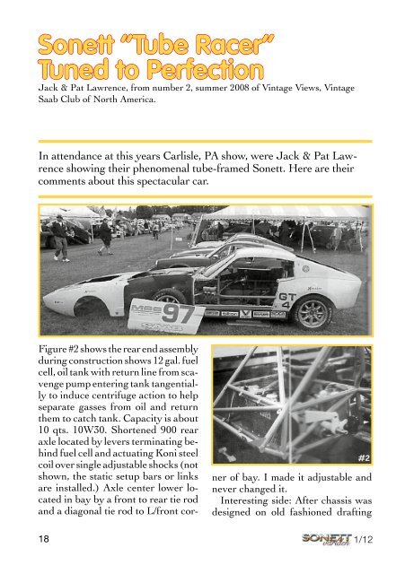
In attendance at this years Carlisle, PA show, were Jack & Pat Lawrence<br />
showing their phenomenal tube-framed <strong>Sonett</strong>. Here are their<br />
comments about this spectacular car.<br />
Figure #2 shows the rear end assembly<br />
during construction shows 12 gal. fuel<br />
cell, oil tank with return line from scavenge<br />
pump entering tank tangentially<br />
to induce centrifuge action to help<br />
separate gasses from oil and return<br />
them to catch tank. Capacity is about<br />
10 qts. 10W30. Shortened 900 rear<br />
axle located by levers terminating behind<br />
fuel cell and actuating Koni steel<br />
coil over single adjustable shocks (not<br />
shown, the static setup bars or links<br />
are installed.) Axle center lower located<br />
in bay by a front to rear tie rod<br />
and a diagonal tie rod to L/front cor-<br />
ner of bay. I made it adjustable and<br />
never changed it.<br />
Interesting side: After chassis was<br />
designed on old fashioned drafting<br />
board, the tube frame was assembled<br />
and welded on a small hydraulic<br />
die table approx. 3 ft. square using the<br />
eyed for horizontal alignment and diagonal<br />
measure for square. All necessary<br />
brackets, components, etc. were assembled<br />
to unpainted frame for fit and<br />
function, then the frame was stripped,<br />
cleaned and painted, then final assembly<br />
proceeded without any welding or<br />
changes to the tube frame. Many of the<br />
original parts were used from the old<br />
chassis, plus about $4500 worth of material<br />
and new components plus about<br />
1700 hours labor paper to finished car.<br />
The finished car came out lighter than<br />
expected and required 240# of lead to<br />
meet a weight of 1915# with driver.<br />
In Picture #3, note the oil pump<br />
L/H center. This is our own design<br />
and incorporates scavenge and pressure<br />
pumps on one input shaft and<br />
housing. The pressure pump is a low<br />
pulse to avoid breaking the relief val-<br />
ve springs. The fancy U fitting line is<br />
the scavenge return line to the tank.<br />
The lower house in this photo is the<br />
supply line to the high-pressure pump<br />
suction side. The 3 rd line visible in photo<br />
#2 is the pressure line to the engine,<br />
passing under the shock absorber<br />
down to the oil cooler filter bracket.<br />
The adjacent line going forward to<br />
a connector feeds the engine system.<br />
In place of the filter on a stock engine,<br />
we have installed an aluminium<br />
cap that has one line going in from<br />
the connector and 3 hoses going, 1<br />
each to the main bearing caps. The<br />
center retaining bolt threads into the<br />
¾ - 16NF hole in the block and feeds<br />
the oil gallery in the block. The holes<br />
to the main bearings are plugged as<br />
they are lubricated from the bottom.<br />
The oil gallery then feeds the cam,<br />
balance shaft, and rocker arm assemblies.<br />
The advantage of the separation<br />
is that the oil pressure to the up-<br />
18 19<br />
1/12 1/12