LEYBOLD DIDACTIC GMBH Gebrauchsanweisung 373 04 ...
LEYBOLD DIDACTIC GMBH Gebrauchsanweisung 373 04 ...
LEYBOLD DIDACTIC GMBH Gebrauchsanweisung 373 04 ...

Create successful ePaper yourself
Turn your PDF publications into a flip-book with our unique Google optimized e-Paper software.
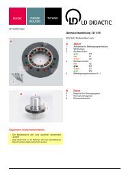
9/96-Di/Sf-<br />
Physik Chemie ⋅ Biologie Technik <strong>LEYBOLD</strong> <strong>DIDACTIC</strong> <strong>GMBH</strong><br />
Das Gerät wird vorzugsweise für Versuche zur Aerodynamik<br />
eingesetzt. Es dient bei Versuchen auf der offenen Meßstrecke<br />
zur Aerodynamik (<strong>373</strong> 06) und mit dem Venturirohr<br />
(<strong>373</strong> 09) als Druckgebläse; in Verbindung mit dem Windkanal<br />
(<strong>373</strong> 12) wird es als Sauggebläse eingesetzt.<br />
1 Sicherheitshinweise<br />
! <strong>Gebrauchsanweisung</strong> lesen!<br />
• Vor Einschalten des Gebläses sicherstellen, daß<br />
- das Schutzgitter � aufgesteckt ist<br />
und<br />
- das Gebläse entweder am Windkanal (<strong>373</strong> 12) angebracht<br />
ist oder mit Düse � (bzw. der zur Offenen Meßstrecke,<br />
<strong>373</strong> 06, gehörenden Düse) versehen wurde.<br />
• Vor Abnehmen des Schutzgitters oder der Düse oder vor<br />
Trennung vom Windkanal<br />
a) Netzstecker ziehen<br />
b) mindestens eine halbe Minute warten, bis der Rotor<br />
steht.<br />
• Lamellen des Schutzgitters � sowie das Metallgitter in der<br />
Düsenöffnung nicht mechanisch beanspruchen!<br />
• Vor dem Abnehmen der Abdeckhaube � für die Steuereinheit<br />
(vgl. Abschnitt 4.1) Netzstecker ziehen!<br />
• Maximal zulässige Umgebungstemperatur: 50 °C<br />
2 Lieferumfang, Beschreibung, technische Daten<br />
�� Schutzgitter, an Saugseite � oder Druckseite � des Gebläses<br />
� aufsteckbar<br />
�� Gebläse<br />
Drehzahl: maximal 2550 U/min<br />
Fördervolumen: 875 m 3 /h<br />
Schallpegel: 70 dBA<br />
Einlaufzeit: ca. 3 min<br />
Einstellzeit bei Drehzahländerung: ca. 30 s<br />
Netzanschlußspannung; 230 V/50 Hz<br />
Leistungsaufnahme: 260 VA<br />
Sicherung: Schmelzsicherung T 2.0 B (unter der Abdeckhaube<br />
�)<br />
�� Abdeckhaube für Steuereinheit<br />
�� Netzschalter<br />
�� Potentiometer-Stellknopf zur stufenlosen Drehzahleinstellung<br />
zwischen 10 % und 100 % der maximalen Drehzahl<br />
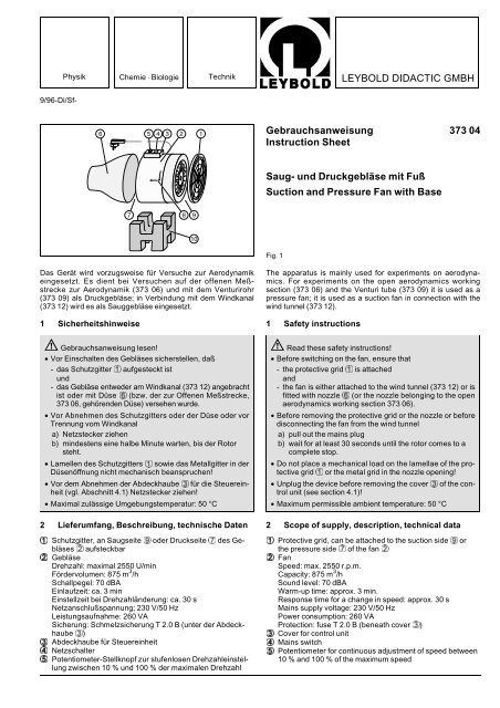
<strong>Gebrauchsanweisung</strong> <strong>373</strong> <strong>04</strong><br />
Instruction Sheet<br />
Saug- und Druckgebläse mit Fuß<br />
Suction and Pressure Fan with Base<br />
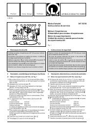
Fig. 1<br />
The apparatus is mainly used for experiments on aerodynamics.<br />
For experiments on the open aerodynamics working<br />
section (<strong>373</strong> 06) and the Venturi tube (<strong>373</strong> 09) it is used as a<br />
pressure fan; it is used as a suction fan in connection with the<br />
wind tunnel (<strong>373</strong> 12).<br />
1 Safety instructions<br />
! Read these safety instructions!<br />
• Before switching on the fan, ensure that<br />
- the protective grid � is attached<br />
and<br />
- the fan is either attached to the wind tunnel (<strong>373</strong> 12) or is<br />
fitted with nozzle � (or the nozzle belonging to the open<br />
aerodynamics working section <strong>373</strong> 06).<br />
• Before removing the protective grid or the nozzle or before<br />
disconnecting the fan from the wind tunnel<br />
a) pull out the mains plug<br />
b) wait for at least 30 seconds until the rotor comes to a<br />
complete stop.<br />
• Do not place a mechanical load on the lamellae of the protective<br />
grid � or the metal grid in the nozzle opening!<br />
• Unplug the device before removing the cover � of the control<br />
unit (see section 4.1)!<br />
• Maximum permissible ambient temperature: 50 °C<br />
2 Scope of supply, description, technical data<br />
�� Protective grid, can be attached to the suction side � or<br />
the pressure side � of the fan �<br />
�� Fan<br />
Speed: max. 2550 r.p.m.<br />
Capacity: 875 m 3 /h<br />
Sound level: 70 dBA<br />
Warm-up time: approx. 3 min.<br />
Response time for a change in speed: approx. 30 s<br />
Mains supply voltage: 230 V/50 Hz<br />
Power consumption: 260 VA<br />
Protection: fuse T 2.0 B (beneath cover �)<br />
�� Cover for control unit<br />
�� Mains switch<br />
�� Potentiometer for continuous adjustment of speed between<br />
10 % and 100 % of the maximum speed
�� Düse, Ø 100 mm, zum Aufstecken auf die Druckseite �<br />
des Gebläses<br />
Öffnung passend für Venturirohr (<strong>373</strong> 09)<br />
�� Druckseite<br />
�� Pfeile zur Anzeige von Drehsinn und Luftstromrichtung<br />
�� Saugseite<br />
�� Aufstellfuß zur Halterung des Gebläses<br />
Ohne Abbildung: Styroporball, Ø 70 mm<br />
Abmessungen (mit aufgesteckter Düse): 60 cm x 25 cm x 25 cm<br />
Gesamtmasse: 7,3 kg<br />
3 Bedienung<br />
! Gebläse nur bei ordnungsgemäß aufgestecktem Schutzgitter<br />
� und bei aufgesteckter Düse bzw. angesetztem<br />
Windkanal einschalten!<br />
Schutzgitter � entweder (beim Einsatz als Druckgebläse für<br />
das Venturirohr, <strong>373</strong> 09, und für die offene Meßstrecke, <strong>373</strong> 06)<br />
auf Saugseite � stecken oder (beim Einsatz als Sauggebläse<br />
für den Windkanal, <strong>373</strong> 12) auf Druckseite � stecken.<br />
Hinweis: Schlitzschraubenzieher als Hebel verwenden, wenn<br />
das Schutzgitter so fest auf dem Gebläse sitzt, daß es sich<br />
nicht ohne Schwierigkeiten abnehmen läßt.<br />
Die nach dem Aufstecken des Schutzgitters noch freie Druckseite<br />
mit Düse � (bzw. 150-m-Düse aus <strong>373</strong> 06) bestücken<br />
oder die freie Saugseite vor dem Windkanal positionieren;<br />
Gebläse entsprechend den Versuchsbedingungen gemäß<br />
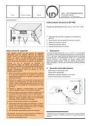
Fig. 2 waagerecht oder gemäß Fig. 4 lotrecht auf den Fuß stellen;<br />
um einen schräg nach oben gerichteten Luftstrom zu erzeugen,<br />
Gebläse vorsichtig schräg in den Fuß einsetzen, so daß es in<br />
der vorgesehenen Schräglage festklemmt. Vor dem Einschalten<br />
Stabilität der Schräglage prüfen!<br />
Vor dem Einschalten des Gebläses stets minimale Drehzahl an<br />
Potentiometer � einstellen.<br />
Potentiometer für Drehzahleinstellung feinfühlig betätigen! Geringe<br />
Änderungen der Einstellung können große Auswirkungen<br />
auf die Luftgeschwindigkeit haben! Einlaufzeit des Motors: ca.<br />
3 min. Einstellzeit bei Drehzahländerungen: ca. 30 s.<br />
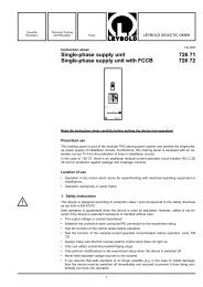
4 Sicherungswechsel (s. Fig. 3)<br />
Wichtig: Netzstecker ziehen, Kappe � vom Potentiometerknopf<br />
� entfernen (Fig. 3.1)!<br />
Mit einem Schlitzschraubendreher bei festgehaltenem Knopf<br />
Schraube � im Innern des Knopfes eine halbe Umdrehung<br />
gegen den Uhrzeigersinn drehen. Knopf von der Potentiometerachse<br />
abziehen.<br />
Mit einem Kreuzschlitzschraubendreher die vier Schrauben �<br />
herausschrauben und Abdeckhaube � der Steuereinheit abziehen,<br />
so daß die Steuereinheit zugänglich ist (Fig. 3.2).<br />
2-A-Schmelzsicherung (s. Fig. 3.2) mit dem Schlitzschraubendreher<br />
aus der Halterung hebeln und Sicherung T 2,0 B hineindrücken.<br />
Abdeckhaube �, Potentiometerknopf � und Kappe �<br />
Fig. 2<br />
2<br />
�� Nozzle, dia. 100 mm, for attaching to the pressure side �<br />
of the fan<br />
Opening suitable for use with Venturi tube (<strong>373</strong> 09)<br />
�� Pressure side<br />
�� Arrows for indicating direction of rotation and direction of<br />
air flow<br />
�� Suction side<br />
�� Base for securing the fan<br />
Not shown: polystyrene ball, dia. 70 mm<br />
Dimensions (with attached nozzle): 60 cm x 25 cm x 25 cm<br />
Total weight: 7.3 kg<br />
3 Operation<br />
! Only switch on the fan when protective grid � has been<br />
properly attached and after attachment of the nozzle or<br />
the wind tunnel!<br />
Attach protective grid � either to the suction side � (when<br />
using as a pressure fan for the Venturi tube <strong>373</strong> 09 and for the<br />
open aerodynamics working section <strong>373</strong> 06) or to the pressure<br />
side � (when using as a suction fan for the wind tunnel <strong>373</strong> 12).<br />
Note: Use a flat-blade screwdriver as a lever if the protective<br />
grid is so tightly attached to the fan that it cannot be removed<br />
easily.<br />
After attaching the protective grid, either fit the nozzle � (or the<br />
150-m nozzle from <strong>373</strong> 06) to the unconnected pressure side or<br />
position the unconnected suction side in front of the wind tunnel.<br />
According to the experiment conditions, place the fan on the<br />
base either horizontally as in Fig. 2 or vertically as in Fig. 4.<br />
In order to produce an air flow directed diagonally upwards, carefully<br />
place the fan in the base at an angle, so that it locks into<br />
the inclined position provided. Test the stability of this inclined<br />
position before switching on!<br />
Before switching on the fan, always set minimum speed at potentiometer<br />
�.<br />
Operate the potentiometer for speed adjustment carefully!<br />
Small changes in the setting can lead to large changes in air<br />
velocity! Run-in time of the motor: approx. 3 min. Response<br />
time for changes in speed: approx. 30 s.<br />
4 Changing the fuse (see Fig. 3)<br />
Important: pull out mains plug and remove cap � from potentiometer<br />
knob � (Fig. 3.1)!<br />
Using a flat-blade screwdriver and holding the knob firmly, turn<br />
the screw (b) in the center of the knob one half turn counterclockwise.<br />
Remove the knob from the shaft of the potentiometer.<br />
Using a Philips-head screwdriver, unscrew the four screws �<br />
and remove the cover of the control unit �; the control unit is<br />
now accessible (Fig. 3.2).<br />
Pry out the 2-A fuse (see Fig. 3.2) from its holder using the<br />
flat-blade screwdriver and insert fuse T 2.0 B.<br />
Cover �, potentiometer knob � and cap �<br />
Fig. 3.1 Fig- 3.2
5 Versuchsbeispiele<br />
Example Experiments<br />
Fig. 4<br />
Auftrieb in einer Luftströmung<br />
Lift in an air flow<br />
Fig. 6<br />
Quantitative Bestimmung des statischen Drucks im Venturirohr mit dem Feinmanometer<br />
Quantitative determination of static pressure in the Venturi tube using the precision manometer<br />
3<br />
Fig. 5<br />
Qualitativer Nachweis des statischen Drucks mit Venturirohr (<strong>373</strong> 09)<br />
und Multimanoskop (<strong>373</strong> 11)<br />
Qualitative proof of static pressure using the Venturi tube (<strong>373</strong> 09) and<br />
multimanoscope (<strong>373</strong> 11)
Fig. 9<br />
Untersuchungen am Tragflügel (aus Meßzubehör 2, <strong>373</strong> 08) im Windkanal<br />
(<strong>373</strong> 12);<br />
Abhängigkeit des Luftwiderstandes, gemessen mit dem Sektorkraftmesser<br />
(<strong>373</strong> 14) und des Auftriebs, gemessen mit der Auftriebswaage<br />
(aus <strong>373</strong> 08) in Abhängigkeit vom Anstellwinkel (Aufnahme der Polaren<br />
eines Tragflügels)<br />
Experiment with the airfoil (from aerodynamics accessories 2, <strong>373</strong> 08)<br />
in the wind tunnel (<strong>373</strong> 12)<br />
Air resistance, measured with the sector dynamometer (<strong>373</strong> 14), and<br />
lift, measured with the lift balance (from <strong>373</strong> 08) as a function of the<br />
angle of attack (recording of the polar coordinates of an airfoil)<br />
Fig. 7<br />
Aerodynamische Untersuchungen im Freiluftstrahl mit dem Meßzubehör<br />
1 (<strong>373</strong> 071) und dem Meßwagen zur Aerodynamik (<strong>373</strong> 075) auf<br />
der Offenen Meßstrecke.<br />
Abhängigkeit des Luftwiderstandes, gemessen mit dem Sektorkraftmesser<br />
(<strong>373</strong> 14), vom Querschnitt und von der Form des Körpers.<br />
Aerodynamics experiments in a free air flow using the aerodynamics<br />
accessories 1 (<strong>373</strong> 071) and the aerodynamics trolley (<strong>373</strong> 075) in the<br />
open aerodynamics working session.<br />
Dependency of air resistance, measured with the sector dynamometer<br />
(<strong>373</strong> 14), on the cross-section and the shape of the test object.<br />
Fig. 8<br />
Veranschaulichung von Stromlinien mit dem Fadenkamm (aus Meßzubehör<br />
1, <strong>373</strong> 071)<br />
Demonstration of streamlines using the thread comb (aerodynamics<br />
accessories 1, <strong>373</strong> 071)<br />
Fig. 10<br />
Verifizierung der Kontinuitätsgleichung und der Bernoulli-Gleichung im<br />
Windkanal (<strong>373</strong> 12), durch dessen schräg ansteigende "Bernoulli-<br />
Rampe" unterschiedliche, definierte Strömungsquerschnitte gegeben<br />
sind.<br />
Verification of the continuity equation and the Bernoulli equation in the<br />
wind tunnel (<strong>373</strong> 12) whose inclined Bernoulli ramp gives various defined<br />
aerodynamic cross-sections.<br />
<strong>LEYBOLD</strong> <strong>DIDACTIC</strong> <strong>GMBH</strong> ⋅ Leyboldstrasse 1 ⋅ D-50354 Hürth ⋅ Phone (02233) 6<strong>04</strong>-0 ⋅ Telefax (02233) 6<strong>04</strong>-222 ⋅ Telex 17 223 332 LHPCGN D<br />
© by Leybold Didactic GmbH, Printed in the Federal Republic of Germany<br />
Technical alterations reserved