LEYBOLD DIDACTIC GMBH Gebrauchsanweisung 388 17 ...
LEYBOLD DIDACTIC GMBH Gebrauchsanweisung 388 17 ...
LEYBOLD DIDACTIC GMBH Gebrauchsanweisung 388 17 ...

Create successful ePaper yourself
Turn your PDF publications into a flip-book with our unique Google optimized e-Paper software.
8/94-Sf-<br />
Physik Chemie ⋅ Biologie Technik <strong>LEYBOLD</strong> <strong>DIDACTIC</strong> <strong>GMBH</strong><br />
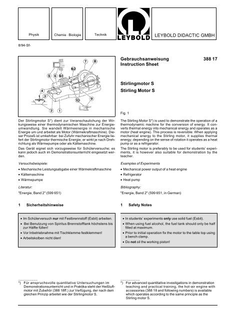
Der Stirlingmotor S*) dient zur Veranschaulichung der Wirkungsweise<br />
einer thermodynamischen Maschine zur Energieumwandlung.<br />
Sie wandelt Wärmeenergie in mechanische<br />
Energie um und arbeitet als Motor (Wärmekraftmaschine). Dieser<br />
Prozeß ist umkehrbar: bei Zufuhr mechanischer Energie liefert<br />
der Stirlingmotor thermische Energie; er wirkt je nach Drehrichtung<br />
als Wärmepumpe oder als Kältemaschine.<br />
Das Gerät eignet sich vorzugsweise für Schülerversuche; es<br />
kann jedoch auch im Demonstrationsunterricht eingesetzt werden.<br />
Versuchsbeispiele:<br />
• Mechanische Leistungsabgabe einer Wärmekraftmaschine<br />
• Kältemaschine<br />
• Wärmepumpe<br />
Literatur:<br />
"Energie, Band 2" (599 651)<br />
1 Sicherheitshinweise<br />
• Im Schülerversuch nur mit Festbrennstoff (Esbit) arbeiten.<br />
• Bei Benutzung von Spiritus Brennstofftank höchstens bis<br />
zur Hälfte füllen!<br />
• Vor Inbetriebnahme mit Tischklemme festklemmen!<br />
• Arbeitskolben nicht ölen!<br />
__________<br />
*) Für anspruchsvolle quantitative Untersuchungen im<br />
Demonstrationsunterricht und in Praktika steht der Heißluftmotor<br />
mit Zubehör (<strong>388</strong> 18ff.) zur Verfügung, der nach dem<br />
gleichen Prinzip arbeitet wie der Stirlingmotor S.<br />
<strong>Gebrauchsanweisung</strong> <strong>388</strong> <strong>17</strong><br />
Instruction Sheet<br />
Stirlingmotor S<br />
Stirling Motor S<br />
Fig. 1<br />
The Stirling Motor S*) is used to demonstrate the operation of a<br />
thermodynamic machine for the conversion of energy. It converts<br />
thermal energy into mechanical energy and operates as a<br />
motor (heat engine). This process is reversible: When applying<br />
mechanical energy to the Stirling motor, it supplies thermal<br />
energy; depending on the sense of rotation it operates as a heat<br />
pump or as a refrigerator.<br />
The Stirling motor is preferably to be used for students’ experiments,<br />
it is however also suitable for demonstration by the<br />
teacher.<br />
Examples of Experiments<br />
• Mechanical power output of a heat engine<br />
• Refrigerator<br />
• Heat pump<br />
Bibliography:<br />
"Energie, Band 2" (599 651, in German)<br />
1 Safety Notes<br />
• In students’ experiments only use solid fuel (Esbit).<br />
• When using fuel alcohol, the fuel tank should only be half<br />
filled at maximum.<br />
• Prior to initial operation fix the motor to the table top using<br />
a bench clamp.<br />
• Do not oil the working piston!<br />
__________<br />
*) For advanced quantitative investigations in demonstration<br />
teaching and practical training, the hot-air engine with<br />
accessories (<strong>388</strong> 18 and following numbers) is available<br />
which operates according to the same principle as the<br />
Stirling motor S.
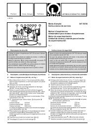
2 Beschreibung, Technische Daten<br />
� Grundplatte, Aluminium-Druckguß<br />
� Brennstofftank zum Einfüllen von Spiritus oder, bei abgenommener<br />
Brennerkappe, zur Aufnahme von Festbrennstoff<br />
� Brennerkappe, mit Hilfe eines Schraubendrehers o. ä.<br />
abnehmbar<br />
� Docht<br />
� Verdrängerkolben<br />
� Verdrängerzylinder mit Kühlrippen (6.1), durch Luftkanal<br />
(6.2) mit Arbeitszylinder � verbunden<br />
� Schwungrad<br />
� Schwungradachse (Ø 4,7 mm) mit Riemenscheibe;<br />
Schnurrillen Ø 8 mm<br />
� Arbeitskolben<br />
� Arbeitszylinder<br />
Mechanische<br />
Leistungsabgabe: 0,1 W<br />
Abmessungen: 20 cm x 10,5 cm x 6 cm<br />
Masse: 0,65 kg<br />
3 Funktionsweise<br />
3.1 Wärmekraftmaschine<br />
Der Stirlingmotor S besitzt zwei Kolben:<br />
den Arbeitskolben �, der in den Arbeitszylinder � dicht eingepaßt<br />
ist und das Arbeitsgas (Luft) komprimiert, und den Verdrängerkolben<br />
�, der sich im Verdrängungszylinder � bewegt.<br />
Da zwischen der Wand des Verdrängungszylinders und<br />
dem Verdrängerkolben ein Spalt besteht, wird das Arbeitsgas<br />
durch den Verdrängerkolben nicht komprimiert, sondern nur<br />
hin- und herbewegt.<br />
Arbeitskolben � und Verdrängerkolben � bewegen sich mit<br />
einer Phasenverschiebung von 90°. Idealisiert läuft ein Arbeitszyklus<br />
so ab:<br />
(1) Der Verdrängerkolben � wird zurückgezogen und drängt<br />
das Arbeitsgas zum Ende des Verdrängerzylinders �, wo<br />
es von außen erhitzt wird.<br />
(2) Dabei dehnt es sich aus und drückt den Arbeitskolben �<br />
aus seinem Zylinder �. Der Motor leistet dabei mechanische<br />
Arbeit (Fig. 2.1).<br />
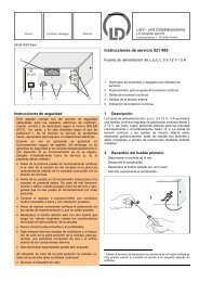
(3) Der Verdrängerkolben � wird vorgeschoben und drängt<br />
das Gas in den mit Kühlrippen (6.1) versehenen Teil des<br />
Verdrängerzylinders. Dabei kühlt sich das Gas ab.<br />
(4) Infolgedessen hat es bei der nachfolgenden Kompression<br />
durch den Arbeitskolben � einen geringeren Druck als bei<br />
der Expansion (2) (Fig. 2.2).<br />
Daher gibt der Motor bei einem vollständigen Arbeitszyklus mechanische<br />
Energie ab.<br />
Fig. 2.1<br />
2<br />
2 Description, Technical Data<br />
� Base plate, aluminium die-casting<br />
� Fuel tank for filling in alcohol or, with cap removed,<br />
for solid fuel<br />
� Burner cap, removable by means of a screw-driver or<br />
similar tool<br />
� Wick<br />
� Displacement piston<br />
� Displacement cylinder with cooling fins (6.1), connected to<br />
operating cylinder � by a ventilating duct (6.2)<br />
� Flywheel<br />
� Flywheel axle (4.7 mm dia.) with pulley,<br />
grooves for thread: 8 mm dia.<br />
� Operating piston<br />
� Operating cylinder<br />
Mechanical power output: approx. 0.1 W<br />
Dimensions: 20 cm x 10.5 cm x 6 cm<br />
Weight: 0.65 kg<br />
3 Mode of Operation<br />
3.1 Hot-air engine<br />
The Stirling motor S has two pistons:<br />
The operating piston �, closely fitting into the operating cylinder<br />
�, compresses the gas (air), and the displacement piston �<br />
which moves in the displacement cylinder �. As there is a gap<br />
between the wall of the displacement cylinder and the displacement<br />
piston, the gas is not compressed by the displacement<br />
piston but only swept to and from.<br />
Operating piston � and displacement piston � move with a<br />
phase shift of 90° between each other.<br />
Idealized operating cycle:<br />
(1) The displacement piston � is retracted and sweeps the<br />
working gas to the end of the displacement cylinder � where<br />
it is heated from outside.<br />
(2) The gas expands and presses the operating piston � nut<br />
of the cylinder � whereby the motor delivers mechanical<br />
work (Fig. 2.1).<br />
(3) The displacement piston � is pushed forward and sweeps<br />
the gas into the part of the displacement cylinder equipped<br />
with cooling fins, whereby the gas cools down.<br />
(4) Due to this, during following compression by the operating<br />
piston � the gas has a lower pressure as during expansion<br />
(2) (Fig. 2.2).<br />
Therefore, during complete cycle the motor supplies mechanical<br />
energy.<br />
Fig. 2.2
3.2 Wärmepumpe und Kältemaschine<br />
Setzt man den Motor in Bewegung, wirkt er, je nach Drehrichtung,<br />
als Wärmepumpe oder Kältemaschine.<br />
Beim Betrieb als Wärmepumpe wird das Gas an das Ende des<br />
Verdrängerzylinders � geschafft und dann komprimiert. Dabei<br />
erwärmt es sich und gibt Energie an den Zylinder ab. Dann wird<br />
das Gas zwischen die Kühlrippen (6.1) transportiert, denen es<br />
bei der nachfolgenden Expansion Wärme entzieht.<br />
Beim Betrieb als Kältemaschine expandiert das Gas unter<br />
Energieaufnahme am Ende des Verdrängerzylinders, den es<br />
dabei abkühlt, wird dann zwischen den Kühlrippen durch Kompression<br />
erwärmt und gibt diese Wärme an die Kühlrippen ab.<br />
Die Drehrichtung des Motors bestimmt also die Richtung des<br />
Wärmetransports.<br />
4 Bedienung<br />
4.1 Zusätzlich erforderlich:<br />
Tischklemme (zum Fixieren des<br />
Motors auf der Tischplatte) z.B. 301 07<br />
Esbit - Festbrennstoff<br />
oder<br />
Spiritus (nicht im Schülerversuch verwenden!)<br />
Angelschnur 309 48<br />
Temperaturanzeige- oder Meßgeräte, Bereich 15 °C bis 25 °C,<br />
z.B.<br />
Flüssigkristallfolie (18 °C bis 23 °C) aus 382 93<br />
oder<br />
Thermometer z.B. 382 35<br />
oder<br />
Digitales Handthermometer 666 188<br />
oder<br />
Temperaturfühler 660 193<br />
mit Digitalem Temperaturmeßgerät 666 190<br />
Wärmeleitpaste<br />
4.2 Betrieb als Heißluftmotor; Wärmekraftmaschine (Fig. 3)<br />
Brennerkappe � mit Hilfe eines Schraubendrehers o. ä. entfernen.<br />
Einen halben Esbit-Quader unter den Verdrängerzylinder � legen<br />
und anzünden. Nach ca. 30 s Schwungrad � anwerfen<br />
(von der Arbeitskolbenseite aus gesehen gegen den Uhrzeigersinn).<br />
Bei Benutzung des Spiritusbrenners (nicht im Schülerversuch!):<br />
Brennstofftank zur Hälfte mit Spiritus füllen, Docht ca.<br />
2 cm aus der Brennerkappe herausziehen, Brennerkappe und<br />
Docht unter den Verdrängerzylinder bringen.<br />
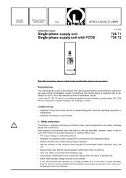
Messung der mechanischen Leistungsabgabe P (Fig. 3)<br />
Zwirnsfaden U-förmig um die Riemenscheibe legen und mit<br />
zwei 1-N-Kraftmessern spannen (314 141). Kraftdifferenz ΔF,<br />
die der am Umfang der Riemenscheibe wirkenden Reibungskraft<br />
entspricht, messen.<br />
3<br />
3.2 Heat pump and refrigerator<br />
When starting the motor it operates as a heat pump or as a<br />
refrigerator, depending on the sense of rotation.<br />
When operated as a heat pump, the gas is swept to the end of<br />
the displacement cylinder � and then compressed. It warms up<br />
and gives off energy to the cylinder. The gas is then transferred<br />
to the space between the cooling fins (6.1) from which it takes<br />
up heat during the following expansion process.<br />
When operated as refrigerator, the gas expands taking up energy<br />
at the end of the displacement piston, thereby cooling the<br />
piston. The gas is then heated up between the cooling fins, due<br />
to compression, and gives off this heat to the cooling fins.<br />
Hence, the sense of rotation of the motor determines the direction<br />
of heat flow.<br />
4 Use<br />
4.1 Additionally required:<br />
Bench clamp (to fix the motor<br />
to the table top) e.g. 301 07<br />
Esbit - solid fuel<br />
or<br />
fule alcohol (not to be used in students’ experiments)<br />
Fishing line 309 48<br />
Temperature indicators or thermometers, range 15 °C to 25 °C,<br />
e.g.<br />
Liquid crystal foil (18 °C to 23 °C) from 382 93<br />
or<br />
Thermometer e.g. 382 35<br />
or<br />
Digital hand-thermometer 666 188<br />
or<br />
Temperature probe with 666 193<br />
Digital thermometer 666 190<br />
Heat conducting paste<br />
4.2 Operation as a hot-air engine; heat engine (Fig. 3)<br />
Remove burner cap � by means of a screw-driver or similar<br />
tool.<br />
Place half an Esbit block below the displacement cylinder �<br />
and ignite it. After approx. 30 secs. set flywheel � in motion<br />
(anticlockwise when viewed from the displacement-piston<br />
side).<br />
When using the alcohol burner (never in students’ experiments!):<br />
fill half of the fuel tank with fuel alcohol, pull out approx.<br />
2 cm of the wick and bring burner cap and wick below the displacement<br />
cylinder.<br />
Measurement of the mechanical power output P (Fig. 3):<br />
Place twisted thread around the pulley to form an U and tension<br />
it by two 1-N dynamometers (314 141). Measure the difference<br />
of force ΔF which corresponds to the frictional force acting on<br />
the circumference of the pulley.<br />
Fig. 3<br />
Bestimmung der mechanischen Leistung des Stirlingmotors S<br />
Determining the mechanical power output of the Stirling motor S
Seidenfaden in geschlossenem Ring um Schwungradachse<br />
und Laufrolle des Tachymeters (337 41) legen und durch Verschieben<br />
der Laufrolle leicht (!) spannen. Auf der v-Skala des<br />
Tachymeters die Umfangsgeschwindigkeit v der Achse in m/s<br />
ablesen.<br />
Leistung P berechnen:<br />
P = ΔF ⋅ v ⋅ D<br />
d<br />
D: Schnurrillen Ø = 8 mm<br />
d: Schwungradachsen Ø = 4,7 mm<br />
Messung bei Leerlaufdrehzahl (ΔF = 0) beginnen und ΔF<br />
schrittweise steigern.<br />
4.3 Betrieb als Kältemaschine oder Wärmepumpe (Fig. 4)<br />
Motor fest an Tischkante anklemmen.<br />
Verdrängerzylinder � entweder<br />
zur Demonstration der Temperaturänderung mit Flüssigkristallfolie<br />
umwickeln, die mit Tesafilm befestigt wird, oder<br />
zur Temperaturmessung über Wärmeleitpaste oder Wassertropfen<br />
mit Thermometer oder Temperaturfühler kontaktieren.<br />
Ca. 80 cm Angelschnur zweimal um die Schwungradachse �<br />
wickeln, spannen und durch kräftige Hin- und Herbewegung<br />
der gespannten Angelschnur Motor antreiben, wobei die Angelschnur<br />
jeweils während der Rückbewegung entspannt wird.<br />
Rechtslauf der Achse (von der Arbeitskolbenseite betrachtet):<br />
Wärmepumpe.<br />
Linkslauf: Kältemaschine (gleiche Richtung des Wärmeflusses<br />
wie bei Motorbetrieb; daher identische Laufrichtungen).<br />
4.4 Pflege<br />
Achse des Verdrängerkolbens und Lagerbuchsen des Schwungrades<br />
gelegentlich ölen (Nähmaschinenöl).<br />
Place silk thread in a closed loop around flywheel axle and roller of<br />
tachymeter and slightly (!) tension it by displacing the roller.<br />
Read off the circumferential speed v of the axle in m/s from the<br />
v-scale of the tachymeter (337 41).<br />
Calculate power P:<br />
P = ΔF ⋅ v ⋅ D<br />
d<br />
D: grooves= 8 mm dia.<br />
d: flywheel axles= 4.7 mm dia.<br />
Start measurement with no-load speed (ΔF = 0) increasing ΔF<br />
step-by-step.<br />
4.3 Operation as a refrigerator or heat pump (Fig. 4)<br />
Clamp the motor firmly to the edge of the table.<br />
To demonstrate the change in temperature, cover the displacement<br />
piston � with liquid-crystal foil fastened with adhesive<br />
tape.<br />
For temperature measurement bring the displacement cylinder<br />
�, via heat-conducting paste or a drop of water, in contact with<br />
a thermometer or temperature probe.<br />
Fig. 4<br />
Betrieb des Stirlingmotors S als Kältemaschine oder Wärmepumpe;<br />
von t = 0 bis t = 3,5 min Betrieb als Kältemaschine,<br />
bei � Stillstand, bei � Umkehr der Drehrichtung und Betrieb<br />
als Wärmepumpe<br />
Stirling motor operated as a refrigerator or heat pump;<br />
from t = 0 to t = 3.5 mins. operation as refrigerator, at �<br />
standstill, at � reversal of direction of rotation and operation<br />
as heat pump.<br />
Wind approx. 80 cm of fishing line twice around the flywheel<br />
axle �, tension it and drive the motor by a strong to-and-from<br />
motion of the tensioned fishing line, slackening the fishing line<br />
with every return motion.<br />
Clockwise rotation of axle (viewed from the working-piston<br />
side): heat pump.<br />
Anticlockwise rotation: refrigerator (same direction of heat flow<br />
as in motor operation; therefore identical directions of rotation).<br />
4.4 Maintenance<br />
Occasionally oil the axle of the displacement piston and the<br />
bearing bushes of the flywheel (sewing machine oil).<br />
<strong>LEYBOLD</strong> <strong>DIDACTIC</strong> <strong>GMBH</strong> ⋅ Leyboldstrasse 1 ⋅ D-50354 Hürth ⋅ Phone (02233) 604-0 ⋅ Telefax (02233) 604-222 ⋅ Telex <strong>17</strong> 223 332 LHPCGN D<br />
© by Leybold Didactic GmbH, Printed in the Federal Republic of Germany<br />
Technical alterations reserved