Expo-Telektron Safety Systems Ltd - Expo Technologies
Expo-Telektron Safety Systems Ltd - Expo Technologies
Expo-Telektron Safety Systems Ltd - Expo Technologies

You also want an ePaper? Increase the reach of your titles
YUMPU automatically turns print PDFs into web optimized ePapers that Google loves.
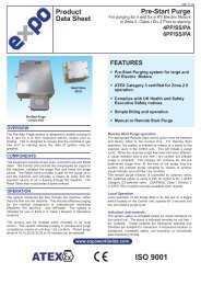
Mini-Z(Y)-Purge CF<br />
Manual<br />
ML432<br />
This manual covers Mini-Z(Y)-Purge Continuous Flow<br />
Size: 1<br />
Mounting Options: bp, pm, nm, ss<br />
Output Options: IS, PO<br />
CONTENTS:<br />
1. Specification Sheet – Mini-Z(Y)-Purge <strong>Systems</strong><br />
2. Application Suitability<br />
3. Installation, Operation and Maintenance for CF <strong>Systems</strong><br />
Section 0. Description and Principle of Operation<br />
Section 1. Installation of the System<br />
Section 2. Operation of the System<br />
Section 3. Maintenance of the System<br />
Section 4. Fault Finding - CF <strong>Systems</strong><br />
Section 5. Annex of Options Fitted<br />
4. Drawings<br />
5. Certificates<br />
ML432 v9 13/11/12
1. Specification Sheet – Mini-Z(Y)-Purge <strong>Systems</strong><br />
Model No. (Example): 07 1 ZCF / ss / IS (Note: Not all codes are applicable)<br />
Purge System Type<br />
07 = MiniPurge<br />
Size<br />
1 = Sub MiniPurge<br />
Purge flow rate up to 8 scfm, 225 Nl / min<br />
2 = MiniPurge<br />
Purge flow rate up to 16 scfm, 450 Nl /min<br />
Approval / Certification<br />
Z = Y =<br />
Europe<br />
EN 60079-0, EN 60079-2,<br />
EN 61241-0, EN 61241-4<br />
Sira 01ATEX1295X<br />
0518 II 3 (2) G D 0518 II 2 (2) G D<br />
Ex [pz Gc] IIC T6 Gb Ex [py] IIC T6 Gb<br />
Ex [p Dc] IIIC T85ºC Db Ex [p] IIIC T85ºC Db<br />
Tamb -20ºC +55ºC Tamb -20ºC +55ºC<br />
IEC<br />
IEC 60079-0, IEC 60079-2,<br />
IEC 61241-0, IEC 61241-4<br />
IECEx SIR 07.0027X<br />
Ex [pz] II T6 Ex [py] II T6<br />
Ex pD II 22 T85ºC Ex pD II 21 T85ºC<br />
Tamb -20ºC +55ºC Tamb -20ºC +55ºC<br />
USA / Canada NFPA 496<br />
FM 1X8A4AE<br />
Class I Div 2 Class I Div 1<br />
Groups A, B, C & D Groups A, B, C & D<br />
UL E190061<br />
Class I Div 2 Class I Div 1<br />
Groups A, B, C & D Groups A, B, C & D<br />
BRAZIL INMETRO/TÜV 12.1462X<br />
Ex [px] IIC T6 Gb Ex [px] IIC T6 Gb<br />
Ex [p] IIIC T85ºC Db Ex [p] IIIC T85ºC Db<br />
-20ºC ≤ Ta ≤ +55ºC -20ºC ≤ Ta ≤ +55ºC<br />
For limitations and conditions of use refer to the applicable certificate at the back of this manual.<br />
Supply Pressure 60 psi / 0.4MPa / 4 bar must be regulated at inlet.<br />
Maximum supply pressure 115 psi / 0.8MPa / 8 bar.<br />
Compressed Air / Nitrogen<br />
Flow & Pressure Sensor<br />
One sensor for both “Low Pressure and Flow” : 1 "WC / 250 Pa ( 2.5 mbarg )<br />
Spark Arrestor Unit<br />
Relief Valve<br />
MiniPurge Size 1 MiniPurge Size 2<br />
Model No SAU25 2 x SAU25<br />
Purge / Dilution Flow Rate 0.4 to 8 scfm / 10 to 225 Nl/min 8.2 to 16 scfm / 235 to 450 Nl/min<br />
8 User selectable orifice plates 16 User selectable orifice plates<br />
Material Stainless Steel Stainless Steel<br />
MiniPurge Size 1<br />
Model No RLV25/ss<br />
Opening Pressure 4” WC / 1 kPa (10 mbar)<br />
Material : 316L Stainless Steel, Spark Arrestor: Stainless Steel mesh, Neoprene Gasket<br />
Action on “Loss of Pressure” : ALARM ONLY<br />
Alarm (Signals)<br />
IS = Internal Switch<br />
“Alarm” : Dry, VFC,SPSTN/O Contact<br />
NI – Ex nA Non-Incendive Circuits<br />
Vmax < 254 Vac rms<br />
Imax < 1 A<br />
Pmax = 70 W<br />
IS – Ex i circuits<br />
Umax = 30 Vdc<br />
Imax = 350 mA<br />
Ci = 0 Li = 0<br />
Hermetically Sealed Switch<br />
Ex m IIC T4 Gc<br />
Vmax = 254 Vac rms<br />
Imax 0.7 A<br />
PO = Pneumatic Output<br />
“Alarm” : Loss of Pressure = No signal<br />
”Pressurized” = at supply pressure<br />
MiniPurge Housing<br />
bp = Back Plate (Top/Side Mount) 316L<br />
Stainless Steel (NROB finish)<br />
pm = Panel Mount (Side/Front Mount) 316L<br />
Stainless Steel (NROB finish)<br />
nm = Non Metallic (Top/Side Mount)<br />
Polystyrene c/w clear cover<br />
ss = 316L Stainless Steel (NROB finish)<br />
Neoprene “Top” Mount Gasket, loose<br />
Purging Method<br />
CF = Continuous Flow<br />
ML432 v9 13/11/12
2. Application Suitability<br />
MiniPurge � <strong>Systems</strong> are certified for use in Hazardous Areas, where the Hazardous Area is<br />
non-mining (i.e. above ground) and the hazard is caused by flammable gasses, vapours or dust.<br />
Mini-Z-Purge � <strong>Systems</strong> may be used in IECEx, ATEX Zone 2(22) - Category 3 and NEC 500<br />
Class I, Div 2.<br />
Mini-Y-Purge � <strong>Systems</strong> may be used in IECEx, ATEX Zone 1(21) - Category 2 and NEC 500<br />
Class I, Div 1.<br />
MiniPurge � systems may be used for hazards of any gas group. However, apparatus<br />
associated with the MiniPurge � system, such as Non-Incendive, Intrinsically Safe signalling<br />
circuits and flameproof enclosures containing switching devices may be limited in their gas<br />
group. The certification documentation supplied with any such devices must be checked to<br />
ensure their suitability.<br />
This system is designed for use primarily with compressed air. Where other inert compressed<br />
gasses are used (Nitrogen, for example) the user must take suitable precautions so that the<br />
build up of the inert gas does not present a hazard to health. Consult the Control of Substances<br />
Hazardous to Health (COSHH) data sheet for the gas used. Where a risk of asphyxiation<br />
exists, a warning label must be fitted to the Pressurized Enclosure.<br />
The following materials are used in the construction of MiniPurge � systems. If substances that<br />
will adversely affect any of these materials are present in the surrounding environment, please<br />
consult <strong>Expo</strong> for further guidance.<br />
Materials of construction:<br />
� Stainless Steel � Aluminium � Acrylic<br />
� Mild (carbon) Steel � Nylon � Silicone Rubber<br />
� Brass � Polyurethane � Neoprene<br />
3. Installation, Operation and Maintenance for CF <strong>Systems</strong><br />
This MiniPurge � is designed for use under normal industrial conditions of ambient temperature,<br />
humidity and vibration. Please consult <strong>Expo</strong> before installing this equipment in conditions that<br />
may cause stresses beyond normal industrial conditions.<br />
The MiniPurge � system shall be installed and operated in accordance with relevant standards,<br />
such as IEC / EN 60079-14, NEC 500, NFPA 496 and any local codes of practice that are in<br />
force.<br />
For IEC / ATEX applications, references to the NFPA 496 within the ML383, should be replaced<br />
by the equivalent clause in IEC / EN 60079-2.<br />
For IEC / ATEX applications, the "Example calculations:" in section 1.1.5 within ML383 should<br />
read:<br />
If the PE external dimensions indicate a volume of 500 Litres then,<br />
500 litres enclosure volume x 5 volume changes = 12 minutes purge time<br />
225 litres/minute purge flow rate<br />
ML432 v9 13/11/12
Installation, Operation and Maintenance Manual for<br />
MiniPurge � Continuous Flow (Model CF)<br />
conforming to NFPA 496<br />
IMPORTANT NOTE It is essential, to ensure conformity with the standard,<br />
that the user of the system observes the following instructions:<br />
Please refer to the latest standard for detailed requirements and definitions.<br />
(N.B. These instructions apply only to the Pressurizing system. It is the responsibility of the manufacturer of the<br />
Pressurized Enclosure to provide equivalent instructions for the Enclosure.)<br />
Contents:<br />
Section 0 Description and Principle of Operation<br />
Section 1 Installation of the System<br />
Section 2 Operation of the System<br />
Section 3 Maintenance of the System<br />
Section 4 Fault Finding<br />
Section 5 Annex (if applicable)<br />
Section 0 Description and Principle of Operation<br />
All MiniPurge � pressurization systems provide:<br />
a) a method of pressurizing a Pressurized Enclosure (PE)<br />
while at the same time compensating for any leakage,<br />
together with<br />
b) a method of purging the enclosure, before power is<br />
turned on, to remove any flammable gas that may have<br />
entered the enclosure while it was not pressurized.<br />
Continuous Flow <strong>Systems</strong>, Model CF, allow air to flow<br />
through the PE continuously by having a fixed outlet<br />
aperture, which does not have any means of closure. The<br />
act of pressurizing the enclosure forces air to “leak”<br />
through the outlet aperture. The Control Unit admits<br />
sufficient air at the inlet to the PE to compensate for the<br />
air leaking out of the outlet aperture as well as from any<br />
other accidental leakage paths. The flow rate is constant<br />
both during purging and thereafter.<br />
The Purging Flow rate is monitored by a separate “Purge<br />
Flow Sensor” located in the CU, which detects the<br />
differential pressure across the purge flow orifice located<br />
directly before the Outlet Orifice. The Purge Flow Sensor<br />
is set to operate when the desired differential pressure is<br />
exceeded. The output from the Flow Sensor is indicated<br />
on the CU and on “X” Pressurization systems, used to<br />
operate the automatic purge timer. Both Enclosure<br />
Pressure and Purge Flow have to be correct before the<br />
Purge Timer can start.<br />
Type CF systems comprises the following major parts:<br />
- A Control Unit (CU) containing as a minimum, for “Y”<br />
and “Z” Pressurization, a Flow Control Valve (FCV),<br />
Minimum Pressure and Purge Flow sensing devices, and<br />
a “Pressurized”/”Alarm” indicator. The CU supplies a<br />
“Pressurized” signal showing whether the PE pressure is<br />
satisfactory or not.<br />
For Type “X” Pressurization, the CU has, in addition, a<br />
fully automatic Purging controller with a purge timer and<br />
electrical power switch interlock.<br />
- A Relief Valve (RLV) fitted to the PE to provide a<br />
means of limiting the maximum pressure<br />
experienced by the enclosure during operation.<br />
The RLV model number has suffixes giving the<br />
diameter of the valve aperture (in millimeters) and<br />
material, e.g. RLV **/cs (Carbon Steel) or /ss<br />
(Stainless Steel). All RLVs incorporate a Spark<br />
Arrestor to prevent sparks being ejected from the PE<br />
through the RLV aperture. The Relief Valve is fitted<br />
solely as a safety device and does not open in<br />
normal operation.<br />
- An Outlet Orifice, which has been pre-calibrated<br />
so that the pressure drop at the desired flow rate is<br />
known. The Minimum Pressure Sensor within the<br />
CU will be set to the same figure as the pressure<br />
drop. When the PE pressure exceeds the calibrated<br />
pressure the Continuous Flow must be taking place.<br />
The system is provided with one of the following<br />
types of calibrated Outlet Orifices. Please consult<br />
the system specification sheet to determine which<br />
has been supplied. The choice:<br />
- Type SAU** where the Outlet Orifice disk is<br />
removable and can be easily changed by the user to<br />
give different flow rates according to the size of the<br />
PE and the available air supply capacity. (** denotes<br />
the metric thread size of the SAU body)<br />
- SA** where the orifice size is fixed and the way to<br />
change the flow rate is either to change the setting<br />
of the Minimum Pressure Sensor or to replace the<br />
SA with one of another size. (** denotes the nominal<br />
thread size of the SA body)<br />
- For low flow rates, the Outlet Orifice may be<br />
incorporated within the Relief Valve making use of<br />
the existing Spark Arrestor. The Relief Valve will<br />
then have a suffix /CF**, where ** is the orifice size<br />
in millimeters.<br />
<strong>Expo</strong> <strong>Technologies</strong> Limited � Page 1 of 6 ML383 issue 03 – 09.01.13
Section 1 Installation of the System<br />
The installation of the MiniPurge � system, the<br />
protective gas supply, any alarm device should be in<br />
accordance with the requirements of NFPA 496.<br />
The electrical installation associated with the<br />
MiniPurge � system shall conform to the local codes<br />
and the relevant clauses of NFPA 496.<br />
1.1 Installation of the <strong>Expo</strong> CF System<br />
1.1.1 The <strong>Expo</strong> system should be installed either<br />
directly on or as close as possible to the Pressurized<br />
Enclosure (PE). It should be installed so that the system<br />
indicators may be readily observed.<br />
1.1.2 All parts of any system carry a common serial<br />
number. If installing more than one system, ensure that<br />
this commonality is maintained on each installation.<br />
1.1.3 Any tubing, conduit and fittings used to connect<br />
to the PE should be metallic, or, if non-metallic, conform<br />
to the local codes for flammability ratings. No valve may<br />
be fitted in any tube connecting the <strong>Expo</strong> system to the<br />
PE.<br />
1.1.4 The user or manufacturer of the PE shall<br />
determine the volume of the PE, the necessary purging<br />
volume, and the time to be allowed for purging, using the<br />
chosen <strong>Expo</strong> system purging flow rate. It is the user’s<br />
responsibility to verify or enter this data on the PE and/or<br />
<strong>Expo</strong> system nameplate. Ask <strong>Expo</strong> if in doubt.<br />
Example calculations:<br />
a) If the PE external dimensions give a volume of 20<br />
cubic feet, and it is NOT a motor, multiply the volume by<br />
four to get the Purging Volume i.e. 80 cubic feet. Divide<br />
the Purging Volume by the purge rate e.g. 32 cubic feet<br />
per minute, and round up to the next even minute above,<br />
i.e. purging time would be 4 minutes.<br />
b) If the PE is a motor, multiply the internal free volume<br />
by ten to get the Purging Volume. For the above<br />
example, the Purging time would be 8 minutes.<br />
1.1.5 If the PE contains an internal source of release of<br />
flammable gas or vapor, the procedures for assessment<br />
of the release as given in NFPA 496 shall be observed.<br />
The user must verify that the specification of the <strong>Expo</strong><br />
system e.g. pressures, continuous flow (dilution) rate and<br />
type of protective gas are correct for the specific<br />
application.<br />
1.1.6 More than one PE can be protected by a single<br />
system. If PEs are connected and purged in “series” e.g.<br />
“Daisy Chained”, the Outlet Orifice must be fitted on the<br />
last enclosure with the Purge Inlet to the first enclosure.<br />
The Relief Valve may be fitted at any convenient location<br />
except when it has the option code /CF in which case it<br />
must be fitted on the last enclosure. The bore and length<br />
of the tube or conduit used to interconnect the enclosures<br />
is critical and will determine the maximum pressure<br />
experienced by the first enclosure in the series. Advice<br />
on sizing can be obtained from your <strong>Expo</strong> <strong>Technologies</strong>,<br />
sales office. The test pressure for all the enclosures<br />
should be 3 times the pressure inside the first<br />
enclosure when purging is taking place.<br />
If PE’s are to be connected in parallel each<br />
enclosure must have its own Outlet Orifice/Spark<br />
Arrestor, Relief Valve, Purge Flow Sensor and<br />
Pressure Sensor. System “Models” can be mixed<br />
e.g. Model LC for one enclosure and Model CF for<br />
another. An example would be a Gas<br />
Chromatograph instrument. <strong>Expo</strong> systems with this<br />
facility have option code /TW.<br />
1.2 Quality and Installation of the<br />
Pressurizing Air or Inert Gas Supply<br />
1.2.1 The source of the compressed air must be<br />
in a non-classified area. Inert gas may be used as<br />
an alternative to compressed air.<br />
1.2.2 Unless a supply shut-off valve has been<br />
specially fitted within the <strong>Expo</strong> system, a valve with<br />
the same, or larger, thread size as the Control Unit<br />
(CU) inlet fitting shall be fitted externally. In addition,<br />
for "Y" and "Z" Pressurization systems, a suitable<br />
nameplate shall be provided.<br />
1.2.3 The tubing and fittings used must conform to<br />
1.1.3 above.<br />
1.3 Provision and Installation of Alarm<br />
Devices<br />
<strong>Expo</strong> <strong>Technologies</strong> systems have a Minimum<br />
Pressure Sensor set to a pressure of at least 0.1”<br />
WC (0.25 mbar). When the PE pressure is above<br />
this set point the Sensor produces a positive<br />
"Pressurized" signal. This is displayed on the<br />
Red/Green indicator. This signal can be used to<br />
operate an electrical contact for a remote “Alarm”.<br />
The pneumatic signal may be supplied either<br />
a) to a pressure operated switch (MiniPurge � Option<br />
Code /IS) suitable for an Intrinsically Safe circuit, in<br />
accordance with <strong>Expo</strong> drawing EP80-2-11 (or for a<br />
Non-Incendive circuit in Division 2), or<br />
b) to a bulkhead fitting where it is available to the<br />
user (MiniPurge � Option Code /PO). It can then be<br />
used to operate an external electrical switch either<br />
local e.g. explosionproof, or remote in a nonclassified<br />
area.<br />
When the enclosure pressure falls below the set<br />
point of the Sensor, the "Pressurized" signal is<br />
removed, i.e. the absence of the signal indicates an<br />
“Alarm” ("Pressure Failure") condition. If the system<br />
“Alarm” indicator is not located in a place where it<br />
can be readily observed, the user must make use of<br />
this external alarm facility in accordance with NFPA<br />
496 requirements.<br />
Example: The "Pressurized" signal can be used to<br />
produce an "Alarm" action by means of a<br />
conventional "pressure switch" set to operate at<br />
around 15 psi (1 bar). The "Pressurized" signal from<br />
the CU at 30 psi (2 bar) or more will hold the switch<br />
in the operated position until the CU detects a low<br />
pressure in the PE and removes the "Pressurized"<br />
<strong>Expo</strong> <strong>Technologies</strong> Limited � Page 2 of 6 ML383 issue 03 – 09.01.13
signal. The Alarm switch will reset and its contacts can be<br />
used to operate a remote electrical alarm.<br />
If the switch is located in the hazardous area it must<br />
either be part of an Intrinsically Safe circuit, or be suitably<br />
protected e.g. explosionproof. The pressure switch<br />
should be IS or explosionproof even if it is fitted within the<br />
PE.<br />
<strong>Expo</strong> <strong>Technologies</strong> Tip: Exception: For a “Z Purge”<br />
system fitted in a Division 2 area a non-classified<br />
switch inside the PE can be used to operate a remote<br />
Alarm provided its electrical supply comes from<br />
within the PE (i.e. NOT PROVIDING DRY CONTACTS).<br />
When the PE is in use the Alarm can operate<br />
normally in response to the pneumatic signal from<br />
the CU with option /PO. When the PE is switched off<br />
there is no need for an alarm! Ask <strong>Expo</strong> for the circuit<br />
diagram.<br />
The Alarm switch can also be located in a nearby<br />
non-classified location. To get the best response<br />
time the switch should be as close as possible to the<br />
CU and the maximum length of tubing between the<br />
CU and the Alarm switch should not exceed 150 feet<br />
(45 m) unless “Quick Exhaust Valves” are used<br />
(please ask <strong>Expo</strong> if in doubt.)<br />
Note: No valves may be fitted between the <strong>Expo</strong> system<br />
and the alarm switch.<br />
1.4 Power Supplies and their Isolation<br />
1.4.1 All power entering the PE shall be provided with a<br />
means of isolation. This requirement also applies to any<br />
external power sources that are connected to "dry<br />
contacts" or "volt-free contacts" within the PE.<br />
Exception: Power to Intrinsically Safe, or other apparatus,<br />
which is already suitable for the location need not be<br />
isolated by the <strong>Expo</strong> <strong>Technologies</strong> system.<br />
<strong>Expo</strong> <strong>Technologies</strong> Tip: It is recommended to fit dry or<br />
volt-free contacts in the non-classified area or inside<br />
an explosionproof box rather than inside the PE.<br />
Please ask <strong>Expo</strong> about “MiniPurge � Interface Units”<br />
(MIU).<br />
In the case of "X" Pressurization, the isolation of the<br />
power must be controlled by the <strong>Expo</strong> system using the<br />
"Purge Complete" pneumatic signal to operate a "Power<br />
Switch" in a similar manner to that described in 1.3<br />
above.<br />
In the case of "Y" or "Z" Pressurization the power may be<br />
controlled manually by the operator using a local isolating<br />
switch.<br />
1.4.2 In accordance with NFPA496 ; <strong>Expo</strong> Mini-X-Purge �<br />
systems can have the "Action on Pressure Failure"<br />
(normally "Alarm and Trip") adjusted by the user to<br />
"Alarm Only". In case of an alarm, it is the responsibility<br />
of the user to de-energize the protected equipment as<br />
soon as possible. The system may require the addition of<br />
an “Alarm Only Kit” (/AO) to perform this function. Please<br />
contact <strong>Expo</strong> Sales office for further details.<br />
1.4.3 The Power (cut-off) Switch must be approved for<br />
the location or located in a non-classified area.<br />
1.4.4 No valves are permitted between the Power<br />
Switch and the <strong>Expo</strong> system.<br />
1.4.5 For "X" Pressurization, the PE door shall<br />
have fasteners that can be opened only by the<br />
use of a tool or key. Otherwise the additional<br />
requirements from NFPA 496 should apply.<br />
Note: The door switch provided with the <strong>Expo</strong><br />
system (when requested) can be either pneumatic or<br />
electric.<br />
1.5 Marking<br />
1.5.1 The MiniPurge � system carries a nameplate<br />
and a specification sheet, which give specific data<br />
such as serial and models numbers, Pressure<br />
Sensor settings, flow rates and purge time.<br />
1.5.2 Other marking, for the PE, required by the<br />
standard includes:<br />
“WARNING - PRESSURIZED ENCLOSURE -<br />
This enclosure shall not be opened unless the<br />
area is known to be free of flammable materials<br />
or unless all devices within have been deenergized"<br />
"Power shall not be restored after the enclosure<br />
has been opened until the enclosure has been<br />
purged for___minutes at a flow rate of___."<br />
<strong>Expo</strong> note: It is understood that NFPA 496 requires<br />
the de-energization of all devices that are not<br />
suitable for the hazard e.g. devices that are not<br />
Explosionproof or Intrinsically Safe. For example, an<br />
explosionproof anti-condensation heater would not<br />
have to be de-energized.<br />
1.5.3 If Inert Gas is used as the Protective Gas and<br />
a risk of asphyxiation exists, a suitable warning plate<br />
should be fitted to the PE.<br />
Section 2 Operation of the System<br />
2.1 Check that the system has been installed in<br />
accordance with Section 1 of this manual.<br />
2.2 Disconnect the supply pipe from the inlet to the<br />
Control Unit (CU) and blow clean air through for at<br />
least 5 seconds per foot of length (15 sec/metre) to<br />
remove any debris, oil and condensation.<br />
2.3 Connect a temporary pressure gauge or liquid<br />
manometer to the PE or CU “Pressure Test Point”<br />
(on the Low Pressure Sensor, by the removal of the<br />
Red plug - 4mm OD nylon tube).<br />
2.4 Open the supply shutoff valve. On "X" Purge<br />
systems check that the internal gauge reads 30 psi<br />
(2 bar). If not, adjust the logic pressure regulator to<br />
suit (lift the red ring to unlock the knob first.)<br />
2.5 Adjust the Flow Control Valve (FCV) so that the<br />
enclosure pressure rises to the point where the<br />
"Pressurized" indicator turns Green.<br />
2.6 Continue to raise the PE pressure until the Relief<br />
Valve (RLV) opens. Verify that the RLV opens at or<br />
below the figure specified in the documentation.<br />
Repeat the test several times.<br />
<strong>Expo</strong> <strong>Technologies</strong> Limited � Page 3 of 6 ML383 issue 03 – 09.01.13
2.7 Lower the PE pressure until the "Pressurized"<br />
indicator turns Red. Verify that the indicator turns Red at<br />
or above the pressure specified in the documentation.<br />
Check the external alarm contacts (if fitted).<br />
Note: On <strong>Expo</strong> CF systems the Minimum Pressure<br />
Sensor set point may be significantly above the minimum<br />
of 0.1"WC (0.25 mbar) since it doubles as both the<br />
Pressure and the Purge Flow Sensor Set points of 1"WC<br />
(2.5 mbar) are common. Please check the documentation<br />
for the actual setting.<br />
2.8 Open the FCV again and set the PE pressure to a<br />
level somewhere between the Minimum Pressure Sensor<br />
set point and the RLV opening pressures. This "working"<br />
pressure is not critical. Enough pressure to keep the<br />
“Pressurized” indicator Green is sufficient.<br />
2.9 On "X" CF Purge systems the purge timer will start as<br />
soon as the “Pressurized” indicator turns Green. Check<br />
that the time delay between the indicator turning Green<br />
and the application of power to the PE is not less than<br />
the minimum time required to purge the PE. Times in<br />
excess of the minimum are permitted and a tolerance of<br />
+25% is normally acceptable. If the time is shorter than<br />
the minimum permitted, it must be adjusted accordingly.<br />
MiniPurge � uses a pneumatic incremental timer which is<br />
adjusted by fully opening or closing one or more of five<br />
screwdriver-operated valves, arranged in a block on the<br />
control logic manifold – see GA Drawing. The opening of<br />
each valve incrementally provides a fixed number of<br />
minutes of purging time as in the following table<br />
Valve: 1 2 3 4 5<br />
Minutes: 2 4 8 8 16<br />
Thus for a 12 minute purge time, valves 2 and 3 would be<br />
open and the others closed. For twenty-four minutes, 4<br />
and 5 would be open and the others closed. At least one<br />
valve must always be open and the screws must be at<br />
the appropriate limit of travel.<br />
2.10 On “Y” and “Z” Purge systems the purge timing and<br />
power control is performed manually by the user.<br />
Never turn on the power without purging first, unless<br />
you have proved that the interior of the PE is gas free<br />
and checked that the “Pressurized” indicator is<br />
green!<br />
2.11 On "X" CF Purge systems, once the purge time is<br />
completed the “Purge Complete” indicator turns Green.<br />
With both indicators Green, the power will be turned on<br />
by the CU. Using the FCV reduce the PE pressure to the<br />
point where both indicators turn Red and check that the<br />
power is automatically turned off. When the PE pressure<br />
is restored the system should re-purge the PE before<br />
power is once again turned on.<br />
2.12 After initial commissioning, the system is ready for<br />
normal operation:<br />
a) “X” CF Purge systems: Turn the air supply valve On or<br />
Off to start or stop the system. After this, the Pressurizing<br />
and Purging sequence is entirely automatic.<br />
b) “Y” and “Z” Purge systems are started and stopped in<br />
the same way as “X” Purge system but the user must<br />
close the Power Switch only after the enclosure has<br />
been pressurized and purged sufficiently to ensure<br />
that the interior of the enclosure is gas free. The<br />
power should be shut off as soon as possible after a<br />
pressure failure. This is also the user’s<br />
responsibility.<br />
Section 3 Maintenance of the System<br />
The maintenance recommended for the system<br />
consists of the following, supplemented by any<br />
additional local requirements imposed by the<br />
authority having jurisdiction.<br />
3.1 Initial Maintenance<br />
<strong>Expo</strong> recommends that the commissioning test be<br />
repeated at least every six months. They include<br />
checking the opening pressure of the Relief Valve,<br />
setting of the Minimum Pressure Sensor, the<br />
"Normal Working Pressure" of the enclosure and, for<br />
"X" Purge systems, the setting of the purge timer (as<br />
described in Section 2 of this manual).<br />
In addition, the following checks are also<br />
recommended at that time:<br />
- Check the RLV and any other Spark Arrestors.<br />
Remove any debris or corrosion, or replace the<br />
Spark Arrestor with a spare.<br />
- Check the condition of the air supply filter element.<br />
Clean or replace it as necessary.<br />
3.2 Routine Maintenance<br />
At least every two years, the following additional<br />
checks are recommended:<br />
- Apparatus is suitable for the Hazardous Location<br />
- There are no unauthorised modifications<br />
- The source of air is uncontaminated<br />
- The interlocks and alarms function correctly<br />
- Approval labels are legible and undamaged<br />
- Adequate spares are carried<br />
- The action on pressure failure is correct<br />
Section 4 Fault Finding for CF <strong>Systems</strong><br />
4.1 General<br />
If the system does not behave in the manner<br />
described above there is a fault. Some of the more<br />
likely faults are dealt with below. If a cure cannot be<br />
effected by following the procedure shown below,<br />
please call <strong>Expo</strong> (24 hour answering) or your<br />
supplier for further assistance.<br />
The system has been designed for ease of fault<br />
finding and many of the components fitted are plugin<br />
or sub-base mounted. Check components by<br />
substitution only after establishing that such action is<br />
necessary. If the system is less than 12 months old,<br />
parts under warranty should be returned to <strong>Expo</strong><br />
<strong>Technologies</strong> for investigation, with a full report of<br />
the fault and the system serial number.<br />
<strong>Expo</strong> <strong>Technologies</strong> Limited � Page 4 of 6 ML383 issue 03 – 09.01.13
As with any pneumatic system the greatest enemies are<br />
water, oil and debris in the air supply. For this reason a<br />
dust and water filter may be fitted. But debris can enter<br />
from other sources and it is vital therefore that the<br />
procedures described in Section 2 are carried out before<br />
using the system for the first time, or following any<br />
disconnection of the pipework. Failure to perform this<br />
work may cause damage which will not be covered under<br />
warranty.<br />
Fault Finding<br />
NOTE: Before making the following checks verify that the<br />
main supply pressure is between 60 and 115 psi (4-8 bar)<br />
at the Control Unit (CU) and, for “X” Purge systems, the<br />
regulated pressure on the logic gauge is 30 psi (2 bar)<br />
4.2 Minimum Pressure Alarm is ON Continuously<br />
(“Pressurized” Indicator is Red)<br />
Possible cause 1: The PE pressure is too low. Try<br />
increasing the setting of the Flow Control Valve (FCV) to<br />
raise the pressure in the PE.<br />
Possible cause 2: Enclosure fault?<br />
- Is the ACTUAL PE pressure below the setting of the<br />
Minimum Pressure Sensor? Check it with a manometer<br />
or gauge.<br />
- Is the Outlet Orifice (if separate from the RLV) fitted<br />
correctly?<br />
- Is debris stuck on the face of the Relief Valve disk,<br />
holding the valve open?<br />
- Has the PE door been closed and all conduit/cable<br />
glands sealed?<br />
Possible cause 3: Insufficient purging Flow due to<br />
inadequate air supply pressure. Check the air supply<br />
pressure at the inlet to the CU when flow is taking place.<br />
Excessive pressure drop in the supply pipe is a very<br />
common cause of this problem. The supply pipe must be<br />
at least as big as the CU inlet fitting, i.e. at least ½” NB.<br />
Possible cause 4: Excessive PE leakage. Check around<br />
the PE when flow is taking place. Any significant leakage<br />
must be cured. Has a Leakage Test been done? The<br />
total leakage should not exceed 10% of the Continuous<br />
Flow rate.<br />
Possible cause 5: PE not strong enough. Repeat the PE<br />
pressure test. FM recommend that the PE is tested to<br />
three times the Relief Valve opening pressure e.g.<br />
12”WC (30 mbar) for standard systems. Has this test<br />
been done?<br />
Possible cause 6: System fault?<br />
Has the pressure sensing tube been damaged?<br />
If checks above reveal that the PE is correct the fault<br />
probably lies in the CU. The basic operation of the<br />
Minimum Pressure Sensor can be checked by<br />
unscrewing the 2.4” diameter diaphragm and, by using a<br />
finger, blocking the threaded hole in the top of the valve<br />
module. The valve should operate and the indicator<br />
should turn Green. If this works correctly and the<br />
enclosure pressure is above the setting of the Minimum<br />
Pressure Sensor it is likely that the Pressure Sensor<br />
diaphragm needs re-calibrating or replacing (See 4.5).<br />
4.3 Relief Valve Opens (Continuously or<br />
Intermittently)<br />
Possible Cause 1: The PE pressure is too high. The<br />
Flow Control Valve (FCV) is too far open. Adjust the<br />
FCV as described in Section 2 above.<br />
Possible Cause 2: Debris on the RLV disk allowing<br />
air to leak from the valve. Remove the RLV cover<br />
and clean the valve disk. The disk and spring may<br />
be removed from the RLV without affect the<br />
calibration.<br />
4.4 System Fails to Switch Power On after<br />
the Purge Time has Elapsed? (“X” Purge<br />
<strong>Systems</strong> Only)<br />
Possible cause 1: Is power available? Is the power<br />
disconnect closed? Are the fuses or circuit breaker<br />
OK?<br />
Possible cause 2: System fault? Timer not timed<br />
out?<br />
a) Has the “Pressurized” indicator been Green for<br />
the whole of the purge time?<br />
b) Is the logic pressure gauge at 30 psi (-0, +10%)<br />
c) Is there pressure at the Power Switch output<br />
bulkhead and at the Power Switch itself? Is the<br />
Switch set at 15 psi?<br />
d) Is the pipe to the Power Switch airtight? The<br />
signal to the Power Switch bulkhead has a restrictor<br />
that limits the permissible leakage from the pipe.<br />
e) Note the timer setting and reduce the time down<br />
to a low setting to check operation on a short purge<br />
time. If it works OK, gradually increase the time until<br />
either the time is correct, or it ceases to time out at<br />
all. In the latter case, there is an air leak in the timer<br />
circuit.<br />
If possible establish the source of the leak with<br />
soapy water and retest the system. This will involve<br />
removing the chassis from the CU –be sure this is<br />
the cause before starting the work. It is VERY<br />
unusual!!<br />
Ensure that the timer is returned to its original<br />
setting and the purge time checked before<br />
putting the system back into service.<br />
Possible cause 3: Faulty Power Switch. Check the<br />
operation of the Power Switch. It should close above<br />
20 psi (1.4 bar).<br />
4.5 Pressure Sensor Calibration If it is<br />
decided that the Minimum Pressure Sensor needs<br />
recalibrating it can either be returned to <strong>Expo</strong><br />
<strong>Technologies</strong> for this service or it can be done by<br />
the user as follows:<br />
Disconnect the pressure sensing pipe from the top<br />
of the diaphragm. (It is a “push-in” quick release<br />
fitting; firmly push inwards the collar surrounding the<br />
pipe where it enters the fitting and then pull the pipe<br />
outwards while maintaining the pressure on the<br />
collar). Unscrew the 2.4” (60mm) diameter<br />
diaphragm housing from the top of the Sensor.<br />
Invert it and note the brass adjusting screw in the<br />
<strong>Expo</strong> <strong>Technologies</strong> Limited � Page 5 of 6 ML383 issue 03 – 09.01.13
centre. Turning the screw inwards (clockwise) will lower<br />
the setting. It is likely that the screw will be very stiff due<br />
to the locking sealant. If the screw cannot be moved the<br />
application of gentle heat in the area of the brass screw<br />
can often help. DO NOT OVERHEAT!<br />
4.6 Filter Cleaning If the filter element needs<br />
cleaning the transparent bowl can be unscrewed and<br />
removed. The filter element also unscrews and can then<br />
be cleaned in soapy water. Do not use solvents on any<br />
part of the filter assembly.<br />
<strong>Expo</strong> <strong>Technologies</strong> Tip: If the bowl is very tight, it is<br />
easier to remove the filter by undoing the fitting that<br />
holds the filter into the CU. On Sub-MiniPurge �<br />
systems it may be necessary to remove the<br />
Minimum Pressure Sensor diaphragm first.<br />
Section 5 Annex of Options Fitted<br />
Refer to the annexes of this manual for any options<br />
fitted as designated by the model code of the<br />
system.<br />
<strong>Expo</strong> <strong>Technologies</strong> <strong>Ltd</strong> <strong>Expo</strong> <strong>Technologies</strong> Inc,<br />
Unit 2 The Summit, 9140 Ravenna Road Unit #3,<br />
Hanworth Road, Twinsburg,<br />
Sunbury-On-Thames, OH 44087,<br />
TW16 5DB. UK. U.S.A.<br />
<strong>Expo</strong> <strong>Technologies</strong> Limited � Page 6 of 6 ML383 issue 03 – 09.01.13
4. Drawings<br />
Consult the appropriate drawings according to the selected system.<br />
SYSTEM *ZCF /bp/IS /bp/PO /pm/IS /pm/PO /nm/IS /nm/PO /ss/IS /ss/PO<br />
XBR-8TD0-012 � �<br />
MZ-1CF-17-CL � �<br />
SD7568 � �<br />
XBR-8TD0-010 � �<br />
MZ-1CF-23-GA � �<br />
MZ-1CF-26-GA � �<br />
XBR-8TD0-014 � �<br />
MZ-1CF-02-GA � �<br />
MZ-1CF-01-CL � �<br />
MZ-1CF-01-CT � � � � � � � �<br />
EP80-2-11 � � � �<br />
SAU25-GA � � � � � � � �<br />
XSD-RTD0-001 sht 1 � � � � � � � �<br />
XSD-RTD0-001 sht 2 � � � � � � � �<br />
5. Certificates<br />
System Approval Authority Certificate Number<br />
MiniPurge � Sira IECEx SIR 07.0027X<br />
Sira 01ATEX 1295X<br />
INMETRO/TUV TÜV 12.1462X<br />
FM 1X8A4.AE<br />
UL E190061<br />
AGE-SW0Z-017 EXPO11ATEX1200X<br />
SC020<br />
ML432 v9 13/11/12
The contents of this drawing / document are Copyright © <strong>Expo</strong> <strong>Technologies</strong> Limited. They are to be treated as confidential and are returnable<br />
upon request. They are not to be copied or communicated in part or in whole without written consent from <strong>Expo</strong> <strong>Technologies</strong> Limited, neither<br />
are they to be used in any way against our interests.<br />
UNSPECIFIED NO DEC PLACE ±0.5<br />
TOLERANCES 1 DEC PLACE ±0.2<br />
2 DEC PLACE ±0.1<br />
FLATNESS TO BE LESS THAN 0.4mm OVER ANY 100mm LENGTH<br />
DIMENSIONS IN mm<br />
DO NOT SCALE<br />
3rd ANGLE<br />
PROJECTION<br />
SPARK ARRESTOR BODY GASKET<br />
35 [1 3/8"]<br />
Ø55 [2 5/32"]<br />
25 [1"]<br />
ORIFICE PLATE & CIRCLIP<br />
(SEE NOTE 2)<br />
RETAINING NUT<br />
M25 x 1.5P<br />
WASHER<br />
PART SECTION THRU SPARK ARRESTOR BODY<br />
TO SUIT PANEL THICKNESS<br />
1.5 [1/16"] MINIMUM<br />
9.5 [3/8"] MAXIMUM<br />
NOTES:<br />
SELECTION OF ORIFICE PLATE<br />
TO ENSURE EFFECTIVE PURGING THE SPARK ARRESTOR SHOULD BE LOCATED<br />
ON THE PRESSURIZED ENCLOSURE AS FAR AWAY AS PRACTICABLE FROM THE<br />
PURGE AIR INLET.<br />
1<br />
BASED ON A PURGE SUPPLY OF 4 barg [60 psi]<br />
& ENCLOSURE PRESSURE OF 2.5 mbarg [1" WC]<br />
PURGE FLOW ENCLOSURE VOLUME<br />
ORIFICE<br />
PLATE No<br />
Nl/min =NORMAL LITRES/MINUTE<br />
scfm = STANDARD CUBIC FEET/MINUTE<br />
FLOW RATE SELECTION:<br />
2<br />
m³ (5VC*)<br />
ft³ (4VC*)<br />
Nl/min<br />
scfm<br />
0.06<br />
3.0<br />
10<br />
0.4<br />
1<br />
* VC = VOLUME CHANGES<br />
(BASED ON 30min PURGE TIME)<br />
0.15<br />
8.3<br />
25<br />
0.9<br />
2<br />
THE FLOW RATE OF THE CONTINUOUS FLOW SYSTEM MAY BE CHOSEN BY THE<br />
USER BY SELECTING THE REQUIRED ORIFICE PLATE.<br />
FOR RANGE OF FLOW RATES SEE TABLE OF VALUES OPPOSITE.<br />
0.24<br />
10.5<br />
40<br />
1.4<br />
3<br />
ASSEMBLY INSTRUCTIONS:<br />
3<br />
0.39<br />
17.2<br />
65<br />
2.3<br />
4<br />
0.54<br />
24<br />
90<br />
3.2<br />
5<br />
0.81<br />
36<br />
135<br />
4.8<br />
6<br />
DECIDE UPON THE REQUIRED FLOW RATE.<br />
SELECT THE REQUIRED ORIFICE PLATE.<br />
INSTALL THE PLATE IN THE SPARK ARRESTOR BODY AND RETAIN WITH THE CIRCLIP.<br />
i<br />
ii<br />
iii<br />
1.08<br />
48<br />
180<br />
6.4<br />
7<br />
1.35<br />
60<br />
225<br />
8.0<br />
8<br />
EXPO PART No. SAU25<br />
RECOMMENDED MOUNTING HOLE Ø26 [1"]<br />
WEIGHT: 0.25kg [0.55lb]<br />
SCALE<br />
SURREY KT7 0RH<br />
UNITED KINGDOM<br />
<strong>Expo</strong> <strong>Technologies</strong> Limited<br />
MATERIAL<br />
ISSUE:<br />
MOD. No:<br />
DRAWING No.<br />
TITLE<br />
FINISH<br />
DATE:<br />
APPROVED:<br />
CUSTOMER:<br />
JOB No:<br />
SHEET No. OF<br />
DRAWING STATUS:
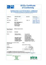
IECEx Certificate<br />
of Conformity<br />
INTERNATIONAL ELECTROTECHNICAL COMMISSION<br />
IEC Certification Scheme for Explosive Atmospheres<br />
for rules and details of the IECEx Scheme visit www.iecex.com<br />
Certificate history:<br />
Issue No. 4 (2011-12-9)<br />
Issue No. 3 (2011-3-9)<br />
Issue No. 2 (2011-1-12)<br />
Issue No. 1 (2009-3-16)<br />
Issue No. 0 (2007-9-20)<br />
Certificate No.: IECEx SIR 07.0027X issue No.:4<br />
Status: Current<br />
Date of Issue: 2011-12-09 Page 1 of 4<br />
EXPO <strong>Technologies</strong> <strong>Ltd</strong><br />
Summer Road<br />
Thames Ditton<br />
Surrey KT7 ORH<br />
United Kingdom<br />
Applicant:<br />
Electrical Apparatus: MiniPurge Purge Controller<br />
Optional accessory:<br />
Type of Protection: Pressurised<br />
Marking: Standard versions: (Ta –20°C to +55°C)<br />
Ex [px] IIC T6 Gb<br />
Ex [py] IIC T6 Gb<br />
Ex [p] IIIC T85°C Db or<br />
Ex [pz Gc ] IIC T6 Gb<br />
Ex [p Dc] IIIC T85°C Db<br />
Standard /ET versions: (Ta –20°C to +55°C)<br />
Ex [px] ia IIC T6 Gb<br />
Ex [p] ia IIIC T95°C Db<br />
Low temp. versions: (Ta –50°C to +55°C)<br />
Ex[px]dem IICT3orT4Gb<br />
Ex [p] IIIC T200°C or T135°C Db<br />
Low temp. /ET versions: (Ta –50°C to +55°C)<br />
Ex [px] dem ia IIC T3 or T4 Gb<br />
Ex [p] ia IIIC T200°C or T135°C Db<br />
C Ellaby<br />
Approved for issue on behalf of the IECEx<br />
Certification Body:<br />
Position: Deputy Certification Manager<br />
Signature:<br />
(for printed version)<br />
Date:<br />
1. This certificate and schedule may only be reproduced in full.<br />
2. This certificate is not transferable and remains the property of the issuing body.<br />
3. The Status and authenticity of this certificate may be verified by visiting the Official IECEx Website.<br />
Certificate issued by:<br />
SIRA Certification Service<br />
Rake Lane<br />
Eccleston<br />
Chester<br />
CH4 9JN<br />
United Kingdom
CERTIFICATION<br />
CERTIFICATION<br />
SCHEDULE<br />
1 EC TYPE-EXAMINATION CERTIFICATE<br />
EC TYPE-EXAMINATION CERTIFICATE Sira 01ATEX1295X<br />
Issue 7<br />
2 Equipment intended for use in Potentially Explosive Atmospheres Directive 94/9/EC<br />
13 DESCRIPTION OF EQUIPMENT<br />
The Purge Controllers are pneumatically operated devices, which are intended to provide a given flow rate of<br />
purging gas for a predetermined time to unspecified Ex p protected electrical equipment. The MiniPurge<br />
Control Units provide one of the following four methods of purge operation.<br />
3 Certificate Number: Sira 01ATEX1295X Issue: 7<br />
4 Equipment: Purge Controllers: Sub-MiniPurge, MiniPurge, Super-MiniPurge,<br />
Super-MiniPurge 1800/3500/7000/7000X<br />
5 Applicant: EXPO <strong>Technologies</strong> Limited<br />
LC-Leakage compensation only after initial high purge<br />
CF-Continuous flow (same flow rate during and after purging)<br />
CF2-Two flow CF system with initial high purge rate only at one orifice<br />
CFHP-Continuous (lower) flow after initial high purge<br />
The MiniPurge control unit may be supplied within a heated enclosure to permit the use of the system within<br />
an ambient temperature down to –50 o C.<br />
The MiniPurge option pD is for use in combustible dust<br />
6 Address: Summer Road, Thames Ditton, Surrey KT7 ORH, UK<br />
7 This equipment and any acceptable variation thereto is specified in the schedule to this certificate and<br />
the documents therein referred to.<br />
8 Sira Certification Service, notified body number 0518 in accordance with Article 9 of Directive 94/9/EC of 23<br />
March 1994, certifies that this equipment has been found to comply with the Essential Health and <strong>Safety</strong><br />
Requirements relating to the design and construction of equipment intended for use in potentially explosive<br />
atmospheres given in Annex II to the Directive.<br />
The examination and test results are recorded in the confidential reports listed in Section 14.2.<br />
Relief Valve - The MiniPurge controller is supplied with an optional overpressure relief valve,whichistobe<br />
fitted to the Ex p protected apparatus to prevent an internal overpressure above the maximum overpressure<br />
rating of the apparatus. There are 14 models of relief valve; the designation of each relief valve refers to its<br />
nominal bore in mm, as follows:<br />
9 Compliance with the Essential Health and <strong>Safety</strong> Requirements, with the exception of those listed in the<br />
schedule to this certificate, has been assured by compliance with the following documents:<br />
IEC 60079-0:2011 EN 60079-2:2007 EN 61241-4: 2006<br />
RLV3, RLV6, RLV9, RLV12, RLV19, RLV25, RLV26, RLV52, RLV36, RLV75, RLV104, RLV125, RLV150 and<br />
RLV200.<br />
10 If the sign ‘X’ is placed after the certificate number, it indicates that the equipment is subject to special<br />
conditions for safe use specified in the schedule to this certificate.<br />
The outlet of each relief valve is fitted with a spark arrestor, of which there are four optional types:<br />
� Metal foam � Multi-layer stainless steel mesh<br />
� Tortuous path with at least 4 x 90�or 2 x 180� bends � Knitted mesh<br />
11 This EC type-examination certificate relates only to the design and construction of the specified equipment. If<br />
applicable, further requirements of this Directive apply to the manufacture and supply of this equipment.<br />
12 The marking of the equipment shall include the following:<br />
Outlet Orifice - Three types of orifice are used:<br />
� Threaded Orifices e.g. ¼� NPT or 2� BSP with a built in spark arrester. These are selected to maintain a<br />
desired back pressure within the Ex p protected apparatus when used with the Continuous Flow options.<br />
Thedesignationofeachoutletorificeindicatesthenominalinletdiameter. Thedesignationsareas<br />
follows: SA3, SA6, SA9, SA12, SA19, SA25, SA32, SA38 and SA50.<br />
� Plain holes in the Relief Valve disk, sizedaccordingtotheflow rate required.<br />
� Replaceable orifice type SAU**.<br />
Standard versions Low temperature versions<br />
II 2(2) GD II 2(2) GD<br />
Ex [px] IIC T6 Gb Ex [px] dem IIC T3 or T4 Gb<br />
Ex [py] IIC T6 Gb Ex [p] IIIC T200°C or T135°C Db<br />
Ex [p] IIIC T85°C Db (Ta –50°C to +55°C)<br />
(Ta –20°C to +55°C)<br />
High Pressure Sensor for CF <strong>Systems</strong> (HP code) - If the pressure in the pressurized enclosure<br />
rises above the setting of the High Pressure sensor, the controller resets cutting the power to the<br />
enclosure. On detecting the overpressure an optional facility is available for the generation of an alarm<br />
or indicator. On systems with a High Pressure sensor, the relief valve may be omitted.<br />
II 2(3) GD<br />
Ex [pz Gc ] IIC T6 Gb<br />
Ex [p Dc] IIIC T85°C Db<br />
(Ta –20°C to +55°C)<br />
Standard /ET versions Low temperature /ET versions<br />
High Pressure Sensor for LC <strong>Systems</strong> (HP code) - If the pressure in the pressurized enclosure<br />
rises above the setting of the High Pressure sensor, the purge gas flow is isolated from the pressurised<br />
enclosure. The valve isolates both the leakage compensation and the purge streams. On detecting the<br />
overpressure, an optional facility isavailableforthegenerationofanalarm or indicator. On systems<br />
with a High Pressure sensor, the relief valve may be omitted.<br />
II 2(2) GD<br />
II 2(2) GD<br />
Ex [px] ia IIC T6 Gb Ex [px] dem ia IIC T3 or T4 Gb<br />
Ex [p] ia IIIC T95°C Db Ex [p] ia IIIC T200°C or T135°C Db<br />
(Ta –20 o Cto+55 o C) (Ta –50°C to +55°C)<br />
Pneumatically Operated Outlet Valve - The pneumatically operated outlet valve is used to<br />
positively open or close the outlet of the purged enclosure by means of a spring return pneumatic<br />
cylinder. <strong>Systems</strong> fitted with the Pneumatically Operated Outlet Valve will carry the option OV.<br />
Project Number 25983 C Ellaby<br />
Deputy Certification Manager<br />
This certificate and its schedules may only be<br />
reproduced in its entirety and without change.<br />
Sira Certification Service<br />
Rake Lane, Eccleston, Chester, CH4 9JN, England<br />
This certificate and its schedules may only be<br />
reproduced in its entirety and without change.<br />
Sira Certification Service<br />
Rake Lane, Eccleston, Chester, CH4 9JN, England<br />
Page 1 of 7<br />
Tel: +44 (0) 1244 670900<br />
Fax: +44 (0) 1244 681330<br />
Email: info@siracertification.com<br />
Web: www.siracertification.com<br />
Page 2 of 7<br />
Tel: +44 (0) 1244 670900<br />
Fax: +44 (0) 1244 681330<br />
Email: info@siracertification.com<br />
Web: www.siracertification.com<br />
Form 9400 Issue 1<br />
Form 9400 Issue1
CERTIFICATION<br />
CERTIFICATION<br />
SCHEDULE<br />
SCHEDULE<br />
EC TYPE-EXAMINATION CERTIFICATE Sira 01ATEX1295X<br />
Issue 7<br />
EC TYPE-EXAMINATION CERTIFICATE Sira 01ATEX1295X<br />
Issue 7<br />
Variation 1 This variation introduced the following changes:<br />
i. The purge controller to be fitted inside an additional, heated, stainless steel enclosure that allows<br />
it to be used down to -50 o C.<br />
The heater (500 W maximum) is manufactured by Intertec-Hess GmbH and coded Ex d m IIC T3<br />
(max) under PTB 02ATEX1041X. If the outer enclosure is reduced in size the power of the heater<br />
may be reduced in proportion to the reduction in surface area. Other alternative heaters may be<br />
used as a replacement if they are suitably certified, carry the same or greater ambient<br />
temperature range, occupy the same or smaller physical space, have the same certification code<br />
and have the same or more restrictive Temperature Class.<br />
The enclosure is made from 1.5mm or 2.5 mm thick stainless or mild steel painted and the lid is<br />
made from 1.5 mm thick stainless steel, lined with 38 mm thick insulation, or other materials with<br />
equivalent insulating properties. The purge inlet, purge outlet and pressure sensing lines are<br />
similarly insulated. The door may optionally be hinged with quick release catches, these will be<br />
fitted with a padlock. An enclosure breather tube is fitted to help prevent condensation. A plastic<br />
clear viewing window may optionally be fitted to the door.<br />
RTDs are fitted to the air inlet pipe-work and inside the purge controller enclosure.<br />
An Ex e terminal box is provided within the main enclosure for connection of the heater leads. This<br />
polyester box is manufactured by Bartec and coded Ex e II T6 under BAS 98ATEX3008X. Other<br />
alternative ATEX terminal boxes may be used as a replacement if they are suitably certified, carry<br />
the same or greater ambient temperature range, occupy the same or smaller physical space, have<br />
the same certification code and have the same Temperature Class.<br />
Model Number Designation for ATEX approved MiniPurge systems<br />
a Size or Capacity<br />
1 Sub-MiniPurge<br />
Model Number:<br />
2 MiniPurge<br />
1 X LC cs DS SS AA MO FM OA TW<br />
3 Super-MiniPurge<br />
4 Super-MiniPurge 1800<br />
Key:<br />
5 Super-MiniPurge 3500<br />
a b cc mm Example option codes<br />
6 Super-MiniPurge 7000<br />
7 Super-MiniPurge xxxx<br />
b Pressurization Type<br />
X X Pressurization<br />
Y Y Pressurization<br />
Z Z Pressurization<br />
cc Action after initial purging<br />
LC Leakage Compensation only after initial High Purge<br />
CF Continuous Flow (same flow rate during and after purging)<br />
CF2 Two Flow CF system with initial High Purge rate but only one orifice<br />
CFHP Continuous (lower) Flow after initial High Purge<br />
DP Dust Protection (pressurization only)<br />
mm Material of the Control Unit Enclosure<br />
al Aluminium alloy<br />
cs Mild steel, painted<br />
ss Stainless steel<br />
bp Back Plate only<br />
co Chassis only<br />
pm Panel mounting<br />
nm Non-Metallic<br />
Option codes (Added only if used)<br />
AA Active Alarm output fitted.<br />
AC Alarm cancellation circuit.<br />
AO "Alarm Only" Action on Pressure or Flow Failure.<br />
AS Alarm "Action on Pressure or Flow failure", Selector valve.<br />
CS Containment System Monitor.<br />
DS Door switch Power Interlock fitted.<br />
DT Delayed Trip after Pressure or Flow failure.<br />
DXXX Special design for specific flow rates<br />
ET Electronic Timer<br />
FM Flow Meter(s) fitted.<br />
HP System LC or CF with High Pressure Sensor<br />
IS Internal Switches suitable for Ex i circuits.<br />
MO Manual Override fitted.<br />
MT Mechanical Timer.<br />
OA On/Off switch controlling Protective gas and logic supply.<br />
OB On/Off switch controlling logic supply only.<br />
OC On/Off switch controlling Protective gas supply only.<br />
OS Outlet (Orifice) Selector valve.<br />
OV Outlet valve, pneumatically operated.<br />
PA "Ex" switch(es) built-in, with/without "Ex" junction box.<br />
PC PE Pressure Control Leakage Compensation Valve (CLAPS System.)<br />
PO Pneumatic Output signals for Power and Alarm control.<br />
SP Secondary Pressurization supply options.<br />
SS Separate Supply for Protective gas and Logic air.<br />
TW Twin (or more) outputs for two or more separate pressurized enclosures purged in parallel<br />
Any suitably ATEX, Category 2 approved cable glandmaybeused,ifitcanbeusedwiththe<br />
ambient temperature range.<br />
ii. A change of the Applicant’s name on the certificate and the substitution of the new name for the<br />
old name on the approved label affixed to the purge controllers:<br />
Old Name: New name:<br />
<strong>Expo</strong> <strong>Telektron</strong> <strong>Safety</strong> System Limited <strong>Expo</strong> <strong>Technologies</strong> Limited<br />
Variation 2 This variation introduced the following change:<br />
i. To permit the pressurisation of enclosures for the exclusion of combustible dusts in accordance<br />
with IEC61241-4:2001 and modification of the marking to include one of the following:<br />
[Ex pD] II T200°C 21 (Ta = -20°C to +55°C) - (used with the low temperature versions)<br />
[Ex pD] II T85°C 21 (Ta = -20°C to +55°C) - (used with the standard temperature versions)<br />
The ATEX coding is modified to: II 2(2) G D<br />
Sira Certification Service<br />
Rake Lane, Eccleston, Chester, CH4 9JN, England<br />
This certificate and its schedules may only be<br />
reproduced in its entirety and without change.<br />
Sira Certification Service<br />
This certificate and its schedules may only be<br />
reproduced in its entirety and without change.<br />
Rake Lane, Eccleston, Chester, CH4 9JN, England<br />
Tel: +44 (0) 1244 670900<br />
Fax: +44 (0) 1244 681330<br />
Email: info@siracertification.com<br />
Web: www.siracertification.com<br />
Page 4 of 7<br />
Tel: +44 (0) 1244 670900<br />
Fax: +44 (0) 1244 681330<br />
Email: info@siracertification.com<br />
Web: www.siracertification.com<br />
Page 3 of 7<br />
Form 9400 Issue1<br />
Form 9400 Issue1
CERTIFICATION<br />
CERTIFICATION<br />
SCHEDULE<br />
SCHEDULE<br />
EC TYPE-EXAMINATION CERTIFICATE Sira 01ATEX1295X<br />
Issue 7<br />
EC TYPE-EXAMINATION CERTIFICATE Sira 01ATEX1295X<br />
Issue 7<br />
Issue Date Report no. Comment<br />
4 7 June 2007 R51L15966B This Issue covers the following changes:<br />
� All previously issued certification was rationalised<br />
into a single certificate, Issue 4, Issues 0 to 3<br />
referenced above are only intended to reflect the<br />
history of the previous certification and have not<br />
been issued as documents in this format.<br />
� The introduction of Variation 3.<br />
5 18 February 2009 R51L19695A The introduction of Variation 4.<br />
6 22 December 2010 R23665A/00 This Issue covers the following changes:<br />
� This certificate history was modified to recognise<br />
that that Variation 2 was re-issued, subsequent<br />
Variations have therefore been re-numbered.<br />
� The introduction of Variation 5.<br />
7 07 December 2011 R25983A/00 The introduction of Variation 6.<br />
Variation 3 This variation introduced the following changes:<br />
i. Following appropriate re-assessment to demonstrate compliance with the requirements of the EN<br />
60079 series of standards, the documents originally listed in section 9, EN 50014:1997<br />
(amendments A1 to A2) and EN 50016:1995, were replaced by EN 60079-0:2006, EN 60079-1:2004,<br />
EN 61241-0:2006 and EN 61241-1:2006, the markings in section 12 were updated accordingly.<br />
ii. The removal of special conditions for safe use that were not specifically associated with the<br />
equipment covered by this certificate.<br />
Variation 4 - This variation introduced the following changes:<br />
i. To permit the inclusion of the following coding for the Low Temperature MiniPurge Enclosure:<br />
Ex [p] dem IIC T4<br />
Ex pD II 21 T135°C<br />
(Ta –50 o Cto+55 o C)<br />
Variation 5 - This variation introduced the following changes:<br />
15 SPECIAL CONDITIONS FOR SAFE USE (denoted by X after the certificate number)<br />
15.1 When using the AO, AS and DT options, the recommendations for the additional requirements of Ex p<br />
apparatus contained within EN 60079-14 shall be applied.<br />
i. The introduction of the /ET version, an alternative to the pneumatic or mechanical timer system,<br />
this incorporates an Electronic Timer Module ETM-IS**-*** in the Mini Purge, the certification<br />
includes ‘ia’ marking when the ETM is fitted.<br />
ii. The dust marking was changed to be consistent with the marking for gases and vapours.<br />
iii. The introduction of a high pressure sensor for the LC option.<br />
15.2 The installer/user shall ensure that the MiniPurge Control Unit is installed in accordance with the<br />
equipment certificate that covers the combination of the pressurised enclosure(s) and MiniPurge<br />
Control Unit.<br />
Variation 6 - This variation introduced the following changes:<br />
15.3 The values of the safety parameters shall be set in accordance with the equipment certificate that<br />
covers the combination of the pressurised enclosure(s) and MiniPurge Control Unit.<br />
15.4 This MiniPurge Control Unit shall be incorporated into equipment and the appropriate Conformity<br />
Assessment Procedures applied to the combination as defined by Directive 94/9/EC. This certificate<br />
does not cover the combination.<br />
i. Following appropriate re-assessment to demonstrate compliance with the requirements of the<br />
latest EN 60079 series of standards, the documents previously listed in section 9, EN 60079-0:<br />
2006 and EN 60079-2: 2004 were replaced by those currently listed (EN 61241-0: 2006 was<br />
removed as this is incorporated into the current version of 60079-0), the markings in section 12<br />
were updated accordingly and a new condition of certification was added.<br />
14 DESCRIPTIVE DOCUMENTS<br />
15.5 The purge controller, low temperature version, shall be protected by a safety related system that<br />
ensures that it cannot be energised if the temperature of the air inlet or purge controller falls below -<br />
20 o C. This system shall utilise the RTDs that are fitted to the purge controller to provide the<br />
appropriate level of system integrity, i.e. a level of operational safety of Cat 3 according to EN 954-1 for<br />
ATEX Category 2 (Zone 1) applications; note that these RTDs have not been assessed as a safety<br />
related device in accordance with EHSR 1.5 of Directive 94/9/EC.<br />
14.1 Drawings<br />
Refer to Certificate Annexe.<br />
14.2 Associated Sira Reports and Certificate History<br />
16 ESSENTIAL HEALTH AND SAFETY REQUIREMENTS (EHSRs)<br />
The relevant EHSRs that are not addressed by the standards listed in this certificate have been<br />
identified and individually assessed reports listed in Section 14.2.<br />
Issue Date Report no. Comment<br />
0 3 July 2002 R53A7169A The release of prime certificate.<br />
1 29 March 2004 R53V11342A The introduction of Variation 1.<br />
2 30 September 2004 R51A11080A The introduction of Variation 2.<br />
3 19 September 2006 R51A15629A The re-issue of Variation 2 to include the changes<br />
described in report number R51A15629A.<br />
17 CONDITIONS OF CERTIFICATION<br />
17.1 The use of this certificate is subject to the Regulations Applicable to Holders of Sira Certificates.<br />
17.2 Holders of Type Examination Certificates are required to comply with the production control<br />
requirements defined in Article 8 of directive 94/9/EC.<br />
17.3 The switches incorporated in the PA option shall be suitably certified for Category 2.<br />
Sira Certification Service<br />
Rake Lane, Eccleston, Chester, CH4 9JN, England<br />
This certificate and its schedules may only be<br />
reproduced in its entirety and without change.<br />
Sira Certification Service<br />
Rake Lane, Eccleston, Chester, CH4 9JN, England<br />
This certificate and its schedules may only be<br />
reproduced in its entirety and without change.<br />
Tel: +44 (0) 1244 670900<br />
Fax: +44 (0) 1244 681330<br />
Email: info@siracertification.com<br />
Web: www.siracertification.com<br />
Page 6 of 7<br />
Tel: +44 (0) 1244 670900<br />
Fax: +44 (0) 1244 681330<br />
Email: info@siracertification.com<br />
Web: www.siracertification.com<br />
Page 5 of 7<br />
Form 9400 Issue1<br />
Form 9400 Issue1
Certificate Annexe<br />
Certificate Number: Sira 01ATEX1295X<br />
CERTIFICATION<br />
Equipment: Purge Controllers<br />
Sub-MiniPurge, MiniPurge, Super-MiniPurge,<br />
Super-MiniPurge 1800/3500/7000/7000X<br />
CERTIFICATION<br />
Applicant: EXPO <strong>Technologies</strong> Limited<br />
SCHEDULE<br />
Issue 0 (The drawings associated with this issue were replaced by those listed in Issue 4)<br />
EC TYPE-EXAMINATION CERTIFICATE Sira 01ATEX1295X<br />
Issue 7<br />
Number Sheet Rev. Date Description<br />
SD7281 1 to 4 3 02 Jul 02 MiniPurge ATEX Certification Labelling<br />
SD7282 1 to 2 2 21 May 01 MiniPurge ATEX Certification Type Numbering Scheme<br />
EP/99-2-17 1 of 1 1 21 Sep 00 MiniPurge, Continuous Flow with /HP Sensor –Schematic diagram<br />
EP99-7-7 1 of 1 1 21 Sep 00 RLV, outlet orifice<br />
EP99-7-9 1 of 1 1 21 Sep 00 Outlet Valve Control Circuit Diagram<br />
17.4 The following routine tests shall be performed by the manufacturer:<br />
Verification of Minimum Overpressure Cut Off<br />
An overpressure loss shall be simulated whilst the MiniPurge Control Unit is cycling, it shall be verified<br />
that the controller provides the appropriate output and resets.<br />
Issue 1 (The drawings associated with this issue were replaced by those listed in Issue 4)<br />
Verification of Purge Failure Protection<br />
Number Sheet Rev. Date Description<br />
SD7448 1 of 1 3 22 March 04 Low Temperature Housing - General Arrangement<br />
A purge failure shall be simulated whilst the MiniPurge Control Unit is cycling, it shall be verified that<br />
the controller provides the appropriate output and resets.<br />
Issue 2 (The drawings associated with this issue were replaced by those listed in Issue 4)<br />
Verification of Air Supply Failure Protection<br />
Number Sheet Rev. Date Description<br />
SD7281* 1 to 5 4 17 Dec 03 Certification label<br />
SD7449 1 of 1 1 18 Dec 03 Low temperature housing wiring certification drawing.<br />
* Modified by Sira 30 September 2004<br />
An air supply failure shall be simulated whilst the MiniPurge Control Unit is cycling, it shall be verified<br />
that the controller provides the appropriate output and resets.<br />
Issue 3 (The drawings associated with this issue were replaced by those listed in Issue 4)<br />
Verification of Purging Overpressure protection<br />
Where the HP is specified an overpressure shall be simulated whilst the MiniPurge Control Unit is<br />
cycling, it shall be verified that the controller provides the appropriate output and resets.<br />
Number Sheet Rev. Date Description<br />
SD7281 1 to 5 5 30 Aug 06 Certification label<br />
Issue 4<br />
Number Sheet Rev. Date Description<br />
EP99-3-1 1 of 1 02 15 Mar 07 Minipurge Control Unit – General Assembly<br />
EP99-2-1 1 of 1 03 09 Jul 07 Schematic - Type x Leakage Compensation<br />
EP99-2-3 1 of 1 02 15 Mar 07 Sequence Diagram - Type x Leakage Compensation<br />
EP99-2-2 1 of 1 02 15 Mar 07 Schematic - Type x Continuous Flow<br />
EP99-2-7 1 of 1 02 15 Mar 07 Schematic – Separate Supply and Mechanical Timer<br />
EP99-2-8 1 of 1 02 15 Mar 07 Schematic – Delay Before Trip and On/Off<br />
EP99-2-9 1 of 1 02 15 Mar 07 Schematic – Twin Output and Manual Override<br />
EP99-2-10 1 of 1 03 15 Mar 07 Schematic – Pressure Control Leakage Compensation<br />
EP99-2-11 1 of 1 03 15 Mar 07 Internal “IS” Switches<br />
EP99-2-12 1 of 1 02 15 Mar 07 Schematic – Containment System and Secondary pressurisation<br />
EP99-2-14 1 of 1 02 15 Mar 07 Schematic – Continuous Flow with 2 Flow Rates<br />
EP99-2-17 1 of 1 02 15 Mar 07 Schematic – Continuous Flow with High Pressure<br />
EP99-2-16 1 of 1 02 15 Mar 07 Schematic – Outlet Valve Control<br />
SD7533 1 of 1 01 15 Mar 07 Schematic – Dust Protection<br />
SD7535 1 of 1 01 15 Mar 07 Spark Arrestor<br />
SD7536 1 of 1 01 18 Apr 07 Differential Flow Monitor<br />
SD7538 1 of 1 01 27 Mar 07 Continuous Flow Outlet Orifice<br />
SD7449 1 of 1 02 15 Mar 07 Wiring Diagram – Low temperature<br />
SD7500 1 of 1 01 25 Apr 07 Outlet Orifice Closing Device<br />
SD7448 1 of 1 04 15 Mar 07 Low Temperature Housing<br />
SD7281 1 to 2 06 20 Feb 07 Certification Label Details<br />
SD7282 1 to 2 03 20 Feb 07 MiniPurge Data Sheet<br />
17.5 The products covered by this certificate incorporate previously certified devices, it is therefore the<br />
responsibility of the manufacturer to continually monitor the status of the certification associated with<br />
these devices, and the manufacturer shall inform Sira of any modifications of the devices that may<br />
impinge upon the explosion safety design of the products.<br />
17.6 The certification code that is appropriate to Purge Controllers low temperature version shall appear in<br />
the product marking applied to outer stainless steel enclosure.<br />
17.7 The Purge Controllers: Sub-MiniPurge, MiniPurge, Super-MiniPurge, Super-MiniPurge<br />
1800/3500/7000/7000X shall not be marked as suitable for use in explosive dust atmospheres when a<br />
non-metallic or painted housing is used.<br />
Sira Certification Service<br />
Rake Lane, Eccleston, Chester, CH4 9JN, England<br />
This certificate and its schedules may only be<br />
reproduced in its entirety and without change.<br />
Sira Certification Service<br />
Rake Lane, Eccleston, Chester, CH4 9JN, England<br />
This certificate and its schedules may only be<br />
reproduced in its entirety and without change.<br />
Tel: +44 (0) 1244 670900<br />
Fax: +44 (0) 1244 681330<br />
Email: info@siracertification.com<br />
Web: www.siracertification.com<br />
Page 1 of 2<br />
Tel: +44 (0) 1244 670900<br />
Fax: +44 (0) 1244 681330<br />
Email: info@siracertification.com<br />
Web: www.siracertification.com<br />
Page 7 of 7<br />
Form 9400 Issue 1<br />
Form 9400 Issue1
Certificate Annexe<br />
Certificate Number: Sira 01ATEX1295X<br />
CERTIFICATION<br />
Equipment: Purge Controllers<br />
Sub-MiniPurge, MiniPurge, Super-MiniPurge,<br />
Super-MiniPurge 1800/3500/7000/7000X<br />
Applicant: EXPO <strong>Technologies</strong> Limited<br />
Number Sheet Rev. Date Description<br />
SD7537 1 to 3 01 20 Feb 07 Fault Evaluation<br />
EP99-7-9 1 of 2 02 15 Mar 07 Outlet Valve Circuit N/O<br />
EP99-7-9 2 of 2 01 15 Mar 07 Outlet Control Valve N/C<br />
SD7531 1 of 1 02 09 Jul 07 Schematic – Type Z or Y leakage compensation<br />
SD7532 1 of 1 01 15 Mar 07 Schematic Type Z or Y Continuous Flow<br />
EP99-2-4 1 of 1 02 15 Mar 07 Sequence Diagram – Type X Continuous Flow<br />
EP99-2-5 1 of 1 02 15 Mar 07 Schematic – Alarm only and Alarm Action Selector<br />
EP99-2-6 1 of 1 02 15 Mar 07 Schematic – Door Switch Active Alarm and Alarm Cancel<br />
SD7555 1 to 4 01 05 Jul 07 RLV Configurations<br />
SD7556 1 of 2 01 09 Jul 07 Alternative Z&Y LC System<br />
SD7556 2 of 2 01 09 Jul 07 Alternative Z&Y LC System<br />
Issue 5<br />
Number Sheets Rev. Date (Sira stamp) Description<br />
SD7281 1 to 2 7 12 Feb 09 Minipurge ATEX/IECEx Certification Label<br />
SD7448 1 of 1 05 12 Feb 09 Minipurge Low temperature Housing<br />
Issue 6<br />
Number Sheets Rev. Date (Sira stamp) Description<br />
SD7281 1 to 2 8 23 Dec 10 Minipurge ATEX/IECEx Certification Label<br />
SD7282 1 to 2 4 21 Dec 10 MiniPurge Data Sheet<br />
SD7913 1 of 1 2 21 Dec 10 MiniPurge electronic timer<br />
SD7914 1 of 1 2 21 Dec 10 MiniPurge HP sensor<br />
Issue 7<br />
Number Sheets Rev. Date (Sira stamp) Description<br />
SD7448 1 of 1 6 23 Nov 11 Minipurge Low Temperature Housing<br />
SD7282 1 & 2 5 23 Nov 11 Minipurge Data Sheets<br />
SD7281 1 to 3 9 23 Nov 11 Minipurge ATEX/IECEx Certification Label<br />
SD7533 1 of 1 2 23 Nov 11 Minipurge Dust Protection Schematic<br />
Sira Certification Service<br />
Rake Lane, Eccleston, Chester, CH4 9JN, England<br />
This certificate and its schedules may only be<br />
reproduced in its entirety and without change.<br />
Tel: +44 (0) 1244 670900<br />
Fax: +44 (0) 1244 681330<br />
Email: info@siracertification.com<br />
Web: www.siracertification.com<br />
Page 2 of 2<br />
Form 9400 Issue 1
®<br />
File E190061 Vol 1 Issued 1999-07-23<br />
Revised 2003-05-08<br />
®<br />
FOLLOW-UP SERVICE PROCEDURE<br />
(TYPE R)<br />
PURGING AND PRESSURIZING CONTROLS AND<br />
ACCESSORIES FOR USE IN HAZARDOUS LOCATIONS<br />
(RFPW,RFPW7)<br />
Manufacturer: EXPO TECHNOLOGIES LIMITED<br />
(466459-001) SUMMER RD<br />
THAMES DITTON<br />
SURREY<br />
KT7 0RH ENGLAND UNITED KINGDOM<br />
Applicant: SAME AS MANUFACTURER<br />
(466459-001)<br />
Classified Company: SAME AS MANUFACTURER<br />
(466459-001)<br />
This Procedure authorizes the above Manufacturer to use the marking specified by<br />
Underwriters Laboratories Inc. only on products covered by this Procedure,<br />
in accordance with the applicable Follow-Up Service Agreement.<br />
333 Pfingsten Road<br />
Northbrook, Illinois 60062-2096<br />
United States Country Code(1)<br />
(847) 272-8800<br />
FAX No. (847) 272-8129<br />
http://www.ul.com<br />
The prescribed Mark or Marking shall be used only at the above manufacturing location<br />
on such products which comply with this Procedure and any other applicable<br />
requirements.<br />
The Procedure contains information for the use of the above named Manufacturer and<br />
representatives of Underwriters Laboratories Inc. and is not to be used for any other<br />
purpose. It is lent to the Manufacturer with the understanding that it is not to<br />
be copied, either wholly or in part, and that it will be returned to Underwriters<br />
Laboratories Inc. upon request.<br />
This PROCEDURE, and any subsequent revisions, is the property of UNDERWRITERS<br />
LABORATORIES INC. and is not transferable.<br />
A<br />
UNDERWRITERS LABORATORIES INC.<br />
A.W. Schaefer<br />
Vice President and General Manager<br />
US and Canadian Operations<br />
A not-for-profit organization<br />
dedicated to public safety and<br />
committed to quality service
(1) Declaration of Conformity.<br />
(2) <strong>Expo</strong> <strong>Technologies</strong> Document Number EXPO11ATEX1200X/1.<br />
(3) This declaration is issued for the electrical apparatus:<br />
Page 1 of 2<br />
AGE-SW0Z-017 non- sparking switch<br />
(4) Manufacturer:<br />
<strong>Expo</strong> <strong>Technologies</strong><br />
Summer Road<br />
Thames Ditton<br />
Surrey<br />
KT7 0RH UK<br />
(5) This electrical apparatus and any acceptable variation thereto is specified in<br />
the Annex to this certificate and the documents therein referred to.<br />
(6) This declaration and schedule confirms compliance of each unit with the<br />
following standards:<br />
EN 60079-0: 2009 General requirements<br />
EN 60079-18: 2009 Encapsulation “m”<br />
(7) This apparatus fulfils all the requirements for Group II Category 3 equipment<br />
in accordance with European Directive 94/9/EC.<br />
(8) The design is documented in <strong>Expo</strong> <strong>Technologies</strong> Technical Construction<br />
File number 33182<br />
(9) The apparatus marking:<br />
Ex m IIC T4 Gc<br />
For and on behalf of <strong>Expo</strong> <strong>Technologies</strong> <strong>Ltd</strong>.<br />
Thames Ditton, 7th June 2012.<br />
II 3 G<br />
Sarah Wickson David Baker<br />
Certification Engineer Certification Engineer<br />
<strong>Expo</strong> <strong>Technologies</strong> <strong>Ltd</strong><br />
Summer Road, Thames Ditton,<br />
Surrey KT7 0RH, UK<br />
T +44 (0)20 8398 8011<br />
F +44 (0)20 8398 8014<br />
E info@expoworldwide.com<br />
<strong>Expo</strong> <strong>Technologies</strong> <strong>Ltd</strong>. Registered in England No2854600 www.expoworldwide.com
Annex to Declaration of Conformity EXPO11ATEX1200X/1.<br />
10 Description:<br />
A pneumatically operated, hermetically sealed switch. The switch is<br />
contained in an aluminium alloy 6082 block encapsulated with an epoxy<br />
resin potting compound.<br />
Page 2 of 2<br />
Ambient temperature range –20 �C to + 55 �C.<br />
11 Switch data:<br />
Maximum Voltage 254Vac rms<br />
Maximum Current 0.7A<br />
Humidity range 0% to 100% RH at 55�C, condensing.<br />
Pneumatic signal: 22 to 100 p.s.i. 1.5 – 7Barg.<br />
12 Special conditions of safe use:<br />
The unit shall be grounded using a cable lug and appropriate grounding wire. The<br />
conductor shall be secured against loosening or twisting and that contact pressure<br />
is permanently secured.<br />
The circuit shall be protected by a suitable fuse or similar device.<br />
13 Test Documentation<br />
Description Doc. Ref. Rev.<br />
General Arrangement AGE-SW0Z-017 3<br />
Reed switch data sheet 2118502030 2<br />
Test procedure TP518-040-WD 2<br />
<strong>Expo</strong> <strong>Technologies</strong> <strong>Ltd</strong><br />
Summer Road, Thames Ditton,<br />
Surrey KT7 0RH, UK<br />
T +44 (0)20 8398 8011<br />
F +44 (0)20 8398 8014<br />
E info@expoworldwide.com<br />
<strong>Expo</strong> <strong>Technologies</strong> <strong>Ltd</strong>. Registered in England No2854600 www.expoworldwide.com
S:\Files\QA\CERTS\C-OF-C\SC020 V2 Non Incendive switch.doc<br />
Manufacturer’s Self Evaluation In<br />
accordance with NFPA-70<br />
National Electric Code Clause 500.8<br />
<strong>Expo</strong> <strong>Technologies</strong> <strong>Ltd</strong><br />
Summer Road<br />
Thames Ditton KT7 0RH UK<br />
The non-incendive switch AGE-SW0Z-017 Manufactured by <strong>Expo</strong> <strong>Technologies</strong> can be<br />
marked for use in Class I division 2 hazardous location.<br />
The switch contacts are formed of a reed switch which is a hermetically sealed contact. It<br />
is therefore is suitable for use in Class I Division 2 Hazardous Location in accordance<br />
with NFPA-70 clause 500.7 J Hermetically sealed.<br />
NEC 501.105 B 1 Exception 2 Allows for hermetically sealed devices to be used as an<br />
alternative to using a listed device. i.e. there is not a requirement for these to be listed .<br />
Similarly 501.1.150 .2 exception 2 also permits hermetically sealed switch for use as<br />
remote alarm.<br />
The switch is marked with the voltage and current ration of the hermetically sealed<br />
contacts and is marked as<br />
V max<br />
I max<br />
P max<br />
Non Incendive Circuit<br />
254V AC<br />
200V DC<br />
1 Amp<br />
70 W<br />
For Intinsically safe circuits or the switch contact is simple apparatus as described in<br />
NEC504.2 and used with control drawing EP-80-2.11<br />
Similarly for non incendive circuits the switch is simple apparatus ( though also<br />
hermetically sealed.).<br />
Therefore the switch AGE-SW0Z-017 can be used as simple apparatus either in an<br />
intrinsically safe circuit or in a non incendive circuit, or it can be used as a hermetically<br />
sealed contact in a Class I Division2 Location within the ratings shown.<br />
Signed Date 7 June 2012<br />
Managing Director Confidential Assessment file reference SC020
EC-Declaration of<br />
Conformity<br />
S:\Files\QA\CERTS\C-OF-C\Minipurge CE SC004 Issue4.doc<br />
With<br />
European<br />
Directives<br />
<strong>Expo</strong> <strong>Technologies</strong> <strong>Ltd</strong><br />
Summer Road<br />
Thames Ditton KT7 0RH UK<br />
<strong>Expo</strong> <strong>Technologies</strong> <strong>Ltd</strong><br />
declares that<br />
Purge Controllers Type “MiniPurge” certified under<br />
EC Type Examination Certificate SIRA 01ATEX1295X<br />
are manufactured in conformity with the following<br />
European Directives and standards:<br />
Electromagnetic Compatibility Directive 2004/108/EG<br />
MiniPurge <strong>Systems</strong> with a /PO suffix in the type number are non-electrical and are outside<br />
the scope of the EMC Directive.<br />
MiniPurge <strong>Systems</strong> with suffices /PA or /IS incorporate one or more volt-free (“dry”)<br />
contacts which work in circuits specified by others. In normal operation these circuits are<br />
“benign” and no CE mark is appropriate.<br />
MiniPurge <strong>Systems</strong> with Electronic Timer (Option /ET) are designed to conform to the<br />
EMC Directive, in compliance with EN 61000-6-4:2007 and EN 61000-6-2:2005 (Intertek<br />
Report EM10048000).<br />
Low Voltage Directive 2006/95/EC<br />
MiniPurge systems are intended to be used in Hazardous Areas (Explosive Atmospheres)<br />
and are therefore excluded from the Low Voltage Directive.<br />
ATEX Directive 94/9/EC<br />
MiniPurge systems are designed to conform to the ATEX Directive, in compliance with:<br />
EN 60079-0 : 2009 EN 60079-2 : 2007<br />
EN 61241-0 : 2006 EN 61241-4 : 2006<br />
Pressure Equipment Directive 97/23/EC<br />
Signed Date 27/01/2011<br />
Managing Director Confidential Assessment file reference SC004
<strong>Expo</strong> <strong>Technologies</strong> <strong>Ltd</strong>., Tel + 44 (0) 20 8398 8011<br />
Unit 2, The Summit, Fax + 44 (0) 20 8398 8014<br />
Hanworth Road, E-mail: sales@expoworldwide.com<br />
Sunbury-On-Thames,<br />
TW16 5DB<br />
<strong>Expo</strong> <strong>Technologies</strong> Inc., Tel: +1 888-NFPA-496<br />
9140 Ravenna Road Unit #3, Tel: +1 (440) 247 5314<br />
Twinsburg Fax: +1 (330) 487 0611<br />
OH 44087 E-mail: sales.na@expoworldwide.com<br />
USA<br />
www.expoworldwide.com