Expo-Telektron Safety Systems Ltd - Expo Technologies
Expo-Telektron Safety Systems Ltd - Expo Technologies
Expo-Telektron Safety Systems Ltd - Expo Technologies

Create successful ePaper yourself
Turn your PDF publications into a flip-book with our unique Google optimized e-Paper software.
Cabinet Cooler Vortex Handbook<br />
CONTENTS:<br />
1. General Instructions<br />
2. Specification<br />
3. Certification Data<br />
4. Application Suitability<br />
5. Installation<br />
6. Commissioning<br />
7. Maintenance<br />
8. Fault Finding<br />
9. Drawings<br />
ML463<br />
ML463 v5 13/11/12<br />
Page 1 of 5
1 GENERAL INSTRUCTIONS<br />
When a Cabinet Cooler is required all potential sources of heat generation should be taken<br />
into account. Example: When an enclosure is in direct sunlight installing a sun shade and<br />
possibly thermal insulation would reduce the solar heating considerably.<br />
If a Cabinet Cooler is required the following must be considered.<br />
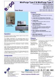
Principle of Operation<br />
The Cabinet Cooler (Vortex type) works by using a compressed air supply and spinning the air<br />
into a chamber at very high RPM. This splits the air into a hot and cold fraction. The hot<br />
fraction of air is exhausted outside the enclosure. The cold fraction is vented into the<br />
enclosure and ultimately has to be vented out of the enclosure.<br />
2 SPECIFICATION<br />
Power Supply (as per model ordered):<br />
-110 Vac or 230 Vac<br />
50/60Hz<br />
-24 Vdc<br />
Air Supply: 60-100psi 4-7barg<br />
25scfm, 708Nl/min at 100psi, 7barg<br />
Maximum of 40ºC, 104ºF<br />
Cooling Capacity 440W at 100psi, 7barg<br />
Temperature Control: Electronic +/-2ºC, +/-3.6ºF<br />
Maximum Air Inlet 40ºC<br />
Temperature<br />
Maximum Air Outlet 130ºC/ 266ºF<br />
Temperature<br />
Weight 1.5kg, 4lbs<br />
Hazardous Area Ex nA II T4 II 3G at -20ºC +40ºC ambient *<br />
* An ambient of up to 55ºC, 131ºF is possible in certain instances with reducing cooling capacity.<br />
Please contact <strong>Expo</strong> directly as these applications must be considered on a case by case basis.<br />
3 CERTIFICATION DATA<br />
This product has been assessed and approved for CAT 3 compliance by <strong>Expo</strong> <strong>Technologies</strong>.<br />
Certification number: <strong>Expo</strong> 09 ATEX 1122x<br />
WARNING<br />
When fitted to an Ex p, X, Y, or Z enclosure this device has been pre-set for use within a T4<br />
rating (135ºC, 275ºF).<br />
The Cabinet Cooler has been pre-set, the exhaust ‘slotted valve’ adjusted and made tamper<br />
evident by use of a fixed pin and red tamperproof varnish. This adjustment is further protected<br />
by the tool operated Cooler/muffler.<br />
After assembly of the Cabinet Cooler on to an Ex p, X, Y, or Z enclosure this Cooler/muffler<br />
must be replaced onto the exhaust of the Vortex Tube which is located in the Hazardous Area.<br />
ML463 v5 13/11/12<br />
Page 2 of 5
Any un-authorised adjustment of the ‘slotted’ valve will automatically invalidate the use of this<br />
product in a hazardous area.<br />
4 APPLICATION SUITABILITY<br />
� As the Cabinet Cooler displaces air care should be given on installations where movement of<br />
dust may be an issue, (Zone 21 & 22 or Class II).<br />
� The following materials are used in the construction of Cabinet Cooler.<br />
If substances that will adversely affect any of these materials are present in the surrounding<br />
environment, please consult <strong>Expo</strong> <strong>Technologies</strong> for further guidance.<br />
Materials of construction:<br />
� Stainless Steel � Polyamide<br />
� Mild (carbon) Steel � Epoxy Resin<br />
� Brass � ABS<br />
� Copper � PVC<br />
� This equipment is designed for use under normal industrial conditions of ambient<br />
temperature, humidity and vibration. Please consult EXPO before installing this equipment<br />
in conditions that may cause stresses beyond normal industrial conditions.<br />
� The Cabinet Cooler is not silent in operation.<br />
5 INSTALLATION<br />
General Notes<br />
When installing a Cabinet Cooler into a Pressurized Enclosure the following issues should be<br />
considered.<br />
� A second Relief Valve unit may be required to exhaust the cold fraction entering the<br />
Pressurized Enclosure. This second Relief Valve unit will need to be set at a higher lift off<br />
pressure than the Relief Valve unit supplied with the MiniPurge Control Unit. This is to<br />
ensure that the operation of the MiniPurge is not interfered with.<br />
� The second Relief Valve unit must also be capable of exhausting the full flow rate of the cold<br />
fraction. This is typically between 20-80% of the air supply dependant on setting at time of<br />
commissioning.<br />
� The MiniPurge must control the operation of the Cabinet Cooler by way of the purge complete<br />
signal. The MiniPurge must go through a purge cycle before the Cabinet Cooler receives<br />
either a supply of compressed air or electrical power. This will prevent the MiniPurge<br />
considering the cold fraction as the purge flow which would be incorrect. The solenoid valve<br />
will obtain its power once the purge time has elapsed.<br />
� Cabinet Cooler assemblies supplied by <strong>Expo</strong> have a solenoid valve to control the compressed<br />
air supply. In addition a thermostatic control is included and a one way air valve fitted to the<br />
cold fraction.<br />
� The one way air valve is to prevent the enclosure losing pressure when the Cabinet Cooler is<br />
not in operation.<br />
� If a customer is to install a Cabinet Cooler themselves into an <strong>Expo</strong> Pressurized Enclosure<br />
that has already been certified by <strong>Expo</strong> then <strong>Expo</strong> requires:<br />
documents, drawings, circuits etc, recording this addition so that we can issue an amendment<br />
to the overall certificate. This may incur additional costs.<br />
� To install the Cabinet Cooler refer to the general assembly drawing for overall dimensions.<br />
� Drill a hole on the top face of the enclosure, the one way valve must be vertical.<br />
It is possible to mount the Vortex tube in the side wall, although this is not the preferred option.<br />
� Unscrew the hot air exhaust muffler and remove the gland.<br />
� Fix gland into the drilled hole.<br />
ML463 v5 13/11/12<br />
Page 3 of 5
� Now insert the vortex tube through the gland and tighten the gland up to hold the Cabinet<br />
Cooler in place.<br />
� Now replace the hot air exhaust muffler and place supplied label adjacent to the muffler on the<br />
outside of the enclosure.<br />
� The temperature sensor can now be positioned within the enclosure. This could be on a<br />
specific device or in the top of the enclosure where the temperature will normally be at it’s<br />
greatest.<br />
� The wiring and pneumatic pipe work can now be fitted.<br />
6 COMMISSIONING<br />
Always ensure that there is adequate exhaust and pressure relief provided for the enclosure.<br />
If this is not provided the enclosure will become over pressurized and may operate outside of<br />
its Test Pressure specification and possibly become a hazard in itself.<br />
General Notes<br />
Compressed air supply:<br />
The air supply temperature should not exceed 40ºC, 104ºF. Solar shading or thermal<br />
insulation of air supply pipe work may be required.<br />
Air supplies are plagued with condensed water vapour and droplets in the air lines. This<br />
condensation leads to rust and dirt in the air lines. Also, some compressors will allow oil or oil<br />
vapour to enter the air line.<br />
It is important that the electrical equipment within the Pressurized Enclosure is not<br />
contaminated. Small orifices within the Cabinet Cooler may become clogged with rust, dirt<br />
and water droplets. A 5 micron filter will separate 99% of foreign material from the air supply,<br />
allowing virtually maintenance free operation. The use of an oil filter with an effective filtration<br />
of 0.01 micron will remove the oil droplets for an even cleaner air supply.<br />
Keep in mind that the current line or hose might contain water, dirt or oil and should be blown<br />
out before installation. Also, pipe thread sealant or tape must be carefully applied to avoid<br />
clogging product orifices.<br />
When the temperature of the air inside the Cabinet drops to 0ºC (32ºF), the water vapour in<br />
the air will start to freeze. If this poses a problem with ice clogging the orifices of the generator<br />
inside the tube, an air dryer must be used to lower the dew point to keep out the water vapour.<br />
An air dryer rated at -19ºC, 2ºF will produce a dew point low enough to eliminate the water<br />
vapour freezing in the orifices of the generator.<br />
� The installation of the electrical connections shall be inspected for correct installation before the<br />
unit is put into service.<br />
� The Cabinet Cooler has the temperature setting, factory set to 20ºC, 86ºF<br />
� If the customer wishes to change this then the adjustment resistor is shown on the drawing<br />
provided. This does not have an indexed scale.<br />
� The Cabinet Cooler can now be operated. Once a purge cycle has been completed the Cabinet<br />
Cooler will become active. As soon as the sensor detects the set temperature has been<br />
exceeded the Solenoid Valve will open and the Cabinet Cooler will operate.<br />
� Air will be vented from the Hot air Muffler and out of the enclosure Relief Valve.<br />
� The Solenoid Valve will close once the set temperature has been reached.<br />
7 MAINTENANCE<br />
The Cabinet Cooler has no moving parts. Clean, compressed air moving through the tube will<br />
not cause wear on the parts and will provide the same service for an indefinite period of time.<br />
Occasionally, dirt, water or oil may enter the tube from the compressed air supply and hinder<br />
the performance. When this happens, simply take the unit apart, clean the parts, and<br />
reassemble, tightly replacing the cold end cap to properly seat the generator.<br />
ML463 v5 13/11/12<br />
Page 4 of 5
The Solenoid Valve is also maintenance free and should be replaced if a fault does occur. The<br />
encapsulated fuse fitted inside the IP66 box using double sided sticky tape can be easily<br />
changed if it is required.<br />
8 FAULT FINDING<br />
� The most common fault is a lack of air supply due to either low air supply pressure or poor flow rate.<br />
Poor flow is because of too small pipe work, long pipe lengths or small fittings.<br />
� Occasionally dirty or very wet air causes ice build up within the enclosure, leading to intermittent<br />
operation and water within the enclosure.<br />
� If the system does not work at all check the fuse has not blown.<br />
� Ensure the temperature setting has not been tampered with.<br />
� Ensure the air exhausts are not blocked.<br />
� Recommended spares list:<br />
� EFU-F006-302 Encapsulated fuse EExm CAT 3 160mA 250V<br />
9 DRAWINGS AND DIAGRAMS<br />
See attached drawings:<br />
TITLE Drawing Number<br />
Cabinet Cooler Assembly AVC-0000-006<br />
AVC-0000-007<br />
AGE-GE00-142<br />
ML463 v5 13/11/12<br />
Page 5 of 5
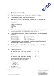
1) Declaration of Conformity.<br />
(2) <strong>Expo</strong> <strong>Technologies</strong> Document Number EXPO 09 ATEX 1122X.<br />
(3) This declaration is issued for the electrical apparatus:<br />
Page 1 of 2<br />
Cabinet Vortex Cooler Type n<br />
(4) Manufacturer:<br />
<strong>Expo</strong> <strong>Technologies</strong> <strong>Ltd</strong><br />
Surrey<br />
KT7 0RH<br />
UK<br />
(5) This electrical apparatus and any acceptable variation thereto is specified in the<br />
Annex to this certificate and the documents therein referred to.<br />
(6) This declaration and schedule confirms compliance of each unit with the following<br />
standards:<br />
EN 60079-2:2006 General requirements<br />
EN 60079-15:2005 Type ‘n’ protection<br />
EN 60079-18:2004 Type ‘m’ encapsulation<br />
(7) This apparatus fulfils all the requirements for Group II Category 3 equipment in<br />
accordance with European Directive 94/9/EC.<br />
(8) The design is documented in <strong>Expo</strong>-<strong>Technologies</strong> Technical Construction File<br />
number 40777<br />
(9) The apparatus marking:<br />
Ex m nA II T4 t.amb –20 0 C to +40 0 C<br />
For and on behalf of <strong>Expo</strong> <strong>Technologies</strong> <strong>Ltd</strong>.<br />
Thames Ditton, 15 th May 2009.<br />
David Baker<br />
Consultancy Manager<br />
II 3 G<br />
<strong>Expo</strong> <strong>Technologies</strong> <strong>Ltd</strong><br />
Summer Road, Thames Ditton,<br />
Surrey KT7 0RH, UK<br />
T +44 (0)20 8398 8011<br />
F +44 (0)20 8398 8014
Annex to Declaration of Conformity EXPO 09 ATEX 1122X.<br />
10) Description:<br />
Page 2 of 2<br />
The <strong>Expo</strong> <strong>Technologies</strong> Cabinet Vortex Cooler has been designed for use for<br />
Group II application with enclosures protected by type ‘py’. or ‘pz’ pressurized<br />
enclosures. The cooler is provided with an air solenoid valve and temperature<br />
controller.<br />
11) Specification<br />
Air supply 4-7barg<br />
Supply voltage 110-230Vac or 24Vdc<br />
Cooling capacity 400W @ 7barg<br />
Ambient temperature range –20 °C to + 40 °C.<br />
12) Special conditions of safe use:<br />
• The device adjuster screw located beneath the air silencer has been pinned to<br />
limit the maximum exit air temperature. It shall under any circumstanced be<br />
altered or any attempt be made to adjust it.<br />
• The maximum supply air temperature shall not exceed 40 0 C<br />
• The cooler must be installed to conform to the instructions in the manual.<br />
Measures shall be taken to limit the enclosure pressure to safe levels.<br />
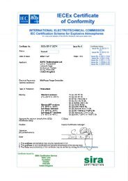
13) Certificates<br />
Description Mark Doc. ref<br />
Solenoid Housing type N EEx nA IIC T6 or T4 ETSS 03ATEX 1009<br />
Fuse Encapsulated 160mA EEx m II T4 ETSS 02ATEX 1004<br />
14) Documentation<br />
Description Doc. ref Rev.<br />
Vortex Cooler Control IP66 Box AGE-GE00-142 GA 1<br />
Vortex Cooler 24 VDC AVC-0000-007 1<br />
Vortex Cooler Controller 24 VDC AGE-WC00-176 1<br />
Vortex Cooler 110-230 Vac AVC-0000-006 1<br />
Vortex Cooler Controller 110-230 Vac AGE-WC00-177 1<br />
Vortex Cooler Handbook ML463<br />
<strong>Expo</strong> <strong>Technologies</strong> <strong>Ltd</strong><br />
Summer Road, Thames Ditton,<br />
Surrey KT7 0RH, UK<br />
T +44 (0)20 8398 8011<br />
F +44 (0)20 8398 8014
Declaration of<br />
Conformity<br />
S:\Files\QA\CERTS\C-OF-C\Cabinet Cooler CE SC007.doc<br />
With<br />
European<br />
Directives<br />
<strong>Expo</strong> <strong>Technologies</strong> <strong>Ltd</strong><br />
Summer Road<br />
Thames Ditton KT7 0RH UK<br />
This document confirms that<br />
Cabinet Coolers manufactured by<br />
<strong>Expo</strong> <strong>Technologies</strong> <strong>Ltd</strong> conform, as described, to the following<br />
European Directives and standards:-<br />
89/336/EEC Electromagnetic Compatibility Directive<br />
73/23/EEC Low Voltage Directive<br />
97/23/EC Pressure Equipment Directive<br />
Signed Date 16/11/2004<br />
Managing Director Confidential Assessment file reference SC007
<strong>Expo</strong> <strong>Technologies</strong> <strong>Ltd</strong>., Tel + 44 (0) 20 8398 8011<br />
Unit 2, The Summit, Fax + 44 (0) 20 8398 8014<br />
Hanworth Road, E-mail: sales@expoworldwide.com<br />
Sunbury-On-Thames,<br />
TW16 5DB<br />
<strong>Expo</strong> <strong>Technologies</strong> Inc., Tel: +1 888-NFPA-496<br />
9140 Ravenna Road Unit #3, Tel: +1 (440) 247 5314<br />
Twinsburg Fax: +1 (330) 487 0611<br />
OH 44087 E-mail: sales.na@expoworldwide.com<br />
USA<br />
www.expoworldwide.com