ML478 v4 - Expo Technologies
ML478 v4 - Expo Technologies
ML478 v4 - Expo Technologies

Create successful ePaper yourself
Turn your PDF publications into a flip-book with our unique Google optimized e-Paper software.
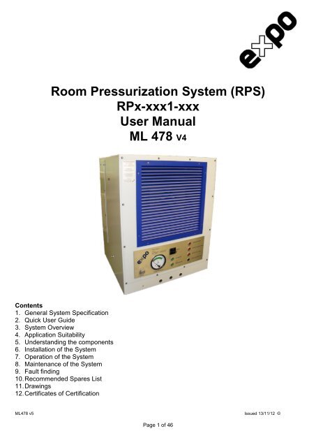
Room Pressurization System (RPS)<br />
RPx-xxx1-xxx<br />
User Manual<br />
ML 478 V4<br />
Contents<br />
1. General System Specification<br />
2. Quick User Guide<br />
3. System Overview<br />
4. Application Suitability<br />
5. Understanding the components<br />
6. Installation of the System<br />
7. Operation of the System<br />
8. Maintenance of the System<br />
9. Fault finding<br />
10. Recommended Spares List<br />
11. Drawings<br />
12. Certificates of Certification<br />
<strong>ML478</strong> v5 Issued 13/11/12 ©<br />
Page 1 of 46
Markings and Warnings<br />
Required for Rooms in Hazardous Areas in accordance with IEC60079-13<br />
Markings using equivalent text may be used.<br />
The isolating switch shall be clearly marked:<br />
“WARNING – Run fan for T min before energizing the installation,<br />
unless the atmosphere inside the room is known not to be hazardous.”<br />
Where T is the minimum specified time to purge the room.<br />
All doors to the pressurized room shall be clearly marked on the inside and the outside, by the<br />
following:<br />
“WARNING – Pressurized room – Keep door closed”<br />
Each infrequently used entrance to a room in a zone 2 area shall be marked to restrict access such<br />
as with the following:<br />
“AUTHORIZED PERSONNEL ONLY”<br />
An airlock shall be clearly marked with the following:<br />
“WARNING – Verify other door is closed before opening this door”<br />
Each entrance to a room where the protective gas is inert shall be clearly marked with the following:<br />
“DANGER – Room does not contain breathable air and is an asphyxiation hazard”<br />
Each entrance to a room where loss of pressurization could result in an alarm indicating an<br />
asphyxiation hazard from build-up of inert gas shall be clearly marked with the following:<br />
“DANGER – Do not enter when alarm sounds.<br />
Room does not contain breathable air and is an asphyxiation hazard”<br />
Each entrance to a room where loss of pressurization could result in an alarm indicating an explosion<br />
hazard from build-up of flammable gas or vapours shall be clearly marked with the following:<br />
“DANGER – Do not enter when alarm sounds,<br />
room contains a dangerous level of combustible gas and is an explosion hazard”<br />
<strong>ML478</strong> v5 Issued 13/11/12 ©<br />
Page 2 of 46
1 System Specification<br />
General Specification<br />
Classification For use in NEC 505 or ATEX Zone 2<br />
System Marking Ex nA nL nR [pz] IIC T4 Gc<br />
Room Pressure User adjustable via Flow potentiometer on User Interface Panel<br />
Fan Capacity 1800cfm (3000 m 3 /h ) for Single door or up to 3000cfm (5100 m 3 /h)<br />
for two 3’ x 7’ doors (0.91m x 2.13m)<br />
Fan Type ATEX Approved Backward Curved Centrifugal Ex II 2G c IIC T4<br />
Fan Motor Type ATEX Approved Induction Motor Ex II 2G e IIC T4<br />
Pressurizer Control Enclosure Restricted Breathing<br />
RPS Mounting method In-Room or Through-Wall<br />
Temperature Limits -20° C to + 40° C (-4° F to + 104°)<br />
Supply Air Ambient air (Or from remote source as required.)<br />
RPS Weight 120kg (265 lb)<br />
Sound Level 75dB(A) max at High Flow<br />
Electrical Specification<br />
System Supply Voltage 230 VAC nominal, limits are 180V to 264V, 1 Phase, 50/60 Hz<br />
System Power Consumption Less than 1.5 kW<br />
Fan Motor Rating 3~230/400V D/Y 50Hz 1.1kW, 3.2/1.85A 1290 RPM<br />
Outputs Volt Free (Dry) contacts: 1A 250Vac AC1<br />
Inputs Optoisolated; activate either by mechanical switch or by NPN<br />
transistor. Maximum current: 10 mA.<br />
Sensor Specification<br />
Room Pressure Sensor Differential diaphragm switch with gauge. Factory set point 25 Pa<br />
(0.1” w.c.)<br />
High Flow Sensor Differential diaphragm switch with 150 Pa (0.6” w.c.) rising set point.<br />
Materials of Construction<br />
System Enclosure Polyester powder coated mild (carbon) steel<br />
Indications and alarms<br />
Indicators visible on the front panel of the unit (See Figure 1, p6)<br />
System OK<br />
Pressure OK<br />
Pressure Alarm<br />
Forced Fan Shutdown<br />
Forced High Flow<br />
Users Volt Free Contacts<br />
See drawing SD7833 for user terminal connection.<br />
System output: lamp indicator and Volt Free (Dry) output contacts<br />
System output: lamp indicator and Volt Free (Dry) output contacts<br />
System output: lamp indicator and Volt Free (Dry) output contacts<br />
User input: input contacts and lamp indicator<br />
User input: input contacts and lamp indicator<br />
Volt Free Output Contacts Volt Free (Dry) contact for Buzzer (Buzzer supplied by others)<br />
<strong>Expo</strong> recommended part: EBU-0000-013<br />
Pressure Alarm<br />
System OK<br />
<strong>ML478</strong> v5 Issued 13/11/12 ©<br />
Page 3 of 46
2 Quick User Guide<br />
Installation<br />
� Mount the Room Pressurization System (RPS) as per the General Arrangement drawing (SYS-<br />
M000-032-GA).<br />
� Make Electrical connections as per applicable local Codes of Practice. Users Electrical hook up is<br />
shown in drawing SD7833<br />
� Always ensure the system has been installed as per the full instructions in the section of the<br />
manual titled ‘Installation of the System’.<br />
Operation of system<br />
� Once installed correctly turn on the power supply. It is important to note that when switching<br />
the unit off and on within a short period, the ‘System OK’ light will blink for 3 minutes after<br />
which the power may be recycled to start. This feature prevents damage to the frequency<br />
drive.<br />
� Adjust the flow on the User Interface Panel to achieve required room pressure as per information<br />
supplied in Start-Up Procedure<br />
If the system has not worked as expected check the installation thoroughly.<br />
Read the section in manual called “Operation of the System.”<br />
If an obvious problem has not been highlighted and corrected then follow the checks in the section “Fault Finding”.<br />
If the checks have been made and the system will still not work then please contact your local distributor or EXPO.<br />
3 System Overview<br />
Area Classification: NEC Class I Zone 2 or ATEX Zone 2 Category 3<br />
Applicable Directives: Local Codes of Practice, NEC 505, NFPA 496, EN 60079-0 and<br />
IEC 60079-13 (draft)<br />
The RPS generates a room pressure to prevent ingress of the external hazardous atmosphere.<br />
� The design of the RPS allows it to operate in a classified area.<br />
� The protective air is ambient air drawn from the rear of the RPS and it is the Users’<br />
responsibility to ensure that the protective air is free from hazardous gasses. The RPS<br />
features mounting holes on the rear of the unit at the air intake to which ducting can be fixed.<br />
System Description<br />
<strong>Expo</strong> Room Pressurization System is designed for the following applications, but may not be limited<br />
to:<br />
� Positively pressurize a room above atmospheric pressure.<br />
� Provide an outward velocity through opened door(s).<br />
� Prevent hazardous gas ingress from an external source.<br />
� The RPS is a z-Type pressurizer, ‘pz’. The RPS measures the difference between the<br />
pressure in the room and the atmosphere outside the room. The user sets the low-flow on the<br />
unit via the Flow adjust control knob on the User Interface Panel to ensure that a positive<br />
room overpressure is maintained. The air intake to the RPS is potentially from a classified<br />
area and it is the responsibility of the User to ensure the air supply is free of hazardous gases.<br />
<strong>ML478</strong> v5 Issued 13/11/12 ©<br />
Page 4 of 46
Start-up procedure<br />
1. Switch on the RPS with the Power disconnect switch on the User Interface Panel.<br />
2. An automatic Lamp Test will take place, which will see all the indicators on the User Interface<br />
Panel lighting up briefly.<br />
3. The RPS will require the Flow potentiometer on the User Interface Panel to be adjusted to the<br />
set point. The Pressure OK, Green Indicator shall remain illuminated. The Pressure Gauge<br />
shall be in the "Green Band" (above 25 Pa [0.1" w.c]). The User has 30 seconds in which to<br />
set the Flow (and thus desired pressure) to compensate for the individual room leakage rate.<br />
After 30 seconds High Flow will commence until room pressure is established.<br />
4. Refer to Section 7 “Operation of the System: Commissioning” to ensure correct airflow as per<br />
Local Codes of Practice.<br />
Normal operating conditions.<br />
The following system operating characteristics are considered normal and any deviation should be<br />
fully investigated by referring to the ‘Fault Finding’ section:<br />
1. The RPS (once set) will ensure that the room maintains an internal overpressure to prevent<br />
the ingress of the external atmosphere.<br />
2. Should the RPS pressure drop below the pre-set threshold of 25 Pa (0.1” w.c.) (due to a door<br />
being opened or for any other reason), after a preset delay of 10 seconds (to allow personnel<br />
to enter and exit the Pressurized Room) the RPS will:<br />
a) Engage High-Flow to ensure an outward air velocity of 0.3m/s (60fpm) across the<br />
doorway<br />
b) After an additional 20 seconds: Indicate an alarm condition both locally (visual<br />
indicator) and, if connected by the user, by switch contact to remote location<br />
c) Indicate alarm status via volt free contact which is available for the user to connect an<br />
alarm buzzer or indicate the alarm at a remote location (see Electrical Termination Box<br />
drawing SD7833 for buzzer contacts.) When the pressure differential drops below the<br />
25 Pa (0.1” w.c.) threshold, and the alarm contact is made, it can be silenced on the<br />
User Interface Panel by depressing the Alarm Silence button. This will not clear the<br />
alarm status or induce low flow, it only silences the buzzer.<br />
3. The action to be taken on alarm is to be determined by the owner in accordance with his risk<br />
assessment.<br />
4. When the pressure is restored in the Room (e.g. by closing the door) the RPS will reduce the<br />
flow rate to the low level again and the alarm will clear.<br />
5. The RPS features volt free input contacts which the user can use to Force Shutdown or Force<br />
High Flow. The breaking or making of these contacts will change the illumination status of the<br />
corresponding indicator's on the User Interface Panel (see Electrical Termination Box drawing<br />
SD7833)<br />
<strong>ML478</strong> v5 Issued 13/11/12 ©<br />
Page 5 of 46
System Running Conditions and Alarm Status.<br />
Figure 1 (The User Interface Panel)<br />
Normal Running: i.e. Flow setting is sufficient to maintain room pressure, the fan will run in low-flow<br />
mode and the following will occur:<br />
� The System OK and Pressure OK indicator will be illuminated.<br />
High Flow Running: i.e. A door has been open for more than 10 seconds or the flow setting is<br />
insufficient to maintain enough pressure to overcome room leakage or any other reason that would<br />
result in a loss of room overpressure for longer than 10 seconds, The high-flow mode will engage<br />
and the following will occur:<br />
� The System OK indicator will remain illuminated, The Pressure OK indicator will no longer be<br />
illuminated and the Pressure Alarm indicator will illuminate. The Pressure Alarm volt free<br />
contact will close and the External Buzzer volt free contact will close, unless silenced via<br />
Audible Alarm Silence button on User Interface Panel. The Audible Alarm Silence feature only<br />
overrides the External Buzzer contact. It does not affect the Pressure OK and Pressure Alarm<br />
indicators, nor does it affect the remote Pressure Alarm contact.<br />
High Flow is maintained until the room overpressure is reestablished, at which time the System will<br />
revert to normal running conditions (i.e. low flow).<br />
Fan/System Failure: i.e. There is a failure to achieve sufficient flow through the unit due to any<br />
reason like a blocked filter, restriction in ducting, fan failure, faulty flow switch, electrical control<br />
failure etc.<br />
� The System OK indicator will no longer be illuminated and the System OK volt free output<br />
contact will go open circuit.<br />
Forced Fan Shutdown: i.e. An external hazardous gas is detected at the inlet, mechanical damage<br />
is observed etc.<br />
� The user can connect an external volt fee input contact to the unit as per the Electrical<br />
Termination Box drawing SD7833. When the external input is open circuit the corresponding<br />
indicator on the User Interface Panel will illuminate. When this contact is not used a link within<br />
the Electrical Termination Box must be used<br />
Forced High Flow: i.e. An internal hazardous gas is detected in the room, additional ventilation is<br />
required etc.<br />
� The user can connect an external volt fee input contact to the unit as per the Electrical<br />
Termination Box drawing SD7833. When the external input is closed the corresponding<br />
indicator on the User Interface Panel will illuminate.<br />
<strong>ML478</strong> v5 Issued 13/11/12 ©<br />
Page 6 of 46
4 Application Suitability<br />
This version is designed for use in a Zone 2 classified environment. The RPS is designed to<br />
pressurize the interior of a room by introducing ambient air. This equipment is designed for use<br />
under normal industrial conditions of ambient temperature, humidity and vibration. Please consult<br />
<strong>Expo</strong> before installing this equipment in conditions that may cause stresses beyond normal industrial<br />
conditions.<br />
Materials of construction:<br />
� Stainless Steel � Nylon<br />
� Mild (carbon) Steel � Polyurethane<br />
� Brass � Acrylic<br />
� Aluminum � Silicone Rubber<br />
� Bronze � Neoprene<br />
� EPDM � Epoxy<br />
5 Understanding the main components<br />
The Filter<br />
The RPS is designed to provide particle-free ambient air to the room. The air is drawn in to the rear<br />
of the enclosure and then filtered through a fine filter with a G4 classification and a MERV 8 rating.<br />
The Fan Unit<br />
The RPS uses an ATEX rated aluminium impeller and induction fan motor unit approved for use in<br />
hazardous areas.<br />
Inlet Stack<br />
Fresh air is drawn in from outside the room. All flanges and joints shall be sealed and free of leaks<br />
and inlet stack or ducting shall be protected against foreseeable mechanical damage. The source of<br />
air shall be determined from the nature of the process and physical layout and shall not normally be<br />
from a classified location. Applicable Standards and local Codes of Practice shall be adhered to.<br />
Inlet tubing must be equal or greater than 350mm or 13.8” in diameter or equivalent rectangular area.<br />
For user supplied stack or ducting longer than 3m (9.8’) and/or with more than one bend,<br />
consult <strong>Expo</strong> to ensure ability to provide sufficient flow is not impaired.<br />
Room Pressure Switch<br />
To prevent spurious alarms, a factory-set delay is programmed into the System Control Unit. When<br />
the room overpressure drops to below 25 Pa (0.1” w.c.) and remains below for 10 seconds, the<br />
System Control Unit (SCU) initiates high flow and will remain in this state until Room Pressure has<br />
reestablished. The users’ volt free contacts for the Pressure Alarm and Buzzer remain unchanged<br />
during the 10 second delay.<br />
Flow Sensor<br />
The RPS is fitted with a differential diaphragm type pressure switch which is set to alarm if the RPS<br />
does not reach the correct pressure inside the RPS enclosure when high flow is engaged. This will<br />
indicate a fan flow failure. Should the fan fail or a lack of flow cause the switch to alarm, the System<br />
OK indicator will no longer be illuminated and the System OK volt free contact will go open circuit.<br />
<strong>ML478</strong> v5 Issued 13/11/12 ©<br />
Page 7 of 46
The System Control Enclosure<br />
The System Control Unit (SCU) is housed within this enclosure. The System Control Enclosure is<br />
located inside the RPS enclosure. The enclosure contains no user serviceable components.<br />
Opening the enclosure may invalidate the certificate and should only be opened by trained <strong>Expo</strong><br />
service engineers.<br />
Routine testing may be required to ensure the sealing integrity of the restricted breathing enclosure<br />
has not been compromised. A test port is provided for this purpose. Routine testing frequency is<br />
determined by the Users’ operating procedures and should consider operating environment, thermal<br />
cycling, exposure etc. For routine testing the procedure shall be in accordance with the current<br />
applicable standard for restricted breathing.<br />
Currently the test is prescribed as follows:<br />
� Using the test port provided, induce a vacuum in the enclosure of 300 Pa below atmospheric.<br />
Seal the test port tube.<br />
� The enclosure shall still hold at least 270 Pa below atmospheric after 14 seconds. Ensure test<br />
equipment is absolutely leak free.<br />
Where restricted breathing test fails, consult <strong>Expo</strong>.<br />
6 Installation of the System<br />
Room Pressurization System (RPS)<br />
The RPS must be fitted to the room using suitable fasteners and the supplied support brackets<br />
where required. There are two methods of fitting the unit: In-Room and Through-Wall mount. The<br />
unit is supplied with a removable fixing frame and fixing points for both methods. For Through-Wall<br />
the default fixing frame position is shown on the General Arrangement drawing SYS-M000-032-GA.<br />
As per common engineering practice, the room wall should be sufficiently strengthened and sufficient<br />
thread engagement is to be provided in the strengthened room wall structure. When mounted, care<br />
should be taken where shock loading could occur during transportation. Suitable measures<br />
should be in place to mitigate any adverse affects caused by shock loading on the RPS including all<br />
internal components. Failure to adhere to the aforementioned guidelines may result in failures<br />
or damages falling beyond the scope of the manufacturers guarantee.<br />
Ensure that inlet ducting or stack flanges and joints are sealed and free of leaks and are protected<br />
against foreseeable mechanical damage. Inlet tubing must be equal or greater than 350mm or 13.8”<br />
in diameter or equivalent rectangular area. Refer to drawing SYS-M000-032-GA for inlet connection<br />
bushing for 1 door system and SYS-M000-035-GA for 2 door system. For user supplied stack or<br />
ducting longer than 3m (9.8’) and/or with more than one bend, consult <strong>Expo</strong> to ensure ability<br />
to provide sufficient flow is not impaired.<br />
When mechanical installation is complete, the Users’ electrical connections are made by opening the<br />
hinged front door to access the Electrical Termination Box. The Power Disconnect Switch must be in<br />
the ‘Off’ position, and the door fasteners must be removed. The conduit/cable entry bushes at the<br />
front of the enclosure are threaded 3/4” NPT(F) for the user to fit hard conduit and/or cable glands<br />
(refer to drawing SYS-M000-032-GA). A minimum IP54 seal is required at conduit/ cable entries<br />
and suitable glands or conduit stopper box’s shall be used. Unused entries shall be blanked<br />
with suitable blanking plugs. The user must then carry out electrical terminations as required per<br />
drawing SD7833 where recommended conductor sizes are found. Screws should be tightened to a<br />
setting of 0.5 N.m.<br />
<strong>ML478</strong> v5 Issued 13/11/12 ©<br />
Page 8 of 46
On completion the user is to replace the Electrical Termination Box lid and RPS door ensuring that<br />
all screws are in place and are sufficiently tightened.<br />
<strong>ML478</strong> v5 Issued 13/11/12 ©<br />
Page 9 of 46
7 Operation of the RP System<br />
<strong>ML478</strong> v5 Issued 13/11/12 ©<br />
Page 10 of 46
Initial Commissioning<br />
� Refer to ‘Installation of the System’ and ensure the system has been installed correctly.<br />
� Ensure the filter is clean and in position and filter access covers are securely in place.<br />
� The RPS door and all other removable covers are closed properly.<br />
Commissioning (Putting into use)<br />
� Ensure all installation requirements are met.<br />
� Ensure all openings (doors, gland plates etc.) to the Room which is being pressurized are<br />
shut.<br />
� Apply the appropriate power to the system<br />
� Switch Power on at User Interface Panel. It is important to note that when switching the<br />
unit off and on within a short period, the ‘System OK’ light will blink for 3 minutes after<br />
which the power may be recycled to start. This feature prevents damage to the<br />
frequency drive.<br />
� Adjust the Flow potentiometer on the User Interface Panel until the Pressure Gauge needle is<br />
in the ‘Green Band’ (above 25 Pa [0.1" w.c]) and the green ‘Pressure OK’ indicator is<br />
illuminated.<br />
� After Start-up the User has 30 seconds in which to set the Flow (and thus desired pressure) to<br />
compensate for the individual room leakage rate. After 30 seconds, if the Room Pressure is<br />
below 25 Pa [0.1" w.c] High Flow will commence. When room pressure is established, the<br />
RPS will resume Low Flow.<br />
To ensure correct clean airflow as per Local Codes of Practice:<br />
� With the Room Pressure set around 50 Pa, slowly turn the Flow adjust knob counterclockwise<br />
until the pressure is just above 25 Pa. This step must be performed on a falling pressure.<br />
� Allow the flow to stabilize for a minute.<br />
� Read off the Room Pressure from the gauge and the Fan Speed in ‘%’ on the Flow adjuster<br />
knob by rounding down to the next lowest increment i.e. if on 54 % use 50 %.<br />
� On Graph XGR-PTD0-xxx (use correct graph for 1 or 2 door system), draw a horizontal line<br />
at the Room Pressure set above i.e. 26 Pa. Where this line intersects the corresponding Fan<br />
Speed curve set above (i.e. 50% curve) draw a vertical line down and read off the Flow rate<br />
on the horizontal axis.<br />
� To increase/ decrease the Flow rate at a desired Room Pressure, the rate of room leakage<br />
can be altered e.g. higher room leakage will require higher flow to pressurize the room to the<br />
desired level. The room leakage rate may be altered by adjusting the overall sealing quality of<br />
the room i.e. entry apertures, gland plates, door seals etc.<br />
Provided the system has been installed correctly and the initial system checks described in the<br />
previous section have been performed, the system is now ready for continuous use with little or no<br />
user input or maintenance required.<br />
<strong>ML478</strong> v5 Issued 13/11/12 ©<br />
Page 11 of 46
8 Maintenance of the system<br />
The maintenance recommended for the system is as follows, supplemented by any additional local<br />
requirements imposed by the local Code of Practice.<br />
<strong>Expo</strong> recommends that the following checks are undertaken regularly:<br />
Part Frequency Procedure<br />
Filter 1 months (minimum)<br />
inspection with 6<br />
month replacement<br />
frequency or more<br />
often as required<br />
depending on the<br />
degree of pollution.<br />
Indicator's Regular checking as<br />
per Users’<br />
maintenance plan<br />
Fan &<br />
motor<br />
assembly<br />
Fan<br />
impeller<br />
Restricted<br />
breathing<br />
enclosure<br />
At least every 6<br />
months or upon signs<br />
of wear or more<br />
frequently per Users’<br />
maintenance plan.<br />
Regular inspection per<br />
Users’ maintenance<br />
plan depending on the<br />
degree of pollution.<br />
Routine checking as<br />
per Users’<br />
maintenance plan<br />
Ensure RPS is off. Open a filter access panel on either side of<br />
the RPS. Replace the filter and ensure all access panel seating<br />
surfaces and gasketing is free from sand/dirt. Ensure filter is in<br />
correct flow orientation (see flow direction marking on filter).<br />
Replace access panels and ensure that they are properly<br />
secured.<br />
Switch RPS off for 3 minutes and switch RPS on again, visually<br />
inspect that ALL indicator's on User Interface Panel illuminate<br />
for 3 seconds during automatic Indicator Test at startup.<br />
The fan motor is equipped with bearings with ‘lifetime<br />
lubrication’ and requires no maintenance. At least every 2 years<br />
the motor winding insulation resistance should be measured<br />
and should be above 1.5MOhm. Upon signs of wear or 35 000h<br />
a bearing exchange is required. Take note of any abnormal<br />
operating noise or vibration. Fan motor maintenance may only<br />
be carried out by the fan manufacturer.<br />
Always ensure the system is isolated and fan is stationary.<br />
Inspect impeller blades for dirt and pollution build-up. Clean<br />
impeller with a damp cloth only. Do not use any aggressive or<br />
solvent cleaners.<br />
For more detail, refer to Section 5: The System Control<br />
Enclosure<br />
<strong>ML478</strong> v5 Issued 13/11/12 ©<br />
Page 12 of 46
9 Fault Finding<br />
If the system does not behave in the manner described in any of the above there is a fault. Some of<br />
the more likely faults are dealt with below. If a cure cannot be affected by following the procedure<br />
shown below please call <strong>Expo</strong> or your distributor for further assistance.<br />
Symptom Possible Fault Resolution<br />
System does not<br />
start up<br />
System OK light<br />
blinks continually<br />
� There is no power to the system � Check that appropriate power<br />
is applied to the system<br />
� Internal fuse may have blown � Consult <strong>Expo</strong><br />
� 3 minute ‘Power On’ has not<br />
elapsed, refer to Operation of the<br />
System<br />
Fan keeps failing � Flow sensor fault<br />
Room Pressure<br />
alarm keeps coming<br />
on or system stays<br />
in High Flow<br />
System stays in low<br />
flow<br />
An indicator does<br />
not illuminate during<br />
Indicator Test<br />
10 Recommended Spares List<br />
� Motor or impeller damage causes<br />
flow to drop off<br />
� Excessive room leakage or Flow<br />
too low<br />
<strong>ML478</strong> v5 Issued 13/11/12 ©<br />
Page 13 of 46<br />
� After 3 minutes, recycle the<br />
Power i.e. Switch Off then On<br />
once<br />
� Replace loose pneumatics<br />
tube or faulty sensor (consult<br />
<strong>Expo</strong>)<br />
� Investigate fan motor for any<br />
visual obstructions or damage.<br />
(Consult <strong>Expo</strong>)<br />
� Ensure room is airtight Or<br />
Increase setting on Flow<br />
adjust knob.<br />
� Faulty room pressure sensor � Consult <strong>Expo</strong><br />
� Faulty variable speed drive � Consult <strong>Expo</strong><br />
� Loose wiring connection to<br />
indicator contact<br />
� Reconnect Wiring<br />
� Faulty indicator � Replace damaged indicator<br />
Part Description <strong>Expo</strong> part number<br />
Filter Replaceable G4 filter HF1-A000-004<br />
Fan Motor Assembly Motor and fan impeller assembly AGE-GE00-134<br />
Red Indicator User Interface Panel Indicator ELA-D000-013<br />
Green Indicator User Interface Panel Indicator ELA-D000-014<br />
Alarm Silence Pushbutton Ø22 Black Pushbutton MBU-Z000-006<br />
Room Pressure Gauge Pressure Gauge & Switch, factory set at 25 Pa<br />
(0.1” w.c) falling<br />
HGA-0000-055<br />
Fan High Flow Sensor Differential Diaphragm pressure switch, factory ESW-0PS0-008<br />
set at 150 Pa (0.6” w.c.) rising.<br />
Flow Adjust potentiometer Panel mount 10K single turn potentiometer ERE-DMK0-10K<br />
Front grille Aluminium air inlet grille MLV-D000-000<br />
For all other parts or faults, locate applicable identification tag and consult <strong>Expo</strong> to discuss<br />
appropriate action.
11 Drawings and Diagrams<br />
The following drawings are attached:<br />
Title Drawing Number Sheet(s)<br />
1 Door System Low Flow Range XGR-PTD0-000 1 of 1<br />
1 Door System Full Flow Range XGR-PTD0-001 1 of 1<br />
2 Door System Low Flow Range XGR-PTD0-002 1 of 1<br />
2 Door System Full Flow Range XGR-PTD0-003 1 of 1<br />
1 Door Room Pressurizer General Assembly SYS-M000-032 3 of 3<br />
2 Door Room Pressurizer General Assembly SYS-M000-035 2 of 2<br />
Electrical Termination Box SD7833 1 of 1<br />
Terminal Box Label MLA-PAP0-062 1 of 1<br />
Fire and Smoke Damper Label (where fitted) Figure.3 1 of 1<br />
<strong>ML478</strong> v5 Issued 13/11/12 ©<br />
Page 14 of 46
Figure.3 Fire and Smoke Damper Label<br />
(where fitted)<br />
<strong>ML478</strong> v5 Issued 13/11/12 ©<br />
Page 26 of 46
12 Certificates of Certification<br />
The following certificates are attached:<br />
Title Certificate Number Sheet(s)<br />
Fan Motor Certificate PTB08ATEX 3062 4 of 4<br />
Room Pressurizer System Certificate 1 of 1<br />
Declaration of Conformity 1 of 1<br />
Fire and Smoke Damper Certificate SASF080134 2 of 2<br />
(where fitted)<br />
Actuator Certificate (where fitted) PTB-04ATEX 2106 3 of 3<br />
Fire Sensor Certificate (where fitted) PTB 10 ATEX 2006 3 of 3<br />
Junction Box Certificate (where fitted) SIRA99ATEX3173 6 of 6<br />
<strong>ML478</strong> v5 Issued 13/11/12 ©<br />
Page 27 of 46
12 Certificates of Certification<br />
The following certificates are attached:<br />
Title Certificate Number Sheet(s)<br />
Fan Motor Certificate PTB08ATEX 3062 4 of 4<br />
Room Pressurizer System Certificate 1 of 1<br />
Declaration of Conformity 1 of 1<br />
Fire and Smoke Damper Certificate SASF080134 2 of 2<br />
(where fitted)<br />
Actuator Certificate (where fitted) PTB-04ATEX 2106 3 of 3<br />
Fire Sensor Certificate (where fitted) PTB 10 ATEX 2006 3 of 3<br />
Junction Box Certificate (where fitted) SIRA99ATEX3173 6 of 6<br />
<strong>ML478</strong> <strong>v4</strong> Issued 28/09/10 ©<br />
Page 26 of 45
Product Description
<strong>Expo</strong> <strong>Technologies</strong> Ltd., Tel + 44 (0) 20 8398 8011<br />
Unit 2, The Summit, Fax + 44 (0) 20 8398 8014<br />
Hanworth Road, E-mail: sales@expoworldwide.com<br />
Sunbury-On-Thames,<br />
TW16 5DB<br />
<strong>Expo</strong> <strong>Technologies</strong> Inc., Tel: +1 888-NFPA-496<br />
9140 Ravenna Road Unit #3, Tel: +1 (440) 247 5314<br />
Twinsburg Fax: +1 (330) 487 0611<br />
OH 44087 E-mail: sales.na@expoworldwide.com<br />
USA<br />
www.expoworldwide.com