Engineered Electric Heat - Control And Power
Engineered Electric Heat - Control And Power
Engineered Electric Heat - Control And Power

You also want an ePaper? Increase the reach of your titles
YUMPU automatically turns print PDFs into web optimized ePapers that Google loves.
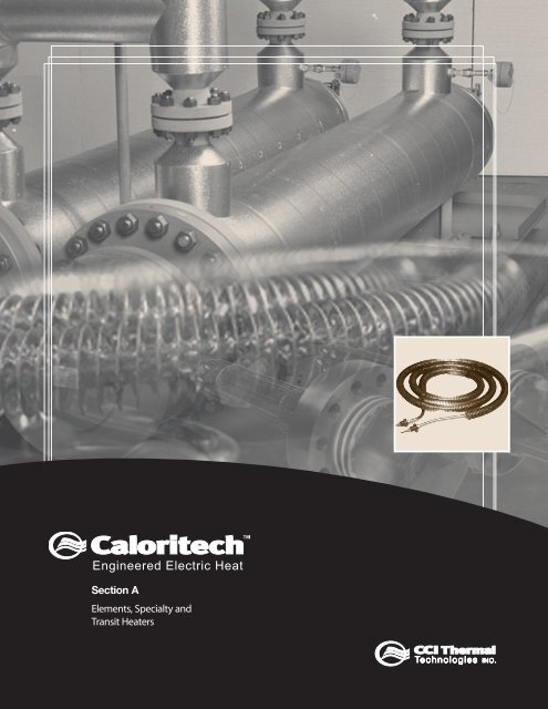
<strong>Engineered</strong> <strong>Electric</strong> <strong>Heat</strong><br />
Section A<br />
Elements, Specialty and<br />
Transit <strong>Heat</strong>ers
Contents<br />
A<br />
Section A<br />
Product Type Page<br />
Band <strong>Heat</strong>ers A36 & A40<br />
Bolt <strong>Heat</strong>ers A39<br />
Calvane <strong>Heat</strong>ers A41<br />
Cartridge <strong>Heat</strong>ers A22 - A27<br />
Cast-in <strong>Heat</strong>ers A36 - A37<br />
Drum <strong>Heat</strong>ers A38<br />
Finned Tubular <strong>Heat</strong>ers A8, A18 - A21<br />
Hot Plate <strong>Heat</strong>ers A38<br />
Mitosis <strong>Heat</strong>ers A45<br />
Strip and Finned Strip <strong>Heat</strong>ers A28 - A35<br />
Transit <strong>Heat</strong>ers A42 - A44<br />
Tubular <strong>Heat</strong>ers A6 - A16<br />
Technical Data Section D<br />
D32 - D50<br />
Catalog Prefix Page<br />
BA A35<br />
BC A36<br />
C A23 - A28<br />
CA A35<br />
D A38<br />
FS A28 - A29, A34 - A35<br />
FV A41<br />
HPH A38<br />
HX A6 - A16<br />
IX A6 - A16, A39<br />
KX A7, A18 - A21<br />
MC A36 - A37<br />
MH A45<br />
SA A35<br />
SD A28 - A29, A32 - A33<br />
SS A28 - A31<br />
TB A40<br />
<strong>Engineered</strong> <strong>Electric</strong> <strong>Heat</strong>
CCI Thermal Technologies Inc. is a leader in advanced<br />
heating solutions. We offer our customers the broadest<br />
based industry knowledge, expertise and industrial heating<br />
products. In addition to our focus on product quality, we are<br />
setting a new industry standard for customer service.<br />
At our facilities across North America we manufacture<br />
five of the top brands in industrial heating:<br />
•<br />
•<br />
•<br />
•<br />
•<br />
Cata-Dyne - Explosion-Proof Gas Catalytic <strong>Heat</strong>ers<br />
Ruffneck - <strong>Heat</strong>ers for the Harshest Environments<br />
Caloritech - <strong>Engineered</strong> <strong>Electric</strong> <strong>Heat</strong><br />
Norseman - <strong>Electric</strong> Explosion-Proof <strong>Heat</strong>ers<br />
DriQuik - Curing Solutions<br />
This catalog presents the products manufactured by<br />
CCI Thermal Technologies Inc. under the Caloritech brand<br />
name.<br />
Caloritech products are built to any one of five<br />
nationally recognized quality control standards at our<br />
Edmonton, Alberta<br />
CCI Thermal Technologies Inc.<br />
Oakville, Ontario<br />
Orillia, Ontario Greensburg, Indiana<br />
<strong>Engineered</strong> <strong>Electric</strong> <strong>Heat</strong><br />
modern manufacturing facilities in Oakville and Orillia,<br />
Ontario, Canada. The majority of Caloritech equipment<br />
(where applicable) is U.L. recognized/listed, C.S.A. approved<br />
or CE/ATEX certified. We manufacture most of our own<br />
pressure vessels, we have ASME U, S, and H stamps, and<br />
we can provide National Board registration. In addition to<br />
the standard product models listed in this catalog, our team<br />
of experienced engineers and designers is well equipped to<br />
handle custom projects for specific and unique applications.<br />
We have accredited design expertise to complement the<br />
custom engineered aspect of our business and we hold<br />
a corporate Certificate of Authorization from Professional<br />
Engineers Ontario to practice professional engineering in the<br />
design and application of our equipment.<br />
We invite you to visit www.ccithermal.com to view<br />
the broad range of innovative industrial heating products<br />
manufactured by CCI Thermal Technologies Inc.<br />
A
CCI Thermal Catalogs at a Glance<br />
A<br />
Caloritech Catalog: Section A<br />
Elements and Specialty <strong>Heat</strong>ers<br />
calvane heaters, tubular heaters,<br />
bolt heaters, tubular band heaters,<br />
mitosis heaters, finned tubular<br />
heaters, cartridge heaters, strip and<br />
finned strip heaters, hot plate/drum<br />
heaters, cast-in heaters, transit heaters.<br />
Caloritech Catalog: Section B<br />
Immersion <strong>Heat</strong>ers<br />
screwplug heaters, domestic<br />
immersion heaters, urn heaters,<br />
flange heaters, over-the-side<br />
heaters, pipe insert heaters, gate<br />
and gain heaters.<br />
Caloritech Catalog: Section C<br />
Air and Space <strong>Heat</strong>ers<br />
infrared radiant heaters, panel<br />
heaters, convection heaters,<br />
commercial and explosion-proof<br />
duct heaters, unit heaters, gate<br />
and gain heaters.<br />
Caloritech Catalog: Section D<br />
<strong>Engineered</strong> Products<br />
circulation heaters, heat transfer<br />
systems, custom engineered<br />
products, panel heaters, control<br />
panels, technical data.<br />
Caloritech Catalog: Section E<br />
Boilers<br />
hot water boilers, steam boilers,<br />
condensate receiver packages,<br />
blow off tanks, packaged<br />
circulation heaters, calorifiers.<br />
Caloritech Catalog: Section F<br />
<strong>Control</strong>s<br />
electronic controls, industrial<br />
thermostats, explosion-proof<br />
thermostats, thermoswitches,<br />
thermocouples and thermowells,<br />
x-Max ® explosion-proof housings.<br />
<strong>Engineered</strong> <strong>Electric</strong> <strong>Heat</strong>
Cata-Dyne Catalog<br />
explosion-proof infrared gas<br />
catalytic heaters, high temperature<br />
industrial infrared heaters, infrared<br />
gas catalytic heating systems,<br />
accessories.<br />
Norseman Catalog<br />
natural convection explosion-proof<br />
heaters, forced air explosion-proof<br />
heaters, thermostats.<br />
Putting Safety First<br />
CCI Thermal has always been committed to the safety<br />
and well being of our customers.<br />
We are familiar with the safety regulations of heating<br />
products in a wide variety of environments and ensure that<br />
our products meet or exceed the requirements for their<br />
applications.<br />
CCI Thermal takes great pride in its lines of certified<br />
products.<br />
C US<br />
CCI Thermal Catalogs at a Glance<br />
<strong>Engineered</strong> <strong>Electric</strong> <strong>Heat</strong><br />
Ruffneck Catalog<br />
explosion-proof electric air<br />
heaters, heat-exchanger unit<br />
heaters, corrosion-resistant<br />
washdown unit heaters,<br />
convection heaters, thermostats.<br />
DriQuik Catalog<br />
long, medium and short<br />
wavelength infrared ovens and<br />
emitters, dusters, cooling tunnels<br />
and control panels.<br />
Visit us at www.ccithermal.com<br />
Our web site offers on-line PDF catalogs, product<br />
specifications, installation manuals, and technical<br />
documentation 24 hours a day. Additionally, you will find easy<br />
access to anyone of our factory representatives, regional<br />
sales managers or customer service personnel.<br />
Quality<br />
All our business processes are steered by the principles<br />
of ISO 9001:2000, providing an operational framework that<br />
places emphasis on continual improvement and customer<br />
satisfaction.<br />
A
Tubular <strong>Heat</strong>ers<br />
A<br />
Tubular <strong>Heat</strong>ers Types HX and IX<br />
CCI Thermal Technologies Inc. has one factory<br />
dedicated to the production of the highest quality tubular<br />
heating elements. We use only the best commercially<br />
available materials and we use design parameters proven<br />
to maximize element life expectancy.<br />
Operating Principles<br />
Refer to Fig. 1 page A8 for typical heating element<br />
construction. The coil and terminal pins are electrically<br />
isolated from the outer metal sheath with highly compacted<br />
magnesium oxide which also serves as a conductor for the<br />
heat generated by the coil.<br />
When voltage is applied to the heating element terminals,<br />
an electric current passes through the heating element<br />
resistance coil. <strong>Heat</strong> is produced as wattage in accordance<br />
with Ohm’s law where the wattage equals I 2 R (current<br />
squared x coil resistance).<br />
Watt Density<br />
Watt density is defined as the watts per unit of surface<br />
area of the heated section of the heating element. The<br />
selection of the ideal watt density for a particular application<br />
is the most important parameter affecting heating element<br />
service life.<br />
All heat generated by the element resistance coil must<br />
be transferred from its sheath so that a balance is maintained.<br />
If the transferring medium is poor, the element may reach a<br />
high temperature before a sufficient temperature gradient is<br />
developed to reach thermal balance.<br />
Since watt density also determines the temperature<br />
gradient between the sheath and the resistance coil, it is<br />
essentially the watt density that sets the resistance coil<br />
temperature.<br />
Life Expectancy<br />
Normal life expectancy depends mainly on the resistance<br />
coil operating temperature (see Fig. 1) which is a function of<br />
the sheath operating temperature and the wattage per unit<br />
heated length of element.<br />
Factors such as cycling frequency will also affect life.<br />
Sheath Materials<br />
Sheath material selection ranks next to watt density<br />
in importance. The sheath must withstand the corrosive<br />
and temperature effects of its environment. For instance,<br />
elements designed for operation in water will generally fail<br />
if operated in air.<br />
Fortunately, many different sheath materials are available,<br />
making the tubular heater suitable for the vast majority of<br />
heating applications.<br />
FIG. 1 - Life vs. Coil Temperature (Typical)<br />
LIFE (HOURS)<br />
100000<br />
80000<br />
60000<br />
40000<br />
20000<br />
10000<br />
8000<br />
6000<br />
4000<br />
2000<br />
1000<br />
800<br />
600<br />
400<br />
200<br />
100<br />
Sizes and Shapes<br />
We offer a broad selection of element sizes and shapes<br />
to suit most any requirement. Larger diameter elements<br />
must be used for high voltage applications. Although<br />
practical considerations limit length, we can splice selected<br />
diameter elements to achieve continuous lengths in excess<br />
of 50 meters (2000 ins.).<br />
In most applications, the elements are formed at the<br />
factory in a series of loops or coils. Elements require<br />
furnace annealing prior to bending.<br />
Insulation Resistance<br />
If an unsealed element is to be installed in a damp area,<br />
the element insulation resistance to ground may decrease<br />
and, in severe cases, approach zero ohms. Elements with<br />
low insulation resistance have high leakage currents which,<br />
under certain circumstances, could be hazardous. Factory<br />
installed seals which prevent moisture from entering at the<br />
terminal ends of the element are available.<br />
Dielectric Strength Tests<br />
One hundred percent (100%) of the elements we<br />
manufacture are dielectric strength tested before they are<br />
released for shipment. This test, conducted at many times<br />
the intended operating voltage of the element, insures that<br />
the heater will not “short-out” during normal life.<br />
<strong>Engineered</strong> <strong>Electric</strong> <strong>Heat</strong><br />
1550 1650 1750 1850 1950 2050 2150<br />
WIRE TEMPERATURE (°F)<br />
800 850 900 950 1000 1050 1100 1150<br />
WIRE TEMPERATURE (°C)<br />
Types HX and IX
Types HX and IX<br />
Application<br />
Tubular elements of proper rating, material and shape<br />
can be used in most heating applications requiring process<br />
temperatures to 750°C (1382°F).<br />
Many of the heaters listed in this catalog utilize tubular<br />
elements as the heat source.<br />
Tubular elements may be clamped, immersed, cast into<br />
metal or spaced away from the work as radiant heaters.<br />
Elements can also be positioned in ducts or vessels for<br />
heating air or other gases.<br />
Features<br />
• Easy to install<br />
• Available in a wide variety of sheaths, diameters and<br />
ratings<br />
• <strong>Heat</strong> can be located exactly where required<br />
• Can be formed to practically any shape<br />
• Compact<br />
• Easy to control to provide heat only when required<br />
• Low maintenance and long life<br />
• Excellent internal electrical insulation and heat<br />
conduction<br />
• <strong>Electric</strong>ally isolated sheath<br />
Construction<br />
HIGH PURITY<br />
MAGNESIUM OXIDE<br />
FULLY COMPACTED<br />
COLD<br />
END<br />
NICKEL CHROMIUM<br />
RESISTANCE COIL<br />
CONCENTRICALLY<br />
POSITIONED<br />
OVERALL<br />
LENGTH<br />
SHEATH<br />
LENGTH<br />
<strong>Engineered</strong> <strong>Electric</strong> <strong>Heat</strong><br />
Catalog Numbers<br />
We assign a unique catalog number to all elements we<br />
manufacture (where practical). One of three prefixes is used<br />
to designate which type of element has been supplied as<br />
follows:<br />
HEATED<br />
LENGTH<br />
PROTECTIVE METAL<br />
SHEATH ELECTRICALLY<br />
ISOLATED<br />
PREFIX TYPE<br />
FIG. 1 - Tubular Element Features and Components<br />
HX straight, unfinned<br />
IX formed unfinned<br />
KX any finned element<br />
HELIARC WELDED<br />
COIL-PIN JUNCTION<br />
Tubular <strong>Heat</strong>ers<br />
COLD<br />
END<br />
SEALING<br />
COMPOUND<br />
(OPTIONAL)<br />
INSULATOR<br />
TYPICAL<br />
TERMINAL<br />
A
Tubular <strong>Heat</strong>ers<br />
A<br />
Factory Bending<br />
Tubular heaters can be factory formed to virtually any<br />
shape. Inside bending diameters as small as one element<br />
diameter are sometimes possible. Figures 1 to 11 illustrate<br />
some of the most commonly used element shapes. If your<br />
application can be satisfied with one of these shapes,<br />
you may wish to refer to these figures when ordering or<br />
requesting pricing information.<br />
FIG. 3<br />
W R2 D<br />
FIG. 4<br />
FIG. 6 FIG. 7<br />
W<br />
R 1<br />
R 1<br />
R 1<br />
F<br />
F<br />
B<br />
FIG. 9 FIG. 10<br />
B<br />
B<br />
C<br />
R 3<br />
R 2<br />
D<br />
D<br />
R 1<br />
R 2<br />
W<br />
R 1<br />
R 1<br />
R 2<br />
F<br />
B<br />
R 2<br />
F<br />
R 3<br />
E<br />
R 3<br />
D<br />
H<br />
R 1 D<br />
B<br />
R<br />
1<br />
B<br />
R<br />
2<br />
E<br />
D<br />
<strong>Engineered</strong> <strong>Electric</strong> <strong>Heat</strong><br />
FIG. 1<br />
FIG. 2<br />
FIG. 5<br />
W<br />
FIG. 8<br />
FIG. 11<br />
A DIA.<br />
R 1<br />
R D<br />
R 1<br />
R 2<br />
B<br />
B<br />
R 3<br />
Typical Shapes<br />
D<br />
R 2<br />
R 4<br />
F H<br />
B<br />
R<br />
F<br />
D<br />
B<br />
H<br />
N = Number of turns<br />
D<br />
H<br />
R<br />
D<br />
H
Typical Installations Tubular <strong>Heat</strong>ers<br />
FIG. 12 - In ovens or cabinets FIG. 13 - In ducts<br />
FIG. 14 - In pipe wells<br />
FIG. 15 - High wattage resistors or<br />
load banks<br />
FIG. 18 - Clamped to walls, hoppers<br />
and pipes<br />
FIG. 21 - Cast-in to iron, aluminum<br />
or copper<br />
FIG. 16 - To radiate heat FIG. 17 - Immersed in liquids<br />
FIG. 19 - In drilled holes in plates or<br />
cylinders<br />
FIG. 22 - Bent to conform to system<br />
geometry<br />
<strong>Engineered</strong> <strong>Electric</strong> <strong>Heat</strong><br />
FIG. 20 - Sandwiched between<br />
plates<br />
FIG. 23 - In finned heater<br />
assemblies<br />
A
Tubular <strong>Heat</strong>ers<br />
Selection<br />
Most tubular elements are made-to-order. The following<br />
procedure (Step 1 to Step 9) will simplify the selection of the<br />
element best suited to your needs. If you need assistance<br />
we will, without obligation, determine your kW requirements<br />
and provide design sketches.<br />
STEP 1 - Determination of wattage requirements.<br />
Refer to Section D of the Caloritech catalog for<br />
technical data and sample calculations.<br />
STEP 2 - Selection of voltage rating and phase.<br />
Remember that, for any fixed voltage, the higher the<br />
wattage rating, the higher will be the current. If you have<br />
a choice of available voltages try to specify the higher<br />
voltage, especially if the required wattage is above 6 kW.<br />
STEP 3 - Selection of sheath material.<br />
Sheath material selection is based on the highest<br />
expected sheath temperature and also the ability of the<br />
metal to withstand corrosion.<br />
COPPER - For immersion heating of water and noncorrosive<br />
aqueous solutions.<br />
STEEL - For immersion heating of oil or paraffin or casting<br />
into iron.<br />
INCOLOY ® - For heating air and other gases; clamping-on<br />
to tanks and platens; immersion into salt solutions, soft<br />
metals, oils, most mildly corrosive chemical solutions; for<br />
radiant heating.<br />
OTHER MATERIALS - Refer to the Corrosion Guide<br />
recommendations in Section D of the Caloritech<br />
catalog.<br />
See Table 1 for common sheath materials and maximum<br />
allowable sheath temperatures.<br />
TABLE 1 - Sheath Materials vs. Temperature<br />
A10<br />
STANDARD MAX. ALLOWABLE TEMP.<br />
SHEATHS °C °F<br />
Copper 177 350<br />
Bundy ® 400 750<br />
Incoloy ® 815 1500<br />
Stainless 304, 321 760 1400<br />
Steel 400 750<br />
SPECIAL MAX. ALLOWABLE TEMP.<br />
SHEATHS °C °F<br />
Inconel ® 870 1600<br />
Monel 452 900<br />
Stainless 316 760 1400<br />
Titanium 540 1000<br />
STEP 4 - Selection of sheath diameter.<br />
<strong>Engineered</strong> <strong>Electric</strong> <strong>Heat</strong><br />
TABLE 3 - Maximum Watt Density Ratings<br />
MAXIMUM<br />
WATTS PER OPERATING<br />
MATERIAL BEING HEATED SQUARE INCH TEMP. (°F)<br />
Acid Solution 40 180<br />
Alkaline Solution 40 212<br />
Ammonia Plating Solution 25 50<br />
Degreasing Solution, Vapor 20 275<br />
Types HX and IX<br />
Select sheath diameter from Table 2. Remember that<br />
smaller diameter sheaths are the most economical, but<br />
their use is restricted at the higher voltages.<br />
TABLE 2 - Sheath Diam. vs. Max. Allowable Voltage<br />
STANDARD DIA. MAX. SPECIAL DIA. MAX.<br />
mm (in.) VOLTS mm (in.) VOLTS<br />
6.6 (.260) 250 2.8 (.112) 120<br />
8.0 (.315) 600* 4.1 (.160) 250<br />
10.9 (.430) 600 5.2 (.205) 250<br />
12.1 (.475) 600 9.5 (.375) 600<br />
13.7 (.540) 600<br />
*NOTE: .315 dia. elements above 300V require special terminals.<br />
STEP 5 - Determination of allowable watt density.<br />
Below is a partial listing of maximum recommended<br />
watt densities. Refer to Section D for a more complete<br />
listing encompassing most applications.<br />
MAXIMUM WATT DENSITY RATINGS<br />
These are suggested ratings only and will differ when flow<br />
velocity, heat transfer rate, or operating temperature vary.<br />
Electroplating Solution 40 180<br />
Fatty Acids 20 150<br />
Freon 3 300<br />
Gasoline 25 300<br />
Glycerine 40 50<br />
Lead-Stereotype Pot 35 600<br />
Linseed Oil 50 150<br />
Molasses 4-5 100<br />
Oils Bunker C Fuel 8 160<br />
Dowtherm A 20 600<br />
Dowtherm E 12 400<br />
Fuel Preheating 9-14 180<br />
Machine (SAE 30) 18-24 250<br />
Mineral 20-26 200<br />
16-18 400<br />
Vegetable 30-50 400<br />
Paraffin or Wax 16-22 150<br />
Potassium Hydroxide 25 160<br />
Water 55-80 212
Types HX and IX Tubular <strong>Heat</strong>ers<br />
STEP 6 - Determination of total required heated<br />
length.<br />
Using the maximum allowable watt density from Step<br />
5 and the selected diameter from Step 4 refer to Figure 1<br />
below to determine the wattage per unit of length.<br />
FIGURE 1 - SURFACE WATTS vs. LINEAR WATTS<br />
WATT DENSITY<br />
WATTS / cm 2<br />
14<br />
12<br />
10<br />
8<br />
6<br />
4<br />
2<br />
WATTS / IN 2 .<br />
100<br />
90<br />
80<br />
70<br />
60<br />
50<br />
40<br />
30<br />
20<br />
10<br />
0<br />
2.8 mm (.112") DIA.<br />
4.1 mm (.160") DIA.<br />
5.2 mm (.205") DIA.<br />
6.6 mm (.260") DIA.<br />
8.0 mm (.315") DIA.<br />
9.5 mm (.375") DIA.<br />
10 20 30 40 50 60 70 80 90 100<br />
WATTS / IN.<br />
5 10 15 20 25 30 35<br />
WATTS / cm<br />
WATTS PER UNIT OF LENGTH<br />
10.9 mm (.430") DIA.<br />
12.1 mm (.475") DIA.<br />
Next divide this number into the required wattage<br />
as determined in Step 1. This gives you the total heated<br />
length required.<br />
STEP 7 - Determination of the cold end length<br />
13.7 mm (.540") DIA.<br />
Ideally, the cold end should not be less than 40<br />
mm (1-1/2") for sheath lengths up to 2000 mm (80")<br />
and 65 mm (2-1/2") for sheath lengths over 2000 mm. It<br />
shall not terminate within a bent section of the element. For<br />
immersion, the cold end must always terminate below the<br />
minimum liquid level. For higher temperature, “clamp-on”,<br />
or air heating applications, increasing the cold length will<br />
result in lower terminal temperatures.<br />
STEP 8 - Determination of element configuration and<br />
total sheath length.<br />
Refer to page A8 for some of the more common shapes<br />
for elements. For other shapes, forward to us a hand sketch<br />
showing all critical dimensions. In selecting an element<br />
shape you may have to use more than one element to meet<br />
the following conditions:<br />
<strong>Engineered</strong> <strong>Electric</strong> <strong>Heat</strong><br />
(a) to distribute heat over a large surface or tank;<br />
(b) if required sheath length is greater than maximum<br />
available length shown in Table 4;<br />
(c) if element heated length, voltage and wattage selected<br />
are outside of minimum and maximum ohms per unit of<br />
length as shown in Table 4.<br />
OHMS/UNIT LENGTH = VOLTS 2<br />
WATTS x HEATED LENGTH<br />
TABLE 4 - SHEATH DIAMETER VS. MAXIMUM LENGTH<br />
AND OHMS/UNIT LENGTH<br />
SHEATH MAXIMUM OHMS PER HEATED LENGTH<br />
DIAMETER LENGTH MINIMUM MAXIMUM<br />
mm (in.) mm (in.) OHMS/mm (in.) OHMS/mm (in.)<br />
2.8 (.112) 1400 (55) .0118 (.300) .126 (3.2)<br />
4.1 (.160) 3050 (120) .0090 (.230) .354 (9.0)<br />
5.2 (.205) 3940 (155) .0066 (.170) .472 (12.0)<br />
6.6 (.260) 2590 (102) .0022 (.056) .395 (10.0)<br />
8.0 (.315) 3835 (151) .0014 (.035) .512 (13.0)<br />
9.5 (.375) 3710 (146) .0016 (.040) .512 (13.0)<br />
10.9 (.430) 7240 (285) .0010 (.025) .551 (14.0)<br />
12.1 (.475) 7240 (285) .0010 (.025) .551 (14.0)<br />
13.7 (.540) 2700 (106) .0010 (.025) .551 (14.0)<br />
NOTES: (1) .260 & .315 Diam. elements are available in lengths<br />
up to 7240 mm (285") in low volume runs (check<br />
factory).<br />
(2) Lengths beyond maximums shown above can be<br />
increased by splicing. Check factory for limitations.<br />
STEP 9 - Selection of element terminal and optional<br />
hardware.<br />
Refer to page A12 for standard element terminal types<br />
and to page A16 for optional hardware.<br />
Types AA and AB terminals can be supplied with 1"<br />
length on request.<br />
WHEN ORDERING SPECIFY:<br />
- number of elements<br />
- element voltage<br />
- element wattage<br />
- sheath diameter<br />
- sheath length<br />
- sheath material<br />
- length of cold ends<br />
- terminal type<br />
- optional hardware<br />
- forming dimensions (send sketch)<br />
A11
Tubular <strong>Heat</strong>ers<br />
A1<br />
TYPE A<br />
TYPE AAH<br />
TYPE AC<br />
TYPE DA<br />
TYPE E<br />
Q<br />
Q<br />
Q<br />
Q<br />
EPOXY SEAL<br />
Q<br />
NOTE: ALLOWABLE CURRENT FOR EACH TERMINAL TYPE DEPENDS, IN PART, ON THE APPLICATION - CHECK FACTORY FOR DETAILS<br />
TABLE 1 - TERMINAL TYPE SPECIFICATIONS<br />
TYPE AA<br />
Q<br />
TYPE AB<br />
Q<br />
TYPE D<br />
TYPE DB<br />
Q<br />
Q<br />
TYPE EA<br />
TYPE F<br />
TYPE FB<br />
TYPE J1<br />
TYPE JF<br />
TERM. THD. MAX. MAX. SUITABLE FOR ELEMENT DIAMETERS (in.)<br />
TYPE DIM. ‘Q’ SIZE VOLTS TEMP. 0.112 0.160 0.205 0.260 0.315 0.375 0.430 0.475 0.540<br />
A 1 1/8"* #10-32* 600 400°C ✔ ✔ ✔ ✔ ✔ ✔ ✔ ✔ —<br />
AA 1 1/8"* #10-32* 600 200°C — — — ✔ ✔ ✔ ✔ ✔ —<br />
AAH 1 1/8"* #10-32* 600 150°C — — — ✔ ✔ ✔ ✔ ✔ —<br />
AB 1 1/8"* #10-32* 600 400°C — ✔ ✔ ✔ ✔ ✔ ✔ ✔ —<br />
AC 1 1/8"* #10-32* 600 400°C — — — — — — ✔ — ✔<br />
D 13/16" #10-32* 250 400°C ✔ ✔ ✔ ✔ ✔ ✔ ✔ ✔ —<br />
DA 13/16" #10-32* 250 200°C — ✔ ✔ ✔ ✔ ✔ ✔ ✔ —<br />
DB 13/16" #10-32* 250 400°C — ✔ ✔ ✔ ✔ ✔ ✔ ✔ —<br />
E 11/16" #10-32* 250 400°C ✔ ✔ ✔ ✔ ✔ ✔ ✔ ✔ —<br />
EA 11/16" #10-32* 250 200°C — ✔ ✔ ✔ ✔ ✔ ✔ ✔ —<br />
EB 11/16" #10-32* 250 400°C — ✔ ✔ ✔ ✔ ✔ ✔ ✔ —<br />
F 15/16" N/A 250 250°C ✔ ✔ ✔ ✔ ✔ ✔ ✔ ✔ —<br />
FA 15/16" N/A 250 200°C — ✔ ✔ ✔ ✔ ✔ ✔ ✔ —<br />
FB 15/16" N/A 250 250°C — — — ✔ ✔ ✔ ✔ ✔ —<br />
G 1 1/8" #8-32 250 400°C — — — ✔ — — — — —<br />
G 1 3/8" #10-32 250 400°C — — — — ✔ — — — —<br />
G 1 3/8" #10-32 250 400°C — — — — — ✔ — — —<br />
G 1 5/8" 1/4"-28 250 400°C — — — — — — ✔ — —<br />
J1 1 N/A 300 200°C ✔ ✔ ✔ ✔ ✔ ✔ ✔ ✔ —<br />
J2 1/2" N/A 300 200°C ✔ ✔ ✔ ✔ ✔ ✔ ✔ ✔ —<br />
JF* 1 5/8" N/A 300 90°C — — — ✔ ✔ ✔ ✔ — —<br />
* 1 1/8" available as 1"; #10-32 available in #8-32; type JF, Q = 2 1/4" for 0.375 and 2 3/4" for 0.430.<br />
<strong>Engineered</strong> <strong>Electric</strong> <strong>Heat</strong><br />
Q<br />
Standard Terminal Types<br />
Q<br />
Q<br />
Q<br />
Q<br />
Q<br />
TYPE EB<br />
Q<br />
Q<br />
TYPE FA<br />
Q<br />
TYPE G<br />
TYPE J2
Watt Density - Temperature Data<br />
FIG. 1 - Watt density vs. sheath temperature of tubular<br />
elements in 70°F air.<br />
WATT DENSITY - W/IN 2<br />
FIG. 2 - Allowable watt density on tubular elements in<br />
distributed air velocity of 1 ft. / sec.<br />
WATT DENSITY - W/IN 2<br />
WATT DENSITY - W/IN 2<br />
40<br />
35<br />
30<br />
25<br />
20<br />
15<br />
10<br />
5<br />
0<br />
0 200 400 600 800 1000 1200 1400<br />
40<br />
35<br />
30<br />
25<br />
20<br />
15<br />
10<br />
5<br />
0<br />
0 200 400 600 800 1000 1200 1400<br />
40<br />
35<br />
30<br />
25<br />
20<br />
15<br />
10<br />
5<br />
600°F<br />
400°F<br />
AIR TEMPERATURE - °F<br />
FIG. 3 - Allowable watt density on tubular elements in<br />
distributed air velocity of 4 ft. / sec.<br />
400°F<br />
800°F<br />
SHEATH TEMPERATURE - °F<br />
1000°F<br />
1200°F<br />
600°F<br />
800°F<br />
1400°F<br />
SHEATH<br />
TEMP<br />
1000°F<br />
1200°F<br />
1400°F<br />
SHEATH<br />
TEMP<br />
16 FPS<br />
0<br />
0 200 400 600 800 1000 1200 1400<br />
AIR TEMPERATURE - °F<br />
9 FPS<br />
4 FPS<br />
1 FPS<br />
STILL AIR<br />
<strong>Engineered</strong> <strong>Electric</strong> <strong>Heat</strong><br />
Tubular <strong>Heat</strong>ers<br />
FIG. 4 - Allowable watt density on tubular elements in<br />
distributed air velocity of 9 ft. / sec.<br />
WATT DENSITY - W/IN 2<br />
FIG. 5 - Allowable watt density on tubular elements in<br />
distributed air velocity of 16 ft. / sec.<br />
WATT DENSITY - W/IN 2<br />
WATT DENSITY - W/IN 2<br />
40<br />
35<br />
30<br />
25<br />
20<br />
15<br />
10<br />
5<br />
0<br />
0 200 400 600 800 1000 1200 1400<br />
40<br />
35<br />
30<br />
25<br />
20<br />
15<br />
10<br />
5<br />
0<br />
0 200 400 600 800 1000 1200 1400<br />
40<br />
35<br />
30<br />
25<br />
20<br />
15<br />
10<br />
5<br />
400°F<br />
400°F<br />
600°F<br />
800°F<br />
600°F<br />
1000°F<br />
1200°F<br />
1400°F<br />
SHEATH<br />
TEMP<br />
AIR TEMPERATURE - °F<br />
800°F<br />
AIR TEMPERATURE - °F<br />
FIG. 6 - Allowable watt density for clamped-on tubular<br />
elements based on work temperature.<br />
800°F<br />
1000°F<br />
1000°F<br />
1200°F<br />
1200°F<br />
1400°F<br />
SHEATH<br />
TEMP<br />
1400°F<br />
SHEATH<br />
TEMP<br />
0<br />
0 200 400 600 800 1000 1200 1400<br />
SHEATH TEMP + WORK TEMP<br />
2<br />
A1
Tubular <strong>Heat</strong>ers<br />
A1<br />
Listed Elements - .315 (8.0 mm) and .430 (10.9 mm) Diameters<br />
Tables 1 and 2 list typical incoloy<br />
sheathed elements. The .315 diameter<br />
elements are generally for use at supply<br />
voltages of 240V and less. The .430<br />
diameter elements listed in Table 2 can<br />
be used at up to 600V. An unlimited<br />
number of combinations of length,<br />
wattage, voltage rating and heated<br />
length are available in a wide selection<br />
of sheath materials (check factory).<br />
continued on next page ...<br />
Table 1 - .315" (8.0 mm) Diameter Incoloy Sheathed Elements<br />
HEATED WATTAGE AND WATT DENSITY AT VARIOUS VOLTAGES<br />
LENGTH RESISTANCE 120V 208V 240V CATALOG<br />
mm in. (ohms) WATTS W/cm 2 W/in. 2 WATTS W/cm 2 W/in. 2 WATTS W/cm 2 W/in. 2 NUMBER<br />
400 15.7 90.0 160 1.6 10 470 4.7 30 620 6.2 40 HXI10480-01<br />
400 15.7 46.5 310 3.1 20 940 9.3 60 1250 12.4 80 HXI10480-02<br />
400 15.7 23.2 620 6.2 40 — — — — — — HXI10480-03<br />
600 23.6 120.0 120 0.8 5 350 2.3 15 470 3.1 20 HXI10480-04<br />
600 23.6 62.6 230 1.6 10 700 4.7 30 940 6.2 40 HXI10480-05<br />
600 23.6 30.6 470 3.1 20 1400 9.3 60 1870 12.4 80 HXI10480-06<br />
600 23.6 15.3 940 6.2 40 — — — — — — HXI10480-07<br />
800 31.5 90.0 160 0.8 5 470 2.3 15 620 3.1 20 HXI10480-08<br />
800 31.5 46.5 310 1.6 10 940 4.7 30 1250 6.2 40 HXI10480-09<br />
800 31.5 23.2 620 3.1 20 1870 9.3 60 2490 12.4 80 HXI10480-10<br />
800 31.5 11.5 1250 6.2 40 — — — — — — HXI10480-11<br />
1000 39.4 75.8 190 0.8 5 580 2.3 15 780 3.1 20 HXI10480-12<br />
1000 39.4 36.9 390 1.6 10 1170 4.7 30 1560 6.2 40 HXI10480-13<br />
1000 39.4 18.5 780 3.1 20 2340 9.3 60 3120 12.4 80 HXI10480-14<br />
1000 39.4 9.2 1560 6.2 40 — — — — — — HXI10480-15<br />
1200 47.2 62.6 230 0.8 5 700 2.3 15 940 3.1 20 HXI10480-16<br />
1200 47.2 30.6 470 1.6 10 1400 4.7 30 1870 6.2 40 HXI10480-17<br />
1200 47.2 15.3 940 3.1 20 2810 9.3 60 3740 12.4 80 HXI10480-18<br />
1200 47.2 7.7 1870 6.2 40 — — — — — — HXI10480-19<br />
1500 59.1 49.7 290 0.8 5 880 2.3 15 1170 3.1 20 HXI10480-20<br />
1500 59.1 24.8 580 1.6 10 1750 4.7 30 2340 6.2 40 HXI10480-21<br />
1500 59.1 12.3 1170 3.1 20 3510 9.3 60 4680 12.4 80 HXI10480-22<br />
1500 59.1 6.2 2340 6.2 40 — — — — — — HXI10480-23<br />
1800 70.9 41.1 350 0.8 5 1050 2.3 15 1400 3.1 20 HXI10480-24<br />
1800 70.9 20.6 700 1.6 10 2100 4.7 30 2810 6.2 40 HXI10480-25<br />
1800 70.9 10.3 1400 3.1 20 4210 9.3 60 5610 12.4 80 HXI10480-26<br />
1800 70.9 5.1 2810 6.2 40 — — — — — — HXI10480-27<br />
2100 82.7 35.1 410 0.8 5 1230 2.3 15 1640 3.1 20 HXI10480-28<br />
2100 82.7 17.6 820 1.6 10 2450 4.7 30 3270 6.2 40 HXI10480-29<br />
2100 82.7 8.8 1640 3.1 20 4910 9.3 60 6550 12.4 80 HXI10480-30<br />
2100 82.7 4.4 3270 6.2 40 — — — — — — HXI10480-31<br />
2400 94.5 30.6 470 0.8 5 1400 2.3 15 1870 3.1 20 HXI10480-32<br />
2400 94.5 15.3 940 1.6 10 2810 4.7 30 3740 6.2 40 HXI10480-33<br />
2400 94.5 7.7 1870 3.1 20 5610 9.3 60 7480 12.4 80 HXI10480-34<br />
2700 106.3 27.2 530 0.8 5 1580 2.3 15 2100 3.1 20 HXI10480-35<br />
2700 106.3 13.7 1050 1.6 10 3160 4.7 30 4210 6.2 40 HXI10480-36<br />
2700 106.3 6.9 2100 3.1 20 6310 9.3 60 8420 12.4 80 HXI10480-37<br />
3000 118.1 24.8 580 0.8 5 1750 2.3 15 2340 3.1 20 HXI10480-38<br />
3000 118.1 12.3 1170 1.6 10 3510 4.7 30 4680 6.2 40 HXI10480-39<br />
3000 118.1 6.2 2340 3.1 20 7010 9.3 60 9350 12.4 80 HXI10480-40<br />
COLD<br />
END<br />
OVERALL<br />
LENGTH<br />
<strong>Engineered</strong> <strong>Electric</strong> <strong>Heat</strong><br />
HEATED<br />
LENGTH<br />
SHEATH<br />
LENGTH<br />
COLD<br />
END<br />
Listed Elements
Listed Elements Tubular <strong>Heat</strong>ers<br />
... continued from previous page<br />
These elements are stocked in limited quantities (181.1<br />
and shorter). We can add the terminal type you require,<br />
adjust the cold end length anywhere from 40 - 150 mm (1.6"<br />
- 5.9") and ship within three or four working days. Multiple<br />
elements can be field wired in series or parallel to meet your<br />
application requirements.<br />
If a lead time of three or four weeks is available, it is<br />
always best to order a custom element to meet your specific<br />
needs. A word of caution... regardless of the element you<br />
choose, since it can get very hot, it may prove hazardous to<br />
people or property if it is improperly selected and applied.<br />
Table 2 - .430" (10.9 mm) Diameter Incoloy Sheathed Elements<br />
HEATED WATTAGE AND WATT DENSITY AT VARIOUS VOLTAGES<br />
LENGTH RESISTANCE 240V 480V 600V CATALOG<br />
mm in. (ohms) WATTS W/cm 2 W/in. 2 WATTS W/cm 2 W/in. 2 WATTS W/cm 2 W/in. 2 NUMBER<br />
600 23.6 180.0 320 1.6 10 1280 6.2 40 1980 9.6 62 HXI10481-01<br />
600 23.6 120.0 480 2.3 15 1910 9.3 60 2970 14.4 93 HXI10481-02<br />
600 23.6 60.0 960 4.7 30 — — — — — — HXI10481-03<br />
900 35.4 240.0 240 0.8 5 960 3.1 20 1480 4.8 31 HXI10481-04<br />
900 35.4 120.0 480 1.6 10 1910 6.2 40 2970 9.6 62 HXI10481-05<br />
900 35.4 80.0 720 2.3 15 2870 9.3 60 4450 14.4 93 HXI10481-06<br />
900 35.4 40.0 1440 4.7 30 — — — — — — HXI10481-07<br />
1200 47.2 180.0 320 0.8 5 1280 3.1 20 1980 4.8 31 HXI10481-08<br />
1200 47.2 90.0 640 1.6 10 2550 6.2 40 3960 9.6 62 HXI10481-09<br />
1200 47.2 60.0 960 2.3 15 3830 9.3 60 5940 14.4 93 HXI10481-10<br />
1200 47.2 30.2 1910 4.7 30 — — — — — — HXI10481-11<br />
1600 63.0 134.0 430 0.8 5 1700 3.1 20 2640 4.8 31 HXI10481-12<br />
1600 63.0 67.8 850 1.6 10 3400 6.2 40 5280 9.6 62 HXI10481-13<br />
1600 63.0 45.0 1280 2.3 15 5110 9.3 60 7910 14.4 93 HXI10481-14<br />
1600 63.0 22.6 2550 4.7 30 — — — — — — HXI10481-15<br />
2000 78.7 108.7 530 0.8 5 2130 3.1 20 3300 4.8 31 HXI10481-16<br />
2000 78.7 54.3 1060 1.6 10 4250 6.2 40 6590 9.6 62 HXI10481-17<br />
2000 78.7 36.0 1600 2.3 15 6380 9.3 60 9890 14.4 93 HXI10481-18<br />
2000 78.7 18.1 3190 4.7 30 — — — — — — HXI10481-19<br />
2400 94.5 90.0 640 0.8 5 2550 3.1 20 3960 4.8 31 HXI10481-20<br />
2400 94.5 45.0 1280 1.6 10 5110 6.2 40 7910 9.6 62 HXI10481-21<br />
2400 94.5 30.2 1910 2.3 15 7660 9.3 60 11870 14.4 93 HXI10481-22<br />
2400 94.5 15.0 3830 4.7 30 — — — — — — HXI10481-23<br />
2800 110.2 77.8 740 0.8 5 2980 3.1 20 4620 4.8 31 HXI10481-24<br />
2800 110.2 38.7 1490 1.6 10 5960 6.2 40 9230 9.6 62 HXI10481-25<br />
2800 110.2 25.8 2230 2.3 15 8930 9.3 60 13850 14.4 93 HXI10481-26<br />
2800 110.2 12.9 4470 4.7 30 — — — — — — HXI10481-27<br />
3400 133.9 64.0 900 0.8 5 3620 3.1 20 5610 4.8 31 HXI10481-28<br />
3400 133.9 31.8 1810 1.6 10 7230 6.2 40 11210 9.6 62 HXI10481-29<br />
3400 133.9 21.3 2710 2.3 15 10850 9.3 60 16820 14.4 93 HXI10481-30<br />
3400 133.9 10.6 5420 4.7 30 — — — — — — HXI10481-31<br />
4000 157.5 54.3 1060 0.8 5 4250 3.1 20 6590 4.8 31 HXI10481-32<br />
4000 157.5 27.0 2130 1.6 10 8510 6.2 40 13190 9.6 62 HXI10481-33<br />
4000 157.5 18.1 3190 2.3 15 12760 9.3 60 19780 14.4 93 HXI10481-34<br />
4000 157.5 9.0 6380 4.7 30 — — — — — — HXI10481-35<br />
4600 181.1 47.2 1220 0.8 5 4890 3.1 20 7580 4.8 31 HXI10481-36<br />
4600 181.1 23.5 2450 1.6 10 9790 6.2 40 15170 9.6 62 HXI10481-37<br />
4600 181.1 15.7 3670 2.3 15 14680 9.3 60 22750 14.4 93 HXI10481-38<br />
4600 181.1 7.8 7340 4.7 30 — — — — — — HXI10481-39<br />
<strong>Engineered</strong> <strong>Electric</strong> <strong>Heat</strong><br />
Pages A10 and A11 discuss the selection process. If you<br />
are even the least bit uncertain of your choice or if you<br />
require any type of assistance, contact our agent or nearest<br />
sales office.<br />
TO ORDER SPECIFY:<br />
• quantity<br />
• catalog no.<br />
• voltage<br />
• wattage<br />
• cold end length; 40 mm (1.6") to 150 mm (5.9")<br />
• terminal type (see page A12)<br />
A1
Tubular <strong>Heat</strong>ers<br />
A1<br />
THREADED FITTING (FIG. 1)<br />
Threaded fittings can be factory brazed or welded to the<br />
element cold section. These fittings provide a leak tight joint<br />
in applications where the heater is installed in open tanks<br />
or vessels. Fittings are available in brass, steel or stainless.<br />
(Check factory.)<br />
FIG. 1<br />
COMPRESSION FITTING (FIG. 2)<br />
Compression fittings (in nickel plated brass) can be<br />
provided for field installation on .430 diam. elements only.<br />
FIG. 2<br />
TERMINAL BOX (FIG. 3)<br />
Moisture resistant terminal boxes can be supplied loose<br />
or factory installed.<br />
Boxes supplied for field installation can be provided<br />
with predrilled holes to accept the element. Note that the<br />
element will require fittings for connection to the box.<br />
FIG. 3<br />
ELEMENT CLAMP (FIG. 4)<br />
FIG.4<br />
MOUNTING BRACKETS (FIGS. 5-7)<br />
PART NUMBERS<br />
Refer to these part numbers when ordering special<br />
features.<br />
<strong>Engineered</strong> <strong>Electric</strong> <strong>Heat</strong><br />
Special Features<br />
These two piece stainless steel clamps can be used as<br />
element standoffs in ovens or tanks. One half of the clamp<br />
is ideal for clamp-on applications when used with a stud<br />
welded to the tank or plate. "C" dim. is available at 1 1/4",<br />
1 7/16", 1 5/8" or 1 15/16".<br />
Standard mounting brackets can be factory crimped<br />
to elements to facilitate installation. Special brackets are<br />
available for high volume orders.<br />
FIG. 5<br />
FIG. 6 FIG. 7<br />
FIG. DESCRIPTION PART NO.<br />
1 Threaded Fitting Check Factory<br />
2 Compression Fitting A11300<br />
3 Terminal Box (small diam.) XH1B2M<br />
3 Terminal Box (large diam.) XH2B1M<br />
4 Element Clamp A10619<br />
5 Bracket A10783<br />
6 Bracket A50100<br />
7 Bracket A10860
<strong>Engineered</strong> <strong>Electric</strong> <strong>Heat</strong><br />
Notes:<br />
A1
Finned Tubular <strong>Heat</strong>ers<br />
A1<br />
Finned Tubular <strong>Heat</strong>ers Type KXF<br />
Most of the finned tubular heaters we manufacture are<br />
custom designed to suit a particular need. This section is<br />
intended to explain the various finned heater features and<br />
the importance you should place on each of them. Refer to<br />
pages A20 and A21 for listed finned elements in the most<br />
popular shapes.<br />
FINNED HEATER VS. NON-FINNED HEATER<br />
Finned heaters are normally used for forced convection<br />
heating with outlet air temperatures of 300°C (572°F) or less.<br />
Steel finned heaters are standard with surface temperatures<br />
limited to about 425°C (797°F) compared to 815°C (1500°F)<br />
for an alloy sheathed non-finned heater. If a high surface<br />
temperature and the high radiation heat transfer that<br />
accompanies it is not detrimental to the remaining system<br />
components, a non-finned heater may prove to be the more<br />
economical choice.<br />
Some applications require stainless steel materials for<br />
corrosion resistance. The most efficient finned heaters are<br />
made with steel sheath and steel fins. Keep in mind that<br />
stainless heaters with stainless fins are very inefficient since<br />
the heat transfer rate of stainless is less than one quarter of<br />
that for steel.<br />
FINNED TUBULARS VS. OPEN COIL<br />
Finned tubular heaters are more expensive than open<br />
coil heaters and have a slower thermal response.<br />
Other than the above, the finned tubular offers distinct<br />
advantages over the open coil:<br />
(i) it is safer to operate in that the risk of fire or<br />
electrical shock is minimized;<br />
(ii) it has a much longer service life; and<br />
(iii) it is more rugged requiring less maintenance than<br />
an open coil heater.<br />
Open coil heaters generally have less static pressure<br />
drop, but the static pressure drop offered by a finned<br />
tubular heater is seldom high enough to matter.<br />
FIN EFFICIENCY<br />
Steel fins are spirally wound over the heating element<br />
and then metallurgically bonded by furnace brazing leaving<br />
negligible thermal resistance at the joint. Brazed fins transfer<br />
heat at about double the efficiency of unbrazed designs.<br />
Various combinations of fin thickness, width and pitch<br />
are available as shown in Table 1 page A19. Fin combinations<br />
which give higher heat transfer areas do not necessarily<br />
transfer heat more effectively than similar elements with a<br />
bit less area. Fin efficiency is lower for wide fins, thin fins or<br />
fins made from a low conductivity metal.<br />
COATINGS<br />
Four choices of surface finish are available. (Check factory<br />
for selection assistance).<br />
• bare steel<br />
• nickel plated<br />
• aluminum painted<br />
• black enamel<br />
TEMPERATURE VS. AIR VELOCITY<br />
Finned element operating temperatures will vary<br />
depending on air velocity, air temperature and watts per<br />
square inch of finned element.<br />
FIG. 1 - WATT DENSITY VS. AIR TEMPERATURE FOR<br />
797°F (425°C) FIN TEMPERATURE<br />
SHEATH WATT DENSITY - W/IN. 2<br />
100<br />
90<br />
80<br />
70<br />
60<br />
50<br />
40<br />
30<br />
20<br />
10<br />
Figure 1 shows the combination of these factors that<br />
would develop a sheath temperature of 425°C (797°F).<br />
These are approximate only since fin efficiencies and<br />
element spacing may cause the temperature to vary.<br />
<strong>Engineered</strong> <strong>Electric</strong> <strong>Heat</strong><br />
0<br />
1 FPS<br />
4 FPS<br />
9 FPS<br />
16 FPS<br />
0 100 200 300 400 500 600 700 800<br />
AIR TEMPERATURE - °F<br />
Type KXF
Type KXF<br />
Selection<br />
In general, specify an element with a minimum .375"<br />
diameter if the power supply voltage exceeds 300V. In<br />
some cases we can install special terminals on the .315"<br />
diameter elements which will also allow their use up to<br />
600V.<br />
Table 1 below shows the standard fin sizes and pitches<br />
available from CCI Thermal. We will consider other sizes<br />
on special order. Also refer to this table for information on<br />
maximum lengths and forming limitations for the various<br />
element diameters.<br />
Figure 1 will give the recommended sheath watt density<br />
for any combination of velocity and temperature. This<br />
TABLE 1 - FINNING SPECIFICATIONS - STEEL SHEATH WITH FURNACE BRAZED STEEL FINS<br />
ELEMENT ELEM. SQ. IN. FIN MATERIAL FIN OUTSIDE TOTAL SQ. IN. DIMENSIONS (in.)<br />
DIAMETER SURFACE PER WIDTH DIAMETER SURFACE PER MAX. MAX. MIN. MIN.<br />
in. (mm) LINEAL IN. in. (mm) in. (mm) LINEAL IN. 'A' 'B' 'C' 'D'<br />
22 GAUGE (.030") FIN MATERIAL - 4 FINS PER INCH<br />
0.260 (6.6) 0.82 5/16 (7.9) 0.83 (21.1) 5.4 102* 100 1.375 2.20<br />
0.315 (8.0) 0.99 5/16 (7.9) 0.89 (22.6) 6.0 151* 149 1.500 2.40<br />
0.315 (8.0) 0.99 3/8 (9.5) 1.01 (25.7) 7.6 151* 149 1.625 2.65<br />
0.375 (9.5) 1.18 5/16 (7.9) 0.95 (24.1) 6.6 146 144 1.750 2.70<br />
0.375 (9.5) 1.18 3/8 (9.5) 1.07 (27.2) 8.2 146 144 1.875 2.90<br />
0.430 (10.9) 1.35 5/16 (7.9) 1.01 (25.7) 7.1 285 283 1.875 2.90<br />
0.430 (10.9) 1.35 3/8 (9.5) 1.13 (28.7) 8.8 285 283 2.000 3.15<br />
0.475 (12.1) 1.49 3/8 (9.5) 1.20 (30.5) 9.5 102* 100 2.000 3.20<br />
0.540 (13.7) 1.70 3/8 (9.5) 1.25 (31.8) 10.2 106 104 2.000 3.25<br />
26 GAUGE (.022") FIN MATERIAL - 5 FINS PER INCH<br />
0.260 (6.6) 0.82 5/16 (7.9) 0.85 (21.6) 6.9 102* 100 2.000 2.85<br />
0.315 (8.0) 0.99 5/16 (7.9) 0.91 (23.1) 7.6 151* 149 2.250 3.15<br />
0.375 (9.5) 1.18 5/16 (7.9) 0.97 (24.6) 8.3 146 144 2.500 3.50<br />
0.430 (10.9) 1.35 5/16 (7.9) 1.02 (25.9) 8.8 285 283 2.750 3.80<br />
<strong>Engineered</strong> <strong>Electric</strong> <strong>Heat</strong><br />
Finned Tubular <strong>Heat</strong>ers<br />
recommended density when multiplied by the element<br />
surface area per lineal inch from the table will allow you to<br />
determine the recommended wattage for each heated inch<br />
of element.<br />
It is then a simple matter to determine the number of<br />
heated inches of element that would be required for any<br />
particular wattage output. Larger wattage or three phase<br />
installations will require more than one element.<br />
Factory Assistance<br />
We invite you to phone or fax your local CCI Thermal<br />
Representative or nearest factory sales department to<br />
assist you in your selection since many factors other than<br />
those mentioned above require consideration.<br />
A1
Finned Tubular <strong>Heat</strong>ers<br />
Applications<br />
Listed finned tubular heaters are designed for use in<br />
forced circulation, air or gas heating systems such as<br />
ducts, fan forced electric heaters, recirculating ovens,<br />
loading resistors, etc. Standard terminals are type AA<br />
shown on page A12. <strong>Heat</strong>ers are available with most of the<br />
other terminal types shown.<br />
Watt Density<br />
Listed heaters have 10 watts per square inch of total<br />
heated surface area. Other watt densities are available for<br />
lower velocities or higher outlet temperatures. See pages<br />
A18 and A19.<br />
Selection of a safe wattage rating depends upon<br />
air velocity over heater, temperature of outlet air and<br />
allowable sheath temperatures. The graph shown on page<br />
A22 indicates air velocity necessary to avoid overheating.<br />
Mounting<br />
<strong>Heat</strong>ers shown on this page can be installed using<br />
brazed, crimped or welded plates (see figures 5 to 7<br />
on page A16). Standard elements having factory installed<br />
fittings for installation are shown on page A21.<br />
TABLE 1 - FINNED ELEMENTS WITHOUT FITTINGS<br />
SPECIAL FEATURES: See pages A13 and A18 TO ORDER SPECIFY: Quantity, catalog no., voltage,<br />
wattage and special features.<br />
A 0<br />
FIG. 1<br />
FIG. 2<br />
FIG. 3<br />
<strong>Engineered</strong> <strong>Electric</strong> <strong>Heat</strong><br />
C<br />
E<br />
1<br />
TYP.<br />
5<br />
16<br />
5<br />
8<br />
5<br />
8<br />
5<br />
8<br />
A +/- 1/2<br />
B +/- 1/4<br />
D +/- 1/4<br />
Type KXF<br />
STANDARD DIM. A CAT. NO. DIM. B DIM. C CAT. NO. DIM. D DIM. E CAT. NO.<br />
kW VOLTAGES mm (in.) FIG. 1 mm (in.) mm (in.) FIG. 2 mm (in.) mm (in.) FIG. 3<br />
.540 DIA. ELEMENT: 1 1 / 4 " O.D. FIN - 10W/in 2<br />
2 240,600 540 ( 21.3) KXF502S 275 (10.9) 50 (2.0) KXF502H 150 ( 6.0) 150 (6.0) KXF502W<br />
3 " 795 ( 31.3) KXF503S 405 (15.9) " KXF503H 215 ( 8.5) " KXF503W<br />
4 " 1045 ( 41.3) KXF504S 530 (20.9) " KXF504H 280 (11.0) " KXF504W<br />
5 " 1305 ( 51.3) KXF505S 660 (25.9) " KXF505H 345 (13.5) " KXF505W<br />
6 " 1555 ( 61.3) KXF506S 785 (30.9) " KXF506H 405 (16.0) " KXF506W<br />
7 " 1810 ( 71.3) KXF507S 910 (35.9) " KXF507H 470 (18.5) " KXF507W<br />
8 " 2065 ( 81.3) KXF508S 1040 (40.9) " KXF508H 535 (21.0) " KXF508W<br />
9 " 2320 ( 91.3) KXF509S 1165 (45.9) " KXF509H 595 (23.5) " KXF509W<br />
10 " 2575 (101.3) KXF510S 1290 (50.9) " KXF510H 660 (26.0) " KXF510W<br />
.430 DIA. ELEMENT: 1 1 / 8 " O.D. FIN - 10W/in 2<br />
2 240,480,600 675 ( 26.5) KXF402S 330 (13.1) 50 (2.0) KXF402H 185 ( 7.3) 150 (6.0) KXF402W<br />
3 " 990 ( 39.0) KXF403S 490 (19.4) " KXF403H 265 (10.4) " KXF403W<br />
4 " 1310 ( 51.5) KXF404S 650 (25.6) " KXF404H 345 (13.5) " KXF404W<br />
5 " 1625 ( 64.0) KXF405S 810 (31.9) " KXF405H 420 (16.6) " KXF405W<br />
6 " 1945 ( 76.5) KXF406S 970 (38.1) " KXF406H 505 (19.8) " KXF406W<br />
7 " 2260 ( 89.0) KXF407S 1130 (44.4) " KXF407H 580 (22.8) " KXF407W<br />
8 " 2580 (101.5) KXF408S 1285 (50.6) " KXF408H 660 (26.0) " KXF408W<br />
.315 DIA. ELEMENT: 1" O.D. FIN - 10W/in 2<br />
1 120,208,240 480 ( 18.9) KXF301S 225 ( 8.9) 40 (1.5) KXF301H 140 ( 5.5) 115 (4.5) KXF301W<br />
2 " 865 ( 34.0) KXF302S 415 (16.4) " KXF302H 235 ( 9.3) " KXF302W<br />
3 " 1245 ( 49.0) KXF303S 610 (23.9) " KXF303H 330 (13.0) " KXF303W<br />
4 208,240 1625 ( 64.0) KXF304S 800 (31.4) " KXF304H 425 (16.8) " KXF304W<br />
5 " 2005 ( 78.9) KXF305S 990 (38.9) " KXF305H 520 (20.5) " KXF305W<br />
6 " 2385 ( 93.9) KXF306S 1180 (46.4) " KXF306H 615 (24.3) " KXF306W
Type KXF<br />
Special Wattage<br />
For low air velocities and/or high outlet air temperatures,<br />
a special watt density (watts/sq.in. of heated surface area)<br />
may be required.<br />
FIG. 4 - VELOCITY VS. AIR TEMPERATURE FOR 800°F<br />
(425°C) FIN TEMPERATURE<br />
AIR VELOCITY - FT/MIN.<br />
4000<br />
2000<br />
1000<br />
700<br />
500<br />
300<br />
10 W/in. 2<br />
8 W/in. 2<br />
6 W/in. 2<br />
4 W/in. 2<br />
0 200 400 600 800<br />
MAX. OUTLET AIR TEMPERATURE - °F<br />
Listed heaters are available in lower wattage ratings.<br />
TABLE 2 - FINNED ELEMENTS WITH FITTINGS<br />
STANDARD DIM. F DIM. G DIM. B DIM. C CAT. NO. DIM. D DIM. E CAT. NO.<br />
kW VOLTAGES mm (in.) mm (in.) mm (in.) mm (in.) FIG. 5 mm (in.) mm (in.) FIG. 6<br />
.540 DIA. ELEMENT: 1 1 / 4 " O.D. FIN - 10W/in 2<br />
2 240,600 30 (1.1) 23 (0.90) 310 (12.3) 50 (2.0) KXF502HM 185 ( 7.4) 150 (6.0) KXF502WM<br />
3 " " " 440 (17.3) " KXF503HM 250 ( 9.9) " KXF503WM<br />
4 " " " 565 (22.3) " KXF504HM 315 (12.4) " KXF504WM<br />
5 " " " 695 (27.3) " KXF505HM 380 (14.9) " KXF505WM<br />
6 " " " 820 (32.3) " KXF506HM 440 (17.4) " KXF506WM<br />
7 " " " 945 (37.3) " KXF507HM 505 (19.9) " KXF507WM<br />
8 " " " 1075 (42.3) " KXF508HM 570 (22.4) " KXF508WM<br />
9 " " " 1200 (47.3) " KXF509HM 630 (24.9) " KXF509WM<br />
10 " " " 1325 (52.3) " KXF510HM 695 (27.4) " KXF510WM<br />
.430 DIA. ELEMENT: 1 1 / 8 " O.D. FIN - 10W/in 2<br />
2 240,480,600 30 (1.1) 16 (0.63) 365 (14.5) 50 (2.0) KXF402HM 220 ( 8.7) 150 (6.0) KXF402WM<br />
3 " " " 525 (20.8) " KXF403HM 300 (11.8) " KXF403WM<br />
4 " " " 685 (27.0) " KXF404HM 380 (14.9) " KXF404WM<br />
5 " " " 845 (33.3) " KXF405HM 455 (18.0) " KXF405WM<br />
6 " " " 1005 (39.5) " KXF406HM 540 (21.2) " KXF406WM<br />
7 " " " 1165 (45.8) " KXF407HM 615 (24.2) " KXF407WM<br />
8 " " " 1320 (52.0) " KXF408HM 695 (27.4) " KXF408WM<br />
.315 DIA. ELEMENT: 1" O.D. FIN - 10W/in 2<br />
FIG. 5<br />
1 120,208,240 30 (1.1) 13 (0.52) 260 (10.3) 40 (1.5) KXF301HM 175 ( 6.9) 115 (4.5) KXF301WM<br />
2 " " " 450 (17.8) " KXF302HM 270 (10.7) " KXF302WM<br />
3 " " " 645 (25.3) " KXF303HM 365 (14.4) " KXF303WM<br />
4 208, 240 " " 835 (32.8) " KXF304HM 460 (18.2) " KXF304WM<br />
5 " " " 1025 (40.3) " KXF305HM 555 (21.9) " KXF305WM<br />
6 " " " 1215 (47.8) " KXF306HM 650 (25.7) " KXF306WM<br />
SPECIAL FEATURES: See pages A13 and A18<br />
<strong>Engineered</strong> <strong>Electric</strong> <strong>Heat</strong><br />
Finned Tubular <strong>Heat</strong>ers<br />
For example - assume an air velocity of 800 ft./min. and<br />
an outlet air temperature of 500°F. Reference to Figure 4<br />
indicates that 6 watts/sq.in. is the maximum recommended<br />
watt density. Since the listed heaters are 10 watts/sq.in.,<br />
you would require special elements with 6/10 or 60% of the<br />
kW ratings shown in Tables 1 or 2.<br />
FIG. 6<br />
G DIA.<br />
C<br />
G DIA.<br />
E<br />
F<br />
F<br />
B +/- 1/4<br />
D +/- 1/4<br />
TO ORDER SPECIFY: Quantity, catalog no., voltage,<br />
wattage and special features.<br />
A 1
Cartridge <strong>Heat</strong>ers<br />
A<br />
Cartridge <strong>Heat</strong>ers Type C<br />
Caloritech type C cartridge heaters represent the<br />
highest commercial grade of heaters available anywhere.<br />
We sell only swaged heaters which provide maximum life<br />
expectancy and optimum value.<br />
Unswaged heaters, not available from CCI Thermal, may<br />
be less expensive initially but will not provide reasonable<br />
service life in severe applications.<br />
Application<br />
Cartridge heaters offer a convenient and efficient means<br />
of heating for metal dies, platens, molds, heat sealing<br />
tools, hot plates, etc. Most heaters can be factory fitted with<br />
threaded bushings for liquid heating applications. Metal<br />
temperatures up to 1400°F (760°C) can be achieved with<br />
proper selection of materials, watt density and fit. (See<br />
Figure 2).<br />
Construction<br />
High grade nickel chromium resistance wire is uniformly<br />
wound on a premium quality MgO core and welded to<br />
termination points. The core is then carefully centered in a<br />
stainless steel casing which is MgO filled and compacted.<br />
Stranded leads with silicon-impregnated mica glass insulation<br />
are fixed to termination points.<br />
FIG. 1 - CARTRIDGE HEATER CONSTRUCTION<br />
PURE NICKEL<br />
CONNECTING<br />
LEADS<br />
HIGH CAPACITY HEAT<br />
CONDUCTOR NICKEL-<br />
CHROMIUM WIRE<br />
SHEATH MANUFACTURED<br />
FROM CHROME-NICKEL-STEEL<br />
AISI 321<br />
HIGHLY COMPRESSED<br />
INSULATING MATERIAL GAS TIGHT<br />
WELDED BASE<br />
CERAMIC<br />
COIL BASE<br />
Installation<br />
To install a cartridge heater it is necessary only to provide<br />
a hole in the part to be heated. The hole diameter and<br />
tolerance are determined from Figure 2. Wherever possible,<br />
it is advisable to extend the hole entirely through the part,<br />
so that the unit can be driven out readily if the necessity for<br />
removing it ever arises.<br />
If a through hole is impractical it is best to increase the<br />
hole size a bit but not beyond the tolerances indicated by<br />
Figure 2.<br />
To prolong life, minimize vibration and flexing of the lead<br />
wires and protect the end of the heater from contamination,<br />
especially by liquids.<br />
FIG. 2 - ALLOWABLE WATT DENSITY VS. FIT<br />
TOLERANCE AND WORK TEMPERATURE<br />
HOLE FIT (inches)<br />
0.100<br />
0.080<br />
0.060<br />
0.040<br />
0.030<br />
0.020<br />
0.010<br />
0.008<br />
0.006<br />
0.004<br />
0.003<br />
0.002<br />
<strong>Engineered</strong> <strong>Electric</strong> <strong>Heat</strong><br />
1400°F<br />
1200°F<br />
0.001<br />
30 40 50 60 70 80 100 200 300 400<br />
WATT DENSITY - W/in. 2<br />
Manufacturing Tolerances<br />
Wattage tolerance (at rated voltage) ................ +5%,<br />
-10%<br />
Diameter tolerance ............................................ ±.0008"<br />
Length tolerances .......................±1/16" or 1.5% of<br />
length<br />
1000°F<br />
800°F<br />
600°F<br />
200°F<br />
Type C
Type C Cartridge <strong>Heat</strong>ers<br />
Construction<br />
Caloritech high quality Type C cartridge heaters are<br />
swaged for maximum life expectancy.<br />
Sheath is high temperature 321 stainless steel.<br />
TO ORDER SPECIFY:<br />
Caloritech catalog number, quantity, voltage, wattage<br />
and special features.<br />
TABLE 1 - STANDARD WATT DENSITY CARTRIDGE HEATERS, TYPE C<br />
SHEATH WATT CALORITECH CHROMALOX WATLOW<br />
LENGTH DENSITY CAT. NO. CAT. NO. CAT. NO.<br />
in. mm WATTS W/in. 2 W/cm 2 120V 240V 120V 240V 120V 240V<br />
1/4" HOLE DIAMETER (0.247" SHEATH DIAMETER)<br />
1 25.4 80 208 32.2 C1025801 — CIR10110 — E1A51 —<br />
1 25.4 100 260 40.3 C1025101 C1025103 CIR10111 CIR10111 E1A52 E1A66<br />
1 25.4 150 390 60.5 C1025151 — CIR10112 — E1A53 —<br />
1 1 / 4 31.8 225 390 60.5 — C1031223 — CIR10121 — E1E61<br />
1 1 / 2 38.1 125 140 21.7 C1038121 — CIR1015 — — —<br />
1 1 / 2 38.1 175 228 35.3 C1038171 C1038173 CIR1019 CIR1019 — E1J49<br />
1 1 / 2 38.1 250 325 50.4 — C1038253 — CIR10153 — E1J35<br />
2 50.8 100 87 13.5 C1050101 — CIR1021 — E2A55 —<br />
2 50.8 150 130 20.2 C1050151 C1050153 CIR1020 CIR1020 E2A56 E2A77<br />
2 50.8 200 173 26.8 C1050201 C1050203 CIR1023 CIR1023 E2A57 E2A50<br />
2 50.8 250 215 33.3 C1050251 C1050253 CIR1024 CIR1024 E2A72 E2A76<br />
2 50.8 300 260 40.3 — C1050303 — CIR10201 — E2A83<br />
3 76.2 200 104 16.1 C1076201 C1076203 CIR1030 CIR1030 E3A49 E3A60<br />
3 76.2 300 156 24.2 C1076301 C1076303 CIR1032 CIR1032 E3A50 E3A51<br />
4 101.6 300 111 17.2 C1101301 C1101303 CIR1040 CIR1040 E4A30 E4A6<br />
5 127.0 350 101 15.7 — C1127353 — CIR1050 — E5A45<br />
6 152.4 400 94 14.6 — C1152403 — CIR1060 — E6A46<br />
3/8" HOLE DIAMETER (0.372" SHEATH DIAMETER)<br />
1 25.4 55 95 14.7 C2025551 — CIR20110 — G1A71 —<br />
1 25.4 100 172 26.7 C2025101 — CIR20112 — G1A29 —<br />
1 25.4 150 259 40.1 C2025151 — CIR20113 — G1A38 —<br />
1 25.4 200 344 53.3 — C2025203 — CIR20114 — G1A83<br />
1 1 ⁄4 31.8 125 144 22.3 C2031121 — CIR20131 — G1E74 —<br />
1 1 ⁄4 31.8 150 172 26.7 C2031151 C2031153 CIR2012 CIR2012 G1E92 G1E93<br />
1 1 ⁄2 38.1 30 32 5.0 C2038301 — — — — —<br />
1 1 ⁄2 38.1 50 53 8.2 C2038501 — CIR2018 CIR2018 G1J25 —<br />
1 1 ⁄2 38.1 85 68 10.5 C2038851 — CIR2016 — G1J66 —<br />
1 1 ⁄2 38.1 100 86 13.3 C2038101 C2038103 CIR20151 CIR20151 G1J59 G1J110<br />
1 1 ⁄2 38.1 150 129 20.0 C2038151 C2038153 CIR2019 CIR2019 G1J31 G1J39<br />
1 1 ⁄2 38.1 200 173 26.8 C2038201 C2038203 CIR2015 CIR2015 G1J85 G1J73<br />
1 1 ⁄2 38.1 250 216 33.5 C2038251 C2038253 CIR20191 CIR20191 G1J86 G1J54<br />
2 50.8 50 29 4.5 C2050501 — CIR20201 — G2A53 —<br />
2 50.8 75 42 6.5 C2050751 C2050753 CIR20209 — — G2A192<br />
2 50.8 100 57 8.8 C2050101 C2050103 CIR20202 CIR20202 G2A84 G2A76<br />
2 50.8 150 86 13.3 C2050151 C2050153 CIR2021 CIR2021 G2A56 G2A81<br />
2 50.8 200 115 17.8 C2050201 C2050203 CIR20203 CIR20203 G2A127 G2A37<br />
2 50.8 250 144 22.3 C2050251 C2050253 CIR2020 CIR2020 G2A47 G2A73<br />
2 50.8 300 172 26.7 C2050301 C2050303 CIR20204 CIR20204 G2A139 G2A98<br />
2 50.8 400 230 35.7 C2050401 C2050403 CIR20206 CIR20206 G2A153 G2A146<br />
2 1 ⁄2 63.5 500 216 33.5 C2063501 C2063503 CIR20252 CIR20252 G2J109 G2J52<br />
3 76.2 100 34 5.3 C2076101 C2076103 CIR2032 CIR2032 G3A55 G3A137<br />
3 76.2 150 52 8.1 C2076151 C2076153 CIR2033 CIR2033 G3A121 —<br />
3 76.2 200 69 10.7 C2076201 C2076203 CIR2031 CIR2031 G3A61 G3A39<br />
3 76.2 250 86 13.3 C2076251 C2076253 CIR2034 CIR2034 G3A52 G3A54<br />
3 76.2 300 104 16.1 C2076301 C2076303 CIR20301 CIR20301 G3A73 G3A92<br />
3 76.2 400 138 21.4 C2076401 C2076403 CIR20302 CIR20302 G3A44 G3A65<br />
3 76.2 500 173 26.8 C2076501 C2076503 CIR2030 CIR2030 G3A119 G3A120<br />
3 1 ⁄2 88.9 300 87 13.5 C2088301 C2088303 CIR2038 CIR2038 G3J87 G3J68<br />
3 1 ⁄2 88.9 500 144 22.3 C2088501 C2088503 CIR2035 CIR2035 G3J22 G3J63<br />
4 101.6 150 37 5.7 C2101151 C2101153 — — — —<br />
4 101.6 250 62 9.6 C2101251 C2101253 CIR2042 CIR2042 G4A40 G4A87<br />
4 101.6 400 99 15.3 C2101401 C2101403 CIR2047 CIR2047 G4A48 G4A44<br />
4 101.6 500 123 19.1 C2101501 C2101503 CIR2043 CIR2043 G4A96 G4A92<br />
4 1 ⁄2 114.3 300 65 10.1 C2114301 C2114303 CIR20401 CIR20401 G4J54 G4J33<br />
5 127.0 150 29 4.5 C2127151 C2127153 CIR2055 CIR2055 G5A68 G5A56<br />
5 127.0 200 39 6.0 C2127201 C2127203 — — — —<br />
5 127.0 500 96 14.9 C2127501 C2127503 CIR2053 CIR2053 G5A38 G5A71<br />
5 127.0 750 144 22.3 — C2127753 — CIR2054 — G5A67<br />
6 152.4 200 31 4.8 C2152201 — CIR2064 — G6A80 —<br />
<strong>Engineered</strong> <strong>Electric</strong> <strong>Heat</strong><br />
Table 1 is continued on page A25<br />
A
Cartridge <strong>Heat</strong>ers<br />
A<br />
Construction<br />
Caloritech high quality Type C cartridge heaters are<br />
swaged for maximum life expectancy.<br />
Sheath is high temperature 321 stainless steel.<br />
TO ORDER SPECIFY:<br />
Caloritech catalog number, quantity, voltage, wattage<br />
and special features.<br />
TABLE 1 - STANDARD WATT DENSITY CARTRIDGE HEATERS, TYPE C ... continued<br />
SHEATH WATT CALORITECH CHROMALOX WATLOW<br />
LENGTH DENSITY CAT. NO. CAT. NO. CAT. NO.<br />
in. mm WATTS W/in. 2 W/cm 2 120V 240V 120V 240V 120V 240V<br />
3/8" HOLE DIAMETER (0.372" SHEATH DIAMETER)<br />
6 152.4 250 39 6.0 C2152251 C2152253 CIR2061 CIR2061 G6A40 G6A92<br />
6 152.4 400 63 9.8 C2152401 C2152403 CIR2065 CIR2065 G6A81 G6A82<br />
6 152.4 600 94 14.6 C2152601 C2152603 CIR2066 CIR2066 G6A56 G6A51<br />
6 152.4 750 117 18.1 — C2152753 — CIR2062 — G6A46<br />
6 152.4 1000 157 24.3 — C2152103 — CIR2063 — G6A83<br />
7 177.8 250 33 5.1 C2177251 C2177253 CIR2070 CIR2070 G7A40 G7A32<br />
7 177.8 600 80 12.4 C2177601 C2177603 CIR2076 CIR2076 G7A41 G7A42<br />
7 177.8 1000 133 20.6 — C2177103 — CIR2079 — G7A43<br />
8 203.2 300 34 5.3 C2203301 C2203303 CIR2081 CIR2081 G8A54 G8A47<br />
8 203.2 500 58 9.0 C2203501 C2203503 CIR2085 CIR2085 G8A81 G8A32<br />
8 203.2 1000 115 17.8 — C2203103 — CIR2089 — G8A45<br />
10 254.0 600 54 8.4 C2254601 C2254603 CIR2100 CIR2100 G10A35 G10A31<br />
10 254.0 1000 91 14.1 — C2254103 — CIR2101 — G10A32<br />
12 304.8 400 30 4.7 C2304401 — CIR2122 — G12A45 —<br />
12 304.8 600 45 7.0 C2304601 C2304603 CIR2123 CIR2123 G12A29 G12A46<br />
12 304.8 1000 75 11.6 — C2304103 — CIR2121 — G12A47<br />
1/2" HOLE DIAMETER (0.497" SHEATH DIAMETER)<br />
1 25.4 50 65 10.1 C3025501 — CIR3010 — J1A30 —<br />
1 25.4 150 193 29.9 C3025151 — CIR3011 — J1A31 —<br />
1 1 ⁄4 31.8 125 107 16.6 C3031121 C3031123 CIR3019 CIR3019 J1E51 J1E58<br />
1 1 ⁄4 31.8 200 172 26.6 — C3031203 — CIR30121 — J1E52<br />
1 1 ⁄2 38.1 150 97 15.0 C3038151 C3038153 CIR3015 CIR3015 J1J48 J1J96<br />
1 1 ⁄2 38.1 200 128 19.8 C3038201 C3038203 CIR3018 CIR3018 J1J59 J1J38<br />
2 50.8 200 86 13.3 C3050201 C3050203 CIR3021 CIR3021 J2A49 J2A75<br />
2 50.8 250 108 16.7 C3050251 C3050253 CIR30202 CIR30202 J2A85 J2A71<br />
2 50.8 300 128 19.8 C3050301 C3050303 CIR30203 CIR30203 J2A95 J2A96<br />
2 50.8 400 171 26.5 C3050401 C3050403 CIR3020 CIR3020 J2A81 J2A82<br />
2 1 ⁄4 57.2 75 28 4.3 C3057751 — CIR30221 — J2E86 —<br />
2 1 ⁄4 57.2 125 46 7.1 C3057121 — CIR30222 — J2E87 —<br />
2 1 ⁄4 57.2 250 92 14.3 C3057251 C3057253 CIR3022 CIR3022 J2E56 J2E69<br />
2 1 ⁄4 57.2 400 147 22.8 C3057401 C3057403 CIR30223 CIR30223 J2E114 J2E115<br />
2 3 ⁄8 60.3 100 34 5.3 C3060101 C3060103 CIR3026 CIR3026 J2G35 J2G28<br />
2 3 ⁄8 60.3 250 86 13.3 C3060251 C3060253 CIR3023 CIR3023 J2G34 J2G37<br />
2 1 ⁄2 63.5 100 32 5.0 C3063101 C3063103 CIR30255 CIR30255 J2J67 J2J57<br />
2 1 ⁄2 63.5 300 96 14.9 C3063301 C3063303 CIR3028 CIR3028 J2J109 J2J110<br />
2 1 ⁄2 63.5 400 128 19.8 C3063401 C3063403 CIR30253 CIR30253 J2J81 J2J82<br />
2 1 ⁄2 63.5 500 161 25.0 C3063501 C3063503 CIR30254 CIR30254 J2J66 J2J70<br />
3 76.2 125 32 5.0 C3076121 C3076123 CIR30302 CIR30302 J3A108 J3A109<br />
3 76.2 250 64 9.9 C3076251 C3076253 CIR3031 CIR3031 J3A107 J3A89<br />
3 76.2 400 104 16.1 C3076401 C3076403 CIR3033 CIR3033 J3A132 J3A29<br />
3 76.2 500 129 20.0 C3076501 C3076503 CIR3030 CIR3030 J3A110 J3A111<br />
3 76.2 600 154 23.9 C3076601 C3076603 CIR3034 CIR3034 J3A51 J3A127<br />
3 76.2 750 193 29.9 C3076751 C3076753 CIR30301 CIR30301 J3A137 J3A112<br />
3 1 ⁄2 88.9 250 54 8.4 C3088251 C3088253 CIR3035 CIR3035 J3J44 J3J64<br />
3 1 ⁄2 88.9 500 107 16.6 C3088501 C3088503 CIR3037 CIR3037 J3J45 J3J46<br />
4 101.6 150 28 4.3 C3101151 C3101153 CIR3045 CIR3045 J4A117 J4A122<br />
4 101.6 250 46 7.1 C3101251 C3101253 CIR30402 CIR30402 J4A118 J4A90<br />
4 101.6 350 65 10.1 C3101351 C3101353 CIR3046 CIR3046 J4A1 J4A103<br />
4 101.6 400 74 11.5 C3101401 C3101403 CIR3043 CIR3043 J4A139 J4A68<br />
4 101.6 500 92 14.3 C3101501 C3101503 CIR3041 CIR3041 J4A16 J4A92<br />
4 101.6 750 138 21.4 C3101751 C3101753 CIR3044 CIR3044 J4A198 J4A119<br />
4 101.6 1000 184 28.5 — C3101103 — CIR30401 — J4A73<br />
5 127.0 250 38 5.9 C3127251 C3127253 — — — —<br />
5 127.0 350 50 7.8 C3127351 C3127353 CIR3051 CIR3051 J5A86 J5A63<br />
5 127.0 400 58 9.0 C3127401 C3127403 CIR3054 CIR3054 J5A98 J5A46<br />
5 127.0 500 72 11.2 C3127501 C3127503 CIR30501 CIR30501 J5A52 J5A45<br />
<strong>Engineered</strong> <strong>Electric</strong> <strong>Heat</strong><br />
Type C<br />
Table 1 is continued on page A26
Type C<br />
Construction<br />
Caloritech high quality Type C cartridge heaters are<br />
swaged for maximum life expectancy.<br />
Sheath is high temperature 321 stainless steel.<br />
TO ORDER SPECIFY:<br />
Caloritech catalog number, quantity, voltage, wattage<br />
and special features.<br />
TABLE 1 - STANDARD WATT DENSITY CARTRIDGE HEATERS, TYPE C ... continued<br />
<strong>Engineered</strong> <strong>Electric</strong> <strong>Heat</strong><br />
Cartridge <strong>Heat</strong>ers<br />
SHEATH WATT CALORITECH CHROMALOX WATLOW<br />
LENGTH<br />
in. mm WATTS<br />
DENSITY<br />
W/in.<br />
CAT. NO. CAT. NO. CAT. NO.<br />
2 W/cm2 120V 240V 120V 240V 120V 240V<br />
1/2" HOLE DIAMETER (0.497" SHEATH DIAMETER)<br />
5 127.0 750 108 16.7 C3127751 C3127753 CIR3050 CIR3050 J5A121 J5A72<br />
5<br />
5<br />
127.0 1000 143 22.2 — C3127103 — CIR30502 — J5A87<br />
1 ⁄2<br />
5<br />
139.7 500 64 9.9 C3139501 C3139503 CIR3055 CIR3055 J5J43 J5J33<br />
1 ⁄2 139.7 750 97 15.0 C3139751 C3139753 CIR3057 CIR3057 J5J44 J5J45<br />
6 152.4 300 35 5.4 C3152301 C3152303 CIR3061 CIR3061 — J6A66<br />
6 152.4 500 59 9.1 C3152501 C3152503 CIR3062 CIR3062 J6A115 J6A94<br />
6 152.4 750 88 13.6 C3152751 C3152753 CIR3063 CIR3063 J6A99 J6A90<br />
6 152.4 1000 117 18.1 C3152101 C3152103 CIR3064 CIR3064 J6A53 J6A36<br />
6 1 ⁄2 165.1 1000 108 16.7 — C3165103 — CIR30601 — J6J27<br />
7 177.8 500 50 7.8 C3177501 C3177503 CIR3071 CIR3071 J7A80 J7A57<br />
7 177.8 1000 99 15.3 — C3177103 — CIR3075 — J7A81<br />
8 203.2 300 26 4.0 C3203301 C3203303 CIR3085 CIR3085 J8A71 J8A111<br />
8 203.2 500 43 6.7 C3203501 C3203503 CIR3084 CIR3084 J8A64 J8A66<br />
8 203.2 1000 86 13.3 C3203101 C3203103 CIR3080 CIR3080 J8A84 J8A60<br />
8 203.2 1500 129 20.0 — C3203153 — CIR3082 — J8A100<br />
8 203.2 2000 172 26.7 — C3203203 — CIR3086 — J8A101<br />
9 228.6 500 38 5.9 — C3228503 — CIR3090 — J9A35<br />
9 228.6 1000 76 11.8 — C3228103 — CIR3091 — J9A58<br />
10 254.0 500 34 5.3 C3254501 C3254503 CIR3103 CIR3103 J10A61 J10A62<br />
10 254.0 1000 68 10.5 C3254101 C3254103 CIR3101 CIR3101 J10A63 J10A42<br />
10 254.0 1500 102 15.8 — C3254153 — CIR3102 — J10A33<br />
10 254.0 2000 136 21.1 — C3254203 — CIR3105 — J10A64<br />
12 304.8 550 30 4.7 C3304551 C3304553 CIR3121 CIR3121 J12A63 J12A76<br />
12 304.8 1000 56 8.7 C3304101 C3304103 CIR3122 CIR3122 J12A40 J12A49<br />
12 304.8 1500 84 13.0 — C3304153 — CIR3120 — J12A37<br />
12 304.8 2000 112 17.4 — C3304203 — CIR3125 — J12A89<br />
14 355.6 2300 110 17.1 — C3355233 — CIR3142 — J14A39<br />
18 457.2 1700 62 9.6 — C3457173 — CIR3180 — J18A23<br />
5/8" HOLE DIAMETER (0.622" SHEATH DIAMETER)<br />
1 1 ⁄4 31.8 50 34 5.3 C4031501 — CIR4011 — L1E26 —<br />
1 1 ⁄4 31.8 200 137 21.2 C4031201 — CIR4012 — L1E24 —<br />
1 1 ⁄4 31.8 250 171 26.5 C4031251 — CIR4013 — L1E27 —<br />
2 50.8 100 34 5.3 C4050101 — CIR40201 — L2A48 —<br />
2 50.8 200 68 10.5 C4050201 C4050203 CIR4020 CIR4020 L2A49 —<br />
2 1 ⁄4 57.2 100 29 4.9 C4057101 — CIR4023 — L2E49 —<br />
2 1 ⁄4 57.2 350 103 16.0 C4057351 C4057353 CIR4029 CIR4029 L2E40 L2E51<br />
2 3 ⁄8 60.3 280 77 11.9 C4060281 C4060283 CIR4024 CIR4024 L2G18 L2G19<br />
3 76.2 150 31 4.8 C4076151 — CIR4035 — L3A81 —<br />
3 76.2 250 51 7.9 C4076251 C4076253 CIR4031 CIR4031 L3A82 L3A9<br />
3 76.2 500 102 15.8 C4076501 C4076503 CIR4030 CIR4030 L3A113 L3A33<br />
3 76.2 750 154 23.9 — C4076753 — CIR4034 — L3A71<br />
3 3 ⁄4 95.3 525 82 12.7 C4095521 C4095523 CIR4037 CIR4037 L3N12 L3N1<br />
4 101.6 250 37 5.7 C4101251 C4101253 CIR4044 CIR4044 L4A99 L4A104<br />
4 101.6 400 58 9.0 — C4101403 — CIR4045 — L4A47<br />
4 101.6 500 73 11.3 C4101501 C4101503 CIR4041 CIR4041 — L4A53<br />
4 101.6 600 88 13.6 C4101601 C4101603 — CIR4046 — L4A44<br />
4 101.6 750 110 17.1 C4101751 C4101753 CIR4040 CIR4040 — L4A100<br />
4 101.6 1000 146 22.6 — C4101103 — CIR4042 — L4A71<br />
5 127.0 250 28 4.3 C4127251 C4127253 CIR4056 CIR4046 L5A76 L5A107<br />
5 127.0 500 57 8.8 C4127501 C4127503 CIR4051 CIR4051 — L5A24<br />
5 127.0 750 86 13.3 C4127751 C4127753 CIR4050 CIR4050 — L5A31<br />
5 127.0 1000 114 17.7 — C4127103 — CIR4052 — L5A77<br />
5 1 ⁄8 139.7 285 32 5.0 C4139281 C4139283 — — — —<br />
6 152.4 300 28 4.3 C4152301 C4152303 CIR4067 CIR4067 L6A28 L6A64<br />
6 152.4 500 47 7.3 C4152501 C4152503 CIR4061 CIR4061 — L6A73<br />
6 152.4 1000 93 14.4 C4152101 C4152103 CIR4060 CIR4060 — L6A71<br />
6 152.4 1500 140 21.7 C4152151 C4152153 CIR4062 CIR4062 L6A163 L6A94<br />
Table 1 is continued on page A27<br />
A
Cartridge <strong>Heat</strong>ers<br />
A<br />
Construction<br />
Caloritech high quality Type C cartridge heaters are<br />
swaged for maximum life expectancy.<br />
Sheath is high temperature 321 stainless steel.<br />
TO ORDER SPECIFY:<br />
Caloritech catalog number, quantity, voltage, wattage<br />
and special features.<br />
TABLE 1 - STANDARD WATT DENSITY CARTRIDGE HEATERS, TYPE C ... continued<br />
SHEATH WATT CALORITECH CHROMALOX WATLOW<br />
LENGTH DENSITY CAT. NO. CAT. NO. CAT. NO.<br />
in. mm WATTS W/in. 2 W/cm 2 120V 240V 120V 240V 120V 240V<br />
5/8" HOLE DIAMETER (0.622" SHEATH DIAMETER)<br />
7 177.8 500 39 6.0 C4177501 C4177503 CIR4072 CIR4072 L7A42 L7A15<br />
7 177.8 1000 79 12.2 — C4177103 — CIR4070 — L7A37<br />
7 177.8 1500 118 18.3 — C4177153 — CIR4071 — L7A12<br />
8 203.2 500 34 5.3 C4203501 C4203503 CIR4085 CIR4085 L8A96 L8A46<br />
8 203.2 850 58 9.0 — C4203853 — CIR4088 — L8A115<br />
8 203.2 1000 68 10.5 — C4203103 — CIR4083 — L8A10<br />
8 203.2 1500 102 15.8 — C4203153 — CIR4084 — L8A37<br />
10 254.0 500 27 4.2 C4254501 C4254503 CIR4103 CIR4103 L10A51 L10A40<br />
10 254.0 1000 54 8.4 — C4254103 — CIR4100 — L10A52<br />
10 254.0 1500 81 12.6 — C4254153 — CIR4101 — L10A8<br />
10 254.0 2000 108 16.7 — C4254203 — CIR4102 — L10A50<br />
12 304.8 500 22 3.4 C4304501 C4304503 CIR4125 CIR4125 L12A81 L12A80<br />
12 304.8 1000 45 7.0 C4304101 C4304103 CIR4120 CIR4120 L12A82 L12A34<br />
12 304.8 1500 67 10.4 C4304151 C4304153 CIR4121 CIR4121 L12A14 L12A39<br />
14 355.6 3700 140 21.7 – C4355373 — CIR4140 — L14A21<br />
15 381.0 2400 84 13.0 — C4381243 — CIR4150 — L15A20<br />
16 406.4 4500 148 22.9 — C4406453 — CIR4167 — L16A40<br />
18 457.2 1500 44 6.8 — C4457153 — CIR4180 — L18A32<br />
18 457.2 3000 87 13.5 — C4457303 — CIR4182 — L18A34<br />
18 457.2 4700 137 21.2 — C4457473 — CIR4184 — L18A36<br />
20 508.0 4700 123 19.1 — C4508473 — CIR4205 — L20A14<br />
36 914.4 3000 43 6.7 — C4914303 — CIR4361 — L36A8<br />
3/4" HOLE DIAMETER (0.747" SHEATH DIAMETER)<br />
2 1 ⁄4 57.2 200 49 7.6 C5057201 — CIR5022 — N2E8 —<br />
3 76.2 250 43 6.7 C5076251 — CIR5031 — N3A11 —<br />
3 76.2 500 85 13.2 C5076501 C5076503 CIR5030 CIR5030 — N3A12<br />
4 101.6 500 61 9.5 — C5101503 — CIR5040 — N4A17<br />
4 101.6 1000 122 18.9 — C5101103 — CIR5041 — N4A15<br />
5 127.0 300 28 4.3 C5127301 — CIR5052 — N5A19 —<br />
5 127.0 500 47 7.3 — C5127503 — CIR5051 — N5A12<br />
5 127.0 1000 95 14.7 C5127101 C5127103 CIR5050 CIR5050 — N5A20<br />
6 152.4 500 39 6.0 C5152501 C5152503 CIR5065 CIR5065 N6A19 N6A20<br />
6 152.4 1000 78 12.1 — C5152103 — CIR5067 — N6A21<br />
6 152.4 1500 116 18.0 — C5152153 — CIR5068 — N6A82<br />
6 152.4 2000 155 24.0 — C5152203 — CIR5069 — N6A22<br />
7 177.8 500 33 5.1 C5177501 C5177503 CIR5075 CIR5075 N7A15 N7A1<br />
7 177.8 1000 66 10.2 — C5177103 — CIR5072 — N7A16<br />
8 203.2 500 28 4.3 C5203501 C5203503 CIR5085 CIR5085 N8A19 N8A20<br />
8 203.2 1000 57 8.8 — C5203103 — CIR5080 — N8A21<br />
8 203.2 2000 114 17.7 — C5203203 — CIR5082 — N8A22<br />
10 254.0 1000 45 7.0 — C5254103 — CIR5100 — N10A15<br />
10 254.0 2000 90 14.0 — C5254203 — CIR5102 — N10A14<br />
12 304.8 1000 37 5.7 — C5304103 — CIR5120 — N12A15<br />
12 304.8 2000 74 11.5 — C5304203 — CIR5121 — N12A24<br />
12 304.8 4000 148 22.9 — C5304403 — CIR5124 — N12A25<br />
15 381.0 1500 44 6.8 — C5381153 — CIR5150 — N15A26<br />
16 406.4 1800 49 7.6 — C5406183 — CIR5162 — N16A26<br />
18 457.2 2000 49 7.6 — C5457203 — CIR5182 — N18A13<br />
20 508.0 1150 25 3.9 — C5508113 — CIR5202 — N20A21<br />
20 508.0 2250 49 7.6 — C5508223 — CIR5203 — N20A22<br />
20 508.0 5000 115 17.8 — C5508503 — CIR5205 — N20A10<br />
24 609.6 1375 25 3.9 — C5609133 — CIR5243 — N24A24<br />
24 609.6 2750 50 7.8 — C5609273 — CIR5244 — N24A23<br />
36 914.4 2500 30 4.7 — C5914253 — CIR5362 — N36A4<br />
1 19/64" HOLE DIAMETER (1.293" SHEATH DIAMETER)<br />
5 127.0 600 35 5.4 C6127601 C6127603 C806 C806 — —<br />
8 1 ⁄2 215.9 1000 32 5.0 C6215101 C6215103 C830 C830 — —<br />
8 1 ⁄2 215.9 1200 39 6.0 C6215121 C6215123 C810 C810 — —<br />
<strong>Engineered</strong> <strong>Electric</strong> <strong>Heat</strong><br />
Type C
Type C<br />
Special Designs and Modifications<br />
• Mitosis heaters - See page A46 for ultra high<br />
temperature custom designs.<br />
• Special voltages and wattages - Cartridge heaters<br />
can be custom manufactured to voltages and wattages<br />
other than those listed. Series connecting cartridges on<br />
line voltages above 300 volts is not recommended. For<br />
details check factory.<br />
• Special lengths - Cartridge heaters can be custom<br />
manufactured in lengths up to 100 inches. However,<br />
drilling and reaming holes accurately in long lengths<br />
requires special equipment. If possible shorter heaters<br />
from each side are a cost effective solution. An improper<br />
fit will reduce heater life.<br />
• Special sheath materials - Caloritech cartridge<br />
heaters are manufactured from grade 321 stainless<br />
steel; which is suitable for most applications. For special<br />
requirements check factory.<br />
• Moisture-resistant - The end cap of the Caloritech<br />
cartridge heater is welded to form a gas tight seal.<br />
Optional lead wire construction includes silicon<br />
potting, teflon seals and teflon leads. Check factory for<br />
application assistance.<br />
• Lead wire length - Fibreglass insulated nickel leads,<br />
10" in length, are standard. Cartridge heaters can be<br />
manufactured with longer leads or extended leads can<br />
be spliced to stock units.<br />
• Protective lead covering - Armoured cable or wire<br />
mesh sleeving is available for additional mechanical<br />
protection over lead wires.<br />
• Thermocouple - J or K thermocouples can be built<br />
into any cartridge heater.<br />
• Ground wire - An additional wire for ground, fixed<br />
to the sheath, can be provided for special code<br />
requirements.<br />
• Threaded bushing - Welded single-ended and<br />
double-ended stainless steel bushings are available<br />
for immersion applications. Check factory for suitable<br />
densities.<br />
How to Order<br />
Specify quantity and Caloritech catalog number<br />
when ordering, plus special features.<br />
<strong>Engineered</strong> <strong>Electric</strong> <strong>Heat</strong><br />
THREADED BUSHING (FIG. 1 & 2)<br />
Brass for liquid immersion heating applications under<br />
750°F. Stainless steel available for applications over<br />
750°F.<br />
FIG. 1<br />
Cartridge <strong>Heat</strong>ers<br />
CART. 'A' DIM. 'B' DIM. STD. TAPER<br />
DIA. mm mm PIPE THD.<br />
1/4" 11.9 15.2 1/8" NPT<br />
3/8" 15.7 17.2 1/4" NPT<br />
1/2" 17.2 21.7 3/8" NPT<br />
5/8" 22.5 24.2 1/2" NPT<br />
3/4" 26.8 26.5 3/4" NPT<br />
1 19/64" 44.5 34.9 1 1/4" NPT<br />
FIG. 2<br />
CART. 'A' DIM. 'B' DIM. 'C' DIM. STD. TAPER<br />
DIA. mm mm mm PIPE THD.<br />
1/4" 11.9 24.8 9.6 1/8" NPT<br />
3/8" 15.7 27.6 10.4 1/4" NPT<br />
1/2" 17.2 35.6 13.9 3/8" NPT<br />
5/8" 22.1 38.2 16 1/2" NPT<br />
3/4" 26.8 43.2 16.7 3/4" NPT<br />
1 19/64" 44.5 60.3 25.4 1 1/4" NPT<br />
A
Strip & Finned Strip <strong>Heat</strong>ers<br />
A<br />
Strip & Finned Strip <strong>Heat</strong>ers<br />
Type FS, SS & SD<br />
Application<br />
Strip <strong>Heat</strong>ers have many applications, including:<br />
surface heating — on platens, dies, molds, tanks, piping<br />
and more; process air heating — both strip and finned<br />
strip heaters in drying cabinets, ovens, baking ovens and<br />
vacuum dehydrating ovens and for moisture protection<br />
for motors, etc.; resistors — as dropping resistors for line<br />
applications in railroads and load banks; winterizing — on<br />
hoppers, conveyors, ducts, car heating, thawing; original<br />
equipment — air conditioning, laboratory equipment, food<br />
packaging, ovens, presses and drying equipment.<br />
TYPE SS<br />
TYPE SD<br />
TYPE FS<br />
Construction<br />
Caloritech strip heaters are constructed of specially<br />
selected high quality materials, beginning with the hightemperature<br />
alloy resistance wire uniformly coiled and<br />
spaced over the width of the heated length of the strip<br />
heater. This controlled coil process and placement assures<br />
uniform heat distribution over the entire active surface of the<br />
heater.<br />
Special care is taken to secure the stud-type terminal<br />
to the high-temperature alloy resistance contact. The coiled<br />
resistance wire is embedded in a special refractory material<br />
which possesses excellent heat transfer characteristics and<br />
superior insulation properties.<br />
The entire heater assembly is encased in either an<br />
aluminized steel or stainless steel sheath and is compressed<br />
under high pressure. The completed assembly is heated<br />
under controlled conditions to bake and semi-vitrify the<br />
refractory material for a rigid, vibration resistant, heavy-duty<br />
heating unit.<br />
Features<br />
Strip heaters are available with aluminized steel or<br />
stainless steel sheath. Aluminized steel strip heaters are<br />
suitable for applications where the maximum sheath<br />
temperature does not exceed 1000°F. Stainless steel strip<br />
heaters are suitable for applications where the maximum<br />
sheath temperature does not exceed 1200°F.<br />
Caloritech strip heaters have slotted mounting tabs<br />
which allow for lineal expansion during the initial heat<br />
up period. The flat surface of the strip heater is suitable<br />
for clamp-on applications and provides uniform heat<br />
distribution for broad surfaces.<br />
Finned Strip <strong>Heat</strong>ers<br />
Type SS strip heaters can be finned to improve heat<br />
transfer in free or forced air heating applications. See<br />
listings on page A35.<br />
Benefits<br />
<strong>Engineered</strong> <strong>Electric</strong> <strong>Heat</strong><br />
Type FS, SS & SD<br />
• Aluminized steel sheath provides both corrosion<br />
resistance and an attractive appearance.<br />
• Stainless steel sheath combines additional corrosion<br />
protection and excellent appearance.<br />
• Vibration resistant — the compacted semi-vitrified<br />
refractory material with the rigid sheathed construction<br />
enable strip heaters to withstand severe vibration<br />
conditions.<br />
• Rugged construction for long life.<br />
• Application versatility — easy to use in a wide variety<br />
of surface and air heating applications.
Type FS, SS & SD<br />
Normal Limits<br />
• Maximum Voltage<br />
(with Secondary Insulators)............................ 600 volts<br />
• Maximum Amps .............................................. 48 amps<br />
• Overall Length Limit ................................ 42 1/4 inches<br />
• Effective Length Limit .................................... 39 inches<br />
• Approx. Weight/Inch of Length.................... .08 lbs/inch<br />
• Maximum Allowable<br />
Sheath Temperature............... Aluminized Steel 1000°F<br />
................................................... Stainless Steel 1200 ° F<br />
• Minimum Lengthwise Factory Bending Radius<br />
(Terminals on Outside) ..................................... 4 inches<br />
Selection<br />
Use the graphs shown on this page to assist in the<br />
selection of the strip heater or finned strip heater with the<br />
correct watt density so that the sheath temperature will<br />
not exceed 1000°F for aluminized steel and 1200°F for<br />
stainless steel. Consult factory for additional assistance.<br />
FIG. 1 - STRIP HEATER SHEATH TEMPERATURE<br />
vs. WATT DENSITY FOR AIR HEATING<br />
APPLICATIONS<br />
SHEATH TEMPERATURE (°F)<br />
1200<br />
1100<br />
1000<br />
900<br />
800<br />
700<br />
600<br />
500<br />
400<br />
300<br />
200<br />
100<br />
NATURAL<br />
CONVECTION<br />
200 FPM<br />
600 FPM<br />
AMBIENT - 70°F<br />
0 2 4 6 8 10 12 14 16 18 20<br />
WATT DENSITY (W/in. 2 )<br />
<strong>Engineered</strong> <strong>Electric</strong> <strong>Heat</strong><br />
Strip & Finned Strip <strong>Heat</strong>ers<br />
FIG. 2 - STRIP HEATER SHEATH TEMPERATURE<br />
vs. WATT DENSITY FOR CLAMPED-ON<br />
APPLICATIONS<br />
SHEATH TEMP. + MAT'L TEMP. (°F)<br />
2<br />
1200<br />
1100<br />
1000<br />
900<br />
800<br />
700<br />
600<br />
500<br />
400<br />
300<br />
200<br />
100<br />
500°F<br />
600°F<br />
700°F<br />
800°F<br />
SHEATH TEMPERATURES<br />
900°F<br />
1000°F<br />
WATT DENSITY (W/in. 2 )<br />
1200°F<br />
0 2 4 6 8 10 12 14 16 18 20<br />
FIG. 3 - FINNED STRIP HEATER OUTLET AIR<br />
TEMPERATURE vs. WATT DENSITY FOR 700 -<br />
750°F SHEATH OPERATING TEMPERATURE<br />
OUTLET AIR TEMPERATURE (°F)<br />
700<br />
600<br />
500<br />
400<br />
300<br />
60 FPM<br />
960 FPM<br />
540 FPM<br />
3 6 9 12 15 18 21 24 27 30<br />
WATT DENSITY (W/in. 2 )<br />
240 FPM<br />
1100°F<br />
A
Strip & Finned Strip <strong>Heat</strong>ers<br />
Type SS Strip <strong>Heat</strong>ers<br />
Type SS strip heaters have two offset bolt type terminals<br />
at one end. Table 1 lists heaters having aluminized steel<br />
sheath.<br />
ALUMINIZED STEEL SHEATH<br />
The entire heater assembly is encased in an aluminized<br />
steel sheath and is compressed under high pressure. The<br />
sheath provides both corrosion resistance and an attractive<br />
appearance. Aluminized steel strip heaters are suitable for<br />
applications where the maximum sheath temperature does<br />
not exceed 1000°F.<br />
If higher temperatures are anticipated, use stainless<br />
steel heaters listed in Table 2.<br />
A 0<br />
INSTALLATION<br />
TABLE 1 - TYPE SS STRIP HEATERS - TERMINALS AT ONE END / ALUMINIZED STEEL SHEATH<br />
CALORITECH CHROMALOX<br />
A. DIM. WATTS PER CATALOG NO. PART NO.<br />
(in.) (mm) WATTS (in 2 ) (cm 2 ) 120V 240V 287V 120V 240V<br />
5 1 ⁄2 140 125 15.7 2.4 SS1001 — — PT512 —<br />
6 152 150 15.2 2.4 SS1011 SS1022 — PT615 —<br />
7 1 ⁄4 184 100 8.2 1.3 SS1031 — — — —<br />
7 1 ⁄4 184 150 12.3 1.9 SS1041 SS1052 — OT715 OT715<br />
8 203 150 10.0 1.6 SS1061 SS1072 — OT815 OT815<br />
8 203 175 11.7 1.8 SS1081 SS1092 — OT817 OT817<br />
10 1 ⁄2 267 250 10.3 1.6 SS1101 SS1112 — OT1025 —<br />
11 3 ⁄4 298 250 8.6 1.3 SS1141 SS1152 — OT1225 OT1225<br />
14 356 300 8.0 1.2 SS1181 SS1192 — OT1430 OT1430<br />
15 381 325 7.9 1.2 SS1201 SS1212 — OT1532 OT1532<br />
17 3 ⁄4 451 350 6.8 1.1 SS1221 SS1232 — OT1835 OT1835<br />
17 3 ⁄4 451 375 7.3 1.1 SS1241 SS1252 — OT1837 OT1837<br />
17 3 ⁄4 451 500 9.7 1.5 SS1261 SS1272 — OT1850 OT1850<br />
17 3 ⁄4 451 250 4.8 0.7 SS1281 SS1292 — — —<br />
19 1 ⁄2 495 350 6.0 0.9 SS1301 SS1312 — — OT1935<br />
19 1 ⁄2 495 500 8.6 1.3 SS1321 SS1332 — OT1950 OT1950<br />
21 533 500 7.8 1.2 SS1341 SS1352 — OT2150 OT2150<br />
23 1 ⁄2 597 500 6.8 1.1 SS1361 SS1372 SS1386 OT2450 OT2450<br />
23 1 ⁄2 597 750 10.3 1.6 SS1391 SS1402 — OT2475 OT2475<br />
25 1 ⁄2 648 500 6.2 1.0 SS1421 SS1432 — OT2550 OT2550<br />
25 1 ⁄2 648 750 9.3 1.4 SS1441 SS1452 — OT2575 OT2575<br />
26 3 ⁄4 679 700 8.2 1.3 SS1461 SS1472 — — OT2670<br />
30 1 ⁄4 768 750 7.6 1.2 SS1481 SS1492 2A830A706 OT3075 —<br />
33 1 ⁄2 851 750 6.8 1.1 SS1511 SS1522 — — OT3375<br />
35 3 ⁄4 908 1000 8.4 1.3 SS1531 SS1542 2A835A703 OT3610 OT3610<br />
38 1 ⁄2 978 800 6.2 1.0 SS1561 SS1572 — — —<br />
38 1 ⁄2 978 1000 7.7 1.2 SS1581 SS1592 — OT3810 —<br />
42 1 ⁄4 1073 1250 8.7 1.3 SS1601 SS1612 — — —<br />
42 1 ⁄4 1073 1500 10.5 1.6 SS1621 SS1632 — — —<br />
TO ORDER SPECIFY: Quantity, catalog number, voltage, wattage and special features.<br />
<strong>Engineered</strong> <strong>Electric</strong> <strong>Heat</strong><br />
Type SS<br />
Standard strip heaters listed are rated at 120 and 240<br />
volts. A limited selection of 287 V heaters is also tabled. All<br />
strip heaters can be used on voltages lower than listed for<br />
reduced wattage, and some designs can also be used on<br />
higher voltages — check factory.<br />
Whenever voltage to ground exceeds 300V, secondary<br />
insulators must be used. See page A35.
Type SS Strip & Finned Strip <strong>Heat</strong>ers<br />
Type SS Strip <strong>Heat</strong>ers (cont'd)<br />
<strong>Heat</strong>ers with high temperature stainless steel sheath<br />
are listed in Table 2.<br />
STAINLESS STEEL SHEATH<br />
The entire heater assembly is encased in a stainless<br />
steel sheath and is compressed under high pressure.<br />
The sheath combines additional corrosion protection and<br />
excellent appearance. Stainless steel strip heaters are<br />
suitable for applications where the maximum sheath<br />
temperature does not exceed 1200°F.<br />
INSTALLATION<br />
TABLE 2 - TYPE SS STRIP HEATERS - TERMINALS AT ONE END / STAINLESS STEEL SHEATH<br />
CALORITECH CHROMALOX<br />
A. DIM. WATTS PER CATALOG NO. PART NO.<br />
(in.) (mm) WATTS (in 2 ) (cm 2 ) 120V 240V 287V 120V 240V<br />
5 1 ⁄2 140 250 31.4 4.9 SS2001 — — — —<br />
6 152 300 30.5 4.7 SS2011 SS2022 — — —<br />
7 1 ⁄4 184 100 8.2 1.3 SS2031 — — — —<br />
7 1 ⁄4 184 200 16.4 2.5 SS2041 SS2052 — — OT702<br />
8 203 250 16.7 2.6 SS2061 SS2072 — OT802 OT802<br />
8 203 400 26.7 4.1 SS2081 SS2092 — OT804 OT804<br />
10 1 ⁄2 267 350 14.4 2.2 SS2101 SS2112 — OT1003 OT1003<br />
10 1 ⁄2 267 400 16.4 2.5 SS2131 SS2132 — OT1004 OT1004<br />
11 3 ⁄4 298 350 12.0 1.9 SS2141 SS2152 — OT1203 OT1203<br />
11 3 ⁄4 298 500 17.2 2.7 SS2161 SS2172 — OT1205 OT1205<br />
14 356 500 13.3 2.1 SS2181 SS2192 — OT1405 OT1405<br />
15 381 500 12.1 1.9 SS2201 SS2212 — — OT1505<br />
17 3 ⁄4 451 350 6.8 1.1 SS2221 SS2232 — — —<br />
17 3 ⁄4 451 500 9.7 1.5 SS2241 SS2252 2A917A707 — —<br />
17 3 ⁄4 451 750 14.5 2.2 SS2261 SS2272 — OT1807 OT1807<br />
17 3 ⁄4 451 1000 19.4 3.0 SS2281 SS2292 — OT1801 OT1801<br />
19 1 ⁄2 495 500 8.6 1.3 SS2301 SS2312 — OT1905 OT1905<br />
19 1 ⁄2 495 1000 17.2 2.7 SS2321 SS2332 — — OT1901<br />
21 533 750 11.8 1.8 SS2341 SS2352 — OT2107 OT2107<br />
23 1 ⁄2 597 500 6.8 1.1 SS2361 SS2372 — OT2405 OT2405<br />
23 1 ⁄2 597 750 10.3 1.6 SS2381 SS2392 2A923A703 OT2407 OT2407<br />
23 1 ⁄2 597 1000 13.7 2.1 SS2401 SS2412 — OT2401 OT2401<br />
25 1 ⁄2 648 750 9.3 1.4 SS2421 SS2432 — OT2507 OT2507<br />
25 1 ⁄2 648 1000 12.4 1.9 SS2441 SS2452 — — OT2501<br />
26 3 ⁄4 679 1000 11.7 1.8 SS2461 SS2472 — — OT2601<br />
30 1 ⁄4 768 750 7.6 1.2 — SS2482 — — OT3007<br />
30 1 ⁄4 768 1000 10.2 1.6 SS2491 SS2502 2A930A701 — —<br />
33 1 ⁄2 851 750 6.8 1.1 SS2511 SS2522 — — OT3307<br />
35 3 ⁄4 908 1000 8.4 1.3 — SS2532 — — —<br />
35 3 ⁄4 908 1500 12.6 2.0 SS2541 SS2552 2A935A701 — —<br />
38 1 ⁄2 978 1000 7.7 1.2 SS2561 SS2572 — OT3801 —<br />
42 1 ⁄4 1073 1250 8.7 1.3 SS2601 SS2612 — — —<br />
42 1 ⁄4 1073 1500 10.5 1.6 SS2621 SS2632 — — OT4315<br />
TO ORDER SPECIFY: Quantity, catalog number, voltage, wattage and special features.<br />
<strong>Engineered</strong> <strong>Electric</strong> <strong>Heat</strong><br />
Standard strip heaters listed are rated at 120 and 240<br />
volts. A limited selection of 287 V heaters is also tabled.<br />
All strip heaters can be used on voltages lower than listed<br />
for reduced wattage, and some designs can also be used<br />
on higher voltages — check factory.<br />
Whenever voltage to ground exceeds 300V, secondary<br />
insulators must be used. See page A35.<br />
A 1
Strip & Finned Strip <strong>Heat</strong>ers<br />
A<br />
Type SD Strip <strong>Heat</strong>ers<br />
Type SD strip heaters have two bolt type terminals at<br />
opposite ends. Table 3 lists heaters having aluminized steel<br />
sheath.<br />
ALUMINIZED STEEL SHEATH<br />
The entire heater assembly is encased in an aluminized<br />
steel sheath and is compressed under high pressure. The<br />
sheath provides both corrosion resistance and an attractive<br />
appearance. Aluminized steel strip heaters are suitable for<br />
applications where the maximum sheath temperature does<br />
not exceed 1000°F.<br />
If higher temperatures are anticipated use stainless<br />
steel heaters listed in Table 4.<br />
INSTALLATION<br />
Standard strip heaters listed are rated at 120 and 240<br />
volts. All strip heaters can be used on voltages lower than<br />
listed for reduced wattage, and some designs can also be<br />
used on higher voltages — check factory.<br />
Whenever voltage to ground exceeds 300V, secondary<br />
insulators must be used. See page A35.<br />
TABLE 3 - TYPE SD STRIP HEATERS - TERMINALS AT EACH END / ALUMINIZED STEEL SHEATH<br />
CALORITECH CHROMALOX<br />
A. DIM. WATTS PER CATALOG NO. PART NO.<br />
(in.) (mm) WATTS (in 2 ) (cm 2 ) 120V 240V 120V 240V<br />
7 1 ⁄4 184 100 8.2 1.3 SD1001 — — —<br />
7 1 ⁄4 184 150 12.3 1.9 SD1011 — — —<br />
8 203 150 10.0 1.6 SD1021 SD1032 S815 S815<br />
9 1 ⁄2 241 200 9.7 1.5 SD1041 SD1052 S920 —<br />
11 3 ⁄4 298 250 8.6 1.3 SD1061 SD1072 S1225 S1225<br />
14 356 300 8.0 1.2 SD1131 SD1142 S1430 —<br />
15 381 325 7.9 1.2 SD1151 SD1162 — —<br />
17 3 ⁄4 451 350 6.8 1.1 SD1171 SD1182 — —<br />
17 3 ⁄4 451 375 7.3 1.1 SD1191 SD1202 — —<br />
17 3 ⁄4 451 500 9.7 1.5 SD1211 SD1222 S1850 S1850<br />
19 1 ⁄2 495 500 8.6 1.3 SD1231 SD1242 — —<br />
21 533 500 7.8 1.2 SD1291 SD1302 S2050 —<br />
23 1 ⁄2 597 250 3.4 0.5 SD1311 SD1322 — S2425<br />
23 1 ⁄2 597 500 6.8 1.1 SD1331 SD1342 S2450 S2450<br />
25 1 ⁄2 648 750 9.3 1.4 SD1401 SD1412 — —<br />
26 3 ⁄4 679 700 8.2 1.3 SD1421 SD1432 — —<br />
30 1 ⁄4 768 750 7.6 1.2 SD1441 SD1452 — S3075<br />
33 1 ⁄2 851 750 6.8 1.1 SD1461 SD1472 — —<br />
35 3 / 4 908 1000 8.4 1.3 SD1481 SD1492 — S3610<br />
38 1 ⁄2 978 1000 7.7 1.2 SD1501 SD1512 — —<br />
42 1 ⁄4 1073 1250 8.7 1.3 SD1521 SD1532 — —<br />
TO ORDER SPECIFY: Quantity, catalog number, voltage, wattage and special features.<br />
<strong>Engineered</strong> <strong>Electric</strong> <strong>Heat</strong><br />
Type SD
Type SD<br />
Type SD Strip <strong>Heat</strong>ers (cont'd)<br />
<strong>Heat</strong>ers with high temperature stainless steel sheath are<br />
listed in Table 4.<br />
STAINLESS STEEL SHEATH<br />
The entire heater assembly is encased in a stainless steel<br />
sheath and is compressed under high pressure. The sheath<br />
combines additional corrosion protection and excellent<br />
appearance. Stainless steel strip heaters are suitable for<br />
applications where the maximum sheath temperature does<br />
not exceed 1200°F.<br />
<strong>Engineered</strong> <strong>Electric</strong> <strong>Heat</strong><br />
Strip & Finned Strip <strong>Heat</strong>ers<br />
INSTALLATION<br />
TABLE 4 - TYPE SD STRIP HEATERS - TERMINALS AT EACH END / STAINLESS STEEL SHEATH<br />
CALORITECH CHROMALOX<br />
A. DIM. WATTS PER CATALOG NO. PART NO.<br />
(in.) (mm) WATTS (in 2 ) (cm 2 ) 120V 240V 120V 240V<br />
7 1 ⁄4 184 100 8.2 1.3 SD2001 — — —<br />
7 1 ⁄4 184 200 16.4 2.5 SD2011 — — —<br />
8 203 250 16.7 2.6 SD2021 SD2032 — —<br />
9 1 ⁄2 241 300 14.5 2.2 SD2041 SD2052 — —<br />
11 3 ⁄4 298 100 3.4 0.5 — SD2062 — —<br />
11 3 ⁄4 298 250 8.6 1.3 SD2071 SD2082 S1202 S1202<br />
11 3 ⁄4 298 350 12.0 1.9 SD2091 SD2102 — —<br />
11 3 ⁄4 298 500 17.2 2.7 SD2111 SD2122 — S1205<br />
14 356 500 13.3 2.1 SD2131 SD2142 — —<br />
15 381 500 12.1 1.9 SD2151 SD2162 — —<br />
17 3 ⁄4 451 500 9.7 1.5 SD2171 SD2182 S1805 S1805<br />
17 3 ⁄4 451 750 14.5 2.2 SD2191 SD2202 — S1807<br />
17 3 ⁄4 451 1000 19.4 3.0 SD2211 SD2222 S1801 S1801<br />
19 1 ⁄2 495 500 8.6 1.3 SD2231 SD2242 — —<br />
19 1 ⁄2 495 750 12.9 2.0 SD2251 SD2262 — S1907<br />
19 1 ⁄2 495 1000 17.2 2.7 SD2271 SD2282 — —<br />
21 533 500 7.8 1.2 SD2291 SD2302 S2005 —<br />
23 1 ⁄2 597 500 6.8 1.1 SD2311 SD2322 S2405 S2404<br />
23 1 ⁄2 597 750 10.3 1.6 SD2341 SD2352 S2407 S2407<br />
23 1 ⁄2 597 1000 13.7 2.1 SD2361 SD2372 S2401 S2401<br />
23 1 ⁄2 597 1500 20.5 3.2 SD2381 SD2392 — —<br />
25 1 ⁄2 648 1000 12.4 1.9 SD2401 SD2412 — —<br />
26 3 ⁄4 679 750 8.8 1.4 SD2421 SD2432 — —<br />
30 1 ⁄4 768 750 7.6 1.2 SD2441 SD2452 — —<br />
33 1 ⁄2 851 1000 9.0 1.4 SD2461 SD2472 — S3301<br />
35 3 ⁄4 908 1000 8.4 1.3 SD2481 SD2492 — S3601<br />
38 1 ⁄2 978 1000 7.7 1.2 SD2501 SD2512 — —<br />
42 1 ⁄4 1073 1500 10.5 1.6 SD2521 SD2532 — —<br />
TO ORDER SPECIFY: Quantity, catalog number, voltage, wattage and special features.<br />
Standard strip heaters listed are rated at 120 and 240<br />
volts. All strip heaters can be used on voltages lower than<br />
listed for reduced wattage, and some designs can also be<br />
used on higher voltages — check factory.<br />
Whenever voltage to ground exceeds 300V, secondary<br />
insulators must be used. See page A35.<br />
A
Strip & Finned Strip <strong>Heat</strong>ers Type FS<br />
A<br />
Type FS Strip <strong>Heat</strong>ers<br />
Type FS strip heaters have two offset bolt type terminals<br />
at one end.<br />
ALUMINIZED STEEL SHEATH<br />
The entire heater assembly is encased in an aluminized<br />
steel sheath and is compressed under high pressure. The<br />
sheath provides both corrosion resistance and an attractive<br />
appearance. Aluminized steel strip heaters are suitable for<br />
applications where the maximum sheath temperature does<br />
not exceed 1000°F.<br />
Fins are .022" thick cadmium plated steel with a nominal<br />
four fins per inch. Fins are approximately 2" x 1 3 ⁄8".<br />
INSTALLATION<br />
TABLE 5 - TYPE FS FINNED STRIP HEATERS - TERMINALS AT ONE END / ALUMINIZED STEEL SHEATH<br />
CALORITECH CALORITECH CHROMALOX<br />
'A' DIM. 'C' DIM. WATTS PER CATALOG NO. PART NO. PART NO.<br />
(in.) (mm) (in.) (mm) WATTS (in 2 ) (cm 2 ) 120V 240V 120V 240V 120V 240V<br />
HIGH WATT DENSITY<br />
10 1 ⁄2 267 6 1/4 159 725 29.7 4.6 FS2001 FS2002 — — OTF-100 OTF-100<br />
11 3 ⁄4 298 7 1/2 191 900 31.0 4.8 FS2011 FS2012 — — OTF-120 OTF-120<br />
14 356 9 3/4 248 1100 29.3 4.5 FS2021 FS2022 — — OTF-140 OTF-140<br />
15 381 10 3/4 273 1250 30.3 4.7 FS2031 FS2032 — — — OTF-150<br />
17 3 ⁄4 451 13 1/2 343 1550 30.1 4.7 FS2041 FS2042 — — — OTF-180<br />
19 1 ⁄2 495 15 1/4 387 1700 29.2 4.5 FS2051 FS2052 — — — OTF-190<br />
21 533 16 3/4 425 1900 29.8 4.6 FS2061 FS2062 — — — OTF-210<br />
23 1 ⁄2 597 19 1/4 489 2200 30.1 4.7 FS2071 FS2072 — — — OTF-240<br />
25 1 ⁄2 648 21 1/4 540 2400 29.8 4.6 — FS2142 — — — OTF-250<br />
26 3 ⁄4 679 22 1/2 572 2500 30.1 4.7 — FS2082 — — — OTF-260<br />
30 1 ⁄4 768 26 660 2800 28.4 4.4 — FS2092 — — — OTF-300<br />
33 1 ⁄2 851 29 1/4 743 3150 28.5 4.4 — FS2102 — — — OTF-330<br />
35 3 ⁄4 908 31 1/2 800 3450 29.0 4.5 — FS2112 — — — OTF-360<br />
38 1 ⁄2 978 34 1/4 870 3700 28.6 4.4 — FS2122 — — — OTF-380<br />
42 1 ⁄4 1073 38 965 4150 28.9 4.5 — FS2132 — — — OTF-430<br />
LOW WATT DENSITY<br />
7 1 ⁄4 184 3 76 150 12.3 1.9 FS1001 FS1002 † SS1041F † SS1052F — —<br />
8 203 3 3/4 95 175 11.7 1.8 FS1011 FS1012 † SS1081F † SS1092F — —<br />
10 1 ⁄2 267 6 1/4 159 350 14.4 2.2 FS1021 FS1022 — — OTF-10 OTF-10<br />
11 3 ⁄4 298 7 1/2 191 500 17.2 2.7 FS1031 FS1032 † SS2161F † SS2172F OTF-12 OTF-12<br />
14 356 9 3/4 248 500 13.3 2.1 FS1041 FS1042 † SS2181F † SS2192F — OTF-14<br />
15 381 10 3/4 273 500 12.1 1.9 FS1051 FS1052 † SS2201F † SS2212F — —<br />
17 3 ⁄4 451 13 1/2 343 1000 19.4 3.0 FS1061 FS1062 † SS2281F † SS2292F OTF-18 OTF-18<br />
19 1 ⁄2 495 15 1/4 387 1000 17.2 2.7 FS1071 FS1072 † SS2321F † SS2332F — OTF-19<br />
21 533 16 3/4 425 1000 15.7 2.4 FS1081 FS1082 — — — OTF-21<br />
23 1 ⁄2 597 19 1/4 489 1000 13.7 2.1 FS1091 FS1092 † SS2401F † SS2412F — OTF-24<br />
25 1 ⁄2 648 21 1/4 540 1250 15.5 2.4 FS1151 FS1152 — — — OTF-25<br />
26 3 ⁄4 679 22 1/2 572 1350 15.8 2.4 FS1101 FS1102 — — — OTF-26<br />
30 1 ⁄4 768 26 660 1500 15.2 2.4 FS1111 FS1112 — — — OTF-30<br />
33 1 ⁄2 851 29 1/4 743 1700 15.4 2.4 FS1121 FS1122 — — — —<br />
35 3 ⁄4 908 31 1/2 800 1800 15.1 2.3 FS1131 FS1132 — — — OTF-36<br />
38 1 ⁄2 978 34 1/4 870 2000 15.5 2.4 — FS1162 — — — OTF-38<br />
42 1 ⁄4 1073 38 965 2100 14.6 2.3 — FS1142 — — — —<br />
TO ORDER SPECIFY: Quantity, catalog number, voltage, wattage and special features.<br />
Standard strip heaters listed are rated at 120 and 240<br />
volts. All strip heaters can be used on voltages lower than<br />
listed for reduced wattage, and some designs can also be<br />
used on higher voltages — check factory.<br />
Whenever voltage to ground exceeds 300V, secondary<br />
insulators must be used. See page A35.<br />
<strong>Engineered</strong> <strong>Electric</strong> <strong>Heat</strong><br />
† Assembly stock (2 days)
Special Features<br />
SPECIAL WATTAGE, VOLTAGE AND LENGTHS<br />
Check factory if you require a custom designed<br />
heater.<br />
LENGTHWISE BENDING<br />
Consult factory if lengthwise bending is required.<br />
FINNED STRIP HEATERS—TYPE FS<br />
Type SS strip heaters (with offset terminals) can<br />
be supplied with fins on request. Also see page A34 for<br />
standard listings.<br />
SECONDARY INSULATORS<br />
Whenever the voltage to ground on the strip heater<br />
exceeds 300V secondary insulators must be used.<br />
CAT. NO. SA1014<br />
This insulator shown is for use where mounting space<br />
is limited to 1/2" longer than the strip heater. Strip heater<br />
mounting tabs must be factory punched to install insulator.<br />
CAT. NO. SA1024<br />
SA1014<br />
This secondary insulator is for use with stock strip<br />
heaters. The mounting space must be 3" longer than the<br />
strip heater.<br />
SA1024<br />
CERAMIC POST TERMINAL COVER (BA0002)<br />
For heaters with standard 10-32 threaded terminals at<br />
both ends or with offset terminals at one end, these ceramic<br />
post terminal covers may be used with insulated wiring to<br />
provide protection against electrical shock.<br />
BA0002<br />
<strong>Engineered</strong> <strong>Electric</strong> <strong>Heat</strong><br />
Strip & Finned Strip <strong>Heat</strong>ers<br />
BRASS BUS BAR - CAT. NO. CA1003<br />
Perforated brass bus bar provides a sturdy conductor<br />
for connecting numerous strip heaters in series or parallel.<br />
Bus bars may be stacked for higher current-carrying<br />
capacities.<br />
AMBIENT TEMP CURRENT CAPACITY (AMPS)<br />
(°F) 1 BUS 2 BUSES<br />
CA1003<br />
SA1054<br />
SA1044<br />
70 36 50<br />
250 32 45<br />
500 26 36<br />
750 20 28<br />
TERMINAL BOX—CAT. NO. SA1054<br />
For type SS strip heaters the box is equipped with BX<br />
cable fitting and can be mounted in any of four directions.<br />
1 7/8"<br />
1 3/4"<br />
1 3/4"<br />
SURFACE CLAMP—CAT. NO. SA1044<br />
1/2" BX opening<br />
This heavy-gauge, nickel-plated steel clamp is used to<br />
mount strip heaters securely to broad surfaces such as tank<br />
walls, platens, dies. Threaded 3/8" diameter studs must be<br />
first welded, brazed or threaded into the work surfaces.<br />
.<br />
A
Band <strong>Heat</strong>ers/Cast-In <strong>Heat</strong>ers Type BC and MC<br />
A<br />
Band <strong>Heat</strong>ers<br />
Type BC<br />
Caloritech band heaters are aluminized steel strip<br />
heaters formed to a semicircle and supplied in pairs.<br />
A spring at the terminal end keeps the heater halves in<br />
contact with the barrel and compensates for thermal<br />
expansion. The other end is fastened by a captive chrome<br />
plated allen screw for ease of installation.<br />
Band heaters are used to heat the barrels of plastic<br />
injection and extrusion machines, kettles, pipes and<br />
other cylinders. Standard heaters are designed for 240<br />
volt operation and insulated for 600 volts. Two can be<br />
connected to accommodate a 480 volt supply.<br />
The selection procedure is the same as for aluminized<br />
steel strip heaters. <strong>Heat</strong>ers are 1 ½”± 1 / 64 ” wide and 3 / 8 ”<br />
± 1 / 64 ” thick. Standard diameters are from 5” to 20” with<br />
outputs from 580 watts to 3 kW.<br />
INSIDE<br />
DIAMETER<br />
Inside Watts Catalog<br />
dia.(in) Number<br />
5 580 BC4502<br />
5 770 BC4502G100<br />
5 1/2 600 BC4552<br />
6 1/2 1000 BC4652<br />
7 580 BC4702<br />
7 1/2 900 BC4752<br />
8 800 BC4802G100<br />
8 1000 BC4802<br />
9 1100 BC4902G100<br />
9 1400 BC4902<br />
9 1/2 1000 BC4952<br />
10 1200 BC4102<br />
11 1480 BC4112<br />
13 1400 BC4132<br />
20 3000 BC4202<br />
Aluminized steel. MgO insulated. 240 volt.<br />
Catalog number covers two heater halves, spring clamp<br />
and tightening clamp.<br />
Cast-In Immersion <strong>Heat</strong>ers<br />
Type MC<br />
Application<br />
Caloritech cast-in heaters are used for melting soft<br />
metals such as solder, tin, lead and babbitt at temperatures<br />
up to 950°F. Standard heaters are cast in iron and are not<br />
recommended for babbitt alloys containing more than<br />
4% copper, zinc, aluminum, or any other metal in which<br />
iron is soluble. <strong>Heat</strong>ers rated at 30 W/in 2 of casting area<br />
are suitable for applications where the crucible is kept<br />
full. <strong>Heat</strong>ers rated at 14 W/in 2 of casting area should be<br />
selected if the crucible is normally emptied and started<br />
with fragments of cold material.<br />
Three types of heaters are available:<br />
• Over-the-side (models 1 - 8)<br />
• Through-the-bottom (model 9)<br />
• Through-the-side (model 10)<br />
Molten material must cover the heated portion of<br />
the casting during normal operation - de-energize if the<br />
molten metal level falls below dimension "H".<br />
Construction<br />
A heavy wall, large diameter element with long cold<br />
terminals is formed and braced as necessary. Following<br />
casting the element is terminated in a general purpose<br />
box.<br />
Standard Specification<br />
<strong>Engineered</strong> <strong>Electric</strong> <strong>Heat</strong><br />
• Element - steel, large diameter, heavy wall<br />
• Casting - iron<br />
• Terminal box - general purpose<br />
• Watt density - 30 W/in 2 , 14W/in 2 , and 20 W/in 2<br />
(through-the-bottom only)<br />
• Rating - up to 3 kW at 120 volts and 10 kW at 240<br />
volts.<br />
Two 240 volt heaters rated 2 kW and above can be<br />
connected in series to a 480 volt supply.<br />
• Gasket - through-the-side and through-the-bottom<br />
heaters are supplied with a non-asbestos, high<br />
temperature gasket.<br />
Special Modifications<br />
• Moisture resistant or horizontal terminal box (used for<br />
wide tank walls)<br />
• Element design using a standard casting pattern<br />
Custom Design<br />
Aluminum and iron cast-in heaters for special applications<br />
including:<br />
• Non-standard single phase and three phase metal<br />
melting heaters<br />
• <strong>Heat</strong>ing plates<br />
• <strong>Heat</strong> storage systems<br />
• Corrosive fluid heaters
Type MC<br />
FIG. 1 - TYPE MC CAST-IN HEATERS<br />
TABLE 1 - TYPE MC CAST-IN HEATERS<br />
MODEL KW HALF<br />
HEAT<br />
WIN 2 OF<br />
CASTING<br />
SURFACE<br />
CATALOG NUMBER IMMERSED<br />
DISPLACEMENT<br />
VOLUME (IN 3 )<br />
<strong>Engineered</strong> <strong>Electric</strong> <strong>Heat</strong><br />
Cast-In <strong>Heat</strong>ers<br />
NOMINAL DIMENSIONS<br />
(INCHES)<br />
APPROX.<br />
WEIGHT<br />
120V 240V A B C D F H LBS KG<br />
A
Hot Plate & Drum <strong>Heat</strong>ers Type HPH, D<br />
A<br />
Industrial Heavy Duty Hot Plate<br />
Type HPH<br />
APPLICATION<br />
The HPH hot plate is designed for heavy duty use<br />
in industrial environments. The low watt density heating<br />
surface makes the HPH an ideal solution for heating<br />
viscous liquids or for holding the temperature of cleaning<br />
solutions, glues, waxes or epoxies during use.<br />
4"<br />
TEMP. CATALOG WEIGHT<br />
WATTS VOLTS RANGE NUMBER LBS (KG)<br />
1200 120<br />
50 - 250°F<br />
(10 - 120°C)<br />
20<br />
pail<br />
Caution: When heating a container, be sure to loosen<br />
the lid or open a vent connection to prevent potentially<br />
dangerous pressure build-up.<br />
FEATURES<br />
10"<br />
The 10" (254 mm) plate diameter was selected to<br />
nest under a 20 litre pail optimizing contact of the heating<br />
surface with the pail.<br />
Units are rated at 120V 1200 watts for plug-in to a<br />
standard 15 amp grounded wall receptacle. An 8 ft (2400<br />
mm) cord facilitates placement.<br />
The robust Caloritech heating element is pressed<br />
into a groove on the underside of the aluminum heating<br />
plate to provide efficient heat transfer and uniform surface<br />
temperatures. The element is end sealed to resist<br />
moisture and contamination during use.<br />
Thermostat senses plate temperature and has an<br />
adjustable range from 50°F to 250°F (10 - 120°C). The<br />
built-in pilot light goes off after plate temperature reaches<br />
the set point.<br />
HPH1200 10 (4.5)<br />
TO ORDER: Specify quantity and catalog number.<br />
Drum <strong>Heat</strong>er<br />
Type D<br />
APPLICATION<br />
Type D130 drum heaters are a portable lightweight<br />
heat source designed for a standard 45 gallon drum but<br />
versatile enough for use on any similar sized vessel where<br />
quick, adjustable heating is required. Other sizes are<br />
available as shown.<br />
Type D130 drum heaters are not for use on pressure<br />
tight containers or in hazardous environments. The<br />
model D130 drum heater is rated at 8.5 W/in 2 which is<br />
approximately 6 to 7 W/in 2 on the inside drum surface.<br />
Ensure the material to be heated is compatible with this<br />
watt density rating.<br />
FEATURES<br />
• CSA certified<br />
• Rust resistant aluminized steel<br />
• Low maintenance<br />
• Easy installation<br />
• Thermostat<br />
• Heavy duty cord and plug<br />
Note: The 120 volt unit is a 20 amp configuration.<br />
Ensure the power supply will handle 20 amps before<br />
connecting this model.<br />
<strong>Engineered</strong> <strong>Electric</strong> <strong>Heat</strong><br />
DRUM CATALOG VOLTS WATTS DIMENSIONS<br />
CAPACITY NUMBER I.D. WIDTH<br />
45 IMP. D130120 120 1900 22 1/2” 5”<br />
55 U.S. GAL. D130240 240 3000 22 1/2” 5”<br />
25 IMP D140120 120 1900 18” 5”<br />
30.U.S. GAL. D140240 240 2500 18” 5”<br />
5 IMP. D135120 120 1500 11 1/2” 5“<br />
6 U.S. GAL. D135240 240 1500 11 1/2 5”<br />
TO ORDER: Specify quantity, catalog number, voltage<br />
and wattage.
Type IX<br />
Bolt or Stud <strong>Heat</strong>ers<br />
APPLICATION<br />
Bolt heaters are for insertion into large hollow studs.<br />
When energized, the heater is intended to expand the<br />
length of the stud to facilitate wrench tightening of the<br />
nut.<br />
<strong>Heat</strong>ers are generally used in pairs or sets to achieve<br />
uniform bolt tension. Applications include assembly and<br />
disassembly of turbines, engine heads, dies, cylinders and<br />
large flanged connections.<br />
Special lengths, diameters and wattages are available<br />
(check factory).<br />
TABLE 1 - BOLT HEATERS<br />
APPROX. “B” HEATED NET<br />
HOLE DIA. HEATER DIA. LENGTH STANDARD WATTAGE CATALOG WEIGHT<br />
MM (IN.) MM (IN.) MM (IN.) VOLTAGES NUMBER LBS (KG)<br />
12.7 (.500) 12.4 (.490) 305 (12) 120, 208, 240 850 IXS12600-01 4 (2)<br />
457 (18) " 1250 IXS12600-02 4 (2)<br />
610 (24) " 1700 IXS12600-03 7 (3)<br />
762 (30) " 2100 IXS12600-04 7 (3)<br />
14.3 (.563) 14.0 (.550) 305 (12) 120, 208, 240 850 IXS12600-05 4 (2)<br />
457 (18) " 1250 IXS12600-06 4 (2)<br />
610 (24) " 1700 IXS12600-07 7 (3)<br />
762 (30) " 2100 IXS12600-08 7 (3)<br />
15.9 (.625) 15.6 (.615) 305 (12) 120, 208, 240 1700 IXS12600-09 7 (3)<br />
457 (18) " 2500 IXS12600-10 7 (3)<br />
610 (24) " 3400 IXS12600-11 9 (4)<br />
762 (30) 208, 240 4200 IXS12600-12 9 (4)<br />
17.5 (.688) 17.1 (.673) 305 (12) 120, 208, 240 1700 IXS12600-13 7 (3)<br />
457 (18) " 2500 IXS12600-14 7 (3)<br />
610 (24) " 3400 IXS12600-15 9 (4)<br />
762 (30) 208, 240 4200 IXS12600-16 9 (4)<br />
19.0 (.750) 18.7 (.736) 457 (18) 120, 208, 240 2500 IXS12600-17 4 (2)<br />
610 (24) " 3400 IXS12600-18 4 (2)<br />
762 (30) 208, 240 4200 IXS12600-19 7 (3)<br />
1067 (42) " 5900 IXS12600-20 9 (4)<br />
22.5 (.875) 21.9 (.863) 610 (24) 120, 208, 240, 480, 600 3500 IXS12600-21 7 (3)<br />
914 (36) 208, 240, 480, 600 5000 IXS12600-22 7 (3)<br />
1219 (48) " 6500 IXS12600-23 9 (4)<br />
1524 (60) " 8000 IXS12600-24 9 (4)<br />
25.4 (1.00) 25.0 (.984) 610 (24) 120, 208, 240, 480, 600 3500 IXS12600-25 7 (3)<br />
914 (36) 208, 240, 480, 600 5000 IXS12600-26 7 (3)<br />
1219 (48) " 6500 IXS12600-27 9 (4)<br />
1524 (60) " 8000 IXS12600-28 9 (4)<br />
TO ORDER: Specify quantity, catalog number, voltage, and wattage<br />
<strong>Engineered</strong> <strong>Electric</strong> <strong>Heat</strong><br />
Bolt <strong>Heat</strong>ers<br />
NOTE: Because of the elevated element sheath<br />
temperatures experienced in these applications, expect<br />
heater life to be relatively brief. Service life can be<br />
improved if the heater “on” time during a heating cycle is<br />
kept to the minimum required.<br />
Although heaters are of premium quality CCI Thermal<br />
Technologies Inc. does not warranty the service life of<br />
these heaters since life is essentially user dependent.<br />
A
Tubular Band <strong>Heat</strong>ers<br />
Tubular Band <strong>Heat</strong>ers<br />
Types TBH & TBW<br />
Types TBH and TBW tubular band heaters can be<br />
clamped to extruder barrels, nozzles, pipes or vessels<br />
requiring highly concentrated heating. <strong>Heat</strong>ers can be<br />
mounted side-by-side and wrapped with high temperature<br />
insulation to improve efficiency.<br />
Some installations may require high temperature wiring<br />
or bus bar. If in doubt, check factory.<br />
Two choices of watt densities are listed for some models.<br />
To improve service life in high temperature applications<br />
greater than 800°F (425°C), select the unit with the lower<br />
watt density and consider using multiple heaters.<br />
CONSTRUCTION<br />
The band heater consists of two heating elements held<br />
in place by a stainless steel band with a threaded swivel<br />
type clamping device.<br />
Two standard widths, 2" (51 mm) Type TBH and 5" (127<br />
mm) Type TBW, are available. The TBW unit has two tension<br />
bolts and two double hairpin elements.<br />
TABLE 1 - TBH BAND HEATERS<br />
USED ON INSIDE DIAMETER<br />
STANDARD DIAMETER TOLERANCE WATTAGE AT WATTS / SQ. IN AT CATALOG WEIGHT<br />
PIPE SIZE IN (MM) ± IN (MM) 120V, 240V 208V 120V, 240V 208V NUMBER LBS (KG)<br />
TABLE 2 - TBW BAND HEATERS<br />
A 0<br />
3" 3 1/2 (89) 1/8 (3) 400 300 25 19 TBH03-040 1.6 (0.7)<br />
3" 3 1/2 (89) 1/8 (3) 600 450 37 28 TBH03-060 1.6 (0.7)<br />
4" 4 1/2 (114) 1/8 (3) 550 412 24 18 TBH04-055 1.8 (0.8)<br />
4" 4 1/2 (114) 1/8 (3) 700 525 31 23 TBH04-070 1.8 (0.8)<br />
5" 5 9/16 (141) 1/8 (3) 700 525 24 18 TBH05-070 2.0 (0.9)<br />
5" 5 9/16 (141) 1/8 (3) 850 637 29 22 TBH05-085 2.0 (0.9)<br />
6" 6 5/8 (168) 1/8 (3) 850 637 24 18 TBH06-085 2.2 (1.0)<br />
6" 6 5/8 (168) 1/8 (3) 1000 750 28 21 TBH06-100 2.2 (1.0)<br />
8" 8 5/8 (219) 1/4 (6) 1100 825 23 17 TBH08-110 2.4 (1.1)<br />
8" 8 5/8 (219) 1/4 (6) 1350 1012 29 22 TBH08-135 2.4 (1.1)<br />
10" 10 3/4 (273) 1/4 (6) 1450 1087 24 18 TBH10-145 2.5 (1.2)<br />
10" 10 3/4 (273) 1/4 (6) 1700 1275 28 21 TBH10-170 2.5 (1.2)<br />
USED ON INSIDE DIAMETER<br />
STANDARD DIAMETER TOLERANCE WATTS/ STANDARD CATALOG WEIGHT<br />
PIPE SIZE IN (MM) ± IN (MM) WATTS SQ. IN VOLTAGES NUMBER LBS (KG)<br />
6" 6 5/8 (168) 1/8 (3) 1500 18 120, 208, 240, 480, 600 TBW06-150 4 (2)<br />
6" 6 5/8 (168) 1/8 (3) 2000 25 " TBW06-200 4 (2)<br />
8" 8 5/8 (219) 1/4 (6) 1500 14 " TBW08-150 4 (2)<br />
8" 8 5/8 (219) 1/4 (6) 2500 23 " TBW08-250 4 (2)<br />
10" 10 3/4 (273) 1/4 (6) 2000 14 " TBW10-200 5 (2)<br />
10" 10 3/4 (273) 1/4 (6) 3000 21 " TBW10-300 5 (2)<br />
12" 12 3/4 (324) 1/4 (6) 2500 15 " TBW12-250 6 (3)<br />
12" 12 3/4 (324) 1/4 (6) 3500 20 " TBW12-350 6 (3)<br />
14" 14 (356) 1/4 (6) 3000 16 " TBW14-300 7 (3)<br />
14" 14 (356) 1/4 (6) 4000 21 " TBW14-400 7 (3)<br />
16" 16 (406) 1/4 (6) 3500 16 " TBW16-350 8 (4)<br />
16" 16 (406) 1/4 (6) 4500 20 " TBW16-450 8 (4)<br />
TO ORDER: Specify quantity, catalog number, voltage, wattage, and special features.<br />
Incoloy elements suitable for up to 600V are used in the<br />
larger models.<br />
Terminal housings are available on special order.<br />
SPECIAL FEATURES<br />
• Other wattages, diameters and widths are available on<br />
special order. Check factory.<br />
• Terminal housings.<br />
T TBH = 3/8" (9)<br />
T TBW = 7/16" (11)<br />
2"<br />
(51)<br />
<strong>Engineered</strong> <strong>Electric</strong> <strong>Heat</strong><br />
D<br />
Types TBH & TBW<br />
TYPE<br />
TBH<br />
2"<br />
(51)<br />
TYPE<br />
TBW<br />
5"<br />
(127)
Type FV<br />
Compact and Lightweight for Space,<br />
Economy and Comfort<br />
Calvane heaters combine compact size with<br />
lightweight Calrod ® construction for an efficient and easily<br />
installed electrical heating source. They are designed for<br />
installations requiring size and weight control, where heater<br />
sheath temperatures below 600°F can be maintained. The<br />
heaters are used primarily in natural and forced convection<br />
heating applications such as aircraft and transit car comfort<br />
heating.<br />
Construction<br />
The Calvane heating element, U.S. Patent No.<br />
6,963,053, features an aluminum sheath with integrally<br />
extruded fins for an extended heat transfer surface.<br />
Nickel chromium resistance wire or ribbon and high grade<br />
magnesium oxide insulation combine to provide maximum<br />
life expectancy. With lengths up to 120" and widths of 2.25"<br />
and 3.25", Calvane heaters are exceptionally well suited<br />
for air heating for comfort and dehumidification purposes<br />
in aircraft or transit cars. Quick connect or screw type<br />
projection welded connectors are available, and elements<br />
can be supported on studs.<br />
Standard Product Features<br />
• Two standard widths: 2.25" & 3.25"<br />
• Lightweight: 2.25" wide = 0.2 lbs/ft<br />
3.25" wide = 0.3 lbs/ft<br />
• Extended heat transfer area: 2.25" wide = 5 sq. in / in<br />
3.25" wide = 7 sq. in / in<br />
• Low watt density<br />
• Calrod ® construction for long life<br />
• Fast start-up and cool down periods<br />
• No magnetic noise<br />
• Low pressure drop<br />
• Resistance to damage from shock and vibration<br />
• Easily isolated for high voltage applications<br />
<strong>Heat</strong>er Selection<br />
Thermal Duty<br />
23/64"<br />
2 1/4"<br />
<strong>Engineered</strong> <strong>Electric</strong> <strong>Heat</strong><br />
1"<br />
1 1/2"<br />
Calvane <strong>Heat</strong>ers<br />
See Secion D (technical data) for guidance on how to<br />
determine the appropriate total kW rating for a specific<br />
application.<br />
Watt Density<br />
The surface temperature of the heater must not exceed<br />
600°F. Where there is a free flow of air through the element<br />
array, a watt density of 250 watts/ft is acceptable for natural<br />
convection and low velocity, forced convection, comfort<br />
air heating. For other applications, consult CCI Thermal<br />
Technologies Inc.<br />
Mounting Arrangements<br />
CCI Thermal Technologies supplies calvane heaters in three<br />
configurations:<br />
•<br />
•<br />
•<br />
With plain fins for field modification to accommodate<br />
user installed hardware.<br />
With holes/slots in fins.<br />
Mounted on back plates.<br />
Standard Product Listing<br />
A<br />
HEATED<br />
1 1/2"<br />
A. DIM. WATTS CATALOG<br />
(in.) (mm) NUMBER<br />
29 737 500 FV1241<br />
41 1041 750 FV1361<br />
53 1346 1000 FV1481<br />
65 1651 1250 FV1601<br />
77 1956 1500 FV1721<br />
89 2261 1750 FV1841<br />
Note:<br />
•<br />
•<br />
Standard heaters 120 volts and rated at 250 W/ft<br />
Custom designs available<br />
1"<br />
A 1
Transit <strong>Heat</strong>ers<br />
A<br />
Transit Car Floor <strong>Heat</strong>ers<br />
Transit Car Specifications<br />
Transit car applications typically require floor heaters<br />
and even heat distribution. <strong>Heat</strong>ers are normally installed in<br />
enclosures that take in air at the bottom and discharge air<br />
at the top or at the base of the window. Enclosure surfaces<br />
which can be contacted should not exceed temperatures of<br />
125°F.<br />
Calvane <strong>Heat</strong>ers<br />
Calvane heating elements in lengths up 120" can be<br />
purchased factory-mounted to stainless steel sub panels,<br />
ready for easy installation. These lengths reduce the number<br />
of field interconnections and allow series-connected<br />
elements to be powered at car ends or mid-car, thus<br />
minimizing assembly and wiring costs during car building.<br />
Calvane heaters also offer more even heat output and<br />
resultant lower casing temperatures than steel case strip<br />
heaters in similar applications. Calvane element weight is<br />
approximately 25% of steel case strip heater weight.<br />
For transit car applications with supply voltages in<br />
the 600 volt nominal range, ceramic stand-off insulator<br />
systems are available. These insulators provide the<br />
required creepage and clearance distance for operation<br />
at over 240 volts. They also allow for expansion and<br />
contraction of the elements with minimal noise.<br />
Actual Calvane Installation<br />
Calvane Standard Product Features<br />
• Two standard widths: 2.25" & 3.25"<br />
• Light weight: 2.25" wide = 0.2 lbs/ft<br />
3.25" wide = 0.3 lbs/ft<br />
• Low watt density<br />
• Calrod ® construction for long life<br />
• Fast start-up and cool down periods<br />
• No magnetic noise<br />
• Low pressure drop<br />
• Resistance to damage from shock and vibration<br />
• Easily isolated for high voltage applications<br />
Strip <strong>Heat</strong>ers<br />
CCI Thermal offers steel case strip heaters in chrome,<br />
aluminized, and rust resistant steel. For more information<br />
refer to pages A28-A35.<br />
Typically, strip heaters designed for transit application<br />
are straight with terminal studs at each end. A high<br />
temperature nickle chromium resistance wire is uniformly<br />
spaced evenly over the width of the heater embedded<br />
in a special refractory material that possesses excellent<br />
heat transfer characteristics for demanding railcar<br />
environments.<br />
Strip <strong>Heat</strong>er Standard Product Features<br />
• Uniform heat distribution<br />
• Vibration resistant<br />
• Rust resistant sheath material<br />
<strong>Engineered</strong> <strong>Electric</strong> <strong>Heat</strong>
Overhead HVAC <strong>Heat</strong>ers<br />
Low to high temperature open coil and finned tubular<br />
overhead heaters are designed for operation with the<br />
primary HVAC system.<br />
Tubular Overhead HVAC <strong>Heat</strong>ers<br />
Finned or non-finned tubular elements positioned in<br />
a metal fabricated frame generally designed for removal<br />
during servicing without disturbing the heater frame.<br />
Elements are rigidly braced to minimize vibrations.<br />
Features<br />
•<br />
•<br />
•<br />
Fully protected against mechanical shock, vibration or<br />
breakage.<br />
Completely encased resistance wire that will not, sag,<br />
oxidize or deteriorate.<br />
Coiled alloy resistor wire is centered and permanently<br />
encased within highly compacted magnesium oxide<br />
surrounded by a steel sheath.<br />
Open Coil Overhead HVAC <strong>Heat</strong>ers<br />
Helical wound high grade nickel chromium resistant<br />
wires supported by interlocking ceramic insulators with<br />
four times the creepage distance between terminal and<br />
ground.<br />
Features<br />
•<br />
•<br />
Static pressure drop through open coil is very low,<br />
reducing fan horsepower requirements.<br />
Low element mass yields relatively small amounts of<br />
residual heat on fan shut down, reducing heat effect on<br />
surrounding material.<br />
<strong>Engineered</strong> <strong>Electric</strong> <strong>Heat</strong><br />
Fan-Forced <strong>Electric</strong> <strong>Heat</strong>ers<br />
Transit <strong>Heat</strong>ers<br />
Caloritech fan-forced electric heaters provide efficient<br />
and economical comfort heating for transit car use in<br />
operator cabs, lavatories, and passenger areas.<br />
The illustrations show examples of various fan-forced electric<br />
heaters designed and built to meet customer specifications.<br />
Calvane Cab <strong>Heat</strong>er<br />
The Calvane heater is lightweight (6.35 kg) and quiet.<br />
It contains six horizontally staggered 333 watt Calvane<br />
heaters with a 250 c.f.m. centrifugal fan strategically<br />
placed in a brushed aluminum frame. The heater is low<br />
profile, having a depth of 152 cm.<br />
Rated 208V, 3 phase, 60hz, 2 kW.<br />
Open Coil Cab <strong>Heat</strong>er<br />
The open coil cab heater has a speed-controled fan,<br />
one 500 watt and one 1000 watt open coil element.<br />
Tubular Element Cab <strong>Heat</strong>er<br />
The tubular element cab heater consists of a single<br />
entry axial flow fan that forces air over tubular elements.<br />
An automatic reset thermal cutout acts as the primary<br />
protector. In this design the fan and the elements operate<br />
on 480V while the controls function on a separate 120V<br />
feed.<br />
A
Transit <strong>Heat</strong>ers<br />
A<br />
Fan-Forced <strong>Electric</strong> <strong>Heat</strong>ers (continued...)<br />
TYPE PH - Enclosure <strong>Heat</strong>er<br />
The PH fan-forced heater is a light weight heater typically<br />
used in confined areas.<br />
Features<br />
•<br />
•<br />
•<br />
•<br />
•<br />
•<br />
•<br />
•<br />
•<br />
•<br />
•<br />
Available in 125W, 200W, 400W and 800W<br />
CSA C/US approved<br />
Light weight unit<br />
Low maintenance<br />
Aluminum alloy outer casting<br />
Externally adjustable thermostat -18ºC to 38ºC (0 to 100ºC)<br />
Pilot light for "heat-on" indication<br />
High temperature safety protection<br />
Fan on/auto switch to prolong motor life<br />
Terminal strip provides quick installation and accepts<br />
both standard and solid wire<br />
Optional DIN rail mounts available<br />
Refer to Caloritech Catalog Section C, page C3 for more<br />
information on the Type PH Enclosure <strong>Heat</strong>er.<br />
Other <strong>Heat</strong>ers<br />
CALBAR Threshold <strong>Heat</strong>er<br />
Threshold heaters utilize the unique CALBAR heating<br />
element. The flat cross section of the CALBAR ensures<br />
maximum heat transfer to the threshold. Threshold heaters<br />
are hermetically sealed.<br />
Customized designs and mounting hardware allow<br />
adaptation to existing thresholds. Alternatively, CALBAR<br />
heaters can be factory-installed in threshold extrusions.<br />
Type PXFT Natural Convection <strong>Heat</strong>er<br />
A natural convection heater engineered to provide<br />
freeze protection inside an enclosure or wall containing<br />
water pipes or electrical instrumentation.<br />
The PXFT uses a high surface area aluminum heat<br />
emitter to eliminate the need for a fan while providing low<br />
radiation and high convection heating to the enclosure. The<br />
thermostat rating is 25A at 240V S.P.S.T., adjustable from<br />
30-120ºF (0-50ºC). A movable bracket allows the heater<br />
to be floor or wall mounted with the terminal box located<br />
on the left or right side, top or bottom. Wire guards are<br />
provided standard with the PXFT-300, 400 and 600 watt<br />
heaters, and are available as an option on the PXFT-050,<br />
125 and 200 watt units.<br />
Refer to Caloritech Catalog Section C, page C4 for<br />
more information on the Type PXFT Natural Convection<br />
<strong>Heat</strong>er.<br />
TYPE CX Immersion <strong>Heat</strong>ers<br />
Screwplug immersion heaters are primarily used to heat<br />
water in tanks through natural convection currents. Typical<br />
heaters have standard 1"-2 1 / 2 " NPT tapered plugs. Other<br />
sizes or plugs are available on special order.<br />
All thermostat equipped screwplug heaters with moisture<br />
or explosion-proof housings feature a convenient terminal<br />
block mounted to a slide out trolley.<br />
Refer to Caloritech Catalog Section B, pages B3-B11,<br />
B14-B25 for more information on the Type CX Immersion<br />
<strong>Heat</strong>er.<br />
<strong>Engineered</strong> <strong>Electric</strong> <strong>Heat</strong>
Type MH<br />
Specialty Tubular/Cartridge<br />
Type MH<br />
Type MH (mitosis) heaters are custom designed<br />
tubulars to meet special process conditions. Because of<br />
their unique construction, they are capable of withstanding<br />
much higher operating temperatures than conventional<br />
tubular heaters.<br />
TYPE MH1A has two, four or six terminals at one end with<br />
the opposite end hermetically sealed.<br />
TYPE MH1B is similar to the MH1A except that the end<br />
opposite the terminals is not hermetically sealed.<br />
TYPE MH2 has three or four terminals at each end.<br />
FIGURE 1 - BASIC TYPES<br />
TYPE MH1 (TERMINALS ONE END)<br />
APPLICATION<br />
TYPE MH2 (TERMINALS EACH END)<br />
TABLE 1 - TYPICAL DESIGN AND CONSTRUCTION DETAILS<br />
* OTHER DIAMETERS AVAILABLE, CONSULT FACTORY.<br />
SEALED (A)<br />
UNSEALED (B)<br />
• Inserted in machined holes to heat dies and platens<br />
• High temperature furnaces<br />
• Simulated fuel elements for nuclear reactors<br />
• Pressurizer heaters<br />
• Dryout heaters in large generators<br />
• Multizone heating<br />
CELLS<br />
<strong>Engineered</strong> <strong>Electric</strong> <strong>Heat</strong><br />
Specialty Tubular/Cartridge<br />
The ideal mitosis shape of Figure 2 is subject to<br />
variation depending on the specific heater requirements<br />
which determine the number and size of individual<br />
"cells".<br />
FIGURE 2 - TYPE MH MITOSIS HEATER CROSS<br />
SECTION<br />
OPERATING TEMPERATURE<br />
METAL RIBS<br />
OUTER SHEATH<br />
MAGNESIUM OXIDE<br />
ALLOY RESISTOR<br />
Excellent service life at process temperatures up to<br />
1600°F (875°C) is achievable using a custom designed<br />
mitosis heater. Above 1600°F it is generally advisable to<br />
utilize other technologies.<br />
<strong>Control</strong>s for high temperature mitosis heaters should<br />
utilize solid state switching for maximum life.<br />
A
A<br />
<strong>Engineered</strong> <strong>Electric</strong> <strong>Heat</strong><br />
Notes:
Mission Statement<br />
To be recognized as a world-wide industry leader in our core<br />
competencies;<br />
To build and maintain a loyal customer base through dedicated<br />
customer service;<br />
To provide our customers with broad based industry knowledge,<br />
expertise and products;<br />
To promote continuous improvement in all existing product lines<br />
and develop and market a wide range of quality products through a<br />
commitment to research and development;<br />
To maintain strict quality control standards in all manufactured products;<br />
To support a human resource program that provides ongoing training<br />
and development of all employees;<br />
To create an internal work environment that supports teamwork, safety<br />
and quality control.<br />
TM<br />
TM<br />
For more information on CCI Thermal Technologies Inc. and our products,<br />
please visit us at:<br />
www.ccithermal.com<br />
<strong>Engineered</strong> <strong>Electric</strong> <strong>Heat</strong><br />
TM<br />
TM<br />
A
A<br />
Engineeed <strong>Electric</strong> <strong>Heat</strong><br />
Edmonton Head Office<br />
5918 Roper Road<br />
Edmonton, Alberta<br />
Canada T6B 3E1<br />
1-800-661-8529<br />
F 780-468-5904<br />
Oakville<br />
2767 Brighton Road<br />
Oakville, Ontario<br />
Canada L6H 6J4<br />
1-800-410-3131<br />
F 905-829-4430<br />
Orillia<br />
1 Hunter Valley Road<br />
Orillia, Ontario<br />
Canada L3V 6H2<br />
1-877-325-3473<br />
F 705-325-2106<br />
Montreal<br />
1-866-513-5252<br />
F 888-252-4477<br />
Greensburg, U.S.A.<br />
1420 West Main Street<br />
Greensburg, Indiana<br />
U.S.A. 47240<br />
1-800-473-2402<br />
F 812-663-4202<br />
www.ccithermal.com<br />
info@ccithermal.com<br />
A Leader In Advanced<br />
<strong>Heat</strong>ing Solutions<br />
<strong>Engineered</strong> <strong>Electric</strong> <strong>Heat</strong><br />
CCI Thermal Catalog Series<br />
Explosion-Proof Gas Catalytic <strong>Heat</strong>ers<br />
Curing Solutions<br />
<strong>Heat</strong>ers for the Harshest Environments <strong>Electric</strong> Explosion-Proof <strong>Heat</strong>ers<br />
Engineeed <strong>Electric</strong> <strong>Heat</strong><br />
Printed in Canada<br />
M40411-002-A
Section B<br />
Immersion <strong>Heat</strong>ers
B2<br />
Contents<br />
Section B<br />
Product Type Page<br />
Flange <strong>Heat</strong>ers B14 - B25<br />
Gain and Gate <strong>Heat</strong>ers B34<br />
High Limit B11<br />
Over-the-Side Immersion <strong>Heat</strong>ers D26 - D29<br />
Pipe-Insert Immersion <strong>Heat</strong>ers B30 - B33<br />
Screwplug <strong>Heat</strong>ers B3 - B11<br />
Thermostat - Snap-Disc B11<br />
Urn <strong>Heat</strong>ers B12 - B13<br />
Technical Data Section D<br />
D32 - D50<br />
Catalog ML350 - Section Listings<br />
Catalog Prefix Page<br />
3QM B29<br />
6HX B28<br />
AW B11<br />
CX B3 - B11, B14 - B25<br />
DX B26 - B27<br />
HLC B11<br />
HX B28<br />
MX B30 - B33<br />
MXG B34<br />
QM B29<br />
WXG B34<br />
Section A - Elements and Specialty <strong>Heat</strong>ers:<br />
calvane heaters, tubular heaters, bolt heaters, tubular band heaters, mitosis heaters, finned tubular<br />
heaters, cartridge heaters, strip and finned strip heaters, hot plate / drum heaters, cast-in heaters.<br />
Section B - Immersion <strong>Heat</strong>ers:<br />
screwplug heaters, domestic immersion heaters, urn heaters, flange heaters, over-the-side heaters, pipe<br />
insert heaters, gate and gain heaters.<br />
Section C - Air and Space <strong>Heat</strong>ers:<br />
infrared radiant heaters, panel heaters, convection heaters, duct heaters, unit heaters, gate and gain<br />
heaters.<br />
Section D - <strong>Engineered</strong> Products:<br />
circulation heaters, heat transfer systems, custom engineered products, panel heaters, control panels,<br />
technical data.<br />
Section E - Boilers:<br />
boiler flange heaters, packaged circulation heaters, boilers, calorifiers.<br />
Section F - <strong>Control</strong>s:<br />
controls, housings.
Type CX Screwplug <strong>Heat</strong>ers<br />
Screwplug <strong>Heat</strong>ers Type CX<br />
Application<br />
Screwplug heaters are primarily used to heat liquids in<br />
tanks or vessels. To do so safely and reliably requires that<br />
the heating elements remain fully immersed in the liquid.<br />
Liquids such as water, oils, trichlorethylene, etc. can be<br />
heated through natural convection currents created by the<br />
immersed elements.<br />
Although electricity costs are generally higher than gas<br />
or oil, it can be demonstrated that a Caloritech immersion<br />
heater is often your best choice. The electric heater<br />
provides close to 100% efficiency, is safer and easier to<br />
control and is usually cheaper to install.<br />
Terminal Block Simplifies Wiring<br />
All thermostat equipped screwplug heaters with moisture<br />
or explosion-proof housings feature a convenient terminal<br />
block mounted to a slide out trolley.<br />
This unique Caloritech feature simplifies installation<br />
and reduces maintenance.<br />
Installation<br />
Listed heaters have standard 1" to 2 1/2" NPT tapered<br />
plugs. Any other size or type of plug is available on special<br />
order. The heater is installed through a threaded half coupling<br />
located in the vessel wall well below the minimum liquid<br />
level but spaced sufficiently above the bottom to allow for<br />
sludge build-up which should never be allowed to cover<br />
any part of the elements.<br />
Horizontal installation is preferred even though heater<br />
replacement will require draining of the tank. Vertical<br />
installation is sometimes possible but it is best that you<br />
contact the factory for advice prior to purchase.<br />
Operation<br />
For an immersion heater to transfer heat it must<br />
establish a balance between convection currents and the<br />
temperature difference between itself and the liquid.<br />
Viscous liquids which retard convection currents are the<br />
most difficult to heat. Care must be exercised to ensure<br />
that the required rate of heat transfer from the heating<br />
elements is achieved without overheating the element and<br />
the liquid resulting in coking. This is generally achieved<br />
through the selection of heater watt density.<br />
<strong>Heat</strong>ers immersed in liquids, such as water with high<br />
calcium and magnesium content, phosphates or eluate<br />
solutions, have a tendency to precipitate their solids over<br />
the elements on heating. These heaters require scheduled<br />
maintenance to remove scale build up which may thermally<br />
insulate the elements and reduce their service life.<br />
Selection<br />
Proper selection of the screwplug heater is required to<br />
maximize service life. Once the wattage requirement is<br />
established decide on heater voltage and phase. Remember<br />
that unrealistic heat-up time requirements will increase<br />
equipment and operating costs.<br />
The tables list, under “watt density”, the required heat<br />
transfer rate from the various heaters. Refer to Section D<br />
of the Caloritech catalog for guidance on the acceptable<br />
watt density for your application. If a heater is not listed with<br />
the density you require we can fabricate to suit.<br />
Of equal importance is the selection of the materials of<br />
construction which will resist corrosion and not wear away<br />
or contaminate the liquid. Refer to the corrosion guide in<br />
Section D for a list of the standard materials for various<br />
solutions. Also see page B14 for discussion on watt density.<br />
The heaters are not guaranteed against corrosion since<br />
CCI Thermal has no control over the liquid type,<br />
concentration or temperature of the solution. Consult your<br />
factory representative or your chemical supplier for<br />
recommendation on materials for your solution.<br />
Recommendations are not implied guarantees.<br />
Warning - Fire Hazard<br />
The heaters listed in the catalog may occasionally<br />
malfunction in normal use and if operated in the presence<br />
of explosive or combustible materials may cause fires. Do<br />
not operate in the presence of explosive or combustible<br />
materials. Observe fire prevention precautions and consult<br />
the local sales office or contact CCI Thermal for proper<br />
application and installation instructions.<br />
The thermostat controls function as temperature<br />
controls. Because they do not fail safe, an approved<br />
temperature and/or pressure safety control may be required<br />
for safe operation. Inclusion of consumer warnings on<br />
assembled products containing these elements and<br />
thermostats is recommended.<br />
B3
Screwplug <strong>Heat</strong>ers Type CX<br />
B4<br />
<strong>Heat</strong>ers with 1" and 1 1/4" Plugs<br />
APPLICATION<br />
Type CXC heaters are used primarily for water heating<br />
and have brass screwplugs and copper sheaths.<br />
Type CXF are used primarily for oil heating and have<br />
steel screwplugs. Low watt density heaters are used in<br />
heavier, non-circulated oils. Higher watt density heaters<br />
are suitable for light oils or in forced oil circulation loops.<br />
Incoloy elements are silver brazed into a steel screwplug.<br />
BUILT-IN THERMOSTATS<br />
Standard built-in thermostat is a one pole device limited<br />
to 240V 25 amp. Whenever the heater voltage exceeds<br />
240V or the heater current exceeds 25 amps or for three<br />
phase supply, the thermostat is intended for pilot duty only<br />
and is not factory wired to the elements. See Section F of<br />
the Caloritech catalog for selection of the contactor and<br />
control transformer you may require in these instances.<br />
IMMERSION STANDARD WATT WITHOUT THERMOSTAT WITH THERMOSTAT NET<br />
KILO- LENGTH 'B' VOLTAGES DENSITY 10 - 120°C (50 - 250°F) WT.<br />
WATTS mm in. 1 PHASE ONLY W/cm2 W/in2 CAT. NO. PART NO. CAT. NO. PART NO. (KG)<br />
TABLE 1 - 1" NPT SCREWPLUG HEATERS (ONE ELEMENT)<br />
HIGH DENSITY - COPPER SHEATH / BRASS PLUG<br />
0.5 140 5.5 120,208,240 8.4 54 CXC105P1 MT1051B CXCT105P1 — 1<br />
0.75 140 5.5 " 12.4 80 CXC107P1 MT1076B CXCT107P1 ARMT750 1<br />
1.0 180 7.1 " 12.4 80 CXC110P1 MT1101B CXCT110P1 ARMT1000 1<br />
1.5 270 10.6 " 12.4 80 CXC115P1 MT1151B CXCT115P1 ARMT1500 1<br />
2.0 190 7.5 " 12.4 80 CXC120P1 MT1201BU CXCT120P1 ARMT2000 1<br />
3.0 275 10.8 " 12.4 80 CXC130P1 MT1301BU CXCT130P1 ARMT3000 1<br />
5.0 430 16.9 " 12.4 80 CXC150P1 MT1501BU CXCT150P1 — 1<br />
MEDIUM DENSITY - INCOLOY SHEATH / STEEL PLUG<br />
0.3 190 7.5 120,208,240 3.1 21 CXF103P1 MTO1036K CXFT103P1 — 1<br />
0.5 225 8.9 " 3.1 21 CXF105P1 MTO1051K CXFT105P1 — 1<br />
0.7 280 11.0 " 3.1 21 CXF107P1 MTO1076K CXFT107P1 — 2<br />
0.9 305 12.0 " 3.4 23 CXF109P1 MTO1091K CXFT109P1 — 2<br />
LOW DENSITY - INCOLOY SHEATH / STEEL PLUG<br />
0.2 190 7.5 120,208,240 2.2 14 CXF102P1 MTL1017 CXFT102P1 ARMTL1017 1<br />
0.4 240 9.4 " 2.2 14 CXF104P1 MTL1040 CXFT104P1 ARMTL1040 2<br />
0.6 280 11.0 " 2.2 14 CXF106P1 MTL1050 CXFT106P1 ARMTL1050 2<br />
TABLE 2 - 1 1/4" NPT SCREWPLUG HEATERS (TWO ELEMENTS)<br />
HIGH DENSITY - COPPER SHEATH / BRASS PLUG<br />
1.5 145 5.7 120,208,240 12.4 80 CXC215P12 MT115 CXCT215P12 — 4<br />
2.0 185 7.3 " 12.4 80 CXC220P12 MT120 CXCT220P12 — 4<br />
MEDIUM DENSITY - INCOLOY SHEATH / STEEL PLUG<br />
1.0 280 11.0 120,208,240 3.9 25 CXF210P12 MTO110 CXFT210P12 — 4<br />
2.0 540 21.2 " 3.9 25 CXF220P12 MTO120 CXFT220P12 — 5<br />
LOW DENSITY - INCOLOY SHEATH / STEEL PLUG<br />
0.6 280 11.0 120,208,240 2.3 15 CXF206P12 MTL105 CXFT206P12 ARMTL105 4<br />
1.2 540 21.2 " 2.3 15 CXF212P12 MTL110 CXFT212P12 ARMTL110 4<br />
TO ORDER SPECIFY: Quantity, catalog number, voltage, wattage and special features.<br />
B<br />
B
Type CX Screwplug <strong>Heat</strong>ers<br />
<strong>Heat</strong>ers with 2" Plugs<br />
APPLICATION<br />
Type CXC heaters are used primarily for water heating<br />
and have brass screwplugs and copper sheaths.<br />
Type CXI heaters are used primarily for heating mildly<br />
corrosive solutions and use higher density incoloy elements<br />
welded into a stainless steel screwplug.<br />
BUILT-IN THERMOSTATS<br />
Standard built-in thermostat is a one pole device limited<br />
to 240V 25 amp. Whenever the heater voltage exceeds<br />
240V or the heater current exceeds 25 amps or for three<br />
phase supply, the thermostat is intended for pilot duty only<br />
and is not factory wired to the elements. See Section F of<br />
the Caloritech catalog for selection of the contactor and<br />
control transformer you may require in these instances.<br />
TO ORDER SPECIFY: Quantity, catalog number, voltage, wattage and special features.<br />
B<br />
B<br />
B<br />
UNIT WITH EXPLOSION-<br />
PROOF HOUSING AND<br />
ADJUSTABLE THERMOSTAT<br />
IMMERSION STANDARD WATT WITHOUT THERMOSTAT WITH THERMOSTAT NET<br />
KILO- LENGTH 'B' VOLTAGES DENSITY 10 - 120°C (50 - 250°F) WT.<br />
WATTS mm in. 1 PHASE ONLY W/cm2 W/in2 CAT. NO. PART NO. CAT. NO. PART NO. (KG)<br />
TABLE 3 - 2" NPT SCREWPLUG HEATERS (TWO ELEMENTS)<br />
HIGH DENSITY - COPPER SHEATH (BRASS PLUG)<br />
1.5 200 7.9 120,208,240<br />
416,480,600<br />
6.1 39 CXC215P2 MT215 CXCT215P2 ARMT215 4<br />
2.0 200 7.9 " 8.1 53 CXC220P2 MT2203 CXCT220P2 ARMT2203 4<br />
3.0 300 11.8 " 7.8 51 CXC230P2 MT230 CXCT230P2 ARMT230 4<br />
4.0 450 17.7 " 9.3 60 CXC240P2 MT240 CXCT240P2 ARMT240 5<br />
5.0 550 21.7 " 8.8 57 CXC250P2 MT250 CXCT250P2 ARMT250 5<br />
6.0 650 25.6 " 8.5 55 CXC260P2 MT260 CXCT260P2 ARMT260 6<br />
8.0 825 32.5 208,240,416<br />
480,600<br />
8.4 54 CXC280P2 — CXCT280P2 — 6<br />
10.0 1000 39.4 " 8.4 54 CXC2100P2 MT2100 CXCT2100P2 ARMT2100 7<br />
12.0 1200 47.2 " 8.2 53 CXC2120P2 — CXCT2120P2 — 7<br />
HIGH DENSITY - INCOLOY SHEATH (STAINLESS PLUG)<br />
1.5 200 7.9 120,208,240<br />
416,480,600<br />
6.1 39 CXI215P2 MTI215 CXIT215P2 ARMTI215 4<br />
2.0 200 7.9 " 8.1 53 CXI220P2 MTI220 CXIT220P2 ARMTI2203 4<br />
3.0 300 11.8 " 7.8 51 CXI230P2 MTI230 CXIT230P2 ARMTI230 4<br />
4.0 450 17.7 " 9.3 60 CXI240P2 MTI240 CXIT240P2 ARMTI240 5<br />
5.0 550 21.7 " 8.8 57 CXI250P2 MTI250 CXIT250P2 ARMTI250 5<br />
6.0 650 25.6 " 8.5 55 CXI260P2 MTI260 CXIT260P2 ARMTI260 6<br />
8.0 825 32.5 208,240,416<br />
480,600<br />
8.4 54 CXI280P2 — CXIT280P2 — 6<br />
10.0 1000 39.4 " 8.4 54 CXI2100P2 MTI2100 CXIT2100P2 ARMTI2100 7<br />
12.0 1200 47.2 " 8.2 53 CXI2120P2 MTI2120 CXIT2120P2 — 7<br />
TABLE 3 is continued on page B6<br />
B5
Screwplug <strong>Heat</strong>ers Type CX<br />
B6<br />
<strong>Heat</strong>ers with 2" Plugs (cont’d) and<br />
with 2 1/2" Plugs<br />
APPLICATION<br />
Type CXC heaters are used primarily for water heating<br />
and have brass screwplugs and copper sheaths.<br />
Type CXF are used primarily for oil heating and have<br />
steel screwplugs. Low watt density heaters are used in<br />
heavier, non-circulated oils. Higher watt density heaters<br />
are suitable for light oils or in forced oil circulation loops.<br />
Incoloy elements are silver brazed into a steel screwplug.<br />
Type CXI heaters are used primarily for heating mildly<br />
corrosive solutions and use higher density incoloy<br />
elements welded into a stainless steel screwplug.<br />
BUILT-IN THERMOSTATS<br />
Standard built-in thermostat is a one pole device limited<br />
to 240V 25 amp. Whenever the heater voltage exceeds<br />
240V or the heater current exceeds 25 amps or for three<br />
TO ORDER SPECIFY: Quantity, catalog number, voltage, wattage and special features.<br />
phase supply, the thermostat is intended for pilot duty only<br />
and is not factory wired to the elements. See Section F of<br />
the Caloritech catalog for selection of the contactor and<br />
control transformer you may require in these instances.<br />
IMMERSION STANDARD WATT WITHOUT THERMOSTAT WITH THERMOSTAT NET<br />
KILO- LENGTH 'B' VOLTAGES DENSITY 10 - 120°C (50 - 250°F) WT.<br />
WATTS mm in. 1 PHASE ONLY W/cm 2 W/in 2 CAT. NO. PART NO. CAT. NO. PART NO. (KG)<br />
TABLE 3 - 2" NPT SCREWPLUG HEATERS (TWO ELEMENTS) ... continued<br />
MEDIUM DENSITY - INCOLOY SHEATH (STEEL PLUG)<br />
1.5 300 11.8 120,208,240 3.9 25 CXF215P2 MTO215 CXFT215P2 ARMTO215 4<br />
416,480,600<br />
2.0 450 17.7 " 4.6 30 CXF220P2 MTO220 CXFT220P2 ARMTO220 5<br />
3.0 650 25.6 " 4.2 27 CXF230P2 MTO230 CXFT230P2 ARMTO230 5<br />
4.0 825 32.5 " 4.2 27 CXF240P2 MTO240 CXFT240P2 ARMTO240 6<br />
5.0 1000 39.4 " 4.2 27 CXF250P2 MTO250 CXFT250P2 ARMTO250 7<br />
6.0 1200 47.2 208,240,416 4.1 26 CXF260P2 MTO260 CXFT260P2 ARMTO260 7<br />
480,600<br />
MEDIUM DENSITY - INCOLOY SHEATH (STAINLESS PLUG)<br />
1.5 300 11.8 120,208,240 3.9 25 CXI215P211 — CXIT215P211 — 4<br />
416,480,600<br />
2.0 450 17.7 " 4.6 30 CXI220P217 — CXIT220P217 — 5<br />
3.0 650 25.6 " 4.2 27 CXI230P225 — CXIT230P225 — 5<br />
4.0 825 32.5 " 4.2 27 CXI240P232 — CXIT240P232 — 6<br />
5.0 1000 39.4 " 4.2 27 CXI250P239 — CXIT250P239 — 7<br />
6.0 1200 47.2 208,240,416 4.1 26 CXI260P247 — CXIT260P247 — 7<br />
480,600<br />
LOW DENSITY - INCOLOY SHEATH (STEEL PLUG)<br />
1.0 450 17.7 120,208,240 1.7 11 CXF210P2 MTL210 CXFT210P2 ARMTL210 5<br />
416,480,600<br />
1.5 650 25.6 " 1.7 11 CXF215P225 MTL215 CXFT215P225 ARMTL215 5<br />
2.0 825 32.5 " 2.1 14 CXF220P232 MTL220 CXFT220P232 ARMTL220 6<br />
3.0 1000 39.4 " 2.5 16 CXF230P239 MTL230 CXFT230P239 ARMTL230 7<br />
LOW DENSITY - INCOLOY SHEATH (STAINLESS PLUG)<br />
1.0 450 17.7 120,208,240 1.7 11 CXI210P2 — CXIT210P2 — 5<br />
416,480,600<br />
1.5 650 25.6 " 1.7 11 CXI215P225 — CXIT215P225 — 5<br />
2.0 825 32.5 " 2.1 14 CXI220P232 — CXIT220P232 — 6<br />
3.0 1000 39.4 " 2.5 16 CXI230P239 — CXIT230P239 — 7<br />
B<br />
B
Type CX Screwplug <strong>Heat</strong>ers<br />
UNIT WITH EXPLOSION-<br />
PROOF HOUSING<br />
UNIT WITH EXPLOSION-<br />
PROOF HOUSING AND<br />
ADJUSTABLE THERMOSTAT<br />
IMMERSION STANDARD WATT WITHOUT THERMOSTAT WITH THERMOSTAT NET<br />
KILO- LENGTH 'B' VOLTAGES DENSITY 10 - 120°C (50 - 250°F) WT.<br />
WATTS mm in. 1 OR 3 PHASE W/cm 2 W/in 2 CAT. NO. PART NO. CAT. NO. PART NO. (KG)<br />
TABLE 4 - 2" NPT SCREWPLUG HEATERS (THREE ELEMENTS)<br />
HIGH DENSITY - COPPER SHEATH (BRASS PLUG)<br />
3.0 200 7.9 120,208,240<br />
416,480,600<br />
8.1 53 CXC330P2 — CXCT330P2 — 4<br />
4.5 300 11.8 " 7.8 51 CXC345P2 — CXCT345P2 — 4<br />
6.0 450 17.7 " 9.3 60 CXC360P2 — CXCT360P2 — 5<br />
7.5 550 21.7 " 8.8 57 CXC375P2 — CXCT375P2 — 5<br />
9.0 650 25.6 " 8.5 55 CXC390P2 — CXCT390P2 — 6<br />
12.0 825 32.5 208,240,416<br />
480,600<br />
8.4 54 CXC3120P2 — CXCT3120P2 — 7<br />
MEDIUM DENSITY - INCOLOY SHEATH (STEEL PLUG)<br />
3.0 450 17.7 120,208,240 4.6 30 CXF330P2 — CXFT330P2 — 5<br />
416,480,600<br />
6.0 825 32.5 " 4.2 27 CXF360P2 — CXFT360P2 — 6<br />
9.0 1200 47.2 208,240,416 4.1 26 CXF390P2 — CXFT390P2 — 8<br />
480,600<br />
LOW DENSITY - INCOLOY SHEATH (STEEL PLUG)<br />
1.5 450 17.7 120,208,240 1.7 11 CXF315P2 — CXFT315P2 — 5<br />
416,480,600<br />
3.0 825 32.5 " 2.1 14 CXF330P232 — CXFT330P232 — 6<br />
4.5 1000 39.4 " 2.5 16 CXF345P2 — CXFT345P2 — 7<br />
TABLE 5 - 2 1/2" NPT SCREWPLUG HEATERS (THREE ELEMENTS)<br />
HIGH DENSITY - COPPER SHEATH (BRASS PLUG)<br />
3.0 195 7.7 120,208,240<br />
416,480,600<br />
8.1 53 CXC330P25 MT330 CXCT330P25 ARMT330 4<br />
4.5 295 11.6 " 7.8 51 CXC345P25 MT345 CXCT345P25 ARMT345 4<br />
6.0 445 17.5 208,240,416<br />
480,600<br />
9.3 60 CXC360P25 MT360 CXCT360P25 ARMT360 5<br />
7.5 545 21.5 " 8.8 57 CXC375P25 MT375 CXCT375P25 ARMT375 5<br />
9.0 645 25.4 " 8.5 55 CXC390P25 MT390 CXCT390P25 ARMT390 6<br />
12.0 820 32.3 " 8.4 54 CXC3120P25 — CXCT3120P25 — 6<br />
15.0 995 39.2 " 8.4 54 CXC3150P25 — CXCT3150P25 — 7<br />
18.0 1195 47.0 " 8.2 53 CXC3180P25 — CXCT3180P25 — 7<br />
HIGH DENSITY - INCOLOY SHEATH (STAINLESS PLUG)<br />
3.0 195 7.7 120,208,240<br />
416,480,600<br />
8.1 53 CXI330P25 MTS330 CXIT330P25 ARMTS330 4<br />
4.5 295 11.6 " 7.8 51 CXI345P25 MTS345 CXIT345P25 ARMTS345 4<br />
6.0 445 17.5 208,240,416<br />
480,600<br />
9.3 60 CXI360P25 MTS360 CXIT360P25 ARMTS360 5<br />
7.5 545 21.5 " 8.8 57 CXI375P25 MTS375 CXIT375P25 ARMTS375 5<br />
9.0 645 25.4 " 8.5 55 CXI390P25 MTS390 CXIT390P25 ARMTS390 6<br />
12.0 820 32.3 " 8.4 54 CXI3120P25 MTS3120 CXIT3120P25 ARMTS3120 6<br />
15.0 995 39.2 " 8.4 54 CXI3150P25 MTS3150 CXIT3150P25 ARMTS3150 7<br />
18.0 1195 47.0 " 8.2 53 CXI3180P25 MTS3180 CXIT3180P25 ARMTS3180 7<br />
TABLE 5 is continued on page B8<br />
TO ORDER SPECIFY: Quantity, catalog number, voltage, phase, wattage and special features.<br />
B7
Screwplug <strong>Heat</strong>ers Type CX<br />
B8<br />
<strong>Heat</strong>ers with 2 1/2" Plugs (cont'd)<br />
APPLICATION<br />
Type CXF are used primarily for oil heating and have<br />
steel screwplugs. Low watt density heaters are used in<br />
heavier, non-circulated oils. Higher watt density heaters<br />
are suitable for light oils or in forced oil circulation loops.<br />
Incoloy elements are silver brazed into a steel screwplug.<br />
Type CXI heaters are used primarily for heating mildly<br />
corrosive solutions and use higher density incoloy<br />
elements welded into a stainless steel screwplug.<br />
BUILT-IN THERMOSTATS<br />
Standard built-in thermostat is a one pole device limited<br />
to 240V 25 amp. Whenever the heater voltage exceeds<br />
240V or the heater current exceeds 25 amps or for three<br />
phase supply, the thermostat is intended for pilot duty only<br />
and is not factory wired to the elements. See Section F of<br />
the Caloritech catalog for selection of the contactor and<br />
control transformer you may require in these instances.<br />
TABLE 5 - 2 1/2" NPT SCREWPLUG HEATERS (THREE ELEMENTS) ... continued<br />
B<br />
B<br />
B<br />
UNIT WITH EXPLOSION-<br />
PROOF HOUSING AND<br />
ADJUSTABLE THERMOSTAT<br />
IMMERSION STANDARD WATT WITHOUT THERMOSTAT WITH THERMOSTAT NET<br />
KILO- LENGTH 'B' VOLTAGES DENSITY 10 - 120°C (50 - 250°F) WT.<br />
WATTS mm in. 1 OR 3 PHASE W/cm 2 W/in 2 CAT. NO. PART NO. CAT. NO. PART NO. (KG)<br />
MEDIUM DENSITY - INCOLOY SHEATH (STEEL PLUG)<br />
3.0 445 17.5 120,208,240<br />
416,480,600<br />
4.6 30 CXF330P25 MTO330 CXFT330P25 ARMTO330 5<br />
4.5 645 25.4 " 4.2 27 CXF345P25 MTO345 CXFT345P25 ARMTO345 5<br />
6.0 820 32.3 208,240,416<br />
480,600<br />
4.2 27 CXF360P25 MTO360 CXFT360P25 ARMTO360 6<br />
7.5 995 39.2 " 4.2 27 CXF375P25 MTO375 CXFT375P25 ARMTO375 7<br />
9.0 1195 47.0 " 4.1 26 CXF390P25 MTO390 CXFT390P25 ARMTO390 7<br />
MEDIUM DENSITY - INCOLOY SHEATH (STAINLESS PLUG)<br />
3.0 445 17.5 120,208,240<br />
416,480,600<br />
4.6 30 CXI330P2517 — CXIT330P2517 — 5<br />
4.5 645 25.4 " 4.2 27 CXI345P2525 — CXIT345P2525 — 5<br />
6.0 820 32.3 208,240,416<br />
480,600<br />
4.2 27 CXI360P2532 — CXIT360P2532 — 6<br />
7.5 995 39.2 " 4.2 27 CXI375P2539 — CXIT375P2539 — 7<br />
9.0 1195 47.0 " 4.1 26 CXI390P2547 — CXIT390P2547 — 7<br />
LOW DENSITY - INCOLOY SHEATH (STEEL PLUG)<br />
3.0 820 32.3 120,208,240<br />
416,480,600<br />
2.1 14 CXF330P2532 — CXFT330P2532 — 5<br />
4.5 995 39.2 " 2.5 16 CXF345P2539 — CXFT345P2539 — 7<br />
6.0 1195 47.0 208,240,416<br />
480,600<br />
2.7 18 CXF360P2547 — CXFT360P2547 — 7<br />
LOW DENSITY - INCOLOY SHEATH (STAINLESS PLUG)<br />
3.0 820 32.3 120,208,240 2.1 14 CXI330P2532 — CXIT330P2532 — 5<br />
416,480,600<br />
4.5 995 39.2 " 2.5 16 CXI345P2539 — CXIT345P2539 — 7<br />
6.0 1195 47.0 208,240,416 2.7 18 CXI360P2547 — CXIT360P2547 — 7<br />
480,600<br />
TO ORDER SPECIFY: Quantity, catalog number, voltage, phase, wattage and special features.
A<br />
Type CX Screwplug <strong>Heat</strong>ers<br />
A<br />
Special Features (Check Factory)<br />
HEATERS WITH BUILT-IN THERMOSTATS<br />
All screwplug heaters listed are available with built-in<br />
thermostats. <strong>Heat</strong>ers with thermostats have a “T” added to<br />
their catalog no. prefix.<br />
Standard thermostat range is 10-120°C (50-250°F).<br />
Ratings are normally 25 amps at 240V single pole single<br />
throw. 600V thermostats and double pole thermostats are<br />
available on special order.<br />
SPECIAL THERMOSTAT RANGES<br />
Thermostats with the following temperature ranges are<br />
also available upon request:<br />
-18 to 40 °C (0-100°F)<br />
70 to 280 °C (150-550°F)<br />
150 to 370 °C (300-700°F)<br />
TERMINAL HOUSINGS<br />
Shown below are the different types of terminal<br />
housings used with screwplug heaters.<br />
FIG. 1 FIG. 2<br />
FIG. 3<br />
B<br />
FIG. 4<br />
B B<br />
A<br />
A<br />
B<br />
FIG. 5<br />
SHOWN WITH<br />
OPTIONAL<br />
EXTERNALLY<br />
ADJUSTABLE<br />
THERMOSTAT<br />
DESCRIPTION FIG. A B<br />
mm (in.) mm (in.)<br />
Standard Housing Without<br />
Thermostat<br />
1 102 Dia. (4) 70 (2 3/4)<br />
Standard Thermostat<br />
Housing (1 pole)<br />
2 102 Dia. (4) 102 (4)<br />
Special Thermostat Housing 3 105 Sq.(4 1/8) 180 (7)<br />
Moisture Resistant Housing<br />
With 1 Pole Thermostat<br />
or Without Thermostat<br />
4 108 (4 1/4) 185 (7 1/4)<br />
Moisture Resistant Housing<br />
With 2 Pole Thermostat<br />
4 108 (4 1/4) 215 (8 1/2)<br />
Explosion-Proof Housing<br />
With 1 Pole Thermostat<br />
or Without Thermostat<br />
5 108 (4 1/4) 205 (8)<br />
Explosion-Proof Housing<br />
With 2 Pole Thermostat<br />
5 108 (4 1/4) 235 (9 1/4)<br />
VOLTAGE<br />
Custom built heaters are available in any special<br />
voltage rating up to 600V max.<br />
A<br />
B<br />
WATTAGE<br />
<strong>Heat</strong>ers listed are standard wattage. Any reasonable<br />
wattage is available to replace your present heater with a<br />
similar Caloritech unit.<br />
LENGTH<br />
<strong>Heat</strong>ers are available with immersed lengths up to 3430<br />
mm (135"). Internal vessel support must be used when<br />
immersed length exceeds 1245 mm (49").<br />
PLUG SIZES AND RATINGS<br />
CCI Thermal can install elements in virtually any size or<br />
rating of plug, special or standard.<br />
SPECIAL MATERIALS<br />
Special sheath, plug and terminal box materials are<br />
available on request.<br />
WELDED ELEMENTS<br />
While welded elements are standard for CXI heaters,<br />
CXF heaters listed have the elements silver brazed to the<br />
plug which suits most applications. CCI Thermal can provide<br />
listed CXF heaters with elements welded to the plug.<br />
BUILT-IN THERMOSTAT WELL<br />
Built-in thermostat wells are available. Specify length<br />
and internal diameter required.<br />
<strong>Heat</strong>ers ordered with explosion-proof or moisture<br />
resistant housings have built-in wells as standard.<br />
PASSIVATION<br />
Incoloy and stainless steel sheathed heaters are<br />
available with chemically passivated sheaths which will<br />
provide superior corrosion resistance in most applications.<br />
Passivation is achieved through an electropolishing<br />
technique.<br />
<strong>Heat</strong>ers with stainless steel plugs are available with all<br />
wetted surfaces passivated.<br />
MOISTURE RESISTANT TERMINAL HOUSINGS<br />
Moisture resistant terminal housings suitable for outdoor<br />
applications are available for all heater sizes. See Figure 4.<br />
EXPLOSION-PROOF TERMINAL HOUSINGS<br />
If the heater is to be operated in a hazardous environment<br />
an explosion-proof housing must be used. See Figure 5.<br />
Specify Class, Div. (or Zone), Group and Temp. Code for the<br />
hazardous location.<br />
B9
Domestic Immersion <strong>Heat</strong>ers Type CX<br />
B10<br />
Domestic Immersion <strong>Heat</strong>ers<br />
Type CX<br />
Application<br />
Caloritech domestic immersion heaters have been<br />
developed as high quality replacements for the most<br />
commonly used heater types.<br />
In cases where the old style resistor type element is<br />
called for, choose a tin or zinc plated element. The plating<br />
reduces galvanic current within the tank, thus reducing<br />
corrosion and providing a longer heater and tank life. The<br />
elements are also epoxy sealed to protect the heater from<br />
moisture and other contaminants which could otherwise<br />
lead to premature element failure.<br />
Choose a suitable element from the following tables or<br />
have your nearest Caloritech representative assist you<br />
in your selection.<br />
FIG. 1 - CXC10632-XX and CXI10635-XX<br />
TABLE 1 - Domestic Immersion <strong>Heat</strong>ers<br />
'B' DIM. CATALOG REPLACEMENT CAT. NO.<br />
(in.) WATTS VOLTS NUMBER CHROM'X GIANT GSW<br />
2 1/2" SQ. FLANGE - TINNED COPPER SHEATH (FIG.1)<br />
6 1/2 500 120 CXC10632-01 20200-010 — —<br />
6 1/2 750 120 CXC10632-04 20200-100 — —<br />
6 1/2 750 240 CXC10632-06 20200-120 9G7 —<br />
8 1000 120 CXC10632-07 20200-160 /<br />
20204-070<br />
9G10 85075<br />
8 1000 240 CXC10632-09 20200-180 /<br />
20204-090<br />
10G10 85079<br />
15 3/4 1500 120 CXC10632-10 20200-580 9G1527 —<br />
15 3/4 1500 240 CXC10632-12 20200-600 — —<br />
11 1500 120 CXC10632-13 20200-250 /<br />
20204-130<br />
9G15 85100<br />
11 1500 240 CXC10632-15 20200-260 /<br />
20204-150<br />
10G15 85104<br />
6 1/2 1500 120 CXC10632-16 — — —<br />
6 1/2 1500 240 CXC10632-18 — — —<br />
14 1/2 2000 120 CXC10632-19 20200-670 — —<br />
14 1/2 2000 208 CXC10632-20 20200-680 — —<br />
14 1/2 2000 240 CXC10632-21 20200-690 — —<br />
8 2000 120 CXC10632-22 20200-640 /<br />
20204-430<br />
9G20 —<br />
8 2000 208 CXC10632-23 20200-650 /<br />
20204-440<br />
9AG20 —<br />
8 2000 240 CXC10632-24 20200-660 /<br />
20204-450<br />
10G20 85151<br />
11 1/4 3000 120 CXC10632-28 20200-760 /<br />
20204-490<br />
9G30 85202<br />
11 1/4 3000 208 CXC10632-29 20200-770 /<br />
20204-500<br />
9AG30 85200<br />
11 1/4 3000 240 CXC10632-30 20200-780 /<br />
20204-510<br />
10G30 85201<br />
11 3000 120 CXC10632-31 — — —<br />
11 3000 240 CXC10632-33 — — —<br />
INVENTORY - THESE HEATERS ARE NORMALLY STOCKED<br />
IN LIMITED QUANTITIES<br />
B<br />
TABLE 1 - Domestic Immersion <strong>Heat</strong>ers ... continued<br />
'B' DIM. CATALOG REPLACEMENT CAT. NO.<br />
(in.) WATTS VOLTS NUMBER CHROM'X GIANT GSW<br />
2 1/2" SQ. FLANGE - TINNED COPPER SHEATH (FIG.1)<br />
15 3/4 4500 208 CXC10632-35 20200-860 /<br />
20204-560<br />
9AG45 85302<br />
15 3/4 4500 240 CXC10632-36 20200-870 /<br />
20204-570<br />
10G45 85304<br />
16 4500 208 CXC10632-38 — — —<br />
16 4500 240 CXC10632-39 — — —<br />
17 1/2 5000 208 CXC10632-41 20200-890 /<br />
20204-590<br />
9AG50 85402<br />
17 1/2 5000 240 CXC10632-42 20200-900 /<br />
20204-600<br />
10G50 85400<br />
9 1/2 5000 208 CXC10632-44 — — —<br />
9 1/2 5000 240 CXC10632-45 — — —<br />
21 6000 208 CXC10632-47 20200-920 /<br />
20204-680<br />
9AG60 —<br />
21 6000 240 CXC10632-48 20200-930 /<br />
20204-690<br />
10G60 85501<br />
11 1/4 6000 208 CXC10632-50 — — —<br />
11 1/4 6000 240 CXC10632-51 — — —<br />
2 1/2" SQ. FLANGE - INCOLOY SHEATH (FIG.1)<br />
8 3/4 2000 600 CXI10635-03 20205-020 — —<br />
11 5/8 3000 600 CXI10635-06 20205-040 — —<br />
13 7/8 4500 600 CXI10635-09 20205-200 — —<br />
15 1/8 5000 600 CXI10635-12 20205-220 — —<br />
17 7/8 6000 600 CXI10635-15 20205-240 — —<br />
1" TAPERED BRASS PLUG - COPPER SHEATH (FIG.2)<br />
5 1/2 500 120 CXC10640-01 30201-070 — —<br />
5 1/2 500 240 CXC10640-03 30201-090 — —<br />
5 1/2 750 120 CXC10640-04 30201-130 — —<br />
5 1/2 750 240 CXC10640-06 30201-150 — —<br />
7 1000 120 CXC10640-07 30201-190 1G10 80469<br />
7 1000 240 CXC10640-09 30201-210 2G10 80471<br />
15 1/4 1500 208 CXC10640-11 — — —<br />
15 1/4 1500 240 CXC10640-12 — — —<br />
10 1/2 1500 120 CXC10640-13 30201-250 1G15 80470<br />
10 1/2 1500 208 CXC10640-14 — — —<br />
10 1/2 1500 240 CXC10640-15 30201-270 2G15 80472<br />
6 1/2 1500 120 CXC10640-16 — — —<br />
6 1/2 1500 208 CXC10640-17 — — —<br />
6 1/2 1500 240 CXC10640-18 — — —<br />
14 2000 208 CXC10640-20 — — —<br />
14 2000 240 CXC10640-21 — — —<br />
7 1/2 2000 120 CXC10640-22 30201-280 — —<br />
7 1/2 2000 208 CXC10640-23 — — —<br />
7 1/2 2000 240 CXC10640-24 30201-300 — —<br />
9 2500 208 CXC10640-26 — — —<br />
9 2500 240 CXC10640-27 — — —<br />
10 3/4 3000 120 CXC10640-28 30201-340 — —<br />
10 3/4 3000 208 CXC10640-29 — — —<br />
10 3/4 3000 240 CXC10640-30 30201-360 2G30 80473<br />
6 3000 120 CXC10640-31 — — —<br />
6 3000 208 CXC10640-32 — — —<br />
6 3000 240 CXC10640-33 — — —<br />
15 1/4 4500 208 CXC10640-35 — — —<br />
15 1/4 4500 240 CXC10640-36 30201-420 — —<br />
8 1/4 4500 208 CXC10640-38 — — —<br />
8 1/4 4500 240 CXC10640-39 — — —<br />
17 5000 208 CXC10640-41 — — —<br />
17 5000 240 CXC10640-42 30201-450 — —<br />
9 5000 208 CXC10640-44 — — —<br />
9 5000 240 CXC10640-45 — — —<br />
20 1/2 6000 208 CXC10640-47 — — —<br />
20 1/2 6000 240 CXC10640-48 — — —<br />
10 3/4 6000 208 CXC10640-50 — — —<br />
10 3/4 6000 240 CXC10640-51 — — —<br />
1" NON-TAPERED BRASS PLUG - COPPER SHEATH (FIG.3)<br />
6 1/2 500 120 CXC10642-01 20704-070 — —<br />
6 1/2 500 240 CXC10642-03 20704-090 — —<br />
6 1/2 750 120 CXC10642-04 — — —<br />
Table 1 is continued on page B11
Type CX Domestic Immersion <strong>Heat</strong>ers<br />
FIG. 2 - CXC10640-XX<br />
FIG. 4 - CXC10636-XX<br />
B<br />
B<br />
FIG. 3 - CXC10642-XX<br />
TABLE 1 - Domestic Immersion <strong>Heat</strong>ers ... continued<br />
'B' DIM. CATALOG REPLACEMENT CAT. NO.<br />
(in.) WATTS VOLTS NUMBER CHROM'X GIANT GSW<br />
1" NON-TAPERED BRASS PLUG - COPPER SHEATH (FIG.3)<br />
6 1/2 750 240 CXC10642-06 — — —<br />
8 1000 120 CXC10642-07 20704-190 3G10/80 —<br />
8 1000 240 CXC10642-09 20704-210 04G10/80 —<br />
15 3/4 1500 120 CXC10642-10 — — —<br />
15 3/4 1500 240 CXC10642-12 — — —<br />
11 1500 120 CXC10642-13 20704-580 3G15/80 80476<br />
11 1500 240 CXC10642-15 20704-600 04G20/80 80474<br />
6 1/2 1500 120 CXC10642-16 20704-640 — —<br />
6 1/2 1500 240 CXC10642-18 20704-660 — —<br />
14 1/2 2000 240 CXC10642-21 — — —<br />
8 2000 120 CXC10642-22 20704-280 — —<br />
8 2000 208 CXC10642-23 20704-290 3AG20/80 —<br />
8 2000 240 CXC10642-24 20704-300 04G20/80 —<br />
9 1/2 2500 120 CXC10642-25 20704-310 — —<br />
9 1/2 2500 240 CXC10642-27 20704-330 — —<br />
11 1/4 3000 120 CXC10642-28 20704-340 — —<br />
11 1/4 3000 208 CXC10642-29 20704-350 3AG30/80 —<br />
11 1/4 3000 240 CXC10642-30 20704-360 04G30/80 80475<br />
6 1/2 3000 240 CXC10642-33 20704-690 — —<br />
15 3/4 4500 208 CXC10642-35 20704-410 3AG45/80 —<br />
15 3/4 4500 240 CXC10642-36 20704-420 04G45/80 80477<br />
8 3/4 4500 208 CXC10642-38 20704-710 — —<br />
8 3/4 4500 240 CXC10642-39 20704-720 — —<br />
17 1/2 5000 208 CXC10642-41 20704-440 3AG50/80 —<br />
17 1/2 5000 240 CXC10642-42 20704-450 04G50/80 —<br />
9 1/2 5000 208 CXC10642-44 — — —<br />
9 1/2 5000 240 CXC10642-45 — — —<br />
21 6000 240 CXC10642-48 20704-510 04G50/80 —<br />
11 1/4 6000 240 CXC10642-51 — — —<br />
ROUND FLANGE - ZINC PLATED COPPER SHEATH (FIG.4)<br />
11 1/4 4500 240 CXC10636-12 — — —<br />
INVENTORY - THESE HEATERS ARE NORMALLY STOCKED<br />
IN LIMITED QUANTITIES<br />
B<br />
TYPE AW REPLACEMENT THERMOSTATS AND<br />
TYPE HLC1610 HIGH LIMIT CUTOUT<br />
Type AW thermostats are replacement units for all<br />
storage-type domestic water heaters. They are for use with<br />
immersion or wrap around type elements and can be<br />
screw or clamp mounted.<br />
Type HLC1610 high limit controls are specifically designed<br />
for domestic hot water heater protection.<br />
TABLE 2 - Domestic Immersion <strong>Heat</strong>er Thermostats and<br />
High Limit with Manual Reset<br />
CATALOG ELECTRICAL CIRCUIT TEMP.<br />
NUMBER RATING OPENS °F<br />
AW7025<br />
240 V<br />
25 amp<br />
Single Pole<br />
Single Throw<br />
on<br />
temp.<br />
rise<br />
120 - 180<br />
240 V Circuit 1 on<br />
AW7135 25 amp<br />
Single Pole<br />
temp. rise<br />
Circuit 2 on<br />
120 - 180<br />
Double Throw temp. fall<br />
HLC1610<br />
240 V<br />
25 amp<br />
Double Pole<br />
Double Throw<br />
on<br />
temp.<br />
rise<br />
190 ± 5<br />
FIG. 5 - AW7025<br />
THERMOSTAT<br />
FIG. 7 - HLC1610<br />
HIGH LIMIT<br />
FIG. 6 - AW7135<br />
THERMOSTAT<br />
B11
Urn <strong>Heat</strong>ers<br />
B12<br />
Urn <strong>Heat</strong>ers Type TX<br />
Application<br />
Type TX immersion heaters are intended for use in<br />
steam tables, coffee urns, kettles, sterilizers, percolators and<br />
many other water heating applications where a bottommount<br />
heater is most practical.<br />
The heaters are not guaranteed against corrosion<br />
since CCI Thermal has no control over the liquid type,<br />
concentration or temperature.<br />
<strong>Heat</strong>ers must be kept free of heavy scale build-up to<br />
prolong life. Most importantly, the heating elements must be<br />
fully immersed in liquid during operation. Units with built-in<br />
low water level cutouts are recommended. Units without<br />
cutout will fail under low water conditions. Cutouts are a<br />
safety device and should not be relied on as the only form<br />
of water level control.<br />
Features<br />
The type TX heater represents a complete redesign of<br />
the TTUH unit. All models have an O-ring sealing gasket<br />
with elements fully prewired.<br />
The most advanced feature, intended to provide<br />
extended life, is the fast response low level trip used on<br />
the built-in cutout models. Once the cutout trips (and after<br />
the water level is restored) it must be manually reset before<br />
the heater will energize.<br />
Caution: This limit is not intended to function as a<br />
low level control. Repeated use as a low level control<br />
will result in premature failure of the heater.<br />
For heaters which draw over 25 amps, or for three phase<br />
heaters, the cutout is intended for pilot duty only and is not<br />
factory prewired to the elements.<br />
Installation<br />
After removal of the terminal box and the mounting ring,<br />
the heater is inserted from the inside of the tank. A 2 7/16"<br />
(62 mm) diameter opening in the vessel (which is normally<br />
of thin walled construction) is required to receive the brass<br />
mounting flange.<br />
VESSEL<br />
CUTOUT<br />
CAPILLARY<br />
'O' RING<br />
GROOVE<br />
TERMINAL<br />
BOX<br />
CUTOUT<br />
RESET<br />
'O' RING<br />
MOUNTING<br />
RING<br />
TABLE 1 - HAND-HOLE REQUIREMENTS<br />
HEATER<br />
To insert the heater into a closed or semi-closed tank,<br />
an opening at the top or side of the tank is required. Check<br />
Table 1 for the required size of this hand-hole.<br />
HEATER TYPE INCHES MM<br />
1 ELEMENT 5 1/8 130<br />
2 ELEMENT 5 1/2 140<br />
3 ELEMENT 5 7/8 150<br />
Construction<br />
HAND-HOLE SIZE<br />
Type TX<br />
All units have a brass mounting flange and a copper<br />
sensing capillary for the low level cutout (when installed).<br />
<strong>Heat</strong>ers without a factory installed cutout can only be<br />
retrofitted with a cutout at the factory since a special socket<br />
wrench is required for this purpose.<br />
Standard element sheath material is copper. Other<br />
materials are available on custom orders. Special wattage<br />
and voltage ratings can be ordered.
Type TX Urn <strong>Heat</strong>ers<br />
Selection<br />
Type TXC heaters are primarily for water heating and<br />
have copper sheathed heating elements. These units do<br />
not have a built-in low level cutout and should only be used<br />
where there is no chance that the water level will fall<br />
exposing the elements. Elements will fail if not completely<br />
immersed.<br />
Type TXCC heaters are similar to the TXC models<br />
except that a built-in low level cutout is designed to trip the<br />
heater circuit in the event of low water. If there is even the<br />
slightest chance of a low water condition, the TXCC should<br />
be specified.<br />
Special Sheath<br />
These heaters are available with incoloy ® sheath on<br />
special order.<br />
TO ORDER SPECIFY: Quantity, catalog number, voltage,<br />
phase, wattage and special features.<br />
FIG. 1 - One<br />
Element<br />
Unit<br />
FIG. 2 - Two<br />
Element<br />
Unit<br />
FIG. 3 - Three<br />
Element<br />
Unit<br />
FIG. 4 - Bottom<br />
View<br />
TABLE 2 - TYPE TX HEATERS<br />
STD. VOLTAGES B DIM. L DIM. CATALOG PART FIG.<br />
KW 120 208 240 IN. (MM) IN. (MM) NUMBER NUMBER NO.<br />
TYPE TXC WITHOUT LOW LEVEL CUTOUT<br />
1.0 1φ 1 1/2 (3.8) 7 3/4 (19.7) TXC110 TTUH-10R 1<br />
1.5 1 1/2 (3.8) 7 3/4 (19.7) TXC115 TTUH-15R 1<br />
2.0 1φ or 3φ 1 1/2 (3.8) 7 3/4 (19.7) TXC220 TTUH-20R 2<br />
2.5 - 1φ 1 1/2 (3.8) 12 3/4 (32.4) TXC125 TTUH-25R 1<br />
3.0 1φ or 3φ 1 1/2 (3.8) 7 3/4 (19.7) TXC230 TTUH-30R 2<br />
4.0 - 1 1/2 (3.8) 12 3/4 (32.4) TXC240 TTUH-40R 2<br />
4.5 - 2 1/8 (5.4) 7 3/4 (19.7) TXC345 TTUH-45R 3<br />
5.0 - 1 or 3φ 1 1/2 (3.8) 12 3/4 (32.4) TXC250 TTUH-50R 2<br />
6.0 - 2 1/8 (5.4) 12 3/4 (32.4) TXC360 TTUH-60R 3<br />
7.5 - 2 1/8 (5.4) 12 3/4 (32.4) TXC375 TTUH-75R 3<br />
TYPE TXCC WITH BUILT-IN LOW LEVEL CUTOUT<br />
1.0 1φ 1 1/2 (3.8) 7 3/4 (19.7) TXCC110 TTUH-CO-10R 1<br />
1.5 1 1/2 (3.8) 7 3/4 (19.7) TXCC115 TTUH-CO-15R 1<br />
2.0 1φ or 3φ 1 1/2 (3.8) 7 3/4 (19.7) TXCC220 TTUH-CO-20R 2<br />
2.5 - 1φ 1 1/2 (3.8) 12 3/4 (32.4) TXCC125 TTUH-CO-25R 1<br />
3.0 1φ or 3φ 1 1/2 (3.8) 7 3/4 (19.7) TXCC230 TTUH-CO-30R 2<br />
4.0 - 1 1/2 (3.8) 12 3/4 (32.4) TXCC240 TTUH-CO-40R 2<br />
4.5 - 2 1/8 (5.4) 7 3/4 (19.7) TXCC345 TTUH-CO-45R 3<br />
5.0 - 1 or 3φ 1 1/2 (3.8) 12 3/4 (32.4) TXCC250 TTUH-CO-50R 2<br />
6.0 - 2 1/8 (5.4) 12 3/4 (32.4) TXCC360 TTUH-CO-60R 3<br />
7.5 - 2 1/8 (5.4) 12 3/4 (32.4) TXCC375 TTUH-CO-75R 3<br />
4"<br />
L<br />
B<br />
B<br />
B<br />
2 1/2"<br />
3 5/8"<br />
B13
Flange <strong>Heat</strong>ers<br />
B14<br />
Flange <strong>Heat</strong>ers Type CX<br />
Application<br />
Flange heaters are used to heat liquids or gases in<br />
tanks or in-line vessels. Safe and reliable service from the<br />
heater requires the correct selection of materials and heating<br />
element watt density.<br />
Watt Density<br />
Watt density refers to the wattage output of a heater<br />
divided by the total surface area of the heated sections of<br />
all heating elements in the heater.<br />
It is important to understand the basic thermal<br />
difference between an electric immersion heater and a<br />
steam or liquid heat exchanger. Unlike the steam or<br />
liquid heat exchanger, all of the heat produced by an<br />
electric heater will leave the heater. Even though the<br />
surface area in contact with the work is fixed, the<br />
heating element sheath temperature will continue to<br />
rise until the heat produced is equal to the heat<br />
transferred to the process.<br />
A detailed understanding of this behaviour and the<br />
system parameters will allow the design of a suitable heater<br />
to heat virtually any liquid or gas with the only limitation<br />
being its ability to resist corrosion in highly active solutions.<br />
As a general rule, low watt density heaters will provide<br />
longer service life than high density heaters, especially<br />
when the fluid being heated is viscous or stagnant.<br />
However, low density heaters are initially more expensive<br />
and in larger systems it is best to check with the factory for<br />
assistance in optimizing the heater selection.<br />
See Section D of the Caloritech catalog for<br />
recommended watt densities for some of the more common<br />
fluids.<br />
A final word of caution... improper selection of watt<br />
density can result in damage to the product and failure of<br />
the heater.<br />
Corrosion<br />
The heaters are not guaranteed against corrosion since<br />
CCI Thermal has no control over the type, concentration<br />
and temperature of the solution. Our experience is that<br />
published corrosion guidelines are based on ideal situations<br />
which may prove to be a bit optimistic in actual practice. In<br />
some instances there is little alternative other than to accept<br />
reduced service life and keep a spare heater on hand as a<br />
standby replacement.<br />
Passivation<br />
Type CX<br />
Incoloy and stainless steel sheathed heaters are<br />
available with chemically passivated sheaths which will<br />
provide superior corrosion resistance in most applications.<br />
Passivation is achieved through an electropolishing<br />
technique.<br />
<strong>Heat</strong>ers with stainless steel flanges are available with all<br />
wetted surfaces passivated.<br />
Since passivation is a relatively expensive procedure it<br />
should only be specified in highly corrosive applications and<br />
on the recommendation of the chemical supplier.
Type CX Flange <strong>Heat</strong>ers<br />
Construction<br />
Standard heaters listed have 150 lb. ANSI rated steel<br />
flanges and copper or incoloy sheathed elements silver<br />
brazed to the flange. <strong>Heat</strong>ers pictured on these introductory<br />
pages are examples of some of the custom heaters we<br />
have produced to meet special process requirements.<br />
It is important to note that the majority of flange heaters<br />
used in closed vessels require registration as ASME fittings<br />
from the local jurisdiction. If you are unsure as to whether<br />
or not your heater requires registration, check with the<br />
factory. Using a non-registered heater, besides violating the<br />
Pressure Vessels Act, places personnel and equipment<br />
at risk.<br />
Wiring<br />
High amperage heaters allow staging through 45 AMP<br />
subcircuits to allow the use of 50 AMP definite purpose<br />
magnetic contactors on each circuit.<br />
Terminal lugs and grounding lugs are provided.<br />
Refer to Section F of the Caloritech catalog for wiring<br />
and temperature control accessories available from CCI<br />
Thermal.<br />
<strong>Control</strong><br />
Most systems require some method of temperature and<br />
limit control. As heating control specialists we can provide<br />
state-of-the-art control systems to meet any process<br />
requirements.<br />
Moisture and Sealing<br />
Standard flange heaters have unsealed heating<br />
element ends and utilize magnesium oxide for both<br />
electrical insulation and heat transfer. Magnesium oxide in<br />
contact with the atmosphere will hydrate ... absorb moisture<br />
— lowering the insulation resistance of the heater.<br />
On start-up, this often results in small leakage currents<br />
which pose no hazard to operating personnel or equipment<br />
in properly grounded systems. However, these currents<br />
may be sufficient to trip a ground fault interruptor (G.F.I.)<br />
and shut down the system.<br />
General procedure is to by-pass the G.F.I. until the<br />
heater dries itself out after a period of operation. If this is<br />
impractical, it is best to order a heater with special end<br />
seals at extra cost.<br />
B15
Flange <strong>Heat</strong>ers<br />
B16<br />
2 1/2" Flange <strong>Heat</strong>ers<br />
Selection<br />
Type CXC heaters are used primarily for heating water<br />
and have copper sheathed elements silver brazed to a<br />
steel flange.<br />
Type CXI heaters may also be used to heat water,<br />
especially in hot water and steam boilers. These heaters<br />
are also suitable for heating mildly corrosive solutions in<br />
rinse tanks, spray washers, etc.<br />
<strong>Heat</strong>ers consist of incoloy sheathed elements silver<br />
brazed to a steel flange.<br />
Type CXF heaters are constructed of similar materials<br />
to CXI heaters except that the heating elements have<br />
much lower watt densities. These heaters are especially<br />
suited to heating oils, gases and mildly corrosive liquids.<br />
Select the lower density CXF heaters for stagnant or heavy<br />
oils or for high temperature, low flow gas heating.<br />
TABLE 1 - 2 1/2" - 150 LB. STEEL FLANGE HEATERS<br />
HEATER DIMENSIONS IN INCHES<br />
FLANGE FLANGE<br />
SIZE RATING A C D E F G H<br />
TO ORDER SPECIFY: Quantity, catalog number, voltage, phase, wattage and special features.<br />
Type CX<br />
2 1/2" 150 lb. 2 7/8 5 1/2 7 4 3/4 7/8 5 1/2<br />
300 lb. 2 7/8 5 7/8 7 1/2 8 7/8 1 5 1/2<br />
STANDARD WITH THERMOSTAT<br />
IMMERSION VOLTAGES WATT WITHOUT THERMOSTAT 10 - 120°C (50 - 250°F) NET<br />
KILO-<br />
WATTS<br />
LENGTH 'B'<br />
mm in.<br />
208,240,416<br />
480,600<br />
DENSITY<br />
W/cm<br />
WT.<br />
2 W/in2 CAT. NO. PART NO. CAT. NO. PART NO. LBS (KG)<br />
2 1/2" - 150 LB. STEEL FLANGE HEATERS<br />
HIGH DENSITY - COPPER SHEATH<br />
6 460 18.1 1 or 3 Phase 9.3 60 CXC306F25 — CXCT306F25 — 15.4 (7)<br />
9 660 26.0 " 8.5 55 CXC309F25 — CXCT309F25 — 15.4 (7)<br />
12 835 32.9 " 8.4 54 CXC312F25 — CXCT312F25 — 17.6 (8)<br />
15 1010 39.8 " 8.4 54 CXC315F25 — CXCT315F25 — 17.5 (8)<br />
18 1210 47.6 " 8.2 53 CXC318F25 — CXCT318F25 — 19.8 (9)<br />
HIGH DENSITY - INCOLOY SHEATH<br />
6 460 18.1 1 or 3 Phase 9.3 60 CXI306F25 — CXIT306F25 — 15.4 (7)<br />
9 660 26.0 " 8.5 55 CXI309F25 — CXIT309F25 — 15.4 (7)<br />
12 835 32.9 " 8.4 54 CXI312F25 — CXIT312F25 — 17.6 (8)<br />
15 1010 39.8 " 8.4 54 CXI315F25 — CXIT315F25 — 17.6 (8)<br />
18 1210 47.6 " 8.2 53 CXI318F25 — CXIT318F25 — 19.8 (9)<br />
MEDIUM DENSITY - INCOLOY SHEATH<br />
3 460 18.1 1 or 3 Phase 4.6 30 CXF303F25 — CXFT303F25 — 15.4 (7)<br />
4.5 660 26.0 " 4.2 27 CXF304F25 — CXFT304F25 — 15.4 (7)<br />
6 835 32.9 " 4.2 27 CXF306F25 — CXFT306F25 — 17.6 (8)<br />
7.5 1010 39.8 " 4.2 27 CXF307F25 — CXFT307F25 — 17.6 (8)<br />
9 1210 47.6 " 4.1 26 CXF309F25 — CXFT309F25 — 19.8 (9)<br />
LOW DENSITY - INCOLOY SHEATH<br />
3 835 32.9 1 or 3 Phase 2.1 14 CXF303F2532 — CXFT303F2532 — 17.6 (8)<br />
4.5 1010 39.8 " 2.5 16 CXF304F2539 — CXFT304F2539 — 17.6 (8)<br />
6 1210 47.6 " 2.7 18 CXF306F2547 — CXFT306F2547 — 19.8 (9)
Type CX Flange <strong>Heat</strong>ers<br />
3" Flange <strong>Heat</strong>ers<br />
Selection<br />
Type CXC heaters are used primarily for heating water<br />
and have copper sheathed elements silver brazed to a<br />
steel flange.<br />
Type CXI heaters may also be used to heat water,<br />
especially in hot water and steam boilers. These heaters<br />
are also suitable for heating mildly corrosive solutions in<br />
rinse tanks, spray washers, etc.<br />
<strong>Heat</strong>ers consist of incoloy sheathed elements silver<br />
brazed to a steel flange.<br />
Type CXF heaters are constructed of similar materials<br />
to CXI heaters except that the heating elements have<br />
much lower watt densities. These heaters are especially<br />
suited to heating oils, gases and mildly corrosive liquids.<br />
Select the lower density CXF heaters for stagnant or heavy<br />
oils or for high temperature, low flow gas heating.<br />
TABLE 2 - 3" - 150 LB. STEEL FLANGE HEATERS<br />
TO ORDER SPECIFY: Quantity, catalog number, voltage,<br />
phase, wattage and special features.<br />
HEATER DIMENSIONS IN INCHES<br />
FLANGE FLANGE<br />
SIZE RATING A C D E F G H<br />
3" 150 lb. 3 1/2 6 7 1/2 4 3/4 15/16 5 1/2<br />
300 lb. 3 1/2 6 5/8 8 1/4 8 7/8 1 1/8 5 1/2<br />
STANDARD WITH THERMOSTAT<br />
IMMERSION VOLTAGES WATT WITHOUT THERMOSTAT 10 - 120°C (50 - 250°F) NET<br />
KILO-<br />
WATTS<br />
LENGTH 'B'<br />
mm in.<br />
208,240,416<br />
480,600<br />
DENSITY<br />
W/cm<br />
WT.<br />
2 W/in2 CAT. NO. PART NO. CAT. NO. PART NO. LBS (KG)<br />
3" - 150 LB. STEEL FLANGE HEATERS<br />
HIGH DENSITY - COPPER SHEATH<br />
6 455 17.9 1 or 3 Phase 9.3 60 CXC306F3 TM-3-306 CXCT306F3 — 15.4 (7)<br />
9 655 25.8 " 8.5 55 CXC309F3 TM-3-309 CXCT309F3 — 15.4 (7)<br />
12 830 32.7 " 8.4 54 CXC312F3 TM-3-312 CXCT312F3 — 17.6 (8)<br />
15 1005 39.6 " 8.4 54 CXC315F3 TM-3-315 CXCT315F3 — 17.6 (8)<br />
18 1205 47.4 " 8.2 53 CXC318F3 TM-3-318 CXCT318F3 — 19.8 (9)<br />
18 655 25.8 " 8.5 55 CXC618F3 — CXCT618F3 — 22.0 (10)<br />
24 830 32.7 " 8.4 54 CXC624F3 — CXCT624F3 — 24.3 (11)<br />
30 1005 39.6 " 8.4 54 CXC630F3 — CXCT630F3 — 26.5 (12)<br />
HIGH DENSITY - INCOLOY SHEATH<br />
6 455 17.9 1 or 3 Phase 9.3 60 CXI306F3 TMI-3H-306 CXIT306F3 — 15.4 (7)<br />
9 655 25.8 " 8.5 55 CXI309F3 TMI-3H-309 CXIT309F3 — 15.4 (7)<br />
12 830 32.7 " 8.4 54 CXI312F3 TMI-3H-312 CXIT312F3 — 17.6 (8)<br />
15 1005 39.6 " 8.4 54 CXI315F3 TMI-3H-315 CXIT315F3 — 17.6 (8)<br />
18 1205 47.4 " 8.2 53 CXI318F3 TMI-3H-318 CXIT318F3 — 19.8 (9)<br />
18 655 25.8 " 8.5 55 CXI618F3 — CXIT618F3 — 22.0 (10)<br />
24 830 32.7 " 8.4 54 CXI624F3 — CXIT624F3 — 24.3 (11)<br />
30 1005 39.6 " 8.4 54 CXI630F3 — CXIT630F3 — 26.5 (12)<br />
MEDIUM DENSITY - INCOLOY SHEATH<br />
3 455 17.9 1 or 3 Phase 4.6 30 CXF303F3 TMI-3-303 CXFT303F3 — 15.4 (7)<br />
4.5 655 25.8 " 4.2 27 CXF304F3 TMI-3-304 CXFT304F3 — 15.4 (7)<br />
6 830 32.7 " 4.2 27 CXF306F3 TMI-3-306 CXFT306F3 — 17.6 (8)<br />
7.5 1005 39.6 " 4.2 27 CXF307F3 TMI-3-307 CXFT307F3 — 19.8 (9)<br />
9 1205 47.4 " 4.1 26 CXF309F3 TMI-3-309 CXFT309F3 — 19.8 (9)<br />
LOW DENSITY - INCOLOY SHEATH<br />
3 830 32.7 1 or 3 Phase 2.1 14 CXF303F332 TMI-3L-303 CXFT303F332 — 17.6 (8)<br />
4.5 1005 39.6 " 2.5 17 CXF304F339 TMI-3L-304 CXFT304F339 — 17.6 (8)<br />
6 1205 47.4 " 2.7 18 CXF306F347 TMI-3L-306 CXFT306F347 — 19.8 (9)<br />
B17
Flange <strong>Heat</strong>ers<br />
B18<br />
4" Flange <strong>Heat</strong>ers<br />
Selection<br />
Type CXC heaters are used primarily for heating water<br />
and have copper sheathed elements silver brazed to a<br />
steel flange.<br />
Type CXI heaters may also be used to heat water,<br />
especially in hot water and steam boilers. These heaters<br />
are also suitable for heating mildly corrosive solutions in<br />
rinse tanks, spray washers, etc.<br />
<strong>Heat</strong>ers consist of incoloy sheathed elements silver<br />
brazed to a steel flange.<br />
Type CXF heaters are constructed of similar materials<br />
to CXI heaters except that the heating elements have<br />
much lower watt densities. These heaters are especially<br />
suited to heating oils, gases and mildly corrosive liquids.<br />
Select the lower density CXF heaters for stagnant or heavy<br />
oils or for high temperature, low flow gas heating.<br />
TABLE 3 - 4" - 150 LB. STEEL FLANGE HEATERS<br />
Type CX<br />
HEATER DIMENSIONS IN INCHES<br />
FLANGE FLANGE<br />
SIZE RATING A C D E F G H<br />
4" 150 lb. 5 7 1/2 9 8 3/4 15/16 5 1/2<br />
300 lb. 5 7 7/8 10 8 7/8 1 1/4 5 1/2<br />
STANDARD WITH THERMOSTAT<br />
IMMERSION VOLTAGES WATT WITHOUT THERMOSTAT 10 - 120°C (50 - 250°F) NET<br />
KILO- LENGTH 'B' 208,240,416 DENSITY WT.<br />
WATTS mm in. 480,600 W/cm 2 W/in 2 CAT. NO. PART NO. CAT. NO. PART NO. LBS (KG)<br />
4" - 150 LB. STEEL FLANGE HEATERS<br />
HIGH DENSITY - COPPER SHEATH<br />
12 455 17.9 1 or 3 Phase 8.4 60 CXC612F4 — CXCT612F4 — 26.5 (12)<br />
15 555 21.9 " 8.8 57 CXC615F4 — CXCT615F4 — 28.7 (13)<br />
18 655 25.8 " 8.5 55 CXC618F4 — CXCT618F4 — 28.7 (13)<br />
24 830 32.7 " 8.4 54 CXC624F4 — CXCT624F4 — 30.9 (14)<br />
30 1005 39.6 " 8.4 54 CXC630F4 — CXCT630F4 — 33.1 (15)<br />
18 455 17.9 " 9.3 60 CXC918F4 — CXCT918F4 — 37.5 (17)<br />
27 655 25.8 " 8.5 55 CXC927F4 — CXCT927F4 — 39.7 (18)<br />
36 830 32.7 " 8.4 54 CXC936F4 — CXCT936F4 — 39.7 (18)<br />
45 1005 39.6 " 8.4 54 CXC945F4 — CXCT945F4 — 44.1 (20)<br />
HIGH DENSITY - INCOLOY SHEATH<br />
12 455 17.9 1 or 3 Phase 8.4 60 CXI612F4 — CXIT612F4 — 26.5 (12)<br />
15 555 21.9 " 8.8 57 CXI615F4 — CXIT615F4 — 28.7 (13)<br />
18 655 25.8 " 8.5 55 CXI618F4 — CXIT618F4 — 28.7 (13)<br />
24 830 32.7 " 8.4 54 CXI624F4 — CXIT624F4 — 30.9 (14)<br />
30 1005 39.6 " 8.4 54 CXI630F4 — CXIT630F4 — 33.1 (15)<br />
18 455 17.9 " 9.3 60 CXI918F4 — CXIT918F4 — 37.5 (17)<br />
27 655 25.8 " 8.5 55 CXI927F4 — CXIT927F4 — 39.7 (18)<br />
36 830 32.7 " 8.4 54 CXI936F4 — CXIT936F4 — 39.7 (18)<br />
45 1005 39.6 " 8.4 54 CXI945F4 — CXIT945F4 — 44.1 (20)<br />
MEDIUM DENSITY - INCOLOY SHEATH<br />
6 455 17.9 1 or 3 Phase 4.6 30 CXF606F4 — CXFT606F4 — 28.7 (13)<br />
9 655 25.8 " 4.2 27 CXF609F4 — CXFT609F4 — 30.9 (14)<br />
12 830 32.7 " 4.2 27 CXF612F4 — CXFT612F4 — 33.1 (15)<br />
9 455 17.9 " 4.6 30 CXF909F4 — CXFT909F4 — 37.5 (17)<br />
13.5 655 25.8 " 4.2 27 CXF913F4 — CXFT913F4 — 39.7 (18)<br />
18 830 32.7 " 4.2 27 CXF918F4 — CXFT918F4 — 41.9 (19)<br />
LOW DENSITY - INCOLOY SHEATH<br />
6 830 32.7 1 or 3 Phase 2.1 14 CXF606F432 — CXFT606F432 — 30.9 (14)<br />
9 830 32.7 " 2.1 14 CXF909F432 — CXFT909F432 — 39.7 (18)<br />
TO ORDER SPECIFY: Quantity, catalog number, voltage, phase, wattage and special features.
Type CX Flange <strong>Heat</strong>ers<br />
5" Flange <strong>Heat</strong>ers<br />
Selection<br />
Type CXC heaters are used primarily for heating water<br />
and have copper sheathed elements silver brazed to a<br />
steel flange.<br />
Type CXI heaters may also be used to heat water,<br />
especially in hot water and steam boilers. These heaters<br />
are also suitable for heating mildly corrosive solutions in<br />
rinse tanks, spray washers, etc.<br />
<strong>Heat</strong>ers consist of incoloy sheathed elements silver<br />
brazed to a steel flange.<br />
Type CXF heaters are constructed of similar materials<br />
to CXI heaters except that the heating elements have<br />
much lower watt densities. These heaters are especially<br />
suited to heating oils, gases and mildly corrosive liquids.<br />
Select the lower density CXF heaters for stagnant or heavy<br />
oils or for high temperature, low flow gas heating.<br />
TABLE 4 - 5" - 150 LB. STEEL FLANGE HEATERS<br />
TO ORDER SPECIFY: Quantity, catalog number, voltage,<br />
phase, wattage and special features.<br />
HEATER DIMENSIONS IN INCHES<br />
FLANGE FLANGE<br />
SIZE RATING A C D E F G H<br />
5" 150 lb. 5 8 1/2 10 8 7/8 15/16 6 3/4<br />
300 lb. 5 9 1/4 11 8 7/8 1 3/8 6<br />
STANDARD WITH THERMOSTAT<br />
IMMERSION VOLTAGES WATT WITHOUT THERMOSTAT 10 - 120°C (50 - 250°F) NET<br />
KILO-<br />
WATTS<br />
LENGTH 'B'<br />
mm in.<br />
208,240,416<br />
480,600<br />
DENSITY<br />
W/cm<br />
WT.<br />
2 W/in2 CAT. NO. PART NO. CAT. NO. PART NO. LBS (KG)<br />
5" - 150 LB. STEEL FLANGE HEATERS<br />
HIGH DENSITY - COPPER SHEATH<br />
12 455 17.9 1 or 3 Phase 9.3 60 CXC612F5 TM-5-612 CXCT612F5 — 26.5 (12)<br />
15 555 21.9 " 8.8 57 CXC615F5 TM-5-615 CXCT615F5 — 28.7 (13)<br />
18 655 25.8 " 8.5 55 CXC618F5 TM-5-618 CXCT618F5 — 28.7 (13)<br />
24 830 32.7 " 8.4 54 CXC624F5 TM-5-624 CXCT624F5 — 30.9 (14)<br />
30 1005 39.6 " 8.4 54 CXC630F5 TM-5-630 CXCT630F5 — 33.1 (15)<br />
27 655 25.8 " 8.5 55 CXC927F5 TM-5-927 CXCT927F5 — 39.7 (18)<br />
36 830 32.7 " 8.4 54 CXC936F5 TM-5-936 CXCT936F5 — 41.9 (19)<br />
45 1005 39.6 " 8.4 54 CXC945F5 TM-5-945 CXCT945F5 — 44.1 (20)<br />
HIGH DENSITY - INCOLOY SHEATH<br />
12 455 17.9 1 or 3 Phase 9.3 60 CXI612F5 TMI-5H-612 CXIT612F5 — 26.5 (12)<br />
15 555 21.9 " 8.8 57 CXI615F5 TMI-5H-615 CXIT615F5 — 28.7 (13)<br />
18 655 25.8 " 8.5 55 CXI618F5 TMI-5H-618 CXIT618F5 — 28.7 (13)<br />
24 830 32.7 " 8.4 54 CXI624F5 TMI-5H-624 CXIT624F5 — 30.9 (14)<br />
30 1005 39.6 " 8.4 54 CXI630F5 TMI-5H-630 CXIT630F5 — 33.1 (15)<br />
27 655 25.8 " 8.5 55 CXI927F5 TMI-5H-927 CXIT927F5 — 39.7 (18)<br />
36 830 32.7 " 8.4 54 CXI936F5 TMI-5H-936 CXIT936F5 — 41.9 (19)<br />
45 1005 39.6 " 8.4 54 CXI945F5 TMI-5H-945 CXIT945F5 — 44.1 (20)<br />
MEDIUM DENSITY - INCOLOY SHEATH<br />
6 455 17.9 1 or 3 Phase 4.6 30 CXF606F5 TMI-5-606 CXFT606F5 — 28.7 (13)<br />
9 655 25.8 " 4.2 27 CXF609F5 TMI-5-609 CXFT609F5 — 30.9 (14)<br />
12 830 32.7 " 4.2 27 CXF612F5 TMI-5-612 CXFT612F5 — 33.1 (15)<br />
15 1005 39.6 " 4.2 27 CXF615F5 TMI-5-615 CXFT615F5 — 33.1 (15)<br />
18 1205 47.4 " 4.1 26 CXF618F5 — CXFT618F5 — 41.9 (19)<br />
9 455 17.9 " 4.6 30 CXF909F5 TMI-5-909 CXFT909F5 — 37.5 (17)<br />
13.5 655 25.8 " 4.2 27 CXF913F5 TMI-5-913 CXFT913F5 — 41.9 (19)<br />
18 830 32.7 " 4.2 27 CXF918F5 TMI-5-918 CXFT918F5 — 41.9 (19)<br />
27 1205 47.4 " 4.1 26 CXF927F5 — CXFT927F5 — 50.7 (23)<br />
LOW DENSITY - INCOLOY SHEATH<br />
6 830 32.7 1 or 3 Phase 2.1 14 CXF606F532 TMI-5L-606 CXFT606F532 — 30.9 (14)<br />
12 1205 47.4 " 2.7 18 CXF612F547 — CXFT612F547 — 41.9 (19)<br />
9 830 32.7 " 2.1 14 CXF909F532 — CXFT909F532 — 39.7 (18)<br />
18 1205 47.4 " 2.7 18 CXF918F547 — CXFT918F547 — 50.7 (23)<br />
B19
Flange <strong>Heat</strong>ers<br />
B20<br />
6" Flange <strong>Heat</strong>ers<br />
Selection<br />
Type CXC heaters are used primarily for heating water<br />
and have copper sheathed elements silver brazed to a<br />
steel flange.<br />
Type CXI heaters may also be used to heat water,<br />
especially in hot water and steam boilers. These heaters<br />
are also suitable for heating mildly corrosive solutions in<br />
rinse tanks, spray washers, etc.<br />
<strong>Heat</strong>ers consist of incoloy sheathed elements silver<br />
brazed to a steel flange.<br />
Type CXF heaters are constructed of similar materials<br />
to CXI heaters except that the heating elements have<br />
much lower watt densities. These heaters are especially<br />
suited to heating oils, gases and mildly corrosive liquids.<br />
Select the lower density CXF heaters for stagnant or heavy<br />
oils or for high temperature, low flow gas heating.<br />
TABLE 5 - 6" - 150 LB. STEEL FLANGE HEATERS<br />
Type CX<br />
HEATER DIMENSIONS IN INCHES<br />
FLANGE FLANGE<br />
SIZE RATING A C D E F G H<br />
6" 150 lb. 5 9 1/2 11 8 7/8 1 6 3/4<br />
300 lb. 5 10 5/8 12 1/2 12 7/8 1 7/16 6<br />
IMMERSION STD VOLTAGES WATT WITHOUT THERMOSTAT WITH THERMOSTAT NET<br />
KILO- LENGTH 'B' 208, 240 480, 600 DENSITY 10 - 120°C (50 - 250°F) WT.<br />
WATTS mm in. 1φ 3φ 1φ 3φ W/cm 2 W/in 2 CAT. NO. PART NO. CAT. NO. PART NO. LBS (KG)<br />
6" - 150 LB. STEEL FLANGE HEATERS<br />
HIGH DENSITY - COPPER SHEATH<br />
36 655 25.8 ✓ ✓ ✓ ✓ 8.5 55 CXC1236F6 TM-6-1236 CXCT1236F6 — 44.1 (20)<br />
48 830 32.7 - ✓ ✓ ✓ 8.4 54 CXC1248F6 TM-6-1248 CXCT1248F6 — 48.5 (22)<br />
60 1005 39.6 - ✓ ✓ ✓ 8.4 54 CXC1260F6 TM-6-1260 CXCT1260F6 — 52.9 (24)<br />
72 1205 47.4 - ✓ ✓ ✓ 8.2 53 CXC1272F6 TM-6-1272 CXCT1272F6 — 57.3 (26)<br />
45 655 25.8 - ✓ ✓ ✓ 8.5 55 CXC1545F6 — CXCT1545F6 — 50.7 (23)<br />
60 830 32.7 - ✓ ✓ ✓ 8.4 54 CXC1560F6 — CXCT1560F6 — 55.1 (25)<br />
75 1005 39.6 - ✓ ✓ ✓ 8.4 54 CXC1575F6 — CXCT1575F6 — 61.7 (28)<br />
90 1205 47.4 - - ✓ ✓ 8.2 53 CXC1590F6 — CXCT1590F6 — 68.3 (31)<br />
90 1005 39.6 - - ✓ ✓ 8.4 54 CXC1890F6 — CXCT1890F6 — 70.5 (32)<br />
HIGH DENSITY - INCOLOY SHEATH<br />
36 655 25.8 ✓ ✓ ✓ ✓ 8.5 55 CXI1236F6 TMI-6-1236 CXIT1236F6 — 44.1 (20)<br />
48 830 32.7 - ✓ ✓ ✓ 8.4 54 CXI1248F6 — CXIT1248F6 — 48.5 (22)<br />
60 1005 39.6 - ✓ ✓ ✓ 8.4 54 CXI1260F6 — CXIT1260F6 — 52.9 (24)<br />
72 1205 47.4 - ✓ ✓ ✓ 8.2 53 CXI1272F6 — CXIT1272F6 — 57.3 (26)<br />
45 655 25.8 - ✓ ✓ ✓ 8.5 55 CXI1545F6 — CXIT1545F6 — 50.7 (23)<br />
60 830 32.7 - ✓ ✓ ✓ 8.4 54 CXI1560F6 — CXIT1560F6 — 55.1 (25)<br />
75 1005 39.6 - ✓ ✓ ✓ 8.4 54 CXI1575F6 — CXIT1575F6 — 61.7 (28)<br />
90 1205 47.4 - - ✓ ✓ 8.2 53 CXI1590F6 — CXIT1590F6 — 68.3 (31)<br />
90 1005 39.6 - - ✓ ✓ 8.4 54 CXI1890F6 — CXIT1890F6 — 70.5 (32)<br />
120 1205 47.4 - - - ✓ 10.9 70 CXI15120F6 — CXIT15120F6 — 72.8 (33)<br />
144 1205 47.4 - - - ✓ 10.9 70 CXI18144F6 — CXIT18144F6 — 83.8 (38)<br />
MEDIUM DENSITY - INCOLOY SHEATH<br />
18 655 25.8 ✓ ✓ ✓ ✓ 4.2 27 CXF1218F6 TMI-6H-1218 CXFT1218F6 — 46.3 (21)<br />
24 830 32.7 ✓ ✓ ✓ ✓ 4.2 27 CXF1224F6 TMI-6H-1224 CXFT1224F6 — 50.7 (23)<br />
30 1005 39.6 ✓ ✓ ✓ ✓ 4.2 27 CXF1230F6 TMI-6H-1230 CXFT1230F6 — 55.1 (25)<br />
36 1205 47.4 ✓ ✓ ✓ ✓ 4.1 26 CXF1236F6 TMI-6H-1236 CXFT1236F6 — 59.5 (27)<br />
48 1555 61.2 - ✓ ✓ ✓ 4.1 26 CXF1248F6 — CXFT1248F6 — 70.5 (32)<br />
22.5 655 25.8 ✓ ✓ ✓ ✓ 4.2 27 CXF1522F6 — CXFT1522F6 — 52.9 (24)<br />
30 830 32.7 ✓ ✓ ✓ ✓ 4.2 27 CXF1530F6 — CXFT1530F6 — 57.3 (26)<br />
37.5 1005 39.6 ✓ ✓ ✓ ✓ 4.2 27 CXF1537F6 — CXFT1537F6 — 63.9 (29)<br />
45 1205 47.4 - ✓ ✓ ✓ 4.1 26 CXF1545F6 — CXFT1545F6 — 70.5 (32)<br />
60 1555 61.2 - ✓ ✓ ✓ 4.1 26 CXF1560F6 — CXFT1560F6 — 83.8 (38)<br />
LOW DENSITY - INCOLOY SHEATH<br />
12 830 32.7 ✓ ✓ ✓ ✓ 2.1 14 CXF1212F6 — CXFT1212F6 — 48.5 (22)<br />
18 1005 39.6 ✓ ✓ ✓ ✓ 2.5 16 CXF1218F639 TMI-6L-1218 CXFT1218F639 — 57.3 (26)<br />
24 1205 47.4 ✓ ✓ ✓ ✓ 2.7 18 CXF1224F647 — CXFT1224F647 — 66.1 (30)<br />
15 830 32.7 ✓ ✓ ✓ ✓ 2.1 14 CXF1515F6 — CXFT1515F6 — 52.9 (24)<br />
22.5 1005 39.6 ✓ ✓ ✓ ✓ 2.5 16 CXF1522F639 — CXFT1522F639 — 63.9 (29)<br />
30 1205 47.4 ✓ ✓ ✓ ✓ 2.7 18 CXF1530F647 — CXFT1530F647 — 77.2 (35)<br />
TO ORDER SPECIFY: Quantity, catalog number, voltage, phase, wattage and special features.
Type CX Flange <strong>Heat</strong>ers<br />
8" Flange <strong>Heat</strong>ers<br />
Selection<br />
Type CXC heaters are used primarily for heating water<br />
and have copper sheathed elements silver brazed to a<br />
steel flange.<br />
Type CXI heaters may also be used to heat water,<br />
especially in hot water and steam boilers. These heaters<br />
are also suitable for heating mildly corrosive solutions in<br />
rinse tanks, spray washers, etc.<br />
<strong>Heat</strong>ers consist of incoloy sheathed elements silver<br />
brazed to a steel flange.<br />
Type CXF heaters are constructed of similar materials<br />
to CXI heaters except that the heating elements have<br />
much lower watt densities. These heaters are especially<br />
suited to heating oils, gases and mildly corrosive liquids.<br />
Select the lower density CXF heaters for stagnant or heavy<br />
oils or for high temperature, low flow gas heating.<br />
TABLE 6 - 8" - 150 LB. STEEL FLANGE HEATERS<br />
IMMERSION STD VOLTAGES WATT WITHOUT THERMOSTAT WITH THERMOSTAT NET<br />
KILO- LENGTH 'B' 208, 240 480, 600 DENSITY 10 - 120°C (50 - 250°F) WT.<br />
WATTS mm in. 1φ 3φ 1φ 3φ W/cm 2 W/in 2 CAT. NO. PART NO. CAT. NO. PART NO. LBS (KG)<br />
8" - 150 LB. STEEL FLANGE HEATERS<br />
HEATER DIMENSIONS IN INCHES<br />
FLANGE FLANGE<br />
SIZE RATING A C D E F G H<br />
HIGH DENSITY - COPPER SHEATH<br />
54 650 25.6 - ✓ ✓ ✓ 8.5 55 CXC1854F8 TM-8-1850 CXCT1854F8 — 79.4 (36)<br />
72 825 32.5 - ✓ ✓ ✓ 8.4 54 CXC1872F8 TM-8-1872 CXCT1872F8 — 83.8 (38)<br />
90 1000 39.4 - ✓ ✓ ✓ 8.4 54 CXC1890F8 — CXCT1890F8 — 90.4 (41)<br />
108 1200 47.2 - ✓ ✓ ✓ 8.2 53 CXC18108F8 TM-8-18100 CXCT18108F8 — 99.2 (45)<br />
81 650 25.6 - ✓ ✓ ✓ 8.5 55 CXC2781F8 — CXCT2781F8 — 90.4 (41)<br />
108 825 32.5 - - ✓ ✓ 8.4 54 CXC27108F8 — CXCT27108F8 — 101.4 (46)<br />
135 1000 39.4 - - - ✓ 8.4 54 CXC27135F8 — CXCT27135F8 — 110.2 (50)<br />
162 1200 47.2 - - - ✓ 8.2 53 CXC27162F8 — CXCT27162F8 — 125.7 (57)<br />
HIGH DENSITY - INCOLOY SHEATH<br />
54 650 25.6 - ✓ ✓ ✓ 8.5 55 CXI1854F8 TMI-8-1850 CXIT1854F8 — 79.4 (36)<br />
72 825 32.5 - ✓ ✓ ✓ 8.4 54 CXI1872F8 — CXIT1872F8 — 83.8 (38)<br />
90 1000 39.4 - ✓ ✓ ✓ 8.4 54 CXI1890F8 — CXIT1890F8 — 90.4 (41)<br />
108 1200 47.2 - ✓ ✓ ✓ 8.2 53 CXI18108F8 — CXIT18108F8 — 99.2 (45)<br />
81 650 25.6 - ✓ ✓ ✓ 8.5 55 CXI2781F8 — CXIT2781F8 — 90.4 (41)<br />
108 825 32.5 - - ✓ ✓ 8.4 54 CXI27108F8 — CXIT27108F8 — 101.4 (46)<br />
135 1000 39.4 - - - ✓ 8.4 54 CXI27135F8 — CXIT27135F8 — 110.2 (50)<br />
162 1200 47.2 - - - ✓ 8.2 53 CXI27162F8 — CXIT27162F8 — 125.7 (57)<br />
120 1200 47.2 - - - ✓ 10.9 70 CXI15120F8 — CXIT15120F8 — 92.6 (42)<br />
144 1200 47.2 - - - ✓ 10.9 70 CXI18144F8 — CXIT18144F8 — 99.2 (45)<br />
168 1200 47.2 - - - ✓ 10.9 70 CXI21168F8 — CXIT21168F8 — 110.2 (50)<br />
192 1200 47.2 - - - ✓ 10.9 70 CXI24192F8 — CXIT24192F8 — 116.8 (53)<br />
216 1200 47.2 - - - ✓ 10.9 70 CXI27216F8 — CXIT27216F8 — 125.7 (57)<br />
240 1200 47.2 - - - ✓ 10.9 70 CXI30240F8 — CXIT30240F8 — 134.5 (61)<br />
MEDIUM DENSITY - INCOLOY SHEATH<br />
36 825 32.5 ✓ ✓ ✓ ✓ 4.2 27 CXF1836F8 TMI-8H-1830 CXFT1836F8 — 83.8 (38)<br />
54 1200 47.2 - ✓ ✓ ✓ 4.1 26 CXF1854F8 TMI-8H-1850 CXFT1854F8 — 101.4 (46)<br />
63 1200 47.2 - ✓ ✓ ✓ 4.1 26 CXF2163F8 — CXFT2163F8 — 110.2 (50)<br />
72 1200 47.2 - ✓ ✓ ✓ 4.1 26 CXF2472F8 — CXFT2472F8 — 116.8 (53)<br />
81 1200 47.2 - ✓ ✓ ✓ 4.1 26 CXF2781F8 — CXFT2781F8 — 125.7 (57)<br />
90 1200 47.2 - ✓ ✓ ✓ 4.1 26 CXF3090F8 — CXFT3090F8 — 134.5 (61)<br />
LOW DENSITY - INCOLOY SHEATH<br />
27 1000 39.4 ✓ ✓ ✓ ✓ 2.5 16 CXF1827F8 — CXFT1827F8 — 90.4 (41)<br />
31.5 1000 39.4 ✓ ✓ ✓ ✓ 2.5 16 CXF2131F8 TMO-8-1830 CXFT2131F8 — 97.0 (44)<br />
36 1000 39.4 ✓ ✓ ✓ ✓ 2.5 16 CXF2436F8 TMO-8-1840 CXFT2436F8 — 101.4 (46)<br />
36 1200 47.2 ✓ ✓ ✓ ✓ 2.7 17 CXF1836F847 TMO-8L-2435 CXFT1836F847 — 101.4 (46)<br />
40.5 1000 39.4 - ✓ ✓ ✓ 2.5 16 CXF2740F8 — CXFT2740F8 — 110.2 (50)<br />
45 1000 39.4 - ✓ ✓ ✓ 2.5 16 CXF3045F8 — CXFT3045F8 — 116.8 (53)<br />
54 1200 47.2 - ✓ ✓ ✓ 2.7 17 CXF2754F8 TMO-8L-2450 CXFT2754F8 — 125.7 (57)<br />
TO ORDER SPECIFY: Quantity, catalog number, voltage, phase, wattage and special features.<br />
8" 150 lb. 5 11 3/4 13 1/2 8 7/8 1 1/8 6 3/4<br />
300 lb. 5 13 15 12 1 1 5/8 6<br />
B21
Flange <strong>Heat</strong>ers<br />
B22<br />
10" Flange <strong>Heat</strong>ers<br />
Selection<br />
Type CXC heaters are used primarily for heating water<br />
and have copper sheathed elements silver brazed to a<br />
steel flange.<br />
Type CXI heaters may also be used to heat water,<br />
especially in hot water and steam boilers. These heaters<br />
are also suitable for heating mildly corrosive solutions in<br />
rinse tanks, spray washers, etc.<br />
<strong>Heat</strong>ers consist of incoloy sheathed elements silver<br />
brazed to a steel flange.<br />
Type CXF heaters are constructed of similar materials<br />
to CXI heaters except that the heating elements have<br />
much lower watt densities. These heaters are especially<br />
suited to heating oils, gases and mildly corrosive liquids.<br />
Select the lower density CXF heaters for stagnant or heavy<br />
oils or for high temperature, low flow gas heating.<br />
TABLE 7 - 10" - 150 LB. STEEL FLANGE HEATERS<br />
Type CX<br />
HEATER DIMENSIONS IN INCHES<br />
FLANGE FLANGE<br />
SIZE RATING A C D E F G H<br />
10" 150 lb. 8 14 1/4 16 12 1 1 3/16 10<br />
300 lb. 8 15 1/4 17 1/2 16 1 1/8 1 7/8 9 1/4<br />
IMMERSION STD VOLTAGES WATT WITHOUT THERMOSTAT WITH THERMOSTAT NET<br />
KILO- LENGTH 'B' 208, 240 480, 600 DENSITY 10 - 120°C (50 - 250°F) WT.<br />
WATTS mm in. 1φ 3φ 1φ 3φ W/cm 2 W/in 2 CAT. NO. PART NO. CAT. NO. PART NO. LBS (KG)<br />
10" - 150 LB. STEEL FLANGE HEATERS<br />
HIGH DENSITY - COPPER SHEATH<br />
180 1000 39.4 - - - ✓ 9.8 63 CXC36180F10 — — — 152.1 (69)<br />
216 1200 47.2 - - - ✓ 9.3 60 CXC36216F10 — — — 165.4 (75)<br />
252 1200 47.2 - - - ✓ 9.3 60 CXC42252F10 — — — 187.4 (85)<br />
HIGH DENSITY - INCOLOY SHEATH<br />
180 1000 39.4 - - - ✓ 9.8 63 CXI36180F10 — — — 152.1 (69)<br />
216 1200 47.2 - - - ✓ 9.3 60 CXI36216F10 — — — 165.4 (75)<br />
252 1200 47.2 - - - ✓ 9.3 60 CXI42252F10 — — — 187.4 (85)<br />
288 1200 47.2 - - - ✓ 12.3 80 CXI36288F10 — — — 165.4 (75)<br />
336 1200 47.2 - - - ✓ 12.3 80 CXI42336F10 — — — 187.4 (85)<br />
384 1200 47.2 - - - ✓ 12.3 80 CXI48384F10 — — — 205.0 (93)<br />
MEDIUM DENSITY - INCOLOY SHEATH<br />
108 1200 47.2 - - ✓ ✓ 4.6 30 CXF36108F10 — — — 165.4 (75)<br />
126 1200 47.2 - - - ✓ 4.6 30 CXF42126F10 — — — 187.4 (85)<br />
144 1200 47.2 - - - ✓ 4.6 30 CXF48144F10 — — — 205.0 (93)<br />
LOW DENSITY - INCOLOY SHEATH<br />
72 1200 47.2 - ✓ ✓ ✓ 3.1 20 CXF3672F10 — — — 165.4 (75)<br />
84 1200 47.2 - ✓ ✓ ✓ 3.1 20 CXF4284F10 — — — 187.4 (85)<br />
96 1200 47.2 - ✓ ✓ ✓ 3.1 20 CXF4896F10 — — — 205.0 (93)<br />
TO ORDER SPECIFY: Quantity, catalog number, voltage, phase, wattage and special features.
Type CX Flange <strong>Heat</strong>ers<br />
12" Flange <strong>Heat</strong>ers<br />
Selection<br />
Type CXC heaters are used primarily for heating water<br />
and have copper sheathed elements silver brazed to a<br />
steel flange.<br />
Type CXI heaters may also be used to heat water,<br />
especially in hot water and steam boilers. These heaters<br />
are also suitable for heating mildly corrosive solutions in<br />
rinse tanks, spray washers, etc.<br />
<strong>Heat</strong>ers consist of incoloy sheathed elements silver<br />
brazed to a steel flange.<br />
Type CXF heaters are constructed of similar materials<br />
to CXI heaters except that the heating elements have<br />
much lower watt densities. These heaters are especially<br />
suited to heating oils, gases and mildly corrosive liquids.<br />
Select the lower density CXF heaters for stagnant or heavy<br />
oils or for high temperature, low flow gas heating.<br />
TABLE 8 - 12" - 150 LB. STEEL FLANGE HEATERS<br />
HEATER DIMENSIONS IN INCHES<br />
FLANGE FLANGE<br />
SIZE RATING A C D E F G H<br />
12" 150 lb. 8 17 19 12 1 1 1/4 9 3/4<br />
300 lb. 8 17 3/4 20 1/2 16 1 1/4 2 9<br />
IMMERSION STD VOLTAGES WATT WITHOUT THERMOSTAT WITH THERMOSTAT NET<br />
KILO- LENGTH 'B' 208, 240 480, 600 DENSITY 10 - 120°C (50 - 250°F) WT.<br />
WATTS mm in. 1φ 3φ 1φ 3φ W/cm 2 W/in 2 CAT. NO. PART NO. CAT. NO. PART NO. LBS (KG)<br />
12"—150 LB. STEEL FLANGE HEATERS<br />
HIGH DENSITY - COPPER SHEATH<br />
240 995 39.2 - - - ✓ 9.8 63 CXC48240F12 — — — 218.3 (99)<br />
288 1195 47.0 - - - ✓ 9.3 60 CXC48288F12 — — — 238.1 (108)<br />
324 1195 47.0 - - - ✓ 9.3 60 CXC54324F12 — — — 255.7 (116)<br />
360 1195 47.0 - - - ✓ 9.3 60 CXC60360F12 — — — 246.9 (112)<br />
HIGH DENSITY - INCOLOY SHEATH<br />
240 995 39.2 - - - ✓ 9.8 63 CXI48240F12 — — — 218.3 (99)<br />
288 1195 47.0 - - - ✓ 9.3 60 CXI48288F12 — — — 238.1 (108)<br />
324 1195 47.0 - - - ✓ 9.3 60 CXI54324F12 — — — 255.7 (116)<br />
360 1195 47.0 - - - ✓ 9.3 60 CXI60360F12 — — — 246.9 (112)<br />
432 1195 47.0 - - - ✓ 12.3 80 CXI54432F12 — — — 255.7 (116)<br />
480 1195 47.0 - - - ✓ 12.3 80 CXI60480F12 — — — 271.2 (123)<br />
MEDIUM DENSITY - INCOLOY SHEATH<br />
144 1195 47.0 - - - ✓ 4.6 30 CXF48144F12 — — — 238.1 (108)<br />
162 1195 47.0 - - - ✓ 4.6 30 CXF54162F12 — — — 255.7 (116)<br />
180 1195 47.0 - - - ✓ 4.6 30 CXF60180F12 — — — 271.2 (123)<br />
LOW DENSITY - INCOLOY SHEATH<br />
96 1195 47.0 - ✓ ✓ ✓ 3.1 20 CXF4896F12 — — — 238.1 (108)<br />
108 1195 47.0 - - ✓ ✓ 3.1 20 CXF54108F12 — — — 255.7 (116)<br />
120 1195 47.0 - - - ✓ 3.1 20 CXF60120F12 — — — 271.2 (123)<br />
TO ORDER SPECIFY: Quantity, catalog number, voltage, phase, wattage and special features.<br />
B23
Flange <strong>Heat</strong>ers<br />
B24<br />
14" Flange <strong>Heat</strong>ers<br />
Selection<br />
Type CXC heaters are used primarily for heating water<br />
and have copper sheathed elements silver brazed to a<br />
steel flange.<br />
Type CXI heaters may also be used to heat water,<br />
especially in hot water and steam boilers. These heaters<br />
are also suitable for heating mildly corrosive solutions in<br />
rinse tanks, spray washers, etc.<br />
<strong>Heat</strong>ers consist of incoloy sheathed elements silver<br />
brazed to a steel flange.<br />
Type CXF heaters are constructed of similar materials<br />
to CXI heaters except that the heating elements have<br />
much lower watt densities. These heaters are especially<br />
suited to heating oils, gases and mildly corrosive liquids.<br />
Select the lower density CXF heaters for stagnant or heavy<br />
oils or for high temperature, low flow gas heating.<br />
TABLE 9 - 14" - 150 LB. STEEL FLANGE HEATERS<br />
Type CX<br />
HEATER DIMENSIONS IN INCHES<br />
FLANGE FLANGE<br />
SIZE RATING A C D E F G H<br />
14" 150 lb. 8 18 3/4 21 12 1 1/8 1 3/8 9 3/4<br />
300 lb. 8 20 1/4 23 20 1 1/4 2 1/8 9<br />
IMMERSION STD VOLTAGES WATT WITHOUT THERMOSTAT WITH THERMOSTAT NET<br />
KILO- LENGTH 'B' 208, 240 480, 600 DENSITY 10 - 120°C (50 - 250°F) WT.<br />
WATTS mm in. 1φ 3φ 1φ 3φ W/cm 2 W/in 2 CAT. NO. PART NO. CAT. NO. PART NO. LBS (KG)<br />
14" - 150 LB. STEEL FLANGE HEATERS<br />
HIGH DENSITY - COPPER SHEATH<br />
300 995 39.2 - - - ✓ 9.8 63 CXC60300F14 — — — 286.6 (130)<br />
360 1195 47.0 - - - ✓ 9.3 60 CXC60360F14 — — — 313.1 (142)<br />
432 1195 47.0 - - - ✓ 9.3 60 CXC72432F14 — — — 343.9 (156)<br />
504 1195 47.0 - - - ✓ 9.3 60 CXC84504F14 — — — 377.0 (171)<br />
HIGH DENSITY - INCOLOY SHEATH<br />
300 995 39.2 - - - ✓ 9.8 63 CXI60300F14 — — — 286.6 (130)<br />
360 1195 47.0 - - - ✓ 9.3 60 CXI60360F14 — — — 313.1 (142)<br />
432 1195 47.0 - - - ✓ 9.3 60 CXI72432F14 — — — 343.9 (156)<br />
504 1195 47.0 - - - ✓ 9.3 60 CXI84504F14 — — — 377.0 (171)<br />
576 1195 47.0 - - - ✓ 12.3 80 CXI72576F14 — — — 343.9 (156)<br />
672 1195 47.0 - - - ✓ 12.3 80 CXI84672F14 — — — 377.0 (171)<br />
MEDIUM DENSITY - INCOLOY SHEATH<br />
180 1195 47.0 - - - ✓ 4.6 30 CXF60180F14 — — — 313.1 (142)<br />
216 1195 47.0 - - - ✓ 4.6 30 CXF72216F14 — — — 343.9 (156)<br />
252 1195 47.0 - - - ✓ 4.6 30 CXF84252F14 — — — 377.0 (171)<br />
LOW DENSITY - INCOLOY SHEATH<br />
120 1195 47.0 - - - ✓ 3.1 20 CXF60120F14 — — — 313.1 (142)<br />
144 1195 47.0 - - - ✓ 3.1 20 CXF72144F14 — — — 343.9 (156)<br />
168 1195 47.0 - - - ✓ 3.1 20 CXF84168F14 — — — 377.0 (171)<br />
TO ORDER SPECIFY: Quantity, catalog number, voltage, phase, wattage and special features.
Special Features<br />
Special Features<br />
VOLTAGE<br />
Custom built flange heaters are available in any special<br />
voltage rating up to 600V max.<br />
WATTAGE<br />
Special wattage units are available to replace your<br />
present heater with a similar Caloritech unit.<br />
LENGTH<br />
<strong>Heat</strong>ers are available with immersed lengths up to<br />
3430 mm (135"). Internal vessel support is recommended<br />
when immersed length exceeds 1275 mm (50").<br />
EXTRA HEAVY WALL SHEATH<br />
Standard sheath wall thickness is .035". Heavy wall<br />
sheath with a thickness of .049" or .065" is available in<br />
incoloy, inconel, steel and stainless steel sheaths.<br />
FLANGE SIZES AND RATINGS<br />
CCI Thermal can install elements in virtually any size or<br />
rating of flange, special or standard.<br />
FLEXITALLIC GASKET<br />
Stainless steel flexitallic gaskets are available for all<br />
flange sizes.<br />
SPECIAL MATERIALS<br />
Special sheath, flange and terminal box materials are<br />
available on request.<br />
PASSIVATION<br />
Incoloy and stainless steel sheathed heaters are<br />
available with chemically passivated sheaths which will<br />
provide superior corrosion resistance in most applications.<br />
Passivation is achieved through an electropolishing<br />
technique.<br />
<strong>Heat</strong>ers with stainless steel flanges are available with<br />
all wetted surfaces passivated.<br />
WELDED ELEMENTS<br />
Standard flange heaters listed have the elements silver<br />
brazed to the flange which suits most applications. CCI<br />
Thermal can provide heaters with elements welded to the<br />
flange for all sheath materials except copper.<br />
BUILT-IN THERMOSTAT WELL<br />
Built-in thermostat wells are available. Specify length<br />
and internal diameter required.<br />
BUILT-IN LIMITS AND THERMOSTATS<br />
Built-in high limits and thermostats are available.<br />
Standard built-in thermostat is a one pole device limited<br />
to 240V 25 amp. Whenever the heater voltage exceeds<br />
240V or the heater current exceeds 25 amps or for three<br />
phase supply, the thermostat is intended for pilot duty only<br />
and is not factory wired to the elements. See Section F of<br />
the Caloritech catalog for selection of the contactor and<br />
control transformer you may require in these instances.<br />
L<br />
FIG. 1<br />
FIG. 3<br />
EXPLOSION RESISTANT MOISTURE RESISTANT<br />
FIG. 2<br />
For S.I. conversion to metric multiply by 25.4<br />
Flange <strong>Heat</strong>ers<br />
BUILT-IN THERMOCOUPLES<br />
Integrally mounted thermocouples can be provided for<br />
sheath limit protection or temperature control of the fluid.<br />
VENTED OR STILTED HOUSINGS<br />
Vented or stilted terminal housings are required in many<br />
high temperature applications to ensure that connection<br />
wire is not overheated.<br />
SPECIAL TERMINAL HOUSINGS<br />
Moisture resistant and/or explosion resistant terminal<br />
housings are available for all flange heater types. When<br />
ordering an explosion-proof housing specify Class, Div. (or<br />
Zone), Group and Temp. Code for the hazardous location.<br />
See Figs. 1 to 4.<br />
L<br />
K<br />
K<br />
SHOWN WITH OPTIONAL<br />
EXTERNALLY ADJUSTABLE<br />
THERMOSTAT<br />
L<br />
FIG. 4<br />
FLG. FIG. NO THERMOSTAT WITH THERMOSTAT<br />
SIZE NO. K L K L<br />
2 1/2" 1 4 3/4" 4 1/4" 8 1/2" 4 1/4"<br />
3 " 1 4 3/4" 4 1/4" 8 1/2" 4 1/4"<br />
4 " 1 5 1/8" 6 " 8 1/2" 6 "<br />
5 " 2 7 " 9 1/4" — —<br />
6 " 2 7 " 10 1/8" — —<br />
8 " 2 9 " 12 1/8" — —<br />
10 " 2 9 " 14 3/4" — —<br />
12 " 2 9 " 16 3/4" — —<br />
14 " 2 9 " 18 3/4" — —<br />
2 1/2" 3 5 3/4" 4 " 9 1/4" 4 "<br />
3 " 3 5 3/4" 4 " 9 1/4" 4 "<br />
4 " 3 6 1/8" 5 5/8" 9 1/4" 5 5/8"<br />
5 " 4 7 1/2" 7 1/2" — —<br />
6 " 4 7 1/2" 9 " — —<br />
8 " 4 8 1/8" 11 " — —<br />
10 " 4 10 1/8" 13 1/2" — —<br />
12 " 4 10 1/8" 15 1/2" — —<br />
14 " 4 10 1/8" 17 1/2" — —<br />
L<br />
K<br />
K<br />
B25
Over-the-Side Immersion <strong>Heat</strong>ers Type DX<br />
B26<br />
Over-the-Side Immersion <strong>Heat</strong>ers<br />
Type DX<br />
Application<br />
Side mount immersion heaters are for use in solutions<br />
requiring easy removal of heaters for cleaning or inspection.<br />
Single phase or three phase heaters are available.<br />
Refer to the Corrosion Guide (Section D) to assist in the<br />
selection of the heater most suited to your conditions.<br />
Refer to Section D to select the heater with a watt<br />
density suitable to your application. Lower watt densities<br />
normally provide longer service life.<br />
Also refer to pages B28 and B29 for quartz and teflon<br />
sheathed heaters for use in highly active solutions.<br />
Installation<br />
During installation the heated section (See Figure 1 and<br />
2) of the heater must always remain totally immersed or the<br />
heater may fail.<br />
When determining your minimum liquid level be sure to<br />
make allowance for loss of solution volume by evaporation<br />
and removal of work.<br />
TYPE DXC - Used mainly for heating water or water<br />
solutions which will not corrode copper.<br />
TYPES DXI, DXS - Type DXI heaters are used in water<br />
rinse tanks with contaminants which would be corrosive to<br />
copper. Type DXS and DXI are also suitable for use in oil<br />
based solutions or other chemical solutions which would<br />
not be corrosive to stainless or incoloy.<br />
TYPES DXN, DXT - These high grade inconel ® or<br />
titanium sheathed heaters are frequently used when copper,<br />
stainless or incoloy sheathed heaters are unsuitable. Check<br />
the Corrosion Guide in Section D for further information.<br />
Note that the type DXT titanium sheathed heater does<br />
not have stand-off brackets.<br />
TABLE 1 - SINGLE ELEMENT TYPE<br />
OVER-THE-SIDE IMMERSION (FIGURE 1)<br />
STANDARD VOLTS: 208, 240, 480, 600 (1 PHASE)<br />
WATT DENSITY CAT. PART NET WT.<br />
KW SHEATH W/in2 W/cm2 NO. NO. LBS (KG)<br />
3 Copper 19 2.9 DXC1030 RTC-30 8.8 (4)<br />
5 Copper 32 5.0 DXC1050 RTC-50 8.8 (4)<br />
7.5 Copper 48 7.4 DXC1075 RTC-75 8.8 (4)<br />
3 304 S.S. 19 2.9 DXS1030 RTSS-30 8.8 (4)<br />
5 304 S.S. 32 5.0 DXS1050 RTSS-50 8.8 (4)<br />
7.5 304 S.S. 48 7.4 DXS1075 RTSS-75 8.8 (4)<br />
3 Incoloy 19 2.9 DXI1030 RTI-30 8.8 (4)<br />
5 Incoloy 32 5.0 DXI1050 RTI-50 8.8 (4)<br />
7.5 Incoloy 48 7.4 DXI1075 RTI-75 8.8 (4)<br />
3 Inconel 19 2.9 DXN1030 RTIL-30 8.8 (4)<br />
5 Inconel 32 5.0 DXN1050 RTIL-50 8.8 (4)<br />
7.5 Inconel 48 7.4 DXN1075 RTIL-75 8.8 (4)<br />
3 Titanium 19 2.9 DXT1030 RTT-30 8.8 (4)<br />
5 Titanium 32 5.0 DXT1050 RTT-50 8.8 (4)<br />
7.5 Titanium 48 7.4 DXT1075 RTT-75 8.8 (4)<br />
FIG. 1 FIG. 2<br />
NOTE: Special dimensions are available.<br />
TABLE 2 - THREE ELEMENT TYPE<br />
OVER-THE-SIDE IMMERSION (FIGURE 2)<br />
STANDARD VOLTS: 208, 240, 480, 600 (1 or 3 PHASE)<br />
WATT DENSITY CAT. PART NET WT.<br />
KW SHEATH W/in2 W/cm2 NO. NO. LBS (KG)<br />
9 Copper 19 2.9 DXC3090 — 22.0 (10)<br />
15 Copper 32 5.0 DXC3150 — 22.0 (10)<br />
22.5 Copper 48 7.4 DXC3225 — 22.0 (10)<br />
9 304 S.S. 19 2.9 DXS3090 — 22.0 (10)<br />
15 304 S.S. 32 5.0 DXS3150 — 22.0 (10)<br />
22.5 304 S.S. 48 7.4 DXS3225 — 22.0 (10)<br />
9 Incoloy 19 2.9 DXI3090 — 22.0 (10)<br />
15 Incoloy 32 5.0 DXI3150 — 22.0 (10)<br />
22.5 Incoloy 48 7.4 DXI3225 — 22.0 (10)<br />
9 Inconel 19 2.9 DXN3090 — 22.0 (10)<br />
15 Inconel 32 5.0 DXN3150 — 22.0 (10)<br />
22.5 Inconel 48 7.4 DXN3225 — 22.0 (10)<br />
TO ORDER SPECIFY:<br />
Quantity, catalog no., voltage, phase and wattage.
Type DX<br />
Type DX<br />
Application<br />
Caloritech bottom mount heaters are available as<br />
standard in copper or incoloy sheaths for use in most liquid<br />
heating applications. Check the construction details listed<br />
below and also Section D of the Caloritech catalog for<br />
watt density and sheath selection.<br />
Construction<br />
Types DXLC and DXRC heaters have copper sheathed<br />
heating elements silver brazed to a welded 304 stainless<br />
steel box and riser.<br />
Types DXLI and DXRI heaters feature high density<br />
incoloy sheathed heating elements and 304 stainless steel<br />
immersed parts in a fully welded construction.<br />
Types DXLF and DXRF heaters feature low density<br />
incoloy sheathed heating elements and steel immersed<br />
parts in a fully welded construction.<br />
FIG. 3<br />
3/4" NPT<br />
TABLE 3 - OVER-THE-SIDE HEATERS - FIGURES 3 & 4<br />
Over-the-Side Immersion <strong>Heat</strong>ers<br />
FIG. 4<br />
TO ORDER SPECIFY: Quantity, catalog no., voltage, phase and wattage.<br />
Special Features (ordered separately)<br />
• Special wattage or voltage<br />
• Special riser height<br />
• Special materials<br />
• Multiple rows of elements for higher wattages<br />
• Built-in thermostat or high limit controller<br />
• 4" sludge legs<br />
• Passivation for incoloy and stainless steel sheath<br />
• Explosion-proof construction<br />
NO THERMOSTAT WITH THERMOSTAT<br />
BOX TYPE<br />
MOISTURE<br />
K L K L<br />
RESISTANT<br />
(STANDARD)<br />
3 1/2" 4 1/4" 6 1/4" 6"<br />
EXPLOSION-<br />
PROOF<br />
4 3/4" 4" 7" 5 5/8"<br />
3/4" NPT<br />
STANDARD VOLTS: 208, 240, 480, 600 (1 or 3 PHASE)<br />
DIMENSIONS FIGURE 3 FIGURE 4 NET<br />
KW B (FIG. 3) D (FIG. 4) SHEATH WATT DENSITY CATALOG PART CATALOG PART WT.<br />
mm in. mm in. MATERIAL W/cm2 W/in. 2 NUMBER NUMBER NUMBER NUMBER LBS (KG)<br />
3 315 12.4 — — Copper 8.1 53 DXLC3030 TLC-330-1 — KTLC-330-1 11.0 (5)<br />
6 565 22.2 400 15.7 Copper 9.3 60 DXLC3060 TLC-360-1 DXRC3060 KTLC-360-1 11.0 (5)<br />
9 765 30.1 440 17.3 Copper 8.5 55 DXLC3090 TLC-390-1 DXRC3090 KTLC-390-1 13.2 (6)<br />
12 940 37.0 480 18.9 Copper 8.4 54 DXLC3120 TLC-312-1 DXRC3120 KTLC-312-1 13.2 (6)<br />
15 1115 43.9 520 20.5 Copper 8.4 54 DXLC3150 TLC-315-1 DXRC3150 KTLC-315-1 15.4 (7)<br />
18 1315 51.8 560 22.0 Copper 8.2 53 DXLC3180 TLC-318-1 DXRC3180 KTLC-318-1 15.4 (7)<br />
3 315 12.4 — — Incoloy 8.1 53 DXLI3030 TLI-330-1 — KTLI-330-1 11.0 (5)<br />
6 565 22.2 400 15.7 Incoloy 9.3 60 DXLI3060 TLI-360-1 DXRI3060 KTLI-360-1 11.0 (5)<br />
9 765 30.1 440 17.3 Incoloy 8.5 55 DXLI3090 TLI-390-1 DXRI3090 KTLI-390-1 13.2 (6)<br />
12 940 37.0 480 18.9 Incoloy 8.4 54 DXLI3120 TLI-312-1 DXRI3120 KTLI-312-1 13.2 (6)<br />
15 1115 43.9 520 20.5 Incoloy 8.4 54 DXLI3150 TLI-315-1 DXRI3150 KTLI-315-1 15.4 (7)<br />
18 1315 51.8 560 22.0 Incoloy 8.2 53 DXLI3180 TLI-318-1 DXRI3180 KTLI-318-1 15.4 (7)<br />
3 565 22.2 400 15.7 Incoloy 4.6 30 DXLF3030 TLO-330-1 DXRF3030 KTLO-330-1 11.0 (5)<br />
6 940 37.0 480 18.9 Incoloy 4.2 27 DXLF3060 TLO-360-1 DXRF3060 KTLO-360-1 13.2 (6)<br />
9 1315 51.8 560 22.0 Incoloy 4.1 26 DXLF3090 TLO-390-1 DXRF3090 KTLO-390-1 15.4 (7)<br />
3 940 37.0 480 18.9 Incoloy 2.1 14 DXLF3030-1 — DXRF3030-1 — 11.0 (5)<br />
4.5 1115 43.9 520 20.5 Incoloy 2.5 16 DXLF3045 — DXRF3045 — 13.2 (6)<br />
6 1315 51.8 560 22.0 Incoloy 2.7 18 DXLF3060-1 — DXRF3060-1 — 15.4 (7)<br />
B27
Over-the-Side Immersion <strong>Heat</strong>ers<br />
B28<br />
Type HX and 6HX - Teflon Sleeved<br />
The HX and 6HX series electric immersion heaters feature<br />
the robust Caloritech incoloy sheathed heating element.<br />
The elements are covered with a tightly fitted 0.030" (0.76 mm)<br />
teflon ® tube. The HX element is wound into a space saving<br />
spiral configuration, while the 6HX is made from six U-shaped<br />
elements to give single or three phase heating in a compact<br />
space.<br />
A polypropylene guard is supplied as standard on all<br />
heaters. The easy-access terminal housing, made from flame<br />
retardant polypropylene, provides a vapour tight construction.<br />
The terminal box is fitted with a 36" (914 mm) liquid tight and<br />
acid resistant flexible conduit with lead wires. A positive metal<br />
ground is provided for a safe installation.<br />
All quartz heaters are supplied with a field replaceable “one<br />
time” thermal fuse designed to protect the heater from burn-out<br />
on low liquid levels.<br />
TABLE 1 - TYPE HX - 10 W/in. 2<br />
cold section<br />
KW C L VOLTS CATALOG<br />
in. (mm) in. (mm) NUMBER<br />
1 5 (127) 11 (279) 120 HX-1111C<br />
240 HX-1211C<br />
120 HX-2117C<br />
2 7 (178) 17 (432) 240 HX-2217C<br />
480 HX-2417C<br />
600 HX-2617C<br />
240 HX-3223C<br />
3 9 (229) 23 (584) 480 HX-3423C<br />
600 HX-3623C<br />
240 HX-4229C<br />
4 11 (279) 29 (737) 480 HX-4429C<br />
600 HX-4629C<br />
240 HX-5235C<br />
5 12 (305) 35 (889) 480 HX-5435C<br />
600 HX-5635C<br />
240 HX-6240C<br />
6 13 (330) 40 (1016) 480 HX-6440C<br />
600 HX-6640C<br />
TO ORDER SPECIFY:<br />
Quantity, catalog no., voltage, phase and wattage.<br />
cold<br />
end<br />
HX<br />
HX<br />
GUARD<br />
TABLE 2 - TYPE 6HX - 10 W/in. 2<br />
Type HX & 6HX<br />
6HX<br />
cold<br />
end<br />
KW<br />
cold section<br />
C L VOLTS CATALOG<br />
in. (mm) in. (mm) NUMBER<br />
240 6HX-2217C<br />
2 8 (203) 17 (432) 480 6HX-2417C<br />
600 6HX-2617C<br />
240 6HX-3223C<br />
3 8 (203) 23 (584) 480 6HX-3423C<br />
600 6HX-3623C<br />
240 6HX-4229C<br />
4 8 (203) 29 (737) 480 6HX-4429C<br />
600 6HX-4629C<br />
240 6HX-6235C<br />
6 8 (203) 35 (889) 480 6HX-6435C<br />
600 6HX-6635C<br />
240 6HX-8247C<br />
8 9 (229) 47 (1194) 480 6HX-8447C<br />
600 6HX-8647C<br />
240 6HX-10259C<br />
10 12 (305) 59 (1499) 480 6HX-10459C<br />
600 6HX-10659C<br />
240 6HX-12268C<br />
12 13 (330) 68 (1727) 480 6HX-12468C<br />
600 6HX-12668C
Type QM & 3QM Over-the-Side Immersion <strong>Heat</strong>ers<br />
Type QM and 3QM Quartz<br />
Immersion <strong>Heat</strong>ers<br />
The QM and 3QM series immersion heaters feature robust<br />
Caloritech incoloy elements. The field replaceable<br />
element assembly is inserted into a quartz tube which is<br />
protected by a polypropylene guard. The 3QM has three<br />
element/quartz tube assemblies inside a common guard.<br />
The easy access terminal housing, made from flame<br />
retardant polypropylene, provides a vapour tight<br />
construction. The terminal box is fitted with a 36" (914 mm)<br />
liquid tight and acid resistant flexible conduit with lead<br />
wires. A positive metal ground is provided for a safe<br />
installation. All quartz heaters are supplied with a “one<br />
time” thermal fuse designed to protect the heater from<br />
burn-out on low liquid levels.<br />
TABLE 3 - MODEL QM SINGLE ELEMENT - 26 W/in. 2<br />
KW<br />
cold section<br />
C L VOLTS CATALOG<br />
in. (mm) in. (mm) NUMBER<br />
1 4 (102) 11 (279) 120 QM-1111C<br />
240 QM-1211C<br />
240 QM-2217C<br />
2 5 (127) 17 (432) 480 QM-2417C<br />
600 QM-2617C<br />
240 QM-3223C<br />
3 5 (127) 23 (584) 480 QM-3423C<br />
600 QM-3623C<br />
240 QM-35229C<br />
3.5 8 (203) 29 (737) 480 QM-35429C<br />
600 QM-35629C<br />
240 QM-4235C<br />
4 7 (178) 35 (889) 480 QM-4435C<br />
600 QM-4635C<br />
240 QM-5241C<br />
5 8 (203) 41 (1041) 480 QM-5441C<br />
600 QM-5641C<br />
240 QM-6247C<br />
6 8 (203) 47 (1194) 480 QM-6447C<br />
600 QM-6647C<br />
240 QM-8259C<br />
8 10 (254) 59 (1499) 480 QM-8459C<br />
600 QM-8659C<br />
240 QM-10271C<br />
10 9 (229) 71 (1803) 480 QM-10471C<br />
600 QM-10671C<br />
L<br />
QM<br />
L<br />
C<br />
cold<br />
end<br />
COMMON<br />
ELEMENT<br />
ASSEMBLY<br />
TO ORDER SPECIFY:<br />
Quantity, catalog no., voltage, phase and wattage.<br />
THERMAL<br />
FUSE<br />
3QM<br />
C<br />
cold<br />
end<br />
TABLE 4 - MODEL 3QM TRIPLE ELEMENT - 26 W/in. 2<br />
KW<br />
cold section<br />
C L VOLTS CATALOG<br />
in. (mm) in. (mm) NUMBER<br />
3 4 (102) 11 (279) 120 3QM-3111C<br />
240 3QM-3211C<br />
240 3QM-6217C<br />
6 5 (127) 17 (432) 480 3QM-6417C<br />
600 3QM-6617C<br />
240 3QM-9223C<br />
9 5 (127) 23 (584) 480 3QM-9423C<br />
600 3QM-9623C<br />
240 3QM-105229C<br />
10.5 8 (203) 29 (737) 480 3QM-105429C<br />
600 3QM-105629C<br />
240 3QM-12235C<br />
12 7 (178) 35 (889) 480 3QM-12435C<br />
600 3QM-12635C<br />
240 3QM-15241C<br />
15 8 (203) 41 (1041) 480 3QM-15441C<br />
600 3QM-15641C<br />
240 3QM-18247C<br />
18 8 (203) 47 (1194) 480 3QM-18447C<br />
600 3QM-18647C<br />
240 3QM-24259C<br />
24 10 (254) 59 (1499) 480 3QM-24459C<br />
600 3QM-24659C<br />
240 3QM-30271C<br />
30 9 (229) 71 (1803) 480 3QM-30471C<br />
600 3QM-30671C<br />
B29
Pipe-Insert Immersion <strong>Heat</strong>ers<br />
B30<br />
Pipe-Insert <strong>Heat</strong>ers Type MX<br />
Application<br />
For heating asphalt, molasses, tar, paint, glue or any<br />
viscous fluids. When heating corrosive liquids the pipe<br />
enclosing the heater must be resistant to corrosion. Tank<br />
fabricator to supply and install pipes. <strong>Heat</strong>er can be<br />
removed without draining the liquid.<br />
<strong>Heat</strong> is transferred safely from the heating element to<br />
the inner wall of the pipe by a combination of convection<br />
and radiation. Note that filling the pipe with a heat transfer<br />
fluid is neither required nor recommended.<br />
FIG. 1 - Typical application of pipe-insert immersion<br />
heater for viscous fluids<br />
Construction<br />
Standard heaters have heavy duty alloy sheathed<br />
element(s) fitted to either a 3" 150 Ib. steel flange or a 2"<br />
NPT screwplug. The terminal box is moisture resistant for<br />
outdoor applications. One 1" NPT conduit fitting is provided<br />
on units without thermocouple, and an additional 1/2" NPT<br />
conduit fitting is provided on units with built-in<br />
thermocouples.<br />
<strong>Heat</strong>ers with Type K thermocouples (one per tank) are<br />
used for detecting low liquid levels. If the level drops below<br />
the uppermost heater, the temperature inside the heater<br />
pipe will rise. The thermocouple will detect this temperature<br />
rise, and, when this signal is fed through an electronic<br />
temperature limit control, it will automatically trip the<br />
system off. CCI Thermal can provide a packaged control<br />
panel or ship the control components individually.<br />
Refer to Section D for information on Caloritech<br />
control panels for this application.<br />
Refer to Section F for information on thermostat and<br />
thermocouple assemblies with attached wells.<br />
Installation<br />
Install heaters in a suitable metal pipe with a 2" minimum<br />
inside diameter. Fit 3" standard pipe flanges or 2"<br />
couplings where pipes extend outside the tank wall and<br />
cap the pipe ends inside the vessel.<br />
It is best to leave one pipe a few inches higher than the<br />
others. This pipe will receive the heater with the built-in<br />
thermocouple or limit device to provide fast response<br />
under low liquid level conditions.<br />
Selection and Sizing<br />
Use the graphs (Figures 2-4) and the explanation on<br />
the following page to determine the kilowatts necessary to<br />
maintain the tank at the required temperature. Next, select<br />
the required number of heaters with an insert length long<br />
enough to provide good heat distribution.<br />
Normally the one element and two element style<br />
heaters are used in groups of three so that they can be<br />
wired in a three phase balanced system.<br />
When the application entails heating an extremely<br />
viscous liquid from a cold start, the one element heater<br />
should be selected since the lower resulting watt density<br />
on the pipe surface will prevent coking (see Table 1).<br />
SPECIAL FEATURES<br />
• Packaged control systems<br />
• Special voltage<br />
• Special wattage<br />
• Explosion resistant terminal housings<br />
• Built-in thermostats/limits<br />
• Special lengths<br />
• Special flange or screwplug sizes<br />
• Extra conduit fittings<br />
Type MX<br />
TABLE 1 - WATT DENSITY ON PIPE SURFACE vs.<br />
HEATER TYPE<br />
WATTS/SQ.IN. ON PIPE<br />
PIPE 1 ELEM. 2 ELEM. 3 ELEM.<br />
SIZE TYPE TYPE TYPE<br />
2" 5.5 7.4 6.8<br />
2 1/2" 4.6 6.2 5.7<br />
3" 3.8 5.1 4.7<br />
4" 3.0 4.0 3.7
Type MX<br />
SOLVING HEATING PROBLEMS USING FIGS. 2 TO 4:<br />
STEP 1 Use tank diameter and length and Figure 2 to<br />
determine tank surface area.<br />
STEP 2 Using Figure 3, surface area, and maximum<br />
design temperature difference between tank<br />
contents and surroundings, the heat loss can be<br />
determined for 2" or 4" of insulation.<br />
STEP 3 Figure 4 for asphalt or heavy oil, is used to<br />
determine the additional energy required for heatup<br />
from a cold start if cold loads are added. Use<br />
maximum heat-up times to minimize installed KW<br />
requirements.<br />
FIG. 2 - TANK SURFACE AREA vs. LENGTH<br />
FIG. 3 - TANK SURFACE AREA vs.<br />
RECOMMENDED INSTALLED KILOWATTS<br />
FIG. 4 - TANK CAPACITY vs. HEAT-UP TIME FOR<br />
ASPHALT<br />
KW PER 1000 U.S. GALLONS<br />
SURFACE AREA - SQ. FT.<br />
SURFACE AREA - SQ. FT.<br />
17.3<br />
15<br />
10<br />
5<br />
2200<br />
2000<br />
1800<br />
1600<br />
1400<br />
1200<br />
1000<br />
800<br />
600<br />
400<br />
200<br />
2200<br />
2000<br />
1800<br />
1600<br />
1400<br />
1200<br />
1000<br />
800<br />
600<br />
400<br />
200<br />
KW PER 1000 IMPERIAL GALLONS<br />
0 4 8 12 16 20 24 28 32 36 40<br />
TANK LENGTH - FT.<br />
20<br />
15<br />
10<br />
5<br />
50°F ∆T<br />
100°F ∆T<br />
150°F ∆T<br />
200°F ∆T<br />
14 FT. DIA.<br />
12 FT. DIA.<br />
10 FT. DIA.<br />
8 FT. DIA.<br />
250°F ∆T<br />
0 5 10 15 20 25 30 35 40 45 50<br />
KW REQUIRED - 2" OF INSULATION<br />
0 2 4 6 8 10 12 14 16 18 20 22 24 26 28 30<br />
KW REQUIRED - 4" OF INSULATION<br />
300°F<br />
200°F<br />
100°F<br />
50°F<br />
6 FT. DIA.<br />
300°F ∆T<br />
0 6 12 18 24 30 36 42 48<br />
HEAT-UP TIME (HOURS)<br />
Pipe-Insert Immersion <strong>Heat</strong>ers<br />
<strong>Control</strong> Systems<br />
CCI Thermal manufactures standard and custom<br />
designed control panels for pipe insert heating systems.<br />
See Section D for listings of CPA, CPB and CPP panels.<br />
FIG. 5 - TYPICAL CONTROL SYSTEM<br />
Special Pipe <strong>Heat</strong>ers Assemblies<br />
Some applications may require a higher KW rating than<br />
can be achieved with individual pipe heaters. Special<br />
assemblies of closely spaced pipes mounted to a common<br />
header are available. Each pipe in the header is fitted with<br />
a special heating element.<br />
Another advantage of this system is that, in the event<br />
that an element has to be removed for servicing, draining<br />
is not required.<br />
This type of heater is particularly suitable for suction<br />
heating in large bunker oil storage tanks.<br />
B31
Pipe-Insert Immersion <strong>Heat</strong>ers<br />
B32<br />
Pipe-Insert <strong>Heat</strong>ers Type MX<br />
Pipe-insert heaters are listed with a choice of flange or<br />
screwplug mount. Special mounting types and sizes are<br />
available on request.<br />
Many storage tanks containing high viscosity liquids<br />
require a method of heating which will uniformly distribute<br />
the heat and will not cause charring or coking. <strong>Electric</strong><br />
insert heaters installed in pipe wells with large surface<br />
areas in contact with the product have proven to be a cost<br />
effective and virtually maintenance free solution to these<br />
heating problems.<br />
Application<br />
<strong>Heat</strong> transfer in liquids is mainly by convection as<br />
opposed to conduction. Because of their high viscosities,<br />
heavy liquids such as asphalt, molasses, tar, paint, wax<br />
and some oils have poor heat transfer at low temperatures.<br />
If these liquids require heating, careful consideration<br />
must be given to the rate at which heat is being introduced<br />
into the product since coking of the liquid at the heating<br />
surface could spoil the entire tank contents. <strong>Electric</strong> pipeinsert<br />
heaters eliminate the need for high maintenance<br />
pumps or open flames which may present a fire hazard,<br />
especially when the liquid being heated is flammable.<br />
Refer to pages B30 and B31 for detailed information on<br />
the construction and use of pipe-insert heaters. Table 1 on<br />
page B30 gives the resultant watt density (watts per sq. in.<br />
of surface area) on 2" to 4" pipes when fitted with any one<br />
of the three basic heater types offered.<br />
When heating highly viscous liquids select a pipe size<br />
large enough to match the pipe surface watt density with<br />
the ability of the liquid to carry the heat away. Page B14<br />
gives an explanation of watt density which also applies to<br />
pipe heater pipe well surfaces.<br />
Built-In Thermocouples and<br />
Thermostats as Limit Devices<br />
If there is even the slightest chance that the liquid level<br />
could fall below the uppermost surface of any pipe well, an<br />
overtemperature control is recommended. Units listed with<br />
built-in thermocouples are intended for use with a<br />
Caloritech control system.<br />
EXPLOSION-PROOF<br />
HOUSING WITH EXTERNALLY<br />
ADJUSTABLE THERMOSTAT<br />
FOR LIMIT SENSING<br />
The type MXI heater can also be factory fitted with a<br />
built-in thermostat as a limit device with the sensing bulb<br />
installed in a thermostat well. Note that the temperature<br />
inside the pipe is much hotter than the pipe itself and varies<br />
with the system parameters. It is recommended that you<br />
consult the nearest CCI Thermal sales office for assistance<br />
with the thermostat selection.<br />
Construction<br />
The heaters are available with single hairpin element,<br />
double hairpin elements, or three straight elements. The<br />
double hairpin element type can be wired in single phase or<br />
three phase, open delta. The three element type is suitable<br />
for three phase wiring only.<br />
The heaters can be coiled to a six foot diameter to<br />
permit installation or removal where space restrictions exist.<br />
Special Features<br />
• Special voltage<br />
• Special wattage<br />
• Explosion resistant terminal housings<br />
• Built-in thermostats/limits<br />
• Special lengths<br />
• Special flange sizes<br />
• Extra conduit fittings<br />
• <strong>Control</strong> systems<br />
3" - 150 LB. FLANGE - ONE HAIRPIN ELEMENT<br />
5 3/4"<br />
6"<br />
COLD<br />
END<br />
INSERT LENGTH<br />
2" MAX.<br />
TABLE 1 - 3" - 150 LB. FLANGE - ONE HAIRPIN ELEMENT<br />
STD. INSERT WITHOUT T/C WITH 'K' TYPE T/C<br />
KW VOLTS LENGTH CATALOG PART CATALOG PART<br />
(1φ Only) mm (in.) NUMBER NUMBER NUMBER NUMBER<br />
3<br />
208, 240<br />
480, 600<br />
1900 (74.8) MXI103F3 TMP-3-103 MXIK103F3 TMP-3-103-2<br />
4 " 2500 (98.4) MXI104F3 TMP-3-104 MXIK104F3 TMP-3-104-2<br />
5 " 3100(122.0) MXI105F3 TMP-3-105 MXIK105F3 TMP-3-105-2<br />
6 480, 600 3400(133.9) MXI106F3133 TMP-3-106 MXIK106F3133 TMP-3-106-2<br />
6 " 3700(145.7) MXI106F3 — MXIK106F3 —<br />
7 " 4300(169.3) MXI107F3169 TMP-3-107 MXIK107F3169 TMP-3-107-2<br />
7 " 4600(181.1) MXI107F3 — MXIK107F3 —<br />
8 " 4900(192.9) MXI108F3 TMP-3-108 MXIK108F3 TMP-3-108-2<br />
9 " 5500(216.5) MXI109F3 TMP-3-109 MXIK109F3 TMP-3-109-2<br />
10 " 6100(240.2) MXI110F3 TMP-3-110 MXIK110F3 TMP-3-110-2<br />
11 " 6700(263.8) MXI111F3 TMP-3-111 MXIK111F3 TMP-3-111-2<br />
12 " 7300(287.4) MXI112F3 TMP-3-112 MXIK112F3 TMP-3-112-2<br />
13 " 7900(311.0) MXI113F3 TMP-3-113 MXIK113F3 TMP-3-113-2<br />
14 600 8500(334.6) MXI114F3 — MXIK114F3 —<br />
15 " 9100(358.3) MXI115F3 — MXIK115F3 —<br />
15 " 10800(425.2) MXI115F3425 — MXIK115F3425 —<br />
TO ORDER SPECIFY:<br />
Quantity, catalog no., voltage, wattage and special features.<br />
Type MX
Type MX Pipe-Insert Immersion <strong>Heat</strong>ers<br />
3" - 150 LB. FLANGE - TWO HAIRPIN ELEMENTS<br />
5 3/4"<br />
6"<br />
COLD<br />
END<br />
INSERT LENGTH<br />
2" MAX.<br />
TABLE 2 - 3" - 150 LB. FLANGE - TWO HAIRPIN ELEMENTS<br />
STD. INSERT WITHOUT T/C WITH 'K' TYPE T/C<br />
KW VOLTS LENGTH CATALOG PART CATALOG PART<br />
(1φ Only) mm (in.) NUMBER NUMBER NUMBER NUMBER<br />
3<br />
208, 240<br />
480, 600<br />
1400 (55.1) MXI203F3 — MXIK203F3 —<br />
4 " 1800 (70.9) MXI204F3 — MXIK204F3 —<br />
5 " 2200 (86.6) MXI205F3 — MXIK205F3 —<br />
6 " 2600(102.4) MXI206F3 — MXIK206F3 —<br />
7 " 3000(118.1) MXI207F3 — MXIK207F3 —<br />
8 " 3400(133.9) MXI208F3 — MXIK208F3 —<br />
10 480, 600 4200(165.4) MXI210F3 — MXIK210F3 —<br />
12 " 5000(196.9) MXI212F3 — MXIK212F3 —<br />
14 " 5800(228.3) MXI214F3 — MXIK214F3 —<br />
16 " 6600(259.8) MXI216F3 — MXIK216F3 —<br />
3" - 150 LB. FLANGE - THREE STRAIGHT ELEMENTS<br />
5 3/4" INSERT LENGTH<br />
6"<br />
COLD<br />
END<br />
2" DIA. MAX.<br />
TABLE 3 - 3" - 150 LB. FLANGE - THREE STRAIGHT<br />
ELEMENTS<br />
STD. INSERT WITHOUT T/C WITH 'K' TYPE T/C<br />
KW VOLTS LENGTH CATALOG PART CATALOG PART<br />
(3φ Only) mm (in.) NUMBER NUMBER NUMBER NUMBER<br />
2<br />
208, 240<br />
480, 600<br />
1150 (45.3) MXI302F3 — MXIK302F3 —<br />
3 " 1625 (64.0) MXI303F3 — MXIK303F3 —<br />
4 " 2100 (82.7) MXI304F3 — MXIK304F3 —<br />
5 " 2575(101.4) MXI305F3 — MXIK305F3 —<br />
6 " 3050(120.1) MXI306F3 — MXIK306F3 —<br />
7 480, 600 3525(138.8) MXI307F3 — MXIK307F3 —<br />
8 " 4000(157.5) MXI308F3 — MXIK308F3 —<br />
9 " 4475(176.2) MXI309F3 — MXIK309F3 —<br />
10 " 4950(194.9) MXI310F3 — MXIK310F3 —<br />
11 " 5425(213.6) MXI311F3 — MXIK311F3 —<br />
12 " 5900(232.3) MXI312F3 — MXIK312F3 —<br />
13 " 6375(251.0) MXI313F3 — MXIK313F3 —<br />
14 " 6850(269.7) MXI314F3 — MXIK314F3 —<br />
15 " 7325(288.4) MXI315F3 — MXIK315F3 —<br />
TO ORDER SPECIFY: Quantity, catalog no., voltage,<br />
phase, wattage and special features.<br />
2" NPT SCREWPLUG - ONE HAIRPIN ELEMENT<br />
4 1/4"<br />
5"<br />
COLD<br />
END<br />
8 7/8" INSERT LENGTH<br />
TABLE 4 - 2" NPT SCREWPLUG - ONE HAIRPIN ELEMENT<br />
STD. INSERT WITH T'STAT WELL WITH 'K' TYPE T/C<br />
KW VOLTS LENGTH CAT PART CAT PART<br />
(1φ Only) mm (in.) NO. NO. NO. NO.<br />
3 208, 240<br />
480, 600<br />
1900 (74.8) MXI130P2 MTP-230-1 MXIK130P2 MTP-230-2<br />
4 " 2500 (98.4) MXI140P2 MTP-240-1 MXIK140P2 MTP-240-2<br />
5 " 3100(122.0) MXI150P2 MTP-250-1 MXIK150P2 MTP-250-2<br />
6 480, 600 3400(133.9) MXI160P2 — MXIK160P2 —<br />
2" NPT SCREWPLUG - TWO HAIRPIN ELEMENTS<br />
4 1/4"<br />
6" WELL<br />
6" WELL<br />
5"<br />
COLD<br />
END<br />
8 7/8" INSERT LENGTH<br />
2" MAX.<br />
TABLE 5 - 2" NPT SCREWPLUG - TWO HAIRPIN ELEMENTS<br />
STD. INSERT WITH T'STAT WELL WITH 'K' TYPE T/C<br />
KW VOLTS LENGTH CAT PART CAT PART<br />
(1φ Only) mm (in.) NO. NO. NO. NO.<br />
3 208, 240<br />
480, 600<br />
1400 (55.1) MXI230P2 — MXIK230P2 —<br />
4 " 1800 (70.9) MXI240P2 — MXIK240P2 —<br />
5 " 2200 (86.6) MXI250P2 — MXIK250P2 —<br />
6 " 2600(102.4) MXI260P2 — MXIK260P2 —<br />
7 " 3000(118.1) MXI270P2 — MXIK270P2 —<br />
8 " 3400(133.9) MXI280P2 — MXIK280P2 —<br />
2" NPT SCREWPLUG - THREE STRAIGHT ELEMENTS<br />
4 1/4"<br />
8 7/8"<br />
6" WELL<br />
5"<br />
COLD<br />
END<br />
INSERT LENGTH<br />
2" MAX.<br />
2" DIA. MAX.<br />
TABLE 6 - 2" NPT SCREWPLUG - THREE STRAIGHT<br />
ELEMENTS<br />
STD. INSERT WITH T'STAT WELL WITH 'K' TYPE T/C<br />
KW VOLTS LENGTH CAT PART CAT PART<br />
(3φ Only) mm (in.) NO. NO. NO. NO.<br />
2 208, 240<br />
480, 600<br />
1150 (45.3) MXI320P2 — MXIK320P2 —<br />
3 " 1625 (64.0) MXI330P2 — MXIK330P2 —<br />
4 " 2100 (82.7) MXI340P2 — MXIK340P2 —<br />
5 " 2575(101.4) MXI350P2 — MXIK350P2 —<br />
6 " 3050(120.1) MXI360P2 — MXIK360P2 —<br />
B33
Gain and Gate <strong>Heat</strong>ers<br />
B34<br />
Gain and Gate Guide <strong>Heat</strong>ers<br />
Type MXG<br />
APPLICATION<br />
These heaters are specifically designed to prevent ice<br />
build-up on sluice gate guides or bodies. The heater is<br />
usually installed in a vertical well or duct of round or square<br />
cross section having a round nozzle at the top for fastening.<br />
CONSTRUCTION<br />
The heaters are available in<br />
single or dual wattage, customized<br />
to specifically suit the application.<br />
The heating elements are silver<br />
brazed into a water tight terminal<br />
housing having recessed base for<br />
mounting. Element ends are<br />
hermetically sealed to prevent<br />
moisture ingression over prolonged<br />
periods when the heaters are not<br />
in service.<br />
Unlike open wire heaters with<br />
ceramic supports, Type MXG<br />
heaters can be coiled to a six foot<br />
diameter to facilitate shipping and<br />
handling.<br />
STANDARD BOX DIMENSIONS (not exactly as shown)<br />
DIMENSIONS MAXIMUM<br />
TYPE A C DIAMETER<br />
mm IN. mm IN. mm IN.<br />
1 127 5 76 3 92 3 5/8<br />
2 127 5 105 4 1/8 117 4 5/8<br />
3 127 5 111 4 3/8 124 4 7/8<br />
SPECIFY<br />
FIG. 1 - TYPE MXG<br />
HEATER<br />
Voltage and Wattage - wattage may range from 6 to 18<br />
watts per lineal inch depending on the conditions. For extra<br />
long heaters, utilize 480V or 600V to ensure that the heater<br />
can be built.<br />
If dual wattage is required, specify details.<br />
Terminal Box - check the dimensions of the Fig. 1<br />
standard terminal box shown for suitability. Other sizes and<br />
types are available.<br />
<strong>Heat</strong>ing Element Dimensions - indicate insert length<br />
“B” and non-heated section “D”. Allow 2% for manufacturing<br />
tolerance plus heater expansion when specifying “B”<br />
dimension.<br />
B<br />
D<br />
51 mm (2")<br />
DIA. MAX.<br />
MAX.<br />
DIAM.<br />
C<br />
A<br />
Gate Body Duct <strong>Heat</strong>ers<br />
APPLICATION<br />
INLET<br />
END<br />
Type MXG & WXG<br />
Gate body duct heaters are custom engineered by CCI<br />
Thermal to heat the inside of the gate and prevent ice<br />
build-up on the gate walls, windseals and end members.<br />
The heaters can be connected to a duct having outlets<br />
at various elevations within the gate.<br />
FIG. 2 - TYPE WXG HEATER<br />
CONSTRUCTION<br />
OUTLET<br />
END<br />
Gate body duct heaters feature a weather proof duct<br />
heater and matched motor and high static axial fan<br />
assembly installed within a galvanized heavy steel<br />
housing.<br />
<strong>Heat</strong>ing elements are hermetically sealed to prevent<br />
moisture ingression over prolonged periods when the<br />
heaters are not in service.<br />
Various control options are available such as ambient<br />
temperature sensing thermostat, outlet air temperature<br />
thermostat, limit control and differential pressure switch.<br />
Designs are available from 4.0 KW to 120 KW.<br />
SPECIFY<br />
Voltage, phase and wattage plus control options.<br />
Also specify static pressure requirements of the fan<br />
assembly at the design air flow and the duct diameter.<br />
Note that CCI Thermal also builds control panels for<br />
sluice gate heating control. (See Section D).
Mission Statement<br />
To be recognized as a world-wide industry leader in our core competencies;<br />
To build and maintain a loyal customer base through dedicated customer<br />
service;<br />
To provide our customers with broad based industry knowledge, expertise<br />
and products;<br />
To promote continuous improvement in all existing product lines and<br />
develop and market a wide range of quality products through a<br />
commitment to research and development;<br />
To maintain strict quality control standards in all manufactured products;<br />
To support a human resource program that provides ongoing training and<br />
development of all employees;<br />
To create an internal work environment that supports teamwork, safety and<br />
quality control.<br />
CCI Thermal is known as a leader in advanced heating solutions. As a provider of industrial<br />
heating equipment we offer customers the broadest based industry knowledge, expertise<br />
and products in industrial heating. In addition to our focus on product quality we are setting<br />
a new industry standard for customer service.<br />
At our facilities across North America we manufacture some of the top brands in industrial<br />
heating: Cata-Dyne Gas Catalytic Explosion-Proof <strong>Heat</strong>ers; Norseman and Ruffneck<br />
<strong>Electric</strong> Explosion-Proof <strong>Heat</strong>ers; DriQuik Oven Systems; and the Caloritech line of<br />
<strong>Electric</strong>al <strong>Heat</strong>ing Equipment and Tubular Elements.<br />
This catalog presents the products manufactured by CCI Thermal Technologies Inc. under<br />
the Caloritech brand name.<br />
Caloritech products are built to any one of five nationally recognized quality control<br />
standards at our modern manufacturing facilities in Oakville and Orillia, Ontario, Canada.<br />
Both of these facilities are certified ISO 9001:2000, evidence of CCI Thermal’s commitment<br />
to quality. The majority of Caloritech equipment (where applicable) is U.L.<br />
recognized/listed or C.S.A. approved. At CCI Thermal Technologies Inc. we manufacture<br />
most of our own pressure vessels, we have ASME U, S, and H stamps, and we can provide<br />
National Board registration. In addition to the standard product models listed in this catalog<br />
our team of experienced engineers and designers is well equipped to handle custom projects<br />
for specific and unique applications. We have accredited design expertise to complement the<br />
custom engineered aspect of our business and we hold a corporate Certificate of<br />
Authorization from P.E.O. to practice professional engineering in the design and application<br />
of our equipment.<br />
We invite you to visit our website at www.ccithermal.com to view the broad range of<br />
innovative industrial heating products manufactured by CCI Thermal Technologies Inc.<br />
B35
Edmonton Head Office<br />
5918 Roper Road<br />
Edmonton, Alberta<br />
Canada T6B 3E1<br />
1-800-661-8529<br />
F 780-468-5904<br />
Oakville<br />
2767 Brighton Road<br />
Oakville, Ontario<br />
Canada L6H 6J4<br />
1-800-410-3131<br />
F 905-829-4430<br />
Orillia<br />
1 Hunter Valley Road<br />
Orillia, Ontario<br />
Canada L3V 6H2<br />
1-877-325-3473<br />
F 705-325-2106<br />
Montreal<br />
bureau 210<br />
5490, boul. Thimens<br />
Saint-Laurent (Quebec)<br />
Canada H4R 2K9<br />
T 514-334-3720<br />
F 514-334-6491<br />
Greensburg, U.S.A.<br />
1420 West Main Street<br />
Greensburg, Indiana<br />
U.S.A. 47240<br />
1-800-473-2402<br />
F 812-663-4202<br />
www.ccithermal.com<br />
info@ccithermal.com<br />
A Leader In Advanced<br />
<strong>Heat</strong>ing Solutions<br />
CCI Thermal Catalog Series<br />
Printed in Canada<br />
M40411-001-B
Section C<br />
Air and Space <strong>Heat</strong>ers
Contents<br />
Section C<br />
Catalog ML350 - Section Listings<br />
C2<br />
Product<br />
Type<br />
Section A - Elements and Specialty <strong>Heat</strong>ers:<br />
calvane heaters, tubular heaters, bolt heaters, tubular band heaters, mitosis heaters, finned tubular<br />
heaters, cartridge heaters, strip and finned strip heaters, hot plate / drum heaters, cast-in heaters.<br />
Section B - Immersion <strong>Heat</strong>ers:<br />
screwplug heaters, domestic immersion heaters, urn heaters, flange heaters, over-the-side heaters, pipe<br />
insert heaters, gate and gain heaters.<br />
Section C - Air and Space <strong>Heat</strong>ers:<br />
infrared radiant heaters, panel heaters, convection heaters, duct heaters, unit heaters, gate and gain<br />
heaters.<br />
Section D - <strong>Engineered</strong> Products:<br />
circulation heaters, heat transfer systems, custom engineered products, panel heaters, control panels,<br />
technical data.<br />
Section E - Boilers:<br />
boiler flange heaters, packaged circulation heaters, boilers, calorifiers.<br />
Section F - <strong>Control</strong>s:<br />
controls, housings.<br />
Page<br />
<strong>Control</strong> Panel and Pump House <strong>Heat</strong>er C4<br />
Convection<br />
<strong>Heat</strong>er<br />
C5<br />
Duct <strong>Heat</strong>ers - Commercial C6 - C9<br />
Duct <strong>Heat</strong>ers - Explosion-Proof C10 - 14<br />
Duct <strong>Heat</strong>ers - Process C16 - C17<br />
Fan-Forced<br />
Enclosure<br />
<strong>Heat</strong>er<br />
C3<br />
Gain<br />
and<br />
Gate<br />
<strong>Heat</strong>ers<br />
C15<br />
Infrared Radiant <strong>Heat</strong>ers C24 - C32<br />
Unit <strong>Heat</strong>ers - Heavy Duty C20 - C21<br />
Unit <strong>Heat</strong>ers - Regular Duty C18 - C19<br />
Unit <strong>Heat</strong>ers - Wash Down C22 - C23<br />
Unit <strong>Heat</strong>ers - Corrosion-Resistant Wash Down C33 - C36<br />
Technical<br />
Data<br />
Section<br />
D<br />
D32 - D50<br />
Catalog<br />
Prefix<br />
AX<br />
BX<br />
CCR1<br />
DF<br />
DI<br />
GE<br />
GX<br />
MXG<br />
OK3<br />
OKA<br />
OKB<br />
OKD<br />
OKH<br />
OKP<br />
OKT<br />
PH<br />
PXFT<br />
WX<br />
WXG<br />
XDF<br />
Page<br />
C22<br />
- C23<br />
C5<br />
C33<br />
- C36<br />
C6<br />
- C9<br />
C6<br />
- C9<br />
C18<br />
- C19<br />
C20<br />
- C21<br />
C15<br />
C27<br />
C26<br />
- C27<br />
C28<br />
- C29<br />
C30<br />
- C31<br />
C29<br />
- C30<br />
C32<br />
C23<br />
C3<br />
C4<br />
C16<br />
- C17<br />
C15<br />
C10<br />
- 14
Type PH Fan-Forced Enclosure <strong>Heat</strong>er<br />
Fan-Forced Enclosure <strong>Heat</strong>er Type PH<br />
APPLICATION<br />
Caloritech TM type PH fan-forced enclosure heaters<br />
are designed to control the environment within enclosures<br />
by maintaining a stable temperature.<br />
Effects of low temperatures such as corrosion, freezing<br />
or condensation will adversely affect the components<br />
inside control panels. The Caloritech TM PH enclosure heater<br />
will provide optimal performance environment for the<br />
critical components contained within the control panel.<br />
FEATURES<br />
• CSA C/US approved<br />
• CUL US Certified<br />
• Light weight unit<br />
• Low maintenance<br />
• Aluminum alloy outer casing<br />
• Externally adjustable thermostat -18 o C to 38 o C<br />
(0 o F to 100 o F)<br />
• Pilot light for “heat-on” indication<br />
• High temperature safety protection<br />
• Fan on/auto switch to prolong motor life<br />
• Terminal strip provides quick installation and accepts<br />
both stranded and solid wire<br />
• Optional DIN rail mounts available<br />
SELECTION<br />
The wattage requirement is determined from a<br />
consideration of the surface area, insulation properties of<br />
the enclosure or space and the temperature difference<br />
between the ambient and the enclosure. For small enclosures<br />
( less than 100 ft 2 surface area) conservative values for heat<br />
losses areas shown in Table 1.<br />
TABLE 1 - WATTS/FT 2 PER 10°F TEMP. DIFFERENCE<br />
Example: To find wattage requirements in an uninsulated<br />
enclosure 2’ x 3’ x 1’, which must be held at 40 o F in a 10 o F<br />
outdoor ambient. Internal electrical components use 80<br />
watts.<br />
Surface Area = 2[(2’ x 3’) + (2’ x 1’) + (3’ x 1’)] = 22 ft 2<br />
From Table 1, an uninsulated outdoor enclosure requires 7<br />
watts for each 10 o F temperature difference.<br />
Temperature Difference = 40 o F - 10 o F = 30 o F<br />
Wattage Required = (30 o F ÷ 10 o F) x 7 x 22 = 462 watts<br />
<strong>Heat</strong>er Wattage = Wattage required less component<br />
wattage or 462 - 80 = 382 watts<br />
Use one PH400 rated at 400 watts. For enclosures requiring<br />
more than 800 watts, two or more PH heaters may be used.<br />
INSTALLATION<br />
The Caloritech TM PH fan-forced enclosure heater should<br />
be installed in the center of the cabinet and as low as<br />
practicable for the best possible heat dissipation. The optimum<br />
efficiency is obtained when the unit is mounted in a vertical<br />
position allowing the top air vents to release the heated air<br />
in the most effective manner. The control panels should be<br />
sealed and free from dust and dirt. Do not install the heaters<br />
on wood, cardboard or other flammable panels. <strong>Heat</strong> sensitive<br />
components should not be placed near the heat discharge<br />
area. For larger enclosures, two or more heaters may be used.<br />
Catalog<br />
Number<br />
PH12511<br />
PH12531<br />
PH20011<br />
PH20031<br />
PH40011<br />
PH40031<br />
PH80011<br />
PH80031<br />
Watts<br />
125<br />
125<br />
105<br />
200<br />
200<br />
168<br />
400<br />
400<br />
336<br />
800<br />
800<br />
672<br />
Voltage<br />
120<br />
240<br />
220<br />
120<br />
240<br />
220<br />
120<br />
240<br />
220<br />
120<br />
240<br />
220<br />
INDOORS OUTDOORS<br />
UNINSULATED 5 7<br />
INSULATED (MIN. 1") 1 1.2<br />
TABLE 2 - TYPE PH FAN-FORCED ENCLOSURE HEATER<br />
Hertz<br />
60<br />
60<br />
50<br />
60<br />
60<br />
50<br />
60<br />
60<br />
50<br />
60<br />
60<br />
50<br />
Phase<br />
1<br />
1<br />
1<br />
1<br />
1<br />
1<br />
1<br />
1<br />
1<br />
1<br />
1<br />
1<br />
Weight<br />
Lbs. Kg<br />
2.2 1.0<br />
2.2 1.0<br />
2.2 1.0<br />
2.2 1.0<br />
2.2 1.0<br />
2.2 1.0<br />
3.0 1.4<br />
3.0 1.4<br />
3.0 1.4<br />
3.0 1.4<br />
3.0 1.4<br />
3.0 1.4<br />
C3
<strong>Control</strong> Panel & Pump House <strong>Heat</strong>er Type PXFT<br />
<strong>Control</strong> Panel and Pump House<br />
<strong>Heat</strong>er Type PXFT<br />
APPLICATION<br />
The PXFT heater is designed to maintain a suitable<br />
temperature inside a control enclosure, pump house or<br />
similar space. The standard unit is not suitable for use<br />
outdoors, unprotected from the weather. All heaters have a<br />
built-in thermostat. The heater is also available without<br />
thermostat on special order.<br />
C4<br />
VIEW WITHOUT GUARD<br />
ADJUST<br />
TO SUIT<br />
FEATURES<br />
L<br />
GUARD OPTIONAL ON SOME UNITS<br />
CUL US Certified<br />
5 5/8"<br />
5"<br />
3 3/4"<br />
4 1/4"<br />
The PXFT uses a high surface area aluminum heat<br />
emitter to eliminate the need for a fan while providing low<br />
radiation and high convection heating to the enclosure.<br />
The thermostat rating is 25A at 240V, S.P.S.T., adjustable<br />
from 30-120°F (0 to 50°C). A movable bracket allows the<br />
heater to be floor or wall mounted with the terminal box<br />
located on the left or right side, top or bottom. Wire guards<br />
are provided standard with the PXFT-300,400 and 600 watt<br />
heaters, and are available as an option on the PXFT-050,<br />
125 and 200 watt units.<br />
Moisture resistant heaters (shown below) are available<br />
on special order.<br />
SELECTION<br />
The wattage requirement is determined from a<br />
consideration of the surface area, insulation properties of<br />
the enclosure or space and the temperature difference<br />
between the ambient and the enclosure. For small<br />
enclosures (less than 100 ft 2 surface area) conservative<br />
values for heat losses are as shown in Table 1.<br />
TABLE 1 - WATTS/FT 2 PER 10°F TEMP. DIFFERENCE<br />
INDOORS OUTDOORS<br />
UNINSULATED 5 7<br />
INSULATED (MIN. 1") 1 1.2<br />
EXAMPLE - To find wattage requirements in an<br />
uninsulated enclosure 2' x 3' x 1/2', which must be held at<br />
40°F in a 10°F outdoor ambient.<br />
• Surface Area = 2 (2 x 3 + 2 x 1/2 + 3 x 1/2) = 17 ft 2<br />
From Table 1, an uninsulated outdoor enclosure<br />
requires 7 watts for each 10°F temperature difference.<br />
• Temperature Diff. = 40°F - 10°F = 30°F<br />
• Wattage Rating Required = (30°F / 10°F)x 7 x 17 = 357<br />
watts<br />
Use one PXFT400 rated at 400 watts<br />
For enclosures requiring more than 600 watts, two or<br />
more PXFT heaters can be used. Higher wattage heaters<br />
are available. Check factory.<br />
INSTALLATION<br />
The PXFT heater is approved for horizontal or vertical<br />
mounting on the floor or lower wall of the enclosure.<br />
<strong>Heat</strong>ers must be installed using the mounting bracket<br />
provided to ensure minimum spacing between the heater<br />
and the wall or floor. Try to maximize the spacing between<br />
the heater and temperature sensitive components.<br />
Surface temperatures of the 50 watt and 125 watt units<br />
are about 100°C (212°F) and 170°C (338°F) respectively.<br />
The other units listed operate around 210°C (410°F).<br />
TABLE 2 - TYPE PXFT CONTROL PANEL AND PUMP HOUSE HEATERS<br />
STANDARD LENGTH 'L' CATALOG NET WT.<br />
WATTS VOLTAGES IN (MM) NUMBER* LBS (KG)<br />
50 120 8 3/8 (213) PXFT050 2.6 (1.1)<br />
125 120 8 3/8 (213) PXFT125 2.6 (1.1)<br />
200 120 8 3/8 (213) PXFT200 2.9 (1.3)<br />
300 120, 240 15 (381) PXFT300 3.5 (1.6)<br />
400 120, 240 21 3/4 (553) PXFT400 5.5 (2.5)<br />
600 120, 240 28 1/2 (724) PXFT600 7.5 (3.4)<br />
* FOR UNITS WITHOUT THERMOSTAT, OMIT 'T' IN CATALOG NUMBER<br />
INVENTORY - THESE HEATERS ARE NORMALLY STOCKED IN<br />
LIMITED QUANTITIES<br />
TO ORDER: Specify quantity, catalog number, voltage,<br />
and special features.
Type BX<br />
.<br />
Heavy Duty Convection <strong>Heat</strong>er<br />
Type BX<br />
APPLICATION<br />
Caloritech BX type convection heaters are ideally<br />
suited for industrial applications where a rugged and<br />
dependable unit is required. Typical installations include:<br />
• factory offices<br />
• crane cabs<br />
• ticket booths<br />
• guard houses<br />
• repair shops<br />
• shipping rooms<br />
• trains and streetcars<br />
The unit is not for use in hazardous locations. CCI<br />
Thermal manufactures heaters under the Ruffneck ® and<br />
Norseman brand names that are approved for<br />
hazardous areas.<br />
CONSTRUCTION<br />
The BX heater features low density stainless steel<br />
sheathed Caloritech heating elements for extended life.<br />
The perforated enclosure is 14 gauge steel to withstand<br />
even the most hostile industrial environment. Standard<br />
finish is scratch resistant black wrinkle baked enamel.<br />
Symmetrical design allows the terminal box to be located<br />
at the left or right side of the heater.<br />
SPECIAL FEATURES<br />
L<br />
16"<br />
(406)<br />
4"<br />
(100)<br />
<strong>Heat</strong>ers are available without controls for connection to<br />
a remote switch or with built-in thermostat.<br />
Heavy Duty Convection <strong>Heat</strong>er<br />
INSTALLATION<br />
In addition to the reversible terminal enclosure, as a<br />
further convenience, heaters include combination brackets<br />
(shipped separately) suitable for wall or floor mounting.<br />
When installed, heaters must be spaced not less than<br />
3 5/8" (92 mm) from floor or wall. Use supply wires suitable<br />
for 90°C.<br />
(92mm)<br />
TABLE 1 - BX CONVECTION HEATER<br />
(92mm)<br />
CATALOG NUMBER<br />
With Without 'L' APPROX.<br />
KW Volts PH Thermostat <strong>Control</strong>s DIM SHIP WT.<br />
2 120 1 BX2011ST BX2011S<br />
2 208 1 BX2021ST BX2021S<br />
2 240 1 BX2031ST BX2031S 26 1/2" 30 LBS.<br />
2 480 1 BX2071ST BX2071S (673) (14 KG)<br />
2 600 1 BX2081ST BX2081S<br />
2 208 3 BX2023ST BX2023S<br />
2 240 3 BX2033ST BX2033S 26 1/2" 30 LBS.<br />
2 480 3 BX2073ST BX2073S (673) (14 KG)<br />
2 600 3 BX2083ST BX2083S<br />
2 208 1 BX2021T BX2021<br />
2 240 1 BX2031T BX2031 40" 44 LBS.<br />
2 480 1 BX2071T BX2071 (1016) (20 KG)<br />
2 600 1 BX2081T BX2081<br />
2 208 3 BX2023T BX2023<br />
2 240 3 BX2033T BX2033 40" 44 LBS.<br />
2 480 3 BX2073T BX2073 (1016) (20 KG)<br />
2 600 3 BX2083T BX2083<br />
3 208 1 BX3021T BX3021<br />
3 240 1 BX3031T BX3031 40" 44 LBS.<br />
3 480 1 BX3071T BX3071 (1016) (20 KG)<br />
3 600 1 BX3081T BX3081<br />
3 208 3 BX3023T BX3023<br />
3 240 3 BX3033T BX3033 40" 44 LBS.<br />
3 480 3 BX3073T BX3073 (1016) (20 KG)<br />
3 600 3 BX3083T BX3083<br />
TO ORDER SPECIFY: Quantity, catalog no., voltage,<br />
phase and wattage.<br />
C5
Air Duct <strong>Heat</strong>ers<br />
Air Duct <strong>Heat</strong>ers<br />
Types DFF, DIF, DFT & DIT<br />
APPLICATION<br />
Caloritech air duct heaters are for use in comfort<br />
heating applications. Typical applications include:<br />
• make-up air heating<br />
• air pre-heating<br />
• air handling equipment<br />
• fan coils<br />
• terminal reheating<br />
• multizone reheating<br />
• heat pump auxiliary systems<br />
• return air heating<br />
TYPE DFF is a flanged duct heater with finned tubular<br />
heating elements.<br />
TYPE DIF is an insert duct heater with finned tubular<br />
heating elements.<br />
TYPE DFT is a flanged duct heater with incoloy (nonfinned)<br />
tubular heating elements.<br />
TYPE DIT is an insert duct heater with tubular heating<br />
elements.<br />
STANDARD FEATURES<br />
• Primary linear cutout,<br />
160°F (71°C)<br />
277/600 VAC, 25/10 AMP non-inductive<br />
• Secondary linear cutout - Manual reset complete with<br />
back-up magnetic contactor on units under 300V, 30<br />
kW and less,<br />
225°F (107°C)<br />
277/600 VAC, 25/10 AMP non-inductive<br />
C6<br />
TYPE DFF<br />
TYPE DIF<br />
OPTIONAL AUXILIARY DUCT HEATER CONTROLS<br />
These controls are available as factory installed on the<br />
duct heater or as an EEMAC rated (specify) control panel<br />
for wall mount:<br />
• wall thermostats<br />
T498A<br />
T6051A (1 stage)<br />
T6052A (2 stage)<br />
T921A (0-135 OHM)<br />
• duct thermostats<br />
T675A (1 stage)<br />
T678A (2 stage)<br />
T991A (0-135 OHM)<br />
• bulb holders<br />
• silent contactors<br />
• SCR controllers<br />
• sail switch<br />
ELEMENT TYPES<br />
Types DFF, DIF, DFT & DIT<br />
• differential pressure<br />
switch<br />
• main disconnect<br />
• pneumatic electric<br />
switches<br />
• on-off switch<br />
• magnetic contactors<br />
• step controllers<br />
• HRC fusing<br />
• control transformers<br />
• fan interlock relay<br />
• pilot lights<br />
The finned tubular element design is the most popular.<br />
It incorporates the highest wattage per cross sectional duct<br />
area thus making it more economical than the incoloy<br />
tubular design.<br />
FIG. 1 - FINNED TUBULAR ELEMENT<br />
Finned tubular elements are constructed using a steel tube<br />
with a corrugated steel fin wrapped around it and brazed<br />
together. This increases the heat transfer surface of the<br />
element resulting in a lower operating temperature than<br />
tubular designs.
Types DFF, DIF DFT & DIT Air Duct <strong>Heat</strong>ers<br />
Air Duct <strong>Heat</strong>ers (continued)<br />
ELEMENT TYPES (continued)<br />
FIG. 2 - TUBULAR ELEMENT<br />
Incoloy tubular elements are similarly constructed, but<br />
without the steel fin in order to increase the corrosion<br />
resistance.<br />
The incoloy design should be chosen where high<br />
humidity or slightly corrosive chemical contaminants are<br />
present in the air stream. These units are made and<br />
approved on special order only.<br />
Both element types are designed to provide many<br />
years of maintenance free service.<br />
Unlike open coil designs, duct heaters fitted with<br />
tubular elements are not subject to hazards of electrical<br />
shock which allows installation close to a register or grille.<br />
RECOMMENDED KILOWATTS<br />
In order to select the proper kW for your application,<br />
use Figure 3 below.<br />
FIG. 3 - RECOMMENDED KILOWATTS<br />
KILOWATTS<br />
60<br />
48<br />
36<br />
24<br />
12<br />
14000<br />
10000<br />
8000<br />
6000<br />
4000<br />
3000<br />
2000 CFM<br />
1500<br />
1000<br />
500<br />
0 10 20 30 40 50 60 70 80<br />
TEMPERATURE RISE - °F<br />
WIRING AND AUXILIARY CONTROLS<br />
Caloritech electric duct heaters are available for<br />
supply voltages up to 600V, 3 phase. Multi-staging to provide<br />
increments of temperature rise can be incorporated where<br />
dimensional space and element spacing allows. Special<br />
electrical features are available providing simple or<br />
sophisticated temperature control to suit individual<br />
requirements. See optional controls on previous page.<br />
CONSTRUCTION<br />
Two basic heater frame constructions are available,<br />
flange type or insert type (see Figures 4 and 5 below).<br />
FIG. 4 - INSERT TYPE<br />
FIG. 5 - FLANGE TYPE<br />
All frames are fabricated from 16 gauge satin coat<br />
steel. Specially constructed stainless steel frames are also<br />
available.<br />
A unique modular construction using stock frame<br />
components is employed using vertical and horizontal<br />
dimensional increments of two inches, ensuring rapid<br />
delivery.<br />
C7
Air Duct <strong>Heat</strong>ers<br />
Air Duct <strong>Heat</strong>ers (continued)<br />
STANDARD DIMENSIONS<br />
Insert type duct heaters are slightly undersized to permit<br />
installation in ducts having the A and B dimensions listed in<br />
Table 1.<br />
SELECTION AND INSTALLATION<br />
Finned tubular duct heaters are approved for horizontal<br />
duct installation where the maximum inlet air temperature<br />
does not exceed 25°C (77°F) and the maximum rating<br />
does not exceed 120 kW.<br />
Multiple heaters can be installed in tandem (series)<br />
provided that the inlet temperature to any heater section<br />
(one heater) is not more than 25°C (77°F) and the air<br />
velocity is not less than the requirements of Figure 6.<br />
Check factory if you require assistance.<br />
FIG. 6 - AIR VELOCITY REQUIREMENTS<br />
TOTAL KILOWATTS PER SQ. FT.<br />
0 2 4 6 8 10 12 14<br />
MINIMUM AIR VELOCITY (FPS)<br />
See Table 1 below for typical duct heater sizes and kW<br />
ratings based on an air flow velocity of 500 ft/min or higher.<br />
If the flow velocity is less than 500 ft/min, the typical<br />
maximum kW ratings in the table must be derated using<br />
Figure 7.<br />
Multiply the kW ratings shown in Table 1 by the<br />
appropriate derating factor from Figure 7.<br />
C8<br />
28<br />
24<br />
20<br />
16<br />
12<br />
8<br />
4<br />
70°F TO 80°F<br />
FIG.7 - DERATING FACTORS<br />
DERATING FACTOR<br />
1.0<br />
0.8<br />
0.6<br />
0.4<br />
0.2<br />
Types DFF, DIF, DFT & DIT<br />
DIT/DFT (UNFINNED)<br />
DIF/DFF (FINNED)<br />
0 100 200 300 400 500<br />
VELOCITY (FT/MIN)<br />
Table 1 below lists some of the more common heater<br />
sizes with maximum kilowatt ratings for each size. Stock<br />
modular frames allow quick delivery for other sizes in<br />
increments of 2".<br />
TABLE 1 - MAXIMUM SINGLE HEATER KW RATING FOR TYPICAL<br />
DUCT HEATER SIZES<br />
DIMENSIONS TYPES DIF/DFF TYPES DIT/DFT<br />
INCHES MAX. MAX. NO. MAX. MAX. NO.<br />
A x B KW OF ELEMS. KW OF ELEMS.<br />
6 x 6 2.5 3 1.5 6<br />
8 x 6 3 3 3.0 6<br />
10 x 6 4 3 2.5 6<br />
10 x 8 5.5 4 3.5 8<br />
12 x 6 5 3 3.5 6<br />
12 x 8 6.5 4 4.5 8<br />
12 x 10 8 5 5.5 10<br />
14 x 8 7.5 4 5.5 8<br />
14 x 10 9.5 5 6.5 10<br />
14 x 12 11.5 6 8.0 12<br />
16 x 10 11 5 7.5 10<br />
16 x 12 13 6 9.0 12<br />
16 x 14 15.5 7 10.5 14<br />
18 x 12 15 6 10.5 12<br />
18 x 14 17.5 7 12 14<br />
18 x 16 20 8 14 16<br />
20 x 14 19 7 13.5 14<br />
20 x 16 22 8 15.5 16<br />
20 x 18 25 9 17.5 18<br />
22 x 16 24 8 17 16<br />
22 x 18 27.5 9 19 18<br />
22 x 20 30.5 10 21 20<br />
24 x 18 30 9 21 18<br />
24 x 20 33 10 23 20<br />
24 x 22 36.5 11 25.5 22<br />
26 x 20 36 10 25 20<br />
26 x 22 39.5 11 27.5 22<br />
26 x 24 43 12 30 24<br />
28 x 22 42.5 11 29.5 22<br />
28 x 24 46.5 12 32.5 24<br />
28 x 26 50.5 13 35 26<br />
30 x 24 50 12 35 24<br />
30 x 26 54 13 37.5 26<br />
30 x 28 58 14 40.5 28<br />
30 x 30 62.5 15 43.5 30
Types DFF, DIF, DFT & DIT Air Duct <strong>Heat</strong>ers<br />
Air Duct <strong>Heat</strong>ers (continued)<br />
Types DFF and DIF duct heaters are designed and<br />
approved for comfort heating applications. Unit must be<br />
installed in a horizontal duct with the terminal housing at<br />
the side or bottom.<br />
Tandem mounting (more than one heater in series) is<br />
permitted within certain limitations. See previous discussion.<br />
Units listed in Table 2 are representative only. It is<br />
reasonably safe to specify any similar unit using this table<br />
as a guideline, and we will build to your specifications.<br />
TYPE DFF<br />
D<br />
TABLE 2 - TYPES DFF/DIF DUCT HEATERS WITH FINNED ELEMENTS<br />
A<br />
E<br />
C<br />
B<br />
E<br />
DIM. in. mm<br />
C 6 1/2 163<br />
D 7 178<br />
E 2 51<br />
STANDARD FEATURES<br />
• Primary linear cutout,<br />
160°F (71°C)<br />
277/600 VAC, 25/10 AMP non-inductive<br />
• Secondary linear cutout - Manual reset complete with<br />
back-up magnetic contactor on units under 300V, 30<br />
kW and less,<br />
225°F (107°C)<br />
277/600 VAC, 25/10 AMP non-inductive<br />
OPTIONAL FEATURES<br />
See page C6.<br />
NOTE: Incoloy tubular duct heaters, types DFT and DIT,<br />
are available on special order only.<br />
TYPE DIF C<br />
STANDARD VOLTAGES DIMENSIONS MINIMUM NO. CATALOG NUMBERS APPROX.<br />
KW 120V 208V, 240V 480V, 600V IN. (MM) AIR FLOW OF FLANGE INSERT WEIGHT<br />
1Ø 1Ø 3Ø 1Ø 3Ø A B CFM (M 3 /MIN) ELEMS. TYPE TYPE LBS (KG)<br />
1 ✔ ✔ — — — 6 (152) 6 (152) 50 (1.4) 2 DFF06x06-01 DIF06x06-01 15 (7)<br />
2.5 ✔ ✔ ✔ — — 6 (152) 6 (152) 150 (4.2) 3 DFF06x06-02.5 DIF06x06-02.5 15 (7)<br />
7.5 — ✔ ✔ ✔ ✔ 14 (356) 8 (203) 390 (11.0) 4 DFF14x08-07.5 DIF14x08-07.5 20 (9)<br />
10 — ✔ ✔ ✔ ✔ 14 (356) 12 (305) 500 (14.1) 6 DFF14x12-10 DIF14x12-10 25 (11)<br />
12.5 — ✔ ✔ ✔ ✔ 16 (406) 12 (305) 625 (17.7) 6 DFF16x12-12.5 DIF16x12-12.5 30 (14)<br />
15 — ✔ ✔ ✔ ✔ 18 (457) 12 (305) 750 (21.2) 6 DFF18x12-15 DIF18x12-15 30 (14)<br />
17.5 — ✔ ✔ ✔ ✔ 18 (457) 14 (356) 875 (24.8) 6 DFF18x14-17.5 DIF18x14-17.5 35 (16)<br />
20 — ✔ ✔ ✔ ✔ 18 (457) 16 (406) 1000 (28.3) 6 DFF18x16-20 DIF18x16-20 35 (16)<br />
25 — — ✔ ✔ ✔ 20 (508) 18 (457) 1250 (35.4) 9 DFF20x18-25 DIF20x18-25 50 (23)<br />
30 — — ✔ ✔ ✔ 24 (610) 18 (457) 1500 (42.4) 9 DFF24x18-30 DIF24x18-30 55 (25)<br />
35 — — ✔ ✔ ✔ 24 (610) 22 (559) 1650 (46.7) 9 DFF24x22-35 DIF24x22-35 60 (27)<br />
40 — — ✔ ✔ ✔ 26 (660) 24 (610) 2050 (58.0) 12 DFF26x24-40 DIF26x24-40 70 (32)<br />
45 — — ✔ ✔ ✔ 28 (711) 24 (610) 2200 (62.2) 12 DFF28x24-45 DIF28x24-45 75 (34)<br />
50 — — ✔ ✔ ✔ 28 (711) 26 (660) 2500 (70.7) 12 DFF28x26-50 DIF28x26-50 80 (36)<br />
60 — — ✔ ✔ ✔ 30 (762) 30 (762) 3000 (84.9) 15 DFF30x30-60 DIF30x30-60 95 (43)<br />
80 — — ✔ ✔ ✔ 36 (914) 32 (813) 4000 (113.1) 15 DFF36x32-80 DIF36x32-80 105 (48)<br />
100 — — ✔ ✔ ✔ 42 (1067) 36 (914) 5250 (148.5) 18 DFF42x36-100 DIF42x36-100 130 (59)<br />
120 — — ✔ ✔ ✔ 48 (1219) 36 (914) 6000 (170.0) 18 DFF48x36-120 DIF48x36-120 150 (68)<br />
TO ORDER: Specify quantity, catalog number, volts, phase, kW, minimum CFM, duct dimensions, and optional features.<br />
D<br />
A<br />
B<br />
C9
Explosion-Proof Duct <strong>Heat</strong>ers<br />
Explosion-Proof Duct <strong>Heat</strong>ers<br />
Type XDF<br />
Caloritech type XDF duct heaters are designed for<br />
heating air or gases which contain potentially explosive<br />
substances. XDF heaters feature the unique Caloritech<br />
approach to explosion-proof electric heater design which<br />
embodies safety, reliability and economy.<br />
The XDF is a factory pre-wired explosion-proof duct<br />
heater. Standard models are available in three duct sizes,<br />
with either a single or double bank of heating modules.<br />
XDF heaters are available as standard units with a T2D,<br />
T3A or T3B hazardous area temperature codes.<br />
Construction<br />
The XDF explosion-proof duct heater utilizes heavy<br />
walled carbon steel finned<br />
tubular elements with nickel<br />
plated finish to provide safe,<br />
efficient, low temperature heat<br />
transfer. Standard units have a<br />
painted steel duct with mounting<br />
holes provided for attachment to<br />
the duct section.<br />
XDF heaters feature the unique copper free aluminum<br />
extruded x-Max® terminal housing (U.S. Pat. No.<br />
5,798,910, CDN. Pat. No. 2,212,500). A track and trolley<br />
system and threaded covers at each end allow easy<br />
access to wiring terminal connections.<br />
Units are approved for mounting in a horizontal duct<br />
section.<br />
Wattage<br />
C10<br />
Units are available in wattages up to 50kW.<br />
Type XDF<br />
Designed for Application in Hazardous<br />
Environments, Such as:<br />
• oil refineries<br />
• coal mines<br />
• pulp and paper mills<br />
• petrochemical plants<br />
• grain elevators<br />
• sewage treatment plants<br />
<strong>Control</strong> Panels<br />
<strong>Control</strong> panel options are shown on page C12.<br />
Thermostats<br />
CCI Thermal Technologies Inc. offers a wide variety of<br />
explosion proof thermostats to suit most every need. All<br />
model XDF heaters are available with remote externally<br />
adjustable thermostats which are field convertible to<br />
tamper-proof.<br />
<strong>Heat</strong>er Selection<br />
Standard Caloritech XDF duct heaters may be<br />
operated in hazardous areas where the ambient<br />
temperature does not exceed 104°F(40°C) and the<br />
maximum heater surface temperature does not exceed<br />
the temperature code rating.<br />
Use the following steps for heater selection.<br />
1. Determine temperature code rating Standard heaters<br />
are available for the T2D, T3A or T3B areas.<br />
2. Determine kW rating Standard heaters are available<br />
up to 50kW.<br />
3. Determine duct size Three standard sizes are<br />
available and transition sections can be provided for<br />
other duct sizes.<br />
4. Verify air flow requirements Table 2 lists the minimum<br />
air flow (SCFM) required for each heater type.<br />
5. Verify temperature rise using the following formula:<br />
F° Temperature Rise C° Temperature Rise<br />
F° temp. rise = kW x 3000 C° temp. rise = kW x 1667<br />
SCFM SCFM<br />
6. Determine power supply voltage and phase Standard<br />
units are available in 208, 240, 480 or 600V - 3 phase.<br />
Optional 1 phase units also available.
Type XDF Explosion-Proof Duct <strong>Heat</strong>ers<br />
Standard <strong>Heat</strong>er Features:<br />
• T2D, T3A or T3B temperature code<br />
• painted steel duct section<br />
• differential pressure switch<br />
• factory installed high limit sensing thermocouples<br />
Optional Features:<br />
• transition sections<br />
• stainless steel duct section<br />
• mechanical temperature control<br />
• special temperature code<br />
• outlet air thermostat<br />
• outlet air thermocouple<br />
Table 1 - Dimensions Inches (mm)<br />
DUCT SIZE A B C D L<br />
24” x 12” 24 12 27 15 35 1/2<br />
(610 x 305) (610) (305) (686) (381) (927)<br />
30” x 18” 30 18 33 21 42 1/2<br />
(762 x 457) (762) (457) (838) (533) (1080)<br />
36” x 24” 36 24 39 27 48 1/2<br />
(914 x 610) (914) (610) (991) (686) (1232)<br />
Table 2 - <strong>Heat</strong>er Specifications<br />
DUCT<br />
SIZE<br />
(A x B)<br />
24” x 12”<br />
610x305mm<br />
30” x 18”<br />
762x457mm<br />
36” x 24”<br />
914x610mm<br />
NUMBER<br />
OF<br />
HEATING<br />
BANKS<br />
1<br />
2<br />
1<br />
2<br />
1<br />
2<br />
HIGH TEMP. RISE UNITS – T2D (215°C) LOW TEMP. RISE UNITS – T3A (165°C)<br />
AVAILABLE VOLTAGES<br />
Class I, Div. 1 & 2, Groups C,D<br />
Class I, Div. 1 & 2, Groups C,D<br />
Class II, Div. 1 & 2, Groups E,F<br />
KW<br />
Class II, Div. 1 & 2, Groups G (T3B units only)<br />
208V<br />
3Ø<br />
240V<br />
3Ø<br />
480V<br />
3Ø<br />
600V<br />
3Ø<br />
MAX. TEMP.<br />
RISE<br />
MAX. TEMP.<br />
RISE<br />
TEMP<br />
CODE<br />
CATALOG NO.<br />
°F °C<br />
MIN.<br />
AIR<br />
FLOW<br />
(SCFM)<br />
TEMP<br />
CODE<br />
CATALOG NO.<br />
°F °C<br />
MIN.<br />
AIR<br />
FLOW<br />
(SCFM)<br />
2.5 T2D XDF1-24x12-025T2D 13.9 7.7 540 T3B XDF1-24x12-025T3B 6.8 3.8 1107<br />
3.75 T2D XDF1-24x12-038T2D 20.8 11.6 540 T3B XDF1-24x12-038T3B 8.4 4.7 1334<br />
5 T2D XDF1-24x12-050T2D 19.7 11.0 761 T3B XDF1-24x12-050T3B 9.6 5.3 1562<br />
7.5 T2D XDF1-24x12-075T2D 18.0 10.0 1247 T3A XDF1-24x12-075T3A 13.0 7.2 1728<br />
5 T2D XDF2-24x12-050T2D 27.8 15.4 540 T3B XDF2-24x12-050T3B 13.6 7.5 1107<br />
7.5 T2D XDF2-24x12-075T2D 41.7 23.2 540 T3B XDF2-24x12-075T3B 16.9 9.4 1334<br />
10 T2D XDF2-24x12-100T2D 39.4 21.9 761 T3B XDF2-24x12-100T3B 19.2 10.7 1562<br />
15 T2D XDF2-24x12-150T2D 36.1 20.1 1247 T3A XDF2-24x12-150T3A 16.0 14.6 1728<br />
5 T2D XDF1-30x18-060T2D 14.8 8.2 1013 T3B XDF1-30x18-060T3B 7.1 4.0 2109<br />
5.25 T2D XDF1-30x18-063T2D 18.5 10.3 1013 T3B XDF1-30x18-063T3B 8.0 4.5 2331<br />
7.5 T2D XDF1-30x18-075T2D 22.2 12.3 1013 T3B XDF1-30x18-075T3B 8.8 4.9 2553<br />
10 T2D XDF1-30x18-100T2D 19.6 10.8 1538 T3B XDF1-30x18-100T3B 10.0 5.6 2991<br />
12.5 T2D XDF1-30x18-125T2D 18.9 10.5 1989 T3B XDF1-30x18-125T3B 10.9 6.1 3434<br />
15 T2D XDF1-30x18-150T2D 18.4 10.2 2440 T3A XDF1-30x18-150T3A 13.5 7.5 3333<br />
10 T2D XDF2-30x18-100T2D 29.5 16.5 1013 T3B XDF2-30x18-100T3B 14.2 7.9 2109<br />
12.5 T2D XDF2-30x18-125T2D 37.0 20.6 1013 T3B XDF2-30x18-125T3B 16.1 8.9 2331<br />
15 T2D XDF2-30x18-150T2D 44.5 24.7 1013 T3B XDF2-30x18-150T3B 17.6 9.8 2553<br />
20 T2D XDF2-30x18-200T2D 39.0 21.7 1538 T3B XDF2-30x18-200T3B 20.1 11.1 2991<br />
25 T2D XDF2-30x18-250T2D 37.7 21.0 1989 T3B XDF2-30x18-250T3B 21.8 12.1 3434<br />
30 T2D XDF2-30x18-300T2D 36.9 20.5 2440 T3A XDF2-30x18-300T3A 27.0 15.0 3333<br />
7.5 T2D XDF1-36x24-075T2D 13.9 7.7 1620 T3B XDF1-36x24-075T3B 6.9 3.8 3256<br />
10 T2D XDF1-36x24-100T2D 18.5 10.3 1620 T3B XDF1-36x24-100T3B 8.1 4.5 3690<br />
12.5 T2D XDF1-36x24-125T2D 23.2 12.9 1620 T3B XDF1-36x24-125T3B 9.1 5.1 4125<br />
15 T2D XDF1-36x24-150T2D 20.2 11.2 2230 T3B XDF1-36x24-150T3B 9.9 5.5 4559<br />
20 T2D XDF1-36x24-200T2D 19.3 10.7 3115 T3B XDF1-36x24-200T3B 11.1 8.1 5428<br />
25 ▬ T2D XDF1-36x24-250T2D 18.8 10.4 4000 T3A XDF1-36x24-250T3A 13.8 7.7 5427<br />
15 T2D XDF2-36x24-150T2D 27.8 15.4 1620 T3B XDF2-36x24-150T3B 13.8 7.7 3256<br />
20 T2D XDF2-36x24-200T2D 37.0 20.6 1620 T3B XDF2-36x24-200T3B 16.3 9.0 3690<br />
25 T2D XDF2-36x24-250T2D 46.3 25.7 1620 T3B XDF2-36x24-250T3B 18.2 10.1 4125<br />
30 T2D XDF2-36x24-300T2D 40.4 22.4 2230 T3B XDF2-36x24-300T3B 19.7 11.0 4559<br />
40 T2D XDF2-36x24-400T2D 38.5 21.4 3115 T3B XDF2-36x24-400T3B 22.1 12.3 5428<br />
50 ▬ T2D XDF2-36x24-500T2D 37.5 20.8 4000 T3A XDF2-36x24-500T3A 27.6 15.4 5427<br />
To Order: Specify quantity, catalog no., voltage and phase, wattage, hazardous location designation, temperature code,<br />
control package and optional features.<br />
NET<br />
WEIGHT<br />
LBS.<br />
(KG)<br />
90<br />
(41)<br />
160<br />
(73)<br />
135<br />
(61)<br />
250<br />
(114)<br />
180<br />
(82)<br />
325<br />
(148)<br />
C11
Explosion-Proof Duct <strong>Heat</strong>ers Type XDF<br />
C12<br />
<strong>Control</strong> Panels for XDF Duct <strong>Heat</strong>ers<br />
Type CPXD<br />
Caloritech type XDF duct heaters are normally supplied<br />
with a type CPXD control panel. These control panels are<br />
available in two basic types - type 4 moisture resistant or<br />
explosion proof, and with four different control packages<br />
as listed.<br />
Standard Features<br />
All CPXD control panels are supplied with magnetic<br />
contactor, HRC fusing, fused 120V control transformer,<br />
high limit controls, control circuit, ON/OFF switch, control<br />
ON light, high limit indicator light, high limit push-to-reset,<br />
terminals for connection of temperature controls and<br />
differential air pressure switch.<br />
Enclosure Types<br />
CPXD control panels are available for either type 4<br />
moisture resistant locations, or hazardous locations Class<br />
I, Div. 1 & 2, Groups B, C, D and Class II, Div. 1 & 2,<br />
Groups E, F, G.<br />
Table 3 - <strong>Control</strong> Panel Specifications<br />
Note: For optional disconnect switch, add ‘D’ to end of catalog number.<br />
<strong>Control</strong> Packages<br />
Package #1 Basic Unit (ON/OFF <strong>Control</strong>)<br />
All standard features. Terminals are provided for connection<br />
to a remote ON/OFF temperature control and connection<br />
of differential air pressure switch.<br />
Package #2 Built-in Temperature <strong>Control</strong>ler<br />
Same features as Package #1 except with factory installed<br />
digital temperature controller for control of outlet air<br />
temperature.<br />
Package #3 SCR with Remote Temperature <strong>Control</strong>ler<br />
All standard features and a factory installed full load zero<br />
fired SCR with terminals provided for remote 4-20 mA<br />
temperature control signal and connection of differential air<br />
pressure switch.<br />
Package #4 SCR with Built-in Temperature <strong>Control</strong>ler<br />
Same features as Package #3 except with factory installed<br />
digital temperature controller for control of outlet air<br />
temperature.
Type XDF Explosion-Proof Duct <strong>Heat</strong>ers<br />
Package #1 - Basic Unit (ON/OFF <strong>Control</strong>) Package #2 - Built-in Temperature <strong>Control</strong>ler<br />
Package #3 - SCR with Remote Temperature <strong>Control</strong>ler Package #4 - SCR with Built-in Temperature <strong>Control</strong>ler<br />
CCI C13
Explosion-Proof Duct <strong>Heat</strong>ers Type XDF<br />
C14<br />
EXPLOSION-PROOF HEATERS TYPE XDF<br />
SPECIFICATION SHEET<br />
1.0 Scope<br />
<strong>Electric</strong> explosion-proof duct heaters shall be Caloritech type XDF, from CCI Thermal Technologies, complete with all<br />
standard equipment and optional features as specified below<br />
2.0 General<br />
2.1 The heater is to be CSA C/US certified with ratings as specified in 3.0.<br />
2.2 The heater shall be provided with standard features and optional features as outlined in 4.0 and 6.0.<br />
3.0 Specifications and Ratings<br />
3.1 The duct heater shall be designed to heat air at ______ SCFM from _____ °F to _____°F (_____°C to _____°C).<br />
3.2 The heater shall be of the explosion-proof, duct type, catalog number_____________________ ,<br />
rated ______ V, ______ Ø, ______ Hz., ______ kW.<br />
❒ Class __________, Divisions __________, Groups __________;<br />
❒ Class __________, Divisions __________, Groups __________,<br />
3.4 The duct heater shall be marked with a _______ temperature code, or maximum surface temperature of ______.<br />
3.5 The minimum rated airflow through the duct heater shall be ______ SCFM.<br />
3.6 The maximum outlet temperature of the duct heater shall not exceed ______°F (______°C).<br />
3.7 The duct heater is to be mounted in a horizontal duct section ❒ downstream / ❒ upstream from the customer supplied<br />
blower.<br />
3.8 The duct heater shall be suitable for operation in a -40°F (-40°C) min. to 104°F (40°C) max. ambient temperature.<br />
4.0 Standard Features – Duct <strong>Heat</strong>er<br />
4.1 The duct heater shall be supplied with a ______"(W) x ______" (H) x ______" (L) carbon steel duct section with 1” wide<br />
mounting flange and painted ASA61 gray epoxy outside and high temperature aluminum inside.<br />
4.2 The heating elements shall be 0.475" dia., extra heavy wall (0.095") finned tubular steel with nickel plated finish. Fins<br />
are to be fully brazed to the element sheath for maximum performance and efficiency.<br />
4.3 The heating elements shall extend through CCI Thermal Technologies certified explosion-proof compression fittings into<br />
a patented x-Max ® explosion-proof, extruded copper-free aluminum terminal housing(s) with 1_ " NPT power conduit entry<br />
and _" NPT conduit entry for high limit thermocouple connection.<br />
4.4 The heating elements shall be mounted as ______ removable heating bank(s) and wired to terminal blocks for ______ x<br />
______ kW, ____ V, ______ phase heating circuits to be ❒ fully SCR controlled, or ❒ ON/OFF control.<br />
4.5 The duct heater shall be supplied with ______ 'J' type sheathed thermocouples welded or brazed to the element sheath<br />
for connection to<br />
❒ customer supplied / ❒ factory installed certified high limit controllers. High limit set points will be factory preset.<br />
4.6 Explosion-proof differential pressure switch shall be factory installed on the heater to prove that air is moving. Customer<br />
must ensure that the minimum airflow is maintained at all times. The differential pressure switch is to be:<br />
❒ field wired to the remote control panel;<br />
❒ factory mounted onto the heater.<br />
4.7 The duct heater shall be mounted in a horizontal duct section with the terminal box(es) at the side.<br />
4.9 The approximate weight of the duct heater shall be ______ lbs.<br />
5.0 Standard Features – <strong>Control</strong> Package<br />
5.1 Enclosure type (check one):<br />
❒ Type 4 - moisture-proof<br />
❒ Explosion-proof<br />
5.2 Temperature control (check one):<br />
❒ Basic unit - customer supplied temperature control signal<br />
❒ Built-in temperature controller<br />
❒ SCR controller - customer supplied 4-20 mA control signal<br />
❒ SCR controller with built-in temperature controller<br />
6.0 Optional Features and Equipment (check as desired)<br />
❒ Stainless steel duct section<br />
❒ Transition sections to ______"(H) x ______" (W) duct or ______" round duct.<br />
❒ Special temperature code of ______.
Type MXG & WXG<br />
Gain and gate Guide <strong>Heat</strong>ers<br />
Type MXG<br />
APPLICATION<br />
These heaters are specifically designed to prevent ice<br />
build-up on sluice gate guides or bodies. The heater is<br />
usually installed in a vertical well or duct of round or square<br />
cross section having a round nozzle at the top for<br />
fastening.<br />
CONSTRUCTION<br />
The heaters are available in<br />
single or dual wattage, customized<br />
to specifically suit the application.<br />
The heating elements are<br />
silver brazed into a water tight<br />
terminal housing having recessed<br />
base for mounting. Element ends<br />
are hermetically sealed to prevent<br />
moisture ingression over prolonged<br />
periods when the heaters are not<br />
in service.<br />
Unlike open wire heaters with<br />
ceramic supports, Type MXG<br />
heaters can be coiled to a six foot<br />
diameter to facilitate shipping and<br />
handling.<br />
MAX.<br />
DIAM.<br />
STANDARD BOX DIMENSIONS (not exactly as shown)<br />
DIMENSIONS MAXIMUM<br />
TYPE A C DIAMETER<br />
mm IN. mm IN. mm IN.<br />
1 127 5 76 3 92 3 5/8<br />
2 127 5 105 4 1/8 117 4 5/8<br />
3 127 5 111 4 3/8 124 4 7/8<br />
SPECIFY<br />
FIG. 1 - TYPE MXG<br />
HEATER<br />
Voltage and Wattage - wattage may range from 6 to<br />
18 watts per lineal inch depending on the conditions. For<br />
extra long heaters, utilize 480V or 600V to ensure that the<br />
heater can be built.<br />
If dual wattage is required, specify details.<br />
Terminal Box - check the dimensions of the Fig. 1<br />
standard terminal box shown for suitability. Other sizes and<br />
types are available.<br />
<strong>Heat</strong>ing Element Dimensions - indicate insert length<br />
“B” and non-heated section “D”. Allow 2% for manufacturing<br />
tolerance plus heater expansion when specifying “B”<br />
dimension.<br />
B<br />
D<br />
51 mm (2")<br />
DIA. MAX.<br />
C<br />
A<br />
Gate Body Duct <strong>Heat</strong>ers<br />
Type WXG<br />
APPLICATION<br />
Gate body duct heaters are custom engineered by<br />
Caloritech to heat the inside of the gate and prevent ice<br />
build-up on the gate walls, windseals and end members.<br />
The heaters can be connected to a duct having outlets<br />
at various elevations within the gate.<br />
INLET<br />
END<br />
CONSTRUCTION<br />
Gate body duct heaters feature a weather proof duct<br />
heater and matched motor and high static axial fan<br />
assembly installed within a galvanized heavy steel housing.<br />
<strong>Heat</strong>ing elements are hermetically sealed to prevent<br />
moisture ingression over prolonged periods when the heaters<br />
are not in service.<br />
Various control options are available such as ambient<br />
temperature sensing thermostat, outlet air temperature<br />
thermostat, limit control and differential pressure switch.<br />
Designs are available from 4.0 kW to 120 kW.<br />
SPECIFY<br />
Gain and Gate <strong>Heat</strong>ers<br />
FIG. 2 - TYPE WXG HEATER<br />
OUTLET<br />
END<br />
Voltage, phase and wattage plus control options.<br />
Also specify static pressure requirements of the fan<br />
assembly at the design air flow and the duct diameter.<br />
Note that CCI Thermal also builds control panels for<br />
sluice gate heating control. (See Section D).<br />
CCI C15
Process Duct <strong>Heat</strong>ers<br />
Process Duct <strong>Heat</strong>ers<br />
Type WX<br />
APPLICATION<br />
Type WX heaters are designed for installation in<br />
process ducts to heat air or other non-hazardous gases.<br />
CONSTRUCTION<br />
Standard heaters have replaceable “W” shaped incoloy<br />
elements each rated at 2kW. Multiple circuits are selected<br />
to limit the line current in each circuit to 48 AMPS.<br />
TYPE WXL heaters have steel mounting plate and<br />
terminal box with a stainless steel element support plate.<br />
TYPE WXH heaters have stainless steel mounting<br />
plate, terminal box and support plate suitable for high<br />
temperature operation.<br />
INSTALLATION<br />
Installation can be in any position; top, bottom or side<br />
mounting. The heater is inserted into the duct through a<br />
hole and secured with suitable bolts, studs or screws. For<br />
heavier units, duct work may require reinforcement.<br />
In larger ducts, internal duct baffles may be required to<br />
ensure that the minimum air velocity as shown in Fig. 1<br />
passes over the elements.<br />
All process duct heater installations must include a<br />
device such as a thermocouple control or a proximity high<br />
limit cutout to limit the outlet temperature in the event of fan<br />
failure or malfunction of the process temperature regulator.<br />
C16<br />
SELECTION<br />
WXL heaters are suitable for outlet air temperatures up<br />
to 425°C (797°F) providing the air velocity is not less than<br />
the required velocity shown on Fig. 1. If the air velocity is<br />
less, contact factory for a modified heater with a lower watt<br />
density to suit your conditions.<br />
FIG. 1 - HEATER SELECTION<br />
OUTLET TEMPERATURE (°F)<br />
KILOWATTS<br />
1200<br />
1000<br />
800<br />
600<br />
400<br />
200<br />
AIR VELOCITY (FT/SEC)<br />
WXH heaters are suitable for outlet air temperatures up<br />
to 600°C (1112°F) providing the air velocity is not less than<br />
the required velocity shown on Fig. 1. Note that type WXH<br />
heaters are available as standard in two separate watt<br />
densities.<br />
If the air velocity is less than indicated by Fig. 1 contact<br />
factory for a modified heater with a lower watt density to<br />
suit your conditions.<br />
Use Fig. 2 to approximate kW requirements.<br />
FIG. 2 - RECOMMENDED KILOWATTS<br />
84<br />
72<br />
60<br />
48<br />
36<br />
24<br />
12<br />
SPECIAL FEATURES<br />
WXL<br />
TEMPERATURE RISE (°F)<br />
WXH (20 W/IN. 2 )<br />
WXH (27 W/IN. 2 )<br />
0 2 4 6 8 10 12 14 16<br />
1400<br />
1000<br />
800<br />
600<br />
Type WX<br />
Type WX heaters are available in other sizes and<br />
ratings. Units can be supplied with duct section, fan<br />
assembly, and control panel. Consult factory for additional<br />
information.<br />
400<br />
300<br />
200 CFM<br />
150<br />
100<br />
0 100 200 300 400 500 600 700 800<br />
50
Type WX Process Duct <strong>Heat</strong>ers<br />
TO ORDER SPECIFY: Quantity, catalog number, voltage, wattage and special features.<br />
MODEL W/cm2 2 W/in. ‘B’ DIM. ‘E’ DIM. 'F' DIM.<br />
mm (in.) mm (in.) mm (in.)<br />
WXL 4.2 27 410 (16.1) 150 (5.9) 35 (1.4)<br />
WXH 4.2 27 410 (16.1) 250 (9.8) 0<br />
WXH 3.1 20 530 (20.9) 250 (9.8) 0<br />
STD. VOLTS ‘A’ DIM. ‘C’ DIM. ‘D’ DIM. ‘Y’ DIM. SUPERCEDED NET<br />
KW 208, 240 480, 600 CATALOG CATALOG WT.<br />
1φ 3φ 1φ 3φ mm (in.) mm (in.) mm (in.) mm (in.) NUMBER NUMBER LBS (KG)<br />
TYPE WXL - INTERMEDIATE TEMPERATURE DESIGN - 27 W/in. 2 (4.2 W/cm 2 )<br />
6 ✓ ✓ ✓ ✓ 155 (6.1) 135 (5.3) — 110 (4.3) TDH-6C WXL-6 15.4 (7)<br />
12 ✓ ✓ ✓ ✓ 235 (9.3) 215 (8.5) — 190 (7.5) TDH-12C WXL-12 26.5 (12)<br />
18 ✓ ✓ ✓ ✓ 310 (12.2) 290 (11.4) 50 (1.97) 265 (10.4) TDH-18C WXL-18 39.7 (18)<br />
24 - ✓ ✓ ✓ 385 (15.2) 365 (14.4) 90 (3.54) 340 (13.4) TDH-24C WXL-24 48.5 (22)<br />
30 - ✓ ✓ ✓ 460 (18.1) 440 (17.3) 110 (4.33) 415 (16.3) TDH-30C WXL-30 57.3 (26)<br />
36 - ✓ ✓ ✓ 540 (21.3) 520 (20.5) 130 (5.12) 495 (19.5) TDH-36C WXL-36 63.9 (29)<br />
42 - ✓ ✓ ✓ 615 (24.2) 595 (23.4) 150 (5.90) 570 (22.4) TDH-42C WXL-42 72.8 (33)<br />
48 - ✓ ✓ ✓ 690 (27.2) 670 (26.4) 170 (6.69) 645 (25.4) TDH-48C WXL-48 79.4 (36)<br />
54 - ✓ ✓ ✓ 765 (30.1) 745 (29.3) 185 (7.28) 720 (28.3) TDH-54C WXL-54 86.0 (39)<br />
60 - ✓ ✓ ✓ 840 (33.1) 820 (32.3) 205 (8.07) 800 (31.5) TDH-60C WXL-60 92.6 (42)<br />
72 - ✓ ✓ ✓ 990 (39.0) 970 (38.2) 160 (6.30) 950 (37.4) — WXL-72 105.8 (48)<br />
84 - ✓ ✓ ✓ 1140 (44.9) 1120 (44.1) 185 (7.28) 1100 (43.3) — WXL-84 119.1 (54)<br />
TYPE WXH - HIGH TEMPERATURE DESIGN (UP TO 950°F OUTLET TEMPERATURE) - 27 W/in. 2 (4.2 W/cm 2 )<br />
12 ✓ ✓ ✓ ✓ 235 (9.3) 215 (8.5) — 190 (7.5) — WXH-12 28.7 (13)<br />
18 ✓ ✓ ✓ ✓ 310 (12.2) 290 (11.4) 50 (1.97) 265 (10.4) — WXH-18 41.9 (19)<br />
24 - ✓ ✓ ✓ 385 (15.2) 365 (14.4) 90 (3.54) 340 (13.4) — WXH-24 55.1 (25)<br />
36 - ✓ ✓ ✓ 540 (21.3) 520 (20.5) 130 (5.12) 495 (19.5) — WXH-36 68.3 (31)<br />
48 - ✓ ✓ ✓ 690 (27.2) 670 (26.4) 170 (6.69) 645 (25.4) — WXH-48 81.6 (37)<br />
60 - ✓ ✓ ✓ 840 (33.1) 820 (32.3) 205 (8.07) 800 (31.5) — WXH-60 94.8 (43)<br />
72 - ✓ ✓ ✓ 990 (39.0) 970 (38.2) 160 (6.30) 950 (37.4) — WXH-72 108.0 (49)<br />
84 - ✓ ✓ ✓ 1140 (44.9) 1120 (44.1) 185 (7.28) 1100 (43.3) — WXH-84 121.3 (55)<br />
TYPE WXH - HIGH TEMPERATURE DESIGN (UP TO 1100°F OUTLET TEMPERATURE) - 20 W/in. 2 (3.1 W/cm 2 )<br />
12 ✓ ✓ ✓ ✓ 235 (9.3) 215 (8.5) — 190 (7.5) — WXH-1222 30.9 (14)<br />
18 ✓ ✓ ✓ ✓ 310 (12.2) 290 (11.4) 50 (1.97) 265 (10.4) — WXH-1822 44.1 (20)<br />
24 - ✓ ✓ ✓ 385 (15.2) 365 (14.4) 90 (3.54) 340 (13.4) — WXH-2422 57.3 (26)<br />
36 - ✓ ✓ ✓ 540 (21.3) 520 (20.5) 130 (5.12) 495 (19.5) — WXH-3622 70.5 (32)<br />
48 - ✓ ✓ ✓ 690 (27.2) 670 (26.4) 170 (6.69) 645 (25.4) — WXH-4822 83.8 (38)<br />
60 - ✓ ✓ ✓ 840 (33.1) 820 (32.3) 205 (8.07) 800 (31.5) — WXH-6022 97.0 (44)<br />
72 - ✓ ✓ ✓ 990 (39.0) 970 (38.2) 160 (6.30) 950 (37.4) — WXH-7222 110.2 (50)<br />
84 - ✓ ✓ ✓ 1140 (44.9) 1120 (44.1) 185 (7.28) 1100 (43.3) — WXH-8422 123.5 (56)<br />
C17
Forced Air <strong>Heat</strong>ers - Regular Duty<br />
Forced Air <strong>Heat</strong>ers - Regular Duty<br />
Type GE<br />
APPLICATION<br />
The Caloritech fan forced GE unit heater is designed<br />
for use in regular duty industrial and commercial space<br />
heating applications. This heater features CCI Thermal's<br />
robust design which surpasses the standards of most<br />
competitive models.<br />
If the environment is particularly demanding, the<br />
Caloritech model GX heater is recommended (see pages<br />
C20 and C21).<br />
Also available are specially equipped 5 kW barn heaters<br />
which have been approved by Manitoba Hydro for use in<br />
buildings housing livestock.<br />
DESIGNED FOR APPLICATION IN<br />
NON-HAZARDOUS ENVIRONMENTS<br />
• factories<br />
• warehouses<br />
• parking garages<br />
• boiler rooms<br />
• arenas<br />
• grandstands<br />
• mechanical rooms<br />
• shopping malls<br />
• display areas<br />
• stores<br />
FEATURES<br />
• 2 kW to 40 kW output<br />
• 208V to 600V - 1 or 3 phase<br />
• field convertible from 1 to 3 phase<br />
• tubular heating elements<br />
• adjustable air flow louvres<br />
• permanently lubricated motors<br />
• overheat protection<br />
• phosphate coated<br />
• epoxy painted (ASA 61 Grey)<br />
• optional thermostats and controls<br />
• optional wall bracket<br />
• motors mounted outside element bundle<br />
• ceiling mounting bracket supplied<br />
C18<br />
2 - 10 KW UNIT WITH 5 LOUVRES<br />
UNITS OVER 10 KW HAVE 7 LOUVRES<br />
MOTORS<br />
• 2 - 10 kW heaters are standard with dual rated motors;<br />
208/240V single phase. Where necessary,<br />
transformers are used to provide proper motor voltage.<br />
• 15 - 40 kW heaters are standard with single phase full<br />
voltage rated motors.<br />
• standard motors have permanently lubricated bearings<br />
and built-in thermal overloads.<br />
• totally enclosed ball bearing motors are standard.<br />
• motor RPM - 1550 unless otherwise stated.<br />
• motor HP - 2 to 10 kW - 1/20 HP<br />
- 15 to 40 kW - 1/10 HP<br />
- other ratings available, check factory.<br />
CONTACTORS AND TRANSFORMERS<br />
• Factory installed contactors are available when<br />
required.<br />
• Transformers are standard when primary voltage is not<br />
suitable for motor operation or contactor coil ratings.<br />
• Standard control voltage is 240V.<br />
MOUNTING BRACKETS<br />
WB210 Wall Mounting Bracket for 2 - 10 kW heaters<br />
WB1540 Wall Mounting Bracket for 15 - 40 kW heaters<br />
WALL MOUNT<br />
TABLE 1 - DIMENSIONS - in. (mm)<br />
HEATER D<br />
RATING A B C HOLE S T U<br />
KW DEPTH DIA.<br />
2 - 10 17 14 15 1/2 1/2 12 1/2 4 1/2 4 1/2<br />
(432) (356) (394) (13) (318) (114) (114)<br />
15 - 40 24 19 1/2 22 5/8 17 1/2 6 6<br />
(610) (495) (559) (16) (445) (152) (152)<br />
TABLE 2 - HEIGHT & WEIGHT<br />
3/4" (19mm) DIA HOLE FOR<br />
5/8"-11 UNC BOLT<br />
KW NORMAL MOUNTING SHIPPING WEIGHT<br />
HEIGHT - ft (m) lbs. (kg)<br />
2 - 10 6 - 8 (1.8 - 2.4) 59 (24)<br />
15 - 40 8 - 12 (2.4 - 3.0) 104 (47)<br />
Type GE<br />
CEILING MOUNT
Type GE Forced Air <strong>Heat</strong>ers - Regular Duty<br />
TABLE 3 - SPECIFICATIONS<br />
CATALOG NUMBER<br />
BASIC UNIT WITH<br />
KW VOLTS PHASE C.F.M. TEMP. RISE MOTOR BASIC CONTACTOR THERMOSTAT CONTACTOR<br />
(B.T.U./HR) °F (°C) VOLTS UNIT (1 phase only) & THERMOSTAT<br />
2 208 1 or 3 GE022 GE022C GE022T GE022CT<br />
460 14 (8) 208/240<br />
(6824) 240 1<br />
GE023 GE023C GE023T GE023CT<br />
3<br />
(10236)<br />
4<br />
(13648)<br />
208 1 or 3 GE032 GE032C GE032T GE032CT<br />
240 1 465 21 (12) 208/240 GE033 GE033C GE033T GE033CT<br />
600 1 or 3 GE038 GE038C GE038T GE038CT<br />
208 1 or 3 GE042 GE042C GE042T GE042CT<br />
240<br />
480<br />
1<br />
1 or 3<br />
475 28 (16) 208/240<br />
GE043<br />
GE047<br />
GE043C<br />
GE047C<br />
GE043T<br />
GE047T<br />
GE043CT<br />
GE047CT<br />
600 1 or 3 GE048 GE048C GE048T GE048CT<br />
208 1 or 3 GE052 GE052C GE052T GE052CT<br />
5<br />
(17060)<br />
240<br />
480<br />
1<br />
1 or 3<br />
480 40 (22) 208/240<br />
GE053<br />
GE057<br />
GE053C<br />
GE057C<br />
GE053T<br />
GE057T<br />
GE053CT<br />
GE057CT<br />
600 1 or 3 GE058 GE058C GE058T GE058CT<br />
5 208 1<br />
- - GE052T/GX* -<br />
550 35 (20) 208/240<br />
(17060) 240 1 - - GE053T/GX* -<br />
208 GE072 GE072C - GE072CT<br />
7.5 240 1 or 3 590 43 (24) 208/240 GE073 GE073C - GE073CT<br />
(25590) 480 GE077 GE077C - GE077CT<br />
600 GE078 GE078C - GE078CT<br />
208 GE102 GE102C - GE102CT<br />
10 240 1 or 3 760 45 (25) 208/240 GE103 GE103C - GE103CT<br />
(34120) 480 GE107 GE107C - GE107CT<br />
600 GE108 GE108C - GE108CT<br />
208 208 GE152 GE152C - GE152CT<br />
15 240 1 or 3 1040 50 (28) 240 GE153 GE153C - GE153CT<br />
(51180) 480 480 GE157 GE157C - GE157CT<br />
600 600 GE158 GE158C - GE158CT<br />
208 208 GE202 GE202C - GE202CT<br />
20 240 1 or 3 1260 55 (31) 240 GE203 GE203C - GE203CT<br />
(68240) 480 480 GE207 GE207C - GE207CT<br />
600 600 GE208 GE208C - GE208CT<br />
25 208 208 GE252 GE252C - GE252CT<br />
(85300) 480 1 or 3 1500 61 (34) 480 GE257 GE257C - GE257CT<br />
600 600 GE258 GE258C - GE258CT<br />
30 480 1 or 3 1500 70 (39) 480 GE307 GE307C - GE307CT<br />
(102360) 600 600 GE308 GE308C - GE308CT<br />
40 480 1 or 3 1500 80 (44) 480 GE407 GE407C - GE407CT<br />
(136480) 600 600 GE408 GE408C - GE408CT<br />
*Barn <strong>Heat</strong>ers: Approved by Manitoba Hydro for use in<br />
buildings housing livestock: c/w low watt density<br />
elements, manual reset high limit, built-in thermostat.<br />
OPTIONAL FACTORY INSTALLED FEATURES<br />
• built-in thermostat 5°C to 38°C (41°F to 100°F)<br />
• fused control circuit<br />
• manual reset high limit<br />
• “Fan Only” switch<br />
• low voltage relay for remote 24V thermostat<br />
• epoxy painted fan blade and motor<br />
• special wattages and voltages<br />
• special control voltages (standard is 240V)<br />
• available in special finishes<br />
ACCESSORIES FOR FIELD INSTALLATION<br />
• FAT 8 thermostat kit 5°C to 38°C (41°F to 100°F)<br />
• WB210 wall mount bracket (2-10 kW)<br />
• WB1540 wall mount bracket (15-40 kW)<br />
• line voltage and Iow voltage thermostats<br />
TO ORDER SPECIFY:<br />
catalog number, voltage, phase, kilowatts, optional features,<br />
and accessories.<br />
C19
Forced Air <strong>Heat</strong>ers - Heavy Duty<br />
Forced Air <strong>Heat</strong>ers - Heavy Duty<br />
Type GX<br />
Application<br />
The Caloritech GX heater has been designed<br />
specifically for heavy duty use in industrial environments.<br />
This heater will reduce the downtime and maintenance costs<br />
normally experienced with heaters of standard design.<br />
SPECIFICALLY DESIGNED FOR APPLICATION IN<br />
NON-HAZARDOUS ENVIRONMENTS<br />
• mine shafts<br />
• pulp and paper mills<br />
• hoist houses<br />
• welding shops<br />
• maintenance shops<br />
• sewage treatment plants<br />
• chemical plants<br />
• repair shops<br />
• wash down areas<br />
• weigh scale pits<br />
• elevator shafts<br />
• high humidity areas<br />
• crane cabs<br />
STANDARD GX PRODUCT FEATURES:<br />
• CSA approved for horizontal and vertical air flow<br />
• automatic reset high limit<br />
• 15, 20, 25, 30, 40, 50 kw units<br />
• 40 and 50 kw units incorporate split loads (50%) for<br />
remotely controlled energy management systems<br />
• factory installed transformers, contactors, and<br />
thermostats where specified<br />
• individually adjustable louvres<br />
• factory balanced aluminum fan blade<br />
• fan delay in “ON” and “OFF” cycles<br />
• full sized control panel with hinged removable door,<br />
constructed to EEMAC 12 standards<br />
• “Fan Only” terminals for connection to remote switch<br />
• 14 Gauge steel cabinet<br />
• epoxy painted (ASA 61 Grey) for superior resistance<br />
to corrosion<br />
• 1/3 Hp motor with sealed ball bearings and totally<br />
enclosed construction<br />
• ceiling mounting bracket supplied<br />
C20<br />
STANDARD GX PRODUCT FEATURES (Cont’d):<br />
• motor mounted outside of the element bundle<br />
eliminating premature failure due to overheating and<br />
providing easy access for motor maintenance<br />
• elements are robust Caloritech type KX finned tubular<br />
sheathed type with epoxy sealed terminals to eliminate<br />
contamination from moisture and airborne impurities<br />
Mounting Configurations<br />
FIGURE 1 - HORIZONTAL AIR FLOW WALL MOUNT<br />
11 3/4"<br />
FIGURE 2 - HORIZONTAL AIR FLOW CEILING MOUNT<br />
3/4" (19mm) DIA HOLE FOR<br />
5/8"-11 UNC BOLT<br />
FIGURE 3 - VERTICAL AIR FLOW<br />
RECOMMENDED<br />
ELECTRICAL<br />
ENTRY AREA<br />
19"<br />
17 1/2"<br />
23"<br />
10"<br />
SWIVEL<br />
WALL BRACKET<br />
WB1540<br />
6"<br />
18 1/2"<br />
6"<br />
5/8" DIA<br />
4 HOLES<br />
1/2" - 13UNC<br />
THREADED RODS<br />
Type GX<br />
1/2" - 13UNC 4 HOLES<br />
ON 21 3/4" DIA BOLT CIRCLE<br />
DOOR<br />
SWING
Type GX Forced Air <strong>Heat</strong>ers - Heavy Duty<br />
Forced Air <strong>Heat</strong>ers - Heavy Duty<br />
Type GX (continued)<br />
TABLE 1 - SPECIFICATIONS<br />
CATALOG NUMBER<br />
KW VOLTS PHASE C.F.M. TEMP. RISE WITHOUT WITH WITH T'STAT NET<br />
(B.T.U./HR) °F (°C) CONTACTOR CONTACTOR & CONTACTOR WEIGHT<br />
208 3 GX152 GX152C GX152CT<br />
15 240 1 1800 25 (14) GX153 GX153C GX153CT 105 LBS.<br />
(51180) 480 3 GX157 GX157C GX157CT 47.6 KG<br />
600 3 GX158 GX158C GX158CT<br />
208 3 GX202 GX202C GX202CT<br />
20 240 1 1800 34 (19) GX203 GX203C GX203CT 105 LBS.<br />
(68240) 480 3 GX207 GX207C GX207CT 47.6 KG<br />
600 3 GX208 GX208C GX208CT<br />
208 3 GX252 GX252C GX252CT<br />
25 240 1 1800 41 (24) GX253 GX253C GX253CT 105 LBS.<br />
(85300) 480 3 GX257 GX257C GX257CT 47.6 KG<br />
600 3 GX258 GX258C GX258CT<br />
30 480 3 2100 41 (24) GX307 GX307C GX307CT 105 LBS.<br />
(102300) 600 GX308 GX308C GX308CT 47.6 KG<br />
40 480 3 2100 58 (32) GX407 GX407C GX407CT 125 LBS.<br />
(136500) 600 GX408 GX408C GX408CT 56.7 KG<br />
50 480 3 2100 72 (40) GX507 GX507C GX507CT 125 LBS.<br />
(170600) 600 GX508 GX508C GX508CT 56.7 KG<br />
NOTES<br />
1. Motor voltage and phase is same as heater supply.<br />
2. Standard control voltage is 240V. A control transformer<br />
is included where required. Other control voltages are<br />
available (check factory).<br />
3. 15, 20, 25, 30 kW units are pre-wired as one circuit.<br />
The split load feature (50%) is available as an option.<br />
OPTIONAL FACTORY INSTALLED FEATURES<br />
• built-in thermostat 5°C to 38°C (41°F to 100°F)<br />
• disconnect switch with door interlock<br />
• HRC main load fuses<br />
• fused control circuit<br />
• manual reset high limit<br />
• “Fan Only” switch<br />
• low voltage relay for remote 24V thermostat<br />
• epoxy painted fan blade and motor<br />
• special wattages and voltages<br />
• special control voltages (standard is 240V)<br />
• available in special finishes<br />
• split load feature - 15, 20, 25, 30 kW units<br />
• nickel plated elements<br />
• alloy elements with brazed alloy fins<br />
• EEMAC 4 construction<br />
• stainless steel cabinet<br />
4. 40 and 50 kW units are pre-wired for split load (50%)<br />
control by customer unless specified otherwise.<br />
5. All motors are 1/3 hp, totally enclosed ball bearing type,<br />
permanently lubricated, thermally protected.<br />
ACCESSORIES FOR FIELD INSTALLATION<br />
• FAT 8A thermostat kit 5°C to 38°C (41°F to 100°F)<br />
• WB1540 wall mount bracket (horizontal air flow)<br />
• air diffuser (vertical air flow)<br />
• “Fan Only” switch and cover plate<br />
• line voltage and low voltage thermostats<br />
TO ORDER SPECIFY:<br />
catalog number, voltage, phase, kilowatts, optional features,<br />
and accessories.<br />
C21
Wash Down Unit <strong>Heat</strong>ers<br />
Wash Down Unit <strong>Heat</strong>ers Type AX<br />
Application<br />
The Caloritech type AX wash down forced air unit<br />
heater is specifically designed for operation in areas where<br />
the heater may be exposed to water and high humidity or<br />
in dirty areas requiring hosing down.<br />
The AX is intended for use in non-hazardous<br />
environments such as car washes, food industry, waste<br />
water treatment facilities, pulp and paper mills and chemical<br />
plants.<br />
Air Flow Flexibility<br />
If desired, the AX unit heater can be tilted at a 30° angle<br />
below the horizontal. This mounting capability, provides<br />
maximum flexibility for directing air flow. Additionally, the<br />
entire louvre assembly can be conveniently rotated at<br />
increments of 90°, giving the user even more air flow options.<br />
Standard Product Features<br />
• CSA C/US approved<br />
• moisture and corrosion resistant construction (heater<br />
can be hosed down)<br />
• ratings from 5kW to 40kW<br />
• 208V to 600V, 1 or 3 phase<br />
• heavy duty low density corrosion resistant tubular<br />
heating elements with epoxy end seal to inhibit<br />
moisture and dirt contamination<br />
• The patented x-Max ® housing with track and trolley<br />
system simplifies installation and servicing<br />
• heavy duty 16 ga. stainless steel cabinet<br />
• 1/3 hp, 1800 rpm totally enclosed air over ball bearing<br />
motor, epoxy painted for superior corrosion resistance<br />
• epoxy painted factory balanced aluminum fan blade<br />
• terminals for remote thermostat connection<br />
• fan delay in ON and OFF cycles<br />
• automatic reset over-temperature limit<br />
• louvred outlet provides maximum range for outlet flow<br />
direction (air can be directed almost vertically)<br />
• contactors derated for extended service life<br />
C22<br />
Optional Factory Installed Features<br />
• fan-only switch<br />
• pilot light<br />
• on-off switch<br />
• built-in, externally adjustable thermostat<br />
• manual reset high limit<br />
• built-in disconnect<br />
• outlet wire guard (instead of louvres)<br />
Construction and Installation<br />
The AX wash down unit<br />
heater utilizes Caloritech<br />
robust corrosion resistant<br />
tubular heating elements to<br />
provide safe efficient heat<br />
transfer to the environment.<br />
The AX also features a<br />
stainless steel cabinet, epoxy<br />
painted motor and fan, and the x-Max ® housing for superior<br />
moisture and corrosion resistance. The x-Max ® housing,<br />
with track and trolley system, simplifies installation and<br />
allows easy access to internal components for servicing.<br />
Thermostats<br />
CCI Thermal offers a wide variety of thermostats to suit<br />
most every need. See Section F of the Caloritech catalog.<br />
Type AX heaters are available with optional built-in<br />
externally adjustable bulb type thermostats which are field<br />
convertible to tamper-proof.<br />
Thermostats for remote mounting can also be provided<br />
on request.<br />
Motors<br />
Type AX<br />
• totally enclosed air over ball bearing<br />
• 1/3 hp, 1800 rpm<br />
• motor voltage and phase same as heater voltage and<br />
phase<br />
• thermally protected<br />
• epoxy painted for enhanced corrosion resistance<br />
• motor mounted outside of the element bundle simplifies<br />
maintenance
Type AX Wash Down Unit <strong>Heat</strong>ers<br />
Construction<br />
The type AX washdown heater is available in<br />
ratings from 5kW to 40kW. One compact<br />
cabinet size houses all standard heaters.<br />
Inlet wire guard and outlet louvre are<br />
supplied with all units. <strong>Control</strong> circuit voltage<br />
is 120V. Motor voltage and phase are the<br />
same as heater voltage and phase.<br />
kW Voltage Phase Approx. Approx.<br />
NOTES:<br />
(1) Built-in externally adjustable thermostat is optional.<br />
(2) Remote thermostat can be ordered separately.<br />
See Section F of the Caloritech catalog.<br />
(3) Outlet wire guard is available in place of louvre<br />
assembly.<br />
(4) Mounting accessories must be ordered separately.<br />
TO ORDER SPECIFY:<br />
Quantity, catalog number, volts, phase, kilowatts, optional features,<br />
mounting accessories, and location of installation.<br />
27"<br />
(686mm)<br />
1" NPT CONDUIT ENTRY<br />
23 5/8"<br />
(600mm)<br />
6"<br />
17 3/4"<br />
(451mm)<br />
(BTU/hr) 1ø 3ø CFM Temp. Rise<br />
1ø 3ø lbs (kg)<br />
(litres/s) °F °C<br />
208 - AS - AX05023 66 (30)<br />
5 240 AS AS 930 16 (9) AX05031 AX05033<br />
(17060) 480 - AS (440) - AX05073<br />
600 - S - AX05083<br />
208 - AS - AX07523<br />
7.5 240 AS AS 930 24 (13) AX07531 AX07533 66 (30)<br />
(25590) 480 - AS (440) - AX07573<br />
600 - S - AX07583<br />
208 - AS - AX10023<br />
10 240 AS AS 930 32 (18) AX10031 AX10033 66 (30)<br />
(34120) 480 - AS (440) - AX10073<br />
600 - S - AX10083<br />
208 - AS - AX15023<br />
15 240 - AS 1800 25 (14) - AX15033 75 (34)<br />
(51180) 480 - AS (850) - AX15073<br />
600 - S - AX15083<br />
20 480 - AS 1800 33 (19) - AX20073 75 (34)<br />
(68240) 600 - S (850) - AX20083<br />
25 480 - AS 1800 42 (23) - AX25073 75 (34)<br />
(85300) 600 - AS (850) - AX25083<br />
30 480 - AS 2100 43 (24) - AX30073 90 (41)<br />
(102360) 600 - S (990) - AX30083<br />
40 480 - AS 2100 57 (32) - AX40073 90 (41)<br />
(136490) 600 - S (990) - AX40083<br />
S - Normally Stocked; AS - Assembly Stock<br />
Mounting Accessories<br />
Type<br />
Ceiling Mount Kit<br />
Wall Mount Kit<br />
Post Mount Kit<br />
Catalog Number<br />
Catalog Number<br />
CM - 01<br />
WM - 01<br />
PM - 01<br />
Approx. Weight<br />
C23
Infrared Radiant <strong>Heat</strong>ers<br />
General Information<br />
The major benefit of infrared heating is its ability to<br />
transfer heat to a person or object without heating the<br />
surrounding air.<br />
As an example, a person doing heavy work requires an<br />
air temperature of 66-68°F to maintain the feeling of warmth,<br />
but to provide the same feeling of warmth with infrared<br />
heating requires an air temperature of only 55-60°F.<br />
C24<br />
Normal Air Equivalent Temperature<br />
Type of Work Temperature with Infrared <strong>Heat</strong>ing<br />
Heavy Work 66-68°F 55-60°F<br />
Light Work 70-72°F 60-65°F<br />
Seated 74-76°F 65-70°F<br />
Swimming Pool 85-90°F 75-80°F<br />
DANGER-HAZARD OF FIRE - AVOID DIRECT CONTACT OF<br />
HEATER CASE WITH ANY COMBUSTIBLE SURFACES.<br />
ENERGIZED HEATERS SHOULD BE SPACED SO THAT NO<br />
COMBUSTIBLE SURFACES EXCEED 194°F (90°C). ALL<br />
HEATING ELEMENTS AS THEY AGE WILL EVENTUALLY<br />
FAIL BY OPEN OR SHORT CIRCUITING. SHORT<br />
CIRCUITING MAY RESULT IN CATASTROPHIC RUPTURE<br />
OF THE ELEMENT SHEATH WHICH MAY EJECT RED HOT<br />
PARTICLES - CAPABLE OF IGNITING COMBUSTIBLES IN<br />
THEIR PATH. USE OF GROUND FAULT INTERRUPTORS IN<br />
THE CIRCUIT CAN MINIMIZE THIS RISK.<br />
Features<br />
Caloritech infrared heaters are available in a wide<br />
variety of fixtures with a choice of metal sheathed (type C),<br />
quartz tube (type T), or quartz lamp (type L) heating<br />
elements. Quartz lamp heaters are more efficient than<br />
quartz tube heaters which are in turn more efficient than<br />
metal tube heaters.<br />
Where vibration or mechanical shock risk exists, do not<br />
use quartz tube or quartz lamp heaters. Quartz tubes and<br />
lamps must be mounted horizontal. Use metal sheathed<br />
heaters in these instances. Terminal ends must be<br />
protected from severe moisture or contaminating vapours.<br />
Use heaters with moisture resistant terminal housings<br />
(pages C24 and C27) in these environments.<br />
Two fixture types are available. The deep reflector type<br />
gives better radiation at greater than normal mounting height.<br />
Life Expectancy<br />
The normal life expectancy of a radiant heater depends,<br />
in part, on heater watt density and operating conditions.<br />
Applications characterized by high ambient temperatures or<br />
frequent switching are the most demanding. Note that the<br />
heaters are warranted only for defects in material and<br />
workmanship. Estimates of life expectancy for a particular<br />
application are available on request.<br />
Application<br />
In general, the application of infrared heaters is complex<br />
and allowances must be made for in-field adjustments to<br />
output intensity and heater positioning.<br />
INSTALLED WATTS PER SQ. FT.<br />
200<br />
180<br />
160<br />
140<br />
120<br />
100<br />
80<br />
60<br />
40<br />
20<br />
FIG. 1 - Recommended<br />
installed watts/sq. ft. of<br />
floor area using quartz<br />
lamp heaters.<br />
Space heating applications are reasonably straight<br />
forward. Pay close attention to the energy spread to achieve<br />
maximum utilization.<br />
For process heating applications, it may be necessary<br />
to run a series of tests to establish the most satisfactory<br />
heating method. CCI Thermal's technical sales specialists<br />
can help you to achieve the best results.<br />
Energy Spread<br />
Use the table below to determine the effective energy<br />
spread for the 45°, 60° and 70° fixtures. Proper application<br />
of this information will help in establishing an efficient layout<br />
for uniform infrared coverage of the product or space.<br />
H<br />
OUTDOORS 2-3 mph wind velocity<br />
OUTDOORS 6-8 mph wind velocity<br />
INDOORS<br />
0 10 20 30 40 50 60 70 80 90<br />
DESIGN TEMPERATURE DIFFERENCE ∆T IN °F<br />
W<br />
<strong>Heat</strong>ed<br />
Length<br />
(H.L.)<br />
TABLE 1 - RADIANT COVERAGE AT VARIOUS HEIGHTS<br />
SPREAD* WIDTH (W) LENGTH (L)<br />
45° .83H H + H.L.*<br />
60° 1.15H "<br />
70° 1.4H "<br />
* SEE LISTINGS FOR H.L. (HEATED LENGTH)<br />
L
Selection<br />
APPLICATION<br />
COMFORT HEATING APPLICATION<br />
Arenas ✔<br />
Assembly areas ✔ ✔<br />
Auditoriums ✔ ✔ ✔<br />
Bathrooms ✔<br />
Booth ✔ ✔<br />
Bowling alleys ✔ ✔ ✔<br />
Brooders for chickens, etc. ✔ ✔<br />
Building entrances ✔ ✔<br />
Bus stations and shelters ✔ ✔ ✔<br />
Car washes especially coin operated ✔ ✔<br />
Churches (especially rural) ✔ ✔<br />
Drive-ins (restaurants, banks, etc.) ✔ ✔ ✔<br />
Entrances ✔<br />
Exhibition halls ✔ ✔<br />
Factories ✔ ✔<br />
Farm animals ✔ ✔<br />
Farm sheds ✔ ✔<br />
Garages ✔ ✔<br />
Gatehouses ✔ ✔<br />
Grandstands ✔<br />
Gymnasiums ✔ ✔<br />
Hangars ✔ ✔<br />
Hospital emergency entrances ✔<br />
Hotel entrances ✔ ✔<br />
Loading platforms ✔<br />
Milk parlours ✔ ✔<br />
Outdoor cafes ✔ ✔<br />
Skating shelters ✔<br />
Ski chalets ✔<br />
Snow melting (refer to factory) ✔<br />
Spot heating, indoors ✔ ✔ ✔<br />
Spot heating, outdoors ✔ ✔<br />
Stadiums ✔<br />
Subway stations ✔ ✔<br />
PROCESS HEATING APPLICATIONS<br />
Incoloy Quartz Quartz<br />
Tubular Tube Lamp<br />
Element Element Element<br />
Baking (curing) paint on metal ✔ ✔<br />
Baking (curing) paint on plastic or wood ✔ ✔<br />
Baking cakes, etc ✔.<br />
Blanching vegetables ✔<br />
Boosting temperature in existing ovens ✔<br />
Broiling chickens, etc. ✔<br />
Conveyorized systems ✔ ✔ ✔<br />
Curing concrete ✔ ✔<br />
Dehydrating ✔ ✔<br />
Drying abrasive powder ✔<br />
Drying concentrates ✔<br />
Drying gum on powder<br />
(e.g. envelopes and textiles) ✔<br />
Drying paint on textiles - heavy ✔ ✔ ✔<br />
Drying paint on textiles - light ✔ ✔<br />
Drying paint or print on paper, plastic ✔ ✔<br />
Drying soil, clay, sand, etc. ✔<br />
Frit drying in ceramic processes ✔<br />
Ice-prevention in chutes, hoppers, etc. ✔<br />
Melting snow<br />
(in dump sites, etc.) refer to factory ✔<br />
Mirror coatings ✔<br />
Paper machinery ✔<br />
Peeling apples, etc. ✔<br />
Preheating metal prior to welding ✔<br />
Silk screen drying ✔<br />
Thawing frozen ore or coal in<br />
railroad cars for easier dumping ✔ ✔<br />
Thawing ice ✔<br />
Thawing soil ✔<br />
Vacuum forming ✔<br />
<strong>Control</strong> Options<br />
PERCENTAGE TIMERS<br />
Percentage timers (input controllers) are used mainly<br />
for pulsing power to metal tubular element type radiant<br />
heaters. Where load voltage and current ratings exceed<br />
the timer's contact rating, the timer can be used to switch<br />
contactors (see Section F). Percentage timers can not be<br />
effectively used on quartz lamp type radiant heaters and<br />
have restricted use on quartz tube type heaters.<br />
The OKT features a synchronous motor driven cam<br />
which closes a snap action switch for a percentage of 30<br />
second "on" time. The adjustment knob sets the pointer to<br />
an "on" time of 0 to 100%. For instance, a timer set to 50%<br />
(mid scale) would allow full voltage to the heater(s) for 15<br />
seconds and no voltage for 15 seconds thus reducing the<br />
average heat output. Standard features include a plug-in<br />
style mounting, an electrically isolated pilot light and a<br />
cycle progress pointer.<br />
THERMOSTATIC CONTROL<br />
Thermostatic control is used primarily for indoor<br />
applications and consists of an indoor thermostat, or an<br />
indoor thermostat combined with an outdoor thermostat.<br />
Rooms heated with infrared heaters can normally be<br />
maintained at lower temperatures and still be in the comfort<br />
range.<br />
Thermostats should be located in the area to be heated<br />
but not directly exposed to the heater beam pattern.<br />
Thermostats may be shielded by placing a reflective cover<br />
over top.<br />
Thermostatic controls can be used in conjunction with a<br />
percentage timer for cost efficient space heating. Two<br />
thermostats (or one two stage thermostat) are required.<br />
•<br />
•<br />
Infrared Radiant <strong>Heat</strong>ers<br />
•<br />
120V<br />
THERMOSTAT THERMOSTAT CONTACTOR<br />
C<br />
MAX. SETTING MIN. SETTING COIL<br />
PERCENTAGE<br />
TIMER CONTACTS<br />
In the above circuit, one thermostat is set at the<br />
maximum required room temperature and one is set at the<br />
minimum desired room temperature. The input controller is<br />
adjusted to provide modulated infrared heat when the<br />
space temperature is between the above limits.<br />
STEP AND CONTINUOUS CONTROL<br />
Larger installations may require custom control panels<br />
for more sophisticated zone control using staging and<br />
SCRs. Refer to Section D or consult your nearest<br />
Caloritech representative to aid you in selecting the<br />
proper type of control for your individual requirements.<br />
•<br />
C25
Infrared Radiant <strong>Heat</strong>ers<br />
OKA Series<br />
APPLICATIONS<br />
Caloritech series OKA infrared radiant heaters are<br />
primarily designed for industrial applications such as:<br />
• conveyorized or batch type ovens<br />
• degreasing<br />
• weld preheating<br />
• roll heating<br />
• curing, drying, softening of resins, vinyls, and plastics<br />
• baking, drying, curing of paint, lacquers and adhesives<br />
• defrosting soil prior to pouring concrete<br />
• curing concrete in winter construction<br />
• thawing ore and coal in railroad cars for easier dumping<br />
FEATURES<br />
Available with a choice of single or dual incoloy tubular<br />
elements, quartz tubes, or quartz lamps. Anodized and<br />
chemically brightened extruded aluminum reflector.<br />
Custom mounting frames and carts to suit individual<br />
requirements can be provided upon request (check<br />
factory). Also see page C30.<br />
For wiring, use standard 200°C supply wires.<br />
TYPE C - SINGLE TUBULAR ELEMENT<br />
Generally used in conveyorized or batch type process<br />
heating applications requiring far infrared for drying or<br />
curing where a small economical unit is preferred. The<br />
mineral insulated alloy sheath heating element enables the<br />
unit to withstand splashing and vibration and is the most<br />
durable of the three heat sources.<br />
TYPE C - 60° SPREAD<br />
0.95 120, 208<br />
240<br />
737 29 508 20 OKA299C6 1.1 2.5<br />
1.5 " 1041 41 813 32 OKA411C6 1.5 3.4<br />
1.9 " 1194 47 965 38 OKA471C6 1.9 4.2<br />
2.0 208, 240<br />
480, 600<br />
1041 41 813 32 OKA412C6 1.7 3.8<br />
2.3 " 1194 47 965 38 OKA472C6 1.9 4.3<br />
3.0 " 1499 59 1270 50 OKA593C6 2.4 5.2<br />
3.8 " 1803 71 1575 62 OKA713C6 2.8 6.2<br />
NOTE: For 45° spread, last number in catalog no. is changed<br />
from "6" to "4".<br />
C26<br />
OKA SERIES<br />
OVERALL HEATED SHIPPING<br />
KW STANDARD LENGTH LENGTH CATALOG WEIGHT<br />
VOLTAGES mm in. mm in. NUMBER kg lb.<br />
OKA SERIES<br />
2"<br />
TYPE E - 60° SPREAD<br />
SLIDING MOUNTING<br />
PAD WITH<br />
1/4-20 TAPPED HOLE<br />
LENGTH (SEE TABLE)<br />
1.8 208, 240 737 29 508 20 OKA291E6 1.6 3.5<br />
480, 600<br />
3.2 " 1041 41 813 32 OKA413E6 2.2 4.8<br />
3.8 " 1194 47 965 38 OKA473E6 2.5 5.4<br />
5.0 " 1499 59 1270 50 OKA593E6 3.0 6.7<br />
6.2 " 1803 71 1575 62 OKA713E6 3.6 8.0<br />
1.1* 208, 240 463 18 1/4 356 14 OKA141H6R 1.3 2.9<br />
480, 600<br />
1.6 " 590 23 1/4 483 19 OKA191H6R 2.2 4.8<br />
2.1 " 743 29 1/4 635 25 OKA252H6R 2.5 5.4<br />
2.5 " 844 33 1/4 737 29 OKA292H6R 2.6 5.8<br />
3.0 " 971 38 1/4 864 34 OKA343H6R 2.9 6.4<br />
3.6 " 1149 45 1/4 1041 41 OKA413H6R 3.2 7.1<br />
4.2 " 1301 51 1/4 1194 47 OKA474H6R 3.5 7.8<br />
5.3 " 1606 63 1/4 1499 59 OKA595H6R 4.1 9.1<br />
6.5 " 1911 75 1/4 1803 71 OKA716H6R 4.7 10.4<br />
*1.1 kW unit also available in 120V<br />
1/2" TAPPED HOLE<br />
AT EACH END FOR<br />
WIRE ENTRY<br />
TYPE E - DOUBLE TUBULAR ELEMENT<br />
DANGER-HAZARD OF FIRE - AVOID DIRECT CONTACT OF<br />
HEATER CASE WITH ANY COMBUSTIBLE SURFACES.<br />
ENERGIZED HEATERS SHOULD BE SPACED SO THAT NO<br />
COMBUSTIBLE SURFACES EXCEED 194°F (90°C).<br />
ALSO SEE PAGE C24.<br />
TO ORDER SPECIFY:<br />
Quantity, catalog no., voltage and wattage.<br />
1-3/4"<br />
With two series wired heating elements in each<br />
reflector, these units are normally used in industrial<br />
applications where a rugged, efficient, high heat<br />
concentration is required. Applications include degreasing,<br />
weld preheating, roll heating, drying, sterilization, etc.<br />
TYPE R - 60° SPREAD<br />
Process <strong>Heat</strong>ing<br />
4-1/8"<br />
2-3/8"<br />
OVERALL HEATED SHIPPING<br />
KW STANDARD LENGTH LENGTH CATALOG WEIGHT<br />
VOLTAGES mm in. mm in. NUMBER kg lb.<br />
TYPE R - HAIRPIN TUBULAR ELEMENT WITH<br />
MOISTURE RESISTANT TERMINAL HOUSING<br />
Type R heaters are for use in outdoor installations or<br />
areas subject to periodic washdown.<br />
WIRE GUARD OPTIONAL<br />
HEATED LENGTH<br />
OVERALL LENGTH<br />
OVERALL HEATED SHIPPING<br />
KW STANDARD LENGTH LENGTH CATALOG WEIGHT<br />
VOLTAGES mm in. mm in. NUMBER kg lb.
Process <strong>Heat</strong>ing Infrared Radiant <strong>Heat</strong>ers<br />
OKA Series (continued)<br />
TYPE T - QUARTZ TUBE ELEMENT<br />
These units are commonly used in industrial<br />
applications where medium intensity infrared heat is<br />
required such as paint spray booths, curing, drying and<br />
softening of resins, vinyls, or plastics.<br />
Quartz tube fixtures must be mounted horizontally.<br />
TYPE T - 60° SPREAD<br />
OVERALL HEATED SHIPPING<br />
KW STANDARD LENGTH LENGTH CATALOG WEIGHT<br />
VOLTAGES mm in. mm in. NUMBER kg lb.<br />
0.8 120, 208 635 25 406 16 OKA258T6 1.2 2.6<br />
240<br />
1.6 " 1041 41 813 32 OKA411T6 1.7 3.8<br />
2.5 208, 240 1499 59 1270 50 OKA592T6 2.3 5.0<br />
480, 600<br />
3.1 " 1803 71 1575 62 OKA713T6 2.6 5.8<br />
TYPE F - DOUBLE QUARTZ TUBE ELEMENTS<br />
For use in applications where high intensity heat is<br />
required but the light emitted by quartz lamps would be<br />
objectionable.<br />
Quartz tube fixtures must be mounted horizontally.<br />
TYPE F - 60° SPREAD<br />
OVERALL HEATED SHIPPING<br />
KW STANDARD LENGTH LENGTH CATALOG WEIGHT<br />
VOLTAGES mm in. mm in. NUMBER kg lb.<br />
1.6 120, 208 635 25 406 16 OKA251F6 1.5 3.2<br />
240<br />
3.2 " 1041 41 813 32 OKA413F6 2.1 4.6<br />
5.0 208, 240 1499 59 1270 50 OKA595F6 2.8 6.1<br />
480, 600<br />
6.2 " 1803 71 1575 62 OKA716F6 3.2 7.1<br />
TYPE L - QUARTZ LAMP ELEMENT<br />
These are widely used in industrial applications where<br />
high intensity radiation is required and where it is essential<br />
to turn the heat on or off instantaneously. They are<br />
commonly used for baking, drying and curing items such<br />
as paint, varnishes, lacquers, and adhesives, for softening<br />
plastics and for food processing.<br />
Quartz lamp fixtures must be mounted horizontally.<br />
TYPE L - 60° SPREAD<br />
OVERALL HEATED SHIPPING<br />
KW STANDARD LENGTH LENGTH CATALOG WEIGHT<br />
VOLTAGES mm in. mm in. NUMBER kg lb.<br />
0.5 120 356 14 127 5 OKA145L6 0.9 1.9<br />
1.0 208, 240 483 19 254 10 OKA191L6 1.0 2.2<br />
1.6 " 635 25 406 16 OKA251L6 1.2 2.6<br />
2.5 480, 600 864 34 635 25 OKA342L6 1.5 3.3<br />
3.8 600 1194 47 965 38 OKA473L6 1.9 4.2<br />
OK3 Series<br />
APPLICATION<br />
The OK3 infrared radiant heater is used where an extra<br />
high density rugged heat source is required. It is suited for<br />
process or comfort heating.<br />
FEATURES<br />
This unit features two incoloy tubular elements which<br />
are designed for operation under severe working<br />
conditions. Thermal insulation decreases heat losses,<br />
increases efficiency, and reduces power required. Tarnish<br />
free, high lustre, aluminum reflector increases efficiency by<br />
concentrating energy on the area to be heated (energy<br />
spread approx. 60°).<br />
Models are available with general purpose or<br />
weatherproof terminal boxes to meet a wide variety of<br />
special process heating applications.<br />
MOUNTING<br />
HOLES<br />
2 1/2"<br />
64 mm<br />
OK3064<br />
ELEMENT<br />
ARRANGEMENT<br />
72"<br />
1829mm<br />
TYPE OK3 - 60° SPREAD<br />
STANDARD KNOCKOUTS<br />
(1/2", 3/4" and 1" conduit sizes)<br />
3 3/4 "<br />
95mm<br />
9 "<br />
229mm<br />
6.4 208, 240, OK3064 OK3064R 38 17.4<br />
480, 600<br />
8.0 " OK3080 OK3080R 38 17.4<br />
10.0 " OK3100 OK3100R 38 17.4<br />
DANGER-HAZARD OF FIRE - AVOID DIRECT CONTACT OF<br />
HEATER CASE WITH ANY COMBUSTIBLE SURFACES.<br />
ENERGIZED HEATERS SHOULD BE SPACED SO THAT NO<br />
COMBUSTIBLE SURFACES EXCEED 194°F (90°C).<br />
ALSO SEE PAGE C24.<br />
TO ORDER SPECIFY:<br />
Quantity, catalog no., voltage and wattage.<br />
7 3/4 "<br />
197mm<br />
LOUVRES<br />
9 3/8"<br />
238mm<br />
CATALOG NUMBER<br />
GENERAL MOISTURE SHIPPING<br />
KW STANDARD PURPOSE RESISTANT WEIGHT<br />
VOLTAGES HOUSING HOUSING lb. kg<br />
C27
Infrared Radiant <strong>Heat</strong>ers<br />
OKB, OKH, AND OKD Series<br />
APPLICATIONS<br />
• outdoor grandstands<br />
• indoor arenas<br />
• indoor pools<br />
• churches and halls<br />
• patios<br />
• outdoor shelters<br />
• spot heating in large unheated buildings and garages<br />
• entry vestibules<br />
• store front snow melting<br />
• warehouse loading bays<br />
• work areas in farm buildings<br />
FEATURES<br />
All units are available with incoloy tubular, quartz tube,<br />
or quartz lamp type elements. Extruded aluminum,<br />
anodized and chemically brightened reflectors are<br />
standard. Tilting accessories are not required; units come<br />
complete with swivel bracket and set screw adjustment.<br />
Eyebolts are supplied for chain mounting. Units may also<br />
be surface mounted to recessed outlet box on noncombustible<br />
surfaces. Use 90°C wires.<br />
EYEBOLTS<br />
OKB Series<br />
TYPE C - SINGLE TUBULAR ELEMENT<br />
Commonly used for indoor spot heating applications<br />
where a great amount of heat is not required and where the<br />
mounting height is relatively low. Example installations<br />
would include churches, garages, and indoor pools.<br />
TYPE C - 60° SPREAD<br />
.95 120,208 800 31.5 508 20 OKB299C6 2.3 5.1<br />
240<br />
1.5 " 1105 43.5 813 32 OKB411C6 3.1 6.8<br />
1.9 " 1257 49.5 965 38 OKB471C6 3.6 8.0<br />
2.0 208, 240 1105 43.5 813 32 OKB412C6 3.3 7.2<br />
480, 600<br />
2.3 " 1257 49.5 965 38 OKB472C6 3.7 8.1<br />
3.0 " 1562 61.5 1270 50 OKB593C6 4.5 9.9<br />
3.8 " 1867 73.5 1575 62 OKB713C6 5.3 11.7<br />
NOTE: For 45° spread, last number in catalog no. is<br />
changed from "6" to "4".<br />
TO ORDER SPECIFY:<br />
Quantity, catalog no., voltage and wattage.<br />
C28<br />
Tilting accessories are not required.<br />
Simply adjust set screw at one end to<br />
achieve desired degree horizontal<br />
tilting. Eyebolts with holes for chainmounting<br />
are provided.<br />
SET<br />
SCREW<br />
OVERALL HEATED SHIPPING<br />
KW STANDARD LENGTH LENGTH CATALOG WEIGHT<br />
VOLTAGES mm in. mm in. NUMBER kg lb.<br />
OKB SERIES<br />
OKB<br />
1/2" CONDUIT<br />
ENTRY AT<br />
CENTRE<br />
LENGTH (SEE TABLE)<br />
TYPE E - DOUBLE TUBULAR ELEMENT<br />
TYPE E - 60° SPREAD<br />
Comfort <strong>Heat</strong>ing<br />
Ideal for heating small indoor areas where a more<br />
intense heat is required and where the light emitted by a<br />
quartz lamp would be objectionable.<br />
OVERALL HEATED SHIPPING<br />
KW STANDARD LENGTH LENGTH CATALOG WEIGHT<br />
VOLTAGES mm in. mm in. NUMBER kg lb.<br />
1.8 208, 240 800 31.5 508 20 OKB291E6 2.7 6.0<br />
480, 600<br />
3.2 " 1105 43.5 813 32 OKB413E6 3.7 8.2<br />
3.8 " 1257 49.5 965 38 OKB473E6 4.2 9.2<br />
5.0 " 1562 61.5 1270 50 OKB595E6 5.2 11.4<br />
6.2 " 1867 73.5 1575 62 OKB716E6 6.1 13.5<br />
TYPE T - QUARTZ TUBE<br />
Ideal for indoor and outdoor applications where fast<br />
heat up and no light is required such as canopies, patios<br />
and garages.<br />
Quartz tube fixtures must be mounted horizontally.<br />
TYPE T - 60° SPREAD<br />
4 1/8"<br />
10.5 cm<br />
2 5/16"<br />
5.9 cm<br />
4 3/4"<br />
11.9 cm<br />
OVERALL HEATED SHIPPING<br />
KW STANDARD LENGTH LENGTH CATALOG WEIGHT<br />
VOLTAGES mm in. mm in. NUMBER kg lb.<br />
0.8 120,208 699 27.5 406 16 OKB258T6 2.2 4.9<br />
240<br />
1.6 " 1105 43.5 813 32 OKB411T6 3.2 7.1<br />
2.5 208, 240 1562 61.5 1270 50 OKB592T6 4.4 9.7<br />
480, 600<br />
3.1 " 1867 73.5 1575 62 OKB713T6 5.1 11.3<br />
DANGER-HAZARD OF FIRE - AVOID DIRECT CONTACT OF<br />
HEATER CASE WITH ANY COMBUSTIBLE SURFACES.<br />
ENERGIZED HEATERS SHOULD BE SPACED SO THAT NO<br />
COMBUSTIBLE SURFACES EXCEED 194°F (90°C).<br />
ALSO SEE PAGE C24.
Comfort <strong>Heat</strong>ing Infrared Radiant <strong>Heat</strong>ers<br />
TYPE L - QUARTZ LAMP<br />
For use in indoor or outdoor comfort heating<br />
applications where the mounting height is greater than 15<br />
ft. and a small compact unit is required.<br />
Quartz lamp fixtures must be mounted horizontally.<br />
TYPE L - 60° SPREAD<br />
OVERALL HEATED SHIPPING<br />
KW STANDARD LENGTH LENGTH CATALOG WEIGHT<br />
VOLTAGES mm in. mm in. NUMBER kg lb.<br />
0.5 120 419 16.5 127 5 OKB145L6 1.5 3.4<br />
1.0 208, 240 547 21.5 254 10 OKB191L6 1.9 4.1<br />
1.6 " 699 27.5 406 16 OKB251L6 2.2 4.9<br />
2.5 480, 600 927 36.5 635 25 OKB342L6 2.8 6.2<br />
3.8 600 1257 49.5 965 38 OKB473L6 3.6 8.0<br />
OKH Series<br />
TYPE C - INCOLOY TUBULAR ELEMENT<br />
Ideal for arenas and other indoor applications where a<br />
larger, more rugged unit is required and where the light<br />
emitted from a quartz lamp would be objectionable.<br />
Excellent for indoor comfort heating applications such as<br />
factory work stations or isolated service booths where<br />
good temperature control is required.<br />
OKH<br />
LENGTH (SEE TABLE)<br />
TYPE C - 45° SPREAD<br />
1/2" CONDUIT ENTRY<br />
AT CENTRE<br />
2-5/16"<br />
5.9 cm<br />
.95 120, 208 800 31.5 508 20 OKH299C4 3.5 7.7<br />
240<br />
1.5 " 1105 43.5 813 32 OKH411C4 4.6 10.2<br />
1.9 " 1257 49.5 965 38 OKH471C4 5.4 11.9<br />
2.0 208, 240 1105 43.5 813 32 OKH412C4 4.8 10.6<br />
480, 600<br />
2.3 " 1257 49.5 965 38 OKH472C4 5.4 11.9<br />
3.0 " 1562 61.5 1270 50 OKH593C4 6.6 14.6<br />
3.8 " 1867 73.5 1575 62 OKH713C4 7.9 17.3<br />
NOTE: For 70° spread, last number in catalog no. is changed<br />
from "4" to "7".<br />
•<br />
Deep reflector means<br />
better radiation at<br />
greater heights<br />
6-7/8"<br />
17.5 cm<br />
6-5/8"<br />
16.8 cm<br />
OVERALL HEATED SHIPPING<br />
KW STANDARD LENGTH LENGTH CATALOG WEIGHT<br />
VOLTAGES mm in. mm in. NUMBER kg lb.<br />
TYPE R - HAIRPIN TUBULAR ELEMENT WITH<br />
MOISTURE RESISTANT TERMINAL HOUSING<br />
Type R heaters, featuring a hairpin shaped element in<br />
a moisture resistant housing, provide a high heat<br />
concentration minimizing the number of heaters required.<br />
Suitable for outdoor or indoor installation. Note that this<br />
model does not have the tilting fixture. Sliding mounting<br />
pads with hooks are provided.<br />
TYPE R - 60° SPREAD<br />
4 1/4"<br />
10.8 cm<br />
OVERALL HEATED SHIPPING<br />
KW STANDARD LENGTH LENGTH CATALOG WEIGHT<br />
VOLTAGES mm in. mm in. NUMBER kg lb.<br />
1.6 208, 240,<br />
480, 600<br />
590 23 1/4 483 19 OKH191H6R 2.9 6.3<br />
2.1 " 742 29 1/4 635 25 OKH252H6R 3.4 7.4<br />
3.0 " 971 38 1/4 864 34 OKH343H6R 4.1 9.0<br />
4.2 " 1301 51 1/4 1194 47 OKH474H6R 5.1 11.3<br />
5.3 " 1606 63 1/4 1499 59 OKH595H6R 6.1 13.5<br />
6.5 " 1911 75 1/4 1803 71 OKH716H6R 7.1 15.6<br />
TYPE T - QUARTZ TUBE ELEMENT<br />
Used in applications similar to the quartz lamp where<br />
light emitted by the lamp would be undesirable. Maintains<br />
high density at greater than normal mounting heights.<br />
Quartz tube fixtures must be mounted horizontally.<br />
TYPE T - 45° SPREAD<br />
HEATED LENGTH<br />
OVERALL LENGTH<br />
OVERALL HEATED SHIPPING<br />
KW STANDARD LENGTH LENGTH CATALOG WEIGHT<br />
VOLTAGES mm in. mm in. NUMBER kg lb.<br />
0.8 120, 208 699 27.5 406 16 OKH258T4 3.3 7.2<br />
240<br />
1.6 " 1105 43.5 813 32 OKH411T4 4.8 10.6<br />
2.5 208, 240 1563 61.5 1270 50 OKH592T4 6.5 14.3<br />
480, 600<br />
3.1 " 1867 73.5 1575 62 OKH713T4 7.6 16.8<br />
NOTE: For 70° spread, last number in catalog no. is changed<br />
from "4" to "7".<br />
DANGER-HAZARD OF FIRE - AVOID DIRECT CONTACT OF<br />
HEATER CASE WITH ANY COMBUSTIBLE SURFACES.<br />
ENERGIZED HEATERS SHOULD BE SPACED SO THAT NO<br />
COMBUSTIBLE SURFACES EXCEED 194°F (90°C).<br />
ALSO SEE PAGE C24.<br />
TO ORDER SPECIFY:<br />
Quantity, catalog no., voltage and wattage.<br />
C29
Infrared Radiant <strong>Heat</strong>ers<br />
OKH Series (continued)<br />
TYPE L - QUARTZ LAMP ELEMENT<br />
Excellent for indoor and outdoor areas where increased<br />
density at high mounting heights is essential and light<br />
emitted could be used to an advantage. For example:<br />
racetracks and other outdoor stadiums, parking garage<br />
ramps, aircraft hangars and high bay industrial buildings.<br />
OKH<br />
TYPE L - 45° SPREAD<br />
1/2" CONDUIT ENTRY<br />
AT CENTRE<br />
0.5 120 419 16.5 127 5 OKH145L4 2.2 4.9<br />
1.0 208, 240 547 21.5 254 10 OKH191L4 2.7 6.0<br />
1.6 " 699 27.5 406 16 OKH251L4 3.3 7.2<br />
2.5 480, 600 927 36.5 635 25 OKH342L4 4.1 9.1<br />
3.8 600 1257 49.5 965 38 OKH473L4 5.4 11.8<br />
TO ORDER SPECIFY:<br />
Quantity, catalog no., voltage and wattage.<br />
•<br />
2-5/16"<br />
5.9 cm<br />
NOTE: For 70° spread, last number in catalog no. is changed<br />
from "4" to "7".<br />
C30<br />
Quartz lamp fixtures must be mounted horizontally.<br />
LENGTH (SEE TABLE)<br />
Deep reflector means<br />
better radiation at<br />
greater heights<br />
6-7/8"<br />
17.5 cm<br />
6-5/8"<br />
16.8 cm<br />
OVERALL HEATED SHIPPING<br />
KW STANDARD LENGTH LENGTH CATALOG WEIGHT<br />
VOLTAGES mm in. mm in. NUMBER kg lb.<br />
OKD Series<br />
• double reflector unit using OKH fixtures.<br />
OKD<br />
TYPE C - INCOLOY TUBULAR ELEMENT<br />
TYPE C - 45° SPREAD<br />
Comfort <strong>Heat</strong>ing<br />
• contains one element per reflector to utilize maximum<br />
reflector efficiency.<br />
• available in choice of 45° or 70° energy spreads.<br />
• swivel mount.<br />
Used in similar applications to OKH series except twice<br />
as much heat is emitted for harder to heat areas such as<br />
large unheated factories, sawmills, ice rinks and<br />
gymnasiums.<br />
OVERALL HEATED SHIPPING<br />
KW STANDARD LENGTH LENGTH CATALOG WEIGHT<br />
VOLTAGES mm in. mm in. NUMBER kg lb.<br />
1.9 120, 208 800 31.5 508 20 OKD291C4 6.5 14.3<br />
240<br />
3.0 " 1105 43.5 813 32 OKD413C4 8.6 19.0<br />
3.8 " 1257 49.5 965 38 OKD473C4 10.1 22.2<br />
4.0 208, 240 1105 43.5 813 32 OKD414C4 9.0 19.8<br />
480, 600<br />
4.6 " 1257 49.5 965 38 OKD474C4 10.1 22.3<br />
6.0 " 1562 61.5 1270 50 OKD596C4 12.4 27.3<br />
7.6 " 1867 73.5 1575 62 OKD717C4 14.7 32.4<br />
NOTE: For 70° spread, last number in catalog no. is changed<br />
from "4" to "7".<br />
LENGTH (SEE TABLE)<br />
13-3/4"<br />
34.9 cm<br />
2-5/16"<br />
5.9 cm<br />
6-5/8"<br />
16.8 cm<br />
DANGER-HAZARD OF FIRE - AVOID DIRECT CONTACT OF<br />
HEATER CASE WITH ANY COMBUSTIBLE SURFACES.<br />
ENERGIZED HEATERS SHOULD BE SPACED SO THAT NO<br />
COMBUSTIBLE SURFACES EXCEED 194°F (90°C).<br />
ALSO SEE PAGE C24.
Accessories Infrared Radiant <strong>Heat</strong>ers<br />
OKD Series (continued)<br />
TYPE T - QUARTZ TUBE ELEMENT<br />
Used for indoor and outdoor comfort heating at higher<br />
than normal heights (12 to 20 ft.) where light emitted from<br />
lamps would be undesirable such as auditoriums, bowling<br />
alleys and open air restaurants.<br />
Quartz tube fixtures must be mounted horizontally.<br />
TYPE T - 45° SPREAD<br />
OVERALL HEATED SHIPPING<br />
KW STANDARD LENGTH LENGTH CATALOG WEIGHT<br />
VOLTAGES mm in. mm in. NUMBER kg lb.<br />
1.6 120, 208 699 27.5 406 16 OKD251T4 6.0 13.3<br />
240<br />
3.2 " 1105 43.5 813 32 OKD413T4 9.0 19.7<br />
5.0 208, 240 1563 61.5 1270 50 OKD595T4 12.2 26.8<br />
480, 600<br />
6.2 " 1867 73.5 1575 62 OKD716T4 14.4 31.6<br />
NOTE: For 70° spread, last number in catalog no. is changed<br />
from "4" to "7".<br />
TYPE L - QUARTZ LAMP ELEMENT<br />
Very good for indoor applications where the light<br />
emitted could be used to an advantage such as<br />
warehouses, hangars and loading docks. Also well suited<br />
for outdoor applications where a more intense heat is<br />
required, for example: snow melting, hotel entrances, inter<br />
building walkways.<br />
Quartz lamp fixtures must be mounted horizontally.<br />
TYPE L - 45° SPREAD<br />
OVERALL HEATED SHIPPING<br />
KW STANDARD LENGTH LENGTH CATALOG WEIGHT<br />
VOLTAGES mm in. mm in. NUMBER kg lb.<br />
1.0 120 419 16.5 127 5 OKD141L4 4.1 9.0<br />
2.0 208, 240 547 21.5 254 10 OKD192L4 5.0 11.0<br />
3.2 " 699 27.5 406 16 OKD253L4 6.0 13.3<br />
5.0 480, 600 908 36.5 635 25 OKD345L4 7.7 16.9<br />
7.6 600 1258 49.7 965 38 OKD477L4 10.0 22.1<br />
NOTE: For 70° spread, last number in catalog no. is changed<br />
from "4" to "7".<br />
TO ORDER SPECIFY:<br />
Quantity, catalog no., voltage and wattage (if applicable).<br />
DANGER-HAZARD OF FIRE - AVOID DIRECT CONTACT OF<br />
HEATER CASE WITH ANY COMBUSTIBLE SURFACES.<br />
ENERGIZED HEATERS SHOULD BE SPACED SO THAT NO<br />
COMBUSTIBLE SURFACES EXCEED 194°F (90°C).<br />
ALSO SEE PAGE C24.<br />
PROTECTIVE WIRE GUARDS<br />
Protective wire guards can be factory installed on all<br />
styles of infrared heaters.<br />
Guards are recommended when there is a danger of<br />
accidental contact with the heating element by a person,<br />
animal or object.<br />
HEATED CATALOG NUMBER<br />
LENGTH USED ON OKA/OKB OKD OKH OK3<br />
(mm)<br />
127 WGA012 WGD012 WGH012 —<br />
254 WGA025 WGD025 WGH025 —<br />
356 WGA035 — WGH035 —<br />
406 WGA040 WGD040 WGH040 —<br />
483 WGA048 — WGH048 —<br />
508 WGA050 WGD050 WGH050 —<br />
635 WGA063 WGD063 WGH063 —<br />
737 WGA073 — WGH073 —<br />
813 WGA081 WGD081 WGH081 —<br />
864 WGA086 — WGH086 —<br />
965 WGA096 WGD096 WGH096 —<br />
1041 WGA104 — WGH104 —<br />
1194 WGA119 — WGH119 —<br />
1270 WGA127 WGD127 WGH127 —<br />
1499 WGA149 — WGH149 —<br />
1575 WGA157 WGD157 WGH157 —<br />
1803 WGA180 — WGH180 —<br />
1829 — — — WGT182<br />
PERCENTAGE TIMERS<br />
Percentage timers (input controllers) are used mainly<br />
for pulsing power to metal tubular element type radiant<br />
heaters. Where load voltage and current ratings exceed<br />
the timer's contact rating, the timer can be used to switch<br />
contactors (see Section F). Percentage timers can not be<br />
effectively used on quartz lamp type radiant heaters and<br />
have restricted use on quartz tube type heaters.<br />
The OKT features a synchronous motor driven cam<br />
which closes a snap action switch for a percentage of 30<br />
second "on" time. The adjustment knob sets the pointer to<br />
an "on" time of 0 to 100%. Standard features include a<br />
plug-in style mounting, an electrically isolated pilot light<br />
and a cycle progress pointer.<br />
CATALOG<br />
DESCRIPTION NUMBER<br />
30 second cycle percentage timer OKT3010M<br />
10 Amps 120/240 VAC S.P.S.T.<br />
type 1 surface mounting OKE666<br />
enclosure 6" x 6" x 6"<br />
C31
Infrared Radiant <strong>Heat</strong>ers<br />
Portable Radiant <strong>Heat</strong>ers<br />
Type OKP portable radiant heaters provide spot<br />
heating in areas not normally heated. <strong>Heat</strong>ers can be used<br />
to heat workers, thaw pipes, dry paint, remove moisture,<br />
etc. The unit is not suitable for operation in the presence of<br />
combustible liquids or vapours.<br />
CONSTRUCTION<br />
Three OKA hairpin type radiant heaters with a single<br />
moisture resistant housing are mounted to an aluminized<br />
steel casing which is bolted to a rugged two wheel trolley.<br />
Three standard sizes are available: 6.3 kW, 9.0 kW, and<br />
13.5 kW. Special sizes can also be supplied on short notice.<br />
The heating elements are epoxy end sealed. The moisture<br />
resistant housing, when properly connected, allows the<br />
assembly to be hosed clean. A plated steel safety screen<br />
protects persons from accidental contact with hot surfaces.<br />
Movable support legs allow the unit to be self supporting<br />
when laid on its left or right side for wider coverage.<br />
The heavy duty construction of the OKP, built to resist<br />
weathering and rough handling, ensures extended service<br />
life.<br />
C32<br />
WIRING<br />
Terminals from each of the three radiant heating fixtures<br />
are wired to an internal trolley mounted terminal block. All<br />
units are suitable for connection of either single or three<br />
phase power.<br />
B<br />
A<br />
TABLE 1 - TYPE OKP PORTABLE RADIANT HEATERS<br />
Comfort <strong>Heat</strong>ing<br />
DIMENSIONS SHIPPING<br />
STANDARD A B CATALOG WEIGHT<br />
KW VOLTAGES IN mm IN mm NUMBER LBS KG<br />
6.3 208, 240, 26 660 40 1016 OKP063 40 18<br />
480, 600<br />
9.0 " 26 660 49 1245 OKP090 48 22<br />
13.5 " 26 660 62 1575 OKP135 58 26<br />
TO ORDER - Specify quantity, catalog number, voltage,<br />
wattage.
Type CCR1 Triton Corrosion-Resistant Washdown Unit <strong>Heat</strong>ers<br />
CCR1 Triton Corrosion-Resistant Washdown <strong>Heat</strong>ers<br />
Caloritech CCR Triton Series is a new generation<br />
of NEMA 4X corrosion-resistant washdown heaters. The<br />
first UL listed Type 4X heater with models ranging from<br />
3 kW to 39 kW.<br />
Easy installation of<br />
standard mounting<br />
bracket<br />
Inlet grille – 8 gauge,<br />
304 stainless steel<br />
Field wiring connections<br />
Outlet louvres 8-gauge<br />
stainless steel, in 45°<br />
increments<br />
20 Volt controls<br />
Model Coding<br />
MOdel SeRIeS<br />
IMPORTANT: Caloritech CCR heaters are suitable for<br />
non-hazardous locations only. For washdown applications<br />
use water pressure less than 70 PSI.<br />
CCR - 480 3 60 - 200 - T,P,F,D,M, and E<br />
1st GeNeRATION<br />
High-velocity<br />
air flow<br />
NEMA Type 4X<br />
enclosure<br />
FeATURe<br />
• entire heater is NeMA Type 4X<br />
• epoxy coated fan blade<br />
• 16-gauge stainless steel cabinet<br />
• custom configured stainless steel elements<br />
• optional built-in accessories<br />
• stainless steel wall/ceiling mounting kit<br />
• 120 volt controls<br />
• stainless steel temperature high-limit<br />
VOlTAGe<br />
208 V<br />
240 V<br />
480 V<br />
600 V<br />
PHASe<br />
3<br />
HeRTz<br />
60<br />
KIlOWATTS<br />
030 – 3 kW<br />
050 – 5 kW<br />
075 – 7.5 kW<br />
100 – 10 kW<br />
150 – 15 kW<br />
Stainless steel automatic reset temperature<br />
high-limit (optional manual reset<br />
temperature high-limit available)<br />
Corrosion-resistant<br />
stainless steel<br />
spiral-finned<br />
heating elements<br />
Easily accessible<br />
optional controls<br />
200 – 20 kW<br />
250 – 25 kW<br />
300 – 30 kW<br />
350 – 35 kW<br />
390 – 39 kW<br />
/2 HP totally enclosed<br />
motor, permanently<br />
lubricated<br />
Cabinet –<br />
6-gauge type 304<br />
stainless steel<br />
Epoxy coated<br />
aluminum fan<br />
BeNeFIT<br />
• increased safety and protection against water penetration<br />
• added corrosion protection<br />
• better resistance to corrosion for longer life<br />
• improved heat distribution and corrosion protection<br />
• flexibility and reduced field installation costs<br />
• flexible options for mounting heater<br />
• better contactor pull-in reliability<br />
• increased safety and reliability<br />
BUIlT-IN CONTROl OPTIONS<br />
T – Room Thermostat<br />
P – Pilot Light<br />
F – 3-position Fan Switch<br />
d – Door Interlocking Disconnect Switch<br />
M – Manual Reset Temp. High Limit<br />
e – Monel ® elements (special order)<br />
C33
Corrosion-Resistant Washdown Unit <strong>Heat</strong>ers Type CCR1 Triton<br />
CCR1 Triton 60 Hertz Technical data<br />
C34<br />
MOdel<br />
NOMINAl<br />
POWeR<br />
(kW)<br />
UNIT<br />
VOlTAGe<br />
(V)<br />
PHASe<br />
UNIT<br />
CURReNT<br />
(A)<br />
AIR<br />
TeMPeRATURe<br />
°F RISe °C<br />
BTU/hr<br />
CCR -208 60-030 3 208 7.4 7.5 3.5 0250<br />
CCR -240 60-030 3 240 5.5 7.5 3.5 0250<br />
CCR -208360-030 3 208 3 .3 7.5 3.5 0250<br />
CCR -240360-030 3 240 3 0.2 7.5 3.5 0250<br />
CCR -480360-030 3 480 3 5. 7.5 3.5 0250<br />
CCR -600360-030 3 600 3 3.9 7.5 3.5 0250<br />
CCR -208 60-050 5 208 27.0 2.5 22.5 7050<br />
CCR -240 60-050 5 240 23.8 2.5 22.5 7050<br />
CCR -208360-050 5 208 3 6.9 2.5 22.5 7050<br />
CCR -240360-050 5 240 3 5.0 2.5 22.5 7050<br />
CCR -480360-050 5 480 3 7.5 2.5 22.5 7050<br />
CCR -600360-050 5 600 3 5.8 2.5 22.5 7050<br />
CCR -208 60-075 7.5 208 39. 8.8 33.8 25600<br />
CCR -240 60-075 7.5 240 34.3 8.8 33.8 25600<br />
CCR -208360-075 7.5 208 3 23.8 8.8 33.8 25600<br />
CCR -240360-075 7.5 240 3 2 .0 8.8 33.8 25600<br />
CCR -480360-075 7.5 480 3 0.5 8.8 33.8 25600<br />
CCR -600360-075 7.5 600 3 8.2 8.8 33.8 25600<br />
CCR -240 60- 00 0 24 44.7 25.0 45.0 34 00<br />
CCR -208360- 00 0 208 3 30.8 25.0 45.0 34 00<br />
CCR -240360- 00 0 240 3 27. 25.0 45.0 34 00<br />
CCR -480360- 00 0 480 3 3.5 25.0 45.0 34 00<br />
CCR -600360- 00 0 600 3 0.8 25.0 45.0 34 00<br />
CCR -208360- 50 5 208 3 44.6 8. 32.6 5 200<br />
CCR -240360- 50 5 240 3 39. 8. 32.6 5 200<br />
CCR -480360- 50 5 480 3 9.5 8. 32.6 5 200<br />
CCR -600360- 50 5 600 3 5.4 8. 32.6 5 200<br />
CCR -480360-200 20 480 3 25.6 24.2 43.6 68250<br />
CCR -600360-200 20 600 3 20.3 24.2 43.6 68250<br />
CCR -480360-250 25 480 3 3 .6 20.9 37.5 85300<br />
CCR -600360-250 25 600 3 25. 20.9 37.5 85300<br />
CCR -480360-300 30 480 3 37.6 25.0 45. 02350<br />
CCR -600360-300 30 600 3 29.9 25.0 45. 02350<br />
CCR -480360-350 35 480 3 43.6 29.2 52.6 9400<br />
CCR -600360-350 35 600 3 34.7 29.2 52.6 9400<br />
CCR -480360-390 39 480 3 48.0 32.5 58.6 33 00<br />
CCR -600360-390 39 600 3 38.5 32.5 58.6 33 00<br />
Built-in <strong>Control</strong> Options:<br />
. To order a heater with a built-in room thermostat add a “T” suffix to model number.<br />
2. To order a heater with a built-in pilot light add a “P” suffix to model number.<br />
3. To order a heater with a built-in 3-position fan switch (on, off, fan only) add an “F” to model number.<br />
4. To order a heater with a built-in door interlocking disconnect switch add a “D” suffix to model number.<br />
5. To order a heater with a built-in manual reset temperature high-limit add an “M” suffix to model number. Also included<br />
is a built-in door interlocking disconnect switch to meet UL requirements. This option replaces the automatic reset<br />
temperature high-limit.<br />
Note: To order a heater that meets U.S. Coast Guard regulations, order built-in control option #5 above.
Type CCR1 Triton Corrosion-Resistant Washdown Unit <strong>Heat</strong>ers<br />
CCR1 Triton Physical dimensions<br />
dIMeNSIONS A B C d e F<br />
5 to 10 kW 12.5" (318 mm) 12.8" (325 mm) 8.5" (216 mm) 24.4" (620 mm) 6.4" (162.5 mm) 0.9" (23 mm)<br />
15 and 20 kW 12.1" (307 mm) 16.7" (425 mm) 7.5" (190 mm) 23.4" (595 mm) 8.4" (212.5 mm) 1.2" (30 mm)<br />
25 to 39 kW 12.1" (307 mm) 20.7" (526 mm) 7.5" (190 mm) 23.4" (595 mm) 10.3" (262.5 mm) 1.3" (33 mm)<br />
CCR1 Triton Mounting Options<br />
<strong>Heat</strong>er can be mounted<br />
CEILINg MOUNT WALL MOUNT up to a 45° angle.<br />
Using factory-supplied mounting bracket (included with each heater) Customer-supplied bracket<br />
CC35
Corrosion-Resistant Washdown Unit <strong>Heat</strong>ers Type CCR1 Triton<br />
CCR1 Triton General Specifications<br />
Nominal kW 3, 5, 7.5, 10 15, 20 25, 30, 35, 39<br />
Fan Diameter in. (mm) 2 (305) 6 (406) 20 (508)<br />
Air Delivery CFM (m 3 /hr) 700 ( 90) 450 (2465) 2 00 (3570)<br />
Approx. Air Velocity ft./min. (m/s) 785 (4.0) 950 (4.8) 900 (4.6)<br />
Horizontal Throw ft. (m) 22 (6.7) 35 ( 0.7) 44 ( 3.4)<br />
Max. Mounting Height* ft. 8.5 .5 2.3<br />
Horizontal (to underside)<br />
m 2.6 3.5 3.7<br />
Max. Mounting Height* ft. 2.8 8.0 8.8<br />
45° decline (to underside)<br />
m 3.9 5.5 5.7<br />
Min. Mounting Height ft. 6.0 6.0 6.0<br />
C36<br />
m .8 .8 .8<br />
Net Weight lbs. (kg) 75.0 (34. ) 90.0 (40.9) 30 (59. )<br />
Shipping Weight lbs. (kg) 25.0 (56.8) 40.0 (63.6) 80 (8 .8)<br />
Approvals UL listed to U.S. & Canadian safety standards. Type 4X.<br />
Complies with U.S. Coast guard electrical engineering regulations subchapter J<br />
(46 CFR Parts 0– 3) when manual reset temperature high-limit is ordered.<br />
enclosure NEMA Type 4X non-metallic enclosure.<br />
Motor Type Thermally protected, ½ HP, 725 RPM, permanently lubricated ball bearings.<br />
Fan Epoxy coated, aluminum blade, steel spider.<br />
Inlet Grille Type 304 stainless steel, ¼ in. (6.3 mm) maximum openings.<br />
Minimum 8-gauge (0.05 in. / .2 mm).<br />
discharge Grille Type 304 stainless steel. Rotatable in 45° increments.<br />
Minimum 8-gauge (0.05 in. / .2 mm).<br />
Mounting Bracket Type 304 stainless steel universal mounting bracket.<br />
Minimum 6-gauge (0.06 in. / .52 mm).<br />
<strong>Heat</strong>ing elements Type 32 stainless steel sheath with Type 304 stainless steel spiral fins.<br />
Temperature High-limit Automatic reset, stainless steel bulb and capillary.<br />
<strong>Control</strong> Circuit 20 volts AC.<br />
Optional Built-in Thermostat NEMA Type 4X thermostat.<br />
Optional manual reset, stainless steel bulb and capillary. Replaces automatic reset.<br />
<strong>Control</strong> Transformer Multi-tap primary, 20-volt secondary, 50 VA.<br />
Contactor 40 or 75 amp. Rated for 500,000 mechanical operations. 20-volt, 5 VA coil.<br />
Cabinet Material Type 304 stainless steel, 6-gauage (0.06 in. / .52 mm).<br />
All external fasteners are stainless steel.<br />
Temperature limitations Storage: –4°F to 40°F (–20°C to 60°C).<br />
Note: Contact factory for suitable applications.<br />
Operating: –4°F to 04°F (–20°C to 40°C).<br />
* Maximum mounting height to ensure warm air reaches the floor.
44<br />
40<br />
35<br />
30<br />
25<br />
20<br />
15<br />
10<br />
5<br />
NOTES:<br />
0 5 10 15 20 25 30 35<br />
CCI C37<br />
C33
44<br />
40<br />
35<br />
30<br />
25<br />
20<br />
15<br />
10<br />
5<br />
0 5 10 15 20 25 30 35<br />
C38<br />
NOTES:
Mission Statement<br />
To be recognized as a world-wide industry leader in our core<br />
competencies;<br />
To build and maintain a loyal customer base through dedicated<br />
customer service;<br />
To provide our customers with broad based industry knowledge,<br />
expertise and products;<br />
To promote continuous improvement in all existing product lines and<br />
develop and market a wide range of quality products through a<br />
commitment to research and development;<br />
To maintain strict quality control standards in all manufactured<br />
products;<br />
To support a human resource program that provides ongoing training<br />
and development of all employees;<br />
To create an internal work environment that supports teamwork, safety<br />
and quality control.<br />
CCI Thermal is known as a leader in advanced heating solutions. As a provider of industrial<br />
heating equipment we offer customers the broadest based industry knowledge, expertise<br />
and products in industrial heating. In addition to our focus on product quality we are setting<br />
a new industry standard for customer service.<br />
At our facilities across North America we manufacture some of the top brands in industrial<br />
heating: Cata-Dyne Gas Catalytic Explosion-Proof <strong>Heat</strong>ers; Norseman and Ruffneck<br />
<strong>Electric</strong> Explosion-Proof <strong>Heat</strong>ers; DriQuik Oven Systems; and the Caloritech line of<br />
<strong>Electric</strong>al <strong>Heat</strong>ing Equipment and Tubular Elements.<br />
This catalog presents the products manufactured by CCI Thermal Technologies Inc. under<br />
the Caloritech brand name.<br />
Caloritech products are built to any one of five nationally recognized quality control<br />
standards at our modern manufacturing facilities in Oakville and Orillia, Ontario, Canada.<br />
Both of these facilities are certified ISO 9001:2000, evidence of CCI Thermal’s commitment<br />
to quality. The majority of Caloritech equipment (where applicable) is U.L.<br />
recognized/listed or C.S.A. approved. At CCI Thermal Technologies Inc. we manufacture<br />
most of our own pressure vessels, we have ASME U, S, and H stamps, and we can provide<br />
National Board registration. In addition to the standard product models listed in this catalog<br />
our team of experienced engineers and designers is well equipped to handle custom projects<br />
for specific and unique applications. We have accredited design expertise to complement the<br />
custom engineered aspect of our business and we hold a corporate Certificate of<br />
Authorization from P.E.O. to practice professional engineering in the design and application<br />
of our equipment.<br />
We invite you to visit our website at www.ccithermal.com to view the broad range of<br />
innovative industrial heating products manufactured by CCI Thermal Technologies Inc.<br />
C39
Edmonton Head Office<br />
5918 Roper Road<br />
Edmonton, Alberta<br />
Canada T6B 3E1<br />
1-800-661-8529<br />
F 780-468-5904<br />
Oakville<br />
2721 Plymouth Drive<br />
Oakville, Ontario<br />
Canada L6H 5R5<br />
1-800-410-3131<br />
F 905-829-4430<br />
Orillia<br />
1 Hunter Valley Road<br />
Orillia, Ontario<br />
Canada L3V 6H2<br />
1-877-325-3473<br />
F 705-325-2106<br />
Greensburg, U.S.A.<br />
1420 West Main Street<br />
Greensburg, Indiana<br />
U.S.A. 47240<br />
1-800-473-2402<br />
F 812-663-4202<br />
www.ccithermal.com<br />
info@ccithermal.com<br />
CCI Thermal Catalog Series<br />
Printed in Canada<br />
M40411-001-C
Section D<br />
<strong>Engineered</strong> Products
D<br />
Contents<br />
Section D<br />
Product<br />
Type<br />
Catalog ML350 - Section Listings<br />
Section A - Elements and Specialty <strong>Heat</strong>ers:<br />
calvane heaters, tubular heaters, bolt heaters, tubular band heaters, mitosis heaters, finned tubular<br />
heaters, cartridge heaters, strip and finned strip heaters, hot plate / drum heaters, cast-in heaters.<br />
Section B - Immersion <strong>Heat</strong>ers:<br />
screwplug heaters, domestic immersion heaters, urn heaters, flange heaters, over-the-side heaters, pipe<br />
insert heaters, gate and gain heaters.<br />
Section C - Air and Space <strong>Heat</strong>ers:<br />
infrared radiant heaters, panel heaters, convection heaters, duct heaters, unit heaters, gate and<br />
gain heaters.<br />
Section D - <strong>Engineered</strong> Products:<br />
circulation heaters, heat transfer systems, custom engineered products, panel heaters, control panels,<br />
technical data.<br />
Section E - Boilers:<br />
boiler flange heaters, packaged circulation heaters, boilers, calorifiers.<br />
Section F - <strong>Control</strong>s:<br />
controls, housings.<br />
Page<br />
Circulation<br />
<strong>Heat</strong>ers<br />
D3<br />
- D15<br />
<strong>Control</strong><br />
Panels<br />
D24<br />
- D30<br />
<strong>Control</strong> Panel and Pump House <strong>Heat</strong>er D32<br />
<strong>Engineered</strong><br />
Products<br />
D18<br />
- D23<br />
Fan-Forced<br />
Enclosure<br />
<strong>Heat</strong>er<br />
D31<br />
<strong>Heat</strong><br />
Transfer<br />
Systems<br />
D16<br />
- D17<br />
Technical<br />
Data<br />
D33<br />
- D51<br />
Catalog<br />
Prefix<br />
CP<br />
EX<br />
FX<br />
PH<br />
PXFT<br />
Page<br />
D24<br />
- D28<br />
D3<br />
- D15<br />
D16<br />
- D17<br />
D31<br />
D32
Type EX Circulation <strong>Heat</strong>ers<br />
Circulation <strong>Heat</strong>ers Type EX<br />
Application<br />
Caloritech circulation heaters are suitable for use in<br />
forced flow and natural flow heating loops where a safe,<br />
clean, reliable, and efficient heating source is required.<br />
LIQUID HEATING<br />
Virtually any liquid may be heated provided that the<br />
system design ensures that the heater vessel remains<br />
completely full of liquid when in use. Forced flow heating<br />
(with circulator pump) is mandatory when heating heavier<br />
liquids or heating liquids to high temperatures. Natural flow<br />
systems are generally limited to “side arm” water heating<br />
applications where the heater is mounted vertically and the<br />
top of the heater is well below the minimum tank liquid level.<br />
GAS HEATING<br />
In gas heating applications, such as steam superheating,<br />
heating compressed air, nitrogen, ammonia, etc., flow must<br />
be sufficient to ensure that the maximum allowable vessel<br />
and sheath temperatures are not exceeded. CCI Thermal<br />
engineers will assist in the selection of the best heater for<br />
your particular application. Call or write factory, or contact<br />
your nearest Caloritech representative or distributor.<br />
Registration<br />
FIG. 1 - STANDARD EX UNIT MOUNTED<br />
ON OPTIONAL STAND<br />
Circulation heaters may be classified as boilers or<br />
pressure vessels depending on fluid being heated, KW<br />
rating, vessel size, operating pressure and outlet<br />
temperature. Registration requirements are imposed by<br />
the jurisdiction where the heater is to be installed.<br />
CCI Thermal registered vessels are authorized to bear<br />
the S, H or U stamp depending on the Code classification.<br />
Construction<br />
FIG. 2 - CONSTRUCTION DETAILS<br />
Circulation heaters are essentially flange heaters<br />
mounted in welded vessels.<br />
Standard sizes use steel vessels fitted with 150 Ib.<br />
flanges. Units with larger vessels and heavier flanges are<br />
available.<br />
For closed systems the heaters are designed to Sect. I,<br />
IV, or VIII of the ASME Code.<br />
For high temperature use, heaters can be provided with<br />
stainless steel wetted parts and specially designed terminal<br />
boxes protected from excessive heat. Consult factory.<br />
Built-In Limits and Thermostats<br />
Built-in high limits and thermostats are available.<br />
Standard built-in thermostat is a one pole device limited<br />
to 240V 25 amp. Whenever the heater voltage exceeds<br />
240V or the heater current exceeds 25 amps or for three<br />
phase supply, the thermostat is intended for pilot duty only<br />
and is not factory wired to the elements. See Section F of<br />
the Caloritech catalog for selection of the contactor and<br />
control transformer you may require in these instances.<br />
D
Circulation <strong>Heat</strong>ers<br />
D<br />
Watt Density<br />
Watt density refers to the wattage output of a heater<br />
divided by the total surface area of the heated sections of<br />
all heating elements in the heater.<br />
SEGMENT OF HEATING<br />
ELEMENT SURFACE<br />
TUBULAR HEATING<br />
ELEMENT SECTION<br />
NOTE: All heat produced by the element is<br />
transferred to the work.<br />
It is important to understand the basic thermal<br />
difference between an electric immersion heater and a<br />
steam or liquid heat exchanger. Unlike the steam or<br />
liquid heat exchanger, all of the heat produced by an<br />
electric heater will leave the heater. Even though the<br />
surface area in contact with the work is fixed, the<br />
heating element sheath temperature will continue to<br />
rise until the heat produced is equal to the heat<br />
transferred to the process.<br />
A detailed understanding of this behaviour and the<br />
system parameters will allow the design of a suitable heater<br />
to heat virtually any liquid or gas with the only limitation<br />
being its ability to resist corrosion in highly active solutions.<br />
As a general rule, low watt density heaters will provide<br />
longer service life than high density heaters, especially<br />
when the fluid being heated is viscous or stagnant.<br />
However, low density heaters are initially more expensive<br />
and in larger systems it is best to check with the factory for<br />
assistance in optimizing the heater selection.<br />
See page D46 for recommended watt densities for<br />
some of the more common fluids.<br />
A final word of caution... improper selection of watt<br />
density can result in damage to the product and failure of<br />
the heater.<br />
Installation<br />
The heaters are generally suitable for horizontal or<br />
vertical vessel orientation as shown in Figs. 3, 4 and 5.<br />
FIG. 3 - LIQUID HEATING or LOW TEMPERATURE<br />
GAS HEATING — VERTICAL INSTALLATION<br />
FIG. 4 - HIGH TEMPERATURE GAS HEATING<br />
— VERTICAL INSTALLATION<br />
OUTLET<br />
OUTLET<br />
INLET<br />
OUTLET<br />
INLET<br />
INLET<br />
FIG. 5 - GAS or LIQUID HEATING<br />
— HORIZONTAL INSTALLATION<br />
Type EX
Type EX Circulation <strong>Heat</strong>ers<br />
Circulation <strong>Heat</strong>ers<br />
Custom Designed Assemblies<br />
Skidded circulation heater assemblies are available for<br />
process heating in chemical processing, mining, refining,<br />
etc.<br />
Multiple staged assemblies<br />
with control panel, valving, pumps<br />
or fans, chillers, expansion tanks,<br />
etc. can be engineered and<br />
fabricated by CCI Thermal using<br />
state-of-the-art technology and<br />
manufacturing procedures.<br />
Our complete in-house capability... elements, vessels,<br />
CNC equipped machine shop, panel shop, CAD design...<br />
directed by a team of highly skilled professionals ensures<br />
that our products will provide value.<br />
Registered engineers are available for start-up<br />
supervision anywhere in the world.<br />
If it can be done electrically, chances are<br />
we've done it before. Design proposals are<br />
submitted without cost or obligation on<br />
receipt of the bid request and specifications.<br />
D
Circulation <strong>Heat</strong>ers Type EX<br />
D<br />
Miniature Circulation <strong>Heat</strong>ers<br />
Miniature circulation heaters provide an economical<br />
source of heat in many applications. In stationary systems,<br />
these heaters do not normally require mounting support<br />
other than the inlet and outlet piping connections.<br />
Construction<br />
The basic construction of this series of heaters is a one<br />
inch or one and a quarter inch pipe fitted with a pipe "T" to<br />
accept a suitable screwplug heater. The pipe is insulated<br />
with 1 1/4" - 1 1/2" of FSK insulation protected by a 20 ga.<br />
steel casing.<br />
Units are available with or without thermostats and with<br />
general purpose, moisture resistant or explosion-proof<br />
terminal housings.<br />
If the outlet liquid or gas temperature exceeds 150°C<br />
(300°F), use the end away from the terminal box as the<br />
outlet. Otherwise, use the outside threaded connection as<br />
the system inlet.<br />
MINIATURE CIRCULATION HEATERS<br />
STANDARD WATT WITHOUT THERMOSTAT WITH THERMOSTAT NET<br />
K ILO-<br />
VOLTAGES<br />
DENSITY<br />
10<br />
- 120°C<br />
(50 - 250°F) WT.<br />
WATTS 1 PHASE ONLY W/cm2 W/in2 CATALOG NUMBER CATALOG NUMBER LBS (KG)<br />
TYPE EXC - COPPER SHEATH (BRASS PLUG & VESSEL WITH 1" NPT CONNECTIONS)<br />
1.<br />
0<br />
1.<br />
5<br />
2.<br />
0<br />
3.<br />
0<br />
120,<br />
208,<br />
240<br />
"<br />
"<br />
208,<br />
240<br />
FIG. 1 - UNIT WITH BUILT-IN THERMOSTAT SHOWN<br />
12.<br />
4<br />
12.<br />
4<br />
12.<br />
4<br />
12.<br />
4<br />
INSIDE THREAD<br />
80<br />
80<br />
80<br />
80<br />
EXC110P1<br />
EXC115P1<br />
EXC120P1<br />
EXC130P1<br />
TYPE EXF - INCOLOY SHEATH (STEEL PLUG & VESSEL WITH 1 1/4" NPT CONNECTIONS)<br />
TYPE EXC - All wetted parts in brass or copper. Used for<br />
heating water, glycol water solutions or other<br />
liquids of low viscosity which will not corrode<br />
the heater materials.<br />
TYPE EXF - Incoloy elements with steel screwplug and<br />
vessel. Used for heating oils, low pressure<br />
steam, preheating instrument air, etc. Select<br />
lower watt density listings for heavier liquids.<br />
Special Features<br />
• Stainless steel wetted parts<br />
• Moisture resistant or explosion-proof housings<br />
• Special wattage (length will increase for same watt density)<br />
• Special thermostat range<br />
EXCT110P1<br />
EXCT115P1<br />
EXCT120P1<br />
EXCT130P1<br />
OUTSIDE THREAD<br />
13.<br />
2 ( 6)<br />
13.<br />
2 ( 6)<br />
13.<br />
2 ( 6)<br />
13.<br />
2 ( 6)<br />
0.6 120,208,240 2.3 15 EXF206P12 EXFT206P12 17.6 (8)<br />
1.0 " 3.9 25 EXF210P12 EXFT210P12 17.6 (8)<br />
TO ORDER SPECIFY: Quantity, catalog number, voltage,<br />
wattage and special features.<br />
450 mm (17 3/4")<br />
280 mm (11")<br />
115 mm (4 1/2")
Type EX Circulation <strong>Heat</strong>ers<br />
3" Circulation <strong>Heat</strong>ers<br />
SELECTION<br />
TYPE EXC - Used primarily for heating water or aqueous<br />
solutions which are not corrosive to the steel<br />
vessel or the copper sheathed elements.<br />
TYPE EXI - May also be used to heat water, especially in<br />
rinse tanks and spray washing systems where<br />
the chemical additives would be corrosive to<br />
copper.<br />
TYPE EXF - To heat circulated oils or process liquids which<br />
are not corrosive to steel and incoloy. To heat<br />
compressed air or other gases. Lower density<br />
heaters should be specified for high viscosity<br />
liquids or high temperature, low flow steam or<br />
gas heating systems. Consult factory for<br />
technical assistance.<br />
C<br />
9" x 3" SLOT<br />
16 4<br />
'B' DIM. STD. VOLTAGES WATT WITHOUT THERMOSTAT WITH THERMOSTAT NET<br />
K ILO-<br />
INLET/<br />
OUTLET<br />
208,<br />
240<br />
480,<br />
600<br />
DENSITY<br />
10<br />
- 120°C<br />
(50 - 250°F) WT.<br />
WATTS mm in. 1φ 3φ 1φ 3φ W/cm 2 W/in 2 CAT. NO. PART NO. CAT. NO. PART NO. LBS (KG)<br />
3" - 150 LB. FLANGED STEEL VESSEL WITH 1" INLET AND OUTLET<br />
HIGH DENSITY - COPPER SHEATH<br />
6 780 30.7 ? ? ? ? 9.3 60 EXC306F3 NWH-3-306 EXCT306F3 — 108.6 (47)<br />
9 780 30.7 ? ? ? ? 8.5 55 EXC309F3 NWH-3-309 EXCT309F3 — 105.8 (48)<br />
12 780 30.7 ? ? ? ? 8.4 54 EXC312F3 NWH-3-312 EXCT312F3 — 105.8 (48)<br />
18 780 30.7 ? ? ? ? 8.5 55 EXC618F3 — EXCT618F3 — 112.4 (51)<br />
24 780 30.7 ? ? ? ? 8.4 54 EXC624F3 — EXCT624F3 — 112.4 (51)<br />
HIGH DENSITY - INCOLOY SHEATH<br />
6 780 30.7 ? ? ? ? 9.3 60 EXI306F3 — EXIT306F3 — 108.6 (47)<br />
9 780 30.7 ? ? ? ? 8.5 55 EXI309F3 — EXIT309F3 — 105.8 (48)<br />
12 780 30.7 ? ? ? ? 8.4 54 EXI312F3 — EXIT312F3 — 105.8 (48)<br />
18 780 30.7 ? ? ? ? 8.5 55 EXI618F3 — EXIT618F3 — 112.4 (51)<br />
24 780 30.7 ? ? ? ? 8.4 54 EXI624F3 — EXIT624F3 — 112.4 (51)<br />
MEDIUM DENSITY - INCOLOY SHEATH<br />
3 780 30.7 ? ? ? ? 4.6 30 EXF303F3 — EXFT303F3 — 108.6 (47)<br />
4.5 780 30.7 ? ? ? ? 4.2 27 EXF304F3 — EXFT304F3 — 105.8 (48)<br />
6 780 30.7 ? ? ? ? 4.2 27 EXF306F3 NWHO-3-306 EXFT306F3 — 105.8 (48)<br />
LOW DENSITY - INCOLOY SHEATH<br />
DIMENSIONS - mm (in.)<br />
VESSEL<br />
SIZE<br />
3 780 30.7 ? ? ? ? 2.1 14 EXF303F332 NWHO-3L-303 EXFT303F332 — 105.8 (48)<br />
TO ORDER SPECIFY:<br />
Quantity, catalog no., voltage, phase, wattage, special features, fluid to be heated, operating temperature and pressure,<br />
ultimate owner's name and address, installation location name and address.<br />
D<br />
3"<br />
A B C D E F G<br />
1060 780 85 190 235 135 945<br />
(41.7) (30.7) (3.3) (7.5) (9.3) (5.3) (37.2)<br />
G<br />
A<br />
B<br />
C<br />
E<br />
F<br />
MTG.<br />
LUG<br />
2 3"<br />
4<br />
2"<br />
4"<br />
1<br />
1 4 "<br />
D
Circulation <strong>Heat</strong>ers Type EX<br />
D<br />
4" Circulation <strong>Heat</strong>ers<br />
Selection<br />
TYPE EXC - Used primarily for heating water or aqueous<br />
solutions which are not corrosive to the steel<br />
vessel or the copper sheathed elements.<br />
TYPE EXI - May also be used to heat water, especially in<br />
rinse tanks and spray washing systems where<br />
the chemical additives would be corrosive to<br />
copper.<br />
TYPE EXF - To heat circulated oils or process liquids which<br />
are not corrosive to steel and incoloy. To heat<br />
compressed air or other gases. Lower density<br />
heaters should be specified for high viscosity<br />
liquids or high temperature, low flow steam or<br />
gas heating systems. Consult factory for<br />
technical assistance.<br />
'B' DIM. STD. VOLTAGES WATT WITHOUT THERMOSTAT WITH THERMOSTAT NET<br />
K ILO-<br />
INLET/<br />
OUTLET<br />
208,<br />
240<br />
480,<br />
600<br />
DENSITY<br />
10<br />
- 120°C<br />
(50 - 250°F) WT.<br />
WATTS mm in. 1φ 3φ 1φ 3φ W/cm 2 W/in 2 CAT. NO. PART NO. CAT. NO. PART NO. LBS (KG)<br />
4" - 150 LB. FLANGED STEEL VESSEL WITH 1 1/2" INLET AND OUTLET<br />
HIGH DENSITY - COPPER SHEATH<br />
12 780 30.7 ? ? ? ? 8.4 60 EXC612F4 — EXCT612F4 — 138.9 (63)<br />
15 780 30.7 ? ? ? ? 8.8 57 EXC615F4 — EXCT615F4 — 141.1 (64)<br />
18 780 30.7 ? ? ? ? 8.5 55 EXC618F4 — EXCT618F4 — 141.1 (64)<br />
24 780 30.7 ? ? ? ? 8.4 54 EXC624F4 — EXCT624F4 — 141.1 (64)<br />
18 780 30.7 ? ? ? ? 9.3 60 EXC918F4 — EXCT918F4 — 147.7 (67)<br />
27 780 30.7 ? ? ? ? 8.5 55 EXC927F4 — EXCT927F4 — 149.9 (68)<br />
36 780 30.7 ? ? ? ? 8.4 54 EXC936F4 — EXCT936F4 — 152.1 (69)<br />
HIGH DENSITY - INCOLOY SHEATH<br />
12 780 30.7 ? ? ? ? 8.4 60 EXI612F4 — EXIT612F4 — 138.9 (63)<br />
15 780 30.7 ? ? ? ? 8.8 57 EXI615F4 — EXIT615F4 — 141.1 (64<br />
18 780 30.7 ? ? ? ? 8.5 55 EXI618F4 — EXIT618F4 — 141.1 (64<br />
24 780 30.7 ? ? ? ? 8.4 54 EXI624F4 — EXIT624F4 — 141.1 (64<br />
18 780 30.7 ? ? ? ? 9.3 60 EXI918F4 — EXIT918F4 — 147.7 (67)<br />
27 780 30.7 ? ? ? ? 8.5 55 EXI927F4 — EXIT927F4 — 149.9 (68<br />
36 780 30.7 ? ? ? ? 8.4 54 EXI936F4 — EXIT936F4 — 152.1 (69<br />
MEDIUM DENSITY - INCOLOY SHEATH<br />
6 780 30.7 ? ? ? ? 4.6 30 EXF606F4 — EXFT606F4 — 138.9 (63)<br />
9 780 30.7 ? ? ? ? 4.2 27 EXF609F4 — EXFT609F4 — 143.3 (65)<br />
12 780 30.7 ? ? ? ? 4.2 27 EXF612F4 — EXFT612F4 — 143.3 (65)<br />
9 780 30.7 ? ? ? ? 4.6 30 EXF909F4 — EXFT909F4 — 149.9 (68<br />
13.5 780 30.7 ? ? ? ? 4.2 27 EXF913F4 — EXFT913F4 — 152.1 (69<br />
18 780 30.7 ? ? ? ? 4.2 27 EXF918F4 — EXFT918F4 — 154.3 (70)<br />
LOW DENSITY - INCOLOY SHEATH<br />
DIMENSIONS - mm (in.)<br />
VESSEL<br />
SIZE<br />
6 780 30.7 ? ? ? ? 2.1 14 EXF606F432 — EXFT606F432 — 143.3 (65)<br />
9 780 30.7 ? ? ? ? 2.1 14 EXF909F432 — EXFT909F432 — 152.1 (69<br />
TO ORDER SPECIFY:<br />
Quantity, catalog no., voltage, phase, wattage, special features, fluid to be heated, operating temperature and pressure,<br />
ultimate owner’s name and address, installation location name and address.<br />
D<br />
4"<br />
A B C D E F G<br />
1220 780 145 230 260 155 1065<br />
(48.0) (30.7) (5.7) (9.1) (10.2) (6.1) (41.9)<br />
C B C<br />
A<br />
G<br />
E<br />
F<br />
MTG.<br />
LUG<br />
3"<br />
2<br />
4<br />
2"<br />
4"<br />
9" x 3" SLOT<br />
16 4<br />
1<br />
1 4 "
Type EX Circulation <strong>Heat</strong>ers<br />
5" Circulation <strong>Heat</strong>ers<br />
Selection<br />
TYPE EXC - Used primarily for heating water or aqueous<br />
solutions which are not corrosive to the steel<br />
vessel or the copper sheathed elements.<br />
TYPE EXI - May also be used to heat water, especially in<br />
rinse tanks and spray washing systems where<br />
the chemical additives would be corrosive to<br />
copper.<br />
TYPE EXF - To heat circulated oils or process liquids which<br />
are not corrosive to steel and incoloy. To heat<br />
compressed air or other gases. Lower density<br />
heaters should be specified for high viscosity<br />
liquids or high temperature, low flow steam or<br />
gas heating systems. Consult factory for<br />
technical assistance.<br />
C<br />
9" x 3" SLOT<br />
16 4<br />
'B' DIM. STD. VOLTAGES WATT WITHOUT THERMOSTAT WITH THERMOSTAT NET<br />
K ILO-<br />
INLET/<br />
OUTLET<br />
208,<br />
240<br />
480,<br />
600<br />
DENSITY<br />
10<br />
- 120°C<br />
(50 - 250°F) WT.<br />
WATTS mm in. 1φ 3φ 1φ 3φ W/cm 2 W/in 2 CAT. NO. PART NO. CAT. NO. PART NO. LBS (KG)<br />
5" - 150 LB. FLANGED STEEL VESSEL WITH 2" INLET AND OUTLET<br />
HIGH DENSITY - COPPER SHEATH<br />
12 780 30.7 ? ? ? ? 8.4 60 EXC612F5 — EXCT612F5 — 138.9 (63)<br />
15 780 30.7 ? ? ? ? 8.8 57 EXC615F5 — EXCT615F5 — 141.1 (64)<br />
18 780 30.7 ? ? ? ? 8.5 55 EXC618F5 — EXCT618F5 — 141.1 (64)<br />
24 780 30.7 ? ? ? ? 8.4 54 EXC624F5 NWH-5-624 EXCT624F5 — 141.1 (64)<br />
18 780 30.7 ? ? ? ? 9.3 60 EXC918F5 — EXCT918F5 — 147.7 (67<br />
27 780 30.7 ? ? ? ? 8.5 55 EXC927F5 — EXCT927F5 — 149.9 (68)<br />
36 780 30.7 ? ? ? ? 8.4 54 EXC936F5 — EXCT936F5 — 152.1 (69)<br />
HIGH DENSITY - INCOLOY SHEATH<br />
12 780 30.7 ? ? ? ? 8.4 60 EXI612F5 — EXIT612F5 — 138.9 (63)<br />
15 780 30.7 ? ? ? ? 8.8 57 EXI615F5 — EXIT615F5 — 141.1 (64)<br />
18 780 30.7 ? ? ? ? 8.5 55 EXI618F5 — EXIT618F5 — 141.1 (64)<br />
24 780 30.7 ? ? ? ? 8.4 54 EXI624F5 — EXIT624F5 — 141.1 (64)<br />
18 780 30.7 ? ? ? ? 9.3 60 EXI918F5 — EXIT918F5 — 147.7 (67<br />
27 780 30.7 ? ? ? ? 8.5 55 EXI927F5 — EXIT927F5 — 149.9 (68)<br />
36 780 30.7 ? ? ? ? 8.4 54 EXI936F5 — EXIT936F5 — 152.1 (69)<br />
MEDIUM DENSITY - INCOLOY SHEATH<br />
6 780 30.7 ? ? ? ? 4.6 30 EXF606F5 — EXFT606F5 — 138.9 (63)<br />
9 780 30.7 ? ? ? ? 4.2 27 EXF609F5 — EXFT609F5 — 143.3 (65)<br />
12 780 30.7 ? ? ? ? 4.2 27 EXF612F5 NWHO-5-612 EXFT612F5 — 143.3 (65)<br />
9 780 30.7 ? ? ? ? 4.6 30 EXF909F5 — EXFT909F5 — 149.9 (68)<br />
13.5 780 30.7 ? ? ? ? 4.2 27 EXF913F5 — EXFT913F5 — 152.1 (69)<br />
18 780 30.7 ? ? ? ? 4.2 27 EXF918F5 — EXFT918F5 — 154.3 (70<br />
LOW DENSITY - INCOLOY SHEATH<br />
DIMENSIONS - mm (in.)<br />
VESSEL<br />
SIZE<br />
6 780 30.7 ? ? ? ? 2.1 14 EXF606F532 — EXFT606F532 — 143.3 (65)<br />
9 780 30.7 ? ? ? ? 2.1 14 EXF909F532 — EXFT909F532 — 152.1 (69)<br />
TO ORDER SPECIFY:<br />
Quantity, catalog no., voltage, phase, wattage, special features, fluid to be heated, operating temperature and pressure,<br />
ultimate owner's name and address, installation location name and address.<br />
D<br />
5"<br />
A B C D E F G<br />
1220 780 145 255 270 170 1065<br />
(48.0) (30.7) (5.7) (10.0) (10.6) (6.7) (41.9)<br />
C B<br />
A<br />
G<br />
E<br />
F<br />
MTG.<br />
LUG<br />
2 3"<br />
4<br />
2"<br />
4"<br />
1<br />
1 4 "<br />
D
Circulation <strong>Heat</strong>ers Type EX<br />
D10<br />
6" Circulation <strong>Heat</strong>ers<br />
TYPE EXC - Used primarily for heating water or aqueous<br />
solutions which are not corrosive to the steel<br />
vessel or the copper sheathed elements.<br />
TYPE EXI - May also be used to heat water, especially in<br />
rinse tanks and spray washing systems where<br />
the chemical additives would be corrosive to<br />
copper.<br />
TYPE EXF - To heat circulated oils or process liquids which<br />
are not corrosive to steel and incoloy. To heat<br />
compressed air or other gases. Lower density<br />
heaters should be specified for high viscosity<br />
liquids or high temperature, low flow steam or<br />
gas heating systems. Consult factory for<br />
technical assistance.<br />
MTG.<br />
LUG<br />
9" x 3" SLOT<br />
16 4<br />
'B' DIM. STD. VOLTAGES WATT WITHOUT THERMOSTAT WITH THERMOSTAT NET<br />
K ILO-<br />
INLET/<br />
OUTLET<br />
208,<br />
240<br />
480,<br />
600<br />
DENSITY<br />
10<br />
- 120°C<br />
(50 - 250°F) WT.<br />
WATTS mm in. 1φ 3φ 1φ 3φ W/cm 2 W/in 2 CAT. NO. PART NO. CAT. NO. PART NO. LBS (KG)<br />
6" - 150 LB. FLANGED STEEL VESSEL WITH 2" INLET AND OUTLET<br />
HIGH DENSITY - COPPER SHEATH<br />
36 780 30.7 ? ? ? ? 8.5 55 EXC1236F6 — EXCT1236F6 — 200.6 (91)<br />
48 780 30.7 - ? ? ? 8.4 54 EXC1248F6 NWH-6-1248 EXCT1248F6 — 202.8 (92)<br />
60 1100 43.3 - ? ? ? 8.4 54 EXC1260F6 NWH-6-1260 EXCT1260F6 — 209.4 (95)<br />
72 1100 43.3 - ? ? ? 8.2 53 EXC1272F6 NWH-6-1272 EXCT1272F6 — 211.6 (96)<br />
45 780 30.7 - ? ? ? 8.5 55 EXC1545F6 — EXCT1545F6 — 205.0 (93)<br />
60 780 30.7 - ? ? ? 8.4 54 EXC1560F6 — EXCT1560F6 — 211.6 (96)<br />
75 1100 43.3 - ? ? ? 8.4 54 EXC1575F6 — EXCT1575F6 — 240.3 (109)<br />
90 1100 43.3 - - ? ? 8.2 53 EXC1590F6 — EXCT1590F6 — 246.9 (112)<br />
90 1100 43.3 - - ? ? 8.4 54 EXC1890F6 — EXCT1890F6 — 246.9 (112)<br />
HIGH DENSITY - INCOLOY SHEATH<br />
36 780 30.7 ? ? ? ? 8.5 55 EXI1236F6 — EXIT1236F6 — 200.6 (91)<br />
48 780 30.7 - ? ? ? 8.4 54 EXI1248F6 — EXIT1248F6 — 202.8 (92)<br />
60 1100 43.3 - ? ? ? 8.4 54 EXI1260F6 — EXIT1260F6 — 209.4 (95)<br />
72 1100 43.3 - ? ? ? 8.2 53 EXI1272F6 — EXIT1272F6 — 211.6 (96)<br />
45 780 30.7 - ? ? ? 8.5 55 EXI1545F6 — EXIT1545F6 — 205.0 (93)<br />
60 780 30.7 - ? ? ? 8.4 54 EXI1560F6 — EXIT1560F6 — 211.6 (96)<br />
75 1100 43.3 - ? ? ? 8.4 54 EXI1575F6 — EXIT1575F6 — 240.3 (109)<br />
90 1100 43.3 - - ? ? 8.2 53 EXI1590F6 — EXIT1590F6 — 246.9 (112)<br />
90 1100 43.3 - - ? ? 8.4 54 EXI1890F6 — EXIT1890F6 — 246.9 (112)<br />
120 1100 43.3 - - - ? 10.9 70 EXI15120F6 — EXIT15120F6 — 251.3 (114)<br />
144 1100 43.3 - - - ? 10.9 70 EXI18144F6 — EXIT18144F6 — 260.2 (118)<br />
MEDIUM DENSITY - INCOLOY SHEATH<br />
18 780 30.7 ? ? ? ? 4.2 27 EXF1218F6 NWHO-6-1218 EXFT1218F6 — 202.8 (92)<br />
24 780 30.7 ? ? ? ? 4.2 27 EXF1224F6 NWHO-6-1224 EXFT1224F6 — 207.2 (94)<br />
30 1100 43.3 ? ? ? ? 4.2 27 EXF1230F6 NWHO-6-1230 EXFT1230F6 — 233.7 (106)<br />
36 1100 43.3 ? ? ? ? 4.1 26 EXF1236F6 NWHO-6-1236 EXFT1236F6 — 238.1 (108)<br />
22.5 780 30.7 ? ? ? ? 4.2 27 EXF1522F6 — EXFT1522F6 — 209.4 (95)<br />
30 780 30.7 ? ? ? ? 4.2 27 EXF1530F6 — EXFT1530F6 — 213.85 (97)<br />
37.5 1100 43.3 ? ? ? ? 4.2 27 EXF1537F6 — EXFT1537F6 — 240.3 (109)<br />
45 1100 43.3 - ? ? ? 4.1 26 EXF1545F6 — EXFT1545F6 — 246.9 (112)<br />
LOW DENSITY - INCOLOY SHEATH<br />
DIMENSIONS - mm (in.)<br />
VESSEL<br />
SIZE<br />
A B C D E F G<br />
12 780 30.7 ? ? ? ? 2.1 14 EXF1212F6 — EXFT1212F6 — 202.8 (92)<br />
18 1100 43.3 ? ? ? ? 2.5 16 EXF1218F639 NWHO-6L-1218 EXFT1218F639 — 233.7 (106)<br />
24 1100 43.3 ? ? ? ? 2.7 18 EXF1224F647 — EXFT1224F647 — 244.7 (111)<br />
15 780 30.7 ? ? ? ? 2.1 14 EXF1515F6 — EXFT1515F6 — 209.4 (95)<br />
22.5 1100 43.3 ? ? ? ? 2.5 16 EXF1522F639 — EXFT1522F639 — 242.5 (110)<br />
30 1100 43.3 ? ? ? ? 2.7 18 EXF1530F647 — EXFT1530F647 — 253.5 (115)<br />
TO ORDER SPECIFY:<br />
Quantity, catalog no., voltage, phase, wattage, special features, fluid to be heated, operating temperature and pressure,<br />
ultimate owner's name and address, installation location name and address.<br />
D<br />
6"<br />
6"<br />
1220 780 145 280 290 180 1065<br />
(48.0) (30.7) (5.7) (11.0) (11.4) (7.1) (41.9)<br />
1540 1100 145 280 290 180 1385<br />
(60.6) (43.3) (5.7) (11.0) (11.4) (7.1) (54.5)<br />
C B C<br />
A<br />
G<br />
E<br />
F<br />
2 3"<br />
4<br />
2"<br />
4"<br />
1<br />
1 4 "
Type EX Circulation <strong>Heat</strong>ers<br />
8" Circulation <strong>Heat</strong>ers<br />
TYPE EXC - Used primarily for heating water or aqueous<br />
solutions which are not corrosive to the steel<br />
vessel or the copper sheathed elements.<br />
TYPE EXI - May also be used to heat water, especially in<br />
rinse tanks and spray washing systems where<br />
the chemical additives would be corrosive to<br />
copper.<br />
TYPE EXF - To heat circulated oils or process liquids which<br />
are not corrosive to steel and incoloy. To heat<br />
compressed air or other gases. Lower density<br />
heaters should be specified for high viscosity<br />
liquids or high temperature, low flow steam or<br />
gas heating systems. Consult factory for<br />
technical assistance.<br />
MTG.<br />
LUG<br />
9" x 3" SLOT<br />
16 4<br />
'B' DIM. STD. VOLTAGES WATT WITHOUT THERMOSTAT WITH THERMOSTAT NET<br />
K ILO-<br />
INLET/<br />
OUTLET<br />
208,<br />
240<br />
480,<br />
600<br />
DENSITY<br />
10<br />
- 120°C<br />
(50 - 250°F) WT.<br />
WATTS mm in. 1φ 3φ 1φ 3φ W/cm 2 W/in 2 CAT. NO. PART NO. CAT. NO. PART NO. LBS (KG)<br />
8" - 150 LB. FLANGED STEEL VESSEL WITH 2 1/2" INLET AND OUTLET<br />
HIGH DENSITY - COPPER SHEATH<br />
54 1100 43.3 - ? ? ? 8.5 55 EXC1854F8 — EXCT1854F8 — 233.7 (106)<br />
72 1100 43.3 - ? ? ? 8.4 54 EXC1872F8 — EXCT1872F8 — 240.3 (109)<br />
90 1100 43.3 - ? ? ? 8.4 54 EXC1890F8 — EXCT1890F8 — 313.6 (142)<br />
108 1100 43.3 - ? ? ? 8.2 53 EXC18108F8 — EXCT18108F8 — 317.5 (144)<br />
81 1100 43.3 - ? ? ? 8.5 55 EXC2781F8 — EXCT2781F8 — 326.3 (148)<br />
108 1100 43.3 - - ? ? 8.4 54 EXC27108F8 — EXCT27108F8 — 335.1 (152)<br />
135 1100 43.3 - - - ? 8.4 54 EXC27135F8 — EXCT27135F8 — 346.1 (157)<br />
162 1100 43.3 - - - ? 8.2 53 EXC27162F8 — EXCT27162F8 — 352.7 (160)<br />
HIGH DENSITY - INCOLOY SHEATH<br />
54 1100 43.3 - ? ? ? 8.5 55 EXI1854F8 — EXIT1854F8 — 233.7 (106)<br />
72 1100 43.3 - ? ? ? 8.4 54 EXI1872F8 — EXIT1872F8 — 240.3 (109)<br />
90 1100 43.3 - ? ? ? 8.4 54 EXI1890F8 — EXIT1890F8 — 313.6 (142)<br />
108 1100 43.3 - ? ? ? 8.2 53 EXI18108F8 — EXIT18108F8 — 317.5 (144)<br />
81 1100 43.3 - ? ? ? 8.5 55 EXI2781F8 — EXIT2781F8 — 326.3 (148)<br />
108 1100 43.3 - - ? ? 8.4 54 EXI27108F8 — EXIT27108F8 — 335.1 (152)<br />
135 1100 43.3 - - - ? 8.4 54 EXI27135F8 — EXIT27135F8 — 346.1 (157)<br />
162 1100 43.3 - - - ? 8.2 53 EXI27162F8 — EXIT27162F8 — 352.7 (160)<br />
120 1100 43.3 - - - ? 10.9 70 EXI15120F8 — EXIT15120F8 — 313.6 (142)<br />
144 1100 43.3 - - - ? 10.9 70 EXI18144F8 — EXIT18144F8 — 319.7 (145)<br />
168 1100 43.3 - - - ? 10.9 70 EXI21168F8 — EXIT21168F8 — 326.3 (148)<br />
192 1100 43.3 - - - ? 10.9 70 EXI24192F8 — EXIT24192F8 — 332.9 (151)<br />
216 1100 43.3 - - - ? 10.9 70 EXI27216F8 — EXIT27216F8 — 339.5 (154)<br />
240 1100 43.3 - - - ? 10.9 70 EXI30240F8 — EXIT30240F8 — 346.1 (157)<br />
MEDIUM DENSITY - INCOLOY SHEATH<br />
36 1100 43.3 ? ? ? ? 4.2 27 EXF1836F8 — EXFT1836F8 — 304.2 (138)<br />
54 1100 43.3 - ? ? ? 4.1 26 EXF1854F8 — EXFT1854F8 — 319.7 (145)<br />
63 1100 43.3 - ? ? ? 4.1 26 EXF2163F8 — EXFT2163F8 — 328.5 (149)<br />
72 1100 43.3 - ? ? ? 4.1 26 EXF2472F8 — EXFT2472F8 — 335.1 (152)<br />
81 1100 43.3 - ? ? ? 4.1 26 EXF2781F8 — EXFT2781F8 — 341.7 (155)<br />
90 1100 43.3 - ? ? ? 4.1 26 EXF3090F8 — EXFT3090F8 — 348.3 (158)<br />
LOW DENSITY - INCOLOY SHEATH<br />
27 1100 43.3 ? ? ? ? 2.5 16 EXF1827F8 — EXFT1827F8 — 313.6 (142)<br />
31.5 1100 43.3 ? ? ? ? 2.5 16 EXF2131F8 — EXFT2131F8 — 317.5 (144)<br />
36 1100 43.3 ? ? ? ? 2.5 16 EXF2436F8 — EXFT2436F8 — 321.9 (146)<br />
36 1100 43.3 ? ? ? ? 2.7 17 EXF1836F847 — EXFT1836F847 — 321.9 (146)<br />
40.5 1100 43.3 - ? ? ? 2.5 16 EXF2740F8 — EXFT2740F8 — 328.5 (149)<br />
45 1100 43.3 - ? ? ? 2.5 16 EXF3045F8 — EXFT3045F8 — 335.1 (152)<br />
54 1100 43.3 - ? ? ? 2.7 17 EXF2754F8 — EXFT2754F8 — 343.9 (156)<br />
TO ORDER SPECIFY:<br />
Quantity, catalog no., voltage, phase, wattage, special features, fluid to be heated, operating temperature and pressure,<br />
ultimate owner's name and address, installation location name and address.<br />
D<br />
DIMENSIONS - mm (in.)<br />
VESSEL<br />
SIZE<br />
8"<br />
A B C D E F G<br />
1580 1100 165 345 330 215 1425<br />
(62.2) (43.3) (6.5) (13.6) (13.0) (8.5) (56.1)<br />
C<br />
A<br />
G<br />
B<br />
C<br />
E<br />
F<br />
2<br />
3"<br />
4<br />
2"<br />
4"<br />
1<br />
1 4 "<br />
D11
Circulation <strong>Heat</strong>ers Type EX<br />
10" Circulation <strong>Heat</strong>ers<br />
Selection<br />
TYPE EXC - Used primarily for heating water or aqueous<br />
solutions which are not corrosive to the steel<br />
vessel or the copper sheathed elements.<br />
TYPE EXI - May also be used to heat water, especially in<br />
rinse tanks and spray washing systems where<br />
the chemical additives would be corrosive to<br />
copper.<br />
TYPE EXF - To heat circulated oils or process liquids which<br />
are not corrosive to steel and incoloy. To heat<br />
compressed air or other gases. Lower density<br />
heaters should be specified for high viscosity<br />
liquids or high temperature, low flow steam or<br />
gas heating systems. Consult factory for<br />
technical assistance.<br />
D1<br />
2 " 1"<br />
2<br />
13 " x 1" SLOT<br />
16<br />
'B' DIM. STD. VOLTAGES WATT WITHOUT THERMOSTAT WITH THERMOSTAT NET<br />
K ILO-<br />
INLET/<br />
OUTLET<br />
208,<br />
240<br />
480,<br />
600<br />
DENSITY<br />
10<br />
- 120°C<br />
(50 - 250°F) WT.<br />
WATTS mm in. 1φ 3φ 1φ 3φ W/cm 2 W/in 2 CAT. NO. PART NO. CAT. NO. PART NO. LBS (KG)<br />
10" - 150 LB. FLANGED STEEL VESSEL WITH 3" INLET AND OUTLET<br />
HIGH DENSITY - COPPER SHEATH<br />
180 1100 43.3 - - - ? 9.8 63 EXC36180F10 — EXCT36180F10 — 485.0 (220)<br />
216 1100 43.3 - - - ? 9.3 60 EXC36216F10 — EXCT36216F10 — 498.2 (226)<br />
252 1100 43.3 - - - ? 9.3 60 EXC42252F10 — EXCT42252F10 — 520.3 (236)<br />
HIGH DENSITY - INCOLOY SHEATH<br />
180 1100 43.3 - - - ? 9.8 63 EXI36180F10 — EXIT36180F10 — 485.0 (220)<br />
216 1100 43.3 - - - ? 9.3 60 EXI36216F10 — EXIT36216F10 — 498.2 (226)<br />
252 1100 43.3 - - - ? 9.3 60 EXI42252F10 — EXIT42252F10 — 520.3 (236)<br />
288 1100 43.3 - - - ? 12.3 80 EXI36288F10 — EXIT36288F10 — 498.2 (226)<br />
336 1100 43.3 - - - ? 12.3 80 EXI42336F10 — EXIT42336F10 — 520.3 (236)<br />
384 1100 43.3 - - - ? 12.3 80 EXI48384F10 — EXIT48384F10 — 542.3 (246)<br />
MEDIUM DENSITY - INCOLOY SHEATH<br />
108 1100 43.3 - - ? ? 4.6 30 EXF36108F10 — EXFT36108F10 — 498.2 (226)<br />
126 1100 43.3 - - - ? 4.6 30 EXF42126F10 — EXFT42126F10 — 520.3 (236)<br />
144 1100 43.3 - - - ? 4.6 30 EXF48144F10 — EXFT48144F10 — 537.9 (244)<br />
LOW DENSITY - INCOLOY SHEATH<br />
DIMENSIONS - mm (in.)<br />
VESSEL<br />
SIZE<br />
A B C D E F G<br />
72 1100 43.3 - ? ? ? 3.1 20 EXF3672F10 — EXFT3672F10 — 498.2 (226)<br />
84 1100 43.3 - ? ? ? 3.1 20 EXF4284F10 — EXFT4284F10 — 520.3 (236)<br />
96 1100 43.3 - ? ? ? 3.1 20 EXF4896F10 — EXFT4896F10 — 537.9 (244)<br />
TO ORDER SPECIFY:<br />
Quantity, catalog no., voltage, phase, wattage, special features, fluid to be heated, operating temperature and pressure,<br />
ultimate owner’s name and address, installation location name and address.<br />
D<br />
10"<br />
1650 1100 180 405 375 250 1450<br />
(65.0) (43.3) (7.1) (16.0) (14.8) (9.9) (57.1)<br />
C<br />
A<br />
B<br />
G<br />
C<br />
E<br />
F<br />
MTG.<br />
LUG<br />
4"<br />
6"<br />
1<br />
1 2 "
Type EX Circulation <strong>Heat</strong>ers<br />
12" Circulation <strong>Heat</strong>ers<br />
Selection<br />
TYPE EXC - Used primarily for heating water or aqueous<br />
solutions which are not corrosive to the steel<br />
vessel or the copper sheathed elements.<br />
TYPE EXI - May also be used to heat water, especially in<br />
rinse tanks and spray washing systems where<br />
the chemical additives would be corrosive to<br />
copper.<br />
TYPE EXF - To heat circulated oils or process liquids which<br />
are not corrosive to steel and incoloy. To heat<br />
compressed air or other gases. Lower density<br />
heaters should be specified for high viscosity<br />
liquids or high temperature, low flow steam or<br />
gas heating systems. Consult factory for<br />
technical assistance.<br />
'B' DIM. STD. VOLTAGES WATT WITHOUT THERMOSTAT WITH THERMOSTAT NET<br />
K ILO-<br />
INLET/<br />
OUTLET<br />
208,<br />
240<br />
480,<br />
600<br />
DENSITY<br />
10<br />
- 120°C<br />
(50 - 250°F) WT.<br />
WATTS mm in. 1φ 3φ 1φ 3φ W/cm 2 W/in 2 CAT. NO. PART NO. CAT. NO. PART NO. LBS (KG)<br />
12" - 150 LB. FLANGED STEEL VESSEL WITH 3" INLET AND OUTLET<br />
HIGH DENSITY - COPPER SHEATH<br />
240 1100 43.3 - - - ? 9.8 63 EXC48240F12 — EXCT48240F12 — 690.1 (313)<br />
288 1100 43.3 - - - ? 9.3 60 EXC48288F12 — EXCT48288F12 — 709.9 (322)<br />
324 1100 43.3 - - - ? 9.3 60 EXC54324F12 — EXCT54324F12 — 727.5 (330)<br />
360 1100 43.3 - - - ? 9.3 60 EXC60360F12 — EXCT60360F12 — 718.7 (326)<br />
HIGH DENSITY - INCOLOY SHEATH<br />
240 1100 43.3 - - - ? 9.8 63 EXI48240F12 — EXIT48240F12 — 690.1 (313)<br />
288 1100 43.3 - - - ? 9.3 60 EXI48288F12 — EXIT48288F12 — 709.9 (322)<br />
324 1100 43.3 - - - ? 9.3 60 EXI54324F12 — EXIT54324F12 — 727.5 (330)<br />
360 1100 43.3 - - - ? 9.3 60 EXI60360F12 — EXIT60360F12 — 718.7 (326)<br />
432 1100 43.3 - - - ? 12.3 80 EXI54432F12 — EXIT54432F12 — 727.5 (330)<br />
480 1100 43.3 - - - ? 12.3 80 EXI60480F12 — EXIT60480F12 — 743.0 (337)<br />
MEDIUM DENSITY - INCOLOY SHEATH<br />
144 1100 43.3 - - - ? 4.6 30 EXF48144F12 — EXFT48144F12 — 709.9 (322)<br />
162 1100 43.3 - - - ? 4.6 30 EXF54162F12 — EXFT54162F12 — 727.5 (330)<br />
180 1100 43.3 - - - ? 4.6 30 EXF60180F12 — EXFT60180F12 — 743.0 (337)<br />
LOW DENSITY - INCOLOY SHEATH<br />
DIMENSIONS - mm (in.)<br />
VESSEL<br />
SIZE<br />
A B C D E F G<br />
96 1100 43.3 - ? ? ? 3.1 20 EXF4896F12 — EXFT4896F12 — 709.9 (322)<br />
108 1100 43.3 - - ? ? 3.1 20 EXF54108F12 — EXFT54108F12 — 727.5 (330)<br />
120 1100 43.3 - - - ? 3.1 20 EXF60120F12 — EXFT60120F12 — 743.0 (337)<br />
TO ORDER SPECIFY:<br />
Quantity, catalog no., voltage, phase, wattage, special features, fluid to be heated, operating temperature and pressure,<br />
ultimate owner's name and address, installation location name and address.<br />
D<br />
12"<br />
1655 1100 180 480 410 290 1450<br />
(65.1) (43.3) (7.1) (19.0) (16.1) (11.5) (57.1)<br />
C B<br />
A<br />
G<br />
C<br />
E<br />
F<br />
MTG.<br />
LUG<br />
4"<br />
2 "<br />
1"<br />
2<br />
13 " x 1" SLOT<br />
16<br />
6"<br />
1<br />
1 2 "<br />
D1
Circulation <strong>Heat</strong>ers Type EX<br />
14" Circulation <strong>Heat</strong>ers<br />
Selection<br />
TYPE EXC - Used primarily for heating water or aqueous<br />
solutions which are not corrosive to the steel<br />
vessel or the copper sheathed elements.<br />
TYPE EXI - May also be used to heat water, especially in<br />
rinse tanks and spray washing systems where<br />
the chemical additives would be corrosive to<br />
copper.<br />
TYPE EXF - To heat circulated oils or process liquids which<br />
are not corrosive to steel and incoloy. To heat<br />
compressed air or other gases. Lower density<br />
heaters should be specified for high viscosity<br />
liquids or high temperature, low flow steam or<br />
gas heating systems. Consult factory for<br />
technical assistance.<br />
D1<br />
'B' DIM. STD. VOLTAGES WATT WITHOUT THERMOSTAT WITH THERMOSTAT NET<br />
K ILO-<br />
INLET/<br />
OUTLET<br />
208,<br />
240<br />
480,<br />
600<br />
DENSITY<br />
10<br />
- 120°C<br />
(50 - 250°F) WT.<br />
WATTS mm in. 1φ 3φ 1φ 3φ W/cm 2 W/in 2 CAT. NO. PART NO. CAT. NO. PART NO. LBS (KG)<br />
14" - 150 LB. FLANGED STEEL VESSEL WITH 3" INLET AND OUTLET<br />
HIGH DENSITY - COPPER SHEATH<br />
300 1100 43.3 - - - ? 9.8 63 EXC60300F14 — EXCT60300F14 — 877.4 (398)<br />
360 1100 43.3 - - - ? 9.3 60 EXC60360F14 — EXCT60360F14 — 903.9 (410)<br />
432 1100 43.3 - - - ? 9.3 60 EXC72432F14 — EXCT72432F14 — 934.8 (424)<br />
504 1100 43.3 - - - ? 9.3 60 EXC84504F14 — EXCT84504F14 — 967.8 (439)<br />
HIGH DENSITY - INCOLOY SHEATH<br />
300 1100 43.3 - - - ? 9.8 63 EXI60300F14 — EXIT60300F14 — 877.4 (398)<br />
360 1100 43.3 - - - ? 9.3 60 EXI60360F14 — EXIT60360F14 — 903.9 (410)<br />
432 1100 43.3 - - - ? 9.3 60 EXI72432F14 — EXIT72432F14 — 934.8 (424)<br />
504 1100 43.3 - - - ? 9.3 60 EXI84504F14 — EXIT84504F14 — 967.8 (439)<br />
576 1100 43.3 - - - ? 12.3 80 EXI72576F14 — EXIT72576F14 — 934.8 (424)<br />
672 1100 43.3 - - - ? 12.3 80 EXI84672F14 — EXIT84672F14 — 967.8 (439)<br />
MEDIUM DENSITY - INCOLOY SHEATH<br />
180 1100 43.3 - - - ? 4.6 30 EXF60180F14 — EXFT60180F14 — 903.9 (410)<br />
216 1100 43.3 - - - ? 4.6 30 EXF72216F14 — EXFT72216F14 — 934.8 (424)<br />
252 1100 43.3 - - - ? 4.6 30 EXF84252F14 — EXFT84252F14 — 967.8 (439)<br />
LOW DENSITY - INCOLOY SHEATH<br />
DIMENSIONS - mm (in.)<br />
VESSEL<br />
SIZE<br />
A B C D E F G<br />
120 1100 43.3 - ? ? ? 3.1 20 EXF60120F14 — EXFT60120F14 — 903.9 (410)<br />
144 1100 43.3 - ? ? ? 3.1 20 EXF72144F14 — EXFT72144F14 — 934.8 (424)<br />
168 1100 43.3 - ? ? ? 3.1 20 EXF84168F14 — EXFT84168F14 — 967.8 (439)<br />
14"<br />
1680 1100 200 535 445 320 1490<br />
(66.2) (43.3) (7.8) (21.0) (17.5) (12.6) (58.6)<br />
C B<br />
C<br />
MTG.<br />
LUG<br />
2 "<br />
1"<br />
2<br />
D 4" 6"<br />
13 " x 1" SLOT<br />
16<br />
TO ORDER SPECIFY:<br />
Quantity, catalog no., voltage, phase, wattage, special features, fluid to be heated, operating temperature and pressure,<br />
ultimate owner's name and address, installation location name and address.<br />
A<br />
G<br />
E<br />
F<br />
1<br />
1 2 "
Type EX Circulation <strong>Heat</strong>ers<br />
Special Features<br />
• FLANGE HEATERS<br />
See Section B of the Caloritech catalog for special<br />
flange heater features for use in circulation heater vessels.<br />
• SPECIAL MATERIALS<br />
Stainless steel or special alloy construction available<br />
for corrosive liquids or high temperature gas heating when<br />
outlet temperatures are in excess of 475°C (887°F).<br />
• FLANGED INLET AND OUTLET<br />
• FREE STANDING FRAME<br />
Circulation heaters may be mounted on factory<br />
supplied frame as shown.<br />
• FACTORY MOUNTED CONTROL PANEL<br />
Custom designed, fully prewired control panels are<br />
available. See pages D24 to D29 for details,<br />
• INLET AND OUTLET 180 ° APART<br />
To facilitate piping inlet and outlet piping may be<br />
positioned 180 ° apart or as required. Specify desired<br />
location of mounting lugs in relation to inlet and outlet.<br />
(Forward sketch to the factory to avoid mistakes.)<br />
• MULTISTAGE UNITS<br />
Circulation heaters can be supplied as multistage<br />
assemblies with either vertical or horizontal vessel<br />
orientation. See Figs. 1 and 2.<br />
FIG. 1<br />
FIG. 2<br />
• HIGHER RATINGS<br />
Units are available for operation at higher pressures or<br />
kilowatt ratings.<br />
• CROSS FLOW BAFFLES<br />
Cross flow baffles improve heat transfer when heating<br />
viscous fluids and high temperature gases.<br />
• VALVES<br />
Pressure relief valves, bleed and drain valves are<br />
available.<br />
• FLOW SWITCH<br />
• DIFFERENTIAL PRESSURE SWITCH<br />
• THERMOCOUPLE<br />
A built-in type J or K thermocouple mounted in the<br />
outlet pipe.<br />
• BUILT-IN CONTROLS<br />
Mechanical or electronic high limit controls and<br />
temperature controls are available.<br />
• LARGER SIZES<br />
Vessel sizes to 36" diameter or larger are available with<br />
flanged inlets and outlets up to 16" diameter.<br />
D1
Liquid <strong>Heat</strong> Transfer Systems<br />
D1<br />
Liquid <strong>Heat</strong> transfer Systems<br />
Type FX<br />
Applications<br />
Caloritech hot oil heat transfer systems are custom<br />
designed to provide high temperature process heat without<br />
the necessity for high pressure design common to<br />
saturated steam transfer systems.<br />
Accurate process temperatures up to 375°C (707°F)<br />
can be maintained in molds, platens, presses and jacketed<br />
vessels or pipes under practically negligible pressure<br />
conditions.<br />
Ratings available up to 3000 kW at 600 V.<br />
From the table below note the high steam operating<br />
pressures required whenever high process temperatures<br />
are needed. Even at 375°C (707°F) the Caloritech oiI<br />
heat transfer system functions at a pressure less than 30<br />
PSIG depending on the transfer fluid used.<br />
SATURATED STEAM PRESSURE vs. TEMPERATURE<br />
PRESSURE (PSIA) °F °C<br />
250 400 205<br />
500 467 242<br />
750 510 265<br />
1000 545 285<br />
1500 596 313<br />
2000 635 335<br />
2500 668 353<br />
3250 707 375<br />
Construction<br />
Type FX transfer systems are supplied as fully prewired<br />
and piped packaged assemblies customized to your specific<br />
application. You merely connect the process pipes to the<br />
system inlet and outlet, mount the separately supplied<br />
expansion tank, and connect to your electrical supply.<br />
Each system comes equipped with low density EX type<br />
circulation heaters mounted on a structural steel frame.<br />
Centrifugal, direct drive pumps are standard. Positive<br />
displacement pumps are available on request.<br />
Special inlet and outlet valves with high temperature<br />
packing and flanged connections are standard. Bypass,<br />
drain, fill and bleed valves are installed in the piping loop<br />
with all welded connections for 1/2" NPT pipes and larger.<br />
A strainer is installed on the system inlet with an<br />
attached fill valve.<br />
Other mechanical devices provided include an<br />
expansion tank with sight glass and vent, pressure<br />
gauge(s), low and high pressure switches or optional<br />
differential pressure switches.<br />
Systems are available with motorized valves for heating<br />
and cooling applications.<br />
Standard electrical controls include a fully prewired<br />
control panel with disconnect, HRC fusing, derated<br />
magnetic contactors, electronic indicating and fully<br />
adjustable temperature control, electronic high temperature<br />
limit control, optional step controller, switches and pilot<br />
lights.<br />
Selection<br />
Type FX<br />
Contact the factory or your nearest Caloritech agent<br />
or distributor to obtain complete specifications and prices for<br />
an FX electric heat transfer system custom designed to your<br />
specific needs.
Type FX Liquid <strong>Heat</strong> Transfer Systems<br />
Flow Diagram<br />
The heat transfer fluid is circulated through the electric<br />
heaters and the process in a closed loop. All components<br />
are connected with factory tested, leak proof joints. An<br />
expansion tank, vented to atmosphere and elevated above<br />
the system maintains a constant positive suction head on<br />
the pump. A bypass valve is used on cold start-up. The<br />
pump and heater are protected against external shut-off by<br />
an outlet high pressure switch. Loop temperature is<br />
automatically controlled.<br />
PRESSURE SWITCH<br />
HIGH LOW<br />
HI-LIMIT<br />
SENSOR ELECTRIC HEATER<br />
CIRCULATION<br />
PUMP<br />
P<br />
AIR<br />
BLEED<br />
OUTLET<br />
TEMP.<br />
SENSOR<br />
BYPASS<br />
VALVE<br />
STRAINER<br />
EXPANSION<br />
TANK<br />
FILL / DRAIN<br />
VALVE<br />
SIGHT<br />
GLASS<br />
OUTLET<br />
FLOW ADJUST<br />
TO<br />
PROCESS<br />
FROM<br />
PROCESS<br />
D1
Custom <strong>Engineered</strong> Products<br />
D1<br />
Custom <strong>Engineered</strong> Products<br />
<strong>Electric</strong> heating technology can be applied to most<br />
applications where heat is required. Our corporate design<br />
experience began in 1920 and our body of knowledge has<br />
continued to build up since then.<br />
We have many thousands of custom designs on file from<br />
which our heating expertise has evolved.<br />
Custom engineered equipment is expected to work the<br />
first time and we can guarantee performance.<br />
HIGH PRESSURE GAS PREHEATER<br />
480V 3Ø 58KW<br />
Almost all of the work is done in house; frames, vessels,<br />
control panels, heating elements, and CNC machining.<br />
Most important of all is the initial equipment design; our<br />
"design team" approach using experts in electrical,<br />
mechanical, chemical, mining, and metallurgical<br />
engineering, all graduate engineers, can be counted on to<br />
find the most reliable and effective method to get the job<br />
done.<br />
COVER GAS HEATER<br />
CANDU REACTOR<br />
WOLSONG 4, KOREA
CUSTOM DUCT HEATER<br />
ALL STAINLESS CONSTRUCTION<br />
2000 CFM 70°F<br />
MINE VENT DUCT HEATER<br />
600V 3Ø 320KW<br />
21500 SCFM<br />
9 FT x 5 FT<br />
INLINE PACKAGED AIR DUCT HEATER<br />
COMPLETE WITH CONTROLS<br />
AND TEMPERATURE GAUGE<br />
480V 3Ø 6.5KW 80°F<br />
Custom <strong>Engineered</strong> Products<br />
INLINE DEHUMIDIFICATION<br />
DUCT HEATER<br />
NUCLEAR QUALITY CONTROL<br />
480V 3Ø 15KW<br />
D1
Custom <strong>Engineered</strong> Products<br />
D 0<br />
CRUCIBLE PREHEATER<br />
600V 22KW<br />
400 SCFM 250°C OUTLET<br />
PORTABLE BLOWER HEATER<br />
15KW 440V 3Ø 50HZ<br />
STAINLESS STEEL DUCT HEATER<br />
WEATHER RESISTANT / AIR TIGHT CONSTRUCTION<br />
INTEGRAL CONTROL PACKAGE
120 KW STAINLESS STEEL<br />
HIGH TEMPERATURE<br />
DUCT HEATERS<br />
420 KW HOT OIL (THERMINOL 66)<br />
HEATER ASSEMBLY (1 OF 3)<br />
1250°F PORTABLE<br />
SUPERHEATER<br />
Custom <strong>Engineered</strong> Products<br />
375 KW DUCT HEATERS<br />
FOR GENERATING STATION<br />
D 1
Custom <strong>Engineered</strong> Products<br />
D<br />
STEAM SUPERHEATER<br />
600V 324KW 150 PSIG<br />
OPERATING TEMP. 750°F<br />
HEAVY OIL PIPE WELL HEATER<br />
480V 3Ø 600KW
COAL TAR ENAMEL<br />
GRID MELTING SYSTEM<br />
4-30KW MODULES, NEMA 4<br />
VSB-24-225X 600V 3PH 225KW<br />
STEAM BOILER<br />
EXPLOSION-PROOF<br />
CLASS 1 DIV 1 GROUP D<br />
Custom <strong>Engineered</strong> Products<br />
“DOMESTIC” WATER HEATER<br />
FOR HAZARDOUS LOCATIONS<br />
600V 6000W<br />
D
<strong>Control</strong>s Panels<br />
D<br />
<strong>Electric</strong> <strong>Heat</strong>ing <strong>Control</strong> Panels<br />
Caloritech control panels are designed for automatic<br />
control of electric heaters utilizing proven concepts and<br />
procedures developed from our experience with thousands<br />
of installations.<br />
Our panels feature conservative designs with switching<br />
devices, fusing and internal wiring derated from the<br />
manufacturer's specified maximum allowable currents.<br />
Approved panels are available up to 4000 Amps and<br />
600V. We provide the design drawings, bills of material,<br />
replacement parts, operating instructions and component<br />
manuals.<br />
The most basic model is the CPP/CPB which can accept<br />
remote mounted controls and make the balance of your<br />
wiring neat, reliable, and cost effective. Complete standard<br />
packages with contactor power switching (CPA) or staged<br />
contactor (CPS) or solid state switching (CPE) allow you to<br />
select the degree of sophistication required to meet process<br />
and budget requirements.<br />
<strong>Control</strong> panels can be built to meet various<br />
environmental requirements including dust, oil, water,<br />
corrosive or hazardous materials.<br />
Other optional features might include remote setpoint,<br />
proportioning, process variable retransmission, alarms,<br />
remote annunciation, dual energy and peak load controls,<br />
current/voltage/wattage metering and interfacing PLC’s.<br />
Type CPP <strong>Control</strong> Panels<br />
The Caloritech <strong>Power</strong> Pack consists of a prewired<br />
contactor, transformer, pilot light and fuses in a Type 4<br />
enclosure for a quick and convenient installation. <strong>Control</strong><br />
circuits are 120 VAC.<br />
Panels can be built to meet weather resistant or<br />
hazardous location specifications. Check factory for details.<br />
TYPE CPP CONTROL PANELS<br />
(Enclosure size 12" x 10" x 5" deep)<br />
FUSED LOAD<br />
PRIMARY RATING RATING CATALOG<br />
VOLTAGE (Amps) (Amps) NUMBER<br />
600V 30 24 CPP308<br />
480V 30 24 CPP307<br />
600V 50 40 CPP508<br />
480V 50 40 CPP507<br />
600V 60 48 CPP608<br />
480V 60 48 CPP607<br />
TO ORDER: Specify catalog number and special features.
Type CPB <strong>Control</strong> Panels<br />
Type CPB panels are basic control units used to<br />
interface with electric heaters having remotely located<br />
thermostats, limit controls, percentage timers, or other<br />
control components. This series of panels does not include<br />
a disconnect switch but does include the following:<br />
• Type 4 weather resistant enclosure with hinged door<br />
• Fused magnetic contactor(s)<br />
• On-off switch and pilot light<br />
• Fused control circuit transformer with 120V secondary<br />
control voltage<br />
• Terminal blocks for connection of externally located<br />
control devices<br />
TYPE CPB CONTROL PANELS (Type 4 enclosures)<br />
208V, 240V, 480V, 600V, (1 or 3 Phase)<br />
FUSED<br />
RATING<br />
MAX.<br />
LOAD NO. OF AMPS PER<br />
PANEL<br />
SIZE CATALOG<br />
(Amps) (Amps) CIRCUITS CIRCUIT (ins.) NUMBER<br />
30 24 1 24 16X12X6 CPB30<br />
40 32 1 32 16X12X6 CPB40<br />
50 40 1 40 16X12X6 CPB50<br />
60 48 1 48 16X12X6 CPB60<br />
80 64 2 32 20X16X6 CPB80<br />
100 80 2 40 20X16X6 CPB100<br />
150 120 3 40 24X20X6 CPB150<br />
200 160 4 40 24X20X6 CPB200<br />
Type CPA <strong>Control</strong> Panels<br />
<strong>Control</strong> Panels<br />
Type CPA fully packaged control panels are suitable for<br />
use in a variety of electric heater installations. The CPA<br />
series includes:<br />
• Type 4 weather resistant enclosures with hinged doors.<br />
• Disconnect switch with door interlock<br />
• Fused control circuit transformer with 120V secondary<br />
control voltage<br />
• On-off switch<br />
• Fused magnetic definite purpose contactor(s)<br />
• Digital indicating configurable microprocessor based<br />
temperature control (Series UT320)<br />
• Electronic high limit, manual or auto reset<br />
• Pilot lights for “system on”, “heat on”, “high limit”<br />
TYPE CPA CONTROL PANELS (Type 4 enclosures)<br />
208V, 240V, 480V, 600V, (1 or 3 Phase)<br />
DISCONNECT MAX.<br />
SIZE LOAD NO. OF AMPS PER<br />
PANEL<br />
SIZE CATALOG<br />
(Amps) (Amps) CIRCUITS CIRCUIT (ins.) NUMBER<br />
30 24 1 24 24X20X8 CPA30<br />
60 48 1 48 24X20X8 CPA60<br />
100 80 2 40 24X20X8 CPA100<br />
200 160 4 40 36X24X8 CPA200<br />
TO ORDER: Specify panel catalog number, voltage,<br />
phase, temp. range, type of sensor, optional high limits if<br />
required and any other special features<br />
D
D<br />
<strong>Control</strong> Panels<br />
CPS <strong>Control</strong> Panels<br />
(CONTACTOR STAGES)<br />
The CPP, CPB and CPA panels on the previous pages<br />
switch all of the load(s) ON in one or optionally two stages as<br />
controlled from the main temperature control. If a greater<br />
amount of staging is required, the CPS panel is ideal. This<br />
series includes a modulating temperature control driving a<br />
step control which in turn brings on a number of contactor<br />
stages. Time delay between steps is adjustable to match the<br />
system dynamics.<br />
CCI Thermal normally sizes stages between 30-45 Amps<br />
for best control and to optimize contactor and wire sizes.<br />
The standard process control is the UT350 series. This<br />
control is configured to a 4-20 mA proportioning output to<br />
drive the step control. Other controls are available as options.<br />
The high limit is a 543 manual reset, with K thermocouple<br />
for -20 to +1100°C range.<br />
CPS FEATURES:<br />
• TYPE 12 DUST TIGHT ENCLOSURE<br />
• TYPE 4 WEATHER RESISTANT ENCL. OPTIONAL<br />
• DOOR INTERLOCKED DISCONNECT<br />
• 2 to 12 FUSED CONTACTORS<br />
• FUSED CONTROL CIRCUIT TRANSFORMER<br />
• ON / OFF SELECTOR SWITCH & PILOT LIGHT<br />
• PILOT LIGHTS FOR EACH STAGE<br />
• HIGH LIMIT TRIP PILOT LIGHT<br />
• UT350-00 DIGITAL INDICATING CONTROL,<br />
FIELD OR FACTORY CONFIGURABLE<br />
• 54-302121-206 MANUAL RESET LIMIT<br />
TABLE 1 - TYPE CPS CONTROL PANELS<br />
(Contactor Stages)<br />
DISCONNECT LOAD STAGES CATALOG<br />
RATING<br />
RATING<br />
NUMBER<br />
100 80 2 CPS1002<br />
100 80 4 CPS1004<br />
200 160 4 CPS2004<br />
200 160 6 CPS2006<br />
400 320 6 CPS4006<br />
400 320 8 CPS4008<br />
400 320 12 CPS40012<br />
TO ORDER: Specify panel catalog number, voltage, phase,<br />
number of stages, optional features and 921 configuration.
CPSS <strong>Control</strong> Panels<br />
(BASE LOAD - SCR)<br />
The CPSS control panel uses a combination of<br />
contactor stages controlled by a step control and an SCR<br />
solid state power control for fine tuning. Typically the SCR<br />
stage switches 20 to 30% of the total load with contactors<br />
making up the balance.<br />
Standard features are shown below but other<br />
components and features are available to meet specific<br />
process requirements.<br />
The control package automatically determines when<br />
extra base load contactor steps need to be brought in or<br />
dropped out. Many adjustments such as proportioning band,<br />
zero and span, and time delay between stages are field<br />
adjustable to fine tune to the process.<br />
CPSS FEATURES:<br />
• TYPE 12 DUST TIGHT ENCLOSURE<br />
• TYPE 4 WEATHER RESISTANT ENCL. OPTIONAL<br />
• DOOR INTERLOCKED DISCONNECT SWITCH<br />
• FUSED CONTACTORS<br />
• FUSED CONTROL CIRCUIT TRANSFORMER<br />
• ON / OFF SELECTOR SWITCH & PILOT LIGHT<br />
• I 2 t FUSED SCR<br />
• HIGH LIMIT TRIP PILOT LIGHT<br />
• HEATING STAGES PILOT LIGHT<br />
• UT350-00 PROCESS CONTROL<br />
• 54-302121-206 MANUAL RESET LIMIT<br />
TABLE 1 - TYPE CPSS CONTROL PANEL<br />
<strong>Control</strong> Panels<br />
(Baseload & SCR)<br />
MAXIMUM STAGES & AMPS<br />
DISCONNECT BASE SCR CATALOG<br />
RATING LOADS RATING NUMBER<br />
175A 4X30A 60A CPSS1704 60<br />
400A 6X50A 90A CPSS4006 90<br />
600A 8X60A 120A CPSS6008 12<br />
800A 10X60A 180A CPSS8010 18<br />
800A 12X50A 180A CPSS8012 18<br />
TO ORDER: Specify panel catalog number, voltage,<br />
phase, optional features or modifications, types of scans<br />
and control configuration.<br />
D
<strong>Control</strong> Panels<br />
D<br />
CPE <strong>Control</strong> Panels<br />
The CPE control panel features full SCR control.<br />
Multiple backup contactors are used to protect and<br />
facillitate wiring to the process heater.<br />
Where necessary, the type 12 enclosures include fans<br />
and vents to keep ambient temperatures to a safe level.<br />
For type 4 or weather resistant applications check factory.<br />
Standard features are shown below but components and<br />
features are available to meet specific process requirements.<br />
CPE STANDARD FEATURES:<br />
• TYPE 12 DUST TIGHT ENCLOSURE<br />
• DOOR INTERLOCKED DISCONNECT SWITCH<br />
• FUSED BACKUP CONTACTORS<br />
• FUSED CONTROL CIRCUIT TRANSFORMER<br />
• ON / OFF SELECTOR SWITCH & PILOT LIGHT<br />
• I 2 T FUSED SCR<br />
• HIGH LIMIT TRIP PILOT LIGHT<br />
• UT350-00 PROCESS CONTROL<br />
• 54-302121-206 MANUAL RESET LIMIT<br />
TABLE 1 - TYPE CPE CONTROL PANEL<br />
DISCONNECT BACKUP SCR CATALOG<br />
RATING CONTACTORS NUMBER<br />
30A 1X30A 25A CPE030<br />
80A 2X30A 70A CPE080<br />
100A 2X50A 90A CPE100<br />
175A 3X50A 120A CPE175<br />
200A 4X50A 180A CPE200<br />
400A 8X50A 350A CPE400<br />
600A 10X60A 500A CPE600<br />
800A 14X60A 650A CPE800<br />
TO ORDER: Specify panel catalog number, voltage,<br />
phase, optional features or modifications, types of scans<br />
and control configuration.
Optional <strong>Control</strong> Equipment<br />
The panel configurations shown on the previous pages<br />
are some of the most popular variations CCI Thermal has<br />
built. However, many specifications or process requirements<br />
dictate that we custom build a panel to suit. Caloritech<br />
panels are built under our ISO9001 quality program. All<br />
panels are fully tested and meet required electrical<br />
approvals. Panels may include drawings, bills of material,<br />
and depending on the customer requirements, may include<br />
specific operating manuals, replacement parts lists, startup<br />
assistance, etc. Some available options are listed below:<br />
• Weather resistant enclosures<br />
• Hazardous locations enclosures<br />
• NEMA 4X or equivalent<br />
• Breakers instead of disconnects or fuses<br />
• Audible alarms or annunciation<br />
• Input signals from transmitter, level or flow controls<br />
• RTD sensors, different calibration thermocouples<br />
• Retransmitted process variables<br />
• Communications<br />
• Remote set point<br />
• Interface to PLC's<br />
• Remote interlocks<br />
• Time clocks<br />
• Current, voltage, amperage, watt hour metering<br />
<strong>Control</strong> Panels<br />
Hazardous Location Panels<br />
With the x-Max ® line of enclosures (utilizing the unique<br />
“track and trolley” system), CCI Thermal can build<br />
economical control systems suitable for all hazardous<br />
locations.<br />
The available models include basic push<br />
button stations, transformers, contactors,<br />
solid state relays and even windows for<br />
viewing digital displays.<br />
For larger systems, other approved<br />
enclosures are available.<br />
Although many process components must be located in<br />
the hazardous area, control components can often be<br />
located outside this area. It is good engineering design to do<br />
so when feasible.<br />
However, when the need arises CCI<br />
Thermal has the experience and the<br />
capabilities to build safe, functional and<br />
cost effective systems for any location.<br />
D
<strong>Control</strong>s Panels<br />
D 0<br />
CPG GROUND FAULT PROTECTION<br />
CONTROL PANELS<br />
The CPG series control panels are specifically<br />
designed to provide ground fault protection of permanently<br />
installed commercial and industrial heating equipment<br />
such as infrared radiant heaters. The CPG control panel is<br />
designed to protect the heating equipment from damage<br />
due to excessive leakage currents. It is not suitable to<br />
provide shock protection.<br />
A factory wired ground fault sensor continually<br />
monitors the circuit for harmful leakage currents and opens<br />
the circuit when a threshold value has been reached. The<br />
wide 10mA to 100mA adjustable setpoint of the ground<br />
fault sensor provides protection of single or multiple<br />
heaters.<br />
The CPG control panel is to be used in<br />
conjunction with other devices providing main circuit<br />
isolation, overcurrent or short circuit protection.<br />
Typical Schematic Diagram<br />
Standard Features<br />
• TYPE 4 WEATHER RESISTANT ENCLOSURE<br />
• FUSED CONTROL CIRCUIT<br />
• ADJUSTABLE 10mA to 100mA FAULT TRIP LEVEL<br />
• SUITABLE FOR SINGLE OR MULTIPLE HEATER<br />
CONNECTION<br />
• PILOT LIGHTS FOR POWER ON AND TRIP<br />
INDICATION<br />
• PUSH TO TEST BUTTON<br />
• PUSH TO RESET BUTTON TO CLEAR FAULT TRIP<br />
• TERMINAL BLOCK FOR CONNECTION OF SUPPLY,<br />
LOAD AND REMOTE SWITCH OR RELAY<br />
• CUSTOM DESIGNED UNITS ARE AVAILABLE TO<br />
MEET SPECIFIC REQUIREMENTS<br />
TYPE CPG CONTROL PANELS<br />
208V, 240V, 480V, 600V (1 or 3 Phase)<br />
SUPPLY<br />
VOLTAGE<br />
120<br />
240<br />
240<br />
208<br />
240<br />
480<br />
600<br />
PHASE<br />
1<br />
1<br />
1<br />
3<br />
3<br />
3<br />
3<br />
MAX.<br />
LOAD<br />
(Amps)<br />
20<br />
20<br />
40<br />
40<br />
40<br />
40<br />
40<br />
PANEL<br />
SIZE<br />
(ins.)<br />
12X12X6<br />
12X12X6<br />
12X12X6<br />
12X12X6<br />
12X12X6<br />
12X12X6<br />
12X12X6<br />
CATALOG<br />
NUMBER<br />
CPG2011<br />
CPG2031<br />
CPG4031<br />
CPG4023<br />
CPG4033<br />
CPG4073<br />
CPG4083<br />
TO ORDER: Specify panel catalog number, voltage,<br />
phase, load and optional features required.
Type PH Fan-Forced Enclosure <strong>Heat</strong>er<br />
Fan-Forced Enclosure <strong>Heat</strong>er Type PH<br />
APPLICATION<br />
Caloritech TM type PH fan-forced enclosure heaters<br />
are designed to control the environment within enclosures<br />
by maintaining a stable temperature.<br />
Effects of low temperatures such as corrosion, freezing<br />
or condensation will adversely affect the components<br />
inside control panels. The Caloritech TM PH enclosure heater<br />
will provide optimal performance environment for the<br />
critical components contained within the control panel.<br />
FEATURES<br />
• CSA C/US approved<br />
• CUL US Certified<br />
• Light weight unit<br />
• Low maintenance<br />
• Aluminum alloy outer casing<br />
• Externally adjustable thermostat -18 o C to 38 o C<br />
(0 o F to 100 o F)<br />
• Pilot light for “heat-on” indication<br />
• High temperature safety protection<br />
• Fan on/auto switch to prolong motor life<br />
• Terminal strip provides quick installation and accepts<br />
both stranded and solid wire<br />
• Optional DIN rail mounts available<br />
SELECTION<br />
The wattage requirement is determined from a<br />
consideration of the surface area, insulation properties of<br />
the enclosure or space and the temperature difference<br />
between the ambient and the enclosure. For small enclosures<br />
( less than 100 ft 2 surface area) conservative values for heat<br />
losses areas shown in Table 1.<br />
TABLE 1 - WATTS/FT 2 PER 10°F TEMP. DIFFERENCE<br />
Example: To find wattage requirements in an uninsulated<br />
enclosure 2’ x 3’ x 1’, which must be held at 40 o F in a 10 o F<br />
outdoor ambient. Internal electrical components use 80<br />
watts.<br />
Surface Area = 2[(2’ x 3’) + (2’ x 1’) + (3’ x 1’)] = 22 ft 2<br />
From Table 1, an uninsulated outdoor enclosure requires 7<br />
watts for each 10 o F temperature difference.<br />
Temperature Difference = 40 o F - 10 o F = 30 o F<br />
Wattage Required = (30 o F ÷ 10 o F) x 7 x 22 = 462 watts<br />
<strong>Heat</strong>er Wattage = Wattage required less component<br />
wattage or 462 - 80 = 382 watts<br />
Use one PH400 rated at 400 watts. For enclosures requiring<br />
more than 800 watts, two or more PH heaters may be used.<br />
INSTALLATION<br />
The Caloritech TM PH fan-forced enclosure heater should<br />
be installed in the center of the cabinet and as low as<br />
practicable for the best possible heat dissipation. The optimum<br />
efficiency is obtained when the unit is mounted in a vertical<br />
position allowing the top air vents to release the heated air<br />
in the most effective manner. The control panels should be<br />
sealed and free from dust and dirt. Do not install the heaters<br />
on wood, cardboard or other flammable panels. <strong>Heat</strong> sensitive<br />
components should not be placed near the heat discharge<br />
area. For larger enclosures, two or more heaters may be used.<br />
Catalog<br />
Number<br />
PH12511<br />
PH12531<br />
PH20011<br />
PH20031<br />
PH40011<br />
PH40031<br />
PH80011<br />
PH80031<br />
Watts<br />
125<br />
125<br />
105<br />
200<br />
200<br />
168<br />
400<br />
400<br />
336<br />
800<br />
800<br />
672<br />
Voltage<br />
120<br />
240<br />
220<br />
120<br />
240<br />
220<br />
120<br />
240<br />
220<br />
120<br />
240<br />
220<br />
INDOORS OUTDOORS<br />
UNINSULATED 5 7<br />
INSULATED (MIN. 1") 1 1.2<br />
TABLE 2 - TYPE PH FAN-FORCED ENCLOSURE HEATER<br />
Hertz<br />
60<br />
60<br />
50<br />
60<br />
60<br />
50<br />
60<br />
60<br />
50<br />
60<br />
60<br />
50<br />
Phase<br />
1<br />
1<br />
1<br />
1<br />
1<br />
1<br />
1<br />
1<br />
1<br />
1<br />
1<br />
1<br />
Weight<br />
Lbs. Kg<br />
2.2 1.0<br />
2.2 1.0<br />
2.2 1.0<br />
2.2 1.0<br />
2.2 1.0<br />
2.2 1.0<br />
3.0 1.4<br />
3.0 1.4<br />
3.0 1.4<br />
3.0 1.4<br />
3.0 1.4<br />
3.0 1.4<br />
D 1
D<br />
Type PXFT <strong>Control</strong> Panel & Pump House <strong>Heat</strong>er<br />
<strong>Control</strong> Panel and Pump House<br />
<strong>Heat</strong>er Type PXFT<br />
APPLICATION<br />
The PXFT heater is designed to maintain a suitable<br />
temperature inside a control enclosure, pump house or<br />
similar space. The standard unit is not suitable for use<br />
outdoors, unprotected from the weather. All heaters have a<br />
built-in thermostat. The heater is also available without<br />
thermostat on special order.<br />
VIEW WITHOUT GUARD<br />
ADJUST<br />
TO SUIT<br />
FEATURES<br />
L<br />
GUARD OPTIONAL ON SOME UNITS<br />
CUL US Certified<br />
5 5/8"<br />
5"<br />
3 3/4"<br />
4 1/4"<br />
The PXFT uses a high surface area aluminum heat<br />
emitter to eliminate the need for a fan while providing low<br />
radiation and high convection heating to the enclosure.<br />
The thermostat rating is 25A at 240V, S.P.S.T., adjustable<br />
from 30-120°F (0 to 50°C). A movable bracket allows the<br />
heater to be floor or wall mounted with the terminal box<br />
located on the left or right side, top or bottom. Wire guards<br />
are provided standard with the PXFT-300,400 and 600 watt<br />
heaters, and are available as an option on the PXFT-050,<br />
125 and 200 watt units.<br />
Moisture resistant heaters (shown below) are available<br />
on special order.<br />
SELECTION<br />
The wattage requirement is determined from a<br />
consideration of the surface area, insulation properties of<br />
the enclosure or space and the temperature difference<br />
between the ambient and the enclosure. For small<br />
enclosures (less than 100 ft 2 surface area) conservative<br />
values for heat losses are as shown in Table 1.<br />
TABLE 1 - WATTS/FT 2 PER 10°F TEMP. DIFFERENCE<br />
INDOORS OUTDOORS<br />
UNINSULATED 5 7<br />
INSULATED (MIN. 1") 1 1.2<br />
EXAMPLE - To find wattage requirements in an<br />
uninsulated enclosure 2' x 3' x 1/2', which must be held at<br />
40°F in a 10°F outdoor ambient.<br />
• Surface Area = 2 (2 x 3 + 2 x 1/2 + 3 x 1/2) = 17 ft 2<br />
From Table 1, an uninsulated outdoor enclosure requires<br />
7 watts for each 10°F temperature difference.<br />
• Temperature Diff. = 40°F - 10°F = 30°F<br />
• Wattage Rating Required = (30°F / 10°F)x 7 x 17 = 357<br />
watts<br />
Use one PXFT400 rated at 400 watts<br />
For enclosures requiring more than 600 watts, two or<br />
more PXFT heaters can be used. Higher wattage heaters<br />
are available. Check factory.<br />
INSTALLATION<br />
The PXFT heater is approved for horizontal or vertical<br />
mounting on the floor or lower wall of the enclosure.<br />
<strong>Heat</strong>ers must be installed using the mounting bracket<br />
provided to ensure minimum spacing between the heater<br />
and the wall or floor. Try to maximize the spacing between<br />
the heater and temperature sensitive components.<br />
Surface temperatures of the 50 watt and 125 watt units<br />
are about 100°C (212°F) and 170°C (338°F) respectively.<br />
The other units listed operate around 210°C (410°F).<br />
TABLE 2 - TYPE PXFT CONTROL PANEL AND PUMP HOUSE HEATERS<br />
STANDARD LENGTH 'L' CATALOG NET WT.<br />
WATTS VOLTAGES IN (MM) NUMBER* LBS (KG)<br />
50 120 8 3/8 (213) PXFT050 2.6 (1.1)<br />
125 120 8 3/8 (213) PXFT125 2.6 (1.1)<br />
200 120 8 3/8 (213) PXFT200 2.9 (1.3)<br />
300 120, 240 15 (381) PXFT300 3.5 (1.6)<br />
400 120, 240 21 3/4 (553) PXFT400 5.5 (2.5)<br />
600 120, 240 28 1/2 (724) PXFT600 7.5 (3.4)<br />
* FOR UNITS WITHOUT THERMOSTAT, OMIT 'T' IN CATALOG NUMBER<br />
INVENTORY - THESE HEATERS ARE NORMALLY STOCKED IN<br />
LIMITED QUANTITIES<br />
TO ORDER: Specify quantity, catalog number, voltage,<br />
and special features.
Technical Data<br />
Thermocouples<br />
The most common problems associated with<br />
thermocouple sensing controls are:<br />
1) Using the wrong type of thermocouple<br />
Each instrument is calibrated to work with a particular<br />
thermocouple type. Connecting a ‘K’ thermocouple to a ‘J’<br />
instrument will result in severe overshoot and probable<br />
heater damage.<br />
2) Reversing of lead wires<br />
Thermocouple leads are polarized. The red wire is<br />
always negative. Reversing leads will cause reverse<br />
reading at the instrument and loss of control.<br />
3) Using the wrong extension wire<br />
The correct thermocouple extension wire must be used.<br />
For example: type J themocouple extension wire must be<br />
used with J thermocouples. Copper wire cannot be used. A<br />
mixture of copper and thermocouple wire creates extra<br />
thermocouple junctions which will cause unpredictable<br />
reading errors.<br />
Refer to the following charts for proper physical<br />
identification:<br />
Thermocouple Identification<br />
TABLE 1 - Thermocouple Identification<br />
ANSI DESCRIPTION COLOURS JACKET<br />
TYPE<br />
POS+<br />
NEG-<br />
J Iron Constantan White Red Black<br />
K Chromel Alumel Yellow Red Yellow<br />
T Copper Constantan Blue Red Blue<br />
E Chromel Constantan Purple Red Purple<br />
R Platinum Rhodium 13% Black Red Green<br />
S Platinum Rhodium 10% Black Red Green<br />
N Nicrosil NISIL Orange Red Brown<br />
Thermocouple Output<br />
TABLE 2 - Millivolt vs. Temperature<br />
TEMP. J (iron constantan) K (chromel alumel)<br />
°F °C MILLIVOLTS MILLIVOLTS<br />
0 -18 -0.885 -<br />
32 0 -0.000 0.000<br />
100 38 1.942 1.520<br />
212 100 5.268 4.095<br />
300 149 7.947 6.092<br />
500 260 14.108 10.560<br />
700 371 20.253 15.178<br />
1000 538 29.515 22.251<br />
1250 677 37.688 28.146<br />
1500 816 46.503 33.913<br />
2000 1093 63.392 44.856<br />
Thermocouple Extension Wire<br />
Resistance<br />
TABLE 3 - Loop Resistance (2 Wires)<br />
Thermocouples<br />
Thermocouple wires have the resistance outlined in the<br />
following chart (Table 3). Resistances should be kept as<br />
low as possible. Increase the gauge of wire for long runs.<br />
Although modern instrumentation will accept an input<br />
impedence up to 100 ohms or more, the signal degrades<br />
and the instrument becomes more susceptible to external<br />
interference.<br />
For long runs between sensing point and<br />
instrumentation of 50 meters (150 feet) or more, a<br />
transmitter should be considered.<br />
Ohms per 33m (100')<br />
CALIBRATION 8 GA 12 GA 14 GA 16 GA<br />
JX Iron Constantan 2.15 5.42 8.63 13.71<br />
KX Chromel Alumel 3.65 9.22 14.66 23.30<br />
TX Copper Constantan 1.84 4.66 7.41 11.78<br />
EX Chromel Constantan 4.36 11.01 17.51 27.83<br />
Ohms per 33m (100')<br />
CALIBRATION 18 GA 20 GA 22 GA 24 GA<br />
JX Iron Constantan 21.80 35.69 55.11 87.66<br />
KX Chromel Alumel 37.07 58.97 93.68 149.00<br />
TX Copper Constantan 18.74 29.82 46.91 75.34<br />
EX Chromel Constantan 44.27 70.43 111.90 178.00<br />
RTD's<br />
RTD's are available in 2, 3 and 4 wire construction. The<br />
most common (as shown) is 3 wire. With instrumentation<br />
designed to accept 3 wire RTD's, the second red wire is<br />
used in a circuit to calculate lead wire resistance. This<br />
resistance is automatically deducted from the sensor<br />
reading to eliminate potential errors.<br />
RTD Output<br />
RED,RED<br />
TABLE 4 - 100Ω Platinum (.00385 Ω/Ω/°C)<br />
Resistance vs. Temperature<br />
WHITE<br />
RTD ELEMENT<br />
TEMP. OHMS TEMP. OHMS<br />
°F °C °F °C<br />
-40 -40 84.27 302 150 157.31<br />
-4 -20 92.16 392 200 175.84<br />
32 0 100.00 482 250 194.07<br />
68 20 107.79 572 300 212.02<br />
122 50 119.40 662 350 229.67<br />
212 100 138.50 752 400 247.04<br />
D
D<br />
<strong>Electric</strong>al Circuits Technical Data<br />
<strong>Electric</strong>al Equations<br />
Single phase relationships:<br />
V = WR = W/I = IR<br />
RW/I 2 = V 2 /W = V/I<br />
I = V/R = W/V = W/R<br />
W = V 2 /R = I 2 R = VI<br />
For current in electrically balanced three phase A.C.<br />
circuits:<br />
I =<br />
W<br />
V ( 3 )<br />
NOTE: For circuits wired in 3 phase delta, wattage may be<br />
reduced to 1/3 by rewiring to a 3 phase wye connection.<br />
FIG. 1 - THREE PHASE<br />
DELTA CONNECTION<br />
V<br />
(LINE<br />
VOLTS)<br />
LINE 1<br />
LINE 2<br />
LINE 3<br />
FIG. 3 - SPECIAL USE OF TWO POLE THERMOSTAT<br />
Single phase circuit split with half of the current load<br />
across each thermostat contact.<br />
FIG. 4 - USE OF CONTACTOR (SINGLE PHASE)<br />
Single phase circuit for conditions where the line current<br />
exceeds the thermostat rating and a contactor is added.<br />
L1<br />
L2<br />
V<br />
V<br />
L1<br />
L2<br />
FIG. 2 - THREE PHASE WYE<br />
OR STAR CONNECTION<br />
V<br />
TWO POLE<br />
THERMOSTAT<br />
LINE 1<br />
(LINE<br />
VOLTS)<br />
LINE 2<br />
LINE 3<br />
V<br />
V<br />
THERMOSTAT<br />
HEATERS<br />
HEATER<br />
VP= V<br />
V3<br />
FIG. 5 - USE OF CONTACTOR (THREE PHASE)<br />
Three phase circuit for conditions where the line<br />
current exceeds the thermostat rating and a contactor is<br />
added.<br />
L1<br />
L2 HEATER<br />
L3<br />
FIG. 6 - SERIES TO PARALLEL DELTA<br />
TRANSFORMATION<br />
Special circuit with two thermostats and two contactors.<br />
When both contactors are closed, elements are wired in 3<br />
phase parallel delta and circuit operates at full power. When<br />
only one of the contactors is closed, elements are wired in 3<br />
phase series delta and the circuit operates at 1/4 power.<br />
L1<br />
L2<br />
L3<br />
L1<br />
L2<br />
L3<br />
C1<br />
C2<br />
T1<br />
C1<br />
C2<br />
T1<br />
T2<br />
THERMOSTAT<br />
3C1<br />
1C2<br />
C1<br />
C2<br />
HIGH<br />
LOW<br />
2C1<br />
3C2<br />
2C2 1C1<br />
FIG. 7 - WYE TO DELTA TRANSFORMATION<br />
Special circuit with two contactors, thermostat and two<br />
position switch.<br />
When contactor 1 (C1) is closed, elements are wired in<br />
3 phase delta and circuit operates at full power. When<br />
contactor 2 (C2) is closed, contactor 1 (C1) is opened,<br />
elements are wired in 3 phase wye and the circuit operates<br />
at 1/3 power. CAUTION: Contactors C1 and C2 must be<br />
mechanically interlocked in this configuration.<br />
LOAD<br />
C1<br />
C2
Technical Data<br />
SCR’S, THYRISTORS, TRIACS & SSR'S<br />
An SCR (Silicon <strong>Control</strong>led Rectifier) as a component is<br />
one commonly used type of thyristor. Essentially, it consists<br />
of four layers of silicon which, in their normal state, are nonconductive.<br />
The SCR can be made to conduct by applying a very<br />
small current to its “gate”. This feature allows a combination<br />
of SCR’s to have broad application, one of which is the<br />
switching of resistive loads characteristic of electric heating.<br />
Diagramatically, the SCR is represented as follows:<br />
VOLTS<br />
ANODE<br />
GATE<br />
AC VOLTAGE<br />
GATE<br />
P<br />
GATE<br />
TIME<br />
N<br />
SCR<br />
CURRENT<br />
CATHODE<br />
However, for electrical circuits, the SCR is depicted as<br />
follows:<br />
P<br />
N<br />
CURRENT<br />
ANODE CATHODE<br />
If we connect a supply voltage and load (resistance) to<br />
the above circuit<br />
LOAD<br />
the single SCR will act as a half wave rectifier, and at best,<br />
it will only allow the positive (+) part of the AC voltage to<br />
reach the load.<br />
etc.<br />
SCR'S, THYRISTORS, TRIACS & SSR'S<br />
VOLTS<br />
To allow the negative (-) part of the voltage waveform to<br />
get through to the load requires a second SCR of opposite<br />
polarity in parallel with the first.<br />
For example, the circuit below will allow the full<br />
waveform or a part of it to reach the load. Two SCR's<br />
For single phase circuits, one triac will be sufficient to<br />
control the load. For three phase circuits, two triacs are<br />
normally used.<br />
<strong>Control</strong>s are available which can apply a current to the<br />
gate at rapid intervals, blocking out some of the waveforms<br />
or a part of each waveform. The load output will then vary<br />
as a percentage of the blocked to the total cycles.<br />
Two gate switching methods are in use to provide<br />
variable output from the load:<br />
i) Zero crossover fired or burst firing where only full<br />
cycles of the voltage waveform are permitted to pass<br />
through the SCR to the load. Again, there are several<br />
variations as to how this can be done.<br />
(a) Fixed time base where the cycle interval is built into the<br />
controller at the factory and the power is switched through<br />
only one “on” and one “off” cycle during that time. For<br />
example, if the time base is 1 second, at 60 cycles per<br />
second, any sequential number of the 60 voltage waves<br />
could be allowed to pass through to the load. At 50%<br />
demand the first 30 waves would pass and the last 30<br />
would be blocked.<br />
FIGURE 1 - Fixed (one second) time base at 50% output<br />
30 waves<br />
1 sec.<br />
TRIAC<br />
combined in this fashion make up a triac. A triac is generally<br />
depicted as follows:<br />
1/2 sec.<br />
1/2 sec.<br />
TIME<br />
D
SCR'S, THYRISTORS, TRIACS & SSR'S Technical Data<br />
VOLTS<br />
D<br />
The SCR is equipped with circuitry (firing board) that will<br />
modify or proportion the “on” and “off” time during each<br />
subsequent cycle based on the amplitude of the temperature<br />
related signal it receives from an external controller.<br />
Earlier SCR’s employed fixed time bases up to 90<br />
seconds. However, typical controls now in use tend to have<br />
time bases set at ten seconds or less. Most Caloritech<br />
SCR’s have four second or one second fixed time bases.<br />
SSR’s (solid state relays) employ a similar method of<br />
control except that the time base is set by an external<br />
controller which signals the SSR's built-in firing circuitry when<br />
it should fire (conduct).<br />
(b) Variable time base (also burst fired) where the time base<br />
depends on the demand. At 50% demand the time base<br />
would be 1/30 of a second or two cycles;<br />
FIGURE 2 - Variable time base at 50% output<br />
FIGURE 3 - Variable time base at 75% output<br />
VOLTS<br />
VOLTS<br />
1/60 sec<br />
1/30 sec<br />
time base<br />
1/60 sec<br />
1/15 sec<br />
time base<br />
TIME<br />
at 75% demand the time base would be 1/15 of a second<br />
or four cycles, etc.<br />
TIME<br />
Zero crossover firing is used to control resistive loads<br />
which change little with aging and temperature. Since the<br />
voltage is switched at zero amplitude, negligible radio<br />
frequency interference (RFI) is generated.<br />
ii) A second method of gate switching is phase angle<br />
firing where a part of each waveform is blocked.<br />
BLOCKED<br />
WAVEFORM<br />
TIME<br />
Phase angle firing is most frequently used on inductive<br />
loads with high inrush currents. If possible, it is best to avoid<br />
phase angle type SCR's since RFI may be generated.<br />
Fortunately, with Caloritech equipment we seldom<br />
have to resort to this type of control.<br />
ADVANTAGES<br />
SCR switching has as its main advantage the ability to<br />
switch loads at high speed. Properly employed, they can<br />
contribute to excellent system temperature control and<br />
prolong heater service life.<br />
They are silent during operation and, if sized<br />
conservatively, will prove to be low maintenance devices.<br />
PROTECTION<br />
SCR's can fail "ON" and it is vital to protect the device<br />
against short circuits at the load. Special I 2 t semiconductor<br />
fuses are utilized for this purpose. Back-up<br />
fused magnetic contactors are frequently employed as in<br />
Figure 4. These contactors can be de-energized by a limit<br />
device but in the normal state they remain closed allowing<br />
the full load to be switched by the SCR.<br />
With contactors, it is most economical to limit switching<br />
to 45 amps, and for this reason the load is usually divided<br />
into smaller circuits.<br />
FIGURE 4 - SCR with back-up contactors<br />
I 2 T<br />
FUSES<br />
SCR<br />
FIRING BOARDS<br />
Packaged SCR’s incorporate a firing board which is<br />
essentially an electronic circuit that accepts various inputs<br />
from a temperature controller and converts these inputs into<br />
a corresponding gate signal.<br />
HEAT SINKS<br />
All solid state switches have an internal resistance which<br />
is converted into heat when the SCR is in the conduction<br />
mode. High surface area aluminum heat sinks are used to<br />
transfer this heat away from the silicon wafer. For larger<br />
SCR’s, cooling fans are also required for this purpose.<br />
SCR - AS A PACKAGED CONTROL<br />
HRC<br />
FUSES<br />
BACK UP<br />
CONTACTORS<br />
As a matter of convenience, current practice is to call the<br />
combination of component SCR’s, firing board, heat sink,<br />
fusing, fan, enclosure, interconnecting wiring, etc. an SCR!<br />
It’s probably best to adopt this “control” meaning as opposed<br />
to the more limited (but more correct) “component” meaning.
Technical Data <strong>Heat</strong> Calculations<br />
A. <strong>Power</strong> Requirement for Initial <strong>Heat</strong>-up<br />
1. <strong>Heat</strong> absorbed by all materials:<br />
Weight of material<br />
( lb)<br />
x Specific heat<br />
( Btu/<br />
lb-°<br />
F )<br />
3412(Btu/kWh)<br />
x Temperature difference (final - initial)<br />
( ° F)<br />
= ________kWh<br />
Note: The above step must be repeated for each material heated. See Tables 1, 2, 3, and 4 on pages D38 and<br />
D39 for specific heats and weights.<br />
2. <strong>Heat</strong> required for fusion or vaporization:<br />
Weight of material<br />
( lb)<br />
x <strong>Heat</strong> of fusion or vaporization<br />
( Btu/<br />
lb)<br />
3412 (Btu/kWh)<br />
Note: When the specific heat of a material changes at some temperature during the heat-up, due to melting (fusion)<br />
or evaporation (vaporization), perform Step 1 for the heat absorbed from the initial temperature up to the<br />
temperature at the point of change, add Step 2, then repeat Step 1 for heat absorbed from the point of change<br />
to the final operation temperature. See Tables 1, 2, 3, and 4 on pages D38 and D39 for heats of fusion and<br />
vaporization and temperatures at which these changes in state occur.<br />
3. <strong>Heat</strong> required to replace average heat losses:<br />
Exposed surface area x <strong>Heat</strong> loss at final operating temperature x Time allowed for heat-up<br />
( sq.<br />
ft.<br />
)<br />
( W/<br />
sq.<br />
ft.<br />
)<br />
1000<br />
( W/<br />
kW)<br />
( hrs)<br />
x<br />
Note: See Figures 1 - 4 on pages D40 and D41 for normal heat losses<br />
( average<br />
loss)<br />
=<br />
________kWh<br />
1 to obtain an = ________kWh<br />
4. <strong>Heat</strong> to provide for contingencies, Safety Factor: 20% [Step 1 (kWh) + Step 2 (kWh) + Step 3 (kWh)] = ________kWh<br />
Total <strong>Heat</strong> Requirement for Initial <strong>Heat</strong>-up: = ________kWh<br />
Total <strong>Power</strong> Requirement for Initial <strong>Heat</strong>-up: Step 1 (kWh) + Step 2 (kWh) + Step 3 (kWh) + Step 4 (kWh) = ________kW<br />
B. <strong>Power</strong> Requirement for Operating <strong>Heat</strong><br />
1. <strong>Heat</strong> absorbed by all materials added to the process:<br />
Time allowed for heat-up (hrs)<br />
Weight of material added<br />
( lb)<br />
x Specific heat<br />
( Btu/<br />
lb-°<br />
F )<br />
3412(Btu/kWh)<br />
x Temperature difference (final - initial)<br />
( ° F)<br />
= ________kWh<br />
Note: The above step must be repeated for each material heated. See Tables 1, 2, 3, and 4 on pages D38 and<br />
D39 for specific heats and weights.<br />
2. <strong>Heat</strong> required for fusion or vaporization during process:<br />
Weight of material x <strong>Heat</strong> of fusion or vaporization<br />
( lb)<br />
3412 (Btu/kWh)<br />
( Btu/<br />
lb)<br />
Note: When the specific heat of a material changes at some temperature during the heat-up, due to melting (fusion)<br />
or evaporation (vaporization), perform Step 1 for the heat absorbed from the initial temperature up to the<br />
temperature at the point of change, add Step 2, then repeat Step 1 for heat absorbed from the point of change<br />
to the final operation temperature. See Tables 1, 2, 3, and 4 on pages D38 and D39 for heats of fusion and<br />
vaporization and temperatures at which these changes in state occur.<br />
3. <strong>Heat</strong> required to replace heat losses:<br />
Exposed surface area x<br />
( sq.<br />
ft.<br />
)<br />
<strong>Heat</strong> loss at final operating temperature x<br />
( W/<br />
sq.<br />
ft.<br />
)<br />
1000 (W/kW)<br />
Working cycle time<br />
( hrs)<br />
Note: See Figures 1 - 4 on pages D40 and D41 for normal heat losses<br />
2<br />
=<br />
=<br />
________kWh<br />
________kWh<br />
4. <strong>Heat</strong> to provide for contingencies, Safety Factor: 20% [Step 1 (kWh) + Step 2 (kWh) + Step 3 (kWh)] = ________kWh<br />
Total <strong>Heat</strong> Requirement per Working Cycle: = ________kWh<br />
Total <strong>Power</strong> Requirement for Operating <strong>Heat</strong>: Step 1 (kWh) + Step 2 (kWh) + Step 3 (kWh) + Step 4 (kWh) = ________kW<br />
Working cycle time (hrs)<br />
D
<strong>Heat</strong> Calculations Technical Data<br />
D<br />
<strong>Heat</strong>ing Liquids (Water)<br />
An open steel tank, 2 ft. wide, 3 ft. long, 2 ft. deep and<br />
weighing 270 lbs., is filled with water to within 6 inches of the top.<br />
Bottom and sides have 3 inches of insulation. Water is to be<br />
heated from 50°F to 150°F within 2 hours and, from then on,<br />
approximately 4 gallons per hour will be drawn off and replaced.<br />
From Table 1 on page D38, Specific <strong>Heat</strong> of steel:<br />
0.12 Btu/lb.-°F<br />
From Table 3 on page D39, Specific <strong>Heat</strong> of water:<br />
1.0 Btu/lb.-°F<br />
From Table 3 on page D39, Weight of water:<br />
62.5 lb./cu. ft. (8.3 lb./gal.)<br />
Water in tank:<br />
(2 x 3 x 1.5)cu. ft. x 62.5 lb./cu. ft. = 563 lb.<br />
From Fig. 3 on page D41, Water surface loss at 150°F:<br />
270 W/sq. ft.<br />
From Fig. 4 on page D41, Insulated wall loss at 100°F rise:<br />
7 W/sq. ft.<br />
A. INITIAL HEAT-UP REQUIREMENT<br />
1a. To heat water:<br />
563 lb. x 1.0 Btu/lb.-°F x (150 - 50)°F = 16.5 kWh<br />
3412 Btu/kWh<br />
1b. To heat tank:<br />
270 lb. x 0.12 Btu/lb.-°F x (150 - 50)°F = 0.95 kWh<br />
3412 Btu/kWh<br />
2. <strong>Heat</strong> of fusion or vaporization: None<br />
3a. Average water surface loss:<br />
6 sq. ft. x 270 W/sq. ft. x 2 hrs. = 1.62 kWh<br />
1000 W/kW x 2<br />
3b. Average tank surface loss:<br />
26 sq. ft. x 7 W/sq. ft. x 2 hrs. = 0.18 kWh<br />
1000 W/kW x 2<br />
4. Safety factor:<br />
20% (16.5 + 0.95 + 1.62 + 0.18) = 3.85 kWh<br />
Total <strong>Heat</strong> Requirement = 23.10 kWh<br />
<strong>Power</strong> Required for Initial <strong>Heat</strong>-up:<br />
23.<br />
10<br />
kWh<br />
/ 2 hrs.<br />
B. OPERATING REQUIREMENT<br />
=<br />
11.<br />
55<br />
kW<br />
1. To heat additional water<br />
4 gal./hr. x 8.3 lb./gal. x 1.0 Btu/lb.-°F x (150 - 50)°F<br />
3412 Btu/kWh<br />
= 0.97 kW<br />
2. <strong>Heat</strong> of fusion or vaporization: None<br />
3a. Water surface loss:<br />
6 sq. ft. x 270 W/sq. ft. = 1.62 kW<br />
1000 W/kW<br />
3b. Tank surface loss:<br />
26 sq. ft. x 7 W/sq. ft. = 0.18 kW<br />
1000 W/kW<br />
4. Safety factor:<br />
20% (0.97 + 1.62 + 0.18) kW = 0.55 kW<br />
<strong>Power</strong> Required for Operation = 3.32 kW<br />
Melting Solids (Paraffin)<br />
An open top uninsulated steel tank, 1 1 / 2 ft. wide, 2 ft. long, 1 1 / 2 ft.<br />
deep, and weighing 140 lb., contains 168 lb. of paraffin to be heated<br />
from 70°F to 150°F in 2 hours. Steel drills, each weighing 0.157 lb.<br />
are to be placed in a 60 lb. rack and dip coated in the melted paraffin.<br />
1500 drills can be processed per hour with 20 lb. of paraffin.<br />
From Table 1 pg. D38, Specific <strong>Heat</strong> of steel: 0.12 Btu/lb.-°F<br />
From Table 2 pg. D38, Specific <strong>Heat</strong> of solid paraffin: 0.70<br />
Btu/lb.-°F<br />
From Table 2 pg. D38, Melting Point of paraffin: 133°F<br />
From Table 2 pg. D38, <strong>Heat</strong> of Fusion of paraffin: 63 Btu/lb.<br />
From Table 3 pg. D39, Specific <strong>Heat</strong> of melted paraffin: 0.71<br />
Btu/lb.-°F<br />
From Fig. 3 pg. D41, Paraffin surface loss at 150°F: 70<br />
W/ft. 2<br />
From Figs. 1 & 2 pg. D40, Steel surf. loss at 150°F: 55<br />
W/ft. 2<br />
A. INITIAL HEAT-UP REQUIREMENT<br />
1a. To heat tank:<br />
140 lb. x 0.12 Btu/lb.-°F x (150 - 70)°F = 0.39 kWh<br />
3412 Btu/kWh<br />
1b. To heat solid paraffin:<br />
168 lb. x 0.70 Btu/lb.-°F x (133 - 70)°F = 2.17 kWh<br />
3412 Btu/kWh<br />
Fusion occurs at this point<br />
1c. To heat melted paraffin:<br />
168 lb. x 0.71 Btu/lb.-°F x (150 - 133)°F = 0.59 kWh<br />
3412 Btu/kWh<br />
2. <strong>Heat</strong> of fusion, to melt paraffin<br />
168 lb. x 63 Btu/lb. = 3.10 kWh<br />
3412 Btu/kWh<br />
3a. Average paraffin surface loss:<br />
3 sq. ft. x 70 W/sq. ft. x 2 hrs. = 0.21 kWh<br />
1000 W/kW x 2<br />
3b. Average tank surface loss:<br />
13.5 sq. ft. x 55 W/sq. ft. x 2 hrs. = 0.74 kWh<br />
1000 W/kW x 2<br />
4. Safety factor:<br />
20% (0.39 + 2.17 + 0.59 + 3.10 + 0.21 + 0.74) = 1.44 kWh<br />
Total <strong>Heat</strong> Requirement = 8.64 kWh<br />
<strong>Power</strong> Required for Initial <strong>Heat</strong>-up:<br />
8.<br />
64<br />
kWh<br />
/ 2 hrs.<br />
=<br />
4.<br />
32<br />
kW<br />
B. OPERATING REQUIREMENT<br />
1a. To heat drills and rack:<br />
(1500 x 0.157 + 60)lb./hr. x 0.12 Btu/lb.-°F x (150 - 70)°F<br />
3412 Btu/kWh<br />
= 0.83 kW<br />
1b. To heat additional solid paraffin:<br />
20 lb./hr. x 0.70 Btu/lb.-°F x (133 - 70)°F = 0.26 kW<br />
3412 Btu/kWh<br />
Fusion occurs at this point<br />
1c. To heat additional melted paraffin:<br />
20 lb./hr. x 0.71 Btu/lb.-°F x (150 - 133)°F = 0.07 kW<br />
3412 Btu/kWh<br />
2. <strong>Heat</strong> of fusion, to melt additional paraffin:<br />
20 lb./hr. x 63 Btu/lb. = 0.37 kW<br />
3412 Btu/kWh<br />
3a. Paraffin surface loss:<br />
3 sq. ft. x 70 W/sq. ft. = 0.21 kW<br />
1000 W/kW<br />
3b. Tank surface loss:<br />
13.5 sq. ft. x 55 W/sq. ft. = 0.74 kW<br />
1000 W/kW<br />
4. Safety factor:<br />
20% (0.83 + 0.26 + 0.07 + 0.37 + 0.21 + 0.74) kW = 0.50 kW<br />
<strong>Power</strong> Required for Operation = 2.98 kW
Technical Data<br />
TABLE 1 - PROPERTIES OF METALS<br />
Average<br />
specific<br />
Latent<br />
heat of<br />
Density<br />
lbs./in.<br />
Melting Thermal Thermal<br />
3 point Conductivity expansion<br />
heat<br />
Btu/<br />
fusion<br />
Btu/lb.<br />
°F<br />
(lowest)<br />
K<br />
(Btu)(in.)<br />
in./in./°F<br />
x10-6 Material (lb.)(° F )<br />
( hr.<br />
) ( sq.<br />
ft.<br />
) ( °F)<br />
Aluminum .24 169 .098 1190 1540 13.1<br />
Antimony<br />
Babbit - lead<br />
.049 69 .239 1166 131<br />
base .039 .370 470 165.6<br />
Babbit - tin<br />
base .071 .267 465 278.4<br />
Barium .068 .130 1562<br />
Beryllium .052 .066 2345 1121.0<br />
Bismuth .031 22.4 .353 520 59<br />
Boron .309 .083 4172<br />
Brass (80-20) .091 .310 1700 82<br />
Brass (70-30) .10 .304 1700 672<br />
Brass (yellow) .096 .306 1710 830 11.2<br />
Bronze<br />
(75/25) .082 75 .313 1832 180<br />
Cadmium .055 23.8 .313 610 660<br />
Calcium .149 140 .056 1564 912<br />
Carbon .165 .080 6422 173<br />
Chromium .11 .260 2822 484<br />
Cobalt .099 115.2 .321 2696 499<br />
Constantan .098 .321<br />
Copper .095 91.1 .322 1981 2680 9.8<br />
German silver .109 .311 1761 168<br />
Gold .032 29.0 .698 1945 2030 7.9<br />
Incoloy 800 .13 .290 2500 80 7.9<br />
Incoloy 600 .126 .304 2500 103 5.8<br />
Inconel 600 .11 .304 2470 109 5.8<br />
Iron, cast .12 .260 2150 346 6.0<br />
Iron, wrought .12 .278 2800 432<br />
Lead, solid .032 11.3 .410 620 240 16.4<br />
Lead, liquid .037 .387 108<br />
Linotype .04 .363 480<br />
Lithium .79 59 .212 367 516<br />
Magnesium .27 160 .063 1202 1106 14<br />
Manganese .115 116 .268 2268 80.6<br />
Mercury .033 5.0 .488 -38 60.8<br />
Molybdenum .071 126 .369 4750 980 2.94<br />
Monel 400 .11 .319 2400 151 6.4<br />
Nickel 200 .12 133 .321 2615 520 5.8<br />
Nichrome .11 .302 2550 104 7.3<br />
Platinum .035 49 .775 3225 480 4.9<br />
Potassium .058 26.2 .434 146 720<br />
Rhodium .059 .449 3570 636<br />
Silicon .162 .008 2570 600<br />
Silver .057 38 .379 1760 2900 10.8<br />
Sodium .295 49.5 .035 207 972<br />
Solder .051 17 .323 361 310 13.1<br />
Steel, mild .122 .284 2760 460 6.7<br />
Stn. Stl. 304 .12 .286 2550 105 9.6<br />
Stn. Stl. 430 .11 .275 2650 155 6.0<br />
Tantalum .035 .60 5425 375 3.57<br />
Tin, liquid .052 .253 218<br />
Tin, solid .065 26.1 .263 450 455 13<br />
Titanium<br />
99.0 % .13 .164 3035 112 4.7<br />
Tungsten .040 79 .697 6170 1130 2.45<br />
Type Metal .040 14 .388 500 180<br />
Uranium .028 .677 3075 193.2<br />
Zinc .096 43.3 .258 787 740 22.1<br />
Zirconium .067 108 .234 3350 145 3.22<br />
TABLE 2 - PROPERTIES OF NON-METALLIC SOLIDS<br />
Average Latent Average Melting Thermal Thermal<br />
specific<br />
heat<br />
heat of<br />
fusion<br />
Density<br />
lbs./in.<br />
point Conductivity expansion<br />
3 Btu/ Btu/lb.<br />
°F<br />
(lowest)<br />
K<br />
(Btu)(in.)<br />
in./in./°F<br />
x10-6 Material (lb.)(° F )<br />
( hr.<br />
) ( sq.<br />
ft.<br />
) ( °F)<br />
ABS Plastic .35 .042 1.32<br />
2.28<br />
Acrylic .34 .041 1.0<br />
Alumina<br />
. 087<br />
Aluminum<br />
Silicate .2 .086 3690 9.1<br />
Asbestos<br />
. 25<br />
. 021<br />
. 44<br />
Ashes<br />
. 2<br />
. 025<br />
. 49<br />
Asphalt .40 .046 5.3<br />
Bakelight,<br />
Pure Resin<br />
Barium<br />
.3 - .4 .045<br />
Chloride .10 .139 1697<br />
Beeswax<br />
75<br />
. 035<br />
144<br />
1.<br />
67<br />
Boron Nitride .33 .082 5430 125 1 - 4<br />
Physical Constants<br />
TABLE 2 - PROPERTIES OF NON-METALLIC SOLIDS (cont)<br />
Average Latent Average Melting Thermal Thermal<br />
specific<br />
heat<br />
heat of<br />
fusion<br />
Density<br />
lbs./in.<br />
point Conductivity expansion<br />
3 Btu/ Btu/lb.<br />
°F<br />
(lowest)<br />
K<br />
(Btu)(in.)<br />
in./in./°F<br />
x10-6 Material (lb.)(° F )<br />
( hr.<br />
) ( sq.<br />
ft.<br />
) ( °F)<br />
Brickwork<br />
Calcium<br />
.22 .076 3 - 7 3 - 6<br />
Chloride .17 72 .091 1422<br />
Carbon .28 .080 6700 165 0.3 - 2.4<br />
Canauba Wax .8 .036<br />
Cellulose<br />
Acetate .3 - .5 .047 1.2 - 2.3 61 - 83<br />
Cement .19 .054 2.04<br />
Ceramic Fiber .27 .007<br />
Chalk .215 .083 5.76<br />
Clay .224 .052 3160 9<br />
Coal (Coarse<br />
Anthercite) .32 .046 11<br />
Coal Tars .35 - .45 .045<br />
Coke .265 .043<br />
Concrete<br />
(Cinder)<br />
Concrete<br />
.16 .058 5.3<br />
(Stone) .156 .083 9.5<br />
Cork<br />
. 5<br />
. 008<br />
. 36<br />
Cotton (Flax,<br />
Hemp)<br />
. 31<br />
. 053<br />
. 41<br />
Delrin .35 .051 1.6 45<br />
Diamond .147 .127 13872<br />
Earth, Dry &<br />
Packed<br />
. 44<br />
. 054<br />
. 9<br />
Epoxy<br />
Ethyl<br />
.25 - .3 .045 1.2 - 2.4<br />
Cellulose .32 - .46 .041<br />
Fiberglass<br />
Firebrick,<br />
. 0004<br />
. 28<br />
Fireclay<br />
Firebrick,<br />
.243 .083 2900 6.6<br />
Silica .258 .089 3000 7.2<br />
Flourspar .21<br />
Fluoroplastics .28 .081 1.68<br />
Glass, crown .161 .101 7.5 5<br />
Granite .192 .097 13 - 28<br />
Graphite .20 .075 1.25<br />
Ice .53 144 .0324 32 11 28.3<br />
Isoprene .48 .034 1.0<br />
Limestone .217 .088 3.6-9<br />
Magnesia .234 .130 5070 .48<br />
Magnesite<br />
Brick<br />
Magnesium<br />
.222 .092 10.8 - 30<br />
Silicate<br />
. 101<br />
15.<br />
6<br />
Marble .21 .097 14.4<br />
Marinite I<br />
@ 400° F . 29<br />
. 027<br />
. 89<br />
Mica<br />
MgO (Before<br />
.21 .102 3.0 18<br />
Compacted) .21 .085 3.6<br />
MgO<br />
(Compacted) .209 .112 20 7.7<br />
Nylon .4 .040 1.5 61 - 63<br />
Paper<br />
. 45<br />
. 034<br />
. 82<br />
Paraffin .70 63 .032 133 1.6<br />
Phenolic<br />
Plastic .35 .060 1.02<br />
Phenolic<br />
Resin, Cast .3 - .4 .049 1.1<br />
Phenolic,<br />
Sheet or<br />
Tube<br />
Laminated .3 - .5 .045 2.4<br />
Pitch,<br />
Hard<br />
. 048<br />
300<br />
Polycarbonate .3 .044 1.38<br />
Polyester .2 - .35 .046 3.96 - 5<br />
Polyethylene .55 .035 2.3 94<br />
Polypropylene .46 .032 1.72<br />
Polystyrene .32 .038 .7 - 1.0 33 - 44<br />
Polyvinyl<br />
Chloride<br />
Acetate .2 - .3 .049 .84 - 1.2<br />
Porcelain .26 .087 6 - 10<br />
Potassium<br />
Chloride .17 .072 1454<br />
Potassium<br />
Nitrate .26 .076 633<br />
Quartz .26 .080 9.6<br />
Rock<br />
Salt<br />
. 219<br />
1495<br />
Rubber .44 .044 1.1 340<br />
D
Physical Constants Technical Data<br />
D 0<br />
TABLE 2 - PROPERTIES OF NON-METALLIC SOLIDS (cont)<br />
Average Latent Average Melting Thermal Thermal<br />
specific<br />
heat<br />
heat of<br />
fusion<br />
Density<br />
lbs./in.<br />
point Conductivity expansion<br />
3 Btu/ Btu/lb.<br />
°F<br />
(lowest)<br />
K<br />
(Btu)(in.)<br />
in./in./°F<br />
x10-6 Material (lb.)(° F )<br />
( hr.<br />
) ( sq.<br />
ft.<br />
) ( °F)<br />
Sand, Dry .191 .054 2.26<br />
Sandstone .22 .081<br />
Silica<br />
( fused)<br />
Silicon<br />
. 316<br />
10.<br />
0<br />
Carbide .20 - .23 .069 105<br />
Silicone<br />
Rubber .45 .045 1.5<br />
Soapstone .22 .097 11.3<br />
Sodium<br />
Carbonate .30 .078 520<br />
Sodium<br />
Chloride .22 .078 1474<br />
Sodium<br />
Cyanide .30 .054 1047<br />
Sodium<br />
Nitrate .29 .082 584<br />
Sodium<br />
Nitrite .30 .078 520<br />
Soil, Dry<br />
Steatite .20 .094 17.5 - 23 4.5 - 5.5<br />
Stone .20<br />
Sugar .30 .061 320<br />
Sulfur .175 17 .075 246 1.9 36<br />
Tallow<br />
. 035<br />
90<br />
Teflon<br />
Urea, Form-<br />
.25 .078 1.7 55<br />
aldehyde .4 .056<br />
Vinyl<br />
. 3 - . 5<br />
. 046<br />
. 8 - 2.<br />
0 28<br />
- 100<br />
Wood, Oak .57 .029 1.1<br />
TABLE 3 - PROPERTIES OF LIQUIDS<br />
Average <strong>Heat</strong> of Density Boiling Thermal<br />
specific vapor- lbs./ point Conductivity<br />
heat ization U.S. Gal. °F K<br />
Btu/<br />
Btu/<br />
lb.<br />
( Btu)<br />
( in.<br />
)<br />
Material (lb.)(° F )<br />
( hr.<br />
) ( sq.<br />
ft.<br />
) ( °F)<br />
Acetic acid, 20% .91 810 8.6 214 3.7<br />
Acetic acid, 100% .48 175 8.7 245 1.14<br />
Acetone, 100% .514 225 6.5 133 1.15<br />
Alcohol (allyl) .665 293 7.4 207<br />
Alcohol (amyl) .65 216 7.4 280<br />
Alcohol (butyl) .687 254 6.1 244<br />
Alcohol (ethyl) .60 367 6.6 173 1.3<br />
Alcohol (propyl) .57 295.2 6.7 208<br />
Ammonia, 100% 1.1 589 6.4 -27 3.48<br />
Asphalt<br />
. 42<br />
8.<br />
3<br />
5.<br />
04<br />
Benzene .42 170 7.5 175 1.04<br />
Brine<br />
( 25%<br />
CaCl)<br />
. 689<br />
10.<br />
2<br />
3.<br />
36<br />
Brine (25% NaCl) .786 730 9.9 220 2.88<br />
Brine (25% NiCi) .81 728 9.9 221 4.0<br />
Carbon Tetrachloride .21 13.2 170<br />
Caustic soda (18%)<br />
Corn Syrup,<br />
.84 795 10.0 221 3.9<br />
Dextrose<br />
. 65<br />
11.<br />
7 231<br />
Cottonseed<br />
Oil<br />
. 47<br />
7.<br />
9<br />
1.<br />
2<br />
Dowtherm A .44 42.2 8.8 496 .96<br />
Ether .503 160 6.1 95 .95<br />
Ethyl Acetate .475 183.5 6.9 180<br />
Ethyl Bromide .215 108 12.1 101<br />
Ethyl Chloride .367 166.5 7.6 54<br />
Ethyl Iodide .161 81.3 15.1 160<br />
Ethylene Bromide .172 83 16.0 270<br />
Ethylene Chloride .299 139 9.6 240<br />
Ethylene Glycol .555 9.4 387<br />
Formic Acid .525 216 9.3 213<br />
Freon 11 .208 12.3 74.9 .600<br />
Freon 12 .232 62 10.9 -21.6 .492<br />
Freon 22 .300 10.0 -41.36 .624<br />
Fuel Oil #1 .47 86 6.8 440 1.008<br />
Fuel<br />
Oil<br />
# 2<br />
. 44<br />
7.<br />
2<br />
. 96<br />
Fuel Oil #3, #4 .425 67 7.4 580 .918<br />
Fuel<br />
Oil<br />
# 5,<br />
# 6<br />
. 41<br />
7.<br />
9<br />
. 852<br />
Gasoline .53 116 5.5 - 5.7 280 .936<br />
Glycerine .61 10.5 556 2.0<br />
Heptane .49 137.1 5.1 210<br />
Hexane .6 142.5 5.1 155<br />
Hydrochloric<br />
10%<br />
. 93<br />
8.<br />
9 221<br />
3.<br />
9<br />
Ice<br />
. 5<br />
7.<br />
5<br />
3.<br />
96<br />
Lard<br />
. 64<br />
7.<br />
7<br />
Linseed<br />
Oil<br />
. 44<br />
7.<br />
7 552<br />
Mercury .033 117 113.0 675 59.64<br />
Methyl Acetate .47 176.5 7.3 133<br />
Methyl Chloroform .26 95 11.1 165<br />
TABLE 3 - PROPERTIES OF LIQUIDS (continued)<br />
Average <strong>Heat</strong> of Density Boiling Thermal<br />
specific vapor- lbs./ point Conductivity<br />
heat, ization U.S. Gal. °F K<br />
Btu/<br />
Btu/<br />
lb.<br />
( Btu)<br />
( in.<br />
)<br />
Material (lb.)(° F )<br />
( hr.<br />
) ( sq.<br />
ft.<br />
) ( °F)<br />
Methylene Chloride .288 142 11.0 104<br />
Molasses .60 11.7 220<br />
NaK<br />
( 78%<br />
K)<br />
. 21<br />
6.<br />
2 1446<br />
167.<br />
0<br />
Napthalene .396 103 7.2 424<br />
Nitric acid, 7% .92 918 8.6 220 3.8<br />
Nitric acid, 95% .5 207 12.5 187<br />
Nitrobenzene .35 142.2 412<br />
Oil<br />
( SAE10-30)<br />
. 43<br />
7.<br />
4<br />
Oil<br />
( SAE40-50)<br />
. 43<br />
7.<br />
4<br />
Olive<br />
Oil<br />
. 47<br />
7.<br />
8 570<br />
Paraffin<br />
( melted)<br />
. 71<br />
6.<br />
3<br />
Perchlorethylene .21 90 13.5 250<br />
Phenol<br />
. 56<br />
8.<br />
9 346<br />
Phosphoric<br />
10%<br />
. 93<br />
8.<br />
7<br />
Phosphoric<br />
20%<br />
. 85<br />
9.<br />
2<br />
Potassium (K) .18 893 6.0 1400 320.0<br />
Propane (Comp) .576 0.02 -48.1 1.81<br />
Sea<br />
Water<br />
. 94<br />
8.<br />
6<br />
Sodium (Na) .30 1810 6.8 1621 580.0<br />
Sodium Hydroxide<br />
30% Solution .84 11.1<br />
50% Solution .78 12.8<br />
Soybean Oil .24-.33 7.7<br />
Starch<br />
12.<br />
8<br />
Sucrose,<br />
40%<br />
Sugar<br />
. 66<br />
9.<br />
8 214<br />
Sucrose, 60% Sugar .74 10.7 218<br />
Sulfur, Melted 500°F .24 120 15.0 832<br />
Sulfuric<br />
acid,<br />
10%<br />
. 92<br />
9.<br />
9 216<br />
Sulfuric<br />
acid,<br />
20%<br />
. 84<br />
9.<br />
5 218<br />
Sulfuric acid, 60% .52 12.5 282 2.88<br />
Sulfuric acid, 98% .35 219 15.3 625 1.8<br />
Therminol FR-2 .30 12.1 648 .70<br />
Toluene<br />
. 42<br />
7.<br />
2<br />
1.<br />
032<br />
Trichloroethylene .23 103 12.2 188 .84<br />
Transformer<br />
Oils<br />
. 42<br />
7.<br />
5<br />
. 9<br />
Turpentine .41 123 7.3 318 .90<br />
Vegetable<br />
oil<br />
. 43<br />
7.<br />
7<br />
1.<br />
1<br />
Water 1.0 970 8.3 212 4.2<br />
Xylene .411 149.2 7.2 288<br />
TABLE 4 - PROPERTIES OF GASES<br />
Specific heat Density Thermal<br />
Btu/lb./°F lbs./ft. 3 Conductivity<br />
K<br />
(Btu)(in.)<br />
G as<br />
( hr.<br />
) ( sq.<br />
ft.<br />
) ( °F)<br />
Acetylene<br />
. 35<br />
. 073<br />
. 129<br />
Air at 80° F<br />
. 240<br />
. 073<br />
. 18<br />
at 400°F .245 .046 .27<br />
Alcohol, Ethyl (Vapor) .4534<br />
Alcohol,<br />
Methyl (Vapor) .4580<br />
Ammonia<br />
. 523<br />
Argon<br />
. 125<br />
Butane<br />
. 044<br />
. 102<br />
. 1623<br />
. 16<br />
. 12<br />
. 0876<br />
Butylene<br />
. 148<br />
Carbon dioxide .199 .113 .12<br />
Carbon monoxide .248 .072 .18<br />
Chlorine<br />
. 115<br />
. 184<br />
. 06<br />
Chloroform<br />
. 1441<br />
. 046<br />
Chloromethane .24 .1309 .0636<br />
Ethyl<br />
Chloride<br />
. 1703<br />
. 066<br />
Ethyl<br />
Ether<br />
. 4380<br />
. 0924<br />
Ethylene<br />
. 40<br />
. 0728<br />
. 1212<br />
Helium<br />
1.<br />
25<br />
. 011<br />
1.<br />
10<br />
Hydrochloric Acid .191 .0946<br />
Hydrogen<br />
3.<br />
39<br />
. 0052<br />
. 13<br />
Hydrogen Sulfide .2451 .096 .091<br />
Methane<br />
. 528<br />
. 041<br />
. 25<br />
Nitric Oxide .231 .0779 .1656<br />
Nitrogen<br />
. 248<br />
. 072<br />
. 19<br />
Nitrous Oxide .221 .1143 .1056<br />
Oxygen<br />
. 218<br />
. 082<br />
. 18<br />
Sulphur dioxide .152 .172 .07<br />
Water Vapor (212°F) .482 .0372 .16<br />
1.<br />
0<br />
4.<br />
0
Technical Data<br />
TABLE 1 - PROPERTIES OF AIR<br />
SSU CENTIPOISE<br />
4.4°C 26.7°C 49°C 4.4°C 26.7°C 49°C<br />
Material 40°F 80°F 120°F 40°F 80°F 120°F<br />
Asphalt<br />
RS-1<br />
MS-1<br />
SS-1<br />
400<br />
160<br />
Asphalt RC-0 MC-0 SC-0 950 340<br />
Asphalt RC-3 MC-3 SC-3 40000 7000<br />
Asphalt RC-5 MC-5 SC-5 500000 45000<br />
Asphalt 100-120<br />
penetration<br />
3500 at 250°F<br />
Asphalt 40-50<br />
penetration<br />
8000 at 250°F<br />
Benzene<br />
. 8 . 62<br />
. 46<br />
Gasoline<br />
. 7 . 55<br />
. 44<br />
No.1 Fuel Oil (Kerosene) 40 36 3.3 2.1 1.4<br />
No.2 Fuel Oil - PS100 43 36 33 4.6 2.6 1.6<br />
No.3 Fuel Oil - PS200 84 52 41 15.0 7.0 4.0<br />
No.<br />
4 Fuel<br />
Oil<br />
480<br />
125<br />
62<br />
92.<br />
0 24.<br />
0 9.<br />
6<br />
No.<br />
5 Fuel<br />
Oil<br />
- PS300<br />
1600<br />
370<br />
390.<br />
0 75.<br />
0<br />
No.<br />
6 Fuel<br />
Oil.<br />
Bunker<br />
C<br />
4500<br />
650<br />
1000.<br />
0 155.<br />
0<br />
Transformer Oil. Light 170 72 49 34.2 12.1 6.3<br />
Transformer Oil. Medium 460 145 70 89.0 28.2 11.9<br />
34°API Mid-continent<br />
crude<br />
88 51 37 15 6.5 3.0<br />
28°API gas oil<br />
Quench and tempering<br />
Oil<br />
135 59 48 25 9.0 6.0<br />
SAE-5W<br />
550<br />
160<br />
74<br />
SAE-10W<br />
SAE-20<br />
SAE-30<br />
SAE-40<br />
SAE-50<br />
Specific <strong>Heat</strong> Density<br />
Temp. (°F) (BTU/lb.°F) (lb./ft. 3 )<br />
0<br />
50<br />
100<br />
150<br />
200<br />
250<br />
300<br />
350<br />
400<br />
500<br />
600<br />
700<br />
800<br />
900<br />
1000<br />
1100<br />
1200<br />
1500<br />
2900<br />
5000<br />
8500<br />
23000<br />
. 240<br />
. 240<br />
. 240<br />
. 241<br />
. 242<br />
. 243<br />
. 244<br />
. 245<br />
. 247<br />
. 249<br />
. 252<br />
. 254<br />
. 257<br />
. 260<br />
. 262<br />
. 265<br />
. 267<br />
TABLE 2 - THERMAL CONDUCTIVITY OF<br />
INDUSTRIAL INSULATION<br />
265<br />
500<br />
870<br />
1400<br />
3600<br />
120<br />
170<br />
260<br />
380<br />
720<br />
Typical K Values<br />
BTU/hr./sq.ft./°F/in.<br />
Maximum Mean Temp. (°F) Between Inner and<br />
Type of Insulation Service Outer Insulation Surface<br />
Temp. (°F) 100 200 300 500 700 900<br />
Mineral Wool Blanket 450 .26 .34 .45<br />
flexible felt<br />
Mineral Wool Block and 600 .28 .35 .43<br />
Board resin binder<br />
85% Magnesia Block 600 .35 .38 .42 .46<br />
and Board<br />
Foam Glass Block 800 .41 .48 .55<br />
and Board<br />
Calcium Silicate 1200 .38 .41 .44 .52 .62 .72<br />
low density<br />
Mineral Wool Blanket 1200 .29 .35 .42 .56<br />
metal reinforced<br />
Silica Lime Block 1200 .33 .38 .43 .53 .64 .75<br />
and Board<br />
Mineral Wool Block and 1600 .34 .39 .44 .54 .64<br />
Board inorganic binder<br />
Calcium Silicate<br />
high density<br />
1800<br />
. 63<br />
. 74<br />
. 95<br />
TABLE 3 - VISCOSITIES<br />
170<br />
1200<br />
. 086<br />
. 078<br />
. 071<br />
. 065<br />
. 060<br />
. 056<br />
. 052<br />
. 049<br />
. 046<br />
. 041<br />
. 037<br />
. 034<br />
. 032<br />
. 029<br />
. 027<br />
. 025<br />
. 024<br />
86<br />
50<br />
200<br />
400<br />
34<br />
22<br />
60<br />
100<br />
Figure 1 - <strong>Heat</strong> losses from uninsulated smooth solid<br />
surfaces (60 - 180°F). Assumed external<br />
ambient temperature of 70°F.<br />
<strong>Heat</strong> loss, watts/sq. ft.<br />
100<br />
80<br />
60<br />
40<br />
20<br />
0 60 90 120 150 180<br />
Figure 2 - <strong>Heat</strong> losses from uninsulated smooth solid<br />
surfaces (150 - 1000°F). Assumed external<br />
ambient temperature of 70°F.<br />
<strong>Heat</strong> loss, watts/sq. ft.<br />
1000<br />
800<br />
600<br />
400<br />
200<br />
Physical Constants/<strong>Heat</strong> Losses<br />
A - Black body<br />
B - Oxidized steel<br />
C - Oxidized brass<br />
D - Oxidized nickel<br />
E - Oxidized aluminum<br />
Surface temperature, °F<br />
A B C D<br />
A - Black body<br />
B - Oxidized steel<br />
C - Oxidized brass<br />
D - Oxidized nickel<br />
E - Oxidized aluminum<br />
0 200 400 600 800 1000<br />
Surface temperature, °F<br />
E<br />
A<br />
B<br />
C<br />
D<br />
E<br />
D 1
<strong>Heat</strong> Losses Technical Data<br />
D<br />
Figure 3 - <strong>Heat</strong> losses from liquid surfaces. Assumed<br />
external ambient temperature of 70°F.<br />
<strong>Heat</strong> loss, watts/sq. ft.<br />
<strong>Heat</strong> loss, watts/sq. ft.<br />
1000<br />
800<br />
600<br />
400<br />
200<br />
Water<br />
Oil or paraffin<br />
Molten metal<br />
Surface temperature, °F<br />
Figure 4 - <strong>Heat</strong> losses from insulated walls. Curves are<br />
for standard high-grade material, such as 85%<br />
magnesia, Rockwool, etc.<br />
100<br />
0<br />
0 200 400 600 800 1000<br />
80<br />
60<br />
40<br />
20<br />
1" of insulation<br />
2" of insulation<br />
3" of insulation<br />
4" of insulation<br />
0 200 400 600 800 1000<br />
Temperature difference, °F<br />
Inside temperature - Outside temperature<br />
WIND VELOCITY AND HEAT LOSS<br />
Wind velocity will increase surface heat losses. Table<br />
1 can be used as a guide for estimating the factors to be<br />
applied to the still air heat losses from Figs. 1, 2 and 4.<br />
TABLE 1 - WIND VELOCITY FACTORS<br />
WELL SEALED UNINSULATED<br />
WIND INSULATED SURFACE<br />
VELOCITY SURFACE (TEMP. °F)<br />
(MPH) 1" 2" 3" 200 600 1000<br />
5 - - - 1.7 1.5 1.3<br />
10 - - - 2.1 1.7 1.4<br />
15 1.1 - - 2.4 2.0 1.6<br />
20 1.2 1.1 - 2.7 2.3 1.7<br />
25 1.3 1.2 1.1 3.0 2.6 1.8<br />
30 1.4 1.3 1.2 3.3 3.0 1.9<br />
HEAT LOSSES FROM INSULATED PIPES<br />
To find the heat loss from the insulated pipes, in<br />
watts/ft. multiply the appropriate factor from Table 2 by the<br />
°F difference between the pipe holding temperature and<br />
the minimum ambient temperature.<br />
If the pipe holding temperature is above 200°F, multiply<br />
the above answer by 1.2.<br />
TABLE 2 - HEAT LOSS FACTORS FOR PIPE<br />
PIPE INSULATION THICKNESS AND FACTORS<br />
SIZE 1/2" 1" 1 1/2" 2" 2 1/2" 3" 4"<br />
1/2 0.086 0.054 0.043 0.037<br />
1/4 0.102 0.062 0.048 0.041<br />
1 0.123 0.073 0.056 0.047<br />
1 1/4 0.142 0.083 0.063 0.052<br />
1 1/2 0.164 0.094 0.070 0.058<br />
2 0.192 0.109 0.081 0.066<br />
2 1/2 0.229 0.128 0.093 0.076<br />
3 0.259 0.142 0.107 0.083<br />
3 1/2 0.287 0.157 0.113 0.091<br />
4 0.316 0.172 0.123 0.098 0.083 0.073 0.060<br />
4 1/2 0.347 0.189 0.134 0.107 0.090 0.079 0.065<br />
5 0.417 0.219 0.155 0.121 0.103 0.089 0.073<br />
6 0.472 0.250 0.174 0.136 0.114 0.099 0.080<br />
7 0.526 0.275 0.192 0.151 0.126 0.109 0.088<br />
8 0.571 0.305 0.212 0.166 0.137 0.119 0.095<br />
9 0.634 0.338 0.234 0.183 0.151 0.130 0.104<br />
10 0.634 0.338 0.234 0.183 0.151 0.130 0.104<br />
12 0.776 0.397 0.275 0.212 0.175 0.149 0.119<br />
14 0.834 0.431 0.298 0.230 0.190 0.162 0.128<br />
16 0.961 0.498 0.334 0.258 0.212 0.181 0.142<br />
18 1.088 0.555 0.379 0.289 0.236 0.200 0.156<br />
20 1.190 0.598 0.416 0.319 0.260 0.219 0.171<br />
24 1.430 0.731 0.490 0.374 0.305 0.259 0.200
Technical Data<br />
Galvanic Corrosion<br />
Table 1 is the galvanic series of commonly used metals<br />
when immersed in sea water. This list will vary slightly<br />
when a different electrolyte forms the galvanic couple.<br />
Metals which are grouped show negligible corrosion<br />
when joined.<br />
For galvanic corrosion to occur the following conditions<br />
must be met.<br />
i) Two or more electrochemically dissimilar metals are<br />
present and in electrical contact (which is not necessarily<br />
physical contact).<br />
ii) The metals must be in contact with an electrolyte.<br />
Quite often other types of corrosion are incorrectly<br />
attributed to galvanic corrosion. If the foregoing conditions<br />
are met and the corrosion is localized near the junction of<br />
the metals, it was probably caused by galvanic effects.<br />
Otherwise, look elsewhere.<br />
The best one can do is to try to avoid designs which<br />
involve electrically coupled metals. This is not always<br />
practical. However, the choice of metals can help to lessen<br />
corrosive effects. Try to select metals as close together as<br />
possible on the galvanic series.<br />
Keep in mind that the least noble or more active metal<br />
will deplete during corrosion. Never couple a small anode<br />
with a large cathode.<br />
Quite often it is practical to electrically insulate the<br />
metals from one another. If it is determined that dissimilar<br />
uninsulated metals must be used, make the anodic part of<br />
heavier material. Also, design the part for easy<br />
replacement.<br />
Useful Corrosion Terminology<br />
BIMETALLIC CORROSION - Galvanic corrosion.<br />
CORROSION-EROSION - Corrosion which is increased<br />
because of the abrasive action of a moving stream.<br />
CREVICE CORROSION - Localized corrosion resulting<br />
from the formation of a concentration cell in a crevice<br />
formed between a metal and a nonmetal or between two<br />
metal surfaces.<br />
FRETTING CORROSION - Fretting refers to metal<br />
deterioration caused by repetitive slip at the interface<br />
between two surfaces.<br />
HYDROGEN EMBRITTLEMENT - Embrittlement of a<br />
metal caused by hydrogen.<br />
IMPINGEMENT ATTACK - Erosion-corrosion caused by<br />
turbulence or impinging flow at certain points.<br />
INTERGRANULAR CORROSION - Corrosion which<br />
occurs preferentially at grain boundaries.<br />
PITTING - Highly localized corrosion resulting in deep<br />
penetration at only a few spots.<br />
SCALING - High temperature corrosion resulting in<br />
formation of thick corrosion product layers.<br />
STRESS CORROSION - Corrosion which is accelerated<br />
by stress.<br />
TABLE 1 - GALVANIC SERIES OF COMMONLY USED<br />
METALS WHEN EXPOSED TO SEA WATER<br />
ACTIVE OR Magnesium<br />
LEAST NOBLE Magnesium Alloys<br />
Zinc<br />
Galvanized Steel<br />
Aluminum 1100<br />
Aluminum 6053<br />
Alclad<br />
Cadmium<br />
Aluminum 2024 (4.5 Cu, 1.5 Mg<br />
0.6 Mn)<br />
Mild Steel<br />
Wrought Iron<br />
Cast Iron<br />
13% Chromium Stainless Steel<br />
Type 410 (Active)<br />
18-8 Stainless Steel<br />
Type 304 (Active)<br />
18-12-3 Stainless Steel<br />
Type 316 (Active)<br />
Lead-Tin Solders<br />
Lead<br />
Tin<br />
Manganese Bronze<br />
Naval Brass<br />
Nickel (Active)<br />
76 Ni - 16 Cr - 7 Fe Alloy (Active)<br />
60 Ni - 30 Mo - 6 Fe - 1 Mn<br />
Yellow Brass<br />
Admiralty Brass<br />
Aluminum Brass<br />
Red Brass<br />
Copper<br />
Silicon Bronze<br />
70:30 Cupro Nickel<br />
G-Bronze<br />
M-Bronze<br />
Silver Solder<br />
Nickel (Passive)<br />
76 Ni - 16 Cr - 7 Fe Alloy (Passive)<br />
67 Ni - 33 Cu Alloy (Monel)<br />
13% Chromium Stainless Steel<br />
Type 410 (Passive)<br />
Titanium<br />
18-8 Stainless Steel<br />
Type 304 (Passive)<br />
18-12-3 Stainless Steel<br />
Type 316 (Passive)<br />
Silver<br />
Graphite<br />
PASSIVE OR Gold<br />
MORE NOBLE Platinum<br />
Galvanic Corrosion<br />
D
D<br />
Corrosion Guide Technical Data<br />
Corrosion Guide<br />
The sheath materials in the following tables are to be<br />
used as a guide only and not as a firm recommendation.<br />
Such factors as temperature of solution, percentage of<br />
concentration, watt density and contamination are all<br />
factors in corrosion rates which make it impossible to make<br />
an absolute recommendation. For further information on<br />
corrosiveness of a solution, check the supplier of your<br />
solution.<br />
Due to the above factors which are beyond our control,<br />
CCI Thermal cannot be responsible for electric heater<br />
failure due to corrosion.<br />
WARNING: Certain solutions, due to their viscosity or<br />
flammability are not suitable for heating with direct<br />
immersion heaters unless special precautions are taken.<br />
Check factory if you require assistance in the selection of<br />
a safe and reliable heating method for your application.<br />
LEGEND: A - GOOD<br />
F - FAIR<br />
C - DEPENDS ON CONDITIONS<br />
X - UNSUITABLE<br />
AND STEEL<br />
SOLUTION IRON<br />
300 SERIES<br />
STAINLESS<br />
Acetaldehyde<br />
A-316<br />
A<br />
Acetic Acid, Crude X F F C C F F<br />
Pure<br />
A C C F A<br />
Vapors<br />
F C C F F C<br />
150 PSI; 400°F F C C F C<br />
Aerated X F-316<br />
X-304<br />
X X X A C<br />
No<br />
Air<br />
C A X F A C<br />
Acetone C A A A A A A F A<br />
Alboloy Process A<br />
Allyl Alcohol<br />
A A A A A A F<br />
Alcohol F A-316<br />
A A A A A F A<br />
Alkaline Solutions A A-304<br />
Alkaline<br />
Cleaners<br />
A-304<br />
X<br />
Alkaline Soaking Cleaners A<br />
Alum<br />
See<br />
Aluminum<br />
Potassium<br />
Sulphate<br />
Aluminum<br />
( molten)<br />
Contact<br />
Factory<br />
Aluminum Acetate X A-316 F F F A<br />
Aluminum<br />
Bright<br />
Dip<br />
A A<br />
Aluminum Chloride X X X X X X X X A A<br />
Aluminum Cleaners C A A A A X F X X<br />
Aluminum Potassium Sulphate C-316 F F A F X<br />
( Alum)<br />
X-304<br />
Aluminum Sulphate X F F X X F A X A<br />
Ammonia<br />
X X X C F X A C A<br />
Ammonia Gas, Cold A A A A C A A<br />
Hot C C C A X<br />
Ammonia and Oil A<br />
Ammonium Acetate A A A A A X A<br />
Ammonium Bifluoride X X X X X X X X X A<br />
Ammonium Chloride C F F C C X A X A A<br />
Ammonium Hydroxide A A C A A X A C X<br />
MONEL<br />
INCOLOY<br />
INCONEL<br />
COPPER<br />
TITANIUM<br />
ALUMINUM<br />
QUARTZ<br />
TEFLON<br />
SOLUTION<br />
IRON AND STEEL<br />
300 SERIES<br />
STAINLESS<br />
Ammonium Nitrate A A C X X X X F A<br />
Ammonium Persulphate X F X X X X A A<br />
Ammonium Sulphate A A A F F F A X A<br />
Anhydrous<br />
Ammonia<br />
A<br />
X<br />
Aniline<br />
F A F F F X A F A<br />
Aniline, Aniline Oil A A A F F X A X A<br />
Aniline,<br />
Dyes<br />
Anodizing Solutions 10%<br />
A A<br />
Chromic Acid 96°F C A A<br />
Sodium Hydroxide Alkaline A A A<br />
Nickel<br />
Acetate<br />
A<br />
Arsenic Acid<br />
X C X X X X X X A A<br />
Asphalt A A X A A X A X A<br />
Barium<br />
Chloride<br />
F-304<br />
X-316<br />
A X<br />
Barium<br />
Hydroxide<br />
A F F X X X A<br />
Barium Sulphate F F F F F F A A<br />
Barium<br />
Sulphide<br />
A A X<br />
Barium<br />
Sulphite<br />
F-304<br />
Black<br />
Nickel<br />
A A<br />
Black<br />
Oxide<br />
A-304<br />
Bonderizing<br />
C A C C A A A<br />
Boric Acid<br />
X C C C C C A X A A<br />
Brass<br />
Cyanide<br />
A-304<br />
Bright<br />
Nickel<br />
A A<br />
Brine<br />
( Salt<br />
Water)<br />
A F<br />
Bronze Plating A A-304<br />
Butanol (Butyl Alcohol) A A A A A A A F A A<br />
Cadmium<br />
Black<br />
A<br />
Cadmium<br />
Fluoborate<br />
A<br />
Cadmium<br />
Plating<br />
A A<br />
Calcium Chlorate F F F F F C A<br />
Calcium Chloride F F F F F F A C A A<br />
Carbolic Acid, Phenol C A A F F X A F<br />
Carbon Dioxide, Dry A A A A A A X A A X<br />
Wet F A A A A F X A A X<br />
Carbon Tetrachloride C C A A A C A X A<br />
Carbonic<br />
Acid<br />
C A-304<br />
C F A C A C A A<br />
Castor<br />
Oil<br />
A A A A A A A A A<br />
Caustic Etch<br />
A A A X X X A X A X<br />
Caustic Soda (Lye) (Sodium X C-316 C C F X C X X A<br />
Hydroxide)<br />
X-304<br />
2% F F-316<br />
X-304<br />
A A A F A X<br />
10 - 30%, 210°F F A A A A F A X<br />
76%, 180°F X F F A A X F X<br />
Chlorine,<br />
Dry<br />
A A A C F A F X A F<br />
Wet<br />
X X X X X X X X A X<br />
Chloroacetic Acid X X C C X A X A A<br />
Chromic<br />
Acetate<br />
A<br />
Chromic<br />
Acid<br />
C A F X X X A X A X<br />
Chrome<br />
Plating<br />
X X A A X<br />
Citric<br />
Acid<br />
X A A F F A A C A A<br />
Clear<br />
Chromate<br />
A-316<br />
Cobalt Acetate 130° F<br />
A F F<br />
Cobalt<br />
Nickel<br />
A<br />
Cobalt<br />
Plating<br />
A-304<br />
A<br />
Coconut<br />
Oil<br />
F<br />
Cod<br />
Liver<br />
Oil<br />
A A A A<br />
Copper<br />
Acid<br />
A A<br />
MONEL<br />
INCOLOY<br />
INCONEL<br />
COPPER<br />
TITANIUM<br />
ALUMINUM<br />
QUARTZ<br />
TEFLON
Technical Data<br />
Corrosion Guide (continued)<br />
The sheath materials in the following tables are to be<br />
used as a guide only and not as a firm recommendation.<br />
Such factors as temperature of solution, percentage of<br />
concentration, watt density and contamination are all<br />
factors in corrosion rates which make it impossible to make<br />
an absolute recommendation. For further information on<br />
corrosiveness of a solution, check the supplier of your<br />
solution.<br />
Due to the above factors which are beyond our control,<br />
CCI Thermal cannot be responsible for electric heater<br />
failure due to corrosion.<br />
WARNING: Certain solutions, due to their viscosity or<br />
flammability are not suitable for heating with direct<br />
immersion heaters unless special precautions are taken.<br />
Check factory if you require assistance in the selection of<br />
a safe and reliable heating method for your application.<br />
LEGEND: A - GOOD<br />
F - FAIR<br />
C - DEPENDS ON CONDITIONS<br />
X - UNSUITABLE<br />
SOLUTION<br />
IRON AND STEEL<br />
300 SERIES<br />
STAINLESS<br />
Copper<br />
Bright<br />
A<br />
Copper<br />
Bright<br />
Acid<br />
A<br />
Copper Chloride F X F X X C A C A A<br />
Copper Cyanide A X X X A A<br />
Copper<br />
Fluoborate<br />
F F F F<br />
A<br />
Copper Nitrate X F X X X X X A A<br />
Copper Plating A<br />
Copper Sulphate X A A F F C X A<br />
Creosote<br />
A A A F F A C A<br />
Deionized Water X A A A A X X<br />
Deoxidine<br />
A<br />
Deoxidizer<br />
( Etching)<br />
A<br />
Diethylene Glycol F A F F F F A F A A<br />
Diphenyl 300°-350° A A A<br />
Disodium Phosphate<br />
25% 180°F<br />
A A A A A<br />
Dowtherm<br />
A<br />
A<br />
A<br />
Electro<br />
Polishing<br />
A<br />
Electroless<br />
Nickel<br />
Electroless Tin<br />
A A<br />
( Acid)<br />
A<br />
(Alkaline) A-316 A<br />
Ethers<br />
A<br />
A F F A A F A<br />
Ethyl<br />
Chloride<br />
A A A F A A A F A A<br />
Ethylene Gycol 300°F A A F F A A A A<br />
Fatty<br />
Acids<br />
X A-316<br />
F F F X A A A<br />
Ferric Chloride X X X X X X A X A A<br />
Ferric<br />
Nitrate<br />
X F X X X X X A<br />
Ferric Sulphate X F-304<br />
A-316<br />
X C C X A X A<br />
Fluorine Gas, Dry C C A C A X A X C<br />
Formaldehyde F A A F F F A F A<br />
MONEL<br />
INCOLOY<br />
INCONEL<br />
COPPER<br />
TITANIUM<br />
ALUMINUM<br />
QUARTZ<br />
TEFLON<br />
SOLUTION<br />
IRON AND STEEL<br />
300 SERIES<br />
STAINLESS<br />
Corrosion Guide<br />
Formic<br />
Acid<br />
X F C F C F X X A<br />
Freon C C A A A A A<br />
Fuel<br />
Oil<br />
A A A F F A A A<br />
Fuel<br />
Oil,<br />
Acid<br />
C C A C C C A X<br />
Gasoline, Refined A A A F F A A A<br />
Gasoline, Sour C A A X X C C A<br />
Glycerine, Glycerol A A A A A F A A<br />
Gold<br />
- Acid<br />
A<br />
A A<br />
Gold<br />
- Cyanide<br />
A<br />
Grey<br />
Nickel<br />
A A A<br />
Hydrochloric Acid 150°F X X C X X X X X A A<br />
Hydrocyanic Acid (No Air) X F F F F X F A<br />
Hydrofluoric Acid, Cold 65% F X A X X F X X<br />
Hot 65% C X A X X F X X<br />
Hydrogen Peroxide X A F F F X A A A<br />
Indium<br />
A A<br />
Iron Phosphate (Parkerizing) C A<br />
Isopropanol<br />
C<br />
A A F<br />
Kerosene A A A A A A A<br />
Lacquer Solvents C A A F F C A A A<br />
Lard<br />
F<br />
Lead Acetate<br />
X A A A A X A X A<br />
Lead<br />
Acid<br />
Salts<br />
A-304<br />
Lime Saturated Water F A-316 F F F F X X<br />
Linseed<br />
Oil<br />
A A A F F A A F<br />
Magnesium Chloride F F F F A F A X A<br />
Magnesium Hydroxide A A A A A X F A<br />
Magnesium Nitrate F F F F X F F F A<br />
Magnesium Sulphate A A A F A A A F A<br />
Mercuric Chloride C X X X X X F X A<br />
Mercury<br />
A A A A F X X X A<br />
Methyl Alcohol, Methanol A A A F A A A C A<br />
Methyl Bromide C A F F F F A X A<br />
Methyl Chloride A A C C A A X A<br />
Methylene Chloride X C C C F C A C A<br />
Mineral Oils<br />
A A A A A A A A A<br />
Muriato<br />
A A<br />
Naptha A A A A A A A A A A<br />
Napthalene<br />
A<br />
F F A F<br />
Nickel Acetate Seal A-316<br />
Nickel<br />
Chloride<br />
F C C F X F X A A<br />
Nickel Copper Strike (Cyanide<br />
Free)<br />
A<br />
Nickel<br />
Plating,<br />
Bright<br />
A A A<br />
Nickel<br />
Plating,<br />
Dull<br />
A A<br />
Nickel<br />
Plating,<br />
Watts<br />
Solution<br />
A A A<br />
Nickel Sulphate X A C C C X X A A<br />
Nitric Acid, Crude X C X X X X X A A<br />
Concentrated X F X X X X X A A<br />
Diluted X A X X X X X A A<br />
Nitric Hydrochloric Acid X X X X X X X X A A<br />
Nitric<br />
6%<br />
Phosphoric<br />
Acid<br />
C-316<br />
A A<br />
Nitric<br />
Sodium<br />
Chromate<br />
A-316<br />
A A<br />
Nitrobenzene<br />
A A A A A F A A A<br />
Oakite<br />
No.<br />
20<br />
A<br />
Oakite<br />
No.<br />
23<br />
A<br />
Oakite<br />
No.<br />
24<br />
A<br />
MONEL<br />
INCOLOY<br />
INCONEL<br />
COPPER<br />
TITANIUM<br />
ALUMINUM<br />
QUARTZ<br />
TEFLON<br />
D
D<br />
Corrosion Guide Technical Data<br />
AND STEEL<br />
SOLUTION IRON<br />
300 SERIES<br />
STAINLESS<br />
Oakite<br />
No.<br />
30<br />
A<br />
Oakite<br />
No.<br />
51<br />
A<br />
Oakite<br />
No.<br />
67<br />
A-304<br />
Oakite No. 90 @ 180°F A<br />
Oleic<br />
Acid<br />
C A A F A X F C A A<br />
Oxalic<br />
Acid<br />
C C A X F C X F A A<br />
Paint Stripper (High Alkaline Type) A<br />
Paint Stripper (Solvent Type) A-316<br />
Paraffin<br />
A A<br />
A A<br />
Parkerizing<br />
See<br />
Iron<br />
Phosphate<br />
Perchlorethylene<br />
A F A A C A<br />
Petroleum Oils, Crude 500°F A A X X A<br />
>1000°F X C<br />
A-347<br />
X X X<br />
Phenol<br />
See<br />
Carbolic<br />
Acid<br />
Phenol 85%, 120°F C A F F A A<br />
Phosphate<br />
A-316<br />
X<br />
Phosphate<br />
Cleaner<br />
A-304<br />
X<br />
Phosphatizing<br />
A-316<br />
X<br />
Phosphoric Acid, Crude C C X X X<br />
Pure 45% Cold X A F A F X X<br />
Hot X X-304<br />
C-316<br />
C A F C X X<br />
Photo<br />
Fixing<br />
Bath<br />
A C<br />
Potassium Bichromate<br />
(Potassium Dichromate)<br />
C A-316 F F F F A A<br />
Potassium Chloride A A A C F A A X A<br />
Potassium Cyanide A A A F F X X X A A<br />
Potassium<br />
Hydrochloride<br />
A A<br />
Potassium Hydroxide C F A C F X X X X A<br />
Potassium Nitrate (Salt Peter) F F F F F F A A A<br />
Potassium Sulphate A F A F F A A A A A<br />
Prestone 350°F A A<br />
Sea<br />
Water<br />
X C A F F X A X A<br />
Silver Bromide X X C X A X A A<br />
Silver Cyanide C A F A X X A<br />
Silver<br />
Nitrate<br />
X C X C C X A X A<br />
Soap Solutions A A A C X<br />
Sodium - Liquid Metal C A-304 C A A X X X<br />
Sodium Bisulphate X X C F F C<br />
Sodium Bromide F C F F F F X A A<br />
Sodium Carbonate
Technical Data<br />
Typical Watt Densities<br />
1. Watt density is determined by dividing the heater<br />
wattage by the total surface area of all heated surfaces<br />
on the element. Remember that electric heating<br />
elements will continue to increase their surface<br />
temperature until all heat produced by the element is<br />
transferred to the work.<br />
2. Typical watt densities shown in the table below are<br />
based on non-circulated liquids unless noted otherwise.<br />
MAXIMUM<br />
WATTS PER OPERATING<br />
MATERIAL BEING HEATED SQUARE INCH TEMP. (°F)<br />
{<br />
{ {<br />
Acetaldehyde<br />
14<br />
180<br />
Acetone<br />
14<br />
130<br />
Acetic<br />
40<br />
180<br />
Boric<br />
40<br />
257<br />
Carbonic 40 180<br />
Chromic<br />
40<br />
180<br />
Citric<br />
25<br />
180<br />
Acid<br />
Solutions<br />
(Mild)<br />
Fatty Acids<br />
Lactic<br />
Malic<br />
Nitric<br />
25<br />
10<br />
14<br />
25<br />
150<br />
122<br />
120<br />
167<br />
Phenol - 2-4 Disulfonic 40 180<br />
Phosphoric 28 180<br />
Phosphoric (Aerated) 26 180<br />
Proponic 40 180<br />
Tannic<br />
30<br />
/ 40<br />
160<br />
/ 180<br />
Alkaline<br />
Solutions<br />
44<br />
212<br />
Aluminum<br />
Acetate<br />
14<br />
122<br />
Aluminum Potassium Sulfate 40 212<br />
Ammonium<br />
Acetate<br />
28<br />
167<br />
Amyl<br />
Acetate<br />
28<br />
240<br />
Amyl<br />
Alcohol<br />
24<br />
212<br />
Aniline<br />
26<br />
350<br />
Asphalt<br />
4 - 10<br />
200<br />
- 500<br />
Barium<br />
Hydroxide<br />
40<br />
212<br />
Benzene,<br />
liquid<br />
14<br />
150<br />
Butyl<br />
Acetate<br />
14<br />
225<br />
Calcium<br />
Bisulfate<br />
20<br />
400<br />
Calcium<br />
Chloride<br />
5 - 8<br />
200<br />
C arbon<br />
Monoxide<br />
25<br />
—<br />
Carbon<br />
Tetrachloride<br />
2%<br />
Caustic Soda 10% { 75%<br />
25<br />
50<br />
28<br />
26<br />
160<br />
210<br />
210<br />
180<br />
Citrus<br />
Juices<br />
26<br />
185<br />
Degreasing<br />
Solution<br />
25<br />
275<br />
Dextrose<br />
Dowtherm A<br />
1 ft. sec. or more { non-flowing<br />
25<br />
23<br />
10<br />
212<br />
750<br />
750<br />
Dowtherm<br />
E<br />
12<br />
- 18<br />
400<br />
Dyes<br />
& Pigments<br />
{<br />
Cadmium<br />
Copper<br />
Electroplating<br />
Dilute Cyanide<br />
Baths<br />
Sodium Cyanide<br />
23<br />
40<br />
40<br />
40<br />
40<br />
212<br />
180<br />
180<br />
180<br />
180<br />
Potassium Cyanide 40 180<br />
Ethylene<br />
Glycol<br />
30<br />
300<br />
Formaldehyde<br />
12<br />
180<br />
Freon<br />
gas<br />
Fuel { Oils<br />
Grades 1 & 2 (distilate)<br />
Grades 4 & 5 (residual)<br />
2 - 5<br />
23<br />
14<br />
300<br />
200<br />
200<br />
Typical Watt Densities<br />
3. Use of watt density lower than listed will prolong heater<br />
service life.<br />
4. This data is for use as a general guideline only. System<br />
conditions may exist that may mandate densities lower<br />
or higher than listed. Certain substances of high<br />
viscosity and low heat transfer may be subject to<br />
coking if density is too high.<br />
MAXIMUM<br />
WATTS PER OPERATING<br />
MATERIAL BEING HEATED SQUARE INCH TEMP. (°F)<br />
Fuel Grades 6 & bunker C<br />
Oils (residual) 8 160<br />
Gasoline<br />
Liquid<br />
Gelatin { Solid<br />
25<br />
25<br />
6<br />
300<br />
150<br />
150<br />
Glycerine<br />
10<br />
500<br />
Glycerol<br />
L iquid<br />
Grease { S olid<br />
<strong>Heat</strong> Transfer Oils<br />
Static<br />
Circulating<br />
{<br />
{<br />
26<br />
26<br />
5<br />
18<br />
14<br />
24<br />
22<br />
{<br />
{<br />
212<br />
—<br />
—<br />
500<br />
600<br />
500<br />
600<br />
Hydrazine<br />
18<br />
212<br />
Linseed<br />
Oil<br />
Lubrication Oil {<br />
SAE 10<br />
SAE 20<br />
SAE 30<br />
SAE 40<br />
50<br />
26<br />
24<br />
23<br />
16<br />
150<br />
250<br />
250<br />
250<br />
250<br />
SAE 50 14 250<br />
Magnesium<br />
Chloride<br />
40<br />
212<br />
Magnesium<br />
Sulfate<br />
40<br />
212<br />
Manganese<br />
Sulfate<br />
40<br />
212<br />
Methylamine<br />
22<br />
180<br />
Methylchloride<br />
20<br />
180<br />
Mineral Oil<br />
25<br />
{ 18 {<br />
200<br />
400<br />
Molasses<br />
5<br />
100<br />
Molten<br />
Salt<br />
Bath<br />
25<br />
- 30<br />
800<br />
- 900<br />
Naptha<br />
12<br />
212<br />
Oil<br />
Draw<br />
Bath<br />
25<br />
600<br />
Paraffin or Wax (liquid state) 20 150<br />
Perchloroethylene<br />
25<br />
200<br />
Potassium<br />
Chlorate<br />
40<br />
212<br />
Potassium<br />
Chloride<br />
40<br />
212<br />
Potassium<br />
Hydroxide<br />
23<br />
160<br />
Soap,<br />
liquid<br />
24<br />
212<br />
Sodium<br />
Acetate<br />
45<br />
212<br />
Sodium<br />
Cyanide<br />
45<br />
140<br />
Sodium<br />
Hydride<br />
30<br />
720<br />
Sodium<br />
Hydroxide<br />
See<br />
Caustic<br />
Soda<br />
Sodium<br />
Phosphate<br />
40<br />
212<br />
Sulfur,<br />
Molten<br />
Therminols<br />
10<br />
26<br />
23<br />
{ 15<br />
600<br />
500<br />
600<br />
{ 650<br />
Toluene<br />
25<br />
212<br />
Trichlorethylene<br />
25<br />
150<br />
Turpentine<br />
22<br />
300<br />
Vegetable Oil & Shortening 40 400<br />
Water<br />
( Process)<br />
60<br />
- 90<br />
212<br />
D
Pressure Ratings Technical Data<br />
D<br />
PRACTICAL FLOW VELOCITIES IN PIPE<br />
FLOW/SERVICE PSIG VELOCITY<br />
Saturated Steam 0-25 4000-6000 ft./min.<br />
25 and up 6000-10000 ft./min.<br />
Superheated Steam 200 and up 7000-20000 ft./min.<br />
Water/Boiler Feed - 8 - 15 ft./sec.<br />
Water/Pump Suction - 4 - 7 ft./sec.<br />
Water/<br />
Drain<br />
-<br />
4 - 7 ft.<br />
/ sec.<br />
Water/General Service - 4 - 10 ft./sec.<br />
ALLOWABLE PRESSURE RATINGS FOR PIPES AND<br />
FLANGES<br />
The information included on this page is to be used as<br />
a guide only in the pre-selection of pipe and flange sizes for<br />
various temperatures and pressures.<br />
When calculating thickness requirements in accordance<br />
with the ASME code for safe pressure vessel design, stress<br />
values may often be less than shown in Table 1.<br />
TABLE 1 - APPROXIMATE ALLOWABLE STRESS FOR PIPE<br />
IN PSIG<br />
PIPE MATERIAL AND TYPE<br />
A53B A106B A312 A312<br />
TEMP. WELDED SEAMLESS 304 S.S. 316 S.S.<br />
°F STEEL STEEL WELDED WELDED<br />
100 14,600 17,100 17,000 17,000<br />
300 14,600 17,100 16,100 17,000<br />
500 14,600 17,100 14,800 15,300<br />
650 14,600 17,100 13,800 14,100<br />
700 13,300 15,600 13,500 13,900<br />
900 5,000 5,900 12,400 13,200<br />
1100 - - 8,300 10,500<br />
1300 - - 3,100 3,500<br />
DETERMINATION OF APPROXIMATE PIPE WALL<br />
THICKNESS (t N ) FOR VARIOUS PRESSURES AND<br />
TEMPERATURES<br />
.5PD<br />
t N = (1.143)<br />
SE - .6P<br />
t N = Nominal pipe wall thickness (page D48)<br />
not including corrosion allowance<br />
P = Max. pressure (PSIG)<br />
D = Inside pipe diameter (in.)<br />
S = Allowable stress from Table 1<br />
E = Joint efficiency (assume a value of 1.0<br />
for seamless pipe or welded pipe where<br />
full radiography is done).<br />
FLANGE PRESSURE - TEMPERATURE RATINGS<br />
MAX. ALLOWABLE PRESSURE (PSIG)<br />
TEMP. 150 300 400 600 900 1500<br />
METAL °F LB. LB. LB. LB. LB. LB.<br />
CARBON 100 285 740 990 1480 2220 3705<br />
STEEL 200 260 675 900 1350 2025 3375<br />
300 230 655 875 1315 1970 3280<br />
400 200 635 845 1270 1900 3170<br />
500 170 600 800 1200 1795 2995<br />
600 140 550 730 1095 1640 2735<br />
650 125 535 715 1075 1610 2685<br />
700 110 535 710 1065 1600 2665<br />
750 95 505 670 1010 1510 2520<br />
800 80 410 550 825 1235 2060<br />
850 65 270 355 535 805 1340<br />
900 50 170 230 345 515 860<br />
950 35 105 140 205 310 515<br />
1000 20 50 70 105 155 260<br />
304 100 275 720 960 1440 2160 3600<br />
S.S. 200 235 600 800 1200 1800 3000<br />
300 205 540 720 1080 1620 2700<br />
400 190 495 660 995 1490 2485<br />
500 170 465 620 930 1395 2330<br />
600 140 435 580 875 1310 2185<br />
700 110 425 565 850 1275 2125<br />
800 80 405 540 805 1210 2015<br />
900 50 390 520 780 1165 1945<br />
1000 20 320 430 640 965 1605<br />
1100 - 255 345 515 770 1285<br />
1200 - 155 205 310 465 770<br />
1300 - 85 115 170 255 430<br />
1400 - 50 65 90 145 240<br />
1500 - 25 35 55 80 135<br />
316 100 275 720 960 1440 2160 3600<br />
S.S. 200 235 620 825 1240 1860 3095<br />
300 215 560 745 1120 1680 2795<br />
400 195 515 685 1030 1540 2570<br />
500 170 480 635 955 1435 2390<br />
600 140 450 600 900 1355 2255<br />
700 110 430 580 870 1305 2170<br />
800 80 420 565 845 1265 2110<br />
900 50 415 555 830 1245 2075<br />
1000 20 350 465 700 1050 1750<br />
1100 - 305 405 610 915 1525<br />
1200 - 185 245 370 555 925<br />
1300 - 115 155 235 350 585<br />
1400 - 75 100 150 225 380<br />
1500 - 40 55 85 125 205<br />
304L 100 230 600 800 1200 1800 3000<br />
316L 200 195 505 675 1015 1520 2530<br />
S.S. 300 175 455 605 910 1360 2270<br />
400 160 415 550 825 1240 2065<br />
500 145 380 510 765 1145 1910<br />
600 140 360 480 720 1080 1800<br />
700 110 345 460 685 1030 1715<br />
800 80 330 440 660 985 1645<br />
REFERENCE ASME/ANSI B16.5 - 1998
Technical Data<br />
TABLE 1 - Sheet metal gauges in approximate decimals<br />
of an inch<br />
No. of Manufacturers’ 300 Series Galvanized<br />
Sheet Standard Stainless Sheet<br />
Metal Gauge for Steel Steel Steel<br />
Gauge Thk. lbs./ft 2 Thk. lbs./ft 2 Thk.<br />
9 0.1495 6.2500 — — 0.1532<br />
10 0.1345 5.6250 0.134 5.628 0.1382<br />
11 0.1196 5.0000 0.119 4.998 0.1233<br />
12 0.1046 4.3750 0.103 4.326 0.1084<br />
13 0.0897 3.7500 — — 0.0934<br />
14 0.0747 3.1250 0.074 3.108 0.0785<br />
15 0.0673 2.8125 — — 0.0710<br />
16 0.0598 2.5000 0.059 2.478 0.0635<br />
17 0.0538 2.2500 — — 0.0575<br />
18 0.0478 2.0000 0.047 1.974 0.0516<br />
19 0.0418 1.7500 — — 0.0456<br />
20 0.0359 1.5000 0.035 1.470 0.0396<br />
21 0.0329 1.3750 — — 0.0366<br />
22 0.0299 1.2500 0.030 1.260 0.0336<br />
23 0.0269 1.1250 — — 0.0306<br />
24 0.0239 1.0000 0.024 1.008 0.0276<br />
25 0.0209 0.87500 — — 0.0247<br />
26 0.0179 0.75000 0.019 0.798 0.0217<br />
27 0.0164 0.68750 — — 0.0202<br />
28 0.0149 0.62500 — — 0.0187<br />
29 0.0135 0.56250 — — 0.0172<br />
30 0.0120 0.50000 — — 0.0157<br />
31 0.0105 0.43750 — — 0.0142<br />
32 0.0097 0.40625 — — 0.0134<br />
33 0.0090 0.37500 — — —<br />
34 0.0082 0.34375 — — —<br />
35 0.0075 0.31250 — — —<br />
36 0.0067 0.28125 — — —<br />
TABLE 2 - 80-20 NiCr wire properties (650 ohms circ. mil/ft)<br />
DIAM. OHMS/FT<br />
B & S (INS.) (77°F)<br />
13 .072 0.125<br />
14 .064 0.158<br />
15 .057 0.200<br />
16 .051 0.250<br />
17 .045 0.321<br />
18 .040 0.406<br />
19 .036 0.501<br />
20 .032 0.635<br />
21 .0285 0.800<br />
22 .0253 1.015<br />
23 .0226 1.273<br />
24 .0201 1.609<br />
DIAM. OHMS/FT<br />
B & S (INS.) (77°F)<br />
25 .0179 2.029<br />
26 .0159 2.571<br />
27 .0142 3.224<br />
28 .0126 4.094<br />
29 .0113 5.090<br />
30 .0100 6.500<br />
31 .0089 8.206<br />
32 .0080 10.160<br />
33 .0071 12.890<br />
34 .0063 16.330<br />
35 .0056 20.730<br />
36 .0050 26.000<br />
Metal & Wire Gauges / Pipe Sizes<br />
TABLE 3 - DIMENSIONS OF STEEL PIPE<br />
DIAMETER<br />
WALL<br />
DIAMETER<br />
WALL<br />
IN INCHES SCHEDULE THICKNESS IN INCHES SCHEDULE THICKNESS<br />
NOMINAL (O.D.) NO. INCHES NOMINAL (O.D.) NO. INCHES<br />
1/8 (0.405) 10S 0.049<br />
40ST, 40S .068<br />
80XS, 80S .095<br />
1/4 (0.54) 10S .065<br />
40ST, 40S .088<br />
80XS, 80S .119<br />
3/8 (0.675) 10S .065<br />
40ST, 40S .091<br />
80XS, 80S .126<br />
1/2 (0.84) 5S .065<br />
10S .083<br />
40ST, 40S .109<br />
80XS, 80S .147<br />
160 .188<br />
XX .294<br />
3/4 (1.05) 5S .065<br />
10S .083<br />
40ST, 40S .113<br />
80XS, 80S .154<br />
160 .219<br />
XX .308<br />
1 (1.315) 5S .065<br />
10S .109<br />
40ST, 40S .133<br />
80XS, 80S .179<br />
160 .250<br />
XX .358<br />
1 1/4 (1.66) 5S .065<br />
10S .109<br />
40ST, 40S .140<br />
80XS, 80S .191<br />
160 .250<br />
XX .382<br />
1 1/2 (1.9) 5S .065<br />
10S .109<br />
40ST, 40S .145<br />
80XS, 80S .200<br />
160 .281<br />
XX .400<br />
2 (2.375) 5S .065<br />
10S .109<br />
40ST, 40S .154<br />
80ST, 80S .218<br />
160 .344<br />
XX .436<br />
2 1/2 (2.875) 5S .083<br />
10S .120<br />
40ST, 40S .203<br />
80XS, 80S .276<br />
160 .375<br />
XX .552<br />
3 (3.5) 5S .083<br />
10S .120<br />
40ST, 40S .216<br />
80SX, 80S .300<br />
160 .438<br />
XX .600<br />
3 1/2 (4.0) 5S .083<br />
10S .120<br />
40ST, 40S .226<br />
80XS, 80S .318<br />
4 (4.5) 5S .083<br />
10S .120<br />
40ST, 40S .237<br />
80SX, 80S .337<br />
120 .438<br />
160 .531<br />
XX .674<br />
5 (5.563) 5S .109<br />
10S .134<br />
40ST, 40S .258<br />
80XS, 80S .375<br />
120 .500<br />
160 .625<br />
XX .750<br />
6 (6.625) 5S .109<br />
10S .134<br />
40ST, 40S .280<br />
80XS, 80S .432<br />
120 .562<br />
160 .719<br />
XX .864<br />
8 (8.625) 5S .109<br />
10S .148<br />
20 .250<br />
30 .277<br />
40ST, 40S .322<br />
60 .406<br />
80XS, 80S .500<br />
100 .594<br />
120 .719<br />
140 .812<br />
XX .875<br />
160 .906<br />
10 (10.75) 5S .134<br />
10S .165<br />
20 .250<br />
30 .307<br />
40ST, 40S .365<br />
80S, 60XS .500<br />
80 .594<br />
100 .719<br />
120 .844<br />
140, XX 1.000<br />
160 1.125<br />
12 (12.75) 5S 0.156<br />
10S 0.180<br />
20 0.250<br />
30 0.330<br />
ST, 40S 0.375<br />
40 0.406<br />
XS, 80S 0.500<br />
60 0.562<br />
80 0.688<br />
100 0.844<br />
120, XX 1.000<br />
140 1.125<br />
160 1.312<br />
14 (14) 5S 0.156<br />
10S 0.188<br />
10 0.250<br />
20 0.312<br />
30, ST 0.375<br />
40 0.438<br />
XS 0.500<br />
60 0.594<br />
80 0.750<br />
100 0.938<br />
120 1.094<br />
140 1.250<br />
160 1.406<br />
16 (16) 5S 0.165<br />
10S 0.188<br />
10 0.250<br />
20 0.312<br />
30, ST 0.375<br />
40, XS 0.500<br />
60 0.656<br />
80 0.844<br />
100 1.031<br />
120 1.219<br />
140 1.438<br />
160 1.594<br />
18 (18) 5S 0.165<br />
10S 0.188<br />
10 0.250<br />
20 0.312<br />
ST 0.375<br />
30 0.438<br />
XS 0.500<br />
40 0.562<br />
60 0.750<br />
80 0.938<br />
100 1.156<br />
120 1.375<br />
140 1.562<br />
160 1.781<br />
D
Hazardous Locations Technical Data<br />
D 0<br />
TABLE 1 - Equipment Maximum Temperature<br />
Atmospheric Conditions and Temperature Codes<br />
The information listed on this page is to be used only<br />
as a general guide. Consult the latest edition of the Code to<br />
check the suitability of the explosion-proof heater to your<br />
needs.<br />
For detailed information concerning the installation of<br />
electrical equipment in hazardous locations, refer to either<br />
the Canadian <strong>Electric</strong>al Code Part 1 Section 18, available<br />
from the Canadian Standards Association, or the National<br />
<strong>Electric</strong>al Code Chapter 5 Articles 500 through 503, available<br />
from the National Fire Protection Association.<br />
Where electrical equipment is required by Section 18 or<br />
Chapter 5 to be approved for the class of location, it shall<br />
also be approved for the specific gas, vapour, or dust that will<br />
be present. Such approval may be indicated by one or more<br />
atmospheric group designations which have been<br />
established for the purpose of testing and approval.<br />
Note that the maximum external temperature of the<br />
equipment shall not exceed the minimum ignition<br />
temperature of the atmosphere as listed in Table 2.<br />
For example:<br />
Assume the maximum heater temperature is listed as<br />
T2C or 230°C (446°F). This heater would not be suitable for<br />
use in atmospheres containing octanes but would be suitable<br />
for use in atmospheres containing gasoline.<br />
For octanes, select a heater having a temperature code<br />
that does not exceed 206°C (403°F).<br />
Temperature Code Maximum External Temperature<br />
T1<br />
o o 450<br />
C / 842 F<br />
T2<br />
o o 300<br />
C / 572 F<br />
T2A 280oC / 536oF T2B 260oC / 500oF T2C 230oC / 446oF T2D 215oC / 419oF T3<br />
o o 200<br />
C / 392 F<br />
T3A 180oC / 356oF T3B 165oC / 329oF T3C 160oC / 320oF T4<br />
o o 135<br />
C / 275 F<br />
T4A 120oC / 248oF T5<br />
o o 100<br />
C / 212 F<br />
T6<br />
o o 85<br />
C / 185 F<br />
TABLE 2 - Atmospheric Conditions<br />
ATMOSPHERE<br />
MIN. IGNITION<br />
TEMP.<br />
LIMIT<br />
GROUP A CONTAINING<br />
a cetylene<br />
305°C<br />
/ 581°F<br />
GROUP B CONTAINING<br />
b utadiene<br />
420°C<br />
/ 788°F<br />
e thylene<br />
oxide<br />
429°C<br />
/ 804°F<br />
h ydrogen<br />
manufactured gases containing more<br />
500°C<br />
/ 932°F<br />
than 30% hydrogen (by volume) 500°C / 932°F<br />
p ropylene<br />
oxide<br />
499°C<br />
/ 930°F<br />
GROUP C CONTAINING<br />
a cetaldehyde<br />
175°C<br />
/ 347°F<br />
c yclopropane<br />
498°C<br />
/ 928°F<br />
d iethyl<br />
ether<br />
160°C<br />
/ 320°F<br />
e thylene<br />
unsymmetrical dimethyl hydrazine<br />
450°C<br />
/ 842°F<br />
(UDMH 1, 1-dimethyl hydrazine) 249°C / 480°F<br />
GROUP D CONTAINING<br />
a cetone<br />
465°C<br />
/ 869°F<br />
a crylonitrile<br />
alcohol (see ethyl alcohol)<br />
481°C<br />
/ 898°F<br />
a mmonia<br />
651°C<br />
/ 1204°F<br />
b enzene<br />
benzine (see petroleum naphtha)<br />
benzol (see benzene)<br />
498°C<br />
/ 928°F<br />
b utane<br />
287°C<br />
/ 549°F<br />
1 -butanol<br />
( butyl<br />
alcohol)<br />
343°C<br />
/ 649°F<br />
2-butanol (secondary butyl alcohol) 405°C / 761°F<br />
b utyl<br />
acetate<br />
425°C<br />
/ 797°F<br />
i sobutyl<br />
acetate<br />
421°C<br />
/ 790°F<br />
e thane<br />
472°C<br />
/ 882°F<br />
e thanol<br />
( ethyl<br />
alcohol)<br />
363°C<br />
/ 685°F<br />
e thyl<br />
acetate<br />
426°C<br />
/ 799°F<br />
e thylene<br />
dichloride<br />
g asoline<br />
413°C<br />
/ 775°F<br />
280°C<br />
/ 536°F<br />
h eptanes<br />
204°C<br />
/ 399°F<br />
h exanes<br />
223°C<br />
/ 433°F<br />
i soprene<br />
395°C<br />
/ 743°F<br />
m ethane<br />
537°C<br />
/ 999°F<br />
m ethanol<br />
( methyl<br />
alcohol)<br />
385°C<br />
/ 725°F<br />
3-methyl-1-butanol (isoamyl alcohol) 350°C / 662°F<br />
m ethyl<br />
ethyl<br />
ketone<br />
404°C<br />
/ 759°F<br />
m ethyl<br />
isobutyl<br />
ketone<br />
448°C<br />
/ 838°F<br />
2-methyl-1-propanol (isobutyl alcohol)<br />
2-methyl-2-propanol (tertiary butyl<br />
415°C / 779°F<br />
a lcohol)<br />
naphtha (see petroleum naphtha)<br />
478°C<br />
/ 892°F<br />
n atural<br />
gas<br />
482°C<br />
/ 900°F<br />
o ctanes<br />
206°C<br />
/ 403°F<br />
p entanes<br />
260°C<br />
/ 500°F<br />
1 -pentanol<br />
( amyl<br />
alcohol)<br />
300°C<br />
/ 572°F<br />
p etroleum<br />
naphtha<br />
288°C<br />
/ 550°F<br />
p ropane<br />
432°C<br />
/ 810°F<br />
1 -propanol<br />
( propyl<br />
alcohol)<br />
412°C<br />
/ 774°F<br />
2-propanol (isopropyl alcohol) 399°C / 750°F<br />
p ropylene<br />
455°C<br />
/ 851°F<br />
s tyrene<br />
490°C<br />
/ 914°F<br />
t oluene<br />
480°C<br />
/ 896°F<br />
v inyl<br />
acetate<br />
402°C<br />
/ 756°F<br />
v inyl<br />
chloride<br />
472°C<br />
/ 882°F<br />
x ylenes<br />
463°C<br />
/ 865°F<br />
GROUP E COMPRISING<br />
atmospheres containing metal dust, including aluminum,<br />
magnesium, and their commercial alloys, and other metals of<br />
similarly hazardous characteristics<br />
GROUP F COMPRISING<br />
atmospheres containing carbon black, coal, or coke dust<br />
GROUP G COMPRISING<br />
atmospheres containing flour, starch, or grain dust, and other dusts<br />
of similarly hazardous characteristics
Technical Data<br />
Temperature Conversion<br />
°F = 9/5°C + 32 °R = °F + 460<br />
°C = 5/9 (°F - 32) °K = °C + 273<br />
0°C<br />
0°C<br />
200<br />
COMMON CONVERSION FACTORS<br />
To Convert From To Multiply By<br />
Atmospheres mm Mercury (32°F) 760.<br />
Atmospheres Newtons / sq. meter 101,325.<br />
Atmospheres Ft. water (39.1°F) 33.90<br />
Atmospheres Ins. mercury (32°F) 29.921<br />
Atmospheres Pounds / sq. in. 14.696<br />
Bars<br />
Pounds<br />
/ sq.<br />
in.<br />
14.<br />
504<br />
Boiler<br />
H.<br />
P.<br />
Kilowatts<br />
9.<br />
803<br />
B.<br />
t.<br />
u.<br />
Calories<br />
( gram)<br />
252.<br />
B.<br />
t.<br />
u.<br />
/ hour<br />
Watts<br />
0.<br />
29307<br />
B.<br />
t.<br />
u.<br />
/ sec.<br />
Watts<br />
1,<br />
054.<br />
4<br />
B.t.u. / sq. ft. / min. Kilowatts / sq. ft. 0.1758<br />
Circular<br />
mills<br />
Square<br />
inches<br />
7.<br />
854<br />
x 10-7<br />
Cubic<br />
feet<br />
water<br />
Pounds<br />
62.<br />
37<br />
Cubic feet / minute Cubic cm / sec. 472.0<br />
Cubic feet / minute U.S. gallons / sec. 0.1247<br />
Cubic feet / second U.S. gallons / min. 448.8<br />
Feet<br />
/ min.<br />
Miles<br />
/ hour<br />
0.<br />
011364<br />
Gallons (U.S.) Gallons (Imperial) 0.8327<br />
H.<br />
P.<br />
( British)<br />
Watts<br />
745.<br />
7<br />
Pounds<br />
Grains<br />
7,<br />
000.<br />
SPECIAL CONVERSION FACTORS<br />
To Convert From To Multiply By<br />
<strong>Heat</strong> transfer<br />
p.c.u. / (hr.)(ft. 2 )(°C) B.t.u. / (hr.)(ft. 2 )(°F) 1.<br />
kg-cal. / (hr.)(m 2 )(°C) B.t.u. / (hr.)(ft. 2 )(°F) 0.2048<br />
g-cal. / (sec.)(cm 2 )(°C) B.t.u. / (hr.)(ft. 2 )(°F) 7,380.<br />
watts / (cm 2 )(°C) B.t.u. / (hr.)(ft. 2 )(°F) 1,760.<br />
watts / (in 2 )(°F) B.t.u. / (hr.)(ft. 2 )(°F) 490.<br />
B.t.u. / (hr.)(ft. 2 )(°F) p.c.u. / (hr.)(ft. 2 )(°C) 1.<br />
B.t.u. / (hr.)(ft. 2 )(°F) kg-cal. / (hr.)(m 2 )(°C) 4.88<br />
B.t.u. / (hr.)(ft. 2 )(°F) g-cal. / (sec.)(cm 2 )(°C) 0.0001355<br />
B.t.u. / (hr.)(ft. 2 )(°F) watts / (cm 2 )(°C) 0.000568<br />
B.t.u. / (hr.)(ft. 2 )(°F) watts / (in 2 )(°F) 0.00204<br />
B.t.u. / (hr.)(ft. 2 )(°F) hp / (ft. 2 )(° F)<br />
0.<br />
000394<br />
B.t.u. / (hr.)(ft. 2 )(°F) joules / (sec.)(m2 )(°C) 5.678<br />
kg-cal. / (hr.)(m2 )(°C) joules / (sec.)(m2 )(°C) 1.163<br />
watts / (m2 )(°C) joules / (sec.)(m2 )(°C) 1.0<br />
Viscosity<br />
200<br />
400<br />
600<br />
centipoises g / (sec.)(cm) or poise 0.01<br />
centipoises<br />
lb.<br />
/ ( sec.<br />
) ( ft.<br />
)<br />
0.<br />
000672<br />
centipoises<br />
lb.<br />
/ ( hr.<br />
) ( ft.<br />
)<br />
2.<br />
42<br />
centipoises<br />
kg<br />
/ ( hr.<br />
) ( m)<br />
3.<br />
60<br />
centipoises (newton)(sec.) / m2 0.001<br />
lb. / (sec.)(ft.) (newton)(sec.) / m2 1.488<br />
Thermal Conductivity<br />
Degrees Centigrade<br />
400<br />
800<br />
1000<br />
g-cal. / (sec.)(cm 2 )(°C / cm) B.t.u. / (hr.)(ft. 2 )(°F / in.) 2903.0<br />
watts / (cm 2 )(°C / cm) B.t.u. / (hr.)(ft. 2 )(°F / in.) 694.0<br />
g-cal. / (hr.)(cm 2 )(°C / cm) B.t.u. / (hr.)(ft. 2 )(°F / in.) 0.8064<br />
B.t.u. / (hr.)(ft. 2 )(°F / ft.) joules / (sec.)(m 2 )(°C) 1.731<br />
B.t.u. / (hr.)(ft. 2 )(°F / in.) joules / (sec.)(m 2 )(°C) 0.1442<br />
600<br />
1200<br />
Degrees Fahrenheit<br />
1400<br />
800<br />
1600<br />
1000<br />
1800<br />
2000<br />
S. I. Conversions<br />
BASIC CONVERSION FACTORS<br />
Velocity<br />
1 fps = 0.3048 m/s<br />
1 fpm = 0.00508 m/s<br />
1 mph = 0.44704 m/s<br />
1 mph = 1.60934 km/h<br />
Length<br />
1 inch = 25.4 mm<br />
1 foot = 0.3048 m<br />
1 mile = 1.60934 km<br />
Area<br />
1 sq. inch = 6.4516 cm 2<br />
1 sq. foot = 0.09290 m 2<br />
Volume<br />
1 inch 3 = 16.38706 cm 3<br />
1 foot 3 = 0.02832 m 3<br />
Capacity Imp. Measure<br />
1 fluid oz. = 28.41306 ml<br />
1 gallon = 4.54609 l<br />
Weight or Mass<br />
1 oz. = 28.34952 g<br />
1 lb. = 0.45359 kg<br />
Pressure<br />
1 psi = 6.89476 kPa<br />
1 bar =10 5 Pa<br />
Energy<br />
1 kWh = 3.6 MJ<br />
1 watt-hour = 3.6 kJ<br />
Frequency<br />
1 cps = 1 Hz<br />
DERIVED UNITS WITH SPECIAL NAMES<br />
Measurement Unit Symbol Derivation<br />
Frequency hertz Hz s-1<br />
Force newton<br />
N kg•m/s2<br />
Pressure<br />
pascal<br />
Pa<br />
N/<br />
m2<br />
Energy joule<br />
J<br />
N•m<br />
<strong>Power</strong><br />
watt<br />
W J/<br />
s<br />
<strong>Electric</strong> potential volt V W/A<br />
<strong>Electric</strong> resistance ohm Ω V/A<br />
<strong>Electric</strong> conductance siemens S 1/Ω<br />
<strong>Electric</strong> charge coulomb C A•s<br />
Capacitance farad F C/V<br />
Magnetic flux weber Wb V•s<br />
Magnetic flux density tesla T Wb/m 2<br />
Inductance henry H Wb/A<br />
Luminous flux lumen lm cd•sr<br />
Illumination<br />
lux<br />
lx<br />
lm/<br />
m2<br />
Temperature Celsius degree °C K - 273.15<br />
Pressure<br />
bar<br />
bar<br />
105<br />
Pa<br />
Volume<br />
liter<br />
l<br />
dm3<br />
THE PREFERRED PREFIXES<br />
Prefix Symbol Meaning<br />
tera- T 10 12<br />
giga- G 10 9<br />
mega- M 10 6<br />
kilo- k 10 3<br />
deci- d 10 -1<br />
centi- c 10 -2<br />
Conversion Data<br />
<strong>Power</strong><br />
1 Btu/h(int.) = 0.29307 W<br />
1 Btu/s(int.) = 1.05506 kW<br />
1 HP mech. (UK) = 0.74570 kW<br />
1 HP boiler = 9.8095 kW<br />
Density<br />
1 lb./ft 3 = 16.01846 kg/m 3<br />
1 lb./gal (imp.) = 99.77633 kg/m 3<br />
1 lb./gal (US) = 119.82640 kg/m 3<br />
Thermal Conductivity<br />
1 Btu.ft/ft 2 h.°F = 1.73073 W/m°C<br />
1 Btu.in/ft 2 h.°F = 0.14423 W/m°C<br />
Volumetric Flow<br />
1 ft 3 /s = 0.028317 m 3 /s<br />
1 ft 3 /s = 101.9406 m 3 /h<br />
Kinematic Viscosity<br />
1 ft 2 /s = 0.092903 m 2 /s<br />
1 centistoke (cSt)= 1.0 x 10 -6 m 2 /s<br />
Dynamic Viscosity<br />
1 centipoise (cP) = 0.001 Pa-s<br />
1 lb./ft.s = 1.488164 Pa-s<br />
<strong>Heat</strong> Transfer<br />
1 Btu/ft 2 h.°F = 5.67826 W/m 2 °C<br />
1 kcal/m 2 h.°F = 1.163 W/m 2 °C<br />
Specific Energy<br />
1 Btu/lb. = 2.326 kJ/kg<br />
1 cal/g = 4.1868 kJ/kg<br />
Specific <strong>Heat</strong><br />
1 Btu/lb.°F = 4.1868 kJ/kg°C<br />
Prefix Symbol Meaning<br />
milli- m 10 -3<br />
micro- µ 10 -6<br />
nano- n 10 -9<br />
pico- p 10 -12<br />
femto- f 10 -15<br />
atto- a 10 -18<br />
D 1
D<br />
Mission Statement<br />
To be recognized as a world-wide industry leader in our core<br />
competencies;<br />
To build and maintain a loyal customer base through dedicated<br />
customer service;<br />
To provide our customers with broad based industry knowledge,<br />
expertise and products;<br />
To promote continuous improvement in all existing product lines and<br />
develop and market a wide range of quality products through a<br />
commitment to research and development;<br />
To maintain strict quality control standards in all manufactured<br />
products;<br />
To support a human resource program that provides ongoing training<br />
and development of all employees;<br />
To create an internal work environment that supports teamwork, safety<br />
and quality control.<br />
CCI Thermal is known as a leader in advanced heating solutions. As a provider of industrial<br />
heating equipment we offer customers the broadest based industry knowledge, expertise<br />
and products in industrial heating. In addition to our focus on product quality we are setting<br />
a new industry standard for customer service.<br />
At our facilities across North America we manufacture some of the top brands in industrial<br />
heating: Cata-Dyne Gas Catalytic Explosion-Proof <strong>Heat</strong>ers; Norseman and Ruffneck<br />
<strong>Electric</strong> Explosion-Proof <strong>Heat</strong>ers; DriQuik Oven Systems; and the Caloritech line of<br />
<strong>Electric</strong>al <strong>Heat</strong>ing Equipment and Tubular Elements.<br />
This catalog presents the products manufactured by CCI Thermal Technologies Inc. under<br />
the Caloritech brand name.<br />
Caloritech products are built to any one of five nationally recognized quality control<br />
standards at our modern manufacturing facilities in Oakville and Orillia, Ontario, Canada.<br />
Both of these facilities are certified ISO 9001:2000, evidence of CCI Thermal’s commitment<br />
to quality. The majority of Caloritech equipment (where applicable) is U.L.<br />
recognized/listed or C.S.A. approved. At CCI Thermal Technologies Inc. we manufacture<br />
most of our own pressure vessels, we have ASME U, S, and H stamps, and we can provide<br />
National Board registration. In addition to the standard product models listed in this catalog<br />
our team of experienced engineers and designers is well equipped to handle custom projects<br />
for specific and unique applications. We have accredited design expertise to complement the<br />
custom engineered aspect of our business and we hold a corporate Certificate of<br />
Authorization from P.E.O. to practice professional engineering in the design and application<br />
of our equipment.<br />
We invite you to visit our website at www.ccithermal.com to view the broad range of<br />
innovative industrial heating products manufactured by CCI Thermal Technologies Inc.
Edmonton Head Office<br />
5918 Roper Road<br />
Edmonton, Alberta<br />
Canada T6B 3E1<br />
1-800-661-8529<br />
F 780-468-5904<br />
Oakville<br />
2721 Plymouth Drive<br />
Oakville, Ontario<br />
Canada L6H 5R5<br />
1-800-410-3131<br />
F 905-829-4430<br />
Orillia<br />
1 Hunter Valley Road<br />
Orillia, Ontario<br />
Canada L3V 6H2<br />
1-877-325-3473<br />
F 705-325-2106<br />
Greensburg (USA)<br />
1420 West Main Street<br />
Greensburg, Indiana<br />
USA 47240<br />
1-800-473-2402<br />
F 812-663-4202<br />
www.ccithermal.com<br />
info@ccithermal.com<br />
CCI Thermal Catalog Series<br />
Printed in Canada<br />
M40411-001-D
Section E<br />
Boilers
E2<br />
Contents<br />
Section E<br />
Product Type Page<br />
Boilers E10 - E11<br />
Boilers - Hot Water E13 - E23, E26<br />
Boilers - Steam E12 - E18<br />
Calorifiers E24 - E26<br />
Circulation <strong>Heat</strong>ers - Packaged E8 - E9<br />
Flange <strong>Heat</strong>ers - Replacement Boiler E3 - E7<br />
Technical Data Section D<br />
D32 - D50<br />
Catalog ML350 - Section Listings<br />
Catalog Prefix Page<br />
CWCB E8 - E9<br />
CX E3 - E7<br />
HC E24 - E26<br />
HSB E12 - E13, E15 - E18<br />
HWB E19 - E20, E23, E26<br />
VC E24 - E26<br />
VHSB E12 - E13, E15 - E18<br />
VHWB E19 - E20, E23, E26<br />
VSB E12 - E14, E16 - E18<br />
VWB E19 - E23, E26<br />
Section A - Elements and Specialty <strong>Heat</strong>ers:<br />
calvane heaters, tubular heaters, bolt heaters, tubular band heaters, mitosis heaters, finned tubular heaters,<br />
cartridge heaters, strip and finned strip heaters, hot plate / drum heaters, cast-in heaters.<br />
Section B - Immersion <strong>Heat</strong>ers:<br />
screwplug heaters, domestic immersion heaters, urn heaters, flange heaters, over-the-side heaters, pipe<br />
insert heaters, gate and gain heaters.<br />
Section C - Air and Space <strong>Heat</strong>ers:<br />
infrared radiant heaters, panel heaters, convection heaters, duct heaters, unit heaters, gate and gain<br />
heaters.<br />
Section D - <strong>Engineered</strong> Products:<br />
circulation heaters, heat transfer systems, custom engineered products, panel heaters, control panels,<br />
technical data.<br />
Section E - Boilers:<br />
boiler flange heaters, packaged circulation heaters, boilers, calorifiers.<br />
Section F - <strong>Control</strong>s:<br />
controls, housings.
Type CX Replacement Boiler Flange <strong>Heat</strong>ers<br />
Replacement Boiler Flange <strong>Heat</strong>ers<br />
Type CX<br />
Application<br />
Type CX flange heaters are registered Caloritech<br />
quality replacements for boilers manufactured by CCI<br />
Thermal and other boiler manufacturers. CCI Thermal<br />
manufactured replacements are of the highest commercial<br />
quality available anywhere.<br />
Since most boiler heaters are classified as ASME<br />
fittings requiring design registration, a Caloritech<br />
replacement heater is your best choice.<br />
Selection<br />
In the following four pages,<br />
replacement boiler flange heaters with<br />
rectangular flanges are listed in<br />
ascending flange sizes followed by<br />
heaters with circular flanges in a similar<br />
sequence.<br />
If the catalog number of your unit<br />
matches the listed catalog number, the<br />
only additional information we require<br />
is the voltage and phase and whether it<br />
is a steam or water boiler replacement.<br />
If not, check for a flange match and<br />
describe the heater in terms of the<br />
closest match, with exceptions.<br />
Caution - Most boiler heaters<br />
fail due to low water levels in the<br />
boiler or excessive scale build-up<br />
on the heating elements. Suspect<br />
this cause if two or more heaters<br />
fail simultaneously.<br />
Make certain that defects in the<br />
system or poor maintenance<br />
procedures are corrected prior to<br />
installing the replacement heaters.<br />
E3
Replacement Boiler Flange <strong>Heat</strong>ers<br />
E4<br />
Replacement Boiler <strong>Heat</strong>ers<br />
with Rectangular Flanges<br />
Selection<br />
On this page and the following one, replacement boiler<br />
flange heaters with rectangular flanges are listed in<br />
ascending flange sizes.<br />
If the catalog number or part number of your unit<br />
matches a listed one, the only additional information we<br />
require is the voltage and phase and whether it is a steam<br />
or water boiler replacement.<br />
If not, check for a flange match and describe the heater<br />
in terms of the closest match, with exceptions.<br />
2 1/2" SQUARE FLANGE - CALORITECH VWB WATER<br />
CATALOG NUMBER - CXI10063-XX*<br />
KW 208V 240V 416V 480V 600V<br />
6 -31 -32 -33 -34 -35<br />
12 -26 -27 -28 -29 -30<br />
15 -46 -47 -48 -49 -50<br />
18 -01 -02 -03 -04 -05<br />
18 -36 -37 -38 -39 -40<br />
22.5 -21 -22 -23 -24 -25<br />
22.5 -41 -42 -43 -44 -45<br />
24 -66 -67 -68 -69 -70<br />
24 -81 -82 -83 -84 -85<br />
27.5 -86 -87 -88 -89 -90<br />
27.5 -91 -92 -93 -94 -95<br />
2 1/2" SQUARE FLANGE - CALORITECH VSB STEAM<br />
CATALOG NUMBER - CXI10063-XX*<br />
KW 208V 240V 416V 480V 600V<br />
9 -76 -77 -78 -79 -80<br />
12 -61 -62 -63 -64 -65<br />
12 -71 -72 -73 -74 -75<br />
15 -06 -07 -08 -09 -10<br />
15 -51 -52 -53 -54 -55<br />
18 -56 -57 -58 -59 -60<br />
* REPLACE XX WITH APPROPRIATE TWO DIGIT SUFFIX FROM TABLE<br />
2 1/2" SQUARE STEEL FLANGE (CUSTOM)<br />
These various types of heater configurations are<br />
available on special order.<br />
.400"/.410" DIA. - 4 HOLES<br />
EQUI-SPACED ON A 2 1/2"<br />
DIA. BOLT CIRCLE<br />
Specify type 1, 2, or 3 and provide 'B' dimension,<br />
voltage, phase and wattage.<br />
Caution - Most boiler heaters fail due to low water<br />
levels in the boiler or excessive scale build-up on the<br />
heating elements. Suspect this cause if two or more<br />
heaters fail simultaneously.<br />
Make certain that defects in the system or poor<br />
maintenance procedures are corrected prior to installing<br />
the replacement heaters.<br />
TO ORDER: Specify quantity, catalog number , voltage,<br />
phase and whether used as a water or steam boiler<br />
replacement heater.<br />
TYPE 1<br />
TYPE 3<br />
TYPE 2<br />
B<br />
B<br />
B<br />
1 1/2"<br />
1 5/8"<br />
B<br />
Type CX<br />
1 1/2"
Type CX Replacement Boiler Flange <strong>Heat</strong>ers<br />
3 5/8" x 9 5/8" FLANGE - CW REPLACEMENTS<br />
CATALOG NUMBER - 04349-XXX*<br />
KW 208V 240V 277V 416V 480V 600V<br />
6 -010 -020 -030 -040 -050 -060<br />
9 -070 -080 -090 -100 -110 -120<br />
12 -130 -140 -150 -160 -170 -180<br />
15 -190 -200 -210 -220 -230 -240<br />
18 -250 -260 -270 -280 -290 -300<br />
21 -310 -320 -330 -340 -350 -360<br />
24 -370 -380 -390 -400 -410 -420<br />
27 -430 -440 -450 -460 -470 -480<br />
30 -490 -500 -510 -520 -530 -540<br />
* REPLACE XXX WITH APPROPRIATE THREE DIGIT SUFFIX FROM TABLE<br />
4 1/2" SQUARE FLANGE - CMB/CES REPLACEMENTS<br />
CATALOG NUMBER - 30555-XXX*<br />
1Ø 3Ø<br />
KW 120V 208V 240V 208V 240V 416V 480V 600V<br />
3 -011 -021 -031 — — — — —<br />
6 — -081 -091 -060 -070 -080 -090 -100<br />
9 — -141 -151 -110 -120 -130 -140 -150<br />
12 — -201 -211 -160 -170 -180 -190 -200<br />
18 — -261 -271 -210 -220 -230 -240 -250<br />
* REPLACE XXX WITH APPROPRIATE THREE DIGIT SUFFIX FROM TABLE<br />
5 1/2" SQUARE FLANGE - CCES REPLACEMENTS<br />
CATALOG NUMBER - 30555-XXX*<br />
1Ø 3Ø<br />
KW 208V 240V 208V 240V 416V 480V 600V<br />
9 -143 -153 -112 -122 -132 -142 -152<br />
10 -323 -333 -262 -272 — — -302<br />
12 -203 -213 -162 -172 -182 -192 -202<br />
18 -263 -273 -212 -222 -232 -242 -252<br />
* REPLACE XXX WITH APPROPRIATE THREE DIGIT SUFFIX FROM TABLE<br />
5 1/2" SQUARE FLANGE - FP REPLACEMENTS<br />
CATALOG NUMBER - CXI10264-XX*<br />
KW 208V 240V 416V 480V 600V<br />
12 -13 -10 -07 -04 -01<br />
18 -14 -11 -08 -05 -02<br />
24 -28 -27 -26 -25 -24<br />
36 -23 -22 -21 -20 -19<br />
50 — — -18 -17 -16<br />
* REPLACE XX WITH APPROPRIATE TWO DIGIT SUFFIX FROM TABLE<br />
6 3/4" SQUARE FLANGE - CALORITECH MC, MN, MX<br />
CATALOG NUMBER - CXI10264-XX*<br />
KW 208V 240V 416V 480V 600V<br />
15 -33 -32 -31 -30 -29<br />
30 -15 -12 -09 -06 -03<br />
60 -38 -37 -36 -35 -34<br />
* REPLACE XX WITH APPROPRIATE TWO DIGIT SUFFIX FROM TABLE<br />
B<br />
B<br />
E5
Replacement Boiler Flange <strong>Heat</strong>ers<br />
E6<br />
Replacement Boiler <strong>Heat</strong>ers<br />
with Round Flanges<br />
Selection<br />
On this page and the following one, replacement<br />
Caloritech boiler flange heaters with round flanges are<br />
listed in ascending flange sizes.<br />
If the catalog number or part number of your unit<br />
matches a listed one, the only additional information we<br />
require is the voltage and phase and whether it is a steam<br />
or water boiler replacement.<br />
If not, check for a flange match and describe the heater<br />
in terms of the closest match, with exceptions (see pg. E7).<br />
6" SPECIAL FLANGE - CALORITECH BOILERS<br />
KW STD. VOLTAGES CAT. NO. WT. - LBS (KG)<br />
15 208, 240, 416,<br />
480, 600<br />
CXI10220-12 31 (14)<br />
15 " CXI10773-06 31 (14)<br />
30 " CXI10168-29 40 (18)<br />
30 " CXI10220-11 40 (18)<br />
30 " CXI10773-05 40 (18)<br />
36 " CXI10168-21 40 (18)<br />
37.5 " CXI10773-12 40 (18)<br />
45 " CXI10168-04/16 44 (20)<br />
45 " CXI10220-10 44 (20)<br />
45 " CXI10773-04 44 (20)<br />
60 " CXI10168-28 48 (22)<br />
60 " CXI10220-09 48 (22)<br />
60 " CXI10773-03 48 (22)<br />
72 " CXI10168-20 53 (24)<br />
75 " CXI10220-08 53 (24)<br />
75 " CXI10773-02 53 (24)<br />
75 " CXI10773-11 53 (24)<br />
90 " CXI10168-27 59 (27)<br />
90 " CXI10220-07 59 (27)<br />
90 " CXI10773-01 59 (27)<br />
108 " CXI10168-19 66 (30)<br />
112.5 " CXI10773-10 66 (30)<br />
125 " CXI10168-09 70 (32)<br />
135 " CXI10168-02/18 70 (32)<br />
145 " CXI10168-07 70 (32)<br />
150 " CXI10773-09 70 (32)<br />
187.5 " CXI10773-08 79 (36)<br />
225 " CXI10773-07 79 (36)<br />
Caution - Most boiler heaters fail due to low water<br />
levels in the boiler or excessive scale build-up on the<br />
heating elements. Suspect this cause if two or more<br />
heaters fail simultaneously.<br />
Make certain that defects in the system or poor<br />
maintenance procedures are corrected prior to installing<br />
the replacement heaters.<br />
TO ORDER: Specify quantity, catalog number , voltage,<br />
phase and whether used as a water or steam boiler<br />
replacement heater.<br />
6" - 150 LB. FLANGE - CALORITECH BOILERS<br />
Type CX<br />
KW STD. VOLTAGES CAT. NO. WT. - LBS (KG)<br />
15 208, 240, 416<br />
480, 600<br />
CXI10220-13 35 (16)<br />
30 " CXI10168-13 44 (20)<br />
30 " CXI10220-05 44 (20)<br />
38 " CXI10220-06 44 (20)<br />
45 " CXI10168-12/24 48 (22)<br />
45 " CXI10220-04 48 (22)<br />
60 " CXI10220-03 53 (24)<br />
75 " CXI10168-15 57 (26)<br />
75 " CXI10220-02 57 (26)<br />
90 " CXI10168-05/11/23 66 (30)<br />
90 " CXI10220-01 66 (30)<br />
100 " CXI10220-14 73 (33)<br />
135 " CXI10168-03/10/22 73 (33)<br />
TO ORDER: Specify quantity, catalog number , voltage,<br />
phase and whether used as a water or steam boiler<br />
replacement heater.
Type CX Replacement Boiler Flange <strong>Heat</strong>ers<br />
6" - 300 LB. FLANGE - CALORITECH BOILERS<br />
KW STD. VOLTAGES CAT. NO. WT. - LBS (KG)<br />
116.7 208, 240, 416, CXI10773-14 66 (30)<br />
480, 600<br />
150 " CXI10773-16 70 (32)<br />
175.1 " CXI10773-13 75 (34)<br />
8" - 150 LB. FLANGE - CALORITECH BOILERS<br />
KW STD. VOLTAGES CAT. NO. WT. - LBS (KG)<br />
36 208, 240, 416, CXI10221-25 79 (36)<br />
480, 600<br />
45 " CXI10221-06/12/19 84 (38)<br />
72 " CXI10221-24 88 (40)<br />
90 " CXI10221-05/11/18 92 (42)<br />
108 " CXI10221-23 92 (42)<br />
135 " CXI10221-04/10/17 99 (45)<br />
144 " CXI10221-22 99 (45)<br />
180 " CXI10221-03/09/16 106 (48)<br />
180 " CXI10221-21 106 (48)<br />
216 " CXI10221-20 112 (51)<br />
225 " CXI10221-02/08/15 119 (54)<br />
270 " CXI10221-01/07/14 139 (63)<br />
270 " CXI10221-13 139 (63)<br />
CUSTOM HEATERS WITH ROUND FLANGES<br />
To order a custom round flange boiler replacement<br />
specify flange type from adjacent sketches, 'B' dimension,<br />
'C' dimension, voltage, phase, kilowatts, number of<br />
elements, and number of circuits.<br />
B<br />
If your boiler flange does not match any of these types,<br />
send us a similar sketch or a description. Include the<br />
flange thickness.<br />
C<br />
TO ORDER: Specify quantity, catalog number , voltage,<br />
phase and whether used as a water or steam boiler<br />
replacement heater.<br />
5"<br />
TYPE B<br />
3/4" DIA. - 4 HOLES EQUI-SPACED<br />
ON A 4 3/4" DIA. BOLT CIRCLE<br />
6"<br />
TYPE A<br />
TYPE C<br />
TYPE D<br />
3/4" DIA. - 4 HOLES EQUI-SPACED<br />
ON A 6" DIA. BOLT CIRCLE<br />
9/32" DIA. - 8 HOLES EQUI-SPACED<br />
ON A 4 1/2" DIA. BOLT CIRCLE<br />
6"<br />
3/8" DIA. - 6 HOLES EQUI-SPACED<br />
ON A 4 3/4" DIA. BOLT CIRCLE<br />
7 1/2"<br />
E7
Packaged Circulation <strong>Heat</strong>ers Type CWCB<br />
E8<br />
Packaged Circulation <strong>Heat</strong>ers<br />
Type CWCB<br />
Application<br />
Type CWCB packaged water heaters are designed for<br />
installation in circulating loops where space is limited.<br />
The basic unit can be equipped with various control<br />
packages which will allow the heater to function:<br />
(a) as a commercial swimming pool heater, or<br />
(b) as a commercial dishwasher booster heater, or<br />
(c) as a commercial hot water furnace for comfort or<br />
process heating.<br />
Clearance required for<br />
access to controls and<br />
elements for servicing<br />
- 20" / 50.0 cm<br />
22 1/2"<br />
15"<br />
Knockouts<br />
1" & 1 1/4"<br />
11 3/4"<br />
29"<br />
1 1/2" NPT<br />
DRAIN<br />
16 1/4" 4"<br />
Construction<br />
The unit features a 12" SCH. 20 galvanized steel shell<br />
designed to accept one or two heavy duty flange heaters<br />
having copper sheathed heating elements.<br />
The shell is insulated and protected with a prepainted<br />
sheet metal casing. Standard control equipment is<br />
contained within the heater and control compartment at<br />
one end of the casing. A hinged inner panel allows<br />
convenient access to the heaters.<br />
Standard Equipment<br />
• Factory prewired<br />
• Galvanized shell designed to the ASME code for<br />
pressure vessels<br />
• 1 1/2" N.P.T. inlet and outlet<br />
• 1 1/2" N.P.T. drain<br />
• Flange heater(s) with heavy duty copper sheathed<br />
elements<br />
• Insulated shell with painted sheet metal casing<br />
• Mounting legs<br />
• Magnetic contactor(s)<br />
• Splitter block<br />
• On-off switch<br />
7 1/2"<br />
15"<br />
7 1/2"<br />
1 1/2" NPT<br />
OUTLET<br />
1 1/2" NPT<br />
INLET<br />
10 3/4"
Type CWCB Packaged Circulation <strong>Heat</strong>ers<br />
Model CWCB-XX-1 FOR COMMERCIAL POOL<br />
HEATING<br />
The CWCB when configured to specifically function as<br />
a pool heater has the following equipment in addition to the<br />
standard equipment listed on the previous page:<br />
• 15 PSIG maximum pressure<br />
• Adjustable manual reset high limit control<br />
• Thermostat with 2°C - 43°C (35°F - 1 10°F) temperature<br />
range (supplied loose)<br />
• <strong>Control</strong> circuit transformer (when required) with 120V<br />
fused secondary<br />
OPTIONAL EQUIPMENT<br />
• Flow switch (must use when installed above pool water<br />
surface)<br />
• Circulating pump and motor<br />
• ASME registration<br />
Model CWCB-XX-2 FOR DOMESTIC W ATER<br />
HEATING AND DISHWASHER BOOSTER HEATING<br />
The CWCB when configured to function as a domestic<br />
water or dishwasher booster heater has the following<br />
equipment in addition to the standard equipment listed on<br />
the previous page:<br />
• 125 PSIG maximum pressure<br />
• Adjustable manual reset high limit control<br />
• Pressure/temperature relief valve 125 PSIG / 210°F<br />
(99°C)<br />
• <strong>Control</strong> circuit transformer (when required) with 120V<br />
fused secondary<br />
• Thermostat 38°C - 116°C (100°F - 240°F) supplied loose<br />
• Pressure/temperature gauge supplied loose<br />
OPTIONAL EQUIPMENT (check factory)<br />
• Flow switch<br />
• Circulating pump and motor<br />
• ASME registration<br />
MOdel CWCB-XX-3 FOR COMFORT HEA TING<br />
OR PROCESS WATER HEATING<br />
The CWCB when configured to function as a hot water<br />
furnace for comfort heating or for process water heating<br />
has the following equipment in addition to the standard<br />
equipment listed on the previous page:<br />
• 30 PSIG maximum pressure<br />
• Adjustable manual reset high limit control<br />
• Pressure relief valve set at 30 PSIG<br />
• <strong>Control</strong> circuit transformer (when required) with 120V<br />
fused secondary<br />
• Built-in thermostat 10°C - 120°C (50°F - 250°F)<br />
• Low voltage relay for 24V thermostat<br />
• Pressure/temperature gauge supplied loose<br />
OPTIONAL EQUIPMENT (check factory)<br />
• Flow switch<br />
• Circulating pump and motor<br />
• ASME registration<br />
• Expansion tank<br />
• Outdoor thermostat<br />
STD. VOLTAGES NET<br />
KILO- 208, 240 480, 600 CATALOG WT.<br />
WATTS 1φ 3φ 1φ 3φ NUMBER KG (LBS.)<br />
6 ✔ ✔ ✔ ✔ CWCB-06-1 86 (189)<br />
9 ✔ ✔ ✔ ✔ CWCB-09-1 86 (189)<br />
12 ✔ ✔ ✔ ✔ CWCB-12-1 90 (198)<br />
15 ✔ ✔ ✔ ✔ CWCB-15-1 90 (198)<br />
18 ✔ ✔ ✔ ✔ CWCB-18-1 90 (198)<br />
21 ✔ ✔ ✔ ✔ CWCB-21-1 90 (198)<br />
24 ✔ ✔ ✔ ✔ CWCB-24-1 90 (198)<br />
27 ✔ ✔ ✔ ✔ CWCB-27-1 90 (198)<br />
30 ✔ ✔ ✔ ✔ CWCB-30-1 90 (198)<br />
36 ✔ ✔ ✔ ✔ CWCB-36-1 90 (198)<br />
42 ✔ ✔ ✔ ✔ CWCB-42-1 95 (209)<br />
48 - ✔ ✔ ✔ CWCB-48-1 95 (209)<br />
54 - ✔ ✔ ✔ CWCB-54-1 95 (209)<br />
60 - ✔ ✔ ✔ CWCB-60-1 95 (209)<br />
STD. VOLTAGES NET<br />
KILO- 208, 240 480, 600 CATALOG WT.<br />
WATTS 1φ 3φ 1φ 3φ NUMBER KG (LBS.)<br />
6 ✔ ✔ ✔ ✔ CWCB-06-2 86 (189)<br />
9 ✔ ✔ ✔ ✔ CWCB-09-2 86 (189)<br />
12 ✔ ✔ ✔ ✔ CWCB-12-2 90 (198)<br />
15 ✔ ✔ ✔ ✔ CWCB-15-2 90 (198)<br />
18 ✔ ✔ ✔ ✔ CWCB-18-2 90 (198)<br />
21 ✔ ✔ ✔ ✔ CWCB-21-2 90 (198)<br />
24 ✔ ✔ ✔ ✔ CWCB-24-2 90 (198)<br />
27 ✔ ✔ ✔ ✔ CWCB-27-2 90 (198)<br />
30 ✔ ✔ ✔ ✔ CWCB-30-2 90 (198)<br />
36 ✔ ✔ ✔ ✔ CWCB-36-2 90 (198)<br />
42 ✔ ✔ ✔ ✔ CWCB-42-2 95 (209)<br />
48 - ✔ ✔ ✔ CWCB-48-2 95 (209)<br />
54 - ✔ ✔ ✔ CWCB-54-2 95 (209)<br />
60 - ✔ ✔ ✔ CWCB-60-2 95 (209)<br />
STD. VOLTAGES NET<br />
KILO- 208, 240 480, 600 CATALOG WT.<br />
WATTS 1φ 3φ 1φ 3φ NUMBER KG (LBS.)<br />
6 ✔ ✔ ✔ ✔ CWCB-06-3 86 (189)<br />
9 ✔ ✔ ✔ ✔ CWCB-09-3 86 (189)<br />
12 ✔ ✔ ✔ ✔ CWCB-12-3 90 (198)<br />
15 ✔ ✔ ✔ ✔ CWCB-15-3 90 (198)<br />
18 ✔ ✔ ✔ ✔ CWCB-18-3 90 (198)<br />
21 ✔ ✔ ✔ ✔ CWCB-21-3 90 (198)<br />
24 ✔ ✔ ✔ ✔ CWCB-24-3 90 (198)<br />
27 ✔ ✔ ✔ ✔ CWCB-27-3 90 (198)<br />
30 ✔ ✔ ✔ ✔ CWCB-30-3 90 (198)<br />
36 ✔ ✔ ✔ ✔ CWCB-36-3 90 (198)<br />
42 ✔ ✔ ✔ ✔ CWCB-42-3 95 (209)<br />
48 - ✔ ✔ ✔ CWCB-48-3 95 (209)<br />
54 - ✔ ✔ ✔ CWCB-54-3 95 (209)<br />
60 - ✔ ✔ ✔ CWCB-60-3 95 (209)<br />
TO ORDER SPECIFY : Quantity, catalog no., voltage, phase, wattage,<br />
application, optional equipment, operating pressure, ultimate owner's name and<br />
address, installation location name and address.<br />
E9
Packaged <strong>Electric</strong> Boilers<br />
E10<br />
Packaged <strong>Electric</strong> Boilers<br />
<strong>Electric</strong> resistance boilers find broad application in<br />
commercial and industrial heating systems. Their main<br />
advantages over fuel fired boilers are that they are clean<br />
and odorless with no requirement for venting and that they<br />
are easy to operate.<br />
TYPICAL USES<br />
Smaller boilers are used in comfort heating,<br />
commercial dishwashers, heating consumable water for<br />
showers and sinks, swimming pool heating, freeze<br />
protection, and process water heating. During the summer<br />
months when heating is not required, a small electric boiler<br />
may be a good stand-by alternative.<br />
EFFICIENCY<br />
In general, the electric boiler is more expensive to<br />
operate than a fuel burning boiler but in many cases the<br />
difference in cost is insignificant. When you consider that<br />
the electric boiler is close to 100% ef ficient, which may be<br />
almost twice the operating ef ficiency of many gas and oil<br />
boilers, and take into account the savings in space and<br />
maintenance costs, the electric boiler may be your best<br />
option.<br />
Boilers are fully packaged to minimize installation costs<br />
requiring only water and drain plumbing and connection to<br />
the electrical supply.<br />
DESIGN<br />
CCI Thermal is a world leader in electric boiler design<br />
and manufacture. Ratings to 5000 kW and 2500 PSIG<br />
operating pressure are available.<br />
With well over 3000 megawatts of installed boiler<br />
capacity and thirty plus years of experience, the<br />
Caloritech boiler embodies the best combination of cost,<br />
efficiency, and state-of-the-art technology.<br />
Boilers are designed and constructed to ASME code<br />
requirements. Code stamping and national board<br />
registration are available for all models.<br />
SIZING<br />
Care must be exercised in determination of the boiler<br />
kW rating. Steam boilers which are undersized will not be<br />
able to maintain pressure resulting in large amounts of<br />
entrained water in the steam.
TOP MOUNT HEATERS ... A CALORITECH FEATURE<br />
Top mount heaters with vertical elements are standard<br />
in steam boiler designs with ratings up to 1296 kW and<br />
water boiler designs up to 1890 kW.<br />
Water normally contains calcium and magnesium salts<br />
in suspension. The soluability of these chemicals<br />
decreases with increased temperature so that they may<br />
precipitate out of the water when it is heated in the boiler .<br />
A vertical element develops a water-water vapour<br />
"stack" effect and a corresponding cleansing action<br />
over the element. This superior design concept has<br />
proven to minimize scale build-up on the heating<br />
element sheath, prolonging heater life.<br />
Top mount elements also simplify maintenance and<br />
save space.<br />
Unfortunately, with very large boilers the top mount<br />
design becomes impractical.<br />
Packaged <strong>Electric</strong> Boilers<br />
CALORITECH FLANGE HEATERS<br />
Many of the larger boiler manufacturers throughout<br />
North America have chosen CCI Thermal as their prime<br />
supplier of electric boiler flange heaters. Our heaters are<br />
the best quality, designed to provide years of dependable<br />
service when properly maintained.<br />
Elements are silver brazed to the mounting flange to<br />
assure leak proof connections that will not loosen and leak<br />
with time.<br />
E11
Packaged Steam Boilers<br />
E12<br />
Packaged Steam Boilers<br />
DESCRIPTION<br />
Caloritech electric steam boilers provide safe, versatile,<br />
easy to use heat sources for low or high pressure steam in<br />
industrial, commercial or space heating applications. These<br />
boilers can be used as the sole source of steam or may be<br />
readily adapted to dual energy systems. Caloritech boilers<br />
have low water volumes for rapid response.<br />
TYPICAL USES<br />
• dry cleaning<br />
• chemical reactions and distillations<br />
• heating molasses, vegetable oils<br />
• heating jacketed vessels for processing waxes, parafins,<br />
glues, resins and varnishes<br />
• pipe tracing<br />
• knitting mills and dye tanks<br />
• comfort heating, humidification<br />
• storage tanks containing viscous fluids<br />
• water heating, laundries, kitchen equipment<br />
• autoclaves<br />
• kitchen and hospital equipment sterilization<br />
FEATURES<br />
• space saving vertical vessels and top mounted vertically<br />
positioned flange heaters (VSB only) to minimize scaling,<br />
conserve floor space and simplify maintenance.<br />
• clean and odorless; venting not required.<br />
• quiet operation.<br />
• fully packaged to minimize electrical and plumbing<br />
installation costs.<br />
• incoloy sheathed heating elements silver brazed to<br />
mounting flange.<br />
• designed and built to the latest edition of the ASME Code<br />
• compliant to SELO standards.<br />
• capacities up to 5000 kW and pressure ratings to 2500<br />
PSIG are available.<br />
STAGING<br />
<strong>Heat</strong>ing circuits are staged generally in compliance<br />
with the following table:<br />
BOILER AMPS NO. OF STAGES (MIN.)<br />
45 1<br />
90 2<br />
270 3<br />
360 4<br />
450 5<br />
540 6<br />
600 5<br />
720 6<br />
For each additional 120 amps after 720, add an<br />
additional stage. For example, for boiler amps of 960, the<br />
number of stages is 8.<br />
STANDARD BOILER ACCESSORIES<br />
Det. No. Description<br />
1 Insulated ASME designed pressure vessel<br />
2 Vented control cabinet<br />
3 Pressure relief valve<br />
4 Inspection and cleanout holes<br />
5 Pressure gauge c/w isolating stopcock<br />
6 Sight glass assembly c/w protector<br />
7 Back flow check valve<br />
8 Drain blowdown valve(s)<br />
9 Flanged heaters c/w low density elements<br />
10 <strong>Control</strong> circuit transformer (fused)<br />
11 <strong>Control</strong> circuit ON/OFF switch<br />
12 HRC power fusing<br />
13 Magnetic contactors<br />
14 Indicating pilot lights<br />
15 Electronic low water control<br />
16 Electronic feed water control<br />
17 Electronic high water control<br />
(not all models, check factory)<br />
18 ON/OFF staging up to 95 amps<br />
19 Modulating pressure control of units over 95 amps<br />
20 Staging controller with feature no. 19<br />
21 High pressure controller
PHYSICAL DIMENSIONS, OPENING SIZES, VOLUMES,<br />
AND LINE CURRENTS<br />
Listed below is a summary of the approximate<br />
minimum clearance requirements, piping sizes and<br />
volumes for the various standard boiler types and sizes.<br />
If these dimensions are unsuitable to your intended<br />
installation, you may consider two smaller boilers working<br />
in tandem or requesting a quote on a customized unit.<br />
TABLE 1 - STEAM BOILER GENERAL SPECIFICATIONS<br />
Packaged Steam Boilers<br />
To calculate boiler line current, use the following basic<br />
equations.<br />
One phase: AMPS = BOILER WATTAGE<br />
VOLTAGE<br />
Three phase: AMPS = BOILER WATTAGE<br />
1.73 x VOLTAGE<br />
STANDARD DESIGN PRESSURE IS 100<br />
PSIG (690 KPA) OR 150 PSIG (1035 KPA)<br />
DIMENSIONS VESSEL OPENINGS (NPT)* NORMAL NORMAL<br />
MODEL<br />
NO. MAX.<br />
in. (mm)<br />
WATER CHEMICAL SURFACE DRAIN<br />
STEAM OUTLET*<br />
WATER<br />
VOLUME IMP.<br />
STEAM<br />
CHAMBER<br />
KW H W † D C S INLET TREATMENT BLOWDOWN VALVE 15 PSI GALLONS IMP. GALLONS<br />
(103.5 KPA) (103.5 KPA) (LITRES) (LITRES)<br />
VSB-10 120 54 16 24 15 36 3/4 3/4 3/4 3/4 2 2 7.9 3.4<br />
(1372) (406) (610) (381) (914) (36) (15.5)<br />
VSB-20 270 64 26 36 26 36 3/4 3/4 3/4 1 3 3 32.5 14<br />
(1625) (660) (914) (660) (914) (148) (64)<br />
VSB-30 648 66 42 47 38 36 1 3/4 3/4 1 1/4 4 3 73.5 31.5<br />
(1676) (1067) (1194) (965) (914) (334) (143)<br />
VSB-42 1512 66 60 59 38 36 1 1/4 3/4 3/4 1 1/4 6 4 144 62<br />
(1676) (1524) (1499) (965) (914) (655) (282)<br />
VHSB-42 2970 90 72 67 48 48 1 1/4 3/4 3/4 1 1/2 6 4 230 98<br />
(2286) (1829) (1702) (1219) (1219) (1046) (445)<br />
VHSB-48 3780 110 84 85 48 48 1 1/2 3/4 3/4 1 1/2 6 4 327 140<br />
(2794) (2134) (2159) (1219) (1219) (1488) (640)<br />
HSB-54 4995 90 170 92 48 48 2 1 1 2 8 6 840 560<br />
(2286) (4318) (2337) (1219) (1219) (3822) (2550)<br />
* OUTLET FLANGED ABOVE 3" NPT<br />
† WIDTH 'W' MAY BE 8" (200 MM) MORE FOR HIGHER AMPERAGE UNITS<br />
E13
Packaged Steam Boilers<br />
E14<br />
Type VSB Steam Boilers<br />
Caloritech VSB electric steam boilers provide safe,<br />
versatile, easy to use heat sources for low or high pressure<br />
steam in industrial, commercial or space heating<br />
applications. Boilers can be used as the sole source of<br />
steam or may be readily adapted to dual energy systems.<br />
Boilers have low water volumes for rapid response.<br />
The VSB boiler features a space saving vertical vessel,<br />
utilizing top mounted vertically positioned flange heaters to<br />
minimize scaling and simplify maintenance. This design<br />
has set a new standard of reliability proven by thousands<br />
of Caloritech boiler installations.<br />
Boilers are fully packaged to minimize installation<br />
costs. Standard units are designed to operate at less than<br />
100 PSIG; other pressures are available if required.<br />
TABLE 1 - TYPE VSB STEAM BOILERS (10")<br />
STANDARD<br />
KILOWATTS HEATERS VOLTAGES CATALOG WEIGHT<br />
NOM'L (ACT'L)* NO. (KW) 1Ø & 3Ø NUMBER LBS (KG)<br />
9 1(9) 208, 240, 380, VSB-10-09 360 (163)<br />
416, 480, 600<br />
12 1(12) " VSB-10-12 360 (163)<br />
18 2(9) " VSB-10-18 370 (168)<br />
24 2(12) " VSB-10-24 370 (168)<br />
30 2(9) + 1(12) " VSB-10-30 380 (172)<br />
36 3(12) " VSB-10-36 380 (172)<br />
42 2(9) + 2(12) " VSB-10-42 390 (177)<br />
50 (48) 4(12) " VSB-10-50 390 (177)<br />
60 5(12) OR " VSB-10-60 400 (181)<br />
4(15)<br />
72 6(12) OR " VSB-10-72 410 (186)<br />
1(12) + 4(15)<br />
OR 4(18)<br />
84 7(12) OR " VSB-10-84 420 (191)<br />
1(9) + 5(15)<br />
OR 1(12) + 4(18)<br />
100 (96) 8(12) OR " VSB-10-100 430 (195)<br />
2(12) + 4(18)<br />
108 4(12) OR " VSB-10-108 410 (186)<br />
6(15) + 2(9)<br />
OR 6(18)<br />
TABLE 2 - TYPE VSB STEAM BOILERS (20")<br />
STANDARD<br />
KILOWATTS HEATERS VOLTAGES CATALOG WEIGHT<br />
NOM'L (ACT'L) NO. (KW) 3Ø ONLY NUMBER LBS (KG)<br />
120 8(15) 208, 240, 380, VSB-20-120 1010 (458)<br />
416, 480, 600<br />
135 9(15) " VSB-20-135 1020 (463)<br />
150 10(15) " VSB-20-150 1030 (467)<br />
165 11(15) " VSB-20-165 1040 (472)<br />
180 12(15) OR " VSB-20-180 1050 (476)<br />
10(18)<br />
200 (195) 13(15) " VSB-20-200 1050 (476)<br />
210 14(15) OR " VSB-20-210 1060 (481)<br />
1(12) + 11(18)<br />
240 16(15) OR " VSB-20-240 1070 (485)<br />
2(12) + 12(18)<br />
270 18(15) OR " VSB-20-270 1090 (494)<br />
15(18)<br />
TABLE 3 - TYPE VSB STEAM BOILERS (30" AND 42")<br />
Type VSB<br />
ACTUAL KW AT STANDARD<br />
AVAILABLE 3Ø VOLTAGES<br />
NOMINAL 208V, 380V, CATALOG WEIGHT<br />
KW 240V 416V 480V 600V NUMBER LBS (KG)<br />
300 300 300 288 315 VSB-30-300 1500 (680)<br />
350 360 360 360 360 VSB-30-350 1500 (680)<br />
400 405 390 396 405 VSB-30-400 1550 (705)<br />
450 450 450 450 450 VSB-30-450 1550 (705)<br />
500 495 510 504 495 VSB-30-500 1600 (725)<br />
550 540 540 540 540 VSB-30-550 1600 (725)<br />
600 — 600 612 585 VSB-30-600 1650 (750)<br />
650 — 648 648 630 VSB-30-650 1650 (750)<br />
600 600 — — — VSB-42-600 2500 (1135)<br />
650 645 — — — VSB-42-650 2500 (1135)<br />
700 690 690 684 720 VSB-42-700 2500 (1135)<br />
750 750 750 756 765 VSB-42-750 2500 (1135)<br />
800 795 810 792 810 VSB-42-800 2550 (1160)<br />
900 900 900 900 900 VSB-42-900 2550 (1160)<br />
1000 1005 990 1008 990 VSB-42-1000 2600 (1180)<br />
1100 1080 1080 1080 1080 VSB-42-1100 2600 (1180)<br />
1200 1200 1200 1188 1215 VSB-42-1200 2650 (1205)<br />
1250 1260 1260 — — VSB-42-1250 2650 (1205)<br />
1300 — 1296 1296 1305 VSB-42-1300 2650 (1205)<br />
1400 — 1404 1404 1400 VSB-42-1400 2700 (1225)<br />
1500 — 1512 1512 1490 VSB-42-1500 2700 (1225)<br />
TO ORDER: Specify quantity, catalog no., voltage, phase,<br />
kW rating, intended use, optional features (see pages E16<br />
and E17), operating pressure, ultimate owner's name and<br />
address, and installation address.
Types VHSB & HSB Packaged Steam Boilers<br />
Type VHSB & HSB Steam Boilers<br />
The type VHSB steam boiler has a vertical shell with<br />
elements positioned horizontally. Other than this feature,<br />
the VHSB is similar in application to the VSB boiler shown<br />
on the previous page. Intermediate ratings are available.<br />
The HSB steam boiler features a horizontal shell with<br />
elements also positioned horizontally. These larger boilers<br />
are available with actual wattage as listed or in any<br />
incremental rating up to 5000 kW.<br />
When demand exceeds 5000 kW , we recommend two<br />
smaller boilers.<br />
TABLE 4 - TYPE VHSB STEAM BOILERS (42" & 48")<br />
ACTUAL KW AT STANDARD<br />
AVAILABLE 3Ø VOLTAGES<br />
NOMINAL 208V, 380V, CATALOG WEIGHT<br />
KW 240V 416V 480V 600V NUMBER LBS (KG)<br />
1100 CHECK 1110 1116 1080 VHSB-42-1100 3900 (1770)<br />
1200 FACTORY 1200 1188 1215 VHSB-42-1200 3900 (1770)<br />
1300 " 1290 1296 1305 VHSB-42-1300 3900 (1770)<br />
1400 " 1410 1404 1395 VHSB-42-1400 4050 (1840)<br />
1500 " 1500 1512 1485 VHSB-42-1500 4050 (1840)<br />
1750 " 1728 1728 1755 VHSB-42-1750 4200 (1905)<br />
2000 " 1980 1980 1980 VHSB-42-2000 4350 (1975)<br />
2250 — 2268 2268 2250 VHSB-42-2250 4500 (2040)<br />
2500 — — 2520 2520 VHSB-42-2500 4650 (2110)<br />
2750 — — 2745 2745 VHSB-42-2750 4800 (2175)<br />
2500 — 2484 — — VHSB-48-2500 4750 (2160)<br />
2750 — 2772 — — VHSB-48-2750 4850 (2205)<br />
3000 — 3024 3024 2970 VHSB-48-3000 4950 (2245)<br />
3250 — — 3240 3240 VHSB-48-3250 4950 (2245)<br />
3500 — — 3510 3510 VHSB-48-3500 5100 (2315)<br />
3750 — — 3735 3735 VHSB-48-3750 5250 (2380)<br />
SOME BOILER FACTS<br />
1. Most boilers require jurisdictional registration. Larger<br />
boilers may require an operating engineer on staf f.<br />
2. Registered boilers must be fitted with registered flange<br />
heaters<br />
3. Take care that the boiler you select is sufficiently sized.<br />
Undersized boilers, especially those operating at<br />
intended pressures less than 15 PSIG, will not be able<br />
to maintain desired pressure and may produce very<br />
wet steam.<br />
4. The operating pressure on boilers should not normally<br />
exceed 90% of the relief valve setting.<br />
5. One kW-hour of energy produces approximately 3.1 lbs<br />
(1.4 kg) of steam per hour at 212°F (100°C) assuming<br />
water enters the boiler at 60°F (15°C).<br />
TABLE 5 - TYPE HSB STEAM BOILERS (54")<br />
ACTUAL KW AT STANDARD<br />
AVAILABLE 3Ø VOLTAGES<br />
NOMINAL 208V, 380V, CATALOG WEIGHT<br />
KW 240V 416V 480V 600V NUMBER LBS (KG)<br />
4000 — — 3996 4005 HSB-54-4000 5400 (2450)<br />
4250 — — 4230 4230 HSB-54-4250 5550 (2515)<br />
4500 — — 4500 4500 HSB-54-4500 5700 (2585)<br />
4750 — — 4770 4770 HSB-54-4750 5850 (2655)<br />
5000 — — 4995 4995 HSB-54-5000 6000 (2720)<br />
TO ORDER: Specify quantity, catalog no., voltage, phase,<br />
kW rating, intended use, optional features (see pages E16<br />
and E17), operating pressure, ultimate owner's name and<br />
address, and installation address.<br />
6. 1 Boiler horsepower (B.H.P.) = 10 kW.<br />
7. 1 Therm hour = 2.99 B.H.P. = 100,000 BTU/hour.<br />
8. All boilers require a water feed mechanism. See<br />
optional features on page E16.<br />
9. Frequent boiler blowdown minimizes scale build-up<br />
reducing maintenance costs. See auto blowdown<br />
under optional features.<br />
10. Some waters contain a high concentration of solids and<br />
may require water treatment. W e recommend you<br />
consult a water treatment specialist in your area for<br />
advice prior to placing the boiler in operation.<br />
E15
Packaged Steam Boilers<br />
Specify a solenoid feed if condensate is not required to<br />
be returned to the boiler and mains water pressure is<br />
always no less than 10 PSIG higher than maximum boiler<br />
operating pressure. The solenoid is activated by the level<br />
controller.<br />
TABLE 1 - SOLENOID FEED MECHANISMS<br />
E16<br />
Optional Equipment for Steam Boilers<br />
FEED MECHANISMS<br />
All boilers require some type of feed mechanism.<br />
SOLENOID FEED<br />
INLET SIZE SOLENOID FEED CATALOG NO.<br />
(NPT) 50 PSIG 125 PSIG<br />
1/2 SF050-050 SF050-125<br />
3/4 SF075-050 SF075-125<br />
1 SF100-050 SF100-125<br />
1 1/4 SF125-050 SF125-125<br />
1 1/2 SF150-050 SF150-125<br />
2 SF200-050 SF200-125<br />
PUMP FEED<br />
Specify a pump feed if condensate is not required to be<br />
returned to the boiler and mains water pressure is not 10<br />
PSIG or more above maximum boiler operating pressure.<br />
Note that the pump motor is normally powered from a<br />
separate source.<br />
Suction side piping is 1" NPT for BFP240 and smaller<br />
and 1 1/4" for BFP345 and larger.<br />
Discharge piping is 1" NPT.<br />
TABLE 2 - BOILER FEED PUMPS: 0 - 150 PSIG<br />
BOILER MOTOR CATALOG<br />
kW HP VOLTAGE PH NUMBER<br />
0 - 60 1/3 120/240 1 BFP060<br />
60 - 150 1/2 " 1 BFP150<br />
150 - 240 3/4 " 1 BFP240<br />
240 - 345 1 1/2 Specify 3 BFP345<br />
345 - 540 3 " 3 BFP540<br />
540 - 990 5 " 3 BFP990<br />
OVER 1000 KW OR 150 PSIG, CONSULT FACTORY<br />
CONDENSATE RECEIVER PACKAGE<br />
For closed systems, when condensate is to be returned<br />
to the boiler, a condensate return system is required. The<br />
system is packaged as one assembly made up of a feed<br />
pump selected from Table 2, a receiver tank, stand, makeup<br />
water inlet with float control, condensate inlet, vent,<br />
drain valve, strainer , sight glass assembly , and shut of f<br />
valve.<br />
TABLE 3 - CONDENSATE RECEIVER PKG. DIMENSIONS<br />
CATALOG A B C<br />
NUMBER in. (mm) in. (mm) in. (mm)<br />
CRP060 24 (610) 35 (890) 16 1/2 (420)<br />
CRP150 24 (610) 35 (890) 16 1/2 (420)<br />
CRP240 30 (760) 37 (940) 20 1/2 (520)<br />
CRP345 42 (1065) 37 (940) 20 1/2 (520)<br />
CRP540 48 (1220) 37 (940) 20 1/2 (520)<br />
CRP780 48 (1220) 37 (940) 20 1/2 (520)<br />
CRP990 60 (1525) 49 (1245) 27 1/4 (690)<br />
A<br />
C<br />
Optional Equipment<br />
TABLE 4 - CONDENSATE RECEIVER PKG: 0 - 150 PSIG<br />
TANK<br />
BOILER SIZE MOTOR CATALOG WEIGHT<br />
kW GAL. (l ) H.P. NO. LBS (KG)<br />
0 - 60 14 (62) 1/3 CRP060 125 (55)<br />
60 - 150 14 (62) 1/2 CRP150 130 (60)<br />
150 - 240 26 (118) 3/4 CRP240 160 (75)<br />
240 - 345 36 (165) 1 1/2 CRP345 200 (90)<br />
345 - 540 43 (195) 3 CRP540 240(110)<br />
540 - 780 43 (195) 5 CRP780 250(115)<br />
780 - 990 86 (390) 5 CRP990 325(150)<br />
TO ORDER: Specify quantity, catalog number , boiler kW<br />
rating, operating pressure, and motor voltage (if<br />
applicable)<br />
B
Optional Equipment Packaged Steam Boilers<br />
BLOW OFF TANKS<br />
When the boiler pressure exceeds 15 PSIG (103 KPA),<br />
most jurisdictions prohibit the blow of f from the boiler from<br />
being directly discharged into the sewer system.<br />
Registered blow off tanks for installation between the boiler<br />
and drain are listed in Table 6. Units are supplied with<br />
pressure gauge and drain valve.<br />
INLET<br />
WATER<br />
AUXILIARY<br />
OPENING<br />
OUTLET<br />
DRAIN<br />
VENT<br />
TABLE 6 - BLOW OFF TANKS<br />
A<br />
B<br />
C<br />
INSPECTION<br />
OPENING<br />
BLOWOFF<br />
INLET<br />
TO ORDER: Specify quantity, catalog number , boiler kW<br />
rating, and operating pressure.<br />
TABLE 5 - BLOW OFF TANK DIMENSIONS<br />
CATALOG A B C<br />
NUMBER in. (mm) in. (mm) in. (mm)<br />
BOT210 18 (457) 30 (762) 6 (152)<br />
BOT428 24 (610) 39 (991) 6 (152)<br />
BOT855 30 (762) 46 (1168) 6 (152)<br />
BOT2000 36 (914) 44 (1118) 6 (152)<br />
TANK TANK CONNECTIONS (NPT)<br />
BOILER VOLUME DIAM. INLET BLOWOFF CATALOG WEIGHT<br />
kW IMP. GAL. (LITRES) in. (mm) VENT WATER INLET OUTLET DRAIN NUMBER LBS (KG)<br />
0 - 210 22 (100) 18 (457) 3 3/4 1 1/2 3 1 1/2 BOT210 250(115)<br />
210 - 428 50 (225) 24 (610) 3 3/4 1 1/2 3 1 1/2 BOT428 450(205)<br />
428 - 855 94 (425) 30 (762) 4 3/4 2 4 1 1/2 BOT855 650(295)<br />
855 - 2000 125 (565) 36 (914) 4 3/4 2 4 1 1/2 BOT2000 775(350)<br />
OTHER OPTIONAL EQUIPMENT<br />
1. Feed mechanism - choose from solenoid feed, pump<br />
feed or receiver feed package (see above)<br />
2. Steam outlet globe valve<br />
3. Auxiliary low water cutoff<br />
4. Manual reset low water cutoff<br />
5. Timed auto blowdown system<br />
6. Timed surface blowdown system<br />
7. Vacuum breaker<br />
8. Manual surface blowdown metering valve<br />
9. Steam superheater<br />
10. High pressure alarm<br />
11. Low pressure alarm<br />
12. Audible alarm with silence<br />
13. Pilot lights for each stage<br />
14. Manual off/auto staging switch<br />
15. Voltmeter with 3 position selector switch<br />
16. Ammeter with 3 position selector switch<br />
17. KW hour meter<br />
18. Main disconnect (unfused) switch<br />
19. Main automatic breaker<br />
20. Safety door interlock switch<br />
21. Proportional controller (standard over 95 amps)<br />
22. Electronic sequencer (standard over 95 amps)<br />
23. Motor starter with overloads<br />
24. Ground fault indicator<br />
25. Dual energy interface<br />
26. Epoxy sealed elements<br />
27. HRC power fusing<br />
E17
Packaged Steam Boilers<br />
E18<br />
FOR VSB ONLY<br />
Typical Steam Boiler Specifications<br />
1.0 SCOPE<br />
Supply an electrically heated steam boiler complete with standard equipment and options as<br />
indicated in the following specification.<br />
2.0 GENERAL<br />
2.1 The boiler shall be the electric resistance type VSB / VHSB / HSB as manufactured by<br />
CCI Thermal Technologies Inc.<br />
2.2 The boiler shall be constructed to the latest edition of the ASME code with the design<br />
registered in __________________.<br />
3.0 CAPACITY<br />
3.1 The minimum boiler output shall be _______ lbs./hr of steam from and at<br />
212°F(100°C).<br />
3.2 The boiler shall be rated at ______ volts, ______ phase, ______ kW , ______ HZ.<br />
3.3 The boiler vessel shall be designed for an operating pressure of ______ PSIG (kPa)<br />
maximum.<br />
4.0 CONTROLS<br />
4.1 The boiler shall be fully equipped with all electrical and mechanical controls so that it<br />
is complete and ready to operate.<br />
4.2 Standard mechanical components provided shall include a pressure gauge with<br />
isolating stopcock, sight glass assembly , check valve on inlet, blowdown valve(s) as<br />
required, pressure controller(s), high pressure controller, and pressure relief valve(s).<br />
4.3 Standard electrical components provided shall include a control circuit ON/OFF switch,<br />
fused control transformer, fused magnetic contactors derated to a maximum of 90% of<br />
their rated capacity , electronic low water controller , electronic feed water controller ,<br />
pilot lights for "<strong>Power</strong> ON", "<strong>Heat</strong> ON", "Lower Water", and "High Pressure", and<br />
connection lugs for incoming power supply.<br />
4.4 In addition to the standard components itemized in articles 4.2 and 4.3, the boiler shall<br />
come equipped with the following optional features: (specify - see pages E16 and E17<br />
for options)<br />
5.0 FLANGE HEATERS<br />
5.1 The boiler shall be equipped with flanged immersion heaters as manufactured by CCI<br />
Thermal Technologies Inc.<br />
5.2 The flange heaters shall be incoloy sheathed and of low watt density .<br />
5.3 The flange heaters shall be mounted vertically through the top of the vessel so as to<br />
minimize the build-up of solids on the heating elements.<br />
6.0 ENCLOSURE<br />
6.1 The steam boiler shall be equipped with a full structural steel base supporting the<br />
vessel, control panel and sheet metal enclosure.<br />
6.2 The entire enclosure shall be finished with a baked on epoxy finish (ASA-61 gray).<br />
6.3 The boiler dimensions shall be approximately ______ high x ______ wide x ______<br />
deep.
Packaged Hot water Boilers<br />
DESCRIPTION<br />
Caloritech electric hot water boilers are<br />
recommended for applications where a clean, safe, quiet<br />
and reliable source of hot water is required. Caloritech<br />
electric hot water boilers may be used as the sole source<br />
of heat or in standby applications such as summer periods<br />
when operation of larger boilers may prove uneconomical.<br />
The Caloritech boiler is ideally suited for use in dual<br />
energy systems; electric-oil or electric-gas. Low water<br />
volume assures quick response. Caloritech boilers are<br />
100% ef ficient with over 98% of the energy consumed<br />
transferred directly to the water.<br />
TYPICAL USES<br />
• process heating<br />
• heat transfer loops<br />
• comfort heating: institutional and commercial<br />
• freeze protection<br />
• industrial and commercial standby equipment<br />
• commercial dishwashers<br />
• radiant floor heating<br />
• commercial swimming pools<br />
• domestic hot water<br />
• car washes<br />
• laundromats<br />
Packaged Hot Water Boilers<br />
FEATURES<br />
• space saving vertical vessels and top mounted vertically<br />
positioned flange heaters (VWB only) to minimize<br />
scaling, conserve floor space and simplify maintenance.<br />
• clean and odorless; venting not required.<br />
• quiet operation.<br />
• fully packaged to minimize electrical and plumbing<br />
installation costs.<br />
• incoloy sheathed heating elements silver brazed to<br />
mounting flange.<br />
• designed and built to the latest edition of the ASME Code<br />
• compliant to SELO standards.<br />
• capacities up to 4950 kW and pressure ratings to 2500<br />
PSIG are available.<br />
STAGING<br />
<strong>Heat</strong>ing circuits are staged generally in compliance<br />
with the following table:<br />
BOILER AMPS NO. OF STAGES (MIN.)<br />
45 1<br />
90 2<br />
270 3<br />
360 4<br />
450 5<br />
540 6<br />
600 5<br />
720 6<br />
For each additional 120 amps after 720, add an<br />
additional stage. For example, for boiler amps of 960, the<br />
number of stages is 8.<br />
STANDARD BOILER ACCESSORIES<br />
Det. No. Description<br />
1 Insulated ASME designed pressure vessel<br />
2 Vented control cabinet<br />
3 Pressure relief valve<br />
4 Inspection and cleanout holes<br />
5 Pressure gauge c/w isolating stopcock (not<br />
shown)<br />
6 Air vent<br />
7 Temperature gauge<br />
8 Drain blowdown valve<br />
9 Flanged heaters c/w low watt density elements<br />
10 <strong>Control</strong> circuit on/off switch<br />
11 <strong>Control</strong> circuit transformer (fused)<br />
12 HRC power fusing<br />
13 Magnetic contactors<br />
14 Indicating pilot lights<br />
15 Electronic low water control<br />
16 Push to test button for low water simulation<br />
17 On/off staging up to 95 amps<br />
18 Proportional temperature controller for units<br />
over 95 amps<br />
19 Staging controller with detail no. 18<br />
20 High temperature controller<br />
E19
Packaged Hot Water Boilers<br />
E20<br />
PHYSICAL DIMENSIONS, OPENING SIZES, VOLUMES,<br />
AND LINE CURRENTS<br />
Listed below is a summary of the approximate<br />
minimum clearance requirements, piping sizes and<br />
volumes for the various standard boiler types and sizes.<br />
If these dimensions are unsuitable to your intended<br />
installation, you may consider two smaller boilers working<br />
in tandem or requesting a quote on a customized unit.<br />
TABLE 1 - HOT WATER BOILER GENERAL SPECIFICATIONS<br />
To calculate boiler line current, use the following basic<br />
equations.<br />
One phase: AMPS = BOILER WATTAGE<br />
VOLTAGE<br />
Three phase: AMPS = BOILER WATTAGE<br />
1.73 x VOLTAGE<br />
STANDARD DESIGN PRESSURE IS 100<br />
PSIG (690 KPA) OR 160 PSIG (1104 KPA)<br />
DIMENSIONS VESSEL OPENINGS (NPT)* NORMAL<br />
IN (MM) WATER<br />
MODEL MAX. INLET/ DRAIN VOLUME<br />
NO. kW H W † D C S OUTLET VALVE IMP. GALLONS<br />
(LITRES)<br />
VWB-10 150 54 16 24 16 36 2 3/4 11.3<br />
(1372) (406) (610) (406) (914) (51.4)<br />
VWB-20 585 64 26 36 26 36 4 1 1/4 46.5<br />
(1626) (660) (914) (660) (914) (212)<br />
VWB-30 1080 66 42 47 38 36 4 1 1/2 105<br />
(1676) (1067) (1194) (965) (914) (478)<br />
VWB-42 1890 90 72 62 48 36 8 1 1/2 206<br />
(2286) (1829) (1575) (1219) (914) (936)<br />
VHWB-42 3240 96 72 72 48 36 8 2 328<br />
(2438) (1829) (1829) (1219) (914) (1500)<br />
VHWB-48 3735 108 84 84 48 48 8 2 470<br />
(2743) (2134) (2134) (1219) (1219) (2140)<br />
HWB-54 4995 92 163 82 48 48 8 1/2 2 1/2 1400<br />
(2337) (4140) (2083) (1219) (1219) (6370)<br />
* INLET AND OUTLET FLANGED ABOVE 3" NPT<br />
† WIDTH 'W' MAY BE 8" (200 MM) MORE FOR HIGHER AMPERAGE UNITS
Type VWB Packaged Hot Water Boilers<br />
Packaged Hot Water Boilers<br />
Caloritech VWB packaged hot water boilers have<br />
proven their superiority in thousands of installations. The<br />
VWB boiler features a space saving vertical vessel with<br />
vertically positioned flange heaters which minimize scaling<br />
while simplifying maintenance. Standard units have a design<br />
pressure of 160 PSIG with the relief valve set at 125 PSIG.<br />
Three choices of inner shell material coatings allow the<br />
VWB to meet most applications:<br />
TYPE VWBF - The VWBF boiler has an uncoated steel shell.<br />
The boiler is suitable for use in comfort heating, domestic<br />
water heating, freeze protection, process heating, etc. where<br />
water purity is not an important issue.<br />
TYPE VWBC - The VWBC boiler has a sprayed copper inner<br />
shell lining for use in water heating applications where a<br />
higher purity water is required and a galvanized vessel is<br />
unsuitable.<br />
TYPE VWBG - The VWBG boiler has a dipped galvanized<br />
steel shell. Besides covering all uses of the VWBF, the boiler<br />
is also suitable for heating water in commercial dishwashers,<br />
for heating consumable water for showers and sinks, and for<br />
heating swimming pools.<br />
TABLE 1 - TYPE VWBF, VWBC, AND VWBG WATER BOILERS (10")<br />
TO ORDER: Specify quantity, catalog no., voltage, phase,<br />
kW rating, intended use, optional features, operating<br />
pressure, ultimate owner's name and address, and<br />
installation address.<br />
STANDARD CATALOG NUMBER<br />
KILOWATTS HEATERS VOLTAGES UNCOATED COPPER GALVANIZED WEIGHT<br />
NOM'L (ACT'L) NO. (kW) 1Ø & 3Ø STEEL COATED LBS (KG)<br />
12 1(12) 208, 240, 380, VWBF-10-12 VWBC-10-12 VWBG-10-12 350 (159)<br />
416, 480, 600<br />
15 1(15) " VWBF-10-15 VWBC-10-15 VWBG-10-15 350 (159)<br />
18* 1(18) " VWBF-10-18 VWBC-10-18 VWBG-10-18 350 (159)<br />
24 2(12) " VWBF-10-24 VWBC-10-24 VWBG-10-24 360 (163)<br />
30 2(15) " VWBF-10-30 VWBC-10-30 VWBG-10-30 360 (163)<br />
36* 2(18) " VWBF-10-36 VWBC-10-36 VWBG-10-36 360 (163)<br />
42 1(12) + 2(15) " VWBF-10-42 VWBC-10-42 VWBG-10-42 370 (168)<br />
50 (48) 4(12) OR " VWBF-10-50 VWBC-10-50 VWBG-10-50 380 (172)<br />
2(24)<br />
60 5(12) OR " VWBF-10-60 VWBC-10-60 VWBG-10-60 390 (177)<br />
4(15)<br />
72 1(12) + 4(15) " VWBF-10-72 VWBC-10-72 VWBG-10-72 390 (177)<br />
OR 4(18)<br />
OR 3(24)<br />
84 2(12) + 4(15) " VWBF-10-84 VWBC-10-84 VWBG-10-84 400 (181)<br />
90 6(15) OR " VWBF-10-90 VWBC-10-90 VWBG-10-90 400 (181)<br />
5(18) OR<br />
4(22 1/2)<br />
96* 2(12) + 4(18) " VWBF-10-96 VWBC-10-96 VWBG-10-96 400 (181)<br />
OR 4(24)<br />
100* (102) 1(12) + 5(18) " VWBF-10-100 VWBC-10-100 VWBG-10-100 400 (181)<br />
OR<br />
1(12) + 4(22 1/2)<br />
108* 1(12) + 4(24) " VWBF-10-108 VWBC-10-108 VWBG-10-108 400 (181)<br />
OR 6(18)<br />
3Ø ONLY<br />
120 1(12) + 6(18) 208, 240, 380, VWBF-10-120 VWBC-10-120 VWBG-10-120 410 (186)<br />
OR 8(15) 416, 480, 600<br />
135 3(15) + 5(18) " VWBF-10-135 VWBC-10-135 VWBG-10-135 420 (191)<br />
150* 4(15) + 5(18) " VWBF-10-150 VWBC-10-150 VWBG-10-150 430 (195)<br />
* CONTACTORS IN THIS UNIT NOT DERATED FOR 208V, 3Ø<br />
SHOWN<br />
WITH<br />
OPTIONAL<br />
FEATURES<br />
E21
Packaged Hot Water Boilers<br />
Packaged Hot Water Boilers<br />
(continued)<br />
TYPE VWBF - The VWBF boiler has an uncoated steel<br />
shell. The boiler is suitable for use in comfort heating,<br />
domestic water heating, freeze protection, process heating,<br />
etc. where water purity is not an important issue.<br />
TYPE VWBC - The VWBC boiler has a sprayed copper<br />
inner shell lining for use in water heating applications where<br />
a higher purity water is required and a galvanized vessel is<br />
unsuitable.<br />
TYPE VWBG - The VWBG boiler has a dipped galvanized<br />
steel shell. Besides covering all uses of the VWBF , the<br />
boiler is also suitable for heating water in commercial<br />
dishwashers, for heating consumable water for showers and<br />
sinks, and for heating swimming pools.<br />
E22<br />
TABLE 1 - TYPE VWBF, VWBC, AND VWBG WATER BOILERS (20")<br />
STANDARD CATALOG NUMBER<br />
KILOWATTS HEATERS VOLTAGES UNCOATED COPPER GALVANIZED WEIGHT<br />
NOM'L (ACT'L) NO. (kW) 3Ø ONLY STEEL COATED LBS (KG)<br />
165 11(15) OR 208, 240, 380, VWBF-20-165 VWBC-20-165 VWBG-20-165 1120 (508)<br />
5(15) + 5(18) 416, 480, 600<br />
180 12(15) OR " VWBF-20-180 VWBC-20-180 VWBG-20-180 1130 (513)<br />
10(18)<br />
200 (195) 13(15) OR " VWBF-20-200 VWBC-20-200 VWBG-20-200 1130 (513)<br />
1(15) + 10(18)<br />
210 14(15) OR " VWBF-20-210 VWBC-20-210 VWBG-20-210 1140 (517)<br />
2(15) + 10(18)<br />
240 16(15) OR " VWBF-20-240 VWBC-20-240 VWBG-20-240 1160 (526)<br />
4(15) + 10(18)<br />
250 (247, 252, 17(15) OR " VWBF-20-250 VWBC-20-250 VWBG-20-250 1170 (531)<br />
255) 14(18) OR<br />
11(22 1/2)<br />
270 18(15) OR " VWBF-20-270 VWBC-20-270 VWBG-20-270 1180 (535)<br />
15(18)<br />
300 20(15) OR " VWBF-20-300 VWBC-20-300 VWBG-20-300 1200 (544)<br />
2(15) + 15(18) OR<br />
2(15) + 12(22 1/2)<br />
360 24(15) OR " VWBF-20-360 VWBC-20-360 VWBG-20-360 1230 (558)<br />
20(18) OR 16(22 1/2)<br />
400* (396, 22(18) OR " VWBF-20-400 VWBC-20-400 VWBG-20-400 1230 (558)<br />
405) 18(22 1/2)<br />
450 25(18) OR 240, 380, VWBF-20-450 VWBC-20-450 VWBG-20-450 1240 (562)<br />
20(22 1/2) 416, 480, 600<br />
500 (510) 2(15) + 20(24) 380, 416, VWBF-20-500 VWBC-20-500 VWBG-20-500 1240 (562)<br />
OR 480, 600<br />
1(15) + 22(22 1/2)<br />
585 26(22 1/2) 600 VWBF-20-585 VWBC-20-585 VWBG-20-585 1250 (567)<br />
* CONTACTORS IN THIS UNIT NOT DERATED FOR 208V, 3Ø<br />
SHOWN WITH<br />
OPTIONAL FEATURES<br />
Type VWB
Type VWB, VHWB & HWB Packaged Hot Water Boilers<br />
TABLE 2 - TYPE VWB WATER BOILERS (30" AND 42")<br />
ACTUAL kW AT STANDARD<br />
AVAILABLE 3Ø VOLTAGES<br />
NOMINAL 208V, 380V, CATALOG WEIGHT<br />
KW 240V 416V 480V 600V NUMBER LBS (KG)<br />
450 450 450 468 450 VWB-30-450<br />
500 495 510 504 495 VWB-30-500<br />
550 555 540 540 540 VWB-30-550<br />
600 600 600 612 585 VWB-30-600 1640 (745)<br />
650 — 648 648 630 VWB-30-650 1640 (745)<br />
700 — 684 684 720 VWB-30-700 1750 (795)<br />
750 — 756 756 765 VWB-30-750 1750 (795)<br />
800 — 792 792 810 VWB-30-800 1750 (795)<br />
900 — — 900 900 VWB-30-900 1860 (845)<br />
1000 — — 990 990 VWB-30-1000 1970 (895)<br />
1100 — — 1080 1080 VWB-30-1100 1970 (895)<br />
650 645 — — — VWB-42-650 2700 (1225)<br />
700 705 — — — VWB-42-700 2800 (1270)<br />
750 750 — — — VWB-42-750 2800 (1270)<br />
800 795 — — — VWB-42-800 2900 (1320)<br />
900 900 900 — — VWB-42-900 2900 (1320)<br />
1000 1005 990 — — VWB-42-1000 3000 (1365)<br />
1050 1050 1050 — — VWB-42-1050 3000 (1365)<br />
1100 CHECK 1110 1116 1080 VWB-42-1100 3100 (1410)<br />
1200 FACTORY 1200 1188 1215 VWB-42-1200 3100 (1410)<br />
1300 " 1290 1296 1305 VWB-42-1300 3200 (1455)<br />
1400 " 1410 1404 1395 VWB-42-1400 3300 (1500)<br />
1500 " 1500 1512 1485 VWB-42-1500 3300 (1500)<br />
1750 " 1740 1755 1755 VWB-42-1750 3460 (1570)<br />
1900 " 1890 1890 1890 VWB-42-1900 3460 (1570)<br />
TABLE 3 - TYPE VHWB WATER BOILERS (42" & 48")<br />
ACTUAL kW AT STANDARD<br />
AVAILABLE 3Ø VOLTAGES<br />
NOMINAL 208V, 380V, CATALOG WEIGHT<br />
KW 240V 416V 480V 600V NUMBER LBS (KG)<br />
2000 — 2010 1980 1980 VHWB-42-2000 4100 (1860)<br />
2250 — 2250 2268 2250 VHWB-42-2250 4260 (1930)<br />
2500 — 2490 2484 2520 VHWB-42-2500 4410 (2000)<br />
2750 — 2730 2745 2745 VHWB-42-2750 4560 (2070)<br />
3000 — 3000 2970 2970 VHWB-42-3000 4560 (2070)<br />
3250 — 3240 3240 3240 VHWB-42-3250 4710 (2135)<br />
3500 — 3510 3510 3510 VHWB-48-3500 4860 (2205)<br />
3750 — 3750 3735 3735 VHWB-48-3750 5010 (2275)<br />
TABLE 4 - TYPE HWB WATER BOILERS (54")<br />
ACTUAL kW AT STANDARD<br />
AVAILABLE 3Ø VOLTAGES<br />
NOMINAL 208V, 380V, CATALOG WEIGHT<br />
KW 240V 416V 480V 600V NUMBER LBS (KG)<br />
4000 — 3990 3996 4005 HWB-54-4000 5160 (2340)<br />
4250 — 4260 4230 4230 HWB-54-4250 5310 (2410)<br />
4500 — 4500 4500 4500 HWB-54-4500 5460 (2475)<br />
4750 — 4740 4770 4770 HWB-54-4750 5610 (2545)<br />
5000 — 4980 4995 4995 HWB-54-5000 5760 (2615)<br />
TO ORDER: Specify quantity, catalog no., voltage, phase,<br />
kW rating, intended use, optional features, operating<br />
pressure, ultimate owner's name and address, and<br />
installation address.<br />
Options for Packaged Hot Water Boilers<br />
These are many of the most frequently supplied<br />
optional items.<br />
• Inlet and outlet valves (gate)<br />
• Auxiliary low water cutoff<br />
• High temperature alarm<br />
• Low temperature alarm<br />
• Audible alarm c/w reset<br />
• Pilot light per heating stage<br />
• Manual OFF/AUTO switch per heating stage<br />
• Voltmeter c/w three position selector switch<br />
• Ammeter c/w three position selector switch<br />
• kW hour meter<br />
• Main power disconnect switch<br />
• Main power automatic breaker<br />
• Safety door interlock switch<br />
• Proportional temperature controller (std over 95 amps/)<br />
• Electronic progressive sequencer<br />
• Circulating pump<br />
• Motor starter<br />
• Ground fault indicator<br />
• Spare components<br />
• Higher kW capacities<br />
• Non-listed voltages<br />
• Single phase<br />
• Higher pressure rating<br />
• Lined vessels (check factory)<br />
• Dual energy system interface<br />
• Indoor/outdoor temperature reset controller<br />
• Auxiliary high temperature cutoff<br />
• High or low pressure cutoff<br />
• Flow switch<br />
SOME BOILER FACTS<br />
1. Most boilers require jurisdictional registration. V ery<br />
large boilers may require an operating engineer on<br />
staff.<br />
2. Registered boilers must be fitted with registered flange<br />
heaters.<br />
3. The operating pressure on boilers should not normally<br />
exceed 90% of the relief valve setting.<br />
4. 1 Boiler horsepower (B.H.P.) = 10 kW.<br />
5. 1 Therm hour = 2.99 B.H.P. = 100,000 BTU/hour.<br />
6. Some waters contain a high concentration of solids and<br />
may require water treatment. W e recommend you<br />
consult a water treatment specialist in your area for<br />
advice prior to placing the boiler in operation.<br />
E23
Calorifiers<br />
E24<br />
<strong>Electric</strong> Calorifiers<br />
Caloritech types VC and HC electric calorifiers are<br />
essentially hot water storage tanks fitted with one or more<br />
flange heaters and a prewired control panel. Simply<br />
connect the water and power lines and the system is ready<br />
to perform. The tanks are insulated and enclosed with a<br />
painted sheet steel housing. Types VC have vertical<br />
vessels and types HC horizontal vessels.<br />
Vessels are designed and constructed to ASME code<br />
requirements. Code stamping and registration is available<br />
on request. Three choices of inner shell materials cover<br />
most application requirements.<br />
All units are equipped with a pressure relief valve. A<br />
thermometer is located at the top of the vessel near the<br />
outlet to provide a quick check on water temperature.<br />
Standard equipment also includes an inlet water diffuser, a<br />
temperature control thermostat, a high limit thermostat and<br />
a pressure gauge.<br />
FIG. 1 - OFFICE BUILDINGS<br />
kW PER PERSON<br />
FIG. 3 - APARTMENT BUILDINGS<br />
kW PER APARTMENT<br />
1.2<br />
1.0<br />
0.8<br />
0.6<br />
0.4<br />
0.2<br />
2.4<br />
2.0<br />
1.6<br />
1.2<br />
0.8<br />
0.4<br />
0 0.5 1.0 1.5<br />
STORAGE CAPACITY (GALLONS PER PERSON)<br />
20 APTS. OR LESS<br />
50<br />
75<br />
100<br />
130 OR MORE<br />
0<br />
5 15 25 35<br />
STORAGE CAPACITY (GALLONS PER APARTMENT)<br />
A 3" inspection opening is standard. Manholes are<br />
optional.<br />
kW RATINGS<br />
All heaters feature incoloy sheathed heating elements.<br />
The number and kW rating of the flanged heaters installed<br />
in the calorifier are determined from its intended use.<br />
Detailed guidelines on optimum sizing of tanks and heaters<br />
are covered in ASHRAE handbooks. Some local utilities<br />
will also provide assistance on request.<br />
Figures 1 - 4 below represent typical curves which have<br />
been devised to assist in sizing. For example, if the<br />
storage tank capacity was set at 100 U.S. gallons and the<br />
office had a staf f of 100, or 1 gallon per person, the<br />
required power input from Figure 1 would be 0.35<br />
kW/person x 100 persons = 35 kW.<br />
FIG. 2 - MOTELS<br />
kW PER UNIT<br />
FIG. 4 - NURSING HOMES<br />
kW PER BED<br />
1.2<br />
1.0<br />
0.8<br />
0.6<br />
0.4<br />
0.2<br />
1.2<br />
1.0<br />
0.8<br />
0.6<br />
0.4<br />
0.2<br />
Types VC AND HC<br />
20 UNITS OR LESS<br />
50<br />
100 OR MORE<br />
0 5 10 15<br />
STORAGE CAPACITY (GALLONS PER UNIT)<br />
0 5 10 15<br />
STORAGE CAPACITY (GALLONS PER BED)
Types VC AND HC Calorifiers<br />
TYPE VCF AND HCF - The VCF and HCF calorifiers have<br />
an uncoated steel shell best suited to non-potable water<br />
heating.<br />
TYPE VCC AND HCC - The VCC and HCC calorifiers have<br />
a sprayed copper inner shell for use in applications where<br />
high purity water is required.<br />
TYPE VCG AND HCG - The VCG and HCG calorifiers<br />
have a galvanized steel inner shell and are best suited for<br />
hard water storage.<br />
PRICING<br />
Since all units are custom designed, a standard price<br />
list is impractical. If possible, choose from the typical tanks<br />
shown as a guide in Figs. 5 and 6. Also provide the<br />
required KW rating, supply voltage and pressure rating as<br />
part of your quotation request.<br />
10<br />
FIG. 5 - TYPE HC CALORIFIER<br />
1<br />
2<br />
9<br />
13<br />
3<br />
4<br />
B<br />
5<br />
11<br />
12<br />
STANDARD CONNECTIONS OPTIONAL CONNECTIONS<br />
1. IMMERSION HEATER 11. RUPTURE DISC<br />
2. SECONDARY FLOW 12. ANTI-VACUUM VALVE<br />
3. THERMOMETER 13. MANHOLE<br />
4. PRESSURE GAUGE<br />
5. SAFETY VALVE<br />
6. HIGH LIMIT STAT<br />
7. SECONDARY RETURN<br />
8. COLD FEED<br />
9. DRAIN<br />
10. CONTROL PANEL<br />
FIG. 6 - TYPE VC CALORIFIER<br />
11<br />
12 5 3 4<br />
CAPACITY DIMENSIONS TANK<br />
U.S. IMPERIAL A B C D WEIGHT<br />
LITRES GALLONS GALLONS IN. (MM) IN. (MM) IN. (MM) IN. (MM) LBS (KG)<br />
500 132 110 24 (610) 81 (2057) 24 (610) 81(2057) 570 (260)<br />
600 158 132 24 (610) 92 (2337) 24 (610) 92(2337) 635 (290)<br />
700 185 154 24 (610) 108 (2743) 30 (762) 71(1803) 720 (328)<br />
800 211 176 30 (762) 78 (1981) 30 (762) 78(1981) 775 (350)<br />
900 238 198 30 (762) 90 (2286) 30 (762) 90(2286) 860 (390)<br />
1000 264 220 36 (914) 70 (1778) 36 (914) 70(1778) 860 (390)<br />
1250 330 275 36 (914) 86 (2184) 36 (914) 86(2184) 1050 (475)<br />
1500 396 330 36 (914) 102 (2591) 42 (1067) 78(1981) 1200 (545)<br />
1750 462 385 36 (914) 118 (2997) 42 (1067) 90(2286) 1300 (590)<br />
2000 528 440 42 (1067) 96 (2438) 48 (1219) 76(1930) 1700 (770)<br />
2500 660 550 42 (1067) 120 (3048) 48 (1219) 96(2438) 2150 (975)<br />
3000 792 660 48 (1219) 116 (2946) 54 (1372) 92(2337) 2350 (1065)<br />
3500 924 770 48 (1219) 132 (3353) 60 (1524) 90(2286) 2650 (1200)<br />
4000 1056 880 48 (1219) 148 (3789) 60 (1524) 100(2540) 2900 (1315)<br />
4500 1188 990 54 (1372) 134 (3404) 60 (1524) 112(2845) 3050 (1380)<br />
6<br />
7<br />
8<br />
A<br />
6"<br />
D<br />
D<br />
8<br />
2"<br />
1<br />
C<br />
9<br />
6<br />
1<br />
10<br />
1<br />
2<br />
13<br />
E25
Packaged Hot Water Boilers/Calorifiers<br />
FOR VWB BOILERS<br />
FOR CALORIFIERS<br />
FOR CALORIFIERS<br />
E26<br />
Typical Hot Water Boiler/Calorifier Specifications<br />
1.0 SCOPE<br />
Supply an electrically heated hot water boiler / calorifier complete with standard equipment and options as<br />
indicated in the following specification.<br />
2.0 GENERAL<br />
2.1 The boiler / calorifier shall be the electric resistance type VWB / VC / etc. as manufactured by CCI<br />
Thermal Technologies Inc.<br />
2.2 The boiler / calorifier shall be constructed to the latest edition of the ASME code with the design<br />
registered in __________________.<br />
3.0 CAPACITY<br />
3.1 The minimum boiler / calorifier output shall be _______ BTU's/hr .<br />
3.2 The boiler / calorifier shall be rated at ______ volts, ______ phase, ______ kW , ______ HZ.<br />
3.3 The boiler / calorifier shall be suitable for operating under the following conditions:<br />
- flow rate: ______ USGPM (l/s)<br />
- inlet temp.: ______ °F(°C)<br />
- outlet temp.: ______ °F(°C).<br />
3.4 The boiler / calorifier vessel shall be designed for an operating pressure of ______ PSIG(kPa)<br />
maximum.<br />
4.0 CONTROLS<br />
4.1 The boiler / calorifier shall be fully equipped with all electrical and mechanical controls so that it is<br />
complete and ready to operate.<br />
4.2 Standard mechanical components provided shall include a pressure gauge with isolating stopcock,<br />
a temperature gauge, drain blowdown valve(s) as required, temperature controller, high temperature<br />
controller c/w manual reset, and pressure relief valve(s).<br />
4.3 Standard electrical components provided shall include a control circuit ON/OFF switch, fused control<br />
transformer, fused magnetic contactors derated to 90% of their rated capacity , electronic low water<br />
controller, pilot lights for "<strong>Power</strong> ON", "<strong>Heat</strong> ON", "Low Water", and "High Temperature", and<br />
connection lugs for incoming power supply.<br />
4.4 In addition to the standard components itemized in articles 4.2 and 4.3, the boiler / calorifier shall<br />
come equipped with the following optional features: (specify - see pages E23 and E25 for options).<br />
5.0 FLANGE HEATERS<br />
5.1 The boiler / calorifier shall be equipped with flanged immersion heaters as manufactured by CCI<br />
Thermal Technologies Inc.<br />
5.2 The flange heaters shall be incoloy sheathed and of low watt density .<br />
5.3 The flange heaters shall be mounted vertically through the top of the vessel so as to minimize the<br />
build-up of solids on the heating elements.<br />
or<br />
5.3 The flange heater shall be mounted horizontally as close as practical to the bottom of the vessel.<br />
6.0 ENCLOSURE<br />
6.1 The hot water boiler / calorifier shall be equipped with a full structural steel base supporting the<br />
vessel, control panel and sheet metal enclosure.<br />
6.2 The entire enclosure shall be finished with a baked on epoxy finish (ASA-61 gray).<br />
6.3 The boiler / calorifier dimensions shall be approximately ______ high x ______ wide x ______ deep.<br />
6.4 The vessel storage volume shall be ______ U.S. gallons (litres).
Mission Statement<br />
To be recognized as a world-wide industry leader in our core<br />
competencies;<br />
To build and maintain a loyal customer base through dedicated<br />
customer service;<br />
To provide our customers with broad based industry knowledge,<br />
expertise and products;<br />
To promote continuous improvement in all existing product lines and<br />
develop and market a wide range of quality products through a<br />
commitment to research and development;<br />
To maintain strict quality control standards in all manufactured<br />
products;<br />
To support a human resource program that provides ongoing training<br />
and development of all employees;<br />
To create an internal work environment that supports teamwork, safety<br />
and quality control.<br />
CCI Thermal is known as a leader in advanced heating solutions. As a provider of industrial<br />
heating equipment we offer customers the broadest based industry knowledge, expertise<br />
and products in industrial heating. In addition to our focus on product quality we are setting<br />
a new industry standard for customer service.<br />
At our facilities across North America we manufacture some of the top brands in industrial<br />
heating: Cata-Dyne Gas Catalytic Explosion-Proof <strong>Heat</strong>ers; Norseman and Ruffneck<br />
<strong>Electric</strong> Explosion-Proof <strong>Heat</strong>ers; DriQuik Oven Systems; and the Caloritech line of<br />
<strong>Electric</strong>al <strong>Heat</strong>ing Equipment and Tubular Elements.<br />
This catalog presents the products manufactured by CCI Thermal Technologies Inc. under<br />
the Caloritech brand name.<br />
Caloritech products are built to any one of five nationally recognized quality control<br />
standards at our modern manufacturing facilities in Oakville and Orillia, Ontario, Canada.<br />
Both of these facilities are certified ISO 9001:2000, evidence of CCI Thermal’s commitment<br />
to quality. The majority of Caloritech equipment (where applicable) is U.L.<br />
recognized/listed or C.S.A. approved. At CCI Thermal Technologies Inc. we manufacture<br />
most of our own pressure vessels, we have ASME U, S, and H stamps, and we can provide<br />
National Board registration. In addition to the standard product models listed in this catalog<br />
our team of experienced engineers and designers is well equipped to handle custom projects<br />
for specific and unique applications. We have accredited design expertise to complement the<br />
custom engineered aspect of our business and we hold a corporate Certificate of<br />
Authorization from P.E.O. to practice professional engineering in the design and application<br />
of our equipment.<br />
We invite you to visit our website at www.ccithermal.com to view the broad range of<br />
innovative industrial heating products manufactured by CCI Thermal Technologies Inc.<br />
E27
Edmonton Head Office<br />
5918 Roper Road<br />
Edmonton, Alberta<br />
Canada T6B 3E1<br />
1-800-661-8529<br />
F 780-468-5904<br />
Oakville<br />
2767 Brighton Road<br />
Oakville, Ontario<br />
Canada L6H 6J4<br />
1-800-410-3131<br />
F 905-829-4430<br />
Orillia<br />
1 Hunter Valley Road<br />
Orillia, Ontario<br />
Canada L3V 6H2<br />
1-877-325-3473<br />
F 705-325-2106<br />
Montreal<br />
bureau 210<br />
5490, boul. Thimens<br />
Saint-Laurent (Quebec)<br />
Canada H4R 2K9<br />
T 514-334-3720<br />
F 514-334-6491<br />
Greensburg, U.S.A.<br />
1420 West Main Street<br />
Greensburg, Indiana<br />
U.S.A. 47240<br />
1-800-473-2402<br />
F 812-663-4202<br />
www.ccithermal.com<br />
info@ccithermal.com<br />
A Leader In Advanced<br />
<strong>Heat</strong>ing Solutions<br />
CCI Thermal Catalog Series<br />
Printed in Canada<br />
M40411-001-E
Section F<br />
<strong>Control</strong>s
Contents<br />
Section F<br />
Catalog ML350 - Section Listings<br />
F2<br />
Product Type Page Product Type Page<br />
Contactors - Definite Purpose F25<br />
Detect a Fire F13<br />
Electronic Indicating <strong>Control</strong>lers F18 - F20<br />
Flow Switches F27<br />
High Temp wire F26<br />
Housings - Explosion-Proof F3 - F5<br />
Level <strong>Control</strong>/Probe F28<br />
Percentage Timer F14<br />
SCR’s F23 - F24<br />
Silent Contactor F26<br />
Step <strong>Control</strong>s F22<br />
Solid State Relays F25<br />
01 F10<br />
06 F16<br />
08 F13<br />
11 F7<br />
12 F13<br />
15897 F13<br />
15902 F7<br />
19 F16<br />
196 F15<br />
23 F12<br />
28 F16<br />
34 F11<br />
40 F12<br />
41 F25<br />
42 F25<br />
49MD06 F26<br />
54 F17<br />
55 F17<br />
566 F22<br />
710 F22<br />
AFS F27<br />
AR F6<br />
ARC F6<br />
B10013 F21<br />
B11043 F26<br />
C100 F20<br />
Thermal Relay F26<br />
Thermistor <strong>Control</strong>s / Probes F16<br />
Thermocouples F21<br />
Thermostat - Bulb Type F6, F12<br />
Thermostat - Explosion-Proof F8 - F9<br />
Thermostat - Room F15<br />
Thermostat - Snap-Disc F13<br />
Thermoswitch F10 - F12, F14<br />
Thermoswitch - Surface Mount F7<br />
Time/On Delay Relays F26<br />
Transformers F27<br />
Technical Data Section D<br />
D32 - D50<br />
Catalog Prefix Page Catalog Prefix Page<br />
CB100L F20<br />
CWI F7<br />
D100 F20<br />
E F27<br />
EH F28<br />
F61KB F27<br />
J316 F21<br />
K316 F21<br />
OKT F14<br />
RA F25<br />
R851 F22<br />
R822 F26<br />
R841 F26<br />
RE F25<br />
S100 F20<br />
S688 F27<br />
SEW F26<br />
SV F28<br />
T F15<br />
TC F15, F21<br />
TCGT F26<br />
UT F18 - F19<br />
XH F3 - F5<br />
XT F8 - F9, F14<br />
ZF F23 - F24<br />
Section A - Elements and Specialty <strong>Heat</strong>ers:<br />
calvane heaters, tubular heaters, bolt heaters, tubular band heaters, mitosis heaters, finned tubular heaters, cartridge<br />
heaters, strip and finned strip heaters, hot plate / drum heaters, cast-in heaters.<br />
Section B - Immersion <strong>Heat</strong>ers:<br />
screwplug heaters, domestic immersion heaters, urn heaters, flange heaters, over-the-side heaters, pipe insert heaters,<br />
gate and gain heaters.<br />
Section C - Air and Space <strong>Heat</strong>ers:<br />
infrared radiant heaters, panel heaters, convection heaters, duct heaters, unit heaters, gate and gain heaters.<br />
Section D - <strong>Engineered</strong> Products:<br />
circulation heaters, heat transfer systems, custom engineered products, panel heaters, control panels, technical data.<br />
Section E - Boilers:<br />
boiler flange heaters, packaged circulation heaters, boilers, calorifiers.<br />
Section F - <strong>Control</strong>s:<br />
controls, housings.
Type XH Explosion-Proof Housings<br />
Explosion-Proof Housings<br />
Type XH<br />
Application<br />
Caloritech type XH explosion proof terminal housings<br />
(patented) feature the unique x-Max ® “Track and Trolley”<br />
system. Five standard diameters, offered in lengths up to<br />
48" (1220 mm), can cover most of your explosion proof<br />
housing requirements.<br />
No longer is it necessary to remove dozens of bolts to<br />
gain access to housing components for installation,<br />
adjustment or servicing.<br />
With longer Type XH housings, components are<br />
mounted to the trolley. To service, simply unscrew the end<br />
cover and slide the trolley out of the housing.<br />
Features:<br />
• patented under U.S. Pat. No. 5,798,910 and<br />
Canadian patent 2,212,500<br />
• light weight, copper-free aluminum construction<br />
throughout<br />
• four conduit openings provided as standard<br />
• suitable for Class I Groups A,B,C,D, Class II Groups<br />
E,F,G and Class III hazardous locations, Divisions 1 & 2<br />
Class I, Zone 1 & 2, Groups IIA, IIB & IIC<br />
• equipped with neoprene gaskets for Type 4 moisture<br />
resistance<br />
• horizontal or vertical mounting<br />
The Track and Trolley System<br />
Caloritech’s “Track and Trolley” wiring system allows<br />
the user to mount all electrical components to an aluminum<br />
“Trolley”, make all wiring connections outside of the<br />
enclosure, and simply slide the “Trolley” along the extruded<br />
“Track”. Two “Trolley” styles are available as options.<br />
Construction<br />
The x-Max ® terminal housing features copper-free (less<br />
than 0.4 of 1% by weight) aluminum construction<br />
throughout. Four conduit openings are provided on<br />
standard models, allowing the single Model XH to act not<br />
only as a standard X-, T-, C-, or B-style junction box, but<br />
as virtually any combination of standard styles.<br />
XH1 - FRONT SIDE<br />
The standard x-Max ® housing is available in five<br />
cross sectional sizes with approximate inside<br />
diameters from 2 3/4" (70mm) to 5" (127mm)<br />
The x-Max ® system is offered in a variety of lengths<br />
from 2 1/2" (64mm) to 48" (1220mm). Various x-Max ®<br />
products are available that make combining multiple<br />
housings an extremely simple process.<br />
Compliances<br />
XH1 - CLEAR ANODIZED FINISH<br />
• NEC/CEC<br />
• Class I Division 1 & 2 Groups A, B, C, D<br />
• Class II Division 1 & 2 Groups E, F, G<br />
• Class III Division 1 & 2<br />
• Class I, Zone 1 & 2, Groups IIA, IIB & IIC<br />
• CSA Standard C22.2 No. 30<br />
• CSA Standard C22.2 No. 25<br />
F3
Explosion-Proof Housings<br />
Typical Uses<br />
x-Max ® AS A TERMINAL ENCLOSURE ...<br />
x-Max ® AS A CONTROL STATION ...<br />
XS EXPLOSION PROOF<br />
CONTROL STATION<br />
x-Max ® AS A JUNCTION BOX ...<br />
F4<br />
x-Max ® FOR<br />
CUSTOM<br />
ENGINEERED<br />
PRODUCTS ...<br />
XHWB EXPLOSION<br />
PROOF DOMESTIC<br />
WATER HEATER<br />
CX EXPLOSION PROOF<br />
IMMERSION HEATER<br />
XW EXPLOSION<br />
PROOF DUCT<br />
HEATER<br />
Installation<br />
A mounting bracket suitable for vertical or horizontal<br />
mounting is available. Figure 1 illustrates the universal<br />
mounting bracket.<br />
FIG. 1 - The x-Max ® universal mounting bracket<br />
A grounding screw threaded into the inside of the<br />
bottom cover is provided.<br />
Options<br />
3 1 ⁄ 8"<br />
4 5 ⁄ 8"<br />
SER. 1<br />
SER. 2<br />
The construction of type XH housings is such that it can<br />
be tailored to suit almost any hazardous area or moisture<br />
resistant requirement. Consult factory for special orders.<br />
SOME OPTIONS INCLUDE:<br />
• Choice of cover styles:<br />
- “Inside” (standard, with external threads)<br />
- “Outside” (with internal threads)<br />
- “Bolt-On hazardous”<br />
- “Bolt-On non-hazardous”<br />
- “Inside” with glass window<br />
All cover styles can be provided with a neoprene O-ring<br />
gasket to effect a watertight seal. “Outside” and “Inside”<br />
covers are knurled for ease of hand-tightening.<br />
Standard housings (Table 1) have “Inside” covers with<br />
a conduit entry provided through the bottom cover.<br />
Combinations of different cover styles on a single box are<br />
available.<br />
• Choice of finish options:<br />
- black enamel finish<br />
- non-anodized natural finish<br />
- clear anodized finish (standard)<br />
- black anodized finish<br />
Covers are provided with a non-anodized natural<br />
aluminum finish as standard.<br />
1"<br />
Type XH
Type XH Explosion-Proof Housings<br />
Table 1 lists the most popular x-Max ® housings<br />
normally held in stock. CCI Thermal can manufacture box<br />
lengths up to 48" (1220mm).<br />
3 1 ⁄ 2"<br />
Box Length ‘L’<br />
mm in<br />
64 2.50<br />
83 3.25<br />
102 4.00<br />
89 3.50<br />
108 4.25<br />
127 5.00<br />
3 5 ⁄ 8"<br />
Figure 2: XH Series 1 enclosures<br />
TABLE 1 - STANDARD TYPE XH TERMINAL ENCLOSURES<br />
Figure No.<br />
2<br />
2<br />
2<br />
3<br />
3<br />
3<br />
Hole Sizes<br />
(NPT)<br />
1 ⁄ 2"<br />
3 ⁄ 4"<br />
3 ⁄ 4"<br />
1"<br />
1"<br />
1"<br />
TABLE 2 - x-Max ® TROLLEY SECTIONS<br />
Description Length Catalog<br />
mm in Number<br />
152 6 XHT1152<br />
305 12 XHT1305<br />
Small trolley 457 18 XHT1457<br />
(for Ser. 1 or Ser. 2) 610 24 XHT1610<br />
762 30 XHT1762<br />
914 36 XHT1914<br />
152 6 XHT2152<br />
305 12 XHT2305<br />
Large trolley 457 18 XHT2457<br />
(Ser. 2 only) 610 24 XHT2610<br />
762 30 XHT2762<br />
914 36 XHT2914<br />
Optional mounting bracket is shown on page F4. For<br />
special orders, consult factory.<br />
5 1 ⁄ 16"<br />
5 5 ⁄<br />
‘A’ ‘A’<br />
‘L’<br />
16"<br />
‘L’<br />
Hole Location ‘A’<br />
mm in<br />
32 1.250<br />
41 1.625<br />
51 2.000<br />
44 1.750<br />
54 2.125<br />
64 2.500<br />
Special Accessories<br />
Special x-Max ® accessories are available if required for<br />
a specific application. These items include:<br />
• mounting bracket (see page F4)<br />
• dry-seal plugs<br />
• lengths of “Trolley” used for installing components<br />
• housing to housing couplings (consult factory)<br />
• sight glasses<br />
Consult Table 2 and Table 3 for catalog numbers.<br />
Figure 3: XH Series 2 enclosures<br />
Internal Volume<br />
cm 3<br />
87<br />
155<br />
222<br />
455<br />
630<br />
805<br />
6.3 mm<br />
(1/4")<br />
32 mm<br />
(1 1/4")<br />
To Order<br />
in 3<br />
5.3<br />
9.5<br />
13.5<br />
27.8<br />
38.4<br />
49.1<br />
SMALL<br />
TROLLEY<br />
DRY SEAL PLUGS<br />
Catalog Number<br />
XH1B1<br />
XH1B2<br />
XH1B3<br />
XH2B1<br />
XH2B2<br />
XH2B3<br />
6.3 mm<br />
(1/4")<br />
48 mm<br />
(1 7/8")<br />
Weight<br />
kg (lbs)<br />
0.8 (1.7)<br />
0.9 (2.0)<br />
1.1 (2.3)<br />
1.4 (3.0)<br />
1.6 (3.5)<br />
1.8 (4.0)<br />
Thread Size<br />
Catalog<br />
Number<br />
3/8" NPT<br />
1/2" NPT<br />
3/4" NPT<br />
1" NPT<br />
1 1 ⁄ 4" NPT<br />
1 1 ⁄<br />
TABLE 3 - x-Max<br />
2" NPT<br />
® DRY-SEAL PLUGS<br />
XHP037<br />
XHP050<br />
XHP075<br />
XHP100<br />
XHP125<br />
XHP150<br />
LARGE<br />
TROLLEY<br />
SIGHT<br />
GLASS<br />
Specify quantity, catalog number and special<br />
accessories.<br />
F5
<strong>Control</strong>s and Accessories<br />
F6<br />
Industrial Thermostats - Type AR<br />
APPLICATION<br />
Type AR thermostats are used in industrial applications<br />
where close control of process temperatures is not a<br />
requirement.<br />
6 1/2" x 4"<br />
x 3" depth<br />
c/w 84" capillary<br />
STYLE 4<br />
3/8” DIAM.<br />
STYLE 9<br />
3/16” DIAM.<br />
FEATURES<br />
All bulb and capillaries of AR thermostats are copper<br />
with nickel plating with the exception of the high temperature<br />
AR3769 and AR376893. These units have stainless bulb<br />
and capillaries. For corrosive applications a protective well<br />
or sleeving must be used.<br />
DPST controls with 3/8" diam. bulbs include a 3/8" NPT<br />
compression fitting, non-removable. For other controls<br />
without the built-in fitting, the CA1001 is available for field<br />
mounting if required (See Fig. 2, pg. F7).<br />
TABLE 1 - TYPE AR THERMOSTATS<br />
Temp. Range Bulb Superceded Catalog<br />
°F °C Size(ins.) Cat. No. Number<br />
277 VAC 25 Amp D.P.S.T. - Open On Rise<br />
0-100 -18 - 40 3/8 x 5 5/8 TCR220-22 AR0464<br />
50-250 10 - 120 3/8 x 3 3/8 TCR220-25 AR1264<br />
50-250 10 - 120 3/16 x 10 1/4 - AR1269<br />
150-550 70 - 280 3/8 x 3 3/8 TCR220-28 AR2864<br />
150-550 70 - 280 3/16 x 11 1/4 - AR2869<br />
300-700 160 - 370 3/16 x 8 3/4 TCR220-29 AR3769<br />
600 VAC 15 Amp T.P.S.T. - Open On Rise<br />
0-100 -18 - 40 3/8 x 5 1/4 TCR630-22 AR046843<br />
50-250 10 - 120 3/16 x 10 1/4 TCR630-25 AR126893<br />
150-550 70 - 280 3/16 x 11 1/4 TCR630-28 AR286893<br />
300-700 160 - 370 3/16 x 8 3/4 TCR630-29 AR376893<br />
277 VAC 25 Amp D.P.S.T. - Close On Rise<br />
0-100 -18 - 40 3/8 x 6 - ARR0464<br />
50-250 10 - 120 3/8 x 3 1/4 TCR221-25 ARR1264<br />
NOTE: (1) T.P.S.T. switches have two poles that open<br />
thermostatically and one pole that is mechanically<br />
opened in the off position only.<br />
(2) Inverse acting D.P.S.T. switches have only one<br />
thermostatic pole but both poles are mechanically<br />
opened in the off position.<br />
TYPE AR
Thermostat Accessories<br />
• NEON PILOT LIGHT - TYPE TCR-PL (FIG. 1)<br />
Pilot lights are shipped separately for field mounting and<br />
wiring. Standard lights are suitable for 120 to 240 VAC. For<br />
pilot lights on higher voltages, check factory.<br />
• STUFFING BOX - TYPE CA (FIG. 2)<br />
Type CA1001 stuffing box is used to make a leak-proof<br />
joint where the capillary tubing goes through the wall of the<br />
tank or to secure the sensing bulb in a thermostat well.<br />
FIG. 1 - TCR-PL<br />
• PROTECTIVE WELLS<br />
Protective wells are available as standard as a welded<br />
incoloy tube style with stainless bushing. These wells are<br />
suitable for normal processes. For corrosive applications,<br />
special bar stock wells may be required. Check factory.<br />
3/8"<br />
NPT<br />
1/2"<br />
NPT<br />
TABLE 3 - PROTECTIVE WELLS<br />
LENGTH INSIDE MOUNTING CATALOG<br />
‘B’ DIM. THREAD THREAD NUMBER<br />
12" CWI12<br />
24" 3/8” NPT 1/2" NPT CWI24<br />
36" CWI36<br />
• SLEEVING<br />
Sleeving can be supplied to cover the bulb and<br />
capillary of an AR thermostat as protection against<br />
corrosion. All sleevings shown below are 84 inches long.<br />
TABLE 4 - SLEEVING<br />
4 (3/8" DIA.) LOOSE PVC 95°C (203°F) 15902 001<br />
4 (3/8" DIA.) INSTALLED " " 15902 002<br />
9 (3/16" DIA.) LOOSE " " 15902 003<br />
9 (3/16" DIA.) INSTALLED " " 15902 004<br />
4 (3/8" DIA.) LOOSE TEFLON 200°C (392°F) 15902 005<br />
4 (3/8" DIA.) LOOSE " " 15902 006<br />
B<br />
FIG. 2 - CA1001<br />
BULB STYLE SUPPLIED MAT’L MAX. TEMP. CATALOG NO.<br />
<strong>Control</strong>s and Accessories<br />
Series 30000 - SURFACE MOUNTING<br />
THERMOSWITCH ® TEMPERATURE CONTROLLERS<br />
Fenwal Series 30000 Surface Mounting<br />
Thermoswitch ® <strong>Control</strong>lers operate on the principle of the<br />
differential expansion of metals. Because the case is one<br />
of the expanding metals and it is in direct contact with the<br />
heated surface, a temperature change is sensed almost<br />
instantaneously. Contacts open on temperature rise.<br />
1.50”<br />
at room temp.<br />
LOCKING<br />
SCREW<br />
(optional)<br />
TORQUE<br />
SPRING<br />
(optional)<br />
2.15"<br />
2.81"<br />
2.44"<br />
TEMPERATURE<br />
ADJUSTING<br />
SCREW<br />
STOP COLLAR<br />
TABLE 5 - SERIES 30000<br />
APPROX. TEMP.<br />
RANGE AND FACTORY CURRENT CATALOG<br />
SETTING TOLERANCE RATING* NUMBER<br />
50 to 300°F ± 5°F or<br />
3% of setting value 11 030000 000<br />
10 Amps<br />
85 to 250°F ± 5°F or 120 VAC<br />
3% of setting value 5Amps 11 030000 048<br />
240 VAC<br />
50 to 600°F ± 10°F or Resistive<br />
3% of setting value 11 030002 000<br />
* Normally closed contact opens on temperature rise<br />
‘C’ Mounting clip<br />
(INCLUDED)<br />
MODIFICATIONS:<br />
MOD 51 - Adjusting screw lengths<br />
- Available: 1 3/64, 1 1/4, 1 3/4, 1 7/8, 2 3/8, 2 11/16.<br />
MOD 52 - Temperature setting<br />
- Factory setting of temperature. Locking screw included.<br />
MOD 55A - Locking screw and torque spring<br />
- For field calibration.<br />
TO ORDER SPECIFY: quantity, catalog number, and any<br />
optional features<br />
F7
Explosion-Proof Thermostat<br />
Application<br />
The Model XT explosion proof thermostat utilizes the<br />
unique x-Max ® system (U.S. Pat. No. 5,798,910, CDN Pat.<br />
No. 2,212,500) to provide maximum durability, safety and<br />
ease of use. Three basic units are available to suit most<br />
hazardous location temperature control applications.<br />
XT thermostats are suitable for air, duct, pipe or tank<br />
temperature control.<br />
Features<br />
• approvals for all area classifications<br />
• value engineered<br />
• remote or local temperature sensing<br />
• ratings to 600V, S.P.S.T. and D.P.S.T.<br />
• multiple conduit entries<br />
• externally adjustable with tamper-proof feature<br />
• ‘O’-rings for moisture protection<br />
TYPE XTB<br />
The model XTB unit is normally used for remote<br />
sensing. A CSA certified packing gland is provided to allow<br />
the 57" capillary to exit the x-Max ® housing.<br />
MODEL XTB<br />
EXTERNALLY<br />
ADJUSTABLE MODE<br />
SHOWN<br />
All XTB models are certified for Class I Groups C & D,<br />
Class II Groups E, F & G, and Class III hazardous<br />
locations, Divisions 1 and 2.<br />
TYPE XTW<br />
The model XTW unit is suitable for air or liquid<br />
temperature sensing and control in all hazardous locations.<br />
For air sensing applications, a finned stainless steel<br />
thermostat well assembly is provided to enclose the<br />
thermostat bulb. For liquid sensing applications, the model<br />
XTWL has an external 1/2" NPT thread on the well<br />
assembly to permit easy installation into the tank wall.<br />
MODEL XTW<br />
TAMPER-PROOF<br />
ADJUSTABLE MODE<br />
SHOWN<br />
All XTW models are certified for Class I Groups A, B,<br />
C & D, Class II Groups E, F & G and Class III hazardous<br />
locations, Divisions 1 and 2.<br />
F8<br />
UNIVERSAL MOUNTING BRACKET<br />
(SEE PAGE F4 FOR DIMENSIONS)<br />
Type XT<br />
To set the temperature in tamper-proof adjustable<br />
mode, disconnect the power to the unit, remove the<br />
socket-head cap screw and use a slot-type screwdriver to<br />
adjust.<br />
TYPE XTK<br />
The type XTK is a thermostat kit suitable for field<br />
installation into other Caloritech products, such as the<br />
CX explosion proof screwplug heater. This allows these<br />
products to be stocked without thermostat and have a kit<br />
supplied when required.<br />
TYPE XTK<br />
x-Max ® KIT<br />
The model XTK is available either with a thermostat<br />
well assembly or with a packing gland and 60" capillary for<br />
remote bulb sensing.<br />
Construction<br />
Housings and covers are made from copper-free<br />
extruded aluminum. Consult page F9 for unit dimensions.<br />
Standard models XTW and XTB have an attractive<br />
black finish. Enclosures are provided with 3/4" NPT<br />
conduit entries on two sides.<br />
All units are shipped with a universal bracket suitable<br />
for horizontal or vertical mounting.<br />
All XT explosion proof thermostats use the<br />
unique ‘Track and Trolley’ wiring system<br />
for ease of connection. Models XTW and<br />
XTB are provided with a #14 GA wire lead<br />
for grounding purposes.
Type XT Explosion-Proof Thermostat<br />
Selection<br />
Refer to Table 1 to select the XT model best suited to<br />
your application. Note that all XT's are field convertible in<br />
minutes from externally adjustable to internally adjustable<br />
‘tamper-proof’. Just turn off the power and then simply<br />
open the cover, press down on the spring-loaded<br />
thermostat and unscrew the knob and shaft assembly.<br />
Replace this assembly with the socket-head cap screw<br />
provided as standard. When the cap screw is removed, the<br />
temperature can be adjusted using a slot-type screwdriver<br />
without having to remove the cover.<br />
All thermostats feature a convenient terminal block<br />
mounted to a slide-out trolley.<br />
DESCRIPTION<br />
3 1 ⁄ 2"<br />
(92 mm)<br />
This unique feature simplifies wiring.<br />
TABLE 1 - MODEL XT EXPLOSION RESISTANT THERMOSTATS<br />
TEMPERATURE<br />
RANGE<br />
-18 to 40 ° C<br />
10-120 ° C<br />
-18 to 40 ° C<br />
10-120 ° C<br />
-18 to 40 ° C<br />
10-120 ° C<br />
-18 to 40 ° C<br />
10-120°C<br />
-18 to 40 ° Remote Sensing Bulb,<br />
(0-100°F)<br />
with 57” capillary length<br />
(50-250°F)<br />
Bulb in Well with (0-100°F)<br />
(50-250°F)<br />
(0-100°F)<br />
(50-250°F)<br />
(0-100°F)<br />
(50-250°F)<br />
C (0-100°F)<br />
10-120°C (50-250°F)<br />
1 ⁄ 2" NPT<br />
Fitting for Liquid Sensing<br />
Bulb in Finned Well for<br />
Air Sensing<br />
For XB heaters, use as<br />
an add-on Kit, Well<br />
Assembly provided<br />
For CX and XGB heaters,<br />
use as an add-on Kit,<br />
with 8” capillary<br />
Options<br />
4 1 ⁄ 2"<br />
(115 mm)<br />
HAZARDOUS AREA RATING<br />
Cl. 1 Gp. A,B,C,D<br />
Cl.2 Gp. E,F,G<br />
Cl.3<br />
–<br />
–<br />
• 70°C to 280°C (150°F to 550°F) and<br />
160°C to 370°C (300°F to 700°F) temperature ranges<br />
• other cover styles<br />
• series 2 housing construction (4 3 ⁄ 8" I.D.)<br />
• various housing lengths up to 1220mm (48") with<br />
contactor and transformer<br />
Cl.1. Gp C, D<br />
Cl.2 Gp E,F,G<br />
Cl.3<br />
✔<br />
✔<br />
✔<br />
✔<br />
✔<br />
✔<br />
✔<br />
✔<br />
✔<br />
✔<br />
1 ⁄ 2" N.P.T.<br />
To Order<br />
Specify quantity, catalog number, area classification and special features (consult factory).<br />
✔<br />
✔<br />
✔<br />
✔<br />
✔<br />
✔<br />
–<br />
–<br />
L<br />
57"<br />
(1450 mm)<br />
12 1 ⁄ 2"<br />
(318 mm)<br />
3 5 ⁄ 8"<br />
(92 mm)<br />
SPST - 15A/600V<br />
1Ø 25A/277V<br />
• XTB04481<br />
• XTB12481<br />
• XTWL04481<br />
• XTWL12481<br />
• XTWA04481<br />
XTWA12481<br />
• XTKW04481<br />
CATALOG NO.<br />
XTKW12481<br />
• XTKB04481<br />
XTKB12481<br />
3 1 ⁄ 2"<br />
(90 mm)<br />
TYPE L<br />
TYPE XTB<br />
TYPE XTWL<br />
TYPE XTWA<br />
SPST 6 1 ⁄ 2" (165 mm)<br />
DPST 7 1 ⁄ 4" (185 mm)<br />
DPST - 15A/600V<br />
3Ø<br />
• XTB04483<br />
• XTB12483<br />
• XTWL04483<br />
• XTWL12483<br />
• XTWA04483<br />
XTWA12483<br />
• XTKW04483<br />
XTKW12483<br />
XTKB04483<br />
XTKB12483<br />
APPROX. WT.<br />
kg (lbs)<br />
1.7 (3.8)<br />
1.7 (3.8)<br />
1.8 (4.0)<br />
1.8 (4.0)<br />
1.8 (4.0)<br />
1.8 (4.0)<br />
0.3 (0.7)<br />
0.3 (0.7)<br />
0.2 (0.5)<br />
0.2 (0.5)<br />
• Normally stocked<br />
• multiple thermostats in one housing<br />
• custom conduit entry size and location<br />
• other finish options<br />
• capillary protected with flexible armoured cable<br />
• nickel plated or S.S. bulb and capillary<br />
F9
<strong>Control</strong>s and Accessories<br />
Fenwal Thermoswitch ® Temperature <strong>Control</strong>s<br />
The outer shell is an active sensing member, not merely<br />
a housing, resulting in a very fast response time. The shell<br />
and strut arrangement has anticipation characteristics<br />
substantially reducing overshoot. It is a slow make and<br />
break device with a resolution sensitivity of 0.05°C.<br />
TABLE 1 - THERMOSWITCH ® TEMPERATURE CONTROLS<br />
Fenwal<br />
10 Amp 120 V<br />
5 Amp 240 V<br />
-100 to<br />
400°F /<br />
-73 to<br />
204°C<br />
OPENS<br />
CLOSES<br />
Brass<br />
01 017000 000<br />
01 017021 000<br />
-100 to<br />
600°F /<br />
-73 to<br />
316°C<br />
OPENS<br />
CLOSES<br />
Type<br />
300 Series<br />
S.S. Shell<br />
01 017002 000<br />
01 017023 000<br />
-100 to<br />
400°F /<br />
-73 to<br />
OPENS<br />
CLOSES<br />
Brass<br />
01 017100 000<br />
01 017121 000<br />
204°C<br />
-100 to<br />
600°F /<br />
-73 to<br />
316°C<br />
OPENS<br />
CLOSES<br />
Type<br />
300 Series<br />
S.S. Shell<br />
Brass Head<br />
01 017102 000<br />
01 017123 000<br />
-100 to<br />
400°F /<br />
-73 to<br />
204°C<br />
-100 to<br />
600°F /<br />
-73 to<br />
316°C<br />
OPENS<br />
CLOSES<br />
OPENS<br />
CLOSES<br />
Brass<br />
Type<br />
300 Series<br />
S.S. Shell<br />
Brass Head<br />
01 017200 000<br />
01 017221 000<br />
01 017202 000<br />
01 017223 000<br />
-100 to<br />
400°F /<br />
-73 to<br />
204°C<br />
OPENS<br />
CLOSES<br />
Brass<br />
01 017300 000<br />
01 017321 000<br />
-100 to<br />
600°F /<br />
-73 to<br />
316°C<br />
OPENS<br />
CLOSES<br />
Type<br />
300 Series<br />
S.S. Shell<br />
Brass Head<br />
01 017302 000<br />
01 017323 000<br />
-100 to<br />
400°F /<br />
-73 to<br />
OPENS<br />
CLOSES<br />
Brass<br />
01 017800 000<br />
01 017821 000<br />
204°C<br />
-100 to<br />
600°F /<br />
-73 to<br />
316°C<br />
OPENS<br />
CLOSES<br />
Type<br />
300 Series<br />
S.S. Shell<br />
Brass Head<br />
01 017802 000<br />
01 017823 000<br />
.625 to .614 DIA.<br />
(15.88 to 15.65)<br />
6 to 8<br />
(150 to<br />
200)<br />
-100 to<br />
400°F /<br />
-73 to<br />
204°C<br />
OPENS<br />
CLOSES<br />
Brass<br />
01 018000 000<br />
01 018021 000<br />
0 to .25<br />
(0 to 6)<br />
At room temp.<br />
-100 to<br />
600°F /<br />
-73 to<br />
316°C<br />
OPENS<br />
CLOSES<br />
Type<br />
300 Series<br />
S.S. Shell<br />
Brass Head<br />
01 018002 000<br />
01 018023 000<br />
1/2<br />
THERMOSWITCH DIMENSIONS TEMP. CONTACT ACTION SHELL AND CATALOG<br />
TYPE IN INCHES (MILLIMETRES) RANGE ON TEMP. RISE HEAD MAT'L NUMBER<br />
.625 to .614 DIA.<br />
(15.88 to 15.65)<br />
8 to 10<br />
(200 to 250)<br />
CARTRIDGE<br />
(Series 17000)<br />
3.72<br />
(94.5)<br />
.38 to .63<br />
(9.5 to 15.9)<br />
At room temp.<br />
1/2 NPT<br />
.625 to .614 DIA.<br />
8 to 10<br />
(200 to 250)<br />
(15.88 to 15.65)<br />
HEX HEAD<br />
(Series 17100)<br />
2.97<br />
(75.4)<br />
4.28<br />
(108.7)<br />
.38 to .63<br />
(9.5 to 15.9)<br />
At room temp.<br />
BLOCK HEAD<br />
(Series 17200)<br />
.625 to .614 DIA.<br />
(15.88 to 15.65)<br />
3.66<br />
(93.0)<br />
4.28<br />
(108.7)<br />
8 to 10<br />
(200 to 250)<br />
.38 to .63<br />
(9.5 to 15.9)<br />
At room temp.<br />
.625 to .614 DIA.<br />
(15.88 to 15.65)<br />
8 to 10<br />
(200 to 250)<br />
FLANGE HEAD<br />
(Series 17300)<br />
.062<br />
3.59 (1.59)<br />
(91.3)<br />
4.28<br />
(108.7)<br />
.38 to .63<br />
(9.5 to 15.9)<br />
At room temp.<br />
6.50<br />
4.84<br />
(165.1)<br />
2.97<br />
(123.0)<br />
(75.4)<br />
JUNCTION<br />
BOX IMMERSION<br />
(Series 17800)<br />
.625 to .614 DIA.<br />
.875<br />
(15.88 to 15.65) HEX<br />
1/2<br />
NPT<br />
.875 (22.23) DIA.Openings<br />
.375 (95.3)<br />
DIA.<br />
1.00<br />
HEX<br />
NPT<br />
COUPLING HEAD<br />
(Series 18000)<br />
2.97<br />
(75.4)<br />
4.66<br />
(118.3)<br />
.25 (6.4)<br />
TO ORDER SPECIFY: quantity, catalog number, and any special features (see pg. F11).<br />
F10
Fenwal <strong>Control</strong>s and Accessories<br />
Thermoswitch Modifications<br />
Most modifications can be made to stock units on a<br />
short delivery basis. Modifications may be required to<br />
match replacement OEM equipment or to provide extra<br />
functionality for a new application. For complete<br />
information, check factory or request Fenwal brochure 1.10.<br />
MOD 1<br />
Special Marking<br />
MOD 3<br />
Factory Temperature Setting<br />
MOD 4<br />
Temperature Locking Device<br />
MOD 6A<br />
Large Dial & Knob (Specify<br />
Mid-Point Temperature)<br />
MOD 6B<br />
Small Dial & Knob (Specify<br />
Mid-Point Temperature)<br />
MOD 10<br />
Moisture Resistant Tamper-<br />
Proof Cap<br />
MOD 13<br />
Packing Gland On Lead<br />
Wires<br />
MOD 2<br />
Extended Lead Wires<br />
MOD 5<br />
Tamper-Proof Cap Over<br />
Adjusting Sleeve<br />
MOD 8A<br />
Moisture Resistant Seal On<br />
Adjusting Sleeve<br />
MOD 8B<br />
4 Hole Moisture Resistant<br />
Seal On Adjusting Sleeve<br />
used with Mod 6<br />
MOD 11<br />
Armoured Cable Over Lead<br />
Wires<br />
MOD 14<br />
Extended Adjusting Sleeve<br />
NOTE: For volume OEM applications, special features including<br />
longer length shells and plating of brass parts are available.<br />
Check factory.<br />
Thermostat Wells<br />
In certain applications, draining the system to replace a<br />
thermoswitch is impractical. A permanently mounted well<br />
overcomes this obstacle. Wells may also be required in<br />
high pressure or corrosive applications. Although the<br />
Fenwal wells are accurately machined to reduce thermal<br />
lag, best control is still achieved by direct insertion.<br />
FIG. 1<br />
.662" to .654"<br />
(16.8 to 16.6)<br />
FIG. 2<br />
.662" to .654"<br />
(16.8 to 16.6)<br />
FIG. 3<br />
4.88"<br />
(123.8)<br />
3/4"<br />
NPT<br />
3/4"<br />
NPT<br />
5.44"<br />
(138.2)<br />
3.94"<br />
(100.1)<br />
3.0"<br />
(76.2)<br />
TABLE 2 - THERMOSTAT WELLS<br />
1.13"<br />
(28.7)<br />
1.125"<br />
HEX<br />
1.125"<br />
HEX<br />
1.63"<br />
(41.1)<br />
DESCRIPTION MATERIAL CATALOG NO.<br />
Fig. 1 Hex Head Well 321S.S. Well & Head 34 011201 000<br />
100 PSI @ 250°F<br />
60 PSI @ 600°F<br />
Fig. 2 Coupling Head Well " 34 011204 000<br />
Fig. 3 Surface Mounting Well Aluminum 34 011100 002<br />
TO ORDER SPECIFY: quantity, catalog number, and any<br />
special features.<br />
F11
<strong>Control</strong>s and Accessories<br />
Series 20000 - SNAP ACTING THERMOSWITCH<br />
<strong>Control</strong> action is provided by an expandable liquid<br />
acting in a bellows assembly. Bellows motion created by<br />
volume changes of the liquid activates a snap acting switch<br />
through a push rod. Snap switches have both normally<br />
open and normally closed contacts with a 15 amp resistive<br />
120 / 240 VAC rating. <strong>Control</strong> differential is approximately<br />
3.5% of span.<br />
FIG. 1 - MODEL<br />
23-0201XX-000<br />
FIG. 4 - MODEL<br />
23-0210XX-000*<br />
1 15 Amp,120-250 VAC 23 020100 000<br />
100 to 300°F 2 “ 23 020300 000<br />
3 “ 23 020800 000<br />
1 “ 23 020110 000<br />
25 to 225°F 2 “ 23 020310 000<br />
3 “ 23 020810 000<br />
50 to 300°F<br />
0 to 250°F<br />
FIG. 2 - MODEL<br />
23-0203XX-000<br />
FIG. 5 - MODEL<br />
23-0211XX-000*<br />
*shown with optional dial and knob (MOD30)<br />
FIG. 3 - MODEL<br />
23-0208XX-000<br />
TABLE 1 - SNAP ACTING THERMOSWITCH<br />
TEMP. RANGE FIG. RATING CATALOG NO.<br />
4 “ 23 021000 000<br />
5 “ 23 021100 000<br />
4 “ 23 021010 000<br />
5 “ 23 021110 000<br />
TO ORDER: Specify quantity, catalog number and any<br />
special features.<br />
F12<br />
Series 400 - INDICATING TEMPERATURE<br />
CONTROLLER<br />
The 400 line is an on-off bulb<br />
and capillary control. The die cast<br />
aluminum housing is designed to<br />
NEMA 4 weather resistant<br />
standards. The stainless steel<br />
bulb and capillaries are available<br />
in many sizes and lengths. The<br />
snap acting switches are rated for<br />
15 Amp, 125 - 250 VAC and are<br />
single pole, double throw. <strong>Control</strong><br />
differential is typically 1.5% of<br />
span.<br />
TABLE 2 - 400 LINE CONTROL<br />
-150 to 200°F<br />
(-100 to 95°C)<br />
.375” x 2.81” 40 702010 401<br />
50 to 200°F<br />
.375” x 5.87”<br />
1 KNOB<br />
40 702010 403<br />
(10° to 95°C) 1 SWITCH<br />
50 to 700°F<br />
(10 to 370°C)<br />
.375” x 1.87”<br />
15A 250V<br />
40 702010 416<br />
-30 to 170°F<br />
.375” x 4.92” 40 703010 408<br />
(-35 to 75°C) 1 KNOB<br />
50 to 300°F<br />
(10 to 150°C)<br />
.375” x 4.40”<br />
2 SWITCHES<br />
40 703010 424<br />
50 to 400°F<br />
.375” x 3.20” 40 704010 425<br />
(10 to 200°C) 2 KNOBS<br />
50 to 500°F<br />
(10 to 260°C)<br />
.375” x 2.55”<br />
2 SWITCHES<br />
40 704010 429<br />
NOTES:<br />
- Listed units above have 6 ft. capillaries. Other lengths<br />
available.<br />
- Bulbs shown are style A, .375" Dia. Other styles available.<br />
- All temperature ranges are available in all combinations of one<br />
or two switches and one or two knobs.<br />
TABLE 3 - MOD 25 PACKING GLAND<br />
GLAND SIZE MOD. NO. CATALOG NUMBER<br />
NICKEL PLATED BRASS<br />
3/8 - 18 NPT 25A 40 990250 001<br />
1/2 - 14 NPT 25B 40 990250 002<br />
3/4 - 14 NPT 25C 40 990250 003<br />
316 STAINLESS STEEL<br />
3/8 - 18 NPT 25D 40 990250 004<br />
1/2 - 14 NPT 25E 40 990250 005<br />
3/4 - 14 NPT 25F 40 990250 006<br />
Fenwal<br />
TEMP. RANGE BULB SIZE DESCRIPTION CATALOG NO.<br />
TO ORDER: Specify quantity, catalog number and any<br />
special features.
Fenwal <strong>Control</strong>s and Accesssories<br />
Precision Snap-Disc Thermostats<br />
High quality snap-disc thermostats are custom made in<br />
quantities of 50 pieces and up, primarily for original<br />
equipment manufacturers. Typically, snap-discs are used<br />
as high limits. Contact factory for design assistance.<br />
08-0X<br />
TABLE 1- SNAP-DISC THERMOSTATS<br />
DIMENSIONS SET-POINT CATALOG<br />
DIA. HEIGHT RATING RANGE NUMBER<br />
08-0X SURFACE MOUNT SNAP DISC<br />
0.640" 0.250"<br />
7A<br />
240VAC -12 - 177°C; 10 - 350°F<br />
0.640" 0.350"<br />
12A<br />
240V<br />
0.667" 0.350"<br />
08-8X PROBE STYLE SNAP DISC<br />
5A -12 - 288°C; 10 - 550°F<br />
240V<br />
9/16" or 1"<br />
0.545" Probe Length<br />
3A -12 - 288°C; 10 - 550°F<br />
Standard<br />
240V<br />
9/16" or 1"<br />
0.545" Probe Length<br />
5A -12 - 177°C; 10 - 350°F<br />
Standard<br />
240V<br />
08-8X also available in coupling head styles<br />
<strong>Control</strong> Panel Thermostat<br />
40mm<br />
40mm<br />
08-8X<br />
08-01<br />
08-02<br />
08-03<br />
08-80<br />
08-81<br />
These Fenwal snap-discs have been designed to<br />
control low wattage SS or SD type Caloritech strip<br />
heaters which are commonly used to heat control panels to<br />
prevent buildup of damaging internal moisture in low<br />
temperatures.<br />
FIG. 1<br />
TABLE 2 - PANEL THERMOSTAT<br />
40mm<br />
FIG. 2<br />
CONTACT OPERATING CATALOG<br />
DESCRIPTION FIG. RATING TEMP. NUMBER<br />
Less BRACKET 1 12 AMP Open 13°C 15897 001<br />
c/w BRACKET 2 120/240 VAC Close 2°C (fixed) 15897 002<br />
Detect-a-Fire ® Units<br />
These highly reliable detection and release devices have<br />
been a standard of the industry for over 45 years; controlling<br />
the release of fire suppression agents such as CO 2, water,<br />
or dry chemicals. In some systems the device is used as an<br />
alarm to sense overheat or fire and alert personnel. In other<br />
systems, it is used to sense fire and actuate fire attack<br />
systems.<br />
Detect-a-Fire units are designed with rate compensation.<br />
Only the Detect-a-Fire unit accurately senses the<br />
surrounding air temperature as well as fire growth rate. At<br />
precisely the predetermined danger point, the system is<br />
activated.<br />
FIG. 3<br />
FIG. 5<br />
TABLE 3 - FENWAL DETECT-A-FIRE ®<br />
FIG. 4<br />
FIG. 6<br />
Contact Action Fig. Catalog<br />
On Rise No. Description Number<br />
OPEN 4 Horizontal Flush 12 027020 000<br />
OPEN 3 Horizontal Surface 12 027020 001<br />
CLOSE 4 Horizontal Flush 12 027021 000<br />
CLOSE 3 Horizontal Surface 12 027021 001<br />
OPEN 5 Vertical Hex 12 027120 000<br />
CLOSE 5 Vertical Hex 12 027121 000<br />
OPEN 6 Vertical Coupling 12 028020 003<br />
CLOSE<br />
5.0 Amps, 125 VAC<br />
0.5 Amps, 125 VDC<br />
6 Vertical Coupling 12 028021 000<br />
Horizontal detectors (FIGS. 3 & 4) are designed for<br />
locations where appearance is a factor. Horizontal<br />
detectors are suitable for non-hazardous locations. Flush<br />
mounted units (FIG. 3) are designed to mount onto<br />
standard 4” octagonal electrical boxes.<br />
Vertical detectors (FIGS. 5 & 6) can be operated in<br />
hazardous locations provided they are terminated in an<br />
approved fitting. Models are available for all hazardous<br />
locations.<br />
TO ORDER: Specify quantity, catalog number and<br />
temperature setting.<br />
F13
<strong>Control</strong>s and Accessories<br />
Series XTF - THERMOSWITCH ® CONTROLLERS FOR<br />
HAZARDOUS LOCATIONS<br />
The XTF Thermoswitch ® is an assembly consisting of a<br />
Thermoswitch Unit, well assembly, and explosion-proof<br />
junction box designed to meet the UL & CSA requirements<br />
of Class I, Groups A, B, C & D, and Class II, Group E, F &<br />
G, Division 1 & 2 locations.<br />
The sensing element, which is a cartridge-type<br />
Thermoswitch Unit, is seated in the well assembly and held<br />
in place by a snap ring. The well assembly, in turn, is<br />
threaded in to the explosion-proof junction box, giving<br />
protection to the controller.<br />
3/4 - 14<br />
N.P.T.<br />
3 1/2"<br />
(89)<br />
TABLE 1 - SERIES XTF<br />
4.64"<br />
(118)<br />
3.56"<br />
(90)<br />
.656"<br />
(16.7)<br />
9.26" REF.<br />
(235)<br />
CONTACT ACTION<br />
TEMP. RANGE ON TEMP. RISE CATALOG NUMBER<br />
-100 to 400°F OPENS XTF17000<br />
-100 to 400°F CLOSES XTF17021<br />
NOTE: Above units can be factory preset and/or locked<br />
to any temperature within the range. Check factory for<br />
details.<br />
F14<br />
FENWAL SERIES 17000<br />
<strong>Electric</strong>al Rating: 10 Amps @ 120 VAC<br />
5 Amps @ 240 VAC<br />
Resistive<br />
Pressure Rating: 100 PSIG @ 250°F<br />
60 PSIG @ 500°F<br />
Percentage Timers<br />
APPLICATION<br />
Type OKT percentage timers (input controllers) are<br />
used mainly for pulsing power to metal tubular element<br />
radiant heaters. Where load voltage and current ratings<br />
exceed the timer contact rating, the timer can be used to<br />
switch contactors (see page F25). Percentage timers can<br />
not be effectively used on quartz lamp radiant heaters.<br />
FIG. 1 Percentage timer<br />
FIG. 2 Surface mounting enclosure<br />
6"<br />
OPERATION<br />
6"<br />
4 mounting holes<br />
1/4” diameter<br />
on 4” centers<br />
The OKT features a synchronous motor driven cam<br />
which closes a snap action switch for a percentage of 30<br />
second "on" time. The adjustment knob sets the pointer to an<br />
"on" time of 0 to 100%. A timer set to 50% (mid scale) would<br />
allow full voltage to the heater(s) for 15 seconds and no<br />
voltage for 15 seconds thus reducing the average heat<br />
output. Standard features include a plug-in style mounting,<br />
an electrically isolated pilot light and a cycle progress pointer.<br />
TABLE 2 - PERCENTAGE TIMER<br />
FIG. DESCRIPTION<br />
CATALOG<br />
NUMBER<br />
1 30 second cycle percentage timer<br />
10 Amps 120/240 VAC S.P.S.T.<br />
OKT3010M<br />
2 type 1 surface mounting<br />
enclosure 6" x 6" x 6"<br />
OKE666<br />
6"<br />
TO ORDER: Specify quantity, catalog number and<br />
temperature setting.
Specific Purpose Thermostats<br />
TABLE 1 - ROOM THERMOSTATS<br />
Fig. Temp. Contact Features Catalog<br />
No. Range Rating No.<br />
1<br />
1<br />
2<br />
3<br />
3<br />
FIG. 1<br />
5 - 25°C 21A 240VAC<br />
(40 - 80°F) S.P.S.T.<br />
5 - 25°C 21A 240VAC<br />
(40 - 80°F) D.P.S.T.<br />
13 - 30°C 21A 240VAC<br />
(55 - 85°F) S.P.S.T.<br />
13 - 32°C<br />
(55 - 90°F)<br />
13 - 32°C 15A 600VAC<br />
(55 - 90°F) T.P.S.T.<br />
FIG. 2 FIG. 3<br />
- Standard leads<br />
- Snap action switch T498A1786<br />
- <strong>Heat</strong> anticipator<br />
- Standard leads<br />
- Snap action switch T498B1652<br />
- <strong>Heat</strong> anticipator<br />
- Locking screw<br />
- Thermometer 196-12<br />
- Heavy duty<br />
25A 277VAC<br />
- Breaks 1 pole<br />
thermostatically<br />
15A 600VAC - Breaks 1 pole TC620<br />
D.P.S.T. mechanically<br />
- Heavy duty<br />
- Breaks 2 poles<br />
thermostatically<br />
- Breaks 1 pole TC630<br />
mechanically<br />
- Heavy duty<br />
- Proportional<br />
4 10 - 30°C 0 - 135 Ohms for step control T921A1522<br />
or SCR<br />
TABLE 2 - ELECTRONIC REMOTE BULB THERMOSTAT<br />
Fig. Temp. Contact Features Catalog<br />
No. Range Rating No.<br />
Electronic<br />
5 -29 to 116°C 10A 120V 4 stage T775A1035<br />
(-20 to 240°F) 5A 240V c/w sensor<br />
COPPER CAPILLARY AND BULB (1/2" DIA. x 4 13/16")<br />
6<br />
-15 to 35°C<br />
(5 - 95°F)<br />
6000 mm<br />
(236 in.)<br />
T678A1163<br />
6<br />
15 - 75°C<br />
(59 - 167°F)<br />
2000 VA<br />
240 VAC<br />
PILOT DUTY<br />
6000 mm<br />
(236 in.)<br />
T678A1403<br />
TABLE 4 - PROPORTIONAL THERMOSTAT<br />
Fig. Set Throttling Capillary Catalog<br />
No. Point Range Length No.<br />
COPPER CAPILLARY AND BULB (1/2" DIA. x 4 13/16")<br />
6<br />
6<br />
6<br />
6<br />
6<br />
6<br />
<strong>Control</strong>s and Accessories<br />
Some of the more popular thermostats available from CCI Thermal are shown below.<br />
Room thermostats are normally wall mounted to sense room ambient temperature. Various models are available: some can<br />
switch line voltage resistive loads up 600 VAC, some are designed for 24 VAC low voltage systems and others have 0-135 Ω<br />
proportional outputs for step controls and SCR’s.<br />
Remote bulb controls normally mount on ducts, tanks, boilers, ovens, etc. and are also available in models for line voltage or<br />
pilot duty switching and with proportional outputs.<br />
FIG. 4 FIG. 5<br />
FIG. 6<br />
TABLE 3 - TWO STAGE THERMOSTAT<br />
Fig. Temp. Contact Capillary Catalog<br />
No. Range Rating Length No.<br />
6 75 - 125°C<br />
-18 to 38°C 1.7 - 16.7°C 6000 mm<br />
(0 - 100°F) (3 - 30°F) (236 in.)<br />
-34 to 21°C 1.7 - 16.7°C 1500 mm<br />
(-29 to 70°F) (3 - 30°F) (59 in.)<br />
13 - 79°C 1.9 - 20°C 6000 mm<br />
(55 - 174°F) (3.5 - 36°F) (236 in.)<br />
71 - 127°C 1.7 - 16.7°C 1500 mm<br />
(160 - 261°F) (3 - 30°F) (59 in.)<br />
71 - 127°C 1.7 - 16.7°C 6000 mm<br />
(160 - 261°F) (3 - 30°F) (236 in.)<br />
13 - 79°C 1.9 - 20°C 1500 mm<br />
(55 - 174°F) (3 - 30°F) (59 in.)<br />
1500 mm T678A1239<br />
(59 in.)<br />
T991A1012<br />
T991A2044<br />
T991A1194<br />
T991A1061<br />
T991A1079<br />
T991A1186<br />
TO ORDER SPECIFY: quantity, catalog number, and any<br />
special features.<br />
F15
<strong>Control</strong>s and Accessories<br />
Series 195 - THERMISTOR SENSING<br />
TEMPERATURE CONTROL<br />
The 195 is a reduced feature, cost effective electronic<br />
control designed primarily for the OEM. The unit is<br />
available on-off in an open snap track mounting with relay<br />
output and field selectable 120, 208, or 240 VAC input<br />
power.<br />
TABLE 1 - SERIES 195<br />
CONTROL OUTPUT CATALOG NO.<br />
On-Off<br />
CONTROL OUTPUT CATALOG NO.<br />
On-Off<br />
SPDT Relay<br />
10A 120V, 5A 240V<br />
19 424005 200<br />
Proportioning " 19 404005 200<br />
Proportioning<br />
SPST Relay<br />
7.5A 120V, 5A 240V<br />
Remote Set Point<br />
SSR Driver<br />
19 524007 200<br />
TO ORDER SPECIFY: Quantity, and catalog no. - also select<br />
thermistor catalog no. from Table 3.<br />
The temperature range is determined by the sensor.<br />
Series 194 - THERMISTOR SENSING<br />
TEMPERATURE CONTROL<br />
The 194 electronic control is a versatile and economical<br />
solution to temperature control requirements in the -15°C<br />
to 270°C range. Thermistor sensing controls combine<br />
accuracy and speed of response for applications needing<br />
better control than provided by mechanical controls.<br />
<strong>Control</strong> differentials are typically 0.2°C.<br />
Series 194 is available with on-off or time proportioning<br />
control; relay, triac, or SSR outputs; local or remote set<br />
points and field selectable 120, 208 or 240 VAC input<br />
power.<br />
TABLE 2 - SERIES 194<br />
19 404077 200<br />
TO ORDER SPECIFY: Quantity, and catalog no. - also select<br />
thermistor catalog no. from Table 3.<br />
The temperature range is determined by the sensor.<br />
F16<br />
Thermistor Probes<br />
The probes shown are custom to Fenwal controls. The<br />
thermistor probe, along with the appropriate dial, determines<br />
the temperature range of the 194/195 temperature control.<br />
STYLE B CARTRIDGE<br />
3/16"<br />
STYLE E COUPLING HEAD<br />
3/16"<br />
L<br />
L<br />
1/4"<br />
NPT<br />
~ 20"<br />
~ 20"<br />
FIG. 1<br />
FIG. 2<br />
TABLE 3 - THERMISTOR PROBES<br />
TEMPERATURE RANGE<br />
'L.' DIM. SERIES 194 SERIES 195 CATALOG<br />
(IN.) °F °C °F °C NUMBER<br />
STYLE B CARTRIDGE (FIG. 1)<br />
1.5 -90 - 125 -70 - 50 - - 28 230103 308<br />
3.0<br />
28 230106 308<br />
1.5 0 - 200 -10 - 100 25 - 250 -10 - 130 28 230103 304<br />
3.0<br />
28 230106 304<br />
1.5 - - 75 - 270 30 - 130 28 430103 313<br />
3.0<br />
28 430106 313<br />
1.5<br />
3.0<br />
100 - 375 40 - 190 125 - 350 50 - 175 28 230103 302<br />
28 230106 302<br />
1.5<br />
3.0 150 - 525 70 - 270 200 - 450 100 - 250<br />
28 230103 305<br />
28 230106 305<br />
STYLE E COUPLING HEAD (FIG. 2)<br />
1.5 -90 - 125 -70 - 50 - - 28 230803 308<br />
3.0<br />
28 230806 308<br />
1.5 0 - 200 -10 - 100 25 - 250 -10 - 130 28 230803 304<br />
3.0<br />
28 230806 304<br />
1.5<br />
3.0<br />
- - 75 - 270 30 - 130 28 430803 313<br />
28 430806 313<br />
1.5<br />
3.0<br />
100 - 375 40 - 190 125 - 350 50 - 175<br />
28 230803 302<br />
28 230806 302<br />
1.5<br />
3.0<br />
150 - 525 70 - 270 200 - 450 100 - 250<br />
28 230803 305<br />
28 230806 305<br />
Other sizes and configurations available on special order. Check<br />
factory.<br />
TABLE 4 - DIAL SELECTION CHART<br />
PROBE SERIES 194 SERIES 195<br />
SUFFIX DIAL RANGE CATALOG NO. DIAL RANGE CATALOG NO.<br />
-308<br />
-90 - 125°F<br />
-70 - 50°C<br />
06 231013 001<br />
06 231013 011<br />
— —<br />
-304 0 - 200°F 06 231013 002 25 - 175°F 06 231013 074<br />
-10 - 100°C 06 231013 012<br />
-313 75 - 270°F — 75 - 270°F 06 231013 075<br />
-302 100 - 375°F 06 231013 068 125 - 350°F 06 231013 076<br />
40 - 190°C 06 231013 013<br />
-305 150 - 525°F 06 231013 004 200 - 450°F 06 231013 077<br />
70 - 270°C 06 231013 014<br />
TO ORDER SPECIFY: Quantity and catalog number.<br />
Fenwal
Fenwal <strong>Control</strong>s and Accessories<br />
Series 544 - THERMOCOUPLE SENSING<br />
CONTROL<br />
The 544 is an economical solution to temperature<br />
control requirements in the -20 to 430°C (0 to 800°F)<br />
range. Snap track mounting and remote potentiometer<br />
make it ideal for OEM and panel mount applications.<br />
The 544 has a field selectable supply voltage of 120,<br />
208 and 240 VAC.<br />
<strong>Control</strong> differential is typically ±1°C.<br />
SPECIFICATIONS<br />
544 SERIES<br />
TEMPERATURE<br />
CONTROL<br />
CONTROL MODE: On-Off or Time Proportioning<br />
TEMPERATURE RANGES: 0 - 400°F or<br />
0 - 800°F<br />
SENSOR: “J” type thermocouple<br />
sold separately (see page F21)<br />
OUTPUT: 7.5 amp 120 VAC<br />
5A 240 VAC SPST relay<br />
(SSR output optional)<br />
CYCLE TIME (prop. model): Nominal 25 seconds<br />
BANDWIDTH (prop. model): 15°F<br />
DIFFERENTIAL (on-off model): 3°F<br />
TABLE 1 - 544 SERIES TEMPERATURE CONTROL<br />
CONTROL TEMP. RANGE CATALOG NO.<br />
On-Off 0 - 400°F 54 401653 102<br />
On-Off 0 - 800°F 54 401653 103<br />
Time Proportioning 0 - 400°F 54 403653 102<br />
Time Proportioning 0 - 800°F 54 403653 103<br />
TO ORDER SPECIFY: Quantity and catalog number.<br />
Series 543 - THERMOCOUPLE SENSING<br />
CONTROL<br />
The 543 is a premium quality non-indicating<br />
thermocouple, sensing manual reset (FM approved) limit<br />
control. Units are enclosed in surface mount metal<br />
enclosures for stand alone or panel installation. <strong>Control</strong>s<br />
accept ‘J’ or ‘K’ thermocouples as shown. Voltage inputs<br />
120, 208, 240V are field selectable. <strong>Control</strong> differential is<br />
typically 0.25% of span.<br />
543 SERIES<br />
TEMPERATURE<br />
LIMIT CONTROL<br />
SPECIFICATIONS<br />
OUTPUT: 10A 120 VAC, 5A 240 VAC<br />
SPDT relay<br />
NOTE: Thermocouple probes are sold separately.<br />
See page F21 for selection.<br />
TABLE 2 - SERIES 543 THERMOCOUPLE CONTROL<br />
T/C TEMP. RANGE CATALOG NUMBER<br />
HIGH LIMIT PROTECTORS<br />
J 0 - 800°F 54 302121 103<br />
J -20 to 430°C 54 302121 203<br />
K 0 - 2000°F 54 302121 106<br />
K -20 to 1100°C 54 302121 206<br />
SERIES 550 - ELECTRONIC INDICATING<br />
(ANALOG) CONTROLS<br />
The 550 series 1/4 DIN<br />
thermocouple sensing electronic<br />
control is a panel mount, plug in style<br />
device, in use by plastics, packaging<br />
and machinery manufacturers for<br />
many years. Several popular<br />
models are shown below. Check<br />
factory for others.<br />
MODE T/C RANGE CATALOG NUMBER<br />
on-off J<br />
0 - 800°F<br />
-20 to 430°C<br />
55 001840 303<br />
prop. J<br />
0 - 800°F<br />
-20 to 430°C<br />
55 003840 303<br />
on-off K<br />
0 - 2000°F<br />
-20 to 1100°C<br />
55 001840 306<br />
Other models available, check factory.<br />
TO ORDER SPECIFY: Quantity and catalog number.<br />
F17
<strong>Control</strong>s and Accessories<br />
Series UT - ELECTRONIC INDICATING CONTROLS<br />
Series UT Yokogawa electronic controls are available in 1/4 and 1/8 DIN sizes. Red LED displays show both process and<br />
set point.<br />
The UT can accept inputs from all thermocouples, RTDs, mV and mA. Outputs can be relay, pulse DC for solid state relays<br />
and 4 - 20 mA for step controls and SCRs. Most controls are field configurable to any input and output.<br />
F18<br />
UT320 SERIES<br />
ELECTRONIC<br />
INDICATING<br />
CONTROL<br />
TABLE 1 - UT320 SPECIFICATION TABLE<br />
PV/SP Data Display 4 digits / 4 digits<br />
3.78"<br />
PV Input 1 universal input (TCs, RTDs, mV, V)<br />
Indication Accuracy 0.1%±1 digit<br />
Auxiliary Analog Input Not Available<br />
<strong>Control</strong> Scan Period 250ms<br />
<strong>Control</strong> Loops 1<br />
<strong>Control</strong> Modes MAN/AUTO<br />
Number of Setpoint(SP) 4<br />
1.89" 3.94"<br />
<strong>Control</strong> Algorithm ON/OFF, PID (continuous, time-proportional), heating & cooling<br />
SUPER, Auto Tuning SUPER, SUPER2, AT<br />
<strong>Control</strong> Outputs(MV) Select from Relay, Voltage Pulse or 4-20 mA<br />
Auxiliary Analog Output(*) (4-20mA) 1 point except for <strong>Heat</strong>ing/Cooling control (cannot use with LPS15V)<br />
Loop <strong>Power</strong> Supply (LPS) 2 points, 15V and 24V(optional)<br />
Digital Inputs 2<br />
Digital Outputs 3<br />
RS485 Communication Protocols Four-wire, MODBUS, PC-link, Ladder or Coordinated Operation<br />
Approvals UL, CE, CSA. Front Protection IP55<br />
Other Specifications 48(W) x 96(H) x 100(D) mm<br />
90 to 264VAC power supply<br />
max. 20VA power consumption<br />
Ambient T, Limits RH 0-50°C, 20-90%RH<br />
TABLE 2 - UT320 MODEL AND SUFFIX CODES<br />
MODEL SUFFIX CODE DESCRIPTION<br />
UT320 Digital indicating controller<br />
-0 Standard type<br />
Type -2 <strong>Heat</strong>ing/cooling type<br />
-3 Standard type with 24V DC loop power supply<br />
0 None<br />
Options 1 Communication functions, heater burnout alarm (2 points)*<br />
*Sensor for heater burnout alarm sold separately.<br />
2 <strong>Heat</strong>er burnout alarm (2 points)
UT350/UT450 SERIES<br />
ELECTRONIC INDICATING<br />
CONTROL<br />
<strong>Control</strong>s and Accessories<br />
3.78"<br />
3.78" 3.94"<br />
TABLE 1 - UT350/UT450 SPECIFICATION TABLE<br />
UT350 UT450<br />
PV/SP Data Display 4 digits / 4 digits 5 digits / 5 digits<br />
PV Input 1 universal input (TCs, RTDs, mV, V)<br />
Indication Accuracy 0.1%+1 digit<br />
Auxiliary Analog Input Not Available 1 for remote SP<br />
<strong>Control</strong> Scan Period 250ms 200ms<br />
<strong>Control</strong> Loops 1 1<br />
<strong>Control</strong> Modes MAN/AUTO MAN/AUTO/CAS, RUN/STOP<br />
Number of Setpoint(SP) 4 8<br />
<strong>Control</strong> Algorithm ON/OFF, time-proportional PID, ON/OFF, 3 position, time-proportional<br />
continuous PID, heating & cooling PID, continuous PID, heating & cooling<br />
SUPER, Auto Tuning SUPER, SUPER2, AT<br />
<strong>Control</strong> Outputs(MV) Select from Relay, Voltage Pulse or 4-20 mA<br />
Auxiliary Analog Output(*) (4-20mA) 1 point except for <strong>Heat</strong>ing/Cooling 1 point (cannot use with LPS15V)<br />
control (cannot use with LPS15V) 2 points when MV is relay output<br />
Loop <strong>Power</strong> Supply (LPS) 2 points, 15V and 24V(optional)<br />
Digital Inputs 2 2, 3, 6 or 7<br />
Digital Outputs 3 3 or 4<br />
RS485 Communication Protocols Four-wire, MODBUS, PC-link, Ladder or Coordinated Operation<br />
Approvals UL, CE, CSA. Front Protection IP55<br />
Other Specifications 96(W) x 96(H) x 100(D) mm, 90 to 264VAC power supply<br />
max. 20VA power consumption<br />
Ambient T, Limits RH 0-50°C, 20-90%RH<br />
TABLE 2 - UT350 MODEL AND SUFFIX CODES<br />
MODEL SUFFIX CODE DESCRIPTION<br />
UT350 Digital indicating controller<br />
-0 Standard type<br />
Type -2 <strong>Heat</strong>ing/cooling type<br />
-3 Std type with 24V DC loop<br />
0 None<br />
Options 1 Communication functions,<br />
heater burnout alarm (2 pts)*<br />
2 <strong>Heat</strong>er burnout alarm (2 pts)<br />
*Sensor for heater burnout alarm sold separately.<br />
TO ORDER SPECIFY: Quantity and catalog number.<br />
TABLE 3 - UT450 MODEL AND SUFFIX CODES<br />
MODEL SUFFIX CODE DESCRIPTION<br />
UT450 Digital indicating controller<br />
-0 Standard type<br />
-1 Position-proportional type<br />
Type -2 <strong>Heat</strong>ing/cooling type<br />
-3 Std type with 24V DC loop<br />
-4 Position-proportional type with<br />
24V DC loop power supply<br />
0 None<br />
Options 1 Comm. functions, remote<br />
input, 5 add. DIs, 1 add. alarm<br />
2 Comm. functions, remote<br />
input, 1 add. DI<br />
3 4 add. DIs, 1 add. alarm<br />
4 Remote input, 1 add. DI<br />
F19
<strong>Control</strong>s and Accessories<br />
SERIES 100 - ELECTRONIC INDICATING CONTROLS<br />
The 100 series of 1/16 DIN sized controls are available in a number of models having a variety of features to suit the<br />
particular application.<br />
F20<br />
FIG. 1 FIG. 2 FIG. 3 FIG. 4<br />
The S100 is the lowest cost single digital display model.<br />
The C100 is a general purpose control with dual digital<br />
displays for both process and set point.<br />
The D100 offers high end process features for<br />
applications where a 1/8 or 1/4 DIN control is not<br />
appropriate.<br />
The CB100L is an indicating, manual reset, high limit, FM<br />
approved control used in conjunction with another process<br />
control. Table 1 shows the features for each model.<br />
TABLE 1 - 100 SERIES<br />
MODEL DESCRIPTION CATALOG NO.<br />
S100 T/C Input/Relay Output S100FXA8-M*NN<br />
(Fig. 1)<br />
T/C Input/SSR Output S100FXA8-V*NN<br />
RTD Input/Relay Output S100FDB6-M*NN<br />
RTD Input/SSR Output S100FDB6-V*NN<br />
C100 T/C Input/Relay Output C100FXA3-M*NN<br />
(Fig. 2)<br />
T/C Input/4-20 mA Output C100FXA3-8*NN<br />
RTD Input/Relay Output C100FDA1-M*NN<br />
RTD Input/4-20 mA Output C100FDA1-8*NN<br />
D100 All Inputs/Relay Output D100F-MN*NN-NN-NN<br />
(Fig. 3)<br />
All Inputs/SSR Output D100F-VN*NN-NN-NN<br />
All Inputs/4-20 mA Output D100F-8N*NN-NN-NN<br />
CB100L T/C Input/Relay Output CB100LXA3-M*NN-N-NN/A<br />
(Fig. 4)<br />
NOTE: For thermocouple input controllers, replace ‘X’ with the<br />
thermocouple type (i.e. J or K). Other models available, check<br />
factory.<br />
RKC<br />
STANDARD FEATURES<br />
S100 C100 D100 CB100L<br />
Accuracy<br />
+/- 0.5% of span ✔ ✔ - -<br />
+/- 0.3% of span - - ✔ -<br />
Auto tune ✔ ✔ ✔ -<br />
Fuzzy logic<br />
Configurable control<br />
- - ✔ -<br />
modes<br />
Display<br />
✔ ✔ ✔ -<br />
dual - ✔ ✔ ✔<br />
single<br />
Inputs<br />
T/C, RTD,<br />
✔ - - -<br />
current voltage - ✔ ✔ ✔<br />
T/C, RTD (only)<br />
Outputs<br />
✔ - - -<br />
relay ✔ ✔ ✔ ✔<br />
SSR pulse ✔ ✔ ✔ -<br />
4-20 ma - ✔ ✔ -<br />
triac driver - ✔ - -<br />
Loop break alarm ✔ OPT. ✔ -<br />
Ramp to set point - - ✔ -<br />
OPTIONAL FEATURES<br />
2 Alarms (temperature) ✔ ✔ ✔ ✔<br />
<strong>Heat</strong>er break alarm ✔ ✔ ✔ -<br />
Loop break alarm STD. ✔ STD. -<br />
Communications - - ✔ ✔<br />
Retransmitted output - - ✔ ✔<br />
Remote reset - - - ✔<br />
Auxiliary set point - - ✔ -<br />
TO ORDER: Specify quantity and catalog number.
Fenwal <strong>Control</strong>s and Accessories<br />
Standard Thermocouples<br />
Thermocouples are sensing devices used with<br />
electronic controls (such as Fenwal models 921, 550, &<br />
543). Some normally stocked types are shown below.<br />
Many other configurations can be made to order. See<br />
Section D of the Caloritech catalog for general<br />
information.<br />
5 ⁄ 8"<br />
LEAD<br />
LENGTH<br />
1 7 ⁄ 8"<br />
1 ⁄ 4" NPT<br />
TABLE 1 - STANDARD THERMOCOUPLES<br />
ANSI<br />
TYPE<br />
PROBE<br />
LENGTH<br />
J 3" 72" FIBERGLASS 1 J316G31603721ASP<br />
J 6" 72" " 1 J316G31606721ASP<br />
J 12" 72" " 1 J316G316012721ASP<br />
J 18" 72" " 1 J316G316018721ASP<br />
J 24" 72" " 1 J316G316024721ASP<br />
J 3" 72" PVC/ARM'R 2 J316G31603728A<br />
J 6" 72" " 2 J316G31606728A<br />
K 12" 72" FIBERGLASS 1 K316G316012721ASP<br />
K 18" 72" " 1 K316G316018721ASP<br />
K 24" 72" " 1 K316G316024721ASP<br />
J 3" 72" PVC 3 J316G316FX1/403724A<br />
J 3" 72" ARMOUR 4 J316G316FX1/403728A<br />
J ADJ 72" " 5 TC11468-01<br />
J - 48" - 6 J15406A48<br />
J 1 1/8" - TERM. ENCL. 7 TC11467-01<br />
J 1 5/8" - " 7 TC11467-02<br />
J 2 7/8" - " 7 TC11467-03<br />
1 ⁄ 2" NPT<br />
LEAD TYPE<br />
1 ⁄ 4" NPT<br />
3 ⁄ 16" Hole<br />
FIG.<br />
DESCRIPTION FIG. CATALOG NO.<br />
1/8" NPT BAYONET ADAPTOR 8 BA4011-1<br />
1/4" NPT COMPRESSION FITTING 9 A10687-36<br />
PIPE CLAMP ADAPTOR - 10949-2A<br />
J PLUG (BLACK) 10 CO 45101<br />
J JACK (BLACK) 10 CO 45201<br />
K PLUG (YELLOW) 10 CO 45102<br />
K JACK (YELLOW) 10 CO 45202<br />
TO ORDER SPECIFY: Quantity and catalog number.<br />
3 ⁄ 8"<br />
FIG. 1<br />
FIG. 2<br />
FIG. 3<br />
FIG. 4<br />
FIG. 5<br />
FIG. 6<br />
CATALOG NO.<br />
FIG. 7 FIG. 8 FIG. 9 FIG. 10<br />
TABLE 2 - CONTROL SENSOR ACCESSORIES<br />
Thermocouple Well Assemblies<br />
These assemblies are used mostly in tank applications<br />
to provide a strong one piece device to sense liquid<br />
temperatures. The terminal enclosure can be used outdoors<br />
or in dusty, oily or damp environments. Optional enclosures<br />
are available for hazardous applications.<br />
Wells are constructed of steel or stainless for most<br />
applications. For highly corrosive liquids, check with the<br />
factory for custom bar stock well assemblies.<br />
Thermocouple Wire<br />
FIG. 11<br />
D<br />
TABLE 3 - THERMOCOUPLE WELLS<br />
ANSI PROCESS<br />
TYPE FITTING<br />
WELL<br />
MAT’L B<br />
DIMENSIONS<br />
C D CATALOG NO.<br />
J 3/4" NPT STEEL 18" .840 5 3/4" B10013-01<br />
J 3/4" NPT 304 SS 18" .840 5 3/4" B10013-02<br />
J 1/2" NPT 304 SS 6" .540 6 1/4" B10013-03<br />
J 3/4" NPT 304 SS 4 1/2" .540 2 1/2" B10013-06<br />
J 1/2" NPT 316 SS 6" .540 1 1/2" B10013-09<br />
FIG. 12<br />
FIG. 13<br />
TABLE 4 - THERMOCOUPLE / INSTRUMENTATION<br />
EXTENSION WIRE<br />
Gauge ANSI Fig. Insulation Catalog<br />
Type Temperature Number<br />
UNTWISTED, NO SHIELD<br />
16 JX 11 PVC 105°C P/P 16 JX<br />
20 JX 11 " P/P 20 JX<br />
16 KX 11 " P/P 16 KX<br />
20 KX 11 " P/P 20 KX<br />
16 KX 12 G-Glass, 510°C G/G 16 KX<br />
20 KX 12 Fiberglass G/G 20 KX<br />
TWISTED, SHIELDED WITH DRAIN WIRE<br />
20 JX 13 PVC 105°C UP/ALPTW20JX<br />
20 KX 13 PVC 105°C UP/ALPTW20KX<br />
RTD 3WIRE COPPER, SHIELDED<br />
16 Copper 13 PVC 105°C UP/ALPTW16FTRIAD<br />
INSTRUMENT 2WIRE COPPER, SHIELDED<br />
16 Copper 13 PVC 105°C UP/ALPTW16FBX<br />
TO ORDER SPECIFY: Quantity and catalog number.<br />
B<br />
THERMOCOUPLE WELLS<br />
C<br />
F21
<strong>Control</strong>s and Accessories<br />
Electronic Step <strong>Control</strong>s<br />
A step control will bring on stages a few seconds apart.<br />
As the process reaches set point, stages will drop out until<br />
the heat required balances the losses. Under steady state<br />
operation some stages remain on and one or two stages<br />
may cycle to maintain straight line control.<br />
Series R851B Step <strong>Control</strong><br />
The R851B is frequently used in boiler and duct heater<br />
systems.<br />
3"<br />
6 3/4"<br />
TABLE 1 - R851B SERIES STEP CONTROL<br />
No. of Input Relay <strong>Power</strong> Catalog<br />
Stages Signal Rating Number<br />
}<br />
4 0-135 Ω 10Amp R851B-4<br />
2-10 VDC 240 VAC 24 VAC<br />
8 4-20 mA MAX R851B-8<br />
SEQUENCE: Selectable: First stage in, last stage out; or first stage<br />
in, first stage out<br />
Base Load Step <strong>Control</strong>s<br />
A base load step control is used with a number of<br />
contactors and an SCR. Contactors step on<br />
approximately 80% of the load while the last 20% is<br />
controlled by an SCR for very fine trimming.<br />
A temperature control feeds a signal to the SCR. A<br />
signal from the SCR indicating the SCR is at 100% output<br />
will cause the step control to bring on stages. If the SCR is<br />
at zero output, stages will drop out. As long as the SCR is<br />
modulating, base loads are neither added nor dropped out.<br />
4 1/2"<br />
F22<br />
9"<br />
{<br />
5"<br />
4"<br />
566 Series Step <strong>Control</strong><br />
The 566 base load step control is made up of a mother<br />
board and 1 to 5 output boards, each with 4 outputs, for a<br />
maximum of 20 stages (as shown above).<br />
Time delay between stages is independently adjustable<br />
for up and down sequencing from 1 to 200 seconds per<br />
stage.<br />
This step control can operate in base load control mode<br />
by receiving a signal from an SCR. It can also operate in<br />
standard step control mode receiving process signals<br />
directly from a control.<br />
TABLE 4 - 566 SERIES STEP CONTROL<br />
MOTHER BOARD WITH RELAY BOARDS (4 PER CARD)<br />
No. of Input SSR <strong>Power</strong> Catalog<br />
Stages Signal Output Number<br />
4<br />
}<br />
8 0/10V (SCR)<br />
12 4-20 mA,<br />
16 0-135 Ω<br />
24-120 VAC,<br />
2 Amp Max.<br />
per stage {<br />
120 VAC<br />
566-4<br />
566-8<br />
566-12<br />
566-16<br />
20 566-20<br />
TO ORDER: Specify quantity, part number, input and number of<br />
stages.
Thyristor <strong>Power</strong> <strong>Control</strong>s (SCR’s)<br />
SCR’s are solid state switches which can open and close<br />
silently and as frequently as the control device dictates<br />
(even many times per second). This fast switching does not<br />
affect the life of the device as there are no moving parts.<br />
Also see discussion in Section D of the Caloritech catalog.<br />
Besides improving process control, the fast switching will<br />
extend heater life. <strong>Heat</strong>ers will normally stabilize at actual<br />
requirements rather than continuously cycling between off<br />
and maximum output.<br />
For most process applications, zero voltage switched<br />
SCR’s are preferred. This type produces minimal voltage<br />
spikes that may cause radio frequency interference (RFI).<br />
Phase angle fired units are available as an option for low<br />
mass heating sources that can change temperature rapidly<br />
- such as infrared lamps.<br />
TABLE 1 - DIMENSIONS<br />
SERIES AMPS DIMENSIONS - IN (mm)<br />
W H D<br />
ZF2 15-40 9.6 (244) 6 (152) 3.1 (79)<br />
ZF2 70 17.25 (438) 10 (254) 5 (127)<br />
ZF3 15-40 14 (356) 6 (152) 3.1 (79)<br />
ZF3 70 26 (660) 10 (254) 5 (127)<br />
SCR’s are manufactured in all standard voltages, single<br />
or three phase. Units are available with current ratings from<br />
15 to in excess of 1000 amps. All control inputs can be<br />
accomodated including the most common process signals:<br />
0-5k ohm and 4-20 mA.<br />
Single phase units are single leg break. Three phase<br />
units are available in 2 or 3 leg break with the most common<br />
and cost effective version the 2 leg break.<br />
SCR's are available as separate components or for more<br />
reliable performance, can be ordered as part of a factory<br />
designed and built control panel. See pages Section D for<br />
control panel information.<br />
<strong>Control</strong>s and Accessories<br />
Open Style SCR’s<br />
This small, cost effective<br />
series is available in sizes from<br />
15 through 70 amps and in single<br />
or three phase. Note that, for<br />
control inputs other than 4-20mA,<br />
a separate 24VAC control circuit<br />
transformer is required.<br />
TABLE 2 - SSR TYPE 15-70 AMP 1200V PIV<br />
4-20 mA only - SELF POWERED<br />
Amps Voltage Phase <strong>Control</strong> Catalog<br />
40°C XXX Signal Number<br />
15 120, 240, 1ph 4-20 mA ZF1-XXX-15-C<br />
25 480, 600 " " ZF1-XXX-25-C<br />
40 " " ZF1-XXX-40-C<br />
70 " " ZF1-XXX-70-C<br />
0-10 VDC, 0-135 Ω, MANUAL POT<br />
15 120, 240, 1ph 0-10VDC ZF1-XXX-15-V-02‡<br />
25 480, 600 " ZF1-XXX-25-V-02‡<br />
40 " ZF1-XXX-40-V-02‡<br />
70 " ZF1-XXX-70-V-02‡<br />
‡These models require a separate 24VAC control circuit<br />
transformer. Replace XXX with applied line voltage.<br />
Units also available with 5kΩ potentiometer. Change suffix 02<br />
to 05.<br />
H<br />
TABLE 3 - SSR TYPE 15-70 AMP 1200V PIV<br />
4-20 mA only - SELF POWERED<br />
Amps Voltage Phase <strong>Control</strong> Catalog<br />
40°C XXX Signal Number<br />
15 120, 240 3ph, 4-20 mA ZF2-XXX-15-C<br />
25 480, 600 2 leg " ZF2-XXX-25-C<br />
40 break " ZF2-XXX-40-C<br />
70 " ZF2-XXX-70-C<br />
4-20 mA, 0-10 VDC, 0-135 Ω, MANUAL POT<br />
W<br />
4 3/4"<br />
FIG. 1 - SCR<br />
1 PHASE<br />
15 120, 240 3ph, ZF3-XXX-15-V-02‡<br />
25 480, 600 3 leg 0-10VDC ZF3-XXX-25-V-02‡<br />
40 break ZF3-XXX-40-V-02‡<br />
70 ZF3-XXX-70-V-02‡<br />
‡These models require a separate 24VAC control circuit<br />
transformer. Replace XXX with applied line voltage.<br />
Units also available with 5kΩ potentiometer. Change suffix 02<br />
to 05.<br />
TO ORDER: Specify quantity, catalog number, voltage, phase,<br />
& control signal.<br />
6"<br />
3"<br />
FIG. 2- SCR<br />
3 PHASE<br />
F23
<strong>Control</strong>s and Accessories<br />
SCR <strong>Control</strong>s 60-1200 Amps<br />
Listed SCR’s are zero crossover fired. Units from 60 to<br />
225 amps are semi-enclosed with electrically isolated<br />
heatsinks. Units over 225 amp are open, with live heatsinks<br />
that require mounting in a control panel enclosure with<br />
suitable venting. All units over 60 Amp are fan cooled. All<br />
units include a heat sink over temperature thermostat. The<br />
SCR’s are protected with fast blow (I 2 t) semi-conductor<br />
fusing.<br />
FIG. 1- ZF3 SERIES SHOWN<br />
60-225 AMPS<br />
TABLE 1 - DIMENSIONS FIG. 1 CONTROLS<br />
DIMENSIONS - in. (mm)<br />
SERIES W H D<br />
ZF1 9.5 (241) 16.25 (413) 9.25 (235)<br />
ZF2 12.5 (318) 16.25 (413) 9.25 (235)<br />
ZF3 17.5 (452) 16.25 (413) 9.25 (235)<br />
TABLE 2 - SCR’s 60-225AMPS 1400V PIV (FIG. 1)<br />
Amps Voltage Phase <strong>Control</strong> Catalog<br />
40°C XXX Signal Number<br />
60 240,480, 1ph ZF1-XXX-60-01‡<br />
90 600 " ZF1-XXX-90-01<br />
120 " 4-20mA ZF1-XXX-120-01<br />
180 " ZF1-XXX-180-01<br />
225 " ZF1-XXX-225-01<br />
60 240,480, 3ph, ZF2-XXX-60-01‡<br />
90 600 2 leg ZF2-XXX-90-01<br />
120 break 4-20mA ZF2-XXX-120-01<br />
180 ZF2-XXX-180-01<br />
225 ZF2-XXX-225-01<br />
60 240,480, 3ph, ZF3-XXX-60-01‡<br />
90 600 3 leg ZF3-XXX-90-01<br />
120 break 4-20mA ZF3-XXX-120-01<br />
180 ZF3-XXX-180-01<br />
225 ZF3-XXX-225-01<br />
‡60 Amp models do not have fans or over temp. thermostats.<br />
All others are fan cooled with a N.O. over temp. thermostat.<br />
Replace XXX with applied line voltage.<br />
Catalog number shown is for 4-20mA control signal. Change suffix<br />
01 to 02 for 0-10VDC; 05 for 5kΩ potentiometer.<br />
All models include high speed semi-conductor fusing.<br />
TO ORDER: Specify quantity and catalog number.<br />
F24<br />
W<br />
D<br />
H<br />
FIG. 2- ZF3 SERIES SHOWN<br />
800-1200 AMPS<br />
TABLE 3 - DIMENSIONS FIG. 2 CONTROLS<br />
DIMENSIONS - in. (mm)<br />
SERIES AMPS W H D<br />
ZF1 350-500 14 3/4 (375) 20 1/8 (511) 8 1/2 (216)<br />
ZF1 650 16 3/4 (425) 23 (584) 11 1/2 (292)<br />
ZF1 800-1200 16 3/4 (425) 29 (737) 12 (305)<br />
ZF2 350-500 19 (483) 20 1/8(511) 8 1/2 (216)<br />
ZF2 650 24 (588) 23 (584) 11 1/4 (286)<br />
ZF2 800-1200 27 (686) 29 (737) 11 3/4 (298)<br />
TABLE 4 - SCR’s 350-800 A 1400V PIV (FIG. 2)<br />
Amps Voltage Phase <strong>Control</strong> Catalog<br />
40°C XXX Signal Number<br />
350<br />
500<br />
480,600<br />
" 4-20mA<br />
ZF1-XXX-350-01<br />
ZF1-XXX-500-01<br />
650 " ZF1-XXX-650-01<br />
800 " ZF1-XXX-800-01<br />
350<br />
500<br />
650<br />
800<br />
480,600<br />
"<br />
"<br />
"<br />
4-20mA<br />
ZF2-XXX-350-01<br />
ZF2-XXX-500-01<br />
ZF2-XXX-650-01<br />
ZF2-XXX-800-01<br />
Replace XXX with applied line voltage.<br />
Catalog number shown is fo 4-20mA control signal. Change suffix 01 to<br />
02 for 0-10VDC; 05 for 5kΩ potentiometer.<br />
For larger units check factory<br />
All models include fans, I2 1ph<br />
3ph,<br />
2 leg<br />
break<br />
t fusing and N.O. over temp. thermostat<br />
All models have live heatsinks and require enclosures<br />
3 leg break available - check factory<br />
SCR <strong>Control</strong>s (Phase angle)<br />
Phase angle fired SCR’s are also available.<br />
(Check Factory)<br />
W<br />
TO ORDER: Specify quantity, catalog number, voltage, phase,<br />
& control signal.<br />
H
Solid State Relays<br />
Solid state relays (SSR’s) can be used in place of<br />
mechanical contactors and relays. SSR’s are optically<br />
coupled, isolating control components<br />
from the high voltage of the load. SSR's<br />
turn on at zero volts and turn off at zero<br />
current, eliminating spikes that cause<br />
electrical noise (RFI). Since there are no<br />
moving mechanical parts, solid state<br />
relays are noiseless, can switch as fast<br />
as several times per second and still<br />
have a life and reliability many times that<br />
of mechanical devices.<br />
FIG. 1- SSR<br />
TABLE 1 - SOLID STATE RELAYS - ZERO SWITCHING<br />
Current* Load <strong>Control</strong> Catalog<br />
Rating Voltage Signal Number<br />
10 Amp 120-240 VAC 3-32 VDC RA2410-D06T<br />
25 Amp " " RA2425-D06T<br />
10 Amp 120-480 VAC " RA4810-D12<br />
25 Amp " " RA4825-D12<br />
50 Amp 120-600 VAC 4.5-32 VDC RA6050-D16<br />
90 Amp " " RA6090-D16<br />
10 Amp 120-480 VAC MAX 120-240 VAC RA4810-HA12<br />
25 Amp " " RA4825-HA12<br />
50 Amp " " RA4850-HA12<br />
*For 77°F (25°C) Ambient<br />
TABLE 2 - SOLID STATE RELAYS - PHASE ANGLE<br />
Current* Load <strong>Control</strong> Catalog<br />
Rating Voltage Signal Number<br />
50 Amp 240 VAC 4-20 mA RE2450-AA06<br />
50 Amp 480 VAC 4-20 mA RE4850-AA12<br />
50 Amp 600 VAC 4-20 mA RE6050-AA16<br />
*For 77°F (25°C) Ambient<br />
An SSR has a small voltage drop when conducting.<br />
The resulting heat generated must be dissipated by means<br />
of a heat sink. Many styles and ratings are available.<br />
FIG. 2 - HE-54 HEAT SINK<br />
Current rating for SSR's must be derated depending on<br />
ambient temperature and type of heat sink. The HE-54 can<br />
handle a single relay up to 50 Amps.<br />
Check with factory for design assistance.<br />
<strong>Control</strong>s and Accessories<br />
Definite Purpose Contactors<br />
Contactors are required when the current or voltage<br />
conditions of the load to be switched exceed the ratings of<br />
the controller.<br />
Compact definite purpose contactors are ideal for<br />
controlling heating and air conditioning equipment.<br />
FIG. 3 - CONTACTOR<br />
WITH ENCLOSURE<br />
FIG. 4 - OPEN STYLE<br />
CONTACTOR<br />
TABLE 3 - DIMENSIONS - FIG. 3<br />
CONTACTOR<br />
SIZE WIDTH DEPTH HEIGHT<br />
(amps) mm (in.) mm (in.) mm (in.)<br />
30 125 (4 15/16) 97 (3 13/16) 158 (6 7/32)<br />
40 - 75 144 (5 11/16) 104 (4 1/8) 219 (8 5/8)<br />
93 - 112 144 (5 11/16) 158 (6 1/4) 265 (10 7/16)<br />
TABLE 4 - NON-INDUCTIVE AMPS. - COIL DATA<br />
Proportional<br />
No. of On Off <strong>Control</strong> or VA VA Catalog<br />
Poles Nominal Thermostat Input <strong>Control</strong> inrush holding Number<br />
2 30 24 20<br />
35 8<br />
41NB20BF<br />
3 30 24 20 41NB30BF<br />
2 40 32 24 42BF15BF<br />
3<br />
2<br />
40<br />
50<br />
32<br />
40<br />
24<br />
30<br />
52 6.2<br />
42BF35BF<br />
42CF15BF<br />
3 50 40 30 42CF35BF<br />
2 63 50 40 42DF15BF<br />
3<br />
2<br />
63<br />
75<br />
50<br />
60<br />
40<br />
48<br />
42DF35BF<br />
91 15.6<br />
42EF15BF<br />
3 75 60 48 42EF35BF<br />
2 93 75 60 42FF15BF<br />
3 93 75 60<br />
200 31 42FF35BF<br />
2 112 90 72 42GF15BF<br />
3 112 90 72 42GF35BF<br />
The contactors listed above are FIG. 3 enclosed models with 120V coils.<br />
For FIG. 4 open contactors change ‘B’ to ‘A’: eg. 42CF35AF<br />
For 208 / 240V coils change ‘F’ to ‘G’: eg. 42CF35BG<br />
TO ORDER: Specify quantity, catalog number, and control circuit<br />
voltage.<br />
F25
<strong>Control</strong>s and Accessories<br />
On Delay Timer<br />
This electronic module can be added in the field to any<br />
42 series definite purpose contactor. The purpose of the relay<br />
is to delay the closing of the contactor after the coil is<br />
energized. Various models with different adjustable time<br />
bands are shown below.<br />
A typical application would involve sequencing 2 or more<br />
contactors, all energized by one control.<br />
TABLE 1 - ON DELAY TIMERS<br />
Time Delay Coil Catalog No.<br />
Voltage<br />
.7 - 5 sec. " 49MD06FB<br />
5 - 33 sec. " 49MD06FC<br />
33 - 240 sec. " 49MD06FD<br />
4 - 30 min. " 49MD06FE<br />
Time Delay Relays<br />
The 12S series is a field proven relay for controlling fans,<br />
heating elements and like devices where time delay is<br />
required. Several standard on and off time delays are<br />
available with a variety of normally open and normally closed<br />
contacts.<br />
A common application is to keep a fan running after<br />
heaters are shut off to reduce latent heat.<br />
TABLE 2 - TIME DELAY RELAY<br />
ON OFF CONTACTS CATALOG<br />
time time Form <strong>Control</strong> Rating NUMBER<br />
(sec) (sec) Voltage<br />
15-40 60-160 DPST 120V 25A 120/240 B11043-04<br />
15-40 30-70 DPST 120V 10A 480/600 B11043-03<br />
20-50 20-70 DPST 240V " B11043-02<br />
20-50 20-70 SPST 240V " B11043-01<br />
TO ORDER: Specify quantity, catalog number.<br />
F26<br />
Silent Contactors<br />
and Thermal Relays<br />
Silent contactors and thermal relays are typically used in<br />
comfort heating applications when noise is a factor.<br />
Contactors respond instantly to a control signal.<br />
Thermal relays have a 60 second delay when energizing<br />
and a 15 second delay when opening. Thermal relays are<br />
not suitable for use in limit applications.<br />
FIG. 1 - SILENT<br />
CONTACTOR<br />
FIG. 2 - THERMAL<br />
RELAY<br />
TABLE 3 - SILENT CONTACTORS<br />
<strong>Electric</strong>al Fig. No. of Catalog<br />
Rating No. Poles Number<br />
600V 10 A or<br />
1<br />
DOUBLE<br />
240V 25A POLE<br />
TABLE 4 - THERMAL RELAYS<br />
System Max. Fig. Transformer Catalog<br />
Voltage Load No. Rating Number<br />
240V 25A 2 240V / 24V R841C1029<br />
600V 10A 2 600V / 24V R841C1151<br />
600V Max. As Above - Less Transformer R841D1028<br />
TO ORDER: Specify quantity, catalog number.<br />
High Temperature Wire<br />
TABLE 5 - HIGH TEMPERATURE WIRE<br />
R8229A1005B<br />
For specific information on allowable current capacity<br />
and temperatures for wire refer to your regional <strong>Electric</strong>al<br />
Code. Wire ampacity decreases as the ambient<br />
temperature increases.<br />
600V MAX. - 3 WIRES MAX. IN RACEWAY<br />
Maximum Recommended<br />
Allowable Max. Amps at<br />
Wire Temp. Ambient of Catalog<br />
Gauge °C °F 30°C140°C Number<br />
8 200 392 55 32 SEW-8<br />
10 200 392 45 26 SEW-10<br />
12 200 392 30 17 SEW-12<br />
10 250 482 40 23 TCGT-10<br />
12 250 482 25 14 TCGT-12<br />
OTHER GAUGES - Heavier gauges are available.<br />
Consult factory.<br />
TO ORDER: Specify quantity, catalog number.
<strong>Control</strong> Circuit Transformers<br />
Transformers are used whenever the desired control<br />
circuit voltage differs from the supply voltage.<br />
Select a transformer with a VA rating greater than 40%<br />
of the sum of the VA inrush ratings of all contactors used in<br />
the circuit.<br />
EXAMPLE: To determine transformer required with three<br />
only 42GF15BF contactors.<br />
TOTAL INRUSH (Table 4, pg. F25):<br />
200 + 200 + 200 = 600 VA<br />
40% of 600 = 240<br />
Select 250 VA transformer.<br />
FIG. 1 - ENCLOSED<br />
TRANSFORMER<br />
50 64 (2 1/2) 143 (5 5/8) 89 (3 1/2) EE9M<br />
150 79 (3 1/8) 143 (5 5/8) 105 (4 1/8) EH9M<br />
250 95 (3 3/4) 146 (5 3/4) 124 (4 7/8) EJ9M<br />
500 95 (3 3/4) 178 (7) 124 (4 7/8) EL9M<br />
750 27 (5) 225 (6 7/8) 162 (6 3/8) EM9M<br />
1000 127 (5) 194 (7 5/8) 162 (6 3/8) EN9M<br />
*Catalog numbers shown are for Fig. 1 enclosed design with 600V<br />
primary and 120V secondary.<br />
TO ORDER: Specify quantity, VA rating, primary & secondary<br />
voltage.<br />
Flow Switches<br />
Flow Switches are typically<br />
used as proving switches to<br />
energize heaters only when<br />
sufficient flow is present. They are<br />
inserted into pipelines carrying<br />
non-corrosive and non-hazardous<br />
liquids. Flow rates from 3 to 700<br />
G.P.M. can be accommodated in<br />
1" to 8" pipe sizes.<br />
FIG. 2 - OPEN<br />
TRANSFORMER<br />
TABLE 1 - CONTROL CIRCUIT TRANSFORMERS<br />
VA DEPTH WIDTH HEIGHT CATALOG<br />
SIZE mm (in.) mm (in.) mm (in.) NUMBER*<br />
TABLE 2 - FLOW SWITCHES<br />
Process Switch Rating Exposure Catalog<br />
Connection Resistive Inductive Number<br />
1" NPT 16A 277VAC 125VA 150PSIG F61KB-11<br />
MAX 24-277VAC (1034kPa)<br />
TO ORDER: Specify quantity, catalog number.<br />
<strong>Control</strong>s and Accessories<br />
Air Flow Switches<br />
PRESSURE DIFFERENTIAL SWITCH<br />
This device is used as an interlock to ensure sufficient<br />
air movement before a duct heater can be energized.<br />
The pressure differential switch must be installed to a<br />
vertical surface.<br />
TABLE 3 - PRESSURE DIFFERENTIAL SWITCHES<br />
PRESSURE ELECTRICAL CATALOG<br />
RANGE RATING NUMBER<br />
15 AMP RESISTIVE<br />
.05" TO 12.0" WC 120 / 277 VAC AFS-222<br />
(field adjustable) 300VA INDUCTIVE<br />
SAIL SWITCH<br />
Sail switches are used to<br />
activate electrical equipment in<br />
response to airflow in a duct.<br />
Both normally open and<br />
normally closed contacts<br />
(SPDT) are provided with a 2.5<br />
Amp 240 VAC maximum<br />
resistive rating. The normally<br />
open contact makes at 250 fpm<br />
(1.3 m/s) and breaks below 75<br />
fpm (0.4 m/s). The sail switch<br />
can be adapted to horizontal or<br />
vertical air flow.<br />
TABLE 4- SAIL SWITCH<br />
<strong>Electric</strong>al Air Flow Max. Air Catalog<br />
Rating MIN. MAX. Temp. Number<br />
2.5A 240VAC 75 fpm 250 fpm 170°F (77°C) S688A1007<br />
TO ORDER: Specify quantity, catalog number.<br />
F27
<strong>Control</strong>s and Accessories<br />
Level <strong>Control</strong> (FOR CONDUCTIVE LIQUIDS)<br />
The SV series electronic liquid level control senses the<br />
resistance between remote mounted level probe electrodes<br />
(see type EH below). By altering the lengths of the<br />
electrodes, various combinations of high and low limit,<br />
heater ON-OFF and pump ON-OFF can occur as liquid<br />
levels change in the vessel.<br />
When liquid is present, the SV220 de-energizes and the<br />
SV210 energizes. Otherwise both controls are the same.<br />
4<br />
5<br />
3<br />
2<br />
1<br />
6<br />
11<br />
120 VAC<br />
7<br />
10<br />
8<br />
9<br />
NOTE: If the container is non conductive a third (lowest<br />
position) electrode must be installed as shown.<br />
TABLE 2 - LEVEL CONTROL<br />
Sensor < 25 kΩs Relay Catalog<br />
Current Relay Rating Number<br />
2.5 mA De-energizes 8 Amp SV220-115<br />
120 VAC<br />
2.5 mA Energizes DPDT SV210-115<br />
F28<br />
Level Probe<br />
The EH probe assembly can be used with the SV series<br />
electronic level controls. The assembly consists of a 2" NPT<br />
brass screw plug, weather resistant terminal enclosure and<br />
1,2 or 3 brass rods mechanically held and electrically isolated<br />
in porcelain holders. The rods can be field cut from the 24"<br />
supplied lengths to corresponding liquid levels required for<br />
control.<br />
3 ROD MODEL SHOWN<br />
24"<br />
TABLE 3 - LEVEL CONTROL<br />
Number of Rod Mounting Catalog<br />
Sensing Rods Length(s) Number<br />
1 24" (Field 2" NPT EH10863-13<br />
2 cut to desired Brass EH10863-14<br />
3 length) Screwplug EH10863-15<br />
TO ORDER: Specify quantity, catalog number.<br />
2" NPT<br />
BRASS<br />
PLUG
44<br />
40<br />
35<br />
30<br />
25<br />
20<br />
15<br />
10<br />
5<br />
Notes:<br />
0 5 10 15 20 25 30 35<br />
F29
44<br />
40<br />
35<br />
30<br />
25<br />
20<br />
15<br />
10<br />
5<br />
Notes:<br />
0 5 10 15 20 25 30 35<br />
F30
Mission Statement<br />
To be recognized as a world-wide industry leader in our core<br />
competencies;<br />
To build and maintain a loyal customer base through dedicated<br />
customer service;<br />
To provide our customers with broad based industry knowledge,<br />
expertise and products;<br />
To promote continuous improvement in all existing product lines and<br />
develop and market a wide range of quality products through a<br />
commitment to research and development;<br />
To maintain strict quality control standards in all manufactured<br />
products;<br />
To support a human resource program that provides ongoing training<br />
and development of all employees;<br />
To create an internal work environment that supports teamwork, safety<br />
and quality control.<br />
CCI Thermal is known as a leader in advanced heating solutions. As a provider of industrial<br />
heating equipment we offer customers the broadest based industry knowledge, expertise<br />
and products in industrial heating. In addition to our focus on product quality we are setting<br />
a new industry standard for customer service.<br />
At our facilities across North America we manufacture some of the top brands in industrial<br />
heating: Cata-Dyne Gas Catalytic Explosion-Proof <strong>Heat</strong>ers; Norseman and Ruffneck<br />
<strong>Electric</strong> Explosion-Proof <strong>Heat</strong>ers; DriQuik Oven Systems; and the Caloritech line of<br />
<strong>Electric</strong>al <strong>Heat</strong>ing Equipment and Tubular Elements.<br />
This catalog presents the products manufactured by CCI Thermal Technologies Inc. under<br />
the Caloritech brand name.<br />
Caloritech products are built to any one of five nationally recognized quality control<br />
standards at our modern manufacturing facilities in Oakville and Orillia, Ontario, Canada.<br />
Both of these facilities are certified ISO 9001:2000, evidence of CCI Thermal’s commitment<br />
to quality. The majority of Caloritech equipment (where applicable) is U.L.<br />
recognized/listed or C.S.A. approved. At CCI Thermal Technologies Inc. we manufacture<br />
most of our own pressure vessels, we have ASME U, S, and H stamps, and we can provide<br />
National Board registration. In addition to the standard product models listed in this catalog<br />
our team of experienced engineers and designers is well equipped to handle custom projects<br />
for specific and unique applications. We have accredited design expertise to complement the<br />
custom engineered aspect of our business and we hold a corporate Certificate of<br />
Authorization from P.E.O. to practice professional engineering in the design and application<br />
of our equipment.<br />
We invite you to visit our website at www.ccithermal.com to view the broad range of<br />
innovative industrial heating products manufactured by CCI Thermal Technologies Inc.<br />
F31
Edmonton Head Office<br />
5918 Roper Road<br />
Edmonton, Alberta<br />
Canada T6B 3E1<br />
1-800-661-8529<br />
F 780-468-5904<br />
Oakville<br />
2767 Brighton Road<br />
Oakville, Ontario<br />
Canada L6H 6J4<br />
1-800-410-3131<br />
F 905-829-4430<br />
Orillia<br />
1 Hunter Valley Road<br />
Orillia, Ontario<br />
Canada L3V 6H2<br />
1-877-325-3473<br />
F 705-325-2106<br />
Montreal<br />
bureau 210<br />
5490, boul. Thimens<br />
Saint-Laurent (Quebec)<br />
Canada H4R 2K9<br />
T 514-334-3720<br />
F 514-334-6491<br />
Greensburg, U.S.A.<br />
1420 West Main Street<br />
Greensburg, Indiana<br />
U.S.A. 47240<br />
1-800-473-2402<br />
F 812-663-4202<br />
www.ccithermal.com<br />
info@ccithermal.com<br />
A Leader In Advanced<br />
<strong>Heat</strong>ing Solutions<br />
CCI Thermal Catalog Series<br />
Printed in Canada<br />
M40411-001-F