Whole document - Les Missions Scientifiques du Centre National d ...
Whole document - Les Missions Scientifiques du Centre National d ...
Whole document - Les Missions Scientifiques du Centre National d ...

You also want an ePaper? Increase the reach of your titles
YUMPU automatically turns print PDFs into web optimized ePapers that Google loves.
PRO.LB.0.NT.003.ASC Issue. 6 rev. 3 Page: 3.1<br />
Chapter 4: Payload general design requirements<br />
CHANGE TRACEABILITY Chapter 4<br />
Here below are listed the changes between issue N-2 and issue N-1:<br />
N°§ PUID Change Status Reason of Change Change Reference<br />
§4.1.2.2 [PL - 4.1.2 -6 ] New in PUM.6.2.EJ.08<br />
§4.2.1.1 [PL - 4.2.1 - 2 a] Modified in STR cable added CIIS.4.1.JC.1_1<br />
§4.2.2.4 [PL - 4.2.2 - 5 a] Modified in Vertical handling PUM.6.1.CG.31_27<br />
§4.2.2.4 New in Nota added PUM.6.1.CG.31_27<br />
§4.2.2.4 New in Figure 4.2-3 added PUM.6.1.EJ.25<br />
§4.4.3.2 [PL - 4.4.3 - 7 a] Modified in AWG limitation PUM.6.1.EJ.15<br />
§4.6.1.5.2 Modified in X Co-coordinate modified PUM.6.1.EJ.33<br />
§4.7 [PL - 4.5.7 -1 ] Deleted in Replaced by PL-4.7-1 PUM.6.1.CG.31_23<br />
§4.7 [PL - 4.7 -1 ] New in New numbering+ additional<br />
sentence<br />
All right reserved. ALCATEL SPACE /CNES<br />
Passing and copying of this <strong>document</strong>, use and communication of its content is not permitted without prior written authorization.<br />
PUM.6.1.CG.31_23<br />
§4.7 [PL - 4.5.7 -2 ] Deleted in Replaced by PL-4.7-2 PUM.6.1.CG.31_23<br />
§4.7 [PL - 4.7 -2 ] New in New numbering PUM.6.1.CG.31_23
PRO.LB.0.NT.003.ASC Issue. 6 rev. 3 Page: 3.2<br />
Here below are listed the changes from the previous issue N-1:<br />
N°§ PUID Change Status Reason of Change Change Reference<br />
§4.1.4.1 [PL - 4.1.4 - 2 a] Modified in To be <strong>document</strong>ed in IDS/ICD PUM.6.2.EJ.08<br />
§4.1.4.1 [PL - 4.1.4 - 3 a] Modified in To be <strong>document</strong>ed in IDS/ICD PUM.6.2.EJ.08<br />
§4.1.8.4 New in New Section: Storage requirements PUM.6.2.EJ.09<br />
§4.1.8.4 [PL - 4.1.8 -4 ] New in Storage requirements PUM.6.2.EJ.09<br />
§4.1.8.4 [PL - 4.1.8 -5 ] New in Storage requirements PUM.6.2.EJ.09<br />
§4.2.5.2 Modified in Safety factors for characterized<br />
materials added<br />
All right reserved. ALCATEL SPACE /CNES<br />
Passing and copying of this <strong>document</strong>, use and communication of its content is not permitted without prior written authorization.<br />
PUM.6.2.EJ.11<br />
§4.2.5.2 [PL - 4.2.5 - 4 a] Modified in Criteria added PUM.6.2.EJ.12<br />
§4.4.2.1 [PL - 4.4.2 -21 ] New in Sneak circuits and unintentional<br />
alctrical paths to be precluded<br />
§4.4.2.7.4 [PL - 4.4.2 -20 ] New in Connectors with electroexplosive<br />
devices<br />
§4.7 [PL - 4.7 -3 ] New in Warnings and precautions in PL AIT<br />
instructions<br />
PUM.6.2.EJ.30<br />
PUM.6.2.EJ.30<br />
PUM.6.2.EJ.14
PRO.LB.0.NT.003.ASC Issue. 6 rev. 3 Page: 3.3<br />
TABLE OF CONTENTS<br />
4. CHAPTER 4: PAYLOAD GENERAL DESIGN REQUIREMENTS 9<br />
4.1 GENERAL DESIGN REQUIREMENTS 9<br />
4.1.1 INTERFACE CONTROL 9<br />
4.1.2 MATERIAL PROCESSES AND PARTS 10<br />
4.1.2.1 Parts and materials 10<br />
4.1.2.2 Magnetic materials 10<br />
4.1.2.3 Outgassing 10<br />
4.1.2.4 Threads and locking devices 11<br />
4.1.3 IDENTIFICATION AND PRODUCT MARKING 11<br />
4.1.4 MOUNTABILITY, INTERCHANGEABILITY AND ADJUSTMENT 11<br />
4.1.4.1 Hardware Accessibility 11<br />
4.1.4.2 Software Accessibility 11<br />
4.1.5 SAFETY 12<br />
4.1.6 CLEANLINESS 12<br />
4.1.7 AIT SUPPORT 12<br />
4.1.8 PREPARATION FOR STORAGE AND DELIVERY 13<br />
4.1.8.1 Retention of cleanliness 13<br />
4.1.8.2 Marking of the container 13<br />
4.1.8.3 Handling proce<strong>du</strong>re 13<br />
4.1.8.4 Storage requirements 13<br />
4.2 MECHANICAL DESIGN REQUIREMENTS 14<br />
4.2.1 PAYLOAD PHYSICAL CHARACTERISTICS 14<br />
4.2.1.1 Mass 14<br />
4.2.1.2 Center of Gravity 14<br />
4.2.1.3 Moments of inertia 14<br />
4.2.1.4 Size 14<br />
4.2.2 PAYLOAD MOUNTING 15<br />
4.2.2.1 Method 15<br />
4.2.2.2 Grounding point 15<br />
4.2.2.3 Purging and venting interfaces 15<br />
4.2.2.4 Handling attach fittings/fixture 16<br />
4.2.3 ALIGNMENT 19<br />
4.2.4 CO-ALIGNMENT 20<br />
4.2.5 STRUCTURAL DESIGN 20<br />
4.2.5.1 Stiffness requirements 20<br />
4.2.5.2 Safety factors and safety margins 20<br />
4.2.5.3 Notching philosophy 21<br />
4.2.5.4 Structural mathematical models 21<br />
4.3 THERMAL DESIGN REQUIREMENTS 22<br />
4.3.1 DEFINITIONS 22<br />
4.3.1.1 Operational temperatures 22<br />
4.3.1.2 Acceptance temperatures 22<br />
4.3.1.3 Qualification temperatures 22<br />
4.3.1.4 Non operating temperatures 22<br />
4.3.1.5 Start-up temperatures 22<br />
4.3.1.6 Storage temperatures 22<br />
All right reserved. ALCATEL SPACE /CNES<br />
Passing and copying of this <strong>document</strong>, use and communication of its content is not permitted without prior written authorization.
PRO.LB.0.NT.003.ASC Issue. 6 rev. 3 Page: 3.4<br />
4.3.2 THERMAL INTERFACES 23<br />
4.3.2.1 Thermal mathematical models and analysis 23<br />
4.4 ELECTRICAL DESIGN REQUIREMENTS 24<br />
4.4.1 SYSTEM GROUNDING 24<br />
4.4.1.1 General 24<br />
4.4.1.2 Structural grounding 28<br />
4.4.1.3 Thermal grounding 28<br />
4.4.1.4 Electrical bonding 29<br />
4.4.2 CABLING SHIELDING AND GROUNDING 30<br />
4.4.2.1 General 30<br />
4.4.2.2 Serial digital data acquisition, serial digital commands and low level commands grounding 30<br />
4.4.2.3 Digital relay acquisitions, and relay commands grounding 30<br />
4.4.2.4 Bi-level acquisitions grounding 31<br />
4.4.2.5 Thermistors acquisition and heaters commands grounding 31<br />
4.4.2.6 Analog signals grounding 31<br />
4.4.2.7 EED 31<br />
4.4.2.8 Shielding 33<br />
4.4.3 HARNESS REQUIREMENTS 34<br />
4.4.3.1 Pins assignment 34<br />
4.4.3.2 Harness design 34<br />
4.4.4 ISOLATION 36<br />
4.4.5 CONNECTORS TYPE AND KEYING 39<br />
4.5 COMMAND AND CONTROL DESIGN REQUIREMENTS 40<br />
4.5.1 GENERAL CONVENTIONS 40<br />
4.5.1.1 Word and byte convention 40<br />
4.5.1.2 Level 1 and 0 Conventions 40<br />
4.5.2 PROCESSOR TURN-ON TIME 41<br />
4.6 MATHEMATICAL MODELS INTERFACES REQUIREMENTS 42<br />
4.6.1 MECHANICAL MATHEMATICAL MODEL INTERFACES REQUIREMENTS 42<br />
4.6.1.1 General 42<br />
4.6.1.2 General Requirements 42<br />
4.6.1.3 Requirements for the dynamic models 47<br />
4.6.1.4 Requirements for correlated models 51<br />
4.6.1.5 Specific requirement for the payload 51<br />
4.6.2 THERMAL MODELS 52<br />
4.6.3 CAD MODELS 52<br />
4.7 SAFETY REQUIREMENTS 53<br />
All right reserved. ALCATEL SPACE /CNES<br />
Passing and copying of this <strong>document</strong>, use and communication of its content is not permitted without prior written authorization.
PRO.LB.0.NT.003.ASC Issue. 6 rev. 3 Page: 3.5<br />
LIST OF FIGURES<br />
Figure 4.2-0 : Ground stud configuration.............................................................................................................. 15<br />
Figure 4.2-1 : Satellite vertical handling proce<strong>du</strong>re and payload exclusion areas (Calipso example)....................... 17<br />
Figure 4.2-3 : Satellite vertical handling................................................................................................................ 18<br />
Figure 4.2-2 : Satellite horizontal handling proce<strong>du</strong>re (Calipso example)............................................................... 18<br />
Figure 4.4-1 : Grounding concepts ....................................................................................................................... 25<br />
Figure 4.4-2 : Symbols for grounding diagrams.................................................................................................... 26<br />
Figure 4.4-3 : Example of grounding diagram ...................................................................................................... 27<br />
Figure 4.4-4 : Common mode voltage.................................................................................................................. 37<br />
Figure 4.4-5: Signal interference isolation, in common mode ................................................................................ 38<br />
All right reserved. ALCATEL SPACE /CNES<br />
Passing and copying of this <strong>document</strong>, use and communication of its content is not permitted without prior written authorization.
PRO.LB.0.NT.003.ASC Issue. 6 rev. 3 Page: 3.6<br />
LIST OF TABLES<br />
Table 4.2-1: JY and JU safety factors for non pressurized item .............................................................................. 20<br />
Table 4.2-2: JY and JU safety factors for pressurized item ..................................................................................... 20<br />
Table 4.4-1:PROTEUS Bonding Requirement......................................................................................................... 29<br />
Table 4.5-1: Bit numbering inside a byte............................................................................................................... 40<br />
Table 4.6-1: Authorised NASTRAN cards .............................................................................................................. 47<br />
Table 4.6-2: Prohibited NASTRAN cards ............................................................................................................... 47<br />
Table 4.6-3: Numbering Range of the payload ..................................................................................................... 52<br />
Table 4.6-4: Co-ordinates of the payload-platform I/F nodes................................................................................ 52<br />
All right reserved. ALCATEL SPACE /CNES<br />
Passing and copying of this <strong>document</strong>, use and communication of its content is not permitted without prior written authorization.
PRO.LB.0.NT.003.ASC Issue. 6 rev. 3 Page: 3.7<br />
LIST OF CHANGE TRACEABILITY<br />
CHANGE TRACEABILITY Chapter 4 ........................................................................................................................ 1<br />
TABLE OF CONTENTS............................................................................................................................................ 3<br />
LIST OF FIGURES ................................................................................................................................................... 5<br />
LIST OF TABLES...................................................................................................................................................... 6<br />
LIST OF CHANGE TRACEABILITY ............................................................................................................................ 7<br />
All right reserved. ALCATEL SPACE /CNES<br />
Passing and copying of this <strong>document</strong>, use and communication of its content is not permitted without prior written authorization.
PRO.LB.0.NT.003.ASC Issue. 6 rev. 3 Page: 3.8<br />
LIST OF TBCs<br />
.<br />
Section Sentence Planned<br />
Resolution<br />
§4.2.2.2 The Payload Grounding Point shall be located as close as possible to the –Zs –Ys<br />
attachment foot and this location shall be identified in the payload ICD. This<br />
Grounding Point shall consist in a ground stud as shown in Figure 4.2-0 (TBC values<br />
are typical values which shall be defined by the Payload Supplier depending on<br />
payload design). Moreover, this Grounding Point shall be re<strong>du</strong>ndant (so 2 ground<br />
studs).<br />
§4.2.2.4 Nota: If the payload is non compliant with this exclusion area or if the Prime<br />
Contractor wants to handle the satellite by the payload, the payload handling attach<br />
fittings shall allow a vertical handling of the whole maximum equipped satellite. the<br />
whole maximum equipped satellite to be considered is the satellite maximum mass<br />
as indicated on Table 3.1-1 + 80 kg (TBC including all the non-flight harware (GSE)<br />
mounted on both the payload + platform + test PAF with associated separation<br />
device when handled).<br />
.<br />
List of TBDs<br />
All right reserved. ALCATEL SPACE /CNES<br />
Passing and copying of this <strong>document</strong>, use and communication of its content is not permitted without prior written authorization.
PRO.LB.0.NT.003.ASC Issue. 6 rev. 3 Page: 3.9<br />
4. CHAPTER 4: PAYLOAD GENERAL DESIGN REQUIREMENTS<br />
This chapter defines all the design requirements the payload shall comply in order to be compatible with the<br />
PROTEUS platform. It presents a generic specification concerning the general, mechanical, thermal, electrical design<br />
between the satellite bus and the payload.<br />
For the phase A of a PROTEUS based mission, the User is encouraged to contact either ALCATEL SPACE or CNES in<br />
order to consider every specification notified hereafter, check whether it is applicable to the studied payload and<br />
foresee the specific analysis necessary to adapt PROTEUS to the mission requirements.<br />
4.1 GENERAL DESIGN REQUIREMENTS<br />
4.1.1 INTERFACE CONTROL<br />
PL - 4.1.1 - 1<br />
The Payload Interface Control Document (see section 10.2) shall contain at least :<br />
• Payload Interface Data Sheet (Payload IDS framework with its filling rules are given in appendix)<br />
• Mechanical Interface Data Sheets (IDS)<br />
• Thermal IDS<br />
• Power data sheets : average power consumption, transient power demand and average power<br />
dissipation<br />
• List of connectors<br />
• Pin allocation data sheet<br />
• Elementary acquisitions and commands description sheet (discrete acquisition cycle)<br />
• Description of acquisition and command via serial lines<br />
• Description of acquisition and command via 1553 Bus<br />
• Telecommand data sheet (number of messages per unit, delay constraint between 2 consecutive TC)<br />
• Telemetry data sheet (number of messages per unit)<br />
• Miscellaneous sheet (all magnetic components, non flight hardware, location of purge valves and<br />
venting holes)<br />
• Drawings<br />
• Grounding scheme<br />
• Interfaces Description Drawings which completes IDS (volume, location of purge valves and venting<br />
holes, type and location of handling fixtures, definition of the con<strong>du</strong>ctive and radiative interface...)<br />
• Interfaces Description Documents for functional aspects.<br />
A copy of the Interface Data Sheet model will be provided by the Satellite Contractor in Excel software for PC, version<br />
5.0a, on a 3.5’’ floppy disk support.<br />
All right reserved. ALCATEL SPACE /CNES<br />
Passing and copying of this <strong>document</strong>, use and communication of its content is not permitted without prior written authorization.
PRO.LB.0.NT.003.ASC Issue. 6 rev. 3 Page: 3.10<br />
PL - 4.1.1 - 2<br />
This model shall be filled by the Payload Contractor and supplied to the Satellite Contractor in paper and<br />
software form in the same format. This format is described in appendix.<br />
PL - 4.1.1 - 3<br />
The definitions (mass, power...) given in appendix in the filling rules shall be applied at payload level.<br />
PL - 4.1.1 - 4<br />
Masses shall be established and recorded in the IDS and the record shall account for all mass status and<br />
mass dynamics attributable to deployable, consumable, moving or jettisonable materials or assemblies.<br />
PL - 4.1.1 - 5<br />
The external finishes of the payload (MLI, coatings, finishes...) shall be defined along with their optical<br />
properties at BOL and EOL in the payload ICD and/or IDS.<br />
PL - 4.1.1 - 6<br />
All the interfaces shall be defined and <strong>document</strong>ed using the international system of units (metric, SI).<br />
4.1.2 MATERIAL PROCESSES AND PARTS<br />
4.1.2.1 Parts and materials<br />
PL - 4.1.2 - 1<br />
Material used at payload mechanical interface shall be compliant with Aluminium, steel and Titanium alloys.<br />
The use of pure Mercury, Cadmium and Zinc is prohibited.<br />
4.1.2.2 Magnetic materials<br />
PL - 4.1.2 - 2<br />
Non-magnetic materials shall be used for all components of payload except where magnetic materials are<br />
essential to the function of the unit.<br />
PL - 4.1.2 -6<br />
All magnetic components shall be clearly identified in an Interface Control Drawing.<br />
4.1.2.3 Outgassing<br />
PL - 4.1.2 - 3<br />
The Total Mass Loss (TML) of the payload shall be less than 1%.<br />
PL - 4.1.2 - 4<br />
The Collected Volatile Condensable Material (CVCM) of the payload shall be less than 0.1%.<br />
All right reserved. ALCATEL SPACE /CNES<br />
Passing and copying of this <strong>document</strong>, use and communication of its content is not permitted without prior written authorization.
PRO.LB.0.NT.003.ASC Issue. 6 rev. 3 Page: 3.11<br />
4.1.2.4 Threads and locking devices<br />
PL - 4.1.2 - 5<br />
Every bolted assembly (STA and connectors brackets) on the payload shall include a positive locking device<br />
(such as ONDUFLEX washers, for instance).<br />
4.1.3 IDENTIFICATION AND PRODUCT MARKING<br />
PL - 4.1.3 - 1<br />
The payload shall be permanently marked in French or English. The identification shall be visible when<br />
installed on the platform. The identification shall be visible with unaided eye from a 0.5 m distance.<br />
PL - 4.1.3 - 2<br />
The payload shall carry an identification with at least the following information :<br />
• Payload Assembly Name<br />
• Identification Part Number<br />
• Serial Number<br />
4.1.4 MOUNTABILITY, INTERCHANGEABILITY AND ADJUSTMENT<br />
PL - 4.1.4 - 1<br />
It shall be possible to mount and dismount several times (typically 5) the payload for integration constraints.<br />
4.1.4.1 Hardware Accessibility<br />
PL - 4.1.4 - 2 a<br />
The payload shall not require assembly or disassembly to perform mounting on or dismounting from the<br />
spacecraft.<br />
The payload design shall permit easy access to mounting bolts and to test points and components that may<br />
require adjustment.<br />
These points shall be identified in the ICD.<br />
PL - 4.1.4 - 3 a<br />
Non-flight hardware shall be clearly identified (red tags or marks) and easily accessible and removable.<br />
These non-flight hardware shall be identified in the instruments units ICDs.<br />
4.1.4.2 Software Accessibility<br />
PL - 4.1.4 - 4<br />
If a payload software is to be modified <strong>du</strong>ring AIT operations (for uploads or software configuration<br />
changes, for instance), this shall be easily feasible through test connectors and EGSEs, without dismounting<br />
anything.<br />
If performed, this operation shall be under the Payload Supplier responsibility.<br />
All right reserved. ALCATEL SPACE /CNES<br />
Passing and copying of this <strong>document</strong>, use and communication of its content is not permitted without prior written authorization.
PRO.LB.0.NT.003.ASC Issue. 6 rev. 3 Page: 3.12<br />
PL - 4.1.4 - 5<br />
The payload shall be designed such as the required adjustments (mechanical, electrical) are feasible at<br />
satellite level <strong>du</strong>ring AIT operations.<br />
4.1.5 SAFETY<br />
PL - 4.1.5 - 1<br />
Warnings and precautions relative to personnel and payload safety and hazards shall be specified in<br />
payload handling, assembly, and test instructions.<br />
PL - 4.1.5 - 2<br />
Payload and GSEs shall be compliant with launch pad and mission safety requirements (mission dependent).<br />
4.1.6 CLEANLINESS<br />
Hardware shall be designed, manufactured, assembled and handled in a manner to insure the highest practical level<br />
of cleanliness.<br />
PL - 4.1.6 - 1<br />
Suitable precautions shall be taken to insure freedom from debris within the hardware, and unaccessible<br />
areas where debris and foreign materials can become lodged, trapped, or hidden shall be avoided.<br />
PL - 4.1.6 - 2<br />
Hardware shall be designed so that malfunctions or inadvertent operations cannot be caused by exposure to<br />
con<strong>du</strong>cting or non con<strong>du</strong>cting debris or foreign materials floating in a gravity free state.<br />
PL - 4.1.6 - 3<br />
Electrical circuit shall be designed and fabricated to prevent unwanted current paths being pro<strong>du</strong>ced by such<br />
debris.<br />
PL - 4.1.6 - 4<br />
All satellite related activities (after payload delivery) will be performed in class 100 000 clean rooms. The<br />
payload shall be compatible with this class.<br />
4.1.7 AIT SUPPORT<br />
PL - 4.1.7 - 1<br />
The Payload Supplier shall provide all the necessary tooling, equipment and working media for the payload<br />
assembly and test at system level.<br />
All right reserved. ALCATEL SPACE /CNES<br />
Passing and copying of this <strong>document</strong>, use and communication of its content is not permitted without prior written authorization.
PRO.LB.0.NT.003.ASC Issue. 6 rev. 3 Page: 3.13<br />
4.1.8 PREPARATION FOR STORAGE AND DELIVERY<br />
4.1.8.1 Retention of cleanliness<br />
PL - 4.1.8 - 1<br />
The payload shall be sealed for retention of cleanliness using precleaned bags as port closures and shall be<br />
retained by pressure sensitive tape applied over the bags. The payload shall be double bagged in antistatic<br />
polyethylene or polyamid film (100 micron total thickness minimum) and shall then be packed properly<br />
according to commercial practice in a manner which will provide adequate protection against hazards<br />
encountered <strong>du</strong>ring transportation, handling and/or storage.<br />
4.1.8.2 Marking of the container<br />
PL - 4.1.8 - 2<br />
The container for the payload shall be labelled, tagged or marked to permit detailed identification of the<br />
content of the container.<br />
4.1.8.3 Handling proce<strong>du</strong>re<br />
PL - 4.1.8 - 3<br />
The payload handling proce<strong>du</strong>re shall be delivered with the payload container and shall be accessible<br />
without opening it, in order to allow payload incoming inspection after delivery at Satellite Contractor<br />
Facilities.<br />
4.1.8.4 Storage requirements<br />
PL - 4.1.8 -4<br />
Special storage conditions and constraints, if any, shall be listed by the Payload Supplier. When integrated<br />
on the satellite, the payload may be stored in clean room environment up to 8 months.<br />
PL - 4.1.8 -5<br />
End of storage operations shall be minimized.<br />
All right reserved. ALCATEL SPACE /CNES<br />
Passing and copying of this <strong>document</strong>, use and communication of its content is not permitted without prior written authorization.
PRO.LB.0.NT.003.ASC Issue. 6 rev. 3 Page: 3.14<br />
4.2 MECHANICAL DESIGN REQUIREMENTS<br />
4.2.1 PAYLOAD PHYSICAL CHARACTERISTICS<br />
4.2.1.1 Mass<br />
PL - 4.2.1 - 1<br />
The payload mass shall include the total hardware that is intended to fly.<br />
PL - 4.2.1 - 2 a<br />
The payload mass shall be presented as follows :<br />
• Equipped payload mass, including the STA, H02 & H03 connectors brackets and STR cables mass,<br />
• mounting hardware such as screws, washers, bonding straps or equivalent, interface fillers when<br />
delivered.<br />
4.2.1.2 Center of Gravity<br />
PL - 4.2.1 - 3<br />
The Center of Gravity (CoG) shall be identified related to the Payload Reference Frame (shown section 1.4).<br />
4.2.1.3 Moments of inertia<br />
4.2.1.4 Size<br />
PL - 4.2.1 - 4<br />
Moments of inertia shall be identified related to the Payload reference Frame (show section 1.4).<br />
PL - 4.2.1 - 5<br />
The volume allocated to the payload includes the total hardware that is intended to fly.<br />
PL - 4.2.1 - 6<br />
The nominal external dimensions of the payload shall be expressed in millimeters.<br />
An overstepping of the maximum dimensions toward the allocated dimensions will in<strong>du</strong>ce a formal volume change<br />
notice.<br />
PL - 4.2.1 - 7<br />
The external envelope dimensions of the delivered hardware (excluding thermal blankets) shall not exceed<br />
the dimensions specified in the Interface Control Drawing by more than 1.25 mm unless specifically<br />
authorized.<br />
All right reserved. ALCATEL SPACE /CNES<br />
Passing and copying of this <strong>document</strong>, use and communication of its content is not permitted without prior written authorization.
PRO.LB.0.NT.003.ASC Issue. 6 rev. 3 Page: 3.15<br />
4.2.2 PAYLOAD MOUNTING<br />
4.2.2.1 Method<br />
PL - 4.2.2 - 1<br />
Payload mounting shall be accomplished by M8 bolts, passing through interface pods flanges, as described<br />
in section 3.1.4.<br />
Payload mounting bolts shall be provided by the Payload Contractor.<br />
4.2.2.2 Grounding point<br />
PL - 4.2.2 - 2<br />
The Payload Grounding Point shall be located as close as possible to the –Zs –Ys attachment foot and this<br />
location shall be identified in the payload ICD. This Grounding Point shall consist in a ground stud as shown<br />
in Figure 4.2-0 (TBC values are typical values which shall be defined by the Payload Supplier depending on<br />
payload design). Moreover, this Grounding Point shall be re<strong>du</strong>ndant (so 2 ground studs).<br />
(TBC)<br />
(TBC)<br />
Figure 4.2-0 : Ground stud configuration<br />
4.2.2.3 Purging and venting interfaces<br />
PL - 4.2.2 - 3<br />
All right reserved. ALCATEL SPACE /CNES<br />
Passing and copying of this <strong>document</strong>, use and communication of its content is not permitted without prior written authorization.<br />
(TBC)<br />
(TBC)<br />
The payload shall be vented to accommodate the specified barometric pressure rates of change for both<br />
decreasing and increasing pressure but shall avoid any pollution problem <strong>du</strong>ring tests or handling on<br />
ground.
PRO.LB.0.NT.003.ASC Issue. 6 rev. 3 Page: 3.16<br />
4.2.2.4 Handling attach fittings/fixture<br />
PL - 4.2.2 - 5 a<br />
These handling attach fittings shall allow a vertical handling of the equipped Payload. Handling required<br />
environments (covering the environment encountered at ALCATEL SPACE facilities) are given in section<br />
5.11.2.1.3 and required safety factors in section 4.2.5.2.<br />
The payload mass to be considered shall include all the non-flight hardware mounted on the payload when<br />
handled.<br />
In addition, in case of hazardous system handling, a fail-safe analysis (loss of one handling point) shall be<br />
performed with environments required in section 5.11.2.1.3 and safety factors given in section 4.2.5.2.<br />
For safety reasons, this sizing shall be approved by ALCATEL SPACE.<br />
PL - 4.2.2 - 6<br />
deleted<br />
The Satellite handling will be directly performed through platform dedicated handling MGSE. Schematics are<br />
provided in figure 4.2-1 and 4.2-2 to illustrate the foreseen handling proce<strong>du</strong>res.<br />
PL - 4.2.2 - 7<br />
deleted<br />
PL - 4.2.2 - 8<br />
The payload shall comply with the exclusion areas indicated on the figure 4.2-1 for vertical handling MGSE<br />
(including slings). No additional exclusion area is required for the satellite horizontal handling<br />
configuration(see PL-3.1.3-3 for the payload allowed volume).<br />
Nota: If the payload is non compliant with this exclusion area or if the Prime Contractor wants to handle the satellite<br />
by the payload, the payload handling attach fittings shall allow a vertical handling of the whole maximum equipped<br />
satellite. the whole maximum equipped satellite to be considered is the satellite maximum mass as indicated on<br />
Table 3.1-1 + 80 kg (TBC including all the non-flight harware (GSE) mounted on both the payload + platform +<br />
test PAF with associated separation device when handled).<br />
Handling required environments (covering the environment encountered at ALCATEL SPACE facilities) are given in<br />
Section 5.11.2.1.3 and required safety factors in Section 4.2.5.2.<br />
In addition, in case of hazardous system handling, a fail-safe analysis (loss of one handling point) shall be<br />
performed with environment required in Section 5.11.2.1.3 and safety factors given in Section 4.2.5.2.<br />
For safety reason , this sizing shall be approved by ALCATEL SPACE.<br />
In this case, tets at payload level shall be performed in order to demonstrate the possibility of handling the whole<br />
satellite at ALCATEL facilities. These tests shall be performed before delivery and with additional masses in order to<br />
represent the maximal satellite mass.<br />
The maximum load encountered <strong>du</strong>ring nominal handling shall be tested on the flight hardware.<br />
The maximum load encountered <strong>du</strong>ring degraded case (fail-safe for instance) shall be tested on a representative<br />
sample.<br />
For safety resons, related test reports shall be provided with the payload in its acceptance.<br />
All right reserved. ALCATEL SPACE /CNES<br />
Passing and copying of this <strong>document</strong>, use and communication of its content is not permitted without prior written authorization.
PRO.LB.0.NT.003.ASC Issue. 6 rev. 3 Page: 3.17<br />
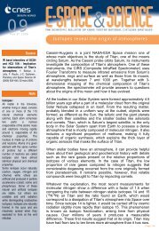
Figure 4.2-1 : Satellite vertical handling proce<strong>du</strong>re and payload exclusion areas (Calipso example)<br />
..<br />
All right reserved. ALCATEL SPACE /CNES<br />
Passing and copying of this <strong>document</strong>, use and communication of its content is not permitted without prior written authorization.
PRO.LB.0.NT.003.ASC Issue. 6 rev. 3 Page: 3.18<br />
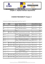
Figure 4.2-3 : Satellite vertical handling<br />
Figure 4.2-2 : Satellite horizontal handling proce<strong>du</strong>re (Calipso example)<br />
All right reserved. ALCATEL SPACE /CNES<br />
Passing and copying of this <strong>document</strong>, use and communication of its content is not permitted without prior written authorization.
PRO.LB.0.NT.003.ASC Issue. 6 rev. 3 Page: 3.19<br />
4.2.3 ALIGNMENT<br />
The integration / alignment of the Payload on the Platform is a Satellite Contractor responsibility but it is the Payload<br />
Supplier responsibility to provide a payload design which is compatible with the required alignment accuracy. The<br />
nominal alignment measurements <strong>du</strong>ring satellite AIT aim at verifying the stability of the payload master reference<br />
cube between the beginning of the AIT mechanical and thermal environment tests and the end of these tests. In<br />
addition, position of this cube will be measured with respect to the STR reference cube in order to determine the<br />
relative position of the payload boresight with respect to the STR boresight. No other optical cubes are nominally<br />
controlled <strong>du</strong>ring satellite AIT.<br />
PL - 4.2.3 - 1<br />
Consequently, a description of payload specific alignment method or needs <strong>du</strong>ring satellite AIT shall be<br />
provided by the Payload Supplier for Satellite Contractor approval before Satellite phase C.<br />
This shall include as a minimum a definition of the payload adjustment range, a detailed description of the<br />
hardware used for that purpose, the reference cube and its field of view.<br />
It shall be noticed that, at satellite level, all alignment measurements will be performed in vertical configuration<br />
(Satellite +Xs axis in vertical position). This leads to some constraints at payload level expressed in PL - 4.2.3 - 3.<br />
PL - 4.2.3 - 2<br />
For each feed/antenna reflector assembly, a specific device (palmer equipped struts, as far as possible)<br />
allowing verification of the relative geometry shall be provided to the Satellite Contractor by the Payload<br />
Supplier, if geometry verification after satellite testing (mechanical, thermal, EMC) is required at System level.<br />
PL - 4.2.3 – 3<br />
The payload master reference optical cube shall fulfil the following requirements :<br />
• This cube shall be <strong>du</strong>plicated (one nominal and one re<strong>du</strong>ndant) and the 2 cubes shall not be located on<br />
the same area (full re<strong>du</strong>ndancy rules)<br />
• These 2 cubes shall be directly accessible with the satellite in vertical position that is to say by 2<br />
perpendicular horizontal lines of sight (+Ys and +Zs for instance or any combination remaining in<br />
+Ys+Zs). Moreover, the previous line of sight shall be free of any interference,<br />
• They shall be located on a stable area (moreover, they shall be preferably located on the +/- Ys faces of<br />
the payload)<br />
• Their minimum size shall be 20 mm x 20 mm x 20 mm,<br />
• They shall not be dismounted <strong>du</strong>ring payload or satellite test campaign.<br />
Information about alignment references, accuracy and adjustments form part of the PL ADP. Any other payload<br />
optical cube, if measured <strong>du</strong>ring satellite AIT, shall be compliant with PL-4.2.3-3 except for the re<strong>du</strong>ndancy aspect.<br />
All right reserved. ALCATEL SPACE /CNES<br />
Passing and copying of this <strong>document</strong>, use and communication of its content is not permitted without prior written authorization.
PRO.LB.0.NT.003.ASC Issue. 6 rev. 3 Page: 3.20<br />
4.2.4 CO-ALIGNMENT<br />
N.A<br />
4.2.5 STRUCTURAL DESIGN<br />
4.2.5.1 Stiffness requirements<br />
PL - 4.2.5 - 1<br />
The first mode frequencies of the payload required in the chapter 3 shall be achieved with the assumption of<br />
a hard-mounted interface on an infinitely rigid interface.<br />
4.2.5.2 Safety factors and safety margins<br />
PL - 4.2.5 - 2<br />
For non pressurized item, the following safety factors for yield sizing (JY) and for ultimate sizing (JU), with<br />
respect to the qualification loads, shall be applied :<br />
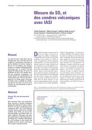
Type of hardware JY (yield) JU (ultimate)<br />
Metal flight hardware 1.25 1.56<br />
Metal inserts and joints (flight hardware) NA 2.0<br />
with characterized materials(*) NA 1.25<br />
Composite flight hardware NA 1.56<br />
with characterized materials(*) NA 1.25<br />
Composite inserts and joints (flight hardware) NA 2.0<br />
with characterized materials(*) NA 1.25<br />
Ground handling 1.5 2.5<br />
(*) : the applicable safety factors may be re<strong>du</strong>ced for pieces of hardware made of materials characterized through an<br />
appropriate number of tests, yielding to a better knowledge of the admissible stress ("A" or "B" type).<br />
PL - 4.2.5 - 7<br />
Table 4.2-1: JY and JU safety factors for non pressurized item<br />
For pressurized item, the following safety factors for yield sizing (JY) and for ultimate sizing (JU), with respect<br />
to the Maximum Operating Design Pressure (defined as the highest pressure occurring from maximum relief<br />
pressure, maximum regulator pressure, maximum temperature or transient pressure excursions), shall be<br />
applied.<br />
In addition, pressure vessels design and verification shall comply with the requirements specified in Safety<br />
Regulations requirements.<br />
Type of hardware JY (yield) JU (ultimate)<br />
Pressure vessels 1.25 1.56<br />
Pressurized components 1.5 2.5<br />
Table 4.2-2: JY and JU safety factors for pressurized item<br />
All right reserved. ALCATEL SPACE /CNES<br />
Passing and copying of this <strong>document</strong>, use and communication of its content is not permitted without prior written authorization.
PRO.LB.0.NT.003.ASC Issue. 6 rev. 3 Page: 3.21<br />
PL - 4.2.5 - 3<br />
The following definitions shall be applied:<br />
Qualification loads = 1.25 x Flight limit loads except for ground handling where:<br />
- qualification loads = 2 x Flight limit loads for nominal analysis and<br />
- qualification loads = 1.5 x limit loads for fail safe analysis (where 1.5 corresponds to the dynamic<br />
factor <strong>du</strong>e to the loss of one handling point).<br />
Sizing loads = JY (or JU) x Qualification loads<br />
The safety margin is defined as follows :<br />
where :<br />
σ admissible<br />
S.<br />
M.<br />
= −1<br />
σ<br />
calculated<br />
the admissible stress is the yield (respectively ultimate) stress when estimating the safety margin wrt yield<br />
(respectively ultimate).<br />
the admissible stress for single points failure pieces of hardware shall be "A" type values (99% probability with<br />
a 95% confidence level),<br />
the admissible stress for re<strong>du</strong>ndant pieces of hardware shall be "B" type values (90% probability with a 95%<br />
confidence level),<br />
the calculated stress is the qualification stress times the yield (respectively ultimate) safety factor.<br />
PL - 4.2.5 - 4 a<br />
All safety margins shall be positive:<br />
• local buckling criterion: there shall be no buckling under qualification loads<br />
4.2.5.3 Notching philosophy<br />
PL - 4.2.5 - 5<br />
Notching at payload level is allowed <strong>du</strong>ring sine vibration test in order not to exceed, at the<br />
platform/payload interface, the Quasi-Static equivalent loads (resultant forces and moments at the<br />
geometrical centre of the interface points) after Satellite Contractor agreement<br />
Notching at payload units level is forbidden.<br />
PL - 4.2.5 - 6<br />
For notching <strong>du</strong>ring random vibration tests, the Payload Supplier shall contact either ALCATEL SPACE or<br />
CNES.<br />
4.2.5.4 Structural mathematical models<br />
The requirements for the quality of mathematical models, numbering ranges and interface point locations are given<br />
in section 4.6.1.<br />
All right reserved. ALCATEL SPACE /CNES<br />
Passing and copying of this <strong>document</strong>, use and communication of its content is not permitted without prior written authorization.
PRO.LB.0.NT.003.ASC Issue. 6 rev. 3 Page: 3.22<br />
4.3 THERMAL DESIGN REQUIREMENTS<br />
4.3.1 DEFINITIONS<br />
For information, the temperatures definition used for the PROTEUS platform are given hereafter.<br />
4.3.1.1 Operational temperatures<br />
The minimum and maximum operational temperatures TOPMIN and TOPMAX are the extreme temperatures a<br />
payload shall withstand <strong>du</strong>ring its specified lifetime for its various operational modes.<br />
4.3.1.2 Acceptance temperatures<br />
Acceptance temperature limits shall be de<strong>du</strong>ced from operational temperature limits by an extension of 5°C :<br />
TAMIN = TOPMIN - 5 °C<br />
TAMAX = TOPMAX + 5 °C<br />
4.3.1.3 Qualification temperatures<br />
Qualification temperature limits shall be de<strong>du</strong>ced from operational temperature limits by an extension of 10°C :<br />
TQMIN = TOPMIN - 10 °C<br />
TQMAX = TOPMAX + 10 °C<br />
4.3.1.4 Non operating temperatures<br />
Minimal and maximal non operating temperatures TNOPMIN and TNOPMAX are the extreme temperatures a<br />
payload shall withstand when it is OFF <strong>du</strong>ring specific satellite modes or <strong>du</strong>ring ground phase up a few days (for<br />
example transport).<br />
4.3.1.5 Start-up temperatures<br />
Minimal and maximal start up temperatures TSUMIN and TSUMAX are the extreme temperatures a payload shall be<br />
able to be turned ON, possibly without fulfilling all its performance requirements (for example a «cold start » after<br />
modes transition, when the satellite stayed in Safe mode for a long time before coming back to normal mode).<br />
4.3.1.6 Storage temperatures<br />
Minimal and maximal temperatures TSTOMIN and TSTOMAX are the extreme temperatures a payload shall<br />
withstand <strong>du</strong>ring storage phase up to several months.<br />
All right reserved. ALCATEL SPACE /CNES<br />
Passing and copying of this <strong>document</strong>, use and communication of its content is not permitted without prior written authorization.
PRO.LB.0.NT.003.ASC Issue. 6 rev. 3 Page: 3.23<br />
4.3.2 THERMAL INTERFACES<br />
4.3.2.1 Thermal mathematical models and analysis<br />
PL - 4.3.2 - 1<br />
A thermal analysis is required at payload level covering the most thermally critical operating modes and<br />
including transient cases where relevant.<br />
In a standard approach, no Payload re<strong>du</strong>ced mathematical model is required. Nonetheless, the platform thermal<br />
control design has to take into account radiative coupling with the payload.<br />
PL - 4.3.2 – 2<br />
So, the Payload Supplier shall provide an external radiative geometrical model, in flight (before payload<br />
PDR) and satellite-level test configurations (six months before test) in the Payload Interface Control<br />
Document.<br />
This model is an external representation of the Payload including for each main surface :<br />
• Thermo-optic characteristics<br />
• Worst temperatures assumption (cold and hot).<br />
All right reserved. ALCATEL SPACE /CNES<br />
Passing and copying of this <strong>document</strong>, use and communication of its content is not permitted without prior written authorization.
PRO.LB.0.NT.003.ASC Issue. 6 rev. 3 Page: 3.24<br />
4.4 ELECTRICAL DESIGN REQUIREMENTS<br />
4.4.1 SYSTEM GROUNDING<br />
4.4.1.1 General<br />
PL - 4.4.1 - 1<br />
The satellite structure shall not be used as a current carrying con<strong>du</strong>ctor.<br />
PL - 4.4.1 - 2<br />
Shields shall not be used for signal returns except for RF signals.<br />
PL - 4.4.1 - 3<br />
An overall zero volt and grounding diagram shall be provided in the ICD/IDS for assessing the functional<br />
and electromagnetic compatibilities. This diagram shall indicate any AC or DC loop, the type of isolation<br />
used, any impedance coupling between zero volt and structure, and the type of connection between<br />
secondary 0 V and mechanical ground (if any).<br />
PL - 4.4.1 - 4<br />
The Payload Supplier shall provide a grounding diagram based on the following concepts.<br />
All right reserved. ALCATEL SPACE /CNES<br />
Passing and copying of this <strong>document</strong>, use and communication of its content is not permitted without prior written authorization.
PRO.LB.0.NT.003.ASC Issue. 6 rev. 3 Page: 3.25<br />
PROTEUS Power<br />
Strap<br />
Battery<br />
supply<br />
PL - 4.4.1 - 5<br />
PCE<br />
Converter<br />
Primary 0V<br />
Secondary 0V<br />
Chassis ground<br />
DHU<br />
Unit 1<br />
Unit 2<br />
Unit 3<br />
Unit 4<br />
Unit 5<br />
Unit 6<br />
ZVS1<br />
ZVS2<br />
ZVS1<br />
Figure 4.4-1 : Grounding concepts<br />
The following rules and symbols shall be used to draw grounding diagrams<br />
Solution 1<br />
Solution 2<br />
Solution 3<br />
All right reserved. ALCATEL SPACE /CNES<br />
Passing and copying of this <strong>document</strong>, use and communication of its content is not permitted without prior written authorization.<br />
For RF parts of<br />
equipment only<br />
Solution 4
..<br />
PRO.LB.0.NT.003.ASC Issue. 6 rev. 3 Page: 3.26<br />
i<br />
: Chassis ground<br />
: Ground<br />
: Secondary 0V n°i<br />
: Primary 0V<br />
: Bonding stud<br />
: Twisted pair<br />
: Twisted shielded pair<br />
: Coxial cable<br />
: DC/DC converter (isolated)<br />
: Signal transformer<br />
All right reserved. ALCATEL SPACE /CNES<br />
Passing and copying of this <strong>document</strong>, use and communication of its content is not permitted without prior written authorization.<br />
M<br />
T°<br />
: Single ended amplifier (transmitter)<br />
: Differential amplifier (transmitter)<br />
: Single ended amplifier (receiver)<br />
: Differential amplifier (receiver)<br />
: Optocoupler<br />
: Motor<br />
: Thermistor<br />
: Heater<br />
: Metallic housing grounded via mountin<br />
: Metallic housing grounded via foil strip<br />
Figure 4.4-2 : Symbols for grounding diagrams
PRO.LB.0.NT.003.ASC Issue. 6 rev. 3 Page: 3.27<br />
Converter<br />
Primary 0V<br />
Secondary 0V<br />
Chassis ground<br />
ZVS1<br />
ZVS2<br />
Figure 4.4-3 : Example of grounding diagram<br />
All right reserved. ALCATEL SPACE /CNES<br />
Passing and copying of this <strong>document</strong>, use and communication of its content is not permitted without prior written authorization.
PRO.LB.0.NT.003.ASC Issue. 6 rev. 3 Page: 3.28<br />
4.4.1.2 Structural grounding<br />
PL - 4.4.1 - 6<br />
All structural members of the satellite and payload chassis and enclosures shall be designed to provide<br />
electrical con<strong>du</strong>ctivity across all mechanical joints, except where DC isolation is required for maximum<br />
electrical reliability. Con<strong>du</strong>ctive surface protection coatings such as Iridite, Alodine, or plating shall be used<br />
at all joints. The DC resistance across fixed joints shall not exceed 2.5 mOhm.<br />
PL - 4.4.1 - 7<br />
Re<strong>du</strong>ndant bonding straps shall be employed across joints where direct metal-to-metal contact cannot be<br />
assured. The DC resistance of these straps shall not exceed 10 mOhm.<br />
4.4.1.3 Thermal grounding<br />
PL - 4.4.1 - 8<br />
The con<strong>du</strong>ctive surfaces of all metal or metallic coated thermal components, such as heat shields and<br />
metallized layers of thermal blankets (that shall include one con<strong>du</strong>ctive layer) shall be electrically grounded<br />
to the satellite structure with a DC resistance lower than 10 mOhm. The number of bonding points per sheet<br />
of MLI shall be compliant with the following rules:<br />
• Sheets of 0.5m2 max: two points, at corners of the longest diagonal, as a minimum,<br />
• Sheets of 1 m 2 max: four points, at each corner, as a minimum,<br />
• Sheets greater than 1 m 2 : one bonding point at diagonal corners and intermediate points along outer<br />
sheet edges to ensure bonding areas not to exceed 1 m 2 .<br />
PL - 4.4.1 - 9<br />
In addition, the resistance between two bonding points in a MLI shall be lower than 80 Ω.<br />
PL - 4.4.1 - 10<br />
The use of non con<strong>du</strong>ctively coated insulators shall be minimized.<br />
All right reserved. ALCATEL SPACE /CNES<br />
Passing and copying of this <strong>document</strong>, use and communication of its content is not permitted without prior written authorization.
PRO.LB.0.NT.003.ASC Issue. 6 rev. 3 Page: 3.29<br />
4.4.1.4 Electrical bonding<br />
PL - 4.4.1 - 11<br />
Electrical bonding shall be in accordance with Table 4.4-1 with the following additions :<br />
a. The exterior case, including connectors and all metallic external covers shall be electrically bonded,<br />
directly or indirectly to chassis ground with a resistance of no greater than 2.5 milliohm per bond except for<br />
composite components.<br />
b. For composite components, the DC resistance per bond shall be no greater than 100 Ohm.<br />
c. The mounting surface shall be such that it may be electrically bonded to the structure upon which it is to be<br />
mounted at installation in the spacecraft.<br />
d. All internal mechanical assemblies shall be electrically bonded directly or indirectly to the base plate.<br />
e. Gimbaled, hinged, or jointed interfaces shall be bonded by means of re<strong>du</strong>ndant grounding straps.<br />
Bonded configuration max DC resistance<br />
(Ohm)<br />
RF boxes to Panel Ground Reference (PGR) 0.010<br />
Non-RF boxes to PGR 0.020<br />
Electrical boxes on graphite panels (if any) to PGR 0.050<br />
Across hinges (antenna deployed booms & solar array) 0.100<br />
Units, optical heads to PGR 0.020<br />
Harness shields to PGR 0.020<br />
Antenna to PGR 300.0<br />
Thermal blankets ground to Single Ground Point (SGP) 0.010<br />
Mechanical equipment to SGP 1.0<br />
Thermal blanket to multiple grounding tab to tab 0.010<br />
Thermal shields (thrusters) to structure 1.0<br />
Panel Ground Reference to SGP 0.10<br />
Table 4.4-1:PROTEUS Bonding Requirement<br />
All right reserved. ALCATEL SPACE /CNES<br />
Passing and copying of this <strong>document</strong>, use and communication of its content is not permitted without prior written authorization.
PRO.LB.0.NT.003.ASC Issue. 6 rev. 3 Page: 3.30<br />
4.4.2 CABLING SHIELDING AND GROUNDING<br />
4.4.2.1 General<br />
PL - 4.4.2 -21<br />
The design shall preclude sneak circuits and unintentional electrical paths<br />
PL - 4.4.2 - 1<br />
The primary electrical power distribution system will have the power negative grounded to the spacecraft<br />
structure at a single ground point (SGP).<br />
PL - 4.4.2 - 2<br />
The electronic boxes supporting structure shall be designed with a panel ground reference (PGR). The PGR<br />
shall consist of ground studs, or inserts for ground straps, to be connected between the panel and the<br />
adjacent panels.<br />
The DC resistance between PGR and panel structure shall be lower than 10 mΩ.<br />
PL - 4.4.2 - 3<br />
Secondary power return lines shall be connected to the equipment structure in a single point. Exceptions are<br />
RF communication equipments and electrical units with operating frequency > 10 MHz where the secondary<br />
return can be connected to the structure with a lot of points.<br />
PL - 4.4.2 - 4<br />
Command signal wiring:<br />
In general, the wiring for the command signals shall be implemented using 26 gauge twisted pair wire from<br />
the branch mo<strong>du</strong>le. Command signal with rise times < 200 µs which are routed through harness paths<br />
common to signal wires with susceptibility thresholds less than 10 V and less than 10 ms pulse response<br />
time, shall be shielded.<br />
PL - 4.4.2 - 5<br />
Each power line shall be electrically isolated with a dedicated return.<br />
4.4.2.2 Serial digital data acquisition, serial digital commands and low level commands grounding<br />
PL - 4.4.2 - 6<br />
Serial digital data acquisition and command signals shall be carried on shielded twisted pair wires and shall<br />
use structure as signal reference. Receiver shall be isolated from the primary ground ; emitter shall be<br />
ground referenced.<br />
Low level commands shall also be carried on shielded twisted pairs.<br />
4.4.2.3 Digital relay acquisitions, and relay commands grounding<br />
PL - 4.4.2 - 7<br />
Digital relay acquisitions and relay commands shall be completely electrically isolated with dedicated return.<br />
All right reserved. ALCATEL SPACE /CNES<br />
Passing and copying of this <strong>document</strong>, use and communication of its content is not permitted without prior written authorization.
PRO.LB.0.NT.003.ASC Issue. 6 rev. 3 Page: 3.31<br />
4.4.2.4 Bi-level acquisitions grounding<br />
PL - 4.4.2 - 8<br />
Bi-level acquisitions shall use secondary power.<br />
4.4.2.5 Thermistors acquisition and heaters commands grounding<br />
PL - 4.4.2 - 9<br />
Thermistors/heaters lines shall be electrically isolated. Thermistors acquisitions shall use twisted shielded pair<br />
wires. Heaters commands shall use twisted pairs.<br />
4.4.2.6 Analog signals grounding<br />
4.4.2.7 EED<br />
PL - 4.4.2 - 10<br />
Each analog acquisition line shall use a dedicated return which will be grounded at user end.<br />
Analog signals at interfaces shall be arranged to allow the use of twisted shielded wire.<br />
Exception for high accuracy, analog acquisition which shall not be grounded.<br />
4.4.2.7.1 General EED Wiring.<br />
PL - 4.4.2 - 11<br />
All EED wiring circuits shall use double shielded twisted pair wires. The return side of the circuits shall be<br />
grounded at the power supply; exceptions shall be submitted to Satellite Contractor for approval. The shields<br />
shall be grounded at the connector backshell at all connectors.<br />
4.4.2.7.2 EED Circuit Shields<br />
PL - 4.4.2 - 12<br />
Firing circuit shields shall provide a minimum of 20 dB attenuation from 30 kHz to 18 GHz. All firing circuit<br />
bundles shall use a double shielding configuration that has zero aperture from the power control unit to the<br />
electroexplosive devices (EED). The inner shield on these harnesses shall be the regular flat braided shield of<br />
the cables, which provides a minimum coverage of 90%. The outer shield shall be an overall shield to<br />
provide complete coverage from end to end. There shall be no gaps or discontinuities in the shielding,<br />
including the terminations at the back faces of the connectors. Electrical continuity and isolation of the inner<br />
and outer electroexplosive circuit shields shall be maintained.<br />
4.4.2.7.3 EED Cabling<br />
PL - 4.4.2 - 13<br />
Bundles shall be manufactured such that several electroexplosive device circuits are contained in a common<br />
shielded bundle. Splices within the bundles are forbidden. When breaking of a circuit is required, a mating<br />
connector pair shall be provided. All bundles shall be routed as close to the con<strong>du</strong>ctive metal ground plane<br />
of the platform/payload structure as feasible, with provision for tie-downs a maximum of 15 mm apart.<br />
All right reserved. ALCATEL SPACE /CNES<br />
Passing and copying of this <strong>document</strong>, use and communication of its content is not permitted without prior written authorization.
PRO.LB.0.NT.003.ASC Issue. 6 rev. 3 Page: 3.32<br />
4.4.2.7.4 EED Circuit Connectors<br />
PL - 4.4.2 - 14<br />
Connectors used in the electroexplosive bundles shall be of the circular MIL-C-26482 Series 2 type with<br />
con<strong>du</strong>ctive nickel slated metal shell bodies. These shall be self-locking and compatible with the mating<br />
equipment interface connectors. There shall be only one wire per pin, and in no case shall a connector pin<br />
be used as a terminal or a tie-point for multiple connections.<br />
PL - 4.4.2 -20<br />
All connectors used with the electroexplosive devices shall:<br />
• be approved by the procuring activity,<br />
• have a stainless steel shell or suitable electrically con<strong>du</strong>ctive finish,<br />
• complete the shell-to-shell connection before the pins connect,<br />
• provide for 360° shield continuity.<br />
There shall be only one wire per pin, and in no case shall a connector pin be used as a terminal or a tiepoint<br />
for multiple connections.<br />
The source circuits shall terminate in a connector with socket contacts.<br />
Connectors shall be selected such that they are not subject to demating when exposed to the maximum<br />
anticipated environment.<br />
Connectors that twist and lock into position are preferred.<br />
4.4.2.7.5 EED Circuit Re<strong>du</strong>ndant Wiring<br />
PL - 4.4.2 - 15<br />
Re<strong>du</strong>ndant EED circuits shall be wired and routed in separate wire bundles where required. Separation of<br />
wire bundles shall be maintained to the maximum extent possible, including the use of separate connectors if<br />
feasible.<br />
4.4.2.7.6 EED Harness Electrical Bonding<br />
PL - 4.4.2 - 16<br />
The EED harness hardware shall be bonded to the spacecraft local panel ground reference through the<br />
mating equipment chassis. Each connector and shield termination shall be assembled (mated) and tested to<br />
insure a maximum resistance of 10 mΩ (between connector or shield and PGR).<br />
4.4.2.7.7 EED Harness identification.<br />
PL - 4.4.2 - 17<br />
Each EED harness shall be positively identified by part number and serial number. Identifying information<br />
may be attach directly to the wiring harness by a sleeve attach to the harness. Other forms of identification<br />
such as mylar nameplates, metal nameplates, metal stampings, vibropeening, acid, electrical or<br />
mechanically etched, embossed, forged, brazed, cast or molded methods of manufacture shall not be used.<br />
All right reserved. ALCATEL SPACE /CNES<br />
Passing and copying of this <strong>document</strong>, use and communication of its content is not permitted without prior written authorization.
PRO.LB.0.NT.003.ASC Issue. 6 rev. 3 Page: 3.33<br />
4.4.2.7.8 EED Harness Records<br />
PL - 4.4.2 - 18<br />
Each EED wiring harness assembly shall have inspection and test records maintained by appropriate number<br />
and with a connector mate log maintained for all connectors from initial assembly and test throughout unit<br />
and satellite integration and acceptance test lifetime.<br />
4.4.2.8 Shielding<br />
PL - 4.4.2 - 19<br />
The general shielding guideline shall be such that each line function is evaluated to determine if it is possible<br />
to cable the line as an unshielded wire.<br />
The shielding guidelines are as follows :<br />
a. All telemetry lines shall be shielded indivi<strong>du</strong>ally or in functional groups.<br />
b. Unit interfaces which interconnect with sensitive or susceptible circuitry or are proximate to sensitive or<br />
susceptible circuitry shall be shielded.<br />
c. All command lines may use shielded wiring (except the digital command lines which may use unshielded<br />
wires).<br />
d. Regulated power lines shall use shielded wire.<br />
e. Shields shall not carry currents (except RF).<br />
f. Shields shall be jacketed to provide isolation from ground and chassis except at designated points.<br />
g. Shields shall provide a minimum of 90 percent coverage (e.g. tinned copper braid and woven copper).<br />
h. All pyrotechnics lines shall be double shielded. Firing circuits shielding shall provide a minimum of 20 dB<br />
attenuation from 30 kHz to 18 GHz. All firing circuit harnesses shall use a double shielding configuration<br />
that has zero aperture from the DHU to the electroexplosive devices (EED). There shall be no gaps or<br />
discontinuities in the shielding, including the terminations at the back faces of the connectors. Electrical<br />
continuity and isolation of EED circuit shields shall be maintained. All electrical cables may be fabricated<br />
such that several EED circuits are contained in a common shield cable bundle. There shall be no splices<br />
within the cable bundles.<br />
i. Each end every cable or waveguide going through the Payload shall have shield bonded to the payload<br />
structure over 360 deg.<br />
All right reserved. ALCATEL SPACE /CNES<br />
Passing and copying of this <strong>document</strong>, use and communication of its content is not permitted without prior written authorization.
PRO.LB.0.NT.003.ASC Issue. 6 rev. 3 Page: 3.34<br />
4.4.3 HARNESS REQUIREMENTS<br />
PL - 4.4.3 - 1<br />
Circuits having incompatible electromagnetic interference characteristics shall be segregated in cabling and<br />
connectors to the maximum extent possible to minimize interference coupling.<br />
Separation is necessary for the following circuits categories :<br />
DC power and command circuits<br />
Digital signals (0 - 5 V)<br />
Analog signals (0 - 5 V)<br />
Electro Explosive Devices<br />
Radio Frequency lines<br />
Wires carrying proprietary data<br />
MIL-STD-1553B bus<br />
4.4.3.1 Pins assignment<br />
PL - 4.4.3 - 2<br />
If two or more circuit categories must share a connector, pin assignments shall be made to provide a<br />
maximum of isolation in the connector and facilitate separation of the wiring external to the connector. A<br />
minimum of two pins separation shall be used.<br />
4.4.3.2 Harness design<br />
PL - 4.4.3 - 3<br />
Signal control interface harnesses, in general shall be constructed using twisted shielded wires. Signal return<br />
lines shall be shielded. However, some pulse commands and relay driver lines may not be shielded in order<br />
to save weight on the satellite. In this case, EMI analysis shall be performed to ensure EMC/ESD requirement<br />
compliance.<br />
PL - 4.4.3 - 4<br />
Neither the structure nor any cable shield shall be used to carry power bus return. This will minimize<br />
common mode noise input to the units.<br />
PL - 4.4.3 - 5<br />
For sensitive and critical functions, another shield shall be added that is continuous from the backshells of<br />
each of the associated unit connectors.<br />
PL - 4.4.3 - 6<br />
All shields shall be terminated to chassis external to the unit enclosure. Where external cables penetrate the<br />
enclosure of the satellite main body, they shall be terminated to the structure externally.<br />
All right reserved. ALCATEL SPACE /CNES<br />
Passing and copying of this <strong>document</strong>, use and communication of its content is not permitted without prior written authorization.
PRO.LB.0.NT.003.ASC Issue. 6 rev. 3 Page: 3.35<br />
PL - 4.4.3 - 7 a<br />
The following general rule on wiring shall be applied unless special approval has been granted:<br />
a. wiring shall be sized to provide a maximum voltage drop for power lines of 240 mV between source<br />
and user. For telemetry lines, this value can be as high as 1.0 V depending on the telemetry system<br />
parameter.<br />
b. wiring size and shield shall be :<br />
• No 20, 22 and 24 AWG twisted shielded pairs for secondary power distribution. If flexible wiring is<br />
utilized, it shall be EMI controlled, and in accordance with MIL-P-50884B.<br />
• No 26 AWG single through nine con<strong>du</strong>ctors twisted shielded wire for control and monitor.<br />
PL - 4.4.3 - 8<br />
For explosive parts, all circuits shall use twisted double shielded pair wires. The return side of the circuits shall<br />
be grounded at the power supply. Shield shall be grounded at both ends of the harness.<br />
PL - 4.4.3 - 9<br />
When feasible, re<strong>du</strong>ndant wiring shall be routed in separate wire bundles. Separation of wire bundles shall<br />
be maintained to the maximum extent possible, including the use of separate connectors, if necessary.<br />
PL - 4.4.3 - 10<br />
Spare wires shall not be provided in wiring harness terminating in removable crimp-contact connectors.<br />
PL - 4.4.3 - 11<br />
EMI controls on printed flexible wiring includes shielding and guard con<strong>du</strong>ctors. A circuit pattern may have<br />
shields on one or both sides. Additional shielding may be used on circuit edges if necessary. Top and bottom<br />
shielding may be added as solid con<strong>du</strong>ctive material connected and tied electrically. Insulation layers<br />
(covercoats) are normally used as outside layer. Guard con<strong>du</strong>ctors are effective in re<strong>du</strong>cing adjacent trace<br />
coupling (crosstalk).<br />
PL - 4.4.3 - 12<br />
Every cable submitted to the external environment (i.e external to the Payload Instrument Mo<strong>du</strong>le) shall be<br />
overshielded.<br />
All right reserved. ALCATEL SPACE /CNES<br />
Passing and copying of this <strong>document</strong>, use and communication of its content is not permitted without prior written authorization.
PRO.LB.0.NT.003.ASC Issue. 6 rev. 3 Page: 3.36<br />
4.4.4 ISOLATION<br />
PL - 4.4.4 - 1<br />
Onboard power, supplied by inverters, converters and transformer isolated power supplies, shall be defined<br />
as secondary power and shall be referenced to the mechanical ground at one location, at the secondary<br />
power source, via the shortest possible low impedance path. For those types of equipments, secondary<br />
power return is connected to the mechanical ground. In this case, the DC resistance between secondary<br />
power return line and mechanical ground shall be less than 2.5 mΩ.<br />
Remote sensors, pressure sensors, magnetometers, or assemblies without internal power supply may be<br />
exempt from the above requirement and secondary power return is isolated from the mechanical ground.<br />
PL - 4.4.4 - 2<br />
Primary power :<br />
All the users shall maintain an electrical isolation of at least 1 MΩ shunted by not more than 50 nF between:<br />
• primary power positive and chassis,<br />
• primary power return and chassis,<br />
• primary power return and secondary power return.<br />
PL - 4.4.4 - 3<br />
Secondary power:<br />
except secondary single point referenced, all the sources and loads shall maintain an electrical isolation of at<br />
least 1 MΩ shunted by not more than 50 nF between:<br />
• secondary power positive and chassis,<br />
• secondary power return and chassis,<br />
• primary power return and secondary power return.<br />
At no time the satellite will impose more than 1.5 V DC and 1 V peak to peak, from 15 kHz to 180 KHz, falling to<br />
0.2 V at 15 MHz, between the primary return and secondary return.<br />
All right reserved. ALCATEL SPACE /CNES<br />
Passing and copying of this <strong>document</strong>, use and communication of its content is not permitted without prior written authorization.
PRO.LB.0.NT.003.ASC Issue. 6 rev. 3 Page: 3.37<br />
2<br />
1<br />
0<br />
PL - 4.4.4 - 4<br />
V pp<br />
Common mode voltage<br />
1.00E+04 1.00E+05 1.00E+06 1.00E+07 1.00E+08<br />
Frequency (Hz)<br />
Figure 4.4-4 : Common mode voltage<br />
Differential interface circuits between instrument units shall be designed to maintain a common mode<br />
isolation as described on the Figure 4.4-5.<br />
All right reserved. ALCATEL SPACE /CNES<br />
Passing and copying of this <strong>document</strong>, use and communication of its content is not permitted without prior written authorization.
PRO.LB.0.NT.003.ASC Issue. 6 rev. 3 Page: 3.38<br />
10<br />
Impedance in KOhm<br />
Signal interface isolation<br />
in common mode<br />
0<br />
1.00E+01 1.00E+02 1.00E+03 1.00E+04 1.00E+05 1.00E+06 1.00E+07 1.00E+<br />
Frequency (Hz)<br />
Figure 4.4-5: Signal interference isolation, in common mode<br />
All right reserved. ALCATEL SPACE /CNES<br />
Passing and copying of this <strong>document</strong>, use and communication of its content is not permitted without prior written authorization.
PRO.LB.0.NT.003.ASC Issue. 6 rev. 3 Page: 3.39<br />
4.4.5 CONNECTORS TYPE AND KEYING<br />
PL - 4.4.5 - 1<br />
Use of micro-D connectors is not allowed.<br />
PL - 4.4.5 - 2<br />
The MIL-STD-1553B bus connectors shall be dedicated (no sharing of connectors with any other signal) and<br />
segregated (one connector for nominal bus and one for re<strong>du</strong>ndant bus) on each unit using this bus.<br />
PL - 4.4.5 - 3<br />
Deleted<br />
PL - 4.4.5 - 4<br />
The payload shall employ connector keying, where required, to prevent accidental mismating of connectors.<br />
The harness mating connectors shall be configured to properly maintain this keying requirement The harness<br />
shall be designed to interface with the mating connectors of the spacecraft electrical units with provision for<br />
unit and harness serviceability after assembly. Access shall be provided which supports safe and proper<br />
mating and demating of all connectors after spacecraft integration.<br />
PL - 4.4.5 - 5<br />
Electrical connectors shall be electrically bonded to the metallic case in which they are installed to provide<br />
electrical resistance of less than 2.5 mOhm. Except for cases otherwise approved by the satellite contractor,<br />
the connector housing shall be bonded to the chassis via a strap with a resistance of less than 10 mOhm.<br />
All right reserved. ALCATEL SPACE /CNES<br />
Passing and copying of this <strong>document</strong>, use and communication of its content is not permitted without prior written authorization.
PRO.LB.0.NT.003.ASC Issue. 6 rev. 3 Page: 3.40<br />
4.5 COMMAND AND CONTROL DESIGN REQUIREMENTS<br />
4.5.1 GENERAL CONVENTIONS<br />
PL - 4.5.1 - 1<br />
The following conventions shall be used at payload level.<br />
4.5.1.1 Word and byte convention<br />
A word is composed of 16 bits.<br />
A byte is composed of 8 bits.<br />
The numbering of the bits inside a byte shall be as follows :<br />
Integer bit B0 B1 B2 B3 B4 B5 B6 B7<br />
decimal value (MSB)<br />
(LSB)<br />
1 0 0 0 0 0 0 0 1<br />
128 1 0 0 0 0 0 0 0<br />
255 1 1 1 1 1 1 1 1<br />
Table 4.5-1: Bit numbering inside a byte<br />
Note : there is an equivalent convention for a word, yielding to B0 as MSB and B15 as LSB.<br />
4.5.1.2 Level 1 and 0 Conventions<br />
Convention for direct commands :<br />
TC 1 level shall reflect the ON or ENABLE command to the concerned circuit:<br />
active level of a relay,<br />
closed contact of a switch.<br />
TC 0 level shall reflect the OFF or DISABLE command to the concerned circuit:<br />
quiescent level of a relay,<br />
open contact of a switch.<br />
Convention for serial commands:<br />
when applicable, logic one voltage (TC 1) level shall reflect the ON or ENABLE command to the concerned<br />
circuit, MSB shall be transmitted first.<br />
Convention for direct acquisitions:<br />
TM 1 level shall reflect the ON or ENABLE status of the concerned circuit:<br />
closed contact of a relay,<br />
logic one of a status.<br />
TM 0 level shall reflect the OFF or DISABLE status of the concerned circuit:<br />
open contact of a relay,<br />
logic zero of a status.<br />
Convention for serial acquisitions:<br />
All right reserved. ALCATEL SPACE /CNES<br />
Passing and copying of this <strong>document</strong>, use and communication of its content is not permitted without prior written authorization.
PRO.LB.0.NT.003.ASC Issue. 6 rev. 3 Page: 3.41<br />
when applicable, logic one voltage (TM 1) level shall reflect the ON or ENABLE status of the concerned circuit,<br />
MSB shall be transmitted first.<br />
4.5.2 PROCESSOR TURN-ON TIME<br />
PL - 4.5.2 - 1<br />
Full reset, start up, and initialization maximum <strong>du</strong>ration shall be provided in their IDS for payload with flight<br />
electronic processor inside.<br />
There shall be no polling of these units until they are declared operational by the Ground Segment.<br />
All right reserved. ALCATEL SPACE /CNES<br />
Passing and copying of this <strong>document</strong>, use and communication of its content is not permitted without prior written authorization.
PRO.LB.0.NT.003.ASC Issue. 6 rev. 3 Page: 3.42<br />
4.6 MATHEMATICAL MODELS INTERFACES REQUIREMENTS<br />
PL - 4.6 - 1<br />
The delivered mathematical models shall comply with the following requirements (section 4.6.1 to 4.6.3).<br />
4.6.1 MECHANICAL MATHEMATICAL MODEL INTERFACES REQUIREMENTS<br />
4.6.1.1 General<br />
This section presents the general requirements for the delivered mathematical models which will be mounted on<br />
PROTEUS platform Finite Element Model (FEM).<br />
The system structural analysis will be performed with the finite element code MSC/NASTRAN.<br />
Therefore, all delivered mathematical models are required in NASTRAN format. These models will be used to<br />
perform system analyses.<br />
The Payload Supplier must provide two kinds of model: a physical model and a re<strong>du</strong>ced model (condensed or modal<br />
model).<br />
preliminary physical and re<strong>du</strong>ced models <strong>du</strong>e date: at the beginning of the satellite phase B<br />
detailed physical and re<strong>du</strong>ced models <strong>du</strong>e date: at the beginning of the satellite phase C/D<br />
one correlated re<strong>du</strong>ced model <strong>du</strong>e date: after payload qualification test<br />
The models shall be in accordance with the following items defined in the next paragraphs:<br />
utilisation of versions compatible with version 70 of the NASTRAN Code,<br />
the basic axis system and the payload system,<br />
the rules of modelisation,<br />
the interface nodes: co-ordinates, boundaries conditions, number of degrees of freedom (d.o.f.) and<br />
identification number of the GRID cards,<br />
the loaded nodes: number of d.o.f. and identification number of the GRID cards,<br />
the conditioning of the matrices,<br />
the form of the delivery.<br />
For information, the pro<strong>du</strong>cts of inertia are defined with the following sign convention :<br />
Ixy = - x y dm ; Iyz = - y z dm ; Ixz = - x z dm<br />
4.6.1.2 General Requirements<br />
4.6.1.2.1 Axis systems and payload system<br />
The basic axis system of the payload model shall be the satellite reference frame (show section 1.4).<br />
The unit system is the International System (meter, kilogram, second, radian).<br />
Local axis systems are prohibited for the definition of the co-ordinates and the degrees of freedom (displacements) of<br />
all the conserved nodes (loaded and interface ones).<br />
All local axis systems must be defined wrt the basic one, and their number limited to around 5.<br />
4.6.1.2.2 Rigid bodies<br />
Any rigid body or rigid element connecting interface nodes between them is prohibited.<br />
All right reserved. ALCATEL SPACE /CNES<br />
Passing and copying of this <strong>document</strong>, use and communication of its content is not permitted without prior written authorization.
PRO.LB.0.NT.003.ASC Issue. 6 rev. 3 Page: 3.43<br />
If an interface node is connected by a rigid element to non interface nodes, the d.o.f of the interface node must be<br />
the independent (or non constrained) d.o.f.<br />
4.6.1.2.3 Data and capabilities requested<br />
The physical finite elements model shall contain all the data necessary to perform eventually :<br />
a static analysis<br />
a modal analysis (eigen modes calculation)<br />
a sine response analysis<br />
a thermoelastic analysis (only Coefficient of Thermal Expansion (CTE) and reference temperature).<br />
Concerning the thermoelastic analysis, the finite element model shall be such that it does not intro<strong>du</strong>ce stresses<br />
higher than 1 MPa in the payload primary structure under the following loading case :<br />
payload with isostatic boundary conditions<br />
coefficient of thermoelastic expansion set to 20 10 -6 °C -1 (only for this test) on all parts of the model<br />
homogeneous increase of temperature of +100°C applied to the whole model.<br />
One of the major condition necessary to fulfil this requirement is that there will be no rigid body with length > 0<br />
connecting 2 nodes of the payload primary structure.<br />
4.6.1.2.4 Masses representation<br />
The masses representation (choice between concentrated masses and distributed masses) is to be defined by the<br />
supplier in order to fit as well as possible with the actual payload masses distribution. However, the meaning of the<br />
masses representation cards will be explained by comments cards.<br />
In case of distributed mass, the following data are requested :<br />
structural mass value (kg/m, kg/m 2 or kg/m 3 depending on the element)<br />
non structural mass values (kg/m, kg/m 2 or kg/m 3 depending on the element)<br />
total mass value (kg/m, kg/m2 or kg/m3 depending on the element).<br />
The model rigid mass along the 3 axes must have the same value.(use of CMASS2 elements could generate<br />
problems).<br />
4.6.1.2.5 Results of the non condensed model (physical model)<br />
The following data are requested:<br />
description of the model with plots of the mesh showing clearly the numbering of the most important nodes<br />
(conserved, loaded, interface, ...) and elements<br />
results of the eigen mode analysis performed under free-free boundary conditions (frequencies of the 6 rigid<br />
modes + frequencies of the 3 first elastic modes)<br />
results of the eigen mode analysis performed with the specified boundaries conditions (frequencies, effective<br />
masses and inertia, participation factors, plots of mode shapes) for the significant modes<br />
masses, inertia, centre of gravity of the model compared with the data of the real mass breakdown<br />
results of the test defined § 4.6.1.2.10 and § 4.6.1.2.3, allowing to state on the acceptability of the F.E.M. with<br />
regard to thermoelastic analysis requirements.<br />
All right reserved. ALCATEL SPACE /CNES<br />
Passing and copying of this <strong>document</strong>, use and communication of its content is not permitted without prior written authorization.
PRO.LB.0.NT.003.ASC Issue. 6 rev. 3 Page: 3.44<br />
4.6.1.2.6 Results of the condensed model<br />
The results considered in this paragraph correspond to the condensed model with the specified boundaries<br />
conditions. For the free-free condensed model, only the values of the 9 first frequencies are required.<br />
The following data are requested:<br />
same results and plots that for the uncondensed model, excepted thermoelastic test<br />
In addition, a table of comparison to demonstrate the agreement between the condensed and the uncondensed<br />
models, containing for both models: the frequencies, the effective masses and inertia, the participation factors up to<br />
150 Hz at least or until the resi<strong>du</strong>al masses and inertia are less than 20% (or higher if test sequence at sub-system<br />
level foresees larger frequency band).<br />
In the frequencies range defined above, the requested representativity for the condensed model modal characteristics<br />
with regard to the physical model ones shall be:<br />
±5% on frequencies<br />
±15% on effective masses and inertia.<br />
4.6.1.2.7 Data about the condensation<br />
"Conserved nodes (or d.o.f.)" means the loaded nodes (or d.o.f.) plus the interface ones.<br />
The following data and deliveries are requested whatever form of the delivered model:<br />
the partitioning vector to expanse the condensed matrices (size nc x nc) to the physical matrices (size nt x nt)<br />
under the form of a column vector (DMI NASTRAN vector) where:<br />
nc is the number of conserved d.o.f.<br />
nt is the number of conserved nodes multiplied by 6.<br />
the conserved GRID cards package: each conserved node shall be present on a GRID card. All the d.o.f. of<br />
the conserved nodes which do not appear in the matrices are to be permanently constrained to zero directly<br />
on the GRID card.<br />
if the interface nodes are loaded by any mass or inertia, that shall be clearly indicated,<br />
the ASET 1 cards package<br />
No resequencing process must be used for the creation of the condensed matrices. It is required to use the following<br />
NASTRAN parameter:<br />
PARAM,NEWSEQ,-1<br />
4.6.1.2.8 Plotel cards package<br />
Plotel elements connecting the conserved nodes are required to plot the undeformed and deformed structures with<br />
sufficient representativity.<br />
The identification number of the Plotel cards will be taken between the same limits that for the conserved nodes for<br />
the payload.<br />
To make more representative the plots of the substructure, some nodes could be especially conserved, but with the<br />
6 d.o.f. blocked as they would be used only for the figures. They must fulfil all the requirements of the conserved<br />
nodes.<br />
4.6.1.2.9 Check of the delivered condensed model<br />
The payload supplier shall verify that the stiffness matrix is well conditioned by the herebelow tests and shall show the<br />
results of these tests.<br />
All right reserved. ALCATEL SPACE /CNES<br />
Passing and copying of this <strong>document</strong>, use and communication of its content is not permitted without prior written authorization.
PRO.LB.0.NT.003.ASC Issue. 6 rev. 3 Page: 3.45<br />
A modal analysis has to be performed using large mass and NASTRAN SUPORT card in order to extract rigid modes,<br />
elastic modes and effective masses. The strain energy of the rigid modes and the conditioning parameter ε have to<br />
be low:<br />
STRAIN ENERGY < 10-3 J (Joule)<br />
ε < 10 -8<br />
The previous modal analysis with large mass can be replaced by a constraint check performed when the condensed<br />
model is in free-free configuration. The test to be performed is to calculate the strain energy as defined below for<br />
each rigid mode Φ R:<br />
where:<br />
S.E. = ½ .[ Φ R ] T .[K].[ Φ R ]<br />
• [ΦR ] is a vector for one of the six rigid modes<br />
• [ ΦR ] T • [K]<br />
the transposed vector of [ΦR ],<br />
is the model stiffness matrix<br />
A unit rigid body displacement is applied on the whole structure on the 6 DOF (3 translations and 3 rotations).<br />
The strain energy computed for each of these rigid body motions shall be:<br />
< 10 -3 J<br />
This last test shall be performed without SUPORT card.<br />
This Strain Energy Check is used to identify constrained or grounding problems in a FEM model and ensure that the<br />
model is free-free.<br />
This test can be performed using NASTRAN DMAP rigid body checks, or by a specific NASTRAN DMAP.<br />
A free-free modal analysis has to be performed without large mass, without SUPORT card and without rigid interface<br />
in order to extract the six rigid modes. The frequency of these modes divided by the first elastic mode shall be :<br />
< 10 -4<br />
Moreover, the 3 first elastic free-free frequencies will be provided.<br />
All these tests must be performed on the condensed matrices or on the physical model re-read on the delivered tape.<br />
All the models not in accordance with these tests will be rejected.<br />
4.6.1.2.10 Check of the delivered full model<br />
Idem § 4.6.1.2.9<br />
4.6.1.2.11 Magnetic tape characteristics<br />
The package defined here above will be provided on one of the following magnetic data storage:<br />
Streamer cartridge 150 Mbytes , SGI , UNIX , tar format<br />
DAT 4mm (60, 90 or 120 m length) SGI , UNIX , tar format<br />
Floppy disk 3 «1/2 DOS formatted ASCII code<br />
The command used for the creation of the tape archive is to be delivered with the tape delivery.<br />
If data are compressed, the uncompress software must be provided on the magnetic tape .<br />
4.6.1.2.12 Associated <strong>document</strong>ation<br />
The technical note delivered with the tape shall include all the items mentioned in chapter 2:<br />
All right reserved. ALCATEL SPACE /CNES<br />
Passing and copying of this <strong>document</strong>, use and communication of its content is not permitted without prior written authorization.
PRO.LB.0.NT.003.ASC Issue. 6 rev. 3 Page: 3.46<br />
the results of the non condensed model (§ 4.6.1.2.5),<br />
the results of the condensed model (§ 4.6.1.2.6),<br />
the results of the tests about the matrices conditioning (§ 4.6.1.2.9),<br />
plots of each substructure showing clearly the numbering of the nodes and of the elements of the physical<br />
model,<br />
plots performed with the PLOTEL cards showing the conserved nodes,<br />
a scheme showing the various local axis systems w.r.t. the basic one,<br />
a description of each substructure and of the way to modelise,<br />
an explanation of the modelisation hypotheses and of the equivalent representations,<br />
the detailed mass breakdown of the model compared with the real one and indications of:<br />
the representation of the masses: concentrated or distributed,<br />
the considered offsets and rigid bodies between the masses and the structure,<br />
a table summarising the main structural characteristics of each substructure<br />
a summary of the tape contents.<br />
All right reserved. ALCATEL SPACE /CNES<br />
Passing and copying of this <strong>document</strong>, use and communication of its content is not permitted without prior written authorization.
PRO.LB.0.NT.003.ASC Issue. 6 rev. 3 Page: 3.47<br />
4.6.1.3 Requirements for the dynamic models<br />
4.6.1.3.1 Physical models<br />
4.6.1.3.1.1 General<br />
The authorised NASTRAN elements are provide in the table hereunder.<br />
Item connectivity card property card material card<br />
1D elements PROD, PBAR, PBEAM MAT1<br />
2D elements CTRIA3, CQUAD4 PSHELL MAT1, MAT2, MAT8<br />
3D elements CPENTA, CTETRA, CHEXA PSOLID MAT1<br />
MAT9<br />
Masses CONM1, CONM2, CMASS2 - -<br />
Local stiffness and<br />
CELAS1, CELAS2 PELAS<br />
connection<br />
-<br />
Rigid element & constraint RBAR, RBE2, MPC, RBE3 - -<br />
Miscellaneous PLOTEL - -<br />
NASTRAN parameter PARAM AUTOSPC YES - -<br />
Table 4.6-1: Authorised NASTRAN cards<br />
The following NASTRAN cards are to be prohibited:<br />
NASTRAN prohibited cards<br />
PARAM BAILOUT<br />
PARAM K6ROT<br />
NASTRAN parameters *<br />
PARAM MAXRATIO<br />
PARAM EPZERO<br />
NASTRAN parameters ** PARAM WTMASS<br />
NASTRAN cards CQUAD8, CQUADR, CTRIAR CTRIA6, EGRID<br />
Table 4.6-2: Prohibited NASTRAN cards<br />
• * parameters affecting model conditioning<br />
• **parameters affecting the other models <strong>du</strong>ring FEM assembly<br />
In case of necessity to use other cards than the authorised elements, the supplier will have to ask for the agreement<br />
of ALCATEL SPACE.<br />
Remarks concerning FEM rules:<br />
It is requested to use elements RBE2 with zero length and MPC with zero length (to simplify the use for<br />
thermoelastic analyses)<br />
The use of MPC card is forbidden to link interface nodes between substructures. The interface shall be performed<br />
with CELAS or zero length RBE2.<br />
The interface nodes do not have to be dependent nodes of rigid bodies<br />
The interface nodes do not have to be linked together by a rigid body<br />
Only RBE3 with simply supported independent nodes will be allowed (independent nodes: DOF 123 (456<br />
forbidden) , reference node: No restriction on dependent DOF)<br />
4.6.1.3.1.2 Size limitation<br />
All right reserved. ALCATEL SPACE /CNES<br />
Passing and copying of this <strong>document</strong>, use and communication of its content is not permitted without prior written authorization.
PRO.LB.0.NT.003.ASC Issue. 6 rev. 3 Page: 3.48<br />
The physical models are limited to 3000 nodes and 3000 elements.<br />
4.6.1.3.1.3 List of the data to be supplied<br />
The model will be supply on magnetic tape with the characteristics given on § 4.6.1.2.11.<br />
The following items will be provided on the tape:<br />
the ASET1 cards,<br />
the CORD2 cards,<br />
the complete Bulk Data Deck gathered in one file.<br />
Preferably the BDD will be built in order that all the cards defining the same substructure will be gathered together in<br />
the file. Enough comments will be added to make easy the understanding of the file.<br />
4.6.1.3.2 Condensed physical models<br />
4.6.1.3.2.1 General<br />
The nodal points and degrees of freedom will be defined as follows:<br />
the degrees of freedom will be related to nodal points (6 dof maximum per nodal point ordered as follows: T x,<br />
T y, T z, R x, R y, R z - T for translation and R for rotation),<br />
nodal points will be supplied in ascending numerical order,<br />
nodal points co-ordinates will be supplied according to the satellite reference axes system (see §4.6.1.2.1).<br />
Local co-ordinates system are not acceptable.<br />
nodal points must be kept at the location of the accelerometers foreseen for the sine test vibrations<br />
nodal points must be chosen in order to plot the deformed shapes of the structure with a sufficient<br />
representativity<br />
These rules will determine the numbering of the rows and columns of the mass, stiffness and damping (if supplied)<br />
matrices.<br />
4.6.1.3.2.2 Size limitation<br />
The maximum size of the stiffness, mass and damping (if supplied) matrices including the interface dof is 500 x 500.<br />
4.6.1.3.2.3 List of the data to be supplied<br />
The model will be supply on magnetic tape with the characteristics given on § 4.6.1.2.11.<br />
The following items will be provided on the tape:<br />
the ASET1 cards package,<br />
the DMI partitioning vector,<br />
the conserved GRID cards,<br />
the PLOTEL cards,<br />
the stiffness, mass and damping (if supplied) matrices in NASTRAN format OUTPUT4 option BCD non sparse,<br />
with D23.16 format for version 68 and following.<br />
All right reserved. ALCATEL SPACE /CNES<br />
Passing and copying of this <strong>document</strong>, use and communication of its content is not permitted without prior written authorization.
PRO.LB.0.NT.003.ASC Issue. 6 rev. 3 Page: 3.49<br />
4.6.1.3.3 Modal models<br />
4.6.1.3.3.1 General<br />
The dynamic behaviour of the structure is described by the re<strong>du</strong>ced stiffness and mass matrices, relative to the elastic<br />
cantilevered modes and rigid body modes of the structure.<br />
The motion of the structure is represented as a superposition of the rigid body and elastic cantilevered motions.<br />
The rigid body motion is represented by the six rigid body modes shapes referenced to unity at the structure interface.<br />
The elastic motion is represented by the elastic cantilevered structure interface modes shapes.<br />
Thus:<br />
where:<br />
( )<br />
X<br />
=<br />
I<br />
Φ<br />
Φ<br />
<br />
0<br />
e R<br />
( p xn) ( p x6m)<br />
( 6mxn) ( 6mx6m) q<br />
<br />
X<br />
<br />
<br />
<br />
n is the number of elastic modes<br />
p is the number of dof of the source model matrices<br />
Φ R<br />
Φ e<br />
are the rigid body modes shapes<br />
are the elastic cantilevered modes shapes<br />
(normalized such that Φ e t MΦe=I* )<br />
X is the motion of the structure degrees of freedom<br />
Using the above formulation, the modal equations of motion are:<br />
where:<br />
GEN<br />
* At for transposed A and I for identity matrix.<br />
or in partitionned formulation:<br />
where:<br />
M I<br />
K I<br />
µ<br />
<br />
t<br />
M el<br />
i i<br />
GEN<br />
cantilevered modal co - ordinates<br />
payload interface motion<br />
( M ) Q<br />
+ ( C ) Q<br />
+ ( K ) Q = F<br />
q <br />
Q = <br />
<br />
<br />
<br />
X i <br />
All right reserved. ALCATEL SPACE /CNES<br />
Passing and copying of this <strong>document</strong>, use and communication of its content is not permitted without prior written authorization.<br />
GEN<br />
GEN<br />
2<br />
M el <br />
<br />
Q<br />
<br />
2µξω<br />
0<br />
+ Q<br />
µω 0 0<br />
+ <br />
<br />
Q =<br />
M<br />
<br />
I 0 K I 0 K I FI<br />
<br />
<br />
<br />
() 1<br />
is the condensed stiffness matrix at interface<br />
is the condensed mass matrix at interface
PRO.LB.0.NT.003.ASC Issue. 6 rev. 3 Page: 3.50<br />
B I<br />
M eI<br />
t ( ) e e MΦ Φ =<br />
is the condensed damping matrix at interface<br />
is the elastic coupling mass matrix<br />
µ is the generalized mass matrix (normalized to unity)<br />
( µξω ) ( 2ξω<br />
)<br />
2 = is the generalized damping matrix<br />
2 2 ( ) ( ω )<br />
µω = is the generalized stiffness matrix<br />
( FI )<br />
are the structure interface loads.<br />
The size of MGEN, CGEN and KGEN matrices is N rows by N columns where N is the number of elastic modes increased<br />
of the six interface rigid body degrees of freedom. These matrices must be diagonal and elastic modes with no<br />
modal mass are forbbiden.<br />
4.6.1.3.3.2 Restitution matrices<br />
For modal data delivery, displacement restitution matrix is necessary to provide structure internal responses. This<br />
matrix provide analytical relationship between the internal responses and the modal generalized parameters. This<br />
matrix must be a subset of the transformation matrix (see equation (1)) used to re<strong>du</strong>ce the mass and stiffness<br />
matrices.<br />
The equation is:<br />
The restitution matrix must containt at least:<br />
( X ) = DTMQ<br />
Nodes at the location of the accelerometers foreseen for the sine test vibrations<br />
Nodes allowing to plot the deformed shapes of the structure with a sufficient representativity<br />
Any other nodes considered as important by the supplier.<br />
4.6.1.3.3.3 Matrices size and output requirement limitations<br />
The maximum size of the stiffness, mass and damping (if supplied) matrices including the interface dof is 500 x 500.<br />
The number of restitution parameters must be less or equal to the number of dof allowed for physical condensed<br />
model.<br />
The delivered modal model will contain internal nodes representative to the main parts of the subsystem in order to<br />
allow the exploitation of dynamic responses inside of modal model (Notching possibilities).<br />
For modal model, only the modes having their effective mass (or inertia) greater than 0.5 % of the total subsystem<br />
mass will have to be retained in model delivery.<br />
4.6.1.3.3.4 List of the data to be supplied<br />
The model will be supply on magnetic tape with the characteristics given on § 4.6.1.2.11.<br />
The following items will be provided on the tape:<br />
the list of <strong>du</strong>mmy nodal points (see remark below),<br />
All right reserved. ALCATEL SPACE /CNES<br />
Passing and copying of this <strong>document</strong>, use and communication of its content is not permitted without prior written authorization.
PRO.LB.0.NT.003.ASC Issue. 6 rev. 3 Page: 3.51<br />
the list of <strong>du</strong>mmy degrees of freedom (see remark below),<br />
the ASET1 cards package,<br />
the DMI partitioning vector,<br />
the restitution GRID cards,<br />
the PLOTEL cards,<br />
the stiffness, mass and damping (if supplied) matrices in NASTRAN format OUTPUT4 option BCD non sparse<br />
with D23.16 format for version 68 and following,<br />
the displacement restitution matrix format OUTPUT4.<br />
Remark:<br />
To allow provision of modal model in the same way as condensed physical model, definition of <strong>du</strong>mmy nodal points<br />
and <strong>du</strong>mmy degrees of freedom is necessary. These points and degrees will be defined as follows:<br />
n nodal points (with 1 dof) associated to the n elastic modes (numbered in the range defined in § 5.1). For<br />
each nodal point, the co-ordinates are (1., 0., 0.).<br />
m nodal points (with 6 dof) associated to each structure interface point. Their number have to be greater than<br />
n and must be chosen in the range given in § 4.6.1.5.1. Their co-ordinates are defined in § 4.6.1.5.2.<br />
The such defined number of degrees of freedom will be the same as the re<strong>du</strong>ced mass and stiffness matrices size<br />
(N).<br />
4.6.1.4 Requirements for correlated models<br />
4.6.1.4.1 Purpose<br />
The purpose of the correlated models is to perform the System dynamic analyses to prepare the satellite system sine<br />
tests and to confirm the its behaviour in flight by means of a transient response and/or a Coupled Analysis with the<br />
launch vehicle.<br />
The models must be representative of the last definition of the hardware and of the tests results. For the correlation<br />
with the tests the goals are:<br />
< ± 5 % on the frequencies<br />
for the significant modes and mainly for the first ones.<br />
For this delivery:<br />
the physical F.E.M. are requested,<br />
a comparison between the test results and the test predictions of the correlated model has to be provided.<br />
4.6.1.4.2 Comparison between predictions and tests<br />
The supplier of the payload shall provide the comparison of the frequencies and amplifications measured <strong>du</strong>ring the<br />
low level runs and the ones predicted by the correlated model for :<br />
each main mode,<br />
the point with the highest response in the correlated F.E.M.,<br />
instrumented point with the highest response <strong>du</strong>ring the test of each substructure,<br />
4.6.1.5 Specific requirement for the payload<br />
This chapter presents the requirements concerning the numbering range and the co-ordinates of the interfaces with<br />
the platform.<br />
All right reserved. ALCATEL SPACE /CNES<br />
Passing and copying of this <strong>document</strong>, use and communication of its content is not permitted without prior written authorization.
PRO.LB.0.NT.003.ASC Issue. 6 rev. 3 Page: 3.52<br />
4.6.1.5.1 Numbering range of the payload<br />
Grids, elements<br />
rigid bodies, MPC<br />
Allowed Numbering Range<br />
Properties Materials Co-ordinate<br />
All right reserved. ALCATEL SPACE /CNES<br />
Passing and copying of this <strong>document</strong>, use and communication of its content is not permitted without prior written authorization.<br />
system<br />
Payload 50001-90000 50001-90000 50001-90000 50001-90000<br />
Table 4.6-3: Numbering Range of the payload<br />
The physical F.E.M. and the condensed F.E.M. of the payload shall comply with the above general numbering<br />
requirement.<br />
4.6.1.5.2 Interface with the platform model<br />
This paragraph refers to the interface between the payload and the platform F.E.M.<br />
All co-ordinates are expressed in the satellite co-ordinate system defined §4.6.1.2.1.<br />
I/F Node name<br />
Co-ordinates (m)<br />
Grid<br />
Number X Y Z<br />
P1 50001 1.070 0.430 -0.430<br />
P2 50002 1.070 0.430 0.430<br />
P3 50003 1.070 -0.430 0.430<br />
P4 50004 1.070 -0.430 -0.430<br />
Table 4.6-4: Co-ordinates of the payload-platform I/F nodes<br />
4.6.2 THERMAL MODELS<br />
The need of thermal mathematical model is mission dependent.<br />
In a standard approach, only respective ICD is required (payload thermal ICD containing the geometrical model for<br />
satellite analyses and platform thermal geometrical model for payload analyses).<br />
If necessary, the exchange of electronic model will be discussed case by case.<br />
4.6.3 CAD MODELS<br />
All Computer Aided Design data exchanges between the Satellite Contractor and the Payload Supplier shall be<br />
based on CATIA V4.20 software .
PRO.LB.0.NT.003.ASC Issue. 6 rev. 3 Page: 3.53<br />
4.7 SAFETY REQUIREMENTS<br />
PL - 4.5.7 -1<br />
deleted<br />
PL - 4.7 -1<br />
The Payload Supplier shall provide a safety analysis:<br />
• describing the hazardous items<br />
• identifying all hazardous events and associated causes<br />
• identifying all hazard controls and safety verification methods.<br />
• This analysis shall cover all phases from Payload Supplier delivery up to the launch site activities<br />
included.<br />
• This analysis shall include the GSE and operations.<br />
Nota : hazardous items can be pressurised items, pyrotechnic devices, ionizing and non ionizing radiation<br />
including lasers, batteries, lifting points, ignition sources…<br />
PL - 4.5.7 -2<br />
deleted<br />
PL - 4.7 -2<br />
The Payload shall be compliant with the Launch pad safety regulations in accordance with the contractual<br />
launch sites (depending on mission: launcher and launch site choice).<br />
PL - 4.7 -3<br />
Warnings and precautions relative to personnel and unit safety and hazards shall be specified in the payload<br />
handling, assembly, and test instructions.<br />
END OF CHAPTER<br />
All right reserved. ALCATEL SPACE /CNES<br />
Passing and copying of this <strong>document</strong>, use and communication of its content is not permitted without prior written authorization.
PRO.LB.0.NT.003.ASC issue 06 rev. 03 Page: 1<br />
External Diffusion Sheet<br />
DIFFUSION CNES/PROTEUS<br />
Noms Sigles BPi Diffusion<br />
Action Information<br />
Ph. GILLEN (20 ex.) X<br />
External Companies<br />
Company Name Nb of Copies<br />
All right reserved. ALCATEL SPACE /CNES<br />
Passing and copying of this <strong>document</strong>, use and communication of its content is not permitted without prior written authorization.
PRO.LB.0.NT.003.ASC issue 06 rev. 03 Page: 2<br />
Internal Diffusion Sheet<br />
Chef de Projet 5PF L. Frécon X P.A. Sureté/Fiabilité F.Cosson<br />
Chef de Projet Calipso M.Jourdan X P.A. Logiciel D.Lagelle<br />
Secrétariat M.Moreno X P.A. Sécurité D.Storto<br />
Process Manager P. Nicolas P.A. Composant Ph.Gasnier<br />
Controle Projet C.Bourget-Réné P.A. DHU J.F.Hernandez<br />
PA Manager G. Ferrier X P.A. Matériaux Procéd. E.Bordeux<br />
PA Adjoint V.Grossetete P.A. STR J.M.Cognet<br />
Configuration J.C. Daguzan P.A.Radiation O.Mion<br />
Contrat J. Pianca-Ripert X P.A. GPS / Roues C.Foggia<br />
Achat P.Borie VCF Ph.Cam<br />
Achat B.Durand BDS C.Lecrivain<br />
Resp. Tech. Proteus F.Douillet X AIT Ph.Chipon X<br />
Resp. Tech. 5PF T.Huiban X AIT système G.Obadia<br />
Ingénerie Sytème PF J.Camous X AIT avionique P.Ricca<br />
Resp. Tech. Calipso F.Paoli X AIT mécanique Patrice Moulin<br />
I/F Payload Calipso Y.Baillion X<br />
Architecte Cde & Ctrl S.Pouget X G.S R.Laget<br />
Cde & Ctrl DHU W.Medrecki OBSW LV L.Guibellini<br />
Gestion Bord Ph.Fourtier<br />
Architecte Electrique J.P. Canard X BANCS S.Vinay<br />
Architecte Elect.support E.Liebgott BANCS G.Nicolas<br />
Alimentation V.Michoud BANCS C.Bourgeois<br />
Harnais M.Preiti BANCS F.Maingam<br />
Alim. Batterie H.De Tricaud<br />
Alim.BEU. J.J.Digoin I.R.P. Avionique J.M.Bartolo<br />
PCE /Diode Box L.Gerreboo<br />
SEPTA (sadm) L.Canas<br />
EMC A.Luc<br />
Simulat.Energie J.F.Plantier<br />
Resp.Ch.Fonct. SCAO M.Sghedoni Direction Obs. et Sciences J. Chenet X<br />
Architecte SCAO F.Raissiguier X Directeur des prog de sat Sc<br />
et Obs de la Terre<br />
P. Mauté X<br />
Ingenerie SCAO J.L.Beaupellet Affaires futures Sc P. Kamoun X<br />
Ingenerie SCAO D.Brethé Ingénierie des Sat. Et PF – B.Lafouasse/ H. Sainct X<br />
Aff. Futures<br />
(7 ex)<br />
Ingenerie SCAO O.Rouat Ingénierie des Instruments –<br />
Aff. Futures<br />
JB Ghibaudo X<br />
GPS / STR J.L.Ribet<br />
GYR / CSS H.Dauphin<br />
MTB/MAG C.Lawrence<br />
RW T.Demas<br />
Propulsion T.Weulersse<br />
IRP Mo<strong>du</strong>le D.Franqueville<br />
Structure J.Mourey<br />
Architecte AMT C.Duplay X Ingénieur Système P. Terrenoire X<br />
Aménag. CAO B.Cyvoct Ingénieur Système Y. Durand X<br />
AMT Analyses R.Knockaert Ingénieur Système JM. Nakache X<br />
Thermique M.Valentini X<br />
Etudes Mo<strong>du</strong>les (Ids/Icd) P.Laurenti<br />
DOCUMENTATION<br />
(original)<br />
X<br />
All right reserved. ALCATEL SPACE /CNES<br />
Passing and copying of this <strong>document</strong>, use and communication of its content is not permitted without prior written authorization.
PRO.LB.0.NT.003.ASC issue 06 rev. 03 Page: i<br />
PROTEUS USER'S MANUAL<br />
This <strong>document</strong> contains the technical information which is necessary to:<br />
1. assess the compatibility of a payload with a PROTEUS platform<br />
2. assess the compatibility of a mission control centre with a PROTEUS satellite control centre<br />
3. prepare all technical and operational <strong>document</strong>ation related to a mission based on a PROTEUS<br />
system<br />
<strong>Missions</strong> out of PROTEUS standard flight envelope could be possible depending on launcher, orbit and<br />
payload parameters combination. In such a case, a more detailed analysis shall be done.<br />
This <strong>document</strong> will be revised periodically, comments and suggestions on all aspects of this manual will<br />
be encouraged and appreciated.<br />
Any questions concerning commercial aspects or interpretation of this manual should be directed to:<br />
Jocelyne PIANCA-RIPERT<br />
ALCATEL SPACE<br />
Proteus Sales Manager<br />
ALCATEL SPACE<br />
26, avenue Jean-François CHAMPOLLION<br />
BP 1187<br />
31037 TOULOUSE Cedex 1<br />
FRANCE<br />
Tel: 33 (0)5.34.35.46.68<br />
Fax: 33 (0)5.34.35.51.90<br />
Jocelyne.pianca-ripert@space.alcatel.fr<br />
Inquiries concerning technical clarifications of this manual should be directed to:<br />
Christian TARRIEU Francis Douillet<br />
CNES Proteus Program manager ALCATEL SPACE<br />
Proteus technical coordination and futur<br />
studies<br />
CNES<br />
BPi 2532<br />
18 Av. E.Belin<br />
31401 TOULOUSE CEDEX 4<br />
FRANCE<br />
ALCATEL SPACE<br />
100 Boulevard <strong>du</strong> Midi<br />
BP 99<br />
06322 CANNES LA BOCCA CEDEX<br />
FRANCE<br />
Tel: (33) 05.61.27.30.50 Tel: (33) 04.92.92.61.41<br />
Fax: (33) 05.61.28.13.21 Fax: (33) 04.92.92.79.50<br />
Christian.Tarrieu@cnes.fr Francis.Douillet@space.alcatel.fr<br />
All right reserved. ALCATEL SPACE /CNES<br />
Passing and copying of this <strong>document</strong>, use and communication of its content is not permitted without prior written authorization.
PRO.LB.0.NT.003.ASC issue 06 rev. 03 Page: ii<br />
FOREWORD<br />
The PROTEUS development program is carried out under the partnership of the French Space Agency<br />
<strong>Centre</strong> <strong>National</strong> d’Etudes Spatiales (CNES) and ALCATEL SPACE.<br />
The equipment for PROTEUS system are provided by the in<strong>du</strong>strial companies from countries such as<br />
Belgium, Canada, France, Germany, Italy, Spain, Sweden, USA.<br />
ALCATEL SPACE/CNES - ALL RIGHT RESERVED<br />
All information contained in the PROTEUS User’s Manual are proprietary to ALCATEL SPACE and<br />
CNES and shall be treated as such by the recipient party. It is supplied in confidence and shall not be used<br />
for any purpose other than the evaluation of PROTEUS capacities, and shall not, in whole or in part be<br />
repro<strong>du</strong>ced, communicated or copied in any form or by any means (electronically, mechanically,<br />
photocopying, recording, or otherwise) to any person without priAll information contained in the<br />
PROTEUS User’s Manual are proprietary to ALCATEL SPACE and CNES and shall be treated as such by<br />
the recipient party. It is supplied in confidence and shall not be used for any purpose other than the<br />
evaluation of PROTEUS capacities, and shall not, in whole or in part be repro<strong>du</strong>ced, communicated or<br />
copied in any form or by any means (electronically, mechanically, photocopying, recording, or otherwise)<br />
to any person without prior written permission from ALCATEL SPACE and CNES.<br />
Such right to use proprietary information shall not be deemed to imply any transfer or licence on<br />
intellectual property rights to such proprietary information, including patent, trademark, copyright, ideas,<br />
know how, methods or in<strong>du</strong>strial design.<br />
ALCATEL SPACE and CNES could not held be responsible for the possible PROTEUS evolutions and<br />
evolutions of the launch vehicles compatible with PROTEUS based satellites.<br />
ALCATEL SPACE is ready to update the information concerning the launch vehicles capacities upon<br />
request based on Launch Service Agencies new data.<br />
All right reserved. ALCATEL SPACE /CNES<br />
Passing and copying of this <strong>document</strong>, use and communication of its content is not permitted without prior written authorization.
PRO.LB.0.NT.003.ASC issue 06 rev. 03 Page: iii<br />
1. CNES<br />
CNES AND ALCATEL SPACE OVERVIEW<br />
Copyright CNES / C. Bardou / D. Ducros, 1997<br />
The <strong>Centre</strong> <strong>National</strong> d’Etudes Spatiales (CNES) is the French space agency. This public institution of in<strong>du</strong>strial<br />
and commercial nature was founded in December 1961 in order to develop French space activities.<br />
The CNES role is to propose the directions that French space policy should take and, along with its partners<br />
(in in<strong>du</strong>stry research, and defence), to implement the programmes selected.<br />
CNES leads French space policy in two complementary ways:<br />
by playing a major role in European Space Agency (ESA) programmes,<br />
and by a dynamic national programme guaranteeing in<strong>du</strong>strial competitiveness on a world level.<br />
All right reserved. ALCATEL SPACE /CNES<br />
Passing and copying of this <strong>document</strong>, use and communication of its content is not permitted without prior written authorization.
PRO.LB.0.NT.003.ASC issue 06 rev. 03 Page: iv<br />
CNES is strongly linked with many different partners: space users, French in<strong>du</strong>stry, scientific laboratories,<br />
defence corps It also cooperates with foreign space agencies to fulfil ambitious programmes mainly within the<br />
realm of science.<br />
The major CNES programmes are those which involve the major strategic and economic challenges:<br />
access to space, with the Ariane programme and the creation of a launch base in French Guyana.<br />
Ariane is an ESA programme, whose launch services are marketed by Arianespace,<br />
space applications such as Earth observation (Spot, Topex-Poseidon, Jason, Polder/Adeos, Scarab,<br />
Vegetation,and so on...) and telecommunications (Telecom 2, Stentor, GNSS ...),<br />
science programmes in conjunction with research corps and led on the basis either European or<br />
international co-operation (Rosetta, intervention in Cassini-Huygens, Iso, Soho, Integral, Mars Sample<br />
Return,...),<br />
activities related to microgravity research and mankind in space (Alice2, Fertile, Castor,...) and the<br />
preparation of experiments designed for the International Space Station (Pharao),<br />
activities linked to Defence programmes (Helios, radar satellites ...).<br />
In order to fulfil its function, the CNES has various centres: Head Office in Paris, the launch vehicle directorate<br />
in Evry (responsible for the Ariane programme), the technical and operational centre in Toulouse (responsible<br />
for preparing and developing space projects for satellites and planetary vehicles as well as for running<br />
operational facilities and test infrastructures), the Guyana Space <strong>Centre</strong> and a balloon launch centre located<br />
in Aire-sur-l’Adour. CNES employs a total of 2500 staff spread throughout these five sites.<br />
The CNES budget stands at 12309 MF (almost 2052 M$, or 1876 MEuros),broken down into a State subsidy of 9265<br />
MF (almost 1544M$, or 1412 MEuros) and the Establishment’s own resources of 3044 MF (almost 507 M$, or 464<br />
MEuro). Over the past fifteen years or so, CNES has founded commercial subsidiaries to sell pro<strong>du</strong>cts and services<br />
arising from space technology. The 19 companies thus created directly employ a total staff of over 1000.<br />
CNES - <strong>Centre</strong> spatial de Toulouse<br />
18 Avenue Edouard Belin<br />
31401 Toulouse Cedex 4 - France<br />
All right reserved. ALCATEL SPACE /CNES<br />
Passing and copying of this <strong>document</strong>, use and communication of its content is not permitted without prior written authorization.
PRO.LB.0.NT.003.ASC issue 06 rev. 03 Page: v<br />
2. ALCATEL SPACE : THE CANNES FACILITY<br />
The French in<strong>du</strong>strial company ALCATEL SPACE was created by the merger of Aerospatiale Satellites<br />
(Cannes), Alcatel Espace (Nanterre, Toulouse), Thomson-CSF-spatial ground systems section (Buc, Toulouse,<br />
Kourou, Evry), Sextant avionique, spatial section (Valence), Cegelec (Telemetries activities at Kourou and in<br />
metropolitan France). ALCATEL SPACE holds leadership positions in all areas of satellite applications :<br />
Telecommunications (Arabsat, Eutelsat, Turcksat, Nahuel, Thaicom, Sinosat, Astra), navigation, observation<br />
(Helios, Vegetation), meteorology (MSG), science (ISO, Huygens) with a range of platforms (Spacebus,<br />
PROTEUS, Meteosat), payloads, instruments, pro<strong>du</strong>cts (microwaves, electronics, optics, radar, mechanisms,<br />
structures, thermal control...), ground segments, ground pro<strong>du</strong>cts and logistic support. ALCATEL SPACE owns<br />
partners throughout the world: strategic partners with Space Systems/Loral in the USA and partnerships or<br />
agreements with leading in<strong>du</strong>strialists world wide (Europe : Matra Marconi Space, Alenia, Dasa - Canada :<br />
Spar - Japan : Toshiba, Mitsubishi, Sharp - Russia : NPO-PM - USA : Lockheed Martin, Hughes). ALCATEL<br />
SPACE 1998 turnover (forecast) amounts to 10 billion FF. (1.5 billionEuros) ALCATEL SPACE counts a 6000<br />
workforce.<br />
Cannes <strong>Centre</strong> has a staff of 1,300, more than 60% of whom being highly skilled engineers and<br />
professionals, making it thus stand out as the French Riviera's leading in<strong>du</strong>strial employer. Over three<br />
decades of space activity, they have contributed to making this Operations <strong>Centre</strong> the Number1 European<br />
manufacturer, taking an active part in delivering over a hundred satellites to date.<br />
The Cannes <strong>Centre</strong>'s research departments, laboratories and integration clean rooms are staffed by top notch<br />
specialists in numerous fields, from mechanics to electronics, from telecommunications to optics, from power<br />
supply to cryogenics.<br />
This multidisciplinary approach enables ALCATEL SPACE to provide complex systems, from inception to<br />
completion, in full compliance with Customer specifications, jointly with many French and foreign partners.<br />
The Cannes <strong>Centre</strong>'s integrated environmental test facilities offer complete testing of satellites. It houses, in<br />
particular, Europe's largest space-oriented integration clean room for the complete assembly of up to six<br />
All right reserved. ALCATEL SPACE /CNES<br />
Passing and copying of this <strong>document</strong>, use and communication of its content is not permitted without prior written authorization.
PRO.LB.0.NT.003.ASC issue 06 rev. 03 Page: vi<br />
satellites at a time, including a Compact Radiofrequency Simulator for measuring the radioelectric<br />
performance of antennas and satellites. And finally, there are powerful techniques for the integration and<br />
testing of spatial optical systems to pro<strong>du</strong>ce increasingly sophisticated instruments.<br />
ALCATEL SPACE is rising to the challenges of the third millennium. In space and on the Earth we provide the<br />
tailor made solutions requested by our Customers.<br />
ALCATEL SPACE<br />
Cannes Center<br />
BP 99 - 06156 Cannes-la-Bocca Cedex - France<br />
Tel : (+33) 04 92 92 70 00 - Fax : (+33) 04 92 92 33 10<br />
http://www.alcatel.com<br />
350 SATELLITES<br />
All right reserved. ALCATEL SPACE /CNES<br />
Passing and copying of this <strong>document</strong>, use and communication of its content is not permitted without prior written authorization.
PRO.LB.0.NT.003.ASC issue 06 rev. 03 Page: vii<br />
USER'S MANUAL CONFIGURATION CONTROL SHEET<br />
ED. REV. DATES<br />
MODIFIED<br />
PAGES<br />
CHANGES APPROVAL<br />
1 0 30/10/95 First Edition F. DOUILLET<br />
2 0 24/06/98 all<br />
3 draft1 30/10/98 all<br />
3 draft 2 30/11/98 all<br />
3 15/02/99 all<br />
Updating of the previous issue and insertion of new<br />
chapters from the draft CNES LDP.MU.L0.SC.300.CNES<br />
- Updating of the previous issue for chapters 1 and 2.<br />
- Deletion of the chapters 3 which presents detailed<br />
platform design. Instead of this chapter, Payload<br />
characteristics and satellite interfaces are presented.<br />
- Insertion of chapters 4, 5, 6 which deal with the payload<br />
interfaces, environment, verification tests. These chapters<br />
become the baseline to specified the studied mission<br />
requirements.<br />
- Chapter 7 is the ex chapter 5<br />
- Updating of chapter 8 which corresponds to the previous<br />
chapter6<br />
- Updating of the previous issue mainly chapters1,2 and 3.<br />
- Insertion of a new chapter between the ex chapter 7 and<br />
the previous chapter 8.<br />
- Updating of the previous issue<br />
- Insertion of a new chapter between the previous chapter<br />
7 and the previous chapter 8<br />
All right reserved. ALCATEL SPACE /CNES<br />
Passing and copying of this <strong>document</strong>, use and communication of its content is not permitted without prior written authorization.<br />
J. BLOUVAC<br />
B. LAZARD<br />
C. GRIVEL<br />
J. BLOUVAC<br />
C. GRIVEL<br />
J. BLOUVAC<br />
C. GRIVEL<br />
P. TERRENOIRE
PRO.LB.0.NT.003.ASC issue 06 rev. 03 Page: viii<br />
ED. REV. DATES<br />
MODIFIED<br />
PAGES<br />
4 16/12/99 all<br />
CHANGES APPROVAL<br />
TOTAL UPDATING<br />
- Updating with respect to :<br />
• ASPI-1999-ILF-142<br />
• ASPI-1999-ILF-150<br />
• ASPI-1999-ILF-160<br />
• ASPI-1999-ILF-162<br />
• ASPI-1999-ILF-170<br />
• ASPI-2000-ILF-006<br />
- Restructuration of the chapters 3 and 4 :<br />
• Chapter 3 becomes the description of the interface<br />
requirements<br />
• Chapter 4 becomes the description of the payload<br />
design requirements<br />
- Numbering of the requirements<br />
- Modification of the <strong>document</strong> in order to transform it in<br />
an applicable <strong>document</strong> for the payload<br />
- Addition of the IDS format and help in appendix<br />
- Addition of figures :<br />
• electrical interface brackets<br />
• STA interface<br />
- Chapter 1<br />
Updating with respect to the modifications of the other<br />
chapters.<br />
Intro<strong>du</strong>ction of section 1.7 (applicable & reference<br />
<strong>document</strong>s) and of section 1.8 (acronyms)<br />
Addition of the Star Tracker reference frames<br />
- Chapter 2<br />
Updating of the lower inclination for the allowable<br />
orbits<br />
Clarification for the visibility <strong>du</strong>ration (addition of<br />
figures with 10° of elevation instead of 5°)<br />
Updating of the section 2.3.3<br />
...<br />
All right reserved. ALCATEL SPACE /CNES<br />
Passing and copying of this <strong>document</strong>, use and communication of its content is not permitted without prior written authorization.<br />
Y. BAILLION
PRO.LB.0.NT.003.ASC issue 06 rev. 03 Page: ix<br />
ED. REV. DATES<br />
MODIFIED<br />
PAGES<br />
4 16/12/99 all<br />
CHANGES APPROVAL<br />
Chapter 3<br />
It becomes the Payload interface requirements.<br />
Addition of some figures (electrical interface brackets,<br />
STA interfaces)<br />
Modification of the mass properties requirements<br />
Modification of the stiffness requirements<br />
Modification of the in flight allowable volume<br />
Clarification of the mechanical interfaces<br />
Modification of the maximum generated disturbances<br />
requirements<br />
Description of the active thermal control algorithm<br />
Addition of the « Power Supply requirements » section<br />
Total updating of the command / control sections<br />
Description of the active thermal control algorithm<br />
Addition of the « Power Supply requirements » section<br />
Total updating of the command / control sections<br />
Description of the pins allocation<br />
Addition of some information about the STA<br />
Addition of a « Ground Support Equipment<br />
requirements » section<br />
- Chapter 4<br />
It become the Payload design requirements.<br />
Updating of mechanical design requirements<br />
Addition of the « mathematical models interfaces<br />
requirements » section<br />
- Chapter 5<br />
Updating of the mechanical environment<br />
Updating of the sine environment<br />
Addition of a random environment<br />
Clarification of the shock requirement<br />
Modification of the thermal environment<br />
Modification of the magnetic field requirement<br />
Addition of the ground, storage and transportation<br />
environment<br />
- Chapter 6<br />
New organisation of the chapter.<br />
Intro<strong>du</strong>ction of new requirements about the payload<br />
instrumentation for satellite tests<br />
- Chapter 7<br />
No modifications<br />
- Chapter 8<br />
No modifications<br />
- Chapter 9<br />
No modifications<br />
- Chapter 10<br />
Identification of the delivering items responsibility<br />
Addition of an appendix containing the IDS files and an<br />
help for filling these IDS<br />
All right reserved. ALCATEL SPACE /CNES<br />
Passing and copying of this <strong>document</strong>, use and communication of its content is not permitted without prior written authorization.<br />
Y. BAILLION
PRO.LB.0.NT.003.ASC issue 06 rev. 03 Page: x<br />
ED. REV. DATES MODIFIED<br />
PAGES<br />
CHANGES APPROVAL<br />
4 1 24/03/00 P ii, foreword modification, Rid PUM.4.0.BL.003<br />
P ix, change notice evolution<br />
P xii, TBC list evolution<br />
P xiii, TBD list evolution<br />
- Chapter 1<br />
P 1.13, figure 1.3-6, Rid PUM.4.0.YB.021<br />
P 1.13, S-band data rate, Rid PUM.4.0.BL.005<br />
P 1.14, figure 1.3-7, Rid PUM.4.0.YB.019<br />
P 1.14, Table 1.3-1, Rid PUM.4.0.BL.005<br />
P 1.16, Table 1.3-2, Rid PUM.4.0.BL.005, Rid<br />
PUM.4.0.YB.027<br />
P 1.16, section 1.3.5, Rid PUM.4.0.CG.003<br />
P 1.18, section 1.3.5.4, Rid PUM.4.0.CG.003<br />
P 1.19, section 1.3.5.4, Rid PUM.4.0.CG.003<br />
P 1.25, SY-1.4-8, Rid PUM.4.0.YB.002<br />
P 1.26, addition of figure, Rid PUM.4.0.YB.002<br />
P 1.28, SY-1.5-1, Rid PUM.4.0.YB.001<br />
P 1.29, Figure 1.5-1, Rid PUM.4.0.YB.001<br />
P 1.33, RD10 deleted, Rid PUM.4.0.CG.001<br />
P 1.34, addition of acronyms, Rid PUM.4.0.CG.003,<br />
Rid PUM.4.0.YB.012<br />
- Chapter 2<br />
P 2.18, last paragraph, Rid PUM.4.0.FD.002<br />
P 2.19, Table 2.4-2, Rid PUM.4.0.CG.005<br />
P 2.28, first sentence, Rid PUM.4.0.YB.026<br />
P 2.32, fig 2.5-14, Rid PUM.4.0.YB.040<br />
P 2.33, fig 2.5-16, Rid PUM.4.0.YB.003<br />
P 2.39, typing error, Rid PUM.4.0.YB.015<br />
…<br />
All right reserved. ALCATEL SPACE /CNES<br />
Passing and copying of this <strong>document</strong>, use and communication of its content is not permitted without prior written authorization.
PRO.LB.0.NT.003.ASC issue 06 rev. 03 Page: xi<br />
ED. REV. DATES MODIFIED<br />
PAGES<br />
CHANGES APPROVAL<br />
Chapter 3<br />
P 3.2, , Rid PUM.4.0.FD.002<br />
P 3.3, PL-3.1.1-1, Rid PUM.4.0.YB.008<br />
P 3.4, PL-3.1.1-2 & 3, Rid PUM.4.0.YB.008<br />
P 3.4, typing error, Rid PUM.4.0.YB.004<br />
P 3.4, Fig 3.1-1, Rid PUM.4.0.YB.045<br />
P 3.5, Fig 3.1-2 and 3.1-3, Rid PUM.4.0.FD.003<br />
P 3.6, PL-3.1.1-6 & 7 & 9, Rid PUM.4.0.YB.008<br />
P 3.6, PL-3.1.1-9, Rid PUM.4.0.YB.038<br />
P 3.7, figure 3.1-4, Rid PUM.4.0.YB.033<br />
P 3.2 to 3.9, equipped payload, Rid PUM.4.0.YB.008<br />
P 3.16, typing error, Rid PUM.4.0.YB.004<br />
P 3.17, wording, Rid PUM.4.0.FD.004<br />
P 3.17, clarification, Rid PUM.4.0.YB.009<br />
P 3.20, clarification, Rid PUM.4.0.YB.004<br />
P 3.21, text below PL-3.1.4-11, Rid PUM.4.0.BL.011<br />
P 3.21, typing error, Rid PUM.4.0.YB.004<br />
P 3.24, table 3.2-1, Rid PUM.4.0.YB.018<br />
P 3.25, figure 3.2-1, Rid PUM.4.0.YB.024<br />
P 3.26, above section 3.2.2.1, Rid PUM.4.0.FD.005<br />
P 3.28, wording, Rid PUM.4.0.FD.006<br />
P 3.30, typing error, Rid PUM.4.0.YB.004<br />
P 3.30, information addition, Rid PUM.4.0.YB.005<br />
P 3.30, information addition, Rid PUM.4.0.FD.007<br />
P 3.34, section 3.3.3.2, Rid PUM.4.0.BL.012<br />
P 3.34, section 3.3.3.3, Rid PUM.4.0.YB.039<br />
P 3.36, information addition, Rid PUM.4.0.FD.009<br />
P 3.37, Figure 3.4-1, Rid PUM.4.0.FD.022<br />
P 3.38, level 3 definition, Rid PUM.4.0.YB.023<br />
P 3.38, 1553 time line addition, Rid PUM.4.0.YB.025<br />
P 3.39, PL-3.4.3-5 deleted, Rid PUM.4.0.YB.006<br />
P 3.39, PL-3.4.3-6, Rid PUM.4.0.YB.023<br />
P 3.40, PL-3.4.3-15 deleted, Rid PUM.4.0.YB.006<br />
P 3.40, typing error, Rid PUM.4.0.YB.004<br />
All right reserved. ALCATEL SPACE /CNES<br />
Passing and copying of this <strong>document</strong>, use and communication of its content is not permitted without prior written authorization.
PRO.LB.0.NT.003.ASC issue 06 rev. 03 Page: xii<br />
ED. REV. DATES MODIFIED<br />
PAGES<br />
CHANGES APPROVAL<br />
…<br />
- Chapter 3 (Continued)<br />
P 3.43, clarification, Rid PUM.4.0.YB.013<br />
P 3.43, TBC deleted, Rid PUM.4.0.YB.014<br />
P 3.49, typing error, Rid PUM.4.0.YB.010<br />
P 3.52, section 3.4.5.3.1.2, Rid PUM.4.0.YB.026<br />
P 3.55, information addition, Rid PUM.4.0.FD.010<br />
P 3.56, typing error, Rid PUM.4.0.YB.004<br />
P 3.57, addition of PL–3.4.7-4, Rid PUM.4.0.FD.011<br />
P 3.58, typing error, Rid PUM.4.0.YB.004<br />
P 3.60, typing error, Rid PUM.4.0.YB.004<br />
P 3.63, PL-3.5.3-1 and Fig 3.5-7, Rid PUM.4.0.FD.020<br />
P 3.63, monitoring frequency, Rid PUM.4.0.YB.044<br />
P 3.64, wording, Rid PUM.4.0.FD.012<br />
P 3.66, PL-3.5.3-10 deleted, Rid PUM.4.0.FD.011<br />
P 3.66, PL-3.5.3-11, Rid PUM.4.0.FD.011<br />
P 3.68, Figure 3.5-9, Rid PUM.4.0.FD.013<br />
P 3.70, typing error, Rid PUM.4.0.YB.004<br />
P 3.73, typing error, Rid PUM.4.0.YB.004<br />
P 3.87, wording, Rid PUM.4.0.YB.016<br />
P 3.93, figure 3.5-24, Rid PUM.4.0.YB.031<br />
P 3.95, typing error, Rid PUM.4.0.YB.004<br />
P 3.98, section 3.5.8.2, Rid PUM.4.0.YB.007<br />
P 3.102, figure 3.6-3, Rid PUM.4.0.BL.007<br />
P 3.103, section 3.6.2.2.5, Rid PUM.4.0.BL.002<br />
P 3.104, PL-3.6.2-7, Rid PUM.4.0.YB.028<br />
P 3.105, PL-3.6.2-8, Rid PUM.4.0.BL.008<br />
P 3.106, section 3.6.5, Rid PUM.4.0.YB.030<br />
- Chapter 4<br />
P 4.8, PL-4.2.1-2, Rid PUM.4.0.YB.001<br />
P 4.9, PL-4.2.2-5, Rid PUM.4.0.FD.014<br />
P 4.10, Fig 4.2-2, Rid PUM.4.0.YB.043<br />
P 4.15, PL-4.3.2-2, Rid PUM.4.0.Jde.002<br />
P 4.20, Typing error, Rid PUM.4.0.YB.004<br />
P 4.21, Typing error, Rid PUM.4.0.YB.004<br />
P 4.22, Typing error, Rid PUM.4.0.YB.004<br />
P 4.34, section 4.6.1.2.3, Rid PUM.4.0.YB.029<br />
P 4.37, first paragraph, Rid PUM.4.0.YB.029<br />
-<br />
All right reserved. ALCATEL SPACE /CNES<br />
Passing and copying of this <strong>document</strong>, use and communication of its content is not permitted without prior written authorization.
PRO.LB.0.NT.003.ASC issue 06 rev. 03 Page: xiii<br />
ED. REV. DATES MODIFIED<br />
PAGES<br />
CHANGES APPROVAL<br />
- Chapter 5<br />
P 5.2, Table 5.1-1, Rid PUM.4.0.YB.034<br />
P 5.3, Table 5.1-2, Rid PUM.4.0.YB.035<br />
P 5.5, fig 5.1-1, Rid PUM.4.0.JDe.001<br />
P 5.8, typing error, Rid PUM.4.0.YB.026<br />
P 5.10, table 5.6-1, Rid PUM.4.0.YB.042<br />
P 5.12, section 5.8, Rid PUM.4.0.YB.017<br />
P 5.16, random vibrations, Rid PUM.4.0.YB.041<br />
P 5.18, random vibrations, Rid PUM.4.0.YB.041<br />
- Chapter 6<br />
P 6.2, last paragraph, Rid PUM.4.0.BL.016<br />
P 6.7, typing error, Rid PUM.4.0.YB.036<br />
P 6.10, below PL-6.1.6-2, Rid PUM.4.0.JDe.003<br />
P 6.17, addition of PL-6.1.8-28, Rid PUM.4.0.YB.011<br />
P 6.18, typing error, Rid PUM.4.0.YB.004<br />
P 6.20, typing error, Rid PUM.4.0.YB.004<br />
P 6.24, typing error, Rid PUM.4.0.YB.004<br />
P 6.29, typing error, Rid PUM.4.0.YB.037<br />
- Chapter 7<br />
No modification<br />
- Chapter 8<br />
P 8.4, section 8.3.2, Rid PUM.4.0.BL.013<br />
P 8.6, Rid PUM.4.0.BL.014<br />
P 8.7, Rid PUM.4.0.BL.014<br />
P 8.8, Rid PUM.4.0.BL.014<br />
P 8.9, Rid PUM.4.0.BL.014<br />
P 8.12 to P8.22, Rid PUM.4.0.BL.014<br />
P 8.26, section 8.3.2, Rid PUM.4.0.BL.018<br />
P 8.27 to P 8.33, Rid PUM.4.0.BL.014<br />
P 8.36, Rid PUM.4.0.BL.014<br />
- Chapter 9<br />
P 9.3, S-band data rates, Rid PUM.4.0.BL.005<br />
- Chapter 10<br />
P 10.4, typing errors, Rid PUM.4.0.FD.016<br />
P 10.5, typing errors, Rid PUM.4.0.FD.016<br />
P 10.8, typing errors, Rid PUM.4.0.FD.016<br />
- Appendix A<br />
P 4, Mass definition, Rid PUM.4.0.YB.001<br />
P 13, Typing error, Rid PUM.4.0.FD.005<br />
All right reserved. ALCATEL SPACE /CNES<br />
Passing and copying of this <strong>document</strong>, use and communication of its content is not permitted without prior written authorization.
PRO.LB.0.NT.003.ASC issue 06 rev. 03 Page: xiv<br />
ED. REV. DATES<br />
4 2 23/06/00<br />
MODIFIED<br />
PAGES CHANGES APPROVAL<br />
1.33<br />
2.8<br />
2.13<br />
2.14<br />
2.15<br />
2.16<br />
2.17<br />
3.4<br />
3.5<br />
3.21<br />
3.22<br />
3.27<br />
3.30<br />
3.31<br />
3.32<br />
3.33<br />
3.33<br />
3.40<br />
3.40<br />
3.41<br />
3.45<br />
3.45<br />
3.46<br />
3.52<br />
3.57<br />
3.63<br />
3.64<br />
3.71<br />
3.72<br />
3.74<br />
3.75<br />
3.76<br />
3.77<br />
3.77<br />
3.78<br />
3.79<br />
3.79<br />
3.80<br />
3.80<br />
3.81<br />
3.83<br />
3.84<br />
3.85<br />
3.93<br />
3.93<br />
3.95<br />
3.95<br />
3.95<br />
3.96<br />
Addition of RD10 and RD11<br />
Addition of critical points for vertical configuration<br />
Yaw steering figures intro<strong>du</strong>ction<br />
Yaw steering figures intro<strong>du</strong>ction<br />
Yaw steering figures intro<strong>du</strong>ction<br />
Making-up<br />
Making-up<br />
PL-3.1.1-3 modification<br />
Typing error<br />
PL-3.1.4-8 modification<br />
Section 3.1.5.1 clarification<br />
Figure 3.2-2 addition<br />
TBC suppression<br />
PL-3.3.1-1 modification<br />
Figure 3.3-1 & 3.3-2 updates<br />
Figure 3.3-3 update<br />
PL-3.3.2-1 clarification<br />
PL-3.4.3-16 clarification<br />
Status word description clarification<br />
Command types clarification<br />
Timing requirement clarification<br />
1553 errors description<br />
PL-3.4.4-12 addition<br />
PL-3.4.5-11 clarification<br />
Description of bit 12 of pps signal<br />
Control of relays clarification<br />
Typing error<br />
HLC input voltage update<br />
LLC DHU output & User input updates<br />
CS16 DHU output & User input updates<br />
Clarification<br />
Analog telemetry measurement chain accuracy<br />
Th. acquisition DHU output & User input updates<br />
Thermistors acquisition measurement chain accuracy<br />
Digital relay electrical interfaces updates<br />
Section numbering modification<br />
Digital bi-level electrical interfaces updates<br />
Section numbering modification<br />
AS16 electrical interfaces updates<br />
AS16 electrical interfaces updates<br />
Clock signal electrical interfaces updates<br />
Section numbering modification<br />
Section numbering modification<br />
PL-3.5.7-12 addition<br />
PL-3.5.7-13 addition<br />
PL-3.5.7-14 addition<br />
Figure 3.5-25 deleted<br />
Figure 3.5-26 recalled Figure 3.5-25<br />
PL-3.5.7-15 addition<br />
All right reserved. ALCATEL SPACE /CNES<br />
Passing and copying of this <strong>document</strong>, use and communication of its content is not permitted without prior written authorization.
PRO.LB.0.NT.003.ASC issue 06 rev. 03 Page: xv<br />
ED. REV. DATES<br />
MODIFIED<br />
4 2 23/06/00 3.96<br />
3.98<br />
3.99<br />
3.100<br />
3.101<br />
3.103<br />
3.104<br />
3.105<br />
3.105<br />
3.106<br />
3.107<br />
3.110<br />
4.9<br />
4.9<br />
4.11<br />
5.3<br />
5.8<br />
5.12<br />
6.36<br />
6.37<br />
6.38<br />
7.16<br />
Chap 10<br />
Append. C<br />
PAGES CHANGES APPROVAL<br />
Vandenberg RF environment TBC suppression<br />
Maximum magnetic moment TBC suppression<br />
Reference to Appendix C<br />
Figure 3.6-2 modification<br />
Figure 3.6-2b intro<strong>du</strong>ction<br />
PL-3.6.2-6 clarification<br />
Figure 3.6-4 intro<strong>du</strong>ction<br />
TBC suppression<br />
Section 3.6.2.3.2 addition<br />
Section 3.6.4 modification<br />
Molecular cleanliness provided<br />
Molecular cleanliness provided<br />
PL-4.2.2-4 clarification<br />
PL-4.2.2-6 clarification<br />
PL-4.2.2-7 clarification<br />
Sine environment confirmation<br />
TBC suppression (PL-5.4-2)<br />
Typing error<br />
TBD suppression (thermal vacuum tests)<br />
PL-6.2.3-6 modification<br />
TBC suppression<br />
Typing error<br />
Total update<br />
Addition of appendix C<br />
All right reserved. ALCATEL SPACE /CNES<br />
Passing and copying of this <strong>document</strong>, use and communication of its content is not permitted without prior written authorization.
PRO.LB.0.NT.003.ASC issue 06 rev. 03 Page: xvi<br />
ED. REV. DATES MODIFIED<br />
PAGES CHANGES<br />
All right reserved. ALCATEL SPACE /CNES<br />
Passing and copying of this <strong>document</strong>, use and communication of its content is not permitted without prior written authorization.<br />
APPROVAL<br />
5 0 23/11/01 All pages Logo of Alcatel Space In<strong>du</strong>stries updated I.Bénilan<br />
i <strong>Missions</strong> out of PROTEUS standard flight envelope: RID<br />
N°PUM.4.2.IB.015<br />
xiii Change notice evolution<br />
xviii TBC list evolution<br />
xix TBD list evolution<br />
xxi Table of Contents updated with "First page" and "Ch.0"<br />
Chapter 1 I.Bénilan<br />
1.12 Figure 1.3-5: RID N°PUM.4.2.IB.007<br />
1.16 Table 1.3-2: RID N°PUM42.IB.039.<br />
The range of possible payload masses is also modified<br />
as a consequence of the new STA mass (RID<br />
N°PUM42.YB.003 and impact on PL-3.1.1-1)<br />
1.26 Figure with the STA Reference Frame modified as in<br />
RID N°PUM.4.2.YB.003 (Figure 3.6-1), numbered and<br />
named<br />
1.27 SY-1.4-9: RID N°PUM.4.2.IB.048<br />
1.29 Figure 1.5-1: RID N°PUM.4.2.IB.047<br />
1.33 RD5: RID N°PUM.4.2.IB.057<br />
1.37 Addition of the acronym "w/o"<br />
Chapter 2 I.Bénilan<br />
2.19 Table 2.4-1: "Platform Inertias and Cog position in<br />
satellite co_ordinate system" replaced by "Platform<br />
Inertias in CoG Satellite Reference Frame and CoG<br />
position in Satellite Reference Frame"<br />
2.24 Figure 2.5-3: RID N°PUM42.IB.052<br />
2.39-40 §2.5.7.1 and Figure 2.5-19: RID N°PUM42.IB.039
PRO.LB.0.NT.003.ASC issue 06 rev. 03 Page: xvii<br />
ED. REV. DATES MODIFIED<br />
PAGES CHANGES<br />
All right reserved. ALCATEL SPACE /CNES<br />
Passing and copying of this <strong>document</strong>, use and communication of its content is not permitted without prior written authorization.<br />
APPROVAL<br />
Chapter 3 I.Bénilan<br />
3.2 § between Ch.3 and 3.1: point added to close the<br />
sentence.<br />
3.2 § 3.1: RID N°PUM42.IB.001<br />
3.3 PL-3.1.1-1: mass allocated to the Payload modified as<br />
a consequence of the new STA mass (RID<br />
N°PUM42.YB.003)<br />
3.3 Table 3.1-1: RID N°PUM42.YB.003 and .IB.039<br />
3.4 PL-3.1.1-2: RID N°PUM42.IB.058<br />
3.4-6 §3.1.1.2 and in particular PL-3.1.1-3 + Figures 3.1-1,<br />
-2, -3: RID N°PUM42.IB.004<br />
3.7 PL-3.1.1-6, -7, -8, -9, -10: RID N°PUM42.YB.008<br />
3.12 Figure 3.1-7: RID N°PUM42.IB.008<br />
3.13 Figure 3.1-8: RID N°PUM42.IB.008<br />
3.14 Figure 3.1-19: RID N°PUM42.IB.008<br />
3.15 Figure 3.1-9: RID N°PUM42.IB.008<br />
3.16 Figure 3.1-10: RID N°PUM42.IB.008<br />
3.16 Figure 3.1-11: RID N°PUM42.YB.009+ .IB.008<br />
3.17 Figure 3.1-12: RID N°PUM42.YB.009<br />
3.19 After PL-3.1.4-7: RID N°PUM42.YB.013<br />
3.20 Figure 3.1-14: RID N°PUM42.IB.008<br />
3.22 Figure 3.1-17: RID N°PUM42.IB.050<br />
3.23 Creation of §3.1.4.3.2.2: RID N°PUM42.YB.003<br />
3.24 PL-3.1.5-4 and Table 3.1-3: RID N°PUM42.IB.005<br />
3.26 PL-3.2.1-1: RID N°PUM42.YB.009<br />
3.26 §3.2.1: "on" is added after "shown" in the sentence<br />
"The Solar Array dimensions are shown Figure 3.1-7."<br />
3.26 Before Figure 3.2-1: RID N°PUM42.IB.020 (MLI<br />
thickness)<br />
3.27 Creation of Figure 3.2-3: RID N°PUM42.YB.007<br />
3.28 Figure 3.2-1: RID N°PUM42.IB.008<br />
3.29 § between 3.2.2 and 3.2.2.1: RID N°PUM42.YB.005<br />
3.29 PL-3.2.2-3: RID N°PUM42.YB.001<br />
3.30 PL-3.2.2-5: RID N°PUM42.YB.011<br />
3.31 § 3.2.2.2: RID N°PUM42.IB.054<br />
3.30 Before and in PL-3.2.3-1: RID N°PUM42.YB.011<br />
3.34 Typing error: " suppressed.<br />
3.35-36 Figure 3.3-1, -2 and -3: RID N°PUM42.IB.026<br />
3.37 §3.3.3.3 and PL-3.3.3-2: RID N°PUM42.IB.040<br />
3.38 After PL-3.4.1-1: RID N°PUM42.IB.029<br />
3.39 Table before PL-3.4.1-2 numbered and named.<br />
3.39 PL-3.4.1-2: RID N°PUM42.IB.037<br />
3.41 Figure in §3.4.3 numbered, named and updated as a<br />
consequence of RID N°PUM42.IB.029. Typing errors<br />
also corrected.<br />
3.43 Figure in §3.4.3.4 numbered and named.<br />
3.44 Table of §3.4.3.4: RID N°PUM42.FD.01
PRO.LB.0.NT.003.ASC issue 06 rev. 03 Page: xviii<br />
ED. REV. DATES MODIFIED<br />
PAGES CHANGES<br />
3.44 Table of §3.4.3.4: empty line before added. Table is<br />
numbered and named.<br />
Bullets of the subadresses are modified.<br />
3.45 2nd table of §3.4.3.4 numbered and named.<br />
3.48 PL-3.4.4-2: "be send" is replaced by "be sent" (typing<br />
error)<br />
3.51 §3.4.4.3.2 and PL-3.4.4-11: RID N°PUM42.FD.01<br />
3.52 PL-3.4.5-1: RID N°PUM42.IB.029<br />
3.52 PL-3.4.5-2: RID N°PUM42.IB.029<br />
3.53 Typing error after PL-3.4.5-4: "OBS" replaced by<br />
"OBSW".<br />
3.53 §3.4.5.3: RID N°PUM42.IB.029<br />
3.58 §3.4.5.4: RID N°PUM42.IB.029<br />
3.64-66 Figures 3.5-4, -5 and -6 and Table 3.5-1, -2 and -3<br />
issued from the updated Appendix B.<br />
3.67 PL-3.5.3-1: RID N°PUM42.YB.001<br />
3.68 Before PL-3.5.3-2: RID N°PUM42.IB.014<br />
3.68 PL-3.5.3-4: RID N°PUM42.YB.001<br />
3.69 § 3.5.3.3.1 1st line: RID N°PUM42.YB.001<br />
3.71 PL-3.5.3-19: RID N°PUM42.IB.013<br />
3.74 Table 3.5-4: RID N°PUM42.YB.012<br />
3.76-77 Modification of Table 3.5-7 and creation of Figure<br />
3.5-11a: RID N°PUM42.YB.012<br />
3.77 Before Figure 3.5-12: RID N°PUM42.YB.012<br />
3.78 Creation of Table 3.5-8a: RID N°PUM42.YB.012<br />
3.81 After Table 3.5-11: RID N°PUM42.YB.012<br />
3.82 Table 3.5-15: RID N°PUM42.YB.011<br />
3.83 Typing error in Table 3.5-16: "reciever" replaced by<br />
"receiver"<br />
3.83 Table 3.5-17 and under the table after "Protocol": RID<br />
N°PUM42.YB.012<br />
3.83 Table after "Protocol" numbered and named.<br />
3.85 Creation of Table 3.5-20a: RID N°PUM42.YB.012<br />
3.88 § 3.5.6.3.1 In orbit pulse <strong>du</strong>ration: RID<br />
N°PUM42.YB.010<br />
3.89 Creation of PL-3.5.6-17: RID N°PUM42.YB.014<br />
3.89 §3.5.6.5: RID N°PUM42.IB.029<br />
3.92 Fig 3.5-21: RID N°PUM42.YB.001<br />
3.94 § 3.5.7.1.2 c): RID N°PUM42.YB.001<br />
3.96 PL-3.5.7-11: RID N°PUM42.IB.030<br />
3.96 Figure after PL-3.5.7-11 numbered and named.<br />
All right reserved. ALCATEL SPACE /CNES<br />
Passing and copying of this <strong>document</strong>, use and communication of its content is not permitted without prior written authorization.<br />
APPROVAL
PRO.LB.0.NT.003.ASC issue 06 rev. 03 Page: xix<br />
ED. REV. DATES MODIFIED<br />
PAGES CHANGES<br />
3.101 Figures after PL-3.5.8-1 and -2 numbered and<br />
named.<br />
3.102 PL-3.5.9-1 inherits from PL-5.7.2-1: RID<br />
N°PUM42.IB.060<br />
3.102 Creation of PL-3.5.9-3 from PL-5.7.2-2: RID<br />
N°PUM42.IB.060<br />
3.102 PL-3.5.9-2 inherits from PL-5.7.1-1 : RID<br />
N°PUM42.IB.060 and .IB.012<br />
3.102 Creation of PL-3.5.9-4 from PL-5.7.1-2: RID<br />
N°PUM42.IB.060<br />
3.103 §3.6.1 and Figure 3.6-1: RID N°PUM.4.2.YB.003<br />
3.104 Point added at the end of PL-3.6.2-1<br />
3.104 Figure 3.6-2: RID N°PUM.4.2.YB.003<br />
3.105 Figure 3.6-2b and §3.6.2.2.1: RID N°PUM.4.2.YB.003<br />
3.106 Figure 3.6-3: RID N°PUM42.IB.008 and .YB.003<br />
3.106 §3.6.2.2.3 and §3.6.2.2.4: RID N°PUM.4.2.YB.003<br />
3.106-107 §3.6.2.2.5 and PL-3.6.2-6: RID N°PUM.4.2.YB.003<br />
3.108 Point added at the end of PL-3.6.2-7<br />
3.108 Figure 3.6-4: RID N°PUM42.IB.008<br />
3.110 PL-3.6.2-10 + Table 3.6-3: RID N°PUM42.IB.005<br />
3.110-112 §3.6.3: RID N° PUM42.YB.004<br />
3.112 §3.6.4 and PL-3.6.4-1: RID N° PUM42.YB.003<br />
All right reserved. ALCATEL SPACE /CNES<br />
Passing and copying of this <strong>document</strong>, use and communication of its content is not permitted without prior written authorization.<br />
APPROVAL
PRO.LB.0.NT.003.ASC issue 06 rev. 03 Page: xx<br />
ED. REV. DATES MODIFIED<br />
PAGES CHANGES<br />
All right reserved. ALCATEL SPACE /CNES<br />
Passing and copying of this <strong>document</strong>, use and communication of its content is not permitted without prior written authorization.<br />
APPROVAL<br />
Chapter 4 I.Bénilan<br />
4.9 PL-4.2.2-2 and creation of Figure 4.2-0: RID N°<br />
PUM42.YB.006<br />
4.12 PL-4.2.3-1 and -3: RID N° PUM42.IB.044<br />
4.14 Table after PL-4.2.5-2 numbered and named<br />
4.33 Table in §4.5.1.1 numbered and named<br />
4.40 Tables in §4.6.1.3.1.1 numbered and named<br />
4.42-43 Formulae re-written with "Equation Microsoft 3.0" but<br />
unchanged w.r.t. PUM42<br />
4.45 Table in §4.6.1.5.1 numbered and named<br />
4.45 Table in §4.6.1.5.2 numbered and named<br />
Chapter 5 I.Bénilan<br />
5.5 Figure 5.1-1: RID N°PUM42.IB.005<br />
5.9 Intro<strong>du</strong>ction to Table 5.6-1 and Figure 5.6-3 modified<br />
as a consequence of RID N°PUM42.IB.016<br />
5.10 Table 5.6-1: RID N°PUM42.IB.016<br />
5.11 Figure 5.6-3: RID N°PUM42.IB.016<br />
5.12 PL-5.7.1-1, -2, PL-5.7.2-1 and -2 are deleted and<br />
moved to §3.5.9: RID N°PUM42.IB.060<br />
5.16-18 Tables and figures numbered and named<br />
Chapter 6 I.Bénilan<br />
6.1 "requirement" replaced by "requirements"<br />
6.11 Table 6.1-2 renumbered in 6.1-3 (there is already a<br />
Table 6.1-2 at page 6.7). PL-6.1.6-5 modified in<br />
consequence.<br />
6.12 PL-6.1.6-7: RID N°PUM42.IB.006<br />
6.12 Creation of §6.1.4 and PL-6.1.6-8: RID<br />
N°PUM42.YB.015<br />
6.16 Table after PL-6.1.8-9 numbered and named<br />
6.20 PL-6.1.8-15: RID N°PUM42.YB.001<br />
6.21 Tables after PL-6.1.8-19 numbered and named<br />
6.36 Typing error in PL-6.2.3-2: "shallbe" replaced by "shall<br />
be"<br />
6.36 Table of §6.2.2 numbered and named
PRO.LB.0.NT.003.ASC issue 06 rev. 03 Page: xxi<br />
ED. REV. DATES MODIFIED<br />
PAGES CHANGES<br />
All right reserved. ALCATEL SPACE /CNES<br />
Passing and copying of this <strong>document</strong>, use and communication of its content is not permitted without prior written authorization.<br />
APPROVAL<br />
Chapter 7 J-M.Touraille<br />
New issue of Ch.7: RID N° PUM.4.2.IB.051<br />
Chapter 8 J-M.Touraille<br />
8.1 "PROTEUS Generic Ground System" replaced by<br />
"PROTEUS Generic Ground Segment"<br />
8.2 In the title and in §8.1: "PROTEUS Generic Ground<br />
System" replaced by "PROTEUS Generic Ground<br />
Segment"<br />
New issue of Ch.8: RID N° PUM.4.2.IB.051<br />
Chapter 9 I.Bénilan<br />
9.2 "PROTEUS User Manual" replaced by "PROTEUS User's<br />
Manual"<br />
9.3 Table numbered and named<br />
Chapter 10 I.Bénilan<br />
10.3 Figure 10.1-1: RID N°PUM42.IB.049<br />
10.4 Figure 10.1-2: RID N°PUM42.IB.049<br />
10.8 §10.1.4: RID N°PUM42.IB.049<br />
10.13 §10.2.4.2: RID N°PUM42.IB.049<br />
10.16 §10.3.4: RID N°PUM42.IB.049<br />
10.17 PL-10.3.7-1: RID N°PUM42.IB.010<br />
10.18 PL-10.3.7-3: RID N°PUM42.IB.056<br />
10.18 PL-10.3.8-3: RID N°PUM42.IB.055<br />
Appendix A<br />
RID N°PUM42.YB.002<br />
Appendix B<br />
The whole appendix: RID N°PUM42.YB.002<br />
Sheets "Title" and "Drawings": RID N°PUM42.IB.002<br />
Sheets "Connectors": RID N°PUM42.IB.009<br />
Appendix C<br />
The whole appendix: RID N°PUM42.YB.003<br />
Y.Baillion<br />
Y.Baillion<br />
Y.Baillion
PRO.LB.0.NT.003.ASC issue 06 rev. 03 Page: xxii<br />
ED. REV. DATES MODIFIED<br />
PAGES CHANGES<br />
All pages<br />
Alcatel Space instead of Alcatel Space In<strong>du</strong>stries<br />
6 0 03/03/03<br />
i<br />
xviii<br />
xxv<br />
xxvi<br />
Front pages<br />
Responsibilities modified RID.PUM 5.0.FD.01<br />
diffusion list modified RID.PUM 5.0.FD.01<br />
Alcatel space technical contact modification RID.PUM<br />
5.0.FD.01<br />
Intro<strong>du</strong>ction<br />
CNES and Alcatel Space contacts changes RID.PUM<br />
5.0.FD.01<br />
Change notice evolution<br />
TBC list evolution<br />
TBD list evolution<br />
Chapter 1<br />
1.10 Figure 1.3-3 modified (Proteus evolution) RID.PUM<br />
5.0.FD.04<br />
1.12 Figure 1.3-5 modified (Battery Li Ion indicated), text<br />
below : battery Li Ion instead of battery Ni Cd :<br />
RID.PUM 5.0.FD.04<br />
1.14 Table 1.3-1 : 99.864 kbits/s instead of 24.562 kbits/s<br />
for low TM rate : RID.PUM 5.0.CG.09<br />
1.16 Table 1.3.-2 : updated performances : RID.PUM<br />
5.0.FD.04<br />
1.25 SY-1.4-6 & SY-1.4-7: typing error (Star instead of<br />
Start) : RID.PUM 5.0.FD.02<br />
1.26 Figure 1.4-3 modification <strong>du</strong>e to STR modification<br />
RID.PUM 5.0.FD.02 + RID.PUM.5.0.CG.02<br />
1.29 SY-1.5.1 : launcher adapter definition added RID.PUM<br />
5.0.FD.05<br />
1.32 CAD and NASTRAN version update RID.PUM<br />
5.0.FD.02<br />
1.34 RD12 and RD13 intro<strong>du</strong>ction: debris analysis RID.PUM<br />
5.0.FD.10<br />
1.34 Section addition for reference of standards used in this<br />
<strong>document</strong> RID.PUM 5.0.FD.02<br />
All right reserved. ALCATEL SPACE /CNES<br />
Passing and copying of this <strong>document</strong>, use and communication of its content is not permitted without prior written authorization.<br />
APPROVAL<br />
C.Grivel<br />
C. Grivel<br />
C. Grivel<br />
C. Grivel
PRO.LB.0.NT.003.ASC issue 06 rev. 03 Page: xxiii<br />
ED. REV. DATES MODIFIED<br />
PAGES CHANGES<br />
Chapter 2<br />
2.2 Added sentence to precise the launch vehicles<br />
characteristics are given for information only RID.<br />
PUM.5.0.FD.09<br />
2.3 Table 2.1-1 updated for 4 launchers + mention “for<br />
information only” added. RID.PUM.5.0.FD.09<br />
2.4 Figure 2.2-1 modified (flight domain 600 km)<br />
RID.PUM.5.0.FD.06<br />
2.5 2.2.2.1 : environment explanation about 600 km limit<br />
added RID.PUM.5.0.FD.06<br />
2.2.2.2, 2.2.2.3, 2.2.2.4 : precisions about flight<br />
domain limitations added RID.PUM.5.0.FD.06<br />
2.45 2.5.8 debris analysis intro<strong>du</strong>ction RID.PUM.5.0.FD.10<br />
Chapter 3<br />
3.4 to 3.6 Figures 3.1-1, 3.1-2 and 3.1-3 modified (MCI Proteus<br />
evolutions) RID.PUM.5.0.CG.04<br />
3.11 PL-3.1.3-2 modified : PF height = 1070 mm instead<br />
of 1047 mm RID.PUM.5.0.FD.02<br />
3.12 Figure 3.1-7 modified (Proteus evolutions: column<br />
height) RID.PUM.5.0.CG.04<br />
3.13 Figure 3.1-8 update RID.PUM.5.0.CG.04<br />
3.14 Figure 3.1-19 update RID.PUM.5.0.CG.04<br />
3.15 Figure 3.1-9 update RID.PUM.5.0.CG.04<br />
3.16 Figure 3.1-10 update RID.PUM.5.0.CG.04<br />
3.16 Figure 3.1-11 update RID.PUM.5.0.CG.04<br />
3.20 Figure 3.1-14 update RID.PUM.5.0.CG.04<br />
3.21 Figure 3.1-15 update RID.PUM.5.0.CG.04<br />
3.22 Figure 3.1-16 update RID.PUM.5.0.CG.04<br />
3.23 PL-3.1.4-11 biases clarification RID.PUM.5.0.FD.02<br />
3.26 PL-3.1.5-4 shock level generated by the PL at PL/PF I/F<br />
modified RID.PUM.5.0.CG.05<br />
3.26 PL-3.2.1-1 +XS MLI blancket efficiency<br />
RID.PUM.5.0.FD.02<br />
3.30 PL-3.2.2-5 : thermistors type clarification<br />
RID.PUM.5.0.FD.02<br />
All right reserved. ALCATEL SPACE /CNES<br />
Passing and copying of this <strong>document</strong>, use and communication of its content is not permitted without prior written authorization.<br />
APPROVAL<br />
C. Grivel<br />
C. Grivel
PRO.LB.0.NT.003.ASC issue 06 rev. 03 Page: xxiv<br />
ED. REV. DATES MODIFIED<br />
PAGES CHANGES<br />
3.33 PL-3.2.3-1: thermistors type clarification + nb of<br />
Fenwal and Rosemount updated RID.PUM.5.0.FD.02<br />
3.34 PL-3.3.1-1 clarification RID.PUM.5.0.FD.02<br />
3.34 3.3.1: after PL-3.3.1-1 specification , power values are<br />
guaranteed at minimum RID.PUM.5.0.CG.05<br />
3.36 PL-3.3.2-1 et PL3.3.2-2 : 900 W peak power + TBD<br />
mission dependent RID.PUM.5.0.CG.05<br />
3.37 Figure 3.3-4 correction RID.PUM.5.0.FD.02<br />
3.40 3.4.2 initializing phases precision<br />
3.4.2 transitions performed “after operational<br />
coordination” added<br />
3.4.2 automatic transition description transferred to<br />
3.4.6.1 so paragraph corresponding deleted in this<br />
intro<strong>du</strong>ction<br />
RID.PUM.5.0.FD.02<br />
3.41-3.42 3.4.3 1553 intro<strong>du</strong>ction completed +figure 3.4-4<br />
modified<br />
RID.PUM.5.0.FD.02, RID.PUM.5.0.FD.07 &<br />
RID.PDIS.5.0.FP.05<br />
3.43 PL-3.4.3-20 + figure 3.4-6 intro<strong>du</strong>ction<br />
RID.PUM.5.0.FD.02, RID.PUM.5.0.FD.07 &<br />
RID.PDIS.5.0.FP.030<br />
3.43 Paragraph 3.4.3.2<br />
PL-3.4.3.7, PL-3.4.3.8, PL-3.4.3.10, PL-3.4.3.11<br />
deleted<br />
PL-3.4.3-9 modified<br />
RID.PUM.5.0.FD.07<br />
3.44 PL-3.4.3-13, “message types” instead of “types”<br />
RID.PUM.5.0.FD.07<br />
3.45 After PL-3.4.3-17, 2. status word : bit 15 is not used<br />
RID.PUM.5.0.FD.02<br />
3.46 Table 3.4-2: 6 th column title modified<br />
RID.PUM.5.0.FD.07<br />
3.46 Table 3.4-2: for transmitter shutdown & override<br />
transmitter shutdown modifications<br />
RID.PUM.5.0.FD.02<br />
3.49 PL-3.4.4-1 + text deleted<br />
RID.PUM.5.0.FD.07<br />
3.51 PL-3.4.4-5 is modified + text added<br />
RID.PUM.5.0.FD.02- RID.PDIS.5.0.FP.07-RID.PDIS.5.<br />
0.FP.08<br />
3.51 PL-3.4.4-6 is completed<br />
RID.PUM.5.0.FD.07<br />
3.52 PL-3.4.4-8 is modified<br />
RID.PUM.5.0.FD.02-RID.PDIS.5.0.FP.09<br />
All right reserved. ALCATEL SPACE /CNES<br />
Passing and copying of this <strong>document</strong>, use and communication of its content is not permitted without prior written authorization.<br />
APPROVAL
PRO.LB.0.NT.003.ASC issue 06 rev. 03 Page: xxv<br />
D. REV. DATES MODIFIED<br />
PAGES CHANGES<br />
3.52 Text deleted after PL-3.4.4-9<br />
RID.PUM.5.0.FD.07<br />
3.52 For PL-3.4.4-9 text clarification<br />
RID.PUM.5.0.FD.07<br />
3.53 PL-3.4.4-10 requirement clarification<br />
RID.PUM.5.0.FD.02<br />
3.53 After PL-3.4.4-10 text clarification<br />
RID.PUM.5.0.FD.07<br />
3.56 PL-3.4.5-5 completed and nota added<br />
RID.PUM.5.0.FD.07<br />
3.57 PL-3.4.5-6 modified RID.PUM.5.0.FD.02<br />
3.57 PL-3.4.5-7 modified RID.PUM.5.0.FD.07<br />
and nota added RID.PUM.5.0.FD.07<br />
3.57 PL-3.4.5-8 nota added RID.PUM.5.0.FD.07<br />
3.58 PL-3.4.5-9 modified RID.PUM.5.0.FD.07<br />
3.58 PL-3.4.5-14 added RID.PUM.5.0.FD.07<br />
3.59 3.4.5.1.3.2: Intro<strong>du</strong>ction modified RID.PUM.5.0.FD.07<br />
3.59 3.4.5.1.3.3: Intro<strong>du</strong>ction modified RID.PUM.5.0.FD.07<br />
3.59 After PL-3.4.5-12: text modified RID.PUM.5.0.FD.07<br />
3.59 After PL-3.4.5-12: text suppressed RID.PUM.5.0.FD.07<br />
3.59 After PL-3.4.5-12: text added RID.PUM.5.0.FD.07<br />
3.63 3.4.6.1 intro<strong>du</strong>ction: SHM precision added (text<br />
suppressed in 3.4.2 intro<strong>du</strong>ced here)<br />
RID.PUM.5.0.FD.02<br />
3.63 3.4.6.1 intro<strong>du</strong>ction : 2 lines may be ON in SHM<br />
RID.PUM.5.0.FD.07<br />
3.64 PL-3.4.6-4 deleted RID.PUM.5.0.FD.02<br />
3.64 PL-3.4.6-5 intro<strong>du</strong>ction : Payload switch off in case of<br />
system monitoring by HW leading to SHM<br />
RID.PUM.5.0.FD.02<br />
3.65 PL-3.4.6-6 intro<strong>du</strong>ction : Payload switch off in case of<br />
system monitoring by SW leading to SHM<br />
RID.PUM.5.0.FD.02<br />
3.65 PL-3.4.6-7 intro<strong>du</strong>ction : Payload switch off in case of<br />
payload anomaly RID.PUM.5.0.FD.02<br />
3.66 After PL-3.4.7-1, text added : Pps available when GPS<br />
ON RID.PUM.5.0.FD.07<br />
3.66 PL-3.4.7-3: 825 ms instead of 875 ms<br />
RID.PDIS.5.0.FP.010<br />
3.70 –3.72 PL –3.5.2-1 description H01, H02, H03 modified :<br />
figures 3.5-4, 3.5-5 et 3.5-6+tables 3.5-1, 3.5-2,<br />
3.5-3. RID.PUM.5.0.CG.06<br />
3.75 PL-3.5.3-7: deleted. Information only<br />
RID.PUM.5.0.FD.02<br />
3.76 PL-3.5.3-8: deleted. Information only<br />
RID.PUM.5.0.FD.02<br />
3.80 PL-3.5.4-4: added. RID.PUM.5.0.FD.03<br />
All right reserved. ALCATEL SPACE /CNES<br />
Passing and copying of this <strong>document</strong>, use and communication of its content is not permitted without prior written authorization.<br />
APPROVAL
PRO.LB.0.NT.003.ASC issue 06 rev. 03 Page: xxvi<br />
ED. REV. DATES MODIFIED<br />
PAGES CHANGES<br />
3.80 PL-3.5.4-5: added. RID.PUM.5.0.FD.03<br />
3.81 PL-3.5.6.1: <strong>du</strong>ration between consecutive HLC for<br />
information only. RID.PUM.5.0.FD.02<br />
3.81 PL-3.5.6.2: Table 3.5-4 modified: fault voltage 33 V<br />
RID.MUP.5.0.CG.03<br />
3.82 PL-3.5.6.3: Table 3.5-5 modified: input voltage 21.5<br />
V-fault voltage 33 V RID.MUP.5.0.CG.03<br />
3.83 PL-3.5.6.4: Table 3.5-6 modified: diff.output<br />
impedance RID.MUP.5.0.CG.03<br />
3.83 PL-3.5.6.4: Table 3.5-7 modified: single input to<br />
ground RID.MUP.5.0.CG.03<br />
3.85 PL-3.5.6.6: Table 3.5-8 modified: diff.output<br />
impedance RID.MUP.5.0.CG.03<br />
3.85 PL-3.5.6.6: Table 3.5-9 modified: single input to<br />
ground RID.MUP.5.0.CG.03<br />
3.88 Table 3.5-11 modified: fault voltage (tolerance)<br />
RID.MUP.5.0.CG.03<br />
3.88 Table 3.5-12 modified: fault voltage (emission)<br />
RID.MUP.5.0.CG.03<br />
3.89 Table 3.5-15 correction : thermistors type and<br />
resistance RID.MUP.5.0.FD.02<br />
3.91 Table 3.5-18 modified RID.MUP.5.0.CG.03<br />
3.91 Table 3.5-20 modified: diff.output impedance<br />
RID.MUP.5.0.CG.03<br />
3.92 Table 3.5-21 modified: single input to ground<br />
RID.MUP.5.0.CG.03<br />
3.109 PL-3.5.9-1 modified payload ON and OFF separated<br />
RID.MUP.5.0.FD.02<br />
3.109 PL-3.5.9-2 modified RID.MUP.5.0.CG.08<br />
3.109 PL-3.5.9-4 modified RID.MUP.5.0.CG.08<br />
3.109 Tables 3.5-25 et 3.5-26 : volume vhere B is maximum<br />
intro<strong>du</strong>ction RID.MUP.5.0.CG.08<br />
3.111 Figure 3.6-1 modified RID.MUP.5.0.CG.02<br />
3.112 Figure 3.6-2 modified RID.MUP.5.0.CG.02<br />
3.113 Figure 3.6-2b modified RID.MUP.5.0.CG.02<br />
3.113 Figure 3.6-3 modified RID.MUP.5.0.CG.02<br />
3.113 STR mass modified RID.MUP.5.0.CG.02<br />
3.114 3.6.2.2.3 centre of gravity information deleted, see<br />
appendix C RID.MUP.5.0.FD.02<br />
3.114 3.6.2.2.4 moments of inertia information deleted, see<br />
appendix C RID.MUP.5.0.FD.02<br />
3.114 3.6.2.2.5 moments of inertia information deleted, see<br />
appendix C RID.MUP.5.0.FD.02<br />
3.114 3.6.2.2.5 stiffness RID.MUP.5.0.CG.02<br />
All right reserved. ALCATEL SPACE /CNES<br />
Passing and copying of this <strong>document</strong>, use and communication of its content is not permitted without prior written authorization.<br />
APPROVAL
PRO.LB.0.NT.003.ASC issue 06 rev. 03 Page: xxvii<br />
ED. REV. DATES MODIFIED<br />
PAGES CHANGES<br />
3.115 PL-3.6.2-2 correction RID.PDIS.5.0.FP.031<br />
3.115 PL-3.6.2-3 correction RID.MUP.5.0.FD.02<br />
3.115 PL-3.6.2-4 correction RID.MUP.5.0.FD.02<br />
3.115 PL-3.6.2-6 correction RID.MUP.5.0.FD.02<br />
3.115 PL-3.6.2-7 correction RID.MUP.5.0.FD.02<br />
3.115 Text added :real azimuth angle clarification<br />
RID.MUP.5.0.FD.02<br />
3.116 Figure 3.6-4 modified RID.MUP.5.0.CG.02<br />
3.117 PL-3.6.2-11 corrected RID.MUP.5.0.FD.02<br />
3.117 PL-3.6.2-8 corrected RID.MUP.5.0.FD.02<br />
3.117 Text added after PL-3.6.2-9 RID.MUP.5.0.FD.02<br />
3.117 Table 3.6.2 modified RID.MUP.5.0.CG.02<br />
3.118 PL-3.6.3-1 modified and text suppressed<br />
RID.MUP.5.0.FD.02<br />
3.120 PL-3.6.3-3 updated RID.MUP.5.0.FD.02<br />
3.120 After PL-3.6.3-3, text suppression RID.MUP.5.0.FD.02<br />
3.120 After PL-3.6.3-3 text addition on STR cable<br />
characteristics RID.MUP.5.0.FD.02<br />
3.120 Intro<strong>du</strong>ction of paragraph 3.6.4 : Zsta MLI blanket<br />
efficiency provided RID.MUP.5.0.FD.02<br />
3.121 Intro<strong>du</strong>ction of paragraph 3.7 : TBD added (additional<br />
requirements on GSE) RID.MUP.5.0.FD.02<br />
3.121 PL3.7.1-1 completed RID.MUP.5.0.FD.02<br />
3.121 PL3.7.1-1 modified + nota :PF handling points<br />
RID.MUP.5.0.CG.04<br />
3.121 3.7.1.2 intro<strong>du</strong>ction clarification<br />
RID.MUP.5.0.CG.04<br />
3.123 PL3.7.1-10 completed RID.MUP.5.0.FD.02<br />
3.123 PL3.7.1-10 corrected RID.MUP.5.0.CG.04<br />
3.123 Section 3.7.1.2.4 added RID.MUP.5.0.FD.02<br />
3.124 PL-3.7.2-2 completed RID.MUP.5.0.FD.02<br />
3.129 PL-3.7.2-18 completed RID.MUP.5.0.FD.02<br />
All right reserved. ALCATEL SPACE /CNES<br />
Passing and copying of this <strong>document</strong>, use and communication of its content is not permitted without prior written authorization.<br />
APPROVAL
PRO.LB.0.NT.003.ASC issue 06 rev. 03 Page: xxviii<br />
ED. REV. DATES MODIFIED<br />
PAGES CHANGES<br />
Chapter 4<br />
4.10 PL-4.2.2-4 corrected RID.MUP.5.0.CG.04<br />
4.10 PL-4.2.2-5 modified-RID.MUP.5.0.CG.04<br />
4.10 PL-4.2.2-6 deleted-RID.MUP.5.0.CG.04<br />
4.11 Figure 4.2.1 corrected RID.MUP.5.0.CG.04<br />
4.12 Figure 4.2.2 corrected RID.MUP.5.0.CG.04<br />
4.13 PL-4.2.2-7 deleted RID.MUP.5.0.CG.04<br />
4.13 Text and PL-4.2.2-8 intro<strong>du</strong>ction RID.MUP.5.0.CG.04<br />
4.13 Intro<strong>du</strong>ction of paragraph 4.2.3 completed-<br />
RID.MUP.5.0.FD.02<br />
4.13 PL-4.2.3-1 to PL4.2.3-3 requirements update-<br />
RID.MUP.5.0.FD.02<br />
4.15 PL-4.2.5-2 clarification-RID.MUP.5.0.FD.02<br />
4.15 PL-4.2.5-7 pressurised item added-<br />
RID.MUP.5.0.FD.02<br />
4.15 After PL-4.2.5-3 qualification loads clarification<br />
RID.MUP.5.0.FD.02<br />
4.34 PL-4.4.5-3 deleted RID.MUP.5.0.FD.02<br />
4.37 Nastran version update RID.MUP.5.0.FD.02<br />
4.42 Table 4.6-1 typing error correction<br />
RID.MUP.5.0.FD.02<br />
4.48 Paragraph 4.7 “safety requirements “intro<strong>du</strong>ced –<br />
RID.MUP.5.0.FD.08<br />
Chapter 5<br />
5.4 Table 5.1-4 updated RID.MUP.5.0.CG.04<br />
5.8 PL-5.4-1 maximum pressure value modified-<br />
RID.MUP.5.0.FD.09<br />
5.12 PL-5.7.2-1 typing error correction RID.MUP.5.0.IB.01<br />
5.18 Table 5.11-7 hoisting and handling clarification<br />
RID.MUP.5.0.FD.02<br />
Chapter 9<br />
9.3 Low bit rate at 99.864 kbit/s RID.MUP.5.0.CG.09<br />
Appendix C<br />
Standard STA ids update-RID.MUP.5.0.CG.02<br />
All right reserved. ALCATEL SPACE /CNES<br />
Passing and copying of this <strong>document</strong>, use and communication of its content is not permitted without prior written authorization.<br />
APPROVAL<br />
C. Grivel<br />
C. Grivel<br />
C. Grivel<br />
C. Grivel
PRO.LB.0.NT.003.ASC issue 06 rev. 03 Page: xxix<br />
ED. REV. DATES MODIFIED<br />
6 1 03/03/03<br />
PAGES CHANGES<br />
Chapter 0<br />
xxvii Table of contents modified (impact of<br />
RID.PUM.5.0.CG.10)<br />
Chapter 2<br />
2.37 Figure 2.5-18 changed for solar activity profile<br />
+intro<strong>du</strong>ction text modified RID.PUM.5.0.CG.01<br />
2.38 Table 2.5-1 corrected + text intro<strong>du</strong>ction modified<br />
RID.PUM.5.0.CG.01<br />
Chapter 3<br />
3.3 Table 3.1-1 updated RID.PUM.5.0.FD.04<br />
3.4 Center of gravity height = 0.73 m instead of 0.75 m<br />
RID.PUM.5.0.CG.04<br />
3.75 Intro<strong>du</strong>ction of 3.5.3.3 section modified<br />
RID.PUM.6.0.FP.29<br />
3.95 Pps characteristics update (just before PL-3.5.6-15)<br />
RID.MUP.5.0.CG.07<br />
Chapter 4<br />
4.10 Handling attach fittings instead of handling attached<br />
fittings, RID.MUP.5.0.CG.04<br />
Chapter 5<br />
5.12 5.8 meteroid typing error correction<br />
RID.MUP.5.0.IB.01<br />
Appendix A<br />
Ids filling rules update RID.MUP.5.0.CG.10<br />
Appendix B<br />
Payload ids update-RID.MUP.5.0.CG.10<br />
Appendix D<br />
Platform Ids intro<strong>du</strong>ction RID.MUP.5.0.CG.10<br />
All right reserved. ALCATEL SPACE /CNES<br />
Passing and copying of this <strong>document</strong>, use and communication of its content is not permitted without prior written authorization.<br />
APPROVAL<br />
C. Grivel<br />
C. Grivel<br />
C. Grivel<br />
C. Grivel<br />
C. Grivel<br />
C. Grivel<br />
C. Grivel<br />
C. Grivel
PRO.LB.0.NT.003.ASC issue 06 rev. 03 Page: xxx<br />
ED. REV. DATES MODIFIED<br />
PAGES CHANGES<br />
All right reserved. ALCATEL SPACE /CNES<br />
Passing and copying of this <strong>document</strong>, use and communication of its content is not permitted without prior written authorization.<br />
APPROVAL<br />
6 2 09/07/04 Chapter 0 E. JAUFFRAUD<br />
Table of contents modified<br />
Chapter 1 E. JAUFFRAUD<br />
Configuration Control Sheets are displayed at the<br />
beginning of the chapter<br />
Chapter 2 E. JAUFFRAUD<br />
Configuration Control Sheets are displayed at the<br />
beginning of the chapter<br />
Chapter 3 E. JAUFFRAUD<br />
Configuration Control Sheets are displayed at the<br />
beginning of the chapter<br />
Chapter 4 E. JAUFFRAUD<br />
Configuration Control Sheets are displayed at the<br />
beginning of the chapter<br />
Chapter 5 E. JAUFFRAUD<br />
Configuration Control Sheets are displayed at the<br />
beginning of the chapter<br />
Chapter 6 E. JAUFFRAUD<br />
Configuration Control Sheets are displayed at the<br />
beginning of the chapter<br />
Chapter 9 E. JAUFFRAUD<br />
Configuration Control Sheets are displayed at the<br />
beginning of the chapter<br />
Chapter 10 E. JAUFFRAUD<br />
Configuration Control Sheets are displayed at the<br />
beginning of the chapter<br />
Appendix B E. JAUFFRAUD<br />
Payload ids replaced by Payload Platform ids-<br />
RID.CIIS.4.1.JC.4_4<br />
Appendix D E. JAUFFRAUD<br />
Platform Ids ireplaced by STR user’s manual<br />
RID.CIIS.4.1.JC.1_13
PRO.LB.0.NT.003.ASC issue 06 rev. 03 Page: xxxi<br />
ED. REV. DATES MODIFIED<br />
PAGES CHANGES<br />
All right reserved. ALCATEL SPACE /CNES<br />
Passing and copying of this <strong>document</strong>, use and communication of its content is not permitted without prior written authorization.<br />
APPROVAL<br />
6 3 22/11/04 Chapter 0 E. JAUFFRAUD<br />
One Configuration Control sheet added<br />
Chapter 1 E. JAUFFRAUD<br />
Configuration Control Sheets are displayed at the<br />
beginning of the chapter – List of TBCs/TBDs added<br />
Chapter 2 E. JAUFFRAUD<br />
Configuration Control Sheets are displayed at the<br />
beginning of the chapter – List of TBCs/TBDs added<br />
Chapter 3 E. JAUFFRAUD<br />
Configuration Control Sheets are displayed at the<br />
beginning of the chapter - List of TBCs/TBDs added<br />
Chapter 4 E. JAUFFRAUD<br />
Configuration Control Sheets are displayed at the<br />
beginning of the chapter - List of TBCs/TBDs added<br />
Chapter 5 E. JAUFFRAUD<br />
Configuration Control Sheets are displayed at the<br />
beginning of the chapter - List of TBCs/TBDs added<br />
Chapter 6 E. JAUFFRAUD<br />
Configuration Control Sheets are displayed at the<br />
beginning of the chapter - List of TBCs/TBDs added<br />
Chapter 9 E. JAUFFRAUD<br />
Configuration Control Sheets are displayed at the<br />
beginning of the chapter - List of TBCs/TBDs added<br />
Appendix A O. LERONDE<br />
In relation with Payload Platform IDS update<br />
Appendix B O. LERONDE<br />
Payload Platform IDS updated -RID.PUM.6.2.OL.02
PRO.LB.0.NT.003.ASC issue 06 rev. 03 Page: xxxii<br />
TBC / TBD list<br />
Tables are displayed at the beginning of each chapter.<br />
All right reserved. ALCATEL SPACE /CNES<br />
Passing and copying of this <strong>document</strong>, use and communication of its content is not permitted without prior written authorization.
PRO.LB.0.NT.003.ASC issue 06 rev. 03 Page: xxxiii<br />
TABLE OF CONTENTS<br />
First page<br />
Ch.1 Scope<br />
Contacts - Foreword - CNES & ASPI Overview<br />
Configuration Control Sheet<br />
Ch.2 Mission envelope<br />
Ch.3 Payload interface requirements<br />
Ch.4 Payload general design requirements<br />
Ch.5 Payload environment requirements<br />
Ch.6 Payload verification and test requirements<br />
Ch.7 Generic PROTEUS control ground segment<br />
Ch.8 PROTEUS Generic Ground System (PGGS) -<br />
Mission <strong>Centre</strong> interfaces<br />
Ch.9 On board - ground interfaces<br />
Ch.10 Standard sche<strong>du</strong>le, deliveries and <strong>document</strong>ation<br />
All right reserved. ALCATEL SPACE /CNES<br />
Passing and copying of this <strong>document</strong>, use and communication of its content is not permitted without prior written authorization.
PRO.LB.0.NT.003.ASC issue 06 rev. 03 Page: xxxiv<br />
Appendix A IDS Filling Rules<br />
Appendix B Payload/Platform IDS<br />
Appendix C Standard STA IDS<br />
Appendix D STA User’s Manual<br />
All right reserved. ALCATEL SPACE /CNES<br />
Passing and copying of this <strong>document</strong>, use and communication of its content is not permitted without prior written authorization.
PRO.LB.0.NT.003.ASC Issue. 06 rev. 03 Page: 1.1<br />
Chapter 1 : Scope<br />
CHANGE TRACEABILITY Chapter 1<br />
Here below are listed the changes between issue N-2 and issue N-1<br />
N°§ PUID Change Status Reason of Change Change Reference<br />
§1.3.3 Modified in useful TM data flow rate PUM.6.1.CG.06<br />
§1.5 [SY - 1.5 - 1 a] Modified in STR cable intro<strong>du</strong>ction PUM.6.1.JC.1_1<br />
§1.8.2 New in Intro<strong>du</strong>ced in J2 IISs PUM.6.1.EJ.32<br />
§1.8.2 New in Intro<strong>du</strong>ced in J2 IISs PUM.6.1.EJ.32<br />
§1.8.2 New in Intro<strong>du</strong>ced in J2 IISs PUM.6.1.EJ.32<br />
§1.8.2 New in Intro<strong>du</strong>ced in J2 IISs PUM.6.1.EJ.32<br />
§1.8.2 New in Intro<strong>du</strong>ced in J2 IISs PUM.6.1.EJ.32<br />
§1.8.2 New in Intro<strong>du</strong>ced in J2 IISs PUM.6.1.EJ.32<br />
§1.8.2 New in Intro<strong>du</strong>ced in J2 IISs PUM.6.1.EJ.32<br />
§1.8.2 New in Intro<strong>du</strong>ced in J2 IISs PUM.6.1.EJ.32<br />
§1.8.2 New in Intro<strong>du</strong>ced in J2 IISs PUM.6.1.EJ.32<br />
§1.8.2 New in Intro<strong>du</strong>ced in J2 IISs PUM.6.1.EJ.32<br />
§1.8.2 Modified in modified in J2 IISs PUM.6.1.EJ.32<br />
§1.8.2 New in Intro<strong>du</strong>ced in J2 IISs PUM.6.1.EJ.32<br />
§1.8.2 New in Intro<strong>du</strong>ced in J2 IISs PUM.6.1.EJ.32<br />
§1.8.2 New in Intro<strong>du</strong>ced in J2 IISs PUM.6.1.EJ.32<br />
§1.8.2 New in Intro<strong>du</strong>ced in J2 IISs PUM.6.1.EJ.32<br />
§1.8.2 New in Intro<strong>du</strong>ced in J2 IISs PUM.6.1.EJ.32<br />
§1.8.2 New in Intro<strong>du</strong>ced in J2 IISs PUM.6.1.EJ.32<br />
§1.8.2 New in Intro<strong>du</strong>ced in J2 IISs PUM.6.1.EJ.32<br />
Here below are listed the changes from the previous issue N-1<br />
N°§ PUID Change Status Reason of Change Change Reference<br />
§1.4 [PL - 1.4 -3 ] New in Antenna boresight transfer matrix to be<br />
provided<br />
PUM.6.2.EJ.02<br />
All right reserved ALCATEL SPACE/CNES<br />
Passing and copying of this <strong>document</strong> , use and communication of its content is not permitted without prior written authorization
PRO.LB.0.NT.003.ASC Issue. 06 rev. 03 Page: 1.2<br />
TABLE OF CONTENTS<br />
CHANGE TRACEABILITY Chapter 1 1<br />
1. Scope 5<br />
1.1 PURPOSE OF PROTEUS USER’S MANUAL 5<br />
1.2 SERVICES 8<br />
1.2.1 PROTEUS STANDARD SERVICES 8<br />
1.2.2 EXTENDED SERVICES 8<br />
1.2.2.1 Specific adaptations 8<br />
1.2.2.2 Payload Instrument Mo<strong>du</strong>le 8<br />
1.2.2.3 Payload 8<br />
1.2.2.4 Launch vehicle procurements 8<br />
1.2.2.5 Mission ground segment 8<br />
1.2.2.6 In orbit operations 9<br />
1.2.2.7 Full turnkey system 9<br />
1.2.3 INDUSTRIAL SHARING 9<br />
1.3 SYSTEM OVERVIEW 10<br />
1.3.1 SYSTEM ARCHITECTURE 10<br />
1.3.2 THE SATELLITE SYSTEM CHARACTERISTICS 11<br />
1.3.3 GENERAL PLATFORM DESCRIPTION 13<br />
1.3.4 PROTEUS MAIN CHARACTERISTICS 19<br />
1.3.5 PROTEUS BASED SATELLITE MODES 19<br />
1.3.5.1 Satellite OFF mode 21<br />
1.3.5.2 Satellite Start-up 21<br />
1.3.5.3 Satellite Test Mode 22<br />
1.3.5.4 Satellite Safe Hold Mode (SHM) 22<br />
1.3.5.5 Satellite Star Acquisition mode (STAM) 23<br />
1.3.5.6 Satellite Normal Mode 23<br />
1.3.5.7 Satellite OCM Modes (OCM2 and OCM4) 23<br />
1.3.6 GROUND CONTROL SEGMENT CHARACTERISTICS 23<br />
1.4 FRAMES AND SATELLITE AXIS DEFINITION 26<br />
1.5 DEFINITIONS 32<br />
1.6 UNITS, MODELS AND CONSTANTS 34<br />
1.6.1 UNITS 34<br />
1.6.2 MODELS 34<br />
1.6.3 CONSTANTS 35<br />
1.7 REFERENCE AND APPLICABLE DOCUMENTS 36<br />
1.7.1 REFERENCE DOCUMENTS 36<br />
1.7.2 APPLICABLE DOCUMENTS 37<br />
1.7.3 STANDARDS 37<br />
1.8 ACRONYMS 38<br />
1.8.1 REQUIREMENTS ACRONYMS 38<br />
1.8.2 OTHER ACRONYMS 38<br />
All right reserved ALCATEL SPACE/CNES<br />
Passing and copying of this <strong>document</strong> , use and communication of its content is not permitted without prior written authorization
PRO.LB.0.NT.003.ASC Issue. 06 rev. 03 Page: 1.3<br />
LIST OF FIGURES<br />
Figure 1.3-1: PROTEUS system architecture........................................................................................................... 11<br />
Figure 1.3-2 : Typical satellite based on PROTEUS ................................................................................................ 12<br />
Figure 1.3-3 : internal lay out of the PROTEUS platform ........................................................................................ 13<br />
Figure 1.3-4 : PROTEUS platform overview ........................................................................................................... 14<br />
Figure 1.3-5 : PROTEUS functional block diagram ................................................................................................ 15<br />
Figure 1.3-6 : Payload data path.......................................................................................................................... 16<br />
Figure 1.3-7 : Telemetry flow................................................................................................................................ 17<br />
Figure 1.3-8: Satellite modes................................................................................................................................ 21<br />
Figure 1.4-1 : Local orbital reference frame.......................................................................................................... 27<br />
Figure 1.4-2 : Satellite Reference Frame (For information, JASON 1 Satellite: PROTEUS platform+JASON 1 specific<br />
Payload) ....................................................................................................................................................... 28<br />
Figure 1.4-3: STA Reference Frame ...................................................................................................................... 30<br />
Figure 1.5-1 : Satellite architecture ....................................................................................................................... 33<br />
LIST OF TABLES<br />
Table 1.3-1 : Main data flows characteristics ........................................................................................................ 18<br />
Table 1.3-2: PROTEUS main characteristics .......................................................................................................... 19<br />
LIST OF CHANGE TRACEABILITY<br />
CHANGE TRACEABILITY Chapter 1 ........................................................................................................................ 1<br />
All right reserved ALCATEL SPACE/CNES<br />
Passing and copying of this <strong>document</strong> , use and communication of its content is not permitted without prior written authorization
PRO.LB.0.NT.003.ASC Issue. 06 rev. 03 Page: 1.4<br />
LIST OF TBCs<br />
.<br />
N° § Sentence Planned<br />
Resolution<br />
§1.3.2 The PROTEUS platform has been designed to be compatible with various orbits<br />
(phased, sun synchronous, frozen and inertial orbits) with altitudes ranging from<br />
500 km to 1500 km, for an orbital plane inclination contained between 20 (TBC)<br />
and 145 deg. Flight domain is detailed in chapter 2.2.1. Mission design support is<br />
provided in paragraph 2.4.<br />
§1.3.5.2 The satellite is powered, the receivers are ON (hot re<strong>du</strong>ndancy, not commandable,<br />
automatically ON at satellite powering) and the Reconfiguration Mo<strong>du</strong>le (RM) is<br />
waiting for separation strap disconnection. It is possible to send direct TCs (TCD) to<br />
command ON a Processor Mo<strong>du</strong>le (PM) or modify the RM registers which define the<br />
on board configuration which shall be used after Umbilical Strap disconnection. If a<br />
PM is set ON, this PM will nominally detect the Umbilical presence and go to Test<br />
Mode. Nominally, the payload is OFF. It is not powered or, in case of special<br />
needs, in a re<strong>du</strong>ced way depending on launch phase (30 W maximum for 2 of the<br />
16 power lines which can be maintained ON (TBC) and which are not managed<br />
but protected with a passive system (fuses) (see section 3.5.3)). Its thermal control is<br />
not ensured by the platform and the satellite attitude is imposed by the launch<br />
vehicle.<br />
§1.6.3 Orbit bulletin will be given in adapted parameters (a, ex, ey, i, Ω, α) in Veis<br />
reference frame (TBC) with<br />
§1.8.2 TBC To Be Confirmed<br />
LIST OF TBDs<br />
.<br />
N° § Sentence Planned<br />
Resolution<br />
§1.8.2 TBD To Be Determined<br />
All right reserved ALCATEL SPACE/CNES<br />
Passing and copying of this <strong>document</strong> , use and communication of its content is not permitted without prior written authorization
PRO.LB.0.NT.003.ASC Issue. 06 rev. 03 Page: 1.5<br />
1. SCOPE<br />
1.1 PURPOSE OF PROTEUS USER’S MANUAL<br />
Chapter 1<br />
P roteus overview<br />
Proteus services<br />
S atellite S ystem characteristics<br />
P latform description<br />
Ground control segment<br />
Chapter 7<br />
Ground segment functions,<br />
architecture,<br />
operations concepts, data<br />
exchanges<br />
Proteus?<br />
For a first approach, this<br />
chapter could be skipped<br />
Chapter 8<br />
Mission centre/Ground segment<br />
interfaces described in details<br />
P roteus Ground segment ?<br />
Chapter 9<br />
On board/Ground<br />
interfaces<br />
On board/Ground<br />
interfaces?<br />
Chapter 10<br />
S che<strong>du</strong>le, deliveries,<br />
<strong>document</strong>ation for<br />
typical Proteus mission<br />
The User<br />
S che<strong>du</strong>le, deliveries,<br />
<strong>document</strong>ation?<br />
C hapter 2.1,2.2,2.3,2.4<br />
orbit types,pointings,satellite orientations<br />
launch vehicles possible with Proteus<br />
Proteus<br />
missions panel?<br />
mission<br />
parameters choice?<br />
Chapter 2.5<br />
notions for mission<br />
analysis<br />
Payload<br />
compatible? Chapter 3<br />
P ayload Interfaces<br />
P ayload design<br />
rules?<br />
R equirements<br />
Payload<br />
Chapter 4<br />
environment ?<br />
P ayload design and construction<br />
requirements<br />
Payload tests?<br />
Chapter 5<br />
Payload environment requirements<br />
Chapter 6<br />
P ayload verification and<br />
test requirements<br />
All right reserved ALCATEL SPACE/CNES<br />
Passing and copying of this <strong>document</strong> , use and communication of its content is not permitted without prior written authorization
PRO.LB.0.NT.003.ASC Issue. 06 rev. 03 Page: 1.6<br />
PROTEUS is a generic name for a multimission platform designed for low Earth orbits: « Plate-forme<br />
Reconfigurable pour l’Observation, les Télécommunications Et les Usages <strong>Scientifiques</strong> ». This platform and the<br />
associated ground control segment have been developed together by ALCATEL SPACE and the CNES .<br />
This <strong>document</strong> is intended to be a reference manual which presents the general capabilities offered by the<br />
PROTEUS system. Indeed, its purpose is to allow a User looking for an efficient way to access space in low Earth<br />
orbits, to assess different mission profiles and solutions to achieve his objectives, to design User payload<br />
compatible with PROTEUS bus and launch vehicles, to build and verify his payload within the constraints imposed<br />
by the satellite bus and launch vehicles.<br />
In order to do so, Chapter 1 gives an overview of the PROTEUS system and its main characteristics, so that the<br />
User can easily evaluate the efficiency of this kind of concept for the baselined mission.<br />
Chapter 2 is entirely devoted to PROTEUS capabilities and indicates the main mission options, grouping the<br />
potential launch vehicles, achievable orbits, possible pointing modes, and different orbit types. The User can then<br />
determine the required orbit kind, main orbital parameters, pointing mode, and launch vehicle which are<br />
compatible with the mission objectives.<br />
Chapter 3 describes the interfaces requirements for a payload based on PROTEUS platform. For mechanical<br />
thermal, electrical and command & control domains, the requirements at payload level are listed. The User,<br />
responsible for the payload (considered as one element) must read this chapter to check the payload compatibility<br />
with the standard PROTEUS platform.<br />
This chapter deals with other interesting points for the authority in charge of the payload :<br />
• the satellite operational features implying some constraints for the payload,<br />
• the star trackers assembly accommodation as star trackers are laid out on the payload,<br />
• the interfaces between the Ground Support Equipment (GSE) and the payload for the satellite integration<br />
and alignment phase.<br />
Chapter 4 defines mechanical, thermal, electrical and command & control requirements for payload design and<br />
construction.<br />
Chapter 5 presents payload requirements <strong>du</strong>e to the flight environment imposed by the chosen launch vehicle,<br />
the mission environment parameters (mission objective, orbit kind, mission date and <strong>du</strong>ration). The listed<br />
requirements are estimated taking into account the envelope of the launch vehicles compatible with PROTEUS;<br />
that means the flight and qualification levels for the payload, (and the satellite) could be re<strong>du</strong>ced as soon as the<br />
considered launch vehicle envelope is restrained. In this chapter, payload requirements for ground operations,<br />
storage, transportation and handling phases are detailed too.<br />
Chapter 6 lists payload design verification tests before payload delivery and briefly presents tests and verification<br />
at satellite level.<br />
Chapters 3, 4, 5 and 6 are a suitable baseline to tailor the payload requirements to the satellite bus ones. The<br />
tailoring of these chapters to the studied mission is an efficient tool to gather the payload requirements, to write<br />
the Payload Design Interface Specification and to identify very early the points needing a specific analysis.<br />
Chapter 7 presents the generic ground segment for PROTEUS based satellites. This chapter describes the<br />
functions, the operations concepts and operational organisation, the architecture, the performances for the<br />
ground control segment.<br />
Chapter 8 gives in detail the information necessary to understand and handle data exchanged between Mission<br />
<strong>Centre</strong> (MC) and PROTEUS Generic Ground System (PGGS). For a first approach with PROTEUS based mission,<br />
the User could skip this chapter.<br />
Chapter 9 deals with the on board-ground interfaces, all characteristics of the communication links between the<br />
ground control/command station(s) and the platform.<br />
Chapter 10 presents the standard sche<strong>du</strong>le, deliveries and <strong>document</strong>ation for a typical PROTEUS mission.<br />
All right reserved ALCATEL SPACE/CNES<br />
Passing and copying of this <strong>document</strong> , use and communication of its content is not permitted without prior written authorization
PRO.LB.0.NT.003.ASC Issue. 06 rev. 03 Page: 1.7<br />
In any case, given the very wide range of possibilities offered by the PROTEUS system, ranging from the assembly<br />
and delivery of the platform to a full turn key system, the User is strongly encouraged to contact ALCATEL SPACE<br />
or CNES to help him analyse the mission and design the most appropriate solution, according to his needs.<br />
All right reserved ALCATEL SPACE/CNES<br />
Passing and copying of this <strong>document</strong> , use and communication of its content is not permitted without prior written authorization
PRO.LB.0.NT.003.ASC Issue. 06 rev. 03 Page: 1.8<br />
1.2 SERVICES<br />
1.2.1 PROTEUS STANDARD SERVICES<br />
The PROTEUS standard services ensured by ALCATEL SPACE and CNES consist in providing:<br />
• the satellite platform,<br />
• the satellite engineering, assembly, integration and test,<br />
• the generic ground control segment procurement including a ground station and a control centre,<br />
• the transportation, the satellite launch campaign activities and the first operations including orbital<br />
checkout,<br />
• the control centre operations.<br />
1.2.2 EXTENDED SERVICES<br />
1.2.2.1 Specific adaptations<br />
Any requirement at platform, payload interfaces, mission levels not described in this <strong>document</strong> can be studied<br />
case by case by ALCATEL SPACE and CNES; for instance PROTEUS based mission may present smaller payload<br />
or heavier one, need more power...<br />
1.2.2.2 Payload Instrument Mo<strong>du</strong>le<br />
ALCATEL SPACE and CNES propose a Payload Instrument Mo<strong>du</strong>le based on a standard design compared with<br />
PROTEUS platform and easily adaptable. It allows:<br />
• either to integrate a payload composed of several boxes,<br />
• or to be a mo<strong>du</strong>le between the platform and the main payload instrument; its function consists in<br />
containing various electronic boxes, harness to connect the payload instrument to the platform, and/or an<br />
optional X band data communication subsystem.<br />
1.2.2.3 Payload<br />
The wide field of activities and the important experience of ALCATEL SPACE make possible the delivery of specific<br />
payload instruments, according to the Customer’s needs.<br />
Adopting this functional scheme also allows to optimise the system activities as ALCATEL SPACE is involved at<br />
satellite platform level.<br />
1.2.2.4 Launch vehicle procurements<br />
ALCATEL SPACE or CNES can provide the launcher. This task covers all the interface management activities with<br />
the launch vehicle provider from the choice of the launch vehicle (about 2.5 years before launch) to the launch<br />
campaign itself. This activity includes all the necessary safety considerations.<br />
1.2.2.5 Mission ground segment<br />
The mission centre is usually specific to each mission. It can be developed by ALCATEL SPACE or the CNES upon<br />
request.<br />
All right reserved ALCATEL SPACE/CNES<br />
Passing and copying of this <strong>document</strong> , use and communication of its content is not permitted without prior written authorization
PRO.LB.0.NT.003.ASC Issue. 06 rev. 03 Page: 1.9<br />
1.2.2.6 In orbit operations<br />
CNES or ALCATEL SPACE can be in charge of operating PROTEUS command-control ground segment for some<br />
missions. CNES is also responsible for Launch and Early Operation Phase. Once in orbit, the operations<br />
(including station keeping) can also be performed by the CNES. This is a good way to re<strong>du</strong>ce operations cost<br />
because the teams can work simultaneously on different missions.<br />
1.2.2.7 Full turnkey system<br />
As it is done for some geostationary telecommunications missions or in other domains, ALCATEL SPACE is able to<br />
provide a full turn-key system if desired by the Customer.<br />
1.2.3 INDUSTRIAL SHARING<br />
The in<strong>du</strong>strial sharing on a PROTEUS based mission depends on the Customer’s needs. It typically depends on<br />
the origin of the contract: commercial bids versus governmental space agencies procurements. In the case of a<br />
commercial contract, ALCATEL SPACE can be the prime contractor, supplying the Customer with a complete<br />
operational system, including operations and ground control for instance. For scientific missions which result from<br />
an international co-operation like for Jason (USA/French co-operation), or for a CNES mission like for Corot<br />
another entity such as a national space agency is responsible or co-responsible for the mission and may want to<br />
take the responsibility for the command-control ground segment and operations. Then, ALCATEL SPACE is<br />
responsible for the platform, integration and test of the payload on the platform and for the satellite level<br />
engineering. Other tasks may depend on each mission.<br />
All right reserved ALCATEL SPACE/CNES<br />
Passing and copying of this <strong>document</strong> , use and communication of its content is not permitted without prior written authorization
PRO.LB.0.NT.003.ASC Issue. 06 rev. 03 Page: 1.10<br />
1.3 SYSTEM OVERVIEW<br />
PROTEUS offers a standard multimission platform for a very attractive cost and within a delivery time of 24<br />
months (from end of phase B (PDR) to launch for a standard mission). Technically, the platform architecture is<br />
generic. Adaptations are limited to relatively minor changes in a few electrical interfaces and software mo<strong>du</strong>les.<br />
The robustness and low cost properties of this recurring design concept have been demonstrated, and very<br />
different missions such as Jason 1 for radar altimetry, Picasso-Cena for earth environment, Corot for astronomy,<br />
and commercial for optical Earth and radar observation plan to use the PROTEUS system.<br />
1.3.1 SYSTEM ARCHITECTURE<br />
The architecture of a space system based on PROTEUS is shown on Figure 1.3-1.<br />
The central column gives the main components of a standard PROTEUS system:<br />
• the standard platform,<br />
• the standard control command ground system (SSGP) with the station (TTC-ET), the satellite control centre<br />
(CCC) and the ground network,<br />
• all <strong>document</strong>ation, hardware and software needed to pro<strong>du</strong>ce and to test a satellite including payload<br />
instruments,<br />
• launch pad and first in-orbit operations.<br />
The left column describes the mission specific contribution to the system:<br />
• the payload instruments,<br />
• the mission control centre where the payload operations are commanded and the payload data is<br />
processed,<br />
• an optional TM station used to increase the visibility <strong>du</strong>ration or the ground segment availability.<br />
The right column presents the launch vehicle chosen by the mission system manager and not included in the<br />
standard PROTEUS service, and one CNES 2 GHz station used to help the first acquisition after launch<br />
separation.<br />
All right reserved ALCATEL SPACE/CNES<br />
Passing and copying of this <strong>document</strong> , use and communication of its content is not permitted without prior written authorization
PRO.LB.0.NT.003.ASC Issue. 06 rev. 03 Page: 1.11<br />
Figure 1.3-1: PROTEUS system architecture<br />
1.3.2 THE SATELLITE SYSTEM CHARACTERISTICS<br />
The PROTEUS platform has been designed to be compatible with various orbits (phased, sun synchronous, frozen<br />
and inertial orbits) with altitudes ranging from 500 km to 1500 km, for an orbital plane inclination contained<br />
between 20 (TBC) and 145 deg. Flight domain is detailed in chapter 2.2.1. Mission design support is provided in<br />
paragraph 2.4.<br />
The platform with its folded solar arrays is compatible with small launch vehicle fairing internal diameters from<br />
1.9 m.<br />
The platform provides a wide range of payload pointing capabilities (Earth and anti-Earth pointing, inertial<br />
pointing); typical pointing performance is 0.05 deg (3σ).<br />
Satellite based on PROTEUS belong to the 500 kg class with a payload mass between 100 kg and 275 kg,<br />
consuming up to 300 W power. Typical satellite based on this platform is shown on Figure 1.3-2.<br />
All right reserved ALCATEL SPACE/CNES<br />
Passing and copying of this <strong>document</strong> , use and communication of its content is not permitted without prior written authorization
PRO.LB.0.NT.003.ASC Issue. 06 rev. 03 Page: 1.12<br />
Jason mission 475 kg/400W<br />
altitude = 1336 km/ inclination = 66 deg/Earth pointing<br />
Figure 1.3-2 : Typical satellite based on PROTEUS<br />
All right reserved ALCATEL SPACE/CNES<br />
Passing and copying of this <strong>document</strong> , use and communication of its content is not permitted without prior written authorization
PRO.LB.0.NT.003.ASC Issue. 06 rev. 03 Page: 1.13<br />
1.3.3 GENERAL PLATFORM DESCRIPTION<br />
Figure 1.3-3 and Figure 1.3-4 show the general lay out of a PROTEUS platform.<br />
..<br />
Figure 1.3-3 : internal lay out of the PROTEUS platform<br />
All right reserved ALCATEL SPACE/CNES<br />
Passing and copying of this <strong>document</strong> , use and communication of its content is not permitted without prior written authorization
PRO.LB.0.NT.003.ASC Issue. 06 rev. 03 Page: 1.14<br />
Figure 1.3-4 : PROTEUS platform overview<br />
The platform structure has a 1 m sided cubic shape. All the equipment units are accommodated on four lateral<br />
panels; hydrazine mono-propellant units with a 40 litre tank and four 1 N thrusters are laid out on and under the<br />
lower plate. The interface with the launch vehicle is through an adapter (specific to each launch vehicle) bolted to<br />
the bottom of the structure. The mechanical interface with the payload is provided through four points at the<br />
corners of the upper panel. The platform features a structure with frame permitting panel removal and easy<br />
integration. When payload topology allows for it, the platform structure concept is reused for the payload mo<strong>du</strong>le<br />
structure.<br />
The PROTEUS functional block diagram is shown on Figure 1.3-5. The functional re<strong>du</strong>ndancies are fully ensured<br />
at satellite level; as far as the hardware is concerned, the equipment units are either one-to-one, or n out-of m<br />
re<strong>du</strong>ndant (for example : 2 gyros out of 3, 3 reaction wheels out of 4...)<br />
All right reserved ALCATEL SPACE/CNES<br />
Passing and copying of this <strong>document</strong> , use and communication of its content is not permitted without prior written authorization
PRO.LB.0.NT.003.ASC Issue. 06 rev. 03 Page: 1.15<br />
9s3p 78A.h<br />
Li Ion Battery<br />
Figure 1.3-5 : PROTEUS functional block diagram<br />
The thermal control subsystem is dimensioned to withstand the maximum thermal loads defined by PROTEUS<br />
candidate mission. The concept relies on passive radiators and active regulation with heaters, monitored by the<br />
central computer. Mission adaptation is limited to MLI windows dimensioning and thermal control parameters<br />
adjustments. To ensure the safety and health of the satellite payload, PROTEUS provides thermal control and<br />
heater power to the payload in all satellite modes.<br />
Electrical power is generated by two symmetric wing arrays attached near to the satellite centre of mass with two<br />
single-axis stepping motordrives. Each wing is comprised of four 1.5*0.8 m panels covered with classical silicon<br />
cells. The power is distributed through a single non-regulated primary electrical bus (23/36V with an average 28V<br />
voltage), using a Li Ion battery (9s 3 p technology) developed by SAFT.<br />
The electrical, on-board command and data handling architecture is centralised on one single computer, the<br />
Data Handling Unit (DHU). Functionally, one half of the satellite is under the control of one processor within the<br />
DHU, and the other half of the satellite is under the control of the other processor.<br />
The primary functions devoted to the Data Handling Unit are:<br />
• Satellite modes management consisting of automatic mode transitions and routines.<br />
• Failure detection, isolation and recovery (FDIR), consisting of monitoring of satellite health and switching to<br />
safe hold mode if necessary.<br />
• On-board observability, consisting of generation, maintenance, and downlink of housekeeping telemetry<br />
data.<br />
• Satellite commandability, consisting of telecommands sent by ground either to hardware or software.<br />
The DHU performs most of its tasks through the central MA 31750 processor which runs the satellite software. It is<br />
responsible for the power distribution to all satellite units.<br />
All right reserved ALCATEL SPACE/CNES<br />
Passing and copying of this <strong>document</strong> , use and communication of its content is not permitted without prior written authorization
PRO.LB.0.NT.003.ASC Issue. 06 rev. 03 Page: 1.16<br />
It also supports the management of the communication links to each satellite unit either through discrete point to<br />
point lines or via MIL-STD-1553 B bus. The processor generates a clock reference, manages satellite data<br />
storage, and ensures telemetry frame decoding. A maximum of 1000 time-executable commands may be<br />
uplinked and stored in any given pass, although additional immediate commands can be sent <strong>du</strong>ring satellite<br />
ground visibility.<br />
The DHU command buffer can hold a maximum of 20 kwords (16-bit words) and is the constraining element in<br />
the uplink commanding capability. Payload commands are relayed to the payload at a maximum rate of 8 Hz.<br />
The DHU manages the payload throughout the commands, offers standard thermal control, and standardized<br />
electrical interfaces (23/36V power supply, 1553 bus, specific point to point lines). A payload specific software<br />
application can be implemented in the DHU to control complex payload.<br />
The Data Handling Unit has an internal mass memory organised in two main areas :<br />
• a housekeeping area (HKTM-R) to record payload and platform housekeeping data out of visibility periods.<br />
• a data payload area of 2 Gbits, split in two size programmable areas (PLTM1 / PLTM2) to store and<br />
transmit independently payload data to ground <strong>du</strong>ring visibility periods.<br />
The data is transmitted from payload to mass memory through a1553 link with a maximum rate of 100 kbits/s or<br />
through a specific high speed line with a data rate up to 10 Mbits/s (optional).<br />
A 722.116 kbit/s S band QPSK downlink (without encoding -reedsolomon nor Viterbi- nor frame packetting) is<br />
available for telemetry. A ground control capacity is provided by a 4 kbit/s S band up-link. The CCSDS packet<br />
standard protocol is used for TM encoding and TC decoding.<br />
Figure 1.3-6 shows the general payload data path and Figure1.3-7 shows more particularly the telemetry flow<br />
from the payload to the ground system.<br />
..<br />
Figure 1.3-6 : Payload data path<br />
All right reserved ALCATEL SPACE/CNES<br />
Passing and copying of this <strong>document</strong> , use and communication of its content is not permitted without prior written authorization
PRO.LB.0.NT.003.ASC Issue. 06 rev. 03 Page: 1.17<br />
Figure 1.3-7 : Telemetry flow<br />
Table 1.3-1 gives the useful TM information flows (except for transport overhead) pro<strong>du</strong>ced on board and<br />
transmitted to ground, the on-board rate characteristics used as basis to size the information transport and<br />
storage functions. The rate is the average over one day to allow easy calculation of the quantities of information<br />
to be stored and sent to the ground.<br />
All right reserved ALCATEL SPACE/CNES<br />
Passing and copying of this <strong>document</strong> , use and communication of its content is not permitted without prior written authorization
PRO.LB.0.NT.003.ASC Issue. 06 rev. 03 Page: 1.18<br />
Flow function Data rate characteristics<br />
(average over one day)<br />
HKTM-P knowledge of the<br />
satellite status and<br />
configuration<br />
HKTM-R detailed satellite<br />
surveillance<br />
Scientific<br />
PLTM<br />
information<br />
pro<strong>du</strong>ced by the<br />
payload to be sent<br />
to mission center<br />
Observations Transmission<br />
to the ground<br />
N/A received <strong>du</strong>ring<br />
visibility if<br />
emitter is ON<br />
-300 bps when useful TM data<br />
rate is 85.966 kbit/s<br />
- 500 bps when data rate is<br />
722.116 kbit/s<br />
rate very variable<br />
depending on the<br />
mission phase and<br />
the ground<br />
programmation<br />
mission dependent the control centre<br />
does not know the<br />
packets contents<br />
-recorded on<br />
board<br />
-transmitted<br />
upon request<br />
from the ground<br />
-recorded on<br />
board<br />
-sent upon<br />
request from the<br />
ground<br />
Table 1.3-1 : Main data flows characteristics<br />
For more information, the chapter 9 deals with the on board / ground interfaces in details.<br />
Accurate attitude determination is based on two star trackers (nominal and re<strong>du</strong>ndant) measurements. Both star<br />
trackers are accommodated on the payload in a Star Tracker Assembly (STA) equipped with an autonomous<br />
thermal control.<br />
The normal in-orbit platform attitude control is based on a gyro-stellar concept. Three accurate 2-axis gyrometers<br />
are used for stability requirements and attitude propagation. Attitude acquisition is obtained using magnetic and<br />
solar measurements (two 3-axis magnetometers and eight coarse sun sensors). Platform attitude control can<br />
provide a rotation around the axis perpendicular to the solar array driving mechanisms (yaw steering), allowing a<br />
90 % recovery of sunlight in the case of a non sun synchronous orbit.<br />
Four small reactions wheels will generate torque for attitude command, and are de-saturated using magnetic<br />
torquers.<br />
A Global Positioning System (GPS) receiver will provide satellite position information for accurate orbit ephemeris<br />
determination and on board time delivery.<br />
The unavailability for a PROTEUS based satellite is estimated to 0.82 % with 0.25% <strong>du</strong>e to reconfigurable failures<br />
(example : switch froman equipment unit to a re<strong>du</strong>ndant one), 0.50% <strong>du</strong>e to the radiation effects, 0.07% <strong>du</strong>e to<br />
the orbit correction manoeuvres. This last mission interruption case is calculated assuming manoeuvres of 15<br />
minutes/month (mission dependent). The Star Tracker occultation could imply a damaged pointing performance<br />
and so a mission unavailability, but nominally the star tracker lay out on the payload is optimised to avoid it.<br />
All right reserved ALCATEL SPACE/CNES<br />
Passing and copying of this <strong>document</strong> , use and communication of its content is not permitted without prior written authorization
PRO.LB.0.NT.003.ASC Issue. 06 rev. 03 Page: 1.19<br />
1.3.4 PROTEUS MAIN CHARACTERISTICS<br />
Table 1.3-2 summarises the main characteristics and related performances of the PROTEUS platform.<br />
Orbit any orbit altitude in 500-1500 km<br />
orbit inclination higher than 20 deg (TBC)<br />
Launch vehicles compatible with all launch vehicle<br />
with fairing diameter >1.9m<br />
Mass dry platform mass w/o STA = 262 kg<br />
28 kg hydrazine capacity<br />
Payload mass = 100 to 286 kg<br />
Reliability 0.892 over 3 years<br />
0.759 over 5 years<br />
Lifetime 3 to 5 years depending on the orbit<br />
Power bus maximum consumption = 300 W<br />
Payload consumption class = 200 W<br />
up to 300 W on some orbits<br />
Pointing<br />
Attitude restitution<br />
0.05 deg (3 σ) on each axis<br />
Data storage 2 Gbits for payload<br />
Down link 722.116 kbits/s<br />
Up link 4 kbits/s<br />
Unavailability 0.81 %<br />
Table 1.3-2: PROTEUS main characteristics<br />
1.3.5 PROTEUS BASED SATELLITE MODES<br />
Various satellite « modes » are used to define the behaviour of the satellite, together with the associated<br />
configuration of the equipment units, and their monitoring.<br />
The main in-flight modes are driven by the Attitude and Orbit Control System (AOCS) :<br />
• Start up mode<br />
• Safe Hold Mode (SHM)<br />
• Star Acquisition Mode (STAM)<br />
• Normal mode (Nom)<br />
All right reserved ALCATEL SPACE/CNES<br />
Passing and copying of this <strong>document</strong> , use and communication of its content is not permitted without prior written authorization
PRO.LB.0.NT.003.ASC Issue. 06 rev. 03 Page: 1.20<br />
• Orbit Correction Mode with 2 thrusters (OCM2)<br />
• Orbit Correction Mode with 4 thrusters.(OCM4)<br />
Two other modes are used on ground :<br />
• Off mode<br />
• Test mode.<br />
All these modes, shown on Figure 1.3-8 are described in more details hereafter.<br />
Notice : During transition phases (for instance manoeuvres for orbit correction depending on the mission and<br />
<strong>du</strong>ring Safe Hold Mode), the payload could be dazzled.<br />
An automatic transition to Safe Hold Mode (on re<strong>du</strong>ndant equipment) is automatically engaged after critical on<br />
board failure detection. If there is an instrument in failure, this instrument will be put in passive state and powered<br />
OFF; but it does not imply a satellite transition to Safe Hold Mode.<br />
All right reserved ALCATEL SPACE/CNES<br />
Passing and copying of this <strong>document</strong> , use and communication of its content is not permitted without prior written authorization
PRO.LB.0.NT.003.ASC Issue. 06 rev. 03 Page: 1.21<br />
Figure 1.3-8: Satellite modes<br />
Notice: In flight, the Safe Hold mode-Start Up mode transition <strong>du</strong>ration is less than around 1.5 minutes.<br />
1.3.5.1 Satellite OFF mode<br />
The satellite is not powered (battery not connected), the satellite is not operable. This mode is used for storage or<br />
transportation.<br />
1.3.5.2 Satellite Start-up<br />
This mode is used <strong>du</strong>ring the launch and on ground.<br />
All right reserved ALCATEL SPACE/CNES<br />
Passing and copying of this <strong>document</strong> , use and communication of its content is not permitted without prior written authorization
PRO.LB.0.NT.003.ASC Issue. 06 rev. 03 Page: 1.22<br />
The satellite is powered, the receivers are ON (hot re<strong>du</strong>ndancy, not commandable, automatically ON at satellite<br />
powering) and the Reconfiguration Mo<strong>du</strong>le (RM) is waiting for separation strap disconnection. It is possible to<br />
send direct TCs (TCD) to command ON a Processor Mo<strong>du</strong>le (PM) or modify the RM registers which define the on<br />
board configuration which shall be used after Umbilical Strap disconnection. If a PM is set ON, this PM will<br />
nominally detect the Umbilical presence and go to Test Mode. Nominally, the payload is OFF. It is not powered<br />
or, in case of special needs, in a re<strong>du</strong>ced way depending on launch phase (30 W maximum for 2 of the 16<br />
power lines which can be maintained ON (TBC) and which are not managed but protected with a passive system<br />
(fuses) (see section 3.5.3)). Its thermal control is not ensured by the platform and the satellite attitude is imposed<br />
by the launch vehicle.<br />
This mode is normally engaged in two ways :<br />
• either with the connection of the battery to the Power and Conditioning Equipment unit (PCE) ; in that case,<br />
it lasts from ground operations on the launch pad till separation from the launcher.<br />
• or on an alarm triggering ; in that case, the switch to start up mode is only a transient.<br />
Safe Hold Mode transition is automatically engaged after umbilical strap disconnection detection.<br />
The exit from this mode is performed in two ways:<br />
• either the automatic way when the satellite is separated from the launch vehicle,<br />
• or by a high priority ground command to enter the test mode; this transition is used on the launch pad,<br />
under ground control, when the satellite is connected via an umbilical cord, or <strong>du</strong>ring AIT.<br />
1.3.5.3 Satellite Test Mode<br />
This mode is used <strong>du</strong>ring AIT or on the launch pad for final verifications. On the launch pad, the allowed TCs are<br />
limited to the ones necessary for health checks.<br />
This mode is typically engaged with a high priority ground command (TCD) on the launch pad.<br />
The exit of this mode is performed by using a TCD on the launch pad: switch OFF Processor Mo<strong>du</strong>le A or B.<br />
On the launch pad, it is possible from this mode to return to Start up Mode by a telecommand.<br />
1.3.5.4 Satellite Safe Hold Mode (SHM)<br />
This mode consists in 3 main phases : RDP (Rate Damping Phase), SPP (Sun Pointing Phase), BBQ (Barbecue).<br />
The aim of this mode consists in reaching autonomously a safe attitude with the -X satellite axis pointed to the Sun<br />
and with the mean roll angular rate equal to -0.25 deg/s. In this mode, thrusters and sophisticated equipment<br />
(for instance gyros) are not used.<br />
For Safe Hold mode transfer, in the first phase, the satellite changes its attitude in order to place its solar array in<br />
canonical position (40 min) and then is oriented until its -Xs axis points to the Sun. To achieve this attitude, the<br />
satellite can be briefly oriented such as the payload is dazzled by the Sun.<br />
Then, the satellite may stay as long as necessary in Safe Hold Mode. In this mode, PROTEUS provides the<br />
minimum amount of satellite management required to support vital functions for diagnosis or anomaly handling.<br />
These include ground to satellite communication, thermal control, battery management, failure management,<br />
re<strong>du</strong>ced (30W) payload power (see section 3.5.3), and coarse sun pointing. Coarse sun sensors and<br />
magnetometers provide attitude measurement, and magnetic torquers generate torque. In addition, two of the<br />
four reaction wheels are used to provide gyroscopic stiffness.<br />
This mode is always engaged after the initialisation transition defined by the Start up Mode. This mode begins<br />
after the first initialisation, or on an alarm triggering, or on a software reset.<br />
The satellite leaves the Safe Hold Mode:<br />
• normally, when the OBSW identifies the TC which commands the Transition mode<br />
All right reserved ALCATEL SPACE/CNES<br />
Passing and copying of this <strong>document</strong> , use and communication of its content is not permitted without prior written authorization
PRO.LB.0.NT.003.ASC Issue. 06 rev. 03 Page: 1.23<br />
• if an alarm occurs, implying an automatic transition to Start up Mode.<br />
1.3.5.5 Satellite Star Acquisition mode (STAM)<br />
Star Acquisition Mode is used to reacquire fine attitude, position, and time information <strong>du</strong>ring the transition from<br />
Safe Hold Mode to Nominal Mode. These data are given by the Global Positioning System and Star Tracker. It<br />
starts when the satellite can be considered « safe ».<br />
In this mode, the payload operations are restricted to the ones strictly necessary to verify the instruments<br />
behaviour. Priority is given to housekeeping operations. Nominally payload is OFF. In case of special needs, 2 of<br />
the 16 power lines can be maintained ON which insure re<strong>du</strong>ced (30W) payload power. Nominal payload<br />
thermal control is performed by the OBSW.<br />
The only way this mode is engaged is when receiving a ground command while on Safe Hold Mode.<br />
The mode exit is performed on ground request, with the TC mode change to Nominal Mode.<br />
1.3.5.6 Satellite Normal Mode<br />
The normal mode, in addition to the vital satellite management functions, provides generic or specific services as<br />
required by the payload, including power, commanding and status via 1553B bus, precise datation and fine<br />
pointing.<br />
The Normal mode is engaged in three different ways:<br />
• from the Star Acquisition Mode, upon ground request,<br />
• automatically when leaving the Orbital Correction Mode,<br />
• in a Normal Mode reset process, upon ground request; this method is used to change the attitude and<br />
orbit control system equipment configuration.<br />
Usually, the satellite stays in Normal Mode. An alarm or a ground request could involve a mode exit towards the<br />
Safe Hold Mode via the Start-up Mode.<br />
1.3.5.7 Satellite OCM Modes (OCM2 and OCM4)<br />
Orbit Manoeuvres are commanded in these modes. The performances and services are the same as in Nominal<br />
mode, but attitude pointing can be damaged and payload functioning can be restricted <strong>du</strong>ring large<br />
manoeuvres. The Satellite is under the OBSW control. The thrusters are used to control the orbit: 4 thrusters are<br />
needed when an important delta V is to be performed; only 2 thrusters are required when small manoeuvres are<br />
necessary. As the thrust direction is aligned with the +Xs satellite axis, the satellite shall be oriented such as the<br />
+Xs axis is aligned with the velocity vector <strong>du</strong>ring these manoeuvres.<br />
The periodicity and the choice of these modes depend on specific mission analysis and control. During these<br />
manoeuvres, payload units may be either operating or not, according to the mission.<br />
Those modes are always engaged upon ground request. The transition is always performed from the Nominal<br />
Mode.<br />
Exit from these modes is performed automatically :<br />
• when the orbit manoeuvre is over, to nominal mode<br />
• on alarm, to start up mode.<br />
1.3.6 GROUND CONTROL SEGMENT CHARACTERISTICS<br />
The ground segment called « PROTEUS Generic Ground Segment » (PGGS) consists of one or more<br />
Telecommand and Telemetry Earth Terminal (TTCET), a Command and Control Center (CCC) and a Data<br />
All right reserved ALCATEL SPACE/CNES<br />
Passing and copying of this <strong>document</strong> , use and communication of its content is not permitted without prior written authorization
PRO.LB.0.NT.003.ASC Issue. 06 rev. 03 Page: 1.24<br />
Communication Network (DCN). The mission centers (MC) are connected to the CCC and the TTCETs via the<br />
DCN.<br />
The TTCET consists in three subsystems :<br />
• the « radio frequency » subsystem sets up the on board/ground link on order from the CCC. It ensures the<br />
reception of the signals delivered by the satellite and the transmittal of signals to the satellite. Reception is<br />
made in circular polarization diversity mode and transmission according to a polarization selected by the<br />
CCC.<br />
• the « base band » subsystem receives the telecommands from the CCC and transfers them to the radio<br />
frequency subsystem. It transmits satellite telemetry to the CCC and to the MCs. Completely automated, it<br />
does not require the operators presence.<br />
• the « time frequency » subsystem distributes a time reference and a frequency reference to the radio<br />
frequency and base band subsystems.<br />
The CCC ensures the telemetry processing, satellite orbit and attitude control functions, the generation and<br />
transmission of platform telecommands, the reception and transmission of mission telecommands from the MC.<br />
The operating modes of the CCC depend on the needs of the User mission and range from partially automatic<br />
operation <strong>du</strong>ring working hours and on working days to all manual operations 24 hours-a-day.<br />
The consultation function for the archived data (TM parameters, raw TM packets, the satellite status, the logbook<br />
and the operational <strong>document</strong>ation) and distribution of results is performed by a WWW data server. The<br />
Customer uses either a standard workstation equipped with a navigator, or a specific station (DRPPC) equipped<br />
with a navigator and packages supplied by the CCC.<br />
The protocols used for PGGS data transfer are the following :<br />
• TCP-IP (Internal Protocol) for real time exchanges between the Command and Control Center (CCC) and<br />
the Telecommand and Telemetry Earth Terminal (TTCET) (housekeeping, telecommand, RC, RM) and for<br />
transmitting TTCET RMs to the Mission Center(s).<br />
• FTP (File Transfer Protocol) for files transfer (housekeeping, payload telemetry, pointing data, mission<br />
generation help data)<br />
• HTTP and e-mail for data exchanged between the CCC and the expert DRPPCs.<br />
For a given mission, the PROTEUS Generic Ground Segment (PGGS) is a part of the mission ground segment. It<br />
does not ensure all the mission functions but all those required for final orbit acquisition and control of the<br />
satellite. Its main functions are the following ones:<br />
• Satellite surveillance and technical control<br />
these functions consist in checking, thanks to housekeeping telemetry processing, that the status of the satellite is<br />
satisfactory for mission needs and for transmitting telecommands to maintain normal satellite operation.<br />
• Orbit and attitude control<br />
Satellite orbit determination is performed by the PGGS from the Global Positioning System (GPS) data received in<br />
housekeeping telemetry. If an orbit correction is required, the PGGS generates the control commands which are sent<br />
by telecommands and executed by the satellite. Attitude control is performed automatically on board from the GPS<br />
data and the sensor information. The PGGS periodically updates the attitude control on board model parameters.<br />
• Payload service<br />
This consists in transmitting the received payload telemetry to the Mission Center, checking the status of the payload<br />
thanks to housekeeping telemetry processing and in performing the programming operations at the frequency<br />
dependent on mission requirements and satellite storage capacity.<br />
• Satellite expert appraisal<br />
All right reserved ALCATEL SPACE/CNES<br />
Passing and copying of this <strong>document</strong> , use and communication of its content is not permitted without prior written authorization
PRO.LB.0.NT.003.ASC Issue. 06 rev. 03 Page: 1.25<br />
It consists in leading investigations in case of satellite misfunctioning or reports on its behaviour. These operations<br />
are led by the operators of the Control Center or by external experts.<br />
All right reserved ALCATEL SPACE/CNES<br />
Passing and copying of this <strong>document</strong> , use and communication of its content is not permitted without prior written authorization
PRO.LB.0.NT.003.ASC Issue. 06 rev. 03 Page: 1.26<br />
1.4 FRAMES AND SATELLITE AXIS DEFINITION<br />
Inertial Reference Frame J2000.0<br />
SY - 1.4 - 1<br />
This reference frame shall be used at system level<br />
J2000 means the date 01/01/2000 at 12h00 (barycentric dynamic time)<br />
The X axis is the mean equinox of the J2000 date, the intersection between the mean equator of the J2000 date<br />
and the mean ecliptic of the J2000 date.<br />
The Z axis is colinear to the poles axis with the South-North direction. The poles axis is perpendicular to the mean<br />
equator of the J2000 date.<br />
The Y axis completes the right-handed orthogonal reference frame.<br />
Earth Reference Frame WGS 84<br />
SY - 1.4 - 2<br />
This reference frame shall be used at system level<br />
WGS 84 means World Geodesic System.<br />
For PROTEUS ground/on board calculations requirements, the WGS 84 Earth Reference Frame is considered as the<br />
same as the IERS (International Earth Rotation Service) reference frame: IRTF90, IERS terrestrial reference system for<br />
the year 90.<br />
All right reserved ALCATEL SPACE/CNES<br />
Passing and copying of this <strong>document</strong> , use and communication of its content is not permitted without prior written authorization
PRO.LB.0.NT.003.ASC Issue. 06 rev. 03 Page: 1.27<br />
Local Orbital Reference Frame (G, X Lo, Y Lo, Z Lo) F Lo<br />
SY - 1.4 - 3<br />
This reference frame shall be used at system level.<br />
It is known as the conventional pitch, roll and yaw system.<br />
G is the satellite center of mass in operational conditions.<br />
Y Lo (Pitch axis) is perpendicular to the orbital plane and oriented in the opposite direction of the orbital kinetic<br />
momentum.<br />
Z Lo (Yaw axis) is parallel to the orbital plane and oriented toward the geocentric direction.<br />
X Lo (Roll axis) completes the right-handed orthogonal reference frame (this axis is parallel to the velocity vector and<br />
oriented in the same direction if the orbit is perfectly circular).<br />
All right reserved ALCATEL SPACE/CNES<br />
Passing and copying of this <strong>document</strong> , use and communication of its content is not permitted without prior written authorization<br />
+Z Lo<br />
+X Lo<br />
Figure 1.4-1 : Local orbital reference frame<br />
+Y Lo
PRO.LB.0.NT.003.ASC Issue. 06 rev. 03 Page: 1.28<br />
Satellite Reference Frame (P, Xs, Ys, Zs) Fs<br />
SY - 1.4 - 4<br />
This reference frame shall be used at system level<br />
It is used to define hardware location within the satellite.<br />
P is located at the center of the launch vehicle interface circle: at the bottom of the standard PROTEUS interface<br />
frame and the top of the specific launch vehicle adapter.<br />
+Zs is parallel to the launch vehicle interface plane and pointed towards H01 electrical bracket (towards Earth in<br />
normal flight configuration). This axis defines the normal to the « Earth panel ».<br />
+Xs is perpendicular to the launch vehicle interface plane and oriented from launch vehicle towards satellite.<br />
+Ys completes this right-handed orthogonal reference frame (this axis is parallel to the launch vehicle interface<br />
plane and parallel to the solar array rotation axis).<br />
This frame is materialized by a reference mirror cube located on the platform bottom frame.<br />
The frame axis is shown with Jason payload as example on Figure 1.4-2.<br />
Figure 1.4-2 : Satellite Reference Frame<br />
(For information, JASON 1 Satellite: PROTEUS platform+JASON 1 specific Payload)<br />
All right reserved ALCATEL SPACE/CNES<br />
Passing and copying of this <strong>document</strong> , use and communication of its content is not permitted without prior written authorization
PRO.LB.0.NT.003.ASC Issue. 06 rev. 03 Page: 1.29<br />
Satellite Center of Gravity Reference Frame (G, X G, Y G, Z G) F G<br />
SY - 1.4 - 5<br />
This reference frame shall be used at system level<br />
It is obtained by a simple translation of the Satellite Reference Frame (Fs) to the satellite center of gravity (G).<br />
It is the reference for the satellite mass, centering and moments of inertia configuration.<br />
Star Tracker n°2 Frame (O STR2, X STR2, Y STR2, Z STR2) F STR2<br />
SY - 1.4 - 6<br />
This reference frame shall be used at system level and is defined by<br />
OSTR2 is the geometric centre of the reference mirror cube of Star Tracker 2<br />
XSTR2 is parallel to the Star Tracker 2 CCD length and is pointed towards Star Tracker 1<br />
Z STR2 is parallel to the Star Tracker 2 optical axis toward space<br />
Y STR2 completes this right-handed orthogonal reference frame ( it is parallel to the CCD width)<br />
Star Tracker n°1 Frame (O STR1, X STR1, Y STR1, Z STR1) F STR1<br />
SY - 1.4 - 7<br />
This reference frame shall be used at system level and is defined by<br />
OSTR1 is the geometric centre of the reference mirror cube of Star Tracker 1<br />
XSTR1 is parallel to the Star Tracker 1 CCD length and is pointed in the same direction as XSTR2 Z STR1 is parallel to the Star Tracker n°1 optical axis toward space<br />
Y STR1 completes this right-handed orthogonal reference frame ( it is parallel to the CCD width)<br />
The reference for satellite attitude determination is reference mirror cube of Star Tracker 1.<br />
Star Trackers Assembly Frame (OSTA, XSTA, YSTA, ZSTA) FSTA SY - 1.4 - 8<br />
This reference frame shall be used at system level and is defined by<br />
OSTA is geometric centre of the interface points of the STA<br />
XSTA is parallel to the STA interface plane and is in the same direction of XSTR1 Z STA is perpendicular to the interface plane and is pointed toward the payload<br />
Y STA completes this right-handed orthogonal reference frame ( it is parallel to the STA interface plane)<br />
The reference frame is shown on Figure 1.4-3.<br />
All right reserved ALCATEL SPACE/CNES<br />
Passing and copying of this <strong>document</strong> , use and communication of its content is not permitted without prior written authorization
PRO.LB.0.NT.003.ASC Issue. 06 rev. 03 Page: 1.30<br />
Payload Reference Frame (O P, X P, Y P, Z P) F P<br />
PL - 1.4 - 1<br />
Figure 1.4-3: STA Reference Frame<br />
This reference frame shall be used at payload level.<br />
It is obtained by a translation of the Satellite Reference Frame (Fs) to the Payload Interface Plane.<br />
O P is the geometric centre of the four platform/payload interface points in this interface plane.<br />
This frame is materialized by a reference mirror cube located on the Payload Instrument Mo<strong>du</strong>le, on or close to<br />
the Star Tracker bracket.<br />
Instrument Unit Reference Frames<br />
PL - 1.4 - 2<br />
This reference frame shall be defined for each Instrument Unit and shall be <strong>document</strong>ed in the corresponding IDS.<br />
This frame shall have preferably Z axis perpendicular to the unit mounting plane.<br />
For Instrument Units with accurate pointing constraints, this Instrument Unit reference frame will be materialized<br />
by a reference mirror cube.<br />
All right reserved ALCATEL SPACE/CNES<br />
Passing and copying of this <strong>document</strong> , use and communication of its content is not permitted without prior written authorization
PRO.LB.0.NT.003.ASC Issue. 06 rev. 03 Page: 1.31<br />
PL - 1.4 -3<br />
The transfer matrix from the instrument antenna boresight (if any) to its reference frame shall be provided in its<br />
mechanical IDS.<br />
Satellite Attitude<br />
SY - 1.4 - 9<br />
The satellite attitude is defined by the orientation of the Satellite Center of Gravity Reference Frame (G, XG, YG,<br />
ZG) or the Satellite Reference Frame (P, Xs, Ys, Zs), versus the Local Orbital Reference Frame (G, XLo, YLo, Zlo).<br />
In case of nominal configuration (see section 2.3.1.1.1.2 a), the Satellite attitude is defined by the Euler Angles,<br />
defined in the following order:<br />
Ψ: Yaw angle = positive rotation around ZLo (from XLo toward YLo)<br />
θ: Pitch angle = positive rotation around the image of YLo after the Ψ rotation.<br />
φ: Roll angle = positive rotation around Xs (image of XLo after Ψ and θ rotations).<br />
For any other configuration, these definitions will be mission dependent (vertical flight, inertial pointing,...).<br />
An equivalent representation of the attitude is given by the quaternion representation [q0, q1, q2, q3] with the<br />
convention q0>0 (real part) .<br />
All right reserved ALCATEL SPACE/CNES<br />
Passing and copying of this <strong>document</strong> , use and communication of its content is not permitted without prior written authorization
PRO.LB.0.NT.003.ASC Issue. 06 rev. 03 Page: 1.32<br />
1.5 DEFINITIONS<br />
These definitions are used to distinguish standard PROTEUS elements and mission specific elements making a<br />
satellite.<br />
SY - 1.5 - 1 a<br />
These definitions shall be used at system level<br />
Unit or Instrument Unit: A unit is a single box defined by an equipment/assembly name, an identification part<br />
number and a serial number.<br />
Instrument or Payload Instrument: An instrument or a payload instrument is defined by one unit or a set of<br />
units with associated harness necessary to perform a type of measurement or a payload function.<br />
Payload Instrument Mo<strong>du</strong>le (PIM): The payload instrument mo<strong>du</strong>le supports the payload instruments, and<br />
provides a thermally controlled environment and the necessary harness to connect the Payload instrument to the<br />
platform.<br />
Payload: The payload is the assembly of the Payload Instrument Mo<strong>du</strong>le and the Payload Instruments.<br />
Equipped Payload: Payload + STA + H02 & H03 connectors brackets + STR cables<br />
STA : The Star Trackers Assembly is a part of the platform but shall be mounted on the payload. The assembly<br />
payload + STA + connectors brackets + STR cables is the equipped payload.<br />
Platform or PROTEUS Platform: The PROTEUS platform provides all the necessary housekeeping functions to<br />
perform the mission: Payload support, electrical power, command, data handling and storage, attitude and orbit<br />
control,...<br />
Launcher adapter: mechanical ring bolted on PROTEUS standard platform at one end and specific to the<br />
launcher clamp band at the other end, equipped with thermal protections and actuator interface pads.<br />
Bus or Satellite Bus: The Bus is the assembly of the PROTEUS Platform, the Payload Instrument Mo<strong>du</strong>le (mission<br />
specific) and the launcher adapter (launcher specific) which stays attached to the platform after launch vehicle<br />
/satellite separation.<br />
Satellite: The satellite is the assembly of the Bus and the Payload Instrument or (equivalent) the assembly of the<br />
Platform, the Payload and the Launcher adapter.<br />
To allow an easy adaptation to missions, the interfaces between the platform and the payload are standardised<br />
and clearly defined.<br />
This architecture is illustrated in Figure 1.5-1.<br />
For missions with a single instrument, the Platform Instrument Mo<strong>du</strong>le can be suppressed if the instrument fits with<br />
these standard interfaces.<br />
All right reserved ALCATEL SPACE/CNES<br />
Passing and copying of this <strong>document</strong> , use and communication of its content is not permitted without prior written authorization
PRO.LB.0.NT.003.ASC Issue. 06 rev. 03 Page: 1.33<br />
Figure 1.5-1 : Satellite architecture<br />
All right reserved ALCATEL SPACE/CNES<br />
Passing and copying of this <strong>document</strong> , use and communication of its content is not permitted without prior written authorization
PRO.LB.0.NT.003.ASC Issue. 06 rev. 03 Page: 1.34<br />
1.6 UNITS, MODELS AND CONSTANTS<br />
1.6.1 UNITS<br />
For PROTEUS studies, the physical parameters are expressed in metric system.<br />
SY - 1.6 - 1<br />
These units shall be used at system level.<br />
• Length in millimetre (mm), Metre (m) or kilometre (km),<br />
• Mass in kilogram (kg),<br />
• Inertia in kg x m 2 ,<br />
• Pressure in Bars (b) or millibars (mb) or in Pascal (Pa) for very low pressure,<br />
• Temperatures in degrees Kelvin (K) or Celsius ( °C),<br />
• Thermal inertia in J/K,<br />
• Angles in degree (deg), arc minute and arc second, or in microradian (µrad) for small angles,<br />
• Specific impulse in Seconds (s),<br />
• Power in Watt (W).<br />
1.6.2 MODELS<br />
A PROTEUS based satellite is designed with the following models :<br />
CAD model:<br />
CAD model is developed on CATIA version 4.21.<br />
Structural model:<br />
Structural analysis will be performed on NASTRAN version or 70.<br />
Thermal model:<br />
Thermal analysis is performed on CORATHERM release 99.<br />
Radiations:<br />
The models used for the calculation of<br />
trapped electrons and protons are AE8 and AP8 models, NASA environment models,<br />
heavy ions ; LET curve is established with the Cosmic Ray Effects on Micro Electronics (CREME) programme. The M<br />
« Weather index » of CREME is usually equal to 3 which corresponds to « Galactic Cosmics Rays + Adams 90 %<br />
worst case Solar activity ».<br />
Earth magnetic field model:<br />
Reference: IGRF95 International Geomagnetic Reference Field 1995. Order: 10.<br />
Model IGRF is used.<br />
Atmospheric model:<br />
a) BARLIER : A thermospheric model based on satellite drag data. A-N°185-1997.<br />
All right reserved ALCATEL SPACE/CNES<br />
Passing and copying of this <strong>document</strong> , use and communication of its content is not permitted without prior written authorization
PRO.LB.0.NT.003.ASC Issue. 06 rev. 03 Page: 1.35<br />
b) monoatomic oxygen : In ESABASE, the software which permits to calculate the monoatomic oxygen effect is called<br />
ATOMOX.<br />
1.6.3 CONSTANTS<br />
Orbitography:<br />
Orbit bulletin will be given in adapted parameters (a, ex, ey, i, Ω, α) in Veis reference frame (TBC) with<br />
a = semi major axis in km<br />
ex = e x COS (perigee argument) = X component of eccentricity vector<br />
ey = e x SIN (perigee argument) = Y component of eccentricity vector<br />
i = inclination in deg<br />
Ω = inertial ascending node longitude in deg<br />
α = perigee argument + true anomaly = position on orbit (pso) in deg<br />
Rt<br />
Earth potential field:<br />
The model GEM10 will be used:<br />
= Earth ellipsoid equatorial radius = 6378.140 km<br />
G = Universal gravitational constant = 6672 x 10-14 kg-1 .m3 /s2 µ = Earth gravitational constant = 398600.64 km 3 /s 2<br />
a = Earth ellipsoid flatness = 0.003352836<br />
J2 = second zonal harmonic = -1.0826268 x 10⁻³ T = Earth sidereal period = 86163.9796 sec<br />
q1 = Earth sidereal rotation rate<br />
Other main constant:<br />
= 0.00417808 deg/sec<br />
c = light speed = 299792.458 km/s<br />
Ps = Solar pressure coefficient = 4.56 10-6 Mt = Earth magnetic dipole moment = 8.06 x 10²² SI<br />
Definition of mean (or centred) orbital parameters:<br />
The centred elements represent the osculating elements for which the short periodic effects from all perturbations<br />
are removed. They are obtained by filtering the short-period effects of osculating elements which are issued from<br />
a numerical integration with all the forces (Earth gravity field (a full 70x70 field), Moon and Sun effects,<br />
atmospheric drag, solar radiation pressure).<br />
The filtering method uses low-pass filters and the cut-off frequency can be chosen in order to keep the long<br />
period effects and the secular effects. The filtering method can be applied on keplerian elements as semi-major<br />
axis, inclination, eccentricity or operational elements of station keeping as altitude, local hour, cross ground tracks<br />
....<br />
Propulsion:<br />
The constant g 0 is used for hydrazine consumption (∆V = g 0 x Isp x ln(m i/m f)) with g 0 = 9,80665 m/s -2 .<br />
All right reserved ALCATEL SPACE/CNES<br />
Passing and copying of this <strong>document</strong> , use and communication of its content is not permitted without prior written authorization
PRO.LB.0.NT.003.ASC Issue. 06 rev. 03 Page: 1.36<br />
1.7 REFERENCE AND APPLICABLE DOCUMENTS<br />
1.7.1 REFERENCE DOCUMENTS<br />
Reference Document reference Document title<br />
RD1 LDP.SB.LBP.12.CNES Specification technique de besoin partie 1 plate-forme<br />
RD2 Issue 5 rev 1 16/06/1999<br />
PROTEUS Technical Requirements specification<br />
LDP-SB-LB/LS-12-CNES<br />
Part 2 : satellite to ground interface<br />
RD3 LDP-SB-LS-12-CNES PROTEUS specification Technique de Besoin<br />
Partie 3 : segment sol générique<br />
RD4 PRO.LB.0.MU.0651.ASC<br />
issue 1 rev 0<br />
PROTEUS launch vehicle compatibility guide<br />
RD5 Deleted<br />
RD6 PRO.LBP.0.DJ.0640.ASC PROTEUS platform budgets and margins<br />
RD7 Cours de technologie spatiale CNES -<br />
Cépa<strong>du</strong>ès éditions<br />
RD8 Scientific Satellites Achievements and<br />
Prospects in Europe 20/22/11/96 Paris<br />
RD9 DGA/T/TI/MS/AM/98022 11/03/98<br />
Techniques et technologies des véhicules spatiaux (tome 1)<br />
A new European small platform : PROTEUS, and prospected scientific<br />
applications<br />
RD10 PTU/TNT/0034/SE PROTEUS DHU – Interface Data Sheets<br />
RD11 P-PTU-NOT-0048-SE PROTEUS DHU Analogue Measurement accuracy<br />
RD12 Guidelines and Assessment Proce<strong>du</strong>res for Limiting Orbital Debris,<br />
NASA Safety Standard NSS 1740.14<br />
RD13 JPL D-18663 Rev A, May 20, 2000 Jason 1 Orbital Debris Assessment<br />
All right reserved ALCATEL SPACE/CNES<br />
Passing and copying of this <strong>document</strong> , use and communication of its content is not permitted without prior written authorization
PRO.LB.0.NT.003.ASC Issue. 06 rev. 03 Page: 1.37<br />
1.7.2 APPLICABLE DOCUMENTS<br />
None<br />
1.7.3 STANDARDS<br />
Reference Document reference Document title<br />
ST01 MIL-STD-1553 B notice 2 Aircraft Internal Time Division Data Bus<br />
ST02 MIL-STD-462 Measurement of EMF characteristics<br />
ST03 ESA PSS-04-106 issue 1 Packet Telemetry Standard<br />
ST04 ESA PSS-04-107 issue 2 Packet Telecommand Standard<br />
All right reserved ALCATEL SPACE/CNES<br />
Passing and copying of this <strong>document</strong> , use and communication of its content is not permitted without prior written authorization
PRO.LB.0.NT.003.ASC Issue. 06 rev. 03 Page: 1.38<br />
1.8 ACRONYMS<br />
1.8.1 REQUIREMENTS ACRONYMS<br />
The requirements given in the PROTEUS User’s Manual use the following convention<br />
GR : GRound<br />
SY : System<br />
PL : Payload<br />
xx - yyy - z<br />
Section number<br />
GR requirements are applicable to the Ground System<br />
SY are applicable to all the system that is to say : satellite, payload ...<br />
PL are applicable to the payload.<br />
1.8.2 OTHER ACRONYMS<br />
Requirements number<br />
AD Applicable Document<br />
AIT Assembly Integration and Test<br />
AIV Assembly , Integration and Validation<br />
AN Analog<br />
AOCS Attitude and Orbit Control System<br />
AOS Acquisition Of Signal<br />
APID Application Process Identifier<br />
AS16 16-bit Serial Acquisition<br />
BB Broadband<br />
BBQ Barbecue<br />
BC Bus Controller<br />
BIT Built-in-test<br />
BDR Baseline Design Review<br />
BOL Beginning of Life<br />
BVLE Banc de Validation Logiciel et Electrique (Software and Electrical Validation Bench)<br />
CCC Command Control <strong>Centre</strong><br />
CCSDS Central Committee for Space Data System<br />
CDR Critical Design Review<br />
CLCW Command Link Command Word<br />
CLTU Command Link Transmission Unit<br />
CNES <strong>Centre</strong> <strong>National</strong> d'Etudes Spatiales<br />
CoG <strong>Centre</strong> of Gravity<br />
CON CNES Operational Network<br />
COROT COnvection and ROTation<br />
CS Con<strong>du</strong>cted Susceptibility<br />
CSS Coarse Sun Sensor<br />
CST <strong>Centre</strong> Spatial Toulouse<br />
CVCM Collected Volatile Condensable Material<br />
DB Digital Bilevel<br />
DC Direct Current<br />
DCN Data Communications Network<br />
DDV Development Design and Verification<br />
DHU Data Handling Unit<br />
DoD Depth of Discharge<br />
All right reserved ALCATEL SPACE/CNES<br />
Passing and copying of this <strong>document</strong> , use and communication of its content is not permitted without prior written authorization
PRO.LB.0.NT.003.ASC Issue. 06 rev. 03 Page: 1.39<br />
DR Digital Relay<br />
DS Digital Serial<br />
EED ElectroExplosive Device<br />
EEE Electrical, Electronic and Electromechanical<br />
EGSE Electrical Ground Support Equipment<br />
EM Engineering Model<br />
EMC ElectroMagnetic Compatibility<br />
EMI ElectroMagnetic Interference<br />
EOL End Of Life<br />
ESA European Space Agency<br />
ESD ElectroStatic Discharge<br />
FDIR Failure Detection Isolation and Recovery<br />
FDTM Failure Detection TM<br />
FEM Finite Element Model<br />
FM Flight Model<br />
FOV Field of View<br />
FTP File Transfer Protocol<br />
GDIS General Design and Interface Specification<br />
GNSS Global Navigation Satellite System<br />
GPS Global Positioning System<br />
GSE Ground Support Equipment<br />
GYR Gyrometer<br />
HKTM House Keeping Telemetry<br />
HKTM-P House Keeping Telemetry Pass<br />
HKTM-R House Keeping Telemetry Record<br />
HLC High Level Command<br />
HW Hardware<br />
IAT Instrument Aliveness Test<br />
ICD Interface Control Document<br />
IDS Interface Data Sheet<br />
IERS International Earth Rotation Service<br />
I/F Interface<br />
IGRF International Geomagnetic Reference Field<br />
IHCT Instrument Health Check Test<br />
IIS Instrument Interface Specification<br />
I/O Input/Output<br />
IP Internal Protocol<br />
IPVT Instrument Performance Verification Test<br />
ISDN Integrated Services Digital Network<br />
LEO Low Earth Orbit<br />
LET Linear Energy Transfer<br />
LGP Local Ground Point<br />
LISN Line Impedance Stabilised Number<br />
LISN Line Impedance Stabilised Network<br />
LNI Local Network Interconnection (CNES Intranet)<br />
LogB Logbook<br />
LOS Loss Of Signal<br />
LTTM Long Term Telemetry<br />
MAG Magnetometer<br />
MC Mission <strong>Centre</strong><br />
MCI Mass, Centring & Inertia<br />
MCR Main Control Room<br />
MGSE Mechanical Ground Support Equipment<br />
MIL-STD Military - Standard<br />
All right reserved ALCATEL SPACE/CNES<br />
Passing and copying of this <strong>document</strong> , use and communication of its content is not permitted without prior written authorization
PRO.LB.0.NT.003.ASC Issue. 06 rev. 03 Page: 1.40<br />
MLI Multi Layer Insulation<br />
MMIC Microwave Monolithic Integrated Circuit<br />
MOI Moment Of Inertia<br />
MSB Most Significant Bit<br />
MTB Magnetotorquer Bar<br />
NA Not Applicable<br />
NB NarrowBand<br />
NR No requirement<br />
NOM Normal Operation Mode<br />
OBSW On Board Software<br />
OBT On Board Time<br />
OCM2 Orbit Control Mode 2 Thrusters<br />
OCM4 Orbit Control Mode 4 Thrusters<br />
OMP Operations and Manoeuvres Proce<strong>du</strong>res<br />
OOC Operational Orbit <strong>Centre</strong><br />
OQ Operational Qualification<br />
OS Operating System<br />
OVB Operational Validation Bench<br />
PCE Power Conditioning Equipment<br />
PDIS Payload Design & Interface Specification<br />
PDR Preliminary Design Review<br />
PF Platform<br />
PFM ProtoFlight Model<br />
PGGS PROTEUS Generic Ground Segment<br />
PGR Panel Ground Reference<br />
PIM Payload Instrument Mo<strong>du</strong>le<br />
PL Payload<br />
PLTM Payload Telemetry<br />
PM Processor Mo<strong>du</strong>le<br />
PPS Pulse Per Second<br />
PROTEUS Platforme Réutilisable pour l' Observation, les Télécommunications<br />
et Usages <strong>Scientifiques</strong> (multimission platform for low Earth orbits)<br />
PSD Power Spectral Density<br />
PVT Position / Velocity / Time<br />
QA Quality Assurance<br />
QFS Qualification and Flight Spares<br />
QM Qualification Model<br />
RAM Random Access Memory<br />
RD Reference Document<br />
RDP Rate Damping Phase<br />
RF Radio Frequency<br />
RM Reconfiguration Mo<strong>du</strong>le<br />
RT Remote Terminal<br />
RWA Reaction Wheel Assembly<br />
RX Receiver<br />
SA Solar Array<br />
SADM Solar Array Drive Mechanism<br />
SBDL Standard Balanced Digital Link<br />
SCC Satellite Control <strong>Centre</strong><br />
SC16 16 bits Serial Command<br />
SD Satellite Dynamics simulator<br />
SDB Satellite Data Base<br />
SGP Single Ground Point<br />
SHM Safe Hold Mode<br />
All right reserved ALCATEL SPACE/CNES<br />
Passing and copying of this <strong>document</strong> , use and communication of its content is not permitted without prior written authorization
PRO.LB.0.NT.003.ASC Issue. 06 rev. 03 Page: 1.41<br />
SL Satellite<br />
SOP Specialised Operations Plan<br />
SPL Sound Pressure Level<br />
SPP Sun Pointing Phase<br />
SR Service Request<br />
SSGP Standard Control Command Ground System<br />
STA Star Tracker Assembly<br />
STAM Star Acquisition Mode<br />
STR Star Tracker<br />
SW Software<br />
TBC To Be Confirmed<br />
TBD To Be Determined<br />
TC Telecommand (Ground command)<br />
TCD Direct Telecommand (hardware TC)<br />
TCUI Telecommand charge Utile Immédiat (Telecommand Payload Immediat)<br />
TCUH Telecommand Charge Utile Chargement (Telecommand Payload Software loading)<br />
TCUT Telecommand Charge Utile « time Tagged » (Telecommand Payload Time Tagged )<br />
TQ Technical Qualification<br />
THR Thrusters<br />
TM Telemetry<br />
TMD Direct Telemetry<br />
TML Total Mass Loss<br />
TTC Telemetry Tracking and Command<br />
TTC-ET Telemetry Telecommand Earth Terminal<br />
TX Transmitter<br />
UTC Universal Time Coordinated<br />
VCA Virtual Channel Access<br />
VCM Virtual Channel Multiplexer<br />
w/o without<br />
ZVS Zero Volt Secondaire<br />
All right reserved ALCATEL SPACE/CNES<br />
Passing and copying of this <strong>document</strong> , use and communication of its content is not permitted without prior written authorization
PRO.LB.0.NT.003.ASC Issue. 06 rev. 03 Page: 1.42<br />
END OF CHAPTER<br />
All right reserved ALCATEL SPACE/CNES<br />
Passing and copying of this <strong>document</strong> , use and communication of its content is not permitted without prior written authorization
PRO.LB.0.NT.003.ASC Issue. 06 rev. 03 Page: 2.1<br />
Chapter 2 : Mission envelope<br />
CHANGE TRACEABILITY Chapter 2<br />
Here below are listed the changes between issue N-2 and issue N-1:<br />
Here below are listed the changes from the previous issue N-1:<br />
All right reserved. ALCATEL SPACE /CNES<br />
Passing and copying of this <strong>document</strong>, use and communication of its content is not permitted without prior written authorization.
PRO.LB.0.NT.003.ASC Issue. 06 rev. 03 Page: 2.2<br />
TABLE OF CONTENTS<br />
2.1 LAUNCH VEHICLES 6<br />
2.1.1 POTENTIAL LAUNCH VEHICLES 6<br />
2.1.2 LAUNCH VEHICLE ADAPTER 7<br />
2.2 ACHIEVABLE ORBITS 8<br />
2.2.1 FLIGHT DOMAIN 8<br />
2.2.2 CONSTRAINTS RELATIVE TO ORBIT ALTITUDE 9<br />
2.2.2.1 Environment 9<br />
2.2.2.2 Global Positioning System (GPS) constraint 9<br />
2.2.2.3 Attitude and Orbit Control System (AOCS) constraint 9<br />
2.2.2.4 Telecommunication constraints 9<br />
2.2.3 CONSTRAINTS RELATIVE TO ORBIT INCLINATION 11<br />
2.3 IN FLIGHT ORIENTATION AND POINTING 12<br />
2.3.1 ACHIEVABLE POINTING 12<br />
2.3.1.1 Earth pointing / fixed yaw / sun synchronous 13<br />
2.3.1.2 Earth pointing / fixed yaw / Low inclination orbits (About 20 deg) 17<br />
2.3.1.3 Earth pointing / free yaw / all orbits 18<br />
2.3.1.4 Inertial pointing 21<br />
2.3.1.5 Sun pointing 21<br />
2.3.2 POINTING COMMAND 22<br />
2.3.3 POINTING AND RESTITUTION PERFORMANCES 22<br />
2.4 ORBIT DETERMINATION AND CONTROL 23<br />
2.4.1 ORBIT DETERMINATION PERFORMANCES 23<br />
2.4.2 ORBIT CONTROL 23<br />
2.5 FUNDAMENTAL NOTIONS FOR MISSION ANALYSIS 25<br />
2.5.1 CRITERIA FOR ORBIT DESIGN 26<br />
2.5.2 DIFFERENT ORBIT TYPES 27<br />
2.5.2.1 Phased orbits 27<br />
2.5.2.2 Sun synchronous orbits 28<br />
2.5.2.3 Frozen orbits 29<br />
2.5.3 ORBIT PERIOD AND ECLIPSE DURATION 30<br />
2.5.4 ACCESSIBILITY 32<br />
2.5.5 VISIBILITY DURATION 33<br />
2.5.6 ORBITAL PERTURBATIONS 41<br />
2.5.6.1 Earth potential 41<br />
2.5.6.2 Moon and Sun gravity potential influence 42<br />
2.5.6.3 Atmospheric drag 42<br />
2.5.6.4 Solar radiation pressure 45<br />
2.5.6.5 Synthesis 45<br />
2.5.7 ORBITAL MANOEUVRES 46<br />
2.5.7.1 PROTEUS capabilities 46<br />
2.5.7.2 Cost in ∆V to change orbital parameters 48<br />
2.5.7.3 Orbit positioning 50<br />
2.5.7.4 Orbit maintenance 50<br />
2.5.7.5 Synthesis 51<br />
2.5.8 ORBIT DEBRIS GENERATION ANALYSIS 51<br />
All right reserved. ALCATEL SPACE /CNES<br />
Passing and copying of this <strong>document</strong>, use and communication of its content is not permitted without prior written authorization.
PRO.LB.0.NT.003.ASC Issue. 06 rev. 03 Page: 2.3<br />
LIST OF FIGURES<br />
Figure 2.2-1: Orbit envelope .................................................................................................................................. 8<br />
Figure 2.2-2: Achievable orbits versus launch sites and vehicles ............................................................................ 11<br />
Figure 2.3-1 : Nominal satellite configuration for the sun synchronous orbits (orbits around noon or midnight on the<br />
drawing)....................................................................................................................................................... 14<br />
Figure 2.3-2 : Vertical satellite configuration for the sun synchronous orbits (example : orbits around noon or<br />
midnight on the drawing).............................................................................................................................. 15<br />
Figure 2.3-3 : 6 am or 6 pm Sun synchronous orbits............................................................................................. 16<br />
Figure 2.3-4 : low inclination orbits ...................................................................................................................... 17<br />
Figure 2.3-5 : Yaw steering .................................................................................................................................. 18<br />
Figure 2.3-6: Theoretical evolution of the yaw angle along the orbit...................................................................... 19<br />
Figure 2.3-7: PROTEUS evolution of the yaw angle along the orbit ........................................................................ 19<br />
Figure 2.3-8: PROTEUS solar array position.......................................................................................................... 20<br />
Figure 2.5-1: Phased circular orbits 1 to 5 days - the inclination depending on the altitude....................................27<br />
Figure 2.5-2: Sun synchronous circular orbit inclination versus altitude .................................................................. 28<br />
Figure 2.5-3 Frozen eccentricity for w = 90° ......................................................................................................... 29<br />
Figure 2.5-4: keplerian orbital period ................................................................................................................... 30<br />
Figure 2.5-5: Eclipse <strong>du</strong>ration and percentage of the orbital period depending on the altitude............................... 31<br />
Figure 2.5-6: Equatorial accessibility of a phased satellite ..................................................................................... 32<br />
Figure 2.5-7: Station visibility <strong>du</strong>ration (minimum elevation 5°).............................................................................. 34<br />
Figure 2.5-8: Station vibility <strong>du</strong>ration (minimum elevation 10°) .............................................................................. 34<br />
Figure 2.5-9 : Kiruna (21.1 E, 67.9 N) (minimum elevation 5°).............................................................................. 35<br />
Figure 2.5-10: Kiruna (21.1 E, 67.9 N) (minimum elevation 10°)........................................................................... 35<br />
Figure 2.5-11 : Aussaguel (1.5 E, 43.4 N) (minimum elevation 5°) ........................................................................ 36<br />
Figure 2.5-12 : Aussaguel (1.5 E, 43.4 N) (minimum elevation 10°) ...................................................................... 37<br />
Figure 2.5-13 : Kourou (52.6 W, 5.1 N) (minimum elevation 5°) ........................................................................... 38<br />
Figure 2.5-14 : Kourou (52.6 W, 5.1 N) (minimum elevation 10°) ......................................................................... 38<br />
Figure 2.5-15 : Hartbeesthoek (27.7 E, 25.9 S) (minimum elevation 5°) ................................................................ 39<br />
Figure 2.5-16 : Hartbeesthoek (27.7 E, 25.9 S) (minimum elevation 10°) .............................................................. 40<br />
Figure 2.5-17: Orbital node secular drift, for a circular orbit ................................................................................. 42<br />
Figure 2.5-18: Solar activity for 01/2003-01/2015 period.................................................................................... 43<br />
Figure 2.5-19: Maximum DV as a function of the equipped payload mass............................................................. 47<br />
Figure 2.5-20: Semi major axis correction cost...................................................................................................... 49<br />
Figure 2.5-21:Inclination correction cost ............................................................................................................... 49<br />
LIST OF TABLES<br />
Table 2.1-1: Main launch vehicles compatible with PROTEUS platform.................................................................... 7<br />
Table 2.3-1 : PROTEUS satellites pointings............................................................................................................ 12<br />
Table 2.3-2 : Typical satellite pointing stability ...................................................................................................... 22<br />
Table 2.4-1 : Platform Inertias in CoG Satellite Reference Frame and CoG position in Satellite Reference Frame.... 24<br />
Table 2.4-2 : Orbit control performances.............................................................................................................. 24<br />
All right reserved. ALCATEL SPACE /CNES<br />
Passing and copying of this <strong>document</strong>, use and communication of its content is not permitted without prior written authorization.
PRO.LB.0.NT.003.ASC Issue. 06 rev. 03 Page: 2.4<br />
LIST OF CHANGE TRACEABILITY<br />
CHANGE TRACEABILITY Chapter 2 ........................................................................................................................ 1<br />
TABLE OF CONTENTS............................................................................................................................................ 2<br />
LIST OF FIGURES ................................................................................................................................................... 3<br />
LIST OF TABLES...................................................................................................................................................... 3<br />
LIST OF CHANGE TRACEABILITY ............................................................................................................................ 4<br />
All right reserved. ALCATEL SPACE /CNES<br />
Passing and copying of this <strong>document</strong>, use and communication of its content is not permitted without prior written authorization.
PRO.LB.0.NT.003.ASC Issue. 06 rev. 03 Page: 2.5<br />
LIST OF TBCs<br />
LIST OF TBDs<br />
N°§ Sentence Planned Resolution<br />
§2.2.1 Notice : The lower limit of the flight domain is estimated to 20 deg<br />
(TBC).<br />
All right reserved. ALCATEL SPACE /CNES<br />
Passing and copying of this <strong>document</strong>, use and communication of its content is not permitted without prior written authorization.
PRO.LB.0.NT.003.ASC Issue. 06 rev. 03 Page: 2.6<br />
Chapter 2: Mission envelope<br />
The first part of this chapter deals with the PROTEUS mission capabilities: the potential launch vehicles, the<br />
achievable orbits, the possible pointing modes with the associated orbit kinds. The second part is dedicated to the<br />
User in order to help him analyse his mission at a first level (phase A), choose an orbit type, and assess the required<br />
propellant capacities in order to achieve the necessary orbital manoeuvres. In any case, the User is strongly<br />
encouraged to contact either ALCATEL SPACE or CNES in order to detail the mission further on, thus benefiting from<br />
the greatest experience in mission analysis and design.<br />
2.1 LAUNCH VEHICLES<br />
2.1.1 POTENTIAL LAUNCH VEHICLES<br />
The PROTEUS platform is compatible with the following launch vehicles: Ariane 5, Athena 2, Cosmos, Delta 2, LM-<br />
2D, PSLV, Rockot, Soyuz and Taurus. Their main characteristics are summarised in Table 2.1-1, for information only.<br />
The User shall refer to the corresponding launcher manual applicable at its study moment<br />
This list takes into account all developed launch vehicles in the 500 to 1000 kg class. It could be updated if new<br />
launch vehicles became available. Assuming this large panel of compatible launch vehicles, it will be easy to adapt<br />
PROTEUS with other launch vehicles like Ariane 4 (Europe), Atlas (USA), etc...<br />
All right reserved. ALCATEL SPACE /CNES<br />
Passing and copying of this <strong>document</strong>, use and communication of its content is not permitted without prior written authorization.
PRO.LB.0.NT.003.ASC Issue. 06 rev. 03 Page: 2.7<br />
Launch<br />
vehicle<br />
Country /<br />
Launch sites<br />
Launch<br />
service<br />
provider<br />
First<br />
flight<br />
Usable volume<br />
diameter (mm)<br />
All right reserved. ALCATEL SPACE /CNES<br />
Passing and copying of this <strong>document</strong>, use and communication of its content is not permitted without prior written authorization.<br />
Comments<br />
Ariane 5 Europe/Kourou Arianespace 1998 4570 or 4800 Multiple launch<br />
Athena 2 USA/Cape Lockeed January 1984<br />
(LMLV2) Canaveral,<br />
Vandenberg<br />
Martin 1998<br />
Cosmos Russia/Plesetsk Cosmos<br />
international<br />
1970 2200<br />
Delta 2 USA/Cape Boeing 1995 2743 (upper Dual launch<br />
(upper Canaveral,<br />
position)<br />
position) Vandenberg<br />
2330 (lower<br />
position)<br />
LM-2D China/Jiquan GWIC 1992 2360/1715<br />
PSLV India/Shriarikota ISRO 1993 2900<br />
Rockot Russia/Plesetsk Eurockot 1990 1983 Dual launch<br />
foreseen<br />
Soyuz Russia/Baikonur, Starsem in the 3395<br />
Plesetsk<br />
sixties<br />
Taurus USA/Cape<br />
OSC 1994 2055 Taurus versions<br />
Canaveral,<br />
equipped with a<br />
Vandenberg, Wallops<br />
2.34 m fairing *<br />
Table 2.1-1: Main launch vehicles compatible with PROTEUS platform<br />
* The Taurus, Taurus XL, Taurus XLS can be equipped with a 2.34 m diameter fairing.<br />
2.1.2 LAUNCH VEHICLE ADAPTER<br />
The standard PROTEUS bottom frame has a standard interface with 60 M5 screws on a 943,6 mm diameter.<br />
The launch vehicle adapter is the interface hardware between the platform bottom frame and the launch vehicle. It is<br />
bolted on the platform and is maintained by a clamp band on the launch vehicle side. At the launch vehicle/satellite<br />
separation, the clamp band opens and the satellite (with the launch vehicle adapter staying fixed at the platform)<br />
separates off from the launch vehicle (cf. chapter 1.5). The launch vehicle adapter is a thick ring with a 943.5 mm<br />
diameter (for Delta 2, Taurus, Athena 2); but it can be different depending on the launch vehicle (interface diameter).<br />
ALCATEL SPACE and CNES are logically responsible for the launch vehicle adapter mechanical and thermal design;<br />
it shall be negotiated with the launch vehicle authorities case by case.
PRO.LB.0.NT.003.ASC Issue. 06 rev. 03 Page: 2.8<br />
2.2 ACHIEVABLE ORBITS<br />
2.2.1 FLIGHT DOMAIN<br />
The allowed orbits are limited by several constraints detailed hereafter. The resulting orbit envelope is shown on<br />
Figure 2.2-1.<br />
Altitude<br />
2000 Km<br />
1750 Km<br />
1500 Km AOCS<br />
Limit.<br />
1250 Km<br />
20° (TBC)<br />
1000 Km<br />
750 Km<br />
0 Km<br />
PROTEUS FLIGHT ENVELOPE<br />
Allowed with life <strong>du</strong>ration (radiations) and other<br />
restrictions at upper altitudes (GPS, magnetic field,...)<br />
500 Km<br />
Allowed with life <strong>du</strong>ration (monoatomic oxygen, atmos. drag)<br />
250 Kmand<br />
ground station visibility restrictions<br />
0° 20° 40° 60° 80° 100° 120° 140°<br />
Inclination<br />
Figure 2.2-1: Orbit envelope<br />
Notice : The lower limit of the flight domain is estimated to 20 deg (TBC).<br />
All right reserved. ALCATEL SPACE /CNES<br />
Passing and copying of this <strong>document</strong>, use and communication of its content is not permitted without prior written authorization.<br />
3 Years w ith margin<br />
(5 Years Without margins)<br />
3 Years w ithout margins<br />
Allowed with<br />
launch site<br />
restrictions<br />
(Sun synchronous orbits)
PRO.LB.0.NT.003.ASC Issue. 06 rev. 03 Page: 2.9<br />
2.2.2 CONSTRAINTS RELATIVE TO ORBIT ALTITUDE<br />
2.2.2.1 Environment<br />
The lower altitudes limit of the flight domain is determined by the atmospheric drag and the mono-oxygen effects.<br />
The atmospheric drag is usually compensated by periodic manoeuvres in order to maintain the altitude and/or the<br />
semi-major axis or the orbit. In this area, the propellant capacity of the satellite limits the orbital manoeuvres<br />
capacity and has a direct effect on the satellite lifetime.<br />
The mono-atomicoxygen contained in the upper atmosphere reacts with satellite materials, especially Kapton and<br />
Silver and causes the erosion and the weakening of these materials.<br />
MLI external layer is very sensitive to mono-atomic axygene dose. Standard PROTEUS design allows minimum<br />
altitude of about 600 km.<br />
The mono-atomic oxygene dose specified for the Proteus generic Star Tracker is such that STR is not designed for<br />
missions at an altitude under 600 km.<br />
Standard Solar Arrays (without protection against atomic oxygen) can stand environment met at altitude around 600<br />
km. With a coating protection on the solar arrays, the flight domain can cover lower altitudes.<br />
Due to the exponential relationship between these effects and the altitude, a minimum altitude of 600 km is<br />
recommended.<br />
The upper altitudes (above 1500km, roughly) are sensitive to radiation, LET (Linear Energy Transfer) and Trapped<br />
Proton fluxes.<br />
The sizing has been performed taking into account a cumulated radiation dose over 5 years on a reference orbit :<br />
1336 km/66° (without margins), cf. red curve on figure 2.2-1.<br />
2.2.2.2 Global Positioning System (GPS) constraint<br />
A GPS is used on board to have a time, position and velocity reference.<br />
High altitudes limit the GPS constellation satellites visibility, but GPS satellites are far above the satellites using the<br />
PROTEUS platform: 20 000 km versus about 1500 km and therefore are not a limiting constraint for PROTEUS<br />
nominal flight envelope.<br />
A specific study (on request/orbit dependent) will be done for circular orbits or elliptical orbits with an apogee higher<br />
than 1500 km or in case of inertial pointing (mission dependent).<br />
2.2.2.3 Attitude and Orbit Control System (AOCS) constraint<br />
The PROTEUS platform AOCS uses magnetic torquers for reaction wheels desaturation in normal mode and attitude<br />
acquisition in Safe Hold Mode. This equipment can generate a torque perpendicular to the Earth magnetic field.<br />
Unfortunately, at the equator, the Earth’s magnetic field is nearly perpendicular to the equatorial plane, so one axis<br />
becomes poorly controllable for low inclination orbits. Below 20° inclination and depending on satellite inertia, the<br />
mission feasibility has to be checked on a case by case basis.<br />
The magnetic field strength decreases with altitude and an other limitation could appear for very high orbits. As for<br />
GPS constraint, a specific study will be led for circular orbits or elliptical orbits with an apogee higher than 1500 km.<br />
2.2.2.4 Telecommunication constraints<br />
The downlink and ground command budget has been evaluated for a circular orbit with a 1336 km altitude and a<br />
minimum elevation angle equal to 10 deg, which is nearly the highest altitude allowed.<br />
All right reserved. ALCATEL SPACE /CNES<br />
Passing and copying of this <strong>document</strong>, use and communication of its content is not permitted without prior written authorization.
PRO.LB.0.NT.003.ASC Issue. 06 rev. 03 Page: 2.10<br />
For higher orbits and the same site angle, the satellite to ground station distance is greater, but the visibility <strong>du</strong>ration<br />
per day with a single ground station increases. RF link budget performances could be maintained assuming a higher<br />
minimum elevation angle and/or a data rate re<strong>du</strong>ction.<br />
For lower altitudes, the visibility <strong>du</strong>ration per day decreases dramatically and a second ground station could be<br />
necessary (mission dependent on TM flow and ground station minimum elevation constraint)<br />
All right reserved. ALCATEL SPACE /CNES<br />
Passing and copying of this <strong>document</strong>, use and communication of its content is not permitted without prior written authorization.
PRO.LB.0.NT.003.ASC Issue. 06 rev. 03 Page: 2.11<br />
2.2.3 CONSTRAINTS RELATIVE TO ORBIT INCLINATION<br />
The achievable orbits are limited by the launch azimuth allowable from a given launch site. PROTEUS can correct the<br />
launch vehicle injection errors, but manoeuvres to change significantly the orbit inclination are propellant<br />
consuming. The achievable orbits depending on the launch vehicles and launch sites are shown on Figure 2.2-2.<br />
Figure 2.2-2: Achievable orbits versus launch sites and vehicles<br />
All right reserved. ALCATEL SPACE /CNES<br />
Passing and copying of this <strong>document</strong>, use and communication of its content is not permitted without prior written authorization.
PRO.LB.0.NT.003.ASC Issue. 06 rev. 03 Page: 2.12<br />
2.3 IN FLIGHT ORIENTATION AND POINTING<br />
2.3.1 ACHIEVABLE POINTING<br />
The standard PROTEUS platform allows five main kinds of pointing:<br />
Earth pointing with a fixed yaw on a sun synchronous orbit or on a low inclination orbit (about 20 deg),<br />
Earth pointing with a yaw steering on every orbit,<br />
inertial pointing,<br />
sun pointing on a sun synchronous orbit,<br />
other non standard pointing modes which can be studied upon request.<br />
The possible manoeuvres around these pointings shall be compatible with the platform reaction wheels torque<br />
capacity and the moment of inertia acceptable for the reaction wheels.<br />
The AOCS dynamic range is compatible with the following pointings : Earth pointing, Nadir pointing, track pointing,<br />
yaw steering, inertial pointing.<br />
Table 2.3-1 summarises the conceivable satellite pointings considering the PROTEUS flight domain.<br />
Table 2.3-1 : PROTEUS satellites pointings<br />
The pointing chosen according to the mission needs imposes:<br />
the satellite orientation in routine mode, so the associated mechanical configuration of the payload and the set<br />
up of some equipment components such as the star trackers, the antennas.<br />
(satellite lay out, centering, inertia)<br />
thermal limitations for the satellite,<br />
solar arrays efficiency and so the power limitations for the satellite and the payload,<br />
the AOCS approach,<br />
telecommunications link constraints.<br />
For PROTEUS based missions, these constraints lead to consider preferably the standard satellite configurations<br />
described hereafter.<br />
All right reserved. ALCATEL SPACE /CNES<br />
Passing and copying of this <strong>document</strong>, use and communication of its content is not permitted without prior written authorization.
PRO.LB.0.NT.003.ASC Issue. 06 rev. 03 Page: 2.13<br />
2.3.1.1 Earth pointing / fixed yaw / sun synchronous<br />
The satellite configurations presented in this paragraph can be applied for fixed yaw but also for angular variations<br />
of a few degrees around the pointing axis.<br />
2.3.1.1.1 Sun synchronous orbits<br />
2.3.1.1.1.1 Definition<br />
The orbital plane keeps a constant angle with the Earth-Sun direction <strong>du</strong>ring the year. Under some inclination and<br />
altitude conditions, the orbital plane drift is equal to the Earth movement around the Sun (0.986 deg per day).<br />
Sun synchronous orbits allows to get:<br />
a constant solar local time at a reference location, which determines a constant illumination (if the seasonal<br />
variations are not considered),<br />
a sweeping over the whole surface of the Earth; the orbit is nearly polar (orbit inclination around 98 deg).<br />
They are usually circular with the frozen perigee and at a constant altitude. This orbit kind is typically selected for<br />
Earth observation.<br />
2.3.1.1.1.2 Satellite pointing<br />
For PROTEUS, the possible sun synchronous orbits are as follows:<br />
sun synchronous orbits with an ascending or a descending node between 9:30 am and 2:30 pm or between<br />
9:30 pm and 2:30 am.<br />
sun synchronous orbits with an ascending or a descending node close to 6 am or to 6 pm. In this case, the<br />
nominal satellite configuration is classical.<br />
For the sun synchronous orbits, two satellite pointing modes are possible:<br />
the +Zs axis can be oriented towards the Earth; it is called « nominal satellite configuration »<br />
the +Xs axis can be oriented towards the Earth; it is called « vertical satellite configuration ». This second<br />
configuration shall be negotiated. Currently, the main identified critical points for this configuration are :<br />
TMTC link<br />
Thermal control (mainly battery and DHU)<br />
Lead to important attitude slew for orbit manoeuvers and loss of pointing<br />
GPS antenna field of view (only on –Z s side and –X s sides)<br />
STA accommodation<br />
All right reserved. ALCATEL SPACE /CNES<br />
Passing and copying of this <strong>document</strong>, use and communication of its content is not permitted without prior written authorization.
PRO.LB.0.NT.003.ASC Issue. 06 rev. 03 Page: 2.14<br />
Sun synchronous orbits with an ascending or a descending node between 9:30 am and 2:30 pm or between 9:30<br />
pm and 2:30 am<br />
a) Nominal configuration<br />
The nominal satellite configuration (cf. Figure 2.3-1) is such that the satellite +Zs axis points towards the Earth.<br />
The +Ys axis is aligned with the solar array rotation axis and it is oriented such that the Sun is in the - Ys<br />
hemisphere. The +Xs axis is aligned with the launch vehicle axis and is oriented following the velocity or antivelocity<br />
direction depending on local time. The axis direction is imposed by the right handed orthogonal<br />
reference frame.<br />
+X S<br />
+Z S<br />
+Y S<br />
Figure 2.3-1 : Nominal satellite configuration for the sun synchronous orbits (orbits around noon or<br />
midnight on the drawing)<br />
All right reserved. ALCATEL SPACE /CNES<br />
Passing and copying of this <strong>document</strong>, use and communication of its content is not permitted without prior written authorization.
PRO.LB.0.NT.003.ASC Issue. 06 rev. 03 Page: 2.15<br />
b) Vertical configuration<br />
For this orbit kind, the payload accommodation with the platform is such that the satellite adopts the vertical<br />
configuration (cf. Figure 2.3-2); that means the +Xs axis is pointed towards the Earth. The +Ys axis is aligned<br />
with the solar array rotation axis and it is oriented such that the Sun is in the - Ys hemisphere. The +Z axis is<br />
aligned with the launch vehicle axis and is oriented following the velocity or anti-velocity direction depending<br />
on local time. The axis direction is imposed by the right handed orthogonal reference frame.<br />
+X S<br />
+Z S<br />
Figure 2.3-2 : Vertical satellite configuration for the sun synchronous orbits (example : orbits around<br />
noon or midnight on the drawing)<br />
+Y S<br />
All right reserved. ALCATEL SPACE /CNES<br />
Passing and copying of this <strong>document</strong>, use and communication of its content is not permitted without prior written authorization.
PRO.LB.0.NT.003.ASC Issue. 06 rev. 03 Page: 2.16<br />
Sun synchronous orbits with an ascending or a descending node from 5 am to 7 am or 5 pm to 7 pm.<br />
In this case, the Sun/orbital plane angle is equal to the orbit inclination (nearly 98 deg), plus a seasonal variation<br />
equal to the solar declination (+23.5 deg maximum at solstice).<br />
The satellite will fly with the +Ys axis parallel to the orbital speed and preferably the Sun is in - Xs hemisphere to<br />
have a configuration similar to the Safe Hold Mode pointing.<br />
+Y S<br />
+Z S<br />
+X S<br />
Figure 2.3-3 : 6 am or 6 pm Sun synchronous orbits<br />
All right reserved. ALCATEL SPACE /CNES<br />
Passing and copying of this <strong>document</strong>, use and communication of its content is not permitted without prior written authorization.
PRO.LB.0.NT.003.ASC Issue. 06 rev. 03 Page: 2.17<br />
2.3.1.2 Earth pointing / fixed yaw / Low inclination orbits (About 20 deg)<br />
Low inclination orbits drift around the polar axis (several degrees a day) and the sun/orbit plane angle varies in the<br />
following interval [-(orbit inclination + solar declination);+(orbit inclination + solar declination)]. It is necessary to<br />
make a 180° slew around the yaw axis (Zs) when the sun crosses the orbital plane to maintain the sun in one satellite<br />
hemisphere. A three axis pointed satellite flies with the +Xs axis along the orbital velocity <strong>du</strong>ring half the time and<br />
with the +Xs axis in the opposite direction other wise.<br />
+Y S<br />
+Z S<br />
All right reserved. ALCATEL SPACE /CNES<br />
Passing and copying of this <strong>document</strong>, use and communication of its content is not permitted without prior written authorization.<br />
+X S<br />
Figure 2.3-4 : low inclination orbits
PRO.LB.0.NT.003.ASC Issue. 06 rev. 03 Page: 2.18<br />
2.3.1.3 Earth pointing / free yaw / all orbits<br />
For Earth pointing, the +Zs satellite axis remains pointed towards the Nadir axis. In the free yaw case, the satellite<br />
attitude follows a yaw steering to orient the solar arrays towards the sun (cf. Figure 2.3-5); the aim is to avoid<br />
thermal and power losses.<br />
The satellite rotates around the Earth direction to maintain the Sun in the (Xs, Zs) plane, with the Sun in the -Xs<br />
hemisphere (configuration close to the Safe Holdmode). Then the solar arrays are continuously oriented<br />
towards the Sun, following a near sinusoidal movement along the orbital period.<br />
When the Sun angle versus the orbital plane is less than 20 deg (typical value), the yaw steering movement is<br />
stopped and the satellite follows a three axis pointing profile with +Xs or -Xs oriented towards the orbital<br />
speed.<br />
Figure 2.3-5 : Yaw steering<br />
The yaw angle theoretical evolution versus Sun/orbital plane is shown on Figure 2.3-6.<br />
Figure 2.3-7 and Figure 2.3-8 show the yaw angle and the solar array position given by the implemented<br />
approximated laws.<br />
All right reserved. ALCATEL SPACE /CNES<br />
Passing and copying of this <strong>document</strong>, use and communication of its content is not permitted without prior written authorization.
..<br />
..<br />
PRO.LB.0.NT.003.ASC Issue. 06 rev. 03 Page: 2.19<br />
Yaw angle (deg)<br />
Yaw angle (deg)<br />
180<br />
160<br />
140<br />
120<br />
100<br />
80<br />
60<br />
40<br />
20<br />
0<br />
-20<br />
-40<br />
-60<br />
-80<br />
-100<br />
-120<br />
-140<br />
-160<br />
-180<br />
0<br />
180.0<br />
160.0<br />
140.0<br />
120.0<br />
100.0<br />
80.0<br />
60.0<br />
40.0<br />
20.0<br />
0.0<br />
-20.0<br />
-40.0<br />
-60.0<br />
-80.0<br />
-100.0<br />
-120.0<br />
-140.0<br />
-160.0<br />
-180.0<br />
20<br />
40<br />
60<br />
80<br />
100<br />
120<br />
140<br />
160<br />
180<br />
200<br />
All right reserved. ALCATEL SPACE /CNES<br />
Passing and copying of this <strong>document</strong>, use and communication of its content is not permitted without prior written authorization.<br />
220<br />
240<br />
260<br />
280<br />
Orbital position with regard to subSun position (deg)<br />
Figure 2.3-6: Theoretical evolution of the yaw angle along the orbit<br />
0<br />
10<br />
20<br />
30<br />
40<br />
50<br />
60<br />
70<br />
80<br />
90<br />
100<br />
110<br />
120<br />
130<br />
140<br />
150<br />
160<br />
170<br />
180<br />
190<br />
200<br />
210<br />
220<br />
230<br />
240<br />
250<br />
260<br />
270<br />
280<br />
290<br />
300<br />
310<br />
320<br />
330<br />
340<br />
350<br />
360<br />
Orbital position with regard to subSun position (deg)<br />
Figure 2.3-7: PROTEUS evolution of the yaw angle along the orbit<br />
300<br />
320<br />
340<br />
360<br />
Beta=-90°<br />
Beta=-75°<br />
Beta=-60°<br />
Beta=-45°<br />
Beta=-30°<br />
Beta=-15°<br />
Beta=90°<br />
Beta=75°<br />
Beta=60°<br />
Beta=45°<br />
Beta=30°<br />
Beta=15°<br />
Beta -90 deg<br />
Beta -75 deg<br />
Beta -60 deg<br />
Beta -45 deg<br />
Beta -30 deg<br />
Beta -15 deg<br />
Beta 15 deg<br />
Beta 30 deg<br />
Beta 45 deg<br />
Beta 60 deg<br />
Beta 75 deg<br />
Beta 90 deg
PRO.LB.0.NT.003.ASC Issue. 06 rev. 03 Page: 2.20<br />
Solar array position (deg)<br />
90.0<br />
80.0<br />
70.0<br />
60.0<br />
50.0<br />
40.0<br />
30.0<br />
20.0<br />
10.0<br />
0.0<br />
-10.0<br />
-20.0<br />
-30.0<br />
-40.0<br />
-50.0<br />
-60.0<br />
-70.0<br />
-80.0<br />
-90.0<br />
0<br />
10<br />
20<br />
30<br />
40<br />
50<br />
60<br />
70<br />
80<br />
90<br />
100<br />
110<br />
120<br />
130<br />
140<br />
150<br />
160<br />
170<br />
180<br />
190<br />
200<br />
210<br />
220<br />
230<br />
240<br />
250<br />
260<br />
270<br />
280<br />
290<br />
300<br />
310<br />
320<br />
330<br />
340<br />
350<br />
360<br />
Orbital position with regard to subSun position (deg)<br />
Figure 2.3-8: PROTEUS solar array position<br />
All right reserved. ALCATEL SPACE /CNES<br />
Passing and copying of this <strong>document</strong>, use and communication of its content is not permitted without prior written authorization.<br />
Beta +/-15 deg<br />
Beta +/-30 deg<br />
Beta +/-45 deg<br />
Beta +/-60 deg<br />
Beta +/-75 deg<br />
Beta +/-90 deg
PRO.LB.0.NT.003.ASC Issue. 06 rev. 03 Page: 2.21<br />
2.3.1.4 Inertial pointing<br />
In order to avoid Earth shadowing, the polar inertial orbit is recommended.<br />
For inertial missions, the payload will have its field of view boresight towards +X satellite axis.<br />
It is supposed that these missions do not impose attitude around X axis (inertial, but 2 axis pointing) and the Sun<br />
could remain in the -X satellite hemisphere. Then, the attitude around the X axis will be chosen such that the Sun is<br />
near (X,Z) plane to minimize thermal constraints and optimize the power budget:<br />
the Sun could be placed perpendicular to the Solar Array by a rotation of these Solar Arrays around these axis.<br />
the Sun could remain in the +Z hemisphere to minimize solar aspect on the battery radiator, performing a<br />
180° slew around +X when the Sun crosses the (X,Y) plane (solar aspect up to 10 to 20° maximum on the -Z<br />
face tolerated).<br />
Star trackers orientation will be optimized (near payload boresight) to avoid Earth, Sun, Moon, planets, stars holes<br />
perturbations.<br />
These limitations can be reviewed on a case by case analysis <strong>du</strong>e to the difficulty to define a generic inertial pointing<br />
mission and associated constraints.<br />
2.3.1.5 Sun pointing<br />
Sun pointing can be considered as a particular case of inertial pointing, with the Sun along the +Xs or -Xs direction.<br />
In order to avoid Earth shadowing (Sun eclipse), a Sun synchronous orbit with a 6 am or 6 pm node and with a high<br />
altitude is recommended. The pointing direction (Xs axis) is oriented between 0 and 32 deg from the perpendicular<br />
to the orbit.<br />
All right reserved. ALCATEL SPACE /CNES<br />
Passing and copying of this <strong>document</strong>, use and communication of its content is not permitted without prior written authorization.
PRO.LB.0.NT.003.ASC Issue. 06 rev. 03 Page: 2.22<br />
2.3.2 POINTING COMMAND<br />
The pointing command is defined by time tagged commands. These commands are defined by:<br />
the time T 0 from which the time tagged command shall be applied<br />
the attitude quaternion at T 0 ( the command shall be continuous with the preceding command)<br />
the quaternion evolution rate from T 0 . This evolution rate is described by:<br />
a flag indicating if the evolution is versus an Inertial Frame or the Local Orbital Frame.<br />
a flag indicating if the evolution is described by a polynome defined versus T 0 or a Fourier serie defined<br />
versus the orbital position ωt.<br />
the degree of the polynomial or the Fourier Serie (maximum value 4).<br />
the polynomial or Fourier serie coefficients along the three axes.<br />
the Solar array commanded evolution. This command is defined as the sum of a linear function and a Fourier<br />
serie of degre 1:<br />
a0+a1t+b1sin ωt +c1 cos ωt<br />
These commands are applied until a new time tagged command replaces them (infinite <strong>du</strong>ration possible).<br />
For instance, a geocentric mission has a command with all coefficients at 0, so this command is valid for the whole<br />
mission <strong>du</strong>ration.<br />
2.3.3 POINTING AND RESTITUTION PERFORMANCES<br />
The pointing requirement is mission dependent. It consists in two main items :<br />
Alignment difference (bias, thermoelastic…) between payload boresight and STA interface plane (mission and<br />
payload dependent)<br />
Pointing performance at STA interface plane level with respect to reference frame (inertial or local orbital<br />
frame)<br />
The satellite system provides this pointing performance at the STA interface plane with an accuracy of 0,05 deg (3σ)<br />
around each axis.<br />
In order to achieve this performance, the payload shall fulfil the two requirements given in section 3.1.4.3.<br />
The platform pointing stability in routine is mission dependent.<br />
Without perturbation <strong>du</strong>e to the payload, the typical values are indicated in Table 2.3-2.<br />
Frequency band pointing stability (3σ)<br />
0.1 to 1 Hz 7.10 -4 deg/s<br />
1 to 5 Hz 3.10 -4 deg<br />
5 to 20 Hz 10 -2 deg/s<br />
20 to 80 Hz 2.10 -4 deg<br />
>80 Hz 3.10 -2 deg/s<br />
Table 2.3-2 : Typical satellite pointing stability<br />
All right reserved. ALCATEL SPACE /CNES<br />
Passing and copying of this <strong>document</strong>, use and communication of its content is not permitted without prior written authorization.
PRO.LB.0.NT.003.ASC Issue. 06 rev. 03 Page: 2.23<br />
2.4 ORBIT DETERMINATION AND CONTROL<br />
2.4.1 ORBIT DETERMINATION PERFORMANCES<br />
The measurements to determine the orbit are performed with the on board GPS. There are three methods to<br />
determine the orbit:<br />
real time on board measurements: the orbit restitution accuracy is estimated to 120 m (3σ),<br />
post-processing of the telemetry data: in this case, the orbit restitution accuracy is better than 30 m (3σ)<br />
(this value must be confirmed for the case of very low orbit with an altitude < 800 km and depends<br />
on solar activity)<br />
the orbit prediction depending on the initial error issued from the orbit restitution and the error issued from the<br />
orbit perturbation. In the low orbit case, the atmospheric drag effect is estimated with difficulties, affecting the<br />
orbit prediction accuracy. The orbit prediction accuracy is along the satellite track and strongly depends on the<br />
orbit altitude and on the solar activity.<br />
2.4.2 ORBIT CONTROL<br />
The PROTEUS platform is equipped with an hydrazine propulsion system which allows<br />
a complementary injection after the launch phase,<br />
to acquire the orbit with accuracy and to correct for launch errors,<br />
to maintain the orbit.<br />
The orbital manoeuvres resulting from these three operation types must correspond to an overall velocity increment<br />
∆V equal to :<br />
∆V = 130 m/s (for the 450 kg satellite class).<br />
The detail for other satellites is given in chapter 2.5.7.<br />
The possible minimal magnitude of a manoeuvre is estimated to 0,5 mm/s, and the maximal one is equal to 5 m/s.<br />
The manoeuvres resolution is better than 0,5 to 1 mm/s depending on the number of thrusters used (2 to 4 which<br />
corresponds to the OCM2 and OCM4 modes). The accuracy to perform the manoeuvres is better than 5% after the<br />
in flight calibration.<br />
The delay between two orbital corrections is typically one orbit <strong>du</strong>ration for inclination corrections and 0.5 orbit<br />
<strong>du</strong>ration for semi major axis corrections. The delay between two manoeuvres depends on the visibility characteristics;<br />
<strong>du</strong>ring the first visibility, a telemetry allows to know with accuracy the orbit just after the first manoeuvre and <strong>du</strong>ring<br />
the second visibility, a telecommand is sent to perform the next manoeuvre.<br />
The satellite slew rate depends on the inertia of the payload and of the wheels torque capacity. In the nominal case,<br />
the available torque is 0.1 Nm (worst case) on each axis for a maximum <strong>du</strong>ration of nearly 1 minute.<br />
For information, Platform inertias and Center of Gravity (CoG) position are given in satellite co_ordinate system with<br />
solar arrays folded and unfolded (cf. Table 2.4-1). These platform characteristics do not take into account STA and<br />
launch vehicle adapter characteristics.<br />
All right reserved. ALCATEL SPACE /CNES<br />
Passing and copying of this <strong>document</strong>, use and communication of its content is not permitted without prior written authorization.
PRO.LB.0.NT.003.ASC Issue. 06 rev. 03 Page: 2.24<br />
Folded configuration Unfolded configuration<br />
Platform Inertias<br />
Ix (m2 *kg) 55 425<br />
Iy (m2 *kg) 45 45<br />
Iz (m2 *kg)<br />
Platform CoG position<br />
45 415<br />
X (mm) 480 525<br />
Y (mm) 0 0<br />
Z (mm) -10 -10<br />
Table 2.4-1 : Platform Inertias in CoG Satellite Reference Frame and CoG position in Satellite<br />
Reference Frame<br />
The mission interruption <strong>du</strong>ration depends on the flight satellite configuration :<br />
For a standard flight configuration with the +Xs satellite axis aligned with the velocity direction in the Nadir or<br />
Earth pointing case, orbital manoeuvres shall not imply any flight configuration change, so the payload should<br />
stay pointed to the same direction. In this case, orbital manoeuvres should not imply any mission interruption.<br />
But <strong>du</strong>ring these manoeuvres, the pointing performance could be damaged.<br />
For a vertical flight with the Zs satellite axis aligned with the velocity direction, the satellite shall be rotated by<br />
90° before performing orbital manoeuvres. It will imply mission interruption; the <strong>du</strong>ration will depend on<br />
satellite inertia and the time to perform the manoeuvres.<br />
All these main performances are summarised in Table 2.4-2.<br />
Characteristic values<br />
overall velocity increment ∆V 130 m/s (for the 450 kg satellite class)<br />
(detail given in chapter 2.5.7)<br />
manoeuvres magnitude :<br />
minimal<br />
maximal<br />
1 mms<br />
2.5 m/s<br />
Manoeuvres resolution 0.5 - 1 mm/s<br />
Manoeuvres accuracy 5%<br />
Delay between two orbital corrections :<br />
for inclination corrections<br />
for semi- major axis corrections<br />
1 orbit <strong>du</strong>ration<br />
0.5 orbit <strong>du</strong>ration<br />
Available torque on each satellite axis 0.1 Nm for about 1 minute<br />
Table 2.4-2 : Orbit control performances<br />
All right reserved. ALCATEL SPACE /CNES<br />
Passing and copying of this <strong>document</strong>, use and communication of its content is not permitted without prior written authorization.
PRO.LB.0.NT.003.ASC Issue. 06 rev. 03 Page: 2.25<br />
2.5 FUNDAMENTAL NOTIONS FOR MISSION ANALYSIS<br />
This chapter is a general intro<strong>du</strong>ction to the spatial mechanics for low Earth orbits. These first rules allows the User to<br />
perform his mission analysis, they are not specific to PROTEUS based missions.<br />
The user must choose the orbit kind fulfilling the technical and scientific needs of his mission. At first, the criteria<br />
necessary to select the orbit are listed; the aim is to decide on the main orbital parameters without impacting the<br />
platform performances, without restricting the specifications at the payload level and to achieve the mission<br />
objectives.<br />
Some useful notions for the orbit choice are reminded :<br />
the main orbit kinds are listed with an abacus which allows to determine the orbit plane position for every<br />
case; this may imply an orbit inclination depending on the altitude,<br />
the orbit period and the eclipse <strong>du</strong>ration depending on the altitude are given in the keplerian orbit case,<br />
the main forces which can disturb the satellite motion and their impact are described, for instance the daily<br />
inclination drift and the altitude drift versus time.<br />
the visibility <strong>du</strong>ration depending on the altitude, the elevation, the different stations used.<br />
These notions are applied for circular orbits at an altitude between 400 and 1000 km and with an inclination<br />
between 0 and 100 deg because these orbits are considered as the most usual ones for PROTEUS missions. Highly<br />
elliptical or other particular orbits are conceivable but need specific studies.<br />
The second part of this chapter deals with the orbital manoeuvres. It allows to determine the cost in ∆V (and<br />
therefore in propellant mass) so that the satellite is able to reach and to maintain the chosen operational orbit even<br />
when launch errors and orbital perturbations are considered. Then, the User can estimate if PROTEUS is able to fulfil<br />
the mission according to the chosen orbit.<br />
All right reserved. ALCATEL SPACE /CNES<br />
Passing and copying of this <strong>document</strong>, use and communication of its content is not permitted without prior written authorization.
PRO.LB.0.NT.003.ASC Issue. 06 rev. 03 Page: 2.26<br />
2.5.1 CRITERIA FOR ORBIT DESIGN<br />
The orbit choice criteria are classified into two groups: the first one concerns items having a direct impact on the<br />
platform performances, the second list only concerns the payload. In the latter, the most usual items are reported<br />
assuming each payload has very specific needs.<br />
Main criteria which have an impact on the platform performances:<br />
the pointing type, the payload accommodation and the orbit are coupled (see paragraph 2.3),<br />
over 1000 km in altitude, the radiation effects become important and affect the mission life <strong>du</strong>ration,<br />
under 600 km in altitude, the atmospheric drag implies a propellant consumption increase to maintain the<br />
orbit; mono-oxygen reacts with satellite external materials like Kapton or solar cell connections, meaning that<br />
mission <strong>du</strong>ration is affected,<br />
the ground visibility <strong>du</strong>ration with one Earth terminal leads to select a high inclination orbit, or an equatorial<br />
orbit and a high altitude,<br />
the launch vehicle cannot reach all inclinations because of the launch pad latitude and/or azimuth restrictions.<br />
As a satellite can not procure a high orbit inclination modification on its own, the orbit inclination choice does<br />
not only depend on the payload needs; the launch pad location and the launch vehicle performances also<br />
have to be considered. For instance, an orbit inclination lower than 28.5 deg cannot be reached with a small<br />
launch vehicle from its usual launch pad, without an important dogleg (change of orbital plane by the launch<br />
vehicle needs an important propellant consumption)<br />
the link budget optimisation leads to minimise the altitude for radar or telecommunication missions.<br />
Main criteria for orbit design not impacting the platform performances:<br />
the resolution for an optical mission leads to choose a low altitude for the orbit,<br />
the accessibility of the mission leads to increase the altitude and constrains some particular altitudes<br />
depending on the mission needs,<br />
the altitude repetitivity from one orbit to another one leads to select a frozen eccentricity.<br />
All right reserved. ALCATEL SPACE /CNES<br />
Passing and copying of this <strong>document</strong>, use and communication of its content is not permitted without prior written authorization.
PRO.LB.0.NT.003.ASC Issue. 06 rev. 03 Page: 2.27<br />
2.5.2 DIFFERENT ORBIT TYPES<br />
Hereafter are described some particular orbits:<br />
phased orbits for which the satellite flies over the same ground track with a periodical cycle,<br />
sun synchronous orbits for which the orbital plane keeps a constant angle with the Earth-Sun direction,<br />
frozen orbits for which the perigee argument and the eccentricity are constant.<br />
2.5.2.1 Phased orbits<br />
A phased orbit ensures the periodicity of the satellite ground track. That means the satellite performs a daily<br />
revolution number corresponding to a rational fraction p = n+m/q with n = number of full revolutions per day, m =<br />
sub cycle <strong>du</strong>ration (in days), q = cycle <strong>du</strong>ration (in days). In this case, the ground track will have a period of q days.<br />
Chart 2.5.1 gives the inclination depending on the circular phased orbit altitude. The orbital perturbation taken into<br />
account is the J 2 effect for Earth gravitational potential, <strong>du</strong>e to the Earth oblateness.<br />
Figure 2.5-1: Phased circular orbits 1 to 5 days - the inclination depending on the altitude<br />
All right reserved. ALCATEL SPACE /CNES<br />
Passing and copying of this <strong>document</strong>, use and communication of its content is not permitted without prior written authorization.
PRO.LB.0.NT.003.ASC Issue. 06 rev. 03 Page: 2.28<br />
2.5.2.2 Sun synchronous orbits<br />
For Sun synchronous orbits, the orbital ascending node drift is equal to the Sun mean apparent rate<br />
Ω 1 = n S = 0.985626 deg/day. Figure 2.5-2 shows the inclination for circular Sun synchronous orbits in the typical<br />
altitude range for PROTEUS based missions.<br />
Figure 2.5-2: Sun synchronous circular orbit inclination versus altitude<br />
All right reserved. ALCATEL SPACE /CNES<br />
Passing and copying of this <strong>document</strong>, use and communication of its content is not permitted without prior written authorization.
PRO.LB.0.NT.003.ASC Issue. 06 rev. 03 Page: 2.29<br />
2.5.2.3 Frozen orbits<br />
Frozen orbits are chosen in certain missions to obtain a repetitive altitude at any given latitude. This is used for radar<br />
applications, where the range needs to be determined with accuracy. In order to maintain a constant altitude, the<br />
secular variations of average parameters such as the eccentricity e and the argument of perigee ω which are under<br />
Earth potential perturbation effects must be cancelled.<br />
The following equation set is solved: de/dt =f1(e, ω,u) = 0 and dω/dt = f2(e, ω,u)=0, where u corresponds to the<br />
orbital parameters such as the semi major axis a and the inclination i, f1 and f2 being temporal functions linked to<br />
the Earth potential.<br />
Assumption: the expression used for the Earth potential to estimate the solutions includes the secular and long period<br />
terms (the zonal terms, up to degree 50), short period perturbations being considered to be negligible.<br />
There are two optimum values of the frozen perigee ω G = 90° and ω G = 270°. Figure 2.5-3 shows the frozen<br />
eccentricity depending on the couple of parameters (a, i).<br />
Figure 2.5-3 Frozen eccentricity for w = 90°<br />
The eccentricities given on the Figure 2.5-3 are to be multiplied by 10 -3 .<br />
All right reserved. ALCATEL SPACE /CNES<br />
Passing and copying of this <strong>document</strong>, use and communication of its content is not permitted without prior written authorization.
PRO.LB.0.NT.003.ASC Issue. 06 rev. 03 Page: 2.30<br />
2.5.3 ORBIT PERIOD AND ECLIPSE DURATION<br />
The objective is to give a rough idea of the orbit period and eclipse <strong>du</strong>ration. These values are estimated under the<br />
keplerian orbit assumption. This model means that the only force applied to the satellite is the central force expressed<br />
in 1/r2 and caused by the Earth gravity. The keplerian period depends on the altitude for circular orbits as shown on<br />
Figure 2.5-4. The maximum eclipse <strong>du</strong>ration depends on the altitude, and appears on Figure 2.5-5.<br />
..<br />
Figure 2.5-4: keplerian orbital period<br />
All right reserved. ALCATEL SPACE /CNES<br />
Passing and copying of this <strong>document</strong>, use and communication of its content is not permitted without prior written authorization.
PRO.LB.0.NT.003.ASC Issue. 06 rev. 03 Page: 2.31<br />
Figure 2.5-5: Eclipse <strong>du</strong>ration and percentage of the orbital period depending on the altitude<br />
All right reserved. ALCATEL SPACE /CNES<br />
Passing and copying of this <strong>document</strong>, use and communication of its content is not permitted without prior written authorization.
PRO.LB.0.NT.003.ASC Issue. 06 rev. 03 Page: 2.32<br />
2.5.4 ACCESSIBILITY<br />
This property assesses the capacity to access the satellite from a given location on Earth. In the case of phased orbits<br />
for instance, it is very useful to evaluate the <strong>du</strong>ration of the cycle for full access of the satellite to the equator over its<br />
orbital cycle. Figure 2.5-6 shows, as a function of altitude and for various orbital cycle <strong>du</strong>rations, the half field of<br />
view of the instrument (or antenna) required for a full equatorial coverage. A calculation of this kind is necessary for<br />
each possible orbit, in order to estimate the performance of the mission.<br />
Figure 2.5-6: Equatorial accessibility of a phased satellite<br />
All right reserved. ALCATEL SPACE /CNES<br />
Passing and copying of this <strong>document</strong>, use and communication of its content is not permitted without prior written authorization.
PRO.LB.0.NT.003.ASC Issue. 06 rev. 03 Page: 2.33<br />
2.5.5 VISIBILITY DURATION<br />
The PROTEUS based satellite - ground link is ensured by a S-band TM/TC link which characteristics are detailed in<br />
chapter 9. Except for vertical flight (some restrictions to be analysed on a case by case basis), PROTEUS allows a<br />
TM/TC link budget with a margin greater than 3 dB for all altitudes from 400 to 1800 km and for all elevations over<br />
5 deg (with no mask for ground antenna). For a circular orbit, the visibility <strong>du</strong>ration of PROTEUS only depends on the<br />
orbit altitude, minimum elevation, and station localisation versus orbital track.<br />
The control station visibility typical <strong>du</strong>ration is estimated to 10 minutes in the case of low orbits characterised by a<br />
period of around 100 minutes.<br />
The User can estimate the visibility <strong>du</strong>ration for his mission with the following graphs. Depending on the ground<br />
station location, the visibility <strong>du</strong>ration may be re<strong>du</strong>ced <strong>du</strong>e to some geometrical masks for elevation between 5 deg<br />
and 10 deg. Before the choice of the ground station location, the visibility <strong>du</strong>ration budget shall be done with an<br />
assumption of a minimum elevation of 10°.<br />
Figure 2.5-7 gives the station visibility <strong>du</strong>ration depending on the maximum elevation when the satellite enters the<br />
visibility area (defined by a minimum 5 elevation, here), for low orbits (altitudes between 400 km and 1800 km).<br />
Figure 2.5-8 gives the same think for a minimum 10° elevation.<br />
A computation of the <strong>du</strong>ration of the accesses of the satellite to the associated ground station is necessary for each<br />
specific mission, in order to make sure that the link budget is adapted to the downloading needs of the mission,<br />
given the capabilities of the TM/TC function.<br />
For information, Figure 2.5-9, 2.5-11, 2.5-13 and Figure 2.5-15 give for Kiruna (Sweden), Aussaguel (France),<br />
Kourou (French Guiana) and Hartbeesthock (HBK South Africa) stations the mean daily visibility <strong>du</strong>ration function of<br />
altitude and inclination with a minimal elevation equal to 5°. Figure 2.5-10, 2.5-12, 2.5-14 and 2.5-16 give the<br />
same think for a minimal elevation equal to 10°.<br />
All right reserved. ALCATEL SPACE /CNES<br />
Passing and copying of this <strong>document</strong>, use and communication of its content is not permitted without prior written authorization.
..<br />
..<br />
PRO.LB.0.NT.003.ASC Issue. 06 rev. 03 Page: 2.34<br />
Figure 2.5-7: Station visibility <strong>du</strong>ration (minimum elevation 5°)<br />
Figure 2.5-8: Station vibility <strong>du</strong>ration (minimum elevation 10°)<br />
All right reserved. ALCATEL SPACE /CNES<br />
Passing and copying of this <strong>document</strong>, use and communication of its content is not permitted without prior written authorization.
..<br />
..<br />
PRO.LB.0.NT.003.ASC Issue. 06 rev. 03 Page: 2.35<br />
Figure 2.5-9 : Kiruna (21.1 E, 67.9 N) (minimum elevation 5°)<br />
Figure 2.5-10: Kiruna (21.1 E, 67.9 N) (minimum elevation 10°)<br />
All right reserved. ALCATEL SPACE /CNES<br />
Passing and copying of this <strong>document</strong>, use and communication of its content is not permitted without prior written authorization.
..<br />
PRO.LB.0.NT.003.ASC Issue. 06 rev. 03 Page: 2.36<br />
Figure 2.5-11 : Aussaguel (1.5 E, 43.4 N) (minimum elevation 5°)<br />
All right reserved. ALCATEL SPACE /CNES<br />
Passing and copying of this <strong>document</strong>, use and communication of its content is not permitted without prior written authorization.
..<br />
PRO.LB.0.NT.003.ASC Issue. 06 rev. 03 Page: 2.37<br />
Figure 2.5-12 : Aussaguel (1.5 E, 43.4 N) (minimum elevation 10°)<br />
All right reserved. ALCATEL SPACE /CNES<br />
Passing and copying of this <strong>document</strong>, use and communication of its content is not permitted without prior written authorization.
..<br />
..<br />
PRO.LB.0.NT.003.ASC Issue. 06 rev. 03 Page: 2.38<br />
Figure 2.5-13 : Kourou (52.6 W, 5.1 N) (minimum elevation 5°)<br />
Figure 2.5-14 : Kourou (52.6 W, 5.1 N) (minimum elevation 10°)<br />
All right reserved. ALCATEL SPACE /CNES<br />
Passing and copying of this <strong>document</strong>, use and communication of its content is not permitted without prior written authorization.
..<br />
PRO.LB.0.NT.003.ASC Issue. 06 rev. 03 Page: 2.39<br />
Figure 2.5-15 : Hartbeesthoek (27.7 E, 25.9 S) (minimum elevation 5°)<br />
All right reserved. ALCATEL SPACE /CNES<br />
Passing and copying of this <strong>document</strong>, use and communication of its content is not permitted without prior written authorization.
PRO.LB.0.NT.003.ASC Issue. 06 rev. 03 Page: 2.40<br />
Figure 2.5-16 : Hartbeesthoek (27.7 E, 25.9 S) (minimum elevation 10°)<br />
All right reserved. ALCATEL SPACE /CNES<br />
Passing and copying of this <strong>document</strong>, use and communication of its content is not permitted without prior written authorization.
PRO.LB.0.NT.003.ASC Issue. 06 rev. 03 Page: 2.41<br />
2.5.6 ORBITAL PERTURBATIONS<br />
In the keplerian orbit case, the satellite only experiences a central force behaving in 1/r2 . In reality, the satellite<br />
movement is perturbed by other forces:<br />
gravitational disturbances: oblateness of the Earth, Sun and Moon gravitational attraction,<br />
non gravitational disturbances: solar radiation pressure, atmospheric drag.<br />
2.5.6.1 Earth potential<br />
Earth potential is neither spherical nor homogeneous. It can be described as the sum of spherical harmonics. C l,m<br />
and S l,m are the harmonic coefficients with the degree l and the order m. The spherical harmonics can be classified<br />
into two groups:<br />
the zonal harmonics (m = 0, J n = –C no) correspond to the irregularities in latitude<br />
the tesseral harmonics (m ≠ 0, m ≠ l) corresponds to the irregularities in longitude<br />
The first zonal harmonic (J 2) is about 10 -3 in comparison with the main term in µ/r whereas higher terms have a<br />
magnitude lower or equal to 10 -6 . In order to have better results, the model for Earth potential often takes into<br />
account the J 2 harmonic.<br />
According to this assumption, the secular variations of orbital elements of the orbital node Ω and the perigee<br />
argument ω spell in the following way:<br />
the orbital node drift in deg/day:<br />
the perigee argument drift in deg/day:<br />
Ω<br />
1<br />
1<br />
Ω<br />
1<br />
=<br />
3<br />
ω = −<br />
1<br />
2<br />
3nJ<br />
2Rt<br />
cosi<br />
= − 2 2 2<br />
2(<br />
1−<br />
e ) a<br />
− 2.<br />
064<br />
x 10<br />
2 2 7/2 ( 1-<br />
e ) a<br />
2<br />
nJ 2Rt<br />
1.<br />
032<br />
ω = −<br />
All right reserved. ALCATEL SPACE /CNES<br />
Passing and copying of this <strong>document</strong>, use and communication of its content is not permitted without prior written authorization.<br />
14<br />
cos i<br />
( 1−<br />
5cos<br />
2 2 2<br />
4(<br />
1−<br />
e ) a<br />
2<br />
i)<br />
14<br />
2<br />
x 10 ( 1−<br />
5 cos i)<br />
2 2 7/2 ( 1−<br />
e ) a<br />
with n = Keplerian average angular velocity, a= semi major axis in km, i = inclination in deg.<br />
Figure 2.5-17 shows the orbital node drift depending on the (inclination, altitude) couple for a circular orbit.
PRO.LB.0.NT.003.ASC Issue. 06 rev. 03 Page: 2.42<br />
Figure 2.5-17: Orbital node secular drift, for a circular orbit<br />
2.5.6.2 Moon and Sun gravity potential influence<br />
As the Moon is attracted by the Earth and the Earth by the Sun, a satellite in space is attracted by more than one<br />
celestial body. There are usually long period effects (1 year) on the inclination i, the orbital node Ω and the position<br />
on orbit α and on the secular terms on Ω. In the Sun synchronous orbit case, there is a secular drift on i and Ω.<br />
The secular drift <strong>du</strong>e to the effects of the Sun and Moon on i and Ω strongly depends on the local hour of the<br />
ascending node: this property can be used to re<strong>du</strong>ce this drift value.<br />
2.5.6.3 Atmospheric drag<br />
Whereas the previous perturbations have a gravitational origin, the atmospheric drag creates areal forces.<br />
The aerodynamic force F, caused by the atmospheric drag up to a 1000 km altitude, gives the corresponding<br />
acceleration:<br />
1 2 S <br />
γ = − ρV<br />
CX<br />
µ<br />
2 m<br />
<br />
where ρ is the atmospheric density, V the spacecraft velocity versus the atmosphere, S the drag effective surface, CX the drag coefficient, m the mass (Cx depends on the altitude; Cx (400 km) = 2.2, Cx (600 km) = 2.5, Cx (800 km) =<br />
2.7, Cx (1000 km) = 2.75).<br />
The drag effect on the orbital elements is mainly a secular decrease on the semi-major axis:<br />
All right reserved. ALCATEL SPACE /CNES<br />
Passing and copying of this <strong>document</strong>, use and communication of its content is not permitted without prior written authorization.
PRO.LB.0.NT.003.ASC Issue. 06 rev. 03 Page: 2.43<br />
da<br />
dt (m/day) = -1.725.1012 a C S<br />
ρ X<br />
m<br />
with a (m), ρ (kg/m3 ), CX (m2 /kg).<br />
Figure 2.5-18 gives the the solar activity curve for the [01/2003-01/2015] period, taken into account in the da/dt<br />
and ∆V calculation (table 2.5-1)<br />
SOLAR ACTIVITY 01/2003-01/2015<br />
Figure 2.5-18: Solar activity for 01/2003-01/2015 period<br />
Table 2.5-1 gives the annual budget of the estimated altitude drift da/dt in m/year and the corresponding velocity<br />
increment ∆V (m/s) needed to compensate for this drift in order to maintain the nominal orbit for a 400-2000 km<br />
altitude range and for the years 2003 to 2014. The S/m coefficient depends on the size and mass of the payload,<br />
the local time of the ascending node, the orbit inclination, and the season. For the da/dt and DV calculation, the<br />
main hypothesis are given here after :The S/m ratio is equal to 10-2 m2 /kg<br />
the satellite mass is of 500 kg,<br />
the Cx coefficient is between 2.2 and 2.7, depending on the altitude,<br />
Year<br />
All right reserved. ALCATEL SPACE /CNES<br />
Passing and copying of this <strong>document</strong>, use and communication of its content is not permitted without prior written authorization.
PRO.LB.0.NT.003.ASC Issue. 06 rev. 03 Page: 2.44<br />
the orbit is Sun Synchronous with an ascending node at 12h00.<br />
the orbit maintenance strategy is based on semi-major axis correction (section 2.5.7.4).<br />
This table is given for information only; the calculation specific to the mission (taking into account the drag effective<br />
surface, the satellite mass, the chosen orbit, the orbit maintenance strategy) will be performed case by case.<br />
400 km<br />
450 km<br />
500 km<br />
550 km<br />
600 km<br />
650 km<br />
700 km<br />
750 km<br />
800 km<br />
900 km<br />
1000 km<br />
1100 km<br />
1200 km<br />
1500 km<br />
2000 km<br />
2003 2004 2005 2006 2007 2008 2009 2010 2011 2012 2013 2014<br />
198963 135517 77340 47854 44583 93321 240417 449580 525718 438443 278053<br />
112,5 76,7 43,8 27,1 25,2 52,8 136 254,3 297,4 248 157,3 82,3<br />
89583 57982 31422 17892 16658 37731 110102 221187 263154 216272 130138<br />
50,1 32,4 17,6 10 9,3 21,1 61,6 123,8 147,2 121 72,8 35,5<br />
42718 26292 13228 7138 6632 16552 53326 114078 139178 111964 64222<br />
23,6 14,6 7,3 4 3,7 9,2 29,5 63,1 77 62 35,5 15,9<br />
21355 12386 6028 3142 2868 7618 27000 61562 76158 60010 33320 14<br />
11,7 6,8 3,3 1,7 1,6 4,2 14,8 33,7 41,7 32,9 18,2 7,7<br />
12224 7239 3139 1551 1385 3878 15936 39222 48602 38114 19851 8<br />
6,6 3,9 1,7 0,8 0,8 2,1 8,6 21,2 26,3 20,6 10,8 4,3<br />
6365 3602 1568 784 747 2053 8399 21950 27773 21819 10919 39<br />
3,4 1,9 0,8 0,4 0,4 1,1 4,5 11,8 14,9 11,7 5,8 2,1<br />
3641 1886 830 509 490 1170 4565 12639 16619 12733 6169 216<br />
1,9 1 0,4 0,3 0,3 0,6 2,4 6,7 8,8 6,8 3,3 1,1<br />
1945 1049 553 343 324 591 2631 7550 9952 7492 3451 1182<br />
1 0,6 0,3 0,2 0,2 0,3 1,4 4 5,2 3,9 1,8 0,6<br />
1272 751 385 231 250 385 1638 4970 6704 4855 2177 848<br />
0,7 0,4 0,2 0,1 0,1 0,2 0,8 2,6 3,5 2,5 1,1 0,4<br />
531 374 216 138 138 236 747 2105 2616 1908 885 393<br />
0,3 0,2 0,1 0,1 0,1 0,1 0,4 1,1 1,3 1 0,5 0,2<br />
261 221 141 100 100 120 341 944 1285 964 442 221<br />
0,1 0,1 0,1 0,1 0,1 0,1 0,2 0,5 0,6 0,5 0,2 0,1<br />
164 143 61 61 61 102 225 451 615 512 266 143<br />
0,1 0,1 < 0,1 < 0,1 < 0,1 0,1 0,1 0,2 0,3 0,2 0,1 0,1<br />
125 63 63 42 42 63 125 272 397 272 167 63<br />
0,1
PRO.LB.0.NT.003.ASC Issue. 06 rev. 03 Page: 2.45<br />
2.5.6.4 Solar radiation pressure<br />
The solar wind implies an alteration of the satellite momentum.<br />
The acceleration corresponding to the direct pressure is:<br />
S <br />
M = −K.<br />
. i .<br />
m <br />
p usun<br />
where m is the spacecraft mass, S the equivalent surface (spacecraft + solar arrays) perpendicular to the solar flux, K<br />
the radiation coefficient and equal to 4.56 10 -6 .N/m 2 , i p the illumination parameter (1 if the spacecraft is illuminated,<br />
0 if not), u sun the unit vector spacecraft-Sun.<br />
The main parameter is the angle β between the orbital plane and the Earth-Sun direction; for a given altitude, it<br />
determines the illuminated part x of the orbit (associated period Tβ).<br />
The usual effects on the orbital elements are long term perturbations on the eccentricity vector coordinates ex and ey, on the inclination i, on the position on orbit α.<br />
Typical values of this perturbation for the main orbital elements are:<br />
di<br />
dt = -5.2 10-4 degrees/year ;<br />
de<br />
dt<br />
y<br />
= 10 -4 /year<br />
d p so<br />
-3 = 3.10 degrees/year<br />
dt<br />
For Sun synchronous orbits, these terms become secular terms depending on the local hour of the ascending node<br />
and on x.<br />
2.5.6.5 Synthesis<br />
In comparison with the central term of Earth potential, the Earth oblateness term (J2) is the most important orbit<br />
perturbation. The main effects are secular drifts of the orbital parameters ω, Ω (typically a few degrees/day) and α.<br />
For long range studies, the non periodic variations of elements (secular terms) are predominant.<br />
The atmospheric drag causes a secular drift on the semi major axis which becomes very important under 600 km.<br />
For most missions, other effects can be considered as negligible in a first approach.<br />
All right reserved. ALCATEL SPACE /CNES<br />
Passing and copying of this <strong>document</strong>, use and communication of its content is not permitted without prior written authorization.
PRO.LB.0.NT.003.ASC Issue. 06 rev. 03 Page: 2.46<br />
2.5.7 ORBITAL MANOEUVRES<br />
The satellite is able to modify the orbit characteristics with its propulsion system. It can perform orbital manoeuvres<br />
for several reasons:<br />
in order to correct certain orbital parameters after injection by the launch vehicle (possible errors at injection<br />
or sometimes because the launch vehicle cannot deliver directly the satellite on its operational orbit),<br />
because of perturbations which are the result of a non ideal keplerian movement (see paragraph 2.5.4),<br />
for orbit transfer or rendez-vous manoeuvres.<br />
2.5.7.1 PROTEUS capabilities<br />
The PROTEUS Satellite manoeuvres use a propelling system with hydrazine (maximum capacity of the tank: 28 kg).<br />
In order to estimate the mass of propellant used for an instantaneous thrust necessary for orbital manoeuvres, the<br />
following formula is used:<br />
0 1 (1)<br />
<br />
−∆V<br />
<br />
g Isp<br />
∆m<br />
= m − e<br />
<br />
<br />
with mo is the initial mass of the satellite, Isp is the specific impulse of the engines (in seconds).<br />
Figure 2.5-19 shows the satellite capability over its life time in term of total velocity increment that allows a hydrazine<br />
mass of 28 kg. The curve gives the evolution of the ∆V versus payload mass. The assumptions for this chart are the<br />
following:<br />
a specific impulse I sp=220 s,<br />
a satellite initial mass m 0 = 330 + m ePL, assuming that m ePL is the equipped payload mass and that 330<br />
includes 28 kg of Hydrazine (see Table 3.1-1).<br />
All right reserved. ALCATEL SPACE /CNES<br />
Passing and copying of this <strong>document</strong>, use and communication of its content is not permitted without prior written authorization.
PRO.LB.0.NT.003.ASC Issue. 06 rev. 03 Page: 2.47<br />
Velocity Increment [m/s]<br />
190<br />
170<br />
150<br />
130<br />
110<br />
90<br />
0 50 100 150<br />
Equipped Payload Mass [kg]<br />
200 250 300<br />
Figure 2.5-19: Maximum DV as a function of the equipped payload mass<br />
A specific and detailed fuel budget will be calculated for each mission taking into account launch vehicle dispersions,<br />
the manoeuvres needs (established by mission analysis) and the performance criteria of the propulsion and its<br />
components (from Design and Acceptance testing).<br />
All right reserved. ALCATEL SPACE /CNES<br />
Passing and copying of this <strong>document</strong>, use and communication of its content is not permitted without prior written authorization.
PRO.LB.0.NT.003.ASC Issue. 06 rev. 03 Page: 2.48<br />
2.5.7.2 Cost in ∆V to change orbital parameters<br />
Orbital manoeuvres mainly consist in correcting the orbital parameters like the inclination and the semi major axis.<br />
This allows for control of the orbital plane drift, satellite position and phasing parameters.<br />
The cost in ∆V corresponding to an inclination or semi major axis correction in the case of low circular orbits can be<br />
evaluated using the charts provided hereafter.<br />
The orbital parameters variations (∆a, ∆e x, ∆e y, ∆i, ∆Ω, ∆α) can be expressed as functions of the tangential, radial<br />
and normal coordinates of the velocity increment ∆V:<br />
∆<br />
∆a<br />
a VT<br />
= 2 (2)<br />
V<br />
∆VN<br />
∆i<br />
= cos α<br />
V<br />
∆VT ∆ex<br />
= 2cosα V<br />
∆VR<br />
+ sinα<br />
V<br />
∆<br />
∆Ω = sinα<br />
VN<br />
sin i V<br />
∆VT ∆VR<br />
∆ey<br />
= 2sinα −cosα<br />
V V<br />
∆<br />
∆α<br />
=−2 α ∆<br />
−<br />
V<br />
V<br />
sin V<br />
tan i V<br />
R N<br />
Figure 2.5-20 gives the velocity increment for altitudes between 400 and 1600 km needed for semi major axis<br />
corrections (the formula (2) is applied for the calculation). For instance, if the need is to correct the semi major axis of<br />
40 km at an altitude equal to 700 km, this manoeuvre corresponds to a change in velocity ∆V = 21 m/s. It can be<br />
de<strong>du</strong>ced from Figure 2.5-20 that the PROTEUS satellite can perform this manoeuvre with a payload mass up to 400<br />
kg. The associated consumed propellant mass can be estimated with formula (1).<br />
All right reserved. ALCATEL SPACE /CNES<br />
Passing and copying of this <strong>document</strong>, use and communication of its content is not permitted without prior written authorization.
PRO.LB.0.NT.003.ASC Issue. 06 rev. 03 Page: 2.49<br />
Figure 2.5-20: Semi major axis correction cost<br />
Figure 2.5-21 gives the velocity increment for altitudes between 400 and 1600 km, for an inclination correction from<br />
0 to 0.9 deg. Using the same process as above, one can estimate PROTEUS capacity in terms of inclination<br />
correction.<br />
Figure 2.5-21:Inclination correction cost<br />
All right reserved. ALCATEL SPACE /CNES<br />
Passing and copying of this <strong>document</strong>, use and communication of its content is not permitted without prior written authorization.
PRO.LB.0.NT.003.ASC Issue. 06 rev. 03 Page: 2.50<br />
2.5.7.3 Orbit positioning<br />
In most of the cases, after launch, a certain period is dedicated to the satellite in order for it to reach the target orbit<br />
necessary for mission completion. The initial orbit, depending on the capacity and on the accuracy of the launch<br />
vehicle, can be close to the operational orbit, or the satellite can be put on a parking orbit which can be quite<br />
different from the one of the mission itself. In both cases, the satellite must perform manoeuvres to be positioned on<br />
its nominal orbit. These positioning manoeuvres can modify every orbital parameter. In order to limit the propellant<br />
consumption of the satellite, the ∆V manoeuvres are performed tangential to the velocity (semi major axis<br />
corrections).<br />
Launch errors<br />
The satellite can not reach the target orbit with the sole launch vehicle; errors occur <strong>du</strong>ring flight and at the<br />
satellite/launch vehicle separation. These errors are usually estimated by a covariance matrix at injection. In order to<br />
correct the orbit parameters, two approaches can be applied:<br />
the satellite is close to the target orbit and the significant launch vehicle errors are corrected,<br />
the satellite is on a drift or parking orbit and the strategy consists in correcting the injection errors <strong>du</strong>ring the<br />
optimisation of the global orbit positioning process to decrease the manoeuvres number and the cost in ∆V.<br />
Strategy<br />
The strategy for orbit positioning often foresees a rendez-vous to achieve the target orbit with accuracy. In a first step,<br />
the strategy consists in intro<strong>du</strong>cing a sequence of impulse manoeuvres and Hohmann transfers between intermediate<br />
orbits in order that the satellite reaches the target orbit.<br />
As soon as the User chooses the sequence, the kind and the number of orbital manoeuvres, he can estimate the cost<br />
in ∆V, and so the propellant consumption of the satellite and the mission feasibility with a PROTEUS system can then<br />
be de<strong>du</strong>ced (see paragraphs 2.5.6.1 and 2.5.6.2).<br />
2.5.7.4 Orbit maintenance<br />
For most of the missions a station keeping strategy is necessary to take into account every constraint. For instance,<br />
the phased orbits need to have a well defined semi major axis. In this case, because of orbital perturbation effects,<br />
the semi major axis value must be regularly corrected to maintain the satellite in a given altitude range. The allowed<br />
variations of orbital parameters depend on the mission and their limits can be de<strong>du</strong>ced from a specific analysis.<br />
The usual strategy consists in correcting the semi major axis. The inclination parameter is less often altered. The<br />
number and the amplitude of manoeuvres depend on the strategy applied to position the satellite in a given window.<br />
The station keeping manoeuvres can affect every orbital parameters (a, e x, e y, i, Ω, α). The main perturbation<br />
concerning orbit maintenance is <strong>du</strong>e to the atmospheric drag. As soon as the altitude and the <strong>du</strong>ration of the mission<br />
are known, one can estimate the cost in ∆V needed to compensate for atmospheric drag (see Table 2.5-1) and the<br />
corresponding inclination correction can be evaluated with Figure 2.5-1.<br />
All right reserved. ALCATEL SPACE /CNES<br />
Passing and copying of this <strong>document</strong>, use and communication of its content is not permitted without prior written authorization.
PRO.LB.0.NT.003.ASC Issue. 06 rev. 03 Page: 2.51<br />
2.5.7.5 Synthesis<br />
The main orbital manoeuvres <strong>du</strong>ring orbit positioning and maintenance are used to compensate for launch errors<br />
dispersion, phasing if necessary, and atmospheric drag. The most usual manoeuvres consist in correcting the semi<br />
major axis and the inclination. Each mission needs a different strategy depending on the mission constraints, the<br />
satellite AOCS properties, and the station visibility. For instance, a mission can require to perform every orbital<br />
manoeuvre in eclipse or over the sea while the payload is turned off. These constraints, once included into the<br />
optimisation process, can modify the manoeuvre sche<strong>du</strong>le. The manoeuvre frequency mainly depends on the satellite<br />
altitude and on the window allowed for the orbital parameters.<br />
2.5.8 ORBIT DEBRIS GENERATION ANALYSIS<br />
Analysis shall be led and <strong>document</strong>ed for each Proteus mission to assess orbital debris generation potential and<br />
debris mitigation options.<br />
This analysis is required in particular to demonstrate compliance with the requirements of NASA Directive NPD<br />
8710.3 and [RD12]<br />
The analysis shall include the following:<br />
- potential for orbital debris generation in both nominal operation and malfunction conditions, including<br />
malfunctions <strong>du</strong>ring launch phase.<br />
- potential for orbital debris generation <strong>du</strong>e to on-orbit impact with existing space debris (natural or human<br />
generated) or other orbiting space systems.<br />
Such orbital debris generation analysis was performed for the JASON 1 mission [RD13], and can be used as<br />
reference for subsequent analysis reports.<br />
The Payload Supplier shall provide input for the corresponding Satellite System Analysis.<br />
END OF CHAPTER<br />
All right reserved. ALCATEL SPACE /CNES<br />
Passing and copying of this <strong>document</strong>, use and communication of its content is not permitted without prior written authorization.
PRO.LB.0.NT.003.ASC Issue. 06 rev. 03 Page: 3.1<br />
Chapter 3 : Payload interface requirements<br />
CHANGE TRACEABILITY Chapter 3<br />
Here below are listed the changes between issue N-2 and issue N-1:<br />
N°§ PUID Change<br />
Status<br />
§3 Modified<br />
in<br />
§3 Modified<br />
in<br />
Reason of Change Change Reference Doc<br />
Issue<br />
STR cable intro<strong>du</strong>ction CIIS.4.1.JC.1_1 6.2<br />
STR cable intro<strong>du</strong>ction CIIS.4.1.JC.1_1 6.2<br />
§3.1 New in 6.2<br />
§3.1.1.1 [PL - 3.1.1 - 1 a] Modified<br />
in<br />
§3.1.1.1 Modified<br />
in<br />
§3.1.1.1 Modified<br />
in<br />
Equipped paylaod mass updated PUM.6.1.CG.31_20 6.2<br />
Platform mass updated, Launch<br />
vehicle adapter mass updated<br />
All right reserved. ALCATEL SPACE /CNES<br />
Passing and copying of this <strong>document</strong>, use and communication of its content is not permitted without prior written authorization.<br />
CIIS.4.1.JC.1_2 6.2<br />
Reference to Figure 3.1-3 removed CIIS.4.1.JC.1_2 6.2<br />
§3.1.1.1 New in STA position on the payload CIIS.4.1.JC.1_2 6.2<br />
§3.1.1.1 Modified<br />
in<br />
§3.1.1.2 [PL - 3.1.1 - 3 a] Modified<br />
in<br />
§3.1.1.2 [PL - 3.1.1 - 4 a] Modified<br />
in<br />
§3.1.1.2 Modified<br />
in<br />
§3.1.1.2 Modified<br />
in<br />
§3.1.1.2 Modified<br />
in<br />
§3.1.4.1.2.1 [PL - 3.1.4 - 3 a] Modified<br />
in<br />
§3.1.4.1.2.2 [PL - 3.1.4 - 4 a] Modified<br />
in<br />
"mission" replaced by "launch vehicle" CIIS.4.1.JC.1_2 6.2<br />
Reference to Figure 3.1-3 removed CIIS.4.1.JC.1_2 6.2<br />
CoG location accuracy on complete<br />
FM<br />
PUM.6.2.EJ.03 6.2<br />
Reference to Figure 3.1-3 removed CIIS.4.1.JC.1-2 6.2<br />
Clarification on counterbalance<br />
masses considered<br />
CIIS.4.1.JC.1-2 6.2<br />
Figure 3.1-2 title updated CIIS.4.1.JC.1-2 6.2<br />
Flatness requirement updated PUM.6.1.CG.31_1 6.2<br />
Parallelism requirement updated PUM.6.1.CG.31_2 6.2
PRO.LB.0.NT.003.ASC Issue. 06 rev. 03 Page: 3.2<br />
N°§ PUID Change<br />
Status<br />
Reason of Change Change Reference Doc<br />
Issue<br />
§3.1.4.2.1 Figure 3.1-13 updated PUM.6.1.CG.31_3 6.2<br />
§3.1.4.2.1 New in Nota added PUM.6.1.CG.31_3 6.2<br />
§3.1.4.2.1 New in H02, H03 bracket masses PUM.6.1.CG.31_20 6.2<br />
§3.1.4.3.2.2 Modified<br />
in<br />
Title modified PUM.6.1.CG.31_4 6.2<br />
§3.1.4.3.2.2 New in Reference to Figure 3.6-2b PUM.6.1.CG.31_4 6.2<br />
§3.2.2.2 [PL - 3.2.2 -8 ] New in Constraints on (C1,C2) thermal<br />
parameters<br />
§3.4.1 New in Correspondance between P1, P2 &<br />
P3 with SiOP 3, SiOP 4, SiOP 5<br />
All right reserved. ALCATEL SPACE /CNES<br />
Passing and copying of this <strong>document</strong>, use and communication of its content is not permitted without prior written authorization.<br />
6.2<br />
CIIS.4.1.JC.2_1 6.2<br />
§3.4.3.1 New in P/F test point availability PUM.6.1.CG.31_5 6.2<br />
§3.4.3.1 [PL - 3.4.3 - 6 a] Modified<br />
in<br />
Up to 16 (instead of 12) units to be<br />
connected<br />
§3.4.5.1 New in Rationale of the PL-3.4.5-1<br />
requirement<br />
§3.4.5.3.1.2 Modified<br />
in<br />
§3.4.6.1 Modified<br />
in<br />
§3.4.6.2 [PL - 3.4.6 - 6 ] Deleted<br />
in<br />
§3.4.6.3.1 [PL - 3.4.6 – 7 a] Modified<br />
in<br />
§3.4.6.3.1 Deleted<br />
in<br />
§3.4.7.1 [PL - 3.4.7 - 2 a] Modified<br />
in<br />
§3.4.7.1 [PL - 3.4.7 - 4 a] Modified<br />
in<br />
§3.4.7.1 Modified<br />
in<br />
§3.4.7.1 Modified<br />
in<br />
§3.4.7.1 [PL - 3.4.7 - 3 a] Modified<br />
in<br />
PUM.61.CG.31_13 6.2<br />
PUM.6.1.OR.2 6.2<br />
Nota displaced PUM.6.1.CG.31_9 6.2<br />
Lines "8" and "16" which may be ON<br />
precised<br />
P/F actions definition in case of PL<br />
anomaly removed<br />
PUM.6.1.CG.31_10 6.2<br />
PUM.6.2.CG.31_10 6.2<br />
CIIS.4.1.JC.4_5 6.2<br />
Figure 3.4-7 removed CIIS.4.1.JC.4_5 6.2<br />
New wording PUM.6.1.CG.31_11 6.2<br />
New wording PUM.6.1.CG.31_11 6.2<br />
Bit allocation for time distribution<br />
updated<br />
Bit allocation for time distribution<br />
updated<br />
PUM.6.1.CG.31_11 6.2<br />
PUM.6.1.CG.31_11 6.2<br />
New wording PUM.6.1.CG.31_11 6.2<br />
§3.4.7.1 New in Figure 3.4-4 added PUM.6.1.CG.31_11 6.2<br />
§3.5.2 New in Connector designation (fixed or<br />
mobile)<br />
CIIS.4.2.JC.1_5 6.2<br />
§3.5.2.2 Change of connector reference 6.2
PRO.LB.0.NT.003.ASC Issue. 06 rev. 03 Page: 3.3<br />
N°§ PUID Change<br />
Status<br />
§3.5.2.2 Modified<br />
in<br />
§3.5.3.1 [PL - 3.5.3 - 1 a] Modified<br />
in<br />
§3.5.3.1 Modified<br />
in<br />
Reason of Change Change Reference Doc<br />
Issue<br />
Change of connector reference PUM.6.1.EJ.31 6.2<br />
Reference to voltage removed CIIS.4.1.JC.1_9 6.2<br />
Reference in Figure 3.5-7 to voltage<br />
removed<br />
§3.5.3.1 New in Correspondance P1,P2 & P3 with<br />
SiOP 3, SiOP 4 and SiOP 5<br />
§3.5.3.2 [PL - 3.5.3 - 3 a] Modified<br />
in<br />
§3.5.3.2 [PL - 3.5.3 - 4 a] Modified<br />
in<br />
§3.5.3.3.1 Modified<br />
in<br />
§3.5.3.3.1 [PL - 3.5.3 - 6 a] Modified<br />
in<br />
§3.5.3.3.3 [PL - 3.5.3 - 8 ] Modified<br />
in<br />
§3.5.3.3.5 Modified<br />
in<br />
§3.5.3.3.5 [PL - 3.5.3 - 11<br />
a]<br />
Modified<br />
in<br />
§3.5.3.3.5 Modified<br />
in<br />
§3.5.3.3.8 [PL - 3.5.3 - 16<br />
a]<br />
Modified<br />
in<br />
§3.5.7.1.1 Modified<br />
in<br />
§3.5.7.1.2 Modified<br />
in<br />
§3.5.9.2 Modified<br />
in<br />
§3.5.9.2 Modified<br />
in<br />
Reference to nominal voltage<br />
removed<br />
All right reserved. ALCATEL SPACE /CNES<br />
Passing and copying of this <strong>document</strong>, use and communication of its content is not permitted without prior written authorization.<br />
CIIS.4.1.JC.1_9 6.2<br />
CIIS.4.1.JC.2_1 6.2<br />
CIIS.4.1.JC.1_16 6.2<br />
28 V voltage added CIIS.4.1.JC.1_16 6.2<br />
Nominal voltage removed CIIS.4.1.JC.1_16 6.2<br />
Nominal and degraded voltage<br />
ranges defined<br />
CIIS.4.1.JC.1_16 6.2<br />
Text re-intro<strong>du</strong>ced in the requirement CIIS.4.1.JC.1_17 6.2<br />
One sentence removed CIIS.4.1.JC.1_17 6.2<br />
Compatibility with the fuse blowing CIIS.4.1.JC.1_17 6.2<br />
Figure 3.5-29 added CIIS.4.1.JC.1_17 6.2<br />
Minimim voltage defined in PL-3.5.3-<br />
6<br />
Minimim voltage defined in PL-3.5.3-<br />
6<br />
Minimim voltage defined in PL-3.5.3-<br />
6<br />
Coherence between Note 1 and PL-<br />
3.5.9-2<br />
Coherence between Note and PL-<br />
3.5.9-2<br />
CIIS.4.1.JC.1_16 6.2<br />
CIIS.4.1.JC.1_16 6.2<br />
CIIS.4.1.JC.1_16 6.2<br />
CIIS.4.1.JC.1_6 6.2<br />
CIIS.4.1.JC.1_6 6.2<br />
§3.6.2.1 Figure 3.6-2 Title corrected PUM.6.1.CG.31_13 6.2<br />
§3.6.2.1 Modified<br />
in<br />
§3.6.2.2.2 Modified<br />
in<br />
Figure 3.6-2b updated PUM.6.1.CG.31_13 6.2<br />
STA optical cube positioned in Figure<br />
3.6-3<br />
PUM.6.1.CG.31_16 6.2<br />
§3.6.2.2.5 New in SRA definition mission dependant PUM.6.1.CG.31_15<br />
a<br />
6.2
PRO.LB.0.NT.003.ASC Issue. 06 rev. 03 Page: 3.4<br />
N°§ PUID Change<br />
Status<br />
§3.6.2.2.5 Modified<br />
in<br />
Reason of Change Change Reference Doc<br />
Issue<br />
STA stiffness specified PUM.6.1.CG.31_15<br />
a<br />
§3.6.2.2.5 New in STA FEM model to be provided to the<br />
PL<br />
§3.6.2.2.8 [PL - 3.6.2 - 8 a] Modified<br />
in<br />
PUM.6.1.CG.31_15<br />
a<br />
All right reserved. ALCATEL SPACE /CNES<br />
Passing and copying of this <strong>document</strong>, use and communication of its content is not permitted without prior written authorization.<br />
6.2<br />
6.2<br />
STR clearance angles updated CIIS.4.1.JC.1_12 6.2<br />
§3.6.2.2.8 New in Moon effect to be analysed CIIS.4.1.JC.1_12 6.2<br />
§3.6.2.3.2 [PL - 3.6.2 - 12<br />
a]<br />
Modified<br />
in<br />
STA random vibration levels updated PUM.6.1.CG.31_17 6.2<br />
§3.6.2.3.2 Table 3.6-2 updated PUM.6.1.CG.31_17 6.2<br />
§3.6.2.3.2 New in Figure 3.6-6 added PUM.6.1.CG.31_17 6.2<br />
§3.6.2.3.2 New in Additional sentence PUM.6.1.CG.31_17 6.2<br />
§3.6.3 Modified<br />
in<br />
§3.6.3 Modified<br />
in<br />
§3.6.3 Modified<br />
in<br />
§3.6.3 [PL - 3.6.3 - 2 a] Modified<br />
in<br />
§3.6.3 [PL - 3.6.3 - 3 a] Modified<br />
in<br />
Intro<strong>du</strong>ction of H20 connector<br />
bracket<br />
Figure 3.6-5 updated (intro<strong>du</strong>ction of<br />
H20 connector bracket)<br />
PUM.6.1.CG.31_18 6.2<br />
PUM.6.1.CG.31_18 6.2<br />
Suppression of reference to line N°14 PUM.6.1.CG.31_18 6.2<br />
Wiring routing of the thermal control<br />
harness<br />
Intro<strong>du</strong>ction of Anchor #1 & 2 on<br />
STA baseplate<br />
§3.6.3 New in Intro<strong>du</strong>ction of Anchor #1 & 2 on<br />
STA baseplate<br />
§3.6.3 Modified<br />
in<br />
Figure 3.6-7 added (Intro<strong>du</strong>ction of<br />
Anchor #1 & 2 on STA baseplate)<br />
§3.6.3 New in Table 3.6-4 added (STR cable<br />
lengths)<br />
§3.6.3 Modified<br />
in<br />
§3.6.4 [PL - 3.6.4 - 1 a] Modified<br />
in<br />
PUM.6.1.CG.31_19 6.2<br />
PUM.6.1.CG.31_20 6.2<br />
PUM.6.1.CG.31_20 6.2<br />
PUM.6.1.CG.31_20 6.2<br />
PUM.6.1.CG.31_20 6.2<br />
STR wires masses PUM.6.1.CG.31_20 6.2<br />
updated tension in the 8 interface<br />
screws<br />
RID<br />
CIIS.4.1.JC.1_13<br />
§3.6.4 [PL - 3.6.4 -2 ] New in Interface screws type RID<br />
CIIS.4.1.JC.1_13<br />
§3.6.4 [PL - 3.6.4 -3 ] New in Tightening torque of the interface<br />
screws to be defined and justified<br />
§3.6.4 [PL - 3.6.4 -4 ] New in Payload insert mechanical loads to<br />
support the STA<br />
§3.6.4 New in Data to be provided by the Payload<br />
Supplier<br />
RID<br />
CIIS.4.1.JC.1_13<br />
RID<br />
CIIS.4.1.JC.1_13<br />
RID<br />
CIIS.4.1.JC.1_13<br />
6.2<br />
6.2<br />
6.2<br />
6.2<br />
6.2
PRO.LB.0.NT.003.ASC Issue. 06 rev. 03 Page: 3.5<br />
N°§ PUID Change<br />
Status<br />
§3.7 Modified<br />
in<br />
§3.7.1.2.3.3 [PL - 3.7.1 - 13<br />
a]<br />
§3.7.1.2.4 [PL - 3.7.1 - 15<br />
a]<br />
§3.7.2.2.4 [PL - 3.7.2 - 18<br />
a]<br />
Modified<br />
in<br />
Modified<br />
in<br />
Modified<br />
in<br />
Reason of Change Change Reference Doc<br />
Issue<br />
Additional sentence PUM.6.1.CG.31_21 6.2<br />
Precision on static tests and<br />
inspection report added<br />
Here below are listed the changes from the previous issue N-1:<br />
N°§ PUID Change<br />
Status<br />
All right reserved. ALCATEL SPACE /CNES<br />
Passing and copying of this <strong>document</strong>, use and communication of its content is not permitted without prior written authorization.<br />
PUM.6.1.CG.31_21 6.2<br />
Certificate of conformity precised PUM.6.1.CG.31_21 6.2<br />
Certificate of conformity precised PUM.6.1.CG.31_22 6.2<br />
Reason of Change Change<br />
Reference<br />
§3.1.5.1 [PL - 3.1.5 - 0 ] New in Clarification PUM.6.2.EJ.04 6.3<br />
§3.2.2.2 [PL - 3.2.2 -8<br />
a]<br />
Modified<br />
in<br />
§3.4.2 Modified<br />
in<br />
Constraints on (C1,C2) thermal<br />
parameters<br />
Doc<br />
Issue<br />
PUM.6.1.EJ.34a 6.3<br />
Coherence with generic PAYLINT packet PUM.6.2.EJ.25 +<br />
PRTS-DIM-0043<br />
§3.4.2 Coherence with generic PAYLINT packet PUM.6.2.EJ.25 +<br />
PRTS-DIM-0043<br />
§3.4.3 [PL - 3.4.3 -1<br />
a]<br />
Modified<br />
in<br />
6.3<br />
6.3<br />
1 instrument is a 1553 RT PUM.6.2.EJ.28a 6.3<br />
§3.4.3.4 [PL - 3.4.3 -21 ] New in Clarification PUM.6.2.EJ.05 6.3<br />
§3.4.4.3.1.2 [PL - 3.4.4 - 6<br />
a]<br />
Modified<br />
in<br />
Subaddress 16d added RID N°<br />
CIIS4.1.JC1_4a<br />
§3.4.4.3.1.4 New in Average data rate is mission dependent PUM.6.2.TH.02 6.3<br />
§3.4.5.3.1.1 New in Risk of anomaly on PLYTM <strong>du</strong>e to remain<br />
on elephant packets<br />
§3.4.5.3.1.1 Modified<br />
in<br />
§3.4.6 [PL - 3.4.6 - 1<br />
a]<br />
Modified<br />
in<br />
6.3<br />
PUM.6.2.PL.01 6.3<br />
Clarification RID N°<br />
CIIS4.1.JC1_4a<br />
6.3<br />
PL surveillance clarification PUM.6.2.EJ.28a 6.3<br />
§3.4.6 New in PL surveillance clarification PUM.6.2.EJ.28a 6.3<br />
§3.4.6 Modified<br />
in<br />
PL surveillance clarification PUM.6.2.EJ.28a 6.3<br />
§3.4.6 New in PL surveillance clarification PUM.6.2.EJ.28a 6.3<br />
§3.4.6.1 Modified<br />
in<br />
PL surveillance clarification PUM.6.2.EJ.28a 6.3<br />
§3.4.6.1 New in PL surveillance clarification PUM.6.2.EJ.28a 6.3<br />
§3.4.6.2.1 New in New title PUM.6.2.EJ.28a 6.3
PRO.LB.0.NT.003.ASC Issue. 06 rev. 03 Page: 3.6<br />
N°§ PUID Change<br />
Status<br />
Reason of Change Change<br />
Reference<br />
§3.4.6.2.2 New in New title PUM.6.2.EJ.28a 6.3<br />
§3.4.6.2.2 [PL - 3.4.6 -6<br />
]a<br />
Modified<br />
in<br />
All right reserved. ALCATEL SPACE /CNES<br />
Passing and copying of this <strong>document</strong>, use and communication of its content is not permitted without prior written authorization.<br />
Doc<br />
Issue<br />
PL surveillance clarification PUM.6.2.EJ.28a 6.3<br />
§3.4.6.2.2 New in PL surveillance clarification PUM.6.2.EJ.28a 6.3<br />
§3.4.6.3 [PL - 3.4.6 -7 ]<br />
b<br />
Modified<br />
in<br />
PL surveillance clarification PUM.6.2.EJ.28a 6.3<br />
§3.4.6.3 [PL - 3.4.6 -9 ] New in Tuning rules to establish the thresholds<br />
for each surveillance<br />
PUM.6.2.PL.02 6.3<br />
§3.4.6.3 New in Figure 3.4-7 added PUM.6.2.EJ.28a 6.3<br />
§3.5.2 New in Lines not used by PL PUM.6.2.EJ.31 6.3<br />
§3.5.3.1 [PL - 3.5.3 –1b<br />
]<br />
Modified<br />
in<br />
one instrument correponds to one power<br />
line<br />
§3.5.3.1 New in Configuration not recommended <strong>du</strong>ring<br />
launch<br />
PUM.6.2.EJ.28a 6.3<br />
CIIS.4.1.JC.1_9a 6.3<br />
§3.5.4.1 New in Safe plug arm PUM.6.2.EJ.27 6.3<br />
§3.5.4.1 New in Pyro lines activition PUM.6.2.EJ.27 6.3<br />
§3.5.4.1 [PL - 3.5.4 -12 ] New in Additional pyro lines requirement PUM.6.2.EJ.27 6.3<br />
§3.5.4.1 [PL - 3.5.4 -13 ] New in Additional pyro lines requirement PUM.6.2.EJ.27 6.3<br />
§3.5.4.1 [PL - 3.5.4 -14 ] New in Additional pyro lines requirement PUM.6.2.EJ.27 6.3<br />
§3.5.4.1 [PL - 3.5.4 -15 ] New in Additional pyro lines requirement PUM.6.2.EJ.27 6.3<br />
§3.5.4.2 [PL - 3.5.4 -16 ] New in Additional pyro lines requirement PUM.6.2.EJ.27 6.3<br />
§3.5.4.2 New in PUM.6.2.EJ.27 6.3<br />
§3.5.4.2 [PL - 3.5.4 -10 ] New in Additional pyro lines requirement PUM.6.2.EJ.27 6.3<br />
§3.5.4.2 [PL - 3.5.4 -11 ] New in Additional pyro lines requirement PUM.6.2.EJ.27 6.3<br />
§3.5.4.2 [PL - 3.5.4 -17 ] New in Additional pyro lines requirement PUM.6.2.EJ.27 6.3<br />
§3.5.4.2 [PL - 3.5.4 -18 ] New in Additional pyro lines requirement PUM.6.2.EJ.27 6.3<br />
§3.5.4.2 [PL - 3.5.4 -19 ] New in Additional pyro lines requirement PUM.6.2.EJ.27 6.3<br />
§3.5.4.2 [PL - 3.5.4 -20 ] New in Additional pyro lines requirement PUM.6.2.EJ.27 6.3<br />
§3.5.4.2 [PL - 3.5.4 -21 ] New in Additional pyro lines requirement PUM.6.2.EJ.27 6.3<br />
§3.5.4.2 [PL - 3.5.4 -22 ] New in Additional pyro lines requirement PUM.6.2.EJ.27 6.3<br />
§3.5.4.2 [PL - 3.5.4 -23 ] New in Additional pyro lines requirement PUM.6.2.EJ.27 6.3<br />
§3.5.6 [PL - 3.5.6 -28 ] New in PL OFF to be compaible with DHU<br />
outputs<br />
PUM.6.2.EJ.25 +<br />
PRTS-DIM-0043<br />
§3.5.6.1.2 [PL - 3.5.6 -18 ] New in To be <strong>document</strong>ed in IDS/ICD PUM.6.2.EJ.06 6.3<br />
§3.5.6.1.3 Modified<br />
in<br />
Complinace with DHU IDS PUM.6.2.EJ.23 6.3<br />
6.3
PRO.LB.0.NT.003.ASC Issue. 06 rev. 03 Page: 3.7<br />
N°§ PUID Change<br />
Status<br />
§3.5.6.1.3 Modified<br />
in<br />
Reason of Change Change<br />
Reference<br />
All right reserved. ALCATEL SPACE /CNES<br />
Passing and copying of this <strong>document</strong>, use and communication of its content is not permitted without prior written authorization.<br />
Doc<br />
Issue<br />
Compliance with DHU IDS PUM.6.2.EJ.23 6.3<br />
§3.5.6.1.3 [PL - 3.5.6 -19 ] New in To be <strong>document</strong>ed in IDS/ICD PUM.6.2.EJ.06 6.3<br />
§3.5.6.1.4 Modified<br />
in<br />
§3.5.6.1.4 Modified<br />
in<br />
Compliance with DHU IDS PUM.6.2.EJ.23 6.3<br />
Compliance with DHU IDS PUM.6.2.EJ.23 6.3<br />
§3.5.6.2.1 [PL - 3.5.6 -20 ] New in Compatibility with DHU active analog<br />
input<br />
§3.5.6.2.1 Modified<br />
in<br />
§3.5.6.2.1 Modified<br />
in<br />
PUM.6.2.EJ.06 6.3<br />
Compliance with DHU IDS PUM.6.2.EJ.23 6.3<br />
Compliance with DHU IDS PUM.6.2.EJ.23 6.3<br />
§3.5.6.2.1 [PL - 3.5.6 -21 ] New in To be <strong>document</strong>ed in IDS/ICD PUM.6.2.EJ.06 6.3<br />
§3.5.6.2.2 [PL - 3.5.6 -22 ] New in To be <strong>document</strong>ed in IDS/ICD PUM.6.2.EJ.06 6.3<br />
§3.5.6.2.3 [PL - 3.5.6 -23 ] New in To be <strong>document</strong>ed in IDS/ICD PUM.6.2.EJ.06 6.3<br />
§3.5.6.2.4 Modified<br />
in<br />
Compliance with DHU IDS PUM.6.2.EJ.23 6.3<br />
§3.5.6.2.4 [PL - 3.5.6 -24 ] New in To be <strong>document</strong>ed in IDS/ICD PUM.6.2.EJ.06 6.3<br />
§3.5.6.2.5 Modified<br />
in<br />
§3.5.6.2.5 Modified<br />
in<br />
Compliance with DHU IDS PUM.6.2.EJ.23 6.3<br />
Compliance with DHU IDS PUM.6.2.EJ.23 6.3<br />
§3.5.6.2.5 [PL - 3.5.6 -25 ] New in To be <strong>document</strong>ed in IDS/ICD PUM.6.2.EJ.06 6.3<br />
§3.5.6.3.1 [PL - 3.5.6 -26 ] New in To be <strong>document</strong>ed in IDS/ICD PUM.6.2.EJ.06 6.3<br />
§3.5.6.4 [PL - 3.5.6 -27 ] New in To be <strong>document</strong>ed in IDS/ICD PUM.6.2.EJ.06 6.3<br />
§3.5.7.2.2 Modified<br />
in<br />
DELTA II radiated field levels updated PUM.6.2.EJ.29 6.3<br />
§3.5.7.2.2 New in DELTA RF environment on launch site<br />
defined<br />
PUM.6.2.EJ.29 6.3<br />
§3.5.7.2.2 New in ROCKOT radiated field updated PUM.6.2.EJ.29 6.3<br />
§3.5.7.2.2 New in Figure which displays the RF environment<br />
added<br />
§3.5.7.2.2 New in SOYUZ belongs to the selected launch<br />
vehicles<br />
§3.5.7.2.2 New in SOYUZ belongs to the selected launch<br />
vehicles<br />
§3.5.7.2.2 New in SOYUZ belongs to the selected launch<br />
vehicles<br />
PUM.6.2.EJ.29 6.3<br />
PUM.6.2.EJ.29 6.3<br />
PUM.6.2.EJ.29 6.3<br />
PUM.6.2.EJ.29 6.3
PRO.LB.0.NT.003.ASC Issue. 06 rev. 03 Page: 3.8<br />
N°§ PUID Change<br />
Status<br />
§3.6.1 Modified<br />
in<br />
Reason of Change Change<br />
Reference<br />
All right reserved. ALCATEL SPACE /CNES<br />
Passing and copying of this <strong>document</strong>, use and communication of its content is not permitted without prior written authorization.<br />
Doc<br />
Issue<br />
Standard STA IDS PUM.6.2.TH.01 6.3<br />
§3.6.1 New in Standard STA compatibility with PL<br />
interface in carbon<br />
§3.6.1 New in Compatibility of the standard STA to be<br />
assessed<br />
PUM.6.2.TH.01 6.3<br />
PUM.6.2.TH.01 6.3<br />
§3.6.1 New in STA adaptation PUM.6.2.TH.01 6.3<br />
§3.6.2.3.1 [PL - 3.6.2 - 9<br />
a]<br />
Modified<br />
in<br />
§3.6.2.3.1 Modified<br />
in<br />
§3.6.2.3.2 Modified<br />
in<br />
To be defined at STA I/F level PUM.6.2.EJ.32 6.3<br />
To be defined at STA I/F level PUM.6.2.EJ.32 6.3<br />
To be defined at STA I/F level PUM.6.2.EJ.32 6.3<br />
§3.6.2.3.2 New in To be defined at STA I/F level PUM.6.2.EJ.32 6.3<br />
§3.6.6 New in STA ground braids to be provided by PF CIIS.4.1.JC.3_1 6.3<br />
§3.6.6 [PL - 3.6.6 -1 ] New in New Section: STA grounding on PL CIIS.4.1.JC.3_1 6.3<br />
§3.7.1.2.2.3 Modified<br />
in<br />
Factors of safety modified PUM.6.2.EJ.24 6.3
PRO.LB.0.NT.003.ASC Issue. 06 rev. 03 Page: 3.9<br />
TABLE OF CONTENTS<br />
3. PAYLOAD INTERFACE REQUIREMENTS 17<br />
3.1 MECHANICAL INTERFACE REQUIREMENTS 17<br />
3.1.1 MASS PROPERTIES 18<br />
3.1.1.1 Mass 18<br />
3.1.1.2 Centering 18<br />
3.1.1.3 Inertia 21<br />
3.1.2 STIFFNESS 22<br />
3.1.2.1 Stiffness in launch configuration 22<br />
3.1.2.2 Stiffness in flight configuration 23<br />
3.1.3 AVAILABLE VOLUME FOR THE PAYLOAD 24<br />
3.1.3.1 Launch vehicles fairing constraint 24<br />
3.1.3.2 In flight configuration constraint 25<br />
3.1.4 MECHANICAL INTERFACES PAYLOAD/PLATFORM 27<br />
3.1.4.1 External interfaces for the payload accommodation 27<br />
3.1.4.2 Connector brackets interfaces 32<br />
3.1.4.3 Star Trackers Assembly interfaces 38<br />
3.1.5 MAXIMUM GENERATED DISTURBANCES 39<br />
3.1.5.1 Dynamic disturbances 39<br />
3.1.5.2 Maximum Shock generated by the payload 39<br />
3.1.6 OPTIONAL PAYLOAD MODULE 39<br />
3.2 THERMAL INTERFACE REQUIREMENTS 41<br />
3.2.1 PLATFORM-PAYLOAD CONDUCTIVE AND RADIATIVE INTERFACES 42<br />
3.2.2 ACTIVE THERMAL CONTROL 45<br />
3.2.2.1 Heaters lines and thermistors 45<br />
3.2.2.2 Regulation algorithm 47<br />
3.2.3 PAYLOAD THERMAL MONITORING 49<br />
3.3 POWER SUPPLY INTERFACE REQUIREMENTS 50<br />
3.3.1 MEAN ORBITAL POWER AVAILABLE FOR THE PAYLOAD 50<br />
3.3.2 POWER PEAKS LIMITATIONS FOR THE PAYLOAD 52<br />
3.3.3 POWER SUPPLY DURING TRANSIENTS 53<br />
3.3.3.1 Launch phase 53<br />
3.3.3.2 SHM phase 53<br />
3.3.3.3 Orbit Control phase 53<br />
3.4 COMMAND & CONTROL INTERFACE REQUIREMENTS 54<br />
3.4.1 COMMAND AND CONTROL AVAILABLE LINES 54<br />
3.4.2 PAYLOAD INSTRUMENT COMMAND/CONTROL STATUS 56<br />
3.4.3 MIL-STD-1553B DATA BUS INTERFACE 57<br />
3.4.3.1 System requirements 58<br />
3.4.3.2 Description of payload units behaviour 60<br />
3.4.3.3 Protocol general requirements 60<br />
3.4.3.4 Data Bus interface characteristics 61<br />
3.4.3.5 Initialisation of the protocol 63<br />
3.4.4 PAYLOAD COMMANDABILITY 64<br />
3.4.4.1 General 64<br />
3.4.4.2 Discrete commands 64<br />
3.4.4.3 1553 commands 65<br />
3.4.5 PAYLOAD TELEMETRY 68<br />
3.4.5.1 General 68<br />
3.4.5.2 TM from discrete acquisitions 68<br />
All right reserved. ALCATEL SPACE /CNES<br />
Passing and copying of this <strong>document</strong>, use and communication of its content is not permitted without prior written authorization.
PRO.LB.0.NT.003.ASC Issue. 06 rev. 03 Page: 3.10<br />
3.4.5.3 TM from 1553 acquisitions 69<br />
3.4.5.4 Deleted 74<br />
3.4.6 PAYLOAD SURVEILLANCE 75<br />
3.4.6.1 Failure Detection Isolation and Recovery 75<br />
3.4.6.2 Payload switch-off in case of SHM 76<br />
3.4.6.3 Payload switch-off in case of payload anomaly 78<br />
3.4.7 TIME AND SYNCHRONISATION DISTRIBUTION ERREUR! SIGNET NON DÉFINI.79<br />
3.4.8 PAYLOAD SPECIFIC SOFTWARE INSIDE DHU 81<br />
3.5 ELECTRICAL INTERFACE REQUIREMENTS 82<br />
3.5.1 GENERAL SYSTEM CONFIGURATION 82<br />
3.5.2 PIN ALLOCATION 84<br />
3.5.2.1 Power bracket 84<br />
3.5.2.2 Acquisition and command interface brackets 85<br />
3.5.3 POWER LINES 87<br />
3.5.3.1 Available lines 87<br />
3.5.3.2 Payload power consumption 88<br />
3.5.3.3 Power interface characteristics 88<br />
3.5.4 PYROTECHNIC LINES 93<br />
3.5.5 THERMAL LINES 96<br />
3.5.5.1 Active thermal control 96<br />
3.5.5.2 Thermal monitoring 96<br />
3.5.6 COMMAND AND CONTROL LINES 97<br />
3.5.6.1 Commands 97<br />
3.5.6.2 Telemetry 106<br />
3.5.6.3 Time distribution and synchronization 114<br />
3.5.6.4 MIL-STD-1553B bus 115<br />
3.5.6.5 Deleted 115<br />
3.5.7 ELECTROMAGNETIC INTERFACE REQUIREMENTS 116<br />
3.5.7.1 Con<strong>du</strong>cted Emission & Susceptibility Requirements 116<br />
3.5.7.2 Radiated Emission and Susceptibility Requirements 123<br />
3.5.8 ESD PROTECTION 129<br />
3.5.8.1 Direct arc discharge 129<br />
3.5.8.2 Indirect arc discharge 129<br />
3.5.9 MAGNETIC FIELD INTERFACE REQUIREMENTS 130<br />
3.5.9.1 Emission requirements 130<br />
3.5.9.2 Susceptibility requirements 130<br />
3.6 STAR TRACKER ASSEMBLY ACCOMMODATION 132<br />
3.6.1 GENERAL 132<br />
3.6.2 MECHANICAL SPECIFICATIONS 134<br />
3.6.2.1 Interfaces 134<br />
3.6.2.2 Physical characteristics 136<br />
3.6.2.3 Dynamic Environment 141<br />
3.6.3 HARNESS CONSTRAINTS 145<br />
3.6.4 THERMAL DESIGN AND INTERFACE REQUIREMENTS 148<br />
3.6.5 CLEANLINESS REQUIREMENTS 149<br />
1493.6.6 STA GROUNDING ON PAYLOAD 149<br />
3.7 GROUND SUPPORT EQUIPMENT INTERFACES 151<br />
3.7.1 MECHANICAL GSE INTERFACES 151<br />
3.7.1.1 General 151<br />
3.7.1.2 Requirements for delivered MGSE 151<br />
3.7.2 ELECTRICAL GSE INTERFACES 155<br />
3.7.2.1 General 155<br />
3.7.2.2 Requirements for delivered EGSE 155<br />
All right reserved. ALCATEL SPACE /CNES<br />
Passing and copying of this <strong>document</strong>, use and communication of its content is not permitted without prior written authorization.
PRO.LB.0.NT.003.ASC Issue. 06 rev. 03 Page: 3.11<br />
LIST OF FIGURES<br />
Figure 3.1-1 : Satellite CoG Xs location for different equipped payload masses and for different equipped payload<br />
CoG Xp locations.......................................................................................................................................... 19<br />
Figure 3.1-2 : Equipped payload CoG allowed Yp/Zp locations in function of the equipped payload mass ............ 20<br />
Figure 3.1-4 : Stiffness requirements at equipped payload level............................................................................. 22<br />
Figure 3.1-5 : Payload volume under fairings........................................................................................................ 24<br />
Figure 3.1-6 : Payload allowed volume in flight configuration ............................................................................... 25<br />
Figure 3.1-7 : Volume occupied by the solar array rotation ................................................................................... 26<br />
Figure 3.1-8 : Platform Y view .............................................................................................................................. 27<br />
Figure 3.1-19 : Platform Z view ............................................................................................................................ 27<br />
Figure 3.1-9 : +Xs panel platform with its four PF/PL mechanical interfaces........................................................... 28<br />
Figure 3.1-10: Payload fitting interface ................................................................................................................. 29<br />
Figure 3.1-11 : Platform / payload interface details .............................................................................................. 29<br />
Figure 3.1-12 : Payload mounting interface detail, case of payload with the same structure as platform................. 30<br />
Figure 3.1-13 : H01 connector bracket mechanical interface................................................................................. 32<br />
Figure 3.1-14 : Electrical interface brackets global view ........................................................................................ 33<br />
Figure 3.1-15 : Electrical brackets volume............................................................................................................. 34<br />
Figure 3.1-16 : H02 & H03 electrical brackets : mechanical interface plane .......................................................... 36<br />
Figure 3.1-17 : H02 & H03 electrical brackets : connectors interface..................................................................... 36<br />
Figure 3.1-18 : Payload JASON mo<strong>du</strong>le as example............................................................................................. 40<br />
Figure 3.2-3 : MLI typical interface between platform and payload........................................................................ 43<br />
Figure 3.2-1 : Typical dimensions of Platform thermal radiators ............................................................................ 44<br />
Figure 3.2-2 : Heaters and thermistors re<strong>du</strong>ndancy configuration for thermal control ............................................ 46<br />
Figure 3.3-1 : Maximal satellite mean orbital power w.r.t the altitude and the inclination ....................................... 51<br />
Figure 3.3-2 : Maximal satellite mean orbital power w.r.t. the ascending node of the sun synchronous orbit and the<br />
altitude ......................................................................................................................................................... 51<br />
Figure 3.3-3 : Maximal satellite mean orbital power versus the altitude for Sun-synchronous orbits LHAN 18 h ..... 52<br />
Figure 3.3-4 : Allocation for payload power consumption <strong>du</strong>ring SHM phase .......................................................53<br />
Figure 3.4-1 : Payload instrument command/control status ................................................................................... 56<br />
Figure 3.4-4: Timing of typical 1553 exchanges between platform and payload (corresponding respectively to few<br />
and many data transferred on the bus).......................................................................................................... 57<br />
Figure 3.4-6: interface between Payload Unit connected to 1553 and H02/H03.................................................... 59<br />
Figure 3.4-5: 1553 status word ............................................................................................................................ 61<br />
Figure 3.4-2: TC communication .......................................................................................................................... 66<br />
Figure 3.4-3 : Scientific Telemetry Exchange.......................................................................................................... 73<br />
Figure 3.4-7: Time bulletin versus PPS signal......................................................................................................... 80<br />
Figure 3.5-1 : System configuration with re<strong>du</strong>ndant units and cross-strapping ....................................................... 82<br />
Figure 3.5-2 : System configuration with single unit internally re<strong>du</strong>ndant ............................................................... 83<br />
Figure 3.5-3 : System configuration with no re<strong>du</strong>ndant unit ................................................................................... 83<br />
Figure 3.5-4 : H01 Connector bracket .................................................................................................................. 84<br />
Figure 3.5-5 : H02 Connector bracket .................................................................................................................. 85<br />
Figure 3.5-6 : H03 Connector bracket .................................................................................................................. 86<br />
Figure 3.5-7 : DHU I/O channel layout................................................................................................................. 87<br />
Figure 3.5-8 : DHU output impedance.................................................................................................................. 89<br />
Figure 3.5-29: Transients of the power bus to fuse blowing ................................................................................... 91<br />
Figure 3.5-9 : Electrical inhibit implementation (only the main branch is illustrated) ............................................... 91<br />
Figure 3.5-10 : Signal wave shape for the HLC pulses........................................................................................... 99<br />
Figure 3.5-11 :Electrical interface for the SBDL.................................................................................................... 100<br />
All right reserved. ALCATEL SPACE /CNES<br />
Passing and copying of this <strong>document</strong>, use and communication of its content is not permitted without prior written authorization.
PRO.LB.0.NT.003.ASC Issue. 06 rev. 03 Page: 3.12<br />
Figure 3.5-11a: Receiver input impedance (differential)....................................................................................... 101<br />
Figure 3.5-12 : Signal wave shape for the LLC pulses ........................................................................................ 101<br />
Figure 3.5-13 : Electrical interface for the SBDL................................................................................................... 103<br />
Figure 3.5-14 : Serial Command timing (B0 is MSB) ........................................................................................... 104<br />
Figure 3.5-15 : Electrical interface for the SBDL................................................................................................... 111<br />
Figure 3.5-16 : Digital Serial Acquisition (8 bit) timing......................................................................................... 112<br />
Figure 3.5-17 : Digital Serial Acquisition (16 bit) timing (B0 is MSB)..................................................................... 113<br />
Figure 3.5-19 : Con<strong>du</strong>cted emission over the power supply bus (Narrowband).................................................... 116<br />
Figure 3.5-20 : Inrush Current profile ................................................................................................................. 117<br />
Figure 3.5-21 : Off-switching transient................................................................................................................ 118<br />
Figure 3.5-22 : Susceptibility to sine con<strong>du</strong>cted emissions ................................................................................... 119<br />
Figure 3.5-23 : Con<strong>du</strong>cted susceptibility, transient wave shape ........................................................................... 121<br />
Figure 3.5-26: Common mode voltage............................................................................................................... 122<br />
Figure 3.5-24 : Radiated emission, E-field, Narrow band .................................................................................... 123<br />
Figure 3.5-25 : Radiated susceptibility, E-field ..................................................................................................... 125<br />
Figure 3.5-31: ROCKOT Launch Vehicle RF environment .................................................................................... 126<br />
Figure 3.5-32: LV and Launch base Emission Spectra (Soyuz ST Configuration) ................................................... 128<br />
Figure 3.5-27: Unit under direct arc discharge.................................................................................................... 129<br />
Figure 3.5-28: Unit under indirect arc discharge ................................................................................................. 129<br />
Figure 3.6-1 : Standard Star Trackers Assembly .................................................................................................. 132<br />
Figure 3.6-2 : Standard Star Trackers Assembly interface plane........................................................................... 134<br />
Figure 3.6-2b : Interface cross section................................................................................................................. 135<br />
Figure 3.6-3 : Standard Star Trackers Assembly volume ...................................................................................... 136<br />
Figure 3.6-3c : F1 view of the STR 1 with reference cube orientation.................................................................... 138<br />
Figure 3.6-3d : F2 view of the STR 2 with reference cube orientation ................................................................... 139<br />
Figure 3.6-4 : Azimuth and elevation definition : CALIPSO (111° and 45°) .......................................................... 140<br />
Figure 3.6-6: Maximum random vibration levels at Star Trackers Assembly level.................................................. 143<br />
Figure 3.6-5 : STAs wiring (STRs and CTA) .......................................................................................................... 145<br />
Figure 3.6-7 : Anchor# 1 and Anchor# 2 positions on the STA baseplate ........................................................... 147<br />
Figure 3.6-8: Ground stud configuration for STA grounding................................................................................ 150<br />
All right reserved. ALCATEL SPACE /CNES<br />
Passing and copying of this <strong>document</strong>, use and communication of its content is not permitted without prior written authorization.
PRO.LB.0.NT.003.ASC Issue. 06 rev. 03 Page: 3.13<br />
LIST OF TABLES<br />
Table 3.1-1: Satellite mo<strong>du</strong>le masses.................................................................................................................... 18<br />
Table 3.1-2 : Interface mechanical distortions ....................................................................................................... 31<br />
Table 3.1-3 : Maximum Shock levels generated at the PF/PL I/F plane by the Payload ........................................... 39<br />
Table 3.2-1 : Thermo-optic characteristics of the platform parts ............................................................................ 42<br />
Table 3.4-1: Distribution of the Command & Control resources inside the DHU.....................................................54<br />
Table 3.4-2: "mode_code" commands usable by the Payload ................................................................................ 62<br />
Table 3.4-3: Subaddresses of the address 31 reserved for broadcast command management ............................... 62<br />
Table 3.4-4: Payload switch-off sequence by reconfiguration mo<strong>du</strong>le (see figure 3.5-7 for lines group definition)... 76<br />
Table 3.5-1 : H01 connector bracket description................................................................................................... 84<br />
Table 3.5-2 : H02 connector bracket description................................................................................................... 85<br />
Table 3.5-3 : H03 connector bracket description................................................................................................... 86<br />
Table 3.5-4 : Electrical characteristics of the DHU HLC output interface................................................................. 98<br />
Table 3.5-5 : USER High Level Command input interface ...................................................................................... 99<br />
Table 3.5-6 : Electrical characteristics of the SBDL complementary driver............................................................. 100<br />
Table 3.5-7 : Electrical characteristics of the SBDL complementary receiver.......................................................... 101<br />
Table 3.5-8a: DRIVER and RECEIVER values for Data, Clock and enable ............................................................. 103<br />
Table 3.5-8 :Electrical characteristics of the SBDL complementary driver.............................................................. 103<br />
Table 3.5-9 : Electrical characteristics of the SBDL complementary receiver.......................................................... 104<br />
Table 3.5-10 : Characteristic Times values.......................................................................................................... 105<br />
Table 3.5-11 : Electrical characteristics of the DHU AN input interface................................................................. 106<br />
Table 3.5-12 : Analog monitoring output interface (USER side)............................................................................ 106<br />
Table 3.5-13 : Electrical characteristics of the DHU TH input interface ................................................................. 108<br />
Table 3.5-14 : Interconnection characteristics ..................................................................................................... 108<br />
Table 3.5-15 : Output characteristics .................................................................................................................. 108<br />
Table 3.5-16 : Electrical characteristics of the DHU DR input interface ................................................................. 109<br />
Table 3.5-17 : Digital relay monitoring output interface (USER side) .................................................................... 109<br />
Table 3.5-17a : DRS protocol in S/W register...................................................................................................... 109<br />
Table 3.5-18 : Electrical characteristics of the DHU DB input interface ................................................................. 110<br />
Table 3.5-19 : Digital bilevel monitoring output interface (USER side) .................................................................. 110<br />
Table 3.5-20a: DRIVER and RECEIVER values for Data, Clock and enable ........................................................... 111<br />
Table 3.5-20 : Electrical characteristics of the SBDL complementary driver........................................................... 111<br />
Table 3.5-21 : Electrical characteristics of the SBDL complementary receiver........................................................ 112<br />
Table 3.5-22 : Digital Serial Acquisition timing.................................................................................................... 113<br />
Table 3.5-24 : Requirements about radiated emission, E field and narrow band.................................................. 124<br />
Table 3.5-28 ROCKOT L/V transmitters radiated field levels................................................................................ 126<br />
Table 3.5-29: LV and launch base mission Spectra (Soyuz ST configuration)........................................................ 127<br />
Table 3.5-25 Volume C1 where the magnetic field is between 1 and 3 Gauss in satellite nominal mode.............. 130<br />
Table 3.5-26 Volume C2 where the magnetic field can reach 23 Gauss in satellite SHM...................................... 130<br />
Table 3.6-1 : Quasi static acceleration loads ...................................................................................................... 141<br />
Table 3.6-2 : Maximum random vibration levels at Star Trackers Assembly level.................................................. 142<br />
Table 3.6-3 : Maximum Shock levels at Star Trackers Assembly level ................................................................... 144<br />
Table 3.6-4: STR cables length ........................................................................................................................... 148<br />
Table 3.7-1 : Factors of safety ............................................................................................................................ 153<br />
All right reserved. ALCATEL SPACE /CNES<br />
Passing and copying of this <strong>document</strong>, use and communication of its content is not permitted without prior written authorization.
PRO.LB.0.NT.003.ASC Issue. 06 rev. 03 Page: 3.14<br />
LIST OF CHANGE TRACEABILITY<br />
CHANGE TRACEABILITY Chapter 3 ........................................................................................................................ 1<br />
TABLE OF CONTENTS............................................................................................................................................ 9<br />
LIST OF FIGURES ................................................................................................................................................. 11<br />
LIST OF TABLES.................................................................................................................................................... 13<br />
LIST OF CHANGE TRACEABILITY .......................................................................................................................... 14<br />
All right reserved. ALCATEL SPACE /CNES<br />
Passing and copying of this <strong>document</strong>, use and communication of its content is not permitted without prior written authorization.
PRO.LB.0.NT.003.ASC Issue. 06 rev. 03 Page: 3.15<br />
LIST OF TBCs<br />
Section Sentence Planned<br />
Resolution<br />
§3.1.1.3.1 In launch configuration, the absolute values of the equipped payload inertia<br />
expressed in the Payload Reference Frame (O P, X P, Y P, Z P) F p shall be less than 75<br />
kg.m 2 relative to the (O P, X P) axis and less than 300 kg.m 2 (TBC) relative to the two<br />
other axes (O P, Y P) and (O P, Z P).<br />
§3.1.2.2 The first mode frequencies allowed at equipped payload level in flight<br />
configuration shall be higher than 5 Hz (TBC).<br />
§3.1.4.1.2.1 The relative flatness between the four mounting surfaces provided by the platform<br />
will be better than 0.1 mm (obtained by manufacturing or wedging) (TBC).<br />
§3.3.3.2 Payload power consumption (including thermal control) shall be less than or<br />
equal to the profile given in Figure 3.3-4 (TBC).<br />
§3.4.1 For each kind of lines (command, acquisitions ...), all the available lines may be<br />
used but the total number of lines used by the Payload shall be lower than 75%<br />
(TBC) of these 268 lines.<br />
§3.4.4.1 Time tagged packets are regularly scanned to check if their <strong>du</strong>e date is arrived.<br />
When this occurs, the packet is dispatched exactly as in the direct dispatching way.<br />
The dispatching time accuracy is estimated to ±250 ms (TBC) for 1553<br />
commands and ± 125 ms (TBC) for discrete command.<br />
§3.4.6 The platform offers nominally payload surveillance at 1/32 Hz and 1/8 Hz. It may<br />
also provide surveillance at 1 Hz. If any, the number of these last surveillance<br />
shall be lower than 20 (TBC).<br />
§3.5.3.1 During launch phase, the power lines 8 and 16 can be configured before launch,<br />
to supply power to part of the payload if needed (TBC depending on launch<br />
phase). But in this case they are not controlled by software before separation <strong>du</strong>e<br />
to the OFF status of the data handling unit processors.<br />
§3.6.6 If these two ground braids can't be connected with the Payload Grounding Point<br />
(i.e. 2 ground studs as indicated on § 4.2.2.2), the payload supplier shall foresee<br />
2 dedicated ground studs as shown on Figure 3.6-8 (TBC values are typical values<br />
which shall be defined by the Payload Supplier depending on payload design).<br />
The ability to use Payload Grounding Point for STA grounding can be discussed<br />
with the Satellite Contractor.<br />
All right reserved. ALCATEL SPACE /CNES<br />
Passing and copying of this <strong>document</strong>, use and communication of its content is not permitted without prior written authorization.
PRO.LB.0.NT.003.ASC Issue. 06 rev. 03 Page: 3.16<br />
LIST OF TBDs<br />
Section Sentence Planned<br />
Resolution<br />
§3.3.2 The power peaks demands of the payload <strong>du</strong>ring eclipse shall be lower TBD W (with<br />
TBD lower than 900 W) <strong>du</strong>ring TBD min. TBD are mission dependent.<br />
§3.3.2 The power peaks demands of the payload shall be lower than TBD W (with TBD lower<br />
than 900 W) <strong>du</strong>ring TBD min. TBD are mission dependent.<br />
All right reserved. ALCATEL SPACE /CNES<br />
Passing and copying of this <strong>document</strong>, use and communication of its content is not permitted without prior written authorization.
PRO.LB.0.NT.003.ASC Issue. 06 rev. 03 Page: 3.17<br />
3. PAYLOAD INTERFACE REQUIREMENTS<br />
This chapter deals with the mechanical, thermal, electrical, command & control interface requirements which must<br />
allow the payload to be compatible with the standard PROTEUS platform. An overview of the interfaces between<br />
payload and platform is given through these subjects. The information contained in the present chapter allows to<br />
design the payload at system level. The next chapters 4, 5 and 6 detail the payload other requirements; they are<br />
useful for the following step of the mission study.<br />
Note that, except opposite mention, all the payload requirements are expressed at equipped payload level that is to<br />
say «payload + STA + H02 & H03 brackets + STR cables (see section 1.5).<br />
STR cables shall be routed on the payload (see section 3.6.3)<br />
3.1 MECHANICAL INTERFACE REQUIREMENTS<br />
The platform/payload mechanical interfaces consist in:<br />
four surfaces which allow to mate the payload on the platform (see section 3.1.4.1)<br />
two electrical interface brackets (H02 & H03) which shall be accommodated on the payload (see section<br />
3.1.4.2)<br />
another electrical interface bracket (H01) which is located on the platform (see section 3.1.4.2)<br />
a Star Trackers Assembly (STA) which consists in 2 Star Trackers, their brackets and radiator and which shall<br />
be accommodated on the payload (see section 3.1.4.3).<br />
STR cables shall be routed on the payload (see section 3.6.3)<br />
All right reserved. ALCATEL SPACE /CNES<br />
Passing and copying of this <strong>document</strong>, use and communication of its content is not permitted without prior written authorization.
PRO.LB.0.NT.003.ASC Issue. 06 rev. 03 Page: 3.18<br />
3.1.1 MASS PROPERTIES<br />
3.1.1.1 Mass<br />
PL - 3.1.1 - 1 a<br />
The maximum allocated mass for the equipped payload is 300 kg.<br />
Mass properties given in the payload IDS shall be equipped payload mass properties (see appendix A).<br />
In order to estimate the satellite mass, the Table 3.1-1 gives PROTEUS masses.<br />
Mass (kg)<br />
Payload M – 14<br />
Payload balancing 0 *<br />
[STA + H02, H03 electrical brackets + STR wires] 14 **<br />
Equipped payload Total M<br />
PROTEUS dry platform without [STA, H02, H03 brackets, STR wires] 269<br />
Platform balancing 0 *<br />
Dry Platform without [STA, H02, H03 brackets, STR wires] Total 269<br />
Launch vehicle adapter 15 *** (TBC)<br />
Hydrazine (maximum capacity of the tank) 28<br />
Satellite balancing mass 20 *<br />
Satellite maximum mass 332+ M<br />
* The balancing mass is a satellite one (no balancing mass is required at payload level because a system approach<br />
is preferred) which is limited to 20 kg and depends on the natural balancing of the payload. The rough<br />
determination of the needed balancing mass is obtained by Figure 3.1-2.<br />
** Considering the STA definition, the STA position on the payload and the STR cables routing on the payload are<br />
mission dependent, this maximum mass is an allocation. The maximum true mass shall be estimated when precised<br />
definitions will be known.<br />
*** Launch vehicle dependent<br />
Table 3.1-1: Satellite mo<strong>du</strong>le masses<br />
3.1.1.2 Centering<br />
PL - 3.1.1 - 2<br />
The distance between the equipped payload (including STA and IF brackets) center of gravity location and<br />
the payload/platform interface plane must be lower than 0,73 m along the X P axis in launch and on orbit<br />
configuration.<br />
The payload/platform interface is defined in section 3.1.4.<br />
All right reserved. ALCATEL SPACE /CNES<br />
Passing and copying of this <strong>document</strong>, use and communication of its content is not permitted without prior written authorization.
PRO.LB.0.NT.003.ASC<br />
PL - 3.1.1 - 3 a<br />
Issue. 06 rev. 03 Page: 3.19<br />
The equipped payload balancing (in the YZ plane), in launch and on orbit configurations, shall be<br />
compatible with a position of the satellite center of gravity inside a cylinder of radius equal to 5 mm around<br />
the satellite Xs axis.<br />
In order to express this requirement at equipped payload level, Figure 3.1-2 describe the allowed position of<br />
the equipped payload centre of gravity to get a balanced satellite versus counterbalance mass. Y and Z<br />
counterbalance masses shall be considered independently and the sum of these two masses shall be less<br />
than 20 kg.<br />
These counterbalance masses will be dispatched in the PF by ALCATEL SPACE.<br />
PL - 3.1.1 - 4 a<br />
The Payload Supplier shall determine the location of the CoG of the complete flight model of the payload to<br />
an accuracy better than 5 mm spherical error, in launch and deployed configurations.<br />
Figure 3.1-1 gives the equipped payload center of gravity (CoG) allowed Xp location in the Payload Reference Frame<br />
Fp with the corresponding satellite CoG Xs location in the Satellite Reference Frame Fs for different equipped<br />
payload masses. The platform mass is the maximum one, counted with hydrazine and launch vehicle adapter as<br />
described in Table 3.1-1, but without the balancing mass.<br />
Satellite CoG Xs location (mm)<br />
1200,0<br />
1100,0<br />
1000,0<br />
900,0<br />
800,0<br />
700,0<br />
600,0<br />
0 50 100 150 200 250 300 350 400 450 500 550 600 650 700 750<br />
Equipped payload CoG Xp location (mm)<br />
All right reserved. ALCATEL SPACE /CNES<br />
Passing and copying of this <strong>document</strong>, use and communication of its content is not permitted without prior written authorization.<br />
Equipped<br />
payload<br />
mass<br />
Figure 3.1-1 : Satellite CoG Xs location for different equipped payload masses and for different<br />
equipped payload CoG Xp locations<br />
Figure 3.1-2 gives :<br />
the envelope of the equipped payload CoG allowed Zp (Yp) locations in function of the equipped payload<br />
mass ; this envelope is defined by the maximal balancing mass, 20 kg, placed either on Zs = -460 (Ys = -<br />
460) or on Zs = 460 (Ys = 460) ; and<br />
100 kg<br />
150 kg<br />
200 kg<br />
250 kg<br />
300 kg
PRO.LB.0.NT.003.ASC Issue. 06 rev. 03 Page: 3.20<br />
the envelope of the equipped payload CoG allowed Zp (Yp) locations in function of the equipped payload<br />
mass ; this envelope is defined by two maximal balancing masses limited to 10 kg, placed each one on a<br />
single point either on Zs = -460 (Ys = -460) or on Zs = 460 (Ys = 460) (Y and Z counterbalance masses<br />
shall be considered independently and the sum of these two masses shall be less than 20 kg); and<br />
the needed balancing mass and its Zs (Ys) location in order to maintain the satellite CoG Zs (Ys) location<br />
within the limits fixed by the requirement PL - 3.1.1 - 3.<br />
The platform mass is the maximum one, counted with hydrazine and launch vehicle adapter as described in Table<br />
3.1-1.<br />
--<br />
PL centering allocation (Yp,Zp)<br />
40<br />
20<br />
0<br />
Yp<br />
(mm)<br />
-80 -60 -40 -20 0 20 40 60<br />
-20<br />
-40<br />
-60<br />
-80<br />
Zp<br />
(mm)<br />
All right reserved. ALCATEL SPACE /CNES<br />
Passing and copying of this <strong>document</strong>, use and communication of its content is not permitted without prior written authorization.<br />
PL 300 kg<br />
PL 250 kg<br />
PL 200 kg<br />
Figure 3.1-2 : Equipped payload CoG allowed Yp/Zp locations in function of the equipped payload<br />
mass
PRO.LB.0.NT.003.ASC<br />
3.1.1.3 Inertia<br />
Issue. 06 rev. 03 Page: 3.21<br />
PL - 3.1.1 - 5<br />
The Payload Supplier shall determine each equipped payload principal inertia to an accuracy better than 5%<br />
of the total inertia, in launch and deployed configurations.<br />
3.1.1.3.1 In launch configuration<br />
PL - 3.1.1 - 6<br />
In launch configuration, the absolute values of the equipped payload inertia expressed in the Payload<br />
Reference Frame (O P, X P, Y P, Z P) F p shall be less than 75 kg.m 2 relative to the (O P, X P) axis and less than 300<br />
kg.m 2 (TBC) relative to the two other axes (O P, Y P) and (O P, Z P).<br />
PL - 3.1.1 - 7<br />
In launch configuration, the absolute values of the equipped payload crossed inertia expressed in the<br />
Payload Reference Frame (O P, X P, Y P, Z P) F p shall be less than 5 kg.m 2 .<br />
3.1.1.3.2 On orbit configuration<br />
PL - 3.1.1 - 8<br />
For on orbit configuration and for payload with deployable appendages, inertia limits will be discussed with<br />
the Satellite Contractor (orbit dependent).<br />
PL - 3.1.1 - 9<br />
For on orbit configuration, the difference between the equipped payload highest inertia expressed in the<br />
Payload <strong>Centre</strong> Of Gravity Reference Frame (Payload Reference Frame translated to the equipped payload<br />
CoG) and the equipped payload inertia relative to the (OP, XP) axis shall be lower than 50 kg.m².<br />
That is to say that : Imax – Ixx < 50 kg.m2 PL - 3.1.1 - 10<br />
For on orbit configuration, the absolute values of the equipped payload crossed inertia expressed in the<br />
Payload Reference Frame (O P, X P, Y P, Z P) F p shall be less than 5 kg.m 2 .<br />
All right reserved. ALCATEL SPACE /CNES<br />
Passing and copying of this <strong>document</strong>, use and communication of its content is not permitted without prior written authorization.
PRO.LB.0.NT.003.ASC Issue. 06 rev. 03 Page: 3.22<br />
3.1.2 STIFFNESS<br />
3.1.2.1 Stiffness in launch configuration<br />
PL - 3.1.2 - 1<br />
The minimum first mode frequencies allowed at equipped payload level in launch configuration are shown<br />
on Figure 3.1-4.<br />
The boundary conditions are hard mounted conditions on an infinitely rigid interface.<br />
Frequency [Hz]<br />
Frequency [Hz]<br />
47,5<br />
45<br />
42,5<br />
50<br />
45<br />
40<br />
35<br />
30<br />
25<br />
50<br />
40<br />
Longitudinal Stiffness requirement for the Payload<br />
50 100 150 200 250 300<br />
Mass [kg]<br />
Lateral Stiffness requirement for the Payload<br />
50 100 150 200 250 300<br />
Mass [kg]<br />
Figure 3.1-4 : Stiffness requirements at equipped payload level<br />
All right reserved. ALCATEL SPACE /CNES<br />
Passing and copying of this <strong>document</strong>, use and communication of its content is not permitted without prior written authorization.
PRO.LB.0.NT.003.ASC<br />
3.1.2.2 Stiffness in flight configuration<br />
Issue. 06 rev. 03 Page: 3.23<br />
PL - 3.1.2 - 2<br />
The first mode frequencies allowed at equipped payload level in flight configuration shall be higher than 5<br />
Hz (TBC).<br />
Low frequencies domain shall be subject to specific mission analysis.<br />
All right reserved. ALCATEL SPACE /CNES<br />
Passing and copying of this <strong>document</strong>, use and communication of its content is not permitted without prior written authorization.
PRO.LB.0.NT.003.ASC Issue. 06 rev. 03 Page: 3.24<br />
3.1.3 AVAILABLE VOLUME FOR THE PAYLOAD<br />
3.1.3.1 Launch vehicles fairing constraint<br />
The volume allocated for the PROTEUS satellite by the main launch vehicle fairings and the satellite container is<br />
shown, for information, on Figure 3.1-5. Adaptation to smaller fairings is optional.<br />
PL - 3.1.3 - 1<br />
The envelope volume allocated to the equipped payload is the most constraining volume between the<br />
container volume and the fairing of the chosen launch vehicle.<br />
* the container volume envelope is characterised by a diameter of 2500 mm on a height of 3424 mm, this diameter<br />
is negotiable until 3280 mm (following the payload shape).<br />
Figure 3.1-5 : Payload volume under fairings<br />
All right reserved. ALCATEL SPACE /CNES<br />
Passing and copying of this <strong>document</strong>, use and communication of its content is not permitted without prior written authorization.
PRO.LB.0.NT.003.ASC<br />
PL - 3.1.3 - 2<br />
Issue. 06 rev. 03 Page: 3.25<br />
In order to accommodate the payload on the platform in the allocated volume, the following data shall be<br />
considered :<br />
• the height (along Xs axis) of the platform which is 1070 mm (show section 3.1.4.1)<br />
• the additional height of the launch vehicle adapter (example : 80 mm in case of DELTA II launch) type<br />
3.1.3.2 In flight configuration constraint<br />
In flight configuration, the volume dedicated to the payload is located above the platform pods and is limited first by<br />
the volume occupied by the solar array rotation around Y axis. Moreover, the payload shall not shadow this SA and<br />
the platform thermal radiators.<br />
PL - 3.1.3 - 3<br />
In flight configuration, the payload (excluding STA and local appendices) shall not exceed the volume<br />
described in Figure 3.1-6.<br />
Otherwise, the payload lay out on the platform shall be studied case by case (the critical points are mainly the<br />
shadow on the solar arrays, the payload and star trackers fields of view and the platform thermal control) and the<br />
Payload Supplier shall contact ALCATEL SPACE or CNES.<br />
For information, the volume occupied by the solar array is shown on Figure 3.1-7 and is described as follows : at<br />
815.5 mm from the +/-Y platform panels, the solar arrays can occupy a cylinder volume of 6.15 m3 of which the<br />
part interfering with the payload volume corresponds to a tunnel volume of height h = 550mm on a length L =<br />
3530 mm along Y axis for each side.<br />
45°<br />
270 mm<br />
170 mm<br />
PAYLOAD volume<br />
PROTEUS<br />
Platform<br />
955 mm<br />
IF platform/payload<br />
All right reserved. ALCATEL SPACE /CNES<br />
Passing and copying of this <strong>document</strong>, use and communication of its content is not permitted without prior written authorization.<br />
Xs<br />
Ys or Zs<br />
Figure 3.1-6 : Payload allowed volume in flight configuration
PRO.LB.0.NT.003.ASC Issue. 06 rev. 03 Page: 3.26<br />
Figure 3.1-7 : Volume occupied by the solar array rotation<br />
All right reserved. ALCATEL SPACE /CNES<br />
Passing and copying of this <strong>document</strong>, use and communication of its content is not permitted without prior written authorization.
PRO.LB.0.NT.003.ASC Issue. 06 rev. 03 Page: 3.27<br />
3.1.4 MECHANICAL INTERFACES PAYLOAD/PLATFORM<br />
3.1.4.1 External interfaces for the payload accommodation<br />
3.1.4.1.1 Description<br />
Interface with the payload on the +Xs platform panel consists in four mechanical links at the four upper faces of four<br />
pods (cf. Figures 3.1-8 and 3.1-9). These pods are screwed on each upper corner fitting of the platform (cf. Figure<br />
3.1-10, Figure 3.1-11).<br />
This interface allows easy mounting and dismounting of the payload without opening neither the payload, nor the<br />
platform. It provides also a good thermal decoupling between platform and payload.<br />
The mating of the payload will be performed with the Xs mounting plane in a horizontal position.<br />
PL - 3.1.4 - 1<br />
The payload interfaces shall be compatible of those described Fig 3.1-8 to 3.1-11.<br />
Figure 3.1-8 : Platform Y view<br />
Figure 3.1-19 : Platform Z view<br />
All right reserved. ALCATEL SPACE /CNES<br />
Passing and copying of this <strong>document</strong>, use and communication of its content is not permitted without prior written authorization.
..<br />
PRO.LB.0.NT.003.ASC Issue. 06 rev. 03 Page: 3.28<br />
Figure 3.1-9 : +Xs panel platform with its four PF/PL mechanical interfaces<br />
All right reserved. ALCATEL SPACE /CNES<br />
Passing and copying of this <strong>document</strong>, use and communication of its content is not permitted without prior written authorization.
PRO.LB.0.NT.003.ASC Issue. 06 rev. 03 Page: 3.29<br />
Figure 3.1-10: Payload fitting interface<br />
Figure 3.1-11 : Platform / payload interface details<br />
All right reserved. ALCATEL SPACE /CNES<br />
Passing and copying of this <strong>document</strong>, use and communication of its content is not permitted without prior written authorization.
PRO.LB.0.NT.003.ASC Issue. 06 rev. 03 Page: 3.30<br />
Figure 3.1-12 : Payload mounting interface detail, case of payload with the same structure as<br />
platform.<br />
All right reserved. ALCATEL SPACE /CNES<br />
Passing and copying of this <strong>document</strong>, use and communication of its content is not permitted without prior written authorization.
PRO.LB.0.NT.003.ASC Issue. 06 rev. 03 Page: 3.31<br />
3.1.4.1.2 Mounting surfaces<br />
The platform will provide four planar surfaces made of Titanium to which the payload is linked.<br />
Payload mounting bolts (with torquing tool) shall be provided by the Payload Supplier (see section 10.3 for delivery<br />
responsibility).<br />
PL - 3.1.4 - 2<br />
Platform/ payload interface sizing shall be under Payload Supplier responsibility.<br />
3.1.4.1.2.1 Flatness<br />
The relative flatness between the four mounting surfaces provided by the platform will be better than 0.1 mm<br />
(obtained by manufacturing or wedging) (TBC).<br />
PL - 3.1.4 - 3 a<br />
The surface defined by the four payload mounting faces shall have global flatness of 0.1 mm.<br />
3.1.4.1.2.2 Parallelism<br />
Each PF mounting surface will be parallel to the others with a precision better than 0.5 mrad.<br />
PL - 3.1.4 - 4 a<br />
The plane defined by the four payload mounting faces planes shall be parallel to the reference plane [Yp,<br />
Zp] with an accuracy of 0.35 mm.<br />
3.1.4.1.2.3 Roughness<br />
The PF mounting surface will have a surface roughness better than 3.2 micro m.rms.<br />
PL - 3.1.4 - 5<br />
The surface roughness of the payload mounting surfaces shall be better than 3.2 micro m.rms.<br />
3.1.4.1.2.4 Interfaces mechanical distortions<br />
The interface distortions will be defined specifically for each mission.<br />
PL - 3.1.4 - 6<br />
Nonetheless, the payload shall achieve its full performance with the following interface distortions coming<br />
from the platform.<br />
Origin of the distorions Type Values<br />
Orbital Flatness mission dependant value<br />
Parallelism mission dependant value<br />
Integration Flatness 0,2 mm (TBC)<br />
Parallelism 0,5 mrad<br />
Table 3.1-2 : Interface mechanical distortions<br />
All right reserved. ALCATEL SPACE /CNES<br />
Passing and copying of this <strong>document</strong>, use and communication of its content is not permitted without prior written authorization.
PRO.LB.0.NT.003.ASC<br />
3.1.4.2 Connector brackets interfaces<br />
Issue. 06 rev. 03 Page: 3.32<br />
3.1.4.2.1 Description<br />
The connector interfaces between payload and platform are distributed among three standard electrical interface<br />
brackets. The responsibility in the delivering items (brackets, connectors, harness, interface bolts) is given in section<br />
10.3.<br />
The « power » interface bracket (H01) is located in +Zs PROTEUS platform panel. The H01 connector bracket<br />
description is shown Figure 3.1-13.<br />
F<br />
Figure 3.1-13 : H01 connector bracket mechanical interface<br />
Nota: If payload does not use pyro, J03 and J06 places on H01 bracket stay empty<br />
F View<br />
All right reserved. ALCATEL SPACE /CNES<br />
Passing and copying of this <strong>document</strong>, use and communication of its content is not permitted without prior written authorization.
PRO.LB.0.NT.003.ASC<br />
PL - 3.1.4 - 7<br />
Issue. 06 rev. 03 Page: 3.33<br />
The two « acquisition and command » interface brackets (H02 and H03) shall be accommodated on the<br />
payload.<br />
Figure 3.1-14 gives the position and the size of the three interface brackets (JASON-1 example, mission dependant).<br />
Figure 3.1-15 shows these brackets global volume and Figure 3.1-16 gives their interface plane.<br />
Finally, the connector brackets mechanical description is given in Figure 3.1-17.<br />
The maximum mass of each bracket H02 and H03 is 0.15 Kg (this maximum mass is an allocation mass to take into<br />
account on the equipped payload mass calculation (see PL-3.1.1-1 specification). The maximum real mass shall be<br />
estimated when the lines will be affected and bracket definition known.<br />
These connector brackets electrical description (pin allocation) is given in section 3.5.2.<br />
Figure 3.1-14 : Electrical interface brackets global view<br />
All right reserved. ALCATEL SPACE /CNES<br />
Passing and copying of this <strong>document</strong>, use and communication of its content is not permitted without prior written authorization.
--<br />
PRO.LB.0.NT.003.ASC Issue. 06 rev. 03 Page: 3.34<br />
Figure 3.1-15 : Electrical brackets volume<br />
All right reserved. ALCATEL SPACE /CNES<br />
Passing and copying of this <strong>document</strong>, use and communication of its content is not permitted without prior written authorization.
PRO.LB.0.NT.003.ASC Issue. 06 rev. 03 Page: 3.35<br />
All right reserved. ALCATEL SPACE /CNES<br />
Passing and copying of this <strong>document</strong>, use and communication of its content is not permitted without prior written authorization.
PRO.LB.0.NT.003.ASC Issue. 06 rev. 03 Page: 3.36<br />
Figure 3.1-16 : H02 & H03 electrical brackets : mechanical interface plane<br />
Figure 3.1-17 : H02 & H03 electrical brackets : connectors interface<br />
Warning: H02 & H03 electrical brackets mechanical interface plane and connectors interface will be updated if the<br />
J03 connector (carrying the CS16 lines) needs to be used.<br />
All right reserved. ALCATEL SPACE /CNES<br />
Passing and copying of this <strong>document</strong>, use and communication of its content is not permitted without prior written authorization.
PRO.LB.0.NT.003.ASC Issue. 06 rev. 03 Page: 3.37<br />
3.1.4.2.2 Connector Location<br />
PL - 3.1.4 - 8<br />
H02 and H03 Connectors shall be preferably located near the position shown in Figure 3.1-13 and 3.1-14.<br />
Moreover, a volume of ±120 mm around these brackets shall be reserved in order to be able to connect and<br />
disconnect connectors.<br />
Nonetheless, the Payload Supplier shall contact ALCATEL SPACE or CNES to discuss the real location of<br />
these connectors.<br />
PL - 3.1.4 - 9<br />
It shall be possible to grasp firmly the connectors for mating and demating.<br />
All right reserved. ALCATEL SPACE /CNES<br />
Passing and copying of this <strong>document</strong>, use and communication of its content is not permitted without prior written authorization.
PRO.LB.0.NT.003.ASC Issue. 06 rev. 03 Page: 3.38<br />
3.1.4.3 Star Trackers Assembly interfaces<br />
3.1.4.3.1 Description<br />
See section 3.6.<br />
3.1.4.3.2 Mounting surfaces<br />
3.1.4.3.2.1 Stability<br />
The position of the STA interface plane with respect to the platform / payload interface plane shall comply with the 2<br />
following requirements.<br />
PL - 3.1.4 - 10<br />
The thermoelastics effects between STA interface plane and payload interface plane shall be lower than 64<br />
arcsec,<br />
PL - 3.1.4 - 11<br />
Biases (including launch shift, gravity release and hygroelastic) between STA interface plane and payload<br />
interface plane shall be lower than 32 arcsec.<br />
These requirements could be negotiated according to mission pointing requirements.<br />
3.1.4.3.2.2 Flatness and parallelism<br />
PL - 3.1.4 - 12<br />
The parallelism between all the STA mounting surfaces shall be better than 0.4 mm for 400 mm.<br />
PL - 3.1.4 - 13<br />
The global flatness of each mounting surface shall be better than 0.1 mm<br />
Nota : See Figure 3.6.2b<br />
All right reserved. ALCATEL SPACE /CNES<br />
Passing and copying of this <strong>document</strong>, use and communication of its content is not permitted without prior written authorization.
PRO.LB.0.NT.003.ASC Issue. 06 rev. 03 Page: 3.39<br />
3.1.5 MAXIMUM GENERATED DISTURBANCES<br />
3.1.5.1 Dynamic disturbances<br />
In case of generation of such dynamic disturbances, the Payload Supplier shall contact ALCATEL SPACE or CNES and<br />
provide, for a first iteration, this kind of data :<br />
Total forces and moments at the PF/PL interface as a frequency spectrum<br />
Inertia of moving parts<br />
Kinetic momentum of turning parts<br />
Static and dynamic balancing<br />
Then, after this first iteration, the requirement could be the following :<br />
PL - 3.1.5 - 0<br />
Payload permanent dynamic disturbances are mission dependent and shall only be accepted after system<br />
analysis.<br />
PL - 3.1.5 - 1<br />
The permanent kinetic momentum <strong>du</strong>e to a payload turning part at satellite level shall be lower than<br />
»mission dependent value».<br />
PL - 3.1.5 - 2<br />
The static balancing of the payload turning part shall be lower than »mission dependent value».<br />
PL - 3.1.5 - 3<br />
The dynamic balancing of the payload turning part shall be lower than »mission dependent value».<br />
3.1.5.2 Maximum Shock generated by the payload<br />
PL - 3.1.5 - 4<br />
The Payload shall not generate, at the platform / payload interface plane, a shock which leads to a shock<br />
response spectrum higher than the one given in Table 3.1-3.<br />
Frequency<br />
qualification level<br />
(Hz)<br />
(g)<br />
100 5<br />
2000 900<br />
10000 900<br />
Table 3.1-3 : Maximum Shock levels generated at the PF/PL I/F plane by the Payload<br />
3.1.6 OPTIONAL PAYLOAD MODULE<br />
As an extended PROTEUS service, a standard payload mo<strong>du</strong>le design, adaptable in height, mechanically qualified, is<br />
proposed :<br />
either to accommodate a payload made of several boxes,<br />
All right reserved. ALCATEL SPACE /CNES<br />
Passing and copying of this <strong>document</strong>, use and communication of its content is not permitted without prior written authorization.
PRO.LB.0.NT.003.ASC Issue. 06 rev. 03 Page: 3.40<br />
either to be an intermediate mo<strong>du</strong>le between the platform and a main instrument (for example a telescope..)<br />
to contain various electronics and/or an optional X band data communication subsystem (mass memory,<br />
mo<strong>du</strong>lators, amplifiers, switch).<br />
Figure 3.1-18 : Payload JASON mo<strong>du</strong>le as example<br />
The payload mo<strong>du</strong>le as shown on Figure 3.1-18 presents the same structure as the platform one: it is a cubic shape<br />
with no central structure, the panels making the cube have both functions of providing structural strength as well as<br />
surface to accommodate equipment. Lateral panels provide heat rejection surfaces for thermal control of the<br />
mo<strong>du</strong>le. Interface with the platform is provided through the four upper corners of the platform, with the pods out of<br />
titanium alloy. The interface with the payload is realized in the same way. In fact, the payload mo<strong>du</strong>le presents four<br />
mechanical links at the four upper corners as the platform ones (see section 3.1.4). Satellite design is thought such<br />
that each mo<strong>du</strong>le (platform, payload mo<strong>du</strong>le, payload) is thermally decoupled.<br />
All right reserved. ALCATEL SPACE /CNES<br />
Passing and copying of this <strong>document</strong>, use and communication of its content is not permitted without prior written authorization.
PRO.LB.0.NT.003.ASC Issue. 06 rev. 03 Page: 3.41<br />
3.2 THERMAL INTERFACE REQUIREMENTS<br />
The purpose of the satellite thermal control is to maintain all the elements of a satellite system within their<br />
temperature limits for all mission phases including safe hold mode. For the launching phase, active thermal control<br />
is not foreseen.<br />
All right reserved. ALCATEL SPACE /CNES<br />
Passing and copying of this <strong>document</strong>, use and communication of its content is not permitted without prior written authorization.
PRO.LB.0.NT.003.ASC Issue. 06 rev. 03 Page: 3.42<br />
3.2.1 PLATFORM-PAYLOAD CONDUCTIVE AND RADIATIVE INTERFACES<br />
PL - 3.2.1 - 1<br />
The payload is thermally decoupled from the PROTEUS platform through the four interface pods made of<br />
titanium alloy. A MLI blanket is accommodated between the PROTEUS platform and the payload mo<strong>du</strong>le on<br />
the +Xs panel. The equivalent efficiency of this blanket is 0.1 W/m²/°C. Moreover, an ALCATEL provided MLI<br />
skirt is also accommodated as shown in Figure 3.2-3. The remaining thermal con<strong>du</strong>ctive coupling can be<br />
assumed to be less than 0.04 W/°C for each titanium pod.<br />
The Payload Supplier shall size its thermal control assuming this remaining con<strong>du</strong>ctive coupling and<br />
assuming a platform structure temperature between -5 °C and +40 °C.<br />
PL - 3.2.1 - 2<br />
The Payload Supplier shall size its thermal control assuming the radiative coupling based on the following<br />
assumptions relating to the platform surfaces :<br />
• SSM areas between -25°C and +40°C<br />
• MLI areas in adiabatic equilibrium with the environment<br />
• Solar Array between -100°C and +95°C<br />
The thermo-optic characteristics of the platform are given in Table 3.2-1.<br />
ε<br />
InfraRed Emissivity<br />
α min<br />
Solar Absorptivity<br />
All right reserved. ALCATEL SPACE /CNES<br />
Passing and copying of this <strong>document</strong>, use and communication of its content is not permitted without prior written authorization.<br />
α max<br />
Solar Absorptivity<br />
SSM 0.76 0.10 0.16<br />
MLI 0.77 0.32 0.49<br />
Solar array (Solar cells face) 0.82 0.75 0.85<br />
Solar array (back face) 0.7 0.92 0.92<br />
Table 3.2-1 : Thermo-optic characteristics of the platform parts<br />
MLI typical interface between platform and payload is shown on Figure 3.2-3.<br />
Typical sizes of SSM surfaces are given in Figure 3.2-1. The other part of the panels may be considered as MLI<br />
surfaces.<br />
The Solar Array dimensions are shown on Figure 3.1-7.<br />
Dimensions of the Platform as indicated in Figures 3.1-7 and 3.2-1 may differ <strong>du</strong>e to MLI thickness.
PRO.LB.0.NT.003.ASC Issue. 06 rev. 03 Page: 3.43<br />
PAYLOAD<br />
Payload<br />
5 mm<br />
Platform<br />
5 mm<br />
5 mm<br />
L<br />
INTERFACE MLI<br />
A<br />
A<br />
80 mm < L < 150 mm<br />
TYPICAL VELCRO (25 x 25)<br />
A - A<br />
INTERFACE MLI<br />
PLATFORM<br />
PAYLOAD<br />
PLATFORM<br />
Figure 3.2-3 : MLI typical interface between platform and payload<br />
All right reserved. ALCATEL SPACE /CNES<br />
Passing and copying of this <strong>document</strong>, use and communication of its content is not permitted without prior written authorization.<br />
VELCRO ASTRAKAN<br />
VELCRO HOOK<br />
INTERFACE MLI
PRO.LB.0.NT.003.ASC Issue. 06 rev. 03 Page: 3.44<br />
874<br />
874<br />
140<br />
100<br />
165<br />
124<br />
625<br />
955<br />
706<br />
955<br />
594<br />
674<br />
Figure 3.2-1 : Typical dimensions of Platform thermal radiators<br />
All right reserved. ALCATEL SPACE /CNES<br />
Passing and copying of this <strong>document</strong>, use and communication of its content is not permitted without prior written authorization.<br />
125<br />
124<br />
706<br />
706<br />
955<br />
955<br />
674<br />
674<br />
100<br />
100
PRO.LB.0.NT.003.ASC Issue. 06 rev. 03 Page: 3.45<br />
3.2.2 ACTIVE THERMAL CONTROL<br />
As the payload is completely decoupled from the platform, it can be in charge of its own thermal control, no<br />
constraint by the platform is imposed at payload level.<br />
If the payload requires an active thermal control, then two options are offered:<br />
Option 1: the payload is in charge of its own thermal control and it uses the power lines described in section 3.5.3.<br />
This is possible because the payload is decoupled from the platform. But it should be noticed that in this case and as<br />
described in section 3.5.3, no power will be available <strong>du</strong>ring SHM phases and that therefore no active<br />
thermal control will be available <strong>du</strong>ring SHM phases.<br />
Option 2: the payload uses the heating lines provided by the platform and described in section 3.2.2.1. These<br />
heating lines are continuously active, except <strong>du</strong>ring the switching phase to SHM when reconfiguration<br />
occurs (typically 1 minute). They are controlled by the OBSW starting from the launcher separation (see section<br />
3.2.2.2). In case of reconfiguration by FDIR, an automatic swap from nominal to re<strong>du</strong>ndant (or vice versa) will be<br />
performed.<br />
These two options can be mixed.<br />
3.2.2.1 Heaters lines and thermistors<br />
PL - 3.2.2 - 1<br />
A maximum of eleven heating lines (11 nominal and 11 re<strong>du</strong>ndant) shall be used by the payload. Each line<br />
is associated to three temperature acquisition sensors which must be located inside a circle of 15 mm of<br />
diameter.<br />
PL - 3.2.2 -2<br />
The maximum power available for these 11 lines is distributed in the following way :<br />
• 3 lines of 50 W under 28 V (lines number 17, 18 and 21),<br />
• 4 lines of 25 W under 28 V (lines number 15, 16, 19 and 20),<br />
• 4 lines of 10 W under 28 V (lines number 01 to 04).<br />
PL - 3.2.2 - 3<br />
Voltage applied on heaters will be provided by the BNR (23-37 V).<br />
Note : a heating line is able to provide any heating power lower than its design value (i.e. a 25 W line may provide<br />
8 W only if needed in case all the 10 W lines are allocated).<br />
Nominal heaters are controlled by DHU/PM A (nominal processor mo<strong>du</strong>le).<br />
Re<strong>du</strong>ndant heaters are controlled by DHU/PM B (re<strong>du</strong>ndant processor mo<strong>du</strong>le).<br />
The 3 thermistors (for each heaters line) monitor both nominal and re<strong>du</strong>ndant heaters.<br />
Thermistors are shared components, controlled by PMA and PMB (cf. Figure 3.2-2).<br />
All right reserved. ALCATEL SPACE /CNES<br />
Passing and copying of this <strong>document</strong>, use and communication of its content is not permitted without prior written authorization.
PRO.LB.0.NT.003.ASC Issue. 06 rev. 03 Page: 3.46<br />
Figure 3.2-2 : Heaters and thermistors re<strong>du</strong>ndancy configuration for thermal control<br />
PL - 3.2.2 - 4<br />
Heater lines are considered as pure resistors. They shall be dimensioned at an average voltage of 28 V.<br />
PL - 3.2.2 - 5<br />
Thermistors type shall be Fenwal Fw 526-31 BS12-153.<br />
All right reserved. ALCATEL SPACE /CNES<br />
Passing and copying of this <strong>document</strong>, use and communication of its content is not permitted without prior written authorization.
PRO.LB.0.NT.003.ASC<br />
3.2.2.2 Regulation algorithm<br />
Issue. 06 rev. 03 Page: 3.47<br />
The heating lines are controlled in closed loop (PI algorithm) by a regulation algorithm running on the PROTEUS On<br />
Board Software.<br />
In this algorithm, the heating lines are described by :<br />
one line identifier,<br />
one regulation authorization flag,<br />
one heater command address,<br />
three thermistor acquisition addresses,<br />
the maximum power dissipated by the heater P Heat under the V Heat command:<br />
P Heatt is to be given by the Payload Supplier for each line.<br />
V Heat is a constant value set to V Heat = 28 V in the Satellite database.<br />
the target temperature T t,<br />
the PI correction coefficients C1 and C2. The standard thermal control works at 1/32 Hz with a commands resolution of 1 s.<br />
The thermal control loop executes at each cycle (identified by k), the following steps :<br />
Get the 3 thermistors measurements{T k_Th1, T k_Th2, T k_Th3},<br />
Compute T k as the median value within the triplet {T k_Th1, T k_Th2, T k_Th3}.<br />
Compute the power injection command P k(T t, T k, P k-1),<br />
Apply Pk command algorithm.<br />
The power injection command Pk is computed as follows :<br />
Compute the temperature error : E k = -1 * (T t - T k)<br />
Compute the PI correction : S k = P k-1 + C 1*E k + C 2*E k-1<br />
Compute power injection command :<br />
if (0 < S k < P heat) then P k = S k<br />
else if (S k > P heat) then P k = P heat<br />
else P k = 0<br />
Memorize Ek and Pk for next regulation cycle<br />
The power injection command computation algorithm is initialized for each control loop as follows :<br />
P 0 = 0<br />
E 0 = 0<br />
k = 1<br />
On ground and for test purpose, the thermal control SW application could be deactivated or each line could be<br />
commanded independently with a constant power injection command (for thermal balance test or other test).<br />
The Pk command algorithm consists in :<br />
Computing the Heating Duration within the 32 seconds regulation cycle, assuming that the Heating Duration<br />
granularity is 1 second and that the power dissipated by heater is an instantaneous power (P max) dependant on<br />
the voltage :<br />
All right reserved. ALCATEL SPACE /CNES<br />
Passing and copying of this <strong>document</strong>, use and communication of its content is not permitted without prior written authorization.
PRO.LB.0.NT.003.ASC<br />
Pmax = (VDHU / Vheat) Issue. 06 rev. 03 Page: 3.48<br />
square * Pheat Heating Duration = Min {E (Pk * 32 / Pmax), 32}, where E is the closest integer value.<br />
TH application will continuously overload the computed Heating Duration, if it is authorized, with the uploaded value<br />
for the associated line.<br />
For each line, the default initial value of the Heating Duration overloading is inhibited.<br />
TH application shall apply the Heating Duration (computed or overloaded) as follow:<br />
Start heating (heater ON command), if Heating Duration is different from 0, immediately at the beginning of<br />
the next one second regulation cycle,<br />
Stop heating (heater OFF command), if Heating Duration is different from 0, when Heating Duration is<br />
expired.<br />
At each begin of thermal control loop, the commands heater OFF of previous thermal control loops shall be sent<br />
prior to the eventual command heater ON.<br />
The default initial values of C1, C2, Tt and Vheat will be extracted from satellite database at OBSW generation.<br />
Thermal control set of adjustment parameters consist in all thermal lines parameters :<br />
Target temperature T t,<br />
Coefficients C1 and C2. These parameters are modifiable by telecommand.<br />
PL - 3.2.2 - 6<br />
These thermal parameters (C 1, C 2, T t) shall be defined by the payload thermal control responsible for each<br />
line and each payload mode.<br />
PL - 3.2.2 -8 a<br />
These thermal parameters (C1, C2) shall be defined as follows:<br />
• C1 < 0<br />
• C 2 > 0<br />
• ⏐C 1⏐ > ⏐C 2⏐<br />
• A difference between ⏐C 1⏐ and ⏐C 2⏐ higher than 0.05 W/°C is recommanded.<br />
PL - 3.2.2 - 7<br />
Electrical thermal sensors characteristics shall be compliant with requirements of section 3.5.6.2.2.<br />
All right reserved. ALCATEL SPACE /CNES<br />
Passing and copying of this <strong>document</strong>, use and communication of its content is not permitted without prior written authorization.
PRO.LB.0.NT.003.ASC Issue. 06 rev. 03 Page: 3.49<br />
3.2.3 PAYLOAD THERMAL MONITORING<br />
In addition to the 11 heating lines and the 33 associated acquisitions lines offered for active thermal control, the<br />
Satellite Contractor provides to the Payload up to 48 temperature acquisition lines for thermal monitoring (see<br />
section 3.4.1). These lines are split in 3 independant groups as described in section 3.4.1.<br />
The thermal sensors compatible with these acquisition lines are the Fenwal Fw 526-31 BS12-153 var 32 and the<br />
Rosemount 118 MF.<br />
PL - 3.2.3 - 1<br />
The respective number of each sensor shall be lower than :<br />
• 36 Fenwal Fw 526-31 BS12-153<br />
• 12 Rosemount 118 MF 2000<br />
If necessary, this standard repartition shall be negotiated with ALCATEL SPACE or CNES.<br />
These thermal sensors will be powered by the satellite and conditioned in the satellite data handling subsystem. They<br />
will be read out in the satellite housekeeping data stream when the payload is either ON or OFF except for the<br />
launch phase and for the SHM until the first acquisition of the satellite (cf. section 3.4.6).<br />
The Fenwal thermistor measurement range is from -60 °C to +90 °C.<br />
The Rosemount sensor measurement range is from -120 °C to +140°C.<br />
All right reserved. ALCATEL SPACE /CNES<br />
Passing and copying of this <strong>document</strong>, use and communication of its content is not permitted without prior written authorization.
PRO.LB.0.NT.003.ASC Issue. 06 rev. 03 Page: 3.50<br />
3.3 POWER SUPPLY INTERFACE REQUIREMENTS<br />
3.3.1 MEAN ORBITAL POWER AVAILABLE FOR THE PAYLOAD<br />
On each orbit, and for each pointing type, the maximum available mean orbital power for the payload can be<br />
calculated, searching the limit when the battery Deep Of Discharge returns to Zero just before eclipse entry in the<br />
worse case (End Of Life, worst case seasonal effect and maximum Solar Array pointing error in the case of yaw<br />
steering), assuming a constant power consumption.<br />
The calculation (cf. Figure 3.3-1) gives the total satellite available power on the PROTEUS flight domain for four solar<br />
array strings failed after a life <strong>du</strong>ration of 3 years. The calculation results with the previous hypothesis (3 years and 4<br />
lost strings) are similar to the ones with 5 years and no platform failure. So in a first approach, these estimations can<br />
be used to lead studies about PROTEUS based missions with a life <strong>du</strong>ration of 5 years. The same calculation (cf.<br />
Figure 3.3-2) is done in the particular case of sun synchronous orbits, assuming a perfect 3 axis pointing toward the<br />
Earth (no yaw). This estimation is given at the worst case date. The curve is not symmetrical around noon <strong>du</strong>e to Sun<br />
declination. For orbits far from12 hours, the power loss on the solar array (cosine effect <strong>du</strong>e to solar array angle<br />
versus Sun direction) is partially compensated by a better battery charge/discharge efficiency : different SA<br />
temperature, different SA voltage, different battery charge and a re<strong>du</strong>ced eclipse <strong>du</strong>ration.<br />
Then, the same simulation (cf. Figure 3.3-3) is done but for sun synchronous orbits 6h00-18h00, assuming a perfect<br />
3 axis pointing toward the Earth (no yaw) and considering two cases : the solar arrays are fixed and the solar arrays<br />
turn around their axis (Ys) to optimise the Sun incidence on the solar arrays. This estimation is given on the 21th June<br />
with an ascending node of 18h00 corresponding to a solar flux close to the minimum value and a maximum eclipse<br />
<strong>du</strong>ration. The User can distinguish three areas for these curves :<br />
the first one with an altitude varying from 500 to around 1350 km corresponds to an orbit of which one part is<br />
in total eclipse ; the satellite power increases as the eclipse <strong>du</strong>ration decreases.<br />
the second one from 1350 km to 1400 km corresponds to an orbit of which one part is in penumbra ; that<br />
explains the satellite power increasing.<br />
the third one from 1400 km to 1500 km corresponds to an orbit with no eclipse. In this area, the radiation<br />
effects perturb the solar array power gain.<br />
PL - 3.3.1 - 1<br />
The maximum mean power available for the payload per orbit is given by these abaci* assuming the power<br />
drained by the platform is typically 300 W.<br />
Moreover, the mean consumption of the payload <strong>du</strong>ring eclipse shall be lower than or equal to the mean<br />
orbital power.<br />
Notice : The power consumed for the payload thermal control must be taken into account in the payload<br />
power budget.<br />
* The following abaci are estimated with Jason electrical architecture hypothesis; for the Standard Proteus platform,<br />
the values shown in these abaci are guaranteed as minimum in all cases and will be updated in the next PUM<br />
edition.<br />
Any other payload consumption profile (average on several orbits for example) may be discussed with ALCATEL<br />
SPACE and CNES.<br />
All right reserved. ALCATEL SPACE /CNES<br />
Passing and copying of this <strong>document</strong>, use and communication of its content is not permitted without prior written authorization.
PRO.LB.0.NT.003.ASC Issue. 06 rev. 03 Page: 3.51<br />
Figure 3.3-1 : Maximal satellite mean orbital power w.r.t the altitude and the inclination<br />
(EOL 3 years, 21/06, sun at 15 deg of the orbital plane without Yaw steering , 4 lost string,<br />
ascending node 12 h, Battery temp = 10°C)<br />
Figure 3.3-2 : Maximal satellite mean orbital power w.r.t. the ascending node of the sun<br />
synchronous orbit and the altitude<br />
(EOL 3 years, worst case date, 4 lost string, battery temp. = 10°C)<br />
All right reserved. ALCATEL SPACE /CNES<br />
Passing and copying of this <strong>document</strong>, use and communication of its content is not permitted without prior written authorization.
PRO.LB.0.NT.003.ASC Issue. 06 rev. 03 Page: 3.52<br />
(Y coordinate represents mean local hour; that is to say instantaneous local hour varies around this mean value of<br />
±16 min according to the time equation)<br />
Figure 3.3-3 : Maximal satellite mean orbital power versus the altitude for Sun-synchronous orbits<br />
LHAN 18 h<br />
Payload power = Satellite power - Platform power (300 W)<br />
(EOL 3 years, summer solstice, 4 lost string)<br />
3.3.2 POWER PEAKS LIMITATIONS FOR THE PAYLOAD<br />
In addition with the respect of the mean orbital power available (specification PL - 3.3.1 - 1), the Payload shall<br />
comply with the following requirements.<br />
PL - 3.3.2 - 1<br />
The power peaks demands of the payload <strong>du</strong>ring eclipse shall be lower TBD W (with TBD lower than 900 W)<br />
<strong>du</strong>ring TBD min. TBD are mission dependent.<br />
PL - 3.3.2 - 2<br />
The power peaks demands of the payload shall be lower than TBD W (with TBD lower than 900 W) <strong>du</strong>ring<br />
TBD min. TBD are mission dependent.<br />
All right reserved. ALCATEL SPACE /CNES<br />
Passing and copying of this <strong>document</strong>, use and communication of its content is not permitted without prior written authorization.
PRO.LB.0.NT.003.ASC Issue. 06 rev. 03 Page: 3.53<br />
3.3.3 POWER SUPPLY DURING TRANSIENTS<br />
3.3.3.1 Launch phase<br />
Nominally, no power is delivered to the payload.<br />
3.3.3.2 SHM phase<br />
PL – 3.3.3 - 1<br />
Payload power consumption (including thermal control) shall be less than or equal to the profile given in<br />
Figure 3.3-4 (TBC).<br />
Power (W)<br />
140<br />
120<br />
100<br />
80<br />
60<br />
40<br />
20<br />
0<br />
T 0 T 1<br />
2 4 6 8 10 12<br />
Duration (h)<br />
T1 = 8 minutes for first SHM (after separation from the launch vehicle)<br />
T1 = 1 minute for other SHM<br />
Figure 3.3-4 : Allocation for payload power consumption <strong>du</strong>ring SHM phase<br />
3.3.3.3 Orbit Control phase<br />
PL – 3.3.3 - 2<br />
Payload power consumption (including thermal control) <strong>du</strong>ring orbit control phase shall be less than or<br />
equal to «mission dependent value».<br />
All right reserved. ALCATEL SPACE /CNES<br />
Passing and copying of this <strong>document</strong>, use and communication of its content is not permitted without prior written authorization.
PRO.LB.0.NT.003.ASC Issue. 06 rev. 03 Page: 3.54<br />
3.4 COMMAND & CONTROL INTERFACE REQUIREMENTS<br />
3.4.1 COMMAND AND CONTROL AVAILABLE LINES<br />
The standard PROTEUS platform Command and Control functional chain provides the following electrical interfaces<br />
to the payload:<br />
1 MIL-STD-1553B re<strong>du</strong>ndant bus (possibility to connect up to 12 units or instruments)<br />
command lines:<br />
16 pyrotechnic lines, protected by three safety barriers (re<strong>du</strong>ndancy has to be chosen among these 16 lines<br />
by the Payload Supplier),<br />
56 relay command lines, also named HLC for High Level Commands (power management excluded),<br />
10 CS16 (16 bits serial command lines),<br />
20 LLC (low level command lines),<br />
acquisition lines:<br />
28 relay status lines, also named DRS for Digital Relay Status,<br />
10 logic status acquisition lines, also named DB for Digital Bilevel<br />
16 AS16 (16 bits serial acquisition lines),<br />
56 analogous acquisition lines (ANA),<br />
48 temperature acquisition lines (acquisition lines dedicated to thermal control excluded),<br />
8 lines delivering simultaneously one pulse per second for datation. Information on date are given through the<br />
MIL-STD-1553B bus.<br />
PL - 3.4.1 - 1<br />
For each kind of lines (command, acquisitions ...), all the available lines may be used but the total number of<br />
lines used by the Payload shall be lower than 75% (TBC) of these 268 lines.<br />
The standard PROTEUS platform Command and Control resources are distributed as follows in three independent<br />
groups (P1, P2, P3) inside the DHU:<br />
HLC (*) LLC CS16 (**) DRS (*) DB (*) AS16 (**) ANA (*) TEMP<br />
P1 20 7 1(×2) +1(×1) 10 3 1(×3) + 1(×2) 18 16<br />
P2 16 6 2(×2) 8 4 2(×3) 20 16<br />
P3 20 7 1(×2) +1(×1) 10 3 1(×3) + 1(×2) 18 16<br />
Total 56 20 10, of which 6<br />
are independent<br />
28 10 16, of which 6<br />
are independent<br />
All right reserved. ALCATEL SPACE /CNES<br />
Passing and copying of this <strong>document</strong>, use and communication of its content is not permitted without prior written authorization.<br />
56 48<br />
Table 3.4-1: Distribution of the Command & Control resources inside the DHU<br />
Remark: The 3 independent groups (P1, P2 & P3) indicated on the Table above correspond with respectively the 3<br />
independent cards (SiOP 3, SiOP 4 and SiOP 5) implemented inside the DHU.<br />
(*) Note: 1 common return for 2 lines.<br />
PL - 3.4.1 - 2<br />
Two lines having the same return shall be allocated to the same unit.
PRO.LB.0.NT.003.ASC Issue. 06 rev. 03 Page: 3.55<br />
(**) Note: CS16 and AS16 have multiplex capability.<br />
Notation n(×3) means n independent lines, each one having 3 enable signals.<br />
For each multiplexed line, the wiring is as follows:<br />
1 clock signal (2 wires),<br />
1 data signal (2 wires),<br />
up to 3 enable signals (2 wires per enable signal).<br />
PL - 3.4.1 - 3<br />
Using this capability, one multiplexed AS16 (with 3 enable signals) is equivalent to three AS16. All the enable<br />
signals of a multiplexed CS16 or AS16 shall be connected to the same unit.<br />
Some CC resources from P1 and P2 share the same connector on H02. Idem for P2 and P3 on H03. This could<br />
in<strong>du</strong>ce a deviation from standard SPF (Single Point Failure) rules . This point shall be discussed (mission dependant)<br />
with ALCATEL and CNES.<br />
All right reserved. ALCATEL SPACE /CNES<br />
Passing and copying of this <strong>document</strong>, use and communication of its content is not permitted without prior written authorization.
PRO.LB.0.NT.003.ASC Issue. 06 rev. 03 Page: 3.56<br />
3.4.2 PAYLOAD INSTRUMENT COMMAND/CONTROL STATUS<br />
Payload instruments are monitored by the platform using four status:<br />
ISOLATED, PASSIVE, STAND-BY STATUSES: The 1553 bus is not used. Even if these modes are equivalent<br />
from a functional point of view, they have been kept because on ground they represent different states of<br />
confidence in OBDH measures acquired on payload, and they can be used as a decommutation criterion.<br />
OPERATIONAL STAUS : The 1553 bus is used for the TC/TM transit between platform and payload.<br />
OPERATIONAL STATUS: The 1553 bus is used for the TC/TM transit between platform and payload units.<br />
Any transition between the instrument states is allowed from ground command. Instrument powering is performed by<br />
a specific telecommand (OBDH one) before the transition between passive state to stand by or operational state.<br />
All the transitions are performed under ground control and after operational coordination.<br />
The automatic transition performed by the OBSW are described into section 3.4.6.1.<br />
TC or PL<br />
anomaly<br />
ISOLATED<br />
TC<br />
PASSIVE<br />
TC TC<br />
TC<br />
STANDBY OPERATIONAL<br />
All right reserved. ALCATEL SPACE /CNES<br />
Passing and copying of this <strong>document</strong>, use and communication of its content is not permitted without prior written authorization.<br />
TC<br />
TC or 1553 anomaly<br />
TC or PL<br />
anomaly<br />
Figure 3.4-1 : Payload instrument command/control status
PRO.LB.0.NT.003.ASC Issue. 06 rev. 03 Page: 3.57<br />
3.4.3 MIL-STD-1553B DATA BUS INTERFACE<br />
The DHU will implement all the standard features of the 1553B standard using the implementation of the DDC BU<br />
61582 bus controller.<br />
The DHU will operate as Bus Controller (BC), and the payload instruments as Remote Terminals (RTs).<br />
A protocol level (level 3) was built above the standard protocol (level 2) in order to allow the foreseen BC to RT and<br />
RT to BC exchanges. This protocol level 3 is described hereafter.<br />
A general view of 1553 BC to RT and RT to BC exchanges and associated timing is given hereafter. It shall be<br />
noticed that the proposed protocol is based on asynchronous communication mechanisms and that its timing will<br />
highly differ from one 250 ms cycle to another. Indeed, this timing is highly dependent on OBSW activities such as<br />
AOCS activities, telemetry acquisition and command dispatching which are not constant along the time.<br />
Consequently, figure 3.4-4 provides the description of the 1553 activities on one 250 ms cycle for two examples:<br />
the first one gives the timing of BC to RT and RT to BC exchanges in a typical case where a few PL data is<br />
transferred on the bus,<br />
the second one gives the same timing exchanges in a case where a lot of PL data is transferred on the bus.<br />
In addition, it shall be noticed that these 250 ms cycles are not synchronised with PPS delivery.<br />
Steps 1, 2, 3, 4, 5, 6 of this cycle are executed in chronological order.<br />
Figure 3.4-4: Timing of typical 1553 exchanges between platform and payload (corresponding<br />
respectively to few and many data transferred on the bus)<br />
All right reserved. ALCATEL SPACE /CNES<br />
Passing and copying of this <strong>document</strong>, use and communication of its content is not permitted without prior written authorization.
PRO.LB.0.NT.003.ASC<br />
3.4.3.1 System requirements<br />
Issue. 06 rev. 03 Page: 3.58<br />
PL - 3.4.3 - 1 a<br />
The payload units shall dialog with the central OBSW via a MIL-STD-1553B bus.<br />
A line may not be associated to Remote Terminal.<br />
PL - 3.4.3 - 20<br />
The MIL-STD-1553B interface between Payload units and H02/H03 connectors brackets shall comply with<br />
the Figure 3.4-6 configuration.<br />
PL - 3.4.3 - 2<br />
This bus will be compliant with the MIL-STD-1553B notice 2.<br />
The BC interface coupler is the DDC BU 61 582.<br />
PL - 3.4.3 - 3<br />
The length of the transmitted message from the RT to the BC shall be less or equal to 512 words.<br />
PL - 3.4.3 - 4<br />
The RT to BC messages shall be encoded using the CCSDS format.<br />
All right reserved. ALCATEL SPACE /CNES<br />
Passing and copying of this <strong>document</strong>, use and communication of its content is not permitted without prior written authorization.
H02<br />
PRO.LB.0.NT.003.ASC Issue. 06 rev. 03 Page: 3.59<br />
B<br />
AD<br />
Z2N<br />
PL<br />
PL Unit connected<br />
to 1553<br />
AD AD<br />
AD AD<br />
AD AD<br />
H02-P/J05 H03-P/J05<br />
Test point HO4<br />
J05 & J06<br />
DHU<br />
DHU-P044 DHU-P094<br />
P/F<br />
Z2R<br />
AD<br />
AD<br />
B Z1N<br />
Z1R B<br />
Bus N Bus R<br />
All right reserved. ALCATEL SPACE /CNES<br />
Passing and copying of this <strong>document</strong>, use and communication of its content is not permitted without prior written authorization.<br />
B<br />
PL<br />
H03<br />
Figure 3.4-6: interface between Payload Unit connected to 1553 and H02/H03<br />
Nota : the P/F test point H04 J05 & J06, allowing 1553 spying, is available along AIT satellite campaign for<br />
investigation in case of anomaly or any specific request.<br />
PL - 3.4.3 - 5<br />
Deleted.<br />
BC to RT messages will not be CCSDS encoded.<br />
PL - 3.4.3 - 6 a<br />
The system will offer the possibility to connect up to 16 units (each unit shall be shared, that is to say<br />
accessible by the nominal and re<strong>du</strong>ndant PMs of the DHU).<br />
P/F
PRO.LB.0.NT.003.ASC Issue. 06 rev. 03 Page: 3.60<br />
Note that the total number of RT addresses is 30 and that the assignment of one address to one RT will be done<br />
through the IDS.<br />
3.4.3.2 Description of payload units behaviour<br />
PL - 3.4.3 - 7<br />
deleted<br />
As 1553 communication protocol is used between platform and payload units, payload units send messages in an<br />
asynchronous way.<br />
PL - 3.4.3 - 8<br />
deleted<br />
PL - 3.4.3 - 9<br />
Payload units shall change their mode autonomously (according to experiment conditions), or on ground<br />
request. Proteus platform does not manage internal modes of the payload units.<br />
PL - 3.4.3 - 10<br />
deleted<br />
PL - 3.4.3 - 11<br />
deleted<br />
3.4.3.3 Protocol general requirements<br />
PL - 3.4.3 - 12<br />
The length of a message shall be constant for a given message type.<br />
PL - 3.4.3 - 13 a<br />
Message types will be specific to a payload unit ; a message type shall correspond to a RT subaddress.<br />
PL - 3.4.3 - 14<br />
The knowledge of the different lengths associated with each message shall be communicated to the BC<br />
Software developers, using IDS, <strong>du</strong>ring the development phase. Then, they will be part of the satellite<br />
database.<br />
PL - 3.4.3 - 15<br />
Deleted<br />
All right reserved. ALCATEL SPACE /CNES<br />
Passing and copying of this <strong>document</strong>, use and communication of its content is not permitted without prior written authorization.
PRO.LB.0.NT.003.ASC<br />
PL - 3.4.3 - 16<br />
Issue. 06 rev. 03 Page: 3.61<br />
Priority between RTs for acquisitions is managed by the OBSW according to the following rule :<br />
• RT selection : priority decreases from RT address 1 to RT address 30 (ie RT@1 has the highest priority,<br />
RT@30 has the smallest priority).<br />
• Message selection : priority increases from message subaddress 1 to subaddress 14 (ie subaddress 1<br />
has the smallest priority, subaddress 14 has the highest priority). Subaddress 15 (reserved) shall<br />
correspond to MSB.<br />
For commands, messages date determines the order.<br />
3.4.3.4 Data Bus interface characteristics<br />
PL - 3.4.3 - 17<br />
The communications allowed are BC to RT, RT to BC, BC to all RTs. There is no RT to RT exchange.<br />
PL - 3.4.3 -21<br />
The instrument units shall comply with the following restrictions of 1553 standard features:<br />
1. Types of messages<br />
RT to RT transfer information is not used on PROTEUS.<br />
2. Status Word<br />
Here is a picture of the 1553 status word showing bit times (including synchronization and parity bits which are<br />
not useful bit for the payload). Useful bits are also numbered.<br />
Bit times 1 2 3 4 5 6 7 8 9 10 11 12 13 14 15 16 17 18 19 20<br />
Useful bits 0 1 2 3 4 5 6 7 8 9 10 11 12 13 14 15<br />
Sync<br />
Remote terminal<br />
Address<br />
Figure 3.4-5: 1553 status word<br />
Remote_terminal_address (5 bits:0 to 4) and message_error bit (bit5) are mandatory.<br />
Other optional status bit of the standard are used as follows:<br />
Message error bit<br />
Instrumentation<br />
bit 6: no use of the instrumentation bit, set to zero.<br />
All right reserved. ALCATEL SPACE /CNES<br />
Passing and copying of this <strong>document</strong>, use and communication of its content is not permitted without prior written authorization.<br />
Service request<br />
Reserved<br />
Broad cast command<br />
Busy bit<br />
Subsystem flag<br />
Dynamic bus control<br />
acceptance<br />
Terminal flag<br />
bit 7:the service_request bit will be used; refer to section 3.4.5.3.1 (RT to BC transfer protocol)<br />
bits 8, 9, 10: reserved<br />
bit 11: the broadcast_command bit will be used; it will be acquired with a transmit_status_word or<br />
transmit_last_command mode code message.<br />
bit 12: no use of the busy_bit; set to zero.<br />
bit 13: no use of the sub-system_flag bit; set to zero.<br />
bit 14: no use of the dynamic_bus_control bit; set to zero.<br />
bit 15: the terminal_flag_bit is not used by the OBSW.<br />
Parity bit
PRO.LB.0.NT.003.ASC<br />
3. Command types<br />
Issue. 06 rev. 03 Page: 3.62<br />
The following mode_code commands will be used (only the white column has to be considered by the payload; the<br />
3 other columns are given for information):<br />
Mode<br />
Code<br />
Function Broadcast<br />
allowed<br />
(1553 standard)<br />
may be used at may be sent under<br />
Instrument level Ground Control or<br />
<strong>du</strong>ring Satellite AIT<br />
All right reserved. ALCATEL SPACE /CNES<br />
Passing and copying of this <strong>document</strong>, use and communication of its content is not permitted without prior written authorization.<br />
used by<br />
Platform<br />
OBSW<br />
00000 Dynamic bus control No No No No<br />
00001 Synchronise Yes No No No<br />
00010 Transmit status word No Yes No No<br />
00011 Initiate self test Yes Yes Yes No<br />
00100 Transmitter shutdown Yes No No No<br />
00101 Override transmitter shutdown Yes No No No<br />
00110 Inhibit terminal flag bit Yes Yes Yes No<br />
00111 Override inhibit terminal flag bit Yes Yes Yes No<br />
01000 Reset remote terminal Yes Yes Yes No<br />
01001 to<br />
01111<br />
Reserved<br />
10000 Transmit vector word No Yes No Yes<br />
10001 Synchronise with data word Yes Yes No Yes<br />
10010 Transmit last command No Yes Yes No<br />
10011 Transmit BIT word No Yes Yes No<br />
10100 Selected transmitter shutdown Yes No No No<br />
10101 Override selected transmitter shutdown Yes No No No<br />
10110 to<br />
11111<br />
Reserved<br />
Table 3.4-2: "mode_code" commands usable by the Payload<br />
Address 31(1FH) is reserved for broadcast command management.<br />
Subaddress 16 (10H) is reserved for broadcast reception within each RT.<br />
Subaddress 30 (1EH) is reserved for data wrap-around.<br />
Subaddresses 31 (1FH) and 0 (0H) are reserved to indicate a mode_code command.<br />
Address use Sub address use<br />
31d broadcast address 16d broadcast subaddress<br />
0d indication of a mode_code command<br />
30d reserved for data wrap-around capability<br />
indication of a mode_code command<br />
31 d<br />
Table 3.4-3: Subaddresses of the address 31 reserved for broadcast command management<br />
Some mode_code commands may be sent by Ground for investigation purpose (refer to Command Types table<br />
herebefore).<br />
The ones which do not require any RT answer will be sent to the RT using a standard 1553 TC service within<br />
the OBSW.<br />
The mode_code commands requiring a two word answer will be sent to the OBSW via a specific<br />
telecommand.<br />
When executing this telecommand, the OBSW will wait for the answer (status word + one word), then the<br />
OBSW will built an asynchronous TM packet to reply the RT answer to the Ground.
PRO.LB.0.NT.003.ASC Issue. 06 rev. 03 Page: 3.63<br />
This packet will be found in the platform housekeeping telemetry (TMD, LTTM, FDTM).<br />
The concerned mode_code commands are the followings :<br />
TRANSMIT_LAST_COMMAND<br />
TRANSMIT_BUILT_IN_TEST_WORD<br />
Only one of these two mode_code commands will be transferred by the OBSW <strong>du</strong>ring a 250 ms cycle for the whole<br />
payload.<br />
3.4.3.5 Initialisation of the protocol<br />
PL - 3.4.3 - 18<br />
There is no initialisation phase of the 1553 level 3 protocol.<br />
The payload instruments will be turned on and managed by Ground until they are operational (observed via<br />
the AS16, ANA, DR status).<br />
The Ground Segment is able to manage 4 status of the instruments within the OBSW :<br />
isolated,<br />
passive,<br />
standby,<br />
operational.<br />
These status are managed via specific OBSW telecommand.<br />
The BC will not send a synchronize command at the initialisation.<br />
PL - 3.4.3 - 19<br />
RTs shall be able to receive commands to (if necessary) :<br />
• Load the SW of the RT Host<br />
• Change RT application mode (ex : calibration, standby, operational....).<br />
All right reserved. ALCATEL SPACE /CNES<br />
Passing and copying of this <strong>document</strong>, use and communication of its content is not permitted without prior written authorization.
PRO.LB.0.NT.003.ASC Issue. 06 rev. 03 Page: 3.64<br />
3.4.4 PAYLOAD COMMANDABILITY<br />
3.4.4.1 General<br />
The orders issued from ground are received, decoded, stored, and sent by the platform DHU to the Payload<br />
Instrument. These orders are of several types :<br />
telecommands sent to the payload for immediate execution (TCUI)<br />
telecommands sent to the payload for delayed execution, called time tagged telecommands (TCUT)<br />
The time tagged telecommand service is characterized by the following rules :<br />
Time tagged packets are regularly scanned to check if their <strong>du</strong>e date is arrived. When this occurs, the packet is<br />
dispatched exactly as in the direct dispatching way. The dispatching time accuracy is estimated to ±250 ms<br />
(TBC) for 1553 commands and ± 125 ms (TBC) for discrete command.<br />
Time tagged ground commands are dated using UTC.<br />
A TCUT command has priority on an immediate one.<br />
If the date of the TCUT command is older than 16s from the current time, it is rejected and a message is sent<br />
to ground.<br />
There is no TCUT command <strong>du</strong>ring the Safe Hold Mode.<br />
Ground is able to suppress TCUT commands in the TCT command file between two dates. This telecommand<br />
is an immediate one.<br />
Ground commands may be protected by using standard CCSDS mechanism called «authentication». This protection<br />
avoids any external intrusion <strong>du</strong>ring the satellite’s operation.<br />
Payload commands are distributed to the payload using discrete lines or the MIL-STD-1553 bus.<br />
PL - 3.4.4 - 1<br />
Deleted<br />
3.4.4.2 Discrete commands<br />
PL - 3.4.4 - 2<br />
Commands will be sent asynchronously towards the payload by the Platform On Board Software.<br />
PL - 3.4.4 - 3<br />
The Commands will be delivered to the instruments on time: <strong>du</strong>e date will be managed by the software<br />
included in the Platform DHU (Data Handling Unit).<br />
All right reserved. ALCATEL SPACE /CNES<br />
Passing and copying of this <strong>document</strong>, use and communication of its content is not permitted without prior written authorization.
PRO.LB.0.NT.003.ASC<br />
3.4.4.3 1553 commands<br />
Issue. 06 rev. 03 Page: 3.65<br />
3.4.4.3.1 Telecommand protocol (BC to RT transfer)<br />
3.4.4.3.1.1 BC to RT Functional requirements<br />
PL - 3.4.4 - 4<br />
No particular protocol is foreseen to manage telecommand transfer from BC to RT.<br />
• The number of words within a telecommand is less or equal to 32 (1w=16 bits).<br />
• Each telecommand shall be contained in one 1553 message<br />
• The RT shall accept all types of commands that Ground can send to a particular unit. Those commands<br />
have to be included within the command/control IDS.<br />
Note : be careful when building 1553 commands : in the 1553 standard, a length equal to zero means 32 words.<br />
3.4.4.3.1.2 BC to RT timing requirements<br />
As well for immediate or time tagged commands, messages are sent keeping them in chronological order.<br />
PL - 3.4.4 - 5<br />
The BC will process and send the telecommands issued from ground not before 51 ms after the end of the<br />
polling sequence.<br />
An allocation of 32 ms is foreseen for that purpose on the bus.<br />
In addition, it shall be noticed that the platform will only provide a [8µs, 11µs] inter-message gap (1553 standard<br />
value). There are no other minimum or maximum timing constraints than the ones imposed by the standard protocol<br />
between the end of a message and the beginning of the next one.<br />
The polling sequence includes:<br />
The sending of the Transmit_Vector_Word towards the RT (step 1)<br />
The analysis of the Vector_Word transmitted by the RT (step 2).<br />
Figure 3.4-4 provided in section 3.4.3 illustrates this timing requirement.<br />
PL - 3.4.4 - 6 a<br />
As soon as at least one RT is in operational state,<br />
• Every second the RT shall accept a BROADCAST COMMAND (remote terminal address : 31 ie 1FH, Sub<br />
address 16d (see table 3.4-3)<br />
• this BROADCAST COMMAND includes the datation of the next pps (cf. Time and synchronisation<br />
section).<br />
Nota : As soon as a Payload unit is declared operational by OBSW (upon ground Tc), 1553 dialog starts<br />
between DHU and this Payload Unit.<br />
3.4.4.3.1.3 Error Handling on BC to RT transfer<br />
PL - 3.4.4 - 7<br />
1553 commands issued from Ground will be rejected if the concerned instrument is not known as «<br />
operational » by the OBSW.<br />
All right reserved. ALCATEL SPACE /CNES<br />
Passing and copying of this <strong>document</strong>, use and communication of its content is not permitted without prior written authorization.
PRO.LB.0.NT.003.ASC<br />
PL - 3.4.4 - 8<br />
Issue. 06 rev. 03 Page: 3.66<br />
In case of an anomaly detection (either non response or anomaly detected at BC level), the instrument on<br />
which the anomaly is detected will be put in STANDBY status by the OBSW (no longer polled regarding the<br />
1553 communications, but observable via the discrete acquisitions).<br />
Here are the possible 1553 errors :<br />
Time out on 1553 fault register<br />
Handshake error on 1553 fault register<br />
Format error on 1553 fault register<br />
Status word error on 1553 fault register<br />
Detailed explanation of these errors are given in the RT controller Data Sheet.<br />
3.4.4.3.1.4 BC to RT Protocol limitations<br />
PL - 3.4.4 - 12<br />
The number of types of messages (broadcast excepted) is limited to 14 max per RT (subaddresses 1 to 14).<br />
PL - 3.4.4 - 9<br />
The maximum number of TC messages of 32 words each RT shall be able to manage <strong>du</strong>ring a 250 ms cycle<br />
is 8 (peak level).<br />
The maximum peak command capacity is then 20,5 kbits/s (8×32×20 (16 useful bits + 1parity bit + 3<br />
synchronisation bits) ×4).<br />
However, average data rate to be considered for mission sizing purpose is mission dependent and is an output of<br />
system analysis taking into account ground-to-board constraints.<br />
GR - 3.4.4 - 1<br />
It is the responsibility of the Ground Segment to ensure that the rate is not overrun.<br />
The Commands will be delivered to the instruments on time: <strong>du</strong>e date will be managed by the software included in<br />
the Platform DHU (Data Handling Unit).<br />
The TC communication between DHU and payload is summarized on the following figure, where N is the length of<br />
the TC in words of 16 bits (N ≤ 32)<br />
Message BC to RT<br />
Receive<br />
Command Data Word 1 Data Word 2<br />
...<br />
Data Word N-1 Data Word N<br />
Response RT to BC<br />
Status Word<br />
Figure 3.4-2: TC communication<br />
All right reserved. ALCATEL SPACE /CNES<br />
Passing and copying of this <strong>document</strong>, use and communication of its content is not permitted without prior written authorization.
PRO.LB.0.NT.003.ASC<br />
PL - 3.4.4 - 10<br />
Issue. 06 rev. 03 Page: 3.67<br />
Instrument unit delay constraint between two consecutive TCs shall be <strong>document</strong>ed in its IDS. The delay shall<br />
be managed by ground using TTCs for instance. No specific delay other than time tagged execution is<br />
implemented on board.<br />
In particular, if 1553 TCs have to be processed in the same 250 ms cycle, they can be sent on 1553 in the same<br />
cycle without delay between each other.<br />
3.4.4.3.2 Shutdown<br />
Not used.<br />
PL - 3.4.4 - 11<br />
Deleted<br />
All right reserved. ALCATEL SPACE /CNES<br />
Passing and copying of this <strong>document</strong>, use and communication of its content is not permitted without prior written authorization.
PRO.LB.0.NT.003.ASC Issue. 06 rev. 03 Page: 3.68<br />
3.4.5 PAYLOAD TELEMETRY<br />
3.4.5.1 General<br />
The observability function allows for monitoring of the satellite’s behaviour and groups all the mechanisms which<br />
collect data on the satellite, transmitting this information to the ground. From the on board software point of view,<br />
this starts with acquisitions up to delivery of telemetry packets to the telemetry down link hardware.<br />
PL - 3.4.5 - 1<br />
The average PLTM rate (1553) shall be lower than « mission dependent value » kbit/s.<br />
The rationale of this requirement is to size the autonomy of the satellite and the number of ground stations required.<br />
this value shall be determined by system mission analysis.<br />
PL - 3.4.5 - 2<br />
PLTM shall be filled by the 1553 bus.<br />
3.4.5.2 TM from discrete acquisitions<br />
3.4.5.2.1 General<br />
PL - 3.4.5 - 3<br />
Payload parameters acquisition is based on a cyclic concept.<br />
The frequency of the acquisition will be adaptable, depending on the payload.<br />
This frequency shall be defined as 1/32 Hz, 1/8 Hz or 1 Hz.<br />
Discrete acquisitions will be formatted as TM packets by the satellite on board software.<br />
These packets will be part of the platform housekeeping telemetry.<br />
3.4.5.2.2 Housekeeping telemetry<br />
Housekeeping Telemetry (HKTM) messages are devoted to advise ground of the on board events and to perform a<br />
cyclic monitoring of all the in use flight units including the payload. This telemetry contains cyclic TM packets<br />
recorded with pre-defined telemetry frequencies, and asynchronous TM packets generated « on events ». Payload<br />
HKTM is separated from platform HKTM by specific APID (Application Identifier) in each packet header.<br />
The downlink flow is divided into the following flows :<br />
The HKTM-P flow (permanent flow) : information of the current state of the satellite. This flow is a permanent<br />
flow, received in real time by the ground station when the satellite is in visibility and the emitter ON.<br />
The HKTM-R flow (registered flow) : the information contained in this flow is recorded in the on board mass<br />
memory and sent to ground upon request. It gives the « history » of the satellite for long term analysis and<br />
observability of some programmable « zooms » on particular events.<br />
HKTM packets will be adapted for each mission.<br />
Two HKTM packets contain payload power lines relay status and current and all discrete payload acquisitions as<br />
defined in chapter 3.4.1 : relay status, analog acquisitions, temperature acquisitions, DS16 data...<br />
All right reserved. ALCATEL SPACE /CNES<br />
Passing and copying of this <strong>document</strong>, use and communication of its content is not permitted without prior written authorization.
PRO.LB.0.NT.003.ASC<br />
3.4.5.3 TM from 1553 acquisitions<br />
Issue. 06 rev. 03 Page: 3.69<br />
PL - 3.4.5 - 4<br />
Scientific TM messages shall be formatted by the payload as CCSDS standard TM packets (packetisation<br />
layer). The TM messages shall have a maximum length of 512 words of 16 bits.<br />
These TM packets will be stored in the PROTEUS mass memory, before being downloaded to ground in visibility<br />
periods, on ground request. Payload telemetry is extracted from mass memory and transferred to TM downlink by<br />
OBSW, packet by packet.<br />
Two mass memory areas (PLTM1 and PLTM2) are saved for the payload telemetry; their size and mapping are<br />
configured at OBSW generation and are mission dependent. In case of overloading the storage capacity, the oldest<br />
TM are overwritten by the new ones. The maximum storage capacity for the PLTM is limited to 2 Gbits useful at the<br />
End Of Life. The PLTM granularity is equal to 16 Mbits.<br />
These two levels (PLTM1 and PLTM2) will be downloaded according to their priority (mission dependent)<br />
The storage mechanism of the payload telemetry (PLTM) packets depends on the maximum instantaneous data rate<br />
generated by the payload.<br />
During the Safe Hold Mode, the telemetry packet time reference is the current OBT. During all the other modes, the<br />
TM packets dating reference is UTC.<br />
In the PROTEUS standard, payload management is not authorized <strong>du</strong>ring Safe Hold Mode (RT are isolated).<br />
PL - 3.4.5 - 5<br />
According to their respective RT address and sub address, 1553 messages may be stored either in the PLTM1<br />
or PLTM2 .<br />
This choice is to be indicated within the ICD.<br />
PLTM storage are exclusive and cannot be modified in flight.<br />
If necessary, few packets could be stored in HKTM and this option shall be negotiated with ALCATEL SPACE or CNES.<br />
Nota : TM messages are written in Mass Memory according to the length indicated in the packet ; if this length is<br />
over 1024 bytes, the packet will be truncated to 1024 bytes and so the end of the message lost.<br />
All right reserved. ALCATEL SPACE /CNES<br />
Passing and copying of this <strong>document</strong>, use and communication of its content is not permitted without prior written authorization.
PRO.LB.0.NT.003.ASC Issue. 06 rev. 03 Page: 3.70<br />
3.4.5.3.1 Telemetry protocol (RT to BC transfer)<br />
3.4.5.3.1.1 RT to BC Functional requirements<br />
PL - 3.4.5 - 6<br />
The BC will regularly poll each Remote Terminal, by starting to send it a TRANSMIT_VECTOR_WORD<br />
mode_command.<br />
• The polling rate is set at 250 ms.<br />
• The RT shall accept the TRANSMIT_VECTOR_WORD MODE_COMMAND (mode_code 10000).<br />
• When needed, the RT shall request to transmit one or several messages by setting the<br />
SERVICE_REQUEST bit in the STATUS word.<br />
• The RT shall transmit the type of the messages it wants to transmit by setting relevant bits in the VECTOR<br />
word.<br />
It is the Payload Supplier responsability not to rise bits in the VECTOR WORD corresponding to undeclared<br />
subaddresses. This would in<strong>du</strong>ce in PLTM trains of bytes at 0000h to which the Payload Ground Segment may not be<br />
robust.<br />
Each bit in the vector word is defined as a subaddress ; that means that, in the proposed protocol, a given message<br />
corresponds to a given subaddress.<br />
PL - 3.4.5 - 7<br />
Each bit in this word corresponds to a type of message, that gives an implicit definition of the length of the<br />
message.<br />
• If the message length is less than or equal to 32 words, then a single_message scheme shall be used.<br />
• If the message length is more than 32 words and less than or equal to 512 words, then this message<br />
shall be acquired by consecutive 1553 messages of 32 words (or less for the last 1553 message).<br />
• Example : MSG = 512 words<br />
= 16x1553 messages of 32 words<br />
or MSG = 255 words<br />
= 7x1553 messages of 32 words and 1x1553 message of 31 words<br />
• SR bit shall be set to 1 when messages are ready for acquisition.<br />
At the end of the polling sequence, the BC will analyse the VECTOR word of each RT, compute the number of<br />
messages it is able to acquire <strong>du</strong>ring the allocated cycle, and program the BC to acquire the selected messages.<br />
PL - 3.4.5 - 8<br />
The RT shall accept an acquisition sequence close to the polling sequence. This means that messages shall<br />
be ready in the RT buffer before the RT rises its service request.<br />
Nota : Delay between vector word indicating the type of messages and «transmit data» command can be 0 s.<br />
Non selected messages will be acquired on the next cycle as far as service request bit is still raised. A given message<br />
(i.e. a subaddress content) is acquired <strong>du</strong>ring one single cycle (no splitting on two cycles).<br />
All right reserved. ALCATEL SPACE /CNES<br />
Passing and copying of this <strong>document</strong>, use and communication of its content is not permitted without prior written authorization.
PRO.LB.0.NT.003.ASC<br />
PL - 3.4.5 - 9<br />
Issue. 06 rev. 03 Page: 3.71<br />
When the acquisition frame is completed without error, the BC enters in an acknowledge sequence :<br />
• The RT shall accept a SYNCHRONIZE_WITH_DATA_WORD command (mode code 10001).<br />
• On the reception of the command, the RT shall reset VECTOR word bits.<br />
• The SR (Service Request) bit shall stay in the SET state until all messages have been acquired by the BC,<br />
or if new messages have to be read out.<br />
Example of SYNCHRONIZE_WITH_DATA_WORD command, according to preceding example of service<br />
request.<br />
MSB 0<br />
LSB 15<br />
Sub Address 10 still to be acquired<br />
Sub address 13 still to be acquired<br />
SYNCHRONIZE data WORD<br />
Sub address 1 : message 1 acquired if bit set to 0<br />
Sub address 5 : message 5 acquired if bit set to 0<br />
• The SYNCHRONIZE_WITH_DATA_WORD command will have the same structure as the RT VECTOR<br />
word.<br />
Bit convention : each bit of the SYNCHRONIZE_WITH_DATA_WORD command is set to zero by the BC when<br />
the corresponding message is fully acquired.<br />
Unused bit will stay to zero (subadress 0 and 15).<br />
The other bits shall be set to 1.<br />
• The delay between a SYNCHRONISE_WITH_DATA_WORD command and the next polling will be at least<br />
32 ms.<br />
Please note that for packets not declared in the IDS (thus unused on this RT), the bits of the data word will stay to 0,<br />
while for used subaddresses, the bits will be put to 1 if the message was not collected <strong>du</strong>ring the cycle or if nothing<br />
happened on this subaddress <strong>du</strong>ring the cycle (no request from the RT and no collection from the BC) and while<br />
messages collected <strong>du</strong>ring the cycle will have a bit set to 0.<br />
PL - 3.4.5 - 14<br />
The vector word shall be updated by the payload units according to 1553 protocol in less than 32 ms.<br />
3.4.5.3.1.2 RT to BC timing requirements<br />
The <strong>du</strong>ration of the polling sequence is zero at minimum and is repeated every 250 ms.<br />
All right reserved. ALCATEL SPACE /CNES<br />
Passing and copying of this <strong>document</strong>, use and communication of its content is not permitted without prior written authorization.
PRO.LB.0.NT.003.ASC<br />
PL - 3.4.5 - 10<br />
Issue. 06 rev. 03 Page: 3.72<br />
Considering the proposed protocol, if some timing constraints are imposed by the RT (ex : elapsed time<br />
between the set-up of the service_request bit and the acquisition of the data), these constraints shall be<br />
reported within the RT IDS.<br />
Nota : Inter message gap (delay between the end of the last data word and the next transmit command, i.e. gap<br />
between messages) can be [8µs, 11µs] (1553 standard value). There are no other minimum or maximum timing<br />
constraints than the ones imposed by the standard protocol.<br />
The acquisition of the messages can occupy the bus without disturbing the BC host <strong>du</strong>ring about 140 ms (refer<br />
protocol limitations hereafter : maximal allocation for acquisition is 2560 words which represents 140 ms in a 250<br />
ms CPU cycle).<br />
About 32 ms are reserved to transmit Ground commands.<br />
3.4.5.3.1.3 Error handling on RT to BC transfer<br />
There will be no automatic repeat_proce<strong>du</strong>re in case of protocol level 2 error (time-out,...)<br />
The RT will be put in STANDBY status by the OBSW (no longer polled regarding the 1553 communications, but<br />
observable via the discrete acquisitions), see PL-3.4.6-2.<br />
3.4.5.3.1.4 RT to BC Protocol limitations<br />
PL - 3.4.5 - 11<br />
The number of types of messages is limited to 14 max per RT (subaddresses 1 to 14). Two other<br />
subaddresses are reserved for PF use (broadcast...).<br />
PL - 3.4.5 - 12<br />
The full acquisition capacity (peak value) is 2560 words <strong>du</strong>ring a slot of 250 ms, independently of the<br />
sending RT (140 ms for acquisition/16 ms for one 512 word message).<br />
That means that the proposed protocol offers to sample :<br />
one RT updating 5 messages of 512 w every 250 ms,<br />
or 5 RT, each updating 1 message of 512 w every 250 ms,<br />
or any combination which does not overrun the above mentioned limitation.<br />
The maximum peak acquisition capacity is thus 2560 words for 250 ms (204 kbits/s, rate based on 20 bits words :<br />
16 useful bits + 1 parity bit + 3 synchronisation bits, without taking into account the transmit command and the<br />
status word).<br />
If RTs messages total for a slot of 250 ms (one cycle) has a length over 2560 words, the OBSW takes into account<br />
every RT message in decreasing priorities order until a total of 2560 words for the considered cycle. The other ones<br />
not selected in this cycle are taken into account in the next cycle.<br />
Nota : «2560 words selection» principle<br />
After polling, the BC chooses packets: it begins its selection with packets having priority until 2560 words limit. If a<br />
packet is too long to be chosen, the OBSW goes on the selection with packets having less priority to reach the 2560<br />
words limit without exceeding. The «no selected» packet will be taken into account in the next selection processus.<br />
PL - 3.4.5 - 13<br />
It is the responsibility of the Payload Supplier to ensure that the rate is not overrun.<br />
All right reserved. ALCATEL SPACE /CNES<br />
Passing and copying of this <strong>document</strong>, use and communication of its content is not permitted without prior written authorization.
PRO.LB.0.NT.003.ASC Issue. 06 rev. 03 Page: 3.73<br />
The TM communication between payload and DHU is summarized on the following figure. The OBSW is in charge of<br />
building the interrogation frame related to the complete instrument packet acquisition.<br />
This will be done with as much interrogations commands as needed: to acquire a packet with a maximum length of<br />
512 words (header included), 16 interrogations will be sent to the RT.<br />
It is not requested that packet length is a multiple of 32 words; OBSW manages the length of the 1553 messages<br />
according to packet lengths.<br />
The header of TM packets is 8 words of 16 bits long (only the first 3 words are defined by the CCSDS standard,<br />
datation is added).<br />
Message 1 : BC to RT<br />
Transmit<br />
Command<br />
Response 1 : RT to BC<br />
Status<br />
Word<br />
Message N : BC to RT (2 ≤ N ≤ 16)<br />
Transmit<br />
Command<br />
Response N : RT to BC<br />
Status Word<br />
Header<br />
Word 1<br />
Data<br />
Word 1<br />
... Header Data ...<br />
Word 8 Word 1<br />
Header word 1: 3 bits forced to 100 version number (CCSDS standard)<br />
1 bit forced to 0 type indicator<br />
1 bit forced to 1 secondary header presence<br />
11 bits application identifier specific to the payload<br />
Data<br />
Word 2<br />
Data<br />
Word 31<br />
All right reserved. ALCATEL SPACE /CNES<br />
Passing and copying of this <strong>document</strong>, use and communication of its content is not permitted without prior written authorization.<br />
...<br />
Data<br />
Word 24<br />
Header word 2: 2 bits forced to 11 grouping flag<br />
14 bits sequence count<br />
these bits may be set at instruments convenience<br />
Header word 3: 16 bits<br />
Header word 4 to 8:<br />
packet length, number of bytes of the packet data zone<br />
minus one<br />
80 bits date coded on 10 bytes according to section 3.4.7<br />
bits 13 and 14 of the two week number bytes may be set<br />
at instruments convenience<br />
Figure 3.4-3 : Scientific Telemetry Exchange<br />
Data<br />
Word 32
PRO.LB.0.NT.003.ASC<br />
3.4.5.4 Deleted<br />
Issue. 06 rev. 03 Page: 3.74<br />
All right reserved. ALCATEL SPACE /CNES<br />
Passing and copying of this <strong>document</strong>, use and communication of its content is not permitted without prior written authorization.
PRO.LB.0.NT.003.ASC Issue. 06 rev. 03 Page: 3.75<br />
3.4.6 PAYLOAD SURVEILLANCE<br />
PL - 3.4.6 - 1 a<br />
The payload supplier shall discuss its monitoring and surveillance need with the Satellite Contractor..<br />
The platform offers nominally payload surveillance at 1/32 Hz and 1/8 Hz. It may also provide surveillance<br />
at 1 Hz.<br />
However the surveillance shall be limited to current, temperature and analogic parameters including voltage<br />
(not including thermal control lines surveillannces provided by the platform if any)<br />
The number of these surveillances shall be lower than 16.<br />
Surveillance could be also offered with logical status and serial lines affected to the instrument (mask on 16 bits).<br />
Standard design includes also a surveillance (one alarm temperature) on each thermal control line dedicated to<br />
payload (if any). Refer to § 3.2.2 option 2.<br />
In addition, 9 thermistors in spare leading to SHM could be used by the Payload.<br />
3.4.6.1 Failure Detection Isolation and Recovery<br />
The failure detection function is in charge of the satellite monitoring in order to keep it in a safe state.<br />
The operational monitoring is performed by the OBSW. In case of a software malfunction, an hardware watchdog<br />
triggers and an hardware automaton are able to reconfigure the satellite units.<br />
The isolation function satisfies the following requirements :<br />
On board automated tasks are in charge of the decision of switching the satellite to Safe Hold Mode.<br />
In baseline, no isolation, but only deactivation of a failed unit is done on board.<br />
The recovery function is split between on board automatism and ground interventions :<br />
Safe functions are recovered by on board automated tasks.<br />
Unit recovery is performed by ground.<br />
Commandability should be as simple as possible.<br />
These principles imply the following rules :<br />
Every time a critical platform failure is detected on board (including the payload thermal control surveillance),<br />
the satellite is switched to Safe Hold Mode and the mission is interrupted. All the payload units are switched<br />
OFF (except the 2 lines «8» and «16» which may be ON) as the other in use platform units and then, the<br />
satellite is switched to Safe Hold Mode and the payload units are in ISOLATED status.<br />
Every time a payload failure is detected on board, the concerned instruments or equipment are switched to<br />
their PASSIVE status and are switched OFF, but the satellite remains in normal mode.<br />
Every time a 1553 dialogue anomaly is detected, the corresponding instrument is autonomously turned in<br />
STAND BY status.<br />
In flight, functions build telemetry messages with computed or acquired parameters so that ground diagnostic<br />
is made possible.<br />
All right reserved. ALCATEL SPACE /CNES<br />
Passing and copying of this <strong>document</strong>, use and communication of its content is not permitted without prior written authorization.
PRO.LB.0.NT.003.ASC Issue. 06 rev. 03 Page: 3.76<br />
For each instrument, the main parameters that need being checked can be different. It is recommended to limit onboard<br />
automatic survey to the ones needing a quick intervention loop. Other parameters are monitored on the<br />
ground level.<br />
The parameters needing monitoring on ground request (FDIR activation) instrument are usually the following ones:<br />
the power line current (minimum and maximum limits)<br />
the temperature monitoring line affected to this instrument<br />
the analog parameters affected to this instrument (including voltage)<br />
PL - 3.4.6 - 2<br />
Finally, the payload shall withstand without any damage all consequences of a spacecraft FDIR action (power<br />
cut-off and/or MIL-STD-1553B dialog interruption) that is to say :<br />
• rough power cut, because SHM transition (all instruments are concerned except for the 2 specific lines<br />
described in section 3.5.3), or because an instrument failure (only this instrument is concerned even if it<br />
is connected to one of the 2 specific power lines). The 1553 dialogue is also interrupted.<br />
• turning in STAND BY status every time a 1553 dialogue anomaly is detected.<br />
• other actions depending on the mission need and payload specific surveillance.<br />
PL - 3.4.6 - 3<br />
If necessary, recovery action after preceding actions shall be indicated by the Payload Supplier in the Payload<br />
User’s Manual.<br />
PL - 3.4.6 - 4<br />
deleted<br />
3.4.6.2 Payload switch-off in case of SHM<br />
3.4.6.2.1 On PF failure detected by H/W<br />
PL - 3.4.6 - 5<br />
In case of system monitoring by hardware (DHU problem, TCD RM alarm, TCD warm reset) leading to SHM<br />
(PL anomaly are not included here and are considered in section 3.4.6.3), the payload will be isolated and<br />
its power lines will be switched OFF by groups as shown in table 3.4-1. The PL shall withstand this switch<br />
OFF sequence.<br />
Sequence <strong>du</strong>ration Payload lines group #<br />
26 ms P1 (1 to 4)<br />
3 ms<br />
26 ms P2 (5 to 7)<br />
3 ms<br />
26 ms P3 (9 to 12)<br />
3 ms<br />
26 ms P2 (13 to 15)<br />
Table 3.4-1: Payload switch-off sequence by reconfiguration mo<strong>du</strong>le (see figure 3.5-7 for lines group<br />
definition)<br />
All right reserved. ALCATEL SPACE /CNES<br />
Passing and copying of this <strong>document</strong>, use and communication of its content is not permitted without prior written authorization.
PRO.LB.0.NT.003.ASC Issue. 06 rev. 03 Page: 3.77<br />
3.4.6.2.2 On PF failure detected by S/W (including generic PL CTA failure)<br />
PL - 3.4.6 - 6 a<br />
In case of system monitoring by software leading to SHM (PL anomaly is not included here<br />
and is considered in section 3.4.6.3), the payload will be switched off following a generic<br />
sequence defined hereafter. The payload shall withstand this switch OFF sequence.<br />
• The faulty platform surveillance recovery action is inhibited.<br />
• 500 ms delay *<br />
• DHU internal group relays are switched OFF by Reconfiguration Mo<strong>du</strong>le (refer to PL-3.4.6-5)<br />
• new SHM<br />
* This parameter belonging to the SDB could be re-configurated.<br />
All right reserved. ALCATEL SPACE /CNES<br />
Passing and copying of this <strong>document</strong>, use and communication of its content is not permitted without prior written authorization.
PRO.LB.0.NT.003.ASC Issue. 06 rev. 03 Page: 3.78<br />
3.4.6.3 Payload switch-off in case of payload anomaly<br />
PL - 3.4.6 – 7 b<br />
Payload surveillance (description, max. filter value, monitor frequency) leading to FDIR mechanism will be<br />
defined by the payload supplier as defined in PL-3.4.6-1.<br />
It will lead to the following platform actions under platform software control:<br />
• firstly, the power relay of the faulty payload instrument will be opened (the operation will be done before<br />
the «n+1» monitoring cycle, «n» being the filter value in case of analogic data)<br />
• then, the payload instrument is set to a PASSIVE status.<br />
The payload shall withstand this switch OFF sequence.<br />
In case of 1553 dialog failure the payload instrument is only set to a STANDBY status.<br />
The following figure illustrates the previous requirement.<br />
Figure 3.4-7: Payload switch-off timing in case of payload anomaly («n» being the filter value)<br />
All right reserved. ALCATEL SPACE /CNES<br />
Passing and copying of this <strong>document</strong>, use and communication of its content is not permitted without prior written authorization.
PRO.LB.0.NT.003.ASC Issue. 06 rev. 03 Page: 3.79<br />
3.4.7 TIME AND SYNCHRONISATION DISTRIBUTION<br />
The PROTEUS Platform GPS is in charge of the delivery of a precise synchronisation pulse each second, so called PPS<br />
(pulse per second ; the PPS is distributed to the payload via the DHU by hardware design).<br />
PL - 3.4.7 - 1<br />
Eight PPS signals (pulse per second) are available for the payload (each unit will be shared, that is to say<br />
accessible by the nominal PM and by the re<strong>du</strong>ndant PM).<br />
These pps signals are only available when the GPS is ON ; guaranteed when the platform is in nominal mode (CC<br />
mode), in normal operating mode.<br />
In re<strong>du</strong>ced mode (CC mode), the pps performance is damaged : pps frequency depends on the GPS drift and pps<br />
datation depends on the OBT drift.<br />
For Nom to re<strong>du</strong>ced transition, a biases of Nx50 ms (with N : programmable) can appear on the pps datation.<br />
PL - 3.4.7 - 2 a<br />
The payload shall be compatible with the fact that these signals are absolute references (generated by an on<br />
board GPS receiver giving the precise date associated with the coming PPS) in UTC and that they are phased<br />
on entire seconds, coded on 10 bytes and have an accuracy better than 5 µs. Moreover, the date will be<br />
delivered to the payload by the SW of the DHU via the 1553B data bus by a broadcast command.<br />
PL - 3.4.7 - 4 a<br />
The payload shall be compatible with the fact that the datation format in the second header of the platform<br />
header will be the following, on 10 bytes:<br />
• week number : integer, 2 bytes (bits 4 to 15) ; LSB is 1 week. It is to be noted that the first week (6 to 12<br />
January 1980 is numbered zero (0),<br />
• seconds in the week : long integer, 4 bytes. LSB is 1 second.<br />
• second fraction within the second : long integer, 4 bytes. LSB is 2 -32 second.<br />
The week number is encoded on the least significant 12 bits of the first word of the time bulletin (bits 4 to 15). The<br />
time source field is encoded on the most significant bit of the first word. Bit 1, 2and 3 are unused; bit 0 indicates<br />
UTC (if set at 0) or On-Board Time (if set at 1).<br />
The reference date (0H) is: 6 january 1980, 0h00 if UTC, or indicates the beginning of the satellite Safe Hold Mode<br />
if On Board Time is used.<br />
Bit 0 represents datation source, either UTC from GPS if GPS is functional (value 0) or derived from OBT if GPS has<br />
not been yet started or if a GPS constellation problem prevents from using it presently (value 1). Please note that first<br />
case (value 0) corresponds to satellite Command Control NOMINAL mode, while second case (value 1) corresponds<br />
to Command Control SAFE or REDUCED modes. In this latter case (REDUCED), last available GPS date or a ground<br />
issued date bias allow to ensure datation continuity, however with re<strong>du</strong>ced performance, since on board oscillator<br />
does not match the GPS date accuracy on the long term. However, such a situation has to be considered only as a<br />
transient.<br />
PL - 3.4.7 - 3 a<br />
PPS and polling sequence are not synchronised. Consequently, the payload shall be compatible with the<br />
delivery of a broadcast message containing the date of each pulse delivered 825 ms to 250 ms before PPS<br />
delivery.<br />
The broadcast command is the last message sent within a 1553 cycle.<br />
All right reserved. ALCATEL SPACE /CNES<br />
Passing and copying of this <strong>document</strong>, use and communication of its content is not permitted without prior written authorization.
PRO.LB.0.NT.003.ASC Issue. 06 rev. 03 Page: 3.80<br />
Figure 3.4-7: Time bulletin versus PPS signal<br />
The PPS electrical interfaces are described in the chapter 3.5.6.3.<br />
Each HKTM packet contains the date of packet generation using the same UTC reference in the first packet data<br />
words.<br />
All right reserved. ALCATEL SPACE /CNES<br />
Passing and copying of this <strong>document</strong>, use and communication of its content is not permitted without prior written authorization.
PRO.LB.0.NT.003.ASC Issue. 06 rev. 03 Page: 3.81<br />
3.4.8 PAYLOAD SPECIFIC SOFTWARE INSIDE DHU<br />
As an option, a payload specific software can be loaded inside the DHU. The used language is ADA. Software<br />
interfaces will be discussed with ALCATEL SPACE and CNES (the available volume and the percentage of the CPU<br />
load dedicated to the payload will be negotiated).<br />
All right reserved. ALCATEL SPACE /CNES<br />
Passing and copying of this <strong>document</strong>, use and communication of its content is not permitted without prior written authorization.
PRO.LB.0.NT.003.ASC Issue. 06 rev. 03 Page: 3.82<br />
3.5 ELECTRICAL INTERFACE REQUIREMENTS<br />
3.5.1 GENERAL SYSTEM CONFIGURATION<br />
Power supply and command control is performed by the data handling unit (DHU).<br />
The DHU is based on the cold re<strong>du</strong>ndancy concept of two processor mo<strong>du</strong>les (PM).<br />
Power lines and command/control lines (including pyro lines) are organized in independent interfaces mo<strong>du</strong>les<br />
accessible by the two PM. These interface mo<strong>du</strong>les have a high reliability.<br />
Power lines are protected by fuses within the DHU.<br />
Switching of power lines is performed inside the DHU.<br />
Payload pyro lines are protected by three safety barriers inside the DHU.<br />
Command and control is implemented either via busses compliant with the MIL-STD-1553B standard and/or via<br />
direct commands.<br />
A payload unit can be connected to the DHU, as shown on the Figure 3.5-1, Figure 3.5-2 and Figure 3.5-3 :<br />
..<br />
DHU<br />
PM A<br />
PM B<br />
IF A<br />
IF B<br />
Power A<br />
Power B<br />
inst. side A<br />
inst. side B<br />
DHU internal Bus<br />
Figure 3.5-1 : System configuration with re<strong>du</strong>ndant units and cross-strapping<br />
All right reserved. ALCATEL SPACE /CNES<br />
Passing and copying of this <strong>document</strong>, use and communication of its content is not permitted without prior written authorization.<br />
TM/TC<br />
MIL STD 1553<br />
Power lines
..<br />
PRO.LB.0.NT.003.ASC<br />
DHU<br />
Issue. 06 rev. 03 Page: 3.83<br />
DHU<br />
PM A<br />
PM B<br />
PM A<br />
PM B<br />
DHU internal Bus<br />
IF A<br />
IF B<br />
Power A<br />
Power B<br />
instrument<br />
Figure 3.5-2 : System configuration with single unit internally re<strong>du</strong>ndant<br />
IF A<br />
IF B<br />
Power A<br />
Power B<br />
instrument<br />
DHU internal Bus<br />
Figure 3.5-3 : System configuration with no re<strong>du</strong>ndant unit<br />
All right reserved. ALCATEL SPACE /CNES<br />
Passing and copying of this <strong>document</strong>, use and communication of its content is not permitted without prior written authorization.<br />
TM/TC<br />
MIL STD 1553<br />
Power lines<br />
TM/TC<br />
MIL STD 1553<br />
Power lines
PRO.LB.0.NT.003.ASC Issue. 06 rev. 03 Page: 3.84<br />
3.5.2 PIN ALLOCATION<br />
PL - 3.5.2 - 1<br />
The Payload shall comply with the following connectors brackets description (H01, H02 and H03) and the<br />
pin allocation given in appendix B.<br />
Note: J designation is given for fixed connector, P for mobile connector.<br />
The lines not used for the Payload will not be physically wired on Payload side.<br />
3.5.2.1 Power bracket<br />
The connector description is given through Figure 3.5-4 and Table 3.5-1.<br />
Detailed pin allocation is given in appendix B.<br />
Connector<br />
Code<br />
Payload Interface Power Connector Bracket<br />
Platform DHU Payload Nominal Thermal control heaters<br />
Platform DHU Payload Nominal Power<br />
Platform DHU<br />
Platform DHU<br />
Platform DHU<br />
Platform DHU<br />
Payload Nominal Pyros lines<br />
STR1 Star Tracker 1 Power<br />
STR2 Star Tracker 2 Power<br />
Payload Re<strong>du</strong>ndant Pyros lines<br />
Platform DHU Payload Re<strong>du</strong>ndant Power<br />
Platform DHU Payload Re<strong>du</strong>ndant Thermal control heaters<br />
Number<br />
of pins<br />
H01<br />
Figure 3.5-4 : H01 Connector bracket<br />
Sex<br />
(M/F) Description Connector ref<br />
Payload Power Wiring connectors (to H01)<br />
P01 25 M Nominal Thermal control heaters DBM-25P<br />
P02 37 M Nominal Power DCM-37P<br />
P03 37 M Nominal Pyros lines DCM-37P<br />
P04 9 M Star Tracker 1 Power DEM-9P<br />
P05 9 M Star Tracker 2 Power DEM-9P<br />
P06 37 M Re<strong>du</strong>ndant Pyros lines DCM-37P<br />
P07 37 M Re<strong>du</strong>ndant Power DCM-37P<br />
P08 25 M Re<strong>du</strong>ndant Thermal control heaters DBM-25P<br />
Table 3.5-1 : H01 connector bracket description<br />
All right reserved. ALCATEL SPACE /CNES<br />
Passing and copying of this <strong>document</strong>, use and communication of its content is not permitted without prior written authorization.
PRO.LB.0.NT.003.ASC Issue. 06 rev. 03 Page: 3.85<br />
3.5.2.2 Acquisition and command interface brackets<br />
The connector description is given through Figures 3.5-5 and 3.5-6 and also through Table 3.5-2 and 3.5-3.<br />
Detailed pin allocation is given in appendix B<br />
Nominal Payload Interface TM/TC<br />
k<br />
Payload
PRO.LB.0.NT.003.ASC Issue. 06 rev. 03 Page: 3.86<br />
Re<strong>du</strong>ndant Payload Interface TM/TC Connector<br />
B k t<br />
Payload
PRO.LB.0.NT.003.ASC Issue. 06 rev. 03 Page: 3.87<br />
3.5.3 POWER LINES<br />
3.5.3.1 Available lines<br />
PL - 3.5.3 - 1 b<br />
Payload power interface is given by the DHU which typically provides 16 switchable unregulated power lines<br />
(5A max) on the unregulated bus. This distribution permits 16 lines simultaneously or to have a cold<br />
re<strong>du</strong>ndancy concept at Payload /platform level (cf. Figure 3.5-7).<br />
One instrument is powered by one power line.<br />
Power<br />
Bus<br />
Figure 3.5-7 : DHU I/O channel layout<br />
These power lines are distributed as the Command and Control resources (§3.4.1), that is to say in three<br />
independent groups (P1, P2, P3) inside the DHU :<br />
Lines number<br />
P1 1, 2, 3, 4, 8<br />
P2 5, 6, 7, 13, 14, 15<br />
P3 9, 10, 11, 12, 16<br />
Remark: The 3 independent groups (P1, P2 & P3) indicated on the Table above correspond with respectively the 3<br />
independent cards (SiOP 3, SiOP 4 and SiOP 5) implemented inside the DHU.<br />
This distribution might be considered for the re<strong>du</strong>ndancy philosophy.<br />
There are 2 independent levels of relay to command these payload lines for safety reasons. One level is commanded<br />
by software with standard TC, and the other level is directly commanded by hardware TC from ground or<br />
reconfiguration mo<strong>du</strong>le except for lines 8 and 16 for which both relais are commanded by software, but through<br />
independent hardware electronics. The ON/OFF status of each line is accessible to software and telemetry. The<br />
current consumption on each line is accessible to software and telemetry.<br />
Only current (not voltage) is monitored and activates alarm on max threshold. Relay status are also monitored. The<br />
16 power lines are concerned whatever they are used or not. Standard monitoring frequency is 1/8 Hz. The primary<br />
voltage is also monitored at battery level (not at each line level) (note that as far as the resistance of line is known,<br />
the voltage of each line is also known). These monitoring are performed by the platform and information are<br />
included in a devoted HKTM packet.<br />
All right reserved. ALCATEL SPACE /CNES<br />
Passing and copying of this <strong>document</strong>, use and communication of its content is not permitted without prior written authorization.
PRO.LB.0.NT.003.ASC<br />
PL - 3.5.3 - 2<br />
Issue. 06 rev. 03 Page: 3.88<br />
During launch phase, the power lines 8 and 16 can be configured before launch, to supply power to part of<br />
the payload if needed (TBC depending on launch phase). But in this case they are not controlled by software<br />
before separation <strong>du</strong>e to the OFF status of the data handling unit processors.<br />
These two specific power lines remain in the same status in case of Safe Hold Mode transition (after on<br />
board failure detection). So a payload , powered by these specific lines, which is ON before a transition<br />
towards SHM will be maintained ON <strong>du</strong>ring and after reconfiguration. Global payload consumption of these<br />
two power lines has to be limited to 30 W.<br />
As an option (mission specific), output lines might be merged and sized to get a power supply line of more than 5 A.<br />
Nota: However this configuration is not recommanded <strong>du</strong>ring launch. Compatibility with the launch vehicle shall be<br />
analysed in this case.<br />
PROTEUS platform offers several solutions to fit with the payload electrical requirements. The User is cordially invited<br />
to contact ALCATEL SPACE and CNES in order to optimise the electrical distribution at payload/platform level<br />
considering power and energy budgets for its mission.<br />
3.5.3.2 Payload power consumption<br />
PL - 3.5.3 - 3 a<br />
Power budget shall be established at a voltage of 28 V.<br />
PL - 3.5.3 - 4 a<br />
Power consumption and dissipation shall also be provided at the BNR values voltage 23 V (relevant lines), 28<br />
V and 37 V.<br />
PL - 3.5.3 - 5<br />
The nominal average power consumption, the variation and the dispersion values and peak power demand<br />
shall be updated periodically and are taken into account to establish satellite system budgets.<br />
An overstepping of the maximum power consumption toward the allocated power consumption will in<strong>du</strong>ce a formal<br />
power change notice<br />
3.5.3.3 Power interface characteristics<br />
The reference point for the following characteristics is at the H01 bracket.<br />
3.5.3.3.1 Input voltage<br />
The satellite will provide power lines for the payload with a voltage range of 23 V to 37 V DC unregulated power.<br />
All right reserved. ALCATEL SPACE /CNES<br />
Passing and copying of this <strong>document</strong>, use and communication of its content is not permitted without prior written authorization.
PRO.LB.0.NT.003.ASC<br />
PL - 3.5.3 - 6 a<br />
Issue. 06 rev. 03 Page: 3.89<br />
The payload shall operate within the two voltage ranges :<br />
• a nominal voltage range including one battery pack lost for Payload design & performance optimization<br />
(for all units never ON on SHM phases),<br />
• a degraded voltage range for which the Payload shall operate without any dysfunction and out of<br />
specification performances (for units wich must be ON on SHM phase via the power lines 8 and 16)<br />
The corresponding voltage ranges are the following :<br />
• nominal voltage : [27.5 V --> 37 V]<br />
• degraded voltage range : [23 V --> 37 V].<br />
3.5.3.3.2 Source impedance<br />
PL - 3.5.3 - 7<br />
deleted<br />
The distributed users line output maximum impedance is the primary bus impedance degraded by 3 dB for 800 Hz<<br />
f < 60 kHz (computation gives 447 mOhm for 4 kHz < f < 6 kHz and 355 mOhm for 6.1 kHz < f < 60 kHz).<br />
1,00E+01<br />
1,00E+00<br />
1,00E-01<br />
1,00E-02<br />
Z (Ohm)<br />
1,00E+00 1,00E+01 1,00E+02 1,00E+03 1,00E+04 1,00E+05 1,00E+<br />
Figure 3.5-8 : DHU output impedance<br />
All right reserved. ALCATEL SPACE /CNES<br />
Passing and copying of this <strong>document</strong>, use and communication of its content is not permitted without prior written authorization.
PRO.LB.0.NT.003.ASC Issue. 06 rev. 03 Page: 3.90<br />
3.5.3.3.3 Transient<br />
PL - 3.5.3 - 8<br />
The maximum variation of the nominal DC voltage of the primary bus (at DHU input) and of the distributed<br />
switched lines (at DHU output) is 55 V DC <strong>du</strong>ring 0.5 ms and 42 V DC <strong>du</strong>ring 5 ms. The operational<br />
transients voltage variation does not exceed ±0.5 V DC for a <strong>du</strong>ration less than 5 ms. Steady state will be<br />
reached after this <strong>du</strong>ration.<br />
3.5.3.3.4 Input voltage ripple<br />
PL - 3.5.3 - 9<br />
The input voltage ripple and spike, including the effects of all loads, will not exceed 1.0 V peak-to-peak in<br />
the range 50 Hz to 10 MHz.<br />
3.5.3.3.5 Power lines protection<br />
PL - 3.5.3 - 10<br />
Deleted<br />
Power lines protection will be accomplished by the use of fuses within the DHU (Data Handling Unit) for the +<br />
primary power lines.<br />
PL - 3.5.3 - 11 a<br />
The Payload design shall be compatible with 10 A fuses on each power line (corresponding to 5 A maximum<br />
current with a rating factor of 2).<br />
The equipment shall not be degraded by the transients on the power bus <strong>du</strong>e to fuse blowing as indicated in<br />
Figure 3.5-29.<br />
All right reserved. ALCATEL SPACE /CNES<br />
Passing and copying of this <strong>document</strong>, use and communication of its content is not permitted without prior written authorization.
with<br />
PRO.LB.0.NT.003.ASC Issue. 06 rev. 03 Page: 3.91<br />
PL - 3.5.3 - 12<br />
Figure 3.5-29: Transients of the power bus to fuse blowing<br />
The use of fuses inside payload is forbidden. If necessary, a specific protection (example : currrent limiter)<br />
shall be implemented inside the payload to limit effects of short circuit and avoid transients greater than<br />
specified.<br />
PL - 3.5.3 - 13<br />
It is recommended that no primary power relay be implemented inside the payload except in case of<br />
merged power lines.<br />
3.5.3.3.6 Input current<br />
PL - 3.5.3 - 14<br />
The maximum allowed current consumption on payload power line is 5 A DC.<br />
3.5.3.3.7 Converter input impedance<br />
PL - 3.5.3 - 15<br />
Power converters within the payload shall have an input impedance electrically adapted to the distributed<br />
switched lines output impedance (see 3.5.3.3.2).<br />
All right reserved. ALCATEL SPACE /CNES<br />
Passing and copying of this <strong>document</strong>, use and communication of its content is not permitted without prior written authorization.
PRO.LB.0.NT.003.ASC Issue. 06 rev. 03 Page: 3.92<br />
3.5.3.3.8 Undervoltage<br />
PL - 3.5.3 - 16 a<br />
The payload and associated components shall not be damaged by any input voltage on the range [0 V --><br />
Minimum Voltage value as defined in PL-3.5.3-6].<br />
3.5.3.3.9 Overvoltage<br />
PL - 3.5.3 - 17<br />
The payload shall withstand the power transients defined in section 3.5.3.3.3.<br />
3.5.3.3.10 Reverse polarity<br />
PL - 3.5.3 - 18<br />
Payload shall not be damaged after power connection with reverse polarity.<br />
3.5.3.3.11 Short circuit protection<br />
PL - 3.5.3 - 19<br />
Deleted<br />
PL - 3.5.3 - 20<br />
Payload connected to nominal and re<strong>du</strong>ndant power lines shall have an internal isolation of the lines by «<br />
OR » diodes or equivalent devices.<br />
All right reserved. ALCATEL SPACE /CNES<br />
Passing and copying of this <strong>document</strong>, use and communication of its content is not permitted without prior written authorization.
PRO.LB.0.NT.003.ASC Issue. 06 rev. 03 Page: 3.93<br />
3.5.4 PYROTECHNIC LINES<br />
Pyrotechnic lines are organised in independent interface mo<strong>du</strong>les accessible by the two processor mo<strong>du</strong>les of the<br />
DHU.<br />
PL - 3.5.4 - 1<br />
16 pyrotechnic lines (8 nominal and 8 re<strong>du</strong>ndant) are dedicated to the payload.<br />
PL - 3.5.4 - 2<br />
For the payload pyrotechnic lines, the pyrotechnic function is performed after three independent barriers:<br />
barrier 1, barrier 2 & selection relays and one current limiter (ensuring the same function as a firing relay)<br />
according to its mission (cf. Figure 3.5-9)<br />
The barrier 1: electromechanical relay. This relay, common to 8 platform and 8 payload lines, is inhibited by a<br />
separation strap coming from the umbilical. This latching relay is commanded by the software from the processor<br />
mo<strong>du</strong>le.<br />
The current limiter: this current limiter transistor is common to 8 platform and 8 payload lines, is commanded by<br />
software from the processor mo<strong>du</strong>le (pulse <strong>du</strong>ration 26 ms). The current limitation is rated to 5 A.<br />
The barrier 2: electromechanical relay. This relay is commanded by hardware telecommand sent by ground<br />
command.<br />
The selection relay : electromechanical relay. This relay is commanded by software command from the processor<br />
mo<strong>du</strong>le.<br />
Figure 3.5-9: Electrical inhibit implementation (only the main branch is illustrated)<br />
PL - 3.5.4 - 3<br />
The electroexplosive initiator shall be NSI or equivalent, type 1 A / 1 W / 5 mn NO FIRE.<br />
Electrical characteristics are:<br />
No fire current: 1.0 A <strong>du</strong>ring 5 minutes until 150 °C.<br />
Bridgewire resistance: 0.95 to 1.15 Ω.<br />
All right reserved. ALCATEL SPACE /CNES<br />
Passing and copying of this <strong>document</strong>, use and communication of its content is not permitted without prior written authorization.
PRO.LB.0.NT.003.ASC Issue. 06 rev. 03 Page: 3.94<br />
Checkout current: 0.01 A maximum for 1 minute max.<br />
Electrostatic sensitivity: not degraded by 25 kV from 500 pF capacitor and 5 kΩ series resistor.<br />
Insulation resistance: 2 MΩ mini at 250 V (DC) between initiator shorted pins and case,15 s<br />
minimum.<br />
Recommended firing current: 5 A (DC), 10 ms from -162 °C to +150 °C.<br />
Minimum firing current: 3.5 A, 10 ms from -54 °C to +150 °C.<br />
Leakage current:<br />
PL - 3.5.4 - 4<br />
less than 0.050 A at 28 V DC after firing.<br />
The payload pyro lines commanding hazardous devices shall be protected by a safe and arm plug in the<br />
payload harness located on +Z payload panel, as close as possible to the –X payload interface plane and<br />
accessible at any time <strong>du</strong>ring satellite integration.<br />
PL - 3.5.4 - 5<br />
The payload pyro lines safe plug and arm plug connection proce<strong>du</strong>re shall be given by the payload supplier<br />
and approved by ALCATEL SPACE<br />
This protection may be achieved by installing a Safe plug in arm plug receptacle, or by intrinsic design of the firing<br />
circuits.<br />
The activation of the pyro lines and the control of the overall sequence may be done using time-tagged TC from<br />
ground or using a specific application in on-board software.<br />
PL - 3.5.4 -12<br />
Arm and Safe Plugs or caps shall be designed to be positively identifiable by color, shape and name. The<br />
natural body color of the Arm plug is required. The safe plug or cap should be green and shall have a red<br />
remove- before –flight streamer attached. They shall be marked Arm and Safe respectively.<br />
PL - 3.5.4 -13<br />
The design of the device and the firing circuit shall ensure easy access for plug installation and removal<br />
<strong>du</strong>ring assembly and checkout in all prelaunch and post- launch processing facilities.<br />
PL - 3.5.4 -14<br />
Monitor and control circuits shall not be routed through Safe Plugs.<br />
PL - 3.5.4 -15<br />
For each pyro line the overall resistance from H01 to the pyro shall be less than 7ohms.<br />
PL - 3.5.4 -16<br />
Electroexplosive devices shall be protected from electrostatic hazards by the placement of resistors from line<br />
to line and from line to ground (structure)<br />
The placement of line to structure static bleed resistances is not considered to violate the single point ground<br />
requirements of this standard as long as the parallel combination of these resistors are 10 K omhs or more.<br />
PL - 3.5.4 -10<br />
The Electro Explosive Device Extension Subsystem shall be designed to limit the power pro<strong>du</strong>ced at each EED<br />
by the electromagnetic environment acting on the subsystem to a level at least 20dB below the maximum<br />
pin-to-pin DC no fire power of the EED.<br />
All right reserved. ALCATEL SPACE /CNES<br />
Passing and copying of this <strong>document</strong>, use and communication of its content is not permitted without prior written authorization.
PRO.LB.0.NT.003.ASC<br />
PL - 3.5.4 -11<br />
Issue. 06 rev. 03 Page: 3.95<br />
The Electro Explosive Device Extension Subsystem shall be designed to limit the power pro<strong>du</strong>ced at each<br />
devise in the firing circuit that complete any portion of the firing circuit to a level at least 6dB below the<br />
minimum activation power for each of the safety devices<br />
PL - 3.5.4 -17<br />
There shall be no aperture in any container which houses elements of the firing circuit.<br />
PL - 3.5.4 -18<br />
Application of operational voltage to the monitor circuit shall not compromise the safety of the firing circuit<br />
nor cause the electroexplosive subsystem to be armed.<br />
PL - 3.5.4 -19<br />
The monitoring shall be <strong>du</strong>al fault tolerant against EED firing.<br />
PL - 3.5.4 -20<br />
Monitor circuits and test equipment that applies current to the bridgewire shall be designed to limit the open<br />
circuit output voltage to one volt.<br />
PL - 3.5.4 -21<br />
Monitoring currents shall be limited to one tenth of the no-fire current level of the EED or 50 milliAmps<br />
whichever is less.<br />
PL - 3.5.4 -22<br />
Electromechanical and solid-state switches and relays shall be capable of delivering the maximum firing<br />
circuit current for a time interval equal to ten times the <strong>du</strong>ration of the intended firing pulse.<br />
PL - 3.5.4 -23<br />
The return lines grounding is provided by the DHU.<br />
All right reserved. ALCATEL SPACE /CNES<br />
Passing and copying of this <strong>document</strong>, use and communication of its content is not permitted without prior written authorization.
PRO.LB.0.NT.003.ASC Issue. 06 rev. 03 Page: 3.96<br />
3.5.5 THERMAL LINES<br />
3.5.5.1 Active thermal control<br />
The active thermal control algorithm, the number and the power of these lines are described in section 3.2.2.<br />
In addition with these data, some specific electrical aspects of these thermal lines are given in section 3.5.6.2.2.<br />
3.5.5.2 Thermal monitoring<br />
See section 3.5.6.2.2.<br />
All right reserved. ALCATEL SPACE /CNES<br />
Passing and copying of this <strong>document</strong>, use and communication of its content is not permitted without prior written authorization.
PRO.LB.0.NT.003.ASC Issue. 06 rev. 03 Page: 3.97<br />
3.5.6 COMMAND AND CONTROL LINES<br />
PL - 3.5.6 -28<br />
The payload when not powered shall not be degraded when receiving platform electrical signals as defined<br />
in the following paragraphs (characteristics defined in the DHU output tables).<br />
The electrical characteristics of payload at the bracket interfaces when not powered shall be within the user<br />
interface fault voltage signals as defined in the following paragraphs.<br />
3.5.6.1 Commands<br />
3.5.6.1.1 EED<br />
See section 3.5.4.<br />
All right reserved. ALCATEL SPACE /CNES<br />
Passing and copying of this <strong>document</strong>, use and communication of its content is not permitted without prior written authorization.
PRO.LB.0.NT.003.ASC Issue. 06 rev. 03 Page: 3.98<br />
3.5.6.1.2 Relay command (High Level Command and RF High Level Command)<br />
This type of command is intended to drive high power loads, such as relays.<br />
PL - 3.5.6 - 1<br />
It is a single positive voltage pulse.<br />
Successive high level commands, RF high level commands, or low level commands (see 3.5.6.1.3) shall not<br />
be issued before the end of the previous command pulse, whatever is this pulse (HLC, RF HLC, or LLC).<br />
That is to say no HLC, RF HLC or LLC within 28 ms following a HLC or LLC order ; and no HLC, RF HLC or LLC<br />
within 270 to 520 ms following a RF HLC order (depending on this RF HLC length).<br />
PL - 3.5.6 - 2<br />
DHU output<br />
The payload shall respond to relay command inputs having the following characteristics :<br />
Type of source Single ended positive pulse<br />
Voltage level, active<br />
22 V < U < 29 V (at load > 162 Ω)<br />
Voltage level, passive<br />
0 V < U < 2 V<br />
Pulse length (tp)<br />
26 ms ± 2 ms<br />
for HLC<br />
adjustable from 250 ms<br />
to 500 ms ± 20 ms<br />
for RF HLC<br />
Rise time (tr, 10% to 90%) 50 µs < tr < 500 µs (when loaded with<br />
Fall time (tf, 10% to 90%) 50 µs < tf < 500 µs 270 Ω || 0.6 nF)<br />
Driving current capability ≥ 180 mA maximum current for PL relay<br />
Sinking current<br />
≤ 50 µA<br />
Short circuit current<br />
≤ 400 mA protection against short circuit<br />
Output capacitance < 50 pF<br />
Fault voltage (emission)<br />
0 V < U < 33 V<br />
(tolerance)<br />
In<strong>du</strong>ctive spike<br />
short circuit to ground<br />
clamped by user diode<br />
Table 3.5-4 : Electrical characteristics of the DHU HLC output interface<br />
All right reserved. ALCATEL SPACE /CNES<br />
Passing and copying of this <strong>document</strong>, use and communication of its content is not permitted without prior written authorization.
PRO.LB.0.NT.003.ASC Issue. 06 rev. 03 Page: 3.99<br />
tr<br />
tf<br />
USER input<br />
PL - 3.5.6 - 3<br />
90%<br />
50%<br />
10%<br />
tp<br />
90%<br />
50%<br />
10%<br />
Figure 3.5-10 : Signal wave shape for the HLC pulses<br />
The HLC or RF HLC user input interface shall be according to the following characteristics :<br />
Input voltage 21.5 V < U < 29.0 V<br />
Load impedance > 162 Ω<br />
Fault voltage<br />
PL - 3.5.6 -18<br />
(tolerance)<br />
(emission)<br />
0 V < U < 33 V<br />
short circuit to ground<br />
Table 3.5-5 : USER High Level Command input interface<br />
These commands shall be <strong>document</strong>ed in these units electrical ICD and control/command IDS.<br />
All right reserved. ALCATEL SPACE /CNES<br />
Passing and copying of this <strong>document</strong>, use and communication of its content is not permitted without prior written authorization.
PRO.LB.0.NT.003.ASC Issue. 06 rev. 03 Page: 3.100<br />
3.5.6.1.3 Low Level Command<br />
This type of command is primarily intended to drive small loads.<br />
PL - 3.5.6 - 4<br />
The low level commands are of SBDL type.<br />
The Standard Balanced Digital Link (SBDL) is a fully differential interface, with a "true line" and a "complementary<br />
line" (see figure below). The status of the signal is defined as high when the true line has a positive voltage "1" level<br />
with reference to the ground and the complementary line has a "0" level with reference to the ground. The signal is<br />
defined as low when the true line is at "0" and the complementary line is at "1".<br />
DRIVER<br />
+<br />
-<br />
DHU output<br />
Figure 3.5-11 :Electrical interface for the SBDL<br />
All right reserved. ALCATEL SPACE /CNES<br />
Passing and copying of this <strong>document</strong>, use and communication of its content is not permitted without prior written authorization.<br />
RECEIVER<br />
Circuit type Complementary driver<br />
High level (true line, ref. to ground) 4.0 V to 5.5 V (with 10 kΩ diff. Load || 1.2 nF and<br />
100 kΩ common load)<br />
Low level (true line ref. to ground) 0 V to 0.5 V<br />
Rise/fall times, tr/tf (10% to 90%) 0.2 µs to 1.0 µs<br />
(when loaded with 1.2 nF || 10 kΩ)<br />
Skew between inverted and < tr/4, and (with 10 kΩ diff. load, and<br />
non-inverted outputs<br />
< 100 ns 100 kΩ common load)<br />
Diff. output impedance 229 Ω < Z < 305 Ω for f ≥ 300 kHz,<br />
229 Ω < Z < 310 Ω for f ≥ 52 kHz,<br />
229 Ω < Z < 474 Ω for f ≥ 0 Hz<br />
Short circuit current < 100 mA<br />
Fault voltage (emission)<br />
-12 V < U < 12 V (source imp 120 Ω)<br />
(tolerance)<br />
-17 V < U < 17 V (in series with 1.5 kΩ)<br />
Table 3.5-6 : Electrical characteristics of the SBDL complementary driver<br />
+<br />
-<br />
+
PRO.LB.0.NT.003.ASC<br />
User input<br />
Issue. 06 rev. 03 Page: 3.101<br />
Circuit type Differential receiver<br />
High level<br />
> +1 V (differentially)<br />
Low level<br />
Receiver input impedance<br />
< -1 V (differentially)<br />
differential<br />
120 Ω in series with 100 pF || > 10 kΩ || < 150 pF *<br />
single input to ground > 16 kΩ || < 150 pF<br />
Hysteresis ≥ 1 V<br />
Fault voltage (emission) -16 V < U < 16 V (source imp > 1.5 kΩ)<br />
(tolerance)<br />
* see figure 3.5-11a<br />
-13 V < U < 13 V<br />
PL - 3.5.6 - 5<br />
Table 3.5-7 : Electrical characteristics of the SBDL complementary receiver<br />
120 Ω<br />
100 pF<br />
> 10 kΩ<br />
< 150 pF<br />
Figure 3.5-11a: Receiver input impedance (differential)<br />
The pulse <strong>du</strong>ration shall be 26 ms ± 2 ms (the pulse is a positive pulse).<br />
Successive High Level Commands, RF High Level Commands (see 3.5.6.1.2), or Low Level Commands shall not be<br />
issued before the end of the previous command pulse, whatever is the pulse (HLC, RF HLC, or LLC).That is to say no<br />
HLC, RF HLC or LLC within 28 ms following a HLC or LLC order ; and no HLC, RF HLC or LLC within 270 to 520 ms<br />
following a RF HLC order (depending on this RF HLC length).<br />
Pulse characteristics:<br />
- quiescient : negative level (-5 V)<br />
- active : positive level (+5 V)<br />
Here is the [true line-complementary line] voltage shape:<br />
+5 V<br />
-5 V<br />
Figure 3.5-12 : Signal wave shape for the LLC pulses<br />
All right reserved. ALCATEL SPACE /CNES<br />
Passing and copying of this <strong>document</strong>, use and communication of its content is not permitted without prior written authorization.<br />
tp
PRO.LB.0.NT.003.ASC<br />
PL - 3.5.6 -19<br />
Issue. 06 rev. 03 Page: 3.102<br />
These commands shall be <strong>document</strong>ed in the units electrical ICD and control/command IDS.<br />
All right reserved. ALCATEL SPACE /CNES<br />
Passing and copying of this <strong>document</strong>, use and communication of its content is not permitted without prior written authorization.
PRO.LB.0.NT.003.ASC Issue. 06 rev. 03 Page: 3.103<br />
3.5.6.1.4 16 or 8 bits serial command<br />
PL - 3.5.6 - 6<br />
The serial commands (CS8/16) signals shall comply with the interface requirements of the SBDL differential<br />
driver/receiver interface, specified hereafter.<br />
The Standard Balanced Digital Link (SBDL) is a fully differential interface, with a « true line » and a « complementary<br />
line » (see figure below). The status of the signal is defined as high when the true line has a positive voltage « 1 »<br />
level with reference to the ground and the complementary line has a « 0 » level with reference to the ground. The<br />
signal is defined as low when the true line is at « 0 » and the complementary line is at « 1 ».<br />
..<br />
DRIVER<br />
+<br />
-<br />
DHU output<br />
Figure 3.5-13 : Electrical interface for the SBDL<br />
DRIVER RECEIVER<br />
Data DHU USER<br />
Clock DHU USER<br />
Enable DHU USER<br />
Table 3.5-8a: DRIVER and RECEIVER values for Data, Clock and enable<br />
All right reserved. ALCATEL SPACE /CNES<br />
Passing and copying of this <strong>document</strong>, use and communication of its content is not permitted without prior written authorization.<br />
RECEIVER<br />
Circuit type Complementary driver<br />
High level (true line, ref. to ground) 4.0 V to 5.5 V (with 10 kΩ diff. Load || 1.2 nF and<br />
100 kΩ common load)<br />
Low level (true line ref. to ground) 0 V to 0.5 V<br />
Rise/fall times, tr/tf (10% to 90%) 0.2 µs to 1.0 µs<br />
(when loaded with 1.2 nF || 10 kΩ)<br />
Skew between inverted and < tr/4, and (with 10 kΩ diff. load, and<br />
non-inverted outputs<br />
< 100 ns 100 kΩ common load)<br />
Diff. output impedance 229 Ω < Z < 305 Ω for f ≥ 300 kHz,<br />
229 Ω < Z < 310 Ω for f ≥ 52 kHz,<br />
229 Ω < Z < 474 Ω for f ≥ 0 Hz<br />
Short circuit current < 100 mA<br />
Fault voltage (emission)<br />
-12 V < U < 12 V (source imp 120 Ω)<br />
(tolerance)<br />
-17 V < U < 17 V (in series with 1.5 kΩ)<br />
Table 3.5-8 :Electrical characteristics of the SBDL complementary driver<br />
+<br />
-<br />
+
PRO.LB.0.NT.003.ASC<br />
User input<br />
Issue. 06 rev. 03 Page: 3.104<br />
Circuit type Differential receiver<br />
High level<br />
> +1 V (differentially)<br />
Low level<br />
Receiver input impedance<br />
< -1 V (differentially)<br />
differential<br />
120 Ω in series with 100 pF || > 10 kΩ || < 150 pF *<br />
single input to ground > 16 kΩ || < 150 pF<br />
Hysteresis ≥ 1 V<br />
Fault voltage (emission) -16 V < U < 16 V (source imp > 1.5 kΩ)<br />
(tolerance)<br />
* see figure 3.5-11a<br />
-13 V < U < 13 V<br />
Table 3.5-9 : Electrical characteristics of the SBDL complementary receiver<br />
PL - 3.5.6 - 7<br />
The CS command timing is according to the figures below. The values specified are valid at the DHU output<br />
when it is loaded with 1.2 nF || 10 kΩ.<br />
Address<br />
(sample)<br />
ML Clock<br />
ML Data<br />
t2<br />
t1<br />
t4 t5<br />
t6<br />
B0 B1 B2 B3 B4 B5 B6 B7 B8 B9 B11 B13 B15<br />
B10 B12 B14<br />
All right reserved. ALCATEL SPACE /CNES<br />
Passing and copying of this <strong>document</strong>, use and communication of its content is not permitted without prior written authorization.<br />
t3<br />
t2+t4<br />
t7 t8 t9<br />
t8 t9<br />
Figure 3.5-14 : Serial Command timing (B0 is MSB)<br />
t1
PRO.LB.0.NT.003.ASC Issue. 06 rev. 03 Page: 3.105<br />
t1 64 t ± t<br />
t2 4 t ± t<br />
t3 124 t ± t<br />
t4 28 t ± t<br />
t5 4 t ± 0.1 t<br />
t6 2 t ± 0.25 t<br />
t7 < 4 t<br />
t8 2 t ± 0.25 t<br />
t9 > 1.5 t<br />
Rise time 0.2 µs < tr< 1.0 µs<br />
Fall time 0.2 µs < tf< 1.0 µs<br />
where t = 2 -20 s ≈ 0.95 µs<br />
Table 3.5-10 : Characteristic Times values<br />
Rise and fall times are valid for all three signal types : address, clock, and data.<br />
Output data from the DHU is changed on the rising edge of the clock. Sampling of data shall be performed by the<br />
User receiver on the falling edge of the clock for maximum timing margins.<br />
All right reserved. ALCATEL SPACE /CNES<br />
Passing and copying of this <strong>document</strong>, use and communication of its content is not permitted without prior written authorization.
PRO.LB.0.NT.003.ASC<br />
3.5.6.2 Telemetry<br />
Issue. 06 rev. 03 Page: 3.106<br />
3.5.6.2.1 Analog telemetry<br />
DHU input<br />
PL - 3.5.6 -20<br />
The instrument active analog channels characteristics shall be compatible with the DHU active analog input<br />
interface described hereafter:<br />
Type of receiver<br />
Input voltage range<br />
Resolution<br />
Absolute accuracy<br />
Shielding<br />
Input Impedance<br />
differential<br />
differential<br />
single input to ground<br />
single input to ground<br />
Common Mode Rejection Ratio<br />
(CMRR) for voltage - 2 V 10 MΩ (at power ON)<br />
≥ 1 kΩ || ≤ 1 µF (at power OFF)<br />
60 dB up to 10 kHz<br />
falling 20 dB/dec up to 1 MHz<br />
Leakage current < 1 µA (at power ON)<br />
< 0.5 mA (at power OFF)<br />
Fault voltage (emission)<br />
-16 V < U < 16 V (in series with 1.5 kΩ)<br />
(tolerance)<br />
-14 V < U < 14 V<br />
Table 3.5-11 : Electrical characteristics of the DHU AN input interface<br />
Note: As only the unipolar mode is to be used by the PL, the input voltage is positive. Nevertheless, the general<br />
bipolar description calls for a coding including a bit for the sign.<br />
USER output<br />
PL - 3.5.6 - 8<br />
The user end analog output interface shall be according to the Table 3.5-12.<br />
Measurement range 0 - 5.12 V<br />
User output impedance < 10 kΩ (1kΩ recommended)<br />
Fault voltage (emission)<br />
-14 V < U < 14 V<br />
(tolerance)<br />
-16 V < U < 16 V (in series with 1.5 kΩ)<br />
Table 3.5-12 : Analog monitoring output interface (USER side)<br />
Measurement chain accuracy :<br />
The End Of Life inaccuracy of the complete measurement chain from the input (including cables and source as<br />
required in Table 3.5-12) up to and including Analogue/Digital conversion is 0.63 % of the full scale (that is to say<br />
32 mV with respect to 5.12 V).<br />
They are listed hereafer in Table 3.5-36.<br />
All right reserved. ALCATEL SPACE /CNES<br />
Passing and copying of this <strong>document</strong>, use and communication of its content is not permitted without prior written authorization.
PRO.LB.0.NT.003.ASC<br />
PL - 3.5.6 -21<br />
Issue. 06 rev. 03 Page: 3.107<br />
These active analog interface shall be <strong>document</strong>ed in the instrument units electrical ICD and<br />
control/command IDS.<br />
All right reserved. ALCATEL SPACE /CNES<br />
Passing and copying of this <strong>document</strong>, use and communication of its content is not permitted without prior written authorization.
PRO.LB.0.NT.003.ASC Issue. 06 rev. 03 Page: 3.108<br />
3.5.6.2.2 Thermistor acquisition<br />
DHU input<br />
Type of receiver analog input conditioned by DHU<br />
Pull-up voltage + 10.099 V (<br />
Input impedance 6.5 kΩ for Fenwal<br />
3.01 kΩ for Rosemount<br />
Input voltage range 0 to 5.12 V<br />
Resolution 11 bits<br />
(coded on 12 bits, with 1 bit for sign)<br />
Absolute accuracy 1.0% not taking into account thermistor inaccuracy<br />
Differential input capacitance 1 µF<br />
Fault voltage (emission)<br />
(tolerance)<br />
-16 V < U < 16 V (in series with 1.5 kΩ)<br />
short circuit to ground<br />
Table 3.5-13 : Electrical characteristics of the DHU TH input interface<br />
Interconnection<br />
PL - 3.5.6 - 9<br />
USER output<br />
The cable for thermistor acquisition shall be according to Table 3.5-14.<br />
Cable Twisted shielded<br />
Return Return signals are grouped<br />
Return signal connected to secondary ground at DHU<br />
input<br />
Table 3.5-14 : Interconnection characteristics<br />
Type of interface Thermistor<br />
Thermistor type Fenwal Fw 526-31 BS12-153 (15 kΩ at 25°C) or<br />
Rosemount 118 MF2000 (2 kΩ at 0°C)<br />
Fault voltage (emission)<br />
(tolerance)<br />
short circuit to ground<br />
-16 V < U < 16 V (in series with 1.5 kΩ)<br />
Table 3.5-15 : Output characteristics<br />
Measurement chain accuracy :<br />
The End Of Life inaccuracy of the thermistor measurement chain is :<br />
1.14 % of full scale for Fenwal thermistor<br />
0.59 % of full scale for Rosemount thermistor<br />
This inaccuracy do not include thermistor tolerances.<br />
PL - 3.5.6 -22<br />
These thermistor acquisition interface shall be <strong>document</strong>ed in the instrument electrical ICD and<br />
control/command IDS<br />
All right reserved. ALCATEL SPACE /CNES<br />
Passing and copying of this <strong>document</strong>, use and communication of its content is not permitted without prior written authorization.
PRO.LB.0.NT.003.ASC Issue. 06 rev. 03 Page: 3.109<br />
3.5.6.2.3 Digital relay acquisition<br />
DHU input<br />
Type of receiver<br />
Single ended digital receiver, powered by DHU<br />
Secondary ground used as reference<br />
Shielding<br />
Twisted shielded<br />
Threshold level<br />
Emission properties (Acq)<br />
1.5 V ≤ U ≤ 2.5 V<br />
Voltage<br />
< 5.5 V<br />
Current<br />
0.1 mA to 10 mA<br />
Fault voltage (emission)<br />
-16 V < U < 16 V (in series with 1.5 kΩ)<br />
(tolerance)<br />
short circuit to secondary ground<br />
Table 3.5-16 : Electrical characteristics of the DHU DR input interface<br />
USER output<br />
PL - 3.5.6 - 10<br />
Protocol<br />
The output interface at the user end shall be according to the Table 3.5-17.<br />
Type of transmitter<br />
Resistance<br />
Passive open/closed contacts<br />
Open<br />
> 1 MΩ<br />
Closed<br />
< 50 Ω<br />
Fault voltage (emission)<br />
short circuit to secondary ground<br />
(tolerance)<br />
-16 V < U < 16 V (in series with 1.5 kΩ)<br />
Table 3.5-17 : Digital relay monitoring output interface (USER side)<br />
Relay status S/W register<br />
Open 1<br />
Closed 0<br />
Table 3.5-17a : DRS protocol in S/W register<br />
It may be noticed that return lines shall be floating and that each relay shall have a dedicated return (see PL - 4.4.2 -<br />
7).<br />
PL - 3.5.6 -23<br />
These digital relay acquisitions shall be <strong>document</strong>ed in the electrical units ICD and control/command IDS.<br />
All right reserved. ALCATEL SPACE /CNES<br />
Passing and copying of this <strong>document</strong>, use and communication of its content is not permitted without prior written authorization.
PRO.LB.0.NT.003.ASC Issue. 06 rev. 03 Page: 3.110<br />
3.5.6.2.4 Digital bi-level acquisition<br />
DHU input<br />
Type of receiver<br />
Differential (1 return per 2 signals)<br />
Shielding<br />
Twisted shielded<br />
Threshold level<br />
Input Impedance<br />
1.47 V ≤ U ≤ 2.51 V<br />
differential<br />
“≥ 425 kΩ || ≤ 230 nF (ON, acquisition)<br />
differential<br />
≥ 20 MΩ || ≤ 1 µF (ON, outside acq.)<br />
single input to ground<br />
high input > 400 kΩ (at power ON)<br />
low input > 25 kΩ<br />
single input to ground<br />
≥ 1 kΩ || ≤ 1 µF (at power OFF)<br />
Fault voltage (emission)<br />
-16 V < U < 16 V (in series with 1.5 kΩ)<br />
(tolerance)<br />
-3 V < U < 14 V<br />
USER output<br />
PL - 3.5.6 - 11<br />
Table 3.5-18 : Electrical characteristics of the DHU DB input interface<br />
The output interface at the user end shall be according to the Table 3.5-19 .<br />
Output voltage<br />
Low level<br />
High level<br />
User output impedance < 10 kΩ<br />
Fault voltage (emission)<br />
(tolerance)<br />
Single ended<br />
0 V < U < 0.5 V<br />
3.5 V < U < 5.5 V<br />
-3 V < U < 14 V<br />
-16 V < U < 16 V (in series with 1.5 kΩ)<br />
Table 3.5-19 : Digital bilevel monitoring output interface (USER side)<br />
PL - 3.5.6 -24<br />
These bilevel acquisitions shall be <strong>document</strong>ed in the units electrical ICD and control/command IDS.<br />
All right reserved. ALCATEL SPACE /CNES<br />
Passing and copying of this <strong>document</strong>, use and communication of its content is not permitted without prior written authorization.
PRO.LB.0.NT.003.ASC Issue. 06 rev. 03 Page: 3.111<br />
3.5.6.2.5 16 bits serial acquisition<br />
PL - 3.5.6 - 12<br />
The Digital Serial Acquisition (AS8/16) signals (Sample, Data, and Clock) shall comply with the interface<br />
requirements of the SBDL differential driver/receiver interface, specified hereafter.<br />
The Standard Balanced Digital Link (SBDL) is a fully differential interface, with a « true line » and a « complementary<br />
line » (see Figure 3.5-15). The status of the signal is defined as high when the true line has a positive voltage « 1 »<br />
level with reference to the ground and the complementary line has a « 0 » level with reference to the ground. The<br />
signal is defined as low when the true line is at « 0 » and the complementary line is at « 1 ».<br />
DRIVER<br />
+<br />
-<br />
USER output (data line)<br />
Figure 3.5-15 : Electrical interface for the SBDL<br />
DRIVER RECEIVER<br />
Data USER DHU<br />
Clock DHU USER<br />
Enable DHU USER<br />
Table 3.5-20a: DRIVER and RECEIVER values for Data, Clock and enable<br />
All right reserved. ALCATEL SPACE /CNES<br />
Passing and copying of this <strong>document</strong>, use and communication of its content is not permitted without prior written authorization.<br />
RECEIVER<br />
Circuit type Complementary driver<br />
High level (true line, ref. to ground) 4.0 V to 5.5 V (with 10 kΩ diff. Load || 1.2 nF and<br />
100 kΩ common load)<br />
Low level (true line ref. to ground) 0 V to 0.5 V<br />
Rise/fall times, tr/tf (10% to 90%) 0.2 µs to 1.0 µs<br />
(when loaded with 1.2 nF || 10 kΩ)<br />
Skew between inverted and < tr/4, and (with 10 kΩ diff. load, and<br />
non-inverted outputs<br />
< 100 ns 100 kΩ common load)<br />
Diff. output impedance 229 Ω < Z < 305 Ω for f ≥ 300 kHz,<br />
229 Ω < Z < 310 Ω for f ≥ 52 kHz,<br />
229 Ω < Z < 474 Ω for f ≥ 0 Hz<br />
Short circuit current < 100 mA<br />
Fault voltage (emission)<br />
-12 V < U < 12 V (source imp 120 Ω)<br />
(tolerance)<br />
-17 V < U < 17 V (in series with 1.5 kΩ)<br />
Table 3.5-20 : Electrical characteristics of the SBDL complementary driver<br />
+<br />
-<br />
+
PRO.LB.0.NT.003.ASC<br />
DHU input<br />
Issue. 06 rev. 03 Page: 3.112<br />
..<br />
Circuit type Differential receiver<br />
High level<br />
> +1 V (differentially)<br />
Low level<br />
Receiver input impedance<br />
< -1 V (differentially)<br />
differential<br />
120 Ω in series with 100 pF || > 10 kΩ || < 150 pF *<br />
single input to ground > 16 kΩ || < 150 pF<br />
Hysteresis ≥ 1 V<br />
Fault voltage (emission) -16 V < U < 16 V (source imp > 1.5 kΩ)<br />
(tolerance)<br />
* see figure 3.5-11a<br />
-13 V < U < 13 V<br />
Table 3.5-21 : Electrical characteristics of the SBDL complementary receiver<br />
PL - 3.5.6 - 13<br />
The AS8/16 acquisition timing shall be according to the figures below. The values specified are valid at the<br />
SBDL output when it is loaded with 1.2 nF ||10 kΩ.<br />
DS8 Sample<br />
DS8 Clock<br />
DS8 Data<br />
t2<br />
t1<br />
t3<br />
t4 t5<br />
t7 t8<br />
t6<br />
B0 B1 B2 B3 B4 B5 B6 B7<br />
Figure 3.5-16 : Digital Serial Acquisition (8 bit) timing<br />
All right reserved. ALCATEL SPACE /CNES<br />
Passing and copying of this <strong>document</strong>, use and communication of its content is not permitted without prior written authorization.<br />
t9
PRO.LB.0.NT.003.ASC Issue. 06 rev. 03 Page: 3.113<br />
t2<br />
DS16 Sample<br />
DS16 Clock<br />
DS16 Data<br />
t1<br />
t4 t5<br />
t6<br />
B0 B1 B2 B3 B4 B5 B6 B7 B8 B9 B11 B13 B15<br />
B10 B12 B14<br />
All right reserved. ALCATEL SPACE /CNES<br />
Passing and copying of this <strong>document</strong>, use and communication of its content is not permitted without prior written authorization.<br />
t3<br />
t2+t4<br />
t7 t8 t9<br />
t8 t9<br />
Figure 3.5-17 : Digital Serial Acquisition (16 bit) timing (B0 is MSB)<br />
AS8 AS16<br />
t1 64 t ± t as for AS8<br />
t2 4 t ± t as for AS8<br />
t3 60 t ± t 124 t ± t<br />
t4 28 t ± t as for AS8<br />
t5 4 t ± 0.1 t as for AS8<br />
t6 2 t ± 0.25 t as for AS8<br />
t7 < 16 t as for AS8<br />
t8 < 1.2 t as for AS8<br />
t9 > 1.5 t as for AS8<br />
Rise time 0.2 µs < tr< 1.0 µs as for AS8<br />
Fall time 0.2 µs < tr< 1.0 µs as for AS8<br />
where t =2 -20 s ≈ 0.95 µs<br />
Table 3.5-22 : Digital Serial Acquisition timing<br />
Note : bit shift shall be done t8 max following falling edge of clock.<br />
PL - 3.5.6 -25<br />
These 16 bits serial acquisitions shall be <strong>document</strong>ed in the units electrical ICD and control/command IDS.<br />
t1
PRO.LB.0.NT.003.ASC Issue. 06 rev. 03 Page: 3.114<br />
3.5.6.3 Time distribution and synchronization<br />
3.5.6.3.1 Clock (1 pps)<br />
PL - 3.5.6 - 14<br />
The pulse signal (from Platform GPS) characteristics are given here followed<br />
the clock signal uses RS-422 differential interfaces having the following characteristics :<br />
Driver output max voltage - 0.5 V to + 6 V<br />
Driver output signal level loaded ± 2 V<br />
unloaded ± 4 V<br />
Driver load impedance 96 to 124 Ohm<br />
Rise fall time < 400ns when loaded with 1.2nF || 10kOhm<br />
Receiver input voltage range - 7 V to + 7 V<br />
Receiver input sensitivity ± 200 mV<br />
Receiver input resistance 4 kOhm minimum<br />
In orbit In ground Functional tests AIT<br />
GPSA FM GPSA EM with GPSA Functional GPSA FM with<br />
GSSL<br />
Model (HW PPS) GSSL<br />
Period 1s 1s 1s 1s<br />
Period accuracy ± 5µs ± 5µs ± 100µs ± 5µs<br />
Pulse <strong>du</strong>ration 1µs 1µs 10µs 1µs<br />
Pulse <strong>du</strong>ration<br />
accuracy<br />
PL - 3.5.6 - 15<br />
±32ns Depends on<br />
GSSL mode<br />
The pulse date is transmitted via the MIL STD 1553B bus. The time reference will be on the rising edge of the<br />
pulse. By convention, the pulse signal is active at high level.<br />
PL - 3.5.6 -26<br />
± 5µs<br />
The pps interface shall be <strong>document</strong>ed in its electrical ICD and control/command IDS.<br />
All right reserved. ALCATEL SPACE /CNES<br />
Passing and copying of this <strong>document</strong>, use and communication of its content is not permitted without prior written authorization.
PRO.LB.0.NT.003.ASC<br />
3.5.6.4 MIL-STD-1553B bus<br />
Issue. 06 rev. 03 Page: 3.115<br />
The reference standard is MIL-STD-1553B Notice 2.<br />
PL - 3.5.6 - 16<br />
The payload shall use the long stub configuration (transformer-coupled to the bus).<br />
The BC interface coupler is the DDC BU 61582.<br />
PL - 3.5.6 - 17<br />
The RT interface coupler shall be the DDC BU 61582.<br />
The MIL-STD-1553B bus interface is described in section 3.4.3.<br />
PL - 3.5.6 -27<br />
This MIL-STD-1553B interface shall be <strong>document</strong>ed in the units electrical ICD and control/command IDS.<br />
3.5.6.5 Deleted<br />
All right reserved. ALCATEL SPACE /CNES<br />
Passing and copying of this <strong>document</strong>, use and communication of its content is not permitted without prior written authorization.
PRO.LB.0.NT.003.ASC Issue. 06 rev. 03 Page: 3.116<br />
3.5.7 ELECTROMAGNETIC INTERFACE REQUIREMENTS<br />
3.5.7.1 Con<strong>du</strong>cted Emission & Susceptibility Requirements<br />
3.5.7.1.1 Con<strong>du</strong>cted emissions on power lines<br />
The payload shall not generate con<strong>du</strong>cted emissions on the unregulated power bus exceeding the following<br />
requirements.<br />
a-Frequency domain (Narrowband)<br />
PL - 3.5.7 - 1<br />
The limits given in Figure 3.5-19 apply to payloads which supply or absorb up to 30 W of power. For higher<br />
absorbed or supplied power levels, the limit is increased by 20×log(P/30) up to the maximum reference<br />
parameters defined in this figure.<br />
120<br />
100<br />
80<br />
60<br />
40<br />
20<br />
IdBµAe ff<br />
Maximum<br />
P < 30W<br />
0<br />
1,0E+0 10,0E+0 100,0E+0 1,0E+3 10,0E+3 100,0E+3 1,0E+6 10,0E+6 100,0E+6<br />
Frequency (Hz)<br />
Figure 3.5-19 : Con<strong>du</strong>cted emission over the power supply bus (Narrowband)<br />
PL - 3.5.7 - 2<br />
The measurements shall be carried out in differential mode and common mode. (See test set-up section<br />
6.1.8.7.1), between 10 Hz and 50 MHz. If the low frequency limit cannot be 10 Hz, but between 10 and 60<br />
Hz, then a test in time domain is required above 10 Hz (i.e. time domain test cannot be suppressed).<br />
All right reserved. ALCATEL SPACE /CNES<br />
Passing and copying of this <strong>document</strong>, use and communication of its content is not permitted without prior written authorization.
PRO.LB.0.NT.003.ASC<br />
b- time domain<br />
Issue. 06 rev. 03 Page: 3.117<br />
PL - 3.5.7 - 3<br />
A limit of 30 mA peak, read in a bandwidth greater than 75 MHz, is defined for really delivered or absorbed<br />
power levels less than 30 W. For higher absorbed or supplied power levels, the limit is weighted by a factor<br />
P/30, yet without exceeding 1 A peak. This limit is applicable to the frequency domain beyond 10 Hz.<br />
PL - 3.5.7 - 4<br />
The measurements shall be carried out in differential mode and common mode.(See test set up section<br />
6.1.8.7.2).<br />
c-Transient signals (see test set-up section 6.1.8.7.2)<br />
Turn on transients<br />
PL - 3.5.7 - 5<br />
The inrush current shall meet the following requirements: (see Figure 3.5-20)<br />
i) di/dt < 2.106 A/s<br />
ii) Imax. * t1 < 400µC and Imax < 20 A<br />
iii) I < 2*Inom for t1 < t < t2 where Inom = Pmax specified/(Minimum Voltage as defined in PL-3.5.3-6)<br />
iv) t2 = 50 ms<br />
C urrents (A m ps)<br />
Im a x<br />
2xInom<br />
In o m<br />
t<br />
t1 t2<br />
Figure 3.5-20 : Inrush Current profile<br />
Turn off transients at payload switch-off:<br />
PL - 3.5.7 - 6<br />
The voltage transients superimposed on the power supply voltage shall be measured in both differential and<br />
common mode and shall be compliant with Figure 3.5-21.<br />
All right reserved. ALCATEL SPACE /CNES<br />
Passing and copying of this <strong>document</strong>, use and communication of its content is not permitted without prior written authorization.
PRO.LB.0.NT.003.ASC<br />
PL - 3.5.7 - 7<br />
Issue. 06 rev. 03 Page: 3.118<br />
The current transients shall remain within the[I Nominal , I = 0 A] range.<br />
% Power supply line range<br />
160<br />
140<br />
120<br />
100<br />
80<br />
60<br />
Authorized range<br />
40<br />
t1<br />
t(µs)<br />
1,00E+00 1,00E+01 1,00E+02 1,00E+03 1,00E+04<br />
Operational transients<br />
PL - 3.5.7 - 8<br />
t2<br />
t1= 10µs t2= 20 µs t3= 1 ms Vbus = 37 V<br />
Figure 3.5-21 : Off-switching transient<br />
The current transient on the power bus shall be less than 2.10 4 A/s.<br />
All right reserved. ALCATEL SPACE /CNES<br />
Passing and copying of this <strong>document</strong>, use and communication of its content is not permitted without prior written authorization.<br />
t3
PRO.LB.0.NT.003.ASC Issue. 06 rev. 03 Page: 3.119<br />
3.5.7.1.2 Con<strong>du</strong>cted susceptibility on power lines<br />
PL - 3.5.7 - 9<br />
The instrument units shall preserve nominal performance when the following perturbations occur on the<br />
primary power supply lines.<br />
a- Sine wave signals<br />
Differential and common-mode signal injection of a sine signal as defined in Figure 3.5-22. While limits are<br />
expressed as voltages, injected current shall nevertheless be measured for each test frequency, and shall by no<br />
means exceed 1 A eff., re<strong>du</strong>cing voltage if needed.<br />
Above 10 kHz, an amplitude mo<strong>du</strong>lation of 30 % at a frequency of 1 kHz shall be superimposed to the<br />
perturbing signal.<br />
The test shall comply with methods CS01 and CS02 of MIL-STD-462 with voltage measured between the minus<br />
wire and the metallic ground for the common mode.<br />
(See test set up section 6.1.8.7.3).<br />
Sweep rate for the sine signals shall be less than 1 octave/minute.<br />
V(Veff)<br />
1<br />
0,8<br />
0,6<br />
0,4<br />
0,2<br />
0<br />
Differential mode<br />
Common mode<br />
1,00E+00 1,00E+01 1,00E+02 1,00E+03 1,00E+04 1,00E+05 1,00E+06 1,00E+07 1,00E+0<br />
Frequency(Hz)<br />
Figure 3.5-22 : Susceptibility to sine con<strong>du</strong>cted emissions<br />
b-Square wave signals<br />
Square signals : 1 Vpp from 10 Hz to 500 kHz<br />
The square signal sweep rates shall be less than 1 octave/minute, and the square wave rise time less than 50 ns.<br />
The measurement shall be carried out in differential mode (See test set up section 6.1.8.7.3).<br />
All right reserved. ALCATEL SPACE /CNES<br />
Passing and copying of this <strong>document</strong>, use and communication of its content is not permitted without prior written authorization.
PRO.LB.0.NT.003.ASC Issue. 06 rev. 03 Page: 3.120<br />
c-Transient signal<br />
The signal (Figure 3.5-23) shall be applied for not less than 1 minute by method CS06 of MIL-STD-462, using a<br />
positive, then a negative, at a 1 Hz and at a 10 Hz recurrence.<br />
Such signal shall be applied in differential mode and common mode between the return line and the mechanical<br />
ground. The level of injected signal is Vbus in differential mode and 12 V in common mode.<br />
The test shall be performed at Vbus = (Minimum Voltage value as defined in PL-3.5.3-6) and Vbus = 37 V.<br />
The requirement shall be verified with no need for achieving the specified voltage if the limit current value of 3 A<br />
peak is measured at the input of the tested unit.<br />
Source impedance shall be simulated by the LISN as defined in section 6.1.8.5.1 (See test set up section<br />
6.1.8.7.4).<br />
All right reserved. ALCATEL SPACE /CNES<br />
Passing and copying of this <strong>document</strong>, use and communication of its content is not permitted without prior written authorization.
percent of nominal voltage<br />
PRO.LB.0.NT.003.ASC Issue. 06 rev. 03 Page: 3.121<br />
Rise and fall time in all parts < 200 ns<br />
Reference level of the amplitude = 100%<br />
Figure 3.5-23 : Con<strong>du</strong>cted susceptibility, transient wave shape<br />
All right reserved. ALCATEL SPACE /CNES<br />
Passing and copying of this <strong>document</strong>, use and communication of its content is not permitted without prior written authorization.<br />
Time (µs)
PRO.LB.0.NT.003.ASC Issue. 06 rev. 03 Page: 3.122<br />
3.5.7.1.3 Susceptibility wrt intermo<strong>du</strong>lation and cross-mo<strong>du</strong>lation<br />
PL - 3.5.7 - 10<br />
The Payload receiver shall not be perturbed by signal injection as defined hereafter.<br />
The payload receiver units shall be characterised in terms of response to intermo<strong>du</strong>lation and crossmo<strong>du</strong>lation<br />
phenomena as well as of rejection w.r.t. spurious signals. Tests shall be run by methods CS03,<br />
CS04 and CS05 of MIL-STD-462, and they shall be restricted to the frequency bands used by the satellite<br />
(see section 3.5.7.2.1).<br />
3.5.7.1.4 Con<strong>du</strong>cted susceptibility of interface signals<br />
PL - 3.5.7 - 11<br />
2<br />
1<br />
0<br />
Interface signals shall not be sensitive to common mode voltage as follow :<br />
• 1.5 V DC,<br />
• 1 V peak to peak with current limitation at 1 A from 15 kHz to 180 kHz then falling to 0.2 V at 15 MHz.<br />
The measurement shall be carried out in common mode (see test set up section 6.1.8.7.5).<br />
V pp<br />
Common mode voltage<br />
1,00E+04 1,00E+05 1,00E+06 1,00E+07 1,00E+08<br />
Frequency (Hz)<br />
Figure 3.5-26: Common mode voltage<br />
All right reserved. ALCATEL SPACE /CNES<br />
Passing and copying of this <strong>document</strong>, use and communication of its content is not permitted without prior written authorization.
PRO.LB.0.NT.003.ASC Issue. 06 rev. 03 Page: 3.123<br />
3.5.7.2 Radiated Emission and Susceptibility Requirements<br />
The requirements hereafter exclusively apply to units. In case of excess emission or susceptibility, the contributions<br />
from harness/wiring and the test facilities have to be determined.<br />
PL-3.5.7-12<br />
The measurement shall be carried out up to 1 GHz. For RF equipment, the measurement shall be carried out<br />
up to 18 GHz.<br />
3.5.7.2.1 Emissions radiated by E-field<br />
PL-3.5.7-13<br />
Emission radiated from payload units shall not exceed the susceptibility level of Platform components units<br />
and of launch vehicle components.<br />
a) Platform constraints :<br />
Platform constraints for emissions radiated by E-field are defined in the following figure. The two particular bands<br />
with re<strong>du</strong>ced emission concern GPS receiver and TTC receiver which shall not be perturbed by payload emission.<br />
The electric field, measured at 1 m by method RE02 of MIL-STD-462, radiated both by the test equipment and by<br />
associated, representative harness/wiring, shall not exceed the limits set in Figure 3.5-24 (mission dependent<br />
value)<br />
The measurement range is 10 kHz to 1 GHz in Narrow band except for RF equipment.<br />
E (dBµV/m)<br />
90<br />
80<br />
70<br />
60<br />
50<br />
40<br />
30<br />
20<br />
10<br />
0<br />
1.E+04 1.E+05 1.E+06 1.E+07 1.E+08 1.E+09 1.E+10 1.E+11<br />
Frequency (Hz)<br />
Figure 3.5-24 : Radiated emission, E-field, Narrow band<br />
All right reserved. ALCATEL SPACE /CNES<br />
Passing and copying of this <strong>document</strong>, use and communication of its content is not permitted without prior written authorization.
PRO.LB.0.NT.003.ASC Issue. 06 rev. 03 Page: 3.124<br />
Requirements rationale E(dBµV/m) Frequency Band<br />
GPS 30 1555-1596 MHz(8)<br />
PROTEUS receiver 30 2025-2110 MHz(10)<br />
Table 3.5-24 : Requirements about radiated emission, E field and narrow band<br />
Payload emission will be studied case by case (specific narrow bands <strong>du</strong>e to the payload emission will be<br />
identified and negotiable).<br />
b) Launch vehicle constraints :<br />
As no EIRP (Equivalent Isotropically Radiated Power) is emitted by PROTEUS satellite (payload included) <strong>du</strong>ring<br />
launch phase, there should be no susceptibility problem with the chosen launch vehicle.<br />
In case of radiated emissions for particular payload, analysis shall be con<strong>du</strong>cted to appreciate the compatibility<br />
with launch vehicle receivers.<br />
All right reserved. ALCATEL SPACE /CNES<br />
Passing and copying of this <strong>document</strong>, use and communication of its content is not permitted without prior written authorization.
PRO.LB.0.NT.003.ASC Issue. 06 rev. 03 Page: 3.125<br />
3.5.7.2.2 Radiated electric susceptibility<br />
PL-3.5.7-14<br />
The Payload shall be free from any misfunctionning or performance degradation when subjected, by method<br />
RS03 of MIL-STD-462, to electrically generated electromagnetic radiation within the limits specified in terms<br />
of electric fields on Figure 3.5-25.<br />
In the case of receiver units, this test is not applicable within their receiving band.<br />
To that effect, the above field shall be 50 % amplitude-mo<strong>du</strong>lated by a sinusoid of a frequency like those frequencies<br />
at which the unit was found con<strong>du</strong>ction-susceptible. The carrier-to-mo<strong>du</strong>lating frequency ratio shall be more than 5.<br />
Susceptibility shall be tested up to 1 GHz. Susceptibility testing of the RF units shall run up to 18 GHz, as applicable<br />
up to a higher frequency for specific units, with functional emission frequencies used as the test frequencies for all<br />
units.<br />
Sine wave sweep rate shall not exceed 1 octave/minute, and the sine signal shall be amplitude-mo<strong>du</strong>lated by a<br />
square signal with a 30% mo<strong>du</strong>lation rate in the dedicated (e.g. radar) bands.<br />
20<br />
15<br />
10<br />
5<br />
Radiation Origin E(V/m) Frequency Band Applicable for<br />
PROTEUS emitter 14 2200-2290 MHz any equipment<br />
E(V /m )<br />
2200MHz-2290MHz<br />
14V/m<br />
0<br />
1,00E+04 1,00E+05 1,00E+06 1,00E+07 1,00E+08 1,00E+09 1,00E+10 1,00E+11<br />
Frequency (Hz)<br />
Figure 3.5-25 : Radiated susceptibility, E-field<br />
The following tables show the levels generated by launch vehicles telecommands on satellite equipment units, these<br />
levels are given at the satellite / launch vehicle interface.<br />
All right reserved. ALCATEL SPACE /CNES<br />
Passing and copying of this <strong>document</strong>, use and communication of its content is not permitted without prior written authorization.
PRO.LB.0.NT.003.ASC<br />
PL-3.5.7-15<br />
Issue. 06 rev. 03 Page: 3.126<br />
All the equipment shall withstand this environment without permanent performance degradation.<br />
DELTA II :<br />
DELTA II radiated field levels:<br />
Frequency (MHz) 2241.5 2244.5 5765<br />
E (dBµV/m) at 1m 140 140 152<br />
RF environment on Vandenberg Air Force Base launch site:<br />
ROCKOT :<br />
14 KHz to 5762 MHz E = 140 dBµV/m<br />
5762 MHz to 5768 MHz E = 152 dBµV/m<br />
5768 MHz to 40 GHz E = 140 dBµV/m<br />
Frequency (MHz) Max Antenna E-field (dBµV/m)<br />
power (dBW) With fairing Without fairing<br />
120-130 12.3 107 119<br />
1040-1050 8.0 105 117<br />
1015-1025 6.8 100 112<br />
2700 – 3000 (tracking) 20.0 (pulsed<br />
mode)<br />
107 119<br />
Table 3.5-28 ROCKOT L/V transmitters radiated field levels<br />
Figure 3.5-31: ROCKOT Launch Vehicle RF environment<br />
All right reserved. ALCATEL SPACE /CNES<br />
Passing and copying of this <strong>document</strong>, use and communication of its content is not permitted without prior written authorization.
PRO.LB.0.NT.003.ASC<br />
SOYUZ :<br />
Issue. 06 rev. 03 Page: 3.127<br />
Frequency Band (MHz) LV Field Intensity (dBµV/m )<br />
0.014 - 200 60<br />
200 - 250 150<br />
250 - 380 60<br />
380 – 620 80<br />
620 - 680 140<br />
680 - 970 80<br />
970 - 1060 140<br />
1060 - 1250 80<br />
1250 - 2700 100<br />
2700 - 3000 145<br />
3000 - 3300 100<br />
3300 - 3500 145<br />
3500 - 10000 100<br />
>10000 85<br />
Table 3.5-29: LV and launch base mission Spectra (Soyuz ST configuration)<br />
All right reserved. ALCATEL SPACE /CNES<br />
Passing and copying of this <strong>document</strong>, use and communication of its content is not permitted without prior written authorization.
PRO.LB.0.NT.003.ASC Issue. 06 rev. 03 Page: 3.128<br />
Figure 3.5-32: LV and Launch base Emission Spectra (Soyuz ST Configuration)<br />
More precise and detailed information is available in Launch vehicles User Manual. In project phase B, these<br />
characteristics are checked to make the satellite compliant with the launch vehicle.<br />
All right reserved. ALCATEL SPACE /CNES<br />
Passing and copying of this <strong>document</strong>, use and communication of its content is not permitted without prior written authorization.
PRO.LB.0.NT.003.ASC Issue. 06 rev. 03 Page: 3.129<br />
3.5.8 ESD PROTECTION<br />
3.5.8.1 Direct arc discharge<br />
PL - 3.5.8 - 1<br />
No malfunction shall occur when the payload is submitted to a direct repetitive arc discharge of at least 10<br />
mJ energy.<br />
Figure 3.5-27: Unit under direct arc discharge<br />
3.5.8.2 Indirect arc discharge<br />
PL - 3.5.8 - 2<br />
No malfunction shall occur when the payload is submitted to an indirect repetitive arc discharge of at least<br />
10 mJ energy.<br />
300 mm<br />
Figure 3.5-28: Unit under indirect arc discharge<br />
All right reserved. ALCATEL SPACE /CNES<br />
Passing and copying of this <strong>document</strong>, use and communication of its content is not permitted without prior written authorization.
PRO.LB.0.NT.003.ASC Issue. 06 rev. 03 Page: 3.130<br />
3.5.9 MAGNETIC FIELD INTERFACE REQUIREMENTS<br />
3.5.9.1 Emission requirements<br />
PL - 3.5.9 - 1<br />
The total payload magnetic moment shall be lower :<br />
• 1 A.m² .when the Payload is OFF<br />
• 5 A.m² when the Payload is ON.<br />
PL - 3.5.9 - 3<br />
The Payload Supplier shall first identify all ferromagnetic material and the amounts used in the fabrication of<br />
its flight hardware.<br />
Secondly, the Payload Supplier shall provide data on resi<strong>du</strong>al magnetic dipoles of its flight hardware to the<br />
Satellite Contractor for incorporation into the overall magnetic budget.<br />
3.5.9.2 Susceptibility requirements<br />
PL - 3.5.9 - 2<br />
The payload shall withstand a magnetic field created by the PROTEUS platform of up to:<br />
• 1 Gauss in satellite nominal mode excepted in the volume C1 (co-ordinates indicated in Table 3.5-25)<br />
where its value is between 1 Gauss and 3 Gauss<br />
• 5 Gauss in satellite Safe Hold Mode excepted in the volume C2 (co-ordinates indicated in Table 3.5-26)<br />
where it can reach 23 Gauss punctually.<br />
X * (meter) 0 0 0 0 +0.1 0.1 +0.1 +0.1<br />
Y *(meter) -0.45 +0.45 -0.45 +0.45 -0.45 +0.45 -0.45 +0.45<br />
Z *(meter) -0.15 -0.15 -0.6 -0.6 -0.15 -0.15 -0.6 -0.6<br />
* X, Y, Z are payload axes, X (payload) = X(satellite) - 1.07 (in meter)<br />
Table 3.5-25 Volume C1 where the magnetic field is between 1 and 3 Gauss in satellite nominal<br />
mode<br />
X *(meter) 0 0 0 0 +0.2 +0.2 +0.2 +0.2<br />
Y *(meter) -0.6 -0.6 0.6 0.6 -0.6 -0.6 +0.6 +0.6<br />
Z *(meter) -0.15 -0.6 -0.15 -0.6 -0.15 -0.6 -0.15 -0.6<br />
* X, Y, Z are payload axes, X (payload) = X(satellite) - 1.07 (in meter)<br />
Table 3.5-26 Volume C2 where the magnetic field can reach 23 Gauss in satellite SHM<br />
These values are the maximum values of the generated magnetic field at PL level. These fields are generated by MTB.<br />
Note 1 : During normal mode, MTB are used for reaction wheel momentum management. The magnetic field<br />
in<strong>du</strong>ced by MTB use is mission dependent. The value indicated in this specification correspond to 20 Am² MTB use. If<br />
the MTB use is greater than this 20 Am², a specific analysis shall be carried on at the beginning of satellite phase C<br />
in order to evaluate the new magnetic field.<br />
Note 2 : During satellite Safe Hold Mode where MTB are rated at 180 A.m², this magnetic field may reach 5 Gauss<br />
(except in the volume C2 where it can reach 23 Gauss) but the payload will be OFF. It can be noticed when the<br />
satellite is switched to Safe Hold Mode, all the payload units are switched OFF (except the 2 lines «8» and «16» that<br />
may be ON according to their state before SHM)<br />
All right reserved. ALCATEL SPACE /CNES<br />
Passing and copying of this <strong>document</strong>, use and communication of its content is not permitted without prior written authorization.
PRO.LB.0.NT.003.ASC Issue. 06 rev. 03 Page: 3.131<br />
The maximum variation (PL - 3.5.9 - 4) will be evaluated probably at the beginning of satellite phase C. This<br />
maximum variation also occurs <strong>du</strong>ring SHM. Nonetheless, as stated before, <strong>du</strong>ring normal mode, some variation will<br />
also occur.<br />
Moreover, it may be noticed that the generated magnetic field is not uniform inside the whole payload and that the<br />
maximum value is obtained near the –Ys and -Zs payload faces (at the PF/PL interface of course).<br />
PL - 3.5.9 - 4<br />
The payload shall withstand a magnetic field variation created by the PROTEUS platform of up to :<br />
• 19 Gauss/s in satellite nominal mode excepted in the volume C1 (co-ordinates indicated in the table<br />
3.5-25) where the maximum magnetic field variation can reach 50 Gauss/s.<br />
• 94 Gauss/s in satellite Safe Hold Mode excepted in the volume C2 (co-ordinates in the table 3.5-26)<br />
where the maximum magnetic field variation can reach 430 Gauss/s punctually.<br />
All right reserved. ALCATEL SPACE /CNES<br />
Passing and copying of this <strong>document</strong>, use and communication of its content is not permitted without prior written authorization.
PRO.LB.0.NT.003.ASC Issue. 06 rev. 03 Page: 3.132<br />
3.6 STAR TRACKER ASSEMBLY ACCOMMODATION<br />
3.6.1 GENERAL<br />
Two Star Trackers are accommodated as a single Assembly. This STA is part of the Attitude and Orbit Control System<br />
(AOCS) functional chain and will be implemented on the Payload <strong>du</strong>ring the Satellite AIT, after the payload mating.<br />
This section describes the standard STA. Some changes may occur for each mission (orientation angle, mass,<br />
interface,...) but the main characteristics will be unchanged.<br />
Consequently, this section provides to the Payload Supplier all the necessary preliminary data and requirements to<br />
implement the STA on the Payload structure.<br />
PL - 3.6.1 - 1<br />
The STA shall be accommodated on the Payload by the Payload Supplier but this accommodation has to be<br />
agreed by the Satellite Contractor and shall be in accordance with the specifications defined in section 3.6.2.<br />
The STA will be integrated on the Payload <strong>du</strong>ring Satellite AIT, in Satellite Contractor facilities.<br />
The angle between the mounting plane and the line of sight shall be agreed by the Payload Supplier and the Satellite<br />
Contractor.<br />
The Platform Contractor is in charge of the STA thermal control.<br />
Figure 3.6-1 gives a global view of the standard Star Trackers Assembly.<br />
Figure 3.6-1 : Standard Star Trackers Assembly<br />
The standard STA Interface Data Sheet (IDS) is provided in appendix C and STA main characteristics are also given<br />
in the following sections.<br />
This standard STA is compatible with a PL interface in carbon. Indeed, this design is limited in case of PL interface in<br />
aluminium or any other material with a high thermal expansion coefficient to a restricted thermal gradient<br />
This compatibility shall be assessed on each mission as requested in PL-3.6.1-1.<br />
All right reserved. ALCATEL SPACE /CNES<br />
Passing and copying of this <strong>document</strong>, use and communication of its content is not permitted without prior written authorization.
PRO.LB.0.NT.003.ASC Issue. 06 rev. 03 Page: 3.133<br />
This STA may be adapted on amission by mission basis: STR elevation & azimuth, STA radiator panel,...For<br />
example, concerning adaptation to an aluminium PL interfae, an adapted design was developed to cope with high<br />
thermal gradient between PL and STA.<br />
All right reserved. ALCATEL SPACE /CNES<br />
Passing and copying of this <strong>document</strong>, use and communication of its content is not permitted without prior written authorization.
PRO.LB.0.NT.003.ASC Issue. 06 rev. 03 Page: 3.134<br />
3.6.2 MECHANICAL SPECIFICATIONS<br />
3.6.2.1 Interfaces<br />
PL - 3.6.2 - 1<br />
The Payload shall comply with the interface plane and points described in Figure 3.6-2.<br />
Figure 3.6-2 : Standard Star Trackers Assembly interface plane<br />
The STA reference frame is shown in Figure 3.6-2 and defined in section 1.4. Figure 3.6-2b shows interface cross<br />
section.<br />
All right reserved. ALCATEL SPACE /CNES<br />
Passing and copying of this <strong>document</strong>, use and communication of its content is not permitted without prior written authorization.
PRO.LB.0.NT.003.ASC Issue. 06 rev. 03 Page: 3.135<br />
Note A is th e plane defined by th e 8 co n ta ct a rea s<br />
. The global flatness is<br />
. Each contact is // to the other according<br />
All right reserved. ALCATEL SPACE /CNES<br />
Passing and copying of this <strong>document</strong>, use and communication of its content is not permitted without prior written authorization.<br />
0.1<br />
Figure 3.6-2b : Interface cross section<br />
// 0.4/40
PRO.LB.0.NT.003.ASC<br />
3.6.2.2 Physical characteristics<br />
Issue. 06 rev. 03 Page: 3.136<br />
3.6.2.2.1 Mass<br />
The maximum mass of the STA is 12.50 kg.<br />
3.6.2.2.2 Volume<br />
The volume of the standard STA is given in Figure 3.6-3.<br />
3.6.2.2.3 <strong>Centre</strong> of gravity<br />
STR1<br />
STR2<br />
Figure 3.6-3 : Standard Star Trackers Assembly volume<br />
Optical cube STR1<br />
Optical cube STR2<br />
The centre of gravity of the standard STA (expressed with respect to its interface see Figure 3.6-2) is provided in<br />
appendix C.<br />
3.6.2.2.4 Moments of Inertia<br />
The moments of inertia of the standard STA, expressed with respect to the STA centre of gravity, are provided in<br />
appendix C.<br />
3.6.2.2.5 Stiffness<br />
Note: Considering that the STA definition is mission dependant, this stiffness above can vary specially if the STA<br />
definition change is related to the baseplate material.<br />
The STA first mode frequency is higher than 141,8 Hz. Moreover, main modes are :<br />
Along X STA axis : 141,8 Hz<br />
Along Y STA axis : 181,6 Hz<br />
Along Z STA axis : 347,8 Hz<br />
All right reserved. ALCATEL SPACE /CNES<br />
Passing and copying of this <strong>document</strong>, use and communication of its content is not permitted without prior written authorization.
PRO.LB.0.NT.003.ASC Issue. 06 rev. 03 Page: 3.137<br />
A STA FEM simplified model will be provided to the Payload Supplier in a Nastran version 70 format.<br />
The model will include at least:<br />
mass,<br />
location of the CoG,<br />
moments of inertia,<br />
modal characteristics.<br />
All right reserved. ALCATEL SPACE /CNES<br />
Passing and copying of this <strong>document</strong>, use and communication of its content is not permitted without prior written authorization.
PRO.LB.0.NT.003.ASC Issue. 06 rev. 03 Page: 3.138<br />
3.6.2.2.6 Material<br />
PL - 3.6.2 - 2<br />
The material used at STA interface shall be compatible with Carbon (STA honeycomb structure face sheets),<br />
Permaglass (STA thermal insulating washers) and titanium alloys (STA screws). This applies to all PL material<br />
located under the STA baseplate area.<br />
The use of mercury, cadmium and Zinc is prohibited.<br />
3.6.2.2.7 Alignment<br />
The angle between each STR line of sight and the "Payload reference line of sight" (line of sight of one of its<br />
instruments) is mission dependant.<br />
PL - 3.6.2 - 3<br />
After payload mechanical assembly mounting, the targeted orientation of the STA reference frame with<br />
respect to the payload reference frame (Fp) shall be achieved with a maximum deviation of 0.25° (3σ) about<br />
each axis in Fp.<br />
Nota: Verification of alignment accessibility to STR optical cube will be done after reception of PL mature CAD model<br />
<strong>du</strong>ring satellite phase B.<br />
The positions of the STR 1 and STR 2 optical cubes (i.e 5 polished facets) are defined in Figures 3.6-3, 3.6-3c and<br />
3.6-3d.<br />
Figure 3.6-3c : F1 view of the STR 1 with reference cube orientation<br />
All right reserved. ALCATEL SPACE /CNES<br />
Passing and copying of this <strong>document</strong>, use and communication of its content is not permitted without prior written authorization.
PRO.LB.0.NT.003.ASC Issue. 06 rev. 03 Page: 3.139<br />
Figure 3.6-3d : F2 view of the STR 2 with reference cube orientation<br />
PL - 3.6.2 - 4<br />
The 3 axes alignment of each STR with respect to the satellite reference optical cube shall be directly<br />
measurable at any time <strong>du</strong>ring the satellite integration. That is to say that STR optical cubes shall be<br />
accessible from 2 perpendicular directions in the horizontal plane (no payload appendices, no interference).<br />
3.6.2.2.8 Geometrical constraints<br />
PL - 3.6.2 - 5<br />
The STA shall be accommodated on the « mission dependent » side of the Payload.<br />
PL - 3.6.2 - 6<br />
The standard theoretical elevation angle between the STR boresight (Z STR1 and Z STR2) and the STA interface<br />
plane is 45° ± 2.5°.<br />
If no accommodation is possible with this standard value, specific studies will be performed and the bracket will be<br />
modified.<br />
All right reserved. ALCATEL SPACE /CNES<br />
Passing and copying of this <strong>document</strong>, use and communication of its content is not permitted without prior written authorization.
PRO.LB.0.NT.003.ASC<br />
PL - 3.6.2 - 7<br />
Issue. 06 rev. 03 Page: 3.140<br />
The accommodation of the STA shall be such that :<br />
• the theoretical azimuth angle (angle measured in the interface plane between Xp and the projected STR<br />
boresight (YSTA if there are no washers)) is equal to «mission dependent value».<br />
The real azimuth angle shall remain compatible of PL-3.6.2.3.<br />
Figure 3.6-4 : Azimuth and elevation definition : CALIPSO (111° and 45°)<br />
All right reserved. ALCATEL SPACE /CNES<br />
Passing and copying of this <strong>document</strong>, use and communication of its content is not permitted without prior written authorization.
PRO.LB.0.NT.003.ASC<br />
PL - 3.6.2 - 11<br />
Issue. 06 rev. 03 Page: 3.141<br />
Moreover, the stability of angles between STA reference frame and payload boresight shall be consistent with<br />
the satellite pointing knowledge requirement knowing that it impacts directly this budget.<br />
This stability shall include all in-orbit events such as :<br />
• Launch bias (launch loads effects, internal mechanical shift (1g to 0g), hygroelastic effects….)<br />
• Thermo effects…<br />
PL - 3.6.2 - 8 a<br />
The STR is functional only if a clearance angle is respected between its line of sight and an incident light<br />
beam from the Earth or the Sun and also between its line of sight and any satellite (including payload)<br />
appendages.<br />
The clearance angles shall be equal or higher than :<br />
• 40 deg between the Sun and each STR line of sight<br />
• 32 deg between the Earth and each STR line of sight<br />
• 40 deg between the satellite appendices and each STR line of sight.<br />
Note : For inertial mission (as Corot), the possible Moon effects on long <strong>du</strong>ration will be studied.<br />
3.6.2.3 Dynamic Environment<br />
3.6.2.3.1 Quasi static acceleration loads<br />
PL - 3.6.2 - 9 a<br />
The STA shall not see Quasi-Static loads greater than those defined in Table 3.6-1.<br />
Axis qualification level (g)<br />
STA Z axis ± 20<br />
⊥ to STA Z axis ± 20<br />
Table 3.6-1 : Quasi static acceleration loads<br />
Based on delivered STA finite element model (which includes the STR restitution points) and based on these values at<br />
STR level, the Payload Supplier will be able to adequately define the structure supporting the STA by avoiding<br />
coupling between these structures. If necessary, the Payload Supplier will define the required notching level <strong>du</strong>ring<br />
payload sine vibration tests. As required in section 4.2.5.3, this notching request will be analysed by the satellite<br />
contractor and submitted to its approval.<br />
These levels are also given for the calculation of the maximum forces and the moments at the STA interface.<br />
3.6.2.3.2 Random vibrations<br />
PL - 3.6.2 - 12 a<br />
The random vibrations qualification levels seen at each STA interface along each axis shall be less than the<br />
spectrum given in Table 3.6-2 and Figure 3.6-6.<br />
All right reserved. ALCATEL SPACE /CNES<br />
Passing and copying of this <strong>document</strong>, use and communication of its content is not permitted without prior written authorization.
PRO.LB.0.NT.003.ASC Issue. 06 rev. 03 Page: 3.142<br />
Excitation axis Frequency range Power spectral<br />
(Hz)<br />
density (PSD) (TBC)<br />
Longitudinal(XSTA) 20 0.002 g2 /Hz<br />
70-120 0.07 g2 /Hz<br />
140-180 0.02 g2 /Hz<br />
190-250 0.05 g2 /Hz<br />
350-500 0.002 g2 /Hz<br />
600-800 0.03 g2 /Hz<br />
2000 0.0002 g2 /Hz<br />
Lateral (YSTA & ZSTA) 20 0.002 g2 /Hz<br />
70-120 0.07 g2 /Hz<br />
130-220 0.025 g2 /Hz<br />
230-300 0.015 g2 /Hz<br />
350-600 0.04 g2 /Hz<br />
1000 0.001 g2 /Hz<br />
2000 0.0002 g2 /Hz<br />
Table 3.6-2 : Maximum random vibration levels at Star Trackers Assembly level<br />
All right reserved. ALCATEL SPACE /CNES<br />
Passing and copying of this <strong>document</strong>, use and communication of its content is not permitted without prior written authorization.
Random level [g²/Hz]<br />
PRO.LB.0.NT.003.ASC Issue. 06 rev. 03 Page: 3.143<br />
1<br />
0.1<br />
0.01<br />
0.001<br />
0.0001<br />
10 100 1000 10000<br />
Random level [g²/Hz]<br />
1<br />
0.1<br />
0.01<br />
0.001<br />
Frequency [Hz]<br />
STAyz max level [g²/Hz]<br />
0.0001<br />
10 100 1000 10000<br />
Frequency [Hz]<br />
STAx max level [g²/Hz]<br />
All right reserved. ALCATEL SPACE /CNES<br />
Passing and copying of this <strong>document</strong>, use and communication of its content is not permitted without prior written authorization.<br />
STAyz max level [g²/Hz]<br />
Figure 3.6-6: Maximum random vibration levels at Star Trackers Assembly level<br />
For information, and in case of non compliance with the previous requirement at STA interface level, the analysis of<br />
a deviation request on PL-3.6.2-12 will be based on the analysis of the predicted levels at STR level itself.
PRO.LB.0.NT.003.ASC Issue. 06 rev. 03 Page: 3.144<br />
3.6.2.3.3 Shock<br />
PL - 3.6.2 - 10<br />
The STA shall not see a Shock Response Spectrum greater than the one given in Table 3.6-3.<br />
Frequency<br />
qualification level<br />
(Hz)<br />
(g)<br />
100 5<br />
2000 600<br />
10000 600<br />
Table 3.6-3 : Maximum Shock levels at Star Trackers Assembly level<br />
All right reserved. ALCATEL SPACE /CNES<br />
Passing and copying of this <strong>document</strong>, use and communication of its content is not permitted without prior written authorization.
PRO.LB.0.NT.003.ASC Issue. 06 rev. 03 Page: 3.145<br />
3.6.3 HARNESS CONSTRAINTS<br />
PL - 3.6.3 - 1<br />
The power and signal harness will be provided by the Platform Contractor and delivered to the Payload<br />
Supplier for accommodation <strong>du</strong>ring Payload AIT.<br />
The thermal control harness shall be provided by the Payload Supplier.<br />
Figure 3.6-5 summarises wiring interfaces between STA (STRs & H20 connector bracket) and H01, H02 & H03<br />
connectors brackets.<br />
Separation<br />
of the wires<br />
J08<br />
Nominal<br />
STR<br />
Acq & Cmd<br />
H02<br />
STA<br />
J10<br />
Thermistors<br />
for thermal<br />
control 1<br />
"Acquisition & Command"<br />
P/L I/F bracket<br />
STR 1 STR 2<br />
H20<br />
P01<br />
Nominal<br />
Thermal<br />
Control<br />
Heater<br />
2 heaters & 3 thermistors<br />
P05<br />
P04<br />
STR1<br />
power<br />
P05<br />
STR2<br />
power<br />
H01<br />
"Power" bracket<br />
P08<br />
Re<strong>du</strong>ndant<br />
Thermal<br />
Control<br />
Heater<br />
Towards<br />
payload (for<br />
active thermal<br />
control)<br />
J08<br />
Re<strong>du</strong>ndant<br />
STR Acq &<br />
Cmd<br />
All right reserved. ALCATEL SPACE /CNES<br />
Passing and copying of this <strong>document</strong>, use and communication of its content is not permitted without prior written authorization.<br />
J05<br />
H03<br />
J10<br />
Thermistors<br />
for thermal<br />
control 2<br />
"Acquisition & Command"<br />
P/L I/F bracket<br />
Figure 3.6-5 : STAs wiring (STRs and CTA)<br />
As described in PL-3.6.3-1, the power (red) and signal (blue) harness will be provided by the platform contractor. On<br />
the contrary, the thermal control harness (green and orange) shall be provided by the Payload Supplier because this<br />
harness is common with the rest of the payload thermal control (see the separation of the wires on the Figure: line<br />
dedicated to the STA active thermal control).<br />
All the information related to Figure 3.6-5 are given either in section 3.6.3 either in appendix B (PL connectors and<br />
pin description).<br />
With respect to all the previously described constraints, the baseline is the following one.
PRO.LB.0.NT.003.ASC<br />
PL - 3.6.3 - 2 a<br />
Issue. 06 rev. 03 Page: 3.146<br />
With regard to thermal control harness, the payload supplier shall define the wiring routing, shall<br />
accommodate this harness and shall provide the STA wires with connector P05 up to the H20 bracket fixed<br />
on the STA and with the good length (length between H20 bracket and Anchor # 2 = 242 mm, length<br />
between STA Anchor # 2 and H02/H03 = defined by the Payload Supplier).<br />
The Platform J05 connector on the H20 bracket is DEMA-15S (HD) type.<br />
The localization (on the STA Frame) of Anchor# 2 is shown on the Figure 3.6-7.<br />
The satellite contractor will then perform heaters and thermistors connection to STR's <strong>du</strong>ring satellite AIT. These<br />
heaters and thermistors are on the STA and are provided by ALCATEL.<br />
PL - 3.6.3 - 3 a<br />
With regard to power and signal, the payload supplier shall define the harness routing from H01, H02/H03<br />
brackets up to Anchor#1 and Anchor#2 (mounted on the STA baseplate) and accommodate this harness<br />
according to satellite following requirements :<br />
• power and signal harness shall be separated by at least 100 mm,<br />
• bend radius shall be higher than 33 mm (around 3 times the outside diameter),<br />
• harness routing definition shall be approved by the satellite contractor<br />
The localization (on the STA Frame) of Anchor# 1 and Anchor# 2 is shown on the Figure 3.6-7.<br />
On this Figure, J1 = Acquisition connectors and J4 = Power connectors.<br />
All right reserved. ALCATEL SPACE /CNES<br />
Passing and copying of this <strong>document</strong>, use and communication of its content is not permitted without prior written authorization.
PRO.LB.0.NT.003.ASC Issue. 06 rev. 03 Page: 3.147<br />
Anchor # 1 Anchor # 2<br />
STR 1 L to J1 = 250 mm<br />
STR 1 L to J4 = 275 mm<br />
H20 Bracket (CTA)<br />
L to J05 = 242 mm<br />
STR 2 L to J1 = 605 mm<br />
STR 2 L to J4 = 575 mm<br />
STA CTA<br />
L = 242<br />
Groung Stud<br />
Figure 3.6-7 : Anchor# 1 and Anchor# 2 positions on the STA baseplate<br />
All right reserved. ALCATEL SPACE /CNES<br />
Passing and copying of this <strong>document</strong>, use and communication of its content is not permitted without prior written authorization.
PRO.LB.0.NT.003.ASC Issue. 06 rev. 03 Page: 3.148<br />
Characteristics of these power and signal wires are given hereafter:<br />
• Length<br />
Cables length from STR to H01, H02/H03 brackets are given in the Table 3.6-4.<br />
CABLES STR1 P01<br />
H02 J08<br />
Length from STR to<br />
anchor* (mm)<br />
Length from anchor to<br />
bracket (mm)<br />
STR1 P04<br />
H01 P04<br />
STR2 P01<br />
H03 J08<br />
All right reserved. ALCATEL SPACE /CNES<br />
Passing and copying of this <strong>document</strong>, use and communication of its content is not permitted without prior written authorization.<br />
STR2 P04<br />
H01 P05<br />
250 275 605 575<br />
TBD (mission<br />
dependant)<br />
Total (mm) TBD (mission<br />
dependant)<br />
TBD (mission<br />
dependant)<br />
TBD (mission<br />
dependant)<br />
* Anchor#1 and anchor#2 are mounted on the STA baseplate<br />
Table 3.6-4: STR cables length<br />
TBD (mission<br />
dependant)<br />
TBD (mission<br />
dependant)<br />
TBD (mission<br />
dependant)<br />
TBD (mission<br />
dependant)<br />
• Diameter of signal cable = 11 mm<br />
• Diameter of power cable = 9 mm<br />
• Overall maximum mass :<br />
The owerall maximum mass of the 4 STR wires (2 cables signal (N+R) and 2 cables power (N+R) including<br />
connectors, locking, shielding) is 1.2 kg.<br />
Note : Considering the STA definition, the STA position on the payload and the STR cables routing on the payload<br />
are mission dependant, this owerall maximum mass is an allocation mass to take into account on the equipped<br />
payload mass calculation (see PL-3.1.1-1 specification). The maximum real mass shall be estimated when the real<br />
total length of these 4 cables will be defined (in order to keep the maximum real mass under this allocated mass, the<br />
STR cables routing on the payload will goals not to exceed 2.5 m for the 2 cables signal and 3 m for cables power).<br />
Position of STR connectors is shown in appendix C and these connectors are included in the delivered CAD model.<br />
3.6.4 THERMAL DESIGN AND INTERFACE REQUIREMENTS<br />
The two Star trackers are located inside one enclosure (STA) thermally actively controlled at satellite level by a<br />
redounded heating line driven by the DHU. All STA thermal control items (MLI, radiators, heaters, thermistors,<br />
insulating washers) will be determined and supplied by the Platform Contractor<br />
The global thermal con<strong>du</strong>ctive coupling between the STA and the payload will be lower than 0.04 W/°C and<br />
obtained thanks to the insulating washers shown Figure 3.6-2b.<br />
Moreover, the STA will be radiatively decoupled from the payload (MLI covering all sides except the radiative areas).<br />
The equivalent efficiency of the ZSTA MLI blanket (MLI between STA and payload) is 0.1 W.m2 /°C.<br />
The heat rejection capability of the STA is achieved by a radiative area (constituted of silvered SSM) located on the<br />
opposite side of the mounting plane to avoid any radiative coupling with the payload.<br />
PL - 3.6.4 - 1 a<br />
The tension generated by each of the 8 interface screws (provided by the payload Supplier) shall be higher<br />
than 7400 N and less than 12600 N.
PRO.LB.0.NT.003.ASC<br />
PL - 3.6.4 -2<br />
Issue. 06 rev. 03 Page: 3.149<br />
The screws shall be in ISO Standard (M5), the tapping material shall be Aluminium (insert type) and the<br />
mechanical strength of both screws and tapping permit to apply these tensions.<br />
PL - 3.6.4 -3<br />
The Payload supplier shall define the tightening torque of the screws in order to respect the values specified<br />
and shall take into account,when this tightening torque is applied, the specific requirements in term of<br />
tightening proce<strong>du</strong>re in the presence of thermal washers, as indicated in the Appendix D.<br />
The Payload supplier shall provide justification associated (validated tightening proce<strong>du</strong>re for example).<br />
PL - 3.6.4 -4<br />
Each Payload insert supporting the STA shall be capable to withstand mechanical loads :<br />
• Normal load : 2450 N<br />
• Shearing load : 7830 N<br />
Nota: In order to realize the analysis the payload supplier shall provide:<br />
the temperature range [min,max] of the payload interface on each Payload thermal case<br />
the characteristics of the payload interface (material, expansion coefficient, stiffness)<br />
a payload panel thermo-elastic model (supporting the STA) would be appreciated.<br />
3.6.5 CLEANLINESS REQUIREMENTS<br />
N.A<br />
3.6.6 STA GROUNDING ON PAYLOAD<br />
PL - 3.6.6 -1<br />
The STA shall be grounding on payload via the two ground braids provided by the Platform contractor (i.e.<br />
ground braids are STA parts).<br />
The PL supplier shall connect these 2 ground braids with 2 ground studs (for STA Grounding re<strong>du</strong>ndancy)<br />
present on payload side.<br />
If these two ground braids can't be connected with the Payload Grounding Point (i.e. 2 ground studs as<br />
indicated on § 4.2.2.2), the payload supplier shall foresee 2 dedicated ground studs as shown on Figure<br />
3.6-8 (TBC values are typical values which shall be defined by the Payload Supplier depending on payload<br />
design).<br />
The ability to use Payload Grounding Point for STA grounding can be discussed with the Satellite Contractor.<br />
If the 2 dedicated ground studs are needed, they shall be located near the STA ground stud at a distance<br />
about 100 mm.<br />
The localization (on the STA Frame) of the STA ground stud is shown on the Figure 3.6-7.<br />
The localization of these 2 dedicated ground studs shall be identified in the payload ICD.<br />
All right reserved. ALCATEL SPACE /CNES<br />
Passing and copying of this <strong>document</strong>, use and communication of its content is not permitted without prior written authorization.
PRO.LB.0.NT.003.ASC Issue. 06 rev. 03 Page: 3.150<br />
(TBC)<br />
(TBC)<br />
(TBC)<br />
(TBC)<br />
Figure 3.6-8: Ground stud configuration for STA grounding<br />
All right reserved. ALCATEL SPACE /CNES<br />
Passing and copying of this <strong>document</strong>, use and communication of its content is not permitted without prior written authorization.
PRO.LB.0.NT.003.ASC Issue. 06 rev. 03 Page: 3.151<br />
3.7 GROUND SUPPORT EQUIPMENT INTERFACES<br />
General requirements on environmental conditions, design rules, verification and tests are provided hereafter for all<br />
GSE that will be used in ALCATEL facilities and/or will be «in contact» with the platform.<br />
All GSE including OGSE, TGSE… shall be provided with similar data described hereafter.<br />
3.7.1 MECHANICAL GSE INTERFACES<br />
3.7.1.1 General<br />
PL - 3.7.1 - 1<br />
The payload shall be provided with adequate MGSE mechanical interface points for ground handling, lifting<br />
and transportation, in all intermediate assembly configurations before the Payload/Platform fitting. The<br />
payload shall also provide the associated MGSE. In a more general way, any item with a mass > 10 kg shall<br />
be provided with adequate MGSE mechanical interface point for handling, lifting and integration. The<br />
payload shall also provide the associated MGSE.<br />
The I/F point between MGSE and unit shall be designed fail-safe.<br />
The Satellite handling will be directly performed through platform dedicated handling attached fittings. (see<br />
paragraph 4.2.2.4).<br />
3.7.1.2 Requirements for delivered MGSE<br />
The MGSE delivered to ALCATEL for payload specific operations before PL/PF fitting shall comply with the following<br />
specific requirements.<br />
3.7.1.2.1 Environment<br />
3.7.1.2.1.1 Operational climatic environment<br />
PL - 3.7.1 - 2<br />
The MGSE shall operate in the following ranges :<br />
• temperature between +10° C and +40° C<br />
• hygrometry between 20% and 80%<br />
• pressure equivalent to the sea level<br />
Usually, the MGSE will be used in clean rooms with the following environment :<br />
particular cleanliness class 100000 or 10000 in case of presence of optics<br />
molecular cleanliness 10 -6 g/cm 2<br />
temperature 22° C ±3° C<br />
hygrometry 30 < HR (%) < 60<br />
pressure ambient<br />
3.7.1.2.1.2 EMC<br />
PL - 3.7.1 - 3<br />
The MGSE shall be protected against possible EMC disturbances.<br />
All right reserved. ALCATEL SPACE /CNES<br />
Passing and copying of this <strong>document</strong>, use and communication of its content is not permitted without prior written authorization.
PRO.LB.0.NT.003.ASC Issue. 06 rev. 03 Page: 3.152<br />
3.7.1.2.1.3 Non operational mechanical environment<br />
PL - 3.7.1 - 4<br />
The MGSE shall be mounted and packed so as to withstand shocks and vibrations of handling and<br />
transportation as defined herein:<br />
• Vibration (road and air) : 5.5 - 200 Hz +/- 1.5 g<br />
• Shocks (road and air) : up to 8 g for 5-50 ms<br />
• Acceleration (air) : up to 3 g constant vertical (banking).<br />
3.7.1.2.1.4 Non operational thermal environment<br />
PL - 3.7.1 - 5<br />
During transportation, the GSE container shall withstand the following environment<br />
• temperature -40° C < T < +50° C<br />
• hygrometry 1 < HR (%) < 100<br />
3.7.1.2.1.5 Non operational pressure environment<br />
PL - 3.7.1 - 6<br />
During transportation, the GSE container shall withstand the following environment<br />
• pressure 200 hPa < P < 1050 hPa<br />
• pressure drop speed 143 N/m².s<br />
3.7.1.2.2 Design requirements<br />
3.7.1.2.2.1 General design rules<br />
PL - 3.7.1 - 7<br />
The critical requirements are<br />
• mo<strong>du</strong>lar design using standard elements<br />
• minimisation of the hazards towards personnel<br />
3.7.1.2.2.2 Electrical design rules<br />
PL - 3.7.1 - 8<br />
The electrical elements of the MGSE shall be designed for a main power supply of 220 V ±10% single phase,<br />
50 Hz ±20%.<br />
PL - 3.7.1 - 9<br />
The MGSE shall be grounded via a single point attachment.<br />
All right reserved. ALCATEL SPACE /CNES<br />
Passing and copying of this <strong>document</strong>, use and communication of its content is not permitted without prior written authorization.
PRO.LB.0.NT.003.ASC Issue. 06 rev. 03 Page: 3.153<br />
3.7.1.2.2.3 Mechanical design rules<br />
PL - 3.7.1 - 10<br />
MGSE shall be designed applying safety factors of Table 3.7-1 and environment given in section 5.11.2.<br />
Yield Ultimate<br />
MGSE 2 3<br />
Lifting device 3 5<br />
3.7.1.2.3 Verification and tests requirements<br />
3.7.1.2.3.1 Design file<br />
Table 3.7-1 : Factors of safety<br />
The design file mainly consists in drawing associated to each element of the MGSE.<br />
PL - 3.7.1 - 11<br />
This design file shall be approved before the beginning of the manufacturing<br />
3.7.1.2.3.2 Justification file<br />
Each element shall be justified by analysis. All these analyses shall be recorded in the justification file.<br />
PL - 3.7.1 - 12<br />
This justification file shall be approved before the beginning of the manufacturing<br />
3.7.1.2.3.3 Verification and test matrix<br />
PL - 3.7.1 - 13 a<br />
The delivered MGSE shall be submitted to at least :<br />
• Weighing<br />
• Visual inspection<br />
• Initial and periodic static test, the period is fixed according to the MGSE criticality (the proof loads shall<br />
be the double of the maximum required load)<br />
• Functional tests<br />
• Waterproofness test<br />
• EMC tests<br />
• Annual inspection report from a nationally recognized testing organism; validity period shall cover<br />
launch campaign including six months launch delay.<br />
All right reserved. ALCATEL SPACE /CNES<br />
Passing and copying of this <strong>document</strong>, use and communication of its content is not permitted without prior written authorization.
PRO.LB.0.NT.003.ASC Issue. 06 rev. 03 Page: 3.154<br />
3.7.1.2.4 Required <strong>document</strong>ation<br />
PL - 3.7.1 - 14<br />
The <strong>document</strong>ation to be delivered with the hardware give design description and functional explanation of<br />
each equipment. The supplier shall deliver an Acceptance Data Package (ADP) containing at least the<br />
following <strong>document</strong>s:<br />
• Technical manual<br />
• User manual<br />
• Acceptance test proce<strong>du</strong>re and programs. A supplier acceptance test report shall be provided including<br />
the test and operations which have been carried out on equipment or components<br />
PL - 3.7.1 - 15 a<br />
Upon level acceptance, the following additional <strong>document</strong>ation shall be delivered:<br />
• log book,<br />
• acceptance report,<br />
• a certificate of conformity «CE» if the MGSE come from Europe,<br />
• a certificate of conformity according to US regulations if the MGSE come from US.<br />
Any missing part of the ADP shall cause the acceptance process to be stopped.<br />
The ADP <strong>document</strong>s shall be delivered in two copies, plus one for each set of delivered equipment.<br />
All right reserved. ALCATEL SPACE /CNES<br />
Passing and copying of this <strong>document</strong>, use and communication of its content is not permitted without prior written authorization.
PRO.LB.0.NT.003.ASC Issue. 06 rev. 03 Page: 3.155<br />
3.7.2 ELECTRICAL GSE INTERFACES<br />
3.7.2.1 General<br />
3.7.2.2 Requirements for delivered EGSE<br />
The EGSE delivered to ALCATEL for payload specific operations at satellite level shall comply with the following<br />
requirements.<br />
3.7.2.2.1 Environment<br />
3.7.2.2.1.1 Operational climatic environment<br />
PL - 3.7.2 - 1<br />
The EGSE shall operate in full compliance with their requirements in the following environment :<br />
• temperature between +10° C and +40° C<br />
• hygrometry between 30% and 80%<br />
• pressure ground level to 2000 m<br />
Usually, the EGSE will be used in clean rooms with the following environment :<br />
particular cleanliness class 100000 or 10000 in case of presence of optics<br />
molecular cleanliness 10 -6 g/cm 2<br />
temperature 22° C ±3° C<br />
hygrometry 30 < HR (%) < 60<br />
pressure ambient<br />
3.7.2.2.1.2 EMC<br />
PL - 3.7.2 - 2<br />
The EGSE and cables to be used <strong>du</strong>ring functional testing shall be designed under the following guidelines :<br />
• low susceptibility to external interference (con<strong>du</strong>cted interference trough signal and power lines, radiated<br />
interference)<br />
• low con<strong>du</strong>cted emission and radiated emission to avoid interference with satellite and other test<br />
equipment<br />
• the use of the equipment shall not intro<strong>du</strong>ce ground loops<br />
A 6 dB margin for the EGSE shall be taken below the maximum values defined in Figure 3.5-19 and Figure<br />
3.5-24.<br />
All right reserved. ALCATEL SPACE /CNES<br />
Passing and copying of this <strong>document</strong>, use and communication of its content is not permitted without prior written authorization.
PRO.LB.0.NT.003.ASC Issue. 06 rev. 03 Page: 3.156<br />
3.7.2.2.1.3 Non operational mechanical environment<br />
PL - 3.7.2 - 3<br />
The EGSE shall be mounted and packed so as to withstand shocks and vibrations of handling and<br />
transportation as defined herein:<br />
• Vibration (road and air) : 5.5 - 200 Hz +/- 1.5 g<br />
• Shocks (road and air) : up to 8 g for 5-50 ms<br />
• Acceleration (air) : up to 3 g constant vertical (banking).<br />
3.7.2.2.1.4 Non operational thermal environment<br />
PL - 3.7.2 - 4<br />
During transportation, the EGSE container shall withstand the following environment<br />
• temperature -40° C < T < +50° C<br />
• hygrometry 1 < HR (%) < 100<br />
3.7.2.2.1.5 Non operational pressure environment<br />
PL - 3.7.2 - 5<br />
During transportation, the EGSE container shall encounter the following environment<br />
• pressure 200 hPa < P < 1050 hPa<br />
• pressure drop speed 143 N/m².s<br />
3.7.2.2.2 Design requirements<br />
3.7.2.2.2.1 Protection<br />
PL - 3.7.2 - 6<br />
This covers resistance against moisture, salts, corrosion, fungus.<br />
Hygroscopic materials (e.g. wood) and components shall not be used for preservation, casting or similar<br />
protection.<br />
Corrosion sensitive materials are to be avoided or shall be provided with an appropriate high quality surface<br />
tempering and/or finish for the specified environmental conditions.<br />
3.7.2.2.2.2 Electrical design requirements<br />
PL - 3.7.2 - 7<br />
EGSE equipment shall be designed for a main power supply of 220 V ±10% single phase, 50 Hz ± 20%.<br />
PL - 3.7.2 - 8<br />
The maximum current demand from the AC power lines shall be less than 120% of the maximum static input<br />
current.<br />
All right reserved. ALCATEL SPACE /CNES<br />
Passing and copying of this <strong>document</strong>, use and communication of its content is not permitted without prior written authorization.
PRO.LB.0.NT.003.ASC<br />
PL - 3.7.2 - 9<br />
Issue. 06 rev. 03 Page: 3.157<br />
The tolerable noise and ripple level on the AC power line shall be 5%.<br />
PL - 3.7.2 - 10<br />
The connectors types shall be 220 V NF USE.<br />
PL - 3.7.2 - 11<br />
Fuses or circuit breakers shall be implemented on all main inputs of the power lines.<br />
PL - 3.7.2 - 12<br />
The insulation between any output terminal and the AC power line shall be higher than 10 Mohm.<br />
PL - 3.7.2 - 13<br />
The EGSE grounding concept shall be the following :<br />
• All signal lines are floating ones with respect to spacecraft I/F<br />
• To respect galvanic insulation, the electronic components of the EGSE side must be referenced to EGSE<br />
ground<br />
• The umbilical signals which are referenced to the payload primary ground (respectively to the secondary<br />
ground) shall be processed in EGSE by electronic unit referenced to the payload primary ground<br />
(respectively to the payload secondary ground) and shall be isolated from EGSE ground, [analysis]<br />
• The EGSE shall be grounded via a single point attachment.<br />
All right reserved. ALCATEL SPACE /CNES<br />
Passing and copying of this <strong>document</strong>, use and communication of its content is not permitted without prior written authorization.
PRO.LB.0.NT.003.ASC Issue. 06 rev. 03 Page: 3.158<br />
3.7.2.2.3 Verification and tests requirements<br />
PL - 3.7.2 - 14<br />
The acceptance tests will be done in nominal operating environment.<br />
PL - 3.7.2 - 15<br />
The necessary calibration and maintenance of the above equipment shall be provided.<br />
The subcontractor of the testing EGSE equipment shall provide a <strong>document</strong> in which can be found the<br />
suggested solution for each requirement.<br />
PL - 3.7.2 - 16<br />
The acceptance tests shall be performed according to an approved acceptance test proce<strong>du</strong>re.<br />
This shall include at least:<br />
• A visual inspection of hardware<br />
• Verification that EGSE equipment design meets the requirements<br />
• Identification of defects in material or workmanship<br />
• Identification of unexpected interference between assemblies<br />
• Compatibility verification to interfacing equipment, in particular with the platform or spacecraft<br />
equipment<br />
• Incorporate a review of the log book and required <strong>document</strong>s<br />
• An acceptance test for each model built<br />
• Qualification of GSE to be used in working environments.<br />
• Verification of hazardous order inhibition shall be performed<br />
There will be an acceptance test for each model built.<br />
The EGSE system design report will include verification matrixes to define EGSE acceptance tests according to<br />
the design and requirements.<br />
All right reserved. ALCATEL SPACE /CNES<br />
Passing and copying of this <strong>document</strong>, use and communication of its content is not permitted without prior written authorization.
PRO.LB.0.NT.003.ASC Issue. 06 rev. 03 Page: 3.159<br />
3.7.2.2.4 Required <strong>document</strong>ation<br />
PL - 3.7.2 - 17<br />
The <strong>document</strong>ation to be delivered with the hardware give design description and functional explanation of<br />
each equipment.<br />
The supplier shall deliver an Acceptance Data Package (ADP) containing the following <strong>document</strong>s :<br />
• Equipment technical specification (update)<br />
• Manufacturers handbook of all commercial equipment<br />
• Technical manual<br />
• User manual<br />
• Acceptance test proce<strong>du</strong>re and programs. A supplier acceptance test report shall be provided including<br />
the test and operations which have been carried out on equipment or components<br />
PL - 3.7.2 - 18 a<br />
Upon level acceptance, the following additional <strong>document</strong>ation shall be delivered:<br />
• log book,<br />
• acceptance report,<br />
• a certificate of conformity justifying that:<br />
- protective devices are available on EGSE primary circuits<br />
- no live part is accessible to personnel,<br />
• a certificate of calibration with the date of validity.<br />
Any missing part of the ADP shall cause the acceptance process to be stopped.<br />
The ADP <strong>document</strong>s shall be delivered in two copies, plus one for each set of delivered equipment.<br />
END OF CHAPTER<br />
All right reserved. ALCATEL SPACE /CNES<br />
Passing and copying of this <strong>document</strong>, use and communication of its content is not permitted without prior written authorization.
PRO.LB.0.NT.003.ASC Issue. 06 rev. 03 Page: 5.1<br />
Chapter 5 : Payload environment requirements<br />
CHANGE TRACEABILITY Chapter 5<br />
Here below are listed the changes between issue N-2 and issue N-1:<br />
N°§ PUID Change<br />
Status<br />
Doc<br />
Issue<br />
Reason of Change Change Reference<br />
§5.11.2.1 New in 6.2 Additional sentence CIIS.4.1.JC.1_18<br />
Here below are listed the changes from the previous issue N-1:<br />
N°§ PUID Change<br />
Status<br />
Doc<br />
Issue<br />
Reason of Change Change Reference<br />
§5.1.4 6.3 TBD removed in Table CIIS.4.1.JC.2_2<br />
§5.1.5 6.3 Precision: Jason replaced by Jason-<br />
1<br />
§5.4.1 [PL - 5.4 -1 a] 6.3 New wording<br />
§5.4.1 [PL - 5.4 -2 a] 6.3 New wording PUM.6.2.EJ.15<br />
§5.6 [PL - 5.6 -2 ] New in 6.3 Radiation analysis requested PUM.6.2.EJ.16<br />
§5.11.2.2.1 Modified in 6.3 Temperature range modified PUM.6.1.EJ.27a<br />
§5.11.2.2.1 New in 6.3 Temperature variation added PUM.6.1.EJ.27a<br />
§5.11.2.2.1 Modified in 6.3 Relative humidity modified PUM.6.1.EJ.27a<br />
All right reserved. ALCATEL SPACE /CNES<br />
Passing and copying of this <strong>document</strong>, use and communication of its content is not permitted without prior written authorization.
PRO.LB.0.NT.003.ASC Issue. 06 rev. 03 Page: 5.2<br />
TABLE OF CONTENTS<br />
5. PAYLOAD ENVIRONMENT REQUIREMENTS 5<br />
5.1 MECHANICAL ENVIRONMENT 5<br />
5.1.1 QUASI-STATIC ACCELERATION LOADS 5<br />
5.1.2 SINE VIBRATION 6<br />
5.1.3 RANDOM VIBRATIONS 6<br />
5.1.4 ACOUSTICS 7<br />
5.1.5 PYROTECHNIC SHOCK 8<br />
5.2 THERMAL ENVIRONMENT 9<br />
5.3 DEEP SPACE VACUUM 10<br />
5.4 LAUNCH PRESSURE AND THERMAL FLUX PROFILES 11<br />
5.5 ELECTROMAGNETIC ENVIRONMENT 11<br />
5.6 CHARGED PARTICLES RADIATIONS 11<br />
5.7 MAGNETIC FIELD 15<br />
5.7.1 PAYLOAD SUSCEPTIBILITY 15<br />
5.7.2 PAYLOAD EMISSION 15<br />
5.8 METEROID AND SPACE DEBRIS 15<br />
5.9 ATOMIC OXYGEN 16<br />
5.10 HEAVY IONS AND TRAPPED PROTONS ENVIRONMENT 17<br />
5.11 GROUND OPERATIONS, STORAGE, TRANSPORTATION AND HANDLING REQUIREMENTS<br />
19<br />
5.11.1 STORAGE REQUIREMENTS 19<br />
5.11.2 HANDLING & TRANSPORTATION REQUIREMENTS 19<br />
5.11.2.1 Mechanical environment 19<br />
5.11.2.1.1 Road transport 19<br />
5.11.2.1.2 Air transport 21<br />
5.11.2.1.3 Handling/hoisting 21<br />
5.11.2.2 Thermal and climatic environment (TBC) 22<br />
5.11.3 INTEGRATION CONSTRAINTS 22<br />
5.11.4 MAINTAINABILITY 22<br />
5.11.5 SAFETY 22<br />
LIST OF FIGURES<br />
Figure 5.1-1 : Shock levels at payload interface ...................................................................................................... 8<br />
Figure 5.6-1 : Total radiation dose per year under 0.05 mm of aluminium for different inclinations ....................... 11<br />
Figure 5.6-2 : Total radiation dose per year under 3 mm of aluminium for different inclinations ............................ 12<br />
Figure 5.6-3: Radiation dose over 5 years vs Aluminium equivalent thickness and altitude ..................................... 14<br />
Figure 5.8-1 : Spatial Density Values in Low Earth Orbits (Jan. 1989).................................................................... 15<br />
Figure 5.10-1 : LET Spectrum ............................................................................................................................... 17<br />
Figure 5.10-2 :Trapped PROTONS Spectrum........................................................................................................ 18<br />
Figure 5.11-1: Shock <strong>du</strong>ring road transport .......................................................................................................... 20<br />
All right reserved. ALCATEL SPACE /CNES<br />
Passing and copying of this <strong>document</strong>, use and communication of its content is not permitted without prior written authorization.
PRO.LB.0.NT.003.ASC Issue. 06 rev. 03 Page: 5.3<br />
LIST OF TABLES<br />
Table 5.1-1 : Quasi-static acceleration qualification loads (launch vehicles envelope) .............................................. 5<br />
Table 5.1-2 : Sine vibration input qualification levels for the payload....................................................................... 6<br />
Table 5.1-3 : Random vibration qualification loads ................................................................................................. 6<br />
Table 5.1-4 : Acoustic qualification environment ..................................................................................................... 7<br />
Table 5.2-1 : Sizing conditions................................................................................................................................ 9<br />
Table 5.2-2 : Solar constant variations.................................................................................................................... 9<br />
Table 5.6-1 : Radiation dose over 5 years vs Aluminium equivalent thickness and altitude ..................................... 13<br />
Table 5.9-1 : Material reactivity to the atomic oxygen............................................................................................ 16<br />
Table 5.9-2 : Annual erosion of kapton and teflon ................................................................................................ 16<br />
Table 5.11-1: Sine vibration <strong>du</strong>ring road transport................................................................................................ 19<br />
Table 5.11-2: Random vibration <strong>du</strong>ring road transport ......................................................................................... 20<br />
Table 5.11-3: QSL <strong>du</strong>ring road transport.............................................................................................................. 20<br />
Table 5.11-4: Sine vibration <strong>du</strong>ring air transport................................................................................................... 21<br />
Table 5.11-5: Random vibration <strong>du</strong>ring air transport ............................................................................................ 21<br />
Table 5.11-6: QSL <strong>du</strong>ring air transport................................................................................................................. 21<br />
Table 5.11-7: Acceleration <strong>du</strong>ring handling/hoisting............................................................................................. 21<br />
LIST OF CHANGE TRACEABILITY<br />
CHANGE TRACEABILITY Chapter 5 ........................................................................................................................ 1<br />
TABLE OF CONTENTS............................................................................................................................................ 2<br />
LIST OF FIGURES ................................................................................................................................................... 2<br />
LIST OF TABLES...................................................................................................................................................... 3<br />
LIST OF CHANGE TRACEABILITY ............................................................................................................................ 3<br />
All right reserved. ALCATEL SPACE /CNES<br />
Passing and copying of this <strong>document</strong>, use and communication of its content is not permitted without prior written authorization.
PRO.LB.0.NT.003.ASC Issue. 06 rev. 03 Page: 5.4<br />
LIST OF TBCs<br />
LIST OF TBDs<br />
.<br />
N°§ Sentence Planned Resolution<br />
§5.11.3 TBD<br />
All right reserved. ALCATEL SPACE /CNES<br />
Passing and copying of this <strong>document</strong>, use and communication of its content is not permitted without prior written authorization.
PRO.LB.0.NT.003.ASC Issue. 06 rev. 03 Page: 5.5<br />
5. PAYLOAD ENVIRONMENT REQUIREMENTS<br />
This chapter lists the requirements about the qualification and flight environment which the equipped payload shall<br />
meet in order to be compatible with the PROTEUS platform. It deals with the mechanical and thermal environment,<br />
the deep space vacuum, the launch pressure profile, the electromagnetic, radiation, magnetic field, meteoroid and<br />
space debris, atomic oxygen environment. These requirements depend on the launch vehicle choice and the mission<br />
environment parameters (mission objective, orbit type, mission date and <strong>du</strong>ration). So, as soon as these parameters<br />
are well defined, the User shall not hesitate to contact either ALCATEL SPACE or CNES in order to make accurate the<br />
payload qualification and flight environment requirements. ALCATEL SPACE and CNES can also help the User to<br />
define the launch vehicle and the mission parameters.<br />
5.1 MECHANICAL ENVIRONMENT<br />
The mechanical environment is caused by the launch environment. Hereafter the levels qualifying the mechanical<br />
environment are specified considering all the launch vehicles compatible with PROTEUS. As soon as the considered<br />
launch vehicles envelope is restrained (because some or one launch vehicle is chosen among the specified launch<br />
vehicles for the studied mission), the mechanical levels are re<strong>du</strong>ced. Therefore, the payload environment is less<br />
constrained, the payload design requirements are less severe.<br />
5.1.1 QUASI-STATIC ACCELERATION LOADS<br />
PL - 5.1.1 -1<br />
The quasi static qualification load factors for the payload are given in Table 5.1-1, in satellite axes.<br />
For information, these quasi static loads are not applicable to the secondary structures or instruments because they<br />
are covered by dynamic vibration loads.<br />
Longitudinal Qualif. Load (g) Lateral Qualif. Load (g)<br />
Payload 20 9 - 0,02 x (M-100) for 100 kg < M < 200 kg<br />
7 - 0,005 x (M-200) for 200 kg < M < 300 kg<br />
Table 5.1-1 : Quasi-static acceleration qualification loads (launch vehicles envelope)<br />
Lateral and longitudinal QS loads have not to be combined.<br />
There is no quasi static test requirement since payload strength will be tested <strong>du</strong>ring sine vibration testing. The quasi<br />
static qualification load factors given in this section shall only be used to structurally design the payload.<br />
All right reserved. ALCATEL SPACE /CNES<br />
Passing and copying of this <strong>document</strong>, use and communication of its content is not permitted without prior written authorization.
PRO.LB.0.NT.003.ASC Issue. 06 rev. 03 Page: 5.6<br />
5.1.2 SINE VIBRATION<br />
PL - 5.1.2 -1<br />
The payload shall withstand the sine vibration input qualification levels given in Table 5.1-2, in satellite axes.<br />
These preliminary values are taken from PROTEUS (specified launch vehicles envelope) and will be refined after<br />
coupled platform/payload mechanical analysis and launch vehicle inputs.<br />
Part Excitation Axis Frequency Range Input Level (QL)<br />
Payload<br />
longitudinal<br />
(Xs)<br />
lateral<br />
(Ys, Zs)<br />
5 -> 21 Hz<br />
21 -> 30 Hz<br />
30 -> 50 Hz<br />
50 -> 100 Hz<br />
5 -> 14 Hz<br />
14 -> 20 Hz<br />
20 -> 40 Hz<br />
40 -> 80 Hz<br />
80 -> 100 Hz<br />
11 mm<br />
20 g<br />
linear connection<br />
5 g<br />
11 mm<br />
9 g<br />
5 g<br />
1.5 g<br />
3 g<br />
Table 5.1-2 : Sine vibration input qualification levels for the payload<br />
The sine levels in the low frequency range (
PRO.LB.0.NT.003.ASC Issue. 06 rev. 03 Page: 5.7<br />
5.1.4 ACOUSTICS<br />
PL - 5.1.4 -1<br />
The payload shall withstand the qualification sound pressure levels defined Table 5.1-4.<br />
These levels are the envelope of 4 launch vehicles (Rockot, PSLV, Delta 2, Soyuz) for which PROTEUS is compatible.<br />
As soon as the mission specific launch vehicle is chosen, these levels will be updated and recorded in the Payload<br />
Design Interface Specification<br />
Octave Band Center Frequency<br />
(Hz)<br />
Qualification levels<br />
(dB)<br />
31.25 128.5<br />
62.5 135<br />
125 137<br />
250 140<br />
500 141<br />
1000 136<br />
2000 132<br />
4000 129<br />
8000 126<br />
Overall 146<br />
Table 5.1-4 : Acoustic qualification environment<br />
The acceptance levels are 3 dB lower than qualification levels.<br />
All right reserved. ALCATEL SPACE /CNES<br />
Passing and copying of this <strong>document</strong>, use and communication of its content is not permitted without prior written authorization.
PRO.LB.0.NT.003.ASC Issue. 06 rev. 03 Page: 5.8<br />
5.1.5 PYROTECHNIC SHOCK<br />
PL - 5.1.5 -1<br />
The following shock levels are applicable on the payload at the mating interface (at each pod upper face).<br />
The shock levels experienced by the payload comes from the launch vehicle separation and from the solar<br />
arrays deployment.<br />
shock level (g)<br />
10000<br />
1500<br />
1000<br />
100<br />
Q = 10<br />
10<br />
100 1000<br />
Frequency (Hz)<br />
2000<br />
10000<br />
Figure 5.1-1 : Shock levels at payload interface<br />
As explained in PL-5.1.5-1 requirement, this spectrum is given at the PF/PL interface plane level. The overall payload<br />
can be tested with this level, but it is generally difficult to perform such a test.<br />
In case of verification at payload equipment level only (test philosophy to be analysed by CNES on the basis of the<br />
payload validation plan delivered by the Payload Supplier), it may be noticed that, in the framework of the JASON-1<br />
program, the payload equipment had been successfully qualified with a shock spectrum corresponding to an half<br />
sine of 900 g amplitude and 0.5 ms <strong>du</strong>ration. This payload equipment level qualification has allowed to cover shock<br />
levels measured <strong>du</strong>ring JASON-1 satellite shock tests, even for the equipments very close to the PF/PL interface.<br />
It may be noticed that the payload shall not generate shock levels higher than those required in section 3.1.5.2 (for<br />
PF/PL interface plane) and Section 3.6.2.3.3 (for PL/STA interface plane).<br />
All right reserved. ALCATEL SPACE /CNES<br />
Passing and copying of this <strong>document</strong>, use and communication of its content is not permitted without prior written authorization.
PRO.LB.0.NT.003.ASC Issue. 06 rev. 03 Page: 5.9<br />
5.2 THERMAL ENVIRONMENT<br />
The payload is submitted to albedo, Earth and Sun fluxes.<br />
PL - 5.2 -1<br />
Sizing conditions (orbital parameters, satellite attitude) are given in Table 5.2-1.<br />
SATELLITE MODE DURATION APPARENT DIRECTION OF<br />
THE SUN<br />
Launch phase (payload thermal<br />
control OFF)<br />
Mission dependent (up to 90<br />
min)<br />
Mission dependent<br />
SHM mode (RDP and SPP phases) 360 min Random<br />
SHM mode (BBQ phase) Unlimited -X s ± 30°<br />
Normal mode Mission dependent<br />
Transient Mission dependent<br />
Table 5.2-1 : Sizing conditions<br />
The following data will be incorporated in mission environment specifications when it is issued.<br />
PL - 5.2 -2<br />
• solar constant : the solar constant variations are given in Table 5.2-2. The ± 5 W/m2 variation is<br />
<strong>du</strong>e to the 11 year solar cycle.<br />
PL - 5.2 -3<br />
TIME OF YEAR SOLAR CONSTANT (W/m 2 )<br />
Winter solstice (perihelion) 1415 ±5<br />
Vernal equinox 1380 ±5<br />
Summer solstice (aphelion) 1326 ±5<br />
Autumnal equinox 1365 ±5<br />
Table 5.2-2 : Solar constant variations<br />
• albedo and Earth infrared (IR) fluxes: the Earth and its atmosphere radiate like a black body at an<br />
equivalent temperature of 255 K. The albedo coefficient is the ratio of the Earth reflected solar flux by the<br />
overall incident solar flux. The mean value of the albedo coefficient is 0.3 but this value varies from zone<br />
to zone on Earth. The same albedo coefficient shall be considered for the albedo and Earth IR fluxes<br />
calculations. This yields the following formulas:<br />
• albedo flux = albedo coefficient x solar flux<br />
• Earth IR flux = (1 - albedo coefficient)/4 x solar flux<br />
• with albedo coefficient = 0.3 ±0.05<br />
All right reserved. ALCATEL SPACE /CNES<br />
Passing and copying of this <strong>document</strong>, use and communication of its content is not permitted without prior written authorization.
PRO.LB.0.NT.003.ASC<br />
PL - 5.2 -4<br />
Issue. 06 rev. 03 Page: 5.10<br />
• deep space flux: the deep space thermal radiation is equivalent to a black body at a 4 K<br />
temperature.<br />
5.3 DEEP SPACE VACUUM<br />
PL - 5.3 -1<br />
The payload shall withstand the deep space vacuum conditions. Free space vacuum pressure to be<br />
considered in orbit life is below 10 -8 Pa.<br />
All right reserved. ALCATEL SPACE /CNES<br />
Passing and copying of this <strong>document</strong>, use and communication of its content is not permitted without prior written authorization.
PRO.LB.0.NT.003.ASC Issue. 06 rev. 03 Page: 5.11<br />
5.4 LAUNCH PRESSURE AND THERMAL FLUX PROFILES<br />
PL - 5.4 -1 a<br />
The payload shall withstand an expected maximum pressure decay <strong>du</strong>ring the launch ascent phase up to<br />
4000 Pa/s.<br />
PL - 5.4 -2 a<br />
The payload shall withstand the aerothermal flux after fairing jettisoning lower than 1135 W/m 2 .<br />
5.5 ELECTROMAGNETIC ENVIRONMENT<br />
PL - 5.5 -1<br />
The design shall comply with requirements of Section 3.5.7 regarding design guidelines and of section 6.1.8<br />
regarding test proce<strong>du</strong>res and set-up.<br />
5.6 CHARGED PARTICLES RADIATIONS<br />
The dose of radiation received by the payload depends on the satellite orbit. The yearly received doses depending on<br />
the altitude and the inclination of the orbit are shown for two typical equivalent of aluminium thicknesses :<br />
..<br />
0.05 mm which corresponds to an external dose (cf. Figure 5.6-1),<br />
3.0 mm which corresponds to a minimal shielding : 2 mm brought by the structure, 1 mm brought by the<br />
studied equipment box and the neighbouring equipment (cf. Figure 5.6-2)<br />
Figure 5.6-1 : Total radiation dose per year under 0.05 mm of aluminium for different<br />
inclinations<br />
All right reserved. ALCATEL SPACE /CNES<br />
Passing and copying of this <strong>document</strong>, use and communication of its content is not permitted without prior written authorization.
PRO.LB.0.NT.003.ASC Issue. 06 rev. 03 Page: 5.12<br />
Figure 5.6-2 : Total radiation dose per year under 3 mm of aluminium for different<br />
inclinations<br />
The radiation dose received at EEE parts level is a function of the protection given by:<br />
the other units and the satellite structure,<br />
the unit box and the other elements of the unit.<br />
PL - 5.6 -1<br />
The payload sizing shall take into account the total radiation dose (4 pi steradian) versus shielding protection<br />
thickness (margins included).<br />
PL - 5.6 -2<br />
The Payload Supplier shall provide the Satellite Supplier with a radiations analysis at parts level, accounting<br />
for every protection (satellite structure, unit structure, other electronics parts), and with the radiation dose<br />
versus thickness given hereafter.<br />
Table 5.6-1 presents, for information, the maximal radiation dose cumulated over 5 years for different Aluminium<br />
equivalent thickness shielding and for different altitudes.<br />
Table 5.6-1 presents, for information, the maximal radiation dose cumulated over 5 years for different Aluminium<br />
equivalent thickness shielding and for different altitudes.<br />
Figure 5.6-3 gives a graphical representation of the data provided in Table 5.6-1.<br />
All right reserved. ALCATEL SPACE /CNES<br />
Passing and copying of this <strong>document</strong>, use and communication of its content is not permitted without prior written authorization.
..<br />
PRO.LB.0.NT.003.ASC Issue. 06 rev. 03 Page: 5.13<br />
Aluminium Equivalent thickness Radiation dose (rad)<br />
(mm) 700 km 900 km 1100 km 1336 km<br />
Jason orbit<br />
All right reserved. ALCATEL SPACE /CNES<br />
Passing and copying of this <strong>document</strong>, use and communication of its content is not permitted without prior written authorization.<br />
1336 km<br />
Worst case<br />
0 7.65E+06 1.31E+07 3.38E+07 2,96E+07 8.40E+07<br />
0.1 1.30E+06 4.47E+06 1.22E+07 1,85E+07 3.11E+07<br />
0.2 5.90E+05 1.84E+06 5.12E+06 8,24E+06 1.32E+07<br />
0.3 3.17E+05 7.53E+05 2.15E+06 4,11E+06 5.53E+06<br />
0.4 2.00E+05 3.87E+05 1.11E+06 2,22E+06 2.87E+06<br />
0.5 1.38E+05 2.26E+05 6.50E+05 1,32E+06 1.69E+06<br />
0.6 1.02E+05 1.48E+05 4.23E+05 8,67E+05 1.10E+06<br />
0.8 6.39E+04 7.74E+04 2.19E+05 4,71E+05 5.74E+05<br />
1 4.52E+04 5.00E+04 1.39E+05 3,11E+05 3.65E+05<br />
1.5 2.54E+04 2.65E+04 7.04E+04 1,60E+05 1.81E+05<br />
2 1.60E+04 1.87E+04 4.78E+04 1,01E+05 1.20E+05<br />
2.5 1.08E+04 1.51E+04 3.75E+04 7,03E+04 9.21E+04<br />
3 7.52E+03 1.29E+04 3.15E+04 5,17E+04 7.58E+04<br />
4 4.15E+03 1.04E+04 2.45E+04 3,20E+04 5.77E+04<br />
5 2.58E+03 8.96E+03 2.06E+04 2,25E+04 4.75E+04<br />
6 1.87E+03 8.15E+03 1.84E+04 1,82E+04 4.23E+04<br />
7 1.54E+03 7.67E+03 1.72E+04 1,60E+04 3.92E+04<br />
8 1.37E+03 7.31E+03 1.63E+04 1,49E+04 3.69E+04<br />
9 1.27E+03 6.94E+03 1.56E+04 1,39E+04 3.51E+04<br />
10 1.21E+03 6.69E+03 1.50E+04 1,31E+04 3.35E+04<br />
12 1.12E+03 6.23E+03 1.39E+04 1,19E+04 3.11E+04<br />
14 1.04E+03 5.88E+03 1.30E+04 1,11E+04 2.91E+04<br />
16 9.76E+02 5.53E+03 1.22E+04 1,03E+04 2.73E+04<br />
18 9.15E+02 5.22E+03 1.16E+04 9,56E+03 2.58E+04<br />
20 8.69E+02 4.96E+03 1.10E+04 9,19E+03 2.45E+04<br />
Table 5.6-1 : Radiation dose over 5 years vs Aluminium equivalent thickness and altitude
PRO.LB.0.NT.003.ASC Issue. 06 rev. 03 Page: 5.14<br />
Radiation dose over 5 years (rad)<br />
1,00E+06<br />
1,00E+05<br />
1,00E+04<br />
1,00E+03<br />
700 km<br />
900 km<br />
1100 km<br />
1,00E+02<br />
1 2 3 4 5 6 7 8 9 10 11 12 13 14 15 16 17 18 19 20 21<br />
Aluminium Equivalent Thickness (mm)<br />
All right reserved. ALCATEL SPACE /CNES<br />
Passing and copying of this <strong>document</strong>, use and communication of its content is not permitted without prior written authorization.<br />
1336 km<br />
(JASON1 orbit)<br />
1336 km<br />
(JASON1 orbit worst case)<br />
Figure 5.6-3: Radiation dose over 5 years vs Aluminium equivalent thickness and altitude
PRO.LB.0.NT.003.ASC Issue. 06 rev. 03 Page: 5.15<br />
5.7 MAGNETIC FIELD<br />
5.7.1 PAYLOAD SUSCEPTIBILITY<br />
PL - 5.7.1 -1<br />
Deleted (see PL - 3.5.9 - 2).<br />
PL - 5.7.1 -2<br />
Deleted (see PL - 3.5.9 - 4).<br />
5.7.2 PAYLOAD EMISSION<br />
PL - 5.7.2 -1<br />
Deleted (See PL - 3.5.9 - 1).<br />
PL - 5.7.2 -2<br />
Deleted (see PL - 3.5.9 - 3).<br />
5.8 METEROID AND SPACE DEBRIS<br />
For information, Figure 5.8-1 plots spatial density values out to 2000 km altitude for trackable objects of various<br />
sizes.<br />
Figure 5.8-1 : Spatial Density Values in Low Earth Orbits (Jan. 1989)<br />
All right reserved. ALCATEL SPACE /CNES<br />
Passing and copying of this <strong>document</strong>, use and communication of its content is not permitted without prior written authorization.
PRO.LB.0.NT.003.ASC Issue. 06 rev. 03 Page: 5.16<br />
5.9 ATOMIC OXYGEN<br />
PL - 5.9 -1<br />
The payload may be exposed to the atomic oxygen environment. The design shall consider performance in<br />
this environment.<br />
The atomic oxygen, mostly fixed, follow the rotation of the Earth and its atmosphere. Therefore, they hit the satellite<br />
front face with a velocity around 26000 km/h. This kinetic energy adds to the high chemical reactivity of oxygen<br />
atoms that imply a fast reaction with the hit materials. A chemical effect occurs and in<strong>du</strong>ces a materials surfaces<br />
fragilization and a mechanical effect with a materials surfaces erosion. The erosion thickness depends on the oxygen<br />
dose and the materials kind. Table 5.9-1 gives the reactivity of main materials usually used in space technology.<br />
Material Erosion 10-24 cm3 /atom<br />
Kapton H polyimide 3.0<br />
Mylar polyester 2.7 to 3.9<br />
Polyethylene 3.3 to 3.7<br />
Epoxy 1.7<br />
Polycarbonate 2.9 to 6.0<br />
Polystyrene 1.7<br />
Polysulfone 2.4<br />
Urethane (black, con<strong>du</strong>ctor) 0.3<br />
Silver 10.5<br />
Carbon 0.9 to 1.7<br />
Chemglaze Z306 (cblack) paint 0.35<br />
FEP Teflon 0.037 to 0.35<br />
Aluminium 0.0<br />
Copper 0.0<br />
Gold 0.0<br />
SiO2 0.0<br />
Table 5.9-1 : Material reactivity to the atomic oxygen<br />
Table 5.9-2 gives some typical values of eroded thickness per year for a mean solar activity.<br />
Altitude<br />
Oxygen flux kapton erosion (µm) Teflon erosion (µm)<br />
(km)<br />
(atomes/cm2.s)<br />
300 8.1014 750 87<br />
400 1014 95 10<br />
500 2.1013 20 2.3<br />
600 4.1012 3.8 0.45<br />
700 1012 0.95 0.1<br />
800 2.1011 0.20 0.023<br />
900 4.1010 0.04 0.005<br />
1000 8.109 0.008 0.001<br />
Table 5.9-2 : Annual erosion of kapton and teflon<br />
All right reserved. ALCATEL SPACE /CNES<br />
Passing and copying of this <strong>document</strong>, use and communication of its content is not permitted without prior written authorization.
PRO.LB.0.NT.003.ASC Issue. 06 rev. 03 Page: 5.17<br />
5.10 HEAVY IONS AND TRAPPED PROTONS ENVIRONMENT<br />
PL - 5.10 -1<br />
The payload may be exposed to the heavy ions and trapped protons environment. The design shall consider<br />
performance in this environment.<br />
The orbital environment in terms of LET (Linear Energy Transfer) and Trapped Protons for a worst case in the<br />
PROTEUS flight domain (z = 1336 km) is shown on Figure 5.10-1 and Figure 5.10-2 (corresponding to the Jason<br />
case). It includes contributions from solar flares.<br />
..<br />
Flux (Part m -2 ster -1 s -1 )<br />
1.E+04<br />
1.E+03<br />
1.E+02<br />
1.E+01<br />
1.E+00<br />
1.E-01<br />
1.E-02<br />
1.E-03<br />
1.E-04<br />
1.E-05<br />
1.E-06<br />
1.E-07<br />
1.E-08<br />
1.E-09<br />
1.E-10<br />
1.E-11<br />
0 20 40 60 80 100 120<br />
Linear Energy Transfer (MeV mg -1 cm 2 )<br />
Figure 5.10-1 : LET Spectrum<br />
All right reserved. ALCATEL SPACE /CNES<br />
Passing and copying of this <strong>document</strong>, use and communication of its content is not permitted without prior written authorization.
PRO.LB.0.NT.003.ASC Issue. 06 rev. 03 Page: 5.18<br />
Flux (cm -2 jour -1 )<br />
8.E+07<br />
7.E+07<br />
6.E+07<br />
5.E+07<br />
4.E+07<br />
3.E+07<br />
2.E+07<br />
1.E+07<br />
0.E+00<br />
0 50 100<br />
Energy (MeV)<br />
150 200<br />
Figure 5.10-2 :Trapped PROTONS Spectrum<br />
All right reserved. ALCATEL SPACE /CNES<br />
Passing and copying of this <strong>document</strong>, use and communication of its content is not permitted without prior written authorization.
PRO.LB.0.NT.003.ASC Issue. 06 rev. 03 Page: 5.19<br />
5.11 GROUND OPERATIONS, STORAGE, TRANSPORTATION AND HANDLING REQUIREMENTS<br />
5.11.1 STORAGE REQUIREMENTS<br />
PL - 5.11.1 -1<br />
Any payload shall be able to withstand a storage period of 6 months after payload delivery to the satellite<br />
added to 1,5 year between the AIT and the launch without degradation of its functions or performance<br />
This storage will occur under the following conditions :<br />
temperature : 20° C ± 10° C<br />
relative humidity : 40% ± 20%<br />
5.11.2 HANDLING & TRANSPORTATION REQUIREMENTS<br />
PL - 5.11.2 -1<br />
It shall be possible to transport the payload integrated on the satellite with the environment described in the<br />
following paragraphs<br />
5.11.2.1 Mechanical environment<br />
The static and dynamic mechanical environment affecting the payload <strong>du</strong>ring all ground operations is covered by the<br />
envelope of the defined launch mechanical environment (i.e. ground operations shall not drive the design).<br />
The mechanical environment is generated by air/road transportation and handling.<br />
Factors of safety are given in section 4.2.5.2.<br />
Following acting loads are transportation/handling loads.<br />
5.11.2.1.1 Road transport<br />
Sine vibration<br />
The following accelerations act in any three axes simultaneously<br />
Frequency range Level<br />
10 Hz - 100 Hz 1.2 g<br />
Table 5.11-1: Sine vibration <strong>du</strong>ring road transport<br />
3-axis random vibration (standard environment)<br />
All right reserved. ALCATEL SPACE /CNES<br />
Passing and copying of this <strong>document</strong>, use and communication of its content is not permitted without prior written authorization.
PRO.LB.0.NT.003.ASC Issue. 06 rev. 03 Page: 5.20<br />
Frequency range Level Global<br />
(g RMS)<br />
5 Hz - 10 Hz + 6 dB/oct.<br />
10 Hz - 100 Hz 0.003 g²/Hz 0.64<br />
100 Hz - 200 Hz -12 dB/oct<br />
200 Hz - 400 Hz 0.0001875 g²/Hz<br />
Table 5.11-2: Random vibration <strong>du</strong>ring road transport<br />
Shock<br />
10 g <strong>du</strong>ring 10 ms according to the following shock profile.<br />
Acceleration (g)<br />
20<br />
10<br />
Quasi-static (40 km/h top speed)<br />
0<br />
0 5 10 15 20<br />
Duration (ms)<br />
Figure 5.11-1: Shock <strong>du</strong>ring road transport<br />
X Y Z<br />
± 1.1 g ± 1.2 g +1.0 g / -3.0 g<br />
* X velocity, Z vertical<br />
Table 5.11-3: QSL <strong>du</strong>ring road transport<br />
Accelerations act simultaneously along all the 3 axes.<br />
All right reserved. ALCATEL SPACE /CNES<br />
Passing and copying of this <strong>document</strong>, use and communication of its content is not permitted without prior written authorization.
PRO.LB.0.NT.003.ASC Issue. 06 rev. 03 Page: 5.21<br />
5.11.2.1.2 Air transport<br />
3-axes sine vibration (standard environment)<br />
Frequency band Level<br />
2- 20 Hz ± 0.2 mm<br />
20- 50 Hz 0.85 g<br />
50-100 Hz 2 g<br />
Table 5.11-4: Sine vibration <strong>du</strong>ring air transport<br />
3-axis random vibration (standard environment)<br />
Frequency range Level Global (g RMS)<br />
5 Hz - 10 Hz + 6 dB/oct.<br />
10 Hz - 100 Hz 0.003 g²/Hz 0.64<br />
100 Hz - 200 Hz -12 dB/oct<br />
200 Hz - 400 Hz 0.0001875 g²/Hz<br />
Table 5.11-5: Random vibration <strong>du</strong>ring air transport<br />
Shock :<br />
Half sine profile of 4.2 g amplitude and 20 ms <strong>du</strong>ration<br />
Quasi-static<br />
Aircraft axis X (forward) Y Z (+ up)<br />
Landing + 1.5 g ± 1.5 g -2.0 g<br />
Take-off - 1.5 g 0 g +2.0 g / -1.5 g<br />
Table 5.11-6: QSL <strong>du</strong>ring air transport<br />
Accelerations act simultaneously along all the 3 axes.<br />
5.11.2.1.3 Handling/hoisting<br />
Acceleration<br />
Hoisting sling VERTICAL<br />
HORIZONTAL<br />
1.3 g<br />
0.1 g } Act simultaneously<br />
Assembly and integration jig VERTICAL 1.5 g<br />
} Act simultaneously<br />
Table 5.11-7: Acceleration <strong>du</strong>ring handling/hoisting<br />
The gravity acceleration is included in the vertical acceleration<br />
All right reserved. ALCATEL SPACE /CNES<br />
Passing and copying of this <strong>document</strong>, use and communication of its content is not permitted without prior written authorization.
PRO.LB.0.NT.003.ASC<br />
Shock<br />
Issue. 06 rev. 03 Page: 5.22<br />
Equivalent to a 10 cm drop, considering that there is already a MGSE / ground contacting point.<br />
5.11.2.2 Thermal and climatic environment (TBC)<br />
The thermal and climatic environment <strong>du</strong>ring transportation is :<br />
Temperature : in the [5°C, 50°C] range<br />
Temperature variation : +5° C/h maximum<br />
Relative humidity : < 55 %<br />
Cleanliness : better than class 100000<br />
5.11.3 INTEGRATION CONSTRAINTS<br />
TBD<br />
5.11.4 MAINTAINABILITY<br />
PL - 5.11.4 -1<br />
The payload shall be designed to require a minimum of special tools and test equipment to maintain<br />
calibration, perform adjustments and accomplish fault identification<br />
Marking and location of the connectors shall be easily distinguished without any mistake possibility<br />
5.11.5 SAFETY<br />
PL - 5.11.5 -1<br />
The payload shall comply with the standard rules for the utilisation in Clean Room.<br />
END OF CHAPTER<br />
All right reserved. ALCATEL SPACE /CNES<br />
Passing and copying of this <strong>document</strong>, use and communication of its content is not permitted without prior written authorization.
PRO.LB.0.NT.003.ASC Issue. 06 rev. 03 Page: 6.1<br />
Chapter 6 : Payload verification and test requirements<br />
CHANGE TRACEABILITY Chapter 6<br />
Here below are listed the changes between issue N-2 and the issue N-1:<br />
N°§ PUID Change<br />
Status<br />
Reason of Change Change Reference Doc<br />
Issue<br />
§6.1.2.1 New in Aims of the validation tests PUM.6.1.EJ.29 6.2<br />
§6.1.5.1 New in § at a different level: Electrical<br />
Functional Verification<br />
All right reserved. ALCATEL SPACE /CNES<br />
Passing and copying of this <strong>document</strong>, use and communication of its content is not permitted without prior written authorization.<br />
PUM.6.1.CG.31_25 6.2<br />
§6.1.5.1 [PL - 6.1.5 -4 ] New in Kinds of payload reference test PUM.6.1.CG.31_25 6.2<br />
§6.1.5.1 [PL - 6.1.5 -5 ] New in Duration of the tets PUM.6.1.CG.31_25 6.2<br />
§6.1.5.2 New in § Electrical Interface Validation PUM.6.1.CG.31_25 6.2<br />
§6.1.6.1 [PL - 6.1.6 -3 a] Modified in Table replace by Section PUM.6.1.CG.31_26 6.2<br />
§6.1.6.4 [PL - 6.1.6 -8 a] Modified in Handling: additional sentence PUM.6.1.CG.31_27 6.2<br />
§6.2 Modified in Figure 6.2-1 updated PUM.6.1.CG.31_28 6.2<br />
§6.2.5.1 New in § 6.2.5.1 updated PUM.6.1.CG.31_30 6.2<br />
§6.2.5.2 Modified in § 6.2.5.2 updated PUM.6.1.CG.31_30 6.2<br />
Here below are listed the changes from the previous issue N-1:<br />
N°§ PUID Change<br />
Status<br />
§6.1.5.2.1 Deleted<br />
in<br />
§6.1.5.2.1 [PL - 6.1.5 -7 ] Modified<br />
in<br />
Reason of Change Change Reference Doc<br />
Issue<br />
Sentence deleted PUM.6.1.CG.31_25a 6.3<br />
One sentence added PUM.6.1.CG.31_25a 6.3<br />
§6.1.6.3.4.4 [PL - 6.1.8 -29 ] New in Text becomes a requirement PUM.6.2.E.J.21 6.3<br />
§6.2.5.1 Modified<br />
in<br />
§6.2.5.2 Modified<br />
in<br />
Figure updated PUM.6.1.CG.31_30a 6.3<br />
RF launcher required bands ranges<br />
specified in section 3.5.7.2.1<br />
PUM.6.2.EJ.33 6.3<br />
§6.2.5.2 Modified RF Susceptibility defined in Section PUM.6.2.EJ.33 6.3
PRO.LB.0.NT.003.ASC Issue. 06 rev. 03 Page: 6.2<br />
N°§ PUID Change Reason of Change Change Reference Doc<br />
Status<br />
Issue<br />
in 3.5.7.2.2<br />
§6.2.5.2 Deleted<br />
in<br />
Launcher TM band deleted PUM.6.2.EJ.33 6.3<br />
TABLE OF CONTENTS<br />
CHANGE TRACEABILITY CHAPTER 6 1<br />
6. CHAPTER 6: PAYLOAD VERIFICATION AND TEST REQUIREMENTS 7<br />
6.1 PAYLOAD DESIGN VERIFICATION REQUIREMENTS 7<br />
6.1.1 GENERAL 7<br />
6.1.2 PAYLOAD MODEL BUILD STANDARD 7<br />
6.1.2.1 Payload Functional Model definition (TBC) 8<br />
6.1.2.2 Qualification and Flight Spares (QFS) definition 8<br />
6.1.2.3 ProtoFlight Model (PFM) definition 8<br />
6.1.2.4 Flight Model (FM) definition 8<br />
6.1.3 DESIGN VERIFICATION METHODS AND TYPES - DEFINITION 9<br />
6.1.3.1 Verification Methods 9<br />
6.1.3.1.1 Functional Tests 9<br />
6.1.3.1.2 Environmental Tests 9<br />
6.1.3.1.3 Verification by Similarity 9<br />
6.1.3.1.4 Verification by Analysis 9<br />
6.1.3.1.5 Verification by Inspection 9<br />
6.1.3.1.6 Verification by Demonstration 9<br />
6.1.3.1.7 Verification by Validation of Records 10<br />
6.1.3.2 Verification Types 10<br />
6.1.3.2.1 Development Verification 10<br />
6.1.3.2.2 Qualification Verification 10<br />
6.1.3.2.3 Acceptance Verification 10<br />
6.1.4 GENERAL REQUIREMENTS FOR MEASUREMENTS AND TESTS 11<br />
6.1.4.1 Environmental Conditions 11<br />
6.1.4.2 Tolerance levels 11<br />
6.1.4.3 Cleanliness of test equipment 13<br />
6.1.4.4 Measurements 13<br />
6.1.5 ELECTRICAL VERIFICATION 14<br />
6.1.5.1 Electrical Functional Verification 14<br />
6.1.5.1.1 Payload Performance Verification Test (PPVT) 14<br />
6.1.5.1.2 Payload Health Check Test (PHCT) 14<br />
6.1.5.1.3 Payload Aliveness Test (PAT) 14<br />
6.1.5.2 Electrical Interfaces Validation 15<br />
6.1.5.2.1 Platform interfaces simulation 15<br />
6.1.5.2.2 Electrical interface validation 15<br />
6.1.5.2.2.1 Pin allocation/signal addressing 15<br />
6.1.5.2.2.2 Continuity/Isolation 16<br />
6.1.5.2.2.3 Primary Power lines 16<br />
6.1.5.2.2.4 Heater lines 16<br />
6.1.5.2.2.5 Other lines 16<br />
All right reserved. ALCATEL SPACE /CNES<br />
Passing and copying of this <strong>document</strong>, use and communication of its content is not permitted without prior written authorization.
PRO.LB.0.NT.003.ASC Issue. 06 rev. 03 Page: 6.3<br />
6.1.6 STRUCTURAL AND MECHANICAL VERIFICATION 18<br />
6.1.6.1 Sinusoidal Vibrations 18<br />
6.1.6.2 Acoustic/Random Vibrations 19<br />
6.1.6.3 Shocks 20<br />
6.1.6.4 Handling 20<br />
6.1.7 THERMAL VERIFICATION 21<br />
6.1.7.1 Thermal Balance Test definition 21<br />
6.1.7.2 Thermal Vacuum Test (Thermal Cycling) definition 21<br />
6.1.8 EMC VERIFICATION 22<br />
6.1.8.1 Test Configuration 22<br />
6.1.8.2 Test Requirements 23<br />
6.1.8.2.1 Units and harness/wiring configuration 23<br />
6.1.8.2.2 Test operating conditions 23<br />
6.1.8.2.3 Band analyses 24<br />
6.1.8.2.4 Amplitude 24<br />
6.1.8.3 Responsibilities 24<br />
6.1.8.4 Test Site 25<br />
6.1.8.4.1 Facility requirements 25<br />
6.1.8.4.2 Tests outside an anechoic chamber 25<br />
6.1.8.4.3 Measuring instrument 26<br />
6.1.8.4.3.1 Measuring receiver 26<br />
6.1.8.4.3.2 Spectrum analyser 26<br />
6.1.8.4.3.3 Electric field measurement antennas 26<br />
6.1.8.4.3.4 Calibration 26<br />
6.1.8.4.4 Test set-ups 27<br />
6.1.8.5 TESTS 28<br />
6.1.8.5.1 Con<strong>du</strong>cted test requirements 28<br />
6.1.8.5.2 Radiated test requirements 30<br />
6.1.8.5.3 Electrical Ground Support Equipment (EGSE) 30<br />
6.1.8.6 Tests organization 31<br />
6.1.8.6.1 Test Plan 31<br />
6.1.8.6.2 Test proce<strong>du</strong>re 31<br />
6.1.8.6.3 Test execution 32<br />
6.1.8.6.4 Presentation of results 32<br />
6.1.8.6.4.1 General 32<br />
6.1.8.6.4.2 Test report 33<br />
6.1.8.7 Unit Test set-ups 34<br />
6.1.8.7.1 Con<strong>du</strong>cted emissions; Power supply lines, steady perturbations 34<br />
6.1.8.7.2 Con<strong>du</strong>cted emissions; Power supply lines, transient perturbations 35<br />
6.1.8.7.3 Con<strong>du</strong>cted susceptibility ; power supply lines, sine wave and square wave 36<br />
6.1.8.7.4 Con<strong>du</strong>cted Susceptibility; power supply lines, transient signal 37<br />
6.1.8.7.5 Susceptibility to common mode transients; interface signals 38<br />
6.1.8.7.6 Radiated emissions E-fields 39<br />
6.1.8.7.7 Radiated susceptibilities E-fields 40<br />
6.1.8.7.8 Magnetic moment (DC) 40<br />
6.1.9 ESD VERIFICATION 41<br />
6.1.10 MAGNETIC FIELD VERIFICATION 41<br />
6.1.11 VERIFICATIONS PRIOR TO PAYLOAD DELIVERY 42<br />
6.1.11.1 Inspections and examinations at unit level 42<br />
6.1.11.2 Mass properties determination 42<br />
6.1.11.3 Unit acceptance and delivery for satellite integration 42<br />
6.2 TESTS AND VERIFICATIONS AT SATELLITE LEVEL 43<br />
6.2.1 PAYLOAD INSPECTION BEFORE INTEGRATION 44<br />
6.2.2 FUNCTIONAL TESTS 44<br />
All right reserved. ALCATEL SPACE /CNES<br />
Passing and copying of this <strong>document</strong>, use and communication of its content is not permitted without prior written authorization.
PRO.LB.0.NT.003.ASC Issue. 06 rev. 03 Page: 6.4<br />
6.2.3 THERMAL VACUUM TESTS 45<br />
6.2.4 VIBRATION TESTS 47<br />
6.2.4.1 Sinusoidal Vibrations 47<br />
6.2.4.2 Random Vibrations 47<br />
6.2.4.3 Acoustic Noise 47<br />
6.2.4.4 Pyrotechnic shocks 47<br />
6.2.5 EMC-TEST 48<br />
6.2.5.1 Con<strong>du</strong>cted emission 48<br />
6.2.5.2 Radiated emission and susceptibility 48<br />
6.2.5.3 RF compatibility test 50<br />
6.2.6 ESD-TEST 50<br />
LIST OF FIGURES<br />
Figure 6.1-1: Schematic representation of a LISN.................................................................................................. 28<br />
Figure 6.1-3 : Power lines, steady perturbations test set up.................................................................................... 34<br />
Figure 6.1-4 : Power supply line, transient perturbations test set-up ....................................................................... 35<br />
Figure 6.1-5 : Con<strong>du</strong>cted susceptibility test set-up (sine wave and square wave) .................................................... 36<br />
Figure 6.1-6 : Con<strong>du</strong>cted susceptibility test set-up (transient signal) ....................................................................... 37<br />
Figure 6.1-7 : Interface signals test set-up............................................................................................................. 38<br />
Figure 6.1-8 : Radiated emissions E-fields test set-up............................................................................................. 39<br />
Figure 6.1-9 : Radiated susceptibilities E-fields test set-up...................................................................................... 40<br />
Figure 6.2-1 : Satellite Assembly Integration and Test............................................................................................ 43<br />
LIST OF TABLES<br />
Table 6.1-1 : Tests required at payload level before payload delivery ...................................................................... 7<br />
Table 6.1-2 : Measurement requirements.............................................................................................................. 12<br />
Table 6.1-2b: Payload electrical interface verification matrix.................................................................................. 17<br />
Table 6.1-3 : Acoustic test tolerances .................................................................................................................... 19<br />
Table 6.1-4: Analysis bandwidth for NB and BB recordings ................................................................................... 24<br />
Table 6.1-5: Measuring range and section for CE and CS tests ............................................................................. 29<br />
Table 6.1-6: Measuring range and section for RE and RS tests............................................................................... 30<br />
Table 6.2-1: Functional tests................................................................................................................................. 44<br />
LIST OF CHANGE TRACEABILITY<br />
CHANGE TRACEABILITY Chapter 6 ........................................................................................................................ 1<br />
All right reserved. ALCATEL SPACE /CNES<br />
Passing and copying of this <strong>document</strong>, use and communication of its content is not permitted without prior written authorization.
PRO.LB.0.NT.003.ASC Issue. 06 rev. 03 Page: 6.5<br />
All right reserved. ALCATEL SPACE /CNES<br />
Passing and copying of this <strong>document</strong>, use and communication of its content is not permitted without prior written authorization.
PRO.LB.0.NT.003.ASC Issue. 06 rev. 03 Page: 6.6<br />
LIST OF TBCs<br />
List of TBDs<br />
§ N° Sentence Planned Resolution<br />
§6.2.5.2 S/C EMC Radiated Emission and Susceptibility with launcher TBD:<br />
§6.2.5.3 Test sequence TBD.<br />
All right reserved. ALCATEL SPACE /CNES<br />
Passing and copying of this <strong>document</strong>, use and communication of its content is not permitted without prior written authorization.
PRO.LB.0.NT.003.ASC Issue. 06 rev. 03 Page: 6.7<br />
Chapter 6: Payload verification and test requirements<br />
The first section details the "rules of the art" and provides preliminary requirements to qualify the payload before<br />
delivery and consequently ensure the best compatibility with the satellite (especially for EMC). The second section<br />
describes the main tests and verifications (instrument inspection, functional tests) at satellite level in order to give a<br />
rough idea of the satellite tests sequence for the User.<br />
6.1 PAYLOAD DESIGN VERIFICATION REQUIREMENTS<br />
6.1.1 General<br />
PL - 6.1.1 -1<br />
The demonstration of the qualification status shall be given to the Satellite Contractor through the<br />
Development, Design and Verification (DD&V) <strong>document</strong>s and through the Payload End Item Data Package<br />
as defined in the Deliverable Items List.<br />
PL - 6.1.1 -2<br />
The Payload shall be delivered to the Satellite Contractor fully qualified. Required tests are given in Table<br />
6.1-1.<br />
Kind of tests Required Comments<br />
PVT X For reference test purpose.<br />
Functional HCT X For reference test purpose.<br />
AT X For reference test purpose.<br />
Sine X<br />
Mechanical Acoustic or random X Depending on payload shape<br />
Shock X At payload or payload sub-system level<br />
Thermal Thermal balance X<br />
Thermal cycling X<br />
CE/CS X Test set-up described in section 6.1.8.7<br />
EMC RE/RS X Test set-up described in section 6.1.8.7<br />
ESD ESD X<br />
Mass properties Mass properties X Mass and inertia<br />
Table 6.1-1 : Tests required at payload level before payload delivery<br />
The payload development and verification philosophy shall contain, at least, these required tests. Full test campaign<br />
and test levels and <strong>du</strong>ration (qualification and/or acceptance) shall be determined by the Payload Supplier<br />
depending on the payload maturity and agreed by the Satellite Contractor.<br />
The Payload Supplier shall deliver to the Satellite Supplier the Payload Flight Model and the Spare Model (if<br />
applicable).<br />
6.1.2 Payload Model Build Standard<br />
The payload level of assembly and build standard shall comply with the System verification concept selected for the<br />
PROTEUS based mission Program.<br />
Provisions for payload models have to be made according to the Deliverable Items List.<br />
All right reserved. ALCATEL SPACE /CNES<br />
Passing and copying of this <strong>document</strong>, use and communication of its content is not permitted without prior written authorization.
PRO.LB.0.NT.003.ASC Issue. 06 rev. 03 Page: 6.8<br />
PL - 6.1.2 -1<br />
The payload model philosophy and its related payload qualification/acceptance program shall be defined by<br />
the Payload Supplier in his Payload Development and Validation Plan.<br />
Hereafter are defined the payload models usually assembled and built to check the payload concept and<br />
performances. With this information, the User can estimate the need to build or not all these models according to his<br />
mission.<br />
6.1.2.1 Payload Functional Model definition (TBC)<br />
The Payload Functional Model shall be representative of the Flight Model for the following aspects:<br />
Electrical interface parameters<br />
All interface hardware shall be electrically and functionally representative of the flight standard (excluding use<br />
of high reliability parts).<br />
Command control interface<br />
All interface hardware and software equipment shall be representative of the flight standard.<br />
Connectors interface<br />
The interface connectors shall be flight representative. In the event the connectors interface with flight<br />
hardware or EGSE that also interfaces with flight hardware, gold plated hi-rel type or connector savers shall be<br />
used.<br />
This model will be used for functional tests at satellite level on satellite validation bench. Requirements for this model<br />
are given in <strong>document</strong> reference «PIC-P0.3-NT-224-CNES».<br />
Main aims of these validation tests are:<br />
Test of the PF-PL communications for the mission:<br />
• 1553 dialog:<br />
1553 TCs: Payload Controller Commands, Payload Software<br />
PLTM<br />
broadcast command: PPS UTC date message<br />
• discrete acquisition lines from the Payload (OBDH addressing)<br />
• discrete commands from the Platform to the Payload (OBDH addressing)<br />
• Payload software loading through the Platform<br />
FDIR testing<br />
• For example: - Following to 3 consecutive out of range current values acquisitions on line n°X of the<br />
Payload, opening by the Platform of the Payload power lines relays according to a predefined order.<br />
• Following to 3 consecutive out of range PLC temperature value acquisitions, opening by the Platform of the<br />
Payload power lines relays according to a predefined order.<br />
Payload interface level tests<br />
• For example: - closure of the power lines relays according to a predefined order with a fixed timing<br />
• - discrete command sensivity and observation of PL status change<br />
System level tests<br />
• All the functional chains together, with the modes chaining simulation according to real time performances.<br />
6.1.2.2 Qualification and Flight Spares (QFS) definition<br />
The objective is to qualify Payload off-line of the system qualification program.<br />
This Payload shall be used as flight spare. Refurbishment of Payloads shall therefore be considered.<br />
6.1.2.3 ProtoFlight Model (PFM) definition<br />
The ProtoFlight Model shall be of a standard compliant with all the requirements of the applicable Payload Design<br />
Interface Specification (PDIS) last issue and shall have successfully undergone a full program of qualification testing<br />
(with acceptance <strong>du</strong>ration) and verification prior to delivery.<br />
6.1.2.4 Flight Model (FM) definition<br />
The Flight Model shall be of a standard compliant with all the requirements of the applicable PDIS last issue and<br />
shall have successfully undergone a full program of acceptance testing and verification prior to delivery.<br />
All right reserved. ALCATEL SPACE /CNES<br />
Passing and copying of this <strong>document</strong>, use and communication of its content is not permitted without prior written authorization.
PRO.LB.0.NT.003.ASC Issue. 06 rev. 03 Page: 6.9<br />
6.1.3 Design Verification Methods and Types - Definition<br />
The Payload Development and Validation plan must be based on a development qualification and acceptance<br />
scheme compatible with the overall system program concept.<br />
6.1.3.1 Verification Methods<br />
Qualification and Acceptance Verification shall be accomplished by test wherever possible and by assessment as<br />
support or as an alternative should testing be prohibitive:<br />
a) Test<br />
.Functional Tests,<br />
. Environmental Tests,<br />
b) Assessment<br />
. Similarity,<br />
. Analysis,<br />
.Inspection,<br />
. Demonstration,<br />
. Validation of Records.<br />
6.1.3.1.1 Functional Tests<br />
Functional testing is a series of electrical or mechanical performance tests con<strong>du</strong>cted on flight or flight configured<br />
hardware at conditions equal or less than design specifications. Its purpose is to establish that the hardware performs<br />
satisfactorily in accordance with the design specifications. Depending on the situation, there are functional tests of<br />
various complication or degrees of depth.<br />
6.1.3.1.2 Environmental Tests<br />
An environmental test is a test con<strong>du</strong>cted on flight or flight configured hardware to assure that the flight hardware<br />
will perform satisfactorily in one or more of its flight environments. Example are acoustic, thermal vacuum and EMC.<br />
Environmental testing is normally combined with functional testing to a degree which depends on the objectives of<br />
the test.<br />
6.1.3.1.3 Verification by Similarity<br />
Verification by similarity is the process of assessing by review that the article is similar or identical in design and<br />
manufacture to another article that has previously been qualified to equivalent or more stringent conditions.<br />
6.1.3.1.4 Verification by Analysis<br />
Verification by analysis is a process where compliance of an article to specification is proven by analytical methods.<br />
The typical technique used is mathematical modeling (e.g. by finite elements method, simulation, statistics, etc.).<br />
Mathematical models may be supplemented or supported by hardware simulations. Verification by analysis is<br />
normally given lower importance than direct testing, but is applicable where:<br />
Analysis is rigorous and accurate enough to provide reliable results,<br />
Tests are not cost effective,<br />
Similarity is not available.<br />
6.1.3.1.5 Verification by Inspection<br />
Verification by inspection may typically be applied where an article consists of well known and proven manufacturing<br />
methods. The verification process consists in assuring strict adherence to these specified methods <strong>du</strong>ring the article<br />
pro<strong>du</strong>ction (i.e. exclusion of deviations and mistakes) by rigorous supervision and inspection (e.g. wire coding,<br />
materials selection, mechanical and electrical connections, correct screw torquing, etc.). Depending on the specific<br />
case, inspection may re<strong>du</strong>ce or omit later testing of the article in various aspects. Like analysis, inspection in general<br />
is given lower priority than direct testing, but may be applied where other verification methods are not cost effective.<br />
6.1.3.1.6 Verification by Demonstration<br />
Verification by demonstration primarily applies to activities of a handling, servicing, safety and logistics nature, e.g.<br />
easy replaceability of a critical Payload unit, lifting a container with fork-lift, mounting a Payload on a vibrator, etc.<br />
All right reserved. ALCATEL SPACE /CNES<br />
Passing and copying of this <strong>document</strong>, use and communication of its content is not permitted without prior written authorization.
PRO.LB.0.NT.003.ASC Issue. 06 rev. 03 Page: 6.10<br />
The process consists in demonstrating that the activity in question is possible within the specified time, manpower,<br />
safety and other constraints.<br />
6.1.3.1.7 Verification by Validation of Records<br />
Verification by validation of records is a process where on the basis of manufacturing records (which have to be<br />
complete and comprehensive, and may not contain any new unproved processes), compliance with performance<br />
specifications of an article can be proven. This process is of the same nature as inspection, it being an inspection of<br />
(reliable) records "after the event". Again, this verification method is considered lower priority and applies if direct<br />
testing is not feasible.<br />
6.1.3.2 Verification Types<br />
6.1.3.2.1 Development Verification<br />
Development Verification is a process to verify the feasibility of a design approach and to provide confidence in the<br />
ability of the hardware to comply with the performance criteria.<br />
6.1.3.2.2 Qualification Verification<br />
Qualification Verification is an indivi<strong>du</strong>al test or a series of functional and environmental tests con<strong>du</strong>cted on flight<br />
hardware at conditions normally more severe than acceptance test conditions, to establish that the hardware will<br />
perform satisfactorily in the flight environments with sufficient margins. The purpose is to uncover deficiencies in<br />
design and method of manufacture. It is not intended to exceed design safety margins or to intro<strong>du</strong>ce unrealistic<br />
modes of failure.<br />
6.1.3.2.3 Acceptance Verification<br />
Acceptance Verification is an indivi<strong>du</strong>al test or a series of functional and environmental tests con<strong>du</strong>cted on flight<br />
hardware at conditions equal to design specifications plus acceptance level margin to establish that the hardware<br />
performs satisfactorily.<br />
All right reserved. ALCATEL SPACE /CNES<br />
Passing and copying of this <strong>document</strong>, use and communication of its content is not permitted without prior written authorization.
PRO.LB.0.NT.003.ASC Issue. 06 rev. 03 Page: 6.11<br />
6.1.4 General Requirements for measurements and tests<br />
6.1.4.1 Environmental Conditions<br />
PL - 6.1.4 -1<br />
All measurements and tests shall be con<strong>du</strong>cted within the following environmental conditions:<br />
• Pressure: ambient<br />
• Temperature: 22°C + 3°C<br />
• Relative Humidity: < 60 %.<br />
PL - 6.1.4 -2<br />
Actual ambient test conditions shall be recorded regularly <strong>du</strong>ring the tests. In case of ambient conditions<br />
exceeding the allowable limits, the decision not to test or to halt any test in progress shall lie with the<br />
responsible Test Manager who must have adequate evidence that there will be no adverse influences on<br />
component performance.<br />
6.1.4.2 Tolerance levels<br />
PL - 6.1.4 -3<br />
The accuracy of instruments and test equipment used to control or monitor the test parameters shall be better<br />
than one tenth of the tolerance of the variable to be measured.<br />
The accuracy of the measuring instruments and test equipment shall be verified periodically by calibration.<br />
The maximum environmental tolerances (except instrumentation tolerances) on test conditions <strong>du</strong>ring<br />
environmental testing shall be as specified in Table 6.1-2 unless otherwise specified.<br />
All right reserved. ALCATEL SPACE /CNES<br />
Passing and copying of this <strong>document</strong>, use and communication of its content is not permitted without prior written authorization.
PRO.LB.0.NT.003.ASC Issue. 06 rev. 03 Page: 6.12<br />
Parameter Measurement Range Tolerances<br />
Mass + 0.010 kg or 0.15% whichever is greater<br />
Volume + 0.06 dm3 Temperature maximum temperature<br />
+ 3°C<br />
minimum temperature<br />
- 3°C<br />
Pressures system pressure p > 1bar<br />
+ 1 % full scale<br />
p < 1 bar<br />
+ 2 % full scale<br />
barometric pressure: p > 0.1 mbar<br />
+ 5 %<br />
p < 0.1 mbar<br />
+ 50 %<br />
Measured pressure above 60% of full scale.<br />
Relative Humidity + 3 % RH<br />
Acceleration + 10 %<br />
Vibration sinusoidal<br />
+ 10 % g-peak<br />
random PSD 20 - 300 Hz<br />
+ 1.5 dB<br />
300 - 2000 Hz<br />
+ 3 dB<br />
random rms<br />
+ 10 %<br />
Frequencies < 20 Hz<br />
+ 0.5 Hz<br />
> 20 Hz<br />
+ 5 %<br />
Time + 1 %<br />
Sweep Rate + 5 %<br />
Acoustic Pressure ± 3dB per octave band, ±1.5dB OASPL<br />
Force static tests + 5% / - 0 %<br />
Force and Moments dynamic tests + 10 %<br />
Leakage Rate + 50 %<br />
Mass Flow + 10 %<br />
Gra<strong>du</strong>ated Cylinder + 1 %<br />
Electrical Conditioning Voltage < 5 Volt<br />
+ 0.2 %<br />
> 5 Volt<br />
+ 0.5 %<br />
Current + 0.1 %<br />
Resistance high<br />
+ 10 %<br />
low<br />
+ 2 %<br />
<strong>Centre</strong> of Mass Deviation from nominal centre + 0.5 mm<br />
Moments of Inertia Measurements, if MOI > 0.1 kgm2<br />
+ 10%<br />
Calculations, if MOI < 0.1 kgm2<br />
+ 10%<br />
Table 6.1-2 : Measurement requirements<br />
All right reserved. ALCATEL SPACE /CNES<br />
Passing and copying of this <strong>document</strong>, use and communication of its content is not permitted without prior written authorization.
PRO.LB.0.NT.003.ASC<br />
6.1.4.3 Cleanliness of test equipment<br />
Issue. 06 rev. 03 Page: 6.13<br />
PL - 6.1.4 -4<br />
The inner cleanliness of the test equipment as far as it can affect the cleanliness of the Payload shall be<br />
checked and minimum cleanliness level shall be assured before, <strong>du</strong>ring and after each test.<br />
6.1.4.4 Measurements<br />
PL - 6.1.4 -5<br />
During all tests to be performed, the test data and parameter values shall be continuously recorded.<br />
PL - 6.1.4 -6<br />
Prior to con<strong>du</strong>cting any of the tests, the test item shall be operated under ambient conditions, and a record<br />
shall be made of all data necessary to determine compliance with the required performance in the<br />
subsequent performance tests con<strong>du</strong>cted before, <strong>du</strong>ring and after the environmental exposure. The only<br />
exceptions to this requirement are for those items which cannot be tested realistically in ambient conditions.<br />
In such cases, initial testing shall be designed to prove compliance as far as possible without causing<br />
damage to the test item.<br />
All right reserved. ALCATEL SPACE /CNES<br />
Passing and copying of this <strong>document</strong>, use and communication of its content is not permitted without prior written authorization.
PRO.LB.0.NT.003.ASC Issue. 06 rev. 03 Page: 6.14<br />
6.1.5 Electrical Verification<br />
6.1.5.1 Electrical Functional Verification<br />
PL - 6.1.5 -4<br />
Three kinds of payload reference tests shall be defined and con<strong>du</strong>cted <strong>du</strong>ring payload functional tests and<br />
before payload delivery<br />
These tests will serve as a baseline against which all later results can be compared. The results obtained<br />
<strong>du</strong>ring the satellite tests shall be similar to the ones obtained <strong>du</strong>ring payload acceptance.<br />
These tests are:<br />
• Payload Performance Verification Test (PPVT)<br />
• Payload Health Check Test (PHCT<br />
• Payload Aliveness Test (PAT)<br />
PL - 6.1.5 -5<br />
The <strong>du</strong>ration of these tests defined in following sections shall be optimised to the strict necessary. All the<br />
operations shall be indivi<strong>du</strong>ally justified.<br />
6.1.5.1.1 Payload Performance Verification Test (PPVT)<br />
PL - 6.1.5 -1<br />
A reference Payload Performance Verification Test shall be con<strong>du</strong>cted at payload level before payload<br />
delivery. This reference PPVT shall be a part of the total PPVT and will serve as a baseline against which all<br />
later results can be compared. The results obtained <strong>du</strong>ring this part of PPVT shall be similar to the ones<br />
obtained <strong>du</strong>ring Payload acceptance. The <strong>du</strong>ration of this part of the PPVT shall be lower than 5 days (i.e. 5<br />
x 8 hours).<br />
The total PPVT shall be a detailed demonstration that the hardware and software meet all their performance<br />
requirements within allowable tolerances. It shall exercise all Payload modes, science operations and<br />
calibration measurements (where applicable). It shall also demonstrate operation of all prime and re<strong>du</strong>ndant<br />
components and hardware (where applicable) and shall be performed for each Payload side (where<br />
applicable).<br />
6.1.5.1.2 Payload Health Check Test (PHCT)<br />
The Payload Health Check Test is a subset of the PPVT.<br />
PL - 6.1.5 -2<br />
The Payload HCT shall exercise major Payload modes, limited science operations and calibration<br />
measurements (where applicable).<br />
The Payload HCT shall demonstrate for each Payload side operation of all prime and re<strong>du</strong>ndant<br />
components and hardware (where applicable).<br />
The HCT is a part of the PPVT.<br />
6.1.5.1.3 Payload Aliveness Test (PAT)<br />
PL - 6.1.5 -3<br />
The Payload Aliveness Test shall test engineering housekeeping functions only; no Payload science testing<br />
will be performed.<br />
The Payload AT shall be performed <strong>du</strong>ring short <strong>du</strong>ration to check the communication between the DHU and<br />
the Payload.<br />
The <strong>du</strong>ration of PAT shall be lower than 1 day (i.e. 8 hours).<br />
All right reserved. ALCATEL SPACE /CNES<br />
Passing and copying of this <strong>document</strong>, use and communication of its content is not permitted without prior written authorization.
PRO.LB.0.NT.003.ASC<br />
6.1.5.2 Electrical Interfaces Validation<br />
Issue. 06 rev. 03 Page: 6.15<br />
The Payload Supplier is in charge of demonstrating the payload compliance with regard to all I/F requirements by<br />
analyses, similarity or tests. When tests are proposed, the payload responsible shall detail the configuration, the way<br />
how the test is intended to be performed and the success criteria.<br />
In order to somehow clarify the satellite contractor needs, the following sections give some requirements for this<br />
validation.<br />
6.1.5.2.1 Platform interfaces simulation<br />
PL - 6.1.5 -6<br />
If an EGSE is specifically developed to simulate electrical I/F, it shall be fully representative (in term of<br />
electrical characteristics and grounding) of the platform interfaces as described in the section 3.5.<br />
Moreover, implementation in the EGSE of PF I/F electrical schematics & layouts as defined in Appendix E is strongly<br />
recommended.<br />
PL - 6.1.5 -7<br />
The length and the type of harness used between EGSE and payload shall be representative of the platform<br />
harness. Demonstration of the EGSE representativeness shall be provided by the payload responsible<br />
(compliance matrix with regard to platform characteristics shall be provided.<br />
PL - 6.1.5 -8<br />
The electrical validation shall be performed in configuration representative of the flight hardware<br />
configuration. In particular, the EGSE/payload overall grounding network shall be fully representative of the<br />
satellite grounding. Demonstration of the representativeness of the grounding network shall be provided by<br />
the payload responsible.<br />
6.1.5.2.2 Electrical interface validation<br />
PL - 6.1.5 -9<br />
Tests shall be done with the payload fully integrated. The measurements shall be done at connector/bracket<br />
levels.<br />
PL - 6.1.5 -10<br />
All signals shall be tested.<br />
6.1.5.2.2.1 Pin allocation/signal addressing<br />
PL - 6.1.5 -11<br />
All signals shall be addressed <strong>du</strong>ring payload test.<br />
All right reserved. ALCATEL SPACE /CNES<br />
Passing and copying of this <strong>document</strong>, use and communication of its content is not permitted without prior written authorization.
PRO.LB.0.NT.003.ASC Issue. 06 rev. 03 Page: 6.16<br />
6.1.5.2.2.2 Continuity/Isolation<br />
PL - 6.1.5 -12<br />
The following isolation or continuity shall be checked:<br />
• Isolation between each primary power line & P/L structure.<br />
• Isolation between each heater line & P/L structure.<br />
• Isolation between each pyro line & P/L structure (real pyro initiator replaced by <strong>du</strong>mmy).<br />
• Isolation between each DR line & P/L structure.<br />
• Isolation between each TH line & P/L structure.<br />
• Isolation between each HLC line & P/L structure<br />
• Isolation between each LLC line & P/L structure<br />
• Isolation between each 1553 line & P/L structure (long stub case).<br />
• Continuity between each signal line connected to secondary zero-volt line (inside a unit) e.g. ANA/DB<br />
return and P/L structure.<br />
6.1.5.2.2.3 Primary Power lines<br />
PL - 6.1.5 -13<br />
The following measurements shall be performed:<br />
• In-rush current measurement (covered by payload EMC test)<br />
• permanent current measurement for each functional mode (P/L power consumption budget<br />
consolidation),<br />
• other tests for PF to PL electrical interfaces validation are covered by payload EMC test, isolation and pin<br />
out verification.<br />
6.1.5.2.2.4 Heater lines<br />
Heater lines interfaces validation are covered by payload EMC test, isolation and pin out verification.<br />
6.1.5.2.2.5 Other lines<br />
PL - 6.1.5 -14<br />
For other electrical lines, the requirements for validation are provided in the following table.<br />
All right reserved. ALCATEL SPACE /CNES<br />
Passing and copying of this <strong>document</strong>, use and communication of its content is not permitted without prior written authorization.
PRO.LB.0.NT.003.ASC Issue. 06 rev. 03 Page: 6.17<br />
Signal type Voltage Timing Waveform Impedance Triggering<br />
Comments<br />
level<br />
(Tr, Tf, pulse<br />
Threshold<br />
<strong>du</strong>ration, …)<br />
/Hysteresis<br />
DM CM<br />
ANA X X *<br />
DB X X *<br />
DR X ** Open circuit & Close circuit to be checked<br />
Th X ** Measurement at ambient temperature<br />
HLC X ** X Functionality to be validated over the EGSE<br />
active voltage level range and over Tr and Tf<br />
pulse range<br />
LLC X ** X Functionality to be validated over the EGSE<br />
active voltage level range and over Tr and Tf<br />
pulse range<br />
PPS X<br />
ML16 C/E/D X X X X X ML16 & DS16 differential receivers<br />
& DS16 C/E<br />
DS16 D X X X X X DS16 data transmitter<br />
1553 X X X X **<br />
X : to be measured * : covered by continuity test ** : covered by isolation test<br />
Table 6.1-2b: Payload electrical interface verification matrix<br />
Nota : the compliance the fault tolerance requirements of Payload interface shall be demonstrated by analysis for<br />
instance.<br />
All right reserved. ALCATEL SPACE /CNES<br />
Passing and copying of this <strong>document</strong>, use and communication of its content is not permitted without prior written authorization.
PRO.LB.0.NT.003.ASC Issue. 06 rev. 03 Page: 6.18<br />
6.1.6 Structural and Mechanical Verification<br />
6.1.6.1 Sinusoidal Vibrations<br />
The sinusoidal vibrations test aims at demonstrating the capability of the test item to withstand and properly function<br />
after the sine vibration environment encountered <strong>du</strong>ring launch and of the test item primary structure to withstand the<br />
quasi-static loads encountered <strong>du</strong>ring launch.<br />
This test may also reveal defects in design, parts, and workmanship, if any.<br />
And finally, this test allows to demonstrate that the structural design of the test item shows the proper response to<br />
sine excitation. In particular, it identifies the critical lowest resonance frequency of the item.<br />
PL - 6.1.6 -1<br />
The Payload shall undergo a Sinusoidal Vibrations Test before payload delivery.<br />
PL - 6.1.6 -2<br />
The levels given in Table 5.1-2 shall be used for sine vibration design qualification (levels are 0-to-peak).<br />
Acceptance levels are 1.25 times lower (launch vehicle dependent).<br />
Qualification testing shall be with a sweep rate of 2 octaves per minute, one sweep up.<br />
Acceptance testing shall be with a sweep rate of 4 octaves per minute, one sweep up.<br />
For Protoflight testing, see PFM definition section 6.1.2.3.<br />
Notching philosophy at payload level is defined in section 4.2.5.3.<br />
For information, notching at any instrument vibration frequency will not be allowed.<br />
PL - 6.1.6 -3 a<br />
Before and after sine test along each axis at the qualification levels required in Section 5.1.2, a low level sine<br />
test (0.5 g from 5 to 2000 Hz, 2 octaves/min, 1 sweep up) shall be performed with the objective to<br />
demonstrate that the unit has not been damaged by the qualification test.<br />
The sine vibrations tests are usually performed on a shaker along all three axes in sequence.<br />
All right reserved. ALCATEL SPACE /CNES<br />
Passing and copying of this <strong>document</strong>, use and communication of its content is not permitted without prior written authorization.
PRO.LB.0.NT.003.ASC<br />
6.1.6.2 Acoustic/Random Vibrations<br />
Issue. 06 rev. 03 Page: 6.19<br />
These tests aim at demonstrating its ability to survive mechanical stresses arising <strong>du</strong>ring pre-launch and launch<br />
environments.<br />
They will also reveal defects in design, parts, and workmanship, if any.<br />
As a general rule, acoustic test applies to big size payload whereas random vibrations test applies to smaller one.<br />
PL - 6.1.6 -4<br />
The Payload shall undergo an Acoustic or Random Vibrations Test before payload delivery.<br />
PL - 6.1.6 -5<br />
The levels given in Table 5.1-3 or Table 5.1-4 shall be used respectively for random and acoustic vibrations<br />
design qualification.<br />
Qualification testing shall be through a test <strong>du</strong>ration of 120 s on each axis.<br />
Acceptance testing shall be through a test <strong>du</strong>ration of 60 s on each axis.<br />
Test Tolerances for the sound pressure levels are given Table 6.1-3.<br />
Octave Band Center Frequency<br />
(Hz)<br />
Test Tolerances<br />
(dB)<br />
31.5 -2/+2<br />
63 -1/+2<br />
125 -1/+2<br />
250 -1/+2<br />
500 -1/+2<br />
1000 -1/+2<br />
2000 -1/+2<br />
4000 -3/+3<br />
8000 -4/+4<br />
Overall -1/+3<br />
Table 6.1-3 : Acoustic test tolerances<br />
The random vibrations tests are usually performed on a shaker along all three axes in sequence.<br />
All right reserved. ALCATEL SPACE /CNES<br />
Passing and copying of this <strong>document</strong>, use and communication of its content is not permitted without prior written authorization.
PRO.LB.0.NT.003.ASC<br />
6.1.6.3 Shocks<br />
Issue. 06 rev. 03 Page: 6.20<br />
Shock tests aim at demonstrating the capability of the test item to withstand and properly function after the shock<br />
environment encountered <strong>du</strong>ring and after launch (satellite separation, solar arrays deployment).<br />
They will also reveal defects in design, parts, and workmanship, if any.<br />
As a general rule, shock testing is not required for structural components.<br />
PL - 6.1.6 -6<br />
The Payload shall undergo a Shock Test at payload or payload sub-system level (payload dependent) before<br />
payload delivery.<br />
The shock response spectrum is specified in section 5.1.5.<br />
PL - 6.1.6 -7<br />
The Payload shall verify by test that it does not generate shock levels higher than those given in section<br />
3.1.5.2.<br />
6.1.6.4 Handling<br />
PL - 6.1.6 -8 a<br />
Tests at payload level shall be performed in order to demonstrate the possibility of handling the payload at<br />
ALCATEL SPACE facilities. These tests shall be performed before delivery and with additional masses in order<br />
to represent the maximal payload masses (see § 4.2.2.4).<br />
The maximum load encountered <strong>du</strong>ring nominal handling shall be tested on the flight hardware.<br />
The maximum load encountered <strong>du</strong>ring degraded case (fail-safe for instance) shall be tested on a<br />
representative sample.<br />
For safety reasons, related test reports shall be provided with the payload for its acceptance.<br />
All right reserved. ALCATEL SPACE /CNES<br />
Passing and copying of this <strong>document</strong>, use and communication of its content is not permitted without prior written authorization.
PRO.LB.0.NT.003.ASC Issue. 06 rev. 03 Page: 6.21<br />
6.1.7 Thermal Verification<br />
PL - 6.1.7 -1<br />
The thermal active control of the payload (including the lines provided by the platform) shall be qualified at<br />
payload level before delivery to the satellite (thermal balance test).<br />
The regulation parameters (C1, C2 and Tref) shall also be adjusted before payload delivery.<br />
That involves that only minor modifications of the regulation parameters will be authorised <strong>du</strong>ring satellite thermal<br />
tests.<br />
6.1.7.1 Thermal Balance Test definition<br />
A test con<strong>du</strong>cted to verify the adequacy of the thermal model, the adequacy of the thermal design, and the capability<br />
of the thermal control system to maintain thermal conditions within established mission limits.<br />
6.1.7.2 Thermal Vacuum Test (Thermal Cycling) definition<br />
A test to demonstrate the capability of the test item to operate satisfactorily in vacuum at extreme temperatures based<br />
on those expected for the mission with adequate margin. The test can also uncover latent defects in design, parts,<br />
and workmanship.<br />
All right reserved. ALCATEL SPACE /CNES<br />
Passing and copying of this <strong>document</strong>, use and communication of its content is not permitted without prior written authorization.
PRO.LB.0.NT.003.ASC Issue. 06 rev. 03 Page: 6.22<br />
6.1.8 EMC verification<br />
The test sequence applies to the unit level tests, which are to be analysed for earliest possible prediction of whatever<br />
problems may arise. Prediction of the units test results, prior to the tests, shall form the input for writing the Test Plan,<br />
with a view to prevent any potential incompatibility between the units and evidence shortcomings, if any, in the<br />
compatibility margins.<br />
These tests aim at demonstrating the capability of the test item to operate satisfactorily under the electromagnetic<br />
environment encountered <strong>du</strong>ring the mission. The test also demonstrates that the test item does not generate more<br />
electromagnetic interference than specified.<br />
6.1.8.1 Test Configuration<br />
The tested hardware, whether at overall satellite or at Payload level, shall be confronted with all operational modes<br />
for which it was originally designed, with each synchronizable converter operating in synchronized mode.<br />
PL - 6.1.8 -1<br />
The complete EMC tests could be run on one single model of the Payload if several replicas are built. This<br />
test article shall be fully representative of the Flight Model (if not, the full test sequence shall be run on the<br />
FM). Furthermore, where a change has occurred from Engineering Model (EM) or Qualification Model (QM)<br />
to Flight Model (FM), the EMC tests shall be performed again following the same approach.<br />
PL - 6.1.8 -2<br />
A re<strong>du</strong>ced EMC tests sequence will be done with the FM in case the complete EMC tests have been<br />
performed on another model.<br />
PL - 6.1.8 -3<br />
In all operating modes, the aim of the EMC tests shall be a worst-case assessment of both emission and<br />
susceptibility.<br />
All right reserved. ALCATEL SPACE /CNES<br />
Passing and copying of this <strong>document</strong>, use and communication of its content is not permitted without prior written authorization.
PRO.LB.0.NT.003.ASC<br />
6.1.8.2 Test Requirements<br />
Issue. 06 rev. 03 Page: 6.23<br />
6.1.8.2.1 Units and harness/wiring configuration<br />
PL - 6.1.8 -4<br />
The units and harness configuration shall be as<br />
• the lay-out of units is the nominal lay-out,<br />
• actual (flight-standard) inter-unit or inter-connector harness/wiring at final positions,<br />
• interface connectors linked to simulators or to <strong>du</strong>mmy loads.<br />
6.1.8.2.2 Test operating conditions<br />
PL - 6.1.8 -5<br />
Test harness/wiring and Payload units shall not create any grounding loops.<br />
PL - 6.1.8 -6<br />
If some radiated perturbations are measured in an anechoic test room, the simulators and EGSEs shall be<br />
located outside, and the level of ambient perturbations shall be at least 6 dB below the required level.<br />
PL - 6.1.8 -7<br />
The test-operation and parameter-measuring proce<strong>du</strong>res shall be that applicable to the system to be tested.<br />
PL - 6.1.8 -8<br />
Should, in any test sequence, an operating mode appear as the most unfavorable in terms of EMC, that<br />
mode shall be selected.<br />
All right reserved. ALCATEL SPACE /CNES<br />
Passing and copying of this <strong>document</strong>, use and communication of its content is not permitted without prior written authorization.
PRO.LB.0.NT.003.ASC Issue. 06 rev. 03 Page: 6.24<br />
6.1.8.2.3 Band analyses<br />
PL - 6.1.8 -9<br />
The analysis bandwidth to be used for Narrow band (NB) and Broadband (BB) recordings shall be as<br />
follows:<br />
TYPE FREQUENCY RANGE BANDWIDTH<br />
NB up to 10 kHz < 50 Hz<br />
NB 10 kHz - 2.5 MHz < 500 Hz<br />
NB 2.5 MHz - 25 MHz < 5 kHz<br />
NB 25 MHz - 1GHz < 50 kHz<br />
NB 1GHz - 10 GHz
PRO.LB.0.NT.003.ASC<br />
6.1.8.4 Test Site<br />
Issue. 06 rev. 03 Page: 6.25<br />
PL - 6.1.8 -28<br />
The Payload shall be placed within an anechoic chamber whose walls are coated with absorbing panels, to<br />
achieve a reflecting coefficient less than -20 dB in the 100 MHz to 18 GHz frequency band. Use of such<br />
anechoic chamber may not be required if the following conditions are demonstrated for the selected test site:<br />
• - 20 dB reflection coefficient achieved, at the Payload transmission frequencies, by other means,<br />
• ambient noise level less than 6 dB below the levels defined herein; ambient noise may locally exceed the<br />
limits set if occurring as predictable, stable, discrete frequencies sufficiently spaced throughout the<br />
frequency band.<br />
6.1.8.4.1 Facility requirements<br />
PL - 6.1.8 -11<br />
Unless from out-of-control impossibility, the tests shall be run within an anechoic chamber, which shall<br />
comply with the following prescriptions:<br />
• dimensions shall be such that antennas always stand at a distance not less than 1 m to any of the test<br />
chamber walls, except for the dipole and whip antenna, for which the minimal distance can be re<strong>du</strong>ced<br />
to 30 cm.<br />
• filtering of the power sources shall curb resi<strong>du</strong>al perturbations to less than the limits set hereby by at<br />
least 6 dB, with the ambient electric fields lower by at least 6 dB than the limits set hereby; for the<br />
purpose of those measurements, the power source shall be closed on a charge at least equal to the<br />
tested unit, with the measuring Payloads and test devices ON.<br />
• However, should the global level, i.e. ambient perturbations added to the perturbations on the tested<br />
unit, lie within the limits set, the equipment shall be ruled satisfactorily.<br />
• The chamber shall feature a grounding plane as per MIL.STD.462, at least 2 m 2 in size and 0.75 m in<br />
width, which may be formed by a copper, brass, or lightweight alloy plate of a minimal thickness of 0.70<br />
mm; the plate connections to the chamber, preferably made up of 0.7 mm thick copper strips whose<br />
width equals at least 20% of their length, shall be spaced by no more than 1 m.<br />
Use of absorbing materials with anechoic properties is recommended.<br />
6.1.8.4.2 Tests outside an anechoic chamber<br />
The selected test site shall be a clear area, free from rough/uneven features, preferably located near an<br />
earthling/grounding outlet linking up to the grounding plane, which may consist of a copper, brass or lightweight<br />
alloy not less than 2 m 2 in size, with ambient EMC perturbation control identical to that defined here before.<br />
All right reserved. ALCATEL SPACE /CNES<br />
Passing and copying of this <strong>document</strong>, use and communication of its content is not permitted without prior written authorization.
PRO.LB.0.NT.003.ASC Issue. 06 rev. 03 Page: 6.26<br />
6.1.8.4.3 Measuring instrument<br />
6.1.8.4.3.1 Measuring receiver<br />
The minimal characteristics required of measuring receivers are as listed below:<br />
input impedance: 50 Ω<br />
input TOS:<br />
< 1.5 up to 200 MHz<br />
< 2 from 200 MHz to 18 GHz<br />
recommended analysis bands:<br />
see 6.1.8.2.3 (If needed, the analysis bands shall be re<strong>du</strong>ced to decrease measurement noise).<br />
types of detection recommended:<br />
. peak, efficient, mean<br />
accuracy of frequency measurement: 1%<br />
accuracy of voltage: 2 dB<br />
6.1.8.4.3.2 Spectrum analyser<br />
The spectrum analyser may be used as a measurement receiver, using analysis bands similar to those specified for<br />
the receiver.<br />
6.1.8.4.3.3 Electric field measurement antennas<br />
Depending on measuring frequencies, the following antennas may be used:<br />
- below 30 MHz: whip antenna, 1 m in length.<br />
- from 20 MHz to 200 MHz: dipole antenna<br />
biconical antenna<br />
- from 200 MHz to 1 GHz: dipole antenna<br />
‘log spiral’ conical antenna<br />
so-called ‘ridged guide’ antenna<br />
- from 1 GHz to 12.4 GHz: ‘log spiral’ conical antenna<br />
so-called ‘ridged guide’ antenna<br />
- beyond 10 GHz: horn- shaped, parabolic-shaped antennas.<br />
This list is not restrictive: any other antenna may be used, provided its "antenna factor" at receive/transmit stage is<br />
known from calibration or from the manufacturer’s diagrams.<br />
6.1.8.4.3.4 Calibration<br />
PL - 6.1.8 -29<br />
The last-calibration date for the measuring instruments used in the EMC tests shall be less than one year old.<br />
This requirement does not apply to the passive (current probe-type) instruments, as those shall exhibit a<br />
calibration curve.<br />
All right reserved. ALCATEL SPACE /CNES<br />
Passing and copying of this <strong>document</strong>, use and communication of its content is not permitted without prior written authorization.
PRO.LB.0.NT.003.ASC Issue. 06 rev. 03 Page: 6.27<br />
6.1.8.4.4 Test set-ups<br />
PL - 6.1.8 -12<br />
Generally speaking, the test conditions and set-ups shall comply with standard MIL.STD.462 where<br />
applicable.<br />
PL - 6.1.8 -13<br />
Moreover, the Payload to be tested shall be installed in conditions that best repro<strong>du</strong>ce the normal conditions<br />
of use, particularly at unit level:<br />
• grounding, shielding and backshell identical to conditions of use<br />
• harness/wiring of same nature and immunity as at unit installation<br />
• accurate definition of Payload-associated harness/wiring shall be provided<br />
• the antenna of every tested receiver or transmitter shall be replaced with a <strong>du</strong>mmy antenna or with a<br />
shielded charge of equivalent impedance to that of the actual antenna.<br />
PL - 6.1.8 -14<br />
Both test conditions and test set-ups shall be described in the Test Plan.<br />
All right reserved. ALCATEL SPACE /CNES<br />
Passing and copying of this <strong>document</strong>, use and communication of its content is not permitted without prior written authorization.
PRO.LB.0.NT.003.ASC<br />
6.1.8.5 TESTS<br />
Issue. 06 rev. 03 Page: 6.28<br />
6.1.8.5.1 Con<strong>du</strong>cted test requirements<br />
PL - 6.1.8 -15<br />
The requirements given in section 3.5.7 shall be verified at a power supply voltage of 37 V for con<strong>du</strong>cted<br />
emission and 23 V for con<strong>du</strong>cted susceptibility.<br />
PL - 6.1.8 -16<br />
A Line Impedance Stabilised Network (LISN, Figure 6.1-1) shall be used to simulate impedance of primary<br />
power supply. The wound, unshielded test connections shall be with the negative power supply point on LISN<br />
input grounded.<br />
PL - 6.1.8 -17<br />
The LISN shall be used in each EMC test except if mentioned . Its characteristics shall be measured by the<br />
Instrument Contractor and delivered with the EMC test report.<br />
PL - 6.1.8 -18<br />
The star point of the test set up shall be in the LISN, on the return link.<br />
R1, R2 < 20 mOhm (in<strong>du</strong>ctance parasistic resistors)<br />
R3, R4 = 50 Ohms<br />
L1, L2 = 4 µH<br />
C1 = 19 mF<br />
Figure 6.1-1: Schematic representation of a LISN<br />
PL - 6.1.8 -19<br />
As far as possible, Payload shall be tested within a shielded chamber. The test requirements shall be as<br />
follows:<br />
• Con<strong>du</strong>cted emission and susceptibility to be tested on Engineering or Qualification model (EM or QM)<br />
equipment.<br />
• Need for partial or full tests at Flight Model (FM) level to be analysed in case of changes and where<br />
components technology or manufacturer are not identical for EM or QM and FM.<br />
All right reserved. ALCATEL SPACE /CNES<br />
Passing and copying of this <strong>document</strong>, use and communication of its content is not permitted without prior written authorization.
PRO.LB.0.NT.003.ASC<br />
Flight Model (FM) tests consist in:<br />
Issue. 06 rev. 03 Page: 6.29<br />
measuring inrush current at time-domain on switching,<br />
measuring con<strong>du</strong>cted emissions in both common and differential modes.<br />
All the above involve both the nominal and the re<strong>du</strong>ndant channels.<br />
Identification Measuring range Section N°<br />
Con<strong>du</strong>cted emissions (CE) 10 Hz - 50 MHz<br />
Power supply bus<br />
Wave 3.5.7.1.1<br />
Transients<br />
Emissions from transmitter units/devices 10 kHz - 18 GHz<br />
Con<strong>du</strong>cted susceptibility (CS) 10 Hz - 50 MHz<br />
Power supply bus<br />
Sine wave<br />
Mo<strong>du</strong>lated wave 3.5.7.1.2<br />
Transients<br />
Receiver units/devices 10 kHz - 18 GHz<br />
Table 6.1-5: Measuring range and section for CE and CS tests<br />
All right reserved. ALCATEL SPACE /CNES<br />
Passing and copying of this <strong>document</strong>, use and communication of its content is not permitted without prior written authorization.
PRO.LB.0.NT.003.ASC Issue. 06 rev. 03 Page: 6.30<br />
6.1.8.5.2 Radiated test requirements<br />
Identification measuring range Section N°<br />
Radiated emissions (RE)<br />
Non-RF equipment 10 kHz - 1 GHz 3.5.7.2.1<br />
RF equipment 10 kHz - 18 GHz<br />
Radiated susceptibilities (RS)<br />
Sine 10 kHz - 1 GHz 3.5.7.2.2<br />
Mo<strong>du</strong>lation 10 kHz - 18 GHz<br />
Table 6.1-6: Measuring range and section for RE and RS tests<br />
6.1.8.5.3 Electrical Ground Support Equipment (EGSE)<br />
Regarding EGSE, the requirements here before are applicable only to those EGSE to be co-located with the Payload<br />
<strong>du</strong>ring radiated emission/susceptibility tests.<br />
PL - 6.1.8 -20<br />
Such EGSE, complemented with the dedicated harness/wiring interfacing the tested unit, shall be subjected to<br />
the following measurements:<br />
• Narrowband radiated emissions over the 10 kHz to 18 GHz range (up to 1Ghz for all units except RF<br />
units),<br />
• Susceptibility to the Payload transmit frequencies.<br />
All right reserved. ALCATEL SPACE /CNES<br />
Passing and copying of this <strong>document</strong>, use and communication of its content is not permitted without prior written authorization.
PRO.LB.0.NT.003.ASC<br />
6.1.8.6 Tests organization<br />
Issue. 06 rev. 03 Page: 6.31<br />
6.1.8.6.1 Test Plan<br />
PL - 6.1.8 -21<br />
Each electromagnetic compatibility test shall be defined in a dedicated <strong>document</strong> drawn up by the Payload<br />
Supplier. This <strong>document</strong>, which constitutes the Test Plan, contains the specific data to be used in writing the<br />
test proce<strong>du</strong>re.<br />
The following pieces of information shall be provided in the Test Plan:<br />
a) Specimen operational configuration <strong>du</strong>ring test,<br />
b) Duly justified choice of a measuring method,<br />
c) The bare descriptive modicum for environmental and operational conditions,<br />
d) Specimen operating modes and points to be watched (susceptibility criteria),<br />
e) Description of injected signals for measuring susceptibility or the compatibility margin.<br />
6.1.8.6.2 Test proce<strong>du</strong>re<br />
The unit development, qualification or verification EMC tests follow a test proce<strong>du</strong>re that details how tests must be<br />
run to verify compliance with the EMC requirements.<br />
PL - 6.1.8 -22<br />
The proce<strong>du</strong>re shall be made available to the Satellite Contractor for approval one month at least before test<br />
inception, and shall contain at least the following sections, in sequential order:<br />
a) contents,<br />
b) applicable <strong>document</strong>s,<br />
c) purpose of tests,<br />
d) general test conditions (electromagnetic environment, grounding plan, measuring precautions, authorized<br />
personnel, power supply characteristics),<br />
e) specimen detailed mechanical and electrical configuration (operating mode, power supply voltage, input<br />
signals, stimuli, <strong>du</strong>mmy charge power levels, points to be watched, detailed description of interface<br />
harness/wiring, overall layout on test site, grounding connection),<br />
f) for each type of test:<br />
• required test instrumentation,<br />
• antenna calibration data sheets,<br />
• measurement set-up, accuracy over the specific precautions for each type of test,<br />
• test limits and levels,<br />
• frequency ranges or discrete frequencies for the test,<br />
• susceptibility criterion.<br />
All right reserved. ALCATEL SPACE /CNES<br />
Passing and copying of this <strong>document</strong>, use and communication of its content is not permitted without prior written authorization.
PRO.LB.0.NT.003.ASC Issue. 06 rev. 03 Page: 6.32<br />
6.1.8.6.3 Test execution<br />
PL - 6.1.8 -23<br />
Test execution shall be <strong>document</strong>ed by the proceedings from the test sequence as actually experienced,<br />
which state the facts as observed in real time:<br />
a) calibration of the actually used instruments,<br />
b) recording of measurements (photos, plots, graphs, tables, etc.),<br />
c) deviations from proce<strong>du</strong>res, or changes required by real conditions.<br />
PL - 6.1.8 -24<br />
Assessment of the specimen compliance with the specifications shall be acquired <strong>du</strong>ring tests, with a clear<br />
identification of non-conformance, e.g.:<br />
a) measurement of emitted level, should the emission limit be exceeded<br />
b) measurement of susceptibility threshold, if actual threshold is less than specified,<br />
c) measurement of real compatibility margin, if found less than specified.<br />
The above elements are critical to obtaining a waiver for not meeting a specified requirement.<br />
6.1.8.6.4 Presentation of results<br />
6.1.8.6.4.1 General<br />
The rough results shall be of the following form:<br />
XY recording with sufficient resolution to ease out data analysis,<br />
photos of oscilloscope or spectrum analyser.<br />
The data recorded in emission tests shall be read in continuous frequency-scanning mode.<br />
For a quick assessment of results, the test data and the maximum levels allowed by the present specification<br />
(requirements of section 3.5.7) shall be presented on the same plots.<br />
All such auxiliary data as sensitivity, bandwidth, antenna factor, aso., shall be provided along with the data and<br />
photos.<br />
All right reserved. ALCATEL SPACE /CNES<br />
Passing and copying of this <strong>document</strong>, use and communication of its content is not permitted without prior written authorization.
PRO.LB.0.NT.003.ASC Issue. 06 rev. 03 Page: 6.33<br />
6.1.8.6.4.2 Test report<br />
PL - 6.1.8 -25<br />
The unit EMC test report shall be submitted to the Satellite Contractor by the Payload Supplier within thirty<br />
(30) days from official completion of the EMC tests, complete with the relevant test proce<strong>du</strong>res.<br />
PL - 6.1.8 -26<br />
For uniformity, and to ease out analysis, such test report shall contain at least the following:<br />
a) Contents<br />
b) Purpose of test<br />
c) Changes to nominal proce<strong>du</strong>re<br />
d) Summarized results<br />
e) Conclusions<br />
f) Working copy of the proce<strong>du</strong>res, containing:<br />
• description of test set-up, with photos of test configuration,<br />
• detailed description of grounding network,<br />
• problems encountered and corrective actions,<br />
• type and serial number of the measuring instrumentation, date of last calibration,<br />
• measures of ambient noise including EGSE,<br />
• raw measurement sheets, recordings,<br />
• transfer function of actually used probes or antennas,<br />
• interpretation of measurements against specified noise,<br />
• complementary measurements performed, as applicable.<br />
PL - 6.1.8 -27<br />
In addition, the test report shall spell out and justify all deviations from, or changes to the test proce<strong>du</strong>re,<br />
which proce<strong>du</strong>re shall have been approved by the Satellite Contractor prior to official inception of the EMC<br />
tests.<br />
All right reserved. ALCATEL SPACE /CNES<br />
Passing and copying of this <strong>document</strong>, use and communication of its content is not permitted without prior written authorization.
PRO.LB.0.NT.003.ASC<br />
6.1.8.7 Unit Test set-ups<br />
Issue. 06 rev. 03 Page: 6.34<br />
6.1.8.7.1 Con<strong>du</strong>cted emissions; Power supply lines, steady perturbations<br />
Methods: CE01 - CE04 of MIL-STD-462<br />
Test set-up:<br />
1. 5 cm Stand-off<br />
2. Low-impedance bond to ground plane<br />
3. Current probe<br />
4. Test sample chassis ground<br />
5. High side<br />
6. Return (neutral line)<br />
7. DC bond impedance between the ground plane and enclosure wall<br />
8. Line impedance stabilization network shall be terminated in 50 Ohm resistive.<br />
Figure 6.1-3 : Power lines, steady perturbations test set up<br />
All right reserved. ALCATEL SPACE /CNES<br />
Passing and copying of this <strong>document</strong>, use and communication of its content is not permitted without prior written authorization.
PRO.LB.0.NT.003.ASC Issue. 06 rev. 03 Page: 6.35<br />
6.1.8.7.2 Con<strong>du</strong>cted emissions; Power supply lines, transient perturbations<br />
Method: out of standards<br />
Test set-up:<br />
Test set-up is identical to that one used in steady perturbation measurements, except that an oscilloscope is<br />
substituted for the spectrum analyser, and that the current probe bandwidth has to be adapted to the measurement<br />
signal.<br />
Figure 6.1-4 : Power supply line, transient perturbations test set-up<br />
Observations : Whatever measurements are needed over the command lines at the switching unit, outputs are made<br />
with representative harness/wiring and charges, without any LISN or 10 µF capacities.<br />
All right reserved. ALCATEL SPACE /CNES<br />
Passing and copying of this <strong>document</strong>, use and communication of its content is not permitted without prior written authorization.
PRO.LB.0.NT.003.ASC Issue. 06 rev. 03 Page: 6.36<br />
6.1.8.7.3 Con<strong>du</strong>cted susceptibility ; power supply lines, sine wave and square wave<br />
Methods: CS01 and CS02 of MIL-STD-462<br />
Test set-up:<br />
CS01, Differential mode<br />
Generator<br />
Measur. Inst.<br />
Current probe<br />
Power supply = LISN V Tested unit/device<br />
CS02, Common mode<br />
Measur. Inst.<br />
Power supply = LISN Tested unit/device<br />
10µF<br />
Generator ~ V V<br />
Figure 6.1-5 : Con<strong>du</strong>cted susceptibility test set-up (sine wave and square wave)<br />
All right reserved. ALCATEL SPACE /CNES<br />
Passing and copying of this <strong>document</strong>, use and communication of its content is not permitted without prior written authorization.
PRO.LB.0.NT.003.ASC Issue. 06 rev. 03 Page: 6.37<br />
6.1.8.7.4 Con<strong>du</strong>cted Susceptibility; power supply lines, transient signal<br />
Method: CS06 of MIL-STD-462<br />
Test set-up:<br />
Power supply = LISN Zo Tested unit/device<br />
CS, spike, power leads, injection in series<br />
Pulse generator Oscilloscope<br />
L = 20µH<br />
Filter<br />
Power supply= LISN Tested unit/device<br />
Pulse<br />
Generator Zo<br />
CS, spike, power leads, injection in parallel<br />
Filter Oscilloscope<br />
Figure 6.1-6 : Con<strong>du</strong>cted susceptibility test set-up (transient signal)<br />
All right reserved. ALCATEL SPACE /CNES<br />
Passing and copying of this <strong>document</strong>, use and communication of its content is not permitted without prior written authorization.
PRO.LB.0.NT.003.ASC Issue. 06 rev. 03 Page: 6.38<br />
6.1.8.7.5 Susceptibility to common mode transients; interface signals<br />
Method: out of standards<br />
Test set-up:<br />
EGSE<br />
Generator<br />
Intermediate connector<br />
disconnecting shields<br />
Figure 6.1-7 : Interface signals test set-up<br />
Unit/device under<br />
test<br />
All right reserved. ALCATEL SPACE /CNES<br />
Passing and copying of this <strong>document</strong>, use and communication of its content is not permitted without prior written authorization.
PRO.LB.0.NT.003.ASC Issue. 06 rev. 03 Page: 6.39<br />
6.1.8.7.6 Radiated emissions E-fields<br />
Test method: RE02 of MIL-STD-462<br />
Test set-up :<br />
Figure 6.1-8 : Radiated emissions E-fields test set-up<br />
The unit/device to be tested is installed and connected to the ground plane.<br />
Harness/wiring of the tested equipment shall be flight representative: same type, same twisting, same gauge, same<br />
shielding connection mode as on the flight model.<br />
Such harness/wiring shall be kept 2 to 3 cm clear above the ground plane, and shall as far as possible offer a length<br />
of 1 meter maximum, 1 meter off the measurement antenna.<br />
Remarks :<br />
Measurements shall be made in two linear cross-polarizations, or in one circular polarization beyond 50 MHz.<br />
All right reserved. ALCATEL SPACE /CNES<br />
Passing and copying of this <strong>document</strong>, use and communication of its content is not permitted without prior written authorization.
PRO.LB.0.NT.003.ASC Issue. 06 rev. 03 Page: 6.40<br />
6.1.8.7.7 Radiated susceptibilities E-fields<br />
Method :RS03 of MIL-STD-462<br />
Test set-up:<br />
Figure 6.1-9 : Radiated susceptibilities E-fields test set-up<br />
The unit to be tested is installed and attached to the ground plane.<br />
All of the tested equipment harness/wiring (not the power supply strands only) shall be representative in their nature<br />
of the real, flight-standard harness/wiring: same type, same twisting, same gauge, same shielding connection mode.<br />
Lengths shall be limited to 2 meters for significant lengths.<br />
Such harness/wiring shall be kept 2 to 3 cm clear above the ground plane, and shall as far as possible offer a length<br />
of 1 meter, 1 meter off the measurement antenna.<br />
Remarks :<br />
Such test sample orientation shall be sought to maximize emitted perturbations.<br />
Measurements shall be made in two linear cross-polarizations (or in one circular polarization beyond 50 MHz).<br />
6.1.8.7.8 Magnetic moment (DC)<br />
The measuring proce<strong>du</strong>re to be used shall be subject to prior approval by the Satellite Contractor.<br />
All right reserved. ALCATEL SPACE /CNES<br />
Passing and copying of this <strong>document</strong>, use and communication of its content is not permitted without prior written authorization.
PRO.LB.0.NT.003.ASC Issue. 06 rev. 03 Page: 6.41<br />
6.1.9 ESD Verification<br />
PL - 6.1.9 -1<br />
The payload shall verify its compatibility with the arc discharge described in section 3.5.8.<br />
PL - 6.1.9 -2<br />
The test shall be performed with the discharge electrodes being directly applied on the payload chassis and<br />
cables shields for repetitive electrostatic discharges of 10 to 15 kV.<br />
PL - 6.1.9 -3<br />
The repetition rate shall be 1 ESD pulse per second, <strong>du</strong>ring at least 3 minutes.<br />
6.1.10 Magnetic field Verification<br />
PL - 6.1.10 -1<br />
If there are magnetic elements, Magnetic Cleanliness control shall be performed at unit level. It shall include<br />
the following:<br />
• quality control of parts and material including magnetic characterization,<br />
• magnetic characterization test in a dedicated magnetic facility.<br />
All right reserved. ALCATEL SPACE /CNES<br />
Passing and copying of this <strong>document</strong>, use and communication of its content is not permitted without prior written authorization.
PRO.LB.0.NT.003.ASC Issue. 06 rev. 03 Page: 6.42<br />
6.1.11 Verifications prior to Payload Delivery<br />
6.1.11.1 Inspections and examinations at unit level<br />
PL - 6.1.11 -1<br />
The Payload shall be examined to verify compliance with the following criteria:<br />
• Configuration,<br />
• Interface Requirements,<br />
• Parts, Materials and Process,<br />
• Identification and Marking,<br />
• Workmanship.<br />
6.1.11.2 Mass properties determination<br />
PL - 6.1.11 -2<br />
The mass shall be determined by weighing before delivery for satellite integration.<br />
PL - 6.1.11 -3<br />
The moments of inertia and the center of gravity shall be determined by test.<br />
6.1.11.3 Unit acceptance and delivery for satellite integration<br />
PL - 6.1.11 -4<br />
After completion of all acceptance tests at Payload level, accepted Payload shall be appropriately sealed by<br />
the Payload Supplier QA and released for storage or transportation or integration.<br />
An Acceptance Data Package as defined in Payload Deliverable Items List shall be delivered with the unit.<br />
All right reserved. ALCATEL SPACE /CNES<br />
Passing and copying of this <strong>document</strong>, use and communication of its content is not permitted without prior written authorization.
PRO.LB.0.NT.003.ASC Issue. 06 rev. 03 Page: 6.43<br />
6.2 TESTS AND VERIFICATIONS AT SATELLITE LEVEL<br />
Figure 6.2-1 shows the main sequence of assembly, integration and test at satellite level.<br />
Figure 6.2-1 : Satellite Assembly Integration and Test<br />
All right reserved. ALCATEL SPACE /CNES<br />
Passing and copying of this <strong>document</strong>, use and communication of its content is not permitted without prior written authorization.
PRO.LB.0.NT.003.ASC Issue. 06 rev. 03 Page: 6.44<br />
6.2.1 Payload Inspection before Integration<br />
PL - 6.2.1 -1<br />
The Payload shall be examined visually to verify that no handling damage has occurred.<br />
6.2.2 Functional tests<br />
The Functional tests will be as follows :<br />
What kind ? How many ? When ?<br />
AT 3 Initial, final & post vibration<br />
HCT 2 EMC & thermal vacuum<br />
PVT 2 Initial & final<br />
Table 6.2-1: Functional tests<br />
All right reserved. ALCATEL SPACE /CNES<br />
Passing and copying of this <strong>document</strong>, use and communication of its content is not permitted without prior written authorization.
PRO.LB.0.NT.003.ASC Issue. 06 rev. 03 Page: 6.45<br />
6.2.3 Thermal Vacuum tests<br />
The satellite will be submitted to a thermal balance test (cold case) to correlate the platform thermal mathematical<br />
models and qualify satellite thermal control and to a thermal vacuum test (thermal cycling) to verify the satellite<br />
ability to meet the qualification requirements under vacuum conditions and extreme temperatures, which simulate<br />
those predicted in flight with qualification margins.<br />
To obtain steady case temperature a vacuum chamber with liquid nitrogen-cooled shroud is used. The pressure will<br />
be lower than 10-4 torr. The thermal conditions will be established with infrared heat sources or by skin heaters. The<br />
choice could be different for the platform and for the payload. Nonetheless, with regard to the payload, this thermal<br />
environment shall be simulated thanks to the dedicated electrical facilities specified in PL-6.2.3-4.<br />
Moreover the Payload shall be compatible with the « ESPACE 70 » thermal vacuum facility of Alcatel Space Cannes.<br />
Consequently, the payload shall comply with the following requirements.<br />
PL - 6.2.3 -1<br />
The payload and its specific thermal facilities and instrumentation in thermal vacuum test configuration must<br />
be enclosed in a volume defined as a cylinder centred on the Satellites Xs axis with a diameter less than 3.60<br />
m and a height less than 2.80 m.<br />
PL - 6.2.3 -2<br />
The mechanical configuration of the payload <strong>du</strong>ring thermal vacuum test shall be, indiscriminately, the<br />
following :<br />
• even Xs horizontal and Ys vertical (Satellite axis)<br />
• even Xs horizontal and Zs vertical (Satellite axis)<br />
PL - 6.2.3 -3<br />
The Payload shall have its own thermal thermocouple instrumentation. The maximum allocation for Payload<br />
thermocouples is :<br />
• 110 thermocouples in the Cu/Cs class<br />
• 25 thermocouples in the Cr/Al class<br />
PL - 6.2.3 -4<br />
If needed, the Payload shall have its own thermal facilities dedicated to external fluxes simulation in orbital<br />
environment (solar, albedo and IR earth fluxes). In order to achieve this simulation, the Payload has at its<br />
disposal, <strong>du</strong>ring test, the following maximum electrical power lines allocation :<br />
• 3 lines in the category : { Pmax=100W under Umax=50V with Imax=2A }<br />
• 2 lines in the category : { Pmax=200W under Umax=35V with Imax=5.5A }<br />
• 6 lines in the category : { Pmax=200W under Umax=60V with Imax=3.5A }<br />
• 3 lines in the category : { Pmax=500W under Umax=60V with Imax=5.5A }<br />
These electrical power lines are driven by a dedicated computer.<br />
Note that the programming of a succession of different required power for each line <strong>du</strong>ring the test is<br />
possible (by modifying the needed power at each step of update of the command, for instance each 30 or<br />
60 seconds).<br />
All right reserved. ALCATEL SPACE /CNES<br />
Passing and copying of this <strong>document</strong>, use and communication of its content is not permitted without prior written authorization.
PRO.LB.0.NT.003.ASC<br />
PL - 6.2.3 -5<br />
Issue. 06 rev. 03 Page: 6.46<br />
The satellite thermal test campaign is divided in 2 phases :<br />
• first, a thermal balance test in order to declare the final qualification of the satellite<br />
• second, a functional test in simulated spatial thermal conditions in order to qualify and verify<br />
performances of the satellite in extreme thermal environment configurations.<br />
These tests are performed in succession, without chamber pressure or shroud temperature modifications.<br />
The maximum <strong>du</strong>ration for satellite thermal test campaign is :<br />
• 3 days for the thermal balance test step<br />
• 10 days for the functional verification in thermal environment condition step.<br />
PL - 6.2.3 -6<br />
During all the tests, thanks to the efficient thermal uncoupling between the payload and platform, no<br />
constraint on thermal configuration synchronisation is required between the payload and the rest of the<br />
satellite. Nevertheless, the PL thermal environment simulation facilities (in case of use of infrared heat<br />
sources) shall not generate fluxes towards the platform.<br />
PL - 6.2.3 -7<br />
During the thermal balance step, the functioning scenario of the payload units (with the exact timing) is<br />
defined by the payload and specified to the satellite (if any).<br />
During the functional test in simulated spatial thermal conditions step, the functioning scenario of the<br />
payload units is determined in accordance with the satellite.<br />
This information shall be supplied at the latest 4 months before the beginning of the satellite thermal test<br />
campaign.<br />
PL - 6.2.3 -8<br />
The Payload shall supply ALCATEL SPACE with the detailed mechanical, thermal and electrical ICD (Interface<br />
Control Documents) and IDS (Interface Data Sheets) of the payload in its thermal satellite test configuration,<br />
including instrumentation and dedicated thermal test facilities, at the latest 6 months before the beginning<br />
of the satellite thermal test campaign.<br />
PL - 6.2.3 -9<br />
The Payload shall supply ALCATEL SPACE with all the data allowing the monitoring of the thermal test. More<br />
particularly, the Payload must deliver all the parameters of the thermal test facilities dedicated to the payload<br />
and monitored by ALCATEL SPACE <strong>du</strong>ring all the tests (thermal regulation parameters, test heaters<br />
instructions, ...).<br />
This information shall be supplied at the latest 2 months before the beginning of the satellite thermal test<br />
campaign.<br />
The vacuum before first turn on shall be 10-5 hPa. During cycling, temperature and current will be continuously<br />
monitored. During these tests, provisions will be made to prevent the Payload from exceeding the specified operating<br />
temperature limits.<br />
All right reserved. ALCATEL SPACE /CNES<br />
Passing and copying of this <strong>document</strong>, use and communication of its content is not permitted without prior written authorization.
PRO.LB.0.NT.003.ASC Issue. 06 rev. 03 Page: 6.47<br />
6.2.4 Vibration tests<br />
PL - 6.2.4 -1<br />
The Payload shall have its own mechanical instrumentation. The maximum allocation for Payload<br />
instrumentation is:<br />
• 50 sensors for sine, acoustic (or random) vibrations and shock tests (no specific instrumentation is<br />
foreseen for shock tests).<br />
6.2.4.1 Sinusoidal Vibrations<br />
The satellite will be qualified for each of the three axes with the following sequence:<br />
Low level sine scan for resonance search (verification of the primary notching if any).<br />
Intermediate level run, with notching (notching defined divided by 2), performed with qualification levels<br />
divided by 2.<br />
Qualification level, with notching defined, at acceptance sweep rate.<br />
Control low level (to verify that vibration did not modify the behaviour of the satellite).<br />
To avoid unrealistic overtesting, the sine spectrum may be adjusted by notching the input on the basis of the load<br />
limit levels derived from mathematical analysis.<br />
House keeping telemetry monitoring is performed to know the satellite status.<br />
6.2.4.2 Random Vibrations<br />
Random vibrations test at satellite level is not foreseen.<br />
6.2.4.3 Acoustic Noise<br />
Acoustic noise qualification test will be performed on the integrated satellite.<br />
The expected levels seen by the payload will be covered by random qualification level specification of section 5.1.3.<br />
and acoustic qualification level specification of section 5.1.4.<br />
The test sequence will be as described hereafter:<br />
Low level, performed with 8 dB less than the qualification level, <strong>du</strong>ring 1 minute.<br />
Intermediate level, performed with 4 dB less than the qualification level, <strong>du</strong>ring 1 minute.<br />
Qualification level <strong>du</strong>ring 1 minute.<br />
Control low level, performed with 8 dB less than the qualification level <strong>du</strong>ring 1 minute to verify that vibration<br />
did not modified the behaviour of the Payload.<br />
House keeping telemetry monitoring is performed to know the satellite status.<br />
6.2.4.4 Pyrotechnic shocks<br />
Pyrotechnic tests will be performed on the integrated satellite simulating launch vehicle separation and satellite EEDs<br />
activation.<br />
The expected levels seen by the units will be covered by pyrotechnic shock qualification level specification of section<br />
5.1.5.<br />
All right reserved. ALCATEL SPACE /CNES<br />
Passing and copying of this <strong>document</strong>, use and communication of its content is not permitted without prior written authorization.
PRO.LB.0.NT.003.ASC Issue. 06 rev. 03 Page: 6.48<br />
6.2.5 EMC-Test<br />
6.2.5.1 Con<strong>du</strong>cted emission<br />
• Electrical configuration is defined as below :<br />
EMC Con<strong>du</strong>cted SL-EGSE Configuration<br />
Refer to Paylod Prime AIT requirements<br />
PL EGSE PLTM LAN<br />
PL EGSE<br />
SAS SADM to PCE<br />
SCOE PWR lines<br />
PL<br />
Umbilicals<br />
PCE<br />
Test Jig on PL pwr EMC CE<br />
& signal lines Acquisition<br />
equipment<br />
TTC Antenna TTC Test cap (isolated) on +Z<br />
GPS Antenna Test cap -X GPS<br />
(isolated) SCOE<br />
Aux Pwr RF<br />
SCOE SCOE<br />
PC for PLTM TM/TC<br />
ftp exchg. SCOE<br />
HK TM/TC & RC/RM LAN Ethernet 10 Mbps<br />
MCDT (SL bus EGSE)<br />
N.B.: Battery integration is required for this qualification as battery simulator EGSE is not reprentative of con<strong>du</strong>cted<br />
EMC characteristics.<br />
• Con<strong>du</strong>cted emission verification:<br />
A blank scan is performed to calibrate the background noise (test set up operating with satellite power switch<br />
off).<br />
Satellite is powered on to noisy mode : equipment in the CE worst cases<br />
Con<strong>du</strong>cted emission is measured on BNR primary bus at PCE connection (ripple detection..) and at PF/PL I/F<br />
connector bracket<br />
6.2.5.2 Radiated emission and susceptibility<br />
These tests will be performed with the satellite in a shielded anechoic chamber on a tilting dolly MGSE, with a<br />
minimum hard-line connection to EGSEs.<br />
This test will be performed with the satellite in a shielded anechoic chamber on integration dolly MGS, with a<br />
minimum hard-line connection to EGSEs.<br />
All right reserved. ALCATEL SPACE /CNES<br />
Passing and copying of this <strong>document</strong>, use and communication of its content is not permitted without prior written authorization.
PRO.LB.0.NT.003.ASC Issue. 06 rev. 03 Page: 6.49<br />
• Electrical configuration is defined as below :<br />
EMC Radiated Configuration : Autocompatibility<br />
To Be Define for each Payload<br />
PL EGSE PLTM LAN<br />
PL EGSE<br />
All right reserved. ALCATEL SPACE /CNES<br />
Passing and copying of this <strong>document</strong>, use and communication of its content is not permitted without prior written authorization.<br />
PL<br />
EMC RE/RS<br />
field<br />
measur.<br />
equipment<br />
GPS<br />
Battery SCOE<br />
simulator<br />
PF<br />
TTC Antennas<br />
ANECHOIC Umbilical<br />
ROOM<br />
Aux Pwr RF<br />
SCOE SCOE<br />
PC for PLTM TM/TC<br />
ftp excgh. SCOE<br />
HK TM/TC & RC/RM LAN Ethernet 10 Mbps<br />
MCDT (SC bus EGSE)<br />
• SC Radiated EMC self-Compatibility:<br />
A blank scan is performed to calibrate the background noise (test set up operating with satellite power<br />
switched off).<br />
Platform reference measurement by field measurement and reference equipment HCT,<br />
Instrument characterisation alone and with PF equipment,<br />
Instrument characterisation all together and with PF equipment.<br />
• S/C EMC Radiated Emission and Susceptibility with launcher TBD:<br />
S/C removal from integration dolly and hanging on Hosting device by the room crane for EMC/RS<br />
susceptibility with launcher
PRO.LB.0.NT.003.ASC Issue. 06 rev. 03 Page: 6.50<br />
R.E. : S/C is switched on in launch mode and radiated emission is performed within RF launcher required<br />
bands range (Radiated emission is measured at 1 m of I/F plane in circular polarisation) as specified in<br />
section 3.5.7.2.1.<br />
R.S.: an RF field is radiated according to launcher and launch site requirements, at 1 m by a test antenna ,<br />
with a circular polarisation or two perpendicular axes with a linear antenna, as specified in section<br />
3.5.7.2.2. Susceptibility is checked by switching on the S/C to launch mode with required checks foreseen<br />
<strong>du</strong>ring combined operations.<br />
Satellite re-installation on Integration Dolly<br />
6.2.5.3 RF compatibility test<br />
Test sequence TBD.<br />
6.2.6 ESD-Test<br />
ESD test at satellite level is not foreseen.<br />
END OF CHAPTER<br />
All right reserved. ALCATEL SPACE /CNES<br />
Passing and copying of this <strong>document</strong>, use and communication of its content is not permitted without prior written authorization.
PRO.LB.0.NT.003.ASC Issue. 6 rev. 03 Page: 7.1<br />
Chapter 7 : Generic PROTEUS control ground segment<br />
CHANGE TRACEABILITY Chapter 7<br />
Here below are listed the changes between issue N-2 and issue N-1:<br />
Here below are listed the changes from the previous issue N-1:<br />
All right reserved. ALCATEL SPACE /CNES<br />
Passing and copying of this <strong>document</strong>, use and communication of its content is not permitted without prior written authorization.
PRO.LB.0.NT.003.ASC Issue. 6 rev. 03 Page: 7.2<br />
TABLE OF CONTENTS<br />
7. GENERIC PROTEUS CONTROL GROUND SEGMENT 5<br />
7.1 PURPOSE 5<br />
7.2 SCOPE 5<br />
7.3 PGGS FUNCTIONS 5<br />
7.3.1 STATION KEEPING PHASE 5<br />
7.3.2 FINAL ORBIT ACQUISITION PHASE 6<br />
7.4 OPERATIONS CONCEPTS AND OPERATIONAL ORGANIZATION 7<br />
7.5 ARCHITECTURE 8<br />
7.5.1 BASIC ARCHITECTURE 9<br />
7.5.2 ARCHITECTURE WITH OPTIONS 10<br />
7.5.3 SYSTEM TECHNICAL CHOICES FOR PGGS DEFINITION 11<br />
7.5.4 COMMUNICATION ARCHITECTURE 12<br />
7.6 INTERFACES BETWEEN PGGS COMPONENTS 13<br />
7.6.1 DIAGRAM AND LIST OF INTERFACES 13<br />
7.6.2 OPERATING MODES 15<br />
7.6.2.1 Telemetry processing operating mode 15<br />
7.6.2.2 Telecommand processing operating mode 15<br />
7.6.2.3 TTCET station management processing operating mode 16<br />
7.6.2.4 CCC-Mission Center interface operating mode 16<br />
7.6.2.5 Angular measurement and 2GHz KIT option operating mode 16<br />
7.7 PERFORMANCE 17<br />
7.7.1 PGGS MONOSATELLITE PERFORMANCE 17<br />
7.7.2 PGGS MULTISATELLITE PERFORMANCE 17<br />
7.8 CNES OPERATIONAL ORGANIZATION 18<br />
7.8.1 OPERATIONAL ORGANIZATION FOR STATION KEEPING 19<br />
7.8.2 OPERATIONAL ORGANIZATION FOR FINAL ORBIT ACQUISITION 19<br />
LIST OF FIGURES<br />
Figure 7.5-1 : Basic PGGS diagram........................................................................................................................ 9<br />
Figure 7.5-2 : Diagram of PGGS with options....................................................................................................... 10<br />
Figure 7.5-3 : Communication architecture........................................................................................................... 12<br />
Figure 7.6-1 : Interfaces between PGGS components ............................................................................................ 13<br />
Figure 7.8-1 : Relations between PGGS components and CNES multimission items ............................................... 18<br />
All right reserved. ALCATEL SPACE /CNES<br />
Passing and copying of this <strong>document</strong>, use and communication of its content is not permitted without prior written authorization.
PRO.LB.0.NT.003.ASC Issue. 6 rev. 03 Page: 7.3<br />
LIST OF TABLES<br />
Table 7.6-1 : PGGS interfaces and their functions ................................................................................................. 14<br />
LIST OF CHANGE TRACEABILITY<br />
CHANGE TRACEABILITY Chapter 7 ........................................................................................................................ 1<br />
TABLE OF CONTENTS............................................................................................................................................ 2<br />
LIST OF FIGURES ................................................................................................................................................... 2<br />
LIST OF TABLES...................................................................................................................................................... 3<br />
LIST OF CHANGE TRACEABILITY ............................................................................................................................ 3<br />
LIST OF TBCs ........................................................................................................................................................ 4<br />
LIST OF TBDs ......................................................................................................................................................... 4<br />
All right reserved. ALCATEL SPACE /CNES<br />
Passing and copying of this <strong>document</strong>, use and communication of its content is not permitted without prior written authorization.
Sectio<br />
n<br />
PRO.LB.0.NT.003.ASC Issue. 6 rev. 03 Page: 7.4<br />
LIST OF TBCs<br />
LIST OF TBDs<br />
Sentence Planned<br />
resolution<br />
§7.8.1 1. An organisation bases on the standard one but complemented by a hot line service<br />
TBD hours-a-day using:<br />
All right reserved. ALCATEL SPACE /CNES<br />
Passing and copying of this <strong>document</strong>, use and communication of its content is not permitted without prior written authorization.
PRO.LB.0.NT.003.ASC Issue. 6 rev. 03 Page: 7.5<br />
7. GENERIC PROTEUS CONTROL GROUND SEGMENT<br />
7.1 PURPOSE<br />
This chapter describes the architecture of the generic ground control segment for a satellite based on the PROTEUS<br />
platform, the operations concepts applicable to the various components, the data exchanges between the PGGS<br />
components and the data exchanges with other external components.<br />
This architecture is broken down into the final orbit acquisition and station keeping phases.<br />
7.2 SCOPE<br />
This part is applicable to all missions using the PROTEUS platform for all concerning satellite control-command.<br />
7.3 PGGS FUNCTIONS<br />
For a given mission, the PROTEUS generic ground segment (PGGS) is part of the Mission Ground Segment. It does<br />
not ensure all the functions of the mission but those required for satellite final orbit acquisition and station keeping.<br />
The PGGS functions are broken down according to the satellite life phase, the station keeping phase or the final orbit<br />
acquisition phase.<br />
The PGGS is multisatellite for a given mission. The multisatellite configuration is limited to a cluster of 3 to 4<br />
satellites.<br />
To fulfil these functions, the PGGS consists of 3 components:<br />
The Command Control <strong>Centre</strong> (CCC)<br />
The Telemetry and Telecommand Earth Terminal (TTCET)<br />
The Data Communication Network (DCN)<br />
7.3.1 STATION KEEPING PHASE<br />
- Satellite monitoring and technical control<br />
The satellite monitoring and technical control consists in checking by processing monitoring telemetry data<br />
(HKTM) that the state of the satellite meets mission requirements, in transmitting telecommands intended to<br />
maintain the normal operation of the satellite, in transmitting telecommands intended to obtain additional<br />
diagnosis data, in transmitting telecommands to rectify abnormal situations or to call on onboard re<strong>du</strong>ndancies.<br />
The technical abilities of the CCC cover the platform and payload aspects for all that which may endanger the<br />
satellite survival.<br />
- Satellite configuring<br />
Even though the PROTEUS family satellites are highly autonomous thanks to automatic control of the onboard<br />
flight software, a certain number of systematic operations must be performed on the satellite to maintain it in an<br />
operational mode and to optimise its life (calibration of sensors, measurements on tanks, etc.). The frequency of<br />
these operations is very low, typically every three months. Operations proce<strong>du</strong>res are associated with all these<br />
operations.<br />
- Orbit and attitude controls<br />
All right reserved. ALCATEL SPACE /CNES<br />
Passing and copying of this <strong>document</strong>, use and communication of its content is not permitted without prior written authorization.
PRO.LB.0.NT.003.ASC Issue. 6 rev. 03 Page: 7.6<br />
The calculations are done onboard by the AOCS from GPS data, attitude sensor information, data catalogue and<br />
models (magnetic fields, star catalogue, etc.). It consists in updating the UT/atomic time delta ; the parameters of<br />
the reference system change model at a very low frequency (typically every month) in delivering the control and<br />
orbit control instructions to the AOCS at a specific frequency according to mission requirements. Operations<br />
proce<strong>du</strong>res are associated with all these operations.<br />
- Payload service<br />
Payload service consists in transmitting to the payload processing centres (MC) the telemetry data pro<strong>du</strong>ced by the<br />
payloads (PLTM) received on the ground via the TTCET, checking the state of the payloads thanks to monitor<br />
telemetry processing (HKTM) and performing the programming operations according to mission requirements.<br />
Programming frequency depends on mission requirements, the long <strong>du</strong>ration onboard programming storage<br />
capability are used. Operations proce<strong>du</strong>res are associated with each programming operation.<br />
- Satellite expert appraisal<br />
Satellite expert appraisal consists in leading investigations in case of anomalies, making out operations reports<br />
for experience feedback especially for PROTEUS platform changes. These investigations and reports are<br />
performed from archived monitoring telemetry data (HKTM) and various generated operational data (logbooks,<br />
telecommand logs, orbitography data).<br />
7.3.2 FINAL ORBIT ACQUISITION PHASE<br />
During this phase, the PGGS ensures the same functions as the ones performed <strong>du</strong>ring the station keeping phase :<br />
satellite monitoring and technical control<br />
satellite configuring<br />
orbit and attitude controls<br />
satellite expert appraisal.<br />
Except for the payload service, this function is not applied or re<strong>du</strong>ced to the strict minimum defined specifically for<br />
each mission.<br />
However, the activities related to orbit and attitude controls are completed by manoeuvres intended to reach mission<br />
orbit. These calculations are optimised for each mission and result from the mission analysis.<br />
During this phase, the satellite is supposed to be, in relation to its nominal transfer orbit, inside the covariance matrix<br />
relevant to the launcher retained for the mission. Outside of this specification, maximum efforts must be made to<br />
recover the satellite without however being committed to a result.<br />
All right reserved. ALCATEL SPACE /CNES<br />
Passing and copying of this <strong>document</strong>, use and communication of its content is not permitted without prior written authorization.
PRO.LB.0.NT.003.ASC Issue. 6 rev. 03 Page: 7.7<br />
7.4 OPERATIONS CONCEPTS AND OPERATIONAL ORGANIZATION<br />
The operations concepts result from the general requirements and use the following platform characteristics :<br />
Requirements:<br />
To be able to perform the operations imposed by the platform <strong>du</strong>ring working hours.<br />
To be compatible with multiform mission ground segment organisations: CNES mission, mission in cooperation<br />
with other agencies, commercial or export missions.<br />
To be compatible with highly varied mission programming needs: once or twice per day, several times per<br />
month.<br />
To be mo<strong>du</strong>lar to indifferently cover final orbit acquisition and station keeping needs.<br />
Platform characteristics:<br />
The platform is robust and able to protect itself from emergency case which occurs under 72 hours. This satellite<br />
autonomy avoids ground mechanisms which monitor satellite under 72 hours.<br />
The following concepts have been retained:<br />
The TTCET operates without operator and is controlled by the CCC.<br />
The CCC operates with operators working non-stop for final orbit acquisition.<br />
The CCC operates with operators working normal hours for station keeping.<br />
For final orbit acquisition and station keeping, presence of an operator at the CCC is required only for<br />
transmitting telecommands and preparing operation sequencing.<br />
The onboard and ground items can be monitored automatically from the CCC, an anomaly must call for<br />
operator intervention within a variable delay specific to each mission.<br />
All the CCC functions, other than telecommand transmissions, can be activated in automatic or manual<br />
sequencing mode.<br />
Generation of satellite commands is divided out and attributed to groups with independent responsibilities;<br />
there are three groups in all: the platform command generator group, the AOCS command generator group<br />
and the mission command generator group.<br />
Satellite expert appraisal is decentralised from the CCC; it can be performed directly by the expert from his<br />
work station.<br />
The state of the TTCET is controlled through the state of the TM data that it delivers; there is no need for<br />
station equipment monitoring.<br />
Satellite state is monitored in deferred time at a daily frequency varying according to mission requirements:<br />
from "after each pass" to "at least once every 7 days".<br />
A PGGS architecture and an operational organisation for final orbit acquisition and station keeping result from these<br />
operations concepts. The operational organisation presented is specific to CNES missions.<br />
All right reserved. ALCATEL SPACE /CNES<br />
Passing and copying of this <strong>document</strong>, use and communication of its content is not permitted without prior written authorization.
PRO.LB.0.NT.003.ASC Issue. 6 rev. 03 Page: 7.8<br />
7.5 ARCHITECTURE<br />
The PGGS is presented as a set of three basic components: the CCC, TTC-ET and DCN, to which various options are<br />
added, these options being:<br />
1. TTC-ET station <strong>du</strong>plication.<br />
2. Use of Angular Measurements obtained by the 2GHz stations for first acquisition.<br />
3. Use of a 2GHz station with PROTEUS TM/TC kit <strong>du</strong>ring the final orbit acquisition phase to increase<br />
operational availability (Option proposed within the scope of final orbit acquisition performed by CNES).<br />
4. Use of a 2GHz station with the PROTEUS TM/TC kit <strong>du</strong>ring routine phase in case of serious failure to the<br />
operational TTC-ET station (Option proposed within the scope of a CNES mission).<br />
Each component is based on the assembly of elementary building blocks.<br />
For the TTCET, the elementary building blocks are the following ones:<br />
1. "Antenna/Tracking" part<br />
2. "TM/TC Processing" part<br />
3. "Time Frequency" part<br />
Notice: part 2 can itself be broken down into two sub elements: the TM and the TC.<br />
For the CCC, the elementary building blocks are teh following ones:<br />
1. "Onboard/Ground" interface part<br />
2. "Orbit and Attitude" part<br />
3. "Archiving" part<br />
4. "Consultation/Expert Appraisal" part<br />
5. "Operations Automation" part<br />
The DCN consists in various networks supporting the IP protocol.<br />
The generic characteristic of the PGGS for the various missions is obtained by assembling components including all<br />
or part of their elementary building blocks and options.<br />
For example:<br />
The PROTEUS TM/TC kit added to a 2GHz station corresponds to the elementary building blocks 2 and 3 of the<br />
TTCET.<br />
For a single satellite mission, the CCC consists in 5 elementary building blocks; for a mission including several<br />
satellites, building blocks 1 and 3 are <strong>du</strong>plicated.<br />
All right reserved. ALCATEL SPACE /CNES<br />
Passing and copying of this <strong>document</strong>, use and communication of its content is not permitted without prior written authorization.
PRO.LB.0.NT.003.ASC Issue. 6 rev. 03 Page: 7.9<br />
7.5.1 BASIC ARCHITECTURE<br />
Figure 7.5-1 shows the basic PGGS.<br />
In this configuration, it meets the final orbit acquisition and station keeping requirements for a mission:<br />
Compatible with an operational availability, excluding launch, of 0.93.<br />
Multisatellites without need for simultaneous access to satellites.<br />
Use of a launcher with launch positioning errors in DELTA class.<br />
Figure 7.5-1 : Basic PGGS diagram<br />
All right reserved. ALCATEL SPACE /CNES<br />
Passing and copying of this <strong>document</strong>, use and communication of its content is not permitted without prior written authorization.
PRO.LB.0.NT.003.ASC Issue. 6 rev. 03 Page: 7.10<br />
7.5.2 ARCHITECTURE WITH OPTIONS<br />
Figure 7.5-2 shows the basic PGGS with its options. In this case, it meets the final orbit acquisition and station<br />
keeping requirements for a mission:<br />
With operational availability requirements, excluding launch, better than 0.93.<br />
Multisatellites.<br />
Using all types of launchers identified for PROTEUS<br />
Figure 7.5-2 : Diagram of PGGS with options<br />
All right reserved. ALCATEL SPACE /CNES<br />
Passing and copying of this <strong>document</strong>, use and communication of its content is not permitted without prior written authorization.
PRO.LB.0.NT.003.ASC Issue. 6 rev. 03 Page: 7.11<br />
7.5.3 SYSTEM TECHNICAL CHOICES FOR PGGS DEFINITION<br />
- Communications protocol<br />
The communications principle retained is "all IP" (UDP/IP or TCP/IP enabling file transfer (FTP), remote control (rlogin<br />
or telnet), remote execution (RPC) and real time transfer (socket stream or datagram).<br />
To obtain IP communication protocol on WAN, we will interconnect the local network (Ethernet) of the Control<br />
Command Center (CCC) to the local network (Ethernet) of the station (TTC-ET) by a standard router via the WAN<br />
communication means retained for the mission.<br />
The use of a standard router will enable us to more easily adapt to a later change in WAN communication means by<br />
simply replacing the router without modifying the CCC software or the TTC-ET.<br />
-Exchange of telemetry data in server customer mode between CCC and TTC-ET and between MC and TTC-ET<br />
In this mode, the TTC-ET, the recorded platform telemetry and payload telemetry data server and pro<strong>du</strong>cer, places<br />
the data received, outside of the pass, at the disposal of the customers (CCC and MC). There is uncoupling between<br />
recorded platform telemetry or payload telemetry reception and its use by the customers. The customers take<br />
initiative for the exchange that they perform in accordance with their requirements. The real time telemetry is<br />
transmitted in real time to the CCC.<br />
- CCC-SAT telecommand link in authenticated mode<br />
The telecommands are segmented at the CCC and authenticated. Then all telecommand to onboard TC decoder are<br />
protected against intrusion.<br />
- End-to-end telecommand retransmission protocol (CCC-SAT)<br />
Transmission of telecommand segments is based on the COP1 protocol where the onboard automatism part is<br />
implemented in the onboard TC decoder, the ground automatism part is implemented in the CCC. Retransmission<br />
management covers the end-to-end link, from CCC work station to the onboard TC decoder output.<br />
- Open loop antenna designation<br />
The TTC-ET antenna is controlled by the designations calculated by the CCC. The simplification of the station<br />
equipment to comply with the cost re<strong>du</strong>ction targets imposes this type of control mode.<br />
- Interface with mission center<br />
The PGGS receives the programming messages from a single mission center (MC-P). The programming messages<br />
are sets of ready-to-send TCs. Only segmentation and authentication are done by the PGGS.<br />
- Multisatellite design<br />
The PGGS software packages are established for a single satellite. Multisatellite implementation is achieved by<br />
<strong>du</strong>plicating the software on the same machine if operation is sequential or on different machines for simultaneous<br />
use.<br />
All right reserved. ALCATEL SPACE /CNES<br />
Passing and copying of this <strong>document</strong>, use and communication of its content is not permitted without prior written authorization.
PRO.LB.0.NT.003.ASC Issue. 6 rev. 03 Page: 7.12<br />
7.5.4 COMMUNICATION ARCHITECTURE<br />
The communication architecture is based on IP routers interfacable with the RNIC, the Integrated Services Digital<br />
Networks (ISDN), and dedicated lines (cf.Figure7.5-3).<br />
The security of the information systems can be ensured in three ways:<br />
by physical insulation of the IP network; this solution being well adapted to export use,<br />
by use of PACTE,<br />
or by use of a PGL.<br />
The PACTE solution is adapted to CNES missions. The PGL solution, specific to PROTEUS, is the solution to be<br />
retained if mission operational availability constraints are not compatible with those of PACTE.<br />
Data communication network (DCN) administration can be ensured in two ways:<br />
by station integrated into the CCC; this solution is adapted to export use,<br />
from one of the CNES network administration service stations for CNES missions.<br />
The IP address range retained for a given mission will belong to the CNES address ranges for CNES missions.<br />
Figure 7.5-3 : Communication architecture<br />
All right reserved. ALCATEL SPACE /CNES<br />
Passing and copying of this <strong>document</strong>, use and communication of its content is not permitted without prior written authorization.
PRO.LB.0.NT.003.ASC Issue. 6 rev. 03 Page: 7.13<br />
7.6 INTERFACES BETWEEN PGGS COMPONENTS<br />
7.6.1 DIAGRAM AND LIST OF INTERFACES<br />
The interfaces between the PGGS components are shown on Figure 7.6.1 and listed in details in Table 7.6-1.<br />
TTCET TTCET<br />
PLTM<br />
MC MC<br />
CCC - TTCET<br />
Telecommands (TC)<br />
Remote Controls (RC)<br />
Antenna designation<br />
TTCET - CCC<br />
HKTM-P, HKTM-R<br />
Remote Monitoring (RM)<br />
TC acknowledge<br />
RC acknowledge<br />
TTCET logbook<br />
Proc station - CCC<br />
CCC data request<br />
CCC - Proc station<br />
Consultable CCC data<br />
(HKTM-R, LogB,<br />
satellite status, etc)<br />
TTCET - MC<br />
CCC CCC<br />
Data Data remote remote processing processing PC PC<br />
CCC - MC<br />
Timing diagram<br />
TC transmission acknowledge<br />
Satellite orbit & attitude prediction<br />
MC - CCC<br />
Payload prog. TC<br />
CCC - Sband ET<br />
Telecommands<br />
Sband ET - CCC<br />
HKTM-P, HKTM-R, RM<br />
TC acknowledge<br />
Orbit parameters<br />
IERS data<br />
Solar activity<br />
Figure 7.6-1 : Interfaces between PGGS components<br />
2 GHz GHz<br />
Proteus Proteus Kit Kit<br />
All right reserved. ALCATEL SPACE /CNES<br />
Passing and copying of this <strong>document</strong>, use and communication of its content is not permitted without prior written authorization.
PRO.LB.0.NT.003.ASC Issue. 6 rev. 03 Page: 7.14<br />
GENERIC NAME ROLE<br />
CCC_MC_ORBIT_EVENTS Timing diagram giving all predicted events related to the<br />
orbit, to station visibilities or to AOCS programming for<br />
orbit and attitude control<br />
CCC_MC_PREDICTED_ATTITUDE Predicted satellite attitude [orbit] elaborated by the CCC<br />
for x days <strong>du</strong>ration<br />
CCC_MC_PREDICTED_ORBIT Predicted satellite orbit elaborated by the CCC for x days<br />
<strong>du</strong>ration<br />
CCC_MC_TC_LOGBOOK Report of Payload TCs and Platform TCs transmitted by<br />
CCC to satellite<br />
CCC_OCC_ORBIT_PARAMETERS Orbit parameters estimated by CCC and supplied to OCC (Orbit<br />
Computation Center) when recourse to CNES 2GHz network is<br />
required (acquisition on first orbits or survival). The OCC uses<br />
these parameters to calculate 2GHz network station designations<br />
CCC_TTCET_PASS-PLANNING Pass planning to be followed by TTCET sent by Main CCC<br />
CCC_TTCET_POINTING Antenna designations describing a pass of a visible satellite sent<br />
by the Main CCC to TTCET<br />
CCC_TTCET_RC All remote controls sent by Main CCC to TTCET<br />
CCC_TTCET_TC CLTU to CCSDS format containing the TCs sent by the Main CCC<br />
to TTCET<br />
MC_CCC_TCPL Payload TCs sent by MC to CCC for mission programming<br />
OCC_CCC_IERS_DATA Data delivered by IERS and transmitted to CCC via OCC<br />
OCC_CCC_ORBIT_PARAMETERS Orbit parameters delivered to CCC by OCC when recourse to<br />
CNES 2GHz network is required (acquisition on first orbits or<br />
survival) to locate the satellite (TTCET station designation accuracy<br />
insufficient). In this case, the OCC performs orbit determination<br />
from angular measurements and pro<strong>du</strong>ces adjusted orbit<br />
parameters<br />
OCC_CCC_SOLAR_ACTIVITY Solar activity data delivered by the MEUDON observatory.<br />
Transmitted to CCC via OCC<br />
TTCET_CCC_ACQRC CCSDS Packets containing TTCET RC reception acknowledgments<br />
TTCET_CCC_CLCW CCSDS Packets containing the CLCWs extracted from TM frames<br />
and transmitted in real time by TTCET to Main CCC<br />
TTCET_CCC_HKTMP CCSDS Packets of real time telemetry transmitted in real time by<br />
TTCET to CCC (Main CCC and/or Secondary CCC)<br />
TTCET_CCC_HKTMR Files containing CCSDS packets of HKTM-R stored in TTCET<br />
TTCET_CCC_LOGBOOK Station logbook<br />
TTCET_CCC_RM CCSDS Packets containing TTCET remote monitoring information<br />
TTCET_MC_PLTM Files containing payload telemetry stored in TTCET<br />
Table 7.6-1 : PGGS interfaces and their functions<br />
All right reserved. ALCATEL SPACE /CNES<br />
Passing and copying of this <strong>document</strong>, use and communication of its content is not permitted without prior written authorization.
PRO.LB.0.NT.003.ASC Issue. 6 rev. 03 Page: 7.15<br />
7.6.2 OPERATING MODES<br />
7.6.2.1 Telemetry processing operating mode<br />
In TTCET<br />
TM reception at station<br />
Separation of TM flows<br />
Transmission of pass TM to CCC in real time (HKTM-P)<br />
Local storage of recorded TM (HKTM-R) in station and making available to CCC for 72 hours.<br />
Local storage of payload TM (PLTM) in station and making available to Mission Centers (MC) for 72 hours.<br />
In CCC<br />
Reception, demultiplexing for TC function and transmission of real time telemetry to DRPPC in real time<br />
Recovery of recorded plat-form telemetry after pass for archiving and processing (satellite monitoring, satellite<br />
state generation and orbit calculation).<br />
In MCs<br />
Specific mission processing operations<br />
7.6.2.2 Telecommand processing operating mode<br />
In CCC<br />
Elaboration of platform TCs and AOCS TCs.<br />
Recovery of ready-to-send mission TCs from MC.<br />
Authentication and Transmission of TCs to satellite with satellite current state checks.<br />
In main MC<br />
Elaboration of mission programming TCs<br />
In TTCET<br />
Setting up of onboard-ground link on CCC request.<br />
Transmission of TCs to satellite.<br />
Real-time transmission of TC acknowledgements received by satellite to CCC.<br />
All right reserved. ALCATEL SPACE /CNES<br />
Passing and copying of this <strong>document</strong>, use and communication of its content is not permitted without prior written authorization.
PRO.LB.0.NT.003.ASC Issue. 6 rev. 03 Page: 7.16<br />
7.6.2.3 TTCET station management processing operating mode<br />
In CCC<br />
Transmission of remote controls (RC) to TTCET to change TM digital rate, start and end of TC session, change<br />
of TC transmission polarization.<br />
Reception of RC acknowledgement after each transmission.<br />
Transmission of antenna designations and pass management at least every 72 h (12h for orbits at altitudes<br />
lower than 600 km).<br />
Transmission of a station long loop test for diagnosis in case of CCC-Satellite link failure.<br />
7.6.2.4 CCC-Mission Center interface operating mode<br />
From CCC<br />
Transmission of event timing diagram related to orbit, station visibilities and station programming after orbit<br />
determination.<br />
Transmission of TC transmission report after onboard loading.<br />
Recovery of MC mission TCs at mission frequency.<br />
7.6.2.5 Angular measurement and 2GHz KIT option operating mode<br />
At OCC for MA option<br />
Elaboration of orbit parameters from MAs<br />
Transmission of orbit parameters to CCC<br />
At CCC for 2GHz KIT option<br />
Elaboration of orbit parameters<br />
Transmission of orbit parameters to OCC<br />
At OCC<br />
Elaboration of station designation with KIT<br />
All right reserved. ALCATEL SPACE /CNES<br />
Passing and copying of this <strong>document</strong>, use and communication of its content is not permitted without prior written authorization.
PRO.LB.0.NT.003.ASC Issue. 6 rev. 03 Page: 7.17<br />
7.7 PERFORMANCE<br />
7.7.1 PGGS MONOSATELLITE PERFORMANCE<br />
Telemetry processing:<br />
Once set up, the end-to-end link ensures a maximum telemetry frame loss rate of 10 -8<br />
Recovery at TTC-ET of recorded TM (HKTM-R) over one day (40Mb) in less than 16 minutes <strong>du</strong>ring pass on 40<br />
Kbs channel.<br />
Access by CCC to recorded TM (HKTM-R) of one day, stored at TTCET in less than 15 minutes outside pass on<br />
a 64 Kbs link between CCC and TTC-ET.<br />
Telecommand processing:<br />
The end-to-end link, once set up, ensures a telecommand frame rejection probability lower than 10-5.<br />
The end-to-end link is protected by authentication guaranteeing probability of a successful attack (recognition<br />
of telecommand profile) lower than 10 -12 .<br />
Maximum rate is fixed by the capacity of the Satellite/TTC-ET link, that is 4Kbs.<br />
Designation:<br />
• The accuracy of TTC-ET designation, all causes combined (station and designation accuracy) enables<br />
complete autonomy of TTC-ET greater than 72H for all orbits with an altitude higher than 600 km, a<br />
minimum autonomy of 12H for orbits between 500 and 600 Km.<br />
• The accuracy of the designation data calculation (three-sigma angle) delivered by the CCC is<br />
guaranteed as better than:<br />
± 0.3 deg over 72H for orbits of altitude > 1000 km,<br />
± 0.5 deg over 72H for orbits of altitude between 800 and 1000 km,<br />
± 0.7 deg over 72H for orbits of altitude between 600 and 800 km,<br />
± 1 deg over 12H for orbits of altitude between 500 and 600 km.<br />
Operational availability:<br />
During the first 24 hours of final orbit acquisition PGGS availability is better than 0.97.<br />
Maximum repair time is 12 hours for simple failures with equipment in stock<br />
After the first 24 hours, PGGS availability is better than 0.93.<br />
Maximum repair time is 72 hours for simple failures with equipment in stock<br />
7.7.2 PGGS MULTISATELLITE PERFORMANCE<br />
Same performance is guaranteed for multisatellite configurations with following constraints:<br />
With a one TTC-ET configuration, two successive visibilities must be separated by at least 5 min.<br />
Access time by CCC to recorded telemetry (HKTM-R) of one day, stored in TTCET, will be complied with<br />
outside pass time of any one of the satellites.<br />
All right reserved. ALCATEL SPACE /CNES<br />
Passing and copying of this <strong>document</strong>, use and communication of its content is not permitted without prior written authorization.
PRO.LB.0.NT.003.ASC Issue. 6 rev. 03 Page: 7.18<br />
7.8 CNES OPERATIONAL ORGANIZATION<br />
Figure7.8-1 indicates the relations between PGGS components and CNES multimission items.<br />
--<br />
TTCET<br />
Main CCC - TTCET<br />
TC (TeleCommand)<br />
RC (Remote Control)<br />
POINTING (Antenna pointing)<br />
PASS_PLANNING<br />
TTCET - Main CCC<br />
HKTMP, HKTMR<br />
RM (Remote Monitoring)<br />
CLCW (TC send<br />
Acknowledge)<br />
ACKRC (RC send<br />
Acknowledge)<br />
CCC - Ext users<br />
TC (TCs<br />
External<br />
Users<br />
CCC - MCR<br />
HKTMP<br />
RM<br />
CLCW<br />
TTCET - MC<br />
PLTM_FRAME<br />
PLTM PACKET<br />
Main CCC<br />
MC<br />
CCC - MC<br />
ORBIT_EVENTS<br />
TC_LOGBOOK<br />
PREDICTED_ORBIT<br />
PREDICTED_ATTITUDE<br />
MC - CCC<br />
TC_PL (Payload TCs<br />
SPC<br />
CCC - SPC<br />
RAWDUMP<br />
(Satellite Prime<br />
Contactor)<br />
SYMBOLICDUMP<br />
SPC - CCC<br />
MAPLV<br />
(Same IF descri ptions than TTCET -<br />
CCC - SBANDET<br />
TC, RC, PASS-PLANNING<br />
SBANDET - CCC<br />
HKTMP, HKTMR, RM,<br />
CLCW<br />
CCC - OCC<br />
ORBIT_PARAMETER<br />
S<br />
OCC - CCC<br />
ORBIT_PARAMETER<br />
S<br />
IERS_DATA<br />
SBANDET<br />
with Kit<br />
TTCET<br />
OCC<br />
DRPPC<br />
DRPPC - CCC<br />
CCC data request<br />
CCC - DRPPC<br />
Answers<br />
• HKTM<br />
DRPPC<br />
(CNES Clients,<br />
Main Control<br />
Room)<br />
•<br />
•<br />
•<br />
•<br />
•<br />
Logbooks<br />
Satellite status<br />
Email<br />
Satellite Data Base<br />
Visualisation files<br />
(CNES Clients,<br />
External<br />
Clients, Main<br />
Control Room)<br />
• Documentation<br />
Figure 7.8-1 : Relations between PGGS components and CNES multimission items<br />
All right reserved. ALCATEL SPACE /CNES<br />
Passing and copying of this <strong>document</strong>, use and communication of its content is not permitted without prior written authorization.
PRO.LB.0.NT.003.ASC Issue. 6 rev. 03 Page: 7.19<br />
7.8.1 OPERATIONAL ORGANIZATION FOR STATION KEEPING<br />
The platform design permits the following standard organisation for station keeping :<br />
an operator station which performs all daily operational tasks <strong>du</strong>ring working hours,<br />
a mission onboard-ground team (one or two engineers),<br />
Data Communications Network monitoring performed <strong>du</strong>ring working hours by the network department.<br />
The operator station is in charge of:<br />
preparing the task sequencer work plan,<br />
preparing platform telecommands,<br />
transmitting platform, AOCS telecommands and telecommands received by Mission <strong>Centre</strong>,<br />
monitoring Command Contrôle <strong>Centre</strong> data.<br />
The mission onboard-ground team is in charge of:<br />
analysing satellite operation,<br />
optimising operation,<br />
correction of anomalies.<br />
However for the mission availability, two other organisation types are conceivable:<br />
1. An organisation bases on the standard one but complemented by a hot line service TBD hours-a-day using:<br />
the remote call function,<br />
the Data Remote Processing Personal Computer.<br />
2. If the previous organisation types do not meet scientific, preoperational or operational mission requirements (for<br />
example Jason 1 is a mission with 24 hours-a-day operations), a specific organisation shall be defined according to<br />
the mission needs.<br />
7.8.2 OPERATIONAL ORGANIZATION FOR FINAL ORBIT ACQUISITION<br />
For final orbit acquisition, operations are ensured non-stop.<br />
The station keeping organisation is complemented by:<br />
a corresponding Operational Computation Center (OCC) and Network Operations Center to handle MA<br />
processing, 2GHz station designation with PROTEUS KIT if these options are retained for the mission,<br />
5 to 6 stations in Main Control Room for satellite experts.<br />
END OF CHAPTER<br />
All right reserved. ALCATEL SPACE /CNES<br />
Passing and copying of this <strong>document</strong>, use and communication of its content is not permitted without prior written authorization.
PRO.LB.0.NT.003.ASC Issue. 06 rev. 03 Page: 8.1<br />
Chapter 8 : PROTEUS Generic Ground Segment (PGGS)<br />
Référence Fichier :PUM Ch08 22 10 04 <strong>du</strong> 22/10/04<br />
17:25<br />
CHANGE TRACEABILITY Chapter 8<br />
Here below are listed the changes between issue N-2 and issue N-1:<br />
Here below are listed the changes from the previous issue N-1:<br />
Repro<strong>du</strong>ction interdite © ALCATEL SPACE Company confidential<br />
Référence <strong>du</strong> modèle : M023-3
PRO.LB.0.NT.003.ASC Issue. 06 rev. 03 Page: 8.2<br />
Référence Fichier :PUM Ch08 22 10 04 <strong>du</strong> 22/10/04<br />
17:25<br />
TABLE OF CONTENTS<br />
8. PROTEUS GENERIC GROUND SEGMENT (PGGS) – MISSION CENTRE INTERFACES 4<br />
8.1 SUBJECT 4<br />
8.2 INTERFACES NOMENCLATURE 5<br />
8.3 CONVENTIONS APPLIED TO ASCII FILES 6<br />
8.4 PGGS – MISSION CENTRE INTERFACES DESCRIPTION 7<br />
8.5 NETWORK IF – FTP CONNECTIONS SPÉCIFICATIONS 39<br />
8.5.1 TRANSFER SCENARIO 39<br />
8.5.2 CONNECTION REQUIREMENTS 39<br />
LIST OF FIGURES<br />
Erreur! Aucune entrée de table d'illustration n'a été trouvée.<br />
LIST OF TABLES<br />
Erreur! Aucune entrée de table d'illustration n'a été trouvée.<br />
LIST OF CHANGE TRACEABILITY<br />
CHANGE TRACEABILITY Chapter 8 ........................................................................................................................ 1<br />
TABLE OF CONTENTS............................................................................................................................................ 2<br />
LIST OF FIGURES ................................................................................................................................................... 2<br />
LIST OF TABLES...................................................................................................................................................... 2<br />
LIST OF CHANGE TRACEABILITY ............................................................................................................................ 2<br />
LIST OF TBCs ........................................................................................................................................................ 3<br />
LIST OF TBDs ......................................................................................................................................................... 3<br />
Repro<strong>du</strong>ction interdite © ALCATEL SPACE Company confidential<br />
Référence <strong>du</strong> modèle : M023-3
PRO.LB.0.NT.003.ASC Issue. 06 rev. 03 Page: 8.3<br />
Référence Fichier :PUM Ch08 22 10 04 <strong>du</strong> 22/10/04<br />
17:25<br />
LIST OF TBCs<br />
LIST OF TBDs<br />
Repro<strong>du</strong>ction interdite © ALCATEL SPACE Company confidential<br />
Référence <strong>du</strong> modèle : M023-3
PRO.LB.0.NT.003.ASC Issue. 06 rev. 03 Page: 8.4<br />
8. PROTEUS GENERIC GROUND SEGMENT (PGGS) – MISSION<br />
CENTRE INTERFACES<br />
8.1 SUBJECT<br />
The purpose of this chapter is to specify, for each exchanged data between the Mission <strong>Centre</strong> (MC) and PROTEUS<br />
Generic Ground Segment (PGGS), all the useful information for their understanding and treatment.<br />
The data are described using several different forms:<br />
FORM1 general level of interface description.<br />
FORM2 File general characteristics.<br />
FORM3 File logical records description giving their size, number and fields.<br />
FORM5 File example.<br />
Référence Fichier :PUM Ch08 22 10 04 <strong>du</strong> 22/10/04<br />
17:25<br />
Repro<strong>du</strong>ction interdite © ALCATEL SPACE Company confidential<br />
Référence <strong>du</strong> modèle : M023-3
PRO.LB.0.NT.003.ASC Issue. 06 rev. 03 Page: 8.5<br />
8.2 INTERFACES NOMENCLATURE<br />
Generic interface name XXX_YYY_FREE UPPER CASE LETTER TEXT<br />
Example:<br />
TTCET_CCC_HKTMP HKTM-P data provided by TTCET to CCC<br />
File name FREE TEXT WITH FOLLOWING RULES:<br />
Référence Fichier :PUM Ch08 22 10 04 <strong>du</strong> 22/10/04<br />
17:25<br />
Separated character: _ (underscore)<br />
XXX Sender's abbreviation<br />
YYY Receiver's abbreviation with following rules:<br />
CCC Command Control <strong>Centre</strong><br />
MC Mission <strong>Centre</strong><br />
OCC Orbit Computation Center<br />
TTCET Telemetry TeleCommand Earth Terminal<br />
Separated character: _ (underscore)<br />
SLID is satellite identifier (if needed)<br />
ETID is earth terminal identifier (if needed)<br />
SLID is the satellite identifier defined with a character string (maximum 6 characters)<br />
(example JASON1 or COROT)<br />
ETID is a TTCET identifier defined with a character string (maximum 6 characters)<br />
(example AUS to design a CNES TTCET located at Aussaguel)<br />
Repro<strong>du</strong>ction interdite © ALCATEL SPACE Company confidential<br />
Référence <strong>du</strong> modèle : M023-3
PRO.LB.0.NT.003.ASC Issue. 06 rev. 03 Page: 8.6<br />
8.3 CONVENTIONS APPLIED TO ASCII FILES<br />
C1 The lines which begin with the character # are comment lines<br />
C2 The first file record is #BEGIN_OF_FILE<br />
C3 The last file record is #END_OF_FILE<br />
C4 The real numbers are represented in scientific notation with a decimal point examples:<br />
1.2345E3 -1.2345E-3 123.456 -0.123456<br />
C5 The hexadecimal representation of values are terminated by the character h<br />
examples: A0F4h 042Ah<br />
Référence Fichier :PUM Ch08 22 10 04 <strong>du</strong> 22/10/04<br />
17:25<br />
Repro<strong>du</strong>ction interdite © ALCATEL SPACE Company confidential<br />
Référence <strong>du</strong> modèle : M023-3
PRO.LB.0.NT.003.ASC Issue. 06 rev. 03 Page: 8.7<br />
8.4 PGGS – MISSION CENTRE INTERFACES DESCRIPTION<br />
Référence Fichier :PUM Ch08 22 10 04 <strong>du</strong> 22/10/04<br />
17:25<br />
GENERIC NAME ROLE<br />
CCC_MC_ORBIT_EVENTS Orbit sequence of events giving in anticipation orbital events, TTCET<br />
events (fly-by times) and satellite events (programming AOCS TC<br />
times)<br />
CCC_MC_PREDICTED_ATTITUDE Predicted satellite attitude information elaborated by the CCC to the<br />
MC<br />
CCC_MC_PREDICTED_ORBIT Predicted orbit data of the satellite and time reference (Position,<br />
Velocity, Time) elaborated by the CCC after an orbit determination<br />
CCC_MC_TC_LOGBOOK Sending acknowledge of TCPL and TCBUS transmitted from CCC to<br />
satellite<br />
MC_CCC_TC_PL Payload programming commands files provided by MC to CCC<br />
TTCET_MC_PLTM_FRAME Files containing PLTM CCSDS standard frames stored in TTCET and<br />
transmitted to MC on MC request<br />
TTCET_MC_PLTM_PACKET Files containing PLTM CCSDS standard packets stored in TTCET and<br />
transmitted to MC on MC request<br />
Repro<strong>du</strong>ction interdite © ALCATEL SPACE Company confidential<br />
Référence <strong>du</strong> modèle : M023-3
PRO.LB.0.NT.003.ASC Issue. 06 rev. 03 Page: 8.8<br />
FORM1 INTERFACE DESCRIPTION FILE<br />
Generic interface name: CCC_MC_ORBIT_EVENTS<br />
Orbit sequence of events giving in anticipation orbital events, TTCET events (fly-by times) and satellite events<br />
(programming AOCS TC times)<br />
EXCHANGE DESCRIPTION<br />
Provider CCC Consumer MC<br />
Client CCC Server MC<br />
Protocol FTP authenticated mode Exchange initiative CCC<br />
Sche<strong>du</strong>le Once a week and anytime if needed<br />
Comment<br />
EXCHANGE DATA DESCRIPTION<br />
Exchange format ASCII sequential file Compressed data NO<br />
File name SLID_ORBIT_EVENTS<br />
Size Max 1 Mbytes<br />
Référence Fichier :PUM Ch08 22 10 04 <strong>du</strong> 22/10/04<br />
17:25<br />
Repro<strong>du</strong>ction interdite © ALCATEL SPACE Company confidential<br />
Référence <strong>du</strong> modèle : M023-3
PRO.LB.0.NT.003.ASC Issue. 06 rev. 03 Page: 8.9<br />
File contains x records<br />
• Chronologically sorted file<br />
• 1 record contains 1 event description<br />
• The first record contains the file creation UT time<br />
• Event description parameters<br />
• Event time<br />
• Event class (Navigation, earth terminal, satellite or mission)<br />
• Event number in the class<br />
• Event orbital position<br />
• Event longitude and latitude<br />
• TTCET ID (only for earth terminal events class)<br />
• Event comment<br />
• List of events<br />
• Class of orbital events<br />
− Ascending and descending pass nodes times<br />
− Times of transitions (light -> half light -> shadow and reverse)<br />
− Times of under satellite point transitions (day -> night and reverse)<br />
− Time of shifting into quadrature position (satellite – sun – earth)<br />
− Time of shifting into subsolary position<br />
− Time of sun eclipse by moon<br />
• Class of Earth terminal events<br />
− TTCET AOS and LOS (0°, physical angle of elevation, any angle)<br />
− Maximal angle of elevation pass<br />
− TM/TC polarization modification<br />
− Times if TM/TC TTCET antenna glare by sun<br />
− RF AOS time and LOS time<br />
• Class of satellite events<br />
− AOCS TCs <strong>du</strong>e date<br />
• Class of mission events (Mission dependent)<br />
Référence Fichier :PUM Ch08 22 10 04 <strong>du</strong> 22/10/04<br />
17:25<br />
Repro<strong>du</strong>ction interdite © ALCATEL SPACE Company confidential<br />
Référence <strong>du</strong> modèle : M023-3
PRO.LB.0.NT.003.ASC Issue. 06 rev. 03 Page: 8.10<br />
FORM2 FILE DESCRIPTION FORM<br />
FIlE NAME: SLID_ORBIT_EVENTS<br />
FILE DESCRIPTION<br />
Orbit sequence of events giving in anticipation orbital events, TTCET events (fly-by times) and satellite events<br />
(programming AOCS TC times)<br />
FILE TYPE<br />
Sequential [ X ]<br />
Number of record types: 2<br />
Logical structure of records: {«#BEGIN_OF_FILE»,<br />
«1»,n*{«2»}, (n = number of events descriptions in the file)<br />
"#END_OF_FILE»}<br />
Direct [ ]<br />
Record size:<br />
Référence Fichier :PUM Ch08 22 10 04 <strong>du</strong> 22/10/04<br />
17:25<br />
1 < UT file creation time><br />
2 <br />
<br />
NB: The lines which begin with the character # are comment lines<br />
Repro<strong>du</strong>ction interdite © ALCATEL SPACE Company confidential<br />
Référence <strong>du</strong> modèle : M023-3
PRO.LB.0.NT.003.ASC Issue. 06 rev. 03 Page: 8.11<br />
FORM3 RECORD DESCRIPTION FORM<br />
FILE NAME: SLID_ORBIT_EVENTS<br />
Record number: 1<br />
Record size: 35 bytes<br />
RECORD DESCRIPTION<br />
Field name Size<br />
(bytes)<br />
Référence Fichier :PUM Ch08 22 10 04 <strong>du</strong> 22/10/04<br />
17:25<br />
Kind Content description<br />
Line_Type 15 F ASCII Forced to <br />
File_Time 19 F ASCII File creation time<br />
(Format YYYY/MM/DD HH:MN:SS)<br />
All the fields are separated by a "tabulation character"<br />
Repro<strong>du</strong>ction interdite © ALCATEL SPACE Company confidential<br />
Référence <strong>du</strong> modèle : M023-3
PRO.LB.0.NT.003.ASC Issue. 06 rev. 03 Page: 8.12<br />
FORM3 RECORD DESCRIPTION FORM<br />
FILE NAME: SLID_ORBIT_EVENTS<br />
Record number: 2<br />
Record size: Max 313 bytes<br />
RECORD DESCRIPTION<br />
Field name Size<br />
(bytes)<br />
Event_Time 23 F ASCII Event time<br />
Référence Fichier :PUM Ch08 22 10 04 <strong>du</strong> 22/10/04<br />
17:25<br />
Kind Content description<br />
(Format YYYY/MM/DD HH:MN:SS.MMM)<br />
Event_Class 1 F ASCII Class of Event<br />
O Orbital<br />
E Earth terminal<br />
S Satellite<br />
M Mission<br />
Class of NON SELECTED Event<br />
XO Non selected Orbital event<br />
XE Non selected Earth terminal event<br />
XS Non selected Satellite event<br />
XM Non selected Mission event<br />
Repro<strong>du</strong>ction interdite © ALCATEL SPACE Company confidential<br />
Référence <strong>du</strong> modèle : M023-3
PRO.LB.0.NT.003.ASC Issue. 06 rev. 03 Page: 8.13<br />
Field name Size<br />
(bytes)<br />
Référence Fichier :PUM Ch08 22 10 04 <strong>du</strong> 22/10/04<br />
17:25<br />
Kind Content description<br />
Event_Number 2 V Int16 Event number in the class<br />
• Orbital events class<br />
1 Ascending node pass time<br />
2 Descending node pass time<br />
3 Light penombra transition time<br />
4 Penombra shadow transition time<br />
5 Shadow penombra transition time<br />
6 Penombra light transition time<br />
7 Day night transition time<br />
8 Night day transition time<br />
9 Time of shifting into quadrature position (satellite –<br />
sun – earth)<br />
10 Time of shifting into subsolary position<br />
11 Time of sun eclipse by moon<br />
• Earth terminal events class<br />
1 0° TTCET AOS time<br />
2 Physical TTCET AOS time<br />
3 Another fixed TTCET AOS time (5° for example)<br />
4 Another fixed TTCET LOS time (5° for example)<br />
5 Physical TTCET LOS time<br />
6 0° TTCET AOS time<br />
7 Maximum angle of elevation pass time<br />
8 Left right TM/TC polarization modification<br />
9 Right left TM/TC polarization modification<br />
10 Start of TM/TC TTCET antenna glare by sun<br />
11 End of TM/TC TTCET antenna glare by sun<br />
12 RF AOS time<br />
13 RF LOS time<br />
• Satellite events class<br />
1 Orbital position guidance TC<br />
2 Profile guidance TC<br />
3 SADM guidance TC<br />
4 Request STAM1 mode TC<br />
5 Request STAM2 mode TC<br />
6 Request OCM2 mode TC<br />
7 Beginning of thrust in OCM2 mode<br />
8 End of thrust in OCM2 mode<br />
9 Request OCM4 mode TC<br />
10 Beginning of thrust in OCM4 mode<br />
11 End of thrust in OCM4 mode<br />
12 Kinetic momentum TC<br />
13 Enable star tracker TC<br />
14 Disable star tracker TC<br />
15 Manoeuver beginning<br />
16 Manoeuver end<br />
• Satellite events class<br />
Mission dependent<br />
Repro<strong>du</strong>ction interdite © ALCATEL SPACE Company confidential<br />
Référence <strong>du</strong> modèle : M023-3
PRO.LB.0.NT.003.ASC Issue. 06 rev. 03 Page: 8.14<br />
Field name Size<br />
(bytes)<br />
Orbital_Position 6 F Real<br />
F6.2<br />
Longitude 6 F Real<br />
F6.2<br />
Latitude 6 F Real<br />
F6.2<br />
Référence Fichier :PUM Ch08 22 10 04 <strong>du</strong> 22/10/04<br />
17:25<br />
Kind Content description<br />
Orbital position of the event<br />
Angle in degree from 0 deg (Equator) to 360 deg in the orbit<br />
direction<br />
Terrestrial longitude of the event<br />
Angle in degree from 0 deg (Greenwich meridian) to 360 deg in<br />
the East direction<br />
Latitude of the event<br />
Angle in degree from 0 deg (Equator) to +90 deg (North pole) and<br />
from 0 deg (Equator) to –90 deg (South pole)<br />
ETID 6 V ASCII Earth terminal identifier (only for the Earth terminal class, nothing<br />
otherwise)<br />
Comment 256 V ASCII String of characters describing the event<br />
All the fields are separated by a "tabulation character"<br />
Repro<strong>du</strong>ction interdite © ALCATEL SPACE Company confidential<br />
Référence <strong>du</strong> modèle : M023-3
PRO.LB.0.NT.003.ASC Issue. 06 rev. 03 Page: 8.15<br />
FORM1 INTERFACE DESCRIPTION FORM<br />
Generic interface name: CCC_MC_PREDICTED_ATTITUDE<br />
Predicted satellite attitude information elaborated by the SOCC AOCS subsystem to the MOCC<br />
EXCHANGE DESCRIPTION<br />
Provider CCC Consumer MC<br />
Client CCC Server MC<br />
Protocol FTP authentified mode Exchange initiative CCC<br />
Sche<strong>du</strong>le Depending mission requirements<br />
Comment • Covered period : depending mission requirements<br />
EXCHANGED DATA DESCRIPTION<br />
Référence Fichier :PUM Ch08 22 10 04 <strong>du</strong> 22/10/04<br />
17:25<br />
• The first point is dated at the end of adjustment period<br />
• Fixed gap of 60 s between each point<br />
• If needed, the file takes a maneuver into account<br />
Exchange format ASCII sequential file Compressed data NO<br />
File name SLID_PREDICTED_ATTITUDE<br />
Size Variable<br />
• File contains x records<br />
• The first record contains the file creation UT time and the type of reference frame (J2000, WGS84<br />
or other)<br />
• Fixed length records<br />
• Record structure<br />
• UTC time of attitude event<br />
• Quaternion of the predicted attitude<br />
• Satellite attitude in ROLL, pitch and yaw (rd)<br />
• 3 components of the predicted satellite rate (rd/s)<br />
• Predicted position for the SADM<br />
Repro<strong>du</strong>ction interdite © ALCATEL SPACE Company confidential<br />
Référence <strong>du</strong> modèle : M023-3
PRO.LB.0.NT.003.ASC Issue. 06 rev. 03 Page: 8.16<br />
FORM2 FILE DESCRIPTION FORM<br />
FILE NAME: SLID_PREDICTED_ATTITUDE<br />
FILE DESCRIPTION<br />
Predicted satellite attitude information elaborated by the CCC AOCS subsystem to Mission Center<br />
FILE TYPE<br />
Sequential [ X ]<br />
Number of record types: 2<br />
Logical structure of records: {“#BEGIN_OF_FILE”,<br />
“1”,n*{“2”}, (n = number of points in the file)<br />
#END_OF_FILE”}<br />
Direct [ ]<br />
Record size:<br />
Référence Fichier :PUM Ch08 22 10 04 <strong>du</strong> 22/10/04<br />
17:25<br />
1 <br />
2 < QISLPRED2> < QISLPRED3><br />
<br />
< SLRATEPREDY> < SLRATEPREDZ> <br />
<br />
NB: The lines which begins with the character # are comment lines<br />
Repro<strong>du</strong>ction interdite © ALCATEL SPACE Company confidential<br />
Référence <strong>du</strong> modèle : M023-3
PRO.LB.0.NT.003.ASC Issue. 06 rev. 03 Page: 8.17<br />
FORM3 RECORD DESCRIPTION FORM<br />
FILE NAME: SLID_PREDICTED_ATTITUDE<br />
Record number: 1<br />
Record size: 23 bytes<br />
RECORD DESCRIPTION<br />
Field name Size<br />
(bytes)<br />
Line_Type 1 F ASCII Forced to 1<br />
Référence Fichier :PUM Ch08 22 10 04 <strong>du</strong> 22/10/04<br />
17:25<br />
Kind Content description<br />
File_Time 19 F ASCII File creation time<br />
(Format YYYY/MM/DD HH:MN:SS)<br />
Type_frame 1 F Integer Type of reference frame in the file<br />
1 = J2000<br />
2 = WGS84<br />
All the fields are separated by a "tabulation character"<br />
Repro<strong>du</strong>ction interdite © ALCATEL SPACE Company confidential<br />
Référence <strong>du</strong> modèle : M023-3
PRO.LB.0.NT.003.ASC Issue. 06 rev. 03 Page: 8.18<br />
FORM3 RECORD DESCRIPTION FORM<br />
FILE NAME: SLID_PREDICTED_ATTITUDE<br />
Record number: 2<br />
Record size: Variable<br />
RECORD DESCRIPTION<br />
Field name Size<br />
(bytes)<br />
Line_Type 1 F ASCII Forced to 2<br />
Référence Fichier :PUM Ch08 22 10 04 <strong>du</strong> 22/10/04<br />
17:25<br />
Kind Content description<br />
UTC_time 23 F ASCII UTC time of the attitude data<br />
(Format YYYY/MM/DD HH:MN:SS.MMM)<br />
QISLPRED1 V Float32 Component 1 of the predicted satellite attitude<br />
QISLPRED2 V Float32 Component 2 of the predicted satellite attitude<br />
QISLPRED3 V Float32 Component 3 of the predicted satellite attitude<br />
QISLPRED4 V Float32 Component 4 of the predicted satellite attitude<br />
ROLLPRED V Float32 Predicted roll unit: rd<br />
PITCHPRED V Float32 Predicted pitch unit: rd<br />
YAWPRED V Float32 Predicted yaw unit: rd<br />
SLRATEX V Float32 Component Xs of the predicted satellite rate unit: rd/s<br />
SLRATEY V Float32 Component Ys of the predicted satellite rate unit: rd/s<br />
SLRATEZ V Float32 Component Zs of the predicted satellite rate unit: rd/s<br />
POSPREDL V Float32 Predicted position for the left SADM unit: rd<br />
POSPREDR V Float32 Predicted position for the left SADM unit: rd<br />
All the fields are separated by a "tabulation character"<br />
Repro<strong>du</strong>ction interdite © ALCATEL SPACE Company confidential<br />
Référence <strong>du</strong> modèle : M023-3
PRO.LB.0.NT.003.ASC Issue. 06 rev. 03 Page: 8.19<br />
FORM1 INTERFACE DESCRIPTION FORM<br />
Generic interface name: CCC_MC_PREDICTED_ORBIT<br />
Predicted orbit data of the satellite and time (Position, Velocity, Time) elaborated by the CCC after an orbit<br />
determination<br />
EXCHANGE DESCRIPTION<br />
Provider CCC Consumer MC<br />
Client MC Server CCC<br />
Protocol FTP authentified mode Exchange initiative CCC<br />
Sche<strong>du</strong>le Depending mission requirements<br />
Comment<br />
EXCHANGED DATA DESCRIPTION<br />
Exchange format ASCII sequential file Compressed data NO<br />
Files name PREDICTED_ORBIT_SLID<br />
Size Variable<br />
Référence Fichier :PUM Ch08 22 10 04 <strong>du</strong> 22/10/04<br />
17:25<br />
• File contains x records<br />
• The first record contains the file creation UT time and the type of reference frame (J2000, WGS84<br />
or other)<br />
• Fixed length records<br />
• Record structure<br />
• UTC time of orbit data (Position, Velocity)<br />
• Position (x, y, z) (m)<br />
• Velocity (vx, vy, vz) (m/s)<br />
Repro<strong>du</strong>ction interdite © ALCATEL SPACE Company confidential<br />
Référence <strong>du</strong> modèle : M023-3
PRO.LB.0.NT.003.ASC Issue. 06 rev. 03 Page: 8.20<br />
FORM2 FILE DESCRIPTION FORM<br />
FILE NAME: PREDICTED_ORBIT_SLID<br />
FILE DESCRIPTION<br />
Predicted orbit data of the satellite and time (Position, Velocity, Time) elaborated by the CCC after an orbit<br />
determination<br />
FILE TYPE<br />
Sequential [ X ]<br />
Number of record types: 2<br />
Logical structure of records: {“#BEGIN_OF_FILE”,<br />
“1”,n*{“2”}, (n = number of points in the file)<br />
#END_OF_FILE”}<br />
Direct [ ]<br />
Record size:<br />
Référence Fichier :PUM Ch08 22 10 04 <strong>du</strong> 22/10/04<br />
17:25<br />
1 <br />
2 <br />
NB: The lines which begins with the character # are comment lines<br />
Repro<strong>du</strong>ction interdite © ALCATEL SPACE Company confidential<br />
Référence <strong>du</strong> modèle : M023-3
PRO.LB.0.NT.003.ASC Issue. 06 rev. 03 Page: 8.21<br />
FORM3 RECORD DESCRIPTION FORM<br />
FILE NAME: PREDICTED_ORBIT_SLID<br />
Record number: 1<br />
Record size: 23 bytes<br />
RECORD DESCRIPTION<br />
Field name Size<br />
(bytes)<br />
Line_Type 1 F ASCII Forced to 1<br />
Référence Fichier :PUM Ch08 22 10 04 <strong>du</strong> 22/10/04<br />
17:25<br />
Kind Content description<br />
File_Time 19 F ASCII File creation time<br />
(Format YYYY/MM/DD HH:MN:SS)<br />
Type_frame 1 F Integer Type of reference frame in the file<br />
1 = J2000<br />
2 = WGS84<br />
All the fields are separated by a "tabulation character"<br />
Repro<strong>du</strong>ction interdite © ALCATEL SPACE Company confidential<br />
Référence <strong>du</strong> modèle : M023-3
PRO.LB.0.NT.003.ASC Issue. 06 rev. 03 Page: 8.22<br />
FORM3 RECORD DESCRIPTION FORM<br />
FILE NAME: PREDICTED_ORBIT_SLID<br />
Record number: 2<br />
Record size: 151 bytes<br />
RECORD DESCRIPTION<br />
Field name Size<br />
(bytes)<br />
Line_Type 1 F ASCII Forced to 2<br />
Référence Fichier :PUM Ch08 22 10 04 <strong>du</strong> 22/10/04<br />
17:25<br />
Kind Content description<br />
UTC_time 23 F ASCII UTC time of the orbit data<br />
(Format YYYY/MM/DD HH:MN:SS.MMM)<br />
X_Position 20 F Real<br />
F20.5<br />
Y_Position 20 F Real<br />
F20.5<br />
Z_Position 20 F Real<br />
F20.5<br />
X_Velocity 20 F Real<br />
F20.5<br />
Y_Velocity 20 F Real<br />
F20.5<br />
Z_Velocity 20 F Real<br />
F20.5<br />
X position (m)<br />
Y position (m)<br />
Z position (m)<br />
X velocity position (m/s)<br />
Y velocity position (m/s)<br />
Z velocity position (m/s)<br />
All the fields are separated by a "tabulation character"<br />
Repro<strong>du</strong>ction interdite © ALCATEL SPACE Company confidential<br />
Référence <strong>du</strong> modèle : M023-3
PRO.LB.0.NT.003.ASC Issue. 06 rev. 03 Page: 8.23<br />
FORM1 INTERFACE DESCRIPTION FORM<br />
Generic interface name: CCC_MC_TC_LOGBOOK<br />
Sending acknowledge of TCPL and TCBUS transmitted from CCC to satellite<br />
EXCHANGE DESCRIPTION<br />
Provider CCC Consumer MC<br />
Client CCC Server MC<br />
Protocol FTP authenticated mode Exchange initiative CCC<br />
Sche<strong>du</strong>le Depending on mission requirements<br />
Comment<br />
EXCHANGED DATA DESCRIPTION<br />
Exchange format ASCII sequential file Compressed data NO<br />
File name R_TCLOG_SLID_(YYYY_MM_DD_HH_MM_SS) begin__(YYYY_MM_DD_HH_MM_SS) end<br />
(extraction period UT date)<br />
Size Depending on number of sending TC <strong>du</strong>ring the period<br />
Référence Fichier :PUM Ch08 22 10 04 <strong>du</strong> 22/10/04<br />
17:25<br />
• The first record contains the sending time of the first TC described in the file<br />
• The second record contains the sending time of the last TC described in the file<br />
• The following blocks describe the TCs<br />
• Block description<br />
• TC description (mnemo, destination, nature, operational description, APID, family, TC ID,<br />
MAP number, VC number)<br />
• TC sending time<br />
• Due date for time-tagged TC<br />
• TC sending acknowledge result<br />
• TC binary profile<br />
Repro<strong>du</strong>ction interdite © ALCATEL SPACE Company confidential<br />
Référence <strong>du</strong> modèle : M023-3
PRO.LB.0.NT.003.ASC Issue. 06 rev. 03 Page: 8.24<br />
FORM2 FILE DESCRIPTION FORM<br />
FILE NAME: R_TCLOG_SLID_YYYY_MM_DD_HH_MM_SS<br />
FILE DESCRIPTION<br />
Sending acknowledge of TCPL and TCBUS transmitted from CCC to satellite<br />
FILE TYPE<br />
Sequential [ X ]<br />
Number of record types: 1<br />
Logical structure of records: {«#BEGIN_OF_FILE»,<br />
«1»,»2»,n*{3},<br />
#END_OF_FILE»}<br />
(n = number of TC logbook messages)<br />
Direct [ ]<br />
Record size:<br />
Référence Fichier :PUM Ch08 22 10 04 <strong>du</strong> 22/10/04<br />
17:25<br />
1 <br />
2 <br />
3 <br />
NB: The lines which begins with the character # are comment lines<br />
Repro<strong>du</strong>ction interdite © ALCATEL SPACE Company confidential<br />
Référence <strong>du</strong> modèle : M023-3
PRO.LB.0.NT.003.ASC Issue. 06 rev. 03 Page: 8.25<br />
FORM3 RECORD DESCRIPTION FORM<br />
FILE NAME: SLID_TC_LOGBOOK<br />
Record number: 3<br />
Record size: Variable<br />
RECORD DESCRIPTION<br />
Field name Size<br />
(bytes)<br />
Line_Type 1 F ASCII Forced to 1<br />
TC_Mnemo 8 V ASCII TC mnemo<br />
TC_Dest 4 V ASCII TC destination<br />
TC_Nature 2 F ASCII TC nature<br />
Référence Fichier :PUM Ch08 22 10 04 <strong>du</strong> 22/10/04<br />
17:25<br />
Kind Content description<br />
TC_OpDesc 80 V ASCII TC operational description<br />
TC_APID Int16 TC packet APID number<br />
TC_Family Int16 TC family number (0 for TCD)<br />
TC_ID Int16 TC number (0 for TCD)<br />
MAP Int16 Multiplexed access point number<br />
VC_ID Int16 Virtual channel number<br />
Sending_Time 19 F ASCII Sending time of the TC<br />
(Format YYYY/MM/DD HH:MN:SS)<br />
Due_Date 23 F ASCII Due date for time tagged TC<br />
(Format YYYY/MM/DD HH:MN:SS.MMM)<br />
TC_ACK 3 V ASCII TC acknowledge by satellite through the CLCW<br />
TC_Binary HEXA Binary TC profile in hexadecimal<br />
OK TC sent by CCC and acknowledged by the satellite<br />
NOK TC sent by CCC and non acknowledged by the<br />
satellite<br />
All the fields are separated by a "tabulation character"<br />
Repro<strong>du</strong>ction interdite © ALCATEL SPACE Company confidential<br />
Référence <strong>du</strong> modèle : M023-3
PRO.LB.0.NT.003.ASC Issue. 06 rev. 03 Page: 8.26<br />
FORM1 INTERFACE DESCRIPTION FORM<br />
Generic interface name: MC_CCC_TC_PL<br />
Payload programming commands files provided by MC to CCC<br />
EXCHANGE DESCRIPTION<br />
Provider MC Consumer CCC<br />
Client CCC Server MC<br />
Protocol FTP authentified mode Connection initiative CCC<br />
Sche<strong>du</strong>le Depending on mission requirments<br />
Comment<br />
EXCHANGED DATA DESCRIPTION<br />
Exchange format ASCII sequential file Compressed data NO<br />
File name SLID_TC_specific-name_YYYY_MM_DD_HH_MM_SS (File creation UT time)<br />
Size Max: 500 Kbytes<br />
Référence Fichier :PUM Ch08 22 10 04 <strong>du</strong> 22/10/04<br />
17:25<br />
• 1 file contains ASCII description and binary profile TC<br />
• The first record contains the file creation UT time<br />
• The second record contains the provider of the file<br />
• 1 file contains one or more blocks of TC description<br />
• Each TC is described in a block which contains<br />
• TC mnemo and operational description<br />
• Due date if TC time-tagged<br />
• Delay before the TC sending<br />
• ASCII TC parameters description<br />
• Binary TC packet profile<br />
• For a time_tagged TC, it shall not specify a delay before the TC sending<br />
Repro<strong>du</strong>ction interdite © ALCATEL SPACE Company confidential<br />
Référence <strong>du</strong> modèle : M023-3
PRO.LB.0.NT.003.ASC Issue. 06 rev. 03 Page: 8.27<br />
FORM2 FILE DESCRIPTION FORM<br />
FILE NAME: SLID _TC_specific-name_YYYY_MM_DD_HH_MM_SS<br />
FILE DESCRIPTION<br />
Payload programming commands files provided by MC to CCC<br />
FILE TYPE<br />
Sequential [ X ]<br />
Number of record types: 7<br />
Logical structure of records: {“#BEGIN_OF_FILE”,<br />
“1”,”2”,n*{“3”,[“4”],[”5”],[ m*{“6”}],”7”},<br />
“#END_OF_FILE”}<br />
(n = number of TC description in the file)<br />
(m = number of ASCII TC description record)<br />
1 <br />
2 <br />
3 <br />
4 (optional record)<br />
5 (optional record)<br />
6 (optional record)<br />
7 <br />
Direct [ ]<br />
Record size:<br />
Référence Fichier :PUM Ch08 22 10 04 <strong>du</strong> 22/10/04<br />
17:25<br />
NB: The lines which begins with the character # are comment lines<br />
Repro<strong>du</strong>ction interdite © ALCATEL SPACE Company confidential<br />
Référence <strong>du</strong> modèle : M023-3
PRO.LB.0.NT.003.ASC Issue. 06 rev. 03 Page: 8.28<br />
FORM3 RECORD DESCRIPTION FORM<br />
FILE NAME: SLID _TC_specific-name_YYYY_MM_DD_HH_MM_SS<br />
Record number: 1<br />
Record size: 35 bytes<br />
RECORD DESCRIPTIO<br />
Field name Size (bytes) Kind Content description<br />
Line_type 15 F ASCII Forced to <br />
Creation_Time 19 F ASCII File creation UT time (Format YYYY/MM/DD HH:MN:SS)<br />
Référence Fichier :PUM Ch08 22 10 04 <strong>du</strong> 22/10/04<br />
17:25<br />
All the fields are separated by a "tabulation character"<br />
Repro<strong>du</strong>ction interdite © ALCATEL SPACE Company confidential<br />
Référence <strong>du</strong> modèle : M023-3
PRO.LB.0.NT.003.ASC Issue. 06 rev. 03 Page: 8.29<br />
FORM3 RECORD DESCRIPTION FORM<br />
FILE NAME:<br />
Record number: 2<br />
Record size: 15 bytes<br />
RECORD DESCRIPTION<br />
Référence Fichier :PUM Ch08 22 10 04 <strong>du</strong> 22/10/04<br />
17:25<br />
SLID _TC_specific-name_YYYY_MM_DD_HH_MM_SS<br />
Field name Size (bytes) Kind Content description<br />
Line_type 10 F ASCII Forced to <br />
Provider 4 F ASCII TC group provider acronym<br />
All the fields are separated by a "tabulation character"<br />
Repro<strong>du</strong>ction interdite © ALCATEL SPACE Company confidential<br />
Référence <strong>du</strong> modèle : M023-3
PRO.LB.0.NT.003.ASC Issue. 06 rev. 03 Page: 8.30<br />
FORM3 RECORD DESCRIPTION FORM<br />
FILE NAME: SLID _TC_specific-name_YYYY_MM_DD_HH_MM_SS<br />
Record number: 3<br />
Record size: Max 101 bytes<br />
RECORD DESCRIPTION<br />
Field name Size (bytes) Kind Content description<br />
Line_type 10 F ASCII Forced to <br />
TC_Mnemo 11 V ASCII Satellite Data Base TC mnemo<br />
TC_OpDesc 80 V ASCII Satellite Data Base TC operational description<br />
All the fields are separated by a "tabulation character"<br />
FORM3 RECORD DESCRIPTION FORM<br />
FILE NAME: SLID _TC_specific-name_YYYY_MM_DD_HH_MM_SS<br />
Record number: 4 Optional record<br />
Record size: 34 bytes<br />
RECORD DESCRIPTION<br />
Field name Size (bytes) Kind Content description<br />
Line_type 10 F ASCII Forced to <br />
Due_Date<br />
23<br />
F ASCII Due time for TC time-tagged<br />
(Format YYYY/MM/DD HH:MN:SS.MMM)<br />
Référence Fichier :PUM Ch08 22 10 04 <strong>du</strong> 22/10/04<br />
17:25<br />
All the fields are separated by a "tabulation character"<br />
Repro<strong>du</strong>ction interdite © ALCATEL SPACE Company confidential<br />
Référence <strong>du</strong> modèle : M023-3
PRO.LB.0.NT.003.ASC Issue. 06 rev. 03 Page: 8.31<br />
FORM3 RECORD DESCRIPTION FORM<br />
FILE NAME: SLID _TC_specific-name_YYYY_MM_DD_HH_MM_SS<br />
Record number: 5 Optional record<br />
Record size: Variable<br />
RECORD DESCRIPTION<br />
Field name Size (bytes) Kind Content description<br />
Line_type 7 F ASCII Forced to <br />
Delay V Int32 Delay to respect before the TC sending in milliseconds<br />
This field is authorized only if the TC is not a time_tagged command<br />
All the fields are separated by a "tabulation character"<br />
FORM3 RECORD DESCRIPTION FORM<br />
FILE NAME: SLID _TC_specific-name_YYYY_MM_DD_HH_MM_SS<br />
Record number: 6 Optional record<br />
Record size: Max 90 bytes<br />
RECORD DESCRIPTION<br />
Field name Size (bytes) Kind Content description<br />
Line_type 9 F ASCII Forced to <br />
TC_Desc 80 V ASCII Free text describing the TC data<br />
Référence Fichier :PUM Ch08 22 10 04 <strong>du</strong> 22/10/04<br />
17:25<br />
All the fields are separated by a "tabulation character"<br />
Repro<strong>du</strong>ction interdite © ALCATEL SPACE Company confidential<br />
Référence <strong>du</strong> modèle : M023-3
PRO.LB.0.NT.003.ASC Issue. 06 rev. 03 Page: 8.32<br />
FORM3 RECORD DESCRIPTION FORM<br />
FILE NAME: SLID _TC_specific-name_YYYY_MM_DD_HH_MM_SS<br />
Record number: 7<br />
Record size: Max 265 bytes<br />
RECORD DESCRIPTION<br />
Field name Size (bytes) Kind Content description<br />
Line_type 12 F ASCII Forced to < TC_PROFILE><br />
Length V Int16 TC packet length in bytes (max 248 bytes)<br />
TC_Binary V Hexa Binary TC packet profile in hexadecimal<br />
See packet structure in [RD2]<br />
• Packet header (6 bytes) with APID and data length<br />
• Packet data (max 242 bytes)<br />
Référence Fichier :PUM Ch08 22 10 04 <strong>du</strong> 22/10/04<br />
17:25<br />
All the fields are separated by a "tabulation character"<br />
Repro<strong>du</strong>ction interdite © ALCATEL SPACE Company confidential<br />
Référence <strong>du</strong> modèle : M023-3
PRO.LB.0.NT.003.ASC Issue. 06 rev. 03 Page: 8.33<br />
FORM1 INTERFACE DESCRIPTION FORM<br />
Generic interface name: TTCET_MC_PLTM_FRAME<br />
Files containing PLTM CCSDS standard frames strored in TTCET and transmitted to MC on MC request<br />
EXCHANGE DESCRIPTION<br />
Provider TTCET Consumer MC<br />
Client MC Server TTCET<br />
Protocol FTP authenticated mode Exchange initiative MC<br />
Sche<strong>du</strong>le Files creation after each programmed fly-by<br />
Comment • Data are provided by TTCET to MC after fly-by LOS + 3 min<br />
EXCHANGED DATA DESCRIPTION<br />
Référence Fichier :PUM Ch08 22 10 04 <strong>du</strong> 22/10/04<br />
17:25<br />
• Storage time at TTCET level: 72 hours<br />
• 1 file contains an integer number of PLTM CCSDS frames<br />
• The PLTM file can be removed in TTCET by the MC after recovery and processing<br />
Exchange format Binary sequential file Compressed data NO<br />
File name SLID_PLTM1_F_YYYY_MM_DD_HH_MM_SS (If VC for PLTM1)<br />
SLID_PLTM2_F_YYYY_MM_DD_HH_MM_SS (If VC for PLTM2)<br />
(File creation UT time)<br />
Size Max 10 Mbytes<br />
• 1 file contains maximum 8900 frames of PLTM1 or maximum 8900 frames of PLTM2<br />
• Fixed-length records<br />
• 1 record contains 1 PLTM1 frames:<br />
• Frame synchronization marker (4 bytes)<br />
• CCSDS main header of the frame (6 bytes)<br />
• Data zone of the frame (1105 bytes) with:<br />
• Count of the virtual channel frame extension<br />
• PLTM1 or PLTM2 packet(s)<br />
• Operational control zone (4 bytes)<br />
Repro<strong>du</strong>ction interdite © ALCATEL SPACE Company confidential<br />
Référence <strong>du</strong> modèle : M023-3
PRO.LB.0.NT.003.ASC Issue. 06 rev. 03 Page: 8.34<br />
FORM2 FILE DESCRIPTION FORM<br />
FILE NAME: SLID_PLTMi_F_YYYY_MM_DD_HH_MM_SS<br />
FILE DESCRIPTION<br />
Files containing PLTM CCSDS standard frames strored in TTCET and transmitted to MC on MC request<br />
FILE TYPE<br />
Sequential [ X ]<br />
Number of record types: 1<br />
Logical structure of records: {n*{«1»}} (n = number of PLTM frames in the file)<br />
1 <br />
<br />
Direct [ ]<br />
Record size:<br />
Référence Fichier :PUM Ch08 22 10 04 <strong>du</strong> 22/10/04<br />
17:25<br />
Repro<strong>du</strong>ction interdite © ALCATEL SPACE Company confidential<br />
Référence <strong>du</strong> modèle : M023-3
PRO.LB.0.NT.003.ASC Issue. 06 rev. 03 Page: 8.35<br />
FORM3 RECORD DESCRIPTION FORM<br />
FILE NAME: SLID_PLTMi_F_YYYY_MM_DD_HH_MM_SS<br />
Record number: 1<br />
Record size: 1119 bytes<br />
RECORD DESCRIPTION<br />
Field name Size<br />
(bytes)<br />
Référence Fichier :PUM Ch08 22 10 04 <strong>du</strong> 22/10/04<br />
17:25<br />
Kind Content description<br />
Synchro 4 F Frame synchronization marker<br />
Forced to value 1ACFFC1D hexa<br />
Frame_Header 6 F Main header of the frame<br />
See frame structure in [RD2]<br />
Frame_Data 1105 F Data zone of the frame<br />
See frame structure in [RD2]<br />
Control_Zone 4 F Operational control zone<br />
See frame structure in [RD2]<br />
Repro<strong>du</strong>ction interdite © ALCATEL SPACE Company confidential<br />
Référence <strong>du</strong> modèle : M023-3
PRO.LB.0.NT.003.ASC Issue. 06 rev. 03 Page: 8.36<br />
FORM1 INTERFACE DESCRIPTION FORM<br />
Generic interface name: TTCET_MC_PLTM_PACKET<br />
Files containing PLTM CCSDS standard packets stored in TTCET and transmitted to MC on MC request<br />
EXCHANGE DESCRIPTION<br />
Provider TTCET Consumer MC<br />
Client MC Server TTCET<br />
Protocol FTP authenticated mode Exchange initiative MC<br />
Sche<strong>du</strong>le Files creation after each programmed fly-by<br />
Comment - Data are provided by TTCET to MC after fly-by LOS + 5 MN<br />
- Storage time are TTCET level: 72 hours<br />
- 1 file contains an integer number of PLTM CCSDS packets<br />
- The PLTM file can be removed in TTCET by the MC after recovery and processing<br />
EXCHANGED DATA DESCRIPTION<br />
Exchange format Binary sequential file Compressed data<br />
File name SLID_PLTM1_P_YYYY_MM_DD_HH_MM_SS (If VC for PLTM1)<br />
SLID_PLTM2_P_YYYY_MM_DD_HH_MM_SS (If VC for PLTM2)<br />
(File creation UT time)<br />
Size Max 10 Mbytes<br />
Référence Fichier :PUM Ch08 22 10 04 <strong>du</strong> 22/10/04<br />
17:25<br />
• 1 file contains x MN of PLTM1 or x MN of PLTM2<br />
• Variable-length records<br />
• 1 record contains 1 PLTM packet:<br />
• CCSDS packet header with in particular:<br />
• TM APID number<br />
• Data length (fixed length for each APID)<br />
• PLTM packet data (max 1018 bytes) with:<br />
• UT time except on-board computer time <strong>du</strong>ring safe mode<br />
• APID data (see Satellite Data Base)<br />
Repro<strong>du</strong>ction interdite © ALCATEL SPACE Company confidential<br />
Référence <strong>du</strong> modèle : M023-3
PRO.LB.0.NT.003.ASC Issue. 06 rev. 03 Page: 8.37<br />
FORM2 FILE DESCRIPTION FORM<br />
FILE NAME: SLID_PLTMi_P_YYYY_MM_DD_HH_MM_SS<br />
FILE DESCRIPTION<br />
Files containing PLTM CCSDS standard packets stored in TTCET and transmitted to MC on MC request<br />
FILE TYPE<br />
Sequential [ X ]<br />
Number of record types: 1<br />
Logical structure of records: {n*{«1»}} (n = number of PLTM packets in the file)<br />
1 <br />
Direct [ ]<br />
Record size:<br />
Référence Fichier :PUM Ch08 22 10 04 <strong>du</strong> 22/10/04<br />
17:25<br />
Repro<strong>du</strong>ction interdite © ALCATEL SPACE Company confidential<br />
Référence <strong>du</strong> modèle : M023-3
PRO.LB.0.NT.003.ASC Issue. 06 rev. 03 Page: 8.38<br />
FORM3 RECORD DESCRIPTION FORM<br />
FILE NAME: SLID_PLTMi_P_YYYY_MM_DD_HH_MM_SS<br />
Record number: 1<br />
Record size: Max 1 kbytes<br />
RECORD DESCRIPTION<br />
Field name Size<br />
(bytes)<br />
Référence Fichier :PUM Ch08 22 10 04 <strong>du</strong> 22/10/04<br />
17:25<br />
Kind Content description<br />
Packet_Header 6 F Packet header including APID number and data length<br />
See TM packet structure in [RD2]<br />
Packet_Data V TM packet data with:<br />
• Datation information (10 bytes)<br />
• PLTM TM data (max 1008 bytes)<br />
See TM packet structure in [RD2]<br />
Repro<strong>du</strong>ction interdite © ALCATEL SPACE Company confidential<br />
Référence <strong>du</strong> modèle : M023-3
PRO.LB.0.NT.003.ASC Issue. 06 rev. 03 Page: 8.39<br />
8.5 NETWORK IF – FTP CONNECTIONS SPÉCIFICATIONS<br />
8.5.1 TRANSFER SCENARIO<br />
CCC always initiates the FTP connections with TTCET, MC or OCC (i.e. CCC host is always client).<br />
MC always initiates the FTP connection s with TTCET.<br />
8.5.2 CONNECTION REQUIREMENTS<br />
R1 The FTP connection must be authenticated.<br />
R2 Login/password are included in system file "passwd".<br />
R3 A password is not in plain text.<br />
R4 The password must be changed at least every ninety days.<br />
R5 Files must be stored in a dedicated data directory.<br />
R6 The FTP server must provide a logfile. The server administrator only manages this logfile.<br />
Référence Fichier :PUM Ch08 22 10 04 <strong>du</strong> 22/10/04<br />
17:25<br />
END OF CHAPTER<br />
Repro<strong>du</strong>ction interdite © ALCATEL SPACE Company confidential<br />
Référence <strong>du</strong> modèle : M023-3
PRO.LB.0.NT.003.ASC Issue. 06 rev. 03 Page: 9.1<br />
Chapter 9 : On board ground interface<br />
CHANGE TRACEABILITY Chapter 9<br />
Here below are listed the changes between issue N-2 and issue N-1:<br />
N°§ PUID Change<br />
Status<br />
Reason of Change Change Reference Doc Issue<br />
§9 New in Useful TM data rate PUM.6.1.CG.06 6.2<br />
Here below are listed the changes from the previous issue N-1:<br />
All right reserved. ALCATEL SPACE /CNES<br />
Passing and copying of this <strong>document</strong>, use and communication of its content is not permitted without prior written authorization.
PRO.LB.0.NT.003.ASC Issue. 06 rev. 03 Page: 9.2<br />
TABLE OF CONTENTS<br />
LIST OF FIGURES<br />
No Figure in this chapter<br />
LIST OF TABLES<br />
Table 9-1: Frequency couples reserved at UIT for PROTEUS .................................................................................... 4<br />
LIST OF CHANGE TRACEABILITY<br />
CHANGE TRACEABILITY Chapter 9 ........................................................................................................................ 1<br />
LIST OF TBCs<br />
LIST OF TBDs<br />
All right reserved. ALCATEL SPACE /CNES<br />
Passing and copying of this <strong>document</strong>, use and communication of its content is not permitted without prior written authorization.
PRO.LB.0.NT.003.ASC Issue. 06 rev. 03 Page: 9.3<br />
Chapter 9: On board-ground interfaces<br />
The on board-ground interfaces designate the communication links between the ground control/command station or<br />
stations and the platform. It includes the interface with the launch and tests facilities.<br />
Trough this ground to satellite interfaces :<br />
communication can be established between the satellite and ground control station as well as the mission<br />
station(s) and can be maintained <strong>du</strong>ring visibility phases,<br />
communication can be protected against perturbations in order to achieve a minimum bit rate error,<br />
information can be transmitted from the platform and payload via the control station, thus ensuring that the<br />
status and functioning of the satellite can be monitored,<br />
commands can be transmitted from the ground to the platform and payload via the control station,<br />
data necessary to fix the satellite’s orbit can be exchanged with the ground and with the on-board equipment,<br />
communication with the satellite subsystems is possible, thus ensuring commands to the subsystem and<br />
acquisition of test results <strong>du</strong>ring integration,<br />
information can be transmitted between the payload and the ground control station and/or the mission<br />
station(s) for transfer to the mission user.<br />
If the User needs to have more information on the on board-ground interfaces, he can contact CNES or ALCATEL<br />
SPACE to get the interesting part or the whole of the <strong>document</strong> « Technical requirements specification : satellite-toground<br />
interface » (LDP-SB-LB/LS-12-CNES, issue 5).<br />
This <strong>document</strong> describes in details the on board-ground interfaces specifications for PROTEUS based missions. It<br />
deals with the following main subjects :<br />
1. The information flows which include<br />
the different telecommands types,<br />
the telemetry divided in permanent housekeeping telemetry (HKTM-P), housekeeping telemetry historic<br />
(HKTM-R), the failure diagnostic telemetry (FDTM) giving an accurate telemetry over a short period preceding<br />
a platform failure, the payload telemetry (PLTM1 and PLTM2),<br />
the separation flows and priorities,<br />
the volumes of the data flows.<br />
These aspects are already dealt in the PROTEUS User's Manual chapter 3.<br />
2. The exchange format which explains in details:<br />
the parameter number in a transmitted flow,<br />
the telemetry flow structure compliant with the ESA packet telemetry standard, the packet structure, the frame<br />
structure, the exchange format at the parameters level,<br />
the telecommand flow structure compliant with the ESA packets telecommand standard, the packet structure,<br />
the segment structure, the transfer frame structure, the transmission-units structure.<br />
3. The exchange protocols; that means the TM and TC circuits, the establishment and maintenance of the<br />
satellite to station link.<br />
4. The radioelectric interface<br />
The main characteristics are summarised below, and more accurate information is contained in the <strong>document</strong> «<br />
Technical requirements specification : satellite-to-ground interface » (LDP-SB-LB/LS-12-CNES, issue 5).<br />
All right reserved. ALCATEL SPACE /CNES<br />
Passing and copying of this <strong>document</strong>, use and communication of its content is not permitted without prior written authorization.
PRO.LB.0.NT.003.ASC Issue. 06 rev. 03 Page: 9.4<br />
The PROTEUS satellite - Ground link is ensured by a S band TM/TC link supporting CCSDS packet ESA standard<br />
data flow.<br />
The source packet shall not exceed a 512*16 bits word size (1 kbyte).<br />
The useful up link (TC) rate is equal to 4 kbit/s <strong>du</strong>ring all the satellite lifetime.<br />
The down link (TM) rate corresponds to 85.966 kbit/s [useful bit rate before coding] <strong>du</strong>ring the emergency phase<br />
and to 722.116 kbit/s <strong>du</strong>ring the routine phase.<br />
TM reception can be performed in both right and left circular polarisations.<br />
In Earth pointing mode, left polarisation will be used for TC in normal mode.<br />
For inertial, or solar pointing, the ground polarisation is modified depending on the current attitude <strong>du</strong>ring each<br />
visibility.<br />
For each mission, the telecommunication frequencies are chosen among the following frequency couples presented<br />
hereafter. The frequency couple chosen for a satellite is determined by both the customer and the PROTEUS team<br />
depending on the orbit and frequencies already attributed. If needed, other frequencies can be requested.<br />
Up link frequency Down link frequency UIT publication<br />
Couple 1 2040.34300 - 2040.64300 MHz 2214.920 - 2216.920 MHz AR/11A/1828<br />
Couple 2 2088.72819 - 2089.02819 MHz 2267.515 - 2269.415 MHz AR/11A/1826<br />
Couple 3 2101.56000 - 2101.86000 MHz 2281.400 - 2283.400 MHz AR/11A/1827<br />
Table 9-1: Frequency couples reserved at UIT for PROTEUS<br />
5. the exchange constraints which shall be respected by the ground and by the on board software are listed.<br />
END OF CHAPTER<br />
All right reserved. ALCATEL SPACE /CNES<br />
Passing and copying of this <strong>document</strong>, use and communication of its content is not permitted without prior written authorization.
PRO.LB.0.NT.003.ASC Issue. 06 rev. 03 Page: 10.1<br />
Chapter 10 : Standard sche<strong>du</strong>le, deliveries and <strong>document</strong>ation<br />
CHANGE TRACEABILITY Chapter 10<br />
Here below are listed the changes between issue N-2 and issue N-1:<br />
N°§ PUID Change<br />
Status<br />
Reason of Change Change<br />
Reference<br />
§10.3.5 Modified in Star Tracker Assembly CIIS.4.1.JC.1_14 6.2<br />
§10.3.6.1 [PL - 10.3.6 -1 a] Modified in Connectors provided by<br />
ALCATEL<br />
CIIS.4.1.JC.2_3 6.2<br />
§10.3.6.2 Modified in Wiring provided by ALCATEL PUM.6.1.CG.31_31 6.2<br />
§10.3.6.2 [PL - 10.3.6 -2 a] Modified in Connectors provided by Payload CIIS.4.1.JC.2_3 6.2<br />
Here below are listed the changes from the previous issue N-1:<br />
All right reserved. ALCATEL SPACE /CNES<br />
Passing and copying of this <strong>document</strong>, use and communication of its content is not permitted without prior written authorization.<br />
Doc Issue
PRO.LB.0.NT.003.ASC Issue. 06 rev. 03 Page: 10.2<br />
TABLE OF CONTENTS<br />
10.1 PROTEUS STANDARD SCHEDULE (PRELIMINARY) 4<br />
10.1.1 PROTEUS PRE-PHASE B 7<br />
10.1.2 PROTEUS PHASE B 8<br />
10.1.3 PROTEUS PHASE C 9<br />
10.1.4 PROTEUS PHASE D 10<br />
10.1.5 PROTEUS PHASE E 10<br />
10.2 SATELLITE DOCUMENTATION 11<br />
10.2.1 APPLICABLE DOCUMENTS AND INTERFACES DOCUMENTS 11<br />
10.2.1.1 Satellite and system 11<br />
10.2.1.2 Launch vehicle interfaces 11<br />
10.2.1.3 Payload interfaces 12<br />
10.2.2 MANAGEMENT DOCUMENTS 14<br />
10.2.3 PRODUCT ASSURANCE DOCUMENTS 14<br />
10.2.4 DOCUMENTS RELATING TO DEVELOPMENT AND VALIDATION LOGIC 15<br />
10.2.4.1 Development and Validation plans 15<br />
10.2.4.2 Specifications of facilities for satellite integration and system tests 15<br />
10.2.5 TEST PLANS, ASSEMBLY INTEGRATION AND TESTS 16<br />
10.2.6 SYSTEM DESCRIPTION AND PERFORMANCES 16<br />
10.2.7 JUSTIFICATION DOCUMENTS 17<br />
10.2.8 SYSTEM DATA BASE AND OPERATIONS 17<br />
10.2.9 MISSION CENTRE/PROTEUS GENERIC GROUND SEGMENT INTERFACES DOCUMENTATION 17<br />
10.3 PROTEUS PROVISION 18<br />
10.3.1 PAYLOAD MECHANICAL MATHEMATICAL MODELS 18<br />
10.3.2 PAYLOAD CAD MODELS 18<br />
10.3.3 PAYLOAD FUNCTIONAL INTERFACES MODEL (EM OR PAYLOAD SIMULATOR ?) 18<br />
10.3.4 DELETED 18<br />
10.3.5 STAR TRACKER PROVISION 18<br />
10.3.6 PLATFORM/PAYLOAD INTERFACES WIRING PROVISION 18<br />
10.3.6.1 Platform/Payload power interfaces 18<br />
10.3.6.2 Nominal & Re<strong>du</strong>ndant Platform/Payload TM/TC interfaces 19<br />
10.3.7 THERMAL MLI 19<br />
10.3.8 PLATFORM/PAYLOAD INTERFACES SCREWS 19<br />
10.3.8.1 Payload interface screws 19<br />
10.3.8.2 STA interface screws 19<br />
10.3.8.3 Electrical brackets interface screws 19<br />
All right reserved. ALCATEL SPACE /CNES<br />
Passing and copying of this <strong>document</strong>, use and communication of its content is not permitted without prior written authorization.
PRO.LB.0.NT.003.ASC Issue. 06 rev. 03 Page: 10.3<br />
LIST OF FIGURES<br />
Erreur! Aucune entrée de table d'illustration n'a été trouvée.<br />
LIST OF TABLES<br />
Figure 10.1-1 : PROTEUS standard sche<strong>du</strong>le .......................................................................................................... 5<br />
Figure 10.1-2 : PROTEUS development logic .......................................................................................................... 6<br />
LIST OF CHANGE TRACEABILITY<br />
CHANGE TRACEABILITY Chapter 10 ...................................................................................................................... 1<br />
LIST OF TBCs<br />
LIST OF TBDs<br />
All right reserved. ALCATEL SPACE /CNES<br />
Passing and copying of this <strong>document</strong>, use and communication of its content is not permitted without prior written authorization.
PRO.LB.0.NT.003.ASC Issue. 06 rev. 03 Page: 10.4<br />
Chapter 10: Standard sche<strong>du</strong>le, deliveries and <strong>document</strong>ation<br />
10.1 PROTEUS STANDARD SCHEDULE (PRELIMINARY)<br />
The generic sche<strong>du</strong>le corresponding to the PROTEUS standard services is presented Figure 10.1-1.<br />
This sche<strong>du</strong>le is built with the following hypothesis :<br />
• the satellite is based on a standard platform; the platform adaptations are limited to minor changes so called<br />
«missionisation».<br />
• ALCATEL SPACE and CNES lead activities on platform and satellite engineering, integration and tests.<br />
• The generic ground control segment is procured including one ground station and one control centre.<br />
• A single interface is considered between the mission centre and the control centre located in Toulouse.<br />
• PROTEUS standard services include the transportation, the launch campaign activities, flight acceptance & first<br />
operations and the control centre operations too.<br />
• Pre-Phase B and phase B <strong>du</strong>rations are indicative. They shall be adapted to cope with payload development.<br />
Notice : BV is validation bench and may be adapted either in numerical validation bench or in system functional<br />
validation bench ; it is defined in the paragraph 10.1.3.<br />
Note that the satellite is based on an existing platform and consequently the sche<strong>du</strong>le critical path is more likely<br />
through the payload development. Thus, payload works have to start firstly, but some satellite studies must begin as<br />
well, at the beginning of the payload development, in order to ensure a global technical consistency and provide<br />
payload with updated interface and environmental specifications.<br />
The logigram shown in Figure 10.1-2 describes the general logic regarding the satellite segment level and the 3<br />
main system levels which are Payload, Platform and Satellite On Board SoftWare.<br />
All right reserved. ALCATEL SPACE /CNES<br />
Passing and copying of this <strong>document</strong>, use and communication of its content is not permitted without prior written authorization.
..<br />
PRO.LB.0.NT.003.ASC Issue. 06 rev. 03 Page: 10.5<br />
Figure 10.1-1 : PROTEUS standard sche<strong>du</strong>le<br />
All right reserved. ALCATEL SPACE /CNES<br />
Passing and copying of this <strong>document</strong>, use and communication of its content is not permitted without prior written authorization.
PRO.LB.0.NT.003.ASC Issue. 06 rev. 03 Page: 10.6<br />
PLATFORM SATELLITE OBSW PAYLOAD<br />
PF<br />
Long<br />
Lead<br />
Standard<br />
elements<br />
PF<br />
AIT<br />
PF DRB<br />
PF<br />
mission<br />
adaptable<br />
elements<br />
design and<br />
manufact.<br />
Sat<br />
Spec.<br />
PUM<br />
Pre B Sat.<br />
SAT.<br />
B Phase<br />
SAT. PDR<br />
SAT.<br />
C Phase<br />
SAT.<br />
CDR<br />
SAT.<br />
AIT<br />
QFAR<br />
Launch<br />
Campaign<br />
Launch<br />
BV<br />
Adapt.<br />
SFC<br />
Validation<br />
PL DP0<br />
PDIS1<br />
PL DP1<br />
PDIS 2<br />
PL DP2<br />
PDIS 3<br />
PL EFM<br />
OBSW<br />
Adapt.<br />
OBSW<br />
Validation<br />
PL<br />
C Phase<br />
PL Perf.<br />
Spec.<br />
PL<br />
A Phase<br />
PL SRR<br />
PL<br />
B Phase<br />
PL PDR<br />
PL CDR<br />
PL AIT<br />
PL<br />
QR/DRB<br />
All right reserved. ALCATEL SPACE /CNES<br />
Passing and copying of this <strong>document</strong>, use and communication of its content is not permitted without prior written authorization.<br />
SWQR<br />
Figure 10.1-2 : PROTEUS development logic<br />
PL<br />
EFM<br />
Manufactur.
PRO.LB.0.NT.003.ASC Issue. 06 rev. 03 Page: 10.7<br />
The satellite sche<strong>du</strong>le is divided in five main phases : Pre-phase B, phase B, phase C (<strong>du</strong>ration of 9 months), phase<br />
D (14 months)and phase E. Hereafter are described the main activities and objectives for each satellite phase. These<br />
essential points shall be fulfilled to maintain the sche<strong>du</strong>le.<br />
10.1.1 PROTEUS PRE-PHASE B<br />
The purpose of this phase is to confirm that the mission belongs to the PROTEUS flight domain (feasibility study) and<br />
to provide the payload with specific inputs to complete the generic ones which are described in the PROTEUS User’s<br />
Manual (PUM). In order to achieve this goal, the necessary inputs, required at the beginning of this phase, are :<br />
• a first issue of Satellite Specification<br />
• a first issue of Mission Specification<br />
• a first Payload Data Package (DP 0) containing at least :<br />
• an issue of Payload Interfaces Requirements Descriptions or Instruments Interfaces Requirements Descriptions<br />
(if the payload is composed of several independent instruments and managed separately)<br />
• Payload mathematical models<br />
A simplified CAD model<br />
A simplified Finite Element Model<br />
• Payload budgets<br />
At the beginning, ALCATEL SPACE reads and comments the Satellite Specification, as well as the activities led by the<br />
Customer <strong>du</strong>ring the payload phase A. Then, the feasibility studies (depending on the satellite specific points) are<br />
performed and end at a Baseline Design Review (BDR) with :<br />
• A preliminary concept of the satellite,<br />
• An identification of points out of PROTEUS flight domain,<br />
• An identification of critical points,<br />
• A confirmation of sche<strong>du</strong>le aspects.<br />
• A first issue of Payload Design and Interface Specification (PDIS)<br />
The Customer ensured the follow up of payload phases A and B. The input data provided by the platform for these<br />
first payload feasibility and design phases are :<br />
• the PROTEUS User’s Manual<br />
• the standard Star Trackers Assembly Finite Element Model (this standard STA can be modified if imposed by<br />
mission constraints; in this case, a new FEM will be provided at the beginning of payload phase C)<br />
The PUM is replaced by the PDIS at the end of this pre-phase B. During this phase, the customer still ensures the<br />
payload follow up. As an option, ALCATEL SPACE could participate to the payload meetings if ALCATEL SPACE is in<br />
charge of the payload follow up for the next phases.<br />
All right reserved. ALCATEL SPACE /CNES<br />
Passing and copying of this <strong>document</strong>, use and communication of its content is not permitted without prior written authorization.
PRO.LB.0.NT.003.ASC Issue. 06 rev. 03 Page: 10.8<br />
10.1.2 PROTEUS PHASE B<br />
Phase B starting defines the T0.<br />
The platform equipment are ordered <strong>du</strong>ring this phase and the long lead Items procurement starts immediately after<br />
T0. Some agreements between Alcatel Space and the concerned suppliers permit to get these items on time, that<br />
means for platform assembly.<br />
The objectives consist in establishing a satellite preliminary definition, in confirming the missionisation activities<br />
(platform harness, system data base, software updates and so on) to lead in phase C and also to provide the<br />
payload with accurate data for its detailed definition phase.<br />
In order to manage the phase B tight sche<strong>du</strong>le and to obtain results as accurate as possible, the necessary inputs at<br />
the beginning of this phase are :<br />
• The launch vehicle choice. This point is very important to make accurate satellite qualification and flight<br />
environment requirements.<br />
• Update (if any) of the Satellite and Mission specification<br />
• A new payload Data Package (DP 1) containing at least :<br />
• A Payload Description Document (synthesis <strong>document</strong>)<br />
• A Payload Interface Control Document<br />
• A set of mathematical models<br />
• A CAD model<br />
• Two Finite Element Models (one physical model and one re<strong>du</strong>ced model)<br />
• Payload budgets<br />
• A Payload Design, Development and Validation Plan<br />
The required <strong>document</strong>s are described in section 10.2.<br />
Based on these data, the following main activities are performed :<br />
• Preliminary analyses in mechanical, thermal, electrical, Attitude Orbit Control System (AOCS) and command<br />
control domains.<br />
• Attitude Orbit Control laws coefficients tuning<br />
The Satellite Preliminary Design Review concludes the phase B and allows to begin the detailed analysis. At the end<br />
of this phase:<br />
• The payload interfaces specifications are updated in the PDIS (Payload Design and Interfaces Specifications).<br />
As an option, the instruments interfaces specifications are defined too in the IIS (Instruments Interfaces<br />
Specifications) and the PDIS is adapted at instrument level if ALCATEL SPACE is responsible for instruments<br />
integration in the Payload Instruments Mo<strong>du</strong>le.<br />
• The ground and launch interfaces are defined too.<br />
• A satellite configuration is defined<br />
• The PL ICD is commented and, if necessary, STA and H02 & H03 new accommodation is proposed.<br />
All right reserved. ALCATEL SPACE /CNES<br />
Passing and copying of this <strong>document</strong>, use and communication of its content is not permitted without prior written authorization.
PRO.LB.0.NT.003.ASC Issue. 06 rev. 03 Page: 10.9<br />
10.1.3 PROTEUS PHASE C<br />
During this phase, Alcatel Space leads all the activities relating to the missionisation :<br />
• satellite detailed analysis in mechanical, thermal, electrical, Attitude Orbit Control System (AOCS) and<br />
command control domains.<br />
• platform realization files updates<br />
• flight software updates<br />
• satellite data base parameters updates.<br />
• Payload Design and Interfaces Specifications (PDIS) are updated again after detailed analysis.<br />
• Beginning of the adaptation activities for the validation bench BV.<br />
BV permits to validate the flight software; It simulates all the Data handling Unit (DHU) interfaces in opened or<br />
closed loop. The simulation in closed loop is possible for the AOCS chain. The flight software for validation is<br />
loaded from a computer to the DHU.<br />
BV permits also to validate all the satellite functional chains. It simulates all command/control interfaces of<br />
these chains in opened or closed loop. The simulation in closed loop is possible for the AOCS, thermal and<br />
electrical chains and the payload.<br />
BV activities requires a payload functional interface model (see section 6.1.2.1).<br />
• Beginning of the software modifications and the system data base update.<br />
• Beginning of the activities for the launch vehicle adapter realization.<br />
Moreover, the first Launch Coupled Analysis is performed.<br />
The necessary inputs are :<br />
• A new payload Data Package (DP 2) containing at least :<br />
• A Payload Description Document (synthesis <strong>document</strong>)<br />
• A Payload Interface Control Document<br />
• A set of mathematical models<br />
• A CAD model<br />
• Two Finite Element Models (one physical model and one re<strong>du</strong>ced model)<br />
• Payload budgets<br />
• A Payload Design, Development and Validation Plan<br />
• A Payload Verification Plan<br />
• A Payload AIV requirements<br />
The Critical Design Review concludes the phase C; that permits to freeze the design and to start realization.<br />
All right reserved. ALCATEL SPACE /CNES<br />
Passing and copying of this <strong>document</strong>, use and communication of its content is not permitted without prior written authorization.
PRO.LB.0.NT.003.ASC Issue. 06 rev. 03 Page: 10.10<br />
10.1.4 PROTEUS PHASE D<br />
During this phase, ALCATEL SPACE manages the modifications defined in Phase C. In this phase, the platform<br />
equipment units and the long lead items are supplied . Then, ALCATEL SPACE leads the platform Assembly<br />
Integration and Tests. And as soon as the payload flight model is received and accepted, ALCATEL SPACEleads the<br />
satellite Assembly Integration and Tests.<br />
Notice : The payload shall be entirely qualified before ALCATEL SPACE delivery. At satellite level, only payload health<br />
check and acceptance tests are planned.<br />
ALCATEL SPACE delivers to the Customer:<br />
• the satellite numerical models for launch vehicle,<br />
• the system data base,<br />
• the satellite flight model on launch site,<br />
• a « Telemetry Tracking and Command suitcase » is available; it permits to check the compatibility between<br />
satellite and ground segment,<br />
A satellite simulator is delivered to the ground segment in order to validate the operational interfaces (optional).<br />
The Authority in charge of the payload delivers to ALCATEL SPACE:<br />
• a payload functional interface model for the validation bench (BV) adaptation, this model shall be fully<br />
representative in term of electrical and functional interfaces<br />
• a payload flight model,<br />
• the payload ground support equipment is available, <strong>du</strong>ring all satellite activities : from payload delivery to<br />
launch.<br />
10.1.5 PROTEUS PHASE E<br />
During this phase, ALCATEL SPACE supports CNES for the launch campaign and the flight acceptance.<br />
In PROTEUS standard, CNES operates the satellite in Toulouse.<br />
The Customer operates the mission center.<br />
All right reserved. ALCATEL SPACE /CNES<br />
Passing and copying of this <strong>document</strong>, use and communication of its content is not permitted without prior written authorization.
PRO.LB.0.NT.003.ASC Issue. 06 rev. 03 Page: 10.11<br />
10.2 SATELLITE DOCUMENTATION<br />
The <strong>document</strong>ation relating to the PROTEUS mission can be divided in the main following parts :<br />
• the applicable <strong>document</strong>s (inputs) and interfaces <strong>document</strong>s<br />
• the management <strong>document</strong>s<br />
• the pro<strong>du</strong>ct assurance <strong>document</strong>s<br />
• the <strong>document</strong>s describing the development and validation logic<br />
• the system description and performances <strong>document</strong>s<br />
• the justification <strong>document</strong>s<br />
• the <strong>document</strong>ation relating to operations<br />
• the <strong>document</strong>ation dealing with the mission centre/PROTEUS Generic Ground Segment interfaces<br />
The purpose of this chapter is to list the main <strong>document</strong>s delivered for each activity quoted above. In the following<br />
tables, « Supplier » designates ALCATEL SPACE or CNES.<br />
The publication dates are satellite events dates.<br />
10.2.1 APPLICABLE DOCUMENTS AND INTERFACES DOCUMENTS<br />
10.2.1.1 Satellite and system<br />
Title Issued by Publication<br />
date<br />
Mission System Requirements Customer<br />
T0 Pre-phase B<br />
T0 phase B<br />
Satellite Specification<br />
Customer<br />
or<br />
CNES<br />
Satellite to Ground Interfaces CNES<br />
T0 Pre-phase B<br />
T0 phase B<br />
T0 phase C<br />
T0 phase B<br />
T0 phase C<br />
System Test Requirements Customer CDR<br />
System Test Plan Customer CDR<br />
for information<br />
Comments / Purpose<br />
this <strong>document</strong> refers to the standard<br />
“PROTEUS Satellite to Ground interfaces”<br />
10.2.1.2 Launch vehicle interfaces<br />
The launch vehicle choice and the launch configuration are definitive at the beginning of phase B (BDR). The main<br />
<strong>document</strong>s exchanged with the launch vehicle authority are listed in the User’s Manual of the chosen launch vehicle.<br />
All right reserved. ALCATEL SPACE /CNES<br />
Passing and copying of this <strong>document</strong>, use and communication of its content is not permitted without prior written authorization.
PRO.LB.0.NT.003.ASC Issue. 06 rev. 03 Page: 10.12<br />
10.2.1.3 Payload interfaces<br />
PL - 10.2.1 -1<br />
The payload Supplier shall delivered all the <strong>document</strong>s mentioned in this Table as issued by the Customer<br />
Title Issued by Publication<br />
date<br />
PROTEUS User’s Manual (PUM) Supplier Standard<br />
Payload Interfaces Requirements<br />
Description (PID)<br />
Payload Design and Interfaces<br />
Specifications (PDIS)<br />
Payload Interfaces Specifications<br />
Compliance and Verification Matrix<br />
Customer T0 Pre-phase B<br />
Supplier<br />
Customer<br />
Payload CAD models (electronic files) Customer<br />
STA mechanical mathematical<br />
models (electronic files)<br />
Payload mechanical mathematical<br />
models (electronic files)<br />
Supplier<br />
Customer<br />
Payload budgets Customer<br />
BDR<br />
PDR<br />
CDR<br />
CDR and with<br />
PL FM delivery<br />
T0 Pre-phase B<br />
T0 phase B<br />
T0 phase C<br />
Standard<br />
PDR<br />
T0 Pre-phase B<br />
T0 phase B<br />
T0 phase C<br />
after correlation<br />
T0 Pre-phase B<br />
T0 phase B<br />
T0 phase C<br />
Payload description <strong>document</strong> Customer T0 phase B<br />
T0 phase C<br />
Payload Interface Control Document<br />
(PICD)<br />
Customer<br />
T0 phase B<br />
T0 phase C<br />
and at every<br />
change<br />
Some of these <strong>document</strong>s are more precisely described in the following paragraphs.<br />
Comments / Purpose<br />
it gives the interfaces & environment<br />
specifications for a payload based on<br />
PROTEUS before the first PDIS issue.<br />
this <strong>document</strong> describes the payload<br />
interfaces<br />
this <strong>document</strong> is written from the PUM and<br />
PID and is the applicable interface<br />
<strong>document</strong> for the payload<br />
this <strong>document</strong> allows to check the PL<br />
interfaces compliance<br />
These inputs are necessary to lead satellite<br />
accommodation under the fairing, field of<br />
view verification ... These models shall be<br />
provided with the associated drawings.<br />
these inputs are necessary to lead payload<br />
mechanical analyses. These models will be<br />
provided with a description <strong>document</strong>.<br />
these inputs are necessary to lead satellite<br />
mechanical analyses. These models shall<br />
be provided with a description <strong>document</strong>.<br />
Mass properties, power (for each lines and<br />
each PL mode), data rates<br />
This <strong>document</strong>s provides a description of<br />
the payload and gives at least :<br />
• Payload and mission overview<br />
• Description of each architecture<br />
(mechanical, thermal, electrical,<br />
•<br />
command and control)<br />
And other specific features<br />
PICD is composed of at least<br />
• Payload Interfaces Data sheet<br />
• Grounding scheme<br />
• Interfaces Descriptions Drawings<br />
• ... (see section 4.1.1)<br />
All right reserved. ALCATEL SPACE /CNES<br />
Passing and copying of this <strong>document</strong>, use and communication of its content is not permitted without prior written authorization.
PRO.LB.0.NT.003.ASC Issue. 06 rev. 03 Page: 10.13<br />
10.2.1.3.1 PROTEUS User’s Manual (PUM)<br />
PROTEUS User’s Manual is a generic <strong>document</strong> describing more particularly interfaces specifications between<br />
PROTEUS Satellite and Payload. This <strong>document</strong> is a standard <strong>document</strong> and is available at the beginning of project.<br />
It is written for three PROTEUS User groups : System Prime, Mission Center Prime and Payload Prime.<br />
10.2.1.3.2 Payload Design and Interfaces Specification (PDIS)<br />
PDIS is a specifying <strong>document</strong>, particular for each mission. It is a PROTEUS User’s Manual specific adaptation and its<br />
table of contents is the same as the PUM one. PUM is a reference <strong>document</strong> for PDIS. Adaptations to the generic<br />
specifications, if needed for the mission, are described in PDIS.<br />
It deals with interfaces constraints imposed by the Satellite Prime to the Payload Prime. Specifications result from<br />
Platform, satellite and system levels.<br />
This <strong>document</strong> is updated in each design phase thanks to payload data packages and satellite level analyses.<br />
10.2.1.3.3 Payload Interface Control Document (PICD)<br />
Payload Prime describes payload interfaces in PICD. PICD is the answer to the PDIS, that is to say that for each PDIS<br />
issue, there is a PICD issue.<br />
All right reserved. ALCATEL SPACE /CNES<br />
Passing and copying of this <strong>document</strong>, use and communication of its content is not permitted without prior written authorization.
PRO.LB.0.NT.003.ASC Issue. 06 rev. 03 Page: 10.14<br />
10.2.2 MANAGEMENT DOCUMENTS<br />
Title Issued by Publication<br />
date<br />
Management plan Supplier PDR<br />
Review reports Supplier PDR<br />
CDR<br />
FAR<br />
Sche<strong>du</strong>le report Supplier PDR, each 6<br />
weeks<br />
Payload Deliverable Items list Supplier PDR, CDR<br />
10.2.3 PRODUCT ASSURANCE DOCUMENTS<br />
Comments / Purpose<br />
At each review, a report is published<br />
Title Issued by Publication<br />
date<br />
Comments / Purpose<br />
Satellite Pro<strong>du</strong>ct Assurance Plan Supplier PDR It gives the rules applicable to the satellite<br />
follow up<br />
Satellite Configuration Items Data<br />
List<br />
Supplier PDR<br />
CDR<br />
FAR<br />
It gives the references of the <strong>document</strong>s<br />
useful for the supply, the fabrication, the<br />
tests and deliveries of pro<strong>du</strong>cts<br />
Satellite Qualification Status list Supplier CDR, FAR It gives the qualification state of each<br />
equipment, sub-system, system.<br />
Satellite Deviations List Supplier PDR, CDR, FAR It lists the deviations emitted by the<br />
suppliers.<br />
Payload Material and Mechanical<br />
Part List<br />
Customer CDR - 2 months<br />
Payload Process List Customer CDR - 2 months<br />
Payload EEE part List Customer PDR - 2 months<br />
OBSW Software Quality Assurance<br />
Plan (to be discussed)<br />
Supplier PDR It gives the rules to implement the software<br />
Payload Reliability analysis Customer PDR, CDR<br />
Payload Safety analysis Customer PDR, CDR it studies the design conformity regards to<br />
the rules applicable on launch sites<br />
Satellite Material and Mechanical<br />
Part List<br />
Supplier CDR<br />
Satellite Process List Supplier CDR<br />
Satellite EEE part List Supplier PDR<br />
Satellite Reliability analysis Supplier PDR, CDR<br />
Satellite Safety analysis Supplier PDR, CDR<br />
All right reserved. ALCATEL SPACE /CNES<br />
Passing and copying of this <strong>document</strong>, use and communication of its content is not permitted without prior written authorization.
PRO.LB.0.NT.003.ASC Issue. 06 rev. 03 Page: 10.15<br />
10.2.4 DOCUMENTS RELATING TO DEVELOPMENT AND VALIDATION LOGIC<br />
10.2.4.1 Development and Validation plans<br />
Title Issued by Publication<br />
date<br />
Payload Design, Development &<br />
Validation Plan<br />
Payload Verification Plan & Test<br />
Matrix<br />
Satellite Development & Validation<br />
plan<br />
10.2.4.1.1 Verification Plan<br />
Customer T0 phase B<br />
T0 phase C<br />
Customer T0 phase C<br />
T0 phase D<br />
Supplier PDR<br />
CDR<br />
Comments / Purpose<br />
This <strong>document</strong> defines the development,<br />
qualification model, tests philosophy to<br />
comply with satellite interfaces,<br />
environment and planning and also how to<br />
validate it.<br />
See here below.<br />
This <strong>document</strong>s describes the philosophy<br />
chosen for satellite validation (cf. PUM &<br />
PDIS)<br />
The Verification Plan shall describe how the Payload will verify each requirement of the PDIS and PUM (Test,<br />
Analysis...).<br />
10.2.4.1.2 Test Matrix<br />
In addition to the Verification Plan, a Test Matrix shall be prepared that summarizes all the tests that will be<br />
performed on the payload. The purpose of the matrix is to provide a quick reference to the contents of the test<br />
program in order to prevent the deletion of a portion thereof without an alternate means of accomplishing the<br />
objectives; it has the additional purpose of ensuring that all flight hardware has seen environmental exposures that<br />
are sufficient to demonstrate acceptable workmanship. In addition, the matrix shall provide a review of the<br />
qualification heritage of hardware. All flight hardware, spares and prototypes (when appropriate) shall be included<br />
in the matrix.<br />
The Test Matrix shall be prepared in conjunction with the initial Verification Plan and shall be updated as changes<br />
occur.<br />
10.2.4.2 Specifications of facilities for satellite integration and system tests<br />
Title Issued by Publication<br />
date<br />
Comments / Purpose<br />
Technical Requirements of payload Supplier PDR This <strong>document</strong>s lists the requirements for<br />
simulator<br />
payload simulator<br />
Payload functional and interfaces Customer CDR Numerical models useful for validation<br />
model for validation benches<br />
bench<br />
Payload Simulator User’s Manual Customer for BV<br />
adaptations<br />
All right reserved. ALCATEL SPACE /CNES<br />
Passing and copying of this <strong>document</strong>, use and communication of its content is not permitted without prior written authorization.
PRO.LB.0.NT.003.ASC Issue. 06 rev. 03 Page: 10.16<br />
10.2.5 TEST PLANS, ASSEMBLY INTEGRATION AND TESTS<br />
Title Issued by Publication<br />
date<br />
Payload AIT Plan Customer PDR<br />
CDR<br />
Payload AIV requirements Customer T0 phase B<br />
T0 phase C<br />
Payload User’s Manual Customer T0 phase C<br />
and at PL FM<br />
delivery<br />
Payload End Item Data Package Customer CDR and with<br />
PL FM delivery<br />
Satellite AIT plan Supplier PDR<br />
CDR<br />
Payload integration (on satellite)<br />
proce<strong>du</strong>res<br />
Supplier for satellite AIT -<br />
3 months<br />
Comments / Purpose<br />
Integration and test plan at payload level<br />
Defines Payload verification and tests at<br />
satellite level<br />
These inputs are useful for satellite AIT<br />
Data package to be delivered with the<br />
payload flight model<br />
Integration and test plan at satellite level<br />
For Customer approval to verify Payload<br />
safety <strong>du</strong>ring satellite AIT.<br />
Satellite End Item Data Package Supplier FAR Data package to be delivered with the<br />
satellite flight model.<br />
10.2.6 SYSTEM DESCRIPTION AND PERFORMANCES<br />
Title Issued by Publication<br />
date<br />
Satellite executive summary Supplier PDR<br />
CDR<br />
Satellite budgets and margins Supplier PDR<br />
CDR<br />
FAR<br />
In Orbit Test Plan Supplier PDR<br />
CDR<br />
Satellite mechanical ICD Supplier PDR<br />
CDR<br />
Satellite electrical ICD Supplier CDR<br />
Functional synoptic Supplier PDR, CDR +<br />
every major<br />
modification<br />
Comments / Purpose<br />
Presentation of SL architecture<br />
It presents mass, fuel, power & energy, link,<br />
TM & TC, pointing & stability, reliability &<br />
availability budgets and margins at satellite<br />
level.<br />
All right reserved. ALCATEL SPACE /CNES<br />
Passing and copying of this <strong>document</strong>, use and communication of its content is not permitted without prior written authorization.
PRO.LB.0.NT.003.ASC Issue. 06 rev. 03 Page: 10.17<br />
10.2.7 JUSTIFICATION DOCUMENTS<br />
Title Issued by Publication<br />
date<br />
Design Verification Matrix and Customer PDR<br />
conformity to PDIS requirements<br />
CDR<br />
PDR<br />
Satellite justification files Supplier CDR<br />
FAR<br />
Design Verification Matrix and<br />
conformity to satellite requirements<br />
Design Verification Matrix and<br />
conformity to On board/Ground<br />
requirements<br />
10.2.8 SYSTEM DATA BASE AND OPERATIONS<br />
Supplier PDR<br />
CDR<br />
FAR<br />
Supplier PDR<br />
CDR<br />
FAR<br />
Title Issued by Publication<br />
date<br />
Command control and Operations Supplier CDR,<br />
User Manual<br />
FAR - 6 months<br />
Satellite Telemetry plan Supplier PDR, CDR, FAR<br />
Satellite Telecommand Plan Supplier PDR, CDR, FAR<br />
Satellite Simulator User’s Manual Supplier phase D<br />
Comments / Purpose<br />
It gives all the specific justification<br />
<strong>document</strong>s for each functional chains. The<br />
generic ones are given in the PROTEUS<br />
justification <strong>document</strong>s.<br />
Comments / Purpose<br />
10.2.9 MISSION CENTRE/PROTEUS GENERIC GROUND SEGMENT INTERFACES DOCUMENTATION<br />
Title Issued by Publication<br />
date<br />
Comments / Purpose<br />
Proteus User’s Manual Supplier NA 2 chapters deal with the generic ground<br />
segment and its interfaces<br />
Command Control Ground Segment<br />
Description<br />
Supplier NA<br />
Ground Segment System Description Customer CDR<br />
PGGS adaptation specification Supplier CDR<br />
PGGS Interfaces Supplier CDR ∆ with respect to the PUM<br />
Network interfaces architecture Supplier CDR<br />
All right reserved. ALCATEL SPACE /CNES<br />
Passing and copying of this <strong>document</strong>, use and communication of its content is not permitted without prior written authorization.
PRO.LB.0.NT.003.ASC Issue. 06 rev. 03 Page: 10.18<br />
10.3 PROTEUS PROVISION<br />
10.3.1 PAYLOAD MECHANICAL MATHEMATICAL MODELS<br />
PL - 10.3.1 -1<br />
These models shall be delivered by Payload Supplier to lead mechanical and thermal analysis at the<br />
following dates:<br />
• Beginning of the Satellite pré phase B<br />
• Beginning of the Satellite phase B (T0)<br />
• Beginning of the Satellite phase C (T0 + 4)<br />
• After payload environment tests (correlated model)<br />
The requirements are given in section 4.6<br />
10.3.2 PAYLOAD CAD MODELS<br />
PL - 10.3.2 -1<br />
These models shall be delivered by Payload Supplier at the following dates:<br />
• Beginning of the Satellite pré phase B<br />
• Beginning of the Satellite phase B (T0)<br />
• Beginning of the Satellite phase C (T0 + 4)<br />
The requirements are given in section 4.6<br />
10.3.3 PAYLOAD FUNCTIONAL INTERFACES MODEL (EM OR PAYLOAD SIMULATOR ?)<br />
PL - 10.3.3 -1<br />
These interfaces shall be delivered by Payload Supplier for validation bench (BV) adaptation phase (T0+11).<br />
A preliminary definition of this model is given in section 6.1.2.<br />
10.3.4 DELETED<br />
10.3.5 STAR TRACKER PROVISION<br />
A Star Trackers Assembly composed of a STA flight model equipped with mechanical breadboard of 2 STRs, with its<br />
associated STA User’s Manual, will be provided by ALCATEL SPACE to Payload Supplier for the Payload environment<br />
tests. A STA User’s Manual model shown in appendix D permit to see in particular the STA integration proce<strong>du</strong>re<br />
requirement.<br />
The Star Trackers Assembly (Flight model) will be integrated on Satellite at ALCATEL SPACE.<br />
The Star Trackers wiring harness (between STR and platform) will be provided by ALCATEL SPACE.<br />
PL - 10.3.5 -1<br />
The Star Tracker Assembly thermal control harness (monitoring and active thermal control) shall be provided<br />
by the Payload Supplier with ALCATEL SPACE requirements.<br />
10.3.6 PLATFORM/PAYLOAD INTERFACES WIRING PROVISION<br />
10.3.6.1 Platform/Payload power interfaces<br />
Bracket H01 (platform/payload power interfaces bracket) and wiring from platform to this bracket are provided by<br />
ALCATEL SPACE.<br />
All right reserved. ALCATEL SPACE /CNES<br />
Passing and copying of this <strong>document</strong>, use and communication of its content is not permitted without prior written authorization.
PRO.LB.0.NT.003.ASC<br />
PL - 10.3.6 -1 a<br />
Issue. 06 rev. 03 Page: 10.19<br />
Wiring from this bracket to the Payload shall be made by Payload Supplier, but connectors (P01 to P03 and<br />
P06 to P08), on payload side, will be provided by ALCATEL SPACE.<br />
10.3.6.2 Nominal & Re<strong>du</strong>ndant Platform/Payload TM/TC interfaces<br />
Wiring from platform to the Platform/Payload TM/TC interfaces brackets H02 and H03 will be provided by ALCATEL<br />
SPACE.<br />
Brackets H02 and H03 will be also provided by ALCATEL SPACE.<br />
PL - 10.3.6 -2 a<br />
Wiring from these brackets to the payload shall be provided by Payload Supplier, but connectors (J01 to J07<br />
and J09 to J12), on payload side, will be provided by ALCATEL SPACE.<br />
10.3.7 THERMAL MLI<br />
PL - 10.3.7 -1<br />
MLI protection for H02 and H03 brackets shall be provided by the Payload Supplier and it shall be possible<br />
to dismount these MLI several times.<br />
MLI protection between the payload and the platform will be provided by ALCATEL SPACE.<br />
PL - 10.3.7 -2<br />
The Payload shall contain attachment points for the previous MLI between the payload and platform.<br />
PL - 10.3.7 -3<br />
Deleted<br />
10.3.8 PLATFORM/PAYLOAD INTERFACES SCREWS<br />
PL - 10.3.8 -1<br />
For each type of delivered screws, the associated torquing tools shall be provided by the Payload Supplier<br />
10.3.8.1 Payload interface screws<br />
PL - 10.3.8 -2<br />
The 4 x 4 platform/payload interface M8 screws shall be provided by the Payload Supplier.<br />
10.3.8.2 STA interface screws<br />
PL - 10.3.8 -3<br />
The 8 STA/payload interface M5 screws shall be provided by the Payload Supplier.<br />
10.3.8.3 Electrical brackets interface screws<br />
PL - 10.3.8 -4<br />
The 6 bracket/payload interface M5 screws shall be provided by the Payload Supplier for each bracket (H02<br />
and H03).<br />
All right reserved. ALCATEL SPACE /CNES<br />
Passing and copying of this <strong>document</strong>, use and communication of its content is not permitted without prior written authorization.
PRO.LB.0.NT.003.ASC Issue. 06 rev. 03 Page: 10.20<br />
END OF CHAPTER<br />
All right reserved. ALCATEL SPACE /CNES<br />
Passing and copying of this <strong>document</strong>, use and communication of its content is not permitted without prior written authorization.
PRO.LB.0.NT.003.ASC Issue. 06 rev. 03 Page: C.1<br />
APPENDIX – C<br />
STANDARD STA IDS<br />
All right reserved ALCATEL SPACE/CNES<br />
Passing and copying of this <strong>document</strong> , use and communication of its content is not permitted without prior written authorization
Title PUM 6.3 Appendix C – STA IDS<br />
Title CALIPSO Star Trackers Assembly Reference PRO-LBP-O-IC-3060-ASP<br />
Issue 1 Issue Date 18/02/2003<br />
Revision 0 Revision Date<br />
Authors Christophe DUPLAY<br />
Pro<strong>du</strong>ct code<br />
Issue / Revision Change notice summary / Applicability<br />
1 / 0 ORIGINE<br />
Use ALT-RETURN for add a line in a same cell.<br />
Mechanical architect :<br />
Technical Manager :<br />
Thermal architect :<br />
Procurement manager :<br />
Electrical architect :<br />
Command/Control architect :<br />
Configuration manager : Quality manager : Payload manager :<br />
Page C.2 29/11/04
Title Reference Issue<br />
SED16 Interface Control Document for<br />
Proteus<br />
Reference list PUM 6.3 Appendix C – STA IDS<br />
Issue<br />
date<br />
Revision<br />
Rev<br />
Date<br />
PRO.SOD.IS.SED1600010 11/06/02 A 11/06/02<br />
Description<br />
Page C.3 29/11/04
PL_Mechanics PUM 6.3 Appendix C – STA IDS<br />
MECHANICAL CHARACTERISTICS<br />
Envelope DIMENSIONS in mm: C.G LOCATION in mm: MASS in kg<br />
L 474,00 +/- 5,00 CGx: 0,00 +/- 5,00 Nominal Mass 11,400<br />
W: 466,00 +/- 5,00 CGy: 4,00 +/- 5,00 Mass Variation<br />
DIA: +/- CGz: -179,00 +/- 5,00 Mass Dispersion<br />
H: 377,00 +/- 5,00 Maximum Mass 12,500<br />
Allocated Mass<br />
Nominal inertia provided in STA reference frame axes<br />
INERTIA in m^2.kg<br />
Ixx: 0,6 +/- 0,05 Ixy: 0 +/-<br />
Iyy: 0,6 +/- 0,05 Ixz: 0 +/-<br />
Izz: 0,2 +/- 0,05 Iyz: 0 +/-<br />
-6<br />
MATERIAL OF HOUSING AND SURFACE FINISH: Housing material : aluminum honeycomb with carbon face sheets (CTE < 2.10 m/m/°)<br />
NUMBER OF CONTACT POINTS 8 Contact points material: PERMAGLASS ME 730<br />
CONTACT AREA OF EACH POINT in cm^2: 0,265% of the baseplate area:<br />
FLATNESS OF CONTACT AREA in mm: 0,10<br />
ROUGHNESS OF CONTACT AREA in microns rms: 3,20<br />
EIGENFREQUENCY in Hz > 150 Hz TIGHTENING THICKNESS in mm: 19 (see annexed sketch)<br />
Page C.4 29/11/04
PL_Therm PUM 6.3 Appendix C – STA IDS<br />
THER MAL CHAR ACTER ISTICS<br />
For radiative part of the thermal s izing, the following datas s hall be cons idered<br />
Cf ICD Drawing: drawings with all the dimens ions define every S TA coating.<br />
The following table completes the drawings<br />
Thermal-optical features Temperatures limits (°C)<br />
Coating Coating type eir amin amax op. mode non-op. mode<br />
area (BOL) (EOL) Tmin Tmax Tmin Tmax<br />
MLI 0,77 0,32 0,49 adiabatic equilibrium with environment<br />
R adiative Area (S S M) 0,76 0,10 0,16 -15,00 30,00 -40,00 30,00<br />
For con<strong>du</strong>ctive part, the following datas shall be considered<br />
Global thermal con<strong>du</strong>ctive coupling 0.04 W/°C (0.005 W/°C per contact points)<br />
Thermal-optical features Temperatures limits (°C)<br />
Type eir amin amax op. mode non-op. mode<br />
(BOL) (EOL) Tmin Tmax Tmin Tmax<br />
S TA s tructure NA NA NA -15,00 30,00 -40,00 30,00<br />
Page C.5 29/11/04
Drawings PUM 6.3 Appendix C – STA IDS<br />
Page C.6 29/11/04
Drawings PUM 6.3 Appendix C – STA IDS<br />
Page C.7 29/11/04
Drawings PUM 6.3 Appendix C – STA IDS<br />
END OF APPENDIX<br />
Page C.8 29/11/04
PRO.LB.0.NT.003.ASC Issue. 06 rev. 03 Page: D.1<br />
APPENDIX – D<br />
STA USER’S MANUAL<br />
(this model correspond to a STA flight model equipped with mechanical breadboard of 2 STRs<br />
All right reserved ALCATEL SPACE/CNES<br />
Passing and copying of this <strong>document</strong> , use and communication of its content is not permitted without prior written authorization
PRO.LB.0.NT.003.ASC Issue. 06 rev. 03 Page: D.2<br />
TABLE OF CONTENTS<br />
1. SCOPE 1<br />
2. APPLICABLE DOCUMENTATION 1<br />
2.1 PROJECT SPECIFIC DOCUMENTATION 1<br />
2.2 GENERAL DOCUMENTATION 1<br />
2.3 ACRONYMS 1<br />
3. STA MASS MODEL 1<br />
3.1 STA General description 1<br />
3.2 Mass model representativity 1<br />
4. STA MASS MODEL INSTRUMENTATION 1<br />
5. STA MASS MODEL INTEGRATION PROCEDURE 1<br />
5.1 STA mass model integration on Payload 1<br />
5.2 Tightening proce<strong>du</strong>re with thermal washers: 1<br />
5.3 Electrical connection & Harness routing 1<br />
5.4 STA Grounding on PL 1<br />
All right reserved ALCATEL SPACE/CNES<br />
Passing and copying of this <strong>document</strong> , use and communication of its content is not permitted without prior written authorization
PRO.LB.0.NT.003.ASC Issue. 06 rev. 03 Page: D.3<br />
1. SCOPE<br />
The present <strong>document</strong> describes the Star Tracker Support Assembly (STA) mass model and its integration proce<strong>du</strong>re.<br />
2. APPLICABLE DOCUMENTATION<br />
2.1 PROJECT SPECIFIC DOCUMENTATION<br />
NA<br />
2.2 GENERAL DOCUMENTATION<br />
NA<br />
2.3 ACRONYMS<br />
CTA: Active Thermal Control<br />
STB : Requirement specification<br />
N/A : not applicable<br />
Nida : Honeycomb<br />
STR : Star Tracker<br />
STA : Star Tracker Assembly<br />
TML : Total Mass Loss<br />
CVCM : Collected Volatile Condensable Material<br />
PL : Payload<br />
3. STA MASS MODEL<br />
3.1 STA GENERAL DESCRIPTION<br />
STA is composed of 2 STR mass model and the STA flight carbon structure.<br />
The structure is composed of the primary structure, the structure grounding, the thermal control connector mounting on its<br />
bracket (H20).<br />
All right reserved ALCATEL SPACE/CNES<br />
Passing and copying of this <strong>document</strong> , use and communication of its content is not permitted without prior written authorization
PRO.LB.0.NT.003.ASC Issue. 06 rev. 03 Page: D.4<br />
TOTAL MASS : TBD maximum calculated mass<br />
3.2 MASS MODEL REPRESENTATIVITY<br />
The STA mass model is structurally flight representative with STR mass models.<br />
• Mass<br />
• COG and Inertia<br />
• First modal frequency and first structural mode: 142 Hz, lateral oscillation.<br />
• Geometrical interface<br />
• Fixation component (insulating washers)<br />
• Electrical connectors (with savers for STR connector and screw lock).<br />
All right reserved ALCATEL SPACE/CNES<br />
Passing and copying of this <strong>document</strong> , use and communication of its content is not permitted without prior written authorization
PRO.LB.0.NT.003.ASC Issue. 06 rev. 03 Page: D.5<br />
4. STA MASS MODEL INSTRUMENTATION<br />
ALCATEL needs 5 accelerometers located as shown on the figures hereafter:<br />
STR2:Triaxe<br />
STR3:Triaxe<br />
STR4:Triaxe<br />
All right reserved ALCATEL SPACE/CNES<br />
Passing and copying of this <strong>document</strong> , use and communication of its content is not permitted without prior written authorization
PRO.LB.0.NT.003.ASC Issue. 06 rev. 03 Page: D.6<br />
STR1:Triaxe<br />
STR5:Triaxe<br />
Nota : For commodity reasons, the STR’s shown on the figure are the flight CAD representation.<br />
Sensor Type Location Orientation<br />
ST1 3 axes compatible with Sine On STA structure<br />
Parallel to STA Frame<br />
and acoustic Test frequency As close as possible from<br />
range..<br />
STR1 attachment point<br />
ST2 3 axes compatible with Sine On STA structure<br />
Parallel to STA Frame<br />
and acoustic Test frequency As close as possible from<br />
range..<br />
STR2 attachment point<br />
ST3 3 axes compatible with Sine On STA baseplate<br />
Parallel to STA Frame<br />
and acoustic Test frequency As close as possible vertical<br />
range.<br />
panel.<br />
ST4 3 axes compatible with Sine On STA baseplate<br />
Parallel to STA Frame<br />
and acoustic Test frequency On +X STA axis close to the<br />
range.<br />
baseplate border<br />
ST5 3 axes compatible with Sine On STA baseplate<br />
Parallel to STA Frame<br />
and acoustic Test frequency On - X STA axis close to the<br />
range.<br />
baseplate border<br />
All right reserved ALCATEL SPACE/CNES<br />
Passing and copying of this <strong>document</strong> , use and communication of its content is not permitted without prior written authorization
PRO.LB.0.NT.003.ASC Issue. 06 rev. 03 Page: D.7<br />
5. STA MASS MODEL INTEGRATION PROCEDURE<br />
5.1 STA MASS MODEL INTEGRATION ON PAYLOAD<br />
See Annexe figure 1<br />
The M5 titanium screws are provided by Payload supplier. The mini tension required is defined in PL-3.4.6-1.<br />
The tightenig torque TBD is given by Payload supplier<br />
The thermal washers (16 units+ 16 spare) are provided, by Alcate l(rep STA01).<br />
The aluminium washer (10 units) are provided, by Alcatel (rep 344).<br />
The on<strong>du</strong>flex washer (10 units) are provided, by Alcatel (rep 324).<br />
5.2 TIGHTENING PROCEDURE WITH THERMAL WASHERS:<br />
First the torque is applied to each screw.<br />
After 30 minutes the torque shall be applied a second time.<br />
After 48 hours the torque shall applied a third time.<br />
5.3 ELECTRICAL CONNECTION & HARNESS ROUTING<br />
See annexe figure 2 :<br />
Savers are accommodated on STR connectors in order to not damage the STR cable.<br />
The material of STR female connectors screw-locks is gilded brass.<br />
The material of H20 female connectors screw-locks is inox female connectors screw-locks.<br />
The tightening torque of connector screw-lock is : 0.33 N.m.<br />
5.4 STA GROUNDING ON PL<br />
The ground braids are mounted on the payload. The PL supplier shall connect the 2 ground braids with the 2 dedicated stud as<br />
shown in next figure.<br />
(TBC)<br />
(TBC)<br />
(TBC)<br />
(TBC)<br />
All right reserved ALCATEL SPACE/CNES<br />
Passing and copying of this <strong>document</strong> , use and communication of its content is not permitted without prior written authorization
PRO.LB.0.NT.003.ASC Issue. 06 rev. 03 Page: D.8<br />
ANNEX<br />
All right reserved ALCATEL SPACE/CNES<br />
Passing and copying of this <strong>document</strong> , use and communication of its content is not permitted without prior written authorization
All right reserved ALCATEL SPACE/CNES<br />
Passing and copying of this <strong>document</strong> , use and communication of its content is not permitted without prior written authorization<br />
Drawings PUM 6.3 Appendix D – STA User’s Manual<br />
Figure 1 : STA Integration (CALIPSO Exemple)
All right reserved ALCATEL SPACE/CNES<br />
Passing and copying of this <strong>document</strong> , use and communication of its content is not permitted without prior written authorization<br />
Drawings PUM 6.3 Appendix D – STA User’s Manual<br />
Figure 2 : STA Electrical connexion and cable routing (CALIPSO Exemple)
PRO.LB.0.NT.003.ASC Issue. 06 rev. 03 Page: D.11<br />
END OF APPENDIX<br />
All right reserved ALCATEL SPACE/CNES<br />
Passing and copying of this <strong>document</strong> , use and communication of its content is not permitted without prior written authorization