COMPOSITE DISTRIBUTOR FOR DISTRICT HEATING - Henco
COMPOSITE DISTRIBUTOR FOR DISTRICT HEATING - Henco
COMPOSITE DISTRIBUTOR FOR DISTRICT HEATING - Henco

You also want an ePaper? Increase the reach of your titles
YUMPU automatically turns print PDFs into web optimized ePapers that Google loves.
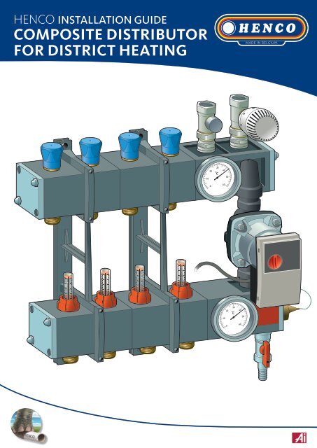
HENCO INSTALLATION GUIDE<br />
<strong>COMPOSITE</strong> <strong>DISTRIBUTOR</strong><br />
<strong>FOR</strong> <strong>DISTRICT</strong> <strong>HEATING</strong>
Composite distributor for district heating<br />
Introduction<br />
The composite distributor for district heating is used to distribute<br />
the medium in systems for underfloor heating and cooling. This<br />
series of distributors has been created using a special composite<br />
which makes it suitable for systems which use low temperatures.<br />
Two models<br />
The composite distributor for district heating is available<br />
in two models. Both models have been fitted with a pump<br />
group, a thermostat valve with capillary and a check valve<br />
between the supply and the return. The Essent model is<br />
being extended with an extra thermostatic valve and zone<br />
valve. The Nuon/Eneco model has been equipped with an<br />
RTL knob on the return (to help determine the temperature<br />
limits) and an RTL valve to the supply (to help determine the<br />
amount of water in litres).<br />
Static or dynamic adjustment<br />
The distributors can be pre-assembled in two ways. The<br />
supply valve on the first type has been equipped with flow<br />
meters for the flow’s static setting, the supply valve on the<br />
second type has been equipped with regulator valves for<br />
a dynamic setting. The other components are identical in<br />
both versions.<br />
Dimensions<br />
The width of the distributor depends on the number of groups.<br />
The depth of the distributor depends on the type of pump and can be anywhere between 165 mm to 200 mm.<br />
Groups 1 2 3 4 5 6 7 8 9 10 11 12 13 14 15 16<br />
Width (mm) 225 285 345 405 465 525 585 645 705 765 825 885 945 1005 1065 1125<br />
60<br />
NNuon/Eneco: 545<br />
Essent: 535<br />
60<br />
¾”<br />
97<br />
breedte<br />
165 - 200
II<br />
I<br />
III<br />
Return distributor<br />
Thermostatic zone<br />
valve (optional)<br />
Supply: thermostatic valve with<br />
thermostat knob<br />
Return: thermostatic valve<br />
with RTL knob<br />
Return: foot valve with<br />
ventilator, filling and<br />
draining function<br />
Supply: thermostatic valve<br />
with thermostat knob<br />
Supply: thermostatic<br />
zone valve<br />
Return: foot valve with<br />
ventilator, filling and<br />
draining function<br />
20<br />
30<br />
Thermostatic valve<br />
with handwheel<br />
Thermostatic<br />
valve M30 x 1,5<br />
Model Nuon/Eneco<br />
Model Essent Essent model<br />
Thermometer<br />
Connection 3/4”<br />
x euroconus<br />
Circulator pump<br />
L<br />
N<br />
200<br />
30<br />
340<br />
200<br />
30<br />
340<br />
200<br />
Immersion pipe<br />
Supply distributor<br />
AFC: Active Flow<br />
Control (optional)<br />
Thermometer<br />
Flow meter, adjustable<br />
& can be shut off<br />
Filling valve and<br />
drain valve<br />
Technical specifications<br />
Medium:<br />
water or water glycol solutions<br />
Maximum percentage glycol: 30%<br />
Maximum working pressure:<br />
4 bar<br />
Maximum static pressure using cold water: 6 bar<br />
Temperature range: 5 - 55°C<br />
Flow meter scale:<br />
1 - 5 l/min<br />
Thermometer scale: 0 - 60°C<br />
Connecting the distributor:<br />
1” F<br />
Connecting the groups:<br />
3/4” M - euroconus<br />
Centre distance between the groups: 60 mm
II<br />
I<br />
III<br />
II<br />
II<br />
II<br />
II<br />
1. Assembly<br />
Fix the extra parts to the distributor and attach the distributor to the wall using the bolts and plugs provided.<br />
The Nuon/Eneco model is used in this example unless stated otherwise.<br />
Model Essent<br />
1<br />
2<br />
Model Nuon/Eneco<br />
1 2<br />
20<br />
30<br />
Remove the protective cap<br />
from the top thermostat<br />
valve.<br />
3 4<br />
L<br />
Attach the zone valve to the<br />
thermostat valve by hand.<br />
Remove the protective cap<br />
from the thermostat valve.<br />
Fix the distributor to the wall.<br />
Turn the RTL knob to 50. Attach<br />
it to the thermostat valve by<br />
hand and set the parameters in accordance<br />
with the district heating<br />
supplier’s instructions.<br />
N<br />
L<br />
N<br />
L<br />
N<br />
I<br />
III<br />
L<br />
N<br />
L<br />
N<br />
Distance between the brackets<br />
I<br />
III<br />
The number of brackets needed depends on the number of groups<br />
connected to the distributor. Distance in millimetres.<br />
I<br />
III<br />
200<br />
30<br />
340<br />
200<br />
Remove the circulator pump’s<br />
cover and connect the wires to<br />
the zone valve near the plugs<br />
wires. Take heed of the following<br />
colours: brown with L, blue with N.<br />
5<br />
200<br />
30<br />
340<br />
200<br />
Remove the protective cap from<br />
the bottom thermostat valve.<br />
6<br />
2 brackets A (mm)<br />
2-groups 60<br />
3-groups 60<br />
4-groups 120<br />
5-groups 180<br />
6-groups 240<br />
7-groups 300<br />
8-groups 360<br />
9-groups 420<br />
10-groups 480<br />
A<br />
355 mm<br />
L<br />
N<br />
200<br />
30<br />
340<br />
200<br />
Attach the thermostat knob to 6<br />
and connect it to the thermostat<br />
valve by hand.<br />
Assemble the sensor in<br />
immersion pipe.<br />
I<br />
III<br />
L<br />
N<br />
L<br />
N<br />
3 brackets A B<br />
11-groups 240 300<br />
12-groups 300 300<br />
13-groups 300 360<br />
14-groups 360 360<br />
15-groups 360 420<br />
16-groups 420 420<br />
17-groups 420 480<br />
18-groups 480 480<br />
A<br />
B<br />
200<br />
30<br />
340<br />
200<br />
4 brackets A B C<br />
19-groups 300 360 360<br />
20-groups 360 360 360<br />
A B C<br />
Fix the distributor to the wall.<br />
L<br />
N
20<br />
30<br />
II<br />
I<br />
III<br />
II<br />
I<br />
III<br />
II<br />
I<br />
III<br />
II<br />
II<br />
III<br />
20<br />
30<br />
20<br />
20<br />
30<br />
30<br />
20<br />
30<br />
20<br />
30<br />
II<br />
I<br />
III<br />
II<br />
I<br />
2. Connection<br />
Connect the district heating’s (primary) supply and return,<br />
and connect the underfloor heating pipes (secondary).<br />
3. Filling<br />
Fill the underfloor heating pipes.<br />
1 2<br />
1 2<br />
20<br />
30<br />
20<br />
30<br />
20<br />
30<br />
20<br />
30<br />
Connect the return pipe to<br />
the return valve.<br />
Connect the supply pipe to<br />
the thermostat valve.<br />
20<br />
30<br />
Close all groups. Turn the<br />
thermostat knob to 0.<br />
Connect the return valve<br />
using a screwdriver and<br />
screw the provided hose<br />
nipple to the return valve.<br />
3<br />
4<br />
3<br />
20<br />
30<br />
4<br />
L<br />
N<br />
Connect the underfloor<br />
heating<br />
pipe to the return<br />
distributor.<br />
Tighten the coupling using the included<br />
plastic assembly spanner.<br />
I<br />
III<br />
Connect the filling pipe<br />
to the filling and draining valves,<br />
and the draining pipe to the<br />
200<br />
30<br />
340<br />
200<br />
return valve (primary side).<br />
I<br />
Open the filling and the draining<br />
valves.<br />
III<br />
5<br />
6<br />
5<br />
6<br />
Install the pipe. Avoid tension<br />
on the distributor by making a<br />
perpendicular, but fluid curve.<br />
Cut the other end of<br />
the pipe to the right<br />
length and connect<br />
it to the supply distributor<br />
the same way.<br />
Fill the first group by opening it.<br />
Make sure that all air is removed<br />
from the circuit.<br />
Close the first group.<br />
Repeat steps 3 through 6 for all the groups<br />
connected to the distributor.<br />
Repeat steps 5 and 6 for all the other groups.
II<br />
III<br />
20<br />
30<br />
II<br />
II<br />
II<br />
I<br />
III<br />
L<br />
N<br />
II<br />
II<br />
I<br />
III<br />
4. Pressure test<br />
Pressurise the system and complete the pressure<br />
report.<br />
I<br />
5. Adjustments<br />
Set the calculated flow per group to guarantee optimal comfort.<br />
This will occur statically or dynamically depending onthe<br />
version you choose.<br />
1<br />
2<br />
Preparatory steps for the Nuon/Eneco model<br />
1 2<br />
20<br />
30<br />
20<br />
30<br />
20<br />
30<br />
Connect the test pump to<br />
supply distributor’s filling and<br />
draining valves.<br />
Close the return valve<br />
using a screwdriver.<br />
Remove the protective cap<br />
from the thermostat valve.<br />
Attach the valve to the calculated<br />
capacity using a screwdriver. Please<br />
see the valve’s manual provided.<br />
3<br />
4<br />
3 4<br />
20<br />
30<br />
20<br />
30<br />
2 3 4<br />
1<br />
5<br />
°C<br />
-20<br />
0<br />
6<br />
60<br />
bar<br />
I<br />
I<br />
I<br />
III<br />
III<br />
III<br />
0<br />
40<br />
20<br />
Open all groups.<br />
5<br />
200<br />
Pressurize the distributor.<br />
Minimum 4 bar, maximum 6 bar<br />
(in accordance with NEN-EN 1264-4<br />
guidelines).<br />
30<br />
340<br />
200<br />
Turn the thermostat knob to 6<br />
and connect it to the thermostat<br />
valve by hand.<br />
Adjust the RTL knob in accordance<br />
with the district heating supplier’s<br />
instructions. Set the return temperature<br />
by turning the knob to<br />
the desired value(s) and lock this<br />
value/these values by using the<br />
two pins provided.<br />
Check the operation and make<br />
sure there are no leaks in the pressure<br />
report.<br />
You will find the pressure report on the supply’s box.<br />
Set the calculated flow to static or dynamic.
20<br />
30<br />
200<br />
30<br />
340<br />
200<br />
30<br />
340<br />
2 0<br />
200<br />
30<br />
340<br />
2 0<br />
200<br />
30<br />
340<br />
2 0<br />
20<br />
30<br />
II<br />
20<br />
30<br />
20<br />
30<br />
20<br />
30<br />
Static<br />
Dynamic<br />
1<br />
2<br />
1 2<br />
I<br />
III<br />
30 340<br />
200<br />
30<br />
340<br />
200<br />
200<br />
340<br />
200<br />
200<br />
30<br />
340<br />
200<br />
200<br />
30<br />
340<br />
200<br />
Open all groups and<br />
operate the system as usual.<br />
Remove the the red cap from the<br />
flow meter.<br />
Open all groups and make<br />
sure the installation runs<br />
under normal working conditions.<br />
Remove the transparant locking<br />
cap.<br />
3<br />
4<br />
3<br />
4<br />
I<br />
I<br />
I<br />
200<br />
30<br />
340<br />
200<br />
200<br />
II<br />
III<br />
340<br />
200<br />
200<br />
200<br />
30<br />
340<br />
200<br />
200<br />
II<br />
III<br />
30<br />
340<br />
200<br />
200<br />
30 340<br />
340<br />
30<br />
340<br />
200<br />
200<br />
30<br />
340<br />
200<br />
200<br />
30<br />
340<br />
II<br />
III<br />
200<br />
Adjust the RTL knob in accordance<br />
with the district heating supplier’s<br />
instructions. Set the return temperature<br />
by turning the knob to<br />
the desired value(s) and lock this<br />
value/these values by using the<br />
two pins provided.<br />
Reposition the red cap back over<br />
the flow meter to prevent the settings<br />
from changing.<br />
Set the calculated flow by turning<br />
the hand wheel to the desired<br />
value.<br />
Reposition the transparent locking<br />
cap to the handwheel to prevent<br />
the settings from changing.<br />
Repeat steps 2 through 4 for all the groups connected<br />
to the distributor.<br />
Repeat steps 2 through 4 for all the groups connected<br />
to the distributor.<br />
Connecting zone valves (optional)<br />
You can connect zone valves if desired. Zone valves, when<br />
combined with zone controls, allow you to independently<br />
determine the temperature in each area.<br />
1 2<br />
1<br />
2<br />
Remove the handwheel from the thermostat valve.<br />
Attach the zone valve to the thermostat valve by hand.<br />
200<br />
30<br />
340<br />
200<br />
200<br />
30<br />
340<br />
200<br />
200<br />
30<br />
340<br />
200<br />
200<br />
30<br />
340<br />
200
Tips & comments<br />
General safety regulations<br />
n Please read this manual before using the distributor.<br />
n The distributor should be installed by a qualified professional.<br />
n The water in the distributor can reach 55°C. Please prevent skin contact at all<br />
n<br />
n<br />
n<br />
times.<br />
We are not responsible for any damages or injuries resulting from a failure to<br />
comply with this manual.<br />
The distributor is solely intended for wall assembly using the bolts and plugs<br />
provided.<br />
Using the right pipes during installation is necessary to guarantee the distributor<br />
will function properly.<br />
Tips when removing<br />
the distributor<br />
Follow the steps below if you wish to remove the<br />
distributor.<br />
1 Release all the water from the distributor.<br />
2 Remove the supply and the return pipes.<br />
3 Remove the distributor from the wall.<br />
4 After disassembly, take the distributor<br />
to the proper collection or recycling point.<br />
Emergency help in the event of a breakdown<br />
Malfunction Cause Resolution<br />
The floor heating doesn't get warm.<br />
The thermostat valves and/or<br />
the flow meters are closed.<br />
Open the thermostat valves and/or flow<br />
meters.<br />
The supply valve and/or return valve is<br />
closed.<br />
Open the supply valve and/or return valve.<br />
All groups are open but there is<br />
little or no flow from the manifold.<br />
There is too much resistance in the circuit.<br />
Possible causes are:<br />
1. Groups are too long<br />
2. Contamination in the system<br />
3. Incorrect installation<br />
1. Check if the maximum length<br />
of the groups has been exceeded.<br />
2. Rinse the installation.<br />
3. Consult your installer.<br />
HENCO cannot be held responsible for any printing errors. The technical data in this edition are<br />
subject to change and are therefore of a non-binding character. Nothing in this edition may be<br />
copied, reproduced and/or published by reprinting, photocopying, transfer to microfilm, or by any<br />
other reproduction method whatsoever without the prior consent from HENCO Industries NV.<br />
DO08-0006EN00 imaprorealisations.com<br />
Your Connection to Perfection<br />
HENCO Industries NV • Toekomstlaan 27 - B-2200 Herentals • Tel. +32 14 28 56 60 • Fax +32 14 21 87 12 • www.HENCO.be