Metal Matrix Composites and Physical Properties - ICCM
Metal Matrix Composites and Physical Properties - ICCM
Metal Matrix Composites and Physical Properties - ICCM

You also want an ePaper? Increase the reach of your titles
YUMPU automatically turns print PDFs into web optimized ePapers that Google loves.
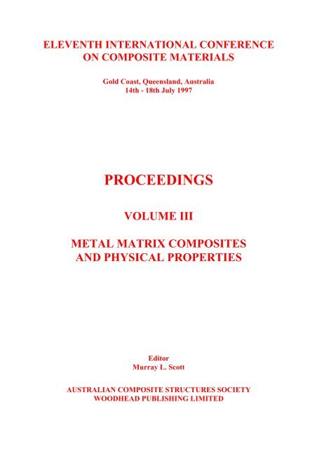
ELEVENTH INTERNATIONAL CONFERENCE<br />
ON COMPOSITE MATERIALS<br />
Gold Coast, Queensl<strong>and</strong>, Australia<br />
14th - 18th July 1997<br />
PROCEEDINGS<br />
VOLUME III<br />
METAL MATRIX COMPOSITES<br />
AND PHYSICAL PROPERTIES<br />
Editor<br />
Murray L. Scott<br />
AUSTRALIAN COMPOSITE STRUCTURES SOCIETY<br />
WOODHEAD PUBLISHING LIMITED
TABLE OF CONTENTS<br />
<strong>Metal</strong> <strong>Matrix</strong> <strong>Composites</strong><br />
Local Strain Fields in a Particulate <strong>Metal</strong> <strong>Matrix</strong> <strong>Composites</strong> Characterized by<br />
Object Grating Technique<br />
Y.L. Liu, G. Fischer<br />
In Situ Tensile Observation of a Squeeze Casting SiC Whisker-6061AL<br />
Composite in Transmission Electron Microscope<br />
ZongRong Liu, DeZun Wang<br />
Analysis on the Load Transfer to Misaligned Whiskers in<br />
<strong>Metal</strong> <strong>Matrix</strong> Composite<br />
Soon H. Hong, Kyung H. Chung<br />
Microstructure of Titanium Dioxide(Rutile)/Pure Aluminum <strong>Composites</strong><br />
Gen Sasaki, Isao Tuchitori, Hideharu Fukunaga<br />
The Interpretation of X-Ray Stress Measurements of <strong>Metal</strong> <strong>Matrix</strong> <strong>Composites</strong><br />
Using Computer Modelling Techniques<br />
M.R. Watts, P.J. Withers<br />
A Cost Effective Foundry Method for the Preparation of Structural Grade<br />
Discontinuously Reinforced AIMCs<br />
Varuzan M. Kevorkijan<br />
Thermomechanical Behavior of Squeeze Cast SiC/AI <strong>Metal</strong>-<strong>Matrix</strong> <strong>Composites</strong><br />
S. Elomari, M.D. Skibo, C. San Marchi, H. Richards<br />
Reaction Hardening of TiO 2 /Al Alloys <strong>Composites</strong> Stimulated by Doping<br />
Isao Tsuchitori, Toshio Fujii, Nobuyuki Fuyama, Hideharu Fukunaga<br />
A Study of the <strong>Metal</strong> Flow Characteristics of Composite Sheets Formed by<br />
Powder Plating <strong>and</strong> Rolling<br />
Zhang Daiming, Sun Yong, Zhang Shuhong, Shi Qingnan<br />
Surface MMCs on a TI-6AL-4V Alloy Produced by Combining Laser Nitriding<br />
<strong>and</strong> Powder Alloying<br />
C. Hu, H. Xin, T.N. Baker<br />
Graphite Reinforced Non Equilibrium Al-Mo <strong>Metal</strong> <strong>Matrix</strong> <strong>Composites</strong><br />
Barbara A. Shaw, William C. Moshier, Robert G. Wendt<br />
Electron Irradiation Induced Crystalline Amorphization at SiO 2 Surface Layer<br />
of SiC Particles in a SiCp/Al Composite<br />
Zhi Mei, Mingyuan Gu, Yi Liu, Renjie Wu<br />
Joining Process of Alumina Borate Whiskers Reinforced Aluminum Composite<br />
J. Hu, W.D. Fei, Q.F. Xing<br />
Resistance Brazing of SiCp/Al Composite<br />
J. Zhang, J. Yu, S. Meng, X.B. Zeng<br />
Effect of Sintering Conditions on the Bond Strength of Roll Bonded <strong>Metal</strong><br />
Laminate <strong>Composites</strong><br />
Xing Kui Peng, Greg Heness, Wing Yiu Yeung<br />
Effects of Process Parameters <strong>and</strong> Surface Conditioning on the Bonding<br />
Between MMC-Inserts <strong>and</strong> <strong>Matrix</strong><br />
Sabine Hofmann, Eric Neussl, Peter R. Sahm<br />
1<br />
10<br />
15<br />
24<br />
32<br />
43<br />
53<br />
63<br />
75<br />
80<br />
90<br />
101<br />
108<br />
113<br />
119<br />
126<br />
xiii
Design <strong>and</strong> Mechanical <strong>Properties</strong> of Continuous Fibre Reinforced MMC<br />
Bolt Connectors<br />
Eric Neussl, Sabine Hofmann, Peter R. Sahm, Jérôme Pora, Dominique Schuster<br />
Hot Forging of a Suspension Arm Component in Al-MMC for<br />
Automotive Applications<br />
A. Forcellese, F. Gabrielli, S.M. Roberts, P.J. Withers<br />
High Strain Rate Superplasticity of Ceramic Particulate Reinforced<br />
Aluminium <strong>Composites</strong> <strong>and</strong> the Fabrication Processing<br />
Tsunemichi Imai, Takeo Hikosaka, Gilles L'Esperance, B<strong>and</strong>e Hong, Daming Jiang<br />
Fabrication <strong>and</strong> <strong>Properties</strong> Of Reaction Squeeze Cast (Al 2 O 3 .SiO 2 +Ni)/A1<br />
Hybrid <strong>Metal</strong> <strong>Matrix</strong> <strong>Composites</strong><br />
Sangsuck Kim, Sungmin Kang, Ik-Min Park, Sungjoon Kim, Ildong Choi<br />
Lower Volume Fraction SiCp/Al <strong>Composites</strong> Fabricated by<br />
Squeeze Infiltration Casting<br />
Kung-Hsien Shue, Su-Jien Lin<br />
Reaction Squeeze Cast Processing <strong>and</strong> Intermetallics Dispersed<br />
Aluminum <strong>Matrix</strong> <strong>Composites</strong><br />
Hideharu Fukunaga, Gen Sasaki, Isao Tsuchitori, Toshio Fujii, Nobuyuki Fuyama<br />
High Temperature Thermal Explosive Synthesis of Nickel/Nickel Aluminide<br />
Multilayer <strong>Composites</strong><br />
Huabin Wang, Jie-Cai Han, Shanyi Du<br />
Superplastic Forming of Aluminum <strong>Matrix</strong> Composite Sheets Reinforced by<br />
SiC Particles<br />
T. Ninomiya, H. Hira, N. Kanetake, T. Choh<br />
Machining of Reinforced Aluminium <strong>and</strong> Magnesium<br />
K. Weinert, D. Biermann, M. Liedschulte<br />
The Effect of a Slight Interfacial Reaction on the Mechanical Behaviour of<br />
Squeeze-Cast SiCp/6061 Al <strong>Composites</strong><br />
Yan Cui, Lin Geng, Congkai Yao, Xiaoli Li<br />
Influence of the Interface on the Creep <strong>Properties</strong> of the Carbon Fibre<br />
Reinforced Magnesium Alloy AS41<br />
Bernd Sommer, Karl Ulrich Kainer, Harry Berek<br />
Strain Analysis of Interface of Composite Formed by PPR Method with<br />
Computer-Aided Techniques<br />
Zhang Shuhong, Zhang Daiming, Sun Yong, Shi Qingnan<br />
Effects of the Interface on Local Versus Global Load Sharing Behavior in <strong>Metal</strong><br />
<strong>Matrix</strong> <strong>Composites</strong> Under Longitudinal Tension<br />
B.S. Majumdar, T.E. Matikas, D.B. Miracle<br />
Microstructure <strong>and</strong> Mechanical <strong>Properties</strong> of Al-4.5Wt.%Cu/10Vol.%SiCp<br />
<strong>Metal</strong> <strong>Matrix</strong> Composite Fabricated via Mechanical Alloying Technique<br />
J.K. Kek, L. Lu, M.O. Lai<br />
The Effects of Interfacial Debonding <strong>and</strong> Work Hardening on the Fracture of<br />
<strong>Metal</strong>-Ceramic Laminates<br />
S.J. Howard, S.K. Pateras, T.W. Clyne<br />
Effect of Squeeze Infiltration Speed on Infiltration Quality <strong>and</strong> Tensile<br />
<strong>Properties</strong> of Cast Saffil/AlCu4MgAg Composite<br />
S. Long, O. Beffort, L. Rohr, H.M. Flower<br />
134<br />
143<br />
154<br />
164<br />
174<br />
182<br />
192<br />
198<br />
205<br />
215<br />
221<br />
230<br />
238<br />
250<br />
260<br />
274<br />
xiv
The Mechanical <strong>Properties</strong> of Particulate Reinforced Aluminum Alloy at<br />
Elevated Temperature<br />
J.H. Shyong, Y.M. Yeh, C.H. Huang, C.Y. Ma<br />
<strong>Properties</strong> of Discontinuously Reinforced Copper <strong>Matrix</strong> <strong>Composites</strong><br />
J. Goñi, D. Coupard, A. Garcia-Romero, M.C. Castro, J. Coleto , C. Foruria,<br />
J.F. Silvain<br />
Effect of Reinforcement <strong>and</strong> Processing on Isothermal Creep <strong>Properties</strong> of<br />
Discontinuously Reinforced Aluminium <strong>Composites</strong><br />
A.F. Whitehouse, H.M.A. Win<strong>and</strong><br />
The Bending <strong>Properties</strong> <strong>and</strong> Fracture Character of Directional Solidified<br />
Al 2 O 3 /Al-4.5Cu <strong>Composites</strong><br />
Chu Shuangjie, Wu Renjie, Zhao Changzheng<br />
Transverse Tensile Characterization of SiC/Ti-6242 Fiber-Reinforced MMC's<br />
with the Cruciform Sample Geometry<br />
D.B. Miracle, A.F. Kalton, T.W. Clyne<br />
Fracture Toughness Evaluation of Hybrid <strong>Metal</strong> <strong>Matrix</strong> <strong>Composites</strong><br />
J.I. Song, K.S. Han<br />
Assessment of Microfracture Mechanisms in Al 2 O 3 /6061 Al <strong>and</strong> SiC/6061 Al<br />
Discontinuous Reinforced <strong>Composites</strong><br />
J.P. Lucas, J.K. Park<br />
Influence of SiC Particles Volume Fraction on Ductile Damage Process in<br />
Al-Si <strong>Metal</strong> <strong>Matrix</strong> <strong>Composites</strong><br />
N. Bonora, F. Iacoviello, G.M. Newaz<br />
An In Situ Study of Fatigue Crack Growth in Comral-85 at Ambient <strong>and</strong><br />
Elevated Temperatures<br />
Greg Heness, Yiu-Wing Mai<br />
Strength Degradation in Titanium <strong>Matrix</strong> <strong>Composites</strong> Exposed to Fatigue at<br />
Elevated Temperature<br />
David D. Robertson, Shankar Mall<br />
Effect of the Interface on Crack Deflection <strong>and</strong> Fiber Bridging During Fatigue<br />
Crack Growth of SiC/Ti-6Al-4V <strong>Composites</strong><br />
S.G. Warrier, B.S. Majumdar, D.B. Miracle<br />
Synthesis of YBa 2 Cu 3 O 7-x /Ag Composite Superconductors by a<br />
Citric Acid SOL-Gel Method<br />
A.L. Juwono, S. Waluyo, S. Poertadji<br />
Fabrication <strong>and</strong> Characterisation of Continuous Fibre Reinforced<br />
MoSi 2 -Based <strong>Composites</strong><br />
A.R. Bhatti, R.A. Shatwell<br />
On the Role of Carbon Diffusion During Fiber/<strong>Matrix</strong> Reaction in SiC Fiber<br />
Reinforced Ti-Based MMCs<br />
S. Krishnamurthy, D.B. Miracle<br />
Damage Accumulation <strong>and</strong> Fracture in <strong>Metal</strong> <strong>Matrix</strong> <strong>Composites</strong><br />
J.D. Boyd, R.D. Evans, G. de Kleine, S. Tao<br />
Rupture of 7075/Al 2 O 3 <strong>Composites</strong> at High Temperature<br />
H.J. McQueen, E.V. Konopleva, G. Avramovic Cingara<br />
Relations of the Mesoscopic Damage Mechanisms with the<br />
Macroscopic <strong>Properties</strong> of <strong>Metal</strong> <strong>Matrix</strong> <strong>Composites</strong><br />
Chen Haoran, Su Xiaofeng<br />
284<br />
294<br />
300<br />
311<br />
317<br />
327<br />
337<br />
348<br />
356<br />
365<br />
374<br />
384<br />
391<br />
399<br />
409<br />
418<br />
429<br />
xv
Synthesis <strong>and</strong> Compression Behaviour of Al 2 O 3 -Al 3 Ti In Situ Intermetallic<br />
<strong>Matrix</strong> Composite<br />
Huaxin Peng, Ceng Liu, Dezun Wang<br />
Effect of Interfacial Damage on Residual Tensile Strength for SCS6/Ti-15-3<br />
<strong>Metal</strong> <strong>Matrix</strong> Composite<br />
Chitoshi Masuda, Yoshihisa Tanaka, Yu-Fu-Liu<br />
Fully-Coupled Thermomechanical Analysis of Viscoplastic <strong>Composites</strong> Under<br />
Quasistatic <strong>and</strong> Dynamic Environments<br />
Eui-Sup Shin, Seung-Jo Kim, Yong Hyup Kim<br />
The Failure Mechanism in Monofilament-Reinforced Titanium Under<br />
Axial Compression<br />
J.E. Spowart, T.W. Clyne<br />
Superplastic Deformation Mechanisms for SiC Whisker And Particulate<br />
Reinforced Aluminium <strong>Composites</strong><br />
K.C. Chan, B.Q. Han<br />
Superplasticity of Ceramic Particulate Reinforced Magnesium Alloy <strong>Composites</strong><br />
Fabricated by a Melt Stirring Method<br />
Suk-Won Lim, T. Imai, Y. Nishida, D. Jiang<br />
Electrochemical Plating of Composite Coatings<br />
S. Steinhäuser, B. Wielage<br />
SiCp - Al <strong>Composites</strong> Fabricated with a Modified Extrusion Method<br />
S. Kohara<br />
<strong>Properties</strong> of Particle Reinforced Magnesium Alloys in Correlation with<br />
Different Particle Shapes<br />
F. Moll, K.U. Kainer<br />
Fracture Behavior of Cast SiCp-Al <strong>Composites</strong> Under Elevated Temperature<br />
Daifeng Wang, Fengying Wu, Pengxing Li, Renjie Wu, Jingkun Guo<br />
Squeeze Casting <strong>and</strong> Characterization of Al 2 O 3 p/ZL102 Composite Materials<br />
X.L. Guo, B.Y. Wu, J. Tao, S.L. Li<br />
Cold Rolling of Particle Reinforced Aluminium <strong>Matrix</strong> Composite <strong>and</strong><br />
Mechanical <strong>Properties</strong><br />
N. Kanetake, T. Kaneko, T. Choh<br />
An In-Situ Study of the Fracture Mechanisms of SiCw/AZ91 Magnesium<br />
<strong>Matrix</strong> <strong>Composites</strong><br />
Mingyi Zheng, Kun Wu, Wencong Zhang, Min Zhao<br />
Study on Fabrication Technique of Al 2 O 3 /Steel Composite Pipe by<br />
Centrifugal SHS Process<br />
Wei Canchun, Zhou Xiang, Tao Jie<br />
High Temperature Compressive Deformation Behavior of SiCw/6061Al<br />
Composite at Liquid-Solid Dual Phase Zone<br />
L. Geng, J. Q. Hu, B. Liu<br />
SiC Particles Volume Fraction Influence on Fatigue Crack Propagation in Al-Si<br />
<strong>Metal</strong> <strong>Matrix</strong> <strong>Composites</strong><br />
F. Iacoviello, N. Bonora, L. Jaresovà, Z. Jonsta, L. Hyspeckà<br />
Modelling <strong>and</strong> Experimental Characterisation of Phase Strain Evolution in<br />
10vol% Al/SiC w Composite During Thermo Mechanical Loading<br />
T. Lorentzen, Y.L. Liu<br />
438<br />
447<br />
457<br />
467<br />
479<br />
486<br />
495<br />
505<br />
511<br />
520<br />
527<br />
532<br />
539<br />
546<br />
550<br />
556<br />
565<br />
xvi
Synthesis <strong>and</strong> Characterization of Si- N=C=N Containing Preceramic Polymers<br />
Hai-Feng Hu, Zhao-Hui Chen, Chun-Xiang Feng, Chang-Rui Zhang, Yong-Cai Song,<br />
Jia-Yu Xiao, Zheng-Fang Xie, Wen-Wei Zheng, Zheng-Xiang Fan<br />
Elastic Deformation Behaviors of Particulate Reinforced <strong>Composites</strong><br />
Quan Gaofeng, Chai Donglang, Song Yujiu<br />
Detection of Dislocations in Short Fibre Reinforced Magnesium Alloys by<br />
Non-Destructive Methods<br />
J. Kiehn, K.U. Kainer, Z. Trojanová, F. Chmelik, P. Lukác<br />
Process <strong>and</strong> Tribological Behavior of 6061 Al/Gr.(p) <strong>Composites</strong><br />
R.J. Chang, C.B. Lin<br />
Hardness Property <strong>and</strong> Wear Resistance of ZN-AL/AL 2 O 3 p or SiCp<br />
Particulate Composite<br />
Tao Jie, Cui Yihua , Li Shunlin<br />
A Study on the Microstructure of Alumina Borate Whisker Reinforced<br />
Aluminum Composite<br />
W.D. Fei, L.J. Yao, C.K. Yao<br />
Cast Welding of Aluminum Alloy Reinforced with Alumina Material<br />
C.K Mu, C.B. Lin<br />
The Effect of Squeeze Casting <strong>and</strong> Hot Extrusion Process on the<br />
Mechanical <strong>Properties</strong> of SiCp/Al <strong>Composites</strong><br />
C.G. Kang, Y.H. Seo<br />
Microstructure of LaB 6 -ZrB 2 In Situ Composite Prepared by<br />
Electron Beam Heated Melting Methods<br />
Chang-Ming Chen, W.C. Zhou, L.T. Zhang, L.F. Cheng, Y.D. Xu<br />
Nano-Structures of Pitch-Based Carbon Fibers <strong>and</strong> the Compatibility with<br />
Aluminium <strong>Matrix</strong> <strong>Composites</strong><br />
Takakazu Suzuki<br />
Preparation <strong>and</strong> the <strong>Properties</strong> of SiC/MoSi 2 <strong>Composites</strong><br />
J.Pan, B.W. Liu, D.M. Yang, M.K. Surappa, Y. Zhuo<br />
Models of Anodic Diffusion When Joining PSZ to Nickel<br />
Yu Wang, Robert G. Bathgate<br />
The Influence of Solidification on the Interface of CF/Al-4.5 CU <strong>Composites</strong><br />
Chu Shuangjie, Wu Renjie<br />
The Sliding Wear Resistance Behavior of NiAl <strong>and</strong> SiC Particles Reinforced<br />
Aluminium <strong>Matrix</strong> <strong>Composites</strong><br />
Rong Chen, Akira Iwabuchi, Tomoharu Shimizu, Hyung Seop Shin, Hidenobu Mifune<br />
Fabrication of SiC-Reinforced AZ91D Magnesium-Based <strong>Composites</strong><br />
Jason S.H. Lo, Graham J.C. Carpenter<br />
Effect of Microstructure, Interface <strong>and</strong> on the Aging Behavior of A356<br />
Al/SiC(p) <strong>Composites</strong><br />
J.J. Yeh, L.D. Chen, C.B. Lin<br />
The Influence of Heat Treatment on the Dry Sliding Wear Behaviour of Saffil-<br />
Reinforced AA6061 <strong>Composites</strong><br />
H.C. How, T.N. Baker<br />
573<br />
578<br />
585<br />
597<br />
607<br />
612<br />
617<br />
627<br />
637<br />
643<br />
653<br />
661<br />
672<br />
678<br />
688<br />
698<br />
709<br />
xvii
<strong>Physical</strong> <strong>Properties</strong><br />
Moisture Absorption in Voided Polymer <strong>Composites</strong><br />
L.M.P. Fellows, A.R. Chambers<br />
Shielding Effects of Different Aspect Ratio of Aluminum Flakes in<br />
Conductive Plastics for Injection Molding Processes<br />
Huang-Lung Hung, Chao-Chang A. Chen, C.B. Lin, C.H. Liu, Tung-Han Chuang<br />
Neutron Diffraction Study of the Co-Deformation Behavior of a<br />
Beryllium-Aluminium Composite<br />
David H. Carter, Mark A.M. Bourke<br />
Generation of Electret State in Composite Polymeric Materials by Friction<br />
A.I. Sviridenok, A.F. Klimovich, V.N. Kestelman<br />
The Flow Behaviour of <strong>Composites</strong> Containing Cut, Aligned Fibres<br />
D.T. Steel, W.J. Clegg<br />
A Study on Thermo-Oxidative Stability of Non-MDA PMR Polyimide<br />
<strong>Composites</strong><br />
Xiang Bao Chen, Ying Fu, Ping Li<br />
The Application of Positron Annihilation Methods for Investigation <strong>and</strong><br />
Testing of <strong>Composites</strong><br />
S.A. Tishin, V.A. Tishin, V.N. Kestelman<br />
Nonlinear Viscoelastic Characterization of Filled Elastomer <strong>Composites</strong><br />
J.D. Brown, S.S. Sternstein, L. Yanyo<br />
“Good Vibrations”, the Science <strong>and</strong> Application of Intrinsically Damped<br />
Composite Materials<br />
I.D. Grant, A. Lowe, S. Thomas<br />
719<br />
727<br />
736<br />
746<br />
755<br />
765<br />
772<br />
781<br />
792<br />
xviii
Proceedings of <strong>ICCM</strong>–11, Gold Coast, Australia, 14th-18th July 1997<br />
LOCAL STRAIN FIELDS IN PARTICULATE METAL<br />
MATRIX COMPOSITES CHARACTERIZED BY THE<br />
OBJECT GRATING TECHNIQUE<br />
Y. L. Liu 1 <strong>and</strong> G. Fischer 2<br />
1<br />
Materials Department, Risø National Laboratory,<br />
Frederiksborgvej 399, P.O. Box 49, DK-4000 Roskilde, Denmark<br />
2 Quality Assurance Department, Dortmund University,<br />
D-44227 Dortmund, Germany<br />
SUMMARY: This paper addresses the experimental characterization of local strain distribution<br />
in Al6061-10%Al 2 O 3 <strong>and</strong> Al6061-20%Al 2 O 3 particulate composites under deformation using the<br />
object grating technique. The maximum overall strain of the specimen deformed by bending or<br />
tension in SEM is 2-3%. The lateral resolution <strong>and</strong> strain measurement accuracy of this<br />
technique allow the local strain field associated with large particles to be characterized. Strain<br />
maps of particles of different geometries have been obtained <strong>and</strong> the effects of particle<br />
geometry on the constrained plastic flow in the matrix are analyzed <strong>and</strong> compared to FEM<br />
predictions.<br />
KEYWORDS: metal matrix composite, object grating technique, deformation, local strain<br />
distribution, constrained plastic flow.<br />
INTRODUCTION<br />
The presence of the hard, plastically undeformable reinforcement in the ductile matrix changes<br />
radically the stress/strain fields in the vicinity of the reinforcement when a metal matrix<br />
composite (MMC) is strained. The characteristics of the stress/strain field are affected by<br />
geometry <strong>and</strong> distribution of the reinforcement. The study of the evolution of the local<br />
stress/strain fields is essential for improved underst<strong>and</strong>ing of the overall elastic <strong>and</strong> plastic<br />
response, <strong>and</strong> of the strengthening mechanisms of the composite. Numerical techniques such as<br />
FEM (Finite Element Model) have been widely used in recent years, where the phase geometry,<br />
thermomechanical properties of phases <strong>and</strong> non-uniform local stress <strong>and</strong> strain fields are easily<br />
accounted for in the simulation of overall mechanical response [1-3]. These models have been<br />
used successfully to make quantitative predictions about the overall stress-strain behaviour of<br />
such materials. On the local scale they demonstrate that the hydrostatic stresses lead to<br />
constrained plastic deformation. The degree of constraint is dependent on the geometrical shape<br />
<strong>and</strong> arrangement of reinforcement.<br />
Various experimental techniques have been developed to characterize the local distribution of<br />
stress/strain in MMCs for comparison with FEM simulations. High energy synchrotron<br />
radiation [4] has been used to determine the local stress field in bulk material of a composite<br />
by measuring the lattice (elastic) strain of small volumes deep within the material. This<br />
technique provides the possibility of in-situ measurements, but the lateral resolution is low<br />
III - 1
Volume III: <strong>Metal</strong> <strong>Matrix</strong> <strong>Composites</strong> <strong>and</strong> <strong>Physical</strong> <strong>Properties</strong><br />
(tens <strong>and</strong> hundreds of microns). TEM (Transmission Electron Microscopy) <strong>and</strong> EBSP<br />
(Electron BackScattered Pattern) have been used to determine the local dislocation density as<br />
a measure of the local plastic strain [5,6]. These methods have high lateral resolution in the<br />
order of microns or less. But the strain measure is indirect.<br />
Object grating methods [7] have been used to characterize the strain fields on the bulk<br />
specimen surface of inhomogeneous materials in the past decades. To meet the new challenge<br />
of applying this technique to local strain investigation in particulate reinforced MMCs where<br />
both high lateral resolution <strong>and</strong> high accuracy of strain measurement are required, a more<br />
sophisticated object grating method has been developed [8,9]. This method combined with a<br />
stress-rig in a scanning electron microscope (SEM) allows the local strain distribution to be<br />
studied in-situ during deformation. The experimental procedure consists of: 1) the deposition<br />
of a grating on the polished specimen surface by photolithography, 2) deforming the specimen<br />
in a SEM by bending or tension, taking digital images at different stages of deformation, 3)<br />
image processing, <strong>and</strong> 4) computation of strain components. Finally the measured strains are<br />
plotted in 2D-strain maps.<br />
With the aim to evaluate numerical predictions of the local behaviour, the MMC materials of<br />
Al6061 containing 10 or 20%Al 2 O 3 particulates are investigated using this object grating<br />
technique. The maximum overall strain reached by bending or tension is 2-3%. In this paper, the<br />
characteristic strain field in the vicinity of the reinforcement particles revealed by this<br />
technique is described, the effects of particle geometry are analyzed <strong>and</strong> compared to FEM<br />
predictions.<br />
EXPERIMENTAL<br />
The materials Al6061-10%Al 2 O 3 <strong>and</strong> Al6061-20%Al 2 O 3 are supplied by Duralcan, USA. The<br />
as-received materials are in the form of extrusion rod. The measured mean particle size of<br />
Al 2 O 3 is 6 - 8 µm, while the particle size distribution ranges from
Proceedings of <strong>ICCM</strong>–11, Gold Coast, Australia, 14th-18th July 1997<br />
The specimen is strained in a stress-rig (Raith GmbH, Dortmund) inside a JEOL 840 SEM.<br />
The loading is applied by the crosshead displacement at a constant speed of 50 mm/min,<br />
corresponding to a strain rate of 10 -5 -10 -4 s -1 in the case of tensile tests. A typical stress-strain<br />
curve recorded during tension is given in Fig. 2. For tensile tests the overall strain is recorded<br />
by an extensometer. The test is interrupted at various strains. Without unloading, digitized<br />
images of the area of interest are taken at each deformation step. Also digitized images before<br />
loading (as a reference image), <strong>and</strong> after final unloading are recorded.<br />
Fig. 2: Stress-strain curve recorded during tensile testing in SEM. 1-8 indicate the<br />
deformation steps where the load is held <strong>and</strong> the image is taken.<br />
Fig. 3: Schematic drawing showing subimage, centre <strong>and</strong> overlapping of subimages.<br />
The especially developed algorithm for image processing [8,9] divides the whole image into<br />
many subimages (Fig. 3). The algorithm is iteratively searching the best local <strong>and</strong> grey value<br />
transformation of each subimage in the deformed state to the corresponding subimage in the<br />
undeformed state. As a result, an average set of local transformation parameters for each<br />
subimage is calculated. The in-plane strain components ε xx , ε yy <strong>and</strong> ε xy at the centre point of<br />
each subimage can be derived on the basis of these transformation parameters. The equivalent<br />
strain ε equ is calculated as<br />
ε equ = 2/3 (ε 1 - ε 2 ) (1)<br />
where ε 1 <strong>and</strong> ε 2 are principal strains. The mathematics for image processing <strong>and</strong> strain<br />
component calculations are given elsewhere [8,9]. Finally contours of strain ε equ are plotted<br />
on the top of the deformed image to visualize the distribution of strain over the<br />
microstructural inhomogeneities.<br />
III - 3
Volume III: <strong>Metal</strong> <strong>Matrix</strong> <strong>Composites</strong> <strong>and</strong> <strong>Physical</strong> <strong>Properties</strong><br />
RESULTS AND DISCUSSION<br />
Strain Measure Accuracy <strong>and</strong> Lateral Resolution<br />
All the strain measurements are performed on the surface of the specimen. One has to assume<br />
that there is no free-surface effect, so the obtained surface information has also a threedimensional<br />
significance. The previous work [9] shows that the measured strain value while<br />
the load is held is a sum of elastic <strong>and</strong> plastic strains. Since the elastic strain value is very low<br />
<strong>and</strong> remains constant in the elastic-plastic region, the measured strain can be considered to<br />
represent the evolution of the plastic strain.<br />
The algorithm determines the displacement of the subimage centre with subpixel accuracy<br />
(0.2 - 0.3 pixel) (see Fig. 3). With a subimage size of 64 pixel, accuracy for strain measure is<br />
therefore estimated to be in the range of 0.3 to 0.5 % [9]. The improvement in strain accuracy<br />
compared with that of the algorithm used by other authors [7] is significant. The latter [7]<br />
extracts the individual dots <strong>and</strong> gives an accuracy of about 1 pixel to determine the<br />
displacement of the centre of each dot.<br />
The lateral resolution is improved with decreasing grating distance <strong>and</strong> subimage size [9]. The<br />
presently used grating distance of 1.5 µm is practically the smallest grating distance which<br />
can be made on the surface of this type of material by means of photolithography. For<br />
statistical reasons a least number of grey level edges within a subimage is needed to secure<br />
the measuring accuracy. The selection of the subimage size is therefore a compromise<br />
between lateral resolution (a small subimage is wanted) <strong>and</strong> strain accuracy (a large subimage<br />
is preferred). In the present work, a combination of the grating distance of 1.5 µm <strong>and</strong> the<br />
subimage size of 64x64 pixel (2.5x2.5 µm) is used. Generally the local strain field around<br />
particles greater than 10 - 15 µm can be characterized [9].<br />
Characterization of Local Strain Fields<br />
With the aim of making a comparison with FEM simulations which are based on ideal arrays<br />
of reinforcement, the particles of interest in the experiment are selected as follows: they are<br />
close to a regular shape <strong>and</strong> reasonably isolated.<br />
Al6061-20%Al 2 O 3<br />
The first set of experiments is carried out using bending specimens of Al6061-20%Al 2 O 3 .<br />
Due to the high volume concentration of the Al 2 O 3 particles <strong>and</strong> the small particle spacing<br />
(calculated value 13 µm), it is very difficult, if not impossible, to find an isolated particle.<br />
Typical microstructure is shown in Fig. 4 where a large particle (about 20 x 30 µm) is<br />
surrounded by many small particles at rather small particle spacing. The shape of the large<br />
particle is irregular <strong>and</strong> it is not aligned with the loading direction. A series of strain maps of<br />
this area at different deformation steps has been obtained, of which two examples are shown<br />
in Fig. 4 (a) <strong>and</strong> (b). The overall strain of these two deformation steps is 1.7 <strong>and</strong> 3.3%,<br />
respectively. (The overall strain is taken as the mean ε equ value over the whole image area).<br />
III - 4
Proceedings of <strong>ICCM</strong>–11, Gold Coast, Australia, 14th-18th July 1997<br />
Fig. 4: Strain maps of Al6061-20%Al 2 O 3 specimen deformed by bending at overall strains of<br />
(a) 1.7% <strong>and</strong> (b) 3.3%..<br />
The characteristic information about the strain field one can obtain from the strain maps in<br />
Fig. 4 is:<br />
1) A systematic development of the strain field with the increasing overall strain can be<br />
visualized.<br />
2) The strain in the Al 2 O 3 particles is lower than 1% in the whole deformation process<br />
studied, apart from a few exceptions in which the strain line of 1% penetrates into the<br />
particles. This agrees with the fact that the Al 2 O 3 particles are not plastically deformable.<br />
3) The deformation introduces large strain gradients in the matrix region close to the<br />
reinforcement particles.<br />
4) Strain localization has different origins. The occurrence of high strain localization in the<br />
matrix may be related to the sharp corner of particle or to a given particle distribution [1-<br />
3, 5]. However, the present microstructural examination shows that high strain peaks are<br />
often associated with micro-voids/cracks [9]. In the studied composites these microdefects<br />
are possibly present in the initial state, <strong>and</strong> new micro-defects may develop at the<br />
early stage of deformation. It is therefore important to distinguish the strain localization<br />
caused by the particle geometry <strong>and</strong> by the presence of micro-voids/cracks. Examples of<br />
strain localization of the latter type can be seen in Fig. 4(b), such as the strain contour<br />
lines of i <strong>and</strong> h near the interface in the lower part of the figure. Similarly the high strain<br />
contour lines (> 1%) within the particle are often found to be associated with microcracks<br />
of the particle.<br />
Al6061-10%Al 2 O 3<br />
Further experiments are carried out by uniaxial tension of Al6061-10%Al 2 O 3 specimens. The<br />
lower concentration of particles <strong>and</strong> the larger particle spacing in this material (calculated<br />
III - 5
Volume III: <strong>Metal</strong> <strong>Matrix</strong> <strong>Composites</strong> <strong>and</strong> <strong>Physical</strong> <strong>Properties</strong><br />
particle spacing 18 µm) give rise to more possibilities of finding reasonably isolated particles.<br />
Two particles of different geometries are selected: one has an aspect ratio of ~ 3 <strong>and</strong> is<br />
aligned to the direction of tensile loading (Fig. 5(a)), whereas the other has an aspect ratio of<br />
~1.5 <strong>and</strong> the axis of the particle is 45 o to the direction of loading (Fig. 5(b)). These two<br />
particles will be referred as A <strong>and</strong> B, respectively in the following text. One must bear in<br />
mind that these observations are made on the specimen surface, which is only a cross section<br />
of the material. On the basis of Fig. 5, we assume that the shapes of particle A <strong>and</strong> B are close<br />
to the ideal shapes of an aligned cylinder <strong>and</strong> a double-cone, respectively. The cross section of<br />
the two ideal shapes is shown schematically in Fig. 6.<br />
III - 6
Proceedings of <strong>ICCM</strong>–11, Gold Coast, Australia, 14th-18th July 1997<br />
Fig. 5: Strain maps of Al6061-10%Al 2 O 3 specimen deformed by tension at an overall strain of<br />
0.4%. (a) particle A, <strong>and</strong> (b) particle B.<br />
Fig. 6: Cross section of the ideal shapes. (a) aligned cylinder, <strong>and</strong> (b) double-cone.<br />
The images of the areas which include the selected particles are taken at overall tensile strains<br />
of 0.4, 1.1, 3.1 <strong>and</strong> 4.6%. Immediately after the stage 4 (4.6%) the specimen fractures. This<br />
paper will concentrate on the study of strain distribution at a very early stage of deformation<br />
(strain of 0.4%) shown in Fig. 5 (a) <strong>and</strong> (b). The contour line of 1% follows the<br />
particle/matrix interface quite well implying that the strain map is a good description of the<br />
strain field around the particle.<br />
III - 7
Volume III: <strong>Metal</strong> <strong>Matrix</strong> <strong>Composites</strong> <strong>and</strong> <strong>Physical</strong> <strong>Properties</strong><br />
Further investigation reveals that for both particles intense matrix plastic deformation occurs<br />
along a direction of about 45 o to the tensile axis. But the extent of plastic flow is different.<br />
Consider the contour line of 1% (c line) in the two maps in Fig. 5, the matrix portion with a<br />
strain greater than this value forms three continuous b<strong>and</strong>s along the 45 o direction (which is<br />
parallel to the interface) for particle B (Fig. 5(b)). The scale of these b<strong>and</strong>s is about 30 µm<br />
long <strong>and</strong> 5 µm wide. But for the particle A (Fig. 5(a)), the matrix region with a strain greater<br />
than 1% is small <strong>and</strong> discontinuous in most cases, only one long b<strong>and</strong> can be seen in the<br />
lower-right part of the particle. This indicates that for the aligned particle with a higher aspect<br />
ratio (particle A), the plastic flow path is to a larger extent interrupted as compared to particle<br />
B.<br />
FEM analysis made by Shen et al. [2] can be correlated with the present observations. The<br />
shapes of particles studied in this FEM work, among others, are cylinder <strong>and</strong> double-cone<br />
(Fig. 6). At an average axial strain of 0.5% under tensile loading, the plastic deformation<br />
b<strong>and</strong>s in the matrix at 45 o to the tensile axis are continuous for the double-cone particle,<br />
whereas this pattern is interrupted for the cylinder, particularly for the aligned cylinder with<br />
an aspect ratio greater than 1 (whisker) (Fig. 6 in [2]). As the ideal shapes of the aligned<br />
cylinder <strong>and</strong> the double-cone are assumed to be related to the shapes of particles A <strong>and</strong> B,<br />
respectively, the comparison between the FEM predictions <strong>and</strong> the experimental observations<br />
shows good qualitative agreement. It is understood that such effects of particle shape on the<br />
local plastic flow pattern within the matrix are caused by the differences in the level of<br />
hydrostatic stress <strong>and</strong> the differences in constrained plastic flow in the matrix [2].<br />
In Fig. 5. it can also be seen that strain tends to be more concentrated at the end of particle A,<br />
but distributed more uniformly around the particle B. This is in agreement with TEM<br />
observations [5] where it is reported that the ends of an aligned whisker (aspect ratio 5) are<br />
particularly associated with early dislocation generation, while the dislocation structure<br />
around a particle (smaller aspect ratio) is more homogeneous. According to FEM predictions<br />
[2], the highest strain localization associated with the end <strong>and</strong> the sharp corner of an aligned<br />
whisker is about two times of that associated with a double-cone particle. However, this<br />
“sharp corner” effect has not been observed in the present experiment. The direct explanation<br />
for the disagreement is that the shape of studied particles in the real composites is more<br />
smooth <strong>and</strong> without sharp corners, by comparison with the assumptions in FEM calculations.<br />
The observed highest strain localization for both particles shown in Fig 5 is, independent of<br />
shape, at the level of 4% (contour line f in Fig. 5(a) <strong>and</strong> (b)), which is about 10 times the<br />
overall strain. The occurrence of such high strain localization may be associated with the early<br />
void initiation (see above), the chance of which may well be similar for both particles. The<br />
strain localization caused by void formation is so intense that the effect of the “sharp corner”<br />
of the aligned particle, if there is any, is likely to be concealed.<br />
CONCLUSIONS<br />
The newly developed object grating technique is a powerful tool for characterizing local strain<br />
fields in metal matrix composites in-situ during deformation in a SEM. The strain distribution<br />
in the matrix around particles greater than 10 - 15 µm can be characterized. The accuracy of<br />
strain measurement is in the range of 0.3 - 0.5%. The development of the strain field in a low<br />
strain range of 2-3% can be followed. Strain maps of particles of different geometries in<br />
particulate composites Al6061-10%Al 2 O 3 <strong>and</strong> Al6061-20%Al 2 O 3 have been obtained at early<br />
stages of deformation by bending/tension. The effects of particle geometry on the constrained<br />
plastic flow in the matrix have been visualized. For the aligned particle with an aspect ratio of<br />
III - 8
Proceedings of <strong>ICCM</strong>–11, Gold Coast, Australia, 14th-18th July 1997<br />
3, the strain in the matrix tends to be more concentrated at the end of the particle <strong>and</strong> the 45 o<br />
plastic flow pattern is often interrupted, whereas the strain around the 45 o aligned particle<br />
with an aspect ratio close to 1 is more homogeneous <strong>and</strong> continuous plastic deformation<br />
b<strong>and</strong>s are formed. The comparison with FEM predictions shows good qualitative agreement.<br />
However, the disagreement suggests that the very high constraint effect at the end <strong>and</strong> corner<br />
of an aligned cylinder predicted by FEM is an overestimation of the situation in the real<br />
material.<br />
ACKNOWLEDGEMENTS<br />
This work is supported by the German Research Foundation (DFG) <strong>and</strong> by the Danish<br />
research program MP 2 M “Centre for Materials Processing, <strong>Properties</strong> <strong>and</strong> Modelling”.<br />
REFERENCES<br />
1. Sørensen, N.J., Hansen, N. <strong>and</strong> Liu, Y.L., “On the Inelastic Behaviour of <strong>Metal</strong> <strong>Matrix</strong><br />
<strong>Composites</strong>”, Proceedings 15th Risø International Symposium on Materials Science,<br />
Andersen, S.I., Bilde-Sørensen, J.B., Lorentzen, T., Pedersen, O.B. <strong>and</strong> Sørensen, N.J.,<br />
Eds., Risø National Laboratory, Roskilde, Denmark, 1994, pp. 149-168.<br />
2. Shen, Y.-L., Finot, M., Needleman, A. <strong>and</strong> Suresh, S., “Effective Plastic Response of<br />
Two-Phase <strong>Composites</strong>”, Acta <strong>Metal</strong>l. Mater., Vol. 43, No. 4, 1995, pp. 1701-1722.<br />
3. Watt, D.F., Xu, X.Q. <strong>and</strong> Lloyd, D.J., “Effects of Particle Morphology <strong>and</strong> Spacing on<br />
the Strain Fields in a Plastically Deforming <strong>Matrix</strong>”, Acta Mater., Vol. 44, No. 2, 1996,<br />
pp. 789-799.<br />
4. Poulsen, H.F., Lorentzen, T., Feidenhans’l, R. <strong>and</strong> Liu, Y.L., “A Synchrotron X-ray<br />
diffraction Study of the Local Residual Strains Around a Single Inclusion in an Al/W<br />
<strong>Metal</strong>-<strong>Matrix</strong> Composite”, <strong>Metal</strong>l. Trans., Vol. 28A, 1997, pp. 237-243.<br />
5. Barlow, C.Y. <strong>and</strong> Hansen, N., “Dislocation Configurations in <strong>Metal</strong>-<strong>Matrix</strong> <strong>Composites</strong><br />
Correlated with Numerical Predictions”, Acta <strong>Metal</strong>l. Mater., Vol. 43, No. 10, 1995, pp.<br />
3633-3648.<br />
6. Wilkinson, A.J. <strong>and</strong> Dingley, D.J., “The Distribution of Plastic Deformation in a <strong>Metal</strong><br />
<strong>Matrix</strong> Composite Caused by Straining Transverse to the Fibre Direction”, Acta <strong>Metal</strong>l.<br />
Mater., Vol. 40, No. 12, 1992, pp. 3357-3368.<br />
7. Allais, L., Bornert, M., Bretheau, T. <strong>and</strong> Caldemaison, D., “Experimental Characterization<br />
of the Local Strain Field in a Heterogeneous Elastoplastic Material”, Acta <strong>Metal</strong>l.<br />
Mater., Vol. 42, No. 11, 1994, pp. 3865-3880.<br />
8. Crostack, H.-A. <strong>and</strong> Fischer, G., Beitrage zur eiektronenmikroskopischen<br />
Direktabbildung und Analyse von Oberflachen (BEDO) Vol.29, in press, (1996).<br />
9. Liu Y.L. <strong>and</strong> Fischer, G., “In-Situ Measurement of Local Strain in a <strong>Metal</strong> <strong>Matrix</strong><br />
Composite by the Object Grating Technique”, Scripta Mater., Vol. 36, No. 10, 1997, pp.<br />
1187-1194.<br />
III - 9
Volume III: <strong>Metal</strong> <strong>Matrix</strong> <strong>Composites</strong> <strong>and</strong> <strong>Physical</strong> <strong>Properties</strong><br />
IN SITU TENSILE OBSERVATION OF A SQUEEZE<br />
CASTING SIC WHISKER-6061AL COMPOSITE IN<br />
TRANSMISSION ELECTRON MICROSCOPE<br />
ZongRong Liu <strong>and</strong> DeZun Wang<br />
National Defence Key Laboratory for precision Hot-Working<br />
School of Materials Science <strong>and</strong> Engineering, Harbin Institute<br />
of Technology, Harbin 150001, People's Republic of China.<br />
SUMMARY: The fracture process of a squeeze casting SiCw/6061Al composite has been<br />
observed using transmission electron microscopy (TEM) straining techniques. The results<br />
show that the crack initiation modes include: (1) cracking of the SiC whiskers; (2) decohesion<br />
of the SiCw-Al interfaces <strong>and</strong> (3) tearing of the matrix. The interaction between crack,<br />
dislocations <strong>and</strong> whisker has been exaimed in detail. The SiC whiskers in the SiCw/6061Al<br />
composite are major obstacles to the propagation of cracks. The SiCw/6061Al composite does<br />
not form the single major crack which results in the fracture of the composite, instead, the<br />
microcracks can only propagate <strong>and</strong> grow to a limited size. The failure of the specimen is<br />
caused by the abrupt linkage of cracks. A film of aluminum could be observed adhering to the<br />
exposed whiskers along the crack edge. This indicates that the SiCw-Al interfaces in the<br />
squeeze casting SiCw/6061Al composite is high strength bonded.<br />
KEYWORDS: SiCw/6061Al composite, transmission electron microscopy (TEM) straining<br />
techniques, crack initiation, crack propagation, interaction between crack, dislocations <strong>and</strong><br />
whisker<br />
INTRODUCTION<br />
Major restrictions on the application <strong>and</strong> dissemination of aluminum-matrix composite<br />
materials reinforced with SiC whiskers or particles have been their low ductility <strong>and</strong> fracture<br />
toughness. In recent years, its failure mechanisms have been studied by numerous<br />
investigations[1-4]. These machanisms can be loosely grouped into four categories: (1)<br />
cracking of the whiskers or particles [1]; (2) decohesion of the SiC-Al interfaces; (3) fracture<br />
of the matrix [2,3] <strong>and</strong> (4) cracking of the precipitates <strong>and</strong>/or brittle particles in the matrix<br />
[4]. The dominant fracture mechanism of a SiC/Al composite depends on a variety of factors<br />
such as: (1) the composition of the matrix <strong>and</strong> the alloying element added; ( 2) the<br />
microstructure of the matrix; (3) the volume fraction, shape (short fibre, whisker, particulate<br />
<strong>and</strong> particle) <strong>and</strong> size of the SiC; (4) the spatial distribution of SiC; (5) the nature of the SiC-<br />
Al interfaces; (6) the fabrication technique <strong>and</strong> processing of the composite <strong>and</strong> (7) the heat<br />
treatment condition applied to the composite. Since the failure of a SiC/Al composite is<br />
influenced by so many factors <strong>and</strong> failure mechanisms mentioned above often coexist, it is<br />
difficult to categorize the fracture process in SiC/Al composite materials <strong>and</strong> to take effective<br />
measures to improve the ductility <strong>and</strong> toughness. Although the fracture process of SiC<br />
particle-Al (SiCp/Al) composites produced by powder metallurgy process have been<br />
extensively studied, related information on the squeeze casting SiC whisker-Al (SiCw/Al )<br />
composites is limited. The objective of the present paper is to investigate the fracture process<br />
III - 10
Proceedings of <strong>ICCM</strong>–11, Gold Coast, Australia, 14th-18th July 1997<br />
of a squeeze casting SiCw/6061Al composite using transmission electron microscopy (TEM)<br />
straining techniques. Compared with a previous work in which the initiation <strong>and</strong> growth of<br />
microcracks in a squeeze casting SiCw/99.75% Al has been examined in details [5], particular<br />
emphasis will be placed on the difference in fracture behavior of the SiCw/6061 from that of<br />
SiCw/99.75%Al.<br />
EXPERIMENTAL PROCEDURE<br />
The SiCw/6061Al composite was produced by a squeeze casting method. Using (-SiC<br />
whisker (of diameter 0.1~1.0µm <strong>and</strong> length 30~100µm) as the reinforcement <strong>and</strong> commercial<br />
6061 aluminum alloy as the matrix. The volum fraction of SiCw is 23%. The TEM specimens<br />
were cut from as-cast billets <strong>and</strong> prepared by ion milling <strong>and</strong> then strained on the tensile stage<br />
in the TEM. The fracture process of the composite was observed in situ.<br />
Crack Initiation<br />
RESULTS AND DISCUSSION<br />
Figures 1(a), (b) <strong>and</strong> (c) are microcracks caused by the cracking of SiC whisker, the<br />
decohesion of SiCw-Al interface <strong>and</strong> the tearing of the matrix in the SiC clustering region,<br />
respectively. The crack initiation sources are the same as that in the SiCw/99.75%Al<br />
composite [5]. However, the microcracks caused by the matrix cracking in the SiCw/6061Al<br />
can only grow to a limited size rather than propagate <strong>and</strong> form the major crack which leads to<br />
fracture of the specimen as that in the SiCw/99.75%Al.<br />
Interaction Between Crack, Dislocations <strong>and</strong> Whisker<br />
As shown in Figure 1(c), a distinct dislocation-free zone (DFZ) is present between the crack<br />
tip <strong>and</strong> the inverse pile up. The size of DFZ in the SiCw/6061Al is much smaller than that in<br />
aluminum. This may be due to the suppressing effect of the SiC to the movement of<br />
dislocations. Cell wall are often observed adjacent to SiC whiskers during the TEM<br />
experiments, see Figure 2. When a crack approaches to a whisker, the propagation of the<br />
crack often stoped <strong>and</strong> a pile up of dislocations concurs between the crack <strong>and</strong> the whisker.<br />
This indicates that SiC whiskers play an important role in impeding crack propagation. On the<br />
other h<strong>and</strong>, it is obvious that the piling up dislocations in front of SiC whiskers will also lead<br />
to stress concentration.<br />
Fig.1: Microcrack initiation sources: (a) cracking of SiC whisker; (b) decohesion of<br />
SiC-Al interface <strong>and</strong> (c) tearing of the matrix<br />
III - 11
Volume III: <strong>Metal</strong> <strong>Matrix</strong> <strong>Composites</strong> <strong>and</strong> <strong>Physical</strong> <strong>Properties</strong><br />
Fracture Mode<br />
Fig.2: Interaction between a crack, dislocations <strong>and</strong> a whisker;<br />
the crack advancing by bypassing the whisker end<br />
In the early stages of straining, many microcracks could be detected mainly in the matrix<br />
adjacent to SiC whiskers <strong>and</strong> in the matrix in the SiC clustering regions. These microcracks<br />
could only propagate <strong>and</strong> grow to a limited size, as shown in Figure 3(a). The cracking<br />
processes of the ligament between cracks are sequentialy shown in Figures 4(a), (b), (c) <strong>and</strong><br />
(d). The ligament cracks by shear fracture, <strong>and</strong> there is no substantial neckin before fracture.<br />
An interesting phenomenon can be found from the sequential TEM micrographs that a distinct<br />
turing of the ligament is occurred, which may be due to the shear stress applied to the<br />
ligament. The fracture mode of the SiCw/Al is different from that of the SiCw/99. 75% Al [5]<br />
<strong>and</strong> the unaged SiCp/6061Al [6]: (1) the SiCw/6061Al composite does not form the single<br />
major crack which leads to the fracture of the specimen; (2) the local strain of the ligament<br />
between cracks after fracture is much smaller than that in the SiCw/99.75%Al <strong>and</strong> (3) the<br />
failure of the specimen is caused by the quick linkage of cracks (see Figure 3(b)). There may<br />
be two interpretations. Firstly, it is easier to result in stress concentration for SiC whiskers<br />
than SiC particles, <strong>and</strong> the matrix adjacent SiC whiskers is easier to crack. Secondly, they are<br />
more difficult for the stress concentration to relax <strong>and</strong> for the crack to propagate for the<br />
SiCw/6061Al relative to the SiCw/99.75%Al due to higher yield strength <strong>and</strong> work hardening<br />
rate of the former than that of the latter.<br />
Fig.3: Fracture mode of the SiCw/6061Al composite, (b) showing the failure of<br />
the specimen is caused by the abrupt linkage of microcracks in (a)<br />
III - 12
Proceedings of <strong>ICCM</strong>–11, Gold Coast, Australia, 14th-18th July 1997<br />
Fig.4: Sequential TEM micrographs showing fracture of the ligament between cracks<br />
Fractured Surface<br />
The TEM micrographs of the fractured surface in SiCw/6061Al composite are shown in<br />
Figure 5, in which (b) is at higher magnification than (a). A film of aluminum could<br />
Fig.5: TEM micrographs of the fractured surface in SiCw/6061Al composite.<br />
(b) is at a higher magnification than (a)<br />
be observed adhering to the exposed whiskers along the crack edge. This indicates the<br />
bonding strength of the SiC-Al interfaces in the squeeze casting SiCw/6061Al is at least<br />
higher than the ultimate strength of 6061Al alloy. In addition, the quantity of the exposed<br />
whiskers along the crack path is far smaller than the average volume fraction of SiC whiskers<br />
III - 13
Volume III: <strong>Metal</strong> <strong>Matrix</strong> <strong>Composites</strong> <strong>and</strong> <strong>Physical</strong> <strong>Properties</strong><br />
in the SiC/6061Al. This may be because that the formation of microcracks is dominated by<br />
the cracking of the matrix although there are three microcrack initiation sources detected as<br />
shown in Figure 1.<br />
CONCLUSIONS<br />
The SiCw-Al interfaces in the squeeze casting SiCw/6061Al composite is high strength<br />
bonded. The crack initiation modes include: (1) cracking of the SiC whiskers; (2) decohesion<br />
of the SiCw-Al interfaces <strong>and</strong> (3) tearing of the matrix. The SiC whiskers in the SiCw/6061Al<br />
composite are major obstacles to the propagation of cracks. The SiCw/6061Al composite does<br />
not form the single major major crack which results in the fracture of the composite, instead,<br />
the microcracks can only propagate <strong>and</strong> grow to a limited size. The failure of the specimen is<br />
caused by the abrupt linkage of of cracks.<br />
ACKNOWLEDGMENT<br />
The support of the National Nature Science Fundations, No. 59381002 <strong>and</strong> the foundation for<br />
young scientist with a newly confered Ph.D in Harbin Institute of Technology, is gratefully<br />
acknowledged.<br />
REFERENCES<br />
1. Llorca, J., Martin, A., Ruiz, J. <strong>and</strong> Elices, M. “Particulate Fracture During Deformation<br />
of a Spray Formed <strong>Metal</strong>-<strong>Matrix</strong> Composite”, <strong>Metal</strong>lurgical Transactins A, Vol.24A,<br />
No.11, 1993, pp.1575-1588<br />
2. Manoharan, M. <strong>and</strong> Lew<strong>and</strong>owski, J.J.,“Effect of Reinforcement Size <strong>and</strong> <strong>Matrix</strong><br />
Microstructure on the Fracture <strong>Properties</strong> of an Aluminum <strong>Metal</strong> <strong>Matrix</strong> Composite”,<br />
Materials Science <strong>and</strong> Engineering, Vol.A150, No.1, 1992, pp.179-186.<br />
3. Lee, C.S., Kim, Y.H.,Lim T.<strong>and</strong> Han, K.S., “Dynamic Observation of Failure Processes<br />
in Al/SiCw Composite Materials”, Scripta <strong>Metal</strong>lurgica et Materialia, Vol.25, No.3,<br />
1991, pp.613-618.<br />
4. Kim, Y.H., Lee, S. <strong>and</strong> Kim, N., “Fracture Mechnisms of a 2124 Aluminum <strong>Matrix</strong><br />
Composite Reinforced with SiC Whiskers”, <strong>Metal</strong>lurgical Transactions A, Vol.23A,<br />
No.9, 1992, pp.2589-2596.<br />
5. Liu, Z.R., Wang, D.Z., Yao, Z.K., Yao, M., Liu, J.<strong>and</strong> Geng, L.“In Situ Transmission<br />
Electron Microscopy Observation of the Initiation <strong>and</strong> Growth of Microcracks in an SiC<br />
Whisker-Al Composite”, Materials Science <strong>and</strong> Engineering, Vol.A189, No.12, 1994,<br />
pp.235-239.<br />
6. Doong, S.H., Lee, T.C., Robertson, I.M.<strong>and</strong> Birnbaum,H.K., “Dynamic Studies of the<br />
Crack Initiation <strong>and</strong> Growth Mechanisms in Al/SiCp <strong>Composites</strong>”, Scripta<br />
<strong>Metal</strong>lurgica, Vol.23, No.8, 1989, pp.1413-1418.<br />
III - 14
Proceedings of <strong>ICCM</strong>–11, Gold Coast, Australia, 14th-18th July 1997<br />
ANALYSIS ON THE LOAD TRANSFER TO<br />
MISALIGNED WHISKERS IN METAL MATRIX<br />
COMPOSITE<br />
Soon H. Hong 1 <strong>and</strong> Kyung H. Chung 2<br />
1 Department of Materials Science <strong>and</strong> Engineering, Korea Advanced Institute of Science <strong>and</strong><br />
Technology, 373-1 Kusung-dong, Yusung-gu, 305-701, Korea<br />
2 Automotive Part, Samsung Electro-Mechanics Co., 28 Block, Nocksan Industrial Complex,<br />
Songjeong-dong, Kangseo-ku, Pusan, 618-270, Korea<br />
SUMMARY: The load transfer mechanism from matrix to whiskers in metal matrix<br />
composite was investigated by analyzing the load transfer efficiency at whisker/matrix<br />
interfaces. The stress acting on the surface of a whisker was divided into two components,<br />
which are longitudinal <strong>and</strong> transverse to the whisker axis. The stress transferred on a whisker<br />
was calculated by solving the differential equations for force equilibrium in longitudinal <strong>and</strong><br />
transverse directions. An effective aspect ratio was suggested as a new parameter indicating<br />
the load transfer efficiency of a misaligned whisker. The effective aspect ratio contributed<br />
from the whole distributed whiskers in metal matrix composites was formulated as a function<br />
of average aspect ratio <strong>and</strong> misalignment angle of whiskers. A generalized shear-lag model<br />
based on the analysis of the load transfer of misaligned whiskers predicted the tensile<br />
strengths of metal matrix composites more accurately than the modified shear-lag model.<br />
KEYWORDS: metal matrix composites, whiskers, load transfer, generalized shear-lag<br />
model, effective aspect ratio, misalignment angle, interface<br />
INTRODUCTION<br />
The addition of SiC reinforcements in aluminum matrix results in an increase of mechanical<br />
properties, such as tensile strength, elastic modulus <strong>and</strong> creep resistance [1,2]. The increase of<br />
mechanical properties of metal matrix composites(MMCs) is explained by the two<br />
strengthening mechanisms. One is the strengthening mechanism due to the load transfer from<br />
soft matrix to rigid reinforcement [3]. The other is the strengthening mechanism by the<br />
increase of dislocation density due to the mismatch of thermal expansion coefficients between<br />
matrix <strong>and</strong> reinforcement [4]. The two strengthening mechanisms influence on the tensile<br />
strength of MMCs independently [4,5]. The effects of dislocation density on tensile strength<br />
were effectively formulated by Hall-Petch equation [5] or other equations [6,7]. The shear-lag<br />
model was proposed by Piggot [3] to analyze the load transfer effect of fibers in composite<br />
materials.<br />
The shear-lag model was modified by Nardone <strong>and</strong> Prewo [8] into the form which takes into<br />
account the tensile load transfer from the matrix to the discontinuous reinforcement. The<br />
modified shear-lag model describes the strengthening of metal matrix composites more<br />
precisely than the shear-lag model, especially for the composites containing reinforcement<br />
with small aspect ratio. However, the modified shear-lag model often overestimates the<br />
III - 15
Volume III: <strong>Metal</strong> <strong>Matrix</strong> <strong>Composites</strong> <strong>and</strong> <strong>Physical</strong> <strong>Properties</strong><br />
strengthening effect in longitudinal direction <strong>and</strong> underestimates in transverse direction [5].<br />
This discrepancy in the strengthening effect is originated from the assumption of perfect<br />
alignment of reinforcement in the modified shear-lag model. In our previous works [9,10], the<br />
load transfer efficiency of misaligned whiskers was analyzed <strong>and</strong> could reasonably correlated<br />
with the creep behavior of metal matrix composites.<br />
In this paper, a generalized shear-lag model was proposed through the theoretical modeling of<br />
the load transfer mechanism of misaligned whiskers in metal matrix composite. The tensile<br />
strengths of metal matrix composites were estimated by the proposed model <strong>and</strong> were<br />
compared with the measured tensile strengths in longitudinal <strong>and</strong> transverse directions.<br />
Load Transfer on a Misaligned Whisker<br />
THEORETICAL MODEL<br />
In our previous investigations [9,10], the load transfer at the side surface of a whisker was<br />
analysed. When the aspect ratio of a whisker is relatively small, the load transfer contribution<br />
at the end surface of whisker need to be also considered. Therefore, the load transfer<br />
efficiency was analyzed considering the load transfer on both side surface <strong>and</strong> end surface of<br />
a misaligned whisker as shown in Fig.1.<br />
Loading<br />
direction<br />
σ m<br />
σ m<br />
σ cos θ<br />
m sinθ<br />
Longitudinal<br />
direction<br />
τ<br />
f,l<br />
σ<br />
f,l<br />
Transverse<br />
direction<br />
σ f.t<br />
σ f<br />
θ σ f.l<br />
End surface<br />
dx<br />
Side surface<br />
2L<br />
2r<br />
Fig.1 : The analysis of the stresses acting<br />
on a whisker aligned with misorientation<br />
angle θ from the loading axis<br />
Fig.2: Schematic diagram showing the<br />
longitudinal stresses on thin slice of<br />
a misaligned whisker<br />
As the differential longitudinal tensile stress, dσ f,l , should balance with the shear stress on side<br />
surface of thin slice perpendicular to the longitudinal direction of a whisker with length 2L<br />
<strong>and</strong> diameter 2r as shown in Fig.2, a differential equation for the longitudinal stresses on<br />
whisker is derived as Eq.(1),<br />
− dσ<br />
=<br />
fl ,<br />
2τ<br />
il ,<br />
r<br />
dx<br />
(1)<br />
III - 16
Proceedings of <strong>ICCM</strong>–11, Gold Coast, Australia, 14th-18th July 1997<br />
where τ i,l is longitudinal shear stress on side surface of thin slice of whisker in Fig.2.<br />
Integration of Eq.(1) using a boundary condition, σ f,l = σ m cosθ at x = L, gives following<br />
Eq.(2).<br />
2τil , ( L−x)<br />
σfl<br />
, = σmcosθ+<br />
(2)<br />
r<br />
Then the average longitudinal tensile stress on a misaligned whisker is given as,<br />
τil<br />
, ⋅L<br />
σfl<br />
, = σmcosθ+<br />
r<br />
(3)<br />
Assuming the longitudinal shear stress on whisker/matrix interface is one half of the tensile<br />
stress parallel to the interface, i.e. τ i,l =σ m cosθ/2, the Eq.(3) can be expressed as,<br />
σ<br />
σfl<br />
, = σ cosθ+ S⋅<br />
m<br />
m<br />
cosθ<br />
2<br />
(4)<br />
where S is aspect ratio, which is defined as L/r, of whisker.<br />
At the same time, as the differential transverse tensile stress, dσ f,t , should balance with the<br />
shear stress on side surface of a thin slice perpendicular to the transverse direction of whisker<br />
as shown in Fig.3, a force balance equation is derived as Eq.(5).<br />
2<br />
4Lr cos φτ ( + rτ ) dφ = − dσ 4Lr<br />
cosφ<br />
(5)<br />
it , it , ft ,<br />
Then, a differential equation for the transverse stresses on whisker, σ f,t , is given as Eq.(6),<br />
⎛ ⎞<br />
− dσft<br />
, = ⎜1+<br />
1 ⎟cosφ⋅τit<br />
, ⋅dφ<br />
(6)<br />
⎝ S⎠<br />
where τ i,t is transverse shear stress on side surface of thin slice of whisker in Fig.3. Integration<br />
of Eq.(6) using a boundary condition, σ f,t =σ m sinθ at θ=90°, gives a following Eq.(7).<br />
⎛ ⎞<br />
σft , = σmsin θ+ ⎜1+<br />
1 ⎟( 1 −sin φ)<br />
τit<br />
,<br />
(7)<br />
⎝ S⎠<br />
To calculate the average transverse tensile stress on whiskers, the stress multiplied by the slice<br />
area, (2L)(2rcosφ), was integrated from center to surface <strong>and</strong> then divided by the integrated<br />
area. Since the relative position, y, is represented as rsinφ, dy is substituted by rcosφdφ, the<br />
average transverse tensile stress acting on a whisker can be represented as Eq.(8),<br />
σ<br />
ft ,<br />
=<br />
90<br />
0 ft ,<br />
90<br />
∫<br />
σ ⋅4Lr cosφ⋅r cosφdφ<br />
∫<br />
0<br />
4Lr cosφ⋅r cosφdφ<br />
⎛3π−4⎞<br />
= σmcosφ+<br />
⎜<br />
τ<br />
⎝ π ⎠<br />
⎟ ⎛<br />
⎜<br />
⎝<br />
+ ⎞<br />
1 1 ⎟⋅<br />
3 S⎠<br />
i,<br />
t<br />
(8)<br />
III - 17
Volume III: <strong>Metal</strong> <strong>Matrix</strong> <strong>Composites</strong> <strong>and</strong> <strong>Physical</strong> <strong>Properties</strong><br />
Assuming the shear stress on side surface is one half of the tensile stress on matrix, i.e.<br />
τ i,t =σ m sinθ/2, the Eq.(8) can be rewritten as following Eq.(9),<br />
σf,t<br />
A<br />
τi,tcosφ<br />
τi,t cosφ<br />
τi,t cos 2 φ<br />
2r<br />
2L<br />
A' A<br />
A'<br />
y<br />
r<br />
φ<br />
τi,t<br />
Fig.3:Schematic diagram showing the<br />
transverse stresses on thin slice<br />
of a misaligned whisker.<br />
Fig.4: The schematic diagram showing the<br />
hemisphere for integration of distributed<br />
whiskers in composites.<br />
⎛3π−4⎞<br />
σmsin<br />
θ<br />
σft<br />
, = σmsin<br />
θ+<br />
⎜<br />
⎝ π ⎠<br />
⎟ ⎛<br />
⎜<br />
⎝<br />
+ ⎞<br />
1 1 ⎟<br />
3 S⎠<br />
2<br />
(9)<br />
The stress transferred on whisker along loading axis, σ f , can be calculated by the vector<br />
summation of average longitudinal tensile stress <strong>and</strong> average transverse tensile stress as<br />
following,<br />
σf = σfl , ⋅ cosθ+ σft<br />
, ⋅sinθ<br />
2<br />
2 S 2 2 ⎛3π−4⎞<br />
σm<br />
θ<br />
= σm θ+ σm θ+ σm<br />
θ+<br />
⎜<br />
⎝ π ⎠<br />
⎟ ⎛<br />
+ ⎞ sin<br />
cos cos sin<br />
⎜1 1 ⎟<br />
(10)<br />
2<br />
3 ⎝ S⎠<br />
2<br />
⎡ S 2 ⎛3π−4⎞<br />
= σm<br />
+ θ+<br />
⎜<br />
θ σm<br />
⎝ π ⎠<br />
⎟ ⎛<br />
⎜<br />
⎝<br />
+ ⎞ 2 ⎤<br />
⎢1 cos<br />
1 1 ⎟sin<br />
⎣<br />
S⎠<br />
⎥<br />
⎦<br />
+<br />
2 3<br />
By using the rule-of-mixture for composites, a generalized shear-lag model is proposed to<br />
calculate the stress on composites with misaligned whiskers as following Eq.(11).<br />
σ = Vσ + V σ<br />
f f m m<br />
⎡ S ⎛3π−4⎞<br />
θ<br />
= σ + θ+<br />
⎜<br />
σ<br />
⎝ π ⎠<br />
⎟ ⎛<br />
⎜<br />
⎝<br />
+ ⎞ ⎤<br />
V ⎢1 1 1 2<br />
2<br />
sin<br />
cos<br />
⎟<br />
⎣<br />
⎠<br />
⎥+ V<br />
2 3 S 2 ⎦<br />
f m m m<br />
1⎡<br />
⎛3π−4⎞<br />
= σ θ+<br />
⎜<br />
⎝ π ⎠<br />
⎟ ⎛<br />
⎜<br />
⎝<br />
+ ⎞<br />
V ⎢Scos<br />
1 1 ⎟sin<br />
2⎣<br />
3 S⎠<br />
⎤<br />
θ⎥ σ<br />
⎦<br />
+<br />
2 2<br />
f m m<br />
(11)<br />
III - 18
Proceedings of <strong>ICCM</strong>–11, Gold Coast, Australia, 14th-18th July 1997<br />
From the modified shear-lag model [8], the stress on composites with perfectly aligned<br />
whiskers is suggested as Eq.(12).<br />
S<br />
σ = Vfσm + σm<br />
(12)<br />
2<br />
Comparing Eq.(11) <strong>and</strong> Eq.(12), a new parameter named effective aspect ratio, S eff , for a<br />
misaligned whisker is defined as following Eq.(13).<br />
⎛3π−4⎞<br />
Seff = S + ⎜<br />
⎝ ⎠<br />
⎟ ⎛<br />
⎜<br />
⎝<br />
+ ⎞<br />
cos θ 1 1 ⎟sin<br />
3π<br />
S⎠<br />
2 2<br />
θ (13)<br />
Load Transfer on Distributed Whiskers<br />
The density of whiskers aligned with misorientation angle, θ, in extruded composite decreases<br />
exponentially with increasing θ [10,11]. Therefore, it is reasonable to assume that the whisker<br />
density function, F(θ), is expressed as following Eq.(14),<br />
F( θ) = A⋅exp( − Kθ)<br />
(14)<br />
where A <strong>and</strong> K are constants related to the degree of whisker alignment. The effective aspect<br />
ratio contributed by the whiskers aligned with misorientation angle between θ <strong>and</strong> θ+dθ, as<br />
shown in Fig.4, could be calculated as following equation.<br />
dS = S ( θ) ⋅F( θ) ⋅( 2 πsin θ)<br />
⋅dθ<br />
(15)<br />
eff<br />
eff<br />
Then, the effective aspect ratio contributed by the whole distributed whiskers along the<br />
longitudinal direction of composites is calculated as,<br />
90<br />
Seff , l = ∫ Seff<br />
( θ) ⋅F( θ) ⋅2πsinθ⋅dθ<br />
0<br />
(16)<br />
On the other h<strong>and</strong>, the effective aspect ratio contributed by the whole distributed whiskers<br />
along the transverse direction of composite is calculated as Eq.(17) including the two<br />
geometrical angles, η <strong>and</strong> φ, shown in Fig.5.<br />
90 90<br />
−1<br />
Seff , t = 4∫ ∫ Seff<br />
( η) ⋅F(cos (sin η⋅cos φ)) ⋅sin<br />
η⋅dη⋅dφ (17)<br />
0<br />
0<br />
The value of S eff,t can be calculated numerically as a function of degree of alignment, K , <strong>and</strong><br />
average aspect ratio, S , of whiskers.<br />
III - 19
Volume III: <strong>Metal</strong> <strong>Matrix</strong> <strong>Composites</strong> <strong>and</strong> <strong>Physical</strong> <strong>Properties</strong><br />
Extrusion Axis<br />
12<br />
θ<br />
φ<br />
η<br />
Whisker Axis<br />
Effective Aspect Ratio, S eff<br />
10<br />
8<br />
6<br />
4<br />
2<br />
S=10<br />
S=5<br />
S=3<br />
0<br />
0 20 40 60 80 100<br />
Misorientation Angle, θ<br />
Fig.5: The schematic diagram showing<br />
the geometrical angles related to<br />
the alignment of a whisker<br />
Fig.6: The variation of effective aspect<br />
ratio of a whisker with varying<br />
the misorientation angle, θ<br />
RESULTS AND DISCUSSION<br />
The calculated effective aspect ratio of a misaligned whisker using the Eq.(13) decreased<br />
rapidly with increasing the misorientation angle, θ, from 0° to 90° as shown in Fig.6. The<br />
effective aspect ratio of a whisker with larger aspect ratio decreased more rapidly than that<br />
with smaller aspect ratio with increasing the misorientation angle. The decrease in effective<br />
aspect ratio with increasing the misorientation angle in Fig.6 indicates that the load transfer<br />
efficiency decreases <strong>and</strong> the strengthening effect of misaligned whisker reduces with<br />
increasing the misorientation angle.<br />
Fig.7 shows the variation of the effective aspect ratio with varying the aspect ratio of a<br />
misaligned whisker having misorientation angle θ. When the whisker is perfectly aligned<br />
parallel to the loading axis, i.e. the misorientation angle is 0°, the effective aspect ratio<br />
increased linearly with increasing the aspect ratio of whisker. When the misorientation angle<br />
is 45°, the effective aspect ratio increased non-linearly with increasing the aspect ratio <strong>and</strong><br />
was smaller than that with misorientation angle of 0°. However, when the misorientation<br />
angle is 90°, i.e. the whisker is aligned perpendicular to the loading axis, the effective aspect<br />
ratio decreased with increasing the aspect ratio of whisker. This is because the end surface of<br />
whisker mainly contribute to the load transfer to whisker with misorientation angle of 90° <strong>and</strong><br />
the fraction of end surface area decreased with increasing the aspect ratio.<br />
Fig. 8 shows the variation of effective aspect ratios of distributed whiskers in longitudinal <strong>and</strong><br />
transverse directions with varying the degree of alignment, K, when the average aspect ratio<br />
of whiskers is 3 <strong>and</strong> 10. The effective aspect ratio in longitudinal direction increased, while<br />
that in transverse direction decreased with increasing the K value. The effective aspect ratio<br />
was sensitively varied within the K value ranged from -10 to +10, while showed almost<br />
constant value when the K value above 10 or below -10. When the K value is 10, the amount<br />
of whiskers misaligned more than 30° was calculated only 0.5%. This indicates almost perfect<br />
alignment of whiskers when the K value is 10 or higher. As the most extruded metal matrix<br />
III - 20
Proceedings of <strong>ICCM</strong>–11, Gold Coast, Australia, 14th-18th July 1997<br />
composites showed K value less than 5, the effective aspect ratio was sensitively dependent<br />
on the degree of alignment in addition to the average aspect ratio of whiskers.<br />
Effective Aspect Ratio, S eff<br />
10<br />
8<br />
6<br />
4<br />
2<br />
θ = 0 o<br />
θ = 45 o<br />
θ = 90 o<br />
0<br />
0 2 4 6 8 10<br />
Aspect Ratio<br />
Effective Aspect Ratio<br />
12<br />
10<br />
8<br />
6<br />
4<br />
2<br />
Longitudinal, S=10<br />
Transverse, S=10<br />
Longitudinal, S=3<br />
Transverse, S=3<br />
0<br />
-15 -10 -5 0 5 10 15 20 25<br />
K value<br />
Fig.7 : The variation of effective aspect Fig.8: The variation of the effective aspect<br />
ratio with varying the aspect ratio ratio of distributed whiskers in<br />
of a whisker with misorientation longitudinal <strong>and</strong> transverse directions<br />
angle θ with varying the degree of alignment,<br />
K, of distributed whisker.<br />
The tensile strength of metal matrix composites along longitudinal <strong>and</strong> transverse directions<br />
can be represented by the generalized shear-lag model by substituting the effective aspect<br />
ratio, S eff , into the aspect ratio, S, expressed as following equation,<br />
σ<br />
⎡ eff<br />
= σ V ⋅ S + V<br />
⎤<br />
m<br />
⎣<br />
⎢ 2 ⎦<br />
⎥<br />
c m f<br />
(18)<br />
where σm is the average stress on matrix, <strong>and</strong> V f <strong>and</strong> V m are the volume fractions of whisker<br />
<strong>and</strong> matrix, respectively. To examine the validity of the concept on the generalized shear-lag<br />
model, the tensile strengths calculated from the Eq.(18) using the effective aspect ratios in<br />
longitudinal <strong>and</strong> transverse directions were compared with the measured tensile strengths[7]<br />
<strong>and</strong> calculated values by the modified shear-lag model. The average aspect ratio was assumed<br />
to be 4 as indicated in the paper, <strong>and</strong> the degree of whisker alignment, K, was assumed to be<br />
4, which is a typical value for whiskers in extruded metal matrix composites. Table1<br />
compares the measured tensile strengths of SiCw/Al composites with the calculated values<br />
based on both the generalized shear-lag model <strong>and</strong> the modified shear-lag model,<br />
respectively. The calculated tensile strengths from the generalized shear-lag model showed<br />
more similar values with the measured tensile strengths of SiCw/Al composites in<br />
longitudinal <strong>and</strong> transverse directions than those calculated from the modified shear-lag<br />
model. This indicates that the load transfer efficiency of whiskers was analyzed more<br />
accurately by the proposed generalized shear-lag model, which considers the load transfer at<br />
III - 21
Volume III: <strong>Metal</strong> <strong>Matrix</strong> <strong>Composites</strong> <strong>and</strong> <strong>Physical</strong> <strong>Properties</strong><br />
side <strong>and</strong> end surface of misaligned whiskers, because the whiskers are not perfectly aligned in<br />
metal matrix composites.<br />
Table1: The measured <strong>and</strong> calculated tensile strengths of SiCw/Al composites in longitudinal<br />
<strong>and</strong> transverse directions.<br />
Measured Tensile<br />
Strength<br />
(MPa)<br />
Calculated by<br />
Generalized<br />
Shear-lag Model<br />
(MPa)<br />
Calculated by<br />
Modified<br />
Shear-lag Model<br />
(MPa)<br />
20% Longitudinal 447 472 500<br />
SiCw/6061Al Transverse 409 402 393<br />
-T6 L/T Ratio 1.10 1.17 1.27<br />
20% Longitudinal 524 520 551<br />
SiCw/2124Al Transverse 466 442 433<br />
-T6 L/T Ratio 1.12 1.18 1.27<br />
CONCLUSIONS<br />
The load transfer efficiency of a misaligned whisker was analyzed assuming that both the<br />
shear stresses on side surface <strong>and</strong> the normal stress on end surface of whisker contribute to<br />
the load transfer from matrix. Considering the load transfer contribution of distributed<br />
whiskers in composite, a new parameter of effective aspect ratio, S eff , was proposed to<br />
represent the load transfer efficiency of misaligned whiskers in composites as a function of<br />
average aspect ratio <strong>and</strong> misalignment angle. A generalized shear-lag model was proposed as<br />
a function of effective aspect ratio to estimate the tensile strength of metal matrix composites.<br />
It is confirmed that the generalized shear-lag model estimate the tensile strength of SiCw/Al<br />
composites more accurately compared to the modified shear-lag model in longitudinal <strong>and</strong><br />
transverse directions.<br />
REFERENCES<br />
1. T.G. Nieh <strong>and</strong> R.F. Karlak, “Hot-Rolled Silicon Carbide-Aluminium Composite”,<br />
Journal of Materials Science Letters, Vol. 2, No. 3, 1983, 119-122.<br />
2. D.J. Lloyd, “Particle Reinforced Aluminium <strong>and</strong> Magnesium <strong>Matrix</strong> Composite”,<br />
International Materials Reviews, Vol. 39, No. 1, 1994, pp. 1-23.<br />
3. M.R. Piggot, Load Bearing Fiber <strong>Composites</strong>, Pregamon Press Inc., 1980, pp. 62-82.<br />
III - 22
Proceedings of <strong>ICCM</strong>–11, Gold Coast, Australia, 14th-18th July 1997<br />
4. Y. Wu <strong>and</strong> E.J. Lavernia, “Strengthening Behaviror of Particlulate Reinforced MMCs”,<br />
Scripta <strong>Metal</strong>lurgica et Materialis, Vol. 27, No. 2, 1992, pp. 173-178.<br />
5. V.C. Nardone, “Assesment of Models Used to Predict The Strength of Discontinuous<br />
Silicon Carbide Reinforced Aluminium Alloys”, Scripta <strong>Metal</strong>lurgica et <strong>Metal</strong>lurgica,<br />
Vol. 21, No. 19, 1987, pp.1313-1318.<br />
6. R.J. Arsenault, “The Strengthening of Aluminium Alloy 6061 by Fiber <strong>and</strong> Platelet<br />
Silicon Carbide”, Materials Science <strong>and</strong> Engineering, Vol. 64, No.2, 1984, pp.171-181.<br />
7. J. Sarkar, “Aspects of Strengthening <strong>and</strong> Work Hardening in Particulate <strong>Metal</strong> <strong>Matrix</strong><br />
<strong>Composites</strong>”, Scripta <strong>Metal</strong>lurgica et Materialia, Vol. 32, No.1, 1995, pp.37-42.<br />
8. V.C. Nardone <strong>and</strong> K.M. Prewo, “On The Strength of Discontinuous Silicon Carbide<br />
Reinforced Aluminium <strong>Composites</strong>”, Scripta <strong>Metal</strong>lurgica, Vol.20, No.1, 1986, pp.43-<br />
48.<br />
9. S.H. Hong <strong>and</strong> K.H. Chung, “High Temperature Creep Behavior of <strong>Metal</strong> <strong>Matrix</strong><br />
<strong>Composites</strong>”, Key Engineering Materials, Vol. 104-107, 1995, pp.757-764.<br />
10. S.H. Hong <strong>and</strong> K.H. Chung, “The Role of Reinforcement on High Temperature of<br />
SiC/2124Al <strong>Metal</strong> <strong>Matrix</strong> <strong>Composites</strong>”, Proceedings Tenth International Conference on<br />
Composite Materials, Whistler, British Colombia, Canada, August 14-18, 1995, pp. 645-<br />
652.<br />
11. R.K. Everett <strong>and</strong> R.J. Arsenault, <strong>Metal</strong> <strong>Matrix</strong> <strong>Composites</strong>, New York: Academic Press,<br />
1991.<br />
III - 23
Volume III: <strong>Metal</strong> <strong>Matrix</strong> <strong>Composites</strong> <strong>and</strong> <strong>Physical</strong> <strong>Properties</strong><br />
MICROSTRUCTURE OF TITANIUM DIOXIDE<br />
(RUTILE)/ PURE ALUMINUM COMPOSITES<br />
Gen Sasaki 1 , Isao Tuchitori 2 <strong>and</strong> Hideharu Fukunaga 1<br />
1 Department of Mechanical Engineering, Hiroshima University, 1-4-1 Kagamiyama Higashi-<br />
Hiroshima, Hiroshima, 739 Japan.<br />
2 Industrial Research Institute West of Hiroshima Prefecture, 2-10-1 Aga-minami, Kure,<br />
Hiroshima, 737 Japan.<br />
SUMMARY: The hardness of TiO 2 /Al composites by squeeze casting is able to control<br />
easily by carrying out a heat treatment. The hardening of the composites is caused by Al 2 O 3<br />
<strong>and</strong> Al-Ti compounds reacted from TiO 2 <strong>and</strong> Al. For as-cast composites, TiO 2 particles are<br />
dispersed uniformly in Al matrix. On the other h<strong>and</strong>, the completely reacted composite is<br />
composed by the reaction products, <strong>and</strong> Al 2 O 3 grains are dispersed uniformly. The interface<br />
between Al 2 O 3 <strong>and</strong> Al-Ti compounds has a good coherent with little lattice mismatch.<br />
However, the crack propagate along Al 2 O 3 <strong>and</strong> Al-Ti compound grains, so that the hardness<br />
of the composite seem to depend on the interface strength, strongly. In order to investigate the<br />
micromechanism that Na containing in TiO 2 particles decrease the temperature for TiO 2 <strong>and</strong><br />
Al, Na was thermal doped to TiO 2 particles. Some structure changes are locally occurred on<br />
the surface of the particles, which seem to be a reaction site of TiO 2 <strong>and</strong> Al.<br />
KEYWORDS: metal matrix composite, titanium dioxide, aluminum, squeeze casting,<br />
reaction hardening, transmission electron microscopy, interface, sodium<br />
INTRODUCTION<br />
Recently, the study on the composites prepared by utilizing a reaction between aluminum<br />
alloys <strong>and</strong> inorganic reinforcements is watched with great interest because of the hardness,<br />
strength <strong>and</strong> some other mechanical properties of which are able to be controlled by carrying<br />
out a heat treatment after or during fabrication. Many remarkable fabrication techniques, such<br />
as Lanxide method[1], XD process[1], VLS process[2] <strong>and</strong> spontaneous infilation<br />
technique[3] have been studied. Squeeze casting method have great advantage for the<br />
productivity <strong>and</strong> the workability. Authors fabricated TiO 2 /Al alloy composites by squeeze<br />
casting, <strong>and</strong> found that the hardness of the composites is controlled easily by heattreatment[4].<br />
TiO 2 reacts slowly with solid Al resulting Al 2 O 3 <strong>and</strong> Al-Ti compounds during<br />
heat-treatment process[5]. This composite is the mixture of metal matrix <strong>and</strong> intermetallic<br />
compound matrix composite, so that the hardness <strong>and</strong> strength of the composite are superior<br />
than the usual metal matrix composite. The composites fabricated by the reaction process are<br />
able to obtain the high performance compounds under the low temperature <strong>and</strong> easy forming<br />
condition. But the microstructure of the composite <strong>and</strong> the change of the micromechanism by<br />
the reaction are unknown.<br />
III - 24
Proceedings of <strong>ICCM</strong>–11, Gold Coast, Australia, 14th-18th July 1997<br />
Pure TiO 2 particles do not react with solid Al, so that the composites are not able to be<br />
hardened by heat treatment. It is also reported that alkaline metal <strong>and</strong> alkaline earth metal<br />
elements containing in the practical grade TiO 2 particles lead to decrease in the reaction<br />
temperature[6]. Especially, the elements having large ionic diameter such as Na assist the<br />
reaction of Al <strong>and</strong> TiO 2 with calorification above 873K. But the micromechanism about the<br />
effect of Na element containing in the particles is also unknown.<br />
In order to improve the mechanical properties for TiO 2 /Al composites, an analysis to the<br />
microstructure <strong>and</strong> micromechanism of the reaction is needed. This study puts stress on issues<br />
the structure change in the composite during the reaction <strong>and</strong> the effect of Na element on the<br />
reaction process.<br />
EXPERIMENTAL PROCEDURE<br />
TiO 2 particles employed here were the rutile type with 0.3µm in diameter <strong>and</strong> its purity was<br />
98.5% (practical grade, Wako Pure chemical Industry Ltd., Japan). In order to make clear the<br />
effect of Na element on the reactivity, the mixture of pure TiO 2 (99.9%, Wako Pure chemical<br />
Industry Ltd., Japan) <strong>and</strong> NaCO 3 powders was doped by ball milling (Pulverisette-5, Fritsch<br />
Ltd., Germany) <strong>and</strong> be heat-treated at 1373K for 3.6ks. Table 1 <strong>and</strong> Table 2 show the<br />
chemical compositions of practical grade TiO2 particles <strong>and</strong> the impurity elements in high<br />
purity TiO 2 particles, respectively. In practical grade, 0.2 mass% NaO are contained. On the<br />
other h<strong>and</strong>, there is few Na content (7.8 mass ppm), <strong>and</strong> other alkaline <strong>and</strong> alkaline earth<br />
metal elements in high purity TiO 2 particles. The TiO 2 preform was fabricated by cold press<br />
forming with 0.3MPa <strong>and</strong> heat-treated at under 1373K for 1.8ks in atmosphere. The size of<br />
prepared preform is 30mm in diameter <strong>and</strong> 25mm in height <strong>and</strong> the volume fraction of TiO 2 is<br />
40.5%. Pure Al (99.993%) was selected as the matrix <strong>and</strong> the composite was fabricated by a<br />
squeeze casting method at the molten metal temperature of 923K <strong>and</strong> preform temperature of<br />
523K with the pressure of 100MPa. These parameters are almost the lowest temperature<br />
condition for the fabrication of a composite. Then the fabricated materials was heat-treated at<br />
a temperature between 773K <strong>and</strong> 1273K in atmosphere by the electric furnace. The<br />
microstructure <strong>and</strong> the reaction products were analyzed by transmission electron microscopy<br />
(TEM), scanning electron microscopy (SEM), energy dispersive X-ray spectroscopy (EDS)<br />
<strong>and</strong> X-ray diffraction analysis (XRD). TEM observation was carried out with<br />
JEOL/JEM4000EX for high resolution observation <strong>and</strong> JEOL/JEM2010 with EDS<br />
(NORAN/series II) for elemental analysis. SEM observation was carried out with<br />
HITACHI/S800.<br />
III - 25
Volume III: <strong>Metal</strong> <strong>Matrix</strong> <strong>Composites</strong> <strong>and</strong> <strong>Physical</strong> <strong>Properties</strong><br />
RESULTS AND DISCUSSION<br />
Microstructure of Practical Grade TiO 2 Particles/Al Composite<br />
Figure 1 is some TEM photographs showing the microstructure of TiO 2 /Al composites. The<br />
compounds of the composite were identified by EDS analysis. Fig. 1(a) shows the as-cast<br />
TiO 2 /Al composites, which hardness is Hv 210. TiO 2 particles are dispersed uniformly in the<br />
Al matrix. Fig. 1(b) shows the composite heat-treated at 833K for 3.0ks, which hardness is Hv<br />
400. Under this heat-treatment condition, the composite consists of TiO 2 , Al 2 O 3 <strong>and</strong> Al 3 Ti<br />
compounds. But Ti 3 Al compound was not observed. Al 2 O 3 exists at the surface of TiO 2<br />
particles <strong>and</strong> among Al 3 Ti compounds. Fig. 1(c) is taken from the heat-treated composite at<br />
973K for 0.3ks, which hardness is Hv 760. TiO 2 <strong>and</strong> Al were not observed under this<br />
condition. It seem that TiO 2 <strong>and</strong> Al in the composite react completely. The composites consist<br />
of Al 2 O 3 <strong>and</strong> Al-Ti composites, such as Al 3 Ti <strong>and</strong> Ti 3 Al compounds. Al 2 O 3 grains are<br />
dispersed uniformly in Al-Ti matrix <strong>and</strong> are equiaxied in shape with 10-50 nm in diameter. It<br />
seems that TiO 2 particles react with Al resulting in Al 2 O 3 <strong>and</strong> Al 3 Ti at first <strong>and</strong> then TiO 2<br />
react with Al 3 Ti forming Al 2 O 3 <strong>and</strong> Ti 3 Al.<br />
Figure 2 is an enlargement of fig. 1(a) showing the microstructure of the as-cast TiO 2 /Al<br />
composite. The black-white contrasts are observed in TiO 2 particles (fig. 2(a)). Fig. 2(b)<br />
shows the lattice arrangement of TiO 2 particles. Lattices have some curvature <strong>and</strong> disappeared<br />
here <strong>and</strong> there. The broad black-white contrast is due to strain field. It seems that the lattice of<br />
TiO 2 particles is distorted by the high pressure of squeeze casting <strong>and</strong> the compression stress<br />
caused by the solidification of Al matrix. Fig. 2(c) shows the atomic arrangement of the<br />
interface between TiO 2<br />
Figure 1. TEM images of TiO 2 /Al composites. (a) As cast, (b) 833K-3.0ks heat treatment, (c)<br />
973K-0.3ks heat treatment.<br />
III - 26
Proceedings of <strong>ICCM</strong>–11, Gold Coast, Australia, 14th-18th July 1997<br />
Figure 2. TEM images of as-cast TiO 2 /Al composites. (a) microstructure of the composite, (b)<br />
High resolution image inside TiO 2 particles, (c) high resolution image of the interface<br />
between TiO 2 particles <strong>and</strong> Al matrix.<br />
<strong>and</strong> Al. The lattices of TiO 2 <strong>and</strong> Al connect directly. There is not any reaction product<br />
between TiO 2 <strong>and</strong> Al. The accurate interface position is not able to decade because of the<br />
good coherent. It seems that there is a epitaxial growth of Al on TiO 2 particles during<br />
solidification after a squeeze casting. Figure 3 is a microstructure of heat-treated composite at<br />
973K for 0.3ks.<br />
Fig. (a) is a high resolution observation at the interface between Al 2 O 3 grain <strong>and</strong> Al 3 Ti<br />
compound. In the heat-treated TiO 2 /Al composites, the interface between Al 2 O 3 <strong>and</strong> Al-Ti<br />
compounds formed by the reaction of TiO 2 <strong>and</strong> Al has a good coherent with little lattice<br />
mismatch. Fig. (b) shows a crack propagation in the microstructure. The crack propagates<br />
almost straightly along Al 2 O 3 <strong>and</strong> Al-Ti compound grains. It seem that the interface strengths<br />
between Al 2 O 3 <strong>and</strong> Al-Ti compounds or between the Al-Ti compound themselves are week.<br />
The hardness <strong>and</strong> strength of the composite depend on these interface strength, strongly.<br />
III - 27
Volume III: <strong>Metal</strong> <strong>Matrix</strong> <strong>Composites</strong> <strong>and</strong> <strong>Physical</strong> <strong>Properties</strong><br />
Figure 3. TEM images of heat-treated TiO 2 /Al composite at 973K for 0.3ks. (a) high<br />
resolution image of the interface between Al 2 O 3 <strong>and</strong> Al3Ti compound (b) conventional image<br />
of the crack propagation.<br />
Effect of Na Element in TiO 2 Particles<br />
Na element in practical grade TiO 2 particles leads to a decrease in the reaction temperature<br />
during a heat treatment after the fabrication of the composites. In order to investigate this<br />
effect, Na element was doped to TiO 2 particles by ball milling. Figure 4 show that the<br />
microstructure of no-treated high purity TiO 2 particles (fig. 4(a)) <strong>and</strong> Na doped TiO 2 particles<br />
(fig. 4(b)). There is no difference for the morphology between Na doped <strong>and</strong> no-doped TiO 2<br />
particles. Both the particles in fig. 4(a) <strong>and</strong> (b) are equiaxed in shape with about 300nm in<br />
diameter <strong>and</strong> have a straight surface. Table 3 is a EDS analysis of Na doped TiO 2 particles at<br />
the center <strong>and</strong> edge of the particle. At the center, the detected element was only Ti <strong>and</strong> O <strong>and</strong><br />
the atomic ratio of Ti:O is about 1:2, which is equal to the composition of TiO 2 . At the edge,<br />
0.28 at% Na element are detected. The EDS result illustrates that Na distributes only at the<br />
surface of the particle.<br />
Figure 4. TEM images of high purity TiO 2 particles. (a) no-treated particle (b) Na doped<br />
particles.<br />
III - 28
Proceedings of <strong>ICCM</strong>–11, Gold Coast, Australia, 14th-18th July 1997<br />
Table 3. EDS analysis of Na doped TiO 2 particles in region X <strong>and</strong> Y shown in fig. 4 (b).<br />
Analyzed areas are 3nm in diameter.<br />
(analyzed area : φ3nm)<br />
Figure 5 is some high resolution images showing the microstructure of the interface. Fig. 5 (a)<br />
is the case of no-treated TiO 2 particle. There is an amorphous layer at the surface which is the<br />
contamination, such as organic matter. The surface structure shown in fig. 5 (b) are observed<br />
here <strong>and</strong> there in Na doped TiO 2 particle. By thermal doping Na to TiO 2 particles, an<br />
amorphous layer on the surface disappeared, <strong>and</strong> new structure layer generated. This New<br />
layer is 1-2nm in depth. The structure of it seem to be the complex oxide formed by Na <strong>and</strong><br />
Ti. Some structure changes are locally occurred on the surface of the particles.<br />
Figure 5. High resolution TEM images of the surface structure of TiO 2 particle. (a) Notreated<br />
TiO 2 particle (b)Na doped TiO 2 particle.<br />
Figure 6 shows the microstructure of TiO 2 /Al composite operated by SEM. TiO 2 particles<br />
employed here are the high purity grade (99.9%) with 5µm in diameter. Fig. 6(a) shows the<br />
no doped <strong>and</strong> as cast composite. TiO 2 particles are dispersed uniformly <strong>and</strong> the reaction<br />
products have not been observed. Fig. 6(b) is the no-doped <strong>and</strong> heat-treated composite at<br />
873K for 86.4ks. The reaction products are observed at the interface between TiO 2 <strong>and</strong> Al.<br />
The white layers at the interface is Al 2 O 3 which is formed by the reaction of TiO 2 <strong>and</strong> Al. Fig.<br />
6(c) is the Na doped <strong>and</strong> heat-treated composite under the condition of 873K for 86.4ks. The<br />
reaction products are observed as the fine precipitates in TiO 2 particles. The reaction occurs<br />
III - 29
Volume III: <strong>Metal</strong> <strong>Matrix</strong> <strong>Composites</strong> <strong>and</strong> <strong>Physical</strong> <strong>Properties</strong><br />
inside the TiO 2 particles. This phenomenon quite differ from that of the no-doped composite.<br />
Some structure changes are locally occurred on the surface of the TiO 2 particle <strong>and</strong> these<br />
areas become a reaction site of TiO 2 . Consequently, the reaction temperature is decreased <strong>and</strong><br />
Al 2 O 3 can be seen to precipitate inside the TiO 2 particles.<br />
Figure 6. SEM images of the microstructure of TiO 2 /Al composites. (a) As cast high purity<br />
TiO 2 composite (b) high purity TiO 2 /Al composite with the heat treated under the condition of<br />
873K for 86.4ks (c) Na doped TiO 2 /Al composite heat treated under the condition of 873K for<br />
86.4ks.<br />
CONCLUSION<br />
TiO 2 /Al composites were fabricated by a squeeze casting <strong>and</strong> the changes of microstructure in<br />
the composite during the heat-treatment process were investigated. The mechanism of the<br />
stimulatory reaction by thermal doping Na to TiO 2 was analyzed.<br />
1) For the as-cast TiO 2 /Al composite, TiO 2 particles are dispersed uniformly in the matrix.<br />
There is not any reaction product between TiO 2 <strong>and</strong> Al. The lattice of TiO 2 particles is<br />
distorted by the high pressure of squeeze casting.<br />
2) For the heat-treated TiO 2 /Al composites, TiO 2 particles react with Al resulting in Al 2 O 3<br />
<strong>and</strong> Al-Ti compounds. The interface between Al 2 O 3 <strong>and</strong> Al-Ti compounds has a good<br />
coherent with little lattice mismatch.<br />
3) By thermal doping Na to TiO 2 particles, some structure changes are locally occurred on<br />
the surface of the particles in depth of 1nm. By heat-treating TiO 2 /Al composite, Al 2 O 3<br />
formed inside TiO 2 particles. The spotty areas seem to be a reaction site of TiO 2 <strong>and</strong> Al,<br />
<strong>and</strong> the reaction temperature is decreased.<br />
ACKNOWLEDGEMENTS<br />
The authors are grateful to Mr. Yao L. J. of Hiroshima University for his help. This works is<br />
supported by a Grant-in-Aid (No. 08455312) from the Ministry of Education, Science, Sports<br />
<strong>and</strong> Culture of Japan <strong>and</strong>, performed under the inter-university cooperative research program<br />
of the Institute for Materials Research, Tohoku University.<br />
III - 30
Proceedings of <strong>ICCM</strong>–11, Gold Coast, Australia, 14th-18th July 1997<br />
REFERENCES<br />
1. R.K. Everett <strong>and</strong> R.J. Arsenault, <strong>Metal</strong> <strong>Matrix</strong> <strong>Composites</strong>: Processing <strong>and</strong> Interface,<br />
Academic Press Ltd, San Diego, 1991.<br />
2. H. Nakata, T.Choh <strong>and</strong> N. Kanetake, "Fabrication <strong>and</strong> mechanical properties of in situ<br />
TiCp/Al composites by the interfacial reaction between SiCp <strong>and</strong> liquid Al-Ti alloy", J.<br />
Japan Inst. Light <strong>Metal</strong>s, Vol.43, No.3, 1993, pp. 152-158<br />
3. H. Nakata, T.Choh <strong>and</strong> N. Kanetake, "Development of Spontaneous Infiltration-in situ<br />
Production Process for Fabrication of Particulate Reinforced Aluminum <strong>Composites</strong>", J.<br />
Japan Inst. <strong>Metal</strong>s, Vol.58, No.7, 1994, pp.803-809<br />
4. I. Tuchitori <strong>and</strong> H. Fukunaga, "Reaction Hardening of Particulate Titanium Dioxide<br />
(rutile)/ Aluminum <strong>Composites</strong> by Heat-Treatment", J. Japan. Inst. <strong>Metal</strong>s, Vol.58, No.9,<br />
1994, pp.1029-1035<br />
5. I. Tuchitori <strong>and</strong> H.Fukunaga, "Process Control by Reaction Squeeze Casting for<br />
Intermetallic-strengthening of TiO 2 /AL Composite", Proc. of <strong>ICCM</strong>9, Vol.2, 1993, pp.<br />
906-912<br />
6. I. Tuchitori, N. Morinaga <strong>and</strong> H. Fukunaga, "Effects of Mg <strong>and</strong> Si on Reaction<br />
Hardening of Particulate Titanium Dioxide (Rutile)/ Aluminum <strong>Composites</strong>", J Japan<br />
Inst. <strong>Metal</strong>s, Vol.59, No.3, 1995, pp. 331-338<br />
III - 31
Volume III: <strong>Metal</strong> <strong>Matrix</strong> <strong>Composites</strong> <strong>and</strong> <strong>Physical</strong> <strong>Properties</strong><br />
THE INTERPRETATION OF X-RAY STRESS<br />
MEASUREMENTS OF METAL MATRIX<br />
COMPOSITES USING COMPUTER MODELLING<br />
TECHNIQUES<br />
M.R.Watts <strong>and</strong> P.J.Withers<br />
Department of Materials Science <strong>and</strong> <strong>Metal</strong>lurgy, University of Cambridge, Pembroke Street,<br />
Cambridge, CB2 3QZ, United Kingdom.<br />
SUMMARY: In this paper the interpretation of X-ray measurements of stress based on the<br />
conventional sin 2 ψ method is examined for metal matrix composites. While the biaxial<br />
assumption may be valid for macrostress distributions, its range of validity for materials such<br />
as composites which contain microstresses is not so clear. A finite element model has been<br />
constructed to simulate the relaxation of an internal thermal microstress distribution near the<br />
free surface. Analytical modelling has then been used to simulate the stress distribution, on<br />
the basis of which sin 2 ψ plots have been produced. This work suggests that the biaxial stress<br />
assumption is valid over a shorter region than previously thought <strong>and</strong> that this has serious<br />
implications for the interpretation of X-ray measurements made on composites. These<br />
implications are examined for an Al/SiC metal matrix particulate composite system.<br />
KEYWORDS: residual stresses, metal matrix composites, x-rays, finite element modelling,<br />
internal stresses, thermal stresses<br />
INTRODUCTION<br />
The fact that the normal stress across a free surface must be zero has long been exploited for<br />
the interpretation of X-ray stress measurements using the sin 2 ψ method [1-3] . Of course this<br />
assumption is only strictly true at the surface, but since the penetration of X-ray radiation<br />
within metallic materials is limited to depths of only tens of microns, in many cases it is a fair<br />
assumption for the whole of the sampling volume. While this assumption may well have<br />
merit for single phase materials, the situation is not so clear for composites, which often<br />
contain microstresses between the phases, arising for example, from differences in thermal<br />
expansion coefficient, or from plastic deformation of the matrix phase. Previously, Nishioka<br />
et al. <strong>and</strong> Hanabusa et al. [4,5] attempted to calculate the rate at which the internal stresses<br />
fall off as the free surface is approached for a regular array of second phase particles. In this<br />
paper we use finite element modelling techniques to examine the rate of decay of the stress<br />
state near-surface for a r<strong>and</strong>omly distributed reinforcing phase.<br />
When the penetration depth is significantly less than the particle spacing a steep gradient is<br />
predicted indicative of a biaxial stress <strong>and</strong> when the penetration is greater than the particle<br />
III - 32
Proceedings of <strong>ICCM</strong>–11, Gold Coast, Australia, 14th-18th July 1997<br />
spacing, the gradient is shallow, indicative of the hydrostatic stress state typical of the bulk.<br />
Hanabusa et al. [5] found that using their model the sin 2 ψ gradient is dependent upon the<br />
depth of penetration as a fraction of the particle spacing. Traditionally, it is assumed that if<br />
the sin 2 ψ plot gives a straight line then the biaxial assumption is valid, because were the<br />
biaxial assumption to be invalid one would expect to find curvature of the sin 2 ψ plot arising<br />
from the decreasing depth of penetration as the ψ angle increases. In practice it is extremely<br />
rare to obtain a perfect straight line. Loss of linearity is not uncommon for MMC's <strong>and</strong> is<br />
often ascribed to poor counting statistics. However, if the effect is caused through a<br />
breakdown in the biaxial assumption, then the stress state will be very poorly estimated. In<br />
this paper the severity of this problem is investigated by modelling the stress relaxation<br />
profile from the surface for a series of composites, <strong>and</strong> to use the profiles thus deduced to<br />
simulate the associated X-ray sin 2 ψ profiles. As the results amply demonstrate, for Al based<br />
composites, the estimated microstresses can be seriously in error.<br />
The Sin 2 ψ Method<br />
EXPERIMENTAL APPROACH<br />
In general X-ray stress measurements are made using the st<strong>and</strong>ard sin 2 ψ method (Fig.1).<br />
Unstressed<br />
d n<br />
Strain measurement<br />
directions<br />
d n<br />
Stressed<br />
σ ∅<br />
Specimen Surface<br />
ψ<br />
di<br />
σ ∅<br />
ψ<br />
d i<br />
d n<br />
Figure 1: Schematic representations illustrating the variation in d<br />
with measurement angle ψ [1] .<br />
It can be shown that [1],<br />
ε ψ −ε y = σ ø<br />
E (1 +υ)sin2 ψ<br />
(1)<br />
where ε ψ is the strain at an angle ψ, <strong>and</strong> ε y is the normal strain. This equation is the basis for<br />
the sin 2 ψ method for the measurement of stress using X-rays. By rewriting Eqn 1 in terms of<br />
lattice parameter instead of strains, the following equation can be arrived at;<br />
E<br />
σ φ =<br />
(1+υ)sin 2 ψ (d i -d n<br />
) (2)<br />
d n<br />
Using this equation, it is possible to calculate in-plane stresses without having to know the<br />
unstressed plane spacing, d o since it is assumed that the error between d o , d i <strong>and</strong> dn is small.<br />
III - 33
Volume III: <strong>Metal</strong> <strong>Matrix</strong> <strong>Composites</strong> <strong>and</strong> <strong>Physical</strong> <strong>Properties</strong><br />
The Finite Element Model<br />
To simulate experimental sin 2 ψ plots, two types of computer model were used. The first, a<br />
finite element model, was used to model the composite in order to calculate the extent of<br />
relaxation of the microstress profile as a function of distance from the free surface. The<br />
second was used to calculate the X-ray sin 2 ψ response that such stress variation would<br />
produce.<br />
A 25,000 element model was constructed within ABAQUS. To reduce computational<br />
complexity a two dimensional generalised plane strain model was employed. In effect this is<br />
equivalent to studying a r<strong>and</strong>omly distributed array of fibres with their axes all lying parallel<br />
to the z-axis. Each particle was represented as a square comprising 5x5 square four noded<br />
elements. Overall, the model comprised 500 elements in the x-direction <strong>and</strong> 50 element<br />
layers in the y-direction (Fig. 2). The boundaries of the model were constrained to remain<br />
planar, except for the free surface at y=0, across which there was no constraint at all. The x-<br />
co-ordinate of each particle was chosen at r<strong>and</strong>om, but ensuring that no particles were<br />
touching. With respect to the through thickness (y) co-ordinate, the particles were placed<br />
such that each layer contained the same volume fraction of particles as the composite as a<br />
whole. This procedure was chosen to simulate a r<strong>and</strong>om particle distribution without the need<br />
for thous<strong>and</strong>s of particles to overcome the fluctuations in the stress profile from sub-surface<br />
layer to layer arising from r<strong>and</strong>om fluctuations in the number of particles in each layer.<br />
Particle volume fractions of 5, 10 <strong>and</strong> 20% were studied simply by adding more <strong>and</strong> more<br />
particles using the above procedure. The use of square particles does lead to some level of<br />
stress concentration at particle corners not present if spheres were used, but this geometry has<br />
the advantage that it requires relatively few elements to capture the geometry <strong>and</strong> it simplifies<br />
the process of calculating the average phase stresses as a function of distance from the free<br />
surface. In order to generate sizeable thermal expansion misfit microstresses, a temperature<br />
drop of 400ºC was applied across the whole composite, <strong>and</strong> it was assumed that there were no<br />
temperature gradients through the body of the material. Perfect elasticity <strong>and</strong> perfect bonding<br />
across the interface of the particle/matrix were also assumed. The particle <strong>and</strong> matrix regions<br />
were assigned material properties appropriate to silicon carbide <strong>and</strong> an aluminium alloy<br />
respectively (Table 1).<br />
Once the stress field had been computed the stress profile with distance from the free surface<br />
was calculated by measuring the average phase stress in each layer. By doing this as a<br />
function of depth from the surface, it was possible to obtain a profile of the stress as it<br />
increased from the surface into the bulk of the material. Profiles such as those shown in Fig.<br />
3 were produced for the stress in the x, y, <strong>and</strong> z-directions, as a function of depth (y) from the<br />
free surface.<br />
Table 1: Material properties used in finite element modelling.<br />
Material Property <strong>Matrix</strong> (Aluminium, 2024) Particles (Silicon Carbide)<br />
Young's Modulus, E (GPa) 69 400<br />
Poisson's Ratio, υ 0.34 0.17<br />
CTE, α (10 -6 K -1 ) 24 4.5<br />
III - 34
Proceedings of <strong>ICCM</strong>–11, Gold Coast, Australia, 14th-18th July 1997<br />
Figure 2: The stress distribution caused by cooling the composite by 400 0 C in a small part of<br />
the FE model.<br />
Mathematica Simulation of X-ray Sin 2 ψ Curves<br />
With the stress profile for the matrix <strong>and</strong> reinforcement phases calculated it is necessary to<br />
simulate the sin 2 ψ curves taking into account increasing attenuation with increasing depth.<br />
The elastic strain ε(y) in the direction ψ at a depth y can be calculated from the stress profiles,<br />
σ x (y), σ y (y) <strong>and</strong> σ z (y). For a given measurement direction ψ, the strain from each layer<br />
contributes to the overall diffraction peak according to:<br />
where Io is the incident beam intensity, <strong>and</strong> a <strong>and</strong> b are constants. By using at least five ψ<br />
angles a plot of the strain versus sin 2 ψ can be obtained, which can then be compared to actual<br />
experimental plots.<br />
Stress Relaxation Profiles<br />
RESULTS<br />
Fig. 3a-d shows the stress profiles obtained from finite element (FEA) models of the type<br />
shown in Fig. 2. As expected, <strong>and</strong> predicted by Hanabusa et al. [5] , the stress components<br />
increase from the surface towards the bulk. As required of a free surface, the out-of-plane<br />
stress, σ y, tends to zero as the surface is approached, as do the in-plane stresses. As one might<br />
expect, little change is observed the fibre direction.<br />
III - 35
Volume III: <strong>Metal</strong> <strong>Matrix</strong> <strong>Composites</strong> <strong>and</strong> <strong>Physical</strong> <strong>Properties</strong><br />
Table 2: A comparison of residual stress levels predicted from Eshelby’s method <strong>and</strong> FEM<br />
models. All the values quoted are in MPa.<br />
Direction ESHELBY FEM<br />
x <strong>and</strong> y <strong>Matrix</strong> Fibre <strong>Matrix</strong> Fibre<br />
5% 21.7 -415.0 22.2 -434<br />
10% 44.0 -398.0 45.5 -409<br />
20% 89.0 -360.0 90.8 -363<br />
z<br />
5% 130.0 -2520 119 -2263<br />
10% 232.0 -2080 206 -1847<br />
20% 366.0 -1500 329 -1318<br />
Stress (MPa)<br />
120<br />
100<br />
80<br />
60<br />
40<br />
20<br />
(a)<br />
<strong>Matrix</strong><br />
x-direction<br />
20%<br />
10%<br />
5%<br />
0<br />
-2 0 2 4 6 8 10 12<br />
Distance from surface<br />
(In particle radii)<br />
Stress (MPa)<br />
0<br />
-100<br />
-200<br />
-300<br />
-400<br />
(b)<br />
Reinforcement<br />
x-direction<br />
20%<br />
5%<br />
-500<br />
-2 0 2 4 6 8 10 12<br />
Distance from surface<br />
(In particle radii)<br />
120<br />
100<br />
(c)<br />
y-direction<br />
20%<br />
0<br />
-100<br />
(d)<br />
y-direction<br />
Stress (MPa)<br />
80<br />
60<br />
40<br />
20<br />
10%<br />
5%<br />
Stress (MPa)<br />
-200<br />
-300<br />
-400<br />
0<br />
-2 0 2 4 6 8 10 12<br />
Distance from surface<br />
(In particle radii)<br />
-500<br />
-2 0 2 4 6 8 10 12<br />
Distance from surface<br />
(In particle radii)<br />
Figure 3a-d: The stress variation with distance from the free surface within the matrix <strong>and</strong><br />
reinforcement, for 5, 10, <strong>and</strong> 20% reinforcement.<br />
III - 36
Proceedings of <strong>ICCM</strong>–11, Gold Coast, Australia, 14th-18th July 1997<br />
Far from the free surface, the results of the FEA are in very good agreement with the stresses<br />
predicted by a simple Eshelby analysis (see Table 2). Because the ‘fibre’ direction is not<br />
representative of particulate composites, the following discussion will focus primarily on<br />
changes in the x <strong>and</strong> y directions. A number of features should be noted; i) as the percentage<br />
of reinforcement increases, the stresses in the matrix increase greatly, while the stresses in the<br />
particles decrease slightly. ii) The stress reaches the bulk value more quickly in the in-plane<br />
direction (x) than in the out-of-plane direction. iii) While the rate at which the bulk value is<br />
reached is dependent on the particle spacing <strong>and</strong> volume fraction, it is more closely related to<br />
the particle size in that the rise in stress is almost identical for each reinforcement fraction.<br />
DISCUSSION<br />
The approach of Hanabusa et al. [5] predict the following responses for the 2D <strong>and</strong> 3D cases:<br />
While the stress profiles are in qualitative agreement with the response predicted by Hanabusa<br />
et al. [5] for the two dimensional ‘particle’ (fibre) system, Fig. 4 shows that the stress field for<br />
the r<strong>and</strong>om array relaxes to zero at the surface over a much shorter distance. Furthermore, the<br />
observation that the σ x (y) <strong>and</strong> the σ y (y) stress components increase at approximately the same<br />
rate with depth irrespective of particle volume fraction (see Fig. 3) is in contrast to the<br />
predictions of Hanabusa et al. [5] . This is clear from the normalised plots (Fig. 5) which do<br />
not all fall onto a single curve as Eqns 4a <strong>and</strong> b would suggest they should.<br />
III - 37
Volume III: <strong>Metal</strong> <strong>Matrix</strong> <strong>Composites</strong> <strong>and</strong> <strong>Physical</strong> <strong>Properties</strong><br />
Figure 4: Predicted <strong>and</strong> experimental normalised ‘particle’ (fibre) stress profiles in the x <strong>and</strong><br />
y-directions. The unconnected points correspond to the FE predictions of Fig. 3, <strong>and</strong> the<br />
symbols denoting the curves are the same as used in Fig. 3, 5% (open circles), 10% (closed<br />
circles), <strong>and</strong> 20% (open diamonds). Hanabusa's model is represented by solid triangles, <strong>and</strong><br />
the representative area 5% area fraction curves denoted by solid squares.<br />
The difference stems from the form of the stress field fluctuation assumed by Hanabusa et al.<br />
[5] in their theoretical treatment. Essentially, the approach is too simplistic to capture this<br />
effect in that it places a row of fibres at the surface <strong>and</strong> assumes the variation in normal stress<br />
to be sinusoidal prior to cutting the free surface. It is then, this sinusoidal variation which is<br />
reduced to zero when the free surface is formed. Consequently, the model for stress<br />
relaxation contains no information about the particle size or volume fraction. In reality the<br />
stress does not decay as a sine wave from the centre of each particle, instead the stress is<br />
found to be fairly uniform within the particle <strong>and</strong> changes rapidly within the matrix (Fig.2).<br />
Eshelby’s approach is consistent with Lamé’s relationship for the out-of-plane (hoop) stress,<br />
namely that it varies as -P(r o /r) 3 away from each particle where r o is the particle diameter [6] .<br />
In an attempt to capture these aspects of the stress distribution we have extended the approach<br />
of Hanabusa et al. [5] whilst retaining a fairly simple analytical approach. We have<br />
approximated the stress variation as a step function, having the constant value P throughout<br />
each particle |x|
Proceedings of <strong>ICCM</strong>–11, Gold Coast, Australia, 14th-18th July 1997<br />
Figure 5: Normalised plots of the FE derived stress profiles. The markers used represent the<br />
same reinforcement percentages as those in Fig. 3 <strong>and</strong> 4. The out of plane (y) direction is<br />
shown by a solid line, <strong>and</strong> the x-direction by dashed line.<br />
As a result, the stress which must be superimposed to ensure zero stress at the newly formed<br />
surface is a fourier series the components of which decay exponentially with distance from<br />
y = 0. In order to calculate the net stress within the particle, the resulting equations must be<br />
averaged over the width of the particle (|x|
Volume III: <strong>Metal</strong> <strong>Matrix</strong> <strong>Composites</strong> <strong>and</strong> <strong>Physical</strong> <strong>Properties</strong><br />
created free surface is much greater than the volume fraction of reinforcement because of the<br />
periodic nature of the array. Consequently, although the stress is balanced over the crosssection,<br />
the phase stresses are quite different from if the section contained a fraction of<br />
reinforcing particles equivalent to the composite as a whole, i.e. f a = f. This also has the effect<br />
of bringing the particles closer together than would be expected in a r<strong>and</strong>omly distributed<br />
composite or for a less special cut through the periodic array. In order to account for this<br />
effect, results corresponding to an r o /a ratio representative of a slice with f a =f for the 5%<br />
composite are also shown in Fig. 4.<br />
While a cubic (square) array of particles (fibres) at this spacing would have a reinforcement<br />
content much greater than 5%, this regular arrangement could be thought of as representing a<br />
r<strong>and</strong>om slice through a r<strong>and</strong>omly distributed system. Besides, the distribution of particles<br />
below the free surface (y = 0) is not actively included in the model anyway. Other<br />
simplifications include the fact that the rate of change of stress from a free surface would be<br />
affected by the elastic heterogeneity. Nevertheless, the model does capture the effect of<br />
reinforcing volume fraction on the rate at which the bulk stress state is reached <strong>and</strong> is in fairly<br />
good agreement with the actual stress values, whilst retaining the simplicity of the approach<br />
pioneered by Hanabusa et al. [5] . In common with the FE results the rate of change of stress<br />
decreases with increasing volume fraction. The area fraction matched curve shows the<br />
greatest rate of change of stress, much greater than the original 5% curve. This is because the<br />
model predicts a strong sensitivity to f, only when the ratio r o /a is small; hence the similarity<br />
of the 5, 10, <strong>and</strong> 20% curves. The FEA data can be seen to lie between the two 5% curves,<br />
but can be said to be closer to the new representative area curve, indicating that this approach<br />
may have merit, although further work is still needed to confirm this.<br />
Simulation of X-ray Sin 2 ψ Curves<br />
The FE results <strong>and</strong> the modelling approaches all show that the concept of using the sin 2 ψ<br />
technique to measure thermal micro residual stresses for the fibre-like composite in the<br />
transverse directions is fundamentally flawed. If the attenuation depth is much smaller than<br />
the microstructure of the reinforcement the normal stress state (σ y ) is zero over the sampling<br />
volume, but so too is the in-plane stress so that the sin 2 ψ gradient is zero <strong>and</strong> no stress would<br />
be inferred. If on the other h<strong>and</strong>, the penetration is large the bulk stress state is sampled <strong>and</strong><br />
since the stresses two transverse directions (σ x <strong>and</strong> σ y ) are equal, deep within the bulk, the<br />
sin 2 ψ technique would again record zero gradient, incorrectly suggesting a zero transverse<br />
stress component. Note however that it is possible to estimate the average axial fibre <strong>and</strong><br />
matrix stresses (σ z ) since these stresses decrease only slightly as the surface is approached<br />
giving a relatively reliable measure of the stress. In this case the gradient would give σ z<br />
under highly attenuating conditions <strong>and</strong> σ z - σ y if the reinforcement separation is smaller than<br />
the penetration depth.<br />
Given that the extended series approach to modelling the stress profiles is a fairly good<br />
predictor of the actual stresses evaluated using our 2D FE model, it would seem reasonable to<br />
assume that the 3D series solution is an acceptable approximation for the computationally<br />
more dem<strong>and</strong>ing 3D case for which it is very laborious to construct a model. The 3D series<br />
solution profiles are shown in Fig. 6. Here it can be seen that the predicted stress profiles for<br />
5, 10, <strong>and</strong> 20% are essentially the same, indicating that except at low r o /a ratios, the stress<br />
profile is dependent only upon a, as for Hanabusa’s model. In the x-direction, again our<br />
III - 40
Proceedings of <strong>ICCM</strong>–11, Gold Coast, Australia, 14th-18th July 1997<br />
model shows a shift towards the surface with decreasing volume fraction. In both directions,<br />
our models show a greater rise in the stress than Hanabusa's model.<br />
Optimised curve fits describing the stress profiles of the type shown in Fig. 6 were defined<br />
<strong>and</strong> used to simulate the sin 2 ψ curves. In each case best fit straight lines have been used to<br />
estimate the phase stress results that would arise were biaxiality of stress assumed. The<br />
results are summarised in Table 3 for Cu <strong>and</strong> Cr radiation. Upon comparing the results with<br />
the stresses in the bulk it is clear the thermal mismatch stresses are significantly<br />
underestimated <strong>and</strong>, for Cu radiation, are even of the wrong sign relative to the bulk value.<br />
It is believed that the incorrect sign is achieved because the sin 2 ψ shifts upwards from near<br />
the triaxial to the biaxial curve as the penetration decreases with increasing ψ angle. This<br />
would record as a tensile gradient This has been observed in the literature previously for X-<br />
ray measurements on Al-SiC particulate composites [7] , although unexplained. A similar<br />
situation has been observed experimentally by the authors, where thermal micro-stresses were<br />
being measured. The lower penetration of Cr would tend to increase the level of biaxiality<br />
<strong>and</strong> this may be responsible for the correct sign of the Cr results. The table also shows that as<br />
the percentage of reinforcement gets larger the measured stress increases.<br />
Figure 6: Predicted normalised particle stress profiles in the x <strong>and</strong> y-directions for a 3D<br />
arrangement of particles, spacing a. Markers are as in earlier Figs.<br />
Table 3: Predicted stress results for the reinforcement calculated using the sin 2 ψ criteria for<br />
the simulated stress profiles. All stresses are in MPa.<br />
20µm (Cu 20µm (Cr radiation) Eshelby<br />
radiation)<br />
5% in cut plane 6.4±5.7 -19.3±8.3 -415<br />
5% 14.3±7.3 -16.0±8.1 -415<br />
10% 15.6±6.8 -7.6±8.0 -398<br />
20% 17.1±6.3 2.6±8.3 -360<br />
III - 41
Volume III: <strong>Metal</strong> <strong>Matrix</strong> <strong>Composites</strong> <strong>and</strong> <strong>Physical</strong> <strong>Properties</strong><br />
CONCLUSIONS<br />
i) The stress in both the matrix <strong>and</strong> the reinforcement in a metal matrix composite<br />
increases to the bulk value at a much greater rate than predicted by Hanabusa et al. [5],<br />
<strong>and</strong> it is not only dependent upon the size of the particle, but also on the spacing.<br />
ii)<br />
The X-ray ‘measurements’ indicate that in the Al system, the assumption of a biaxial<br />
stress over the x-ray sampling volume is invalid. This could give rise to totally<br />
unreliable estimates of the microstress fields. Even using Cr radiation, little<br />
improvement is seen. It is expected that in other systems where the penetration is much<br />
lower, such as titanium metal matrix composites, that the use of these plots becomes<br />
much more useful, although further work will be needed before this can be confirmed.<br />
Mr Watts is funded by EPSRC <strong>and</strong> the DRA.<br />
ACKNOWLEDGEMENTS<br />
REFERENCES<br />
1. Cullity, B.D. “Measurement of Residual Stress.” in Elements Of X-Ray Diffraction.,<br />
Addison-Wesley, 1978, pp.447-478.<br />
2. Kurimura, T. <strong>and</strong> King, J.E. “Residual Stress Effects On Crack Initiation And Growth In<br />
Al/SiC MMCs.” at Fourth European Conference On Residual Stresses, Cluny, France,<br />
1996.<br />
3. Holdway, P. <strong>and</strong> Bowen, A.W. “Surface And Near Surface Analysis Of Residual<br />
Stresses In Aluminium And Titanium Alloys - Examples Of The Case For X-Ray<br />
Diffraction.” in Measurement of Residual Stress Using Neutron Diffraction. Eds.<br />
Hutchings, M.T. <strong>and</strong> Krawitz, A.D., 1, 1992, pp.461-471.<br />
4. Nishioka, K., Hanabusa, T. <strong>and</strong> Fujiwara, H. “Theory Of The X-Ray Residual Stress<br />
Analysis.” Scripta <strong>Metal</strong>lurgica , Vol.8, 1974, pp.1349-1350.<br />
5. Hanabusa, T., Nishioka, K. <strong>and</strong> Fujiwara, H. “Criterion For The Triaxial X-Ray<br />
Residual Stress Analysis.” Zeitschrift Fuer <strong>Metal</strong>lkunde , Vol.74, No.5, 1983, pp.307-<br />
313.<br />
6. Clyne, T.W. <strong>and</strong> Withers, P.J. “An Introduction To <strong>Metal</strong> <strong>Matrix</strong> <strong>Composites</strong>.”<br />
Cambridge, Cambridge University Press, 1993, pp 44-70<br />
7. Arsenault, R.J. <strong>and</strong> Taya, M. “The Effects Of differences In Thermal Coefficients Of<br />
Expansion In SiC Whisker 6061 Aluminium Composite.” at Fifth International<br />
Conference On Composite Materials, San Diego, California, USA, 1985, The<br />
<strong>Metal</strong>lurgical Society, Eds; Harrigan, W.C., Strife, J. <strong>and</strong> Dhingra, A.K., pp.21-36.<br />
III - 42
Proceedings of <strong>ICCM</strong>–11, Gold Coast, Australia, 14th-18th July 1997<br />
A COST EFFECTIVE FOUNDRY METHOD FOR THE<br />
PREPARATION OF STRUCTURAL GRADE<br />
DISCONTINUOUSLY REINFORCED AIMCS<br />
Varuzan M. Kevorkijan<br />
Alpha <strong>and</strong> Omega in <strong>Composites</strong>, Lackova 139, 2341 Pekre, Slovenia<br />
KEYWORDS: discontinuously reinforced metal matrix composites, liquid metal processing<br />
modes, wetting activated by exothermic interfacial reactions, hipping<br />
III - 43
Volume III: <strong>Metal</strong> <strong>Matrix</strong> <strong>Composites</strong> <strong>and</strong> <strong>Physical</strong> <strong>Properties</strong><br />
III - 44
Proceedings of <strong>ICCM</strong>–11, Gold Coast, Australia, 14th-18th July 1997<br />
III - 45
Volume III: <strong>Metal</strong> <strong>Matrix</strong> <strong>Composites</strong> <strong>and</strong> <strong>Physical</strong> <strong>Properties</strong><br />
III - 46
Proceedings of <strong>ICCM</strong>–11, Gold Coast, Australia, 14th-18th July 1997<br />
III - 47
Volume III: <strong>Metal</strong> <strong>Matrix</strong> <strong>Composites</strong> <strong>and</strong> <strong>Physical</strong> <strong>Properties</strong><br />
III - 48
Proceedings of <strong>ICCM</strong>–11, Gold Coast, Australia, 14th-18th July 1997<br />
III - 49
Volume III: <strong>Metal</strong> <strong>Matrix</strong> <strong>Composites</strong> <strong>and</strong> <strong>Physical</strong> <strong>Properties</strong><br />
III - 50
Proceedings of <strong>ICCM</strong>–11, Gold Coast, Australia, 14th-18th July 1997<br />
III - 51
Volume III: <strong>Metal</strong> <strong>Matrix</strong> <strong>Composites</strong> <strong>and</strong> <strong>Physical</strong> <strong>Properties</strong><br />
III - 52
Proceedings of <strong>ICCM</strong>–11, Gold Coast, Australia, 14th-18th July 1997<br />
THERMOMECHANICAL BEHAVIOR OF SQUEEZE<br />
CAST SIC/AL METAL-MATRIX COMPOSITES<br />
S. Elomari 1 , M. D. Skibo 2 , C. San Marchi 3 <strong>and</strong> H. Richards 1<br />
1 Spacecraft Engineering, Canadian Space Agency, Montreal, Canada<br />
2 MC-21 Incorporated, San Diego, CA 92121, USA<br />
3<br />
Department of Materials Science <strong>and</strong> Engineering, Massachusetts Institute of Technology,<br />
Cambridge, USA<br />
SUMMARY: Aluminum-matrix composites containing thermally oxidized SiC particles of<br />
controlled diameter ranging from 3 to 40 µm were successfully produced by vacuum<br />
assisted- high pressure infiltration. Their thermal expansion coefficients were measured<br />
between 25 <strong>and</strong> 500°C, <strong>and</strong> compared with the predictions of various theoretical models. The<br />
thermal expansion behavior of three-phase Al-SiC-SiO 2 composite show no significant<br />
deviation from the predictions of elastic analysis, since the measured CTEs lie within the<br />
elastic bounds derived by Schapery’s analysis. The effect of particle size is quite evident<br />
in the pressure infiltrated composites reinforced with oxidized ceramic particulates. The<br />
larger the particles, the greater the thermal expansion of the composite. The observed<br />
behavior of these composites is discussed in terms of particle size, silica layer formed during<br />
oxidation, <strong>and</strong> thermal stresses developed as a result of the difference in the coefficient of<br />
thermal expansion between the reinforcement <strong>and</strong> the matrix.<br />
KEYWORDS: metal-matrix, SiC particle, oxidation, squeeze casting, thermal expansion<br />
INTRODUCTION<br />
Advanced composites show considerable promise for applications where weight <strong>and</strong> volume<br />
are critical as, for example, in aircraft <strong>and</strong> space vehicles. Aluminum alloys reinforced with<br />
various ceramics such as SiC <strong>and</strong> Al 2 O 3 (MMC) are gaining commercial importance.<br />
Although these composites are quite light they exhibit significant improvements in strength<br />
<strong>and</strong> elastic modulus [1-3], wear resistance [4], fatigue resistance [5] <strong>and</strong> damping capacity [6]<br />
in addition to high-temperature mechanical properties [7] <strong>and</strong> low thermal expansion [8].<br />
The coefficient of thermal expansion of metal-matrix composites can be tailored by varying<br />
the nature, volume fraction <strong>and</strong> morphology of the reinforcement in the composite. A low<br />
CTE <strong>and</strong> high thermal conductivity are desirable for applications such as electronic heat sinks<br />
<strong>and</strong> space structures. Furthermore, a low density is desirable for aerospace applications,<br />
particularly electrical structural applications. Conventional metals for electronic packaging<br />
applications include Cu, Al, Ni-Fe alloys, <strong>and</strong> Cu-W <strong>and</strong> Cu-Mo blends; however, these<br />
materials do not meet the requirements in advanced electronic packaging applications for low<br />
CTE, high thermal conductivity, low density <strong>and</strong> low cost.<br />
The limitations of conventional metallic materials have led to increased focus on SiC particle<br />
reinforced Aluminum-matrix composites as potential c<strong>and</strong>idates for a variety of uses in<br />
III - 53
Volume III: <strong>Metal</strong> <strong>Matrix</strong> <strong>Composites</strong> <strong>and</strong> <strong>Physical</strong> <strong>Properties</strong><br />
advanced electronic packaging. The SiC particulates, which are available in different<br />
structures from inexpensive raw material sources, exhibit low density (d=3.2 g/cm 3 ), low<br />
CTE (α=4.7 x 10 -6 K -1 ), high Young’s modulus (E=450 GPa), <strong>and</strong> a commercially available<br />
particle size range of 1 to 80 µm. The thermal conductivity, κ, of SiC is in the range 80 to<br />
200 W/(m.K), depending on purity <strong>and</strong> processing conditions. By contrast, pure Al has the<br />
following physical properties : d=2.7 g/cm 3 , E=70 GPa, α=23 x 10 -6 K -1 , <strong>and</strong> κ=180 to 230<br />
W/(m.K).<br />
The present investigation was undertaken with the objective of studying the thermal<br />
expansion behavior of isotropic metal-matrix composites reinforced with SiC particles. In<br />
this work, composites having a matrix of high purity aluminum containing oxidized SiC<br />
reinforcements ranging from 3 to 40 µm in size were successfully produced using the high<br />
pressure infiltration technique. The coefficient of thermal expansion (CTE) of the MMCs was<br />
measured between 25 <strong>and</strong> 500°C, <strong>and</strong> compared to the predictions of three theoretical<br />
models.<br />
EXPERIMENTAL PROCEDURES<br />
<strong>Metal</strong>-<strong>Matrix</strong> <strong>Composites</strong> Production by Squeeze Casting<br />
The composites were fabricated by vacuum-ssisted infiltration of a liquid metal into a porous<br />
preform under high pressure. The matrix was 99.9 pct initial purity aluminum from<br />
ALCOA TM (Trademark, Aluminum Company of America, Pittsburgh, PA, USA). Four SiC<br />
particulates from two suppliers with average diameters in the range 3 to 40 µm were used.<br />
Thickness of preform used in this study was 30 mm. The procedure of preform fabrication<br />
can be outlinded as follows. First, SiC particles were packed by h<strong>and</strong> into a boat made of<br />
Fiberfrax TM board. Stirring by impeller was performed to establish a uniform particle<br />
distribution. Finally, oxidation of particles in air under programmed heating <strong>and</strong> isothermal<br />
conditions was carried out at 1300°C. The temperature in the hot zone was kept constant to<br />
within ±1°C. As the preforms used in this study were fabricated with different particle sizes,<br />
the oxidation time was varied somewhat, ranging from two to four hours. Preforms were<br />
infiltrated with pure aluminum using the squeeze casting press shown in Fig.1.<br />
The composite samples were cut along their length on a low-speed diamond saw with ethanol<br />
as a lubricant. <strong>Metal</strong>lography was performed on the Al/SiC composites by grinding the<br />
samples with a 200 grit perforated diamond wheel. Samples were then polished using 15µm,<br />
6µm <strong>and</strong> 3µm Buehler Metadi TM (Lake Bluff, IL, USA) diamond suspension on a Buehler<br />
Metlap 10 TM spiral polishing platens. Samples were washed with water <strong>and</strong> ethanol between<br />
polishing steps. Finally, samples were polished for approximately 10 minutes on Buehler<br />
Chemomet TM polishing cloth using Buehler Mastermet TM polishing compound. Scanning<br />
electron microscope examination of the polished composite was performed on a Jeol 840<br />
microscope equipped with EDAX energy dispersive X-Ray analysis. The volume fractions of<br />
the SiC particles were measured using an IBAS2 image analyzer system attached to an<br />
optical microscope.<br />
III - 54
Proceedings of <strong>ICCM</strong>–11, Gold Coast, Australia, 14th-18th July 1997<br />
Upper platen<br />
Ring centring<br />
Piston<br />
Die<br />
Cylinder<br />
Aluminum<br />
Fiberfrax<br />
Preform<br />
Lower platen<br />
Vacuum<br />
pump<br />
Measurement of Thermal Expansion<br />
Fig. 1: Schematic of the pressure infiltration unit.<br />
Specimens for CTE testing, 10 x 5 x 2 mm in size, were machined from the prepared MMC<br />
samples. Specimen surfaces were polished using 1 µm diamond paste. More than four<br />
samples of each composite were tested under each condition to verify reproducibility of the<br />
data. CTE measurements were performed from 25°C to 500°C at 5°C/min using a<br />
commercial thermal mechanical analysis equipment (model TMA 2940, Dupont, USA). The<br />
thicknesses of the samples were measured with increased sensitivity (0.1 µm) using the<br />
st<strong>and</strong>ard expansion probe. The data were obtained in the form of PLC (per cent linear<br />
change) versus temperature curve. TMA st<strong>and</strong>ard data analysis software was used to evaluate<br />
the coefficient of thermal expansion of the composites tested.<br />
Composite Characterization<br />
RESULTS<br />
Fig. 2 shows SEM micrograph of polished section of the SiC/Al composite. Pressure<br />
infiltration of the oxidized preforms produced composites in which most of the material<br />
appeared to be free of porosity <strong>and</strong> microscopically homogeneous <strong>and</strong> thus, are expected to<br />
have isotropic properties. The SEM micrographs for the oxidized SiC particles, as compared<br />
to those of unoxidized particulates, showed that the SiC particles have been cemented<br />
together by the viscous silica glass formed by the oxidation reaction. The large<br />
reinforcements (20-40 µm) exhibited less coalescence than the other materials. The silicon<br />
carbide particulates showed extensive coarsening following this oxidation exposure <strong>and</strong> clear<br />
evidence of bonding of the particles by the glassy silica phase. After oxidation at 1300°C,<br />
even for periods of 2 hrs, the small particles of 3 µm in size were found to have fused into a<br />
bonded network as a result of the flow of the silica glass from particle to particle.<br />
The volume fraction of silicon carbide in the composites was determined via image analysis.<br />
The average volume fraction of oxidized particles was 56 vol.%, regardless the size of<br />
ceramic particulate.<br />
III - 55
Volume III: <strong>Metal</strong> <strong>Matrix</strong> <strong>Composites</strong> <strong>and</strong> <strong>Physical</strong> <strong>Properties</strong><br />
Fig. 2: Typical Microstructure of infiltrated SiC/Al metal-matrix composite.<br />
Thermal Expansion<br />
The results of the thermal expansion (expressed as a PLC), as a function of temperature, for<br />
the different composites, containing oxidized SiC particulates, are shown in Fig. 3. In<br />
general, the thermal cycling experiments produced no conclusive evidence of thermal<br />
ratcheting in any of the materials during two cycles. As shown in Fig.3, the effect of particle<br />
size is quite evident <strong>and</strong> the larger the particles, the greater is the thermal expansion at a<br />
particular temperature.<br />
PLC<br />
0.8<br />
0.7<br />
0.6<br />
0.5<br />
0.4<br />
0.3<br />
0.8<br />
Particle size : 3 µm Particle size : 10 µm<br />
0.7<br />
0.2<br />
Cycle 1<br />
0.1<br />
Cycle 2<br />
0<br />
0 100 200 300 400 500 600<br />
(a)<br />
Temperature (°C)<br />
PLC<br />
0.6<br />
0.5<br />
0.4<br />
0.3<br />
0.2<br />
Cycle 1<br />
0.1<br />
Cycle 2<br />
0<br />
0 100 200 300 400 500 600<br />
(b)<br />
Temperature (°C)<br />
PLC<br />
0.8<br />
0.7<br />
0.6<br />
0.5<br />
0.4<br />
0.3<br />
0.2<br />
0.1<br />
0.8<br />
Particle size : 20 µm<br />
Particle size : 40 µm<br />
0.7<br />
Cycle 1<br />
Cycle 2<br />
0<br />
0 100 200 300 400 500 600<br />
(c)<br />
Temperature (°C)<br />
PLC<br />
0.6<br />
0.5<br />
0.4<br />
0.3<br />
0.2<br />
0.1<br />
Cycle 1<br />
Cycle 2<br />
0<br />
0 100 200 300 400 500 600<br />
(d)<br />
Temperature (°C)<br />
Fig. 3: Per cent linear change (PLC) versus temperature for composites reinforced with<br />
various oxidized SiC particle sizes: (a) 3 µm, (b) 10 µm, (c) 20 µm, <strong>and</strong> (d) 40 µm.<br />
III - 56
Proceedings of <strong>ICCM</strong>–11, Gold Coast, Australia, 14th-18th July 1997<br />
Fig. 4 shows the values of the coefficient of thermal expansion as a function of temperature<br />
for each of the composites tested. Note that the CTE is determined at intervals of 50°C based<br />
on the calculated slope fit between two selected temperatures. As expected from Fig.3, the<br />
larger oxidized particle reinforced composite shows consistently higher CTE than the<br />
composite containing smaller oxidized particles. It is evident for a given composite, that the<br />
CTE is decreased by the oxidation process. This is consistent with image analysis results<br />
which indicate a higher volume fraction of the composite reinforcement in the case of<br />
oxidized particles.<br />
Theoretical Models<br />
DISCUSSION<br />
Several theoretical analyses have been presented in the literature which give expressions for<br />
the CTE of the metal-matrix composite; these are reviewed in Refs. [9,10]. Of these, the<br />
simplest <strong>and</strong> most used are those of Kerner, Schapery <strong>and</strong> Turner.<br />
Kerner’s Model<br />
The Kerner model assumes that the reinforcement is spherical <strong>and</strong> wetted by a uniform layer<br />
of matrix; thus the CTE of the composite is stated to be identical with that of a volume<br />
element composed of a spherical reinforcement particle surrounded by a shell of matrix, both<br />
phases having the volume fractions present in the composite. This model gives the composite<br />
CTE as:<br />
KP<br />
Km<br />
αC = α + V ( −<br />
P<br />
1−V<br />
)( P<br />
α<br />
P<br />
−α<br />
) m ( 1− V ) K + V K + ( 3K K / 4G<br />
)<br />
P m P P P m m<br />
(1)<br />
Where the rule of mixture is given by α = ( 1− VP)<br />
αm + VPα<br />
p<br />
. K <strong>and</strong> G are the bulk <strong>and</strong><br />
shear moduli, V is the volume fraction, <strong>and</strong> α is the coefficient of thermal expansion. The<br />
bulk modulus is calculated using the st<strong>and</strong>ard relationship :<br />
K =<br />
E<br />
33 ( −E<br />
/ G)<br />
(2)<br />
b) Schapery’s Model<br />
Among the several formulae that have been suggested for the calculation of the thermal<br />
expansion coefficient of composite materials taking into account the stress interaction<br />
between components is that of Schapery who has derived the effective CTE of isotropic<br />
composites. By employing extremum principles of thermoelasticity, The CTE value can be<br />
written as<br />
Kc<br />
− KP<br />
αC = α<br />
P<br />
+ ( αm −α<br />
P) ( 1 / ) ( 1 / )<br />
( 1/ K ) −( 1/ K )<br />
m<br />
P<br />
(3)<br />
Where α c <strong>and</strong> K c<br />
are the CTE <strong>and</strong> bulk modulus of the composite. Note that α C depends on<br />
the volume fraction <strong>and</strong> phase geometry only through their effect on bulk modulus. This<br />
III - 57
Volume III: <strong>Metal</strong> <strong>Matrix</strong> <strong>Composites</strong> <strong>and</strong> <strong>Physical</strong> <strong>Properties</strong><br />
equation provides an exact relation between composite CTE <strong>and</strong> bulk modulus. However,<br />
only upper <strong>and</strong> lower bounds of K c are known in a given case (Hashin’s bounds [11]), thus,<br />
this expression will provide only bounds on CTE. The lower bound on bulk modulus is<br />
K<br />
( −)<br />
C<br />
= K +<br />
m<br />
K<br />
P<br />
1<br />
−K<br />
m<br />
V<br />
P<br />
+<br />
K<br />
m<br />
Vm<br />
4<br />
+ G<br />
3<br />
m<br />
(4)<br />
The upper bound is obtained by interchanging indices m <strong>and</strong> p everywhere. Lower bound on<br />
K c yields the upper bound on the composite CTE shown in equation (1) (<strong>and</strong> vice-versa). It is<br />
noteworthy that this upper bound of composite CTE was shown by Schapery to coincide with<br />
CTE value determined using Kerner’s model. This is not surprinsing since Hashin’s lower<br />
bound for bulk modulus is stated to be an exact result for elastic composite, in which the<br />
reinforcement is a sphere coated with a uniform layer of the matrix.<br />
c) Turner’s Model<br />
The Turner model considered that an internal stress system on a mixture containing n phases<br />
is such that the stresses are nowhere sufficient to distrupt the composite, the sum of the<br />
internal forces can be equated to zero <strong>and</strong> an expression of the CTE of the composite is<br />
obtained.<br />
α<br />
c<br />
=<br />
n<br />
∑<br />
i<br />
n<br />
α VK<br />
∑<br />
i<br />
i i i<br />
VK<br />
i<br />
i<br />
(5)<br />
Where V is the volume fraction.<br />
It is interesting to point out, none of the many models that have been proposed for calculating<br />
the CTE of a composite incorporates a dependence on particle size. Nevertheless, we have<br />
used the Turner, Schapery <strong>and</strong> Kerner expressions to see whether any of them fitted our<br />
results.<br />
Theoretical Calculations of Three-phase Al-SiC-SiO 2 Composite CTE<br />
The apparent influence of reinforcement particle size on the CTE may reflect differences in<br />
the relative amount of silicon oxide formed as particle size varies: with a roughly constant<br />
silica layer thickness, smaller particles feature more silica in proportion to SiC. To evaluate<br />
the influence of this effect, the CTE of composites of aluminum reinforced with silica-coated<br />
SiC was evaluated under the assumption that the reinforcement is spherical <strong>and</strong> coated with a<br />
uniform thickness of silica. So, considering Vp uncoated particles volume fraction, the<br />
3<br />
number of particles, N, is N = 6VP<br />
/π d , where d is the SiC particle size. The volume<br />
fraction of silica layer for thickness t is:<br />
⎡π<br />
3<br />
π<br />
3⎤<br />
VSiO2<br />
= N ( d + 2t) − ( d) (6)<br />
⎣⎢6<br />
6 ⎦⎥<br />
III - 58
Proceedings of <strong>ICCM</strong>–11, Gold Coast, Australia, 14th-18th July 1997<br />
<strong>and</strong> then we calculate the CTE change expected for different size particles <strong>and</strong> different<br />
thickness interface layer. The reinforcement CTE <strong>and</strong> bulk modulus were calculated for each<br />
particle size explored in this work, using the Kerner model, use of which is justified by the<br />
predominantly convex shape of the SiC reinforcement. Using these values for the<br />
reinforcement properties, elastic bounds for aluminum reinforced with silica-coated SiC were<br />
then calculated using Kerner’s <strong>and</strong> Schapery's formulae (Eq. (1) <strong>and</strong> (3)). Finally, Turner’s<br />
model was used to determine the CTE of three-phase Al-SiC-SiO 2 composite.<br />
Numerical values of parameters used for the computation of predicted composite CTE using<br />
Eqs. (1), (2) <strong>and</strong> (4) are extracted from previous work [12,13]. The variation in Young’s <strong>and</strong><br />
shear moduli with temperature for pure aluminum was examined using Dynamic Mechanical<br />
Analysis (DMA), <strong>and</strong> a summary of the elastic constants evaluated is provided in Table 1.<br />
Table 1: <strong>Properties</strong> of SiC, SiO 2 <strong>and</strong> pure Al.<br />
SiC SiO 2 Pure Aluminum<br />
T°C E<br />
(GPa)<br />
G<br />
(GPa)<br />
CTE<br />
(µ/°C)<br />
E<br />
(GPa)<br />
G<br />
(GPa)<br />
CTE<br />
(µ/°C)<br />
E<br />
(GPa)<br />
G<br />
(GPa)<br />
CTE<br />
(µ/°C)<br />
50 450 192 4.5 70.5 30.7 0.41 72.03 27.2 21.8<br />
100 450 192 4.5 71.3 31.1 0.47 70.66 26.6 22.4<br />
200 450 192 4.5 72.3 31.6 0.55 65.90 24.7 23.9<br />
300 450 192 4.5 73.4 32.1 0.58 63.73 24.1 25.9<br />
400 450 192 4.5 74.2 32.5 0.61 49.16 18.1 27.8<br />
500 450 192 4.5 75.2 33.5 0.62 36.91 13.2 29.5<br />
Comparison Between the Experimental <strong>and</strong> Theoretical Results<br />
The comparison between the theoretical calculations <strong>and</strong> experimental results for the<br />
composites produced with preform oxidation is shown in Fig. 4. In the case of composites<br />
which contain larger oxidized particles (20 <strong>and</strong> 40 µm), the experimental CTEs agree well<br />
with the values predicted by the Schapery model at low temperatures (50-150°C), while the<br />
CTEs in 400-500°C temperature range, are relatively close to Kerner's predictions. On the<br />
200-400°C range, the experimental CTEs show a rapid increase, <strong>and</strong> do not agree with any of<br />
the theories <strong>and</strong> this underlines the influence of matrix plasticity. On the other h<strong>and</strong>, CTE<br />
values measured on composites produced from oxidized preforms show no significant<br />
deviation from the predictions of elastic analysis, since these lie within the elastic bounds<br />
derived by Schapery’analysis. This feature was reported in previous work [14] on Duralcan<br />
Al 2 O 3 /6061 composites containing high volume fraction of reinforcement (40%). A good<br />
agreement with Kerner’s model at high temperatures was found while the CTEs in the lowtemperatures<br />
agreed relatively well with the values predicted by Schapery’s equation.<br />
The results in terms of particle size effect, indicate that the oxidized particles interact<br />
sufficiently strongly with the surrounding aluminum that they are able to modify the thermal<br />
expansion behavior of the bulk material. The greater the particle size, the higher is the<br />
thermal expansion. The more constraint in the composites reinforced with smaller oxidized<br />
III - 59
Volume III: <strong>Metal</strong> <strong>Matrix</strong> <strong>Composites</strong> <strong>and</strong> <strong>Physical</strong> <strong>Properties</strong><br />
particulates is attributed to the interfacial zone where a layer of silica exists because of<br />
oxidation. Since the interfacial area is related to the particle size, the volume of the interfacial<br />
zone will depend on the particle size <strong>and</strong> accordingly, the CTE of the composites will vary<br />
with the reinforcement size. It is not surprising that very small particles, with their larger<br />
surface area, have a greater effect than large particles-as our own observations demonstrate.<br />
The measured CTE shows, for each composite type, similar variations with temperature, but<br />
with a slight decrease in the CTE value by about 10 -6 °C -1 , as the SiC particle size decreases<br />
from 40 to 3 µm. This effect of particle size is, as shown in Fig. 4, relatively well predicted<br />
by mechanical models using three phases composite system.<br />
Recently, Ma et al. [15] have examined the effect of reinforcement size on the CTE of<br />
SiC/Al metal-matrix composite, in which the SiC particle sizes were 3.5, 10 <strong>and</strong> 20 µm.<br />
They reported no significant effect of particle size on the thermal behavior of the composites<br />
produced with SiC particles having undergone no oxidation treatment prior to the infiltration<br />
process.<br />
CTE (in ppm/°C)<br />
20<br />
18<br />
16<br />
14<br />
12<br />
10<br />
Particle size : 3 µm<br />
Exper. Kerner<br />
Schap Turner<br />
CTE (in ppm/°C)<br />
20<br />
18<br />
16<br />
14<br />
12<br />
10<br />
Particle size : 10 µm<br />
Exper. Kerner<br />
Schap Turner<br />
8<br />
8<br />
6<br />
0 100 200 300 400 500 600<br />
(a)<br />
Temperature (°C)<br />
6<br />
0 100 200 300 400 500 600<br />
(b)<br />
Temperature (°C)<br />
CTE (in ppm/°C)<br />
20<br />
18<br />
16<br />
14<br />
12<br />
10<br />
Particle size : 20 µm<br />
Exper. Kerner<br />
Schap Turner<br />
CTE (in ppm/°C)<br />
20<br />
18<br />
16<br />
14<br />
12<br />
10<br />
Particle size : 40 µm<br />
Exper. Kerner<br />
Schap Turner<br />
8<br />
8<br />
6<br />
0 100 200 300 400 500 600<br />
(c)<br />
Temperature (°C)<br />
6<br />
0 100 200 300 400 500 600<br />
(d)<br />
Temperature (°C)<br />
Fig. 4: Comparison of the measured CTE of infiltrated SiC/Al composites with<br />
the theoretical predictions.<br />
The agreement of the high temperature CTE with the Kerner model prediction is not in<br />
agreement with published CTE values for highly loaded SiC particle reinforced aluminum<br />
composites, which have been found to agree with the Turner model above 40 vol% SiC [16].<br />
However, Balch et al. [12], in 53 vol% SiC/Al composites produced by pressure infiltration,<br />
reported that the measured low-temperature CTE agreed fairly well with that predicted by the<br />
Turner model, while the CTE in the high temperature (175-325°C) were in a good agreement<br />
with the Kerner prediction. The authors interpreted these observations as being an effect of<br />
residual stresses <strong>and</strong> void volume change in the thermally cycled composites.<br />
III - 60
Proceedings of <strong>ICCM</strong>–11, Gold Coast, Australia, 14th-18th July 1997<br />
CONCLUSIONS<br />
Several important conclusions can be drawn from this work :<br />
1. Vacuum assisted-high pressure infiltration produced composites in which most of<br />
the material appeared to be free of porosity <strong>and</strong> of high quality.<br />
2. The thermal expansion coefficients of pressure infiltrated metal-matrix composites lie<br />
within the elastic bounds derived by Schapery’s analysis.<br />
3. Oxidized SiC particles in the amount of 56 vol% decreased the CTE of aluminum<br />
from 25.2 x 10 -6 C -1 to 12 x 10 -6 C -1 . In the case of composites which contain larger<br />
oxidized particles (20, 40 µm), the experimental CTEs agree well with the values<br />
predicted by the Schapery model at low temperatures (50-150°C), while the CTEs in 400-<br />
500°C temperature range, are relatively in agreement with Kerner's predictions.<br />
4. The effect of particle size is quite evident <strong>and</strong> the larger the particles, the greater the<br />
thermal expansion of the composite.<br />
ACKNOWLEDGMENTS<br />
The authors are grateful to Professors Flemings <strong>and</strong> Mortensen (MIT) for the squeeze casting<br />
facilities used in this work. Also, we would like to thank Dr. Vukovich, Director of<br />
Spacecraft Engineering at the Canadian Space Agency for assistance <strong>and</strong> stimulating<br />
suggestions.<br />
REFERENCES<br />
1. M. J. Koczak, S. C. Khatri, J. E. Allison <strong>and</strong> M. G. Bader, "Fundamentals of <strong>Metal</strong> <strong>Matrix</strong><br />
<strong>Composites</strong>", edited by S. Suresh, A. Mortensen <strong>and</strong> A. Needleman (Butterworth-<br />
Heinemann, Boston, 1993) 297.<br />
2. S. Elomari, R. Boukhili, M. D. Skibo <strong>and</strong> J. Masounave, "Dynamic mechanical analysis of<br />
prestrained <strong>Metal</strong>-<strong>Matrix</strong> <strong>Composites</strong>", Journal of Materials Science, Vol. 30, 1995, pp.<br />
3037-3044<br />
3. Y. Flom <strong>and</strong> R. J. Arsenault, Journal of <strong>Metal</strong>s, Vol. 38, 1986, p. 31.<br />
4. F. A. Girot, J. M. Quenisset <strong>and</strong> R. Nashlain, Composite Science & Technology, Vol. 30,<br />
1987, p. 155.<br />
5. R. H. Jones, C. A. Lavender <strong>and</strong> M. T. Smith, Scripta <strong>Metal</strong>lurgica, Vol. 21, 1987, p.<br />
1565.<br />
6. H. J. Heine, Foundary Mgmt & technology, Vol. 116, 1988, p. 25.<br />
7. V. C. Nardone <strong>and</strong> J. R. Strife, <strong>Metal</strong>lurgical Transactions, Vol. 18, 1987, p. 109.<br />
8. Duralcan composites casting guidelines,"Duralcan composites-mechanical <strong>and</strong> physical<br />
property, Wrought composites, SI Units", 1992, Duralcan USA , San Diego, CA, USA.<br />
9. R. J. Vaidya <strong>and</strong> K. K. Chawla, Composite Science & Technology,Vol. 50,1994, p. 13.<br />
III - 61
Volume III: <strong>Metal</strong> <strong>Matrix</strong> <strong>Composites</strong> <strong>and</strong> <strong>Physical</strong> <strong>Properties</strong><br />
10. S. Elomari, R. Boukhili <strong>and</strong> D. J. Lloyd, "Thermal expansion behavior of prestrained<br />
metal-matrix composites", Acta Materialia, Vol. 44, No. 5, 1996, pp. 1873-1882.<br />
11. R.A. Schapery, Journal of Composite Materials, Vol. 2, 1968, pp. 380-404.<br />
12. D. K. Balch, V. J. Michaud, T. J. Fitzgerald, A. Mortensen, Y.L. Shen <strong>and</strong> S. Suresh,<br />
“Thermal Expansion of <strong>Metal</strong>s Reinforced with Ceramic Particles <strong>and</strong> Microcellular”,<br />
<strong>Metal</strong>lurgical <strong>and</strong> Materials Transactions, in press, 1997.<br />
13. O. V. Mazurin, M. V. Streltsina <strong>and</strong> T. P. Shvaiko-Shvaikovkaya, H<strong>and</strong>book of Glass<br />
Data, Elsevier Inc., Oxford, 1983.<br />
14. S. Elomari <strong>and</strong> D. J. Lloyd, "Thermal expansion behavior of Duralcan metal-matrix<br />
composites", ASM/TMS Materials week, Cincinnati, Ohio, 1996.<br />
15. Z. Y. Ma, J. Bi, Y. X. Lu <strong>and</strong> Y. X. Gao, "Effect of SiC particulate size on properties <strong>and</strong><br />
fracture behavior of SiCp/2024 Al composites", Proceedings of the The Ninth International<br />
Conference of Composite Materials (<strong>ICCM</strong>/9), Madrid, 12-16 July, 1993.<br />
16. M. K. Premkumar, W. H. Hunt <strong>and</strong> R. R. Sawtell, Journal of <strong>Metal</strong>s, Vol. 44, 1992, p.<br />
24.<br />
III - 62
Proceedings of <strong>ICCM</strong>–11, Gold Coast, Australia, 14th-18th July 1997<br />
REACTION HARDENING OF TIO 2 /AL ALLOYS<br />
COMPOSITES STIMULATED BY DOPING<br />
Isao Tsuchitori 1 , Toshio Fujii 1 , Nobuyuki Fuyama 1 <strong>and</strong> Hideharu Fukunaga 2<br />
1 Industrial Research Institute West of Hiroshima Prefecture,<br />
2-10-1, Aga-Minami, Kure city, Hiroshima, 737, JAPAN<br />
2 Faculty of Engineering, Hiroshima University,<br />
1-4-1, Kagamiyama, Higashi-Hiroshima, Hiroshima, 724, JAPAN<br />
SUMMARY: The reactivities of rutile type TiO 2 /Al composites have been investigated for<br />
the purpose of defining the effects of some impurities in rutile type TiO 2 on the solid state<br />
reaction. Because such reaction in the composites is induced by impurity in reinforcement <strong>and</strong><br />
is considered practically valuable. The reactivities of each TiO 2 /Al composites, which are<br />
fabricated from pure Al <strong>and</strong> TiO 2 doped with alkali <strong>and</strong> alkali earth metal oxides respectively,<br />
have been examined by DSC. Doped Na, K, Rb <strong>and</strong> Cs except for Li caused the TiO 2 /Al<br />
composites to react on the solid state. Otherwise, in the case of alkali earth metals, doped Ca,<br />
Sr <strong>and</strong> Ba except for Be <strong>and</strong> Mg effects on the reaction of the composites on the solid state.<br />
These results indicate that some elements which are large ionic radius, caused the reaction of<br />
the composites on the solid state. In addition, it is seemed that the exothermic reaction of the<br />
composites on the solid state is lager with increasing ionic radius of the dopants. These results<br />
reveal the possibility of reaction control between matrix alloy <strong>and</strong> reinforcement by doping.<br />
In other words, it is shown that new flexible MMC <strong>and</strong> the process, which harden by heat<br />
treatment are produced.<br />
KEYWORDS: TiO 2 , Al alloys, <strong>Metal</strong> matrix composites, Heat treatment, Reaction,<br />
Hardening, Doping, Al 2 O 3 , Al-Ti intermetallic<br />
INTRODUCTION<br />
Much attention on metal matrix composites has been recently paid to take advantage of the<br />
reaction between matrix alloy <strong>and</strong> reinforcement. The reaction has great potential to offer<br />
economically high performance composites. From the views, various kinds of fabrication<br />
procedure for the composites have been developed. They are divided into classes by the<br />
reactants states, e.g. liquid-liquid, liquid-solid, solid-solid <strong>and</strong> gas-liquid, <strong>and</strong> therefore, have<br />
various features. Some of them are practically applying for machine components, but a<br />
disadvantage of these composites is lower machinability. Because, most of these composites<br />
have been fabricated accompanying with the reaction, <strong>and</strong> resulting to include reaction<br />
products in it.<br />
III - 63
Volume III: <strong>Metal</strong> <strong>Matrix</strong> <strong>Composites</strong> <strong>and</strong> <strong>Physical</strong> <strong>Properties</strong><br />
die. Subsequently, the composites were fabricated by squeeze casting under lower<br />
temperature condition. That is, preheating temperature of the preform <strong>and</strong> the die were less<br />
than 523K <strong>and</strong> pouring temperature of melt is less than 973K. Thus fabricated TiO 2 /Al<br />
composites has not hardly reacted.<br />
III - 64
Proceedings of <strong>ICCM</strong>–11, Gold Coast, Australia, 14th-18th July 1997<br />
Fig 1: Particle size distribution <strong>and</strong> SEM image of rutile type high purity Ti0 2 powder<br />
Some Examination on Reactivity of the <strong>Composites</strong><br />
The specimens for thermal analysis are cut out from each composites <strong>and</strong> examined the<br />
reactivity on the solid state by DSC. The structures of each composites corresponding to<br />
proceeding of reaction were observed <strong>and</strong> analyzed by SEM-EDX, TEM-EDX <strong>and</strong> XRD.<br />
From the view of reaction mechanism, the amount of element Na was analyzed before <strong>and</strong><br />
after dissolving case of TiO 2 by fluorescent X ray analysis. Fluoride solution was used as<br />
dissolving fluid The microstructure of TiO 2 observed by TEM from the view of seeing effect<br />
of the additives.<br />
Furthermore, the interface between sintered TiO 2 <strong>and</strong> pure Al was examined with regard to<br />
interaction between reinforcement <strong>and</strong> matrix.<br />
RESULTS AND DISCUSSION<br />
Reactivities <strong>and</strong> Structures of the Doped TiO 2 /Al <strong>Composites</strong><br />
DSC thermograms of each TiO 2 /Al composites doped with alkali metal which is univalent are<br />
shown in Fig.2. The curves of Li 2 O doped TiO 2 /Al composites did not react on the solid<br />
state(arrow a). But, when Na 2 O or K 2 O doped TiO 2 , it shows that the composites indicate<br />
little peak on the solid state(arrow a) due to exothermic reaction. Then, in the case of Rb 2 O,<br />
the peak is more define at the same temperature. Furthermore, Cs 2 O doped TiO 2 /Al<br />
composites reveal more greater peak. On the other h<strong>and</strong>, in the case of alkali earth metal<br />
elements which are divalent, DSC thermograms of each doped TiO 2 /Al composites are shown<br />
in Fig.3. Although the curves of BeO or MgO doped TiO 2 /Al composites did not react on the<br />
solid state(arrow a), one of CaO doped TiO 2 /Al composites emerged little peak of exothermic<br />
reaction at the same temperature. When SrO doped TiO 2 , the composites appear sharp peak.<br />
III - 65
Volume III: <strong>Metal</strong> <strong>Matrix</strong> <strong>Composites</strong> <strong>and</strong> <strong>Physical</strong> <strong>Properties</strong><br />
Then BaO doped TiO 2 , the composites show more large peak. From the results of Fig.2 <strong>and</strong> 3,<br />
the later element of atomic number on periodic table give rise to larger peak ‘a’ versus ‘c’ for<br />
exothermic reaction in each figure respectively. The tendency also corresponds to the order of<br />
ionic radius of each element.<br />
Fig. 2: DSC thermograms of TiO 2 /Al composites doped with 0.3 mass% of alkali metal<br />
oxides.<br />
Fig. 3: DSC thermograms of TiO2/Al composites doped with 0.3 mass% of alkali earth metal<br />
oxides.<br />
III - 66
Proceedings of <strong>ICCM</strong>–11, Gold Coast, Australia, 14th-18th July 1997<br />
For representative examples, XRD of BeO or Rb 2 O doped TiO 2 /Al composites after heat<br />
treatment on the solid state are shown in Fig.4. In the case of BeO, the XRD patterns does not<br />
change before <strong>and</strong> after heat treatment. However, in the case of Rb 2 O, the main peak of Al 3 Ti<br />
near one of Al appears after heat treatment on the XRD patterns. The Rb2O doped TiO 2 /Al<br />
composites actually hardened after heat treatment. Thus, TiO 2 /Al composites proceed the<br />
reaction by heat treatment on the solid state.<br />
Fig. 4: XRD patterns of TiO 2 /Al composites doped with small amount of BeO or Rb 2 O before<br />
<strong>and</strong> after heat treatment. reaction by heat treatment on the solid state.<br />
Fig.5 shows TEM structures <strong>and</strong> point analysis of Na 2 O doped TiO 2 /Al composites during<br />
reaction hardening. Point a or b in Al matrix contains small amount of Ti <strong>and</strong> O. Point c or d<br />
is thought to be in TiO 2 particle region. Al is slightly detected at point c <strong>and</strong> is considerably<br />
detected at point d. Al-Ti intermetallic may be produced at point d. In this way, every TiO 2 in<br />
the composites during reaction hardening contains somewhat Al. Therefore, it is thought that<br />
Al diffuses into TiO 2 comparatively. Since then, it is also revealed there is difference of<br />
proceeding of the reactions between each TiO 2 particles <strong>and</strong> matrix in the composites.<br />
For the purpose of confirming the morphology of the reaction, SEM structures in TiO 2 /Al<br />
composites during reaction hardening were observed(shown in Fig.6). When the reaction of<br />
the composites begin from (a) to (b), white crusty layer precipitates surround TiO 2 particle,<br />
<strong>and</strong> the layer thickness increases with time such as (c),(c’). The white layer is α-Al 2 O 3<br />
certainly from the results of XRD. But, the crusty α-Al 2 O 3 did not develop into the core of<br />
TiO 2 particle, <strong>and</strong> the core seemed to be Al-Ti intermetallic.<br />
III - 67
Volume III: <strong>Metal</strong> <strong>Matrix</strong> <strong>Composites</strong> <strong>and</strong> <strong>Physical</strong> <strong>Properties</strong><br />
Fig. 5: Microstructure <strong>and</strong> point analysis at the respective locations of TiO 2 /Al composites on<br />
the way of reaction hardening by TEM-EDX.<br />
Fig. 6: SEM structures of practical grade TiO 2 /Al composites. (a)As cast, (b)873K-10min,<br />
(c)873K-60min, (c')Magnified of (c).<br />
Effects of Doping Element on Interaction<br />
Interface constituted of sintered high purity TiO 2 or practical TiO 2 contained Na as impurity<br />
<strong>and</strong> Al was fabricated by squeeze casting, <strong>and</strong> the comparison of both interfaces after heat<br />
treatment on the solid state is shown in Fig.7. In the case of Na contained TiO 2 , TiO 2 side<br />
changes dark layer near the interface after heat treatment, though the interface does not<br />
change in the case of high purity TiO 2 . Fig. 8 shows XRD of the dark layer. The color<br />
changed dark layer is almost rutile type TiO 2 from the results. It is recognized that the dark<br />
III - 68
Proceedings of <strong>ICCM</strong>–11, Gold Coast, Australia, 14th-18th July 1997<br />
layer have electric conductivity too. Considering these results, it can be fairly certain that the<br />
dark layer is produced to be removed oxygen from TiO 2 . That is, TiO 2 has been partially<br />
reduced by Al. From these phenomena, it is indicated that either oxygen is easy to move in<br />
TiO 2 or Al is easy to diffuse into TiO 2 when TiO 2 contain a specific element such as Na.<br />
Fig. 7: Optical microstructures of interface between Al <strong>and</strong> sintered TiO 2 before <strong>and</strong> after<br />
heat treatment. (a) Practical grade TiO 2 - as cast, (a') Practical grade TiO 2 - after heat<br />
treatment (873K-120h), (b) High purity TiO 2 - as cast, (b') High purity TiO 2 - after heat<br />
treatment (873K-120h).<br />
Fig. 8: XRD patterns of the dark layer of sintered practical grade TiO 2 bonded with Al after<br />
heat treatment.<br />
III - 69
Volume III: <strong>Metal</strong> <strong>Matrix</strong> <strong>Composites</strong> <strong>and</strong> <strong>Physical</strong> <strong>Properties</strong><br />
Anyway, it is significant to find out where such specific element is located in TiO 2 from the<br />
view of reaction mechanism. When each specific element in Fig.2 <strong>and</strong> 3 doped TiO 2 , Lattice<br />
parameter of TiO 2 was attempted to get by XRD. But the results corresponding to ionic radius<br />
of each element were not obtained. Table 2 shows the concentrations of case <strong>and</strong> core of TiO 2<br />
particles which were doped with Na 2 O. From the results, it is clear that Na exists near surface<br />
of TiO 2 particle. This can be extended in the case of alkali or alkali earth metal element from<br />
the phase diagrams.<br />
Table 2: Analysis of impurity oxide of case <strong>and</strong> core in TiO 2 particle.<br />
(mass%)<br />
Sample Impurity oxide Whole particle After dissolution Case (difference)<br />
Doped TiO 2 Na 2 O 0.028 0.000 0.028<br />
Reaction Mechanism<br />
It has been reconfirmed that the high purity TiO 2 hardly react with Al by heat treatment on the<br />
solid state <strong>and</strong> specific element doped TiO 2 reacts. The reaction represents as follows<br />
equation from reaction products.<br />
3TiO 2 + 4Al → 2Al 2 O 3 + 3Ti (1)<br />
Ti + Al → Al-Ti intermetallic (Al 3 Ti, AlTi, AlTi 3 ) (2)<br />
In equation (1), the change of freedom energy ‘∆ G’ gives negative (´-173kJ/mol) on the<br />
solid state (~873K). Therefore, The reaction of equation (1) has to proceed, but not proceed<br />
actually (in the case of high purity TiO 2 ). However, it has been apparent when alkali or alkali<br />
earth metal element except for a part of them dopes into TiO 2 , the reaction of the composite<br />
comes to proceed.<br />
We shall discus the reaction mechanism between specific element contained TiO 2 <strong>and</strong> Al on<br />
the solid state. In the high purity TiO 2 /Al composites, the reaction occurred firstly at the<br />
interface, <strong>and</strong> does not almost proceed since. It was observed in the composites that Al 2 O 3 is<br />
thin produced at the interface <strong>and</strong> Al-Ti intermetallic existed massively near the interface. The<br />
first reaction on the interface makes Al 2 O 3 . As the heat treatment is carried out on the solid<br />
state, Al or Ti have to diffuse through the Al 2 O 3 so as to continue the reaction. It was reported<br />
that Ti could diffuse fast in Al 2 O 3 relatively[6]. But, the self diffusion of Al in Al 2 O 3 is<br />
extremely late at same temperature[7]. Accordingly, it is considered that the late diffusion<br />
retard the reaction between TiO 2 <strong>and</strong> Al.<br />
However, when alkali or alkali earth metal element dopes TiO 2 , it is predicted that oxide<br />
complex is produced to react with TiO 2 at surface, partially or overall. In fact, when the<br />
amount of dopant which is Na or Ba increased over 1 mass%, Na 2 Ti 6 O 13 or Ba 2 Ti 9 O 20 was<br />
detected by XRD, respectively. Thus, these oxide complexes could be also produced in<br />
relation to another dopants from phase diagram. Then the ion radius of the elements<br />
accelerated the reaction are large (1Å) except for some dopants. Considering that these<br />
III - 70
Proceedings of <strong>ICCM</strong>–11, Gold Coast, Australia, 14th-18th July 1997<br />
dopants form substitutional solid solutions with TiO 2 is impossible ,because cation radius<br />
which can be substituted for Ti ion limits to it’s 15% increment. Then, such large space does<br />
not indeed exist in interstitial of rutile structure in TiO 2 . Accordingly, The dopants accelerated<br />
the reaction can not consider to diffuse into TiO 2 particle. From these results, it is thought that<br />
alkali or alkali earth metal elements form thin film of oxide complex with TiO 2 at interface<br />
except for Li, Be, Mg.<br />
These oxide complex constituted of each alkali or alkali earth metal element <strong>and</strong> TiO 2 is<br />
known to have a layer or tunnel structure. These cation are sited in interlayer or tunnel of the<br />
structures <strong>and</strong> can be easy to exchange another alkali or alkali earth metal cation. The oxide<br />
complexes react with Al furthermore, <strong>and</strong> ternary oxide complexes may be produced. The<br />
ternary oxide complexes have occasionally one dimensional ion conductor or super ion<br />
conductor, etc.[8]. Anyhow Al ion is thought to diffuse through such as the complex oxide<br />
easily.<br />
Fig.9 shows schematic illustration of reaction mechanism. As above mentioned, in alkali or<br />
alkali earth metal element doped TiO 2 /Al composites, the oxide complex layer which<br />
constituted of alkali or alkali earth metal element <strong>and</strong> Al, is produced partially on the TiO 2 . In<br />
site of direct contact interface between TiO 2 <strong>and</strong> Al, matrix Al reacts with TiO 2 to form Al 2 O 3<br />
as initial reaction by heat treatment on the solid state. In the site of oxide complex layer on the<br />
TiO 2 , matrix Al changes to Al ion to release electric charges on the interface. The Al ion<br />
diffuses fast through the complex oxide compared with through α - Al 2 O 3 by the heat<br />
treatment <strong>and</strong> therefore, Al ion can attain to TiO 2 . Rutile structure of TiO 2 is known to have<br />
diffusion path in the direction of c axis. It had been reported that the diffusion rate of Li ion in<br />
the direction of c axis of rutile has 108 times compared with a or b axis[9]. It had been also<br />
reported that thus strong anisotropy of impurity diffusion in rutile had not only univalent ion<br />
such as Li, but also divalent or trivalent ion such as B, O, Ni, Co, Fe, Cr[10-13]. From the<br />
facts, Al ion (0.53 Å) which is smaller ion radius than one of Li (0.74 Å), is considered to<br />
diffuse to inner of TiO 2 . The maximum radius of void in rutile structure is reported as 0.77 Å<br />
by Wittke[10]. Diffused Al ion in TiO 2 reacts with O ion to form Al 2 O 3 <strong>and</strong> to dissociate into<br />
Ti ion. For the development of the produced Al 2 O 3 , O ions have to diffuse in TiO 2 . But O ions<br />
are difficult to diffuse because of the large ionic radius. Therefore, the growth of Al 2 O 3 is so<br />
late, Al ions diffuse to inner of TiO 2 to nucleate <strong>and</strong> grow of Al 2 O 3 . Then the dark layer<br />
observed in Fig.7 shows that TiO 2 is reduced partially. The apparatus activation energy is<br />
calculated 255.1 kJ/mol from DSC to use Augis <strong>and</strong> Bennet’s method[14].<br />
Fig. 9: Schematic illustrations of promoted reaction mechanism by impurity elements in<br />
TiO 2 /Al composites.<br />
III - 71
Volume III: <strong>Metal</strong> <strong>Matrix</strong> <strong>Composites</strong> <strong>and</strong> <strong>Physical</strong> <strong>Properties</strong><br />
As the value is closest to one of O ion in rutile type TiO 2 [15], the reaction of TiO 2 /Al<br />
composites on the solid state is considered to be controlled by the diffusion of O ion in TiO 2 .<br />
On the other h<strong>and</strong>, as the dissociated Ti ion is easy to diffuse through Al 2 O 3 , Ti ion received<br />
electric charge released from Al to form metal Ti on the interface. The Ti immediately<br />
dissolved in Al. Al-Ti intermetallic is produced because Ti is so late to diffuse in Al[16]. Thus<br />
Al-Ti intermetallic increases with proceeding the reaction <strong>and</strong> comes to occupy in matrix.<br />
The following reactions proceed on the both interfaces.<br />
On the interface of Al / oxide complex;<br />
On the interface of Al 2 O 3 / TiO 2 ;<br />
Al → Al 3+ + 3e - Ti m+ + me - → Ti (m=3 or 4) (3)<br />
Al 3+ + O 2- → Al 2 O 3 TiO 2 → Ti 4+ + O 2- + V ti (V ti is vacancy) (4)<br />
The doping of Li, Be or Mg oxide to TiO 2 gives no effect on the solid reaction of TiO 2 /Al<br />
composites. The ionic radius of Li, Be or Mg are 0.74 Å, 0.35 Å, 0.72 Å respectively <strong>and</strong> as<br />
above mentioned, the radius of the diffusion path in the direction of c axis of rutile is 0.77 Å.<br />
Therefore, when TiO 2 doped with each oxide of Li, Be or Mg was fired at 1273~1473K, the<br />
each ion is presumed to diffuse into TiO 2 through c axis of rutile structure. As a consequence,<br />
the oxide complex of the each elements <strong>and</strong> TiO 2 could not produced. The ionic radius of Na<br />
or Ca are 1.00 Å or 1.02 Å which are larger radius than 15% increment of 0.77 Å. Indeed, the<br />
another ions of alkali or alkali earth metal have larger radius with later elements in periodical<br />
table <strong>and</strong> oxide complex is produced.<br />
Furthermore, it is thought that the magnitude of exothermic reaction on the composites on the<br />
solid state depends on volume diffusivities of Al ion in the oxide complex. When large ion<br />
sites in interlayer or tunnel of oxide complex, the interlayer or the tunnel is broaded <strong>and</strong> Ti-<br />
O6 octahedron may be distorted to widen the lattice. Anyhow, Al ion is easy to pass through<br />
the oxide complex with larger ion sited in the interlayer or the tunnel.<br />
Rutile type TiO 2 /Al composites can harden by heat treatment on the solid state, which<br />
contained the specific elements in reinforcement. The reaction hardening is considered effects<br />
of ion diffusivity due to the oxide complex, their’s structures <strong>and</strong> rutile structure.<br />
CONCLUSION<br />
In the reaction hardening of rutile type TiO 2 /Al composites on the solid state, the reactivity of<br />
the composites in which each oxide of alkali or alkali earth metal elements was doped to<br />
TiO 2 , was examined <strong>and</strong> the reaction mechanism was investigated. These results as follows;<br />
(1) TiO 2 /Al composites shows exothermic reaction on the solid state which Na, K, Rb, Cs,<br />
Ca, Sr, Ba doped in the reinforcement except for Li, Be, Mg.<br />
(2) The exothermic reaction of the composites on the solid state appeared to be intensive with<br />
increasing ionic radius of the dopants.<br />
III - 72
Proceedings of <strong>ICCM</strong>–11, Gold Coast, Australia, 14th-18th July 1997<br />
(3) The reaction mechanism of the composites on the solid state can be explained by the<br />
formation of titanate alkali or alkali earth metal oxide, their structures, the rutile structure<br />
<strong>and</strong> the diffusivity of each ion.<br />
REFERENCES<br />
1. Isao Tsuchitori <strong>and</strong> Hideharu Fukunaga, “High Performance <strong>Composites</strong> by Reaction<br />
Hardening in Titanium Di-Oxide /Aluminum Alloys System”, Proceedings of the Tenth<br />
International Conference on Composite Materials (<strong>ICCM</strong>-10), Whistler, British<br />
Columbia, Canada, August 14-18, Vol. 2, 1995, pp.263-270.<br />
2. Isao Tsuchitori <strong>and</strong> Hideharu Fukunaga, “Process Control by Reaction Squeeze Casting<br />
for Intermetallics-Strengthening of TiO 2 /Al <strong>Composites</strong>”, Proceedings of the Ninth<br />
International Conference on Composite Materials (<strong>ICCM</strong>-9), Madrid, 12-16 July, Vol. 2,<br />
1993, pp. 906-912.<br />
3. Isao Tsuchitori <strong>and</strong> Hideharu Fukunaga, “Reaction Hardening of Particulate Titanium<br />
Dioxide(rutile)/Aluminum <strong>Composites</strong> by Heat-Treatmenth”, Journal of Japan Institute of<br />
<strong>Metal</strong>s, Vol. 58, No. 9, 1994, pp. 1029-1035.<br />
4. Isao Tsuchitori <strong>and</strong> Hideharu Fukunaga, “Effects of Mg <strong>and</strong> Si on Reaction Hardening of<br />
Particulate Titanium Dioxide(Rutile)/Aluminum <strong>Composites</strong>”, Journal of Japan Institute<br />
of <strong>Metal</strong>s, Vol. 59, No. 3, 1995, pp. 331-338.<br />
5. Isao Tsuchitori <strong>and</strong> Hideharu Fukunaga, “Effect of Impurity Elements on Reaction of<br />
Reinforcement with <strong>Matrix</strong> in Rutile Type Titanium Oxide / Aluminum <strong>Composites</strong>h”,<br />
Journal of Japan Institute of <strong>Metal</strong>s, Vol. 59, No. 12, 1995, pp. 1306-1314.<br />
6. Yoshiaki Shida <strong>and</strong> Hiroyuki Anada,“ Structure of Oxide of Binary Ti-Al Alloys formed<br />
in High Temperature Air”, Journal of Japan Institute of <strong>Metal</strong>s, Vol. 55, No. 6, 1991, pp.<br />
690-695.<br />
7. Kingery W.D., Bowen H.K. <strong>and</strong> Uhlmann D.R., “Introduction to Ceramics”, Uchida<br />
Rokakuho LTD, Tokyo, 1981.<br />
8. National Institute for research in Inorganic Materials, “Study on Alkali Titanate <strong>Metal</strong>s”,<br />
Research Report of National Institute for Research in Inorganic Materials Edition, Vol.<br />
38, 1984.<br />
9. Johnson O.W., “One-Dimensional Diffusion of Li in Rutile”, <strong>Physical</strong> Review, Vol. 136,<br />
No. 1A, 1964, pp. A284-A290.<br />
10. Wittke J.P., “Diffusion of Transition <strong>Metal</strong> Ions into Rutile(TiO 2 )”, Journal of The<br />
Electrochemical Society, Vol. 113, No. 2, 1966, pp. 193-194.<br />
11. Steele J.L. <strong>and</strong> Mccartney E.R., “Anisotropy of Diffusion in Rutile”, NATURE, Vol.<br />
222, No. 5, 1969, pp. 79.<br />
III - 73
Volume III: <strong>Metal</strong> <strong>Matrix</strong> <strong>Composites</strong> <strong>and</strong> <strong>Physical</strong> <strong>Properties</strong><br />
12. Bogomolov V.N., “Anisotropy of The Diffusion of Oxygen <strong>and</strong> Boron in Rutile”, Soviet<br />
Physics-Solid State, Vol. 5, 1964, pp. 1468-1469.<br />
13. Haul R. <strong>and</strong> Dumbgen G., “Suerstoff-Selbstdiffsion in Rutilkristallen”, <strong>Physical</strong><br />
Chemistry in Solids, Vol. 26, 1964, pp. 1-10.<br />
14. Augis J.A. <strong>and</strong> Bennet J.E., “Calculation of The Avrami Parameters for Heterogeneous<br />
Solid State Reactions Using A Modification of The Kissinger Method”, Journal of<br />
Thermal Analysis, Vol. 13, 1978, 283-292.<br />
15. Venkatu D.A. <strong>and</strong> Poteat L.E., “Diffusion of Titanium in Single Crystal Rutile”, Materials<br />
Science <strong>and</strong> engineering, Vol. 5, 1969/1970, pp. 258-262.<br />
16. Grammatikakis J., Eftaxias K. <strong>and</strong> Hadjicontis V., “Interconnection of The Diffusion<br />
Coefficients of Various Elements in Aluminum”, Journal of <strong>Physical</strong> Chemistry in<br />
Solids, Vol. 49, No. 10, pp. 1275-1277.<br />
III - 74
Proceedings of <strong>ICCM</strong>–11, Gold Coast, Australia, 14th-18th July 1997<br />
A STUDY OF THE METAL FLOW<br />
CHARACTERISTICS OF COMPOSITE SHEETS<br />
FORMED BY POWDER PLATING AND ROLLING<br />
Zhang Daiming, Sun Yong, Zhang Shuhong, Shi Qingnan<br />
Kunming University of Science <strong>and</strong> Technology Kunming 650093, Yunnan, P.R..China<br />
KEYWORDS : sheet-composite rolling, metal flow, friction coefficient<br />
III - 75
Volume III: <strong>Metal</strong> <strong>Matrix</strong> <strong>Composites</strong> <strong>and</strong> <strong>Physical</strong> <strong>Properties</strong><br />
III - 76
Proceedings of <strong>ICCM</strong>–11, Gold Coast, Australia, 14th-18th July 1997<br />
III - 77
Volume III: <strong>Metal</strong> <strong>Matrix</strong> <strong>Composites</strong> <strong>and</strong> <strong>Physical</strong> <strong>Properties</strong><br />
III - 78
Proceedings of <strong>ICCM</strong>–11, Gold Coast, Australia, 14th-18th July 1997<br />
III - 79
Volume III: <strong>Metal</strong> <strong>Matrix</strong> <strong>Composites</strong> <strong>and</strong> <strong>Physical</strong> <strong>Properties</strong><br />
SURFACE MMCS ON A TI-6AL-4V ALLOY<br />
PRODUCED BY COMBINING LASER NITRIDING<br />
AND POWDER ALLOYING<br />
C. Hu, H. Xin <strong>and</strong> T.N. Baker<br />
<strong>Metal</strong>lurgy <strong>and</strong> Engineering Materials Group, Department of Mechanical Engineering<br />
University of Strathclyde, Glasgow G1, UK<br />
SUMMARY: Laser processing, which normally involves gaseous alloying by combining<br />
laser melting with nitriding, has been developed to produce better surface properties. Surfaces<br />
having hardness >2000 (HV0.1) have been produced, but rarely in a crack-free alloy <strong>and</strong> then<br />
only with sheet < 7 mm thickness. The present work describes a combined alloying approach<br />
as an alternative to gaseous laser nitriding, with the aim of overcoming the cracking problem<br />
while providing better tribological properties than the untreated material. Several types of<br />
powder were preplaced on the surface prior to the laser nitriding. Abrasive wear testing was<br />
conducted to determine the improvement in the surface wear resistance after the nitriding plus<br />
powder alloying process. The microstructures developed in the laser processing were<br />
examined <strong>and</strong> the cracking tendencies studied for all the processed surfaces.<br />
KEYWORDS: laser processing, Ti-6Al-4V alloy, hardness, wear resistance, nitriding,<br />
powder alloying, melt pool<br />
INTRODUCTION<br />
The application of titanium alloys which require good wear or erosion resistance has been<br />
restricted, despite their attractive strength to weight ratio, due to their poor tribological<br />
properties. Therefore, laser nitriding of titanium alloys has been extensively investigated with<br />
the aim of improving the surface properties [1-5]. The hardness was reported to reach<br />
1800HV, when a commercial purity titanium alloy was treated by a CO 2 laser with a Gaussian<br />
energy distribution under a pure nitrogen environment [4]. The wear resistance significantly<br />
increased [2]. However, cracking on the nitrided surface was recognised as a critical problem in<br />
laser nitriding of titanium alloys [1-7]. The tendency to cracking has been found to relate to the<br />
processing conditions, the nitrogen concentration in the environment <strong>and</strong> the thickness of the<br />
specimen. Although the residual stress could be reduced <strong>and</strong> cracking eliminated when a dilute<br />
nitrogen environment was used for the processing [2-4, 6-7], the dilution of the nitrogen<br />
concentration equates to less effective tribological properties. For example, the surface laser<br />
nitriding of Ti-6Al-4V (Ti64) alloy using 100v%N gave a surface hardness greater than 850 HV,<br />
while that using 40v% had a value of ∼650 HV [5].<br />
Obviously, the titanium nitride formed during the process, on one h<strong>and</strong>, is the major phase to<br />
enhance the material surface properties, <strong>and</strong> on the other h<strong>and</strong>, is a cause of cracking as well as<br />
the rapid cooling rate in laser processing. The quantity of the titanium nitride formed in the melt<br />
III - 80
Proceedings of <strong>ICCM</strong>–11, Gold Coast, Australia, 14th-18th July 1997<br />
has a significant influence on the tendency to cracking. The purpose of the present work is to<br />
explore a new technique of combining laser nitriding <strong>and</strong> powder alloying to compensate the<br />
reduction of the surface properties due to the decrease in the amount of titanium nitrides in the<br />
melt when the quantity of the titanium nitride is controlled below a critical level to avoid<br />
cracking.<br />
Four types of powders, or mixtures of powders, were chosen. These powders were preplaced on<br />
the surface prior to the laser scanning under a nitrogen environment. When the surface was<br />
melted by the laser, the preplaced powders dissolved, or partially dissolved into the melt <strong>and</strong><br />
formed a phase or compound which enhanced the properties of the melt. If the powders partially<br />
dissolved, solid particles with a reduced size remained after the laser processing. These particles<br />
would also reinforce the surface <strong>and</strong> enhance the properties. The processed specimens were<br />
examined to characterise the microstructure, the hardness, the melt depth <strong>and</strong> the tendency to<br />
cracking. Since the thickness of the specimens has also an influence on the tendency to cracking,<br />
the effect of the specimen thickness in the nitriding plus powder alloying was also investigated.<br />
This is believed to be important in industrial applications where the thickness/size of the<br />
component to be treated must be considered.<br />
EXPERIMENTAL WORK<br />
A continuous CO 2 5kW laser was used at AEA Technology, Culham, UK. The beam had an<br />
annular shape <strong>and</strong> the energy was uniformly distributed in an annular area when the beam was<br />
in a stationary state. In the spinning beam mode the radius of the spinning locus (r S ) was set at<br />
2 mm <strong>and</strong> the velocity of the spinning at 1500 rpm for all the experiments in the present work.<br />
Single tracks were melted. The laser power q was set at 2.8 kW, the specimen velocity v at 5,<br />
10 or 15 mm.s -1 . A Ti-6Al-4V alloy (IMI 318) was used as the base alloy to be nitrided. The<br />
specimens were ground with 600 grit paper <strong>and</strong> cleaned with methanol before painting <strong>and</strong><br />
then laser nitrided. Four types of particles, SiC(7µm), a mixture of SiC (7µm, 50v%) <strong>and</strong> Ti-<br />
6Al-4V (45µm, 50v%) powders, ZrC (45µm) <strong>and</strong> ZrN (45µm), were used as a preplaced layer<br />
<strong>and</strong> processed by a spinning laser beam under a gas contained 40%N <strong>and</strong> 60%Ar with a gas<br />
flow of 10 l.min -1 . These powders were blended with an organic solution <strong>and</strong> painted on the<br />
surface. During the processing, the specimens were moved under the laser on a work table<br />
with the surfaces to be treated at a defocused distance (DFD) of 15 mm above the focal point.<br />
Three levels of the specimen thickness (4, 10 <strong>and</strong> 18 mm) were used, <strong>and</strong> the dimensions of<br />
the surface were 100 mm × 100 mm.<br />
The microstructure, the melt pool depth <strong>and</strong> the profile of the transverse section were<br />
examined on an optical microscope. The hardness of the surface was measured on the<br />
transverse section of the specimens using a Mitutoyo MVK-G1 microhardness tester with a<br />
load of 100g, <strong>and</strong> given as a function of the depth below the surface. Wear resistance of these<br />
processed specimens were determined using a pin-on disc device using a constant load of 4.9<br />
N <strong>and</strong> a speed of 0.236 ms -1 . The wear specimens were cleaned in methanol <strong>and</strong> blown dry<br />
with air before testing against P600 SiC grit paper, which was replaced every 25 m during<br />
each test. Weight losses were measured after a known sliding distance by weighing the<br />
sample to an accuracy of 10 -5 g. All tests were carried out at room temperature in air under dry<br />
sliding conditions.<br />
III - 81
Volume III: <strong>Metal</strong> <strong>Matrix</strong> <strong>Composites</strong> <strong>and</strong> <strong>Physical</strong> <strong>Properties</strong><br />
Microstructure<br />
RESULTS AND DISCUSSION<br />
The microstructure developed in the specimen preplaced with SiC powder followed by laser<br />
nitriding, is shown Fig.1. No solid SiC particles remained after the laser nitriding. This<br />
showed a good agreement with our previous work [8] that only the SiC particles greater than<br />
50µm had a chance to remain in the solid state after the preplaced SiC surface was laser<br />
processed under an argon environment. Fine dendrites formed in the melt pool. The phases<br />
developed under argon were identified as TiC <strong>and</strong> Ti 5 Si 3 [9]. The phases formed in the melt<br />
shown in Fig.1 could be different from these, or more complex compounds containing a<br />
certain content of nitrogen since a nitrogen environment was used in the present work.<br />
Fig.1 The microstructure developed in the 4 mm thick specimen preplaced with SiC powder<br />
<strong>and</strong> laser treated at 2.8 kW, 10 mms -1 .<br />
The microstructure developed in the specimen preplaced with a mixture of SiC <strong>and</strong> Ti-6Al-4V<br />
alloy powders after laser nitriding shows similar features to those in Fig.1, except for a lower<br />
concentration of the dendrites formed in the melt pool. This is because less SiC was added<br />
into the melt shown in Fig.2 compared with that in Fig.1. A significant high concentration of<br />
nitrides formed in the top region of the melt in Fig.2, but the nitrides did not grow into a<br />
dendritic structure which was observed in a normal laser nitriding process [9]. It is considered<br />
that when SiC powder was preplaced on the surface, the preplaced layer separated the base<br />
alloy liquid from the nitrogen environment for a considerable time with respect to the liquid<br />
life-time, <strong>and</strong> therefore restricted the diffusion of nitrogen into the alloy melt pool. This<br />
resulted in fewer titanium nitrides forming in the melt shown in Fig.1 than that in Fig.2. In the<br />
case of the preplaced mixture of SiC <strong>and</strong> Ti64 powders, the Ti64 particles melted <strong>and</strong> were<br />
nitrided, but the nitrogen concentration in the melt was less than that in the melt developed on<br />
the surface without a preplaced layer. An insufficient concentration together with a high<br />
content of silicon <strong>and</strong> carbon in the liquid, resulted in a non-dendritic nitride layer formed in<br />
the top region of the melt.<br />
III - 82
Proceedings of <strong>ICCM</strong>–11, Gold Coast, Australia, 14th-18th July 1997<br />
Fig.3 shows the microstructure developed in the surface preplaced with ZrC powders. Large<br />
particles of ZrC (5-8 in the transverse section of the melt pool) remained after laser nitriding.<br />
The mean size of the particles of ZrC preplaced on the surface is 45µm. The size of the ZrC<br />
particle shown in Fig.3 is about 55µm, <strong>and</strong> no smaller ZrC particles were observed in the melt<br />
after the laser nitriding. This is in good agreement with our previous work [8] <strong>and</strong> indicates<br />
that a large size is required for the preplaced particle to remain undissolved after nitriding.<br />
The size required for the particle to remain undissolved also depends on the processing<br />
conditions. This can be seen clearly by comparing Fig.4 with Fig.5.<br />
Both Figs.4 <strong>and</strong> 5 show the microstructures developed in the ZrN preplaced specimens but<br />
laser processed under different conditions. When a low specimen velocity was used, which<br />
gave a high laser energy density, no particles of ZrN remained in the melt, as shown in Fig.4.<br />
With a higher specimen velocity, the extent of the dissolution of these ZrN particles<br />
decreased, <strong>and</strong> some of the ZrN particles remained, but at a reduced size. This is shown in<br />
III - 83
Volume III: <strong>Metal</strong> <strong>Matrix</strong> <strong>Composites</strong> <strong>and</strong> <strong>Physical</strong> <strong>Properties</strong><br />
Fig.5. Also it is seen in Fig.5 that the titanium nitrides near to the undissolved ZrN particles<br />
grew radially. This suggests that a nitrogen concentration gradient developed locally around<br />
the undissolved ZrN particles. A significant difference shown in Figs.4 <strong>and</strong> 5 from the<br />
previous figures is that a high concentration of titanium nitrides formed in the melts<br />
developed in the surfaces preplaced with ZrN particles. This must be attributed to a higher<br />
nitrogen concentration in the melt due to the dissolution of the ZrN particles. Typical titanium<br />
nitrides were observed in these two specimens as a thin continuous TiN (or more possiblly<br />
TiN 0.8 [9]) layer formed at the top of the melt, <strong>and</strong> dendritic TiN grew from the continuous<br />
layer in a nearly perpendicular direction to the surface. It is interesting to note that at the top<br />
left corner of Fig.4, two continuous TiN layers formed in the melt which are likely to be<br />
branches from the original one. This is because the liquid melted in other areas was moved by<br />
the convective flow <strong>and</strong> filled the previously nitrided surface, due to the effect of overlapping<br />
of a spinning laser trace on the surface. Different sizes of TiN 0.3 needles (N) below the region<br />
of TiN (T) can be clearly seen in Figs.4 <strong>and</strong> 5.<br />
Cracking Tendency<br />
No cracking was observed in the 4 mm thick specimens, but cracks did occur in all the 17 mm<br />
thick specimens. This indicates that the thickness of the specimen has a significant influence<br />
III - 84
Proceedings of <strong>ICCM</strong>–11, Gold Coast, Australia, 14th-18th July 1997<br />
on the tendency to cracking. When the same laser processing conditions were used, a thicker<br />
specimen absorbed a smaller energy per unit volume <strong>and</strong> resulted in a higher cooling rate<br />
during the solidification of the melt. The effect of the thickness of the specimen on the<br />
cracking in the present work is in good agreement with our previous work on laser gas<br />
nitriding of Ti64 alloy [10], where a thick specimen (18 mm) was observed to have a high<br />
tendency to cracking.<br />
The cracking tendency in the specimens preplaced with different types of powders can be<br />
seen from the 10 mm thick specimens. No cracking was observed except in the ZrN preplaced<br />
specimens. This is shown in Fig.6. Obviously, the high cracking tendency in the ZrN<br />
preplaced specimens could be related to the high concentration of titanium nitrides formed in<br />
the melt. In other words, no matter whether the nitrogen content is introduced into the melt by<br />
gas nitriding or by preplacement of the powders containing nitrogen, a high concentration of<br />
nitrides formed in the melt resulted in a high tendency to cracking. Therefore, one or both of<br />
the followings reduced the tendency to cracking in the specimens preplaced with other<br />
powders. Firstly, the compounds formed in the specimens preplaced with non-N-containing<br />
powders are less brittle, <strong>and</strong> secondly the compounds have a lower melting point than the<br />
titanium nitrides, <strong>and</strong> reduced the temperature range over which the development of residual<br />
stresses during the solidification of the melt occurred. However, a further analysis of the<br />
phases formed in the melts is required before this conclusion can be verified.<br />
Melt Pool<br />
There was no significant difference between the melt depths developed in the specimens<br />
preplaced with different powders. This is true even in the specimen preplaced with ZrN<br />
powder, in which a high concentration of titanium nitrides formed in the melt is considered to<br />
release a larger amount of heat than in the other specimens <strong>and</strong> therefore to develop a deeper<br />
melt. This may be explained by the fact that the heat of formation of the ZrN is -82.2<br />
kcal/gmol, <strong>and</strong> that of TiN -73 kcal/gmol [11], <strong>and</strong> therefore the amount of heat released from<br />
the formation of TiN was only just sufficient to compensate that spent on the dissolution of<br />
ZrN when the same content of nitrogen in the preplaced powder is assumed.<br />
III - 85
Volume III: <strong>Metal</strong> <strong>Matrix</strong> <strong>Composites</strong> <strong>and</strong> <strong>Physical</strong> <strong>Properties</strong><br />
Both the laser processing conditions <strong>and</strong> the thickness of the specimen have an influence on<br />
the melt depth. This is shown in Fig.7 for the SiC preplaced specimens of thickness 4, 10 <strong>and</strong><br />
17 mm at speeds 5, 10 <strong>and</strong> 15 mms -1 . The deepest position in the centre of the melt pool was<br />
measured for Fig.7. It can be seen that the thicker the specimen, the shallower the melt when<br />
the specimen speed is constant, <strong>and</strong> that the lower the speed, the deeper the melt pool for a<br />
given specimen. The relation between the specimen speed <strong>and</strong> the melt depth is linear. The<br />
influence of the specimen thickness is less significant when the thickness is greater than 10<br />
mm. This is because when the specimen thickness is above a certain value, the specimen can<br />
be considered as a semi-infinite plate with respect to the heat flow developed by the laser<br />
beam. Therefore, melt pools developed in a semi-infinite plate under the same laser<br />
processing conditions are of constant depth.<br />
Fig.7 The relations between the melt depth, the specimen speed <strong>and</strong> thickness.<br />
Fig.8 A uniformly thick smooth surface MMC layer produced in the 4 mm thick specimen<br />
preplaced with a mixture of SiC <strong>and</strong> Ti64 powders <strong>and</strong> laser treated at 2.8 kW, 5 mms -1 .<br />
The profile of the melt pool can be controlled by laser processing conditions. Under specific<br />
processing conditions, a uniformly thick smooth surface MMC was produced. Fig.8 shows a<br />
melt pool developed on the specimen preplaced with a mixture of SiC <strong>and</strong> Ti64 powders. It<br />
was reported in our previous work [12] that the melt pool profile was affected not only by the<br />
laser processing conditions, but also by the laser modes (the shape <strong>and</strong> the energy distribution<br />
III - 86
Proceedings of <strong>ICCM</strong>–11, Gold Coast, Australia, 14th-18th July 1997<br />
of the beam), <strong>and</strong> that a spinning beam was the only mode possible to produce a uniformly<br />
deep melt layer in comparison with a stationary Gaussian or annular beam. Fig.8 shows a<br />
good agreement with our previous work.<br />
Microhardness<br />
Fig.9 shows a group of the hardness profiles measured in the melt pools developed in the 5<br />
mm thick specimens, which were given as a function of the depth below the surface. The SiC<br />
preplaced specimen has a hardness of 1200 HV at the top of the surface <strong>and</strong> then the hardness<br />
decreases sharply with the depth below the surface until a value of 600HV was achieved at<br />
depth of 200 µm. The hardness continues to decrease with melt depth but at a relative low rate<br />
until a nearly constant value 450-500 HV at the bottom of the melt. Both the hardness in the<br />
SiC+Ti64 preplaced specimen <strong>and</strong> that in the ZrN preplaced specimen reached a value over<br />
700 HV. The ZrC preplaced specimen shows the lowest hardness. This is due to the fact that<br />
some large ZrC particles remained in the specimen <strong>and</strong> the hardness was measured only in the<br />
matrix with a micro-hardness tester. In other words, if a hardness tester with a 10 kg load had<br />
been used for the measurement of the same bulk material, the hardness in the melt of the ZrC<br />
preplaced specimen might have shown a higher hardness than that shown in Fig.9.<br />
Fig.9 The hardness profiles of the surface layers developed in the 4 mm thick specimens.<br />
Abrasive Wear Testing Results<br />
The abrasive wear testing results are shown in Fig.10. A typical wear testing graph of the<br />
processed specimens consists of two periods of wearing: the wear in the surface layer <strong>and</strong> that<br />
in the base alloy after the surface layer was worn away. The wear graph of the base alloy is<br />
also presented in Fig.10 for comparison. All the laser processed specimens show a significant<br />
improvement in wear resistance in the surface layer, compared with that of the base alloy. As<br />
soon as the surface layer was worn away, the processed specimens had the same wear rate as<br />
that of the base alloy. A close relation between the hardness <strong>and</strong> the wear resistance can be<br />
clearly seen by comparing Fig.9 with Fig.10, i.e. the higher the hardness of the melt, the better<br />
the wear resistance. The specimen preplaced with SiC powder has the highest wear resistance.<br />
Therefore, to obtain a high wear resistant surface, a high hardness in a deep surface layer is<br />
III - 87
Volume III: <strong>Metal</strong> <strong>Matrix</strong> <strong>Composites</strong> <strong>and</strong> <strong>Physical</strong> <strong>Properties</strong><br />
required with the harder phase being strongly bonded to the matrix. The undissolved ZrC <strong>and</strong><br />
ZrN particles may have been detached <strong>and</strong> accelerated the wear rate by a three body wear<br />
mechanism.<br />
Fig.10 The wear testing results for the base alloy <strong>and</strong> the 4 mm thick processed specimens.<br />
CONCLUSIONS<br />
1. A process of combining CO 2 laser powder alloying <strong>and</strong> nitriding was investigated in the<br />
present work to produce a crack-free high wear resistant surface of Ti64 alloy. Four types<br />
of powders (SiC, SiC+Ti64, ZrC <strong>and</strong> ZrN) were chosen in this investigation.<br />
2. The surface preplaced with ZrN powder after laser nitriding has a higher tendency to<br />
cracking than the surfaces preplaced with other three powders. This is because the nitrogen<br />
content in the ZrN powder increased the volume of the titanium nitrides formed in the melt<br />
which is a cause of the cracking.<br />
3. The thickness of the specimen has a significant influence on the tendency to cracking. The<br />
thicker the specimen, the greater the tendency to cracking when all the other conditions are<br />
constant.<br />
4. The specimen preplaced with SiC powder achieved the highest hardness (1200 HV) of the<br />
four specimens. This suggests that the surface hardness can be controlled by the quantity<br />
of the SiC powder in a mixture of powders of SiC <strong>and</strong> the base alloy.<br />
5. The abrasive wear testing showed that the higher the hardness of the surface, the higher the<br />
wear resistance, when the hard phase was well bonded to the matrix.<br />
ACKNOWLEDGEMENTS<br />
The authors of this paper gratefully acknowledge a financial support from EPSRC, UK <strong>and</strong> an<br />
ORS grant for Mr H. Xin. Thanks are due to Dr J. Fieret <strong>and</strong> Mr R. Heath for their assistance<br />
with the operation of the laser.<br />
III - 88
Proceedings of <strong>ICCM</strong>–11, Gold Coast, Australia, 14th-18th July 1997<br />
REFERENCES<br />
1. Walker, A., Folkes, J., Steen, W.M. <strong>and</strong> West, D.R.F., “Laser Surface Alloying of Titanium<br />
Substrates with Carbon <strong>and</strong> Nitrogen”, J. Surf. Eng., vol. 1, 1985, pp. 23-29.<br />
2. Morton, P.H., Bell, T., Weisheit, A., Kroll, J., Mordike, B.L. <strong>and</strong> Sagoo, K., “Laser Gas<br />
Nitriding of Titanium <strong>and</strong> Titanium Alloys”, Surface Modification Technologies 5,<br />
Sudarshan, T. S. <strong>and</strong> Braza, J. F., The Institute of Materials, 1992, pp. 593-609.<br />
3. Mridha, S. <strong>and</strong> Baker, T.N., “Crack Free Hard Surface Produced by Laser Nitriding of<br />
Commercial Purity Titanium”, Mater. Sci. Eng., vol. A188, 1994, pp. 229-239.<br />
4. Kloosterman, A.B. <strong>and</strong> Hosson, J.Th.M. De., “Microstructral Characterization of Laser<br />
Nitrided Titanium”, Scripta <strong>Metal</strong>lurgica et Materialia, vol. 33, 1995, pp. 567-573.<br />
5. Hu, C., Mrihda, S., Ubhi, H.S., Bowen, A.W. <strong>and</strong> Baker, T.N., “Hardness, Dendrite<br />
Population <strong>and</strong> Microstructure under Different Environments in the Laser Nitrided Ti-6Al-<br />
4V Alloy”, Titanium ‘95: Science <strong>and</strong> the Technology, Blenkinsop, P.A., Evans, W.J., <strong>and</strong><br />
Flower, H.M., The Institute of Materials, London, UK, vol. 3, 1996, pp. 2835-2842.<br />
6. Bell, T., Bergmann, H.W., Lanagan, J., Morton, P.H. <strong>and</strong> Staines, A.M., “Surface<br />
Engineering of Titanium with Nitrogen”, J. Surf. Eng. vol. 2, 1986, pp. 133-143.<br />
7. Mrihda, S. <strong>and</strong> Baker, T.N., “Surface Cracking in Laser-Nitrided Titanium of Commercial<br />
Purity <strong>and</strong> Possible ways of Reducing These Defects”, Proc. Ad. Mater., vol. 4, 1994, pp.<br />
85-94.<br />
8. Mridha, S., Hu, C., Ubhi, H.S., Holdway, P., Bowen, A.W. <strong>and</strong> Baker, T.N., “Characteristic<br />
Features of the MMC Layer Formed on Ti-6Al-4V (IMI318) Alloy Surface through Laser<br />
Treatment by Using SiC Powder Injection <strong>and</strong> Preplacement Techniques”, Titanium ‘95:<br />
Science <strong>and</strong> the Technology, Blenkinsop, P.A., Evans, W.J. <strong>and</strong> Flower, H.M., The Institute<br />
of Materials, London, UK, Vol. 3, 1996, pp. 1959-1966.<br />
9. Hu, C., Xin, H., Watson, L. M. <strong>and</strong> Baker, T.N., “Analysis of the Phases Developed in Laser<br />
Nitriding Ti64 Alloys”, Acta. <strong>Metal</strong>l. Mater., submitted for publication.<br />
10. Hu, C. <strong>and</strong> Baker, T. N., “Overlapping Laser Tracks to Produce a Continuous Nitrided<br />
Layer in Ti-6Al-4V Alloy”, J. Mater. Sci., submitted for publication.<br />
11. R.C. Weast <strong>and</strong> M.J. Astle (eds), H<strong>and</strong>book of Chemistry <strong>and</strong> Physics (61th edition),<br />
CRC Press, Florida, USA, 1980.<br />
12. Hu, C. <strong>and</strong> Baker, T.N., “Influence of the Beam Mode in Laser Processing to Create a<br />
Surface Ti-SiC p MMC”, Proceedings of 5th International Conference on Improvement of<br />
Materials, Liu, J., MATEC, Paris-Marne La Vallee, 1996, pp. 167-176.<br />
III - 89
Volume III: <strong>Metal</strong> <strong>Matrix</strong> <strong>Composites</strong> <strong>and</strong> <strong>Physical</strong> <strong>Properties</strong><br />
GRAPHITE REINFORCED NONEQUILIBRIUM<br />
AL-MO METAL MATRIX COMPOSITES<br />
Barbara A. Shaw 1 , William C. Moshier 2 , Robert G. Wendt 3<br />
1 Department of Engineering Science <strong>and</strong> Mechanics, The Pennsylvania State University,<br />
211 Hallowell Bldg., University Park, PA 16802, USA<br />
2 Global Solar Energy Incorporated, 12401 West 49th Avenue, Wheat Ridge, CO 80033, USA<br />
3 Bettis Atomic Power Lab, PO Box 79, West Mifflin, PA 15122, USA<br />
SUMMARY: Poor corrosion resistance, fiber/matrix reaction-induced embrittlement,<br />
excessive thermal/strain hysteresis, <strong>and</strong> restricted processing capabilities are problems<br />
associated with graphite/aluminum MMCs. To alleviate these problems, this research<br />
investigated nonequilibrium alloying by sputter disposition.<br />
Binary nonequilibrium Al-Cr, Al-Mo, Al-Ta, <strong>and</strong> Al-W alloys were successfully fabricated<br />
<strong>and</strong> evaluated. All Al-based alloys exhibited improved corrosion resistance over pure Al; Al-<br />
W <strong>and</strong> Al-Mo alloys showed marked increased resistance to pitting <strong>and</strong> galvanic corrosion.<br />
An Al-17Mo alloy with pure Al surface foils <strong>and</strong> interlayers was chosen for processing into a<br />
composite. The best hot-pressed composites contained void contents exceeding 9% <strong>and</strong><br />
processing damage of the Al surface foils exposed graphite fibers. SEM analysis of the pitted<br />
composite after anodic polarization in 0.1M NaCl revealed that diffusion bonding of the alloy<br />
coated fibers was not achieved; moreover, the alloy coating on the graphite fibers was<br />
apparently unchanged during diffusion bonding or polarization. The lack of diffusion bonding<br />
was disappointing, but the fact that the alloy coated fibers underwent no discernible<br />
degradation after polarization was very promising. An alternative consolidation approach,<br />
such as hot isostatic pressing without surface foils or using Al-Mo surface foils, could result<br />
in a fully consolidated, corrosion resistant composite.<br />
KEYWORDS: graphite-reinforced metal matrix composites, nonequilibrium Al alloys, Albased<br />
metal matrix composites, corrosion resistant composites<br />
INTRODUCTION<br />
<strong>Metal</strong> matrix composites (MMCs) have been intensively studied over the past thirty years due<br />
to their unique combination of stiffness <strong>and</strong> thermal stability. During this period, there have<br />
been many proposals to develop matrix alloys that are compatible with the reinforcing phase.<br />
However, for one reason or another, the technology has continued to focus on conventional<br />
alloys <strong>and</strong> fabrication practices. Although there have been tremendous advances in the field<br />
of composite materials, the basic technology remains similar to systems studied twenty years<br />
ago. This work represents the first program where new alloys are being developed for<br />
graphite reinforced composites that are tailored to a novel processing technology for<br />
manufacturing corrosion resistant graphite reinforced composites.<br />
Graphite fiber reinforced aluminum metal matrix composites are susceptible to rapid<br />
III - 90
Proceedings of <strong>ICCM</strong>–11, Gold Coast, Australia, 14th-18th July 1997<br />
corrosion especially in chloride environments [1-16], which has, in part, limited the use of<br />
these materials in aircraft, spacecraft, <strong>and</strong> naval applications. Attempts have been made to<br />
improve the corrosion resistance of graphite/aluminum composites through the use of<br />
coatings or some other form of electrical isolation between the fiber <strong>and</strong> matrix [4,5,7,9],<br />
cathodic protection, or cathodic inhibitors [3,13]. However, each of these protection<br />
techniques often adversely affects composite properties <strong>and</strong> in the long term only delays<br />
pitting <strong>and</strong> subsequent galvanic interaction between the matrix <strong>and</strong> fiber. In addition, none of<br />
these corrosion prevention processes address the real problem -- poor corrosion resistance of<br />
the aluminum matrix, especially when coupled to graphite fibers in a chloride-containing<br />
environment. In this program, the approach was to develop a corrosion resistant matrix alloy<br />
more electrochemically compatible with graphite than pure Al or commercially available Al<br />
alloys.<br />
One study of the corrosion of graphite/aluminum MMCs reported that these composites<br />
corroded at rates up to fifteen times greater than monolithic aluminum alloys in a sodium<br />
chloride (NaCl) electrolyte at room temperature [13]. Corrosion of conventionally processed<br />
graphite/aluminum composites is a result of pitting of the face sheet foils. Once these foils<br />
have been penetrated, corrosion is accelerated by the following mechanisms [4,5,13-16]:<br />
• Residual microstructural chlorides within the composite at precursor wire interfaces<br />
increase <strong>and</strong> lead to rapid internal composite corrosion, <strong>and</strong><br />
• Exposure of the graphite fibers creates a galvanic couple with the aluminum matrix leading<br />
to rapid matrix dissolution.<br />
One of the key problems leading to rapid corrosion of graphite/aluminum composites stems<br />
from the current state-of-the-art (SOA) manufacturing of graphite/aluminum MMCs, which<br />
introduces residual microstructural chlorides during the liquid metal infiltration (LMI) process<br />
[13,17-21].<br />
A new process has been developed, <strong>and</strong> is in commercial practice, that does not rely on the<br />
titanium diboride coating or the cast aluminum matrix [21,22]. In this process, the matrix<br />
alloy is deposited onto each individual fiber by a physical vapor deposition (PVD) method<br />
such as sputtering. The very nature of the PVD process allows virtually any matrix alloy to<br />
be deposited on the graphite fibers.<br />
Using the PVD approach, composite processing involves the following steps:<br />
• Deposit metal alloy onto fibers using automated magnetron sputtering (a process<br />
developed at Naval Research Laboratory <strong>and</strong> now in commercial practice).<br />
• Configure the flexible graphite fibers by automated processes such as filament winding,<br />
braiding, or weaving.<br />
• Consolidate the composite by low temperature diffusion bonding or hot isostatic pressing<br />
(HIPing).<br />
Sputtering of metal alloys onto graphite fibers has several potential advantages over the<br />
current liquid metal infiltration process used to fabricate graphite/aluminum composites. The<br />
three most significant advantages of the physical vapor deposition method of fabricating<br />
graphite/aluminum composites are that it eliminates unwanted reactions at the fiber/matrix<br />
interface [23-30], it minimizes thermal strain hysteresis [21], <strong>and</strong> sputter coated graphite<br />
fibers provide near-net shape processing capability.<br />
III - 91
Volume III: <strong>Metal</strong> <strong>Matrix</strong> <strong>Composites</strong> <strong>and</strong> <strong>Physical</strong> <strong>Properties</strong><br />
EXPERIMENTAL DETAILS<br />
Non-equilibrium Al-Mo, Al-W, Al-Cr, <strong>and</strong> Al-Ta alloys for the initial phases of the<br />
investigation were prepared by co-sputtering the two elements onto silicon single crystal<br />
wafers using a Denton Vacuum 602RS Loadlock Thin Film Deposition System. For the final<br />
phase of the investigation, a nonequilibrium Al-17 atomic % (a/o%) Mo alloy was deposited<br />
onto graphite fibers using a proprietary process developed at Cordec Incorporated. The<br />
temperature of the substrates was not controlled during deposition for either of the substrates.<br />
Compositional analysis of the alloys was conducted using the inductively coupled plasma<br />
(ICP) technique. Alloy compositions reported in this paper as Al-xxMo correspond to Al<br />
alloys with a Mo concentration, in atomic percent, of xx percent. X-ray diffraction (XRD) of<br />
each alloy film was conducted to determine: 1) whether the solute was in solid solution in the<br />
aluminum, <strong>and</strong> 2) whether precipitation occurred after heat treating. In the initial phases of<br />
the research, the alloy coated Si wafers were heat treated at 400, 500 <strong>and</strong> 600° C for times of<br />
one, two <strong>and</strong> eight hours to assess stability of the alloys at anticipated processing<br />
temperatures.<br />
In the initial phases of the research, anodic polarization experiments were conducted to assess<br />
the corrosion resistance of each of the alloys in chloride-containing environments (typically<br />
0.1M NaCl) before <strong>and</strong> after heat treatment. Corrosion testing during the initial phases of the<br />
investigation also included galvanic corrosion experiments. In these experiments, the alloy<br />
coated Si substrates were coupled to graphite-fiber specimens in 0.1M NaCl solutions <strong>and</strong> the<br />
galvanic corrosion current was monitored as a function of time. Later phases of the research<br />
involved anodic polarization testing of single alloy coated fibers <strong>and</strong> consolidated composites<br />
in chloride solutions. In all of the anodic potentiodynamic polarization experiments, the<br />
alloys were allowed to stabilize for at least one hour prior to scanning the potential at a rate of<br />
0.2 mV/s, or lower. Areas not to be tested on electrochemical specimens were masked with a<br />
room temperature curing marine epoxy paint. All electrochemical tests were conducted under<br />
ambient lab conditions in cells open to the atmosphere <strong>and</strong> potentials were measured versus a<br />
saturated calomel electrode (SCE).<br />
Alloy Development Studies<br />
RESULTS<br />
In comparison to pure Al <strong>and</strong> commercial Al alloys, all of the alloys investigated in this study<br />
exhibited enhanced corrosion resistance. Figure 1 shows a comparison of representative<br />
anodic polarization curves for four of the alloys produced in this study to that of pure Al. The<br />
largest passive regions were noted for the Al-W <strong>and</strong> Al-Mo alloys. X-ray diffraction of asdeposited<br />
Al-Mo, Al-W, Al-Cr <strong>and</strong> Al-Ta alloy films revealed that the solute in all of the<br />
alloys was in solid solution with the Al (i.e., no precipitates were found). After heat treatment<br />
at 400° C only the Al-Mo <strong>and</strong> Al-W alloys remained precipitate free. The lack of<br />
precipitation in the Al-Mo <strong>and</strong> Al-W alloy systems, especially at the higher solute<br />
concentrations despite the high driving force for precipitation, was believed to be a result of<br />
the amorphous nature of these alloys. This early segment of the investigation clearly showed<br />
that the Al-W <strong>and</strong> the Al-Mo alloy systems provided the best combination of corrosion<br />
resistance <strong>and</strong> thermal stability at anticipated processing temperatures.<br />
Since one of the possible applications for MMCs made with these nonequilibrium alloys is<br />
aerospace structures, alloy density was an important parameter in selecting the best alloy for<br />
use in subsequent phases of the investigation. Because of their combination of corrosion<br />
III - 92
Proceedings of <strong>ICCM</strong>–11, Gold Coast, Australia, 14th-18th July 1997<br />
resistance, thermal stability, <strong>and</strong> density, the Al-Mo alloy system was selected for further<br />
evaluation <strong>and</strong> optimization. The following are important factors in determining the optimal<br />
Al-Mo alloy composition: lack of precipitates <strong>and</strong> the presence of a<br />
nanocrystalline/amorphous structure for the alloy after heat treatment at anticipated<br />
consolidation temperatures; extent of the passive region in alloy anodic polarization curve;<br />
galvanic compatibility of the alloy with graphite; corrosion resistance of the alloy after heat<br />
treatment at anticipated consolidation temperatures; <strong>and</strong> alloy density.<br />
Potential, E (V v. SCE)<br />
0.80<br />
0.40<br />
0.00<br />
-0.4 0<br />
Al40W att<br />
Alloys<br />
0.1M NaC l<br />
pH 8<br />
0.2m V /s<br />
Al-25.6W<br />
Al-25.9Mo<br />
Al-8.2Ta<br />
Al-11.6C r<br />
-0.8 0<br />
-1.2 0<br />
-13.00 -11.0 0 -9.0 0 -7.0 0 -5.0 0 -3.0 0 -1.0 0<br />
Current Density, log (A/cm 2 )<br />
Fig. 1: Comparison of the anodic polarization behavior for the highest solute concentration<br />
Al nonequilibrium alloys in 0.1M NaCl under quiescent conditions.<br />
X-ray Diffraction Studies<br />
X-ray diffraction was conducted on both the as-sputtered <strong>and</strong> heat treated Al-Mo alloys to<br />
determine whether the Mo: 1) was in solid solution with the Al <strong>and</strong> readily available for<br />
enhancing corrosion resistance, or 2) had reacted with the Al to form Al x Mo y precipitates.<br />
The as-deposited alloys showed no signs of precipitation. X-ray diffraction results for the<br />
heat-treated alloys are presented in Table 1. At the two higher Mo concentrations, the Al-Mo<br />
alloys exhibited no precipitates <strong>and</strong> a nanocrystalline/amorphous structure when heat treated<br />
at 400° C. Again, the lack of precipitation at the higher solute concentrations, despite the<br />
higher driving force for precipitation, was believed to be a result of the amorphous structure<br />
of the alloys.<br />
Corrosion Evaluation<br />
As Figure 1 revealed, the Al-Mo alloys exhibited significant passivity. This passivity was<br />
maintained in a variety of different chloride solutions over a wide range of pH <strong>and</strong> after<br />
galvanic coupling to either graphite, SiC, or TiB 2 . A galvanic diagram for the Al-18Mo alloy<br />
coupled to various reinforcing materials in a variety of different chloride solutions is<br />
presented in Figure 2. This figure reveals that galvanic corrosion is controlled by the anodic<br />
metal dissolution reaction for the alloy rather than by the reduction of oxygen on the<br />
reinforcement material. Since the Al-18Mo alloy is passive in the crossover region for the<br />
two curves, low galvanic corrosion rates are predicted when this alloy is coupled to graphite.<br />
Current measurements in actual galvanic couple experiments, Figure 3, confirmed the<br />
galvanic diagram prediction <strong>and</strong> showed that low galvanic currents were also obtained after<br />
heat treatment of the alloy.<br />
III - 93
Volume III: <strong>Metal</strong> <strong>Matrix</strong> <strong>Composites</strong> <strong>and</strong> <strong>Physical</strong> <strong>Properties</strong><br />
Table 1: Summary of Al-Mo Alloy structure as a function of heat treatment time <strong>and</strong><br />
temperature<br />
Heat Treatment Temperature<br />
400°C 500°C 600°C<br />
Heat Treatment Time (h)<br />
1<br />
2<br />
8<br />
Al-11Mo, ppt<br />
Al-18Mo, Amorphous<br />
Al-23Mo, Amorphous<br />
Al-11Mo, ppt<br />
Al-18Mo, Amorphous<br />
Al-23Mo, Amorphous<br />
Al-11Mo, ppt<br />
Al-18Mo, Amorphous<br />
Al-23Mo, Amorphous<br />
Al-11Mo, ppt<br />
Al-18Mo, ppt<br />
Al-23Mo, Amorphous<br />
Al-11Mo, ppt<br />
Al-18Mo, ppt<br />
Al-23Mo, Amorphous<br />
Al-11Mo, ppt<br />
Al-18Mo, ppt<br />
Al-23Mo, Amorphous<br />
Al-11Mo, ppt<br />
Al-18Mo, ppt<br />
Al-23Mo, Amorphous<br />
Al-11Mo, ppt<br />
Al-18Mo, ppt<br />
Al-23Mo, Amorphous<br />
Al-11Mo, ppt<br />
Al-18Mo, ppt<br />
Al-23Mo, ppt<br />
Potential, E vs. SCE (V)<br />
0.8<br />
0.4<br />
0.0<br />
-0 .4<br />
-0 .8<br />
-1 .2<br />
-1 .6<br />
Al-18Mo<br />
pH 8, 25°C<br />
As-Deposited<br />
0.1M N aC l, Ae ra ted<br />
3.15 w t. % N a C l, Q uie scen t<br />
Hihara Data [R ef. 3]<br />
3.15 w t% N aC l<br />
Aerated, pH7<br />
P100 Gr<br />
SiC<br />
TiB 2<br />
0.1M N aC l, Q u iesce n t<br />
3.15 w t. % N a C l, A erate d<br />
P75 Graphite<br />
-2.0<br />
-10<br />
-8<br />
-6<br />
Current Density, log (A/cm 2 )<br />
-4<br />
-2<br />
Fig. 2: Galvanic diagram created by overlaying the anodic polarization data for the Al-18<br />
Mo alloy tested in quiescent 0.1M <strong>and</strong> 0.55M NaCl on the cathodic curves for P75 graphite,<br />
P100 graphite, SiC, <strong>and</strong> TiB 2 . Cathodic data for P100 graphite, SiC <strong>and</strong> TiB 2 after Hihara<br />
<strong>and</strong> Latanision (16).<br />
Coated Fiber Evaluation<br />
Al with a Mo concentration greater than 11a/o Mo <strong>and</strong> less than, or equal to, 18 a/o Mo was<br />
targeted as the optimum alloy composition because these alloys showed promise for<br />
consolidation, they retained their enhanced corrosion resistance after heat treatment, <strong>and</strong> they<br />
minimized the impact of higher Mo concentrations on alloy density. Several fiber coating<br />
trials were conducted at Cordec Incorporated using a commercial in-line sputtering system<br />
designed for rapid deposition of alloys onto graphite fibers. Targets for this system were<br />
fabricated by inserting 99.9 % pure Mo plugs into 99.99 % pure Al plates. Alloy<br />
composition was controlled by modifying the area ratio of the Mo <strong>and</strong> Al. Both hollow<br />
cathode <strong>and</strong> planar cathode sputter deposition processes were investigated for depositing the<br />
Al-Mo alloy onto the graphite fibers. The hollow cathode process for applying the alloy<br />
resulted in uniform coating of the fibers; however, the Mo concentrations in the coatings were<br />
low <strong>and</strong> curling of the fibers made h<strong>and</strong>ling difficult. The planar cathode process resulted in<br />
III - 94
Proceedings of <strong>ICCM</strong>–11, Gold Coast, Australia, 14th-18th July 1997<br />
slightly less uniform coating of the fibers, but an Al-17Mo coating was easily produced <strong>and</strong><br />
fibers coated with this process were easy to h<strong>and</strong>le. A micrograph one of the fibers coated<br />
using the planar cathode process is presented in Figure 4.<br />
Galvanic Current (µA)<br />
10 0<br />
10<br />
1<br />
.1<br />
x<br />
x x<br />
x<br />
xx xx xx<br />
x<br />
x x<br />
xx xxx<br />
x<br />
xx<br />
x<br />
x<br />
Al-11M o; c:a = 0 .314<br />
Al-18Mo; c:a = 0.278<br />
Al-23Mo; c:a = 0.243<br />
Al-18Mo, 400°, 2 h, c:a = 1.1<br />
Al-18Mo, 500°, 2 h, c:a = 1.1<br />
CP Alum inum, c:a = 0.2<br />
x<br />
x<br />
.0 1<br />
0<br />
200<br />
400<br />
600<br />
800<br />
Time (ks)<br />
Fig. 3: Galvanic Current as a function of time for commercially pure Al <strong>and</strong> Al-18 Mo Alloys<br />
(as-deposited <strong>and</strong> heat treated) coupled to P75 graphite fibers in quiescent 0.1M NaCl, (at a<br />
pH of 8 <strong>and</strong> a temperature of 25° C). (Since the anodic area was 1 cm2 the galvanic current<br />
equals the galvanic current density.)<br />
Anodic polarization of a single coated fiber revealed a pitting potential of approximately -250<br />
mV vs. SCE resulting in a passive range about half the size of the one obtained for the Al-<br />
18a/o Mo when it was deposited onto a Si substrate using the laboratory deposition system.<br />
The difference in polarization behavior was attributed to the columnar morphology of the<br />
Cordec Al-Mo deposit. While the polarization behavior of the single coated fibers was not<br />
nearly a good as the behavior of the alloy deposited onto Si, it was thought that this modest<br />
enhancement in corrosion resistance would be adequate enough <strong>and</strong> that consolidation of the<br />
alloy might result in further densification of the coating.<br />
Composite Consolidation <strong>and</strong> Testing<br />
Consolidation trials (via hot pressing) were conducted on the Al-17Mo alloy coated fibers at<br />
both Martin Marietta <strong>and</strong> Cordec Incorporated. For each consolidation trial, the preforms<br />
were created by unidirectional orientation of the coated fibers between Al interlayers <strong>and</strong> Al<br />
surface foils. The best consolidation was achieved on the Cordec specimen hot pressed at<br />
550º C at a pressure of 8 ksi for 240 minutes.<br />
<strong>Metal</strong>lographic examination of the best Cordec composite revealed the presence of<br />
approximately 9 volume percent porosity <strong>and</strong> exposed graphite fibers at the composite<br />
surface. X-ray diffraction of the consolidated composite revealed the presence of precipitates.<br />
While the presence of precipitates was undesirable, it was not surprising in light of the higher<br />
than anticipated temperature needed for consolidation.<br />
III - 95
Volume III: <strong>Metal</strong> <strong>Matrix</strong> <strong>Composites</strong> <strong>and</strong> <strong>Physical</strong> <strong>Properties</strong><br />
Graphite Fiber<br />
Al-Mo Coating<br />
Fig. 4: Cross section of an Al-17 a/o Mo Alloy-Coated Graphite Fiber. The fiber was<br />
produced using a planar cathode sputtering system at Cordec Incorporated.<br />
Fig. 5: Representative cross-sectional Fig. 6: SEM micrograph of composite after<br />
microstructures of corrosion resistant polarization in 0.1M NaCl revealing lack of<br />
Al-14Mo/P120 Gr fiber composite. consolidation of coated fibers<br />
Anodic polarization experiments were conducted on the composite panels that were<br />
considered to have consolidated relatively well. Unfortunately, none of the polarization<br />
curves generated on the composite specimens in chloride-containing environments showed<br />
evidence of passive behavior. The poor anodic polarization performance of the alloy was not<br />
unexpected considering that the composite contained galvanic couples between pure Al, the<br />
Al-17Mo alloy, <strong>and</strong> the graphite fibers. In addition, SEM inspection of the composite after<br />
corrosion testing, Figure 6, clearly revealed that diffusion bonding of the coated fibers was far<br />
from complete. In fact, the alloy coating on the fiber surfaces appeared to have undergone<br />
little or no change during either the diffusion bonding process or potentiodynamic<br />
polarization.<br />
III - 96
Proceedings of <strong>ICCM</strong>–11, Gold Coast, Australia, 14th-18th July 1997<br />
SUMMARY<br />
This research has clearly revealed that nonequilibrium Al-Mo, Al-W, Al-Ta, Al-Cr alloys<br />
exhibit significantly enhanced resistance to corrosion when compared to pure Al or any<br />
commercial aluminum alloy. For two of the alloys investigated in this program (the<br />
intermediate solute concentration Al-Mo <strong>and</strong> Al-W alloys) this significantly enhanced<br />
corrosion resistance was maintained at nominal composite consolidation temperatures<br />
(400°C). In addition to anodic potentiodynamic polarization testing, the enhanced corrosion<br />
resistance of these alloys was confirmed in long-term galvanic coupling experiments.<br />
Precipitation reactions in the intermediate solute concentration Al-Mo <strong>and</strong> Al-W alloys were<br />
retarded as a result of the nanocrystalline /amorphous nature of these sputter deposited alloys.<br />
Commercial deposition of an Al-17Mo alloy on P120 graphite fibers yielded a very columnar<br />
deposit that maintained a degree of flexibility similar to that of the uncoated fibers. The<br />
breakdown potential for the Al-17Mo coated fiber was several hundred millivolts greater than<br />
that of pure Al (or any commercial Al alloy), but it was also several hundred millivolts less<br />
than that of the Al-18Mo alloy sputtered on planar substrates using a laboratory scale system<br />
at Martin Marietta. This difference in performance between the alloy deposited by Cordec on<br />
graphite fibers <strong>and</strong> the alloy deposited by Martin Marietta on planar substrates was a result of<br />
the morphology differences between the two deposits. The alloy film produced at Martin<br />
Marietta was smooth <strong>and</strong> dense; whereas, the Cordec deposit was rough <strong>and</strong> columnar.<br />
Rough columnar deposits, such as the one illustrated in Figure 4 for the Al-17Mo alloy on the<br />
P120 graphite fibers, have been shown to significantly degrade localized corrosion resistance<br />
[31]. Fortunately, the morphology of the deposit can be changed by optimizing the sputtering<br />
conditions. In this research, optimization of the sputtering process was not conducted because<br />
of the limited budget <strong>and</strong> because it was hoped that hot pressing would densify the alloy.<br />
Consolidation of the alloy via hot pressing proved to be a more difficult task than anticipated.<br />
As a result of the relatively high melting temperature of the alloy (715° C), consolidation was<br />
far from complete at the temperature <strong>and</strong> pressure ranges available for hot pressing. Void<br />
concentrations greater than 9 volume %, lack of diffusion bonding of the alloy coated fiber<br />
within the composite, <strong>and</strong> the presence of pure aluminum surface foils <strong>and</strong> inter-layers all<br />
contributed to the poor corrosion performance of the hot-pressed composite. SEM<br />
examination of the composite after anodic polarization testing confirmed that diffusion<br />
bonding of the coated fibers was far from complete. In addition, this analysis revealed that<br />
little or no degradation of the coated fibers had taken place; instead, corrosion of the<br />
composite was confined to the Al surface foils <strong>and</strong> interlayers. As a result of the excellent<br />
corrosion behavior of the nonequilibrium Al-17 Mo matrix alloy under these conditions<br />
(despite its less than optimal morphology), it is believed that corrosion resistant graphitereinforced<br />
composites could be produced with this alloy via hot-isostatic pressing (HIPing).<br />
To insure that the enhanced corrosion resistance of the nonequilibrium Al alloy is not<br />
compromised by corrosion of the pure Al surface foils or interlayers these composites should<br />
either be HIPed without surface foils or HIPed with vapor deposited Al-17 Mo surface foils.<br />
CONCLUSIONS<br />
1) Aluminum alloyed with W or Mo at atomic concentrations between 10 <strong>and</strong> 25 percent<br />
showed the best overall corrosion resistance of the alloys investigated in this program.<br />
This enhanced corrosion resistance was maintained after heat-treatment at nominal<br />
composite consolidation temperatures (400º C).<br />
III - 97
Volume III: <strong>Metal</strong> <strong>Matrix</strong> <strong>Composites</strong> <strong>and</strong> <strong>Physical</strong> <strong>Properties</strong><br />
2) The most promising alloys for use in MMCs exhibited amorphous or short range<br />
ordering.<br />
3) Intermediate concentration Al-Mo alloys (with Mo concentration between 11 <strong>and</strong> 18<br />
a/o %) provide the best combination of corrosion resistance, thermal stability, <strong>and</strong><br />
alloy density for use as a matrix metal in graphite reinforced composites.<br />
4) Consolidation of the nonequilibrium Al-17 Mo coated wires will require higher<br />
pressures than those used in this study.<br />
5) Production of a corrosion resistant graphite reinforced composite utilizing<br />
nonequilibrium Al-Mo allows will require processing without surface foils <strong>and</strong> interlayers<br />
or with vapor deposited surface foils <strong>and</strong> inter-layers of the same composition<br />
as the matrix alloy.<br />
ACKNOWLEDGMENTS<br />
The authors would like to acknowledge the Office of Naval Research (Dr. A.J. Sedriks) for<br />
their support of this research.<br />
REFERENCES<br />
1. Evans, J.M. <strong>and</strong> D.M. Braddick, Corros. Sci., 1971, vol. 11, pp. 611-614.<br />
2. Dull, D.L., W.C. Harrigan Jr., <strong>and</strong> M.F. Amateau, Proceedings of Tri-service Corrosion<br />
of Military Equipment Conference, F.H. Meyer, ed., Air Force Materials Laboratory<br />
Report AFML-TR-75-42, 1975, vol. 1, p. 399.<br />
3. Crowe, C.R., Localized Corrosion Currents from Graphite Aluminum <strong>and</strong> Welded SiC/Al<br />
metal <strong>Matrix</strong> <strong>Composites</strong>, NRL Memor<strong>and</strong>um report 5415, Naval Research Laboratory,<br />
February, 1985.<br />
4. Payer, J.H. <strong>and</strong> P.G. Sullivan, Bicentennial of Materials, Society for the Advancement of<br />
Material <strong>and</strong> Process Engineering, Azusa, CA, 1976 vol. 8, pp. 343-352.<br />
5. Aylor, D.M. <strong>and</strong> R.M. Kain, ASTM STP 864 - Recent Advances in <strong>Composites</strong> in the US<br />
<strong>and</strong> Japan, Vinson <strong>and</strong> Taya, ed., American Society of Testing <strong>and</strong> Materials,<br />
Philadelphia, PA, 1985, pp. 632-647.<br />
6. Trzaskoma, P.P., Environmental Effects on Advanced Materials, R.H. Jones <strong>and</strong> R.E.<br />
Ricker, ed., The Minerals, <strong>Metal</strong>s, <strong>and</strong> Materials Society, Warrendale, PA, 1991, pp. 249-<br />
266.<br />
7. Pfeifer, W.H. <strong>and</strong> W.J. Renton, ed., American Institute of Aeronautics <strong>and</strong> Astronautics,<br />
New York, NY, 1977, pp. 231-252.<br />
8. Vassilaros, M.G., D.A. Davis, G.L. Steckel, <strong>and</strong> J.P. Gudas, Proceeding of the 1980 Tri-<br />
Service Corrosion Conference, vol. 2, U.S. Government Publication, 1980.<br />
9. Aylor, D.M., R.J. Ferrara, <strong>and</strong> R.M. Kain, Mater. Performance, 1984, vol. 23, pp. 32-39.<br />
III - 98
Proceedings of <strong>ICCM</strong>–11, Gold Coast, Australia, 14th-18th July 1997<br />
10. Aylor, D.M. <strong>and</strong> P.J. Moran, J. Electrochem. Soc., 1985, vol. 132, pp. 1277-2684.<br />
11. Kendall, E.G. <strong>and</strong> D.L. Dull, National Technical Information Service, U.S. Department<br />
of Commerce, AD-777, p. 160, (1974).<br />
12. Buonanno, M.A., R.M. Latanision, L.H. Hihara, <strong>and</strong> J.F. Chiang, Environmental Effects<br />
on Advanced Materials, R.H. Jones <strong>and</strong> R.E. Ricker, ed., The Minerals, <strong>Metal</strong>s, <strong>and</strong><br />
Materials Society, Warrendale, PA, 1991, pp. 267-282.<br />
13. Hihara, L.H., Corrosion of Aluminum-<strong>Matrix</strong> <strong>Composites</strong>, Ph.D. Dissertation,<br />
Massachusetts Institute of Technology, (1985).<br />
14. Hihara L.H. <strong>and</strong> R.M. Latanision, Mater. Sci. Engineering A, 1990, vol. 126, pp. 231-<br />
234.<br />
15. Hihara L.H. <strong>and</strong> R.M. Latanison, Corrosion, 1991, vol. 47, pp. 335-340.<br />
16. Hihara L.H. <strong>and</strong> R.M. Latanison, Corrosion, 1992, vol. 48, pp. 546-552.<br />
17. Harrigan, W.C. <strong>and</strong> R.H. Flowers, Failure Modes in <strong>Composites</strong> IV, J.A. Cornie <strong>and</strong><br />
F.W. Crossman, eds., The Minerals, <strong>Metal</strong>s, <strong>and</strong> Materials Society, Warrendale, PA,<br />
1977, pp. 319-335.<br />
18. Toth, I.J., W.D. Brenthall, <strong>and</strong> G.D. Menke, <strong>Composites</strong>: State of the Art, J.W. Weeton<br />
<strong>and</strong> E. Scala, eds., The Minerals, <strong>Metal</strong>s, <strong>and</strong> Materials Society, Warrendale, PA, 1971,<br />
pp. 139-207.<br />
19. Meyerer, W., D. Kizer, S. Paprocki, Failure Modes in <strong>Composites</strong> IV, J.A. Cornie <strong>and</strong><br />
F.W. Crossman, ed., The Minerals, <strong>Metal</strong>s, <strong>and</strong> Materials Society, Warrendale, PA, 1977,<br />
pp. 319-335.<br />
20. Amateau, M.F., J. Composite Mat., 1976, vol. 10, pp 279-296.<br />
21. Nardone, V.C. <strong>and</strong> J.R. Strife, United Technologies Research Center, Interim Report<br />
R89-917711-4, East Hartford, CT, July 1989.<br />
22. Weimer, R.J., W.F. Henshaw, T.G. Casswell, B.D. Dickerson, J.P. Hickerson, <strong>and</strong> S.D.<br />
Shelton, Fabrication of Thin-Walled Seamless Tubes from Gr/Mg Precursor Tapes,<br />
Cordec Corporation, Lorton, VA, 1992.<br />
23. Pepper, R.T. <strong>and</strong> R.A. Penty, J. Composite Mat., 1974, vol. 8, pp. 29-37.<br />
24. Baker, A.A., C. Shipman, <strong>and</strong> P.W. Jackson, Fibre Science <strong>and</strong> Technology, 1972, vol. 5,<br />
pp. 213-218.<br />
25. Shorshorov, M.Kh., T.A. Chernyshova, <strong>and</strong> L.I. Kobeleva, <strong>ICCM</strong>-IV, T. Hayashi, K.<br />
Kawata, <strong>and</strong> S Umekawa, ed., Toyoka, 1982, pp. 1273-1279.<br />
26. Arsenault, R.J. <strong>and</strong> C.S. P<strong>and</strong>e, Scripta <strong>Metal</strong>lurgica, 1984, vol. 18, pp. 1131-1134.<br />
27. Baker, S.J. <strong>and</strong> W. Bonfield, J. of Mater. Sci., 1978, vol. 13, pp. 1329-1334.<br />
III - 99
Volume III: <strong>Metal</strong> <strong>Matrix</strong> <strong>Composites</strong> <strong>and</strong> <strong>Physical</strong> <strong>Properties</strong><br />
28. Fu, L.-J., M. Schmerling, <strong>and</strong> H.L. Marcus, Composite Materials: Fracture <strong>and</strong> Fatigue,<br />
ASTM Special Publication 907, H.T. Hahn, ed., 1984, pp. 51-72.<br />
29. Khan, I.H., <strong>Metal</strong>lurgical Transactions A, 1976, vol. 7A, pp. 1281-1289.<br />
30. Harrigan Jr., W.C., <strong>Metal</strong>lurgical Transactions A, 1978, vol. 9A.<br />
31. Gunier, A., X-Ray Diffraction In Crystals, Imperfect Crystals <strong>and</strong> Amorphous Bodies,<br />
W.H. Freeman <strong>and</strong> Company, San Francisco, CA, 1963, pp. 121-126.<br />
III - 100
Proceedings of <strong>ICCM</strong>–11, Gold Coast, Australia, 14th-18th July 1997<br />
ELECTRON IRRADIATION INDUCED<br />
CRYSTALLINE AMOPHIZATION AT SIO 2 SURFACE<br />
LAYER OF SIC PARTICLES IN A SIC P /AL<br />
COMPOSITE<br />
Zhi Mei 1 , Mingyuan Gu 2 , Yi Liu 2 , Renjie Wu 2<br />
1 Department of Materials, Huazhong University of Science & Technology, Wuhan, 430074,<br />
P.R.China<br />
2 State Key Lab of MMCs, Shanghai Jiao Tong University, Shanghai , P.R.China, 200030<br />
SUMMARY: The structures of surface SiO 2 layer of oxidized silicon carbide before <strong>and</strong><br />
after compositing with aluminum matrix were studied by XRD <strong>and</strong> TEM. It is shown that the<br />
surface SiO 2 layer is crystalline when silicon carbide particles are oxidized at the temperature<br />
of 1100 0 C in the air. It will be amorphized under the irradiation of high energy eleitron beam<br />
after being composited with aluminum matrix. It was found by EDX analysis that there<br />
existed a concentration gradient of aluminum across the SiO 2 layer. The amorphization<br />
mechanism of the SiO 2 layer was also discussed on the basis of qualitative thermodynamics<br />
<strong>and</strong> kinetic considerations.<br />
KEYWORDS: amorphization, electron irradiation, induced, SiC particle, oxidization, SiO 2 ,<br />
surface layer, crystalline, aluminum matrix<br />
INTRODUCTION<br />
It is widely recognized that introducing an oxide layer (SiO 2 ) on the surface of SiC plays an<br />
important role in preventing SiC from being attacked by liquid Al, improving its wettability<br />
<strong>and</strong> also improving the fracture strain of the SiC p /Al composites [1,2,3]. Nevertheless, as for<br />
the structure of surface oxidized layer of SiC particles, there exist different views. Some<br />
investigators believe that the oxidation of SiC below 1200 o C produces amorphous silica [4,5],<br />
but according to other researchers’ result [6], heat treatment of the SiC particulates in the<br />
temperature range of 800-1100 o C produces a crystalline SiO 2 layer of tetragonal <strong>and</strong><br />
hexagonal structures.<br />
The purpose of this communication is to report a new observation concerned with in situ<br />
electron irradiation studies using transmission electron microscopy (TEM). In this particular<br />
case a crystalline to amorphous transformation is observed. Although the electron irradiation<br />
induced crystalline amorphization is well known in ionization-sensitive materials, so far it has<br />
not been observed to occur in such composite systems.<br />
III - 101
Volume III: <strong>Metal</strong> <strong>Matrix</strong> <strong>Composites</strong> <strong>and</strong> <strong>Physical</strong> <strong>Properties</strong><br />
EXPERIMENTAL PROCEDURES<br />
SiC particles used in this work is green α- SiC abrasives with an average diameter of 60 µm.<br />
The particles used were in an artifically oxidized comdition. Oxidization was carried out in air<br />
at 1100 0 C for 10 hours using a Al 2 O 3 crucible heated in an electric furnace. The phases<br />
formed after oxidization were identified by X-ray diffraction (XRD) using nickel-filtered Cu<br />
Kα radiation.<br />
The composite samples were manufactured by squeeze casting technology in the matrix of<br />
commercial pure aluminum. Transmission electron microscopes (PHILIPS CM 12, JEM-<br />
200CX) were used. The interface microstructure was examined by using bright field(BF)<br />
images, dark field(DF) images, selected aera diffraction(SAD), electron energy loss<br />
spectroscopy(EELS) <strong>and</strong> energy dispersive X-ray spectroscopy(EDX). The TEM thin foils<br />
were prepared by ion milling at 12 degree with a voltage of 4 kv after mechanical polishing<br />
<strong>and</strong> dimpling.<br />
RESULTS<br />
The XRD result (Fig.1) shows that the oxidized SiC particles consist of two different phases<br />
identified as hexagonal α- SiC <strong>and</strong> pseudohexagonal SiO 2 . Intensities of α- SiC peaks are<br />
much higher than those of the SiO 2 . According to the oxidation process, it is reasonable to<br />
deduct that the oxidized SiC is composed of a SiC core <strong>and</strong> a SiO 2 sueface shell. At this time,<br />
the SiO 2 phase is crystalline.<br />
Fig.1 X-ray diffraction pattern of oxidized SiC<br />
A layer of about 500 nm was observed on the surface of oxidized SiC at the Al/SiC interface<br />
(Fig.2a), <strong>and</strong> its diffraction pattern <strong>and</strong> corresponding dark field image were shown in<br />
Figs.2b, 2c. It is interesting to find that the layer becomes unstable under the radiation of high<br />
energy electron beam. Only after about two minutes the SAD pattern of the SiO 2 layer<br />
became a halo ring (Fig.3a) which is characteristic of an amorphous phase. Differaction spots<br />
outside the halo ring are from aluminum matrix. It is a pity that a symmetric low index pattern<br />
of crystalline SiO 2 could not be obtained due to the rapid tramsformation from crystalline to<br />
III - 102
Proceedings of <strong>ICCM</strong>–11, Gold Coast, Australia, 14th-18th July 1997<br />
amorphous. Nevertheless, according to the indexing of the obtained diffraction<br />
pattern(Fig.2b), there exists some diffraction spots which corresponds strong X-ray diffraction<br />
peaks (such as d=0.407 nm) of the crystalline SiO 2 . Fig.3b is the morphology of the SiO 2<br />
oxidization layer after irradiation of the electron beam for about two minutes. Compared with<br />
its morphology before the transformation (Fig.2a), the two contrasts under TEM are different.<br />
The SiO 2 layer before the transformation showed typical contrast variation with the tilt of the<br />
specimen. This indicates that the SiO 2 layer before irradiation are crystalline in nature. On the<br />
other h<strong>and</strong>, the SiO 2 layer after the transformation showed no distinct diffraction contrast at<br />
any orientation <strong>and</strong> its diffraction patterns typically consisted of only halo rings as shown in<br />
Fig.3a. The absence of any diffraction contrast indicates the presence of an amorphous phase.<br />
Fig.2 Morphology of SiO 2 layer at SiC/Al interface before the transformation<br />
(a)bright field image (b)diffraction pattern (c)dark field image<br />
Fig.3 Morphology of SiO 2 layer at SiC/Al interface after the transformation<br />
(a)halo ring diffeaction (b)bright field image<br />
EELS analysis performed on the oxidized SiC shows a strong presence of O <strong>and</strong> Si peaks.<br />
Fig.4 shows the obtained electron energy loss spectrums of the amorphous layer. Comparing<br />
with Fig.5, we can see that the amorphous layer contains silicon element whose valence state<br />
is plus four <strong>and</strong> oxygen element whose valence state is negative two. So, we confirm the<br />
amorphous layer is amorphous SiO 2 layer. The EDX chemical analysis of the amorphous<br />
layer (Fig.6) was performed using a 100 nm diameter electron beam. We find that there exists<br />
a concentration gradient of aluminum. Obviously this is caused by the diffusion of aluminum.<br />
III - 103
Volume III: <strong>Metal</strong> <strong>Matrix</strong> <strong>Composites</strong> <strong>and</strong> <strong>Physical</strong> <strong>Properties</strong><br />
Fig.4 Electron energy loss spectrums of amorphous layer<br />
(a) Silicon edge (b) Oxygen edge<br />
Fig.5 St<strong>and</strong>ard electron energy loss spectrums<br />
(a)Silicon L 2,3 edge of SiO 2 (b)Oxygen K edge of Al 2 O 3<br />
Fig.6 Concentration gradient of aluminum in the SiO 2 layer<br />
III - 104
Proceedings of <strong>ICCM</strong>–11, Gold Coast, Australia, 14th-18th July 1997<br />
From the above experimental results, it can be concluded that when SiC particles are heated at<br />
temperature of 1100 o C, crystalline SiO 2 layer firstly forms. After the oxidized SiC particles<br />
were composited with commercial pure aluminum, the crystalline SiO 2 layer transforms to<br />
amorphous SiO 2 layer under the irradiation of high energy(200kv) electron beam. Due to the<br />
rapid transformation process, only by careful observation can the phenomenum be observed.<br />
Thus, the difference between X-ray diffraction result <strong>and</strong> electron diffraction result is<br />
explained. It helps to underst<strong>and</strong> the combining mechanism of SiC <strong>and</strong> Al matrix.<br />
DISCUSSION<br />
The present results are interesting in the radiation damage field since the crystalline silica<br />
layer has been made amorphous with such mild damage conditions. A proper combination of<br />
thermodynamic <strong>and</strong> kinetic factors is necessary for amorphization to occur. The basic<br />
requirements for a crystal to glass transformation are [7]: (I) a large negative heat of mixing<br />
of the constituent elements <strong>and</strong> (II) a large disparity in the diffusivities of the elements<br />
involved in the transformation. Criteria (I) makes the glassy phase thermodynamically stable<br />
with respect to the crystalline reactants while criteria (II) kinetically favours growth of the<br />
amorphous phase as opposed to the crystalline products.<br />
The strong Al-O, Si-O, Al-C <strong>and</strong> Si-C bond strengths suggest that these elements have large<br />
negative heats of mixing as binary systems. Therefore, it is proposed that in the Al/SiO 2 /SiC<br />
system examined, the strong attraction between Al, C, Si <strong>and</strong> O results in an amorphous<br />
mixture of these elements that has a lower free energy than the Al <strong>and</strong> SiC crystals with a thin<br />
layer of silica in between. It is possible that O, which has a strong affinity for Al, Si <strong>and</strong> C,<br />
binds <strong>and</strong> stabilizes the amorphous phase. Formation of competing crystalline phases such as<br />
Al 4 C 3 <strong>and</strong> Al 2 O 3 which probably have higher thermodynamic stability than the Al-Si-C-O<br />
phase has to be kinetically suppressed in order for the amorphous phase to form.<br />
Based on the results of this study, the following mechanism is proposed to explain the<br />
amorphization at the Al/SiO 2 /SiC interface. At the manufacturing temperature of the SiC p /Al<br />
composite, nascent Al comes into contact with the silica on the surface of SiC. As Al has a<br />
high affinity for C <strong>and</strong> O, while SiC is relatively stable, hence Al diffuses into the silica.<br />
Because manufacturing process is short <strong>and</strong> manufacturing temperature is not high enough,<br />
the diffusion process may not be fully carried out. When an energetic electron strikes an atom<br />
in the SiO 2 crystal, a substantial energy transfer occurs <strong>and</strong> the atom is displaced <strong>and</strong> set in<br />
motion. It in turn collides with other atoms settimg up a displacement cascade during which<br />
many atoms are relocated in the lattice. The displacement process can be viewed as an<br />
isotropic r<strong>and</strong>om walk [8]. It was shown that radiation induced atomic mixing of a diffusion<br />
couple can be thought of as a very high temperature diffusion process(10 4 K or so) which<br />
takes place in very short time intervals (10 -11 -10 -12 second). The overall composition profile<br />
evolution is the result of many uncorrelated displacement spikes. So, the diffusion of<br />
aluminum is sped up. The presence of Al in the amorphous layer with the lack of Si or C<br />
diffusion into Al indicates that there is a large disparity in the diffusives of the elements<br />
involved in the transformation.<br />
Of course, when discussing amorphization process, the effects of the defects produced by the<br />
collision cascade can not be neglected. These defects include interstitial atom-vacancy pairs<br />
as well as other types of defects such as vacancy loops <strong>and</strong> possible chemical disordering by<br />
III - 105
Volume III: <strong>Metal</strong> <strong>Matrix</strong> <strong>Composites</strong> <strong>and</strong> <strong>Physical</strong> <strong>Properties</strong><br />
irradiation, etc. The presence of such defects should destabilize crystalline solid solutions<br />
with respect to glass formation. All the above factors support the amorphization <strong>and</strong> hence the<br />
amorphous phase forms.<br />
Much work remains to be done to find out the conditions (composition, temperature, dose<br />
rate, electron energy, etc) under which amorphization occurs. Fundamental insight into the<br />
atomic mechanisms of the amorphizaition is lacking in this preliminary work <strong>and</strong> will require<br />
extensive further experimentation.<br />
CONCLUSIONS<br />
XRD <strong>and</strong> TEM studies show that the surface SiO 2 layer is crystalline when SiC particles are<br />
oxidized at the temperature of 1100 o C in the air, but it will be amorphized under the<br />
irradiation of high energy electron beam after composited with commercial pure aluminumn<br />
matrix. The crystal to glass transformation is explained on the basis of qualitative<br />
thermodynamics <strong>and</strong> kinetic considerations.<br />
ACKNOWLEDGEMENTS<br />
This research has been supported by the Chinese National Natural Science Foundation <strong>and</strong> the<br />
State Key Lab of MMCs in Shanghai Jiao Tong University. The authors would like to thank<br />
Yu Chen for his help with the EELS studies <strong>and</strong> Dr. Qian Wang for helpful discussions.<br />
REFERENCES<br />
1. Ribes H, Suery M, L’esperance G, et al, “Microscopic Examination of the Interface<br />
Region in 6061-Al/SiC <strong>Composites</strong> Reinforced with As-received <strong>and</strong> Oxidized SiC<br />
Particles”, <strong>Metal</strong>lurgical Transactions, Vol.21A, 1990, pp.2489-2496<br />
2. Salvo L, L’esperance G, Suery M, et al, “Interfacial Reactions <strong>and</strong> Age Hardening in<br />
Al-Mg-Si <strong>Metal</strong> <strong>Matrix</strong> <strong>Composites</strong> Reinforced with SiC Particles”, Materials Science<br />
<strong>and</strong> Engineering, Vol.177A, 1994, pp.173-183<br />
3. Mei Zhi, Gu Mingyuan, Jiang Weiji et al, “The Effect of Surface Oxidized Layer on the<br />
Interface of Silicon Carbide Particulate Reinforced Aluminum <strong>Matrix</strong> Composite”,<br />
Journal of Shanghai Jiao Tong University(in Chinese), Vol.30, Sup., 1996, pp.116-121<br />
4. P.J.Jorgenson, M.E.Wadsworh <strong>and</strong> I.B.Cutler, “Oxidation of Silicon Carbide”, Journal<br />
of The American Ceramic Society, Vol.42, No.12, 1959, pp.613-616<br />
5. S.Sen, B.K.Dhindaw <strong>and</strong> D.M.Stefanescu, “Evaluation of Interface Stability <strong>and</strong> Meltprocessing<br />
Techniques of Ni 3Al /SiC Particulate <strong>Composites</strong>”, Materials Science <strong>and</strong><br />
Engineering, Vol.174A, 1994, pp.207-214<br />
6. Li Jianping, “The Study of the Microstructure of the SiCp/ZL101 Composite”, Journal<br />
of Xi’an Institute of Polytechnique(in Chinese), Vol.13, No.2, 1993, pp.79-82<br />
III - 106
Proceedings of <strong>ICCM</strong>–11, Gold Coast, Australia, 14th-18th July 1997<br />
7. P.L.Ratnaparkhi <strong>and</strong> J.M.Howe, “Characterization of A Diffusion-bonded Al-Mg<br />
Alloy/SiC Interface by High Resolution <strong>and</strong> Analytical Electron Microscopy”, Acta<br />
metallurgical et materials, Vol.42, No.3, 1994, pp.811-815<br />
8. William L.Johnson, “Thermodynamic <strong>and</strong> Kinetic Aspects of the Crystal to Glass<br />
Transformation in <strong>Metal</strong>lic Materials”, Progress in Materials Science, Vol.30, No.81,<br />
1986, pp.42-126<br />
III - 107
Volume III: <strong>Metal</strong> <strong>Matrix</strong> <strong>Composites</strong> <strong>and</strong> <strong>Physical</strong> <strong>Properties</strong><br />
JOINING PROCESS OF ALUMINA BORATE<br />
WHISKERS REINFORCED ALUMINUM COMPOSITE<br />
J. Hu, W. D. Fei, Q. F. Xing<br />
Box 433, School of Materials Science <strong>and</strong> Engineering , Harbin Institute of Technology,<br />
Harbin 150001, P. R. China<br />
SUMMARY: Alumina borate whisker reinforced aluminum composite which is considered<br />
as a advanced material with high properties <strong>and</strong> low cost. In this study, the joining processes<br />
was studied using alumina borate whisker reinforced aluminum-copper alloy composite in<br />
semi-solid state. The microstructure <strong>and</strong> the joint strengths of the joining interface were<br />
investigated. Both composites were connected directly with a wide aluminum b<strong>and</strong>, no pore<br />
<strong>and</strong> crack can be found at the joining interface. The whiskers which exited at the jointing<br />
interface play a key role for the joining. The joint strengths is higher than matrix alloy.<br />
Moreover, the joint strength could be improved by T4 treatment. It was revolted that the<br />
composites could be successfully joined to themselves.<br />
KEYWORDS: alumina borate whisker, aluminum matrix composite, semi-solid state,<br />
joining interface, joint strength.<br />
INTRODUCTION<br />
<strong>Metal</strong> matrix composites exhibit high specific strength, elastic modules <strong>and</strong> good hightemperature<br />
properties. These properties offer a wide application spectrum in aerospace<br />
industries <strong>and</strong> make them attractive materials for airframe <strong>and</strong> spacecraft structure. There are<br />
some problems which hinder the engineering application of MMCs in structure components:<br />
the high cost <strong>and</strong> the secondary procedures. Two steps are necessary for MMCs to achieve<br />
application in industry: the fabrication of MMCs <strong>and</strong> the secondary procedures, especially the<br />
joining of MMCs. Among the different secondary procedures for structure component<br />
fabrication, joining of MMCs is fundamental for the production of complex structures.<br />
Joining technologies are essential for practical application of MMCs[1]. The fabrication<br />
processes for MMCs are being overcome by many efforts, however, there has been litter study<br />
concerning joining processes of the materials. Thus, the paper aims to study these processes<br />
using alumina borate whiskers reinforced aluminum composite which is considered as a<br />
advanced material with high properties <strong>and</strong> low cost[2,3].<br />
EXPERIMENTAL<br />
The composite used in this study was an Al-Cu alloy reinforced by 20% volume fraction<br />
alumina borate whiskers. The chemical composition of matrix alloy is 4.5wt% Cu, 0.6wt%<br />
Mn, 0.15wt% Ti, 94.75wt% Al. The composite was fabricated by squeeze casting method.<br />
The dimension of the composite is φ50×25mm.<br />
III - 108
Proceedings of <strong>ICCM</strong>–11, Gold Coast, Australia, 14th-18th July 1997<br />
The to-be-jointed specimens were cut from the parent composite material, along the center<br />
line of the material. The joint form is butt joint. Its schematic diagram was shown in Fig.1.<br />
Prior to be bonded, the specimens were treated as follows: First, the surfaces were<br />
mechanically grinned with silicon carbide papers up to 600 grade, then, they were chemically<br />
cleaned using a commercial deoxidant to reduce the alumina film thickness.<br />
The joining experiment of the composites were carried out at the pressure of 110 MPa with<br />
the hold time of 3 min <strong>and</strong> 560 0 C temperature at which the matrix is in semi-solid state.<br />
The specimens blanks were cut from the different position of the butt joining interface of the<br />
material which had been joined for microstructure study, using scanning electron<br />
microcopy(SEM).<br />
The tensile specimens of joining interface were studied both in the as-bonded state <strong>and</strong> in T4<br />
heat treated state. The T4 treatment is at 540 0 C for 8 hours. The direction selected for tensile<br />
specimen <strong>and</strong> the dimension of the specimen were shown in Fig.2.<br />
The texts of bond strength were carried out using Instron-1186 type electron testing machine,<br />
at room temperature, with a speed of 0.5 mm/min.<br />
RESULTS<br />
From the microstructure of butt joining interface in Fig.3, it can be observed that a wide<br />
aluminum b<strong>and</strong> exits at the interface, which was connected directly with both composites. The<br />
matrix b<strong>and</strong> is continuos in the joint composite from top to bottom. The width of the matrix<br />
b<strong>and</strong> is almost same. The unbonded part does not exist at the whole material. At the initial<br />
stage of butt joining process, the surfaces to be jointed were not connected directly <strong>and</strong> a<br />
small gap exited. In this case, the matrix <strong>and</strong> whiskers in the composite could not flow at the<br />
same time, the flow rate of matrix with the semi-solid state in the composite may be quicker<br />
than that of the motion or deformation of the surface to be jointed, so the matrix with semisolid<br />
was squeezed from composites to break the oxide film of the to-be-joined surface <strong>and</strong><br />
formed the matrix b<strong>and</strong>.<br />
Fig.4 is the high magnification microgragh of butt joining interface, it can be found that litter<br />
whiskers exits at both of the interface <strong>and</strong> the aluminum b<strong>and</strong>. The whiskers were broken<br />
during the joining process <strong>and</strong> moved along with the flowing matrix. The oxide film can<br />
easily be broken by these whiskers. The break oxide films <strong>and</strong> the existence of break whiskers<br />
at joining interface play an important role for joining process. In this case, the joint strength of<br />
the joining interface is higher than that of the matrix alloy. After T4 treated, the strength can<br />
be improved.<br />
The joining interface was not break during tensile test, which revolted that the joint state is<br />
good. Moreover, no pore <strong>and</strong> crack can be found as shown in Fig.3 <strong>and</strong> Fig.4.<br />
As discussion above, the joint process of the composite in semi-solid state can be concluded<br />
as follows: the first step is the formation of the semi-solid aluminum b<strong>and</strong>. Because the to-bejointed<br />
surface was unfair in micro-scale, the gaps should exist, during deformation of the<br />
composite, the aluminum alloy with semi-solid state can flow out from the surface, which<br />
III - 109
Volume III: <strong>Metal</strong> <strong>Matrix</strong> <strong>Composites</strong> <strong>and</strong> <strong>Physical</strong> <strong>Properties</strong><br />
lead to the aluminum b<strong>and</strong> formation with semi-solid state; the second step is the aluminum<br />
b<strong>and</strong> solidification, which results in the joining of the two parts of the composite.<br />
Because aluminum film at the to-be-jointed surface can obstruct the joining of the composite,<br />
to break the aluminum film is very important for the joining process of the composite.<br />
CONCLUSIONS<br />
On the basis of the above analysis, the following conclusions were provided:<br />
1. The alumina borate whiskers reinforced aluminum composite can be joined to<br />
themselves using butt joint in semi-solid. The joint state is good.<br />
2. The joining strength of bonding interface is higher than that of matrix alloy, it could be<br />
improved by T4 treatment in butt joint.<br />
3. The break of oxide films of the to-be-jointed surface <strong>and</strong> the existence of whiskers in<br />
the jointed interface play a key role for the joining.<br />
REFERENCES<br />
1. A. Hirose, S. Fukumoto, <strong>and</strong> K. F. Kobayashi, Joining Processes for Structural<br />
applications of Continuous Fiber Reinforced MMCs”, <strong>Metal</strong> <strong>Matrix</strong> <strong>Composites</strong>: key<br />
Engineer ing Materials Vols. 104-107 (1995) pp. 853-872.<br />
2. K. Suganuma, T. Fujita, N. Suzuki <strong>and</strong> K. Nihara, “Aluminum <strong>Composites</strong> Reinforced<br />
with a New Aluminum Borate Whisker”, Journal of Materials Science Letters. 9<br />
(1990) 633-635.<br />
3. J. Hu, W. D. Fei, C. Li <strong>and</strong> C. K. Yao, “Interfacial Reaction in Alumina Borate<br />
Whisker Reinforced Aluminum Composite”, Journal of Materials Science Letters. 13<br />
(1994) 1797- 1799.<br />
III - 110
Proceedings of <strong>ICCM</strong>–11, Gold Coast, Australia, 14th-18th July 1997<br />
III - 111
Volume III: <strong>Metal</strong> <strong>Matrix</strong> <strong>Composites</strong> <strong>and</strong> <strong>Physical</strong> <strong>Properties</strong><br />
III - 112
Proceedings of <strong>ICCM</strong>–11, Gold Coast, Australia, 14th-18th July 1997<br />
RESISTANCE BRAZING OF SICP/AL COMPOSITE<br />
J. Zhang 1 , J. Yu 1 , S. Meng 2 <strong>and</strong> X.B. Zeng 1<br />
1 Analysis <strong>and</strong> Measuring Center, Harbin Institute of Technology,<br />
Harbin 150001, P.R. China<br />
2 Beijing Spacecrafts, Chinese Academy of Space Technology,<br />
Beijing 100080, P.R. China<br />
SUMMARY: The SiCp/Al composite plate was fabricated by powder metallurgy <strong>and</strong><br />
rolling. Resistance brazing of the SiCp/Al composite was carried out by a Gleeble-1500<br />
Thermal Mechanical Simulator. Al, Al-Zn-Mg-Si, Cu, Zn-Al <strong>and</strong> Zn-Sn-Cu were adopted as<br />
interlayer materials. The properties of the joint were measured <strong>and</strong> the microstructure was<br />
observed by electron microscope. It was found that the properties of the joints with interlayer<br />
of Al, Al-Zn-Mg-Si or Cu is lower, while the shear strength of the joint with a interlayer of<br />
Zn-Sn-Cu is 76 MPa, which is almost the same as the strength of the interlayer. Therefore, the<br />
effects of welding parameters (temperature, pressure <strong>and</strong> interlayer thickness) on the shear<br />
strength of the joint with the interlayer of Zn-Sn-Cu were studied in detail. The strength of the<br />
joint with a interlayer of Zn-Al is influenced by the composition of the agent for eliminating<br />
the oxide film on the composite surface, <strong>and</strong> especially, greatly depends on the welding<br />
parameters which is hardly controlled precisely.<br />
KEYWORDS: silicon carbide, particle, aluminum, interlayer, brazing.<br />
INTRODUCTION<br />
Silicon carbide particle reinforced aluminum (SiCp/Al) composites have potential advantages<br />
such as high properties <strong>and</strong> low cost, <strong>and</strong> therefore have a strong application future in many<br />
fields. Many works have been done about the fabrication techniques, plastic deformation<br />
behavior, microstructure <strong>and</strong> properties of the SiCp/Al composites. However, welding<br />
technique of this composite is still a big problem which limits its applications in many<br />
aspects. The great difference of the physical <strong>and</strong> chemical properties between matrix <strong>and</strong><br />
reinforcement in the SiCp/Al composite results in a low weldability of the SiCw/Al composite<br />
[1].<br />
There are a few reports about the welding of the SiCp/Al composites [2,3], from which it can<br />
be seen that brazing is a feasible route for welding this composite. There are two main<br />
advantages of the brazing of the SiCp/Al composite: (1) there is a small damage to the matrix<br />
materials because of the low temperature during brazing; <strong>and</strong> (2) The brazing interlayer<br />
material will be melted <strong>and</strong> squeezed out of the welding seam together with the oxide film,<br />
which improves the wettability between the interlayer <strong>and</strong> matrix materials.<br />
A resistance brazing route was adopted in this research for welding the SiCw/Al composite.<br />
The welded specimens can be heated at a very high speed, <strong>and</strong> a higher pressure can be<br />
applied, so a good bonding of the SiCw/Al composites can be expected.<br />
III - 113
Volume III: <strong>Metal</strong> <strong>Matrix</strong> <strong>Composites</strong> <strong>and</strong> <strong>Physical</strong> <strong>Properties</strong><br />
MATERIALS AND EXPERIMENTAL PROCEDURES<br />
The SiCp/Al composite was fabricated by powder metallurgy technique. The reinforcement is<br />
SiC particle with average diameter of 10µm, <strong>and</strong> the matrix is 2024Al. The SiCp/Al<br />
composites were joined by the resistance braze welding technique, <strong>and</strong> the effect of interlayer<br />
<strong>and</strong> welding parameter on the microstructure <strong>and</strong> shear strength of the joint was investigated.<br />
The microstructure <strong>and</strong> elemental distribution at the joints were observed <strong>and</strong> measured by<br />
EPMA, <strong>and</strong> the fracture surfaces were observed by SEM.<br />
Table 1: Optimum shear strength of the joints with different interlayers<br />
Interlayer material Al Al-Zn-Mg-Si Cu Zn-Sn-Cu Zn-Al<br />
Melting point (°C) 660 547~568 1083 (548)* 200~350 430~500<br />
Shear strength (MPa) 33.5 13.5
Proceedings of <strong>ICCM</strong>–11, Gold Coast, Australia, 14th-18th July 1997<br />
Fig.1: EPMA morphology (a) of the joint <strong>and</strong> the distribution of Si <strong>and</strong> Al (b)<br />
across the joint with a interlayer of Al.<br />
When Cu was used as interlayer material, the SiCp/Al composite was welded in the<br />
conditions that interlayer thickness of 35~75µm, temperatures of 450~500°C, pressure of<br />
25MPa <strong>and</strong> time of 2s. It was found that the shear strength of the joint is very low, <strong>and</strong> the<br />
maximum value is lower than 10MPa, which indicates that the SiCp/Al composite is almost<br />
not connected. If the Al-Cu eutectic alloy is formed at the interface between Cu interlayer <strong>and</strong><br />
the SiCp/Al composite, the melting point of the Al-Cu eutectic alloy is only 548°C, <strong>and</strong> a<br />
good bonding may be formed in this case. However, no Al-Cu eutectic alloy is formed in this<br />
experimental condition, so the SiCp/Al composite can not be welded with Cu interlayer in this<br />
condition.<br />
Zn-Sn-Cu alloy are the most desirable interlayer materials, <strong>and</strong> an optimum shear strength of<br />
76 MPa was obtained.<br />
The effect of welding parameters on the microstructure <strong>and</strong> shear strength of the joint with a<br />
Zn-Sn-Cu interlayer was studied. The shear strength of the joint firstly increases with<br />
increasing welding temperature from 370°C to 410°C <strong>and</strong> then gradually decrease from<br />
420°C to 440°C, as shown in Fig.2. With increasing temperature, the flowability of the Zn-<br />
Sn-Cu alloy increases, which mades it easier for the interlayer material to be squeezed out of<br />
the welding seam together with the oxide film. So the shear strength of the joint increases<br />
with increasing temperature. However, when the temperature is higher than 420°C, the shear<br />
strength of the joint decreases with increasing temperature because of the more serious<br />
oxidization.<br />
Fig.3 is fracture surfaces of the welded specimens with a 40µm thick Zn-Sn-Cu interlayer.<br />
Under a same pressure (15MPa), when the temperature is lower (370°C, as shown in Fig.3a)<br />
lots of area was broken between the interlayer <strong>and</strong> the matrix, because some oxide film can<br />
not be eliminated; while at higher temperature (410°C, as shown in Fig.3b), only a few area<br />
was broken at the interface, <strong>and</strong> most of the fracture takes place in the interlayer.<br />
III - 115
Volume III: <strong>Metal</strong> <strong>Matrix</strong> <strong>Composites</strong> <strong>and</strong> <strong>Physical</strong> <strong>Properties</strong><br />
Fig.3: SEM photographs of the fracture surface of the welded specimens with<br />
a 40µm thick Zn-Sn-Cu interlayer, (a) T=370°C, P=15MPa;<br />
(b) T=410°C, P=15MPa, (c) T=410°C, P=30MPa.<br />
With increasing welding pressure, the joint shear strength firstly increases from 12MPa to<br />
25MPa, <strong>and</strong> becomes constant when the pressure is higher than 25MPa, as shown in Fig.4.<br />
With increasing pressure, more <strong>and</strong> more oxide film can be eliminated, <strong>and</strong> when the pressure<br />
is higher than 25MPa, all the fracture takes place in the interlayer, so the joint strength<br />
becomes constant. This analysis can be proved from the comparison between Fig.3b <strong>and</strong><br />
Fig.3c.<br />
Interlayer thickness is also a very important factor to influence the joint shear strength. From<br />
Fig.5 it can be seen that the joint shear strength decreases with increasing interlayer thickness<br />
from to 40µm to 100µm. This is mainly because that with decreasing interlayer thickness the<br />
elemental diffusion becomes easier, <strong>and</strong> the diffusion bonding will contribute to the high joint<br />
strength.<br />
III - 116
Proceedings of <strong>ICCM</strong>–11, Gold Coast, Australia, 14th-18th July 1997<br />
An optimum shear strength of the joint was obtained by the resistance braze welding with a<br />
Zn-Sn-Cu interlayer (40µm in thickness) under the pressure of 25MPa at 420¡æ. At this<br />
condition, a good connect between SiCp/Al composite <strong>and</strong> the interlayer was obtained as<br />
shown in Fig.6(a). The elemental distribution shown in Fig.6(b) indicates that there is a little<br />
elemental diffusion at the interface, which leads to a higher bonding strength .<br />
Zn-Al alloy was also adopted as the interlayer material for welding the SiCp/Al composite.<br />
The liquidus temperature is 500°C, which is only 5°C lower than the soldies temperature of<br />
2024Al, so it is very difficult to precisely control the welding temperature. On the other h<strong>and</strong>,<br />
the strength of the joint with a interlayer of Zn-Al is greatly influenced by the composition of<br />
the agent for eliminating the oxide film on the composite surface. In this test, we can not get<br />
good result because of above reason <strong>and</strong> also because it is difficult to get very thin Zn-Al<br />
alloy film. However, it is believed that Zn-Al alloy is one of the most suitable interlayer<br />
material for welding the SiCp/Al composite.<br />
III - 117
Volume III: <strong>Metal</strong> <strong>Matrix</strong> <strong>Composites</strong> <strong>and</strong> <strong>Physical</strong> <strong>Properties</strong><br />
Fig.6: EPMA results of the joint: (a) morphology of the joint,<br />
(b) elemental distribution at the joint.<br />
CONCLUSIONS<br />
1. Al, Al-Zn-Mg-Si <strong>and</strong> Cu is not suitable for brazing the SiCp/Al composite. The joint<br />
strength is very low because the three kinds of materials can not be melted at the<br />
temperature lower than 505°C.<br />
2. Zn-Sn-Cu alloy is suitable for the brazing of the SiCp/Al composite, <strong>and</strong> a shear strength<br />
of 76MPa was obtained, which reaches the strength of the interlayer.<br />
3. The effect of welding parameters on the joint properties was studied with a interlayer of<br />
Zn-Sn-Cu alloy. The shear strength of the joint firstly increases with increasing welding<br />
temperature from 370°C to 410°C <strong>and</strong> then gradually decrease from 420°C to 440°C; with<br />
increasing welding pressure, the joint shear strength firstly increases from 12MPa to<br />
25MPa, <strong>and</strong> becomes constant when the pressure is higher than 25MPa; the joint shear<br />
strength decreases with increasing interlayer thickness from to 40µm to 100µm.<br />
4. The strength of the joint with a interlayer of Zn-Al is influenced by the composition of the<br />
agent for eliminating the oxide film on the composite surface, <strong>and</strong> especially, greatly<br />
depends on the welding parameters which is hardly controlled precisely.<br />
REFERENCES<br />
1. “What’s Being done to Weld <strong>Metal</strong>-<strong>Matrix</strong> Composite”, Welding Journal, June, 1991, pp.<br />
65.<br />
2. Devletion, J.H., “SiC/Al <strong>Metal</strong> <strong>Matrix</strong> Composite Welding by a Capacitor Discharge<br />
Process”, Welding Journal, June, 1987, pp. 33.<br />
3. Guo, Y., “Brazing of Al-C Fiber Composite”, Journal of Welding, No.4, 1993, pp. 233 (in<br />
Chinese).<br />
III - 118
Proceedings of <strong>ICCM</strong>–11, Gold Coast, Australia, 14th-18th July 1997<br />
EFFECTS OF SINTERING CONDITIONS ON THE<br />
BOND STRENGTH OF ROLL BONDED METAL<br />
LAMINATE COMPOSITES<br />
Xing Kui Peng, Greg Heness <strong>and</strong> WingYiu Yeung<br />
Department of Materials Science, University of Technology, Sydney<br />
P. O. Box 123, Broadway, NSW 2007, Australia<br />
SUMMARY: <strong>Metal</strong> laminate composites of copper/aluminium were prepared by roll bonding<br />
at 430°C with a 60% rolling reduction. Post-rolling heat treatments were applied to the<br />
composite laminates to investigate the effect on the interface reaction between the bonded<br />
metals monitored. It was found that as the sintering temperature <strong>and</strong> duration increased, the<br />
interface of the metal laminates continued to grow to greater thickness. However growth of<br />
the interface did not always enhance the strength of the composites. Critical sintering<br />
conditions were found to exist for achieving the optimum bond strengths of the composites. It<br />
is evident that development of the optimum bond strength for the composites is related to the<br />
formation of the various intermetallic phases at the interface, determined by their energies of<br />
formation <strong>and</strong> the composition gradient across that interface. Development of the copper-rich<br />
porous structure, consisting of a Cu 9 Al 4 phase, becomes dominant in the interface after<br />
sintering at high temperatures <strong>and</strong>/or prolonged periods. The porous structure is detrimental to<br />
the bonding of the metal laminates, leading to the observed low strengths. When aluminiumrich<br />
phases are developed during sintering at lower temperatures the bond strength of the<br />
laminate composites is increased.<br />
KEYWORDS: metal laminate composites, sintering treatments, bond strength, intermetallic<br />
phases<br />
INTRODUCTION<br />
Advanced metal laminate composites have experienced rapid development in engineering<br />
applications in the past 30 years [1,2]. The composites usually possess high specific strengths,<br />
enhanced fatigue characteristics, improved wear performance <strong>and</strong> corrosion resistance,<br />
resulting in better service performance at reasonable manufacturing costs. <strong>Metal</strong> laminate<br />
composites can be manufactured by a number of methods <strong>and</strong> roll bonding is one of the major<br />
production methods commonly used in industry [3]. It is known that the bond strength <strong>and</strong><br />
properties of the laminate composites are determined by several important processing<br />
parameters such as rolling temperature, deformation strain <strong>and</strong> sintering conditions. However<br />
the complex interface reaction of the metal laminates in the rolling <strong>and</strong> sintering processes<br />
which determine the bond strength of the composites are still not fully understood. In<br />
studying the formation of intermetallic phases at the interface of multilayer thin films, Jiang et<br />
al. [4] suggested that the interface reactions might be controlled by interfacial <strong>and</strong> grain<br />
boundary diffusion of the metallic elements in the area. Detail of the mechanism however has<br />
not been explored. The present paper reports results of a study of the effects of sintering<br />
conditions on the interface development <strong>and</strong> bond strength of the copper/aluminium laminate<br />
III - 119
Volume III: <strong>Metal</strong> <strong>Matrix</strong> <strong>Composites</strong> <strong>and</strong> <strong>Physical</strong> <strong>Properties</strong><br />
composites. Examination of composition profile <strong>and</strong> formation of intermetallic phases across<br />
the interface of the metal laminates was performed. Relationship between the interface<br />
development <strong>and</strong> bond strength of the composites was studied.<br />
EXPERIMENTAL<br />
<strong>Metal</strong> laminate composites of copper/aluminium were prepared by rolling, with a 60%<br />
reduction, at 430 o C. Post-rolling heat treatments of the composites were employed at<br />
sintering temperatures from 350 o C to 500 o C for various periods to investigate the effect on<br />
interface reactions between the bonded metals. Bond strength of the composites was<br />
determined by peel tests conducted on samples of st<strong>and</strong>ard dimensions of 100 (L) x 10 (W)<br />
mm. Microstructure <strong>and</strong> interface morphology of the composites were examined using<br />
scanning electron microscopy (SEM). Composition profiles across the interface of the metal<br />
laminates were determined using energy dispersive X-ray spectroscopy (EDS) at 15 kV<br />
conducted in a scanning electron microscope. Thickness of the interface was determined as<br />
the distance between the 5%Cu/95%Al <strong>and</strong> 95%Cu/5%Al compositional boundaries in all the<br />
samples. Detection of the intermetallic phases at the interface of the laminate composites was<br />
carried out in a Siemens D5000 X-ray diffractometer using CuKα radiation at small scattering<br />
angles of 1 o - 3 o .<br />
The Effect of Sintering Time<br />
RESULTS<br />
A steady growth of the interface was evident in the specimens sintered at 450 o C, as shown in<br />
the scanning electron micrographs of Figures 1a <strong>and</strong> 1b.<br />
(a)<br />
(b)<br />
Figure 1. Scanning Electron Micrographs showing Interface Development after Sintering at<br />
450°C for (a) 1.5 hours (b) 3.0 hours<br />
Figure 2 shows that as the sintering time increased, thickness of the copper/aluminium<br />
interface continuously increased from 5.7 µm in the as-rolled condition to 28.6 µm after the<br />
samples were sintered for a period of 3 hours.<br />
III - 120
Proceedings of <strong>ICCM</strong>–11, Gold Coast, Australia, 14th-18th July 1997<br />
30<br />
25<br />
B<br />
B<br />
B<br />
B<br />
20<br />
B<br />
B<br />
15<br />
10<br />
5<br />
B<br />
0<br />
0 0.5 1 1.5 2 2.5 3<br />
Sintering Time, hours<br />
Figure 2. Growth of the Interfacial Thickness at 450°C for Different Times<br />
Figure 3 shows, however, that the bond strength of the composites had not shown similar<br />
trends with growth of the interface.<br />
250<br />
200<br />
B<br />
B<br />
B<br />
150<br />
B<br />
100<br />
B<br />
B<br />
50<br />
B<br />
0<br />
0 0.5 1 1.5 2 2.5 3<br />
Sintering Time, hours<br />
Figure 3 Variation of Peel Strength as a Function of Sintering Time at 450°C<br />
As sintering time increased, the bond strength of the composites, measured by the peel test,<br />
increased from 59 N/cm in the as-rolled condition to a maximum of ~220 N/cm after a<br />
sintering of 1.5 hours <strong>and</strong> then substantially decreased to 83 N/cm after 3 hours as shown in<br />
III - 121
Volume III: <strong>Metal</strong> <strong>Matrix</strong> <strong>Composites</strong> <strong>and</strong> <strong>Physical</strong> <strong>Properties</strong><br />
Figure 3, indicating the bonding of the metal laminates had been degraded after prolonged<br />
sintering. The results also reflect the complexity of the strength development of the<br />
composites <strong>and</strong> show no simple relationship between the interface growth <strong>and</strong> bond strength<br />
of the material.<br />
The Effect of Sintering Temperature<br />
The effect of sintering temperature on the bond strength of the laminates were investigated by<br />
heat treating the composites at temperatures from 350 o C to 500 o C for 0.5 <strong>and</strong> 2 hours. Figure<br />
4 shows that as the sintering temperature increased, interface thickness increased for both<br />
conditions. After the samples were sintered for 0.5 hour, the interface of the metal laminates<br />
grew from a thickness of 8.2 µm at 350 o C to 31.4 µm at 500 o C. On the other h<strong>and</strong>, after<br />
sintered for 2 hours, thickness of the interface increased from 11.5 µm at 350 o C to 33.8 µm<br />
at 500 o C.<br />
35<br />
30<br />
B<br />
J<br />
25<br />
B<br />
20<br />
15<br />
B<br />
J<br />
10<br />
5<br />
B<br />
J<br />
J<br />
J<br />
B<br />
0.5hrs<br />
2.0hrs<br />
0<br />
350 400 450 500<br />
Sintering Temperature,<br />
Figure 4. Interface Thickness as a Function of Sintering Temperature for Times of 0.5 <strong>and</strong> 2.0<br />
Hours.<br />
However an increase of the interface thickness did not always enhance the bond strength of<br />
the composites. After the samples were sintered for 0.5 hour, the peel strength of the samples<br />
increased from 192 N/cm at 350 o C to a maximum of 216 N/cm at 400 o C <strong>and</strong> decreased to a<br />
very low value of 17 N/cm at 500 o C, Figure 5. In samples sintered for 2 hours, the peel<br />
strength increased from 141 N/cm at 350 o C to a maximum of 186 N/cm at 400 o C <strong>and</strong> then<br />
dropped to 10 N/cm at 500 o C, Figure 5. The results indicated that the bonds of the metal<br />
laminates were significantly weakened after the composites were sintered at high<br />
temperatures.<br />
R<br />
&<br />
III - 122
Proceedings of <strong>ICCM</strong>–11, Gold Coast, Australia, 14th-18th July 1997<br />
250<br />
200<br />
J<br />
J<br />
B<br />
J<br />
150<br />
B<br />
B<br />
100<br />
50<br />
J 0.5 hrs<br />
B 2.0 hrs<br />
0<br />
J<br />
B<br />
350 400 450 500<br />
Sintering Temperature,<br />
R<br />
&<br />
Figure 5 Variation of Peel Strength with Temperature for Sintering Times of 0.5 <strong>and</strong> 2.0<br />
Hours.<br />
Fractography<br />
Fracture surfaces of the tested samples were examined to identify origins of failure. Scanning<br />
electron microscopy of the fracture surface of the composites showed substantially different<br />
microstructural development under various sintering conditions. A porous structure consisting<br />
of many voids was generally observed in samples of lower peel strength after sintering at high<br />
temperatures <strong>and</strong>/or prolonged durations. A typical structure of the porous interface after<br />
sintering at 500 o C for 2 hours is shown in Figure 6a. For the stronger laminates cleavage<br />
facets were usually dominant with features as those shown in Figure 6b. In general, the<br />
porous structure contained a copper content above 85% whereas the faceted structure<br />
consisted of less than 75% copper, resulting in formation of different phases <strong>and</strong> structures at<br />
the interface. X-ray diffraction measurement confirmed existence of different intermetallic<br />
phases in the samples. Cu 9 Al 4 was found to be a dominant phase in the structures of high<br />
copper whilst formation of CuAl 2 was evident in those of lower copper content.<br />
(a) (b)<br />
Figure 6 Scanning Eectron Fractographs Showing the Structural Development after Sintering<br />
at (a) 500°C for 2 hours <strong>and</strong> (b) 400°for 2hours<br />
III - 123
Volume III: <strong>Metal</strong> <strong>Matrix</strong> <strong>Composites</strong> <strong>and</strong> <strong>Physical</strong> <strong>Properties</strong><br />
DISCUSSION<br />
Results of the present study show that a complex relationship exists between the interface<br />
development <strong>and</strong> bond strength of the composites in the sintering process. It was found that as<br />
the sintering temperature <strong>and</strong>/or duration increased, interface of the composites would<br />
continue to grow to greater thickness. However an increase of the interface thickness did not<br />
always enhance the strength of the composites. In general the peel strength of the composites<br />
initially rose to some maximum values <strong>and</strong> then dropped to low values after sintering at high<br />
temperatures for prolonged periods, indicating critical sintering conditions do exist for<br />
attaining optimum strengths of the composites. It is believed that development of the optimum<br />
strengths of the composites is related to the formation of various intermetallic phases at the<br />
interface area. Scanning electron microscopy on the fracture surface of the tested samples<br />
showed substantially different structures developed under various sintering conditions. A<br />
porous structure of higher copper content, as that shown in Figure 6a generally developed<br />
after sintering at a high temperature for a long period. Results of the peel tests showed that<br />
this porous structure was generally of low bond strength. X-ray diffraction measurement<br />
confirmed that Cu 9 Al 4 was dominant in this structure. On the other h<strong>and</strong>, a cleavage facet<br />
structure was found to develop in the tested samples of high peel strength. The facet structure<br />
was usually of lower copper content with formation of CuAl 2 phase.<br />
It is understood that both copper <strong>and</strong> aluminium atoms will be thermally activated in the<br />
sintering treatment. Moreover the diffusion rate of copper in aluminium is reported to be<br />
greater than that of aluminium in copper [5], thus creating a composition gradient of the<br />
metallic elements across the interface. Different intermetallic phases form across the interface<br />
of the composites. According to the phase equilibrium diagram of the copper-aluminium<br />
system [6], a copper-rich structure will then favour formation of Cu 9 Al 4 -γ phase <strong>and</strong> as the<br />
copper content decreases, formation of CuAl 2 -θ phase will become possible. The EDS <strong>and</strong> X-<br />
ray diffraction measurements conducted in the present study confirmed the above phase<br />
development. It is recognised that with increasing sintering time, the volume of the copperrich<br />
structure will increase because of the higher diffusion rate of copper atoms, thus<br />
increasing the volume of the porous structure. On the other h<strong>and</strong>, development of the Cu 9 Al 4<br />
<strong>and</strong> CuAl 2 phases will also be affected by their energies of formation. In a study of phase<br />
development of the copper-aluminium system, Jiang et al. [4] reported that the formation<br />
energies of Cu 9 Al 4 <strong>and</strong> CuAl 2 are respectively 0.83 <strong>and</strong> 0.78 eV, showing that CuAl 2 may<br />
develop with lower activation energy. With a higher sintering temperature, the activation<br />
energy provided in the heating process is substantially increased, thus formation of Cu 9 Al 4<br />
becomes more viable at higher sintering temperatures. A comparison of the microstructures<br />
shown in Figures 6a <strong>and</strong> 6b shows a large difference in structure development between<br />
sintering at 400 o C <strong>and</strong> 500 o C, indicating the significant effect of sintering temperature on<br />
phase development at the interface. Development of a large volume of a porous structure at<br />
the interface will weaken the strength of the composites as reflected by the results obtained in<br />
the peel tests.<br />
III - 124
Proceedings of <strong>ICCM</strong>–11, Gold Coast, Australia, 14th-18th July 1997<br />
CONCLUSIONS<br />
Interface development <strong>and</strong> bond strength of copper/aluminium metal laminate composites<br />
were examined in the present study. It was found that as the sintering temperature <strong>and</strong><br />
duration increased, the interface of the metal laminates continued to become thicker.<br />
However, growth of the interface did not always enhance the strength of the composites.<br />
Critical sintering conditions for achieving optimum bond strengths of the composites were<br />
identified. It is believed that development of the optimum strengths of the composites is<br />
related to the formation of various intermetallic phases at the interface area that is in turn<br />
determined by the composition gradient across the interface of the composites <strong>and</strong> the<br />
formation energies of the various intermetallic phases. It is evident that development of the<br />
copper-rich porous structure of Cu 9 Al 4 phase is detrimental to the bond strength of the<br />
laminates <strong>and</strong> formation of the aluminium-rich phases will enhance the strength of the<br />
composites as reflected by the results of the peel tests.<br />
REFERENCES<br />
1. Horvath, C. <strong>and</strong> Haynes, G., “Stainless Steel Claddings” Automotive Engineering, Vol.<br />
99, 1991, pp.35-37.<br />
2. Bittrich, J. <strong>and</strong> Fluegge, D, “Al-Cu Cladding Cables”., Aluminium, Vol. 21, 1984, pp.379-<br />
383.<br />
3. Baboian, R. <strong>and</strong> Haynes, G., “Corrosion of Clad <strong>Metal</strong>s” ASM <strong>Metal</strong>s H<strong>and</strong>book, Vol. 6,<br />
1993, pp.887-890.<br />
4. Jiang, H.G., Dai, J.Y., Tong, H.Y., Ding, B.Z., Song, Q.H. <strong>and</strong> Hu, Z.Q., “Interfacial<br />
Reactions on Annealing Cu/Al Multilayer Thin Films”, Journal of Applied Physics, Vol.<br />
74, 1993, pp.6165-6169.<br />
5. Askill, J., Tracer Diffusion Data for <strong>Metal</strong>s, Alloys <strong>and</strong> Simple Oxides, IFI Plenum, New<br />
York, 1970, p.31.<br />
6. Lu, J.Q. <strong>and</strong> Yi, W.Z., <strong>Metal</strong>lurgical Equilibrium Diagrams of Binary Alloys, Science <strong>and</strong><br />
Technology Press, Shanghai, 1987, p.137.<br />
III - 125
Volume III: <strong>Metal</strong> <strong>Matrix</strong> <strong>Composites</strong> <strong>and</strong> <strong>Physical</strong> <strong>Properties</strong><br />
EFFECTS OF PROCESS PARAMETERS AND<br />
SURFACE CONDITIONING ON THE BONDING<br />
BETWEEN MMC-INSERTS AND MATRIX<br />
Sabine Hofmann, Eric Neussl, Peter R. Sahm<br />
Geisserei-Institut, RWTH Aachen, Intzestr. 5, D-52072 Aachen, Germany<br />
SUMMARY: The selective reinforcement by continuous fibres promises various new<br />
applications. Especially if high quality inserts are produced separately <strong>and</strong> embedded<br />
subsequently into a commercial casting. A systematic investigation to determine the<br />
appropriate process parameter for the embedding has been carried out.<br />
KEYWORDS: CFRM, selective reinforcement, two-step process, insert, hybrid, interface<br />
INTRODUCTION<br />
The properties of CFRM (Continuous Fibre Reinforced <strong>Metal</strong>s) especially containing light<br />
weight alloys based on aluminium <strong>and</strong> magnesium have attracted researchers <strong>and</strong> engineers<br />
alike. The vast majority of investigations carried out in the field of light metal MMCs with<br />
continuous fibre reinforcement has so far concentrated on pure Aluminium <strong>and</strong> Al-2%Cu as<br />
matrix materials. The main advantage being the chemical compatibility with the fibres <strong>and</strong><br />
high gain of strength. However the mechanical properties transverse to the fibres <strong>and</strong> of the<br />
unreinforced material itself are poor. As this only allows for the application with full<br />
reinforcement <strong>and</strong> under one-dimensional loading, these material combinations are not<br />
suitable for the production of complex loaded components. Also the production of completely<br />
reinforced parts is restricted to few applications especially due to the high fibre costs [1].<br />
Most components require a reinforcement only locally, where the exposure is most severe.<br />
The prerequisite being to select an alloy/fibre combination which fulfils at least the minimum<br />
property requirements in all areas. The use of commercial alloys is not feasible, due to the<br />
formation of second phase precipitates as well as brittle reaction products on the fibre-matrix<br />
interface. As this would result in stress peaks on the fibre surface <strong>and</strong> leads to the untimely<br />
failure of the MMC. Therefore alloy development is obligatory. The AlZnMg alloys are most<br />
suitable to make use of the reinforcement potential. They exhibit very high static strength <strong>and</strong><br />
stiffness <strong>and</strong> are consequently highly interesting for a wide range of applications [2, 3].<br />
A one step process for the production of MMCs has been developed <strong>and</strong> established at the<br />
Giesserei-Institut (Foundry Institute) in Aachen [3, 4]. This means that the mould is filled <strong>and</strong><br />
the fibres are infiltrated in a single pressure assisted casting step [5]. Therefore the alloy<br />
composition of the reinforcement is the same as in the unreinforced sections. The alloy<br />
composition has to compromise the mechanical properties of the reinforced <strong>and</strong> the<br />
unreinforced material. Even though the results are very encouraging [6] the potential of<br />
III - 126
Proceedings of <strong>ICCM</strong>–11, Gold Coast, Australia, 14th-18th July 1997<br />
continuous fibre reinforced MMCs is not made use of <strong>and</strong> for many industrial applications [7]<br />
the embedding alloy cannot easily be modified.<br />
For more flexibility in alloy composition a two step processing technique is more suitable for<br />
industrial series production. The two steps are the pre-fabrication of MMC-inserts <strong>and</strong> the<br />
subsequent embedding into a conventional casting, the fabrication of the so-called hybrid. The<br />
separate production of the reinforced section offers the advantage of adapting an alloy for<br />
optimum properties in the MMC inserts. The matrix alloy of the continuous fibre reinforced<br />
composites should be rather ductile than of high strength to provide a homogeneous load<br />
transfer between the fibres. In contrast the choice of the embedding alloy can be governed by<br />
the required service properties <strong>and</strong> the appropriate casting process. Commercially available<br />
high strength, corrosion resistant alloys can be selected for the second processing step.<br />
However, proper embedding of the fibre reinforced part in the embedding metal (secondary<br />
matrix) is imperative. The interface formed during the casting process has to be strong. This<br />
means especially the ability to transfer load from the unreinforced sections to the fibre<br />
reinforced part <strong>and</strong> to withst<strong>and</strong> shear. <strong>Metal</strong>lurgical bonding between insert <strong>and</strong> surrounding<br />
casting is the objective. As for most applications the embedding alloy cannot be modified, the<br />
parameters, which are to be investigated are the parameters of the casting process <strong>and</strong> the<br />
surface treatment of the insert.<br />
MMC-inserts can be surface conditioned for the embedding process by removal of oxide<br />
layers or by galvanic coatings. Alloy additives for the insert matrix can be selected <strong>and</strong> tried<br />
to enhance the metallurgical reaction while avoiding the formation of brittle phases at the<br />
interface during the embedding. But all these measures require a further production substep<br />
<strong>and</strong> consequently increase the production costs. The process parameters of the casting process<br />
are a more practicable approach to promote an easy embedding <strong>and</strong> maintain the good<br />
properties of both the fibre reinforced part <strong>and</strong> the secondary metal surrounding the insert.<br />
The specific parameters are the preheating temperature of the shell mould, the casting<br />
temperature <strong>and</strong> inert-gas pressure applied during the embedding casting. Mechanical testing<br />
<strong>and</strong> surface analysis provides the means of evaluation.<br />
The Insert<br />
MATERIALS<br />
The selection of an appropriate alloy/fibre combination was based on the results of previous<br />
investigations [2] (Table 1). The composite was fabricated by a precision casting process<br />
developed at the Giesserei Institut in Aachen [2, 3]. The technique is based on the investment<br />
casting process which is well established for the manufacture of high quality cast components.<br />
High design flexibility is ensured by employing a filament winding technique known from<br />
fibre reinforced polymers. Infiltration of the molten aluminium alloy into the fibres is<br />
supported by inert gas pressurisation. The matrix alloy for the cylindrical MMC-specimens<br />
consists of 6% Zn, 1% Mg <strong>and</strong> balance aluminium. The continuous fibre reinforcement<br />
consists of 50 vol.% continuous fibres (type Sumitomo Altex ) composed of 85%Al 2 O 3 <strong>and</strong><br />
15% SiO 2 . A typical cross section is shown in Figure 1. All rods were prepared with identical<br />
process parameters. The inserts were used in the as cast condition after machining by cutting<br />
<strong>and</strong> turning with diamond or hard metal cutting tools to the overall diameter of 8 mm.<br />
III - 127
Volume III: <strong>Metal</strong> <strong>Matrix</strong> <strong>Composites</strong> <strong>and</strong> <strong>Physical</strong> <strong>Properties</strong><br />
Fig. 1: A typical cross-section of a MMC rod with good fibre distribution<br />
The Hybrid<br />
A commercially available alloy A356 (Pantal7, Al-7%Si-0.3%Mg) was chosen for the<br />
unreinforced section (Table 1). The MMC rods were inserted into a deepening in the<br />
preheated ceramic shell mould <strong>and</strong> remained there for one hour before the alloy for the<br />
unreinforced section was cast around them. Three preheating temperatures for the shell<br />
moulds (300°C, 400°C <strong>and</strong> 500°C) were selected <strong>and</strong> the casting temperature was varied<br />
(700°C, 750°C <strong>and</strong> 800°C for each shell mould temperature). The pressure applied was 3 bar<br />
for all experiments. This makes a total of 9 parameter combinations. After the removal of the<br />
shell mould the specimens were s<strong>and</strong> blasted <strong>and</strong> solutionised at 538°C for 12 hours, water<br />
quenched <strong>and</strong> then aged at 154°C for 5 hours to produce a T6 temper. They were then cut <strong>and</strong><br />
machined to the final test geometry (see Figure 2a <strong>and</strong> 2b). The cut-off sections were prepared<br />
for the microscopical investigation of the interface.<br />
Table 1: Mechanical properties of the materials used<br />
UTS [MPa] Elastic Modulus [GPa] Density [g/cm 3 ]<br />
Fibre Sumitomo Altex 1800 210 3.3<br />
<strong>Matrix</strong> I Al-6%Zn-1%Mg 304 67.9 2.96<br />
Insert <strong>Matrix</strong> I + 50 vol.% 970 140 3.13<br />
fibres<br />
<strong>Matrix</strong> II Al-7%Si-0.3%Mg 230 71.5 2.68<br />
III - 128
Proceedings of <strong>ICCM</strong>–11, Gold Coast, Australia, 14th-18th July 1997<br />
∅8mm<br />
10mm<br />
55mm<br />
∅40mm<br />
Fig. 2: (left) Geometry of cast hybrid, (right) <strong>and</strong> test specimen geometry<br />
EXPERIMENTAL PROCEDURES<br />
The pull out tests were carried out on a servohydraulic testing machine (Figure 3) in order to<br />
test the quality of the interface. A total number of 36 tests has been performed with a number<br />
of 4 specimens for each parameter combination. Load <strong>and</strong> dislocation have been measured.<br />
Furthermore, the specimens have been investigated by optical microscopy to determine the<br />
interface characteristics.<br />
F<br />
Ball Head<br />
Gripping Device<br />
Specimen<br />
Gripping Device<br />
F<br />
Load Cell<br />
Hydraulic Piston<br />
Fig. 3: Schematic drawing of the servohydraulic testing machine<br />
III - 129
Volume III: <strong>Metal</strong> <strong>Matrix</strong> <strong>Composites</strong> <strong>and</strong> <strong>Physical</strong> <strong>Properties</strong><br />
RESULTS AND DISCUSSION<br />
For the evaluation of the interface behaviour under shear load several sources of information<br />
were taken into account:<br />
From the graphs the slope <strong>and</strong> the highest load value of the first linear section as it was found<br />
in most experiments <strong>and</strong> the maximum load value obtained were determined. The shear<br />
strength of the interface <strong>and</strong> the highest applicable shear load were calculated. Additionally<br />
the test specimens <strong>and</strong> the cut-off sections were investigated under a light microscope. No<br />
definite conclusion concerning the parameter-property-correlation could be drawn, therefore<br />
this evaluation will concentrate on the description of findings <strong>and</strong> on tendencies.<br />
Interface Failure<br />
Two main types of failure could be identified: Of the 36 specimens tested 20 failed because of<br />
MMC failure (Figure 4 left) (half of those near the gripping device <strong>and</strong> the other half close to<br />
or inside the hybrid zone), 15 because the insert was pulled out of the hybrid (Figure 4 right).<br />
One specimen showed no interfacial adhesion.<br />
Load [kN]<br />
14<br />
12<br />
10<br />
8<br />
6<br />
4<br />
2<br />
0<br />
0 1 2 3 4 5 6 7 8 9 10<br />
14<br />
12<br />
10<br />
8<br />
6<br />
4<br />
2<br />
0<br />
0 1 2 3 4 5 6 7 8 9 10<br />
dislocation [mm]<br />
Fig. 4: The two main types of failure identified: (left) the specimen fails by MMC failure,<br />
(right) the insert is pulled out<br />
It should be noted that with three specimens a mixture of both types was found. A sharp loaddrop<br />
occurred, when the insert cracked inside the hybrid zone, but the interface friction was<br />
strong enough so the load increased again <strong>and</strong> the specimens finally failed by pull-out.<br />
Shear Strength <strong>and</strong> Shear Load<br />
The primal slope <strong>and</strong> maximum load before a kink or gradual change in slope occurs<br />
characterises the shear strength of the hybrid. The linear slope in the beginning varies very<br />
little. The mean value for all tests performed is an angle of 85.04° to the x-axis. The samples<br />
which exhibited the lowest interfacial adhesion also had the lowest maximum strength values<br />
<strong>and</strong> failed by pull-out. However the samples with the higher values exhibited all types of<br />
failure described above.<br />
After the failing of the interface sliding effects take place. This is due to the friction between<br />
insert <strong>and</strong> embedding material. By this the applicable shear can be increased to at least 5-<br />
times the value for the interfacial shear strength, before the specimen fails. The applicable<br />
shear load was calculated from the maximum interface area. However, as no dislocation was<br />
III - 130
Proceedings of <strong>ICCM</strong>–11, Gold Coast, Australia, 14th-18th July 1997<br />
measured, it is not known how large the interfacial area accountable for the friction exactly is,<br />
the actual shear load values are even higher.<br />
From the experiments it is not possible to present a conclusion on the correlation between<br />
process parameters, hybrid behaviour <strong>and</strong> the kind of failure that occurs. Even within a single<br />
set of process parameters the performance varies strongly. The maximum load values<br />
obtained range between 2.89 kN <strong>and</strong> 13.22 kN with a mean value of 8.24 kN, the mean<br />
interface shear strength being 6.26 N/mm 2 . The best parameters according to the data<br />
measured are 400°C as preheating temperature of the shell mould of <strong>and</strong> 700°C as casting<br />
temperature. For these parameters the mean value of the 4 specimens was 11.72 kN for the<br />
maximum load <strong>and</strong> a shear strength of 9.26 N/mm 2 . However, good values were also obtained<br />
with other parameter combinations.<br />
Micro-optical Investigation<br />
The micro-optical investigation revealed three different categories of interface (Figure 5):<br />
• The interface is closed <strong>and</strong> of varying thickness, the interface precisely separates MMC<br />
<strong>and</strong> embedding alloy.<br />
• Even though the interface layer is closed, it is washed away from the fibres <strong>and</strong> the<br />
presence of embedding alloy within the MMC can be identified by Si crystals. Under the<br />
microscope the cross section of some fibres appears to be elliptical because they are bend<br />
<strong>and</strong> no longer aligned.<br />
• The interface is broken up <strong>and</strong> embedding alloy has penetrated into the MMC. In many<br />
cases channels of AlSiMg alloy leading into the interior of the MMC are clearly visible in<br />
the cross section.<br />
Most test specimens comprise all three categories. Pores on the interface in differing size <strong>and</strong><br />
quantity were present in samples of all temperature ranges.<br />
Fig. 5: (left)The oxide layer is broken up <strong>and</strong> embedding alloy can be found within the MMC<br />
region, (middle) the oxide layer is closed but is washed away from the fibres, Si crystals are<br />
visible inside, (right) the interface is closed with fibres straight to the interface<br />
III - 131
Volume III: <strong>Metal</strong> <strong>Matrix</strong> <strong>Composites</strong> <strong>and</strong> <strong>Physical</strong> <strong>Properties</strong><br />
Figure 6 shows two specimens which had some of the top values <strong>and</strong> failed within the MMC.<br />
Yet the cross section is evidently divergent.<br />
The specimen on the left (preheating temperature: 400°C, casting temperature: 700°C) has an<br />
interface clearly defined by a thin dark line. It is almost perfect with just some minor matrix<br />
channels <strong>and</strong> very few Si crystals within the MMC. The shear stress value of 10.39 N/mm 2<br />
indicates good metallurgical bonding between insert <strong>and</strong> embedding material. Other test<br />
specimens with similar cross sections exhibited distinctly lower values. This means that the<br />
quality of the metallurgical bonding cannot be judged by micro-optical investigation.<br />
The MMC insert of the specimen on the right (preheating temperature: 500°C, casting<br />
temperature: 750°C) is unmistakably deformed. In contrast to the specimen on the left the<br />
high values are not caused by good interface quality but rather because MMC <strong>and</strong> embedding<br />
alloy are meshed. This constitutes mechanical rather than metallurgical bonding. This was the<br />
case for all samples where the insert was hardly dislocated from the hybrid prior to MMC<br />
failure.<br />
Fig 6: (left) almost perfect interface, MMC not damaged, (right) strongly deformed MMC<br />
insert <strong>and</strong> broken up interface<br />
CONCLUSIONS<br />
The micro optical investigation of the test specimens shows that there is no clear macroscopic<br />
interface between embedding alloy <strong>and</strong> MMC. Almost all specimens show areas where the<br />
oxide layer has been broken up or washed away from the fibres. The embedding material<br />
frequently penetrates into the MMC. This means that the strength values detected is a total of<br />
sheer, dovetail <strong>and</strong> friction effects. The scatter of test results <strong>and</strong> the limited number of four<br />
test specimens produced with identical process parameters dose not allow to judge whether<br />
the control of process parameters is sufficient to guarantee proper embedding of an insert or<br />
which parameters are to be chosen. For a real components the load has to be transferred from<br />
the reinforcement to the unreinforced sections via sheer. The average interface sheer strength<br />
of 6.26 N/mm 2 seems to be insufficient for this purpose. The pressure applied during casting<br />
of the embedding alloy can be increased to improve the metallurgical bonding.<br />
III - 132
Proceedings of <strong>ICCM</strong>–11, Gold Coast, Australia, 14th-18th July 1997<br />
For the investigations presented in this paper an aluminium-silicon alloy was chosen for<br />
embedding of the MMC due to its popularity for high quality castings. Especially the<br />
combination of silicon containing matrix materials with a continuous fibre reinforcement is<br />
known to be disadvantageous [3]. Therefore the interface between reinforced <strong>and</strong><br />
unreinforced sections should prevent the penetration of silicon into the MMC. Especially if<br />
silicon gets into contact with the fibres the advantageous mechanical properties of the<br />
composite are lost. However, almost all micrographs indicate that silicon finally has<br />
penetrated into the MMC. To avoid the penetration of silicon further developments should<br />
concentrate on how the interface can be sealed. Scanning electron microscopy of the shear<br />
surface as well as EDX analysis of the alloy composition across the interface area will be<br />
performed next.<br />
Al test specimens have been T6 heat treatment to reach optimised mechanical properties of<br />
the embedding alloy. However, the influence of the heat treatment on the MMC <strong>and</strong> the<br />
interface quality needs further investigations.<br />
A further improvement of the test device would be to introduce a displacement pick up into<br />
the gripping device so that the dislocation at the bottom of the insert can be measured as an<br />
additional data source.<br />
Finally, if sufficient bonding cannot be achieved by parameter control surface coating should<br />
be considered, as there are chemical deoxidisation of surface or galvanic coatings.<br />
REFERENCES<br />
1. E. Neussl, M. Nolte, P.R. Sahm, "Mechanical Testing of Unidirectionally Reinforced<br />
Aluminium Alloys" <strong>ICCM</strong>/10 1995 p. 505ff<br />
2. M. Nolte, E. Neussl, P.R. Sahm, "Near Net Shape Processing of Fibre Reinforced<br />
Aluminium", Advanced Structural Fibre <strong>Composites</strong> Vol. 7, 1995<br />
3. M. Nolte, E. Neussl, P.R. Sahm, B. Hornung, "The Effect of Alloy Additions in Binary<br />
Al-alloys for Fibre MMCs Produced by Medium Pressure Casting", Euromat 1995<br />
4. BREU-92-5258<br />
5. Mortensen, I. Jin, Int. Mat. Rev. 37 (1992) p. 101-128<br />
6. M. Nolte, E. Neussl, P.R. Sahm, C. Carré, B. Hornung, "Progress in the Development of<br />
Cost-Efficient MMCs with Selective Continuous Fibre Reinforcement" <strong>ICCM</strong>/10 1995<br />
p.115ff<br />
7. C. Carré, Y. Barbaux "Discontinuous Reinforced Aluminium <strong>Matrix</strong> <strong>Composites</strong> for<br />
Aerospace Applications -an Overview" <strong>ICCM</strong>/9 Madrid 1993<br />
III - 133
Volume III: <strong>Metal</strong> <strong>Matrix</strong> <strong>Composites</strong> <strong>and</strong> <strong>Physical</strong> <strong>Properties</strong><br />
DESIGN AND MECHANICAL PROPERTIES OF<br />
CONTINUOUS FIBRE REINFORCED MMC BOLT<br />
CONNECTORS<br />
Eric Neussl 1 , Sabine Hofmann 1 , Peter R. Sahm 1 , Jérôme Pora 2 , Dominique Schuster 2<br />
1 Gisserei Institut, RWTH Aachen, Intzestr. 5, 52072 Aachen, Germany<br />
2 Aerospatiale, 12, rue Pasteur, 92152 Suresnes, France<br />
SUMMARY: An analytic model to predict the load distribution within the shoulder area of<br />
MMC bolt connectors has been developed <strong>and</strong> verified. This model predicts, that the<br />
specimen geometry has a significant influence on the stress distribution. The theoretic stress<br />
distribution <strong>and</strong> the experiments indicate that the failure of the component occurs as soon as a<br />
critical stress level in the face of the hole has been reached. For these investigations the<br />
detected critical stress level was 550 MPa. However, this value is significantly below the<br />
values measured by tensile tests of UTS = 970 MPa. This may be due to the more complex<br />
stress field in the component than in the tensile test specimen.<br />
The theoretic model <strong>and</strong> the experiments show, that the applicable load can be reduced by<br />
50% <strong>and</strong> more by use of an unfavourable component geometry. A comparison of the fatigue<br />
behaviour of fibre reinforced castings to unreinforced components, machined out of a<br />
aluminium 2024 sheet, shows the improvement that can be achieved by local fibre<br />
reinforcement.<br />
KEYWORDS: continuous fibre reinforced MMC, aluminium matrix composites, selective<br />
reinforcement, bolt connector, fatigue behaviour<br />
INTRODUCTION<br />
Various production processes <strong>and</strong> material combinations for CFRMs (Continuous Fibre<br />
Reinforced <strong>Metal</strong>s) have been investigated in the past. Especially light weight metals such as<br />
aluminium <strong>and</strong> magnesium have attracted researchers, <strong>and</strong> in several cases, encouraging<br />
mechanical properties have been obtained [1]. One potential c<strong>and</strong>idate for application is an<br />
aluminium based Zn-Mg alloy reinforced with alumina or alumina-silica fibres.<br />
A common means for fixation of components in aeronautics <strong>and</strong> also other applications, are<br />
bolt connectors. The bolt connection of an aileron to the wing is one example. Often large<br />
scale housings are fixed to other components by rather small connectors, so that the housing<br />
may be highly stressed locally. A potential application for CFRMs can be the local<br />
reinforcement of such highly stressed areas.<br />
Within a project funded by the EC [2] a modified investment casting process has been<br />
developed [3], which allows the production of selectively fibre-reinforced castings. The<br />
investigated test specimens have all been produced at the Giesserei-Institut (Foundry<br />
Institute) by this process <strong>and</strong> the testing was performed by Aerospatiale <strong>and</strong> Giesserei-<br />
III - 134
H<br />
Proceedings of <strong>ICCM</strong>–11, Gold Coast, Australia, 14th-18th July 1997<br />
Institut. First investigations of bolt connector specimens showed unsatisfactory strength<br />
values. For better underst<strong>and</strong>ing an analytic model has been developed to predict the load<br />
distribution in the shoulder area of such components. This model has been confirmed by<br />
tensile tests of various specimen geometries. Additional fatigue tests showed the potential for<br />
improvement by local fibre reinforcement.<br />
These investigations have been performed with a Al-6%Zn-1%Mg matrix, selectively<br />
reinforced by 50 vol% „Altex“ Alumina-silica fibres. The mechanical properties of the<br />
constituents <strong>and</strong> the composite are listed in Table 1.<br />
Table 1: Mechanical properties of the constituents, fibre <strong>and</strong> matrix, <strong>and</strong> of the 50 vol%<br />
unidirectionally reinforced composite ( (1) = own measurements on dog bone specimen<br />
geometry; (2) = value given by the fibre producer).<br />
Al-Zn-Mg matrix (1) Altex fibre (2) Composite (1)<br />
Tensile strength [MPa] 300 1800 UTS II = 970<br />
E-Modulus [GPa] 74 210 E II = 125; E ⊥ = 85<br />
Strain to failure [%] 2 – 8 0.85 0.75 - 0.85<br />
Density [g/cm 3 ] 2.95 3.3 3.1<br />
THEORETIC LOAD DISTRIBUTION IN THE SHOULDER AREA OF BOLT<br />
CONNECTORS<br />
All tests performed on bolt connector specimens (Fig. 1) showed a fracture in the shoulder<br />
area of the specimen. Therefor an analytic model to predict the load distribution within this<br />
area has been developed. To simplify the model some assumptions had to be made.<br />
R ex<br />
Z<br />
fibre reinforcement<br />
hole<br />
Y<br />
R in<br />
shoulder<br />
X<br />
σ [MPa]<br />
800<br />
600<br />
400<br />
E=108,9 GPa<br />
no reinforcement<br />
a<br />
200<br />
E=141,5 GPa<br />
0<br />
0 0,2 0,4 0,6<br />
ε [%]<br />
Fig.1:Example of selectively reinforced<br />
bolt connection geometry.<br />
Fig.2: Typical stress-strain behaviour of<br />
unidirectional "Altex" fibre reinforced<br />
aluminium.<br />
1. The stress-deformation correlation corresponds to the Hook’s law until rupture of the<br />
specimen. The typical stress-strain behaviour of continuous ceramic fibre reinforced<br />
aluminium (Fig. 2) indicates the validity of this assumption, at least in direction of<br />
the reinforcement.<br />
III - 135
Volume III: <strong>Metal</strong> <strong>Matrix</strong> <strong>Composites</strong> <strong>and</strong> <strong>Physical</strong> <strong>Properties</strong><br />
2. The stress distribution in y-direction is homogeneous.<br />
3. A constant elongation ∆l in the shoulder area of the specimen results in a peak stress<br />
of the internal fibres. This is due to the smaller circumference of internal compared<br />
to external fibres (Fig. 3).<br />
ε = 2 × ∆ l<br />
ex<br />
ε = 2 × ∆ l<br />
in<br />
π × Rex<br />
π × Rin<br />
Hook's law<br />
with R ex > R in → ε in > ε ex ⎯⎯⎯ ⎯→σ in > σ<br />
ex<br />
4. The bolt creates compression in the face of the hole, which results in a further<br />
relaxation of the external fibres ∆l ⊥ . This is due to elastic deformations transverse to<br />
the fibre orientation (Fig. 4).<br />
( )<br />
2× ∆l<br />
= π × R − π × R = π R −R<br />
1<br />
∆l⊥<br />
= π × λ ⊥<br />
2<br />
⊥ e x e x′ e x e x′<br />
∆l ⊥ is given as soon as λ ⊥ has been determined.<br />
(1)<br />
∆l<br />
∆l<br />
∆l⊥<br />
∆l⊥<br />
Fig.3: Linear elongation ∆l in the shoulder<br />
area of the specimen<br />
Fig.4: Relaxation ∆l ⊥ caused by compression<br />
in the face of the hole<br />
5. Presuming the validity of Hook’s law also transverse to the fibre orientation, it<br />
follows:<br />
σ⊥( r)<br />
σ⊥( r) = ε⊥( r) × E⊥ ⇔ ε⊥( r)<br />
=<br />
(2)<br />
E⊥<br />
6. A linear decrease of σ ⊥ has been assumed, showing a maximum at the face of the<br />
hole <strong>and</strong> dropping to zero at the outside. This means:<br />
( Rin)<br />
σ ⊥ =<br />
2N<br />
+ × a<br />
( Re x Rin)<br />
Herewith the stress σ ⊥ (r) transverse to the fibres results to:<br />
<strong>and</strong> σ ⊥ ( Re x)<br />
= 0<br />
III - 136
Proceedings of <strong>ICCM</strong>–11, Gold Coast, Australia, 14th-18th July 1997<br />
2N<br />
σ ⊥ ( r)<br />
=<br />
( Re x−r)<br />
(3)<br />
2 2<br />
( Rex<br />
− Rin<br />
) × a<br />
The strain at the position r is given by the quotient of the infinitesimal relaxation dλ ⊥ verses<br />
the infinitesimal radius dr.<br />
dλ⊥<br />
ε⊥<br />
⎢= r<br />
dr<br />
In combination with Eqn 2 we get:<br />
λ⊥<br />
dλ⊥<br />
σ⊥( r) σ⊥( r)<br />
= ⇔ dλ<br />
dr E<br />
E<br />
dr<br />
⊥=<br />
⊥<br />
⊥<br />
r<br />
σ⊥( r)<br />
λ⊥( r)<br />
=∫<br />
E<br />
dr<br />
⊥<br />
Rin<br />
2N<br />
⎡<br />
( r)<br />
=<br />
− − −<br />
E⊥<br />
R −R a⎣⎢<br />
R r R 1<br />
2<br />
r R<br />
2 2<br />
( )<br />
ex<br />
in<br />
2 2<br />
( ) ( )<br />
ex in in<br />
⎤<br />
⎦⎥<br />
(4)<br />
The stress distribution in the shoulder area parallel to the fibres σ II (r) can be calculated by<br />
overlapping the two effects, the linear elongation ∆l in the shoulder area of the specimen <strong>and</strong><br />
the relaxation ∆l ⊥ caused by compression in the face of the hole.<br />
With Eqn 1 <strong>and</strong> 4 it follows:<br />
2[ ∆l-∆l<br />
( )]<br />
σII<br />
(r) =<br />
⊥<br />
r<br />
π⋅r<br />
E<br />
II<br />
2∆l-π⋅λ<br />
( )<br />
σII<br />
(r) =<br />
⊥<br />
EII<br />
π⋅r<br />
2∆l 2N<br />
EII<br />
1 ⎡<br />
1<br />
σII<br />
(r) = E<br />
II −<br />
⋅ ⋅ ⋅ R r−R −<br />
2 2<br />
π⋅r<br />
R −R a E r ⎣⎢<br />
2<br />
r −R<br />
( )<br />
ex<br />
in<br />
⊥<br />
2 2<br />
( ) ( )<br />
ex in in<br />
It has to be considered that there is no relaxation of the fibres in the face of the hole.<br />
Herewith we get:<br />
σ<br />
2∆l<br />
(r = R ) = σ =<br />
π ⋅<br />
E<br />
II in in II<br />
R in<br />
⎤<br />
⎦⎥<br />
σ<br />
II<br />
(r) = σ<br />
in<br />
R<br />
⋅<br />
r<br />
in<br />
−<br />
E ⎡<br />
2<br />
2N<br />
II<br />
1 1⎛Rin<br />
⋅ ⋅⎢Rex<br />
− r+ ⎜ −Rex<br />
⋅R<br />
R R a E ⎣ 2 r⎝<br />
2<br />
2 2<br />
( − )<br />
ex<br />
in<br />
⊥<br />
in<br />
⎞⎤<br />
⎟⎥<br />
⎠⎦<br />
(5)<br />
The integral of the stress σ II (r) via the width of the shoulders must be in equilibrium with the<br />
load N applied by the bolt.<br />
Re x<br />
∫<br />
N = 2⋅ σ ( r)<br />
⋅a⋅dr<br />
Rin<br />
II<br />
III - 137
Volume III: <strong>Metal</strong> <strong>Matrix</strong> <strong>Composites</strong> <strong>and</strong> <strong>Physical</strong> <strong>Properties</strong><br />
With Eqn 5 it follows:<br />
⎧<br />
N ⎪<br />
σ in<br />
=<br />
⎨1 2<br />
⎛R<br />
⎞<br />
ex<br />
2⋅a⋅Rin<br />
⋅ln<br />
⎪<br />
⎜ ⎟<br />
⎝Rin<br />
⎠⎪<br />
⎩<br />
⎡<br />
⎢<br />
⎛<br />
EII<br />
Rex<br />
+<br />
⎢1<br />
+ + ⎛ E<br />
⎝ ⎜ ⎞<br />
⎜1<br />
⎟<br />
⎢<br />
⊥<br />
2 Rin<br />
⎠<br />
⎢<br />
⎣<br />
⎝<br />
2<br />
⎛R<br />
⎞<br />
⎛<br />
ex<br />
R ⎞ ⎤⎫<br />
ex<br />
⎞<br />
⎜ −1⎟<br />
⎝Rin<br />
⎠ R R<br />
ex<br />
in<br />
⎟ − ⎛ ⎜ ⎟ ⎥<br />
⎠⎛R<br />
⎞ R<br />
ex ⎝ ⎜ ⎞ ⎝ ⎠ ⎥<br />
⎪<br />
ln ln ⎟⋅ 2<br />
⎬ (6)<br />
in ⎠ ⎛R<br />
⎞ ⎥<br />
ex<br />
⎜ + 1<br />
⎪<br />
⎟<br />
⎝R<br />
⎜ ⎟ −1⎥<br />
in ⎠ ⎝Rin<br />
⎠ ⎦<br />
⎪<br />
⎭<br />
Inserting Eqn 6 into Eqn 5 <strong>and</strong> after some additional transformations, we get:<br />
⎧<br />
⎪<br />
⎡<br />
⎛<br />
⎛Rex<br />
⎢<br />
⎜<br />
⎜<br />
⎪ E<br />
R<br />
II<br />
in<br />
σ II<br />
() r =<br />
⎢ 1 ⎜ 1 1 ⎝<br />
⎨⎢<br />
+ ⋅<br />
⎛ R ⎞ E ⎜ + ⋅<br />
⎪<br />
⎛<br />
ex ⊥ R ⎞<br />
ex ⎛ Rex<br />
Rex<br />
⎜ ⎟ ⎜ ⎟<br />
⎝ Rin<br />
⎠ ⎝Rin<br />
⎠ ⎝ ⎜ ⎞ ⎛<br />
⎢2ln ⎜2ln ln ⎟ ⎜<br />
⎣⎢<br />
⎝<br />
Rin<br />
⎠ ⎝Rin<br />
⎩⎪<br />
The final structure of the equation is:<br />
⎞⎞⎤<br />
⎡<br />
⎤ ⎡<br />
⎤⎫<br />
E<br />
R<br />
II<br />
−1⎟⎟⎥<br />
⎢<br />
⎥ ⎢ ⎛<br />
ex<br />
E ⎞<br />
II<br />
2⎜<br />
⋅ ⎟ ⎥⎪<br />
⎠⎟⎥1<br />
⎢ E ⎥ ⎢ ⎝ R<br />
⊥<br />
in<br />
E ⎠ ⎥<br />
⊥ ⎪<br />
r<br />
⎞⎟⎥<br />
+ ⎢<br />
r ⎛<br />
+ ⎟⎟⎥<br />
⎢ ⎛<br />
ex<br />
R<br />
R ⎥⋅ −<br />
2<br />
⎢<br />
⎞ ⎞<br />
1<br />
2<br />
⎠<br />
in ⎜ ⎟ −<br />
⎥ Rex<br />
⎠⎦⎥<br />
⎢ ⎜<br />
1<br />
⎝⎝Rin<br />
⎠ ⎟⎥<br />
Rin<br />
⋅ ⎛ 2<br />
⎥⎬<br />
⎢ ⎛<br />
⎣⎢<br />
⎠⎦⎥<br />
⎝ ⎜ ⎞ ⎞<br />
⎢<br />
⎜ ⎟ −<br />
⎥⎪<br />
1<br />
⎝ Rin<br />
⎠ ⎟⎥<br />
⎣⎢<br />
⎠⎦⎥<br />
⎭⎪<br />
⎧ 1 ⎫<br />
σ II<br />
( r)<br />
= ⎨A⋅ + B⋅r−C⎬<br />
N ⎩ r ⎭ ⋅ a<br />
Obviously the specimen geometry, especially the quotient R ex /R in , has a decisive influence on<br />
the stress distribution in the shoulder area. The anisotropy of the material is represented by the<br />
quotient of the elastic modulus in fibre direction <strong>and</strong> transverse to it E II /E ⊥ . Furthermore the<br />
load applied N <strong>and</strong> the specimen geometry, represented by the width a <strong>and</strong> the internal radius<br />
R in , influence the stress values.<br />
For validation of the above equation three different specimen geometries have been produced<br />
<strong>and</strong> tested. The theoretic stress distribution for these geometries are shown in Fig.7.<br />
N<br />
a<br />
TENSILE TEST RESULTS<br />
The first specimen geometry investigated is shown in Fig.5 <strong>and</strong> has been produced <strong>and</strong> tested<br />
within a BritEuRam project. For comparison specimens of the same geometry have been<br />
machined out of a 2024 aluminium sheet. The tests showed that the tensile strength of the<br />
2024 specimens is 390 MPa in average compared to 189 MPa for the composite (Fig.8).<br />
The starting point for the theoretical <strong>and</strong> practical investigations on the influence of the<br />
specimen geometry on tensile strength, was to explain the low tensile strength values detected<br />
with geometry 1. The follow up investigations have been performed as university study in<br />
cooperation of Institut für Leichtbau (Institute for light weight structures) <strong>and</strong> Giesserei<br />
Institut. To facilitate the investigation <strong>and</strong> to minimise the material required, three small<br />
geometries have been selected (Table 2), showing always the same cross section of the<br />
shoulder area. With these geometries a significant variation of the relation R ex /R in has been<br />
achieved. The tensile tests have been performed on a servohydraulic test device. The applied<br />
load has been increased with a step width of 1000 N starting from zero until failure of the<br />
specimen. Additionally the strain of the external fibres have been recorded with strain gauges<br />
(Fig. 6). The average tensile strength, the external fibre stress <strong>and</strong> the resulting theoretic stress<br />
distribution are shown in Fig.7.<br />
III - 138
Proceedings of <strong>ICCM</strong>–11, Gold Coast, Australia, 14th-18th July 1997<br />
24<br />
58<br />
200<br />
13<br />
Fig 5: First investigated bolt connection geometry. For reinforcement the fibres are wound<br />
around a hole.<br />
Table 2: Geometries, average tensile strength <strong>and</strong> external fibre stress values of the three<br />
small bolt connectors (see Fig.1).<br />
Specimen geometry<br />
small medium large<br />
a [mm] 4 4 4<br />
H [mm] 80 80 80<br />
R in [mm] 2 3 6<br />
R ex [mm] 4.5 5.5 8.8<br />
A = 2a∗(R ex -R in ) [mm 2 ] 20 20 20<br />
R ex / R in 2.25 1.83 1.42<br />
N [N] 4400 5500 8000<br />
σ ex<br />
90 46 320<br />
Fig. 6: Small specimen geometry equipped with strain gauges after tensile test.<br />
III - 139
Volume III: <strong>Metal</strong> <strong>Matrix</strong> <strong>Composites</strong> <strong>and</strong> <strong>Physical</strong> <strong>Properties</strong><br />
σ [MPa]<br />
500<br />
400<br />
300<br />
Tensile Strength<br />
(Average)<br />
Calculated Load<br />
Distribution<br />
200<br />
100<br />
small<br />
medium<br />
large<br />
Strain Gauge<br />
Values<br />
(Average)<br />
0<br />
1 2 3 4 5 6 7 8<br />
r [mm]<br />
Fig.7: Average tensile strength, detected by the load cell of the servohydraulic test equipment,<br />
calculated stress distribution in the shoulder area of the specimen <strong>and</strong> average tensile stress<br />
of the external fibres, measured by strain gauges, for the three investigated geometries.<br />
From Fig.7 it can be seen that the geometry has a significant influence on the load distribution<br />
<strong>and</strong> that with increasing R ex /R in ratio the average tensile strength decreases significantly. Even<br />
though the average tensile strength of the small specimen is much lower than of the large one,<br />
the peak stress in the face of the hole for all three specimens is similar. This indicates that<br />
once the critical stress level for the composite has been reached, a sudden failure of the<br />
specimen occurs. However, the peak level (550 MPa) of the bolt connector specimens is<br />
significantly lower then the values detected by tensile tests (970 MPa). The geometry 1<br />
specimen has a even worse ratio of R ex /R in = 2.42 <strong>and</strong> therefore the average tensile strength is<br />
very low.<br />
FATIGUE TEST RESULTS<br />
Fatigue tests have been performed on specimens of geometry 1, reinforced with 50 vol.%<br />
„Altex“ fibres, made of the same Al-Zn-Mg alloy as used for tensile test specimens.<br />
Furthermore five components have been machined from 2024 T351 plates in order to compare<br />
the properties of fibre reinforced cast parts to those of a conventional wrought alloy,<br />
frequently used on aerospace structures. All the specimens have been tested on a MTS<br />
machine. Fatigue tests were conducted at R = 0,1 under a frequency of 10 Hertz. The test<br />
results are shown in Fig.8.<br />
III - 140
Proceedings of <strong>ICCM</strong>–11, Gold Coast, Australia, 14th-18th July 1997<br />
σ<br />
400<br />
300<br />
max<br />
[MPa]<br />
Aluminium Alloy<br />
Composition<br />
2024<br />
Al-Zn-Mg<br />
200<br />
100<br />
0<br />
GI R=0.1<br />
1 10 100 1,000 10,000<br />
10 5 10 6<br />
reinforced<br />
50 vol.%<br />
Altex<br />
non<br />
rein-<br />
forced<br />
N<br />
Fig.8: Tensile <strong>and</strong> fatigue test results of fibre reinforced castings <strong>and</strong> unreinforced machined<br />
specimen of geometry 1.<br />
CONCLUSION AND OUTLOOK<br />
The advantageous tensile properties of the composite (970 MPa) could not be transferred to<br />
the bolt connector geometry. This can be due to the more complex stress field in the<br />
component than in the tensile test specimen. The bolt creates compression transverse to the<br />
orientation of the fibre reinforcement. This effect is overlapped by an additionally tensile<br />
loading of the composite in fibre direction. Both stresses have there maximum in the face of<br />
the hole.<br />
The specimen geometry influences the stress distribution in the shoulder area significantly.<br />
Compared to unreinforced aluminium the composite shows only limited stress relaxation’s in<br />
the shoulder area, especially in the face of the hole, which results in a sudden failure of the<br />
component, as soon as a critical peak stress-level has been reached. This can be explained by<br />
the characteristic stress-strain of the ceramic fibre reinforcement, which is almost linear until<br />
failure. Therefore the tensile strength values of the composite component are rather low <strong>and</strong> a<br />
favourable geometry has a R ex /R in ratio close to 1. For unfavourable geometries the external<br />
sections of the component remain almost unloaded.<br />
The fatigue tests show that, even though the tensile strength values of composite geometry 1<br />
specimens are much lower than of unreinforced 2024, the fatigue behaviour can significantly<br />
be improved. Under a stress of 150 MPa, both materials present the same behaviour <strong>and</strong> for<br />
lower stresses longer fatigue lives have been observed on the composite. These results<br />
confirm the high fatigue potential of fibre reinforced aluminium castings.<br />
III - 141
Volume III: <strong>Metal</strong> <strong>Matrix</strong> <strong>Composites</strong> <strong>and</strong> <strong>Physical</strong> <strong>Properties</strong><br />
There are two possibilities to reach a favourable stress distribution in the shoulder area of bolt<br />
connectors:<br />
1. To design the component with a R ex /R in ratio close to 1<br />
2. With increasing radius r a gradual increase of the composite stiffness would homogenise<br />
the stress distribution.<br />
A gradual increase represents the theoretical optimum, but would be very difficult to realise.<br />
Therefore a step by step increase is more realistic. Specimens of geometry 1 are in preparation<br />
showing an unreinforced section in the centre followed up by an alumina-silica "Altex"<br />
reinforcement <strong>and</strong> a pure alumina "Nextel 610" reinforcement of the external section. Test<br />
results will be presented at the conference.<br />
ACKNOWLEDGEMENTS<br />
The authors would like to thank Prof. Dr.-Ing. H. Öry for his support to develop the theoretic<br />
stress distribution model. Furthermore we would like to thank the European Commission for<br />
there financial support, given within the project No. BREU-92-5258.<br />
REFERENCES<br />
1. Nolte, E. Neussl, P.R. Sahm, B. Hornung, "The Effect of Alloy Additions in Binary Alalloys<br />
for Fibre MMCs Produced by Medium Pressure Casting", Euromat 1995<br />
2. Project No. BREU-92-5258<br />
3. M. Nolte, E. Neussl, P.R. Sahm, "Near Net Shape Processing of Fibre Reinforced<br />
Aluminium", Advanced Structural Fibre <strong>Composites</strong> Vol. 7, 1995<br />
III - 142
Proceedings of <strong>ICCM</strong>–11, Gold Coast, Australia, 14th-18th July 1997<br />
HOT FORGING OF A SUSPENSION ARM<br />
COMPONENT IN AL-MMC FOR AUTOMOTIVE<br />
APPLICATIONS<br />
A. Forcellese 1 , F. Gabrielli 1 , S. M. Roberts 2 , P. J. Withers 2<br />
1 Department of Mechanics, University of Ancona, Via Brecce Bianche, 60131 Ancona, Italy<br />
2 Department of Materials Science & <strong>Metal</strong>lurgy, University of Cambridge,<br />
Pembroke Street, Cambridge CB2 3QZ, UK<br />
SUMMARY: A procedure to establish the optimum hot forging conditions needed to produce<br />
a suspension arm component in Al-MMCs is proposed. Hot formability studies on Al-<br />
6061/Al 2 O 3 /10p composite were used to develop processing <strong>and</strong> stability maps. In the ‘safe’<br />
region of the processing map, the most favourable forming window was defined as being over<br />
temperature <strong>and</strong> strain rate ranges of 450-500°C <strong>and</strong> 0.03-0.3 s -1 , respectively. These<br />
conditions were used to define the optimum forging parameters by FEM analysis. For the<br />
suspension arm geometry, a die speed of 18 mm/s, <strong>and</strong> initial die <strong>and</strong> billet temperatures of<br />
450 <strong>and</strong> 500°C were found to best fit the nominal constraints of temperature <strong>and</strong> strain rate<br />
distributions in the workpiece imposed by the optimal processing window. Internal damage<br />
was then predicted using a critical strain rate model; hence, it was predicted that damage<br />
would be confined to a very small region, <strong>and</strong> an excellent agreement between processing <strong>and</strong><br />
stability maps <strong>and</strong> the critical strain rate model was found. The validity of the proposed<br />
approach was confirmed by the experimental damage measurements.<br />
KEYWORDS: Al-MMCs, damage model, FEM, forging, processing map, stability map<br />
INTRODUCTION<br />
In a climate of intense international competition, the efforts of the production industries in<br />
industrialised countries are devoted to improving the quality of their products in order to counter<br />
the strong competition deriving from industries in the developing countries where labour costs<br />
are much lower. At the same time, the manufactured products must evolve due to pressures<br />
deriving from more sophisticated markets, government regulations, etc. Such objectives can be<br />
reached by developing new materials, by applying innovative processing techniques <strong>and</strong><br />
technologies, <strong>and</strong> using simulation methods that allow one to study the production process <strong>and</strong> to<br />
optimise the conditions.<br />
In the automotive industry, a major target is the reduction in fuel car consumption <strong>and</strong> the<br />
associated reduction in harmful engine emissions. The replacement of traditional materials such<br />
as steels by lighter metals such as aluminium is desirable. However, aluminium is not<br />
sufficiently stiff or strong to be used in many situations <strong>and</strong> so reinforcement is necessary.<br />
Discontinuously reinforced aluminium alloy matrix composites (Al-MMCs) are among the most<br />
promising c<strong>and</strong>idate materials for this purpose. However, such materials are difficult to form due<br />
to their intrinsic poor ductility deriving from the presence of the undeformable reinforcing phase,<br />
III - 143
Volume III: <strong>Metal</strong> <strong>Matrix</strong> <strong>Composites</strong> <strong>and</strong> <strong>Physical</strong> <strong>Properties</strong><br />
usually SiC or Al 2 O 3 particles. The presence of the reinforcement also makes the subsequent<br />
machining operations difficult. Consequently, the production of defect-free components is<br />
strongly dependent on the processing parameters. Forming conditions can be more easily<br />
optimised if models, that describe the evolution of damage, are developed.<br />
The present paper aims to establish the optimum forging parameters needed to produce an<br />
automotive suspension arm component from Al-MMC. To this end, a combined approach based<br />
on both the processing <strong>and</strong> stability maps <strong>and</strong> the critical strain rate damage model is proposed.<br />
THE DYNAMIC MATERIAL MODEL<br />
Processing <strong>and</strong> stability maps are a helpful guide in the optimisation of metal-forming processes.<br />
They are based on a dynamic material model (DMM) [1-3] which considers metal-forming<br />
systems as energy manipulators; the power, generated by a source, is transmitted through the dies<br />
to the deforming material. This power is dissipated both by plastic work <strong>and</strong> dynamic processes<br />
occurring during deformation such as recovery, recrystallization, phase transformation, etc., <strong>and</strong><br />
by damage mechanisms such as cavitation <strong>and</strong> cracking. In the DMM material behaviour is<br />
modelled in terms of power dissipated by metallurgical mechanisms defined as: J=σε m/(m+1),<br />
where σ is the equivalent stress, ε is the equivalent strain rate <strong>and</strong> m ( =∂log σ/ ∂log<br />
ε ) is ε ,T<br />
the strain rate sensitivity coefficient. The maximum value of J is obtained when the deforming<br />
material acts as a linear dissipator (i.e. m=1 ⇒ J max = σε /2). Under this condition, one-half of the<br />
power applied to the workpiece is dissipated by the operative deformation mechanisms. Usually<br />
m
Proceedings of <strong>ICCM</strong>–11, Gold Coast, Australia, 14th-18th July 1997<br />
conditions, <strong>and</strong> s should be greater than 1, derived from the observation that all the irreversible<br />
processes are associated with a net increase in entropy, the following relationships are used to<br />
identify the stable plastic flow regions [2]:<br />
(3)<br />
(4)<br />
A high value of the strain rate sensitivity coefficient reduces the tendency for plastic flow<br />
localisation <strong>and</strong> hinders necking <strong>and</strong> shear b<strong>and</strong> formation. Eqn 3 requires that, for stable plastic<br />
flow, the power dissipation efficiency must decrease with increasing strain rate, that is the strain<br />
rate sensitivity coefficient must decrease with increasing strain rate. In fact, if strain rate<br />
increases in a given region of the workpiece, the flow stress also increases owing to the positive<br />
m value. If m increases with increasing strain rate, flow stress undergoes a further increase. Such<br />
a strong increase in flow stress leads to a non-uniform stress field with marked plastic flow<br />
localisation. On the contrary, a decrease in m with increasing strain rate leads to a plastic flow<br />
condition that leads to a more uniform stress state in the deforming material. The stability<br />
criterion given by Eqn 4 requires that the rate at which entropy increases decreases with<br />
increasing strain rate. In reality, when the strain rate increases, flow softening due to adiabatic<br />
heating causes a decrease in flow stress. If the entropy rate ratio increases with increasing strain<br />
rate, a further decrease in flow stress will occur. Such a marked flow softening can lead to severe<br />
plastic flow localisation <strong>and</strong> adiabatic shear b<strong>and</strong>s.<br />
Eqn 1 defines the strain rate <strong>and</strong> temperature ranges with the highest capacity for power<br />
dissipation; Eqns 3 <strong>and</strong> 4 provide the necessary, but not sufficient, strain rate <strong>and</strong> temperature<br />
conditions for stable plastic flow. Such equations are probabilistic indicators of the intrinsic hot<br />
formability of a material. If they are not realised, the corresponding plastic flow instabilities can<br />
be reduced by a proper definition of the die geometry, i.e. by designing the die cavity so that a<br />
stress state characterised by a highly compressive hydrostatic stress component, or by reduced<br />
tensile stresses, is created in the workpiece.<br />
THE CRITICAL STRAIN RATE MODEL<br />
The dynamic material model neglects the micromechanics of a deforming composite material.<br />
We have developed a micromechanical criterion to establish whether the strain rate is<br />
sufficiently large for stress to accumulate within the reinforcing particles at the relevant<br />
temperature as a function of location within the workpiece. During plastic deformation load<br />
may be transferred from the plastically deforming matrix to the elastically deforming<br />
particles. If the misfit between the two phases is not relaxed the particle stress will rise <strong>and</strong><br />
damage may occur. For large scale plasticity it has been shown that these particle stresses can<br />
be many times greater than the applied stresses [4]. If the deformation rate is high enough, or<br />
the temperature adequately low, then dislocations which approach the reinforcing particles<br />
will not be able to climb or by-pass them sufficiently quickly <strong>and</strong> the stress in the particle will<br />
build up drastically [5]. If, however, the deformation rate is less than the critical rate at that<br />
temperature then the dislocations will be able to by-pass the particles sufficiently quickly<br />
without a ‘pile-up’ effect so that the misfit strain is relaxed. This is the basis of the<br />
III - 145
Volume III: <strong>Metal</strong> <strong>Matrix</strong> <strong>Composites</strong> <strong>and</strong> <strong>Physical</strong> <strong>Properties</strong><br />
Humphreys <strong>and</strong> Kalu model [6]. The successful implementation of the criterion depends on<br />
recognising the areas in which such a critical rate is exceeded. This in itself may indicate<br />
areas of potential damage, however, an important aspect is the extent to which the<br />
deformation rate exceeds the critical rate, since regions for which the strain rate is very large<br />
will tend to accumulate stress <strong>and</strong> hence damage more quickly than regions for which the<br />
strain rate is only slightly above the critical rate. As such the model developed reflects the rate<br />
of stress build up <strong>and</strong> hence damage accumulation simply by determining the difference<br />
between the actual strain rate <strong>and</strong> the critical strain rate. Whilst promising results can be<br />
obtained for most stages of the forging process using this condition alone it is not in itself<br />
sufficient. Zones exhibiting high strain rate levels, but in which the stress state is<br />
predominantly compressive, are found to exhibit little damage. On the other h<strong>and</strong>, one might<br />
expect damage to occur predominantly in regions for which at least one of the principal<br />
stresses is tensile. This does indeed appear to be so; in that the areas of observed damage<br />
appear to coincide with areas of tensile stress. The critical strain rate criterion has thus been<br />
augmented by a condition that requires the stress field to be tensile for damage to occur [7]. It<br />
is the combination of these simple criteria which enables the location of potential damage<br />
sites.<br />
THE PROPOSED APPROACH<br />
In our approach to metal-forming process design, the forming parameters are selected using as a<br />
guide the ‘safe’ region of the processing map characterised by the highest level of the power<br />
dissipation efficiency. The temperature <strong>and</strong> strain rate distributions within the workpiece, for a<br />
given die geometry, predicted by Finite Element Method (FEM) simulations using different<br />
forming parameters, are compared with the nominal ranges defined by the selected processing<br />
window. The parameters that best fit the constraints imposed by the processing window<br />
represent, in terms of intrinsic formability of the material, the conditions that minimise the<br />
probability of the occurrence of damage mechanisms.<br />
The processing <strong>and</strong> stability maps, however, do not allow for any effect on damage arising<br />
from the internal stress state between matrix <strong>and</strong> particle caused by the deformation. In order<br />
to take into account such effects <strong>and</strong> to obtain a more accurate description of the material<br />
behaviour, the critical strain rate model can be implemented into a FEM code. The utilisation<br />
of a micromechanical damage model allows verification of whether the forming parameters<br />
selected on the basis of the material formability still ensure product integrity at the<br />
microstructural level.<br />
Damage mechanisms occurring at low strain rates <strong>and</strong> high temperatures, such as diffusional<br />
void growth at the matrix-reinforcing particle interfaces in MMCs, are not considered by the<br />
critical strain rate model. Therefore, the forming parameters must be selected from the<br />
processing map window so that the lower limit of strain rate <strong>and</strong> the upper limit of<br />
temperature are not exceeded.<br />
Material<br />
MATERIAL AND EXPERIMENTAL TECHNIQUES<br />
The particle-reinforced aluminium alloy matrix composite used in the present work is Al-<br />
6061/Al 2 O 3 /10p supplied by Duralcan Co., USA (Duralcan designation: W6A.10A). It was<br />
III - 146
Proceedings of <strong>ICCM</strong>–11, Gold Coast, Australia, 14th-18th July 1997<br />
produced by mixing 10 vol% of Al 2 O 3 particles, having an average size of 7 µm, into molten AA<br />
6061 aluminium alloy. After casting, billets were pre-homogenised at 570°C for 4 h <strong>and</strong> cooled<br />
at 200°C/h. They were then hot extruded into 55 <strong>and</strong> 80 mm diameter rods.<br />
Compression Tests<br />
The hot deformation behaviour of Al-6061/Al 2 O 3 /10p composite was studied by axisymmetric<br />
compression tests performed, using a servohydraulic computer-controlled testing machine, in the<br />
temperature <strong>and</strong> strain rate ranges of 350-500°C <strong>and</strong> 0.001-1.16 s -1 , respectively. Cylindrical<br />
samples with an initial diameter of 12 mm <strong>and</strong> an initial height of 18 mm were obtained by<br />
EDM. The samples <strong>and</strong> the loading platens were heated before testing in a resistance furnace<br />
with a total heating time of 90 min, consistent with the industrial forging practice. An aquous<br />
suspension of graphite (Renite S-28 TM ) was used to reduce the frictional effects at the workpiecedie<br />
interfaces. The equivalent stress-equivalent strain data were deduced from the load versus<br />
stroke data according to the relationships reported in reference [8]. The equivalent stress was<br />
corrected for the increase in friction <strong>and</strong> in temperature due to deformation induced heating (for<br />
ε≥0.1 s -1 ).<br />
Forging Trials<br />
The upper transversal arm (Fig. 1) of a multilink suspension for an automotive application was<br />
forged. The forging sequence consists of two steps: a preforming process in which the billet is<br />
bent followed by a closed-die forging that leads to the final shape.<br />
Each extruded billet in Al-6061/Al 2 O 3 /10p, with a diameter of 55 mm <strong>and</strong> a length of 390 mm,<br />
was heated at 475°C for 2 h before preforming. After the first step each workpiece was heated at<br />
500±10°C for 2 h prior to closed-die forging. The temperature was checked using a pyrometer<br />
just before operation. The average upper <strong>and</strong> lower die temperatures were about 325°C <strong>and</strong><br />
320°C, respectively; these values were continuously monitored throughout the trials by<br />
embedded thermocouples. The optimum lubrication conditions were found to be a combination<br />
of Renite S-28 TM sprayed between each operation, <strong>and</strong> animal grease mixed with lead oxide<br />
‘painted’ on the dies every third or fourth forging. The forgings were obtained on a hydraulic<br />
press with a piston diameter of 1450 mm <strong>and</strong> a capacity of 5000 t at 300 bar. The average<br />
pressure was 180 bar <strong>and</strong> the pressing time was about 8 s; the die speed was about 18 mm/s.<br />
The extent <strong>and</strong> location of damage in the crank section of the upper transversal arm was mapped<br />
using an image analysis technique based on optical microscope images. The very small size of<br />
voids <strong>and</strong> their location at the reinforcing particle-matrix interfaces, where Mg 2 Si precipitates are<br />
also present, made the damage measurements very difficult. Damage was quantified by the ratio<br />
between the number of particles associated with voids <strong>and</strong> the total number of particles<br />
investigated (Pv%). A second damage parameter was given by the ratio between the number of<br />
voids per unit of area in the forging (N) <strong>and</strong> the number of voids per unit of area in the<br />
undeformed material (Na) [9]. As such, the ratio N/Na indicates the amount of damage<br />
accumulated during the process in terms of the damage prior to forging. The change in damage<br />
level is thus monitored, indicating the influence of the processing state on the observed damage.<br />
III - 147
Volume III: <strong>Metal</strong> <strong>Matrix</strong> <strong>Composites</strong> <strong>and</strong> <strong>Physical</strong> <strong>Properties</strong><br />
Fig. 1: The forged suspension arm component (length: 340 mm).<br />
Processing <strong>and</strong> Stability Maps<br />
RESULTS AND DISCUSSION<br />
Equivalent stress-equivalent strain data for Al-6061/Al 2 O 3 /10p demonstrates a weak influence of<br />
strain <strong>and</strong> a strong influence of strain rate <strong>and</strong> temperature on flow stress [8], as typically<br />
observed in aluminium alloys. The data were used to calculate the strain rate sensitivity<br />
coefficient. At each strain <strong>and</strong> temperature, the logσ-log ε data were fitted using a third order<br />
regression; a dependency of the strain rate sensitivity coefficient on strain rate was also assumed.<br />
The map of the power dissipation efficiency, expressed in terms of strain rate <strong>and</strong> temperature,<br />
shows three different processing windows (Fig. 2):<br />
• window I, in the temperature <strong>and</strong> strain rate ranges of about 350-400°C <strong>and</strong> 0.1-1.16 s -1 ,<br />
characterised by the lowest power dissipation efficiency;<br />
• window II, in the temperature <strong>and</strong> strain rate ranges of about 450-500°C <strong>and</strong> 0.03-0.3 s -1 ,<br />
characterised by the highest power dissipation efficiency;<br />
• window III, in the temperature <strong>and</strong> strain rate ranges of about 350-400°C <strong>and</strong> 0.001-0.003 s -1 ,<br />
characterised by intermediate power dissipation efficiency values.<br />
The occurrence of the plastic flow stability was assessed by Eqns 3 <strong>and</strong> 4. Eqn 3 is not satisfied<br />
in the temperature <strong>and</strong> strain rate ranges of about 430-500°C <strong>and</strong> 0.001-0.025 s -1 (Fig. 3); this<br />
indicates a plastic flow instability. Such an unstable region can be attributed to the diffusional<br />
void growth at the matrix-particle interfaces that is the mechanism governing damage at low<br />
strain rates <strong>and</strong> high temperatures [10]. This causes a reduction in flow stress that decreases, for a<br />
given temperature, with increasing strain rate <strong>and</strong>, for a given strain rate, with decreasing<br />
temperature. This flow stress behaviour produces an increase in the strain rate sensitivity<br />
coefficient with increasing strain rate <strong>and</strong>, therefore, a non-uniform stress state leading to an<br />
instability in the plastic flow. This was confirmed by the occurrence of several very small voids<br />
at the reinforcing particle-matrix interfaces in the compression-tested samples deformed within<br />
the unstable plastic flow region [8].<br />
III - 148
Proceedings of <strong>ICCM</strong>–11, Gold Coast, Australia, 14th-18th July 1997<br />
The Definition of the Forging Parameters<br />
The ‘safe’ region II (T=450-500°C, ε =0.03-0.3 s -1 ) in the processing map was used to select the<br />
nominal forming parameters of both preforming <strong>and</strong> forging operations for producing the upper<br />
transversal arm (Fig. 1) in Al-6061/Al 2 O 3 /10p composite. Since the stress <strong>and</strong> strain states<br />
induced by the closed-die forging are more severe than those induced by the initial bending, the<br />
optimisation focused on the forging stage. Furthermore, due to the complexity of applying the<br />
critical strain rate model to the closed-die forging simulation with the available 3-D numerical<br />
codes, only the cross section across the crank of the suspension arm component was simulated<br />
(i.e. across A-A in Fig. 1). A plane strain approximation was made using the DEFORM TM 2-D<br />
code. The combination of the distortion due to the forming of the elbow followed by the<br />
subsequent closed-die operation in this section of the component suggests that the internal<br />
damage is expected to be the highest. For the suspension arm die geometry, a die speed of 18<br />
mm/s, <strong>and</strong> initial die <strong>and</strong> billet temperatures of 450 <strong>and</strong> 500°C, respectively, are the forging<br />
parameters that best fit the nominal constraints of temperature <strong>and</strong> strain rate distributions<br />
within the workpiece imposed by the processing window II. As already mentioned, the<br />
forging parameters must be selected in order to avoid the damage mechanisms occurring at<br />
the low strain rates <strong>and</strong> high temperatures that are not taken into account by the critical strain<br />
rate model; such conditions were obtained by preventing the strain rate from falling below<br />
0.03 s -1 <strong>and</strong> the temperature rising above 500°C. The damage predicted by the critical strain rate<br />
model is shown in Fig. 4.a. It can be observed that a very small damaged area is expected in the<br />
region of the forging near the flash. This is due to the high ε values in this region which exceed<br />
the upper limit of the reference range (0.3 s -1 ) given by the window II of the processing map.<br />
Validation of the Predictive Model<br />
350 400 450 500<br />
0.0<br />
0.0<br />
0.0<br />
350 400 450 500<br />
0.0<br />
-0.5<br />
-0.5<br />
-0.5<br />
-0.5<br />
log strain rate<br />
-1.0<br />
-1.5<br />
-2.0<br />
-1.0<br />
-1.5<br />
-2.0<br />
log strain rate<br />
-1.0<br />
-1.5<br />
-2.0<br />
-1.0<br />
-1.5<br />
-2.0<br />
-2.5<br />
-2.5<br />
-2.5<br />
-2.5<br />
-3.0<br />
-3.0<br />
350 400 450 500<br />
Temperature, °C<br />
Fig. 2: Map showing the power<br />
dissipation efficiency contours for<br />
Al-6061/Al 2 O 3 /10p composite.<br />
-3.0<br />
-3.0<br />
350 400 450 500<br />
Temperature, °C<br />
Fig. 3: Map showing the unstable plastic<br />
flow region ( ∂η/ ∂ log ε > 0 ) for<br />
Al-6061/Al 2 O 3 /10p composite.<br />
III - 149
Volume III: <strong>Metal</strong> <strong>Matrix</strong> <strong>Composites</strong> <strong>and</strong> <strong>Physical</strong> <strong>Properties</strong><br />
In order to validate the predictive damage capability of the procedure based on both the<br />
processing <strong>and</strong> stability maps, <strong>and</strong> the critical strain rate model, the component was produced<br />
under conditions for which internal damage was expected to occur. Closed-die trials were carried<br />
out with a die temperature of about 320°C whilst the billet temperature (500°C) <strong>and</strong> the die<br />
speed (18 mm/s) were taken to be equal to the optimal values obtained in the previous section.<br />
The FEM simulation performed under these conditions has shown that the workpiece<br />
temperature varies from about 320 to 480°C. These conditions correspond to the processing<br />
window IV (T=320-480°C, ε =0.03-0.3 s -1 ). In this window, despite the plastic flow still being<br />
stable (Fig. 3), the probability of occurrence of internal damage is higher than in the window II.<br />
This is as a result of the level of the stability parameters of the Eqns 3 <strong>and</strong> 4 being closer to the<br />
instability condition than in window II. Moreover, the processing window IV is characterised by<br />
power dissipation efficiency values that are lower than those of the optimum window II;<br />
therefore, it can be assumed that the dynamic restoration mechanisms taking place under the<br />
temperature <strong>and</strong> strain rate conditions given by window IV are less effective in recovering<br />
ductility than those occurring under the conditions of window II. In the temperature <strong>and</strong> strain<br />
rate conditions given by the processing window IV the critical strain rate model successfully<br />
a<br />
b<br />
Fig. 4: Maps showing the propensity for damage as characterised by the strain rate/critical<br />
strain rate ratio for:<br />
a) a die speed of 18 mm/s, initial die <strong>and</strong> billet temperatures of 450 <strong>and</strong> 500°C;<br />
b) a die speed of 18 mm/s, initial die <strong>and</strong> billet temperatures of 320 <strong>and</strong> 500°C.<br />
III - 150
Proceedings of <strong>ICCM</strong>–11, Gold Coast, Australia, 14th-18th July 1997<br />
predicts internal damage in the flash area (Fig. 4.b). This behaviour is confirmed by the<br />
experimental damage measurements (Pv% <strong>and</strong> N/Na parameters) performed in different<br />
positions of the crank cross section of the upper transversal arm (Fig. 5), forged at an initial billet<br />
temperature of about 500°C, initial lower <strong>and</strong> upper die temperatures of about 325 <strong>and</strong> 320°C,<br />
respectively, with a die speed of 18 mm/s (Table I). Fig. 6 shows the comparison between<br />
measured <strong>and</strong> predicted damage: both the parameters used to ‘measure’ damage show the same<br />
behaviour. A strong correlation is observed between the measured <strong>and</strong> predicted damage values.<br />
The high level of damage in the regions B <strong>and</strong> G can be attributed to the high values of strain<br />
rate in the corners close to the flash. Such values were successfully predicted by the critical strain<br />
rate model. In regions C <strong>and</strong> D the primary cause of damage would appear to be the tensile<br />
stress. Whilst areas C <strong>and</strong> D were indicated by the critical strain rate model to be the next most<br />
susceptible to damage, the levels predicted are less satisfactory. As such the model is an<br />
excellent indicator of zones of likely damage in forgings but a more precise model is required to<br />
predict actual damage levels by position. To this end, a particle stress predictor model is under<br />
development [5].<br />
B<br />
A<br />
C<br />
D<br />
E<br />
I<br />
H<br />
F<br />
G<br />
Fig. 5: Positions of the crank cross section of the suspension arm component where<br />
damage was measured.<br />
Predicted damage<br />
160<br />
140<br />
120<br />
100<br />
80<br />
60<br />
40<br />
20<br />
0<br />
Predicted<br />
damage<br />
Measured<br />
damage<br />
A B C D E F G H I<br />
Position<br />
2,5<br />
2<br />
1,5<br />
1<br />
0,5<br />
0<br />
Measured damage N/Na<br />
Fig. 6: Comparison between the predicted propensity for damage (arbitrary units) <strong>and</strong> the<br />
measured damage.<br />
III - 151
Volume III: <strong>Metal</strong> <strong>Matrix</strong> <strong>Composites</strong> <strong>and</strong> <strong>Physical</strong> <strong>Properties</strong><br />
Table 1:Damage measured in different positions of the crank cross section of the suspension<br />
arm component.<br />
Position A B C D E F G H I<br />
Pv% 18 35 16 27 17 17 30 23 22<br />
N/Na 1.15 2.25 1.30 1.87 1.41 1.38 2.24 1.56 1.62<br />
CONCLUSIONS<br />
A combined procedure based on the processing <strong>and</strong> stability maps <strong>and</strong> the critical strain rate<br />
model for selecting the optimum parameters to forge a suspension arm component in Al-<br />
6061/Al 2 O 3 /10p composite was proposed. The processing <strong>and</strong> stability maps were shown to be<br />
a very effective guide for optimisation the choice of the forging parameters, in terms of billet <strong>and</strong><br />
die temperatures <strong>and</strong> die speed. The utilisation of the critical strain rate damage model allows a<br />
more precise <strong>and</strong> safer choice of the forging conditions <strong>and</strong> a faster route to forge process design.<br />
ACKNOWLEDGEMENTS<br />
The present work has been carried out with funding from the BRITE-EURAM project “Forging<br />
of Aluminium <strong>Metal</strong> <strong>Matrix</strong> <strong>Composites</strong> for Automotive Applications” (Contract n. BRE2-<br />
CT92-0177). The authors would like to thank their partners on this project: Risø National<br />
Laboratory, Roskilde, Dk (H. Lilholt, T.M. Nilsson, Y.L. Lin), Alcan International Ltd, Banbury,<br />
UK (P. Enright, A. Owen, R. Grimes, R. Dickson), Stampal SpA, Caselette, I (G.L. Chiarmetta),<br />
U.E.S. Garringtons, Bromsgrove, UK (P. Williams), Centro Ricerche Fiat, Orbassano, I (C. Mus,<br />
A. Fuganti, L. Lorenzi), <strong>and</strong> UMIST, Manchester, UK (F.J. Humphreys, P.B. Prangnell, S.J.<br />
Barnes).<br />
REFERENCES<br />
1. Gegel, H.L., “Material Behaviour Modeling - An Overview”, Proceedings Symposium on<br />
“Experimental Verification of Process Models”, <strong>Metal</strong>s Congress, C.C. Chen Ed., ASM,<br />
<strong>Metal</strong>s Park, OH, September 21-23, 1983, pp. 3-32.<br />
2. Prasad, Y.V.R.K., Gegel, H.L., Doraivelu, S.M., Malas, J.C., Morgan, J.T., Lark, K.A. <strong>and</strong><br />
Barker D.R., “Modeling of Dynamic Material Behaviour in Hot Deformation: Forging of<br />
Ti-6242”, <strong>Metal</strong>lurgical Transaction, Vol. 15A, 1984, pp.1883-1892.<br />
3. Gegel H.L., Malas, J.C., Doraivelu, S.M. <strong>and</strong> Shende, V.A., “Modeling Techniques Used<br />
in Forging Process Design”, <strong>Metal</strong>s H<strong>and</strong>book, 9th Edition, ASM, <strong>Metal</strong>s Park, OH, Vol.<br />
14, 1987, pp. 417-438.<br />
4. Withers, P.J., Lorentzen, T. <strong>and</strong> Stobbs W.M., “A Study of the Relation Between the<br />
Internal Stresses <strong>and</strong> the External Loading Response in Al/SiC <strong>Composites</strong>”,<br />
Proceedings 7th International Conference on Composite Materials (<strong>ICCM</strong>-7), Beijing,<br />
China, 1989, Vol. 1, pp. 429-434.<br />
III - 152
Proceedings of <strong>ICCM</strong>–11, Gold Coast, Australia, 14th-18th July 1997<br />
5. Roberts, S.M., Kusiak, J., Withers, P.J., Barnes, S.J. <strong>and</strong> Prangnell, P.B., “Numerical<br />
Prediction of the Development of Particle Stress in Forging of Aluminium <strong>Metal</strong> <strong>Matrix</strong><br />
<strong>Composites</strong>”, Journal of Materials Processing Technology, Vol. 60, 1996, pp 711-718.<br />
6. Humphreys, F.J. <strong>and</strong> Kalu, P.N., “Dislocation-Particle Interaction During High<br />
Temperature Deformation of Two-Phase Aluminium Alloys”, Acta <strong>Metal</strong>lurgica, Vol.<br />
35, 1987, pp. 2815-2829.<br />
7. Withers, P.J., Roberts, S.M. <strong>and</strong> Kusiak, J., “Computer Aided Design of Forged <strong>Metal</strong><br />
<strong>Matrix</strong> Composite Component Microstructures”, Proceedings 4th International<br />
Conference on CAD of Advanced Materials <strong>and</strong> Technology (CADAMT ’95), Tomsk,<br />
Russia,1995.<br />
8. De Sanctis, A.M., Evangelista, E. <strong>and</strong> Forcellese, A., “Assessment of the Forging<br />
Conditions of 6061/Al 2 0 3 /10p Using Processing Maps <strong>and</strong> Stability Criteria, Key<br />
Engineering Materials, Vol. 127-131, Part 1, Trans Tech Publications, 1997, pp. 525-<br />
532.<br />
9. Barnes, S.J., Prangnell, P.B., Roberts, S.M. <strong>and</strong> Withers, P.J., “The Influence of<br />
Temperature on Microstructural Damage During Uniaxial Compression of Aluminium<br />
<strong>Matrix</strong> <strong>Composites</strong>”, Scripta <strong>Metal</strong>lurgica, Vol. 33, 1995, pp. 323-329.<br />
10. Syu, D.-G.C. <strong>and</strong> Ghosh, A.K., “The Effect of Temperature on the Fracture Mechanism<br />
in 2014Al/15vol.%Al 2 O 3 Composite”, Materials Science <strong>and</strong> Engineering, Vol. A184,<br />
1994, pp. 27-35.<br />
III - 153
Volume III: <strong>Metal</strong> <strong>Matrix</strong> <strong>Composites</strong> <strong>and</strong> <strong>Physical</strong> <strong>Properties</strong><br />
HIGH STRAIN RATE SUPERPLASTICITY OF<br />
CERAMIC PARTICULATE REINFORCED<br />
ALUMINUM COMPOSITES AND THE FABRICATION<br />
PROCESSING<br />
Tsunemichi Imai 1 , Takeo Hikosaka 2 , Gilles L'Esperance 3 , B<strong>and</strong>e Hong 3 , <strong>and</strong><br />
Daming Jiang 4<br />
1 National Industrial Research Institute of Nagoya, 1 Hirate-cho, Kita-ku,Nagoya 462,Japan<br />
2 Industrial Research Institute, Aichi Prefectural Government Nishishinwari,<br />
Hitotsuki-cho, Kariya City 448, Japan<br />
3 Ecole polytechnique de Montreal, P.O.Box 6079, Station"A", Montreal<br />
(Quebec)Canada H3C 3A7<br />
4 Harbin Institute of Techology, Harbin 150001, P.R.China<br />
SUMMARY: <strong>Metal</strong> matrix composites (MMC) fabricated by a vortex method, squeeze<br />
casting <strong>and</strong> PM method have already been applied to automobile engine components, satellite<br />
components <strong>and</strong> even for semi-conductor packings. It is important to clarify deformation<br />
mechanism involved in high strain rate superplasticity(HSRS) which exhibits a total<br />
elongation of 250~600% at strain rates of about 0.1~10s-1 <strong>and</strong> to establish a cost-effective<br />
fabrication processing for HSRS materials.<br />
An AlN/1N90 PM pure aluminum composite were hot-rolled after extrusion.The deformation<br />
mechanism of the HSRS were investigated. A maximum tensile elongation of about 200% of<br />
the AlN/1N90 Al composite was obtained in a strain rate range of 0.1~0.3 s-1 <strong>and</strong> at 913K.<br />
The results indicate that the optimum strain rate at which a maximum elongation is obtained<br />
is related to the fine grain size <strong>and</strong> that the primary deformation mechanism in HSRS is fine<br />
grain boundary sliding.<br />
Effect of hot rolling condition on the superplastic characteristics of the SiCp/6061 Al alloy<br />
composite fabricated by a vortex method before squeeze casting <strong>and</strong> extrusion were<br />
examined. The composite was hot-rolled at 573K with a rolling strain per passes of 0.05~<br />
0.3 <strong>and</strong> exhibits a m value of 0.4~0.6 <strong>and</strong> a total elongation of 200~300% in the strain rate<br />
range of 0.08~1.3 s-1 at 853K. The optimum rolling temperature to produce a m value of<br />
more than 0.4 <strong>and</strong> a total elongation of 300% were 573, 673 <strong>and</strong> 723K.<br />
TEM observations indicate that the SiC/6061 Al composite has a grain size of about 2µm with<br />
dispersed fine dispersoids after hot rolling. There was no major microstructure variation<br />
during the superplastic deformation.<br />
KEYWORDS: superplasticity, SiC, 6061 aluminum, composite, a vortex method, hot rolling<br />
III - 154
Proceedings of <strong>ICCM</strong>–11, Gold Coast, Australia, 14th-18th July 1997<br />
INTRODUCTION<br />
High strain rate superplasticity (HSRS) in ceramic whisker or particulate reinforced aluminum<br />
alloy composites is expected to offer an efficiently near-net shape forming technique to<br />
automobile, aerospace, <strong>and</strong> even semi-conductor industries, since the HSRS composites<br />
usually exhibit a total elongation of 250~600% at a high strain rate of about 0.1~10 s -1 [1-12]<br />
as shown in Table 1.<br />
<strong>Metal</strong> matrix composites (MMC) fabricated by squeeze casting, a vortex method,<br />
compocasting, a powder metallurgical (P/M) method <strong>and</strong> spray deposition could produce<br />
HSRS. Among fabrication processing of MMC, casting processes such as squeeze casting,<br />
compocasting <strong>and</strong> a vortex method are cost effective so that composites fabricated by these<br />
processing methods have already been applied to automobile engine components, satellite<br />
components, <strong>and</strong> so on. A serious problem of cast aluminum alloy composites reinforced by<br />
relatively larger size ceramic particles is their low tensile ductility <strong>and</strong> fracture toughness at<br />
room temperature, since the composite just after being fabricated by a vortex method includes<br />
a lot of defects. Therefore, it is important to control fine microstructure for any aluminum<br />
alloy <strong>and</strong> ceramic system composites fabricated by casting processing <strong>and</strong> to produce the<br />
HSRS.<br />
It has been pointed out that primary deformation mechanisms of the HSRS composites<br />
include grain boundary sliding, interfacial sliding at liquid phase <strong>and</strong> dynamic recrystalization<br />
because the decreasing of a grain size is related to the increasing of the optimum strain rate at<br />
which maximum total elongation of the HSRS composites is obtained <strong>and</strong> also the HSRS<br />
usually produces above or below solidus temperature of the matrix [1-12]. An interfacial<br />
sliding at liquid phase is expected to take an important role as accommodation mechanism to<br />
achieve larger elongation in the HSRS composites. It has not yet, however, made clear how<br />
interfacial sliding at liquid phase could promote the HSRS phenomena. It is necessary,<br />
therefore, to investigate effect of testing temperature on superplastic behavior of pure<br />
aluminum based composite to make clear deformation mechanism of HSRS.<br />
The purpose of this study is to investigate effect of testing temperature on the HSRS in a AlN<br />
particulate reinforced 1N90 pure aluminum composites <strong>and</strong> to make clear the effect of hot<br />
rolling condition after extrusion <strong>and</strong> squeeze casting on HSRS behavior of a SiC particulate<br />
reinforced aluminum alloy composite fabricated by a vortex method. In addition, the<br />
deformation mechanism of the HSRS in the composite will also be discussed.<br />
EXPERIMENTAL PROCEDURE<br />
AlN particle (average particle size of 1.35µm) <strong>and</strong> α−SiC particles(the average particle size<br />
of 0.6µm, the chemical composition by weight%:94.0SiC, 1.3SiO 2 , 1.53Si, 1.05C, 0.09Fe,<br />
0.02Al) were used as reinforcement material. Table 2 indicates chemical composition of AlN<br />
particle <strong>and</strong> 1N90 pure aluminum powder. Chemical compositions of 6061 aluminum alloy<br />
used as matrix <strong>and</strong> of the SiC/6061 Al composite fabricated by a vortex method are shown in<br />
Table 3. AlN/1N90 Al composite was sintered with the pressure of 200 MPa under 773K for<br />
20 minutes <strong>and</strong> extruded with the extrusion ratio of 44 at 773K.<br />
III - 155
Volume III: <strong>Metal</strong> <strong>Matrix</strong> <strong>Composites</strong> <strong>and</strong> <strong>Physical</strong> <strong>Properties</strong><br />
Table :1 Superplastic characteristics of aluminum matrix composites<br />
Fabrication<br />
Processing<br />
Materials *1<br />
Vf*2<br />
Temp.<br />
(K)<br />
Strain<br />
rate(1/s)<br />
Elongation<br />
(%)<br />
m<br />
value<br />
Ref.<br />
PM+Ex<br />
SiCw/2124<br />
Si3N4w/2124<br />
Si3N4w/6061<br />
Si3N4w/7064<br />
Si3N4p/6061<br />
0.20<br />
0.20<br />
0.20<br />
0.20<br />
0.20<br />
798<br />
798<br />
818<br />
798<br />
818<br />
0.3<br />
0.2<br />
0.2<br />
0.8<br />
0.1<br />
300<br />
250<br />
600<br />
160<br />
600<br />
0.3<br />
0.5<br />
0.5<br />
0.34<br />
0.5<br />
1<br />
2<br />
3<br />
4<br />
5<br />
PM+Ex<br />
+Roll<br />
AlNp/6061<br />
SiCp/6061<br />
AlNp/1N90<br />
TiCp/2014<br />
TiCp/6061<br />
TiB2p/6061<br />
TiB2p/2014<br />
0.15<br />
0.175<br />
0.15<br />
0.15<br />
0.15<br />
0.15<br />
0.15<br />
873<br />
853<br />
913<br />
818<br />
873<br />
873<br />
818<br />
0.1~1.0<br />
0.1<br />
0.1<br />
0.8<br />
0.8<br />
0.1~0.8<br />
0.1~0.8<br />
300~500<br />
375<br />
200<br />
200~300<br />
200<br />
200<br />
200<br />
0.5<br />
0.5<br />
0.3<br />
0.23<br />
0.3<br />
0.26<br />
0.25<br />
6<br />
7<br />
8<br />
9<br />
9<br />
10<br />
10<br />
SQ+Ex<br />
Si3N4w/6061<br />
Si3N4w/2024<br />
SiCw/7075<br />
SiCw/6061<br />
SiCw/2324<br />
0.25<br />
0.27<br />
0.27<br />
0.20<br />
0.20<br />
818<br />
773<br />
773<br />
823<br />
793<br />
0.07<br />
0.17<br />
0.1<br />
0.17<br />
0.05<br />
170<br />
175<br />
---<br />
300<br />
520<br />
0.3<br />
0.5<br />
0.3<br />
0.3<br />
0.47<br />
11<br />
12<br />
13<br />
14<br />
15<br />
Vor+Ex<br />
SiCp/2024<br />
0.20<br />
515<br />
0.0004<br />
685<br />
0.4<br />
16<br />
Vor+SQ+<br />
Ex+Roll<br />
SiCp/6061<br />
0.20<br />
853<br />
0.2<br />
200<br />
0.3<br />
17<br />
Fabrication processing:SQ:Squeeze casting, Vor:Vortex method, Ex:Extrusion,<br />
Roll:Rolling, PM:Powder metallurgy<br />
*1:w:whikser, p:particle, *2:Vf:volume fraction of reinforcement<br />
Table 3 Chemical composition of 6061 Al matrix <strong>and</strong> SiC/6061 Al composite<br />
Materials Si Cu Fe Zn Mg Mn Cr Ti<br />
6061 0.68 0.29 0.20 0.14 0.75 0.03 0.07 0.02<br />
SiC/6061 *8.67 0.25 0.40 0.16 0.90 0.02 0.06 0.16<br />
*:The Si content includes the value of SiC particle<br />
(wt%)<br />
III - 156
Proceedings of <strong>ICCM</strong>–11, Gold Coast, Australia, 14th-18th July 1997<br />
Molten 6061 aluminum alloy heated at 1023K was stirred with the heated SiC particles <strong>and</strong><br />
with 0.3wt%Ca <strong>and</strong> 0.15%Sb at a rotating speed of 500~700rpm in a crucible for 10.8Ksec.<br />
Also, 0.3wt%Mg was added to 6061 aluminum alloy of 40Kg to compensate for evaporation<br />
during stirring so that the final Mg content in the matrix became 0.90wt%. Ti was added as<br />
Al-5mass%Ti-B alloy. The volume fraction (Vf) of SiC particle was about 0.20. The as-cast<br />
composite was further forged at 1123K in air under an applied pressure of 100MPa by a<br />
squeeze casting machine in order to remove the defects.<br />
Thermomechanical processing, including further hot rolling, was used to produce the HSRS<br />
composite. Hot rolling was carried out at 923K for AlN/1N90 Al PM composite. The hot<br />
extrusion for SiC/6061 Al composite was performed at 573 <strong>and</strong> 673K. Rolling strain per pass<br />
used 0.1 <strong>and</strong> the reheating time between each rolling pass was about 5 minutes. The final<br />
thickness of the hot-rolled composite was about 0.75mm (total strain was about 2.4). Tensile<br />
specimens with a 4mm gage width <strong>and</strong> a 5.5mm gage length were made. The AlN/1N90 Al<br />
composite were pulled at 873, 893 , 913, 923K <strong>and</strong> the SiC/6061 Al composite was pulled at<br />
853K <strong>and</strong> at strain rates ranging from 1x10 -3 to 2s -1 . The microstructure <strong>and</strong> fracture surface<br />
of the sample were examined by TEM <strong>and</strong> SEM.<br />
Microstructure<br />
RESULTS AND DISCUSSION<br />
Fig.1 shows SEM microstructures of the SiC/6061 Al composites just after hot rolling. SiC<br />
particles are dispersed homogeneously in the hot-rolled SiC/6061 Al composites, although a<br />
vortex method is so difficult processing as to make fine SiC particles of 0.6µm disperse<br />
homogeneously <strong>and</strong> reinforcement-free aluminum alloy layer is present. The fact that SiC<br />
particles are dispersed along grain boundaries probably restrains grain growth during hot<br />
rolling.<br />
Fig.1: SEM microstructures of SiC/6061 Al composite.<br />
III - 157
Volume III: <strong>Metal</strong> <strong>Matrix</strong> <strong>Composites</strong> <strong>and</strong> <strong>Physical</strong> <strong>Properties</strong><br />
Fig.2: Superplastic characteristics of AlN/1N90 Al composite with Vf=0.20<br />
HSRS of AlN/1N90 Al Composite<br />
Flow stress (σ) <strong>and</strong> true strain rate (ε . ) in a superplastic material are related via the equation<br />
σ=Kε .m where K is a constant, <strong>and</strong> m is the strain rate sensitivity value. The m value of a<br />
superplastic material is normally greater than 0.3 because a higher m value is expected to<br />
suppress neck formation <strong>and</strong> leads to high tensile elongation.<br />
Superplastic characteristics of the AlN/1N90 Al composite with Vf=0.20 are shown in<br />
Fig.2(a), (b) as a function of testing temperature. The composite deformed at 873, 913 <strong>and</strong><br />
923K indicates the m value of about 0.3 in the strain rate range higher than 0.01 s -1 <strong>and</strong> also<br />
threshold stress appears in the strain rate range less than 0.01 s -1 . The maximum tensile<br />
elongation of about 200% in the composite was obtained at the strain rate of about 0.3 s -1 <strong>and</strong><br />
at 923K which is just below melting temperature of pure aluminum. At strain rates higher<br />
than 1.0s -1 , the elongation value of the AlN/1N90 Al composite deformed at 923K begins to<br />
decrease although the m value still keeps 0.3.<br />
The results indicate that the AlN/1N90 pure aluminum composite made by a powder<br />
metallurgical method before extrusion <strong>and</strong> rolling could produce HSRS by grain boundary<br />
sliding.<br />
III - 158
Proceedings of <strong>ICCM</strong>–11, Gold Coast, Australia, 14th-18th July 1997<br />
Fig.3: Effect of rolling temperature on (a)the flow stress <strong>and</strong>(b) on the total elongation of<br />
the SiC/6061 Al composite hot-rolled after extrusion <strong>and</strong> squeeze casting<br />
Fig.3(a) shows the flow stress-strain rate relationship of the SiC/6061 Al composite fabricated<br />
by a vortex method <strong>and</strong> squeeze casting before extrusion <strong>and</strong> hot rolling as a function of<br />
rolling temperature. The flow stresses increase with increasing strain rate <strong>and</strong> the m value<br />
becomes more than 0.3 in the strain rate region from 0.1 to 1.3 s -1 . The flow stress in the case<br />
of 873K rolling became higher as compared with those of the composites hot-rolled below<br />
723K because reaction between matrix <strong>and</strong> SiC may have occurred. The composites hotrolled<br />
at 573 <strong>and</strong> 623K give lowest flow stresses. The composite made by the vortex method<br />
shows a lower m value of about 0.2 in the strain rates of less than 0.08 s -1 .<br />
Total elongations of the SiC/6061 Al composites hot-rolled after extrusion, are shown in Fig.<br />
3(b). The composites hot-rolled at 573, 623 <strong>and</strong> 723K exhibit 200~300% in the strain rate<br />
range of 0.01~0.8s -1 . The total elongation of the composite hot-rolled at 873K decreases to<br />
less than 50% due to reaction with SiC particles. The lower total elongation of the composite<br />
hot-rolled at 523K <strong>and</strong> 623K might be related to damage produced near or at the interface<br />
during hot rolling. For rolling temperatures of 573, 673 <strong>and</strong> 723K, the highest elongation<br />
were obtained for a strain rate of about 0.1s -1 .<br />
III - 159
Volume III: <strong>Metal</strong> <strong>Matrix</strong> <strong>Composites</strong> <strong>and</strong> <strong>Physical</strong> <strong>Properties</strong><br />
Fig.4: TEM microstructures of (a) the SiC/6061 aluminum alloy composite heated at 853K<br />
<strong>and</strong> (b) the SiC/6061 deformed superplastically<br />
Deformation Mechanism of HSRS<br />
Several possible deformation processes, including fine grain boundary sliding, interfacial<br />
sliding at liquid phase, <strong>and</strong> dynamic recrystallization, are expected to take place during<br />
HSRS. The m value of more than 0.3 at a relatively high strain rate of about 0.1s -1 in the<br />
AlN/1N90 Al composites indicates that the observed HSRS phenomena in the both<br />
composites occur predominantly by fine grain boundary sliding, since melting temperature of<br />
AlN/1N90 pure aluminum composite is 923.5K <strong>and</strong> the matrix in the AlN/1N90 Al composite<br />
hot-rolled after extrusion consists of a fine grain of about 2µm. Fig.4(a) shows TEM<br />
microstructure of the SiC/6061 Al composite fabricated by a vortex method, squeeze casting<br />
before extrusion <strong>and</strong> rolling. TEM micrograph of the SiC/6061 Al composites in Fig.4(b)<br />
deformed superplastically indicate that the composite consists of a fine grain of about 2µm<br />
<strong>and</strong> the grain size is thought to be stable during <strong>and</strong> after superplastic deformation.<br />
Fig.5 shows the fracture surfaces of the SiC/6061 Al composite(ε . =0.13s -1 <strong>and</strong> e f =342%)<br />
pulled at 853K. The fracture surface of the SiC/6061 Al composites shows a partially melted<br />
matrix <strong>and</strong> a lot of filaments. The solidus temperature of the SiC/6061 composite was 836K.<br />
The solidus <strong>and</strong> melting temperature of the composite decreases due to the Mg, Si, Cu<br />
segregation at grain boundaries [9-12], so that semi-solid phase is thought to exist at the<br />
interfaces between matrix <strong>and</strong> SiC particles during superplastic deformation at 853K. The<br />
filaments could be related to a semi-solidus phase at or near an interface of the composite<br />
III - 160
Proceedings of <strong>ICCM</strong>–11, Gold Coast, Australia, 14th-18th July 1997<br />
since this could be elongated significantly during hot rolling <strong>and</strong> superplastic deformation [9-<br />
12]. Table 3 indicates that the SiC/6061 Al composite made by a vortex method includes a<br />
lot of alloy elements which decrease the melting point of the aluminum alloy matrix. The<br />
diameters of the filaments in the SiC/6061 Al composite are very fine as the relative distance<br />
between the fine SiC with average particle size of 0.6µm is narrow. It is thought, therefore,<br />
that the interfacial sliding at the liquid phase contributes to HSRS in addition to grain<br />
boundary sliding.<br />
Fig.5: Fracture surface of the SiC/6061 aluminum alloy composite hot-rolled <strong>and</strong> extruded<br />
after vortex & squeeze castings<br />
CONCLUSIONS<br />
The superplastic characteristics of AlN/1N90 Al composite made by a powder metallurgical<br />
method <strong>and</strong> the SiC/6061 Al alloy composite fabricated by a vortex method before squeeze<br />
casting, hot-rolled after extrusion, were investigated.<br />
(1) The AlN/1N90 PM Al composite with Vf=0.20 indicates the m value of about 0.3 in<br />
the strain rate range higher than 0.01 s -1 at 873, 913 <strong>and</strong> 923K.<br />
(2) The maximum total elongation of about 200% in the AlN/1N90 PM Al composite with<br />
Vf=0.20 was obtained at the strain rate of about 0.3 s -1 <strong>and</strong> at 923K. The result<br />
indicates that in the case of AlN/1N90 Al composite, the HSRS could produce without<br />
help of interfacial sliding at liquid phase.<br />
(3) The SiC/6061 Al composites hot-rolled in rolling strain per passes of 0.1 <strong>and</strong> at 573K<br />
exhibits m values of 0.4~0.6 <strong>and</strong> total elongations of 200~300% at 853K in the strain<br />
rate of 0.08~1.3 s -1 .<br />
(4) The AlN/1N90 <strong>and</strong> the SiC/6061 Al composite has a fine grain of about 2µm <strong>and</strong> the<br />
fine grain size did not change after superplastic deformation.<br />
(5) The fracture surface of the SiC/6061 Al composite has a partially liquid phase <strong>and</strong><br />
shows filaments. It is thought that in the case of the SiC/6061 Al composite, interfacial<br />
sliding at the liquid phase contributes to the HSRS in addition to grain boundary sliding<br />
in these composites.<br />
III - 161
Volume III: <strong>Metal</strong> <strong>Matrix</strong> <strong>Composites</strong> <strong>and</strong> <strong>Physical</strong> <strong>Properties</strong><br />
REFERENCES<br />
1. T.G.Nieh, C.A.Henshall <strong>and</strong> J.Wadsworth, "Superplasticity at High Strain Rate in A<br />
SiC Whisker Reinforced Al Alloy"Scripta <strong>Metal</strong>l.et Mat., Vol.18, No.12,1984, pp.1405-<br />
1408.<br />
2. T.Imai, M.Mabuchi, Y.Tozawa <strong>and</strong> M. Yamada, "Superplasticity in β-silicon nitride<br />
whisker^reinforced 2124 aluminum composite"J.Mat.Sci.letters vol.9, 1990, pp.255.<br />
3. M.Mabuchi, T.Imai, K.Kubo, H.Higashi,Y.Obada <strong>and</strong> T.Tanimura, "Superplasticity in<br />
as-extruded Si3N4w/6061 aluminum composites processed at a ratio of 100:1",<br />
Materials Letters, vol.11, 1991, pp.339.<br />
4. T.Imai, G.L'Esperance & B.D.Hong, "High Strain rate Superplasticity of AlN<br />
Particulate Reinforced Aluminum Alloy <strong>Composites</strong>", Scripta <strong>Metal</strong>l. et Mat., Vol.31,<br />
No.3, 1994, pp.321-326.<br />
5. M.Mabuchi, K.Higashi, Y.Okada, S. Tanimura, T.Imai <strong>and</strong> K.Kubo, "Very High Strain-<br />
Rate Suerplastcity in a Particulate Si3N4/6061 Aluminum composite"Scripta <strong>Metal</strong>l. et<br />
Mat. Vol.25, 1991, pp.2517.<br />
6. T. Imai, G.L'Esperance, B.D.Hong & J.Kusui, "High Strain Rate Superplasticity of AlN<br />
<strong>and</strong> TiC particulate reinforced Aluminum Alloy <strong>Composites</strong>", Proceedings of ECCM-6,<br />
Edited by A.R.Bunsell, A.K.Kelly & A.Massianh, 1993, pp.533.<br />
7. T.G.Nieh, T.Imai, J.Wadsworth <strong>and</strong> S.Kojima, "High Strain Rate Superplasticity of a<br />
Powder <strong>Metal</strong>lugy SiC Particulate Reinforced 6061 Al Composite(6061/SiC/17.5p) ",<br />
Scripta <strong>Metal</strong>l. et Mat., Vol.31, No.12 (1994)pp.1685-1690.<br />
8. T.Imai, G.L'Esperance, B.D.Hong <strong>and</strong> S.Kojima, "High Strain Rate Superplasticity of<br />
AlN Particulate Reinforced 1N90 Pure Aluminum Composite"Scripta <strong>Metal</strong>l. et Mat.,<br />
Vol.33, No.8, 1995, pp.1333-1338.<br />
9. T. Imai, G. L'Esperance, B.D.Hong, Y.Tozawa, "Fabrication <strong>and</strong> properties of TiC<br />
particulate reinforced aluminum alloy composite foils"J.Mat. Scie. Letters, Vol.13,<br />
1994, pp.963-965.<br />
10. T. Imai, G. L'Esperance, B.D.Hong, Y.Tozawa, "High Strain Rate Superplasticity of<br />
TiB2 Particulate Reinforced Aluminum Alloy <strong>Composites</strong>", ibid, Vol.14, 1995, pp.373-<br />
376.<br />
11. I.Tochigi, T.Imai <strong>and</strong> K.Ai, "High Temperature Mechanical <strong>Properties</strong> of A β-Si3N4<br />
whisker reinforced aluminum alloy composite produced by squeeze casting", Scripta<br />
<strong>Metal</strong>l. et Mat., Vol.32, No.11, 1995, pp.1801-1806.<br />
12. Suk-Won Lim <strong>and</strong> Y.Nishida, "Superplasticity of Whisker Reinforced 2024 Aluminum<br />
Alloy <strong>Composites</strong> Fabircated by Squeeze casting"Scripta <strong>Metal</strong>l. et Mat., Vol.32,<br />
No.12, 1995, pp.1911-1915.<br />
III - 162
Proceedings of <strong>ICCM</strong>–11, Gold Coast, Australia, 14th-18th July 1997<br />
13. Suk-Won Lim <strong>and</strong> Y.Nishida, "High Strain Rate Superplasticity of Si3N4 Whisker<br />
Reinforced 7075 Alloy <strong>Matrix</strong> Composite Fabricated by Squeeze casting", ibid., Vol.32,<br />
No.11, 1995, pp.1821-1825.<br />
14. H.Xiaoxu, L.Qing, Ciki Yao <strong>and</strong> Y.Mei, "Superplasticty in a SiCw-6061 Al<br />
Composite"J.Mat. Scie. Letters, Vol.10, 1991, pp.964-966.<br />
15. M.Kon, J.Kaneko <strong>and</strong> M.Sugamata, J.Japan STP, Vol, 35, 1994, pp.823-828.<br />
16. J.Pilling, "Superplasticity in Aluminium Base <strong>Metal</strong> <strong>Matrix</strong> <strong>Composites</strong>, Scripta<br />
<strong>Metal</strong>l., Vol.13, No.8, 1989, pp.1375-1380.<br />
17. T.Hikosaka, T.Imai, T.G.Hieh <strong>and</strong> J.Wadsworth, "High Strain Rate Superplasticity of A<br />
SiC Particulate Reinforced Aluminum Alloy <strong>Composites</strong> by A Vortex Method", Scripta<br />
<strong>Metal</strong>l. et Mat., Vol.31, No.9, 1994, pp.1181-1186.<br />
III - 163
Volume III: <strong>Metal</strong> <strong>Matrix</strong> <strong>Composites</strong> <strong>and</strong> <strong>Physical</strong> <strong>Properties</strong><br />
FABRICATION AND PROPERTIES OF REACTION<br />
SQUEEZE CAST (AL 2 O 3 • SIO 2 +NI)/AL HYBRID<br />
METAL MATRIX COMPOSITES<br />
Sangsuck Kim 1 , Sungmin Kang 1 , Ikmin Park 1 , Sungjoon Kim 2 , Ildong Choi 3<br />
1 Dept. of <strong>Metal</strong>lurgical Engineering, Pusan National University, Pusan 609-735, Korea<br />
2 Korea Institute of Machinery <strong>and</strong> Materials, Changwon 641-010, Korea<br />
3 Dept. of Mat. Eng., Korea Maritime University, Pusan 606-791, Korea<br />
SUMMARY: Mechanical properties of (10%Al 2 O 3 • SiO 2 +5%Ni)/Al hybrid composites<br />
fabricated by the reaction squeeze casting were compared with those of (15%Al 2 O 3 •<br />
SiO 2 )/Al composites. Al-Ni intermetallic compounds (10~20 µm) formed by the reaction<br />
between nickel powder <strong>and</strong> molten aluminum were uniformly distributed in the Al matrix.<br />
These intermetallic compounds were identified as Al 3 Ni using X-ray diffraction analysis <strong>and</strong><br />
they resulted in beneficial effects on room <strong>and</strong> high temperature strength <strong>and</strong> wear resistance.<br />
Microhardness values of (10%Al 2 O 3 • SiO 2 +5%Ni)/Al hybrid composite were greater by<br />
about 100Hv than those of (15%Al 2 O 3 • SiO 2 )/Al composite. Wear resistance of (10%Al 2 O 3 •<br />
SiO 2 +5%Ni)/Al hybrid composites was superior to that of (15%Al 2 O 3 • SiO 2 )/Al composites<br />
regardless of the applied load. Tensile tests were carried out at room temperature <strong>and</strong> 300°C.<br />
While tensile <strong>and</strong> yield strength of (10%Al 2 O 3 • SiO 2 +5%Ni)/Al hybrid composites were<br />
greater at both temperature, strength drop at high temperature was much smaller in hybrid<br />
composites.<br />
KEYWORD: reaction squeeze cast, hybrid MMC, wear resistance, room <strong>and</strong> high<br />
temperature strength<br />
INTRODUCTION<br />
The application of Al alloy metal matrix composites for automotive parts has been limited due<br />
to softening of Al matrix <strong>and</strong> interfacial reaction between matrix <strong>and</strong> reinforcement at the<br />
high temperature (more than 300°C)[1-2]. Recently the new reaction squeeze casting<br />
techniques have been proposed to overcome the deterioration of Al matrix at high<br />
temperatures. Intermetallic compounds formed by the reaction between aluminum melt <strong>and</strong><br />
the metal powder (Fe,Cu,Ni) or the metal oxide powder (TiO 2 , NiO) during the squeeze<br />
casting are very effective for improving the mechanical properties such as hardness, wear<br />
resistance, <strong>and</strong> high temperature strength[3-4].<br />
Intermetallic compounds can be formed by the processes such as plasma arc melting, powder<br />
metallurgy, plastic deformation <strong>and</strong> reaction squeeze casting. Plasma arc melting is difficult<br />
to obtain a proper composition in the formation of Ti-Al type intermetallic compounds by the<br />
difference of melting point. Powder metallurgy is apt to contaminate the surface of the<br />
III - 164
Proceedings of <strong>ICCM</strong>–11, Gold Coast, Australia, 14th-18th July 1997<br />
powders by the oxygen adsorption. Plastic deformation must be performed at the high<br />
temperature <strong>and</strong> has difficulty in fabricating complicated shape. However, reaction squeeze<br />
casting which is newly applied to form intermetallic compounds has advantages of low cost,<br />
simple process, low product defects, mass producibility of near-net-shape parts, <strong>and</strong> save<br />
energy(form easily intermetallic compounds near the melting point of low melting metal).<br />
In the present study, (10%Al 2 O 3 • SiO 2 +5%Ni)/Al hybrid composites were fabricated with<br />
reaction squeeze casting technique with a variation of pouring temperature of the pure<br />
aluminum melt. To underst<strong>and</strong> the reaction characteristics, the differential thermal analysis of<br />
the reaction squeeze cast samples was performed. Microstructure has been analyzed by the<br />
SEM, XRD <strong>and</strong> mechanical properties such as bending strength, wear properties, elevated<br />
temperature properties have been characterized for the (10%Al 2 O 3 • SiO 2 +5%Ni)/Al hybrid<br />
composites. Microstructure <strong>and</strong> mechanical properties of (15%Al 2 O 3 • SiO 2 )/Al composites<br />
<strong>and</strong> Al have been also analysed for comparison.<br />
EXPERIMENTAL<br />
Pure aluminum (purity 99.9%) was chosen for matrix, Kaowool short fibers (amorphous<br />
structure with average dimensions of 2.8µm in diameter <strong>and</strong> 200°C in length, 47%Al 2 O 3 -<br />
53%SiO 2 : Isolite Co.) <strong>and</strong> pure nickel powders (purity 99.9%, 2-3 in diameter) were used as<br />
reinforcements for the fabrication of reaction squeeze cast (10%Al 2 O 3 • SiO 2 +5%Ni)/Al<br />
hybrid composites. The hybrid preforms were prepared by employing the vacuum suction<br />
method. The mixture of reinforcements, 3% silica colloidal inorganic binder <strong>and</strong> 2% starch<br />
organic binder was dispersed in distilled water <strong>and</strong> consolidated with vacuum suction method<br />
[5]. The aiming volume fraction of reinforcement in the preform (20 x 32 x 84 mm) was about<br />
15% <strong>and</strong> preform was roughly controlled with vacuum suction pressure. Preforms were dried<br />
at room temperature for 3 days <strong>and</strong> at 110°C for 7 days. Reaction squeeze casting was carried<br />
out by pouring the molten aluminum of 750°C, 800°C, 850°C <strong>and</strong> 900°C into the hybird<br />
preform placed in the mold preheated to 400°C. Preform was also preheated to 400°C to<br />
improve the wettability bewteen matrix <strong>and</strong> reinforcements. After pouing molten aluminum,<br />
pressure of 35 MPa was applied within 7 seconds, <strong>and</strong> was held for 60 seconds. SEM, XRD<br />
<strong>and</strong> DTA analyses were carried out for the investigation of the microstructure. For the<br />
composites fabricated by pouring the molten aluminum of 800°C, microhardness test, threepoint<br />
bending test, wear test, <strong>and</strong> tensile test were carried out to characterize the mechanical<br />
properties of composites.<br />
Microstructure<br />
RESULTS AND DISCUSSION<br />
Figure 1(a) <strong>and</strong> 1(b) are SEM micrographs of the Al 2 O 3 • SiO 2 <strong>and</strong> the Al 2 O 3 • SiO 2 + Ni<br />
preform respectively. Regardless of the size of reinforcement in Figure 1(b), both<br />
reinforcements of Al 2 O 3 • SiO 2 short fibers <strong>and</strong> Ni powders were uniformly distributed <strong>and</strong><br />
thus preforms were successfully prepared by the vacuum suction method. Figure 2(a) <strong>and</strong><br />
2(b) show SEM microstructures of the (15%Al 2 O 3 • SiO 2 )/Al composite <strong>and</strong> the (10%Al 2 O 3 •<br />
SiO 2 +5%Ni)/Al hybrid composite fabricated from the preforms shown in Figure 1.<br />
Reinforcements in composites were uniformly distributed <strong>and</strong> revealed no casting defects.<br />
III - 165
Volume III: <strong>Metal</strong> <strong>Matrix</strong> <strong>Composites</strong> <strong>and</strong> <strong>Physical</strong> <strong>Properties</strong><br />
SEM microstructure for the hybrid composites in Figure 2(b) revealed that Al-Ni intermetallic<br />
compounds(10~20 µm) formed by the reaction between nickel powder <strong>and</strong> molten aluminum.<br />
Figure 1. The preforms fabricated by the vacuum suction method with the reinforcement of<br />
(a) Al 2 O 3 • SiO 2 (b) Al 2 O 3 • SiO 2 + Ni<br />
Figure 2. SEM microstructure of squeeze cast Al matrix composites.<br />
(a) (15%Al 2 O 3 • SiO 2 )/Al (b) (10%Al 2 O 3 • SiO 2 +5%Ni)/Al<br />
According to thermodynamics, the equation of the reaction between nickel powder <strong>and</strong><br />
molten aluminum can be written as :<br />
xAl + yNi => Al x Ni y (1)<br />
The phases Al x Ni y can be Al 3 Ni, Al 3 Ni 2 <strong>and</strong> AlNi intermetallic compounds according to the<br />
reaction condition. The DTA curve of the (10%Al 2 O 3 • SiO 2 +5%Ni)/Al hybrid composite is<br />
shown in Figure 3. There are two peaks related to phase transitions. The exothermic peak<br />
appearing in the range of 629-645°C <strong>and</strong> 855-863°C is related to the Al 3 Ni <strong>and</strong> Al 3 Ni 2<br />
formation respectively. Detection of formation temperature for Al-Ni intermetallic<br />
compounds by using differential thermal analysis is coincide with the Al-Ni binary phase<br />
diagram[6]. However, the X-ray diffraction patterns of Figure 4 are identified with a major<br />
III - 166
Proceedings of <strong>ICCM</strong>–11, Gold Coast, Australia, 14th-18th July 1997<br />
portion of the Al 3 Ni <strong>and</strong> free of other compounds regardless of the pouring temperature<br />
(750°C,800°C,850°C,900°C) of the molten aluminum. The reason of this phenomenon could<br />
be explained by the formation temperature of the Al-Ni type intermetallic compounds. The<br />
Al 3 Ni intermetallic compounds are formed more easily than the other compounds due to their<br />
lower formation temperature.<br />
Figure 3. Differential thermal analysis scan for the (10%Al 2 O 3 • SiO 2 +5%Ni)/Al composites.<br />
Figure 4. X-ray diffraction pattern of (10%Al 2 O 3 • SiO 2 +5%Ni)/Al composites according to<br />
pouring temperature of molten aluminum.<br />
Mechanical properties<br />
The results of the microhardness test <strong>and</strong> three-point bending test are summarized in Figure 5<br />
for squeeze cast Al, (15%Al 2 O 3 • SiO 2 )/Al composite <strong>and</strong> the (10%Al 2 O 3 • SiO 2 +5%Ni)/Al<br />
hybrid composite. Microhardness <strong>and</strong> bending strength of (10%Al 2 O 3 • SiO 2 +5%Ni)/Al<br />
hybrid composite are higher than those of (15%Al 2 O 3 • SiO 2 )/Al composite 100Hv, 66 MPa,<br />
respectively. The enhancement of the bending strength is not as high as that of the<br />
III - 167
Volume III: <strong>Metal</strong> <strong>Matrix</strong> <strong>Composites</strong> <strong>and</strong> <strong>Physical</strong> <strong>Properties</strong><br />
microhardness because the hybrid composite containing the intermetallic compounds is<br />
somewhat brittle as shown in the result of three-point bending test in Figure 6.<br />
(10%Al2O3¡¤SiO2+5%Ni)/A<br />
151<br />
263<br />
329<br />
49<br />
142<br />
Bending<br />
Strength(MPa)<br />
Hardness(Hv)<br />
Al<br />
19<br />
0 50 100 150 200 250 300 350 400<br />
Figure 5. Hardness(Hv) <strong>and</strong> bending strength(MPa) of squeeze cast Al <strong>and</strong> Al matrix<br />
composites.<br />
50<br />
40<br />
(10% Al2O 3¡ ¤SiO 2+5% N i)/Al<br />
(15% Al2O 3¡ ¤SiO2)/Al<br />
Al<br />
LOAD Kgf<br />
30<br />
20<br />
10<br />
0<br />
0 1 2 3<br />
Displacem ent(m m )<br />
Figure 6. Load-Displacement curve of the Al <strong>and</strong> Al matrix composites with the three-point<br />
bending test.<br />
III - 168
Proceedings of <strong>ICCM</strong>–11, Gold Coast, Australia, 14th-18th July 1997<br />
Wear loss was measured employing a total sliding contact block-on-roller type wear testing<br />
machine with variations of applied load(42N, 66.5N, 91N) at ambient temperature under dry<br />
condition. Sliding speed was 0.64m/sec <strong>and</strong> sliding distance was set to 1000m which was long<br />
enough for the onset of the steady state wear. Wear tests were performed with block<br />
specimens (12.7 x 12.7 x 12.7 mm) against counterface ring of S45C steel (HRC=63, 60mm<br />
in diameter <strong>and</strong> 20mm in thickness). Figure 7 shows the wear loss of squeeeze cast Al matrix,<br />
(15%Al 2 O 3 • SiO 2 )/Al composite <strong>and</strong> the (10%Al 2 O 3 • SiO 2 +5%Ni)/Al hybrid composite as a<br />
function of applied load at ambient temperature. As the applied load increased, for all<br />
specimens, the wear loss increased. Wear resistance of (10%Al 2 O 3 • SiO 2 +5%Ni)/Al hybrid<br />
composite is highly superior to that of (15%Al 2 O 3 • SiO 2 )/Al composites regardless of the<br />
applied load. In order to characterize the wear behavior observed in Figure 7, worn surfaces<br />
<strong>and</strong> wear debris collected at the end of wear experiment were examined. Figure 8 shows worn<br />
surfaces of the three specimens tested at 66.5N load. Worn surfaces of Al <strong>and</strong> (15%Al 2 O 3 •<br />
SiO 2 )/Al composites deformed severely by the softening of aluminum. On the other h<strong>and</strong>,<br />
worn surface of the (10%Al 2 O 3 • SiO 2 +5%Ni)/Al hybrid composites reveals the flat tracks<br />
with the crushed fine intermetallic compound particles on the worn surfaces. Conclusively<br />
speaking, wear resistance is likely to be increased due to the hard intermetallic compound<br />
particles. It was found that the shape of debris particles produced during wear tests coincided<br />
with the above features observed on worn surfaces as shown in Figure 9.<br />
Tensile tests were utilized to evaluate the room <strong>and</strong> elevated temperature properties of the<br />
composites. All tensile-test data are summarized in Table 1 for the sake of quick reference.<br />
Tensile <strong>and</strong> yield strength of (10%Al 2 O 3 • SiO 2 +5%Ni)/Al hybrid composites are greater at<br />
both temperature (25°C,300°C), strength drop at 300°C is much smaller in hybrid composites.<br />
13<br />
Al<br />
(15%Al2O3¡ ¤SiO2)/Al<br />
10<br />
(10%Al2O3¡ ¤SiO2+5%Ni)/Al<br />
Wear Loss(mg)<br />
7<br />
4<br />
1<br />
35 50 65 80 95<br />
Load(N)<br />
Figure 7. Wear loss of Al <strong>and</strong> Al matrix composites with variations of applied load.<br />
III - 169
Volume III: <strong>Metal</strong> <strong>Matrix</strong> <strong>Composites</strong> <strong>and</strong> <strong>Physical</strong> <strong>Properties</strong><br />
III - 170
Proceedings of <strong>ICCM</strong>–11, Gold Coast, Australia, 14th-18th July 1997<br />
The improvement of elevated temperature strength in hybrid composites is considered that the<br />
intermetallic compound particles act as barriers to the slip behavior of the aluminum matrix as<br />
schematically shown in Figure 10. This strengthening mechanism is similar to the<br />
conventional theory of grain-boundary strengthening in which the grain boundaries block the<br />
dislocation movement during plastic deformation. However, this effect of the intermetallic<br />
compound particles in the matrix is obviously much stronger than that of grain boundary [7].<br />
Table 1. The results of tensile test of the Al matrix composites at the 25°C <strong>and</strong> 300°C.<br />
<strong>Composites</strong> (15%Al 2 O 3 • SiO 2 )/Al (10%Al 2 O 3 • SiO 2 +5%Ni)/Al<br />
25 300 25 300<br />
0.2% Y.S., MPa 83 52 130 123<br />
U.T.S., MPa 118 89 135 130<br />
Elongation, % 5 9 1.2 2.3<br />
The differences in the high temperature fracture behaviors between the (15%Al 2 O 3 • SiO 2 )/Al<br />
composite <strong>and</strong> the (10%Al 2 O 3 • SiO 2 +5%Ni)/Al hybrid composite can be found in the SEM<br />
fractographs of Figure 11. Figure 11(a),(c) showing the overall feature of the ductile fracture<br />
which has mostly circular-shaped dimples <strong>and</strong> a number of short fibers distributed irregularly<br />
are to be pulled out. Figure 11(b),(d) exhibit the interfacial debonding between the<br />
intermetallic compound particles <strong>and</strong> Al matrix. It is considered that the interfacial debonding<br />
of matrix-intermetallic compounds particles plays an important role in the microcrack<br />
formation of hybrid composite. Therefore, (10%Al 2 O 3 • SiO 2 +5%Ni)/Al hybrid composite<br />
exhibited somewhat brittle fracture in comparison with (15%Al 2 O 3 • SiO 2 )/Al composite.<br />
Intermetallic compound particle<br />
Slip b<strong>and</strong><br />
Short fiber<br />
Figure 10. Schematic illustration showing the role of intermetallic compound particles for<br />
interfering slip behavior of the MMCs.<br />
III - 171
Volume III: <strong>Metal</strong> <strong>Matrix</strong> <strong>Composites</strong> <strong>and</strong> <strong>Physical</strong> <strong>Properties</strong><br />
Figure 11. SEM fractographs of squeeze cast Al matrix composites tested at 300°C.<br />
(a) (15%Al 2 O 3 • SiO 2 )/Al (b) (10%Al 2 O 3 • SiO 2 +5%Ni)/Al<br />
(c) <strong>and</strong> (d) is magnification of (a),(b), respectively.<br />
CONCLUSIONS<br />
1. (10%Al 2 O 3 • SiO 2 +5%Ni)/Al hybrid composites were fabricated successfully by the<br />
reaction squeeze casting.<br />
2. It was exhibited that a major portion of the Al 3 Ni was formed regardless of the pouring<br />
temperature of the molten aluminum. The Al 3 Ni intermetallic compounds are formed<br />
more easily than the other intermetallic compounds due to their lower formation<br />
temperature.<br />
3. Microhardness <strong>and</strong> bending strength of (10%Al 2 O 3 • SiO 2 +5%Ni)/Al hybrid composite<br />
are higher than those of (15%Al 2 O 3 • SiO 2 )/Al composite 100Hv, 66MPa, respectively.<br />
And besides, wear resistance of (10%Al 2 O 3 • SiO 2 +5%Ni)/Al hybrid composite is<br />
highly superior to that of (15%Al 2 O 3 • SiO 2 )/Al composites regardless of the applied<br />
load. The enhancement of these mechanical properties is likely to be due to the hard<br />
intermetallic compound particles.<br />
4. The improvement of elevated temperature strength is considered that the intermetallic<br />
compound particles act as barriers to the slip behavior of the aluminum matrix.<br />
Interfacial debonding between the matrix <strong>and</strong> intermetallic compound particles which<br />
was observed in the fractographs plays a role in the microcrack formation <strong>and</strong>, hence,<br />
(10%Al 2 O 3 • SiO 2 +5%Ni)/Al hybrid composite exhibited somewhat brittle behavior in<br />
comparison with (15%Al 2 O 3 • SiO 2 )/Al composite.<br />
III - 172
Proceedings of <strong>ICCM</strong>–11, Gold Coast, Australia, 14th-18th July 1997<br />
ACKNOWLEDGMENT<br />
This work was supported by RASOM( CNU ) <strong>and</strong> Ministry of Education Research Fund for<br />
Advanced Materials in 1996.<br />
REFERENCES<br />
1. I.M.Park, B.S.Kim, Bulletin of the Korean Inst. of Met. & Mat. vol.9, No.2, (1996),112-<br />
125<br />
2. T.Blucher, “Discussion of a Liquid <strong>Metal</strong> Pressure Infiltration Process to Produce <strong>Metal</strong><br />
<strong>Matrix</strong> <strong>Composites</strong>,” J.Mat.Pross.Tech., 30 (1992), 381-390<br />
3. H.Fukunaga <strong>and</strong> G.K. Yeoh, J. of Jpn. Soc. of Powd. <strong>and</strong> Powd. Met., 39(6) (1992), 459-<br />
463<br />
4. I.Tsuchitori <strong>and</strong> H.Fukunaga, Proc. <strong>ICCM</strong>-10, Ceramic <strong>Matrix</strong> <strong>Composites</strong> <strong>and</strong> Other<br />
Systems, (2) (1993), 906-912<br />
5. K.Kim et al, “Fabrication Processing <strong>and</strong> <strong>Properties</strong> of AZ91D Mg/9(Al 2 O 3 ) • 2(B 2 O 3 )<br />
<strong>Metal</strong> <strong>Matrix</strong> <strong>Composites</strong>,” Proc. of 3rd Asian Foundry Congress, ed. Z.H. Lee, C.P.<br />
Hong <strong>and</strong> M.H.Kim (Kyongju, Korea, 1995), 328-335<br />
6. T.B.Massalski, Binary Phase Diagram, ASM, <strong>Metal</strong> Park, Ohio (1958), 174<br />
7. Zhirui Wang <strong>and</strong> Ruby J. Zhang, <strong>Metal</strong>l. Trans. A, 22A, (1991), 1585-1591<br />
III - 173
Volume III: <strong>Metal</strong> <strong>Matrix</strong> <strong>Composites</strong> <strong>and</strong> <strong>Physical</strong> <strong>Properties</strong><br />
LOWER VOLUME FRACTION SICp/AL COMPOSITES<br />
FABRICATED BY SQUEEZE INFILTRATION<br />
CASTING<br />
Kung-Hsien Shue <strong>and</strong> Su-Jien Lin<br />
Department of Materials Science <strong>and</strong> Engineering<br />
National Tsing Hua University, Hsinchu, Taiwan, R.O.C.<br />
SUMMARY: The volume fraction of particulate reinforcement in an aluminum composite<br />
fabricated by squeeze infiltration casting is always about 50 vol% or higher. To make lower<br />
volume fraction composites (0-25 vol%), a mixed preform, composed of pure aluminum<br />
powder <strong>and</strong> SiC particles, was used <strong>and</strong> squeeze cast by a low melting-point alloy (AA383).<br />
Reinforcement macro-distribution uniformity <strong>and</strong> successful infiltration suggest that the<br />
suitable processing parameters are: melt temperature, 750(C; preform temperature, 515(C;<br />
infiltration pressure, 75 MPa; ram speed, 4 mm/s. Microstructure analysis shows that SiCp<br />
distributed uniformly <strong>and</strong> no pore was observed for all the composites with various volume<br />
fraction or size of particulate reinforcement. The tensile properties of 85 µm SiCp/Al/A383<br />
composites (0-25 vol%) are better than that of A383 alloy though pure Al has a low strength.<br />
It is resulted from the refinement of silicon plates.<br />
KEYWORDS: SiCp/Al composites, squeeze casting, microstructures, tensile properties<br />
INTRODUCTION<br />
<strong>Metal</strong> matrix composites (MMCs) have been developed <strong>and</strong> applied as structural materials in<br />
aerospace <strong>and</strong> automobile industry for two decades because of their high specific strength,<br />
high specific stiffness, good elevated temperature properties, <strong>and</strong> better wear resistance [1-4].<br />
Among these composites, short fiber <strong>and</strong> particulate reinforced aluminum matrix composites<br />
have maintained a lot of emphases recently because of their isotropic properties. Methods for<br />
the production of the particulate reinforced MMCs mainly involve liquid casting [5,6] <strong>and</strong><br />
powder metallurgy [7]. Though liquid casting offers an advantage of high economic profit,<br />
many defects, such as gas porosity, oxide inclusions, clustering of the reinforcements, <strong>and</strong><br />
intensive interfacial reaction between the reinforcements <strong>and</strong> the molten metal, incorporate<br />
with this products <strong>and</strong> result in the worse properties [8]. In other side, the powder metallurgy<br />
method offers the products good properties, however, the cost is expensive.<br />
Squeeze casting [9-11] eliminates the gas porosity <strong>and</strong> interfacial reaction by a large pressure<br />
<strong>and</strong> rapid solidification rate, respectively, offering a combination of economic profit <strong>and</strong> good<br />
properties. However, only the composites with high <strong>and</strong> fixed volume fraction of the<br />
reinforcements can be obtained by a traditional squeeze casting. In our research, a mixed<br />
preform, composed of the reinforcements <strong>and</strong> pure aluminum powders, lowered the amount of<br />
the reinforcements in the composites. Squeeze casting this mixed preform by a lower<br />
III - 174
Proceedings of <strong>ICCM</strong>–11, Gold Coast, Australia, 14th-18th July 1997<br />
melting-point aluminum alloy obtained the composites containing lower <strong>and</strong> various volume<br />
fraction of the reinforcements.<br />
Materials<br />
EXPERIMENTAL PROCEDURES<br />
Four different particle size of SiCp: 85 µm (180 mesh), 35 µm (400 mesh), µm (800 mesh),<br />
<strong>and</strong> 12 µm (1200 mesh), with a density of 3.22 g/cm 3 were chosen as the reinforcements. The<br />
40 µm (325 mesh) commercial pure aluminum powders with the purity of 99.7% was mixed<br />
with SiCp to lower the amount of reinforcements in the preform. The lower melting-point<br />
A383 Al alloy, whose solidus temperature is 515 0 C <strong>and</strong> liquidus temperature is 585 0 C, was<br />
chosen as the casting matrix material. The chemical composition of AA383 Al alloy was<br />
obtained by the inductively coupled plasma-atomic emission spectrometer (ICP-AES)<br />
analysis <strong>and</strong> was Al-8.60 wt% Si-2.28 wt% Cu-0.14 wt% Fe.<br />
Preforms<br />
Various volume fractions of the reinforcements were determined by the mixing ratio of the<br />
amount of SiCp to that of the pure aluminum powder. The proper amounts of the different<br />
particle-size SiCp <strong>and</strong> the aluminum powder were well ball mixed for one hour <strong>and</strong> then cold<br />
compacted at a pressure of 5 MPa to be the SiCp/Al mixed preform. Another preform, pure<br />
aluminum without reinforcements, was also prepared for comparison.<br />
Squeeze Castings<br />
The SiCp/Al preform was preheated in the mold to 465 or 515 0 C. Molten A383 alloy at 685<br />
or 750 0 C was poured into the mold <strong>and</strong> followed by the push action of the preheated ram.<br />
The pressure between 50 <strong>and</strong> 125 MPa was applied to squeeze the liquid A383 alloy into the<br />
preform at various ram speeds between 1-6 mm/s until the ram could no longer advance.<br />
After squeeze casting, the SiCp/Al/A383 composites containing different volume fraction <strong>and</strong><br />
particle size of the reinforcements were furnace cooled <strong>and</strong> obtained. Monolithic A383 alloy<br />
<strong>and</strong> Al/A383 alloys without reinforcements were also squeeze cast <strong>and</strong> compared to the<br />
composites.<br />
Microstructure Observations<br />
Optical microscopy (OM) <strong>and</strong> JEOL scanning electronic microscopy (SEM) were applied to<br />
investigate the microstructure of composites <strong>and</strong> the distribution of reinforcements. Volume<br />
fraction of SiCp was obtained by a LECO image analysis system. Specimens for OM <strong>and</strong><br />
SEM observations were prepared by conventional metallographic procedures up to 0.05 µm<br />
diamond powder polishing. The fracture surface of the tensile test specimens were analyzed<br />
by SEM.<br />
Tensile Tests<br />
Tensile tests were conducted using a materials testing system (MTS 810). Before test, the<br />
specimens were machined to a gauge size of 6.25 mm in width, 3 mm in thickness, <strong>and</strong> a<br />
gauge length of 25 mm. The surfaces of the specimens were polished to 600 mesh.<br />
III - 175
Volume III: <strong>Metal</strong> <strong>Matrix</strong> <strong>Composites</strong> <strong>and</strong> <strong>Physical</strong> <strong>Properties</strong><br />
Squeeze Castings<br />
RESULTS AND DISCUSSION<br />
Table 1 The SiCp volume fractions of various locations in the 25 vol% 85 µm SiCp/Al/A383<br />
composites fabricated by various squeeze pressures <strong>and</strong> ram speeds at<br />
515(C preform <strong>and</strong> 750(C melt temperatures.<br />
Location from Bottom (mm) 2 10 17 Average St<strong>and</strong>ard<br />
Location from Side (mm) 0~25, 25~50 0~25, 25~50 0~25, 25~50 Value Deviation<br />
50 MPa, 2 mm/s incomplete filtration<br />
75 MPa, 2 mm/s 27.66, 25.59 27.68, 32.43 25.65, 26.38 27.63 2.29<br />
100 MPa, 2 mm/s 28.46, 24.99 28.82, 33.01 29.61, 29.02 28.98 2.34<br />
125 MPa, 2 mm/s 26.90, 24.46 29.40, 31.91 27.76, 25.84 27.71 2.42<br />
75 MPa, 1 mm/s incomplete infiltration<br />
75 MPa, 3 mm/s 25.61, 23.30 28.80, 29.36 33.28, 28.20 28.09 3.11<br />
75 MPa, 4 mm/s 26.25, 23.03 25.53, 26.33 24.84, 25.08 25.18 1.11<br />
75 MPa, 5 mm/s 24.74, 23.08 30.47, 28.26 37.14, 29.91 28.93 4.53<br />
75 MPa, 6 mm/s 30.15, 30.33 33.37, 29.78 38.06, 35.55 32.87 3.10<br />
The 25 vol% 85 µm SiCp/Al/A383 alloy composites were used to check the optimum squeeze<br />
casting parameters. The prefom <strong>and</strong> melt temperatures of squeeze casting were selected at<br />
515 <strong>and</strong> 750(C, respectively, because too low temperature resulted in an incomplete<br />
infiltration. Table 1 exhibits the SiCp volume percentages of various locations in the 25 vol%<br />
85 µm SiCp/Al/A383 composites fabricated under various squeeze pressures <strong>and</strong> ram speeds<br />
at 515(C preform <strong>and</strong> 750(C melt temperatures. Each datum is the average value of five<br />
100x pictures of a location specimen. The infiltration was not complete when the squeeze<br />
pressure was only 50 MPa. The preform can be complete infiltrated as the squeeze pressure<br />
was increased to 75 MPa or more. The volume fraction <strong>and</strong> distribution uniformity of SiCp<br />
are almost the same for various squeeze pressure condition in the successful infiltrated<br />
composites. This means that the optimum squeeze pressure is 75 MPa from economic aspect.<br />
For various ram speeds, Table 1 shows the optimum ram speed is 4 mm/s because it can result<br />
the most uniform distribution <strong>and</strong> the least volume percentage of SiCp. These suggest that the<br />
deformation of the preform under 4 mm/s ram speed is the smallest during squeeze casting<br />
processing. Darcy,s law is usually used to describe a non-compressible fluid infiltrates the<br />
porous preform [12] <strong>and</strong> is<br />
dP/dX = -()/k)/V (1)<br />
where dP/dX is pressure gradient, µ is viscosity, k is permeability, <strong>and</strong> V is fluid velocity.<br />
Increasing ram speed increases the fluid velocity <strong>and</strong> decreases the fluid viscosity because the<br />
heat absorption by preform is increased. The former increases the pressure gradient, however,<br />
the latter decreases the pressure gradient. The degree of preform deformation is dependent on<br />
the pressure gradient. A higher pressure gradient will result in a severer deformation of<br />
preform. So that, to get a minimum distortion of preform <strong>and</strong> uniform SiCp distribution, a<br />
optimum ram speed should be selected. In this experiment, the optimum ram speed is 4<br />
mm/s.<br />
From above results, the suitable squeeze processing parameters are: 750(C melt temperature,<br />
515 (C preform temperature, 75 MPa infiltration pressure, <strong>and</strong> 4 mm/s ram speed.<br />
III - 176
Proceedings of <strong>ICCM</strong>–11, Gold Coast, Australia, 14th-18th July 1997<br />
Microstructures<br />
(a) (b)<br />
Fig. 1 Microstructures of the squeeze casting (a) A383 <strong>and</strong> (b) Al/A383 alloys.<br />
Figure 1 shows the microstructures of the squeeze casting A383 <strong>and</strong> Al/A383 alloys. A large<br />
amount of silicon plates precipitated in the A383 Al alloy as shown in Fig. 1a. Several tens<br />
micrometers of the silicon plates grew up without any limitations <strong>and</strong> distributed r<strong>and</strong>omly in<br />
the A383 Al alloy. However, in the squeeze cast Al/A383 alloy, as shown in Fig. 1b, the size<br />
of the silicon precipitates decreased to a few micrometers <strong>and</strong> the shape of precipitates in the<br />
Al/A383 alloy changed to smaller spheroids. Precipitation of silicon concentrated around<br />
different-size <strong>and</strong> round shape particles, that seems to be the added aluminum powders. It<br />
suggests that Al powders did not melt obviously during squeeze casting, but only the surfaces<br />
of powders melted <strong>and</strong> Al powders behaved as a limitation for the growth of the silicon<br />
precipitates. Besides, melting of the surfaces of aluminum powders needed to adsorb a lot of<br />
heat <strong>and</strong> would lower the temperature of the A383 alloy melt. This resulted in a rapid<br />
solidification rate <strong>and</strong> refined the size of silicon precipitates.<br />
Figure 2 shows the microstructures of SiCp/Al/A383 composites with (a) 8 vol% 85 µm,<br />
(b)14.5 vol% 85 µm, (c) 21 vol% 85 µm, <strong>and</strong> (d) 21 vol% 12 µm SiCp. The distributions of<br />
SiCp in the matrix are rather uniform <strong>and</strong> no pore can be found in all composites. These<br />
suggest that squeezing a low melting-point alloy (A383) into a mixed preform, composed of<br />
pure aluminum powder <strong>and</strong> SiC particles, is a successful technique to make lower volume<br />
fraction (0-25 vol%) composites. Figure 3 shows the microstructures of a squeeze cast SiCp/<br />
Al/A383 composite <strong>and</strong> Al/A383 alloy with higher magnification. It is easier to observe the<br />
size <strong>and</strong> shape of silicon precipitates. Many silicon precipitates nucleated heterogeneously on<br />
the SiCp <strong>and</strong> aluminum powders. Silicon were refined by the addition of SiCp <strong>and</strong> Al powder<br />
due to the growth limitation. However, the size <strong>and</strong> shape of silicon precipitates in<br />
SiCp/Al/A383 composites were not as small <strong>and</strong> round as that in Al/A383 alloys, as shown in<br />
Fig. 3. Adding SiCp, that is decreasing the amount of aluminum powders, reduces the<br />
quantity of heat adsorbed by the surface melting of aluminum powders, <strong>and</strong> results in the less<br />
refinement of the silicon precipitates.<br />
III - 177
Volume III: <strong>Metal</strong> <strong>Matrix</strong> <strong>Composites</strong> <strong>and</strong> <strong>Physical</strong> <strong>Properties</strong><br />
(a)<br />
(b)<br />
(c) (d)<br />
Figure 2 The microstructures of SiCp/Al/A383 composites with (a) 8 vol% 85 µm,<br />
(b) 14.5 vol% 85 µm, (c) 21 vol% 85 µm, <strong>and</strong> (d) 21 vol% µm SiCp.<br />
(a)<br />
(b)<br />
Fig. 3 Microstructures of the squeeze casting (a) 21 vol% 85 µm SiCp/Al/A383 composite<br />
<strong>and</strong> (b) Al/A383 alloy.<br />
Tensile <strong>Properties</strong><br />
Table 2 shows the tensile properties of the squeeze cast A383, pure Al/A383 alloys <strong>and</strong><br />
various SiCp/Al/A383 composites. The tensile strengths of the A383 <strong>and</strong> Al/A383 alloys are<br />
166 <strong>and</strong> 188 MPa, respectively. Though the strength of the pure Al is absolutely lower than<br />
the A383 alloy, the tensile strength of the Al/A383 alloy is higher than that of the A383 alloy<br />
III - 178
Proceedings of <strong>ICCM</strong>–11, Gold Coast, Australia, 14th-18th July 1997<br />
due to the refinement of the silicon precipitates. By the same reason, the elongation of the<br />
Al/A383 alloy increases to 12.2% from 0.65%, elongation of the A383 alloy. However, the<br />
yield strength <strong>and</strong> Young’s modulus of Al/A383 alloy are lower than that of A383 alloy<br />
because of the existence of pure aluminum in Al/A383 alloy.<br />
Table 2 Tensile properties of various squeeze cast specimens.<br />
Specimens Tensile Strength Yield Strength Young’s Modulus Elongation<br />
MPa MPa GPa %<br />
A383 166 142 86 0.7<br />
Al/A383 188 75 76 12.2<br />
8% 85 µm SiCp/Al/A383 180 77 88 7.6<br />
15% 85 µm SiCp/Al/A383 176 85 100 5.3<br />
21% 85 µm SiCp/Al/A383 174 105 112 3.6<br />
25% 85 µm SiCp/Al/A383 174 117 118 2.1<br />
21% 12 µm SiCp/Al/A383 223 121 104 3.0<br />
For the 85 µm SiCp/Al/A383 composites, the tensile strength <strong>and</strong> elongation decrease from<br />
180 to 174 MPa <strong>and</strong> 7.6% to 2.1%, respectively, as the SiCp content increases from 8 to 25<br />
vol% because the large stress concentration on SiCp results in the earlier failure of the<br />
composites. However, the yield strengths <strong>and</strong> Young's moduli of the composites arise by the<br />
addition of the rigid SiCp. The tensile strength <strong>and</strong> yield strength of composites can be<br />
increased to 223 MPa <strong>and</strong> 121 MPa, respectively, by changing SiCp size from 85 µm to 12<br />
µm. These must be resulted from the plastic constrain <strong>and</strong> Si refinement by the fine SiCp.<br />
Comparing the composites <strong>and</strong> A383 alloy, the tensile properties of composites are better than<br />
that of A383 alloy except the yield strength. The major reasons are the refinement of silicon<br />
<strong>and</strong> some low strength pure Al in the composites. As for the Al/A383 alloy, the largest<br />
elongation should be resulted from the strongest silicon refinement <strong>and</strong> lack of SiCp.<br />
Fracture Surfaces<br />
Figures 4 shows the fracture surfaces after tensile tests of the squeeze cast (a) A383, (b)<br />
Al/A383, (c) 25 vol% 85 µm SiCp/Al/A383, <strong>and</strong> (d) 21 vol% 12 µm SiCp/Al/A383<br />
specimens. As shown in Fig. 4a, obvious cleavage of the silicon plates <strong>and</strong> aluminum matrix<br />
without dimples dominates the brittle fracture behavior of the A383 Al alloy. In contrast,<br />
little cleavage of the silicon precipitates on the fracture surface of the Al/A383 alloy, shown<br />
in Fig. 4b, are associated with a large amount of dimples <strong>and</strong> explains the better ductility.<br />
These fine dimples are resulted from the silicon refinement in the Al/A383 alloy.<br />
From the fracture surfaces of the composites, cleavage <strong>and</strong> crash of the 85 µm SiCp always<br />
happens whether the amount of SiCp was 8 or 25 vol% (Fig. 4c). No decohesion in the<br />
interface reveals a good <strong>and</strong> strong bonding between SiCp <strong>and</strong> the matrix. Cleavage <strong>and</strong> crash<br />
of SiCp illustrates the large stress concentration on SiCp <strong>and</strong> results a decrease in tensile<br />
strength of composites with higher SiCp content. A larger amount of dimples was found in<br />
the composite containing 8 vol% of SiCp. Decreasing amount of dimples as increasing the<br />
SiCp content explains the decrease of the elongation. Figure 4d shows the fracture surface of<br />
the 21 vol% 12 µm SiCp/Al/A383 composite. Cleavage of the SiCp associating with a large<br />
amount of dimples in the matrix is the dominant fracture mode. Some SiCp pull-out was<br />
found in the 12 µm SiCp/ Al/A383 composite. Comparing composites with A383 alloy, the<br />
III - 179
Volume III: <strong>Metal</strong> <strong>Matrix</strong> <strong>Composites</strong> <strong>and</strong> <strong>Physical</strong> <strong>Properties</strong><br />
dimple quantity on the fracture surface of composites is much more than that of A383 alloy<br />
because of the silicon refinement in composites. This can explain the tensile properties of<br />
composites are better than that of A383 alloy, especially for the 21 vol% 12 µm<br />
SiCp/Al/A383 composite.<br />
(a)<br />
(b)<br />
(d)<br />
Figure 4 The fracture surfaces of the squeeze cast (a) A383, (b) Al/A383, (c) 25 vol% 85 µm<br />
SiCp/Al/A383, <strong>and</strong> (d) 21 vol% 12 µm SiCp/Al/A383 specimens.<br />
CONCLUSIONS<br />
1. A special squeeze infiltration technique, using a lower melting point A383 Al alloy to<br />
infiltrate the Al/SiCp mixed preform, has been developed to fabricate lower SiCp volume<br />
fraction (0-25 vol%) metal matrix composites.<br />
2. The suitable squeeze processing parameters are: 750(C melt temperature, 515(C preform<br />
temperature, 75 MPa infiltration pressure, <strong>and</strong> 4 mm/s ram speed.<br />
3. SiCp distributed uniformly <strong>and</strong> no pore was observed for all the composites with various<br />
volume fraction or size of particulate reinforcement.<br />
4. The tensile properties of SiCp/Al/A383 composites (0-25 vol%) are better than that of<br />
A383 alloy though pure Al has a low strength, especially for the 12 µm SiCp composite.<br />
This is resulted from the refinement of silicon plates.<br />
III - 180
Proceedings of <strong>ICCM</strong>–11, Gold Coast, Australia, 14th-18th July 1997<br />
ACKNOWLEDGEMENT<br />
The authors are pleased to thank the financial support for this research by the National<br />
Science Council of Taiwan, R.O.C. under Grant No. NSC 85-2216-E-007-043.<br />
REFERENCES<br />
1. Fishman, S.G., “Conference Review: Interfaces in <strong>Composites</strong>”, JOM, Vol. 38, No. 3,<br />
1986, pp. 26-27.<br />
2. Flom, Y. <strong>and</strong> Arsenault, R.J., “Interfacial Bond Strength in an Aluminum Alloy 6061-<br />
SiC <strong>Composites</strong>”, Materials Science & Engineering, Vol. 77, 1986, pp. 191-197.<br />
3. Howes, M.A.H., “Ceramic-Reinforced MMC Fabricated by Squeeze Casting”, JOM,<br />
Vol. 38, No. 3, 1986, pp. 28-29.<br />
4. Mortensen, A., Cornie, J.A. <strong>and</strong> Flemings, M.C., “Solidification Processing of <strong>Metal</strong>-<br />
<strong>Matrix</strong> <strong>Composites</strong>”, JOM, Vol. 40, No. 2, 1988, pp. 12-19.<br />
5. McCoy, J.W., Jones, C. <strong>and</strong> Wawner, F.E., “Preparation <strong>and</strong> <strong>Properties</strong> of Cast<br />
Ceramic/Aluminum <strong>Composites</strong>”, SAMPLE Quarterly, Vol. 19, No. 2, 1988, pp. 37-50.<br />
6. Milliere, C. <strong>and</strong> Suery, M., “Fabrication <strong>and</strong> <strong>Properties</strong> of <strong>Metal</strong> <strong>Matrix</strong> <strong>Composites</strong><br />
Based on SiC fiber Reinforced Aluminum Alloys”, Materials Science <strong>and</strong> Technology,<br />
Vol. 4, Jan., 1988, pp. 41-51.<br />
7. Cappleman, G.R., Watts, J.F. <strong>and</strong> Clyne, T.W., “The Interface Region in Squeeze-<br />
Infiltrated <strong>Composites</strong> Containing δ-Alumina Fiber in an Aluminum <strong>Matrix</strong>”, Journal<br />
of Materials Science, Vol. 20, 1985, pp. 2159-2168.<br />
8. Chen, R. <strong>and</strong> Zhang, G., “Casting Defects <strong>and</strong> <strong>Properties</strong> of Cast A356 Aluminum<br />
Alloy Reinforced with SiC Particles”, <strong>Composites</strong> Science <strong>and</strong> Technology, Vol. 47,<br />
1993, pp. 51-56.<br />
9. Cook, A.J. <strong>and</strong> Werner, P.S., “Pressure Infiltration Casting of <strong>Metal</strong> <strong>Matrix</strong><br />
<strong>Composites</strong>” Materials Science & Engineering A, Vol. A144, 1991, pp. 189-206.<br />
10. Hwu, B.K., Lin, S.J. <strong>and</strong> Jahn, M.T., “Effects of Process Parameters on the <strong>Properties</strong> of<br />
Squeeze-Cast SiCp-6061 Al <strong>Metal</strong>-<strong>Matrix</strong> <strong>Composites</strong>.”, Materials Science &<br />
Engineering A, Vol. A207, 1996, pp. 135-141.<br />
11. Hwu, B.K., Lin, S.J. <strong>and</strong> Jahn, M.T., “The Interfacial Compound <strong>and</strong> SEM<br />
Fractography of Squeeze-Cast SiCp-6061 Al <strong>Composites</strong>.”, Materials Science &<br />
Engineering A, Vol. A206, 1996, pp. 110-119.<br />
12. Poirier, D.R. <strong>and</strong> Geiger, G.H., Transport Phenomena in Materials Processing, TMS,<br />
Pennsylvania, 1994, p. 90.<br />
III - 181
Volume III: <strong>Metal</strong> <strong>Matrix</strong> <strong>Composites</strong> <strong>and</strong> <strong>Physical</strong> <strong>Properties</strong><br />
REACTION SQUEEZE CAST PROCESSING AND<br />
INTERMETALLICS DISPERSED ALUMINUM<br />
MATRIX COMPOSITES<br />
Hideharu Fukunaga 1 , Gen Sasaki 2 , Isao Tsuchitori 3 , Toshio Fujii 4<br />
<strong>and</strong> Nobuyuki Fuyama 5<br />
1,2<br />
Faculty of Engineering, Hiroshima University, 1-4-1, Kagamiyama,<br />
Higashi-Hiroshima, 739 JAPAN,<br />
3,4,5 Industrial Research Institute West of Hiroshima Prefecture, 2-10-1,<br />
Aga-minami, Kure, 737 JAPAN<br />
KEYWORDS: MMC, reaction, titanium, nickel, squeeze casting, processing, aluminum<br />
alloy, intermetallic compounds, mechanical properties<br />
III - 182
Proceedings of <strong>ICCM</strong>–11, Gold Coast, Australia, 14th-18th July 1997<br />
III - 183
Volume III: <strong>Metal</strong> <strong>Matrix</strong> <strong>Composites</strong> <strong>and</strong> <strong>Physical</strong> <strong>Properties</strong><br />
III - 184
Proceedings of <strong>ICCM</strong>–11, Gold Coast, Australia, 14th-18th July 1997<br />
III - 185
Volume III: <strong>Metal</strong> <strong>Matrix</strong> <strong>Composites</strong> <strong>and</strong> <strong>Physical</strong> <strong>Properties</strong><br />
III - 186
Proceedings of <strong>ICCM</strong>–11, Gold Coast, Australia, 14th-18th July 1997<br />
III - 187
Volume III: <strong>Metal</strong> <strong>Matrix</strong> <strong>Composites</strong> <strong>and</strong> <strong>Physical</strong> <strong>Properties</strong><br />
III - 188
Proceedings of <strong>ICCM</strong>–11, Gold Coast, Australia, 14th-18th July 1997<br />
III - 189
Volume III: <strong>Metal</strong> <strong>Matrix</strong> <strong>Composites</strong> <strong>and</strong> <strong>Physical</strong> <strong>Properties</strong><br />
III - 190
Proceedings of <strong>ICCM</strong>–11, Gold Coast, Australia, 14th-18th July 1997<br />
III - 191
Volume III: <strong>Metal</strong> <strong>Matrix</strong> <strong>Composites</strong> <strong>and</strong> <strong>Physical</strong> <strong>Properties</strong><br />
HIGH TEMPERATURE THERMAL EXPLOSIVE<br />
SYNTHESIS OF NICKEL/NICKEL ALUMINIDE<br />
MULTILAYER COMPOSITES<br />
Huabin Wnag, Jie-Cai Han <strong>and</strong> Shanyi Du<br />
Center for Composite Materials, Harbin Institute of Technology, Harbin, China<br />
SUMMARY: Full density nickel-nickel alumninide multilayer composites were successfully<br />
fabricated by thermal explosive synthesis of metal foil laminations at 620 o C for 1h under 1<br />
MPa pressure <strong>and</strong> post-treatment for 4 hours at 750 o C, 950 o C <strong>and</strong> 1150 o C under 5 MPa<br />
pressure in vacuum, respectively. The ductile nickel layers in composites can significantly<br />
improve room temperature toughness by bridging mechanism of multiple cracks. For post<br />
treatment at 750 o C <strong>and</strong> 950 o C, the composites are easy to delaminate at low tensile stress<br />
level because of the poor-bonded interface <strong>and</strong> the existence of Al 2 O 3 between Ni 2 Al 3 layers ,<br />
but effects of aluminium oxides is relatively smaller for post-treated at 1150 o C, Ni 3 Al layer<br />
can deform together with nickel layer like its single crystal by sliding, so it shows<br />
significantly strain-hardening <strong>and</strong> plastic flow as metal. Its mean strain <strong>and</strong> fracture strength<br />
at room temperature are about 13% <strong>and</strong> 786 MPa respectively.<br />
KEYWORDS: nickel-nickel aluminide multilayer composites, thermal explosive synthesis,<br />
post-treatment<br />
INTRODUCTION<br />
Owing to their excellent high-temperature strength, chemical stability <strong>and</strong> low density, The<br />
aluminides of nickel as promising high-temperature structural materials are attracting the<br />
attention of many researchers. But their practical application was greatly restricted by their<br />
brittleness of room temperature, high sensitivity to composition <strong>and</strong> hard to shaping, <strong>and</strong> so<br />
on [1]. Recently, combustion synthesis(SHS) method has been applied to manufrature Ni-Al<br />
intermetallics [2,3]. However, combustion synthesis is difficult to fabricate full density<br />
products. So, J.C. Rawers attempts to produce metal intermetallics composites (MICs) by<br />
reaction sintering (hot-press SHS) of metal foils instead of metal powders [4] . The method<br />
for producing MICs has many advantages, such as: a) easily formatting full density products,<br />
b) conventionally fabricating near net shape composites through pre-deforming before<br />
reaction sintering, c) possibly obtaining well-bonded interfaces of metal <strong>and</strong> intermetallics, d)<br />
obtaining MICs of high fracture toughness, high-strength, high elastic modulus <strong>and</strong> light<br />
weight, <strong>and</strong> so on.<br />
This paper mainly discusses the effects of microstructures, interfaces <strong>and</strong> aluminium oxide<br />
inclusions on tensile properties <strong>and</strong> behaviors in nickel-nickel aluminide multilayer<br />
composites.<br />
III - 192
Proceedings of <strong>ICCM</strong>–11, Gold Coast, Australia, 14th-18th July 1997<br />
EXPERIMENTAL PROCEDURE<br />
Commercially pure Ni <strong>and</strong> Al foils degreased with acetone were cut into squares<br />
(80mm80mm) <strong>and</strong> stacked into laminations as shown in fig.1 in reference 4. The foil<br />
laminations in vacuum was heated to 620 o C for 1 hour under MPa pressure for thermal<br />
explosive synthesis, then heated to 750 o C, 950 o C, 1150 o C respectively for 4 hours under 5<br />
MPa pressure for post-treatment. The tensile specimens were electro-discharger machined<br />
into flat dog-bone shaped bars. The effective gauge length <strong>and</strong> width was 20mm 10mm<br />
respectively, <strong>and</strong> the specimen thickness was 1mm. The tensile testing was taken in Instron at<br />
a constant crosshead speed of 1mm/min, correspondingly to strain rate of 8. 3×<br />
10 − 4 /s in the<br />
gauge section. The microstructures <strong>and</strong> cross-sectional view of fractures were evaluated by<br />
JEOL probe in backscattered mode. Fracture surface was examined by SEM. Phases in<br />
composites were identified by x-ray energy-dispersive spectroscopy (XEDS) in SEM.<br />
Microstructures<br />
RESULTS<br />
Fig 1. Backscattered electron images of composites<br />
(a) reacted at 620 o C for 1h; (b) post-treated at 750 o C for 4h<br />
(c) post-treated at 950 o C for 4h; (d) post treated at 1150 o C for 4h<br />
The microstructure of composites by thermal explosive reacting Ni <strong>and</strong> Al foils at 620 o C for<br />
1 hour under 1MPa pressure in vacuum consists of Ni <strong>and</strong> Ni 2 Al 3 layer as shown in fig. 1 (a).<br />
Aluminium oxides coming from Al foil surfaces remain in the middle of Ni 2 Al 3 layers.<br />
III - 193
Volume III: <strong>Metal</strong> <strong>Matrix</strong> <strong>Composites</strong> <strong>and</strong> <strong>Physical</strong> <strong>Properties</strong><br />
The phases in composites post-treated at 750 o C, 950 o C <strong>and</strong> 1150 o C respectively for 4 hours<br />
under 5 MPa pressure are shown in fig.1 (b),(c) <strong>and</strong> (d) correspondingly. By post-treating 4<br />
hours at 750 o C, thin layer of NiAl presents between Ni <strong>and</strong> Ni 2 Al 3 layers. With increasing<br />
post-treating temperature to 950 o C, NiAl layer continually grows into Ni 2 Al 3 layer <strong>and</strong><br />
becomes thicker, <strong>and</strong> simultaneously Ni 3 Al layer formats <strong>and</strong> grows by consuming Ni <strong>and</strong><br />
NiAl. Aluminium oxides still remain between Ni 2 Al 3 layers. After post-treated 4 hours at<br />
1150 o c, Ni 2 Al 3 layer was completely consumed, NiAl layer becomes thinner, <strong>and</strong> Ni 3 Al layer<br />
grows thicker.<br />
Tensile <strong>Properties</strong> <strong>and</strong> Behaviors<br />
Table 1 gives the phases <strong>and</strong> room-temperature tensile properties of Ni-Ni aluminide<br />
multilayer composites post-treated at 750 o C, 950 o C <strong>and</strong> 1150 o C respectively, after reacted at<br />
620 o C for 1h. The data in table 1 is average value of five specimens.<br />
Table 1: Phases <strong>and</strong> tensile properties of Ni-Ni aluminide multilayer composites<br />
post-treating<br />
phases σ 0.2 (MPa) σ b (MPa) δ(%)<br />
temperature<br />
750 o C Ni 2 Al 3 , NiAL, Ni 204 252 11.3<br />
950 o C Ni 2 Al 3 , NiAl, Ni 3 Al, Ni 83 98 0.51<br />
1150 o C NiAl, Ni 3 Al, Ni 348 786 12.8<br />
Their typical room temperature tensile stress-strain curves are shown in fig 2.<br />
Fig 2. Stress-strain curves ofNi-Ni aluminide multilayer composites.<br />
III - 194
Proceedings of <strong>ICCM</strong>–11, Gold Coast, Australia, 14th-18th July 1997<br />
DISCUSSIONS<br />
Aluminium oxides coming from Al foil surfaces present in the middle of Ni 2 Al 3 layers at<br />
primarily Al foils position before reacting. It indicates that Ni atoms are hard to diffuse<br />
through Al oxide films of Al foils <strong>and</strong> react with Al atoms, <strong>and</strong> only Al atoms are easy to<br />
diffuse through Al oxide films <strong>and</strong> format Ni 2 Al 3 with Ni atoms.<br />
Fig 3. cross-sectional view of tensile fracture surface<br />
(a)post-treated at 950 o C for 4h; (b) post-treated at 1150 o C for 4h<br />
Fig 4. fracture surface of tensile specimens<br />
(a) post-treated at 950 o C for 1h; (b) post-treated at 1150 o C for 4h<br />
III - 195
Volume III: <strong>Metal</strong> <strong>Matrix</strong> <strong>Composites</strong> <strong>and</strong> <strong>Physical</strong> <strong>Properties</strong><br />
After post-treated at 750 o C poor-bonded interfaces between Ni 2 Al 3 layers because of<br />
existence of Al oxide inclusions rapidly debond in the primary stage of tensile. <strong>Composites</strong><br />
fail by bridging mechanism of cracks little by little. The sharp turns of curve 1 in fig 2. mean<br />
breaking of one or more Ni layers. so curve 1 wind sharply.<br />
In composites post-treated at 950 o C, brittle Ni aluminides is relative thicker, <strong>and</strong> Ni layer is<br />
thinner, the microcracks in NiAl <strong>and</strong> Ni 2 Al 3 layers are longer than others. <strong>and</strong> Ni 3 Al is too<br />
thin to inhibit cracks propagating, so it’s breaks at low stress level. Aluminium oxides like<br />
honeycomb can be viewed at the side of Ni 2 Al 3 as shown at point A in fig 4.(a). Fracture<br />
surface in ductile Ni layer mainly consists of tearing prism <strong>and</strong> merely ductile voids. It<br />
indicates that cracks rapidly cross thorough Ni layer by tearing without significantly plastic<br />
deforming.<br />
For post-treatment at 1150 o C, at the beginning of tension, NiAl layer can coordinately elastic<br />
deform with Ni 3 Al <strong>and</strong> Ni layers, stress dipersion in Ni <strong>and</strong> Ni aluminides abides with<br />
combined rule. When stress is higher than the strength of NiAl, NiAl layers begin typically<br />
break by transgranular cleavage along its {110}due to intrinsic brittleness of NiAl. Cleavage<br />
planes cross mostly with tensile direction at about 45 o angle, as shown in fig 3 (b) <strong>and</strong> at<br />
point A in fig 4 (b). Debonded interfaces of between NiAl layer with Al oxide inclusions<br />
seldom are viewed in fig 4(b). It suggests that effects of Al oxides is rather smaller at posttreatment<br />
at 1150 o C. The length of debonded interface of NiAl <strong>and</strong> Ni 3 Al is very short, it<br />
suggests that interface of NiAl <strong>and</strong> Ni 3 Al is strongly-bonded. The density of cleavage cracks<br />
in NiAl layers increases with increasing of tensile stress. The modulus of composites<br />
decreases little by little, so the slope of tensile curve at about 300 MPa becomes slow.<br />
However, cleavage cracks in NiAl layer are difficult to propagate throughhardNi 3 Al layers,<br />
since merely cracks crossed through Ni layer are shown in fig 3(b). Ni 3 Al layers inhibiting<br />
crack propagating in NiAl layers can retard the decrease of the effective area of composites,<br />
<strong>and</strong> strength continually increases by work hardening with strain increasing as shown in fig 2.<br />
And little debonded interface in the fracture surface shows that interface of Ni 3 Al <strong>and</strong> Ni layer<br />
informed by reaction diffusion is strongly bonded too. The single Ni 3 Al layer slides mainly in<br />
{111} like single crystal <strong>and</strong> can cooperatively deform with Ni layer, many fine <strong>and</strong><br />
intensive slipping lines can be clearly viewed in the side of Ni 3 Al layer which debonded<br />
with NiAl layer as shown at point B in fig 4. Therefore the composites post-treated at 1150ºC<br />
shows excellent plasticity <strong>and</strong> good strength. Significantly strain-hardening <strong>and</strong> plastic flow is<br />
presented under the tensile loading.<br />
The slide deformation of Ni 3 Al at 45 o angle with tensile direction results in stress<br />
concentration at the interface of NiAl <strong>and</strong> Ni 3 Al, <strong>and</strong> their well-bonded interface requires the<br />
deformation of NiAl with Ni 3 Al layer together, therefore, the cleavage at about 45 o angle with<br />
tensile direction are induced in NiAl layers.<br />
CONCLUSIONS<br />
1) <strong>Composites</strong> by reaction-synthesis of metal foil laminations <strong>and</strong> post-treatment at<br />
elevated temperature is a conventional <strong>and</strong> feasible method of producing material.<br />
2) The good plasticity <strong>and</strong> strength can be made by reaction-synthesis at 620 o C for 1h<br />
under 1 MPa pressure <strong>and</strong> post-treated at 1150 o C for 4 hours under 5 MPa pressure in<br />
vacuum.<br />
III - 196
Proceedings of <strong>ICCM</strong>–11, Gold Coast, Australia, 14th-18th July 1997<br />
3) Ni atoms are hard to diffuse through Al oxide films of Al foils, <strong>and</strong> only Al atoms are<br />
easy to diffuse through Al oxide films <strong>and</strong> format Ni 2 Al 3 with Ni atoms.<br />
4) Al oxide inclusions on the aluminium foil surface result in the poor-bonded interface<br />
between intermetallics, especially for that post-treated at relative low temperature.<br />
5) Generally, Ni 3 Al layer is strongly bonded with Ni <strong>and</strong> NiAl layers.<br />
6) The large deformation is attribution to the slide of Ni 3 Al layer <strong>and</strong> cooperatively deform<br />
of Ni 3 Al <strong>and</strong> Ni layer together<br />
REFERENCES<br />
1. H.J.Engell, etc., Advanced structural <strong>and</strong> functional materials edited by W.G.J.Bunk,<br />
1991.<br />
2. A.S. Rogachov, etc., Inter.J.SHS., Vol. 2, No.1, 1993, P25-38.<br />
3. A.S.Rogachov, etc., Inter. J.SHS., Vol. 3, No.3, 1994, P239-252.<br />
4. J.C.Rawers, etc., Inter. J.SHS. Vol. 2, No.1, 1993, P12-24.<br />
III - 197
Volume III: <strong>Metal</strong> <strong>Matrix</strong> <strong>Composites</strong> <strong>and</strong> <strong>Physical</strong> <strong>Properties</strong><br />
SUPERPLASTIC FORMING OF ALUMINUM MATRIX<br />
COMPOSITE SHEETS REINFORCED BY SIC<br />
PARTICLES<br />
T.Ninomiya 1 , H.Hira 1 , N.Kanetake 2 <strong>and</strong> T.Choh 2<br />
1 Aerospace Division, Kawasaki Heavy Industries, LTD.,<br />
1.Kawasaki-Cho, Kakamigahara City,Gifu-Pref.504 Japan<br />
2 Department of Materials Processing Engineering, Nagoya University,<br />
Furo-Cho, Chikusa-Ku, Nagoya,464-01, Japan<br />
SUMMARY: Superplastic forming of aluminum alloy matrix composites reinforced by SiC<br />
particles was studied from their basic deformation properties in a tensile test to the forming<br />
applications of various shape parts by gas pressure. The tensile test was performed at elevated<br />
temperatures to characterize the optimum strain rate for superplasticity. It is much higher for<br />
the aluminum matrix composite sheets than that of a conventional 7475 alloy sheet. One of<br />
the forming tests is an axisymmetric conical part, in which the composite sheet is biaxially<br />
formed at high strain rate around the suitable rate characterized in the tensile test. It can be<br />
successfully formed even in biaxial forming at high strain rate. The others are box shape parts<br />
with different geometry, in which the sheet is formed at lower strain rate than that in the<br />
conical part forming. The composite sheet can be also successfully formed into box part as<br />
well as the conventional 7475 alloy sheet.<br />
KEYWORDS: <strong>Metal</strong> matrix composite, Superplastic forming, Aluminum alloy, SiC particle,<br />
High strain rate, Tensile test, Forming test<br />
INTRODUCTION<br />
Discontinuously reinforced metal matrix composites (MMCs) exhibit a unique combination of<br />
high modulus <strong>and</strong> strength at room temperature <strong>and</strong> have possibility for secondary forming<br />
that is difficult for fiber reinforced composites. The development of forming process is very<br />
important to apply the discontinuously reinforced MMC for complex shape products, because<br />
the MMC has some difficulties in the conventional manufacturing process including cold<br />
forming <strong>and</strong> machining due to its excellent strength <strong>and</strong> wear resistance.<br />
Recently superplastic behavior of the discontinuously reinforced aluminum matrix composite<br />
was reported in some works[1-3]. Therefore the superplastic forming is one of the useful<br />
secondary processes, <strong>and</strong> it enables precise dimension forming by low applied load.<br />
Especially, it is very useful for the MMC because its superplastic behavior appears at higher<br />
strain rate than that of conventional aluminum alloys. It means that the forming process<br />
enables also high productivity.<br />
In the present work, superplastic deformation behavior in a tensile test <strong>and</strong> forming<br />
applications of various shape parts were investigated for aluminum alloy matrix composites<br />
reinforced by SiC particles. The tensile test was performed at elevated temperature to<br />
III - 198
Proceedings of <strong>ICCM</strong>–11, Gold Coast, Australia, 14th-18th July 1997<br />
characterize the optimum strain rate for the superplasticity. One of the forming tests is an<br />
axisymmetric conical part, which is selected to examine the possibility of the high strain rate<br />
superplasticity in biaxial forming. The others are box shape parts, which are selected as basic<br />
shapes aiming the real complex shape parts design.<br />
MATERIAL AND EXPERIMENTAL PROCEDURE<br />
Several aluminum matrix composites reinforced by SiC particles were prepared for the<br />
experiment. They are SiCp/2124 <strong>and</strong> SiCp/8090, <strong>and</strong> their volume fractions of SiC p are 17%<br />
in both materials. They were both commercially fabricated by P/M method <strong>and</strong> received as<br />
annealed sheets with a nominal thickness of 2mm. Then they were hot rolled into 1.0-1.5mm<br />
at 773K to control an initial thickness of the sheet. Conventional superplastic aluminum alloy<br />
7475 was also prepared for comparison of the formability.<br />
Tensile tests at elevated temperatures were performed under various cross-head speeds, <strong>and</strong><br />
deformation characteristics were evaluated.<br />
An axisymmetrical forming test of a conical part was performed by using the forming<br />
equipment shown in Fig.1 with compressed air up to 1 MPa, which enabled to form at high<br />
strain rate. The blank disk with 35mm diameter <strong>and</strong> 1mm thickness is set between a die <strong>and</strong> a<br />
holder, <strong>and</strong> they are heated in the furnace. The compressed air is inlet from the bottom after<br />
reaching the appropriate temperature, <strong>and</strong> the disk is formed into the conical shape along the<br />
die.<br />
Other forming tests of box shape parts with different geometry were performed by using the<br />
die set shown in Fig.2 with Ar gas up to 3 MPa. A rectangular blank sheet with 1.5mm<br />
thickness is set between the preheated upper <strong>and</strong> lower dies, <strong>and</strong> the Ar gas is inlet from the<br />
center of the upper die. In this box shape forming, the gas pressure is not constant during the<br />
forming process, but it is controlled to the appropriate level which is theoretically predicted<br />
on the basis of simple assumptions. The forming tests were carried out in the conditions listed<br />
in Table 1. The distributions of the thickness strain of the formed parts were measured <strong>and</strong><br />
compared among three materials sheets.<br />
EXPERIMENTAL RESULTS AND DISCCUSION<br />
The relationships between the total elongation <strong>and</strong> the strain rate of 7475 sheets <strong>and</strong> hot rolled<br />
composite sheets are compared in Fig.3. The larger superplastic elongation above 200% can<br />
be found in the composite sheets as well as the 7475 alloy. And the maximum elongation of<br />
the composites are observed at about 100 times higher strain rate than that in the conventional<br />
superplastic aluminum alloy 7475.<br />
Fig.4 shows the appearances of the formed conical parts. They were completely formed in<br />
only a few seconds <strong>and</strong> it means the forming was performed at the rate of around 1x10 -1 (/sec)<br />
which is the suitable rate obtained by the tensile test. From this result, it is confirmed that the<br />
superplasticity of the composites at high strain rate which is observed in the uniaxial tensile<br />
test is also recognized in the biaxial forming of a conical shape part. The surface of the<br />
formed part is smooth in general, but slightly rough surface <strong>and</strong> a small crack are observed<br />
only at the top of the cone. The thickness of the formed part decreases gradually from the<br />
flange to the top <strong>and</strong> the crack is occurred at the top, because the sheet is touched to a dieface<br />
<strong>and</strong> its deformation is restricted gradually from the region near the flange during the forming.<br />
III - 199
Volume III: <strong>Metal</strong> <strong>Matrix</strong> <strong>Composites</strong> <strong>and</strong> <strong>Physical</strong> <strong>Properties</strong><br />
The forming tests of box shape parts were performed at the strain rate between 10 -3 <strong>and</strong> 10 -2<br />
/sec that is lower than the suitable rate for the superplasticity of the composites, because of the<br />
limit of the gas supply ability of the forming equipment which was fabricated for the<br />
conventional superplastic forming (strain rate:1x10 -4 to 5x10 -4 /sec). The results of the forming<br />
tests are summarized in Table 1. In the table, “O” <strong>and</strong> “X” show that the box part was formed<br />
with success <strong>and</strong> unsuccess respectively. All materials were successfully formed in the boxes<br />
of type I <strong>and</strong> II, but a burst of the sheet was occurred in the forming of the type III box at the<br />
site shown by an arrow in the figure.<br />
Appearances <strong>and</strong> sizes of the formed parts are shown in Fig.5. The surfaces of the formed<br />
parts were smooth similarly to the conical parts. As above mentioned, the forming rate is very<br />
low for the composites, while it is near the suitable one of the 7475 alloy. The m-values of the<br />
composites <strong>and</strong> 7475 sheets at the forming rate are 0.2 <strong>and</strong> 0.55 respectively. But the<br />
composites have the similar formability as the conventional superplastic aluminum even at<br />
low strain rate.<br />
Fig.6 shows the longitudinal sections of the formed type II boxes. It can be found that the<br />
thickness is also decreased gradually from the flange to the corner along the side wall in all<br />
materials. The distributions of thickness reduction of the type II boxes are shown in Fig.7,<br />
which are measured from the center of a bottom to the flange along the line shown in the<br />
figure. The thickness reductions at the corners of the composite boxes are larger than that of<br />
the 7475 alloy.<br />
During the forming process of the type II box, at first the blank sheet is freely bulged in the<br />
die, <strong>and</strong> then touched on the dieface at the side wall <strong>and</strong> the bottom wall. Finally the box<br />
corner is formed <strong>and</strong> the forming is finished. The forming gas pressure is about 5 to 10 times<br />
higher in the forming of the composites than that of the 7475 alloy. The difference of the gas<br />
pressure level will lead to the difference of the friction between the die <strong>and</strong> the sheet. Namely<br />
the friction in the case of the composites box is much larger than the 7475 alloy. Therefore, in<br />
the box of the composites, the sheet is locally formed in the corner because the sheet slide is<br />
restricted in the touched region due to the large friction. Then the thickness at the corner is<br />
much more decreased than the 7475 alloy. However the localization of deformation is better<br />
for the composite, because the local strain rate around the corner becomes very high <strong>and</strong> it<br />
enables the large elongation without a crack occurrence.<br />
From such a reason, the box shape parts were formed successfully even at lower forming rate<br />
than that of the suitable strain rate for the superplasticity of the composite sheets. Therefore,<br />
deeper <strong>and</strong> more complex shape parts can be expected to be formed by the increase of the<br />
forming rate.<br />
CONCLUSIONS<br />
Superplastic behaviors of aluminum matrix composite sheets were investigated by the tensile<br />
test <strong>and</strong> the forming tests of conical <strong>and</strong> box shape parts.<br />
The high strain rate superplasticity of the composite sheets was observed in the tensile tests.<br />
And axisymmetric conical part was successfully formed at such a high strain rate. Box shape<br />
parts were also successfully formed even at lower forming rate, because the local strain rate<br />
around the corner becomes very high <strong>and</strong> it enables the large elongation without a crack<br />
occurrence.<br />
III - 200
Proceedings of <strong>ICCM</strong>–11, Gold Coast, Australia, 14th-18th July 1997<br />
ACKNOWLEDGEMENT<br />
This work was supported by NEDO (New Energy <strong>and</strong> Industrial Technology Development<br />
Organization) <strong>and</strong> performed as Measures for the Promotion of Regional Technology which<br />
are planned by MITI (the Ministry of International Trade <strong>and</strong> Industry).<br />
REFERENCES<br />
1. Mabuchi, M., Higashi,K. <strong>and</strong> Okada,Y. “High Strain Rate Superplasticity in Particle<br />
Aluminum <strong>Composites</strong>”, Proceedings of an International Conference on Superplasticity in<br />
Advanced Materials, Osaka, Japan,June 3-6,1991, Superplasticity in Advanced Materials<br />
2. Imai,T. L’Esperance,G. <strong>and</strong> Hong,B.D. “High Strain Rate Superplasticity of AlN<br />
Particulate Reinforced Aluminum Alloy Composite”, Scripta <strong>Metal</strong>lurgica et<br />
Materialia,Vol.31, No.3, pp.321-326, 1994<br />
3. Hikosaka,T., Imai,T. <strong>and</strong> Nieh,T.G. <strong>and</strong> Wadsworth,J. “High Strain Rate Superplasticity of<br />
a SiC Particulate Reinforced Aluminum Alloy Composite by a Vortex Method”, Scripta<br />
<strong>Metal</strong>lurgica et Materialia,Vol.31, No.9, pp.1181-1186, 1994<br />
Fig.1 Schematic view of the forming equipment for conical part<br />
Fig.2 Schematic view of the forming die set for box part<br />
III - 201
Volume III: <strong>Metal</strong> <strong>Matrix</strong> <strong>Composites</strong> <strong>and</strong> <strong>Physical</strong> <strong>Properties</strong><br />
1000<br />
Elongation (%)<br />
100<br />
SiCp/8090 (823K)<br />
SiCp/2124 (798K)<br />
7475 (773K)<br />
10<br />
0.0001 0.001 0.01 0.1 1<br />
S train R a te (/sec)<br />
Fig.3 Relationship between elongation <strong>and</strong> strain rate of<br />
7475 <strong>and</strong> hot rolled composite sheets<br />
Material SiC p /2124<br />
(1.1mm t )<br />
Appearance<br />
SiC p /8090<br />
(1.0mm t )<br />
Conditions<br />
Temp : 798K<br />
Gas Pressure :<br />
up to 0.4MPa<br />
Temp : 823K<br />
Gas Pressure :<br />
up to 0.8MPa<br />
Fig.4 Appearance of the superplastically formed small cone at high strain rate<br />
Table 1. Forming Condition <strong>and</strong> the Result of Box shape Forming Test<br />
III - 202
Proceedings of <strong>ICCM</strong>–11, Gold Coast, Australia, 14th-18th July 1997<br />
(1) box size (unit : mm)<br />
(2)appearance<br />
Fig.5 Appearance <strong>and</strong> size of superplastically formed box parts<br />
Fig.6 Longitudinal sections of the type II boxes<br />
III - 203
Volume III: <strong>Metal</strong> <strong>Matrix</strong> <strong>Composites</strong> <strong>and</strong> <strong>Physical</strong> <strong>Properties</strong><br />
200<br />
Thickness Reduction (%)<br />
150<br />
100<br />
50<br />
0<br />
0 10 20 30 40 50 60<br />
Distance from Center (mm)<br />
70 80 90<br />
7475<br />
SiCp/2124<br />
SiCp/8090<br />
Fig.7 Thickness strain of formed type II boxes<br />
III - 204
Proceedings of <strong>ICCM</strong>–11, Gold Coast, Australia, 14th-18th July 1997<br />
MACHINING OF REINFORCED ALUMINIUM<br />
AND MAGNESIUM<br />
K. Weinert, D. Biermann <strong>and</strong> M. Liedschulte<br />
Institut für Spanende Fertigung, University of Dortmund, 44221 Dortmund, Germany<br />
SUMMARY: Several aluminium <strong>and</strong> magnesium alloys reinforced with different particles <strong>and</strong><br />
short fibres have been machined for the investigations. The main problem for the machining of<br />
metal matrix composites (MMC) is tool wear, which is caused by the hard <strong>and</strong> abrasive<br />
reinforcements. Therefore it is necessary to find suitable cutting tools for the MMC <strong>and</strong> the<br />
different machining operations. In addition it is required to investigate the cutting conditions<br />
considering tool wear, surface quality, accuracy <strong>and</strong> surface integrity. In this paper the results of<br />
investigations concerning turning, milling <strong>and</strong> drilling of different MMC are presented.<br />
KEYWORDS: metal matrix composites, turning, drilling, milling, wear mechanism, suitable<br />
cutting tool materials, diamond coated tools, subsurface zone<br />
IMPORTANT MECHANISMS FOR THE MACHINING OF MMC<br />
The main problem encountered in the conventional machining of MMC is tool wear, which is<br />
caused by the hard <strong>and</strong> abrasive reinforcements. A detailed analysis of the tribological system is<br />
necessary to underst<strong>and</strong> the wear mechanism. Figure 1 shows a schematic representation of the<br />
elements <strong>and</strong> parameters of the cutting process. The reason for the extensive tool wear when<br />
machining MMC is the direct contact between the particles or fibres <strong>and</strong> the cutting edge. The<br />
dominant wear mechanism is abrasion which is generated by impacts at the cutting edge <strong>and</strong><br />
relative sliding motion to the rake <strong>and</strong> clearance face of the cutting tool. These interactions lead<br />
to high mechanical <strong>and</strong> thermal loads. Important are the high dynamic stresses by the direct<br />
contact with the reinforcements.<br />
For example: When turning particle reinforced aluminium with a useful reinforcement (volume<br />
fraction: 20 vol. %; grain size of the particles: 10 µm) <strong>and</strong> the listed parameters (cutting speed v c<br />
= 500 m/min; feed rate f = 0.1 mm/rev; depth of cut a p = 1mm) about 20 million particles per<br />
second are separated with the chip. For the relation of the feed rate 0.1mm per revolution <strong>and</strong> the<br />
grain size about 10 µm it can be assumed, that nearly 2 million particles per second have direct<br />
contact with the cutting edge. This calculation shows clearly the high abrasive wear attack<br />
particularly at the cutting edge in form of microimpacts. Furthermore the direct sliding contact<br />
between reinforcement <strong>and</strong> rake face as well as clearance face abrade the cutting tool very<br />
intensive. Because of the high hardness of the reinforcements it can be similar to a grinding<br />
process if cutting tools with an insufficient hardness are used.<br />
III - 205
Volume III: <strong>Metal</strong> <strong>Matrix</strong> <strong>Composites</strong> <strong>and</strong> <strong>Physical</strong> <strong>Properties</strong><br />
Fig. 1: Mechanical <strong>and</strong> thermal loads when machining MMC<br />
Concerning the cutting tool materials it is important to consider their microstructural<br />
composition. Most of the cutting tool materials which are in common use consist of composite<br />
materials. For example: Cemented carbide consists of carbides as hard phase <strong>and</strong> a Co binder<br />
phase. Due to this, decisive factors are the properties of the reinforcement, particularly hardness,<br />
dimension <strong>and</strong> volume fraction but also hardness <strong>and</strong> grain size of the cutting tool material.<br />
Very important for the comprehension of the cutting process conerning the tool wear are the<br />
abrasive wear mechanism: Microploughing, microfatigue, microcutting <strong>and</strong> microcracking [1].<br />
Depending on the ratio of the properties between the reinforcements <strong>and</strong> the cutting tool<br />
materials the different abrasive wear mechanism are dominant:<br />
Microploughing<br />
Microploughing occurs when hard abrasives interact on the surface of a material which causes<br />
high plastic deformations. Several contacts of hard abrasives with microploughing lead to<br />
microfatigue. In general this mechanism is not dominant concerning the tool wear when<br />
machining MMC because the cutting tool materials have a high hardness <strong>and</strong> therefore a high<br />
resistance against plastic deformation. Nevertheless the high stress produced by the<br />
microcontacts between the reinforcement <strong>and</strong> the cutting tool can cause plastic deformation but<br />
the intensity concerning the tool wear is relative low.<br />
Microcutting<br />
The reinforcement removes material from the cutting tool in form of microchips. This<br />
mechanism is dominant if the reinforcement is harder than the cutting tool material <strong>and</strong> the<br />
dimension of the reinforcement is higher than the grain size of the hard phases of the cutting tool<br />
material.<br />
III - 206
Proceedings of <strong>ICCM</strong>–11, Gold Coast, Australia, 14th-18th July 1997<br />
Microcracking <strong>and</strong> Fatigue<br />
The wear is produced by high dynamic loads which generates cracks into the cutting tool. These<br />
mechanism occur if the hardness <strong>and</strong>/or the grain size of the cutting tool material is higher<br />
compared with the properties of the reinforcements.<br />
Comprehensive tests for the machining of aluminium matrix composites have shown that the<br />
suitability of the cutting tool materials mainly depends on the hardness of the reinforcements.<br />
But also the relation between the size of the reinforcements <strong>and</strong> the grain size of the cutting tool<br />
materials is important because these factors influence the dominant abrasive wear mechanism [2,<br />
3, 4].<br />
COMPARISON OF THE TOOL WEAR FOR THE MACHINING OF REINFORCED<br />
ALUMINIUM ALLOYS AND MAGNESIUM ALLOYS<br />
In order to compare the influence of the matrix material on the machining process some<br />
magnesium matrix composites have been investigated. For example the results for milling of two<br />
different magnesium matrix composites with a short fibre reinforcement are summarized in Fig.<br />
2. The shape of the cutting edge is described in the table tool geometry in which the main angles<br />
(α/α' : normal clearance/side clearance; γ/γ' : normal rake/side rake; κ/κ' : cutting edge<br />
angle/minor cutting edge angle) are quantified. The first point is the lower wear rate of<br />
polycrystalline diamond (PCD-MG) compared with cemented carbide (CC-MG). This result<br />
corresponds to the investigations for the machining of aluminium matrix composites [2]. Another<br />
point is the low difference of the wear rate between the different magnesium matrices (AZ 91,<br />
QE 22).<br />
The scanning electron microscope (SEM) photographs show the worn cutting edges. The<br />
topography of the worn cutting edges are in accordance with the analyzed cutting tools used for<br />
the machining of short fibre reinforced aluminium alloys, so that the main wear mechanism can<br />
be transferred. Also the results for the machining oof particle reinforced materials concerning the<br />
tool wear <strong>and</strong> the tribological mechanism are corresponding for aluminium <strong>and</strong> magnesium.<br />
When machining δ-Al 2 O 3 -short fibre reinforced aluminium or magnesium the dominant abrasive<br />
wear mechanism is microcracking <strong>and</strong> fatigue. Because of the low hardness of δ-Al 2 O 3 -short<br />
fibres of approx. 800 HV it is not possible that the short fibre abrade the cemented carbide<br />
(approx. 1600 HV) or PCD (approx. 5000 HV) by microcutting. The hard phases of the cutting<br />
tools are abraded due to microcracking <strong>and</strong> fatigue at the cutting edge. The hard phases which<br />
are separated can also wear the cutting tool because they slide over the rake <strong>and</strong> clearance face<br />
due to the relative motion to the workpiece <strong>and</strong> the chips. Hereby the hard phases of cemented<br />
carbide (WC) effect like a polishing compound because of their small grain size of approx. 1.5-2<br />
µm <strong>and</strong> produce a very smooth topography of the worn surface. In the case of PCD the larger<br />
diamond grains (approx. 10 µm) which are separated as a result of the wear attack by the<br />
reinforcements lead to very high local stresses at the cutting edge <strong>and</strong> can produce a wear out of<br />
the PCD insert by a self furrowing effect.<br />
Fig. 3 shows a comparison between the tool wear when milling δ-Al 2 O 3 -short fibre reinforced<br />
magnesium alloys <strong>and</strong> an aluminium alloy with PCD. The difference between the values of the<br />
flank wear are relative low. This corresponds with the fact that also the differences between the<br />
strength of the matrix alloys is relative low (AlSi12CuMgNi: R m = 295 MPa QE 22: R m = 250<br />
MPa, AZ 91: R m = 220 MPa) [5, 6].<br />
III - 207
Volume III: <strong>Metal</strong> <strong>Matrix</strong> <strong>Composites</strong> <strong>and</strong> <strong>Physical</strong> <strong>Properties</strong><br />
Fig<br />
Fig. 2: Tool wear when milling reinforced magnesium with cemented carbide <strong>and</strong> PCD<br />
Fig. 3: Tool wear when milling magnesium <strong>and</strong> aluminium with PCD<br />
III - 208
Proceedings of <strong>ICCM</strong>–11, Gold Coast, Australia, 14th-18th July 1997<br />
As an example for drilling SEM photographs of the tool wear of a cemented carbide drill when<br />
machining particle reinforced magnesium are depicted in Fig. 4. The different magnifications<br />
present a very regular flank wear. The photograph with the highest magnification (photograph in<br />
the middle of the figure) shows the topography of the worn surface which is characterized by<br />
grooves. These grooves are mainly parallel orientated to the cutting direction. This is the typical<br />
appearance of the wear topography when machining MMC with very hard reinforcements like<br />
SiC or B 4 C particles. Because the hardness of cemented carbide is lower than the hardness of<br />
SiC <strong>and</strong> B 4 C particles, these particles abrade the cemented carbide cutting tool by microcutting<br />
which is indicated by the grooves at the worn clearance face. This mechanism leads to a very<br />
extensive tool wear. Possibilities to reduce the tool wear are the use of harder cutting tool<br />
materials, for example PCD or diamond coatings, or the application of coarse grained cemented<br />
carbide [3].<br />
Fig. 4: SEM photographs of the tool wear when drilling particle reinforced magnesium with<br />
cemented carbide drill<br />
III - 209
Volume III: <strong>Metal</strong> <strong>Matrix</strong> <strong>Composites</strong> <strong>and</strong> <strong>Physical</strong> <strong>Properties</strong><br />
THE USE OF DIAMOND COATED CEMENTED CARBIDE<br />
Due to the high cost of tools when using PCD, particularly of tools with a complex geometry,<br />
such as drills or thread drills, efforts must be made to find suitable coatings in this area. Very<br />
important dem<strong>and</strong>s are high hardness of the cooating <strong>and</strong> a sufficient bonding between the<br />
substrate <strong>and</strong> the coating to achieve a high resistance against the abrasive wear attack. Former<br />
investigations have shown that TiAlN coating on cemented carbide is suitable for turning <strong>and</strong><br />
drilling of δ-Al 2 O 3 -short fibre reinforced aluminium. When machining SiC or B 4 C reinforced<br />
aluminium this coating is early abraded. Because of the very high hardness of SiC or B 4 C<br />
particles the abrasive wear attack is too strong for this coating. Therefore the coating cannot<br />
protect the cutting tool so that there is nearly no advantage reachable compared with the<br />
uncoated cemented carbide tool [2, 7].<br />
Diamond coatings are in principle suitable for turning of MMC because of their high hardness.<br />
However former investigations about the use of diamond coated cemented carbide tools have<br />
resulted that the wear protection is not very efficient. Because of the limited bonding between the<br />
coating <strong>and</strong> the cemented carbide substrate the coating breaks off due to the wear attack of the<br />
reinforcements [2].<br />
For the development of suitable diamond coated tools the choice of the substrate material <strong>and</strong> its<br />
preparation is very important to achieve good nucleation of diamond <strong>and</strong> sufficient bonding<br />
between the coating <strong>and</strong> the substrate. A suitable approach to the problem of sufficient<br />
nucleation <strong>and</strong> adhesion of the diamond film is to use Si 3 N 4 ceramic as substrates. In addition<br />
Si 3 N 4 substrates have a good compatibility with thin diamond films because the deviation of the<br />
thermal expansion coefficient is relative low [8]. Therefore some good results have been<br />
achieved for the use of diamond coated Si 3 N 4 cutting tools for the machining of reinforced<br />
aluminium [2]. However, because of lower toughness <strong>and</strong> higher cost of ceramic compared with<br />
cemented carbide particularly for cutting tools with a complex geometry, such as drills or thread<br />
drills, diamond coated ceramics are not a fundamental solution.<br />
The use of cemented carbide as substrate is preferred because of the good combination of<br />
toughness, wear resistance <strong>and</strong> resistance to plastic deformation <strong>and</strong> furthermore the good<br />
flexibility to produce tools with a high variety of their shape. However, the binder phase of<br />
cemented carbide mainly consists of Co. Co is a good solvent for carbon <strong>and</strong> a good carbon<br />
carrier, it inhibits adhesion of diamond to the carbide substrate <strong>and</strong> also intensifies the formation<br />
of non-diamond material including soot [8]. Therefore an important prerequisite to achieve a<br />
suitable diamond coating is to remove the Co binder phase from the surface <strong>and</strong> the subsurface<br />
zone of the cemented carbide substrate. The research in this field leads to a further development<br />
of improved diamond coated cemented carbide tools.<br />
Fig. 5 shows SEM photographs of a diamond coated cemented carbide insert. It can be seen that<br />
the coating has a very regular grain size <strong>and</strong> a relative smooth surface topography. The thickness<br />
of the coating amounts 10 - 12 µm.<br />
III - 210
Proceedings of <strong>ICCM</strong>–11, Gold Coast, Australia, 14th-18th July 1997<br />
Fig. 5: SEM photographs of a diamond coated insert<br />
Detailed analysis of the tool wear with SEM showed that for the machining of δ-Al 2 O 3 short<br />
fibre reinforced aluminium the diamond coating is in a good condition after a cutting time of t c =<br />
7.5 min (Fig. 7). Only a slight wear in form of abraded diamond grains in the area of the cutting<br />
edge can be detected. When turning SiC-particle reinforced aluminium the tool wear is<br />
insignificant higher <strong>and</strong> the diamond coating is removed in places at the cutting edge. But<br />
nevertheless the remained coating is sufficient to protect the substrate. Also the wear rates for the<br />
diamond coating are in the range of the flank wear when machining with PCD.<br />
The results concerning the tool wear for the use of the diamond coated cemented carbide are<br />
depicted in Fig. 6. The diagrams show the development of the flank wear when turning<br />
δ-Al 2 O 3 short fibre (left side) <strong>and</strong> SiC-particle reinforced aluminium (right side). As reference<br />
the flank wear of uncoated cemented carbide tools is marked. In both cases the diamond coating<br />
leads to a considerable reduction of the tool wear. The high potential of the diamond coating can<br />
be estimated because of the low gradient of flank wear graphs.<br />
III - 211
Volume III: <strong>Metal</strong> <strong>Matrix</strong> <strong>Composites</strong> <strong>and</strong> <strong>Physical</strong> <strong>Properties</strong><br />
Fig. 6: Tool wear when turning short fibre <strong>and</strong> particle reinforced aluminium with diamond<br />
coated cutting tools.<br />
Fig. 7: SEM photographs of the tool wear of diamond coated inserts when turning short fibre<br />
reinforced aluminium.<br />
III - 212
Proceedings of <strong>ICCM</strong>–11, Gold Coast, Australia, 14th-18th July 1997<br />
SURFACE TOPOGRAPHY AND SUBSURFACE ZONE<br />
Besides the tool wear another important factor is the surface integrity of MMC. Damage of the<br />
reinforcements, caused by the machining process, can lead to a decrease in the properties of the<br />
components. The cutting <strong>and</strong> deformation mechanism affects the surface quality in a multitude<br />
of ways. Examples are damages in the form of microcracks, pores, microstructural transformation,<br />
plastic deformation, residual stresses <strong>and</strong> changes in the hardness.<br />
In order to analyze the influence of composite materials on the subsurface zone for turning,<br />
milling <strong>and</strong> drilling, SEM <strong>and</strong> optical microscope analysis of the machined surfaces <strong>and</strong> of<br />
special cross sections were carried out.<br />
Fig. 8 shows SEM photographs of the surface topography <strong>and</strong> a cross section of the subsurface<br />
zone. PCD was used at a cutting speed of v c = 500 m/min, a feed rate of f t = 0.05 mm per tooth<br />
<strong>and</strong> a depth of cut which amounts to a p = 0.5 mm. The surface exhibits a large number of pores,<br />
which primarily develop where individual particles or groups of particles are to be found in the<br />
boundary layer of the surface. Particle fragments can be clearly recognized in the area of the<br />
pore. The dimension of the fine grooves in the surface corresponds to the dimensions of the<br />
particles. Therefore the grooves are attributable to particles torn out in this area. Comparable<br />
results could be determined for the machining of short fibre reinforced materials.<br />
Fig. 8: Surface topography <strong>and</strong> subsurface zone of a milled reinforced aluminium alloy.<br />
The photograph of the cross section show the condition of the subsurface zone. The particles in<br />
the subsurface zone are subjected to enormous stress by the machining process. Particles which<br />
lie up to approximately 20 µm below to the surface are fractured as a result of plastic<br />
deformations.<br />
III - 213
Volume III: <strong>Metal</strong> <strong>Matrix</strong> <strong>Composites</strong> <strong>and</strong> <strong>Physical</strong> <strong>Properties</strong><br />
In general it can be summarized that the surfaces of the machined MMC are characterized by<br />
pores <strong>and</strong> grooves attributable to fibres or particles turn out. Damages of the reinforcements, in<br />
form of fractures, in the subsurface zone can be caused by the cutting process. The fibre <strong>and</strong>/or<br />
particle fractures are found in a relatively small area of approx. 10 - 30 µm. The damages of the<br />
reinforcements increase due to higher specific cutting loads which are caused by the tool wear or<br />
the cutting parameters. An important point for milling operations is the ratio between the length<br />
of the minor edge chamfer <strong>and</strong> the feed rate. This influences the number of load cycles because<br />
of the contacts between the cutting tool <strong>and</strong> a defined surface section <strong>and</strong> therefore it also<br />
controls the level of the reinforcement damages.<br />
ACKNOWLEDGEMENTS<br />
The authors would like to thank the DFG (Deutsche Forschungsgemeinschaft) for supporting<br />
these investigations.<br />
REFERENCES<br />
1. Zum Gahr, K.-H., “Microstructure <strong>and</strong> Wear of Materials“, Tribology Series 10, Elsevier<br />
Amsterdam-Oxford 1987.<br />
2. Biermann, D. “Untersuchungen zum Drehen von Aluminiummatrix-Verbundwerkstoffen“,<br />
Fortschrittberichte, Reihe 2, Nr. 338, VDI Verlag Düsseldorf 1995.<br />
3. Weinert, K., “A Consideration of Tool wear Mechanism when Machining <strong>Metal</strong> <strong>Matrix</strong><br />
<strong>Composites</strong> (MMC)“, Annals of the CIRP, Vol. 42, No. 1, 1993, pp.95-98.<br />
4. Brun, M.K. <strong>and</strong> Lee, M., “Wear characteristics of Various Hard Materials for Machining<br />
SiC Reinforced Aluminium Alloy“, The ASME Int. Conf. on Wear of Materials, Vancouver<br />
Canada 14.4.-18.4.1988, pp. 539-544.<br />
5. Kainer, K.U., “Herstellung und Eigenschaften von faserverstärkten Magnesiumverbundwerkstoffen“,<br />
in <strong>Metal</strong>lische Verbundwerstoffe, Eds.: Kainer, K.U., DGM<br />
Informationsgesellschaft Verlag, 1994, pp.219-244.<br />
6. Henning, W. <strong>and</strong> Neite, G., “Herstellung, Eigenschaften und Anwendung von<br />
kurzfaserverstärkten Aluminiumlegierungen“, in <strong>Metal</strong>lische Verbundwerstoffe, Eds.:<br />
Kainer, K.U., DGM Informationsgesellschaft Verlag, 1994, pp. 169-191.<br />
7. Weinert, K., Biermann, D. <strong>and</strong> Meister, D., “Machining of <strong>Metal</strong> <strong>Matrix</strong> <strong>Composites</strong> - Tool<br />
Wear <strong>and</strong> Surface Integrity“, Proc. <strong>ICCM</strong>-10, British Columbia, Canada, Aug. 14-18, 1995,<br />
Vol III, Eds.: Pousartip, A., Street, K.N., pp. 589-596.<br />
8. Hintermann, H.E. <strong>and</strong> Chattopadhyay, A.K., “Low Pressure Synthesis of Diamond<br />
Coatings“, Annals of the CIRP, Vol. 42, No. 2, 1993, pp. 769-783.<br />
III - 214
Proceedings of <strong>ICCM</strong>–11, Gold Coast, Australia, 14th-18th July 1997<br />
THE EFFECT OF A SLIGHT INTERFACIAL<br />
REACTION ON THE MECHANICAL BEHAVIOR OF<br />
SQUEEZE-CAST SICP/6061 AL COMPOSITES<br />
Yan Cui, Lin Geng, Congkai Yao, Xiaoli Li<br />
P.O. Box 433, School of Materials Science <strong>and</strong> Engineering<br />
Harbin Institute of Technology, Harbin 150001, P.R. China<br />
SUMMARY: A slight interfacial reaction was observed in squeeze-cast SiCp/6061Al<br />
composites, <strong>and</strong> this kind of reaction was found to have a particular effect on the mechanical<br />
properties of the composites. The results of flexure tests show that this reaction in the<br />
composite obviously increases the elastic properties, but it is not beneficial to the fracture<br />
strength <strong>and</strong> ductility. This phenomenon can be interpreted in terms of two different<br />
micromechanisms which were analyzed using TEM <strong>and</strong> HREM observations, acoustic<br />
emission (AE) technique <strong>and</strong> SEM fractography. In addition, a new method of SiC surface<br />
modification which can control the interface state was initially presented.<br />
KEYWORDS: SiCp/Al composites, slight interfacial reaction, mechanical behaviour, keying<br />
in, crack initiation<br />
INTRODUCTION<br />
The interface between reinforcement <strong>and</strong> matrix is currently attracting the maximum attention<br />
as a result of its nature plays a critical role in influencing the properties <strong>and</strong> strengthening<br />
mechanism of metal matrix composites (MMCs). For SiCp/Al composites, it is believed that a<br />
strong interface is necessary for the production of high-dislocation density <strong>and</strong> effective<br />
transfer of load from matrix to the reinforcement, resulting in an increased elastic modulus<br />
<strong>and</strong> strength[1-4]. Since SiC-Al system is out of equilibrium, chemical reactions may occur at<br />
interfacial area during the fabrication or service involved high temperatures[5]. Moreover, the<br />
interface bond strength is controlled to a large extent by the reactions. Therefore, by<br />
underst<strong>and</strong>ing the detailed chemical reaction <strong>and</strong> its effect, it may be possible to control the<br />
reaction, which in turn tailor the interfacial properties <strong>and</strong> overall mechanical behaviour of<br />
SiCp/Al composites to meet the specific requirements for various applications[6].<br />
Considerable previous investigations have shown that the formation of a significant amount of<br />
brittle compound such as Al 4 C 3 or MgAl 2 O 4 at the Al/SiC interface is detrimental to the<br />
stiffness <strong>and</strong> strength of the composites[7,8]. Compared with the excessive reactions as<br />
mentioned above, very few studies have been carried out on a slight interfacial reaction in<br />
SiCp/Al composites[4,9], in particular, the effect of this type of reaction has never been<br />
reported, which may hinder the design, development <strong>and</strong> application of the composites.<br />
III - 215
Volume III: <strong>Metal</strong> <strong>Matrix</strong> <strong>Composites</strong> <strong>and</strong> <strong>Physical</strong> <strong>Properties</strong><br />
The aim of this paper is therefore to study the effect of a slight interfacial reaction on the<br />
mechanical properties of SiCp/6061Al composites, with particular emphasis on the extent of<br />
the reaction <strong>and</strong> the mechanisms of its effect on mechanical properties.<br />
EXPERIMENTAL<br />
Commercial 6061 aluminium alloy was used as the matrix <strong>and</strong> angular-shaped SiC particulate<br />
with a mean size of about 3.5µm was used as the reinforcement. For comparison purposes,<br />
some of SiC particulates had been treated in hydrofluoric acid before the fabrication of the<br />
composites. Both composites (with the volume fraction of 45% as-received or treated SiC<br />
particulates) are fabricated by the squeeze casting method with the same process parameters,<br />
namely, the preform without using any binder was preheated with mold in air to 580°C before<br />
squeeze casting. Molten Al alloy at 800°C was then poured into the mold, followed by<br />
hydraulic compressing under high pressure of 100MPa.<br />
Interface characterization was carried out using TEM <strong>and</strong> HREM, microscopy samples were<br />
observed in detail by Philips CM-12 transmission electron microscope equipped with EDAX<br />
system operating at 120kV <strong>and</strong> JEOL2000EX-II high resolution electron transmission<br />
microscope operating at 200kV. Flexure tests were performed on an Instron 1186 universal<br />
testing machine at a crosshead speed of 0.5mm/min to determine the mechanical properties of<br />
composites. A minimum of 7 specimens was tested for each type of material to eliminate<br />
possible segregation effects <strong>and</strong> to obtain a mean value <strong>and</strong> st<strong>and</strong>ard deviation which would<br />
be representative of the materials. All specimens were 3.0×4.0×36.0 mm according to JIS<br />
specification. In order to further underst<strong>and</strong> the interfacial effect <strong>and</strong> its micromechanism,<br />
acoustic emissions were monitored during the flexure testing until failure, <strong>and</strong> then,<br />
fractographs were examined using S-570 scanning electron microscope .<br />
Interface Microstructure<br />
RESULTS<br />
Fig.1(a) is a typical TEM micrograph of the interface in as-cast 6061 Al matrix composites<br />
reinforced with the as-received SiC particulates, showing the presence of the isolated reaction<br />
product particles with a size of about 50-100nm at SiC-Al interface. These fine particles grow<br />
from the SiC surface into the Al matrix, <strong>and</strong> most of them have angular shapes. These<br />
reaction products were clearly identified as spinel MgAl 2 O 4 by the EDAX <strong>and</strong> SADP as<br />
shown in Fig.1(b), (c) <strong>and</strong> (d). In order to further determine the extent of the interfacial<br />
reaction, chemical analysis of matrix was carried out using inductively coupled plasmaatomic<br />
emission spectrometer. The results showed that the content of Mg in the matrix<br />
decreased t o 0.69% ( from 1.03% in 6061 Al ) as a result of the chemical reaction. Based on<br />
the amount of the depletion of Mg in the matrix arising from the interfacial reaction <strong>and</strong> the<br />
area of interface/per unit volume ( this magnitude was determined by means of the density,<br />
volume fraction <strong>and</strong> specific surface area of SiC particulate ), it can be calculated that about<br />
10~20 % of SiC particulate surface was covered by this kind of reaction product, which in<br />
turn confirm that the extent of interfacial reaction which had taken place during the<br />
fabrication of the composites reinforced with as-received SiC particulates is slight. The<br />
formation mechanism of the reaction products is discussed as follows:<br />
III - 216
Proceedings of <strong>ICCM</strong>–11, Gold Coast, Australia, 14th-18th July 1997<br />
Practically, the as-received SiC particulates had always been slightly oxidized before the<br />
fabrication of the composites, which had been confirmed using XPS. Thus, the thin native<br />
SiO 2 layer around the as-received SiC particulates will firstly react with molten 6061 Al<br />
alloy(containing 1.03% Mg element) to form MgAl 2 O 4 accords to Eq. (1) during the squeeze<br />
casting. Due to the very short time of the contact between SiC <strong>and</strong> liquid Al alloy(about a few<br />
seconds), no further reactions (such as Al 4 C 3 formation) occur. In such case , MgAl 2 O 4 spinel<br />
is the only one type of interfacial compound.<br />
2SiO 2 (S) + 2Al(L) +Mg(L) →MgAl 2 O 4 (S)+2Si(L) ∆G=-442KJ (1)<br />
For comparison purpose, the interface of composites with as-treated (acid washed) SiC<br />
particulates was examined using TEM <strong>and</strong> HREM. It can be seen from Fig.2 that the interface<br />
is clean as expected, <strong>and</strong> there is no reaction product or amorphous transition layer. In such<br />
cases, the native SiO 2 layer had been removed prior to the composites fabrication as a result of<br />
hydrofluoric acid can dissolved the oxide layer easily. In general, the SiC particulates without<br />
oxide cover were rejected from the molten Al alloy, but, the composites can be fabricated by<br />
squeeze casting technique successfully (without forming the voids at the interfaces, <strong>and</strong> the<br />
SiC is perfectly bonded to the matrix), which is attributed to the high pressure role.<br />
Fig.1: (a) TEM micrograph showing the interfacial reaction products<br />
(b) EDAX spectrum for the interfacial reaction product in (a)<br />
(c), (d) Two zone axes SADP obtained from the interfacial reaction products in (a)<br />
III - 217
Volume III: <strong>Metal</strong> <strong>Matrix</strong> <strong>Composites</strong> <strong>and</strong> <strong>Physical</strong> <strong>Properties</strong><br />
Fig.2: (a) TEM micrograph of the interface in the composite with treated SiC particulates<br />
(b) HREM image of area A in (a)<br />
Flexural <strong>Properties</strong><br />
The effect of the thin SiO 2 layer on processing is considered to be beneficial as it appears to<br />
improve the wettability of the SiC by liquid aluminum <strong>and</strong> facilitate the fabrication of<br />
SiCp/Al composites, but the effect of the thin layer <strong>and</strong> the slight interfacial reaction arising<br />
from it on mechanical behaviour of the composites still be unknown, which may hinder the<br />
development <strong>and</strong> application of this kind of material. Since perfect SiCp/Al composites with<br />
the clean interface have been obtained at the same processing condition except the chemical<br />
nature of SiC, it is possible to investigate the law of the above effect. The effect was evaluated<br />
using the flexure tests. The results are shown in Table 1. It is evident from Table 1 that the<br />
interfacial reaction can have a significant effect on the flexural properties of the composites.<br />
As compared to the composites with clean interface, the presence of the fine particulates of<br />
MgAl 2 O 4 at interface results in 11.4% <strong>and</strong> 7.3% increase in elastic modulus <strong>and</strong> elastic limit<br />
(0.01 offset) respectively, at the same time, 11.8% decrease in ultimate flexural strength was<br />
observed. In addition, the interfacial reaction caused 30.5% decrease in the fracture strain of<br />
the composites also.<br />
Table 1: Effect of the slight interfacial reaction on the mechanical properties* of<br />
SiCp/6061Al composites<br />
SPECIMEN E (GPa) σ0.01 (MPa) σfs (MPa) εf (%)<br />
reacted interface 164.9(±2.1) 156.7(±6.6) 497.8(±7.2) 0.73(±0.03)<br />
clean interface 148.0(±2.9) 146.0(±4.5) 564.4(±13.7) 1.05(±0.03)<br />
* Shown in parentheses are the st<strong>and</strong>ard deviation of samples<br />
III - 218
Proceedings of <strong>ICCM</strong>–11, Gold Coast, Australia, 14th-18th July 1997<br />
DISCUSSION<br />
The micromechanisms of the above particular effect law are now discussed respectively as<br />
follows:<br />
Firstly, the discrete particles of compound that are "keyed in" to both phases (as shown in Fig<br />
1)may enhance the bonding of the interface (by the strong chemical bonding <strong>and</strong> mechanical<br />
keying), additionally, they may inhabit the plastic deformation of near-interface matrix when<br />
subjected to lower stress level also, thus, improving the load transfer, consequently, enhanced<br />
elastic properties were observed.<br />
Fig.3 SEM fractographs of flexure tested specimens<br />
(a) fracture surface of the composite with the interfacial reaction products<br />
(b) fracture surface of the composite with clean interface<br />
Secondly, the above "keying in" mechanism might not be responsible for the observed<br />
decrease in both fracture strength <strong>and</strong> ductility. Therefore, the mechanism which can explain<br />
the above mentioned degraded properties was investigated using acoustic emission (AE)<br />
technique <strong>and</strong> SEM fractography. The AE signal <strong>and</strong> stress- strain curve conrespoding to it<br />
indicated that the decohesion of the interface with reaction products occurs earlier than that of<br />
the clean interface, the details of AE response have been described elsewhere [10]. This is due<br />
to the brittleness of MgAl 2 O 4 (its fracture thoughness is only one -third of that of SiC). The<br />
reaction product is a weak region which is prone to initiate microcrack when subjected to the<br />
higher stress level. In addition, the SEM fractographs (as shown in Fig.3) of two kinds of<br />
composites after the flexure tests show that the interface debonding without significant<br />
deformation of the matrix near the SiC particulate is the major fracture mode of the<br />
composites with the reaction products; on the contrary, a large deformation of matrix had<br />
occurred around the SiC particulate before interfacial debonding in the composites with clean<br />
interface, which suggests that this interface is strong enough to permit the effective transfer of<br />
load from matrix to the reinforcement . The SEM observation further confirms the results of<br />
AE analysis, namely, the initiation of microcrack in reaction products is accounted for the<br />
premature interfacial debonding <strong>and</strong> some properties degrading.<br />
III - 219
Volume III: <strong>Metal</strong> <strong>Matrix</strong> <strong>Composites</strong> <strong>and</strong> <strong>Physical</strong> <strong>Properties</strong><br />
CONCLUSIONS<br />
1. At lower stress level, the slight interfacial reaction results in the enhanced elastic<br />
properties through "keying in" mechanism. Whereas for higher stress level, the reaction<br />
degrades the fracture strength <strong>and</strong> ductility through "crack initiation" mechanism.<br />
2. The suitable acid treatment can modify the interface state <strong>and</strong> its bond strength, which<br />
in turn realize the control <strong>and</strong> optimization of the overall mechanical properties of<br />
SiCp/6061Al composites to maximize its performance in specific application .<br />
REFERENCES<br />
1. Feest, E.A., “Interfacial Phenomena in <strong>Metal</strong> <strong>Matrix</strong> <strong>Composites</strong>”, <strong>Composites</strong>. Vol.<br />
25, 1994, pp75-81<br />
2. Ribes, H., Suery, M., Eseperance, G.L. <strong>and</strong> Legoux, J.G., “Microscopic Emiamination<br />
of the Interface Region in 6061- Al SiC <strong>Composites</strong> Reinforced with As-Received <strong>and</strong><br />
Oxidized SiC Particles”, <strong>Metal</strong>l.Trans., Vol. 21A, 1990, pp 2489<br />
3. Li,S., Arsenault, R.J. <strong>and</strong> Jena, P., “Quantum Chemical Study of Adhesion at the SiC/Al<br />
Interface”, J.Appl.Phys., Vol. 64, 1988, pp 6246<br />
4. Wang Ning, Wang Zhirui <strong>and</strong> George C. Weatherly, “Formation of Magnesium<br />
Aluminate (Spinel) in Cast SiC Particulate-Reinforced Al (A356) <strong>Metal</strong> <strong>Matrix</strong><br />
<strong>Composites</strong>”, <strong>Metal</strong>l.Trans., Vol. 23A, 1992, pp1423-1430<br />
5. Boq-Kong Hwo, Su-Jien Lin, Min-Ten Jahn, “The Interfacial Compounds <strong>and</strong> SEM<br />
Fractography of Squeeze-Cast SiCp/6061 Al <strong>Composites</strong>”, Mater.Sci.Eng., Vol. A206,<br />
1996, pp110-119<br />
6. Foo, K.S., Banks,W.M., Craven, A.J. <strong>and</strong> Hendry,A., “Interface Characterization of an<br />
SiC Particulate/6061 Aluminium Alloy Composite”, <strong>Composites</strong>., Vol. 25, 1994,<br />
pp677-683<br />
7. Ribes, H., Silva, R.Da., Suery, M. <strong>and</strong> Brtheau,T., “Effect of Interfacial Oxide Layer in<br />
Al-SiC Particle <strong>Composites</strong> on Bond Strength <strong>and</strong> Mechanical Behaviour”,<br />
Mater.Sci.Tech., Vol.6, 1990, pp 621-628<br />
8. Vedani,M., Gariboldi, E., Silva, G. <strong>and</strong> Gregorio,C.Di., “Influence of Interface<br />
<strong>Properties</strong> on Mechanical Behaviour of Particle Reinforced <strong>Metal</strong> <strong>Matrix</strong> Composite”,<br />
Mater.Sci.Tech., Vol.10, 1994, pp132-140<br />
9. Salvo,L., LEsperance,G., Suery, M.<strong>and</strong> Legoux ,J.G., “Interfacial Reactions <strong>and</strong> Age<br />
Hardening in Al-Mg-Si <strong>Metal</strong> <strong>Matrix</strong> <strong>Composites</strong> Reinforced with SiC Particles”,<br />
Mater.Sci.Eng., Vol.A177, 1994, pp173-183<br />
10. Cui, Y., Geng, L. <strong>and</strong> Yao, C.K., “Interfacial Control <strong>and</strong> Wavelet Analysis of Acoustic<br />
Emission Behaviours in SiCp/Al <strong>Composites</strong>”, Acta <strong>Metal</strong>lurgica Sinica (in Chinese),<br />
to be published<br />
III - 220
Proceedings of <strong>ICCM</strong>–11, Gold Coast, Australia, 14th-18th July 1997<br />
INFLUENCE OF THE INTERFACE ON THE CREEP<br />
PROPERTIES OF CARBON FIBRE REINFORCED<br />
MAGNESIUM ALLOY AS41<br />
Bernd Sommer 1 , Karl Ulrich Kainer 1 <strong>and</strong> Harry Berek 2<br />
1 Department of Material Engineering <strong>and</strong> Technology, Agricolastrasse 6, D-38678<br />
Clausthal-Zellerfeld, Germany<br />
2 Freiberger NE-<strong>Metal</strong>l GmbH, Lessingstrasse 41, D-09599 Freiberg, Germany<br />
SUMMARY: This paper deals with the investigation of creep properties of magnesium alloy<br />
AS41 reinforced by carbon short fibres. The specimens were produced by direct squeezecasting.<br />
The short fibres showed planar isotropic distribution. The volume content of the<br />
fibres is about 16%. The investigation of the microstructure was carried out by optical<br />
microscopy <strong>and</strong> electron microscopy to characterise the interface <strong>and</strong> identify the precipitates<br />
at the interface. The creep tests were performed in a temperature range between 150°C <strong>and</strong><br />
300°C for a stress range of 30 MPa to 90 MPa. The results show the possibility of a reduction<br />
in the creep rate of the magnesium alloy AS41 by one or two orders of magnitude by<br />
introducing a reinforcing phase. The creep exponent determined using Norton-Baily-approach<br />
as calculated to lie between 5-7.<br />
KEYWORDS: magnesium matrix composite, creep of MMC, magnesium alloy AS41,<br />
carbon fibres, creep exponent, activation energy for creep, interface strength<br />
INTRODUCTION<br />
There is a high dem<strong>and</strong> for light metal matrix composites in automotive <strong>and</strong> aircraft<br />
applications. Light metal matrix composites (MMC) are already used for mass produced<br />
components or products e.g. partially reinforced aluminium pistons, crankcases <strong>and</strong> cylinder<br />
heads as well as particle reinforced brake disks [1,2]. A further reduction in weight can be<br />
achieved by replacing Al alloy matrix by magnesium alloys or by switching from ceramic<br />
fibres or particles to carbon fibres.<br />
Magnesium alloys show poor creep properties due to their low melting point or low melting<br />
intermetallic phases. Efforts to improve the creep resistance have led to the development of<br />
magnesium alloys with Silver, Yttrium <strong>and</strong> rare earths (QE <strong>and</strong> WE series). These alloys are<br />
characterised by high melting point rare earth precipitates. Further improvement in the creep<br />
resistance is possible by reinforcement of these alloys with fibres.<br />
The magnesium alloy AS41 (4wt% Al, 1wt% Si, 0.3wt% Mn, rem Mg) belongs to a group of<br />
magnesium alloys without rare earths as alloying elements, which show nevertheless<br />
acceptable creep properties for temperatures up to 150°C [3]. The aim of the reinforcement of<br />
this alloy was the extension of the application temperature up to 200°C <strong>and</strong> to reduce the<br />
creep rate in this temperature interval.<br />
III - 221
Volume III: <strong>Metal</strong> <strong>Matrix</strong> <strong>Composites</strong> <strong>and</strong> <strong>Physical</strong> <strong>Properties</strong><br />
Several models have been proposed to explain the creep properties of short fibre reinforced<br />
MMC [4-10] Some are based on continuum mechanics <strong>and</strong> others on microstructural or<br />
mircomechanical models. The disadvantage of the mircomechanical <strong>and</strong> microstructural<br />
models is its limitation to aligned short fibre MMCs. These models are not applicable to a<br />
planar isotropic fibre distribution. The continuum mechanical models enable the r<strong>and</strong>om<br />
planar distribution of the fibres to be considered but they cannot take into account other<br />
microstructural features. In this work these models were used to describe qualitatively the<br />
results. A quantitative description is not possible due to the number of parameters involved.<br />
Also these parameters cannot be reproduced for each series. The Norton-Baily-law (Eqn 1)<br />
was used to determine the creep exponent n <strong>and</strong> the activation energy Q c for creep.<br />
ε<br />
= α⋅σ<br />
n ⋅<br />
−<br />
e Q c<br />
RT ⋅<br />
ss<br />
ε· ss = secondary creep rate α = constant σ = applied stress<br />
n = creep exponent<br />
Q c = activation energy for creep<br />
R = gas contestant<br />
T = temperature<br />
(1)<br />
EXPERIMENTAL DETAILS<br />
The composite material was produced using direct squeeze casting technique [11]. A porous<br />
fibre preform was infiltrated by the molten alloy AS41 under a high pressure. The carbon<br />
fibre preforms showing a r<strong>and</strong>om planar fibre distribution with a SiO 2 -binder were<br />
manufactured by Didier Werke AG, Wiesbaden, Germany. The carbon fibres had a diameter<br />
of 7µm <strong>and</strong> a mean length of about 150µm. The fibre volume fraction of 14-17% was<br />
determined by interrupted segment method on metallographic sections of the squeeze cast<br />
material. The preform was preheated up to 630°C in CO-atmosphere. The temperature of the<br />
melt was 800°C. Specimens were taken from the composite sheets parallel to the planar<br />
isotropic distribution of the fibres. Cylindrical creep specimens were produced with a gauge<br />
length of 25.4 mm (1"). Constant stress tensions creep tests were carried out in air at<br />
temperatures between 150°C <strong>and</strong> 300°C. Stresses between 30 MPa <strong>and</strong> 90 MPa were applied.<br />
The variation in temperature during the creep tests was ±1K. It took a average time of 2-3<br />
hours for heating the specimens to test temperature before loading. Strain was measured using<br />
nimonic extensometers rigidly affixed to the specimen holders. The specimen displacement<br />
was measured by highly sensitive linear variable displacement transducers with a resolution<br />
of 8·10 -6 strain. The displacement values <strong>and</strong> the temperature were recorded simultaneously<br />
during creeping.<br />
The electron microscopy investigations were carried out using a Hitachi X650 scanning<br />
electron microscope (SEM) <strong>and</strong> a Philips CM30 transmission electron microscope (TEM)<br />
with an acceleration voltage of 300kV. The TEM specimen were prepared by ion milling.<br />
RESULTS AND DISCUSSION<br />
The micrographs in Fig. 2a <strong>and</strong> b show the difference between a reinforced <strong>and</strong> an<br />
unreinforced material. The unreinforced material shows the typical cast structure with<br />
III - 222
Proceedings of <strong>ICCM</strong>–11, Gold Coast, Australia, 14th-18th July 1997<br />
dendrites. Typical Mg 2 Si precipitates (Chinese script) were also observed. This typical cast<br />
structure was also observed in the reinforced material. Due to the fibres a more globular<br />
structure was formed during the solidification in the squeeze cast process. The distribution of<br />
the fibres is not homogenous. Fibre agglomeration <strong>and</strong> unreinforced areas were observed. An<br />
good performed interface without any pore is shown in Fig. 3. Some precipitates in the<br />
interface can be observed. Most of them can be identified as Mg 2 Si.<br />
Fig. 2: Microstructure of unreinforced AS41(a) <strong>and</strong> a carbon fibre<br />
reinforced AS41 (b)<br />
Fig. 3: SEM-micrograph of the interface C-fibre/AS41<br />
III - 223
Volume III: <strong>Metal</strong> <strong>Matrix</strong> <strong>Composites</strong> <strong>and</strong> <strong>Physical</strong> <strong>Properties</strong><br />
One aim of the reinforcement of light metals is the improvement of the creep properties i.e. a<br />
general reduction of the creep rate <strong>and</strong> at the same time increase of the temperatures of<br />
application. Fig. 4 shows typical creep curves for two applied stresses for reinforced <strong>and</strong><br />
unreinforced AS41 at 200°C. The creep curves for the unreinforced as well as for reinforced<br />
AS41 show the typical three stages of creep. The MMCs behave differently compared to<br />
unreinforced materials. In the primary creep stage the load transfer to the fibres takes place.<br />
This leads to an extension of primary creep region which is about 1/3 of the creep time to<br />
rupture. This is followed by a shortened steady state creep region where this region takes ½ of<br />
the creep time.<br />
This phenomenon is typical for short fibre reinforced material because the creep mechanisms<br />
in reinforced materials differ from those in monolithic metals [9,10]. Dlouhy et al. have stated<br />
that primary creep in short fibre reinforced material is dominated by load transfer from the<br />
matrix to the fibres due to a work hardening zone at the interface fibre - matrix [9]. This<br />
model was developed for aligned fibres. It is not surprising that the time for primary creep is<br />
increased significantly due to the r<strong>and</strong>om planar fibre distribution. During creep the fibres are<br />
not only carrying the load, they are also obstacles for dislocations. Tertiary creep takes most<br />
of the time. It is controlled by recovery processes <strong>and</strong> by fibre breakage. Only a few fibres in<br />
some creep specimen were broken but it has to be determined whether the reason is the creep<br />
process.<br />
9%<br />
8%<br />
7%<br />
unreinforced 60MPa<br />
ε=2,7E-7 1/s<br />
6%<br />
elongation<br />
5%<br />
4%<br />
3%<br />
2%<br />
1%<br />
unreinforced 50MPa<br />
ε=7,9E-8 1/s<br />
reinforced 60MPa<br />
ε = 1,4E-8 1/s<br />
reinforced 50MPa<br />
ε = 3,8E-9 1/s<br />
0%<br />
0E+00 1E+06 2E+06 3E+06 4E+06<br />
time [s]<br />
Fig. 4: Comparison of typical creep curves of unreinforced <strong>and</strong> carbon short fibre reinforced<br />
AS41 at 200°C<br />
The behaviour described of the reinforced material is strongly dependent on the testing<br />
parameters such as temperature <strong>and</strong> load. The length of the various creep stages is quite<br />
different. For example a creep test at 150°C <strong>and</strong> 50 MPa shows a primary creep for over<br />
2 months <strong>and</strong> no secondary or tertiary creep because only work hardening mechanism<br />
operates.<br />
III - 224
Proceedings of <strong>ICCM</strong>–11, Gold Coast, Australia, 14th-18th July 1997<br />
In all cases the creep properties of the reinforced metal are much better then the properties of<br />
the unreinforced metal. The secondary creep rates of the reinforced materials are more than<br />
one order of magnitude lower than those of the unreinforced material. The time to fracture<br />
increases also about one order of magnitude.<br />
The values measured of the secondary creep rate for reinforced AS41 are listed in Table 1 <strong>and</strong><br />
plotted in Fig. 5. The values in Table 1 are mean values of the measured creep rates. The<br />
creep exponent n was determined by linear regression. As shown in Fig. 5 only a few<br />
measurements to determine the creep exponent n. Nevertheless the points deviate in most<br />
cases not very much from the regression line. Hence the experimental results can be<br />
qualitatively understood but for a detailed interpretation more work is necessary.<br />
Table 1: Minimal creep rates of carbon short fibres reinforced AS41<br />
150°C 200°C 225°C 250°C 275°C 300°C Q<br />
30MPa - - 3.8·10 -9 s -1 8.5·10 -9 s -1 - 1.9·10 -7 s -1 144kJ<br />
40MPa - 1.3·10 -9 s -1 1.9·10 -8 s -1 1.6·10 -7 s -1 7.7·10 -7 s -1 - 178kJ<br />
50MPa - 4.1·10 -9 s -1 5.2·10 -8 s -1 3.1·10 -7 s -1 - - 172kJ<br />
60MPa 5.9·10 -10 s -1 1.8·10 -8 s -1 1.6·10 -7 s -1 - - - 136kJ<br />
70MPa 1.2·10 -9 s -1 3.8·10 -8 s -1 - - - - -<br />
80MPa 2.6·10 -9 s -1 - - - - - -<br />
90MPa 1.1·10 -8 s -1 - - - - - -<br />
n 4.2/13.8 6.4 5.3 6.7 n.d. n.d. -<br />
In the temperature range between 200°C <strong>and</strong> 250°C the values of the creep exponent lie<br />
between 5.3 <strong>and</strong> 6.7. The regression line indicates that the assumption of a power law creep<br />
mechanism is correct <strong>and</strong> also the value of the creep exponent is in the range of the power law<br />
creep (n=3-8). At 150°C a change in the creep exponent was observed. At stresses between<br />
60MPa <strong>and</strong> 80MPa the creep exponent is 4.2 <strong>and</strong> for stresses between 80MPa <strong>and</strong> 90MPa the<br />
creep exponent increases up to 13.8. This may be explained by the high loads (power low<br />
breakdown). The tensile yield strength of AS41 is about 90MPa at 150°C. If it is assumed that<br />
after load transfer to the fibres the matrix has to bear lower stresses, the stresses in the matrix<br />
are less than the yield strength. At high stresses recovery processes are more dominant <strong>and</strong><br />
this may lead to a breakdown of the interface.<br />
At 200°C the creep exponent of the unreinforced AS41 was 7.7 <strong>and</strong> is thus greater than that<br />
for the reinforced AS41. This behaviour is unusual, but may be explained as follows. A<br />
temperature of 200°C is for an unreinforced AS41 a high temperature (0.7·T E ) <strong>and</strong> several<br />
thermally controlled processes are possible. Creep depends strongly on diffusion. As the load<br />
in reinforced material is transferred from the matrix to the fibre the matrix carries a lower load<br />
<strong>and</strong> this should have an influence on the creep rate.<br />
The activation energy calculated for creep is given in Table 1. Values between 140kJ/mol <strong>and</strong><br />
180kJ/mol were found. These values are higher than the activation energy of self diffusion of<br />
magnesium. Thus it can be assumed that the mechanism for creep does not depend on the<br />
III - 225
Volume III: <strong>Metal</strong> <strong>Matrix</strong> <strong>Composites</strong> <strong>and</strong> <strong>Physical</strong> <strong>Properties</strong><br />
creep properties of the matrix. Dlouhy et al. [9] have pointed out that the rate controlled<br />
processes for creep in short fibre reinforced metals operate in the workhardening zone (WHZ)<br />
surrounding the fibres. Therefore the activation energy depends on the properties of the WHZ.<br />
-5<br />
-5,5<br />
-6<br />
-6,5<br />
250°C n = 6.7<br />
200°C unreinforced n = 7.7<br />
log<br />
-7<br />
-7,5<br />
-8<br />
225°C n = 5.3<br />
-8,5<br />
-9<br />
-9,5<br />
200°C n = 6.4<br />
150°C n = 4.2/13.8<br />
-10<br />
1,4 1,5 1,6 1,7 1,8 1,9 2<br />
log σ<br />
Fig. 5: log ε-log σ diagram for reinforced AS41: determination of the creep exponent n<br />
The interface in fibre reinforced metals is very important for the composite properties. Hence<br />
the behaviour of the composite depends on the characterisation of the interface. It is well<br />
known that wetting of carbon fibres by pure liquid magnesium is very difficult. Nevertheless<br />
the high pressure during squeeze casting overcomes this problem. There is only a short time<br />
during the casting process for reactions between fibre <strong>and</strong> matrix to take place. For this reason<br />
reaction products such as carbides are not expected. Fig. 3 <strong>and</strong> Fig. 6 show good bonding<br />
between fibre <strong>and</strong> matrix. The interface is dense <strong>and</strong> no pores are observed. A small dense<br />
layer (0.5 -1.5µm) of precipitates <strong>and</strong> some isolated precipitates are visible around the fibres.<br />
An analysis of this layer provides the evidence of magnesium, aluminium <strong>and</strong> silicon. A<br />
particular phase could not be identified. The major precipitate which could be identified in the<br />
matrix as well as at the interface is the intermetallic phase Mg 2 Si. This phase occurs in<br />
different forms. In the matrix the typical chinese script form was observed. There are also big<br />
blocky precipitates of Mg 2 Si (Fig. 8). These precipitates result from a reaction of magnesium<br />
<strong>and</strong> silicon. It is assumed that the silicon comes mainly from the reaction of the SiO 2 -binder<br />
of the preform with the liquid or solid magnesium. A reaction between magnesium <strong>and</strong> SiO 2<br />
leads to Mg 2 Si <strong>and</strong> MgO. The selected area diffraction pattern in Fig. 7 shows rings of weak<br />
intensity of a polycrystalline phase. Only very fine distributed particles at the interface matrix<br />
precipitates could be the reason for these rings. An analysis of the pattern indicates that these<br />
rings could come from MgO, but it is not clear yet. In Fig. 6 other precipitates occur. The<br />
EDX-analysis indicated an increased Manganese <strong>and</strong> Aluminium concentration but an<br />
identification of the phase was not possible. Due to these precipitates a high interface strength<br />
between the fibres <strong>and</strong> the matrix can be assumed. Hence it can be considered that the<br />
III - 226
Proceedings of <strong>ICCM</strong>–11, Gold Coast, Australia, 14th-18th July 1997<br />
interface is the reason for the improvement of the creep properties. Further improvement of<br />
creep properties can be expected from higher fibre volume fractions.<br />
Fig. 6: TEM micrograph of a carbon fibre reinforced AS41 alloy showing<br />
a r<strong>and</strong>om orientation <strong>and</strong> some coarse precipitates<br />
Fig. 7: TEM bright field image of a typical coarse Mg 2 Si precipitate<br />
III - 227
Volume III: <strong>Metal</strong> <strong>Matrix</strong> <strong>Composites</strong> <strong>and</strong> <strong>Physical</strong> <strong>Properties</strong><br />
Fig. 8: Mg 2 Si situated at a carbon fibre<br />
CONCLUSION<br />
The creep properties of carbon short fibers reinforced magnesium alloy AS41 were<br />
investigated. A pronounced improvement of the creep properties for the reinforced alloy in<br />
comparison to the unreinforced alloy was observed, although the distribution of the fibres was<br />
not homogenous. The analysis of the creep tests using the Norton-Baily approach shows that<br />
the creep exponent varies from 5 to 6.5 in the temperature range from 200°C to 250°C. At<br />
150°C a transition of the creep exponent from 4.2 for low stresses to 13.8 for high stresses up<br />
to the yield strength was observed. Activation energies were calculated in the range from<br />
140kJ/mol to 180kJ/mol.<br />
ACKNOWLEDGEMENT<br />
The support of this work by the Federal Ministry of Education, Science, Research <strong>and</strong><br />
Technology (BMBF) is gratefully acknowledged.<br />
REFERENCES<br />
1. Köhler, E. <strong>and</strong> Henning W.: "Lokal verstärkte Motorteile: MMC’s in der Serienproduktion",<br />
Verbundwerkstoffe und Werkstoffverbunde, G. Ziegler ed., DGM<br />
Informationsgesellschaft Oberursel, 1996, pp. 299-302.<br />
2. Clyne, T.W <strong>and</strong> Withers, P.J., An Introduction to <strong>Metal</strong> <strong>Matrix</strong> <strong>Composites</strong>, Cambridge<br />
Solid State Scienes Series, Cmbridge University Press, Cambridge, 1993<br />
3. Norsk Hydro database, Norsk Hydro, N-Porsgrunn, 1996<br />
4. Kelly, A. <strong>and</strong> Street, K.N., "Creep of Discontinuous Fibre <strong>Composites</strong> II. Theory for<br />
Steady-state", Proceeding of the Royal Society. Vol. 328, 1972, pp. 283-293.283<br />
III - 228
Proceedings of <strong>ICCM</strong>–11, Gold Coast, Australia, 14th-18th July 1997<br />
5. Dragone, T.L. <strong>and</strong> Nix, W.D., "Geometric Factors Affecting the Internal Stress Distribution<br />
<strong>and</strong> High Temperature Creep of Dicontinuos Fibre Reinforced <strong>Metal</strong>s", Acta metallurgica<br />
et materialia, Vol. 38, No. 10, 1990, pp. 1941-1953<br />
6. Dragone, T.L. <strong>and</strong> Nix, W.D., "Steady State <strong>and</strong> Transient Creep <strong>Properties</strong> of an<br />
Aluminium Alloy Reinforced with Alumina Fibres", Acta metallurgica et materialia, Vol.<br />
40, No. 10, 1992, pp. 2781-2791<br />
7. McLean, M., "Creep of <strong>Metal</strong> <strong>Matrix</strong> <strong>Composites</strong> Materials <strong>and</strong> Engineering Design - The<br />
Next Decade" The Institute of <strong>Metal</strong>s, Dyson, B.F. <strong>and</strong> Hzyhurst, D.R., Eds.1989, pp. 287-<br />
296<br />
8. Goto, S: <strong>and</strong> McLean, M., "Role of Interfaces in Creep of Fibre Reinforced <strong>Metal</strong>-<strong>Matrix</strong><br />
<strong>Composites</strong>", Acta metallurgica et materialia, Vol. 39, No. 2, 1991, pp. 163-177<br />
9. Dlouhy, A., Eggeler, G. <strong>and</strong> Merk, N., "A Micromechanical Model for Creep in Short Fibre<br />
Reinforced Aluminium Alloys", Acta metallurgica et materialia, Vol. 43, No. 2, 1995, pp.<br />
535-550<br />
10. Dlouhy,A., Merk, N. A. <strong>and</strong>. Eggeler, G., "A Microstrutural Study of Creep in Short Fibre<br />
Reinforced Aluminium Alloys", Acta metallurgica et materialia, Vol. 41, No. 11, 1993,<br />
pp. 3245-3256<br />
11. Kainer, K.U., "Cast Magnesium Alloys Reinforced by Short Fibres" Magnesium <strong>and</strong> their<br />
Applications, B.L. Mordike <strong>and</strong> F. Hehmann eds, DGM Oberursel, 1992, 415-422.<br />
III - 229
Volume III: <strong>Metal</strong> <strong>Matrix</strong> <strong>Composites</strong> <strong>and</strong> <strong>Physical</strong> <strong>Properties</strong><br />
STRAIN ANALYSIS OF INTERFACE OF COMPOSITE<br />
FORMED BY PPR METHOD WITH COMPUTER-<br />
AIDED TECHNIQUES<br />
Zhang Shuhong, Zhang Daiming, Sun Yong <strong>and</strong> Shi Qingnan<br />
Kunming University of Science <strong>and</strong> Technology, Kunming, Ynunan, China, 650093<br />
SUMMARY: The PPR method is a new method to compose metal composites. With this<br />
method, different composites such as Cu-steel, Al-steel, Sn-steel, Stainless steel-steel <strong>and</strong><br />
etc. can be formed. In this paper, the Cu-steel <strong>and</strong> Stainless steel-steel are taken as the<br />
examples formed by the PPR method, the strains both the powder grains <strong>and</strong> the matrix on<br />
the compounding interface are studied by making use of experiment, XRD <strong>and</strong> the computeraided<br />
techniques. The processing of experimental <strong>and</strong> analysis are introduced <strong>and</strong> the<br />
mathematics results about the strain distribution, the relationship of strain <strong>and</strong> rolling<br />
force <strong>and</strong> etc. are given. Some conclusions about the results have been made at the<br />
end of the paper.<br />
KEYWORDS: powders plating <strong>and</strong> rolling method, strain analysis of interface, form a<br />
metallic composite,transform moire method<br />
INTRODUCTION<br />
PPR method is the abbreviation of Powders Plating <strong>and</strong> Rolling method. This is a new method<br />
for forming some metallic composites[1]. In this method, a kind of metal powder grains is<br />
plated on the other metal b<strong>and</strong> by making use of a special technology first, then both of them<br />
are rolling together, a new composite is formed. The thickness of the composite layer formed<br />
by this technology could be 0.01mm to 0.20mm. There are some properties about this method<br />
that are different from other’s of known composing technology. First, it is suitable to be<br />
industrialized broad in scope, because the metal as the composing base does not need<br />
machining; second, the producing cost is lower relatively than other composing methods;<br />
third, the technique is relative simpler than other methods; <strong>and</strong> the process of producing have<br />
almost no pollution. The products formed by this technology could be widely used in<br />
architectural decoration, preventing chemical cauterizing <strong>and</strong> transporting of electrical power<br />
<strong>and</strong> etc..<br />
Since the metal formed the composite-layer is not a sheet but powders berfore rolled, it has its<br />
own special deformation laws <strong>and</strong> mechanical characteristics. These will also affect the stress<br />
<strong>and</strong> strain distribution <strong>and</strong> other mechanical properties of the metal base. there surely are<br />
many factors to affect the quality <strong>and</strong> the product cost during the process of rolling <strong>and</strong> heat<br />
treatment after-rolling, such as the state of original composition <strong>and</strong> rolled composition for<br />
the two compositing material, friction coefficients, rolling force, rolling temperature, rolling<br />
speed, the time <strong>and</strong> temperature of heat treatment <strong>and</strong> etc.. It is very important to study them<br />
III - 230
Proceedings of <strong>ICCM</strong>–11, Gold Coast, Australia, 14th-18th July 1997<br />
in order to bring the technique into real industrialized broad in scope. One of the<br />
important aspects is to research the mechanical performance of the composites, because<br />
this can provide very useful <strong>and</strong> essential scientific basis for the process of producing <strong>and</strong><br />
using the composites. As these factors affect each other, it is difficult to study the mechanical<br />
performance <strong>and</strong> obtain the real magnitude <strong>and</strong> distribution of the stress <strong>and</strong> strain by<br />
theoretical method. In this paper, the Cu-steel <strong>and</strong> Stainless steel-steel are taken as the<br />
examples formed by the PPR motnod, the strains of the compounding interface are studied<br />
by combining experiment, XRD <strong>and</strong> the Transform Moire method a computer digital-image<br />
processing technique[2]. The processing of experimental <strong>and</strong> analysis are introduced<br />
<strong>and</strong> the patterns of analysis result about the strain distribution, the relationship of strain<br />
<strong>and</strong> rolling force <strong>and</strong> etc. are provided. Some conclusions about the results are made at<br />
the end of the paper.<br />
Specimen <strong>and</strong> Experimental Materials<br />
EXPERIMENTAL PROCESS<br />
Because this is a metal composite, a metal b<strong>and</strong> must be chosen as the matrix. In this<br />
experiment, A3 cold-rolling board is chosen as the matrix. Its size is 250 x 50 x 0.8mm. Two<br />
typical metallic powders are chosen as the material of plating layer. One is copper <strong>and</strong> another<br />
is stainless-steel. The copper grain is softer than the matrix <strong>and</strong> the stainless-steel is harder<br />
than the matrix. The diameter of the powder grains is less than 0.08mm.<br />
Main Rolling <strong>and</strong> Measure Equipment<br />
The rolling machine is type of SG-160 roller. The measure equipment include the type of YD-<br />
15/8 dynamic strain equipment, the type of SC 20 ray-displayer <strong>and</strong> two compress sensor that<br />
are stacked the resistance strain sheets on its surfaces, a microscope, XRD <strong>and</strong> the personal<br />
computer are also used for analyzing.<br />
Specimen Treatment Before Rolling<br />
The metal b<strong>and</strong> is dealt with its surface by cleaning <strong>and</strong> degreases. A special technology is<br />
used to cover a kind of metallic powder on the matrix. The layer thickness of the powder<br />
grains can be controlled from 0.01mm to 0.20 mm. In order to study the deformation of<br />
matrix, the gratings of 20lines/mm had been etched on the part of combining surface by<br />
mechanical method before the powder grains were put on it.<br />
Rolling<br />
When both the metallic powders <strong>and</strong> the matrix are rolled together, the metallic powders on<br />
the matrix become a metal-lamella <strong>and</strong> a composite b<strong>and</strong> is got. Since we want to study the<br />
relationship of rolling force <strong>and</strong> the deformation, the specimens are divided into two groups<br />
for every kind of metallic powders that covering on the matrix. Every group specimen is<br />
given different compression quantity. It is the main parameter that could be controlled by us.<br />
The rolling compressive force correspondingly is measured <strong>and</strong> recorded.<br />
III - 231
Volume III: <strong>Metal</strong> <strong>Matrix</strong> <strong>Composites</strong> <strong>and</strong> <strong>Physical</strong> <strong>Properties</strong><br />
ANALYSIS AND RESULTS<br />
After rolled, with a microscope the deformed grating can be observed <strong>and</strong> photographed.<br />
Then the Transform Moire method, a method of combining classical Moire experimental<br />
technique <strong>and</strong> analysis theory with computer digital-image processing technique, XRD are<br />
used to analyze the strain of the interface of the composite. The relationships of reduction <strong>and</strong><br />
rolling force, strain <strong>and</strong> rolling force is studied.<br />
Degree of Compression <strong>and</strong> Rolling Force<br />
The experiment shows that the relationship between degree of compression <strong>and</strong> rolling force<br />
is very close. If the thickness of the rolled--piece before rolling is H , <strong>and</strong> the thickness after<br />
rolling is h, then the degree of compression is<br />
λ =<br />
H−<br />
h<br />
H 100% (1)<br />
The experiment measured rolling forces are calculated by the formula<br />
P= aS− b<br />
(2)<br />
Fig. 1: The relationship of P <strong>and</strong> λ<br />
Where, S is the shift signal quantity of exported by the ray-displayer that connected with the<br />
compress sensor, a <strong>and</strong> b is materiel constants. In order to know them, the multiplication of<br />
minimal two is used for doing one element linear regression by the computer. Calculated λ<br />
<strong>and</strong> P, their relationships are shown in Fig. 1. Fig. 1 shows that the rolling forces are increase<br />
with the degree of compression almost linearly, <strong>and</strong> the rolling forces are different for<br />
different metal composite layers. The rolling force for the stainless steel layer is larger than<br />
the rolling force for the copper layer at the same reduction. That is because the powder grain<br />
of stainless steel is harder than the copper’s. But the slops for these two curves are closely.<br />
This means that they increase with the reduction at almost the same proportion.<br />
III - 232
Proceedings of <strong>ICCM</strong>–11, Gold Coast, Australia, 14th-18th July 1997<br />
The Strain Analysis on the Interface of the <strong>Matrix</strong><br />
amplified 60 times amplified 144 times amplified 144 times<br />
a b c<br />
Fig.2: Orthogonal grating on the interface of the composite<br />
After been rolling, the composite lamella was peeled off, <strong>and</strong> the deformed grating was<br />
exposed. With a microscope it can be observed <strong>and</strong> photographed. The Fig.2a shows the<br />
undeformed orthogonal grating <strong>and</strong> the Fig.2b <strong>and</strong> Fig.2c show the deformed orthogonal<br />
grating. By Comparing they, we found that the grating along the rolling direction did not<br />
change at all <strong>and</strong> the pitch of the grating vertically with the rolling direction increased<br />
uniformly. It means that there is no spreading in transverse direction <strong>and</strong> no strain in this<br />
direction. The deformation along the rolling direction is uniform <strong>and</strong> stretch macroscopically.<br />
The compression strain exists in microscopical location area nearly interface of the matrix.<br />
The harder the powder grain is, the more obvious the phenomenon is. This can be seen from<br />
Fig.2c that is covered by stainless steel powder grains.<br />
Although the grating can be seen with the microscope, it will be difficult for treating them<br />
with a computer, because parts of them were damaged by the powder grains. A simulated<br />
grating was made with the computer for analysing the strain by Transformation Moire<br />
Method. The basic principle of this method is the Moir analysis theory. Since the grating<br />
consists of alternate dark <strong>and</strong> bright stripes, <strong>and</strong> the grating is vertical with x axis, then the<br />
gray levels of the digital grating deformed at any point can be represented approximately by a<br />
Fourier series as:<br />
III - 233
Volume III: <strong>Metal</strong> <strong>Matrix</strong> <strong>Composites</strong> <strong>and</strong> <strong>Physical</strong> <strong>Properties</strong><br />
The image of i1( x) shows a complex Moire pattern. Its real part shows a sinusoidal Moire<br />
fringes pattern that is corresponding to the equal displacement Moire pattern produced by the<br />
classical <strong>and</strong> conventional Moire method. If the grating pitch of the reference grating is<br />
p = 1 ω<br />
a:λ=26.1%<br />
b:λ=43.5%<br />
III - 234
Proceedings of <strong>ICCM</strong>–11, Gold Coast, Australia, 14th-18th July 1997<br />
c:λ=65.2%<br />
Fig.3: The equal displacement Moire pattern for the Cu-steel composite interface<br />
[3], then the grating pitch of the specimen is p' = 1 . Fig.3 shows the equal displacement<br />
ω '<br />
Moire pattern on the Cu-steel composite interface at different reductions. Obviously, the<br />
distance f of any two fringes is equal <strong>and</strong> easy to determine from the gray distribution curve of<br />
the patterns. So the average strain can be calculated by the formula<br />
ε = P '<br />
f<br />
(7)<br />
Table 1: The value of strain <strong>and</strong> rolling force<br />
copper - steel stainless steel - steel<br />
Rolling force 51.66 83.96 101.50 118.16 64.93 86.52 114.18 128.95<br />
(kN)<br />
Strain 0.25 0.57 1.06 1.48 0.25 0.53 0.92 1.21<br />
Fig.4 shows the relationship of strain <strong>and</strong> rolling force. Because the deformation of the<br />
composite during rolling is big plastic deformation, the elastic deformation is omitted. Total<br />
strain equal plastic strain. From the curves we can know that relationship between strain <strong>and</strong><br />
rolling force is not linear. The relationship can also be performed non-linear regression<br />
analyses by the computer <strong>and</strong> expressed by the mathematical formula<br />
III - 235
Volume III: <strong>Metal</strong> <strong>Matrix</strong> <strong>Composites</strong> <strong>and</strong> <strong>Physical</strong> <strong>Properties</strong><br />
ε = B<br />
exp( B P) (8)<br />
1 2<br />
Where ε is strain, P is rolling force, B 1<br />
<strong>and</strong> B 2<br />
are regression constants. Here<br />
B1 = 0. 0605, B2<br />
= 0. 0274 for copper powder grains, <strong>and</strong> B 1 = 0. 0576, B 2 = 0. 0241 for<br />
stainless steel powder grains.<br />
The Strain of the Composite Layer<br />
Unlike other composite, the composite layer is a multitude of metal grains before rolling with<br />
PPR method. During the deforming process, the powder grains with bigger diameter first<br />
undergo a deformation while the powder grains with smaller diameter slide into the gaps<br />
among the grains with bigger diameter. With the pressure increasing, the powder grains<br />
gradually flatten out, close to each other, overlap each other <strong>and</strong> combine into continuous<br />
lamella. These metal grains have been cold welded into an even <strong>and</strong> continuous thin layer<br />
covering the interface of the matrix metal. Because the metal powder grains undergo a<br />
considerably big deformation in the composite processing with PPR, this affects a strong<br />
crushing function on metal grains. The result of XRD examination shows that the crystal’s<br />
size inside a grain is changed with the pressure increasing. Table 2 presents the value of the<br />
crystal’<br />
Table 2: The value of crystal’s size <strong>and</strong> strain in copper grains<br />
rolling force (kN) 0 (not rolling) 83.96 101.50 118.16<br />
crstal’s size (A) 1199 241 282 263<br />
crystal’s strain (%) 0.02 0.10 0.09 0.08<br />
Fig. 5: SADP inside copper powder grains<br />
size <strong>and</strong> strain examinated <strong>and</strong> analyzed by XRD. The diffraction spots showed in Fig. 5 is<br />
the result of SADP. They changed into multiple spots or small arcs <strong>and</strong> took on a form of a<br />
III - 236
Proceedings of <strong>ICCM</strong>–11, Gold Coast, Australia, 14th-18th July 1997<br />
discontinuous ring distribution. This reveals that the crystals inside the grains are crushed <strong>and</strong><br />
been super-fineness under the large deformation forces. It is because the crush that made the<br />
crystal’ size <strong>and</strong> strain decrease in certain area.<br />
CONCLUSIONS<br />
(1) The rolling forces are different for different metal composite layers at the same quantity of<br />
compression with PPR method. But, the rolling force is increased with the degree of<br />
compression at almost the same proportion for defferent metal powder grains.<br />
(2) There is no spreading in transverse direction on the interface of the matrix. This means<br />
that there is no strain <strong>and</strong> stress in this direction macroscopically.<br />
(3) The deformation along the rolling direction is uniform on the interface of the matrix<br />
macroscopically. So the strain ε is also uniform. It increases with the increase of rolling force.<br />
It is a stretch strain. The strain along the transverse section <strong>and</strong> vertically the interface is not<br />
uniform, because the velocities of the two surfaces of the composite b<strong>and</strong> are different <strong>and</strong><br />
the friction forces on the two surfaces are different too. This makes the b<strong>and</strong> to be bent. This<br />
problem will be studied in another paper. Since the powder grains were pressed by the rolling<br />
force, they press the matrix too. Therefore the compression strain exists in microscopical<br />
location area nearly interface of the matrix. The harder the powder grain is, the more obvious<br />
the phenomenon is.<br />
(4) The crystal strain inside the grain is not like the strain on the interface of the matix.<br />
It does not increase with the increase of the rolling force. If the rolling force is not large<br />
enough to crush the crystals inside the grains, the strain will increase with the press force, or<br />
else the out film wrapping the metal powder grain is burst, the crystals inside the grains are<br />
crushed <strong>and</strong> the energy is released by the large deformation forces, so the strain inside the<br />
grain decreased by contrary.<br />
ACKNOWLEDGMENT<br />
This project is supported by the National Natural Science Foundation of China.<br />
REFERENCES<br />
1. Shi Q.N., Sun Y., Zhang D. M., Zhang S. H., “A Study of Rolling Force in Composite<br />
Rolling Process with <strong>Metal</strong>lic Powder <strong>and</strong> <strong>Metal</strong>lic Sheets”, MSMM’96, Beijing, 1996.<br />
2. Zhang Shuhong, “Analysis of Local Residue Strain Caused by Thermal-shock by means<br />
of Transform Moire Method”, Thermal Stresses’95, Hamamatsu, Japan, 1995, pp.587-<br />
590.<br />
3. Zhang S.H. ,“Quantitative Analysis of Digital Fourier Transform Moire Pattern”, Journal<br />
of Kunming Institute of Technology, Vol. 20, No.1, 1995, pp.85-90 (In Chinese).<br />
III - 237
Volume III: <strong>Metal</strong> <strong>Matrix</strong> <strong>Composites</strong> <strong>and</strong> <strong>Physical</strong> <strong>Properties</strong><br />
EFFECTS OF THE INTERFACE ON LOCAL VERSUS<br />
GLOBAL LOAD SHARING BEHAVIOR IN METAL<br />
MATRIX COMPOSITES UNDER LONGITUDINAL<br />
TENSION<br />
B.S. Majumdar 1 , T.E. Matikas 2 , D.B. Miracle<br />
USAF Wright Laboratory Materials Directorate, Wright-Patterson AFB, Ohio 45433<br />
1 UES, Inc., 4401 Dayton-Xenia Road, Dayton, Ohio 45432<br />
2 University of Dayton Research Institute, Dayton, Ohio 45431<br />
SUMMARY: The effects of interfaces on load sharing behavior was evaluated by<br />
performing single-fiber <strong>and</strong> multiple-fiber single-ply fragmentation experiments <strong>and</strong> analysis<br />
of SiC/Ti-6Al-4V composites at room temperature. Fiber breaks were monitored by acoustic<br />
emission sensors, <strong>and</strong> the break locations were determined using a novel ultrasonic shear<br />
wave back reflection (SBR) technique. Data analysis was performed using Curtin's<br />
fragmentation model. High friction stresses were obtained under fragmentation conditions<br />
(e.g., 390 MPa for SCS-6 fibers) <strong>and</strong> were consistent with lack of any significant length of<br />
shear crack at the interface. Mechanical data <strong>and</strong> microstructural observations confirmed<br />
local load sharing (LLS) even for "weak" interfaces, <strong>and</strong> the mechanism is illustrated. The<br />
strengths of single-ply composites with different interfaces were predicted extremely well by<br />
Zweben <strong>and</strong> Rosen's LLS model, using a stress concentration factor that was derived based on<br />
a simple plasticity model of load transfer.<br />
KEYWORDS : Interface, longitudinal, metal matrix composites, titanium, silicon carbide,<br />
Load sharing, fragmentation, single-fiber, local, global, damage, plasticity, slip<br />
INTRODUCTION<br />
The anisotropic nature of fiber reinforced composites necessitates the optimization of<br />
interface properties. Thus, the requirement of a strong interface for adequate transverse (90°)<br />
strength <strong>and</strong> creep resistance is at variance to the conventional wisdom of a weak interface for<br />
longitudinal strength. A recent review article [1] sheds insight into the issues involved for<br />
metal matrix composites. In this paper, the mechanisms by which interface properties<br />
influence the longitudinal strength in titanium matrix composites (TMCs), are explored.<br />
In the absence of a matrix crack, the interface becomes important only in the presence of a<br />
fiber break. Fairly high shear <strong>and</strong> compressive radial stresses are generated at the interface<br />
next to the break [2-4], <strong>and</strong> the former can be sufficient to cause interface shear failure <strong>and</strong><br />
relative fiber-matrix sliding. The sliding resistance at the interface is usually represented by<br />
an effective frictional sliding stress, τ. The prevailing underst<strong>and</strong>ing is that when τ is high,<br />
there is high elastic stress concentration in the adjacent fiber to cause it to fail in a cooperative<br />
III - 238
Proceedings of <strong>ICCM</strong>–11, Gold Coast, Australia, 14th-18th July 1997<br />
or cumulative manner. The ensuing sequence of fiber fractures, implicitly assumed to be<br />
coplanar, can lead to failure of the composite. This mechanism is termed local load sharing<br />
(LLS). When τ is small, the elastic stress concentration is less due to the longer debond<br />
length, <strong>and</strong> may not induce failure of the adjacent fiber. Consequently, fiber fractures can<br />
accumulate at r<strong>and</strong>om sites, <strong>and</strong> this mode of progressive fiber failure is termed global load<br />
sharing (GLS). Composite strength models have been developed for both GLS [5,6] <strong>and</strong> LLS<br />
[7,8] modes of fiber fractures. GLS provides higher composite strength <strong>and</strong> also has the<br />
advantage that the strength is not dependent on the volume of the composite, which is<br />
important when considering large structures.<br />
The exact role of the interface on load sharing behavior was recently quantified in [9], based<br />
on the ratio of the stress concentration in nearest <strong>and</strong> next nearest neighbors. For a 35<br />
volume percent SiC/Ti-alloy TMC, the model indicates that GLS would occur when τ was<br />
less than about 10% of the fiber strength. Using available data on interface friction stress<br />
from push-out tests <strong>and</strong> extracted fiber strength, this implies that GLS would prevail at room<br />
temperature for most composites of interest. On the other h<strong>and</strong>, except for reference [10]<br />
where there are concerns regarding the analysis used, available strength data <strong>and</strong> fiber break<br />
density <strong>and</strong> locations in a number of TMCs [11,12] suggest that LLS is the dominant<br />
mechanism. At the load at which the first fiber fails r<strong>and</strong>omly, the stresses in all fibers are<br />
quite high, so that even small stress concentrations can set up successive failures of both<br />
nearest <strong>and</strong> next-nearest neighbors. Also, plasticity from a fiber break can produce significant<br />
stress concentration <strong>and</strong> lead to LLS, as will be demonstrated in this paper.<br />
Past experimental efforts for evaluating the influence of the interface on longitudinal<br />
properties have typically relied on heat treatments of a composite [13,14], such that the<br />
interface is altered by adverse fiber-matrix reactions. Such reactions serve to change<br />
(increase) the fiber-matrix bond strength <strong>and</strong> frictional resistance, which is required for a<br />
comparative study, but which have the undesirable consequence of significantly degrading<br />
both fiber <strong>and</strong> the matrix properties. Consequently, strength loss of the composite cannot<br />
simply be ascribed to changes in interface conditions <strong>and</strong> load sharing behavior. This work<br />
differs from previous efforts in that attention was focused on the mechanisms of progressive<br />
fiber failures at the micro <strong>and</strong> meso scales, rather than on a macroscopic parameter such as the<br />
composite strength. Attention was confined to composites with only limited number of fibers,<br />
in single-fiber <strong>and</strong> multiple-fiber single-ply configurations. In particular, the single-fiber<br />
experiments <strong>and</strong> analysis methodology [15,16] were used to characterize the interface under<br />
fragmentation conditions, <strong>and</strong> to subsequently use that data to evaluate fiber failures in<br />
multiple-fiber specimens. The interface was varied by selecting SiC fibers with different<br />
coatings, <strong>and</strong> associated different interface properties. This overall approach using<br />
mini/micro-composites is part of our continuing effort at establishing a comprehensive<br />
methodology for developing optimized interfaces in TMCs.<br />
EXPERIMENTS<br />
Single-fiber <strong>and</strong> multi-fiber single-ply specimens were fabricated by hot pressing SiC fibers<br />
between two Ti-6Al-4V sheets at 950°C. Tensile specimens with a 25.4 mm gage length<br />
x15.2 mm width x 0.7 mm thickness were prepared by electric discharge machining. Three<br />
different fibers were considered: (i) SCS-0 fiber, which is a 140 µm diameter uncoated SiC<br />
fibers from Textron Specialty <strong>Metal</strong>s (TSM), (ii) SCS-6 fiber, which is essentially the SCS-0<br />
fiber coated with turbostatic carbon (graphitic) with graded amounts of Si, <strong>and</strong> (iii) Trimarc<br />
III - 239
Volume III: <strong>Metal</strong> <strong>Matrix</strong> <strong>Composites</strong> <strong>and</strong> <strong>Physical</strong> <strong>Properties</strong><br />
fiber, which is a 125 µm diameter SiC fiber from ARC Amercom, with a "soft-hard-soft"<br />
turbostatic carbon coating. These fibers were selected because the interfaces represent a<br />
rather wide range of interface tensile (normal) strength [17-19] <strong>and</strong> frictional push-out<br />
stresses (see Table 1), so that the influence of the interface on load sharing behavior can be<br />
assessed. Multiple fiber specimens were prepared in two different configurations. One was a<br />
15-fiber specimen with a 0.7 mm fiber spacing, <strong>and</strong> was used primarily to underst<strong>and</strong> the<br />
basic deformation mechanisms. The other multiple-fiber configuration was a 40-fiber<br />
specimen with a center-to-center fiber spacing of 200 µm, that is characteristic of typical 30<br />
volume percent TMCs. These 40-fiber samples had smaller specimen dimensions, with a<br />
fiber volume percent of approximately 11.6 for the SCS-6 <strong>and</strong> SCS-0 fibers, <strong>and</strong><br />
approximately 9 for the Trimarc fibers. Tensile tests were conducted at room temperature<br />
(RT), <strong>and</strong> acoustic emission (AE) sensors were used to detect fiber breaks. The break<br />
locations were determined using an ultrasonic shear wave back reflection (SBR) technique<br />
[20-22], <strong>and</strong> those results correlated extremely well with the break locations determined<br />
metallographically.<br />
Table 1: Interface <strong>and</strong> Fiber Strength Data for the SiC/Ti-6Al-4V Systems<br />
Fiber<br />
Extracted<br />
Fiber, σo,<br />
(Lo=25.4<br />
mm) MPa<br />
Extracted<br />
Fiber<br />
Weibull<br />
modulus,<br />
m<br />
Push-Out<br />
frictional<br />
stress, τ,<br />
MPa<br />
Normal<br />
(Tensile)<br />
Interface<br />
Strength,<br />
MPa<br />
Fragmentation<br />
strength, σo,<br />
Mpa (Lo =<br />
25.4mm)<br />
Fragmentation<br />
Weibull<br />
modulus, m<br />
Fragmentation<br />
friction<br />
stress, τ,<br />
MPa<br />
SCS-6 4480 14 160-190 1 100-120 3300 5 390<br />
Trimarc 3400 20 30 2 ~ 0-20 3050 9 190<br />
SCS-0 1500 6 290-320 1 ~ 380 1300 6 500<br />
1 Debond stress, τ d, corresponding to the maximum load before the load drop, since the load increased rapidly<br />
after the load drop. 2 Sliding stress in the constant load region following debonding.<br />
DATA ANALYSIS<br />
Past research in single-fiber fragmentation (SFF) testing has relied primarily on the wellknown<br />
Kelly-Tyson equation [23]: τ = (σ f<br />
r)/Lc, where Lc is the critical length of fibers at<br />
break saturation, <strong>and</strong> σf is the fiber strength. Since fiber strengths generally follow Weibull<br />
statistics, this requires an independent measurement of fiber strengths. Also, the procedure<br />
assumes that the insitu strength of the fibers in the composite remain the same as when fibers<br />
are tested independently, an assumption that may be violated in TMCs. In addition, the<br />
formula does not provide a methodology to assess stress concentration effects <strong>and</strong> load<br />
sharing in multiple fiber samples. After surveying a number of recent models [24,25], the<br />
analytical fiber fragmentation model of Curtin [26] was selected for assessing the<br />
fragmentation data. We also performed Monte Carlo simulation of the fragmentation<br />
experiment, <strong>and</strong> found excellent correlation with Curtin's model. The three parameters that<br />
emerge from the analysis are: the insitu Weibull modulus (m) <strong>and</strong> Weibull strength (σo) of<br />
the fiber, <strong>and</strong> the shear stress, τ, at the interface under fiber-fracture conditions. The details of<br />
the application of the model in experiments are described in [15]. Essentially, two plots are<br />
obtained from the fragmentation test: (i) the stress plot, which contains the probability<br />
(LnLn{1/(1-Pf)}) of fiber breaks plotted versus the logarithm of the applied stress, <strong>and</strong> (ii)<br />
cumulative number of breaks plotted versus the fragment length; here Pf is the fiber failure<br />
III - 240
Proceedings of <strong>ICCM</strong>–11, Gold Coast, Australia, 14th-18th July 1997<br />
probability. The analysis involves selection the three parameters that best match the two<br />
experimental plots. Among them , m is the simplest to evaluate, since it represents the slope<br />
of the stress plot. Also, if log(N) is plotted versus log(stress), the curve is linear in the initial<br />
stages with a slope close to m (see additional details in [15]); here N is the cumulative number<br />
of fiber breaks. Comparison of single <strong>and</strong> multiple fiber results provide a means of evaluating<br />
whether stress concentration effects are operative.<br />
RESULTS<br />
Fig. 1 shows SBR scans for the single fiber specimens. The location of breaks are indicated<br />
by the short white line (only a two are marked for the Trimarc fiber). From such scans <strong>and</strong><br />
the stress-strain-AE data, the stress <strong>and</strong> fragment length plots were obtained.<br />
Fig. 1: SBR images for the single fiber specimens: (a) SCS-6 fiber, (b) Trimarc fiber.<br />
3<br />
Trimarc/Ti-6Al-4V<br />
Single-Fiber MMCs<br />
30<br />
lnln(1/1-P f<br />
)<br />
-1<br />
-2<br />
-3<br />
-4<br />
2<br />
1<br />
0<br />
Pf=i/(Nf+1)<br />
i=rank, Nf=<br />
total breaks.<br />
-5<br />
7 7.5 8 8.5 9 9.5 10<br />
25a1a229athtrim.plot1<br />
Ln(Stress, MPa)<br />
Theoretical:<br />
so=3050 MPa<br />
m=9<br />
Lo=25.4 mm<br />
Experimental<br />
Experimental<br />
Experimental<br />
Cumulative Fragments<br />
25<br />
20<br />
15<br />
10<br />
5<br />
0<br />
0 0.5 1 1.5 2<br />
Frag Length/Avg. Length (x/x )<br />
avg<br />
Theoretical:<br />
so=3050 MPa<br />
m=9<br />
Lo=25.4 mm<br />
Experimental<br />
Experimental<br />
Experimental<br />
Fig. 2:<br />
(a) Weibull stress plot for the single-fiber Trimarc/Ti-6Al-4V sample<br />
(b) Corresponding fragment length distribution plot<br />
Figs. 2a <strong>and</strong> 2b illustrate the results for the Trimarc/Ti-6Al-4V system. Referring to Fig. 2a,<br />
it may be noted that the fiber stress was determined by multiplying the measured strain by the<br />
fiber modulus <strong>and</strong> then subtracting the residual stress in the fiber. This assumes isostrain<br />
conditions, which is violated when substantial gaps develop between the ends of the broken<br />
fiber. The deviation of the data from the theoretical curve in Fig. 2a is believed to arise from<br />
this effect. Hence, only the initial part of the theoretical curve was used to match with the<br />
data in Fig. 2a. The second point to note is that the axial compressive residual stress in the<br />
fiber was determined by an etching technique to lie between 600 <strong>and</strong> 900 MPa for both the<br />
III - 241
Volume III: <strong>Metal</strong> <strong>Matrix</strong> <strong>Composites</strong> <strong>and</strong> <strong>Physical</strong> <strong>Properties</strong><br />
single <strong>and</strong> multiple-fiber specimens. This is well below that based on the assumption of a<br />
stress-free fiber at the processing temperature, <strong>and</strong> is believed to be due to loading of the fiber<br />
at the processing temperature (because of the very small amount of fibers).<br />
Using plots such as Fig. 2, the insitu Weibull strength, σo, the Weibull modulus, m, <strong>and</strong> the<br />
frictional sliding stress, τ, were determined. They are listed in the last three coulmns of Table<br />
1, where σo is determined at the gage length Lo=25.4 mm. The table also contains data from<br />
tensile tests on extracted fibers, frictional stress from push-out tests, <strong>and</strong> the tensile (normal)<br />
strength measured by using the cruciform specimen geometry [17-19].<br />
A common feature of the data in Table 1 is the significantly higher friction stress obtained<br />
from the fragmentation experiment compared with the push-out test. For example, in the case<br />
of the Trimarc fiber, the fragmentation frictional stress is nearly six times that obtained from<br />
push-out tests. In the case of SCS-6 fibers, the frictional sliding stress determined from the<br />
fragmentation experiments is 390 MPa, compared with only 160-190 MPa obtained from<br />
push-out tests; the latter is slightly higher than reported values for a 30 volume percent SCS-<br />
6/Ti-6Al-4V composite [27]. These high friction stresses under fragmentation conditions<br />
suggest that there may be significant clamping of the fiber at the fiber break, which may<br />
prevent propagation of the interface crack. If a friction coefficient of 0.5 is assumed for the<br />
SCS-6 fiber (based on push-out tests), it implies that in the fragmentation test there is a radial<br />
clamping on the fiber of 780 MPa, which is of the order of the yield stress of the matrix,<br />
approximately 850 MPa. The analysis in [2,3] suggest that this level of stress can indeed be<br />
generated in the proximity of the break. A more recent elastic-plastic analysis [4] indicates<br />
that even if a small split was assumed along the interface (representative of a debond crack),<br />
the local radial stress at the tip of that crack is negative <strong>and</strong> singular, suggesting that it would<br />
always be very difficult to propagate the interface debond crack under fragmentation<br />
conditions.<br />
Fig. 3 illustrates the interface region next to a fiber break in a SCS-6/Ti-6Al-4V specimen.<br />
7<br />
6<br />
5<br />
4<br />
Single <strong>and</strong> 15-Fiber Comparisons<br />
Trimarc SiC/Ti-6Al-4V<br />
Slope=17<br />
Slope=9<br />
3<br />
2<br />
1<br />
0<br />
-1<br />
Theoretical:<br />
3050-9-190-25.4mm<br />
Experimental, 25.4 mm<br />
Experimental, 25.4 mm<br />
Experimental, 25.4 mm<br />
Theoretical:<br />
3050-9-190-381mm<br />
Experimental, 15 fiber, 381 mm<br />
7 7.5 8 8.5 9 9.5 10<br />
Ln (Stress, MPa)<br />
Fig. 3: Micrograph showing coating damage<br />
near a fiber break in a SCS-6/Ti-6Al-4V<br />
sample.<br />
Fig. 4: Cumulative number of breaks versus<br />
the stress for the single <strong>and</strong> 15-fiber Trimarc<br />
composite. The predictions for 25.4 mm<br />
length <strong>and</strong> 381 mm length are indicated<br />
III - 242
Proceedings of <strong>ICCM</strong>–11, Gold Coast, Australia, 14th-18th July 1997<br />
Although Fig. 3 illustrates a number of damage features, such as transverse cracks<br />
approaching the fiber from the cracked reaction zone, or isolated interface cracks very close to<br />
the SiC surface, there is very little evidence of a continuous shear crack along the interface.<br />
While it is indeed very difficult to verify shear cracks in such carbonaceous coatings, the<br />
observations so far suggest that shear interface failure is extremely limited, which is<br />
consistent with the high frictional shear stress evaluated from the mechanical data.<br />
Fig. 4 is a stress plot for a 15-fiber Trimarc/Ti-6Al-4V specimen, where ln(N) is plotted<br />
versus the logarithm of the breaking stress, ln(σ). This method of plotting is necessary<br />
because the specimen cannot be taken to fiber fracture saturation. Fig. 4 includes data from<br />
the SFF tests, as well as the theoretical curve for a gage length of 25.4 mm, using parameters<br />
that were determined earlier, i.e., σo=3050 MPa, m=9, <strong>and</strong> τ=190 MPa; the designation in the<br />
plot is 3050-9-190. Also included in Fig. 4 is the theoretical curve for the same set of<br />
parameters, but for a total fiber length of 381 mm, which is the total length available for<br />
fracture in the 15-fiber/25.4 mm gage-length specimen. The basis for this latter curve is that<br />
it represents the failure stress distribution if there was no interaction between the 15 fibers.<br />
Thus, any interaction between neighboring fibers would manifest in the form of a lack of<br />
agreement with the theoretical 15-fiber curve.<br />
Fig. 4 shows that although the 15-fiber specimen approached the theoretical curve at higher<br />
stresses, the experimental data significantly deviated from the 15-fiber theoretical curve at<br />
lower values of stresses. During the initial stage, when fiber strain is well represented by the<br />
measured strain, the slope for the experimental data is higher than the theoretical slope by<br />
about a factor of 2. Since the slope of the curve represents the Weibull modulus, the 15-fiber<br />
data suggests a higher apparent Weibull modulus for the fibers. Since there is no reason why<br />
the insitu fiber statistics should differ from the SFF samples, the higher apparent Weibull<br />
modulus may be interpreted as being due to a stress-concentration effect between neighboring<br />
fibers. This is because the occurrence of a break under stress concentration conditions would<br />
quickly load up fibers in adjacent locations, thus setting up a succession of breaks with very<br />
little increase required in the applied stress/strain. In essence, this would manifest as a higher<br />
Weibull modulus.<br />
Fiber Crack<br />
(a) (b)<br />
Fig. 5:(a) Face of the 15-fiber Trimarc specimen showing macroscopic slip b<strong>and</strong>s on the<br />
specimen face. (b) SBR image, illustrating that the intersection of b<strong>and</strong>s with the fiber<br />
correspond to the fiber break locations.<br />
III - 243
Volume III: <strong>Metal</strong> <strong>Matrix</strong> <strong>Composites</strong> <strong>and</strong> <strong>Physical</strong> <strong>Properties</strong><br />
Figs. 5a <strong>and</strong> 5b correspond to the 15-fiber specimen whose data were plotted in Fig. 4. Fig. 5a<br />
is a macroscopic view of the specimen face <strong>and</strong> shows a criss-cross pattern of slip b<strong>and</strong>s that<br />
are concentrated in a relatively small section of the gage length. Figure 5b illustrates the fiber<br />
break locations, as imaged by the SBR technique, <strong>and</strong> shows a one-to-one correspondence<br />
between the slip b<strong>and</strong> intersections with the fiber <strong>and</strong> the fiber break locations. The intense<br />
but macroscopic slip b<strong>and</strong>s are not observed in the unreinforced material, nor can they be seen<br />
near the specimen edges in Fig. 5a because the fibers are located a small distance away from<br />
the edges. Together, Figs. 5a <strong>and</strong> 5b indicate that fiber fractures have occurred cooperatively,<br />
with localized matrix plasticity being responsible for cumulative failure of fibers. This type<br />
of LLS behavior is consistent with the higher Weibull modulus for the 15-fiber specimen<br />
compared with the single fiber specimen (see Fig. 4).<br />
Interrupted tests, where specimens were periodically unloaded to obtain SBR <strong>and</strong> plasticity<br />
images [15], have confirmed that fiber fractures are strongly influenced by slip b<strong>and</strong>s which<br />
propagate from a fiber break <strong>and</strong> impinge on the neighboring fiber. Note that the LLS<br />
behavior that is observed is not inconsistent with the results in [9], since that model predicts<br />
that LLS will always occur in single-ply composites. However, the mechanism of stress<br />
concentration is different here, <strong>and</strong> needs to be modeled rigorously.<br />
In order to illustrate how these results translate to higher volume fraction composites, Fig. 6 is<br />
presented for the 40-fiber specimens that had a center-to-center fiber distance of 200 µm. The<br />
stress-strain curve for the Ti-6Al-4V matrix is also plotted here.<br />
1600<br />
1400<br />
1200<br />
1000<br />
800<br />
40-Fiber SiC/<strong>Composites</strong><br />
vf = 11.6% for SCS-6, SCS-0<br />
vf = 9%, for Trimarc<br />
E<br />
A<br />
B<br />
D<br />
C<br />
600<br />
400<br />
200<br />
0<br />
Ti-6Al-4V <strong>Matrix</strong><br />
SCS-0/Ti-6Al-4V<br />
SCS-6/Ti-6Al-4V<br />
Trimarc/Ti-6Al-4V<br />
0 0.2 0.4 0.6 0.8 1 1.2 1.4 1.6<br />
28abcmat.plot1<br />
Strain, %<br />
Fig. 6: Stress-strain curves for the 40-fiber single-ply composites <strong>and</strong> the neat Ti-6Al-4V<br />
matrix.<br />
III - 244
Proceedings of <strong>ICCM</strong>–11, Gold Coast, Australia, 14th-18th July 1997<br />
In this figure, point D corresponds to failure of the SCS-6/Ti-6Al-4V specimen, <strong>and</strong> point A<br />
corresponds to an instability point in the Trimarc/Ti-6Al-4V specimen. For the latter<br />
specimen, instability ended at point B, <strong>and</strong> the specimen was subsequently unloaded at point<br />
C, by which time the crack in the specimen had almost fully propagated through the specimen<br />
width. The SCS-0/Ti-6Al-4V specimen exhibited a constant flow stress well below that of<br />
the matrix, <strong>and</strong> it was unloaded at approximately 1% strain. The stress-strain curve for the<br />
SCS-0 case became non-linear at approximately 0.5 % strain, which was substantially lower<br />
than the flow stress of the Ti-6Al-4V matrix. Additional important parameters about the data<br />
are provided in Table 2.<br />
Table 2: Tensile Data <strong>and</strong> Predictions for the 40-Fiber Single-Ply Specimens<br />
Type of<br />
Fiber<br />
Vol. %<br />
Fibers<br />
Yield<br />
Strain<br />
%<br />
Measured<br />
Tensile<br />
Strength,<br />
MPa<br />
Measured<br />
Flow<br />
Stress,<br />
MPa<br />
Predicted Strength<br />
Using Zweben’s<br />
LLS Model,<br />
MPa<br />
Predicted Strength<br />
Using Curtin’s<br />
GLS Model,<br />
MPa<br />
SCS-6 11.6 0.66 1160 - 1180 1207<br />
SCS-0 11.6 0.5 - 732 725 1 1020<br />
Trimarc 9 0.695 1076 1064 1096<br />
1<br />
For the SCS-0 fibers, the strain at non-linearity is more relevant than the final flow stress.<br />
The non-linearity was observed at approx. 0.5%, <strong>and</strong> was well predicted by the LLS model.<br />
The most revealing aspect of the above specimens is obtained from optical observation <strong>and</strong><br />
SBR images. Fig. 7 shows the face of the specimens, wherein it may be observed that an<br />
intense slip b<strong>and</strong> has traversed the entire width of the specimen for the SCS-6 <strong>and</strong> Trimarc<br />
fibers, both of which possess relatively weak interfaces. Final fracture took place inside these<br />
intense slip zones, <strong>and</strong> SBR images showed that the fibers were severely fragmented within<br />
the zone. No fiber fractures are determined outside the b<strong>and</strong>, consistent with slip not being<br />
observed at other locations, as well as lack of any significant AE event prior to specimen<br />
fracture. The fiber failure locations confirm LLS in these materials with relatively weak<br />
interfaces. The specimen with SCS-0 fibers shows a rather unanticipated behavior, in that the<br />
entire gage length is filled with a criss-cross arrangement of localized slip, presumably<br />
connecting regions of severely fragmented fibers.<br />
DISCUSSION<br />
The fragmentation experiments <strong>and</strong> analysis show that useful data can be extracted from the<br />
single-fiber fragmentation test, <strong>and</strong> that the analysis can be used to assess load sharing<br />
behavior in multiple-fiber specimens. Thus, local load sharing manifests as a higher insitu<br />
Weibull modulus for the multiple fiber specimen compared with the single fiber sample.<br />
III - 245
Volume III: <strong>Metal</strong> <strong>Matrix</strong> <strong>Composites</strong> <strong>and</strong> <strong>Physical</strong> <strong>Properties</strong><br />
Fig. 7: Macroscopic slip traces on the faces of the 40-fiber specimens. (a) <strong>and</strong> (b) show that<br />
fracture was contained inside the intense slip b<strong>and</strong> that traversed the width of the SCS-6 <strong>and</strong><br />
Trimarc fiber specimens. Fig. 7(c) shows a criss-cross arrangement of slip b<strong>and</strong>s in the<br />
entire gage section of the sample with SCS-0 fibers.<br />
The tests show that the friction stress is much higher under fragmentation conditions than in a<br />
push-out test, <strong>and</strong> this is believed to be due to substantial clamping of the fiber at the location<br />
of the break. The microstructures also showed very little evidence of debonding. The high<br />
friction stresses are a real effect, <strong>and</strong> indicate that shear stresses obtained from push-out tests<br />
are not applicable when considering fiber failures in longitudinal loaded composites.<br />
A more difficult item to resolve is the discrepancy in the Weibull parameters (see Table 1)<br />
obtained from the fragmentation tests versus those obtained by testing extracted fibers,<br />
although the difference is modest for the SCS-0 <strong>and</strong> Trimarc fibers. The worst agreement is<br />
for the SCS-6 fibers, <strong>and</strong> a possible reason is damage to the fibers during testing. This is<br />
discussed in more detail in [15] <strong>and</strong> is based on the SCS-6 coating structure [28] It may be<br />
noted that the SCS-6 fiber has been found to exhibit strength degradation under fatigue crack<br />
growth conditions [29-31], whereas Trimarc fibers do not show that behavior[29]. Thus,<br />
SCS-6 fibers appear to be more prone to damage than the Trimarc fibers, <strong>and</strong> explanation may<br />
lie in the interlayer next to the SiC surface <strong>and</strong> the profile of that surface.<br />
As final part of the discussion, we shall attempt to rationalize the strengths obtained from the<br />
40-fiber specimens. In a previous paper [11], we have shown the existence of LLS at RT in a<br />
4-ply SCS-6/Ti-25Al-17V composite. The evidence was based on significant strength overprediction<br />
by Curtin's GLS model [6], <strong>and</strong> lack of r<strong>and</strong>om fiber breaks outside a thin 2 mm<br />
b<strong>and</strong> on either side of the fracture surface. It was found [11] that Zweben <strong>and</strong> Rosen's LLS<br />
model [7], based on the occurrence of the second fiber break, provided excellent correlation<br />
with the measured strengths. In this model, the critical event is the formation of a doublet,<br />
where the second break is due to stress concentration from the first break.<br />
In reference [11], a stress concentration factor of 1.146 was assumed, based on the elastic<br />
calculations in [32]. On the other h<strong>and</strong>, the current observations suggest the scenario shown<br />
in Figure 8, where slip b<strong>and</strong>s emanating from the break allow the high modulus fibers to pick<br />
up the load at four equivalent locations, making those locations vulnerable to fracture. Since<br />
III - 246
Proceedings of <strong>ICCM</strong>–11, Gold Coast, Australia, 14th-18th July 1997<br />
the load is equally transmitted along the slip b<strong>and</strong>s, at most one fourth of the load in the center<br />
fiber is picked up at any one location by the unbroken high modulus fiber. In other words, as a<br />
first approximation we obtain a stress concentration factor of 1.25 at the possible fiber<br />
fracture location, although this needs to be confirmed by rigorous analysis. The strength<br />
prediction follows from the following equation for the fiber stress, σ f [7,11]:<br />
{δ.L/Lo 2 }.Nt. C. (σ f /σo) 2m =1 (1)<br />
where δ is the shear lag distance (= σ f d/4τ ), d is the fiber diameter, Lo is the length on which<br />
σo is based, L is the gage length of the sample, Nt is the total number of fibers, <strong>and</strong> C is a<br />
constant, given by C = 4. { k m - 1}, where k is the stress concentration factor, <strong>and</strong> is assessed<br />
to be 1.25 for the single-ply specimens. Substituting in σc=vf.σf + (1-vf).σmatrix, <strong>and</strong> noting<br />
that σmatrix is the matrix yield stress for the specimens with SCS-6 <strong>and</strong> Trimarc fibers, the<br />
composite strength, σc , can be obtained. Here vf is the volume fraction of fibers. In the<br />
predictions, the friction stress was based on the fragmentation tests, <strong>and</strong> the Weibull<br />
parameters corresponded to those of the extracted fibers. The predicted strengths were 1180<br />
MPa <strong>and</strong> 1064 MPa for the SCS-6 <strong>and</strong> Trimarc composites, respectively, which show<br />
excellent correlation with the corresponding measured values of 1160 MPa <strong>and</strong> 1076 MPa for<br />
these two materials (see Table 2). The corresponding GLS predictions using Curtin's model<br />
[6] are 1207 MPa <strong>and</strong> 1096 MPa, respectively. Although these numbers are also not very far<br />
from the measured strengths, the lack of r<strong>and</strong>om fiber breaks away from the intense slip zone<br />
suggests that the premise of the GLS model is violated in the current samples. In the case of<br />
the SCS-0 fibers, the second fiber break model leads to LLS becoming operative at a fiber<br />
stress of only 950 MPa (approx. 0.26%, using a fiber modulus of 370 GPa). Adding to this<br />
strain the residual strain (approx. 0.24%) in the fiber, the critical condition is predicted at an<br />
applied strain of 0.5 % strain, which also correlates extremely well with the experimental data<br />
(Fig.6). The constant flow stress for the sample with SCS-0 fibers is not predicted by the<br />
model, but the measured value is consistent with that of the yielded matrix modified by 11.6<br />
percent of voided area.<br />
Fig. 8. Sketch illustrating how a fiber break trasnmits load through local slip zones. The<br />
intersection of the lobes with the adjacent fibers are potential fiber failure sites.<br />
CONCLUSIONS<br />
1. A methodology has been established for extracting the interface friction stress <strong>and</strong> the<br />
insitu Weibull parameters from fragmentation tests. The friction stress is much higher under<br />
fragmentation conditions than in push-out tests, <strong>and</strong> the microstructures showed very little<br />
evidence of debonding.<br />
III - 247
Volume III: <strong>Metal</strong> <strong>Matrix</strong> <strong>Composites</strong> <strong>and</strong> <strong>Physical</strong> <strong>Properties</strong><br />
2. The methodology is shown to be effective in assessing load sharing behavior in multifiber<br />
samples with different types of interfaces.<br />
3. The results show that LLS is operative at room temperature even for interfaces that<br />
are considered to be relatively weak. Localized plasticity plays a dominant role in enhancing<br />
this load sharing mode in preference to GLS.<br />
4. Strengths of composites with closely spaced fibers are very well predicted by a LLS<br />
model based on the second fiber break scenario. The model relies on a stress concentration<br />
factor of 1.25 for the single-ply material, <strong>and</strong> was derived based on a simple plasticity<br />
mechanism of load transfer.<br />
ACKNOWLEDGMENTS<br />
This research was performed at the USAF Wright Laboratory Materials Directorate, under<br />
Contract Nos. F33615-96-C-5258 (BSM) <strong>and</strong> F-33615-94-C-5213 (TEM). The assistance of<br />
T. Campbell in specimen preparation is sincerely acknowledged.<br />
REFERENCES<br />
1. B.S. Majumdar, "Interfaces in <strong>Metal</strong> <strong>Matrix</strong> <strong>Composites</strong>", in Titanium <strong>Matrix</strong><br />
<strong>Composites</strong>", Ed. S. Mall <strong>and</strong> T. Nicholas, Technomic Publications, Lancaster, PA-<br />
17604, in press (1997)<br />
2. M.J. Iremonger & W.G. Wood, J. Strain Anal., Vol. 5, pp.212-222 (1970)<br />
3. A.S. Carara <strong>and</strong> F.J. McGarry, J. Compos. Materials, Vol.2, p.222 (1968)<br />
4. T. Nicholas <strong>and</strong> J.A. Ahmad, Compos. Sc. <strong>and</strong> Tech., Vol.52, pp.29-38 (1994)<br />
5. B.W. Rosen, AIAA Journal, Vol.2, No.11, pp.1985-1991 (1964)<br />
6. W.A. Curtin, <strong>Composites</strong>, Vol.24, No.2, pp.98-102 (1993)<br />
7. Zweben <strong>and</strong> B.W. Rosen, J. Mech. Phys. Solids, Vol.18, pp.189-206 (1970)<br />
8. S.B. Batdorf <strong>and</strong> R. Ghaffarian, J. Reinforced Plastics, Vol.1, No.4, pp.165-176 (1982)<br />
9. M.Y. He, A.G. Evans, <strong>and</strong> W.A. Curtin, Acta <strong>Metal</strong>l., Vol.41, No.3, pp.871-878 (1993)<br />
10. C.H. Weber, X. Chen, S.J. Connell, <strong>and</strong> F.W. Zok, Acta Met., 42, pp.3443-3450 (1994)<br />
11. C.J.Boehlert, B.S.Majumdar,S.Krishnamurthy, &D.B.Miracle, Met.Trans,in print<br />
(1996)<br />
12. D.B. Gundel <strong>and</strong> F.E. Wawner, Compos. Science <strong>and</strong> Tech., in press (1996)<br />
13. A.G. Metcalfe <strong>and</strong> M.J. Klein, Interfaces in <strong>Metal</strong> <strong>Matrix</strong> <strong>Composites</strong>, Ed. A.G.<br />
Metcalfe, Academic Press, New York, pp.125-166 (1974)<br />
III - 248
Proceedings of <strong>ICCM</strong>–11, Gold Coast, Australia, 14th-18th July 1997<br />
14. M.G. Watson <strong>and</strong> T.W. Clyne, <strong>Composites</strong>, Vol.24, No.3, pp.222-228 (1993)<br />
15. B.S. Majumdar, T.E. Matikas, & D.B. Miracle, J.<strong>Composites</strong> B:Engg., in press (1997)<br />
16. B.S. Majumdar, S.G. Warrier, <strong>and</strong> D.B. Miracle, MRS Proc., Oct. 1996, in press (1997)<br />
17. D.B. Gundel, B.S. Majumdar & D.B. Miracle, Scripta <strong>Metal</strong>l., 33, p.2057 (1995)<br />
18. D.B. Gundel, B.S. Majumdar & D.B. Miracle, Proc. <strong>ICCM</strong>-10, 2, Ed. A. Poursartip,<br />
Woodhead Publishing Ltd. ,U.K., pp. 703-710, (1995)<br />
19. S.G. Warrier, D.B. Gundel, B.S.Majumdar & D.B. Miracle, Scripta Met., 34, 293<br />
(1995)<br />
20. P. Karpur, T. E. Matikas, S. Krishnamurthy, & N. Ashbaugh, Rev. of Progress in<br />
Quant. NDE, 12B, Ed. by D.O. Thompson & D.E.Chimenti, Plenum Press, New York,<br />
pp. 1507-1513 (1993)<br />
21. M.C. Waterbury, P. Karpur, T.E. Matikas, S. Krishnamurthy, <strong>and</strong> D.B. Miracle,<br />
Composite Science <strong>and</strong> Technology, Vol. 52, pp. 261-266 (1994)<br />
22. P. Karpur, T.E. Matikas, S. Krishnamurthy, <strong>and</strong> D.B. Miracle, Proc. <strong>ICCM</strong>-10, Ed. A.<br />
Poursartip <strong>and</strong> K. Street, Woodhead Publishing Limited, Vol. V, pp. 479-486 (1995)<br />
23. A. Kelly <strong>and</strong> W.R. Tyson, J. Mech. Phys. of Solids, Vol.13, pp.329-350 (1965)<br />
24. L.T. Drzal, M.J. Rich, <strong>and</strong> P.F. Lloyd, J. Adhesion, Vol.16, pp.1-30 (1982)<br />
25. B. Yavin, H.E. Gallis, J. Scherf, A. Eitan, & H.D. Wagner, Polym. Comp., 12, (1991)<br />
26. W.A. Curtin, J. Mat, Sc., Vol.26, pp.5239-5253 (1991)<br />
27. C.J. Yang, S.M. Jeng, <strong>and</strong> J.M. Yang, Scripta <strong>Metal</strong>l., Vol.24, pp.469-474 (1990)<br />
28. X.J. Ning <strong>and</strong> P. Pirouz, J. Mater. Res., Vol.6, No. 10, pp.2234-2248 (1991)<br />
29. S.G. Warrier <strong>and</strong> B.S. Majumdar, submitted to Mat. Sc. <strong>and</strong> Engg. (1997)<br />
30. J.M. Larsen, J.R. Jira, R. John, & N.E. Ashbaugh, ASTM STP 1253 (1995)<br />
31. P. Kantzos, J.I. Eldridge, D.A. Koss, & L.J. Ghosn, MRS Proc., 273, pp.325-330 (1992)<br />
32. J.M. Hedgepeth & P. Van Dyke: J. Composite Materials, vol. 1, p. 294 (1967)<br />
III - 249
Volume III: <strong>Metal</strong> <strong>Matrix</strong> <strong>Composites</strong> <strong>and</strong> <strong>Physical</strong> <strong>Properties</strong><br />
MICROSTRUCTURE AND MECHANICAL<br />
PROPERTIES OF AL-4.5WT.%CU/10VOL.%SIC P<br />
METAL MATRIX COMPOSITE FABRICATED VIA<br />
MECHANICAL ALLOYING TECHNIQUE<br />
J.K. Kek, L. Lu <strong>and</strong> M.O. Lai<br />
Department of Mechanical <strong>and</strong> Production Engineering, National University of Singapore,<br />
10 Kent Ridge Crescent, Singapore 119260.<br />
SUMMARY: <strong>Metal</strong> matrix composite with composition of Al-4.5wt.%Cu reinforced by<br />
10vol.% SiC particulate has been successfully fabricated via mechanical alloying technique.<br />
Ethyl acetate was used as process control agent during mechanical alloying. After alloying,<br />
the powder was cold compacted, sintered at 600°C, <strong>and</strong> extruded at 600°C, with an extrusion<br />
ratio of 12.96. The extruded rods were solutionized at 520°C for 4 hours <strong>and</strong> peak aged at<br />
170°C for 19 hours. Through microstructural observations, different stages of alloying were<br />
identified in the process. At the early stage of mechanical alloying, SiC p were observed to be<br />
embedded in the matrix. During the final stage of process, SiC p were continuously refined.<br />
Tensile tests showed that the mechanically alloyed material possessed some superior<br />
properties in comparison to that which had not been mechanically alloyed. Increase in both<br />
yield stress <strong>and</strong> elastic modulus had been observed.<br />
KEYWORDS: Mechanical Alloying, Aluminium <strong>Metal</strong> <strong>Matrix</strong> <strong>Composites</strong>, Age Hardening.<br />
INTRODUCTION<br />
The development of metal matrix composites (MMCs) has been one of the major innovations<br />
in advanced materials for the past two decades [1]. MMCs combine metallic properties<br />
(ductility <strong>and</strong> toughness) with ceramic properties (high strength <strong>and</strong> high modulus), leading to<br />
higher strength, greater modulus, lower density, <strong>and</strong> better thermal stability. Discontinuously<br />
reinforced MMCs hold the additional advantages of lower fabrication cost, <strong>and</strong> of more<br />
isotropic properties than continuous fibre materials. However the commercialisation of short<br />
fibre or whisker reinforced MMCs has been slow due to the relatively high costs associated<br />
with currently available reinforcements. More recently, particle reinforced MMCs, with their<br />
potential as lower cost, characteristic isotropic, high modulus <strong>and</strong> strength, high wear<br />
resistance, <strong>and</strong> easily fabricated materials, are becoming more attractive <strong>and</strong> are reaching<br />
commercial production stage [2].<br />
Many processing techniques have been developed to produce particle reinforced MMCs in the<br />
attempt to optimise the structure <strong>and</strong> properties [2-4]. Since most ceramic materials are not<br />
well wetted by molten alloys, the cost of improving wettability has limited the commercial<br />
application of the conventional molten metal methods. Similarly, there are also other methods<br />
such as the infiltration techniques <strong>and</strong> spray deposition processes. In most cases, however,<br />
III - 250
Proceedings of <strong>ICCM</strong>–11, Gold Coast, Australia, 14th-18th July 1997<br />
high control costs in preventing contamination of liquid metal matrix, as well as prohibitively<br />
high melting points have constrained the processes to be less commonly used. As a result,<br />
powder metallurgy (P/M) process has become more popular [5,6]. However, one of the major<br />
problems in production of MMCs using P/M is either the agglomeration of reinforcement<br />
particles due to size difference between powders for the matrix <strong>and</strong> the particles, or static<br />
charge on the particles. To achieve homogeneity of particle distribution, several methods may<br />
have to be employed, such as a proper choice of the particle size <strong>and</strong> the use of polar solvents<br />
that neutralise the charge on the surface of the particles [7].<br />
Another alternative method to improve particles distribution is to use mechanical milling<br />
(MM) or mechanical alloying (MA) technique [8]. MA is a solid state processing technique<br />
allowing production of macroscopically homogeneous composite materials starting from<br />
various powder mixtures. It is a ball milling process carried out in a dry ball mill for mixing<br />
the mixtures. This process involves repeated welding, fracturing <strong>and</strong> rewelding of powder<br />
particles during the high energy collision between balls <strong>and</strong> the powder particles. The<br />
repeated welding <strong>and</strong> fracturing finally lead to the formation of alloys <strong>and</strong> a uniform<br />
distribution of very fine powder mixture with a finely controlled microstructure after<br />
compaction. In addition to the strengthening caused by uniformly dispersed fine particles, the<br />
fine grain size <strong>and</strong> the high dislocation density of the metal matrix, as a result of work<br />
hardening of metal powers, also contributed to the strengthening of the MMCs. One of the<br />
advantages of MA is the ease of preparation of alloy powders containing both high <strong>and</strong> low<br />
melting point elements. MA was originally developed in the late 1960s to produce oxidedispersion<br />
strengthened (ODS) nickel-based superalloys [9], it has now been shown capable<br />
of producing several stable <strong>and</strong> metastable crystalline <strong>and</strong> quasicrystalline intermediate<br />
phases, <strong>and</strong> amorphous phases. The crystalline phases produced usually are of nanometer<br />
dimensions. All these effects (very similar to those obtained by other non-equilibrium<br />
processing techniques like rapid solidification from the melt, vapour deposition, ion<br />
irradiation, etc.) lead to improvements in properties of the alloys. The technique of MA is<br />
now applied to all types of materials - metals, ceramics, <strong>and</strong> polymers, <strong>and</strong> is being actively<br />
pursued by industry, academia, <strong>and</strong> research laboratories all over the world [10-13].<br />
Aluminium alloys based MMCs are one of the particle reinforced MMCs, under development<br />
with MA as a processing route [11]. In an investigation of SiC p reinforced Al-4.5wt.%Cu<br />
composite, well homogeneous distribution of reinforcement in the matrix was achieved by<br />
using a planetary ball mill for MA processing [13]. In this paper, composites of Al-<br />
4.5wt.%Cu reinforced by 10vol.% SiC p were fabricated by P/M route, via MA technique as<br />
the mixing process for the composite powder at different ball milling durations in a planetary<br />
ball mill. Comparison was made with composites that processed via conventional blending<br />
method. The microstructure, ageing behaviour, <strong>and</strong> mechanical properties of the composites<br />
were examined in the study.<br />
EXPERIMENTAL PROCEDURES<br />
Elemental Al <strong>and</strong> Cu powder particles with average particle size of 150 <strong>and</strong> 50 µm<br />
respectively were mechanically alloyed with SiC p of average particle size of 35 µm in a<br />
FRITSCH pulverisette 5 planetary ball mill. 40 hardened steel balls of 16 gram each were<br />
used in the ball milling process. The weight ratio of ball to powder was about 16:1. The<br />
rotational speed of the turn table was 200 rpm. The corresponding relative speed of the vial<br />
was 434 rpm. To prevent excessive cold welding during ball milling, ethyl acetate<br />
III - 251
Volume III: <strong>Metal</strong> <strong>Matrix</strong> <strong>Composites</strong> <strong>and</strong> <strong>Physical</strong> <strong>Properties</strong><br />
(CH 3 CO 2 C 2 H 5 ) was used as a process control agent (PCA) at various amount for different<br />
MA duration. Argon gas was filled into the vial to reduce the oxygen content <strong>and</strong> therefore<br />
minimised the chance of oxidation during ball milling due to temperature rise. After ball<br />
milling, the composite powders were cold compacted at about 420 MPa, lubricated with<br />
molybdenum disulphide. The green compacts were then sintered at 600°C for 2 hours in an<br />
inert environment of forming gas (95%N 2 <strong>and</strong> 5%H 2 ). The sintered compacts were hot<br />
extruded at 600°C, with an extrusion ratio of 12.96, using dry graphite as lubricant. The<br />
morphologies <strong>and</strong> microstructure of the powder particles after ball milling were examined<br />
using scanning electron microscopy (SEM). The extruded rods were machined to st<strong>and</strong>ard<br />
tensile specimens according to ASTM E 8M. The specimens were solution treated at 520°C<br />
for 4 hours, quenched into water at room temperature, <strong>and</strong> then artificially aged at 170°C for<br />
various durations. 15T-scale Rockwell superficial hardness testing was used for<br />
determination of the duration of peak ageing. Based on the average values of hardness<br />
measurement, the specimens were eventually peak aged at 170°C for 19 hours. Tensile<br />
testing was conducted using an Instron testing machine for the peak aged specimens <strong>and</strong> the<br />
fractography study was performed using SEM.<br />
Morphologies of MA Powder Particles<br />
RESULTS AND DISCUSSION<br />
Figs. 1(a) to 1(e) show the typical morphologies of the powder particles after conventional<br />
blending (MA 0 hour) <strong>and</strong> different MA durations (MA of 1, 3, 6 <strong>and</strong> 12 hours). With MA,<br />
the lumpy Cu powder <strong>and</strong> SiC particles were broken into smaller fragments, <strong>and</strong> these<br />
fragments were more uniformly distributed within the mixture. MA has significantly<br />
improved the distribution of SiC p in the mixture <strong>and</strong> reduced the extent of segregation in the<br />
composite. A reduction in overall particle size can be observed as MA duration increased.<br />
The shape of the particles was also changed to be more rounded after MA. Particles with<br />
sharp edges were more difficult to be found.<br />
Microstructural Evolution of MA Powder Particles<br />
Figs. 2(a) to 2(e) show the microstructures of the powder particles at different MA durations.<br />
Cu powder could hardly be found as it finally formed a solid solution in Al. It can be seen<br />
that as the MA duration increased, the number of SiC p embedded into the Al matrix increased<br />
<strong>and</strong> the particle size of SiC p decreased. The incorporation of SiC p into the surface of the<br />
matrix powders was due essentially to inlaying of SiC p into the cold welded soft matrix<br />
powder under collision force. With the increase in MA duration, soft particles were<br />
eventually severely deformed <strong>and</strong> embrittled by cold deformation. For MA durations of 1 <strong>and</strong><br />
3 hours, SiC p were not well distributed (Figs. 2(b) <strong>and</strong> 2(c)). In some areas, large clusters of<br />
SiC p could be found while in other areas little could be perceived. For longer MA duration,<br />
due to continuing fracturing <strong>and</strong> rewelding, distribution of SiC p became more <strong>and</strong> more<br />
homogeneous (Figs. 2(d) <strong>and</strong> 2(e)). In addition, a change in shape of SiC p was also observed.<br />
At the beginning of MA, SiC p were seen to be sharp <strong>and</strong> angular, with non-uniform particle<br />
sizes. They were gradually reshaped to a more rounded form <strong>and</strong> more uniformly refined<br />
with increasing MA duration. After 6 hours of MA, better distribution of SiC p had been<br />
achieved. It can be concluded that agglomeration of reinforcement particles due to size <strong>and</strong><br />
weight differences of powders from the matrix could be improved via MA process. No<br />
clustering of SiC p could be found from Figs. 2(b) to 2(e).<br />
III - 252
Proceedings of <strong>ICCM</strong>–11, Gold Coast, Australia, 14th-18th July 1997<br />
(a) MA 0 hour<br />
(b) MA 1 hour<br />
(c) MA 3 hours<br />
(d) MA 6 hours<br />
(e) MA 12 hours<br />
Fig. 1: Morphologies of powder particles at different MA durations.<br />
III - 253
Volume III: <strong>Metal</strong> <strong>Matrix</strong> <strong>Composites</strong> <strong>and</strong> <strong>Physical</strong> <strong>Properties</strong><br />
(a) MA 0 hour<br />
( b) MA 1 hours<br />
(c) MA 3 hours<br />
(d) MA 6 hours<br />
(e) MA 12 hours<br />
Fig. 2: Microstructure of powder particles at different MA durations.<br />
III - 254
Proceedings of <strong>ICCM</strong>–11, Gold Coast, Australia, 14th-18th July 1997<br />
Age Hardening Behaviour<br />
The hot extruded bars were solutionized at 520°C for 4 hours <strong>and</strong> quenched into water at<br />
room temperature. Hardness measurement as a function of artificial ageing time at an ageing<br />
temperature of 170°C is given in Fig. 3. For those specimens fabricated by conventional<br />
blending method (MA 0 hour), the average hardness readings suggest that the MMC achieved<br />
the peak age (T6) condition at about 19 hours of ageing time. However for specimens<br />
produced by MA technique, there is no significant trend of reaching peak hardness for the<br />
ageing duration from 0 to 23 hours. Since the age hardenability is appreciably reduced by<br />
MA process in P/M of Al alloy [12], <strong>and</strong> hence, superposition of age hardening on dispersion<br />
strengthening due to MA has not been attained. This is because the presence of fine grain size<br />
after MA significantly contributed to the increase in hardness. The other reason is due to high<br />
dislocation density resulted from work hardening of metal powers during ball milling.<br />
Consequently, further dispersion strengthening by age hardening will not have much<br />
influence once the hardness has already exceeded the peak limit due to the saturation of<br />
dislocation density. As a result, the overall hardness values obtained for all MA specimens<br />
regardless of MA duration, are found mostly to be higher than the peak hardness value of the<br />
non-MA specimen (MA 0 hour). Since the T6 condition for all MA specimens could not be<br />
accurately determined, the peak aged duration was taken to be the same as the non-MA<br />
specimen, which is 19 hours.<br />
90<br />
15T Rockwell Superficial Hardness<br />
85<br />
80<br />
MA 0 hr<br />
75<br />
MA 1 hr<br />
MA 3 hr<br />
70<br />
MA 6 hr<br />
MA 12 hr<br />
65<br />
0 1 2 3 4 5 6 7 8 9 10 11 12 13 14 15 16 17 18 19 20 21 22 23<br />
Ageing Time (hours) at 170°C<br />
Fig.3: Variation of hardness with ageing time at 170°C for the extruded MA specimens<br />
Mechanical Property<br />
0.2% yield stress <strong>and</strong> Young’s modulus of the MMC specimens are given in Fig. 4. It can be<br />
seen that except for MA duration of 6 hours, 0.2% yield stresses increase after MA. Young’s<br />
moduli also increase with MA duration to a maximum value after 6 hours of MA, followed by<br />
a decrease. The increase in moduli <strong>and</strong> yield stresses may be associated with two factors.<br />
Firstly, prolonged ball milling led to the homogenisation of SiC p distribution, an increase in<br />
bonding strength between SiC p <strong>and</strong> the Al matrix, <strong>and</strong> to the refinement of SiC p . Secondly,<br />
although the milling vials were protected by Ar atmosphere, existence of oxygen could still be<br />
possible due to improper sealing. The residual oxygen would react with Al to form<br />
aluminium oxide during milling since new surfaces were formed continuously due to<br />
III - 255
Volume III: <strong>Metal</strong> <strong>Matrix</strong> <strong>Composites</strong> <strong>and</strong> <strong>Physical</strong> <strong>Properties</strong><br />
fracturing of Al particles. Furthermore, the oxygen <strong>and</strong> carbon that decomposed from the<br />
PCA, would also react with Al to form oxide <strong>and</strong> carbide. These effects could have<br />
contributed to the increase in the Young’s modulus <strong>and</strong> yield stress. However, the formation<br />
of extra oxide <strong>and</strong> carbide would decrease the ductility <strong>and</strong> hence increase the sensibility to<br />
produce voids <strong>and</strong> microcracks. With long MA duration, crystalline size of the particle was<br />
refined to nanosize. This refinement of the crystalline size may enhance ductility of the<br />
MMC. The Poisson’s ratio obtained for the MMC is about 0.3, similar to that of common<br />
metallic materials.<br />
MA Duration (hour) 0 1 3 6 12<br />
0.2% Yield Stress 219.2 275.8 259.3 217. 5 266. 5<br />
(MPa)<br />
Elastic Modulus (GPa) 90.0 95.5 99.0 113.0 93.3<br />
Poisson’s ratio 0.32 0.3 0.3 0.3 0.3<br />
300<br />
250<br />
200<br />
0.2% Yield Stress (MPa)<br />
150<br />
100<br />
50<br />
Elastic Modulus (GPa)<br />
Fractography<br />
0<br />
0 3 6 9 12<br />
MA Duration (hour)<br />
Fig. 4: Mechanical properties of composites at different MA durations<br />
Fig. 5 shows the fractographs of the MMC specimens. Generally, fracture is macroscopically<br />
brittle, but on a microscopic scale, local ductile fracture of the metal matrix is often observed.<br />
Evidence of SiC p fracture <strong>and</strong> interfacial failure are also frequently seen. Fig. 5(a) shows the<br />
fracture surface of the blended specimen (MA 0 hour). Agglomeration of sharp edged SiC p in<br />
the matrix can easily be observed. These clumps of reinforcement essentially act as large<br />
voids in the composite. Large clusters of SiC p are also more commonly seen on the fracture<br />
surfaces of specimens with shorter MA durations. The fractographs suggest that fracture was<br />
due mainly to the segregation of SiC p <strong>and</strong>/or debonding at the matrix-particle interfaces in<br />
conventional blending <strong>and</strong> at shorter MA duration where a uniform distribution of SiC p has<br />
not been achieved, especially at the locations where weak diffusion bonding between SiC p<br />
took place. Microvoids can also be observed as microvoid coalescence is generally the<br />
predominant fracture mode in particulate reinforced MMCs [14]. Almost no agglomeration of<br />
SiC p could be observed after 12 hours of MA. The agglomeration of SiC p in the matrix <strong>and</strong><br />
the interfacial bonding strength were improved with increase in MA duration as a result of<br />
more SiC p being well incorporated into <strong>and</strong> bonded with the matrix materials, leading to the<br />
increase in the interfacial strength between Al matrix <strong>and</strong> SiC p reinforcement. Hence the<br />
fracture mode changes from initial debonding between SiC p <strong>and</strong> Al matrix, to inter-particle<br />
fracture. For instance, fracture of SiC particles can be seen in Fig. 5(d) (MA 6 hours). This<br />
explains partially why the elastic modulus dropped for MA duration of beyond 6 hours. Due<br />
to prolong MA, until such time that the particle size of SiC could become excessively refined<br />
III - 256
Proceedings of <strong>ICCM</strong>–11, Gold Coast, Australia, 14th-18th July 1997<br />
<strong>and</strong> start losing its effect of high modulus property. Stresses applied to the MMC are<br />
transferred through the matrix to the SiC p . Since the modulus of the SiC is higher than that of<br />
Al matrix, once fracture occurred at SiC p , the load would be absorbed by the Al matrix which<br />
caused a decrease in the modulus of the MMC. The yield stress was also increased because<br />
the work for the fracture of SiC p (which is stronger than Al), is greater than the weak<br />
debonding force at shorter MA duration.<br />
a. MA 0 hour b. MA 1 hour<br />
c. MA 3 hours d. MA 6 hours<br />
Fig. 5: Scanning electron<br />
micrograph showing the fracture<br />
surfaces of the MMC after tensile<br />
test at different MA durations.<br />
e. MA 12 hours<br />
III - 257
Volume III: <strong>Metal</strong> <strong>Matrix</strong> <strong>Composites</strong> <strong>and</strong> <strong>Physical</strong> <strong>Properties</strong><br />
CONCLUSIONS<br />
Al-4.5wt.%Cu matrix composite reinforced by 10vol.% SiC p , with uniform distribution of<br />
SiC p leading to superior properties compared with those processed by conventional blending<br />
method, has been successfully fabricated via mechanical alloying technique. In addition, MA<br />
processing has been observed to significantly reduce the age hardenability of the MMC. The<br />
elastic modulus of the MMC was optimised at a MA duration of 6 hours. Further increase in<br />
MA duration would only increase its yields stress.<br />
ACKNOWLEDGEMENT<br />
The authors would like to thank Messrs. Lau Pak Kai, Tung Siew Kong, Tay Peng Yeow <strong>and</strong><br />
Chiam Tow Jong of the same University, for their excellence technical assistance.<br />
REFERENCES<br />
1. Kelly, A., Compos. Sci. Technol., Vol.23, 1985, pp.171-199.<br />
2. Ibrahim, I.A., Mohamed, F.A. <strong>and</strong> Lavernia, E.J., J. Mat. Sci., Vol.26, 1991, pp.1137-<br />
1156.<br />
3. Srivatsan, T.S., Ibrahim, I.A., Mohamed, F.A. <strong>and</strong> Lavernia, E.J., J. Mat. Sci., Vol.26,<br />
1991, pp.5965-5978.<br />
4. Lloyd, D.J., Int. Mat. Rev., Vol.39 , No.1, 1994, pp.1-23.<br />
5. Liu, Y.B., Lim, S.C., Lu, L. <strong>and</strong> Lai, M.O., Proc. of <strong>ICCM</strong>/9, 1993, Vol.I: <strong>Metal</strong> <strong>Matrix</strong><br />
<strong>Composites</strong>, Miravete, A., Ed., pp.770-778.<br />
6. Liu, Y.B., Lim, S.C., Lu, L. <strong>and</strong> Lai, M.O., J. Mat. Sci., Vol.29, 1994, pp.1999-2007.<br />
7. Bhanuprasad, V.V., Bhat, R.B.V., Kuruvilla, A.K., Prasad, K.S., P<strong>and</strong>ey, A.B. <strong>and</strong><br />
Mahajan, Y.R., Int. J. Powder <strong>Metal</strong>l., Vol.27, 1991, pp.227-235.<br />
8. Benjamin, J.S., New Materials by Mechanical Alloying Techniques, Arzt, E. <strong>and</strong><br />
Schultz, L., Eds, Deutsche Gesellschaft fur <strong>Metal</strong>lkunde e. V., Oberursel, Germany,<br />
1989, pp.3-18.<br />
9. Benjamin, J.S., <strong>Metal</strong>l. Trans., Vol.1, 1970, pp.2943-2951.<br />
10. Koch, C.C., Ann. Rev. Mater. Sci., Vol.19, 1989, pp.121-143.<br />
11. Sundaresan, R. <strong>and</strong> Froes, F.H., New Materials by Mechanical Alloying Techniques,<br />
Arzt, E. <strong>and</strong> Schultz, L., Eds, Deutsche Gesellschaft fur <strong>Metal</strong>lkunde e. V., Oberursel,<br />
Germany, 1989, pp.243-262.<br />
III - 258
Proceedings of <strong>ICCM</strong>–11, Gold Coast, Australia, 14th-18th July 1997<br />
12. Tatsuta, M., Kim, D.-G., Kaneko, J. <strong>and</strong> Sugamata, M., Science <strong>and</strong> Engineering of<br />
Light <strong>Metal</strong>s, Hirano, K., Oikawa, H. <strong>and</strong> Ikeda, K., Eds, Japan Inst. Light <strong>Metal</strong>s,<br />
Tokyo, 1991, pp.685-690.<br />
13. Lu, L., Lai, M.O. <strong>and</strong> Zhang, S., Key Engineering Materials, Vol.104-107, 1995,<br />
pp.111-124.<br />
14. Crow, C.R., Gray, R.A. <strong>and</strong> Hasson, D.F., Proc. 5th International Conference on<br />
Composite Materials, San Diego, Californa, Harrigan, 1985, W.C.,Jr., et al, Eds, pp.843-<br />
866.<br />
III - 259
Volume III: <strong>Metal</strong> <strong>Matrix</strong> <strong>Composites</strong> <strong>and</strong> <strong>Physical</strong> <strong>Properties</strong><br />
THE EFFECTS OF INTERFACIAL DEBONDING AND<br />
WORK HARDENING ON THE FRACTURE OF<br />
METAL-CERAMIC LAMINATES<br />
S.J. Howard §,† , S.K. Pateras § , <strong>and</strong> T.W. Clyne §<br />
§Department of Materials Science <strong>and</strong> <strong>Metal</strong>lurgy, Cambridge University,<br />
Pembroke Street, Cambridge CB2 3QZ UK<br />
†Structural Materials Centre, Defence Research Agency,Farnborough,<br />
Hampshire GU14 6ND UK<br />
SUMMARY: Experiments are described in which laminates made up of alternate layers of<br />
aluminium <strong>and</strong> alumina have been fractured in bending, with the fracture energy being<br />
measured. The testing geometry was such as to ensure that failure occurred by propagation of<br />
a single, dominant crack. The effect of debonding has been investigated by systematically<br />
reducing the interfacial bond strength. In order to study the deformation <strong>and</strong> fracture of metal<br />
ligaments which bridge cracks in neighbouring ceramic layers, s<strong>and</strong>wich specimens were<br />
tested in tension. A model has been developed in which the contribution from metal ligament<br />
deformation has been quantified by adaptation of the Bridgman treatment of constrained<br />
notch growth. Application of the model to the commercial purity aluminium used in this<br />
work necessitated incorporation of the effect of work hardening. Work hardening raises the<br />
work of fracture. Fairly good agreement was observed between prediction <strong>and</strong> experiment for<br />
the work done when a single constrained metal layer was tested in tension. Good agreement<br />
was also found when the model was applied to fracture of multi-layered laminates. It is<br />
expected that interfacial debonding will raise the fracture energy of a laminate during<br />
dominant crack propagation <strong>and</strong> this was observed experimentally. However, in practice<br />
multiple cracking may occur in metal-ceramic laminates. This can raise the fracture energy<br />
dramatically, but it also makes it more difficult to predict <strong>and</strong> likely to be sensitive to the<br />
specimen dimensions <strong>and</strong> loading geometry. Interfacial debonding will tend to reduce the<br />
incidence of multiple cracking <strong>and</strong> hence to reduce the fracture energy in cases where it is<br />
likely to occur.<br />
KEYWORDS: metal-ceramic laminates, energy absorption, crack bridging, plastic zone, slip<br />
line field, interfacial debonding, crack opening displacement, necking, work hardening<br />
INTRODUCTION<br />
There has been extensive interest [1-8] recently in metal/ceramic laminated materials, which<br />
offer the potential for attractive combinations of stiffness, creep resistance, wear properties,<br />
strength <strong>and</strong> toughness. This interest follows earlier work on how ceramics can be toughened<br />
by the incorporation of dispersed metallic constituents [9-12]. The key issue for the<br />
development of such layered materials concerns the retention of acceptable toughness levels<br />
when the laminates have sufficiently high loading of ceramic to confer good stiffness, creep<br />
resistance <strong>and</strong> tribological properties.<br />
III - 260
Proceedings of <strong>ICCM</strong>–11, Gold Coast, Australia, 14th-18th July 1997<br />
There have been several studies [1, 6, 7, 13, 14] aimed at prediction of the fracture energy of<br />
a laminate composed of alternate layers of brittle <strong>and</strong> ductile materials. Such modelling is<br />
based on the propagation of a single dominant crack (oriented normal to the plane of the<br />
layers), although it is recognised that in practice multiple cracking may occur - particularly<br />
with relatively high metal contents [8]. Most of the energy absorbed when such crack<br />
propagation takes place is expended in plastic deformation of the metal layers while they<br />
bridge the cracks between adjacent ceramic layers. A key issue concerns the effect of the<br />
constraint imposed by the surrounding ceramic layers. This constraint tends to raise the initial<br />
traction needed to generate plastic flow of the metal. However, it will also tend to limit the<br />
plastic strain at failure. The net effect is in general to reduce the work of fracture. It has been<br />
recognised [9] for some time that one consequence of this is that the fracture energy is<br />
expected to fall (approximately linearly) with decreasing metal layer thickness (for a given<br />
overall metal volume fraction), although there has been little experimental validation of this.<br />
In the present study, experimental data are presented from specimens with a strong interfacial<br />
bond <strong>and</strong> also from specimens in which this bond has been deliberately weakened. In<br />
modelling the fracture process, particular attention is directed towards the effect of the shape<br />
of the bridging ligament, which is affected by interfacial debonding.<br />
Material <strong>and</strong> Specimen Production<br />
EXPERIMENTAL PROCEDURES<br />
Laminates were prepared by diffusion bonding[6] . The process involves stacking alternate<br />
layers of alumina <strong>and</strong> (commercial purity) aluminium in a vacuum hot press. Pressing was<br />
carried out at ~650(C <strong>and</strong> 4 MPa, for about 4 hours. This procedure generates interfaces<br />
which are well bonded. Three different metal layer thicknesses were used, with the same<br />
ceramic layer thickness (0.5 mm), so that 3 metal volume fractions (from 8% to 61%) were<br />
studied. Each specimen contained 7 ceramic layers. Specimens for bend testing were<br />
chevron-notched [8] prior to testing, in order to constrain fracture to a single well defined<br />
plane <strong>and</strong> avoid complications due to multiple cracking. S<strong>and</strong>wich specimens were also<br />
produced, composed of outer ceramic layers (2 mm thick) <strong>and</strong> a central metal layer (2.6 mm<br />
thick). These were tested in tension, after notching of the two ceramic layers, in order to<br />
study the deformation <strong>and</strong> rupture of a bridging ligament. Specimens were also produced<br />
with interfaces which had been weakened in a controlled manner. This was done by spraying<br />
a discontinuous graphitic layer onto the interface prior to the bonding process. The area<br />
coverage with graphitic material (which inhibited interfacial bonding) was about 50%.<br />
Mechanical Testing<br />
All testing was carried out at room temperature, using a servo-hydraulic machine under<br />
displacement control. Specimens were loaded in four-point bending with a roller<br />
displacement rate of 0.2 mm min -1 . The distance between the inner <strong>and</strong> the outer rollers<br />
varied from 12.5 to 20 mm. Roller displacement was measured using an LVDT. Tensile<br />
testing was carried out with a range of strain rates. For the s<strong>and</strong>wich specimens, a clip gauge<br />
was used to measure the changing crack opening displacement as straining continued.<br />
III - 261
Volume III: <strong>Metal</strong> <strong>Matrix</strong> <strong>Composites</strong> <strong>and</strong> <strong>Physical</strong> <strong>Properties</strong><br />
MODELLING OF FRACTURE<br />
The principal contribution to the absorption of energy during cracking by a laminate<br />
reinforced by ductile layers has been previously identified as deformation of constrained<br />
metal ligaments behind the crack tip [13]. This deformation process can be divided into three<br />
distinct regimes: (a) small scale yielding, (b) onset of global yielding <strong>and</strong> (c) necking of the<br />
metal ligament until it ruptures. These are considered in detail below. Elastic properties of<br />
the metal <strong>and</strong> ceramic used in the modelling work, taken to represent aluminium <strong>and</strong> alumina,<br />
were values for E of 70 <strong>and</strong> 350 GPa <strong>and</strong> for ν of 0.33 <strong>and</strong> 0.24 respectively. The metal yield<br />
stress, σ Y , was taken as constant.<br />
Small Scale Yielding<br />
The small scale yielding (SSY) behaviour of a metal near the high stress region of a crack tip<br />
has been analysed by several researchers[15, 16] . A relationship between the nominal stress,<br />
σ n , <strong>and</strong> the opening displacement of the crack, u, has been proposed[7, 17, 18] , based on<br />
elementary fracture mechanics under plane strain conditions where σ Y is the uniaxial yield<br />
stress of the metal, E is its Young’s modulus, h m is its thickness <strong>and</strong> Y is a dimensionless<br />
constant.<br />
σ n<br />
σ Y<br />
≈ Y<br />
πE<br />
2σ Y<br />
2u<br />
h m (1)<br />
In order to validate this expression <strong>and</strong> evaluate Y, finite element (FEM) analysis of the<br />
constrained notch problem has been performed, using ABAQUS software[7] . A mesh was<br />
set up consisting of an elastic - perfectly plastic (metal) layer between two radially notched<br />
elastic (ceramic) layers of equal thickness. This was loaded in tension by uniform<br />
displacement of the top surface. The results suggest that Y is not a strong function of the<br />
ceramic elastic properties or thickness, but is related to the Poisson ratio of the metal layer.<br />
For materials with Poisson ratios lower than 0.4, Y was found to be well approximated by the<br />
following expression.<br />
Y ≈ 0.46 1 − 2ν (2)<br />
The FEM results are shown in Fig. 1 for three different ratios of the initial notch opening, u 0 ,<br />
to the metal layer thickness, h m . It is clear that the SSY curve for an initial notch opening of<br />
zero, ie an infinitely sharp crack, will be similar in form to those predicted for finite initial<br />
openings, albeit with a higher maximum constraint expected at the onset of net section<br />
plasticity. The good agreement exhibited over the initial sections of the plots indicates that<br />
Eqn.(1) gives a reliable indication of the SSY behaviour. The problem of predicting the<br />
maximum constraint (peak value of σ n / σ Y ) is addressed in the next section.<br />
III - 262
Proceedings of <strong>ICCM</strong>–11, Gold Coast, Australia, 14th-18th July 1997<br />
Normalised nominal stress, σ n<br />
/ σ<br />
Y<br />
5<br />
4<br />
3<br />
2<br />
1<br />
2u<br />
o<br />
/ h<br />
m<br />
= 0.02<br />
FEM<br />
Eq.(1)<br />
2u<br />
o<br />
/ h<br />
m<br />
= 0.04<br />
2u<br />
o<br />
/ h<br />
m<br />
= 0.08<br />
0<br />
0 0.02 0.04 0.06 0.08 0.1 0.12<br />
Normalised crack opening displacement, 2u / h m<br />
Fig. 1: Plots of normalised nominal stress against normalised crack opening displacement, as<br />
obtained by using Eqn. 1) with the value of Y given by Eqn. 2, <strong>and</strong> by using FEM analysis.<br />
These plots refer to the straining of a single metal layer bonded between two ceramic layers,<br />
which have missing sections which constitute the initial crack opening displacement.<br />
Onset <strong>and</strong> Development of Global Yielding<br />
It is well established that the constraint of plastic yielding in an elastic/ductile composite, as<br />
indicated by the ratio of the mean axial stress required for net section yielding to the uniaxial<br />
(unconstrained) yield stress, can be large. Values between 3 <strong>and</strong> 8 have been reported in the<br />
literature for layered systems, using either experimental[11, 12] or theoretical[13]<br />
approaches. In order to predict the stress field ahead of the notch after the onset of global<br />
yielding, <strong>and</strong> therefore the constraint factor, the present work has involved derivation of slip<br />
line field solutions for various geometries, following the procedures of Hill[19] , Rice <strong>and</strong><br />
Johnson[20] <strong>and</strong> Evans <strong>and</strong> McMeeking[21] . Three different notch shapes, with square,<br />
radial or circular geometries (see Fig. 3) were examined in the current study. Predictions<br />
from the slip line field analysis of the case of a radial notch were found to be in very good<br />
agreement with an expression derived by Bridgman[22] , which gives the distribution of axial<br />
stress across the section of the neck, σ yy , as a function of the curvature of the free surface, κ s ,<br />
(=1/R, where R is the radius of curvature) at the section of minimum area. Modifying<br />
Bridgman’s original expression so that it is applicable to plane strain, rather than the case of<br />
axial symmetry which he treated, leads to the following equation.<br />
σ yy<br />
σ Y<br />
a<br />
= 1 +<br />
∫<br />
κ dx<br />
(3)<br />
x<br />
where a is the semi-thickness of the metal layer at the minimum section, x is the distance from<br />
the centre of the metal layer <strong>and</strong> κ is the radius of curvature of the principal tensile stress<br />
trajectory as it passes through the minimum section of the neck (see Fig. 2). It is clear from<br />
Fig. 2 that κ is zero at the centre line (x = 0) <strong>and</strong> rises monotonically to a value of κ s at the<br />
free surface (x = a), since there can be no stress acting normally to a free surface. Bridgman<br />
proposed the following expression for the variation of κ with x:<br />
III - 263
Volume III: <strong>Metal</strong> <strong>Matrix</strong> <strong>Composites</strong> <strong>and</strong> <strong>Physical</strong> <strong>Properties</strong><br />
κ =<br />
2x<br />
a 2 + 2aR − x 2 (4)<br />
Fig. 2: Schematic depiction of a section through half of the metal layer during necking,<br />
showing the dimensions which characterise the radial notch.<br />
Evaluating the integral in Eqn. 3, after substituting from Eqn. 4, gives:<br />
σ yy<br />
⎛<br />
= 1 + "n⎜<br />
a2 + 2aR − x 2<br />
⎞<br />
σ Y<br />
⎝ 2aR ⎠<br />
(5)<br />
The constraint factor, in terms of the nominal stress, is now found by integrating this stress<br />
across the section of the narrowest part of the neck <strong>and</strong> normalising by the original metal<br />
layer thickness, h m , to give<br />
σ n<br />
= 2 ⎛<br />
⎛<br />
⎜ 2 a2R+a ( )tanh −1 ⎜ a ⎞<br />
⎟<br />
⎞ − a ⎟<br />
σ Y h m<br />
⎝<br />
⎝ 2R + a ⎠ ⎠<br />
(6a)<br />
It can be seen from Fig. 2 that a = (h m - u)/2 <strong>and</strong> R = u/2, so that this expression can be<br />
rewritten:<br />
σ n<br />
σ Y<br />
=<br />
⎛ χ<br />
⎝ 2 −1 ⎞<br />
⎠ + 2<br />
⎛<br />
⎜<br />
⎝<br />
1−<br />
χ2<br />
⎞<br />
4 ⎠ tanh−1<br />
2 − χ<br />
2 + χ<br />
(6b)<br />
where the parameter χ represents the normalised crack opening displacement (χ = 2u / h m ).<br />
The slip line field predictions for a radial type notch are shown in Fig. 3, together with that<br />
from the Bridgman model, represented by Eqn. 6. These two curves are in good agreement,<br />
which may be taken as confirmation of the accuracy of the Bridgman formula.<br />
III - 264
Proceedings of <strong>ICCM</strong>–11, Gold Coast, Australia, 14th-18th July 1997<br />
Fig. 3: (a) Predicted plots of the dependence of the nominal stress on the crack opening<br />
displacement, obtained from the slip line field treatment <strong>and</strong> from two versions of the<br />
Bridgman equation. (b) Schematic depiction of possible notch geometries<br />
There is, however, a problem with both of these approaches, in that neither takes account of<br />
the changes in the shape of the neck which will occur as plastic straining becomes extensive.<br />
A basic problem with representing the progression of necking by simply allowing a notch of<br />
circular section to progressively increase in radius is that the volume of metal is not conserved<br />
during such a process: the simple relationship generated between κ s <strong>and</strong> the opening<br />
displacement, u, is not physically admissible. A modified form of the Bridgman equation<br />
(Eqn. 6) has therefore been developed, based on a conservation of volume approach proposed<br />
elsewhere[23] for ductile reinforcements with spherical shape. The resultant modified form<br />
of the Bridgman equation is given below.<br />
σ n<br />
σ Y<br />
=<br />
⎛<br />
⎜<br />
⎝<br />
χ<br />
2π −1<br />
⎞<br />
⎟<br />
⎠<br />
+<br />
⎛<br />
⎜ 4 − 2χ ⎝ π<br />
⎞ 2 π − χ<br />
⎟ tanh −1<br />
⎠ 2 π + χ<br />
(7)<br />
Details of the derivation of this equation are presented elsewhere [24] . The curve predicted<br />
using this equation is shown in Fig. 3. It can be seen that the effect of the modification is to<br />
reduce the constraint factor immediately after the peak stress, but also to lower the rate at<br />
which the nominal stress falls as the crack opening becomes large. This is due to the<br />
quadratic relationship found between κ s <strong>and</strong> the opening displacement, u, where the notch is<br />
initially required to grow very quickly to conserve volume, but after it becomes large it can<br />
grow much more slowly.<br />
The Rupture Criterion<br />
Having predicted the behaviour in the initial SSY regime, the maximum constraint factor <strong>and</strong><br />
the changing load borne by the neck as it thins down, it only remains to identify a criterion for<br />
the displacement at which final rupture will occur. This will in practice vary with the fracture<br />
characteristics of the metal. In some cases, cavitation <strong>and</strong> rupture could occur at relatively<br />
low displacements, giving a sharp fall in nominal stress as fracture occurs. However, with<br />
III - 265
Volume III: <strong>Metal</strong> <strong>Matrix</strong> <strong>Composites</strong> <strong>and</strong> <strong>Physical</strong> <strong>Properties</strong><br />
highly ductile metals there will be a tendency for the section to progressively neck down to a<br />
point, so that after failure the two sections will have included angles of about 90ºC. This is<br />
certainly the type of behaviour observed with the (commercial purity) aluminium used in the<br />
present work. Such necking is expected to lead to a progressive reduction in nominal stress,<br />
falling to zero at a normalised displacement (χ = 2 u / h m ) of 2.0 (assuming the initial opening<br />
is not larger than the metal layer thickness).<br />
It follows that the modified Bridgman curve in Fig. 3 is actually rather unsatisfactory, since is<br />
predicts a normalised displacement at rupture which is considerably above χ = 2. It is<br />
difficult to derive an analytical expression which takes account of the complex changes in<br />
sectional shape which occur as a bridging ligament necks down. However, it is believed that<br />
the modified Bridgman equation is reasonably accurate over the initial part of the<br />
displacement range, where the notch is still expected to be approximately radial, <strong>and</strong> only<br />
becomes unreliable at large opening displacements, after the radial notch shape has been<br />
substantially deformed.<br />
Fig. 4. (a) Predicted plots of the dependence of the nominal stress on the crack opening<br />
displacement, showing the effect of the tangent correction (for linear necking) to the modified<br />
Bridgman curve. (b) Schematic depiction of initial <strong>and</strong> final notch geometries .<br />
As a plausible, but arbitrary, attempt to model the very large opening behaviour, a linear<br />
dependence of nominal stress on displacement is proposed, by constructing a tangent from the<br />
point (χ = 2.0, σ n / σ Y = 0) to the modified Bridgman curve. The full plot is then assumed to<br />
follow Eqn. 7 up to this tangent contact point <strong>and</strong> the tangent itself from there until failure.<br />
This is shown graphically in Fig. 4. The initial (SSY) part of the plot is taken as that<br />
predicted by FEM; the main point to note about this part of the plot, however, is that the area<br />
under the curve (giving the fracture energy) will be very insensitive to the details of the SSY<br />
regime, in which an assumption that the stress rises instantly to the maximum constraint<br />
factor value would be a perfectly acceptable approximation.<br />
Fracture Energy Prediction<br />
Plots of nominal stress against displacement can be used to obtain the energy absorbed during<br />
deformation of the metal ligament, which is given by the area under the curve. The net<br />
fracture energy can be obtained from this by adding the contribution from fracture of the<br />
III - 266
Proceedings of <strong>ICCM</strong>–11, Gold Coast, Australia, 14th-18th July 1997<br />
ceramic layers <strong>and</strong> weighting for the volume fractions of the two constituents. Expressed in<br />
terms of normalised displacement <strong>and</strong> nominal stress, the fracture energy can thus be<br />
expressed as<br />
G tot = (1 − f m )G c + f m σ Y<br />
h m<br />
2 w where w = σ n<br />
χ max<br />
∫<br />
0<br />
σ Y<br />
dχ (8)<br />
where χ max is the normalised crack opening displacement when the ligament fractures. The<br />
integral, w, can be evaluated once the form of the σ n /σ Y against χ plot has been finalised. For<br />
example, for the modified Bridgman plot in Fig. 4, with the tangent correction for linear<br />
necking, w has a value of 1.61. Providing the values of G c <strong>and</strong> σ Y are known, this would<br />
allow the fracture energy to be predicted as a function of the metal volume fraction f m . It may<br />
be noted that, assuming the total energy to be dominated by the contribution from<br />
deformation of the metal ligaments (which is normally the case), the fracture energy will<br />
increase linearly with h m , ie with the scale of the layer structure, if the volume fraction of the<br />
ductile constituent is held constant. It should, however, be noted that this treatment is based<br />
on the assumption that a single crack propagates through the laminate; multiple cracking will<br />
raise the value substantially <strong>and</strong> may occur to different degrees with different scales of layer<br />
thickness.<br />
Effect of Work Hardening<br />
Before making a comparison between predicted <strong>and</strong> measured fracture energies, it should be<br />
noted that it has been implicitly assumed hitherto that the yield stress of the metal is a<br />
constant <strong>and</strong> that no work hardening occurs. This assumption needs to be examined carefully,<br />
since the plastic strains experienced within the neck region will often become relatively large.<br />
Fig. 5 shows an experimental stress-strain plot obtained from tensile testing of a thick sheet of<br />
aluminium with a similar composition <strong>and</strong> microstructure to that of the layers within the<br />
laminates. The test was carried out at a strain rate of about 1.4 × 10 -4 s -1 .<br />
True Stress, σ t<br />
(MPa)<br />
100<br />
80<br />
60<br />
40<br />
20<br />
Experimental<br />
Power Law Curve Fit<br />
yielding starts<br />
at ~15 MPa<br />
onset of plastic<br />
instability at<br />
51.4% strain<br />
Power Law Equation<br />
<strong>and</strong> Coefficients<br />
σ Y<br />
= σ Y0<br />
( ε / ε Y0<br />
) n<br />
σ Y0<br />
= 12.2 MPa<br />
ε Y0<br />
= 1 %<br />
n = 0.518<br />
0<br />
0 10 20 30 40 50 60<br />
Nominal Strain, ε (%)<br />
Fig. 5: Stress-strain plots for tensile testing of aluminium with a similar microstructure to<br />
that of the layers in the laminates, showing the experimental data <strong>and</strong> the curve obtained<br />
using the equation described in the inset.<br />
III - 267
Volume III: <strong>Metal</strong> <strong>Matrix</strong> <strong>Composites</strong> <strong>and</strong> <strong>Physical</strong> <strong>Properties</strong><br />
It can be seen that the flow stress changes considerably with strain. (This will often be the<br />
case with a soft metal, such as unalloyed aluminium which has been annealed.) With such<br />
yielding behaviour, it seems likely that significant errors will be introduced by the ascribing<br />
of a constant flow stress <strong>and</strong> it is certainly unclear what single value would be most<br />
appropriate in this case. The experimental flow stress is well fitted in the present case by a<br />
power law hardening curve having a strain exponent of 0.518 <strong>and</strong> a yield stress at 1 % strain<br />
of 12.2 MPa. The curve was only fitted for stress-strain data above 15 MPa, the point at<br />
which yielding started, <strong>and</strong> before a strain of 51.4 % was attained, when plastic instability<br />
occurred. (This is consistent with Considère’s construction [25] , which predicts the strain at<br />
plastic instability to be equal to the strain exponent (=51.8 %).)<br />
The preceding theoretical treatment may be assumed to apply for the case of σ Y being a<br />
function of plastic strain. The predicted area under the plot of normalised nominal stress<br />
against normalised displacement will be unaffected. There is, however, a difficulty in<br />
attributing a value to the σ Y term outside the integral in Eqn. 8. If it is assumed that the<br />
longitudinal strain across the minimum section is approximately uniform (as Bridgman did),<br />
then the most obvious solution to is to select a value of σ Y which represents a weighted<br />
average over the range of strain experienced by metal in the ligaments. It should be possible<br />
to obtain a reasonable estimate for this in particular cases, perhaps after studying the<br />
morphology of failed ligaments.<br />
In order to explore the reliability of using this approach to simulation of the effect of work<br />
hardening, tensile tests were conducted on aluminium layers (h m = 2.6 mm) bonded on each<br />
side to thick ceramic layers, each being notched through to the metal. The notch width (ie<br />
initial crack opening displacement, u 0 ) was 0.2 mm (so that χ 0 = 0.15). The crack opening<br />
displacement during loading was measured with a clip gauge. A typical normalised loaddisplacement<br />
plot is shown in Fig. 6. Normalisation of the load data was carried out using the<br />
yield stress / strain dependency from Fig. 5, expressed algebraically in the inset, where the<br />
minimum yield stress was taken to be 15 MPa, the value of σ Y is in MPa <strong>and</strong> the strain taken<br />
to be equal to the increase in notch displacement divided by the original displacement. This<br />
relationship between displacement <strong>and</strong> strain will clearly be unreliable for very small initial<br />
displacements, since it effectively assumes that straining is confined to the region within the<br />
initial notch, but it should be acceptable for relatively large initial displacements.<br />
The area under the curve in Fig. 6 is about 4.4, which may be compared with the value of w of<br />
1.6 from the modified Bridgman model. Considering the approximations involved in this<br />
treatment of work hardening, this represents fair agreement <strong>and</strong> may be taken as broadly<br />
supporting the validity of the modified Bridgman model with the linear necking correction.<br />
The major discrepancy between the curves concerns the height of the peak constraint factor.<br />
In fact, the magnitude of this peak for the experimental curve is very sensitive to the exact<br />
shape of the early part of the flow stress curve <strong>and</strong> cannot be taken as being reliable. In<br />
particular, in this regime the linear relation assumed between strain <strong>and</strong> notch opening is<br />
suspect. In practice, the local strain increased more rapidly with displacement in the early<br />
regime than at higher displacements. It follows that the yield stress employed when<br />
normalising was too low at small displacements, which has resulted in the normalised<br />
nominal stress being too high in this regime. This is an area requiring further investigation.<br />
III - 268
Proceedings of <strong>ICCM</strong>–11, Gold Coast, Australia, 14th-18th July 1997<br />
LAMINATE FRACTURE<br />
Load/displacement plots are shown in Fig. 7 from four-point bending experiments on<br />
chevron-notched laminates containing 8%, 35% <strong>and</strong> 61% of metal by volume. Also shown,<br />
for the two higher metal contents, are corresponding plots for laminates with weakened<br />
interfaces. The areas under these curves were divided by the corresponding sectional areas to<br />
give the fracture energy. Two features are immediately apparent from these plots. Firstly, the<br />
fracture energy rises sharply with increasing metal content. This is entirely as expected <strong>and</strong> it<br />
follows from the forms of Eqns. 7 <strong>and</strong> 8. The second point is that introduction of the<br />
weakened interfaces has increased the fracture energy slightly. This is apparently a<br />
consequence of an increase in roller displacement at final failure, which presumably arose<br />
because interfacial debonding allowed deformation of the metal ligaments to occur over<br />
greater lengths. This is consistent with observations made on failed specimens.<br />
The fracture energy data are summarised in Fig. 8, where experimental <strong>and</strong> predicted values<br />
are plotted against the volume fraction of metal. The predicted curves were obtained by<br />
substituting the predicted value of the integral w (= 1.6) into Eqn. 8 <strong>and</strong> using three values for<br />
the effective yield stress over the strain range, σ Y : 15, 30 <strong>and</strong> 60 MPa. These values of the<br />
effective yield stress represent the stress at initial yielding of the aluminium, an approximate<br />
unweighted average over the strain range observed in Fig. 5 <strong>and</strong> an intermediate value<br />
representing the effect of weighting the effective yield stress towards the lower strain values<br />
via the predicted σ n /σ Y : χ curve (Fig. 4). Clearly, the effect of work hardening in raising the<br />
fracture energy is manifest as an increase in the appropriate value of this effective yield stress.<br />
The predicted fracture energy is more sensitive to f m than Eqn. 8 apparently indicates,<br />
because it is the ceramic layer thickness, rather than the metal layer thickness, which is being<br />
held constant (at a value of 0.5 mm). For this particular case, the curves correspond to the<br />
expression:<br />
G tot = 20 (1 − f m ) + 402.5 σ Y<br />
2<br />
⎛<br />
⎜<br />
f m ⎟<br />
⎞<br />
(9)<br />
⎝ 1- f m ⎠<br />
where σ Y is the effective yield stress in MPa <strong>and</strong> the value of 20 J m -2 for the fracture energy<br />
of alumina has been taken from the literature. In general, the values obtained with the strong<br />
interfaces are in quite good agreement with predictions. The experimental values are<br />
somewhat higher than those predicted, but this is probably associated with the (limited<br />
amount of) local multiple cracking which tends to occur, even with the chevron notch present<br />
to constrain the crack plane. (In the absence of the chevron notch, extensive multiple<br />
cracking is observed with the higher metal contents [7] , which raises the fracture energy<br />
substantially.)<br />
III - 269
Volume III: <strong>Metal</strong> <strong>Matrix</strong> <strong>Composites</strong> <strong>and</strong> <strong>Physical</strong> <strong>Properties</strong><br />
7<br />
120<br />
Normalised nominal stress, σ n<br />
/ σ Y<br />
6<br />
5<br />
4<br />
3<br />
2<br />
1<br />
Experimental σ<br />
n<br />
/ σ<br />
Y<br />
Predicted σ<br />
n<br />
/ σ<br />
Y<br />
(Fig.4)<br />
Nominal stress<br />
Yield Stress<br />
100<br />
80<br />
60<br />
40<br />
20<br />
Stress (MPa)<br />
0<br />
0 0.5 1 1.5 2<br />
Normalised crack opening displacement, χ<br />
0<br />
Fig. 6: Experimental data for the nominal stress as a function of crack opening displacement<br />
for an aluminium layer s<strong>and</strong>wiched between two pre-notched alumina layers . The stress<br />
values have been normalised by the yield stress, which is also shown as a function of crack<br />
opening (derived from Fig. 5). The strain was taken as the increase in displacement divided<br />
by the original notch width.<br />
700<br />
600<br />
500<br />
f =8%<br />
m<br />
f =35%<br />
m<br />
f =61%<br />
m<br />
700<br />
600<br />
500<br />
f<br />
m<br />
=35%<br />
f<br />
m<br />
=61%<br />
Weak Interfaces<br />
Load (N)<br />
400<br />
300<br />
Strong Interfaces<br />
Load (N)<br />
400<br />
300<br />
200<br />
200<br />
100<br />
100<br />
0<br />
0.0 1.0 2.0 3.0 4.0 5.0<br />
Displacement (mm)<br />
0<br />
0.0 1.0 2.0 3.0 4.0 5.0<br />
Displacement (mm)<br />
Fig. 7: Load/displacement plots for chevron-notched laminates tested in bending.<br />
For the weakly-bonded laminates, prediction of the fracture energy is difficult, since the<br />
extent of debonding is unknown a priori. The effect of debonding is to introduce an initial<br />
crack opening displacement equal to the total debonded length. This will tend to reduce the<br />
magnitude of the peak load (maximum constraint factor), but increase the displacement at<br />
ligament rupture. A consequence of the general shape of the load-displacement plot (Figs. 4<br />
<strong>and</strong> 6) is that the maximum constraint has relatively little influence on the work done, since<br />
the load subsequently falls rather sharply with increasing strain. The effect of an increased<br />
displacement at failure is therefore expected to be more significant, so that the net effect of<br />
weakening the interface is to raise the fracture energy. This is consistent with these<br />
observations.<br />
It should, however, be noted that, when multiple cracking is occurring, a weak interface may<br />
lead to fewer cracks being generated per unit length of specimen. This means that a reduction<br />
III - 270
Proceedings of <strong>ICCM</strong>–11, Gold Coast, Australia, 14th-18th July 1997<br />
in fracture energy will be effected under many conditions by weakening the interface. It<br />
should also be noted that a weak interface may be undesirable for other purposes, such as<br />
under conditions where the laminate may fail in shear.<br />
100<br />
Fracture energy, G (kJ m -2 )<br />
10<br />
1<br />
Exptl. - Weak Interfaces<br />
Exptl. - Strong Interfaces<br />
Predicted ( σ Y = 15 MPa)<br />
Predicted ( = 30 MPa)<br />
Predicted ( σ Y = 60 MPa)<br />
0.1<br />
0.0 0.1 0.2 0.3 0.4 0.5 0.6 0.7 0.8<br />
<strong>Metal</strong> volume fraction, f m<br />
σ Y<br />
Fig. 8: Comparison between predicted <strong>and</strong> measured fracture energy of aluminium-alumina<br />
laminates. The experimental data were obtained by bending of chevron-notched specimens.<br />
CONCLUSIONS<br />
1. Bending <strong>and</strong> tensile loading experiments have been carried out on aluminium-alumina<br />
laminates in order to measure the fracture energy. This was done on chevron-notched<br />
specimens in which fracture took place by propagation of a single dominant crack..<br />
2. Modelling work aimed at predicting the fracture energy of such laminates has been<br />
focused on the work done during deformation of metal ligaments which bridge cracks in<br />
adjacent ceramic layers. A modified form of the Bridgman equation has been<br />
developed to predict the load borne by the bridging ligament as it deforms, necks down<br />
<strong>and</strong> fails.<br />
3. The proposed form of the Bridgman equation is thought to be applicable to metals<br />
which undergo extensive plastic deformation <strong>and</strong> tend to neck down progressively until<br />
the load-bearing section falls to zero. Tensile loading experiments on single aluminium<br />
layers, constrained by notched ceramic layers bonded on both sides, confirmed that the<br />
observed load-displacement behaviour was generally similar to that predicted using this<br />
equation. Broad agreement was only observed when account was taken of the workhardening<br />
characteristics of the aluminium. Work hardening tends to raise the total<br />
work done by requiring a higher load for deformation to continue, provided it does not<br />
lead to premature rupture.<br />
4. Use of the modified form of the Bridgman equation allowed the work done in<br />
deforming a single ligament to be evaluated as a function of layer thickness <strong>and</strong> metal<br />
work hardening characteristics. This in turn allowed prediction of the fracture energy of<br />
a laminate during single crack propagation, as a function of metal volume fraction, for a<br />
given ceramic layer thickness. Comparison between predictions obtained in this way<br />
<strong>and</strong> experimentally measured laminate fracture energies showed good agreement.<br />
III - 271
Volume III: <strong>Metal</strong> <strong>Matrix</strong> <strong>Composites</strong> <strong>and</strong> <strong>Physical</strong> <strong>Properties</strong><br />
5. The characteristic form of the load-displacement curve for constrained single layers<br />
shows a fairly sharp peak at low displacement, followed by a rapid fall <strong>and</strong> then a more<br />
shallow gradient as the section necks down. The work done tends to be more sensitive<br />
to the factors affecting the displacement at failure than to those which control the<br />
magnitude of the initial peak load. Consistent with this were observations that<br />
specimens with reduced interfacial bond strengths exhibited slightly higher fracture<br />
energies than those with strong interfaces. This is attributed to the effect of debonding<br />
in allowing a larger deformation zone in each metal ligament <strong>and</strong> consequently greater<br />
crack opening displacement at failure.<br />
ACKNOWLEDGEMENTS<br />
This work forms part of a project supported financially by the EPSRC. Funding has also been<br />
provided for one of us (SKP) by the NSF of the Greek government.<br />
REFERENCES<br />
1. H. C. Cao <strong>and</strong> A. G. Evans, On Crack Extension in Ductile/Brittle Laminates, Acta Met.<br />
Mater., 39(12) (1991), pp. 2997-3005.<br />
2. M. C. Shaw, D. B. Marshall, M. S. Dadkhah <strong>and</strong> A. G. Evans, Cracking <strong>and</strong> Damage<br />
Mechanisms in Ceramic/<strong>Metal</strong> Multilayers, Acta <strong>Metal</strong>l. Mater., 41 (1993), pp. 3311-<br />
3320.<br />
3. Z. Chen <strong>and</strong> J. J. Mecholsky, Control of Strength <strong>and</strong> Toughness of Ceramic/<strong>Metal</strong><br />
Laminates Using Interface Design, J. Mat. Res. Soc., 8(9) (1993), pp. 2362-2369.<br />
4. T. Ozturk, J. Mirmesdagh <strong>and</strong> T. Ediz, Strain Partitioning <strong>and</strong> Plastic Flow in Some<br />
<strong>Metal</strong>/<strong>Metal</strong> Laminates, Materials Science <strong>and</strong> Engineering, A175 (1994), pp. 125-129.<br />
5. Q. Ma, M. C. Shaw, M. Y. He, B. J. Dalgleish, D. R. Clarke <strong>and</strong> A. G. Evans, Stress<br />
Redistribution in Ceramic/<strong>Metal</strong> Multilayers Containing Cracks, Acta <strong>Metal</strong>l. et Mater,<br />
43(6) (1995), pp. 2137-2142.<br />
6. S. K. Pateras, M. C. Shaw, W. J. Clegg, A. C. F. Cocks <strong>and</strong> T. W. Clyne, The Effect of<br />
<strong>Metal</strong> Layer Thickness on Energy Absorption during Fracture of <strong>Metal</strong>/Ceramic<br />
Laminates, in Proc. 10th Int. Conf. Comp. Mat. (<strong>ICCM</strong>10), A. Poursartip <strong>and</strong> K. Street<br />
(Eds.), Vol. 1, Woodhead, (1995), pp. 731-737.<br />
7. S. K. Pateras, S. J. Howard <strong>and</strong> T. W. Clyne, The Contribution of Bridging Ligament<br />
Rupture to Energy Absorption during Fracture of <strong>Metal</strong>-Ceramic Laminates, Key Eng.<br />
Mats., 127-131 (1996), pp. 1127-1136.<br />
8. M. C. Shaw, T. W. Clyne, A. C. F. Cocks, N. A. Fleck <strong>and</strong> S. K. Pateras, Cracking<br />
Patterns in Ceramic/<strong>Metal</strong> Laminates, J. Mech. Phys. Solids., 44 (1996), pp. 801-814.<br />
9. P. A. Mataga, Deformation of Crack-Bridging Ductile Reinforcements in Toughened<br />
Brittle Materials, Acta <strong>Metal</strong>l., 37(12) (1989), pp. 3349-3359.<br />
III - 272
Proceedings of <strong>ICCM</strong>–11, Gold Coast, Australia, 14th-18th July 1997<br />
10. M. F. Ashby, F. J. Blunt <strong>and</strong> M. Bannister, Flow Characteristics of Highly Constrained<br />
<strong>Metal</strong> Wires, Acta <strong>Metal</strong>l., 37 (1989), pp. 1847-1857.<br />
11. M. Bannister <strong>and</strong> M. F. Ashby, The Deformation <strong>and</strong> Fracture of Constrained <strong>Metal</strong><br />
Sheets, Acta <strong>Metal</strong>l. Mater., 39 (1991), pp. 2575-2582.<br />
12. M. Bannister, H. R. Shercliffe, G. Bao, F. Zok <strong>and</strong> M. F. Ashby, Toughening in Brittle<br />
Systems by Ductile Bridging Ligaments, Acta <strong>Metal</strong>l. Mater., 40 (1992), pp. 1531-<br />
1537.<br />
13. A. G. Evans <strong>and</strong> R. M. McMeeking, On The Toughening of Ceramics by Strong<br />
Reinforcements, Acta metall., 34(12) (1986), pp. 2435-2441.<br />
14. S. Pateras, M. C. Shaw, W. J. Clegg <strong>and</strong> T. W. Clyne, The Effect of <strong>Metal</strong> Layer<br />
Thickness on the Fracture of <strong>Metal</strong>/Ceramic Laminates in Bending, in High<br />
Performance Materials in Engine Technology, P. Vincenzini (Ed.), Techna Srl., (1995),<br />
pp. 445-453.<br />
15. N. Levy, Small Scale Yielding near a Crack in Plane Strain: a Finite Element Analysis,<br />
Int. J. Fract. Mechs., 7 (1971), pp. 143-156.<br />
16. J. R. Rice, Limitations to the Small Scale Yielding Approximation for Crack Tip<br />
Plasticity, Journal of the Mechanics <strong>and</strong> Physics of Solids, 22 (1974), pp. 17-26.<br />
17. M. F. Kanninen <strong>and</strong> C. H. Popelar, Advanced Fracture Mechanics, First edn., Oxford<br />
University Press, (1985).<br />
18. H. L. Ewalds <strong>and</strong> R. J. H. Wanhill, Fracture Mechanics, 4 edn., Arnold DUM, London,<br />
(1989).<br />
19. R. Hill, The Mathematical Theory of Plasticity, Oxford University Press, London,<br />
(1950).<br />
20. J. R. Rice <strong>and</strong> M. A. Johnson, The Role of Large Crack Tip Geometry Changes in Plane<br />
Strain Fracture, in Inelastic Behaviour of Solids, M. F. Kanninen, W. F. Adler, A. R.<br />
Rosenfield <strong>and</strong> R. I. Jaffee (Eds.), McGraw-Hill, N.Y., (1970), pp. 641-672.<br />
21. A. G. Evans <strong>and</strong> R. M. Cannon, Toughening of Brittle Solids by Martensitic<br />
Transformations, Acta. Met., 34 (1986), pp. 761-800.<br />
22. P. W. Bridgman, Large Plastic Flow <strong>and</strong> Fracture, 1st edn., McGraw-Hill, (1952).<br />
23. L. S. Sigl, P. A. Mataga, B. J. Dalgleish, R. M. McMeeking <strong>and</strong> A. G. Evans, On the<br />
toughness of brittle materials reinforced with a ductile phase, Acta Met. et Mater., 36(4)<br />
(1988), pp. 945-953.<br />
24. S. Pateras, Energy Absorption in <strong>Metal</strong>/Ceramic Laminates, University of Cambridge<br />
(1997).<br />
25. G. E. Dieter, Mechanical <strong>Metal</strong>lurgy, McGraw-Hill, New York, (1986).<br />
III - 273
Volume III: <strong>Metal</strong> <strong>Matrix</strong> <strong>Composites</strong> <strong>and</strong> <strong>Physical</strong> <strong>Properties</strong><br />
EFFECT OF SQUEEZE INFILTRATION SPEED ON<br />
INFILTRATION QUALITY AND TENSILE<br />
PROPERTIES OF CAST SAFFIL/ALCU4MGAG<br />
COMPOSITE<br />
S. Long 1 , O. Beffort 1 , L. Rohr 1 <strong>and</strong> H. M. Flower 2<br />
1 Swiss Federal Laboratories for Material Testing <strong>and</strong> Research, CH-3602 Thun, Switzerl<strong>and</strong><br />
2 Department of Materials, Imperial College, London SW7 2BP, UK<br />
SUMMARY: In the present work, the effects of squeeze infiltration speed on infiltration<br />
pressure gradient, preform saturation, air entrapment <strong>and</strong> the associated infiltration quality<br />
have been theoretically analysed in the light of visualised melt flow behaviour in Saffil<br />
chopped fibre preform <strong>and</strong> the established infiltration hydrodynamics, <strong>and</strong> empirically<br />
investigated by tensile test <strong>and</strong> microscopy of Saffil/AlCu4MgAg composite infiltrated with<br />
systematically varied infiltration speed. It has been found that an increase in infiltration speed<br />
gives rise to infiltration pressure gradient <strong>and</strong> preform saturation. Consequently, the amount<br />
of the air entrapped in the preform is decreased <strong>and</strong> the tensile properties of the fibre casting<br />
are improved. It has been concluded that infiltration speed should be maximised within the<br />
limit of preform compression strength to achieve quality squeeze infiltration in the<br />
atmosphere.<br />
KEYWORDS: metal matrix composite, liquid metal infiltration, Saffil preform, squeeze<br />
casting, AlCuMgAg alloy, infiltration processing, tensile properties<br />
INTRODUCTION<br />
To meet the growing requirements for high specific properties of engineering structural<br />
materials at room <strong>and</strong> elevated temperature, intensive research interest has been devoted to<br />
incorporate high strength ceramic fibres in light matrix alloys to produce fibrous metal matrix<br />
composites (FMMCs). Among the processes developed for fabrication of FMMCs, liquid<br />
metal infiltration of fibre preforms aided by external pressure has been attracting a share of<br />
research <strong>and</strong> commercial attention due to the advantages provided by the well-developed<br />
casting techniques, such as, cost-effectiveness, potential of net-shape production, processing<br />
design versatility <strong>and</strong> production scale flexibility.<br />
Attainment of satisfactory microstructures <strong>and</strong> mechanical properties is the ultimate<br />
destination of processing research for fabrication of engineering materials. Unfortunately, the<br />
wide divergence of processing parameters employed in the infiltration practice, the scattering<br />
<strong>and</strong>, sometimes, discouraging mechanical performance of the cast FMMC materials, <strong>and</strong> the<br />
contradictory interpretations of the observations indicate that the physical nature behind<br />
pressurised liquid metal infiltration of fibrous reinforcement preforms for fabrication of cast<br />
FMMC engineering structures has not been comprehensively understood <strong>and</strong> the infiltration<br />
III - 274
Proceedings of <strong>ICCM</strong>–11, Gold Coast, Australia, 14th-18th July 1997<br />
processing design has not been properly related to the formation of microstructure <strong>and</strong><br />
mechanical properties yet despite that some very good work has been done [1].<br />
According to the nature of pressurised liquid metal infiltration processing, the formation of<br />
the microstructure of the fabricated cast FMMC structures is largely co-determined by the<br />
physico-chemical interplay between melt flow <strong>and</strong> the preform consisting of fibres <strong>and</strong> fibre<br />
binder. Achievement of quality infiltration of a chopped fibre preform in the atmosphere<br />
relies first on a scientific manipulation of infiltration hydrodynamic parameters, mainly,<br />
infiltration speed <strong>and</strong> pressure, to optimally control the melt flow in the preform <strong>and</strong> the<br />
accompanying air retreat. Based on a quality infiltration, the melt solidification can be<br />
regulated to develop desired fibre-matrix bonding, uniform microstructural <strong>and</strong> phase<br />
constitutions.<br />
In the present work, efforts have been contributed to theoretically analyse the effect of<br />
squeeze infiltration speed on infiltration quality in terms of infiltration pressure gradient,<br />
preform saturation <strong>and</strong> air entrapment based upon the visualised melt flow behaviour in Saffil<br />
preforms <strong>and</strong> the established infiltration hydrodynamics [2, 3]. Empirically, Saffil preforms<br />
have been squeeze infiltrated with AlCu4MgAg melt under systematically varied infiltration<br />
speed <strong>and</strong> optimal thermal parameters. The fabricated material was mechanically <strong>and</strong><br />
microscopically characterised to visualise the effect of infiltration speed.<br />
Following the procedure of infiltration, melt solidification can take place during <strong>and</strong> post melt<br />
infiltration of the preform. It has been made evident that the melt solidification prior to<br />
completion of infiltration, the so-called premature melt solidification, will alter the features of<br />
infiltration hydrodynamics <strong>and</strong> degrade the infiltration quality [4]. Therefore, the theoretical<br />
analysis of infiltration hydrodynamics <strong>and</strong> empirical investigation in the present work are<br />
based on the infiltration free of premature melt solidification.<br />
INFILTRATION HYDRODYNAMICS AND INFILTRATION QUALITY<br />
Melt Flow Behaviour in a Chopped Fibre Preform<br />
To correlate the nature of melt flow during infiltration to microstructure formation, it is<br />
essential to be aware of the melt flow behaviour in a chopped fibre preform.<br />
Fig. 1 gives the visualised flow behaviour of Al alloy melt in a 28% Saffil preform under<br />
squeeze pressurisation. As indicated by its morphology, the melt flow in the fibre preform is<br />
dominated by the non-wetting of the melt to the fibres partially coated with SiO 2 binder <strong>and</strong><br />
the dimensional non-uniformity of the interspaces between the fibres. Under the drive of the<br />
external pressure, the melt preferentially penetrates into the interconnected large interspaces<br />
at micro scale <strong>and</strong>, then, penetrates the small ones when the local infiltration pressure<br />
increases up to the capillarity of the interspaces in question. Behind the infiltration front, with<br />
the increase in infiltration pressure, more <strong>and</strong> more smaller interspaces are infiltrated, which<br />
gives rise to the preform saturation <strong>and</strong> the associated infiltration quality in terms of noninfiltration<br />
interspaces.<br />
III - 275
Volume III: <strong>Metal</strong> <strong>Matrix</strong> <strong>Composites</strong> <strong>and</strong> <strong>Physical</strong> <strong>Properties</strong><br />
Fig. 1 The morphology of the micro infiltration front formed during unidirectional<br />
infiltration of a Saffil preform with Al alloy melt. Note the non-uniformity of fibre<br />
distribution in the preform, the non-wetting nature of melt to Saffil fibres, the<br />
preferential penetration behaviour of melt into the large interspaces between<br />
the chopped fibres, <strong>and</strong> the variation of the preform saturation by the melt flow<br />
in infiltration direction [2]. The arrow indicates the macro infiltration direction.<br />
Infiltration Speed <strong>and</strong> Infiltration Pressure Gradient<br />
According to the visualised melt flow behaviour <strong>and</strong> the principles of hydrodynamics, statistic<br />
analysis of the effect of the dimension of the infiltrated interspaces, ranging from their<br />
maximum value R eq.max<br />
to the minimum R eq. P<br />
, <strong>and</strong> their orientation D on melt flow in<br />
individual interspaces leads to the relationship between infiltration speed in terms of squeeze<br />
ram speed V ram<br />
, <strong>and</strong> the local pressure gradient dP/dz in the infiltration direction z as follows<br />
dP<br />
dz<br />
=<br />
3<br />
Aµ VramReq<br />
.max<br />
5 5<br />
( 1−<br />
f )( eq.max −<br />
eq.<br />
P)<br />
D V R R<br />
(1)<br />
Where, µ is the dynamic viscosity of the matrix melt, A a constant determined by the<br />
infiltration system, <strong>and</strong> V f preform fibre volume fraction [3].<br />
This equation shows that under a prescribed infiltration speed, the pressure gradient in the<br />
5 5<br />
infiltrated preform is inversely proportional to ( Req.max − Req.<br />
P)<br />
, indicating the sensitive nature<br />
of infiltration pressure to the change of the dimension of the newly infiltrated interspaces.<br />
According to the melt flow behaviour <strong>and</strong> the P− R eq . P<br />
relationship presented in Eq. 1, the<br />
infiltration can be described as a three stage process as follows.<br />
1). Initiation of Infiltration: Infiltration of a preform is initiated when the squeeze pressure<br />
is increased up to the minimum capillarity resistance of the largest interspaces between<br />
the fibres, corresponding to R eq P .<br />
close to R eq.max<br />
. Due to the limited conducting area of<br />
the preferentially penetrated large interspaces but the constant melt flux regulated by<br />
squeeze ram speed, the melt flow through the first penetrated interspaces is much higher<br />
than the average speed <strong>and</strong>, correspondingly, the resistance of the preform to melt flow<br />
increases dramatically. As a consequence, infiltration pressure increases dramatically to<br />
III - 276
Proceedings of <strong>ICCM</strong>–11, Gold Coast, Australia, 14th-18th July 1997<br />
maintain the constant melt flux regulated by the pre-selected squeeze infiltration speed.<br />
The increase in pressure endorses the melt higher penetrating capability, resulting in<br />
reduced dimension of infiltrated interspaces <strong>and</strong>, thereby, decreased melt flow speed.<br />
This initial stage of infiltration finishes when the dimension of the newly penetrated<br />
interspaces R eq. P<br />
decreases down to 0.5R eq.max<br />
<strong>and</strong> the infiltration pressure becomes<br />
stable <strong>and</strong> proportional to the further increase in infiltration depth.<br />
2). Stable Infiltration: After the dimension of the newly infiltrated interspaces becomes<br />
smaller than 0.5 R eq.max<br />
, the further increase of infiltration depth brings proportional<br />
increase of infiltration pressure that is required to overcome the melt viscosity <strong>and</strong> to<br />
maintain the constant melt flux until the infiltration front reaches the base of the<br />
preform. However, it must be realised that the unstable P-z features of the initial<br />
infiltration stage exists in the infiltration front throughout the stable infiltration stage.<br />
3). Compression of Entrapped Air: As the infiltration front reaches the base of the preform<br />
<strong>and</strong> seals the venting ducts, the air pre-existing in the un-infiltrated interspaces is<br />
entrapped <strong>and</strong> the infiltration enters its air compression stage. Due to the limited amount<br />
of the air entrapped <strong>and</strong> the constant ram displacement, the stage of the air-compression<br />
is characterised by its rapid pressure increase until its value reaches the pre-selected<br />
maximum infiltration pressure.<br />
According to the above descriptions, the infiltration pressure--infiltration depth relationship<br />
( Pinf − z)<br />
throughout the whole infiltration process can be schematically summarised as<br />
shown in Fig. 2.<br />
P inf. ( z )<br />
Infiltration<br />
Initiation<br />
Air Compression<br />
Stable Infiltration<br />
tgα = dP/dz<br />
P pt<br />
2P cap.min<br />
0<br />
P cap.min<br />
Ram Displacement<br />
Fig. 2 A schematic showing the variation of infiltration pressure with respect to<br />
ram displacement during unidirectional infiltration of a Saffil preform. Where,<br />
P cap.min --minimum pressure required for initiating infiltration, P pt --pressure for<br />
melt penetrating-through the preform with prescribed processing conditions.<br />
α<br />
z<br />
It is important to realise that the infiltration pressure is dominated by the infiltration speed in<br />
the conventional squeeze infiltration practice, where the infiltration speed represented by ram,<br />
III - 277
Volume III: <strong>Metal</strong> <strong>Matrix</strong> <strong>Composites</strong> <strong>and</strong> <strong>Physical</strong> <strong>Properties</strong><br />
or plunger speed is pre-selected. The infiltration pressure is a automatic response of the<br />
hydraulic system to all the resistance of the preform to the melt penetration at the constant<br />
flux regulated by the ram speed. Therefore, for a prescribed melt-preform system, only the<br />
infiltration speed can change the P-z relationship.<br />
Infiltration Pressure Gradient <strong>and</strong> Preform Saturation<br />
As indicated by the above brief description, the squeeze pressurised infiltration in the<br />
atmosphere is characterised by the existence of an air entrapment stage that can severely<br />
affect the infiltration quality. Therefore, it is important to underst<strong>and</strong> the relationship between<br />
the intensity of air entrapment <strong>and</strong> the infiltration hydrodynamics to co-relate the melt flow<br />
behaviour to the geometrical features of the fibre preform <strong>and</strong> the infiltration speed employed.<br />
Due to the kinetic non-wetting nature of the Al alloy melt to the Saffil fibres, the penetrating<br />
ability of the melt into the interspaces between the fibres is regulated by the capillarity laws<br />
<strong>and</strong> the local infiltration pressure applied. If an equivalent radius defined as R eq<br />
is proposed<br />
as a geometrical measurement of an interspace with geometrical irregularity between fibres in<br />
the preform, the infiltration pressure P inf<br />
required to penetrate such an individual interspace<br />
can be given as follows if the melt-fibre kinetic contact angle is suggested as θ <strong>and</strong> the<br />
surface tension of the melt is σ mg .<br />
R<br />
eq<br />
mg<br />
= σ cosθ<br />
P<br />
inf<br />
(2)<br />
Due to the nature of preferential penetration of the melt flow into large interspaces, the degree<br />
of saturation of the preform SP ( inf ) under a local infiltration pressure P inf<br />
is equal to the<br />
cumulative volume fraction of the penetrated interspaces ranging from the largest interspaces<br />
R eq.max<br />
, to the smallest penetrated ones R eq. P<br />
. If the fibre over-crossing sites are treated as<br />
individual interspaces, the cumulative volume fraction of the infiltrated interspaces, i.e.,<br />
SP ( inf ) can be approximately given as follows with an assumption of a statistically uniform<br />
distribution of all the interspaces in the preform [3]:<br />
R<br />
eq.max<br />
( inf ) ( eq)<br />
∫<br />
SP = VR dR =<br />
Req.<br />
P<br />
eq<br />
( 1−Vf<br />
) 3 3<br />
[ Req.max − Req. P( P<br />
3<br />
inf )]<br />
R<br />
eq.max<br />
As mentioned, the local infiltration pressure changes in the partially infiltrated preform in the<br />
infiltration direction. This pressure change will result in the variation of the degree of preform<br />
saturation dS/dz in the infiltration direction as follows [3]<br />
dS<br />
dz<br />
=<br />
σ<br />
mg<br />
( 1− Vf<br />
)<br />
A<br />
cos θR<br />
3<br />
eq.max<br />
R<br />
(3)<br />
dP<br />
. (4)<br />
dz<br />
According to the pressure distribution expressed in Eq. 1 <strong>and</strong> the relationship between<br />
saturation <strong>and</strong> local pressure in Eq. 3, the gradient of preform saturation in the infiltration<br />
direction dS/dz can be expressed as follows:<br />
4<br />
eq P<br />
III - 278
Proceedings of <strong>ICCM</strong>–11, Gold Coast, Australia, 14th-18th July 1997<br />
dS<br />
dz<br />
=<br />
Aµ<br />
Dσ<br />
4<br />
( 1−<br />
Vf) VRam<br />
( Req. P<br />
/ Req.max)<br />
⋅<br />
cosθReq<br />
.max 1−<br />
( Req. P<br />
/ Req.max)<br />
mg<br />
5<br />
(5)<br />
As the above equation indicates, the gradient of preform saturation is a function of<br />
4 5 − 1<br />
R / R 1− R / R . Fig. 3 illustrates the variation of the dS/dz with<br />
[ ]<br />
( eq. P eq.max ) ( eq. P eq.max)<br />
respective to the minimum dimension of the infiltrated interspaces.<br />
20<br />
16<br />
Infiltration Front<br />
12<br />
8<br />
4<br />
0<br />
0 0.2 0.4 0.6 0.8 1<br />
Fig. 3 Effect of φ on η. Note the dramatic change of η at the infiltration front. (where,<br />
φ = R<br />
( eq. P<br />
/ Req.max)<br />
<strong>and</strong> η( Req. P ) = ( Req. P<br />
/ Req.max ) −( Req. P<br />
/ Req.max)<br />
φ<br />
[ ]<br />
4 5 −1<br />
1 ).<br />
S max<br />
100%<br />
S max (P pt )<br />
Fibre Reinforcement<br />
Entrapped Air<br />
Degree of<br />
Melt Saturation<br />
0%<br />
Preform Thickness<br />
Infiltration Direction<br />
Infiltration<br />
Front<br />
Fig. 4 A schematic showing the volume distribution in a Saffil preform at the<br />
moment when the infiltration enters its air-compression stage. Where, S max<br />
refers to the maximum saturation achievable, <strong>and</strong> S max (P pt ) refers to the<br />
maximum saturation achieved under penetrating-through pressure P pt .<br />
III - 279
Volume III: <strong>Metal</strong> <strong>Matrix</strong> <strong>Composites</strong> <strong>and</strong> <strong>Physical</strong> <strong>Properties</strong><br />
As indicated by the figure, the preform saturation is very sensitive to the dimension of the<br />
newly infiltrated interspaces. The preform saturation is subjected to a dramatic change at the<br />
infiltration front, where R eq. P<br />
>0.5R eq.max<br />
, because the newly infiltrated large interspaces<br />
contribute significantly to the volume fraction of the infiltrated interspaces. However, after<br />
the passing-by of the infiltration front <strong>and</strong> the infiltration becomes stable, corresponding to<br />
the minimum dimension of infiltrated interspaces R eq. P<br />
< 0.5R eq.max<br />
, the variation of saturation<br />
gradient becomes stable.<br />
Before infiltration enters its air-compression stage signalled by the arrival of the infiltration<br />
front at the bottom of the preform, the saturation distribution of the preform along the<br />
infiltration direction is schematically shown in Fig. 4, which is consistent with the visualised<br />
saturation distribution [2].<br />
The figure indicates that at the moment when melt penetrates through the preform, the volume<br />
of the un-infiltrated interspaces, occupied by the pre-existing air, mainly concentrates at the<br />
infiltration frontier. In the preform behind, where the infiltration pressure linearly increases<br />
from 2P cap.min<br />
to P pt --the penetrating-through pressure at the preform entry, the degree of the<br />
preform saturation correspondingly increases from 0 875( 1 )<br />
. −V f to SP ( pt )<br />
- the maximum<br />
degree of preform saturation achievable at the moment when melt penetrates through the<br />
preform under P pt . However, as compared with the conventionally employed maximum<br />
squeeze pressure ranging from 50 to 130 MPa, P pt has a very limited value ranging from ∼1.0<br />
to ∼5.0 MPa for infiltration of 10-30% Saffil preform with speeds of less than 30 mm/s.<br />
The above analysis clearly demonstrates that for infiltration in the atmosphere the airentrapment<br />
is bound to happen on one h<strong>and</strong>, <strong>and</strong> indicates the existence of the potential to<br />
minimise the air entrapment by optimisation of the infiltration hydrodynamic parameters to<br />
reduce the length of infiltration front <strong>and</strong> to increase in penetrating-through pressure on the<br />
other h<strong>and</strong>.<br />
Infiltration Speed <strong>and</strong> Air Entrapment<br />
According to Eq. 1, an increase in infiltration speed will not only increase the pressure<br />
gradient in the preform <strong>and</strong> reduce the thickness of the infiltration front, but also gives rise to<br />
the value of the penetrating-through pressure. Correspondingly, the saturation of the preform<br />
is improved <strong>and</strong> the amount of the air entrapped <strong>and</strong> the frequency <strong>and</strong> dimension of the<br />
resultant non-infiltration defects are reduced.<br />
The above analysis has made clear that the full saturation of the preform is not achievable, but<br />
the amount of the air entrapped in the preform can be changed by variation of the infiltration<br />
speed. Furthermore, as indicated by the above analysis, the maximum pressure conventionally<br />
quoted in squeeze pressure infiltration makes no contribution to the control of air-entrapment.<br />
Its significance on infiltration quality lies on the control of the size of non-infiltration defects<br />
caused by the entrapped air <strong>and</strong> capillarity, <strong>and</strong> on the enhancement of melt feeding capability<br />
to eliminate solidification shrinkage voids.<br />
III - 280
Proceedings of <strong>ICCM</strong>–11, Gold Coast, Australia, 14th-18th July 1997<br />
EFFECT OF INFILTRATION SPEED ON MICROSTRUCTURE<br />
AND TENSILE PROPERTIES<br />
Processing of Saffil/AlCu4MgAg Composite<br />
So far, the effect of infiltration speed on infiltration quality has been theoretically analysed in<br />
terms of preform saturation <strong>and</strong>, thereby, the amount of air entrapped. Obviously, an increase<br />
in air entrapment will be manifested as an increase in non-infiltration defects that degrade the<br />
soundness of the microstructure <strong>and</strong> mechanical performance of the material. To visualise this<br />
effect, Saffil chopped fibre preforms of 15% fibre volume fractions were squeeze infiltrated<br />
with AlCu4MgAg melt with a ram speed varying from 1.5 to 10 mm/s, but a constant<br />
maximum pressure of 130 MPa that was maintained until the completion of solidification post<br />
infiltration. The thermal processing parameters have been controlled constantly as: melt<br />
superheat of 750 °C, preform preheat of 650 °C, <strong>and</strong> ram <strong>and</strong> die preheat of 300 °C.<br />
The composite castings produced with different infiltration speeds were subjected to a two<br />
step solution heat treatment (480 °C/2h + 500 °C/1.2h), followed by cold water quenching.<br />
Subsequently, the castings were aged to T4 (RT/1000h) <strong>and</strong> T6 (170 °C/4h) temper <strong>and</strong><br />
machined into A 5 st<strong>and</strong>ard round bar dog bone tensile specimens with a gauge section<br />
geometry of φ6x36 mm <strong>and</strong> tensile tested. Also, the microstructures in as-cast <strong>and</strong> heattreated<br />
conditions were analysed by light microscopy <strong>and</strong> the tensile fractures were observed<br />
by scanning electron microscopy.<br />
Effect on Tensile <strong>Properties</strong><br />
The tensile properties of the material under T4 <strong>and</strong> T6 conditions are given in Fig. 5a <strong>and</strong> Fig.<br />
5b, respectively. It is evident that an increase in infiltration speed from 1.5 to 10 mm/s gives<br />
rise to the tensile strength from 378 MPa to 436 MPa, <strong>and</strong> the elongation from 1.6% to 4.6%<br />
under T4 condition. Under T6 condition, the tensile strength increases from 478 to 517 MPa,<br />
<strong>and</strong> the elongation from 1.2% to 2.0%, indicating the degradation of the infiltration quality<br />
<strong>and</strong> the resultant tensile properties with the decrease of infiltration speed.<br />
Elongation (%)<br />
Max. Strength (MPa)<br />
Elongation (%)<br />
Max. Strength (MPa)<br />
378<br />
396<br />
413<br />
436<br />
478<br />
477<br />
506<br />
517<br />
4.63<br />
3.75<br />
1.87 1.98<br />
1.60<br />
2.10<br />
1.21 1.20<br />
1.5 3 5 10<br />
Ram Speed (mm/s)<br />
Fig. 5a Effect of infiltration speed on T4<br />
tensile properties of Saffil/AlCu4MgAg.<br />
1.5 3 5 10<br />
Ram Speed (mm/s)<br />
Fig. 5b Effect of infiltration speed on T6<br />
tensile properties of Saffil/AlCu4MgAg.<br />
III - 281
Volume III: <strong>Metal</strong> <strong>Matrix</strong> <strong>Composites</strong> <strong>and</strong> <strong>Physical</strong> <strong>Properties</strong><br />
Effect on Microstructure <strong>and</strong> Interfacial Bonding<br />
Under high magnification, the existence of non-infiltration defects at fibre contact sites is<br />
obvious. However, the microstructures of the composite castings infiltrated with different<br />
speeds do not indicated any obvious difference on the dimension <strong>and</strong> frequency of the defects.<br />
The representative microstructures in the as-cast <strong>and</strong> T6 conditions are given in Fig. 6.<br />
Considering the 130 MPa maximum squeeze pressure employed <strong>and</strong> the existence of 5%<br />
porous SiO 2 fibre binder <strong>and</strong> the large number of fibre contact sites in the preform, it is not<br />
surprising that it is hard to note the difference under light microscope.<br />
SEM observation of the tensile fractures, however, reveals the profound effect of the<br />
infiltration speed. As indicated by the fracture morphology in Fig. 7a, the material fabricated<br />
with high infiltration speed formed a strong fibre-matrix interface <strong>and</strong> the failure of the<br />
material is caused by fibre breakage <strong>and</strong> matrix shear failure. Consequently, the macro<br />
fracture of tensile specimens presents a 45° angle with the tensile direction <strong>and</strong> no fibre pullout<br />
can be found, indicating a strong fibre-matrix bonding. The reduction of infiltration speed<br />
to 3 mm/s not only makes the macro fracture perpendicular to the tensile loading direction,<br />
but also characterises the micro fracture morphology by "fibre pull-out" <strong>and</strong> matrix necking,<br />
as shown in Fig. 7b. This fracture feature indicates that, before its final failure, the material<br />
was subjected a prevalent interfacial debonding, followed by matrix plastic necking during the<br />
tensile event.<br />
III - 282
Proceedings of <strong>ICCM</strong>–11, Gold Coast, Australia, 14th-18th July 1997<br />
Effect of Thermal Parameters<br />
In the present work, effort has be concentrated on visualisation of the effect of the infiltration<br />
speed on the infiltration quality <strong>and</strong> mechanical performance under the thermal conditions<br />
that the infiltration is free of premature melt solidification. However, the present authors have<br />
experienced in processing instrumentation that the infiltration itself is not conducted under<br />
constant thermal conditions because the preform temperature <strong>and</strong> melt temperature will<br />
change dramatically during infiltration on the squeeze casters of industrial scale due to their<br />
heat loss prior to infiltration. A time delay during processing is able to induce adverse<br />
premature melt solidification that will degrade the infiltration hydrodynamics <strong>and</strong> impair the<br />
development of strong matrix-fibre bonding, resulting in poor mechanical performance [4].<br />
Therefore, there will never be an over-emphasis on strict thermal management to actually<br />
control the thermal parameters within the optimal range to ensure infiltration free of<br />
premature melt solidification.<br />
CONCLUSIONS<br />
According to the above theoretical analysis <strong>and</strong> empirical investigation, it is clear that the air<br />
entrapment is inevitable in squeeze pressurised infiltration of fibre preforms in the<br />
atmosphere. The amount of the air entrapped is determined by the infiltration speed<br />
employed, the resultant pressure gradient in the infiltrated preform <strong>and</strong> the value of the<br />
penetrating-through pressure. The maximum pressure employed only functions to compress<br />
the entrapped air until it reaches a force balance with back pressure presented by the<br />
entrapped air <strong>and</strong> capillarity.<br />
The entrapped air not only induces non-infiltration defects in the material, but also degrades<br />
the fibre-matrix interfacial bonding strength. Consequently, with decreased infiltration speed,<br />
the fabricated material will fail at reduced strength <strong>and</strong> elongation due to the low stress<br />
activation of non-infiltration defects <strong>and</strong> the interfacial debonding. To produce quality cast<br />
FMMCs, the infiltration speed should be maximised as far as the ultimate compression<br />
strength of the preform allows to minimise the amount of air entrapped.<br />
REFERENCES<br />
1. Kang, C. G. <strong>and</strong> Seo, Y. H., J. Mater. Proc. & Tech., Vol. 61 (1996), p241-249.<br />
2. Long, S., Zhang, Z. <strong>and</strong> Flower, H. M., Acta <strong>Metal</strong>l., Vol. 43 (1995), p3489-3498.<br />
3. Long, S., Zhang, Z. <strong>and</strong> Flower, H. M., Acta <strong>Metal</strong>l., Vol. 43 (1995), p3499-3509.<br />
4. Long, S., Flower, H. M. <strong>and</strong> Beffort, O., Effects of Premature Melt Solidification on<br />
Pressurised Infiltration Kinetics <strong>and</strong> Infiltration Quality, a presentation on 4th<br />
Decennial International Conference on Solidification Processing, 7-10 July, 1997,<br />
Sheffield, UK.<br />
III - 283
Volume III: <strong>Metal</strong> <strong>Matrix</strong> <strong>Composites</strong> <strong>and</strong> <strong>Physical</strong> <strong>Properties</strong><br />
THE MECHANICAL PROPERTIES OF<br />
PARTICULATE REINFORCED ALUMINUM ALLOY<br />
AT ELEVATED TEMPERATURE<br />
J.H. Shyong 1 ,Y.M. Yeh 1 , C.H. Huang 2 <strong>and</strong> C. Y. Ma 3<br />
1 Department of Mechanical Engineering, Chung-Cheng Institute of Technology,<br />
Tahsi, Taoyuan 335, Taiwan, R. O. C.<br />
2 Dept. of Ordnance Office, The Army Logistics School, Chung-Li 320, Taiwan, R.O.C.<br />
3 Material research <strong>and</strong> Development Center, Chung-Shan Institute of Technology,<br />
P.O.Box 90008-8-4, Lungtan, Taoyuan 325, Taiwan, R.O.C.<br />
SUMMARY: The deformation characteristics at elevated temperature of aluminium alloy<br />
6061 reinforced with particulate SiC have been investigated. The materials investigated<br />
contained 10% by volume <strong>and</strong> 10 m by size of SiC particulates. In order to set up a<br />
comparative materials data base, the microstructural characteristics of the unreinforced matrix<br />
material with identical fabricating <strong>and</strong> processing history were examined. The results show<br />
that at room temperature, the compressive strength of the SiC 10/10/6061Al composite is<br />
higher than 6061Al alloy, <strong>and</strong> there is not so much difference between 200~25(C. But at<br />
elevated temperature, the compressive strength of the SiC 10/10/6061Al composite is less<br />
than 6061Al alloy.<br />
KEYWORDS: metal matrix composites, particulate reinforced, thermal mechanical property<br />
INTRODUCTION<br />
<strong>Metal</strong> matrix composites (MMCs) have been developed in the last few years, in order to<br />
reduce the weight of components in structural applications <strong>and</strong> to improve their thermal <strong>and</strong><br />
mechanical properties. Particulate reinforced MMCs have the advantage of being machinable<br />
<strong>and</strong> workable using conventional processing methods. The particulate-reinforced metal matrix<br />
composites have been widely applied to the aerospace industry, because of their desirable<br />
properties, including low density, high specific stiffness, <strong>and</strong> increased wear resistance.<br />
The influence of matrix microstructure <strong>and</strong> the morphology of the particulate reinforced<br />
composite on the compressive strength at elevated temperature is still not clear. In order to<br />
reveal the influence of the strengthening mechanism, the compressive tests have been studied<br />
on the silicon carbide particulate reinforced aluminum at various temperature. It attempts to<br />
characterize their behaviour on experimental observations of the matrix microstructure <strong>and</strong><br />
reinforcement morphology on uniaxial stress-strain response of the 10/10/6061Al composite.<br />
The mechanisms of strengthening <strong>and</strong> failure in metal matrix composites have been issues of<br />
academic research for some time. Many different mechanisms have been proposed. These<br />
include: (1) load transfer between the matrix <strong>and</strong> reinforcement [1,2,3], (2) enhanced<br />
III - 284
Proceedings of <strong>ICCM</strong>–11, Gold Coast, Australia, 14th-18th July 1997<br />
dislocation density in the matrix [4,5], (3) matrix <strong>and</strong> interfacial precipitation [6,7]. In<br />
addition to the wide range of viewpoints on the strengthening of MMCs, there were a variety<br />
of failure mechanisms have been reported. These include: (1) cavitation at the interface <strong>and</strong><br />
within the matrix [8,9,10], (2) ductile failure in the matrix of the composite [11, 12], particle<br />
cracking [13], <strong>and</strong> (4) interfacial decohesion [14]. A recent study has shown aging induced<br />
precipitation <strong>and</strong> microstructure evolution in the matrix of SiC reinforced Al-6061 to be quite<br />
different from the unreinforced control alloy which was subjected to identical heat treatment<br />
[15]. Such differences in the precipitation kinetics will affect the strength of the composite<br />
more than details of strengthening theories such as the rule of mixtures, which assumes the<br />
matrix of the composite to be unaffected by the presence of reinforcement.<br />
EXPERIMENTAL DETAILS<br />
The mechanical properties of particulate reinforced MMCs are controlled by a complex<br />
interaction between the matrices <strong>and</strong> reinforcements. The addition of a reinforcing phase<br />
of different elastic properties induces strain concentrations. In order to maintain the<br />
displacement compatibility across the interface when a far-field strain is applied,<br />
dislocations are generated at the composite interface. Also, the difference in thermal<br />
expansion coefficients between the two phases necessitates the generation of dislocations<br />
to accommodate thermal strain on changing temperature. The interaction of matrix<br />
dislocations, with precipitates <strong>and</strong> with the reinforcing phase determines the mechanical<br />
behaviour of the composite. The aim of this study was to study the effect of systematic<br />
variations in reinforcement volume fraction, particle size <strong>and</strong> heat treatment on the<br />
mechanical behaviour of SiC reinforced Al-6061.The model materials consisted of a<br />
matrix metal (6061Al) <strong>and</strong> 10%vol. 10m of silicon carbide particulate reinforced<br />
composite, as shown in Fig.1. Uniaxial compression test was performed on cylindrical<br />
specimens (φ:9mm, L:10mm) at various temperature (RT, 100, 150, 200, 250, <strong>and</strong><br />
400(C). Before testing, the specimens were isothermal exposure in the testing box 30min<br />
at every stage. The results of the 10/10/6061Al composite <strong>and</strong> pure 6061Al alloy at<br />
various temperature are shown in Fig. 2, <strong>and</strong> Fig. 3. The strength of the 10/10/6061Al<br />
composite between RT <strong>and</strong> 150(C is higher than 6061Al alloy, <strong>and</strong> no significant<br />
difference between 200(C <strong>and</strong> 250(C, but lower than expected from 250~400(C. The<br />
additional reinforcing particles in the composite is the dominant effect on compressive<br />
strength at RT~250(C. But at higher temperature the strength afforded by the reinforced<br />
particle varied with temperature <strong>and</strong> matrix temper. The fractographic section of the<br />
thermal compressive specimen 10/10/6061Al on SEM is shown in Fig. 4. The composite<br />
compressive fracture section on higher temperature exhibit that fewer SiC particles are<br />
cracking, <strong>and</strong> the voids nucleated near by the SiC particles. The voids (2 µm) most likely<br />
nucleate by cracking of the particles.<br />
DISCUSSION AND CONCLUSION<br />
The 10/10/6061Al composite <strong>and</strong> 6061Al alloy exhibit different thermal mechanical<br />
properties. The additional reinforcing particles to the 6061Al matrix metal can increase<br />
the compressive stress at room temperature, but decrease at elevated temperature. The<br />
main reasons are discussed as follow:<br />
III - 285
Volume III: <strong>Metal</strong> <strong>Matrix</strong> <strong>Composites</strong> <strong>and</strong> <strong>Physical</strong> <strong>Properties</strong><br />
At room temperature:<br />
1. The additional silicon carbide hard particles are presented in softer matrix, they hinder<br />
dislocations motion, <strong>and</strong> enhance the composite strength.<br />
2. The difference in coefficient of thermal expansion<br />
(CTE) between the two phases have been related to a high dislocation density in the<br />
matrix. The CTE of aluminum is seven times larger than that of SiC, the thermal<br />
mismatch strains occurring at the interface hence high density dislocations <strong>and</strong> the<br />
particles are obstacle to the dislocation movement. This enhances the composite strength<br />
as well[16].<br />
At elevated temperature:<br />
1. The thermal mechanical properties of the particulates reinforced composite are<br />
controlled by interaction between the matrices <strong>and</strong> reinforced particles, if the<br />
particulate are well bonded to the matrix. However, the SiC particles may be broken,<br />
or debonded with the matrix, <strong>and</strong> left the voids. This induce the displacement<br />
discontinuity, <strong>and</strong> reduce the resistant strength. So that, the matrix deformation play a<br />
key role in the thermal compression behavior. At higher temperature, the particles on<br />
the matrix, induce an incoherent effect, <strong>and</strong> disturb the matrix coherent to resist the<br />
extra force. So that, the mechanical properties of the composite is less than the pure<br />
6061Al alloy[17].<br />
As stated above, we conclude that at higher temperature (250(C), the matrix metal<br />
become soften, then the particles may debond with the matrix, left the voids, <strong>and</strong> reduce<br />
the resistant strength. Because the matrix metal affect significanly the composite<br />
characteristics, <strong>and</strong> determine the mechanical behavior of the composite at higher<br />
temperature, in order to increase the compressive strength of composites at elevated<br />
temperature, a well control heat treatment process is recommended.<br />
ACKNOWLEDGMENTS<br />
We would like to thank for Material Research <strong>and</strong> Development Center Chung-Shan<br />
Institute of Technology to provide the MMCs. This work was funded by the NSC, ROC<br />
(National Science Council, Republic of China) under grant 86-2815-C-014-013-E.<br />
REFERENCES<br />
1. Nardone, V.C. <strong>and</strong> Prewo, K.M., Scr. <strong>Metal</strong>l., 20, 43.(1986)<br />
2. Nardone, V.C., Scr. <strong>Metal</strong>l, 21, 1313. (1987)<br />
3. Cho, K.<strong>and</strong> Gurl<strong>and</strong>, J., Met. Trans., 19A, 2027.(1988)<br />
4. Arsenault, R.J. <strong>and</strong> Fisher, R.F., Scr. <strong>Metal</strong>l., 17,67.(1983)<br />
5. Arsenault, R.J., Mat. Sci. Eng., 64, 171.(1984)<br />
6. Christman, T. <strong>and</strong> Suresh, S., Acta <strong>Metal</strong>l., 6, 1691.(1988)<br />
7. Lew<strong>and</strong>owski, J.J., Liu, C. <strong>and</strong> Hunt, W.H. Jr.,Mat. Sci. Eng., A107, 241.(1989)<br />
III - 286
Proceedings of <strong>ICCM</strong>–11, Gold Coast, Australia, 14th-18th July 1997<br />
8. Nutt, S.R. <strong>and</strong> Duva, J.M., Scr. <strong>Metal</strong>l., 20, 1055.(1986)<br />
9. Nutt, S.R. <strong>and</strong> Needleman, A., Scr. <strong>Metal</strong>l., 21, 705.(1987)<br />
10. Christman, T., Needleman, A., Nutt, S. <strong>and</strong> Suresh, S. ,Mat. Sci. Eng., 107A, 49. (1989)<br />
11. McDanels, D.L., Met. Trans., 16A, 1105. (1985)<br />
12. You, C.P., Thompson, A.W. <strong>and</strong> Bernstein I.M., Scr. <strong>Metal</strong>l.,21, 181. (1987)<br />
13. Nair, S.V., Tien, J.K. <strong>and</strong> Bates, R.C., Int. Met. Rev., 30, 275. (1985)<br />
14. Christman, T. <strong>and</strong> Suresh S., Mat. Sci. Eng., 102A, 221. (1988)<br />
15. Shyong, J.H., Ruiz, C., Mummery, P.M. <strong>and</strong> Derby B., The Relationship Between<br />
Microstructure <strong>and</strong> Mechanical <strong>Properties</strong> of Particulate Reinforced <strong>Metal</strong> <strong>Matrix</strong><br />
Composite, MMC 3rd., Inst.of <strong>Metal</strong>s, London. (1991)<br />
16. Shyong, J.H., The 36th conference on Aeronautics <strong>and</strong> Astronautics R.O.C., Taiwan, 813.<br />
(1994)<br />
17. Taya, M. <strong>and</strong> Arsenault, R.J., <strong>Metal</strong> <strong>Matrix</strong> <strong>Composites</strong>: Thermo - mechanical<br />
Behaviour, Pergamon Press, Oxford. (1989)<br />
Fig. 1: Transverse micrograph of 10/10/6061<br />
III - 287
Volume III: <strong>Metal</strong> <strong>Matrix</strong> <strong>Composites</strong> <strong>and</strong> <strong>Physical</strong> <strong>Properties</strong><br />
Fig. 2: The compressive true stress-strain curve of 6061Al alloy <strong>and</strong> 10/10/6061Al<br />
composite at RT <strong>and</strong> 400°C<br />
Fig. 3: The compressive true stress of 10/10/6061Al composite <strong>and</strong> pure 6061Al alloy at<br />
various temperature.<br />
III - 288
Proceedings of <strong>ICCM</strong>–11, Gold Coast, Australia, 14th-18th July 1997<br />
Fig. 4: The microstructure of the compressive fracture surface of SiCp 10/10/6061Al<br />
composite at 400°C<br />
III - 289
Volume III: <strong>Metal</strong> <strong>Matrix</strong> <strong>Composites</strong> <strong>and</strong> <strong>Physical</strong> <strong>Properties</strong><br />
PROPERTIES OF DISCONTINUOUSLY REINFORCED<br />
COPPER MATRIX COMPOSITES<br />
J.Goñi 1 , D.Coupard 1 , A.García-Romero 1 , M.C.Castro 1 , J.Coleto 1 , C.Foruria 1 <strong>and</strong><br />
J.F.Silvain 2<br />
1 INASMET, C. de Portuetxe 12, Barrio de Igara s/n, 20009 San Sebastián (Guipúzcoa),<br />
Spain<br />
2 ICMCB, Istitut de chimie de la matière condensée de Bordeaux, Château Brivazac, Avenue<br />
du Docteur A.Schweitzer, 33608 Pessac cedex, Bordeaux, France<br />
SUMMARY: Some properties of copper matrix composites based on three typical binary<br />
copper alloys (CuSn, CuCr <strong>and</strong> CuAl) <strong>and</strong> reinforced with a 13% V f (volume fraction) of a<br />
mixture of both graphite flakes <strong>and</strong> δ-alumina short fibers have been studied. The hardness of<br />
the composites is practically similar to that measured for the unreinforced matrices, although<br />
it is higher for the composites manufactured with the highest volume V f of δ-alumina short<br />
fibers (7%). Moreover, the composites have shown a lower coefficient of thermal expansion<br />
between the room <strong>and</strong> 400°C temperatures in comparison with their unreinforced matrices.<br />
On the other h<strong>and</strong>, the bronze based composite has excellent wear resistance <strong>and</strong> a lower<br />
coefficient of friction with respect to its matrix alloy. The tribological properties of this<br />
composite are mainly attributed to the thin layer of graphite at the surface of the wear track<br />
impeding metal-to-metal contact.<br />
KEYWORDS: Copper matrix composites, graphite, alumina, foundry technique, hardness,<br />
coefficient of thermal expansion, coefficient of friction, wear behaviour.<br />
INTRODUCTION<br />
The need for quality in present industrial st<strong>and</strong>ards has made <strong>Metal</strong> <strong>Matrix</strong> <strong>Composites</strong> into a<br />
relevant <strong>and</strong> attractive alternative to unreinforced alloys in many components <strong>and</strong><br />
applications. Copper <strong>Matrix</strong> <strong>Composites</strong> (CuMCs) are a new field, recently approached in the<br />
USA <strong>and</strong> Japan, which potentially offers several great advantages <strong>and</strong> possibilities of<br />
application in different industrial fields [1]. Initially, the leading factor for the development of<br />
these new materials was weight reduction <strong>and</strong> the improvement in reliability required by the<br />
aerospace industry. However, in recent years it has been clear that many other advantages can<br />
also be obtained by reinforcing copper alloys with discontinuous reinforcements such as<br />
particles or short fibers. Specifically, hardness, hot strength <strong>and</strong> above all wear resistance, can<br />
be drastically improved by the addition of a hard or a lubricant reinforcing phase (typical V f :<br />
5-25%) to the copper based alloy [2].<br />
III - 290
Proceedings of <strong>ICCM</strong>–11, Gold Coast, Australia, 14th-18th July 1997<br />
Due to the novelty of CuMCs, many studies are still required to characterize their properties<br />
<strong>and</strong> in use behaviour before their application at industrial scale. Specially interesting is the<br />
study of the wear mechanisms <strong>and</strong> behaviour, due to the large number of components made of<br />
bronzes, brasses or other copper alloys where wear is the main operating condition. Although<br />
the wear process has been extensively investigated in typical wear resistance materials, <strong>and</strong> is<br />
partially known in the case of aluminium based composites containing solid lubricants <strong>and</strong>/or<br />
hard ceramic particles [3-4], almost no study is available in the open literature on wear or<br />
lubricating properties of CuMCs.<br />
Taking into account this situation, the main objective of this work was to determine some<br />
properties of discontinuously reinforced CuMCs, manufactured by a typical <strong>and</strong> widely<br />
applied foundry technique <strong>and</strong> then, compare them with those shown by the same<br />
unreinforced copper alloys. The materials selected for this study were composites based on<br />
three different binary copper alloys (Cu-Sn, Cu-Al <strong>and</strong> Cu-Cr), reinforced with a mixture of<br />
both graphite flakes <strong>and</strong> δ-alumina short fibers. The final reinforcement V f was 13% for all<br />
the composites studied.<br />
MATERIALS AND EXPERIMENTAL PROCEDURE<br />
The materials selected for their characterization in the present study are three commercial<br />
copper alloys either unreinforced or reinforced with a mixture of both δ-alumina short fibers<br />
(L=200 µm <strong>and</strong> D=3.2 µm) <strong>and</strong> graphite flakes (160 µm average size). The composites were<br />
produced by a well-known foundry techique <strong>and</strong> reinforced with a mixture of both<br />
reinforcements whose V f varied from 6% to 7% <strong>and</strong> lead to a total V f of 13% for each<br />
composite, depending on the mechanical <strong>and</strong> tribomechanical properties required. The<br />
unreinforced copper alloys were processed by the same foundry technique, under similar<br />
working conditions, in order to compare later on the properties obtained with those shown by<br />
the corresponding composites.<br />
The different materials manufactured <strong>and</strong> tested in the present study are summarized in the<br />
following Table 1.<br />
Table 1: Materials manufactured <strong>and</strong> tested<br />
<strong>Matrix</strong> (% given by weight) Type of Reinforcement V f (%) Material State<br />
Cu-12%Sn None - As-cast<br />
Cu-12%Sn<br />
δ-Alumina short fibers<br />
Graphite Flakes<br />
6-7<br />
7-6<br />
As-cast<br />
Cu-10%Al-5%Ni-5%Fe None - As-cast<br />
Cu-10%Al-5%Ni-5%Fe<br />
δ-Alumina short fibers<br />
Graphite Flakes<br />
6-7<br />
7-6<br />
As-cast<br />
Cu-1%Cr-0.2%Zr None - As-cast<br />
Cu-1%Cr-0.2%Zr<br />
δ-Alumina short fibers<br />
Graphite Flakes<br />
6<br />
7<br />
As-cast<br />
III - 291
Volume III: <strong>Metal</strong> <strong>Matrix</strong> <strong>Composites</strong> <strong>and</strong> <strong>Physical</strong> <strong>Properties</strong><br />
A representative microstructure of the different CuMCs produced for the present research<br />
work is shown in the following Fig.1. The graphite flakes <strong>and</strong> the δ-alumina short fibers are<br />
uniformly distributed inside the copper based matrix <strong>and</strong> no significat porosity is observed.<br />
Fig.1: Microstructure of a CuSn/Graphite (V f =7%) - Alumina (V f =6%)composite<br />
Both Brinell <strong>and</strong> Rockwell B were used to estimate the hardness of the composites <strong>and</strong> the<br />
corresponding unreinforced copper alloys, following the st<strong>and</strong>ards UNE 7422 <strong>and</strong> UNE 7424<br />
respectively. The steel ball indentor used for these measurements had a diameter of either 10<br />
mm or 1.5875 mm, for Brinell <strong>and</strong> Rockwell hardness respectively. In general, the<br />
measurement of macrohardness such as Rockwell or Brinell are more suitable than<br />
microhardness (e.g., Vickers) because of the typical great dispersion <strong>and</strong> variation of<br />
microhardness in the MMCs due to their usual complex microstructure.<br />
Moreover, the Coefficient of Thermal Expansion (CTE) was measured following the st<strong>and</strong>ard<br />
ASTM (E228-85) through an Adamel L´Homargy DT 1000 dilatometer. The measurements<br />
were carried out with cylindrical test specimens of 2 mm in diameter <strong>and</strong> 12.5 mm in length,<br />
at a heating rate of 2 °C/min between the room <strong>and</strong> 400 °C temperatures.<br />
Finally, the coefficient of friction <strong>and</strong> the wear behaviour studies have been performed for the<br />
CuSn bronze alloy, <strong>and</strong> its correspoding manufactured based composite, which is the most<br />
usual alloy for mechanical components such as bearings[5]. For that particular application,<br />
this alloy requires excellent tribological properties (low coefficient of friction <strong>and</strong> high wear<br />
resistance) under service conditions.<br />
The dry sliding wear <strong>and</strong> friction tests were carried out in air under unlubricated conditions<br />
through a Biceri universal wear test machine. It was used either in the pin-on-reciprocatingplate<br />
mode for wear testing or in the pin-on-disk mode for friction tests. For the pin, a bearing<br />
ball (10 mm in diameter) made of steel AISI-54100 (UNE F-131) was used. The ball was<br />
gripped <strong>and</strong> the wear samples were cut <strong>and</strong> machined in squares of 40 mm side. In both cases,<br />
the samples were polished using a 3 µm diamond paste <strong>and</strong> cleaned with alcohol before <strong>and</strong><br />
after each test. The roughness of the polished bronze, measured with a HOMMEL T 1000<br />
profilometer gave a medium R a value close to 0.02 µm, while the composite R a values<br />
III - 292
Proceedings of <strong>ICCM</strong>–11, Gold Coast, Australia, 14th-18th July 1997<br />
suffered a rather great dispersion of between 0.1 µm <strong>and</strong> 0.6 µm. The samples were weighted<br />
accurately before <strong>and</strong> after each test for further ploting the sample weight loss vs. test<br />
conditions. For both the friction <strong>and</strong> the wear study, each test was repeated three times <strong>and</strong> the<br />
mean value was used for the analysis of the results. The coefficient of friction was calculated<br />
using the measurement of change in voltage given by a transductor connected to the wear<br />
machine.<br />
The friction tests were carried out at a fixed velocity (V), load (P) <strong>and</strong> test duration (t) of<br />
V=235 mm/s, P=500 g <strong>and</strong> 200 g, t=30 min., while the wear behaviour was studied by<br />
varying the load applied on the sample <strong>and</strong> the sliding speed. The values tested for both<br />
parameters are shown in the Table 2.<br />
Table 2: Wear test conditions<br />
Load (g)<br />
Speed (mm/s)<br />
2.34 67<br />
7.02 100<br />
10.53 133<br />
Optical microscopy was used in order to study the microstructure <strong>and</strong> detect physical changes<br />
in the tribo-deformed surfaces.<br />
Hardness<br />
RESULTS AND DISCUSSION<br />
The following Table 3 summarizes the main results obtained for both the copper matrices <strong>and</strong><br />
the CuMCs tested.<br />
Table 3: Measured hardness for the different materials tested<br />
<strong>Matrix</strong> (% given by weight) V f Graphite (%) V f Alumina (%) Hardness<br />
Cu-10%Al-5%Ni-5%Fe -<br />
7<br />
6<br />
Cu-12%Sn -<br />
-<br />
7<br />
6<br />
Cu-1%Cr-0.2%Zr -<br />
7<br />
-<br />
6<br />
7<br />
-<br />
-<br />
6<br />
7<br />
-<br />
6<br />
86-88 HRb<br />
82-85 HRb<br />
88-91 HRb<br />
60-67 HRb<br />
102 HB5<br />
60-67 HRb<br />
100-102 HB5<br />
60-63 HB5<br />
69-70 HB5<br />
III - 293
Volume III: <strong>Metal</strong> <strong>Matrix</strong> <strong>Composites</strong> <strong>and</strong> <strong>Physical</strong> <strong>Properties</strong><br />
As can be observed, the hardness of both the composite <strong>and</strong> the corresponding unreinforced<br />
matrix for each copper alloy selected is quite similar, except for the CuCrZr based composite<br />
which exhibits approximately a ten percent increase. Moreover, the higher the alumina fiber<br />
V f incorporated inside the matrix, the harder the material, as can be checked for the CuAlNiFe<br />
based composite. In this case, the higher alumina fiber content composite is harder than the<br />
corresponding unreinforced matrix, when, on contrary, the low alumina fiber content<br />
composite is softer than the respective matrix. In general, the hardness of the MMCs<br />
reinforced with ceramic particles or fibers is higher than that shown by the unreinforced<br />
matrix. However, althought in the present work it has not been always the case, it might be<br />
attributed to the presence of the soft graphite flakes (hardness of 0.25 GPa) which could be<br />
responsible for the relatively low hardness values obtained for the composites in comparison<br />
with those initially expected.<br />
Coefficient of Thermal Expansion (CTE)<br />
The high CTE value traditionally shown by copper <strong>and</strong> its alloys is one of the main physical<br />
properties which is required to be notably improved for their application in several potential<br />
components such as electronics [6]. In this way, a great improvement of the CTE value can be<br />
obtained by means of CuMCs due to the very low thermal expansion reinforcements available<br />
in the market for its incorporation inside metallic matrices. For example, the high stiffness<br />
long carbon fibers which have a CTE value close to zero in the fiber axis direction <strong>and</strong> allow<br />
the obtention of CuMCs with a very low CTE for a high V f of carbon fibers, as has been<br />
reported in other previous studies [7].<br />
Table 4 shows the CTE values measured for two CuMCs reinforced with a mixture of<br />
graphite flakes (V f =7%) <strong>and</strong> δ-alumina short fibers (V f = 6%) each one, <strong>and</strong> the<br />
corresponding values measured for their unreinforced matrices. A slight reduction of the CTE<br />
value, in the range of temperatures studied, has been obtained for both composites in respect<br />
to the unreinforced corresponding matrices, due to the reinforcements incorporated which<br />
have a considerably lower CTE value.<br />
Table 4: Measured Coefficients of Thermal Expansion<br />
Material<br />
Coefficent of Thermal Expansion α (x10 -6 m/mC)<br />
100°C 200°C 300°C 400°C<br />
CuSn alloy 15.65 16 16.36 16.88<br />
CuSn based composite 15.24 15.40 15.65 16.07<br />
CuAlNiFe alloy 15.21 15.45 16.01 17.02<br />
CuAlNiFe based composite 14.22 14.55 15.43 16.32<br />
On the other h<strong>and</strong>, the variation of the CTE versus the test temperature in the range of<br />
temperatures studied is very small for both composites, as in the case of the respective<br />
unreinforced matrices. Although the four materials presented a linear behaviour until the 200<br />
°C test temperature, the slope for their evolution of the CTE with the test temperature was<br />
III - 294
Proceedings of <strong>ICCM</strong>–11, Gold Coast, Australia, 14th-18th July 1997<br />
continuously increasing after that temperature until 400°C, as can be checked through the<br />
data presented in this Table.<br />
Friction Behaviour<br />
The Fig.2 shows the measured coefficient of sliding friction as a function of the sliding time<br />
for both a CuSn bronze alloy <strong>and</strong> its based composite reinforced with a mixture of graphite<br />
flakes (V f =7%) <strong>and</strong> δ-alumina short fibers (V f =6%).<br />
The evolution of the friction coeficient versus time, enables two different states to be<br />
distinguished. The transient state develops at the beginning of the friction test, during about<br />
the first ten or fifteen minutes, which is characterized by an increase of the friction coefficient<br />
(state 1) followed by a decrease until a permanent steady state is reached (state 2).<br />
Fig.2: Coefficient of friction vs. test duration<br />
In this steady state <strong>and</strong> considering a load of 500 g, the coefficient of friction for the<br />
composite is close to 0.17 <strong>and</strong> about one third lower of that of the unreinforced alloy. The<br />
highly pronounced wear track in the alloy suggested that the load applied was too great to<br />
allow a correct estimation of the coefficient of friction. Thus, a lower applied weight of 200 g<br />
was used later on. The coefficient of friction measured in the steady state condition is quite<br />
similar but the wear track was still significant.<br />
Wear Behaviour<br />
The wear behaviour was also studied with the same materials used for evaluating the<br />
coefficient of friction: a CuSn alloy <strong>and</strong> a composite based on this alloy <strong>and</strong> reinforced with a<br />
mixture of graphite flakes (V f =7%) <strong>and</strong> δ-alumina short fibers (V f =6%).<br />
Firstly, the plot of the measured CuSn matrix weight loss as a function of the sliding velocity<br />
<strong>and</strong> applied load is presented in the following Fig.3. As is shown, keeping the applied load<br />
constant, the sample weight loss increases linearly when increasing the sliding speed from 67<br />
mm/s to 133 mm/s. Moreover, the heavier the load applied on the sample at a constant speed,<br />
the higher the weight loss. Considering that the sliding speed is connected to the sliding<br />
III - 295
Volume III: <strong>Metal</strong> <strong>Matrix</strong> <strong>Composites</strong> <strong>and</strong> <strong>Physical</strong> <strong>Properties</strong><br />
distance as a result of a similar wear track length in each test, the wear rate can be defined as<br />
the weight loss per unit of sliding distance [8]. Then, the higher the load applied on the<br />
sample, the greater the wear rate being otherwise constant for a given load. For example, at a<br />
weak load of 2.34 kg, the wear rate is constant around 3.5x10 -4 g/m, when it is close to 2x10 -3<br />
g/m for a heavy load of 10.53 kg.<br />
Fig.3: CuSn matrix weight loss vs. the sliding speed<br />
As far as the composite tested is concerned, only one sample of the five studied gave rise to a<br />
significant weight loss. Thus, considering both an applied load of 7.02 kg <strong>and</strong> a sliding speed<br />
of 133 mm/s, the composite weight loss was ten times lower than that of the unreinforced<br />
matrix. In the same way, the composite weight loss was five hundred times lower under<br />
conditions of load <strong>and</strong> speed such as 2.34 kg <strong>and</strong> 100 mm/s. For any other combinations of<br />
load <strong>and</strong> applied weight of those shown in the Table 2, the four samples left did suffer very<br />
low wear, that is, a wear giving rise to a non-significant sample weight difference before <strong>and</strong><br />
after the test. Furthermore, by applying more severe wear conditions such as a speed of 166<br />
mm/s <strong>and</strong> a load of 30 kg, the composite sample did not exhibit measurable weight loss either.<br />
Wear Mechanisms<br />
The Fig.4 shows a micrograph of the wear track after the wear testing carried out for a CuSn<br />
copper alloy under a load <strong>and</strong> speed of 2.34Kg <strong>and</strong> 67 mm/s respectively.<br />
The wear seems to be controlled by an adhesion mechanism. Adhesive wear occurs when two<br />
metallic components slide against each other under a given applied load, <strong>and</strong> no abrasive is<br />
presented [9]. This type of wear is called “adhesive” because of the strong metallic bonds<br />
created between surface asperities of both the sample <strong>and</strong> the counterpart material. Wear<br />
results from plastic deformation <strong>and</strong> shear failure of the weaker of the two metallic surfaces.<br />
In theory, when the applied load is low enough, the oxide film present at the surface of the<br />
sample can prevent the formation of metallic bonds between the asperities of the sliding<br />
surfaces, resulting in low wear rates. This form of wear is called “mild wear”. When the<br />
applied load is high, metallic bonds are formed between the surface asperities <strong>and</strong> the<br />
resulting wear rates are high. Thus, it is called “severe wear”. As shown in the Fig.4, the wear<br />
mechanism is severe wear. The oxide film at the surface of the bronze is continuously<br />
dispersed at the point of contact of each material as a result of the tangential motion at the<br />
III - 296
Proceedings of <strong>ICCM</strong>–11, Gold Coast, Australia, 14th-18th July 1997<br />
interface. Thus, the oxide film can not act as a lubricant which results in a mechanism of<br />
severe wear. During the wear test against steel, bronze particles are produced giving rise to a<br />
great amount of debris. Also, some of the debris is not ejected from the track but spread again<br />
on the surface. By optical examination, a few particles of bronze are seen to have transferred<br />
to steel where they remains attached, but most sliding surface of the steel ball remains<br />
undisturbed.<br />
Fig.4: Micrograph of the CuSn bronze alloy wear track<br />
The wear track resulting from the sliding wear of a CuSn based composite against steel under<br />
a load <strong>and</strong> speed of 2.34 Kg <strong>and</strong> 67 mm/s respectively, is shown in Fig.5 below.<br />
Fig.5: Micrograph of the CuSn/Graphite - Alumina composite wear track<br />
III - 297
Volume III: <strong>Metal</strong> <strong>Matrix</strong> <strong>Composites</strong> <strong>and</strong> <strong>Physical</strong> <strong>Properties</strong><br />
In most samples, whatever the wear conditions, there is nearly neither wear loss, nor grooves<br />
<strong>and</strong> the plastic deformation is low. However, a fine discontinuous graphite layer is dispersed<br />
at the surface of the track avoiding metal-to-metal contact. The graphite in the composite is<br />
flake graphite <strong>and</strong> due to its anisotropic crystal structure, it has lubricating properties. During<br />
the wear event, the shear stresses lead to a shear process of the graphite flakes. Afterwards,<br />
the graphite forms a film on the surface of the wear track <strong>and</strong> protects the bulk material from<br />
adhesion wear. By optical examination, a few grooves can be noticed at the surface of the<br />
steel balls with some graphite dispersed at a few points. The wear of the ball may result from<br />
a mechanism of abrasive wear induced by the presence of the δ-alumina short fibers inside the<br />
matrix. They are also supposed to increase the hardness of the composite giving rise to low<br />
plastic deformation around the wear track. Thus, mixing ceramic fibers with lubricant<br />
graphite in a metal is a good way of improving the copper tribological properties, reducing<br />
both the friction coefficient <strong>and</strong> the wear tendency of the metallic matrix.<br />
CONCLUSIONS<br />
1. The CuMCs tested have shown a hardness similar to that measured for the<br />
corresponding unreinforced matrices, except for the CuCrZr based composite which has<br />
presented a ten percent increase. However, the hardness of the composites has been<br />
higher in comparison with the matrix for that based on a CuAlNiFe alloy <strong>and</strong> reinforced<br />
with the highest V f of δ-alumina short fibers used (7%).<br />
2. The coefficient of thermal expansion shown by both CuSn <strong>and</strong> CuAl copper alloys has<br />
been slightly reduced through the incorporation of a 13% final V f of a mixture of both<br />
graphite flakes <strong>and</strong> δ-alumina short fibers for the range of temperatures tested.<br />
3. The coefficient of friction for the CuSn based composite is around 0.17, being three<br />
times lower than that shown by the unreinforced copper alloy.<br />
4. The CuSn based composite shows excellent wear resistance compared to that shown by<br />
the unreinforced bronze alloy. For example, the composite weight loss is five hundred<br />
times lower under a load of 2.34 kg <strong>and</strong> a speed of 100 mm/s. Moreover, after a 30 min.<br />
wear test under a load <strong>and</strong> speed of 30 kg <strong>and</strong> 166 mm/s respectively, the composite did<br />
not exhibit higher wear loss than in the former specified conditions.<br />
5. The CuSn bronze alloy weight loss increases linearly when the sliding velocity is<br />
increased. Moreover, the heavier the load applied at a constant speed, the higher the<br />
weight loss, <strong>and</strong> the higher the load applied, the greater the wear rate.<br />
6. The tribological properties of the CuSn based composite are mainly attributed to the<br />
thin layer of graphite at the surface of the wear track, impeding metal-to-metal contact<br />
responsible for the adhesion wear process suffered by the CuSn alloy. The graphite in<br />
the composite is flake graphite <strong>and</strong> due to its anisotropic crystal structure, it has<br />
lubricant properties. The δ-alumina short fibers mixed inside the metal are also<br />
supposed to play a significant role, giving the composite a higher hardness than the<br />
matrix. Consequently, it is not surprising than both the plastic deformation around the<br />
wear track <strong>and</strong> the composite weight loss are low. Thus, mixing ceramic fibers with<br />
lubricant graphite in a metal is a good way of improving the composite tribological<br />
III - 298
Proceedings of <strong>ICCM</strong>–11, Gold Coast, Australia, 14th-18th July 1997<br />
properties, reducing both the friction coefficient <strong>and</strong> the wear tendency of the metallic<br />
matrix.<br />
7. Further optimization of the composite processing parameters has to be carried out in<br />
order to obtain more homogeneous properties.<br />
REFERENCES<br />
1. A.García <strong>and</strong> J.Goñi, “<strong>Composites</strong> de matriz cobre con refuerzo cerámico”, Conference<br />
Proceedings, MATCOMP´95, Sevilla (Spain), 1995, pp.145-151.<br />
2. A.V.Nadkarni, “Copper-based alloys”, Mechanical <strong>Properties</strong> of <strong>Metal</strong>lic <strong>Composites</strong>,<br />
Edited by S.Ochiai, Marcel Dekker, Inc., New York, 1994, pp.293-308.<br />
3. I.Shiota <strong>and</strong> M.Suzuki, “Wear resistance of metal matrix composites”, Mechanical<br />
<strong>Properties</strong> of <strong>Metal</strong>lic <strong>Composites</strong>, Edited by S.Ochiai, Marcel Dekker, Inc., New York,<br />
1994, pp.681-704.<br />
4. P.K.Rohatgi, S.Ray <strong>and</strong> Y.Liu, “Friction <strong>and</strong> wear in metal-matrix graphite particle<br />
composite”, Tribology of Composite Materials, ASM Int., Conf. Proceedings, Edited by<br />
P.K.Rohatgi, P.J.Blau, C.S.Yust <strong>and</strong> O.Ridge, Tenesse (USA), 1-3 May 1990, pp.1-13.<br />
5. D.T.Peters <strong>and</strong> K.J.A.Kundig, “Selecting coppers <strong>and</strong> copper alloys”, Advanced<br />
Materials & Processes, June 1994, pp.20-26.<br />
6. J.K.Weeks <strong>and</strong> J.L.Sommer, “Copper-graphite composites for thermal management”,<br />
40th Int.SAMPE Symposium, May 8-11, 1995, pp.1708-1717.<br />
7. P.Stefanik <strong>and</strong> P.Sebo, “Thermal expansion of copper-carbon fiber composites”,<br />
Theoretical <strong>and</strong> Applied Fracture Mechanics 20, 1994, pp.41-45.<br />
8. A.Arnold, “Wear behaviour of aluminium matrix composites for automotive<br />
applications”, Thesis, INASMET, May 1994.<br />
9. G.R.Kingsbury, “Friction <strong>and</strong> wear of sliding bearing materials”, ASM H<strong>and</strong>book, Vol 18,<br />
1992, pp.741-757.<br />
III - 299
Volume III: <strong>Metal</strong> <strong>Matrix</strong> <strong>Composites</strong> <strong>and</strong> <strong>Physical</strong> <strong>Properties</strong><br />
EFFECT OF REINFORCEMENT AND PROCESSING<br />
ON ISOTHERMAL CREEP PROPERTIES OF<br />
DISCONTINUOUSLY REINFORCED ALUMINIUM<br />
COMPOSITES<br />
A. F. Whitehouse 1 , H. M. A. Win<strong>and</strong> 2<br />
1 Department of Engineering, Leicester University, University Road, Leicester LE1 7RH, UK<br />
2 Department of Materials Science <strong>and</strong> <strong>Metal</strong>lurgy, University of Cambridge, Pembroke<br />
Street, Cambridge CB2 3QZ, UK<br />
SUMMARY: Commercially pure aluminium composites have been prepared containing<br />
Al 2 O 3 particulates, Saffil or Carbon short fibres, <strong>and</strong> SiC whiskers with various volume<br />
fractions, using powder-blending. Isothermal creep tests have been performed <strong>and</strong> damage<br />
has been characterised using microscopy. The effect of processing has been investigated by<br />
comparing short fibre composites produced by powder-blending <strong>and</strong> infiltration followed in<br />
each case by extrusion. It was found that reinforcement distribution <strong>and</strong> shape were critical in<br />
determining creep resistance. Damage initiation was found to dominate composite behaviour,<br />
rather than load transfer considerations, for the short fibres <strong>and</strong> particulates. However, for the<br />
finer SiC whisker reinforcement, very good creep properties were observed.<br />
KEYWORDS: damage, creep, cavitation, MMC, failure, reinforcement shape<br />
INTRODUCTION<br />
Previous work [1-3] has suggested that the load transfer effect in discontinuously reinforced<br />
composites can result in enhanced creep performance. When a stress is applied to a<br />
composite, some portion of the load is transferred to the reinforcement, as a consequence of<br />
its higher elastic modulus. As subsequent global plastic flow occurs in the matrix, this<br />
introduces a plastic misfit between the two phases, which further increases the load transfer to<br />
the reinforcement. This reduces the average stresses in the matrix, <strong>and</strong> hence reduces the<br />
driving force for creep. However, it is not necessarily true that load transfer will be the<br />
dominant effect on the composite creep behaviour. A high degree of load transfer also results<br />
in a high driving force for stress relaxation, <strong>and</strong> if this stress relaxation occurs in the form of<br />
microstructural damage, the mechanical properties of the composite can be degraded. While<br />
considerable work has been done on the creep behaviour of discontinuously reinforced metal<br />
matrixcomposites [1-3] some important questions have not previously been addressed.<br />
It has been established that the fine oxide dispersion present in the matrix of powder-route<br />
composites leads to material with good creep resistance [2] . However, there has been little in<br />
the way of systematic comparisons to identify the relative importance of reinforcement <strong>and</strong><br />
oxide dispersion in such systems.<br />
III - 300
Proceedings of <strong>ICCM</strong>–11, Gold Coast, Australia, 14th-18th July 1997<br />
Another important issue is that of damage stability. When damage is initiated in a composite,<br />
this will degrade the material by reducing the stiffness. However, if the damage is stable, <strong>and</strong><br />
acts to reduce local stress concentrations, this may postpone failure, although the creep rate<br />
increases. Conversely, if the damage is unstable, this will lead rapidly to failure. It is<br />
therefore important to establish how the damage processes influence the overall mechanical<br />
response of the composite.<br />
Material Production<br />
EXPERIMENTAL PROCEDURE<br />
Discontinuously reinforced Al composites were prepared using powder blending or squeeze<br />
infiltration followed by extrusion >@ The matrix used was commercially pure (CP)<br />
aluminium. The reinforcements used in the powder-route material were spherical <strong>and</strong> angular<br />
alumina particulates (with mean diameter 11 <strong>and</strong> 13 µm respectively, 20% volume fraction),<br />
chopped Saffil alumina fibres <strong>and</strong> chopped Carbon fibres, both with an average aspect ratio<br />
(in the final composite) of 5 <strong>and</strong> 3 µm diameter (volume fractions of 10 <strong>and</strong> 20%), <strong>and</strong> SiC<br />
whiskers with aspect ratio 5 <strong>and</strong> diameter 1 µm (volume fraction 10%). Composite was also<br />
prepared using squeeze infiltration followed by extrusion, with volume fractions of 10 <strong>and</strong><br />
20%, using Saffil alumina preforms. After extrusion, the average aspect ratio of the Saffil<br />
fibres was also 5. In addition, unreinforced CP Al was also prepared using powder blending<br />
<strong>and</strong> squeeze casting followed by extrusion. In the powder-route materials, there was a<br />
significant amount of oxide in the matrix, in the form of fine platelets (~100 x 30 nm,<br />
0.8 vol%) as demonstrated by Fig. 1. This was derived from the film present on the<br />
aluminium powder prior to fabrication, which was broken up <strong>and</strong> aligned during extrusion.<br />
Such a fine oxide dispersion acts as an efficient barrier to dislocation motion, so the<br />
powder-route matrices are themselves creep resistant.<br />
Figure 1: SEM micrographs showing longitudinal sections of CP Al 10 vol% Saffil produced<br />
by (a) powder processing <strong>and</strong> (b) infiltration followed by extrusion.<br />
III - 301
Volume III: <strong>Metal</strong> <strong>Matrix</strong> <strong>Composites</strong> <strong>and</strong> <strong>Physical</strong> <strong>Properties</strong><br />
Creep Testing<br />
Isothermal creep tests were performed at 270 <strong>and</strong> 300°C with various loads, using a rig which<br />
incorporated a twin elliptical infra-red furnace, the load train being placed at the focal line of<br />
the furnace. This allowed visual direct access to the specimen during deformation. Both the<br />
axial <strong>and</strong> transverse strains of the specimen were monitored simultaneously during creep<br />
using scanning laser extensometry.<br />
Microstructural Characterisation<br />
In order to reveal the damage, specimens were carefully sectioned <strong>and</strong> electropolished.<br />
Details of the preparation procedure are given elsewhere>@ Microstructural observations<br />
revealed that the powder-route composites contained a significant amount of fine oxide in the<br />
matrix, which was not present in the infiltrated composites. The grain structure was<br />
investigated by anodising the specimens>@. In all cases the grain structure was elongated in<br />
the extrusion direction. Results of initial grain sizes <strong>and</strong> aspect ratios for selected composites<br />
are shown in Table 1.<br />
Table 1: Average grain sizes in as-fabricated composite, with unreinforced material,<br />
measured from anodised specimens, processed by powder-route (P) or Infiltration (I)<br />
Material<br />
Average<br />
Grain<br />
Length<br />
(µm)<br />
σn-1<br />
(µm)<br />
Average d<br />
(µm)<br />
σn-1<br />
(µm)<br />
20% Al2O3 ang (P) 22 4 6 1 4<br />
20% Al2O3 sph (P) 21 3 5 1 5<br />
20% Saffil (P) 12 3 4 1 3<br />
20% Saffil (I) 32 6 23 6 2<br />
10% SiCw 60 8 2 1 30<br />
20% C (P) 13 3 4 1 3<br />
CP Al (P) 75 6 7 1 11<br />
Average<br />
Grain<br />
Aspect<br />
Ratio<br />
RESULTS<br />
The composites did not exhibit significant secondary creep regimes; as has been reported<br />
previously with similar composites>@. This is demonstrated by Fig. 2, which shows the<br />
proportion of total plastic strain, <strong>and</strong> proportion of rupture time, spent in each creep regime.<br />
III - 302
Proceedings of <strong>ICCM</strong>–11, Gold Coast, Australia, 14th-18th July 1997<br />
Figure 2: Percentage of (a) strain <strong>and</strong> (b) time spent in each creep regime<br />
for various composites (processed by powder-route or infiltration), <strong>and</strong> unreinforced<br />
powder-route Al tested at 270ºC with an initial applied stress of 30 MPa.<br />
Both the primary <strong>and</strong> secondary regimes are very small, with the tertiary region lasting for the<br />
majority of the specimen life in all cases. This suggests that damage is occurring throughout<br />
most of the deformation. Conversely, for the unreinforced powder-route material, the<br />
majority of the deformation occurs during the secondary creep regime.<br />
Strain to failure data are shown in Fig. 3. Minimum creep rates are shown in Fig. 4. It can be<br />
seen that the composites display significantly differing creep responses. The spherical<br />
particulate reinforced composite exhibits the lowest creep resistance, with a high strain to<br />
failure <strong>and</strong> a very short rupture time, whereas the unreinforced powder-route material has a<br />
much greater creep resistance. It is interesting to note that the unreinforced powder-route<br />
aluminium displays better creep resistance than the short fibre <strong>and</strong> particulate reinforced<br />
composites, although not as good as the whisker reinforced material. The powder-route<br />
composites have significantly better creep resistance than the infiltrated material. It is also<br />
found that the angular particulate reinforcement gives a better creep resistance than the<br />
spherical or any of the short fibre reinforced materials. This is perhaps surprising, since from<br />
a load transfer argument, the higher aspect ratio fibres should give the best creep resistance.<br />
Similarly, it can be seen that the unreinforced powder-route aluminium material exhibits both<br />
lower minimum strain rates <strong>and</strong> higher rupture times than any of the composites, with the<br />
exception of the whisker reinforced material.<br />
Fig. 5 shows minimum creep rates for the Saffil composites produced using the two<br />
processing routes, together with unreinforced aluminium, also produced by powder <strong>and</strong><br />
casting methods. It can be seen that the powder-route composite has much better creep<br />
resistance than the infiltrated material. What is also interesting to note is that the unreinforced<br />
cast aluminium <strong>and</strong> the infiltrated Saffil composite show very similar values. This suggests<br />
that the load is not being effectively carried by the reinforcement in the infiltrated composite.<br />
III - 303
Volume III: <strong>Metal</strong> <strong>Matrix</strong> <strong>Composites</strong> <strong>and</strong> <strong>Physical</strong> <strong>Properties</strong><br />
30<br />
Fai<br />
lur<br />
e<br />
Str<br />
ain<br />
(%<br />
)<br />
25<br />
20<br />
15<br />
10<br />
Saffil I (270 o C)<br />
Saffil I (300 o C)<br />
C fibre (270 o C)<br />
C fibre (300 o C)<br />
Saffil P (270 o C)<br />
Saffil P (300 o C)<br />
5<br />
0<br />
10 20 30 40 50 60<br />
Nominal Applied Stress (MPa)<br />
Figure 3: Failure Strain for 10 vol% composites tested at 270ºC <strong>and</strong> 300ºC with various<br />
applied loads fabricated by powder-route (P) or squeeze infiltration (I).<br />
Figure 4: Minimum creep rates for (a) 10 vol% <strong>and</strong> (b) 20 vol% reinforced composites<br />
together with unreinforced powder-route Al tested at 270ºC, fabricated by powderroute<br />
(P) or infiltration followed by extrusion (I).<br />
III - 304
Proceedings of <strong>ICCM</strong>–11, Gold Coast, Australia, 14th-18th July 1997<br />
DISCUSSION<br />
Effect of Processing Route<br />
Creep Resistance<br />
The initial matrix microstructure was found to be highly dependent on the processing route.<br />
The initial grain size was much finer for the powder-route material than for the squeeze<br />
infiltrated, <strong>and</strong> there was a significant extent of fine oxide along the prior particle boundaries<br />
of the aluminium. It would therefore be expected that the creep properties of composites<br />
prepared using the two methods would be very different. This is confirmed by the creep data.<br />
The powder-route composites displayed far better creep resistance than the infiltrated<br />
(Figs. 3-5), in terms of failure strain, minimum strain rate <strong>and</strong> rupture times.<br />
The fine matrix oxide, present in the powder-route composites, has two significant effects.<br />
Firstly it results in a fine grain structure by effectively pinning the grain boundaries.<br />
Secondly, it provide effective barriers to dislocation motion, thus enhancing the creep<br />
resistance of the material.<br />
10 8 10 15 20 25 30 35 40 45 50<br />
Minimum Strain Rate (s -1 )<br />
10 7<br />
10 6<br />
10 5<br />
10 4<br />
10 3<br />
Saffil (P)<br />
Saffil (I)<br />
Unrein Al (Cast)<br />
Unrein Al (P)<br />
10 2<br />
Nominal Applied Stress (MPa)<br />
Figure 5: Minimum strain rates for CP Al 10 vol% Saffil reinforced composites, <strong>and</strong><br />
unreinforced Al produced by powder-route <strong>and</strong> squeeze infiltration/casting.<br />
Damage Characteristics<br />
The favoured damage sites were found to be different for the two processing routes. This is<br />
demonstrated by Fig. 6 which shows electropolished specimens from the two Saffil reinforced<br />
composites taken from regions near the fracture surfaces. In the squeeze infiltrated<br />
composites damage occurred at the matrix/reinforcement interface of isolated fibres. This<br />
damage was distributed fairly homogeneously throughout the specimen, suggesting that it was<br />
stable, <strong>and</strong> could be accommodated without immediately initiating failure. In the powderroute<br />
Saffil composites, the reinforcement distribution was found to be poor, with significant<br />
III - 305
Volume III: <strong>Metal</strong> <strong>Matrix</strong> <strong>Composites</strong> <strong>and</strong> <strong>Physical</strong> <strong>Properties</strong><br />
clustering. Large voids tended to open up in these clustered regions, where there is a high<br />
degree of triaxial constraint in the matrix. The cavitation was highly localised near the<br />
fracture surface, suggesting that it was unstable, <strong>and</strong> once formed, rapidly lead to the onset of<br />
failure.<br />
It is unfortunate that the reinforcement distributions in these composites were not comparable,<br />
thus preventing the evaluation of the effect of matrix oxide on the damage processes.<br />
However, the powder-route material still displayed significantly better creep resistance than<br />
the infiltrated. This therefore suggests that if the distribution of the fibres during the<br />
powder-processing could be improved, this would lead to a composite with significantly<br />
better creep resistance.<br />
Figure 6: SEM micrographs showing longitudinal sections of CP Al 10vol% Saffil produced<br />
by (a) powder processing, <strong>and</strong> (b) infiltration, taken from regions near the fracture surface.<br />
Effect of Interfacial Bond Strength<br />
It has been established>@ that the interfacial bond in the Al-Al 2 O 3 system is strong. This is<br />
consistent with the experimental observation>@ that debonding occurs when a critical<br />
hydrostatic stress is attained at the interface, rather than a critical normal stress. However, in<br />
the case of carbon fibre reinforced Al, the interfacial bond strength is much weaker>@. It is<br />
therefore expected that interfacial sliding <strong>and</strong> decohesion will occur more readily in the Al-C<br />
system than in the Al-Al 2 O 3 system. This is consistent with microstructural observations<br />
taken from failed specimens of the two composites. For example, Fig. 7 shows regions of<br />
failed specimen of Al 10 vol% C fibre, with clear evidence of interfacial failure. It was also<br />
found that cavitation occurred extensively throughout the specimens, <strong>and</strong> was not localised<br />
near the fracture surface. This confirms that cavitation at individual reinforcement fibres is<br />
very easy in the Al-C system, <strong>and</strong> that the resulting damage, although lowering the composite<br />
stiffness, is stable <strong>and</strong> does not immediately initiate failure. As has already been observed,<br />
the Saffil composites exhibited significant fibre clustering, resulting in large cavities <strong>and</strong> early<br />
failure.<br />
III - 306
Proceedings of <strong>ICCM</strong>–11, Gold Coast, Australia, 14th-18th July 1997<br />
Figure 7: Micrographs of 10 vol% (a) C <strong>and</strong> (b) SiC w material, taken near fractur surface<br />
Effect of Reinforcement Shape <strong>and</strong> Aspect Ratio<br />
Failed specimens of angular <strong>and</strong> spherical particulate reinforced composites are shown in<br />
Fig. 8. It can be seen from Fig. 4 that the spherical reinforcement shows much worse creep<br />
resistance than the angular. What is interesting is the surprisingly large difference between<br />
the two. Since the initial grain size <strong>and</strong> structure were very similar, the two matrices are<br />
expected to have similar strengths. It is also unlikely that the large difference in creep<br />
resistance would be due entirely to the small difference in reinforcement aspect ratio between<br />
the two reinforcements (~1.5 compared with 1). Also, from Fig. 4 it can be seen that the<br />
angular particulate gave better creep resistance than any of the fibre reinforced composites. If<br />
load transfer were dominating the creep response, then the higher aspect ratio reinforcements<br />
would be expected to have a better creep resistance than the particulate, which is not observed<br />
here.<br />
Figure 8: SEM micrographs showing longitudinal sections CP Al reinforced with (a)<br />
spherical <strong>and</strong> (b) angular alumina, taken from regions near the fracture surface.<br />
Both these effects can be explained if the promotion of damage is taken into account. It has<br />
been established>@ that high local hydrostatic stresses are evolved adjacent to the<br />
reinforcement/matrix interface on loading a composite, <strong>and</strong> that these stresses promote<br />
damage. It has also been shown that the higher the reinforcement aspect ratio, the higher the<br />
resulting local stress concentration. Therefore, damage will be expected to occur more readily<br />
III - 307
Volume III: <strong>Metal</strong> <strong>Matrix</strong> <strong>Composites</strong> <strong>and</strong> <strong>Physical</strong> <strong>Properties</strong><br />
in the fibre reinforced materials compared with the particulates. If this is the case, <strong>and</strong><br />
damage does occur more readily in the fibre reinforced materials, this may accelerate the<br />
onset of failure giving these composite inferior creep resistance. This also explains why the<br />
unreinforced powder-route Al showed significantly better creep resistance than all composites<br />
except the whisker reinforced material (Fig.4). If load transfer were dominating the creep<br />
response then the composites would give better performance than the unreinforced material.<br />
Clearly this is not the case. This suggests that reinforcement of this size range accelerates the<br />
onset of failure by promoting internal damage.<br />
In the case of the particulate reinforcements, the distribution of damage is the key factor.<br />
From Fig.8, it can be seen that, for the angular reinforcement, cavities tend to form at<br />
individual reinforcement particles <strong>and</strong> that the distribution is fairly homogeneous. Favoured<br />
sites were reinforcement angularities >@. With the spherical reinforcement, cavities did not<br />
tend to nucleate at individual reinforcement particles, but instead large cavities opened up in<br />
the matrix. This again agrees with finite element predictions >@ , that the spherical<br />
reinforcement shape does not promote cavitation at elevated temperature. The cavities were<br />
also highly localised at the fracture surface, showing that damage was unstable. These<br />
microstructural observations show that damage can be accommodated more easily in the<br />
angular reinforced material, without leading to failure of the composite. This therefore<br />
explains why the angular material showed much better creep resistance than the spherical<br />
material.<br />
Effect of Reinforcement Scale<br />
Creep data have shown (Fig. 4) that the whisker reinforcement gave enhanced creep<br />
resistance (relative to unreinforced powder-route Al), whereas short fibres were detrimental to<br />
the creep resistance. Both reinforcements had an average aspect ratio of 5, so purely on load<br />
transfer arguments, their behaviour would be expected to be similar. Clearly this is not the<br />
case here.<br />
Experimental observations suggest that the difference in creep properties between the two<br />
composites is due to the size of the cavities. It has been shown >@ that when a cavity is<br />
nucleated at a reinforcement the size of the cavity is directly related to the size of the<br />
reinforcement. Also, since both composites had the same volume fraction of reinforcement<br />
(10 vol%), the actual number of whiskers, <strong>and</strong> hence potential cavitation sites, was much<br />
larger than for the short fibre system. For this reason, in the whisker reinforced material, the<br />
damage tends to form as a large number of very small cavities (Fig. 7). This observation has<br />
also been confirmed by neutron diffraction studies >@. This contrasts with the short fibre<br />
material, where fewer large cavities were observed. Since it is more likely that large cavities<br />
will coalesce, this explains why damage was found to limit the creep life of the short fibre<br />
reinforced material. In the case of the whisker material, a high level of damage could be<br />
accommodated without leading to failure. Therefore, the beneficial effects of load transfer to<br />
the reinforcement dominated the composite behaviour. These observations demonstrate that<br />
the scale of the reinforcement is important in determining the creep behaviour.<br />
Damage Sites <strong>and</strong> Distribution<br />
The formation of damage within a composite is not necessarily detrimental to the subsequent<br />
creep resistance (or at least, the resistance to creep rupture). The important factor is whether<br />
or not that damage is stable. Stable cavitation can act to relax local stress concentrations, <strong>and</strong><br />
III - 308
Proceedings of <strong>ICCM</strong>–11, Gold Coast, Australia, 14th-18th July 1997<br />
hence delay the onset of failure. Previous work >@ on tensile deformation in these<br />
materials has shown that significant damage can be accommodated without accelerating the<br />
onset of failure. Whether stable cavities can form in the composite essentially depends on the<br />
distribution of that damage in the composite, <strong>and</strong> the ease with which the cavities can grow<br />
<strong>and</strong> coalesce. Cavitation is favoured by reinforcement angularities <strong>and</strong> elongation parallel to<br />
the applied stress. The shape of the angular particulates <strong>and</strong> short fibres therefore promoted<br />
cavitation at the reinforcement/matrix interface, while that of the spherical particulates did<br />
not. This is demonstrated by Figs. 6-8 which show typical regions of failed composite. This<br />
agrees with the experimentally favoured cavitation sites observed during tensile deformation<br />
at elevated temperature >@. The distribution of the reinforcement is critical in determining<br />
the sites <strong>and</strong> extent of damage in the composites. Where the reinforcement distribution was<br />
homogeneous, then reinforcement shape was the dominant parameter controlling cavitation.<br />
However, if there were a significant extent of clustering in the reinforcement, then the<br />
resulting high triaxial constraint led to preferential formation of large cavities, rather than<br />
small cavities at individual reinforcement fibres or particles. Microstructural observations<br />
showed that where the reinforcement distribution was homogeneous, <strong>and</strong> the shape of the<br />
reinforcement promoted cavitation, cavitation was found to occur throughout the specimen,<br />
<strong>and</strong> was not catastrophic. Such damage can be accommodated within the composite without<br />
leading rapidly to failure. However, when damage was localised near the point of fracture,<br />
this suggests that the onset of cavitation is catastrophic,.<br />
CONCLUSIONS<br />
The scale of the reinforcement is important in determining creep resistance. Larger<br />
reinforcements (3µm diameter, aspect ratio 5 fibres, 10-13 µm particulates) reduce the creep<br />
resistance relative to unreinforced powder-route aluminium. Fine whisker reinforcement<br />
(1µm diameter, aspect ratio 5) enhances the creep resistance relative to unreinforced powderroute<br />
aluminium. <strong>Composites</strong> produced by powder-processing show significantly better creep<br />
resistance than those produced by squeeze infiltration. This is due to the fine oxide dispersion<br />
in the powder matrices, which inhibits both dislocations motion <strong>and</strong> recrystallisation. For the<br />
larger reinforcements, the site <strong>and</strong> distribution of damage is more important than load transfer<br />
considerations for determining creep resistance.<br />
Reinforcement distribution is critical in determining damage distribution. Clustered regions<br />
of reinforcement are favoured sites for severe cavitation. If damage occurs at isolated<br />
reinforcement particles or fibres, it is favoured by reinforcement elongation parallel to the<br />
applied stress <strong>and</strong> by reinforcement angularities. When cavitation occurs at isolated<br />
reinforcement particles or fibres, it can be tolerated without immediately leading to failure.<br />
Such cavitation can be beneficial in relaxing local stress concentrations. When damage is<br />
associated with reinforcement clusters, or occurred within the matrix, the cavities are highly<br />
unstable, <strong>and</strong> rapidly lead to failure of the composite.<br />
ACKNOWLEDGEMENTS<br />
The funding for AFW was provided by the EPSRC. The funding for HMAW was provided<br />
by DRA/RAE <strong>and</strong> the EPSRC.<br />
III - 309
Volume III: <strong>Metal</strong> <strong>Matrix</strong> <strong>Composites</strong> <strong>and</strong> <strong>Physical</strong> <strong>Properties</strong><br />
REFERENCES<br />
1. Nieh, T.G., "Creep Rupture of a Silicon Carbide Reinforced Aluminium Composite",<br />
Met. Trans., Vol. 15A, 1984, pp. 139-146.<br />
2. Park, K.T., Lavernia, E.J. <strong>and</strong> Mohamed, F.A., "High-Temperature Creep Of Silicon-<br />
Carbide Particulate Reinforced Aluminum", Acta <strong>Metal</strong>lurgica Et Materialia, Vol.<br />
38(11), 1990, pp. 2149-2159.<br />
3. Mohamed, F.A., Park, K.T. <strong>and</strong> Lavernia, E.J., "Creep-Behavior Of Discontinuous SiC-<br />
Al <strong>Composites</strong>," Materials Science <strong>and</strong> Engineering a-Structural Materials <strong>Properties</strong><br />
Microstructure <strong>and</strong> Processing, Vol. 150(1), 1992, pp. 21-35.<br />
4. Whitehouse, A.F., Shahani, R.A. <strong>and</strong> Clyne, T.W., "Use Of Light <strong>and</strong> Scanning Electron-<br />
Microscope Techniques to Monitor Microstructural Changes In Aluminum-Based <strong>Metal</strong>-<br />
<strong>Matrix</strong> <strong>Composites</strong>", Journal Of Microscopy-Oxford, Vol. 178(Pt3), 1995, pp. 208-225.<br />
5. Win<strong>and</strong>, H.M.A. "Damage, Internal Stresses <strong>and</strong> the High Temperature Behaviour of<br />
<strong>Metal</strong> <strong>Matrix</strong> <strong>Composites</strong>," Ph.D. Thesis, University of Cambridge, (1996).<br />
6. Nieh, T.G., Xia, K. <strong>and</strong> Langdon, T.G., "Mechanical <strong>Properties</strong> of Discontinuous SiC<br />
Reinforced Aluminium <strong>Composites</strong> at Elevated Temperatures", J. Eng Mat & Tech, Vol.<br />
110, 1988, pp. 77-82.<br />
7. Flom, Y. <strong>and</strong> Arsenault, R.J., "Interfacial Bond Strength in an Al Alloy 6061-SiC<br />
Composite", Mat. Sci. & Eng., Vol. A77, 1986, pp. 191-197.<br />
8. Whitehouse, A.F. <strong>and</strong> Clyne, T.W., "Effect Of Test Conditions On Cavitation <strong>and</strong> Failure<br />
During Tensile Loading Of Discontinuous <strong>Metal</strong>-<strong>Matrix</strong> <strong>Composites</strong>", Materials Science<br />
<strong>and</strong> Technology, Vol. 10(6), 1994, pp. 468-474.<br />
9. Whitehouse, A.F. <strong>and</strong> Clyne, T.W., "Critical Stress Criteria For Interfacial Cavitation In<br />
MMCs", Acta <strong>Metal</strong>lurgica Et Materialia, Vol. 43(5), 1995, pp. 2107-2114.<br />
10. Mercier, S., Ehrburger, P. <strong>and</strong> Lahaye, J., "Interfacial Reactivity In Aluminium/Carbon<br />
Fiber <strong>Composites</strong>", Journal De Physique IV, Vol. 3(C7 Pt3), 1993, pp. 1723-1726.<br />
11. Whitehouse, A.F. <strong>and</strong> Clyne, T.W., "Cavity Formation During Tensile Straining Of<br />
Particulate <strong>and</strong> Short-Fibre <strong>Metal</strong>-<strong>Matrix</strong> <strong>Composites</strong>", Acta <strong>Metal</strong>lurgica Et Materialia,<br />
Vol. 41(6), 1993, pp. 1701-1711.<br />
III - 310
Proceedings of <strong>ICCM</strong>–11, Gold Coast, Australia, 14th-18th July 1997<br />
THE BENDING PROPERTIES AND FRACTURE<br />
CHARACTER OF DIRECTIONAL SOLIDIFIED<br />
AL 2 O 3 /AL-4.5 CU COMPOSITES<br />
Chu Shuangjie 1 , Wu Renjie 2 , Zhao Changzheng 2<br />
1 Cold Rolling Mill Plant, BaoShan Iron & Steel Corporation,<br />
Shanghai 200941, P. R. China<br />
2 Institute of Composite Materials, Shanghai Jiao Tong University,<br />
Shanghai 200030, P. R. China<br />
KEYWORDS: directional solidification, metal matrix composites, cooling rate, fracture,<br />
Mechanical properties<br />
III - 311
Volume III: <strong>Metal</strong> <strong>Matrix</strong> <strong>Composites</strong> <strong>and</strong> <strong>Physical</strong> <strong>Properties</strong><br />
III - 312
Proceedings of <strong>ICCM</strong>–11, Gold Coast, Australia, 14th-18th July 1997<br />
III - 313
Volume III: <strong>Metal</strong> <strong>Matrix</strong> <strong>Composites</strong> <strong>and</strong> <strong>Physical</strong> <strong>Properties</strong><br />
III - 314
Proceedings of <strong>ICCM</strong>–11, Gold Coast, Australia, 14th-18th July 1997<br />
III - 315
Volume III: <strong>Metal</strong> <strong>Matrix</strong> <strong>Composites</strong> <strong>and</strong> <strong>Physical</strong> <strong>Properties</strong><br />
III - 316
Proceedings of <strong>ICCM</strong>–11, Gold Coast, Australia, 14th-18th July 1997<br />
TRANSVERSE TENSILE CHARACTERIZATION OF<br />
SIC/TI-6242 FIBER-REINFORCED MMC'S WITH THE<br />
CRUCIFORM SAMPLE GEOMETRY<br />
D.B. Miracle 1 , A.F. Kalton 2 , <strong>and</strong> T.W. Clyne 2<br />
1 Air Force Wright Laboratory, Materials Directorate, 2230 Tenth St Ste 1, Wright-Patterson<br />
AFB, OH 45433 USA<br />
2 Department of Materials Science <strong>and</strong> <strong>Metal</strong>lurgy, Cambridge University, Pembroke Street,<br />
Cambridge CB2 3QZ UK<br />
KEYWORDS: <strong>Metal</strong> matrix composite, interface properties, transverse properties,<br />
Cruciform sample, residual stress, Ti-6242<br />
III - 317
Volume III: <strong>Metal</strong> <strong>Matrix</strong> <strong>Composites</strong> <strong>and</strong> <strong>Physical</strong> <strong>Properties</strong><br />
III - 318
Proceedings of <strong>ICCM</strong>–11, Gold Coast, Australia, 14th-18th July 1997<br />
III - 319
Volume III: <strong>Metal</strong> <strong>Matrix</strong> <strong>Composites</strong> <strong>and</strong> <strong>Physical</strong> <strong>Properties</strong><br />
III - 320
Proceedings of <strong>ICCM</strong>–11, Gold Coast, Australia, 14th-18th July 1997<br />
III - 321
Volume III: <strong>Metal</strong> <strong>Matrix</strong> <strong>Composites</strong> <strong>and</strong> <strong>Physical</strong> <strong>Properties</strong><br />
III - 322
Proceedings of <strong>ICCM</strong>–11, Gold Coast, Australia, 14th-18th July 1997<br />
III - 323
Volume III: <strong>Metal</strong> <strong>Matrix</strong> <strong>Composites</strong> <strong>and</strong> <strong>Physical</strong> <strong>Properties</strong><br />
III - 324
Proceedings of <strong>ICCM</strong>–11, Gold Coast, Australia, 14th-18th July 1997<br />
III - 325
Volume III: <strong>Metal</strong> <strong>Matrix</strong> <strong>Composites</strong> <strong>and</strong> <strong>Physical</strong> <strong>Properties</strong><br />
III - 326
Proceedings of <strong>ICCM</strong>–11, Gold Coast, Australia, 14th-18th July 1997<br />
FRACTURE TOUGHNESS EVALUATION OF HYBRID<br />
METAL MATRIX COMPOSITES<br />
J. I. Song 1 <strong>and</strong> K. S. Han 2<br />
1 Intelligent Machine Research Team, RIST, P.O. Box 135, Pohang, 790-600, Korea<br />
2 Dept. of Mechanical Engineering, POSTECH, San 31 Hyoja-Dong, Pohang, 790-784,<br />
Korea<br />
SUMMARY: The objective of this study is to evaluate comparison of fracture toughness<br />
between static <strong>and</strong> dynamic behavior in various metal matrix composites(MMCs) fabricated<br />
by squeeze infiltration method. A lot of MMCs which comprise various matrix alloy, volume<br />
fractions, <strong>and</strong> types of reinforcements have been tested. Static <strong>and</strong> dynamic fracture<br />
toughness of MMCs remarkably increased due to the addition of ceramic reinforcements.<br />
Specifically dynamic fracture toughness was slightly decreased compared with static fracture<br />
toughness because of the dynamic loading effect. In this work, major effects which influence<br />
toughness could be include the type of reinforcement, volume fraction <strong>and</strong> combination of<br />
reinforcement, <strong>and</strong> the matrix alloy. And notch fracture toughness which is not produced the<br />
pre-crack was discussed.<br />
KEYWORDS: hybrid metal matrix composites, squeeze infiltration method, cynamic<br />
fracture, toughness, static fracture toughness, notch fracture toughness<br />
INTRODUCTION<br />
Recently, there has been an effort to use discontinuously reinforced metal matrix composites<br />
for engineering structural applications. These composites can offer distinct technological<br />
advantages over continuously reinforced MMCs including fabricability using squeeze<br />
infiltration method, as well as cost advantages[1-3]. A lot of studies on metal matrix<br />
composites(MMCs) have been done but there have been very limited structural applications<br />
so far since significant problems remain unresolved, such as complexity of processing, high<br />
costs, low fracture toughness <strong>and</strong> low strain to failure[4, 6, 7].<br />
Many studies have been undertaken concerning the static fracture toughness of aluminum<br />
alloys with either SiC particulate or whisker reinforcement. Few studies on comparison<br />
between the static <strong>and</strong> dynamic fracture toughness behavior have been available in the<br />
literature. These have been done mainly on the fracture toughness of discontinuous MMCs<br />
reinforced by the addition of a single reinforcement, such as Al 2 O 3 , SiC, <strong>and</strong> C, etc.[2, 4 - 11].<br />
However, little attention was paid to the effect of hybrid metal matrix composites on fracture<br />
toughness behavior. Moreover, reinforcement with a single fiber has been the major subject<br />
of research <strong>and</strong> development, while reinforcement with hybrid fibers which consists of two or<br />
more reinforcements has not widely been studied. Evaluation of fracture toughness of short<br />
fiber reinforced metal matrix composites becomes important for application as structural<br />
materials.<br />
III - 327
Volume III: <strong>Metal</strong> <strong>Matrix</strong> <strong>Composites</strong> <strong>and</strong> <strong>Physical</strong> <strong>Properties</strong><br />
In this study, therefore, the authors conducted the experimental study to investigate the<br />
fracture toughness behavior of hybrid MMCs, <strong>and</strong> also to compare the behavior of static <strong>and</strong><br />
dynamic fracture toughness. In addition, the plane strain <strong>and</strong> notch fracture toughness for<br />
MMCs were evaluated to find the effect of notch at the crack tip.<br />
Materials <strong>and</strong> Fabrication<br />
EXPERIMENTAL PROCEDURE<br />
For the fabrication of composite materials, various reinforcements such as alumina, SiC<br />
whisker <strong>and</strong> carbon fiber were used, <strong>and</strong> Al6061 wrought product <strong>and</strong> cast Al alloy of AC2B<br />
<strong>and</strong> AC8A were used as a matrix as indicated in Table 1. Typical specifications of<br />
reinforcements used are listed in Table 2[13, 14]. After preparation of preform by vacuum<br />
equipment, <strong>and</strong> then we have fabricated the MMCs by using squeeze infiltration method.<br />
Casting ingots for mechanical <strong>and</strong> fracture toughness tests were given a T6 heat treatment.<br />
Table 1. Specification of various reinforcements used<br />
Material<br />
Chemical composition(w/o)<br />
Si Cu Mg Ni Fe Mn<br />
Zn Ti Pb Al<br />
AC2B 6.0 3.0 0.4 0.3 0.9 0.4 0.09 0.1 0.15 rem.<br />
AC8A 12.7 1.1 0.9 1.57 0.8 0.1 0.12 0.15 0.04 rem<br />
Al6061 6.0 0.2 1.0 - 0.6 0.1 0.2 0.1 - rem<br />
Table 2. Specification of various reinforcements used<br />
Material<br />
Density<br />
(g/cm 3 )<br />
Diameter<br />
(mm)<br />
Length<br />
(mm)<br />
Aspect<br />
ratio(l/d)<br />
T. S<br />
(GPa)<br />
E<br />
(GPa)<br />
Al 2 O 3 3.3 4 150 38 2.0 310<br />
SiC w 3.2 0.6 15 25 3~14 600<br />
Carbon 1.9 16 144 8.2 1.9 280<br />
Mechanical <strong>and</strong> Fracture Toughness Tests<br />
Room temperature tensile tests were performed with a universal testing machine. Tensile<br />
tests were displacement controlled <strong>and</strong> the displacement rate was 0.5mm/min. To measure<br />
strains, an extensometer with a gage length of 12.5mm was attached in the center of the gage<br />
length to round bar specimen. Round tensile specimens with 6.5mm diameter <strong>and</strong> 65 mm<br />
length were machined perpendicular to the direction of the applied pressure.<br />
Static fracture toughness test was carried out at room temperature according to ASTM E399<br />
<strong>and</strong> 5ton capacity hydraulic testing machine was used. In the case of matrix alloy, we<br />
performed the CTS test using the single specimen J-integral test method according to ASTM<br />
st<strong>and</strong>ard E813. Dynamic fracture toughness test was carried out at room temperature <strong>and</strong> 300<br />
J capacity instrumented Charpy impact testing machine was used. The fatigue tests for the<br />
III - 328
Proceedings of <strong>ICCM</strong>–11, Gold Coast, Australia, 14th-18th July 1997<br />
induced pre-crack were conducted under constant load amplitude with a R value of 0.1 using<br />
a sinusoidal wave form at a frequency of 10 Hz. Crack length measurements were performed<br />
using a traveling light microscope (with resolution < 5mm) on the surface of the specimens.<br />
Using P Q <strong>and</strong> P m obtained from experiment, static <strong>and</strong> dynamic fracture toughness are<br />
calculated as followed equation (1) <strong>and</strong> equation(2), respectively.<br />
K Q = P Q / B W 1/2 . Y (a/W) (1)<br />
Where, P Q is 5% offset of maximum load , B <strong>and</strong> W are thickness <strong>and</strong> width of specimen,<br />
respectively, <strong>and</strong> Y (a/W) is configuration coefficient of CT specimen.<br />
K 1d = P m . S / B W 3/2 . Y (a/W) (2)<br />
Where, P m is maximum load after impact loading, <strong>and</strong> S is span of specimen, Y (a/W) is<br />
configuration coefficient of 3-point bending specimen.<br />
Fig. 1 Orientation from cast ingot <strong>and</strong> dimension of fracture toughness test specimen<br />
Test specimens were machined from cast ingots parallel to the applied pressure direction as<br />
shown in Fig.1(a) The static fracture toughness tests were performed on compact tension<br />
(CT) type specimens of 25 mm width <strong>and</strong> 12.5 mm thickness as shown in Fig. 1(b) <strong>and</strong> the<br />
dynamic fracture toughness tests were performed on 3-point bending type specimens of 55<br />
mm width <strong>and</strong> 10 mm thickness.<br />
III - 329
Volume III: <strong>Metal</strong> <strong>Matrix</strong> <strong>Composites</strong> <strong>and</strong> <strong>Physical</strong> <strong>Properties</strong><br />
Static Fracture Toughness<br />
RESULTS AND DISCUSSION<br />
The various manufacturing methods of composites currently in use dictate that large<br />
microstructural variations between different materials are to be expected. This means that<br />
fracture toughness behavior of MMCs might be sensitive to actual manufacturing methods,<br />
such as the squeeze casting <strong>and</strong> powder metallurgy route. Fracture toughness behavior of<br />
MMCs is associated not only with the matrix, but also affected by some other factors, such as<br />
type, size <strong>and</strong> orientation of reinforcement. Therefore, we have focused on effects of<br />
controlling a complexity interaction between the matrix alloy <strong>and</strong> reinforcement on fracture<br />
toughness of short fiber reinforced MMCs.<br />
Table 3 summarizes the results of static <strong>and</strong> dynamic fracture toughness experimented. We<br />
have discussed in three types of metal matrix composites which is used each different matrix<br />
alloy as follows. In the case of AC2B based MMCs, firstly, plane strain fracture<br />
toughness(K 1C ) of alumina <strong>and</strong> hybrid composites was decreased about 50% compared with<br />
that of matrix alloy. Comparison of fracture toughness values between Al 2 O 3 -15%/Al <strong>and</strong><br />
Al 2 O 3 -12%/C-3%/Al composites were little different as showed 45% <strong>and</strong> 47%, respectively.<br />
We generally underst<strong>and</strong> that mechanical properties of short fiber reinforced metal matrix<br />
composite are improved over matrix alloy because of the addition of ceramic reinforcement.<br />
Ductility of MMCs, however, decreases remarkably since ceramic reinforcements in<br />
composite restrain to deform a matrix alloy. Static fracture toughness of Al 2 O 3 /C/Al<br />
composite showed greater than that of Al 2 O 3 /Al composite. This results seem to be a similar<br />
tensile properties, in which elongation of Al 2 O 3 /C/Al composite is improved over Al 2 O 3 /Al<br />
composite. And ductility of alumina composite was decreased with the increase of volume<br />
fraction, so that elongation of Al 2 O 3 -20%/Al composite was decreased up to 9% compared<br />
with that of Al 2 O 3 -15%/Al composite. Consequently, reduction of ductility in composites<br />
resulted in the deterioration of fracture toughness.<br />
In the case of AC8A based MMCs, static fracture toughness test was performed with notch<br />
specimen since AC8A matrix alloy with elongation of 0.3% was very hard to produce the<br />
fatigued pre-crack. Therefore, strictly speaking, fracture toughness of AC8A based MMCs<br />
must be defined as a fracture toughness (K C ) rather than plane strain fracture toughness(K 1C ).<br />
The static fracture toughness (K C ) of Al 2 O 3 -15%/Al <strong>and</strong> Al 2 O 3 -20%/Al composites was<br />
decreased up to 27% <strong>and</strong> 38% respectively compared with that of AC2B matrix alloy. AC8A<br />
based MMCs, however, showed less reduction rate than AC2B <strong>and</strong> Al6061 Al based MMCs.<br />
This results are originated in characterization of AC8A Al matrix alloy which has a low strain<br />
to failure. It means that AC8A aluminum alloy is not proper to structural materials. Compared<br />
amounts of fibers, fracture toughness of Al 2 O 3 -20%/Al composites was decreased by 17%<br />
over that of Al 2 O 3 -15%/Al composites. The increase of volume fraction in MMCs indicates<br />
the decrease of fracture toughness due to a low ductility.<br />
Al 6061 based MMCs deals with three effects including hybrid, volume fraction, <strong>and</strong> notch on<br />
their fracture toughness. As mentioned before, static fracture toughness of Al 2 O 3 -15%/Al <strong>and</strong><br />
Al 2 O 3 -20%/Al composites was remarkably decreased compared with that of matrix alloy, <strong>and</strong><br />
was decreased about 20% with the increase of volume fraction. Static fracture toughness of<br />
Al 2 O 3 /SiC w /Al hybrid composites showed l4% lower than that of Al 2 O 3 -20%/Al composites.<br />
Consequently, Al 2 O 3 /SiC w /Al composites appears to be more effective in strength than<br />
Al 2 O 3 /Al composites[12]. Fracture surfaces of Al 2 O 3 /SiC w /Al composites show a different<br />
III - 330
Proceedings of <strong>ICCM</strong>–11, Gold Coast, Australia, 14th-18th July 1997<br />
type from those of Al 2 O 3 /Al composites. Overall, the dimple size of fracture surfaces in the<br />
hybrid composite appeared much smaller than dimple size of Al 2 O 3 /Al composites. This<br />
fineness of microstructure in Al 2 O 3 /SiC w /Al composites is more effective in strengthening<br />
than in Al 2 O 3 /Al composites. FCG rate curves in composites, however, exist over a narrow<br />
range of ∆K since the K 1C values of MMCs are substantially lower than that of Al matrix<br />
alloy. On the other h<strong>and</strong>, the notch fracture toughness (K 1C,N ) of Al 2 O 3 -15%/Al <strong>and</strong><br />
Al 2 O 3 /SiC w /Al composites showed 9% <strong>and</strong> 13% greater than plane strain fracture toughness<br />
(K 1C ) which is produced the pre-cracked at the crack tip notch. Consequently, notch fracture<br />
toughness was increased about up to 10% over plane strain fracture toughness.<br />
Table 3. Results of fractur toughness for various composites<br />
Materials Fracture Toughness( MPa m )<br />
Static toughness<br />
Dynamic toughness<br />
AC2B<br />
Al/Al 2 O 3 -15%<br />
Al/Al 2 O 3 -10%/C-5%<br />
Al/Al 2 O 3 -20%<br />
K 1C K 1C,N K 1d K 1d,N<br />
2<br />
16.7<br />
1<br />
15.3<br />
-<br />
-<br />
-<br />
-<br />
1<br />
18.8<br />
19.5<br />
3<br />
-<br />
-<br />
-<br />
-<br />
AC8A<br />
Al/Al 2 O 3 -15%<br />
Al/Al 2 O 3 -20%<br />
-<br />
-<br />
-<br />
4<br />
1<br />
1<br />
-<br />
-<br />
-<br />
1<br />
16.8<br />
2<br />
Al6061<br />
Al/Al 2 O 3 -15%<br />
Al/Al 2 O 3 -15%(N)<br />
Al/Al 2 O 3 /SiC w (15%)<br />
Al/Al 2 O 3 /SiC w (N)<br />
Al/Al 2 O 3 -20%<br />
29.5<br />
17.8<br />
-<br />
15.3<br />
-<br />
14.2<br />
-<br />
-<br />
5<br />
-<br />
17.6<br />
-<br />
4<br />
26.5<br />
-<br />
23.7<br />
-<br />
18.4<br />
-<br />
-<br />
27.0<br />
-<br />
22.6<br />
-<br />
* N means the notched fracture toughnes specimen<br />
In consequence, it can be known that static fracture toughness of MMCs was closely related<br />
with the ductility of material itself, as well as volume fraction, types of reinforcements, <strong>and</strong><br />
matrix alloy. This effect is associated with the more extensive matrix regions surrounding the<br />
larger diameter reinforcements which enhance the toughness by producing additional<br />
constraint on the fracture event through matrix plastic deformation. Our results are showed<br />
similar behavior to Flom <strong>and</strong> Arsenault[4]. They reported that crack initiation fracture<br />
toughness did not depend on SiC particle size <strong>and</strong> crack growth fracture toughness increases<br />
as the size of the SiC particle increase. And notch fracture toughness values show within 10%<br />
of the plane strain fracture toughness, K 1C . Our results agree with Crowe's results[7] which<br />
reported that the apparent fracture toughness fits the relation K 1C (ρ) = K 1C (1+ ρ /2c)3/2/(1+ ρ<br />
/c).<br />
III - 331
Volume III: <strong>Metal</strong> <strong>Matrix</strong> <strong>Composites</strong> <strong>and</strong> <strong>Physical</strong> <strong>Properties</strong><br />
Dynamic Fracture Toughness<br />
The fracture toughness must be evaluated under the dynamic loading condition, when the<br />
materials are used for structures such as a pressure vessel that are desired to a higher safety<br />
<strong>and</strong> taken into account of the dynamic loading effect. Dynamic fracture toughness should be<br />
needed to an effort to use discontinuously reinforced metal matrix composites for engineering<br />
structural applications.<br />
As listed in Table 3, we will discuss the dynamic fracture toughness behavior experimented,<br />
as follows. Fig. 2 shows a typical plot of relations between dynamic load vs. time after<br />
impact tests, in which the computer aided instrumented Charpy impact testing(CAI) system is<br />
used. From P m of this graph <strong>and</strong> equation (1), we calculated the dynamic fracture<br />
toughness(K 1d ).<br />
In the case of AC2B based composite systems, dynamic fracture toughness(K 1d ) of Al 2 O 3 /Al<br />
<strong>and</strong> Al 2 O 3 /C/Al composites was decreased about 40% compared with that of matrix alloy. K 1d<br />
of Al 2 O 3 /C/Al hybrid composites improves by 5% over that of Al 2 O 3 /Al composites. This<br />
results are well reflected in elongation of carbon hybrid composites, which is more effective<br />
in toughening than only alumina composites. The effect of carbon fibers on the fracture<br />
toughness characteristics in the Al 2 O 3 /C/Al composites, however, appears slightly improved.<br />
Fig. 3 shows the SEM photographs of (a) Al 2 O 3 /Al <strong>and</strong> (b) Al 2 O 3 /C/Al composites at near<br />
crack tip after impact loading. The fracture surface morphology of Al matrix appears widely<br />
dimpled, a so called, ductile fracture. The fracture surface morphology of both Al 2 O 3 /Al <strong>and</strong><br />
A Al 2 O 3 /C/Al composites appears to be similar. Specifically, the surface morphologies of<br />
Al 2 O 3 /C/Al composites are far less rough since Al 2 O 3 /Al composites does not contain carbon<br />
fibers. Fracture morphologies of both Al 2 O 3 /Al <strong>and</strong> Al 2 O 3 /C/Al composites appear<br />
essentially unchanged. However, the dimple size of matrix clearly increases with increasing<br />
fiber size. This dimple pattern could be affected a fracture toughness for each material.<br />
III - 332
Proceedings of <strong>ICCM</strong>–11, Gold Coast, Australia, 14th-18th July 1997<br />
In the case of AC8A based MMCs, K 1d,N of Al 2 O 3 /Al composites was decreased about 20 -<br />
30% over matrix alloy. K 1d,N of alumina composites was decreased with the increase of<br />
volume fraction due to a low ductility. And in the case of A6061 based MMCs, we studied<br />
Al6061 based MMCs on the effect of volume fraction, notch <strong>and</strong> hybrid. Firstly, hybrid effect<br />
of Al 2 O 3 /SiC w /Al composites on the dynamic fracture toughness resulted in the decrease of<br />
10% than alumina alone. Pre-cracked dynamic fracture toughness(K 1d,N ) <strong>and</strong> notch fracture<br />
toughness (K 1d ) of Al 2 O 3 /Al composites are little different. These are indicated similar<br />
behavior to dynamic fracture toughness of Al 2 O 3 /SiC w /Al composites. Consequently, this<br />
means that loading speeds may not much affect dynamic fracture toughness behavior.<br />
Fig. 4 shows relationships between static <strong>and</strong> dynamic fracture toughness for both (a) AC8A<br />
<strong>and</strong> (b) Al6061 based composites. As shown in Fig.4(a), the static fracture toughness of<br />
AC8A matrix <strong>and</strong> composites under quasi static loading rate of 1.23 MPa m /sec increases<br />
about 10% over those of the dynamic fracture toughness under fast loading rate of 5x10⁶<br />
MPa m /sec. The results are also consistent with showing a rather large increase in fracture<br />
toughness accompanying higher loading rates. On the basis of Duffy's model[9], it can be<br />
described that the increase in fracture toughness at the higher rates is due to a combination of<br />
an increase in the yield strength <strong>and</strong> fracture strain at the higher rates. The dynamic fracture<br />
toughness of a alumina(Al 2 O 3 ) reinforced aluminum alloy is found to decrease as the volume<br />
fraction of alumina increase. The dynamic fracture toughness of a alumina(Al 2 O 3 ) reinforced<br />
aluminum alloy is found to decrease as the volume fraction of alumina increase. As shown in<br />
Fig.4(b), K 1C <strong>and</strong> K 1d values show a large difference as the ductility of matrix alloy increase.<br />
III - 333
Volume III: <strong>Metal</strong> <strong>Matrix</strong> <strong>Composites</strong> <strong>and</strong> <strong>Physical</strong> <strong>Properties</strong><br />
Fig. 4 Relationships between static <strong>and</strong> dynamic fracture toughness for both AC8A <strong>and</strong><br />
Al6061 based composites<br />
From these results, fracture toughness (static <strong>and</strong> dynamic) behavior of MMCs is associated<br />
not only with the matrix, but also affected by some other factors, such as type, size <strong>and</strong><br />
orientation of reinforcement. In addition, the fracture toughness of ceramic reinforced MMCs<br />
is controlled by a complexity interaction between the matrix alloy <strong>and</strong> reinforcement. No<br />
single parameter appears to be capable of describing the full toughness response of MMCs.<br />
The poor toughness of MMCs derives from i) a low initiation energy for fracture as a result of<br />
their high elastic modulus <strong>and</strong> low failure strains <strong>and</strong> (ii) a low propagation energy. Also, it is<br />
important to choose fibers of reinforcements for the development of hybrid metal matrix<br />
composites whether effects of hybrid reinforcement is always improved all of their<br />
engineering properties or not. Moreover, it is possible to improve the fracture toughness of<br />
these MMCs by the use of higher failure strain reinforcements <strong>and</strong> by increasing the<br />
propagation energy by the introduction of additional energy absorbing mechanisms such as<br />
pull out <strong>and</strong> reinforcement <strong>and</strong> matrix debonding.<br />
CONCLUSIONS<br />
In this study, the characterizations of static <strong>and</strong> dynamic fracture toughness behavior in<br />
various metal matrix composites were evaluated. These results can be summarized as<br />
follows:<br />
1) The static fracture toughness (K 1d ) of MMCs is found to decrease as the volume fraction<br />
of alumina increase. Reduction of ductility in composites resulted in the deterioration of<br />
fracture toughness. K 1d of Al 2 O 3 /C/Al hybrid composites slightly improves over that of<br />
Al 2 O 3 /Al composites. Notch fracture toughness (K 1C,N ) of MMCs was increased about<br />
up to 10% over that of plane strain fracture toughness(K 1C ). Major effects which<br />
influence toughness could be found the type of reinforcement, volume fraction <strong>and</strong><br />
combination of reinforcement, <strong>and</strong> the matrix alloy.<br />
2) The dynamic fracture toughness (K 1d ) of MMCs is found to decrease as the volume<br />
fraction of alumina increases. Static <strong>and</strong> dynamic fracture toughness of MMCs<br />
remarkably decreased due to a low strain to failure. K 1C <strong>and</strong> K 1d values of MMCs<br />
III - 334
Proceedings of <strong>ICCM</strong>–11, Gold Coast, Australia, 14th-18th July 1997<br />
show a big difference whether the matrix alloy is ductile. The effect of carbon fibers on<br />
the fracture toughness characteristics in the Al 2 O 3 /C/Al composites appears slightly<br />
improved. Specifically, dynamic fracture toughness of MMCs was slightly increased<br />
compared with that of static fracture toughness because of the dynamic loading effect.<br />
Notch dynamic fracture toughness (K 1d,N ) of MMCs showed insensitive to actual<br />
loading speed.<br />
ACKNOWLEDGMENT<br />
This work was supported by Hyundai Motor Co. <strong>and</strong> Korean Ministry of Science <strong>and</strong><br />
Technology (KMST) through G-7 PROJECT. The authors wish to thank Hyundai Motor Co.<br />
<strong>and</strong> KMST for financial assistance.<br />
REFERENCES<br />
1. S.F.Moustafa <strong>and</strong> T.A. El-Bassyouni, " Squeeze casting of a - alumina fiber containing Al<br />
- 22% Si composite, APSFS, ,1993,pp. 43 - 46<br />
2. R.J. Arsenault, " Relationship between strengthening mechanisms <strong>and</strong> fracture toughness<br />
of discontinuous SiC/Al composites, J. of <strong>Composites</strong> Technology & Research, Vol. 10,<br />
No. 4, 1988, pp. 140 - 145<br />
3. S. Dionne, S.H.J.Lo <strong>and</strong> G.J.C.Carpenter, " Mechanical properties of squeeze cast zink -<br />
aluminum composites", <strong>ICCM</strong> 9, Vol.1, 1993, pp. 195 - 199<br />
4. Y.Flom <strong>and</strong> R.J.Arsenault, "Effect of particle size on fracture toughness of SiC/Al<br />
composites material", Acta metall., Vol. 37, No. 9, 1989, pp. 2413 - 2423<br />
5. T.J. Downes <strong>and</strong> J.E. King, " The effect of microstructure on the fracture toughness of a<br />
metal matrix composite, <strong>Composites</strong>, Vol. 24, No. 3, 1993, pp. 276 - 281<br />
6. M.Manoharan <strong>and</strong> J.J. Lew<strong>and</strong>owski, " Crack initiation <strong>and</strong> growth toughness of an<br />
aluminum metal matrix composite, Acta metall., Vol. 38, No. 3, 1990, pp. 489 - 496<br />
7. C.R. Crowe, R.A. Gray <strong>and</strong> D.F. Hassen, " Microstructure controlled fracture toughness of<br />
SiC/Al metal matrix composites ", <strong>ICCM</strong> 5, 1985, pp. 843 - 866<br />
8. D.L. Davidson, "Fracture Characteristics of Al - 4 Pct Mg Mechanically Alloyed with<br />
SiC", <strong>Metal</strong>lugical Transaction A, Vol.18A, 1987, pp.2115-2126<br />
9. Cho, S .Lee, Y.W. Chang <strong>and</strong> J. Duffy "Dynamic fracture behavior of SiC whisker<br />
reinforced aluminum alloys", <strong>Metal</strong>lurgical Trans. A., Vol. 22A, 1991, pp. 367 - 375<br />
10. K.Surppa <strong>and</strong> P. Sivakumar, " Fracture toughness evaluation of 2040-Al/Al 2 O 3<br />
particulate composites by instrumented impact ", Composite Science <strong>and</strong> Technology,<br />
Vol. 46, 1993, pp. 287 - 292<br />
III - 335
Volume III: <strong>Metal</strong> <strong>Matrix</strong> <strong>Composites</strong> <strong>and</strong> <strong>Physical</strong> <strong>Properties</strong><br />
11. Giridhar <strong>and</strong> M.K.Surappa, " Effect of aging on impact fracture behavior of 2040-Al/<br />
Al 2 O 3p composites made by casting route", <strong>ICCM</strong> 9, Vol. 2, 1993, pp. 219 - 226<br />
12. J.I.Song <strong>and</strong> K.S.Han, "Mechanical <strong>Properties</strong> <strong>and</strong> Fatigue Crack Propagation Behavior<br />
of Hybrid <strong>Metal</strong> <strong>Matrix</strong> <strong>Composites</strong>", SAE Technical Paper Series 960577, 1996, pp.1-12<br />
13. Data Sheet from Japanese Industrial St<strong>and</strong>ards (JIS) : H 5303<br />
14. Data Sheet from ICI Co <strong>and</strong> Tokaiwhisker Co..<br />
III - 336
Proceedings of <strong>ICCM</strong>–11, Gold Coast, Australia, 14th-18th July 1997<br />
ASSESSMENT OF MICROFRACTURE MECHANISMS<br />
IN AL 2 O 3 /6061 AL AND SIC/6061 AL DISCONTINUOUS<br />
REINFORCED COMPOSITES<br />
J. P. Lucas <strong>and</strong> J. K. Park<br />
Department of Materials Science <strong>and</strong> Mechanics, Michigan State University<br />
A304 Engineering Building, East Lansing, MI 48824<br />
SUMMARY: Microfracture mechanisms are investigated in artificially aged discontinuously<br />
reinforced metal matrix composites (MMCs). Fracture behavior is presented for a 6061 Al<br />
alloy reinforced with Al 2 O 3 <strong>and</strong> SiC particulates. Stir-cast processing was used to fabricate<br />
both Al 2 O 3 /6061 Al <strong>and</strong> SiC/6061 Al MMCs. Emphasis is placed on the role played by the<br />
particulate/matrix interface in these materials as the interfacial character <strong>and</strong> integrity<br />
influence microfracture mechanisms. Interface <strong>and</strong> near-interface phase characterization was<br />
conducted using electrochemical dissolution, <strong>and</strong> optical, scanning, <strong>and</strong> transmission<br />
microscopy. Crack initiation <strong>and</strong> crack propagation behavior was investigated in the underaged,<br />
peak-aged, <strong>and</strong> over-aged conditions using double notched, 4-pt. bend specimens <strong>and</strong><br />
half-inch short bar specimens, respectively. The effect of aging, associated microstructure<br />
development, <strong>and</strong> reinforcement type on microcrack initiation <strong>and</strong> crack propagation<br />
mechanisms is discussed.<br />
KEYWORDS: particulate reinforced composites, fracture toughness, microcracking, aging<br />
effects, interfacial reaction, spinel, aluminum carbide<br />
INTRODUCTION<br />
Particulate reinforced metal matrix composites (PRMMCs) are steadily emerging as attractive<br />
structural materials because of their enhanced properties compared to the unreinforced,<br />
monolithic matrix alloy. Improvements in specific strength <strong>and</strong> specific modulus are<br />
common. The coefficient of thermal expansion <strong>and</strong> wear properties are also improved.<br />
Moreover, PRMMCs can be fabricated by conventional thermomechanical metal processing<br />
practices [1]. However, PRMMCs tend to exhibit considerably lower elongation, fracture<br />
strain, <strong>and</strong> fracture toughness [2,3] due to premature cracking of the particulates or void<br />
formation at the particulate/matrix interface. The lack of fracture toughness still limits the<br />
application of particulate reinforced composite materials. Therefore, research continues in<br />
efforts to better underst<strong>and</strong> <strong>and</strong> resolve this issue.<br />
Why there is a lack of fracture toughness in PRMMCs compared to the unreinforced matrix<br />
alloy can be related to several factors, for example: (a) the addition of the reinforcement<br />
changes the matrix alloying composition, <strong>and</strong> the matrix microstructure [4], (b) new interfaces<br />
are created between the matrix alloy <strong>and</strong> the reinforcement phases, (c) reaction products <strong>and</strong><br />
interphase phases develop around the particulates, <strong>and</strong> (d) the hard, brittle reinforcement<br />
III - 337
Volume III: <strong>Metal</strong> <strong>Matrix</strong> <strong>Composites</strong> <strong>and</strong> <strong>Physical</strong> <strong>Properties</strong><br />
particulates are considerably larger compared to constituent particles; consequently, the<br />
particulates are prone to microcracking <strong>and</strong>/or debonding in the domain of the<br />
particulate/matrix interface. Also, clustering of particulates in MMCs occurs. It has been<br />
suggested that particulate clusters act as nucleation sites for microcracking <strong>and</strong> void formation<br />
[5]. Accelerated aging also takes place in the PRMMCs due to mismatch of the coefficient of<br />
thermal expansion (∆CTE) between the reinforcement phase <strong>and</strong> the matrix alloy.<br />
Dislocations are punched out in the matrix in the vicinity of the particulates. <strong>Matrix</strong><br />
precipitates that form on these punched-out dislocations nucleate heterogeneously. Thus, the<br />
time is decreased for PRMMCs to reach peak aging [6].<br />
In this study, two types of PRMMCs were investigated. The composites contain the same<br />
matrix alloy, 6061 aluminum, reinforced with either SiC or Al 2 O 3 particulates. Fracture<br />
behavior was determined for the PRMMCs in the underaged (UA), peak aged (PA), <strong>and</strong><br />
overaged (OA) conditions. The character of the interface <strong>and</strong> the interfacial microstructure<br />
severely influences the fracture mechanisms in the composite materials. The effect of<br />
microstructure on microfracture behavior is examined <strong>and</strong> discussed.<br />
MATERIALS AND EXPERIMENTAL PROCEDURES<br />
Al 2 O 3 /6061 <strong>and</strong> SiC/6061 particulate reinforced metal matrix composites (PRMMCs) were<br />
investigated. The materials were fabricated by Duralcan by a stir-cast process in which<br />
particulates were incorporated into the molten matrix alloy, 6061 aluminum. Incorporation of<br />
particulates in the alloy melt tends to promote chemical reactions between the matrix <strong>and</strong> the<br />
reinforcement producing a reaction-product microstructure at the interface. The nominal<br />
elemental composition of the matrix alloy is given in Table I. The composite materials<br />
examined contained 10 <strong>and</strong> 20 v/o particulate volume fractions. The average diameters of the<br />
SiC <strong>and</strong> Al 2 O 3 reinforcement phases were 14 µm <strong>and</strong> 18 µm, respectively. Nominal<br />
properties of the composite materials are listed in Table II.<br />
Table I. Elemental composition of the matrix alloy of the composite, 6061 Al<br />
Elements Mg Si Cu Fe Cr Mn Zn Ti<br />
Content (wt%) 1.12 0.59 0.27 0.11 0.10 0.04 0.02 0.004<br />
Table II. Mechanical <strong>Properties</strong> of Al2O3/6061 <strong>and</strong> SiC/6061 <strong>Composites</strong>.<br />
Materials Modulus<br />
(GPa)<br />
Elongation<br />
(%)<br />
UTS<br />
(MPa)<br />
YS<br />
(MPa)<br />
Particulate<br />
Size, (µm)<br />
Hardness*<br />
(Hv)<br />
Al 2 O 3 /6061 (10 v/o) 81.4 10 296 ----- 18 118<br />
Al 2 O 3 /6061 (20 v/o) 97.2 4 352 ----- 18 121<br />
SiC/6061 (10 v/o) 78.6 7.5 351 321 16 133<br />
SiC/6061 (20 v/o) 97.3 2.8 378 343 16 137<br />
Monolithic 6061 69 15.1 326 305 ----- 113<br />
*peak hardness values, T6<br />
III - 338
Proceedings of <strong>ICCM</strong>–11, Gold Coast, Australia, 14th-18th July 1997<br />
All specimens were solution heat treated at 550°C for 90 minutes <strong>and</strong> quenched in ice brine.<br />
Artificial aging was conducted at 180°C, immediately after the solution heat treatment to<br />
prevent the natural aging at room temperature. The aging process time ranged from 1 to<br />
3,000 minutes.<br />
After aging, the composite specimens were cast in polymeric metallographic mounts, 3.175<br />
mm in diameter, for polishing to reveal the microstructural features. Initial grinding was<br />
accomplished using a 120 grit zirconia/alumina abrasive belt polisher. Plastically mounted<br />
specimens were subsequently polished using a lapping wheel using 30 µm, 6 µm <strong>and</strong> 1µm<br />
diamond suspensions. The final polishing step was performed using 0.06 µm colloidal silica<br />
suspension on a vibratory polisher (Buehler Vibromet II ® ) for 2 hours.<br />
Hardness testing was conducted using a Leco‚ M-400-G microhardness tester equipped with a<br />
Vickers diamond pyramid indenter. Hardness indentations were taken exclusively in matrix<br />
regions avoiding contact between the indenter <strong>and</strong> the reinforcement particles using a 10-<br />
gram load. A minimum of ten hardness readings were taken for each composite sample.<br />
Fracture toughness tests were conducted on the materials using short bar specimens (width, B<br />
= 0.5 in) according to ASTM 1309 test procedures. Fracture toughness testing was conducted<br />
on specimens in the under aged (UA), peak aged (PA), <strong>and</strong> over aged (OA) conditions to<br />
ascertain the aging effects. Using the SEM, the fracture morphology was assessed by<br />
examining fracture surface of PRMMC specimens. The crack propagation path profile was<br />
observed from half-sectioned (transverse to the chevron notch direction) <strong>and</strong> polished SB<br />
specimens using optical <strong>and</strong> scanning electron microscopy. Particular emphasis was given to<br />
the examination of the deformation wake produced by the main crack.<br />
Interfacial Microstructure<br />
RESULTS AND DISCUSSION<br />
The interface regime between the matrix alloy <strong>and</strong> the particulate is characterized by the<br />
reaction products that form during melt casting <strong>and</strong> subsequent heat treatment. SEM<br />
micrographs in Fig. 1 show the matrix/reinforcement interface region for (Al 2 O 3 )p/6061<br />
composites. Interfacial reaction product phases are clearly seen in the (Al 2 O 3 )p composite.<br />
The interfacial reaction product is primarily spinel, MgAl 2 O 4 [7]. Typically, the spinel layer<br />
is 2 µm thick. The irregular interface structure between (Al 2 O 3 )p <strong>and</strong> the matrix alloy<br />
indicates that the Al 2 O 3 reinforcement was partially consumed. Spinel forms readily with the<br />
reinforcement <strong>and</strong> promotes strong interfacial bonding between the matrix phase [7-10]. The<br />
formation MgAl 2 O 4 of is given by the following reaction,<br />
Mg (liq.) + 4/3 Al 2 O 3 MgAl 2 O 4 + 2/3 Al (1)<br />
III - 339
Volume III: <strong>Metal</strong> <strong>Matrix</strong> <strong>Composites</strong> <strong>and</strong> <strong>Physical</strong> <strong>Properties</strong><br />
Fig. 1: a) The growth of spine, MgAl 2 O 4 , is shown on an Al 2 0 3 particulate.<br />
b) Spinel crystallites are shown.<br />
The interface of SiCp/6061 composites is characterized primarily by the formation of Al 4 C 3 as<br />
an interfacial reaction product. The morphology of the interfacial reaction product revealed<br />
extensive formation of hexagonal-shaped aluminum carbide platelets, Fig. 2. Al 4 C 3 platelets<br />
are ~ 0.7 µm thick <strong>and</strong> ~3 µm wide. Interfacial Al 4 C 3 forms via following reaction:<br />
4Al (liq.) + 3SiC Al 4 C 3 + 3Si (2)<br />
This reaction produces elemental Si as a reaction product. The formation of Al 4 C 3 can be<br />
hindered by increasing the silicon content of the matrix alloy. Si additions to the matrix tend<br />
to slow the forward reaction because rejected Si raises the activity beyond its equilibrium<br />
content [4,11]. Al 4 C 3 is sensitive to moisture; consequently, it presence at the interface may<br />
adversely affect the resultant mechanical properties of the composite [12-14] by reducing the<br />
interfacial strength, fracture strain, ε f , <strong>and</strong>/or fracture toughness. The propensity for corrosion<br />
increases with Al 4 C 3 formation [12,13]. Barrier coatings (SiO 2 <strong>and</strong> TiO 2 ) <strong>and</strong> alternative<br />
thermal processing can limit the formation of Al 4 C 3 .<br />
Fig. 2: a) Aluminum carbide, Al 4 C 3 , is shown on the interface of a SiC particulate.<br />
b) Isolated Al 4 C 3 crystallites are shown.<br />
III - 340
Proceedings of <strong>ICCM</strong>–11, Gold Coast, Australia, 14th-18th July 1997<br />
Aging<br />
Accelerated aging was observed for the composite materials compared to the monolithic<br />
matrix alloy. In Fig. 3, the hardness versus aging time data demonstrate accelerated aging as<br />
peak hardness occurs sooner for the composite materials. Accelerated aging of particulate<br />
reinforced composites is relate to the increase the dislocation density in materials, particularly<br />
in the vicinity of the reinforcement, due to mismatch of the coefficients of thermal expansion<br />
(∆CTE) between the matrix alloy <strong>and</strong> the ceramic reinforcement. The ∆CTE-induced<br />
dislocations serve as heterogeneous nucleation sites of aging precipitates [6,15].<br />
140<br />
Hardness, (Hv)<br />
130<br />
120<br />
110<br />
100<br />
90<br />
80<br />
6061 Al<br />
10 v/o Al2O3/6061 Al<br />
20 v/o Al2O3/6061 Al<br />
10 v/o SiC/6061 Al<br />
20 v/o SiC/6061 Al<br />
1 10 100 1000 10 4<br />
Time, (min.)<br />
Fig. 3: Microhardness versus aging time. Accelerated aging is demonstrated for the<br />
composite materials.<br />
<strong>Composites</strong> with the higher reinforcement volume percent (v/o) show higher microhardness<br />
values both for the solutionized condition <strong>and</strong> for the as-quenched condition as well. Higher<br />
strengths are observed in composites with increasing reinforcement content because of the<br />
enhancement in the dislocation density cause by reinforcement/matrix thermal expansion<br />
mismatch [15,16].<br />
For the same reinforcement volume fraction, however, SiCp reinforced MMCs exhibited<br />
significantly higher hardness values than do Al 2 O 3 reinforced composites in the peak aged<br />
condition. The hardness difference can be explained by the changes in matrix composition<br />
created by matrix alloying modification <strong>and</strong> elemental redistribution due to interfacial<br />
reactions [4] between the matrix <strong>and</strong> the Al 2 O 3 <strong>and</strong> SiC particulates. At the Al 2 O 3 /6061<br />
interface, magnesium is consumed <strong>and</strong> the pure aluminum is rejected upon the formation of<br />
MgAl 2 O 4 according to the Eqn. 1. The major matrix-strengthening precipitate in 6061 Al-T6<br />
is the β phase (Mg 2 Si) [17]. When Mg is consumed by particulate/matrix interfacial reactions,<br />
less Mg is available for formation of matrix-strengthening precipitates, Mg 2 Si. Mg is<br />
copiously consumed during the formation of the spinel phase. In contrast, aluminum is<br />
consumed <strong>and</strong> silicon is rejected by the formation of Al 4 C 3 at the SiC/6061 Al interface<br />
according to the Eqn. 2. The higher hardness of SiC/6061 Al, presumably, is due to the fact<br />
the Mg is not consumed during particulate/matrix interfacial reactions <strong>and</strong>, consequently, Mg<br />
is available to form major matrix-hardening precipitates, Mg 2 Si [4,18].<br />
III - 341
Volume III: <strong>Metal</strong> <strong>Matrix</strong> <strong>Composites</strong> <strong>and</strong> <strong>Physical</strong> <strong>Properties</strong><br />
Microfracture<br />
Microcracking <strong>and</strong> microcrack initiation were examined for both types of composite<br />
materials, 20 v/o Al 2 O 3 /6061 <strong>and</strong> 20 v/o SiC/6061, in the UA <strong>and</strong> OA conditions. Double<br />
notched 4-pt. bend specimens were used to capture the nucleation of microcracks in the<br />
vicinity of the crack tip. Similar experiments were conducted previously by Lew<strong>and</strong>owski et.<br />
al. [5] to study crack initiation events. Extensive plastic deformation <strong>and</strong> microcracking were<br />
observed at the notch tip. Of interest here, regarding the composite materials, was the<br />
tendency for microcracking <strong>and</strong>/or void formation at the particulate/matrix interface of<br />
SiC/6061 composites, whereas microcrack initiation occurred disproportionately by<br />
particulate cracking in the Al 2 O 3 /6061 composite. Microcracking <strong>and</strong> void formation<br />
tendencies for 20 v/o Al 2 O 3 /6061 <strong>and</strong> 20 v/o SiC/6061 composite materials are illustrated<br />
schematically in Fig. 4. Regardless of the aging conditions, ~ 67% of the particulates cracked<br />
during the fracture process for the Al 2 O 3 /6061 composites <strong>and</strong> 33% of the particulates failed<br />
by particulate/matrix debonding. In stark contrast, ~ 72% of the particulates exhibited<br />
particulate/matrix debonding for SiC reinforced composites <strong>and</strong> only 28% of the particulates<br />
failed by particulate cracking. The differences in microcracking character have implication<br />
regarding the fracture resistance of particulate reinforced composite materials. Spinel is<br />
known to form a very strong, stable interface with magnesium-containing aluminum alloys<br />
[7-9]. Consequently, preferential fracture occurs by transparticulate cracking of the<br />
reinforcement phase (Fig. 4a). In contrast, aluminum carbide forms at the interface of<br />
SiC/matrix interface . Apparently, the interfacial bond strength of Al 4 C 3 is weaker compared<br />
to the interfacial bond strength of MgAl 2 O 4 . Interface microcracking apparently occurs at<br />
lower applied stress in SiC reinforced composites than does transparticulate microcracking<br />
which occurs in Al 2 O 3 particulate reinforced materials (Fig. 4b). The deformation process<br />
zone size was more extensive in Al 2 O 3 /6061 composites as noted in Fig. 6. Al 4 C 3 is moisture<br />
sensitive [19] <strong>and</strong> may contribute to lower fracture resistance in some composite materials.<br />
Due to moisture sensitivity, composites containing interfacial Al 4 C 3 exhibit significantly<br />
higher fatigue crack propagation rate [20] <strong>and</strong> show greater susceptibility to sustained-load<br />
cracking in moist environments.<br />
(a)<br />
crack wake<br />
(b)<br />
crack wake<br />
Main Crack<br />
Main Crack<br />
Al 2O<br />
3 p<br />
particulate cracking<br />
SiC p<br />
Interface fracture<br />
Fig: 4: A schematic representation of microfracture at the crack tip. a) Particulate cracking<br />
was the dominant fracture mechanism for Al 2 O 3 /6061 composites <strong>and</strong> b) particulate/matrix<br />
debonding was the dominant fracture mechanism for SiC reinforced composite materials.<br />
III - 342
Proceedings of <strong>ICCM</strong>–11, Gold Coast, Australia, 14th-18th July 1997<br />
Fracture Toughness<br />
The fracture toughness was determined for both composite materials in the UA, PA, <strong>and</strong> OA<br />
conditions. Unlike monolithic age-hardenable Al alloys where the fracture toughness <strong>and</strong><br />
fracture strain recover upon overaging; the fracture toughness <strong>and</strong>/or fracture strain do not<br />
recover for PRMMCs in the overaged condition [5,21-23]. The lack of recovery of the<br />
fracture toughness for the PRMMCs investigated in this study is clearly demonstrated in Fig.<br />
5. Klimowicz <strong>and</strong> Vecchio [23] suggested that the lack of recovery of fracture toughness in<br />
overaged 2000-series PRMMCs was due to the strain localization in the matrix ligaments<br />
resulting from fracture of the reinforcement particles; <strong>and</strong>, also due to premature microvoids<br />
formation at large second-phase precipitates within the matrix ligaments at the crack tip. The<br />
effect of aging time on the fracture toughness of 20v/o Al 2 O 3 /6061 <strong>and</strong> 20 v/o SiC/6061<br />
particulate reinforced metal matrix composites are shown in Fig. 5. Regardless of aging<br />
conditions or volume fraction of<br />
25<br />
24<br />
Fracture Toughness, KIv<br />
MPa¦m<br />
23<br />
22<br />
21<br />
20<br />
19<br />
18<br />
UA<br />
20 v/o Al 2O 3/6061<br />
20 v/o SiC/6061<br />
PA<br />
OA<br />
17<br />
1 10 100 1000 10 4<br />
Aging Time, (minutes)<br />
Fig: 5: The fracture toughness versus aging time is shown. The fracture toughness is not<br />
recovered with overaging.<br />
reinforcement, Al 2 O 3 reinforced composites demonstrated higher fracture toughness.<br />
Although neither composite recovered to fracture toughness values approaching the<br />
underaged condition, SiC/6061 composites tended to have a lower OA fracture toughness<br />
because of (i) premature fracture of the reinforcement/matrix interface which occurred at low<br />
nucleation strains, <strong>and</strong>, (ii) localized strain elevation achieved in the interparticulate<br />
ligaments. Also, void nucleation, growth, <strong>and</strong> coalescence centered around overaged Mg 2 Si<br />
precipitates in the interparticulate ligaments readily occur. Void formation <strong>and</strong> growth are<br />
impelled by the complex state of stress that exist in the ligaments. Unlike Al 2 O 3 /6061<br />
composites which consume Mg during the formation of spinel, Mg is not consumed by the<br />
particulate/matrix interface reactions of SiC/6061 composites. Consequently, the density of<br />
overaged Mg 2 Si precipitates is higher <strong>and</strong> the interparticle, λ, is smaller for SiC/6061. Smaller<br />
λ raises the rate of void nucleation <strong>and</strong> void link up due to overlap of strain fields around<br />
closely-spaced, overaged precipitates in the ligaments. The fracture toughness observed for<br />
the composites is consistent with the modified-stress fracture strain model [24,25], which<br />
suggests that toughness is controlled by the crack tip process zone size, l*. The fracture<br />
toughness as derived from the modified-stress fracture strain model is given by the following<br />
expression,<br />
III - 343
Volume III: <strong>Metal</strong> <strong>Matrix</strong> <strong>Composites</strong> <strong>and</strong> <strong>Physical</strong> <strong>Properties</strong><br />
K Iv = α σ o ε f ' El * (3)<br />
where E is the elastic modulus of the composite, α is a constant, ε f is the stress-modified<br />
fracture strain, <strong>and</strong> σ 0 is the composite strength.<br />
Examination of the crack tip wake generated by the crack propagation revealed that the size of<br />
the wake (i.e., the plastic deformation enclave) of Al 2 O 3 /6061 composites was consistently<br />
larger than the wake of the SiC/6061 composites regardless of the aging conditions. The<br />
damage zone left by the propagating crack wake is shown in Fig. 6. The crack profiles <strong>and</strong><br />
the damage enclaves caused by particulate cracking <strong>and</strong>/or particulate/matrix debonding<br />
sketched in Fig. 6 are traces of the actual cracks developed during fracture toughness testing<br />
of the composite materials.<br />
crack<br />
SiC/6061<br />
particulate debonding<br />
x<br />
x<br />
damage enclave<br />
x<br />
particulate cracking<br />
x<br />
x x<br />
x<br />
x<br />
x<br />
x x x<br />
x x<br />
x<br />
x<br />
x<br />
x<br />
x<br />
x<br />
x<br />
x<br />
x<br />
x<br />
x<br />
x<br />
crack propagation dir.<br />
damage enclave<br />
Al O /6061<br />
2 3<br />
x<br />
particulate debonding<br />
particulate cracking<br />
crack<br />
x<br />
x<br />
x<br />
x<br />
x<br />
x<br />
x<br />
x<br />
x<br />
x<br />
x x<br />
x<br />
x<br />
x<br />
x x<br />
x<br />
x<br />
x<br />
x<br />
x<br />
x<br />
x<br />
crack propagation dir.<br />
x<br />
x<br />
x<br />
x x<br />
x<br />
x<br />
x<br />
x<br />
x<br />
x<br />
x<br />
x<br />
x<br />
x<br />
x<br />
x<br />
x x<br />
x<br />
x<br />
x<br />
x x<br />
x<br />
x<br />
x<br />
x<br />
x<br />
x<br />
x<br />
x<br />
x<br />
x x<br />
x x x<br />
x<br />
x<br />
x<br />
x<br />
x<br />
x<br />
x<br />
x<br />
x<br />
x<br />
x<br />
Fig. 6: The damage zone (actual cracks are represented) created by the propagating crack is<br />
schematically represented. Particulate cracking was dominant in Al 2 O 3 /6061 composites,<br />
whereas particulate/matrix debonding was the dominant in SiC reinforced composite<br />
materials. The plastic damage enclave is significantly larger for Al 2 O 3 /6061 composites<br />
Assuming that fracture toughness is controlled by process zone-dominated mechanisms, the<br />
results provided in Fig. 6 suggest that Al 2 O 3 /6061 composites should show higher fracture<br />
resistance. Indeed, the Al 2 O 3 /6061 composites examined revealed larger crack tip wakes or<br />
plastic zone enclaves; thus, they exhibit a higher fracture toughness. In part, the increase in<br />
fracture toughness is due to the ability of larger process zone enclaves to dissipate plastic<br />
energy associated with crack propagation.<br />
III - 344
Proceedings of <strong>ICCM</strong>–11, Gold Coast, Australia, 14th-18th July 1997<br />
CONCLUSIONS<br />
From this investigation the following conclusions are:<br />
1. The composite materials exhibited accelerated aging compared to the monolithic alloy.<br />
Peak aging was attained sooner for materials with higher reinforcement volume<br />
fractions. SiC-reinforced MMCs aged faster than Al 2 O 3 -reinforced MMCs.<br />
2. Spinel, MgAl2O4, was the dominate interfacial reaction product between Al 2 O 3 <strong>and</strong> the<br />
6061 matrix alloy. Al 4 C 3 formed at the SiC/matrix interface. Aluminum carbide is<br />
moisture sensitive <strong>and</strong> may degrade mechanical properties.<br />
3. The predominant microfracture mechanism in SiC reinforced composites was<br />
debonding at the particulate/matrix interface. In contrast, particulate cracking was the<br />
dominant microfracture mechanism for Al 2 O 3 -reinforced MMCs.<br />
4. Fracture toughness was not recovered in the overaged condition for the PRMMCs.<br />
Al 2 O 3 -reinforced MMCs generally exhibited higher fracture toughness compared to<br />
SiC-reinforced MMCs. The higher fracture toughness values observed for the Al 2 O 3 -<br />
reinforced composites were directly related to crack tip microfracture mechanisms in<br />
which particulate cracking produced a larger size process zone at the crack tip.<br />
ACKNOWLEDGEMENTS<br />
This research was partially supported by the State of Michigan through the Research<br />
Excellence Fund, (REF)<br />
REFERENCES<br />
1. M. Hunt, “Aluminum <strong>Composites</strong> Come of Age,” Materials Engineering, Vol. 106 (1989)<br />
p. 37.<br />
2. C. P. You, A. W. Thompson <strong>and</strong> I. M. Bernstein, “Proposed Failure Mechanism in a<br />
Discontinuously Reinforced Aluminum Alloy,” Scripta <strong>Metal</strong>lurgica., Vol. 21 (1987) p.<br />
181.<br />
3. J. J. Stephens, J. P. Lucas <strong>and</strong> F. M. Hosking, “Cast Al - 7 Si <strong>Composites</strong>: Effect of<br />
Particle Type <strong>and</strong> Size on Mechanical <strong>Properties</strong>,” Scripta <strong>Metal</strong>lurgica, Vol. 22 (1988)<br />
p.1307.<br />
4. J. P. Lucas, J. J. Stephens <strong>and</strong> F. A. Greulich, “The Effect of Reinforcement Stability on<br />
Composition Redistribution in Cast Aluminum <strong>Metal</strong> <strong>Matrix</strong> <strong>Composites</strong>,” Materials<br />
Science <strong>and</strong> Engineering, Vol. A131 (1991) p. 221.<br />
5. J. J. Lew<strong>and</strong>owski, C. Liu <strong>and</strong> W. H. Hunt Jr., Powder <strong>Metal</strong>lurgy <strong>Composites</strong>, Eds. M.<br />
Kumar et al., TMS-AIME, Warrendale, PA (1988) p. 117.<br />
III - 345
Volume III: <strong>Metal</strong> <strong>Matrix</strong> <strong>Composites</strong> <strong>and</strong> <strong>Physical</strong> <strong>Properties</strong><br />
6. T. G. Nieh <strong>and</strong> R. F. Karlak, “Aging Characteristics of B4C-Reinforced 6061-<br />
Aluminum,” Scripta <strong>Metal</strong>lurgica, Vol. 18 (1984) p.25.<br />
7. A. Munitz, M. Metzger <strong>and</strong> R. Mehrabian, “The Interface Phase in Al-Mg/ Al 2 O 3<br />
<strong>Composites</strong>,” <strong>Metal</strong>lurgical Transactions A, Vol. 10A (1979) p. 1491.<br />
8. R. Molins, J. K. Bartout <strong>and</strong> Y. Bienvenu, “Microstructural <strong>and</strong> Analytical<br />
Characterization of Al 2 O 3 -(Al-Mg) Composite Interfaces,” Materials Science <strong>and</strong><br />
Engineering, Vol. A135 (1991) p. 111.<br />
9. J. C. Lee, K. N. Subramanian <strong>and</strong> Y. Kim, “The Interface In Al 2 O 3 Particulate-Reinforced<br />
Aluminum Alloy Composite And Its Role On The Tensile <strong>Properties</strong>,” Journal of<br />
Materials Science, Vol. 29 (1994) p. 1983.<br />
10. J. C. Lee, G. H. Kim, J. I. Lee <strong>and</strong> H. I. Lee, “Characterization of Interfacial Reaction in<br />
(Al 2 O 3 )p/6061 Al Composite,” in press.<br />
11. T. Iseki, T. Kameda <strong>and</strong> T. Maruyama, “Interfacial Reactions between SiC <strong>and</strong> Aluminum<br />
during Joining,” Journal of Materials Science, Vol. 19 (1984) p. 1962.<br />
12. D. J. Lloyd, H. Lagace, A. McLeod <strong>and</strong> P. L. Morris, “Microstructural Aspects of<br />
Aluminum-Silicon Carbide Particulate <strong>Composites</strong> Produced by a Casting Method,”<br />
Materials Science <strong>and</strong> Engineering, Vol. A107 (1989) p. 73.<br />
13. G. Gonzalez, L. Salvo, M. SuÇry <strong>and</strong> G. L'EsÇrance, “Interfacial Reactions In Al-Mg<br />
<strong>Metal</strong> <strong>Matrix</strong> <strong>Composites</strong> Reinforced with (Sn/Sb) Oxide Coated SiC Particles,” Scripta<br />
<strong>Metal</strong>lurgica., Vol. 33 (1995) p. 1969.<br />
14. H. Ribes, M. SuÇry, G. L'EsÇrance <strong>and</strong> J. G. Legoux, “Microscopic Examination of the<br />
Interface Region in 6061-Al/SiC <strong>Composites</strong> Reinforced with As-Received <strong>and</strong> Oxidized<br />
SiC Particles,” <strong>Metal</strong>lurgical Transactions A, Vol. 21A (1990) p. 2489.<br />
15. I. Dutta, S. M. Allen <strong>and</strong> J. L. Hafley, “Effect of Reinforcement on the Aging Response of<br />
Cast 6061 Al- Al 2 O 3 Particulate Composite,” <strong>Metal</strong>lurgical Transactions A, Vol. 22A<br />
(1991) p. 2553.<br />
16. M. Vogelsang, R. J. Arsenault <strong>and</strong> R. M. Fisher, “An In Situ HVEM Study of Dislocation<br />
Generation at Al/SiC Interface in <strong>Metal</strong> <strong>Matrix</strong> <strong>Composites</strong>,” <strong>Metal</strong>lurgical Transactions<br />
A, Vol. 17A (1986) p. 379.<br />
17. H. J. Rack <strong>and</strong> R. W. Krenzer, “Thermomechanical Treatment of High Purity 6061<br />
Aluminum,” <strong>Metal</strong>lurgical Transactions A, Vol. 8A (1977) p. 335.<br />
18. L. Salvo, M. SuÇry, J. G. Legoux <strong>and</strong> G. L'EsÇrance, “Influence of Particle Oxidation on<br />
Age-Hardening Behavior of As-Fabricated <strong>and</strong> Remelted SiC Reinforced Al-1% Mg<br />
Alloys,” Materials Science <strong>and</strong> Engineering, Vol. A135 (1991) p. 129.<br />
19. J. K. Park <strong>and</strong> J. P. Lucas, “Moisture Effect on SiC p /6061 Al MMCs: Dissolution of<br />
Interficical Al 4 C 3 , Scripta Materialia, in press.<br />
III - 346
Proceedings of <strong>ICCM</strong>–11, Gold Coast, Australia, 14th-18th July 1997<br />
20. S. S. Yau <strong>and</strong> G. Mayer, “Fatigue of <strong>Metal</strong> <strong>Matrix</strong> Composite Materials,” Materials<br />
Science <strong>and</strong> Engineering, Vol. 82, (1986) p. 45<br />
21. D. J. Lloyd, “Aspects of Fracture in Particulate Reinforced <strong>Metal</strong> <strong>Matrix</strong> <strong>Composites</strong>,”<br />
Acta <strong>Metal</strong>lurgica., Vol. 39 (1991) p. 59.<br />
22. M. Manoharan <strong>and</strong> J. J. Lew<strong>and</strong>owski, “Crack Initiation <strong>and</strong> Growth Toughness of an<br />
Aluminum <strong>Metal</strong>-<strong>Matrix</strong> Composite,” Acta <strong>Metal</strong>lurgica., Vol. 38 (1990) p. 489.<br />
23. T. F. Klimowicz <strong>and</strong> K. S. Vecchio, “The Influence of Aging Condition on the Fracture<br />
Toughness of Alumina-Reinforced Aluminum <strong>Composites</strong>,” Fundamental Relationships<br />
Between Microstructure <strong>and</strong> Mechanical <strong>Properties</strong> of <strong>Metal</strong>-<strong>Matrix</strong> <strong>Composites</strong>, Eds. P.<br />
K. Liaw <strong>and</strong> M. N. Gungor, TMS (1990).<br />
24. R.O. Ritchie <strong>and</strong> A. W. Thompson, “On Macroscopic <strong>and</strong> Microscopic Analyses for<br />
Crack Initiation <strong>and</strong> Crack Growth Toughness in Ductile Alloys,” <strong>Metal</strong>lurgical<br />
Transactions A, Vol. 16A (1985) p. 233.<br />
25. J. P. Lucas, P. K. Liaw, J. J. Stephens <strong>and</strong> J. Nunes, “The Effect of Particulate Fracture in<br />
Determining Fracture Toughness of <strong>Metal</strong> <strong>Matrix</strong> <strong>Composites</strong>,” Morris E. Fine<br />
Symposium, Eds. P. K. Liaw et al. TMS (1991) p.171.<br />
III - 347
Volume III: <strong>Metal</strong> <strong>Matrix</strong> <strong>Composites</strong> <strong>and</strong> <strong>Physical</strong> <strong>Properties</strong><br />
INFLUENCE OF SIC PARTICLES VOLUME<br />
FRACTION ON DUCTILE DAMAGE PROCESS IN<br />
AL-SI METAL MATRIX COMPOSITES<br />
N. Bonora 1 , F. Iacoviello 1 <strong>and</strong> G. M. Newaz 2<br />
1<br />
Industrial Engineering Dept., University of Cassino,<br />
Via G.De Biasio 43, 03043 Cassino(FR), Italy<br />
2 Mechanical Engineering Dept., Wayne State University, Detroit, 40202 MI, USA<br />
SUMMARY: It is well known that composites are, in most of the cases, notch insensitive <strong>and</strong><br />
traditional fracture mechanics concepts, as stress intensity factor, are inadequate to describe<br />
material performance. In addition to the complex damage state that takes place in composite<br />
materials, metal matrix composites (MMC) present an additional damage process as a result<br />
of plastic deformations. One of the basic microstructural process for ductile damage is the<br />
formation <strong>and</strong> growth of cavities in the ductile matrix when irreversible strains take place as a<br />
result of the external loading. In particulate composites this process is emphasized by the<br />
presence of the brittle particles deep drowned in the matrix where voids are initiated as a<br />
result of matrix-particle debonding. In this paper, ductile damage evolution was measured on<br />
two Aluminum based MMC characterized by different SiC particles volume fractions. Several<br />
experimental tests shown that even if failure strain is very low, plasticity takes place in the<br />
material microstructure. Once the ductile matrix is yielded, the included particles debonds<br />
acting as microvoids initiators. As result of this process, damage evolution law come out to be<br />
very steep.<br />
KEYWORDS: damage, mechanics, microvoids, Al-Li/SiC composites<br />
INTRODUCTION<br />
Linear elastic regime in metal matrix composites (MMC) is characterized by a very low strain<br />
range. For instance, Newaz <strong>and</strong> Majumdar [1] <strong>and</strong> Brust et alii [2] observed that elastic range<br />
in SCS-6/Ti-15-3 MMC is below 0.0035 strain for unidirectional composite <strong>and</strong> below 0.002<br />
strain for 90° oriented laminate. Non-linearities observed in the stress-strain curve for higher<br />
strain levels is the results of two processes: the first, is the plastic deformation that takes place<br />
in the ductile matrix; the latter, is the appearance of damage process as a result of the debond<br />
between the matrix <strong>and</strong> the included brittle particles or fibers.<br />
In the present paper the attention is focused on two aluminum-silicium based composites<br />
reinforced with 10% <strong>and</strong> 20% SiC dispersed particles, respectively. Even if the presence of<br />
the included SiC particles increases the material stiffness, on the other h<strong>and</strong> it seems to reduce<br />
dramatically the strain to failure.<br />
Experimental observation shows that the bond between the matrix <strong>and</strong> the included brittle<br />
particles is mainly due to the gripping effect of the matrix produced during the cooling down<br />
phase of the manufacturing process, (Bonora et alii, [3]). As a consequence of this, SiC<br />
particles play the role of microvoids initiators that nucleate under monotonic straining.<br />
III - 348
Proceedings of <strong>ICCM</strong>–11, Gold Coast, Australia, 14th-18th July 1997<br />
Even if, several continuum damage mechanics models that describe the effect of void growth<br />
in ductile metals are available (Lemaitre, [4], Chow <strong>and</strong> Wang, [5], Gurson, [6]), very few of<br />
them take into account of the non linear behavior of damage evolution as a function of<br />
imposed strain. Recently, Bonora [7],[8] presented a non-linear damage model based on the<br />
nucleation, steady growth <strong>and</strong> coalescence process of microvoids in a ductile matrix.<br />
According to Bonora [7], damage evolution can be given by the following equation,<br />
( D −D0)<br />
α ⎛ ⎞<br />
α−1<br />
cr<br />
σH<br />
dp<br />
dD = α⋅<br />
⋅ f ⎜ ⎟⋅( Dcr<br />
−D)<br />
α ⋅<br />
(1)<br />
ln( ε ) −ln( ε ) ⎝σ<br />
⎠<br />
p<br />
cr<br />
1<br />
th<br />
where p is the effective plastic strain, D 0 <strong>and</strong> D cr are the initial <strong>and</strong> the critical damage; ε th <strong>and</strong><br />
ε cr are the threshold strain for which damage processes are initiated <strong>and</strong> the critical strain to<br />
failure; f(σ H /σ eq ) is a function that takes into account of the triaxial state of stress where σ H is<br />
hydrostatic stress <strong>and</strong> σ eq is the equivalent Mises stress. α is the damage exponent that<br />
characterizes the damage evolution law for the material under investigation.<br />
This equation, together with the elastic <strong>and</strong> plastic equations gives a rational description for<br />
the constitutive model of a ductile metal damaged by microvoids growth.<br />
This model comes out also to be able to describe the material response of those ductile metals<br />
where the presence of damage, as a result of large included particles, induces brittle fracture.<br />
For instance, failure in Al-Li 2091 alloy resulted to be due to the concurrent actions of twosteps<br />
process. Initially, plastic deformation takes place in the material in form of narrow slip<br />
b<strong>and</strong>s where included particles nucleate microvoids, (Bonora et alii, [3]). Once the plastic<br />
deformed region is saturated by nucleated voids, the further increase of the imposed strain<br />
induces a sudden linking of the nucleated cavities through cleavage cracks with consequent<br />
failure of the material, as shown in Fig.1. This kind of process resulted to be characterized by<br />
a well defined damage curve as depicted in Fig.2. Similar damage curve was observed by<br />
Chow <strong>and</strong> Wang [5] on Al 7075 alloy.<br />
eq<br />
Fig. 1: Cleavage initiating from microvoid in Al-Li, from Bonora et alii, [10]<br />
III - 349
Volume III: <strong>Metal</strong> <strong>Matrix</strong> <strong>Composites</strong> <strong>and</strong> <strong>Physical</strong> <strong>Properties</strong><br />
In both cases, the Bonora’s model was able to predict particularly well the experimental data.<br />
In this paper, the damage evolution in Al-Si alloy reinforced with SiC particles was studied<br />
integrating damage measurements, obtained in form of loss of stiffness, with microstructural<br />
observations using electron scanning microscope.<br />
Two were the issues addressed in this work: the underst<strong>and</strong>ing of the global material response<br />
using a damage description that takes into account of the irreversible deformation process that<br />
occurs in the microstructure prior failure <strong>and</strong> the effect of a different particles content on the<br />
damage evolution law.<br />
0.22<br />
0.20<br />
0.18<br />
0.16<br />
0.14<br />
Damage<br />
0.12<br />
0.10<br />
0.08<br />
0.06<br />
0.04<br />
0.02<br />
Al2024 exp. data<br />
Present model<br />
0.00<br />
0.00 0.05 0.10 0.15 0.20 0.25 0.30 0.35<br />
Strain ε<br />
Fig. 2: Damage variable evolution in Al202.<br />
MATERIAL AND EXPERIMENTAL PROCEDURE<br />
The material under investigation is a Al-Si/SiC composite produced by injection of SiC<br />
particles during the pressure die casting process in form of tiles with dimensions:<br />
140×140×12.7mm. Zenìsek et alii. [9] observed that the mean SiC particle areas 70 µm 2 for<br />
the 10% composites <strong>and</strong> 100 µm 2 for the 20%, approximately. A sample of the microstructure<br />
is given in Fig. 3a-3b where the back scatter electron image highlights the SiC particles shape<br />
<strong>and</strong> content.<br />
From each tile with 10% <strong>and</strong> 20% SiC content, at least 10 specimens were obtained <strong>and</strong><br />
tested. For the specimen geometry, the rectangular strip configuration was chosen. Initially,<br />
an hourglass-shape geometry, as proposed by Bonora et alii [10], was used in order to localize<br />
the damage process in the pre-defined section instrumented with small strain gauges.<br />
Unluckily, this configuration resulted to be not useful as a result of the very low strain at<br />
failure of the material that reduced the possibility to control the deformation process <strong>and</strong><br />
damage acquisition. A more general specimen geometry, as used by Chow <strong>and</strong> Wang [5], was<br />
III - 350
Proceedings of <strong>ICCM</strong>–11, Gold Coast, Australia, 14th-18th July 1997<br />
used. In this case, no section reduction was performed <strong>and</strong> damage was monitored, <strong>and</strong><br />
averaged, on a length of 25 mm. In Fig. 4 the specimen dimensions are given.<br />
Fig. 3a<br />
Fig. 3b<br />
Back scatter electron image highlights the SiC particles shape <strong>and</strong> content in 10 <strong>and</strong> 20% SiC<br />
composites, respectively.<br />
4.00 mm<br />
R=25 mm<br />
7.5 mm<br />
40 mm<br />
150 mm<br />
12.5 mm<br />
Fig. 4: Specimen geometry <strong>and</strong> dimensions.<br />
Each specimen was cut with electroerosion machine in order to avoid a too deep material<br />
hardening <strong>and</strong> to obtain a cleaner surface cut. Specimen surfaces were polished to rectify<br />
defects caused by the impression or detachment of SiC into or out from the matrix.<br />
III - 351
Volume III: <strong>Metal</strong> <strong>Matrix</strong> <strong>Composites</strong> <strong>and</strong> <strong>Physical</strong> <strong>Properties</strong><br />
For each composites, traction tests were performed both in strain <strong>and</strong> load control. The results<br />
obtained were extremely close indicating a very low scatter in the stress-strain material curve.<br />
In Fig. 5, the stress-strain curves obtained with several specimens is plotted for a 20% <strong>and</strong><br />
10% SiC particles content.<br />
250<br />
200<br />
Eng. Stress [MPa]<br />
150<br />
100<br />
50<br />
Stress-Strain curve for<br />
Al-Si/SiC Composite<br />
Spec C (load control) 20%<br />
Spec B 20%<br />
Spec A 20%<br />
Spec A 10%<br />
0<br />
0.0000 0.0005 0.0010 0.0015 0.0020 0.0025 0.0030 0.0035 0.0040 0.0045<br />
Eng. Strain [mm/mm]<br />
Fig. 5: Stress-strain curves for 10% <strong>and</strong> 20% Al-Si/SiC composite.<br />
Damage was measured using instant Young’s modulus measurements. The instant stiffness is<br />
normalized by the reference modulus measured in the very early linear part of the stress-strain<br />
curve.<br />
Alternatively, damage measurement using multiple unloading technique has been also<br />
performed. Both techniques gave similar damage estimations.<br />
0.50<br />
0.45<br />
0.40<br />
0.35<br />
0.30<br />
Damage<br />
0.25<br />
0.20<br />
0.15<br />
0.10<br />
0.05<br />
Damage curve for<br />
Al-Si/SiC Composite 20%<br />
Spec C Spec A<br />
Spec B<br />
Bonora's damage model<br />
0.00<br />
0.0000 0.0005 0.0010 0.0015 0.0020 0.0025 0.0030 0.0035 0.0040 0.0045 0.0050<br />
Strain<br />
Fig. 6: Damage evolution in 20% Al-SI/SiC composite.<br />
In Fig. 6, the damage curves for the 20% SiC composites are given. Damage cumulates<br />
rapidly, almost linearly, with strain. This kind of behavior, for which below a given threshold<br />
III - 352
Proceedings of <strong>ICCM</strong>–11, Gold Coast, Australia, 14th-18th July 1997<br />
strain no damage is produced <strong>and</strong> as soon as this strain value is exceeded a large amount of<br />
damage is generated, is typical of brittle materials. Similarly to Al-Li alloy, here plasticity is<br />
localized. In the plastic zone, particles rapidly debond from the matrix reducing the effective<br />
net resisting section with a highly localized loss of stiffness that soon induces material failure.<br />
The scanning electron microscope (SEM) analysis revealed that failure process in 10% SiC<br />
composite initiates at SiC particle boundary where plastic deformation occurs. If the strain<br />
field is strong enough, the particle can be ripped away. When the particle is fully debonded<br />
from the matrix, cleavage occurs . In Fig. 7a close up of the fracture surface is given. This<br />
picture shows how, after particle debond as a result of plastic deformation, cleavage fracture<br />
proceeds through the Aluminum-Si matrix.<br />
In 20% SiC composite failure process maintains the same basic characteristic as illustrated<br />
above. However, this multiple sites induced tearing is increased as a result of the higher<br />
particles content but cleavage process is arrested by the presence of the neighborhood<br />
particles. Thus, failure surfaces results in a completely different morphology, as showed in<br />
Fig. 7b, that can explain the higher strain at failure observed macroscopically <strong>and</strong> the higher<br />
value of the critical damage.<br />
CONCLUSIONS<br />
In the present paper, the damage mechanisms in Al-Si composite reinforced with two<br />
different SiC particle contents has been investigated.<br />
The presence of the particle reinforcement resulted in a higher material performance in terms<br />
of stiffness <strong>and</strong> strength respect to the base matrix metal. However, this increase of stiffness is<br />
accompanied by an highly reduced strain to failure that strongly reduces the material<br />
applicability.<br />
The present study highlighted the role of damage mechanisms that takes place in the material<br />
under straining. More particularly, the experimental tests performed showed that damage<br />
mechanisms are activated as soon as the strain is applied. In this direction, damage<br />
measurements indicate that damage process starts for strain higher then 0.0005 mm/mm.<br />
The effect of the particles content strongly affects material failure. In the case of 10% SiC<br />
composite, particles performs as a initiation nuclei that trigger cleavage as soon as the<br />
particles are debonded by plastic deformation. When the particles content is higher, the same<br />
particles has the double action to initiate cleavage <strong>and</strong> to arrest it. This process results in a<br />
higher material damage tolerance, even if strain at failure remains very low.<br />
In order to measure damage using a continuum damage mechanics, the non linear damage<br />
model proposed by Bonora has been used <strong>and</strong> the material damage parameters have been<br />
identified. Once again the non linear damage law, as proposed by Bonora, resulted to be able<br />
to follows completely the damage evolution in this material.<br />
III - 353
Volume III: <strong>Metal</strong> <strong>Matrix</strong> <strong>Composites</strong> <strong>and</strong> <strong>Physical</strong> <strong>Properties</strong><br />
Fig. 7a: Fracture mechanism in 10% Al-SI/SiC composite: close up near a ripped SiC<br />
particle surrounded by extended cleavage areas.<br />
Fig. 7b: Close up of the fracture surface in 20% Al-SI/SiC composite.<br />
III - 354
Proceedings of <strong>ICCM</strong>–11, Gold Coast, Australia, 14th-18th July 1997<br />
ACKNOWLEDGMENT<br />
This work was made possible thanks to the MURST <strong>and</strong> CNR financial support. The authors<br />
gratefully acknowledge.<br />
REFERENCES<br />
1. Newaz G.M. <strong>and</strong> Majumdar B.S., “Deformation <strong>and</strong> Failure Mechanisms in MMC”,<br />
AD-22,ASME Winter Meeting, Atlanta, GA-USA, 1991, pp.55-66.<br />
2. Brust F.W., Majumdar B.S. <strong>and</strong> Newaz G.M., “Constitutive Response analysis of <strong>Metal</strong><br />
<strong>Matrix</strong> <strong>Composites</strong> Via the Unit Cell Model”, Proc. ASTM Symposium on Composite<br />
Material, Pittsburgh, PA, USA,. 1992,<br />
3. Bonora N., Costanzi M., Newaz G. <strong>and</strong> Marchetti M., “Microdamage Effects on the<br />
Overall Response of long Fibre/<strong>Metal</strong> <strong>Matrix</strong> <strong>Composites</strong>”, <strong>Composites</strong>, Vol. 25, N.7,<br />
1994, pp.575-582.<br />
4. Lemaitre J., “Local Approach to Fracture”, Engn. fract. Mech. Vol. 25, No. 5/6,1986<br />
pp.523-537.<br />
5. Chow C.L. <strong>and</strong> Wang J., “ An Anisotropic Theory of Continuum Damage Mechanics<br />
For Ductile Facture”, Engn. Fract. Mech. Vol.27, n° 5, 1987, pp. 547-558.<br />
6. Gurson A.L., ” Continuum Theory of Ductile Rupture by Void Nucleation <strong>and</strong> Growth:<br />
Part I- Yield Criteria <strong>and</strong> Flow Rules for Porous Ductile Media”, J. Engn. Mat. Tech.,<br />
Vol. 99, 1977, pp,2-15.<br />
7. Bonora N., "A Non-Linear CDM Model for Ductile Fracture Based on the Void<br />
Nucleation, Growth <strong>and</strong> Coalescence" submitted for publication on Engn Frac. Mech.,<br />
1996.<br />
8. Bonora N., "Effect of Triaxial State of Stress on Ductile Fracture Damage Parameters"<br />
submitted for publication on Engn Frac. Mech., 1996.<br />
9. Zenisek P., Lasertova M., Iacoviello F., Cavallini M. <strong>and</strong> Hyspecka L., “ Structure <strong>and</strong><br />
Mechanical <strong>Properties</strong> of Al-Si <strong>Matrix</strong> Composite with additions of SiC Particles”, Met.<br />
Sci <strong>and</strong> Tech., Vol. 14, n°1, 1996, pp.37-44<br />
10. Bonora N., Cavallini M., Iacovello F. <strong>and</strong> Marchetti M., "Crack Initiation in Al-Li<br />
Alloy Using Continuum Damage Mechanics", in Localized Damage III Computer-<br />
Aided Assessment <strong>and</strong> Control, Ed. M.H.Aliabadi, A. Carpinteri, S. Kalisky <strong>and</strong> D.J.<br />
Cartwright, Computational Mechanics Publication, Southampton Boston , 1994, pp.<br />
657-665.<br />
III - 355
Volume III: <strong>Metal</strong> <strong>Matrix</strong> <strong>Composites</strong> <strong>and</strong> <strong>Physical</strong> <strong>Properties</strong><br />
AN IN SITU STUDY OF FATIGUE CRACK GROWTH<br />
IN COMRAL-85 AT AMBIENT AND ELEVATED<br />
TEMPERATURES<br />
Greg Heness 1 <strong>and</strong> Yiu-Wing Mai 2<br />
1 Department of Materials Science, University of Technology, Sydney, PO Box 123, Broadway<br />
NSW 2007, Australia<br />
2<br />
Centre for Advanced Materials Technology <strong>and</strong> Department of Mechanical <strong>and</strong><br />
Mechatronic Engineering, University of Sydney, NSW 2006, Australia<br />
SUMMARY: Direct observation of the interaction of a fatigue crack with the microstructure<br />
<strong>and</strong> reinforcement in Comral-85 metal matrix composite (MMC) at both ambient <strong>and</strong> elevated<br />
temperatures was undertaken. In general particle matrix debonding was the dominant<br />
mechanism <strong>and</strong> is explained in terms of the constraint imposed by the particles on the matrix.<br />
Prior to failure the process zone, consisting of debonded particles <strong>and</strong> microcracked matrix,<br />
around <strong>and</strong> in front of the crack tip increased. There was still little evidence of cracked<br />
particles although some became evident. The major growth mechanism was the linkage of<br />
debonded particles by the crack growing through the matrix. There was also evidence of the<br />
crack seeking particle clusters due to the significant debonding occurring in these regions.<br />
KEYWORDS: metal matrix composite, fatigue, in-situ, crack growth<br />
INTRODUCTION<br />
There has been a considerable amount of investigation into the fatigue behaviour of metal<br />
matrix composites (MMCs). Characterisation of the behaviour through S-N curves <strong>and</strong> crack<br />
growth data have been the main areas of research. A number of mechanisms have been<br />
observed during fatigue crack propagation. Possible reinforcement-crack tip interactions<br />
during fatigue crack growth are particle fracture promoted by coarse particles in high strength<br />
matrices; the crack remaining in the matrix promoted by strong interfaces <strong>and</strong> high modulus<br />
particles; crack growth along particle-matrix interfaces promoted by weak interfaces<br />
(precipitation, oxidation, reaction).<br />
These crack growth mechanisms have generally been determined from post mortem studies of<br />
the fracture surface or thin slices taken perpendicular to the crack plane.. In this study the<br />
crack growth mechanisms were observed in situ.<br />
Shang <strong>and</strong> Ritchie have suggested the dominant mechanisms, near threshold, that lead to<br />
better fatigue crack growth resistance involve crack deflection around particles <strong>and</strong> crack<br />
trapping by the particles with the composites of coarser particles being the most effective at<br />
higher crack growth rates. Shang et al. found that with increasing K levels in the intermediate<br />
regime, growth rates become progressively slower in the composites, particularly in the<br />
coarse SiCp material compared with the unreinforced alloys. This was the result of a mutual<br />
III - 356
Proceedings of <strong>ICCM</strong>–11, Gold Coast, Australia, 14th-18th July 1997<br />
competition of SiC particle fracture ahead of the crack-tip (enhancing crack growth) <strong>and</strong> crack<br />
bridging from ligaments behind the crack-tip (retarding crack growth).<br />
The effect was more pronounced with the large SiC particles as they are more effective in<br />
bridging. As the stress intensities approached K IC the growth rates were found to be higher in<br />
both composites compared with the unreinforced alloy due to their much lower fracture<br />
toughness. Shang et al. concluded that the fracture crack growth performance of the system<br />
studied depends upon the interaction, <strong>and</strong> in particular the brittle fracture of the SiC particles.<br />
The interaction was found to vary with stress intensity level <strong>and</strong> the size of the carbides.<br />
For many composites the fracture of particles ahead of the crack tip has been given as a<br />
reason for enhanced crack growth rates. For very strong or very fine reinforcements this<br />
acceleration mechanism is not relevant as little or no particle fracture occurs. Knowles <strong>and</strong><br />
King have suggested, for these materials, an acceleration mechanism associated with failure<br />
at or near the particle-matrix interface.<br />
Factors such as highly faceted crack growth which can lead to crack closure would not be<br />
applicable for fine grain size composites. The high dislocation densities associated with the<br />
thermal expansion mismatch in MMCs <strong>and</strong> the closely spaced reinforcements all act to<br />
homogenise slip, even in under-aged matrices. As well, the presence of the particles has been<br />
shown to accelerate the ageing process in some systems <strong>and</strong> to cause an increase in precipitate<br />
density near the particle reinforcement.<br />
EXPERIMENTAL PROCEDURE<br />
The material used in this study was Comral-85, a spherical ceramic particle (20 vol.%)<br />
reinforced 6061 aluminium alloy composite. The composite is produced via the liquid<br />
metallurgy route by Comalco Research Centre.<br />
The specimens tested were small compact tension specimens, 20 X 20 mm by 3mm thick <strong>and</strong><br />
heat treated to the T6 condition. The specimens were polished, ion etched <strong>and</strong> pre-cracked in<br />
a laboratory machine at 6 < ∆Κ < 10 MPa√m. Cracks were grown on a small servo-hydraulic<br />
machine outside the SEM. The specimen was then introduced into the microscope chamber in<br />
a special loading rig <strong>and</strong> cycled at rates from 0.3 to 1Hz, at an R=0.1 <strong>and</strong> an initial ∆K of 8.5<br />
MPa√m.. The crack tip region of each specimen was observed <strong>and</strong> photographed with both<br />
video film <strong>and</strong> still photographs. In order to save wear <strong>and</strong> tear on the fixture <strong>and</strong> to allow<br />
interactions to be studied at increasing K levels the specimen was removed, at required<br />
intervals, from the SEM <strong>and</strong> cycled outside on the servo-hydraulic <strong>and</strong> then replaced in the<br />
chamber for further observation. A similar loading stage, but with heating facilities, was used<br />
for the elevated temperature experiments.<br />
The deformation response of the material in the crack tip zone was first determined by<br />
observing stereo pairs of the crack tip in the loaded <strong>and</strong> unloaded conditions. Some of the<br />
displacements visualised in the stereo-viewer were measured using DISMAP, an automated<br />
analysis system. From the measured displacements, three elements of the symmetric strain<br />
tensor (ε xx , ε yy , γ xy ) were computed at each measurement point, using the large strain<br />
definition, <strong>and</strong> from these values, the principal strains, the maximum shear strain <strong>and</strong> the<br />
mean <strong>and</strong> effective strains were derived. Thus eight values of strain were obtained at each of<br />
the ≈ 40 to 200 points within each field examined.<br />
III - 357
Volume III: <strong>Metal</strong> <strong>Matrix</strong> <strong>Composites</strong> <strong>and</strong> <strong>Physical</strong> <strong>Properties</strong><br />
RESULTS AND DISCUSSION<br />
In all cases studied the major crack growth mechanism was one of particle-matrix debonding<br />
ahead of the crack tip followed by linkage to the main crack. Particle cracking ahead of the<br />
crack tip that was evident in fast fracture experiments was not observed except at ∆K<br />
approaching K IC .<br />
Ambient Temperature Tests<br />
Debonding was not limited to interfaces perpendicular to the applied load <strong>and</strong> was observed<br />
on interfaces parallel to the loading direction. For example, the large particle at centre bottom<br />
in Figure 1 is debonded at the top interface. This is particularly clear when viewed<br />
stereoscopically. Where debonding occurs on any particle is a function of the relative<br />
orientation of the approaching crack tip. For example, the particle at the top of the photograph<br />
is debonded on the right h<strong>and</strong> side a result of the approach of the crack towards that side.<br />
Figure 1. Comral-85 at ∆K ≈ 10MPa√m after (a) 48,000, (b) 53,000, (c) 57,000<br />
<strong>and</strong> (d) 59,500 cycles.<br />
The rate of crack growth was also found to vary depending on the vicinity of the crack tip to<br />
the particles. As the crack negotiated a path around the particles the crack growth rate was<br />
seen to decrease. For the case of Figure 1(d) the crack growth rate was seen to reduce as the<br />
particle approached the top of the particle.In general it was observed in going around particles<br />
III - 358
Proceedings of <strong>ICCM</strong>–11, Gold Coast, Australia, 14th-18th July 1997<br />
the crack provided crack surfaces at orientations up to 90° to the applied load reducing the<br />
effective driving force at the crack tip. Also significant Mode II displacement was observed.<br />
The sliding surfaces <strong>and</strong> the presence of the particles behind the crack tip also provided a<br />
wedging action on the crack, the crack opening displacement being observed to be quite large<br />
even when the crack tip in front of these disturbances were tightly shut.<br />
The particle on the very left in Figure 1(a) is debonded, visible clearly when viewed<br />
stereographically, some 18µm ahead of the effective crack tip. The crack does eventually link<br />
up with this particle <strong>and</strong> can be seen to be “opening up” in Figure 1(b). Evidence of the crack<br />
growing parallel to the applied load is seen in Figure 1(c). An estimation of the crack growth<br />
rate from the video is approximately 4 x 10 -9 m/cycle at a ∆K of 8MPa√m. This corresponds<br />
well with values obtained from st<strong>and</strong>ard crack growth measurements. Debonding was not<br />
limited to one particle near the crack tip.<br />
As the crack grew the incidence of debonding <strong>and</strong> microcracking in the matrix, along grain<br />
boundaries between particles, increased occurring further away from the crack tip as the stress<br />
intensity range increased. Growth, then occurs, by a mechanism by which these microcracks<br />
<strong>and</strong> debonds linked up. Crack branching was also observed <strong>and</strong> seemed to occur at grain<br />
boundary intersections. These branches generally only grew a small distance, however, some<br />
vied with the main crack for some distance growing at the same rate. In all cases the main<br />
crack continued to propagate, the branches slowing down <strong>and</strong> stopping.<br />
Prior to failure the process zone around the crack tip, consisting of debonded particles <strong>and</strong><br />
microcracked matrix, increased. The number of particles that started to crack also increased.<br />
There was also evidence of the crack seeking particle clusters due to the significant debonding<br />
occurring in these regions. Figure 2 shows some of these effects.<br />
(a) (b)<br />
Figure 2. Comral-85 specimen at ∆K ≈ 12 MPa√m after 66,500 cycles outside the SEM <strong>and</strong><br />
(a) 100 cycles in the SEM <strong>and</strong> (b) 200 cycles inside the SEM.<br />
Figure 2(a) shows the crack passing along the right side of the particle. Close examination of<br />
the video <strong>and</strong> the photograph via stereoscopic techniques shows that crack branching, along<br />
grain boundaries, has occurred.(‘1’, ‘2’ &’3’ in Figure 2b). Large shear deformation was<br />
observed. On cycling the microcrack near the bottom of the particle (3 in Figure 2) won out.<br />
III - 359
Volume III: <strong>Metal</strong> <strong>Matrix</strong> <strong>Composites</strong> <strong>and</strong> <strong>Physical</strong> <strong>Properties</strong><br />
Over the next 100 cycles damage accumulation continued between the particle at the top of<br />
the figure <strong>and</strong> the two joined particles in the centre of the photograph. Figure 2(b) shows the<br />
crack growing via the linkage of debonds <strong>and</strong> cracking along grain boundaries.<br />
Over the 100 cycles the crack had now joined the two particles. ∆K was now increased by 2<br />
MPa√m. At lower magnifications a large degree of debonding was now observed around the<br />
crack tip. On reaching the joined particles the crack branched again. Crack opening<br />
displacement 2µm behind the crack tip was now measured at 10µm. Microcracking along<br />
grain boundaries continued with these microcracks growing in both directions <strong>and</strong> linking up<br />
to form the dominant crack.<br />
With the formation of this deformation zone of debonding <strong>and</strong> microcracks the crack opening<br />
increased dramatically, as shown in Figure 3, <strong>and</strong> is primarily a result of the large horizontal<br />
section of the crack that was the crack branch through the “joint” in the two particles.<br />
Figure 3. Comral-85 after 66,500 cycles outside the SEM <strong>and</strong> 400 cycles in the chamber.<br />
Debonding <strong>and</strong> microcracking can be seen clearly in Figure 3, highlighted by the edge effects<br />
or charging in the photograph. The deformation zone is becoming quite large with cracking<br />
occurring predominantly at particle agglomerations. Significant debonding occurs at particle<br />
agglomerates ahead of the main crack tip. This debonded region then links up with the crack<br />
tip resulting in an effective sudden increase in crack length. Of course the effective crack tip<br />
in a system like this is very difficult to determine. Significant Mode II displacement is also<br />
observed as is large deformation within the matrix <strong>and</strong> wedging some 100 µm behind the<br />
main crack tip. As failure approaches slip line formation <strong>and</strong> shear b<strong>and</strong>s are observed as is<br />
the classic sharpening/blunting cycle (over approximately 3-4 cycles)<br />
III - 360
Proceedings of <strong>ICCM</strong>–11, Gold Coast, Australia, 14th-18th July 1997<br />
Elevated Temperature Tests<br />
At 180°C similar trends are observed with intergranular crack growth much more<br />
pronounced. Grain boundaries parallel to the applied load slide over one another slowing<br />
down the local crack growth rate until the deformation in the matrix becomes sufficiently<br />
large to cause the crack to proceed again along one or more grain boundaries perpendicular to<br />
the applied load assisted by Mode II displacement.<br />
Mode II displacements also accounted for wedging on the crack at the large bend shown in<br />
Figure 4 at “B” with the two crack surfaces becoming increasingly misaligned. Figure 4 also<br />
shows the growth of the crack through the matrix along the grain boundaries<br />
Figure 4. Progress of cracks along grain boundaries through the matrix at elevated<br />
temperature for the Comral-85 composite.<br />
Debonding at particle “E” results in the crack deflected to the interface. The joined particles<br />
to the right have already debonded <strong>and</strong> the matrix ligament between them <strong>and</strong> “E” final tears.<br />
the crack eventually follows the grain boundaries down to particle “F”. Thus, although it<br />
might appear that the crack would travel straight down between particles “C” <strong>and</strong> “E” the<br />
debonding of particles in the process zone has controlled the crack path.<br />
Indeed debonding can be seen to the left as well along the path from “G” to “H”.<br />
Microcracking at “H” eventually leads to crack growth into that region. At this stage there are<br />
3 cracks growing as shown in Figure 5. This also shows the amount of deformation <strong>and</strong><br />
damage just prior to failure. Microcracking at grain boundaries <strong>and</strong> particle-matrix interfaces<br />
is prevalent along with what appears to be lifting of grains <strong>and</strong> particles. The level of<br />
deformation in the matrix is higher than that of the ambient specimens. The lowering of the<br />
yield stress <strong>and</strong> elastic modulus with increase in temperature could affect this deformation as<br />
could any creep mechanisms due to the slow cycle rate.<br />
Grain boundaries were also observed to “open up” ahead of the crack tip <strong>and</strong> was not evident<br />
in the room temperature in situ samples. Just prior to failure out-of-plane distortion was<br />
observed. Grains <strong>and</strong> particles were observed to lift up out of the specimen plane.<br />
Microcracks ahead of the main crack were seen to grow in both directions as well as cracks at<br />
the debonded interfaces. Crack branching along grain boundaries oblique to the main crack<br />
III - 361
Volume III: <strong>Metal</strong> <strong>Matrix</strong> <strong>Composites</strong> <strong>and</strong> <strong>Physical</strong> <strong>Properties</strong><br />
was observed <strong>and</strong> in some cases where significant crack opening occurred debris was seen to<br />
be moving about.<br />
Figure 5. Low magnification photographs of Comral-85 at (a) minimum <strong>and</strong> (b) maximum<br />
loads, fatigued at 180°C.<br />
GENERAL COMMENTS<br />
It appears that the crack tends to grow along grain boundaries, this being particularly evident<br />
at the elevated temperatures. Generally intergranular failure suggests some form of creep<br />
mechanism or the presence of impurities at the grain boundaries. Creep-fatigue interactions<br />
have been documented <strong>and</strong> usually lead to intergranular cavitation. For aluminium alloys this<br />
mechanism has been observed at room <strong>and</strong> low temperatures. Creep may also be a result of<br />
the very low cycle rate in this test <strong>and</strong> may explain why, although deformation seemed greater<br />
at the elevated temperature for the in situ tests, little difference was found in the st<strong>and</strong>ard<br />
fatigue tests.<br />
Furukawa et al. have investigated creep in the Comral material. Though not complete, their<br />
results show that the composite has a higher stress exponent (≈ 8.3 at 200°C) than the<br />
corresponding plane alloy. Mishra et al. reanalysed data on SiC reinforced 6061 alloy. They<br />
suggest that in these composites dislocations are generated at a grain boundary, travel across<br />
the grain <strong>and</strong> are absorbed by the other grain boundary.<br />
Hadianfard et al. have confirmed the observations made here that the growth of fatigue cracks<br />
at the higher levels of ∆K occurs via the linkage of the main crack with microcracks ahead of<br />
the crack tip <strong>and</strong> particle debonding.<br />
Using stereo-opsis the deformation behaviour around the rack tip was obseved. A series of<br />
photographs were taken as the crack approached the particle <strong>and</strong> the strain response of the<br />
matrix was observed. the strain response represented by Mohr’s circles is shown in Figure 6.<br />
III - 362
Proceedings of <strong>ICCM</strong>–11, Gold Coast, Australia, 14th-18th July 1997<br />
Figure 6. Mohr circles of strain at (a) 57,000 cycles, (b) 58,000 cycles <strong>and</strong> (c) 59,500 cycles.<br />
As the crack approaches the particle, though growth here is very small, <strong>and</strong> as damage<br />
accumulates two main points can be noted:<br />
1. The shear strain between the crack tip <strong>and</strong> the particle does not increase significantly but<br />
does change orientation, tending to align with the interface;<br />
2. The magnitude of the strain between the crack tip <strong>and</strong> the particle reduces.<br />
The first point may explain why the observed behaviour of crack growth is to travel toward<br />
the side of the particle instead of straight on. Together with the second point of a lower strain<br />
at the top of the particle may explain the observed behaviour as shown <strong>and</strong> discussed in<br />
Figure 1(b). The crack eventually curves over to the right <strong>and</strong> down the matrix-particle<br />
interface.<br />
CONCLUSION<br />
Crack growth rates, on a microstructural scale, in this material are a function of the proximity<br />
of the crack tip to the particles. Away from the particles the crack grows faster than when it is<br />
near a particle. The crack deflection <strong>and</strong> wedging, caused by the particle, tends to slow the<br />
growth rate down. However, as the stress intensity at the crack tip increases, microcrack<br />
formation at the particle matrix interface, i.e. debonding, <strong>and</strong> along grain boundaries, mainly<br />
between closely spaced particles <strong>and</strong> their resultant linkage results in an increased overall<br />
growth rate.<br />
III - 363
Volume III: <strong>Metal</strong> <strong>Matrix</strong> <strong>Composites</strong> <strong>and</strong> <strong>Physical</strong> <strong>Properties</strong><br />
The mechanisms observed at elevated temperatures were the same as those at room<br />
temperature though more pronounced. There appeared to be much more deformation within<br />
the matrix. This is due to the lower yield strength <strong>and</strong> stiffness at these elevated temperatures<br />
as well as the possibility of creep-fatigue interactions. This latter point is the subject of further<br />
studies. In both cases, crack growth occurred via particle debonding ahead of the crack tip <strong>and</strong><br />
is associated with intergranular void formation <strong>and</strong> coalescence. This suggests that the matrix<br />
particle interface is weak <strong>and</strong> that either creep <strong>and</strong>/or grain boundary impurities are present.<br />
ACKNOWLEDGEMENTS<br />
The authors would like to thank the Australian Research Council for partial support of this<br />
work. Thanks are also due to Dr Malcolm Couper of Comalco Research Centre, Thomastown,<br />
Australia, for the supply of Comral-85 for testing <strong>and</strong> Dr David Davidson of Southwest<br />
Research Institute, San Antonio, USA for the use of his testing <strong>and</strong> SEM facilities.<br />
REFERENCES<br />
III - 364
Proceedings of <strong>ICCM</strong>–11, Gold Coast, Australia, 14th-18th July 1997<br />
STRENGTH DEGRADATION IN TITANIUM MATRIX<br />
COMPOSITES EXPOSED TO FATIGUE AT<br />
ELEVATED TEMPERATURE<br />
David D. Robertson <strong>and</strong> Shankar Mall<br />
Department of Aeronautics <strong>and</strong> Astronautics, Air Force Institute of Technology,<br />
2950 P Street, Wright-Patterson AFB, OH 45433-7765, USA<br />
SUMMARY: The residual strength of both unidirectional <strong>and</strong> cross-ply titanium matrix<br />
composites are examined after being exposed to isothermal fatigue loading at elevated temperature<br />
(427°C). The SCS6/Ti-15-3 composite system was tested with a cyclic fatigue load<br />
at 900 MPa maximum stress for the unidirectional layup <strong>and</strong> at 450 <strong>and</strong> 300 MPa for the<br />
cross-ply layup. Triangular waveforms with a minimum to maximum stress ratio of 0.05 <strong>and</strong><br />
frequencies of 5 or 10 Hz were used. For the present conditions, the reduction in strength was<br />
not significant until after 50% of the expected life. The macroscopic behavior suggests damage<br />
accumulation consistent with fiber bridged matrix cracks. Microscopic evaluation of the<br />
failed specimens further corroborate this conclusion.<br />
KEYWORDS: residual strength, failure of composites, fatigue, damage, failure<br />
mechanisms, fatigue life, titanium matrix composites, metal matrix composites<br />
INTRODUCTION<br />
Various fatigue studies of titanium matrix composites have been accomplished in recent years<br />
[1-4]. The long term goal of these <strong>and</strong> many other such studies have been to develop fatigue<br />
life maps for material characterization; thereby providing means for prediction of component<br />
design life. However, equally important to the designer is the remaining or residual strength<br />
of the material at any given fraction of the fatigue life. The present study examines the residual<br />
strength of both unidirectional <strong>and</strong> cross-ply titanium matrix composites after being exposed<br />
to isothermal fatigue loading at elevated temperature.<br />
Damage accumulation during fatigue is expected to have a detrimental effect on the residual<br />
strength. This damage consists of the accumulation <strong>and</strong> distribution of matrix cracks, fiber<br />
cracks, <strong>and</strong> interfacial debonding. Some analytical studies have attempted to characterize the<br />
strength of metal matrix composites (MMCs) based on the distribution of constituent damage<br />
[5-6]. These investigations have focused on the fiber strength distribution <strong>and</strong> the interfacial<br />
characteristics as the critical parameters controlling the strength of the composite. Such<br />
methods have proven reliable for predicting the ultimate strength of virgin material [6]. However,<br />
in fatigue damaged specimens, it is possible the main source of damage is matrix cracking.<br />
If the fibers bridge these matrix cracks, then any significant reduction in strength may be<br />
prevented. However, there is a lack of such information. The present study investigates this<br />
important area.<br />
III - 365
Volume III: <strong>Metal</strong> <strong>Matrix</strong> <strong>Composites</strong> <strong>and</strong> <strong>Physical</strong> <strong>Properties</strong><br />
MATERIAL AND EXPERIMENT DESCRIPTION<br />
The material investigated in this study was a titanium matrix composite (TMC) composed of a<br />
titanium alloy (Ti-15V-3Cr-3Sn-3Al) continuously reinforced with silicon carbide fibers<br />
(SCS-6) at approximately 35 % fiber volume fraction. After consolidation <strong>and</strong> machining, the<br />
specimens were heat treated at 700°C in an argon environment for 24 hours. Both unidirectional,<br />
[0] 8 , <strong>and</strong> cross-ply, [0/90] 2S , layups were considered in the present study <strong>and</strong> fatigued<br />
isothermally at 427°C. All specimens possessed a nominal length of 15 cm <strong>and</strong> width of 0.9<br />
cm. The cross-ply specimens were rectangular coupons while the unidirectional specimens<br />
were machined with a dogbone geometry (shoulder radius: 116 cm) to ensure failure within<br />
the gauge length.<br />
The experiments consisted of both monotonic <strong>and</strong> fatigue loading. Some specimens were fatigued<br />
to failure while others were stopped at different intervals of their fatigue life <strong>and</strong> then<br />
loaded to failure monotonically to obtain the residual strength. In addition, a few virgin<br />
specimens were loaded monotonically to failure (no prior fatigue) to obtain the ultimate<br />
strength. The unidirectional specimens were fatigued at a maximum stress of 900 MPa while<br />
two maximum stress levels, 300 MPa <strong>and</strong> 450 MPa, were used with the cross-ply specimens.<br />
A 10 Hz frequency triangular waveform with a minimum to maximum load ratio of 0.05 was<br />
chosen as the baseline cycle. However, due to extensometer slip at this frequency, the crossply<br />
tests at 300 MPa maximum stress were performed at 5 Hz. The monotonic tests to failure<br />
were loaded at 15 MPa/s. All tests were performed under load-control mode.<br />
The specimen temperature within the gauge length was maintained at 427°C through the use<br />
of two 1000 W parabolic strip lamps positioned on either side (front <strong>and</strong> back) of the specimen<br />
face. Three thermocouples were welded onto the specimen within the gauge region (one<br />
in the center of the gauge length <strong>and</strong> two on either side) to monitor the specimen temperature<br />
during the test <strong>and</strong> provide input to the lamp controller. All specimens possessed a 1.27 cm<br />
gauge length <strong>and</strong> the displacement within this was obtained from a quartz rod extensometer<br />
positioned on the side of the specimen.<br />
RESULTS AND DISCUSSION<br />
The static, fatigue, <strong>and</strong> residual strength data is presented in Table 1. In some cases, such as<br />
the cross-ply specimen with a 663 MPa residual strength, extensometer slip prevented the<br />
strain data from being accurately recorded. Therefore, the strain <strong>and</strong> modulus data for these<br />
cases does not appear in the table. In addition, the static tests to measure ultimate strength<br />
<strong>and</strong> the fatigue tests to obtain the fatigue life are indicated with appropriate footnotes.<br />
Comparison of the residual strength with other parameters listed in the table such as the<br />
change in maximum strain <strong>and</strong> modulus provides some qualitative relations. For instance, an<br />
increase in the maximum strain <strong>and</strong> a decrease in the modulus correlates to a reduction in the<br />
residual strength. However, these general trends do not provide a direct quantitative relation<br />
for the strength degradation. Also, for a given load level <strong>and</strong> layup the strength degradation<br />
with cycles demonstrates significant scatter, but this is consistent with the fatigue life which<br />
displays a factor of two variation in repeated tests as seen with the cross-ply 300 MPa maximum<br />
stress experiments.<br />
III - 366
Proceedings of <strong>ICCM</strong>–11, Gold Coast, Australia, 14th-18th July 1997<br />
Table 1.<br />
Static, Fatigue, <strong>and</strong> Residual Strength Test Results for Unidirectional <strong>and</strong><br />
Cross-Ply Composite Layups of SCS6/Ti-15-3 at 427°C<br />
Layup σ max (MPa) Last Cycle ∆ε max (%) ∆E (GPa) σ RS (MPa)<br />
[0] 8 -- -- -- -- 1,386*<br />
[0] 8 900 7,645 0.002 - 0.2 1,325<br />
[0] 8 900 15,284 0.014 - 1.6 1,287<br />
[0] 8 900 20,244 0.109 - 4.0 900**<br />
[0] 8 900 30,561 -- -- 900**<br />
[0/90] 2S -- -- -- -- 996*<br />
[0/90] 2S -- -- -- -- 844*<br />
[0/90] 2S 450 6,598 0.049 - 1.0 768<br />
[0/90] 2S 450 8,004 0.021 - 1.0 859<br />
[0/90] 2S 450 10,692 -- -- 663<br />
[0/90] 2S 450 17,023 0.101 - 16.0 450**<br />
[0/90] 2S 300 50,010 0.071 - 5.5 767<br />
[0/90] 2S 300 80,009 0.081 - 5.0 512<br />
[0/90] 2S 300 94,153 -- -- 300**<br />
[0/90] 2S 300 100,011 0.084 - 13.0 481<br />
[0/90] 2S 300 186,003 0.103 - 19.0 300**<br />
* Static Test to Failure<br />
** Fatigue Test to Failure<br />
∆ε max : Difference of the maximum strain in the last recorded cycle <strong>and</strong> the first cycle<br />
∆E : Difference of the modulus in the last recorded cycle <strong>and</strong> the first cycle<br />
σ RS : Specimen residual strength<br />
Figures 1 through 3 plot the residual strength versus cycles for the three conditions investigated<br />
in this study. Figure 1 presents the unidirectional data while Figures 2 <strong>and</strong> 3 present the<br />
cross ply data. The unidirectional test to 20,244 cycles <strong>and</strong> the cross-ply 300 MPa maximum<br />
stress test to 94,153 cycles each failed in fatigue before they reached their respective target<br />
cycle for residual strength determination. These points provide some indication of the scatter<br />
in the fatigue life for this material.<br />
The unidirectional data displays a slight drop-off in the strength of approximately ten percent<br />
over the first half to two-thirds of the projected fatigue life. The majority of the strength reduction<br />
occurs near the end of the life. In fact, it is difficult to capture the residual strength in<br />
this region. However, the number of data points is sparse <strong>and</strong> more testing of the unidirectional<br />
material is required before this conclusion can be finalized. In contrast, the cross-ply<br />
data at both stress levels displays a reduction in strength with successive cycles that can almost<br />
be classified as linear with a scatter b<strong>and</strong> approximately 15% of the virgin material<br />
strength. In addition, this characteristic is not affected by the maximum stress level but simply<br />
scales according to the fatigue life.<br />
III - 367
Volume III: <strong>Metal</strong> <strong>Matrix</strong> <strong>Composites</strong> <strong>and</strong> <strong>Physical</strong> <strong>Properties</strong><br />
1600<br />
Strength (MPa)<br />
1400<br />
1200<br />
1000<br />
Maximum Stress of Fatigue Test (900 MPa)<br />
800<br />
0 20,000 40,000<br />
Cycles<br />
Figure 1. Residual Strength of Unidirectional SCS6/Ti-15-3 at Selected Cycles (900<br />
MPa Maximum Stress)<br />
1000<br />
Strength (MPa)<br />
800<br />
600<br />
400<br />
Maximum Stress of Fatigue Test (450 MPa)<br />
200<br />
0 10,000 20,000<br />
Cycles<br />
Figure 2.<br />
Residual Strength of Cross-Ply SCS6/Ti-15-3 at Selected Cycles (450 MPa<br />
Maximum Stress)<br />
III - 368
Proceedings of <strong>ICCM</strong>–11, Gold Coast, Australia, 14th-18th July 1997<br />
1000<br />
Strength (MPa)<br />
800<br />
600<br />
400<br />
Maximum Stress of Fatigue Test (300 MPa)<br />
200<br />
0 100,000 200,000<br />
Cycles<br />
Figure 3.<br />
Residual Strength of Cross-Ply SCS6/Ti-15-3 at Selected Cycles (300 MPa<br />
Maximum Stress)<br />
Such behavior is reasonable considering the mechanisms involved. The unidirectional specimens<br />
experience matrix relaxation within the first few cycles because the microstress in the<br />
matrix is above its yield strength of approximately 550 MPa at this temperature (427°C) [7].<br />
A previously developed inelastic micromechanics model was employed for the present study<br />
to perform a calculation of the microstress in the matrix [8]. This analysis provided a longitudinal<br />
matrix stress of 642 MPa at the peak of the first cycle which is significantly higher<br />
than the yield stress. Thus, due to plastic/viscoplastic deformation the matrix will relax with<br />
subsequent cycles <strong>and</strong> its ability to carry load will be reduced. However, because the fibers<br />
carry the majority of the load, this will not greatly effect the overall strength of the composite.<br />
In addition, if matrix fatigue cracks develop <strong>and</strong> are bridged by the fibers, then the strength of<br />
the composite will still be maintained. It is not until some of the fibers begin to fail near this<br />
matrix crack plane that the strength of the unidirectional system will be significantly reduced.<br />
Such an effect would not be noticeable until near the end of the fatigue life [9]. The presence<br />
of fiber-bridged matrix fatigue cracks is corroborated by microscopic evaluation of a specimen<br />
polished down to the first layer of fibers (Figure 4). As this figure shows, there is no<br />
evidence of fiber damage even though a matrix fatigue crack extends through several fibers.<br />
In fact, little or no fiber cracks were observed in any of the specimens.<br />
On the other h<strong>and</strong>, the almost linear reduction in strength observed in the cross-ply specimens<br />
can be related to the 90° plies providing a predictable mechanism for crack initiation early in<br />
the material life. It is well documented that this MMC system possesses a relatively weak fiber/matrix<br />
interface which debonds once the clamping effect of the thermal residual stresses<br />
in the matrix are overcome [1,10]. This debonding provides a source for crack formation in<br />
the 90° plies which then propagate through-the-thickness into the 0° plies [11]. Such a mechanism<br />
effectively reduces the crack initiation time to the first few cycles. Thus, strength reduction<br />
associated with this is observed early in life. Microscopic evaluation revealed these<br />
III - 369
Volume III: <strong>Metal</strong> <strong>Matrix</strong> <strong>Composites</strong> <strong>and</strong> <strong>Physical</strong> <strong>Properties</strong><br />
Figure 4. Bridged <strong>Matrix</strong> Crack in Unidirectional Specimen of SCS6/Ti-15-3<br />
fatigue cracks were bridged by the longitudinal fibers in a similar manner to what is depicted<br />
in Figure 4. In addition, multiple site initiation produces a more r<strong>and</strong>om distribution of cracks<br />
throughout the matrix, <strong>and</strong> hence, a more gradual reduction in strength is observed as opposed<br />
to the unidirectional specimens where a single dominant fatigue crack is the main mechanism.<br />
This conclusion is further validated by the observed modulus reduction in the cross-ply specimens.<br />
Over a ten percent reduction from the initial modulus was recorded before fatigue<br />
failure of the cross-ply while the unidirectional data only shows a drop of about three percent<br />
from the initial modulus. Figure 5 plots the modulus reduction for cross-ply specimens that<br />
failed in fatigue at both the 450 MPa <strong>and</strong> 300 MPa maximum stress levels. In the figure, the<br />
modulus is normalized with each specimen’s initial modulus, <strong>and</strong> the cycle number is normalized<br />
with each specimen’s respective fatigue life. At least for the cross-ply, the characteristics<br />
of modulus reduction is similar in behavior to the drop in residual strength <strong>and</strong> offers the best<br />
practical method of predicting the residual strength for this layup. However, as previously<br />
mentioned, obtaining a direct quantitative relationship is difficult (see Table 1). A more extensive<br />
test program is required before any such relationship could be outlined with confidence<br />
due to the statistical scatter in the data.<br />
Figure 6 presents all the residual strength data on a single normalized plot. For the normalized<br />
cycles, each condition (loading <strong>and</strong> layup) was normalized with respect to its average fatigue<br />
life as measured in this study. The normalization method used for the strength was as<br />
follows<br />
Normalized Strength<br />
σ<br />
=<br />
σ<br />
RS<br />
ult<br />
− σ<br />
− σ<br />
max<br />
max<br />
(1)<br />
III - 370
Proceedings of <strong>ICCM</strong>–11, Gold Coast, Australia, 14th-18th July 1997<br />
Figure 5. Normalized Modulus Throughout Life for Cross-Ply SCS6/Ti-15-3<br />
where σ max is the maximum stress of the fatigue cycle <strong>and</strong> σ ult is the average ultimate<br />
strength of the virgin material as found in the present study.<br />
A distinct advantage of the above normalization is that all the data from the layups <strong>and</strong> loading<br />
conditions considered in the present work are collapsible to a single scatter b<strong>and</strong> from<br />
which a safe operating region may be gleaned. In fact, the scatter associated with this representation<br />
is no more than what is observed in the fatigue tests run under identical conditions.<br />
Also, it should be noted that the multiple points plotted in Figure 6 for the cross-ply virgin<br />
strength are not from additional experiments but due to the different maximum fatigue stress<br />
level used in Eq (1). As mentioned in the preceding paragraphs, the damage initiation<br />
mechanisms for the unidirectional versus cross-ply material are not the same. However, both<br />
systems display similar characteristics of maintaining a significant portion of their strength up<br />
to 50% of the expected life.<br />
CONCLUSIONS<br />
The present study examined the SCS6/Ti-15-3 titanium matrix composite for strength<br />
reduction due to tension-tension fatigue loading under isothermal conditions (427°). Both<br />
unidirectional <strong>and</strong> cross-ply layups were investigated. The unidirectional specimens exhibited<br />
damage mechanisms involving fiber-bridged matrix fatigue cracks which initiated at the surface<br />
<strong>and</strong>/or edge. Although a few small cracks were observed away from the fracture surface,<br />
a single dominant matrix crack controlled the progression of damage. Thus, due to crack ini-<br />
III - 371
Volume III: <strong>Metal</strong> <strong>Matrix</strong> <strong>Composites</strong> <strong>and</strong> <strong>Physical</strong> <strong>Properties</strong><br />
tiation time <strong>and</strong> bridging fibers, the majority of strength reduction occurred near the end of<br />
expected life. More tests are required, however, to validate this finding. On the other h<strong>and</strong>, the<br />
1.2<br />
[0]<br />
[0/90] 450 MPa<br />
[0/90] 300 MPa<br />
Normalized Strength<br />
0.8<br />
0.4<br />
0.0<br />
0.0 0.5 1.0 1.5<br />
Normalized Cycle<br />
Figure 6. Normalized Residual Strength Versus Life for the SCS6/Ti-15-3 System<br />
cross-ply specimens possessed a predictable crack initiation mechanism in the fiber/matrix<br />
interface of the off-axis plies. This reduced the crack initiation time, created a more r<strong>and</strong>om<br />
distribution of damage, <strong>and</strong> resulted in a more gradual reduction in strength throughout life<br />
than observed in the unidirectional specimens. Nevertheless, both layups maintained significant<br />
strength through 50% of the expected life.<br />
Thus, titanium matrix composites subjected to these conditions offer the designer a robust<br />
material system. Reduction in the material’s strength due to fatigue loading will not be a factor<br />
in design as long as conservative component service lives are adopted. However, further<br />
characterization with other layups <strong>and</strong> loading conditions are required before firm conclusions<br />
may be drawn.<br />
ACKNOWLEDGEMENTS<br />
This study was supported by the Air Force Office of Scientific Research (Maj Brian S<strong>and</strong>ers),<br />
<strong>and</strong> the Propulsion Directorate (Ted Fecke) of Wright Laboratory.<br />
III - 372
Proceedings of <strong>ICCM</strong>–11, Gold Coast, Australia, 14th-18th July 1997<br />
REFERENCES<br />
1. Johnson, W.S., Lubowinski, S.J., <strong>and</strong> Highsmith, A.L., “Mechanical characterization of<br />
unnotched SCS6/Ti-15-3 metal matrix composites at room temperature,” Thermal <strong>and</strong><br />
Mechanical Behavior of <strong>Metal</strong> <strong>Matrix</strong> <strong>and</strong> Ceramic <strong>Matrix</strong> <strong>Composites</strong>, Kennedy,<br />
Moeller, <strong>and</strong> Johnson, eds, ASTM STP 1080 (1990) 193-218<br />
2. Lerch, B.A., Verrilli, M.J., <strong>and</strong> Halford, G.R., “Fully-reversed fatigue of a Ti-MMC,”<br />
Proceedings of the American Society for <strong>Composites</strong>: Eighth Technical Conference,<br />
Technomic Pub (1993) 388-396<br />
3. S<strong>and</strong>ers, B., <strong>and</strong> Mall, S., “Isothermal fatigue behavior of a titanium matrix composite<br />
under a hybrid strain-controlled loading condition,” Materials Science & Engineering<br />
A200 (1995) 130-139<br />
4. Boyum, E.A., <strong>and</strong> Mall, S., “Fatigue behavior of a cross-ply titanium matrix composite<br />
under tension-tension <strong>and</strong> tension-compression cycling,” Materials Science <strong>and</strong> Engineering,<br />
A200 (1995) 1-11<br />
5. Curtin, W.A., “Ultimate strengths of fibre-reinforced ceramics <strong>and</strong> metals,” <strong>Composites</strong>,<br />
24(2) (1993) 98-102<br />
6. Robertson, D.D., <strong>and</strong> Mall, S., “Incorporating fiber damage in a micromechanical analysis<br />
of metal matrix composite laminates,” Journal of <strong>Composites</strong> Technology & Research,<br />
18(4) (1996) 265-273<br />
7. Foringer, M.A., Robertson, D.D., <strong>and</strong> Mall, S., “A micro-mechanistic based approach to<br />
fatigue life modeling of titanium matrix composites,” <strong>Composites</strong> Engineering (in press)<br />
8. Robertson, D. D., <strong>and</strong> Mall, S., "A nonlinear micromechanics based analysis of metal<br />
matrix composite laminates," <strong>Composites</strong> Science <strong>and</strong> Technology, 52(3) (1994) 319-331<br />
9. Begley, M.R., <strong>and</strong> McMeeking, R.M., “Fatigue crack growth with fiber failure in metalmatrix<br />
composites,” <strong>Composites</strong> Science <strong>and</strong> Technology, 53 (1995) 365-382<br />
10. Nimmer, R.P., “Fiber-matrix interface effects on the presence of thermally induced residual<br />
stresses,” ASTM Journal of <strong>Composites</strong> Technology & Research, 12(2) (1990) 65-75<br />
11. Mall, S., <strong>and</strong> Portner, B., “Characterization of fatigue behavior in cross-ply laminate of<br />
SCS6/Ti-15-3 metal matrix composite at elevated temperature,” Journal of Engineering<br />
Materials <strong>and</strong> Technology, 114, (1992) 409-415<br />
III - 373
Volume III: <strong>Metal</strong> <strong>Matrix</strong> <strong>Composites</strong> <strong>and</strong> <strong>Physical</strong> <strong>Properties</strong><br />
EFFECT OF THE INTERFACE ON THE CRACK<br />
DEFLECTION AND FIBER BRIDGING DURING<br />
FATIGUE CRACK GROWTH OF SIC/TI-6A1-4V<br />
COMPOSITES<br />
S.G. Warrier 1 , B.S.Majumdar 2 <strong>and</strong> D.B. Miracle<br />
Wright Laboratory Materials Directorate, Wright-Patterson AFB, Ohio-45433, USA.<br />
1&2 UES, Inc., 4401 Dayton-Xenia Rd., Dayton, OH 45432, USA.<br />
KEYWORDS: Interface, Fatigue Crack Growth, Crack Deflection, Bridging, Elastic<br />
Shielding, Bond Strength, Normal Interface Separation, Shear Failure.<br />
III - 374
Proceedings of <strong>ICCM</strong>–11, Gold Coast, Australia, 14th-18th July 1997<br />
III - 375
Volume III: <strong>Metal</strong> <strong>Matrix</strong> <strong>Composites</strong> <strong>and</strong> <strong>Physical</strong> <strong>Properties</strong><br />
III - 376
Proceedings of <strong>ICCM</strong>–11, Gold Coast, Australia, 14th-18th July 1997<br />
III - 377
Volume III: <strong>Metal</strong> <strong>Matrix</strong> <strong>Composites</strong> <strong>and</strong> <strong>Physical</strong> <strong>Properties</strong><br />
III - 378
Proceedings of <strong>ICCM</strong>–11, Gold Coast, Australia, 14th-18th July 1997<br />
III - 379
Volume III: <strong>Metal</strong> <strong>Matrix</strong> <strong>Composites</strong> <strong>and</strong> <strong>Physical</strong> <strong>Properties</strong><br />
III - 380
Proceedings of <strong>ICCM</strong>–11, Gold Coast, Australia, 14th-18th July 1997<br />
III - 381
Volume III: <strong>Metal</strong> <strong>Matrix</strong> <strong>Composites</strong> <strong>and</strong> <strong>Physical</strong> <strong>Properties</strong><br />
III - 382
Proceedings of <strong>ICCM</strong>–11, Gold Coast, Australia, 14th-18th July 1997<br />
III - 383
Volume III: <strong>Metal</strong> <strong>Matrix</strong> <strong>Composites</strong> <strong>and</strong> <strong>Physical</strong> <strong>Properties</strong><br />
SYNTHESIS OF YBA 2 CU 3 O 7-X /AG COMPOSITE<br />
SUPERCONDUCTORS BY A CITRIC ACID SOL-GEL<br />
METHOD<br />
A.L. Juwono 1 , S. Waluyo 2 , <strong>and</strong> S. Poertadji 1<br />
1 Department of Physics, Faculty of Mathematics <strong>and</strong> Sciences,<br />
University of Indonesia, Depok, 16424, Indonesia<br />
2 Present address: PT Iron Hill Mitra Sejati Microelectronic Packaging,<br />
Tangerang, Indonesia<br />
SUMMARY: YBa 2 Cu 3 O 7-x superconductor <strong>and</strong> YBa 2 Cu 3 O 7-x /Ag composite superconductors<br />
were synthesized by a citric acid sol-gel method. The weight ratios of silver to YBa 2 Cu 3 O 7-x<br />
were varied by 5 %, 10 % <strong>and</strong> 15 %. Superconducting phenomenon was observed on<br />
YBa 2 Cu 3 O 7-x superconductor, <strong>and</strong> on 5 <strong>and</strong> 10 weight % Ag composites. X-ray diffraction<br />
patterns of YBa 2 Cu 3 O 7-x <strong>and</strong> YBa 2 Cu 3 O 7-x / Ag have been analysed by Powder Diffraction<br />
Package (PDP) simulation <strong>and</strong> indicated that all specimens contained YBa 2 Cu 3 O 7-x crystal.<br />
Critical current densities (J c ) of YBa 2 Cu 3 O 7-x <strong>and</strong> YBa 2 Cu 3 O 7-x / Ag were obtained at 77 K<br />
using four-point-probe method (I-V Curve Technique). Silver additions of up to 10 % weight<br />
increased the critical current density values <strong>and</strong> improved the degree of YBa 2 Cu 3 O 7-x<br />
crystallization. The presence of large amount of silver degraded the superconducting property<br />
<strong>and</strong> decreased the critical current density.<br />
KEYWORDS: YBCO, YBCO/Ag, citric acid, Powder Diffraction Package, critical current,<br />
Meissner effect<br />
INTRODUCTION<br />
Superconductors became important electronic materials after H.K. Onnes in 1911 found a<br />
zero resistance of mercury at a critical temperature (T c ) of 4.2 K. After a long period of<br />
research, T c could be raised until 23.2 K for Nb 3 Ge superconductors [1]. An interesting<br />
invention, that was found by G. Bednorz <strong>and</strong> K.A. Miller in 1986, was a ceramic oxide<br />
based superconductor, La 5-x Ba x Cu 5 O 5(3-y) with T c of 30 K [2]. This material was called a high<br />
temperature superconductor. Some modifications have been worked to obtain higher critical<br />
temperature materials, such as to substitute La atoms to Y atoms to produce YBa 2 Cu 3 O 7-x<br />
(YBCO) system [3]. The highest T c (220 K) was found by J.T. Chen in 1989 for<br />
Y 5 Ba 6 Cu 11 O 7-x system [4]. The bulk YBCO superconducting materials have low strength, low<br />
modulus <strong>and</strong> low strain to failure. Other important variables of superconducting phenomenon,<br />
beside critical temperature (T c ), are critical magnetic field (H c ) <strong>and</strong> critical current density<br />
(J c ). The main problem is how to produce a material in the superconducting state with T c , H c<br />
<strong>and</strong> J c are as high as possible. To enhance the mechanical properties, T c , <strong>and</strong> J c , some<br />
additives, such as silver, silver oxide, zirconia, stainless steel fibres, were added to the<br />
material [5].<br />
III - 384
Proceedings of <strong>ICCM</strong>–11, Gold Coast, Australia, 14th-18th July 1997<br />
YBCO system has an orthorombic perovskite structure as shown in Figure 1 [6]. Difficulty in<br />
manufacturing single phase crystal YBCO system has been an interested issue. It has been<br />
reported that there are three different techniques in producing superconductors, namely the<br />
solid state reaction, the diffusion <strong>and</strong> the solution reaction. The solution reaction method<br />
employs cheaper base materials, processes in lower sintering temperatures <strong>and</strong> produces more<br />
homogeneous system materials in large scale compare to the others two method.<br />
Fig. 1: Orthorombic perovskite structure of a YBa 2 Cu 3 O 7-x crystal [6]<br />
The aims of this research were examining the synthesis of YBa 2 Cu 3 O 7-x /Ag composite<br />
superconductors using a citric acid sol-gel method <strong>and</strong> observing silver addition to<br />
superconducting properties (including T c , H c , J c ).<br />
Material <strong>and</strong> Equipment<br />
EXPERIMENTAL<br />
Both YBa 2 Cu 3 O 7-x superconductor <strong>and</strong> YBa 2 Cu 3 O 7-x /Ag composite superconductors were<br />
produced by the solution reaction, namely a citric acid sol-gel method. The weight ratios of<br />
silver to YBa 2 Cu 3 O 7-x were varied by 5 %, 10 % <strong>and</strong> 15 %. Three samples were prepared for<br />
each type of specimen. Basic materials for the synthesis had purity of about 99 %.<br />
The synthesis procedure can be seen in Figure 2. The sol solution was synthesized on a<br />
magnetic plate equipped with a magnetic stirrer. While the gel solution was produced in a<br />
vacuum evaporation type JEE-4X. Calcination <strong>and</strong> sintering were proceed in a controlled<br />
furnace with temperature range from room up to 1000°C. Pellet shaped specimens were<br />
pressed using a hydraulic pressure which had 150 kN maximum power force.<br />
III - 385
Volume III: <strong>Metal</strong> <strong>Matrix</strong> <strong>Composites</strong> <strong>and</strong> <strong>Physical</strong> <strong>Properties</strong><br />
Fig. 2: The synthesis procedure of YBa 2 Cu 3 O 7-x /Ag composite superconductors<br />
by a citric acid sol-gel method<br />
III - 386
Proceedings of <strong>ICCM</strong>–11, Gold Coast, Australia, 14th-18th July 1997<br />
Meissner Effect Test<br />
A permanent magnetic of SmCo was used for Meissner effect tests at liquid nitrogen<br />
temperature (77 K).<br />
Critical Current Density (J c ) Measurement<br />
A linear four point probe was used for this test. During measurement, the specimens were<br />
immersed in liquid nitrogen (77 K). A current-voltage curve was obtained from this work.<br />
When the voltage changes from zero to a certain finite value, the current obtained is the<br />
critical one.<br />
X-ray Diffraction<br />
A Phillip PW 3710 difractometer was used to obtain X-ray diffraction patterns. The X-ray<br />
source was CoK α <strong>and</strong> the diffraction angle was between 20° up to 80°. Powder Diffraction<br />
Package (PDP) simulation was applied to analyse the experimental results.<br />
RESULTS AND DISCUSSION<br />
Figures 3 <strong>and</strong> 4 are X-ray diffraction patterns of YBa 2 Cu 3 O 7-x superconductor <strong>and</strong><br />
YBa 2 Cu 3 O 7-x /Ag composite superconductors respectively. Perovskite phase of YBa 2 Cu 3 O 7-x<br />
was proved by the highest peak at 38° at both Figures 3a <strong>and</strong> 4a. Comparing these figures,<br />
silver additiions increased the intensity of the 38° peak. It means that silver additions<br />
improved the degree of crystallinity. These patterns were compared to previous study <strong>and</strong><br />
gave similar results [7]. There are three other peaks at 45°, 52° <strong>and</strong> 77° at Figure 4a. These<br />
peaks exposed the presence of silver phase in the specimens. This pattern was confirmed by<br />
PDP simulation. A detail study showed that as the silver content increased, these three peaks<br />
increased accordingly. Thus, simulation showed evidently that the presence of silver phase in<br />
the bulk material built a YBCO/Ag system composite superconductor. It was shown that the<br />
silver phase did not interfere the perovskite YBCO crystal. Hence, the silver phase filled the<br />
void positions between crystal grains <strong>and</strong> could increase the mass <strong>and</strong> the current density.<br />
Critical current densities of both YBa 2 Cu 3 O 7-x <strong>and</strong> YBa 2 Cu 3 O 7-x /Ag were graphed to weight<br />
% Ag as shown in Figure 5. The composite containing 5 <strong>and</strong> 10 % Ag had higher J c than the<br />
pure YBCO superconductor. In contrast, the J c value of composite containing 15 % Ag was<br />
zero. This deviation was confirmed by Meissner effect test. The superconductor <strong>and</strong> the<br />
composite containing 5 <strong>and</strong> 10 % Ag exhibited the Meissner effect, while the composite<br />
containing 15 % Ag did not demonstrate that one.<br />
Silver additions of up to 10 % weight increased the YBCO grain percentage (this was proved<br />
by XRD pattern) <strong>and</strong> might increase the YBCO grain size [8]. This state resulted decreasing<br />
the void fractions. Therefore, the J c values of the composite superconductors were higher<br />
than that of pure superconductor itself. The percentage of YBCO crystal decreased by<br />
addition of 15 % weight of Ag <strong>and</strong> degraded superconducting properties.<br />
III - 387
Volume III: <strong>Metal</strong> <strong>Matrix</strong> <strong>Composites</strong> <strong>and</strong> <strong>Physical</strong> <strong>Properties</strong><br />
III - 388
Proceedings of <strong>ICCM</strong>–11, Gold Coast, Australia, 14th-18th July 1997<br />
III - 389
Volume III: <strong>Metal</strong> <strong>Matrix</strong> <strong>Composites</strong> <strong>and</strong> <strong>Physical</strong> <strong>Properties</strong><br />
Jc (10^5 A/m^2)<br />
3<br />
2.5<br />
2<br />
1.5<br />
1<br />
0.5<br />
0<br />
0 5 10 15<br />
Ag (%)<br />
Fig. 5: Graph of critical current densities (J c ) versus weight % Ag<br />
of YBa 2 Cu 3 O 7-x <strong>and</strong> YBa 2 Cu 3 O 7-x /Ag<br />
CONCLUSIONS<br />
YBa 2 Cu 3 O 7-x superconductors <strong>and</strong> YBa 2 Cu 3 O 7-x /Ag composite superconductors have been<br />
synthesized by a solution technique, namely a citric acid sol-gel method. The best<br />
composition was the YBa 2 Cu 3 O 7-x /10 % Ag which shown the highest J c . Silver additions of<br />
up to 10 % weight increased the critical current density values <strong>and</strong> improved the degree of<br />
YBa 2 Cu 3 O 7-x crystallization. The presence of large amount of silver degraded the<br />
superconducting property <strong>and</strong> decreased the critical current density.<br />
REFERENCES<br />
1. Kittel, C., “Introduction To Solid State Physics”, 6th.ed., John Willey & Sons Inc.,<br />
New York, 1991.<br />
2. Bednorz, J.G. <strong>and</strong> K.A. Muller, Z. Phys. B 64, 1989, p. 189.<br />
3. Wu, M.K., Ashburn, J.R., Torng, C.J., Hor, P.H., Meng, R.L., Go, L., Huang, Z.J.,<br />
Wang, Y.O., <strong>and</strong> Wu, C.W., <strong>Physical</strong> Review Letters, Vol. 58, 1987, p 908.<br />
4. Chen, J.T., Qian, L.X., Wang, L.Q., Wenger, L.E., <strong>and</strong> Logothetis, E.M., Modern<br />
Physics Letters B3, 1989, pp 1197 - 1206.<br />
5. Vipul<strong>and</strong>an, C. <strong>and</strong> S. Salib, Journal of Material Science. Vol. 30, 1995, pp 763 -<br />
769.<br />
6. Grant, P.M., Beyers, R.B., Engler, E.M., Lim, G., Parkin, S.S.P., Ramirez, M.L.,<br />
Lee, V.Y., Nazzal, A., Vazquez, J.E., <strong>and</strong> Savoy, R.J., <strong>Physical</strong> Review B 35, No.<br />
13, 1987, p 7242.<br />
7. Jiaju, D., Jianyi, J, Xiang, W., <strong>and</strong> Huaqing, Y., Chinese Physics, Vol. 9, No. 4,<br />
1988, pp. 1011 - 1014.<br />
8. Dwir, B., Appl. Phys. Lett. Vol. 55 (4), 1989, p 399.<br />
III - 390
Proceedings of <strong>ICCM</strong>–11, Gold Coast, Australia, 14th-18th July 1997<br />
FABRICATION AND CHARACTERISATION OF<br />
CONTINUOUS FIBRE REINFORCED MOSI 2 -BASED<br />
COMPOSITES<br />
A.R. Bhatti <strong>and</strong> R.A. Shatwell<br />
Structural Materials Centre, DRA Farnborough, Hampshire, GU14 6TD, UK.<br />
SUMMARY: High density continuous reinforced MoSi 2 -based composites have been produced<br />
by hot-pressing technique. Both SiC <strong>and</strong> single crystal Al 2 O 3 fibre reinforcements were<br />
investigated. Modification of MoSi 2 matrix with sialon powder minimises the thermal expansion<br />
mismatch with the SiC fibre,thereby suppressing the matrix cracking. No matrix cracking was<br />
observed in Al 2 O 3 reinforced MoSi 2 composites due to good fibre/matrix thermal expansion<br />
match.<br />
Microstructural <strong>and</strong> EDS studies of interfacial regions in SiC reinforced MoSi 2 /Sialon <strong>and</strong> single<br />
crystal Al 2 O 3 reinforced MoSi 2 composites have identified the formation of Mo 5 Si 3 <strong>and</strong> mullite<br />
phases respectively. Key issues concerning these reaction phases <strong>and</strong> their influence on the<br />
mechanical properties are presented.<br />
KEYWORDS: MoSi 2 , matrix cracking, continuous fibre reinforcement, thermal expansion,<br />
fibre/matrix interface, sialon, mullite, scanning electron microscopy<br />
INTRODUCTION<br />
Molybdenum disilicide (MoSi 2 ) based composites are very attractive c<strong>and</strong>idates for various high<br />
temperature aerospace <strong>and</strong> industrial applications. MoSi 2 has high melting point of 2030°C,<br />
excellent oxidation resistance <strong>and</strong> good thermal <strong>and</strong> electrical conductivity [1,2]. Additionally it<br />
can be electro-discharge machined which is a significant advantage for the low cost fabrication<br />
of components. Mechanically, it exhibits a brittle-to-ductile transition at ~ 1000°C. Creep effects<br />
could reduce its high temperature strength.<br />
Several attempts have been made to increase both the low temperature toughness <strong>and</strong> the high<br />
temperature creep resistance of MoSi 2 Recent work on the addition of SiC powder <strong>and</strong> whiskers<br />
to MoSi 2 [3,4], has shown small improvements both in fracture toughness <strong>and</strong> high temperature<br />
resistance. ZrO 2 additions also improve room temperature fracture toughness [5]. Both strength<br />
<strong>and</strong> <strong>and</strong> creep resistance are improved by alloying MoSi 2 with WSi 2 [6]. Substantial<br />
improvements are necessary to achieve the required levels of damage tolerance <strong>and</strong> strength for<br />
high temperature engineering applications. Reinforcing MoSi 2 with continuous fibres could<br />
achieve substantial improvements in mechanical properties. The use of refractory metal fibres<br />
such as Nb <strong>and</strong> Ta into MoSi 2 matrix has demonstrated significant improvements in toughness<br />
[7,8]. However, this type of fibres react with the matrix at high temperatures which leads to the<br />
formation of trisilicides (Mo,Nb) 5 Si 3 <strong>and</strong> (Mo,Ta) 5 Si 3 at the interface between MoSi 2 <strong>and</strong> the<br />
refractory metal fibre. Additional reaction barrier coatings are, therefore, necessary in order to<br />
minimise reaction effects [9].<br />
III - 391
Volume III: <strong>Metal</strong> <strong>Matrix</strong> <strong>Composites</strong> <strong>and</strong> <strong>Physical</strong> <strong>Properties</strong><br />
In previous study, the use of SiC based, Textron SCS-6 SiC reinforcement to MoSi 2 matrix was<br />
investigated [10]. The material showed extensive matrix cracking which occurred during its high<br />
temperature processing. This cracking was attributed to the large thermal expansion mismatch<br />
between the SCS-6 SiC fibre ( 4.6x10 -6 °C -1 ) <strong>and</strong> the MoSi 2 matrix (7x10 -6 °C -1 ).<br />
In this paper, the results of an approach, whereby the composition of the matrix is modified<br />
by the addition of sialon powder to reduce the thermal expansion mismatch between the SiC<br />
fibre <strong>and</strong> the matrix, are presented. The work was extended to incorporate Saphikon single<br />
crystal Al 2 O 3 fibre with thermal expansion ~ 8x10⁻⁶ °C -1 , a reasonably close match to that of<br />
MoSi 2 matrix.<br />
Fabrication of Composite Materials<br />
EXPERIMENTAL<br />
Starting materials were MoSi 2 powder (Starck, Grade C) <strong>and</strong> Sialon (Vesuvius Zyalons, 101).<br />
The fibres used were Textron, SCS-6 <strong>and</strong> Saphikon single crystal Al 2 O 3. The SCS-6 SiC fibre<br />
essentially consists of a SiC sheath with an outer diamater of ~140 µm surrounding a carbon core<br />
with a diameter of ~33 µm. The outer surface of the SiC sheath has a carbon rich coating<br />
approximately 3µm thick. The Saphikon single crystal Al 2 O 3 has a diameter ~125 µm.<br />
MoSi 2 <strong>and</strong> Sialon powders were blended by ball milling. A composite with 10 vol% SCS-6 SiC<br />
fibre), reinforcing a matrix, comprising of 60 vol% MoSi 2 <strong>and</strong> 40 vol% Sialon was prepared via<br />
a three stage route. A SiC fibre was wound onto a drum <strong>and</strong> coated with a slurry, consisting of<br />
the blended ceramic powders <strong>and</strong> dispersants with a polymer binder in an alcohol solvent. The<br />
sheet was removed from the drum <strong>and</strong> dried. Coupons were punched out of the dried sheet <strong>and</strong><br />
stacked to produce the green composite. This was heated to remove the the binder. The compact<br />
was coated with BN <strong>and</strong> then hot pressed in atmosphere in a graphite die at 1650°C under<br />
18MPa for 1 hour. The pressure was applied using two close fitting graphite plungers in a<br />
hydraulic press. The heating was applied by radio frequency induction using a Radyne 150E<br />
generator. The composite had density >99% of theoretical. The hot pressed blocks were<br />
rectangular measuring typically 45mm x 25mm x 8mm in size.<br />
Single crystal Al 2 O 3 fibre reinforced MoSi 2 matrix composites were prepared using 100% MoSi 2<br />
powder. The fabrication route was essentially the same as used for SCS-6 SiC reinforced<br />
MoSi 2 /Sialon composites. A slurry consisting of MoSi 2 <strong>and</strong> dispersants with a polymer binder in<br />
an alcohol solvent was prepared <strong>and</strong> cast onto the wound up fibres. After drying, sheets were<br />
punched out, laid up to produce the green composite compact, pressed <strong>and</strong> heated to remove the<br />
binder. The composite was then hot pressed as before. Two blocks of composites, with 16 <strong>and</strong> 20<br />
vol% fibre, were produced. Both the composite blocks had density close to theoretical density.<br />
Microstructural examination<br />
The composites were examined by optical metallography, X-ray diffractometry (XRD),<br />
Scanning Electron Microscopy (SEM) with Energy Dispersive Spectroscopy (EDS), <strong>and</strong><br />
Transmission Electron Microscopy (TEM) with EDS system. SEM was performed both in<br />
secondary <strong>and</strong> backscattered electron imaging modes. Samples for TEM observation were precoated<br />
with Au.<br />
III - 392
Proceedings of <strong>ICCM</strong>–11, Gold Coast, Australia, 14th-18th July 1997<br />
RESULTS AND DISCUSSION<br />
Microstructure of SiC fibre reinforced MoSi 2 /Sialon<br />
Figure 1 shows a typical optical micrograph of a cross-section of an MoSi 2 -40 vol% Sialon<br />
composite reinforced with 10 vol% SCS-6 SiC fibre. The central carbon core <strong>and</strong> outer carbon<br />
coating are evident in this figure. EDS <strong>and</strong> XRD examination in conjunction with SEM showed<br />
that the matrix contained mainly MoSi 2 , Mo 5 Si 3 , <strong>and</strong> β-Si 3 N 4 with a small amount of SiC. Since<br />
the sample was not etched, the glassy phase [11] which presumably existed between the β-Si 3 N 4<br />
grains could not be detected. Furthermore no SiO 2 was observed in the matrix even though the<br />
starting MoSi 2 contained a significant amount of this phase. Some may have reacted with carbon<br />
from the binder material or carbon die to give the small amount of SiC picked up in the matrix<br />
analysis. The remainder may have been consumed in the formation of the glassy phase.<br />
Fig. 1. Optical micrograph of a cross-section of the hot pressed MoSi 2 -40 vol% Sialon composite<br />
reinforced with 10 vol% SCS-6 SiC fibre.<br />
The addition of low thermal expansion Sialon powder to MoSi 2 was successful in eliminating the<br />
formation of cracking in the matrix which was observed in the SCS-6 SiC / MoSi 2 composite<br />
investigated previously [10]. This is attributed to the reduction in the coefficient of thermal<br />
expansion mismatch between the MoSi 2 matrix <strong>and</strong> the fibre, resulting from the addition of<br />
Sialon powder to MoSi 2 .<br />
The C-rich surface coating of the fibre is observed as a ring of black contrast (Fig. 1). This would<br />
imply that no severe reaction has occurred between the C-rich surface of the fibre <strong>and</strong> the matrix<br />
during hot pressing cycle. However, closer examination of the interface in cross-section (Fig. 2)<br />
reveals penetration of the coating by the bright phase. EDS studies of the bright phase shows that<br />
it is Mo 5 Si 3 . However, removal of the C layer surrounding it suggests that it may have reacted to<br />
form Mo 5 Si 3 C. Since Electron Energy Loss Spectroscopy was not available it was not possible to<br />
check for C in the Mo 5 Si 3 phase. The formation <strong>and</strong> penetration of the bright phase at the<br />
interface could lead to a strong interfacial bond which may have adverse effects on mechanical<br />
properties of the composite.<br />
III - 393
Volume III: <strong>Metal</strong> <strong>Matrix</strong> <strong>Composites</strong> <strong>and</strong> <strong>Physical</strong> <strong>Properties</strong><br />
Fig. 2. SEM micrograph showing intefacial region in the hot pressed MoSi 2 -40 vol% Sialon<br />
composite reinforced with 10vol% SCS-6 SiC fibre.<br />
Previous work on creep studies in monolithic <strong>and</strong> SiC whisker reinforced MoSi 2 [12] has<br />
demonstrated that SiO 2 has a detrimental effect on the high temperature strength due to grain<br />
boundary sliding of MoSi 2 The absence of SiO 2 in the present composite is therefore likely to<br />
have beneficial effect on high temperature mechanical properties. However, the formation <strong>and</strong><br />
penetration of bright phase at the interface is potentially disadvantageous. Nevertheless, C<br />
coating applied to SCS-6 SiC fibre was found to survive hot pressing <strong>and</strong> should provide at least<br />
limited debonding <strong>and</strong> hence toughening in the matrix.<br />
Microstructure of Al 2 O 3 fibre-reinforced MoSi 2<br />
Figure 3 is a typical SEM micrograph showing a cross-section of a hot pressed MoSi 2 matrix<br />
composite reinforced with 16 vol% single crystal Al 2 O 3 fibres. There is no evidence of any<br />
matrix cracking due to high temperature processing of the composite. Figure 4. shows a<br />
secondary electron micrograph of the microstructure for the matrix at higher magnification. As<br />
seen from Fig. 4 the matrix consisted of three different contrasting phases, light grey, grey, <strong>and</strong><br />
dark grey. This change in contrast is due to the variation of Mo/Si in these phases. EDS analysis<br />
(Table 1) revealed that the light grey <strong>and</strong> grey phase are Mo 5 Si 3 <strong>and</strong> MoSi 2 respectively whereas<br />
the dark phase appears to be glassy SiO 2 with minor fractions of Mo <strong>and</strong> Al<br />
III - 394
Proceedings of <strong>ICCM</strong>–11, Gold Coast, Australia, 14th-18th July 1997<br />
Fig. 3. SEM micrograph of a cross-section of the hot pressed MoSi 2 composite reinforced with<br />
16 vol% single crystal Al 2 O 3 fibre.<br />
Fig. 4. SEM micrograph of the microstructur of the matrix of the hot pressed MoSi 2 composite<br />
reinforced with 16 vol% single crystal Al 2 O 3 fibre.<br />
Table1.SEM <strong>and</strong> EDS data from matrix phases in Al 2 O 3 /MoSi 2 Composite<br />
Composition (wt%) Light Grey Grey Dark Grey<br />
Si 15.78 36.60 65-90<br />
Mo 85.22 63.30 Trace<br />
Al<br />
Trace<br />
The microstructure of the fibre/matrix interfacial region along with the compositional profile<br />
across the interface, analysed by EDS line scan are shown in Figure 5. There is no indication of<br />
any reaction at the interface from these composition profiles. The interface was further<br />
III - 395
Volume III: <strong>Metal</strong> <strong>Matrix</strong> <strong>Composites</strong> <strong>and</strong> <strong>Physical</strong> <strong>Properties</strong><br />
investigated by Transmission Electron Microscopy. This investigation reveals (Fig. 6) that a<br />
crystalline phase is present at the interface. The phase was identified to be mullite (marked M in<br />
Fig. 6) by EDS <strong>and</strong> Electron Diffraction (ED) studies [see inset- [113] zone axix for mullite].<br />
The mullite composition was found to be variable <strong>and</strong> lies in the 3Al 2 O 3 2SiO 2 - 2Al 2 O 3 SiO 2<br />
range.<br />
Fig. 5. SEM micrograph showing the interfacial region <strong>and</strong> the compositional profile across the<br />
interface in the hot pressed MoSi 2 composite reinforced with 16 vol% single crystal Al 2 O 3 fibre.<br />
Fig. 6. TEM micrograph of the interfacial region in the hot pressed MoSi 2 composite with 16<br />
vol% single crystal Al 2 O 3 fibre. The diffraction pattern (inset) is from the Mullite phase at the<br />
interface.<br />
III - 396
Proceedings of <strong>ICCM</strong>–11, Gold Coast, Australia, 14th-18th July 1997<br />
The composite containing 20vol% Al 2 O 3 fibre was also examined. It has essentially the same<br />
interfacial <strong>and</strong> microstructure features as the composite containing 16 vol% fibre. As before, the<br />
presence of mullite phase was confirmed from TEM <strong>and</strong> ED observations<br />
The presence of mullite reaction phase at the fibre/matrix interface is likely to influence the<br />
mechanical behaviour of the composite. This will, however, depend on the nature of the<br />
interfacial bond. The composite will fail in brittle manner if the bond is strong.<br />
Use of various coatings on fibres by different methods has been reported in literature [13] to<br />
prevent interfacial reactions <strong>and</strong> to promote debonding leading to significant enhancement in<br />
toughness. The main limitation of this approach is the unavoidable damage suffered by the<br />
coating during h<strong>and</strong>ling <strong>and</strong> hot pressing.<br />
Finally it should be noted that thermomechanical stability of a fibre is a major requirement for<br />
high temperature structural composites. The SCS-6 SiC <strong>and</strong> single crystal Al 2 O 3 fibres were<br />
selected due to their potential for use at high temperatures. The SCS-6 SiC fibres are structurally<br />
more stable than Nicalon <strong>and</strong> Tyranno fibres. However, they suffer from grain growth above<br />
1400°C which reduces their strength. Single crystal Al 2 O 3 fibre overcomes this problem of grain<br />
growth <strong>and</strong> retains strength to above 1400°C. The mechanism for the slow strength loss in this<br />
fibre may be related to thermal effects on dislocation densities.<br />
CONCLUSIONS<br />
The main conclusions are :<br />
1. This work has demonstrated that the problem of matrix cracking during the processing of<br />
SCS-6 SiC/MoSi 2 may be overcome by the addition of 40 vol% sialon to MoSi 2 , thereby<br />
reducing the fibre/matrix overall thermal expansion mismatch. The preservation of C coating<br />
(despite local degradation) of the SCS-6 SiC fibre should provide some debonding <strong>and</strong> pullout<br />
mechanism for enhanced fracture toughness.<br />
2. Single crystal Al 2 O 3 fibre-reinforced MoSi 2 composites can be successfully produced<br />
without any matrix cracking. This is attributed to good thermal expansion match between the<br />
Al 2 O 3 fibre <strong>and</strong> the MoSi 2 matrix.<br />
3. Microstructural <strong>and</strong> EDS analyses of interfacial regions in SCS-6 SiC reinforced<br />
MoSi 2 /Sialon <strong>and</strong> single crystal Al 2 O 3 reinforced MoSi 2 composites have shown the<br />
formation of Mo 5 Si 3 (or possibly Mo 5 Si 3 C) <strong>and</strong> mullite phases respectively. Work is<br />
underway to identify suitable protective coatings to prevent the formation of such phases at<br />
the interface. The objective is to obtain a weak fibre/matrix interface in order to achieve<br />
improvements in toughness by fibre debonding <strong>and</strong> pull-out mechanism.<br />
ACKNOWLEDGEMENTS<br />
The authors would like to acknowledge the technical assistance of Dr.H.S. Ubhi <strong>and</strong> Dr.P.<br />
Korgul in the microscopic <strong>and</strong> X-ray evaluation.<br />
REFERENCES<br />
1. Meschter, P.J., <strong>and</strong> Schwartz, D.S., "Silicide-matrix materials for high temperature<br />
applications" Journal of <strong>Metal</strong>s, 1989, pp. 52-55.<br />
III - 397
Volume III: <strong>Metal</strong> <strong>Matrix</strong> <strong>Composites</strong> <strong>and</strong> <strong>Physical</strong> <strong>Properties</strong><br />
2. Schlichting, J. "Molybdenum disilicide as a component of modern high temperature<br />
composites" (in German), High Temperatures-High Pressures, Vol.10, No.3, 1978, pp.<br />
241-269.<br />
3. Carter, D.H., Petrovic, J.J., Honnell, R.E., <strong>and</strong> Gibbs, W.S., “SiC-MoSi 2 <strong>Composites</strong>”<br />
Ceramic Engineering & Science Proceedings, Vol. 10, 1989, pp. 1121-1129.<br />
4. Gibbs, W.S., Petrovic, J.J., <strong>and</strong> Honnell, R.E., "SiC whisker-MoSi 2 matrix composites",<br />
Ceramic Engineering & Science Proceedings, Vol. 8, 1987, pp. 645-648.<br />
5. Petrovic, J.J., Honnel, R.E., Mitchell. T.E., Wade, R.K., <strong>and</strong> McClennan, K.J., “Zirconia -<br />
Reinforced MoSi 2 <strong>Matrix</strong> <strong>Composites</strong>,” Ceramic Engineering & Science Proceedings, Vol.<br />
12, 1991, pp. 1633-1642.<br />
6. Petrovic, J.J., <strong>and</strong> Honnel, R.E., “SiC Reinforced MoSi 2 /WSi 2 Alloy <strong>Matrix</strong> <strong>Composites</strong>,”<br />
Ceramic Engineering & Science Proceedings, Vol. 11, 1990, pp. 734-744.<br />
7. Xiao, L., <strong>and</strong> Abbaschian, R.,"Microstructure <strong>and</strong> properties of MoSi 2 /Nb interfaces with <strong>and</strong><br />
without alumina coating", Materials Research Society Symposium, Proceedings, Vol. 239,<br />
1992, pp. 567-573.<br />
8. Fitzer, E., <strong>and</strong> Remmele, W., Proceedings 5th International Conference on Composite<br />
Materials, <strong>ICCM</strong>-5, San Diego, CA, TMS-AIME, Warrendale, PA 1985, pp. 515-530.<br />
9. Deve, H.E., Weber, C.H., <strong>and</strong> Maloney, M.,"On the toughness <strong>and</strong> creep behaviour of fibre<br />
reinforced MoSi 2 intermetallic", Materials Science Engineering , Vol. A153, 1992, pp. 668-<br />
675.<br />
10. Bhatti, A.R. "Processing <strong>and</strong> characterisation of monolithic molybdenum disilicide <strong>and</strong><br />
silicon carbide fibre-reinforced MoSi 2 matrix composites" Ceramic Engineering & Science<br />
Proceedings, Vol. 15, 1994, pp. 1068-1075.<br />
11. Bhatti, A.R., Lewis, M.H., Lumby, R.J.,<strong>and</strong> North, B. "The microstructure of sintered Si-Al-<br />
O-N ceramics", Journal of Materials Science, Vol.15, 1980, pp.103-113.<br />
12. Sadan<strong>and</strong>a, K., Jones, K., Feng, J., Petrovic, J.J., <strong>and</strong> Vasudevan, A.K.,"Creep of monolithic<br />
<strong>and</strong> SiC-whisker reinforced MoSi 2 ", Ceramic Engineering & Science Proceedings, Vol. 12,<br />
1991, pp. 1671-1678.<br />
13. Lu, T.C., Deng, Y.G., Levi, C.G., <strong>and</strong> Mehrabian, R., “On the strength <strong>and</strong> stiffness of<br />
ductile phase reinforced MoSi 2 <strong>Composites</strong> for elevated temperatures”, Proceedings.<br />
Conference, ASM, Cincinatti, OH, 1991.<br />
III - 398
Proceedings of <strong>ICCM</strong>–11, Gold Coast, Australia, 14th-18th July 1997<br />
ON THE ROLE OF CARBON DIFFUSION DURING<br />
FIBER/MATRIX REACTION IN SIC FIBER<br />
REINFORCED TI-BASED MMCS<br />
S. Krishnamurthy * <strong>and</strong> D.B.Miracle<br />
Materials Directorate, Wright Laboratory,<br />
WL/MLLM, Wright-Patterson AFB, OH 45433-7817, USA<br />
*UES, Inc, 4401 Dayton-Xenia Rd., Dayton, OH 45432-1894, USA<br />
KEYWORDS: titanium matrix MMC, SiC fiber, fiber/matrix reaction, carbon diffusion,<br />
heat treatment, carbide precipitation<br />
III - 399
Volume III: <strong>Metal</strong> <strong>Matrix</strong> <strong>Composites</strong> <strong>and</strong> <strong>Physical</strong> <strong>Properties</strong><br />
III - 400
Proceedings of <strong>ICCM</strong>–11, Gold Coast, Australia, 14th-18th July 1997<br />
III - 401
Volume III: <strong>Metal</strong> <strong>Matrix</strong> <strong>Composites</strong> <strong>and</strong> <strong>Physical</strong> <strong>Properties</strong><br />
III - 402
Proceedings of <strong>ICCM</strong>–11, Gold Coast, Australia, 14th-18th July 1997<br />
III - 403
Volume III: <strong>Metal</strong> <strong>Matrix</strong> <strong>Composites</strong> <strong>and</strong> <strong>Physical</strong> <strong>Properties</strong><br />
III - 404
Proceedings of <strong>ICCM</strong>–11, Gold Coast, Australia, 14th-18th July 1997<br />
III - 405
Volume III: <strong>Metal</strong> <strong>Matrix</strong> <strong>Composites</strong> <strong>and</strong> <strong>Physical</strong> <strong>Properties</strong><br />
III - 406
Proceedings of <strong>ICCM</strong>–11, Gold Coast, Australia, 14th-18th July 1997<br />
III - 407
Volume III: <strong>Metal</strong> <strong>Matrix</strong> <strong>Composites</strong> <strong>and</strong> <strong>Physical</strong> <strong>Properties</strong><br />
III - 408
Proceedings of <strong>ICCM</strong>–11, Gold Coast, Australia, 14th-18th July 1997<br />
DAMAGE ACCUMULATION AND FRACTURE IN<br />
METAL MATRIX COMPOSITES<br />
J. D. Boyd, R. D. Evans, G. de Kleine <strong>and</strong> S. Tao<br />
Department of Materials <strong>and</strong> <strong>Metal</strong>lurgical Engineering,<br />
Queen’s University, Kingston, Ontario, Canada, K7L 3N6<br />
SUMMARY: This paper describes the effects of particle size <strong>and</strong> distribution on damage<br />
behaviour in particle reinforced metal matrix composites (PRMMCs) under different loading<br />
conditions. Two types of PRMMCs were studied: 1) molten metal processed <strong>and</strong> squeeze<br />
cast aluminum A356 + 15 µm diameter SiC, <strong>and</strong> 2) solid state powder processed <strong>and</strong> extruded<br />
commercial purity Al + 0.8, 3, or 12 µm SiC.<br />
Three types of damage behaviour were observed: 1) Tensile loading - large, clustered<br />
particles. Damage is a combination of particle cracking <strong>and</strong> interface decohesion, <strong>and</strong> is<br />
concentrated in particle clusters. 2) Tensile loading - small, uniformly distributed particles.<br />
Particle cracking is suppressed, <strong>and</strong> fracture occurs by growth <strong>and</strong> coalescence of voids<br />
originating at particle interfaces. 3) Compression - large, uniformly distributed particles.<br />
Interface decohesion occurs due to tensile stresses which result from non-homogeneous flow<br />
of the matrix around the particles.<br />
KEYWORDS: particle-reinforced MMCs, particle cracking, decohesion, damage, fracture<br />
INTRODUCTION<br />
The micromechanism of fracture in particulate reinforced metal matrix composites<br />
(PRMMCs) is a “locally ductile” process whereby the ductile fracture mechanism of void<br />
nucleation <strong>and</strong> growth occurs over a small fraction of the stressed volume <strong>and</strong> the<br />
macroscopic ductility is low.<br />
Hence, ductile fracture models which were developed for materials containing low volume<br />
fractions (< 1%) of uniformly dispersed particles [1,2] do not accurately predict the observed<br />
effects of particle volume fraction on fracture ductility or fracture toughness in PRMMCs [3].<br />
In PRMMCs, the fracture process is a continuous nucleation <strong>and</strong> growth of voids (damage)<br />
with increasing strain until a critical damage condition for fracture is reached. The critical<br />
level of accumulated damage is 2 - 5 %, whether measured by an averaged property (eg.,<br />
elastic modulus [4]) or by a microscopic measurement (eg., % damaged particles [5]). Most<br />
studies of the fracture behaviour of PRMMCs have been for particle sizes of 10 µm or larger,<br />
where particle cracking is the dominant damage mechanism [6,7]. In molten metal processed<br />
PRMMCs, the particle distribution is non-uniform (clustered), <strong>and</strong> damage is concentrated in<br />
the particle clusters [4,5]. The current models for void nucleation <strong>and</strong> growth <strong>and</strong> the<br />
prediction of fracture ductility in PRMMCs have been recently reviewed [8].<br />
III - 409
Volume III: <strong>Metal</strong> <strong>Matrix</strong> <strong>Composites</strong> <strong>and</strong> <strong>Physical</strong> <strong>Properties</strong><br />
The objective of the present study was to determine the effects of particle size <strong>and</strong> distribution<br />
on damage behaviour in PRMMCs under different loading conditions. In particular, damage<br />
mechanisms were determined for material containing uniformly distributed particles < 1 µm<br />
diameter, <strong>and</strong> compared with previous results for clustered distributions of larger particles.<br />
Materials<br />
EXPERIMENTAL<br />
Two types of PRMMCs were studied. The first type was molten metal processed <strong>and</strong> squeeze<br />
cast aluminum A356 matrix alloy (Al-7Si-0.35Mg) reinforced with 15 µm diameter SiC<br />
particulate. Processing details are given elsewhere [5]. The second type of PRMMC studied<br />
was solid state powder processed commercial purity aluminum matrix (Al-0.26 Fe-0.18 Si)<br />
reinforced with 10 vol.% of SiC particulate, either 0.8 µm, 3µm or 12 µm diameter. 6.3 µm<br />
Al powder was mixed with the SiC, compacted <strong>and</strong> hot extruded at 500°C to 6.3 mm<br />
diameter rod with an extrusion ratio of ~15:1. This material was supplied by Risø National<br />
Laboratory, Denmark.<br />
Particle distributions were characterized by optical metallography <strong>and</strong> image analysis. The<br />
mean values of volume fraction (V f ) <strong>and</strong> particle diameter (d) are given in Table 1. It was<br />
obvious from optical metallography (Fig. 1) that the particle distribution was non-uniform<br />
(‘clustered’) in the molten metal processed/squeeze cast material, <strong>and</strong> much more uniform in<br />
the powder processed/extruded material, especially for the smaller particle sizes.<br />
Table 1: Characterization of MMC Materials<br />
Material V f (%) d (µm) σ y (MPa) ε f (%)<br />
molten metal processed/squeeze cast<br />
A356-SiC<br />
14.1 ± 1.9 15.0 ± 5.5 198 3.3<br />
powder processed/extruded<br />
Al-SiC (12 µm)<br />
11.2 10.1 ± 5.0 141 29<br />
powder processed/extruded<br />
Al-SiC (0.8 µm)<br />
10.7 0.8 ± 1.1 166 23<br />
V f = volume fraction of particulate<br />
d = mean particle diameter<br />
σ y = tensile yield stress<br />
ε f = true fracture stress<br />
III - 410
Proceedings of <strong>ICCM</strong>–11, Gold Coast, Australia, 14th-18th July 1997<br />
a<br />
b<br />
Fig. 1: Particle Distributions a) Molten <strong>Metal</strong> Processed/Squeeze Cast (15 µm)<br />
b) Powder Processed/Extruded (0.8 µm)<br />
Fracture Tests <strong>and</strong> Characterization of Damage<br />
Tensile tests were carried out on all materials at a crosshead speed of 0.005 mm/s, <strong>and</strong><br />
fracture surfaces were examined by SEM. The sample dimensions were 4 mm diameter x 14<br />
mm gauge length. Tensile yield stresses <strong>and</strong> fracture strains are reported in Table 1.<br />
Four-point bend tests of double-notch samples were also carried out on the molten-metal<br />
processed/squeeze cast materials. This allowed the nature <strong>and</strong> extent of pre-fracture damage<br />
to be determined from examination of the microstructure at the uncracked notch. A complete<br />
description of this technique is given elsewhere [5].<br />
Direct observations of damage initiation in the 3 µm powder-processed/extruded material<br />
were made by performing notched tensile tests in-situ in an environmental scanning electron<br />
microscope (ESEM). The sample dimensions were 5.4 mm 2 cross-section, 25 mm length,<br />
with a 3.5 mm notch in the centre of the gauge length. The microscope was focussed to<br />
observe initiation <strong>and</strong> development of damage at the notch tip.<br />
Machining Tests <strong>and</strong> Characterization of Damage<br />
Machining tests were carried out by orthogonal cutting the ends of cylinders of the MMC<br />
samples. The cylinders were 5.0 mm diameter x 1.25 mm wall thickness. The cutting tool was<br />
a polycrystalline diamond (PCD) tool bit having a rake face angle of 7° <strong>and</strong> a tool nose radius<br />
of 0.8 mm. In orthogonal cutting, both the (single) cutting edge <strong>and</strong> the feed direction are<br />
perpendicular to the direction of workpiece (rotational) velocity. The depth of cut was held<br />
constant at 1.25 mm, feed rate was either 0.05 or 0.20 mm/rotation, <strong>and</strong> the rotational speed<br />
was either 500 rpm or 1500 rpm.<br />
Machined chips were collected <strong>and</strong> mounted to examine either the chip surface or cross<br />
section by optical metallography <strong>and</strong> SEM. “Quick-stop” samples were obtained by stopping<br />
the lathe suddenly, which captured the chip on the workpiece. Material was cut from the<br />
workpiece with the chip attached so that the complete deformation zone could be studied. The<br />
flow pattern of the material in the deformation zone was enhanced by etching the mounted<br />
<strong>and</strong> polished samples in 0.5 % HF for approximately 30 s.<br />
III - 411
Volume III: <strong>Metal</strong> <strong>Matrix</strong> <strong>Composites</strong> <strong>and</strong> <strong>Physical</strong> <strong>Properties</strong><br />
RESULTS<br />
Damage in Molten <strong>Metal</strong> Processed MMCs Containing 15 µm Particles<br />
The development of damage prior to fracture was studied by examining the region near the tip<br />
of the uncracked notch in the double-notched 4-point bend samples. Fig. 2 shows that damage<br />
was not uniformly distributed, rather it developed preferentially at clusters of particles. The<br />
damage was a combination of particle cracking <strong>and</strong> interface decohesion, <strong>and</strong> approximately<br />
5 % of particles were damaged at the point of fracture initiation. Examination of the region<br />
near the cracked notch indicated that the crack path linked damage clusters. SEM of fracture<br />
surfaces revealed evidence of particle cracking, interface decohesion, small dimples<br />
associated with Si needles <strong>and</strong> localized areas of matrix rupture. Measurements of area<br />
fraction of SiC particles (cracked <strong>and</strong> decohered) on the fracture surface gave values of 22-<br />
30% for all samples, again indicating that fracture propagated through the high V f regions of<br />
the particle clusters.<br />
Fig. 2: Damage at Uncracked Notch in 4-Pt. Bend Test<br />
(Molten <strong>Metal</strong> Processed/Squeeze Cast (15 µm))<br />
Damage in Powder Processed MMCs Containing 0.8 µm, 3 µm <strong>and</strong> 12µm Particles<br />
In comparison with the squeeze-cast A356-SiC material, the extruded Al-SiC had lower yield<br />
strength <strong>and</strong> much higher fracture strain (Table 1). In-situ ESEM tests of material containing<br />
3 µm particles showed that the damage initiation was in the form of particle-matrix<br />
decohesion, with minimal particle cracking. After void nucleation at interfaces, damage<br />
progressed by void growth <strong>and</strong> coalescence in the matrix (Fig. 3). The damage <strong>and</strong> fracture<br />
characteristics were strongly dependent on particle size. For the 12 µm particles, the<br />
dominant damage mechanism was particle cracking. Fracture surfaces of this material<br />
revealed a combination of cracked particles <strong>and</strong> ductile failure in the matrix with ~ 1 µm<br />
dimples (Fig. 4a). There was no particle cracking in the MMCs containing 0.8 µm particles<br />
<strong>and</strong> the only damage associated with the particles was interface decohesion. Fracture surfaces<br />
III - 412
Proceedings of <strong>ICCM</strong>–11, Gold Coast, Australia, 14th-18th July 1997<br />
of this material showed completely ductile failure with ~1 µm dimples (Fig. 4b). A few of the<br />
dimples contained visible particles. There were also some secondary dimples ~0.1 µm in<br />
diameter (Fig. 4b @ arrow).<br />
Fig. 3: Damage Observed During In-Situ ESEM Test<br />
(Powder Processed/Extruded (3 µm))<br />
a<br />
b<br />
Fig. 4: Fracture Surfaces in Tensile Tests (Powder Processed/Extruded)<br />
a) 12 µm b) 0.8 µm<br />
Damage During Machining of Powder Processed MMCs<br />
In all cases, the chips produced were quasi-continuous <strong>and</strong> had a serrated edge, indicating<br />
segmented chip formation [9]. Again, there was a distinct effect of particle size on damage<br />
mechanism. For the samples containing 12 µm particles, there was clear evidence of interface<br />
decohesion <strong>and</strong> void growth in the machined chips (Fig. 5a). Increasing the rotational speed<br />
increased the strain rate <strong>and</strong> resulted in a corresponding increase in damage. In contrast, there<br />
was no evidence of damage in the machined chips of the 0.8 µm MMC (Fig. 5b). A quick -<br />
stop section of the 12 µm material revealing the flow pattern in the deformation zone is shown<br />
in Fig. 5c. The non-homogeneous flow of the matrix around the particles is evident <strong>and</strong> voids<br />
which have formed at particle interfaces are indicated by arrows. Quick-stop sections of the<br />
0.8 µm MMCs showed no evidence of non-homogeneous flow around particles <strong>and</strong> no void<br />
formation in the deformation zone. The distinctly different damage behaviour for the 2<br />
III - 413
Volume III: <strong>Metal</strong> <strong>Matrix</strong> <strong>Composites</strong> <strong>and</strong> <strong>Physical</strong> <strong>Properties</strong><br />
particle sizes was reflected in the ease of chip fracture. The 0.8 µm MMC produced long<br />
chips, whereas the 12 µm MMC fractured more frequently <strong>and</strong> produced shorter chips.<br />
(b)<br />
(c)<br />
Fig. 5: Damage During Orthogonal Machining (Powder Processed/Extruded)<br />
a) Chip Cross-Section (12 µm) b) Chip Cross-Section (0.8 µm)<br />
c) Quick-Stop Sample Showing Deformation Zone (12 µm)<br />
III - 414
Proceedings of <strong>ICCM</strong>–11, Gold Coast, Australia, 14th-18th July 1997<br />
DISCUSSION<br />
The results demonstrate the effects of particle size <strong>and</strong> distribution on the pre-fracture<br />
damage mechanisms. The degree of damage is also a function of stress state, <strong>and</strong> differs<br />
widely for the predominantly tensile stress state in bend- <strong>and</strong> tensile tests, in contrast with<br />
machining where there is a combination of compression <strong>and</strong> shear stresses. Three different<br />
combinations of loading condition <strong>and</strong> particle distribution are considered, <strong>and</strong> damage<br />
models are described for each: i) tensile loading - large, clustered particles, ii) tensile loading<br />
- small, uniformly distributed particles, iii) compression - large, uniformly distributed<br />
particles. Schematic diagrams for each case are shown in Fig. 6.<br />
Tensile Loading - Large, Clustered Particles<br />
The damage is concentrated in particle clusters (Figs. 2 <strong>and</strong> 6a). Cracking <strong>and</strong> interface<br />
decohesion of individual particles as well as matrix failure are observed in the damage<br />
clusters. The voids which develop in the particle clusters do not grow extensively in the<br />
tensile direction. This is consistent with constraint of plastic flow in the matrix leading to<br />
triaxial stress intensification. The maximum tensile stress can be estimated by considering the<br />
deformation of a volume of matrix between particles to be equivalent to uniaxial deformation<br />
between elastic platens with sticking friction at the interface [4]. In a typical particle cluster,<br />
the dimensions of the constrained matrix are approximately 1-2 µm x 15 µm, which gives<br />
σ max = 1600 - 3000 MPa [5]. Thus, high tensile stresses in the particle clusters lead to damage<br />
by particle cracking, as well as interface decohesion.<br />
The critical condition for fracture would be determined by the size <strong>and</strong> spacing of the damage<br />
clusters. It has been shown that the fracture toughness (K IC ) depends strongly on the degree<br />
of particle clustering [5].<br />
Tensile Loading - Small, Uniformly Distributed Particles<br />
For particle diameters 3 µm or less, there is no particle cracking <strong>and</strong> the sole damage<br />
mechanism is particle-matrix interface decohesion (Figs. 3 <strong>and</strong> 6b). There are 2 reasons why<br />
the particle fracture stress is not reached. With uniformly distributed particles, there is no<br />
stress intensification by plastic constraint. Secondly, the fracture stress of SiC increases with<br />
decreasing particle diameter, because the probable length of an intrinsic flaw is proportional<br />
to particle diameter [7]. Although the damage is relatively uniformly distributed, Fig. 3<br />
indicates that the voids which form at particle interfaces grow primarily in the lateral<br />
direction perpendicular to the tensile axis.<br />
The fracture condition is that for void coalescence, <strong>and</strong> the resulting fracture surfaces show<br />
dimples predominantly 1 µm in diameter, which is comparable to the particle spacing. The<br />
0.1 µm secondary dimples could form at small Al 2 O 3 particles which originate with the<br />
powder processing. Thus, it is expected that the fracture strain will vary with mean particle<br />
spacing, as shown by the data in Table 1.<br />
Compression - Large, Uniformly Distributed Particles<br />
Ideally, orthogonal cutting occurs by a pure shear deformation at the plane which separates<br />
the workpiece from the chip. In reality, deformation occurs over a significant volume of the<br />
workpiece material, under a combination of compressive <strong>and</strong> shear stresses. Deformation<br />
III - 415
Volume III: <strong>Metal</strong> <strong>Matrix</strong> <strong>Composites</strong> <strong>and</strong> <strong>Physical</strong> <strong>Properties</strong><br />
begins well ahead of the tool bit, as seen in Fig.5c. The workpiece material is initially<br />
compressed in the direction perpendicular to the tool rake face, then deformed by shear into<br />
the chip. The observations on damage in the deformation zone can be explained by<br />
considering simple compressive loading (Fig. 6c). With large particles (Fig. 5a), tensile<br />
stresses develop in the matrix normal to the compression axis due to non-homogeneous flow<br />
of the matrix, leading to interface decohesion. There is no particle cracking because the<br />
particles are in compression. The degree of non-homogeneous flow, <strong>and</strong> the magnitude of<br />
the tensile stresses decrease with decreasing particle diameter [10]. This explains the absence<br />
of damage in the MMCs containing 0.8 µm particles (Fig.5b)<br />
Fracture of chips takes place when a critical damage level is reached <strong>and</strong> void coalescence<br />
occurs. Since the damage rate is higher at the larger particle size, fracture is frequent <strong>and</strong> the<br />
mean chip length is small. Conversely, the damage rate is low for small particle size <strong>and</strong> the<br />
chips are much longer.<br />
Fig. 6: Damage Models for Different Particle Distributions <strong>and</strong> Load Geometries<br />
a) Tensile - Clustered, Large Particles b) Tensile - Small Particles<br />
c)Machining - Large Particles<br />
(dashed arrows indicate direction of void growth)<br />
CONCLUSIONS<br />
The following characteristics of damage accumulation <strong>and</strong> fracture in PRMMCs have been<br />
described:<br />
1. In MMCs containing large (> 10 µm), clustered particles (such as produced by molten<br />
metal processing), local tensile stresses in the particle clusters are high leading to<br />
preferential damage initiation in those regions. Under these conditions, damage is a<br />
combination of particle cracking <strong>and</strong> interface decohesion. Fracture toughness varies<br />
inversely with the degree of particle clustering.<br />
2. Particle cracking is suppressed in MMCs containing small (< 3 µm), uniformly distributed<br />
particles (such as produced by powder processing). Fracture occurs by growth <strong>and</strong><br />
coalescence of voids originating at particle interfaces, <strong>and</strong> fracture ductility varies<br />
inversely with mean particle spacing.<br />
III - 416
Proceedings of <strong>ICCM</strong>–11, Gold Coast, Australia, 14th-18th July 1997<br />
3. When deformed in compression (e.g., machining ), interface decohesion occurs due to<br />
tensile stresses in the matrix which result from non-homogeneous flow of the matrix<br />
around the particles. With decreasing particle diameter, the damage rate decreases <strong>and</strong><br />
chip formation becomes more difficult.<br />
ACKNOWLEDGEMENTS<br />
This research was supported by an industrial consortium (Alcan, Inco, Sherritt Technology,<br />
Ontario Hydro, Comdev) <strong>and</strong> the Natural Sciences <strong>and</strong> Engineering Research Council of<br />
Canada. The authors are grateful to Dr. Yi-Lin Liu of Risø National Laboratory, Denmark for<br />
providing the powder processed/extruded material for this study.<br />
REFERENCES<br />
1. Brown, L.M. <strong>and</strong> Embury, J.D., “ The Initiation <strong>and</strong> Growth of Voids at Second Phase<br />
Particles”, Proceedings of the 3rd International Conference on the Strength of <strong>Metal</strong>s <strong>and</strong><br />
Alloys, Institute of <strong>Metal</strong>s, London, 1973, pp. 164-168.<br />
2. Hahn, G.T. <strong>and</strong> Rosenfield, A.R., “ <strong>Metal</strong>lurgical Factors Affecting Fracture Toughness of<br />
Al Alloys”, <strong>Metal</strong>l. Trans., Vol. 6A, 1975, pp. 653-670.<br />
3. Clyne, T.W., <strong>and</strong> Withers, P.J., An Introduction to <strong>Metal</strong> <strong>Matrix</strong> <strong>Composites</strong>, Cambridge<br />
University Press, Cambridge, 1993, pp. 230-251.<br />
4. Lloyd, D.J., “Aspects of Particle Fracture in Particulate Reinforced MMCs”, Acta <strong>Metal</strong>l.<br />
Mater., Vol. 39, 1991, pp. 59-72.<br />
5. Tao, S. <strong>and</strong> Boyd, J.D., “Mechanisms of Damage Accumulation <strong>and</strong> Fracture in Particulate<br />
Reinforced <strong>Metal</strong>-<strong>Matrix</strong> <strong>Composites</strong>”, Mechanisms <strong>and</strong> Mechanics of <strong>Composites</strong><br />
Fracture, Eds., Bhagat, R.B., Fishman, S.G. <strong>and</strong> Arsenault, R.J., ASM, Materials Park,<br />
1993, pp. 29-40.<br />
6. Mummery, P. <strong>and</strong> Derby, B., “The Influence of Microstructure on the Fracture Behaviour<br />
of Particulate <strong>Metal</strong> <strong>Matrix</strong> <strong>Composites</strong>”, Mater. Sci. Eng, Vol. A135, 1991, pp. 221-224.<br />
7. Lewis, C.A. <strong>and</strong> Withers, P.J., “Weibull Modelling of Particle Cracking in <strong>Metal</strong> <strong>Matrix</strong><br />
<strong>Composites</strong>”, Acta <strong>Metal</strong>l. Mater., Vol. 43, 1995, pp. 3685-3699.<br />
8. Whitehouse, A.F. <strong>and</strong> Clyne, T.W., “Cavity Formation During Tensile Straining of<br />
Particulate <strong>and</strong> Short Fibre <strong>Metal</strong> <strong>Matrix</strong> <strong>Composites</strong>”, Acta <strong>Metal</strong>l. Mater., Vol. 41,<br />
1993, pp. 1701-1711.<br />
9. Jawahir, I.S. <strong>and</strong> Van Luttervelt, C.A., “Recent Developments in Chip Control Research<br />
<strong>and</strong> Applications”, CIRP ANNALS Manufacturing Technology, Vol. 42, 1993, pp. 659-<br />
693.<br />
10. Humphreys, F.J. <strong>and</strong> Hatherley, M., Recrystallization <strong>and</strong> Related Phenomena, Galliard,<br />
London, 1995, pp. 256-264.<br />
III - 417
Volume III: <strong>Metal</strong> <strong>Matrix</strong> <strong>Composites</strong> <strong>and</strong> <strong>Physical</strong> <strong>Properties</strong><br />
RUPTURE OF 7075/AL2O3 COMPOSITES AT HIGH<br />
TEMPERATURE<br />
H. J. McQueen, E. V. Konopleva <strong>and</strong> G. Avramovic Cingara*<br />
Mechanical Engineering, Concordia University, Montreal H3G 1M8, Canada<br />
*Ontario Hydro Technologies, Toronto, M8Z 5S4, Canada<br />
SUMMARY: Aluminum alloy matrix composites 7075 with 10 <strong>and</strong> 15% Al 2 0 3 particles<br />
have been deformed by torsion in the range 250-540°C at strain rate ε =0.1-4 s -1 . The<br />
strength decreased gradually as test temperature rose <strong>and</strong> ε declined; but maximum ductility<br />
was found at 400°C. Optical <strong>and</strong> scanning electron microscopic examination showed that<br />
particles became aligned at an angle near 45° to the torsion axis <strong>and</strong> did not break up.<br />
Cracked particles were sometimes observed in the shoulder <strong>and</strong> more often in the gage. All<br />
specimens tested at 300-500°C had the cracks on the surface; these were rows of short cracks<br />
propagated in the plane of maximum shear stress. At 400°C in both composites with 10 <strong>and</strong><br />
15% Al 2 0 3 , samples contained many cracks on the surface <strong>and</strong> a few big cracks inside the<br />
gage; particles were the sites for formation of fine cracks. At 500°C, polarized optical<br />
microscopy revealed mainly elongated grains with internal substructure <strong>and</strong> also some areas<br />
of fine equiaxed crystallites. The drop in ductility at 500°C has been related to the formation<br />
of large precipitate particles at that temperature.<br />
KEYWORDS: particulate, aluminum matrix, hot workability, rupture, cracking, TEM,<br />
SEM, optical microscopy, subgrains, grain boundary precipitates<br />
INTRODUCTION<br />
Particulate Al matrix composites (AMC) synthesized by liquid metal mixing have great<br />
potential because of their improved mechanical properties, low density <strong>and</strong> reasonable cost.<br />
Components may be finally produced by casting directly to shape or to billets for subsequent<br />
mechanical shaping, such as extrusion [1-6]. While this last type of processing has the<br />
possibility of rapid, large volume production, it requires that the AMC have adequate<br />
workability which is always reduced relative to the matrix alloy by the reinforcing particles.<br />
The aluminum matrix composites derive their mechanical properties from the high dislocation<br />
density <strong>and</strong> the residual stresses induced by the difference in coefficient of thermal expansion<br />
(∆CTE) [2,6-9]. The strengthening can be increased by fine substructures or grain sizes<br />
developed by TMP which are also designed to produce the required shape. The induced<br />
dislocation densities increase with rising strain <strong>and</strong> strain rate <strong>and</strong> falling temperature to an<br />
even greater extent than in the matrix alloy as the particle volume fraction increases because<br />
of the preexisting ∆CTE dislocations <strong>and</strong> the enhancement of inhomogeneous plastic flow by<br />
the rigid particles [5,6-29]. The properties developed depend strongly on the alloy in which<br />
the solutes, dispersoids <strong>and</strong> precipitates also influence the TMP results [22,26-32]. Finally<br />
the strength of the matrix may be augmented in some alloys by precipitation hardening which<br />
is frequently altered compared to the bulk alloys by the presence of the high dislocation<br />
III - 418
Proceedings of <strong>ICCM</strong>–11, Gold Coast, Australia, 14th-18th July 1997<br />
densities <strong>and</strong> residual stresses. <strong>Matrix</strong> alloys are generally strengthened by the precipitates to<br />
a greater degree in the order 6000 series (Mg 2 Si), 2000 series (CuAl 2 ) <strong>and</strong> 7000 series (Zn-<br />
Cu-Mg) [27-31,33-39].<br />
The workability at high temperatures of the composites depends strongly on the presence of<br />
the reinforcing particles. The matrix up to about 30% by volume contains subgrains produced<br />
by dynamic recovery DRV; however, these are always smaller, less polygonized <strong>and</strong> more<br />
misoriented than in the alloy alone under the same conditions [14-22,26-31,38,39]. In another<br />
30%, there are dense dislocation tangles with limited cellularity, either close to the particles or<br />
in shear b<strong>and</strong>s defined by groups of particles. In the remaining regions, there are cellular<br />
structures with high misorientation walls (possibly derived from the second regions as a result<br />
of DRV or dynamic recrystallization DRX) [13,15-22,26-31]. The microstructure tends to<br />
move towards the second type from an increase in particle volume fraction or a decrease in<br />
temperature, whereas the partial DRX regions are favored by increase in both these factors.<br />
Neither the high density of dislocations nor the DRX structures are found in the matrix alloys<br />
during hot working [33,34,40]. Moreover, the DRX regions are quite different from classical<br />
DRX [40,41] in that growth of the grains associated with mobile high angle boundaries does<br />
not occur so that there is no spread of recrystallization throughout the matrix [27-29].<br />
The workability depends greatly on the matrix since the more highly alloyed (increasing in<br />
order 6000, 2000 <strong>and</strong> 7000 series) are generally stronger due to solute or particles which have<br />
various sizes <strong>and</strong> distributions dependent in previous history [26-28,33-37]. In general higher<br />
matrix strength reduces the ductility because of higher stress concentrations which cause<br />
particle matrix decohesion much more frequently than particle fracture as at ambient<br />
temperature [1,11,13,23-25]. In consequence, the ductility increases as the temperature rises<br />
III - 419
Volume III: <strong>Metal</strong> <strong>Matrix</strong> <strong>Composites</strong> <strong>and</strong> <strong>Physical</strong> <strong>Properties</strong><br />
reaching true fracture strains of ε f about 2 at 400°C, 1 s -1 in torsion, which is indicative of<br />
reasonable workability for extrusion or rolling [8-11,16,25]. The ductility also depends on<br />
specific features of the matrix for example in A356 (7% Si) alloy or matrix the size <strong>and</strong><br />
distribution of the 6.5% Si eutectic particles has a deleterious effect unless greatly refined by<br />
strontium modification as described previously [25,26]. While composites with alloys A356,<br />
6061 <strong>and</strong> 2618 increase in ductility as T rises above 400°C [9,10,22,25,26], the ductility of<br />
7075 composites decreases markedly between 400 <strong>and</strong> 500°C [30-32]. The objective is to<br />
examine the failures in 7075/10%Al 2 0 3 <strong>and</strong> 7075/15%Al 2 0 3 in order to clarify the causes.<br />
TECHNIQUES<br />
The torsion tests are conducted at constant temperature T (200-540°C) <strong>and</strong> surface strain rate<br />
ε (0.01-4 s -1 ), to determine the surface stress σ (von Mises uniaxial equivalent) according to<br />
techniques <strong>and</strong> principles explained frequently before [9,10,32,41]. The flow curves strain<br />
harden to a peak stress σ p <strong>and</strong> then decline rapidly to failure at 200 or 300° but at 400 <strong>and</strong><br />
500°C decline very gradually to a fracture strain ε f , which may be the result of deformation<br />
heating, microstructural evolution or gradual formation of voids. Constitutive equations of<br />
the sinh-Arrhenius type relating σ max to T <strong>and</strong> ε have been derived for use in finite element<br />
modeling of extrusion [9,10,32,42]. After fracture, the non-rotating end is extracted by<br />
longitudinally displacing the load cell mount to permit rapid quenching in less than 3 s.<br />
The specimens are examined on a tangential flat (normal to radius just below the gage<br />
surface) by either optical microscopy (OM) of unetched surfaces or of anodized surfaces with<br />
polarization (POM) [28]. The same tangential section was used for SEM examination. For<br />
TEM, slices were cut normal to a radius <strong>and</strong> near the surface; they were thinned by<br />
mechanical dimpling <strong>and</strong> ion milling on a GATAN ion mill [17-20,30].<br />
In torsion, initially equiaxed grains near the specimen surface are elongated <strong>and</strong> twisted into<br />
helicoids (like spiral springs) about the torsion axis to a degree dependent on the total strain<br />
[41]. The specimen surface becomes rumpled in association with these spirals <strong>and</strong> the<br />
uniformity of deformation can be assessed by macroscopic examination. The tangential<br />
III - 420
Proceedings of <strong>ICCM</strong>–11, Gold Coast, Australia, 14th-18th July 1997<br />
section exhibits the elongated <strong>and</strong> thinned grains at an angle to the torsion axis which<br />
increases as strain rises; a second phase becomes strung out along the grain boundaries. The<br />
tangential flat is usually produced in unison with a chord section in the attached shoulder so it<br />
is possible to observe the original structure <strong>and</strong> the increase in strain across the transition filet.<br />
In contrast to optical microscopy, SEM permits observation of both the polished section <strong>and</strong><br />
the adjacent surface at high magnification as a result of the great depth of focus. With an<br />
ability to peer into them, shallow surface cracks may be tracked from the curved surface into<br />
the flat tangential section where they terminate because they have been polished away. The<br />
depth of cracks entering from the surface was clearly confirmed on longitudinal diametral<br />
sections.<br />
RESULTS<br />
Some schematic flow curves with representative flow stresses are shown for 7075/15%Al 2 0 3<br />
<strong>and</strong> 7075/10%Al 2 0 3 along with 6061/15%SiC <strong>and</strong> A356/15% SiC for comparison (Fig. 1)<br />
[9,10,21,25,26,32]. The flow stress is clearly reduced by increase in T <strong>and</strong> decrease in ε .<br />
The 7075 composites are stronger than the others notably at low T <strong>and</strong> the strength is raised<br />
by the higher volume fraction of reinforcements. All the curves exhibit long slightly drooping<br />
plateaus at 400°C compared to limited ductility at 300°C. On raising T to 500°C, the plateaus<br />
are much curtailed for 7075 composites but extended for 6061 <strong>and</strong> A356 ones. In Fig. 2, the<br />
fracture strains ε f , rise rapidly with rising T near 250-350°C <strong>and</strong> passes through a maximum<br />
at 400°C for 7075 whereas it continues to increase at a slower rate for the other two matrices<br />
[9,10,22,25-28,32].<br />
The optical micrographs of unpolished sections exhibit the reinforcing particles in a fairly<br />
uniform array, however, they are sometimes in cells <strong>and</strong> occasionally agglomerated as a result<br />
of their exclusion by the fast growing primary dendrites (Fig. 2a) [1,2,6,16-21,31]. In some<br />
specimens with high strains, the particles are lined up parallel to the spiral grain boundaries.<br />
III - 421
Volume III: <strong>Metal</strong> <strong>Matrix</strong> <strong>Composites</strong> <strong>and</strong> <strong>Physical</strong> <strong>Properties</strong><br />
In longitudinal sections showing their depth, the cracks run irregularly through the matrix,<br />
including many particles as though they had connected voids at interfaces. There are<br />
occasions when the cracks are quite wide <strong>and</strong> in contact with clusters of particles indicative of<br />
shrinkage voids from solidification (Fig 2a).<br />
The SEM examination of the 7075/10%Al 2 0 3 composite on the tangential section (after<br />
repeated polishings to improve the quality) revealed cracking variation with T <strong>and</strong> ε . At<br />
300°C 0.1 s -1 (ε f = 1.80) in regions away from the principal one, many short narrow cracks<br />
were barely visible. In the areas scanned (Fig. 3), one large crack was noted at the boundary<br />
of the polished tangent <strong>and</strong> the surface; it was comparatively wide <strong>and</strong> was associated with<br />
some particles. Sharper secondary cracks emanated from the tip (near a particle) <strong>and</strong> one of<br />
these ran along a reinforcement interface. Many particles appeared to be cracked, although<br />
the pieces had not been separated by plastic strain; however, some particles in the shoulder<br />
chord section nearby were also cracked. Secondary cracks <strong>and</strong> fissures between more closely<br />
spaced particles were observed near the principal fracture.<br />
At 400°C 0.1 s -1 (ε f = 2.3, the maximum), many cracks were apparent along the gage surface,<br />
all lying roughly parallel to the plane of maximum shear stress; however they did contain<br />
sharp kinks <strong>and</strong> bifurcations associated with particles (Fig. 4). There were a few cracks in the<br />
tangential section mostly at the edge where it meets the surface. One such crack which<br />
obviously had penetrated downwards from the surface is quite wide in the axial direction <strong>and</strong><br />
is very irregular possibly indicating a solidification defect. Near the fracture surface there<br />
were many auxiliary cracks in which one could see protruding particles as well as tears at<br />
many particles. The matrix fracture appears dimpled, that is ductile; this would be consistent<br />
with observations of 25°C fractures [23,24]. At 400°C, 4 s -1 (ε f = 1.1), the behaviour was<br />
similar to the previous specimen; however the surface cracks were shorter <strong>and</strong> not so open.<br />
The cracking directions seemed to be primarily defined by the deformation geometry <strong>and</strong> to<br />
III - 422
Proceedings of <strong>ICCM</strong>–11, Gold Coast, Australia, 14th-18th July 1997<br />
touch r<strong>and</strong>omly on particles where were not broken. However 40-50% of the particles were<br />
broken at 4 s -1 compared to only a few at 0.1 s -1 (some broken in the shoulder).<br />
At 500°C, 1 s -1 (ε f = 0.4), there were many fewer cracks than at 400; 0.1 s -1 but they were<br />
much larger, more opened up <strong>and</strong> penetrating more deeply into the tangential section (Fig. 5).<br />
While much of the crack was in the matrix, the end was associated with decohesion in a<br />
cluster of particles. Very few particles were broken; although some of the larger ones in the<br />
shoulder were cracked. In the 7075/15%Al 2 0 3 composite under the same conditions (ε f =<br />
0..45), few cracks were observed away from the main crack <strong>and</strong> the particles were not broken.<br />
There appeared to be voids at some particles preferentially at clusters, but most interfaces<br />
appeared perfect.<br />
The examination of the tangential sections by POM (Fig. 2b) was partially successful only at<br />
the highest temperature because at lower T the cells were not well developed [31]. Moreover,<br />
the particles gave varying contrast due to their optical characteristics in contrast to their<br />
uniform dark appearance against the bright unetched matrix. In the specimens at 500°C (0.1<br />
or 1 s -1) , some elongated grains showed uniform contrast due to the subgrains being at a<br />
similar angle to the extinction condition (Fig. 2b). Other grains close to polarizing extinction<br />
exhibited cells with a range of contrasts; however, the misorientations cannot be determined<br />
by this method. There appeared to be equiaxed recrystallized grains separating the long<br />
grains but more careful analysis revealed that most of these were particles [31]. In a specimen<br />
at 400°C, 0.1 s -1 , the TEM examinations revealed substructures of variable density, degree of<br />
polygonizaton <strong>and</strong> misorientation: subgrains away from Al 2 0 3 particles <strong>and</strong> either fine cells<br />
or DRX grains near to them. (Fig. 6) [30]. In addition the precipitates occuring at different<br />
temperatures were identified <strong>and</strong> their association with subboundaries or grain boundaries<br />
noted (Fig. 7).<br />
DISCUSSION<br />
The ductility of the 7075 composites up to 400°C varies with T <strong>and</strong> ε in a similar way to that<br />
of other AMC which were all much less then their respective matrices [9,10,25-28]; this<br />
indicates that the fracture is controlled by the matrix particle interactions. The drop in<br />
III - 423
Volume III: <strong>Metal</strong> <strong>Matrix</strong> <strong>Composites</strong> <strong>and</strong> <strong>Physical</strong> <strong>Properties</strong><br />
ductility of 7075 composites in similarity to the matrix alloy <strong>and</strong> dissimilarity to other AMC<br />
indicates that this is likely a matrix feature. The matrix character has been shown to<br />
significantly affect ε f in the case of A356 where fine Si eutectic particles in the composite<br />
give rise to a ductility equaling that of unmodified A356 alloy in which the Si particles look<br />
like 12 µ m long needles but are actually interconnected flakes [25,26]. The decrease in<br />
ductility of 7075 with such rise in T is well known <strong>and</strong> has been associated to large<br />
precipitates, when one might expect them to be dissolving [35-37].<br />
The POM <strong>and</strong> TEM observations (Figs. 2b,6) provide evidence of substructures which are<br />
equivalent to those in other AMC [6,11,12,14,16-23]. The occurrence of subgrains agrees<br />
with other observations of 7075/Al 2 0 3 composites [38]. The increase in scale <strong>and</strong> cellularity<br />
of the substructure as T rises is consistent with the decline in flow stress which has been<br />
greater in 7075 composites than those of other matrices thus resulting in more closely similar<br />
high T values. The decrease in ductility is thus not due to especially high dislocation<br />
densities <strong>and</strong> associated stress concentrations.<br />
The SEM observations show an alteration in the cracking behavior. At 300°C (Fig. 3), where<br />
the stress is high there is evidence of cracked particles, decohesion <strong>and</strong> a few r<strong>and</strong>om cracks<br />
because ε f is rather low due to rapid fracture at the principal crack which appears related to<br />
linking up of voids at particle matrix interfaces. At 400°C (Fig. 4), the flow stress is<br />
decreased so there is reduced particle damage but there are many more minor cracks which<br />
have had opportunity to develop because of the much greater fracture strain. At 500°, (Fig. 5)<br />
there are no broken particles, much less decohesion <strong>and</strong> almost no minor cracks because of<br />
the low fracture strain indicative of matrix microstructural instabilities which enhance crack<br />
III - 424
Proceedings of <strong>ICCM</strong>–11, Gold Coast, Australia, 14th-18th July 1997<br />
propagation. Foils from different deformation temperatures show alteration of particle<br />
morphologies in TEM examination [37]. At 500°C, large precipitates are found mainly in<br />
grain boundaries (Fig. 7); diffraction shows that these are a phase which is absent at lower T<br />
because other metastable particles had formed with much smaller size <strong>and</strong> more uniform<br />
distribution.<br />
The low ductilities of the 7075 composites above 450°C (Fig. 1), are thus seen to be a<br />
peculiarity of the matrix alloy in developing new stable precipitates mainly at grain<br />
boundaries [37]. The ductility could be improved by delaying the formation of this phase<br />
until the forming process is completed. Starting with material in the solution treated<br />
condition has the disadvantage that the high solute level <strong>and</strong> dynamic precipitation of fine<br />
particles at initiation of straining may cause very high stress peaks which would require<br />
extreme break-out pressures in extrusion [5,34,43,44]. The alternative is to lock the alloying<br />
elements in fairly large particles stabilized at a lower temperature so that it would require a<br />
prolonged time to redissolve them at the high temperature. This procedure would also lead to<br />
lower extrusion pressures. The presence of the deleterious T phase particles leads to poor<br />
surface quality in 7000 series extrusions thus conferring on these alloys reputation for very<br />
poor extrudability.<br />
CONCLUSIONS<br />
For the 7075 composites with 10 or 20% Al 2 0 3 the flow stress declines from 200 to 540°C<br />
<strong>and</strong> the level of DRV with formation of subgrains rises in a manner similar to composites of<br />
6061 <strong>and</strong> A356 alloys. The 7075 composite ductility rises like the others up to 400°C but in<br />
contrast decreases severly at 500 <strong>and</strong> 540°C in similarity to the bulk alloy behavior. Up to<br />
400°C, cracks initiate at matrix-particle interfaces <strong>and</strong> propagate by linking up through the<br />
III - 425
Volume III: <strong>Metal</strong> <strong>Matrix</strong> <strong>Composites</strong> <strong>and</strong> <strong>Physical</strong> <strong>Properties</strong><br />
matrix. At 500°C there is limited void formation but matrix failure at a low strain. The cause<br />
appears to be invigorated precipitation of a T phase as large particles on the grain boundaries<br />
REFERENCES<br />
1. D.J. Lloyd, " Composite Science <strong>and</strong> Technology", 35, (1989), 159-1791.<br />
2. D.J. Lloyd, "Advanced Structural Materials", D.S. Wilkenson, ed., (Pergamon Press,<br />
Oxford 1989), pp. 1-21.<br />
3. A.R. Kjar, J.L. Miihelich, T. Srithavan <strong>and</strong> C.J. Heathcock, "Light Weight Alloys for<br />
Aerospace Applications", E.W. Lee et al. eds., (TMS-AIME, Warrendale PA 1989), pp.<br />
273-288.<br />
4. H.J. McQueen <strong>and</strong> P. Sakaris, "Composite Structures <strong>and</strong> Materials", S. Hoa <strong>and</strong> R.<br />
Gauvin, eds., (Elsevier Applied Science, London, 1992),pp. 297-306.<br />
5. H.J.McQueen <strong>and</strong> O. Celliers, "Can <strong>Metal</strong>. Quart", 34, 1995, 265-273.<br />
6. H.J. McQueen <strong>and</strong> X. Xia, (Joint Canada-Japan Workshop on <strong>Composites</strong>, Kyoto, August<br />
1996).J. Sci. Eng. Comp. Mat. 1997 (in press).<br />
7. R.J. Arsenault, L. Wang <strong>and</strong> C.R. Feng, Acta <strong>Metal</strong>. 39, (1991), 47-57.<br />
8. R.J. Arsenault, "Strength of <strong>Metal</strong>s <strong>and</strong> Alloys", (ICSMA9, Tel-Aviv), D.G. Br<strong>and</strong>on et<br />
al., eds , Freund Pub. Co. Ltd., London, U.K., 1990, vol. 2, pp. 31-46.<br />
9. P. Sakaris <strong>and</strong> H.J. McQueen, "Aluminum Alloys: Their <strong>Physical</strong> <strong>and</strong> Mechanical<br />
<strong>Properties</strong> - Proceedings ICAA3", L. Arnberg, E. Nes, O. Lohne, N. Ryum, eds., (NTH-<br />
Sinteff, Trondheim, Norway, 1992), Vol. 1, pp. 554-559.<br />
10. P. Sakaris <strong>and</strong> H.J. McQueen, "Advances in Production <strong>and</strong> Fabrication of Light <strong>Metal</strong>s",<br />
(Edmonton), M.M. Avedesian et al., eds.,CIM Montreal, 1992, pp.605-617.<br />
11. J.R. Pickens, T.J. Langan, R.O. Engl<strong>and</strong> <strong>and</strong> M. Liebson, "<strong>Metal</strong>. Trans.", 18A, (1987),<br />
303-312.<br />
12. C. Demetry, J.T. Beale <strong>and</strong> F.R. Tuler, "Advanced Structural Materials", D.S. Wilkenson,<br />
ed., Pergamon Press, Oxford, 1989, pp. 33-39.<br />
13. K.N. Subramanian, T.R. Bieler <strong>and</strong> J.P. Lucas, "Key Engineering Materials", G.M Newa<br />
Z et al., eds, Trans. Tech. Pub. Ltd., 1995, 104-107, part 1, pp. 175-213.<br />
14. F.J. Humphreys, W.S. Miller <strong>and</strong> M.R. Djazeb, "Met. Sci. Tech.", 6, 1990, 1157-1166.<br />
15. T.R. Bieler, "Hot Workability of Steels <strong>and</strong> Light Alloys-<strong>Composites</strong>", H.J. McQueen,<br />
E.V. Konopleva <strong>and</strong> N.D. Rayan (eds.), Met. Soc. CIM, Montreal, 1996, pp. 124-154.<br />
16. X. Xia, P. Sakaris <strong>and</strong> H.J. McQueen, "Proc. Ninth Intl. Conf. on Composite Materials",<br />
(<strong>ICCM</strong>/9, Madrid), 1993, pp. 157-162.<br />
III - 426
Proceedings of <strong>ICCM</strong>–11, Gold Coast, Australia, 14th-18th July 1997<br />
17. X. Xia, H.J. McQueen <strong>and</strong> P. Sakaris, "Developments <strong>and</strong> Applications of New Ceramics<br />
<strong>and</strong> <strong>Metal</strong> Alloys", R.A.L. Drew <strong>and</strong> H. Mostaghad,eds., Met. Soc. CIM, Montreal,1993,<br />
pp. 135-142.<br />
18. X.Xia <strong>and</strong> H.J. McQueen, "Microstructural Science, (Intnl. Met. Soc. Conf., Montreal",<br />
1994, 22, (1995), 297-314.<br />
19. X.Xia, P. Sakaris <strong>and</strong> H.J. McQueen," Recent Developments in Light <strong>Metal</strong>s", Met. Soc.<br />
CIMM, Montreal, 1994, pp. 123-134.<br />
20. X. Xia, P. Sakaris <strong>and</strong> H.J. McQueen, "Mat. Sci. Tech. ",10 (1994), pp. 487-494.<br />
21. X. Xia, H.J. McQueen <strong>and</strong> P. Sakaris, "Scipta. <strong>Metal</strong>. Mat.",32, (1995), 1185-1190.<br />
22. X. Xia, J. Zhao <strong>and</strong> H.J. McQueen, (Joint Canada-Japan Workshop on <strong>Composites</strong>,<br />
Kyoto, August 1996). J. Sci. Eng. Comp. Mat. 1997 (in press).<br />
23. X. Xia <strong>and</strong> H.J. McQueen,"Proc. Tenth International Conf. on Composite Materials",<br />
<strong>ICCM</strong>-10, (Whistler, B.C.) A. Poursartip <strong>and</strong> D. Street, eds., Woodhead Pub., Abington,<br />
UK, Vol. II, 1995. pp. 233-240.<br />
24. X. Xia <strong>and</strong> H.J. McQueen, "Failure Analysis <strong>and</strong> Prevention (ICFAP ‘95, Beijing)", C.Q.<br />
Chen <strong>and</strong> M.D. Chaturvedi, eds. Intnl Academic Pub., Beijing, 1995, pp. 242-247.<br />
25. H.J. McQueen, P. Sakaris <strong>and</strong> J. Bowles, "Advance <strong>Composites</strong> 93", (Australia), T.<br />
Ch<strong>and</strong>ra, A.K. Dhingra, eds., (TMS-AIME, Warrendale, PA, 1993), pp. 1193-1198.<br />
26. H.J. McQueen, E.V. Konopleva <strong>and</strong> M. Myshlyaev, "Strength of Materials (ICSMA/10,<br />
Sendai)", H.Oikawa et al., eds., (Japan Inst. <strong>Metal</strong>s, 1994) pp. 773-776.<br />
27. H.J. McQueen, X. Xia, E.V. Konopleva, "Al Alloys, <strong>Physical</strong> <strong>and</strong> Mechanical <strong>Properties</strong>"<br />
(ICAA4), T. S<strong>and</strong>ers <strong>and</strong> E.A. Starke, Georgia Inst. Tech. Atlanta, 1994, vol.2, pp. 645-<br />
652.<br />
28. H.J. McQueen, E.V. Konopleva, M. Myshlyaev <strong>and</strong> Q. Qin, "Proc. Tenth International<br />
Conf. on Composite Materials, <strong>ICCM</strong>-10", (Whistler, B.C.) A. Poursartip <strong>and</strong> D. Street,<br />
eds., Woodhead Pub., Abington, UK, Vol. II, 1995. pp. 519-530.<br />
29. H.J. McQueen <strong>and</strong> X. Xia, "Recrystallization 96 <strong>and</strong> Related Topics" (Proc. 3rd Intn.<br />
Conf., Monterey, Oct. '96). T.R. McNelley, (ed.), TMS-AIME, Warrendale, PA (in press).<br />
30. G. Avramovic Cingara, H.J. McQueen <strong>and</strong> Q. Qin, "Hot Workability of Steels <strong>and</strong> Light<br />
Alloys-<strong>Composites</strong>", H.J. McQueen, E.V. Konopleva <strong>and</strong> N.D. Ryan (eds.), Met. Soc.<br />
CIM, Montreal, 1996, pp. 143-150.<br />
31. E.V. Konopleva, H.J. McQueen, J. Zhao, Q. Qin <strong>and</strong> J. Sarruf, "Recent <strong>Metal</strong>lurgical<br />
Advances in Light <strong>Metal</strong>s Industries", S. MacEwen <strong>and</strong> J.P. Gilardeau, eds., Met. Soc.<br />
CIM, Montreal, 1995, pp. 519-530.<br />
III - 427
Volume III: <strong>Metal</strong> <strong>Matrix</strong> <strong>Composites</strong> <strong>and</strong> <strong>Physical</strong> <strong>Properties</strong><br />
32. Q.Qin, H.J. McQueen, <strong>and</strong> J.J. Jonas, "Recent Developments in Light <strong>Metal</strong>s", Met. Soc.<br />
CIMM, Montreal, 1994, pp. 213-222.<br />
33. H.J. McQueen, "Hot Deformation of Aluminum Alloys", T.G. Langdon <strong>and</strong> H.D.<br />
Merchant, eds., TMS-AIME, Warrendale, PA, 1991, pp. 31-54.<br />
34. H.J. McQueen, ibid [30], pp. 105-120.<br />
35. E. Evangelista, E. DiRusso, H.J. McQueen, "Homogenization <strong>and</strong> Annealing of Al <strong>and</strong> Cu<br />
Alloys", H.D. Merchant et al. eds, TMS-Aime, Warrendale, PA, 1988, pp. 91-104.<br />
36. H.J. McQueen, E. Evangelista, A. Forcellese, "Modeling the Deformation of Crystalline<br />
Solids", T. Lowe <strong>and</strong> T. Rollett eds., TMS-AIME Warrendale PA, 1991, pp. 31-54.<br />
37. E. Cerri, E. Evangelista, A. Forcellese, H.J. McQueen, "Mat. Sci. Eng"., 1995, A197, pp.<br />
181-198.<br />
38. D. Yu <strong>and</strong> T. Ch<strong>and</strong>ra, "Advanced <strong>Composites</strong> '93", (Wollongong), T. Ch<strong>and</strong>ra et al., eds,<br />
TMS-Aime, Warrendale, PA., 1993, pp. 1073-1077.<br />
39. A. Razaghian, D. Yu <strong>and</strong> T. Ch<strong>and</strong>ra, ibid [37], pp. 1067-1071.<br />
40. H.J. McQueen, E. Evangelista, <strong>and</strong> M.E. Kassner, Z. <strong>Metal</strong>kde, 82, 1991, 336-345.<br />
41. E. Evangelista, N.D. Ryan <strong>and</strong> H.J. McQueen, "<strong>Metal</strong>. Sci. Tech.", 9, 1991, 75-92.<br />
42. H.J. McQueen, E. Evangelista <strong>and</strong> N.D. Ryan, "Recrystallization '90, (Intnl. Conf.<br />
Recrystallization in <strong>Metal</strong>lic Materials", T. Ch<strong>and</strong>ra, ed., TMS-AIME, Warrendale, PA.,<br />
1990, pp. 89-100.<br />
43. H.J. McQueen <strong>and</strong> O.C. Celliers, Can. <strong>Metal</strong>. Quart. 1997 (in press).<br />
44. H.J. McQueen, J. Charlton <strong>and</strong> E. Herba, Materials World 1997 presented at European<br />
Conf. Composite Materials 7, London, May 1996.<br />
III - 428
Proceedings of <strong>ICCM</strong>–11, Gold Coast, Australia, 14th-18th July 1997<br />
RELATIONS OF THE MESOSCOPIC DAMAGE<br />
MECHANISMS WITH THE MACROSCOPIC<br />
PROPERTIES OF METAL MATRIX COMPOSITES<br />
Chen Haoran 1 <strong>and</strong> Su Xiaofeng 2<br />
1, 2 State Key Laboratory of Structural Analysis of Industrial Equipments,<br />
Dalian University of Technology, Dalian, 116023, P. R. China.<br />
SUMMARY: Generalized self-consistent finite element iterative averaging method is united<br />
with the Gurson model for the parametric investigation of the damage mechanisms <strong>and</strong> their<br />
relations with the macroscopic tensile properties of the SiC reinforced Al5456. The mesoscopic<br />
damage mechanisms studied here contain two types: interphase debonding between the<br />
reinforcement <strong>and</strong> matrix <strong>and</strong> the nucleation, growth, <strong>and</strong> coalescence of the voids in the<br />
matrix. The interphase debonding could promote the nucleation <strong>and</strong> growth of the voids in<br />
matrix, which increases the ductility of the metal matrix composite, while the strengthening<br />
effects of the brittle reinforcements decrease unfavorably.<br />
KEYWORDS: mesoscopic damage mechanisms, macroscopic properties, interphase<br />
debonding, void nucleation <strong>and</strong> growth, strengthening, ductility, parametric investigation,<br />
generalized self-consistent finite element iterative averaging method<br />
INTRODUCTION<br />
The damage <strong>and</strong> failure mechanisms of the metal matrix composites contain three types,<br />
namely, reinforcement fracture[1, 2], matrix-reinforcement interfacial debonding[3, 4], <strong>and</strong><br />
ductile failure in matrix by the nucleation, growth, <strong>and</strong> coalescence of the voids from the<br />
cracking of the intermetallic inclusions <strong>and</strong> dispersoids in the matrix[5, 6]. The damage <strong>and</strong><br />
failure mechanisms are often investigated by experimental methods, starting from<br />
metallographic observations of the strained composites. However, the numerical study by the<br />
mesomechanics of the effects of damage mechanisms on the macroscopic deformation <strong>and</strong><br />
ductility of metal matrix composites which could not quantitatively investigated by<br />
experiments alone is also needed[7-9].<br />
The authors, in the previous works[10, 11], developed a generalized self-consistent finite<br />
element iterative averaging method to study the strengthening mechanisms <strong>and</strong> macroscopic<br />
elastoplastic properties of metal-matrix composites, which was proved to be an effective<br />
method. In this paper, the method is united with the Gurson model for the parametric<br />
investigation of the damage mechanisms mentioned above <strong>and</strong> their relations with the<br />
macroscopic tensile properties of the SiC reinforced Al5456, as part of attempts for the<br />
derivation of the whole picture of damage mechanisms of metal matrix composites.<br />
III - 429
Volume III: <strong>Metal</strong> <strong>Matrix</strong> <strong>Composites</strong> <strong>and</strong> <strong>Physical</strong> <strong>Properties</strong><br />
FUNDAMENTAL THEORIES OF THE CONSTITUENT DAMAGE AND<br />
THE MACROSCOPIC TENSILE PROPERTIES OF METAL MATRIX<br />
COMPOSITES<br />
Nucleation, Growth, <strong>and</strong> Coalescence of the Voids in Ductile <strong>Metal</strong>—the Damage <strong>and</strong><br />
Failure of the <strong>Matrix</strong><br />
The yield condition for porous plastic solids in terms of a internal variable f , the void volume<br />
fraction, proposed by Gurson[12], <strong>and</strong> developed by Tvergaard[13] is of the form<br />
2<br />
( ) ( )<br />
φσ ( , σ , σ, f ) = σ σ + 2 fq cosh q σ 2σ<br />
−1 − q f = 0 (1)<br />
e m e 1 2 m<br />
3<br />
where σ e <strong>and</strong> σ m are, respectively, macroscopic Von-Mises effective stress <strong>and</strong> hydrostatic<br />
stress acting on the voided material, while σ is the tensile flow strength of the matrix<br />
material. The parameters q 1 , q 2 <strong>and</strong> q 3 introduced by Tvergaard[13] are<br />
2<br />
1 2 3 1<br />
q = 15 . , q = 1, q = q = 225 . (2)<br />
In general, the evolution of the void volume fraction arises from the growth of existing voids<br />
<strong>and</strong> the nucleation of new voids<br />
f = ( f ) + ( f )<br />
(3)<br />
growth<br />
nucleation<br />
Since the matrix material is plastically incompressible<br />
( ij p<br />
f ) = ( 1−<br />
f ) G η (4)<br />
growth<br />
Where η p ij is the plastic strain rates of the porous plastic solid, <strong>and</strong> G ij is the inverse of metric<br />
tensor G ij . Following Gurson[12], the rate of void nucleation controlled by plastic strain<br />
could be expressed by<br />
ij<br />
( f ) A<br />
nucleation = σ (5)<br />
As suggested by Chu <strong>and</strong> Needleman[14], parameter A is chosen so that void nucleation<br />
follows a normal distribution. Thus, with a volume fraction of void nucleating inclusions f N ,<br />
a mean strain for nucleation ε N <strong>and</strong> a st<strong>and</strong>ard deviation s N<br />
2<br />
⎛ 1 1⎞<br />
A = ⎜ − ⎟<br />
⎝E<br />
E⎠<br />
t<br />
s<br />
N<br />
f<br />
p<br />
2<br />
⎡<br />
1⎛ε<br />
−ε<br />
⎞ ⎤<br />
N<br />
exp ⎢−<br />
⎜ ⎟ ⎥<br />
(6)<br />
2π<br />
⎢ 2⎝<br />
sN<br />
⎠ ⎥<br />
⎣<br />
⎦<br />
N<br />
Here, E is Young's modulus, while E t is the current tangent modulus.<br />
Considering the coalescence effects of two neighbouring voids when the void volume fraction<br />
exceeds a critical value f c , Tvergaard <strong>and</strong> Needleman[15] proposed<br />
III - 430
Proceedings of <strong>ICCM</strong>–11, Gold Coast, Australia, 14th-18th July 1997<br />
f<br />
⎧<br />
⎪<br />
= ⎨<br />
f<br />
⎩<br />
⎪<br />
* *<br />
fu<br />
c +<br />
fF<br />
−<br />
−<br />
f f ≤ f<br />
fc<br />
( f − fc)<br />
f > f<br />
f<br />
c<br />
c<br />
c<br />
(7)<br />
*<br />
where f c =0.15, <strong>and</strong> f F =0.25. f u given by 1 q 1 is the ultimate value at which the<br />
macroscopic stress carrying capacity vanishes.<br />
The plastic strain rates of the porous plastic solid taken in a direction normal to the flow<br />
potential satisfy<br />
η<br />
p<br />
ij<br />
= λ ∂φ<br />
(8)<br />
ij<br />
∂σ<br />
By setting the plastic work rates equal to the matrix dissipation<br />
( ) p ij<br />
1− f σε = σ η (9)<br />
the scalar multiplier, λ , in terms of the Jaumann derivative of Cauchy stress, σ ij , is<br />
determined to be<br />
p<br />
ij<br />
λ = 1 σ<br />
h p ij<br />
<br />
ij<br />
(10)<br />
where<br />
⎡ ∂φ<br />
h f<br />
f G ij ∂φ EE t ∂φ ∂φ<br />
=−⎢( 1− )<br />
+<br />
( A + )<br />
ij<br />
⎣ ∂ ∂σ ( E−Et<br />
)( 1−<br />
f ) σ ∂ f ∂σ σ<br />
ij<br />
∂φ ⎤<br />
ij ⎥<br />
∂σ ⎦<br />
(11)<br />
<strong>and</strong><br />
p ij<br />
= ∂φ<br />
ij<br />
∂σ<br />
(12)<br />
Then, the relation between the Jaumann derivative of Cauchy stress <strong>and</strong> the Lagrangian strain<br />
increment is given in the form<br />
ij ijkl<br />
σ<br />
= C η<br />
(13)<br />
where<br />
kl<br />
C<br />
ijkl<br />
ijmn<br />
rskl<br />
ijkl Le<br />
pmn prsLe<br />
= Le<br />
− (14)<br />
rsmn<br />
h + p L p<br />
rs<br />
e<br />
mn<br />
with the elastic moduli represented by L e ijkl . In the numerical computation of finite element<br />
scheme, Eqn (13) is generally transformed into the incremental constitutive relation in terms<br />
of convected rate of Kirchhoff stress <strong>and</strong> Lagrangian strain rate [16], which is omitted here.<br />
III - 431
Volume III: <strong>Metal</strong> <strong>Matrix</strong> <strong>Composites</strong> <strong>and</strong> <strong>Physical</strong> <strong>Properties</strong><br />
Fracture of Brittle Solids—the Damage <strong>and</strong> Failure of Interphase<br />
The crack criterion for the brittle solid takes the form of maximum principal stress criterion. If<br />
σ 1 , σ 2 <strong>and</strong> σ 3 are used to represent the three principal stress, crack happens when<br />
Here, σ 0 is the tensile strength of brittle solid.<br />
Max( σ , σ , σ ) ≥ σ<br />
(15)<br />
1 2 3 0<br />
Tensile <strong>Properties</strong> of <strong>Metal</strong> <strong>Matrix</strong> <strong>Composites</strong> Based on the Constituent Damage<br />
Initiation <strong>and</strong> Propagation<br />
The generalized self-consistent finite element iterative averaging method is used in this paper<br />
to investigate the tensile properties <strong>and</strong> damage mechanisms of metal matrix composites. The<br />
detailed description of GSCFEIAM is given in [11] <strong>and</strong> will not be repeated here. The<br />
composite tensile properties with constituent damages are of the form<br />
ep<br />
c<br />
ep<br />
m<br />
ep<br />
f f m<br />
1 E = 1 E + V ( 1 E −1<br />
E ) a<br />
ep<br />
i di i m<br />
ep<br />
i di d m<br />
+ ( V −V )( 1 E − 1 E ) a + V ( 1 E −1<br />
E ) a<br />
f<br />
d<br />
(16)<br />
Here, E ep c<br />
is the composite incremental tensile modulus, while E ep m<br />
represents incremental<br />
tensile modulus of the porous matrix. E f <strong>and</strong> E i are Young' s moduli of reinforcements <strong>and</strong><br />
interphase, respectively. For the numerical stability in computation, the cracked parts in the<br />
interphase are regarded as a new phase with rather weak modulus E d which is 1/10000 of<br />
E f . V f <strong>and</strong> V i are, respectively, the volume fractions of reinforcements <strong>and</strong> initial interphase<br />
when no damage occurs, while V di represent the volume fraction of the cracked parts in<br />
interphase evolving with the external loading. The average stress concentration factors for<br />
reinforcements <strong>and</strong> residual interphase are a f <strong>and</strong> a i , respectively, <strong>and</strong> a d is the average<br />
stress concentration factor of cracked parts. The incremental tensile modulus of the matrix<br />
E ep m could be written as<br />
ep 1<br />
Em<br />
=<br />
(17)<br />
p<br />
1 dε<br />
m<br />
+<br />
E dσ<br />
m<br />
ep<br />
where E m is the Young's modulus of the matrix; while dσ m <strong>and</strong> dε m are, respectively; the<br />
average incremental Von-Mises effective stress <strong>and</strong> plastic strain of the matrix.<br />
m<br />
III - 432
Proceedings of <strong>ICCM</strong>–11, Gold Coast, Australia, 14th-18th July 1997<br />
NUMERICAL RESULTS<br />
The tensile properties <strong>and</strong> mesoscopic distributions of constituent damages for SiC-Al5456<br />
with interphase strength equal to 500MPa, in various loading stages, are studied within a<br />
plane strain framework. The aspect ratio <strong>and</strong> volume fraction of reinforcement are 4 <strong>and</strong> 20%,<br />
respectively. The interphase thickness adopted here is 1% of reinforcement radius. The<br />
constituent properties are: Aluminium matrix(5456): E = 73 GPa, υ = 0.33, σ pl = 241 MPa<br />
(proportional limit),σ 02 . = 259 MPa (0.2% offset yield), <strong>and</strong> n = 0.01 (work hardening<br />
exponent); SiCw : E = 485 GPa, υ = 0.2; Interphase: E = 300GPa, υ = 0.25. The void in<br />
matrix will nucleate according to the plastic strain nucleation criterion with f N =0.05,<br />
s N ,=0.01 <strong>and</strong> ε N =0.05.<br />
Stress Strain Curve of the Composite with Interphase Strength Equal to 500MPa<br />
The composite stress-strain curve for the composite with interphase strength equal to 500MPa<br />
is shown in Fig. 1 with the curve of the circumstance without any damages in the composite<br />
as a reference. It is can be seen that the moduli of two curves are the same, because in the<br />
elastic deformation stages there is no damages in composites. While in the elastoplastic<br />
deformation stages, the composite initial work hardening rate of interphase strength 500MPa<br />
begins to decrease sharply, <strong>and</strong> the succeeding work hardening rate of this composite<br />
decreases continuously to the end of the loading stages.<br />
The Propagation of Mesoscopic Damages of the Composite<br />
The contours of the situations of interphase debonding <strong>and</strong> void distribution in matrix for the<br />
composite with interphase strength equal to 500MPa are shown in Fig. 2, when the external<br />
load is in the stage of 350MPa, 500MPa <strong>and</strong> 650MPa, respectively. The zones encircled by<br />
black lines represent the interphase debonding. From these contours, because of the weak<br />
interphase strength <strong>and</strong> stress concentration, the interphase debonding <strong>and</strong> voids in matrix<br />
initiate during the early loading stage, especially around the corner of reinforcement. In the<br />
mid-term loading stage, the interphase debonds completely ahead of the end of reinforcement<br />
<strong>and</strong> over half of the side wall of reinforcement. The nucleation <strong>and</strong> growth of voids develop<br />
progressively, spreading fast from the corner of reinforcement to the whole matrix. While in<br />
the latter loading stage, except the region around the corner of reinforcement a little higher<br />
<strong>and</strong> the region ahead of the reinforcement end a little lower, the distribution of void volume<br />
fractions in matrix is roughly homogeneous.<br />
DISCUSSIONS<br />
The interphase debonding is a rapid process, which results in the sharp decrease of the<br />
composite macroscopic work hardening rate. The interphase debonding in the region of<br />
reinforcement end will decrease the void nucleation <strong>and</strong> growth in the matrix ahead of the end<br />
of reinforcement because of the stress relaxation, while the interphase debonding in the region<br />
of reinforcement side wall will promote the void nucleation <strong>and</strong> growth in the matrix between<br />
the side wall of reinforcements , because the shear lag transfer of load will be hindered by the<br />
interphase debonding, which causes more load carried by the matrix in this region, <strong>and</strong><br />
interphase debonding speed is nearly identical to that of the propagation of void nucleation.<br />
The void propagation <strong>and</strong> distribution in the matrix tend to be homogeneous, which are stable<br />
III - 433
Volume III: <strong>Metal</strong> <strong>Matrix</strong> <strong>Composites</strong> <strong>and</strong> <strong>Physical</strong> <strong>Properties</strong><br />
well before final failure [6]. The damage is carried by the whole metal matrix. Thus, excellent<br />
composite ductility could be derived. However, the strengthening effect for the composite<br />
degrades unfavorably.<br />
Several authors have argued that characterization of the stress-strain response for metal matrix<br />
composites in terms of 0.2% offset yield σ 02 . is incomplete [11, 17, 18]. As the results show<br />
in this paper, to characterize the composite stress-strain curves in terms of σ 02 . , we will run<br />
risk of losing the insight of both the initial work hardening rate <strong>and</strong> succeeding ones. The<br />
characterization of composite stress-strain response should contain several parameters, for<br />
example, proportional limit, initial work hardening rate <strong>and</strong> succeeding work hardening rates<br />
which should be taken further examinations.<br />
CONCLUSIONS<br />
1. The situation of the interphase debonding dominates the propagation <strong>and</strong> distribution of<br />
void nucleation <strong>and</strong> growth in matrix.<br />
2. The interphase debonding increases the composite ductility, while results in the<br />
strengthening effects of the brittle reinforcements decreasing unfavorably.<br />
3. Characterizing the composite stress-strain curves in terms of σ 02 . , we will run risk of<br />
losing the insight of both the initial work hardening rate <strong>and</strong> succeeding ones.<br />
ACKNOWLEDGMENTS<br />
The work was supported by the Key Project of National Natural Science Foundation of China<br />
REFERENCES<br />
1. Lloyed, D.J., “Aspects of fracture in particulate reinforced metal matrix composites”,<br />
Acta <strong>Metal</strong>l. Mater., Vol. 39, 1991, pp. 59-71.<br />
2. Llorca, J., Martin, A., Ruiz, J. <strong>and</strong> Elices, M., “Particulate fracture during deformation<br />
of a spray formed metal-matrix composite”, <strong>Metal</strong>l. Trans., Vol. 24A, 1993, pp. 1575-<br />
1588.<br />
3. Nutt, S.R. <strong>and</strong> Duva, J.M., “A failure mechanism in Al-SiC composites”, Scripta<br />
<strong>Metal</strong>l., Vol. 20, 1986 pp. 1055-1058.<br />
4. Mummery, P.M., Derby, B. <strong>and</strong> Scruby, C.B., “Acoustic emission from particulate<br />
reinforced metal matrix composites”, Acta <strong>Metal</strong>l. Mater., Vol. 41, 1993, pp. 1431-<br />
1445.<br />
5. Kamat, S.V., Hirth, J.P. <strong>and</strong> Mehrabian, R., “Mechanical properties of particulatereinforced<br />
Aluminum-matrix composites”, Acta <strong>Metal</strong>l., Vol. 37, 1989, pp. 2395-2402.<br />
III - 434
Proceedings of <strong>ICCM</strong>–11, Gold Coast, Australia, 14th-18th July 1997<br />
6. Whitehouse, A.F. <strong>and</strong> Clyne, T.W., “Cavity formation during tensile straining of<br />
particulate <strong>and</strong> short fibre metal matrix composites”, Acta <strong>Metal</strong>l. Mater., Vol. 41,<br />
1993, pp. 1701-1711.<br />
7. Tvergaard, V., “Model studies of fibre breakage <strong>and</strong> debonding in a metal reinforced by<br />
short fibres”, J. Mech. Phys. Solids, Vol. 41, 1993, pp. 1309-1326.<br />
8. Llorca, J., Needleman, A. <strong>and</strong> Suresh, S., “An analysis of the effects of matrix void<br />
growth on deformation <strong>and</strong> ductility in metal-ceramic composites”, Acta <strong>Metal</strong>l. Mater.,<br />
Vol. 39, 1991, pp. 2317-2335.<br />
9. Nutt, S.R., “Void nucleation at fibre ends in Al-SiC composites”, Scripta <strong>Metal</strong>l., Vol.<br />
21, 1987, pp. 705-710.<br />
10. Chen, H.R., Su, X.F. <strong>and</strong> Williams, F.W., “The effect of imperfect interphase on<br />
overall average mechanical properties <strong>and</strong> local stress fields of multi-phase composite<br />
materials”, <strong>Composites</strong>, Vol. 26, 1995, pp. 347-353.<br />
11. Chen, H.R., Su, X.F. <strong>and</strong> Zheng, C.L., “Elastoplastic Behaviour of short fiber reinforced<br />
metal matrix composites”, Proceedings Tenth International Conference on Composite<br />
Materials, Whistler, British Columbia, Canada, August 14-18, 1995, Vol. II: <strong>Metal</strong><br />
<strong>Matrix</strong> <strong>Composites</strong>, Poursartip, A. <strong>and</strong> Street, K.N., Eds, pp1184-1190,<br />
12. Gurson, A.L., “Continuum theory of ductile rupture by void nucleation <strong>and</strong> growth: part<br />
I--yield criteria <strong>and</strong> flow rules for porous ductile media”, J. Engng. Mater. Tech., Vol.<br />
99, 1977, pp. 2-15.<br />
13. Tvergaard, T., “Influence of voids on shear b<strong>and</strong> instabilities under plane strain<br />
conditions”, Int. J. Fract., Vol. 17, 1981, pp. 389-407.<br />
14. Chu, C.C. <strong>and</strong> Needleman, A., “Void nucleation effects in biaxially stretched sheets”, J.<br />
Engng. Mater. Tech., Vol. 102, 1980, pp. 249-256.<br />
15. Tvergaard, T. <strong>and</strong> Needleman, A., “Analysis of the cup-cone fracture in a round tensile<br />
bar”, Acta <strong>Metal</strong>l. Mater., Vol. 32, 1984, pp. 157-169.<br />
16. Saje, M., Pan, J. <strong>and</strong> Needleman, A., “Void nucleation effects on shear localization in<br />
porous plastic solids”, Int. J. Fract., Vol. 19, 1982, pp. 163-182.<br />
17. Christman, T., Needleman, A. <strong>and</strong> Suresh, S., “An experimental <strong>and</strong> numerical study of<br />
deformation in metal-ceramic composites”, Acta <strong>Metal</strong>l., Vol. 37, 1989, pp. 3029-3050.<br />
18. Levy, A. <strong>and</strong> Papazian, J.M., “Tensile properties of short fiber-reinforced SiC/Al<br />
composites: Part II. finite-element analysis”, <strong>Metal</strong>l. Trans., Vol. 21A, 1990, pp. 411-<br />
420.<br />
III - 435
Volume III: <strong>Metal</strong> <strong>Matrix</strong> <strong>Composites</strong> <strong>and</strong> <strong>Physical</strong> <strong>Properties</strong><br />
Fig. 1: The composite stress-strain curve of interphase strength, 500MPa. The<br />
circumstance without any damage in the composite is also shown as a reference.<br />
III - 436
Proceedings of <strong>ICCM</strong>–11, Gold Coast, Australia, 14th-18th July 1997<br />
2. (a) External load, 350MPa<br />
2. (b) External load, 500Mpa<br />
2. (c) External load, 650mpa<br />
Fig. 2: Contours of interphase debonding <strong>and</strong> void distribution in the matrix,<br />
with external load in the stages of 350MPa, 500MPa <strong>and</strong> 650MPa. The zones<br />
encircled by black lines represent the interphase debonding.<br />
III - 437
Volume III: <strong>Metal</strong> <strong>Matrix</strong> <strong>Composites</strong> <strong>and</strong> <strong>Physical</strong> <strong>Properties</strong><br />
SYNTHESIS AND COMPRESSION BEHAVIOUR OF<br />
AL 2 O 3 -AL 3 TI IN SITU INTERMETALLIC MATRIX<br />
COMPOSITE<br />
Huaxin Peng, Ceng Liu, Dezun Wang<br />
Harbin Institute of Technology, P.O.Box 433, Harbin,150001, P.R.China<br />
SUMMARY: Fully dense Al 2 O 3 -Al 3 Ti intermetallic matrix composite containing 30vol.%<br />
Al 2 O 3 particles was in situ processed by combining squeeze casting technique with combustion<br />
synthesis utilizing the reaction between TiO 2 powder <strong>and</strong> pure Al. Using XRD, DTA, SEM <strong>and</strong><br />
TEM techniques, the reaction process <strong>and</strong> microstructure of the in-situ composite were<br />
examined. Compressive behaviour of the composite have been investigated at 25-600°C <strong>and</strong><br />
compared with that of cast Al 3 Ti alloy.<br />
The in situ formed spherical α-Al 2 O 3 particles with a size of 0.2-1µm are uniformly distributed<br />
in the Al 3 Ti matrix. The grain size of the Al 3 Ti matrix with a little amount of Al 2 Ti precipitates<br />
is about 2-10µm. The in situ composite possess high compressive strength at room temperature<br />
up-to 600°C <strong>and</strong> is about six to nine times greater than that of cast Al 3 Ti alloy. The high<br />
compressive strength of the composite is mainly attributed to the dispersion strengthening of<br />
Al 2 O 3 particles through grain boundary strengthening <strong>and</strong> the increase of cleavage strength of<br />
Al 3 Ti.<br />
KEYWORDS: combustion synthesis, Al 2 O 3 -Al 3 Ti, squeeze casting, compressive strength,<br />
strengthening mechanisms<br />
INTRODUCTION<br />
In recent years, much attention has been paid to the development <strong>and</strong> application of composites,<br />
such as metal matrix composite (MMC) <strong>and</strong> intermetallic matrix composite (IMC). H<strong>and</strong>reds<br />
kinds of composites were manufactured <strong>and</strong> many fabrication processes were developed.<br />
Traditionally, composites have been produced by such processing techniques as powder<br />
metallurgy (PM), preform infiltration, spray deposition <strong>and</strong> various casting technologies, e. g.<br />
squeeze casting. In all the above techniques the reinforcement e.g. SiC whisker <strong>and</strong> particulate<br />
is combined with the matrix material. In this case the scale of the reinforcing phase is limited<br />
by the starting powder size, which is typically of the order of microns to tens of microns <strong>and</strong><br />
rarely below 1 µm.<br />
In the last decade new in situ processing technologies for fabricating metal <strong>and</strong> ceramic<br />
composites have emerged. In situ techniques involve chemical reactions resulting in the<br />
formation of the reinforcement. Some of these technologies include SHS (Self-propagating<br />
High Temperature Synthesis), DIMOX TM , XD TM , VLS <strong>and</strong> MA (Mechanical Alloying) [1-6].<br />
Due to the very fine <strong>and</strong> thermodynamically stable reinforcing phase, it is expected that the in<br />
III - 438
Proceedings of <strong>ICCM</strong>–11, Gold Coast, Australia, 14th-18th July 1997<br />
situ formed composites may reveal not only excellent dispersion of fine reinforcing particles,<br />
nascent interface, but also high thermodynamically stability <strong>and</strong> high temperature performance.<br />
Al 3 Ti has a lower density <strong>and</strong> probably better oxidation resistance than other Al-Ti intermetallic<br />
compounds. Such attractive characteristics also make Al 3 Ti a potential c<strong>and</strong>idate for lowdensity<br />
high-temperature structural material. But due to its low cleavage strength, the<br />
application is far limited. One way to improve the strength is to introduce reinforcements into<br />
Al 3 Ti matrix. Unfortunately, few report was found.<br />
Fukunaga [7] fabricated in situ composite by reaction squeeze casting between TiO 2 whisker<br />
<strong>and</strong> molten Al, but the microstructure of the composite is ununiform with the hardness ranging<br />
from Hv30 to Hv1050. Wang [8] etal prepared the TiO 2 /Al bulks by squeeze cast <strong>and</strong> sintered<br />
them at 810°C <strong>and</strong> 910°C to produced Al 2 O 3 /TixAly in situ composite. These techniques<br />
related to high temperature synthesis, for instance, self-propagating high temperature synthesis<br />
(SHS) , <strong>and</strong> the fatal weakness of this process is porous of the products. Therefore, many<br />
consolidation techniques were employed to make the product density. Such as SHS+HIP,<br />
SHS+Hot-extrusion[9]. Most of these techniques can provide high density, e.g., 99 pct of<br />
theoretical density, but also incur an economic penalty.<br />
The relatively high porosity in the products are thought to be due mainly to (1) the low density<br />
of the reactant mixture resulting in outgasing during reaction (2) intrinsic volume changes<br />
between reactants <strong>and</strong> products in the combustion synthesis reaction. If the density of the<br />
reactant is increased, the density of the products is expected to be improved. But for the<br />
powder-SHS process, it is impossible to achieve full-density reactant, <strong>and</strong> high green density<br />
will result in high ignition temperature.<br />
In this paper, the fully dense Al 2 O 3 -Al 3 Ti in situ composite was synthesized by reaction<br />
between TiO 2 powder <strong>and</strong> molten Al via squeeze casting route. The method combines the<br />
synthesis <strong>and</strong> the densification steps into a one-step process.<br />
EXPERIMENTAL DETAILS<br />
The anatase TiO 2 powder with the average diameter of 0.6µm <strong>and</strong> pure Al (99.7%) were<br />
employed as the raw materials. TiO 2 /Al bulks with 35% volume fraction of TiO 2 (determined<br />
according to the reaction formula) were prepared by squeeze casting method[7]. Subsequently,<br />
the squeeze-cast TiO 2 /Al bulks were heat treated to form final Al 2 O 3 -Al 3 Ti composite in a<br />
special medium.<br />
Using DTA, XRD, SEM <strong>and</strong> TEM techniques, the reaction process <strong>and</strong> the microstructure of<br />
the composites were investigated in details. The TEM foils were prepared by conventional<br />
procedure which involved cutting discs with diameter of 3.0 mm, mechanical polishing them to<br />
50µm, <strong>and</strong> dimpling to 20µm <strong>and</strong> finally ion milling. SEM <strong>and</strong> TEM observations were carried<br />
out on S-570 <strong>and</strong> EM420, respectively. Compression test at strain rate 4.2×10 -4 s -1 were<br />
conducted in Gleeble1500 test machine to failure in most cases. The specimens ( φ9×20 mm )<br />
were prepared by electro-discharge machining <strong>and</strong> grinding. The composites density were<br />
determined by water immersion technique.<br />
III - 439
Volume III: <strong>Metal</strong> <strong>Matrix</strong> <strong>Composites</strong> <strong>and</strong> <strong>Physical</strong> <strong>Properties</strong><br />
Synthesis Process<br />
Thermodynamic Background<br />
RESULTS AND DISCUSSION<br />
The free energy of formation (∆G T ) of TiO 2 , <strong>and</strong> Al 2 O 3 were calculated according to the<br />
function of free enthalpy of substance[10]. The results indicated that the reaction between TiO 2<br />
<strong>and</strong> Al to form Al 2 O 3 was possible. The reaction heat (∆H T ) under different temperature were<br />
also calculated <strong>and</strong> the results show that the reaction between TiO 2 <strong>and</strong> Al is an exothermic<br />
reaction. The reaction formula used for thermodynamic calculation are as follows:<br />
<strong>and</strong><br />
in general:<br />
3 TiO 2 + 4Al → 2 Al 2 O 3 + 3[Ti] (1)<br />
3[Ti] + 9Al → 3 Al 3 Ti (2)<br />
3 TiO 2 + 13Al → 2 Al 2 O 3 + 3 Al 3 Ti (3)<br />
In case of T=1200K, the theoretical adiabatic temperature of Eqn 1 (Tad) is about 2300K. This<br />
temperature is slightly lower than the melt point of Al 2 O 3 , but higher than that of Al <strong>and</strong> Ti.<br />
Squeeze Casting Process <strong>and</strong> DTA Analysis<br />
During the squeeze casting process for TiO 2 /Al, the TiO 2 powder was directly pressed to<br />
fabricate preform with a determined volume fraction (Vf=35%). The infiltration <strong>and</strong> compound<br />
were achieved between TiO 2 <strong>and</strong> Al. The processing parameters were shown in Table 1. No<br />
reaction occurred through the squeeze casting process. According to the reaction dynamics, the<br />
reaction can be achieved by farther increasing the temperature, but this is limited in squeeze<br />
casting technique. Subsequently, the heat characteristic of the reaction between TiO 2 <strong>and</strong> Al<br />
was shown by the differential thermal analysis ( DTA) curve in Fig.1. The results indicated that<br />
an exothermic reaction occurred in the range 750°C-820°C after Al in the cast block had<br />
molten in the range 660°C-670°C.<br />
Table 1: The processing parameters for TiO 2 /Al bulk materials<br />
Tm (°C)* Td (°C) Tp (°C) P (MPa) τ (s)<br />
800-820 500-550 500-550 30-31 20-25<br />
* Tm, Td, Tp- the temperature of molten Al, die <strong>and</strong> preform, respectively.<br />
P- applied pressure, τ - dewell time of pressure<br />
Reaction Process Achieved by Heat Treatment<br />
According to the results of DTA, the reaction between TiO 2 <strong>and</strong> Al was achieved by heat<br />
treatment. The squeeze cast TiO 2 /Al blocks were heated in a special medium in furnace <strong>and</strong> the<br />
process were examined through the observation window. When the temperature reached to<br />
800°C indicated by the thermometer, the exothermic reaction usually began simultaneously.<br />
III - 440
Proceedings of <strong>ICCM</strong>–11, Gold Coast, Australia, 14th-18th July 1997<br />
Fig.1: DTA curve showing an exothermic reaction of TiO 2 /Al block<br />
High exothermicity result in high brightness of the blocks. Occasionally, the reaction began<br />
locally at one point or side <strong>and</strong> propagated to the whole blocks in a short time. This is the same<br />
as the propagation of the combustion wave in SHS. A typical combustion wave propagating<br />
process recorded by an auto camera with a rate of 2.5 pictures per second was shown in Fig. 2.<br />
Fig.2: The true SHS process of TiO 2 /Al to produce in situ composite<br />
In order to characterize the changes of the microstructure, the microhardness of SHS sample<br />
with unreacted part were determined from unreacted area to reacted area by a microsclerometer<br />
with a load of 5Kg <strong>and</strong> a dwell time of 10s, the result was shown in Fig.3. The size of the<br />
transition region was about 1 mm, the hardness changed significantly with a microhardness<br />
increment of more than 600. This indicated that the material was strengthened remarkably after<br />
the reaction.<br />
III - 441
Volume III: <strong>Metal</strong> <strong>Matrix</strong> <strong>Composites</strong> <strong>and</strong> <strong>Physical</strong> <strong>Properties</strong><br />
Fig.3: Microhardness changes from unreacted area to reacted area of the SHS sample<br />
Microstructure <strong>and</strong> its Formation Mechanisms<br />
No reaction occurs during the squeeze casting process for TiO 2 /Al bulk materials (Fig.4a).<br />
There are only α-Al 2 O 3 <strong>and</strong> Al 3 Ti peaks in the X-ray diffractogrph (XRD) of the products<br />
produced from TiO 2 /Al (Fig.4b), i.e., the product were composed of Al 2 O 3 <strong>and</strong> Al 3 Ti. This<br />
indicated that the reaction between TiO 2 <strong>and</strong> Al had taken place to form Al 3 Ti <strong>and</strong> Al 2 O 3 .<br />
According to Eqn 3, the formation of 1 volume of Al 2 O 3 will be followed by 2.26 volume of<br />
Al 3 Ti. So the product is Al 2 O 3 reinforced Al 3 Ti matrix composite.<br />
Fig.4: X-ray diffraction pattern of as-cast TiO 2 /Al bulk(a) <strong>and</strong> reaction product(b)<br />
III - 442
Proceedings of <strong>ICCM</strong>–11, Gold Coast, Australia, 14th-18th July 1997<br />
A typical scanning electron micrograph of the composites were shown in Fig.5 which indicated<br />
that the densities of the composites are more than 98 pct of the theoretical density (the density<br />
of the composites is 3.56g/cm 3 <strong>and</strong> the theoretical density of Al, Al 2 O 3 <strong>and</strong> Al 3 Ti used in<br />
calculation is 2.7g/cm 3 , 3.99g/cm 3 <strong>and</strong> 3.37g/cm 3 , respectively). The reinforcement produced by<br />
reaction are very fine, uniform distribution <strong>and</strong> in particulate-shape in the matrix. The<br />
dimension of the particles is less than 1µm. The dark zone was Al 3 Ti matrix. If the volume<br />
fraction of TiO 2 in the TiO 2 /Al blocks is further lowered, we can get the Al 2 O 3 <strong>and</strong> Al 3 Ti<br />
mixing reinforced aluminium matrix composite (MMC).<br />
Fig.5: Typical SEM micrograph of in situ composite<br />
TEM observations gave more information of the microstructure as shown in Fig.6. Block-like<br />
<strong>and</strong> particle-shape Al 3 Ti phase with a relative large dimension (2-10µm) formed in the<br />
composite (Fig.6a), but this size is much smaller than the grain size of cast Al 3 Ti alloy ( about 1<br />
mm )[11]. Fine grain may be beneficial to the strength of materials. Many Al 2 O 3 particles were<br />
dispersed around or within Al 3 Ti phases (Fig.6b,c). Helix dislocations were also observed in<br />
Al 3 Ti phases as shown in Fig.6c. Besides these, a strip-like precipitates were found in the Al 3 Ti<br />
matrix (Fig.6d). These phase were determined to be Al 2 Ti precipitates.<br />
Fig.6: TEM images of the microstructure of the composite<br />
III - 443
Volume III: <strong>Metal</strong> <strong>Matrix</strong> <strong>Composites</strong> <strong>and</strong> <strong>Physical</strong> <strong>Properties</strong><br />
Based on the results presented above <strong>and</strong> thermodynamic calculation, the following is believed<br />
to be the mechanisms for the reaction synthesis:<br />
First, the reaction between TiO 2 <strong>and</strong> Al to produce Al 2 O 3 particles <strong>and</strong> [Ti]. Subsequently, a<br />
solidification process between remained Al <strong>and</strong> Ti displaced from the reaction to form nascent<br />
Al 3 Ti matrix <strong>and</strong> Al 2 Ti precipitates. According to the aluminium-titanium equilibrium diagram,<br />
these results can be well understood[12]. During this process, the distribution of Al 2 O 3 particles<br />
produced by the first reaction process would be influenced.<br />
Compressive Behaviour <strong>and</strong> Strengthening Mechanisms<br />
Load versus displacement curves of the in situ composite compressed under different<br />
temperature is shown in Fig.7. The curve of TiO 2 /Al bulk materials is also presented for<br />
comparison. The obtained values of yield stress are plotted as a function of temperature in Fig.8.<br />
In the tested temperature range, the curves have a common feature: after yielding, load begin to<br />
decrease <strong>and</strong> soon the curves are terminated by fracture, fracture often precedes yielding except<br />
that of TiO 2 /Al as seen in Fig.7. Such a small fracture strain relatively mean that the composite<br />
does not exhibit any ductility in this temperature range. This is because of the native brittleness<br />
of Al 3 Ti with DO 22 -type structure <strong>and</strong> presence of large amount of Al 2 O 3 particles.<br />
Fig.7: Load versus displacement curves of the composite<br />
compressed under different temperatures<br />
The yield stress increase gradually from 1200 MPa to 1566 MPa with increasing temperature up<br />
to about 300°C <strong>and</strong> then decrease rapidly until about 600°C. But the compressive strength also<br />
maintained at 645 MPa at 600°C. The strength of Al 2 O 3 -Al 3 Ti composite is about six to nine<br />
times greater than that of unreinforced cast Al 3 Ti alloy in the tested temperature range as shown<br />
in Fig.8.<br />
Based on these results <strong>and</strong> microstructural examination, the following is believed to be the<br />
strengthening mechanisms for the composite:<br />
III - 444
Proceedings of <strong>ICCM</strong>–11, Gold Coast, Australia, 14th-18th July 1997<br />
The dominant mechanism is dispersion strengthening performed through grain boundary<br />
strengthening <strong>and</strong> increase of cleavage strength of Al 3 Ti matrix, i.e., the presence of fine Al 2 O 3<br />
particles impeded propagation of the cleavage cracks in the matrix. Besides, the dislocations<br />
<strong>and</strong> fine grain strengthening are also beneficial to the strength of the composite.<br />
Fig.8: Compressive strength of the composite as a function of temperature. The compressive<br />
yield strength of cast Al 3 Ti alloy is also shown for comparison<br />
CONCLUSIONS<br />
The differential thermal analysis (DTA) of squeeze-cast TiO 2 /Al bulk indicated that an<br />
exothermic reaction occurred after the temperature reached to 750°C. The reaction between<br />
TiO 2 <strong>and</strong> Al is a high exothermicity reaction. A high temperature combustion synthesis of fully<br />
dense Al 2 O 3 - Al 3 Ti in situ composite were successfully achieved for squeeze-cast TiO 2 /Al<br />
blocks by heating the blocks in a special medium.<br />
Very fine-scale <strong>and</strong> excellent dispersion of reinforcing phase (Al 2 O 3 particles) ranging from 0.2<br />
to 1.0µm were obtained in the Al 3 Ti matrix. The discussion on the reaction mechanisms<br />
concluded that the in situ process include a reaction process <strong>and</strong> a solidification process.<br />
The in situ composite possess high compressive strength at room temperature up to 600°C <strong>and</strong><br />
is about six to nine times greater than that of cast Al 3 Ti alloy. The dominant strengthening<br />
mechanism is dispersion strengthening performed through grain boundary strengthening <strong>and</strong><br />
increase of cleavage strength of Al 3 Ti matrix.<br />
ACKNOWLEDGMENT<br />
This work is supported by the National Nature Science Foundation of China (No. 59271009).<br />
III - 445
Volume III: <strong>Metal</strong> <strong>Matrix</strong> <strong>Composites</strong> <strong>and</strong> <strong>Physical</strong> <strong>Properties</strong><br />
REFERENCES<br />
1. Subhash, K. <strong>and</strong> Michael K., Formation of TiC in In Situ Processed <strong>Composites</strong> via Solid-<br />
Gas, Solid-Liquid <strong>and</strong> Liquid-Gas Reaction in Molten Al-Ti, Material Science <strong>and</strong> Engineering,<br />
Vol. A162, 1993, pp. 153-162<br />
2. Rice R. W., Microstructural Aspects of Fabricating Bodies by Self-Propagating Synthesis,<br />
Journal of Materials Science, Vol. 26, 1991, pp. 6533-6541.<br />
3. Stanislav, A. <strong>and</strong> Nagelberg, A. S., Formation of Al 2 O 3 /<strong>Metal</strong> <strong>Composites</strong> by the Directed<br />
Oxidation of Molten Aluminium-Magnesium-Silicon Alloys: Part I, Micrstructural<br />
Development, Journal of American Ceramic Society, Vol.75, No.2, 1992, pp.447-454.<br />
4. Kuruvilla, A. K., Prasad, K. S. <strong>and</strong> Mahajan, Y. R., Microstructure-Property Correlation in<br />
Al/TiB 2 (XD) <strong>Composites</strong>, Scripta <strong>Metal</strong>lurgica et Materialia, Vol.24, 1990, pp.873-878.<br />
5. Gotman,I. <strong>and</strong> Koczak, M..J., Fabrication of Al <strong>Matrix</strong> in situ <strong>Composites</strong> via Self-<br />
Propagating Synthesis, Material Science <strong>and</strong> Engineering, Vol.A187, 1994, pp.189-199.<br />
6. Lee, K.M., <strong>and</strong> Moon, I. H., High Temperature Performance of Dispersion Strengthened<br />
Al -Ti Alloys Prepared by Mechanical Allying, Material Science <strong>and</strong> Engineering, Vol. A<br />
185, 1994, pp.165-170.<br />
7. Fukunaga, H. <strong>and</strong> Wang, X.G., Preparation of Intermetallic Compound <strong>Matrix</strong> <strong>Composites</strong><br />
by Reaction Squeeze Casting, Journal of Material Science Letters, Vol.10, 1991. pp.23-25.<br />
8. Wang,D.Z., Liu,Z.R., Yao,C.K., <strong>and</strong> Yao,M., A Novel Technique for Fabricating in situ<br />
Al 2 O 3 /TixAly <strong>Composites</strong>, Journal of Material Science Letters, Vol.12, 1993. pp.1420-<br />
1421.<br />
9. Munir, Z. A. <strong>and</strong> Tamburini, U.A., Self-Propagating Exothermuc Reactions: The Synthesis<br />
of High-Temperature Materials by Combustion, Materials Science Reports, Vol. 3, No. 7-8,<br />
1989, pp. 277-365.<br />
10. Barin, I. <strong>and</strong> Knacke, O., Thermochemical <strong>Properties</strong> of Inorganic Substance, Springer-<br />
Verlag, New York, 1977.<br />
11. Yamaguchi,M., Umakoshi,Y., <strong>and</strong> Yamane,T., Plastic Deformation of the Intermetallic<br />
Co- mpound Al 3 Ti, Philosophical Magazine, Vol. 55, No. 3, 1987, pp. 301-315.<br />
12. Peng, H.X., Wang, D.Z., Geng, L. <strong>and</strong> Yao, C.K., Formation Mechanisms of the<br />
Microstructure of Al 3 Ti-Al 2 O 3 -Al in situ Composite, Proceedings of the International<br />
Conference on Advanced Materials, Beijing, China, August 12-15, 1996, Wang, T. C. <strong>and</strong><br />
Chou, T.W., Eds, pp. 268-272.<br />
III - 446
Proceedings of <strong>ICCM</strong>–11, Gold Coast, Australia, 14th-18th July 1997<br />
EFFECT OF INTERFACIAL DAMAGE ON RESIDUAL<br />
TENSILE STRENGTH FOR SCS-6/TI-15-3 METAL<br />
MATRIX COMPOSITE<br />
Chitoshi Masuda ,Yoshihisa Tanaka <strong>and</strong> Yu-Fu-Liu<br />
National Research Institute for <strong>Metal</strong>s, 1-2-1, Sengen, Tsukuba, Ibaraki, Japan<br />
SUMMARY: Effect of thermal cycling is discussed on the performance of a metal matrix<br />
composite with special emphasis on the interfacial degradation between fiber <strong>and</strong> matrix.<br />
Material used in this study was Ti-15V-3Cr-3Al-3Sn alloy matrix reinforced by SiC fiber<br />
(SCS-6/Ti-15-3 MMC) fabricated by HIP method at 880°C. The thermal cycling test was<br />
performed at the temperature range from 380°C to 880°C under 2 holding times. After<br />
thermal cycling the residual tensile strength was determined <strong>and</strong> the fracture surface was<br />
examined by a SEM.<br />
The interfacial reaction layer thickness increased with increasing the total holding time for<br />
both aging at 880°C <strong>and</strong> thermal cycling test. The residual tensile strength for thermal<br />
cycling test drastically decreased with increasing the cycling number up to about 100 cycles<br />
<strong>and</strong> the strength tended to be saturate over 100 cycles. The shear strength estimated by<br />
multiple fracture theory on the basis of the interval of fractured fiber also decreased with<br />
increasing cycling number. The residual tensile strength estimated by the modified rule of<br />
mixture on the basis of the average fiber strength was equal to the experimental data for as<br />
received material <strong>and</strong> thermal cycling of 24 cycles under the holding time of 60 minutes,<br />
while for 240 cycles the estimated value from the minimum strength of the fiber was the same<br />
as the experimental one. It is suggested that for the shorter cycling range the multiple fracture<br />
would occur during the tensile test, while for the longer cycling range the weakest fiber<br />
breakage would lead to catastrophic failure of composite.<br />
KEYWORDS: <strong>Metal</strong> matrix composites (MMC), Titanium alloy based MMC, Interfacial<br />
reaction layer, Interfacial shear stress, Thermal cycling, Residual tensile strength<br />
INTRODUCTION<br />
Titanium matrix alloy composites are one of the most promising materials for high<br />
temperature structural applications such as gas turbine components. However, the use of<br />
these materials for turbine engine applications often depends on their ability to withst<strong>and</strong> both<br />
cyclic loading <strong>and</strong> thermal cycling, especially the thermal cycling damages induced from the<br />
mismatch of the thermal expansion coefficients between fiber <strong>and</strong> matrix. On the other h<strong>and</strong>,<br />
the load cycling damages are induced by the starting or stopping of turbine engine. Actually<br />
the machines are affected with both thermal cycling <strong>and</strong> load cycling. There are a few<br />
reports concerning the fatigue strength, the fatigue crack propagation properties tested at<br />
room temperature <strong>and</strong> thermo-mechanical properties, while there are very few reports about<br />
the degradation of the SCS-6/Ti metal matrix composite (MMC) under thermo-mechanical<br />
conditions. According to Johnson et al., the thermo-mechanical damage was not so<br />
predominant up to 2000 cycles tested from 93°C to 650°C under in-phase <strong>and</strong> out-of-phase<br />
for SCS-6/Ti-15-3 MMC[1]. As far as we know, there has been no report to discuss the effect<br />
of thermal cycling damage on the mechanical properties for SCS-6/Ti-15-3 MMC.<br />
III - 447
Volume III: <strong>Metal</strong> <strong>Matrix</strong> <strong>Composites</strong> <strong>and</strong> <strong>Physical</strong> <strong>Properties</strong><br />
III - 448
Proceedings of <strong>ICCM</strong>–11, Gold Coast, Australia, 14th-18th July 1997<br />
III - 449
Volume III: <strong>Metal</strong> <strong>Matrix</strong> <strong>Composites</strong> <strong>and</strong> <strong>Physical</strong> <strong>Properties</strong><br />
III - 450
Proceedings of <strong>ICCM</strong>–11, Gold Coast, Australia, 14th-18th July 1997<br />
III - 451
Volume III: <strong>Metal</strong> <strong>Matrix</strong> <strong>Composites</strong> <strong>and</strong> <strong>Physical</strong> <strong>Properties</strong><br />
III - 452
Proceedings of <strong>ICCM</strong>–11, Gold Coast, Australia, 14th-18th July 1997<br />
III - 453
Volume III: <strong>Metal</strong> <strong>Matrix</strong> <strong>Composites</strong> <strong>and</strong> <strong>Physical</strong> <strong>Properties</strong><br />
III - 454
Proceedings of <strong>ICCM</strong>–11, Gold Coast, Australia, 14th-18th July 1997<br />
III - 455
Volume III: <strong>Metal</strong> <strong>Matrix</strong> <strong>Composites</strong> <strong>and</strong> <strong>Physical</strong> <strong>Properties</strong><br />
cycle number up to about 100 cycles. After that the strength tended to be saturated up to<br />
about 1,000 cycles. The effect of holding time on the residual strength was not so significant.<br />
It is suggested that the thermal cycling effect is very significant to residual strength of<br />
composite.<br />
3) The interval of fractured fiber was examined on the side surface near tensile fracture<br />
surfaces. The intervals increased with increasing thermal cycling number.<br />
The shear stress after thermal cycling was estimated by the multiple fracture theory on the<br />
basis of the interval of the fractured fiber. The shear stress also drastically decreased with<br />
increasing the thermal cycling number.<br />
4) The residual tensile strength of composite was estimated by the modified rule of mixture<br />
on the basis of the average, maximum <strong>and</strong> minimum fiber strength extracted from the<br />
composite after aging test. For shorter cycle range the best estimation of composite strength<br />
was obtained using the average fiber strengths, while for the longer cycling range the<br />
minimum fiber strength leads to a better agreement with experimental data. It is suggested<br />
that for the shorter cycling range the multiple fracture process would occur, while for longer<br />
cycling range the weakest fiber would be broken at first, the catastrophic fracture of<br />
composite would be induced.<br />
REFERENCES<br />
1. M., W.S. Johnson, Y.A. Bahei-El-Din, <strong>and</strong> M.G. Castelli, "Analysis of thermomechanical<br />
fatigue of unidirectional titanium metal matrix composites", NASA Technical<br />
Memor<strong>and</strong>um, 104105, July(1991).<br />
2. S.M.Russ, "Thermal fatigue of SCS-6/Ti-24Al-11Nb ", Met. Trans., 21A(1990) 1595-<br />
1602.<br />
3. D.B. Gundel <strong>and</strong> F.E. Wawner, "Interfacial reaction kinetics of coated SiC fiber with<br />
various titanium alloys", Scripta <strong>Metal</strong>l. Mater., 25(1991)437.<br />
4. I. Shiota, Y. Imai <strong>and</strong> Y. Shinohara, "Relationship between interfacial reaction <strong>and</strong><br />
tensile strength of SiC filament reinforced Ti alloy composites", to be printed on NRIM<br />
Report(in Japanese).<br />
5. Y.Kagawa <strong>and</strong> H. Hatta, "Tailoring Ceramic <strong>Composites</strong>", Agune Shoufusha,(1990)286.<br />
6. Y. Kagawa, T. Fujita <strong>and</strong> A. Okura, "Temperature dependence of tensile mechanical<br />
properties in SiC fiber reinforced Ti matrix composite", Acta <strong>Metal</strong>l. Mater.,<br />
42(1994)3019.<br />
III - 456
Proceedings of <strong>ICCM</strong>–11, Gold Coast, Australia, 14th-18th July 1997<br />
FULLY-COUPLED THERMOMECHANICAL<br />
ANALYSIS OF VISCOPLASTIC COMPOSITES UNDER<br />
QUASISTATIC AND DYNAMIC ENVIRONMENTS<br />
Eui-Sup Shin, Seung-Jo Kim <strong>and</strong> Yong-Hyup Kim<br />
Department of Aerospace Engineering<br />
Seoul National University, Kwanak-ku, Seoul, 151-742, Republic of Korea<br />
KEYWORDS: thermo-elasto-viscoplasticity, unmixing-mising scheme, composite<br />
material, thermomechanical coupling, finite element method<br />
III - 457
Volume III: <strong>Metal</strong> <strong>Matrix</strong> <strong>Composites</strong> <strong>and</strong> <strong>Physical</strong> <strong>Properties</strong><br />
III - 458
Proceedings of <strong>ICCM</strong>–11, Gold Coast, Australia, 14th-18th July 1997<br />
III - 459
Volume III: <strong>Metal</strong> <strong>Matrix</strong> <strong>Composites</strong> <strong>and</strong> <strong>Physical</strong> <strong>Properties</strong><br />
III - 460
Proceedings of <strong>ICCM</strong>–11, Gold Coast, Australia, 14th-18th July 1997<br />
III - 461
Volume III: <strong>Metal</strong> <strong>Matrix</strong> <strong>Composites</strong> <strong>and</strong> <strong>Physical</strong> <strong>Properties</strong><br />
III - 462
Proceedings of <strong>ICCM</strong>–11, Gold Coast, Australia, 14th-18th July 1997<br />
III - 463
Volume III: <strong>Metal</strong> <strong>Matrix</strong> <strong>Composites</strong> <strong>and</strong> <strong>Physical</strong> <strong>Properties</strong><br />
III - 464
Proceedings of <strong>ICCM</strong>–11, Gold Coast, Australia, 14th-18th July 1997<br />
III - 465
Volume III: <strong>Metal</strong> <strong>Matrix</strong> <strong>Composites</strong> <strong>and</strong> <strong>Physical</strong> <strong>Properties</strong><br />
III - 466
Proceedings of <strong>ICCM</strong>–11, Gold Coast, Australia, 14th-18th July 1997<br />
THE FAILURE MECHANISM IN<br />
MONOFILAMENT-REINFORCED TITANIUM<br />
UNDER AXIAL COMPRESSION<br />
J. E. Spowart <strong>and</strong> T. W. Clyne<br />
Department of Materials Science <strong>and</strong> <strong>Metal</strong>lurgy<br />
Cambridge University, Pembroke Street, Cambridge CB2 3QZ UK<br />
SUMMARY: Experiments have been carried out in which titanium reinforced with SiC<br />
monofilaments has been subjected to compressive loading parallel to the fibre axis. Apparent<br />
strengths of about 3 GPa have been obtained. It has been established that extensive matrix<br />
plasticity precedes failure during these tests. Calculations <strong>and</strong> strain gauge measurements<br />
suggest that failure may have been precipitated in these tests by inelastic long range buckling<br />
of the specimen. This is troublesome in view of the limited availability of material which is<br />
sufficiently thick to avoid the problem. Tests were therefore carried out to measure the in situ<br />
compressive strength of monofilaments located near the compression surface of a beam<br />
subjected to bending. Preliminary work has given an upper bound on this strength of about 8-<br />
9 GPa. Such stresses would be generated in a typical composite under an applied axial<br />
compressive stress of less than 4 GPa. This is much less than predicted strengths obtained<br />
using the concept commonly applied to polymer composites that failure occurs by shear<br />
yielding of the matrix on planes parallel to the fibre axis. It is therefore proposed that<br />
compressive failure of the fibres will often limit the strength of this class of material.<br />
KEYWORDS: MMC, titanium matrix, compressive loading, kinking, buckling<br />
INTRODUCTION<br />
Most models for compressive failure of long–fibre composites focus on shear yielding of the<br />
matrix parallel to the fibre axis, which occurs more readily when there is significant<br />
misalignment between this direction <strong>and</strong> the loading axis. Argon[1] proposed that the axial<br />
compressive strength of the composite, σ c* , can be expressed as<br />
σ c* = k φ<br />
(1)<br />
where k is the matrix shear yield stress <strong>and</strong> φ is the angle between the loading axis <strong>and</strong> the<br />
(local) fibre axis. For perfectly aligned fibres (φ=0(), Rosen[2] proposed that the strength<br />
should be given by<br />
G m<br />
σ c* =<br />
(1-f)<br />
(2)<br />
III - 467
Volume III: <strong>Metal</strong> <strong>Matrix</strong> <strong>Composites</strong> <strong>and</strong> <strong>Physical</strong> <strong>Properties</strong><br />
where G m is the matrix shear modulus <strong>and</strong> f is the fibre volume fraction. In effect, these two<br />
models were combined by Budiansky <strong>and</strong> Fleck[3] , who proposed that<br />
σ c* =<br />
k<br />
(γ Y (1-f) + φ)<br />
(3)<br />
where γ Y = k / G m . This gives predictions tending to those of Rosen <strong>and</strong> Argon in the limits<br />
of low <strong>and</strong> high misalignments respectively.<br />
Both the Argon <strong>and</strong> Budiansky <strong>and</strong> Fleck models centre on a failure mechanism in which a<br />
localised b<strong>and</strong> of rotated fibres forms across the entire specimen width as the surrounding<br />
matrix yields in shear, i.e. the formation of a "kink–b<strong>and</strong>". This failure stress will<br />
subsequently be referred to as the kinking stress. In contrast, the Rosen limit to compressive<br />
strength refers not to localised failure, but to global instability of the entire matrix <strong>and</strong> fibre<br />
assembly, as an alternative to kinking. It should be noted that for any given material, the<br />
Rosen limit is usually at least an order of magnitude larger than the kinking stress, unless the<br />
misalignment is taken to be extremely small.<br />
Material And Specimen Preparation<br />
EXPERIMENTAL PROCEDURES<br />
The composite material, consisting of 36 vol% SiC monofilament (SM1240) in a matrix of<br />
Ti-6Al-4V, was prepared by DRA, using the foil-fibre-foil hot pressing technique[4]. The<br />
work described here was carried out using material supplied in the form of 12-ply plate,<br />
having a thickness of 2.0 mm. In addition to this composite material, mechanical testing was<br />
also carried out on unreinforced material in the form of 2 mm thick rolled sheet. Specimens<br />
for metallographic examination <strong>and</strong> mechanical testing were cut from this plate using electrodischarge<br />
machining, followed where appropriate by mechanical polishing.<br />
Characterisation of Fibre Alignment<br />
As reported in a previous publication[5], maximum fibre misalignment values were obtained<br />
experimentally using the method of Yurgartis[6]. Briefly, this involves taking accurate<br />
metallographic sections at low angles to the specimen loading axis <strong>and</strong> measuring the aspect<br />
ratios of the individual fibre profiles produced. These values were then transformed into<br />
angular misalignments with respect to the loading axis. Plotting the individual results on a<br />
histogram revealed that there was a spread of misalignments (around zero) of ∆φ = ±2.0 o .<br />
Mechanical Testing<br />
Compression testing was carried out on specimens with dimensions of 75 × 10.0 × 2.0 mm<br />
<strong>and</strong> 75 × 5.0 × 2.0 mm. These were cut with the long axis parallel to the edge of the original<br />
plate <strong>and</strong> hence to the nominal axis of fibre alignment. Strain gauge rosettes were attached to<br />
the centres of both the large faces, in order to monitor compressive strain, Poisson ratio <strong>and</strong><br />
specimen bending. The specimens were held in two pairs of hydraulic grips, with a closing<br />
force of 30 kN. The grips were machined from low alloy steel, which was then hardened.<br />
One of the mating surfaces of each pair had a rectangular recess with dimensions of either<br />
III - 468
Proceedings of <strong>ICCM</strong>–11, Gold Coast, Australia, 14th-18th July 1997<br />
31.5 × 10 × 1.8 mm, or 30.0 × 5 × 1.8 mm, within which the specimen was located, <strong>and</strong> the<br />
other had a flat surface. Thus, the gauge lengths of the 5.0 mm specimens were about 13 mm,<br />
<strong>and</strong> those of the 10.0 mm specimens were about 11.5 mm. These are sufficiently short to<br />
avoid full-column elastic Euler buckling. The surfaces of the grips to be in contact with the<br />
specimen were all grit blasted to improve the transfer of shear load. Testing was carried out<br />
under displacement control, at a strain rate of 3 × 10 -4 s -1 .<br />
Elastic <strong>and</strong> Plastic Deformation<br />
RESULTS AND DISCUSSION<br />
A typical stress-strain plot is shown in Fig.1(a). Data are presented for the axial strain on<br />
both sides of the specimen. These coincide closely up until about 7 millistrain, when they<br />
slowly bifurcate prior to final failure. Also shown, in Fig.1(b), is a plot of the Poisson ratio<br />
against axial strain, for one of the two sides. (The 1, 2 <strong>and</strong> 3 directions correspond to the fibre<br />
axis, the in-plane transverse direction <strong>and</strong> the through-thickness transverse direction, normal<br />
to the plane of the titanium foils.) It can be seen in Fig.1(a) that the specimen experiences<br />
macroscopic plastic deformation at compressive strains above about 12 millistrain (1.2%).<br />
This is confirmed by the Poisson plot (Fig.1(b)), which shows a noticeable rise, associated<br />
with global matrix plasticity, at strains about 10 millistrain (1.0%). Clearly, a significant<br />
amount of plastic flow occurs before final failure.<br />
3.0<br />
0.35<br />
σ 1<br />
(GPa)<br />
2.5<br />
2.0<br />
1.5<br />
1.0<br />
right-side<br />
left-side<br />
0.3<br />
ν 12<br />
ε 1<br />
(%)<br />
0.25<br />
0.5<br />
0.0<br />
0.0 0.5 1.0 1.5 2.0<br />
ε 1<br />
(%)<br />
0.2<br />
0 0.5 1 1.5<br />
Fig.1: Data from a typical mechanical test. (a) Stress-strain plots, obtained using outputs<br />
from the load cell <strong>and</strong> from the two axial strain gauges on either side of the specimen, <strong>and</strong><br />
(b) a Poisson plot, using outputs from the axial <strong>and</strong> transverse strain gauges on one side of<br />
the specimen.<br />
III - 469
Volume III: <strong>Metal</strong> <strong>Matrix</strong> <strong>Composites</strong> <strong>and</strong> <strong>Physical</strong> <strong>Properties</strong><br />
Table 1: Measured <strong>and</strong> calculated elastic constants <strong>and</strong> yielding / failure data for the<br />
composite.<br />
† The actual temperature drop during processing is significantly greater than this, but some<br />
creep <strong>and</strong> plastic flow might be expected during cooling, so that the effective ∆T value<br />
represented by the residual stresses is reduced.<br />
Some simple calculations can be made concerning both elastic <strong>and</strong> plastic regimes. For<br />
example, the Eshelby method[8] can be used to calculate the elastic constants <strong>and</strong> also to<br />
treat the onset of plastic flow. This can be done by evaluating the volume-averaged matrix<br />
stresses under a given applied stress, taking account of residual thermal stresses, <strong>and</strong> applying<br />
a suitable yield criterion. In the present case, the von Mises criterion was used.<br />
The Eshelby method can also be used to predict the maximum work-hardening rate expected<br />
on the basis of load transfer to the fibres after yielding occurs, assuming that the matrix itself<br />
does not work-harden, (a reasonable assumption for Ti–6Al–4V). Results from these<br />
operations are presented in Table 1. It can be seen that there is good agreement between<br />
measured <strong>and</strong> calculated values for both the elastic constants <strong>and</strong> for the applied compressive<br />
stress at the onset of yielding.<br />
Failure<br />
As previously reported[5], some specimens failed by the formation of a type of kink b<strong>and</strong>, as<br />
is consistent with the modelling approach of Argon. However, when the Argon formula for<br />
prediction of the failure stress is applied, the agreement with experiment is very poor. This<br />
remains true when developments of the approach, such as that of Budiansky & Fleck, are<br />
applied. This is illustrated by Fig.2, which shows a plot of failure stress (normalised by the<br />
matrix shear yield stress, k = 0.450 GPa) as a function of fibre misalignment angle, φ. On this<br />
plot, various data are shown from previous work on polymer composites, together with results<br />
from the current work. It can be seen that, while agreement between theory <strong>and</strong> experiment<br />
III - 470
Proceedings of <strong>ICCM</strong>–11, Gold Coast, Australia, 14th-18th July 1997<br />
appears good for many polymer composites, the observed strengths are well below those<br />
predicted for these MMCs. Indeed, if the Argon predictions were to be fulfilled for this<br />
material, even assuming the value of φ could be as high as 2(, then the kinking stress would<br />
be about 12.9 GPa; it would be very surprising if such high strengths could be achieved.<br />
Conversely, the measured compressive strength of about 2.9 GPa corresponds to a φ value of<br />
about 10(, which is quite inconsistent with microstructural observations.<br />
Fig.2: Experimental strength data, as a function of fibre misalignment, from the current work<br />
<strong>and</strong> from previous studies on polymer-based composites[9-11] , together with predictions<br />
from the Argon[1] (eqn.(1)) <strong>and</strong> Budiansky & Fleck[3] (eqn.(3)) models. The latter is<br />
shown for values of f <strong>and</strong> γ Y typical of polymer- <strong>and</strong> metal-based long fibre composites.<br />
For monofilament-reinforced metals, the high matrix shear yield stress <strong>and</strong>/or the good fibre<br />
alignment elevate the kinking stress above the level at which alternative failure mechanisms<br />
are likely to occur. (Note that the Rosen limit for our MMC material is 66.1 GPa, which is<br />
quite impossible).<br />
Mechanical tests were also performed on unreinforced (matrix-only) specimens having the<br />
same dimensions as the composite. It was found that a form of inelastic buckling failure<br />
occurred in all cases. After yielding at around 0.9 GPa, limiting loads of ~1.0 GPa were<br />
approached, as the specimen became increasingly deformed. Fig.3 shows the longitudinal<br />
profile of a matrix-only specimen after loading. (The figure has been foreshortened by a<br />
factor of 2.5 in the axial direction in order to accentuate the curvature.) It is evident that<br />
considerable plastic deformation has occurred upon buckling.<br />
III - 471
Volume III: <strong>Metal</strong> <strong>Matrix</strong> <strong>Composites</strong> <strong>and</strong> <strong>Physical</strong> <strong>Properties</strong><br />
1<br />
2<br />
3<br />
4<br />
Fig.3: Profile of matrix-only specimen after compressive loading. (Note that this image has<br />
been artificially compressed in the loading direction to accentuate the specimen curvature<br />
which has occurred.) The numbered arrows refer to the positions of the strain gauges in<br />
Fig.4.<br />
In view of this result, it was decided to repeat some of the tests on reinforced specimens, in<br />
order to ascertain whether or not they too adopt similarly buckled shapes prior to failure. As<br />
the suspected buckling mode would not be detected via gauges placed in the middle of the<br />
gauge length, axial strain gauges were placed at the quarter–length points on both sides. Fig.4<br />
shows the axial strains measured at these four points during compressive loading. These<br />
strains are indeed consistent with the buckled configuration seen in the unreinforced<br />
specimens. It is worth noting that the lateral deflections of the specimen producing these<br />
strains would be undetectable by eye.<br />
4<br />
Compressive stress, σ 1<br />
(GPa)<br />
3<br />
2<br />
1<br />
E 1C<br />
(Eshelby)<br />
gauge 1<br />
gauge 2<br />
gauge 3<br />
gauge 4<br />
0<br />
0 0.5 1 1.5 2 2.5 3<br />
Compressive strain, ε 1<br />
(%)<br />
Fig.4: Compressive stress vs. axial strains for 5.0 mm wide specimen, with strain gauges<br />
placed at the quarter-length points, on both sides of the specimen. Note that the curvatures at<br />
the ends of the gauge length are approximately equal <strong>and</strong> are in opposite senses.<br />
III - 472
Proceedings of <strong>ICCM</strong>–11, Gold Coast, Australia, 14th-18th July 1997<br />
PREDICTION OF MACROSCOPIC BUCKLING LOADS<br />
Elastic Case<br />
The simplest approach to predicting a macroscopic buckling instability in an axially<br />
compressed column is due to Euler[12] . In the fully elastic regime, the buckling load P c can<br />
be related to the gauge length of the sample, the moment of inertia in the plane of buckling (I)<br />
<strong>and</strong> the axial modulus (E).<br />
P c = Cπ2 E I (4)<br />
L2<br />
where, for a rectangular column, I = b h 3 / 12 <strong>and</strong> C is a constant related to the degree of<br />
clamping provided by the loading fixture. The value of C ranges from 1 (when the clamping<br />
is such that the tangents to the curves at the ends of the column are constrained to remain<br />
parallel with the loading axis, but the ends themselves may translate sideways during loading)<br />
to 4 (where the ends are neither allowed to rotate or translate relative to the loading axis). The<br />
buckled profiles of the matrix-only specimens are consistent with the condition corresponding<br />
to C = 1, as are the strain data for the reinforced specimen.<br />
The elastic buckling stress σ c<br />
el is therefore given by<br />
σ c<br />
el = P A = Cπ2 E I = Cπ2 E (5)<br />
(L/r)2<br />
s2<br />
where the radius of gyration is given by r = I/A <strong>and</strong> the slenderness ratio by s = L/r<br />
The critical slenderness ratio s c is the value of s below which the fully elastic (Euler)<br />
treatment becomes inappropriate, i.e. for s < s c then σ Y < σ el c .<br />
From Eqn.(5), the value of s c is therefore given by<br />
For the present case, using the elastic constants from Table 1, along with the measured<br />
composite yield stress (σ Yc ) of 2.1 GPa <strong>and</strong> the most likely clamping condition (C = 1), gives<br />
s c = 30. These specimens had slenderness ratios varying from 20.0 to 22.5, so it would be<br />
expect that inelastic (i.e. plastic) buckling would occur well before elastic buckling. (It<br />
follows that reducing the gauge length sufficiently to prevent Euler buckling was inadequate<br />
to prevent plastic buckling in this case).<br />
Inelastic Case<br />
A suitable approach to predicting the lowest stress at which an inelastic material will buckle is<br />
given by Shanley[13] . In his analysis, the inelastic buckling criterion is very similar to the<br />
Euler equation (Eqn.(4)), but with the elastic modulus E replaced by the instantaneous tangent<br />
modulus E T , where E T is given by 0σ/0ε evaluated at the buckling load. The Shanley formula<br />
therefore gives the inelastic buckling stress (σ c<br />
in) as<br />
III - 473
Volume III: <strong>Metal</strong> <strong>Matrix</strong> <strong>Composites</strong> <strong>and</strong> <strong>Physical</strong> <strong>Properties</strong><br />
σ in c = Cπ2 ET (7)<br />
s2<br />
Values for E T taken from the literature[7] (data from tensile tests on the same material - see<br />
Table 1) were used to calculate σ c<br />
in for various slenderness ratios. These are plotted, along<br />
with the elastic (Euler) predictions, in Fig.5.<br />
10<br />
Buckling Stress (GPa)<br />
8<br />
6<br />
4<br />
2<br />
Elastic (Euler, Eqn.(5))<br />
Inelastic (Shanley, Eqn.(7))<br />
Shear corrected (Eqn.(8))<br />
Eqn.(8) with reduced G 21<br />
5mm wide specimens<br />
10mm wide specimens<br />
0<br />
15 20 25 30<br />
Slenderness ratio, s<br />
Fig.5: Experimental strength data as a function of slenderness ratio, s with the predictions<br />
based on macroscopic specimen buckling, either elastic or inelastic (Eqns.(5), (7) <strong>and</strong> (8)).<br />
Also plotted on the figure are inelastic buckling predictions that have been corrected for shear<br />
deformation, according to Eqn.(8), below[14] , where G 21 has been evaluated using the<br />
Eshelby method (see Table 1).<br />
σ c<br />
in,corr =<br />
σ c<br />
in<br />
1+ 1.2 σ c in<br />
G 21<br />
(8 )<br />
Although this is generally a small correction, it becomes significant at low slenderness ratios<br />
(i.e. short, stubby beams) <strong>and</strong> is therefore included for completeness. It may also be argued<br />
that, since the axial modulus of the composite approaches E T with increasing plastic strain,<br />
the shear modulus should be reduced (making the correction more significant) so Eqn.(8) is<br />
also plotted using a 50% reduced shear modulus as an attempt to incorporate this effect.<br />
Several points can be made regarding this figure.<br />
(a) Experimental failure strengths are of the same magnitude as predicted inelastic buckling<br />
stresses, <strong>and</strong> are much closer than those predicted on the basis of a fibre kinking<br />
mechanism.<br />
III - 474
Proceedings of <strong>ICCM</strong>–11, Gold Coast, Australia, 14th-18th July 1997<br />
(b) Experimental failure strengths are 36% larger for 5 mm wide specimens, even though<br />
they are slightly more slender than 10 mm wide specimens. This may be due to the grips<br />
providing less effective clamping at the higher loads attained with wider specimens (i.e.<br />
C < 1, allowing the specimen ends to rotate).<br />
(c) Inelastic buckling may be much more important in MMCs than in PMCs due to their<br />
more pronounced inelastic behaviour prior to compressive failure. Also, PMC specimens<br />
can be produced of sufficiently low slenderness ratios to preclude even inelastic buckling<br />
effects.<br />
(d) Much squatter specimens are required to avoid inelastic buckling in these MMC<br />
compression specimens, either through production of thicker section material (which may<br />
be prohibitively expensive or technically difficult) or via hotpress diffusion bonding of<br />
several as-consolidated panels (which will impose a further heat–treatment on the<br />
material).<br />
ALTERNATIVE SPECIMEN GEOMETRY FOR COMPRESSION TESTING<br />
A specimen geometry allowing large axial compressive loads to be imposed on a single layer<br />
of reinforcing fibres, without encountering difficulties due to global specimen instability, is<br />
one in which the fibres are located on the compression side of a beam. This has been<br />
suggested previously for this type of testing[15]. A single fibre layer was consolidated<br />
between matrix foils to produce a reinforced "monosheet". This monosheet was then<br />
diffusion bonded to a stack of Ti–6Al–4V plates, in order to form a deep beam. This beam<br />
was then loaded in 4-point flexure. During the test, axial strains at the surface of the beam<br />
were measured by using a strain gauge, as shown in Fig.6. According to the plastic theory of<br />
deep beams, it is relatively easy to show[16] that the strains actually experienced by the subsurface<br />
fibres are similar to the measured surface strains, to within a few %. Bending of the<br />
fibres is minimised by using a deep beam, with the fibres well away from the neutral axis. In<br />
fact, the minimum bend radius to which these fibres were exposed during this test was about<br />
150 mm, which may be compared with a reported value necessary to cause failure of about<br />
10 mm.<br />
The main objective of this testing was to establish the compressive strength of the reinforcing<br />
fibres themselves, when they undergo brittle fracture within the plastically deforming matrix.<br />
Preliminary tests have been aimed at establishing an upper bound to this strength by<br />
extracting fibres from the matrix before <strong>and</strong> after subjecting the monosheet to a specified<br />
compressive strain. Fibres were extracted by using a strong etch of 25 % HF acid in water to<br />
dissolve the surrounding matrix. Fig.7 shows such extracted fibres, the loaded specimen in<br />
this case having been subjected to a strain of 2%. It is clear that this strain was sufficient to<br />
cause extensive compressive failure. The absence of significant damage to the fibres from the<br />
unloaded specimen confirms that damage did not arise during material preparation or matrix<br />
dissolution.<br />
III - 475
Volume III: <strong>Metal</strong> <strong>Matrix</strong> <strong>Composites</strong> <strong>and</strong> <strong>Physical</strong> <strong>Properties</strong><br />
Fig.6: Specimen construction <strong>and</strong> dimensions for compression testing by flexure.<br />
20 mm 20 mm<br />
Fig.7: Photographs of extracted fibres from specimens subjected to (a) no loading <strong>and</strong><br />
(b) bending so that the compressive surface was subjected to a strain of 2.0%.<br />
By completing a series of tests, at different compressive strains, it was found that a strain of<br />
1.6 % was sufficient to promote significant fibre fracture. This corresponds to an applied<br />
axial compressive stress of 6.5 GPa. The total axial stress on the fibres is higher than this due<br />
to the presence of thermal residual stresses. The axial thermal residual stress was calculated<br />
as -1.75 GPa, using ∆T = -900 K from the diffusion bonding temperature <strong>and</strong> an overall fibre<br />
volume fraction of 1.5 %, so that the total axial compressive stress in the fibres was ~8.3 GPa.<br />
This represents an upper bound on the fibre compressive strength. This figure may be<br />
compared with typical in situ tensile strengths exhibited by these fibres of about 3-4 GPa.<br />
FIBRE COMPRESSIVE STRENGTH AND FAILURE<br />
Although the fibre compressive strength measured via beam–bending is an upper limit, it is<br />
still well below the compressive stress expected in the fibres at the onset of kinking,<br />
according to either the Argon or Budiansky <strong>and</strong> Fleck models. Reading directly from the<br />
graph of Fig.2, the kinking stress predicted for the MMC material being studied here is<br />
12.9 GPa. At these stress levels, even assuming elastic load sharing between matrix <strong>and</strong><br />
fibres, the axial compressive stress in the fibres would be about 23.4 GPa; taking plasticity<br />
into account would substantially increase this figure. It therefore seems paradoxical that some<br />
of the specimens clearly failed in a manner similar to kinking. However, it seems likely that<br />
such features arose after instabilities had been produced by fibre fracture, which allowed<br />
gross local plastic deformation of the type seen during kinking.<br />
III - 476
Proceedings of <strong>ICCM</strong>–11, Gold Coast, Australia, 14th-18th July 1997<br />
From a knowledge of the compressive strength of the fibres, is possible to predict the<br />
compressive strength of the composite based on a fibre failure criterion. Assuming a fibre<br />
compressive failure strain of 1.6 %, the matrix will already be fully plastic at this stage, so a<br />
simple equal strain condition can be invoked to predict the failure stress.<br />
σ c* = fσ f* + (1-f)σ Ym (9)<br />
When appropriate values are inserted into this equation, σ c* 3.6 GPa is obtained as an upper<br />
limit on the composite compressive strength. This is only slightly greater than observed<br />
failure values obtained hitherto of about 2.9 GPa., which suggests that the true strength might<br />
be measurable by conventional compressive testing of composite material, providing minor<br />
steps can be taken to reduce further the danger of inelastic buckling. Further work of this type<br />
is required before it can be confirmed that a completely different failure criterion is<br />
appropriate for prediction of the compressive strength of such MMCs than has been used<br />
hitherto for polymer composites.<br />
CONCLUSIONS<br />
1. MMC material composed of Ti-6Al-4V reinforced with SiC monofilaments has been<br />
tested in compression. Apparent failure stresses of about 3 GPa have been obtained.<br />
2. Such strength levels are substantially below those predicted on the basis of established<br />
theories of compressive strength, based on failure occurring when the matrix undergoes<br />
shear yielding on planes parallel to the fibre axis. Such predictions give rise to<br />
extremely high values (>10 GPa) for these materials, as a consequence of the excellent<br />
fibre alignment they exhibit <strong>and</strong> the high matrix yield stress.<br />
3. It has been established that, although the specimen dimensions employed were such as<br />
to ensure that elastic (Euler) buckling could not occur, it is probable that failure was<br />
initiated by inelastic long range buckling. This is consistent with measurements made<br />
during loading which confirmed that matrix plasticity was well developed by the time<br />
that failure occurred.<br />
4. While the measured strength values are thus invalid, it is suspected that these<br />
composites will not in fact sustain appreciably higher stresses. This postulate is based<br />
on preliminary measurements of the compressive failure strength of the monofilaments,<br />
undertaken by incorporating them into the compressive face of a beam loaded in<br />
bending. These experiments have tentatively established an upper bound on the<br />
compressive strength of these monofilaments, when located within this matrix, of about<br />
8.6 GPa. It follows that the composites would fail, by compressive failure of the fibres,<br />
at applied stresses of the order of 3.7 GPa.<br />
ACKNOWLEDGEMENTS<br />
Financial support has been provided by the EPSRC, via a CASE award with DRA<br />
Farnborough. The authors have benefited from a number of fruitful discussions with <strong>and</strong><br />
technical assistance from researchers at DRA Farnborough <strong>and</strong> DRA Sigma, particularly<br />
Prof.C.M.Ward-Close, Dr.R.A.Shatwell, Mr.J.Robertson <strong>and</strong> Mr.A.Wisby. Miss E.Ciechan,<br />
of Cambridge University, has provided technical assistance with certain aspects of the work.<br />
III - 477
Volume III: <strong>Metal</strong> <strong>Matrix</strong> <strong>Composites</strong> <strong>and</strong> <strong>Physical</strong> <strong>Properties</strong><br />
REFERENCES<br />
1. A. S. Argon, "Fracture of <strong>Composites</strong>", Vol. 1, Academic Press, New York, (1972).<br />
2. B. W. Rosen, "Strength of Uniaxial Fibrous <strong>Composites</strong>", in "Mechanics of Composite<br />
Materials", F. W. Wendt, H. Liebowitz <strong>and</strong> N. Perrone (Eds.), Pergamon Press, Oxford,<br />
(1970), pp. 621-651.<br />
3. B. Budiansky <strong>and</strong> N. A. Fleck, "Compressive Failure of Fibre <strong>Composites</strong>", J. Mech.<br />
Phys. Sol., 41 (1993), pp. 183-211.<br />
4. P. D. Nicolaou, H. R. Piehler <strong>and</strong> M. A. Kuhni, "Fabrication of Ti-6Al-4V <strong>Matrix</strong>, SCS-<br />
6 Fiber <strong>Composites</strong> by Hot Pressing Using the Foil-Fibre-Foil Technique", in<br />
"Developments in Ceramic <strong>and</strong> <strong>Metal</strong>-<strong>Matrix</strong> <strong>Composites</strong>", K. Upadhyaya (Ed.), TMS,<br />
Warrendale, (1991), pp. 37-47.<br />
5. J. E. Spowart <strong>and</strong> T. W. Clyne, "Deformation <strong>and</strong> Failure of Monofilament–Reinforced<br />
Titanium under Axial Compressive Loading", Key Eng. Mats., 127-131 (1996), pp. 833-<br />
842.<br />
6. S. W. Yurgartis, "Measurement of Small Angle Fiber Misalignments in Continuous<br />
Fiber <strong>Composites</strong>", Comp. Sci. Tech., 30 (1987), pp. 279-293.<br />
7. D. S. Li <strong>and</strong> M. R. Wisnom, "Unidirectional Tensile Stress-Strain Response of BP-SiC<br />
Fiber Reinforced Ti-6Al-4V", J. <strong>Composites</strong> Tech. <strong>and</strong> Res., 16(3) (1994), pp. 225-233.<br />
8. T. W. Clyne <strong>and</strong> P. J. Withers, "An Introduction to <strong>Metal</strong> <strong>Matrix</strong> <strong>Composites</strong>",<br />
Cambridge University Press, Cambridge, (1993).<br />
9. P. M. Jelf <strong>and</strong> N. A. Fleck, "Compression Failure Mechanisms in Unidirectional<br />
<strong>Composites</strong>", J. Comp. Mats., 26 (1992), pp. 2706-2726.<br />
10. A. L. Highsmith, J. J. Davis <strong>and</strong> K. L. E. Helms, "The Influence of Fiber Waviness on<br />
the Compressive Behavior of Unidirectional Continuous Fiber <strong>Composites</strong>", in<br />
"Composite Materials, Testing <strong>and</strong> Design, ASTM STP 1120", G. C. Grimes (Ed.),<br />
ASTM, Philadelphia, (1992), pp. 20-36.<br />
11. A. M. Mrse <strong>and</strong> M. R. Piggott, "Compressive <strong>Properties</strong> of Unidirectional Carbon Fibre<br />
Laminates: II. The Effects of Unintentional <strong>and</strong> Intentional Fibre Misalignments",<br />
Comp. Sci. Tech., 46 (1993), pp. 219-227.<br />
12. Timoshenko, "History of Strength of Materials", McGraw-Hill, New York, (1953).<br />
13. F. R. Shanley, "Inelastic Column Theory", J. Aeronaut. Sci., 14(5) (1947), pp. 261.<br />
14. S. P. Timoshenko <strong>and</strong> J. M. Gere, "Theory of Elastic Stability", McGraw-Hill Book<br />
Company, New York, (1961), pp. 46.<br />
15. S. J. Deteresa, S. R. Allen, R. J. Farris <strong>and</strong> R. S. Porter, "Compressive <strong>and</strong> Torsional<br />
Behaviour of Kevlar 49 Fibre", J. Mat. Sci., 19 (1984), pp. 57-72.<br />
16. S. P. Timoshenko <strong>and</strong> J. M. Gere, "Mechanics of Materials", D. Van Nostr<strong>and</strong><br />
Company, New York, (1972).<br />
III - 478
Proceedings of <strong>ICCM</strong>–11, Gold Coast, Australia, 14th-18th July 1997<br />
SUPERPLASTIC DEFORMATION MECHANISMS OF<br />
SIC WHISKER AND PARTICULATE REINFORCED<br />
ALUMINIUM COMPOSITES<br />
K. C. Chan <strong>and</strong> B. Q. Han<br />
Department of Manufacturing Engineering<br />
The Hong Kong Polytechnic University, Hung Hom, Kowloon, Hong Kong<br />
SUMMARY: Although in the past decades there have been many investigations on highstrain-rate<br />
superplasticity of discontinous metal matrix composites, their deformation<br />
mechanisms have not yet been fully understood clearly. In the present paper, high-strain-rate<br />
superplastic behavior of 6061/SiC w <strong>and</strong> 8090/SiC p aluminum composites was investigated <strong>and</strong><br />
compared. It was found that a maximum elongation of 440 % was obtained for the 6061/SiC w<br />
aluminium composite at 1.7×10 -1 s -1 <strong>and</strong> at 873 K which is just slightly above its solidus<br />
temperature. A maximum elongation of 300 % was obtained for the 8090/SiC p aluminum<br />
composite at 1.83×10 -1 s -1 <strong>and</strong> at 848 K which is just slightly above its solidus temperature. It<br />
was considered that dislocation climb/glide was the major accommodation mechanism for the<br />
6061/SiC w aluminum composites. However, grain boundary sliding <strong>and</strong> interfacial sliding<br />
accommodated by dislocation movement were the major deformation mechanisms for the<br />
8090/SiC p aluminum composite. The predictions resulting from the simple theoretical models<br />
were shown to be in consistence with the experimental results.<br />
KEYWORDS: superplasticity, metal matrix composites, deformation mechanisms<br />
INTRODUCTION<br />
In the last decade, discontinuously reinforced aluminium based metal matrix composites<br />
(MMCs) have been successfully manufactured through powder metallurgy technology. These<br />
high performance MMCs are attractive for many structural applications because of their high<br />
specific strength <strong>and</strong> modulus of elasticity. These composites, however, have lower ductility<br />
when compared with their monolithic alloys. In recent years, some aluminium-based MMCs<br />
of fine equiaxed grained structure were found to be able to behave superplasticity under the<br />
conditions of high strain rates <strong>and</strong> high testing temperatures [1-7]. These findings are<br />
important since one of the major drawbacks of conventional superplastic forming technology<br />
is that the forming rate is too low. The discovery of superplastic behaviour of some<br />
aluminium-based MMCs at high-strain-rates, thus makes these materials to be even more<br />
attractive to industry.<br />
There are two common types of commercially available discontinuous reinforced MMCs, i.e.<br />
whisher <strong>and</strong> particulate reinforced composites. Both of them have been observed to behave<br />
superplastically. Although there are many investigations on high-strain-rate superplasticity of<br />
MMCs, their deformation mechanisms have not yet been fully understood clearly.<br />
III - 479
Volume III: <strong>Metal</strong> <strong>Matrix</strong> <strong>Composites</strong> <strong>and</strong> <strong>Physical</strong> <strong>Properties</strong><br />
EXPERIMENTAL INVESTIGATIONS<br />
A 20vol. % SiC whisker reinforced 6061 aluminium composite <strong>and</strong> a 17 vol.% SiC particulate<br />
reinforced 8090 aluminium composite were examined <strong>and</strong> compared in this paper. The<br />
composites were manufactured by powder metallurgy, <strong>and</strong> the material were supplied in sheet<br />
form having a thickness of 2mm. For the 6061/SiC w aluminium composite, the size of the<br />
reinforcement was 0.45 ~ 0.65 µm in diameter <strong>and</strong> 5 ~ 80 µm in length, <strong>and</strong> its solidus<br />
temperature was found to be 857K. Whereas, the average particle size <strong>and</strong> the solidus<br />
temperature of the 8090/SiC p aluminium composite was about 3 µm <strong>and</strong> 833K respectively.<br />
The relationship between the total elongation-to-failure <strong>and</strong> the initial strain rate of the<br />
composite at different test temperatures for 6061/SiC w was shown in Fig.1. A maximum<br />
elongation of 440 % was obtained at the strain rate of 1.7×10 -1 s -1 <strong>and</strong> at 873 K which is just<br />
slightly above the solidus temperature of 6061/SiC w . Similarly, the relationship between the<br />
elongation <strong>and</strong> the initial strain rate of 8090/SiC p aluminum composite at different test<br />
temperatures was shown in Fig.2. A maximum elongation of 300 % was obtained at the strain<br />
rate of 1.8×10 -1 s -1 <strong>and</strong> at 848 K which is just slightly above the solidus temperature of<br />
8090/SiC p .<br />
The change of flow stress at true strain of 0.2 with strain rate of the 6061/SiC w aluminum<br />
composite was shown in Fig. 3. The m value in the range of 10 -2 to 10 0 s -1 was about 0.34.<br />
The change of flow stress at true strain of 0.2 with strain rate of 8090/SiC p aluminum<br />
composite was shown in Fig. 4. The m value in the range of 10 -2 to 10 0 s -1 was about 0.37 -<br />
0.53.<br />
Figure 1. Change of elongation with strain rate at different temperatures for 6061/SiC p<br />
aluminum composite. •873 K; † 883 K;▲ 853 K; 833 K; ‹ 813 K.<br />
III - 480
Proceedings of <strong>ICCM</strong>–11, Gold Coast, Australia, 14th-18th July 1997<br />
Figure 2. Change of elongation with strain rate at different temperatures for 8090/SiC p<br />
aluminum composites.<br />
Figure 3. Change of flow stress with strain rate at different temperatures <strong>and</strong> at true strain =<br />
0.2 for 6061/SiC p aluminum composite. 813 K; ‹ 833 K; ∆ 853 K; z 873 K; † 883 K.<br />
III - 481
Volume III: <strong>Metal</strong> <strong>Matrix</strong> <strong>Composites</strong> <strong>and</strong> <strong>Physical</strong> <strong>Properties</strong><br />
Figure 4. Change of flow stress with strain rate at different temperatures for 8090/SiC p<br />
aluminum composite.<br />
SUPERPLASTIC DEFORMATION MECHANISMS<br />
The strain rate sensitivity, m, was an important indicator of superplastic deformation<br />
mechanism. It was argued that when m = 0.5, grain boundary sliding <strong>and</strong> interfacial sliding<br />
accommodated by dislocation movement along the grain boundaries would be the major<br />
deformation mechanisms for some fine-grained superplastic aluminum composites [8-11]. On<br />
the other h<strong>and</strong>, solute-drag controlled dislocation climb/glide mechanism was considered to<br />
be superplastic deformation mechanism for aluminum composites [12] when m is well below<br />
0.5.<br />
In the present study, dislocation climb/glide was assumed to be the major accommodation<br />
mechanism for the 6061/SiC w aluminum composite as m is only 0.34. The constitutive<br />
equation [13] for creep under the dislocation climb/glide mechanism could be expressed as:<br />
2 2 3 3<br />
ε ≈ βγ ( D/ b )( Gb / kT)( σ / G )<br />
(1)<br />
where β was a dimensionless constant, γ was a constant, D was the diffusivity, G is shear<br />
modulus, T is absolute temperature, b is Burgers vector , k is Boltzmann's constant.<br />
In order to apply this equation to the high-strain-rate superplastic deformation, the glide<br />
velocity v g , should be expressed as β / (D/h 2 )(σb 3 /kT), where h was the climb distance of<br />
dislocation. Moreover, the presence of threshold stress, σ o , in the high-strain-rate superplastic<br />
deformation of aluminum composites should be considered <strong>and</strong> the equation (1) could be<br />
modified as:<br />
III - 482
Proceedings of <strong>ICCM</strong>–11, Gold Coast, Australia, 14th-18th July 1997<br />
3<br />
Gb<br />
σ σ<br />
ε = α exp<br />
⎛ Q ⎞⎛<br />
−<br />
o ⎞<br />
⎜−<br />
2 ⎟⎜<br />
⎟<br />
kTh ⎝ RT ⎠⎝<br />
G ⎠<br />
3<br />
(2)<br />
where α was a constant whose value depended on microstructural factors <strong>and</strong> Q was the<br />
activation energy of superplastic deformation. The experimental result for the temperature of<br />
853 K which was slightly below the solidus temperature was used to determine the constant<br />
α. At this temperature, the threshold stress was 1.2 MPa <strong>and</strong> the true strain rate was 1.4×10 -1<br />
s -1 at the flow stress of 5.85 MPa. If h was assumed to be 12b [14], α was calculated to be<br />
about 6.8462×10 3 . In order to compare the predicted strain rate with the experimental results,<br />
the strain rate at the optimum temperature of 873 K which was slightly higher than the solidus<br />
temperature was predicted using the equation (2). At this temperature, the threshold stress was<br />
0.22 MPa. If h was assumed to be 5b [15], the consitutive relationships relating strain rate <strong>and</strong><br />
flow stress for the 6061 aluminium composite at the optimum temperature of 873 K is hence<br />
given as follows.<br />
−2 3<br />
ε = 13762 . × 10 σ −0.<br />
22 . (3)<br />
( )<br />
For the 8090 aluminium composite, since a relatively high m value of 0.37~0.53 was found in<br />
the high-strain-rate range, grain boundary sliding <strong>and</strong> interfacial sliding accommodated by<br />
dislocation movement along the grain boundaries would be the major deformation<br />
mechanisms. Recently, the authors have developed a model to predict the high-strain-rate<br />
superplastic deformation of aluminium composites based on the deformation mechanisms of<br />
grain boundary sliding <strong>and</strong> interfacial sliding [10]. According to their model, the consitutive<br />
equation which describing the stress-strain relationship of superplastic particulate reinforced<br />
composite deformed at temperatures slightly above its solidus temperature is expressed as:<br />
o<br />
t = 1<br />
I GB<br />
75 3 [(1- 1 p ) D + 1 f (2p - 1) ( σ −σ<br />
)<br />
ε<br />
b<br />
bD ]<br />
kTG<br />
where D I is interfacial diffusivity, D GB is grain boundary diffusivity, p is the ratio of the matrix<br />
grain size to the particle size of the reinforcement <strong>and</strong> f=[π/(3 2v r )] 1/3 where v r is the volume<br />
fraction of reinforcement. At the optimum temperature of 848K, the consitutive equation is<br />
obtained as follows.<br />
−3 2<br />
ε = 3. 292 × 10 σ −0.<br />
5 . (5)<br />
( )<br />
Figure 5 shows the comparison between the theoretical prediction <strong>and</strong> the experimental findings<br />
for the composites. The predictions are in consistence with the experimental findings. However,<br />
it should be pointed out that the consitutive equation for the 6061 aluminium doesn’t take the<br />
shape <strong>and</strong> size of the grain <strong>and</strong> whiskers into consideration. Moreover the assumed climb<br />
distance used in this equation is not so accurate. A more precise model for superplastic<br />
whisker reinforced aluminum composites should be worthwhile to develop.<br />
2<br />
(4)<br />
III - 483
Volume III: <strong>Metal</strong> <strong>Matrix</strong> <strong>Composites</strong> <strong>and</strong> <strong>Physical</strong> <strong>Properties</strong><br />
Figure 5. Comparison of the theoretical predictions ({ 6061/SiC w ; ∆ 8090/SiC p ) with<br />
experimnetal findings (z 6061/SiC w ; ▲ 8090/SiC p ).<br />
CONCLUSIONS<br />
High-strain-rate superplasticity of 6061/SiC w <strong>and</strong> 8090/SiC p aluminum composite was<br />
investigated <strong>and</strong> compared. A maximum elongation of 440 % was obtained for the 6061/SiC w<br />
aluminium composite <strong>and</strong> a maximum elongation of 300 % was obtained for the 8090/SiC p<br />
aluminum composite. The strain rate sensitivity, m, was found to be about 0.34 for 6061/SiC w<br />
<strong>and</strong> about 0.5 for 8090/SiC p aluminum composite. Dislocation climb/glide was considered to be<br />
the major accommodation mechanism for the 6061/SiC w aluminum composites <strong>and</strong> grain<br />
boundary sliding <strong>and</strong> interfacial sliding accommodated by dislocation movement was the<br />
major deformation mechanisms for the 8090/SiC p aluminum composite. The predictions<br />
resulting from the simple theoretical models were shown to be in reasonable agreements with the<br />
experimental results. However, a more precise model for superplastic whisker reinforced<br />
aluminum composites with consideration of whisker size <strong>and</strong> shape is particularly worthwhile<br />
to develop.<br />
REFERENCES<br />
1. T.G.Nieh, C.A.Henshall <strong>and</strong> J.Wadsworth, Scri. <strong>Metal</strong>l. 18, 1405 (1984).<br />
2. T.Imai, M.Mabuchi, Y.Tozawa <strong>and</strong> M.Yamada, J. Mater. Sci. Lett. 9, 255 (1990).<br />
3. M.Mabuchi <strong>and</strong> T.Imai, J. Mater. Sci. Lett. 9, 761 (1990).<br />
4. H.Xiaoxu, L.Qing, C.K.Yao <strong>and</strong> Y.Mei, J. Mater. Sci. Lett. 10, 964 (1991).<br />
5. M.Mabuchi, K.Higashi, K.Inoue, S.Tanimura, T.Imai <strong>and</strong> K.Kubo, Mater. Sci. Eng., A156,<br />
L9 (1992).<br />
III - 484
Proceedings of <strong>ICCM</strong>–11, Gold Coast, Australia, 14th-18th July 1997<br />
6. Chia-Chaw Perny, Jiun-Ren Hwang <strong>and</strong> Ji-Liang Doong, Mater. Sci. Eng., A171, 213<br />
(1993).<br />
7. H.Iwasaki, M.Takeuchi, T.Mori, M.Mabuchi <strong>and</strong> K.Higashi, Scri. <strong>Metal</strong>l. Mater., vol.31,<br />
No.3, 255 (1994).<br />
8. T.G. Nieh, J. Wadsworth, Mater. Sci. Eng., A147, 129 (1991).<br />
9. R.S. Mishra, T.R. Bieler <strong>and</strong> A.K. Mukherjee, Acta <strong>Metal</strong>l. Mater., 43(3), 877 (1995).<br />
10. B.Q. Han, K.C. Chan, T.M. Yue <strong>and</strong> W.S. Lau, Scr. <strong>Metal</strong>l. Mater., 33(6), 925(1995).<br />
11. K.C. Chan, B.Q. Han <strong>and</strong> T.M. Yue, Acta <strong>Metal</strong>l. Mater., 44(6), 2515 (1996).<br />
12. Sherby, T.G. Nieh <strong>and</strong> J. Wadsworth, Mater. Sci. Forum, 170-172, 13 (1994).<br />
13. J. Weertman <strong>and</strong> J.R. Weertman, Constitutive Relations <strong>and</strong> Their <strong>Physical</strong> Basis, 191,<br />
edited by S.I.Anderson, J.B.Bilde-Sorensen, N.Hansen, T. Leffers, H. Lilholt, O.B.<br />
Perterson, Roskilde, Riso National Laboratory (1987).<br />
14. J. Friedel, Dislocation, 104, Pergamon Press (1964).<br />
15. F.R.N. Nabarro, Theory of Crystal Dislocations, 683, Dover Publications, INC. (1987).<br />
III - 485
Volume III: <strong>Metal</strong> <strong>Matrix</strong> <strong>Composites</strong> <strong>and</strong> <strong>Physical</strong> <strong>Properties</strong><br />
SUPERPLASTICITY OF CERAMIC PARTICULATE<br />
REINFORCED MAGNESIUM ALLOY COMPOSITES<br />
FABRICATED BY A MELT STIRRING METHOD<br />
Suk-Won Lim 1 , T. Imai 2 , Y. Nishida 2 <strong>and</strong> D. Jiang 3<br />
1 Yeong Dong College, 11 GeumSan-Ri, KangNung-City, KangWon-Do, 210-840, Korea<br />
2 National Industrial Research Institute of Nagoya, 1 Hirate-cho, Kita-ku,Nagoya 462,Japan<br />
3 Harbin Institute of Technology, Harbin, 150001, China<br />
SUMMARY: The superplasticity at high strain rate was investigated for the TiCp/Mg-<br />
5wt.%Zn <strong>and</strong> the AlNp/Mg-5%Al composites, fabricated by a melt stirring method, extrusion<br />
<strong>and</strong> hot rolling. For the TiCp/Mg-5wt.%Zn composites with V f = 0.20, a strain rate sensitivity<br />
of 0.3 <strong>and</strong> the total elongation of 300 % were exhibited in a strain rate of 6.7x10 -2 s -1 at 743K.<br />
The m value of the AlNp/Mg-5wt.%Al composites was 0.4 <strong>and</strong> the maximum total elongation<br />
was about 200% in strain rate of 0.5s -1 at 673~698K. The fracture surfaces of these<br />
composites showed fibrous features, indicating the presence of a kind of glass phase, which<br />
was resulted from tensile testing temperature below the solidus temperature of the composites.<br />
The presence of a glass phase can apparently enhance the HSRS phenomenon in Mg matrix<br />
composites.<br />
KEYWORDS: magnesium matrix composite, high strain rate superplasticity, melt-stirring<br />
method, titanium carbide, aluminum nitride<br />
INTRODUCTION<br />
A magnesium matrix composites has a great potential to apply to automobile, aerospace<br />
industries since the density of magnesium is low as compared with other metal alloys <strong>and</strong> the<br />
composite is expected to achieve excellent mechanical, physical <strong>and</strong> thermal properties [1~3].<br />
High Strain Rate Superplasticity (HSRS) is expected to offer the efficiently near-net shape<br />
forming method for aluminum matrix composites, since HSRS materials usually exhibit an<br />
elongation of 250~600% at a high strain rate of about 0.1~10s -1 [4~12]. However, superplastic<br />
magnesium alloys <strong>and</strong> magnesium matrix composites developed up to date were Mg-<br />
8.5wt.%Li-1wt.%Y, ZK60 <strong>and</strong> AZ61 which indicate the total elongation of 460~700 % at a<br />
lower strain rate of 3~4x10 -3 s -1 <strong>and</strong> at a temperature of 453~623K because of their relatively<br />
larger grain size of about 35µm[13~17]<strong>and</strong> Mg-9wt.%Li-5wt.%B 4 C with a fine-grain of 2µm<br />
prepared by a foil metallurgy can produce superplastic behavior at 423~473K[14]. These Mg<br />
alloys <strong>and</strong> the composite are conventional superplastic materials.<br />
It was found that a SiCp/ZK60 composite made by PM methods shows an m value of 0.5 <strong>and</strong><br />
the total elongation of 350% at very high strain rate of about 1.0s -1 [16] <strong>and</strong> that a TiCp/Mg-<br />
5wt.%Zn composite fabricated by a melt stirrig method can produce an m value of about 0.3<br />
III - 486
Proceedings of <strong>ICCM</strong>–11, Gold Coast, Australia, 14th-18th July 1997<br />
<strong>and</strong> the total elongation of 300% at the strain rate of 0.1s -1 [17]. The results show that it is<br />
important to investigate systematically an effect of component of composites such as size <strong>and</strong><br />
volume fraction of reinforcement, matrix alloys <strong>and</strong> interfaces between reinforcement <strong>and</strong><br />
matrix on superplastic characteristics of magnesium matrix composites.<br />
The purpose of this study is to reveal the HSRS in ceramic particulate reinforced Mg alloy<br />
composite fabricated by a melt stirring method. In addition, the superplastic deformation<br />
mechanism of the Mg matrix composite will be discussed.<br />
EXPERIMENTAL PROCEDURES<br />
TiC (average particle size of 2-5µm) <strong>and</strong> AlN (that of 0.72µm) particles were used as<br />
reinforcement. Molten magnesium alloy heated at 973K was stirred with pre-heated TiC <strong>and</strong><br />
AlN particles in a magnesia crucible under argon atomosphere by using a melt stirring<br />
method. The volume fraction (V f ) of TiC particle was 0.10 <strong>and</strong> 0.20. In the case of V f =0.10,<br />
the stirring was performed for about 350 seconds <strong>and</strong> in the case of V f =0.20, the stirring time<br />
was about 450 seconds. The stirring time was about 420 seconds <strong>and</strong> the V f was 0.15 for AlN<br />
particle. The as-cast composite was further solidified in permanent mould. Table 1 <strong>and</strong> 2<br />
show chemical composition of magnesium alloy matrix <strong>and</strong> ceramic particles.<br />
Hot extrusion <strong>and</strong> hot rolling were used to produce the HSRS composite. The hot extrusion<br />
was performed at an extrusion ratio of 44 at a temperature of 673K. Subsequent hot rolling<br />
was carried out at 698K. Thickness reduction per each pass was less than 0.1 <strong>and</strong> the<br />
reheating time between each rolling pass was about 5 minutes. The final thickness of the hotrolled<br />
composite was less than 0.75mm. Tensile specimens with a 4mm gage width <strong>and</strong> a<br />
5.5mm gage length were made. Specimens were deformed at 673, 698, 723 <strong>and</strong> 743K in strain<br />
III - 487
Volume III: <strong>Metal</strong> <strong>Matrix</strong> <strong>Composites</strong> <strong>and</strong> <strong>Physical</strong> <strong>Properties</strong><br />
rates ranging from 1x10 -4 to 2s -1 . Microstructure <strong>and</strong> fracture surface of the samples were<br />
examined by SEM <strong>and</strong> TEM.<br />
EXPERIMENTAL RESULTS AND DISCUSSION<br />
Figures 1 show the SEM microstructures of TiCp/Mg alloy composites fabricated by (a) melt<br />
stirring, (b) melt stirring <strong>and</strong> extruding <strong>and</strong> (c) melt stirring <strong>and</strong> extruding, further hot-rolling<br />
(denoted by hot-rolled, hereafter), respectively. Although reinforcement-free magnesium layer<br />
<strong>and</strong> TiC particulate agglomerate are present in as-cast composite(a) <strong>and</strong> in the even asextruded(b),<br />
TiC particles were noted to be dispersed homogeneously in the hot-rolled<br />
composite(c) <strong>and</strong> defects were removed.<br />
HSRS of TiCp/Mg-5wt.%Zn composite<br />
The flow stress, σ , relates to true strain rate, ε , via the equation σ = k ε m . In the equation,<br />
the strain rate sensitivity exponent, m, is the slope of the curve (dlnσ /dlnε ), where k is a<br />
constant incorporating structure <strong>and</strong> temperature dependencies. Normally, the m value must<br />
be larger than 0.3 in order to observe superplasticity in a material. A high m value material<br />
can suppress the development of necking <strong>and</strong> leads to a high total elongation.<br />
Fig.1 SEM microstructures of TiCp/Mg-5wt.%Zn composite fabricated by (a) melt stirring,<br />
(b) melt stirring <strong>and</strong> extruding <strong>and</strong> (c) hot-rolling <strong>and</strong> extruding after melt stirring.<br />
III - 488
Proceedings of <strong>ICCM</strong>–11, Gold Coast, Australia, 14th-18th July 1997<br />
Fig. 2 . Relationships (a) between the flow stress <strong>and</strong> the strain rate <strong>and</strong> (b) between the total<br />
elongation <strong>and</strong> the strain rate of TiCp/Mg-5wt.%Zn composite melt stirred, extruded <strong>and</strong> hotrolled.<br />
The relationship between the flow stress <strong>and</strong> the strain rate of the hot-rolled TiCp/Mg-<br />
5wt.%Zn composites with volume fractions of V f =0.10 <strong>and</strong> 0.20 is shown in Fig.2(a). The<br />
flow stress of the both composites increases linearly with increasing strain rate. The strain rate<br />
sensitivity value of the composite with V f =0.20, m, is about 0.43 at 743K <strong>and</strong> in strain rate<br />
range from 0.067 up to 0.33s -1 , but the m value of the composite with V f =0.10 is about 0.33<br />
in strain rate range from 0.017 up to 0.167s -1 . This result is in agreement with the HSRS<br />
observations in ceramic whisker or particulate reinforced aluminum alloy composites [4~7].<br />
Total elongation of the TiCp/Mg-5wt.%Zn composite as a function of strain rate is shown in<br />
Fig.2(b). A maximum total elongation of about 300% was obtained at the strain rates of<br />
0.067s -1 . At strain rates greater than 0.17s -1 , the elongation value begin to decrease, despite<br />
the fact that the m value remains high (see Fig. 2(a)). It is attributed to excessive cavitation in<br />
test samples deformed under extremely-high strain rate.<br />
Generally, a total elongation of over 100% can be obtained in a wide strain rate region from<br />
0.01s -1 up to 0.7s -1 . The results suggest that casting defects in the TiCp/Mg-5wt.%Zn<br />
composite fabricated by melt stirring method can be removed by extrusion <strong>and</strong> hot rolling. In<br />
particular, these thermomechanical processes are very effectively in dispersing TiC particle<br />
<strong>and</strong> to produce homogeneous microstructure. The reason that the maximum elongation value<br />
does not coincide with the maximum m value.<br />
III - 489
Volume III: <strong>Metal</strong> <strong>Matrix</strong> <strong>Composites</strong> <strong>and</strong> <strong>Physical</strong> <strong>Properties</strong><br />
Superplastic Characteristics of Mg-5wt.%Al Alloy<br />
The relationship between the flow stress <strong>and</strong> the strain rate of the hot-rolled Mg-5wt.%Al<br />
alloy is shown in Fig.3(a) as a function of temperature. The logarithmic flow stress of the Mg-<br />
5wt.%Al alloy increases approximately with increasing logarithmic strain rate <strong>and</strong> decreasing<br />
temperature. The strain rate sensitivity value of the Mg-5wt.%Al alloy is about 0.25 at<br />
673~723K in strain rates range from 2.0x10 -4 to 0.6s -1 . And the Mg-5wt.%Al alloy does not<br />
have threshold stress in strain rate range from 2.0x10 -4 to 1.5s -1 .<br />
Fig.3 Superplastic characteristics of Mg-5wt.%Al alloy fabricted by a<br />
melt stirring method before extruding <strong>and</strong> hot-rolling.<br />
Total elongation of the Mg-5wt.%Al alloy is shown in Fig.3(b) as a function of temperature.<br />
The total elongation at 673K <strong>and</strong> 698K becomes less than 150% in the strain rate range from<br />
2.0x10 -3 to 2.0x10 -1 s -1 , but the elongation at 723K increases more than 150% in the strain<br />
rate range from 2x10 -4 to 2x10 -1 s -1 . Maximum total elongation of about 300% in the Mg-<br />
5wt.%Al alloy is obtained in the strain rate of 1x10 -3 s -1 at 723K. Therefore, the results<br />
indicate that the Mg-5wt.%Al alloy alone is a conventional superplastic alloy.<br />
HSRS of AlNp/Mg-5wt.%Al Composite<br />
The relationship between the flow stress <strong>and</strong> the strain rate of AlNp/Mg-5wt.%Al composite<br />
hot-rolled after extrusion is shown in Fig.4(a). The flow stress of the composite increases with<br />
increasing strain rate <strong>and</strong> decreasing temperature. The m value of the composite becomes less<br />
0.1 in strain rate range less than 0.1s -1 , which means that the composite has a threshold stress<br />
in the relatively lower strain rate range. However, the m value of the composite increases to<br />
0.39~0.43 in the strain rate from about 0.1s -1 to 1.5s -1 at 673~698K. These high m values<br />
reveal that the AlNp/Mg-5wt.%Al composite can produce the HSRS in the higher strain rate<br />
III - 490
Proceedings of <strong>ICCM</strong>–11, Gold Coast, Australia, 14th-18th July 1997<br />
range, but the m value of the composite deformed at 723K decreases to 0.18 in the same strain<br />
rate range.<br />
Fig. 4 Superplastic characteristics of the AlNp/Mg-5wt.%Al composite fabricated by a melt<br />
stirring method before extruding <strong>and</strong> hot-rolling.<br />
The maximum total elongation of more than 200% is obtained in the composite in a high<br />
strain rate of about 0.5s -1 at 673~698K as shown in Fig.4(b). By comparison, the composite<br />
deformed at 723K shows the maximum total elongation of about 200% at a higher strain rate<br />
of 1.2s -1 . At relatively lower strain rates less than 0.1s -1 , the total elongation begins to<br />
decrease in temperature range of 673~723K, which is coincident with the fact that the m value<br />
is very low. The decrease of elongation in the relatively lower strain rate range might be<br />
attributed to excessive cavitation during high strain rate deformation[13]. Nonetheless, a total<br />
elongation of over 100% can generally be obtained in a wide strain rate range (0.02s -1 to<br />
1.2s -1 ). The results suggest that hot rolling after extrusion can effectively produce<br />
homogeneous microstructure in the AlNp/Mg-5wt.%Al composite <strong>and</strong> leads to HSRS, <strong>and</strong> it<br />
is noted that the optimum strain rate of about 0.5~1.0s -1 for the AlNp/Mg-5wt.%Al composite<br />
is higher by 10 times than that in the TiCp/Mg-5wt.%Zn composite <strong>and</strong> it is thought that the<br />
result is caused by fine AlN particle size of 0.72µm.<br />
Microstructure<br />
The TEM microstructures of the AlNp/Mg-5wt.%Al composite hot-rolled is shown in Fig.5.<br />
The grain size of the composite before test <strong>and</strong> after superplastic deformation is less than<br />
about 2µm <strong>and</strong> fine AlN particle is dispersed homogeneously along grain boundaries so as to<br />
retain grain growth during hot rolling, heating <strong>and</strong> superplastic deformation. Therefore, it is<br />
III - 491
Volume III: <strong>Metal</strong> <strong>Matrix</strong> <strong>Composites</strong> <strong>and</strong> <strong>Physical</strong> <strong>Properties</strong><br />
thought that primary deformation mechanism of the HSRS for the AlNp/Mg-5wt.%Al<br />
composite is grain boundary sliding.<br />
Fig.6 shows relationship between total elongation <strong>and</strong> strain rate for the TiCp/Mg-5wt.%Zn<br />
with TiC volume fraction of 0.10, 0.20[17] <strong>and</strong> the AlNp/Mg-5wt.%Al composites <strong>and</strong> the<br />
Mg-5wt.%Al matrix made by a melt stirring method <strong>and</strong> for the SiCp/ZK60 PM<br />
composite[16]. Arrows with the numbers of (1)~(5) in Fig.6 indicates optimum strain rate of<br />
the superplastic materials at which maximum total elongation is obtained. The TiCp/Mg-<br />
5wt.%Zn composite with V f =0.20 has the grain size of about 2µm[17] <strong>and</strong> matrix of the<br />
SiCp/ZK60 PM composite consists of grains with 0.5µm[16] <strong>and</strong> the AlNp/Mg-5wt.%Al<br />
composite includes the grain size of less than 2µm but the grain size of the Mg-5wt.%Al<br />
alone becomes more than 20µm. The optimum strain rate in Fig.6 is arranged in order of<br />
SiCp/ZK60 > AlNp/Mg-5%Al > TiCp/Mg-5%Zn (V f =0.20) >TiCp/Mg-5%Zn (V f =0.10) ><br />
Mg-5%Al alone. Therefore, the results reveal that optimum strain rate at which maximum<br />
total elongation is obtained in magnesium matrix composites is associated with grain size.<br />
Fig.5 TEM microstructures of AlNp/Mg-5wt.%Al composite hot-rolled.<br />
CONCLUSIONS<br />
The superplastic characteristics of Mg-5wt.%Al matrix, TiCp/Mg-5wt.%Zn <strong>and</strong> AlNp/Mg-<br />
5wt.%Al composites, fabricated by a melt stirring method, extrusion <strong>and</strong> hot-rolling were<br />
investigated. The following results were obtained<br />
(1) Mg-5wt.%Al alloy indicates a m value of about 0.25 <strong>and</strong> the total elongation of about<br />
300% was obtained in low strain rate of 10 -3 s -1 at 723K.<br />
(2) The composite had a threshold stress in strain rate range lower than 0.1s -1 , although the<br />
flow stress of Mg-5wt.%Al alloy decreased simply with decreasing strain rate.<br />
(3) The strain rate sensitivity (m value) of the AlNp/Mg-5wt.%Al composites is about 0.40<br />
in strain rate range higher than 0.1s -1 <strong>and</strong> the composite hot-rolled after extrusion<br />
exhibited a total elongation of about 200% in strain rate of 0.5s -1 at 673~698K.<br />
(4) The m value of the TiCp/Mg-5wt.%Zn composites with V f =0.20 is about 0.33 <strong>and</strong> the<br />
total elongation of about 300% was obtained in strain rate of 0.067s -1 at 743K.<br />
III - 492
Proceedings of <strong>ICCM</strong>–11, Gold Coast, Australia, 14th-18th July 1997<br />
(5) The composites have a fine grain size of about 2µm since TiC <strong>and</strong> AlN particles were<br />
dispersed homogeneouly along grain boundaries so as to avoid grain growth during<br />
superplastic deformation.<br />
(6) The fracture surface of the composites showed fibrous features <strong>and</strong> a presence of glass<br />
phase which is resulted from excessive sliding in TiC particle-Mg <strong>and</strong> AlN particle-Mg<br />
matrix alloy interfaces.<br />
1000<br />
(5) (1) (2) (3) (4)<br />
Total elongation (%)<br />
100<br />
:(1)TiC/Mg-5%Zn(Vf=0.10)<br />
:(2)TiC/Mg-5%Zn(Vf=0.20)<br />
:(3)AlN/Mg-5%Al(Vf=0.15)<br />
:(4)PM SiC/ZK60<br />
:(5)Mg-5%Al matrix<br />
10<br />
10 -4<br />
10 -3<br />
10 -2<br />
10 -1<br />
Strain rate (1/s)<br />
10 0<br />
10 1<br />
Fig. 6 Relationships between the total elongation <strong>and</strong> the strain rate of TiCp/Mg-<br />
5wt.%Zn((1), (2)), AlNp/Mg-5wt.%Al(3), PM SiCp/ZK60(4) composites <strong>and</strong> Mg-5wt.%Al<br />
matrix(5).<br />
REFERENCES<br />
1. B.A.Mikucki, "Heat Treatment of Magnesium-Zinc Alloy Reinforced with Silicon<br />
Carbide Particulate", Fundamental Relationships Between Microstructure & Mechanical<br />
<strong>Properties</strong> of <strong>Metal</strong>-<strong>Matrix</strong> <strong>Composites</strong>, Edited by P.K.Liaw <strong>and</strong> M.N.Gungor, 1990,<br />
pp.715-726.<br />
2. B.A.Mikucki, W.E.Mercer 2 <strong>and</strong> W.G.Green, "Extruded Magnesium Alloys Reinforced<br />
with Ceramic Particles", SAE Technical Paper 900533, International Congress <strong>and</strong><br />
Exposition, Detroit, Michigan, February 26-March 2, 1990, pp.1-9.<br />
3. V.Laurent, P.Jarry, G.Regazzoni <strong>and</strong> D.Apelian, "Processing-Microstructure Relationships<br />
in Compocast Magnesium/SiC", J.Mater.Sci., Vol.27, No.16, 1992, pp.4447-4459.<br />
4. T.Imai, M.Mabuchi, Y.Tozawa <strong>and</strong> M.Yamada, "Superplasticity in β-Silicon Nitride<br />
Whisker Reinforced 2124 Aluminum Composite", J.Mater.Sci.Lett., Vol.9, No.9, 1990,<br />
pp.255-257.<br />
5. M.Mabuchi, T.Imai, K.Kubo, H.Higashi, Y.Okada <strong>and</strong> S.Tanimura, "Superplasticity in<br />
As-Extruded Si 3 N 4w /6061 Aluminum <strong>Composites</strong> Processed at a Ratio of 100:1",<br />
Mater.Lett., Vol.11, No.10,11,12, 1991, pp.339-342.<br />
III - 493
Volume III: <strong>Metal</strong> <strong>Matrix</strong> <strong>Composites</strong> <strong>and</strong> <strong>Physical</strong> <strong>Properties</strong><br />
6. T.Imai, G.L'Esperance <strong>and</strong> B.D.Hong, "High Strain Rate Superplasticity of AlN<br />
Particulate Reinforced Aluminum Alloy <strong>Composites</strong>", Scripta <strong>Metal</strong>l. Mater., Vol.31,<br />
No.3, 1994, pp.321-326.<br />
7. T.Imai, G.L'Esperance, B.D.Hong <strong>and</strong> J.Kusui, "High Strain Rate Superplasticity of AlN<br />
<strong>and</strong> TiC Particulate Reinforced Aluminum Alloys", Proceedings Sixth International<br />
Conference on Composite Materials, Edited by A.R.Bunsell, A.K.Kelly & A.Massianh,<br />
Woodhead Publishing Limited, 1993, pp.533-538.<br />
8. T.G.Nieh, T.Imai, J.Wadsworth <strong>and</strong> S.Kojima, "High Strain Rate Superplasticity of a<br />
Powder <strong>Metal</strong>lurgy SiC Particulate Reinforced 6061 Al Composite", Scripta <strong>Metal</strong>l.<br />
Mater., Vol.31, No.12, 1994, pp.1685-1690.<br />
9. T.Imai, G.L'Esperance, B.D.Hong <strong>and</strong> S.Kojima, "High Strain Rate Superplasticity of AlN<br />
Particulate Reinforced IN90 Pure Aluminum Composite", Scripta <strong>Metal</strong>l. Mater., Vol.31,<br />
No.8, 1995, pp.1333-1338.<br />
10. H.Xiaoxu, L.Qing, C.K.Yao <strong>and</strong> Y.Mei, "Superplasticity in a SiC w -6061 Al Composite",<br />
J. Mater. Sci. Lett., Vol.10, No.16, 1991, pp.964-966.<br />
11. M.Kon, J.Kaneko <strong>and</strong> M.Sugamata, "Superplastic Deformation of SiC Whisker<br />
Reinforced Aluminum Alloy <strong>Composites</strong>", J. Japan STP, Vol.35, No.402, 1994, pp.823-<br />
828.<br />
12. T.Hikosaka, T.Imai, T.G.Nieh <strong>and</strong> J.Wadsworth, "High Strain Rate Superplasticity of a<br />
SiC Particulate Reinforced Aluminum Alloy Composite by a Vortex Method", Scripta<br />
<strong>Metal</strong>l. Mater., Vol.31, No.9, 1994, pp.1181-1186.<br />
13. M.M.Tilman, R.L.Crosby <strong>and</strong> L.A.Neumeier, "Superplasticity in Selected Magnesium-<br />
Base Alloys", Bureau of Mines Report of Investigations 8382, 1979.<br />
14. J.Wolfenstine, G.Gonzalez-Doncel <strong>and</strong> O.D.Sherby, "Tension versus Compression<br />
Superplastic Behavior of a Mg-9wt%Li-5wt%B 4 C Composite", Mater. Lett., Vol.15,<br />
No.4, 1992, pp.305-308.<br />
15. P.Metenier, G.Gonzalez-Doncel, O.A.Ruano, J.Wolfenstine <strong>and</strong> O.D.Sherby,<br />
"Superplastic Behavior of a Fine-Grained Two-Phase Mg-9wt.%Li Alloy", Mater. Sci.<br />
Eng., Vol.A125, 1990, pp.195-202.<br />
16. T.G.Nieh, A.J.Schwartz <strong>and</strong> J.Wadsworth, "Superplasticity in a 17vol.% SiC Particulate<br />
Reinforced ZK60A Magnesium Composite", Mater. Sci. Eng., Vol.A208, 1996, pp.30-36.<br />
17. S.W.Lim, T.Imai, Y.Nishida <strong>and</strong> T.Choh, "High Strain Rate Superplasticity of TiC<br />
Particulate Reinforced Magnesium Alloy Composite by Vortex Method", Scripta <strong>Metal</strong>l.<br />
Mater., Vol.32, No.11, 1995, pp.1713-1717.<br />
III - 494
Proceedings of <strong>ICCM</strong>–11, Gold Coast, Australia, 14th-18th July 1997<br />
ELECTROCHEMICAL PLATING OF COMPOSITE<br />
COATINGS<br />
Steinhäuser, S.; Wielage, B.<br />
Institute for Composite Materials<br />
Technical University Chemnitz-Zwickau<br />
D-09107 Chemnitz, Germany<br />
SUMMARY: The surface properties of structural units extremely influence their behaviour.<br />
In many cases the structural units are stressed in the surface region by a combination of<br />
mechanical, tribological, corrosive <strong>and</strong> thermal influences. Under these circumstances,<br />
deposition with composite coatings is an effective surface protection. These deposits can be<br />
coated on steel, light metals, ceramics, plastics <strong>and</strong> other materials. The composite coatings<br />
consist of a metal matrix with, in general, non-metal solid particles or short fibres. One of the<br />
most important coating process is the electrochemical plating. Following a survey on the<br />
manufacture, some properties, applications of composite coatings <strong>and</strong> new developments are<br />
presented. Especially fine particles of diameters less than 100 nm are available <strong>and</strong> are<br />
investigated in connection with electroplating experiments.<br />
KEYWORDS: electrochemical plating, electrochemical composite deposition, nickel<br />
electrolytic, matrix materials, dispersal materials, solid particles, nano-particles, structure of<br />
coatings, microhardness of coatings, wear behaviour of coatings, nickel composite coatings<br />
Survey of Composite Coatings<br />
INTRODUCTION<br />
The composition, structure <strong>and</strong> surface determine the properties of materials. The stress of<br />
materials causes a degradation of properties or even damages. The coating of materials can<br />
reduce these effects of stress in many cases. Especially the composite coatings are suitable. A<br />
great variety of coatings <strong>and</strong> as well as additional treatment processes are known (Fig. 1).<br />
Dispersal of solid phases combination of matrix (base material) <strong>and</strong> dispersal phases, determine<br />
the properties - therefore careful selection is very important. Mainly non-metal components in<br />
the form of particles or - in small amounts - of short fibres, are used. These second phases are<br />
incorporated during growth of the coating (e. g. electroplating from suspensions, thermal<br />
spraying) or later created inside the coatings (e. g. thermal treatment of electroless nickel<br />
coatings with phosphorus or boron causes precipitation hardening). Dispersed phases can also be<br />
incorporated into cavities within the coatings (e. g. infiltration of MoS 2 or polymers, production<br />
of phosphates or nitrides, incorporation of dispersed phases in pores or microcracks of<br />
chromium deposits [2]). Molten metal (e. g. steel) in a process called compound casting can<br />
contain dispersed carbides (e. g. VC, WC, MoC) [3] <strong>and</strong> will<br />
III - 495
Volume III: <strong>Metal</strong> <strong>Matrix</strong> <strong>Composites</strong> <strong>and</strong> <strong>Physical</strong> <strong>Properties</strong><br />
Electrochemical Plating<br />
Electroless<br />
Plating<br />
Melting<br />
Possibilities of Manufacture<br />
Thermal Spraying<br />
Electrophoresis Plasma Welding Deposit Welding<br />
Melting on<br />
Multilayer Nanolayer-sequenzes Gradient Coatings<br />
Combination of different processes<br />
Additional Treatment<br />
Heat Treatment Thermochemical Treatment Laser-, Electron-, Plasma-<br />
Beam-Treatment<br />
Infiltration<br />
Incorporation<br />
Fig. 1: Possibilities of manufacture <strong>and</strong> additional treatment of composite coatings<br />
III - 496
Proceedings of <strong>ICCM</strong>–11, Gold Coast, Australia, 14th-18th July 1997<br />
be cast on the surface of highly stressed tools (e. g. drop forging die). By similar methods, laser<br />
or electron beams (remelting), plasma (plasma welding) or deposit welding can be used. In this<br />
way hard alloys on basis iron, nickel or cobalt with carbides, borides <strong>and</strong> others have been<br />
produced. Multilayer <strong>and</strong> nano-coatings are also kinds of composite coatings. Such systems are<br />
useful as deposits on tools (particularly CVD). Similar layers are produced with PVD. Gradient<br />
coatings can be produced e. g. by thermal spraying. Also combinations among diverse coating<br />
processes are possible, e. g. a combination of electrochemical with PVD or thermochemical<br />
processes. From the large number of methods incorporating solid particles into coatings, most<br />
already frequently contain the dispersal phase within the coating materials or coating medium.<br />
Electrochemical plating of composite coatings <strong>and</strong> the thermal spraying of composite coatings<br />
presently are one of the most important techniques for fabrication of composite coatings. Some<br />
examples are the electroplating of Ni-, Fe - <strong>and</strong> Al - dispersion coatings. Important applications<br />
are found in motor production (especially small motors for tools, such as power saws but also for<br />
motor cycles <strong>and</strong> cars) <strong>and</strong> to prevent or reduce wear of tools. Ni- <strong>and</strong> CBN- dispersal coatings<br />
are used for abrasive tools. Electrochemical composite deposits find applications in textile<br />
industry (e. g. to rough up fibres) <strong>and</strong> for improvement of unclosed pair elements. The thermal<br />
sprayed composite coatings will be applied at high tribological <strong>and</strong> corrosive loads, e. g. for<br />
energy generation (e. g. gas turbines), steel manufacture <strong>and</strong> metal forming. [4] - [6]<br />
Structure - <strong>Properties</strong> - Relations of Electrochemical Composite Coatings<br />
The composite coatings depending on application consist of a matrix <strong>and</strong> various dispersal<br />
phases (see Fig. 2). Material <strong>and</strong> structural interactions of different constituent phases induce<br />
modified composite properties. The dispersal phases can change the coatings structure <strong>and</strong> the<br />
coatings properties as well as the surface properties <strong>and</strong> the materials bond.<br />
Composite coatings are used for the primary coating <strong>and</strong> for repair coating. They induce<br />
- raising of strength <strong>and</strong> support effect (high strong phases in an unhardened, tough matrix)<br />
- formation of zones sensitive to absorb or scatter energy, relax stress <strong>and</strong> divert, catch or bridge<br />
cracks<br />
- improvement of tribological properties (wear reduction, friction modification)<br />
- improvement of corrosion resistance <strong>and</strong> of decorative effect<br />
- improvement of thermal resistance<br />
- raising of porosity <strong>and</strong> roughness<br />
- raising of catalysing effects<br />
- production of barrier effects (e. g. thermal insulation).<br />
Examples for matrix <strong>and</strong> dispersal materials are:<br />
matrix materials<br />
dispersal materials<br />
- metals (e. g. Ni; Cu; Fe; Cr; - carbides (e. g. SiC; TiC; Cr 3 C 2 ;<br />
Co; Ag; Au; Zn; Sn; Cd; Pb;<br />
WC; B 4 C; ZrC; HfC)<br />
Pd; Al) - oxides (e. g. Al 2 O 3 ; SiO 2 ; TiO 2 ;<br />
- metal alloys (e. g. NiCr; Cr 2 O 3 ; ZrO 2 ; UO 2 ; BeO)<br />
NiAg; CuNi; CuAg; NiCrBSi; - borides, nitrides (e.g. Cr 3 B 2 ; TiB 2 ;<br />
steel alloys)<br />
ZrB 2 ; HfB 2 ; BN; B 4 N; TiN; AlN)<br />
- diamond<br />
- graphite; MoS 2<br />
- others (e.g. glass; CaF 2 ; BaSO 4 )<br />
III - 497
Volume III: <strong>Metal</strong> <strong>Matrix</strong> <strong>Composites</strong> <strong>and</strong> <strong>Physical</strong> <strong>Properties</strong><br />
The incorporated particles modify coating properties in various ways (Fig. 3):<br />
- they influence the material structure of coating during the coating growth<br />
- modification of coating properties by their pure existence of the particles in the coating.<br />
Fig. 3: Influence of hard particles on structure <strong>and</strong> properties<br />
(G shear modulus, b BURGERS vector, N particle number,<br />
V particle volumen, τ shear stress, τ OR OROWAN stress)<br />
The existence of particles in the electrolyte, especially in the region of phase boundary,<br />
influence the electrochemical system <strong>and</strong> therefore the material structure of coatings<br />
materials. The electrical-insulating particles partly blocking the specimen surface, whereby<br />
the cathode-side current density <strong>and</strong> the cathode-polarization increases. This leads finally to a<br />
reduction of the matrix-crystallite. The mechanically properties can be improved. Fig. 3 points<br />
out, that incoherent build in particles effect a dispersion hardening (orowan-mechanism).<br />
In particular the strengths raising is based on the interactions between the particles <strong>and</strong> the<br />
dislocations. A cutting of the particles by the dislocation lines is dominant in case of coherent<br />
particles. If the coherence decreases, the particles are surrounded with a coherence field which<br />
hinders the motion of dislocations. Biggest work hardening effect will occur if the particles are<br />
incorporated incoherently <strong>and</strong> are harder than the matrix. Then the particles cannot be cut <strong>and</strong><br />
must be encircled by forming dislocation rings. The Orowan-mechanism is valid in the range of<br />
micro elongation; the obstacles are encircled at higher elongation’s by cross slide [7].<br />
It can be seen from the theory of dispersion hardening that realising maximum hardness small<br />
<strong>and</strong> hard particles of uniform shape have to be finely dispersed in the coating. The most<br />
favourable particle size (the critical diameter) should be between 10 <strong>and</strong> 20 nm. Optimal work<br />
hardening will be realised if on the one h<strong>and</strong> the particle diameter is near the critical diameter for<br />
III - 498
Proceedings of <strong>ICCM</strong>–11, Gold Coast, Australia, 14th-18th July 1997<br />
a high strength <strong>and</strong> on the other h<strong>and</strong> somewhat over the critical diameter for a sufficient<br />
toughness. The interaction components between particles <strong>and</strong> dislocations will decrease <strong>and</strong><br />
therefore the dispersion hardening effect as well, if the diameter of particles is higher than the<br />
critical diameter. For thermodynamically stable particles their spatial distribution will be<br />
preserved at higher temperatures as well. In this case the particles prevent recrystallization <strong>and</strong><br />
grain growth <strong>and</strong> raise the high temperature strength. The existence of particles in the coating<br />
results in matrix work hardening, reduces the internal tensile stresses <strong>and</strong> improves the<br />
tribological surface properties (e. g. decrease of adhesion <strong>and</strong> friction).<br />
<strong>Properties</strong> of metal matrix <strong>and</strong> of particles frequently complement each other synergetically. The<br />
content, distribution, shape, size <strong>and</strong> the hardness of hard particles <strong>and</strong> properties of matrix cause<br />
the strength <strong>and</strong> wear behaviour of coatings.<br />
The application of the very fine nano-particles yields two particular advantages:<br />
a genuine dispersion-hardening effect,<br />
the reduction of the layer - thickness.<br />
Until recently sufficiently fine particles, necessary for the dispersion hardening, so far have<br />
not been available. But since a few years some companies <strong>and</strong> institutes are offering powders<br />
with diameters of less than 100 nm. Our institute was one of the first to carry out experimental<br />
investigations for applications of nano-particles.<br />
EXPERIMENTAL<br />
It is well-known that the technological realisation is based on two basic principles:<br />
- Small particles can be dispersed in the electrolyte. They get to the phase boundary between<br />
electrolyte <strong>and</strong> cathode-surface as a result of external, forced convection <strong>and</strong> - probably - of<br />
small electrophoresis effects. As a consequence of migration <strong>and</strong> of electrostatic effects the<br />
particles move to the region of deposit <strong>and</strong> are inserted. Where they have to be fixed until they<br />
are buried by the electro-crystallising matrix.<br />
- Bigger particles are forced to sink to the cathode surface by suitable technical methods or they<br />
are already in a “fixed bed” <strong>and</strong> then incorporated into the growing layer.<br />
The choice of fabrication method depends on particle size. The dispersal method can be applied<br />
up to particle diameters of approximately 10 µm. Examples of coatings with fine, but also with<br />
coarse particles are shown in Fig. 4 <strong>and</strong> 5.<br />
III - 499
Volume III: <strong>Metal</strong> <strong>Matrix</strong> <strong>Composites</strong> <strong>and</strong> <strong>Physical</strong> <strong>Properties</strong><br />
Fig. 4: Micrograph showing a Ni-SiC-composite coating for grinding<br />
Fig. 5: Micrograph showing a conventional Ni-SiC-composite coating<br />
Our investigations are carried out applying a special electrolyte bath based on nickel sulphate<br />
with SiO 2 - nano-particles of fixed diameters of both 100 or 500 nm (Monospher ®, Fa.<br />
Merck, Darmstadt, Germany). Later on investigations will be carried out with smaller<br />
particles ( up to ca. 10 nm diameter). The particles were dispersed in the electrolyte-fluid by<br />
mechanical stirring. At the samples surface particles were placed in the increasing nickel<br />
deposition by electro-crystallization ( see Fig. 6 ).<br />
III - 500
Proceedings of <strong>ICCM</strong>–11, Gold Coast, Australia, 14th-18th July 1997<br />
III - 501
Volume III: <strong>Metal</strong> <strong>Matrix</strong> <strong>Composites</strong> <strong>and</strong> <strong>Physical</strong> <strong>Properties</strong><br />
Fig. 7: Micrograph showing a Ni-SiO 2 (Monospher ®) - composite coating<br />
A comparison with Al 2 O 3 - <strong>and</strong> SiC-particles of diameters 5 to 10 µm was performed by<br />
separate experiments. These results were published in former papers <strong>and</strong> are verified by other<br />
authors.<br />
It is approved to increase the hardness within the incorporation of solid particles into the layer<br />
(Fig. 8).<br />
500<br />
microhardness HV0,05<br />
400<br />
300<br />
200<br />
100<br />
0<br />
without<br />
particles<br />
50 g / l 100 g / l 150 g / l 25 g / l 50 g / l 75 g / l 100 g / l<br />
SiO2<br />
Monosper R 500<br />
Al O 2 3<br />
Fig. 8: Microhardness of nickel composite coatings as function of the particle size <strong>and</strong> content in<br />
the electrolytic bath<br />
III - 502
Proceedings of <strong>ICCM</strong>–11, Gold Coast, Australia, 14th-18th July 1997<br />
The increase of the wear resistance of these layers was pointed out by the oscillation-wear test<br />
(see Fig. 9).<br />
The test under oscillation load creates a wear trace, a calotte in the specimen. The specimen<br />
moves oscillation under the counter-body. The counter-body is a ball (ceramic or steel ) <strong>and</strong><br />
has a diameter of 5 mm [8]. Parameter of the test are: Load F N = 10 N, the frequency f = 20<br />
Hz, testing time t = 20 min. The oscillation wear is determined J h * = d 2<br />
s (8 R) -1 ( R - counterbody<br />
radius, d s calotte width).<br />
15<br />
counter part<br />
F<br />
N<br />
- 8<br />
oscillation wear intensity l [ 10 ]<br />
*<br />
h<br />
10<br />
5<br />
V S<br />
specimen<br />
wear test under oscillating load<br />
0<br />
50 g / l 75 g / l 100 g / l 150 g / l<br />
100 g / l<br />
without<br />
particles<br />
SiO<br />
2<br />
Monospher R 500<br />
Al O 2 3<br />
Fig. 9: Oscillation wear behaviour of nickel composite coatings (hard particles content in the<br />
electrolytic bath)<br />
The results of oscillation wear are interesting because coatings containing monospheres are<br />
better because they show less wear than those with alumina. It is most likely that the reason is<br />
particle form. Monospheres are of spherical shape whereas alumina particles have a sharp-edged<br />
form <strong>and</strong> therefore promote the abrasive wear. It was shown that the placement of nanoparticles<br />
also effects an improvement of the deposition. It can be proved that the spherical<br />
nano-particles are capable to open new <strong>and</strong> favourable options for electrochemical plating of<br />
dispersal coatings.<br />
It can be established, that<br />
CONCLUSIONS<br />
* it is possible to install extreme high grade particles (nano particles with diameters from1<br />
µm to 10 nm) into electrolytic deposited layers.<br />
* within the deposition of the high grade particles the hardness <strong>and</strong> the wear-resistance was<br />
improved.<br />
* with these nano particles it is possible to produce dispersion hardening layers.<br />
III - 503
Volume III: <strong>Metal</strong> <strong>Matrix</strong> <strong>Composites</strong> <strong>and</strong> <strong>Physical</strong> <strong>Properties</strong><br />
It can be proved that the spherical nano-particles are capable of opening new <strong>and</strong> favourable<br />
options for electrochemical plating of dispersal coatings.<br />
It can be stated that composite coatings, especially the electrochemical deposition offer<br />
favourable options for the improvement of the tribological properties of materials <strong>and</strong> thus<br />
make broad applications in significant scale possible.<br />
ACKNOWLEDGEMENTS<br />
The authors would like to acknowledge the employees of the Institute of Composite<br />
Materials, especially Dr. Podlesak. Furthermore they would like to thank Dr. Broszeit (TH<br />
Darmstadt, Germany) <strong>and</strong> the Merck-company (Darmstadt, Germany) for their help with the<br />
manufacture of elelctrochemical composite coatings.<br />
REFERENCES<br />
1. S. STEINHÄUSER: ‘Disperse nichtmetallische Phasen in Oberflächenschichten<br />
(Compositschichten),’ Tagungsb<strong>and</strong> ‘Nichtmetalle in <strong>Metal</strong>len 94’, 11 - 22, Hirschfeld, D.<br />
`ed.,’ DGM Informationsgesellschaft mbH, Oberursel Germany 1995.<br />
And: Materialwissenschaft und Werkstofftechnik 26 (1995) 608 - 614<br />
2. U. BURAN: ‘Herstellung und Eigenschaften von Hartchromschichten mit<br />
Feststoffeinlagerung,’ Tagungsb<strong>and</strong> ‘Verbundwerkstoffe und Werkstoffverbunde,’ 741-748,<br />
`ed.,’ G. Leonhardt, et. al., DGM Informationsgesellschaft mbH, Oberursel Germany 1993.<br />
3. U. DRAUGELATES; B. BOUAIFI; TH. PLEGGE: ‘Verbesserung der tribologischen,<br />
korrosiven und thermischen Eigenschaften von Schutzschichten durch Einlagerung von WSC<br />
und NbC,’ Tagungsb<strong>and</strong> ‘Verbundwerkstoffe und Werkstoffverbunde,’ 329-344., `ed.,’ G.<br />
Leonhardt, et. al., DGM Informationsgesellschaft mbH, Oberursel Germany 1993.<br />
4. S. STEINHÄUSER; A. HENKER; et. al.: ‘Galvanisch abgeschiedene Compositschichten<br />
unter besonderer Berücksichtígung grober Feststoffteilchen,’ Tagungsb<strong>and</strong><br />
‘Verbundwerkstoffe und Werkstoffverbunde,’ 353-360, `ed.,’ G. Leonhardt, et. al., DGM<br />
Informationsgesellschaft mbH, Oberursel Germany 1993.<br />
5. K. MAIER: ‘Ni-SiC-Dispersionsschichten im Motorenbau,’ Tagungsb<strong>and</strong><br />
‘Verbundwerkstoffe und Werkstoffverbunde,’ 283-690, `ed.,’ G. Leonhardt; et. al., DGM<br />
Informationsgesellschaft mbH, Oberursel Germany 1993.<br />
6. J. LUKSCHANDEL: ‘Nickel-Diamant-Schichten für komplexe Beanspruchungen,’<br />
Tagungsb<strong>and</strong> ‘Verbundwerkstoffe und Werkstoffverbunde,’ 691-697, `ed.,’ G. Leonhardt, et.<br />
al., DGM Informationsgesellschaft mbH, Oberursel Germany 1993.<br />
7. W. SCHATT: ‘Einführung in die Werkstoffwissenschaft’, Deutscher Verlag für<br />
Grundstoffindustrie Leipzig, Germany 1984, 346-347 und 391.<br />
8. G. SCHMIDT; S. STEINHÄUSER: ‘Characterization of wear protective coatings,’<br />
Tribology International 29(1996)3, 207 - 213.<br />
III - 504
Proceedings of <strong>ICCM</strong>–11, Gold Coast, Australia, 14th-18th July 1997<br />
SIC P -AL COMPOSITES FABRICATED WITH A<br />
MODIFIED EXTRUSION METHOD<br />
S. Kohara<br />
Department of Materials Science <strong>and</strong> Technology, The Science University of Tokyo, Noda,<br />
Chiba 278, Japan<br />
KEYWORDS: metal matrix composites, SiC powder, aluminum, particulate dispersion<br />
strengthening, wear resisting material, extrusion, unsealed can<br />
III - 505
Volume III: <strong>Metal</strong> <strong>Matrix</strong> <strong>Composites</strong> <strong>and</strong> <strong>Physical</strong> <strong>Properties</strong><br />
III - 506
Proceedings of <strong>ICCM</strong>–11, Gold Coast, Australia, 14th-18th July 1997<br />
III - 507
Volume III: <strong>Metal</strong> <strong>Matrix</strong> <strong>Composites</strong> <strong>and</strong> <strong>Physical</strong> <strong>Properties</strong><br />
III - 508
Proceedings of <strong>ICCM</strong>–11, Gold Coast, Australia, 14th-18th July 1997<br />
III - 509
Volume III: <strong>Metal</strong> <strong>Matrix</strong> <strong>Composites</strong> <strong>and</strong> <strong>Physical</strong> <strong>Properties</strong><br />
III - 510
Proceedings of <strong>ICCM</strong>–11, Gold Coast, Australia, 14th-18th July 1997<br />
PROPERTIES OF PARTICLE REINFORCED<br />
MAGNESIUM ALLOYS IN CORRELATION WITH<br />
DIFFERENT PARTICLE SHAPES<br />
F. Moll, K.U. Kainer<br />
Institut für Werkstoffkunde und Werkstofftechnik, Technische Universität Clausthal,<br />
Agricolastrasse 6, D-38678 Clausthal-Zellerfeld, Germany<br />
SUMMARY: The magnesium alloy QE22 (2.5% Ag, 2.0% RE, 0.6% Zr) was used as matrix<br />
material for particle reinforced magnesium base composites. The alloy was reinforced by<br />
Al 2 O 3 platelets applying the squeeze casting technique to fabricate the composite whereas<br />
QE22/SiC p composites were produced by powder metallurgical methods. To determine the<br />
influence of a particle reinforcement unreinforced materials were obtained for comparison<br />
using both production routes. Investigations have been carried out into mechanical properties<br />
<strong>and</strong> the microstructure of both composites <strong>and</strong> unreinforced materials in the as prepared <strong>and</strong><br />
T6-heat treated condition. Particle reinforcement leads to a distinct improvement in Young`s<br />
moduli of the magnesium alloy. The improvement is highest for plate-like particles <strong>and</strong><br />
lowest when rounded particles are used. Using the Tsai-Halpin model to calculate the<br />
Young`s moduli results in an overestimation of stiffnesses of almost all the composites.<br />
Reinforcement reduces elongations to fracture but increases the strength properties of the<br />
alloy.<br />
KEYWORDS: Magnesium base composites, particle reinforcement, Tsai-Halpin model,<br />
microstructure, mechanical properties<br />
INTRODUCTION<br />
The increasing dem<strong>and</strong> for new <strong>and</strong> lightweight materials has forced the importance of<br />
magnesium as a constructional material in recent years. The use of magnesium on the other<br />
h<strong>and</strong> is limited by the low stiffness, the low strength at elevated temperatures, low wear<br />
resistance <strong>and</strong> the high coefficient of thermal expansion. Up to a certain degree these<br />
properties may be improved by conventional alloying techniques. A more extensive<br />
enhancement of critical properties is realisable by means of a reinforcing phase like particles,<br />
short fibres or long fibres. Reinforcement of magnesium materials by particles has proved to<br />
be advantageous as the production processes enable isotropic composites to be produced<br />
economically. The reinforcing effect is less than in the case of a fibre reinforcement but it is<br />
possible to achieve a whole range on properties that can be varied by varying the parameters<br />
such as matrix alloy, particle shape, size as well as particle volume fraction. Powder<br />
metallurgical as well as casting methods can be used to produce particle reinforced<br />
magnesium alloys. Both processes enable the manufacturing of near net shaped parts. In the<br />
powder metallurgical route gas atomised powder is mixed with the particles <strong>and</strong> subsequently<br />
III - 511
Volume III: <strong>Metal</strong> <strong>Matrix</strong> <strong>Composites</strong> <strong>and</strong> <strong>Physical</strong> <strong>Properties</strong><br />
consolidated by extrusion, powder forging, etc. to fully dense materials. In the case of casting<br />
methods squeeze casting has proved to be very effective. The reinforcing phase which has to<br />
be shaped into porous preforms is infiltrated by the magnesium base alloy under pressure. The<br />
volume fraction of the reinforcement is limited by the produceability <strong>and</strong> uninfiltrability of<br />
the preforms.<br />
EXPERIMENTAL DETAILS<br />
Fabrication of <strong>Composites</strong> <strong>and</strong> Material Testing<br />
To reinforce the alloy QE22 by alumina platelets preforms containing 20 vol.% Al 2 O 3<br />
platelets were infiltrated by the alloy applying the direct squeeze casting process. A sketch of<br />
the tool for the 500 t- squeeze casting press used for composite fabrication is given in figure<br />
1.<br />
Fig. 1: Direct squeeze casting press [1]<br />
Starting the squeeze cast process the particle preform is put onto the bottom plate of the<br />
mould <strong>and</strong> the molten alloy is poured over the preform. Then the upper ram is vertically<br />
moved downwards to close the mould <strong>and</strong> to squeeze the melt into the preform. The applied<br />
pressure is exerted in two stages of 50 MPa for 15 sec <strong>and</strong> 130 MPa for 90 sec to prevent the<br />
melt from spraying out of the gap between ram <strong>and</strong> die <strong>and</strong> to ensure a complete infiltration of<br />
the preform. Following the infiltration the melt solidificates rapidly due to the difference of<br />
temperature between the melt <strong>and</strong> the tool. A premature solidification is avoided by<br />
preheating the preform up to 1000°C <strong>and</strong> overheating the melt up to 800°C [1]. Figure 2<br />
shows a SEM micrograph of the alumina particles. The particles are in mono-crystalline<br />
condition <strong>and</strong> hexagonal shaped with a diameter of 15 µm <strong>and</strong> a thickness of around 1µm.<br />
Further details of physical <strong>and</strong> mechanical properties of the particles can be taken from table 1<br />
<strong>and</strong> the nominal composition of alloy QE22 is given in table 2 [3].<br />
III - 512
Proceedings of <strong>ICCM</strong>–11, Gold Coast, Australia, 14th-18th July 1997<br />
Fig. 2: Al 2 O 3 platelets<br />
Table 1: <strong>Physical</strong> <strong>and</strong> mechanical properties of α-Al 2 O 3 platelets<br />
Young`s<br />
modulus [GPa]<br />
aspect ratio<br />
(l/d)<br />
density<br />
[g/cm 3 ]<br />
α-Al 2 O 3 450 15:1 3,96<br />
Table 2: Chemical composition of magnesium alloy QE22 (wt%)<br />
Ag Cu Fe Mg Mn RE Si Zr<br />
QE22 2,5 0,01 0,003 rem. 0,03 2,0 0,01 0,6<br />
The production of P/M QE22/SiC p composites was carried out by hot extrusion after mixing<br />
<strong>and</strong> milling of matrix powder <strong>and</strong> particles. The matrix powder was obtained from gas<br />
atomisation <strong>and</strong> showed an average size of d 50 = 39µm [4].<br />
Fig. 3: SiC particles<br />
III - 513
Volume III: <strong>Metal</strong> <strong>Matrix</strong> <strong>Composites</strong> <strong>and</strong> <strong>Physical</strong> <strong>Properties</strong><br />
Table 3: <strong>Physical</strong> <strong>and</strong> mechanical properties of SiC particles<br />
Young`s<br />
modulus [GPa]<br />
aspect ratio<br />
(l/d)<br />
density<br />
[g/cm 3 ]<br />
SiC 400 plate-like: 3:1, blocky: 2:1, rounded: 1:1 3,21<br />
To maintain a powder/particle size ratio of about 5:1 as proposed by Schröder [2] SiC<br />
particles possessing a mean diameter of d 50 = 9µm were incorporated as reinforcements in a<br />
volume fraction of 20%. The shapes of the particles were different: plate-like, blocky shaped<br />
<strong>and</strong> rounded particles (fig. 3). The properties of SiC particles are given in table 3 [3]. The<br />
powder/particle blends recieved from mixing <strong>and</strong> milling were precompacted <strong>and</strong><br />
encapsulated to make extrusion possible. These capsules were heated for 30 min. at a<br />
temperature of 400°C before extrusion, which was executed by a 400t extrusion press. The<br />
degree of deformation φ [φ = ln (A 0 /A)] was selected between 2,8 <strong>and</strong> 3,0.<br />
Materials produced by squeeze casting <strong>and</strong> extrusion were machined into specimen for tensile<br />
testing with a diameter of 5mm <strong>and</strong> a gauge length of 25mm <strong>and</strong> samples for metallographic<br />
investigations. Tensile tests were carried out using an INSTRON 1095 testing machine with a<br />
cross head speed of 0.5 mm/min. The force was recorded by tension control using an<br />
extensiometer to evaluate exactly the Young`s modulus. Light microscope <strong>and</strong> SEM were<br />
applied for microstructural analysis.<br />
Microstructure of composites<br />
RESULTS AND DISCUSSION<br />
Fig. 4: Micrograph of QE22/Al 2 O 3 platelet composite<br />
As can be seen from figure 4 the QE22/Al 2 O 3 composite shows a homogenous distribution of<br />
the platelets after squeeze casting. In some cases the preforms cracked due to high stresses<br />
<strong>and</strong> deformation of the preforms <strong>and</strong> small unreinforced areas were generated in the<br />
composite materials. This may be attributed to destruction <strong>and</strong> delamination of particles.<br />
III - 514
Proceedings of <strong>ICCM</strong>–11, Gold Coast, Australia, 14th-18th July 1997<br />
A T6 heat treatment (525°C/6h solution heating, oil quenching, 205°C/8h ageing) resulted in<br />
a formation of different precipitations like Mg 12 (Nd 2 Ag) <strong>and</strong> (Mg, Ag) 12 Nd in the matrix.<br />
Fig. 5: Microstructure of a P/M QE22/SiCp (20 vol.%, rounded), extrusion direction<br />
Regarding the QE22/SiC p composites produced by powder metallurgy a uniform distribution<br />
was found for the blocky shaped <strong>and</strong> rounded particles whereas the plate-like particles have a<br />
tendency to agglomerate. The particles became aligned in lines parallel to the direction of<br />
extrusion (fig. 5).<br />
Mechanical properties of composites<br />
A particle reinforcement of magnesium alloys appears to be most suitable, if an improvement<br />
of the elastic modulus is required. However, to estimate the degree of improvement using the<br />
linear or inverse rule of mixture is insufficient in the case of a particle reinforcement. A<br />
further development of these models, applicable to short fibres <strong>and</strong> particles, is the Tsai-<br />
Halpin model [5], which takes the geometry of the reinforcement into account (eqns. 1, 2):<br />
when<br />
E C , E M , E P<br />
V P<br />
S<br />
EM( 1+<br />
2SqVP)<br />
EC<br />
=<br />
1 −qVP<br />
(1)<br />
( EP/ EM)<br />
−1<br />
q =<br />
( EP/ EM)<br />
+ 2 S<br />
(2)<br />
= Young`s moduli of the composite, matrix <strong>and</strong> particles<br />
= Volume fraction of particles<br />
= particle aspect ratio (l/d)<br />
It is evident from figure 6 <strong>and</strong> 7 that the enhancement of stiffness is overestimated by<br />
applying the Tsai-Halpin model except the QE22/SiC p (rounded) composite in the heat treated<br />
condition, which elastic modulus is slighty underestimated. The discrepancy between the<br />
measured <strong>and</strong> calculated moduli becomes smaller with decreasing aspect ratio. Delamination<br />
<strong>and</strong> damage of particles as well as pores unavoidably remaining in the extruded material are<br />
responsible for these differences. A T6 heat treatment increases the Young`s modulus of<br />
squeeze casted QE22 in the unreinforced <strong>and</strong> reinforced condition. An alteration of stiffness<br />
III - 515
Volume III: <strong>Metal</strong> <strong>Matrix</strong> <strong>Composites</strong> <strong>and</strong> <strong>Physical</strong> <strong>Properties</strong><br />
of alloy QE22 (P/M) is dependent on the shape of SiC particles used as reinforcements. The<br />
Young`s modulus is increased most by plate-like particles from 46 GPa for the unreinforced<br />
alloy up to 77 GPa. The smallest increase is obtained from rounded particles. The heat<br />
treatment lowers the Young`s modulus of unreinforced QE22 <strong>and</strong> equalises the moduli of all<br />
the P/M composite materials.<br />
Fig. 6: Young`s modulus of squeeze casted QE22 <strong>and</strong> QE22/20 vol.% Al 2 O 3(platelet) composite<br />
Fig. 7: Young`s modulus of P/M produced QE22 <strong>and</strong> QE22/20 vol.% SiC p composites<br />
Regarding the tensile properties of the squeeze casted materials investigated the strongest<br />
increase of the ultimate tensile strength was obtained from the unreinforced alloy after heat<br />
treatment (fig. 8). However, the strengths of the composites are just below that value;<br />
III - 516
Proceedings of <strong>ICCM</strong>–11, Gold Coast, Australia, 14th-18th July 1997<br />
therefore a positive influence of the particle reinforcement on the tensile strength of squeeze<br />
casted QE22 is obvious. A more distinct improvement of tensile properties was achieved in<br />
the case of the powder metallurgically produced composites, as given in figure 9. Since the<br />
shape of blocky <strong>and</strong> rounded SiC particles is nearly globular they enhance the tensile strength<br />
more than plate-like particles do. A heat treatment hardly changes the different tensile<br />
strengths.<br />
Fig. 8: Ultimate tensile strength of squeeze casted QE22 <strong>and</strong> QE22/Al 2 O 3(platelet) composite<br />
Fig. 9: Ultimate tensile strength of P/M produced QE22 <strong>and</strong> QE22/SiC p composites<br />
III - 517
Volume III: <strong>Metal</strong> <strong>Matrix</strong> <strong>Composites</strong> <strong>and</strong> <strong>Physical</strong> <strong>Properties</strong><br />
The particle reinforcement generally leads to a marked loss of ductility, which is seen from<br />
fig. 10 <strong>and</strong> 11. The elongation to fracture of the squeeze casted alloy decreases of about 90%<br />
due to the alumina platelets in the as cast <strong>and</strong> heat treated condition. The reduction of ductility<br />
of the P/M material depends as strength properties on the shape of SiC particles incorporated<br />
into the alloy. The composite reinforced by plate-like particles shows the lowest elongation to<br />
fracture of around 5%. With decreasing aspect ratio of the particles the ductility increases up<br />
to about 8% in the case of the rounded particles. The heat treatment reduces all the ductilities<br />
of the unreinforced alloy <strong>and</strong> composites.<br />
Fig. 10: Elongation to fracture of squeeze casted QE22 <strong>and</strong> QE22/Al 2 O 3(platelet) composite<br />
Fig. 11: Elongation to fracture of P/M produced QE22 <strong>and</strong> QE22/SiC p composites<br />
III - 518
Proceedings of <strong>ICCM</strong>–11, Gold Coast, Australia, 14th-18th July 1997<br />
CONCLUSIONS<br />
Particle reinforced magnesium matrix composites can be produced using powder<br />
metallurgical methods as well as the squeeze casting technique. Various matrix alloys <strong>and</strong><br />
particles of different shapes, sizes <strong>and</strong> volume fractions enable a manufacture of composites<br />
providing certain properties. The alloy investigated showed a distinct improvement of<br />
stiffness as a result of the particle reinforcement, which is independent of the production<br />
method applied. Using the Tsai-Halpin model to estimate elastic moduli of particle reinforced<br />
magnesium base composites seems to be suitable only for a small particle aspect ratio <strong>and</strong><br />
composites free of microstructural defects. The tensile strength of alloy QE22 was increased<br />
by the alumina platelets incorporated by squeeze casting <strong>and</strong> the differently shaped SiC<br />
particles used for P/M techniques. In contrast to elastic moduli the strongest increase in<br />
strength was obtained by rounded particles. A condition for obtaining this improvement is a<br />
homogenous distribution of the particles throughout the matrix. Concerning the powder<br />
metallurgy this was achieved by maintaining a size ratio of matrix powder to particle of 5:1.<br />
However, all the composite materials showed a much lower elongation to fracture than the<br />
unreinforced alloys <strong>and</strong> this reduction of ductility varies with the shapes of particles.<br />
Reinforcements with globular particles appear to be appropriate for applications requiring<br />
high strengths combined with a sufficient ductility. Particles with a high aspect ratio such as<br />
plate-like particles should be used if a high stiffness is dem<strong>and</strong>ed.<br />
REFERENCES<br />
1. Kainer, K.U. <strong>and</strong> Böhm, E., "Pressgießen (Squeeze Casting) von Magnesium-legierungen",<br />
VDI-Bericht No. 1235, 1995, pp. 117-125<br />
2. Schröder, J., "Untersuchungen zum Aufbau und den mechanischen Eigenschaften von<br />
partikelverstärkten Magnesium-SiC-Verbundwerkstoffen", PhD-Thesis, Technische<br />
Universität Clausthal, 1991<br />
3. Moll, F. <strong>and</strong> Kainer, K.U., "Microstructure <strong>and</strong> properties of Magnesium-SiC p -composites<br />
influenced by production techniques <strong>and</strong> particle shapes", Proc. 29th Int. Symposium on<br />
Automotive Technology & Automation (ISATA), Florence, Italy, June 3-6, 1996, Vol. 1,<br />
Roller, D. (ed.), Automotive Automation Ltd., UK, pp. 363-369<br />
4. Knoop, F.M. <strong>and</strong> Kainer, K.U., "Erzeugung und Konsolidierung gasversdüster<br />
Magnesiumpulver", <strong>Metal</strong>l, No. 6, 1994, pp. 461-465<br />
5. Halpin, J.C., "Primer on composite materials: Analysis", Technomic Pub., rev. edn., 1984,<br />
Lancaster, PA, U.S.A., p. 130<br />
III - 519
Volume III: <strong>Metal</strong> <strong>Matrix</strong> <strong>Composites</strong> <strong>and</strong> <strong>Physical</strong> <strong>Properties</strong><br />
FRACTURE BEHAVIOR OF CAST SIC P –AL<br />
COMPOSITES UNDER ELEVATED TEMPERATURE<br />
Daifeng Wang 1 , Fengying Wu 1 , Pengxing Li 2 , Renjie Wu 2 Jingkun Guo 1<br />
1<br />
Shanghai Institute of Ceramics, Chinese Academy of Science,<br />
1295 Dingxi Road, Shanghai 200050, P. R. China<br />
2 State Key Lab of <strong>Metal</strong> <strong>Matrix</strong> <strong>Composites</strong>, Shanghai Jiaotong University,<br />
1954 Huashan Road, Shanghai 200030, P. R. China<br />
SUMMARY: Several kinds of aluminum alloy matrix reinforced with silicon carbide<br />
particles had been prepared by casting route <strong>and</strong> tested at various temperatures <strong>and</strong> strain<br />
rates. By observation of composites’ fracture microstructure, two fracture mode had been<br />
determined, namely cavity–coalescing type <strong>and</strong> interface–debonding type. In the testing range<br />
of present paper, main factor influencing fracture mode is strain rate. At lower strain rate,<br />
cavity could be well developed to be operating damage process, in which isolated cavity<br />
nucleated in the initial stage of deformation <strong>and</strong> preferentially grew along matrix grain<br />
boundaries to form microcracks; while interfacing debonding significantly occurred at higher<br />
strain rate, <strong>and</strong> interlinkage of adjacent debonded SiC–Al interface turned to be the<br />
predominant damage mechanism. The influence of temperature on transition of fracture mode<br />
might be indirect <strong>and</strong> needs further study.<br />
KEYWORDS: metal matrix composite, mechanical behavior at high temperature, fracture<br />
process, microstructure<br />
INTRODUCTION<br />
During the last decade, silicon carbide reinforced aluminum alloy matrix(SiC-Al) composite<br />
had demonstrated some favorable characteristics, including low raw material cost, easier<br />
control of the preparation process <strong>and</strong> less damage of reinforcement, property isotropy <strong>and</strong><br />
machinablity by conventional means. To examine the potential of such kind of materials to<br />
be applied under high temperature <strong>and</strong> to improve their workability, numerous research works<br />
had been done on the high temperature mechanical behavior of SiC-Al composites, especially<br />
on creep <strong>and</strong> superplasticity[1-3]. Meanwhile, SiC-Al composites could be manufactured at<br />
lower cost by employing casting route, however, research on cast SiC-Al composites’<br />
properties <strong>and</strong> microstructure under elevated temperature is in lack.<br />
In the present paper, several kinds of SiC-Al composite prepared by compo-casting process<br />
had been tested under various temperature <strong>and</strong> strain rate, <strong>and</strong> the fracture microstructure was<br />
checked to determine the fracture characteristics of SiC-Al composite under elevated<br />
temperature <strong>and</strong> to reveal the role of SiC-Al interface.<br />
III - 520
Proceedings of <strong>ICCM</strong>–11, Gold Coast, Australia, 14th-18th July 1997<br />
EXPERIMENTAL<br />
<strong>Composites</strong> employed in the present work were prepared by compo-casting route, in which<br />
SiC particles were added into solid-liquid state matrix alloy, followed by mechanical stirring<br />
<strong>and</strong> solidification. Ingots were then hot-pressed or extruded to reduce casting porosity, <strong>and</strong><br />
machined to tensile specimens. Prior to testing, some specimen were heat treated to maintain<br />
microstructual stability during deformation, excepting the ones used for superplasticity testing<br />
,where dynamic recrystallization was desired, <strong>and</strong> the 5083Al matrix material samples, which<br />
can not be strengthened by heat treatment. Testing <strong>and</strong> material parameters were summarized<br />
in Table 1.<br />
Table 1: Material <strong>and</strong> testing parameters<br />
Testing<br />
Type<br />
Temperature<br />
(°C)<br />
Strain<br />
Rate (s -1 )<br />
Material<br />
Heat Treatment<br />
Creep 300, 350 10 -9 ~10 -6 15 vol% SiC-2024Al 500°C, 1hr solution<br />
190°C, 8hr aging<br />
Superplasticity ~500 10 -5 ~10 -1 10 vol% SiC-2024Al none<br />
Tension 200~400 ~10 -3 15 vol% SiC-5083Al<br />
15 vol% SiC-5083Al-2Li<br />
500°C, 1hr solution<br />
150°C, 5hr aging<br />
(Li-containing ones only)<br />
The microstructure of tested materials were examined using Hitachi S-520 SEM <strong>and</strong> Philips<br />
SEM515 SEM. In addition to fracture surface observation, more emphasis were put on<br />
sectioned microstructure analysis, in which specimens were sectioned along the longitudinal<br />
direction, then diamond polished <strong>and</strong> then slightly etched with a mixture of 0.5% HF, 1.5%<br />
HCl <strong>and</strong> 2.5% HNO 3 .<br />
RESULTS AND DISCUSSION<br />
Fracture Microstructure of Creep Tested Specimen<br />
The typical microstructure of creep tested composite is shown in Fig. 1. At a very low strain<br />
level, voids were found to appear at the grain boundaries perpendicular to the stress direction,<br />
which might be related to the directional diffusion of vacancies from the interior of grain to<br />
grain boundary[4]. As the strain increases, however, nucleating cavities were observed at the<br />
grain boundary triple points <strong>and</strong> about the interfacial coarse precipitates (Fig. 1(a)).<br />
With creep time <strong>and</strong> macro strain further increasing, cavities began to grow, as shown in Fig.<br />
1(b). It could be seen that the shape of cavities on the grain boundary <strong>and</strong> the coarse<br />
precipitate-matrix interface was elongated along the interface to form discontinuous<br />
microcracks, <strong>and</strong> that some new cavities nucleated within matrix. In a detailed quantitative<br />
work on creep cavitation, it was determined that the matrix cavities growth was controlled by<br />
diffusional mechanism during steady state creep of the SiC-Al composite[5]. It is interesting<br />
to note that the cavities on the SiC-Al interface still remained the original quasi-equiaxied<br />
shape.<br />
III - 521
Volume III: <strong>Metal</strong> <strong>Matrix</strong> <strong>Composites</strong> <strong>and</strong> <strong>Physical</strong> <strong>Properties</strong><br />
Fig. 1(c) shows the prior-to-failure microstructure in the composite. In the case of the<br />
operation of a diffusion controlled growth mechanism, the grain boundary cavities eventually<br />
inter-linked to form microcracks along grain boundary, leading to final failure. Consequently,<br />
the SiC-Al interface was found to delay the propagation of grain boundary microcracks (Fig.<br />
1(c)), indicating a high bonding strength between SiC particles <strong>and</strong> matrix.<br />
Fig.1: Fracture microstructure of 15vol% SiC-2024Al creep tested at 300°C <strong>and</strong> 29.4MPa<br />
(a) Cavity nucleation; (b) Cavity growth; (c) Formation of microcrack<br />
Fracture Microstructure of Superplastically Tested Specimens<br />
Fig. 2 shows the fracture microstructure of SiC-2024Al composite deformed at 495°C <strong>and</strong><br />
2×10 -4 s -1 to an elongation of about 150%, in which debonding of SiC-Al interface was found<br />
III - 522
Proceedings of <strong>ICCM</strong>–11, Gold Coast, Australia, 14th-18th July 1997<br />
to be the main feature. In Fig.2(a), it could be seen that a microcrack initialized in interfacial<br />
region was propagating to adjacent interface, indicating that the interface turned to be the<br />
preferential site of microcrack formation. Furthermore, microcracks were observed to<br />
propagate along SiC-Al interfaces <strong>and</strong> no evidence of matrix deformation in the area was<br />
found (Fig.2(b)), which hints significantly weakening of interface occurred during<br />
superplastical deformation. Compared to creep testing, the superplastic deformation<br />
temperature was much higher <strong>and</strong> near to that of matrix solidus point (502°C). Some<br />
researchers had reported interfacial solution element segregation <strong>and</strong> liquid phase was<br />
observed in superplastic composites [6, 7]. Therefore, it might be some kind of interfacial<br />
liquid phase that leading to interfacial weakening.<br />
By the meantime, some cavities were also observed in regions of low SiC particle fraction,<br />
however, their size were smaller than that of those in creep tested specimens. Considering<br />
higher temperature <strong>and</strong> lower stress level compared to creep testing, it was reasonable to<br />
conclude during superplastical deformation the cavities still grew in diffusional mechanism,<br />
<strong>and</strong> hence the cavity growth rate was rather low to have significant impact on composite<br />
fracture process.<br />
Fig.2: Fracture microstructure of 10vol% SiC-2024Al composite<br />
superplastically deformed at 495°C <strong>and</strong> 2×10 -4 s -1 .<br />
(a) Microcrack initialized in interfacial region; (b) Microcrack propagation<br />
Fracture Microstructure of Tension Tested Specimen<br />
Fig.3 shows fracture microstructure of SiC-5083Al composites tensioned at 300°C <strong>and</strong> about<br />
10 -3 s -1 . In SiC-5083-2Li composite, where lithium was added to improve wetting between<br />
SiC particles <strong>and</strong> melted matrix alloy, reinforcement distributed uniformly. However,<br />
debonding of SiC-Al interface was observed, <strong>and</strong> adjacent debonded interfaces were found to<br />
linkup <strong>and</strong> form microcracks (Fig.3(a)).<br />
III - 523
Volume III: <strong>Metal</strong> <strong>Matrix</strong> <strong>Composites</strong> <strong>and</strong> <strong>Physical</strong> <strong>Properties</strong><br />
Fig.3: Fracture microstructure of SiC-5083Al composite tensioned at 300°C <strong>and</strong> ~10 -3 s -1<br />
(a) SiC-5083Al-2Li; (b) SiC-5083Al<br />
In 5083Al matrix material, SiC phases were severely segregated due to poor wetting <strong>and</strong><br />
particle clusters were found to be the origin of crack formation. It is worth noting that<br />
microcrack propagated along matrix grain boundary was found to be stopped in front of<br />
isolated particle (Fig.3(b)).<br />
For both materials, matrix cavities were observed. Compared with those found in crept<br />
specimens, their shape maintained equaxial. The high deformation rate obviously hindered<br />
intensive development of matrix cavitation.<br />
High Temperature Fracture Mode of Cast SiC-Al <strong>Composites</strong><br />
Based on above observation <strong>and</strong> analysis, fracture characteristics of cast SiC-Al composites<br />
under elevated temperature were summarized in Table 2. From these information, two<br />
fundamental fracture mode were determined. Under low strain rate (e.g. creep testing),<br />
cavitation intensively occurred, <strong>and</strong> the composite failed in cavity coalescence mode. While<br />
increasing strain rate (tension) or simultaneously increasing temperature (superplasticity),<br />
influence of matrix cavitation became minor <strong>and</strong> interface debonding turned to be dominating<br />
factor of composite failure. The two failure mode are illustrated in Fig. 4.<br />
It could been found from Fig.4 that in the testing range of the present work, strain rate<br />
determined the fracture mode. Under elevated temperature, diffusion process is remarkable,<br />
<strong>and</strong> deformation difference between various material component at low strain rate could be<br />
accommodated by diffusion related process, for example, diffusion-controlled cavity growth<br />
under creep condition. While increasing strain rate, deformation difference between matrix<br />
<strong>and</strong> SiC reinforcement can not be accommodated by diffusional process <strong>and</strong> the composite<br />
failed by interface debonding. The role of deformation temperature in failure mode transition<br />
is not clear, might in an indirect way including variation of interfacial strength <strong>and</strong> matrix<br />
phase composition, <strong>and</strong> needs further study.<br />
III - 524
Proceedings of <strong>ICCM</strong>–11, Gold Coast, Australia, 14th-18th July 1997<br />
Table 2: Summary of fracture characteristics of cast SiC-Al composites<br />
under various high temperature deformation<br />
Characteristics Creep Superplasticity Tension<br />
Fracture surface<br />
morphology<br />
Ductile dimples with<br />
size near that of SiC<br />
particles, <strong>and</strong> tearing on<br />
SiC-Al interfaces<br />
Damage mechanis Cavitiation occurred at<br />
matrix grain boundary,<br />
SiC-Al interface<br />
associated with coarse<br />
precipitates<br />
Formation of<br />
microcracks<br />
Microcracks<br />
propagation path<br />
Linkup of cavities grew<br />
in diffusional<br />
mechanisms<br />
Along matrix grain<br />
boundaries <strong>and</strong> matrixprecipitate<br />
interfaces,<br />
<strong>and</strong> well bonded SiC-Al<br />
interface resisted the<br />
propagation<br />
Cavities with size<br />
much larger than SiC<br />
particle radius<br />
Debonding of SiC-Al<br />
interface <strong>and</strong> cavitiation<br />
on matrix grain<br />
boundary<br />
Interlinkage of<br />
debonded interfaces<br />
Preferentially along<br />
SiC-Al interfaces<br />
Ductile dimples with<br />
size near that of SiC<br />
particles, <strong>and</strong> tearing<br />
on some of SiC-Al<br />
interfaces<br />
Debonding of SiC-<br />
Al interface<br />
Interlinkage of<br />
debonded interfaces<br />
in SiC particleaggregated<br />
area<br />
Along matrix grain<br />
boundaries <strong>and</strong> SiC-<br />
Al interfaces, <strong>and</strong><br />
the interface resisted<br />
crack propagation<br />
under certain<br />
condition<br />
Strain rate, s -1<br />
10 01<br />
10 00<br />
10 -01<br />
10 -02<br />
10 -03<br />
10 -04<br />
10 -05<br />
10 -06<br />
10 -07<br />
10 -08<br />
10 -09<br />
10 -10<br />
Tensile<br />
Creep<br />
Superplasticity<br />
Debond<br />
Cavitation<br />
0 100 200 300 400 500 600 700<br />
Temperature, °C<br />
Fig.4: Fracture mode determined in cast SiC-Al composites by present work<br />
III - 525
Volume III: <strong>Metal</strong> <strong>Matrix</strong> <strong>Composites</strong> <strong>and</strong> <strong>Physical</strong> <strong>Properties</strong><br />
CONCLUSIONS<br />
By observing fracture microstructure of several cast SiC-Al composites under elevated<br />
temperature, two fundamental fracture mode had been determined as cavity coalescence mode<br />
<strong>and</strong> interface debonding mode. Following conclusions were obtained:<br />
1. In the testing range in present work, strain rate determined the fracture mode. Cavity<br />
coalescence mode occurred in the case of low strain rate, where main damage mechanism<br />
was cavitation within matrix, <strong>and</strong> cavities aggregated <strong>and</strong> interlinked to form microcracks<br />
leading to final failure. Interface debonding mode took place at higher strain rate, in which<br />
reinforcement-matrix interface debonded due to strain discrepancy or weakening of<br />
interface strength <strong>and</strong> hence linkuped to form microcracks.<br />
2. Cavitiation occurred during high temperature deformation of SiC-Al composites. Cavity<br />
nucleation was related to matrix precipitates, <strong>and</strong> the most preferential nucleating site<br />
were including triple points of matrix grain boundary, interjection of grain boundary <strong>and</strong><br />
SiC-Al interface.<br />
3. Influence of testing temperature on high temperature fracture process of SiC-Al composite<br />
might be indirect <strong>and</strong> needs further study.<br />
ACKNOWLEDGMENT<br />
Financial supports from China National Science Foundation under grant No. 9590015-02 <strong>and</strong><br />
No. 9392300-4-5 are greatly appreciated.<br />
REFERENCES<br />
1. T. G. Nieh, K. Xia <strong>and</strong> T. G. Langdon, “Mechanical properties of discontinuous SiC<br />
reinforced aluminum composites at elevated temperatures”, J. Engng. Mater. Tech.,<br />
110(1988), 77–82<br />
2. K. T. Park, E. J. Lavernia <strong>and</strong> F. A. Mohamed, “High temperature creep of silicon<br />
carbide particulate reinforced aluminum”, Acta <strong>Metal</strong>l. Mater., 38(1990), 2149–2159<br />
3. J. Wadsworth <strong>and</strong> T. G. Nieh, “Superplasticity in ceramic <strong>and</strong> metal matrix composites <strong>and</strong> the<br />
role of grain size, segregation, interfaces, <strong>and</strong> second phase morphology”, Mater. Sci. Engng.,<br />
A166(1993), 97–108<br />
4. H. G. Edward <strong>and</strong> M. F. Ashby, “Intergranular fracture during power-law creep”, Acta<br />
<strong>Metal</strong>l., 27(1979), 1505–1518<br />
5. Daifeng Wang , Pengxing Li, R<strong>and</strong>y Grishaber, Qiang Li <strong>and</strong> A. K. Mukherjee,<br />
“Cavitation <strong>and</strong> its influence on the creep facture process of cast SiC particle reinforced<br />
aluminum alloy composites”, submitted to J. Mater. Sci.<br />
6. M. Strangwood, C. A. Hippsley <strong>and</strong> J. J. Lew<strong>and</strong>owski, “Segregation to SiC/Al<br />
interfaces in Al based metal matrix composites”, Scrip. <strong>Metal</strong>l. Mater., 24(1990),<br />
1483–1487<br />
7. K. Koike, M. Mabuchi <strong>and</strong> K. Higashi, “In situ observation of partial melting in<br />
superplastic aluminum alloy composites at high temperatures”, Acta <strong>Metal</strong>l. Mater.,<br />
43(1995), 199–206<br />
III - 526
Proceedings of <strong>ICCM</strong>–11, Gold Coast, Australia, 14th-18th July 1997<br />
SQUEEZE CASTING AND CHARACTERIZATION OF<br />
AL 2 O 3P /ZL102 COMPOSITE<br />
X.L. Guo 1 , B.Y. Wu 2 , J. Tao 1 <strong>and</strong> S.L. Li 1<br />
1 Composite Institute, Department of Materials Science <strong>and</strong> Engineering.<br />
Nanjing University of Aeronautics & Astronautics. Nanjing 210016, P.R. China<br />
2 Department of Mechanical Engineering, Southeast University,<br />
Nanjing 210018, P.R. China.<br />
SUMMARY: In this research, the Al 2 O 3p / ZL102 composite is used for the squeeze casting<br />
<strong>and</strong> metal module casting respectively. Its microstructure is characterized by optical<br />
microscope <strong>and</strong> scanning electron microscope (SEM). Its tensile strength, elongation <strong>and</strong><br />
wear resistance are tested. The optimum pressure parameters of squeeze casting are achieved<br />
based on the above characterization. The results shoew that by use of the technique of<br />
squeeze casting, the microstructure become dense <strong>and</strong> the pore defects which usually<br />
appeared in metal module casting are completely eliminated, the binding force between the<br />
Al 2 O 3 particles <strong>and</strong> metal matrixes is increased. The surface of the specimen become smooth<br />
<strong>and</strong> bright. The tensile strength, elongation <strong>and</strong> wear resistance are improved compared with<br />
that of metal module casting.<br />
KEYWORDS: squeeze casting, metal module casting, Al 2 O 3 particles, ZL102, tensile<br />
strength, elongation, wear resistance<br />
INTRODUCTION<br />
During the past 30 years, the metal matrix composites (MMCs) have been paid more attention<br />
for its advanced properties. This kind of material is developed rapidly in the advanced<br />
techniques area, esp. in the area of military, aeronautics <strong>and</strong> astronautics [1, 2]. Up to date, a<br />
series techniques are used to prepare MMCs, which can be divided into three types according<br />
to the state of metal matrix during synthesis: (1) liquid synthesis, (2) solid synthesis, (3) twophase-area<br />
synthesis. However, the application of MMCs is still limited because of some<br />
problems, e.g. the interface reaction, high oxygen content, gas content <strong>and</strong> cinder content,<br />
complicated technology <strong>and</strong> high cost etc. [3, 4].<br />
Recently, the squeeze casting techniques are used in the production of fiber reinforced metal<br />
matrix, <strong>and</strong> shows some obvious advantages than the common technology [5]. In this paper,<br />
we report our research on the production of Al 2 O 3p / ZL102 composite by the squeezes casting<br />
technique.<br />
III - 527
Volume III: <strong>Metal</strong> <strong>Matrix</strong> <strong>Composites</strong> <strong>and</strong> <strong>Physical</strong> <strong>Properties</strong><br />
EXPERIMENTAL PROCEDURE<br />
The average diameter of Al 2 O 3 particles used in this experiment is in the range of<br />
0.3µm∼1µm. The ZL102 alloy is chosed as the metal matrix. The chemical composition of<br />
ZL102 alloy is showed in table 1.<br />
Table 1: Chemical composition of ZL102(wt%)<br />
Si Cu Fe Al<br />
12.5 0.01 0.05 87.4<br />
The Al 2 O 3p / ZL102 composite is prepared by adding the pre-heated 6%Al 2 O 3 particles at the<br />
temperature of 200°C into the ZL102 alloy at the state of semi-solidification by a method of<br />
mechanical stirring. Afterwards, the semi-solidify alloy is heated to the temperature of<br />
710∼730 °C for squeeze casting. The squeeze casting module is schematically drew in figure<br />
1. It was pre-heated to 250∼300 °C before pouring.<br />
Fig.1: Schematically drawn of squeeze casting module<br />
1-roof of upper module, 2-upper module, 3-squeeze head,<br />
4-below module,5-casting, 6-push pole, 7- roof of below module<br />
The technological parameters of squeeze casting are showed in table 2.<br />
Table 2: Squeeze casting parameters<br />
pouring<br />
module<br />
pressure(MPa) holding time (s)<br />
temperature (°C) temperature(°C)<br />
710∼730 250∼300 0∼115 60<br />
III - 528
Proceedings of <strong>ICCM</strong>–11, Gold Coast, Australia, 14th-18th July 1997<br />
The microstructures of Al 2 O 3p / ZL102 <strong>Composites</strong> are analyzed by optical microscope <strong>and</strong><br />
scanning electron microscope (SEM). According to the ASTM st<strong>and</strong>ard, the tensile specimen<br />
is prepared for the testing of tensile strength <strong>and</strong> elongation. The wear resistance of Al 2 O 3p /<br />
ZL102 composite is tested.<br />
RESULTS AND DISCUSSION<br />
Under the observation of optical microscope, the Al 2 O 3 particles distribute uniformly in the<br />
matrix of ZL102 (see Fig.2).<br />
Fig.2: Distribution of Al 2 O 3 particles in the matrix of ZL102(pressure: 85MPa ).<br />
Fig.2 also shows that most of the Al 2 O 3 particles usually distribute in the grain boundary,<br />
which is related to the solidification process. It can be sure that the Al 2 O 3 particles uniformly<br />
distributed in the grain boundary will be able to effectively resist the deformation of matrix<br />
<strong>and</strong> reinforce the ZL102 alloy. By use of SEM, the microstructure of the Al 2 O 3p / ZL102<br />
composite is observed at high magnification. The results indicated that pore defects which<br />
often appeared in the metal module castings are completely eliminated <strong>and</strong> the microstructure<br />
become dense. Compared with that of metal castings, the surface brightness is improved. This<br />
is attributed to the reason that the filling ability of liquid Al 2 O 3p / ZL102 composite is<br />
improved by the squeezing force.<br />
The tensile strength <strong>and</strong> elongation of squeeze castings versus the pressure are shown in<br />
figure 3. It reveals that tensile strength <strong>and</strong> elongation of squeeze castings are higher than that<br />
of metal module castings (pressure=0) <strong>and</strong> are increased with the increase of pressure.<br />
However, when the pressure is over 85MPa, the tensile strength is increased slowly with the<br />
increase of presure. Whereas the elongation get its optimum values at the pressure of 85MPa.<br />
This is due to the reason that with the increase of pressure, the pores in the matrix is<br />
eliminated <strong>and</strong> the binding force between the matrix <strong>and</strong> the particle is increased, which made<br />
the tensile strength <strong>and</strong> elongation increased. But if the pressure is too high, the resistance of<br />
Al 2 O 3 particles to the deformation of matrix is greatly increased <strong>and</strong> the elongation is<br />
decreased. Therefore, the brittleness is increased.<br />
III - 529
Volume III: <strong>Metal</strong> <strong>Matrix</strong> <strong>Composites</strong> <strong>and</strong> <strong>Physical</strong> <strong>Properties</strong><br />
13.5<br />
190<br />
δ%<br />
13.0<br />
12.5<br />
12.0<br />
δ%<br />
σ b<br />
180<br />
170<br />
160<br />
150<br />
σ b<br />
(MPa)<br />
11.5<br />
140<br />
11.0<br />
0 15 30 45 60 75 90 105<br />
pressure (MPa)<br />
130<br />
Fig.3: The tensile strength <strong>and</strong> elongation of Al 2 O 3p / ZL102<br />
Composite versus the pressure.<br />
Fig.4 represents the wear resistance of Al 2 O 3p / ZL102 composite versus the pressure.<br />
1.6<br />
loss of weight(mg)<br />
1.4<br />
1.2<br />
1.0<br />
0.8<br />
0.6<br />
0.4<br />
0 20 40 60 80 100 120<br />
pressure(MPa)<br />
Fig.4: Wear resistance of Al 2 O 3p / ZL102<br />
composite versus the pressure.<br />
III - 530
Proceedings of <strong>ICCM</strong>–11, Gold Coast, Australia, 14th-18th July 1997<br />
The wear resistance of Al 2 O 3p / ZL102 is mainly determined by its tensile strength. Fig.4<br />
indicated that the wear resistance also increases with the increase of pressure, but it is<br />
increased slowly as the pressure is over 85MPa. Based on the results of Fig.3 <strong>and</strong> Fig.4, the<br />
optimum pressure value in this experiment is determined as 85MPa.<br />
CONCLUSIONS<br />
1. By use of the technique of squeeze casting, the pore defects in MMCs can be completely<br />
eliminated, the tensile strength, elongation <strong>and</strong> wear resistance can be greatly improved.<br />
2. The optimum pressure can be determined according to the variation of mechanical<br />
properties versus pressure. In this research, the optimum pressure is determined as<br />
85MPa.<br />
3. The improvement of squeeze casting to the quality of Al 2 O 3p / ZL102 composite is<br />
attributed to the fact that the binding force between the Al 2 O 3 particles <strong>and</strong> ZL102 matrix<br />
is increased <strong>and</strong> the pore defects is eliminated under the squeeze force.<br />
ACKNOWLEDGEMENT<br />
The authors would like to express their thanks for fainancial support from the foundation of<br />
Aeronautics Institute of China.<br />
REFERENCES<br />
1. Wang huijie, He jianwei, QinShuyi <strong>and</strong> Lei yanquan, “Review to the Aeronautics<br />
Composite Techniques in China”, Proceedings of China Conference on <strong>Composites</strong>,<br />
Beijing, Aug.14-18, 1996, pp1-6.<br />
2. Yu qiao, Zhu daitong, Mao huamin, “Introduction <strong>and</strong> Review of Composite Materials in<br />
the Application of Aeronautics industry”, Proceedings of China Conference on<br />
<strong>Composites</strong>, Beijing, Aug.14-18, 1996, pp8-15.<br />
3. Liu kaiwen, Zhang jishan <strong>and</strong> Chen guoliang, “Fabrication of Particle Reinforced <strong>Metal</strong><br />
<strong>Matrix</strong> <strong>and</strong> Intermetallics <strong>Matrix</strong> Composite by the unequilibrium Method”, Proceedings<br />
of China Conference on <strong>Composites</strong>, Beijing, Aug.14-18, 1996, pp14-18.<br />
4. Zhang jishang, Zheng yu, Chui hua, Duan xianjin <strong>and</strong> Chen guoliang, “New Formation<br />
technique of MMCs-Spray Forming”, Proceedings of China Conference on <strong>Composites</strong>,<br />
Beijing, Aug.14-18, 1996, pp214-219.<br />
5. Yang chuang, Liu shikai, Zhang jixi, Qin shuyi <strong>and</strong> Lei yanquan, “Strench <strong>and</strong> Fracture<br />
Process of Al 2 O 3f /Al-5%Cu <strong>Composites</strong> <strong>and</strong> Effects of directional arrangement”,<br />
Proceedings of China Conference on <strong>Composites</strong>, Beijing, Aug.14-18, 1996, pp247-251.<br />
III - 531
Volume III: <strong>Metal</strong> <strong>Matrix</strong> <strong>Composites</strong> <strong>and</strong> <strong>Physical</strong> <strong>Properties</strong><br />
COLD ROLLING OF PARTICLE REINFORCED<br />
ALUMINUM MATRIX COMPOSITE AND<br />
MECHANICAL PROPERTIES<br />
N. Kanetake, T. Kaneko <strong>and</strong> T. Choh<br />
Department of Materials Processing Engineering, School of Engineering<br />
Nagoya University, Furo-cho 1, Chikusa-ku, Nagoya 464-01, JAPAN<br />
KEYWORDS: metal matrix composite, pure aluminum, cold roll, anneal, mechanical<br />
property, SiC particle, powder extrusion<br />
III - 532
Proceedings of <strong>ICCM</strong>–11, Gold Coast, Australia, 14th-18th July 1997<br />
III - 533
Volume III: <strong>Metal</strong> <strong>Matrix</strong> <strong>Composites</strong> <strong>and</strong> <strong>Physical</strong> <strong>Properties</strong><br />
III - 534
Proceedings of <strong>ICCM</strong>–11, Gold Coast, Australia, 14th-18th July 1997<br />
III - 535
Volume III: <strong>Metal</strong> <strong>Matrix</strong> <strong>Composites</strong> <strong>and</strong> <strong>Physical</strong> <strong>Properties</strong><br />
III - 536
Proceedings of <strong>ICCM</strong>–11, Gold Coast, Australia, 14th-18th July 1997<br />
III - 537
Volume III: <strong>Metal</strong> <strong>Matrix</strong> <strong>Composites</strong> <strong>and</strong> <strong>Physical</strong> <strong>Properties</strong><br />
III - 538
Proceedings of <strong>ICCM</strong>–11, Gold Coast, Australia, 14th-18th July 1997<br />
AN IN-SITU STUDY OF THE FRACTURE<br />
MECHANISMS OF SICW/AZ91 MAGNESIUM<br />
MATRIX COMPOSITES<br />
Mingyi Zheng, Kun Wu, Wencong Zhang, Min Zhao<br />
P.O.Box 433, School of Materials Science <strong>and</strong> Engineering, Harbin Institute of Technology,<br />
Harbin 150001, P.R.China<br />
SUMMARY: In this paper, the fracture processes of squeeze cast SiCw/AZ91 magnesium<br />
matrix composites were studied with in-situ scanning electron microscope (SEM) <strong>and</strong><br />
transmission electron microscope (TEM) tensile techniques. When the composite was loaded,<br />
plastic deformation took place in local stress concentration regions, then developed into<br />
microcrack. A large number of microcracks initiated in the matrix <strong>and</strong> these cracks linked<br />
abruptly, resulting in catastrophic fracture of the composite. The results indicated that the<br />
poor ductility of the composites was attributed to the local stress concentration because of the<br />
addition of the whiskers <strong>and</strong> the low inherent ductility of the matrix magnesium alloy. The<br />
fracture processes of the composites was matrix-controlled.<br />
KEYWORDS: Magnesium alloy, SiC whisker, metal matrix composites, squeeze cast, in-situ<br />
SEM, In-situ TEM, tensile, microcrack, fracture.<br />
INTRODUCTION<br />
Magnesium alloys are becoming increased favored for structural application. This is not only<br />
due to their relatively low density, which can reduce weight <strong>and</strong> save energy substantially, but<br />
also due to their good damping capacity, castability <strong>and</strong> mechinability. However, the<br />
disadvantages of relatively low strength at room <strong>and</strong> elevated temperature, low elastic<br />
modulus <strong>and</strong> wear resistance, <strong>and</strong> poor corrosion resistance, restrict their use in applications<br />
where stringent requirements must be met. Magnesium alloys reinforced with discontinuous<br />
phases, such as short fibers [1-2], particles [3-6], or whiskers [7-8] can eliminate all the<br />
disadvantages except for poor corrosion resistance, showing that magnesium matrix<br />
composites have increasing potential in automotive, high performance defense <strong>and</strong> aerospace<br />
applications.<br />
However, the poor ductility <strong>and</strong> fracture toughness limited their use in many structural<br />
applications. The strain to failure was often around 1% in these composites. In order to widen<br />
their application areas, low ductility of the composites has to be improved.<br />
III - 539
Volume III: <strong>Metal</strong> <strong>Matrix</strong> <strong>Composites</strong> <strong>and</strong> <strong>Physical</strong> <strong>Properties</strong><br />
Compared with Al-MMCs, only a few studies [5-6, 9-11] have been reported on the fracture<br />
mechanisms of discontinuously reinforced Mg-MMCs, the fracture mechanisms of the<br />
composites are poorly understood.<br />
As for SiCw/Al composites, much effort has been focused on their fracture mechanisms, the<br />
mechanical properties of the matrix, whisker, interface between whisker <strong>and</strong> matrix, <strong>and</strong><br />
coarse intermetallic particles play important roles in the fracture behavior of the composites.<br />
Several techniques have been used to study the fracture behavior of metal matrix composites.<br />
SEM fractrography analysis, SEM <strong>and</strong> TEM examination of the crack path in controlled<br />
fracture test specimens which were stopped <strong>and</strong> unloaded just prior to unstable crack growth<br />
[11], are based on observation of damaged microstructure of postmortem samples, providing<br />
no further information on the critical events in fracture process. In-situ SEM <strong>and</strong> TEM tensile<br />
techniques can provide dynamic observation of the crack initiation <strong>and</strong> propagation. In-situ<br />
SEM tensile technique can only be used to observe the changes of surface microstructure,<br />
while in-situ TEM straining technique can give more information, such as the emission <strong>and</strong><br />
motion of dislocations in the process of deformation, site of crack initiation, propagation path,<br />
as well as the effect of interface <strong>and</strong> precipitates on the crack initiation <strong>and</strong> propagation.<br />
Because of the HCP crystal structure of Mg alloys, the fracture mechanism of Mg-MMCs is<br />
different from that of Al-MMCs. To elucidate the relationship between fracture<br />
micromechanisms <strong>and</strong> microstructure of the composites, dynamic observation of fracture<br />
processes in squeeze cast SiCw/AZ91 magnesium matrix composites was performed with insitu<br />
SEM <strong>and</strong> TEM tensile techniques.<br />
EXPERIMENTAL<br />
The materials used in this study were SiCw/AZ91 magnesium matrix composites fabricated<br />
by squeeze casting method. Commercial heat treatable AZ91 magnesium alloy (8.5-9.5% Al,<br />
0.45-0.90% Zn, 0.15-0.30% Mn, 0.20% Si, 0.01% Ni, balance Mg) was used as matrix, TWS-<br />
100 β-SiC whisker was used as reinforcement whose volume fraction in preform is 20%<br />
without binder. Squeeze casting was carried out by pouring molten AZ91 overheated to<br />
800°C into the SiC whisker preform, which was preheated to 800°C <strong>and</strong> placed in the squeeze<br />
cast mold preheated to 300°C, <strong>and</strong> then by infiltrating the melt into the preform under the<br />
pressure of 100 MPa. The processes of melting <strong>and</strong> pouring were performed under CO2/SF6<br />
atmosphere.<br />
The specimens used for in-situ SEM tensile were machined from the above squeeze casting<br />
ingot into thin plates, the dimensions of which were shown in previous work [12]. A sharp<br />
notch (0.2 mm in depth, 0.1mm in width) was made in the center of the specimens by electric<br />
discharge machining (EDM). For clear observation, the observation surfaces of the specimens<br />
were metallographically polished. In-situ SEM tensile processes were performed with a<br />
HITACHI S-570 SEM equipped with a tensile stage, the strain rate was about 2×10 -4 S -1 .<br />
The in-situ TEM tensile specimens with dimension of 3×5 mm 2 were also prepared from<br />
squeeze casting composites, <strong>and</strong> mechanically ground into 0.3 mm thick thin foils, then<br />
dimpled with Gatan dimpler, finally were ion milled to perforation using a liquid nitrogen<br />
cold stage to prevent heating during the ion milling process. In-situ TEM tensile processes<br />
were performed in a H-800 TEM equipped with a strain stage operating at 175 KV.<br />
III - 540
Proceedings of <strong>ICCM</strong>–11, Gold Coast, Australia, 14th-18th July 1997<br />
RESULTS AND DISCUSSION<br />
The fracture behavior of discontinuously reinforced MMCs is very sensitive to the<br />
reinforcement, the interface <strong>and</strong> the matrix, although it is difficult to identify clearly the<br />
dominant mechanism <strong>and</strong> contributions by each mechanism. Dynamic observation with insitu<br />
tensile techniques make it possible to suggest the dominant mechanism <strong>and</strong> its<br />
contributions.<br />
From in-situ SEM dynamic observation, it is found that when load was applied, microcracks<br />
started to be initiated at the ends of whisker <strong>and</strong> damaged whiskers, as shown in Fig.1. Some<br />
microcracks in the matrix can also be observed. When applied load increased, major crack<br />
formed at the center of the precrack <strong>and</strong> some microcracks formed around the crack tip, see<br />
Fig.2. When high load was applied, major crack grew to some extent, but more microcracks<br />
formed in the matrix <strong>and</strong> some microcracks linked together. After applying more load,<br />
microcracks linked together abruptly, leading to the catastrophic failure of the composites<br />
along a direction perpendicular to the applied stress axis.<br />
III - 541
Volume III: <strong>Metal</strong> <strong>Matrix</strong> <strong>Composites</strong> <strong>and</strong> <strong>Physical</strong> <strong>Properties</strong><br />
In order to further observe the microstructural changes in the composites in the case of<br />
deformation <strong>and</strong> fracture, in-situ TEM tensile was performed, which can give more<br />
information, such as the emission of dislocations in the process of deformation, as well as the<br />
influence of interface <strong>and</strong> precipitates on the crack initiation <strong>and</strong> propagation. Although the<br />
stress conditions between the TEM foil specimen <strong>and</strong> bulk material are different, the former is<br />
under plane stress condition, the latter is under plane strain condition, dynamic observation<br />
can provide insight into the poor ductility of the composites[13].<br />
As the thin foil was loaded, crack initiated at the edge of the perforation perpendicular to the<br />
tensile direction, accompanied by the emission of dislocations which went ahead quickly to<br />
form dislocation free zone(DFZ) at the crack tip, as shown in Fig.3. It also can be seen that<br />
the motion direction of the dislocations was changed because of the pile up of dislocations at<br />
the interface. At the same time, the original dislocations existing in the matrix also went<br />
ahead.<br />
Fig.3: Interaction between dislocations <strong>and</strong> SiC whiskers,<br />
(a) pile up of dislocations at interface, (b) motion of dislocations after further straining.<br />
III - 542
Proceedings of <strong>ICCM</strong>–11, Gold Coast, Australia, 14th-18th July 1997<br />
After further loading, a large number of microcracks formed in the magnesium matrix, <strong>and</strong><br />
local thinning appeared to occur during the microcrack formation. Most of local thinning <strong>and</strong><br />
microcracks were adjacent to the SiC whiskers, as shown in Fig.4. Dislocations stacked in<br />
local thinning regions.<br />
With increase in the applied load, some microcracks propagated, <strong>and</strong> some local thinning<br />
developed to microcracks. Upon further straining, these microcracks quickly linked together,<br />
leading to catastrophic fracture of the composites, along a direction perpendicular to the<br />
tensile axis of the specimen.<br />
Fig.5: Interaction between propagating crack <strong>and</strong> SiC whisker,<br />
(a) crack blunted at a whisker, (b) crack bypassed the whisker after further straining.<br />
III - 543
Volume III: <strong>Metal</strong> <strong>Matrix</strong> <strong>Composites</strong> <strong>and</strong> <strong>Physical</strong> <strong>Properties</strong><br />
Because the regions in the vicinity of the whisker are stress concentration sites, local thinning<br />
<strong>and</strong> microcracks initiated in these regions, the interface between the matrix <strong>and</strong> whisker<br />
accelerated the crack growth. On the other h<strong>and</strong>, the interface prohibited the crack<br />
propagation, the dislocations piling up at the interface forced the crack to change its<br />
propagation direction <strong>and</strong> bypass whisker, as shown in Fig.5. The former effect was more<br />
evident.<br />
Fig.6 shows the crack propagation path in the composite, there is less evidence of whisker<br />
cracking <strong>and</strong> interface debonding, the bond of the interface between the matrix <strong>and</strong> the<br />
whisker was relatively strong. And cracks propagated mainly through the matrix, indicating a<br />
matrix-controlled fracture mechanism.<br />
Fig.6: The path of crack propagation in the composites.<br />
The in-situ TEM fracture process was almost as same as the results obtained by in-situ SEM<br />
tensile technique. The whole composite fracture process is as follows: local thinning <strong>and</strong><br />
microcracks initiated, microcracks linked with each other leading to catastrophic fracture of<br />
the composites, there was no single major crack forming in the in-situ TEM fracture process.<br />
Due to the large difference in CTE between Mg <strong>and</strong> SiC whisker, severe stress concentration<br />
arised in the Mg matrix adjacent to the Mg-SiCw interface. Because of the limited number of<br />
active slip systems available for plastic deformation in the magnesium alloys (h.c.p.Crystal<br />
structure), their ability of deformation is poor. During the process of deformation, because the<br />
local stress concentration can not be easily relaxed by plastic deformation of the matrix, many<br />
microcracks formed in the matrix nearby the matrix - whisker interface at the very low stress.<br />
Fast weakest linkage of these microcracks resulted in the catastrophic failure of the<br />
composites. The fracture process was matrix-controlled.<br />
CONCLUSIONS<br />
1. A large number of local thinning <strong>and</strong> microcracks formed at very low stress, fast weakest<br />
linkage of these microcracks resulted in the catastrophic failure of the SiCw/AZ91<br />
magnesium matrix composites. No single major crack formed in the in-situ TEM fracture<br />
process.<br />
III - 544
Proceedings of <strong>ICCM</strong>–11, Gold Coast, Australia, 14th-18th July 1997<br />
2. Inhomogeneous distribution of stress <strong>and</strong> exhaustion of local plasticity was responsible<br />
for the poor ductility of the SiCw/AZ91 composites. The fracture mechanism was matrixcontrolled.<br />
REFERENCES<br />
1. Kainer, K.U. <strong>and</strong> Mordike, B.L., Production <strong>and</strong> <strong>Properties</strong> of Fiber Reinforced<br />
Magnesium Alloys, <strong>Metal</strong>l., Vol. 44, 1990, pp. 438-443 (in Germany).<br />
2. Kainer, K.U., Cast Magnesium Alloys Reinforced by Short Fibers, Proceedings<br />
Magnesium Alloys <strong>and</strong> Their Applications, Oberursel, Germany, 1993, DGM<br />
Informationsgesellschaft, Mordike, B.L. <strong>and</strong> Hehmann, F., Eds, pp. 415-422.<br />
3. Mikucki, B.A., Mercer, W.E. <strong>and</strong> Green, W.G., Extruded Magnesium Alloys Reinforced<br />
With Ceramic Particles, Light <strong>Metal</strong> Age, Vol. 6, 1990, pp. 12-16.<br />
4. Wilks, T.E., Cost- Effective Magnesium MMCs, Adv. Mater. Processes, Vol. 8, 1992, pp.<br />
27-29.<br />
5. Matin, A. <strong>and</strong> Llorca, J., Mechanical Behaviour <strong>and</strong> Failure Mechanisms of a Binary Mg-<br />
6%Zn Alloys Reinforced with SiC Particulates, Mater. Sci. Eng., Vol. A201, 1995, pp. 77<br />
-87.<br />
6. Luo, A., Processing, Microstructure, <strong>and</strong> Mechanical Behavoir of Cast Magnesium <strong>Metal</strong><br />
<strong>Matrix</strong> <strong>Composites</strong>, <strong>Metal</strong>l. Mater. Trans.A, Vol. 26A, 1994, pp. 2445-2455.<br />
7. Kim, J.S., Sugamata, M.<strong>and</strong> Kaneko, J., Effect of Hot Extrusion on The Mechanical<br />
<strong>Properties</strong> of SiC Whisker/AZ91 Magnesium Alloy <strong>Composites</strong>, J. Japan Inst. <strong>Metal</strong>s,<br />
Vol. 55, No. 5, 1991, pp. 521-528.<br />
8. Kim, J.S., Kaneko, J. <strong>and</strong> Sugamata, M., High Temperature Deformation of SiC Whisker/<br />
AZ91 Magnesium Alloy <strong>and</strong> SiC Whisker/2324 Aluminum Alloy Composite, J. Japan<br />
Inst. <strong>Metal</strong>s, Vol. 56, No.7, 1992, pp. 819-827.<br />
9. Purazrang, K., Schroeder, J. <strong>and</strong> Kainer, K.U., Tensile <strong>and</strong> Fracture Toughness Behaviour<br />
of Reinforced Magnesium <strong>Composites</strong>, Proceedings of ECCM4, Stuttgart, F.R.G.,<br />
September, 1990, pp. 301-306.<br />
10. Hino, H., Komatsu, M., Hirasawa, Y. <strong>and</strong> Sasaki, M., Effects of Reaction Products on<br />
Mechanical <strong>Properties</strong> of Alumina Short Fiber Reinforced Magnesium Alloy, Proceedings<br />
of 5th Annual ASM/ESD Advanced <strong>Composites</strong>, Michigan, September, 1989, pp. 201-208.<br />
11. Purazrang, K., Abachi, P. <strong>and</strong> Kainer, K.U., Mechanical Behavior of Magnesium Alloy<br />
MMCs Produced by Squeeze Casting <strong>and</strong> Powder <strong>Metal</strong>lurgical Techniques, <strong>Composites</strong><br />
Eng., Vol. 3, No. 6, 1993, pp. 489-505.<br />
12. Cao, L., Jiang, C.P., Yao, C.K. <strong>and</strong> Lei T.C., Study of the Whiskers Rotation in <strong>Metal</strong><br />
<strong>Matrix</strong> <strong>Composites</strong>, <strong>Composites</strong>, Vol. 22, No. 2, 1990, pp. 127-131.<br />
13. Dong, S.H., Lee, T.C., Robertson, I.M. <strong>and</strong> Birnbaum, H.K., Dynamic Studies of the<br />
Crack Initiation <strong>and</strong> Growth Mechanisms in Al/SiCp <strong>Composites</strong>, Scr. <strong>Metal</strong>l. Vol. 23,<br />
1989, pp. 1413-1418.<br />
III - 545
Volume III: <strong>Metal</strong> <strong>Matrix</strong> <strong>Composites</strong> <strong>and</strong> <strong>Physical</strong> <strong>Properties</strong><br />
STUDY ON FABRICATION TECHNIQUE OF<br />
AL 2 0 3 /STEEL COMPOSITE PIPE BY CENTRIFUGAL<br />
SHS PROCESS<br />
Wei Canchun 1 , Zhou Xiang 1 <strong>and</strong> Tao Jie 2<br />
1 Jiangsu Gaoxin Ceramic-<strong>Metal</strong> Composite<br />
Pipe Company Ltd., Yang Zhong city, P.R. China<br />
2 Dept. Of Materials Science <strong>and</strong> Engineering, Nanjing University of Aeronautics &<br />
Astronautics, Nanjing 210016,P.R. China<br />
KEYWORDS: centrifugal shs process, A1 2 0 3 steel composite pipe, centrifugal force<br />
III - 546
Proceedings of <strong>ICCM</strong>–11, Gold Coast, Australia, 14th-18th July 1997<br />
III - 547
Volume III: <strong>Metal</strong> <strong>Matrix</strong> <strong>Composites</strong> <strong>and</strong> <strong>Physical</strong> <strong>Properties</strong><br />
III - 548
Proceedings of <strong>ICCM</strong>–11, Gold Coast, Australia, 14th-18th July 1997<br />
III - 549
Volume III: <strong>Metal</strong> <strong>Matrix</strong> <strong>Composites</strong> <strong>and</strong> <strong>Physical</strong> <strong>Properties</strong><br />
HIGH TEMPERATURE COMPRESSIVE<br />
DEFORMATION BEHAVIOR OF SiC W /6061Al<br />
COMPOSITE AT LIQUID-SOLID DUAL PHASE ZONE<br />
L. Geng, J. Q. Hu <strong>and</strong> B. Liu<br />
P.O. Box 433, Department of Materials Science, Harbin Institute of Technology,<br />
Harbin 150001, P.R. China.<br />
SUMMARY: The SiCw/6061Al composite was fabricated by squeeze casting technique, <strong>and</strong><br />
the compressive plastic deformation behavior of the composites was investigated at the liquidsolid<br />
dual phase temperature zone (560°C ~ 640°C). There are three stages in the true stressstrain<br />
curves of the composites. The first stage is a elastic stage; the second stage is a soften<br />
stage, <strong>and</strong> at lower temperature (such as 560°C) a peak appears in the stress-strain curve,<br />
which is due to the rotation <strong>and</strong> broken of the whiskers; the third stage is a strengthening<br />
stage which is coincident with the work hardening of the matrix alloy. With increasing strain<br />
rate, the second stage is enhanced, <strong>and</strong> a obvious peak is formed in the stress-strain curve<br />
when the strain rate reach 1.0s -1 . SEM results show that most of the SiC whiskers rotates to<br />
the direction perpendicular to the applied load direction, <strong>and</strong> some whiskers were broken<br />
during the plastic deformation.<br />
KEYWORDS: silicon carbide, whisker, aluminum, high temperature, plastic deformation<br />
INTRODUCTION<br />
High temperature plastic deformation forming is one of the most important technique for the<br />
application of the SiCw/Al composite. Recently, it was found that the SiCw/Al composites<br />
exhibit a very high plastic deformation ability at the liquid-solid dual phase zone temperatures<br />
of the matrix aluminum alloy [1,2]. Many works have been done about the tensile<br />
deformation behavior at the dual phase temperatures of the SiCw/Al composites [1-6].<br />
However, in order to provide a basis for the applications of the high temperature plastic<br />
deformation forming, it seems more important to study the compressive deformation behavior<br />
at the dual phase temperatures of the SiCw/Al composites.<br />
Optimum superplasticity is often attained in practice at very low strain rates, of the order of<br />
10 -3 s -1 . However, it was demonstrated by Nieh et al. [1] that it is possible to achieve<br />
superplastic-like flow <strong>and</strong> tensile elongation of up to 300% in a 20vol.% SiCw/2124Al<br />
composite at a 525°C using a strain rate of 3.3×10 -1 s -1 . High strain rate superplasticity<br />
provides a practical route for the plastic forming of the SiCw/Al composite, <strong>and</strong> at the liquidsolid<br />
dual phase zone temperatures, the high strain rate superplasticity becomes easy to be<br />
realized.<br />
So far, most of researches about high strain rate superplasticity are on the composites<br />
fabricated by powder metallurgy. Recently more <strong>and</strong> more works have been carried out on the<br />
III - 550
Proceedings of <strong>ICCM</strong>–11, Gold Coast, Australia, 14th-18th July 1997<br />
composites fabricated by squeeze casting route which has industrial advantages in many<br />
respects [2,3,5]. However, all the works are done using tensile tests, <strong>and</strong> there is no report<br />
using compressive tests. In fact, compressive test is more similar to the practical processes of<br />
the plastic forming of the composites. The objective of this paper is to investigate the<br />
compressive plastic deformation behavior of the squeeze casting SiCw/6061Al composites at<br />
the liquid-solid dual phase zone temperatures (560°C ~ 640°C) using high strain rates (0.12 ~<br />
1.00s -1 ).<br />
MATERIALS AND EXPERIMENTAL PROCEDURES<br />
The SiCw/6061Al composite used here was fabricated by using β-SiC whisker (TWS-100) as<br />
the reinforcing element <strong>and</strong> the commercial 6061 alloy as the base metal. Squeeze casting<br />
technique was used for fabricating the composite. Mold <strong>and</strong> whisker preform temperature,<br />
pouring temperature <strong>and</strong> applied pressure were 450°C, 750°C <strong>and</strong> 60MPa, respectively. The<br />
whisker volume fraction (Vf) is 20%.<br />
The solidus temperature of the matrix alloy in the composite, around which the test<br />
temperatures were chosen, was measured to be 580°C by DSC technique. The compressive<br />
deformation tests were conducted in air over the temperature range of 560 to 640°C with<br />
20°C interval using the strain rate of 0.12s -1 . More high strain rates, such as 0.37, 0.56 <strong>and</strong><br />
1.00s -1 , were also adopted with a fixed deformation temperature to study the effect of strain<br />
rate on the compressive deformation behavior of the SiCw/Al composites. The microstructure<br />
of the deformed composites was observed by SEM.<br />
Fig.1: True stress-strain curves of the SiCw/6061Al composites <strong>and</strong> 6061Al with a strain rate<br />
of 0.12s -1 at different temperatures, (a) 540°C, (b)560°C, (c)580°C, (d)600°C, (e)620°C,<br />
(f)640°C.<br />
III - 551
Volume III: <strong>Metal</strong> <strong>Matrix</strong> <strong>Composites</strong> <strong>and</strong> <strong>Physical</strong> <strong>Properties</strong><br />
RESULTS AND DISCUSSION<br />
The true stress-strain curves of the SiCw/6061Al composite <strong>and</strong> 6061Al obtained in the<br />
compressive condition at different temperatures with a strain rate of 0.12s -1 are shown in<br />
Fig.1. It can be seen that there are three stages in the curves. The first stage is elastic stage, in<br />
which the stress increases linearly with increasing strain. It can also be seen that the<br />
maximum stress in the first stage decreases with increasing temperature, <strong>and</strong> when the<br />
temperature is higher than 600°C, the first stage becomes not clear.<br />
Fig.1 also shows that there is not distinguish three stages in the true stress-stain curves of the<br />
6061Al, <strong>and</strong> in the low strain stage, the 6061Al has a lower resistance to the compressive<br />
deformation. This indicates that the high deformation resistance of the SiCw/Al composite in<br />
the first stage comes mainly from the SiC whiskers. Interface plays a very important role to<br />
ensure an effective function of the SiC whiskers. The load transfer ability of the SiC-Al<br />
interface decreases with increasing temperature because of the soften of the matrix. When the<br />
temperature is higher than 600°C, more <strong>and</strong> more liquid phase appears in the matrix, <strong>and</strong> the<br />
liquid phase prefer appears near the SiC-Al interfaces. With increasing temperature, more <strong>and</strong><br />
more whiskers are surrounded by liquid phase, resulting in the losing of the load bearing<br />
ability of the whiskers. Therefore, the first stage gradually disappear when the temperature is<br />
higher than 600°C as shown in Fig.1.<br />
The second stage is a soften stage, which can be seen clearly in the true stress-strain cures of<br />
the SiCw/Al composite deformed at the temperature lower than 600°C. From the true stressstrain<br />
curves of the 6061Al, it can be seen that there is also a soften stage in the same strain<br />
range, which is resulted from the dynamic recovery. Therefore, dynamic recovery of the<br />
matrix alloy is one of the reasons resulting in the soften of the SiCw/Al composite in the<br />
second stage.<br />
Whisker rotation <strong>and</strong> broken is also one of the reasons leading to the soften of the SiCw/Al<br />
composite [7]. At lower temperature, the matrix alloy has a higher strength to limit the<br />
whisker rotation, so it needs a higher stress to made the whisker rotation. When the stress is<br />
high enough, more <strong>and</strong> more whiskers began to rotate to the direction perpendicular to the<br />
compressive load direction, resulting in a decrease of the flow stress of the composite, so a<br />
peak is formed in the true stress-strain curve in this case, as shown in Fig.1(a). With<br />
increasing temperature, the strength of the matrix alloy decreases, <strong>and</strong> more <strong>and</strong> more<br />
whiskers can rotate under a lower stress, so the peak in the stress-strain curve of the SiCw/Al<br />
composite gradually disappears.<br />
Fig.2 is SEM photos showing the whisker distribution in the SiCw/Al composites deformed at<br />
different temperatures. All the photos were taken in the direction perpendicular to the<br />
compressive direction. It can be seen that almost all the SiC whiskers rotate to the direction<br />
perpendicular to the compressive direction. Some broken SiC whisker can also be found,<br />
especially in the composite deformed at lower temperature. The whisker broken can also leads<br />
to the soften of the composite <strong>and</strong> therefore contributes to the peak in the stress-strain curves.<br />
The third stage is a strengthening stage. In this stage the matrix alloy is strengthened by work<br />
hardening, which leading to the increase of the flow stress of all the SiCw/Al composite in the<br />
third stage.<br />
III - 552
Proceedings of <strong>ICCM</strong>–11, Gold Coast, Australia, 14th-18th July 1997<br />
Fig.2: SEM photos showing the whisker distribution in the SiCw/Al composites deformed at<br />
different temperatures, (a) 540°C, (b)580°C, (c)620°C<br />
The effect of deformation temperature on the flow stress at the strain of 0.35 is shown in<br />
Fig.3. It can be seen that the flow stress decreases with increasing temperature, <strong>and</strong> at 600°C<br />
there is a sharp decrease, especially for the SiCw/Al composite. Fig.3 indicates that the flow<br />
stress is much lower if the deformation is carried out at the liquid-solid dual phase<br />
temperatures.<br />
Fig.3: Effect of deformation temperature on the flow stress of the SiCw/6061Al composite at<br />
the strain of 0.35<br />
III - 553
Volume III: <strong>Metal</strong> <strong>Matrix</strong> <strong>Composites</strong> <strong>and</strong> <strong>Physical</strong> <strong>Properties</strong><br />
Fig.4: True stress-strain curves of the SiCw/6061Al composites deformed at 600°C with<br />
strain rate of 0.37(a), 0.56(b) <strong>and</strong> 1.0s -1 (c)<br />
Fig.5: SEM photos showing the whisker distribution in the SiCw/Al composites deformed at<br />
600°C with strain rate of 0.37(a), 0.56(b) <strong>and</strong> 1.0s -1 (c)<br />
In order to study the effect of strain rate on the deformation behavior of the SiCw/Al<br />
composite, the compressive tests were also carried out for the composite at 600°C with strain<br />
rate of 0.37, 0.56 <strong>and</strong> 1.0s -1 . The true stress-strain curves of the composite in these conditions<br />
are shown in Fig.4. It can be seen that in the strain rate range of 0.12 to 0.56s -1 , the strain rate<br />
does not affect the deformation behavior of the composites. However, when the strain rate<br />
reaches 1.0s -1 , a peak appears in the true stress-strain curve. The sharp decrease of the flow<br />
stress means a high speed rotation of the whisker <strong>and</strong> a great amount of broken of whisker (as<br />
shown in Fig.5). Therefore, although the SiCw/Al composite can be plastic deformed in the<br />
liquid-solid dual phase temperatures without any cracks with a strain rate of 1.0s -1 , it is also<br />
not suitable to deform the composite with a strain rate higher than (or equal to) 1.0s -1 , because<br />
the whisker broken may lead to the decrease of the properties of the SiCw/Al composites.<br />
III - 554
Proceedings of <strong>ICCM</strong>–11, Gold Coast, Australia, 14th-18th July 1997<br />
CONCLUSIONS<br />
1. The SiC/6061Al composite fabricated by squeeze casting route can be hot-compressed in<br />
the liquid-solid dual phase temperatures with a high strain rate from 0.12 to 1.00s -1 without<br />
any cracks.<br />
2. There are three stages in the true stress-strain curves of the SiCw/Al composites. The first<br />
stage is elastic stage, in which stress increases linearly with increasing strain; the second<br />
stage is a soften stage, which is resulted from the dynamic recovery of matrix alloy <strong>and</strong><br />
whisker rotation <strong>and</strong> broken; the third stage is strengthening stage, which is because of the<br />
work hardening of the matrix alloy.<br />
3. All the SiC whiskers rotate to the direction perpendicular to the compressive direction<br />
during the compressive deformation , <strong>and</strong> some broken whiskers are also found by SEM.<br />
4. strain rate has no effect on the deformation behavior of the SiCw/Al composite within 0.12<br />
to 0.56s -1 . When the strain rate reaches 1.0s -1 , a peak appeasrs in the stress-strain curve,<br />
which means a high speed rotation <strong>and</strong> a great amount of broken of the whiskers.<br />
REFERENCES<br />
1. Nieh, T.G., Henshall, C.A. <strong>and</strong> Wadsworth, J, “Superplasticity at high strain rate in a SiC-<br />
2124 Al composite”, Scripta <strong>Metal</strong>l., Vol.18, 1984, pp. 1405.<br />
2. Kim, Jae-hong, Lee, Dong-nyung <strong>and</strong> Oh, Kyu-hwan, “High Temperature Deformation<br />
Behavior in a 2124Al/15Vol%SiCw Composite”, Scripta <strong>Metal</strong>l. Mater., Vol.29, 1993, pp.<br />
377.<br />
3. Lim, Suk-wan <strong>and</strong> Nishida, Yoshinori, “Superplasticity of Whisker Reinforced 2024<br />
Aluminum Alloy <strong>Composites</strong> Fabricated by Squeeze Casting”, Scripta <strong>Metal</strong>l. Mater.,<br />
Vol.32, No.12, 1995, pp.1911.<br />
4. Mabuchi, M., Higashi, K. <strong>and</strong> Langdon, T.G., “An Investigation of the Role of a Liquid<br />
Phase in Ai-Cu-Mg <strong>Metal</strong> <strong>Matrix</strong> <strong>Composites</strong> Exhibiting High Strain Rate Superplasticity”<br />
Acta <strong>Metal</strong>l. Mater., Vol.12, No.5, 1994, pp.1739.<br />
5. Imai, Tsunemichi, Tochigi, Isao, Ai, Kyosuke, Gille L’Esperance <strong>and</strong> Hong, B<strong>and</strong>e,<br />
“High strain Rate Superplasticity of a β-SiC3N4 Whisker Reinforced Pure Aluminium<br />
Composite Made by Squeeze Casting”, Scripta Mater., Vol.34, No.10, 1996, pp.1627.<br />
6. Nieh, T.G. <strong>and</strong> Wadsworth, J., “High-strain-rate superplasticity in aluminum matrix<br />
composite”, Mater. Sci. Eng., A147, 1991, pp.129.<br />
7. Xiong, Z., Geng, L. <strong>and</strong> Yao, C.K., “Investigation of high-temperature deformation<br />
behavior of a SiC whisker reinforced 6061 aluminium composite”, Compos. Sci.<br />
Technol., Vol.39, No.2, 1990, pp.117.<br />
III - 555
Volume III: <strong>Metal</strong> <strong>Matrix</strong> <strong>Composites</strong> <strong>and</strong> <strong>Physical</strong> <strong>Properties</strong><br />
SIC PARTICLES VOLUME FRACTION INFLUENCE<br />
ON FATIGUE CRACK PROPAGATION IN AL-SI<br />
METAL MATRIX COMPOSITES<br />
F. Iacoviello 1 , N. Bonora 1 , L. Jaresovà 1 , Z. Jonsta 2 , L. Hyspeckà 2<br />
1 Università di Cassino, Industrial Engineering Dept.,<br />
via G. De Biasio 43, 03043 Cassino (FR) Italy.<br />
2 VSB Technical University, 708 00 Ostrava, Czech Republic.<br />
SUMMARY: <strong>Metal</strong> matrix composites mechanical properties are strongly dependent on the<br />
microstructure <strong>and</strong> on the characteristics <strong>and</strong> the properties of the dispersed particles. The<br />
base materials, the manufacturing modalities, the heat treatment influence the final<br />
microstructure. In this work, the SiC particles volume fraction influence on fatigue crack<br />
propagation has been investigated considering an Al-Si based alloy. Different microstructures<br />
corresponding to the different SiC volume fractions have been also investigated by means of<br />
both optical <strong>and</strong> scanning electron microscope, using secondary electron emission <strong>and</strong> the<br />
electron back scattering.<br />
KEYWORDS: fatigue crack propagation, SiC particles volume fraction, fatigue fracture<br />
surface<br />
INTRODUCTION<br />
<strong>Metal</strong> matrix composites have been developed with the aim to obtain lighter materials with<br />
high specific strength <strong>and</strong> stiffness. These properties are particularly interesting in the<br />
aerospace industry. Aluminium based MMCs reinforced using particles or whiskers can be<br />
considered when not extreme properties are require, thanks to their relatively low cost. Their<br />
advantages are usually connected to their isotropy in mechanical properties <strong>and</strong> the use of<br />
conventional metallurgical processes for the allowing fabrication. SiC particles are commonly<br />
used as reinforcing material thanks to its good thermal conductivity <strong>and</strong> chemical<br />
compatibility with aluminium [1].<br />
In this paper a 10 or 20 volume percent of added SiC particles eutectic Al-Si based MMC<br />
have been investigated, both analysing the microstructure <strong>and</strong> investigating the influence of<br />
SiC volume fraction on fatigue crack propagation.<br />
EXPERIMENTAL MATERIALS AND TECHNIQUES<br />
Chemical composition of the metal matrix <strong>and</strong> mechanical properties of investigated MMC<br />
both with 10 <strong>and</strong> with 20 volume % are shown in Table 1.<br />
III - 556
Proceedings of <strong>ICCM</strong>–11, Gold Coast, Australia, 14th-18th July 1997<br />
Table 1: <strong>Matrix</strong> chemical composition (wt.%; the Al is rest) [2] <strong>and</strong> mechanical<br />
properties for MMCs with 10 <strong>and</strong> 20 vol.% SiC particles.<br />
Si Fe Cu Mn Mg Ni Ti Zn Others<br />
Min. 9.5 0.8 3.0 0.5 0.3 1.0 0.0 0.00 0.03<br />
Max. 10.5 1.2 3.5 0.8 0.5 1.5 0.2 0.03 0.10<br />
σ y [MPa] σ UTS [MPa] A%<br />
F3D.10S 152 241 1.2<br />
F3D.20S 186 303 0.8<br />
SiC particles have been injected during the pressure die casting process with a nominal<br />
volume fraction of 10 <strong>and</strong> 20. MMC has been cast in plates measuring about 12.7x140x140<br />
mm. Specimens machining has been difficult: very hard SiC particles quickly blunted the<br />
saws. A water jet with a slow jet feed rate of 17 mm/min has been used to cut specimens<br />
followed by milling, h<strong>and</strong> grinding <strong>and</strong> polishing. Similar difficulties have been encountered<br />
in the preparation of sections for microstructural studies <strong>and</strong> WDX phase analyses: diamond<br />
grinding paste had to be used.<br />
MMCs fatigue crack propagation has been investigated according to ASTM E647 st<strong>and</strong>ard,<br />
using a computer controlled INSTRON 8501 servohydraulic machine in constant load<br />
amplitude conditions. Tests have been done in laboratory conditions, at a frequency of 20 Hz,<br />
with a sinusoidal waveform, considering a stress ratio of 0.5 (i.e. R). Crack lengths have been<br />
measured using both a compliance method with a double cantilever crack mouth gauge <strong>and</strong> an<br />
optical method with a x40 magnification. CT (Compact Type) specimens have been utilised,<br />
with the notch obtained via electroerosion.<br />
In order to control the results repeatability, fatigue tests have been repeated three times with<br />
the same test conditions.<br />
Fracture surface have been observed using a scanning electron microscopy (SEM) with EDX<br />
analysis.<br />
MICROSTRUCTURE<br />
Microstructure reveals a strongly non-uniform SiC distribution at <strong>and</strong> close to the surface of<br />
both the considered composites [3]. In the middles of the specimens the SiC distribution<br />
uniformity is higher.<br />
Secondary electron emission <strong>and</strong> electron back scattering techniques allowed to characterise<br />
the MMC microstructure.<br />
<strong>Matrix</strong> microstructure is very fine grained, with a matrix grain size of about 15.7 µm <strong>and</strong> 13.6<br />
µm respectively for the 10 <strong>and</strong> the 20 SiC percent. During solidification, SiC particles are<br />
preferential nucleation sites [4], so the high quantity of SiC particles implies a little matrix<br />
III - 557
Volume III: <strong>Metal</strong> <strong>Matrix</strong> <strong>Composites</strong> <strong>and</strong> <strong>Physical</strong> <strong>Properties</strong><br />
grain size. Moreover, microstructure shows particles resembling Chinese script [5], large<br />
rounded particles, a grey background composed only by aluminium (the dendrites of the<br />
matrix), <strong>and</strong> other phases that are too fine to be exactly analysed by the methods employed in<br />
this works. For example, some attempts to analyse particle littler than 3 mm diameter suggest<br />
a composition like Al 7 Cu 4 Ni. Table 2 shows the chemical composition of the main<br />
microstructures observed in the considered MMC.<br />
Table 2: Results of WDX analysis for Al based MMC with 10 <strong>and</strong> 20 % SiC particle volume<br />
fraction.<br />
Morph.<br />
Chinese<br />
script<br />
Likely<br />
Phases<br />
Al 3 NiCu<br />
Al Si Mg Fe Mn Ti Ni Cu<br />
61.8±<br />
0.7<br />
1.03±<br />
0.83<br />
0.04±<br />
0.01<br />
0.85±<br />
0.08<br />
0.04±<br />
0.01<br />
0.01±<br />
0.005<br />
19.4±<br />
0.2<br />
16.8±<br />
0.24<br />
Large<br />
rounded<br />
(Al,Cu,Ni) 15 71.4±<br />
(Fe,Mn) 3 Si 0.54 2<br />
11.3±<br />
0.37<br />
0.02±<br />
0.007<br />
8.7±<br />
0.064<br />
6.84±<br />
0.26<br />
0.05±<br />
0.066<br />
0.08±<br />
0.148<br />
0.92±<br />
0.226<br />
Dendrites<br />
Al + (Si)<br />
97.7±<br />
0.4<br />
1.47±<br />
0.09<br />
0.16±<br />
0.035<br />
0.02±<br />
0.013<br />
0.03±<br />
0.007<br />
0.01±<br />
0.013<br />
0.06±<br />
0.055<br />
0.52±<br />
0.234<br />
<strong>Matrix</strong><br />
66.5±<br />
0.17<br />
30.1±<br />
0.17<br />
0.02±<br />
0.01<br />
0.51±<br />
0.04<br />
0.30±<br />
0.03<br />
0.14±<br />
0.02<br />
0.70±<br />
0.04<br />
1.78±<br />
0.07<br />
SiC<br />
particles<br />
SiC<br />
0.30±<br />
0.074<br />
67.8±<br />
0.71<br />
0.01±<br />
0.01<br />
0.04±<br />
0.013<br />
0.02±<br />
0.019<br />
0.00±<br />
0.007<br />
0.06±<br />
0.026<br />
0.14±<br />
0.08<br />
RESULTS<br />
Fatigue crack propagation is strongly affected by the SiC volume fraction, by the SiC<br />
particles non-uniform distribution <strong>and</strong> by the MMC microstructure. Figures 1 <strong>and</strong> 2 show the<br />
fatigue crack propagation in 10% <strong>and</strong> 20% volume fraction MMC in the da/dN-∆K diagram<br />
(i.e. fatigue crack propagation rate-applied stress intensity factor amplitude).<br />
III - 558
Proceedings of <strong>ICCM</strong>–11, Gold Coast, Australia, 14th-18th July 1997<br />
da/dN [m/cycles]<br />
da<br />
[ ]<br />
m<br />
dN cycle<br />
10 -7<br />
10 -6 ∆K [MPa¦m]<br />
10 -8<br />
10 -9<br />
3 5 10<br />
∆K (MPa m 1/2 )<br />
Fig. 1: da/dN-∆K diagram (10% SiC particles volume fraction,R=0.5, 20Hz).<br />
da<br />
dN<br />
m<br />
cycle<br />
[ ]<br />
da/dN [m/cycles ]<br />
10 -7<br />
10 -6 ∆K [MPa¦m]<br />
10 -8<br />
10 -9<br />
3 5 10<br />
∆K (MPa m 1/2 )<br />
Fig. 2: da/dN-∆K diagram (20% SiC particles volume fraction, R=0.5, 20Hz).<br />
Fatigue crack propagation is characterised by an high dispersion of results in the da/dN-∆K<br />
diagram [6], both for the 10% <strong>and</strong> the 20% SiC particles volume fractions. Considering the<br />
same value of the applied stress intensity factor value, the corresponding fatigue crack<br />
propagation rate can change for a factor of one according to the different specimens. This<br />
result is probably connected to the non-uniformity in the SiC distribution.<br />
Fatigue crack propagation in da/dN-∆K diagram is characterised by an evident fluctuation of<br />
the experimental points. This fluctuation is connected with the variations in the fatigue crack<br />
III - 559
Volume III: <strong>Metal</strong> <strong>Matrix</strong> <strong>Composites</strong> <strong>and</strong> <strong>Physical</strong> <strong>Properties</strong><br />
direction. This direction can change from the orthogonality to the loading direction to an<br />
angle of about ± 30°. This result has been obtained using SEM observations of the lateral<br />
crack path after nickeling of the crack surface. Corresponding to each variation in crack<br />
propagation direction, fatigue crack propagation rate increase or decrease with a high rate,<br />
that can be higher than the rate obtained interpolating the experimental results using the Paris-<br />
Erdogan relationship [7].<br />
da<br />
=<br />
dN C ⋅∆ Km<br />
(1)<br />
where C <strong>and</strong> m are interpolation coefficients obtained by applying the least square method to<br />
the experimental results in the stage II of III.<br />
The phase II of III of fatigue crack propagation, where experimental results have usually a<br />
linear behaviour in the log-log diagram da/dN-∆K, shows a continuous slope variation <strong>and</strong> the<br />
Paris-Erdogan relationship can be used only considering than it could be related with not too<br />
high correlation coefficients. Fig. 3 shows the interpolation coefficients "C" <strong>and</strong> "m" for the<br />
fatigue crack propagation in the two considered MMCs.<br />
log (C)<br />
C<br />
-10<br />
-15<br />
-20<br />
Al Si + 10% SiC<br />
Al Si + 20% SiC<br />
-25<br />
0<br />
5<br />
10<br />
m<br />
15<br />
20<br />
25<br />
Fig. 3: Paris-Erdogan relationship interpolation coefficients in the logC-m diagram.<br />
Using a logC-m diagram, considering the same experimental conditions, C-m values have<br />
usually a linear behaviour [8-10], <strong>and</strong> this linear behaviour could be related to the fatigue<br />
crack propagation micromechanisms, i.e. striation formation. According to our results,<br />
considering the low correlation coefficients of relationship (1), it is not evident that the linear<br />
behaviour of logC-m values is correlated with the fatigue crack propagation mechanisms.<br />
More results are necessary to obviate the influence of SiC distribution on the stage II of<br />
fatigue crack propagation with its peculiar obscillations.<br />
III - 560
Proceedings of <strong>ICCM</strong>–11, Gold Coast, Australia, 14th-18th July 1997<br />
Investigated MMCs show a strongly brittle behaviour, <strong>and</strong> fatigue crack propagation is<br />
affected by the SiC particles presence <strong>and</strong> distribution. Figures 4 <strong>and</strong> 5 show two different<br />
fracture morphologies, with dendrites inside the fracture (Fig. 4) or secondary cracks (Fig. 5).<br />
Fig. 4: SEM micrograph of the fatigue crack surface: dendrite inside a crack (10% SiC<br />
particles volume fraction).<br />
Fig. 5: SEM micrograph of the fatigue crack surface: secondary crack (10% SiC particles<br />
volume fraction).<br />
Differences between 10% SiC <strong>and</strong> 20% SiC are not so evident <strong>and</strong> surely included in the high<br />
statistical dispersion of the results. This is evident in the stage I of III (threshold stage), where<br />
a little increasing of ∆K th value with the increasing of SiC volume fraction can be only<br />
supposed. Differences in ∆K th values <strong>and</strong> in the slope m values are probably due to the<br />
different influence of crack closure effect [11,12]. This effect can be crack tip plasticity<br />
induced, oxide-induced or roughness-induced. Considering that the oxide formation is not SiC<br />
particles volume fraction dependent, crack tip plasticity-induced <strong>and</strong> roughness-induced<br />
crack closure effect connected with the formation of significant mode II displacements. The<br />
first effect can provide an higher contribution at higher ∆K, the second effect can provide an<br />
III - 561
Volume III: <strong>Metal</strong> <strong>Matrix</strong> <strong>Composites</strong> <strong>and</strong> <strong>Physical</strong> <strong>Properties</strong><br />
important contribution to the role of microstructure in influencing near-threshold crack<br />
growth.<br />
SiC volume fraction influence is more evident in the stages II <strong>and</strong> III. In fact, higher SiC<br />
particles volume fractions correspond to higher slope m values. The higher slope m values<br />
are also connected to ∆K max values (= (1-R)K IC ) that decrease with the increasing of the SiC<br />
particles volume fraction. ∆K max values change from about 6.5 MPa⋅m 1/2 , corresponding to<br />
20% SiC particles volume fraction, to about 7.5 MPa⋅m 1/2 , corresponding to 10% SiC particle<br />
volume fraction. The higher SiC particles volume fraction corresponds to a more brittle<br />
behaviour <strong>and</strong> to lower values of the toughness K IC .<br />
SiC particles influence on fatigue crack propagation has been investigated using optical<br />
observations of the crack surface after nickeling <strong>and</strong> a partial polishing. Figures 6 <strong>and</strong> 7 show<br />
the result of these observations respectively for the 20 % <strong>and</strong> the 10% SiC particles volume<br />
fraction MMC.<br />
Fig. 6: Optical micrograph of the fatigue crack surface after nickeling <strong>and</strong> partial polishing<br />
(20% SiC particles volume fraction).<br />
It is evident that interfaces metal matrix - SiC particles do not act as preferential path for the<br />
fatigue crack propagation that propagates in the metal matrix.<br />
It is possible to calculate the reverse plastic zone r rpz using the following relationship [13]:<br />
r<br />
rpz<br />
⎡∆K<br />
⎤<br />
= 004 .<br />
⎣⎢<br />
σy<br />
⎦⎥<br />
2<br />
Considering the ranges of applied ∆K for the two MMC, r rpz is between about 20 <strong>and</strong> 100<br />
µm for the 10% of SiC particles <strong>and</strong> between about 14 <strong>and</strong> 50 µm for the 20% of SiC<br />
particles.<br />
(2)<br />
III - 562
Proceedings of <strong>ICCM</strong>–11, Gold Coast, Australia, 14th-18th July 1997<br />
Fig. 7: Optical micrograph of the fatigue crack surface after nickeling <strong>and</strong> partial polishing<br />
(10% SiC particles volume fraction).<br />
These values are comparable with the grain sizes <strong>and</strong> also with SiC particles dimensions,<br />
lesser than 10 µm. However they are lower then the average spacing between SiC particles<br />
that can act in the same way as dispersoids, preventing the development of long planar slip<br />
b<strong>and</strong>s.<br />
SiC particles can act to deviate crack path, especially considering that the non-uniformity of<br />
SiC particles distribution can facilitate this process. The crack path deviation modifies the<br />
stress intensity factor situation at crack tip where it could be effective a mixed mode I+II<br />
stress intensity factor, <strong>and</strong> a strong decreasing of fatigue crack propagation is evident. Sudden<br />
increasing of the fatigue crack growth rate are connected with an increasing of the component<br />
I of the effective stress intensity factor that act at the crack tip. Moreover, the non-uniform<br />
SiC particles distribution imply the presence of SiC particles free zones with dimensions that<br />
are comparables or higher than the reverse plastic zone. When crack tip meets one or more of<br />
III - 563
Volume III: <strong>Metal</strong> <strong>Matrix</strong> <strong>Composites</strong> <strong>and</strong> <strong>Physical</strong> <strong>Properties</strong><br />
these SiC particles free zones, fatigue crack propagation procedes via ductile striation forming<br />
<strong>and</strong> a lower fatigue crack growth rate is obtained.<br />
CONCLUSIONS<br />
Al-based MMC with 10% <strong>and</strong> 20% SiC particles volume fraction microstructure has been<br />
investigated. <strong>Metal</strong> matrix grain size, secondary phase presence <strong>and</strong> SiC particle distribution<br />
have been analysed.<br />
Fatigue crack propagation has been also investigated using CT specimens, considering a<br />
stress ratio equals to 0.5 <strong>and</strong> three fatigue tests for each considered test conditions.<br />
Fatigue crack propagation results are characterised by a high dispersion. Fatigue crack does<br />
not propagate at the metal matrix-SiC particles interfaces, but SiC particles non-uniform<br />
distribution can participate to deviate the crack path. These deviations are connected with<br />
evident oscillations in the results in da/dN-∆K diagram <strong>and</strong> a Paris -Erdogan relationship that<br />
can interpolate the experimental results in the stage II only with low correlation coefficients.<br />
The influence of SiC volume fraction on fatigue crack propagation is difficult to distinguish to<br />
the statistical dispersion. However, more evident differences are shown in stage II <strong>and</strong> III <strong>and</strong><br />
they are essentially due to the roughness-induced crack closure effect <strong>and</strong> to the decreasing of<br />
the toughness with the increasing of the SiC particles volume fraction.<br />
REFERENCES<br />
1. Knowles D.M., King J.E., Acta metall.mater., vol.39, n.5, p.793, 1991.<br />
2. ALCAN H<strong>and</strong>book: Duralcan <strong>Composites</strong> F3D.10S <strong>and</strong> F3D.20S.<br />
3. Zenìsek P., Losertova M., Iacoviello F., Cavallini M., Hyspeckà L., <strong>Metal</strong>lurgical Science <strong>and</strong><br />
Technology, vol.14, n.1, 1996.<br />
4. Lloyd J.D. Inter. Mater. Reviews, vol. 39, n.1, p.1, 1994.<br />
5. Bäckerud L., Chai G., Tamminen J. Solidification Characteristics of Aluminium Alloys, vol.2,<br />
Foundry alloys, University of Stockholm, AFS/Skanaluminium.<br />
6. Cavallini M., Iacoviello F. Int. J. of Fatigue, vol.17, n.2, p.135, 1995.<br />
7. Paris D.C., Erdogan F. ASME Publication, n. 62-WA 234.<br />
8. Iost A., Lesage J. J. Eng. Fract. Mech., vol.36, p.585, 1990.<br />
9. Sinclaire G.B., Pieri R.V. Int. J .of Fatigue, vol.12, p.57, 1990.<br />
10. Iost A. Int. J. of Fatigue, vol.13, p.25, 1991.<br />
11. W. Elber, ASTM STP 486, p.280, 1971.<br />
12. R.O.Ritchie, S.Suresh <strong>Metal</strong>lurgical Transactions A, vol.13A, p.937, 1982.<br />
13. Levy N., Marcal P.V., Ostergren W.J., Rice J.R., Int. J. Fract. Mech. vol.7, p.143, 1971.<br />
III - 564
Proceedings of <strong>ICCM</strong>–11, Gold Coast, Australia, 14th-18th July 1997<br />
MODELLING AND EXPERIMENTAL<br />
CHARACTERISATION OF PHASE STRAIN<br />
EVOLUTION IN 10 VOL% AL/SiC W COMPOSITE<br />
DURING THERMO MECHANICAL LOADING<br />
T. Lorentzen <strong>and</strong> Y. L. Liu<br />
Materials Department, Risø National Laboratory, P.O. Box 49, Roskilde, Denmark<br />
SUMMARY: This paper addresses the experimental characterisation of the phase strain<br />
response to thermo mechanical loading using neutron diffraction, with the aim to evaluate<br />
numerical predictions of phase strain evolution. By the use of neutron diffraction we<br />
characterise the initial residual phase strains in the two phases of a 10vol% Al/SiC w<br />
composite. When compared to numerical simulations by the Finite Element Method (FEM), it<br />
is apparent, that such predictions over estimates the thermal residual phase strains. FEMsimulations<br />
of subsequent room temperature loading shows some discrepancies as compared<br />
to neutron diffraction experiments, though the phase strain evolution is qualitatively in<br />
agreement with the experimental evidence. It is evident that the cell-model idealisation of real<br />
composites does not accurately reflect the real state of internal stress development in the two<br />
constituent phases.<br />
KEYWORDS: neutron diffraction, residual stresses, thermal stresses, internal stresses, finite<br />
element method, phase strains, Al/SiC, in-situ<br />
INTRODUCTION<br />
<strong>Metal</strong> matrix composites are born with an inherent mis-match in both coefficients of thermal<br />
expansions <strong>and</strong> elastic/plastic deformation characteristics. It is well known that this leads to a<br />
state of initial residual strains <strong>and</strong> stresses in the composites during the production phase.<br />
Subsequent loading will first of all be affected by these residual strains, but further more this<br />
will also develop internal mis-match strains <strong>and</strong> stresses due to the incompatibility in<br />
deformation characteristics.<br />
The generation of phase strains <strong>and</strong> stresses are typically modelled by the FEM cell-model<br />
approach [1-3] which, however, is an idealisation of the real composite consisting of many<br />
inclusions. Despite that such FEM-simulations may render realistic results judged on the<br />
macroscopic deformation of the composite, the individual phase strain evolution, <strong>and</strong> the<br />
microstructural reasoning for the qualitatively correct macroscopic properties is still<br />
uncertain. In order to evaluate the quality of these popular FEM cell-models on a<br />
microstructural level this calls for experimental techniques capable of monitoring the<br />
stress/strain evolution on the scale of the detailed information presented by the numerical<br />
predictions.<br />
III - 565
Volume III: <strong>Metal</strong> <strong>Matrix</strong> <strong>Composites</strong> <strong>and</strong> <strong>Physical</strong> <strong>Properties</strong><br />
Experimental techniques based on high energy synchrotron X-ray diffraction are being<br />
perfected [4] to the state where the spatial resolution approaches the scale of typical<br />
inclusions, but further development is still needed. Hence, the detailed contour results of<br />
FEM-simulations are not at present readily evaluated experimentally. However, volume<br />
average stresses <strong>and</strong> strains over many inclusions can today be characterised by neutron<br />
diffraction [5,6]. It is the aim of the present work to quantify experimentally the extent to<br />
which volume average phase strains as determined by FEM cell-modelling are in agreement<br />
with experimentally observable quantities.<br />
MATERIAL CHARACTERISATION<br />
The material considered is a pure aluminium based composite containing 10vol% SiC<br />
whiskers <strong>and</strong> fabricated by a powder metallurgical route described in [7]. The SiC-whiskers<br />
supplied by M<strong>and</strong>oval Ltd., UK, have a mean diameter of 1µm <strong>and</strong> following extrusion the<br />
average aspect ratio was found to be approximately 7. A neutron diffraction texture analysis<br />
verified that more than 70vol% of the whiskers are aligned with their texture<br />
component within 7 degrees to the extrusion axis. The matrix texture of the extruded<br />
composite was also characterised by neutron diffraction <strong>and</strong> showed a strong fibre<br />
texture with more than 35vol% of the grains oriented with their lattice direction<br />
parallel to the extrusion axis.<br />
In the idealised cell-model considered here the local strains around the inclusion grows very<br />
large during thermo mechanical loading, <strong>and</strong> hence an appropriate constitutive behaviour of<br />
the matrix material must be characterised to equally large strain levels. This is accomplished<br />
by elevated temperature compression tests performed on Ø6mm cylindrical specimens of<br />
6mm height. The materials characterisation is performed to strains of approximately 1., <strong>and</strong> at<br />
temperatures of 20, 100, 200, 300, 400 <strong>and</strong> 500 o C. The experimental results described by a<br />
modified voce type equation are shown in Fig.1 displaying the materials input to the<br />
numerical simulations.<br />
NEUTRON DIFFRACTION<br />
Neutron diffraction is an attractive tool for probing bulk residual/internal strains in crystalline<br />
materials <strong>and</strong> has matured tremendously during the last decade [8,9]. It is based on traditional<br />
Bragg scattering experiments, whereby a selected lattice plane spacing, d hkl , is used as an<br />
internal strain gauge. By the diffraction nature of the technique it provides the ability to<br />
monitor the individual phase strains in the two phases of the composite.<br />
The initial thermal strains are characterised by comparing lattice parameters measured in the<br />
composite with those obtained from samples of the pure aluminium matrix material as well as<br />
a sample of “free” SiC whiskers contained within a sealed quartz tube. The in-situ straining of<br />
the composite samples while monitoring the evolution of phases strains, is accomplished<br />
using a loading rig developed for the neutron spectrometer [10].<br />
III - 566
Proceedings of <strong>ICCM</strong>–11, Gold Coast, Australia, 14th-18th July 1997<br />
Fig. 1: Thermo mechanical behaviour of the matrix material as determined by elevated<br />
temperature compression tests.<br />
In the investigation we focus only on the lattice strains along the extrusion/loading axis. The<br />
inclusion lattice strain response is characterised by measuring on the SiC 111 reflection of the<br />
cubic SiC whiskers, which is the orientation predominantly aligned along the extrusion axis.<br />
For the matrix lattice strain response we use the Al 111 reflection which has also proven to be<br />
the dominating texture component for the matrix material after extrusion. The sample of the<br />
10vol% composite is loaded in uniaxial tension to a total deformation of 10%.<br />
FEM CELL-MODELLING<br />
The numerical simulations are based on a 2D axisymmetric mesh with a single embedded<br />
inclusion. It may be argued that 3D simulations are more appropriate, however, the less cpuintensive<br />
2D-simulations do, render a guidance to how well these idealised numerical<br />
simulation procedures do render results in agreement with experimental evidence.<br />
The FEM cell-model is shown in Fig.2 giving the relative dimensions of the model, which is<br />
constraint to maintain straight surfaces along the free outer surface (x=0.2) as well as along<br />
the free top surface (y=1.0). The constitutive behaviour of the matrix alloy has been described<br />
above <strong>and</strong> is readily included as a elastic, isotropic hardening plastic material with<br />
temperature dependent Young’s moduli <strong>and</strong> hardening characteristics, whereas the inclusion<br />
is assumed to behave purely elastic with no temperature dependent properties.<br />
The initial phase of the numerical simulation is an incremental cooling <strong>and</strong> subsequently the<br />
model is incrementally strained towards a total deformation of 10% at room temperature.<br />
Lack of convergence typically prevents us from reaching 10% total strain, as the local strain<br />
grows very large, <strong>and</strong> in-fact may exceed the extent to which the materials behaviour has been<br />
characterised.<br />
III - 567
Volume III: <strong>Metal</strong> <strong>Matrix</strong> <strong>Composites</strong> <strong>and</strong> <strong>Physical</strong> <strong>Properties</strong><br />
The simulations are done using the implicit ABAQUS code using 760 8-node biquadratic<br />
elements <strong>and</strong> is run as a sequential executing job on the Silicon Graphics Power Challenge<br />
computer at Risø National Laboratory.<br />
Fig. 2: FEM cell-model showing the idealised axisymmetric mesh <strong>and</strong> it’s relative<br />
dimensions.<br />
DISCUSSION<br />
The initial phase of the numerical simulation is a step wise free thermal contraction of the<br />
composite from a selected temperature. In the present investigation we have simulated this<br />
cooling process from temperatures ranging from 500 o C to 100 o C, with 500 o C being the<br />
highest temperature at which the materials data are available, <strong>and</strong> which is close to the actual<br />
extrusion temperature. The results in terms of volume average elastic strains in the extrusion<br />
direction are presented in Fig.3.<br />
In contrast to the linear behaviour expected from purely elastic materials properties [11], we<br />
note the effect of both plasticity <strong>and</strong> temperature dependency giving rise to gradient variations<br />
with temperature. The results of neutron diffraction investigations show a residual thermal<br />
strain in the matrix of 618×10 -6 while the inclusion thermal strain was measured to be<br />
-1395×10 -6 . These results are incorporated in Fig.3 as horizontal dotted lines showing that<br />
whereas the inclusion results point towards a “stress-free” temperature of 470 o C, then the<br />
matrix residual strain level indicates a much lower temperature near 175 o C. Among the two<br />
phases of the composite the purely elastic inclusions are the simplest internal strain gauge of<br />
the two; one which is not prone to any relaxation phenomena related to creep or diffusion<br />
though it is expected that the numerical simulations would render an upper bound on realistic<br />
observable thermal strains of the inclusions, as the simulations are done on an idealised<br />
perfectly aligned system. This points towards the fact that the realistic “stress-free”<br />
temperature is in fact close to the extrusion temperature near 500 o C. On the other h<strong>and</strong> when<br />
looking at the matrix response experiments indicate a much lower thermal residual strain level<br />
than would arise by cooling from 500 o C. It may be argued that the matrix response is merely<br />
a measure on a specific hkl-reflection of the polycrystalline aggregate <strong>and</strong> that single crystal<br />
anisotropy <strong>and</strong> choice of hkl-reflection affects the observable strain levels. However;<br />
aluminium is not a very anisotropic metal with the stiff -orientation being only 9%<br />
stiffer than the typical macroscopic moduli. It is evident that the idealised numerical<br />
III - 568
Proceedings of <strong>ICCM</strong>–11, Gold Coast, Australia, 14th-18th July 1997<br />
predictions to a strong extent over estimates the matrix residual strain level as compared to the<br />
volume average matrix strain measured by neutron diffraction over a volume containing a<br />
large number of inclusions. The relative low level of matrix residual strains may point<br />
towards the lack of adequate relaxation phenomena in the materials description, however, the<br />
matrix strain level is to be balanced by the inclusion strains where we observe good<br />
correlation using a “stress-free” temperature of 500 o C. This is hence indicating that the<br />
idealised FEM cell-model, at least based on volume average values of elastic strains, does not<br />
perform very well in terms of predicting the matrix deformation, while there is good<br />
correlation between experiments <strong>and</strong> simulations when it comes to the simple elasticly<br />
deforming inclusions.<br />
Fig. 3: Thermal residual strains in the two phases of the composite. Here shown as a function<br />
of the temperature from which the numerical simulation of the cooling sequence was initiated.<br />
Dotted lines indicate residual strain levels as measured by neutron diffraction.<br />
Following the simulation of the generation of thermal mis-match strain during cooling we<br />
proceed to room temperature loading in uniaxial tension. These simulations are based on the<br />
cooling sequence from 500-20 o C as predicted above, <strong>and</strong> hence originates from a situation<br />
where the initial volume average inclusion strain nicely resembles the level observed<br />
experimentally, while the volume average matrix strain is about 75% higher than observed<br />
experimentally. The numerical results shown in Fig.4 <strong>and</strong> are to be compared with the<br />
experimental results from the neutron diffraction experiments in Fig.5. The numerical results<br />
are qualitatively in agreement with the experimental observations, however, some<br />
discrepancies are observed on the numerical levels.<br />
III - 569
Volume III: <strong>Metal</strong> <strong>Matrix</strong> <strong>Composites</strong> <strong>and</strong> <strong>Physical</strong> <strong>Properties</strong><br />
It is evident that the evolution of elastic phase strains in the inclusion is much stronger from<br />
the cell model predictions than can be observed experimentally, even in this situation where<br />
the initial residual strain level is accurately estimated. An obvious reason for part of the<br />
discrepancies is that the inclusions of the real composite are not as perfectly aligned as<br />
assumed by the model. For the matrix response we also observe that the numerical<br />
simulations over estimates the evolution of elastic phase strains. It is, however, noticed that<br />
the discrepancies throughout the total strain range appears to be attributed entirely to the lack<br />
of correspondence in the initial thermally induced residual strain level at the outset of the<br />
loading sequence.<br />
The overall correspondence between numerical predictions <strong>and</strong> experimental characterisation<br />
of the phase strain evolution would have been improved had we selected a lower “stress-free”<br />
temperature, however, at present it would be pure speculation as to specifying a more proper<br />
“stress-free” temperature than the 500 o C at which the matrix material does still retain some<br />
measurable strength.<br />
Fig. 4: Numerical predictions of the volume average elastic strain <br />
in matrix (❍) <strong>and</strong> in the inclusion (●) along the loading direction.<br />
III - 570
Proceedings of <strong>ICCM</strong>–11, Gold Coast, Australia, 14th-18th July 1997<br />
Fig. 5: Experimental characterisation of the volume average elastic<br />
strain in matrix (❍) <strong>and</strong> in the inclusions (●) along the loading<br />
direction.<br />
CONCLUSION<br />
The present investigation has highlighted the applicability of the neutron diffraction technique<br />
in the evaluation of an FEM cell-model approach of the thermo mechanical behaviour of<br />
composites. The investigation has highlighted how the utilisation of this novel experimental<br />
technique provides a step towards an evaluation of the micro mechanical value of FEM cellmodels<br />
at a level of detail not achievable with other techniques at present. Such models have<br />
until recently mostly been evaluated by their capability to predict macroscopic deformation<br />
characteristics. The diffraction experiments has shown that the numerical predictions of phase<br />
strains are in qualitative agreement with observations, though there are some discrepancies in<br />
the quantitative estimates. We have pointed out that one of the reasons for the discrepancies is<br />
the idealised alignment of the inclusion in the model, however, the experimental results also<br />
point towards problems in realistic predictions of the relative strain levels between matrix <strong>and</strong><br />
inclusions as it is not possible to define a single “stress-free” temperature in the simulations<br />
which render realistic thermal residual strains in both phases of the composite. It may be<br />
added that possibly problems do also remain in verifying a proper description of the thermo<br />
mechanical behaviour of the matrix material when being part of a composite as compared to<br />
the behaviour when being a “free” monolithic material.<br />
ACKNOWLEDGEMENTS<br />
The present investigation was conducted as part of the centre activities within the<br />
“Engineering Science Centre for Characterisation <strong>and</strong> Modelling of Materials” at Risø.<br />
III - 571
Volume III: <strong>Metal</strong> <strong>Matrix</strong> <strong>Composites</strong> <strong>and</strong> <strong>Physical</strong> <strong>Properties</strong><br />
REFERENCES<br />
1. Christman, T., Needleman, A. <strong>and</strong> Suresh, S., “An Experimental <strong>and</strong> Numerical Study of<br />
Deformation in <strong>Metal</strong>-Ceramic <strong>Composites</strong>”, Acta <strong>Metal</strong>l., 37, 1989, pp. 3029-3050.<br />
2. Levy, A. <strong>and</strong> Papazian, J. M., “Tensile <strong>Properties</strong> of Short Fibre Reinforced SiC/Al<br />
<strong>Composites</strong>, Part II”, <strong>Metal</strong>lurgical Transactions A, 21, pp. 411-420.<br />
3. Tvergaard, V., “Analysis of Tensile <strong>Properties</strong> for a Whisker Reinforced <strong>Metal</strong>”,<br />
Materials Science <strong>and</strong> Engineering, 125, 1990, pp. 203-213.<br />
4. Lorentzen, T., Clarke, A. P., Poulsen, H. F., Garbe, S. <strong>and</strong> Graafsma, H., “Local Strain<br />
Contours around Inclusion in Wire Drawn Cu/W Composite”, <strong>Composites</strong> Part A, 1997, in<br />
press.<br />
5. Povirk, G. L., Stout, M. G., Bourke, M., Goldstone, J. A., Lawson, A. C., Lovato, M.,<br />
MacEwen, S. R., Nutt, S. R. <strong>and</strong> Needleman, A., “Thermally <strong>and</strong> Mechanically Induced<br />
Residual Strains in Al-SiC <strong>Composites</strong>”, Acta <strong>Metal</strong>l. Mater., vol. 40, No. 9, 1992, pp.<br />
2391-2412.<br />
6. Lorentzen, T., Sørensen, N. J. <strong>and</strong> Liu, Y. L., “A Comparison of Numerical Predictions<br />
<strong>and</strong> In-situ Neutron Diffraction Measurements of MMC Phase Response”, Numerical<br />
predictions of deformation processes <strong>and</strong> the behaviour of real materials. Proceedings of<br />
the 15 th Risø International Symposium on Materials Science, Risø (DK), September 5-9 th<br />
1994, edited by S. I. Andersen, J. B. Bilde-Sørensen, T. Lorentzen, O. B. Pedersen <strong>and</strong><br />
N. J. Sørensen, Risø National Laboratory, Roskilde, Denmark, 1994, pp. 405-412.<br />
7. Liu, Y. L., Hansen, N., Juul Jensen, D., Lilholt, H., Nielsen, P. <strong>and</strong> Fei, N. J.,<br />
“Microstructure, Texture <strong>and</strong> Mechanical <strong>Properties</strong> of Al-SiCw <strong>Composites</strong><br />
Manufactured by Powder Blending”, Advances in Powder <strong>Metal</strong>lurgy, edited by J. G.<br />
Gasbarre <strong>and</strong> W. F. J<strong>and</strong>eska, <strong>Metal</strong> Powder Industries Federation, Princeton, vol. 3,<br />
1989, pp. 461-474.<br />
8. Allen, A. J., Hutchings, M. T., Windsor, C. G. <strong>and</strong> Adreani, C., “Neutron Diffraction<br />
Methods for the Study of Residual Stress Fields”, Advances in Physics, vol. 34, No. 4,<br />
1985, pp. 445-473.<br />
9. Hutchings, M. T. <strong>and</strong> Krawitz, A. D., “Measurement of Residual <strong>and</strong> Applied Stress using<br />
Neutron Diffraction, Proceedings of the NATO advanced research workshop ARW-900367,<br />
Oxford, UK, Kluwer Academic Publishers, London, 1992.<br />
10. Lorentzen, T. <strong>and</strong> Sørensen, N., “A New Device for In-situ Loading of Samples During<br />
Neutron Diffraction Strain Measurements”, <strong>Metal</strong> <strong>Matrix</strong> <strong>Composites</strong> - Processing,<br />
Microstructure <strong>and</strong> <strong>Properties</strong>, Proceedings of the 12 th Risø International Symposium on<br />
Materials Science, Risø, edited by N. Hansen, D. Juul Jensen, T. Leffers, H. Lilholt, T.<br />
Lorentzen, O. B. Pedersen, <strong>and</strong> B. Ralph, Risø National Laboratory, Roskilde, Denmark,<br />
1991, pp. 489-496.<br />
11. Lorentzen, T., Lin, Y. L. <strong>and</strong> Lilholt, H., “Relaxation of Thermal Induced Internal Stresses in<br />
<strong>Metal</strong> <strong>Matrix</strong> <strong>Composites</strong>”, Proceedings of the 9 th International Conference on Composite<br />
Materials (<strong>ICCM</strong>-9), edited by A. Miravete, University of Zaragoza, Woodhead Publishing<br />
Limited, Spain, vol. 1, 1993, pp. 371-378.<br />
III - 572
Proceedings of <strong>ICCM</strong>–11, Gold Coast, Australia, 14th-18th July 1997<br />
SYNTHESIS AND CHARACTERIZATION OF<br />
SI-N=C=N CONTAINING PRECERAIC POLYMERS<br />
Hai-Feng Hu, Zhao-Hui Chen, Chun-Xiang Feng, Chang-Rui Zhang,<br />
Yong-Cai Song, Jia-Yu Xiao, Zheng-Fang Xie, Wen-Wei Zheng, Zheng-Xiang Fan<br />
Department of Material Engineering <strong>and</strong> Applied Chemistry, Changsha Institute of<br />
Technology, Changsha 410073, P.R.China<br />
SUMMARY: In the paper, a kind of novel precursors with Si-N=C=N in the main chains<br />
were synthesized <strong>and</strong> characterized. The mediocre ceramic yields were obtained after<br />
heattreatment for [MeHSiNCN] n <strong>and</strong> crosslinking treatment for [MeViSiNCN] n .<br />
KEYWORDS: precursor, Si-N=C=N unit, pyrolysis, ceramic yield<br />
INTRODUCTION<br />
Since the successful applications of organosilicon precursors in manufacturing ceramic fibres<br />
(e.g., Nicalon fibre) [1] <strong>and</strong> ultrafine powders [2], <strong>and</strong> the potential advantages in<br />
manufacturing complex, continuous fibre reinforced ceramic composites [3], much effort has<br />
been focused on devising novel precursors with high ceramic yields <strong>and</strong> good processability.<br />
The precursors ever studied usually bear the main chains with Si-C, Si-C-C, Si-N, Si-Si-N, Si-<br />
N-N, etc., leading to Si-C, Si-N, Si-C-N ceramics upon pyrolysis [4-8]. Here we reported a<br />
kind of novel precursors containing Si-N=C=N units as the main chains.<br />
Agents <strong>and</strong> Synthesis<br />
EXPERIMENTAL PROCEDURE<br />
Silver cyanamide (Ag 2 NCN) was synthesized according to literature [9]. Dichlorosilanes <strong>and</strong><br />
toluene were fresh distilled <strong>and</strong> all manipulations were conducted in an inert atmosphere.<br />
In a 500ml three neck round bottom flask equipped with a stirrer, a condenser, <strong>and</strong> a dropping<br />
funnel, 12.8g silver cyanamide <strong>and</strong> 300ml toluene were added. The temperature of the oil bath<br />
was raised to reflux toluene for 30 minutes, then dichlorosilanes (typically 7.0ml<br />
dichlorodimethylsilane mixed with 50ml toluene) were added dropwise into the flask in 30<br />
minutes. The reaction was sustained for another 2 hours to assure the completion of the<br />
reaction, then gravity filtration was applied to remove the precipitate (AgCl) <strong>and</strong> reducedpressure<br />
distillation (353K/2mmHg) to remove toluene.<br />
III - 573
Volume III: <strong>Metal</strong> <strong>Matrix</strong> <strong>Composites</strong> <strong>and</strong> <strong>Physical</strong> <strong>Properties</strong><br />
Measurement <strong>and</strong> Instrumentation<br />
Infrared analysis was conducted by using Hitachi 270-30 infrared spectrophotometer(KBr<br />
disc). Number average molecular weights(Mn) of samples were measured with a corona 114<br />
molecular weight apparatus by vapor phase osmometry(VPO) in a toluene solution. The<br />
molecular weight distributions were measured using a Waters-244 liquid chromatograph with<br />
Ultrastyragel as the gel-permeation chromatograph(GPC) column in toluene solution. 1 H<br />
nuclear magnetic resonance( 1 HNMR) spectra were obtained on an AC-80 high resolution<br />
NMR spectrometer at 80MHz with deuterated chloroform as a solvent <strong>and</strong> tetramethylsilane<br />
as an external reference. Elemental analysis of carbon, hydrogen, <strong>and</strong> nitrogen were<br />
performed on a PE2400 CHN elemental analyzer. Thermogravimetric analysis curves were<br />
obtained by a Rigaku TGA thermal analyser in 40cm 3 min -1 nitrogen flow up to 1273K at a<br />
heating rate of 10Kmin -1 .<br />
Structural Elucidation<br />
RESULTS AND DISCUSSION<br />
The reaction, according to the formula, should follow the process:<br />
nAg 2 NCN + nRR’SiCl 2 → [RR’Si-N=C=N] n + 2n AgCl↓<br />
Me 2 SiCl 2 , Ph 2 SiCl 2 , MeViSiCl 2 (Vi: -CH=CH 2 ), <strong>and</strong> MeHSiCl 2 were chosen as<br />
dichlorosilanes. The properties of synthetic products were listed in Table 1.<br />
Table 1: The properties of synthetic products<br />
Product Appearance Mn n<br />
[Me 2 SiNCN] n oil 860 8.8<br />
[Ph 2 SiNCN] n gum 1780 8.0<br />
[MeViSiNCN] n oil 1440 13.1<br />
[MeHSiNCN] waxy solid — —<br />
[Me 2 SiNCN] n , [Ph 2 SiNCN] n , [MeViSiNCN] n dissolved well in benzene, toluene, <strong>and</strong> xylene.<br />
The average number of units in the chains was approximately 10, indicating the products were<br />
oligomers or low molecules. The dispersive indexes were around 1.5, showing no cyclic<br />
products present.<br />
But [MeHSiNCN] n dissolved poorly in aromatic solvents, hinting that crosslinking had<br />
occurred <strong>and</strong> branched structure had formed.<br />
Elemental analysis(Table 2) agreed well with theoretical values in the case of [Me 2 SiNCN] n ,<br />
[Ph 2 SiNCN] n , <strong>and</strong> [MeViSiNCN] n , indicating the supposed structures were reasonable. But<br />
for [MeHSiNCN] n the hydrogen content deviated lower from that of the theoretical value,<br />
indicating the existence of the branched structures at the site of the Si atoms due to the loss of<br />
hydrogen, which was in accordance with the poor dissolution in aromatic solvents.<br />
III - 574
Proceedings of <strong>ICCM</strong>–11, Gold Coast, Australia, 14th-18th July 1997<br />
Table 2: Elemental analysis results (%wt)<br />
Product<br />
C H N Si<br />
exp. theo. exp. theo. exp. theo. exp. theo.<br />
[Me 2 SiNCN] n 37.1 36.7 6.2 6.1 27.9 28.6 28.8 28.6<br />
[Ph 2 SiNCN] n 68.4 70.3 4.6 4.5 11.2 12.6 15.8 12.6<br />
[MeViSiNCN] n 44.7 43.6 5.9 5.4 25.1 25.4 24.3 25.4<br />
[MeHSiNCN] n 29.0 28.6 2.6 4.8 32.4 33.3 36.0 33.3<br />
The assumed structures were again confirmed by IR patterns(Table 3) <strong>and</strong> 1 HNMR spectra.<br />
For [Me 2 SiNCN] n , characteristic peaks were 2960cm -1 (γ as CH 3 ), 2900cm -1 (γ s CH 3 ), 2160cm -<br />
1 (γN=C=N), 1410cm -1 (single δ as CH 3 ), 1260cm -1 (δ s Si-CH 3 ), <strong>and</strong> 950cm -1 (γSi-N). For<br />
[Ph 2 SiNCN] n , peaks at 1630cm -1 <strong>and</strong> around 1800cm -1 were ascribed to the stretching<br />
vibrations of the rings. For [MeViSiNCN] n vibrations of unsaturated groups were 1600cm -<br />
1 (γ s C=C) <strong>and</strong> 3100cm -1 (γ as =CH). For [MeHSiNCN] n peaks at 2160cm -1 ascribed to Si-H<br />
vibration couldn’t be distinguished from N=C=N stretching vibration.<br />
For cyanamide, there usually existed two isomers:N=C=N↔N-C≡N, which was characterized<br />
by double peaks at 2160cm -1 . In our experiment, there was only one single peak at 2160cm -1 ,<br />
indicating there was no end groups of N=C=N in the main chains(actually dichlorosilanes<br />
were a little excess).<br />
Table 3: The ascription of vibrations in IR patterns<br />
Wave Number(cm -1 )<br />
3100m<br />
2960m<br />
2900m<br />
2160s<br />
1800w<br />
1630w<br />
1610w<br />
1410s<br />
1260s<br />
950m<br />
Ascription<br />
γ as =CH<br />
γ as CH3<br />
γ s CH3<br />
γ as N=C=N <strong>and</strong> γ as Si-H<br />
aromatic rings(C-H)<br />
aromatic rings(C=C)<br />
γ as C=C<br />
δ as CH3<br />
δ s Si-CH3<br />
γSi-N<br />
In 1 HNMR there were only simple peaks for [Me 2 SiNCN] n at 0.3ppm(single, broad, strong),<br />
for [Ph 2 SiNCN] n at 7.2ppm(single, mediocre strong), for [MeViSiNCN] n at 0.8ppm(strong,<br />
single), 5.8-6.1ppm(double, mediocre strong), <strong>and</strong> for [MeHSiNCN] n at 0.8ppm(single,<br />
strong), 4.7ppm(single, broad, mediocre strong).<br />
III - 575
Volume III: <strong>Metal</strong> <strong>Matrix</strong> <strong>Composites</strong> <strong>and</strong> <strong>Physical</strong> <strong>Properties</strong><br />
Ceramic Yields Upon Pyrolysis<br />
Ceramic yield is one of the most important index to evaluate the usefulness of the precursor.<br />
Generally high ceramic yield is helpful.<br />
The four synthetic polymers were applied to TG to determine the ceramic yield, <strong>and</strong> the<br />
results were listed in Table 4.<br />
As shown above, ceramic yield in [MeHSiNCN] n was as high as 56%, while in [Me 2 SiNCN] n<br />
was nearly none. Two reasons might contribute to the rather low yields: the linear structures<br />
caused segment-after-segment breakage of the main chains <strong>and</strong> crosslinking for<br />
[MeHSiNCN]n <strong>and</strong> [MeViSiNCN]n was not enough. Thus [MeViSiNCN] n was crosslinked in<br />
N 2 in the presence of 0.5%wt dicumyl peroxide(DCP), then it changed from oil to waxy solid,<br />
followed by pyrolysis to obtain 55%wt ceramic. [MeHSiNCN] n was heattreatment at 453K<br />
for 6 hours, then was pyrolyzed to obtain 64% ceramic. In Fig. 1 there showed the TG curves<br />
for the treated polymers. Large weight loss occurred during 450-1000K, <strong>and</strong> the crosslinked<br />
polymer were rather stable before 450K. The mechanism involved during the pyrolysis is<br />
being under study.<br />
Table 4: Char yields upon pyrolysis<br />
Product Char Yield (wt%)<br />
[Me 2 SiNCN] n 3.6<br />
[Ph 2 SiNCN] n 27.8<br />
[MeViSiNCN] n 41.2<br />
[MeHSiNCN] n 56.0<br />
100<br />
80<br />
[MeHSiNCN] n<br />
60<br />
[MeViSiNCN] n<br />
200 600 1000 1400<br />
Temperature(K)<br />
Fig. 1: TG curves for samples after treatment(ramping rate 10K /min, N 2 )<br />
III - 576
Proceedings of <strong>ICCM</strong>–11, Gold Coast, Australia, 14th-18th July 1997<br />
CONCLUSION<br />
By reacting silver cyanamide <strong>and</strong> chlorosilanes (dimethyldichlorosilane, methylvinyldichlorosilane,<br />
diphenyldichlorosilane, methyldichlorosilane) in refluxing toluene, the<br />
synthetic products which were characterized by IR, 1 HNMR, GPC, <strong>and</strong> elemental analysis to<br />
bear the linear <strong>and</strong> light branched structure -(SiRR'N=C=N)- n were obtained . Upon pyrolysis<br />
ceramic yields ranged from nearly zero to 56%(wt). Heat treatment of [MeHSiNCN] n <strong>and</strong><br />
crosslinking treatment of [MeViSiNCN] n gave ceramic yields(upon pyrolysis) of 64% <strong>and</strong><br />
55%, respectively.<br />
REFERENCES<br />
1. Yajima,S., “Special Heat-Resisting Materials from Organometallic Polymers”, American<br />
Ceramic Society Bulletin, vol.62, No.8, 1983, pp.893-898.<br />
2. Suzuki, M., Maniette, Y., Nakata, Y., <strong>and</strong> Okatani, T., “Synthesis of Silicon Carbide-<br />
Silicon Nitride Composite Ultrafine Particles Using a Carbon Dioxide Laser”, Journal of<br />
the American Ceramic Society, vol. 76, No.5, 1993, pp.1195-200.<br />
3. Nakano, K., Kamiya, A., Nishino, Y., Imura, T., <strong>and</strong> Tsu-Wei, Chou., “ Fabrication <strong>and</strong><br />
Characterization of Three Dimensional Carbon Fiber Reinforced Silicon Carbide <strong>and</strong><br />
Silicon Nitride <strong>Composites</strong>”, Journal of the American Ceramic Society, vol.78, No.10,<br />
1995, pp.2811-14.<br />
4. Yajima, S., Hesagawa, Y., Okamura, K., Matsuzawa, T., “Development of High-Tensile-<br />
Strength Silicon Carbide Fibre Using an Organosilicon Polymer Precursor”,<br />
Nature(London), vol.273, 1978, pp.525-526.<br />
5. Boury,B., Corriu, R.J.P., Leclercq, D., Mutin, H., Planex, J.P., <strong>and</strong> Vioux, A., “A<br />
Catalytic Preparation of a New Preceramic Polymers: Transformation into SiC.” IN:<br />
Inorganic <strong>and</strong> Organometallic Polymers with Special <strong>Properties</strong>, Laine, R.M., Ed.,<br />
Academic Publishers, Netherl<strong>and</strong>s, pp.255-266.<br />
6. Gary, T.B., Timothy, P., Angelotti, L. F., Grish, C., John, A.M., “ Alkyl- <strong>and</strong> Arylsilylsesquizanes:<br />
Effects of the R Group on Polymer Degradation <strong>and</strong> Ceramic Char<br />
Composition”, Journal of Material Science, vol.22, 1987, pp.2609-2614.<br />
7. Mocaer,D., Pailler, R., Naslain, R. et al., “Si-C-N Ceramics with a High Microstructural<br />
Stability Elaboration from the Pyrolysis of New Polycarbosilazane Precursors. Part I. The<br />
Organic/Inorganic Transition”, Journal of Material Science,vol. 28 ,1993, pp.2615-<br />
2631.<br />
8. Coloumbier, C., <strong>and</strong> Cuer, J.P., “Preparation of Polysilazanes for Use in Ceramic<br />
Production”, Fr.Dem<strong>and</strong>e FR2633301, 1989.<br />
9. Parshall, G.W.(Editor-in-Chief), Inorganic Syntheses, vol.15, pp.165, McGraw-Hill Book<br />
Company, Inc., London, 1974.<br />
III - 577
Volume III: <strong>Metal</strong> <strong>Matrix</strong> <strong>Composites</strong> <strong>and</strong> <strong>Physical</strong> <strong>Properties</strong><br />
ELASTIC DEFORMATION BEHAVIORS OF<br />
PARTICULATE REINFORCED COMPOSITES<br />
Quan Gaofeng, Chai Donglang & Song Yujiu<br />
State Key Laboratory for Mechanical Behavior of Materials,<br />
Xi’an Jiaotong University, Xi’an, 710049 P.R.China<br />
SUMMARY: The elastic deformation of particulate reinforced aluminum <strong>and</strong> magnesium<br />
alloy matrix composites are both experimentally <strong>and</strong> analytically studied. The materials are<br />
made by P/M method. It is found that there are great differences in elastic deformation<br />
performances between composite materials <strong>and</strong> controlled alloys. The composites have much<br />
higher elastic moduli than controlled alloys, <strong>and</strong> the higher the content of the ceramic<br />
particles is, the higher the modulus is. Moreover, most composites in this work have much<br />
higher elastic limits than those of the controlled materials. The analytical studies, with simple<br />
quansi-tri-dimensioned models for the both, also clarify these rises, <strong>and</strong> can give out some<br />
better quantitative estimations.<br />
KEY WORDS: Al <strong>and</strong> Mg alloy matrix composites, elastic deformation, modulus, elastic<br />
limits, particle content, quantitative analysis, mechanical property estimation<br />
INTRODUCTION<br />
<strong>Metal</strong> matrix composites have achieved great attention both in materials science <strong>and</strong><br />
engineering application fields due to their superiority in mechanical property <strong>and</strong><br />
performance, especially reinforced with short fibers <strong>and</strong>/or particles. Even though a number<br />
of studies are focused on their fabricating method, fracture performance, interfacial<br />
characterizations, etc., there is no denying the fact that almost any component <strong>and</strong>/or structure<br />
is working during service within elastic deformation stage. Up till now there is not much<br />
analytical work on the behavior of elastic or small deformation of the composites, <strong>and</strong> a lot of<br />
digital computation work is taken with various models on stress-strain behavior of the<br />
composites with regular meso-structures [1,2]. Previous work of the present author has<br />
clarified that the particulate reinforced metal matrix composites have excellent strength<br />
properties which can be analyzed quantitatively with a mechanical model by some fuzzy<br />
theoretical treatments [3,4]. The elastic modulus (Young’s modulus) is the most important<br />
both mechanics <strong>and</strong> physics parameter for a specific structural composite, which has been<br />
modeled by many researchers [5]. But most of the models have not included the interactions<br />
of stress fields of the neighboring particles, which may be a unavoidable factor of discrepancy<br />
in calculated results <strong>and</strong> the practical measured ones. In this work the elastic moduli of some<br />
aluminum <strong>and</strong> magnesium alloy matrix composites contained various contents of SiCp<br />
(silicon carbide particles) are measured <strong>and</strong> analyzed with a consideration of interactions of<br />
neighboring particles. Also the engineering elastic limits of them are determined <strong>and</strong><br />
interpreted with a previous proposed model.<br />
III - 578
Proceedings of <strong>ICCM</strong>–11, Gold Coast, Australia, 14th-18th July 1997<br />
EXPERIMENTAL PROCEDURE<br />
SiC p reinforced aluminum (SAE2024) <strong>and</strong> magnesium alloy matrix composites are fabricated<br />
by P/M method ( The former is called aluminum composite, the latter called magnesium<br />
composite for short). The normal sizes of the particles are 5µm, 10µm, <strong>and</strong> 20µm, <strong>and</strong> the<br />
metal or alloy powder’s size are ranged from 5µm to 54µm. The compositions of the matrix<br />
are given in Table 1. The volume fractions of SiC p are from 0.05 to 0.40. The mixtures of the<br />
ceramic <strong>and</strong> metal powders are cold-pressed in a mold, hot-pressed <strong>and</strong> followed by hotextrusion<br />
(extrusion ratio 1:16) <strong>and</strong> heat-treatment (T6, solutioned <strong>and</strong> aged to about peak<br />
hardness). The round tension samples are machined to measure the stress-strain curve (see<br />
Fig. 4), on which the elastic limit (engineering proportional limit), proof stress, ultimate<br />
strength <strong>and</strong> ductility are determined on an INSTRON1195 testing machine. The elastic<br />
moduli are determined from both microstrain <strong>and</strong> a linear regression method on the straight<br />
length of the curves.<br />
Table 1: The Compositions of The <strong>Matrix</strong> Alloys<br />
Alloy / Chemistry Al Mg Si Cu Zn Mn Zr Fe<br />
Aluminum(2024) Bal. 1.6
Volume III: <strong>Metal</strong> <strong>Matrix</strong> <strong>Composites</strong> <strong>and</strong> <strong>Physical</strong> <strong>Properties</strong><br />
Fig. 1: Elastic moduli of aluminum <strong>and</strong> magnesium composites vs volume fraction of SiCp<br />
Table 2: Property data of Magnesium composites vs those of aluminum composites<br />
Material E, GPa σ S, MPa ρ, g/cm E/ρ, 10 m σ S/ρ, 10 m<br />
Magnesium(MB15) 45 180 1.76 2.609 10.436<br />
0.10SiC p /MB15 67.0 266.0 1.904 3.591 14.250<br />
0.20SiC p /MB15 79.5 274.3 2.05 3.957 15.900<br />
0.20SiC p /2024 112 318.0 2.89 3.954 11.228<br />
Analysis of The Modulus for Particles Reinforcing <strong>Composites</strong><br />
According to a multi-particle model, in which a consideration of interactions of neighboring<br />
stress fields of the particles is introduced with superposition at the spherical shell surface of a<br />
radius of R, which is defined as the half-distance of neighboring particles. Let E be the<br />
modulus of the composite, ν the Poisson ratio, K the volume modulus, <strong>and</strong> G the shear<br />
modulus, <strong>and</strong> η=a/R the spacing ratio of the particles (suppose all particles spacially<br />
homogeneous distribution, a is the normal radius of the particles ). So we obtain such an<br />
expression [8]:<br />
2E<br />
n V 0 = ∑ i<br />
3( 1−ν<br />
)<br />
3<br />
0 1 1<br />
3<br />
i = 1 η<br />
− + + η<br />
4G 3K 3K 0 0 i<br />
where V L represents the volume fraction of the constituents, the whole composite can be<br />
treated as two constituents: the matrix <strong>and</strong> reinforcement, so V =1-V S, V =V S. And K L<br />
represents the volume modulus of the constituents. As soon as the distribution pattern is<br />
certain, the relation between V S <strong>and</strong> η is solely certain. For instance, the relation of the two<br />
parameters for a simply body-centered cubic distribution can be written as:<br />
(1)<br />
η =1.4702 V S (2)<br />
III - 580
Proceedings of <strong>ICCM</strong>–11, Gold Coast, Australia, 14th-18th July 1997<br />
This equation also is a limitation of the application of Equ.1, i.e., (V S ) PD[0.68. The ν can be<br />
determined by other method, i.e., ROM method [6]:<br />
ν<br />
0<br />
m<br />
= ∑V i ν i<br />
i=<br />
1<br />
(3)<br />
Fig. 2: Comparisons of Present model with Kuster & Toksoz’s Model <strong>and</strong> Experimental data<br />
Fig. 2 show the estimations of moduli from Equ. 1 for the aluminum (diamond mark) <strong>and</strong><br />
magnesium (square mark) composites, also the practically measured data. It is obviously seen<br />
that the present model would more accurate than Kuster <strong>and</strong> Toksoz’s model (triangle<br />
mark) >@ . The higher points at 0.150.20 of volume fraction than the estimations is caused by<br />
longer oriented sillicon carbide particles (the average axial specific ratio equals 2.17), which<br />
were produced by different factories.<br />
RESISTANCE TO ELASTIC DEFORMATION BEHAVIORS<br />
Elastic Deformation Patterns of <strong>Composites</strong> with Various Contents of Particles<br />
Elastic deformation resistance has most important significance in both material <strong>and</strong> structure<br />
design, also in working life of machines. Almost all practical mechanisms are required not to<br />
be deformed elastically over a given amount. In more exact meaning, the elastic limit σ e is<br />
used as a design parameter, but in most application situations the engineering proportional<br />
limits, σ p is adopted as both design parameter <strong>and</strong> criterion of material qualification. In this<br />
work they are measured by the way that the intersection of the tension curve <strong>and</strong> the straight<br />
line with a 50% slope of straight length of the tension curve is taken as σ p point. The results<br />
are showed in Fig. 3.<br />
III - 581
Volume III: <strong>Metal</strong> <strong>Matrix</strong> <strong>Composites</strong> <strong>and</strong> <strong>Physical</strong> <strong>Properties</strong><br />
These results illustrate that the σ p is increasing with the volume fraction of SiC S , <strong>and</strong> this is<br />
merely found in published work. Also, σ p of magnesium composites are much higher than the<br />
controlled alloy. This is more profitable to all mechanical applications, especially in<br />
aerospace structures. The increase in proportional limits of the composites has also confirmed<br />
the appropriateness of the fabricating techniques. Fig. 4 is the copies of the local tensile<br />
curves of some typical materials, which show a direct evidence of the increases in elastic<br />
limits <strong>and</strong> elastic moduli.<br />
Analysis <strong>and</strong> Verification for Elastic Limits of DRMMCs<br />
According to a pevious model proposed by the present authors [3], in which the mesostructure<br />
destribution in the composites can be seen as a body-centered cubic pattern, the<br />
lower <strong>and</strong> upper elastic limits are written as:<br />
III - 582
Proceedings of <strong>ICCM</strong>–11, Gold Coast, Australia, 14th-18th July 1997<br />
l<br />
σ<br />
cp<br />
[ A k L<br />
c<br />
E E ]<br />
~<br />
⎧<br />
⎪<br />
1+ 2( 2/ 1−1) σ<br />
mp<br />
, σ<br />
z<br />
/ σ1<br />
≥1<br />
= ⎨<br />
L<br />
1+ A2( kc<br />
E2/ E1−1)<br />
~ (4)<br />
σ σ σ<br />
L mp<br />
,<br />
z<br />
/ 1 < 1<br />
⎩⎪<br />
ω1+<br />
ω2kc<br />
E2/<br />
E1<br />
L<br />
⎧ 1+ A2 ( kc<br />
E2 / E1−1)<br />
~<br />
σ σ σ<br />
u<br />
⎪<br />
L mp<br />
,<br />
z<br />
/ 1 ≥1<br />
σ ω ω k<br />
cp<br />
= ⎨ 1+<br />
2 c<br />
E2 / E1<br />
⎪[ 1+ A k L<br />
~<br />
2<br />
(<br />
c<br />
E2 / E1− 1) ] σ<br />
mp<br />
, σ<br />
z<br />
/ σ1<br />
< 1<br />
⎩<br />
(5)<br />
2<br />
2<br />
where k L η λ<br />
c =<br />
1 +<br />
2<br />
η 1<br />
is defined as “strian constraint factor”, <strong>and</strong> + λ ω 1 <strong>and</strong> ω 2 are the structural<br />
parameters determined by a, R, l <strong>and</strong> V p , E 1 <strong>and</strong> E 2 are the elastic moduli of the matrix <strong>and</strong><br />
reinforcement, respectively, A 2 is the area fraction of the reinforcement on an arbitrary cross<br />
~<br />
section. σ z <strong>and</strong> σ 1<br />
are the equivelant stress at the top of the particle <strong>and</strong> the effective axial<br />
stress in the matrix by the particle. Some attention must be paid that the real elastic limit of a<br />
specific composite is inevitably fallen between σ O cp <strong>and</strong> σ X cp .<br />
From the two estimate formula one can be sure to determine the range of elastic limit of a<br />
particular composite whose meso-structural parameters are known. Fig. 5 shows the estimated<br />
results. It is necessary to question that the residual micro- <strong>and</strong> meso-stresses between the<br />
constituents must have some effect on the elastic limit, especially in the matrix with lower<br />
elastic limit.<br />
Fig. 5: Estimate results from Equs. (4, 5) <strong>and</strong> comparison with experimental data(Xpu-Al-0<br />
means the upper elastic limit <strong>and</strong> the both residual stresses are zero for aluminum<br />
composites, <strong>and</strong> Xpl-Al-50 denotes the lower elastic limit <strong>and</strong> the interfacial residual stresses<br />
are equal to 50MPa, <strong>and</strong> so forth).<br />
As a rational deduction the superposition method further can be introduced to deal with the<br />
problem. If the effective radial residual stress near the interface between a particle <strong>and</strong> the<br />
matrix is <strong>and</strong> the tangential stress is [5], then the real elastic limits (lower <strong>and</strong><br />
III - 583
Volume III: <strong>Metal</strong> <strong>Matrix</strong> <strong>Composites</strong> <strong>and</strong> <strong>Physical</strong> <strong>Properties</strong><br />
upper) can be determined by σ mp with σ mp -〈σ r<br />
5 〉 in the first formula of Equ. 5, <strong>and</strong> σ mp with<br />
σ mp -〈σ ψ<br />
5 〉 in the second one. Fig. 5 also gives the estimations which include the interfacial<br />
residual stresses. In the light of the situation with presumed regular residual stress<br />
consideration, the elastic limits vary very much. Actually the residual stresses are not constant<br />
in different position <strong>and</strong> near different particles, <strong>and</strong> that needs more complicated model to<br />
deal with.<br />
CONCLUSIONS<br />
1. The composite materials made by P/M method have much higher resistance to elastic<br />
deformation, illustrated by both higher elastic modulus E <strong>and</strong> higher elastic limit σ cp .<br />
2. A model to evaluate the modulus of composites including interactions of neibeghring<br />
particles is proposed <strong>and</strong> a better agreement with the experimental data has been achieved.<br />
3. An analytical model for estimation of elastic limits of discontinuously reinforced metal<br />
matrix composites is applied to interpret the increase in elastic linits of the composites, in<br />
which the difference in stress at different position of the matrix causes the estimation to<br />
drop in the range of lower <strong>and</strong> upper elastic limits. Experimental results seem to support<br />
the model.<br />
REFERENCES<br />
1. H. Fukuda <strong>and</strong> A. Wada, “Monte Carlo simulation for the strength of unidirectional<br />
composites”, Proceedings of the International Conference on Advanced Materials, August<br />
12-15, 1996, Wang Tzuchiang, Tsu-Wei Chu Eds, pp499-504<br />
2. Scheaeffer B., “Numerical modeling of the mechanical behaviuor of composite materials”,<br />
Proceedings of the International Conference on Advanced Materials, August 12-15, 1996,<br />
Wang Tzuchiang, Tsu-Wei Chu Eds, pp593-598<br />
3. G. F. Quan, D. L. Chai, “A quantitative evaluation <strong>and</strong> experimental study on the elastic<br />
limits for DRMMCs”, Scripta <strong>Metal</strong>l. Et Mater., Vol.33, No.12, 1995, pp 1987-1991<br />
4. G. F. Quan, D. L. Chai, Y. J. Song, “Studies on strengthening mechanisms of DRMMCs”,<br />
Proceedings Tenth International Conference on Composite Materials, Whittler, British<br />
Columbia, Canada, August 14-18, 1995, Vol.II: <strong>Metal</strong> <strong>and</strong> Ceramics <strong>Matrix</strong> <strong>Composites</strong>, A<br />
<strong>and</strong> Street, K. N., Eds, pp521-525<br />
5. G. F. Quan, Doctorate thesis of Xi’an Jiaotong University, June 1994.<br />
6. L. Zhou, F. Q. Fan, Composite mechanics, Advanced Education Press, Beijing, 1989,<br />
pp327-332.<br />
7. G. Berryman, “Long-wave propagation in composite elastic media, I <strong>and</strong> II”, J. Acoust.<br />
Soc. Am., Vol.68, No.6, 1980, pp1809-1830.<br />
III - 584
Proceedings of <strong>ICCM</strong>–11, Gold Coast, Australia, 14th-18th July 1997<br />
DETECTION OF DISLOCATIONS IN SHORT FIBRE<br />
REINFORCED MAGNESIUM ALLOYS BY<br />
NON-DESTRUCTIVE METHODS<br />
J. Kiehn 1 , K.U. Kainer 1 , Z. Trojanová 2 , F. Chmelík 2 <strong>and</strong> P. Lukác 2<br />
1 Department of Materials Engineering <strong>and</strong> Technology,<br />
Technical University of Clausthal, Agricolastr. 6, D-38678 Clausthal-Zellerfeld, Germany.<br />
2 Department of <strong>Metal</strong> Physics, Faculty of Mathematics <strong>and</strong> Physics,<br />
Charles University, Ke Karlovu 5, CZ-12116 Prague 2, Czech Republic.<br />
SUMMARY: Alumina short fibre preforms showing planar isotropic fibre distribution were<br />
infiltrated by commercially pure magnesium applying a direct squeeze cast process. Bending<br />
beams for internal friction measurements <strong>and</strong> rods for dilatometer <strong>and</strong> acoustic emission<br />
experiments were machined from the solution treated samples. During thermal cycling<br />
temperature, elongation <strong>and</strong> acoustic emission of the sample rods were recorded<br />
simultaneously. Thermal cycling causes internal stresses due to the difference in the coefficients<br />
of thermal expansion of the composite components. These stresses lead to permanent<br />
deformation of the specimen by creep <strong>and</strong> plastic flow. The total acoustic emission <strong>and</strong> the<br />
burst emission activity are correlated with plastic deformation mechanisms of the material.<br />
Damping <strong>and</strong> reversible stress relaxation experiments performed after thermal cycling show a<br />
strong dependence of the critical strain amplitude on the top cycle temperature <strong>and</strong> indicate an<br />
increase in the dislocation density with the top temperature.<br />
KEYWORDS: acoustic emission, stress relaxation, damping, dilatation, thermal cycling,<br />
magnesium, alumina short fibre, thermal stresses<br />
INTRODUCTION<br />
During the last decade metal matrix composites (MMCs) based on magnesium have been<br />
developed <strong>and</strong> manufactured by various techniques to achieve low density composites with a<br />
high specific strength, stiffness <strong>and</strong> creep resistance even at elevated temperatures [1].<br />
Additional advantages of Mg composites in comparison to unreinforced Mg alloys are e.g.<br />
improvements in the fatigue <strong>and</strong> wear resistance <strong>and</strong> a significant reduction of the thermal<br />
expansion. For economic reasons the development of Mg MMCs is focused on short fibre or<br />
particle reinforced MMCs rather than continuous fibre reinforced. A volume fraction of at<br />
least 15-20% reinforcement is preferential for an effective increase of strength <strong>and</strong> stiffness in<br />
particle or short fibre reinforced Mg MMCs [2,3]. For applications that require tensile creep<br />
strength a short fibre reinforcement of advanced creep resistant Mg alloys is recommended.<br />
Squeeze casting is considered as an economic method for producing short fibre reinforced Mg<br />
MMCs [2,4]. The load transfer from matrix to fibre is maintained by the interface that is<br />
strongly influenced by reaction products. Silica stabilised δ−Al 2 O 3 fibres can be preheated in<br />
air up to temperatures higher than the liquidus temperature of Mg alloys without any damage<br />
<strong>and</strong> show almost no degradation during solidification of the Mg melt in the squeeze cast<br />
process or during subsequent heat treatment of the MMC [5]. For many Mg alloys reaction<br />
III - 585
Volume III: <strong>Metal</strong> <strong>Matrix</strong> <strong>Composites</strong> <strong>and</strong> <strong>Physical</strong> <strong>Properties</strong><br />
product formation at the interface can be controlled by a proper heat treatment <strong>and</strong> therefore<br />
δ-Al 2 O 3 short fibre reinforced Mg MMCs show a sufficient interface strength <strong>and</strong> a good<br />
thermal stability of the mechanical properties [6]. Mg melt infiltration of δ-Al 2 O 3 short fibre<br />
preforms by squeeze casting is a promising way to improve the mechanical properties of Mg<br />
alloys at room <strong>and</strong> elevated temperatures beyond the limits of alloy development at a<br />
reasonable cost/benefit ratio.<br />
Thermal stresses are generated in MMCs due to the difference in the coefficients of thermal<br />
expansion (∆CTE) between the reinforcement <strong>and</strong> the matrix during the production process or<br />
any further temperature change. These thermal stresses can lead to the generation of new<br />
dislocations as it was proposed by Arsenault <strong>and</strong> Fisher [7] <strong>and</strong> shown by the etch-pit<br />
technique for Cu-W composites [8]. The dislocation generation owing to CTE mismatch is<br />
considered as one important strengthening mechanism [9]. Because of the induced thermal<br />
stresses thermal cycling is one of the most severe thermal environments <strong>and</strong> assumed to be<br />
more dangerous for MMCs than for monolithic alloys [10]. In-situ transmission electron<br />
microscopy observations have proven the increase in the dislocation density in Al-SiC<br />
composites during thermal cycling [11,12]. Large acoustic emission activity during the first<br />
three cooling intervals of thermally cycled SiC-particle reinforced Mg alloy QE22 was<br />
explained by the generation of fresh dislocations <strong>and</strong> displacement of the dislocations under<br />
the increasing thermal stresses during cooling [13]. The effect of thermal cycling on the<br />
microstructure, mechanical properties <strong>and</strong> stress state of MMCs is very well summarised in<br />
the st<strong>and</strong>ard text books on MMCs [10,14-16]. Such dimensional changes are a result of the<br />
thermal stresses introduced by thermal cycling <strong>and</strong> the relaxation mechanisms influenced by a<br />
lot of parameters (i.e. applied temperature-time profile, mechanical properties <strong>and</strong> their<br />
temperature dependencies, creep conditions, additional external load). The deformation of<br />
MMCs during thermal cycling holds the potential for a MMC forming process [17,18].<br />
The effect of thermal cycling on the properties of squeeze cast δ-alumina short fibre<br />
reinforced Mg alloys has been investigated recently. Low load hardness measurements of δ-<br />
alumina short fibre reinforced magnesium alloy AZ91 after thermal cycling between 40°C<br />
<strong>and</strong> 300°C indicate a work hardening effect for the matrix [19]. Dilatometer investigations<br />
show that the dimensional stability during thermal cycling strongly depends on the top<br />
temperature of the thermal cycle (henceforth top cycle temperature - T top ), the thermal history<br />
of the specimens <strong>and</strong> the mechanical properties of the matrix alloy [20,21]. It has been shown<br />
that for higher top cycle temperatures compressive stresses along the main axis prevail during<br />
the thermal cycle <strong>and</strong> result in shortening of the specimens. Reversible stress relaxation<br />
measurements were carried out in order to investigate the thermal stability of thermally cycled<br />
AZ91 <strong>and</strong> QE22 MMCs <strong>and</strong> good correlation was found between precipitation effects <strong>and</strong> the<br />
stress relaxation [22,23]. For large numbers of cycles an interface damage was indicated by a<br />
sharp increase of the stress relaxation [23]. Damping measurements, that have been evaluated<br />
in the framework of the Granato-Lücke theory, have shown a strong dependence of the<br />
amplitude dependent damping on T top but not on the number of cycles up to 100 cycles<br />
between RT <strong>and</strong> 300°C [24]. Internal friction values are strongly influenced by ageing<br />
[25,26].<br />
Measurements of elongation, acoustic emission (AE) <strong>and</strong> internal friction are well suited nondestructive<br />
methods to investigate the dislocation generation in δ-Al 2 O 3 short fibre reinforced<br />
Mg alloys during thermal cycling. In-situ measurements of acoustic emission <strong>and</strong> elongation<br />
in combination with internal friction measurements after thermal cycling will help to<br />
differentiate the matrix deformation mechanisms during thermal cycling.<br />
III - 586
Proceedings of <strong>ICCM</strong>–11, Gold Coast, Australia, 14th-18th July 1997<br />
EXPERIMENTAL DETAILS<br />
The commercially pure magnesium (cp-Mg with Al <strong>and</strong> Si as main impurities) was reinforced<br />
with SiO 2 stabilised δ-Al 2 O 3 short fibres (Saffil ® from ICI) using squeeze casting [1,2,4]. The<br />
preforms consisting of the short fibres (mean diameter <strong>and</strong> length 3µm <strong>and</strong> 87µm,<br />
respectively, after squeeze casting) <strong>and</strong> a binder (containing Al 2 O 3 <strong>and</strong> starch) were preheated<br />
to a temperature higher than the temperature of the magnesium melt (preform 1000°C, melt<br />
800°C) <strong>and</strong> then inserted into a preheated die (290 to 360°C). The pressure for forcing the<br />
melt into the die with the preform was applied in two stages (50MPa for 30s <strong>and</strong> 130MPa for<br />
90s). The second step closes pores <strong>and</strong> shrinkage cavities. The short time of contact between<br />
the liquid metal <strong>and</strong> the fibres leads to only slight reactions between the fibres <strong>and</strong> the matrix.<br />
Mg 2 Si <strong>and</strong> Mg 17 Al 12 are formed at the matrix-fibre interfaces due to reactions of the melt with<br />
the Saffil ® fibres <strong>and</strong>/or the binder. Diffractometer phase analysis provided some evidence for<br />
the presence of MgO. The fibres do not act as centres for heterogeneous nucleation due to<br />
high temperature of the preform [2]. The materials prepared were exposed to a solution<br />
annealing 520°C/5.5h finished by hot water quenching.<br />
Specimens for the damping <strong>and</strong> the reversible stress relaxation measurements were machined<br />
as bending beams (88mm long with thickness of 3mm) with the reinforcement plane parallel<br />
to the main specimen plane. The damping measurements were carried out in vacuum (about<br />
50mPa). The specimens fixed at one end were excited into resonance (the frequency ranged<br />
from 150 to 160Hz) by a permanent magnet <strong>and</strong> the sinusoidal alternating current in the<br />
exciting coil. Damping was measured as the logarithmic decrement δ of the free decay of the<br />
vibrating beam. The signal amplitude is proportional to the strain amplitude ε. Experimental<br />
details are described by Buchhagen et al. [27]. The reversible stress relaxation measurements<br />
were performed with an electronic balance that enables a defined strain to be applied to the<br />
bending beam by lifting or lowering the balance arm. The time dependent change of the stress<br />
in the beam is proportional to the change of the weight read out by computer. A more detailed<br />
description of the experiment including some correcting <strong>and</strong> averaging mathematical<br />
operations is given in [28]. The bending beams were heated in a resistance furnace for 15mins<br />
at various top temperatures <strong>and</strong> quenched in water. The damping measurements were<br />
performed at RT <strong>and</strong> afterwards the reversible stress relaxation at 31°C.<br />
Specimens for the measurements of dilatation were machined as rods (50mm long <strong>and</strong> 5mm in<br />
diameter) with the reinforcement plane parallel to the main specimen axis. The specimen <strong>and</strong> a<br />
quartz piece of the same dimensions as the specimen were mounted into the specimen holder of<br />
the dilatometer. The thermal expansion of both was transmitted by quartz rods to the inductive<br />
displacement transducers outside the radiant furnace used for controlled heating <strong>and</strong> the<br />
elongation of the quartz rods eliminated by the differential measurement. A spring applies a<br />
force of 2N on the quartz rods to ensure good contact between the quartz rods <strong>and</strong> the<br />
specimens. The temperature was determined by the means of a PtRh10-Pt thermocouple<br />
mounted near to the MMC sample. Cooling of the specimens was realised by compressed air. A<br />
sawtooth time-temperature profile was applied with 15min intervals for heating <strong>and</strong> cooling<br />
respectively (Fig. 1). One quartz rod was used as a waveguide <strong>and</strong> the AE transducer was<br />
mounted on its surface by silicon grease. The computer controlled DAKEL AE facility<br />
consisting of a DAKEL-LMS-16 AE analyser <strong>and</strong> a high sensitive LB10A PZT transducer<br />
(85dB ref. 1V/ms -1 ) with a flat response over a frequency range from 100 to 500dB <strong>and</strong> with<br />
built-in preamplifier 30dB was used to detect AE. This system operated with a two-threshold<br />
levels detection recommended by an ASTM st<strong>and</strong>ard [29]. The AE signal was filtered,<br />
amplified <strong>and</strong> then evaluated independently at two different threshold levels to get two AE<br />
III - 587
Volume III: <strong>Metal</strong> <strong>Matrix</strong> <strong>Composites</strong> <strong>and</strong> <strong>Physical</strong> <strong>Properties</strong><br />
counts, N C1 <strong>and</strong> N C2 . The difference between the threshold levels was set at 20dB<br />
(corresponding total gains 105dB, 85dB, respectively) to discriminate high amplitude AE. Thus,<br />
the count N C1 corresponds to the lower threshold level <strong>and</strong> involves all AE counts detected<br />
(total AE count) whereas the count N C2 involves AE counts with higher amplitude only (burst<br />
AE count). No acoustic emission was observed during a check test with an unreinforced<br />
specimen. At all tests, another AE LB10A transducer placed on a steel piece close to the<br />
dilatometer equipment <strong>and</strong> a second, identically set up channel unit were used to monitor<br />
external disturbances, as net shoots, electromagnetic noise, external vibrations etc. Only very<br />
few such signals have been detected by this channel. The signals detected correspondingly in<br />
the measuring channel, if any, have not been taken into account.<br />
RESULTS AND DISCUSSION<br />
Fig. 9 shows the increase of AE counts with increasing fibre volume fraction V f . Note also the<br />
increasing AE burst count indicating more frequent rapid release of large stress<br />
concentrations. Increasing matrix twinning as it was observed for thermally cycled cp-Mg in<br />
[6] may be proposed to explain this behaviour.<br />
Number of AE Events<br />
100000<br />
10000<br />
1000<br />
100<br />
10<br />
N C1 cooling<br />
N C1 heating<br />
N C2 cooling<br />
N C2 heating<br />
∆l<br />
T<br />
1<br />
12 14 16 18 20 22 24 26 28<br />
Fibre Volume Fraction in %<br />
Fig. 9: Acoustic emission activity of thermally cycled δ-Al 2 O 3 short fibre reinforced cp-Mg vs<br />
fibre volume fraction. AE counts were evaluated for the whole heating <strong>and</strong> cooling periods of<br />
the 2nd cycle between 35 <strong>and</strong> 300°C. The box on the right side shows the sawtooth profile of<br />
temperature <strong>and</strong> elongation<br />
In the following the response of the δ-Al 2 O 3 short fibre reinforced cp-Mg MMC on thermal<br />
cycling with step by step increased top cycle (20K/15min) temperature will be discussed.<br />
Thermal cycling with step by step increased T top leads to increasing plastic deformation as<br />
shown in Fig. 4. Thus, a change in the structure <strong>and</strong> density of dislocations can be assumed<br />
<strong>and</strong> is reflected in the internal friction measurements (Fig. 2 <strong>and</strong> Fig. 3.). Fig. 2 shows the<br />
strain dependence of the logarithmic decrement δ measured at room temperature for cp-Mg<br />
composite thermally cycled with step by step increased T top . It is seen that the strain<br />
dependencies of δ for all the top cycle temperatures investigated exhibit two regions. In the<br />
first region of lower strain amplitudes the logarithmic decrement is only weakly dependent on<br />
the maximum strain amplitude whereas in the second region of higher strains it depends<br />
III - 588
Proceedings of <strong>ICCM</strong>–11, Gold Coast, Australia, 14th-18th July 1997<br />
strongly on the strain amplitude. The critical strain at the transition from region one to two is<br />
shifted to lower values with increasing T top . The value of the critical strain for Mg-26.2 vol.%<br />
Saffil ® composites is higher than that for Mg-20vol.% Saffil ® studied by Trojanová et al. [30].<br />
The differences in the damping behaviour between specimens thermally cycled to various<br />
temperatures can be attributed to the interaction between dislocations <strong>and</strong> point defects<br />
including small clusters of foreign atoms <strong>and</strong> to changes in the dislocation density. The strong<br />
strain amplitude dependence of the logarithmic decrement (Fig. 2) suggests dislocations<br />
unpinning processes that can be explained using the Granato-Lücke theory [31]. According to<br />
this theory the dislocation segments are pinned by weak <strong>and</strong> strong pinning points <strong>and</strong> the<br />
strain amplitude dependent logarithmic decrement δ H can be expressed by Eq. 1.<br />
C1<br />
δH = exp( −C2<br />
ε) with C<br />
ε<br />
1<br />
3<br />
L FB<br />
= ρ 2<br />
<strong>and</strong> C<br />
6 b l M<br />
2<br />
FB<br />
= (1)<br />
b l M<br />
where ρ is the dislocation density, L <strong>and</strong> l is the mean distance between strong <strong>and</strong> weak<br />
pinning points, respectively, b is the magnitude of the Burgers vector of dislocation, F B is the<br />
binding force between weak pinning points <strong>and</strong> a dislocation <strong>and</strong> M is the unrelaxed modulus.<br />
The values of C 1 <strong>and</strong> C 2 are presented in Tab. 1. The value of C 2 is decreasing with increasing<br />
T top . The decrease in C 2 for the top temperatures below about 160°C is stronger than that<br />
above 160°C. The values of C 1 exhibit no monotonic variation with temperature.<br />
Table 1: Amplitude independent damping δ 0 <strong>and</strong> the Granato-Lücke constants C 1 <strong>and</strong> C 2<br />
calculated for the curves presented in Fig. 2.<br />
T top /°C 20 60 100 120 160 200 240 280<br />
δ 0 *10 3 2.57 2.24 2.45 2.88 3.09 2.95 4.45 4.69<br />
C 1 *10 4 3.98 1.57 1.73 3.25 1.26 1.96 1.43 1.62<br />
C 2 *10 3 1.93 1.41 1.10 1.19 0.72 0.74 0.55 0.49<br />
30<br />
Logarithmic Decrement δ in 10 -3<br />
25<br />
20<br />
15<br />
10<br />
5<br />
cp-Mg reinforced by<br />
26.2vol.% δ-Al 2 O 3 short fibres<br />
240°C 200°C<br />
280°C<br />
160°C<br />
100°C<br />
60°C<br />
20°C<br />
0<br />
10 100 1000<br />
Strain Amplitude ε max in 10 -6<br />
Fig. 2: Logarithmic decrement vs strain amplitude of thermally cycled δ-Al 2 O 3 short fibre<br />
reinforced cp-Mg with step by step increased top cycle temperature (20K/15min). Damping<br />
measurements were performed at RT after thermal cycling up to T top as noted at the curves.<br />
III - 589
Volume III: <strong>Metal</strong> <strong>Matrix</strong> <strong>Composites</strong> <strong>and</strong> <strong>Physical</strong> <strong>Properties</strong><br />
The stress relaxation measurements for the monolithic cp-Mg <strong>and</strong> the composite show a<br />
monotonic increase of the reversible stress relaxation (∆σ/σ=∆E/E=modulus defect) with time<br />
indicating a dislocation mechanism. Fig. 3 shows the modulus defect after 3600s versus T top<br />
for reinforced <strong>and</strong> unreinforced cp-Mg. The values of the modulus defect for the cp-Mg<br />
samples are much higher than those for alloys measured by Kiehn et al. [22] indicating the<br />
strong influence of foreign atoms in solid solution on the modulus defect. The curve for the<br />
monolithic cp-Mg in Fig. 3 may be explained by fluctuations in the concentration of foreign<br />
atoms in solid solution. The curve for the cp-Mg MMC is more even because of the strong<br />
influence of the dislocation generation due to ∆CTE. The decrease from 160°C with its<br />
minimum at 200°C may refer to changes in the deformation mechanism of the composite<br />
during thermal cycling as also indicated by the variation of N C2 with T top .<br />
80<br />
250<br />
(∆E/E)max in 10 -3<br />
70<br />
60<br />
50<br />
40<br />
30<br />
20<br />
(∆E/E) max monolithic cp-Mg<br />
(∆E/E) max cp-Mg MMC<br />
cp-Mg reinforced by<br />
19.5vol.% δ-Al 2 O 3 short fibres<br />
<strong>and</strong> unreinforced cp-Mg<br />
200<br />
150<br />
100<br />
50<br />
Number of AE Counts<br />
10<br />
N C2 heating - MMC<br />
0<br />
0<br />
20 40 60 80 100 120 140 160 180 200 220 240 260 280 300 320<br />
Top Cycle Temperature T top in °C<br />
Fig. 3: Reversible stress relaxation ∆E/E after 3600s of reinforced <strong>and</strong> unreinforced cp-Mg vs<br />
top cycle temperature of thermal cycling (one cycle each T top ). The modulus defect of the<br />
cycled specimens was measured directly after the damping experiments (Fig. 2). For<br />
comparison the burst count of the thermally cycled composite from Fig. 4 is presented.<br />
The dimensional changes during thermal cycling <strong>and</strong> the acoustic emission activity are<br />
compared in Fig. 4. The total number of AE counts (N C1 ) increases with increasing T top as<br />
well as the residual elongation. For top cycle temperatures higher than 160°C a significant<br />
number of high amplitude AE counts (N C2 ) is registered. This coincides with the change of<br />
the Granato-Lücke constant C 2 (Tab. 1) <strong>and</strong> the modulus defect of the composite (Fig. 3) with<br />
T top at about 160-170°C <strong>and</strong> might be attributed to deformation by twinning. It is worthwhile<br />
to note that the count values measured during heating <strong>and</strong> cooling period of one cycle do not<br />
differ very much up to T top = 200°C. For higher temperatures the number of AE counts during<br />
cooling is higher. Diffusional deformation processes <strong>and</strong> dislocation annihilation may take<br />
III - 590
Proceedings of <strong>ICCM</strong>–11, Gold Coast, Australia, 14th-18th July 1997<br />
place in the high temperature stage of the heating interval while during the cooling interval<br />
dislocation glide may dominate.<br />
The effect of thermal cycling with T top varied from 200°C to 400°C (5 cycles at each<br />
temperature) on the dimensional stability <strong>and</strong> acoustic emission is shown in Fig. 5. A<br />
comparison with Fig. 4 shows that the AE activity may be dependent on the starting top cycle<br />
temperature or the crystallographic orientation of the grains in respect to the fibres which was<br />
not checked. The total number of the AE counts <strong>and</strong> even more the number of burst emissions<br />
are reduced by starting the experiment at T top =200°C. As mentioned above the AE effects are<br />
more pronounced for the cooling interval of a cycle at higher top cycle temperatures. The<br />
figure can be subdivided in three characteristic temperature regions. The first region up to<br />
T top =280°C is characterised by a monotonic growth of the residual expansion <strong>and</strong> a slight<br />
increase of the AE activity. The residual expansion shows an intermediate behaviour up to<br />
T top =340°C. A shortening of the specimen in the first cycle of a temperature step is followed<br />
by specimen growth along the main specimen axis in the following cycles. In this second<br />
region the AE activity is increased about two orders of magnitude in comparison to the first<br />
region <strong>and</strong> remains approximately constant. Thermal cycling with T top ≥340°C results in<br />
shortening of the specimens due to dominating compressive internal stresses. This effect was<br />
also observed in reinforced Mg alloys. Specimens with the reinforcement plane perpendicular<br />
to the main specimen axis show the complementary behaviour: shortening in the first region<br />
<strong>and</strong> elongation in the third region [21]. The AE activity grows with ongoing shortening of the<br />
specimen. Almost no AE bursts have been observed during the whole experiment.<br />
1000000<br />
cp-Mg reinforced by 19.5vol.% δ-Al 2 O 3 short fibres<br />
1.0000<br />
Number of AE Counts<br />
100000<br />
10000<br />
1000<br />
100<br />
10<br />
N C1 cooling<br />
N C1 heating<br />
Residual Expansion<br />
N C2 cooling<br />
N C2 heating<br />
0.1000<br />
0.0100<br />
0.0010<br />
Dimensional Changes ∆l/l 0 in %<br />
1<br />
0.0001<br />
20 40 60 80 100 120 140 160 180 200 220 240 260 280 300 320<br />
Top Cycle Temperature T top in °C<br />
Fig. 4: Comparison of acoustic emission activity <strong>and</strong> dimensional changes vs top cycle<br />
temperature during thermal cycling. AE counts were evaluated for the whole heating <strong>and</strong><br />
cooling periods of the cycles between 33°C <strong>and</strong> T top .<br />
The most important feature of thermal cycling is the generation of dislocations <strong>and</strong> the stress<br />
relaxation by dislocation motion. Their movement is determined by the required stress in<br />
dependence of the temperature, the distribution of pinning points (i.e. l <strong>and</strong> L), the internal<br />
III - 591
Volume III: <strong>Metal</strong> <strong>Matrix</strong> <strong>Composites</strong> <strong>and</strong> <strong>Physical</strong> <strong>Properties</strong><br />
stresses <strong>and</strong> the crystallographic orientation of the grains in respect to the fibres. According to<br />
Arsenault <strong>and</strong> Shi [11] the dislocation density ρ may be calculated as<br />
ρ = B ∆ CTE ∆ T V f<br />
bt (1 − V )<br />
f<br />
(2)<br />
where B is a geometric constant (between 4 <strong>and</strong> 12 depending on the reinforcement shape),<br />
∆T is the temperature difference of the cycle <strong>and</strong> t is the smallest dimension of the<br />
reinforcement. The analysis of the damping measurements (Tab. 1) shows that the dislocation<br />
density ρ <strong>and</strong> the distance between the weak pinning points l increases up to T top =280°C. This<br />
agrees well with damping measurements [24] with T top varied between 100°C <strong>and</strong> 450°C that<br />
indicate a minimum value for the Granato-Lücke constant C 2 between T top =300°C <strong>and</strong> 400°C.<br />
Electrical resistivity measurements revealed only slight changes in the distribution of foreign<br />
atoms during thermal cycling up to T top =300°C [32]. The approximately constant<br />
concentration of weak pinning points <strong>and</strong> the increase in dislocation density leads to an<br />
increase in l which means that the dislocations can break away from pinning points under<br />
lower stresses <strong>and</strong> the critical strain decreases (Fig. 2). The yield stress of the matrix<br />
decreases with increasing temperature, too. The stress necessary for the dislocation breakaway<br />
decreases with increasing temperature <strong>and</strong>, hence, thermal cycling may make easy the<br />
breakaway of dislocations. Thus, the dislocations can move <strong>and</strong> internal plastic flow occurs<br />
accompanied by AE (Fig. 4 <strong>and</strong> 5).<br />
100000<br />
cp-Mg reinforced by 17.8vol.% δ-Al 2 O 3 short fibres<br />
0.10<br />
0.09<br />
Number of AE Counts<br />
10000<br />
1000<br />
100<br />
10<br />
Residual Expansion<br />
N C1 cooling<br />
N C1 heating<br />
N C2 cooling<br />
N C2 heating<br />
0.08<br />
0.07<br />
0.06<br />
0.05<br />
0.04<br />
0.03<br />
0.02<br />
0.01<br />
Dimensional Changes ∆l/l 0 in %<br />
1<br />
200 220 240 260 280 300 320 340 360 380 400<br />
Top Cycle Temperature T top in °C Kept Constant for 5 Cycles<br />
0.00<br />
Fig. 5: Comparison of acoustic emission activity <strong>and</strong> dimensional changes vs top cycle<br />
temperature during thermal cycling. AE counts were evaluated for the whole heating <strong>and</strong><br />
cooling periods of the cycles between 37°C <strong>and</strong> T top .<br />
III - 592
Proceedings of <strong>ICCM</strong>–11, Gold Coast, Australia, 14th-18th July 1997<br />
The increase of AE activity with the fibre volume fraction V f (Fig. 1) can be explained as a<br />
result of the dislocation generation during thermal cycling (Eq. 2). The variation of AE total<br />
count with increasing T top can be explained if we consider that the thermal stresses <strong>and</strong> the<br />
dislocation density grow with increasing T top assuming that Eq. 2 is valid up to T top =300°C.<br />
To explain the thermal cycling behaviour between T top =280°C <strong>and</strong> 340°C (Fig. 5) a dynamic<br />
equilibrium of dislocation generation <strong>and</strong> annihilation my be proposed, leading to a constant<br />
value of ρ <strong>and</strong> significant AE. The change in the sign of the internal stresses from tension to<br />
compression in the main specimen axis for T top ≥340°C (Fig. 5) as well as the increased top<br />
cycle temperatures itself may lead to accelerated dislocation annihilation resulting in a<br />
decrease of the dislocation density <strong>and</strong> thereby more effective AE generation at lower<br />
temperatures. Additionally the change in the stress state could make twinning more<br />
favourable.<br />
CONCLUSIONS<br />
The influence of thermal cycling on the microstructure, especially on the dislocation<br />
generation <strong>and</strong> movement, can be characterised by non-destructive methods such as<br />
measurements of the internal friction, acoustic emission activity <strong>and</strong> residual elongation. The<br />
AE activity is proportional to the fibre volume fraction. Up to T top =300°C the damping<br />
increases with increasing T top <strong>and</strong> the critical strain decreases. Thermal cycling experiments<br />
with step by step increased top cycle temperature reveal several threshold values where the<br />
dislocation related behaviour changes.<br />
ACKNOWLEDGEMENT<br />
This work was supported by the Deutsche Forschungsgemeinschaft. The authors acknowledge<br />
also support of this work by the Grant Agency of the Czech Republic under grant<br />
106/96/0208, the Grant Agency of the Academy of Sciences under grant A2041607 <strong>and</strong> the<br />
Grant Agency of the Charles University under grant GAUK147/96. The experiments were<br />
carried out at the Department of Materials Engineering <strong>and</strong> Technology of the Technical<br />
University of Clausthal. One of the authors (PL) is most grateful to Alex<strong>and</strong>er von Humboldt<br />
Foundation for financial support during his stay in Clausthal.<br />
REFERENCES<br />
1. Oakley, R., Cochrane, R.F. <strong>and</strong> Stevens, R., "Recent Developments in Magnesium <strong>Matrix</strong><br />
<strong>Composites</strong>", Key Eng. Mater., Vols 104-107, 1995, pp. 387-416.<br />
2. Kainer, K.U., "Cast Magnesium Alloys Reinforced by Short Fibres", Magnesium Alloys<br />
<strong>and</strong> Their Applications ed. by Mordike, B.L. <strong>and</strong> Hehmann, F., DGM<br />
Informationsgesellschaft, Oberursel, 1992, pp. 415-422.<br />
3. Roos, U., Kainer, K.U. <strong>and</strong> Mordike, B.L., "Influence of Particle Shape on the Mechanical<br />
<strong>Properties</strong> of P/M produced QE22/SiCp-<strong>Composites</strong> with Various Particle Volume<br />
Fraction", Proc. of the Powder <strong>Metal</strong>lurgy World Congress PM'94, Société Française de<br />
Métallurgie et de Matériaux, Paris, France, Vol. 3, 1994, pp. 2249-2252.<br />
III - 593
Proceedings of <strong>ICCM</strong>–11, Gold Coast, Australia, 14th-18th July 1997<br />
19. Köhler, C., "Thermische Beständigkeit von Kurzfaser-verstärkten Magnesium-Al 2 O 3 -<br />
Verbundwerkstoffen", PhD Thesis, Technical University of Clausthal, Clausthal-<br />
Zellerfeld, Germany, 1994.<br />
20. Köhler, C., Kiehn, J. <strong>and</strong> Kainer, K.U., "Structure <strong>and</strong> Stability of Cast Short Fibre<br />
Reinforced Mg Alloys", Proc. of Cast <strong>Composites</strong>'95, Polish Foundrymen's Technical<br />
Associations, 1995, pp. 13-16.<br />
21. Kiehn, J., Eilers, M., Kainer, K.U., "Formänderung von kurzfaserverstärkten Magnesiummatrix-Verbundwerkstoffen<br />
infolge thermischer Wechselbelastung", Proc. of Werkstoffwoche'96,<br />
Stuttgart, Germany, May 28-31, 1996, Vol. 6, Deutsche Keramische<br />
Gesellschaft, Köln, in press.<br />
22. Kiehn, J., Köhler, C. <strong>and</strong> Kainer, K.U., "Stress Relaxation Behaviour of Thermally Cycled<br />
Short Fibre Reinforced Mg Alloys", Proc. Tenth Int. Conf. on Composite Materials<br />
<strong>ICCM</strong>-10, Whistler, British Columbia, Canada, August 14-18, 1995, Vol. II: <strong>Metal</strong> <strong>Matrix</strong><br />
<strong>Composites</strong>, Poursartip, A. <strong>and</strong> Street, K.N., Eds, pp. 661-668.<br />
23. Kiehn, J., Riehemann, W. <strong>and</strong> Kainer, K.U., "Stress Relaxation of Short Fiber Reinforced<br />
Mg <strong>Metal</strong> <strong>Matrix</strong> <strong>Composites</strong> after Thermal Cycling", Mater. Sci. Forum, Vols 210-213,<br />
1996, pp. 503-510.<br />
24. Kiehn, J., Trojanová, Z., Lukác, P. <strong>and</strong> Kainer, K.U., "Effect of Thermal Cycling on the<br />
Damping Behaviour of Mg <strong>Matrix</strong> <strong>Composites</strong>", Key Eng. Mater., Vols 127-131, 1997,<br />
pp. 993-1000.<br />
25. Riehemann, W., "Detection of Internal Stresses in <strong>Metal</strong> <strong>Matrix</strong> <strong>Composites</strong> by Stress<br />
Relaxation Measurements ", Mater. Sci. Forum, Vols 210-213, 1996, pp. 511-518.<br />
26. Trojanová, Z., Pahutová, M., Kiehn, J., Lukác, P. <strong>and</strong> Kainer, K.U., "Dislocation<br />
Generation in Mg <strong>Matrix</strong> <strong>Composites</strong> due to Thermal Cycling", Key Eng. Mater., Vols<br />
127-131, 1997, pp. 1001-1008.<br />
27. Buchhagen, P. Riehemann, W. <strong>and</strong> Mordike, B.L., "Reversible Stress Relaxation of Saffil<br />
Fibre Reinforced AZ91", Magnesium Alloys <strong>and</strong> Their Applications ed. by Mordike, B.L.<br />
<strong>and</strong> Hehmann, F., DGM Informationsgesellschaft, Oberursel, 1992, pp. 455-460.<br />
28. Riehemann, W., Fleischer, P. <strong>and</strong> Martens, V. "Measurement of Stress Relaxation<br />
Strength in Engineering Materials for High Precision Applications", J. Alloys <strong>and</strong><br />
Compounds, Vols 211/212, 1994, pp.596-599.<br />
29. ASTM St<strong>and</strong>ard Practice for Acoustic Emission Examination of Fiberglas Reinforced<br />
Plastic Resin (FRP) Tank/Vessels, May 31 1985.<br />
30. Trojanová, Z., Lukác, P., Riehemann, W. <strong>and</strong> Mordike, B.L., "Damping in Magnesium<br />
<strong>Matrix</strong> <strong>Composites</strong>", Mater. Sci. Forum, Vols 210-213, 1996, pp. 519-626.<br />
31. Granato, A. <strong>and</strong> Lücke, K., "Theory of Mechanical Damping Due to Dislocations", J.<br />
Appl. Phys., Vol. 27, 1956, pp. 583-593.<br />
III - 595
Volume III: <strong>Metal</strong> <strong>Matrix</strong> <strong>Composites</strong> <strong>and</strong> <strong>Physical</strong> <strong>Properties</strong><br />
32. Vostrý, P, Stulíková, I., Kiehn, J., Samatová, M., Kainer, K.U. <strong>and</strong> Knoop, F.M.,<br />
"Electrical Resitometry of Mg-Based Microcrystalline Alloys <strong>and</strong> Mg-Based<br />
<strong>Composites</strong>", Mater. Sci. Forum, Vols 210-213, 1996, pp. 635-642.<br />
III - 596
Proceedings of <strong>ICCM</strong>–11, Gold Coast, Australia, 14th-18th July 1997<br />
PROCESS AND TRIBOLOGICAL BEHAVIOR OF 6061<br />
AL/GR. (P) COMPOSITES<br />
R. J. Chang <strong>and</strong> C. B. Lin<br />
Department of Mechanical Engineering, Tamkang University,Taipei,<br />
Taiwan 25137, R. O. C<br />
SUMMARY: The present study, the composite of 6061 Al alloy castings which contained<br />
graphite particles which are 6 µ m of an average particle size with 2,4,6 wt% has been<br />
produced successfully by ourselves. The wettability between the graphite particles <strong>and</strong> the<br />
6061 Al alloy matrix is improved by coated copper on the graphite particles. The composites<br />
which have cast with the smaller graphite particles are so superior than the composites which<br />
have cast with the larger graphite particles in tensile property. The fractograph of 6061 Al<br />
alloy is a shear cleavage style, the fractograph of composites becomes the cup <strong>and</strong> cone<br />
without obvious necking. The weight loss decreases with the increasing of graphite particle<br />
contents <strong>and</strong> wear speed. The worn surfaces coarse grooves morphology, however, the<br />
number of coarse grooves of 6061 Al alloy is more than 6061 Al alloy-graphite particles<br />
composites after wear test. Moreover, the b<strong>and</strong>s between the coarse grooves have been found.<br />
The b<strong>and</strong> width of 6061 Al alloy-graphite particles composite is wider than 6061 Al alloy.<br />
KEYWORDS: composites, yield stress, tensile stress, hardness, graphite particles, tribology,<br />
coated copper, cementation process fractograph, wear rate, seizure,<br />
INTRODUCTION<br />
About 40 % of the power loss in engine system is attributed to the adverse effects of friction<br />
in reciprocating engine components[1]. In order to improve the efficient of engine <strong>and</strong> enable<br />
fuel economics to be gained in transport engineering application, the fabrication of the engine<br />
system will be through weight <strong>and</strong> wear rate reduction <strong>and</strong> lubricating condition addition<br />
between the contact objects[2,3]. Aluminium alloys provide designers <strong>and</strong> engineers with a<br />
group of materials with valuable properties which include: excellent corrosion resistance; high<br />
specific strength; high electrical <strong>and</strong> thermal conductivities[2,4], however, it also has a<br />
weakness in wear resistance[2]. During the past 15 years, the researchers who were Rohatgi et<br />
al.[2,5,6] had worked on the development in aluminium alloy-graphite particles composites.<br />
Under optimum conditions, the aluminium-graphite composite becomes self-lubricating<br />
because of the transfer of the graphite particles embedded into the tribosurfaces <strong>and</strong> its<br />
formation into a thin film which prevents direct contact between the worn surfaces. The<br />
coefficient of friction; contact temperature rise <strong>and</strong> wear rate could be reduced .<br />
According to the investigative reports[5-17] of tribology in aluminium alloy-graphite particles<br />
composites by Rohatgi et al., the tribological behaviors would be affected by some parameters<br />
III - 597
Volume III: <strong>Metal</strong> <strong>Matrix</strong> <strong>Composites</strong> <strong>and</strong> <strong>Physical</strong> <strong>Properties</strong><br />
which include: the shape <strong>and</strong> containing of graphite particles, the bonding strength between<br />
the graphite particles <strong>and</strong> aluminium alloy, the processes of fabrication <strong>and</strong> the sliding wear<br />
conditions. According to Gibson et al.[2,5], a reduction in efficient of friction, wear rate <strong>and</strong><br />
contact temperature rise, due to add the graphite particles at low addition levels about 2wt%.<br />
However, at high addition levels as 8wt%, the mechanical properties have been reduced<br />
significantly. The coefficient of friction in composites containing granular graphite is lower<br />
than composites which contain flake graphite as reported by Liu et al.[16]. Prasad et al. have<br />
studied that if the bonding between particle <strong>and</strong> matrix is poor, the interface as equivalent to<br />
preexisting cracks. According to Rohatgi et al.[18,19], graphite particles can be coated Cu or<br />
Ni which increased the wettability <strong>and</strong> decreased the porosity between the graphite <strong>and</strong> matrix<br />
in composites. Prasad et al[7]. has reported that composites have been manufactured by<br />
powder metallurgy process, however, it has reverse effect in tribological properties. This<br />
anomalous behavior was attributed to increased porosity in the composites. Gibson et al. has<br />
manufactured the composites which were added suitable amounts of graphite particles by<br />
compocasting process[2], due to the dry sliding wear test, found to possess superior dry wear<br />
properties over the matrix alloy. The cluster of graphite particles was investing by Prasad[7]<br />
who concluded that crack nucleation due to cluster by graphite particles, such that could be<br />
reveal tribological behavior. The applied pressure could be increased without seizure when<br />
the 6061 Al alloy added graphite particles as reported by Prasad et al.[6]. As the sliding<br />
velocity increases, the wear rate was decreased by Rohatgi et al.[20] The wear rate was<br />
increased as increasing sliding distances as reported by Gibson et al.[2] In fully or partially<br />
lubricated conditions of 6061 Al alloy matrix with SAE30 oil on a pin-on-disc wear test<br />
apparatus, the wear speed <strong>and</strong> the applied pressure range could be increased without seizure.<br />
However, the P-V limits of the aluminium-graphite particles composites are higher than the<br />
aluminium alloy matrix by Das et al.[6]<br />
In this paper, the process of 6061 Al alloy castings contain graphite particles which are 6 µ m<br />
of an average particle size with 2,4,6 wt% have been investigated. Moreover, we also explore<br />
the effect of 6061Al alloy add 6 µ m graphite particles in tensile stress, hardness <strong>and</strong><br />
tribological properties.<br />
Materials Preparation<br />
EXPERIMENTAL DETAILS<br />
The chemical composites of the 6061 aluminium alloy are 0.532%Si-0.833%Mg-0.035%Mn-<br />
0.207%Cu-0.149%Fe-0.0165%Ti-0.103%Cr. The lubricant phases used in this work are a<br />
graphite particle with a mean size of 6 µ m. <strong>Composites</strong> containing up to 6wt% graphite<br />
particles were prepared by a prior technique, which involved the steps of mixing <strong>and</strong><br />
degassing, where the graphite particles were coated copper by cementation process prior to<br />
add 6061 molten alloy, the coated copper procedure shows as Fig.1 <strong>and</strong> has been reported<br />
elsewhere[19] . Specimens for the hardness, tensile <strong>and</strong> wear tests were cut <strong>and</strong> machinery<br />
from these composites <strong>and</strong> T6 treatment (532 0 C 2hr, 160 0 C 18hr).<br />
III - 598
Proceedings of <strong>ICCM</strong>–11, Gold Coast, Australia, 14th-18th July 1997<br />
Mechanical Test<br />
The hardness tests were performed by using B-Scale Rocker‘s hardness apparatus (load time<br />
fully plastic deformation is 47 sec); tensile tests were performed by using Instron tensile<br />
apparatus with 5mm/min cross head speed.<br />
Wear Test<br />
The wear test, which were of the pin-on-disc type. Before the wear tests, each specimen who<br />
ground up to grade 1200 abrasive paper, making sure that the wear surface completely<br />
contacted the surface of the disc (HRC 62 ± 2). Wear tests were carried out under dry<br />
conditions by sliding the specimen under applied constant load up to 29.4N <strong>and</strong> constant<br />
sliding velocity up to 0.8m/sec. The weight losses were calculated from the difference in<br />
weight of the specimens measured before <strong>and</strong> after the test to the nearest 0.1mg using an<br />
analytical balance. For all tests were performed at room temperature(27 0 C, relative humidity<br />
75%), for each test data, at least six runs were performed. Microstuctural observations were<br />
carried out using an optical microscope (OM) on the graphite particles distributed in the 6061<br />
Al matrix.<br />
Coated Copper by Cementation Process<br />
RESULT AND DISCUSSION<br />
Fig.1 shows the flow chart of graphite particles be coated copper. According to the<br />
paper[19,21], copper can be displaced from the copperbearing salts by Zn by the following<br />
cementation process.<br />
CuSO 4 +Zn → ZnSO 4 +Cu<br />
The displaced copper from CuSO 4 in the nascent form has a positive charge for a period <strong>and</strong><br />
the surface of suspended graphite particles in the solution is likely to have a negative charge<br />
as reported by[22]. Fig.2 shows the coated copper on the surface of graphite particles.<br />
According to Fig.2(b) <strong>and</strong> (c) of EDS <strong>and</strong> Mapping analysis respectively, the copper elements<br />
have been detected on the surface of graphite particles uniformly. According to the Fig.2, the<br />
surface of graphite particles was covered with uniform copper.<br />
Dispersion of Copper Coated Graphite Particles in 6061 Al Alloy<br />
Fig.3 shows the microstructures of the 6061 Al alloy <strong>and</strong> the composites with 2,4,6 wt%<br />
graphite particles. Fig.4 shows the magnification from Fig.3(d) by SEM. According to the<br />
Fig.4, 6 µ m graphite particles have been added the in aluminium alloy. Moreover, the<br />
graphite particles have been dispersed in the aluminium alloy uniformly as show in Fig.3.<br />
Consequently, according to the Fig.3 <strong>and</strong> 4, we have produced the composites of 6061 Al<br />
alloy-6 µ m graphite particles composites successfully by our processing equipment <strong>and</strong><br />
casting condition which were designed by ourselves in this experiment. However, we can’t<br />
produce the composites which add 6 µ m graphite particles without any coated copper in our<br />
processing route <strong>and</strong> the same casting condition. This is attributed to the graphite particles<br />
can’t be wet with the aluminium molten <strong>and</strong> the density of graphite particle is less than the<br />
III - 599
Volume III: <strong>Metal</strong> <strong>Matrix</strong> <strong>Composites</strong> <strong>and</strong> <strong>Physical</strong> <strong>Properties</strong><br />
aluminium molten, so that the graphite particles were floating up to the molten <strong>and</strong> can’t<br />
uniform mixture with the aluminium molten.<br />
Tensile <strong>Properties</strong><br />
The variations in mechanical properties with 6061 Al alloy <strong>and</strong> 6061Al/2,4,6 wt% graphite<br />
particles composites are shown in Table 1. The ultimate tensile stress <strong>and</strong> yield stress<br />
decreases with the increases in graphite particles contents were expected. For example, the<br />
ultimate tensile stress of the 6061 Al alloy is 26.3 kg/mm 2 <strong>and</strong> the composite which contains<br />
6 µ m <strong>and</strong> 2 wt% graphite particles is 22.4kg/mm 2 . There is a 14.8% reduction in ultimate<br />
tensile stress. According to the paper[23], the Al-12wt%Si with 40 µ m <strong>and</strong> 2wt% graphite<br />
particles composites, the tensile stress reduces from 207 MPa in the matrix to 164 MPa. There<br />
is a 20.7% reduction in tensile stress. This is attributed to the cracks of the larger graphite<br />
particles have been nucleated <strong>and</strong> created the stress concentration that could be reduced the<br />
fracture toughness easier than the smaller graphite particles. Moreover, the graphite particles<br />
are soft structure. Consequently, the composites which have cast with the smaller graphite<br />
particles are so superior than the composites which have cast with the larger graphite particles<br />
in tensile property. Moreover, the elongation <strong>and</strong> hardness of the composites have no obvious<br />
decrease with increase the graphite particles as shown in Table 1. Otherwise, the fractograph<br />
of tensile test specimens, the shear cleavage of the matrix alloy, the fractograph of composites<br />
were become cup <strong>and</strong> cone style but has no obvious necking with increased the graphite<br />
particles. This is attributed to the crack nucleation, propagation <strong>and</strong> linking up between the<br />
interface of graphite particles <strong>and</strong> Al alloy.<br />
Tribological Behavior<br />
Fig.5 shows that the weight loss versus graphite particles contents of 6061 Al alloy-6 µ m<br />
graphite particles composites. The weight loss has obvious decrease with increasing the<br />
graphite particle contents. This is attributed to the high level addition of graphite particles can<br />
form the lubricating film to prevent the direct contact wear in the short time compared with<br />
the low addition in the same wear condition. Fig.6 shows that microstructures of worn<br />
surface. Fig.6(a) <strong>and</strong> (b) show the worn surface morphology of 6061 Al alloy <strong>and</strong> 6061 Al<br />
alloy-6wt% graphite particles composites before wear test respectively. According to the<br />
Fig.6(a) <strong>and</strong> (b), the surfaces are rough <strong>and</strong> with fine grooves. This is attributed to the each<br />
specimen who has been polished by grade 1200 abrasive paper, making sure that the wear<br />
surface completely contacted the surface of the disc. Fig.6(c) <strong>and</strong> (d) show the worn surface<br />
morphology of 6061 Al alloy <strong>and</strong> 6061 Al alloy-6wt% graphite particles composites after<br />
wear test. According to Fig.6(c) <strong>and</strong> (d), the surfaces reveal coarse grooves, however, the<br />
number of coarse grooves of 6061 Al alloy is more than 6061 Al alloy-6wt% graphite<br />
particles composites after wear test. Moreover, the b<strong>and</strong>s between the coarse grooves have<br />
been found. The b<strong>and</strong> width of 6061 Al alloy-6wt% graphite particles composite is wider than<br />
6061 Al alloy matrix as shown in Fig.6(c) <strong>and</strong> (d). This is attributed to the mating surface of<br />
6061 Al alloy has no lubricants, so that the seizure was happened seriously on the mating<br />
surface as shown in Fig.6(c). Moreover, the 6061 Al alloy-graphite particles composites<br />
becomes self-lubricating because of the transfer of the graphite particles embedded in its<br />
matrix to the tribosurfaces <strong>and</strong> its formation into a thin film which prevents direct contact <strong>and</strong><br />
seizure between the mating surface. Fig.7 shows that wear weight loss versus wear speed. It<br />
shows that the weight loss decreases with increasing the wear speed <strong>and</strong> graphite particle<br />
content, especially in wear speed of 0.8m/s <strong>and</strong> graphite content of 6wt %, the wear loss<br />
III - 600
Proceedings of <strong>ICCM</strong>–11, Gold Coast, Australia, 14th-18th July 1997<br />
amounts of composites were less than others. Moreover, in the same graphite particle content<br />
<strong>and</strong> wear condition, the weight loss decreases with increasing the wear speed.<br />
CONCLUSION<br />
In this paper, the composite of 6061 Al alloy castings which contained graphite particles<br />
which are 6 µ m of an average particle size with 2,4,6 wt% has been produced successfully by<br />
ourselves. The wettability between the graphite particles <strong>and</strong> the 6061 Al alloy matrix is<br />
improved by coated copper by cementation process on the surface of graphite particles.<br />
Moreover, the graphite particles dispersed in the 6061 Al alloy matrix uniformly from the<br />
observation of the microstructure. In this paper, we also explore the effect of 6061 Al alloy<br />
add 6 µ m graphite particles in tensile stress, hardness <strong>and</strong> tribological properties as detailed<br />
below:<br />
1. The elongation <strong>and</strong> hardness have no obvious reduction with increasing graphite particle<br />
contents.<br />
2. The composites which have cast with the smaller graphite particles are so superior than the<br />
composites which have cast with the larger graphite particles in tensile property.<br />
3. The fractograph of 6061 Al alloy is a shear cleavage style, when 6061 Al alloy adding the<br />
graphite particles the fractograph become the cup <strong>and</strong> cone with no obvious necking.<br />
4. The weight loss decreases with increasing of graphite particles contents <strong>and</strong> wear speed.<br />
5. The worn surfaces reveal coarse grooves morphology, the number of coarse grooves of<br />
6061 Al alloy are more than 6061 Al alloy-graphite particles composites after wear test.<br />
Moreover, the b<strong>and</strong>s between the coarse grooves have been found. The b<strong>and</strong> width of 6061<br />
Al alloy-graphite particles composite is wider than 6061 Al alloy.<br />
REFERENCE<br />
1. K. Funatani <strong>and</strong> K. Kurosawa, Advanced Materials <strong>and</strong> Processes, Vol.146, No.6 (1994)<br />
pp.27-29<br />
2. P. R. Gibson, A.J. Clegg <strong>and</strong> A. A. Das, Materials Science <strong>and</strong> Technology, Vol.1<br />
(1985) pp.559-567<br />
3. M. Fujine, T. Kaneko <strong>and</strong> J. Okijima, Advanced Materials <strong>and</strong> Processes, Vol.143 No.3<br />
(1993) pp.20<br />
4. D. Huda, M. A. EI Bradie <strong>and</strong> M. S. J. Hashmi, Journal of Materials Processing<br />
Technology ,Vol.37 (1993) pp.529-541<br />
5. P. R. Gibson, A. J. Clegg <strong>and</strong> A. A. Das, Wear, Vol.95 (1984) pp.193-198.<br />
6. S. Das, S. V. Prasad <strong>and</strong> T. R. Ramach<strong>and</strong>ran, Wear, Vol.133 (1989) pp.173-187<br />
7. A.K. Jha, S. V. Prasad <strong>and</strong> G. S. Upadhyaya, Wear, Vol.133 (1989) pp.163-172<br />
8. S. K. Biswas <strong>and</strong> B. N. Pramila Bai, Wear, Vol.68 (1981) pp.347-358<br />
III - 601
Volume III: <strong>Metal</strong> <strong>Matrix</strong> <strong>Composites</strong> <strong>and</strong> <strong>Physical</strong> <strong>Properties</strong><br />
9. B. P. Krishnan, N. Raman, K. Narayanaswamy <strong>and</strong> P. K. Rohatgi, Wear, Vol.60 (1980)<br />
pp.205-215<br />
10. B. P. Krishnan, N. Raman, K. Narayanaswamy <strong>and</strong> P. K. Rohatgi, Tribology<br />
International,Vol.16, No.5 (1983) pp.239-244<br />
11. P. K. Rohatgi <strong>and</strong> B. C. Pai, Transactions of the ASME, Vol.101 (1979) pp.376-380<br />
12. P. K. Rohatgi <strong>and</strong> B. C. Pai, Wear, Vol.59 (1980) pp.323-332<br />
13. S. Biswas <strong>and</strong> P. K. Rohatgi, Tribology International, Vol.16No.2 (1983) pp.89-102<br />
14. P. K. Rohatgi, Y. Liu, M. Yin <strong>and</strong> T. L. Barr, Materials Science <strong>and</strong> Engineering,<br />
Vol.A123 (1990) pp.213-218<br />
15. P. K. Rohatgi, Y. Liu <strong>and</strong> T. L. Barry, <strong>Metal</strong>lurgical Transactions A, Vol.22A (1991)<br />
pp.1435-1441<br />
16. Y. Liu, P. K. Rohatgi <strong>and</strong> S. Ray, <strong>Metal</strong>lurgical Transactions A, Vol.24A<br />
(1993)pp.151159<br />
17. P. K. Rohatgi <strong>and</strong> S. V. Prasad, Journal of <strong>Metal</strong>s, Nov. (1987) pp.22-26<br />
18. M. Suwa, K. Komuro <strong>and</strong> S. Iijima, Casting, Vol.61, No.3 (1989) pp.139-147<br />
19. B. C. Pai <strong>and</strong> P. K. Rohatgi, Materials Science <strong>and</strong> Engineering, Vol.21 (1975) pp.161-<br />
167<br />
20. P. K. Rohatgi, S. Ray <strong>and</strong> Y. Lin, Internation Materials Reviews, Vol.37, No.3 (1992)<br />
pp.129-149<br />
21. P. H. Strickl<strong>and</strong> <strong>and</strong> F. Lawson, Proc. Australasian Inst. Mining Met., 237(1971) pp.71<br />
22. F. I. Clauss, Solid Lubricants <strong>and</strong> Self Lubricating Solids, Academic Proess; New York,<br />
1972, p67<br />
23. B. P. Krishnan, M. K. Surappa <strong>and</strong> P. K. Rohatgi, Journal of Materials Science, Vol.16<br />
(1981) pp.1209-1216<br />
Fig.1: The flow chart of coated copper by cementation process on graphite particles<br />
III - 602
Proceedings of <strong>ICCM</strong>–11, Gold Coast, Australia, 14th-18th July 1997<br />
(a)<br />
(b)<br />
(c)<br />
Fig.2: (a)Scanning electron micrographs (b)DES (c)Mapping analysis of coated copper on<br />
graphite particle surface<br />
III - 603
Volume III: <strong>Metal</strong> <strong>Matrix</strong> <strong>Composites</strong> <strong>and</strong> <strong>Physical</strong> <strong>Properties</strong><br />
Fig.3: Optical micrographs of 6 µ m graphite particles dispersed in 6061 Al alloy matrix<br />
(a)0wt%(b)2wt%(c)4wt%(d)6wt% ( Magnification, 500X)<br />
Fig. 4: Scanning electron micrograph of 6 µ m graphite particles dispersed in 6061 Al alloy<br />
(Magnification 5000X)<br />
III - 604
Proceedings of <strong>ICCM</strong>–11, Gold Coast, Australia, 14th-18th July 1997<br />
Table 1 Mechanical properties of 6061 Al alloy containing different percentage of<br />
6 µ m graphite particles<br />
property<br />
Gr. (p) %<br />
Yield stress<br />
(kg/mm 2 )<br />
Ultimate tensile<br />
stress (kg/mm 2 )<br />
Elongation<br />
%<br />
Hardness<br />
HRB<br />
0wt% 20.4 26.3 9.46 60<br />
2wt% 22.3 22.4 4.62 62<br />
4wt% 18.9 18.9 2.98 58<br />
6wt% 13.0 13.0 3.33 52<br />
Fig.5: Wear weight loss of 6061 Al alloy- graphite particle composites as a function on<br />
graphite particle contents: sliding speed, 0.6m/s; sliding distance, 144m; applied pressure<br />
0.69 MPa<br />
III - 605
Volume III: <strong>Metal</strong> <strong>Matrix</strong> <strong>Composites</strong> <strong>and</strong> <strong>Physical</strong> <strong>Properties</strong><br />
Fig.6: Optical micrographs of worn surface of (a)matrix alloy <strong>and</strong> (b)6 wt% composite<br />
before wear test, (c)matrix alloy <strong>and</strong> (d)6 wt% composite after wear test: sliding speed<br />
0.6m/s; sliding distance 144m; applied pressure 0.69 MPa ( Magnification, 200X)<br />
Fig.7: Wear weight loss of 6061 Al alloy-graphite composites as a function on wear speed:<br />
sliding distance, 144m; applied pressure 0.69 MPa<br />
III - 606
Proceedings of <strong>ICCM</strong>–11, Gold Coast, Australia, 14th-18th July 1997<br />
HARDNESS PROPERTY AND WEAR RESISTANCE<br />
OF ZN-AL/AL 2 O 3P OR SIC P PARTICULATE<br />
COMPOSITE<br />
Tao Jie, Cui Yihua <strong>and</strong> Li Shunlin<br />
Department of Material Science <strong>and</strong> Engineerig, NUAA<br />
29 Yudao Street, Nanjing 210016,P.R. China<br />
KEYWORDS: Zn-A1 composite, A1 2 0 3p , SiC p , hardnessError! Bookmark not<br />
defined., value, wear resistance<br />
III - 607
Volume III: <strong>Metal</strong> <strong>Matrix</strong> <strong>Composites</strong> <strong>and</strong> <strong>Physical</strong> <strong>Properties</strong><br />
III - 608
Proceedings of <strong>ICCM</strong>–11, Gold Coast, Australia, 14th-18th July 1997<br />
III - 609
Volume III: <strong>Metal</strong> <strong>Matrix</strong> <strong>Composites</strong> <strong>and</strong> <strong>Physical</strong> <strong>Properties</strong><br />
III - 610
Proceedings of <strong>ICCM</strong>–11, Gold Coast, Australia, 14th-18th July 1997<br />
III - 611
Volume III: <strong>Metal</strong> <strong>Matrix</strong> <strong>Composites</strong> <strong>and</strong> <strong>Physical</strong> <strong>Properties</strong><br />
A STUDY ON THE MICROSTRUCTURE OF<br />
ALUMINA BORATE WHISKER REINFORCED<br />
ALUMINUM COMPOSITE<br />
W. D. Fei, L. J. Yao, <strong>and</strong> C. K. Yao<br />
School of Materials Science <strong>and</strong> Engineering, Harbin Institute of Technology,<br />
Harbin 150001, P. R. China<br />
SUMMARY: The squeeze casting method was used to fabricate alumina borate whisker<br />
reinforced aluminum composite with the whisker volume fraction of 25%, the matrix alloy is<br />
AL-Si-Mg alloy (AC8A alloy). The microstructure of the composite was studied Using TEM<br />
observation. The results indicated that the feature of the microstructure of the composite can<br />
be described as follows: the first one is that the interfacial reaction exists between the whisker<br />
<strong>and</strong> Al-Si-Mg alloy; the second one is that twins <strong>and</strong> dislocations were found in the whisker;<br />
the third one is that higher densified dislocation exists in the matrix of the composite. The<br />
twin <strong>and</strong> dislocation in the whisker were considered as the results of relaxation of residual<br />
stress due to the thermal mismatch between the whisker <strong>and</strong> aluminum alloy.<br />
KEYWORDS: alumina borate whisker, aluminum matrix composite, microstructure, twin,<br />
dislocation, thermal mismatch, residual stress, stress relaxation<br />
INTRODUCTION<br />
Because of higher properties <strong>and</strong> formability, aluminum matrix composites reinforced by<br />
whisker were widely studied, it is very important to reduce the cost for large scale application<br />
of this kind of materials. Suganuma et al [1] <strong>and</strong> the Hu et al [2] showed that the properties of<br />
alumina borate whisker (Al 18 B 4 O 33 ) reinforced aluminum composite exhibits excellent<br />
properties <strong>and</strong> low cost, so the composite was received more interesting.<br />
Although many studies were about the microstructure <strong>and</strong> properties of alumina borate<br />
whisker reinforced aluminum opposite[1-4], few studies were concerning the evolution<br />
mechanism of the microstructure of composite, especially the defect in the whisker. As well<br />
known, the microstructure plays a key role on the properties of composites, it is very<br />
important to underst<strong>and</strong> <strong>and</strong> control the microstructure for the optimization of composite<br />
properties. In the present research, the microstructures both in the matrix <strong>and</strong> whisker was<br />
investigated by TEM observation, <strong>and</strong> the formation mechanism of the microstructure in the<br />
composite was discussed in detail.<br />
III - 612
Proceedings of <strong>ICCM</strong>–11, Gold Coast, Australia, 14th-18th July 1997<br />
EXPERIMENTS<br />
The Al 18 B 4 O 33 whisker reinforced AC8A alumni alloy composite was fabricated by squeeze<br />
casting method, <strong>and</strong> the volume fraction of the whisker is 25%, the composition of AC8A<br />
alloy is Si: 11.0mass%, Mg: 1.0mass%, Cu: 0.8mass%, Ni: 1.0mass%, 87.2mass%. The<br />
casting temperature is 800°C, <strong>and</strong> the temperature of the mold is about 450°C.<br />
The specimens for TEM observation is prepared by ion milling manhood. The TEM<br />
observation was carried out in a CM-12 type transmission electron microscope with the<br />
operation voltage of 120kV.<br />
RESULTS AND DISCUSSION<br />
The TEM micrograph of the interface Al 18 B 4 O 33 /AC8A composite was shown in Fig.1, it is<br />
clear that an obvious interfacial reaction exists between the whisker <strong>and</strong> the AC8A alloy, we<br />
had identified that the interfacial reaction product is MgAl 2 O 4 with spinal structure <strong>and</strong> shown<br />
that the interfacial reaction can affect the composite properties greatly[2-4].<br />
(a)<br />
(b)<br />
500nm<br />
Fig.1: TEM photos of the interface of Al18B4O33 /AC8A composite<br />
(a) micrograph, (b) SADP<br />
Fig. 2 is the TEM micrograph of Al 18 B 4 O 33 /AC8A composite, dislocation <strong>and</strong> pile-up of<br />
dislocation can be found in the whisker <strong>and</strong> the dislocations are not straight, which means that<br />
the dislocations are movable in the whisker. The presence of movable dislocation suggested<br />
that the whisker can be deformed by dislocation motion. The stress which lead to the<br />
dislocation motion in the whisker may be the relaxation of thermal residual stress in the<br />
composite.<br />
As the great difference of the coefficient of thermal expansion (CTE) between the whisker<br />
<strong>and</strong> matrix alloy, the residual stress must be induced into the composite when the composite<br />
was cooled down from fabrication temperature. The thermal residual stress may be so high<br />
that the dislocation in the whisker can be moved by it.<br />
III - 613
Volume III: <strong>Metal</strong> <strong>Matrix</strong> <strong>Composites</strong> <strong>and</strong> <strong>Physical</strong> <strong>Properties</strong><br />
Fig.2: Dislocation in Al 18 B 4 O 33 whisker in Al 18 B 4 O 33 /AC8A composite<br />
Fig. 3 is the twin in the Al 18 B 4 O 33 whisker, from Fig. 3, it can be seen that the twin plan is<br />
parallel to the longitudinal direction of whisker. Because the main growth direction of the<br />
whisker is the longitudinal direction, the twin shown in Fig. 3 is deformation twin, not growth<br />
twin. The formation of deformation twin in the whisker is due to the relaxation of thermal<br />
residual stress in the whisker as discussed above.<br />
(a)<br />
500nm<br />
(b)<br />
Fig. 3: Twin in Al 18 B 4 O 33 whisker in Al 18 B 4 O 33 /AC8A composite<br />
TEM observation (see Fig. 2 <strong>and</strong> Fig. 3) show that Al 18 B 4 O 33 whisker can be deformed by<br />
dislocation motion <strong>and</strong> deformation twin. The results is very interesting, the residual stress in<br />
the composite can be relaxed by whisker deformation, on the other h<strong>and</strong> the dislocation<br />
motion <strong>and</strong> deformation twin formation may affect the deformation mechanism of the<br />
composite, which need to be studied further.<br />
III - 614
Proceedings of <strong>ICCM</strong>–11, Gold Coast, Australia, 14th-18th July 1997<br />
Because of Si content of Si in AC8A alloy is higher, the phases in the matrix of the composite<br />
are aluminum <strong>and</strong> silicon . TEM micrographs of matrix in Al 18 B 4 O 33 /Al composite are shown<br />
in Fig. 4. In Fig. 4(a), the high densifield dislocation can be seen in aluminum phase of the<br />
matrix; <strong>and</strong> the deformation twin in silicon phase of the matrix can be found. High densified<br />
defects in the matrix suggests that the matrix were deformed greatly. It is clear that the driver<br />
force for the matrix defamation is the same for the deformation of whisker, i.e. the residual<br />
stress in the composite is very higher, which can higher than the yield strength of the<br />
composite. Comparing the density of defect in the matrix with that in the whisker, it can be<br />
found that the density in the matrix is much higher than that in the whisker, which is due to<br />
the yield strength of the matrix is much lower than that of the whisker, plastic deformation<br />
must be higher in the matrix than that in the whisker at same residual stress.<br />
500nm<br />
(a) (b)<br />
Fig. 4: TEM micrographs of the matrix in Al 18 B 4 O 33 /Al composite<br />
(a) Al phase, (b) Si phase<br />
The residual stress in metal matrix composite is almost avoided, which can influenced many<br />
properties of the composite. From the present study, one can found that the residual stress can<br />
relaxed by two way: one is plastic deformation of the whisker, another is plastic deformation<br />
of the matrix. Because the difference of CTE between the whisker <strong>and</strong> aluminum alloy is<br />
quite high, when the composite was cooled down from fabrication temperature, the residual<br />
stress must be induced into the composite, <strong>and</strong> the residual stress is higher than yield strength<br />
of the composite, so the plastic deformation takes place.<br />
The plastic deformation of the whisker <strong>and</strong> matrix may takes place at various temperature<br />
during the cooling process of the composite, because of the residual stress in the composite<br />
may be very high, the deformation of the composite due to relaxation of the residual stress<br />
may be a continuous process. The high densified dislocation in the matrix can enhance the<br />
strength of the matrix or the composite. The residual stress can relaxed both in the matrix <strong>and</strong><br />
whisker can reduce the residual stress level in the composite, which may be benefit to the<br />
shape satiability of the composite parts, in the point of view, to study this effect is important<br />
for some application of the composite.<br />
III - 615
Volume III: <strong>Metal</strong> <strong>Matrix</strong> <strong>Composites</strong> <strong>and</strong> <strong>Physical</strong> <strong>Properties</strong><br />
CONCLUSIONS<br />
Interfacial reaction exists between the Al 18 B 4 O 33 whisker <strong>and</strong> AC8A alloy.<br />
Dislocation <strong>and</strong> deformation twin were observed in Al 18 B 4 O 33 whisker in Al 18 B 4 O 33 /AC8A<br />
composite, the formation of the defects is due to the relaxation of residual stress in the<br />
composite.<br />
High densified dislocation exists in Al phase <strong>and</strong> deformation twin in Si phase in<br />
Al 18 B 4 O 33 /AC8A composite, which also results from the relaxation of residual stress in the<br />
composite<br />
REFERENCES<br />
1. Suganuma K., Fujita T., Suzuki N., <strong>and</strong> Niihara K., "Alumina Borate whisker Reinforced<br />
Aluminum Composite" J. Mater. Sci. Letter, vol. 9, pp. 633-635<br />
2. Hu J., Fei W.D., Jiang X.D., Li C <strong>and</strong> Yao C.K., "A Study on Alumina Borate Whisker<br />
Reinforced Aluminum Composite" J. Mater. Sci. Tech. 1993, No. 1, 1-3 (in Chinese)<br />
3. Fei W.D., Jiang X.D. Li C. <strong>and</strong> Yao C.K., "Effect of Interfacial Reaction on the Young's<br />
Modulus of Alumina Borate Whisker Reinforced Aluminum Composite" J.Mater.Sci<br />
Letter, 1996, Vol. 15, 1495-1497<br />
4. Hu J., Fei W.D., Li C. <strong>and</strong> Yao C.K., "Aging Behavior of Alumina Borate Whisker<br />
Reinforced AC8A-Al Composite" 1st Inter. Con. on Composite Eng., New Orleans, 1994<br />
III - 616
Proceedings of <strong>ICCM</strong>–11, Gold Coast, Australia, 14th-18th July 1997<br />
CASTING WELDING OF ALUMINIUM ALLOY<br />
REINFORCED WITH ALUMINA MATERIAL<br />
C. K. Mu <strong>and</strong> C. B. Lin<br />
Department of Mechanical Engineering, Tamkang University, Taipei,<br />
Taiwan 25137, R. O. C<br />
KEYWORDS: seamless pipe, metal matrix composites, extrusion particulate, graphite,<br />
casting welding.<br />
III - 617
Volume III: <strong>Metal</strong> <strong>Matrix</strong> <strong>Composites</strong> <strong>and</strong> <strong>Physical</strong> <strong>Properties</strong><br />
III - 618
Proceedings of <strong>ICCM</strong>–11, Gold Coast, Australia, 14th-18th July 1997<br />
III - 619
Volume III: <strong>Metal</strong> <strong>Matrix</strong> <strong>Composites</strong> <strong>and</strong> <strong>Physical</strong> <strong>Properties</strong><br />
III - 620
Proceedings of <strong>ICCM</strong>–11, Gold Coast, Australia, 14th-18th July 1997<br />
III - 621
Volume III: <strong>Metal</strong> <strong>Matrix</strong> <strong>Composites</strong> <strong>and</strong> <strong>Physical</strong> <strong>Properties</strong><br />
III - 622
Proceedings of <strong>ICCM</strong>–11, Gold Coast, Australia, 14th-18th July 1997<br />
III - 623
Volume III: <strong>Metal</strong> <strong>Matrix</strong> <strong>Composites</strong> <strong>and</strong> <strong>Physical</strong> <strong>Properties</strong><br />
III - 624
Proceedings of <strong>ICCM</strong>–11, Gold Coast, Australia, 14th-18th July 1997<br />
III - 625
Volume III: <strong>Metal</strong> <strong>Matrix</strong> <strong>Composites</strong> <strong>and</strong> <strong>Physical</strong> <strong>Properties</strong><br />
III - 626
Proceedings of <strong>ICCM</strong>–11, Gold Coast, Australia, 14th-18th July 1997<br />
THE EFFECT OF SQUEEZE CASTING AND HOT<br />
EXTRUSION PROCESS ON THE MECHANICAL<br />
PROPERTIES OF SIC P /AL CMPOSITES<br />
C. G. Kang 1 , Y. H. Seo 2<br />
1 Engineering Research Center for Net Shape <strong>and</strong> Die Manufacturing, Pusan National<br />
University, San-30, Jang Jeon-Dong, Kum Jung-Ku, Pusan 609-735, South Korea<br />
2 Department of Mechanical <strong>and</strong> Precision Engineering, Pusan National University<br />
SUMMARY: The silicon carbide particulate reinforced metal matrix composites were<br />
fabricated by melt-stirring method. The volume fractions of reinforcements were 5vol% to<br />
20vol% <strong>and</strong> the mean size 13 to 22. Then MMC billets were extruded at 500 under the<br />
constant extrusion velocity of 2mm/min. Extrusion force, particle rearrangement,<br />
microstructure <strong>and</strong> mechanical properties of both primary billets <strong>and</strong> extruded bars have been<br />
investigated. The properites that were most useful in extruded composite products were the<br />
increased modulus of elasticity <strong>and</strong> strength. Through extrusion process, the particles could be<br />
more homogeneously distributed along the extrusion direction. Experimental values of<br />
Young's modulus <strong>and</strong> 0.2% offset yield strength for extruded composites were compared with<br />
theoretical values calculated by the Eshelby model.<br />
KEYWORD: metal matrix composites, melt-stirring method, squeeze casting, homogeneous<br />
distribution, hot extrusion, optimal die<br />
INTRODUCTION<br />
In fabrication process of light parts, considerable attention has been given to the fabrication<br />
<strong>and</strong> property characterization of metal matrix composites. These composite systems have<br />
exhibited improvements in not only mechanical properties at room <strong>and</strong> elevated temperatures<br />
but also wear behavior. And high directional properties can be obtained by the secondary<br />
processing, such as extrusion, rolling, <strong>and</strong> forging etc.[1-4] Among the fabrication methods<br />
the mechanical agitation method which is to stir the liquid metal with solid ceramic particles<br />
have the problems as follows ; the uniform distribution of the reinforcements is disturbed due<br />
to the low wettability <strong>and</strong> the density difference between the molten metal <strong>and</strong> the<br />
reinforcements. Mechanical properties of extruded composites depend on many factors, e.g.<br />
degassing condition before extrusion <strong>and</strong> the extrusion conditions. If these parameters are<br />
chosen correctly, condsiderable improvements in tensile strength compared with the<br />
unreinforced alloy can be achieved. In this study, the particulate reinforced composites were<br />
manufactured with the distribution method improved on the prevenient experimental<br />
equipment[5]. After tensile testing of primary specimens, fracture surfaces were examined in<br />
the SEM <strong>and</strong> microhardness measurements were carried out on polished specimens. To<br />
improve the mechanical properties, the primary billets were hot extruded with curved die.<br />
Tensile properties of the primary <strong>and</strong> secondary specimens were examined with the calculated<br />
results by Eshelby's theory[6].<br />
III - 627
Volume III: <strong>Metal</strong> <strong>Matrix</strong> <strong>Composites</strong> <strong>and</strong> <strong>Physical</strong> <strong>Properties</strong><br />
EXPERIMENTAL<br />
Al6061 alloy(Al-Si-Mg) was employed in this study[7]. The green silicon carbide particles<br />
(Norton 39 Crystolon grain) used in the experiments were supplied by Norton Company [8].<br />
Manufacturing methods of primary billets were as follows. when the temperature of molten<br />
metal reached 670, particle addition was started. The impeller speed was controlled as 750rpm<br />
<strong>and</strong> the preheating temperature of particles was 650. The temperature of the mold was 200.<br />
Applied pressure was 100MPa. The speed of injection plunger was 16mm/sec <strong>and</strong> the<br />
pressure time was 30sec. The fabricated billets were of 44mm diameter <strong>and</strong> of 70~80mm<br />
height[4].<br />
The extrusion experiment was carried out with the curved die of constant strain rate. Die<br />
profile as a function of die length Z was described by[9]<br />
R ( Z ) =<br />
1 F0<br />
π ( λ − 1) Z / L + 1<br />
(1)<br />
R : die profile<br />
F 0 : initial cross section area in billet (mm 2 )<br />
λ : extrusion ratio (D 2 1 /D 2 2 )<br />
Z : extrusion direction<br />
L : die length (mm)<br />
Fig.1: Curved shape die used for hot extrusion.<br />
Table1. Die dimensions used for hot extrusion<br />
D 0 (mm) D 1 (mm) D 2 (mm) L h H λ<br />
84 35 12 15 4 25 8.51<br />
Fig.1 shows the curved shape die used for hot extrusion. The equipments for hot extrusion<br />
were composed of 25 ton universal testing machine, heating furnace, extrusion punch,<br />
upper/lower container, extrusion die <strong>and</strong> dummy block[9]. Table 1 shows die dimensions <strong>and</strong><br />
extrusion ratio(λ) used for hot extrusion. The primary billets manufactured by melt stirring<br />
<strong>and</strong> squeeze casting were fabricated for extrusion billets by machine. The billets were<br />
fabricated to diameters of 35mm <strong>and</strong> lengths of 60mm. The billets, extrusion die <strong>and</strong> dummy<br />
block were put in upper container <strong>and</strong> were kept constant at the experimental temperature by<br />
furnace. The experimental temperature was set to 500. It was observed through a preliminary<br />
III - 628
Proceedings of <strong>ICCM</strong>–11, Gold Coast, Australia, 14th-18th July 1997<br />
experiments that the surface appearance of MMCs extruded by the conventional extrusion<br />
method was smooth at the ram speed 2mm/sec.<br />
Fig.2(a)-(d): Effects of the volume fraction of reinforcement on mechanical<br />
properties of SiC p (13)/Al6061.<br />
RESULTS AND DISCUSSION<br />
The specimens were heat-treated by a T6 thermal treatement <strong>and</strong> tested, at room temperature,<br />
on an MTS at a cross head velocity of 1/min.<br />
Fig.2(a)(d)shows the effects of the volume fraction of reinforcement on mechanical properties<br />
of SiC p (13)/Al6061. Fig.2(a) shows the tensile strength according to the variation of volume<br />
fraction of reinforcements. Tensile strength of the unreinforced Al6061 was rather higher than<br />
that of the reinforced materials. In SiC p (13)/Al6061 composites manufactured by the meltstirring<br />
<strong>and</strong> squeeze casting, when the volume fraction of reinforcements was above 5vol%,<br />
ultimate strength could be improved.<br />
Fig.2(b) shows the variation of elastic modulus with the volume fraction of reinforcement.<br />
The elastic modulus was proportional to the volume fraction of reinforcement. Fig.2(c) shows<br />
the relationship between the elongation <strong>and</strong> the volume fraction. Elongations were decreased<br />
III - 629
Volume III: <strong>Metal</strong> <strong>Matrix</strong> <strong>Composites</strong> <strong>and</strong> <strong>Physical</strong> <strong>Properties</strong><br />
with increasing volume fraction. Hardness tests were performed on a Rockwell Hardness<br />
Machine (B scale). In Fig.2(d), the increase of hardness was proportional to volume fraction.<br />
Fig.3(a)-(d): Effects of reinforcement content on mechanical properties of<br />
SiC p (22)/Al6061.<br />
Fig.3(a)(d) shows the effects of the volume fraction of reinforcement on mechanical<br />
properties of SiC p (22)/Al6061.<br />
In Fig.4(a)(c), SEM examinations were conducted on the tensile fracture surfaces. Some<br />
specimens failed during tensile testing, achieving lower than ultimate strength <strong>and</strong> elongation<br />
of the wrought Al6061. In all of these cases macroscopic features were observed on the<br />
fracture surfaces that could be correlated to the occurrence in the microstructure of large<br />
defects from the fabrication <strong>and</strong> processing of the material. In Fig.4(a) <strong>and</strong> Fig.4(b) for 5vol%<br />
<strong>and</strong> 10vol%, respectively, the large dimples were associated with SiC particulates. The<br />
smaller dimples were not associated with ductile fibrous failure of the aluminum matrix. This<br />
is consistent with the low ductility of these materials. In Fig.4(c) fracture surfaces of<br />
composite with the reinforcement of 15vol% were similar. Fracture surfaces consisted of<br />
cracked SiC particulates embedded in larger dimples <strong>and</strong> surrounded by finely dimpled<br />
aluminum matrix. As the interface bonding force between the matrix <strong>and</strong> the reinforcements<br />
was stronger. the ductile fracture regions Fig.4(c) were larger than those of Fig.4(a) <strong>and</strong><br />
Fig.4(b). The improvement of strengthening effectiveness could be expected above 10vol% in<br />
SiC p (22)/Al6061 composites manufactured by only melt-stirring <strong>and</strong> squeeze casting process.<br />
III - 630
Proceedings of <strong>ICCM</strong>–11, Gold Coast, Australia, 14th-18th July 1997<br />
SiC p /Al6061 composites fabricated by the melt-stirring <strong>and</strong> squeeze casting couldn’t exhibit<br />
improved mechanical properties as compared to the unreinforced Al6061.<br />
Fig.5(a)(d) shows mechanical properties of 13 SiC p /Al6061 extruded as function of volume<br />
fraction. In Fig.5(a), ultimate strengths for the volume fraction of 5, 10, 15 <strong>and</strong> 20vol% were<br />
335, 339, 351 <strong>and</strong> 361MPa, respectively. After hot extrusion process, the ultimate strength<br />
was increased higher, about 25% to 35%, than that of the specimens fabricated by only meltstirring<br />
<strong>and</strong> squeeze casting. From this results, it was improved linearly with increasing the<br />
volume fraction of the reinforcements.<br />
Fig.4: SEM fractograph of Al6061/SiC p tensile specimen (average size of SiC p =22).<br />
III - 631
Volume III: <strong>Metal</strong> <strong>Matrix</strong> <strong>Composites</strong> <strong>and</strong> <strong>Physical</strong> <strong>Properties</strong><br />
Fig.5(a)-(d): Mechanical properties of SiC p (13)/Al6061 extruded as function<br />
of volume fraction.<br />
Elastic modulus was proportioned to the increase of volume fraction in Fig.5(b). Elongation<br />
for the volume fraction 5, 10, 15 <strong>and</strong> 20vol% were 5.02, 3.08, 3.05 <strong>and</strong> 2.48%, respectively,<br />
in Fig.5(c). With the increase of the volume fraction, the stiffness was increased, however, the<br />
elongation was decreased. Fig.5(d) shows Rockwell hardness. Hardness for the volume<br />
fraction 5, 10, 15 <strong>and</strong> 20vol% were 55, 58.4, 67 <strong>and</strong> 70.7HR, respectively. Elastic modulus<br />
<strong>and</strong> hardness for the MMC specimens were improved linearly with increasing the volume<br />
fraction of the particles regardless of hot extrusion. Through extrusion process, however, the<br />
particles could be more homogeneously distributed along the extrusion direction.<br />
Fig.6(a)(c) shows the microstructure for composites. The mean size of SiC p is 13 <strong>and</strong> the<br />
volume fraction of SiC p is 10vol%. The particulate reinforcements within the composite billet<br />
were conglomerated in the entry of extrusion container <strong>and</strong> were aligned in the middle of the<br />
container. The distribution state of the particulate reinforcements was improved in the exit of<br />
it[11].<br />
III - 632
Proceedings of <strong>ICCM</strong>–11, Gold Coast, Australia, 14th-18th July 1997<br />
Fig.6: Microstructure of particle arrangement during hot extrusion process with 13size,<br />
V f =10vol% (a)Die entry (b)Die middle (c)Die exit ( : extrusion direction).<br />
Fig.7: Eshelby's cutting <strong>and</strong> welding model.<br />
III - 633
Volume III: <strong>Metal</strong> <strong>Matrix</strong> <strong>Composites</strong> <strong>and</strong> <strong>Physical</strong> <strong>Properties</strong><br />
THEORETICAL MODEL AND RESULTS<br />
Eshelby's cutting <strong>and</strong> welding model is shown in Fig.7. The region of the reinforcement is cut<br />
from the unstressed elastically homogeneous material <strong>and</strong> the shape change is imagined to<br />
undergo a size change as a uniform ellipsoid. Then the strain is defined as the transformation<br />
strain ε T . Surface tractions to make ε=0 are applied in order to return to its initial shape before<br />
removal. There is no sliding along the interface between the matrix region <strong>and</strong> the<br />
reinforcement region, <strong>and</strong> the surface tractions are then removed. When equilibrium is<br />
reached, strain is defined as a constrained strain ε C . The stress within the reinforcement can be<br />
calculated in terms of the strain (ε C -ε T ) <strong>and</strong> the stiffness tensor of the material C M [12].<br />
σ I =C M (ε C -ε T ) (2)<br />
ε C can be obtained from ε T by means of Eshelby 'S ij ' tensor.<br />
Fig.8: Comparison between the extrusion Fig.9: Comparison of 0.2% offset yield strength<br />
<strong>and</strong> Eshelby theory (13 SiC p ) between the experimental results (22 SiC p )<br />
<strong>and</strong> the theoretical analysis(s=1.5)<br />
ε C =S ij ε T (3)<br />
Mixture rule is used to include the volume fraction f of all the inclusions.<br />
f<br />
( 1− f)<br />
< σ ><br />
M<br />
+ f < σ ><br />
I=<br />
0 → < σ ><br />
M<br />
= − < σ ><br />
1 − f<br />
I<br />
(4)<br />
The mean stresses are given as follows ;<br />
T<br />
T<br />
< σ > = −fC ( S −I) ε , < σ > = ( 1 −fC ) ( S −I)<br />
ε<br />
(5)<br />
M M ij<br />
I M ij<br />
Leading to the equation for the composite stiffness tensor C C<br />
− − − −<br />
C = [ C −f{( C −C )[ S −f( S −I)] − C } × ( C −C ) C ]<br />
1 1 1 1<br />
C M M I M M I M<br />
(6)<br />
III - 634
Proceedings of <strong>ICCM</strong>–11, Gold Coast, Australia, 14th-18th July 1997<br />
The relation between the stress σ A <strong>and</strong> the strain ε A by the applied load can be written with<br />
the composite stiffness tensor.<br />
A<br />
A<br />
A A<br />
A A −1<br />
A σ<br />
σ = CC<br />
( ε + fε<br />
) → ε3 + fε3 = C3<br />
Cσ<br />
=<br />
E3<br />
C<br />
(E 3C : axial Young's modulus)<br />
(7)<br />
Fig.8 represents the comparison between experimental datas <strong>and</strong> theoretical analyses of the<br />
Eshelby model for SiC p (13)/Al6061 composites. The mean values of experimental datas were<br />
within the limits of aspect ratios 1.1 to 2.0. It was difficult to obtain the uniform distribution<br />
of reinforcements through the conventional manufacturing, resulting in particle clustering <strong>and</strong><br />
low work of adhesion. Experimental datas can be predicted with Eshelby approaches in the<br />
elastic region.<br />
Tresca yield criterion is written as<br />
Flow occurs at an applied stress σ A equal to<br />
σYM = σ3 M<br />
− σ1 M<br />
( = ∆ σ )<br />
(8)<br />
A<br />
A<br />
A<br />
σ = σ − ( < σ3 > − < σ1 > )<br />
(9)<br />
YM<br />
The deviatric stress ∆σ to occure the yield stress in the matrix region may be written as<br />
M<br />
M<br />
A<br />
A<br />
A<br />
∆σ = ( σ − σ ) = σ + ( < σ > − < σ > )<br />
3M<br />
1M<br />
3 M<br />
1<br />
M<br />
(10)<br />
In Fig.9, when the volume fractions of reinforcements were 5vol%, 10vol%, 15vol% <strong>and</strong><br />
20vol%, after extrusion, 0.2%offset yield stresses for SiC p (22)/Al6061 composites were<br />
319MPa, 321MPa, 333MPa <strong>and</strong> 340MPa, respectively. The theoretical values were about -<br />
1.5%, 2.4%, 3.3%, 5.7% higher than the experimental values, resulting from various<br />
reinforcement size high particle aspect ratio <strong>and</strong> local stress concentration in the vicinity of<br />
the reinforcements. Due to a factor of the inner defects this phenomenon appear in the initial<br />
deformation of the composites. It is very difficult to predict exactly mechanical properties of<br />
particulate reinforced metal matrix composites.<br />
CONCLUSIONS<br />
Mechanical properties of primary billets manufactured by melt-stirring <strong>and</strong> squeeze casting<br />
method were compared with both the strengths of extrusion specimen <strong>and</strong> the predicted values<br />
of Eshelby model for SiC p /Al6061 composites, respectively. The following results were<br />
obtained by theoretical <strong>and</strong> experimental datas.<br />
(1) SiC p /Al6061 compostes fabricated by the melt-stirring <strong>and</strong> squeeze casting couldn’t<br />
exhibit improved mechanical properties as compared to the unreinforced Al6061.<br />
(2) After hot extrusion process, the ultimate strength was increased about 25% to 35%,<br />
which is higher than that of the specimens fabricated by only melt-stirring <strong>and</strong> squeeze<br />
III - 635
Volume III: <strong>Metal</strong> <strong>Matrix</strong> <strong>Composites</strong> <strong>and</strong> <strong>Physical</strong> <strong>Properties</strong><br />
casting. From this results, it was improved linearly with increasing the volume fraction<br />
of the reinforcements.<br />
(3) Elastic modulus <strong>and</strong> hardness for the MMC specimens were improved linearly with<br />
increasing the volume fraction of the particles regardless of hot extrusion. Through<br />
extrusion process, however, the particles could be more homogeneously distributed<br />
along the extrusion direction.<br />
(4) The experimental results obtained through an extrusion process of SiC p /Al6061<br />
composite were in a good agreement with the theoretical datas.<br />
REFERENCES<br />
1. H. Morimoto, H. Iwamura, K. Ohuchi, Y. Ashida, "Fabrication of thin wall tubes of<br />
SiC whisker reinforced 6061 aluminum alloy composite by extrusion <strong>and</strong> their<br />
mechanical properties", J. of Jap. Inst. Light <strong>Metal</strong>, Vol.45, No.2, 1995, pp.8287<br />
2. S. Watanabe, K. Saitoh, S. Okaniwa, "Extrudability of discontinuous aluminum alloy<br />
composite billets", J. of Jap. Inst. Light <strong>Metal</strong>, Vol.40, No.4, 1990, pp.278284<br />
3. T. Hikosaka, "Effect of Thermal Cycling on the <strong>Properties</strong> of Aluminum Alloy-Alumina<br />
Short Fiber <strong>Composites</strong> Hot Extruded", J. of Jap. Inst. of Casting, Vol.66, No.6, 1994,<br />
pp.424429<br />
4. D. F. Hasson, S. M. Hoover & C. R. Crowe, “Effect of thermal treatment on the<br />
mechanical <strong>and</strong> toughness properties of extruded SiC w /aluminium 6061 metal matrix<br />
composite”, J. of Mat. Sci. 20, 1985, pp.4147~4154<br />
5. Young-Ho Seo, Chung-Gill Kang, "Particle Behavior Characteristics <strong>and</strong> Mechanical<br />
<strong>Properties</strong> of SiC p /Al <strong>Composites</strong> with Squeeze Casting Process", Journal of the Korean<br />
Foundrymen's Society, Vol.15, No.1, 1995, pp.2534<br />
6. Y. D. Eshelby, "The determination of the elastic field of an ellipsoidal inclusion, <strong>and</strong><br />
related problems", 1957, pp.376396<br />
7. <strong>Metal</strong> H<strong>and</strong>book, Vol.2, ASM, 1990, pp.102-103<br />
8. Norton Co., Advanced ceramics engineered materials, pp.2935<br />
9. C. G. Kang, Y. H. Seo, "Extrusion Die Design for Orientation Control of Short Fiber<br />
Reinforced Aluminum <strong>Metal</strong> <strong>Matrix</strong> <strong>Composites</strong>", Second International Conference<br />
<strong>Composites</strong> Engineering, New Orleans, Aug, 1995, pp.2124<br />
10. Y. H. Seo, C. G. Kang, "Deformation Behaviour Characteristics of Reinforcement in<br />
Hot Deformation of <strong>Metal</strong> <strong>Matrix</strong> <strong>Composites</strong>", Proceedings of the KSME Fall Annual<br />
Meeting(), 1994, pp.179184<br />
11. Y. Lu , P. K. Liaw, “Effets of Particle Orientation in Silicon Carbide Particulate<br />
Reinforced Aluminum <strong>Matrix</strong> Composite Extrusions on Ultrasonic Velocity<br />
Measurement”, J. of Comp. Mat., Vol. 29, No. 8, 1995, pp.10961115<br />
12. D. Huda, M. A. El Baradie, M. S. J. Hashmi, “Analytical study for the stress analysis of<br />
metal matrix composites”, J. Mater. Process. Tech. 45, 1994, pp.429~434<br />
III - 636
Proceedings of <strong>ICCM</strong>–11, Gold Coast, Australia, 14th-18th July 1997<br />
MICROSTRUCTURE OF LAB 6 -ZRB 2 IN SITU<br />
COMPOSITE PREPARED BY ELECTRON BEAM<br />
HEATED MELTING METHODS<br />
Chang-Ming Chen, W. C. Zhou, L. T. Zhang£¬L. F. Cheng <strong>and</strong> Y. D. Xu<br />
National Laboratory of Solidification Processing, Northwestern Polytechnic University,<br />
Xi’an 710072, P.R. China<br />
SUMMARY: Directional solidification of LaB 6 -ZrB 2 , by use of an electron beam heating<br />
technique, yielded orientated ZrB 2 fibers in a LaB 6 matrix. The average diameter of the ZrB 2<br />
fibers was about 0.2-1.2 µm, with fiber lengths up to 100 µm. Primary plate-like LaB 6<br />
dendrites formed upon the solidificaton of an ingot with a composition of LaB 6 -18 wt% ZrB 2 .<br />
LaB 6 was the first phase to nucleate when eutectic growth occured, <strong>and</strong> ZrB 2 showed a nonfaceted<br />
growth. For the ingot solidified with planar growth the orientation relation of the<br />
phases was:<br />
Growth direction : [001] LaB6 //[00.1] ZrB2<br />
Interfacial plane: ( 1 10) LaB6 //(01.0) ZrB2<br />
KEYWORDS: lanthanum hexaboride, zirconium diboride, eutectic microstructure, in situ<br />
composite, electron beam<br />
INTRODUCTION<br />
In situ composites prepared by directional solidification have received considerable attention<br />
because of their enhanced interphase bonding <strong>and</strong> microstructure stability. In the past<br />
decades, a great effort has been directed towards developing oxide-oxide [1] <strong>and</strong> metal-metal<br />
[2] eutectic in situ composites, <strong>and</strong> a few types of carbide-diboride eutectic systems [3] have<br />
also been studied. However, little work has been done on boride-boride eutectics which<br />
usually possess higher melting points. Recently, the d- <strong>and</strong> f- transition metal-boride eutectics<br />
have been studied by Paderno [4] <strong>and</strong> revealed unusual thermionic <strong>and</strong> mechanical properties,<br />
The LaB 6 -ZrB 2 system was reported to have the best fracture toughness (up to 20.3 - 27.8<br />
MPa.m 1/2 ) <strong>and</strong> the highest bend strength (up to 1200 MPa). It appears that the boride in situ<br />
composites are potentially a new type of structural materials with unusual mechanical<br />
properties. Although good mechanical properties of these composites have been reported, the<br />
morphology <strong>and</strong> crystallography of the LaB 6 -ZrB 2 eutectic are not clear. The aim of this work<br />
was to investigate the microstructure <strong>and</strong> crystallography of directionally solidified LaB 6 -<br />
ZrB 2 eutectic by using a floating zone melting furnace with electron beam heating.<br />
III - 637
Volume III: <strong>Metal</strong> <strong>Matrix</strong> <strong>Composites</strong> <strong>and</strong> <strong>Physical</strong> <strong>Properties</strong><br />
EXPERIMENT<br />
The LaB 6 <strong>and</strong> ZrB 2 powders used in the experiment were produced in Institute of Materials<br />
Problem in Ukraine. The purity of LaB 6 was >99.4%, with major impurities of 0.3% Fe <strong>and</strong><br />
0.1% O, <strong>and</strong> with Si <strong>and</strong> Mg as minor impurities. The purity of ZrB 2 was >98.2%, with major<br />
impurities of 0.3% Fe, 0.3% Mg <strong>and</strong> 0.15% O, <strong>and</strong> minor impurities of 0.03% Ca <strong>and</strong> 0.04%<br />
Al. The impurity concentrations were reported by the supplier.<br />
Ordan’yan [5] reported an eutectic composition of 80 wt % LaB 6 <strong>and</strong> 20 wt % ZrB 2 , with a<br />
liquidus temperature of 2470°C, <strong>and</strong> Paderno [4] reported 79 wt % LaB 6 <strong>and</strong> 21 wt % ZrB 2 at<br />
the same temperature. As the constituents evaporate in high vacuum at high temperatures, the<br />
variation of composition may cause an irregular structure, so samples with different starting<br />
compositions were prepared to obtain the regular structure. Our experiments showed that the<br />
sample with a composition of 80 wt % LaB 6 <strong>and</strong> 20 wt % ZrB 2 had no primary phase, <strong>and</strong><br />
this composition was preferred for our studies.<br />
The weighed powders were blended in an ethanol slurry for 1 hr, then dry pressed <strong>and</strong> melted<br />
by electric arc to form rods. The rods are about 6 mm in diameter <strong>and</strong> 120 mm in length.<br />
Directional solidification was accomplished by a floating zone melting furnace with electron<br />
beam heating, with 10 kW of power <strong>and</strong> a vacuum of 5 ×10 -5 Torr.<br />
The final specimens were cut by electric discharging along <strong>and</strong> across the axes of the rods to<br />
get longitudinal <strong>and</strong> transverse sections. After polished with diamond paste <strong>and</strong> etched with<br />
nitric acid, the specimens were examined by ARMAY Model 1000B scanning electron<br />
microscope(SEM). Line-intercept method was used to measure the interfiber spacing. Thin<br />
foils were prepared by ion beam thinning <strong>and</strong> examined by JEM-200CX transmission electron<br />
microscope( TEM) to determine the crystallography of the eutectic phases.<br />
RESULTS AND DISCUSSION<br />
All the samples by zone melting had a gray surface layer, probably because of higher<br />
evaporation rate of LaB 6 than ZrB 2 at high temperature, as higher concentration of LaB 6 was<br />
determined in the substance collected from the furnace inwall than that in the ingot <strong>and</strong> almost<br />
single ZrB 2 phase was formed on the surface of the samples. The slower the growth rate, the<br />
thicker the surface layer formed on the sample, <strong>and</strong> cracks usually occured on the layer,<br />
probably because of evaporation of boride at a solid state. Fig. 1 shows the scanning electron<br />
III - 638
Proceedings of <strong>ICCM</strong>–11, Gold Coast, Australia, 14th-18th July 1997<br />
micrographs of an ingot at eutectic composition solidified at a rate of 2.5 mm/min. The<br />
structure consists of very fine orientated ZrB 2 fibers (light phase) uniformly distributed in the<br />
matrix of lanthanum hexaboride. The average diameter of ZrB 2 fibers was about 0.2-1.2 µm,<br />
with fiber lengths up to 100 µm. The fibers were generally parallel to the rod axis, as the<br />
growth direction follows the thermal gradient. Considerable off-axis growth was observed at<br />
the periphery of rods, especially at higher growth rates. Disrupted structure was observed in<br />
the eutectic samples, as shown in Fig. 2(A). The disrupted structure was seen in the early<br />
stage of growth in metal eutectics [6] before establishment of a preferred orientation, so the<br />
growth direction may not be the preferred orientation in LaB 6 -ZrB 2 system when observing<br />
the disrupted structure. Another reason for the formation of the disrupted structure may be a<br />
power fluctuation. As boride evaporated <strong>and</strong> trapped gas run out when the primary rod began<br />
melting, the electron beam emission may be blocked because of bad vacuum <strong>and</strong> the power<br />
may fluctuate abruptly. This may cause nucleation in front of the liquid/solid interface before<br />
a preferred growth occurred along the thermal gradient. In this case, the nucleated phase<br />
appears to be LaB 6 , <strong>and</strong> ZrB 2 fiber branching was observed in the eutectic grain formed<br />
afterwards.<br />
In certain growth condition, the non-planar front was obtained. Fig. 2(B) is an example of<br />
longitudinal section showing a cellular growth, <strong>and</strong> “colony” structure was formed at a<br />
growth rate of 8 mm/min. As growth direction is normal to the solid-liquid interface, the<br />
planar interface must be maintained to obtain well orientated eutectic structure.<br />
III - 639
Volume III: <strong>Metal</strong> <strong>Matrix</strong> <strong>Composites</strong> <strong>and</strong> <strong>Physical</strong> <strong>Properties</strong><br />
The rods with off-eutectic compositions were also directionally solidified at a growth rate of<br />
1.5 mm/min. Fig. 3 shows a SEM micrograph of a sample with a hypoeutectic composition of<br />
LaB 6 -ZrB 2 . Primary plate-like LaB 6 appears, <strong>and</strong> obviously different width of LaB 6 plates<br />
isobserved along the growth direction. In a transverse section of the sample, some rectangular<br />
LaB 6 phase are observed <strong>and</strong> the spiral growth appears parallel to [001] LaB6 direction. Such<br />
orientation assumption would agree with tetragonal symmetry of lanthanum hexaboride <strong>and</strong><br />
the observed circular growth morphology of spirals. The similar behavior has been observed<br />
where growth morphology <strong>and</strong> crystallographic orientations are very closely coupled [7,8].<br />
The eutectic appears to grow directly from the primary lanthanum hexaboride. In Fig. 4, a<br />
transverse section of a hypereutectic ingot, primary ZrB 2 clearly grows in a dentritic manner<br />
<strong>and</strong> has a layer of LaB 6 surrounding it before any eutectic appears.<br />
Fig. 4. SEM micrographs of hypereutectic ingots along the transverse section showing the<br />
morphology of primary ZrB 2 phase.<br />
Fig. 5 shows a transmission electron micrograph <strong>and</strong> an electron diffraction pattern taken<br />
from a longitudinal section of an eutectic ingot at a growth rate of 2.5 mm/min. The fibers<br />
were well orientated along the growth direction <strong>and</strong> the interfacial plains were smooth. This<br />
suggests that low energy interface be formed in this system. The growth direction of the LaB 6<br />
matrix <strong>and</strong> the ZrB 2 fibers were [001] LaB6 <strong>and</strong> [00.1] ZrB2 direction respectively, which were<br />
perpendicular to (001) LaB6 plane. The crystallographic relation between the matrix <strong>and</strong> the<br />
fiber deduced from Fig. 5(B) was:<br />
Growth direction : [001] LaB6 //[00.1] ZrB2<br />
Interfacial plane: ( 1 10) LaB6 //(01.0) ZrB2<br />
III - 640
Proceedings of <strong>ICCM</strong>–11, Gold Coast, Australia, 14th-18th July 1997<br />
Fig. 5. (A) Transmission electron microraph <strong>and</strong> (B) selected area electron diffraction for the<br />
longitudinal direction of LaB 6 -ZrB 2 eutectic.<br />
Fig. 6 shows the structural relation between LaB 6 <strong>and</strong> ZrB 2 phases. It is known that<br />
lanthanum hexaboride has a cubic CaB 6 -type structure with a single cubic arrangement of<br />
metal atoms centered by boron atom octahedron. The zirconium diboride has hexagonal AlB 2<br />
type structure with alternate crystallographic plane along the hexagonal c axis, having flat<br />
hexagonal nets of metal or boron atoms. The intraoctahedral B-B distance in lanthanum<br />
hexaboride <strong>and</strong> B-B distance in zirconium diboride in the flat hexagonal net are 0.1765 nm<br />
<strong>and</strong> 0.1829 nm respectively. The lattice mismatch between the matrix <strong>and</strong> the fiber is only<br />
3.16%, well below the critical value of 16% for a semicoherent interface[1].<br />
Fig. 6. Structural relation between LaB 6 <strong>and</strong> ZrB 2 phases during cocrystallization.B-B’ is a<br />
common boron pair shared by both phases.<br />
III - 641
Volume III: <strong>Metal</strong> <strong>Matrix</strong> <strong>Composites</strong> <strong>and</strong> <strong>Physical</strong> <strong>Properties</strong><br />
CONCLUSIONS<br />
Orientated microstructures of LaB 6 -ZrB 2 system have been produced by use of a electron<br />
beam heated floating zone melting method. For the ingots with planar growth, both phases<br />
grow in the [001] directions with orientation: ( 1 10) LaB6 //(01.0) ZrB2 . The misfit between the<br />
two phases was calculated to be below the critical value of 16% for a semicoherent interface.<br />
REFERENCES<br />
1. Minford, W. J., Bradt, R. C., <strong>and</strong> Stubican, V. S., “ Crystallography <strong>and</strong> Microstructure of<br />
Directionally Solidified Oxide Eutectics”, J. Am. Ceram. Soc., Vol.62, No.3-4, 1979, PP.154-157.<br />
2. Hertzberg, W., And Kraft, K. W., “Fracture Mechanism in Controlled Cu-Cr Eutectic Alloy”,<br />
Trans. Met. Soc. AIME, Vol.227, 1963, PP.580-85.<br />
3. Sorrell, C., Beratan, H. R., Bradt, R. C., <strong>and</strong> Stubican, V. S., “Directional Solidification of (Ti,Zr)<br />
Carbide-(Ti,Zr) Diboride Eutectics”, J. Am. Ceram. Soc., Vol.67, No.3, 1984, PP.190-194.<br />
4. Paderno, Yu. B., Paderno, V. N. And Filippov, V. B., “Some Peculiarities of Structure Formation<br />
in Eutectic d- <strong>and</strong> f- transition <strong>Metal</strong>s Boride Alloys”, AIP Conf. Proc., Vol.231, 1990, AIP, New<br />
York,1991, PP.561-569.<br />
5. Ordan’yan, S., Paderno, Yu. B., <strong>and</strong> Horoshilova, I. K., “Interaction in the system LaB 6 -ZrB 2 ”,<br />
Powder <strong>Metal</strong>lurgy USSR, No.11, 1983, PP.87-89 (in Russian).<br />
6. Hogan, M., Kradt, R. W., <strong>and</strong> Lemkey, F. D., “Eutectic Grains”, Adv. Mater. Res., Ed. by Herbert<br />
Herman, New York, 1971, PP.83-216.<br />
7. Frank, C. <strong>and</strong> Ives, M. B., “Orientation-Dependent Distribution of Germanium”, J. Appl. Phys.<br />
Vol.31, 1960, PP.1996-2002.<br />
8. Gupta, P., Wang, F. Y, <strong>and</strong> Li, C. H., “Growth in the Eutectic System BaNb 2 O 6- SrNb 2 O 6 ,”, J.<br />
Crystal Growth, Vol.29, No.2, 1975, PP.203-208.<br />
III - 642
Proceedings of <strong>ICCM</strong>–11, Gold Coast, Australia, 14th-18th July 1997<br />
NANO-STRUCTURES OF PITCH-BASED CARBON<br />
FIBERS AND THE COMPATIBILITY WITH<br />
ALUMINUM MATRIX COMPOSITES<br />
Takakazu Suzuki<br />
National Institute of Materials <strong>and</strong> Chemical Research<br />
1-1, higashi, Tsukuba, Ibaraki 305, Japan<br />
SUMMARY: The degradation of pitch-based carbon fibers at the interface of aluminum <strong>and</strong><br />
fibers which have wide range of Young's moduli <strong>and</strong> variety of structures has been studied.<br />
The tensile strengths of the composites before <strong>and</strong> after heating at 773-873K for 2h in Ar,<br />
have been examined. The X-ray structure parameters: Lc(002) <strong>and</strong> d 002 , <strong>and</strong> the nanostructures:<br />
radial-, r<strong>and</strong>om-, <strong>and</strong> onion-structure have been evaluated. The interfacial<br />
interaction of the fibers <strong>and</strong> aluminum has been discussed with the results of TEM <strong>and</strong> EDX.<br />
The tensile strength changes drastically with nano-structural difference. The onion structured<br />
fibers where the basal planes of graphitic sheets are oriented in the direction of parallel to the<br />
surface, show less reactivity with aluminum than the other structured fibers. It follows from<br />
this that structurally controlled pitch-based carbon fibers are effective to enhance the<br />
properties of the carbon fiber reinforced aluminum.<br />
KEYWORDS: pitch-based carbon fibers, Lc(002), d 002 , r<strong>and</strong>om-, radial-, onion- structure,<br />
compatibility, aluminum .<br />
INTRODUCTION<br />
Recently pitch-based carbon fibers of various types of structure <strong>and</strong> wide variety of Young's<br />
moduli (E), derived from a coal or a petroleum pitch, have been developed. Although a large<br />
number of researches have been carried out into carbon fiber/aluminum composite system [1-<br />
9], little is known about the compatibility of those various pitch-based carbon fibers with<br />
aluminum.<br />
It has been known that more graphitized pitch-based carbon fibers are less reactive with<br />
aluminum than PAN based carbon fibers [4].The fact suggests that pitch-based carbon fibers<br />
have advantage in the reinforcement for aluminum matrix composites. Kohara <strong>and</strong> Muto<br />
reported that the different structure of aluminum carbide crystal caused different kinds of the<br />
fracture at the interface of PAN based-carbon fibers <strong>and</strong> aluminum [7].<br />
The purpose of this paper is to investigate the compatibility with pitch-based carbon fibers<br />
<strong>and</strong> aluminum for the development of aluminum matrix composites. The changes in tensile<br />
strength of pitch-based carbon fibers/aluminum before <strong>and</strong> after heat treatment have been<br />
investigated.<br />
III - 643
Volume III: <strong>Metal</strong> <strong>Matrix</strong> <strong>Composites</strong> <strong>and</strong> <strong>Physical</strong> <strong>Properties</strong><br />
The X-ray structure parameters <strong>and</strong> the nano-structures of the pitch-based carbon fibers have<br />
been examined. The interface interaction of the fibers <strong>and</strong> aluminum have been discussed<br />
with TEM <strong>and</strong> EDX analysis.<br />
EXPERIMENTAL<br />
Preparation of Pitch-based Carbon Fibers/Aluminum <strong>Composites</strong><br />
MOCVD from tri-isobutyl aluminum was applied for preparations of pitch-based carbon<br />
fibers/aluminum composites. Aluminum of 1 m thick was formed on carbon fibers uniformly<br />
without degradation by CVD process at 533K in deposition temperature, 3990Pa in Ar,<br />
whose throwing power for the multifilament was excellent. The pitch-based carbon fibers<br />
used <strong>and</strong> PAN-based carbon fibers for comparison are listed in Table 1. The fibers<br />
represented by NS - were supplied from Nippon steel Co., XN-, JIS- were from Nippon<br />
Petrochemicals Co., Ltd., P- was from The Union Carbide Co. currently renamed as Amoco<br />
Performance Products Co., <strong>and</strong> T300 <strong>and</strong> M40 were from Torey Co.<br />
The pitch-based carbon fibers/ aluminum composites were heated at 773- 873K for 7.2ks in<br />
Ar of 96 kPa. Some composites after the heat treatment were immersed into a 5 mass% HF<br />
aqueous solution at room temperatures in a few minutes until dissolving out aluminum.<br />
III - 644
Proceedings of <strong>ICCM</strong>–11, Gold Coast, Australia, 14th-18th July 1997<br />
Tensile Strength of the Pitch-based Carbon Fibers/Aluminum<br />
The ultimate tensile strengths of the composites <strong>and</strong> fibers were quantified by a tensile<br />
machine(Minebea TCM-50). The tensile speed was 8m/s. More than 20 specimens in every<br />
series were applied for testing. All the data were evaluated with the Weibull analysis to<br />
compare the mean value, the variation coefficient <strong>and</strong> the Weibull parameter for each series.<br />
Analysis by SEM, XRD, TEM <strong>and</strong> EDX The interlayer spacing between graphitic planes: d 002<br />
of the pitch-based carbon fibers <strong>and</strong> the thickness of graphitic crystallite: Lc(002), were<br />
determined from the (002) profile obtained. The peak position <strong>and</strong> the width at half maximum<br />
intensity of the corrected profiles supplied the values of d 002 <strong>and</strong> Lc(002).<br />
To confirm <strong>and</strong> quantify the aluminum carbide formation of heat treated P-55/aluminum<br />
composite at 773-873K for 7.2ks, gas chromatogram (Simadu GC 9A) <strong>and</strong> 40kV XRD<br />
(Rigaku GFX-RAD3C) were used.<br />
The interfaces of pitch-based carbon fibers/ aluminum after the heat treatment were analized<br />
with TEM <strong>and</strong> EDX. The TEM studies were carried out on 300kV TEM instrument (Hitachi<br />
H-9000HR). The EDX studies were carried out on FESTEM instrument (VG HB501) <strong>and</strong><br />
100kV XMA instrument (KEVEX DELTA) whose probe was 1nm φ.<br />
RESULTS AND DISCUSSION<br />
Tensile Strength of the Pitch-based Carbon Fibers/Aluminum <strong>Composites</strong><br />
The relative tensile strength of the pitch-based carbon fibers/aluminum composite based on<br />
Weibull analysis are shown in Fig. 1. Here, the relative strength means the value divided the<br />
second tensile strength after some treatments by the original tensile strength of pitch-based<br />
carbon fibers. With the increase of the Young's modulus of the fibers (E), the relative tensile<br />
strength divided the strength of the aluminum coated fibers by the tensile strength of the nocoated<br />
fibers before heat treatment, decreases. The relative strengths of coal pitch-based<br />
carbon fibers/aluminum are slightly higher than 1. On the other h<strong>and</strong>, the relative strength of<br />
petroleum pitch-based carbon fiber/aluminum with heat treatment is slightly less than 1, in<br />
spite of the same fabrication condition <strong>and</strong> the same heat treatment are applied. The pitchbased<br />
carbon fiber recovers its original strength, if there is no degradation in the fibers. In<br />
other words, the decrease of the strength of fibers removed from aluminum is interpreted as<br />
fiber degradation itself. The tensile strength of pitch-based carbon fibers removed from<br />
aluminum without heat treatment tend to recover its original strength. The relative strength<br />
removed from aluminum after heat treatment, however, decreased gradually as a function of<br />
the Young's modulus.<br />
III - 645
Volume III: <strong>Metal</strong> <strong>Matrix</strong> <strong>Composites</strong> <strong>and</strong> <strong>Physical</strong> <strong>Properties</strong><br />
Fiber Strength after Removal of Aluminum<br />
Here, as shown in Fig. 1, the relative tensile strengths of the fibers are examined after the<br />
aluminum is dissolved in a 5 mass% aqueous solution of HF. Generally after the aluminum is<br />
removed the fiber should exhibit its original properties, unless fiber degradation has occurred<br />
due to the aluminum coating. Heat treatment at 773-873K should promote stress relaxation<br />
even if any change in relative fracture strength has occurred due to internal stress.<br />
Examination of Fig. 1 from this angle leads to the judgment that the strength degradation in a<br />
fiber with a Young's modulus of 200-300 GPa is due to a decrease in the crosssectional area<br />
of the fiber accounted for by the reaction products.<br />
Fibers with a Young's modulus of more than 500 GPa (except those with an onion structure)<br />
tended to degrade, indicating a relative fracture strength of 1 or less for the fibers after<br />
aluminum removed. However, the carbide concentration (as calculated from the thickness of<br />
the black b<strong>and</strong> by TEM observation) tended to decrease for fibers with a higher<br />
Young'smodulus. In the XN-70/Al composite, the black-b<strong>and</strong> part became discontinuous,<br />
indicating that the concentration was even lower.<br />
There are two conceivable mechanisms for the degradation in strength of aluminum<br />
reinforced with carbon fibers.<br />
(1) Fiber's section reduction mechanism [1]<br />
(2) Notching stress concentration mechanism [2]<br />
Owing to the variety of fibers <strong>and</strong> their structures, it can be easily be supposed that these<br />
mechanisms have varying degrees of involovement. Kohara <strong>and</strong> Muto reported that the<br />
pattern of carbide development differed depending on the type of PAN-based carbon fiber.<br />
They showed that in the case of PAN-based carbon fiber with high modulus, degradation of<br />
strength occurs due to the notch effect, since carbide also develops on the inside of the fiber<br />
[7].<br />
III - 646
Proceedings of <strong>ICCM</strong>–11, Gold Coast, Australia, 14th-18th July 1997<br />
The similarity between the strength degradation of pitch-based carbon fiber <strong>and</strong> that of PANbased<br />
carbon fiber gives rise to the possibility that the same type of carbide development will<br />
occur also in pitch-based carbon fibers.<br />
X-ray Structural Parameters of the Pitch-based Carbon Fibers <strong>and</strong> SEM Images<br />
Lc(002) <strong>and</strong> d 002 of the carbon fibers determined are shown in Table 1. The images of a<br />
scanning electron microscopy of the fractured surface of the pitch based carbon fibers show<br />
that the NX- fibers <strong>and</strong> P-55 fiber have a radial structure, <strong>and</strong> the NS- fibers have a r<strong>and</strong>om<br />
structure. JIS- fibers have an onion structure. The different structure of carbon fibers will<br />
exert influence on the physical <strong>and</strong> chemical interaction with aluminum. In other words, it<br />
will induce different residual stresses <strong>and</strong> different reactivity.<br />
Analysis for the Interface Interaction by TEM <strong>and</strong> EDX<br />
To compare various pitch-based carbon fibers in terms of interface interaction such as carbide<br />
formation, TEM observation was performed on the interfaces of fiber-aluminum composites.<br />
The fibers tested were NS-20, P-55, NS-60, XN-70, <strong>and</strong> JIS-70 heat-treated at 773K for 7.2ks.<br />
Fig. 2 nano-structures of pitch-based carbon fibers left: radial structure, middle: onion<br />
structure, right: r<strong>and</strong>om structure<br />
The results show that a contrasting black-b<strong>and</strong> layer of reaction products formed in the<br />
neighborhood of the interface, except in the JIS-70/Al composite of an onion structure. In the<br />
NS-20/Al composite, a layer approximately 10 nm thick formed along the outer<br />
circumference of the fiber, as shown in Fig. 4. Assuming that there is a uniform layer of<br />
reaction products approximately 10nm thick, 5ppm of reaction products will form per unit<br />
volume of coated aluminum. However, the said presumed amount of reaction products is<br />
extremely low in comparison with the 200ppm of formed carbide obtained by gas<br />
chromatography [10].<br />
The point analysis by EDX showed that the black-b<strong>and</strong> layer contained 21 mass% oxygen,<br />
<strong>and</strong> 3 mass% carbon. In contrast, the inner part of the fiber consisted of 100 mass% carbon<br />
<strong>and</strong> the non-black-b<strong>and</strong> layer contained 98 mass% aluminum or more. With line analysis,<br />
III - 647
Volume III: <strong>Metal</strong> <strong>Matrix</strong> <strong>Composites</strong> <strong>and</strong> <strong>Physical</strong> <strong>Properties</strong><br />
gentle concentration gradients were obtained for both carbon <strong>and</strong> aluminum, while the profile<br />
for oxygen had a peak on the interface, suggesting that a concentration of oxygen exists at the<br />
interface.<br />
As shown in Fig. 4, similar results were obtained with the P-55/A1 composite. The black<br />
b<strong>and</strong> had a thickness of approximately 10nm, which was nearly equal to that of the NS20/A1<br />
composite.<br />
Furthermore, as seen in the upper <strong>and</strong> lower right parts of Fig. 4, the black-b<strong>and</strong> part shows<br />
a number of protuberances as if indicating a process of tissue proliferation; carbon appears to<br />
have diffused into the aluminum. Fig. 6 shows a TEM image of the NS-60/Al composite.<br />
Here, the average thickness of the black-b<strong>and</strong> layer decreased to approximately 5nm. Since a<br />
clear lattice pattern was observed in some areas, the spacing of lattice planes was found by<br />
magnifying the lattice. On the assumption that a lattice that would provide aluminum with the<br />
maximum strength would be caused by the A1 (111) plane, since d=2.33 Å the spacing of<br />
lattice planes in the part derived from the reaction products would be abound about 4 Å. This<br />
is very close to the d= 4.22 Å at I/I0 =100 for the (111) plane of oxycarbide (Al 4 O 4 C). When<br />
this is taken into consideration along with the presence of a great deal of oxygen <strong>and</strong> little<br />
III - 648
Proceedings of <strong>ICCM</strong>–11, Gold Coast, Australia, 14th-18th July 1997<br />
carbon, the possibility arises that oxycarbide is present as a reaction product. When the result<br />
of XRD shown in Fig. 6 was assigned with JCPDS in the light of this possibility, the minute<br />
peaks could be identified more precisely <strong>and</strong> were found to be identical with the JCPDS<br />
st<strong>and</strong>ard peaks for Al 2 OC, <strong>and</strong> Al 4 O 4 C, thus confirming their presence.<br />
Furthermore, a notch never before observed in any other fiber was discovered on the<br />
circumferential surface of the fiber of the NS-60/Al composite. The observational results for<br />
this are shown in Fig. 5(b).<br />
In addition, the observational results for the XN-70/Al composite are shown in Fig. 7. Unlike<br />
the previous observation, there are some parts where aluminum in particle form seems to have<br />
obtruded into the fiber surface. These may be parts where the fiber surface has high<br />
reactivity. A black-b<strong>and</strong> was detected here as well, with analytical results similar to those<br />
previously obtained. However, the oxygen <strong>and</strong> carbon contents were relatively high, 36<br />
mass% <strong>and</strong> 19 mass%, respectively. On the other h<strong>and</strong>, in the SEM picture shown in Fig. 8,<br />
no black b<strong>and</strong> was observed in the JIS-70/Al complex with an onion structure. However, an<br />
oxygen concentration remarkably lower than in previous composites <strong>and</strong> a comparatively<br />
steep gradient of aluminum or carbon concentration were found in the line profiles by EDX.<br />
In previously mentioned series, oxygen was clearly detected in the black-b<strong>and</strong> part, but this<br />
oxygen had been derived from oxygen <strong>and</strong> water absorbed on the fiber surface. Here, the<br />
III - 649
Volume III: <strong>Metal</strong> <strong>Matrix</strong> <strong>Composites</strong> <strong>and</strong> <strong>Physical</strong> <strong>Properties</strong><br />
amount absorbed should depend on the nano-structure of the fiber. Hennig [11], who studied<br />
the oxidative reaction of single crystal graphite below 1073 K, reported that molecular oxygen<br />
reacted preferentially with carbon on the edge plane of graphite crystal, while it reacting little<br />
with carbon on the basal plane. Reasoning based on the report, it is anticipated that the<br />
oxygen absorption properties will vary with the nano-structure of the fiber. That is, it is<br />
presumed that water will be most easily absorbed on the surface of a fiber of radial structure,<br />
<strong>and</strong> least easily on the surface of an onion structure. Murayama <strong>and</strong> Ohuchi have reported<br />
that oxygen absorbed on the surface accelerated the formation of carbide [12]. Considering all<br />
these factors, it can safely be said that a fiber which allows more oxide <strong>and</strong>/or absorbed<br />
oxygen to exist on its surface will form carbide more easily. Water <strong>and</strong> oxygen will not easily<br />
absorb into an onion structure, since the surface consists of basal planes. Hence there will be<br />
only a small amount of oxide on the surface. These expectations accord with the fact that a<br />
distinct black b<strong>and</strong> did not appear in the TEM image.<br />
Reactivity of Pitch-based Carbon Fiber with Aluminum<br />
The reactivity of pitch-based carbon fiber with aluminum may be considered as follows. As<br />
shown in Fig. 9, fiber with a low Young's modulus has high reactivity with aluminum <strong>and</strong><br />
reaction proceeds uniformly over the entire fiber surface. In contrast, fiber with a high<br />
Young's modulus has low reactivity due to its highly developed graphite<br />
crystalline.Therefore, it is expected that strength will decrease greatly in the latter fiber due to<br />
III - 650
Proceedings of <strong>ICCM</strong>–11, Gold Coast, Australia, 14th-18th July 1997<br />
the notch effect, if any locally weak parts, e.g., parts that are highly reactive due to minute<br />
defects, initiate reactions.<br />
It is clear that in an onion structure the carbide layer is very thin <strong>and</strong> that the fiber<br />
degradation is comparatively minor. This means that the fiber of an onion structure itself has<br />
some sort of diffusion barrier layer, thereby suggesting the possibility that it may be usable<br />
without any special coating.<br />
On the other h<strong>and</strong>, the oxidation velocity of carbon fiber reached a minimum at the diameter<br />
of the graphite crystals around d 002 = 0.342nm [13]. The reason for this has been discussed as<br />
follows. The oxidation tends to proceed during the underdeveloped stage of the graphite<br />
crystalline, while defects develop as the graphite crystalline develops, thereby allowing<br />
oxygen to diffuse. These defects promote oxidation until the oxidation velocity reaches a<br />
minimum at a certain point. It is not clear whether the same would be applicable to reactivity<br />
between aluminum <strong>and</strong> graphite, but as described earlier, it is clear that oxygen has a<br />
significant effect at least on the formation of carbide, so from this point of view it is possible<br />
that a similar process may occur. When Fig. 1 is reviewed in terms of the degradation of the<br />
carbon fiber after the aluminum is removed, carbon fiber with a Young's modulus of<br />
approximately 400GPa may be interpreted as being comparatively good compatibility with<br />
aluminum. However, another view is that there will be problems associated with its<br />
properties <strong>and</strong> reactivity from the aspect of the size of the graphite crystalline [14].<br />
Fig. 9. The morphology of aluminum carbide formation <strong>and</strong> the relationship with the<br />
Young's moduli.<br />
CONCLUSIONS<br />
Based on the results <strong>and</strong> considerations described above, as a design guideline for<br />
compoundmaterials with enhanced performance it is recommended that when aluminum is<br />
reinforced with some kind of pitch-based carbon fiber, pitch-based carbon fiber with an onion<br />
structure where the basal planes are oriented in the direction of parallel to the fiber<br />
circumferential surface should be used as filament reinforcements. On the other h<strong>and</strong>, when<br />
any kind of pitch-based carbon fiber with a high modulus of elasticity is used, special<br />
precautions should be taken against possible fiber degradation.<br />
III - 651
Volume III: <strong>Metal</strong> <strong>Matrix</strong> <strong>Composites</strong> <strong>and</strong> <strong>Physical</strong> <strong>Properties</strong><br />
REFERENCES<br />
1. Blankenburges, G., Effect of Carbide Formation on the Mechanical Behavior of Carbide-<br />
Aluminum <strong>Composites</strong>, Journal of Australian Institute of <strong>Metal</strong>s, Vol.14, 1969, p.p.<br />
236-241.<br />
2. Jackson, P.W., Some Studies of the Compatibility of Graphite <strong>and</strong> Other Fibers with<br />
<strong>Metal</strong> <strong>Matrix</strong>es, <strong>Metal</strong>s Engineering Quarterly, Vol. 9, 1969, p.p. 22-30.<br />
3. Baker,A.A., Shipman, C., Cripwell, P.A., Jackson, P.W., " Oxidation of Aluminum-<br />
Coated Carbon Fibres <strong>and</strong> Carbon-Aluminum <strong>Composites</strong>", Fibre Science Technology,<br />
Vol. 5, 1972, p.p. 285-302.<br />
4. Amateau, M.F., "Progress in the Development of Graphite-aluminum <strong>Composites</strong> using<br />
Liquid Infiltlation Technology, Journal Composite Materials, Vol.10, 1976, p.p. 279-<br />
296.<br />
5. Khan, I.H., "The Effect of Thermal Exposure on the Mechanical <strong>Properties</strong> of<br />
Aluminum-Graphite <strong>Composites</strong>, <strong>Metal</strong>lurgical Transactions A, Vol. 7A 1976, p.p.<br />
1281-1289.<br />
6. S.J. Baker, W. Bonfield, " Fracture of Aluminum-Coated Carbon Fibres", Journal<br />
Materials Science, Vol.13, 1978, p.p. 1329-1334.<br />
7. Kohara, S. <strong>and</strong> Muto, N., " Degradation behavior of Carbon Fibers by Molten<br />
Aluminum, Journal of Japan Institute of <strong>Metal</strong>s, Vol. 52, 1988, p.p.1063-1069.<br />
8. Suzuki, T., Umehara, R., Watanabe, S., "Mechanical <strong>Properties</strong> <strong>and</strong> <strong>Metal</strong>lography of<br />
Aluminum <strong>Matrix</strong> <strong>Composites</strong> reinforced with Cu-, or Ni-plating Carbon Fibers",<br />
Journal Materials Research, Vol.8, 1993, p.p. 2492-2498.<br />
9. Friler, J.B., Argon, A.S., Cornie, J.A., Strength <strong>and</strong> Toughness of Carbon Fiber<br />
Reinforced Aluminum <strong>Matrix</strong> <strong>Composites</strong>, Materials Science Engineering, Vol. A162,<br />
1993, p.p.143-152.<br />
10. Suzuki, T, "Compatibility of Pitch-based Carbon Fibers with Aluminum for the<br />
Improvement of Aluminum-matrix <strong>Composites</strong>", <strong>Composites</strong> Science <strong>and</strong> Technology,<br />
Vol.56, 1996, pp.147-153.<br />
11. Hennig, G.R., "Electron Microscopy of Reactivity Changes near Lattice Deffects in<br />
Graphite" Chemistry <strong>and</strong> Physics of carbon, ed. by Walker, P.L.Jr., Marcel Dekker, New<br />
York, Vol. 2, 1966, 1-49<br />
12. Murayama, B. <strong>and</strong> Ohuchi, F.S., "H2O Catalysis of Aluminum Carbide Formation in the<br />
Aluminum-silicon System, Journal Materials Research, 1991, p.p. 1131-1134.<br />
13. Arai, Y <strong>and</strong> Sato, K., (private communication)<br />
14. Hirai, T., (private communication)<br />
III - 652
Proceedings of <strong>ICCM</strong>–11, Gold Coast, Australia, 14th-18th July 1997<br />
PREPARATION AND THE PROPERTIES OF<br />
SIC/MOSI 2<br />
COMPOSITES<br />
J. Pan 1,2 , B. W. Liu 1 , D. M. Yang 1 , M. K. Surappa 2 <strong>and</strong> Y. Zhuo 1<br />
1 Department of Materials Engineering <strong>and</strong> Applied Chemistry,<br />
Changsha Institute of Technology, Changsha 410073, China.<br />
2<br />
Department of <strong>Metal</strong>lurgy, Indian Institute of Science, Bangalore-560012, India.<br />
SUMMARY: Hot press sintering <strong>and</strong> hot press reaction sintering techniques have been used<br />
to prepare SiC particle reinforced MoSi 2 composites. Microstructure of hot pressed<br />
SiCp(20vol%)/MoSi 2 composite showed uniform distribution of 1∼3µm sized SiC particles in<br />
MoSi 2 matrix. In situ SiC/MoSi 2 composite had a 97.5% relative density. SiC particle had a<br />
size less than 1µm <strong>and</strong> a volume fraction of 15%. <strong>Composites</strong> prepared by both the routes<br />
have been found to possess higher flexural strength, indentation fracture toughness <strong>and</strong><br />
hardness compared to monolithic MoSi 2 . Compressive tests done at 1200°C <strong>and</strong> 1400°C<br />
showed that 0.2% compressive proof strength of both composites was increased obviously.<br />
Vickers hardness values of composites at 800°C have been found to be improved compared to<br />
MoSi 2.<br />
KEYWORDS: molybdenum disilicide silicon carbide composites, hot press, reaction<br />
sintering, flexural strength, indentation fracture toughness, compressive strength, hot hardness<br />
INTRODUCTION<br />
Intermetallic matrix composites (IMCs) are currently being investigated for high temperature<br />
structural applications. Molybdenum-disilicide (MoSi 2 ) intermetallic is a promising c<strong>and</strong>idate<br />
for the applications in oxidizing atmospheres. Its melting point (2030°C) is higher than Fe-<br />
Al, Ni-Al <strong>and</strong> Ti-Al intermetallic compounds <strong>and</strong> it has excellent oxidizing <strong>and</strong> thermal<br />
corrosion resistances. Its outst<strong>and</strong>ing oxidation resistance is a result of the formation of a<br />
glassy silica (SiO 2 ), which is a very protective, adherent <strong>and</strong> coherent layer [1]. However, in<br />
most of intermetallics, the major problems include extreme brittleness <strong>and</strong> poor impact<br />
strength at a lower temperature, <strong>and</strong> an insufficient strength <strong>and</strong> creep resistance at elevated<br />
temperatures. Therefore, it is necessary to improve the room-temperature fracture toughness,<br />
elevated-temperature strength <strong>and</strong> creep resistance, if MoSi 2 is to be used as structural<br />
material. Previous studies show that an improved strengthening/toughening is possible<br />
through the incorporation of second phase reinforcements, that is, reinforcing MoSi 2 matrix<br />
with ceramic particle, whisker or continuous fiber. MoSi 2 is stable in contact with a large<br />
number of carbide, nitride, oxide <strong>and</strong> boride ceramic reinforcements, such as SiC, TiC, Si 3 N 4 ,<br />
ZrO 2 , Al 2 O 3 , Y 2 O 3 , TiB 2 <strong>and</strong> ZrB 2 at elevated temperature. In recent years, much attention<br />
has been paid to the preparation of MoSi 2 based intermetallic matrix composites [1~7].<br />
Amongst the reinforcements used, SiC is considered to be more desired. The results of Gac et<br />
al [8] have shown that room-temperature flexural strength <strong>and</strong> fracture toughness of SiC<br />
III - 653
Volume III: <strong>Metal</strong> <strong>Matrix</strong> <strong>Composites</strong> <strong>and</strong> <strong>Physical</strong> <strong>Properties</strong><br />
whisker/MoSi 2 composite were 310 MPa <strong>and</strong> 8.2MPam 1/2 , respectively, <strong>and</strong> they were higher<br />
by 100% <strong>and</strong> 54%, compared to the matrix. Ghosh et al [3] reported that the hot hardness of<br />
SiC particle/MoSi 2 composite was higher than the monolithic MoSi 2 at temperatures below<br />
1400°C .<br />
The purpose of the present work is to enhance the room-temperature toughness <strong>and</strong> the high<br />
temperature strength, by incorporating SiC particle in MoSi 2 matrix. For this, hot press<br />
sintering <strong>and</strong> in situ reaction sintering process have been employed to fabricate SiC particle<br />
reinforced MoSi 2 composites.<br />
EXPERIMENTAL<br />
98.5% pure SiC (-150 mesh), 99.5% pure Mo 2 C (-300 mesh), 99% pure Si(-200 mesh),<br />
99.9% pure MoSi 2 (-120 mesh), were used in the present study. The powder mixture<br />
containing about 20 vol% of SiC <strong>and</strong> 80 vol% of MoSi 2 , the mixture of Mo 2 C <strong>and</strong> Si in a<br />
molar ratio of 1:5 were wet mixed in ethyl alcohol <strong>and</strong> milled for 48h, in different ball<br />
grinding cans of a planetary ball miller. The resulting powder mixtures were then cold formed<br />
in a graphite die <strong>and</strong> sintered in a vacuum furnace. After evacuating the furnace, it was filled<br />
with argon <strong>and</strong> the mixture containing the die was heated. The mixture of SiC <strong>and</strong> MoSi 2<br />
was hot pressed at 1600°C at 24.5MPa for 45min. This yielded SiCp/MoSi 2 composite.<br />
Similar conditions were employed to prepare monolithic MoSi 2 . The mixture of Mo 2 C <strong>and</strong><br />
Si was hot pressed at 1350°C for 2h <strong>and</strong> then at 1700°C for 1h under 27.5 MPa pressure.<br />
During hot pressing the following chemical reaction is expected to take place: Mo 2 C + 5Si →<br />
SiC + 2MoSi 2 , SiC would form in situ in the matrix of MoSi 2 resulting in SiC/MoSi 2<br />
composite.<br />
The optical <strong>and</strong> SEM observations were carried out for underst<strong>and</strong>ing the microstructure,<br />
reinforcing phase distribution <strong>and</strong> fractograph of all the three materials. Phase identification<br />
was done by a GEIGER-FLEX X-ray diffractometer. A Thermoflex TG-DTA was used to<br />
know the endothermic <strong>and</strong> exothermic reaction during composite fabrication using mixture of<br />
Mo 2 C <strong>and</strong> Si powder.<br />
Flexural strength was determined from 3-point bend test, using a cross head speed of 0.05<br />
mm/min <strong>and</strong> a span length of 20 mm. 3×4×30mm size specimen were cut by electrodischarge<br />
machining. Vickers hardness indentations were used to estimate the roomtemperature<br />
fracture toughness(K IC ). For this the average length of indentation crack was<br />
measured using an Interactive Image Analysis System(IBAS-2), <strong>and</strong> K IC was calculated by<br />
the following equation [9] :<br />
K IC = 0.0752P(1/C) 3/2 (1)<br />
where P is the load (98N <strong>and</strong> 196N were used), C is the crack half-length. Meanwhile,<br />
Vickers hardness (Hv) was also calculated. In addition 3-point bend test was also used to<br />
measure K IC . For this 16mm span length specimen was used. A chevron-notch specimen with<br />
a size of 2×4×20mm <strong>and</strong> a chevron-notched precrack of 2mm depth was used. K IC was<br />
given by [10] :<br />
III - 654
Proceedings of <strong>ICCM</strong>–11, Gold Coast, Australia, 14th-18th July 1997<br />
K IC =<br />
PC<br />
S<br />
BW<br />
32 /<br />
f(C/W) (2)<br />
where, Pc is the load at fracture. S is the span length. B, W are the specimen width <strong>and</strong> height.<br />
C is the precrack depth. f(C/W) is a function of C/W, calculated by 2.9(C/W) 1/2 - 4.6(C/W) 3/2<br />
+ 21.8(C/W) 5/2 - 37.6(C/W) 7/2 + 38.7(C/W) 9/2 .<br />
0.2% compressive proof strength at 1200°C <strong>and</strong> 1400°C were measured using an Instron<br />
model 1195 at a crosshead speed of 0.5mm/min. The specimen with a size of 8mmφ×12mm<br />
was heated in air, at a rate of 20°C/min <strong>and</strong> specimen was kept at set temperature for 10min<br />
before testing. Vickers hardness at 800°C was measured on 15mmφ×5mm size specimen,<br />
using a indentation load of 49N.<br />
Microstructural Features<br />
RESULTS AND DISCUSSION<br />
Typical micrographs of unreinforced MoSi 2 , hot pressed SiCp /MoSi 2 <strong>and</strong> in situ SiC/MoSi 2<br />
composites are shown in Fig.1. In the polished section of MoSi 2 (Fig.1a), a dark phase was<br />
found distributed along the grain boundaries of the light matrix. Its volume fraction, measured<br />
by IBAS-2, was approximately 14.2%. X-ray diffraction results indicate that there exist a<br />
small amount of Mo 5 Si 3 phase in monolithic MoSi 2 , which corresponded with the light gray<br />
phase(A phase shown in Fig.1a). In hot pressed SiCp/MoSi 2 composite, the phases present<br />
include MoSi 2 , α-SiC <strong>and</strong> Mo 5 Si 3 . SiC particle was easily seen in optical micrograph(the gray<br />
phase in Fig.1b). Its size was in the order of 1 to 3 µm. As a result of addition of SiC particle,<br />
change in the grain size of MoSi 2 matrix was observed. In the monolithic MoSi 2 grain were<br />
equiaxed <strong>and</strong> had a size of 9µm. In the composite the matrix had a grain size of 3µm(Table<br />
1). In the in situ SiC/MoSi 2 composite microstructure MoSi 2 ,<br />
Fig.1: Micrographs showing the morphology of MoSi 2 <strong>and</strong> two SiC reinforced MoSi 2<br />
composites: (a) MoSi 2 (b) hot pressed SiCp /MoSi 2 (c) in situ SiC/MoSi 2 .<br />
β-SiC <strong>and</strong> a few Mo 5 Si 3 phases were identified by XRD. In the present work composite<br />
processed by the in situ reaction was better compared to the one processed by hot pressing in<br />
term of microstructure <strong>and</strong> properties. It also had the theoretical density. Small SiC particles<br />
(
Volume III: <strong>Metal</strong> <strong>Matrix</strong> <strong>Composites</strong> <strong>and</strong> <strong>Physical</strong> <strong>Properties</strong><br />
The DTA result showed that there was a large exothermic peak in the temperature range of<br />
1200∼1375°C, hence the reaction Mo 2 C + 5Si → SiC + 2MoSi 2 could be completed under<br />
Materials<br />
Table 1: Microstructural features of three kinds of materials<br />
Density<br />
(gcm -3)<br />
Relative<br />
density<br />
MoSi 2 grain<br />
size (µm)<br />
SiC size<br />
(µm)<br />
Other phases<br />
MoSi 2<br />
5.72 91.0 9 ⎯ Mo 5 Si 3<br />
Hot pressed SiCp/MoSi 2<br />
5.00 88.8 3 1∼3 α-SiC, Mo 5 Si 3<br />
in situ SiC/MoSi 2<br />
5.48 97.5 6
Proceedings of <strong>ICCM</strong>–11, Gold Coast, Australia, 14th-18th July 1997<br />
difference (see Table 2). This needs to be studied. Relatively significant improvement<br />
in toughness was seen in both the composites. The average indentation K IC of SiCp/MoSi 2<br />
<strong>and</strong> in situ SiC/MoSi 2 was increased by 112% <strong>and</strong> 28% comparing to that of the monolithic<br />
MoSi 2 . Consequently, SiC particle reinforced MoSi 2 composite not only had an enhanced<br />
strength but also had improved fracture toughness.<br />
Fig.2: SEM photographs of the indents <strong>and</strong> cracks for different materials<br />
(indentation load: 98N): (a,b) MoSi 2 (c,d) hot pressed SiCp/MoSi 2 (e,f) in situ SiC/MoSi 2<br />
Fig.2 shows the indentation <strong>and</strong> the cracks along its corner in all the three materials. It<br />
is widely known that, in brittle material, the fracture toughness can be enhanced by<br />
interrupting the crack propagation through lowering the stress field at an advanced crack tip.<br />
For particle or whisker reinforced composite, this may achieved by the crack deflection,<br />
crack bridging or whisker pull-out. In monolithic MoSi 2 , an indentation crack traveled<br />
primarily in MoSi 2 phase but not in the dark phase(Fig.2b) which indicates that this<br />
phase may not be deleterious to fracture toughness of MoSi 2 . In hot pressed SiCp/MoSi 2<br />
composite, the crack was likely to by pass the SiC particle(Fig.2d) <strong>and</strong> hence was deflected<br />
slightly during propagation. It may be a main mechanism that increased the fracture<br />
toughness. In the in situ SiC/MoSi 2 composite, the indentation crack was shorter(Fig.2e) <strong>and</strong><br />
passed not only through MoSi 2 but also through the dark reinforced phase(Fig.2f). It was<br />
suggested that this reinforced phase had a stronger energy-absorptivity in the process of<br />
crack propagation, so K IC of this material was also higher than that of MoSi 2 .<br />
Mechanical <strong>Properties</strong> at Elevated Temperature<br />
MoSi 2 shows a ductile characteristic at a higher temperature, for instance at 1200°C, thereby<br />
the sample could not be fractured during bending test(shown in Fig.3). In the case of<br />
SiC particle reinforced MoSi 2 composite, the specimen also had a bent shape but the<br />
temperature was much higher compared to monolithic MoSi 2, which means composite<br />
can maintain its stiffness until a higher temperature than monolithic MoSi 2. It was still<br />
III - 657
Volume III: <strong>Metal</strong> <strong>Matrix</strong> <strong>Composites</strong> <strong>and</strong> <strong>Physical</strong> <strong>Properties</strong><br />
difficult to know the flexural strength of monolithic MoSi 2 <strong>and</strong> its composite at a temperature<br />
higher than 1200°C. In the present work, a compressive test was used to evaluate their hightemperature<br />
strength. Above 1200°C, the specimen would be compressed to a drum shape<br />
finally as shown in Fig.4, but a compressive yield stress could be read from the stressstrain<br />
curve. Fig.5 gives the comparisons of those three materials tested at 1200°C <strong>and</strong> 1400°<br />
C. At 1200°C, hot pressed SiCp/MoSi 2 had a 37% <strong>and</strong> in situ SiC/MoSi 2 had a 58%<br />
increase in strength compared to the monolithic MoSi 2 . At 1400°C, there is an obvious<br />
degradation in the strength of all these three materials, i.e, 76% for MoSi 2 , 77% for hot<br />
pressed SiCp/MoSi 2 <strong>and</strong> 71% for in situ SiC/MoSi 2 . But the absolute values show<br />
improvement in strength due to SiC particle incorporation. Another evaluation test for MoSi 2<br />
matrix composites was to measure their Vickers hot hardness at 800°C. The result was<br />
6.47GPa(MoSi 2 ), 6.76GPa(SiCp/MoSi 2 ) <strong>and</strong> 7.84GPa(in situ SiC/MoSi 2 ), which also<br />
showed the strengthening effect of SiC particle at elevated temperature.<br />
Fig.3: The bending test specimen of MoSi 2 after experiment at 1200 O C<br />
Fig.4: Compressive test specimen of SiCp/MoSi 2 before(left) <strong>and</strong> after(right) test at 1400 O C<br />
III - 658
Proceedings of <strong>ICCM</strong>–11, Gold Coast, Australia, 14th-18th July 1997<br />
Fig.5: Compressive yield strength comparisons at 1200 O C <strong>and</strong> 1400 O C of three kinds of<br />
materials.<br />
CONCLUSION<br />
1) SiC particle reinforced MoSi 2 composite was prepared by the hot press process<br />
successfully. SiC particle with a size of 1∼3µm was dispersed homogeneously in<br />
MoSi 2 matrix. SiCp/MoSi 2 composite had a smaller grain size, higher Vickers<br />
hardness, fracture toughness <strong>and</strong> flexural strength than that of the monolithic MoSi 2 .<br />
2) By utilizing the reaction between Mo 2 C <strong>and</strong> Si powder, an in situ grown SiC/MoSi 2<br />
composite was synthesized. It had 97.5% of the theoretical density. SiC had a size<br />
smaller than 1µm <strong>and</strong> was dispersed in matrix homogeneously. The in situ<br />
SiC/MoSi 2 composite also had improved hardness, fracture toughness <strong>and</strong> flexural<br />
strength.<br />
3) MoSi 2 matrix composites prepared by both routes had improved high temperature<br />
strength <strong>and</strong> hot hardness.<br />
4) Addition SiC particle into MoSi 2 matrix reflected in improvement in toughness at room<br />
temperature <strong>and</strong> strength at high temperature.<br />
ACKNOWLEDGEMENTS<br />
The authors would like to thank Mr. A.C. Zhou for helping to prepare material samples. They<br />
are also grateful to Mr. G.Yang for helping with the SEM observation, to Prof. S.Z Liu for<br />
doing the XRD experiment <strong>and</strong> to Mr. G.Q.Zhu for performing the compressive test at<br />
elevated temperature.<br />
III - 659
Volume III: <strong>Metal</strong> <strong>Matrix</strong> <strong>Composites</strong> <strong>and</strong> <strong>Physical</strong> <strong>Properties</strong><br />
REFERENCES<br />
1. Petrovic, J,J. <strong>and</strong> Vasudevan, A. K., Intermetallic <strong>Matrix</strong> <strong>Composites</strong> II, MRS,<br />
Pittsburgh, Pennsylvania, 1992, pp. 229-239.<br />
2. Chang, H., Kung, H. <strong>and</strong> Gibala, R., ibid, pp. 253-258.<br />
3. Ghosh, A. K., Basu, A. <strong>and</strong> Kung, H., ibid, pp. 259-266.<br />
4. Wiedemeier, H. <strong>and</strong> Singh, M., Journal of Materials Science, Vol.27, 1992, pp. 2974-<br />
2978.<br />
5. Kakitsuji, A. <strong>and</strong> Miyamoto, H., Journal Japan Society of Powder <strong>and</strong> Powder<br />
<strong>Metal</strong>lurgy, Vol. 39, No.10, 1992, pp. 819-822.<br />
6. Alman, D. E., Shaw, K. G., Stoloff, N. S. <strong>and</strong> Rajan, K., Materials Science &<br />
Engineering, A155, 1992, pp. 85-93.<br />
7. Cook, J., Khan, A., Lee, E. <strong>and</strong> Mahapatra, R., ibid, pp. 183-198.<br />
8. Gac, F. D. <strong>and</strong> Petrovic, J. J., Journal of American Ceramic Society, Vol. 68, No. 8,<br />
1985, pp. C200-C201.<br />
9. Zhang, Q. C., Mechanical <strong>Properties</strong> of Ceramic Materials, Science Press, 1987 (in<br />
Chinese).<br />
10. Guan, Z.D., <strong>Physical</strong> <strong>Properties</strong> of Inorganic Materials, Qinghua University Press,<br />
1992 (in Chinese).<br />
III - 660
Proceedings of <strong>ICCM</strong>–11, Gold Coast, Australia, 14th-18th July 1997<br />
MODELS OF ANODIC DIFFUSION WHEN JOINING<br />
PSZ TO NICKEL<br />
Yu Wang <strong>and</strong> Robert G. Bathgate<br />
School of Engineering <strong>and</strong> Technology,<br />
Deakin University, Geelong, Victoria 3217, Australia.<br />
SUMMARY: The anodic process during current enhancement joining of partially stabilised<br />
zirconia to nickel was modelled. The model indicated that the current functioned to dissociate<br />
ZrO 2 <strong>and</strong> to promote interphase formation. NiO formation at the anodic junction was<br />
categorised into three stages related to the current density applied, oxygen diffusion, reaction<br />
control <strong>and</strong> mixed control by both the reaction <strong>and</strong> nickel diffusion. In the first stage, no<br />
interphase formed but oxygen diffused into the Ni anode; in the second, the thickness of the<br />
NiO was proportional to the current density; whereas, in the mixed control stage, the NiO<br />
thickness was restricted by an upper limit. The NiO thicknesses predicted by the models<br />
agreed with these observed by SEM. The model also provided useful guidance for process<br />
control.<br />
KEYWORDS: Current enhancement joining, Interface modelling, Interface diffusion,<br />
Interface reaction, Ceramic/metal joining, Joining mechanism<br />
INTRODUCTION<br />
<strong>Composites</strong> of dissimilar materials rely on good interfacial bonding between the constituents.<br />
The general approach is to set up a reaction circumstance by elevating the temperature or<br />
making active additions to the junction. Pomerantz proposed a method which introduced<br />
electrical current to enhance the bond of glass <strong>and</strong> metal [1]. Subsequently this method was<br />
used to join zirconia <strong>and</strong> nickel [2]. The basis of the ZrO 2 <strong>and</strong> nickel joint is shown in Fig 1.<br />
The ZrO 2 <strong>and</strong> nickel to be joined were assembled as a symmetrical electrolyte cell<br />
( Ni ZrO2 Ni ) with an extra piece of nickel as the second electrode. The two electrodes were<br />
connected to an external DC power supply <strong>and</strong> a current was passed through the cell from the<br />
left side to the right. The left-h<strong>and</strong> electrode is an anode <strong>and</strong> the right-h<strong>and</strong> is a cathode, with<br />
respective to junctions I <strong>and</strong> II. In practice, this cell was heated up to 1241 K, maintained at<br />
this temperature for 30 minutes before the external potential was applied. The current ran for<br />
60 minutes <strong>and</strong> then it was switched off, whilst, the cell was cooled. A strong joint was found<br />
at the cathodic junction, which had about 3.5 times higher strength than only diffusion<br />
bonding of the same materials [3]. In contract, no bonding was normally found at the anode if<br />
the current density was applied higher than 20 mA/cm 2 . By SEM inspection, a single layer of<br />
NiO was found at the anodic junction; whilst, a complex multi-layer structure (Zr-Ni<br />
intermetallics) was formed at the cathodic junction [2]. The effects produced by the current<br />
<strong>and</strong> how they enhanced the joint strength are of great interest. Basically the joining process<br />
can be described as an electrochemical event. Since ZrO 2 is an ionic conductor, oxygen<br />
anions (O 2- ) are the principal charge carriers in the ZrO 2 <strong>and</strong> the zirconium cations (Zr 4+ ),<br />
III - 661
Volume III: <strong>Metal</strong> <strong>Matrix</strong> <strong>Composites</strong> <strong>and</strong> <strong>Physical</strong> <strong>Properties</strong><br />
electrons (e - ) <strong>and</strong> charged holes (H + ) take secondary roles. When the cell is subjected to<br />
external potential, charges carried by electrons pour into the junction II where they can<br />
exchange their carriers from electrons to oxygen anions in order to enter the ZrO 2 . At the<br />
junction I, they swap back to flow away. Electrode reactions occur at both the cathodic <strong>and</strong><br />
anodic junctions to sustain steady current flow. They are:<br />
−<br />
2−<br />
Cathode: ZrO2 + 4e + Ni → Ni5Zr + Ni7Zr2 + Ni10Zr7<br />
+ Zr + 2O<br />
(1)<br />
2− −<br />
Anode: Ni + O = NiO + 2 e<br />
(2)<br />
Eqn. 1 represents the ZrO 2 dissociated to arrest electrons <strong>and</strong> to generate O 2- ions. (2) is the<br />
opposite process. Since the anodic reaction is relatively simple, it could be simulated<br />
accurately. The present study is focused on modelling the process at the anodic junction.<br />
Specifically, it addresses the dependence of interlayer formation on the process parameters<br />
<strong>and</strong> material constants. This is thought to be a key element in the joining mechanism. In fact,<br />
the modelling not only determined the interaction at this junction, but also demonstrated the<br />
basic routine for cathodic junction study. Furthermore, the results provided useful advice for<br />
control of the joining process.<br />
Fig. 1: Schematic of Electrolyte Cell<br />
STATIC REACTION MODEL<br />
Current enhancement can primarily be understood by first examining its static structure, the<br />
so called static reaction model. Suppose that electrochemical reaction is the sole process in the<br />
cell, then the relationship between the interphase formation <strong>and</strong> process parameters could be<br />
established by Faraday’s law [4]. The law states that the amount of chemical change occurring<br />
at an electrode is proportional to the quantity of electricity passing through the cell. For the<br />
specific case of Eqn. 2, the law was expressed as:<br />
∆ N<br />
O<br />
mole<br />
t 2− Q<br />
O<br />
=<br />
nF<br />
( mole)<br />
O<br />
where ∆ N mole<br />
is the amount of oxygen anions; n is the number of charges involved per<br />
molecule <strong>and</strong> F is Faraday’s constant; Q is the amount of passed electricity <strong>and</strong>, because only<br />
(3)<br />
III - 662
Proceedings of <strong>ICCM</strong>–11, Gold Coast, Australia, 14th-18th July 1997<br />
O 2- ions appears in the reaction (2), its transport number ( t O<br />
2 − ) must be involved. Since<br />
current (I) is a derivative of Q with respect to the process time (t), I = , a more usefully<br />
alternative representation can be derived as:<br />
dN<br />
dt<br />
O<br />
mole<br />
t 2− I<br />
O<br />
=<br />
nF<br />
( mole )<br />
dQ<br />
dt<br />
/sec (4)<br />
This directly represents the dependence of oxygen production on the current applied.<br />
In the junction I, supposing that the cross sectional area was stipulated as A I <strong>and</strong> there was a<br />
NiO layer formed with a thickness dX I<br />
NiO<br />
, the molar amount of oxygen anions, required by<br />
the NiO formation, is represented as:<br />
( )<br />
O NiO<br />
NiO<br />
∆N = C A d X mole<br />
(5)<br />
mole<br />
O<br />
I<br />
I<br />
where C NiO<br />
O<br />
expresses the mean volume concentration of oxygen in NiO. So then, the<br />
changing rate of the NiO thickness is derived as:<br />
dX<br />
dt<br />
NiO<br />
I<br />
=<br />
A C<br />
I<br />
1<br />
NiO<br />
O<br />
dN<br />
dt<br />
Substituting (4) into (6), we obtain the relationship between the NiO thickness <strong>and</strong> process<br />
parameters as<br />
where<br />
⎛<br />
⎜<br />
⎝<br />
I<br />
A I<br />
defined as h<br />
O<br />
mole<br />
⎛ t 2−<br />
O<br />
⎞<br />
⎜ ⎟<br />
NiO<br />
dX nF<br />
I<br />
⎝ ⎠ ⎛ I<br />
=<br />
NiO<br />
dt CO<br />
⎝ ⎜ ⎞<br />
⎟<br />
(7)<br />
AI<br />
⎠<br />
⎞<br />
⎟ is the current density, denoted by i I<br />
<strong>and</strong> an electrochemical coefficient is<br />
⎠<br />
O<br />
t 2−<br />
O<br />
=<br />
nF<br />
. Therefore, (7) can be simplified to:<br />
dX<br />
dt<br />
NiO<br />
I<br />
hO<br />
= i<br />
NiO I<br />
(8)<br />
C<br />
O<br />
Since i I<br />
was kept constant during the joining process, (8) can be integrated over a time t with<br />
NiO<br />
the initial condition t = 0, X I = 0. The final solution is<br />
X<br />
NiO<br />
I<br />
h<br />
= ( i t<br />
NiO I × )<br />
(9)<br />
C<br />
O<br />
(9) is the final expression for the NiO thickness. It indicates that the NiO thickness is<br />
proportional to a multiple of the current density <strong>and</strong> process time. The ratio depends on<br />
material constants <strong>and</strong> oxygen concentration. The influence of joining temperature on the<br />
thickness was embedded in the transfer numbers ( t O<br />
2 − ).<br />
(6)<br />
III - 663
Volume III: <strong>Metal</strong> <strong>Matrix</strong> <strong>Composites</strong> <strong>and</strong> <strong>Physical</strong> <strong>Properties</strong><br />
ANODIC NICKEL DIFFUSION MODEL<br />
The static reaction model has given a fundamental description of the joining process.<br />
However, (9) shows the thickness would increase without limit when the current density<br />
tended to be large. This is unacceptable. Hence the process couldn’t be reaction alone <strong>and</strong> the<br />
model was modified by introducing a diffusion mechanism. An anodic nickel diffusion model<br />
was proposed which stated that both reaction <strong>and</strong> mass diffusion would occur concurrently in<br />
the process. The reaction would start <strong>and</strong>, once it had dissociated an amount of ZrO 2 , the<br />
diffusion would begin instantaneously <strong>and</strong> continue concurrently with the reaction. As the<br />
first step of study, the modelling considered only kinetic aspects, that is limited to the<br />
isothermal part of the process. The goal was to determine the thickness function for the NiO<br />
formation.<br />
Anodic Simplified Nickel-Diffusion Models<br />
Fig 2 represents a basic scheme of kinetic nickel-diffusion, where the left side is the anode<br />
<strong>and</strong> the right is the ZrO 2 . The vertical axis expresses nickel concentration <strong>and</strong> the horizontal is<br />
distance. Nickel is the diffusing species because its diffusivity is far larger than that of oxygen<br />
in NiO [5]. The simplest case is to assume the nickel diffuses only in the NiO layer, which is<br />
called the anodic simplified nickel-diffusion model.<br />
In the simplified model, junction X I<br />
1<br />
Fig. 2: Nickel Diffusion Profile at Anodic Junction<br />
was immobile. Nickel atoms in the anode diffused<br />
through the NiO layer to junction X I2<br />
, where they met <strong>and</strong> reacted with the oxygen anions to<br />
form NiO. The possibility of Ni diffusing into ZrO 2 had been denied. It notes that the NiO<br />
layer actually became a part of the anode. After a given time, the Ni concentration profile<br />
NiO<br />
would be like the bold line shown in Fig 2, where ( C Ni )<br />
<strong>and</strong> NiO<br />
1<br />
X I<br />
( C Ni ) 2<br />
X I<br />
NiO<br />
concentrations determined by the Ni-O phase diagram. If C ( x t)<br />
are boundary<br />
Ni , expresses the nickel<br />
concentration function in the NiO layer <strong>and</strong> D ~ NiO<br />
Ni<br />
is the chemical diffusion coefficient, the<br />
nickel flux, toward the junction X I2<br />
, can be expressed as:<br />
III - 664
Proceedings of <strong>ICCM</strong>–11, Gold Coast, Australia, 14th-18th July 1997<br />
J<br />
2<br />
X I<br />
Ni<br />
~<br />
=−A D<br />
I<br />
NiO<br />
Ni<br />
⎛∂CNi<br />
⎜<br />
⎝ ∂x<br />
NiO<br />
⎞<br />
⎟<br />
⎠<br />
2<br />
X I<br />
( mole /sec)<br />
At junction X I2<br />
, the amount of nickel, postulated by the NiO formation, is the same as (5) but<br />
the boundary concentration should be used. Then:<br />
NiO<br />
Ni<br />
NiO<br />
( CNi<br />
)<br />
dN<br />
A dX<br />
dt<br />
= I<br />
X<br />
I<br />
(11)<br />
I<br />
2<br />
dt<br />
Suppose that the anodic reaction is faster than the diffusion process, the NiO formation would<br />
be controlled by the supply of nickel atoms, or by the Ni diffusing through the NiO.<br />
Therefore, at junction X I2<br />
the mass conservation can be satisfied by balance between (10) <strong>and</strong><br />
(11) as:<br />
NiO<br />
⎛ C ⎞<br />
−A D ⎜ ⎟ + ( C ) A dX 2<br />
~ NiO ∂ Ni<br />
NiO<br />
I<br />
I Ni<br />
Ni<br />
=<br />
⎝ x<br />
X<br />
I 0 (12)<br />
2<br />
∂ ⎠<br />
I<br />
2<br />
dt<br />
X I<br />
Re-arranging (12) to give the boundary moving velocity, we have<br />
2<br />
(10)<br />
dX<br />
dt<br />
2<br />
I<br />
=−<br />
1<br />
NiO<br />
( CNi<br />
)<br />
2<br />
X I<br />
~ ⎛<br />
NiO ∂CNi<br />
DNi<br />
⎜<br />
⎝ ∂x<br />
Since the ordinary derivative of C NiO Ni<br />
can be expressed as [6]:<br />
NiO<br />
⎞<br />
⎟<br />
⎠<br />
2<br />
X I<br />
(13)<br />
⎛ ∂ CNi<br />
⎜<br />
⎝ ∂ x<br />
NiO<br />
⎞ E0 ⎟ =−<br />
(14)<br />
⎠ 2 t<br />
X I<br />
where E 0 is a constant independent of the process time. Substituting (14) into (13) with a<br />
coefficient m defined as<br />
NiO<br />
E DNi<br />
m = 2 ~<br />
0<br />
, (15)<br />
NiO<br />
( CNi<br />
) 2<br />
X I<br />
the boundary moving rate is obtained:<br />
2<br />
dX I mdt<br />
= (16)<br />
dt 2 t<br />
2 1<br />
Integrating (16) over t, with initial condition t = 0, X I = X I<br />
, we have the thickness function<br />
of the NiO layer as:<br />
NiO<br />
I<br />
2 1<br />
I I<br />
X = X − X = m t<br />
(17) is the final thickness function for the NiO corresponding to the reaction model (9). It<br />
implies that the thickness of NiO would be proportional to t , where the coefficient m is a<br />
constant related to the concentration gradient, boundary concentration <strong>and</strong> diffusivity of<br />
nickel in NiO layer. This function differs from (9) since it is independent of the applied<br />
current density.<br />
(17)<br />
Anodic Full Nickel-Diffusion Model<br />
The simplified nickel diffusion model obviously comes into conflict with the reaction model.<br />
The disappearance of the current factor from the function indicates some important event has<br />
been omitted. Therefore the simplified model could not be used to explain the whole anodic<br />
III - 665
Volume III: <strong>Metal</strong> <strong>Matrix</strong> <strong>Composites</strong> <strong>and</strong> <strong>Physical</strong> <strong>Properties</strong><br />
process. This culpable negligence may be caused by the model’s original specification. A full<br />
nickel diffusion model is proposed to reconcile this problem by releasing the restrictions <strong>and</strong><br />
eventually establishing a comprehensive thickness representation. Major restrictions in the<br />
simplified model are (a) the nickel diffuses only in the NiO layer <strong>and</strong> (b) the electrochemical<br />
reaction must be faster than the diffusion at the junction X I2<br />
. These problems are designated<br />
as two moving boundaries <strong>and</strong> interaction transition respectively.<br />
Two Moving Boundaries<br />
When the nickel diffusion in the nickel matrix (anode) is taken into account, the predicament<br />
becomes nickel diffusing across two junctions ( X I1<br />
<strong>and</strong> X I2<br />
). Starting the discussion with<br />
diffusion mass conservation at the X I1<br />
, the flux of nickel input from the left is<br />
Ni<br />
in ~ ⎛<br />
Ni ∂C<br />
⎞<br />
Ni<br />
J 1 =−A D<br />
X I Ni ⎜ ⎟<br />
(18)<br />
I<br />
⎝ ∂x<br />
⎠ 1<br />
Ni<br />
where C Ni<br />
is the concentration function of Ni in the anode <strong>and</strong> D ~ Ni<br />
Ni<br />
is the diffusion<br />
coefficient of nickel. At the NiO side of X I1<br />
, the flux of nickel output would be<br />
NiO<br />
out ~ ⎛<br />
NiO ∂C<br />
⎞<br />
Ni<br />
J 1 =−A D<br />
X I Ni ⎜ ⎟<br />
(19)<br />
I<br />
⎝ ∂x<br />
⎠ 1<br />
X I<br />
At the X I1<br />
, the nickel accumulation rate, which is the NiO formation, can be expressed as:<br />
⎛dN<br />
⎜<br />
⎝ dt<br />
NiO<br />
Ni<br />
X I<br />
⎞<br />
Ni<br />
NiO<br />
( C ) ( C ) A dX<br />
Ni<br />
X<br />
Ni<br />
X<br />
I<br />
⎠<br />
⎟ = ⎡<br />
− ⎤<br />
1 1<br />
⎣⎢<br />
I<br />
I<br />
1<br />
⎦⎥ dt<br />
X I<br />
According to the mass conservation law, the accumulation part would be equal to the<br />
difference between the input flux <strong>and</strong> the output flux. It is expressed as<br />
Therefore,<br />
Ni<br />
NiO<br />
( CNi<br />
) −( CNi<br />
)<br />
⎡<br />
⎣⎢<br />
dX<br />
dt<br />
1 1<br />
X I<br />
X I<br />
1<br />
I<br />
=<br />
⎡<br />
⎣⎢<br />
⎤dX<br />
⎦⎥ dt<br />
1<br />
I<br />
Ni<br />
~ ⎛<br />
Ni ∂C<br />
⎞ ⎡<br />
Ni ~<br />
DNi<br />
⎜ ⎟ ⎢D<br />
⎝ ∂ x ⎠ 1<br />
X ⎢<br />
I<br />
⎢<br />
⎤ ⎢<br />
1 1<br />
X I<br />
X I ⎦⎥ ⎢<br />
⎣<br />
Ni<br />
NiO<br />
( CNi<br />
) −( CNi<br />
)<br />
⎡<br />
NiO<br />
NiO<br />
⎛ C ⎞<br />
Ni<br />
= ⎢<br />
~ ∂<br />
~<br />
DNi<br />
⎜ ⎟ − D<br />
⎢ ⎝ ∂ x ⎠<br />
⎣<br />
X I<br />
NiO<br />
Ni<br />
~<br />
D<br />
Ni<br />
Ni<br />
⎛∂CNi<br />
⎜<br />
⎝ ∂ x<br />
⎛∂C<br />
⎜<br />
⎝ ∂ x<br />
NiO<br />
Ni<br />
Ni<br />
1<br />
I<br />
⎛∂C<br />
⎜<br />
⎝ ∂ x<br />
Ni<br />
Ni Ni<br />
Ni ⎟<br />
1 ⎠ 1<br />
X I<br />
It is found that the sign of the X I1<br />
velocity would vary depending on the ratio of the nickel<br />
output flux over the nickel input flux.<br />
in out<br />
Assuming J 1 >> J 1 , which means the self diffusion of nickel is larger than<br />
XII<br />
X II<br />
substitutional diffusion, we simplified (22) to:<br />
Ni<br />
~ ⎛<br />
Ni ∂C<br />
⎞<br />
Ni<br />
−DNi<br />
⎜ ⎟<br />
1<br />
dX<br />
⎝ ∂ x ⎠ 1<br />
I<br />
X I<br />
=<br />
(23)<br />
dt ⎡ Ni<br />
NiO<br />
( CNi<br />
) −( C<br />
⎤<br />
1 Ni ) 1<br />
⎣⎢ X I<br />
X I ⎦⎥<br />
⎞<br />
⎟<br />
⎠<br />
⎞<br />
⎟<br />
⎠<br />
1<br />
X I<br />
1<br />
X I<br />
⎤<br />
⎥<br />
⎥<br />
−1⎥<br />
⎥<br />
⎥<br />
⎦<br />
⎞<br />
⎤<br />
⎥<br />
⎥<br />
⎦<br />
(20)<br />
(21)<br />
(22)<br />
III - 666
Proceedings of <strong>ICCM</strong>–11, Gold Coast, Australia, 14th-18th July 1997<br />
Following the principle of (14), the concentration gradient is expressed as:<br />
with a coefficient:<br />
⎛ ∂ C<br />
⎜<br />
⎝ ∂ x<br />
k =<br />
⎡<br />
⎣⎢<br />
Then the boundary moving rate is:<br />
Ni<br />
Ni<br />
⎞ B0 ⎟ =−<br />
(24)<br />
⎠ 1 t<br />
X II<br />
~<br />
B D<br />
2 0<br />
Ni<br />
Ni<br />
Ni<br />
NiO<br />
( CNi<br />
) − ( CNi<br />
)<br />
1 1<br />
X II<br />
X II<br />
1<br />
dX I k<br />
= (26)<br />
dt 2 t<br />
At the junction X I2<br />
, the moving rate of the junction would be the same as (16) deduced by the<br />
simplified model. The total thickness increase rate of the NiO layer would be the difference<br />
between the moving rates of its two boundaries.<br />
NiO<br />
I<br />
2 1<br />
dX dX I dX I m k<br />
= − = −<br />
dt dt dt 2 t 2 t<br />
Integrating the X I over a time t, the thickness of the NiO layer is obtained:<br />
( )<br />
⎤<br />
⎦⎥<br />
(25)<br />
(27)<br />
X NiO = m− k t<br />
(28)<br />
I<br />
where m <strong>and</strong> k are constants at the given temperature. Eventually the thickness predicted by<br />
the two moving boundaries will still be independent of the current density <strong>and</strong> just smaller<br />
than that predicted by the simplified model.<br />
Interaction Transition<br />
Now considering the problem of interaction transition. The mathematical representation that<br />
the reaction is quicker than the diffusion of nickel is dN O<br />
NiO<br />
mole dN Ni<br />
> . Substituting (4), (11)<br />
dt dt<br />
<strong>and</strong> (16) sequentially into this equation, the limiting condition for the simplified model is<br />
obtained:<br />
m<br />
iI<br />
≥ NiO<br />
( CNi<br />
)<br />
(29)<br />
X I<br />
2<br />
2 hO<br />
t<br />
This means the model can only be used in cases of a large current density.<br />
In the reverse case, when nickel diffusion is faster than the electrochemical reaction,<br />
m<br />
iI<br />
< NiO<br />
( CNi<br />
)<br />
(30)<br />
X I<br />
2<br />
2 hO<br />
t<br />
2<br />
the motion of boundary X I<br />
would be governed by the reaction. It means that mass<br />
conservation at X I2<br />
would be satisfied between (4) <strong>and</strong> (11). The result would be similar to<br />
(8) but the boundary concentration should be used. However, the X I1<br />
moving rate, given by<br />
(26), is not changed. Hence the thickness growing rate of NiO is:<br />
III - 667
Volume III: <strong>Metal</strong> <strong>Matrix</strong> <strong>Composites</strong> <strong>and</strong> <strong>Physical</strong> <strong>Properties</strong><br />
dX<br />
dt<br />
NiO<br />
I<br />
<strong>and</strong> the thickness function is derived as<br />
X<br />
NiO<br />
I<br />
hO<br />
= i −<br />
NiO<br />
( CNi<br />
)<br />
NiO<br />
( CNi<br />
)<br />
I<br />
2<br />
2<br />
X I<br />
( )<br />
k<br />
t<br />
hO<br />
= i × t − k t<br />
2<br />
X I<br />
Note that X NiO I < 0 would be physical meaningless. Consequently, (32) must have a minimum<br />
current density at X NiO I = 0 . It is:<br />
NiO<br />
( CNi<br />
)<br />
I<br />
(31)<br />
(32)<br />
k<br />
i<br />
min I = (33)<br />
2<br />
X I h t<br />
It implies that no NiO layer forms when the current density is less than i I<br />
min<br />
. The physical<br />
scenario is that the oxygen produced by ZrO 2 dissociation is not enough to form NiO, but<br />
diffuses into the nickel matrix.<br />
Hence it is seen that the whole anodic process could be divided into three stages by two<br />
critical current densities:<br />
⎛<br />
k ⎞<br />
NiO<br />
NiO<br />
X I = 0 ⎜iI<br />
≤( CNi<br />
)<br />
X ⎟ oxygen diffusing; (34)<br />
2<br />
I<br />
⎝<br />
hO<br />
t⎠<br />
h<br />
⎛<br />
k<br />
m ⎞<br />
NiO O<br />
NiO<br />
NiO<br />
X I = ( iI<br />
× t) − k t ⎜( CNi<br />
) < iI<br />
< ( CNi<br />
)<br />
X I<br />
X ⎟reaction control; (35)<br />
2 2<br />
h t<br />
I<br />
⎝<br />
2h<br />
t⎠<br />
NiO<br />
( CNi<br />
)<br />
2<br />
X I<br />
O<br />
⎛<br />
m ⎞<br />
NiO<br />
NiO<br />
X I = m t − k t ⎜iI<br />
> ( CNi<br />
)<br />
X ⎟ diffusion control; (36)<br />
2<br />
I<br />
⎝<br />
2hO<br />
t⎠<br />
Eqn. 34 <strong>and</strong> 35, at the limiting case when iI<br />
= i<br />
min I<br />
, produce the same result X NiO I = 0 ,<br />
demonstrating continuity. However, the similar comparison for Eqn. 35 <strong>and</strong> 36, when<br />
m<br />
iI<br />
= up<br />
iI<br />
= NiO<br />
( CNi<br />
) , i.e. the upper limit for (35), does not yield the same result. When<br />
X I<br />
2<br />
2h<br />
t<br />
i I<br />
up<br />
is substituted into (35), it becomes<br />
O<br />
m<br />
X INiO = t − k t<br />
(37)<br />
2<br />
This is smaller than (36) by m t . Therefore, a transition between complete reaction <strong>and</strong><br />
2<br />
diffusion control modes has to be considered <strong>and</strong> is thought to be a mixed control stage. In<br />
this stage the reaction <strong>and</strong> diffusion controls would work successively in the incompatible<br />
time domain. To judge their contribution individually, we define a critical time t c . In the time<br />
range from 0 to t c , the process is controlled by the reaction; from t c to t, it is controlled by the<br />
diffusion. Based on t as the whole process time, t C would be the termination of reaction<br />
control.<br />
In the mixed control stage the function of the layer's thickness would be expressed as two<br />
parts:<br />
0−t<br />
h<br />
C<br />
O<br />
X I = i t k t reaction control<br />
NiO I C − C<br />
(38)<br />
C<br />
( Ni )<br />
2<br />
X I<br />
O<br />
O<br />
III - 668
Proceedings of <strong>ICCM</strong>–11, Gold Coast, Australia, 14th-18th July 1997<br />
( )[ C]<br />
t<br />
X C− t<br />
= m − k t − t diffusion control<br />
(39)<br />
I<br />
In the sequence of the time, the total thickness of NiO would be a linear sum of these two<br />
NiO 0−tC<br />
tC−t<br />
parts, X = X + X . So then,<br />
I<br />
I<br />
I<br />
X<br />
NiO<br />
I<br />
NiO<br />
( CNi<br />
)<br />
[ ]<br />
hO<br />
= i t + m t − t − k t<br />
2<br />
X I<br />
I C C<br />
(40)<br />
where t C can be worked out from the applied current density as:<br />
t<br />
C<br />
NiO<br />
( CNi<br />
)<br />
= X I<br />
2<br />
m<br />
2h i<br />
O<br />
I<br />
(41)<br />
It is quite clear that when t C → 0 , (40) shrinks back to the diffusion control function (36).<br />
While the tC → t, the function shrinks to the reaction control function (35). Consequently,<br />
(40) does express the transition between the two control modes. Since t C is not a real<br />
identified process parameter, it is better to express the relationship in terms of current density<br />
. Substituting (41) into (40) instead of t C , we obtain<br />
( )<br />
i I<br />
2<br />
NiO<br />
( CNi<br />
)<br />
m<br />
2<br />
NiO<br />
X ⎛<br />
I<br />
NiO m<br />
X I = ( m− k)<br />
t − iI<br />
≥( CNi<br />
)<br />
h i<br />
⎜<br />
2<br />
4 X<br />
⎝<br />
I 2h<br />
O<br />
I<br />
O<br />
⎞<br />
⎟<br />
t⎠<br />
(42)<br />
(42) is the thickness function in the transition segment. It can still be a function of process<br />
up<br />
parameters <strong>and</strong> material constants. It links with (35) at the current density of i II<br />
<strong>and</strong> with (36)<br />
when i II →∞. It proposes that complete diffusion control (36) would not happen in a real<br />
situation <strong>and</strong> there is an upper limit of NiO thickness. Summarising the deduction, the<br />
thickness of the NiO by the full nickel-diffusion model is represented as a system of the<br />
segmental functions, that is a combination of (34), (35) <strong>and</strong> (42):<br />
⎧<br />
⎪<br />
⎪<br />
⎪<br />
⎪<br />
⎨X<br />
⎪<br />
⎪<br />
⎪<br />
⎪<br />
⎩⎪<br />
NiO<br />
I<br />
⎛<br />
NiO<br />
X I = 0<br />
⎜iI<br />
≤ C<br />
⎝<br />
h<br />
⎛<br />
O<br />
= × − ⎜<br />
< <<br />
X<br />
⎝<br />
I h t<br />
NiO<br />
( CNi<br />
)<br />
2<br />
X I<br />
NiO<br />
( Ni )<br />
NiO k<br />
NiO<br />
( iI<br />
t) k t ⎜( CNi<br />
) iI<br />
( CNi<br />
)<br />
2<br />
NiO<br />
( CNi<br />
)<br />
m<br />
2<br />
NiO<br />
X ⎛<br />
I<br />
NiO m<br />
X I = ( m− k)<br />
t − iI<br />
≥( CNi<br />
)<br />
h i<br />
⎜<br />
2<br />
4 X<br />
⎝<br />
I 2h<br />
O<br />
I<br />
2<br />
X I<br />
h<br />
2 2<br />
X I<br />
O<br />
O<br />
k<br />
O<br />
⎞<br />
⎟<br />
t⎠<br />
m<br />
2h<br />
⎞<br />
⎟<br />
t⎠<br />
O<br />
⎞<br />
⎟<br />
t⎠<br />
(43)<br />
III - 669
Volume III: <strong>Metal</strong> <strong>Matrix</strong> <strong>Composites</strong> <strong>and</strong> <strong>Physical</strong> <strong>Properties</strong><br />
VERIFICATION AND SIGNIFICATION<br />
With diffusion data of ~ Ni<br />
−<br />
D O = 737 . × 10 9 [7] <strong>and</strong> D<br />
~ NiO −<br />
Ni = 203 . × 10 9 cm<br />
2 /sec [8], phase diagram<br />
<strong>and</strong> transport number of t O<br />
2− = 035 . , (43) has been numerically solved using Mathematica<br />
software. Comparison of the mathematical solution with experimental results is shown in Fig<br />
3, where the solid line shows the predicted thickness of NiO layer by the full nickel diffusion<br />
model <strong>and</strong> the stars are the real thicknesses measured using scanning electron microscopy.<br />
The model coincided with the experimental results. Especially, no NiO was found when<br />
current density of 0.2 mA/cm 2 was applied <strong>and</strong> there was a thin NiO layer when the current<br />
was 0.95 mA/cm 2 min<br />
, as compared with the calculated i II<br />
= 0.35 mA/cm 2 . The threshold for the<br />
mixed control was i<br />
up 2<br />
= 68 . mA/ cm .<br />
I<br />
12<br />
NiO Thickness (micro m)<br />
10<br />
8<br />
6<br />
4<br />
2<br />
model prediction<br />
exprerimental<br />
result<br />
0<br />
0 20 40 60 80 100<br />
-2<br />
Current Density (mA/cm^2)<br />
Fig. 3: Comparison of Prediction <strong>and</strong> Experiment<br />
Considering anodic joining, a significant application of model is it’s prediction of the<br />
phenomenon of anodic junction separation. In Eqn. (43), when the current is more than the<br />
up<br />
critical density ( i I<br />
), the process goes into the mixed control mode. There is a time segment<br />
of diffusion controlled NiO formation, then the reaction proceeds faster than nickel diffusion.<br />
In sequence, the oxygen produced by the reaction would be more than requirement by NiO<br />
layer formation. It would require another sink to absorb those excessive oxygen anions. The<br />
considerable event is oxygen combination reaction:<br />
2−<br />
−<br />
2O = O + 4e<br />
(44)<br />
2<br />
If we recognise that joining was performed at high temperature, the resultant O 2 in (44) would<br />
be in gas form <strong>and</strong> tend to evaporate from the junction to atmosphere. Consequently the O 2<br />
evaporation could function to reduce the cohesion of the two materials. It is not surprising the<br />
anodic junction may be separated on those occasions when the applied current density was too<br />
high. Only when the current density is controlled, so that the process remains in the reaction<br />
control mode, can the anodic junction realise good bonding. Experiments have been carried<br />
out to prove this prediction. Table 1 lists the joined strengths at the anodic junction with shear<br />
tests [3]. It clearly illustrates anodic junction separation at between 3 <strong>and</strong> 15 mA/cm 2 which<br />
compares with the theoretical value of 6.8 mA/cm 2<br />
III - 670
Proceedings of <strong>ICCM</strong>–11, Gold Coast, Australia, 14th-18th July 1997<br />
Table 1 Joined Shear Strengths at Anodic Junction<br />
Sample Temp. Time Current Shear strength<br />
(K) (min.) density<br />
01 1241 60 0 mA/cm 2 60.8 MPa<br />
02 1241 60 0.05 mA/cm 2 61.5 MPa<br />
03 1241 60 2 mA/cm 2 46.4 MPa<br />
04 1241 60 3 mA/cm 2 42.1 MPa<br />
05 1241 60 15 mA/cm 2 0 MPa<br />
06 1241 60 20 mA/cm 2 0 MPa<br />
CONCLUSION<br />
(1). Electrical current enhancement is a process combining electrochemical reaction with<br />
diffusion. In the process, current functions to dissociate the ZrO 2 <strong>and</strong> provide oxygen at the<br />
anode for nickel oxide formation.<br />
(2). The formation of an anodic interlayer (NiO) is governed by the applied current density,<br />
process time <strong>and</strong> material constants. Anodic full nickel diffusion model is a comprehensive<br />
description of the NiO formation. In sequence, two critical current densities divide the<br />
formation into three stages, no NiO interlayer, reaction controlled growth of the NiO layer<br />
<strong>and</strong> growth by mixed reaction <strong>and</strong> diffusion control. In the first stage, no NiO formed but<br />
oxygen diffused into anode; in the second stage, the NiO thickness is proportional to current<br />
density <strong>and</strong> in mixed control stage, the thickness reaches an upper limit.<br />
(3). Anodic junction joining is directly dependent on the magnitude of current density. Only<br />
when the current was adjusted, to keep the process in reaction control, could bonding occur.<br />
Larger current led to junction separation because oxygen gas was formed.<br />
REFERENCES<br />
1. Pomerrantz, D. I., “Anodic Bonding”, U.S. Pat. 3,397-278, Aug.13, 1968.<br />
2. Wagner, T., Kirchheim, R. <strong>and</strong> Ruhle, M., “Electrochemically-induced Reaction at Ni/ZrO2<br />
Interface”, Acta metall.mater., Vol. 40, Suppl. pp S85-93 (1992).<br />
3. Wang, Y., Janardhana, M. N. <strong>and</strong> Bathgate, R. G., “Joining of PSZ Ceramic <strong>and</strong> Nickel with<br />
Electrical Current Enhancement”, The Proceeding of the 10th Int. Conf. on Composite Materials,<br />
Whisler, B. C. Canada, Vol. 4, pp 641-648 (1995).<br />
4. Laidler, K. J. <strong>and</strong> Meiser, J. H., “<strong>Physical</strong> Chemistry”, The Benjamin/Cummings Publishing<br />
Company Inc., 1982 pp 253.<br />
5. Cahn, R. W., Haasen, P. <strong>and</strong> Kramer, E. J., “Materials Science <strong>and</strong> Technology -A<br />
Comprehensive Treatment”, VCH Verlagsgesellschaft mbH. Weinheim, Vol 11, pp 317-319<br />
(1994).<br />
6. Crank, J., “The Mathermatics of Diffusion” 2nd Edition, Oxford Univ. Press, pp 32 (1975).<br />
7. “Smithells <strong>Metal</strong>s Reference Book” Edited by Br<strong>and</strong>es, E. A., (7 Edition) pp 13-92.<br />
8. Kaur, I., “H<strong>and</strong>book of grain <strong>and</strong> Interphase Boundary Diffusion Data”, Ziegier Press, pp 1130.<br />
III - 671
Volume III: <strong>Metal</strong> <strong>Matrix</strong> <strong>Composites</strong> <strong>and</strong> <strong>Physical</strong> <strong>Properties</strong><br />
THE INFLUENCE OF SOLIDIFICATION ON THE<br />
INTERFACE OF CF/AL-4.5CU COMPOSITES<br />
Chu Shuangjie <strong>and</strong> Wu Renjie<br />
Institute of Composite Materials, Shanghai Jiao Tong University,<br />
Shanghai 200030, P.R.China<br />
SUMMARY: In this paper, CF/Al-4.5Cu composites was fabricated by using of squeeze cast<br />
method, <strong>and</strong> then the microstructures in the interface of CF/Al-4.5Cu composites were<br />
observed <strong>and</strong> analysised by means of SEM <strong>and</strong> TEM. As results, when the solidification<br />
cooling rate decreased, crystallize quantity of θ-CuAl 2 phase in the interface region decreased<br />
<strong>and</strong> microsegregation of Cu element around carbon fiber surface also decreased, but the size<br />
of θ-CuAl 2 phase increased. As the solidification cooling rate increased, crystallize quantity<br />
of reaction product Al 4 C 3 in the interface of CF/Al-4.5Cu composites was increased, but the<br />
size of Al 4 C 3 phase decreased.<br />
KEYWORDS: CF/Al-4.5Cu composites, interface, solidification, cooling rate<br />
INTRODUCTION<br />
Since carbon fiber (CF) reinforced metal matrix composites have a high specific strength,<br />
high specific modules <strong>and</strong> excellent high temperature characteristics, so a lot of works were<br />
dealed with it [1]. But the strength of CF/Al composites fabricated by liquid infiltration<br />
method almost can not reach the calculation value by theory (ROM value), it is suggested that<br />
the interfacial reactions of CF/Al composites have a serious effect on the strength of the<br />
composites [2].<br />
The interface is an important component of CF/Al composites, the interface of metal matrix<br />
composites is related to a lot of factors, such as the microstructure of the interface, adhesion<br />
<strong>and</strong> chemical reaction between reinforcement <strong>and</strong> matrix, as well as diffusion of alloy<br />
elements between two phases, therefore the interface is a very complicated problem.<br />
Previously there are not quite underst<strong>and</strong> for forming process on the microstructure of<br />
interface <strong>and</strong> influence of the interface on mechanical properties of composites, but recently a<br />
lot of research works are engaged on the interface [3,4], such as: interface chemical reaction,<br />
the interface microstructure, the effect of the interface on mechanical properties of<br />
composites, the influence of thermal treatment on the interface reaction <strong>and</strong> microstructure,<br />
the relation of interface microstructure with failure <strong>and</strong> damage of composites, et al. But, due<br />
to the interface microstructure <strong>and</strong> its forming process are very complicated, they are effected<br />
by the manufacturing of technologies, processing parameters, applied condition, <strong>and</strong><br />
environment, so that there are only few works relate to interface theory.<br />
III - 672
Proceedings of <strong>ICCM</strong>–11, Gold Coast, Australia, 14th-18th July 1997<br />
In this paper, CF/Al-4.5Cu composites will be selected as investigation object, to study the<br />
relationship of reaction products in the interface with solidification process <strong>and</strong> recognize<br />
sufficiently on the interface of CF/Al composites.<br />
<strong>Composites</strong> Preparation<br />
EXPERIMENTAL PROCEDURE<br />
CF/Al-4.5Cu composites was fabricated by squeeze cast method, the schematic diagram of<br />
squeeze cast apparatus was shown in Fig.1. The processing parameters were divided into two<br />
groups:<br />
(A) pouring temperature of Al-4.5Cu alloy was 800°C, the preheating temperature of carbon<br />
fibers (CF) preforms T f was 500°C, the preheating temperature of the mould was 300°C;<br />
(B) pouring temperature of Al-4.5Cu alloy was 820°C, the preheating temperature of carbon<br />
fibers (CF) preforms T f was 600°C <strong>and</strong> the preheating temperature of the mould was 400°C.<br />
Two groups of samples were produced by squeeze casting process under the pressure of 100<br />
MPa, the loading time of constant pressure was 3 minutes, <strong>and</strong> the volume fraction of fibers<br />
V f in composites are about 45%.<br />
Fig.1: Schematic diagram of a apparatus for squeeze cast MMCs.<br />
Interface Microstructure Analyses<br />
Specimens were first cut into pieces by the linear cutting machine, with a thickness of 0.5<br />
mm, <strong>and</strong> mechanically polished to a thickness about 100µm, then mechanically thinned on a<br />
Gatan 656/3 polished machine <strong>and</strong> reduce the thickness to approximately 15µm, final<br />
thinning was carried out by using of argonion plasma bombardment by Gatan model 600-<br />
TMP machine. All thinned specimens were stored in a freezer to prevent possible natural<br />
aging when not in use. The interface microstructure was observed in the TEM 420 with<br />
EDAX at 300 KV of operating voltage.<br />
III - 673
Volume III: <strong>Metal</strong> <strong>Matrix</strong> <strong>Composites</strong> <strong>and</strong> <strong>Physical</strong> <strong>Properties</strong><br />
EXPERIMENTAL RESULTS AND DISCUSSION<br />
The Relationship of CuAl 2 Phase Precipitated in the Interface with Solidification Process<br />
Fig.2 shows the interface microstructures of different samples of CF/Al-4.5Cu composites<br />
fabricated by squeeze cast. By comparing the interface microstructure in cross-section of<br />
sample A with B, it is obviously that eutectic θ-CuAl 2 phase formed on the surface of carbon<br />
fiber <strong>and</strong> with increase of preheating temperature of CF, crystallize quantity of θ-CuAl2 phase<br />
decrease <strong>and</strong> the shape of θ-CuAl 2 phase is changed from block-like to particle-like or wormlike.<br />
The reason is that, according to the phase diagram of Al-4.5Cu alloy [5], an eutectic<br />
reaction will occur under nonequilibrium solidification condition, quantity of precipitated θ-<br />
CuAl 2 phase depends mainly on the degree of the solidus moved leftward <strong>and</strong> according to the<br />
lever rule <strong>and</strong> the quantity of precipitated θ-CuAl 2 phase increased with the increase of degree<br />
of the solidus moved leftward. From A to B, the solidification cooling rate decreased with<br />
increase of preheating temperature of reforms, <strong>and</strong> in the meantime, the degree of solidus<br />
moved leftward decreased, which can be accounted by the decrease of the quantity of θ-CuAl 2<br />
phase.<br />
(a) Specimen A<br />
(b) Specimen B<br />
Fig.2: Distribution of CuAl 2 phase in the interface of CF/Al-4.5Cu composites<br />
Comparing the interface microstructures of specimen A with B, the size of eutectic θ-CuAl 2<br />
phase of B is larger than that of A, it is due to the cooling rate between them was different, in<br />
which the preheating temperature of B was higher than that of A, so that cooling rate of B is<br />
lower than A. According to solidification theory, if the cooling rate is lower, solidification<br />
process needs long time in the local area <strong>and</strong> the precipitated phase is bigger at the same time.<br />
For this reason, the eutectic phase of specimen B is bigger than that of A.<br />
The Relationship of Al 4 C 3 Phase Precipitated with Solidification Process<br />
The interface microstructures are further examined by a transmission electron microscopy<br />
(TEM), it is shown that the interface microstructures has evidently effected by manufacture<br />
technology parameters. During processing of CF/Al-4.5Cu composites, the important<br />
technology parameter is a solidification cooling rate, because at higher temperature, the time<br />
of CF contacting with liquid or solid aluminum alloy will greatly influence on the forming<br />
kinetics of the carbon-aluminum reaction compound [6].<br />
III - 674
Proceedings of <strong>ICCM</strong>–11, Gold Coast, Australia, 14th-18th July 1997<br />
Fig.3 shows the distribution of Al 4 C 3 in the interface of CF/Al-4.5Cu composites fabricated<br />
by squeeze cast under the condition of different technology parameters such as A <strong>and</strong> B.<br />
These results suggest that the quantity of precipitated Al 4 C 3 phase in A specimen is obviously<br />
more than that in B, but the dimension of precipitated Al 4 C 3 phase in A is smaller than that in<br />
B.<br />
(a) Specimen A<br />
(b) Specimen B<br />
Fig.3 Distribution of Al 4 C 3 phase in the interface of CF/Al-4.5 Cu composites<br />
During processing of metal matrix composites, the solidification cooling rate does influence<br />
on shape, size <strong>and</strong> distribution of precipitated phases. In the case of squeezing cast CF/Al-<br />
4.5Cu composites, the factors of the influence on solidification cooling rate are pouring<br />
temperature of liquid metal, preheating temperature of preform <strong>and</strong> mould temperature, et al.<br />
So that, the cooling rate of specimen A is lower than B.<br />
Fig.4 shows the SAD pattern of the Al 4 C 3 phase <strong>and</strong> CuAl 2 phase in B specimen, it identifies<br />
that Al 4 C 3 <strong>and</strong> CuAl 2 phase precipitated in the interface of CF/Al-4.5Cu composites.<br />
Fig. 4 The SAD pattern of CuAl 2 <strong>and</strong> Al 4 C 3 phase in the interface of CF/Al-4.5Cu composites<br />
Previously some works [7,8] have showed that Cu element accumulate easily in the interface<br />
of composites, it is because that probably reducing the interface energy according to Gibbs′<br />
interface absorption theory. For specimen A <strong>and</strong> B, Fig.5 shows Cu element segregation<br />
surrounding CF <strong>and</strong> the extent of Cu element segregation in specimen A is larger than B.<br />
III - 675
Volume III: <strong>Metal</strong> <strong>Matrix</strong> <strong>Composites</strong> <strong>and</strong> <strong>Physical</strong> <strong>Properties</strong><br />
According to forming mechanism of the segregation suggested by literature [9] that before<br />
forming Al 4 C 3 , Cu atoms have accumulated on the surface of CF first <strong>and</strong> during the growth<br />
of Al 4 C 3 by interface reaction, Cu atoms are necessary as an initiator. When the segregation<br />
extent of Cu element is more large, the rendered Al atoms are turn to small. So since the<br />
segregation extent of Cu element in specimen A is larger than B, under the same condition of<br />
the interface reaction, the amount of Al atoms rendered by specimen A is lower than B.<br />
(a) Specimen A<br />
(b) Specimen B<br />
Fig.5: Distribution of Cu element around carbon fiber surface.<br />
In the meanwhile, with the decreasing of solidification cooling rate, the touching time<br />
between carbon fiber <strong>and</strong> liquid Al will increase, it means the interface reaction time is also<br />
prolonged by comparing A with B. Due to the touching time <strong>and</strong> temperature between carbon<br />
fiber <strong>and</strong> liquid Al alloy will greatly effect on the forming kinetics of carbon-aluminum<br />
reaction compound, so that with increase of the touching time <strong>and</strong> temperature, the forming<br />
condition for carbon-aluminum reaction compound is easier, therefore, it would lead that the<br />
size of precipitated Al 4 C 3 in B case is larger than that in A, <strong>and</strong> with the increase of Cu<br />
element segregation, the diffusion hinder effect for Al atoms increased, i.e. the diffusion of Al<br />
atom becomes difficult <strong>and</strong> restricts the growth of Al 4 C 3 .<br />
Besides, when the CuAl 2 forming, it will restrict the growth of Al 4 C 3 <strong>and</strong> trend to precipitate<br />
θ-CuAl 2 phase intensively, so that the dimension of Al 4 C 3 phase in case A is smaller than B.<br />
Normally, the quantity of precipitated Al 4 C 3 phase in specimen B should be large than A, but<br />
actually it is inverse since the nucleation rate of Al 4 C 3 phase in specimen A is higher than B.<br />
CONCLUSIONS<br />
1. In the interface of CF/Al-4.5Cu composite fabricated by squeeze cast, with decrease of<br />
solidification cooling rate, the extent of Cu element segregation on the surface is<br />
decreased <strong>and</strong> the quantity of precipitated θ-CuAl 2 phase is also decreased, but the size of<br />
θ-CuAl 2 phase is increased.<br />
III - 676
Proceedings of <strong>ICCM</strong>–11, Gold Coast, Australia, 14th-18th July 1997<br />
2. TEM analysis showed that in the interface of CF/Al-4.5Cu composites fabricated by<br />
squeeze cast, the quantity of precipitated Al 4 C 3 is increased with increase of solidification<br />
cooling rate, but the size of Al 4 C 3 phase is decreased.<br />
ACKNOWLEDGMENTS<br />
The authors acknowledge gratefully to the financial support by the National Natural Science<br />
Foundation of China, the Doctorate foundation of the State Education Commission of China,<br />
<strong>and</strong> the State Key Laboratory of <strong>Metal</strong> <strong>Matrix</strong> <strong>Composites</strong> of China.<br />
REFERENCES<br />
1. Thomas F. Klimowicz, “The Large-Scale Commercialization of Aluminum-<strong>Matrix</strong><br />
<strong>Composites</strong>”, J. Minerals Met. Mater., Vol.46, No.11, 1994, pp.49-53.<br />
2. R. Henriksen <strong>and</strong> T. E. Johnsen, “Influence of microstructure of fibre/matrix interface<br />
mechanical properties of Al/Si composites”, J. Materials Science <strong>and</strong> Technology, Vol.6,<br />
No.9, 1990, pp.857-861.<br />
3. N. Patankar, V. Gopinathan <strong>and</strong> P. Ramakrishnan, “Chemical Interactions at the carbon<br />
fiber aluminum interface”, Scripta <strong>Metal</strong>lurgica et Materiala, Vol.24, 1990, pp.2197-2203.<br />
4. Tsai hongwei, Zhang Guoding, Wu Renjie, “Interface reaction kinetics study of SiC/Al<br />
composites”, Acta Aeronautica et astronautica sinica, Vol.13, No.5, 1992, pp.A349-342.<br />
5. Li Leiqing, “The collection of illustrative plates of casting aluminum alloy”, Changsha,<br />
Central south university of technology, 1987. (in Chinese)<br />
6. Zhang Guoding, Feng Shaoren, J. A. Cornie, “Control of interface reactions between P-55<br />
fibers <strong>and</strong> aluminum alloy matrices during pressure infiltration processing”, Vol.12B,<br />
No.12, 1991, pp.570-575.<br />
7. Li ming, Gu mingyuan <strong>and</strong> Zhang Guoding, “Effects of alloying element Cu on the<br />
interfacial microstructure of C/Al-Cu composite”, J. Materials Engineering. No.1, 1994,<br />
pp.1-3. (in Chinese)<br />
8. Shojiro Ochiai, Tadao Araike, Kenji Tokinori, et al, “Tensile strength of unidirectional γ-<br />
Al2O3 fibre/Al-5 mass% Cu matrix composite at room <strong>and</strong> high temperatures”, J. Mater.<br />
Sci., Vol.27, 1992, pp.4667-4677.<br />
Chu Shuangjie, “Study on the nonequilibrium solidification process of metal matrix<br />
composites”, Ph.D. thesis of Shanghai Jiao Tong University, 1996. (in Chinese)<br />
III - 677
Volume III: <strong>Metal</strong> <strong>Matrix</strong> <strong>Composites</strong> <strong>and</strong> <strong>Physical</strong> <strong>Properties</strong><br />
THE SLIDING WEAR RESISTANCE BEHAVIOR OF<br />
NIAL AND SIC PARTICLES REINFORCED<br />
ALUMINUM MATRIX COMPOSITES<br />
Rong Chen 1 , Akira Iwabuchi 2 , Tomoharu Shimizu 2 ,<br />
Hyung Seop Shin 3 <strong>and</strong> Hidenobu Mifune 2<br />
1<br />
Institute of Composite Materials, Shanghai Jiao Tong University, Shanghai 200030, China.<br />
2<br />
Department of Mechanical Engineering, Faculty of Engineering, Iwate University,<br />
Morioka 020, Japan.<br />
3<br />
Department of Mechanical Engineering, Andong National University, Andong,<br />
Kyungbuk 760-600, Korea<br />
SUMMARY: The sliding wear resistance behavior of NiAl <strong>and</strong> SiC particles reinforced<br />
aluminum alloy matrix composites against S45C steel was studied. Experiments were<br />
performed within a load range of 3.5 N to 82.7 N. At low loads, the wear resistance of the<br />
SiCp/Al <strong>and</strong> NiAlp/Al composites was superior to that of unreinforced aluminum alloy. With<br />
increasing the applied load, the wear rates of the composites increased to levels comparable to<br />
those of unreinforced matrix alloys. The wear rates of NiAlp/Al <strong>and</strong> SiCp/Al composites<br />
above 13.5 N were much lower than those of aluminum alloy. The wear rates of steel against<br />
a aluminum alloy were lower than those against the SiCp/Al composites. The NiAlp/Al<br />
composites worn the steel at the maximum wear rate at lower loads near 5 N. As load<br />
increased, the wear rates of steel against NiAlp/Al became smaller <strong>and</strong> were almost the same<br />
as those worn against aluminum.<br />
KEYWORDS: particle reinforced metal matrix composites, SiCp/Al composites, NiAlp/Al<br />
composites, wear resistance behavior, wear, friction<br />
INTRODUCTION<br />
Particle reinforced metal matrix composites are recognized to have better wear resistance for<br />
the presence of hard particle. These materials can be used as a reinforced parts in piston,<br />
brake disk <strong>and</strong> in several wear resistance applications. The tribological behavior of MMCs<br />
depends on the type of MMCs, counterface materials <strong>and</strong> the contact situation.<br />
An increase in the sliding wear resistance of particle or whisker reinforced aluminum alloys<br />
has been measured by many researchers in recent years [1-10]. Pramila Bai et al [6] found the<br />
fact that SiC particle reinforced A356 aluminum composites improved the wear resistance<br />
was attributed to the presence of SiC particles which reduced the propensity for materials<br />
flow at the surface, <strong>and</strong> the formation of iron-rich layers on the surfaces of composite during<br />
sliding. However, results of sliding wear conducted by various researchers do not show a<br />
consistent trends, Bhansali <strong>and</strong> Mehrabian [7] found that there was an absence of any<br />
significant improvement in wear resistance under abrasive wear conditions for the 20 wt%<br />
SiCp/2024Al composite worn against steel. It was attributed to the presence of brittle Al 4 C 3 at<br />
the interface between particle <strong>and</strong> matrix. Alpas <strong>and</strong> Embury [8] showed that under the<br />
III - 678
Proceedings of <strong>ICCM</strong>–11, Gold Coast, Australia, 14th-18th July 1997<br />
conditions where SiC particles promoted subsurface cracking <strong>and</strong> materials removed by<br />
delamination, SiC reinforcement did not contribute to the wear resistance of aluminum alloys.<br />
Recent studies [8-10] revealed that wear resistance was largely affected by the strength of<br />
interface between particle <strong>and</strong> matrix as well as the mechanical properties of the materials.<br />
Alpas et al [11-12] found that when particles lose their ability to support the applied load due<br />
to particle fracture, interface debonding <strong>and</strong> pull-out, particle reinforcement may cause no<br />
improvement or even a deterioration in the wear properties.<br />
The NiAl particle reinforced aluminum alloy (Al-Ni-Mg-Mn series alloy) composite was<br />
considered to have a better interface bonding between particle <strong>and</strong> matrix <strong>and</strong> better wear<br />
resistance compared with unreinforced aluminum alloy [13]. Besides, since the hardness of<br />
NiAl particle is lower than that of SiC particle, it is predicted that the NiAl particle reinforced<br />
aluminum composites give the counterface small wear damage. However, the research on the<br />
sliding wear resistance of the NiAlp/Al composites worn against the steel was less reported in<br />
the existed literature. The purpose of this paper is to underst<strong>and</strong> the sliding wear resistance of<br />
the SiCp/Al <strong>and</strong> NiAlp/Al composites with different volume fraction ( 5 vol% <strong>and</strong> 10 vol%)<br />
worn against S45C steel, <strong>and</strong> to study the effects of the applied load <strong>and</strong> different types of<br />
particles on the sliding wear mechanisms.<br />
EXPERIMENTAL METHODS<br />
The experimental apparatus used was a pin-on-disk type tribometer, which was modified in<br />
the previous works [14]. A moving lower specimen (disk) <strong>and</strong> a fixed upper specimen (pin )<br />
were mounted at the ends of a driven shaft <strong>and</strong> a fixed shaft respectively. Normal load was<br />
applied to the specimens by a dead weight at the upper end of the fixed shaft supported by<br />
two sliding ball bearings. The rotating motion of the fixed shaft induced by frictional torque<br />
was restricted by a plate spring on which strain gauges were attached for measuring the<br />
frictional torque. The relative distance between the specimens was measured by a dial gauge<br />
type displacement transducer placed on a fixed upper specimen. The frictional force <strong>and</strong> the<br />
relative distance were recorded continuously by a recorder. The dry sliding wear tests were<br />
carried out at a constant sliding velocity of 0.15 m/s within the applied normal load range of<br />
3.5 N to 82.7 N. The sliding distance was all up to 1000 m.<br />
The disk specimens were made of an aluminum alloy (Al 91.4 %, Ni 3.0 %, Mg 4.8 %, Mn<br />
0.8 %) with or without reinforced particles of NiAl <strong>and</strong> SiC at volume fraction of 5 vol% <strong>and</strong><br />
10 vol% respectively. These alloy <strong>and</strong> composites were produced by the Ryobe Company in<br />
Tokyo, Japan, by means of liquid aluminum alloy stirring method. The dimensions of the<br />
disk specimen were a diameter of 19.5 mm <strong>and</strong> a height of 8 mm which was machined form<br />
the rods fabricated by directly die-casting. The average NiAl <strong>and</strong> SiC particle sizes are 50 <strong>and</strong><br />
10 µm respectively, the Vickers hardness of NiAl particle was about 270 Hv. The counterface<br />
material used as a fixed pin was 0.45%C steel, S45C, with the Vickers hardness of 225 Hv.<br />
The diameter <strong>and</strong> the length were 4 mm <strong>and</strong> 8 mm respectively. The mean contacting<br />
diameter was 13 mm on the disk specimen. The wear surfaces of the disk <strong>and</strong> pin specimens<br />
were polished by the SiC abrasive papers up to1000 grits. The polished surfaces were then<br />
cleaned ultrasonically in acetone for 15 minute. The center line average surface roughness Ra<br />
was 0.2 µm for aluminum alloy, 0.4 µm for NiAlp/Al composite, 0.6 µm for SiCp/Al<br />
composite <strong>and</strong> 0.3 µm for S45C steel respectively.<br />
III - 679
Volume III: <strong>Metal</strong> <strong>Matrix</strong> <strong>Composites</strong> <strong>and</strong> <strong>Physical</strong> <strong>Properties</strong><br />
The weight losses of specimens were measured with an accuracy of 0.1 mg using an<br />
electronic analytical balance. The specific wear rates were calculated as the volume loss<br />
divided by the sliding distance <strong>and</strong> the applied load. The results were taken as the average<br />
from at least three tests. Microstructural investigations <strong>and</strong> semi-quantitative chemical<br />
analyses on the worn surfaces were performed by SEM <strong>and</strong> EDXA(energy dispersive X-ray<br />
analysis).<br />
RESULTS<br />
The Specific Wear Rates of Aluminum Alloy <strong>and</strong> <strong>Composites</strong><br />
The specific wear rates of the aluminum alloy, the NiAlp/Al <strong>and</strong> SiCp/Al composites at<br />
applied loads from 3.5 N to 82.7 N within the sliding distance of 1000 m are shown in Fig. 1.<br />
The specific wear rate of aluminum alloy is decreased with increasing the applied load<br />
between 3.5 N to 9.4 N. However, it is increased at the load from 9.4 N to 13.5 N. Severe<br />
wear appears above 13.5 N. Large aluminum debris particles were formed at the initial stage<br />
of sliding <strong>and</strong> severe surface damage happened to occur.<br />
At the lowest load of 3.5 N, the wear rate of aluminum alloy is about an order of magnitude<br />
larger than those of the SiC <strong>and</strong> the 10 pct NiAl particle reinforced composites. It reveals that<br />
at small loads, aluminum alloy shows lower wear resistance than particle reinforced<br />
composites. The wear rate of the 5 pct NiAl particle reinforced composite is in the moderate,<br />
about 5 times of those of other composites. The specific wear rate of composites is increased<br />
with the load, <strong>and</strong> at 9.4 N, the specific wear rates of composites are almost close to that of<br />
Fig. 1: The specific wear rate of aluminum alloy, 5 vol% <strong>and</strong> 10 vol% NiAlp/Al<br />
<strong>and</strong> SiCp/Al composites versus the applied load.<br />
III - 680
Proceedings of <strong>ICCM</strong>–11, Gold Coast, Australia, 14th-18th July 1997<br />
Fig. 2: The coefficient of friction versus the applied load.<br />
Fig. 3: The specific wear rate of S45C steel worn against aluminum alloy <strong>and</strong><br />
composites versus the applied load after the sliding distance of 1000 m.<br />
unreinforced aluminum alloy, <strong>and</strong> then, no improvement of wear resistance of composites at<br />
this load level. However, above 9.4 N, the specific wear rate of composites decreases with<br />
increasing the applied load, even when the applied load is increased to 82.7 N. It reveals that<br />
particle reinforced composites have the ability to increase wear resistance at higher loads.<br />
Fig. 1 shows that the NiAlp/Al composites seem to have a litter better wear resistance than the<br />
SiCp/Al composites within load range from 5.5 N to 82.7 N, even at the fact that the hardness<br />
of NiAl particle is smaller than that of SiC particle. However, at the low load range below 4.5<br />
N, the wear rate of 5 pct NiAlp/Al composite is higher than other composites. Increasing the<br />
III - 681
Volume III: <strong>Metal</strong> <strong>Matrix</strong> <strong>Composites</strong> <strong>and</strong> <strong>Physical</strong> <strong>Properties</strong><br />
volume fraction of particle decreases the wear rate of NiAlp/Al composites. On the contrary,<br />
the wear rate of SiCp/Al composites is increased by increasing the volume fraction of particle<br />
over the load applied.<br />
The coefficients of friction of aluminum alloy <strong>and</strong> composites are shown as in Fig. 2. It is<br />
obvious that the coefficient of friction between S45C steel <strong>and</strong> 10 pct NiAlp/Al composite is<br />
the largest at the lowest load of 3.5 N, it was above 0.75 <strong>and</strong> decreased with increasing the<br />
load, <strong>and</strong> then, the coefficient of friction became the same with those of other materials<br />
between 0.4 <strong>and</strong> 0.5 at loads above 9.4 N. Meanwhile, the 5 pct NiAlp/Al composite had the<br />
largest coefficient of friction at 4.5 N, however, it drop quickly with increasing the load.<br />
The Specific Wear Rate of the Counterface Materials, S45C Steel<br />
In practical use, it is important to know the total wear of the entire tribological system. The<br />
wear rates of the counterface materials S45C steel worn against aluminum alloy, NiAlp/Al<br />
<strong>and</strong> SiCp/Al composites are shown in Fig. 3. The specific wear rate of the steel against<br />
aluminum alloy is smaller compared with those against SiCp/Al composites at entire loads<br />
<strong>and</strong> NiAlp/Al composites at load range below 9.4 N. The SiCp/Al composites worn the steel<br />
at higher wear rate, especially when the applied loads are above 9.4 N. The wear rates of the<br />
steel against SiCp/Al composites are about an order of magnitude larger than those of against<br />
NiAlp/Al composites <strong>and</strong> aluminum alloy at 13.5 N. The wear rates of the steel are increased<br />
by the increase of volume fraction of SiC particle.<br />
The specific wear rates of steel against NiAlp/Al composites are affected seriously by change<br />
of applied loads. Under the applied loads below 13.5 N, the NiAlp/Al composites worn the<br />
steel at a large wear rate. The wear rate of steel reached the maximum at 4.5 N for 5 pct<br />
composite <strong>and</strong> at 5.5 N for 10 pct composite. The maximum wear rate at relatively low loads<br />
is about 10-15 times of those at high loads. When the load is above 4.5 N for 5 pct composite<br />
<strong>and</strong> 5.5 N for 10 pct composite, the wear rates begun to drop <strong>and</strong> finally became the same<br />
with those of against aluminum alloy.<br />
Wear Resistance at Low Loads<br />
DISCUSSION<br />
At the lowest applied load, the high wear resistance of SiCp/Al materials is attributed to the<br />
presence of SiC particle in the matrix. The particle protrusions are found as high as 6 µm.<br />
These protruded particles act as load supporting elements <strong>and</strong> are useful to prevent the softer<br />
aluminum matrix becoming directly involved in the wear process at low loads. The presence<br />
of SiC particle is also useful to prevent the matrix aluminum alloy from early fracture at low<br />
loads. Fig. 4 shows the coefficient of friction <strong>and</strong> the relative distance between the surfaces of<br />
a pin <strong>and</strong> a disk for the aluminum alloy (a) <strong>and</strong> SiCp/Al composite (b) versus the sliding<br />
distance at 3.5 N. For aluminum alloy, the coefficient of friction jumps to about two times of<br />
the usual value at several sliding distance, meanwhile, the relative distance is also changed<br />
abruptly as shown in point A <strong>and</strong> B in Fig. 4 (a). The increasing of coefficient of friction <strong>and</strong><br />
the abrupt change in distance may be attributed to the formation of wear particles between<br />
surfaces due to the aluminum damaged at the contact surface. However, at the same load for<br />
SiCp/Al composite, no such phenomenon could be found as shown in Fig. 4 (b).<br />
III - 682
Proceedings of <strong>ICCM</strong>–11, Gold Coast, Australia, 14th-18th July 1997<br />
Fig. 4: The coefficient of friction <strong>and</strong> distance change between the contact<br />
surface at 3.5 N (a) Aluminum alloy (b) 5 vol% SiCp/Al composite.<br />
The chemical composition of worn surface of the disk is also changed by the presence of SiC<br />
particle. Energy dispersive X-ray analyses were performed to determine the relative atomic<br />
percentages of metallic elements (Al, Si, <strong>and</strong> Fe) on the worn surfaces of the SiCp/Al<br />
composites at low load. Two typical areas which are full with <strong>and</strong> without SiC particles were<br />
selected. The results reveal that the relative content of Fe element at the surface with SiC<br />
particle is larger than that of the surface without SiC particle at 3.5 N. It implies that transfer<br />
of Fe element form steel to the surface of the composites is increased by the abrasive action of<br />
the presence of SiC particle in the matrix.<br />
The NiAl particle does not st<strong>and</strong> proud of the surface. It is not able to prevent the softer<br />
matrix aluminum alloy directly involved in wear process. As a result, the wear rate of 5 pct<br />
NiAlp/Al composite at 3.5 N is about five times of that of the SiCp/Al composites. However,<br />
it is still lower than that of unreinforced aluminum alloy because the hardness of NiAl particle<br />
is larger than that of aluminum alloy <strong>and</strong> the particle is not fracture at low loads.<br />
III - 683
Volume III: <strong>Metal</strong> <strong>Matrix</strong> <strong>Composites</strong> <strong>and</strong> <strong>Physical</strong> <strong>Properties</strong><br />
Fig. 5: The worn surface of 10 vol% SiCp/Al composite (a) at 3.5 N showing<br />
the SiC particle in structural integrity (b) at 9.4 N.<br />
Wear Resistance at Middle <strong>and</strong> High Loads<br />
When the load is increased to reach the fracture strength of the particle, the particles begin to<br />
fracture <strong>and</strong> lose their ability to support the load. Fig. 5 (a) shows the SiC particles in<br />
structural integrity on the wear surface of the SiCp/Al composite at 3.5 N, it reveals that the<br />
particle do not fracture at low loads. However, at the loads higher than 9.4 N, it is very<br />
difficult to discover these particles in structural integrity as shown in Fig. 5 (b). The<br />
particle near the contact surface may induce the nucleation of crack due to the interface<br />
debonding between particle <strong>and</strong> matrix than monolithic aluminum alloy. In sliding wear<br />
process, these cracks may propagate <strong>and</strong> connect to form the subsurface cracks, the<br />
subsurface damage process is increased by the presence of particle. The subsurface crack is<br />
also found for the 10 pct SiCp/Al composite as shown in Fig. 6. As a result, when the load<br />
increased up to 9.4 N, the wear rates of composites increased to levels comparable to that of<br />
the unreinforced aluminum alloy.<br />
When the load is increased above 13.5 N, the wear process of the aluminum alloy may be a<br />
deformation <strong>and</strong> damage accumulation process. The depth of the deformed layers of the<br />
aluminum alloy below the worn surfaces is more deeper than that of the composites since the<br />
yield strength of the composites is larger. Besides, the surface temperature increased with the<br />
applied load <strong>and</strong> sliding distance. Aluminum alloy is easily to occur thermal softening <strong>and</strong><br />
recrystallization at high temperature compared with the composites because the strength of<br />
the composites at high temperature is greater. As a result, the wear rate of the aluminum alloy<br />
is increased drastically at the load higher than 13.5 N. No this transition to severe wear can be<br />
found for the composites. However, the deformation <strong>and</strong> damage of the worn surface is also<br />
very obvious. Some of the deformed layer is broken, <strong>and</strong> several broken particle become<br />
fragmented <strong>and</strong> accumulated as shown in Fig. 7.<br />
III - 684
Proceedings of <strong>ICCM</strong>–11, Gold Coast, Australia, 14th-18th July 1997<br />
Fig. 6: The cross section perpendicular to worn surface of 10 vol% SiCp/Al<br />
composite at 40 N showing the subsurface crack is occurred.<br />
The Wear Rate of the Counterface Material at Different Loads<br />
The wear rate of the steel against the SiCp/Al composites is larger than that of against<br />
unreinforced aluminum alloy over the load applied for the presence of high hardness of SiC<br />
particle in the matrix. It is interesting that even if the hardness of NiAl particle is smaller than<br />
that of SiC particle , the wear rate of steel against the NiAlp/Al composite is about twice<br />
higher than that against the SiCp/Al composite at low loads near 5 N as shown in Fig. 3. The<br />
Fig. 7: The worn surface of 10 vol% SiCp/Al compsite at 64 N (a) showing the tribolayer<br />
fractured (b) showing the broken particle fragmented <strong>and</strong> accumulated.<br />
III - 685
Volume III: <strong>Metal</strong> <strong>Matrix</strong> <strong>Composites</strong> <strong>and</strong> <strong>Physical</strong> <strong>Properties</strong><br />
coefficient of friction versus sliding distance of a NiAlp/Al composite at 3.5 N shows that<br />
within the sliding distance of 250 m, the coefficient of friction is only 0.4, then, the<br />
coefficient of friction is increased with the sliding distance <strong>and</strong> reached twice of the initial<br />
value. The wear mechanism was changed after the sliding distance of 250 m. The NiAl<br />
particle is not st<strong>and</strong> proud of the contact surface, however, at several meter sliding wear, the<br />
soften aluminum alloy was fractured, as a result, the contact surface became the steel <strong>and</strong> the<br />
NiAl particle, the harder NiAl particle could abrade the S45C steel surface, <strong>and</strong> the NiAl<br />
particle wear the steel at very high wear rate. As a result, the coefficient of friction <strong>and</strong> the<br />
weight loss of steel is increased. At low load, the higher intensity of Fe means that the transfer<br />
of steel to surface of a NiAlp/Al composite is higher, meanwhile, <strong>and</strong> the transfer of<br />
aluminum to the surface of steel (pin) is lower. At the applied load above 9.4 N, the NiAl<br />
particles are easy to fracture <strong>and</strong> become fragment, it can be seen that the coefficient of<br />
friction between steel <strong>and</strong> 10 pct NiAlp/Al composite is decreased with the applied load as<br />
shown in Fig. 2. the broken NiAl particles could not abrade steel at high wear rate. The<br />
transfer of Fe to the surface of NiAlp/Al composite is lower. As a result, the wear rate of steel<br />
at high loads become smaller.<br />
CONCLUSIONS<br />
At low loads, the wear resistance of SiCp/Al <strong>and</strong> 10 pct NiAlp/Al composites are about an<br />
order of magnitude better than that of unreinforced aluminum alloy, which is attributed by the<br />
fact that the particles support the applied load, prevent the soften aluminum matrix to wear<br />
directly with steel.<br />
The wear rates of the SiCp/Al <strong>and</strong> NiAlp/Al composites increased to a levels comparable to<br />
that of unreinforced aluminum alloy at medium loads of 4.5 N to 9.4 N because of particle<br />
fracture <strong>and</strong> damage of subsurface crack layers.<br />
The transition to severe wear takes place for unreinforced aluminum alloy at 13.5 N.<br />
However, no transition could be found for the SiCp/Al <strong>and</strong> NiAlp/Al composites due to their<br />
better yield strength at high temperature.<br />
The SiCp/Al composite wore steel at the wear rate of 5-10 times of unreinfroced aluminum<br />
alloy over the load applied because of the presence of hard particle. High volume fraction of<br />
SiC particle worn against steel at high wear rate.<br />
At low applied loads, the NiAlp/Al composite worn against steel at higher wear rate than<br />
SiCp/Al composite. The wear rates of steel against the NiAlp/Al composite become the<br />
similar with that against the aluminum alloy when the NiAl particle is fractured at hgih loads<br />
above 13.5 N.<br />
ACKNOWLEDGMENTS<br />
The authors would like to thank the Ryobe Company in Tokyo for supply of the materials,<br />
<strong>and</strong> useful discussion with Professor K. Katagiri at Iwate University is greatly appreciated.<br />
III - 686
Proceedings of <strong>ICCM</strong>–11, Gold Coast, Australia, 14th-18th July 1997<br />
REFERENCES<br />
1. F.M. Hosking, F. Folgar Portillo, R. Wunderlin <strong>and</strong> R. Mehrabian, “<strong>Composites</strong> of<br />
aluminum alloys: fabrication <strong>and</strong> wear behavior”, Journal of Materials Science, Vol. 17,<br />
1982, pp. 477-498.<br />
2. M.K. Surappa, S.V. Prasad <strong>and</strong> P.K. Rohatgi, “Wear <strong>and</strong> abrasion of cast Al-alumina<br />
particle composites”, Journal of Wear, Vol. 77, 1982, pp. 295-302.<br />
3. A. G. Wang <strong>and</strong> I.M. Hutchings, “Wear of alumina fiber-aluminum metal matrix<br />
composites by two body abrasion”, Journal of Materials Science <strong>and</strong> Technology, Vol. 5,<br />
1989, pp. 71-76.<br />
4. K. C. Ludema, “A review of scuffing <strong>and</strong> running in of lubricated surfaces with asperities<br />
<strong>and</strong> oxides in perspective”, Journal of Wear, Vol. 100, 1984, pp. 315-331.<br />
5. A. T. Alpas <strong>and</strong> J. Zhang, “Effect of SiC particulate reinforcement on the dry sliding<br />
wear of aluminum-siliaon alloys (A356)”, Journal of wear, Vol. 155, 1992, pp. 83-104.<br />
6. B.N. Pramila Bai, B.S. Ramasesh, <strong>and</strong> M.K. Surappa, “Dry sliding wear of A356-Al-<br />
SiCp composites”, Journal of wear, Vol. 157, 1992, pp. 295-304.<br />
7. K.J. Bhansali <strong>and</strong> R. Mehrabian, “Abrasive wear of alumina-matrix composites”, Journal<br />
of <strong>Metal</strong>, Vol. 34,1982, pp. 30-34.<br />
8. A.T. Alpas <strong>and</strong> J.D. Embury, “Sliding <strong>and</strong> abrasive wear resistance of an aluminum-SiC<br />
particle reinforced composite”, Scripta <strong>Metal</strong>l. Mater., Vol. 24, 1990, pp. 931-935.<br />
9. S.J. Lin <strong>and</strong> K.S. Liu, “Effect of aging on abrasion rate in an Al-Zn-Mg-SiC composite”,<br />
Journal of Wear, Vol. 121, 1988, pp. 1-14.<br />
10. J. Yang <strong>and</strong> D.D.L. Chung, “Wear of bauxite particle reinforced aluminum alloys”,<br />
Journal of wear, Vol. 135, 1989. pp. 53-65.<br />
11. A.T. Alpas <strong>and</strong> J. Zhang, “Effect of microstructure (particulate size <strong>and</strong> volume fraction)<br />
<strong>and</strong> counterface materials on the sliding wear resistance of particulate-reinforced<br />
aluminum matrix composites”, <strong>Metal</strong>lurgical <strong>and</strong> Materials Transactions A, Vol.<br />
25,1994, pp. 969-983.<br />
12. W. Ames <strong>and</strong> A.T. Alpas, “Wear mechanisms in hybrid composites of graphite-20 pct<br />
SiC in A356 aluminum alloy (Al-7 pct Si-0.3 pct Mg)”, <strong>Metal</strong>lurgical <strong>and</strong><br />
MaterialsTransactions A, Vol. 26, 1995, pp. 85-98.<br />
13. H. S. Shin, K. Katagiri, T. Sato, Y. Shoji, H. Kanemaru <strong>and</strong> H. Oumra, “The mechanical<br />
properties of SiC <strong>and</strong> NiAl particles reinforced aluminum alloy composite manufactured<br />
by dia-cast”, Transactions of JSME, in the press<br />
14. A. Iwabuchi, K. Hori <strong>and</strong> H. Kubosawa, “The effect of oxide particles supplied at the<br />
interface before sliding on the severe-mild wear transition”, Journal of Wear, Vol. 128,<br />
1988, pp. 123-137.<br />
III - 687
Volume III: <strong>Metal</strong> <strong>Matrix</strong> <strong>Composites</strong> <strong>and</strong> <strong>Physical</strong> <strong>Properties</strong><br />
FABRICATION OF SIC-REINFORCED AZ91D<br />
MAGNESIUM-BASED COMPOSITES<br />
Jason S.H. Lo <strong>and</strong> Graham J.C. Carpenter<br />
Materials Technology Laboratory,<br />
Canada Centre for Mineral <strong>and</strong> Energy Technology (CANMET),<br />
Department of Natural Resources Canada<br />
568 Booth Street, Ottawa, Ontario KIA 0G1, Canada<br />
KEYWORDS: squeeze casting, magnesium-based metal matrix composites, particulates,<br />
perform, interfacial reactions<br />
III - 688
Proceedings of <strong>ICCM</strong>–11, Gold Coast, Australia, 14th-18th July 1997<br />
III - 689
Volume III: <strong>Metal</strong> <strong>Matrix</strong> <strong>Composites</strong> <strong>and</strong> <strong>Physical</strong> <strong>Properties</strong><br />
III - 690
Proceedings of <strong>ICCM</strong>–11, Gold Coast, Australia, 14th-18th July 1997<br />
III - 691
Volume III: <strong>Metal</strong> <strong>Matrix</strong> <strong>Composites</strong> <strong>and</strong> <strong>Physical</strong> <strong>Properties</strong><br />
III - 692
Proceedings of <strong>ICCM</strong>–11, Gold Coast, Australia, 14th-18th July 1997<br />
III - 693
Volume III: <strong>Metal</strong> <strong>Matrix</strong> <strong>Composites</strong> <strong>and</strong> <strong>Physical</strong> <strong>Properties</strong><br />
III - 694
Proceedings of <strong>ICCM</strong>–11, Gold Coast, Australia, 14th-18th July 1997<br />
III - 695
Volume III: <strong>Metal</strong> <strong>Matrix</strong> <strong>Composites</strong> <strong>and</strong> <strong>Physical</strong> <strong>Properties</strong><br />
III - 696
Proceedings of <strong>ICCM</strong>–11, Gold Coast, Australia, 14th-18th July 1997<br />
III - 697
Volume III: <strong>Metal</strong> <strong>Matrix</strong> <strong>Composites</strong> <strong>and</strong> <strong>Physical</strong> <strong>Properties</strong><br />
EFFECT OF MICROSTRUCTURE, INTERFACE<br />
AND ON THE AGING BEHAVIOUR OF<br />
A356 AL/SIC P COMPOSITES<br />
J. J. Yeh, L. D. Chen, C. B. Lin<br />
Department of Mechanical Engineering, Tamkang University, Taipei, Taiwan 25137, R.O.C.<br />
KEYWORDS: silicone carbide, metal matrix composites diltion, interface, non-uniformity,<br />
accelerated aging<br />
III - 698
Proceedings of <strong>ICCM</strong>–11, Gold Coast, Australia, 14th-18th July 1997<br />
III - 699
Volume III: <strong>Metal</strong> <strong>Matrix</strong> <strong>Composites</strong> <strong>and</strong> <strong>Physical</strong> <strong>Properties</strong><br />
III - 700
Proceedings of <strong>ICCM</strong>–11, Gold Coast, Australia, 14th-18th July 1997<br />
III - 701
Volume III: <strong>Metal</strong> <strong>Matrix</strong> <strong>Composites</strong> <strong>and</strong> <strong>Physical</strong> <strong>Properties</strong><br />
III - 702
Proceedings of <strong>ICCM</strong>–11, Gold Coast, Australia, 14th-18th July 1997<br />
III - 703
Volume III: <strong>Metal</strong> <strong>Matrix</strong> <strong>Composites</strong> <strong>and</strong> <strong>Physical</strong> <strong>Properties</strong><br />
III - 704
Proceedings of <strong>ICCM</strong>–11, Gold Coast, Australia, 14th-18th July 1997<br />
III - 705
Volume III: <strong>Metal</strong> <strong>Matrix</strong> <strong>Composites</strong> <strong>and</strong> <strong>Physical</strong> <strong>Properties</strong><br />
III - 706
Proceedings of <strong>ICCM</strong>–11, Gold Coast, Australia, 14th-18th July 1997<br />
III - 707
Volume III: <strong>Metal</strong> <strong>Matrix</strong> <strong>Composites</strong> <strong>and</strong> <strong>Physical</strong> <strong>Properties</strong><br />
III - 708
Proceedings of <strong>ICCM</strong>–11, Gold Coast, Australia, 14th-18th July 1997<br />
THE INFLUENCE OF HEAT-TREATMENT ON THE<br />
DRY SLIDING WEAR BEHAVIOUR OF SAFFIL-<br />
REINFORCED AA6061 COMPOSITES<br />
H.C. How <strong>and</strong> T.N. Baker<br />
<strong>Metal</strong>lurgy <strong>and</strong> Engineering Materials Group,<br />
Department of Mechanical Engineering,<br />
University of Strathclyde, Glasgow G1 1XN, UK<br />
SUMMARY: The steady-state wear of elemental aluminium alloy AA6061 <strong>and</strong> AA6061<br />
based Saffil fibre-reinforced composites, manufactured by a PM route, was investigated with<br />
a pin-on-disc configuration under dry sliding conditions. For both the monolithic alloy <strong>and</strong> the<br />
MMC, a better dry sliding wear resistance was found in the peak-aged condition than after<br />
over-ageing, except for the lowest load, where the alloy shows an insignificant difference.<br />
Scanning electron microscopy suggested that the controlling wear mechanism for all the<br />
specimens was load dependent. With the improvement in the flow stress of the alloy matrix,<br />
the wear resistance of the MMC was found to be better in the peak-aged than the over-aged<br />
condition, as the tendency for the fracture of Saffil fibres was reduced <strong>and</strong> resulted in a<br />
decrease in the delamination rate.<br />
KEYWORDS: dry sliding wear, heat-treatment, Saffil fibre, aluminium alloy, metal-matrix<br />
composites, pin-on-disc.<br />
INTRODUCTION<br />
Aluminium alloy based metal matrix composites have been commercialised by Toyota Motor<br />
Company in making the ring l<strong>and</strong> of diesel engine pistons [1]. Following this application,<br />
many studies reported an improvement in the lubricated sliding wear resistance by<br />
incorporating the ceramic reinforcement into the aluminium alloys, regardless of the test<br />
methods used [2]. However, in a dry sliding condition, the wear resistance of the composite<br />
was complicated. Although several studies reported that the enhancement of wear resistance<br />
was achieved by the incorporation of ceramics [3-4], others suggested that this phenomenon<br />
was not always the case, as the benefit of the ceramic reinforcement was found to be load<br />
dependent [2,5]. For example, while the composite showed a substantial improvement in wear<br />
performance at low loads, a comparable or even inferior wear resistance was shown by the<br />
composite, compared to the monolithic alloy, as the applied load was sufficiently high to<br />
cause the fracture of the reinforcements.<br />
In view of the many applications which require a heat-treatment to optimise the mechanical<br />
properties, the influence of the heat-treatment on the wear resistance has also received<br />
attention. The literature contains several references to lubricated sliding <strong>and</strong> abrasive wear<br />
resistance of 2000 series aluminium-SiC metal-matrix composites (MMCs) which showed<br />
improved wear resistance when tested in the over-aged compared to the peak-aged condition.<br />
The improvement was found to be due to the ageing effects on the interface bonding between<br />
III - 709
Volume III: <strong>Metal</strong> <strong>Matrix</strong> <strong>Composites</strong> <strong>and</strong> <strong>Physical</strong> <strong>Properties</strong><br />
the reinforcement <strong>and</strong> the matrix [6-8]. For example, Pan <strong>and</strong> Cheng [6] found that the overaged<br />
20 vol% SiC reinforced 2124 Al based composite had a better lubricated sliding wear<br />
resistance than that in peak-aged condition, which was considered to be due to the change of<br />
the fracture path associated with the precipitation of intermetallics. This in turn reduced the<br />
extent of pull-out of the SiC particles <strong>and</strong> caused less damage to both the pin <strong>and</strong> the disc by<br />
third body wear processes. Wang <strong>and</strong> Rack [7], <strong>and</strong> Lin <strong>and</strong> Liu [8] also reported a similar<br />
improvement in abrasive wear performance in an over-aged condition.<br />
While AA2014-SiC <strong>and</strong> AA6061-SiC MMCs have been studied extensively, far less attention<br />
has been given to AA6061- Al 2 O 3 fibre (Saffil) MMCs. Previous work showed that the<br />
enhancement of the wear performance of the composites was load dependent. In the present<br />
study, three different loads were used to investigate the influence of heat-treatment on the<br />
steady-state dry sliding wear resistance of an AA6061 elemental alloy <strong>and</strong> a Saffil-reinforced<br />
AA6061 composite.<br />
Materials<br />
EXPERIMENTAL DETAILS<br />
The materials used in this research were an AA6061 elemental alloy ( 1.1%Mg, 0.76%Si,<br />
0.30%Cu, 0.20%Cr, 0.32%Fe, 0.02%Zn ) <strong>and</strong> 20vol.% δ − alumina( Al 2 O 3 ) fibres (also<br />
known as Saffil) reinforced AA6061 elemental alloy based composite, which were produced<br />
by a powder metallurgy route from the elemental powders. The as-extruded elemental alloys<br />
<strong>and</strong> composites were machined into a pin of length 20mm with a flat surface of 6mm in<br />
diameter at both ends, in the direction parallel to the extrusion axis, so that the Saffil fibres<br />
were normal to the flat surface. Before testing, the samples were given a T6 heat-treatment, of<br />
530±5°C for 2 hours, iced water quenched <strong>and</strong> then artificially aged at 160°C for a period of<br />
time before quenching in ice water. Ageing periods of 16 hours <strong>and</strong> 10 hours were given to<br />
the monolithic alloy <strong>and</strong> the composites respectively, to achieve the peak-aged (PA) condition<br />
[9]. To produce the over-aged (OA) condition, the materials were aged at 260°C for 24 hours<br />
following the same solution treatment <strong>and</strong> quenching as above. The Vickers hardness of the<br />
as-extruded (AEx) <strong>and</strong> heat-treated specimens is given in Table 1. Each value is an average of<br />
6 indentations made with a load of 20kg.<br />
Table 1: Vickers hardness <strong>and</strong> the density of the materials<br />
Volume Fraction, % Hardness, HV20 Calculated Density,<br />
3<br />
g / cm<br />
As-extruded Peak-aged Over-aged<br />
0 47 122 56 2.70<br />
20 60 118 63 2.82<br />
EN24 discs (1.40%Ni, 1.17%Cr, 0.63%Mn, 0.38%C, 0.29%Si, 0.25%Mo, bal. Fe) were used<br />
as the counterfaces. They were heat-treated to the hardness of 560HV30, in a manner similar<br />
to that used by Gurcan <strong>and</strong> Baker [10].<br />
III - 710
Proceedings of <strong>ICCM</strong>–11, Gold Coast, Australia, 14th-18th July 1997<br />
Experimental Procedure<br />
The pin-on-disc configuration was used for the unlubricated sliding wear testing at room<br />
temperature in air under dry conditions, with the pin mounted vertically on the tester arm at<br />
one end <strong>and</strong> the other pin surface held against the rotating EN24 disc. The AA6061 alloys <strong>and</strong><br />
composites were used as the pin, <strong>and</strong> the EN24 disc was used as the counterface. All the tests<br />
were performed under a constant sliding velocity of 0.19m/s at loads of 1.1N, 9.8N <strong>and</strong><br />
48.3N. The friction force was recorded during the tests via a load cell, which consisted of four<br />
strain gauges (full-bridge).<br />
Prior to the test, the flat surface of the pin was lightly finished by sliding against 600 grit SiC<br />
paper which was adhered to the disc specimen, while the pin was mounted on the tester arm.<br />
The EN24 disc specimens were ground to a constant roughness of about 070 . µm Ra, <strong>and</strong><br />
measured using a Talysurf 5-120 surface profilometer.<br />
The wear of the pins was recorded by measuring the weight loss of the pins using a micro<br />
balance of accuracy 10 −5<br />
g. Except for the load of 1.1N, where the process was interrupted<br />
every 300m, to enable a measurable weight loss to be recorded, each measurement was made<br />
by interrupting the test every 100m of sliding distance, The weight loss recorded was<br />
converted to a volume loss by dividing by the calculated density of the material [11]. All the<br />
specimens followed a single track of 50mm in diameter <strong>and</strong> the EN24 disc was changed for<br />
each surface of the pin tested. Before each measurement, the pin was cleaned ultrasonically<br />
while immersed in methanol <strong>and</strong> then blown dry in air. The disc was cleaned by the same<br />
method as the pin although no measurement of weight change was made. Two readings were<br />
made for each weighing of the pin <strong>and</strong> the mean taken.<br />
The microscopic examination of the monolithic alloy <strong>and</strong> the composites was undertaken by<br />
scanning electron microscopy (SEM). An EDAX facility, which was incorporated into the<br />
SEM, was used to provide chemical compositions from the worn surfaces.<br />
RESULTS<br />
Under dry sliding conditions, it is found by experiment that a running-in period is sometimes<br />
observed before a steady-state wear rate was achieved [12]. In the present study, although the<br />
steady-state wear behaviour is the main interest, it is worth noting that as the applied load<br />
increased to 48.3N, the metallic debris generated during the first few meters of running-in<br />
accumulated at the leading edge of the pin due to the repeated sliding along the same track. A<br />
greater extent of accumulation was consistently found on the monolithic alloy than the<br />
composite, regardless of the conditions of heat-treatment. As the accumulated debris were<br />
weakly attached at the leading edge of the pin specimen <strong>and</strong> might suddenly detach as sliding<br />
action proceeded, the debris was removed by a light pressure, after the first 100m of sliding<br />
distance was completed. Fig. 1 shows the accumulated debris which was removed from the<br />
leading edge of the pin. As a result of this removal, the wear rate of the monolithic alloy for<br />
the first 100m of sliding distance was found to be up to eight times greater than that of the<br />
composite. If the accumulated debris is not removed <strong>and</strong> its weight is taken into account when<br />
the pin is weighed, then less wear may be recorded for the monolithic alloy than the<br />
composite. Therefore, if the wear results produced within a short sliding distance are taken as<br />
normal, without having distinguished the running-in period from the steady-state wear<br />
process, the benefit of Saffil reinforcement in improving the wear resistance of the aluminium<br />
III - 711
Volume III: <strong>Metal</strong> <strong>Matrix</strong> <strong>Composites</strong> <strong>and</strong> <strong>Physical</strong> <strong>Properties</strong><br />
alloy would have been misleading. In the present experiments, some evidence of extruded<br />
material at the trailing edge [2] was found in both the monolithic alloy <strong>and</strong> the composite <strong>and</strong><br />
the extent increased with the applied load.<br />
Fig. 1: SEM micrograph shows the accumulated debris which was removed from the leading<br />
edge of the monolithic alloy.<br />
By plotting the volume loss versus sliding distance, the running-in period was identified <strong>and</strong><br />
the relationship between the steady-state wear <strong>and</strong> the sliding distance was then plotted by<br />
normalising with the running-in wear rate, as in Fig. 2. For all cases, the running-in period<br />
was completed by a sliding distance of less than 700m, except for the load of 1.1N, where the<br />
running-in period of the composite was found to be prolonged to 1200m. Fig. 2 shows that the<br />
steady-state wear rate for both the monolithic alloy <strong>and</strong> the composite increased linearly with<br />
sliding distance. Using the principle of least squares, the wear rate, together with the st<strong>and</strong>ard<br />
error, was computed. The maximum st<strong>and</strong>ard error which resulted from the regular<br />
interruptions of the test was found to be ±6%. This confirms the linear relationship between<br />
the steady-state wear rate <strong>and</strong> the sliding distance.<br />
Volume Loss [mm 3 ]<br />
1.4<br />
1.2<br />
1<br />
0.8<br />
0.6<br />
0.4<br />
AA6061 - PA<br />
AA6061+20%Saffil - PA<br />
AA6061 - OA<br />
AA6061+20%Saffil - OA<br />
AA6061 - AEx<br />
AA6061+20%Saffil - AEx<br />
Volume Loss [mm 3 ]<br />
3.5<br />
3<br />
2.5<br />
2<br />
1.5<br />
1<br />
AA6061 - PA<br />
AA6061+20%Saffil - PA<br />
AA6061 - OA<br />
AA6061+20%Saffil - OA<br />
AA6061 - AEx<br />
AA6061+20%Saffil - AEx<br />
0.2<br />
0.5<br />
0<br />
0 300 600 900 1200<br />
0<br />
0 100 200 300 400 500<br />
Sliding Distance [m]<br />
Sliding Distance [m]<br />
(a)<br />
(b)<br />
Fig. 2: Relationship between the steady-state volume loss <strong>and</strong> the sliding distance<br />
at two extreme loads, (a) 1.1N <strong>and</strong> (b) 48.3N.<br />
Fig. 3 demonstrates the wear rate for both the monolithic alloy <strong>and</strong> the composite at three<br />
applied loads, as well as after different heat-treatments. The error bar indicates the variations<br />
from the mean value due to two duplicated tests. While the monolithic alloy <strong>and</strong> the<br />
III - 712
Proceedings of <strong>ICCM</strong>–11, Gold Coast, Australia, 14th-18th July 1997<br />
composite showed a marginal difference in wear rate at a load of 9.8N, wear rates for the<br />
monolithic alloy <strong>and</strong> the composite tested at the two extreme loads were clearly distinctive,<br />
regardless of the heat-treatment conditions. At the lowest load, the composite consistently<br />
showed a better wear performance than the monolithic alloy, whereas the opposite trend was<br />
found using the highest load. Compared with specimens in the as-extruded <strong>and</strong> the over-aged<br />
conditions, the peak-aged composite showed a marginal improvement in wear resistance at<br />
lower loads. Such a marginal improvement was not evident as the applied load increased to<br />
48.3N. For the monolithic alloy, wear rates for the as-extruded <strong>and</strong> both the aged specimens<br />
were almost identical at loads of 1.1N <strong>and</strong> 9.8N. As the load increased to 48.3N, the asextruded<br />
alloy showed the lowest wear rate followed by the peak-aged alloy, while the overaged<br />
alloy demonstrated the highest wear rate.<br />
Wear rate, X10 -3 [mm 3 /m]<br />
7.00<br />
6.00<br />
5.00<br />
4.00<br />
3.00<br />
2.00<br />
1.00<br />
AA6061-AEx<br />
AA6061 - PA<br />
AA6061 - OA<br />
AA6061+20%Saffil - AEx<br />
AA6061+20%Saffil - PA<br />
AA6061+20%Saffil - OA<br />
Coefficient of Friction, µ<br />
0.00<br />
1.1 9.8 48.3<br />
Load, N<br />
1<br />
AA6061-AEx<br />
0.9<br />
AA6061+20Saffil-AEx<br />
0.8<br />
AA6061-PA<br />
AA6061+20%Saffil-PA<br />
0.7<br />
AA6061-OA<br />
AA6061+20%Saffil-OA<br />
0.6<br />
0.5<br />
0.4<br />
0.3<br />
0.2<br />
0.1<br />
0<br />
0 10 20 30 40 50<br />
Load, N<br />
Fig. 3: The influence of heat-treatment<br />
on the wear rate<br />
Fig. 4: The friction behaviour of both the<br />
monolithic alloy <strong>and</strong> the composite<br />
The coefficient of friction was calculated by dividing the recorded friction force by the<br />
normal applied load <strong>and</strong> was plotted against load, as in Fig. 4. Regardless of the heattreatment<br />
conditions, the coefficient of friction generally decreased logarithmically with the<br />
load. At a load of 1.1N, the coefficient of friction of the composite was consistently higher<br />
than that of the monolithic alloy. However, no such trend was observed as the load increased<br />
to 9.8N <strong>and</strong> 48.3N.<br />
DISCUSSION<br />
SEM observations showed that the worn surface morphology of all the tested specimens<br />
shared the similar features, except for the composite when tested at a load of 1.1N. Fig. 5<br />
shows the typical worn surface morphology of the composites tested at the two extreme loads.<br />
As reported in our earlier work [13], in which the influence of the applied load on the peakaged<br />
materials was considered, the wear mechanism for the composites was found to be load<br />
dependent. At a load of 1.1N, the presence of the reinforcing Saffil limited the extent of direct<br />
contact between the matrix <strong>and</strong> the hard asperities of the mating disc surface, which in turn,<br />
prevented plastic deformation on the pin specimen extending from the contact surface to a<br />
greater depth. As a result, strain-hardened shear ripples associated with brittle cracks, were<br />
formed on the worn surface. Cyclic loading due to repeated sliding caused propagation of<br />
these brittle cracks <strong>and</strong> eventually the ripple delaminated giving loose debris. Fig. 5a <strong>and</strong> 5b<br />
III - 713
Volume III: <strong>Metal</strong> <strong>Matrix</strong> <strong>Composites</strong> <strong>and</strong> <strong>Physical</strong> <strong>Properties</strong><br />
show a typical example of this mechanism, in which a small fraction of the shear ripples,<br />
indicated as ‘R’ in Fig. 5b, was about to delaminate to become flake-like debris, as it was<br />
surrounded by extensive cracks. When the load increased to 48.3N, the presence of the<br />
reinforcing Saffil becomes detrimental as the applied load was high enough to cause an<br />
increase in the area fraction of direct contact between the alloy matrix <strong>and</strong> disc asperities, Fig.<br />
5c. Consequently, a greater depth of plastic deformation was induced, which further, caused<br />
fracture of the Saffil fibres beneath the worn surface, Fig. 5d. Such a fracture nucleated a<br />
void, as indicated at ‘V’, which inevitably favoured the delamination process.<br />
(c) (d)<br />
Fig. 5: SEM micrographs of the composite tested at two extreme loads, (a) formation of shear<br />
ripples associated with brittle cracks on the worn surface, 1.1N, (b) high magnification of<br />
region ‘A’ in (a), (c) typical morphology of the worn surface, 48.3N, (d) subsurface<br />
deformation with fracture of the fibre, 48.3N<br />
Despite of the higher hardness, the difference in the wear rate of the peak-aged monolithic<br />
alloy tested at loads of 1.1N <strong>and</strong> 9.8N, was found to be insignificant, compared with the asextruded<br />
<strong>and</strong> the over-aged specimens. As the load increased to 48.3N, the as-extruded alloy,<br />
which has the lowest hardness, surprisingly showed the best wear resistance. These results<br />
obviously contradicted the Archard prediction [14], in which wear rate is found to be<br />
III - 714
Proceedings of <strong>ICCM</strong>–11, Gold Coast, Australia, 14th-18th July 1997<br />
inversely proportional to the hardness. As shown in our earlier study [13], a layer of<br />
compacted debris, which consisted mainly of Al <strong>and</strong> Fe, was formed on the contact surface of<br />
the pin specimen. In an Al-Si based MMC, a similar layer was also found by Venkataraman<br />
<strong>and</strong> Sundararajan [15], <strong>and</strong> the microhardness of this particular layer was reported to be<br />
higher than the bulk hardness by a factor of six. Based on this observation, the use of<br />
Archard’s equation in predicting the dry sliding wear behaviour became complicated.<br />
However, neither bulk hardness nor surface layer hardness was suggested here, but rather, to<br />
point out that the use of Archard’s equation in predicting wear behaviour was not appropriate<br />
in the wear system for which delamination was a dominant mechanism. For example, Saka,<br />
Pamies-Teixeira <strong>and</strong> Suh [16] found that although the increased hardness decreased the<br />
deformation rate, the loss of coherency at the matrix-particle interface with increasing<br />
hardness favoured crack nucleation, which eventually increased the rate of the delamination<br />
process. Although the presence of the fine precipitates in this case possibly limits the degree<br />
of plastic deformation, at the same time, at a load of 48.3N, they result in severe localised<br />
cracking due to extensive plastic strain. Therefore, this suggests that the absence of the fine<br />
precipitates formed during the ageing treatment, may be the reason for the best wear<br />
resistance which was found in the as-extruded alloy tested at a load of 48.3N.<br />
By incorporating the Saffil fibres into the alloy matrix, the influence of the incoherent<br />
precipitates was over taken by the presence of the Saffil fibres. As mentioned earlier, when<br />
tested at a load of 48.3N, an extensive plastic deformation of the matrix caused fracture of the<br />
Saffil fibres at a depth of approximately 50µm beneath the worn surface. The fractured fibre<br />
nucleated a void, as indicated at ‘V’ in Fig. 5d, which has the potential to propagate <strong>and</strong> may<br />
link-up with the neighbouring voids to favour a delamination process, as the crack approaches<br />
the worn surface. By increasing flow stress of the alloy matrix, it was possible to reduce the<br />
extent of plastic deformation, which in turn, prevented or minimised fracture of the fibres.<br />
According to Alpas, Hu <strong>and</strong> Zhang [17], the flow stress is proportional to the hardness of the<br />
material. Thus, it is considered that the improvement in flow stress may lead to a better wear<br />
resistance in the peak-aged composite, when tested at higher loads, compared to the asextruded<br />
<strong>and</strong> the over-aged composites. However, such an improvement was not capable of<br />
reducing the tendency for the fracture of Saffil as the applied load increased to 48.3N. This in<br />
turn lead to an insignificant difference in the wear performance of the composites at all heattreatment<br />
conditions.<br />
It was surprising to note that when tested at a load of 1.1N, the wear rate of the over-aged<br />
composite was higher than that of the as-extruded composite, which in turn showed a similar<br />
wear rate to that of the peak-aged composite, despite the fact that both the as-extruded <strong>and</strong> the<br />
over-aged composites have almost the same hardness. Several studies have revealed that a<br />
greater extent of ceramic pull-out was observed for the peak-aged specimen compared to the<br />
over-aged specimen [6-8]. For example, Pan <strong>and</strong> Cheng [6] attributed this observation to the<br />
change of the fracture path from the matrix/SiC interface in the peak-aged specimen to the<br />
alloy grain boundary in the case of the over-aged. By contrast, embrittlement of the<br />
reinforcement-matrix interface through increased S’/S precipitation in the vicinity of the<br />
reinforcement, decreased the wear resistance of 2009-SiCp composite as observed by Sannino<br />
<strong>and</strong> Rack [18]. By examining the over-aged specimen foil using transmission electron<br />
microscope (TEM), tilted to various angles, no evidence of second phase precipitates or a<br />
reaction layer was observed at the Saffil/matrix interface, Fig. 6. This suggests that a good<br />
bond between the Saffil fibres <strong>and</strong> the matrix was established, <strong>and</strong> difference in the extent of<br />
Saffil pull-out due to different heat-treatment conditions was unlikely in this study.<br />
Furthermore, in the present study, it was only in specimens tested at a load of 1.1N that some<br />
III - 715
Volume III: <strong>Metal</strong> <strong>Matrix</strong> <strong>Composites</strong> <strong>and</strong> <strong>Physical</strong> <strong>Properties</strong><br />
broken Saffil fibres (~5µm in length), indicated as ‘S’ in Fig. 7, were revealed on the worn<br />
surface. For the case of higher loads, no evidence of Saffil fibres was observed on the worn<br />
surface <strong>and</strong> it is believed that the broken fibres were crushed <strong>and</strong> mixed together with the<br />
compacted debris <strong>and</strong> formed the mixed surface layer [13]. Even though the broken fibres<br />
were observed on the composites tested at a load of 1.1N, the number of broken fibres was too<br />
small for the dominant wear mechanism to be considered as fibre pull-out, compared to the<br />
observed greater extent of shear ripples associated with cracks. Compared to the as-extruded<br />
<strong>and</strong> the peak-aged composites, fewer shear ripples were observed on the worn surface of the<br />
over-aged composite. Based on the previous study [13], the formation of shear ripples was<br />
found to be increased in proportion to the volume fraction of Saffil fibres, while the wear rate<br />
showed the opposite trend. Although the mechanism of formation of shear ripples is not<br />
clearly understood at this stage, the presence of fewer of these features in the 10vol.% Saffil<br />
reinforced-composite, which was found in the previous study, resulted in an increase in the<br />
wear rate by more than twice that of the 20vol.% Saffil-reinforced composite. This suggests<br />
that the wear rate for the composite was sensitively dependent on the volume fraction of the<br />
reinforcement. Thus, the inferiority of the wear resistance of the over-aged composite, in this<br />
case, may be due to an inhomogeneous distribution of the Saffil fibres, which lead to<br />
variations in the volume fraction of Saffil at the contact surface. However, it was not possible<br />
to quantify the volume fraction (or area fraction) of the Saffil on the worn surface by using<br />
SEM, as most of the Saffil was smeared by the alloy matrix which had been plastically<br />
deformed.<br />
Fig. 6: Transmission electron microscopy<br />
of the over-aged composite.<br />
Fig. 7: SEM micrograph of broken Saffil<br />
fibres on the worn surface of the<br />
as-extruded composite, 1.1N.<br />
CONCLUSIONS<br />
The influence of heat-treatment on the dry sliding wear behaviour of a PM route elemental<br />
alloy AA6061 <strong>and</strong> a 20 vol.% Saffil-reinforced composite was investigated, under three<br />
different applied loads. On the basis of this study, the following conclusions were reached:<br />
1. The steady-state wear rate for both the alloy <strong>and</strong> the composite was found to be linearly<br />
proportional to the sliding distance, regardless of the heat-treatment conditions.<br />
2. At loads of 1.1N <strong>and</strong> 9.8N, similar wear rates were found for the monolithic alloy, but as<br />
the load increased to 48.3N, the as-extruded alloy showed the best wear resistance.<br />
3. While the composite consistently showed a better wear resistance than the monolithic<br />
alloy at a load of 1.1N, the opposite trend was found at a load of 48.3N.<br />
III - 716
Proceedings of <strong>ICCM</strong>–11, Gold Coast, Australia, 14th-18th July 1997<br />
4. Compared to the as-extruded <strong>and</strong> the over-aged conditions, the increased in flow stress of<br />
the peak-aged composite lead to a better wear resistance at a load of 9.8N, where the<br />
tendency for the fracture of Saffil was considered to be reduced.<br />
5. Little evidence for pull-out of Saffil fibres was observed in this work, regardless of the<br />
heat treatment conditions. Transmission electron microscopy revealed a clean<br />
Saffil/matrix interface with no evidence of a reaction layer.<br />
6. The coefficient of friction generally decreased logarithmically with load, <strong>and</strong> was higher<br />
in the composite than the monolithic alloy, when tested under a load of 1.1N.<br />
ACKNOWLEDGEMENTS<br />
One of the authors, H.C. How thanks the Malaysian Government <strong>and</strong> the St<strong>and</strong>ards <strong>and</strong><br />
Industrial Research Institute of Malaysia (SIRIM) for the provision of a research scholarship.<br />
REFERENCES<br />
1. J. Dinwoodie, E. Moore, C.A.J. Langman, W.R. Symes, “The <strong>Properties</strong> <strong>and</strong> Applications<br />
of Short Staple Alumina Fibre Reinforced Aluminium Alloys”, 5th Inter. Conf. on<br />
Composite Materials, San Diego, 1985, <strong>Metal</strong>lurgical Soc. Inc, Warrendale, USA, 671-<br />
685<br />
2. C. Perrin <strong>and</strong> W.M. Rainforth, “The effect of alumina fibre reinforcement on the wear of<br />
an Al-4.3%Cu alloy”, Wear 181-183 (1995), 312-324<br />
3. L. Cao, Y. Wang <strong>and</strong> C.K. Yao, “The wear properties of an SiC-whisker-reinforced<br />
aluminium composite”, Wear 140 (1990), 273-277<br />
4. B.K. Prasad, O.P. Modi <strong>and</strong> A.K. Jha, “The effects of alumina fibres on the sliding wear<br />
of a cast aluminium alloy”, Tribology International, 27 (1994), 153-158<br />
5. J. Zhang <strong>and</strong> A.T. Alpas, “Wear regimes <strong>and</strong> transitions in Al 2 O 3 particulate-reinforced<br />
aluminum alloys”, Materials Science <strong>and</strong> Engineering, A161 (1993), 273-284<br />
6. Y.M. Pan <strong>and</strong> H.S. Cheng, “Effects of particle size <strong>and</strong> heat treatment on wear of SiC/Al<br />
composites”, Morris E. Fine Symposium, Peter K. Liaw, J.R. Weertman, Harris L. Marcus<br />
<strong>and</strong> Joseph S. Santner (eds.), 1991, The Minerals, <strong>Metal</strong>s & Materials Society, 143-151<br />
7. A. Wang <strong>and</strong> H.J. Rack, “The effect of aging on the abrasion behavior of SiC w /2124<br />
metal matrix composites”, <strong>Metal</strong> <strong>and</strong> Ceramic <strong>Matrix</strong> <strong>Composites</strong>: Processing, Modelling<br />
<strong>and</strong> Mechanical Behaviour, R.B. Bhagat, A.H. Clauer, P. Kumar <strong>and</strong> A.M. Ritter (eds.),<br />
1990, The Minerals, <strong>Metal</strong>s <strong>and</strong> Materials Society, Warrendale, PA, 487-498<br />
8. S.J. Lin <strong>and</strong> K.S. Liu, “Effect of aging on abrasion rate in Al-Zn-Mg-SiC composite”,<br />
Wear 121 (1988), 1-14<br />
9. Y. Song <strong>and</strong> T.N. Baker, “Accelerated aging processes in ceramic reinforced AA6061<br />
composites”, Materials Science <strong>and</strong> Technology, 10 (1994), 406-413<br />
III - 717
Volume III: <strong>Metal</strong> <strong>Matrix</strong> <strong>Composites</strong> <strong>and</strong> <strong>Physical</strong> <strong>Properties</strong><br />
10. A.B. Gurcan <strong>and</strong> T.N. Baker, “Wear behaviour of AA6061 aluminium alloy <strong>and</strong> its<br />
composites”, Wear 188 (1995), 185-191<br />
11. H.C. How <strong>and</strong> T.N. Baker, “The influence of sliding velocity on the dry sliding wear<br />
behaviour of a Saffil-reinforced AA6061 composite”, Proc. of the 5th European Conf. on<br />
Adv. Mat. <strong>and</strong> Processes <strong>and</strong> Applications, L.A.J.L. Sarton <strong>and</strong> H.B. Zeedijk (eds.), 1997,<br />
Vol.1, Neth. Soc. for Mat. Sci., 41-44<br />
12. I.M. Hutchings, Tribology : Friction <strong>and</strong> Wear of Engineering Materials, E. Arnold, Great<br />
Britain, 1992, 84<br />
13. H.C. How <strong>and</strong> T.N. Baker, “Dry sliding wear behaviour of Saffil-reinforced AA6061<br />
composites”, accepted by Wear<br />
14. J.F. Archard, “Contact <strong>and</strong> Rubbing of Flat Surface”, J. Appl. Phys., 24 (1953), 981-988<br />
15. B. Venkataraman <strong>and</strong> G. Sundararajan, “The sliding wear behaviour of Al-SiC particulate<br />
composites-II, The characterization of subsurface deformation <strong>and</strong> correlation with wear<br />
behaviour”, Acta Mater., 44 (1996), 461-473<br />
16. N. Saka, J.J. Pamies-Teixeira <strong>and</strong> N.P. Suh, “Wear of two-phase metals”, Wear, 44<br />
(1977), 77-86<br />
17. Alpas, H. Hu <strong>and</strong> J. Zhang, “Plastic deformation <strong>and</strong> damage accumulation below the<br />
worn surfaces”, Wear, 162-164 (1993), 188-195<br />
18. A.P. Sannino <strong>and</strong> H.J. Rack, Dry sliding wear of discontinuosly reinforced aluminum<br />
composites : review <strong>and</strong> discussion, Wear 189(1995)1-19<br />
III - 718
Proceedings of <strong>ICCM</strong>–11, Gold Coast, Australia, 14th-18th July 1997<br />
MOISTURE ABSORPTION IN VOIDED POLYMER<br />
COMPOSITES<br />
L.M.P.Fellows <strong>and</strong> A.R.Chambers<br />
Department of Engineering Materials, University of Southampton,<br />
Highfield, Southampton SO17 1BJ, UK.<br />
SUMMARY: The objective of this research was to investigate the relationship between void<br />
content <strong>and</strong> moisture uptake in a carbon fibre/epoxy resin system. Void contents in the range 0.5-<br />
2.5% were produced by varying the cure cycle <strong>and</strong> the effect on moisture uptake established by a<br />
controlled weighing programme. It was found that whereas there was a determinable link<br />
between moisture uptake <strong>and</strong> void content, anomalies occurred. These were attributed to the<br />
location of voids within the composite. C-scan, which takes account of both surface <strong>and</strong> bulk<br />
effects gave a better correlation with moisture uptake than void content as measured by image<br />
analysis.<br />
KEYWORDS: carbon/epoxy, moisture absorption, voids, void measurement, c-scan, image<br />
analysis<br />
.<br />
INTRODUCTION<br />
A major factor which limits the performance of composite materials is the presence of defects<br />
which are produced during manufacture; the most common being voids or porosity. The<br />
presence of such defects has a marked effect on the mechanical properties <strong>and</strong> the effect is<br />
proportional to void content [1].<br />
Voids <strong>and</strong> defects also affect moisture absorption, saturation levels, diffusivity <strong>and</strong> mass gain<br />
[2,3]. The latter is especially important with s<strong>and</strong>wich panels which will not readily release<br />
moisture which has been absorbed. Considering that mass is so important to the aerospace<br />
industry, it is surprising that comparatively little research has been undertaken to establish the<br />
relationship between void content <strong>and</strong> moisture uptake.<br />
The objective of this work was to investigate this relationship for a typical carbon fibre/epoxy<br />
aerospace composite system. The cure cycle was altered to give voidage in the range 0% - 2.5%.<br />
Panels<br />
EXPERIMENTAL<br />
Nine, eight ply, panels were produced using woven carbon cloth <strong>and</strong> an epoxy resin system<br />
containing 30% thermoplastic (ICI-977-2). The normal cure cycle to produce a low voidage<br />
product involves heating at 2(C/min to the cure temperature of 185(C. The variation in the void<br />
III - 719
Volume III: <strong>Metal</strong> <strong>Matrix</strong> <strong>Composites</strong> <strong>and</strong> <strong>Physical</strong> <strong>Properties</strong><br />
levels was achieved by altering the times at which the pressure was applied during the cure cycle.<br />
By keeping cure temperatures <strong>and</strong> times constant it was ensured that the other important<br />
variables such as degree of cure, dimensions <strong>and</strong> fibre volume fractions would be unaffected <strong>and</strong><br />
hence not influence the objectives of this research. The only possible exception was panel A<br />
which included an additional dwell at 145(C. A brief summary of the cure cycles amendments is<br />
given in Table 1.<br />
Table 1: Cure cycle amendments<br />
PANEL<br />
G<br />
I<br />
C<br />
D<br />
F<br />
E<br />
H<br />
B<br />
A<br />
CURE CYCLE AMENDMENTS<br />
Control Panel (as manufacturer's spec.)<br />
No compaction pressure<br />
No vacuum<br />
Pressure applied at t=40 min<br />
Pressure applied at t=70 min<br />
Pressure applied at t=80 min<br />
Pressure applied at t=110 min<br />
Vacuum maintained to t=70 min<br />
Extra dwell period at t=65 min<br />
Assessment of Panel Quality <strong>and</strong> Voidage<br />
Accurate measurement of void content at levels below 2% is difficult. Image analysis is<br />
destructive <strong>and</strong> time consuming, but with increased operator skill can give an accurate<br />
assessment of bulk voidage <strong>and</strong> void distributions. Hence, although not ideal from a practical<br />
st<strong>and</strong>point, image analysis was used in order to establish void levels. Coupons (four from each<br />
panel) were cut <strong>and</strong> carefully prepared <strong>and</strong> polished to a 1µm finish prior to assessment using<br />
Vista Image Analysis.<br />
From an industry st<strong>and</strong>point, assessment by non-destructive methods such as ultrasonics is a<br />
more attractive option. Hence, the panels were C-scanned in order to establish an overall picture<br />
of panel quality. Thus it was also possible to establish whether a relationship between attenuation<br />
<strong>and</strong> absorption exists.<br />
Absorption Tests<br />
Three coupons from each panel (50mm x 50mm) were taken from regions adjacent to those from<br />
which the image analysis samples were cut. They were immersed in a bath at 353K <strong>and</strong> weighed<br />
periodically over a four month period in order to produce a plot of weight gain as a function of<br />
root time. Prior to weighing each sample was towel dried. The results presented are the average<br />
of three weighing made on a Mettler balance accurate to .00005g.<br />
In addition, plaques of cured neat resin were immersed in order to establish the saturation levels<br />
of the neat resin.<br />
This value was used in a rule of mixtures relationship to predict the saturation levels for each<br />
panel. This analysis assumed no absorption by the fibres.<br />
III - 720
Proceedings of <strong>ICCM</strong>–11, Gold Coast, Australia, 14th-18th July 1997<br />
RESULTS<br />
C-scan<br />
The results of the T/T C-scan investigation are shown in Fig. 1. The light areas are more<br />
attenuated which implies more interaction with defects. It should be noted that the C-scans are a<br />
plan view which gives a summation of all the points through the thickness at each location. They<br />
do not give the spatial location of defects within the through thickness section.<br />
It can be seen from Fig. 1 that the variations in the cure cycle had been successful in producing<br />
panels of different quality. Panel A is especially good whereas panel I is poor. Variations of the<br />
signal within the panels indicates inhomogeneity. This was taken into account in selecting the<br />
samples for image analysis <strong>and</strong> absorption tests. The average attenuation was recorded for each<br />
panel <strong>and</strong> is shown in Table 2.<br />
Image Analysis<br />
The percentage of voids for the nine panels are given in Table 2. It can be seen that void levels in<br />
the range 0% <strong>and</strong> 2.5 % have been achieved. In all comparative graphs, the results for panel I<br />
(2.5% voids) have been omitted as this is the extreme case, <strong>and</strong> its inclusion would make it<br />
difficult to separate the other results.<br />
At present the st<strong>and</strong>ard method of quoting void contents is to give an average percentage void<br />
content over the entire panel. However, this gives little idea of the variation in levels across the<br />
sample. Fig. 2 shows typical void distribution in the mid-section of the panel. One more<br />
important factor which is overlooked in quoting void contents is the surface porosity. Figures 3<br />
& 4 show micrographs of the edges (ie the surfaces) of samples with very different surface<br />
qualities. The former has a layer of resin at the surface whilst the latter is almost entirely resin<br />
starved. This extra 'surface voidage' is not detected under image analysis as the exposed fibres do<br />
not register as voids. However, under ultrasonic investigation, these surface irregularities will<br />
have an effect on the attenuation of the signal - <strong>and</strong> hence it is possible that a sample showing<br />
low void content under image analysis may show high attenuation (see panel F).<br />
Table 2: Moisture, C-scan <strong>and</strong> image analysis results<br />
PANEL A B C D E F G H I<br />
%m/%m 0.53 0.53 0.81 0.84 0.80 0.91 0.98 1.27 4.0<br />
%Vv 0.10 0.09 0.57 1.34 1.06 0.09 0.92 1.54 2.3<br />
Signal 2932 2486 1968 1729 1928 1469 1827 376 27<br />
Ampl<br />
(αV)<br />
Initial Slope 0.97 1.17 1.68 1.59 1.71 1.84 1.73 4.15 7.2<br />
III - 721
Volume III: <strong>Metal</strong> <strong>Matrix</strong> <strong>Composites</strong> <strong>and</strong> <strong>Physical</strong> <strong>Properties</strong><br />
Fig. 1: C-scan results, 5MHz probe<br />
III - 722
Proceedings of <strong>ICCM</strong>–11, Gold Coast, Australia, 14th-18th July 1997<br />
Moisture Absorption<br />
With the exception of panels H <strong>and</strong> I, the normalised ratio of %m/%m predicted was less than 1.<br />
It is clear that these panels had not achieved full saturation during the time of immersion.<br />
However, by looking at the absorption curves it is also obvious that panels A <strong>and</strong> B are unlikely<br />
to achieve unity. This implies that the presence of fibres within the system in some way impedes<br />
the ingress of water, <strong>and</strong> that all free volume space occupied in the neat resin system is not<br />
occupied in the woven composite. Panels H <strong>and</strong> I absorbed more water than predicted. This<br />
suggests that void filling may be taking place.<br />
Table 2 also shows significant variations in the initial slope of the absorption curve. Panels H <strong>and</strong><br />
I had the greatest rate of initial uptake which is consistent with their higher normalised weight<br />
gains. Given that voidage is the major variable, the results suggest that the effect of voidage is<br />
significant.<br />
III - 723
Volume III: <strong>Metal</strong> <strong>Matrix</strong> <strong>Composites</strong> <strong>and</strong> <strong>Physical</strong> <strong>Properties</strong><br />
III - 724
Proceedings of <strong>ICCM</strong>–11, Gold Coast, Australia, 14th-18th July 1997<br />
Fig. 6 indicates that there is a relationship between attenuation <strong>and</strong> uptake. From a practical<br />
st<strong>and</strong>point, this is encouraging as it suggests that it may well be possible to use C-scans to<br />
identify panels which will saturate quickly.<br />
Relationship between void content <strong>and</strong> moisture uptake<br />
The general trend is for moisture absorption to increase as void volume fraction increases (Fig<br />
7).<br />
However there are some deviations; most significantly panels F <strong>and</strong> H show higher absorptions<br />
than predicted, whereas panels D <strong>and</strong> E show lower absorptions. The results suggest either errors<br />
in the image analysis results (image analysis specimens not being representative of the panel) or<br />
that factors other than internal voids influence the absorption process. Reassessment of the image<br />
analysis results confirmed the original results <strong>and</strong> hence the influence of other factors is<br />
indicated.<br />
Water is absorbed by [1] :<br />
: bulk diffusion<br />
: capillary action<br />
: diffusion into defects<br />
DISCUSSION<br />
Bulk diffusion is an important factor which is determined by the resin system <strong>and</strong> the degree of<br />
cure. With the possible exception of panel A which had the extra dwell in the cure cycle, the<br />
degree of cure would be expected to be the same for all the panels. Hence bulk diffusion factors<br />
are not believed to be responsible for the observed results.<br />
Ingress due to capillary action should also be the similar for all panels since they are essentially<br />
the same in terms of volume fraction <strong>and</strong> lay-up. However, uptake due to capillary action will<br />
also depend upon the presence, location <strong>and</strong> shape of voids. Voids running parallel to fibres will<br />
facilitate capillary action whereas voids entrapped in resin rich areas will not. Although<br />
inhomogeneity in the distribution of voids was observed with some panels (D & E show local<br />
III - 725
Volume III: <strong>Metal</strong> <strong>Matrix</strong> <strong>Composites</strong> <strong>and</strong> <strong>Physical</strong> <strong>Properties</strong><br />
areas of voidage), there was no strong evidence to support capillary action as being the major<br />
influence on the results.<br />
Diffusion of moisture into voids could account for the results. However, there was no clear<br />
correlation between up-take <strong>and</strong> voidage. For example panels F & G were close to saturation<br />
whereas panels D & E which had higher void contents were not. It is interesting to compare the<br />
results of B & F which both had 0.09% voids. Panel F had a significantly higher initial slope <strong>and</strong><br />
up-take. Clearly, factors other than void content are involved.<br />
Panels F <strong>and</strong> H (both saturated) had high surface voidage whereas the remaining samples had<br />
lower surface voidage <strong>and</strong>/or thicker resin surface layers. The presence of voids or exposed<br />
fibres at the surface would facilitate up-take by effectively increasing the length of the diffusion<br />
front. Voids in the centre of the panels would have no effect at all until reached by the diffusion<br />
front. In the case of the panels which did not saturate, this clearly did not happen. Thus it is<br />
believed that surface quality has an important effect on moisture absorption of composites<br />
because it defines the diffusion front.<br />
The surface quality factor also explains why the correlation between C-scan (which takes<br />
account of surface effects) <strong>and</strong> moisture absorption was better than image analysis <strong>and</strong> moisture<br />
absorption. Detailed image analysis in the surface region is required if a better correlation with<br />
moisture absorption is to be obtained.<br />
CONCLUSIONS<br />
This paper has shown that there is a determinable link between void content <strong>and</strong> moisture uptake<br />
- although anomalies have been observed. A much more extensive investigation of the link<br />
between void size, shape <strong>and</strong> location <strong>and</strong> the absorption of moisture is required. For industry's<br />
purposes it is worth noting that a good correlation between ultrasonic scanning <strong>and</strong> absorption<br />
levels can already be obtained, although it is first necessary obviously to account for the effects<br />
of different void free resin systems.<br />
REFERENCES<br />
1. Judd, N.C.W. <strong>and</strong> Wright, W.W., "Voids <strong>and</strong> Their Effects on the Mechanical <strong>Properties</strong><br />
of <strong>Composites</strong> - an Appraisal", SAMPE Journal Jan/Feb 1978; pp. 10-14.<br />
2. Harper, B.D., Staab, G.H. <strong>and</strong> Chen, R.S., "A Note on the Effects of Voids Upon the<br />
Hygral <strong>and</strong> Mechanical <strong>Properties</strong> of AS4/3502 Graphite/Epoxy", Journal of Composite<br />
Materials, Vol. 21, 1987; pp. 280-289.<br />
3. Judd, N.C.W. "Absorption of Water into Carbon Fibre <strong>Composites</strong>", The British Polymer<br />
Journal, March 1977.<br />
4. Shirrell, C.D. <strong>and</strong> Halpin J., "Moisture Absorption <strong>and</strong> Desorption in Epoxy Composite<br />
Laminates", Composite Materials: Testing <strong>and</strong> Design (Fourth Volume), ASTM STP 617,<br />
1977, pp. 514-528.<br />
III - 726
Proceedings of <strong>ICCM</strong>–11, Gold Coast, Australia, 14th-18th July 1997<br />
SHIELDING EFFECTS OF DIFFERENT ASPECT<br />
RATIO OF ALUMINUM FLAKES IN CONDUCTIVE<br />
PLASTICS FOR INJECTION MOLDING PROCESSES<br />
Huang-Lung Hung 1 , Chao-Chang A. Chen 2 , C. B. Lin 2 , C.H. Liu 1 , Tung-Han Chuang 3<br />
1 Graduate Institute of Mechanical Engineering, TamKang University,<br />
Taipei, Taiwan, R.O.C.<br />
2 Department of Mechanical Engineering, TamKang University,<br />
Taipei, Taiwan, R.O.C.<br />
3 Institute of Material Engineering, National Taiwan University,<br />
Taipei, Taiwan, R.O.C.<br />
SUMMARY: This paper presents a study of comparing three aspect-ratio conductive plastic<br />
composite materials based on acrylonitrile-butadiene-styrene (ABS) compounded with<br />
aluminum flakes for the shielding effectiveness of injection molding products against<br />
electromagnetic interference (EMI). Aspect ratio (AR) of these conductive plastics is 6, 156<br />
<strong>and</strong> 695 as well as content is ABS/AL 37wt%, ABS/AL 10.4wt%, <strong>and</strong> ABS/AL 36wt%,<br />
respectively. The EMI values were obtained between 45 dB <strong>and</strong> 28 dB for AR695 conductive<br />
plastics. The relationship of EMI value regarding aspect ratio, conductive network, critical<br />
concentration, <strong>and</strong> gate system of injection mold are also discussed.<br />
KEYWORDS: electromagnetic interference (EMI), aluminum flakes, conductive plastics<br />
composite, injection molding<br />
INTRODUCTION<br />
Recent widespread use of electronic devices has increased electromagnetic interference (EMI)<br />
problems due to the generation of electromagnetic energy. Electromagnetic wave interference<br />
will become an invisible public hazard in the twenty-one century [1,2]. Electromagnetic wave<br />
covers wide range of frequencies including radio frequency, TV signal, radar <strong>and</strong> X-ray [2].<br />
Besides the possible harmfulness to humans, some precise machines including aircraft<br />
guidance systems, <strong>and</strong> medical equipment such as electrocardiograph, pacemakers <strong>and</strong> related<br />
computer systems may be interfered to malfunction [2].<br />
Currently, most of the cabinets of electronic <strong>and</strong> computer products are manufactured by<br />
injection molding processes using engineering plastics, such as ABS <strong>and</strong> PPO. Since surface<br />
resistivity of plastics is 10 16 ∼10 17 Ω/Sq, plastics are usually categorized as insulation<br />
materials to EMI shielding effectiveness [3]. Plastic materials need to be upgraded its<br />
electromagnetic interference shielding effectiveness for satisfying the regulations around the<br />
world. In general, metal shielding is the traditional way to be adopted because of its good<br />
shielding effectiveness. However, the weight of metal shielding is too heavy for making<br />
complex shapes <strong>and</strong> the equipment of treatment of corrosive protection on the surface is<br />
expensive to keep products competitive. Thus metallizing plastic cabinets are popular for<br />
III - 727
Volume III: <strong>Metal</strong> <strong>Matrix</strong> <strong>Composites</strong> <strong>and</strong> <strong>Physical</strong> <strong>Properties</strong><br />
meliorating the above imperfection [4]. Generally, conductive plastics are made by adding<br />
conductive fibers or flakes in the base resin. The most common fillers are carbon fibers,<br />
nickel coated graphite (NCG) fibers, stainless steel fibers, <strong>and</strong> aluminum fibers or flakes. The<br />
amount of fillers in the resin is usually among 7-20 % of the total volume depending upon the<br />
level of shielding required [5]. In this research, aluminum flakes are adopted as metallic<br />
fillers to be directly combined into polymer to produce conductive plastics composite resin.<br />
Some challenges for use of conductive plastic composite materials are listed as follows:<br />
1. Dimensional aspect ratio (AR) of aluminum flakes must be high enough to form<br />
conductive network.<br />
2. Volume of aluminum flakes needs to be sufficiently high to form overlap or conductive<br />
network.<br />
3. Gating system of injection molding has to be modified for improving distribution of<br />
aluminum flakes in ABS polymer.<br />
4. Cluster <strong>and</strong> distortion of aluminum flake flow in mold interior need to be solved during<br />
injection molding.<br />
Different aspect ratio <strong>and</strong> its filler of weight percent are known to affect EMI shielding<br />
effectiveness [6]. The higher aspect ratio of aluminum flakes is in the resin matrix, the easier<br />
for aluminum flakes to form overlap or conductive network that provides a continuous<br />
conductive path throughout other flakes in plastic [7]. From the viewpoint of cost <strong>and</strong><br />
shielding effectiveness, injection molding process was used in this research to fabricate<br />
products of three aspect-ratio conductive plastic composite materials based on acrylonitrilebutadiene-styrene<br />
(ABS) compounded with aluminum flakes. Aspect ratio of these<br />
conductive plastics is 6, 156, <strong>and</strong> 695 as well as content is ABS/AL 37wt%, ABS/AL<br />
10.4wt%, <strong>and</strong> ABS/AL 36wt%, respectively. Relationships between EMI shielding<br />
effectiveness <strong>and</strong> aspect ratio, weight percent, <strong>and</strong> gate system of injection molding are also<br />
investigated for improving the EMI values to meet the industrial dem<strong>and</strong>s.<br />
LITERATURE REVIEW<br />
M.T. Kortschot <strong>and</strong> R.T. Woodhams [6] proposed the characteristics of a conductive filler in<br />
terms of efficiency <strong>and</strong> critical concentration. The concentration of the conductive particles is<br />
the overriding factor to determining the composite conductivity, shielding effectiveness, <strong>and</strong><br />
cost. At the critical concentration, the percolation threshold is reached as network formation<br />
commences <strong>and</strong> then the resistivity decreases greatly. A few weight percentage beyond the<br />
critical concentration will invariably produce a composite that has useful conductivity. An<br />
“efficient” EMI additive may be defined as one which has a very small critical concentration<br />
[8]. Few studies have examined the relationship between critical concentration <strong>and</strong> parameters<br />
such as particle size <strong>and</strong> shape, or filler dispersion. Davenport [6] compared the critical<br />
concentration of conductive fibers of various aspect ratios with their dry packing fractions. A<br />
correlation between packing fraction <strong>and</strong> critical concentration was found <strong>and</strong> a critical<br />
concentration was reported that exceeded the packing fraction for fibers with aspect ratios<br />
greater than 100.<br />
Therefore, the most important characteristic of any filler, in terms of both packing density <strong>and</strong><br />
EMI efficiency, is its geometry or aspect ratio. The aspect ratio of a particle is defined<br />
usually as the ratio of the longest dimension to the shortest dimension: for short fibers is the<br />
length over diameter (L/D), <strong>and</strong> for flakes is the mean diameter over thickness (D/T) [6].<br />
III - 728
Proceedings of <strong>ICCM</strong>–11, Gold Coast, Australia, 14th-18th July 1997<br />
Davenport [6] concluded that electromagnetic effectiveness becomes higher when aspect ratio<br />
increases. It is the higher aspect ratio to form the network of conductive easily. But the<br />
mechanical property of products will decrease as the content of filler increases. Carmona,<br />
Barreau, Delhaes, <strong>and</strong> Canet [6] proposed a geometric scaling law with which the fitted data<br />
obtained a dispersion of carbon fibers in an epoxy matrix. They concluded that for<br />
sufficiently large aspect ratio, critical concentration (φ*) is inversely proportional to the<br />
square of aspect ratio (AR)<br />
φ* ∝ (1/AR) 2 (1)<br />
Thus the larger aspect ratio number is, the smaller critical concentration of aluminum flakes<br />
reaches the same level of conductivity.<br />
J. Martinsson <strong>and</strong> J.L. White [7] provided an ABS (Acrylonitrile-Butadiene-Styrene) polymer<br />
filling with aluminum flakes by injection molding, the aluminum flake was generally<br />
orientated with its major axis in the direction of flow. The electrical anisotropy of<br />
electromagnetic interference composite is caused by the orientation of flake during molding.<br />
The neighborhood of the gate was found to possess unusually high particulate conditions.<br />
The abnormally high concentrations of aluminum flakes near gate are consistent with the<br />
mechanism of the observed pressure fluctuation. This phenomena conduces to the<br />
segregation of aluminum flakes when injection molding. B. Terselius, Y. Sjonell, <strong>and</strong> J.<br />
Jansson [9] reported that a large orientation of fiber was found at mold gate region. It was<br />
probably created when the melt flows through the narrow gate.<br />
From above literature review, higher aspect ratio of aluminum flakes can increase conductive<br />
effectiveness, but the orientation, fracture, <strong>and</strong> segregation phenomena of aluminum flakes<br />
during injection molding need to be solved to improve its mechanical properties while<br />
maintaining the EMI shielding effectiveness. Three aspect ratio value of aluminum flakes<br />
(AR6, AR156, <strong>and</strong> AR695) were used in the experimental for comparing the EMI<br />
effectiveness of injection molding products.<br />
EXPERIMENTAL<br />
Three kind of conductive plastics composite material were used in this paper for comparing<br />
the EMI effectiveness. The first conductive plastics material is AR6 <strong>and</strong> content is ABS/AL<br />
37wt% that was produced by a local company, Alotex Polymer Alloy Company in Taiwan.<br />
The other two conductive plastics materials are AR156 <strong>and</strong> AR695 that were produced in the<br />
laboratory at the National Taiwan University (NTU), each content is ABS/AL 10.4wt% <strong>and</strong><br />
ABS/AL 36wt%, respectively.<br />
The model MPL2000 injection molding machine made by the Outst<strong>and</strong>ing Company in<br />
Taiwan was used in this research. A steel mold was fabricated with a set of specimen mold<br />
cavities of tensile, impact, <strong>and</strong> electromagnetic shielding effectiveness test specimens as<br />
specified in the ASTM st<strong>and</strong>ards: ASTM D638, ASTM D256, <strong>and</strong> ASTM D4935-89. Fig. 1<br />
shows the EMI shielding effectiveness test disk according the ASTM st<strong>and</strong>ard. After<br />
injection molding process, these electromagnetic interference shielding effectiveness<br />
specimens were tested at the Industry Technology Research Institute of Measurement Center,<br />
tensile <strong>and</strong> impact specimens were measured at the National Taiwan University.<br />
III - 729
Volume III: <strong>Metal</strong> <strong>Matrix</strong> <strong>Composites</strong> <strong>and</strong> <strong>Physical</strong> <strong>Properties</strong><br />
The electromagnetic shielding effectiveness method adopted in this paper is the ASTM<br />
D4935-89 coaxial transmission test that uses a two-piece calibration sample <strong>and</strong> a<br />
corresponding solid test disk. These two samples as shown in Fig. 1 must be of equal<br />
thickness <strong>and</strong> maintained at a high degrees of flatness. This technique is valid over the range<br />
of 0.03GHz to 1.5GHz. The test, shown schematically in Fig. 2, requires the reference sample<br />
at the right h<strong>and</strong> side first be evaluated <strong>and</strong> the received power be recorded as baseline value.<br />
This was accomplished by clamping the reference sample between the two halves of the<br />
sample holder, attaching the coaxial cables <strong>and</strong> supplying a sinusoidal signal to one side of<br />
sample holder, while measuring the received power at the other side of the holder. This<br />
through transmission approach can be modified using the same apparatus to give an indication<br />
of the component of the total shield attenuation that can be attributed to each of reflection <strong>and</strong><br />
absorption. By attaching the receiving side of the coaxial cable to a second connector on the<br />
same side of the specimen holder as the input coaxial cable, a measure of the reflected power<br />
can be obtained.<br />
Test Sample<br />
Reference Sample<br />
Fig. 1: Electromagnetic shielding effectiveness test disk<br />
Table 1: Impact data of ABS plastic of unfilled aluminum flakes<br />
Impact specimens ∆E ( J ) ∆E / L ( J / m )<br />
I 10101 Failed Failed<br />
I 10102 1.882 148.20<br />
I 10203 2.061 162.30<br />
I 10104 2.181 171.90<br />
I 10105 1.862 146.61<br />
I 10106 2.072 163.17<br />
Table 2: Impact data of ABS plastic of filled aluminum flakes<br />
Impact specimens ∆E ( J ) ∆E / L (J / m )<br />
I 20101 0.335 26.40<br />
I 20102 0.323 25.44<br />
I 20103 0.321 25.28<br />
I 20104 0.358 28.17<br />
I 20105 0.331 26.08<br />
III - 730
Proceedings of <strong>ICCM</strong>–11, Gold Coast, Australia, 14th-18th July 1997<br />
Specimen Holder<br />
Attenuator<br />
10dB<br />
Attenuator<br />
10dB<br />
Signal Generator<br />
Receiver<br />
Test Sample<br />
Reference Sample<br />
Fig. 2: ASTM D4935-89 coaxial transmission test for EMI value.<br />
RESULTS AND DISCUSSION<br />
Experimental tests were made for tensile, impact, electromagnetic interference shielding<br />
effectiveness. The first test material is AR6 conductive plastics composite material with<br />
ABS/AL 37wt%. Because of low aluminum flake aspect ratio, the value of electromagnetic<br />
shielding effectiveness is too low for industrial applications. As shown in Fig. 3, the<br />
aluminum flakes were cut to chip formation by screw when compounding. Consequently, the<br />
low aspect ratio made its length not enough to form the network of conductivity. The tensile<br />
strength is about 70% ABS plastic of unfilled aluminum flakes, <strong>and</strong> the impact strength is<br />
about 20% ABS plastic of unfilled aluminum flakes as shown Tables 1-2. The interface<br />
between aluminum flakes <strong>and</strong> ABS polymer form crack effect in interior. The low tensile <strong>and</strong><br />
impact strength for the ABS filled with aluminum flakes were obtained in the experiment due<br />
to the molecular chain strength <strong>and</strong> cluster were destroyed at some region to make strength<br />
lower than the unfilled ABS plastic. Orientation flow <strong>and</strong> undispersive problem of the filled<br />
aluminum flakes may affect the mechanical property too.<br />
The other two conductive plastics composite materials, AR156 <strong>and</strong> AR695 that were<br />
produced at NTU, each with content as ABS/AL 10.4wt% <strong>and</strong> ABS/AL 36wt%. The EMI<br />
shielding effectiveness values for AR156 material is too low for industrial applications as<br />
shown in Fig. 4. The aspect ratio of AR156 should be enough to form a network of<br />
conductivity. But the volume critical concentration of aluminum flakes cannot reach packing<br />
III - 731
Volume III: <strong>Metal</strong> <strong>Matrix</strong> <strong>Composites</strong> <strong>and</strong> <strong>Physical</strong> <strong>Properties</strong><br />
fraction that is needed to form network of conductivity. The flow of aluminum flakes was<br />
dragged by molten ABS polymer to generate orientation phenomena that decrease aluminum<br />
flakes of overlap or conductivity network of formation percent. EMI shielding effectiveness<br />
was also affected by mold geometry that easily cause distortion or entanglement of aluminum<br />
flakes.<br />
Fig. 3: Microstructure photos of distored <strong>and</strong> undispersive aluminum flakes in ploymer after<br />
injection process of AR6 conductive plastics (mag.: 200 ×)<br />
8.00<br />
6.00<br />
SE (dBm)<br />
4.00<br />
2.00<br />
0.00<br />
0.00 400.00 800.00 1200.00 1600.00<br />
Frequency (MHz)<br />
Fig. 4: Electromagnetic shielding effectiveness cuver of filled aluminum flakes of conductive<br />
polymer (AR156)<br />
III - 732
Proceedings of <strong>ICCM</strong>–11, Gold Coast, Australia, 14th-18th July 1997<br />
The final test material is AR695 with content of ABS/AL 36wt%. The aluminum flake is<br />
12.5 mm length, 2 mm width, <strong>and</strong> 18 µm thickness. Fig. 5 shows the EMI shielding<br />
effectiveness values locating between 45 dB <strong>and</strong> 28 dB for injection molding specimen of<br />
AR695 material. The high aspect ratio <strong>and</strong> enough volume of aluminum flakes in polymer<br />
successfully form a network of conductivity as shown in Fig. 6. However, as shown in Fig. 6,<br />
the dispersive problem still needs to be improved by considering the injection mold of gate<br />
system, runner system, <strong>and</strong> mold cavity shape in the next step of this project. If aluminum<br />
flakes can be dispersive in ABS polymer, the conductive network will be formed in internal of<br />
electronic device cases. The electromagnetic interference function is then obtained.<br />
At the current stage, conductive plastic with high aspect ratio of aluminum flakes, such as<br />
AR695 material was produced at NTU <strong>and</strong> its EMI shielding effectiveness values were<br />
obtained close to the industrial dem<strong>and</strong>s. By the above modified methods of mold <strong>and</strong><br />
injection process, electromagnetic interference shielding effectiveness is expected to meet the<br />
industrial needs in the near future.<br />
60.00<br />
50.00<br />
Shielding Effectiveness (dBm)<br />
40.00<br />
30.00<br />
20.00<br />
0.00 400.00 800.00 1200.00 1600.00<br />
Frequency (MHz)<br />
Fig. 5: Electromagnetic shielding effectiveness cuver of filled aluminum flakes of conductive<br />
polymer (AR695)<br />
III - 733
Volume III: <strong>Metal</strong> <strong>Matrix</strong> <strong>Composites</strong> <strong>and</strong> <strong>Physical</strong> <strong>Properties</strong><br />
Fig. 6: Microstructure photo of connected network by aluminum flakes in ploymer after<br />
injection process of AR695 conductive plastics (mag. : 50 × )<br />
CONCLUSION<br />
This paper is to compare three aspect-ratio conductive plastic composite materials based on<br />
ABS compounded with aluminum flakes for the shielding effectiveness of injection molding<br />
products against EMI. The EMI values were obtained between 45 dB <strong>and</strong> 28 dB for AR695<br />
conductive plastics. Some conclusions can be drawn as follows:<br />
1. The effects of aspect ratio of aluminum flakes in polymer is obviously important to form<br />
an internal network of conductivity for injection molding products against electromagnetic<br />
interference shielding effectiveness.<br />
2. The volume critical concentration of aluminum flakes is an imperative factor to form a<br />
conductive network for electromagnetic interference shielding effectiveness.<br />
3. EMI shielding effectiveness was also affected by mold geometry that easily cause<br />
distortion or entanglement of aluminum flakes.<br />
ACKNOWLEDGEMENT<br />
The authors wish to thank National Science Council (NSC) in Taiwan, Republic of China<br />
under grant number NSC 85-2622-E-002-015 for the financial support <strong>and</strong> also Mr. Kuo-Yen<br />
Hsia <strong>and</strong> Mr. Chung-Ming Lu for their valuable assistance.<br />
REFERENCES<br />
1. Donald W. Radford <strong>and</strong> Boyle C. Cheng, “Ultra-Lightweight Composite Materials for<br />
EMI Shielding”, SAMPE, Quarterly, 1993,P54~61.<br />
2. EMI/RFI Shielding Guide, General Electrical Company.<br />
3. James M. Margolis , Conductive Polymers <strong>and</strong> Plastics , Chapman <strong>and</strong> Hall , 1989 .<br />
4. D. K. Chen, C. M. Ma, <strong>and</strong> Andrew T. Hu, “The processing <strong>and</strong> Characterization of EMI<br />
Shielding PP <strong>Composites</strong>”, 36 Th. International SAMPE Symposium, April, 1991,<br />
P15~18.<br />
III - 734
Proceedings of <strong>ICCM</strong>–11, Gold Coast, Australia, 14th-18th July 1997<br />
5. C.C. Wu, The Investigation of EMI Shielding of PC/ABS Conductive <strong>Composites</strong>, Master<br />
Thesis of Graduate Institute of Material Engineering, Tatung Institute of Technology,<br />
1994.<br />
6. M.T. Kortschot <strong>and</strong> R.T. Woodhams, “Electromagnetic Interference Shielding with<br />
Nickel-Coated Mica <strong>Composites</strong>”. Polymer <strong>Composites</strong>, October, 1985, Vo1.6, No.4,<br />
P296~303.<br />
7. J. Martinsson <strong>and</strong> J.L. White, “ Characteristics of Thermoplastics Containing Electrically<br />
Conducting Asymmetric Pasticles : Anisotropic Electrical Conductivity of Injection<br />
Molded Parts <strong>and</strong> Extrusion Behavior ”, Polymer <strong>Composites</strong> , October , 1986, Vol.7 ,<br />
No.5 , P.302~314.<br />
8. A. Crossman , “Conductive <strong>Composites</strong> Past,Present,<strong>and</strong> Furture” , Polymer Engineering<br />
<strong>and</strong> Science, Mid-June, 1985, Vol.25, No8, P507~513.<br />
9. Ylva Sjonell , Bjorn Terselius , <strong>and</strong> Jan-Fredrik Jansson , “ Injection Molding of<br />
Polypropylene Discs. I : Effect of Holding Pressure on Orientation Distribution ”,<br />
Polymer Engineering <strong>and</strong> Science , Mid-June 1995 , Vol.35 , No.11 , P950~956.<br />
III - 735
Volume III: <strong>Metal</strong> <strong>Matrix</strong> <strong>Composites</strong> <strong>and</strong> <strong>Physical</strong> <strong>Properties</strong><br />
NEUTRON DIFFRACTION STUDY OF THE<br />
CO-DEFORMATION BEHAVIOUR OF A<br />
BERYLLIUM-ALUMINIUM COMPOSITE<br />
David H Carter <strong>and</strong> Mark A.M. Bourke<br />
Materials Science <strong>and</strong> Technology Division, Los Alamos National Laboratory Los Alamos<br />
NM 87545, USA<br />
KEYWORDS: beryllium alloys, neturon diffraction, beryllium, aluminium<br />
III - 736
Proceedings of <strong>ICCM</strong>–11, Gold Coast, Australia, 14th-18th July 1997<br />
III - 737
Volume III: <strong>Metal</strong> <strong>Matrix</strong> <strong>Composites</strong> <strong>and</strong> <strong>Physical</strong> <strong>Properties</strong><br />
III - 738
Proceedings of <strong>ICCM</strong>–11, Gold Coast, Australia, 14th-18th July 1997<br />
III - 739
Volume III: <strong>Metal</strong> <strong>Matrix</strong> <strong>Composites</strong> <strong>and</strong> <strong>Physical</strong> <strong>Properties</strong><br />
III - 740
Proceedings of <strong>ICCM</strong>–11, Gold Coast, Australia, 14th-18th July 1997<br />
III - 741
Volume III: <strong>Metal</strong> <strong>Matrix</strong> <strong>Composites</strong> <strong>and</strong> <strong>Physical</strong> <strong>Properties</strong><br />
III - 742
Proceedings of <strong>ICCM</strong>–11, Gold Coast, Australia, 14th-18th July 1997<br />
III - 743
Volume III: <strong>Metal</strong> <strong>Matrix</strong> <strong>Composites</strong> <strong>and</strong> <strong>Physical</strong> <strong>Properties</strong><br />
III - 744
Proceedings of <strong>ICCM</strong>–11, Gold Coast, Australia, 14th-18th July 1997<br />
III - 745
Volume III: <strong>Metal</strong> <strong>Matrix</strong> <strong>Composites</strong> <strong>and</strong> <strong>Physical</strong> <strong>Properties</strong><br />
GENERATION OF ELECTRET STATE IN<br />
COMPOSITE POLYMERIC MATERIALS BY<br />
FRICTION<br />
A I. Sviridenok 1 , A. F. Klimovich 2 <strong>and</strong> V. N. Kestelman 3<br />
1 Research Center of Resource Saving, Sovetskaya Str. 10, Grodno, 230023, Belarus<br />
2 Institute of Mechanic of <strong>Metal</strong>-Polymeric System of Academy of Science of Republic Belarus,<br />
Gomel, 246028, Kirova 32A, Belarus<br />
3 KVN International, Inc., 632 Jamie Circle, King of Prussia, Pa 19406, USA<br />
SUMMARY: During operation of metallopolymeric frictional systems, a triboelectret state is<br />
generated in dielectric polymer materials due to intensive electrophysical processes. As it<br />
follows from the analysis of the energy balance at friction, a part of mechanical energy is used to<br />
generate a triboelectret state in polymers during the run-in stage, <strong>and</strong> maintains the same at<br />
steady operation. The following topics are discussed: generation of electret state, effect of<br />
electret state on friction <strong>and</strong> wear, electret-triboloelectrification superposition in the course of<br />
polymer friction. Electret state resulted from the fabrication pre-history of the materials,<br />
processing technology, etc. Mechanical activation of powder is accompanied by increasing its<br />
structural imperfection, density of surface states, <strong>and</strong>, as a result, by higher parameters of electret<br />
state. The experimentation conducted allowed to establish that presence of a filler in electorate<br />
state in a composite affects polymer electrification in the course of frictional interaction with<br />
metal. Depending on the vector's direction of field intensity created by electret filler's particles,<br />
the field generated by triboelectrification can be either weakened or strengthened, i.e. the<br />
principle of electret-triboelectrification superposition is realized. The parameters of frictional<br />
interaction can be controlled.<br />
KEYWORDS: friction, wear, electret, electrostatic interaction, electrization, triboelecrtification,<br />
superposition, bearings.<br />
INTRODUCTION<br />
Intense electrophysical processes in dielectric materials employed in metal-polymer friction<br />
pairs generate their triboelectret state. It is strongly governed by the electrostatic interactions<br />
between contacting surfaces <strong>and</strong> the magnitude of the adhesion component of the force of<br />
friction.<br />
GENERATION OF TRIBOELECTRETS AND THEIR EFFECT<br />
ON FRICTION AND WEAR<br />
The analysis of the energy balance in friction indicates that a portion of the mechanical energy<br />
goes to generate the triboelectret state in a polymer during the run-in <strong>and</strong> to maintain it in the<br />
stationary conditions of friction. Indications of the appearance of the charge 1–10 µC/m 2 in<br />
specimens subjected to friction; persistence of the charge up to 160 days <strong>and</strong> the presence of a<br />
III - 746
Proceedings of <strong>ICCM</strong>–11, Gold Coast, Australia, 14th-18th July 1997<br />
spectrum of thermally stimulated currents (TSC) have allowed to identify the electret state of<br />
polymers during friction in fluids, such as dielectrics <strong>and</strong> electrolytes [1,3]. It has been noted<br />
that friction in fluids with various electric conductivity increases the general effect of<br />
adsorption processes upon the magnitude of the generated charge more than the electric<br />
resistance of the medium. The appearing electret state (ES), in its turn, affects the<br />
chemophysical processes in friction of polymers. In particular, the adsorption processes<br />
evolve primarily on the surface electrically active centers of solids, therefore, the appearing<br />
electret state makes polymers more reactive in tribochemical processes [2].<br />
Appearance of the ES in traditional polymer electrets may be attributed to the accumulation of<br />
charges due to the injection <strong>and</strong> polarization caused by orientation of dipoles. It has required<br />
to study the electret effect in nonpolar (HDPE) <strong>and</strong> polar (PVC) polymers. In order to monitor<br />
the effect of temperature upon the ES kinetics the friction test would be discontinued after a<br />
certain fixed temperature is reached in the friction zone.<br />
The analysis of TSC-graphs of HDPE coatings (Fig. 1) proves that two trapping levels exist<br />
with a corresponding low temperature peak within the range T = 348–358 K <strong>and</strong> a high<br />
temperature peak within the range T = 388–403 K. The depth of traps (the activation energy)<br />
has been estimated for the first level using the ‘initial rise’ technique [3] which turned out to<br />
be within the range 1.07–1.8 eV (10.33–173.7 kJ/mol) in response to the temperature T in the<br />
friction zone. Trapping centers in polyethylene are known to appear when the activation<br />
energy is within the estimated range causing structural modifications.<br />
Fig. 1: TSC diagrams of HDPE coatings after friction against steel counterbody (p = 0.2<br />
MPa, v = 1.0 m/s) at temperature in friction zone: 1, 323 K; 2, 333; 3, 353; 4, 373 K.<br />
Thus, considering that polyethylene is nonpolar, the TSC magnitudes are positive <strong>and</strong> the<br />
position of the peaks on the temperature scale correspond to the relaxation transitions <strong>and</strong><br />
estimated activation energy levels, so it can be asserted that generation of ES in PE is due to<br />
the injection processes. The observed TSC spectra in polyethylene are caused by the charge<br />
liberation when separate links, segments <strong>and</strong> larger kinetic units are displaced [4].<br />
Unlike the nonpolar partially crystalline PE, a negative polarity peak within the glass<br />
transition temperature range T g in the TSC spectrum of the amorphous polar PVC (Fig. 2)<br />
III - 747
Volume III: <strong>Metal</strong> <strong>Matrix</strong> <strong>Composites</strong> <strong>and</strong> <strong>Physical</strong> <strong>Properties</strong><br />
proves that in this case the ES is generated by the injection of charge carriers from the<br />
metallic counterbody assisted by dipole polarization. The negative peak (T=343–348 K)<br />
within the glass transition range (T g of PVC is 345 K) is due to the molecular mobility, the<br />
amorphous phase <strong>and</strong> the dipole segment α-process. The positive peak observed above T g , i.e.<br />
at 358–363 K, is caused by the relaxation of space charges injected during friction due to the<br />
ohmic conductivity. Each relaxation process has its typical duration which depends upon the<br />
temperature according to the known Eqn. 1of Boltzmann-Arenius:<br />
τ i = B i exp(V i / kT) (1)<br />
Fig. 2: TSC diagrams of PVC coatings after friction (p = 0.2 MPa, v = 1.0 m/s) at<br />
temperature in friction zone: 1, 303 ; 2, 313; 3, 323; 4,- 333; 5, 343 K..<br />
The relationship between the effective volume of the kinetic unit W k <strong>and</strong> factor B is expressed<br />
by the Eqn. 2:<br />
W k = [B 6 (6kT/ρ) 3 ] 1/5 (2)<br />
Based on the TSC-diagrams the parameters of relaxation (according to Fig. 2) for the negative<br />
peak have been determined using Eqns. (1) <strong>and</strong> (2). Table 1 shows the results. Their analysis<br />
indicates that the estimated parameters correspond to the λ-process of relaxation. The<br />
relaxation time according to [5] is τ i =10 2 .–10 4 s at T=300 K, the activation time is V 1 =30–50<br />
kJ/mol, the kinetic unit volume is W k =10 –23 –10 –24 M 3 . Also, according to the negative peak<br />
position corresponding to the glass transition temperature on the scale (Fig. 2, curve 4),<br />
absence of the negative peak in the experiments, once they were suspended before this<br />
temperature is reached, (Fig. 2, curves 1–3), proves that the α-process of relaxation takes<br />
place in this case. Apparently, the observed abnormality is caused by the specific friction<br />
effects when both macro- <strong>and</strong> microvolumes of contacting bodies get involved with their sizes<br />
after friction transfer reaching 10 -19 ...10 -20 m 3 . It is accompanied by the orientation <strong>and</strong><br />
III - 748
Proceedings of <strong>ICCM</strong>–11, Gold Coast, Australia, 14th-18th July 1997<br />
elongation of molecular chains in the direction of friction. Hence, the negative peak on the<br />
TSC-graphs of PVC specimens is due to the α-process of relaxation in friction with greater<br />
parameters usually because of dispersion <strong>and</strong> orientation by friction.<br />
Table 1: Parameters of relaxation in PVC coatings subjected to friction.<br />
Temperature<br />
in contact<br />
zone T c , K<br />
Activation<br />
energy U i ,<br />
kJ/mol<br />
Relaxation<br />
time τ at<br />
T=300 k, s<br />
Dimensional<br />
factor V, s<br />
Kinetic unit<br />
volume W k ,<br />
m 3<br />
333 69.9 13217 7.2⋅10 –9 4.1⋅10 –23<br />
343 59.8 9013 2.8⋅10 –7 4.3⋅10 –22<br />
353 63.7 8715 7⋅10 –8 6.4⋅10 –23<br />
* Activation energy is determined by the ‘initial rise technique’.<br />
Thus, the electret state in PVC coatings in a direct couple of friction on the steel counterbody<br />
appears in the following way: when members come into contact <strong>and</strong> go apart the charge<br />
carries are injected into the polymer <strong>and</strong> localize over the trapping centers or surface states.<br />
As the temperature of the contacting bodies increases the molecules are liberated <strong>and</strong> dipole<br />
groups get oriented in the direction of friction <strong>and</strong> in the injected charge field. The friction<br />
process is known to be accompanied by the orientation of segments of the molecules of the<br />
polar groups in the main <strong>and</strong> transferred material in the direction of the force of friction which<br />
may cause polarization. It is caused by the mechanical (the effect of the normal <strong>and</strong> tangential<br />
forces) <strong>and</strong> electrostatic (the inner field effect produced by electrization) factors. The degree<br />
of this effect upon polarization depends upon the structures <strong>and</strong> physical behavior of<br />
contacting materials [3]. The TSC-graphs (Fig. 2) allow to conclude that the parameters of the<br />
negative (dipole) peak governed by the numbers of oriented dipole groups, are determined<br />
primarily by the space charge magnitude injected into polymer by friction. It means that the<br />
orientation of dipole groups in PVC is produced by the internal field created by injected<br />
charge carriers (the electrostatic factor) <strong>and</strong> the orientation produced by friction.<br />
It has been earlier demonstrated that current inversion, as a general regularity of polymers<br />
triboelectrification, proves the intricacy of these processes <strong>and</strong> their adequate relationships<br />
with the chemophysical processes in polymer surface layers. The TSC-graphs for PVC<br />
coatings during various stages of the electrification (Fig. 3) indicate that the moments of time<br />
before <strong>and</strong> after inversion coincide with the earlier established temperature effects in the<br />
friction zone upon the ES generation in friction (Fig. 2, curves 1,2 <strong>and</strong> 4,5), because the<br />
temperature in the contact zone (Fig. 3, curve 1) Th =306 K corresponds to that in experiments<br />
1 <strong>and</strong> 2 (Fig. 2, curves 1,2); Th =346 K (Fig. 3, curve 3) correspond to the temperature in<br />
experiment 5 (Fig. 2, curve 5).<br />
III - 749
Volume III: <strong>Metal</strong> <strong>Matrix</strong> <strong>Composites</strong> <strong>and</strong> <strong>Physical</strong> <strong>Properties</strong><br />
Table 2: ESCD (σ, µC/m 2 ) of HDPE coatings triboelectrified at various friction velocities in<br />
couple with dielectric counterbody (relative humidity 65–75%).<br />
Counterbody material<br />
v, m/s PCA HDPE PTFE<br />
n 1– /n 1+ σ 1– /σ 1+ n 2– /n 2+ σ 2– /σ 2+ n 3– /n 3+ σ 3– /σ 3+<br />
0.3 100/0 57/– 36/64 6/11 71.29 20/5<br />
0.5 100/0 47/– 22/78 10/17 67/33 28/11<br />
0.8 100/0 60/– 71/29 11/5 50/50 28/13<br />
1.1 100/0 46/– 86/14 14/2 80/20 31/19<br />
1.4 100/0 58/– 100/0 8/– 0/100 –/9<br />
Note. All PCA specimens were positively charged.<br />
Fig. 3: TSC diagrams of PVC coatings for different stages of triboelectrification process: 1,<br />
prior to electrification current inversion; 2, moment of inversion; 3, after inversion.<br />
A typical feature of the TSC spectrum at the moment of inversion is a significant reduction<br />
(5–10 times) of the intensity of the positive peak at 353–363 K. The notion ‘the moment of<br />
inversion’ is conventional, only the moment of approaching to such inversion can be implied<br />
in experiments. Proceeding from the temperature in the contact zone, then T k =328 K (Fig. 3,<br />
curve 2) is an intermediate temperature for experiments 3 <strong>and</strong> 4 (Fig. 2), when T k<br />
magnitudes<br />
are equal to 323 <strong>and</strong> 333 K, respectively, the pattern of TSC-graph 2 (Fig. 3) can be<br />
considered intermediate between graphs 3 <strong>and</strong> 4 (Fig. 2). Yet, a significant reduction of the<br />
positive peak intensity at 353–363 K proves that both the surface layers (e.g., desorption) <strong>and</strong><br />
the bulk of the polymer experience strong transformations [10]. Hence, the tribological<br />
behavior closely relates to the appearance <strong>and</strong> relaxation of ES in a polymer.<br />
The positive peak at 343 K (Fig. 2, 3, curves 1,2) should be noted separately. The analysis<br />
indicates that it occurs in the case when the friction zone is much less heated than the glass<br />
transition temperature. Apparently this peak is due to depolarization under the effect of the<br />
III - 750
Proceedings of <strong>ICCM</strong>–11, Gold Coast, Australia, 14th-18th July 1997<br />
field of injected charges when the thermally stimulated discharge appears, it has nothing to do<br />
with structural modifications of the polymer during electrification <strong>and</strong> electretization.<br />
Triboelectretization in the contact between two dielectrics (polymer-polymer) deserves<br />
interest. High density polyethylene (HDPE) was tested in the form of coatings 350–.400 µm<br />
made of the polyethylene powder melt by pressing it at 5 MPa during 0.3 ks at 473 K to<br />
aluminum foil substrates. The dielectric counterbody was made from polycaproamide (PCA),<br />
HDPE <strong>and</strong> polytetrafluorethylene (PTFE). The original roughness of rollers 0.7–0.45 µm was<br />
prepared with abrasive paper. The tests were configured as a shaft on a partial insert at a<br />
nominal pressure 0.1 MPa, the friction torque, the temperature of the specimen <strong>and</strong> current<br />
parameters were registered synchronously. The wear rate of coatings <strong>and</strong> rollers were<br />
evaluated by weighing after continuous operation during 1.8 ks. The air relative humidity<br />
varied within 65–75%. The effective surface charge density (ESCD) characterizing the degree<br />
of triboelectrification was measured using the compensation technique with the help of a<br />
vibrating electrode. The thermally stimulated depolarization current (TSC) of the coatingswas<br />
registered using aluminum electrodes at a linear heating rate 2.5 deg/min. The results were<br />
averaged relative to the air humidity variations.<br />
The results have allowed to establish (Table 2) that the magnitude <strong>and</strong> the polarity of the<br />
residual, hence the generated tribocharge on the coatings strongly depend upon the dielectric<br />
behavior of the counterbody material <strong>and</strong> the friction mode. The HDPE coatings in contact<br />
with the polar PCA at the friction velocities used become negatively charged. The same<br />
coatings in contact with the nonpolar PTFE <strong>and</strong> HDPE acquire an unstable residual<br />
tribocharge: the specimens may become both positively <strong>and</strong> negatively charged under the<br />
same friction conditions. Table 2 demonstrates that the growing friction velocities change the<br />
ratio between the negatively <strong>and</strong> positively charged specimens <strong>and</strong> between the mean ESCD<br />
magnitudes. The dominating charge polarity changes from positive to negative when the<br />
counterbody is HDPE <strong>and</strong> vice versa when it is PTFE. The ESCD inverts at friction velocities<br />
0.5–0.8 <strong>and</strong> 1.1–1.4 m/s, respectively. The mean ESCD magnitudes change most extremely in<br />
contact with PCA, HDPE <strong>and</strong> PTFE as the friction velocities grow (passing through the<br />
maximum) satisfying the relationships σ 1– > σ 3– > σ 2– ; . σ 2+ ≈σ 3+ .<br />
The above friction couples differ by the friction coefficients, the temperature of specimens<br />
<strong>and</strong> the wear rates (Table 3). The above parameters are typically the minimum for HDPE –<br />
PCA systems <strong>and</strong> the maximum for HDPE – PTFE systems. Tables 2 <strong>and</strong> 3 show that higher<br />
wear rates <strong>and</strong> higher friction velocities accelerate the charge inversion.<br />
Table 3: Tribological characteristics of the HDPE – dielectric friction pairs (p = 0.1 MPa, v<br />
= 0.8 m/s, t = 1.8 ks).<br />
Counterbody T, K Friction Wear rate I g , kg/(m 2 m)<br />
material coefficient HDPE<br />
coating<br />
polymer roller–<br />
counterbody<br />
PCA 305 0.15 1.72⋅10 –7 1.65⋅10 –7<br />
HDPE 333 0.21 6.92⋅10 –7 4.20⋅10 –6<br />
PTFE 346 0.24 5.50⋅10 –6 3.72⋅10 –5<br />
Since these polymers have different work functions, different surface (water adsorption) <strong>and</strong><br />
frictional behavior, it can be assumed that the charge inversion is due to the change of the<br />
dominating charging mechanism when the friction velocity is altered.<br />
III - 751
Volume III: <strong>Metal</strong> <strong>Matrix</strong> <strong>Composites</strong> <strong>and</strong> <strong>Physical</strong> <strong>Properties</strong><br />
It has been demonstrated above that the polymer electrets are a classic example of disordered<br />
systems. Also, the effects play a substantial role in the polymer electrets. friction of polymers<br />
can be assumed as an integral process accompanied by a wide variety of electrophysical<br />
phenomena. Apparently, they interact with a possible feedback, self-control <strong>and</strong> selfrestoration<br />
[11,12].<br />
Possibilities of the appearance of an autoregulating system in the process of evolution <strong>and</strong><br />
relaxation of the electret states of polymers in friction is a worthwhile study. Therefore, the<br />
cascading (intermittent) friction mode was used for experimentation with the electrophysical<br />
parameters. The experiment was configured as follows: HDPE films 300–320 µm produced<br />
by hot pressing were subjected to the cyclic friction at p = 0.1 MPa <strong>and</strong> v = 1 m/s during<br />
variable time periods t in the cascading mode with the interval τ between cycles. Common<br />
techniques were applied to check the parameters of the electret states of coatings after friction<br />
by measuring the effective surface charge density (ESCD) <strong>and</strong> thermally stimulated currents<br />
(TSC).Initially the effect of friction duration upon triboelectrification were studied. The<br />
specimens were subjected to friction during one cycle lasting 60, 300, 600 <strong>and</strong> 1.2 10 9 s. The<br />
TSC spectra of the coatings manifested two typical peaks: the low temperature one in the<br />
range of 303 K <strong>and</strong> the high temperature one in the range 383–403 K, the high temperature<br />
peak tending to bifurcate as the friction extends.<br />
A different pattern is observed when the number of cycles is varied together with the intervals<br />
between them. The increasing number of cycles reduces the high temperature peak, i.e. the<br />
electret charge as the variations of the ESCD evidence it under different friction conditions.<br />
As the interval is increased the ESCD grows noticeably. It can be explained by the fact that<br />
continuous <strong>and</strong> concurrent electrification processes produce the electret charge with<br />
consecutive appearance of the space charge domain (SCD), because the existing electron<br />
states in the SCD field are ionized, the emission phenomena occur <strong>and</strong> the charges are<br />
relaxed. Such relaxation primarily occurs in the interval between the cycles: the charges in the<br />
fast surface states are the first to reduce followed by those in the slow states. The charge<br />
relaxation becomes faster as the interval grows. Subsequent friction cycles cause the filling of<br />
the vacant high-energy traps <strong>and</strong> the ESCD goes up.<br />
So, it can be concluded that such unsteady systems are capable to undergo self-organization<br />
when collective, cooperating.<br />
CONCLUSION<br />
Application of the basic postulates of the electrical theory of adhesion to the explanation of<br />
the regularities of electrification of polymers in friction <strong>and</strong> conclusions of the electron theory<br />
of disordered systems <strong>and</strong> surface states have allowed to verify the mechanism of<br />
electrification. The presence of surface states <strong>and</strong> their attraction of electrons injected from<br />
the metallic counterbody when the contact is broken produce an electrical charge on the<br />
surface of the polymer specimen. The triboelectrical field of the surface charge produces<br />
charge redistribution in the surface region producing the spatial charge region. A double<br />
electrical layer appears along the polymer – metal boundary. The charge density <strong>and</strong> the<br />
structure of the layer are governed by the characteristics of the surface states.<br />
III - 752
Proceedings of <strong>ICCM</strong>–11, Gold Coast, Australia, 14th-18th July 1997<br />
The mechanism of electretization of polymers in friction seems to be the following: during<br />
electrification a space charge <strong>and</strong> a spatial charge region appear causing polarization of a<br />
polymer material in the field <strong>and</strong> (with the account of injected charges) an electret state is<br />
generated. The parameters of the state are conditioned by the free injected charge carriers <strong>and</strong><br />
polarization. The triboelectret state significantly affects the frictional characteristics of<br />
polymers.<br />
REFERENCES<br />
1. Guzenkov S.I.. Soviet Journal of Friction <strong>and</strong> Wear, vol. 11, no 1, pp. 151-154, 1990.<br />
2. Belyi V.A., A.F. Klimovich, V.S. Mironov. Proc. of the BSSR Academy of Science, vol.<br />
26, no 1, pp. 39-42, 1982.<br />
3. Lushchejkin G.A.. Polymer Electrets (in Russian), Moscow, 1976.<br />
4. Bartenev G.M.. Strength <strong>and</strong> Mechanism of Failure of Polymers (in Russian), Moscow,<br />
1984.<br />
5. Bartenev G.M., <strong>and</strong> Yu.V. Zemnev. Course of Physics of Polymers(in Russian),<br />
Leningrad, 1972.<br />
6. Sviridenok A.I.. Tribology Int., vol. 24, no 1, pp. 37-44, February 1991.<br />
7. Polymers in Friction Units of Machines <strong>and</strong> Instruments/ Ed. by A.V. Chichinadze (in<br />
Russian), Moscow, 1988.<br />
8. Margis D.. J.Mater.Sci., vol. 20, pp. 3041-73, 1985.<br />
9. Briscoe B.J., K.Fridrich (ed.).Friction <strong>and</strong> Wear of Polymer <strong>Composites</strong>. Elsevier,<br />
Amsterdam, Ch.2,p.25, 1986.<br />
10. Klimovich A.F., <strong>and</strong> V.S. MIronov. Soviet Journal of Friction <strong>and</strong> Wear, vol. 2, no 4, pp.<br />
113-117, 1981.<br />
11. Kostetskii B.N., M.G. Nosovskii, <strong>and</strong> L.I. Bershadskii. Surface Strength of Materials in<br />
Friction (in Russian), Kiev, 1976.<br />
12. Gershman I.S., <strong>and</strong> N.A. Bushe. Journal of Friction <strong>and</strong> Wear, vol. 16, no 1, pp. 41-48,<br />
1995.<br />
13. Harper W.R.. Contact <strong>and</strong> Frictional Electrification, Oxford, 371 pp., 1967.<br />
14. Belyi V.A., A.I. Sviridenok, M.I. Petrokovets, <strong>and</strong> V.G. Savkin. Friction <strong>and</strong> Wear in<br />
Polymer-Based Material. Pergamon Press, N.Y., 1982.<br />
15. Deryagin B.V., N.A. Krotova, <strong>and</strong> Yu.A. Khrustalev. Adhesion of Solids. Moscow, 1973.<br />
III - 753
Volume III: <strong>Metal</strong> <strong>Matrix</strong> <strong>Composites</strong> <strong>and</strong> <strong>Physical</strong> <strong>Properties</strong><br />
16. Balach<strong>and</strong>ran W.. Tribology in Particulate Technology. Ed. by B.J. Briscoe <strong>and</strong> M.J.<br />
Adams. Adam Hilgen, pp. 135-154, 1987.<br />
17. Vallbr<strong>and</strong>t I., U. Brjukner, <strong>and</strong> E. Linke. Proc. of Symposium on Mechanochemistry <strong>and</strong><br />
Mechanoemission of Solids (in Russian), Tallinn, pp. 46-47, 1981.<br />
18. Guzenkov S.I., Yu.V. Gromyko, <strong>and</strong> A.F. Klimovich. Soviet Journal of Friction <strong>and</strong><br />
Wear, vol. 8, no 1, pp. 107–110, 1987.<br />
19. Electrets (English translation), Moscow, 1983.<br />
20. Gromyko Yu.V., <strong>and</strong> A.F. Klimovich. Proc. of BSSR Acad. of Sci., vol. XXXIII, no 6, pp.<br />
531-534, 1989.<br />
21. Mironov V.S., <strong>and</strong> A.F. Klimovich. Proc. of BSSR Acad. of Sci., vol. 30, no 8, pp. 724-<br />
727, 1986.<br />
22. Vannikov A.V., V.K. Matveev, V.P. Sichkarev, <strong>and</strong> A.P. Tyutnev. Radiation Effects in<br />
Polymers.Electrical <strong>Properties</strong>, (in Russian), Moscow, 1982.<br />
23. Silin A.A.. Friction <strong>and</strong> Its Role in The Progress of Technology(in Russian), 176 pp.,<br />
Moscow, 1983.<br />
24. Klimovich A.F., <strong>and</strong> V.S. Mironov. Soviet Journal of Friction <strong>and</strong> Wear, vol. 2, no 4, pp.<br />
113-117, 1981.<br />
25. Pleskachevskii Yu.M., V.V. Smirnov, <strong>and</strong> V.M. Makarenko. Introduction into Radiation<br />
Science of Polymer <strong>Composites</strong> (in Russian), 191 pp., Minsk, 1991.<br />
III - 754
Proceedings of <strong>ICCM</strong>–11, Gold Coast, Australia, 14th-18th July 1997<br />
THE FLOW BEHAVIOUR OF COMPOSITES<br />
CONTAINING CUT, ALIGNED FIBRES<br />
D. T. Steel <strong>and</strong> W. J. Clegg<br />
Department of Materials, Cambridge University, Pembroke Street, Cambridge CB2 3QZ, UK<br />
SUMMARY: The possibility of improving the formability of aligned fibre composites by<br />
cutting the fibres into controlled lengths using a laser has been investigated. It is shown that<br />
the ease with which the composite may be deformed in tension is substantially improved. It is<br />
found that the composite deforms primarily by the growth of the slots introduced by the laser<br />
cutting process <strong>and</strong> that the way in which this growth occurs is dependent upon the details of<br />
the slot pattern.<br />
KEYWORDS: formability, processing, aligned fibres<br />
INTRODUCTION<br />
Long fibre thermoplastic composites can be formed using relatively low cost techniques such<br />
as diaphragm forming [1], rubber forming [2], <strong>and</strong> stamp forming [3]. However, in more<br />
complex shapes, such as those requiring a reverse or double curvature, fibre wrinkling,<br />
component buckling [1,3,4] <strong>and</strong> thickness variations [1,5] often occur during the forming<br />
process, particularly at high forming rates.<br />
The occurrence of these features is principally associated with the inextensible nature of the<br />
fibres [6-8] restricting tensile flow in the direction of the fibres [9]. Under compression the<br />
fibres can buckle <strong>and</strong> become misaligned [3,9]. In a component such as a U-channel the<br />
strains on one face of the laminate are different to those on the opposing face so that shear is<br />
required between the individual plies, normally taking place within resin rich areas between<br />
the individual lamina. However, with a reverse or double curvature, such as a hemisphere,<br />
additional shearing between the individual fibres must also take place within a single ply [10].<br />
While this allows the laminate to conform to the specimen geometry these processes often<br />
result in undesirable thickness variations in the component [1,5].<br />
The superior properties of long fibre composites require not only long fibres but also that the<br />
fibres are aligned along the tensile axis. Misalignments of only a few degrees can cause a<br />
substantial reduction in the properties. It is more difficult to try to align discontinuous fibres,<br />
for instance by extrusion, than it is to cut aligned continuous fibres in the form of pre-preg, so<br />
allowing tensile deformation in the direction of the fibres. A number of methods for doing<br />
this have been tried [8,10]. In this study the flow behaviour <strong>and</strong> formability of a<br />
thermoplastic polymer containing uniaxially aligned carbon fibres cut into shorter lengths<br />
using a laser has been investigated.<br />
III - 755
Volume III: <strong>Metal</strong> <strong>Matrix</strong> <strong>Composites</strong> <strong>and</strong> <strong>Physical</strong> <strong>Properties</strong><br />
Fibre Cutting<br />
EXPERIMENTAL PROCEDURES<br />
The material used was a poly (ether ether ketone) containing a volume fraction of 0.61 of<br />
continuous <strong>and</strong> uniaxially aligned carbon fibres (ICI plc, APC-2). The fibres were cut into<br />
controlled lengths by moving a sheet of the prepreg material below a laser, giving a pattern of<br />
elongated holes. The geometry of these could be varied by changing the rate at which the<br />
material was moved, the length of time for which the laser was on <strong>and</strong> the interval between<br />
successive firings of the laser [11].<br />
The main features of the geometry of the hole array are shown in Fig. 1(a). The material is<br />
cut into strips each with a length l, in this case either 20 or 50 mm <strong>and</strong> with a width, D,<br />
approximately equal to the length of the slot formed by the laser, typically 160 µm. The<br />
adjacent strip is similarly cut except that the slot is displaced by a distance P y in the direction<br />
of the fibres. After a number of strips have been cut, the position of the slot is level with the<br />
original slot, the distance between the two being P x . The very small offset between the holes<br />
on the diagonal line gives the appearance of lines of slots a distance P x apart in the transverse<br />
direction, <strong>and</strong> P y apart in the direction parallel to the fibres, as shown in Fig. 1(b).<br />
Fig. 1: Showing (a) a schematic arrangement of the laser cut slots. Note that the material is<br />
made up essentially of relatively long strips of fibres, each strip of width, D. (b) shows the<br />
appearance of an actual array. Note that it appears to be a rectangular array of slots.<br />
The pattern must also ensure that all the fibres are cut. To minimise the possibility of any<br />
continuous fibres remaining due to any fibre misalignment, there is an overlap between the<br />
holes, δ. The slots do not have a uniform size through the thickness of the prepreg as the laser<br />
energy is absorbed by the material, so the mean diameter of the hole on the surface of the<br />
prepreg on which the laser is incident is typically twice that on the lower surface [12].<br />
Specimen Production<br />
Strips of the pre-preg 420 mm long <strong>and</strong> 75 mm wide were perforated in the gauge section of<br />
each sample. Samples with mean fibre lengths of 20 <strong>and</strong> 50 mm were made, with perforated<br />
gauge lengths of 40 <strong>and</strong> 100 mm respectively.<br />
III - 756
Proceedings of <strong>ICCM</strong>–11, Gold Coast, Australia, 14th-18th July 1997<br />
The perforated strips of pre-preg were butt-jointed together using a soldering iron to give plies<br />
with typical dimensions of 450 x 420 mm. 8-ply laminates were consolidated in an autoclave<br />
heated to 380(C at a pressure of 1.05 MPa for 20 minutes. The plies in the laminate were<br />
stacked with the pre-preg surfaces on which the laser was first incident, uppermost, taking<br />
care to ensure that the holes in neighbouring plies did not overlap.<br />
Mechanical Testing<br />
Tensile drawing was carried out on a 10 kN servo-hydraulic machine at strain-rates between<br />
4.2 x10 -4 <strong>and</strong> 4.2 x10 -2 s -1 . Tests were carried out on both continuous <strong>and</strong> laser cut material.<br />
Tensile drawing tests were carried out at temperatures of 380(C <strong>and</strong> 340(C using a radiant<br />
bulb furnace with six quartz iodine infra-red lamps fitted within a water cooled stainless steel<br />
case giving a uniform heated length on the sample of approximately 110 mm.<br />
To study the overall tensile flow behaviour of the composite <strong>and</strong> its variation with fibre length<br />
some samples were strained to failure. Some samples were deformed to smaller strains to<br />
investigate any microstructural changes occurring during straining.<br />
Flow Behaviour<br />
RESULTS AND DISCUSSION<br />
Typical stress/strain curves for samples containing 20 mm long fibres <strong>and</strong> 50 mm fibres<br />
drawn at 380(C at strain-rates between 4.16 x10 -4 <strong>and</strong> 4.16 x10 -2 s -1 are shown in Fig. 2(a)<br />
<strong>and</strong> (b) respectively. It can be seen that the stress rises approximately linearly with increasing<br />
strain until some peak stress is reached, after which the stress falls. This is consistent with<br />
tensile drawing experiments carried out elsewhere on materials containing aligned fibres cut<br />
into shorter lengths, but by different methods to that used here [8,13]. Reducing the strain-rate<br />
decreased the magnitude of this peak stress. Similar behaviour was observed at 340(C.<br />
However, the peak stresses were higher than those at 380(C at equivalent strain rates.<br />
10<br />
10<br />
50<br />
True Stress(MPa)<br />
8<br />
6<br />
4<br />
2<br />
4.16 x 10 -4 s -1<br />
4.16 x 10 -3 s -1<br />
8<br />
6<br />
4.16 x 10 -2 s -1 4<br />
2<br />
0<br />
True Stress(MPa)<br />
40<br />
30<br />
20<br />
10<br />
4.16 x 10 -2 s -1<br />
4.16 x 10 -3 s -1<br />
4.16 x 10 -4 s -1<br />
0<br />
0 0.1 0.2 0.3 0.4 0.5 0.6<br />
True Strain<br />
(a)<br />
0<br />
0 0.02 0.04 0.06 0.08 0.1 0.12 0.14<br />
True Strain<br />
(b)<br />
Fig. 2: Showing the variation in flow stress with strain-rate for the composite containing<br />
fibres with a mean length of (a) 20 mm, <strong>and</strong> (b) 50 mm, drawn at 380(C.<br />
III - 757
Volume III: <strong>Metal</strong> <strong>Matrix</strong> <strong>Composites</strong> <strong>and</strong> <strong>Physical</strong> <strong>Properties</strong><br />
The tensile drawing behaviour of the continuous fibre material is shown in Fig. 3. The stress<br />
rises rapidly to a peak at approximately 800 MPa, at which point the fibres break. At high<br />
strain-rates the stress immediately drops to zero but at lower rates the broken fibres are held in<br />
the matrix <strong>and</strong> the composite can be drawn to a limited extent. However, the peak stress in<br />
the unperforated composite is more than twenty times higher than that observed in the<br />
perforated material.<br />
1000<br />
True Stress (MPa)<br />
800<br />
600<br />
400<br />
200<br />
2.1 x 10 -3 s -1<br />
2.1 x 10 -2 s -1<br />
4.2 x 10 -2 s -1<br />
0<br />
0 0.1 0.2 0.3 0.4<br />
True Strain<br />
Fig. 3: Showing the variation in flow stress for the composite containing continuous fibres<br />
drawn at 380(C.<br />
The flow behaviour of a Newtonian viscous fluid containing a given volume fraction of<br />
discontinuous fibres, V f has been considered by Byron-Pipes et al [7]. Using a shear-lag<br />
approach, they showed that the applied stress, σ y , at the point where the stress in the matrix is<br />
equal to the shear yield stress, τ y , would be given by<br />
where l <strong>and</strong> d are the mean length <strong>and</strong> the diameter of the fibres respectively <strong>and</strong> V f is the<br />
volume fraction of the fibres.<br />
To compare these ideas with the observations here, the shear yield stress of the unreinforced<br />
resin at 380(C was measured by capillary rheometry. The values obtained at the equivalent<br />
tensile strain-rates to those used in the experiments are given in Table 1, together with the<br />
corresponding peak stresses for the materials containing 20 <strong>and</strong> 50 mm fibres. Setting V f to<br />
0.61, d to 7 µm <strong>and</strong> l to either 20 or 50 mm, as appropriate, allows the values for the tensile<br />
yield stress to be calculated from Equation (1) for the different materials. From Fig. 4, it can<br />
be seen that the predictions give good agreement with the experimental observations,<br />
suggesting that at the peak stress the material is essentially behaving as a uniform array of<br />
discontinuous fibres, in which the interfacial shear stresses are just approaching the flow<br />
stress of the polymer, allowing uniform flow to occur.<br />
III - 758
Proceedings of <strong>ICCM</strong>–11, Gold Coast, Australia, 14th-18th July 1997<br />
Table 1: Showing the stress required to give flow of poly<br />
(ether ether ketone) at different strain-rates.<br />
Tensile strain-rate (s –1 ) Polymer flow stress (Pa)<br />
4.16 10 –2 3652<br />
4.16 10 –3 1386<br />
4.16 10 –4 526<br />
Peak Stress (MPa)<br />
10<br />
8<br />
6<br />
4<br />
2<br />
Experimental<br />
Equation (1)<br />
0<br />
10 -4 10 -3 10 -2 10 -1<br />
Tensile Strain Rate (s -1 )<br />
(a)<br />
Peak Stress (MPa)<br />
40<br />
35<br />
Experimental<br />
30<br />
Equation (1)<br />
25<br />
20<br />
15<br />
10<br />
5<br />
0<br />
10 -4 10 -3 10 -2 10 -1<br />
Tensile Strain Rate (s -1 )<br />
(b)<br />
Fig. 4: Showing the predictions of Equation 1 compared with the experimental results for<br />
composites containing fibres with a mean length of (a) 20 mm <strong>and</strong> (b) 50 mm.<br />
The decrease in the flow stress in Fig. 2, has been observed elsewhere <strong>and</strong> was attributed to<br />
local thinning occurring in the sample followed by eventual tearing <strong>and</strong> failure [8].<br />
Examination of the samples after testing showed that there was rarely any observable<br />
macroscopic necking, although after strains of typically 0.04 the fibres did tend to come loose<br />
from the sample. The flow stress however had already substantially decreased in all cases.<br />
However, as can be seen in Figs 5(a) <strong>and</strong> (b), it was clear that large voids had opened up in<br />
the sample. It was unambiguously established that these holes had grown from those<br />
introduced by the laser cutting process because the fibres at the surfaces of the holes had<br />
swollen ends, which are a characteristic of the laser perforation process [12, 14].<br />
Fig. 5(a) shows a sample deformed to a strain below that at which the peak stress was reached<br />
<strong>and</strong> it can be seen that the perforations have all strained uniformly. However at a strain just<br />
above that where the peak stress is reached, Fig. 5(b), it can be seen that the holes begin to<br />
grow at different rates. Both micrographs have been taken from the surfaces of the specimens<br />
<strong>and</strong> have not in this case been filled with resin. Clearly the presence of a normal pressure<br />
might be expected to force resin into the holes. However given that the holes were filled with<br />
resin before tensile drawing, it is unlikely that it should prevent this growth. This has been<br />
confirmed [8] by similar observations in materials that have been diaphragm formed. Clearly<br />
these holes are likely to have deleterious effects on the mechanical properties of formed<br />
material.<br />
III - 759
Volume III: <strong>Metal</strong> <strong>Matrix</strong> <strong>Composites</strong> <strong>and</strong> <strong>Physical</strong> <strong>Properties</strong><br />
Fig. 5: Showing the holes growing in a sample containing fibres with a mean length of 50mm,<br />
deformed at 340(C to a strain (a) just below that at which the peak stress is reached <strong>and</strong> (b)<br />
just above that at which the peak stress is reached.<br />
One way in which such voids can grow is by the shear of adjacent strips of fibres each of<br />
width D, as shown in Fig. 1(a), past one another, so that all the deformation is concentrated in<br />
a very narrow region between the strips. If this were the case, it would be expected that the<br />
overall displacement of the sample would be equal to the extension of the laser cut slots in a<br />
strip of the sample with a width of the slot. Each sample containing 50 mm fibres had<br />
twenty-three rows of perforations along the gauge length, each a distance P y apart (for 20 mm<br />
material there were twenty-one rows of perforations). Bearing in mind that the mean fibre<br />
length is half the gauge length, each strip of fibres in the 50 mm material covers twelve rows<br />
of holes, each row a distance P y apart, before another hole cuts that strip. This means that if<br />
the sample displacement is due entirely to the growth of the holes, it should be equal to the<br />
displacement measured from two sets of holes, each twelve rows apart (Fig. 6).<br />
Fig. 6: Schematic of a sample showing the rows of laser cut slots for a mean fibre length of<br />
50 mm.<br />
For both sets of specimens the average hole size per line was measured <strong>and</strong> added to the<br />
corresponding average hole size twelve rows along. It was assumed that the groups of fibres<br />
between the respective row of perforations were all moving as one unit. Table 2(a) <strong>and</strong> (b)<br />
III - 760
Proceedings of <strong>ICCM</strong>–11, Gold Coast, Australia, 14th-18th July 1997<br />
show the net opening of the holes for each of the rows as numbered in Fig. 6 for specimens<br />
strained to just below <strong>and</strong> just above the peak stress respectively <strong>and</strong> the row numbers that<br />
correspond to the end of a given strip of fibres.<br />
Table 2(a): Sum of hole openings for samples strained to just below the peak stress.<br />
Row No. 1,12,23 2,13 3,14 4,15 5,16 6,17 7,18 8,19 9,20 10,21 11,22 Mean<br />
Hole<br />
opening<br />
(mm)<br />
0.44 0.52 0.56 0.52 0.50 0.46 0.49 0.47 0.57 0.52 0.48 0.50<br />
Table 2(b): Sum of hole openings for samples strained to just above the peak stress.<br />
Row No. 1,12,23 2,13 3,14 4,15 5,16 6,17 7,18 8,19 9,20 10,21 11,22 Mean<br />
Hole<br />
opening<br />
(mm)<br />
2.27 2.45 2.64 2.75 2.91 2.74 2.47 2.73 2.63 2.42 2.45 2.59<br />
The total displacement for the sample strained to just below the peak stress was 0.95 mm,<br />
approximately double that measured from the elongation of the holes, if this were caused by<br />
shear between the adjacent strips of cut fibres. For the sample strained to above the peak<br />
stress, the total displacement was 3.4 mm, whereas that measured from the elongation of the<br />
holes was 2.6 mm. Clearly once the peak stress has been reached, the majority of the<br />
displacement is caused by shear in very narrow regions between the adjacent strips of fibres.<br />
The decreasing flow stress might then be interpreted in terms of some shear thinning effect.<br />
This is entirely consistent with the idea that flow occurs once the shear stress of the matrix has<br />
reached its flow stress. Indeed one might expect that flow could occur nowhere else apart<br />
from within these thin zones between the strips.<br />
However the observation that substantial hole growth can occur before the peak stress shows<br />
that not only is there another way in which the specimen can irreversibly deform, but also that<br />
there is another mechanism by which the holes can grow. So far we have assumed that the<br />
body is made up simply of cut strips of fibres stuck together. However this neglects the<br />
overlap region which was introduced to minimise the possibility of any intact fibres<br />
remaining.<br />
The existence of the overlap region introduces a zone between laser cut slots in adjacent strips<br />
of material, marked in Fig. 7(a) as ABCD. These zones exist right across the width of the<br />
material, so that deformation of the material within these zones gives rise to a macroscopic<br />
deformation of the sample, as shown in Fig. 7(b). Such a deformation would be expected to<br />
give rise to holes which have grown at an angle to the tensile axis, as shown in Fig. 7(b) <strong>and</strong><br />
this was observed, as shown in Fig. 8.<br />
The experimental observations suggest that this mode of deformation predominates at lower<br />
applied stresses, before the peak stress is reached. The initial length of these fibres is given<br />
by P y in Fig. 1(a). In both cases, this is about 0.1 that of the mean fibre length. Using<br />
equation 1, the yield stress of the regions due to the overlap is less than that elsewhere in the<br />
III - 761
Volume III: <strong>Metal</strong> <strong>Matrix</strong> <strong>Composites</strong> <strong>and</strong> <strong>Physical</strong> <strong>Properties</strong><br />
material by a factor of 10, so that flow of these regions would be predicted to occur before<br />
that of the surrounding material, consistent with the observations.<br />
Fig. 7: Showing an array of holes containing an overlap to minimise the possibility of any<br />
fibres remaining uncut. This introduces regions such as that marked ABCD in (a) which can<br />
deform to A'B'C'D' without any deformation of the immediately surrounding material, as<br />
shown in (b). Compare this with Fig. 8.<br />
Fig. 8: Showing elongated holes which appear to have deformed in a manner similar to that<br />
in Fig. 7(b).<br />
III - 762
Proceedings of <strong>ICCM</strong>–11, Gold Coast, Australia, 14th-18th July 1997<br />
Both mechanisms give rise to hole elongation. The difference between the two is that where<br />
the overlap region is unimportant, the total displacement due to hole elongation is obtained by<br />
summing the contribution from every twelfth row of holes (in this case). Where hole overlap<br />
is important, the displacement will need to be summed from every row of holes, see Fig. 6. Of<br />
course the relative contribution from the two mechanisms cannot be simply separated <strong>and</strong><br />
more detailed measurements are now underway to investigate this further.<br />
CONCLUSIONS<br />
Tensile drawing experiments on a thermoplastic polymer containing 61% of carbon fibres by<br />
volume has demonstrated that the laser cutting approach allows the material to be drawn in<br />
tension much more easily than material containing continuous fibres. The magnitudes of the<br />
stresses required to draw the cut fibre material are close to those predicted for a fluid<br />
containing a given volume fraction of discontinuous fibres. It has been shown that<br />
deformation of the sample can occur in two ways. At lower stresses this occurs by the<br />
deformation of zones between the laser drilled slots. After the peak stress, this occurs<br />
predominantly by the movement of adjacent strips of material, whose thickness is equal to the<br />
length of a laser drilled slot. Both processes result in the formation of large elongated voids.<br />
ACKNOWLEDGEMENTS<br />
The work forms part of a project involving Integrated Materials Technology, T&N<br />
Technology, DRA Farnborough <strong>and</strong> the University of Cambridge. Thanks are due to T&N<br />
Technology for financial support for one of us (DTS).<br />
REFERENCES<br />
1. P.J. Mallon, C.M. O'Brádaigh <strong>and</strong> R.B. Pipes, Polymeric Diaphragm Forming of<br />
Complex-Curvature Thermoplastic Composite Parts, <strong>Composites</strong>, Vol. 20(No. 1)<br />
(1989), pp. 48-56.<br />
2. L.M.J. Robroek, Development of The Rubber Forming Technique to Realize Fabric<br />
Reinforced Thermoplastic Products, in 38th International SAMPE Symposium (1993),<br />
pp. 2032-2044.<br />
3. W. Soll <strong>and</strong> T.G. Gutowski, Forming Thermoplastic Composite Parts, SAMPE Journal,<br />
(May/June) (1988), pp. 15-19.<br />
4. M.A. Keane, <strong>and</strong> P.J. Mallon, A Study into the Forming of Advanced Thermoplastic<br />
Composite Laminates in Diaphragm Forming, in Flow Processes In Composite<br />
Materials, 3rd International Conference. (1994), University College, Galway, Irel<strong>and</strong>,<br />
(eds.), pp. 496-408.<br />
5. R.K. Okine, Analysis of Forming Parts From Advanced Thermoplastic Composite Sheet<br />
Materials, SAMPE Journal, Vol. 25(No. 3) (1989), pp. 9-19.<br />
6. I.Y. Chang <strong>and</strong> J.F. Pratte, LDF Thermoplastic <strong>Composites</strong> Technology, Journal of<br />
Thermoplastic Materials, Vol. 4(July) (1991), pp. 227-252.<br />
III - 763
Volume III: <strong>Metal</strong> <strong>Matrix</strong> <strong>Composites</strong> <strong>and</strong> <strong>Physical</strong> <strong>Properties</strong><br />
7. R.B. Pipes, W.S. Hearle, A.J. Beaussart <strong>and</strong> A.M. Sastry, A Constitutive Relation for<br />
the Viscous Flow of an Orientated Fiber Assembly, Journal of Composite Materials,<br />
Vol. 25(September) (1991), pp. 1204-1217.<br />
8. R.K. Okine, D.H. Edison <strong>and</strong> N.K. Little, <strong>Properties</strong> <strong>and</strong> Formability of A Novel<br />
Advanced Thermoplastic Composite Sheet Product, in 32nd International SAMPE<br />
Symposium (1987), pp. 1413-1421.<br />
9. M. Hou, <strong>and</strong> K. Friedrich, Stamp Forming of Continuous Carbon Fibre/Polypropylene<br />
<strong>Composites</strong>, <strong>Composites</strong> Manufacturing, Vol. 2(No. 1) (1991), pp. 3-9.<br />
10. R.K. Okine, A Formable Advanced Thermoplastic Composite Sheet Based on an Excess<br />
Filament Length Concept, Journal of Thermoplastic Composite Materials, Vol. 5(April)<br />
(1992), pp. 152-165.<br />
11. R.A. Ford, Improved Composite Materials <strong>and</strong> Method For Making Them, Patent No.<br />
WO96/01177 (1996).<br />
12. T.J. Matthams, D.J. Bray <strong>and</strong> T.W. Clyne, A Microperforation Process for Improving<br />
the Formability of Thermoplastic <strong>Composites</strong> <strong>and</strong> its Effect on Mechanical <strong>Properties</strong>,<br />
in ECCM-7 (1996), London, Vol. 1, Woodhead Publishing Ltd, pp. 229-237.<br />
13. J. Schuster <strong>and</strong> K. Friedrich, The Fatigue Behaviour of Thermoformed Discontinuous<br />
Aligned Fiber <strong>Composites</strong>, in <strong>ICCM</strong>-10 (1995), Whistler, British Columbia,<br />
Canada,Vol. 1, pp. 593-600.<br />
14. D.T. Steel <strong>and</strong> W.J. Clegg, The Flow Behaviour <strong>and</strong> Formability of Microperforated<br />
<strong>Composites</strong> Containing Aligned Fibres, in ECCM-7 (1996), London, Vol. 1, Woodhead<br />
Publishing Ltd, pp. 239-245.<br />
III - 764
Proceedings of <strong>ICCM</strong>–11, Gold Coast, Australia, 14th-18th July 1997<br />
A STUDY ON THERMO-OXIDATIVE STABILITY<br />
OF NON-MDA PMR POLYIMIDE COMPOSITES<br />
Xiang Bao Chen, Ying Fu <strong>and</strong> Ping Li<br />
Beijing Institute of Aeronautical Materials, P. O. Box 81, Beijing 100095, China<br />
SUMMARY: Two kinds of diamine monomers, BAPP <strong>and</strong> BABE, were used in PMR<br />
polyimides instead of MDA to develop NON-MDA polyimide systems. Thermo-oxidative<br />
stability <strong>and</strong> elevated-temperature mechanical properties of graphite fiber reinforced NON-<br />
MDA polyimide composites were evaluated to be compared with PMR-15 composite. The<br />
results showed that the NON-MDA polyimide composites have similar mechanical properties<br />
<strong>and</strong> thermo-oxidative stability to that of PMR-15 composite, thus BAPP <strong>and</strong> BABE have the<br />
potentiality of replacing MDA to be used in PMR polyimide composites.<br />
KEYWORDS: PMR polyimide composite, thermo-oxidative stability, mechanical property<br />
INTRODUCTION<br />
The in-situ of polymerization of monomer reactants(PMR) polyimide resins which first<br />
developed at the NASA Lewis Research Center [1] have been used in aircraft engines for its<br />
high temperature mechanical properties <strong>and</strong> processability [2]. PMR-15 is of the best known<br />
PMR polyimide synthesized from three monomers, MDA, NE <strong>and</strong> BTDE. PMR-15 has a<br />
number of unique performances, including easy processing, good mechanical properties,<br />
excellent retention of mechanical properties at elevated temperatures (288 ~ 316°C) [3],<br />
however, its notable shortcomings are inadequate resin flow for complicated composite<br />
structures' fabrication <strong>and</strong> a suspected carcinogen from the use of MDA [4], so it is severely<br />
limited in the applications.<br />
The purpose of this study was to determine the effects of replacing the MDA monomer in<br />
PMR-15 with other two aromatic diamine monomers BAPP <strong>and</strong> BABE on composite hightemperature<br />
mechanical properties <strong>and</strong> thermo-oxidative stability.<br />
EXPERIMENTAL<br />
The monomers used in this study are shown in table 1. The BTDE/NE was prepared by<br />
refluxing a suspension of BTDA/NA in anhydrous ethyl until the BTDA/NA dissolved <strong>and</strong><br />
then continued heating at the reflux temperature for an additional two hours to result to a 50<br />
wt% BTDE/NE ethyl solution. The PMR resin solutions were prepared at room temperature<br />
by adding the diamine monomers(MDA, BAPP, or BABE) to the BTDE/NE solution to<br />
maintain 50 wt% solids. All of the resin formulated molecular weights are about 1500.<br />
AS4 graphite fiber prepreg tapes were made by solution impregnation, which calculated to<br />
give composites having approximately 60 vol% fiber. The tapes were cut into 26 cm by 18 cm<br />
III - 765
Volume III: <strong>Metal</strong> <strong>Matrix</strong> <strong>Composites</strong> <strong>and</strong> <strong>Physical</strong> <strong>Properties</strong><br />
plies <strong>and</strong> stacked unidirectional 16 plies thick. The stack was placed into a matched metal die<br />
<strong>and</strong> cured on a hot molding press, figure 1 showed the cure cycle. 1.5 MPa pressures were<br />
used for NON-MDA systems: LP-15(BAPP) <strong>and</strong> LF-15(BABE), <strong>and</strong> 2.5 MPa pressures for<br />
PMR-15. The postcures were carried out in the air circulating oven at 330 for 16 hours.<br />
Table 1- Monomers used for polyimide synthesis<br />
Structure Name Abbreviation<br />
O<br />
COCH3<br />
COH<br />
O<br />
monomethyl ester of endo-5-<br />
norbornene-2,3-dicarboxylic<br />
acid<br />
NE<br />
o<br />
H 3<br />
CO<br />
c<br />
HOc<br />
o<br />
o<br />
c<br />
o<br />
cOCH 3<br />
cOH<br />
o<br />
dimethyl ester of 3,3’-4,4’-<br />
benzophenonetetracarboxylic<br />
acid<br />
BTDE<br />
H2N CH2<br />
NH2<br />
4,4’-methylenedianiline MDA<br />
CH3<br />
H2N O C<br />
O<br />
NH2<br />
CH3<br />
2,2’-bis(4-<br />
aminophennoxyphenyl)-<br />
BAPP<br />
H2N<br />
O<br />
C<br />
O<br />
O<br />
C<br />
NH2<br />
4’4-bis (aminobenzoyl)<br />
diphen-ether<br />
BABE<br />
Fig.1: Cure cycle used for laminate processing.<br />
III - 766
Proceedings of <strong>ICCM</strong>–11, Gold Coast, Australia, 14th-18th July 1997<br />
Isothermal exposure of the specimens was performed in air circulating oven. Flexural <strong>and</strong><br />
interlaminar shear tests were carried out before <strong>and</strong> after exposure to 260, 280 <strong>and</strong> 300.<br />
Flexural strength tests were performed in accordance with ASTM D-790, interlaminar shear<br />
strength tests were performed in accordance with ASTM D-2344. Elevated temperature tests<br />
were conducted in an environmental heating chamber following at the test temperature .<br />
Composite weight loss measurements were performed after exposure to 260, 280 <strong>and</strong> 300.<br />
Glass transition temperatures (T g ) were determined by dynamic mechanical analysis (DMA).<br />
RESULTS AND DISCUSSION<br />
The composite weight loss characteristics after exposure in air at 260, 280 <strong>and</strong> 300 are shown<br />
in Fig. 2 . It is seeing that all systems have a similar weight loss for exposure to air at 260 <strong>and</strong><br />
280 beyond 300 hours. After 1000 hours of exposure, LP-15 <strong>and</strong> LF-15 composites have<br />
higher weight loss (1.27wt% at 260 <strong>and</strong> 2.25wt% at 280) than that of PMR-15 (1.06wt% at<br />
260 <strong>and</strong> 1.34wt% at 280), <strong>and</strong> there is still not apparent difference between LP-15, LF-15, <strong>and</strong><br />
PMR-15 composites.<br />
Fig.2: Weight loss of the composites with aging time at 260, 280 <strong>and</strong> 300.<br />
Fig. 3 showed the mechanical property retention of the composites after 1000 hours aging<br />
tests at different temperatures. We can see that after exposure 1000 hours at 260 <strong>and</strong> 280, the<br />
interlaminar shear strength <strong>and</strong> flexural strength retention of all systems are higher than 90%;<br />
but after exposure 1000 hours at 300, the retention of interlaminar shear strength <strong>and</strong> flexural<br />
strength of LP-15 <strong>and</strong> LF-15 composites is much lower than that of PMR-15 composite. thus<br />
LP-15 <strong>and</strong> LF-15 composites have a similar thermo-oxidative stability to that of PMR-15<br />
composite up to 280.<br />
III - 767
Volume III: <strong>Metal</strong> <strong>Matrix</strong> <strong>Composites</strong> <strong>and</strong> <strong>Physical</strong> <strong>Properties</strong><br />
Fig.3: The FS(a) <strong>and</strong> ILSS(b) of composites after 1000 hr. aging at 260, 280 <strong>and</strong> 300°C.<br />
III - 768
Proceedings of <strong>ICCM</strong>–11, Gold Coast, Australia, 14th-18th July 1997<br />
Fig.4: FS(a) <strong>and</strong> ILSS(b) of the composites at different temperatures.<br />
III - 769
Volume III: <strong>Metal</strong> <strong>Matrix</strong> <strong>Composites</strong> <strong>and</strong> <strong>Physical</strong> <strong>Properties</strong><br />
Fig.5: Variation of 280ILSS(a) <strong>and</strong> FS(b) of the composites with exposuring time at 280.<br />
Fig. 4 showed the mechanical properties of LP-15, LF-15, <strong>and</strong> PMR-15 composites at room<br />
temperature, 260, 280 <strong>and</strong> 300. The LP-15 <strong>and</strong> LF-15 composites exhibit the high room<br />
temperature flexural strength <strong>and</strong> 260 interlaminar shear strength <strong>and</strong> flexural strength<br />
retention values, <strong>and</strong> at 280 the interlaminar shear strength <strong>and</strong> flexural strength retention are<br />
still higher than 60% <strong>and</strong> 55% respectively. But at 300 the LP-15 <strong>and</strong> LF-15 composites have<br />
a lower property retention, this can be attributed to their lower Tg( LP-15: 318; LF-15: 332<br />
<strong>and</strong> PMR-15: 343). Fig. 5 showed the variation of interlaminar shear strength <strong>and</strong> flexural<br />
III - 770
Proceedings of <strong>ICCM</strong>–11, Gold Coast, Australia, 14th-18th July 1997<br />
strength characteristics of the composites after exposure <strong>and</strong> tested in air at 280. The results<br />
exhibit that the flexural properties at 280 of LF-15 <strong>and</strong> LP-15 composites are similar to that of<br />
PMR-15 composites. After 1000 hours of exposure to air at 280, all systems have a very high<br />
flexural strength retention (>85%), the LP-15 composite exhibits lower interlaminar shear<br />
strength <strong>and</strong> flexural strength retention, but PMR-15 shows the best interlaminar shear<br />
strength <strong>and</strong> flexural strength retention characteristics.<br />
CONCLUSIONS<br />
LP-15 <strong>and</strong> LF-15 have similar mechanical properties, <strong>and</strong> thermo-oxidative stability to that of<br />
PMR-15 <strong>and</strong> offer excellent potential as PMR-15 replacements for use at temperatures up to<br />
280. Thus BAPP <strong>and</strong> BABE have the potentiality of replacing MDA to be used in PMR<br />
polyimide composites.<br />
REFERENCES<br />
1. T.T. Seratini, P. Delvigs, <strong>and</strong> G.R. Lighitsey, J. Appl. Polym. Sci., 16, 905 , 1972.<br />
2. R.H. Pater, SAMPE Journal, Vol.30, No.5, 29, 1994.<br />
3. E. Delaney, F. Ried, T. Uong, J. Beale, K. Hirschbuehler <strong>and</strong> A. Leone-Bay, SAMPE J.,<br />
28(1), 31, 1992.<br />
4. Michael A. Meador, 40th International SAMPE Symposium, 268, 1995.<br />
III - 771
Volume III: <strong>Metal</strong> <strong>Matrix</strong> <strong>Composites</strong> <strong>and</strong> <strong>Physical</strong> <strong>Properties</strong><br />
THE APPLICATION OF POSITRON ANNIHILATION<br />
METHODS FOR INVESTIGATION AND TESTING OF<br />
COMPOSITES<br />
S.A. Tishin 1 , V.A. Tishin 2 , V.N. Kestelman 3<br />
1 Institute of Electronics, Academy of Science, 10 Alleya Paradov, Tashkent, 700000,<br />
Uzbekistan<br />
2 Mitsar-A Inc., 59 Parkentskaya Street, Tashkent, 700070, Uzbekistan<br />
3 KVN International Inc., 632 Jamie Circle, King of Prussia, Pa 19406, USA<br />
SUMMARY: It is shown that the use positron annihilation methods allowed to investigate<br />
the properties of components <strong>and</strong> composites with different fillers <strong>and</strong> matrix. The methods<br />
was also used for analysis of microdefects in disordered polymers, for study of polymer<br />
modification <strong>and</strong> for diagnostics of polymer composites.<br />
KEYWORDS: positron annihilation, microdefects, polymer modification, silica powder,<br />
diagnostics, microstructure, phase transition, diffusion<br />
INTRODUCTION<br />
The purposes of this article are: 1) to analyze the mechanism of formation <strong>and</strong> decay of a<br />
positronium atom in fine powder silicas <strong>and</strong> to use the positron annihilation for study of<br />
structure peculiarities, 2) to use positron annihilation for diagnostics of polymer composites.<br />
RESULTS AND DISCUSSION<br />
Investigation of Fine Power Silicas <strong>Composites</strong><br />
The surface modification of fine powder silicas by the organic compounds allows us to use<br />
them as selective adsorbents, catalysts or active fillers for polymer systems [1,2].<br />
The complicated structure of the surface layer of silica modified by inoculated organic <strong>and</strong><br />
inorganic groups is still very interesting topic [3-12].<br />
Positron annihilation experiments<br />
The observation of positron annihilation (PA) has been conducted by two principal methods:<br />
measuring the life time (LT) <strong>and</strong> spectra <strong>and</strong> the angular correlation of annihilation radiation<br />
(ACAR), to which has been added the measurement of probability of a three-photon<br />
annihilation (TFA). The application of a set of experimental measuring techniques is a<br />
principle particular to this work, as the interpretation of complicated polycomponent<br />
annihilation spectra in fine powder substances is difficult. The comparison of LT, ACAR <strong>and</strong><br />
III - 772
Proceedings of <strong>ICCM</strong>–11, Gold Coast, Australia, 14th-18th July 1997<br />
TFA results permits us to define more precisely the annihilation mechanism <strong>and</strong> consequently<br />
to make well founded conclusions about the properties of the substances under study.<br />
Mathematical treatment of spectra has been carried out by means of the computer programs<br />
POSITRON FIT, RESOLUTION <strong>and</strong> ACAR FIT [13].<br />
Samples<br />
Fine modified silicas [2] obtained by substitution of surface groups by organic compounds of<br />
a different nature as well as alumo- <strong>and</strong> titanoaerosil samples obtained by combined hightemperature<br />
hydrolysis of titanium (or aluminum) vapour <strong>and</strong> silicon chlorides have been<br />
investigated. Some experimental characteristics are in Table 1.<br />
Table 1: Specific surface area (S), structure <strong>and</strong> concentration of inoculated groups (a) of<br />
fine powder silica samples.<br />
Grades of Silica Structure of Surface S⋅10 -3 , m 2 /kg a, nmol/g<br />
Aerosil, A-175 ≡Si-OH 175 0.30-0.35*<br />
Aerosil, A-300 ≡Si-OH 300 0.60*<br />
Aerosil,modified by<br />
diethyleneglycol, ADEG<br />
≡Si-O-CH 2 -CH 2 -OH 300 0.70-0.80<br />
300 0.70<br />
Aminoethoxyaerosil, AEA O-C 2 H 5<br />
O-C 2 H 5<br />
⎢<br />
≡Si-O-CH 2 -CH 2 -NH 2<br />
⎢<br />
Aminopropylaerosil, APA ≡Si-O-Si-O-(CH 2 ) 3 -NH 2 300 0.50<br />
Butosil, B-2 ≡Si-O-(CH 2 ) 3 -CH 3 300 0.70<br />
Titanoaerosil,TAS-20 ≡Si-O-Ti≡ 108 0.20**<br />
Alumoaerosil, A-A-8 ≡ Si-O-Al ≡ 256 0.08**<br />
* Concentration of silanol groups<br />
** Mass part of titanium <strong>and</strong> aluminium oxides<br />
Experimental data<br />
The quick positrons emitted from the source 22Na are thermalized in the volume of silica<br />
microparticles. The thermal positrons can annihilate by means of quasi-elastic collisions with<br />
atoms <strong>and</strong> molecules (free positrons) <strong>and</strong> by means of formation of localized states in<br />
structure defects of atomic size.<br />
III - 773
Volume III: <strong>Metal</strong> <strong>Matrix</strong> <strong>Composites</strong> <strong>and</strong> <strong>Physical</strong> <strong>Properties</strong><br />
An effective mechanism of slowing down positrons at energies of a few eV is the formation<br />
of a positronium atom - bound state of positron <strong>and</strong> electron. With spin orientation it is<br />
possible to form para-positronium p-Ps (self-annihilation time 0.125 ns 2γ -decay), <strong>and</strong> orthopositrinium<br />
o-Ps (self-annihilation time of 140 ns, 3γ -decay in vacuum). The ratio of<br />
probability of the formation of para- <strong>and</strong> ortho-Ps is 1:3 because of different statistical<br />
weights. However, as a result of Ps interaction with atom s <strong>and</strong> molecules of the media, Ps<br />
characteristics (LT <strong>and</strong> its kinetic energy) are changed.<br />
Characteristics of positronium are traditionally of great interest for studying fine powder<br />
samples of silicas [3-12]. Changes of o-Ps LT <strong>and</strong> the formation of a narrow component of<br />
the ACAR curve can be detected easily.<br />
The experimental results of LT, ACAR spectra <strong>and</strong> of TFA probability are in Tables 2-3. The<br />
computer-fitted results of a four-component analysis with a fixed value of the shortest-lived<br />
component (τ 1 = 0.120 ns) <strong>and</strong> associated similarly [12] with annihilation of p-Ps are listed in<br />
the Tables. Annihilation characteristics for the silica samples changed with dispersion degree<br />
<strong>and</strong> with the state of the microparticle surface. The most considerable changes have been<br />
observed for alumo- <strong>and</strong> titanoaerosils. However, samples modified by organic combinations<br />
are also clearly different in comparison with the experimental error by its annihilation spectra.<br />
Table 2: Characteristics of lifetime positron spectra: life time ( τ S , τ I , τ L ) <strong>and</strong> intensities (I S ,<br />
I I , I L ) of short-lived, intermediate <strong>and</strong> long-lived components.<br />
Samples<br />
τ S<br />
±0.006ns<br />
τ I<br />
±0.07ns<br />
τ L<br />
±1.5ns<br />
I S<br />
±0.70 %<br />
I I<br />
±0.70 %<br />
I L<br />
±0.18%<br />
A-175 0.409 1.73 70.9 78.11 10.12 11.77<br />
A-300 0.417 2.14 69.0 79.54 6.38 14.08<br />
ADEG 0.421 1.71 66.6 69.95 18.20 11.86<br />
AEA 0.419 1.87 66.7 78.83 10.16 11.01<br />
APA 0.424 1.93 69.1 76.70 11.35 11.95<br />
B-2 0.417 1.95 67.3 74.15 9.95 15.90<br />
TAS-20 0.366 1.37 71.1 95.89 2.02 2.09<br />
A-A-B 0.429 1.88 69.0 89.35 4.89 5.67<br />
Amorphous<br />
quartz<br />
0.429 1.62 - 58.59 41.41 -<br />
Among the three time components well distinguished for silica powder the origin of the<br />
congest-living component is studied the most [3, 4, 6, 8]. That component is formed as a<br />
result of ortho-positron annihilation in the volume between silica grains [3-6, 9]. The decay<br />
in high vacuum occurs not only by means of 3γ -self-annihilation but also by means of 2γ -<br />
annihilation [11, 12]. Because of the interactions with the microparticle surface LT of o-Ps is<br />
shortened up to 130 ns [11]. If the pores between the particles are filled up with the gas, LT<br />
III - 774
Proceedings of <strong>ICCM</strong>–11, Gold Coast, Australia, 14th-18th July 1997<br />
of oPs decreased more as a result of interactions with gas molecules. In this work the<br />
measurements are carried out in air, for which it is known [9] that the most important<br />
mechanism of LT shortening is ortho-para conversion at an in-elastic collision of a<br />
positronium with a molecule of oxygen.<br />
As a result of conversion, LT of o-Ps in the pores is decreased up to 70 ns <strong>and</strong> as it can be<br />
seen from Table 2 LT does not depend practically on specific surface area <strong>and</strong> surface state.<br />
The state <strong>and</strong> the particle surface are very important. The changes of intensities of<br />
positronium components of annihilation spectra are in Table 2. The samples with different<br />
surfaces are united in two groups. The first group is the silica on the base of A-300 with<br />
different organophylic surfaces. First, it should be noted that an increase in intensity of o-Ps<br />
annihilation in the pores between grains for butosil (B-2) takes place in this group. A<br />
corresponding increase of the intensity of the narrow component of the ACAR curve <strong>and</strong> of<br />
the TFA probability for this sample has been observed. The similar change in angle spectra<br />
have been found earlier [10] at the dehydration of the surface of fine powder silicas. So it can<br />
be proposed, that most values of I L ,I N <strong>and</strong> P 3γ in B-2 are due to hydrophobic properties of its<br />
surface.<br />
Table 3: Total probability of positronium formation (Po), intensity of narrow component of<br />
angular distribution (I N 1 ) obtained by characteristics of positron lifetime <strong>and</strong> probability of<br />
three-photons annihilation (P 3 γ ), as well as intensities of intermediate component (I I )<br />
normalized to the sum of ortho-positroniums components (I I +I L ) <strong>and</strong> probability of threephotons<br />
annihilation.<br />
Samples P 3 γ +0.1 % Po+1.2 % I N 1 +0.5 %<br />
I<br />
I<br />
II<br />
II + I L<br />
P3γ<br />
A-175 7.3 30.7 19.4 0.46 1.37<br />
A-300 8.5 30.3 21.7 0.31 0.75<br />
ADEG 6.0 40.7 22.0 0.60 3.03<br />
AEA 6.0 28.5 18.1 0.48 1.70<br />
AAPA 6.8 31.5 19.7 0.49 1.67<br />
B-2 10.1 36.9 25.1 0.39 0.88<br />
TAS-20 1.5 5.7 2.5 0.47 1.33<br />
A-A-8 3.3 16.5 9.2 0.47 1.92<br />
An alternative possible reason of the effect observed is the change of probability of<br />
positronium formation with the chemical nature of inoculated groups. In this group the<br />
decrease of the positronium quantity with modification by polar amino-containing groups is<br />
observed. The polarity is higher, the probability of positronium formation on the surface is<br />
lower <strong>and</strong> less positronium atoms escaped in the pores between the particles. Such a<br />
III - 775
Volume III: <strong>Metal</strong> <strong>Matrix</strong> <strong>Composites</strong> <strong>and</strong> <strong>Physical</strong> <strong>Properties</strong><br />
correlation of probability of positronum formation with polarity is observed, for example, in<br />
polymers [14].<br />
A special position is occupied by the sample modified by diethylenglycol (ADEG) for which<br />
I L <strong>and</strong> P 3 γ have the lower values, but maximum value of I I . This effect is caused by the<br />
largest probability of formation <strong>and</strong> capture of positronium atoms on the surface among<br />
silicas studied. This sample is likely to be characterized by the formation of a more<br />
complicated <strong>and</strong> extended structure of the surface layer formed by groups inoculated <strong>and</strong> by<br />
water molecules absorbed. Additional hydration of the ADEG surface is connected with the<br />
presence of the mobile hydroxyl end group <strong>and</strong> occurs in decreasing the τ 1 value which<br />
approaches to that characteristic of annihilation in water <strong>and</strong> in increasing I I because of a<br />
larger probability of positronium formation in water.<br />
In accordance with [3, 9, 11], the decrease of I L , P 3 γ values with the increase of grain size<br />
(the samples of A-175 <strong>and</strong> A-300) is observed. However, the anomalously great decrease of<br />
contribution of positronium components to spectra for alumo- <strong>and</strong> titanoaerosills can not be<br />
explained by the changes of particle discursiveness (Table 1).<br />
In our opinion the effect observed can be connected with the decay of positronium atoms<br />
while passing the surface on acid centers or according to the model of formation of<br />
positronium on the surface with the high potential barrier for the electron escape. For the<br />
latter the inhibition of positronium formation is connected with the energy limitation of the<br />
possibility of forcing out electron from the surface, necessary for the formation of<br />
positronium.<br />
There is no common opinion on the origin of the intermediate component of LT in the fine<br />
powder silica samples. Earlier there were ideas more theoretically <strong>and</strong> experimentally<br />
substantiated according to which the positronium formation occurs inside the particles <strong>and</strong><br />
then as a result of diffusion a number of o-Ps atoms can come out into a free volume between<br />
particles. The escape probability can be determined by the microparticle radius, LT <strong>and</strong><br />
coefficient of positronium diffusion [3]. Later it t was experimentally found that the intensity<br />
of the intermediate component (<strong>and</strong> the intensity of narrow positronium component of<br />
ACAR) is varied depending on the state of the particle surface [5, 8, 11, 12]. In addition, it<br />
should be noted that the LT value observed in the amorphous quartz (1,1-1,8 ns) is less than<br />
the τ I value registered in the experiments <strong>and</strong> that the τ I value depends on the surface area<br />
<strong>and</strong> state (Table 2).<br />
Thus, there are reasons to suppose that the intermediate component is due to both annihilation<br />
inside the particles <strong>and</strong> annihilation on its surface. Inner centers of capture are more likely to<br />
be formed on the boundary of primary submicroparticles (by the size of 10 nm), adhering<br />
during high-temperature hydrolysis with the formation of the secondary particle-agglomerates<br />
[1]. Hence, the characteristics of the intermediate component of the LT spectrum are an<br />
integral sum from positronium annihilation on the internal (difficult for the other larger<br />
atomic <strong>and</strong> molecular probes) <strong>and</strong> external surface of silica microparticles.<br />
In accordance with the diffusion model the increase of particles size in alumo- <strong>and</strong><br />
titanoaerosils must lead to the increase of a contribution to the intermediate component<br />
(annihilation in volume defects of packing of molecular size). Values of I I <strong>and</strong> I L are<br />
substantially decreased for those samples. There is no reason to suppose that the whole effect<br />
of inhibition can be explained by the changes of the Ore gap boundaries or by parameters of a<br />
III - 776
Proceedings of <strong>ICCM</strong>–11, Gold Coast, Australia, 14th-18th July 1997<br />
positronium spur as disperse samples of Al 2 O 3 , e.g., are characterized by a not lower<br />
probability of the positronium formation [6, 9]. So there are also reasons to connect the<br />
considerable decrease of I I in those samples with the influence of hidden surface - with the Ps<br />
decay on acid centers on the internal boundary of submicroparticles.<br />
The comparison of positronium LT with the TFA probability permits us to estimate the total<br />
probability Po of positronium formation in the samples studied. The values of Po are in Table<br />
3. It can be seen that the changes of probability of Ps formation differ from the character of<br />
the changes of I L , I N <strong>and</strong> P 3 γ values. That underlines the differences noted above, in<br />
annihilation mechanisms, depending on the surface state or molecular inclusions of metal<br />
oxide.<br />
The contribution of annihilation on the surface can be estimated by the II value normalized to<br />
the total intensity of o-Ps components in the LT spectra I I /(I I + I L ) or by taking into account<br />
that 3 -decay of o-Ps is not completely registered by LT spectra <strong>and</strong> that the TFA probability<br />
gives the more complete information about positronium annihilation in free volume between<br />
the particles, to P 3 γ. Values normalized are in Table 3. According to that parameter<br />
titanoaerosils <strong>and</strong> butosil are characterized by the least surface annihilation contribution <strong>and</strong><br />
ADEG by the most one. Those results are approximate because the small contribution of<br />
volume annihilation is not subtracted from the I I value.<br />
The values of the intensity of the narrow component ACAR are also listed in Table 3.<br />
Estimates have been obtained by approximation, that three annihilation channels contribute to<br />
a narrow component: (1) self-annihilation of p-Ps in pores - as precise measurements [8] have<br />
shown the width of this component is determined by the energy of positronium emitted from<br />
the silica surface which is not thermalized within the short time of a para-state lifetime; (2)<br />
annihilation of p-Ps in defects <strong>and</strong> on the particle surface - this component must be<br />
approximately one third from I I value of lifetime spectrum <strong>and</strong> also, as the first one, can not<br />
be very narrow (because of the formation of the localized state); (3) annihilation as a result of<br />
ortho-para conversion on oxygen, which gives the more narrow distribution because a part of<br />
positrinium is thermalized by elastic collision with walls <strong>and</strong> gas molecules.<br />
The values obtained are in a good agreement with the results of angular spectrum<br />
measurements (Table 3). The experimental data qualitatively justify the annihilation model<br />
suggested. The exceeding of the value calculated by 2-3% in comparison with the<br />
experimental one can be explained by the inadequacy of a three Gaussian model by which the<br />
angular spectrum has been approximated.<br />
POSITRON DIAGNOSTICS OF POLYMER COMPOSITES<br />
The correlation of the probability of positronium formation <strong>and</strong> its annihilation characteristics<br />
with microstructure properties of polymer composites is discussed. The results obtained allow<br />
to make the conclusion about efficiency of this method at analysis microdefects in disordered<br />
polymer (5...20 nm) which are inaccessible or difficult for the other analytical methods.<br />
Observation of Phase Transition in Thermoelastoplasts<br />
The present work investigates the temperature dependencies of positronium component<br />
lifetime τ L butadien-sturene thermoelastoplasts (TEP) <strong>and</strong> in samples of polybutadiene (PB)<br />
III - 777
Volume III: <strong>Metal</strong> <strong>Matrix</strong> <strong>Composites</strong> <strong>and</strong> <strong>Physical</strong> <strong>Properties</strong><br />
<strong>and</strong> polystyrene (PS) [15]. Unique technological properties of TEP make it necessary to study<br />
their microstructure by different methods.<br />
Commercial samples of styrene-butadiene-styrene block copolymers, obtained by the method<br />
of solution polymerization on the presence of lithium-organic compounds, were investigated.<br />
The mass content of styrene in the TEP was 25%.<br />
It is known that butadiene styrene TEPs possess a two phases segregation structure.<br />
According to mechanical factors TEPs are similar to laces filled elastomers. Comparing<br />
τ L =f(T) dependencies for these samples it should be noted that in TEPs there are two fractures<br />
one of which corresponds to the glass transition of polybutadiene matrix (-100 o C) <strong>and</strong> the<br />
second one to the glass transition of polystyrene blocks (+90 o C). In the temperature<br />
dependence in PB, PS there is one glass transition.<br />
The T g for both PS <strong>and</strong> PB blocks increases in comparison to T g of corresponding polymers.<br />
This effect cannot be explained by mutual penetration of PB <strong>and</strong> PS phases. The T g increase<br />
in PS is connected with the formation of the more ordered structure in microblocks PS in<br />
TEP. The T g increase for PB blocks can be explained by the influence of the intermediated<br />
phase.<br />
Annihilation in Polymers with Carbon-black<br />
Annihilation spectra in samples of polybutadiene rubber with different content (up to 50 mass<br />
fraction) <strong>and</strong> type of carbon (the mean of particle diameter being 30 <strong>and</strong> 180 mm for PM-100<br />
<strong>and</strong> PM-15 types, respectively) were measured [16].<br />
The changes of intermediate <strong>and</strong> long-time components intensity (I d ) of the time spectrum<br />
depending in the content <strong>and</strong> type of carbon black were found. I d change in the spectrum<br />
filled by PM-15 is well described by the Eqn.1 obtained under assumption of additive<br />
contribution of positron annihilation in the filled <strong>and</strong> polymer:<br />
O<br />
KC<br />
I I (1<br />
1 KC ) Vn<br />
d<br />
=<br />
d<br />
− ; K = ; C a n<br />
= = 2.45<br />
(1)<br />
+ 1-V a<br />
where: I o<br />
d is the intensity of long-time component in pure rubber; V n is the filled volumetric<br />
fraction; a n , a p are positron absorption coefficients in a filler <strong>and</strong> a polymer respectively.<br />
Concentration dependence I d for the samples filled by highly dispersed black PM-100 is also<br />
well described by the above ratio. In this case C = 5.50, i.e. twice as high as additive value.<br />
Increase of C can be due to positronium atom trapping by black particles (in samples with<br />
PM-15 trapping is negligible as black concentration does not exceed 2∗10-14 cm -3 ).<br />
The efficiency of positron diagnostics application for the study of elastomeric matrix in the<br />
systems with carbon-black content is determined by the ratio of diffusion length <strong>and</strong> the<br />
distance between the trapping centers, i.e. carbon particles. In the case of sample filling by<br />
carbon black of PM-100 type diffusion length is 15-30 nm taking into account high<br />
concentration of particles even for low levels of filling, the diffusion effects in these samples<br />
can be easily found. For samples with PM-15 carbon black trapping effects can be observed<br />
under content of 0.7-0.8 mass fraction.<br />
n<br />
p<br />
III - 778
Proceedings of <strong>ICCM</strong>–11, Gold Coast, Australia, 14th-18th July 1997<br />
Observation of modification of epoxides<br />
The temperature dependencies of the rate of counting in maximum of angular distribution of<br />
annihilation photons in samples of epoxipiperidine polymer (sample 1) modified by silicon<br />
rubber (sample 2) <strong>and</strong> blocked diisocyanates (sample 3) have been measured [17].<br />
Two temperature transitions related to glass transition in densely packed globular (T g 2 ) <strong>and</strong><br />
loosened interglobular regions (T g 1 ) have been discovered. The position <strong>and</strong> intensity of<br />
transitions are found to be largely dependent on the modifiers availability.<br />
The maximum has been observed at temperature range T g 1 +50 o C on temperature curves <strong>and</strong> it<br />
can be caused by the relaxation of microcavities [18]. The relaxation effect occurs at<br />
temperature T g 2 +80 o C too.<br />
Table 4: Temperatures ( o C) of glass transitions <strong>and</strong> relaxation maximums in epoxide<br />
polymers.<br />
Samples T g<br />
1<br />
T g<br />
2<br />
T n<br />
1<br />
T n<br />
2<br />
1 42 130 87 -<br />
2 35 115 82 185<br />
3 37 93 83 170<br />
On the basis of the results obtained it may be concluded the improvement of physical <strong>and</strong><br />
mechanical properties at modification caused not only by increasing the facing density but by<br />
lowering the degree of heterogeneity structure of epoxide composites, as well.<br />
CONCLUSION<br />
Positron annihilation can be widely used as sensitive tool for the investigation of components<br />
<strong>and</strong> their interaction in composites, for study of physic-mechanical properties <strong>and</strong> structure of<br />
composites <strong>and</strong> polymers for diagnostics of polymer composites.<br />
REFERENCES<br />
1. Iler R.K, The chemistry of silica, Wiley-Interscience Publication, London 1979.<br />
2. Chuiko A.A. <strong>and</strong> Gorlov U.I., Khimiya poverchnosty kremnezema, Naukova dumka,<br />
Kiev, 1991.<br />
3. Br<strong>and</strong>t W. <strong>and</strong> Paulin R., Phys.Rev.Lett., 1968, # 21, pp. 193-201.<br />
4. Steld F.R. <strong>and</strong> Varlashkin P.G., Phys.Rev.B, 1972, #5, pp. 4265-4269.<br />
5. Debowska M., Swiatkowski W. <strong>and</strong> Wasolowski J., Acta Phys. Polon, 1977, # 51A, pp.<br />
195-196.<br />
III - 779
Volume III: <strong>Metal</strong> <strong>Matrix</strong> <strong>Composites</strong> <strong>and</strong> <strong>Physical</strong> <strong>Properties</strong><br />
6. Sen P. <strong>and</strong> Sen C., Il Nuovo Cim., 1975, # 29B , pp. 124-127.<br />
7. Hsu F.N., Shao J., Hulett L.D., Rosseel T.M. <strong>and</strong> Dale J.M., in Positron Annihilation,<br />
ICPA-8, World Scientific, Singapore, 1988, pp. 840-843.<br />
8. Chang T., Positron annihilation, ICPA-8, World Scientific, Singapore, 1988, p. 150.<br />
9. Sen P. <strong>and</strong> Patro A.P., Il Nuovo Cim., 1969, # 64B, pp. 324-325.<br />
10. Steld F.R. <strong>and</strong> Varlashkin P.G., Phys. Rev. B, 1973, # 7 , pp. 3394-3395.<br />
11. Chang T.B., Deng J.K., Akahane T., Chiba T. <strong>and</strong> Kakimoto M., Positron Annihilation,<br />
ICPA-7, World Scientific, Singapore, 1985, pp. 974-976.<br />
12. VenKateswaran K., Cheng K.L. <strong>and</strong>.Jean Y.C, J. Phys.Chem., 1984, # 88, pp. 2465-2469.<br />
13. Kirkegaard P., Pedersen N.E. <strong>and</strong> Eldrup M., PATFIT 88| A Date Processing System for<br />
Positron Annihilation Spectra on Main- frame <strong>and</strong> Personal Computers, Denmark, Riso-<br />
M-2740, 1988.<br />
14. Arifov P., Vasserman S. <strong>and</strong> Tishin S., Phys. Stat. Sol., 1987, # 102a, pp. 565-568.<br />
15. Arifov P., Vasserman S., Dontsov A., Tishin S. Dokl. AN SSSR, 1984, # 277, pp. 889-<br />
893.<br />
16. Arifov P., Vasserman S., Tishin S. in Positron Annihilation ICPA-7, World Scientific<br />
Publishers, Singapore, 1985, pp. 787-790.<br />
17. Tishin S., Tishin V. <strong>and</strong> Shipilevskiy B., Plaste und Kautschuk, 1991, # 2, pp. 45-51.<br />
III - 780
Proceedings of <strong>ICCM</strong>–11, Gold Coast, Australia, 14th-18th July 1997<br />
NONLINEAR VISCOELASTIC CHARACTERIZATION<br />
OF FILLED ELASTOMER COMPOSITES<br />
J. D. Brown 1 , S. S. Sternstein 1 , <strong>and</strong> L. Yanyo 2<br />
1 Center for Composite Materials <strong>and</strong> Structures, Rensselaer Polytechnic Institute,<br />
110 8th Street, Troy, NY 12180, USA<br />
2 Thomas Lord Research Center, Lord Corporation<br />
405 Gregson Drive, Cary, NC 27511, USA<br />
SUMMARY: Filled elastomers exhibit highly nonlinear viscoelastic behavior as<br />
demonstrated by a large dynamic strain amplitude dependence of the dynamic moduli.<br />
Dynamic testing has been performed over a range of dynamic amplitudes on a variety of filled<br />
elastomers. Also, stress-strain curves were generated from constant strain rate tests at 4 rates,<br />
with static offsets. Static offsets have minimal effect on both dynamic <strong>and</strong> stress-strain curves.<br />
Frequency dependence is greatest at the lowest dynamic amplitudes <strong>and</strong> minimal for high<br />
dynamic amplitudes. The ramp <strong>and</strong> storage moduli closely mirror one another at<br />
corresponding strain amplitudes. The normalized moduli of a group of natural rubber/carbon<br />
blacks is similar, suggesting that surface area <strong>and</strong> structure influence the magnitude of the<br />
reinforcing mechanism, but not the general behavior. The data suggest that a strain rate<br />
activated structural change in the filler is occurring, which is viscously coupled to the<br />
elastomeric matrix.<br />
KEYWORDS: filled elastomer, nonlinear viscoelasticity, storage <strong>and</strong> loss modulus, strain<br />
rate, damping<br />
INTRODUCTION<br />
The presence of fillers in elastomers serves to enhance many properties, notably dynamic<br />
mechanical behavior. Unfilled elastomers exhibit the classical Gaussian behavior in that they<br />
have linear shear stress-strain curves, <strong>and</strong> have low stiffness <strong>and</strong> low damping. The filler<br />
serves to dramatically increase both stiffness <strong>and</strong> damping. The dynamic behavior of filled<br />
elastomers is highly nonlinear <strong>and</strong> not well understood.<br />
A number of engineering applications require quantitative damping information for the proper<br />
performance of the design. One example is the lead-lag damper of a rotorcraft. This is the<br />
damper which provides in-plane damping <strong>and</strong> is critical to the performance of the helicopter.<br />
EXPERIMENTAL<br />
Payne [1,2] was the first to perform dynamic mechanical characterization on carbon black<br />
reinforced vulcanizates by testing samples of cylinders 2.54 cm high by 0.8 cm radius in shear<br />
in which the shear plane was parallel to the circular cross-section. This is an imperfect test<br />
III - 781
Volume III: <strong>Metal</strong> <strong>Matrix</strong> <strong>Composites</strong> <strong>and</strong> <strong>Physical</strong> <strong>Properties</strong><br />
geometry since the sample is subject to a highly nonuniform strain field (not uniform shear)<br />
<strong>and</strong> the modulus thus obtained is actually an apparent modulus.<br />
Materials<br />
The dynamic behavior of a number of filled elastomers was measured. Proprietary samples<br />
were provided by Lord Corporation, <strong>and</strong> included natural rubber (NR) reinforced with carbon<br />
black at four filler levels, 11 silicone reinforced with silica, <strong>and</strong> two blends. In addition, Lord<br />
Corporation provided a set of natural rubber samples reinforced with one of four different<br />
carbon blacks at 15, 45, <strong>and</strong> 75 phr (parts per hundred rubber). Table 1 shows the four carbon<br />
blacks <strong>and</strong> their respective surface area <strong>and</strong> structure. There are four combinations of high <strong>and</strong><br />
low surface area <strong>and</strong> structure.<br />
Table I: Area <strong>and</strong> structure of carbon blacks to reinforce natural rubber.<br />
Filler Area by Iodine Structure by DBP Filler Levels<br />
Vulcan 5H 81 150 15, 45, 69<br />
Sterling 5550 82 72 15, 45, 75<br />
Sterling 4620 20 126 15, 45, 75<br />
Sterling NS-1 V-4655 28 64 15, 45, 75<br />
Sample Geometry<br />
The sample geometry is critical to the quality of the data. Elastomers have nonlinear behavior<br />
in tension/compression, with rapidly increasing modulus in compression, <strong>and</strong> decreasing<br />
modulus in tension. Simple shear behavior is symmetrical about the undeformed state.<br />
End effects can significantly affect the data if an improper geometry is used. A sample of low<br />
aspect ratio (loaded surface to free surface area ratio) will have significant end effects <strong>and</strong> a<br />
dramatically reduced apparent modulus, even at infinitesimal strains [3]. For the testing in this<br />
research, a concentric cylinder geometry was used (Fig. 1). The elastomer is bonded to two<br />
cylinders, an inner <strong>and</strong> an outer, resulting in an integrated sample/fixture. The annular<br />
geometry has no edges in the circumferential direction <strong>and</strong> hence an “infinite” aspect ratio.<br />
The aspect ratio is 8 in the height to thickness, <strong>and</strong> radius to thickness is sufficient to<br />
minimize end effects <strong>and</strong> produce a nearly homogeneous strain field [3].<br />
It is particularly important to have a homogeneous strain field when measuring nonlinear<br />
material behavior, otherwise the nonlinear material response will be obscured by the<br />
nonuniform strain field, making it difficult, if not impossible, to extract the material nonlinear<br />
behavior.<br />
An additional feature of the concentric cylinder/annulus geometry is that it enables two<br />
orthogonal shears (axial <strong>and</strong> torsional) to be imposed on the sample, either or both being any<br />
combination of static <strong>and</strong> dynamic shear components.<br />
III - 782
Proceedings of <strong>ICCM</strong>–11, Gold Coast, Australia, 14th-18th July 1997<br />
2.54 mm<br />
19.1 mm<br />
21.6 mm<br />
19.1 mm<br />
Fig. 1: Sample geometry used for dynamic testing.<br />
Dynamic Testing<br />
The integrated sample/fixture is mounted to two fixtures which are inserted into collets on an<br />
Instron 1321 biaxial (torsion/tension) servohydraulic testing machine.<br />
The Instron is linked to a Dynalyzer (an FFT based dynamic analyzer), which produces a<br />
digitally generated reference signal which is transmitted to the controlling channel <strong>and</strong><br />
receives load <strong>and</strong> displacement transducer signals from the selected channels. The Dynalyzer<br />
performs a Fourier analysis on the these signals with respect to the reference signal to<br />
determine the phase angle between them. The static components of the load <strong>and</strong> displacement<br />
signals are rejected as well as any harmonics that may be present. The Dynalyzer computes<br />
the storage <strong>and</strong> loss modulus, displacement <strong>and</strong> force signal amplitudes, <strong>and</strong> transmits them<br />
digitally to a PC. Calibration constants, machine compliance <strong>and</strong> electronic phase shift<br />
corrections are h<strong>and</strong>led in software provided with the Dynalyzer.<br />
The maximum dynamic range is attained by performing a test in dynamic torsion load control.<br />
The sizing of the Instron <strong>and</strong> the load cells is such that the capability of the machine to control<br />
in load is much better than in stroke control for very low dynamic amplitudes.<br />
Dynamic moduli are recorded at each frequency in a sweep, where a sweep consists of a fixed<br />
dynamic load amplitude, performed at 21 frequencies from 0.1 to 10 Hz, evenly spaced on a<br />
log scale. The dynamic amplitude was increased from the lowest to the highest amplitude.<br />
The lowest load amplitude was determined from minimal acceptable load resolution. The<br />
highest load amplitude was determined from either the maximum possible load at that scale or<br />
from the LVDT displacement transducer maximum scale if the sample was soft.<br />
Orthogonal static offset tests were performed on the elastomers by imposing dynamic loading<br />
in the torsional mode with static axial displacement. In addition, parallel shear offsets were<br />
performed by performing dynamic displacement in torsion with static angular displacement. It<br />
is not possible to obtain as low a dynamic amplitude in this manner since displacement<br />
control cannot be controlled with good resolution at very small displacements.<br />
III - 783
Volume III: <strong>Metal</strong> <strong>Matrix</strong> <strong>Composites</strong> <strong>and</strong> <strong>Physical</strong> <strong>Properties</strong><br />
Ramp Testing<br />
Stress-strain curves are generated by a constant strain rate test controlled by a computer. Both<br />
ramp time <strong>and</strong> amplitude can be chosen. For this study, ramps were performed up to 5 percent<br />
shear strain in 2, 20, 200, <strong>and</strong> 2000 seconds, corresponding to strain rates from 2.5·10 -2 to<br />
2.5·10 -5 per second.<br />
All samples were ramped to 10 percent shear strain at the nominal rate of 2.5·10 -3 per second<br />
prior to the test ramps. After the initial conditioning ramp, 10 minutes were allowed to elapse<br />
before initiating the fastest ramp. After the first ramp, a static offset of 1 percent shear strain<br />
was set, <strong>and</strong> 10 minutes were allowed to elapse before initiating the next ramp. This sequence<br />
was repeated up to 5 percent static shear strain. Subsequent ramp tests at lower rates were<br />
carried out in the same fashion, always with a 10 minute elapsed time between tests.<br />
RESULTS<br />
Dynamic mechanical testing was performed on all samples. Representative data will be shown<br />
to illustrate general features common to most or all of the samples.<br />
Dynamic Results<br />
The dynamic response of the natural rubber/carbon black in Fig. 2 shows the typical<br />
qualitative features that all filled elastomers exhibit. The storage modulus is highest at the<br />
smallest dynamic amplitudes <strong>and</strong> monotonically decreases to some limiting value at high<br />
dynamic amplitudes. The loss modulus curves show the typical loss peak which occurs at<br />
approximately the same dynamic amplitude range where the storage modulus is most rapidly<br />
decreasing.<br />
To more clearly show that this behavior is typical of filled elastomers, the storage <strong>and</strong> loss<br />
modulus of a silicone filled with silica is shown in Fig. 3.<br />
As stated above, the storage <strong>and</strong> loss modulus show qualitatively the same behavior as the<br />
natural rubber/carbon black, albeit with different magnitudes. The silicone/silica sample<br />
appears to have an asymmetrical loss peak whereas the NR/carbon black has a symmetrical<br />
loss peak. In addition, the ratio of the low amplitude modulus to the modulus at high<br />
amplitude reaches 16 to 1 (at 0.1 Hz) for the silicone rubber sample.<br />
Another feature common to both systems is that the frequency dependence is greatest at the<br />
smallest dynamic amplitudes. For both systems, as the dynamic amplitude increases, the three<br />
curves shown (0.1, 1.0, <strong>and</strong> 10 Hz) converge. This is particularly so for the storage modulus,<br />
but also is apparent in the loss behavior as well.<br />
The effect of static offset, either parallel or orthogonal, is important to the underst<strong>and</strong>ing of<br />
the behavior of elastomers under dynamic conditions. For both the storage <strong>and</strong> loss moduli,<br />
the effect of static offset is to reduce the moduli somewhat, but it is far less than the effect of<br />
dynamic amplitude, <strong>and</strong> can be considered a second order effect. Fig. 4 shows the effect of a<br />
parallel static offset on the storage <strong>and</strong> loss modulus of a NR/carbon black at dynamic<br />
amplitude of 0.025. Similarly, the effect of an orthogonal static offset on the dynamic moduli<br />
is small.<br />
III - 784
Proceedings of <strong>ICCM</strong>–11, Gold Coast, Australia, 14th-18th July 1997<br />
Payne constructed a plot of the loss peak versus the change in storage modulus for a number<br />
of natural rubbers filled with carbon black [1]. This same plot has been constructed for all of<br />
the data on NR/carbon blacks <strong>and</strong> silicone/silica samples for this research <strong>and</strong> is shown in Fig.<br />
5.<br />
The Payne curve in Fig. 5 does not indicate where a particular elastomer will lie, merely that<br />
there is an overall correlation between the loss peak <strong>and</strong> the storage modulus. To determine<br />
where a particular elastomer lies on the Payne curve, a filler effectiveness curve is necessary.<br />
Such a curve is shown in Fig. 6 for a series of NR/carbon blacks.<br />
Fig. 2: Storage <strong>and</strong> loss moduli versus dynamic amplitude for a highly filled natural<br />
rubber/carbon black elastomer system.<br />
III - 785
Volume III: <strong>Metal</strong> <strong>Matrix</strong> <strong>Composites</strong> <strong>and</strong> <strong>Physical</strong> <strong>Properties</strong><br />
Fig. 3: Storage <strong>and</strong> loss modulus of a silicone filled with silica.<br />
The filler effectiveness curve shows the pronounced nonlinear dependence on filler content<br />
for all four fillers. The effect of surface area is clearly stronger than that of the structure. The<br />
Vulcan 5H <strong>and</strong> the ST 5550 have nearly the same surface area, but different structures, yet<br />
their change in moduli is fairly close. The ST 4620 <strong>and</strong> the SNS1 V-4655 have low surface<br />
areas <strong>and</strong> different structures <strong>and</strong> again their behavior is similar.<br />
Harmonic Paradox<br />
If the nonlinear dynamic amplitude dependence is merely a manifestation of a nonlinear<br />
stress-strain curve, then the presence of a static offset should have a significant effect on the<br />
dynamic moduli. However, the data show that this is not the case. In addition, the harmonics<br />
of the response are 25 to 35 decibels below the fundamental, indicating that the response is in<br />
fact, “linear.” This presents a “harmonic paradox,” in which the material exhibits pronounced<br />
nonlinear amplitude dependence, yet has a “linear” response to the sinusoidal excitation. This<br />
suggests that a series of stress-strain curves at various static offsets would be illuminating.<br />
III - 786
Proceedings of <strong>ICCM</strong>–11, Gold Coast, Australia, 14th-18th July 1997<br />
Fig. 4: Effect of parallel static offset on the dynamic moduli of an NR/carbon black filled<br />
elastomer.<br />
Stress-Strain Results<br />
The stress-strain response with static offsets of a natural rubber filled with carbon black<br />
(Vulcan 5H, 69 phr) is shown in Fig. 7.<br />
The effect of a static offset on the stress-strain response is negligible. The material responds<br />
as if there were no offset. The initial modulus of a nonlinear elastic material would be a<br />
function of the total strain level, <strong>and</strong> would therefore be dependent on the static strain level.<br />
The instantaneous modulus of the elastomers in the constant strain rate test further illuminates<br />
their dynamic response. As seen in Fig. 8, there is considerable agreement between the<br />
storage modulus <strong>and</strong> the ramp modulus at a fixed nominal rate for a highly filled natural<br />
rubber with carbon black. It is important to note that for dynamic results, the strain rate is not<br />
III - 787
Volume III: <strong>Metal</strong> <strong>Matrix</strong> <strong>Composites</strong> <strong>and</strong> <strong>Physical</strong> <strong>Properties</strong><br />
constant <strong>and</strong> is an “average” of rates from 0 to some maximum, <strong>and</strong> that on the next halfcycle<br />
varies from 0 to the negative of the maximum value. In addition, the nominal slewing<br />
rate of the dynamic test varies proportionately with dynamic amplitude. Despite these<br />
differences, the similarities in the two curves is striking.<br />
Fig. 5: Loss peak versus change in storage modulus for Payne[1] <strong>and</strong> present work.<br />
Fig. 6: Filler effectiveness curves for carbon blacks in NR. Legend: HA, high area; LA, low<br />
area; HS, high structure; LS, low structure.<br />
DISCUSSION<br />
All of the elastomers tested (30 in all) show qualitatively the same phenomena. They show the<br />
storage modulus at low dynamic amplitude decreasing markedly with increasing dynamic<br />
amplitude. The loss peak occurs at approximately the same dynamic amplitude range in which<br />
the marked change in storage modulus occurs.<br />
III - 788
Proceedings of <strong>ICCM</strong>–11, Gold Coast, Australia, 14th-18th July 1997<br />
The extent of the change in the storage modulus <strong>and</strong> the strength of the loss peak are clearly<br />
related to the filler level. The changes in the dynamic moduli increase nonlinearly with filler<br />
content, with the most rapid increase occurring in the high filler content range.<br />
The presence of a static offset, either parallel or orthogonal, has a minimal second order effect<br />
on the dynamic moduli. The effect that is seen is most pronounced for the storage modulus at<br />
low dynamic amplitudes, <strong>and</strong> near the peak for the loss modulus. Since a static offset does not<br />
alter significantly the dynamic response, it appears that it cannot be due to merely a nonlinear<br />
stress-strain response. This observation led to a critical experiment in which the stress-strain<br />
response <strong>and</strong> the effect of static offsets on that response were tested.<br />
The stress-strain response of filled elastomers show a marked nonlinearity with a high<br />
modulus at the outset, <strong>and</strong> a terminal modulus which is significantly lower. The initial<br />
modulus is highly strain rate dependent, whereas the terminal modulus is nearly strain rate<br />
independent (Fig. 9). This mirrors the frequency dependence which is greatest at low dynamic<br />
amplitudes <strong>and</strong> minimal at high dynamic amplitudes.<br />
Incremental Stress (MPa)<br />
0.20<br />
0.15<br />
0.10<br />
0.05<br />
0.00<br />
Stress – Strain Curves for Vulcan 5H, 69 phr<br />
Offset: γ 0 = 0 – 0.05<br />
Strain Rate: 2.5 · 10 -2 s -1<br />
Offset<br />
0<br />
0.01<br />
0.02<br />
0.03<br />
0.04<br />
0.05<br />
-0.05<br />
-0.02 0.00 0.02 0.04 0.06 0.08 0.10<br />
Strain (γ)<br />
Fig. 7: Stress-strain curves for NR/carbon black with static offsets.<br />
12<br />
10<br />
G <strong>and</strong> G' versus Strain<br />
ST 5550, 75 phr<br />
G' (0.1 Hz)<br />
G (0.025 s -1 )<br />
Modulus (MPa)<br />
8<br />
6<br />
4<br />
2<br />
0<br />
10 -4 10 -3 10 -2 10 -1<br />
Strain, (γ)<br />
Fig. 8: Comparison of storage modulus, G’ (at 1 Hz) <strong>and</strong> ramp modulus at nominal strain<br />
rate of 2.5·10 -2 per second.<br />
III - 789
Volume III: <strong>Metal</strong> <strong>Matrix</strong> <strong>Composites</strong> <strong>and</strong> <strong>Physical</strong> <strong>Properties</strong><br />
10<br />
8<br />
Initial Modulus versus Strain Rate<br />
Vulcan 5H<br />
Initial Modulus<br />
Terminal Modulus<br />
Modulus (MPa)<br />
6<br />
4<br />
2<br />
0<br />
10 -5 10 -4 10 -3 10 -2 10 -1<br />
Strain Rate (s -1 )<br />
Fig. 9: Initial <strong>and</strong> terminal modulus from a stress-strain curve taken<br />
at 2.5·10 -2 per second strain rate.<br />
The ramp modulus can be normalized so that its value is 1 at its maximum <strong>and</strong> 0 at its<br />
minimum, according to Eqn 1.<br />
G norm =<br />
G − G min<br />
G max − G min<br />
(1)<br />
This normalized modulus is then a measure of the proportion of modulus change remaining.<br />
A plot of normalized modulus versus strain amplitude is seen in Fig. 10. Despite the large<br />
differences in filler systems, the normalized moduli show remarkable agreement. The specific<br />
filler used in an elastomer will dramatically affect the magnitude of the response but not the<br />
general behavior of it.<br />
1.0<br />
Normalized Modulus versus Strain<br />
Normalized Modulus<br />
0.8<br />
0.6<br />
0.4<br />
0.2<br />
0.0<br />
Vulcan 5H G max /G min = 2.84<br />
ST 5550 G max /G min = 3.57<br />
ST 4620 G max /G min = 1.92<br />
SNS1 V-4655 G max /G min = 2.03<br />
-0.2<br />
10 -4 10 -3 10 -2 10 -1<br />
Strain, γ<br />
Fig. 10: Normalized modulus versus strain amplitude for the series<br />
of carbon blacks (highly filled).<br />
III - 790
Proceedings of <strong>ICCM</strong>–11, Gold Coast, Australia, 14th-18th July 1997<br />
These results suggest that a strain rate activated structural change of filler is occurring <strong>and</strong><br />
that it is viscously coupled to the matrix. There is a material state that is determined by strain<br />
rate <strong>and</strong> is the result of an equilibrium between breakdown <strong>and</strong> reformation processes. In the<br />
case of dynamic tests, some “average” strain rate controls the steady-state structure or<br />
material state. The ramp tests indicate that the material rapidly equilibrates to the current<br />
strain rate, independent of the static strain level.<br />
CONCLUSIONS<br />
Dynamic testing has been performed over a 3 decade range of dynamic amplitudes on a<br />
variety of filled elastomers. Stress-strain curves were generated from constant strain rate tests<br />
covering 3 decades. Static offsets were found to have minimal effect on both dynamic <strong>and</strong><br />
stress-strain behavior. The ramp <strong>and</strong> storage moduli closely mirror one another at<br />
corresponding strain amplitudes. The data suggest that a strain rate activated structural change<br />
in the filler is occurring, <strong>and</strong> is viscously coupled to the elastomeric matrix. The results cannot<br />
be explained by a nonlinear elastic network theory.<br />
ACKNOWLEDGMENTS<br />
The authors wish to thank the Lord Corporation for providing the samples <strong>and</strong> for support of<br />
this work.<br />
REFERENCES<br />
1. Payne, A. R., “The Dynamic <strong>Properties</strong> of Carbon Black-Loaded Natural Rubber<br />
Vulcanizates,” Journal of Applied Polymer Science, 6(19):57–63 (1962).<br />
2. Payne, A. R. <strong>and</strong> Watson, W. F., “Carbon black structure in rubber,” Rubber Chemistry<br />
<strong>and</strong> Technology, 36:147–155 (1963).<br />
3. Rivlin, R. S. <strong>and</strong> Saunders, D. W., “Cylindrical Shear Mountings,” Transactions I. R. I.,<br />
296–306 (1949).<br />
III - 791
Volume III: <strong>Metal</strong> <strong>Matrix</strong> <strong>Composites</strong> <strong>and</strong> <strong>Physical</strong> <strong>Properties</strong><br />
“GOOD VIBRATIONS”, THE SCIENCE AND<br />
APPLICATION OF INTRINSICALLY DAMPED<br />
COMPOSITE MATERIALS<br />
I.D. Grant, A. Lowe <strong>and</strong> S. Thomas<br />
Structural Materials Centre, DERA, Farnborough, Hampshire, GU14 6TD, UK.<br />
SUMMARY: The work presented in this paper shows how the viscoelastic properties of an<br />
epoxy resin system can be modified to produce an Intrinsically Damped Composite (IDC)<br />
material. Through the addition of chain extension modifiers peak loss factors of up to 0.4<br />
have been achieved compared to 0.005 for traditional Glass Reinforced Epoxy (GRE)<br />
materials. Both Dynamic Mechanical Analysis <strong>and</strong> Vibroacoustic measurement techniques<br />
were used to determine the loss factors of the IDC materials. The DMA technique was less<br />
sensative to changes in damping due to fibre orientations. In conclusion some potential areas<br />
of application for these novel composite materials are described.<br />
KEYWORDS: viscoelastic, damping, vibrations, DMA, flexibilised epoxy, CFRP, GRP<br />
INTRODUCTION<br />
One of the principal benefits offered by composite materials is the ability to tailor their<br />
mechanical properties for different applications. One area which is only just being<br />
investigated is the ability of composite materials to provide considerable reductions in the<br />
level of vibration <strong>and</strong> noise generated by a structure. Through careful choice of fibre angle it<br />
is possible to achieve some increase in the vibrational loss factor of a composite material.<br />
This usually requires a high proportion of fibres orientated at ±45° which results in a<br />
considerable reduction in mechanical properties in the 0° <strong>and</strong> 90° directions. One approach to<br />
overcome this limitation is to use alternative fibres which posses intrinsically higher levels of<br />
damping. Investigations of this type have been carried out by Yu <strong>and</strong> Song at the US Army<br />
Natick Research Labs [1-3] <strong>and</strong> have concentrated on the damping levels achieved by using<br />
Kevlar 29 <strong>and</strong> Spectra for ballistic protection. Other workers have investigated the benefits<br />
gained through the use of interleaving in angle-ply carbon fibre epoxy laminates [4]. All<br />
these techniques do show some improvements, but none of them have achieved loss factors<br />
greater than 0.05 for a composite material at frequencies above 10 Hz. Some workers [5]<br />
have speculated that the only way to achieve high loss factors would be through modifying<br />
the resin system <strong>and</strong> this is the approach which is described here.<br />
Currently a wide range of resins are used for fibre consolidation in composite materials<br />
including Polyesters, Vinyl Esters, Phenolics <strong>and</strong> Epoxies. All these resin systems exhibit<br />
viscoelastic properties, but only when heated well above room temperature i.e. 80°C to<br />
230°C. The viscoelastic region is often referred to as the glass transition temperature (Tg)<br />
<strong>and</strong> is characterised by an increase in loss factor (tan δ) <strong>and</strong> a reduction in the Young’s<br />
III - 792
Proceedings of <strong>ICCM</strong>–11, Gold Coast, Australia, 14th-18th July 1997<br />
Modulus (E’ or E’’). Generally composite materials such as GRP have a loss factor of 0.005<br />
which is only marginally superior to that of mild steel with a value of 0.0001. Through<br />
careful resin chemistry it is possible to enter the viscoelastic region at a much lower<br />
temperature <strong>and</strong> consequently achieve much higher levels of damping. Intrinsically Damped<br />
Composite (IDC) materials containing 4 ply 0/90° woven XAS carbon fibre <strong>and</strong> consolidated<br />
with highly damped epoxy resin systems have shown loss factors of up to 0.4.<br />
Obviously there is a trade off between the level of damping which is achieved <strong>and</strong> the<br />
mechanical properties, however, for many class 2 or secondary type structures these<br />
limitations can be overcome. Furthermore, if careful thought is given to the vibroacoustic<br />
environment a structure may experience during its life time, considerable cost savings can be<br />
made by using these composite materials in the early design phase, rather than adding<br />
additional parasitic damping whilst in service. This paper will describe the work carried out<br />
by the UK Defence Evaluation <strong>and</strong> Research Agency (DERA) in formulating these highly<br />
damped epoxy resin systems, providing information on their dynamic mechanical<br />
characteristics <strong>and</strong> typical areas of application.<br />
COMPOSITE MATERIAL FABRICATION<br />
The time <strong>and</strong> effort required to develop a completely new matrix system with enhanced<br />
damping properties would be immense. Consequently, the approach taken was to use<br />
proprietary resins <strong>and</strong> chain modifiers with the aim of reducing both development <strong>and</strong><br />
eventual unit production costs.<br />
At an early stage a decision was made to focus resources on studying only epoxy based<br />
systems, since flexibilised epoxy resins are widely used for industrial flooring <strong>and</strong> also in the<br />
electronics industry for the encapsulation of electronic devices. Chain modifiers manufactured<br />
by two independent suppliers have been investigated in combination with st<strong>and</strong>ard bisphenol<br />
A epoxy resins. The assessment of c<strong>and</strong>idate matrix systems has been made by considering<br />
the mechanical performance <strong>and</strong> the processibility of the resin systems concurrently. Since<br />
many of the most effective flexibilising additives are highly viscous it was necessary to make<br />
some performance trade-offs to arrive at a viable practical solution. The resins investigated in<br />
this report have been designated R1816, R1818 <strong>and</strong> RF69.<br />
Economic <strong>and</strong> environmental pressures have increased the attractiveness of using closed<br />
mould <strong>and</strong> filament winding techniques to fabricate composites. To be readily processed<br />
using these production methods, a matrix system must have a low viscosity, long pot life <strong>and</strong><br />
only require moderate post curing. Such considerations are equally important for highly<br />
damped composites, <strong>and</strong> careful attention has been made to address these issues early in the<br />
resin development stage.<br />
Viscosity measurements were performed on a Brookfield viscometer immediately after<br />
mixing together the matrix components. The pot life measurements are values of the useable<br />
life of a resin system when stored in a typical 2 litre laminating bucket, based on experience<br />
gained from manufacturing laminates using the various resins. In all cases the ambient<br />
temperature was 22°C. A summary of results is shown Table 1; note the comparison with a<br />
typical resin used for Resin Transfer Moulding (RTM) of components:<br />
The RF69 system has been successfully processed using RTM <strong>and</strong> filament winding. Vosper<br />
III - 793
Volume III: <strong>Metal</strong> <strong>Matrix</strong> <strong>Composites</strong> <strong>and</strong> <strong>Physical</strong> <strong>Properties</strong><br />
Thornycroft Ltd (UK) have fabricated a 30 mm thick composite using RF69 <strong>and</strong> the Seeman<br />
Composite Resin Injection Moulding Process (SCRIMP) with few processing difficulties.<br />
Attempts were made to RTM using the R1816, however these efforts were unsuccessful due<br />
to a combination of the high viscosity <strong>and</strong> the extremely short pot life.<br />
Table 1: Processing <strong>Properties</strong> of Viscoelastic Resin Systems<br />
Resin Type Viscosity (Pa s) Pot life (Hours)<br />
RF69 1.2 ~ 6<br />
R1816 4.6 ~ 1<br />
R1818 4.6 ~ 2.5<br />
Derakane 8084 0.5 ~ 1<br />
Fig 1: DSC Plot of Percentage Cure State v Post Cure Time at Different Temperatures for<br />
RF69.<br />
An analysis of the cure kinetics of the RF69 resin has been performed from results measured<br />
on a Thermal Analysis (TA) 2920 Differential Scanning Calorimeter (DSC). DSC tests were<br />
conducted from -20°C to 250°C using a 10°C/min ramp rate. These measurements were then<br />
used in conjunction with a kinetics analysis package (B&D kinetics) to predict the time<br />
required to post cure the matrix at various temperatures, see Fig. 1.<br />
III - 794
Proceedings of <strong>ICCM</strong>–11, Gold Coast, Australia, 14th-18th July 1997<br />
It should be noted that the conditions within the DSC are not wholly representative of those<br />
found in a 2mm thick laminate where larger amounts of resin will be reacting with less<br />
opportunity for the transfer of heat from the laminate. However, the effect of this will be to<br />
underestimate the time taken for the resin to cure. The data presented above shows that not<br />
only does the RF69 resin system have a relatively low viscosity <strong>and</strong> long pot-life, but it can<br />
also be satisfactorily post cured at moderate temperatures, over a short period of time.<br />
The IDC materials used for Dynamic Mechanical Analysis <strong>and</strong> Vibroacoustic Measurements<br />
have all been manufactured using h<strong>and</strong> lay up or RTM techniques. To allow a direct<br />
comparison of results, spacers were used during h<strong>and</strong> lay-up to ensure that the panel thickness<br />
remained constant (i.e. to maintain a volume fraction of 40% fibre by weight). All laminates<br />
were cured at room temperature for 24 hours followed by a post cure at 60°C for 3 days (4320<br />
min).<br />
DYNAMIC MECHANICAL ANALYSIS (DMA)<br />
Dynamic Mechanical Analysis (DMA) provides a convenient method of testing large numbers<br />
of resin formulations <strong>and</strong> composite systems quickly <strong>and</strong> simply. Test samples were cut from<br />
h<strong>and</strong> layed up laminates panels made from 4 plies of plain weave Courtaulds XAS carbon<br />
fibre <strong>and</strong> tested in three point bending using a Netzsch 242 DMA. Specimen dimensions were<br />
approximately 1.8 x 12.0 mm <strong>and</strong> measurements were made on a sample holder with a free<br />
bending length of 40 mm <strong>and</strong> at a frequency of 10 Hz.<br />
Figs 2 & 3 show the results for 3 highly damped composite laminates measured in both 0/90°<br />
<strong>and</strong> ± 45° fibre orientations. When measured at 0/90° the R1816, R1818 <strong>and</strong> RF69 exhibited a<br />
loss factor (tan δ) of approximately 0.45. However, as the temperature increased this rapidly<br />
fell to around 0.1. This represents a 1-2 order of magnitude improvement compared to a<br />
traditional carbon fibre composite material.<br />
If we compare the data presented in Figs 2 <strong>and</strong> 3 then as expected the Young’s Modulus for<br />
the 0/90° fibre orientation is approximately 4 times that in the ±45° direction. However, the<br />
values for tan δ are similar in magnitude, irrespective of the fibre orientation. The peak values<br />
of tan δ appear to be actually higher for the 0/90° laminates, although for the ±45° specimens<br />
the peak is broader. These results do not comply with the analytical model previously<br />
described by the authors [6] however, there are a number of potential explanations.<br />
In a composite laminate damping occurs as a mixture of two mechanisms. One relies on<br />
damping between the fibre <strong>and</strong> resin within the laminate plies <strong>and</strong> the other on damping<br />
between the plies. Measurements made on the DMA are achieved by cyclic flexure of the<br />
composite beam samples in three point bending at constant amplitude <strong>and</strong> frequency.<br />
Damping in a flexural mode is largely due to shear effects between plies in a laminate which<br />
is analogous to constrained layer damping [7] <strong>and</strong> is dominated by inter-ply effects. Thus the<br />
damping performance measured on the DMA is less sensitive to the properties of the<br />
individual plies than on the effect of shear in the matrix between the plies. Due to the higher<br />
stiffness of the 0/90° plies, the amount of energy that can be transferred into the matrix may<br />
be proportionally higher than for the ±45° plies thus leading to the higher value of peak tan δ.<br />
III - 795
Volume III: <strong>Metal</strong> <strong>Matrix</strong> <strong>Composites</strong> <strong>and</strong> <strong>Physical</strong> <strong>Properties</strong><br />
10.5<br />
0.5<br />
0.45<br />
10<br />
0.4<br />
Log Modulus (Pa)<br />
9.5<br />
9<br />
R1816 0°,90°<br />
R1818 0°,90°<br />
RF69 0°,90°<br />
0.35<br />
0.3<br />
0.25<br />
0.2<br />
0.15<br />
Tan Delta<br />
8.5<br />
0.1<br />
0.05<br />
8<br />
0<br />
-20 -10 0 10 20 30 40 50 60 70 80<br />
Temperature (°C)<br />
Fig 2: DMA performance of 0/90° plain weave carbon fibre, consolidated with a range of<br />
highly damped epoxy resin systems.<br />
10.5<br />
10<br />
R1816 45°,45°<br />
R1818 45°,45°<br />
RF69 45°,45°<br />
0.5<br />
0.45<br />
0.4<br />
Log Modulus (Pa)<br />
9.5<br />
9<br />
8.5<br />
0.35<br />
0.3<br />
0.25<br />
0.2<br />
0.15<br />
0.1<br />
Tan Delta<br />
0.05<br />
8<br />
0<br />
-20 -10 0 10 20 30 40 50 60 70 80<br />
Temperature (°C)<br />
Fig 3: DMA performance of ±45° plain weave carbon fibre, consolidated with a range of<br />
highly damped epoxy resin systems.<br />
An alternative view is given by the theoretical studies carried out by Sun <strong>and</strong> Gibson [8] on<br />
predicting the material damping of laminated polymer matrix composites. Here they used<br />
classical lamination theory to show that when beams with a very small fibre length to<br />
diameter (L/d) ratio are numerically analysed there is very little difference in the value of tan<br />
III - 796
Proceedings of <strong>ICCM</strong>–11, Gold Coast, Australia, 14th-18th July 1997<br />
δ for different fibre orientations. It is only when L/d ratios >5000 are achieved that<br />
significant differences between fibres orientations are shown. If we make a gross<br />
simplification of the mechanisms occurring in an IDC composite material <strong>and</strong> liken the fibre<br />
tows to the individual fibres described in the work of Sun <strong>and</strong> Gibson. Then it is conceivable<br />
that the L/d ratio of the 40 mm long beams used by the DMA are too short to characterise the<br />
effects of fibre orientation.<br />
A further consideration when using the DMA is to remember that it does not measure the<br />
damping due to longitudinal waves. It might be expected that the longitudinal waves are<br />
dependent on the damping performance of the sum of the individual plies (i.e. shear effects<br />
within the plies) <strong>and</strong> rather less due to the shear effects between plies. If this is the case the<br />
±45° beam would be much more effective at damping longitudinal waves when compared<br />
with the 0/90° beam due to the higher in-plane stiffness of the 0/90° fibres. It is therefore<br />
necessary to establish the most dominant type of vibration in potential applications so that a<br />
correct value for the damping performance can be applied i.e. have multiple values for tan δ,<br />
one for flexural <strong>and</strong> the other for longitudinal vibration modes. A more representative<br />
technique for determining damping performance is given by full size beam measurements as<br />
presented below.<br />
VIBROACOUSTIC MEASUREMENTS<br />
To demonstrate the more representative loss factors generated by this technique the<br />
vibroacoustic performance of a plain weave E-Glass/Cycom 919 epoxy (GRE) composite<br />
material has been compared with an IDC XAS Carbon/RF69 material The analysis was<br />
carried out using a hammer with a force gauge mounted on the head <strong>and</strong> a laser accelerometer<br />
as shown schematically in Fig. 4. The signals from these two transducers were then analysed<br />
<strong>and</strong> the Fourier spectrum of each calculated. The output spectrum was then divided by the<br />
input spectrum to give the transfer function. The composite beams were cut to dimensions<br />
215 x 37 x 3.5 mm, with the fibres orientated at ±45°.<br />
Reflective Tape For Laser<br />
Velocity Transducer<br />
Wire Supports at<br />
nodal lines<br />
Sample<br />
Beam<br />
Input<br />
Fig 4: Schematic diagram of vibroacoustic measurement technique.<br />
The transfer function for a given beam sample will give the resonant frequencies of that beam.<br />
Then by taking the half power points of the modes the loss factor can be calculated. With<br />
III - 797
Volume III: <strong>Metal</strong> <strong>Matrix</strong> <strong>Composites</strong> <strong>and</strong> <strong>Physical</strong> <strong>Properties</strong><br />
further knowledge of the beam using the following beam equation [9] it is possible to<br />
calculate the Young’s Modulus.<br />
f<br />
YK<br />
= π 2l<br />
ρ<br />
1 2<br />
2<br />
(1)<br />
Where :<br />
f = fundamental frequency<br />
l = Length of beam<br />
K = Radius of gyration<br />
Y = Young’s Modulus<br />
a = Beam Thickness<br />
ρ = Density<br />
K = a /√12 (2)<br />
To prevent any interference from the mountings <strong>and</strong> the transducers a Bruel <strong>and</strong> Kjear Laser<br />
Velocity Transducer was used <strong>and</strong> a small Dytran hammer was selected to excite the<br />
structure. The signal processing was performed using a Bruel <strong>and</strong> Kjear spectrum analyser<br />
2035 in two channel mode. The beam samples were supported by wire loops at the nodal<br />
lines for the fundamental mode to reduce interactions between the supports <strong>and</strong> the beam. All<br />
tests were conducted in the flexural mode. The frequencies for the first four modes of each of<br />
the two resin types were taken <strong>and</strong> the loss factors calculated, see Figures 5 & 6.<br />
As we can see from the loss factors presented in Fig. 5 this technique gives a value of<br />
between 0.005 <strong>and</strong> 0.01 for the st<strong>and</strong>ard E-Glass/Cycom 919 sample. This provides<br />
confidence in this test method as these values conform to the loss factors traditionally quoted<br />
for GRE. The Young’s Modulus for this material is specified by Cytec as 26 GPa <strong>and</strong><br />
analysis via the vibroacoustic method gives a value of approximately 24 GPa. If we now<br />
examine the data for the IDC material presented in Fig. 6 we can see that the loss factor for<br />
the ±45° <strong>and</strong> 0/90° fibre orientations are approximately 0.2 <strong>and</strong> 0.1 respectively. These data<br />
conform to the theoretical models presented in Refs 6 & 8 where the ±45° fibre orientation<br />
imparts greater shear into the resin system thus introducing a higher level of viscoelastic<br />
response. However, there is some discrepancy in the values of Young’s Modulus which are<br />
considerably lower than the 23 GPa given by the DMA measurements <strong>and</strong> the 27 GPa value<br />
calculated from tensile tests. One explanation may be the inferior quality of these early h<strong>and</strong><br />
layed up laminates compared to the test samples used for the DMA measurements which were<br />
produced by RTM technology. Clearly further testing is required before the definitive<br />
technique for characterising the damping properties of composite materials can be specified<br />
but until then care should be taken to describe the test conditions <strong>and</strong> excitation mode when<br />
quoting loss factors.<br />
III - 798
Proceedings of <strong>ICCM</strong>–11, Gold Coast, Australia, 14th-18th July 1997<br />
25<br />
0.2<br />
Youngs Modulus (GPa)<br />
20<br />
15<br />
10<br />
5<br />
Youngs GPa<br />
Loss Factor<br />
0.18<br />
0.16<br />
0.14<br />
0.12<br />
0.1<br />
0.08<br />
0.06<br />
0.04<br />
0.02<br />
Loss Factor<br />
0<br />
0<br />
0 500 1000 1500 2000 2500 3000<br />
Frequency (Hz)<br />
Fig. 5: Loss Factor <strong>and</strong> Young’s Modulus for st<strong>and</strong>ard GRE composite material. 0°/90°<br />
12<br />
0.25<br />
Youngs Modulus (GPa)<br />
10<br />
8<br />
6<br />
4<br />
2<br />
0<br />
Youngs Modulus 0°/90°<br />
Youngs Modulus 45°<br />
Loss Factor 0°/90°<br />
Loss Factor 45°<br />
0 500 1000 1500 2000<br />
Frequency (Hz)<br />
0.2<br />
0.15<br />
0.1<br />
0.05<br />
0<br />
Loss Factor<br />
Fig. 6: Loss Factor <strong>and</strong> Young’s Modulus for Carbon Fibre IDC material.<br />
III - 799
Volume III: <strong>Metal</strong> <strong>Matrix</strong> <strong>Composites</strong> <strong>and</strong> <strong>Physical</strong> <strong>Properties</strong><br />
APPLICATIONS<br />
There are a wide range of applications for viscoelastically tuned IDC materials many of the<br />
papers listed in the reference section show the potential benefits to be gained in ballistic<br />
impact performance but a number of other examples are given below:<br />
Currently many deep water oil <strong>and</strong> gas platform operators are replacing their existing sea<br />
water pipe systems with pipework manufactured from filament wound Glass Reinforced<br />
Epoxy (GRE) composite materials. If these pipes are exposed to a continuous flow rate<br />
greater than 5 ms -1 then cavitation erosion can occur at bends <strong>and</strong> fittings. Work carried out<br />
by SINTEF in Holl<strong>and</strong> [10] showed that under accelerated testing GRE had an erosion<br />
incubation time of 1.7 hours at a flow rate of 50 ms -1 compared to >30 hours for a 6Mo steel.<br />
It is known that that the erosion resistance of a composite material is resin dependant <strong>and</strong><br />
relies on its capacity to resist the impact energy imparted by the collapsing cavitation bubbles.<br />
Consequently, if the first layers of a pipe were wound in E-glass/RF69 IDC material this<br />
could overcome the additional expense of using an internal thermoplastic liner. In addition<br />
potential benefits could be gained in reduced noise, vibration transmision <strong>and</strong> hence fatigue<br />
damage to connected equipment due to the higher levels of structural damping. A more<br />
extreme cavitation environment is produced by composite marine propellers <strong>and</strong> IDC<br />
materials are currently being developed to provide erosion <strong>and</strong> impact protection under these<br />
conditions.<br />
Another area associated with the oil <strong>and</strong> gas industry is the protection of drilling riser arrays<br />
from clashing damage. This problem became more significant as exploration companies<br />
began developing oil fields at depths greater than 1000 metres. Initial investigations<br />
considered the use of a polyurethane coating, but these proved to be too brittle to resist<br />
repeated impact. Consequently, a filament wound polyester fibre/RF69 is currently being<br />
evaluated.<br />
One of the most significant areas of application for IDC materials is in the reduction of<br />
radiated noise from machinery rafts. These are used in marine applications for the siting of<br />
diesel generators, gearboxes, engines etc. Currently they are manufactured from steel or<br />
aluminium <strong>and</strong> are then isolated from the machinery <strong>and</strong> deck via rubber isolation mounts.<br />
By constructing the space frame structure from box sections filament wound at ±45° from<br />
T300/RF69 IDC material vibrational power transmission levels have been reduced by<br />
between 10 to 20 dB across a broad frequency range.<br />
CONCLUSIONS<br />
A range of Intrinsically Damped Composite (IDC) materials have been produced containing<br />
XAS/T300 carbon fibres <strong>and</strong> consolidated with a highly modified bisphenol A epoxy resin<br />
system. Dynamic mechanical characterisation has revealed that highly damped thermoset<br />
resin systems can produce much higher loss factors than previously shown by techniques such<br />
as interleaving. Due to the compromise made between Young’s Modulus <strong>and</strong> Loss Factor<br />
these materials are more suitable for use in secondary structures. Additional work is required<br />
to broaden the temperature range over which the high levels of loss are produced.<br />
Two techniques were used to dynamically characterise the IDC materials. Generally it was<br />
found that the Dynamic Mechanical Analysis (DMA) was less sensitive in measuring the<br />
III - 800
Proceedings of <strong>ICCM</strong>–11, Gold Coast, Australia, 14th-18th July 1997<br />
changes in loss factor due to fibre direction than a more global vibrating beam method. Also<br />
the level of loss predicted by the DMA was higher than that found on larger scale samples.<br />
Consequently great care must be taken when quoting loss factors for composite materials to<br />
ensure the test technique <strong>and</strong> mode of excitation (i.e. Flexural or Longitudinal) are stated.<br />
ACKNOWLEDGEMENTS<br />
The authors would like to acknowledge the United Kingdom Ministry of Defence for funding<br />
this project <strong>and</strong> the encouragement provided by Mrs C Solen <strong>and</strong> Dr R Leung.<br />
© Crown Copyright/DERA 1997.<br />
Reproduced with the permission of the Controller of Her Britannic Majesty’s Stationery<br />
Office.<br />
REFERENCES<br />
1. Yu J Z, Ko F K, Song J W, “The Effect of Fiber Orientation on the Dynamic<br />
Mechanical Behaviour of Kevlar Fiber Reinforced <strong>Composites</strong>”, Proceedings of <strong>ICCM</strong>-<br />
10, Whistler, B.C., Canada, August 1995, Vol VI, pp 431-438.<br />
2. Ko F K, Lei C, Rahman A, Shaker M, Zavaliangos, Yu J Z, Song J W, “Viscoelastic<br />
<strong>Properties</strong> of Advanced Polymer <strong>Composites</strong> for Ballistic Protective Applications”,<br />
Technical Report/Natick/TR-94/035 (1993).<br />
3. Lee B L, Song J W, Ward J E, “ Failure of Spectra Polyethylene Fiber-Reinforced<br />
<strong>Composites</strong> under Ballistic Impact Loading”, Journal of Composite Materials, Vol 28,<br />
No. 13/1994, pp 1202-1226.<br />
4. Liao F, Su A, Hsu T, “Vibration Damping of Interleaved Carbon Fibre-Epoxy<br />
Composite Beams”, Journal of Materials, Vol 28, No. 18/1994, pp 1840-1854.<br />
5. Benchekchou B, White R G, “ Fatigue of Highly Damped Carbon Fibre Reinforced<br />
Plastic Panels at High Temperature”, Proceedings of <strong>ICCM</strong>-10, Whistler, B.C., Canada,<br />
August 1995, Vol I, pp 657-664.<br />
6. House J R, Grant I D, “Viscoelastic Composite Materials for Noise <strong>and</strong> Damage<br />
Tolerance”, Advanced Performance Materials, Vol 3, No. 3/4 (1996), pp295-307.<br />
7. Beranek L L, Ver I L, “Noise <strong>and</strong> Vibration Control Engineering”, published by John<br />
Wiley & Sons, 1992, ISBN 0-471-61751-2.<br />
8. Sun C T, WU J K, Gibson R F, “Prediction of Material Damping of Laminated Polymer<br />
<strong>Matrix</strong> <strong>Composites</strong>”, Journal of Materials Science, Vol 22 (1987), pp1006-1012.<br />
9. Olson H F, “Elements of Acoustical Engineering” D Van Nostr<strong>and</strong> & Company, inc.<br />
10. Lindheim T, “Erosion Performance of Glass Fibre Reinforced Plastics (GRP)”,<br />
Proceedings of l’Institute Francais du Petrole Composite Materials in the Petroleum<br />
Industry Conference, 3-4 Nov 1994, Paris.<br />
III - 801
Volume III: <strong>Metal</strong> <strong>Matrix</strong> <strong>Composites</strong> <strong>and</strong> <strong>Physical</strong> <strong>Properties</strong><br />
SUBJECT INDEX<br />
6061 154<br />
a vortex method 154<br />
A1 2 0 3p 607<br />
A1 2 O 3 steel composite pipe 546<br />
accelerated aging 698<br />
acoustic emission 585<br />
activation energy for creep 221<br />
age hardening 250<br />
aging effects 337<br />
Al alloys 63<br />
Al <strong>and</strong> Mg alloy matrix composites 578<br />
Al/SiC 565<br />
Al 2 O 3 63<br />
Al 2 O 3 particles 527<br />
Al 2 O 3 -Al 3 Ti 438<br />
Al-based metal matrix composites 90<br />
AlCuMgAg alloy 274<br />
aligned fibres 755<br />
Al-Li/SiC composites 348<br />
Al-MMCs 143<br />
Al-Ti intermetallic 63<br />
alumina 290<br />
alumina borate whisker 108, 612<br />
alumina short fibre 585<br />
aluminium 736<br />
aluminium alloy 709<br />
aluminium matrix composites 134<br />
aluminium metal matrix composites 250<br />
aluminum 24, 113, 154, 505, 643<br />
aluminum alloy 182, 198<br />
aluminum carbide 337<br />
aluminum flakes 727<br />
aluminum matrix 101, 418<br />
aluminum matrix composite 108, 612<br />
aluminum nitride 486<br />
amorphization 101<br />
anneal 532<br />
bearings 746<br />
beryllium 736<br />
beryllium alloys 736<br />
bolt connector 134<br />
bond strength 119, 374<br />
brazing 113<br />
bridging 374<br />
buckling 467<br />
carbide precipitation 399<br />
carbon diffusion 399<br />
carbon fibres 221<br />
carbon/epoxy 719<br />
casting welding 617<br />
cavitation 300<br />
cementation process fractograph 597<br />
centrifugal force 546<br />
centrifugal shs process 546<br />
ceramic yield 573<br />
ceramic/metal joining 661<br />
CF/Al-4.5Cu composites 672<br />
CFRM 126<br />
CFRP 792<br />
citric acid 384<br />
coated copper 597<br />
coefficient of friction 290<br />
coefficient of thermal expansion 290<br />
cold roll 532<br />
combustion synthesis 438<br />
compatibility 643<br />
composite 154<br />
composite material 457<br />
composites 365, 597<br />
compressive loading 467<br />
compressive strength 438, 653<br />
conductive plastics composite 727<br />
constrained plastic flow 1<br />
continuous fibre reinforced MMC 134<br />
continuous fibre reinforcement 391<br />
cooling rate 311, 672<br />
copper matrix composites 290<br />
corrosion resistant composites 90<br />
crack bridging 260<br />
crack deflection 374<br />
crack growth 356<br />
crack initiation 10, 215<br />
crack opening displacement 260<br />
crack propagation 10<br />
cracking 418<br />
creep 300<br />
creep exponent 221<br />
creep of MMC 221<br />
critical current 384<br />
cruciform sample 317<br />
crystalline 101<br />
c-scan 719<br />
current enhancement joining 661<br />
cynamic fracture 327<br />
d 002 643<br />
damage 238, 300, 348, 365, 409<br />
damage model 143<br />
damping 585, 781, 792<br />
decohesion 409<br />
deformation 1<br />
deformation mechanisms 479<br />
diagnostics 772<br />
diamond coated tools 205<br />
diffusion 772<br />
dilatation 585<br />
directional solidification 311<br />
discontinuously reinforced metal matrix<br />
composites 43<br />
III - 802
Proceedings of <strong>ICCM</strong>–11, Gold Coast, Australia, 14th-18th July 1997<br />
dislocation 612<br />
dislocations <strong>and</strong> whisker 10<br />
dispersal materials 495<br />
DMA 792<br />
doping 63<br />
drilling 205<br />
dry sliding wear 709<br />
ductility 418, 429<br />
effective aspect ratio 15<br />
elastic deformation 578<br />
elastic limits 578<br />
elastic shielding 374<br />
electret 746<br />
electrization 746<br />
electrochemical composite deposition 495<br />
electrochemical plating 495<br />
electromagnetic interference (EMI) 727<br />
electron beam 637<br />
electron irradiation 101<br />
electrostatic interaction 746<br />
elongation 527<br />
energy absorption 260<br />
eutectic microstructure 637<br />
extrusion 505<br />
extrusion particulate 617<br />
failure 300<br />
failure mechanisms 365<br />
failure of composites 365<br />
fatigue 356, 365<br />
fatigue behaviour 134<br />
fatigue crack growth 374<br />
fatigue crack propagation 556<br />
fatigue fracture surface 556<br />
fatigue life 365<br />
FEM 143<br />
fiber/matrix reaction 399<br />
fibre/matrix interface 391<br />
filled elastomer 781<br />
finite element method 457, 565<br />
finite element modelling 32<br />
flexibilised epoxy 792<br />
flexural strength 653<br />
forging 143<br />
form a metallic composite 230<br />
formability 755<br />
forming test 198<br />
foundry technique 290<br />
fracture 311, 344, 409, 539<br />
fracture process 520<br />
fracture toughness 337<br />
fragmentation 238<br />
friction 678, 746<br />
friction coefficient 75<br />
generalized self-consistent finite element<br />
iterative averaging method 429<br />
generalized shear-lag model 15<br />
global 238<br />
grain boundary precipitates 418<br />
graphite 290, 617<br />
graphite particles 597<br />
graphite-reinforced metal matrix composites 90<br />
GRP 792<br />
hardening 63<br />
hardness 80, 290, 597, 607<br />
heat treatment 63, 399<br />
heat-treatment, 709<br />
high strain rate 198<br />
high strain rate superplasticity 486<br />
high temperature 550<br />
hipping 43<br />
homogeneous distribution 627<br />
hot extrusion 627<br />
hot hardness 653<br />
hot press 653<br />
hot rolling 154<br />
hot workability 418<br />
hybrid 126<br />
hybrid metal matrix composites 327<br />
hybrid MMC 164<br />
image analysis 719<br />
in situ composite 637<br />
indentation fracture toughness 653<br />
induced 101<br />
infiltration processing 274<br />
injection molding 727<br />
insert 126<br />
in-situ 356, 565<br />
in-situ SEM 539<br />
in-situ TEM 539<br />
interaction between crack 10<br />
interface 15, 24, 126, 238, 374, 672, 698<br />
interface diffusion 661<br />
interface modelling 661<br />
interface properties 317<br />
interface reaction 661<br />
interfacial debonding 260<br />
interfacial reaction 337<br />
interfacial reaction layer 447<br />
interfacial reactions 688<br />
interfacial shear stress 447<br />
interlayer 113<br />
intermetallic compounds 182<br />
intermetallic phases 119<br />
internal stresses 32, 565<br />
interphase debonding 429<br />
joining interface 108<br />
joining mechanism 661<br />
joint strength 108<br />
keying in 215<br />
kinking 467<br />
lanthanum hexaboride 637<br />
laser processing 80<br />
III - 803
Volume III: <strong>Metal</strong> <strong>Matrix</strong> <strong>Composites</strong> <strong>and</strong> <strong>Physical</strong> <strong>Properties</strong><br />
Lc(002) 643<br />
liquid metal infiltration 274<br />
liquid metal processing 43<br />
load sharing 238<br />
load transfer 15<br />
local 238<br />
local strain distribution 1<br />
longitudinal 238<br />
macroscopic properties 429<br />
magnesium 585<br />
magnesium alloy 539<br />
magnesium alloy AS41 221<br />
magnesium base composites 511<br />
magnesium matrix composite 221, 486<br />
magnesium-based metal matrix composites 688<br />
matrix cracking 391<br />
matrix materials 495<br />
mechanical alloying 250<br />
mechanical behavior at high temperature 520<br />
mechanical behaviour 215<br />
mechanical properties 182, 311, 511<br />
mechanical property 532, 765<br />
mechanical property estimation 578<br />
mechanics 348<br />
Meissner effect 384<br />
melt pool 80<br />
melt-stirring method 486, 627<br />
mesoscopic damage mechanisms 429<br />
metal flow 75<br />
metal laminate composites 119<br />
metal matrix composite 1, 24, 198, 274, 317, 356<br />
520, 532<br />
metal matrix composites 15, 32, 63, 205, 238, 284<br />
311, 365, 447, 479, 505, 539, 617, 627<br />
metal matrix composites diltion 698<br />
metal module casting, 527<br />
metal-ceramic laminates 260<br />
metal-matrix 53<br />
metal-matrix composites 709<br />
microcrack 539<br />
microcracking 337<br />
microdefects 772<br />
microhardness of coatings 495<br />
microstructure 511, 520, 612, 772<br />
microstructures 174<br />
microvoids 348<br />
milling 205<br />
misalignment angle 15<br />
MMC 182, 300, 399, 467<br />
modulus 578<br />
moisture absorption 719<br />
molybdenum disilicide silicon carbide composites<br />
653<br />
MoSi 2 391<br />
mullite 391<br />
nano-particles 495<br />
necking 260<br />
neturon diffraction 736<br />
neutron diffraction 565<br />
NiAlp/Al composites 678<br />
nickel 182<br />
nickel composite coatings 495<br />
nickel electrolytic 495<br />
nickel-nickel aluminide multilayer composites 192<br />
nitriding 80<br />
nonequilibrium Al alloys 90<br />
nonlinear viscoelasticity 781<br />
non-uniformity 698<br />
normal interface separation 374<br />
notch fracture toughness 327<br />
object grating technique 1<br />
onion- structure 643<br />
optical microscopy 418<br />
optimal die 627<br />
oxidation 53<br />
oxidization 101<br />
parametric investigation 429<br />
particle 113<br />
particle content 578<br />
particle cracking 409<br />
particle reinforced metal matrix composites 678<br />
particle reinforcement 511<br />
particle-reinforced MMCs 409<br />
particulate 418<br />
particulate dispersion strengthening 505<br />
particulate reinforced 284<br />
particulate reinforced composites 337<br />
particulates 688<br />
perform 688<br />
phase strains 565<br />
phase transition 772<br />
pin-on-disc 709<br />
pitch-based carbon fibers 643<br />
plastic deformation 550<br />
plastic zone 260<br />
plasticity 238<br />
PMR polyimide composite 765<br />
polymer modification 772<br />
positron annihilation 772<br />
post-treatment 192<br />
powder alloying 80<br />
powder diffraction package 384<br />
powder extrusion 532<br />
powders plating <strong>and</strong> rolling method 230<br />
precursor 573<br />
processing 182, 755<br />
processing map 143<br />
pure aluminum 532<br />
pyrolysis 573<br />
quantitative analysis 578<br />
radial 643<br />
r<strong>and</strong>om 643<br />
reaction 63, 182<br />
reaction hardening 24<br />
III - 804
Proceedings of <strong>ICCM</strong>–11, Gold Coast, Australia, 14th-18th July 1997<br />
reaction sintering 653<br />
reaction squeeze cast 164<br />
reinforcement shape 300<br />
residual strength 365<br />
residual stress 317, 612<br />
residual stresses 32, 565<br />
residual tensile strength 447<br />
room <strong>and</strong> high temperature strength 164<br />
rupture 418<br />
Saffil fibre 709<br />
Saffil preform 274<br />
scanning electron microscopy 391<br />
seamless pipe 617<br />
seizure, 597<br />
selective reinforcement 126, 134<br />
SEM 418<br />
semi-solid state 108<br />
shear failure 374<br />
sheet-composite rolling 75<br />
sialon 391<br />
SiC 154<br />
SiC fiber 399<br />
SiC particle 53, 101, 198, 532<br />
SiC particles volume fraction 556<br />
SiC powder 505<br />
SiC whisker 539<br />
SiC p 607<br />
SiCp/Al composites 174, 215, 678<br />
SiCw/6061Al composite 10<br />
silica powder 772<br />
silicon carbide 113, 238, 550<br />
silicone carbide 698<br />
Si-N=C=N unit 573<br />
single-fiber 238<br />
sintering treatments 119<br />
SiO2 101<br />
slight interfacial reaction 215<br />
slip line field 260<br />
sodium 24<br />
solid particles 495<br />
solidification 672<br />
spinel 337<br />
squeeze cast 539<br />
squeeze casting 24, 53, 174, 182, 274, 438, 527<br />
627, 688<br />
squeeze infiltration method 327<br />
stability map 143<br />
static fracture toughness 327<br />
storage <strong>and</strong> loss modulus 781<br />
strain analysis of interface 230<br />
strain rate 781<br />
strengthening 429<br />
strengthening mechanisms 438<br />
stress relaxation 585, 612<br />
structure of coatings 495<br />
subgrains 418<br />
subsurface zone 205<br />
suitable cutting tool materials 205<br />
superplastic forming 198<br />
superplasticity 154, 479<br />
superposition 746<br />
surface layer 101<br />
TEM 418<br />
tensile 539<br />
tensile properties 174, 274<br />
tensile strength 527<br />
tensile stress 597<br />
tensile test 198<br />
thermal cycling 447, 585<br />
thermal expansion 53, 391<br />
thermal explosive synthesis 192<br />
thermal mechanical property 284<br />
thermal mismatch 612<br />
thermal stresses 32, 565, 585<br />
thermo-elasto-viscoplasticity 457<br />
thermomechanical coupling 457<br />
thermo-oxidative stability 765<br />
Ti-6242 317<br />
Ti-6Al-4V alloy 80<br />
TiO 2 63<br />
titanium 182, 238<br />
titanium alloy based MMC 447<br />
titanium carbide 486<br />
titanium dioxide 24<br />
titanium matrix 365, 399, 467<br />
toughness 327<br />
transform moire method 230<br />
transmission electron microscopy 24<br />
transmission electron microscopy (TEM)<br />
straining techniques 10<br />
transverse properties 317<br />
triboelecrtification 746<br />
tribology 597<br />
Tsai-Halpin model 511<br />
turning 205<br />
twin 612<br />
two-step process 126<br />
unmixing-mising scheme 457<br />
unsealed can 505<br />
value 607<br />
vibrations 792<br />
viscoelastic 792<br />
void measurement 719<br />
void nucleation <strong>and</strong> growth 429<br />
voids 719<br />
wear 678, 746<br />
wear behaviour 290<br />
wear behaviour of coatings 495<br />
wear mechanism 205<br />
wear rate 597<br />
wear resistance 80, 164, 527, 607<br />
wear resistance behavior 678<br />
wear resisting material 505<br />
wetting activated by exothermic interfacial<br />
reactions 43<br />
III - 805
Volume III: <strong>Metal</strong> <strong>Matrix</strong> <strong>Composites</strong> <strong>and</strong> <strong>Physical</strong> <strong>Properties</strong><br />
whisker 550<br />
whiskers 15<br />
work hardening 260<br />
x-rays 32<br />
YBCO 384<br />
YBCO/Ag 384<br />
yield stress 597<br />
zirconium diboride 637<br />
ZL102 527<br />
Zn-A1 composite 607<br />
III - 806