Colossus IP Keyboard - Qvis Security
Colossus IP Keyboard - Qvis Security
Colossus IP Keyboard - Qvis Security

Create successful ePaper yourself
Turn your PDF publications into a flip-book with our unique Google optimized e-Paper software.
LJD Network <strong>Keyboard</strong><br />
User Manual<br />
(Version 1.2)
User Manual of LJD <strong>IP</strong> <strong>Keyboard</strong><br />
Thanks a lot for purchasing our product. If there is any question, please feel free to<br />
contact us.<br />
This manual may have something inaccurate in technology, unsuited with the<br />
product’s functions and operations or the misprints. The manual’s content will change<br />
with the enhanced functions of the product, as well as give the regular advance or renew<br />
the product and procedure in this manual. The renewed content will be added in the new<br />
edition of this manual and no separate notice will be given.<br />
LJD Digital <strong>Security</strong> Ltd Page 1<br />
Copyright © 2006. All rights reserved.
User Manual of LJD <strong>IP</strong> <strong>Keyboard</strong><br />
Contents<br />
Chapter1 Features of DS-1000KI .............................................................. 3<br />
1.1 Main Features......................................................................................................................3<br />
1.2 Sketch of DS-1000KI ..........................................................................................................5<br />
1.3 Rear Board Description .......................................................................................................7<br />
Chapter2 <strong>Keyboard</strong> Operation.................................................................. 9<br />
2.1 Enter into keyboard system .................................................................................................9<br />
2.2 <strong>Keyboard</strong> Configuration....................................................................................................11<br />
2.2.1 System Configuration....................................................................................................................... 11<br />
2.2.2 User Configuration........................................................................................................................... 14<br />
2.2.3 Defense Configuration .................................................................................................................. 21<br />
2.3 Control DVR .....................................................................................................................24<br />
2.3.1 Login DVR....................................................................................................................................... 24<br />
2.3.2 DVR Configuration .......................................................................................................................... 26<br />
2.3.2 Video playback................................................................................................................................. 27<br />
2.3.3 Manual Video Recording.................................................................................................................. 30<br />
2.3.4 PTZ control ...................................................................................................................................... 31<br />
2.3.5 Preview............................................................................................................................................. 33<br />
2.3.6 Alarm handling................................................................................................................................. 34<br />
2.4 Other Information..............................................................................................................36<br />
2.4.1 <strong>Keyboard</strong> lock .................................................................................................................................. 36<br />
Appendix A:Specification......................................................................... 37<br />
Appendix B:Troubleshooting................................................................... 38<br />
Appendix C: Notes .................................................................................... 39<br />
Appendix D: Product Service................................................................... 40<br />
Appendix E: User’s Information Card ................................................... 41<br />
LJD Digital <strong>Security</strong> Ltd Page 2<br />
Copyright © 2006. All rights reserved.
User Manual of LJD <strong>IP</strong> <strong>Keyboard</strong><br />
Chapter1 Features of DS-1000KI<br />
1.1 Main Features<br />
• Support DVR cascade. One DS-1000KI keyboard can maximum control 99<br />
DVR units via network. If you use RS485 bus mode, one keyboard can<br />
maximum control 32 DVR units.<br />
• DS-1000KI <strong>Keyboard</strong> has two liquid crystal screens with the left one showing<br />
the controlling and configuring menu respectively. Press the key 【Menu】for<br />
less than 2 seconds and enter into the controlling menu, while press【Menu】for<br />
more than 2 seconds and enter into the keyboard configuring menu. The right<br />
one shows the information including the user information, the present login<br />
state, alarm information etc.<br />
• DS-1000KI has two communication modes: Network mode and RS485 bus<br />
mode. You can use either of them to control DVR.<br />
• DS-1000KI keyboard users are divided into administrator and operator.<br />
Administrator can operate both the controlling and configuring menu while the<br />
operator can only operate the controlling menu.<br />
• DS-1000KI has the function to lock keyboard. Press【<br />
】key to lock the<br />
keyboard, and only input the correct password to unlock it.<br />
• DS-1000KI controlling menu can carry out DVR configuration, video playback,<br />
manual record, PTZ control, DVR local preview and other functions. Both the<br />
administrator and operator can control them.<br />
• DS-1000KI configuring menu can set up keyboard <strong>IP</strong> address, user ID number,<br />
keyboard communication mode, keyboard password management etc. This part<br />
is only controlled by the administrator.<br />
• DS-1000KI can control the different DVR units. Before operating DVR, enter<br />
the configuring menu, in the “SysCfg” menu, select the keyboard control mode<br />
(either network mode or RS485 bus mode). In the “UserCfg” menu, create one<br />
new user, input the user ID, then input the information of the DVR including<br />
DVR user name, password, DEV ID, DVR <strong>IP</strong> etc. After setting up the user<br />
information, press the key【ID】and input the correct user ID, you can login and<br />
operate the corresponding DVR.<br />
• DS-1000KI network keyboard is equipped with the joystick. You can use it to<br />
control PTZ easily.<br />
• DS-1000KI network keyboard could receive the alarm information of DVR.<br />
Before being permitted, it should set up to receive the alarm. In the alarm<br />
LJD Digital <strong>Security</strong> Ltd Page 3<br />
Copyright © 2006. All rights reserved.
User Manual of LJD <strong>IP</strong> <strong>Keyboard</strong><br />
configuration of the keyboard configuring menu, set up the information on<br />
permitting to receive the alarm. Then, by choosing the alarm handling in the<br />
keyboard controlling menu: set “Arm” to receive the alarm; set “Disarm” not to<br />
receive the alarm. Meanwhile, the keyboard can receive the alarm information<br />
of 10 DVR at most.<br />
• DS-1000KI network keyboard has four alarm outputs and can set up or clear the alarm<br />
output by operating the alarm handling in the controlling menu.<br />
Note: If you use DS-1000KI network keyboard to control LJD DVR, the firmware of DVR<br />
must be version1.4 above.<br />
LJD Digital <strong>Security</strong> Ltd Page 4<br />
Copyright © 2006. All rights reserved.
User Manual of LJD <strong>IP</strong> <strong>Keyboard</strong><br />
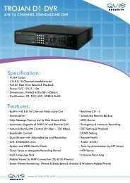
1.2 Sketch of DS-1000KI<br />
Fig 1.1.1<br />
1------ Menu area: Show the keyboard menu;<br />
2------【Menu】: Menu key. Press it more than 2 seconds, the menu area will display the<br />
keyboard menu, otherwise the menu area will display the controlling menu;<br />
3------ Information Display area: Display the input information, communication mode, DVR<br />
information, alarm information, etc.<br />
4------【ID】: The user code name. Use it to select DVR to control.<br />
5------【Zoom】: Zoom function in PTZ control mode.<br />
6------【Focus】: Focus function in PTZ control mode.<br />
7------【Iris】: Iris function in PTZ control mode.<br />
8------ Joystick: Control Pan/Tilt in PTZ control mode.<br />
9------【 】: The key to choose the left keyboard menu.<br />
10-----【 】: The key to choose the right keyboard menu.<br />
LJD Digital <strong>Security</strong> Ltd Page 5<br />
Copyright © 2006. All rights reserved.
User Manual of LJD <strong>IP</strong> <strong>Keyboard</strong><br />
11----【Cam】: Camera ID number (Corresponding the DVR channel number).<br />
12----【0】~【9】: Number and character keys.<br />
13----【Enter】: Confirmation key.<br />
14----【Mon】: Monitor ID key (Reserved).<br />
15---- Lamps: Ready,Status,Link,Tx/Rx,Com,Alarm,Power.<br />
16----【Del】: Delete key.<br />
17----【*】: Input key to choose uppercase character, lowercase character or number.<br />
18----【Shot】: The key to adjust the PTZ preset.<br />
19----【Freeze】: Reserved.<br />
20----【▲】: Page Up key in the information display area. When you input <strong>IP</strong> address, you can<br />
use it as delete key.<br />
21----【▼】: Page Down key in the information area. When you input <strong>IP</strong> address, you can use it<br />
as space key.<br />
22----【 】: <strong>Keyboard</strong> lock key.<br />
LJD Digital <strong>Security</strong> Ltd Page 6<br />
Copyright © 2006. All rights reserved.
User Manual of LJD <strong>IP</strong> <strong>Keyboard</strong><br />
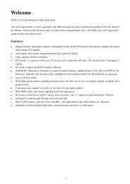
1.3 Rear Board Description<br />
Fig 1.2.1<br />
1------ Dial Switches. The factory default values are “on on off off off off off off (11000000)”.<br />
From the picture we can see the dial switch consists of 8 sub-switches. Now the function of<br />
each sub-switch is following:<br />
‣ Switch 1: When in “on”, PORT A full-duplex 485 is changed into half-duplex 485. It<br />
must be used together with Switch 2.<br />
‣ Switch 2: When in “on”, PORT A full-duplex 485 is changed into half-duplex 485. It<br />
must be uses together with Switch 1.<br />
‣ Switch 3: When in “on”, PORT A R+, R- add the matching resistance of 120Ω.<br />
‣ Switch 4: When in “on”, PORT A T+, T- add the matching resistance of 120Ω.<br />
‣ Switch 5: When in “on”, PORT B D+, D- add the matching resistance of 120Ω<br />
‣ Switch 6: “off”. Reserved.<br />
‣ Switch 7: “off”. Reserved.<br />
‣ Switch 8: “off”. Reserved.<br />
2------ RS485 BUS PORT A ( full-duplex mode SW = 00000000, half-duplex mode SW =<br />
11000000), connecting with KEYBOARD port of DVR.<br />
3------ RS485 BUS PORT B.<br />
4------ RS232 Interface (RJ45).<br />
5------ Network Interface (RJ45).<br />
6------ Alarm output interface.<br />
4 kinds of switches (dry nodes) will output the alarm information. With A and B as a group,<br />
they will turn off when there is an alarm. Otherwise, they will turn on.<br />
LJD Digital <strong>Security</strong> Ltd Page 7<br />
Copyright © 2006. All rights reserved.
User Manual of LJD <strong>IP</strong> <strong>Keyboard</strong><br />
7------ 5V DC Socket.<br />
LJD Digital <strong>Security</strong> Ltd Page 8<br />
Copyright © 2006. All rights reserved.
User Manual of LJD <strong>IP</strong> <strong>Keyboard</strong><br />
Chapter 2 <strong>Keyboard</strong> Operation<br />
2.1 Enter into keyboard system<br />
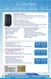
When DS-1000KI network keyboard is in power, the menu screen will show the<br />
following information:<br />
Fig 2.1.1<br />
When “Password” appears on the information screen, input the password (The<br />
default administrator password of DS-1000KI keyboard is 111 and the common<br />
password is 222) and enter into the system operation by pressing the key【Enter】, as<br />
shown following:<br />
LJD Digital <strong>Security</strong> Ltd Page 9<br />
Copyright © 2006. All rights reserved.
User Manual of LJD <strong>IP</strong> <strong>Keyboard</strong><br />
Fig 2.1.2<br />
Note: DS-1000KI keyboard can control DVR by either network mode or RS485 bus<br />
mode. Here we just describe the usage of network mode. It is the same for RS485 bus<br />
mode.<br />
LJD Digital <strong>Security</strong> Ltd Page 10<br />
Copyright © 2006. All rights reserved.
User Manual of LJD <strong>IP</strong> <strong>Keyboard</strong><br />
2.2 <strong>Keyboard</strong> Configuration<br />
Before controlling DVR, you should first configure DS-1000KI net keyboard<br />
including system configuration, user configuration and defense configuration. Press the<br />
key【Menu】for more than 2 seconds, you will enter into the keyboard configuration (the<br />
administrator password is needed to login), as shown in Fig 2.1.1<br />
2.2.1 System Configuration<br />
Fig 2.2.1 <strong>Keyboard</strong> Configuration<br />
After entering into the configuration interface, we could see three corresponding<br />
menu items named “SysCfg” (<strong>Keyboard</strong> System Configuration), “UserCfg” (User<br />
Configuration) and “ArmCfg” (Defense Configuration) on the menu screen. Press<br />
“SysCfg” and enter into the system configuration interface, as shown in Fig 2.2.2. In<br />
this configuration menu, you can setup all detail keyboard parameters such as <strong>Keyboard</strong><br />
<strong>IP</strong>, <strong>Keyboard</strong> ID, port number, super password, operator password and controlling<br />
modes. Each parameter setting is shown below:<br />
LJD Digital <strong>Security</strong> Ltd Page 11<br />
Copyright © 2006. All rights reserved.
User Manual of LJD <strong>IP</strong> <strong>Keyboard</strong><br />
• Prev.: Previous menu.<br />
Fig 2.2.2 <strong>Keyboard</strong> System Configuration<br />
• <strong>IP</strong> Addr: <strong>IP</strong> address of DS-1000KI network keyboard. Press【1】to modify it<br />
while press【2】to confirm it as shown in Fig 2.2.3-1.<br />
• KBD ID: <strong>Keyboard</strong> number. Input the keyboard number with the numeral keys<br />
and press【Enter】to confirm it as shown in Fig 2.2.3-2<br />
• Mask<strong>IP</strong>: The sub net <strong>IP</strong> of DS-1000KI network keyboard. The default factory<br />
value is 255.255.255.0. Press【2】to confirm it. Press【1】to modify it and press<br />
【Enter】to confirm the new mask <strong>IP</strong> as shown in Fig 2.2.3-3<br />
• Port: The network port. Default factory value is 8000. Press【2】to confirm it.<br />
Press【1】to modify it and press【Enter】to confirm the new port number as<br />
shown in Fig 2.2.3-4.<br />
• Gateway: The gateway <strong>IP</strong> address of the keyboard.<br />
• SupPwd: The password of the administrator. The default factory value is 111.<br />
Input the new password with the numeral keys and press【Enter】to confirm it as<br />
shown in Fig 2.2.3-5 and Fig 2.2.3-6.<br />
• Password: The password of the operator. The default factory value is 222. The<br />
setup usage is the same as the super password.<br />
LJD Digital <strong>Security</strong> Ltd Page 12<br />
Copyright © 2006. All rights reserved.
User Manual of LJD <strong>IP</strong> <strong>Keyboard</strong><br />
• CtrlMod: You can select either RS485 BUS mode or network mode to control<br />
DVR. Press【1】to choose the bus mode and press【2】to choose the net mode<br />
as shown in Fig.2.2.3-7.<br />
• Reboot: Reboot keyboard.<br />
• Upgrade: You can upgrade the firmware of DS-1000KI keyboard via network.<br />
In the upgrade menu, input the FTP server <strong>IP</strong>. Then keyboard will connect with<br />
the FTP server and download the firmware via network. Please refer to FTP<br />
server user manual.<br />
Fig 2.2.3 Parameter Settings<br />
LJD Digital <strong>Security</strong> Ltd Page 13<br />
Copyright © 2006. All rights reserved.
User Manual of LJD <strong>IP</strong> <strong>Keyboard</strong><br />
2.2.2 User Configuration<br />
In the “User Configuration” menu, you can setup many users. Each user can only<br />
control one DVR. After you create the relationship between the user and DVR, you can<br />
input the username to login the corresponding DVR and control DVR using the<br />
keyboard. In the “User Configuration” menu, you can add, delete, modify and query the<br />
users and related DVRs.<br />
Fig 2.2.4 User Configuration<br />
• New User<br />
For example, if you want to control DVR with <strong>IP</strong> address of 192.0.1.99 by DS-1000KI<br />
network keyboard. First, you should create one new user. Choose “New” item in the<br />
user configuration menu, you will enter into new user input menu as shown in Fig 2.2.5.<br />
You can input the new user name. Press【*】to shift the input method as shown in Fig<br />
2.2.5.<br />
LJD Digital <strong>Security</strong> Ltd Page 14<br />
Copyright © 2006. All rights reserved.
User Manual of LJD <strong>IP</strong> <strong>Keyboard</strong><br />
Fig 2.2.5 Input Methods of DS-1000KI<br />
For example, here I input “01” as the user name and press【Enter】to confirm it as<br />
shown in Fig 2.2.6-1.<br />
Fig 2.2.6<br />
LJD Digital <strong>Security</strong> Ltd Page 15<br />
Copyright © 2006. All rights reserved.
User Manual of LJD <strong>IP</strong> <strong>Keyboard</strong><br />
Then, choose the device type (“1.DVR” as shown in Fig 2.2.6-2), press【1】to<br />
choose “DVR” and input the user name, password of the DVR. The keyboard must use<br />
this username and password to login the DVR. For example, the default user name of<br />
DVR 192.0.1.99 is “admin” and the default password of the DVR is “12345”. Here we<br />
also input the same username and password as shown in Fig 2.2.6-3, 2.2.6-4.<br />
For Dev ID and Dev Port as shown in Fig 2.2.6-5, Fig 2.2.6-7, you must input the<br />
same Dev ID and port number as DVR has. In the “Display” menu of DVR, you can<br />
find out the Dev ID. The default ID of DVR is “88”. Here we input “01” because the<br />
Dev ID of DVR (192.0.1.99) is 01.<br />
Note: If you use RS485 Bus control mode, please make sure that each DVR has<br />
different Dev ID so that the user can login the corresponding DVR.<br />
Finally, input DVR <strong>IP</strong> address of “192.0.1.99”, then save the configuration. You<br />
can create other new users with the above steps.<br />
• Modify<br />
In case of revising some users, here we use the above example to explain the<br />
operation. We know that the user of “01” can control DVR with “192.0.1.99” <strong>IP</strong> address.<br />
Now, we will change it into controlling DVR with “192.0.1.9” <strong>IP</strong> address. The detailed<br />
operation is following:<br />
1. Input user name: In the user configuration menu as shown in Fig 2.2.4, choose<br />
the “Modify” menu item. In the information display area screen, input the user name of<br />
“01” and press【Enter】to confirm it as shown in Fig 2.2.7.<br />
Fig 2.2.7 Input User Name<br />
2. Modify Device Type: In the information display screen as shown in Fig 2.2.8,<br />
we could see the original configuration of user “01” is DVR. If the new configuration is<br />
also DVR, press【2】; If you want to change into other device type, press【1】to choose<br />
new device type (At present, only DVR device type can be selected).<br />
LJD Digital <strong>Security</strong> Ltd Page 16<br />
Copyright © 2006. All rights reserved.
User Manual of LJD <strong>IP</strong> <strong>Keyboard</strong><br />
Fig 2.2.8 Change device type<br />
3. Modify Device Username: Modify device username according to the indication.<br />
If there is no need to revise, press【2】to confirm it and enter the next operation as shown<br />
in Fig 2.2.9.<br />
Fig 2.2.9 Modify Device Username<br />
4. Modify Device Password: See Fig 2.2.10.<br />
Fig 2.2.10 Modify Device Password<br />
5. Modify Device ID: See Fig 2.2.11.<br />
Fig 2.2.11 Modify Device ID<br />
6. Modify Device <strong>IP</strong> address: See Fig 2.2.12<br />
LJD Digital <strong>Security</strong> Ltd Page 17<br />
Copyright © 2006. All rights reserved.
User Manual of LJD <strong>IP</strong> <strong>Keyboard</strong><br />
Fig 2.2.12 Modify Device <strong>IP</strong> Address<br />
7. Modify Device Port: See Fig 2.2.13.<br />
2.2.14.<br />
Fig 2.2.13 Modify Device Port<br />
8. Save modification: Press 【1】to save the revise of user “01” as shown in Fig<br />
• Delete User<br />
Fig 2.2.14 Save Revised Configuration<br />
Input the user name to be deleted according to the indication, press【Enter】to<br />
confirm it, press【1】to delete or press【2】to exit. In the network control mode, Device<br />
<strong>IP</strong> address is displayed. In RS485 bus mode, device ID is displayed as shown in Fig<br />
2.2.15.<br />
LJD Digital <strong>Security</strong> Ltd Page 18<br />
Copyright © 2006. All rights reserved.
User Manual of LJD <strong>IP</strong> <strong>Keyboard</strong><br />
• Query<br />
Fig 2.2.15 Delete User<br />
Choose “Query” item to show the user information, press【▲】to show the previous<br />
information and press【▼】to show the next information. In network mode, device <strong>IP</strong> is<br />
display. In RS485 bus mode, device ID is displayed, as shown in Fig 2.2.16. In the case<br />
of no user configuration in the keyboard, press “Query” item and system will give the<br />
suggestion of “Not Existing User”.<br />
• Delete all<br />
Fig 2.2.16 Query User Information<br />
If we need to delete all the users, press “DelAll” item and press【1】to confirm it so<br />
that all the built users will be deleted. Press【2】to exit and return to the previous menu.<br />
LJD Digital <strong>Security</strong> Ltd Page 19<br />
Copyright © 2006. All rights reserved.
User Manual of LJD <strong>IP</strong> <strong>Keyboard</strong><br />
It’s interface is shown in Fig 2.2.17.<br />
Fig 2.2.17 Delete All Users<br />
LJD Digital <strong>Security</strong> Ltd Page 20<br />
Copyright © 2006. All rights reserved.
User Manual of LJD <strong>IP</strong> <strong>Keyboard</strong><br />
2.2.3 Defense Configuration<br />
Choose “ArmCfg” item, if there is no defense setting, the information display area<br />
will be shown as Fig 2.2.18-1. Press【1】to defense or press【2】to exit and enter into the<br />
next user. If there is defense setting, the interface will be displayed as Fig 2.2.18-2.<br />
Press【1】to remove the defense or press【2】to enter into the next user.<br />
For each user, the operation of setting up or removing the defense is the same. After<br />
you finish for all users, press【2】to exit “Defense Configuration” as shown in Fig<br />
2.2.18-3 and Fig 2.2.18-4.<br />
Fig 2.2.18 Defense Configuration<br />
After you finish the defense configuration, press [Menu] button of the keyboard to<br />
enter into DVR control menu as following:<br />
LJD Digital <strong>Security</strong> Ltd Page 21<br />
Copyright © 2006. All rights reserved.
User Manual of LJD <strong>IP</strong> <strong>Keyboard</strong><br />
Fig 2.2.19<br />
Choose “DealAlm” item and enter into alarm response menu as shown in Fig<br />
2.2.20:<br />
Fig 2.2.20 <strong>Keyboard</strong> Response DVR Alarm<br />
In the defense configuration as shown in Fig 2.2.18, if you enable arm function and<br />
in the alarm response menu shown in Fig 2.2.20, if you choose “Arm” item, then<br />
DS-1000KI keyboard will listen and receive alarm information from DVR. Please note<br />
LJD Digital <strong>Security</strong> Ltd Page 22<br />
Copyright © 2006. All rights reserved.
User Manual of LJD <strong>IP</strong> <strong>Keyboard</strong><br />
in the DVR menu, enable the “Upload to center” option so that DVR will send alarm<br />
information to the keyboard. When the keyboard receives the alarm information from<br />
DVR, keyboard will display it in the information display area. There are 4 alarm output<br />
ports in the rear panel of the keyboard, you can choose alarm output items to trigger the<br />
corresponding alarm output. Please refer to section 2.3.6.<br />
At present, the keyboard can manage alarm information from 10 DVRs.<br />
LJD Digital <strong>Security</strong> Ltd Page 23<br />
Copyright © 2006. All rights reserved.
User Manual of LJD <strong>IP</strong> <strong>Keyboard</strong><br />
2.3 Control DVR<br />
After finishing the user configuration, we can choose the user name to control the<br />
relevant DVR.<br />
Please note, at one time you can only select DVR front panel or keyboard to<br />
control DVR.<br />
2.3.1 Login DVR<br />
Press【ID】button, you will enter into the following menu.<br />
Fig 2.3.1 Input User Name<br />
If the DVR is in local preview status (no one is controlling DVR using either DVR<br />
front panel or other keyboards) and connection is OK, after you enter into the user and<br />
press [Enter] button, you will login the corresponding DVR as shown in Fig 2.3.2.<br />
You can press【*】to shift the inputting method like numeral【Num】, lower case<br />
【Lower】, upper case【Upper】.<br />
LJD Digital <strong>Security</strong> Ltd Page 24<br />
Copyright © 2006. All rights reserved.
User Manual of LJD <strong>IP</strong> <strong>Keyboard</strong><br />
Fig 2.3.2 Login DVR<br />
After you input the user and login the corresponding DVR, in the network mode,<br />
keyboard will display the DVR <strong>IP</strong> address while in the RS485 bus mode, will display<br />
DVR ID number.<br />
LJD Digital <strong>Security</strong> Ltd Page 25<br />
Copyright © 2006. All rights reserved.
User Manual of LJD <strong>IP</strong> <strong>Keyboard</strong><br />
2.3.2 DVR Configuration<br />
Choose “DVRCfg” item and show the information as in Fig 2.3.3<br />
Fig 2.3.3 DVR Configuration Menu<br />
The items in the keyboard controlling menu are the same as those of DVR local<br />
front panel. We could see the menu below on the menu screen and describe them<br />
respectively below:<br />
【Prev.】: Return to the previous menu of the keyboard.<br />
【Power】: The power switch of DVR.<br />
【Menu】: Shift the operating interface of DVR local menu and can also control the<br />
wiper in the PTZ mode.<br />
【A】: Shift to different input methods such as numeral, lower case, upper case, and<br />
symbol characters.<br />
【Esc】: Cancel the present operation and return to the previous DVR menu.<br />
【Edit】: In the edition mode, delete the wrong character. In preview mode, shift the<br />
picture preview channel.<br />
【Info】: Show the DVR information. (Reserved)<br />
LJD Digital <strong>Security</strong> Ltd Page 26<br />
Copyright © 2006. All rights reserved.
User Manual of LJD <strong>IP</strong> <strong>Keyboard</strong><br />
【Voice】: Start a voice talk function. (Reserved)<br />
【F1】: Turn on or off the sound when playback. Open or close the light in the PTZ<br />
mode (Reserved).<br />
【F2】: Control the auxiliary functions in the PTZ mode (Reserved).<br />
【Up】: Choose the items in the menu.<br />
【Down】: Choose the items in the menu.<br />
【Left】: Shift the items in the menu.<br />
【Right】: Shift the items in the menu.<br />
2.3.2 Video playback<br />
Choose “Playback” item as shown in Fig 2.3.2 and enter into playback menu as<br />
shown in Fig 2.3.4.<br />
Fig 2.3.4 Playback<br />
Choose “Begin Time” and “End Time”, input the start and end time and press<br />
【Enter】. DVR will search and list the matched files in DVR local playback menu.<br />
Choose “BgnTime” item and show the information as shown in Fig 2.3.5-a. Input<br />
LJD Digital <strong>Security</strong> Ltd Page 27<br />
Copyright © 2006. All rights reserved.
User Manual of LJD <strong>IP</strong> <strong>Keyboard</strong><br />
“Year”, “Month” and “Date” respectively as shown in Fig 2.3.5-c, press【Enter】to<br />
confirm it and enter the time set, input “Hour, “Minute” and “Second” respectively.<br />
Please note the above information must be input into two numbers. For example, in the<br />
case of inputting 8:5:5am, July 25th, 2005, the inputting format is “05/07/25” and<br />
“08/05/05” not “5/7/25” and “8/5/5”. Similarly, choose “End Time” and set the end time.<br />
Press【Enter】 to search and list the matched video files.<br />
Return DVR configuration menu as shown in Fig 2.2.3, use【Up】【Down】button to<br />
select one file and press【Enter】, DVR will start playing the selected file.<br />
In the playback menu of keyboard, you can choose the relevant items to playback,<br />
pause, stop, fast play, slow play, forward, backward and the volume. If you press “Fast”<br />
or “Slow”, the playback speed will increase or reduce one time. The maximum speed is<br />
16 times while the minimum speed is 1/16 time. Press “Forward” and “Backward” to go<br />
forward or draw back for about 30 seconds. Press the numeral keys or【Cam】to change<br />
the channel.<br />
Fig 2.3.5 Set Start Time<br />
LJD Digital <strong>Security</strong> Ltd Page 28<br />
Copyright © 2006. All rights reserved.
User Manual of LJD <strong>IP</strong> <strong>Keyboard</strong><br />
Fig 2.3.6 Set End Time<br />
LJD Digital <strong>Security</strong> Ltd Page 29<br />
Copyright © 2006. All rights reserved.
User Manual of LJD <strong>IP</strong> <strong>Keyboard</strong><br />
2.3.3 Manual Video Recording<br />
Choose “Record” as shown in Fig 2.3.2 and display the information as shown in Fig<br />
2.3.7. Choose the relevant items to control the manual video recording function of DVR<br />
including starting and stopping recording of one channel or all channels. Press numeral<br />
keys or【Cam】 to change the channels. Choose “Prev.” to return the previous<br />
controlling menu of the keyboard.<br />
Fig 2.3.7 Manual Recording<br />
LJD Digital <strong>Security</strong> Ltd Page 30<br />
Copyright © 2006. All rights reserved.
User Manual of LJD <strong>IP</strong> <strong>Keyboard</strong><br />
2.3.4 PTZ control<br />
Choose “PTZ” as shown in Fig 2.3.2 and display the information as shown in Fig<br />
2.3.8:<br />
Fig 2.3.8 PTZ Control<br />
Choose the above items,【Focus】,【Iris】,【Zoom】,【Shot】and joystick to realize<br />
PTZ control of DVR. Press numeral keys or【Cam】to change the channel (any numeral<br />
between 1-32; The default channel is 1 if above 16). Choose “Prev.” to enter into the<br />
previous controlling menu of the keyboard.<br />
preset.<br />
Choose “PsetCfg” item, input the preset number and press【Enter】to save the PTZ<br />
Choose “DelPset” item, input the preset number and press【Enter】to delete the<br />
corresponding PTZ preset.<br />
LJD Digital <strong>Security</strong> Ltd Page 31<br />
Copyright © 2006. All rights reserved.
User Manual of LJD <strong>IP</strong> <strong>Keyboard</strong><br />
Fig 2.3.9 PTZ Preset Configuration<br />
Note: The preset function needs PTZ support.<br />
LJD Digital <strong>Security</strong> Ltd Page 32<br />
Copyright © 2006. All rights reserved.
User Manual of LJD <strong>IP</strong> <strong>Keyboard</strong><br />
2.3.5 Preview<br />
Choose “Preview” as shown in Fig 2.3.2 and enter into the preview control menu as<br />
shown in Fig 2.3.10.<br />
Fig 2.3.10 Preview<br />
Choose the above items and realize DVR local preview shift.<br />
Select preview mode:<br />
There are 4 preview modes: 1 Screen, 4 Screen, 9 Screen and 16 Screen. You can<br />
press the corresponding key as shown in Fig 2.3.10 to select one preview mode.<br />
Switch preview camera:<br />
In the one screen preview mode, press【Cam】or any numeral key, input the<br />
channel number in the information display area (At present it can be input any<br />
numerals between 1-32. The default channel is 1 if the input is bigger than16), then<br />
press【Enter】to shift the previewing web page on the different channels.<br />
Start preview cycle:<br />
Choose “StarCyl”, DVR will start cycle previewing according to the preview<br />
sequence and switch interval. Please note the switch interval time must not be set as<br />
“Never”.<br />
Stop preview cycle:<br />
If there is no need to cycle preview between channels, choose “StopCyl” and choose “Prev.” to<br />
exit into the control menu of the keyboard.<br />
LJD Digital <strong>Security</strong> Ltd Page 33<br />
Copyright © 2006. All rights reserved.
User Manual of LJD <strong>IP</strong> <strong>Keyboard</strong><br />
2.3.6 Alarm handling<br />
Choose “DealAlm” as shown in Fig2.3.2 and enter into the following alarm<br />
handling control menu:<br />
Fig 2.3.11 Alarm Handling<br />
Choose “Arm” or “Disarm” to start or stop receiving the alarm information sent<br />
from DVR. The alarm information includes view tampering alarm, motion detection<br />
alarm, video loss alarm and external sensor alarm.<br />
Example when the alarm information is received:<br />
Fig 2.3.12 External Sensor Alarm Input<br />
Fig 2.3.12 means all 16 sensors alarm happened.<br />
LJD Digital <strong>Security</strong> Ltd Page 34<br />
Copyright © 2006. All rights reserved.
User Manual of LJD <strong>IP</strong> <strong>Keyboard</strong><br />
Fig 2.3.13 Video Loss Alarm<br />
Fig 2.3.13 means video lost of the 2nd, 6th and 9 th channels.<br />
LJD Digital <strong>Security</strong> Ltd Page 35<br />
Copyright © 2006. All rights reserved.
User Manual of LJD <strong>IP</strong> <strong>Keyboard</strong><br />
2.4 Other Information<br />
2.4.1 <strong>Keyboard</strong> lock<br />
Press【<br />
】key on the keyboard, the keyboard will be locked. If you press any key,<br />
there is a message “Password” as shown in Fig 2.5.1. Input the correct password to<br />
unlock the keyboard. The unlock password is the same as the keyboard login password<br />
(the default factory password is 111 for the administrator and 222 for the operator). You<br />
have to input the password to login again if the keyboard is locked.<br />
Fig 2.5.1 <strong>Keyboard</strong> Lock/Unlock<br />
LJD Digital <strong>Security</strong> Ltd Page 36<br />
Copyright © 2006. All rights reserved.
User Manual of LJD <strong>IP</strong> <strong>Keyboard</strong><br />
Appendix A: Specification<br />
Control mode RS-485 bus mode (Port A)<br />
Network mode (UTP Port)<br />
Communication interface 1 RJ45 10M/100M UTP network port<br />
1 RJ45 RS-232 port<br />
2 RS-485 port (Port B is reserved)<br />
Bus work mode<br />
1 switch for full-duplex or half-duplex selection<br />
SW = 00000000 is full-duplex mode<br />
SW = 11000000 is half-duplex mode (default)<br />
Relay output<br />
4 output<br />
Power supply<br />
DC +5V/6A<br />
Power consumption 6W<br />
Working temperature<br />
-10℃--+55℃<br />
Working humidity 10%--90%<br />
Size<br />
360mm*190mm*55mm<br />
Weight<br />
2.4Kg<br />
LJD Digital <strong>Security</strong> Ltd Page 37<br />
Copyright © 2006. All rights reserved.
User Manual of LJD <strong>IP</strong> <strong>Keyboard</strong><br />
Description<br />
Unable to login DVR<br />
Appendix B: Troubleshooting<br />
Can not receive alarm information<br />
DVR panel is locked<br />
Unable to operate DVR after the<br />
successful login<br />
Possible Reasons<br />
Incorrect user name or password to login DVR<br />
Incorrect setup of DVR port number or <strong>IP</strong><br />
address<br />
Wrong link between keyboard and DVR<br />
Broken net cable or RS485 bus<br />
No defense is set up for keyboard<br />
Set wrong DVR alarm handling<br />
<strong>Keyboard</strong> operation does not return to the<br />
preview interface<br />
DVR does not return to the preview interface<br />
LJD Digital <strong>Security</strong> Ltd Page 38<br />
Copyright © 2006. All rights reserved.
User Manual of LJD <strong>IP</strong> <strong>Keyboard</strong><br />
Appendix C: Notes<br />
0) Place net keyboard in the adequately ventilated space.<br />
0) Net keyboard shall work in the allowed temperature and humidity scope<br />
0) Do not touch LCD screen with hard objects.<br />
0) Do not splash water or other liquid onto the keyboard when using, to avoid<br />
short-circuit or corrosion.<br />
LJD Digital <strong>Security</strong> Ltd Page 39<br />
Copyright © 2006. All rights reserved.
User Manual of LJD <strong>IP</strong> <strong>Keyboard</strong><br />
Appendix D: Product Service<br />
Thank you for choosing LJD products.<br />
All users of LJD products can enjoy a limited conditional free repair for hardware<br />
within 12 months of guarantee starting from the purchase date, a free exchange service<br />
within one month (valid for non artificial damage) as well as the free permanent<br />
upgrading service for the software.<br />
To protect consumer’s rights and interests, please request the sales agent to seal<br />
and mark out the purchase date when purchasing. If product needs repair in the<br />
guarantee period, please show us the relevant purchase certificate (like receipt). The<br />
date of production will be taken as purchase date if it carries no seal.<br />
Guarantee Range:<br />
1. Guarantee Range covers the failure to operate the device in the normal state and<br />
manufacturing defects.<br />
2. During guarantee period, the device shall not be covered by guarantee range<br />
under following circumstances:<br />
(1) The serial number is unclear, modified or torn up.<br />
(2) The device is damaged by not following the regulations of the instruction<br />
manual or by improper operation.<br />
(3) Impropriate operation environment and conditions, such as, impropriate<br />
power supply, ambient temperature and humidity etc. that damage the device.<br />
(4) The device is damaged by force such as earthquake, fire accident, lightning<br />
stroke etc.<br />
(5) The device is damaged by falling down, damping, immersing in water,<br />
foreign matter invading, losing the parts and components.<br />
(5) The device is damaged again on its way to repair due to improper packing.<br />
(7)Damage caused by the staffs’ repair unauthorized by LJD.<br />
In order to provide various services for you, please fulfill relevant registration<br />
procedure provided by LJD after you purchase the product. Only cut off User’s<br />
Information Card and fax or post it to LJD after the card is filled in.<br />
LJD Digital <strong>Security</strong> Ltd Page 40<br />
Copyright © 2006. All rights reserved.
User Manual of LJD <strong>IP</strong> <strong>Keyboard</strong><br />
Appendix E: User’s Information Card<br />
User Name<br />
□ Mr. □ Ms.<br />
Company Name<br />
Company<br />
Address<br />
Post Code<br />
Tel.<br />
E-mail<br />
Product Model<br />
Product Serial<br />
Number<br />
Purchase Date<br />
Sales Agency<br />
LJD Digital <strong>Security</strong> Ltd Page 41<br />
Copyright © 2006. All rights reserved.
User Manual of LJD <strong>IP</strong> <strong>Keyboard</strong><br />
Your Comments and Suggestions:<br />
LJD Digital <strong>Security</strong> Ltd Page 42<br />
Copyright © 2006. All rights reserved.