Instruction manual - CompaC
Instruction manual - CompaC
Instruction manual - CompaC

You also want an ePaper? Increase the reach of your titles
YUMPU automatically turns print PDFs into web optimized ePapers that Google loves.
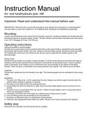
<strong>Instruction</strong> <strong>manual</strong><br />
Compac wheel dolly, model WD60.<br />
Important: Read and understand the instruction before use!<br />
Operating and service <strong>manual</strong> for wheel dolly model WD 60.<br />
Capacity: Max. 60 kg.<br />
Owner and user responsibilities:<br />
This instruction and safety <strong>manual</strong> must be enclosed with the wheel dolly at all times.<br />
It is very important that the owner and the operator completely understand the operating, safety and<br />
maintenance instructions before use. The manufacturer is not liable for wrong- or irresponsible use or<br />
maintenance due to the operators not knowing and following these instructions. If the operator is not<br />
fluent in English, then these instructions and warnings shall be read and explained to the operator in<br />
the operator's native language, making sure that he understands its contents.<br />
Application:<br />
WD 60 is a mobile wheel dolly for easy and safe demounting, handling and mounting of low profile<br />
aluminium wheels up to 24 " fitted with tires that have outer diameters up to 820 mm, a width of<br />
maximum 310 mm and a maximum weight of 60 kg.<br />
Preparation:<br />
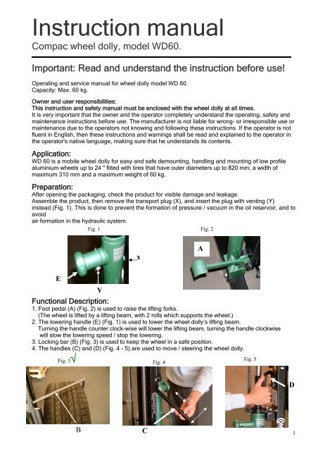
After opening the packaging, check the product for visible damage and leakage.<br />
Assemble the product, then remove the transport plug (X), and insert the plug with venting (Y)<br />
instead (Fig. 1). This is done to prevent the formation of pressure / vacuum in the oil reservoir, and to<br />
avoid<br />
air formation in the hydraulic system.<br />
Fig. 1<br />
Fig. 2<br />
x<br />
E<br />
Y<br />
Functional Description:<br />
1. Foot pedal (A) (Fig. 2) is used to raise the lifting forks.<br />
(The wheel is lifted by a lifting beam, with 2 rolls which supports the wheel.)<br />
2. The lowering handle (E) (Fig. 1) is used to lower the wheel dolly’s lifting beam.<br />
Turning the handle counter clock-wise will lower the lifting beam, turning the handle clockwise<br />
will slow the lowering speed / stop the lowering.<br />
3. Locking bar (B) (Fig. 3) is used to keep the wheel in a safe position.<br />
4. The handles (C) and (D) (Fig. 4 - 5) are used to move / steering the wheel dolly.<br />
Fig. 3√<br />
B C<br />
Fig. 4<br />
A<br />
Fig. 5<br />
D<br />
1
WARNING! :<br />
By the misapplication of this wheel dolly, the user and others can be injured.<br />
1. When the load is in motion, it is important to stand with both feet behind the machine –<br />
(Fig. 6-7)<br />
2. Hands should be placed on the handles (C) and (D) or the release handle (E) (Fig. 9-10).<br />
3. Important! Only move the wheel dolly in the lowered position (Fig. 7-8).<br />
4. The device may only be used on a level, flat and solid base.<br />
5. The wheel which sits in the wheel dolly, shall be locked with the locking bar (B) (Fig. 11)<br />
6. The wheel dolly may not be used to lift a greater load, than specified as max capacity.<br />
(See machine data plate), overload can cause damage to persons or property.<br />
6. The manufacturer disclaims any responsibility, by incorrect use, constructive changes, use of<br />
non-original parts and repairs and adjustments made by unauthorized personnel. Do not use if<br />
oil is leaking, or if the device works differently in use than from new. In these cases, the unit<br />
must be inspected by authorized personnel.<br />
More details are available at www.compac.dk under "Service".<br />
Fig. 6 X Fig. 7 √ Fig. 8 X<br />
Fig. 9 X<br />
Operating <strong>Instruction</strong>s:<br />
C<br />
E<br />
Fig. 10 √<br />
D<br />
Fig. 11 √<br />
B<br />
2
Removing the wheel:<br />
1. When the vehicle is lifted to working height, push the wheel dolly's rolls under the wheel to be<br />
removed. Be careful that the wheel dolly does not make contact with the actual vehicle.<br />
2. Pump with foot pedal (A) (Fig. 12), until the rollers on lifting beam support’s the wheel,<br />
be sure that the tyre will be up against the lifting beam (Fig. 13).<br />
3. Loosen the screws (F) and (G), rotate the locking bar (B) so the tab (I) is horizontal (Fig. 14-15).<br />
Now push the locking bar over the wheel (B), and turn the locking bar so that the tab (I)<br />
support’s the back of the wheel (Fig. 15). Tighten the screw (G), pull the locking bar towards the<br />
operator until the wheel is supported by the support point (H) (Fig. 15) tighten the screw (F).<br />
4. Follow the instruction in the “Warning” section (point 2. – 3.) Pull the wheel free of the vehicle.<br />
5. Lower the wheel to the lowest position with handle (E), (turn it counter clockwise to lower the<br />
lifting beam, rotate it clockwise to stop lowering) (Fig. 16).<br />
7. Now the wheel can be transported away from the vehicle. (See page 4 section “Transport with<br />
wheel”).<br />
8. Removing the wheel from the wheel dolly: Remove the locking bar from the wheel and roll the<br />
wheel off the support rollers and over the wheels dolly’s leg.<br />
A<br />
Fig. 12<br />
H<br />
Fig. 15<br />
Installation of wheels:<br />
1. Roll the wheel up over the wheel dolly’s leg and up in the two supporting rolls, with the tyre against<br />
the lifting beam (Fig. 13).<br />
2. Follow the instruction in section: (Removing the wheel point 3.).<br />
3. Move the wheel dolly with the wheel towards the vehicle.<br />
4. Pump with foot pedal (A) (Fig. 12) until the wheel is in the desired height.<br />
5. Move the wheel into place and secure the wheel with the wheel bolts.<br />
6. Loosen the screw (F) (Fig. 14) and turn the locking bar so the tab at the back is horizontal<br />
pull the locking bar all the way back, so it is free of the wheel.<br />
7. Lower lifting beam with handle (E) (Fig. 16) and move the wheel dolly away from the vehicle.<br />
Continues on page 4.<br />
I<br />
Fig. 13<br />
Fig. 16<br />
E<br />
F G<br />
Fig. 14<br />
B<br />
3
Transport with wheel:<br />
1. Ensure that the lifting beam is lowered to its lowest position.<br />
2. Grab onto the handle (C) (Fig. 17), lift it up in a horizontal position and push it back towards<br />
the device.<br />
3. Grab onto the handle (D) (Fig. 18), now you can control / push the wheel dolly (Fig 19).<br />
C<br />
Fig. 17<br />
Maintenance:<br />
All moving parts must be inspected, cleaned and lubricated once a month. If there is rust on the<br />
device, it has to be cleaned of, and added some rust protection. Ensure that locking and rolls on the<br />
device, all are intact and in order. Be sure that the lock rings, nuts, chains, bolts and axles are intact<br />
and in order. If the unit is repaired, this must be done by someone with experience / skilled in<br />
hydraulics. If any parts of the device are changed, these must be replaced with original parts. If the<br />
device has been defective it has to be inspected by a person experienced / skilled in hydraulics.<br />
There must be performed an annual inspection, the machine must be serviced by skilled personnel so<br />
that the above means are tested and any problems fixed.<br />
Oil:<br />
Oil Reservoir: Contains 0.95 litters.<br />
Use only hydraulic oil AWS22<br />
Do not use brake fluid, engine oil or other liquids!<br />
Disposal:<br />
Drain the device for oil in a responsible manner. Dispose of the oil and other parts to an approved<br />
recipient of the waste.<br />
SN/04-02-2009<br />
Fig. 18<br />
D<br />
Fig. 19<br />
4