NEW_Accomplishments.indd - IRIS
NEW_Accomplishments.indd - IRIS
NEW_Accomplishments.indd - IRIS

Create successful ePaper yourself
Turn your PDF publications into a flip-book with our unique Google optimized e-Paper software.
Cornerstone Facilities<br />
for Seismology and Earth Sciences<br />
Proposal to NSF • 2006–2011<br />
II – <strong>Accomplishments</strong>
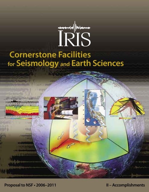
About the Cover<br />
From the innermost inner core, which influences the evolution<br />
of the magnetic field that protects us from cosmic radiation,<br />
to the outermost crust, from which we extract resources<br />
and where we build foundations for our structures, the cover<br />
illustrates recent discoveries about the solid Earth that are<br />
enabled by <strong>IRIS</strong> facilities.<br />
Velocity Profile: A two-dimensional P-wave velocity model<br />
running from southern Austria across eastern Slovakia and<br />
Poland and into Belarus based on data from the Central<br />
European Lithosphere Experiment Based on Refraction<br />
(CELEBRATION 2000). CELEBRATION is one of a series<br />
of seismic refraction experiments conducted between 1997<br />
and 2003 that were possible only with international cooperation<br />
in logistics and data openness that is unprecedented for<br />
geophysical field experiments of this type. Together these<br />
experiments constitute a network of seismic profiles from<br />
Lithuania to Austria. The results have provided new information<br />
to resolve questions about mountain building and largescale<br />
crustal deformation that geologists have been studying<br />
since the 18 th century. (Source: Grad, M, A. Guterch, G.R.<br />
Keller, T. Janik, E. Hegedus, J. Vozár, A. Ślączka, T. Tiira, J.<br />
Yliniemi, and CELEBRATION 2000 Working Group, Lithospheric<br />
structure beneath trans-Carpathian transect from<br />
Precambrian platform to Pannonian basin - CELEBRATION<br />
2000 seismic profile CEL05, J. Geophys. Res., submitted,<br />
2005).<br />
Museum Visitors: The <strong>IRIS</strong> museum display at the Smithsonian<br />
Institutionʼs Museum of Natural History captivates<br />
audiences of all ages and interests. (Courtesy of Jason Mallett.)<br />
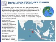
Map of Sumatra-Andaman: Aftershocks for the December<br />
26, 2004 M W 9.3 thrust, including the, M W 8.6 thrust<br />
on March 28, 2005, show the extraordinary extent of the<br />
rupture zone. As the largest earthquake by far, since highdynamic<br />
range, broadband seismometers began to become<br />
widespread in the 1980s, this event suggested new analysis<br />
methods for rapidly determining the disaster potential of an<br />
earthquake, provided new insights about rupture dynamics<br />
and tsunami generation, and resulted in unprecedented<br />
free oscillation records for studying Earthʼs deep structure.<br />
(Reprinted with permission from Lay, T., H. Kanamori, C.<br />
J. Ammon, M. Nettles, S. N. Ward, R. C. Aster, S. L. Beck,<br />
S. L. Bilek, M. R. Brudzinaki, R. Butler, H. R. DeShon,<br />
G. Ekström, K. Satake and S. Sipkin, The Great Sumatra-<br />
Andaman earthquake of 26 December 2004, Science, 308,<br />
1127-1133. Copyright 2004 AAAS.)<br />
Ray Paths: Seismic waves from widely distributed source<br />
regions sample the deep mantle en route to the Kaapvaal,<br />
Tanzania, and Ethopia/Kenya PASSCAL experiments.<br />
Those ray paths shown in red exhibit travel time delays<br />
that could not be accounted for with even the best global<br />
tomography models from before the time of the experiment,<br />
and thus are the basis for discovering the “Africa anomaly,”<br />
an extraordinary low-velocity region extending 1300 km<br />
up from the core-mantle boundary. The thickness, sharp<br />
edges, and magnitude of the velocity anomaly show that<br />
a reasonable understanding of mantle convection requires<br />
consideration of compositional as well as thermal variability.<br />
(Source: Wang, Y. and L. Wen, Geometry and P- and<br />
S- velocity structures of the “African anomaly,” J. Geophys.<br />
Res., submitted, 2005).<br />
About this Proposal<br />
This proposal was produced by the <strong>IRIS</strong> Planning Committee<br />
and <strong>IRIS</strong> staff members on behalf of the <strong>IRIS</strong> Board of<br />
Directors, who represent the full membership of the Consortium,<br />
and thus the collective scientific interests of 102<br />
research institutions. The proposal consists of two volumes,<br />
including the Project Description, Budget and Program Descriptions<br />
in volume 1 and the Review of <strong>Accomplishments</strong><br />
in volume 2.<br />
The Project Description includes an overview of the <strong>IRIS</strong><br />
Consortium and facilities, the role of <strong>IRIS</strong> in supporting<br />
research and education, a description of our resource needs,<br />
and a brief outline of our five-year funding request.<br />
The Budget is an explication of our estimates of costs to<br />
carry out the activities that are summarized in the Project<br />
Description and detailed in the Program Descriptions.<br />
The Program Descriptions are synopses of the core <strong>IRIS</strong><br />
facilities and the programs that operate them. Each synopsis<br />
includes an overview of the development and evolution the<br />
the facility and a detailed description of plans and resources<br />
requested for the <strong>IRIS</strong> program.<br />
The Review of <strong>Accomplishments</strong> is comprised principally<br />
of more than 200 one-page vignettes contributed by the research<br />
community that have been enabled by <strong>IRIS</strong>, in most<br />
cases through use of one or more of the core <strong>IRIS</strong> facilities.
Cornerstone Facilities for<br />
Seismology and Earth Sciences<br />
The <strong>IRIS</strong> Proposal<br />
July 1, 2006 – June 30, 2011<br />
Submitted to<br />
National Science Foundation<br />
Division of Earth Sciences<br />
Instrumentation and Facilities Program<br />
By<br />
Incorporated Research Institutions for Seismology<br />
1200 New York Avenue, NW, Suite 800<br />
Washington, D.C. 20005<br />
On behalf of<br />
Board of Directors<br />
and 102 Member Research Institutions<br />
of the <strong>IRIS</strong> Consortium<br />
August 2005
Board of Directors<br />
Thorne Lay (Chair) ......................University of California, Santa Cruz<br />
Thomas Owens (Vice Chair) ........University of South Carolina<br />
Andrew Nyblade (Secretary) .......Pennsylvania State University<br />
Gregory Beroza ............................Stanford University<br />
Karen Fischer ...............................Brown University<br />
Arthur Lerner-Lam .......................Columbia University<br />
Kate Miller ...................................University of Texas at El Paso<br />
David Okaya ................................University of Southern California<br />
Brian Stump .................................Southern Methodist University<br />
Planning Committee<br />
Arthur Lerner-Lam (Chair) ..........Columbia University<br />
Göran Ekström .............................Harvard University<br />
Alan Levander ..............................Rice University<br />
Thorne Lay ...................................University of California, Santa Cruz<br />
Anne Meltzer ...............................Lehigh University<br />
Barbara Romanowicz ...................University of California, Berkeley<br />
Michael Wysession ......................Washington University in St. Louis<br />
David Simpson .............................<strong>IRIS</strong><br />
Raymond Willemann ...................<strong>IRIS</strong><br />
Standing Committee Chairs<br />
Jeffrey Park ........................GSN .................. Yale University<br />
David James .......................PASSCAL ......... Carnegie Institution of Washington<br />
Guust Nolet ........................DMS ................. Princeton University<br />
Richard Aster .....................E&O .................. New Mexico Institute of Mining and Technology<br />
Senior Staff<br />
David Simpson .............................President<br />
Raymond Willemann ...................Director of Planning<br />
Shane Ingate .................................Director of Operations<br />
Candy Shin ...................................Director of Finance & Administration<br />
Rhett Butler ..................................GSN Program Manager<br />
James Fowler ...............................PASSCAL Program Manager<br />
Timothy Ahern .............................DMS Program Manager<br />
John Taber ....................................E&O Program Manager
2006 <strong>IRIS</strong> 5-YEAR PROPOSAL ACCOMPLISHMENTS<br />
Contents<br />
Introduction .............................................................................. 1<br />
SEISMIC SUMMARIES<br />
Earthquake Seismology and <strong>IRIS</strong> ...................................... 4<br />
The Continental Lithosphere and Seismology ............. 6<br />
Subduction and Seismology .............................................. 8<br />
Investigating Earth’s Dynamic Mantle and Core ...... 10<br />
<strong>IRIS</strong> Education and Outreach ............................................ 12<br />
EARTHQUAKES<br />
Long-period Global Detection and Location of Earthquakes Using the GSN ................................................................................15<br />
The Great Sumatra-Andaman Earthquake of 26 December 2004 ......................................................................................................16<br />
Rupture Process of the 2004 Sumatra-Andaman Earthquake ............................................................................................................17<br />
Imaging the Rupture Process of the 2004 Sumatra-Andaman Earthquake Using Deconvolved Surface Wave<br />
Source Time Functions .............................................. 18<br />
Ultra-long-period Characteristics of the December 2004 Sumatra Earthquake ...........................................................................19<br />
<strong>IRIS</strong> Data Allowed Rapid Public Information About Sumatra Earthquake and Tsunami .............................................................20<br />
Multiple Source Analysis of the 2004 Sumatra Earthquake ..................................................................................................................21<br />
Global Seismographic Network Recording of the Sumatra-Andaman Earthquake .....................................................................22<br />
Rapid Imaging of Large Earthquake Rupture Zones with P waves: Application to the 28 March 2005 Sumatra<br />
Mw 8.7 Earthquake Suggests Bilateral Rupture 23<br />
Regional Monitoring of the Aftershock Sequence of the 2002 M 7.9 Denali Fault, Alaska, Earthquake ...............................24<br />
The 2003 Mid-Indian Ocean Earthquake: An Unusual Earthquake in Oceanic Lithosphere .....................................................25<br />
Relocations and Focal Mechanisms Determined from Waveform Cross-Correlation of Seismic Data from the Nicoya<br />
Peninsula, Costa Rica .................................................. 26<br />
Seismogenic Zone Processes at the Costa Rica Convergent Margin .................................................................................................27<br />
Aftershock Study of the Subduction to Strike-Slip Transition of the North American-Caribbean Plate Boundary in<br />
the Dominican Republic ............................................ 28<br />
Exploring Subduction Zone Earthquake Rupture ... 29<br />
Observational Constraints on the Fracture Energy of Subduction Zone Earthquakes ...............................................................30<br />
Remote Triggering of Deep Earthquakes: Insight from the 2002 Tonga Sequences ...................................................................31<br />
Coupled Seismic Slip on Adjacent Oceanic Transform Faults ...............................................................................................................32<br />
The Use of Waveform Shapes to Automatically Determine Earthquake Focal Depth .................................................................33<br />
MONITORING OTHER SEISMIC SOURCES<br />
Broadband Recording of the First Historical Eruption of Anatahan Volcano, Mariana Islands .................................................34<br />
Use of Multiple Small Aperture Arrays to Study Deep Subduction–Related Tremor in Cascadia ...........................................35<br />
Excitation of Earth’s Incessant Free Oscillations by Atmosphere-Ocean-Seafloor Coupling ....................................................36<br />
Kinematic Modeling and Complete Moment Tensor Analysis of the Anomalous, Vertical CLVD Bardarbunga, Iceland,<br />
Event ................................................................................. 37<br />
Ambient Earth Noise: A survey of the Global Seismographic Network ............................................................................................38<br />
A Real-time Seismic Noise Analysis System for Monitoring Data Quality and Station Performance .....................................39<br />
Four Anomalous Episodes in the Late 2003 Microseism Band Offshore Southern California ..................................................40<br />
Ambient Seismic Noise Monitoring in North-Central Illinois ...............................................................................................................41<br />
Strong Directivity of Ocean-Generated Seismic Noise ...........................................................................................................................42<br />
Glacial and Climate Controls on Tide-Water Glacier Calving Dynamics:A PASSCAL Seismic Experiment on<br />
the Columbia Glacier, Southeast Alaska .............. 43<br />
Mid-Ocean-Bottom and Land-based Microseism Correlations ...........................................................................................................44<br />
Ocean Drilling at the Hawaii-2 Observatory (H2O) .. 45<br />
Nanoearthquakes at H2O .................................................. 46<br />
The May 18, 1998, Indian Nuclear Test Seismograms at Station NIL .................................................................................................47<br />
i
ACCOMPLISHMENTS<br />
2006 <strong>IRIS</strong> 5-YEAR PROPOSAL<br />
Transfer Functions and Seismic Discrimination: a KNET Case Study ..................................................................................................48<br />
Lg-Wave Cross Correlation and Double-Difference Location ...............................................................................................................49<br />
Strong LG Attenuation in Tibet ........................................ 50<br />
Repeating Seismic Events in China ................................ 51<br />
A Comprehensive Database for Mining Explosion Discrimination ....................................................................................................52<br />
Intermediate Period Surface Waves from Mining Explosions ...............................................................................................................53<br />
Source Scaling of Single Fired Mining Explosions with Different Confinement and Explosive Size at a Copper Mine<br />
in Arizona ........................................................................ 54<br />
SIGNALS AND SYSTEMS<br />
Quality Control of GSN Sensor Response Information ............................................................................................................................55<br />
GSN Station Operator Training ........................................ 56<br />
Data Requirements from Low–Frequency Seismology and the Dearth of STS-1 Sensors .........................................................57<br />
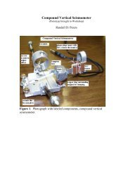
Development of a New Broadband Optical Seismometer ...................................................................................................................58<br />
Earthquake and Ambient Vibration Monitoring of the 17-Story Steel Frame UCLA Factor Building ....................................59<br />
Passive Crustal Refraction Experiments Using <strong>IRIS</strong>/PASSCAL Facilities:New Surveys Show Variable Crustal Thickness<br />
in the Western Great Basin ....................................... 60<br />
Signal Restoration Through Deconvolution Applied to Deep Mantle Seismic Probes ...............................................................61<br />
The Mantle Magnitude Mm and the Slowness Parameter Q: Five Years of Real-time Use in the Context of<br />
Tsunami Warning ......................................................... 62<br />
SAC Availability for the <strong>IRIS</strong> Community ...................... 63<br />
ISC On-line Bulletin and <strong>IRIS</strong> DMC Waveform Retrieval ..........................................................................................................................64<br />
Web Services at the <strong>IRIS</strong> DMC .......................................... 65<br />
The Uniform Product Distribution System .................. 66<br />
SURFACE OF THE EARTH: NORTH AMERICA<br />
The North American Upper Mantle: Density, Composition, and Evolution ......................................................................................67<br />
Tomography of the North American Upper Mantle Using Global and Regional Datasets .......................................................68<br />
High-Resolution 3D Anisotropic Structure of the North American Upper Mantle from Inversion of Body and<br />
Surface Waveform Data ............................................. 69<br />
High-Resolution Surface Wave Tomography From Ambient Seismic Noise ...................................................................................70<br />
Imaging the Fine Structure of the San Andreas Fault at Seismogenic Depths Using an Archived PASSCAL Dataset .....71<br />
A Multi-Institutional, Multi-Disciplinary, Multi-Facility Experiment in Garner Valley, CA .............................................................72<br />
Brittle-Ductile Interactions in California ....................... 73<br />
Steep-Dip Seismic Imaging of the Shallow San Andreas Fault Near Parkfield ...............................................................................74<br />
Foundering Lithosphere Imaged Beneath the Southern Sierra Nevada, California, USA ..........................................................75<br />
Using Marine Seismic Data to Investigate Active Plate Boundary Deformation: The California Continental<br />
Borderland and the Marmara Sea .......................... 76<br />
CANOE: A Broadband Array in Northwestern Canada ............................................................................................................................77<br />
A Refraction/Reflection/Teleseismic Survey of the Northwestern Basin and Range Transition Zone ...................................78<br />
Passive Shallow Seismic Experiments Using <strong>IRIS</strong>/PASSCAL Facilities: Shear-Velocity Assessments at Over<br />
300 Urban Sites ............................................................. 79<br />
Lithospheric Structure of the Rio Grande Rift ............ 80<br />
A Simple Approach for the Joint Tomographic Inversion of Seismic Body and Surface Waves. ..............................................81<br />
Upper-Crustal Structure in SE Arizona from P and Rg Phases Generated by Explosions ...........................................................82<br />
Probing the Structure and Evolution of the Rocky Mountains ............................................................................................................83<br />
Modern Basalt Extraction Structures in the Southern Rocky Mountains:<br />
Multi-band Images from the Jemez Lineament ...............................................................................................................................84<br />
Crustal Structure of the Basin and Range, Colorado Plateau, Rocky Mountains, and Great Plains ..........................................85<br />
Investigating Crust and Mantle Structure with the Florida-to-Edmonton Broadband Array ...................................................86<br />
Numerical Analysis of Overpressure Development in the New Madrid Seismic Zone ..............................................................87<br />
Imaging the Earth With Dense Arrays of Broadband Seismometers .................................................................................................88<br />
Imaging Upper Mantle Structure Beneath the Illinois Basin ................................................................................................................89<br />
ii
2006 <strong>IRIS</strong> 5-YEAR PROPOSAL ACCOMPLISHMENTS<br />
A Surface-Wave Analysis of Seismic Anisotropy Beneath Eastern North America .......................................................................90<br />
Scattered Wave Imaging of a Sharp Lithosphere-Asthenosphere Boundary Beneath Eastern North America .................91<br />
Subduction Potential at the Eastern Margin of North America ...........................................................................................................92<br />
SURFACE OF THE EARTH: GLOBAL STUDIES<br />
BOLIVAR & GEODINOS: The SE Caribbean Continental Dynamics Project .......................................................................................93<br />
The Reflections Under the Scottish Highlands (RUSH) EXPERIMENT: Mapping Fine-Scale Heterogeneities within<br />
the Continental Mantle Lithosphere Beneath Scotland, Combining Active- and Passive-Source Seismology .........94<br />
(quasi)-Love Found in Tuscany: US-European Seismic Array in Italy Catches the Big Wave ......................................................95<br />
PASSCAL Experiments in Central Europe Target Lithospheric Structure ..........................................................................................96<br />
Origin and Tectonic Evolution of Active Continental Lithospheric Delamination in the Vrancea Zone, Romania:<br />
Project DRACULA ......................................................... 97<br />
The Eastern Turkey Seismic Experiment: The Study of a Young Continent-Continent Collision ..............................................98<br />
Systematic High-Resolution Imaging of the Karadere-Düzce Branch of the North Anatolian Fault ......................................99<br />
Tectonic Structure and Surface Wave Dispersion in Eurasia and North Africa ............................................................................ 100<br />
Upper Mantle Q and Thermal Structure Beneath Tanzania, East Africa from Teleseismic P Wave Spectra ....................... 101<br />
Structure and Evolution of the Main Ethiopian Rift .............................................................................................................................. 102<br />
The Upper Mantle P Wave Structure Beneath Ethiopia and Kenya ................................................................................................. 103<br />
Crustal Structure Beneath Ethiopia and Kenya: Implications for Rift Development in Eastern Africa ................................ 104<br />
Small-Scale Variations in Seismic Anisotropy Near Kimberley, South Africa ................................................................................ 105<br />
Xenolith Constraints on Seismic Velocities in the Upper Mantle Beneath Southern Africa ................................................... 106<br />
S-Wave Velocity Structure Beneath the KAAPVAAL Craton ................................................................................................................ 107<br />
Kyrgyz Seismic Network KNET: Application of KNET Data in Scientific Researches ................................................................... 108<br />
Characterizing Crustal Deformation in the North Tien Shan Using Geodetic and KNET Seismic Data .............................. 109<br />
High-Resolution Surface Wave Slowness Tomography in Central Asia .......................................................................................... 110<br />
Seismic Imaging of the Himalayan Collision Zone 111<br />
Receiver Function Imaging of the Eastern Syntaxis of Tibet .............................................................................................................. 112<br />
Shear-Wave Splitting Beneath the Eastern Syntaxis Tibetan Experiment ..................................................................................... 113<br />
Structure and Deformation of the Tibetan Lithosphere ...................................................................................................................... 114<br />
Lithospheric Deformation within a Continental Strike-Slip Fault Zone: Marlborough Fault System, South Island,<br />
New Zealand ............................................................... 115<br />
Seismically Imaging the East Antarctica/West Antarctica Boundary with TAMSEIS .................................................................. 116<br />
Upper Mantle Velocity Structure Beneath the TAMSEIS Network, Antarctica .............................................................................. 117<br />
Cooling History of the Pacific Lithosphere: Evidence for Thermal Boundary Layer Instabilities and Dislocation Creep .....<br />
118<br />
Advances in Active-Source Seismic Imaging Using Traveltime and Waveform Tomography ................................................ 119<br />
High-Resolution Waveform Tomography at a Ground Water Contamination Site .................................................................... 120<br />
Hunting for Ocean Island Moho: The Snipe Bites Back ........................................................................................................................ 121<br />
UPWELLING AND DOWNWELLING<br />
Seismic Hazards Investigations in Puget Sound (SHIPS): I .................................................................................................................. 122<br />
Seismic Hazards Investigations in Puget Sound (SHIPS): II ................................................................................................................. 123<br />
Subduction-Zone Anisotropy Beneath Corvallis, Oregon: A Serpentinite Skidmark of Trench-Parallel<br />
Terrane Migration? ................................................... 124<br />
Imaging Subduction Beneath Alaska: Results From BEAAR ............................................................................................................... 125<br />
The TUCAN Broadband Seismic Experiment: Imaging the Central America Subduction Factory ........................................ 126<br />
Receiver Function Analysis of the Nicoya Peninsula, Costa Rica ....................................................................................................... 127<br />
Crustal and Upper Mantle Structure in the Flat Slab Region of Central Chile and Argentina ............................................... 128<br />
Imaging Shallow Subduction Zones With Surface Waves .................................................................................................................. 129<br />
Detailed Structure and Sharpness of Upper Mantle Discontinuities in The Tonga Subduction Zone ................................ 130<br />
Evidence of Mid-Mantle Deformation From Shear-Wave Splitting ................................................................................................. 131<br />
Seismic Anisotropy in the Izu-Bonin Subduction System ................................................................................................................... 132<br />
Finite Difference Synthetic Test for Kirchhoff Migration of Receiver Function on Subducting Slab ................................... 133<br />
iii
ACCOMPLISHMENTS<br />
2006 <strong>IRIS</strong> 5-YEAR PROPOSAL<br />
Observations of Shear Wave Birefringence in Subduction Zones: A Guide to Mantle Flow? ................................................. 134<br />
Deep Plumes in the Earth’s Mantle ............................. 135<br />
Plume Heat Flux Estimates ............................................. 136<br />
Detection of Upper Mantle Flow Associated with the African Superplume ................................................................................ 137<br />
Structural Features and Velocity Structures of the “African Anomaly” ........................................................................................... 138<br />
Seismic Evidence for Hotspot-Induced Buoyant Flow Beneath the Reykjanes Ridge .............................................................. 139<br />
Imaging Seismic Velocity Structure Beneath the Iceland Hotspot – A Finite-Frequency Approach ................................... 140<br />
Crustal and Uppermost Mantle Structure Beneath Iceland from Local Earthquake Tomography ...................................... 141<br />
The Origin of Hotspot Volcanism in the Pacific Northwest ................................................................................................................ 142<br />
Shear Wave Splitting in the Great Basin Solves the Elevation Problem:<br />
It Was a Simple Plume-like Upwelling All Along ............................................................................................................................ 143<br />
Collaborative Research: Geodynamics of the Yellowstone Hotspot Constrained by Seismic and GPS Imaging ............ 144<br />
GLOBAL MANTLE STRUCTURE<br />
A Three-Dimensional Radially-Anisotropic Model of Shear Velocity in the Whole Mantle ..................................................... 145<br />
Global Anisotropy and the Thickness of Continents ............................................................................................................................ 146<br />
Imaging the Anisotropic Shear-wave Velocity Structure of the Earth’s Mantle .......................................................................... 147<br />
Global Analysis of Upper Mantle Anisotropy Using Automated SKS Splitting Measurements ............................................. 148<br />
Investigating Attenuation and Velocity Structure from Surface-Wave Amplitudes .................................................................. 149<br />
Global Tomographic Model of Q in the Upper Mantle Obtained Using Long-period Waveform Data .............................. 150<br />
Compressional-Wave Studies on the Frequency Dependence of and Lateral Variations in Mantle Attenuation .......... 151<br />
Using <strong>IRIS</strong> Digital Data to Determine the Radial Attenuation Structure of the Lower Mantle .............................................. 152<br />
Whole-Mantle 3D Seismic Attenuation: Evidence for Global Mass Flux ........................................................................................ 153<br />
New Measurements of Radial Mode Eigenfrequencies ....................................................................................................................... 154<br />
The Global Short-Period Wavefield Modeled with a Monte Carlo Seismic Phonon Method ................................................. 155<br />
Discovery of Strong Upper Mantle Reflectors From Back-Scattering of Near-Podal PKPPKP Waves Using Data<br />
Acquired From <strong>IRIS</strong> ................................................... 156<br />
SH Velocity and Compositional Models Near the 660-km Discontinuity Beneath South America ...................................... 157<br />
Seismic Evidence for Accumulated Oceanic Crust Above the 660-km Discontinuity Beneath Southern Africa ............ 158<br />
Seismic Investigation of Upper and Lower Mantle Boundary Layering ........................................................................................ 159<br />
Study of Earth’s Layered Structure on a Global Scale Using Broadband Seismic Datasets ..................................................... 160<br />
Probing the Earth’s Interior by Stacking Stacked Short-Period Seismic Array Data .................................................................. 161<br />
CORE-MANTLE BOUNDARY<br />
Finite-Frequency Tomography of D” Shear Velocity Heterogeneity Beneath the Caribbean ................................................ 162<br />
A Seismological Determination of the Temperature Gradient in D” Beneath the Western Pacific ...................................... 163<br />
Sharp Lateral Boundaries in the D” Region .............. 164<br />
D” Shear Velocity Heterogeneity, Anistropy, and Discontinuity Structure Beneath the Caribbean ..................................... 165<br />
Using Array Methods to Investigate Possible Causes for PKP Deviations ..................................................................................... 166<br />
Lateral Variation of the D” Discontinuity Beneath the Pacific ............................................................................................................ 167<br />
Lateral Variation of the D” Discontinuity Beneath the COCOS Plate ............................................................................................... 168<br />
Migration of the Lowermost Mantle Structure Under the COCOS .................................................................................................. 169<br />
Lateral Variation of P- and S-Wave Velocity Discontinuities in the Lower Mantle Beneath the Cocos Plate .................... 170<br />
Observation of P-Wave Velocity Discontinuities in D’’ Beneath Southeast Asia Using Migration Techniques ................ 171<br />
A Step in the D” Discontinuity Imaged by Kirchoff Migration Through 3D Tomographic Models ....................................... 172<br />
Lowermost Mantle Anisotropy Beneath the Central Pacific .............................................................................................................. 173<br />
D” Anistropy From Lamellae and Transverse Isotropy .......................................................................................................................... 174<br />
Azimuthal Anistropy in the D” Layer Beneath the Caribbean Sea ................................................................................................... 175<br />
Isotropy or Weak Vertical Transverse Isotropy in D” Under the Atlantic ......................................................................................... 176<br />
A Strong Lateral Shear Velocity Gradient and Anisotropy Heterogeneity in the Lowermost Mantle Beneath<br />
the Southern Pacific ................................................. 177<br />
Detection of an Ultralow Velocity Zone at the CMB Using Diffracted PKKPab Waves .............................................................. 178<br />
Examining the Base of the Mantle Using <strong>IRIS</strong> FLED PASSCAL Data ................................................................................................. 179<br />
iv
2006 <strong>IRIS</strong> 5-YEAR PROPOSAL ACCOMPLISHMENTS<br />
INNER CORE<br />
An Observation of PKJKP: Inferences on Inner Core Shear Properties ........................................................................................... 180<br />
Constraints on Density and Shear Velocity Contrasts at the Inner Core Boundary ................................................................... 181<br />
Waveform Search for the Innermost Inner core ..... 182<br />
Near-Podal Observations of PKPPKP Waves and Implications for Central Inner Core Structure .......................................... 183<br />
Non-linear Waveform and Delay Time Analysis of Triplicated Core Phases: A New Method to Extract Differential<br />
Travel Times From Interfering Data .................... 184<br />
Velocity and Attenuation in the Earth’s Inner Core ............................................................................................................................... 185<br />
Anisotropy of the Inner Core ........................................ 186<br />
Slowness Anomalies of PKP Phases Recorded in Alaska: Implications for Inner Core Anisotropy ....................................... 187<br />
Transition From Isotropic Upper Inner Core to Anisotropic Lower Inner Core: The Importance of<br />
Anisotropic Ray Tracing .......................................... 188<br />
Inner Core Anisotropy From PKP Travel Times at Near Antipodal Distances ............................................................................... 189<br />
Hemisphericity and Regional Seismic Anisotropy in the Top 80 km of the Earth’s Inner Core ............................................. 190<br />
Uppermost Inner Core Attenuation From PKP Data Observed at Some South American Seismological Stations ........ 191<br />
Hemispherical Transition of Seismic Attenuation at the Top of the Earth’s Inner Core ............................................................ 192<br />
Differential Inner Core Superrotation From Earthquakes in Alaska Recorded at South Pole Station ................................. 193<br />
Support for Inner Core Super-Rotation from High-Quality Waveform Doublets ....................................................................... 194<br />
The Earth’s Free Oscillations and the Differential Rotation of the Inner Core .............................................................................. 195<br />
EDUCATION AND OUTREACH<br />
The U.S. Educational Seismology Network ............... 196<br />
<strong>IRIS</strong> and Geological Society of America .................... 197<br />
Global Seismicity Monitor as an Interactive Museum Display .......................................................................................................... 198<br />
<strong>IRIS</strong>/USGS Seismology Displays at the American Museum of Natural History, New York ........................................................ 199<br />
Experiences with the <strong>IRIS</strong> E&O Lecture ...................... 200<br />
A Real-Time Interactive Educational Seismology Exhibit ................................................................................................................... 201<br />
A Suite of Educational Computer Programs for Seismology ............................................................................................................. 202<br />
Educational Seismograph Teaching Modules ........ 203<br />
The Global Earthquake Explorer: A Versatile Tool for Science Education ...................................................................................... 204<br />
The Use of <strong>IRIS</strong> Instrumentation in Undergraduate Education ......................................................................................................... 205<br />
Seismic Reflection Processing Workshop ................. 206<br />
<strong>IRIS</strong> and PASSCAL INTERN ............................................... 207<br />
Seismology Education Programs at the University of Portland ........................................................................................................ 208<br />
Influence of <strong>IRIS</strong> on the Construction of a College-Level Seismology Course ............................................................................. 209<br />
Collaborative Teacher Workshops at the Visualization Center at Scripps Institution of Oceanography (San Diego) ... 210<br />
Project SLAM: A Flexible Field Seismology and Earthquake Studies Teaching Module ........................................................... 211<br />
The Boston College Educational Seismology Project: Inviting Students Into the World of Science Research ................ 212<br />
Seismographs in Schools ................................................ 213<br />
Earth and Space Science Professional Development Project ............................................................................................................ 214<br />
The <strong>IRIS</strong> Education Program in Support of the National Earth Science Teachers Association ............................................... 215<br />
Impact of a School Seismograph on a Rural Illinois Middle School: Bringing Real Time Recordings<br />
Into the Classroom ................................................... 216<br />
Seismographs in Schools: Shaking Things Up in the 5th Grade ....................................................................................................... 217<br />
v
2006 <strong>IRIS</strong> 5-YEAR PROPOSAL SCIENCE SUMMARIES<br />
Introduction<br />
Michael Wysession • Washington University<br />
The scope of research facilitated by <strong>IRIS</strong> is truly remarkable. This section of the proposal provides an exciting scientific<br />
exercise: the assembly of a sample of the broad variety of topics directly influenced and enabled by <strong>IRIS</strong> facilities. As you<br />
look through the following “1-pagers,” observe not only the enormous progress that has been achieved in addressing many<br />
long-standing questions in geophysics, but also the large number of new areas of research that have begun since this exercise<br />
was last carried out five years ago. A few words of explanation are appropriate here. The 1-pagers have been divided up into<br />
several categories for the convenience of handling the more-than-200 entries. However, this categorization is arbitrary: many<br />
of the 1-pagers could easily be placed into several different categories, and there are many different choices of categories that<br />
could have been used. In addition, a set of five “2-pager” essays are included in order to provide some context for under-<br />
<br />
Earthquakes<br />
The value and importance of <strong>IRIS</strong> was never better demonstrated than with the success in recording and disseminating<br />
high-quality data from the Sumatra-Andaman earthquake of December, 2004. This earthquake and the devastating tsunami it<br />
caused captured the whole worldʼs full attention. The rapid availability of GSN data demonstrated to world governments that<br />
a real-time tsunami warning system could have saved more than a hundred-thousand human lives, and is providing the basis<br />
and justification for new tsunami warning systems in both the Indian and Atlantic Oceans. A fundamental part of <strong>IRIS</strong>-facilitated<br />
research will continue to focus on earthquakes and understanding the rupture process. This is important, not only for<br />
providing the best advice for earthquake hazard mitigation efforts, but also for addressing fundamental questions concerning<br />
seismotectonics, crustal deformation, and the state and composition of the lithosphere.<br />
Monitoring Other Seismic Sources<br />
Lots of things make waves. An increasing number of studies are using <strong>IRIS</strong> data to examine sources that generate seismic<br />
energy other than earthquakes. An important part of this has been the ongoing efforts to improve our ability to monitor nuclear<br />
tests and other man-made explosions. The reasons include the political, making sure that there are no clandestine nuclear tests,<br />
and the forensic, trying to understand the causes of an accidental explosion. Scientifically, however, <strong>IRIS</strong> data have allowed for<br />
significant new discoveries in the interpretation of seismic signals that have traditionally been considered “noise.” The continuous<br />
low-level excitation of normal modes is now being analyzed in terms of interactions between the atmosphere, oceans, and<br />
solid earth. Array data are now being used to understand the connection between ocean storms and the ubiquitous microseismic<br />
noise. In volcanic regions, a new form of seismic tremor is being studied, and unusual CLVD sources may be related to caldera<br />
collapse. In glacial regions, PASSCAL experiments are examining the dynamics of glacial calving and of the seafloor scraping<br />
of giant ice sheets. There are now whole new areas of interdisciplinary research being pursued with <strong>IRIS</strong> data.<br />
Signals and Systems<br />
For research to be done and for the public (and that includes governments!) to remain informed, it is vital for seismic signals<br />
to be generated, transmitted, processed, archived, retrieved, analyzed, interpreted, and the lessons learned distributed in efficient<br />
and standardized means. <strong>IRIS</strong> has, and will continue to play the leading role in the oversight of these activities for the field of<br />
seismology. This means that <strong>IRIS</strong> is involved in discussions on the creation of the next generation of seismometers. <strong>IRIS</strong> has<br />
been at the forefront of bringing satellite communications to many parts of the world in order to provide reliable real-time access<br />
to seismograms. <strong>IRIS</strong> is at the technological vanguard in the area of database management and web services in order to provide<br />
scientists with instant and user-friendly access to a huge amount of data. And through the E&O, <strong>IRIS</strong> is increasingly involved in<br />
distributing the scientifically, socially, and politically important information that has been obtained from the seismic data.<br />
Surface of the Earth: North America<br />
“North American” seismology is at a very exciting point in time, gearing up for the deployment of the USArray component<br />
of EarthScope, which will rectify the long-standing lack in sufficient seismic coverage for most of the U.S. Several<br />
excellent recent PASSCAL experiments have made preliminary investigations of the lithosphere of North America, and as<br />
1
SCIENCE SUMMARIES<br />
2006 <strong>IRIS</strong> 5-YEAR PROPOSAL<br />
is typical for a new area of research, have raised more questions than given answers. <strong>IRIS</strong> is providing and will continue to<br />
provide the guiding hand for USArray, and the data from this project will provide an important basis for addressing questions<br />
like the structure of fault systems, the current state of stress of the North American lithosphere, the composition and layer-<br />
<br />
slab in the formation of the western U.S., the reasons that North America is moving westward, the connection between deep<br />
tectosphere structure and crustal geology, and the assessment of seismic hazards.<br />
Surface of the Earth: Global Studies<br />
There are as many 1-pagers studying the lithosphere outside of the U.S. as there are studying areas within it. This is a<br />
remarkable feat, given that funding for PASSCAL experiments goes to PIs who reside at universities within the U.S. Seismology<br />
is one of the most successfully international sciences, and this is a very important direction for <strong>IRIS</strong> to continue. <strong>IRIS</strong><br />
PASSCAL research over the past 5 years has spanned all of the continents, including Alaska, and has addressed important<br />
<br />
these experiments have forged important scientific and educational bonds between scientists of many different countries,<br />
to every countryʼs benefit. <strong>IRIS</strong> is also playing an increasingly important role in the establishment of <strong>IRIS</strong>-like programs in<br />
other countries, sharing the technical and scientific knowledge that has been gained. One very important direction for continental<br />
studies has been in the use of telemetered arrays, such as in South Africa, where data are recorded and monitored for<br />
quality in a real-time mode, and this will likely see a greatly expanded use over the next several years.<br />
Upwelling and Downwelling<br />
Plate tectonics is the surface expression of mantle dynamics, and seismology is addressing the nature of vertical mass<br />
flow in several important directions. Because so many earthquakes occur within subduction zones, great advances are being<br />
made in using migrated array data to image the structures of plate collisions, increasing our understanding of water cycles,<br />
mineral phase changes, mantle flow, and magma generation in these regions. We are still missing a complete explanation for<br />
deep earthquakes, however, as rupture seems to occur outside of the cold wedge of the subducted plate. While seismic tomography<br />
has shown unequivocally that subducted lithosphere then proceeds to sink into the lower mantle, the question of how<br />
mass is returned to the upper mantle is still very actively debated, and the nature and ubiquity of hotspot mantle plumes is<br />
currently a topic for much discussion. Imaging mantle plumes is a challenge for seismology, due to a lack of seismic sources<br />
in most of these regions and to the process of waveform annealing through low-velocity regions. However, more creative<br />
ways of using the seismic wave field (e.g., finite-frequency sensitivity kernels, attenuation, anisotropic splitting for flow directions)<br />
have begun to allow for the identification of regions of upward flow between the lower and upper mantles, and these<br />
techniques will play an increasingly important part within future seismic analyses of mantle convection.<br />
Global Mantle Structures<br />
Whole-mantle seismic tomography is more than 20 years old, and for most of it the studies involved two elastic parameters.<br />
Current global studies are now quantifying the degree to which the mantle is neither isotropic nor elastic. This can be<br />
seen in the large number of 1-pagers in this section that involve either anisotropy or attenuation (and in some cases, both!).<br />
The mantle is now viewed not as a static onion-like layered spherical shell, but as a fluid, mobile body. Mantle discontinuities<br />
are <br />
attenuation and anisotropy are being interpreted as indicators of mantle flow. For many years, seismic tomography provided<br />
us with a scalar field of three-dimensional variations in elastic parameters. Currently, however, the diversity of seismic techniques<br />
is moving toward providing all of Earth sciences with a vector field of mass flow, and therefore significant clues as to<br />
the history and evolution of plate tectonics.<br />
Core Mantle Boundary Region<br />
The very base of the mantle continues to be a remarkably rich area for seismological discovery, with a variety of structures<br />
and textures varying significantly over short distances. As such, seismologists are taking advantage of the close station<br />
spacing of PASSCAL arrays and regional networks in order to quantify these variations, and significant advances are being<br />
made using array migration techniques. It seems to be the case that we observe lateral variations at spatial scales as fine as we<br />
are able to resolve, reinforcing our idea that the core-mantle boundary is a thermal and chemical boundary layer that rivals<br />
2
2006 <strong>IRIS</strong> 5-YEAR PROPOSAL SCIENCE SUMMARIES<br />
the surface in complexity. Perceptions of this region were greatly altered by the recent mineral physics discovery of the<br />
transformation of perovskite to a higher-pressure phase, leading to the possibility of a means of detecting lateral temperature<br />
variations and the strength of the thermal boundary layer. Another area of recent interest is the giant megaplume of seismically-slow<br />
rock that extends upward from the core beneath Africa, and many efforts are underway to interpret this in terms of<br />
mantle dynamics.<br />
Inner Core<br />
At 7/10 of one percent of the volume of the earth, the inner core attracts more than its fair share of attention because of<br />
its unusual nature. In spite of the remarkable challenge of viewing this small, frozen ball of iron across two passes through<br />
a very heterogeneous mantle, some very unusual results are emerging. The inner core has long been thought to be anisotropic,<br />
with an axis-parallel fast direction, but it now seems that this anisotropy may only occur in the eastern hemisphere, and<br />
below an isotropic layer at the inner core boundary. The means by which such hemisphere-scale variation could occur is still<br />
unclear, especially if conclusions about the inner coreʼs super-rotation are correct. The big challenge for inner core studies<br />
<br />
distance requirements of PKP waves and the surface distribution of earthquakes and continents. With an increase in global<br />
station coverage, particularly in places like Antarctica, there will be significant advances in our understanding of the inner<br />
core in the near future.<br />
Education and Outreach<br />
We live in a challenging time for science education. The incredible expansion of media information provides many<br />
distractions and sources of competition for peopleʼs attention, particularly that of the students we would most like to reach.<br />
Science used to be able to rest upon the laurels of it inherent “coolness,” but now realizes that it must communicate to the<br />
p -<br />
tellectualism that includes an anti-scientific attitude, tied to the focused agendas of certain political and religious interests. As<br />
the E&O 1-pagers show, <strong>IRIS</strong> is meeting these challenges across a wide variety of fronts, often taking advantage of the very<br />
technologies that can also be distractions. <strong>IRIS</strong> is involved with educating students, teachers, and the general public through<br />
web-based programs and services, museum displays, lectureships, video formats, teacher training workshops, school programs,<br />
teaching materials, curriculum development, and textbooks. Earthquakes are, and always will be, inherently “cool,”<br />
but the <strong>IRIS</strong> E&O program is making sure in a wide variety of ways that everybody knows this.<br />
3
SCIENCE SUMMARIES<br />
2006 <strong>IRIS</strong> 5-YEAR PROPOSAL<br />
Earthquake Seismology and <strong>IRIS</strong><br />
Göran Ekström • Harvard University<br />
Earthquake seismology is a broad and diverse field, encompassing both abstract and theoretical work, as well as directlyapplied<br />
investigations related to earthquake hazards. In between this range lies the broad spectrum of observational earthquake<br />
seismology that is focused on the characterization of seismic sources and their interpretation in terms of tectonic and<br />
other geophysical processes. <strong>IRIS</strong> facilities were designed and developed by the academic community that represents this latter<br />
field of intellectual inquiry. The impact of <strong>IRIS</strong> has also been, and will continue to be, significant for the broader scientific<br />
field represented by physicists, mathematicians, engineers, and social scientists.<br />
To a large extent, the broader impact that data and observations from <strong>IRIS</strong> facilities have made stems from the high level<br />
of our ignorance. We are still far from reaching a comprehensive understanding of earthquakes based on first principles, and<br />
have little opportunity to perform controlled experiments that can isolate the specific physical conditions that control their<br />
occurrence. Observations from individual earthquakes are therefore essential for constraining theoretical models, both of the<br />
earthquake phenomenon and of the relationships to geophysical processes such as tectonism and volcanism. Similarly, experiences<br />
learned from individual earthquakes are still essential for understanding and mitigating their societal effects.<br />
The importance of individual events for furthering our understanding is characteristic for our science, and this is one<br />
context in which the value of <strong>IRIS</strong> facilities can be evaluated. The unpredictability of the events that we wish to study makes<br />
targeted hypothesis testing difficult. For example, while many important earthquake-science results come from PASSCAL<br />
deployments, motivated by specific scientific questions, other discoveries and unique observations obtained with <strong>IRIS</strong> instrumentation<br />
come as the indirect result of the existing observational infrastructure. The last several years have provided several<br />
examples of unanticipated observations that provide added justification for the significant investments in <strong>IRIS</strong> facilities.<br />
The quality and value of <strong>IRIS</strong> facilities and<br />
the data they produce were demonstrated by the<br />
recording of the M W 9.0 Sumatra-Andaman earthquake<br />
of December 26, 2004, and the earthquake<br />
sequence that followed. The ability to record an<br />
earthquake of this size on-scale and with high fidelity<br />
was one of the goals specified when the GSN<br />
was designed 20 years ago. This was achieved for<br />
the Sumatra-Andaman earthquake, even at stations<br />
closest to the earthquake. In addition, data from<br />
most GSN stations were available in near-real time<br />
via the internet, and were used immediately by<br />
operational agencies and academic researchers to<br />
provide an initial assessment of this major event.<br />
With nearly all of the seismological data available<br />
immediately, scientific investigations started<br />
quickly, and research results have arrived nearly<br />
continuously since the earthquake occurred. Many<br />
reported characteristics of the earthquake have now<br />
Cumulative moment release since 1976<br />
Great Earthquakes (M≥8.0)<br />
Sumatra - Andaman Islands Earthquake<br />
12/26/2004, M w=9.0<br />
reached the point of being the consensus view: the earthquake initiated in the south, rupture spread essentially unilaterally<br />
to the north for nearly 1300 km, most of the slip occurred in the area near the hypocenter, and the moment magnitude of the<br />
event is in the range of 9.0-9.3. Also, the slip direction in the earthquake is consistent with slip partitioning and a very large<br />
amount of strike-slip and extensional deformation occurring in the upper plate.<br />
Beyond these basic observations, much still needs to be learned about this earthquake. It is clear that while the tools and<br />
techniques that exist today are adequate for getting zeroth- and first-order information about this earthquake, new methods<br />
need to be developed to analyze fully an event of this size. This is not surprising, given that the seismic moment of the<br />
Sumatra-Andaman earthquake is likely to be 10 to 30 times larger than any event than has occurred since the deployment of<br />
the first digital seismograph network in the 1970s (see the Figure). Many seismologists were simply not prepared or equipped<br />
M
2006 <strong>IRIS</strong> 5-YEAR PROPOSAL SCIENCE SUMMARIES<br />
with the appropriate analysis tools to investigate an earthquake of this size, which had a duration of nearly 10 minutes.<br />
Newly-developed techniques, some applied for the first time, have already produced important results such as the imaging of<br />
the moving rupture area using regional and global short-period recordings and array-processing algorithms.<br />
A key question regarding the Sumatra-Andaman earthquake is the nature of the slip in the northern half of the rupture,<br />
where much of the tsunami was generated. Was the character of the rupture different from elsewhere on the fault? Was there a<br />
slow component to the slip and the deformation? Is there a connection between some special characteristic of the earthquake<br />
and the large tsunami, especially in light of the lack of a large tsunami following the M W 8.6 aftershock on March 28, 2005?<br />
These questions will find answers over the next few years as the result of more-detailed seismological studies. Many of these<br />
questions will also be addressed most productively in joint analyses of seismological, geodetic, and geologic data.<br />
In addition to providing a wealth of seismological data directly relevant to the source process of the Sumatra-Andaman<br />
earthquake, this earthquake generated a number of observations of related but poorly-understood phenomena. A dramatic<br />
example is the intense and geographically-focused earthquake swarm that occurred near the Nicobar Islands one month after<br />
the mainshock. A second example is the seismic activity in volcanic areas as much as 10,000 km away that was triggered by<br />
the passage of surface waves from the mainshock. It is likely that additional phenomena will be discovered as seismologists<br />
examine the data from the earthquake in greater detail. Given that we are still seeing effects of the M = 9.5 1960 Chile earthquake<br />
in the distribution of current earthquakes off the coast of southern Chile and in the geodetic deformation measured on<br />
land, we should expect the effects of the 2004 earthquake to be seen for decades to come.<br />
Over the last few years we have also seen several discoveries in seismic-source seismology that have resulted from analysis<br />
and reanalysis of massive datasets that originally were collected for other purposes. In many cases these investigations<br />
have involved the characterization and analysis of noise. The low-frequency ʻhumʼ of the Earth was discovered in the late<br />
1990s and is still awaiting a convincing explanation, though it seems likely to involve land-ocean interaction. High-frequency<br />
ʻchatterʼ has now been observed in several subduction zones, and in the Pacific northwest subduction zone is associated with<br />
periodic slip transients that were first observed a few years ago. Array analysis of intermediate-period surface waves has led<br />
to the discovery of M = 5 slow seismic slip events associated with outlet glaciers in Greenland, and other glaciers in Antarctica<br />
and Alaska. Of these three newly-observed phenomena, the subduction-zone chatter is the one that now seems most<br />
directly relevant to the traditional field of earthquake seismology and, specifically, to the question of seismic and aseismic<br />
slip in subduction zones. The other two illustrate the range of geophysical phenomena that can be observed and investigated<br />
with <strong>IRIS</strong> instrumentation. Equally important are the facts that they demonstrate how discovery is possible with the tools we<br />
have developed, and that discovery frequently is unpredictable.<br />
Related to the discoveries to be made in the massive volumes of high-quality data <strong>IRIS</strong> has collected is the growing trend<br />
among seismologists to reuse and reprocess data stored at the <strong>IRIS</strong> DMC with new algorithms and increasingly capable computers.<br />
This is necessary when the goal is to find signals and sources in the noise, and also when the objective is to determine<br />
better source parameters and refine images of seismicity. Very impressive relocation results are currently resulting from massive<br />
cross-correlations of broad-band waveforms. One can expect that this type of processing, involving computations that<br />
would have been impossible a few years ago, will be the normal way to deal automatically with the enormous volume of data<br />
now being generated by <strong>IRIS</strong> facilities and networks all over the world.<br />
In conclusion, it is likely that over several years significant advances of our understanding of both the tectonic processes<br />
which result in seismicity and of the earthquake rupture process will result from the analysis of the unprecedented volume<br />
of high-quality data generated and distributed by <strong>IRIS</strong> facilities. Some of this progress will be incremental and will come as<br />
the simple result of the accelerating accumulation of seismological observations. However, judging by recent developments,<br />
it seems probable that dramatic improvements will also occur in the estimation of earthquake parameters, the imaging of the<br />
earthquake source process, and the interpretation of seismic “noise” as the result of new and innovative approaches to the<br />
processing of broad-band data.<br />
5
SCIENCE SUMMARIES<br />
2006 <strong>IRIS</strong> 5-YEAR PROPOSAL<br />
The Continental Lithosphere and Seismology<br />
Alan Levander, Adrian Lenardic • Rice University<br />
Karl Karlstrom • University of New Mexico<br />
The success of plate tectonics in describing the evolution of the ocean basins lies in the regular progression of oceanic<br />
lithosphere from its generation at spreading ridges to its consumption at subduction zones, and the simple description of the<br />
tectonics of oceanic lithosphere in terms of translation, rotation, and consumption of large “rigid,” nearly uniform plates<br />
obeying fairly simple geometric laws at their boundaries. This process dominates global tectonics at scales of hundreds to<br />
thousands of kilometers and durations of ~0.2 Ga and is often taken as the surface expression of mantle convection, with<br />
the crust and mantle forming the upper thermal boundary layer. Differentiation processes at ocean ridges are also relatively<br />
simple, creating plate-wide layered structures that are largely recycled by subduction, and the relationships between the age<br />
of the lithosphere, its thickness, thermal state, and density are well known.<br />
The Earth, unique among the planets, has a bimodal distribution of topography, with ~40% of its surface made up of<br />
continents, whose surfaces reside above to slightly below sea level, and ~60% oceans with average elevation of ~ - 4km.<br />
This is the most obvious difference between the continents and oceans, but there are equally profound differences extending<br />
to depths of 200-400 km first recognized seismologically almost 30 years ago. In contrast to the 60% of the Earth forming<br />
the oceanic plates, the 40% comprising the continents has grown<br />
over the last ~4.5 Ga through a complex sequence of differentiation<br />
and deformation processes that operate on scales of hundreds<br />
of kilometers and smaller, including highly localized, phenomena<br />
such as faulting and pluton emplacement. The resulting continental<br />
lithosphere consists of a complex collage of fragments of various<br />
tectonic affinities. While these fragments can be collected to form<br />
supercontinents or dispersed by the same convection system that<br />
creates and recycles oceanic plates, the development of continental<br />
lithosphere itself, unlike the oceanic lithosphere, cannot be viewed<br />
in terms of the creation of a thermal boundary layer in the convecting<br />
mantle system, and continental tectonics cannot be simply<br />
described by translation, rotation, and consumption of large, “rigid,”<br />
nearly-uniform plates obeying fairly simple geometric laws at their<br />
boundaries. In general, continental crust does<br />
not participate in global mantle overturn and this<br />
also appears to be the case for the subcontinental<br />
mantle beneath many cratons. Thus, the continental<br />
lithosphere is not a simple active upper thermal<br />
boundary layer within the convecting mantle system,<br />
and understanding the structure of continents<br />
requires understanding the cumulative products of<br />
magmatic and deformational processes that have<br />
acted over billions of years of Earthʼs history. The<br />
thickness and chemical buoyancy of continental<br />
crust makes continents resistant to subduction.<br />
That this could effect large-scale mantle dynamics<br />
was proposed almost 70 years ago by Pekeris<br />
(1935).<br />
Continents represent the products of repeated differentiation<br />
cycles whereby less-dense, intermediateto-felsic,<br />
crust is upwardly stratified by combinations<br />
of tectonomagmatic processes. Accretion of uniquely<br />
continental materials takes place above subduction zones<br />
in magmatic arcs and orogenic plateaus, but formation of<br />
High-resolution, teleseismic imaging of the lithosphere beneath the Abitibi<br />
1996 broadband array (<strong>IRIS</strong>-PASSCAL, Lithoprobe). a)Map of study area. b) CCP<br />
receiver function profile. Red and blue pulses denote discontinuities with positive<br />
and negative downward velocity gradients, respectively. Black lines show<br />
interpretation. Abbreviations: GF = Grenville Front, M = Moho. c) S-velocity<br />
perturbation profile obtained by 2D Generalized Radon Transform inversion<br />
(Rondenay et al., 2005), with red to blue colour scale representing negative<br />
(slower) to positive (faster) velocity perturbations.<br />
6
2006 <strong>IRIS</strong> 5-YEAR PROPOSAL SCIENCE SUMMARIES<br />
true continental lithosphere requires multiple differentiation<br />
events to reach the average composition<br />
of continents. These events take place during<br />
plate convergent events such as collisions of<br />
arcs with arcs, arcs with continents, and continents<br />
with continents. They can also take place<br />
during incipient rifting of continents via interactions<br />
between lithosphere and asthenosphere. In<br />
terms of the differentiation processes that make<br />
continental crust over time, the important physical<br />
quantities are heat sources, both mantle and<br />
crustal, magma sources within the mantle (i.e.<br />
fertile mantle), other fluid sources in the crust<br />
and mantle (e.g., H 2 O and CO 2 ), and migration<br />
pathways provided by existing fractures and<br />
shear zones, or in the case of highly-pressured<br />
magmas, the regional stress field that controls<br />
the orientations and locations of hydrofracturing.<br />
It is generally believed that the radiogenic heat<br />
production in the crust is inadequate to produce<br />
crustal magmas, except in the greatly thickened,<br />
probably hydrated, crust occurring near or<br />
within orogenic plateaus. Most crustal melting<br />
results from heat originating in the mantle that is<br />
advectively transferred to the crust in the form of<br />
Interpreted cross section showing compressional velocities (contoured at 0.5-km/s<br />
intervals), relocated seismicity (black circles: continental crustal events; colored<br />
symbols: intraslab events), and Moho reflector (blue line). Interpreted top of subducting<br />
plate (red line) is drawn 7 km above reflector. The region between these<br />
lines is interpreted to be the subducting oceanic crust, composed of basalt above<br />
40-km depth (horizontal green line) and beginning to transform to eclogite below.<br />
Subducting mantle is below the blue line. Low velocities in the mantle wedge<br />
imply the presence of serpentinite. There is no vertical exaggeration.<br />
mantle-derived mafic melts, with the melting process facilitated by other fluids residing in the crust, or transferred to the crust<br />
from the mantle: for example, hydration melting above subduction zones.<br />
Seismology has played a transformational role in our understanding of the continents and the ocean basins, particularly<br />
so in the search for hydrocarbon reserves and (more recently) groundwater, in the recognition and mitigation of earthquake<br />
hazards, and in our understanding of Earthʼs structure, processes, and history. Modern detailed seismic investigations image<br />
details of structural and sedimentary geology, identify magmatic and other fluids in the crust, map details of structure within<br />
fault zones, and image migration of the seismicity associated with volcanic eruptions and volcanic systems. Seismic investig<br />
to make the links between brittle and ductile deformation in the crust. Discussion of the deformation of the continental crust<br />
is virtually impossible without consideration of the mantle underneath it, part of the remote Earth that is only accessible to<br />
seismic and electromagnetic probing. In both ancient cratonic and active modern provinces, surface structures appear to be<br />
highly correlated with various mantle structures, giving structural geologists constraints on large-scale lithospheric processes<br />
that formed and stabilized the continents. In particular, recent seismic results around the peripheries of the North American<br />
craton have led to a thrust-stacking model for the growth and stabilization of the cratonic lithosphere in the late Archean and<br />
early Proterozoic. The density of recording in modern seismic experiments, both active and passive, permits wavefield imaging<br />
to provide unprecedented resolution of the crust and mantle throughout the transition zone. (Such direct imaging is even<br />
being applied to D” and the Core-Mantle Boundary). Seismic heterogeneities observed in the mantle resulting from subduction,<br />
delamination or rifting can be used to infer some of the forces driving modern crustal deformations, providing a vital<br />
link to surface deformation measurements provided by modern geodesy.<br />
Seismology, and by inference <strong>IRIS</strong>, is one of the drivers in modern Earth science, providing images interpreted jointly by<br />
a wide variety of researchers investigating virtually every aspect of the continental system. The expanding PASSCAL instrument<br />
base permits use of seismic imaging techniques drawing on the most advanced aspects of practices in the petroleum<br />
industry, medical imaging fields, and astronomy. This pool of seismometers will continue to provide the primary means by<br />
which we will discover the true nature of the structure and evolution of the continents.<br />
7
SCIENCE SUMMARIES<br />
2006 <strong>IRIS</strong> 5-YEAR PROPOSAL<br />
Subduction and Seismology<br />
Geoffrey Abers • Boston University<br />
Material that forms at mid-ocean ridges descends into the mantle at subduction zones, along with mineralogically bound<br />
fluids and sea floor sediments. Some of the fluid leaves rapidly as pressure and temperature increase, while some migrates into the<br />
mantle wedge to fuel arc volcanism, and some descends to great depth. Hence, subduction zones form the primary site of material<br />
return into the Earthʼs mantle, controlling the behavior of subcrustal earthquakes, triggering and feeding most of the planetʼs destructive<br />
volcanism, and regulating the long-term budgets of the atmospheric gases. The anomalous buoyancy of subducting plates<br />
also exerts the primary control on mantle circulation. Seismology has provided several important advances in the last five years<br />
Until recently, the seismological tools for studying subduction zones remained crude compared to the characteristic scale of many<br />
problems, making it difficult to address even basic questions. For example, subducted oceanic crust is 6 km thick, but traditional<br />
body-wave tomography rarely resolves mantle structures to better than 25-50 km. The advent of digital broadband seismology, and<br />
its deployment through the GSN and PASSCAL programs, has revolutionized our understanding of these systems. High-fidelity<br />
recordings at a range of frequencies are critical for resolving features at the scale of subducted crust, which are turning out to be<br />
some of the largest seismic velocity anomalies within the earthʼs mantle.<br />
Seismology provides constraints on a suite of elastic parameters (Vp, Vs, Q, reflectivity) that bear only passing resemblance to<br />
those needed to actually interpret critical processes (e.g., chemical composition, pressure, temperature, melt and fluid abundance).<br />
Mineral physics measurements are beginning to remove ambiguity from interpreting seismic data, and petrologists and geodynamicists<br />
have begun working directly with seismologists to understand the conditions at which intermediate-depth earthquakes occur,<br />
the thermal structure and geodynamic regime of the mantle wedge, and have begun relating seismic images of the sub-arc mantle to<br />
magma chemistry. Large interdisciplinary collaborations are now leading to a new level of understanding.<br />
The December 26, 2004, Sumatra earthquake served as a sobering reminder of the broader significance of earthquake<br />
source studies. Our methods for analyzing slip on “normal” M < 8 earthquakes clearly are inadequate for events of this size,<br />
as considerable energy is expended at frequencies below those accessible with body wave methods. Reconciling seismic and<br />
tsunami excitation seems possible although challenging, and it remains to be seen whether significant aseismic slip is necessary<br />
to explain the tsunami and geodetic signals observed. At greater<br />
0<br />
km<br />
depth, the very existence of subduction-zone earthquakes below<br />
the<br />
brittle-ductile transition remains a mystery. At intermediate depths,<br />
many recent papers have appealed to dehydration embrittlement<br />
as<br />
an enabler of seismicity. Most intermediate-depth seismicity cor-<br />
relates<br />
well in distribution with that predicted for water release it from<br />
100<br />
dehydration reactions at the top of the slab, although the mech- a-<br />
nism by which dehydration triggers earthquakes remains poorunderstood.<br />
However, the well-documented existence of double seismic<br />
zones requires that at least some intermediate-depth earthquakes occur<br />
20-40 km into the mantle, where the presence and release of water<br />
remains uncertain. Either another mechanism triggers earthquakes here,<br />
in-<br />
some process must deliver water to great depths in oceanic lithosphere.<br />
Seismology addresses this problem both by describing these<br />
intraslab earthquakes, and by imaging the environment in which they<br />
occur.<br />
The triggers for deep earthquakes seem even less clear. Ten years ago, much excitement surrounded the theory that the transformation<br />
of metastable olivine to spinel structure could occur catastrophically and generate seismic shear instabilities. However,<br />
careful examination of seismic observations from PASSCAL experiments show that some deep earthquakes nucleate outside of the<br />
region where olivine should be metastable, and theoretical work has questioned the presence of widespread metastability in most<br />
subduction zones. One possibility is that deep earthquakes occur because of fluid release, either H 2 O or CO 2 . Alternatively, deep<br />
earthquakes may be runaway ductile shear instabilities, an exotic phenomenon rarely observed in rock-forming materials but theoretically<br />
possible. A major challenge will be to find diagnostic seismic signals to distinguish this mechanism from others.<br />
In the last five years, several fundamentally new signals have been discovered. One of the most exciting is non-volcanic<br />
tremor, a high-frequency signal documented in southern Japan and Cascadia subduction zones, associated with the down-dip limit<br />
200<br />
Central Aleutians<br />
2% Vp contours<br />
[Endgahl and Gubbins, 1987]<br />
Figure 1. State-of-the-art seismic modeling of the<br />
subduction zone modeling two decades ago.<br />
ly<br />
or<br />
8
2006 <strong>IRIS</strong> 5-YEAR PROPOSAL SCIENCE SUMMARIES<br />
Depth [km]<br />
SE<br />
0<br />
20<br />
40<br />
60<br />
80<br />
100<br />
120<br />
140<br />
160<br />
180<br />
-10 10<br />
S -Velocity Perturbation [%]<br />
200<br />
0 km 50 100 150 200<br />
Two examples of current attempts at modeling the<br />
structure of the Alaskan subduction zone. (Top) Rondenay,<br />
Abers and Ferris (2004). (Bottom) Abers, van Keken,<br />
Kneller, Ferris, and Stachnik (2005).<br />
of thrust faulting. This tremor correlates closely in space and time with aseismic<br />
creep events on the plate interface, contributing to a coupled phenomenon called<br />
episodic tremor and slip (ETS). The physics behind ETS remains poorly understood,<br />
but a wide range of new experiments and analyses are now underway to explore this<br />
phenomenon. These experiments take advantage of both the PBO and USArray components<br />
of Earthscope and the flexible telemetered arrays developed by PASSCAL,<br />
which provide new tools to characterize the tremor.<br />
Subducting basaltic crust should eventually metamorphose to high-density<br />
eclogite, which has seismic properties very similar to mantle peridotites and hence<br />
difficult to observe. Several studies have shown that a low-velocity layer persists to<br />
depths of 150 km or more at the top of subducting plates, which likely<br />
NW<br />
0 km<br />
-100<br />
-200<br />
corresponds to hydrated, subducted oceanic crust. If these layers are<br />
indeed hydrated, their presence places constraints on the large-scale transport<br />
of water into and through the lower mantle, and the physical conditions<br />
at which intraslab earthquakes operate. In the last several years,<br />
<strong>IRIS</strong> facilities have made it possible to find the traces of subducted crust<br />
throughout the planet. Strategically placed GSN stations on arcs have<br />
provided signals from regional and teleseismic events that interact with<br />
the downgoing plate. These signals form the basis for a global sample<br />
of subduction structure. Recently, dense broadband arrays have begun to<br />
show striking images of subducting plates, resolving features a few kilometers<br />
thick. Apparently, subducted crust remains slower than mantle to<br />
depths of 150 km beneath many arcs. Slow crust has not yet been imaged<br />
at greater depths, although some very deep sources of scattered energy<br />
may be metamorphosed gabbro.<br />
Applying scattered-wave migration, Bostock and colleagues imaged<br />
the apparent dehydration of the Cascadia slab directly below a low-velocity<br />
portion of the hydrating mantle. This and subsequent work has indicated<br />
that serpentinization of the cold lithosphere may constitute a significant global reservoir for water. It is less clear how water<br />
is transported into the deeper, hotter portions of the wedge, where it plays a critical role in melt generation. In the melt generation<br />
region, collaborative, interdisciplinary research will be needed to address first-order questions such as where melt is generated,<br />
how it is transported, what regulates eruptive volatile content, and why volcanic fronts form at all. Seismic experiments are finding<br />
that the rapid flux of cold lithosphere into the transition zone raises and lowers the 410 and 660 km discontinuites, respectively, in<br />
accordance with expectations based upon the minerology of the olivine phase changes. However, the results of shear-wave splitting<br />
studies have not been easy to interpret in terms of mantle chemistry. In many tectonic environments, shear-wave splitting measurements<br />
have been found to be consistent with mantle flow through the induced alignment of olivine crystallographic axes, and flow<br />
patterns appear simple over large regions. In subduction zones, however, the fast axes often lie parallel to the arc within the mantle<br />
wedge, but exceptions are numerous enough to make any generalization difficult. Interpretation of these data has been complicated<br />
by discoveries of new microstructural mechanisms for producing anisotropy, through water- and stress-controlled activation of<br />
other crystal slip systems, and through the alignment of melt or fluid conduits. Until recently, sparse networks provided spot measurements<br />
that probably spatially alias the flow field in the wedge, but the PASSCAL facility now has begun to support multiple<br />
dense arrays, at sufficient density to sample mantle flow.<br />
The next five years should see significant advances. Through EarthScope, Continental Dynamics and the MARGINS program,<br />
several large field experiments are now underway in subduction zones around the world, and will produce significant new<br />
observations. Among the enduring questions this new generation of experiments should help address: What causes deep and intermediate<br />
depth earthquakes? (phase changes, dehydration embrittlement, plastic instabilities or something else?) How much H 2 O<br />
and CO 2 are deeply subducted, how do they descend, and where do they reside? What triggers melting below arc volcanoes, and<br />
what produces the volcanic front? How does slip on the thrust zone, both seismic and aseismic, affect other dynamic phenomena?<br />
What happens between the downdip end of the seismic thrust zone and the flowing part of the mantle wedge? What is the pattern<br />
of flow in the mantle wedge? How do slabs interact with transition-zone discontinuities, and what is the ultimate fate of subducted<br />
material? Answers to these questions, and the formulation of new ones, will come about through partnership between laboratory<br />
and theoretical practitioners and the analysis of new signals coming out of the Earth that the <strong>IRIS</strong> facility will provide.<br />
9
SCIENCE SUMMARIES<br />
2006 <strong>IRIS</strong> 5-YEAR PROPOSAL<br />
Investigating Earth’s Dynamic Mantle and Core<br />
Edward J. Garnero • Arizona State University<br />
Seismologists have long sought to decipher the Earthʼs inaccessible and enigmatic interior through detailed interrogation<br />
of deeply penetrating seismic energy. As we approach the 100th anniversary of the discovery of Earthʼs core, we are<br />
rapidly moving beyond the characterization of Earthʼs first-order radial stratification that dominated the decades that followed<br />
detection of the core. In fact, an explosion in the availability of broadband data from a variety of agencies and organizations<br />
over the last decade has permitted both global and regional analyses of the interior at unprecedented spatial detail. Conclusions<br />
using the remote sensing tool of seismology now regularly reach well beyond solution models of Earthʼs internal elastic<br />
structure, and extend to the characterization of Earthʼs dynamic, thermal, and chemical states (Figure 1). Advancements in<br />
our understanding of the interior have been primarily and fundamentally facilitated through the efforts and successes of the<br />
<strong>IRIS</strong> mission. Data are now easily available through a variety of method, to anyone in the world.<br />
Figure 1. Seismic data provided by <strong>IRIS</strong> continues to allow for rapid changes in our models of Earth’s deep interior.<br />
Mantle Heterogeneity: The Global Picture<br />
In convective systems, diversity in structures can occur near the boundary layers. The core-mantle boundary (CMB),<br />
in fact, contains Earthʼs largest absolute density contrast within the planet, and thus continues to receive significant attention<br />
in high-resolution modeling at a variety of spatial scales. The next largest density contrast is between surface rock and air<br />
or water, and while large-scale surface tectonics have been appreciated for some time, constraining the role of upper and/or<br />
lower mantle structure and the dynamic processes responsible for shaping the surface remains a challenge.<br />
Certainly, tracing subducting slabs to their final resting place or deep plume roots upwards to hot spot volcanism have<br />
been a focus of global mantle travel-time tomography. Some recent successes in imaging the apparent connectivity of<br />
higher-than-average velocities from the crust to core beneath Mexico, presumably from the ancient Farallon slab, and possibly<br />
beneath Japan, have played into the long-standing debate about whether or not the boundary between the upper and<br />
lower mantle demarks chemical stratification. Transition zone structure and discontinuity topography may similarly provide<br />
important constraints on mantle temperature and dynamics. Several research groups can now boast 3-D global P- and S-wave<br />
mantle models, largely owing to data availability through <strong>IRIS</strong>. Attributing global heterogeneity to a solely thermal versus<br />
thermal and chemical origin is regularly pursued. Often significant holes in data coverage are still present, however, which<br />
requires future deployment and densification of instruments. EarthScopeʼs USArray will significantly help in the study of the<br />
deep Earth that is in the hemisphere containing North America.<br />
Mantle Heterogeneity: High-Resolution Imaging and Short-scale features<br />
Forward-modeling waveform studies augment the global images, often revealing a variety of phenomena not yet available<br />
through the tomographic approach. These include discontinuous layering or reflectors near dominant boundary layers,<br />
such as layering some 200-300 km above the CMB (the D” layer), ultra-low velocity (10ʼs of percent reductions from global<br />
reference structures) layering right at the CMB, and vertical boundaries between low-velocity structures and neighboring<br />
mantle which, beneath southern Africa, are mapped as extending up to 1000 km above the CMB. These features may be<br />
intimately related to ultralow velocity zone genesis from partial melt of lowermost mantle material, which can give rise to<br />
10
2006 <strong>IRIS</strong> 5-YEAR PROPOSAL SCIENCE SUMMARIES<br />
instabilities that result in the birth of whole-mantle plumes. Both forward and inverse methods now almost routinely document<br />
seismic wave speed anisotropy, anelasticity, and scattering in the mantle, particularly near the surface and CMB, where<br />
analyses utilizing reference seismic waves are most easily permitted owing to the existence of the highly reflective Earthʼs<br />
surface and CMB.<br />
The Outer and Inner Core<br />
The relatively rapidly convecting fluid iron-alloy outer core is responsible for the generation of Earthʼs magnetic field.<br />
Lateral heterogeneity in outer core elastic properties is generally assumed absent, based on dynamic arguments. However,<br />
the possibility for small-scale structures right at the underside of the CMB, or at the topside of the inner core boundary are<br />
possible. Certainly, high-resolution seismic studies have suggested short-scale variability (e.g., km scale) of each. Larger arrays,<br />
e.g., USArray, will help to further illuminate these possibilities in the near future.<br />
The solid inner core is but a fraction of a percent of Earthʼs volume, yet continues to attract significant attention from<br />
seismologists, often in collaboration with a variety of geophysicists from other disciplines. Better constraints of the depth<br />
and lateral distribution of inner core heterogeneity, anelasticity, and anisotropy (as well as their magnitudes), and inner core<br />
super-rotation, likely hold important<br />
keys for core (and thus Earth)<br />
formation, as well as the nature of<br />
the generation of Earthʼs magnetic<br />
field. Global and regional arrays,<br />
PASSCAL experiments, and traditional<br />
short-period seismic arrays<br />
all have the potential to advance<br />
our knowledge in these important<br />
areas.<br />
Of particular relevance in<br />
imaging Earth structure at depths<br />
below the CMB is properly accounting<br />
for contaminating effects<br />
of mantle structure, especially the<br />
strong heterogeneities now widely<br />
accepted to exist at the base of the<br />
mantle. This will certainly receive ever-increasing attention as the deepest mantle comes into sharper focus and our ability to<br />
incorporate 3-D wave propagation in our imaging studies improves.<br />
Looking to the Future: New Data, New Methods, New Disciplines<br />
Figure 2. A current representation of the core-mantle boundary region, incorporating many of the structures<br />
that have been identified by recent seismological investigations.<br />
We have come a long way since the band-limited digitized recordings from analog instruments (e.g., WWSSN) of the<br />
1960ʼs that were pervasive in studies of the following couple decades. Significant densification of seismic station coverage<br />
has also occurred. Thus we are now afforded interrogation methods of Earthʼs deep interior that once were previously only<br />
enjoyed by exploration and crustal seismologists: traditional seismic array techniques, which augment waveform modeling of<br />
region studies, as well as global waveform and travel-time tomography. However, future work should more fully utilize the<br />
rich bandwidth of information in the recorded wave field. Continued availability and expansion of data made available by<br />
<strong>IRIS</strong> will enable advances on these fronts, which will specifically enhance the connection between seismic results and those<br />
from other Earth interrogation disciplines: for example, geodynamics, mineral physics, geochemistry, geomagnetism, geotectonics,<br />
and petrology. The multi-disciplinary research approach is important, as it will be a principle method in reducing<br />
uncertainty in our often large solution model spaces. More and better data permit better seismic models for this process.<br />
11
SCIENCE SUMMARIES<br />
2006 <strong>IRIS</strong> 5-YEAR PROPOSAL<br />
<strong>IRIS</strong> Education and Outreach<br />
Larry Braile • Purdue University<br />
The <strong>IRIS</strong> E&O program and participating scientists and educators have developed a range of activities and resources designed<br />
to effectively reach a wide audience of interested people, from students and teachers, to college and university faculty,<br />
to the general public. Interested people can investigate a single topic or question, find a teaching lesson on seismology, Earth<br />
<br />
Table 1. “Science Interest Starts Early: More than half of science professionals with<br />
a PhD say their first interest in science came at age 5-10. What they say influenced<br />
their science interest in childhood:” *<br />
People (parent, teacher) 45%<br />
Experiences 11%<br />
Toys/books/equipment (chemistry set) 10%<br />
Other (class, science on TV) 6%<br />
No significant influence 13%<br />
Don’t know 15%<br />
* Source: Roper Starch Worldwide for Bayer, National Science Foundation, as<br />
reported in the USA Today, September 10, 1998.<br />
The<br />
<strong>IRIS</strong> E&O resources and programs provide opportunities<br />
for students and teachers (or other interested<br />
people) to experience or do science (with<br />
real data, in near-real time, with on-line or easily<br />
accessible materials and classroom activities)<br />
rather than just read about science. Earthquakes,<br />
seismology and plate tectonics also provide exciting<br />
and relevant science topics that can be used to<br />
motivate students for science learning and develop<br />
quantitative and critical thinking skills.<br />
During the last century, the United States has<br />
made dramatic progress in advancing the educational<br />
level of its population, such that today<br />
about 85% of the U.S. population (age 25+) has<br />
completed 4 years of high school or greater, about<br />
65% of high school graduates enter college within<br />
one year of high school graduation, and about 25% of the population (age 25+) has completed 4 years of college or greater.<br />
These educational achievement rates are as high, or higher, than those of any other country. High school and college graduates<br />
from around the world compete for entrance to U.S. colleges and universities and for admission to graduate and professional<br />
schools. However, over the past 15 years there has been increasing concern about the performance of graduates from<br />
our educational system. Much of the criticism has focused on apparent underachievement in science and mathematics in both<br />
high school and college graduates. Another area of concern is the failure to attract significant numbers of people to science<br />
and technology careers, especially women and minorities. Increasingly, citizens of foreign countries populate our graduate<br />
programs in science and technology. In this age of rapid advances in science and technology, there is a great need for all<br />
Americans to be scientifically literate to ensure that the US maintains its leadership role in science and the global economy<br />
and is able to conduct scientifically informed policies.<br />
<strong>IRIS</strong> and its member institutions are contributing to solving these problems by:<br />
• Making advances in science and technology<br />
knowledge and skills more accessible to all;<br />
• More effectively preparing current and future<br />
K-12 teachers to teach science and technology;<br />
• Encouraging and preparing the next generation<br />
of scientists and broadening career paths<br />
available to them.<br />
Due to the importance of science learning at<br />
an early age (Table 1) and the tradition of teaching<br />
Earth science primarily in middle school grades,<br />
providing materials and training for K-12 teachers<br />
is an important part of the <strong>IRIS</strong> E&O program.<br />
Over 600 K-12 teachers and college faculty have<br />
participated in <strong>IRIS</strong>-sponsored one-day intensive<br />
workshops on earthquakes and seismology at national<br />
Figure 1. Modeling the seismic shear wave using the human wave demonstration. In<br />
addition to the human wave demos, seismic waves are also investigated using slinky<br />
activities and computer animations.<br />
12
2006 <strong>IRIS</strong> 5-YEAR PROPOSAL SCIENCE SUMMARIES<br />
Figure 2. Investigating earthquake hazards by constructing a model building<br />
that will withstand earthquake shaking. The model buildings are then<br />
tested using a simple shake table with accelerometer output to monitor the<br />
input shaking and the building response. Well designed model buildings<br />
often can withstand over 75% g accelerations. Comparison of modes of<br />
failure (soft first story, building resonance, etc.) of the model buildings with<br />
actual building damage caused by earthquakes (using photographs of<br />
damage) contributes to understanding of earthquake hazards.<br />
and state-level science meetings. During these workshops, the<br />
teacher/participants learn and experience effective hands-on<br />
activities that explore seismic waves (Figure 1), the cause of<br />
earthquakes, earthquake occurrences, plate tectonics, the structure<br />
and properties of the interior of the Earth, and earthquake<br />
hazards (Figure 2). Participant assessments of these workshops<br />
and of the learning activities used in the workshops and implemented<br />
in the classroom by the teachers have been very positive.<br />
Several thousand additional teachers have attended <strong>IRIS</strong>-sponsored<br />
one-hour workshops at national and state-level science teacher<br />
meetings in which one or more seismology activity has been demonstrated.<br />
Distribution of <strong>IRIS</strong> publications (posters, one pagers, etc.,<br />
Figure 3) at these meetings and elsewhere has also impacted many<br />
thousands of educators.<br />
Figure 3. Portion of the <strong>IRIS</strong> poster “Exploring the Earth Using<br />
Seismology”. Additional posters, one-pagers describing<br />
a specific seismology topic, and other E&O publications<br />
have been produced by the <strong>IRIS</strong> E&O Program.<br />
However, there are many different ways that the excitement and<br />
information of science can be conveyed to the public, and so the <strong>IRIS</strong><br />
E&O program is involved in many different kinds of activities. Millions<br />
of people go to science museums each year, and while most science<br />
museums have some sort of display on the earth and earthquakes, well-designed displays can reach enormous numbers of people.<br />
The <strong>IRIS</strong>/USGS real-time earthquake display at museums like the American Museum of Natural History and Smithsonian are very<br />
popular. Earthquakes have an easy appeal to the public because of their potentially violent and destructive nature, and the displays<br />
show that with some good software and attractive design, they can be one of the most successful components of a science museum.<br />
Science museums are also a good site for educating people about earthquakes and seismology through lectures. The newly-begun<br />
<strong>IRIS</strong>-SSA Lectureship has brought research seismologists with a strong interest in public education to many different museums, with a<br />
tremendously enthusiastic response. Many of the people who attend these lectures are themselves teachers, and are now using powerpoint<br />
versions of these <strong>IRIS</strong>-SSA lectures in their own classes.<br />
One important new direction for <strong>IRIS</strong> E&O is in the area of seismology education for seismologists. The <strong>IRIS</strong> Intern program<br />
continues to be very successful, giving undergraduate students the chance to participate in active seismological research. Some have<br />
now gone on to be seismology graduate students. <strong>IRIS</strong> also plans to be more involved with undergraduate curricula, though the<br />
development of technological web-based displays, the development of undergraduate teaching materials, and through its Educational<br />
Affiliate program, which is bringing together people and ideas on how to do a better job teaching seismology and geophysics at the<br />
undergraduate level.<br />
Education occurs on many different fronts, and the <strong>IRIS</strong> E&O program is expanding to take advantage of opportunities in<br />
many of these. It is important for the <strong>IRIS</strong> E&O program to maintain its high level of technological competency needed to keep<br />
up with the increasing opportunities for science education, but there will also be a continued need for broader participation by its<br />
members in the education of the public, whether this is in the form of lectures, hands-on workshops, or one-on-one mentoring.<br />
13
2006 <strong>IRIS</strong> 5-YEAR PROPOSAL EARTHQUAKES<br />
Long-period Global Detection and Location of Earthquakes Using the GSN<br />
Göran Ekström, Meredith Nettles • Harvard University<br />
We use long-period data from the Global Seismographic Network in an array-processing mode to detect and locate shallow<br />
earthquakes globally. A global grid of target locations is monitored continuously for detections of sources of Rayleigh<br />
wave energy in the 35–150 s period band. The tuning of the array for each target location is accomplished by calculation of<br />
frequency-dependent path corrections using detailed global phase-velocity maps. The detection algorithm uses a matched filter<br />
to look for source pulses on reverse-dispersed and stacked seismograms. In addition to analyzing real-time data, we have<br />
applied the algorithm in a systematic fashion to continuous archived data from the <strong>IRIS</strong> GSN and other global networks for a<br />
period of 11 years, 1993–2003. For this period, we detect and locate approximately 25,000 earthquakes. The smallest earthquake<br />
detected has a magnitude M = 4.6. 1,860 of the events are not correlated with any earthquake reported by the NEIC,<br />
ISC, or the IDC (based on the REB bulletins). We believe that fewer than 1% of our new events are false detections, and that<br />
our analysis identifies around 150 new M~5 earthquakes per year. The map below shows the locations of the 1,860 previously<br />
unknown earthquakes. The quality of the detection is indicated by the color: red indicates the best quality, green is very good,<br />
an -<br />
ity of the new events fall along ridges and transform faults, and relatively few in subduction zones; many events associated<br />
on the map with subduction zones are located in back-arc basins. More than 100 of the newly detected events are located in<br />
areas away from regions that are considered seismically active. In particular, a very large number of earthquakes can be seen<br />
along the coast of Greenland. These events, first described by Ekstrom, Nettles, and Abers (Science, 2003), belong to a new<br />
class of earthquakes associated with the sliding of glaciers. These glacial earthquakes are not detected by traditional methods<br />
owing to their very slow slip. The typical duration for an M = 5 glacial event is 30–60s. Other previously undetected events<br />
may also be unusually slow or may be associated with geophysical phenomena that generate elastic waves by processes<br />
other than standard fault motion. For example, several events in central Africa are associated with volcanic eruptions, and<br />
the events off the east coast of North America may be related to submarine sliding. Real-time results from our surface-wave<br />
detector can be seen at http://www.seismology.harvard.edu/~ekstrom/Research/SWD/.<br />
15
EARTHQUAKES<br />
2006 <strong>IRIS</strong> 5-YEAR PROPOSAL<br />
The Great Sumatra-Andaman Earthquake of 26 December 2004<br />
Thorne Lay, Steven N. Ward • University of California, Santa Cruz<br />
Hiroo Kanamori • California Institute of Technology<br />
Charles J. Ammon • The Pennsylvania State University<br />
Meredith Nettles, Goran Ekstrom • Harvard University<br />
Richard C. Aster, Susan L. Bilek • New Mexico Institute of Mining and Technology<br />
Susan L. Beck • University of Arizona<br />
Michael R. Brudzinski, Heather R. DeShon • University of Wisconsin, Madison<br />
Rhett Butler • <strong>IRIS</strong> Consortium<br />
Kenji Satake • Geology Survey of Japan<br />
Stuart Sipkin • U.S. Geological Survey<br />
An overview of the tectonics and faulting process of<br />
the 26 December 2004 rupture and its tsunamigensis is<br />
presented. This earthquake is the largest event in the world<br />
in 40 years, and produced the most devastating tsunami in<br />
recorded history. Slip during the 10 minute-long rupture<br />
along the plate boundary varied systematically toward the<br />
north, decreasing from about 15 m near Banda Aceh to only<br />
a meter or two near the Andaman Islands. It appears that additional,<br />
slower slip occurred in the northern portion of the<br />
Regional tectonic map of the 2004 earthquake, showing earthquakes<br />
with magnitudes > 5.0 from 1965 to 25 December 2004.<br />
The arrows indicate the relative plate motions between the<br />
Indian and Eurasian plates for model NUVEL-1. The location of<br />
prior large events in the area are shown.<br />
rupture zone, possibly on a time-scale of one hour or more. This is<br />
indicated by modeling of the ocean surface displacements observed<br />
by the JASON altimeter. The overall energy release of the earthquake<br />
is measured at 1.1 x10 18 J. The seismic moment is 0.65-1.0<br />
x 10 23 N-m, with some uncertainty being due to weak constraint on<br />
the dip of the fault segments along the rupture. An increasing component<br />
of obliquity in the slip is found along-strike. The rupture<br />
extended about 1300 km from the epicenter, and an additional 300<br />
km of the fault boundary failed in the March 28, 2005 earthquake.<br />
Effective source strength for normal<br />
modes and Rayleigh waves for the 2004<br />
event, obtained from GSN observations.<br />
Lay, T., et. al., The Great Sumatra-Andaman earthquake of 26 December 2004, Science,<br />
308, 1127-1133, 2005.<br />
Supported by NSF grants EAR-0125595, EAR-0337495, EAR-0207608, and Cooperative<br />
Agreement EAR-0004370.<br />
16
2006 <strong>IRIS</strong> 5-YEAR PROPOSAL EARTHQUAKES<br />
Rupture Process of the 2004 Sumatra-Andaman Earthquake<br />
Charles J. Ammon • The Pennsylvania State University<br />
Chen Ji, Vala Hjorleifsdottir, Hiroo Kanamori, Don Helmberger • California Institute of Technology<br />
Hong Kie Thio, Gene Ichinose • URS Corporation<br />
David Robinson, Shamita Das • University of Oxford<br />
Sidao Ni • Chinese Academy of Science<br />
Thorne Lay • University of California, Santa Cruz<br />
Jascha Polet • University of California, Santa Barbara<br />
David Wald • U.S. Geological Survey<br />
An extensive data set of broadband body wave and surface wave observations from <strong>IRIS</strong> GSN stations is used to constrain<br />
the rupture process of the 26 December 2004 rupture. The rupture initiated slowly, with small slip and a slow rupture<br />
speed for the first 40 to 60 seconds. Then the rupture expanded at a speed of about 2.5 km/s toward the north northwest, extending<br />
1200 to 1300 km along the Andaman trough. Peak displacements reached about 15 m along a 600-km segment of the<br />
plate boundary offshore of northwestern Sumatra and the southern Nicobar islands. Slip was less in the northern 400 to 500<br />
kilometers of the aftershock zone, and at least some slip in that region may have occurred on a time scale beyond the seismic<br />
band.<br />
(A) Fault slip 168s after rupture initiation<br />
estimated by using 20 azimuthally distributed<br />
teleseismic SH waveforms. The<br />
rupture model consists of two faults,<br />
the first having a strike of 329° and a dip<br />
of 8° and the second having a strike of<br />
333° and a dip of 7°. (B) Slip distribution<br />
from analysis of intermediate period<br />
surface waves and long-period seismograms.<br />
While small-scale features are<br />
averaged out, this model provides an<br />
excellent fit to all long period seismic<br />
observations for the event. (C) Slip<br />
distribution obtained using teleseismic<br />
body waves (50 to 200 s), intermediate<br />
period three component regional waves<br />
(50 to 500 s) and long-period teleseismic<br />
waves (250 to 2000 s).<br />
Ammon, C., et. al., Rupture process of the 2004 Sumatra-Andaman earthquake, Science, 308, 1133-1139, 2005.<br />
Supported by NSF grants EAR-0125595, EAR-0337491.<br />
17
EARTHQUAKES<br />
2006 <strong>IRIS</strong> 5-YEAR PROPOSAL<br />
Imaging the Rupture Process of the 2004 Sumatra-Andaman Earthquake Using<br />
Deconvolved Surface Wave Source Time Functions<br />
Charles J. Ammon • The Pennsylvania State University<br />
Aaron Velasco • University of Texas, El Paso<br />
Thorne Lay • University of California, Santa Cruz<br />
Rapid determination of the slip distribution for great earthquakes is important for the assessment of their tsunamigenic<br />
potential. While analysis of high frequency radiation offers good potential for rapidly constraining total rupture duration, it is<br />
important to characterize the magnitude of slip on the fault using longer period signals. This was demonstrated by the tsunami<br />
excitation for the 2004 Sumatra-Andaman earthquake, for which reduced slip in the northern portion of the fault plane results<br />
in weak tsunami excitation near the Andaman Islands. We have developed a rapid analysis procedure that requires relativel<br />
interplate fault. This involves deconvolution of global GSN recordings of long-period Rayleigh waves by theoretical Greenʼs<br />
functions for an interplate thrust mechanism, followed by either inverse radon transform for a one-dimensional slip distribution<br />
or inversion of the surface wave source time functions for a two-dimensional slip distribution. This procedure can be<br />
applied to the full surface wave recordings at relatively short distances from the earthquake to extract a first-order characterization<br />
of the earthquake rupture within 20-30 minutes after the event.<br />
Inversion of surface wave source time functions for a two-dimensional slip distribution on the fault for the<br />
2004 Sumatra-Andaman earthquake. Observed and modeled (red) surface wave source time functions for<br />
12 GSN stations are shown on the upper left. The overall source time function for the rupture obtained from<br />
the finite source model is shown on the lower left. The distribution of slip along the interplate fault is shown<br />
in map view on the right, with larger symbols indicating larger dip-slip sliding on the fault.<br />
Ammon, C., et al., Rupture process of the 2004 Sumatra-Andaman earthquake, Science, 308, 1133-1139, 2005.<br />
Supported by NSF grant EAR-0125595.<br />
18
2006 <strong>IRIS</strong> 5-YEAR PROPOSAL EARTHQUAKES<br />
Ultra-long-period Characteristics of the December 2004 Sumatra Earthquake<br />
Seth Stein, Emile A. Okal • Northwestern University<br />
What we are learning about the recent December 26, 2004, Sumatra earthquake has important implications for understanding<br />
the subduction process, for both scientific and hazard mitigation purposes. Analysis of long period normal modes<br />
from <strong>IRIS</strong> GSN data shows that the earthquake was even bigger than first appeared. The earthʼs longest period normal mode,<br />
0S 2 , shows a seismic moment of 1e30 dyn-cm, or moment magnitude Mw = 9.3, approximately 2.5 times larger than initially<br />
reported, making the earthquake the second largest ever instrumentally recorded. The larger magnitude likely reflects slip<br />
along the entire rupture zone suggested by aftershocks, a much larger area than previously inferred, which is comparable to a<br />
rupture of most of the Cascadia subduction zone. These observations have various important implications. It is the first time<br />
we have observed seismic moment systematically increasing with period at such long periods. Hence methods normally used<br />
to assess earthquake size dramatically underestimate it. This has not been previously observed, raising important issues about<br />
the physics of faulting, notably at what<br />
period the moment stabilizes. Although this<br />
issue will be difficult to resolve for Sumatra,<br />
it illustrates the need to integrate seismology<br />
with GPS. Another surprising implication<br />
for tsunami physics is that the tsunami<br />
observations are in accord with our model<br />
in which the entire fault rupture contributed<br />
to the tsunami, raising the question of how<br />
slow slip could do so. Finally, the larger area<br />
indicates that strain on the entire rupture<br />
zone has been released, leaving no immediate<br />
danger of a comparable tsunami being<br />
generated on this part of the plate boundary.<br />
This rupture zone is larger than observed<br />
in earlier earthquakes along this boundary<br />
segment, indicating the variable mode of<br />
subduction zone rupture.<br />
a, Observed (black) and predicted (red) amplitude<br />
spectrum for a 0 S 2 multiplet, showing best-fitting seismic<br />
moment. b, Variation in seismic moment and Mw with<br />
period. “CMT” denotes result from 300-s surface waves.<br />
c. Schematic illustration comparing aftershock zone to<br />
minimum area of fast slip estimated from body waves and<br />
possible area of slow slip inferred from normal modes.<br />
S. Stein and E. A. Okal, Speed and size of the Sumatra earthquake, Nature, 434, 581-582, 2005.<br />
19
EARTHQUAKES<br />
2006 <strong>IRIS</strong> 5-YEAR PROPOSAL<br />
<strong>IRIS</strong> Data Allowed Rapid Public Information About Sumatra<br />
Earthquake and Tsunami<br />
Seth Stein, Emile A. Okal • Northwestern University<br />
The devastation caused by the December 26, 2004 Sumatra earthquake and resultant tsunami caused worldwide public<br />
interest and hence provided a “teachable moment” to inform the public about a variety of scientific and hazard issues. However,<br />
until recently, such opportunities after major earthquakes were limited because the time required to acquire and analyze<br />
seismic data was longer than the period of intense public interest. As a result, although earthquake locations, magnitudes, and<br />
mechanisms are available during this “news window”, the most interesting scientific information about the underlying tectonics<br />
and physics of major earthquakes often emerges after public interest waned. As a result, the public often gets little feel for<br />
how earthquake studies are addressing exciting and unresolved science questions which have great societal import.<br />
The availability of <strong>IRIS</strong> GSN data<br />
immediately following the earthquake<br />
made it possible for exciting science to<br />
be reported by investigators worldwide.<br />
For example, within six weeks (February<br />
7) of the earthquake we reported<br />
publically an analysis of ultra-long<br />
period normal mode data showing that<br />
the earthquake was even bigger than<br />
first appeared.These results were disseminated<br />
on the WWW and reported<br />
worldwide and drew great interest.<br />
Thus we were able to explain through<br />
the media a number of surprisingly<br />
sophisticated concepts. We explained<br />
the often-confusing concepts of different<br />
magnitude scales yielding different<br />
results at different periods. We further<br />
explained that these results indicated<br />
that slip occurred along the entire<br />
rupture zone suggested by aftershocks,<br />
a much larger area than previously<br />
inferred. We were then able to explain<br />
that these seemingly-arcane seismological<br />
issues had important implications.<br />
Comparison of predicted tsunami amplitudes assuming the entire fault ruptured or only the<br />
southern segment did. The largest tsunami waves would have missed Sri Lanka if only the southern<br />
segment of the fault had ruptured.<br />
First, the long rupture played a key role in generating the devastating tsunami. In particular, as shown here, the large tsunami<br />
amplitudes in Sri Lanka and India result from rupture on the northern, north-trending, segment because tsunami amplitudes<br />
are largest perpendicular to the fault. Second, because the entire rupture zone slipped, strain accumulated from subduction<br />
of the Indian plate beneath the Burma microplate has been released, leaving no immediate danger of a large tsunami being<br />
generated by slip on this segment of the plate boundary. However, we explained that the danger of a large tsunami resulting<br />
from a great earthquake on segments to the south remained. When such an earthquake occurred in March, in the week our<br />
paper was published, the media again responded with interest. We used this opportunity to explain both the concept that the<br />
first earthquake may have loaded the segment to the south, and that the March earthquake, though large enough to generate<br />
a major tsunami, did not due so because the rupture did not extend updip to the sea floor. Throughout this processes we were<br />
gratified by the often-sophisticated questions we were able to explore with the media.<br />
S. Stein and E. A. Okal, Speed and size of the Sumatra earthquake, Nature, 434, 581-582, 2005.<br />
20
2006 <strong>IRIS</strong> 5-YEAR PROPOSAL EARTHQUAKES<br />
Multiple Source Analysis of the 2004 Sumatra Earthquake<br />
Victor C. Tsai, Meredith Nettles, Göran Ekström, Adam M. Dziewonski • Harvard University<br />
While it is agreed that the great Sumatra earthquake of December 26, 2004, was among the largest earthquakes of the<br />
past century, there has been disagreement on how large it was, which part of the fault ruptured, and how the rupture took<br />
place. We carried out a centroid-moment-tensor (CMT) analysis of the<br />
earthquake in which multiple point sources were used in the inversion to<br />
mimic a propagating slip pulse. Moment-tensor elements and centroid<br />
locations for a set of five sources were determined simultaneously. We<br />
used waveforms from the <strong>IRIS</strong> Global Seismographic Network (GSN)<br />
filtered in the pass band of 200 to 500 s in the inversion. The multiplesource<br />
inversion resulted in a 56% improvement in the fit to the waveforms<br />
compared with the original CMT analysis. The strong directivity<br />
towards the northwest observed in the data is successfully modeled<br />
by the five sources. The total moment for the five sources is 1.17*10 30<br />
dyne-cm, which corresponds to a moment magnitude Mw = 9.3, significantly<br />
larger than the Mw = 9.0 obtained in the standard single-source<br />
CMT analysis, but in agreement with reported long-period normal-mode<br />
amplitudes. The figure shows the locations and focal mechanisms of the<br />
five sources. The southernmost source ruptured first, and the remaining<br />
four sources ruptured in northward succession with a total duration for<br />
the earthquake of approximately 500 s. The focal mechanisms of the<br />
five sources change systematically from south to north. The strikes of<br />
the mechanisms (indicated by the needles) rotate clockwise, in agreement<br />
with the geometry of the subduction zone, and the slip vectors<br />
(indicated by black arrows) rotate from nearly pure thrust to oblique slip<br />
with a large strike-slip component. Most of the moment release occurred<br />
in the southern portion of the fault. The numbers in the figure give the<br />
individual seismic moments of each source in units of 10 29 dyne-cm.<br />
The seismic data analyzed in this study do not appear to require a slow<br />
component of slip for the Sumatra earthquake.<br />
21
EARTHQUAKES<br />
2006 <strong>IRIS</strong> 5-YEAR PROPOSAL<br />
Global Seismographic Network Recording of the Sumatra-Andaman Earthquake<br />
Rick Aster • New Mexico Institute of Mining and Technology<br />
Kent Anderson • New Mexico Institute of Mining and Technology, The <strong>IRIS</strong> Consortium<br />
Rhett Butler • The <strong>IRIS</strong> Consortium<br />
The Mw = 9.0 Sumatra-Andaman Islands earthquake of December 26, 2004 was among the largest earthquakes of the<br />
past century, and the first such earthquake to be recorded by modern digital seismometry with its broad bandwidth and high<br />
dynamic range. The wavefield recorded by and real-time telemetered from the Global Seismographic Network (Butler et al.,<br />
2004) and from the observatories of the broader Federation of Digital Seismographic Networks (FDSN; Dziewonski, 1994)<br />
exceeded 1 cm (Park et al., 2005; Lay et al., 2005). Data were available to the international research and general user communities<br />
in real time from the <strong>IRIS</strong> Data Management Center.<br />
Global vertical-component displacement record for the Sumatra-Andaman earthquake using data from 109 GSN stations<br />
retrieved from the <strong>IRIS</strong> DMC. Velocity seismograms were high-pass filtered at 120 s prior to integration. The time interval of 6<br />
hours is sufficient to show two global circuits of the Rayleigh waves.<br />
Butler R., Lay, T., Creager, K., Earle, P., Fischer, K., Gaherty, J., Laske, G., Leith, W., Park, J., Ritzwoller, M., Tromp, J., and L. Wen, The Global Seismographic<br />
Network Surpasses its Design Goal, EOS Trans. AGU, 85, 225-229, 2004.<br />
Park, J., K. Anderson, R. Aster, R. Butler, T. Lay, and D. Simpson, Global SeismographicNetwork Records the Great Sumatra-Andaman Earthquake, EOS<br />
Transactions AGU, 86(6), 57, 60-61, 2005.<br />
Lay, T., Kanamori, H., Ammon, C., Nettles, M., Ward, S., Aster, R., Beck, S., Bilek, S., Brudzinski, M., Butler, R., DeShon, H., Ekström, G., Satake, K.,<br />
Sipkin, S., The Great Sumatra-Andaman Earthquake of December 26, 2004, Science, 308, 1127-1133, doi:10.1126/science.1112250, 2005.<br />
22
2006 <strong>IRIS</strong> 5-YEAR PROPOSAL EARTHQUAKES<br />
Rapid Imaging of Large Earthquake Rupture Zones with P waves: Application to<br />
the 28 March 2005 Sumatra M w 8.7 Earthquake Suggests Bilateral Rupture<br />
Kris Walker, Miaki Ishii, Peter Shearer • University of California, San Diego<br />
Paul Earle • U.S. Geological Survey<br />
Figure 1. Images of back-projected P-wave energy for the March 28, 2005, Mw = 8.7<br />
Sumatra earthquake. (a) The GSN station distribution with respect to the epicenter.<br />
(b) Estimated relative seismic energy release with plus symbols showing spatial centroids<br />
at different times. (c) Estimated slip using a simple energy/moment scaling<br />
relationship. Aftershock locations and selected focal mechanisms are also plotted.<br />
The thick gray contour outlines our estimate of the fault plane.<br />
Figure 2. P-waves used to create the image in<br />
Figure 1. These seismograms were recorded<br />
on vertical component stations of the Global<br />
Seismic Network. Traces are sorted by station<br />
azimuth from the epicenter and aligned with a<br />
waveform cross-correlation method using a 15<br />
s window beginning at the predicted IASP91<br />
travel time.<br />
We image the rupture zone of the March 28, 2005, Sumatra Mw<br />
8.7 earthquake by directly back-projecting teleseismic P waves to their<br />
source. We use broadband, vertical-component seismograms recorded<br />
by the Global Seismic Network and the Japanese Hi-net network. Our<br />
resulting images agree favorably with the aftershock distribution and<br />
the location of the Harvard centroid moment tensor. The back-projected<br />
energy suggests that the rupture was 120 s long and propagated<br />
at 2.9-3.3 km/s from the hypocenter in two directions delayed by about<br />
50 s: first towards the northeast for about 100 km and then toward<br />
the southeast for about 200 km. The seismic radiation throughout the<br />
rupture zone is characterized by periods between 2-10 s. However, the<br />
southern half of the rupture zone generated additional longer-period<br />
energy between 10-30 s. The rupture occurred over a surface area of<br />
about 70,000 km 2 , which is fairly consistent with a Mw 8.7 event on a<br />
nearly horizontal fault plane. It appears that this earthquake is similar<br />
to the 1861 Mw 8.3-8.5 thrust event in its location, size, and geometry.<br />
NSF Grant Number: EAR0229323<br />
23
EARTHQUAKES<br />
2006 <strong>IRIS</strong> 5-YEAR PROPOSAL<br />
Regional Monitoring of the Aftershock Sequence of the 2002 M 7.9<br />
Denali Fault, Alaska, Earthquake<br />
Natalia A. Ruppert, Roger A. Hansen, J.C. Stachnik, Steve Estes • University of Alaska, Fairbanks<br />
The 2002 Denali fault, Alaska, earthquake sequence provides an exciting opportunity to study major continental strikeslip<br />
events. The sequence began with the magnitude Mw 6.7 Nenana Mountain event on October 23, 2002. The source<br />
mechanisms from teleseismic and regional data indicate right-lateral strike-slip faulting on a vertical fault plane. Ten days<br />
later, on November 3, 2002, the magnitude Mw 7.9 Denali Fault earthquake ruptured for nearly 340 km along the three different<br />
faults. It initiated as a thrust event on the previously unrecognized Susitna Glacier Thrust fault, a splay fault located south<br />
of the main DF strand. The rupture then transferred onto the main DF strand and continued as a predominately right-lateral<br />
strike-slip event for ~220 km until it reached the Totschunda fault (TF) near 143°W longitude. At that point, it right-stepped<br />
onto the more south-easterly trending TF strand and stopped after rupturing nearly 70 km. A team of geologists surveyed the<br />
total length of the ruptured faults and reported maximum vertical and horizontal offsets of 2.8 m and 8.8 m, respectively, west<br />
of the DF and TF junction.<br />
Following the Mw 6.7 event, the<br />
Alaska Earthquake Information Center<br />
(AEIC) installed a network of seven instruments<br />
west and south of its aftershock<br />
zone. This initial network consisted of<br />
three strong motion and four broadband<br />
stations. From this portable network<br />
two strong motion and three broadband<br />
instruments recorded the Mw 7.9 mainshock.<br />
The nearest site was 34 km from<br />
its epicenter. Within a few days of the<br />
mainshock an additional nineteen temporary<br />
sites were installed for monitoring<br />
the central and eastern segments of the<br />
rupture zone. The temporary installations<br />
greatly improved regional station coverage<br />
around the DF and provided valuable<br />
data. The temporary network consisted of<br />
a mixture of strong motion and broadband<br />
instruments. The sites were serviced<br />
every three to four weeks, when the data<br />
were retrieved from the instruments and<br />
brought back to the AEIC to be merged with the permanent network data. Data recovery continued throughout the difficult<br />
Alaska winter leading to a recovery rate of less than 75%. The temporary sites were dismantled in June, 2003. The AEIC<br />
located ~30,000 aftershocks through the end of 2004. The aftershock sequence provides valuable information on the characteristics<br />
of the rupture zone.<br />
Ratchkovski, N.A., A. Hansen, J.C. Stachnik, T. Cox, O. Fox, L. Rao, E. Clark, M. Lafevers, S. Estes, J.B. MacCormack, and T. Williams, Aftershock sequence<br />
of the MW 7.9 Denali, Alaska, earthquake of 3 November 2002 from regional seismic network data, Seism. Res. Lett., 74, 743- 752, 2003.<br />
Ratchkovski, N.A., Change in stress directions along the central Denali fault, Alaska after the 2002 earthquake sequence, Geophys. Res. Lett., 30, 2017,<br />
doi:10.1029/2003GL017905, 2003.<br />
N.A. Ratchkovski, S. Wiemer, and R.A. Hansen, Seismotectonics of the Central Denali Fault, Alaska and the 2002 Denali Fault Earthquake Sequence, Bull.<br />
Seis. Soc. Am. 6B, S156-S174, 2004.<br />
USGS contract #01HQAG0138 and NSF grant #EAR-0328043<br />
24
2006 <strong>IRIS</strong> 5-YEAR PROPOSAL EARTHQUAKES<br />
The 2003 Mid-Indian Ocean Earthquake: An Unusual Earthquake in<br />
Oceanic Lithosphere<br />
Michael Antolik • Quantum Technology Services, Inc.<br />
Rachel E. Abercrombie • Boston University<br />
Göran Ekström • Harvard University<br />
We analyze the source process of the large earthquake (Mw 7.6) that occurred in the central Indian Ocean on July 15, 2003.<br />
This earthquake ruptured a fossil fracture zone within the Indian Plate. Its epicenter lies within 20 km of the Carlsberg Ridge<br />
separating the Somalian and Indian plates, but the rupture directivity was unilateral away from the spreading ridge. Although the<br />
earthquake occurred in a remote area far from land, the density and quality of stations within the current <strong>IRIS</strong> Global Seismographic<br />
Network is sufficient to resolve many details of the rupture process.<br />
Analysis of broadband body waves (P and SH) at 1-150 s period reveal an unusual rupture process. The source duration of<br />
longer than a minute is more than twice as long as expected from earthquake scaling relations, yet ~80% of the moment release<br />
occurred in two energetic asperities near the end of the rupture (see figure). Very little slip occurred near the hypocenter, or close<br />
to the Carlsberg Ridge. The two energetic asperities are located in lithosphere with an age of 7 Ma or greater as estimated from the<br />
spreading rate of 36 mm/yr.<br />
The rupture process of the 2003 earthquake is strikingly similar to the March 20, 1994, earthquake that occurred along the Romanche<br />
transform in the central Atlantic Ocean. While some studies have concluded that oceanic strike-slip earthquakes are characterized<br />
by high apparent stress (e.g., Choy and McGarr, 2002), Perez-Campos et al. (2003) analyzed several oceanic earthquakes<br />
with unusually long source durations (including the Romanche<br />
earthquake) and suggested that these long-duration events are<br />
the result of a slow slip process and low apparent stress. They<br />
concluded that the average apparent stress of oceanic strikeslip<br />
earthquakes is not significantly higher than those occurring<br />
within continents. We searched for a slow rupture component to<br />
the 2003 Mid-Indian earthquake using long-period spectra and<br />
the method of Abercrombie and Ekström (2001) and could find<br />
no evidence for slow slip.<br />
We suggest that the long source duration of the 2003<br />
earthquake is due only to nucleation close to the active Carlsberg<br />
Ridge in very young lithosphere. Young oceanic lithosphere may<br />
be unable to sustain slip in a large event due to steady release of<br />
strain in aseismic creep events, and large strike-slip earthquakes<br />
may occur only in the central portions of long transforms or<br />
intraplate regions (in lithosphere with an age larger than 7 Ma).<br />
These earthquakes typically rupture energetic asperities like those<br />
which failed in the 2003 earthquake, and lead to the observation<br />
that oceanic strike-slip earthquakes have the largest apparent<br />
stresses among the global population of shallow earthquakes<br />
(Choy and McGarr, 2002).<br />
Abercrombie, R.E., and G. Ekström, Earthquake slip on oceanic transform<br />
faults, Nature, 410, 74-77, 2001.<br />
Choy, G.L., and A. McGarr, Strike-slip earthquakes in the oceanic lithosphere:<br />
Observations of exceptionally high apparent stress, Geophys. J. Int., 150,<br />
506-523, 2002.<br />
Perez-Campos, X., J.J. McGuire, and G.C. Beroza, Resolution of the<br />
slow earthquake/high apparent stress paradox for oceanic transform<br />
fault earthquakes, J. Geophys. Res., 108(B9), 2444, doi:<br />
10.0129/2002JB002312, 2003.<br />
(Top) Isotherms (at 100° C intervals) for a simple half-space cooling<br />
model of the Indian Plate lithosphere. The horizontal axis is plotted<br />
in terms of age of the younger side of the fracture zone and<br />
distance from the Carlsberg Ridge (red). The age and depth range<br />
of the strongest asperity of the 2003 earthquake is indicated by the<br />
gray rectangle. (Bottom) Slip distribution of the 2003 Mid-Indian<br />
Ocean earthquake obtained from inversion of teleseismic body<br />
waves, plotted as distance from the Carlsberg Ridge and depth<br />
below the seafloor. The hypocenter position is shown by the star.<br />
25
EARTHQUAKES<br />
2006 <strong>IRIS</strong> 5-YEAR PROPOSAL<br />
Relocations and Focal Mechanisms Determined from Waveform Cross-Correlation<br />
of Seismic Data from the Nicoya Peninsula, Costa Rica<br />
Samantha Hansen, Susan Schwartz • University of California, Santa Cruz<br />
Heather DeShon • University of California, Santa Cruz, now at University of Wisconsin, Madison<br />
The Nicoya Peninsula in Costa Rica lies directly over the seismogenic zone of the Middle America Trench, making this<br />
an ideal location for geophysical investigations. As part of the collaborative Costa Rica Seismogenic Zone Experiment, a<br />
seismic transect consisting of twenty land and fourteen ocean bottom seismometers was operated across the Nicoya Peninsula<br />
from December, 1999, to June, 2001. Waveform cross-correlation and clustering techniques have been employed to examine<br />
event similarity and to compute adjustments for P-wave arrival times. The corrected picks were then used to determine<br />
cross-correlated relocations as well as more reliable focal mechanisms. Large-scale differences between the cross-correlated<br />
relocations and the previously-determined simultaneous inversion relocations were not observed. It is believed that since lowerror<br />
events were used to begin with and since most of the P-wave shifts were small, the cross-correlated picks did not lead to regional-scale<br />
differences in earthquake locations. However, the focal mechanism determinations using the cross-correlated picks<br />
were significantly enhanced. For events believed to be interplate, over 95% of the focal mechanisms computed are consistent<br />
with underthrusting. Focal mechanisms were also computed for intraplate events in the overlying and subducting plates. In the<br />
overlying plate, evidence for dextral strike-slip motion is observed in the more northerly part of the peninsula while extensional,<br />
normal motion is seen at the southern tip of the peninsula. These motions are most likely associated with oblique convergence<br />
and seamount subduction, respectively. In the subducting plate, the steep P- and T-axes of events at depth are consistent with<br />
unbending of the slab.<br />
Cross-Correlated Waveforms. The panels show the waveforms at four different stations for<br />
a cluster of correlated events. The left panels show stacked (top) and individual (bottom)<br />
waveforms aligned on the original hand picks while the right panels show the stacked<br />
(top) and individual (bottom) waveforms aligned on the cross-correlated picks. The ‘U’ and<br />
‘D’ labels indicate ‘up’ or ‘down’ first motion, respectively.<br />
Interplate Focal Mechanisms.<br />
Map showing events believed<br />
to be interplate seismicity<br />
(red dots) as well as focal<br />
mechanisms for some of<br />
these events. Focal mechanisms<br />
were computed for<br />
both correlated and clustered<br />
events (red beach balls) as<br />
well as individual events<br />
(blue beach balls). About<br />
95% of the computed focal<br />
mechanisms are consistent<br />
with underthrusting.<br />
DeShon, H.R., S.Y. Schwartz, A.V. Newman, V. González, M. Protti, L.M. Dorman, T.H. Dixon, E.O. Norabuena, and E.R. Flueh, Seismogenic zone structure<br />
beneath the Nicoya Peninsula, Costa Rica, from 3D local earthquake P- and S-wave tomography, Geophys. J. Int., in review, 2004.<br />
Rowe, C.A., R.C. Aster, B. Borchers, and C.J. Young, An Automatic, Adaptive Algorithm for Refining Phase Picks in Large Seismic Data Sets, Bull. Seismol.<br />
Soc. Am., 92, 1660-1674, 2002a.<br />
Rowe, C.A., R.C. Aster, W.S. Phillips, R.H. Jones, B. Borchers, and M.C. Fehler, Using Automated, High-precision Repicking to Improve Delineation of<br />
Microseismic Structures at the Soultz Geothermal Reservoir, Pure Appl. Geophys., 159, 563-596, 2002b.<br />
26
2006 <strong>IRIS</strong> 5-YEAR PROPOSAL EARTHQUAKES<br />
Seismogenic Zone Processes at the Costa Rica Convergent Margin<br />
Susan Y. Schwartz, Daniel E. Sampson, Kevin M. Brown • University of California, Santa Cruz<br />
Heather R. DeShon • University of Wisconsin<br />
Andrew V. Newman • Los Alamos National Laboratory<br />
Leroy M. Dorman • Scripps Institution of Oceanography<br />
Timothy H. Dixon • Edmundo Norabuena, University of Miami<br />
Marino Protti, Victor Gonzalez • Universidad Nacional, Costa Rica<br />
Ernst Flueh • GEOMAR, Germany<br />
The Costa Rica Seismogenic Zone Experiment (CRSEIZE) was<br />
a large international effort conducted in 1999-2001 to collect GPS,<br />
fluid flow and seismic observations in Costa Rica in order to better<br />
understand the mechanical behavior of the seismogenic zone. The<br />
seismic component consisted of two OBS and PASSCAL deployments,<br />
one primarily recording aftershocks of the 1999, Mw 6.9<br />
underthrusting earthquake in central Costa Rica and the other on and<br />
offshore the Nicoya Peninsula (Figure 1). Using arrival time data<br />
from our local seismic array and 3D absolute and relative earthquake<br />
location techniques, we precisely located seismicity defining the<br />
seismogenic zone geometry and up and down dip limits. For northern<br />
Costa Rica, well-located earthquakes beneath the Nicoya Peninsula<br />
reveal significant along-strike variation. Shallowing of the up dip<br />
limit of microseismicity from ~20 to ~15 km occurs where the origin<br />
of subducting oceanic crust changes from East Pacific Rise (EPR)<br />
to Cocos-Nazca Spreading Center (CNS). The geodetically locked<br />
region of the plate interface locates up dip of the onset of microseismicity,<br />
while the more freely slipping regions have abundant<br />
microseismicity (Figure 2). Research supported by NSFʼs Margins<br />
and Geophysics programs; land instrumentation provided by <strong>IRIS</strong><br />
PASSCAL.<br />
Figure 1. CRSEIZE consisted of 43 campaign GPS stations<br />
(blue diamonds) and two passive on/off-shore PASSCAL<br />
seismic experiments (black squares and triangles are broadband<br />
and short-period sensors) that recorded earthquakes<br />
(red circles) along Middle America Trench. Osa Peninsula<br />
experiment mainly recorded aftershocks of Mw 6.9, 8/20/99<br />
Quepos earthquake (yellow star; Harvard CMT mechanism).<br />
Thick and thin dashed lines mark boundaries of oceanic crust<br />
of differing origins.<br />
Newman, A.V., S. Y. Schwartz, V. Gonzalez, H.R. DeShon, J. Protti, L. M. Dorman,<br />
Along-strike variability in the seismogenic zone below the Nicoya Peninsula,<br />
Costa Rica, Geophys. Res. Lett., 29, doi10.1029/2002GLO15402, 2002.<br />
DeShon, H.R. S.Y. Schwartz, S.L. Bilek, L.M. Dorman, V. Gonzalez, J.M. Protti, T.<br />
H. Dixon, and E.R. Flueh, Seismogenic zone structure of the southern middle<br />
America Trench, Costa Rica, J. Geophys. Res., 108, dio10.1029/2002JB002294,<br />
2003.<br />
Norabuena, E., T.H. Dixon, S.Y. Schwartz, H. DeShon, M. Protti, L. Dorman, E. R.<br />
Flueh, P. Lundgren, A. Newman, F. Pollitz, D. Sampson, Geodetic and seismic<br />
constraints on some seismogenic zone processes in Costa Rica, J. Geophys. Res.,<br />
109, doi10.1029/2003JB002931, 2004.<br />
DeShon, H.R. and S.Y. Schwartz, Evidence for serpentinization of the forearc<br />
mantle wedge along the Nicoya Peninsula, Costa Rica, Geophys. Res. Lett.,<br />
31,doi:10.1029/2004GL021179, 2004.<br />
Schwartz, S.Y. and H.R. DeShon, Distinct up-dip limits to geodetic locking and<br />
microseismicity at the northern Costa Rica seismogenic zone: Evidence for two<br />
mechanical transitions, in Interplate Subduction Zone Seismogenesis , eds. T.<br />
Dixon and J.C. Moore, Columbia Univerisity Press, New York, in press. 2005.<br />
Figure 2. Comparison of well-located earthquakes from<br />
CRSEIZE (yellow circles are plate interface events), distribution<br />
of locked slip from inversion of the GPS data<br />
(Norabuena et al., 2004), modeled isotherms, and Moho<br />
from DeShon and Schwartz (2004). Earthquakes reach<br />
an up-dip limit where temperatures reach 200-250°C.<br />
The up-dip extent of locked slip (~ 6 cm/yr) occurs<br />
coincident with the 100-150°C isotherms that shallows<br />
across the East Pacific Rise to Cocos-Nazca Spreading<br />
Center generated crustal boundary (dashed line).<br />
27
EARTHQUAKES<br />
2006 <strong>IRIS</strong> 5-YEAR PROPOSAL<br />
Aftershock Study of the Subduction to Strike-Slip Transition of the North American-Caribbean<br />
Plate Boundary in the Dominican Republic<br />
Jay Pulliam, Victor Huérfano, Christa von Hillebrandt-Andrade, Denisse Ocasio Campos, Ivelisse Camacho • Red<br />
Sísmica de Puerto Rico, Depto. de Geología, Universidad de Puerto Rico, Mayagüez<br />
Luis Odonel Gomez • Instituto Nacional de Recursos Hidráulicos, Santo Domingo, República Dominicana<br />
Juan Payero • Instituto Sismológico Universitario de la Universidad Autónoma Santo Domingo, Santo Domingo, República<br />
Dominicana<br />
Eugenio Fajardo • Pontificia Universidad Católica Madre y Maestra, Santiago, República Dominicana<br />
The Northern Caribbean Plate Boundary Zone is a complex region that has been modified extensively by the relative<br />
eastward movement of the Caribbean Plate and the plateʼs impact with the buoyant Bahama carbonate platform. This movement<br />
has produced extensive subduction of oceanic crust belonging to the North American Plate, a broad zone of deformation<br />
to accommodate strain, the development<br />
of several new transform<br />
and normal faults to relieve stress<br />
after collisions, the formation and<br />
rotation of microplates, and the<br />
rearrangement and aggregation<br />
of crustal fragments into new<br />
islands.<br />
Schematic of the Northern Caribbean Plate Boundary Zone with the location of the 22 September<br />
2003 main shock (red star).<br />
On 22 September 2003, a<br />
large (Mw = 6.5) earthquake<br />
struck the Dominican Republic,<br />
causing widespread damage<br />
that included partially collapsed<br />
buildings and bridges in the cities<br />
of Santiago and Puerto Plata<br />
and landslides in the mountainous<br />
outlying areas. Aftershocks reaching Mw = 5.1 followed for months<br />
afterward. This earthquake sequence is the strongest to affect the Dominican<br />
Republic since a series of powerful thrust events, which included five earthquakes<br />
ranging in magnitude from 7.1 to 8.1, occurred between 1943 and<br />
1953. Prior to 1943, significant earthquakes occurred in 1564 (in which the<br />
city of Santiago was destroyed), 1783, 1842, 1887, and 1897.<br />
Map of currently and recently operating seismic stations<br />
in the Dominican Republic. The symbol indicates<br />
the station’s network affiliation: ISU stations are S1-10<br />
and ISU01-10; INDRHI stations are DR01-16; PRSN/UT<br />
temporary stations are YB01-10. The star is a broadband<br />
station at PUCMM in Santiago. Symbol color<br />
indicates the sensor’s passband: red = short-period,<br />
green = intermediate-period, black = broadband. Black<br />
outlines indicate three-component sensors.<br />
Following the 2003 Puerto Plata main shock we deployed 10 <strong>IRIS</strong><br />
PASSCAL broadband seismographs through <strong>IRIS</strong>ʼs Rapid Aftershock<br />
Mobilization Program in and around the aftershock zone for a period of two<br />
months and are analyzing the data jointly with data from two permanent<br />
seismic networks in the DR. Analyses include producing a new 1D model<br />
of earth structure, relocating more than 400 aftershocks, producing a 3D tomographic<br />
model of the fault zone from phase arrivals, and computing focal<br />
mechanisms. These will help elucidate the strain partitioning between strikeslip<br />
and thrust faults and form the basis for a longer-term study of the deep<br />
structure and tectonics beneath Hispaniola, which includes a pocket of unusually<br />
deep earthquakes, subduction of the Caribbean lithosphere northward—<br />
opposing the southwestward subduction of the North American Plate—and a<br />
long historical record of devastating, and tsunamigenic, earthquakes.<br />
28
2006 <strong>IRIS</strong> 5-YEAR PROPOSAL EARTHQUAKES<br />
Exploring Subduction Zone Earthquake Rupture<br />
Susan L. Bilek • New Mexico Institute of Mining and Technology<br />
Thorne Lay • University of California, Santa Cruz<br />
Larry J. Ruff • University of Michigan<br />
Subduction zone earthquakes generate significant amounts of moment in great earthquakes, such as the 2004 Mw 9.0 Sumatra-Andaman<br />
event. In addition, events such as these can have tragic results, as ground shaking and tsunami can results in<br />
large numbers of casualties. We need to increase our understanding of subduction zone earthquake proceses and the important<br />
tectonic conditions that can lead to the devastating events. Some of our research has explored the rupture characteristics of<br />
subduction zone earthquakes, both large and small magnitude, to understand variable rupture and tsunami earthquake occurrence.<br />
For example, tsunami earthquakes such as the 1992 Nicaragua event can be very devastating, and models sugggest<br />
shallow rupture (up to the trench in some cases) though low-rigidity materials can produce the observed tsunami data. Using<br />
seismic waveforms obtained through <strong>IRIS</strong>, we have examined rupture processes of hundreds of earthquakes in 14 global subduction<br />
zones to find a depth-dependent behavior of rupture characteristics. These results, summarized below, suggest a depth<br />
dependence of frictional properties along the megathrust, which may impact tsunami earthquake generation. Indeed, these<br />
results suggest heterogeneous conditions along the megathrust, but that shallow portions of the fault may contain patches of<br />
conditionally stable material, as suggested by tsunami models.<br />
Bilek, S.L., Lay, T., and Ruff, L.J., J. Geophys. Res., 109, B09308, doi:10.1029/2004JB003039, 2004.<br />
Bilek, S.L. and Lay, T., Geophys. Res. Lett. 29, 1673, doi:10.1029/2002GL015215, 2002<br />
29
EARTHQUAKES<br />
2006 <strong>IRIS</strong> 5-YEAR PROPOSAL<br />
Observational Constraints on the Fracture Energy of Subduction Zone Earthquakes<br />
Anupama Venkataraman, Hiroo Kanamori • California Institute of Technology<br />
We computed the radiated energy for 23<br />
large (mostly Mw 7.5) subduction zone earthquakes<br />
recorded between 1992 and 2002 and<br />
some smaller, well-studied subduction zone<br />
and crustal earthquakes. Using estimates of<br />
static stress drop and a slip-weakening model<br />
we determine the radiation efficiency of these<br />
earthquakes. The radiation efficiencies are<br />
consistent with the rupture speed estimated for<br />
these earthquakes. Most earthquakes have radiation<br />
efficiencies between 0.25 and 1 and are<br />
hence efficient in generating seismic waves, but<br />
tsunami earthquakes and two deep earthquakes,<br />
the 1994 Bolivia and the 1999 Russia-China<br />
border earthquakes, have very small radiation<br />
efficiencies (< 0.25) and hence dissipate a large<br />
amount of energy during faulting. We suggest<br />
that in these deep events, energy is probably<br />
dissipated in thermal processes in the fault zone,<br />
while it is possible that the morphology of the<br />
trench causes large energy dissipation during the<br />
rupture process of tsunami earthquakes.<br />
Venkataraman, A., and H. Kanamori, Observational<br />
Constraints on the Fracture Energy of Subduction Zone<br />
Earthquakes, J. Geophys. Res., 109, No. B5, B05302,<br />
10.1029/2003JB002549, 2004.<br />
30
2006 <strong>IRIS</strong> 5-YEAR PROPOSAL EARTHQUAKES<br />
Remote Triggering of Deep Earthquakes: Insight from the 2002 Tonga Sequences<br />
Rigobert Tibi, and Douglas A. Wiens • Washington University<br />
Hiroshi Inoue • National Research Institute, Ibaraki, Japan<br />
It is well established that an earthquake in the Earthʼs crust can trigger subsequent ruptures, but such triggering has not<br />
been documented for deeper earthquakes. Models for shallow fault interactions suggest that static (permanent) stress changes<br />
can trigger nearby earthquakes, within a few fault lengths from the causative event, whereas dynamic (transient) stresses carried<br />
by seismic waves may trigger earthquakes both nearby and at remote distances. Detailed analysis of the August 19, 2002<br />
Tonga deep earthquake sequences shows evidence for both static and dynamic triggering. Seven minutes after a magnitude<br />
7.6 earthquake occurred at a depth of 598 km, a magnitude 7.7 event (664 km depth) occurred 300 km away, in a previously<br />
aseismic region. Nearby aftershocks of the first mainshock are preferentially located in regions where static stresses<br />
are predicted to have been enhanced by the mainshock. But the second mainshock and other triggered events are located at<br />
larger distances where static stress increases should be negligible, thus suggesting dynamic triggering. The origin times of<br />
the triggered events do not correspond to the arrival times of the main seismic waves from the mainshocks and the dynamically-triggered<br />
earthquakes frequently occur in aseismic regions below or adjacent to the seismic zone. We propose that these<br />
events are triggered by transient effects incorporating nonlinear short-term delay mechanisms in regions where high stress<br />
may predominate, but where earthquakes have difficulty nucleating without external influences.<br />
Epicentral locations of the two 2002 Tonga deep earthquake<br />
sequences. Dots represent background seismicity. Lines are contours<br />
of deep seismicity (Gudmundsson and Sambridge, 1998),<br />
with the numbers indicating the depth in km to the seismogenic<br />
zone. A) Star indicates the epicenter (S1) of the initial earthquake<br />
(Mw 7.6, depth 598 km), triangles its second (S2) and third (S3)<br />
episodes of rupture. Cross represents a foreshock that occurred 8<br />
days before the main event. Circles are aftershocks. B) Locations<br />
of the triggered earthquake (star) (Mw 7.7, depth 664 km), and its<br />
aftershocks (circles). Cross represents a foreshock that occurred<br />
about five minutes before the main event.<br />
Vertical cross-section perpendicular to the deep<br />
Tonga slab showing the 95% confidence ellipsoid<br />
for the location of the triggered 2002 Tonga<br />
sequence. White is the main event, yellow its<br />
foreshock, green the aftershocks, and blue the<br />
relocated background seismicity from the latitude<br />
range between –23.25° and –24.25°. Note the lack<br />
of seismicity below about 570 km, indicating that<br />
the triggered 2002 sequence occurred in a previously<br />
aseismic portion of the slab.<br />
Tibi, R., Wiens, D.A, and Inoue, H., Remote triggering of deep earthquakes in the 2002 Tonga sequences, Nature, 424, 921-925, 2003.<br />
31
EARTHQUAKES<br />
2006 <strong>IRIS</strong> 5-YEAR PROPOSAL<br />
Coupled Seismic Slip on Adjacent Oceanic Transform Faults<br />
Donald W. Forsyth, Yingjie Yang, Maria-Daphne Mangriotis • Brown University<br />
Yang Shen • University of Rhode Island<br />
In a 4.5 hour period, more than 60<br />
events in an earthquake swarm on the western<br />
boundary of the Easter microplate were<br />
detected by an array of ocean bottom seismometers<br />
and GSN station RPN on Easter<br />
Island. The larger events of the swarm were<br />
recorded by many GSN stations; the surface<br />
wave radiation patterns indicate that these<br />
events were strike-slip earthquakes located<br />
on two transform faults separated by<br />
about 25 km. Slip on the faults was closely<br />
coupled, with activity alternating back and<br />
forth randomly between the two transforms.<br />
Coupled seismic activity is usually attributed<br />
to triggering by static stress changes<br />
or dynamic stresses in propagating shear<br />
waves generated by another earthquake, but<br />
these earthquakes are too small for either<br />
mechanism to be plausible. The swarm<br />
may have been the seismic manifestation<br />
of a larger, primarily aseismic, slip event or<br />
slow earthquake involving both transforms,<br />
perhaps triggered by dike injection on the<br />
Easter-Pacific spreading center.<br />
Figure 1. Locations and focal mechanisms of earthquakes in the swarm. Ellipses<br />
represent 95% confidence limits of locations relative to reference event (star).<br />
Filled ellipses are largest events for which mechanisms have been determined.<br />
Area of mechanism diagram is proportional to seismic moment, shaded quadrants<br />
represent compressional arrivals, and labels above diagrams indicate origin<br />
time or year and Julian day for events not part of the swarm. Colors indicate<br />
depth to seafloor, with red shades. Double yellow lines indicate location of<br />
spreading centers, dashed where uncertain. Inset shows location of<br />
seismometers (triangles) and differential pressure gauges (circles) of<br />
the MELT Experment, Global Seismic Network station RPN, location<br />
of swarm (star) and plate boundaries.<br />
Forsyth, D.W., Y. Yang, M.-D. Mangriotis, and Y. Shen, Coupled seismic<br />
slip on adjacent oceanic transform faults, Geophys. Res. Lett., 30(12), 1618,<br />
doi:10.1029/2002GL016454, 2003.<br />
This work was supported by National Science Foundation grants OCE-<br />
98912208 and CE-9896393.<br />
Figure 2. Sequence and magnitude of earthquakes in the swarm.<br />
Filled or open circles indicate events large enough to be located<br />
with enough precision to distinguish between the groupings on<br />
the two different transform faults.<br />
32
2006 <strong>IRIS</strong> 5-YEAR PROPOSAL EARTHQUAKES<br />
The Use of Waveform Shapes to Automatically Determine<br />
Earthquake Focal Depth<br />
Stuart A. Sipkin • U.S. Geological Survey<br />
Earthquake focal depth is an important parameter for rapidly determining probable damage caused by a large earthquake.<br />
In addition, it is significant both for discriminating between natural events and explosions and for discriminating between<br />
tsunamigenic and non-tsunamigenic earthquakes. For the purpose of notifying emergency management and disaster relief<br />
organizations, as well as issuing tsunami warnings, potential time delays in determining source parameters are particularly<br />
detrimental. We present a method for determining earthquake focal depth that is well-suited for implementation in an automated<br />
system that utilizes the wealth of broadband teleseismic data that is now available in real-time from the global seismograph<br />
networks. This method uses waveform shapes to determine focal depth and is demonstrated to be valid for events with<br />
magnitudes down to approximately 5.5.<br />
Example using a magnitude 6.1, intermediate depth (150 km), earthquake that occurred on 15 November 1997, in the Hokkaido, Japan region. (Left) Absolute<br />
values of synthetic seismograms computed for an epicentral distance of 40.6° and focal depths ranging from 130 to 170 km, and the corresponding<br />
seismogram recorded at station WMQ. (Right) Stacked cross-correlation, using 17 GSN stations, as a function of lag time and assumed depth.<br />
Sipkin, S.A., The use of waveform shapes to automatically determine earthquake focal depth, Bull. Seismol. Soc. Amer., 90, 248-254, 2000.<br />
33
MONITORING OTHER SEISMIC SOURCES<br />
2006 <strong>IRIS</strong> 5-YEAR PROPOSAL<br />
Broadband Recording of the First Historical Eruption of Anatahan Volcano, Mariana<br />
Islands<br />
Sara H. Pozgay, Douglas A. Wiens • Washington University in St. Louis<br />
On May 10, 2003, the first historical eruption<br />
of Anatahan volcano in the western Pacific Mariana<br />
Islands was recorded by an <strong>IRIS</strong>/PASSCAL broadband<br />
seismograph installed seven kilometers from the<br />
crater only four days earlier. The fortuitous timing of<br />
the deployment offered the opportunity to study the<br />
initial eruption of a dormant volcano with a broadband<br />
seismograph. Almost no precursory events were<br />
recorded until about 5 hrs before the eruption onset.<br />
Approximately one hour before the eruption, the number<br />
of volcano-tectonic (VT) earthquakes dramatically<br />
increased and a large tilt signal commenced. The tilt<br />
signal was constructed from the horizontal components<br />
of the seismograph, and indicates substantial inflation<br />
of the volcanic center. The magnitude of the tilt is<br />
consistent with the inflation of a magmatic chamber at<br />
depth of somewhat smaller size than the total volume<br />
of material output by the eruption. Subsequent deflation<br />
coincided with a reduction in the number of VT events<br />
and the onset of volcanic tremor as well as long-period<br />
and very long-period volcanic events. After about 36<br />
hours of intense earthquake activity, the number of VT<br />
events declined and was replaced by nearly continuous<br />
volcanic tremor for the next six weeks. The Anatahan<br />
records show that portable broadband seismographs<br />
can accurately record a wide variety of volcanic<br />
signals including very long-period earthquakes and<br />
tilt, even when the instruments are deployed in typical<br />
temporary field settings. Such records may contribute<br />
considerable additional information about eruption<br />
mechanics.<br />
Figure 1. The eruption of Anatahan as observed at dawn on May 10, 2003,<br />
from a small ship installing PASSCAL seismographs in the Northern Mariana<br />
Islands (photo by A. Sauter).<br />
Pozgay, S.H., R.A. White, D.A. Wiens, P.J. Shore, A.W. Sauter,<br />
and J.L. Kaipat, Seismicity and Tilt Associated with the 2003<br />
Anatahan Eruption Sequence, J. Vol. Geothermal Res., in press,<br />
2005.<br />
Wiens, D.A., P.J. Shore, S.H. Pozgay, A.W. Sauter, and R.A. White,<br />
Tilt Recorded by a Portable Broadband Seismograph: The 2003<br />
Eruption of Anatahan Volcano, Mariana Islands, Geophys. Res.<br />
Lett., subm. 2005.<br />
Figure 2. Ground tilt record for May 10, 2003, reconstructed from the horizontal<br />
component of the PASSCAL broadband seismograph on Anatahan<br />
Island.<br />
34
2006 <strong>IRIS</strong> 5-YEAR PROPOSAL MONITORING OTHER SEISMIC SOURCES<br />
Use of Multiple Small Aperture Arrays to Study Deep Subduction–<br />
Related Tremor in Cascadia<br />
Wendy McCausland • University of Washington<br />
Steve Malone • Pacific Northwest Seismograph Network<br />
Mario La Rocca • Istituto nazionale di Geofisica e Vulcanologica<br />
Three small aperture (~600 m) seismic arrays were<br />
deployed between April and July, 2004, in the northern<br />
Puget Sound to observe tremor during an episodic tremor<br />
and slip event (ETS). Tremor has been recognized in<br />
real-time using stations of the Pacific Northwest Seismograph<br />
Network (PNSN) since mid-February, 2003.<br />
Approximate epicenters of tremor bursts have been<br />
determined using band-passed, rectified and smoothed<br />
versions of the signals. Using small aperture arrays of<br />
6 to 7, 3-component short-period seismometers spaced<br />
at approximately 200 m we can correlate phases in the<br />
dominant frequency band (2-6 Hz) across individual<br />
arrays. Array processing techniques (beam forming and<br />
zero-lag cross-correlation) are used to determine the<br />
slowness and back-azimuth of tremor bursts. Tremor<br />
bursts lasting a few seconds can be identified across the<br />
stations of each array. Individual bursts from different<br />
back-azimuths often occur within five seconds of<br />
Figure 1. Sample waveforms from six horizontal components of<br />
the Sooke array for a 30 second time window during a strong<br />
period of tremor. Note the coherence of much of the waveform<br />
across the array. A strong burst near the end is marked showing<br />
the start of a five second window used for the beam-forming<br />
analysis shown in Figure 2.<br />
one another, indicating the presence of spatially distributed but near<br />
simultaneous tremor. Earthquake signals have been used to determine<br />
the resolution capabilities of the arrays: 0.01 and 0.02 s/km in<br />
slowness and 5-10 degrees in back-azimuth. Polarization analyses<br />
indicate that the signals are predominantly SH waves, with minor<br />
contributions from P and SV waves. Further analyses are ongoing to<br />
determine the hypocentral locations of the tremor bursts, and to track<br />
their spatial and temporal progression.<br />
Figure 2. The beam-formed relative amplitude<br />
(color shading) is shown on an east-west/northsouth<br />
plot of slowness for a five second period<br />
of tremor shown in Figure 1. The center of the<br />
pattern indicates that energy is arriving from the<br />
south south-east with a slowness of about 0.18<br />
sec/km.<br />
La Rocca, M, S. Malone, G. Soccorotti, W. McCausland, D. Galluzo, and E. Del<br />
Pezzo (2004), Small Apeerture Array Resolution Capabilities for Use in Locating<br />
Deep Tremor, Eos Trans. AGU, 85(47), Fall Meet. Suppl., Abstract S53A-0190.<br />
McCausland, W., S. Malone, K Creager, R Crosson, M La Rocca, and G. Saccoretti<br />
(2004), Array observations and analyses of Cascadia deep tremor, Eos Trans.<br />
AGU, 85(47), Fall Meet. Suppl., Abstract S42B-05.<br />
Research funding for this project is provided by NSF grant, EAR-0337144X; instruments<br />
for two arrays were provided by Istituto Nazionale di gofisica e vulcanologia,<br />
Italy and instruments for the third one, located near Sooke, BC, were<br />
supplied by the <strong>IRIS</strong>-PASSCAL instrument center.<br />
35
MONITORING OTHER SEISMIC SOURCES<br />
2006 <strong>IRIS</strong> 5-YEAR PROPOSAL<br />
Excitation of Earth’s Incessant Free Oscillations by Atmosphere-Ocean-Seafloor<br />
Coupling<br />
Junkee Rhie, Barbara Romanowicz • University of California, Berkeley<br />
The observation on long period seismograms of continuously excited free oscillations of the Earth was first made by<br />
japanese scientists in 1998, during intervals free of significant earthquakes. Since then, attention has focused on elucidating<br />
the physical mechanism responsible for them. The sum of all small earthquakes remaining in the records cannot explain<br />
the observed level of excitation. The mechanism must be shallow, as fundamental modes appear to be preferentially excited.<br />
It shows seasonal variability, with peaks in the northern and southern hemisphere winters. Stochastic mechanisms involving<br />
turbulent motion in the atmosphere have been proposed as well as random distribution of sources around the world. An<br />
al<br />
the computation of spectra or correlations of signals across long time series, do not have the spacial and temporal resolution<br />
to locate these sources.<br />
Results of application of a grid search<br />
method to locate the source of the<br />
low frequency hum using 6 hours of<br />
data from the BDSN array, F-NET and<br />
10 additional quiet GSN stations, on<br />
a day without earthquakes (January<br />
31, 2000). In each panel, the data have<br />
been narrow bandpass filtered with a<br />
different center period. Dark red areas<br />
indicate 5 x 5 degrees areas which<br />
yield maximum amplitudes of the corresponding<br />
network stacks. Resolution<br />
is lost at periods greater than 200 sec.<br />
We have developed an array-based method to detect and locate sources of very long period surface wave energy, utilizing<br />
the dispersive properties of Rayleigh waves. Our basic approach uses data from two large aperture arrays of very long<br />
period seismometers (BDSN in California and F-NET in Japan). We stack the data after projection to the center of each array,<br />
and look for directions of arrival of maximum amplitude in the stacks as a function of back-azimuth, taking into account the<br />
array response. We show that, for each array, there is a well defined preferential direction, which is stable over one season<br />
but changes significantly from winter to summer. The fluctuation as a function of time of the maximum stack amplitudes are<br />
correlated across the two arrays and point to the northern Pacific ocean in the northern hemisphere winter and the southern<br />
Oceans in the summer, correlating with changes in the global distribution of maximum wave height. The addition of other<br />
stations equipped with STS-1 seismometers (GSN and GEOSCOPE) allows us to apply a grid search method to more precisely<br />
determine the loci of the multiple sources during a particularly stormy day in the north Pacific ocean.<br />
We infer that the background oscillations originate primarily in the oceans, and are caused by a non-linear coupling<br />
mechanism involving the atmosphere (winds), the oceans (transfer of energy from ocean waves to infragravity waves) and the<br />
seafloor (transfer of energy to elastic waves).<br />
Rhie, J. and B. Romanowicz, Excitation of earthʼs incessant free oscillations by Atmosphere-Ocean-Seafloor coupling, Nature, 431, 552-556, 2004.<br />
36
2006 <strong>IRIS</strong> 5-YEAR PROPOSAL MONITORING OTHER SEISMIC SOURCES<br />
Kinematic Modeling and Complete Moment Tensor Analysis of the Anomalous,<br />
Vertical CLVD Bardarbunga, Iceland, Event<br />
Hrvoje Tkalcic • Lawrence Livermore National Laboratory<br />
Douglas S. Dreger • University of California, Berkeley<br />
Gillian R. Foulger • University of Durham, United Kingdom<br />
Bruce R. Julian • U.S. Geological Survey, Menlo Park<br />
Using a complete moment tensor inversion method and the seismic data from the HOTSPOT PASSCAL experiment<br />
acquired from the <strong>IRIS</strong> data center, we investigated the September 29, 1996, volcanic event of Mw = 5.6 originated beneath<br />
the Badarbunga caldera in Iceland. The corresponding moment tensor is characterized by a significant non-double-couple<br />
component (NDC) previously reported in the Harvard centroid moment tensor catalog (CMT) and confirmed by analysis of<br />
long-period and intermediate surface wave data. The deviatoric inversion performed by using Iceland HOTSPOT Project<br />
stations, yields a NDC solution with a 67% vertically oriented compensated linear vector dipole (CLVD) component, while<br />
the full moment tensor solution shows a similar, 66% CLVD component, 32% of double-couple component (DC) and a small<br />
volumetric contraction (ISO) of 2%. Statistical tests confirm that CLVD is a stable component of the moment tensor, while<br />
ISO is statistically insignificant. Using an elastic finite difference code with a large number of equidistantly distributed point<br />
sources, we simulated various rupture scenarios on the walls of a conical surface of the Bardarbunga caldera in order to<br />
compare them with the observations. Suites of seismograms for each independent run were produced at locations corresponding<br />
to HOTSPOT stations. We then inverted these synthetic data to investigate what portion of the original source information<br />
can be recovered by the moment tensor inversion (Figure 1). We were able to identify physical characteristics of a rupture<br />
scenario that produces synthetics resembling the observed data to a quite high level of detail. For example, we obtained the<br />
best results for the ruptures extending<br />
along one-half perimeter of the<br />
caldera, while one-quarter or fulllength<br />
perimeter ruptures were unlikely<br />
scenarios. We found that the<br />
rupture velocity, which took place<br />
at Bardarbunga, could have been a<br />
super-shear one, and we hypothesize<br />
that it could have been triggered<br />
by a compressional wave field that<br />
spread throughout the volume of the<br />
caldera.<br />
Full-waveform moment tensor inversion for a half-cone rupture scenario. The<br />
observed waveforms are shown by solid lines while the synthetic data are shown by<br />
dashed lines. The resulting mechanism is dominated by a vertically oriented strong<br />
compensated linear vector dipole. The caldera in finite source modeling is assumed<br />
to be a part of a conical surface, dipping at 45 degrees outward, and the rupture<br />
is assumed to take place along a segment between 3 and 5 km of depth. A finite<br />
source is described with a number of point sources and the rupture is simulated by<br />
initiating increment displacements at multiuple locations on the caldera walls.<br />
37
MONITORING OTHER SEISMIC SOURCES<br />
2006 <strong>IRIS</strong> 5-YEAR PROPOSAL<br />
Ambient Earth Noise: A Survey of the Global Seismographic Network<br />
Jonathan Berger, Peter Davis • University of California, San Diego<br />
Göran Ekström • Harvard University<br />
In the decade since the last comprehensive model of ambient earth noise was published (Peterson Low Noise Model, Peterson,<br />
1993), observations of ambient earth noise from the <strong>IRIS</strong> Global Seismographic Network of widely distributed, similarly<br />
equipped, and well-calibrated stations have become available. We have analyzed data from the 118 GSN stations operating during<br />
the year July, 2001, through June, 2002. Based upon over 738,000 hourly spectral estimates computed from these stationsʼ<br />
data, we have developed a robust noise model that exhibits significant<br />
differences from previous models both in the normal mode and<br />
body-wave bands.<br />
The figure at the right shows our results for the various<br />
percentile distributions of the spectral estimates of GSN noise<br />
levels. Over most of the bandwidth covered by the GSN, the 1st<br />
percentile spectral values are significantly lower than those of the<br />
Peterson Low Noise Mode (PLNM). The exception to this is for<br />
periods less than about 0.4 seconds. Here the minimum spectral<br />
values of the GSN Noise Model are significantly higher than those<br />
for the PLNM. As Peterson (1993) noted in his analysis, there was<br />
inadequate data to determine the noise for periods shorter than 0.5<br />
seconds - the data set from the latter two stations consisted of a<br />
single 4096–sample section.<br />
The minimum horizontal component noise levels are less than<br />
the vertical component noise levels through the microseism band<br />
but considerably higher for periods longer than about 30 seconds.<br />
There is no systematic bias between the levels of the two directions<br />
of horizontal noise. At long periods, some of the horizontal<br />
component noise may be caused by local<br />
atmospheric pressure fluctuations but a<br />
more likely source is thermally induced<br />
tilt. The lowest horizontal-component<br />
noise levels are observed at stations where<br />
the seismometers (all STS-1) are located in<br />
tunnels or very well-insulated vaults. All<br />
minimum noise levels, both horizontal and<br />
vertical, are observed on STS-1 seismometers<br />
for periods longer than 1.4 seconds.<br />
At periods longer than about 120 seconds,<br />
the observed vertical component minimum<br />
noise levels are lower than the theoretical<br />
KS54000 seismometer instrument noise.<br />
At periods longer than about 300 seconds,<br />
the observed vertical component noise<br />
levels are close to the theoretical STS-1<br />
seismometer noise. These results point to<br />
the need for improved seismometers at<br />
many of the stations.<br />
The GSN 1st-percentile noise plotted by sensor.<br />
The GSN minimum noise levels at the 1st, 5th, 25th, and 50th<br />
percentiles for all station and channels with the Peterson low<br />
noise model for comparison.<br />
38
2006 <strong>IRIS</strong> 5-YEAR PROPOSAL MONITORING OTHER SEISMIC SOURCES<br />
A Real-time Seismic Noise Analysis System for Monitoring Data Quality and<br />
Station Performance<br />
Dan E. McNamara, Ray Buland, Harley Benz • U.S. Geological Survey, Golden<br />
Tim Ahern, Bruce Weertman • <strong>IRIS</strong> DMC<br />
A new system for analyzing data quality is now available to the seismology community allowing users to evaluate the<br />
long-term seismic noise levels for any broadband seismic data channel streaming into the buffer of uniform data (BUD) within<br />
the Incorporated Research Institutions for Seismology (<strong>IRIS</strong>) data management system (DMS). BUD is the <strong>IRIS</strong> DMSʼs<br />
acronym for the online data cache from which the DMC collects and distributes near-real time miniSEED data holdings prior<br />
to formal archiving. The new noise processing software uses a probability density function (PDF) to display the distribution<br />
of seismic power spectral density (PSD) and has been implemented against most of the continuous data-stream available<br />
within the BUD utilizing the QUACK framework. QUACK is the system at the <strong>IRIS</strong> DMC responsible for managing the<br />
quality control (QC) of the real-time seismic data flowing into the BUD (see http://www.iris.washington.edu/servlet/quackquery/).<br />
This noise processing system is unique in that there is no need to screen the data for earthquakes, system glitches or<br />
general data artifacts, as is commonly done in seismic noise analysis. Instead, with this new analysis system transients map<br />
into a low-level background probability while ambient noise conditions reveal themselves as high probability occurrences. In<br />
fa -<br />
ti<br />
performance of existing broadband sensors, for detecting operational problems within the recording system, and for evaluating<br />
the overall quality of data for a particular station. The advantages of this new approach include: 1) provides an analytical<br />
view representing the true ambient noise levels rather than a simple absolute minimum; 2) provides an assessment of the<br />
overall health of the instrument/station; and, 3) provides an assessment of the health of recording and telemetry systems. The<br />
figure shows a PDF example, with some artifacts and signals identified for the transportable array station TA 109C in southern<br />
California. Cultural noise due to automobile traffic, machinery and other human activity generates a strong signal that can<br />
vary by 10 dB between day and night time and is observable in the PDFs at high frequencies (1-10 Hz, 0.1-1s). Body waves<br />
from earthquakes occur as low probability signal in the 1sec range while surface waves are generally higher power at longer<br />
periods. The broad signal >10 s is due to thermal instability of the portable vault design.<br />
39
MONITORING OTHER SEISMIC SOURCES<br />
2006 <strong>IRIS</strong> 5-YEAR PROPOSAL<br />
Four Anomalous Episodes in the Late 2003 Microseism Band Offshore Southern<br />
California<br />
Bettina Allmann, Gabi Laske • IGPP, Scripps Inst. of Oceanography<br />
The Scripps Ocean Bottom Seismometer (OBS) group has recently test-deployed their new passive seismic instruments.<br />
Five Nanometrics Trillium 40 3-component seismometers and Cox-Webb differential pressure gauges were deployed between<br />
November 8th, 2003 and January 8th, 2004, operating at a water depth of about 1000 m, 40 km offshore La Jolla, CA. Data<br />
were recorded continuously, at a sampling rate of 31.25 Hz.<br />
In the OBS sonograms, we can identify four time periods of high microseismic activity that occurred in December 2003, around<br />
Julian days 339, 346, 352 and 360. We can classify these events into two categories. The spectral energy of the events on days 346<br />
and 360 is extended to significantly higher frequencies than the other two events. Zoom-ins of these events exhibit Pierson-Moskowitz<br />
dispersion that is characteristic of ocean swell formation under increasing wind speeds. Their signals are much weaker on land<br />
station SOL, that is only 2 km from the beach, and on PFO that is 100 km inland. Comparisons with oceanographic (Scripps Pier and<br />
buoy records) and meteorological data confirm that these events are associated with North Pacific winter storms that approached the<br />
coast further north and then propagated south, generating significant waves within the Southern California Bight.<br />
The two other events distinguish themselves by band-limited energy near the low-frequency end of the double-frequency<br />
microseism band. No dispersion is discernible in zoom-ins. Event 339 is clearly visible in the record of seismic station FFC<br />
in Canada and station KIP in Hawaii. Inspection of global wave amplitude plots published by the Fleet Numerical Meteorology<br />
and Oceanography Center reveals that a large storm approached the North American coast that day. Significant energy<br />
must have coupled into the solid earth by non-linear interaction of waves refracted by the coast. This energy then traveled<br />
as Rayleigh waves across the Pacific ocean and into the North American continent. The other event is very prominent on the<br />
KIP record but not discernible at FFC. The KIP record also exhibits the Pierson-Moskowitz dispersion suggesting that the<br />
microseisms were generated near Hawaii. Inspection of<br />
oceanographic and meteorological data and the wave<br />
amplitude plots draw a complicated picture.<br />
A North Pacific storm approached<br />
the North American coast but quickly dissipated<br />
and never reached the Southern<br />
California Bight. A large pressure trough<br />
expanded south, causing low atmospheric<br />
pressure and significant waves near Hawaii.<br />
We conclude that the microseisms<br />
were generated near Hawaii.<br />
Left: Location map of the Scripps OBS test deployment in 2003. Also shown are nearby land seismic stations and the Scripps<br />
Pier that collects oceanographic and meteorological data. a), c), d) sonograms for December 2003. b) Wave height measured at<br />
Scripps Pier. Most of the microseism signal at the seismometers can be found at twice the frequency of waves measured nearby<br />
(double--frequency peak).<br />
40
2006 <strong>IRIS</strong> 5-YEAR PROPOSAL MONITORING OTHER SEISMIC SOURCES<br />
Ambient Seismic Noise Monitoring in North-Central Illinois<br />
Philip J. Carpenter • Northern Illinois University<br />
Seismic noise monitoring and analysis were conducted as part of a study to evaluate the feasibility of building a new<br />
linear collider in northern Illinois, in close proximity to the Fermi National Accelerator Laboratory, just west of Chicago. The<br />
Seismic Analysis Code 2000 (SAC2000), free to <strong>IRIS</strong> members, was used to process data recorded at the Northern Illinois<br />
University seismic station, earthquake records downloaded from the <strong>IRIS</strong> Data Management Center via WILBERII, and data<br />
recorded by an engineering seismograph with high-frequency geophones. Power-spectral density estimates were computed<br />
from an autocorrelation series in most cases. Using the power density spectra routine of SAC2000, selecting autocorrelation<br />
windows of 20 s for the low-frequency data and 2 s for the high-frequency data, we have found distinctive seismic noise<br />
peaks among the different sites, regardless of the background noise level (e.g., Figure 1). Low-frequency waveform data<br />
typically shows microseism peaks at a frequency of 0.05-0.2 Hz for stations located in the Midwestern U.S. Microseism peak<br />
frequency did not decrease with increasing distance from Lake Michigan, suggesting the lake is not the primary source of the<br />
microseisms, which may be generated in ocean basins. To investigate local ground motion in more detail, noise from trains,<br />
traffic, air-conditioning units and water pumping equipment were recorded with an engineering seismograph in DeKalb,<br />
Illinois, using both vertical and horizontal geophones. These data were also analyzed using SAC2000. Train noise exhibits<br />
strong peaks in the 3-10 Hz range, both for the vertical and horizontal geophones. Spectra of recordings made near a water<br />
treatment plant in DeKalb showed peaks near 10, 30, 90, and 110 Hz, probably related to pumping and mechanical equipment<br />
(Figure 2). Seismic noise collected about 100 m from a municipal swimming pool with vertical geophones showed spectral<br />
peaks at about 10-30 Hz and 180 Hz. Horizontal geophones at the same location exhibited peaks at 5-15 Hz and 140 Hz. Pool<br />
activities, pumping equipment and traffic may contribute to this noise. Delineating particle motion at the recording sites will<br />
determine whether dominant motion is due to Rayleigh, Love or body waves. Two-dimensional geophone arrays will also be<br />
deployed in the future to determine the origin direction and velocity of each seismic noise component.<br />
Acknowledgement: Support for this work was provided by the Fermi National Accelerator Laboratory.<br />
Higuera-Diaz, I.C. and Carpenter, P.J. Frequency content of ambient seismic noise in north-central Illinois<br />
(abstract), EOS: Trans. Amer. Geophys. Un., 25, no. 47, S13C-1074, 2004.<br />
Figure 1. Power spectrum of seismic background noise<br />
recorded at the NIU seismic station in DeKalb, IL, showing<br />
energy peaks due to microseisms.<br />
Figure 2. Power spectrum of noise recorded with different<br />
geophones near pumps at a water treatment plant.<br />
41
MONITORING OTHER SEISMIC SOURCES<br />
2006 <strong>IRIS</strong> 5-YEAR PROPOSAL<br />
Strong Directivity of Ocean-Generated Seismic Noise<br />
Vera Schulte-Pelkum • University of Colorado, Boulder<br />
Paul Earle • U.S. Geological Survey, Golden<br />
Frank Vernon • Scripps Institution of Oceanography<br />
We measure direction and amplitude of ocean-generated continuous seismic noise in the western US. Slowness direction<br />
of the noise is determined using array beamforming, and particle motion direction from individual three-component stations.<br />
We find two surprising results. First, the noise is highly monodirectional at all sites, regardless of coastal distance. A single<br />
narrow generation area dominates for most of the time period, interrupted by a second well-defined direction during ocean<br />
swell events. Second, we find that a storm<br />
off the Labrador coast with not unusual<br />
wave heights generates coherent noise<br />
across the entire continent. We show the<br />
causal relationship between swells arriving<br />
at different North American coastal areas<br />
and the triggered microseisms in timelapse<br />
movies of ocean swells and concurrent<br />
microseisms.<br />
Our results have a number of implications<br />
for different fields of research.<br />
A useful by-product of our finding that<br />
microseisms are a strongly directional<br />
noise source is the possibility of using<br />
automated processing of the continuous<br />
noise as a near real-time check on station<br />
polarity and calibration problems, which<br />
would be a simply implemented indicator<br />
for the state of health of a seismic network.<br />
Consistent monodirectional noise may<br />
have an influence on seismic azimuthal<br />
measurements such as shear wave splitting.<br />
Most importantly, our findings should<br />
be taken into account in proposed studies<br />
which will use seismic noise as a proxy<br />
for ocean wave height in investigations of<br />
interdecadal climate change.<br />
Schulte-Pelkum, V., P. S. Earle and F. L. Vernon,<br />
Strong directivity of ocean-generated seismic<br />
noise, Geochem. Geophys. Geosys., 5,<br />
doi:10.1029/2003GC000520, 2004.<br />
The figure shows two instances of ocean wave height and corresponding seismic noise<br />
directions on land in January 1998. Direction of 2-10 s period noise at the Lodore array in<br />
Wyoming plotted as yellow arrow; noise directions at Anza array, California are shown in pink<br />
(2-10s period) and red (10-20 s period). Note the excitation of seismic noise from storms hitting<br />
distant coasts in Labrador and British Columbia.<br />
42
2006 <strong>IRIS</strong> 5-YEAR PROPOSAL MONITORING OTHER SEISMIC SOURCES<br />
Glacial and Climate Controls on Tide-Water Glacier Calving Dynamics:<br />
A PASSCAL Seismic Experiment on the Columbia Glacier, Southeast Alaska<br />
Dan E. McNamara • U.S. Geological Survey, Golden<br />
Tad Pfeffer, Shad O’Neel • INSTAAR, University of Colorado<br />
Columbia Glacier is a large tidewater glacier, ending at an iceberg-calving terminus in Prince William Sound, 35 km<br />
west of Valdez, in south-central Alaska. It is presently one of the worldʼs fastest glaciers with an annual average speed at the<br />
terminus of approximately 11 km/yr (30 m/day). The glacier is discharging ice into Prince William Sound at rates in excess of<br />
10 km3/yr (OʼNeel et al., in press). The retreat is driven by iceberg calving that exceeds incoming ice flux at an average rate<br />
of 0.74 km/yr (Pfeffer et al., 2002). This value does not include rapid dynamic thinning that exceeds 7.4 m/yr averaged over<br />
the entire glacier area, and 20 m/yr at the present terminus (OʼNeel et al., in press; Arendt at al. 2002). Such retreats are irreversible<br />
until the terminus reaches a location where the bed rises above sea level, and may be analogous to the rapid breakup<br />
of historical ice sheets such as the Laurentide.<br />
In June 2004, we deployed an array of 10 high-frequency and 1 broadband digital seismometers around the lower 10 km<br />
of the glacier channel. Seismic sensors, power systems and recording equipment were obtained through the <strong>IRIS</strong> consortium<br />
PASSCAL program. The goal of the one-year study is to characterize small seismic events (icequakes) due to iceberg calving,<br />
fracturing and crevassing within the glacier and basal sliding. Our main interest is understanding the temporal and spatial distribution<br />
characteristics of icequakes and their relation to the retreat of Columbia Glacier. The type of passive-source seismic<br />
field experiment proposed here is relatively rare in glaciology, especially for temperate glaciers. In June of 2005, we will also<br />
deploy several high-frequency seismic sensors on the glacier itself and record a minimum of two active-source explosions<br />
with the goal of better defining ice velocity and thickness as well as the local rock velocity.<br />
The main objective of the proposed project is to gain a better understanding of the interactions between tidewater calving<br />
mechanics and fracture mechanics, and the mechanisms that may force retreats such as climate change and buoyancy<br />
instabilities. Since Columbia Glacier is the last of the Alaskan tidewater glaciers to begin rapid retreat, and has a 30+ year<br />
-<br />
vatory disappears.<br />
We anticipate that results from this proposed project will be highly pertinent to the glacier/climate interaction debate. In<br />
addition to increasing our understanding of fundamental ice-processes, results from the proposed project have implications<br />
for important societal issues such as global climate change and hazards related to calving icebergs in shipping seaways and<br />
should be addressed by rigorous scientific study. Also, given the rapid changes in Greenland and Antarctica, this study will<br />
help our understanding of potential ice sheet instability.<br />
It is evident that the relevant processes cannot be studied with our Columbia Glacier seismology field experiment alone.<br />
For this reason an integrated approach involving additional studies in global climate change, geology, and glaciology, are<br />
planned. The proposed studies include continued photogrammetric observations to monitor the retreat of the terminus of the<br />
Columbia Glacier (Pfeffer et al., 2002), co-located GPS stations to monitor active ice flow and additional sensors to monitor<br />
tide levels, barometric pressure, temperature and precipitation.<br />
43
MONITORING OTHER SEISMIC SOURCES<br />
2006 <strong>IRIS</strong> 5-YEAR PROPOSAL<br />
Mid-Ocean-Bottom and Land-based Microseism Correlations<br />
Peter D. Bromirski • Scripps Institution of Oceanography, UCSD<br />
Fred K. Duennebier • University of Hawaii, Honolulu<br />
Ralph A. Stephen • Woods Hole Oceanographic Institution<br />
Inversion of the double-frequency (DF) microseism band for ocean wave heights from archived seismic data can provide an<br />
important diagnostic of climate change (Bromirski et al., 1999; Bromirski et al., 2005a). The usefulness of such inversions requires<br />
knowledge of the source areas and propagation attributes of microseisms. The Hawaii-2 Observatory (H2O) is an excellent site for<br />
studying microseism characteristics since it is located far from shorelines and shallow water. The DF microseism band can be divided<br />
into short period and long period bands, SPDF and LPDF, respectively. A strong correlation of seismic amplitude with wind speed<br />
and direction is observed at H2O in the SPDF band from about 0.20 to 0.45 Hz (Bromirski et al., 2005b), implying that the energy<br />
reaching the ocean floor is generated locally by ocean gravity waves. Near-shore land seismic stations see similar SPDF spectra, also<br />
generated locally by wind seas. Correlation of swell height above<br />
H2O with the LPDF band from 0.085 to 0.20 Hz is often poor,<br />
implying that a significant portion of this energy originates at distant<br />
locations. The LPDF microseism signals recorded at the H2O<br />
correlate with signals at other seismic stations around the North<br />
Pacific, clearly shown by comparing difference spectrograms<br />
(Figure 1). Comparison of relative amplitudes gives an indication<br />
of the source region, e.g. higher relative amplitudes at COLA<br />
and LLLB compared with JCC, H2O, and KIP implies a Pacific<br />
Northwest coastal source region. The times of low relative microseism<br />
energy correlate across the stations, indicating that there is<br />
little energy being coupled into LPDF microseisms anywhere in<br />
the North Pacific during these times. Most of the LPDF energy<br />
at H2O appears to be generated by high amplitude storm waves<br />
impacting long stretches of coastline nearly simultaneously, and<br />
the Hawaiian Islands appear to be a significant source of LPDF<br />
energy in the North Pacific when waves arrive from particular<br />
directions. The highest DF levels observed at mid-ocean site<br />
H2O occur in the SPDF band when two coincident nearby storm<br />
systems develop. This extreme event at H2O is not observed at<br />
continental sites, indicating high attenuation of these signals. At<br />
near-coastal seismic land stations, both SPDF and LPDF microseism<br />
levels are generally dominated by local generation at nearby<br />
shorelines (Bromirski and Duennebier, 2002). High relative SPDF<br />
levels are generally not observed concurrently at JCC and H2O<br />
(Figure 1), indicating that DF microseisms generated near H2O<br />
do not propagate well, consistent with low effective Q, and also<br />
indicating that open-ocean generated DF microseisms will not<br />
significantly affect the statistics of ocean wave parameters determined<br />
from inversion of land microseismic spectra.<br />
Frequency (Hz)<br />
0.3<br />
0.2<br />
0.1<br />
0.3<br />
0.2<br />
0.1<br />
0.3<br />
0.2<br />
0.1<br />
0.3<br />
0.2<br />
0.1<br />
0.3<br />
0.2<br />
0.1<br />
D 10 20 30J 10 20 30F<br />
December 2001 − January 2002<br />
−10 −5 0 5 10 15<br />
Spectral Difference (dB)<br />
Difference spectrograms of vertical component data from<br />
eastern North Pacific seismic stations located in Hawaii (KIP),<br />
central Alaska (COLA), southwestern Canada (LLLB), northwestern<br />
California (JCC, NCEDC), and mid-ocean H2O during<br />
December 2001 and January, 2002, showing the similarity<br />
of energy in the LPDF microseism band. Dark vertical strips<br />
indicate times when data are missing.<br />
COLA<br />
LLLB<br />
JCC<br />
H2O<br />
KIP<br />
Bromirski, P.D., R.E. Flick, and N. Graham, Ocean wave height determined from inland seismometer data: Implications for investigating wave climate changes in the NE<br />
Pacific, J. Geophys. Res., 104 (C9), 20,753-20,766, 1999.<br />
Bromirski, P.D., Vibrations from the “Perfect Storm”, Geochem. Geophys. Geosys., 2(7), doi:10.1029/2000GC000119, 2001.<br />
Bromirski, P.D., and F.K. Duennebier, The near-coastal microseism spectrum: Spatial and temporal wave climate relationships, J. Geophys. Res., 107 (B8), 2166,<br />
10.1029/2001JB000265, 2002.<br />
Bromirski, P.D., D.R. Cayan, and R.E. Flick, Wave spectral energy variability in the northeast Pacific, J. Geophys. Res., 110(C3), C03005 10.1029/2004JC002398, 2005a.<br />
Bromirski, P.D., F.K. Duennebier, and R.A. Stephen, Mid-ocean microseisms, Geochem. Geophys. Geosys., 6, doi:10.1029/2004GC000768, 2005b.<br />
Stephen, R.A., F.N. Spiess, J.A. Collins, J.A. Hildebrand, J.A. Orcutt, K.R. Peal, F.L. Vernon, and F.B. Wooding, 4 (10), 1092, Ocean seismic network pilot experiment,<br />
Geochem. Geophys. Geosys., 4 (10), 1092, doi:10.1029/2002GC000485, 2003.<br />
44
2006 <strong>IRIS</strong> 5-YEAR PROPOSAL MONITORING OTHER SEISMIC SOURCES<br />
Ocean Drilling at the Hawaii-2 Observatory (H2O)<br />
Ralph A. Stephen • Woods Hole Oceanographic Institution<br />
Peter D. Bromirski • Scripps Institution of Oceanography, UCSD<br />
Fred K. Duennebier • University of Hawaii<br />
On ODP Leg 200 a borehole was drilled at the Hawaii-2 Observatory in preparation for the installation of a high quality<br />
broadband borehole seismometer similar to the system deployed on the Ocean Seismic Network Pilot Experiment (OSNPE)<br />
(Stephen et al, 2003). The drilling at H2O provided a unique opportunity to observe drilling-related noise from the JOIDES<br />
Resolution on a seafloor seismometer in the frequency band from 0.001 to 60Hz. H2O, located on the seafloor midway between<br />
Hawaii and California, uses a retired trans-oceanic telephone cable to provide continuous, real-time data transmission<br />
to the Makaha cable station on Oahu. At H2O, the University of Hawaii operates a shallow-buried ocean bottom seismometer<br />
composed of a Guralp CMG-3T three-component broadband seafloor seismometer and a conventional 4.5-Hz three-axis<br />
geophone (Duennebier et al., 2000, 2002). Data are acquired continuously and are made available to scientists worldwide<br />
through the <strong>IRIS</strong> Data Management System in Seattle.<br />
The figure shows a broadband horizontal component spectrogram<br />
for the duration of ODP Leg 200. Seismic signal levels can be<br />
associated with wind speed, sea state, shear resonance effects in the<br />
sediments, whales, water gun shooting, earthquakes, passing ships,<br />
and drilling-related activities such as bit noise and running pipe.<br />
Bromirski, P. D., F. K. Duennebier, and R.A. Stephen. “Mid-ocean microseisms.”<br />
Geochemistry, Geophysics, Geosystems, 6: doi:10.1029/2004GC000768, 2005.<br />
Duennebier , F. K., D. W. Harris, J. Jolly, J. Babinec, D. Copson, and K. Stiffel.,<br />
“The Hawaii-2 observatory seismic system.” IEEE Journal of Oceanic Engineering,<br />
27: 212-217, 2002.<br />
Stephen, R.A., F.K. Duennebier, D. Harris, J. Jolly, S.T. Bolmer, and P.D. Bromirski.<br />
Data Report: Broadband seismic observations at the Hawaii-2 Observatory<br />
during ODP Leg 200. In Kasahara, J., R.A. Stephen, G.D. Acton, and F. Frey<br />
(Eds.), Proc. ODP, Sci. Results, 200 (CD-ROM). Available from: Ocean Drilling<br />
Program, Texas A&M University, College Station, TX 77845-9547, USA,<br />
inpress.<br />
Stephen, R.A., J. Kasahara, G.D. Acton, et al., Proc.ODP. Init. Repts., 200 (C-<br />
ROM). Available from: Ocean Drilling Program, Texas A&M University,<br />
College Station, TX 77845-9547, USA, 2003.<br />
Stephen, R.A., F.N. Spiess, J.A. Collins, J.A. Hildebrand, J.A. Orcutt, K.R.<br />
Peal, F.L. Vernon, and F.B. Wooding, 4 (10), 1092, Ocean seismic network<br />
pilot experiment, Geochem. Geophys. Geosyst., 4 (10), 1092, doi:10.1029/<br />
2002GC000485, 2003.<br />
Horizontal component spectrogram for the broadband<br />
Guralp sensor (HH1) at the Hawaii-2 Observatory (H2O)<br />
during drilling operations from JD 350/2001 to 27/2002<br />
(16 December, 2001 to 27 January, 2002). Large<br />
earthquakes are indicated as horizontal red lines in the<br />
band 0.01 to 0.1Hz. Variations in the magnitude of the<br />
microseisms from 0.1 to 0.3Hz correlate with sea state<br />
in the North Pacific (Bromirski et al, 2005). Sediment<br />
resonances at 1.1 and 2 Hz dominate even the microseism<br />
peak. The red blotches in the frequency band<br />
from 2 to 60 Hz correspond primarily to drilling activities.<br />
Color, as defined in the bar on the right, indicates<br />
energy content in decibels relative to m 2 /s 2 Hz.<br />
45
MONITORING OTHER SEISMIC SOURCES<br />
2006 <strong>IRIS</strong> 5-YEAR PROPOSAL<br />
Nanoearthquakes at H2O<br />
Rhett Butler • The <strong>IRIS</strong> Consortium<br />
Nanoearthquakes (M L < 0) have<br />
been observed seismoacoustically at the<br />
Hawaii-2 Observatory GSN station, H2O,<br />
on the seafloor midway between Hawaii<br />
and California (Butler, 2003). Out of a<br />
larger data set, the analysis of a sequence<br />
of 5 events (M L -0.7 to -2) within an hour<br />
yields a number of interesting scientific<br />
insights for the uppermost oceanic crust<br />
and sediments at the H2O site. The events<br />
are consistent with fluid-saturated cracks/<br />
faults with very low stress drops (< 1 bar)<br />
and fault dimension < 150 m. Using P,<br />
and successive water reverberations, PwP<br />
& PwwP, the distance can be constrained<br />
to about 3.7 km from H2O. The polarization<br />
of P waves for the two main events<br />
and largest foreshock are all at the same<br />
azimuthal bearing of 220° ± 180°. The<br />
extremely short durations (< 0.1 s) of the<br />
nanoearthquakes illuminate the uppermost oceanic<br />
crust internally like a “seismic strobe light” that<br />
creates distinct seismic arrivals that can be used to<br />
investigate the seafloor structure at the H2O site.<br />
The observed shear wave reverberations coupled<br />
with an ODP determination of layer thickness<br />
of 29 m near H2O constrains the average shear<br />
wave velocity of the sediments<br />
to be about 97 m/s. Using<br />
differential timing of<br />
PwP-P and S-P,<br />
Murray F.Z.<br />
H2O<br />
<br />
Molokai F.Z.<br />
nanoPascals<br />
Instrument Response Converted to<br />
Standard Wood-Anderson Seismometer (nanometers)<br />
Layer 2B P refracted<br />
P<br />
P<br />
Ps<br />
Sp<br />
Seconds<br />
H2O Hydrophone<br />
Bandpass 5-20 Hz<br />
H2O Vertical<br />
H2O Radial 220º<br />
H2O Tangential 310º<br />
Hydrophone and seismic observations of the first nanoearthquake are shown from the<br />
compressional arrivals through the shear wave reverberations in the sediments. The<br />
seismic channels are converted to a Wood-Anderson response for calculation of ML<br />
magnitude ~ -0.7. The hydrophone channel is dominated by converted compressional<br />
wave energy, and effectively filters out shear waves. A small precursor is consistent<br />
with a refracted head wave from a Layer 2B basalt velocity, assuming a Layer 2A thickness<br />
of about 700 m. Strong conversion of P-to-S and S-to-P is evident at the sediment-basalt<br />
interface. Horizontal components are oriented into radial and transverse<br />
polarizations, as determined from the polarization of the compressional waves. Note<br />
that Ps is substantially larger on the radial component. Multiple reverberations in the<br />
sediment layer and shear wave birefringence constrains the shear velocity structure.<br />
Arrows indicate predicted arrival times from a simple 3-layered velocity model. The<br />
other nanoearthquakes show essentially the same pattern of arrivals.<br />
the uppermost crust has a compressional velocity of about 3.0 km/s and shear velocity of<br />
1.5 m/s, consistent with Layer 2A pillow-like basalts observed by ODP drilling nearby.<br />
Surprisingly, a clear shear wave birefringence is evident for the radial/transverse orientation<br />
determined solely from the P-wave polarization. The radial SV component<br />
is 0.085 seconds faster than the transverse SH, indicating 3% anisotropy in the<br />
basalt, which is consistent with vertically oriented cracks in the basalt. The fidelity<br />
of the signals, particularly on the horizontal components, is so good that one<br />
can use the particle motion to identify phases at high frequencies, which is only<br />
possible with well-coupled, buried sensors.<br />
Sp<br />
S<br />
SV<br />
SH<br />
SH<br />
Sss<br />
0.085 sec = 3% Anisotropy<br />
Butler, R., The Hawaii-2 Observatory: Observation of Nanoearthquakes, Seismol. Res.<br />
Lett.,74(10), 290-297, 2003.<br />
Butler, R., The littlest earthquakes in the GSN?, Seismol. Res. Lett., 73, 273, 2002.<br />
Supported by NSF Cooperative Agreement EAR-0004370<br />
1500 Km<br />
46
2006 <strong>IRIS</strong> 5-YEAR PROPOSAL MONITORING OTHER SEISMIC SOURCES<br />
The May 18, 1998, Indian Nuclear Test Seismograms at Station NIL<br />
William R. Walter, Arthur J. Rodgers • Lawrence Livermore National Laboratory<br />
David Bowers, Neil Selby • Blacknest, United Kingdom<br />
The last underground nuclear tests were conducted by India and Pakistan in May, 1998. Although the Comprehensive<br />
Test Ban Treaty has not entered force, an International Monitoring System (IMS) established by the treaty is nearing completion.<br />
This system includes 170 seismic stations, a number of them originally established by <strong>IRIS</strong>. The <strong>IRIS</strong> station NIL<br />
(Nilore, Pakistan) is close to a planned IMS primary station and recorded some very interesting seismograms from the May<br />
18, 1998, Indian test. We carefully calibrated the path to NIL using a prior Mw 4.4 earthquake that occurred on April 4, 1995,<br />
about 110 km north of the Indian test site. We used joint epicentral location techniques along with teleseismic P waves and<br />
regional surface waves to fix the epicenter, depth, mechanism and moment of this event. From these we obtained a velocity<br />
model for the path to NIL and created explosion synthetic seismograms to compare with the data. Interestingly, the observed<br />
Rayleigh waves are reversed, consistent with an implosion rather than an explosion source. The preferred explanation is that<br />
the explosion released tectonic stress near the source region, which can be modeled as a thrust earthquake of approximate<br />
Mw 4.0 earthquake plus a pure explosion. This tectonic release is sufficient to completely dominate the Rayleigh waves and<br />
produce the observed signal (Walter et al., 2005). We also examined the explosion at high frequencies of 6-8 Hz where many<br />
studies have shown that relative P/S amplitudes can discriminate explosions from a background of earthquakes (Rodgers and<br />
Walter, 2002). Comparing with the April 4 1995 earthquake we see the classic difference of relatively large P/S values for the<br />
explosion compared to the earthquakes despite the complication of the large tectonic release during the explosion. (This is<br />
LLNL report UCRL-TR-211315).<br />
Rodgers, A. J. and W. R. Walter, Seismic discrimination of the May 11, 1998 Indian nuclear test with short-period regional data from station NIL (Nilore,<br />
Pakistan), Pure Appl. Geophys., 159, 679-700, 2002.<br />
Walter, W. R., D. Bowers, N. Selby, A. Rodgers and D. Porter, Tectonic Release from the May 11, 1998 Indian Nuclear Tests, LLNL report UCRL-JRNL-<br />
202983-DRAFT (to be submitted in 2005).<br />
47
MONITORING OTHER SEISMIC SOURCES<br />
2006 <strong>IRIS</strong> 5-YEAR PROPOSAL<br />
Transfer Functions and Seismic Discrimination: a KNET Case Study<br />
Marie Renwald • Southern Methodist University<br />
Steven R. Taylor, Terry C. Wallace • Los Alamos National Laboratory<br />
The basic challenge of nuclear test monitoring lies in quantitatively<br />
identifying earthquakes from explosions. At regional<br />
distances (
2006 <strong>IRIS</strong> 5-YEAR PROPOSAL MONITORING OTHER SEISMIC SOURCES<br />
Lg-Wave Cross Correlation and Double-Difference Location<br />
David P. Schaff, Paul G. Richards • Lamont-Doherty Earth Observatory<br />
A surprising discovery has been made that in some cases the complex, highly-scattered Lg wave is found to be similar<br />
for clusters of events. We analyze in detail a subset of 28 events out of 90 from the 1999 Xiuyan sequence. Cross correlations<br />
provide highly accurate differential travel-time measurements. The error estimated from the internal consistency is about<br />
7 ms. These travel time differences are then inverted by the double-difference technique to obtain epicenter estimates that<br />
have location precision on the order of 150 meters. The locations are computed with data observed by four to five regional<br />
stations 500 to 1000 km away. The epicenter estimates are not substantially affected by the sparseness of stations or large<br />
azimuthal gaps. Comparison with a surface trace a few km away and location estimates based on much more dense networks<br />
<br />
a small number of phases and stations due to weak signal-to-noise ratios and sparse station coverage. This is especially true<br />
for monitoring work that seeks to locate smaller magnitude seismic events with a handful of regional stations. Two primary<br />
advantages of using Lg for detection and location are that it is commonly the largest amplitude regional wave (enabling detection<br />
of smaller events) and it propagates more slowly than P or Sn (resulting in smaller uncertainty in distance for a given<br />
uncertainty in travel time).<br />
Comparison of double-difference relative locations for a subset of events in the sequence for a local/regional network (left) using only<br />
P-wave phase picks recorded at several hundred stations and for a sparse regional network (archived at <strong>IRIS</strong>) using Lg cross-correlation<br />
measurements (right). The rms travel time residuals are about 1 sec for the P waves and 0.02 sec for Lg. 95% confidence formal error ellipses<br />
and bootstrap errors (shaded small circles) are in good agreement (right). Origin in each case is taken as the centroid of the cluster.<br />
Schaff, D.P., and P.G. Richards, Lg-wave cross correlation and double-difference location: application to the 1999 Xiuyan, China, sequence, Bull. Seismol.<br />
Soc. Am., 94, 867-879, 2004.<br />
49
MONITORING OTHER SEISMIC SOURCES<br />
2006 <strong>IRIS</strong> 5-YEAR PROPOSAL<br />
Strong LG Attenuation in Tibet<br />
Guang-Wei Fan, Thorne Lay • University of California, Santa Cruz<br />
One of the challenging regions for monitoring nuclear testing treaties is the high plateau of Tibet. In this region earthquake<br />
signals have a tendency to look explosion-like due to strong attenuation or blockage of high frequency S-wave energy.<br />
Using GSN observations from stations WMQ, LSA, and KMI, we constrain the attenuation of Lg, a reverberating shear<br />
wave in the crust, finding very strong attenuation in northern Tibet, and quite strong attenuation in eastern Tibet, consistent<br />
with local determinations made for data from InDEPTH deployments. To obtain robust estimates of attenuation, we use data<br />
involving two sources and two receivers all along (close-to) a given great circle path. This enables isolation of the attenuation<br />
properties on the path segment between the sources using a double spectral ratio method. Systematic analysis of data from<br />
CDSN stations near Tibet reveal that the strong amplitude and frequency content variations of Lg signals are most consistent<br />
with progressive attenuation effects rather than blockage on the<br />
margins of the Plateau. Mapping out the attenuation behavior<br />
may allow more robust seismic identification in this region of the<br />
world.<br />
Topography map of Tibet, indicating the locations of stations<br />
WMQ and LSA, which are used to study attenuation on the path<br />
segments between clusters of events (white dots) in northern<br />
Tibet. The northern portion of Tibet has very strong attenuation<br />
of Lg, with 1 Hz Lg attenuation coefficients of about 79.<br />
Seismograms from WMQ and LSA for two events at<br />
different distances from the stations along the same<br />
great-circle path. Note that there must be very acute attenuation<br />
of high frequency signal for the path segment<br />
between the two events.<br />
Fan, G.-W., and T. Lay, Strong Lg wave attenuation in the Northern and Eastern Tibetan Plateau measured by a two-station/two-event stacking method,<br />
Geophys. Res. Lett., 30, No. 10, 1530, doi:10.1029/2002GL016211, 2003.<br />
Supported by DTRA contract DTRA01-00-C-0211.<br />
50
2006 <strong>IRIS</strong> 5-YEAR PROPOSAL MONITORING OTHER SEISMIC SOURCES<br />
Repeating Seismic Events in China<br />
David P. Schaff, Paul G. Richards • Lamont-Doherty Earth Observatory<br />
About 10% of seismic events in and near China, from 1985 to 2000, were repeating events not more than about 1<br />
kilometer from each other. We cross correlate seismograms from ~14,000 earthquakes and explosions and measure relative<br />
arrival times to ~0.01 seconds, enabling lateral location precision of about 100-300 meters. This is important for studies of<br />
seismic hazard, understanding earthquake physics, and nuclear test ban verification. Recognition and measurement of repeating<br />
signals in archived data and the resulting improved locations quantifies the inaccuracy of current procedures for picking<br />
onset times and locating events.<br />
P S Lg<br />
150 200 250 300 350 400 450<br />
A pair of similar events in China filtered from<br />
0.5 to 5 Hz. X-axes are travel time in seconds.<br />
Y-axes are normalized to unit amplitude. Lower<br />
subpanels are enlargements of the white and<br />
gray segments. The predicted P wave arrives at<br />
143 s, the S wave arrives at 256 s, and the Lg wave<br />
arrives at 315 s.<br />
120 130 140 150 160 170 180 190 200<br />
210 220 230 240 250 260 270 280 290<br />
300 310 320 330 340 350 360 370 380<br />
390 400 410 420 430 440 450 460 470 480<br />
travel time (s)<br />
1301 events (9% of the Annual Bulletin of Chinese<br />
Earthquakes – ABCE), 950 doublets satisfying the criteria<br />
of cross-correlation coefficients greater than or equal to<br />
0.8 for long windows from 5 seconds before the P wave<br />
to 40 sec after the Lg wave on waveforms that are filtered<br />
from 0.5 to 5 Hz. Recording stations archived at <strong>IRIS</strong> are<br />
denoted with filled triangles. Events are plotted at their<br />
ABCE absolute locations.<br />
45 °<br />
30 °<br />
15 ° N<br />
75 ° E<br />
90 °<br />
105 °<br />
120 °<br />
135 °<br />
Schaff, D.P., and P. Richards, Repeating seismic events in China, Science, 303, 1176-1178, 2004.<br />
51
MONITORING OTHER SEISMIC SOURCES<br />
2006 <strong>IRIS</strong> 5-YEAR PROPOSAL<br />
A Comprehensive Database for Mining Explosion Discrimination<br />
Marie Renwald, Brian Stump • Southern Methodist University<br />
Stephen Arrowsmith, Michael Hedlin • University of California, San Diego<br />
Historically, event identification for explosion monitoring has focused on the<br />
task of separating earthquakes and explosions. This approach was adequate for<br />
large events observed at teleseismic distances since there are few other types of<br />
manmade sources large enough to be observed. However, with the availability of<br />
high-quality regional data, smaller events (m b 3.5 and below) that include many<br />
manmade sources are observed. The present challenge of seismic event identification<br />
now includes the task of classifying not only earthquakes and single-fired<br />
explosions (nuclear or chemical), but also mining explosions, underground mining<br />
collapses, and rock bursts.<br />
In order to investigate smaller, mining-related events, we have assembled a<br />
comprehensive database of earthquakes and mining events. This database consists<br />
of events in both Russia and the United States and includes ground-truth data for<br />
several different kinds of mines (iron, copper, and coal). The Russian portion of<br />
the database includes approximately 25,000 waveforms from five stations (which<br />
include 4 <strong>IRIS</strong> stations and one IMS station) for 850 mining events and 250 earthquakes<br />
(Figures 1 and 2). The US portion of the database comprises 132 stations<br />
(which include <strong>IRIS</strong> stations and the IMS Pinedale Array) that provide regional<br />
coverage of three mines (Figure 3). Nearly 100,000 waveforms were collected<br />
for 900 mining events and 450 earthquakes (Figure 4). All of the data, with the<br />
exception of data from 2 IMS stations, were recovered from the <strong>IRIS</strong> DMC.<br />
This database will be used to develop discrimination tools that specifically<br />
consider the physical processes that accompany mining explosions and what<br />
makes them unique from earthquakes and other types of explosions for classification<br />
purposes. The discrimination tools we are presently investigating are described<br />
in Stump et al. (2002) and include amplitude ratios, time-varying spectral<br />
estimation, waveform correlation, and Ms:mb.<br />
Stump, B. W., M. A. H. Hedlin, D. C. Pearson, and V. Hsu, Characterization of mining explosions at<br />
regional distances: Implications with the International Monitoring System, Rev. Geophys., 40(4),<br />
1011, 2002.<br />
This work sponsored by the National Nuclear Security Administration, Office of Nonproliferation,<br />
Office of Defense Nuclear Proliferation.<br />
52
2006 <strong>IRIS</strong> 5-YEAR PROPOSAL MONITORING OTHER SEISMIC SOURCES<br />
Intermediate Period Surface Waves from Mining Explosions<br />
Rong-Mao Zhou, Brian W. Stump, Chris T. Hayward • Southern Methodist University<br />
Yun-Tai Chen, Zhi-Xian Yang • Institute of Geophysics, China Earthquake Administration<br />
Intermediate period surface waves (2-20 s) are generated by long-source-duration mining explosions. Data from a PASSCAL<br />
broadband network in China and a similar deployment in Wyoming are used in a comparative study to understand sources and<br />
shallow crustal structure in the two regions.<br />
Typical broadband regional seismograms from long-time-duration mining explosions are illustrated in the panel below.<br />
Group velocities of fundamental mode Rayleigh waves were estimated using the Multiple Filter Analysis technique and refined<br />
with Phase Matched Filtering. These data were then used to assess the path effects in China and Wyoming. The crustal<br />
structure inverted from the fundamental mode Rayleigh wave for China is reproduced below. The paths in this example<br />
reflect the importance of the Yanshan uplift to all the paths except BJT.<br />
The velocity models developed from intermediate period surface wave dispersion<br />
allow surface wave magnitude estimates to be made from intermediate period surface<br />
waves. Such estimates allow the investigation of mb/Ms ratios as an earthquake-explosion<br />
discriminate for smaller industrial explosions. mb and Ms values for the US and<br />
China large mining explosions (red x-marks) are superimposed on explosion measures<br />
published by Stevens and Day (1985, black dots) and Bonner et al. (2003, purple<br />
rectangles). This comparison suggests that large, long-delay mining explosions that are<br />
normally detonated may fall away from the earthquake populations. One event occurred<br />
on Aug. 1, 1996, plots in the explosion population. In-mine observations of this event<br />
indicate that it did not detonate as planned. A large portion of the blast accidentally detonated<br />
simultaneously.<br />
This work was supported by Defense Threat Reduction Agency contract DSWA01-98-C-0176, the Air Force<br />
Research Laboratory under contract DTRA01-02-C-0003, and DOE/NNSA under cooperative agreement<br />
DF-FC52-03NA99510/A000.<br />
53
MONITORING OTHER SEISMIC SOURCES<br />
2006 <strong>IRIS</strong> 5-YEAR PROPOSAL<br />
Source Scaling of Single Fired Mining Explosions with Different Confinement and<br />
Explosive Size at a Copper Mine in Arizona<br />
Rong-Mao Zhou, Brian W Stump • Southern Methodist University<br />
A series of single-fired<br />
(simultaneously detonated)<br />
explosions were conducted<br />
in an Arizona copper mine<br />
as part of the Source Phenomenology<br />
Experiment<br />
(SPE) using <strong>IRIS</strong> PASS-<br />
CAL seismometers. The<br />
explosions spanned yields<br />
from 773 to 6181 kg and<br />
were all detonated in an<br />
approximate 100 m by<br />
100 m area. In order to quantify the effect of the mine free-face, the individual explosions were also detonated under three<br />
different emplacement conditions including at the free-face of the mine under normal burden, twice normal burden and fully<br />
contained. The purposes of these experiments were to investigate the generation of<br />
regional phases such as Pg, Pn, and Lg from mining explosions, quantify the relationship<br />
between yield and seismic amplitudes, quantify the effect of confinement<br />
and contrast single-fired waveforms with those from delay-fired explosions. Instrumentation<br />
was deployed in the near-source region (100-500 m), local (1-33km)<br />
and regional distances. Empirical scaling relations for the different shots in this test<br />
series were developed in order to quantify the effects of yield and confinement.<br />
The Mueller-Murphy source model has been used to quantify effects of explosion<br />
depth and material in which the explosion is detonated. Material properties<br />
were measured for the porphory granite at the mine and used in forward<br />
models for the yield scaling of the fully contained explosions. The forward<br />
model of the source scaling is compared to the empirical scaling in the figure to<br />
the right illustrating the ability to appropriately account for source corder and<br />
relative sizes of the absolute energy coupled into the ground.<br />
Typical mining explosions are detonated at a free face or boundary to the<br />
pit in order to fail the rock and possibly cast material. Explosions were conducted<br />
at the free face in order to quantify energy lost relative to a fully contained<br />
explosion. The empirical scaling relations suggest that the free face explosion<br />
can experience a factor of 2-4 reduction in amplitude.<br />
Empirical source scaling relations using the close-in (100-500 m), in mine (1-3<br />
km), local (1-33 km) and regional data are compared for the three confinements. In<br />
all cases data at each range document similar scaling. The fully contained scaling<br />
(twice depth) quantifies the change in individual source corner as well as absolute<br />
source size.<br />
Work at SMU on this project was sponsored by the National Nuclear Security Administration Office of Nonproliferation Research and Engineering Office of<br />
Defense Nuclear Nonproliferation. Equipment for the study was supplied by the PASSCAL Instrumentation Center.<br />
54
2006 <strong>IRIS</strong> 5-YEAR PROPOSAL SIGNALS AND SYSTEMS<br />
Quality Control of GSN Sensor Response Information<br />
Peter Davis • University of California, San Diego<br />
The Mw 9.0 Sumatran earthquake provides a special opportunity to validate the accuracy of sensor responses. We are in<br />
the process of comparing the consistency of free oscillation amplitudes measurements against observations of lunar tides to<br />
investigate how accurate are the GSN instrument responses IDA reports to the community.<br />
Shown inthe figure are observations of the M2 lunar tide and the mode 0 S 0 each normed to their respective expected values.<br />
For the tides, the observed tide at each station was compared to that of a synthetic based upon current models of ocean<br />
loading. For the mode, the data are expressed as deviation from the mean for the set. The consistency between the two sets<br />
suggests that there is a problem with the published amplitude response. This is quite possible: the accepted GSN practice is to<br />
-<br />
sor manufacturerʼs value for the generator constant.<br />
Scatter plot of the M2 tidal amplitude deviations<br />
vs observed 0 S 0 amplitudes at <strong>IRIS</strong>/IDA<br />
stations during January 2005 following the<br />
Mw 9.0 Sumbawan quake. The network scatter<br />
for each period is higher than expected<br />
from instrument calibrations for reasons we<br />
are investigating.<br />
55
SIGNALS AND SYSTEMS<br />
2006 <strong>IRIS</strong> 5-YEAR PROPOSAL<br />
GSN Station Operator Training<br />
Peter Davis • University of California, San Diego<br />
Training of local station operators continues to play an important role in the success of the GSN. During November<br />
2001, UCSD hosted a training session for <strong>IRIS</strong>/IDA station operators whose stations also function as part of the UNʼs International<br />
Monitoring System (IMS). The program, which was sponsored by the United Nations CTBTO, brought together<br />
operators from Chile, Fiji, Iceland, Indonesia, Kyrgyzstan, Peru, Russia, South Africa, Sri Lanka, and Uganda to learn more<br />
about the GSN data acquisition system. Operators were given a thorough orientation to the proper operation of all hardware,<br />
taught basic equipment troubleshooting procedures, and coached in the usage of software for data acquisition and review.<br />
We expect that training will become an increasingly important issue to GSN hosts in the future. There is a scarcity of<br />
trained seismologists in many developing countries, yet the information demands placed by host governments upon nascent<br />
national seismic networks are as great as those in technologically advanced nations. As new emergency response infrastructure<br />
develops following the Sumatra-Andaman earthquake and tsunami, GSN station host institutions will need personnel<br />
fam<br />
groups to integrate GSN data into their own network data flow and to improve their data analysis capabilities, the GSN will<br />
garner tremendous good will among its foreign affiliates throughout the world.<br />
Participants in the UN IMS Technical Training Program for <strong>IRIS</strong>/IDA station operators held at the Cecil H. and Ida M. Green Institute for Geophysics and<br />
Planetary Physics, San Diego, California from 5-9 November 2001.<br />
56
2006 <strong>IRIS</strong> 5-YEAR PROPOSAL SIGNALS AND SYSTEMS<br />
Data Requirements from Low–Frequency Seismology and the Dearth of STS-1<br />
Sensors<br />
Gabi Laske • IGPP, Scripps Inst. of Oceanography<br />
Free-oscillation seismology has exceptionally high demands on data quality. We need long, gap-free records, with consistently<br />
high signal-to-noise performance. The data harvest for a typical very large earthquake (scalar seismic moment M 0 ≥ 5.0<br />
x 10 20 Nm is rather sobering. Only 75% of the records downloaded from the <strong>IRIS</strong> DMC can be used for study.<br />
For the 2004 <strong>IRIS</strong> Broadband Instrumentation workshop I summarized the experience I gathered from analyzing over 20 large<br />
earthquakes in the last 10 years. I inspected each vertical component spectrum visually and assigned grades A-F. A little less than<br />
50% of the records of Wielandt-Streckeisen STS-1 vault sensors (132) meet the highest quality requirements, while the 46 Teledyne-<br />
Geotech KS5400 borehole installations (and its predecessor KS36000) yield less than 10% high-quality records. Surprisingly, the<br />
fraction of such records at 85 STS-2 and Guralp CMG3 (CMG-3t and CMG-3b) installations is almost as large. Overall, I find that<br />
70% STS-1 records are ʻʼacceptableʼʼ for analysis, 50% KS54000 records, but less than 30% STS-2/CMG3 records which clearly<br />
stresses the importance of observatory-quality very-broadband installations. It is often argued that KS54000s are typically deployed<br />
in noisy environments so that my comparison should not be used directly to judge the value of a KS54000. I have also inspected the<br />
data from co-located sensors for the 3 largest earthquakes in 2003. Typically, the primary sensor is either an STS-1 or KS54000 and<br />
the secondary sensor a STS-2 or CMG-3. In 92% of the cases when an STS-1 is involved, it provides the best records. The same is<br />
true for only 46% of the KS54000 records, which implies that in more than half of the cases the secondary sensor (STS-2 or CMG3)<br />
provides the better record. The new station at the South Pole, QSPA, hosts all four sensors. For two of the three largest earthquakes in<br />
2003, the STS-1 delivered the best record, while the STS-2 delivered the best for one event. The quality of the CMG-3 is not far behind<br />
and, occasionally better, while the KS54000 delivers grade C data. For the Sumatra-Andaman earthquake, the CMG-3 delivered<br />
the best data at very low frequencies, while the STS-1 performed relatively poorly, the reason for which is not understood.<br />
Clearly, the STS-1 is the ultimate workhorse of low-frequency seismology. After the 2004 Sumatra earthquake, low-frequency<br />
modes could be seen on STS-2 records of many networks, not just the GEOFON network that has consistently been<br />
delivering good STS-2 records. The Sumatra earthquake and its March 2005 aftershock were extremely large and it is probably<br />
not a good idea to include its data to adjust GSN design goals. Rather, we need to find an adequate successor for the STS-1.<br />
This perhaps necessitates the co-deployment of several sensors rather than one very-broadband sensor that can do it all.<br />
a) Grading of available GSN and equivalent vertical recordings. A grade E record has some surface wave trains but no obvious spectral lines. An ‘F’<br />
grade record has no seismic signal or large data gaps. b) Scoring for co-located sensors. Number of records (dark blue) and instances when the sensor<br />
provided the best seismogram (light blue).<br />
Laske, G.. The Needs for/of Low-Frequency Seismology, <strong>IRIS</strong> Broadband Instrumentation Workshop, 2004. http://www.iris.edu/stations/seisWorkshop04/<br />
PPT/laske/Laske.html<br />
57
SIGNALS AND SYSTEMS<br />
2006 <strong>IRIS</strong> 5-YEAR PROPOSAL<br />
Development of a New Broadband Optical Seismometer<br />
Mark Zumberge and Jonathan Berger • Scripps Institution of Oceanography<br />
Erhard Wielandt • Stuttgart University<br />
The mainstay observatory-class seismometers used by global networks for the past two decades are no longer manufactured<br />
and there is no other commercially available product of sufficient quality on the market today. For such quality instruments,<br />
the development risk is high, the development time long, and the market small and apparently not sufficient to provide<br />
commercial viability.<br />
To meet the instrumentation requirements of global seismology, we have designed and built a prototype sensor that<br />
uses optical fiber interferometry to record the motion of an inertial mass. The use of optical fiber interferometry rather than<br />
traditional electronic displacement transducers affords significant advantages. Features of this broadband optical seismometer<br />
include:<br />
• A linear, high-resolution displacement sensor;<br />
• Displacement measurement referenced to the wavelength of light, providing continuous calibration;<br />
• Increased dynamic range;<br />
• Increased bandwidth;<br />
• No electronics in the sensor — only<br />
optical fiber connection to the seismometer<br />
— eliminating heat from electronics<br />
in the sensor package and noise pickup<br />
from connecting electrical cables;<br />
• Smaller package — our design will be<br />
applicable to both vault and borehole<br />
installations and should be relatively<br />
easy to manufacture.<br />
Figure 1. Schematic of vertical-component<br />
optical seismometer. The two fringe signals<br />
are input to a fast A/D converter (105 sps).<br />
An algorithm on the digital signal processor<br />
(DSP) continually updates the parameters of<br />
an ellipse that characterizes the fringe pattern<br />
while instantaneously computing the optical<br />
phase (i.e., the mass displacement), yielding a<br />
real-time, high-precision fringe resolver. The<br />
DSP circumvents the need for an analog data<br />
recorder, providing digital data logging with an<br />
equivalent dynamic range of about 30 bits.<br />
We have developed an optical displacement<br />
transducer that promises to lead to a greatly improved seismometer. The use of optical fiber interferometry in place<br />
of electronics adds other important benefits, including immunity to noise pickup, simplification of remote deployment (in a<br />
borehole, for example), the elimination of a heat source in the seismometer—an important cause of noise in the best existing<br />
systems, and the elimination of components that can be damaged in<br />
electrical storms (a problem in many field settings).<br />
Figure 2. Prototype Vertical Optical Seismometer. This<br />
unit has a mass of 360 grams and a free period of a few<br />
seconds. The spring is a single strip of “NiSpan-C”, a<br />
trade name for a particular alloy of iron-nickel with small<br />
amounts of chromium and titanium.<br />
Figure 3. The 2004 Sumatra earthquake provided<br />
an opportunity to test our algorithm for converting<br />
mass displacement to ground displacement based on<br />
the spring-mass mechanical characteristics. This is a<br />
challenge because the new sensor does not rely on<br />
force-feedback as do conventional sensors. The good<br />
agreement between the record from the prototype<br />
optical sensor (red) and a conventional sensor (blue)<br />
indicates that the processing is correct (although much<br />
further work is needed).<br />
58
2006 <strong>IRIS</strong> 5-YEAR PROPOSAL SIGNALS AND SYSTEMS<br />
Earthquake and Ambient Vibration Monitoring of the 17-Story Steel Frame UCLA<br />
Factor Building<br />
Monica Kohler, Paul Davis • University of California, Los Angeles<br />
A unique structural health monitoring program using a 17-story moment-resisting steel frame building with an embedded<br />
72-channel accelerometer array has been implemented on the UCLA campus (Figure 1). The array serves as a prototype for<br />
<br />
data that can be used in predictive modeling of structures for damage assessment and building code modification. The array<br />
records waveforms at 100 and 500 sps. The <strong>IRIS</strong> Data Management Center is archiving the continuous, 100 sps data for the<br />
scientific and engineering community. Nine new digitizers were installed as part of UCLAʼs NSF Science and Technology<br />
Center for Embedded Networked Sensing (CENS) to test embedded network technologies and algorithms with the array.<br />
We have used the data to compute time-varying displacements in 2D (Figure 2, left), the buildingʼs finite impulse<br />
response, and angles of horizontal rotation associated with torsions, and to identify the higher modes of vibration (Figure 2,<br />
right). The observations are being compared with finite element modeling in order to refine the structural model and to perform<br />
predictive motion simulations for scenario earthquakes and nonlinear behavior. Our observations show that measurable<br />
softening effects are occurring for small earthquakes due to changes in the stiffness of the building or soil when amplitudes<br />
get larger (Kohler et al., 2005). For example, the frequency of the first mode of deformation decreases by about 10% but increases<br />
to previous pre-earthquake levels within seconds of the earthquake. Our real-time monitoring program illustrates how<br />
changes in building characteristics can be continuously monitored to detect significant damage or breakage in a structure.<br />
Figure 1. (left) Photo of Factor building and (right) diagram<br />
of sensor locations. Arrows show polarities of sensors on<br />
each floor. The 72 channels of building data can presently<br />
be viewed on the web at teren.ess.ucla.edu:5813 (password:<br />
seismo) in real time.<br />
Figure 2. (left) Observed horizontal displacements (filled<br />
circles) from the 9/28/04 Parkfield earthquake; frame is from<br />
a 24-sec animation, (right) spectra of ambient vibrations<br />
summed and stacked to distinguish translational (solid) from<br />
torsional (dashed) frequencies.<br />
Kohler, M. D., P. M. Davis, and E. Safak, Earthquake and ambient vibration monitoring of the steel frame UCLA Factor building, Earthquake Spectra, accepted,<br />
2005.<br />
59
SIGNALS AND SYSTEMS<br />
2006 <strong>IRIS</strong> 5-YEAR PROPOSAL<br />
Passive Crustal Refraction Experiments Using <strong>IRIS</strong>/PASSCAL Facilities:<br />
New Surveys Show Variable Crustal Thickness in the Western Great Basin<br />
John N. Louie and Michelle Heimgartner • University of Nevada<br />
Utilizing commercial mine blasts and local earthquakes, as well as a dense array of portable seismographs, we have<br />
achieved long-range crustal refraction profiles across northern Nevada and the Sierra Nevada Mountains. In our most recent<br />
refraction experiment, the Idaho- Nevada-California (INC) transect, we used a dense spacing of 411 portable seismographs<br />
and 4.5-Hz geophones. The instruments were able to record events ranging from large mine blasts to small local earthquakes.<br />
Our instruments sensed blast first arrivals out to a distance of approximately 400 km. We have obtained 99% data recovery<br />
and clear refractions across the central Sierra Nevada and the northern Great Basin. The Northern Walker Lane refraction<br />
experiment, completed in 2002, confirms the presence of a thin crust ranging from 19-23 km thick in a 100 km region in the<br />
vicinity of Battle Mountain, Nevada. Pn crossover distances of less than 95 km from both the INC and Northern Walker Lane<br />
experiments support this observation. We also observe an unexpectedly deep crustal root under the northern Sierra Nevada,<br />
over 50 km in thickness and centered west of the topographic crest. In addition, we have created contoured crustal thickness<br />
maps based literature cited from previous compilations. These maps integrate our current experiments with past geophysical<br />
assessments of the Great Basin. Our seismic-refraction reconnaissance of the western Great Basin will contribute to the assessment<br />
of geothermal potential in poorly constrained areas.<br />
(left) Map indicating the location of the Idaho-Nevada-California (INC) Northern Walker Lane refraction experiments (Louie et al., 2004)<br />
across the western Great Basin. (right) Record section from the Barrick GoldStrike 100,000-lb mining blast on August 19, 2004: 100 sec<br />
long and beginning 8 sec after the blast. The “Texan” recorder transect extends from Fresno, CA (SW), to the Idaho Nevada border (NE),<br />
approximately 600 km.<br />
Louie, John N., Weston Thelen, Shane B. Smith, Jim B. Scott, Matthew Clark, and Satish Pullammanappallil, The northern Walker Lane refraction experiment:<br />
Pn arrivals and the northern Sierra Nevada root, Tectonophysics, 388, no. 1-4, 253-269, 2004.<br />
This material is based upon work supported by the U.S. Department of Energy under instruments numbered DE-FG07-02ID14311 and DE-FG36-<br />
02ID14311, managed through the DOE Golden Field Office. Reftek RT-125 “Texan” recorders and field support provided by the NSF-funded <strong>IRIS</strong>/<br />
PASSCAL Instrument Center at New Mexico Tech.<br />
60
2006 <strong>IRIS</strong> 5-YEAR PROPOSAL SIGNALS AND SYSTEMS<br />
Signal Restoration Through Deconvolution Applied to Deep Mantle Seismic Probes<br />
Wolfgan Stefan, Ed Garnero, Rosemary Renaut • Arizona State University<br />
In this study we present a method of signal restoration to improve the signal-to-noise ratio, sharpen seismic arrival onset,<br />
and act as an empirical source deconvolution of specific seismic arrivals. Observed time series are modeled as a convolution<br />
of a simpler time series, and an invariant point spread function (PSF) that attempts to account for the earthquake source<br />
process. The method is used on the shear wave time window containing SKS and S, whereby using a Gaussian PSF produces<br />
more impulsive, narrower, signals in the wave train. The resulting restored time series facilitates more accurate and objective<br />
relative travel time estimation of the individual seismic arrivals. We demonstrate the accuracy of the reconstruction method<br />
on reflectivity synthetic seismograms. Clean and sharp reconstructions are obtained with real data, even for signals with<br />
relatively high noise content. Reconstructed signals are simpler, more impulsive, and narrower, which allows highlighting<br />
of some details of arrivals that are not readily apparent in raw waveforms. In particular, phases nearly coincident in time are<br />
separately identified after processing. This is demonstrated for broadband observations as well: two seismic wave pairs used<br />
to probe deep mantle and core-mantle boundary structure: (1) the Sab and Scd arrivals, which travel above and within, respectively,<br />
a 200-300 km thick higher than average shear wave velocity layer at the base of the mantle, observable in the 88°<br />
− 92° epicentral distance range; and (2) SKS and SPdiffKS (shown), which are core waves with the latter having short arcs of<br />
P wave diffraction, and are nearly identical in timing near 108° − 110° in distance. A Java/Matlab algorithm was developed<br />
for the signal restoration, which can be downloaded from the authors webpage (http://mathpost.la.asu.edu/ ̃stefan), along<br />
with example broadband data and synthetic seismograms. This method holds promise for facilitating waveform characterization<br />
and travel time measurements in large data sets.<br />
(a) SV component reflectivity synthetics, for a source depth of 500 km. Receiver distances are from<br />
90 to 115 degrees, in one degree increments. (b) Deconvolved synthetics. Traces in both panels are<br />
aligned at the SKS onset detected in the deconvolved traces of panel (b) using an edge detection<br />
method. At a distance of 108 deg, the formation and subsequent move out of SPdiffKS can be seen<br />
in both plots, though it is first visible in the deconvolved traces: SKS remains rectangular until the<br />
formation of SPdiffKS initiates, which first broadens SKS, and then emerges as an additional rectangle.<br />
Stefan, W., Garnero, E. and Renaut, R. A., Signal restoration through deconvolution applied to deep mantle seismic probes, Geophys. J. Int., in review, 2005.<br />
NSF CMG-02223<br />
61
SIGNALS AND SYSTEMS<br />
2006 <strong>IRIS</strong> 5-YEAR PROPOSAL<br />
The Mantle Magnitude M m and the Slowness Parameter Θ: Five Years of Real-time<br />
Use in the Context of Tsunami Warning<br />
Stuart A. Weinstein • Pacific Tsunami Warning Center, NOAA<br />
Emile A. Okal • Northwestern University<br />
We study a database of more than 115,000 measurements of the mantle magnitude M m introduced by Okal and Talandier<br />
(1989), obtained since 1999 as part of the operational procedures at the Pacific Tsunami Warning Center. The performance of<br />
this method is significantly affected by the seismic instrumentation at the recording station, with the very broad-band STS-1<br />
and KS54000 systems offering the lowest residuals between measured values of M m and those predicted from the Harvard<br />
CMT catalog, and also by the period at which spectral amplitudes are measured, with the best results between 70 and 250 s.<br />
With such mild restrictions, estimates of seismic moments can be obtained in real time by retaining either the maximum value<br />
of M m measured on each record, or its average over the various mantle frequencies, with the resulting residuals on the order<br />
of 0.1 ± 0.2 moment magnitude units. M m deficiencies in the case of the two large earthquakes of Peru (2001) and Hokkaido<br />
(2003) are attributed to azimuthal bias from an excess of stations (principally in North America) in directions nodal for the<br />
focal mechanism and directivity patterns. We further study a group of more than 3000 measurements of the energy-tomoment<br />
ratio Θ introduced by Newman and Okal (1998), which allows the real-time identification of teleseismic sources violating<br />
scaling laws, and in particular of so-called “tsunami earthquakes”. The use of a sliding window of analysis in the computation<br />
of Θ allows the separation of “late earthquakes”, characterized by a delayed, but fast, moment release from truly slow<br />
earthquakes. A number of such events are recognized, notably on major oceanic and continental strike-slip faults.<br />
STS-1 Only<br />
KS-54000 Only<br />
M ean Residual r w<br />
- 0.4 - 0. 2 0<br />
0 . 2<br />
0 . 4<br />
0 . 0. 6<br />
M ean Residual r w<br />
- 0.4 - 0. 2 0<br />
0 . 2<br />
0 . 4<br />
0 . 0. 6<br />
Residual<br />
6 0 0<br />
6 0 0<br />
M ean r w<br />
0 . 0. 6<br />
0 . 4<br />
0 . 2<br />
- 0.4 - 0. 2 0<br />
9 0<br />
1 2 1 5 0 1 8 0 2 1 0 2 4 0 27 0<br />
Period (seconds)<br />
6 0 0<br />
HarvardMw<br />
6.0<br />
6.<br />
4 6.<br />
8 7.<br />
2 7.<br />
6 8.<br />
0 8. 4<br />
STS-2 Only<br />
r w<br />
0.6<br />
0.4<br />
0.2<br />
0.0<br />
-0.2<br />
-0.4<br />
-0.6<br />
M ean Residual r w<br />
- 0.4 - 0. 2 0 . 0 0 . 2 0 . 4 0. 6<br />
9 0<br />
1 2 1 5 0 1 8 0 2 1 0 2 4 0 27 0<br />
Period (seconds)<br />
6 0 0<br />
Harvard<br />
M w<br />
6.0<br />
6.<br />
4 6.<br />
8 7.<br />
2 7.<br />
6 8.<br />
0 8. 4<br />
"Other" Instruments<br />
Three-dimensional plots of<br />
the residuals r w as a function<br />
of period and seismic<br />
moment (expressed as Mw<br />
published in the Harvard<br />
Catalogue). For each of<br />
the standard frequencies,<br />
values of rw are regrouped<br />
in magnitude bins of<br />
width 0.1 Mw−unit, and an<br />
average value computed<br />
in each bin. The resulting<br />
function is then plotted<br />
in three dimensions and<br />
color-coded. Separate plots<br />
are made for the various<br />
types of instruments.<br />
9 0<br />
9 0<br />
2<br />
1 0<br />
1 5 1 8 0 2 1 0 2 4 0 27 0<br />
Period (seconds)<br />
2<br />
6.0<br />
6.<br />
4 6.<br />
8 7.<br />
2 7.<br />
6 8.<br />
0 8. 4<br />
Harvard<br />
M w<br />
1 0<br />
Period<br />
1 5 1 8 0 2 1 0 2 4 0 27 0<br />
(seconds)<br />
6.0<br />
6.<br />
4 6.<br />
8 7.<br />
2 7.<br />
6 8.<br />
0 8. 4<br />
Harvard<br />
M w<br />
62
2006 <strong>IRIS</strong> 5-YEAR PROPOSAL SIGNALS AND SYSTEMS<br />
SAC Availability for the <strong>IRIS</strong> Community<br />
Peter Goldstein • Lawrence Livermore National Laboratory<br />
Arthur Snoke • Virginia Polytechnic Institute<br />
SAC (also known as SAC2000) is a signal processing and analysis code that has been developed by Lawrence Livermore<br />
National Laboratory (LLNL) over the past 20+ years for a variety of seismic and geophysical research projects. SAC has<br />
evolved into a general purpose interactive program designed for the study of sequential signals, especially time-series data.<br />
Emphasis has been placed on analysis tools used by research seismologists in the detailed study of seismic events. Analysis<br />
capabilities include general arithmetic operations, Fourier transforms, three spectral estimation techniques, IIR and FIR filtering,<br />
signal stacking, decimation, interpolation,<br />
correlation, and seismic<br />
phase picking. SAC also contains<br />
an extensive graphics capability.<br />
SAC is used extensively by the<br />
seismic community because: 1) it<br />
has a broad range of well-tested,<br />
efficient data analysis capabilities<br />
(examples include: data inspection,<br />
phase picking, signal correction,<br />
quality control, unary and binary<br />
data operations, traveltime analysis,<br />
spectral analysis including highresolution<br />
spectral estimation, spectrograms<br />
and binary sonograms,<br />
and array and three-component<br />
analysis); 2) it is easy to use and<br />
reliable; 3) it has a macro programming<br />
language that allows users to<br />
develop innovative new analysis<br />
techniques; 4) it has interfaces to the Unix operating system, Matlab , and the Generic Mapping<br />
Tools (GMT) software that make it very flexible, allowing researchers to solve many research<br />
problems innovatively with minimal programming effort; and 5) the suite of analysis capabilities are integrated so that innovative<br />
processing schemes are easily implemented. SAC is also widely used because of its user-oriented development<br />
philosophy, which has led to consistent, easy to use capabilities that are backward compatible.<br />
<strong>IRIS</strong> and LLNL have recently signed a contract to provide <strong>IRIS</strong> with a license for SAC that would allow the sharing of<br />
the SAC/SAC2000 source code with the <strong>IRIS</strong> community, and provide limited support to facilitate a community development<br />
effort.<br />
The first of the above objectives has been met: as of March 1, 2005, the source code can now be downloaded for<br />
members of <strong>IRIS</strong> from Web site . SAC, and its auxiliary graphics conversion<br />
program sgftops, have been built successfully on three operating systems: Sun Solaris (2.9), Mac OS X (10.3), and Linux<br />
(Redhat 8.0 and Debian). Pre-built binary executables for those operating systems can be downloaded from the same site.<br />
Links are also given to a SAC tutorial and usersʼ manual. (Much of the contents of the usersʼ manual can be accessed from<br />
within SAC using the help utility.)<br />
Goldstein, P., D. Dodge, M. Firpo, and Lee Minner, SAC2000: Signal processing and analysis tools for seismologists and engineers, Invited contribution to<br />
The IASPEI International Handbook of Earthquake and Engineering Seismology, Edited by WHK Lee, H. Kanamori, P.C. Jennings, and C. Kisslinger,<br />
Academic Press, London, 2003.<br />
Goldstein, P. and A. Snoke, SAC Availability for the <strong>IRIS</strong> Community, DMS Electronic Newsletter, Vol. VII, No. 1 , 2005.<br />
63
SIGNALS AND SYSTEMS<br />
2006 <strong>IRIS</strong> 5-YEAR PROPOSAL<br />
ISC On-line Bulletin and <strong>IRIS</strong> DMC Waveform Retrieval<br />
Ray Willemann, James Harris • International Seismological Centre<br />
After finding events in the ISC Bulletin<br />
relevant to their work, the next step many<br />
seismologists follow is to obtain waveforms<br />
for further study. The ISC began offering<br />
systems to assist on-line bulletin users<br />
retrieve waveform data for specific events<br />
in early 2002. Most of these systems were<br />
agency and event specific. However, with the<br />
co-operation of the <strong>IRIS</strong> DMC a system was<br />
developed to create a request for the event of<br />
interest for data from the continuous waveform<br />
archive at <strong>IRIS</strong>. SeismiQuery was modified<br />
by <strong>IRIS</strong> to produce an inventory for a<br />
requested time period and tied to the stations<br />
used to locate the event by the ISC. The user<br />
could then select the data of interest before a<br />
request was submitted after this point contact<br />
would be between the user and <strong>IRIS</strong> directly.<br />
It was in operation for just one year during<br />
which period waveforms for over 300 events<br />
were requested.<br />
From early 2003, a new ISC system<br />
has been operating that integrates all available<br />
data centre waveform archive/retrieval<br />
systems into a single request for each event.<br />
This incorporated the work done with <strong>IRIS</strong><br />
to ensure that an up-to-date inventory was<br />
used to create the data request. The system<br />
has proven popular with ~700 event requests<br />
made in each year of operation.<br />
64
2006 <strong>IRIS</strong> 5-YEAR PROPOSAL SIGNALS AND SYSTEMS<br />
Web Services at the <strong>IRIS</strong> DMC<br />
Tim Ahern, Linus Kamb, Joanna Muench • <strong>IRIS</strong> Data Management Center<br />
<strong>IRIS</strong> has always been a leader in advancing the use of enabling technologies within the seismological community, including<br />
the development and adoption of a comprehensive data file format and tools, web browser-based access mechanisms,<br />
distributed archive access, and CORBA-based programmatic interfaces into the archive. The <strong>IRIS</strong> Data Management Center<br />
continues in that role with the development of web services-based interfaces and services.<br />
The adoption of web services answers two important<br />
demands in the current scientific research environment.<br />
While the Internet has made numerous positive changes<br />
in the ways in which scientific efforts are carried out, the<br />
prevalence of malicious software threatens to dampen<br />
this expansion by limiting many types of Internet access<br />
in the form of firewalls. Web services play an important<br />
role in by enabling programmatic interfaces over the<br />
typically less-restricted http protocol. In addition, web<br />
service clients can be built in a wide variety of computer<br />
languages and donʼt require advanced programming<br />
skills to successfully implement. Due to these factors,<br />
we feel that web services are the components on which<br />
a broader community-oriented service framework can be<br />
built.<br />
Current efforts at the DMC include a web service<br />
front-end to the CORBA-based Data Handling Interface<br />
(DHI-WS), a framework to support time-series processing<br />
(seismoproc), and the Uniform Product Distribution<br />
System (UPDS). The DHI-WS service provides a subset<br />
of the DHI interface to provide the commonly accessed<br />
Simplified Access to Services: A client invokes the services of<br />
a remote web services-based server using standard http calls<br />
across the Internet.<br />
DHI functionality to clients behind firewalls. Seismoproc enables the publishing of seismic data processing algorithm implementations<br />
for use by external client applications. UPDS will provide a coherent web services-based system to manage the<br />
submission, searching, and access of USArray XML-based Data and Informational Products.<br />
65
SIGNALS AND SYSTEMS<br />
2006 <strong>IRIS</strong> 5-YEAR PROPOSAL<br />
The Uniform Product Distribution System<br />
Linus Kamb, Tim Ahern • <strong>IRIS</strong> Data Management Center<br />
The <strong>IRIS</strong> DMC is currently developing the Uniform Product Distribution System (UPDS) for the USArray. The UPDS<br />
will provide a coherent Web Services-based system to manage the submission, searching, and access of USArray XML-based<br />
Data and Informational Products. A Data Product is any information that is routinely derived from or calculated from raw<br />
seismic (or other) data. At another level, a Data Product can be essentially anything, including derived information, images,<br />
station information, etc., and even raw data. While targeting USArray products, the UPDS will be able to manage products<br />
from other components of EarthScope.<br />
Producers will create and submit XML-encoded products to a UPDS archive, which will extract searchable metadata<br />
from the product. Users of the system will then be able to query for available products based on the extracted metadata and<br />
download their selections. The UPDS will be structured such that new and as-yet unforeseen product types can be added to<br />
the Archive with minimal effort. Different producers will be able extend the standard product definitions by adding any additional<br />
information in their products.<br />
UPDS will have both a web browser-based interface as well as a Web Services-based programmatic interface (API) that<br />
will allow client programs to be written that can access the UPDS system. The programmatic interface will support the development<br />
of stand-alone GUI applications, command-line clients suitable for use in scripted environments, and background<br />
monitoring processes such as Standing Order –type applications. The web interface will provide an interactive method for<br />
searching and accessing the archived products. Web forms customized for each product type will be presented that will allow<br />
users to browse and query the archived products by their associated metadata.<br />
The Uniform Product Distribution System will provide Web Services-based submission and<br />
query/access servers to support the archiving, discovery, and access of XML-based data products.<br />
66
2006 <strong>IRIS</strong> 5-YEAR PROPOSAL SURFACE OF THE EARTH: NORTH AMERICA<br />
The North American Upper Mantle: Density, Composition, and Evolution<br />
Walter D. Mooney • U.S. Geological Survey, Menlo Park<br />
Misha Kaban • GeoForschungsZentrum (GFZ), Potsdam, Germany<br />
The upper mantle of North America (NA) has been well studied using various seismic methods. Here we investigate the<br />
density structure of the NA upper mantle based on the Bouguer gravity anomaly map. The basis of our study is the removal<br />
of the gravitational effect of the crust to determine the mantle gravity field. The effect of the crust is removed in three steps<br />
by subtracting the gravitational contributions of: (1) topography; (2) low-density sedimentary accumulations; and (3) the 3D<br />
density structure of the crystalline crust. Topographic data are taken from a standard data base; information regarding sedimentary<br />
accumulations, including thickness and density, are taken from published maps and summaries of borehole measurements<br />
of densities; the structure of the crust is from a recent compilation, with layer densities estimated from compressional<br />
wave velocities. The resultant mantle gravity anomaly map shows a negative anomaly (-50 to –400 mgal) beneath western<br />
NA and the adjacent oceanic region, and positive anomalies (+50 to +350 mgal) to the east of the NA Cordillera. This pattern<br />
reflects the well-known division of NA into the stable eastern portion and the tectonically active western portion. In order to<br />
separate the contributions of thermal expansion from mantle composition, we apply an additional correction for the thermal<br />
structure of the uppermost mantle. The thermally-corrected map reveals mantle density anomalies that are solely due to<br />
compositional variations. These anomalies have a magnitude of +250 to –250 mgal. The upper mantle beneath the Canadian<br />
shield exhibits a negative anomaly (-50 to<br />
–200 mgal) that is consistent with chemical<br />
depletion that results in a mantle<br />
composition with lower density, also<br />
referred to as the mantle tectosphere. The<br />
strongest positive anomaly is co-incident<br />
with the Gulf of Mexico, and indicates<br />
a positive density anomaly in the upper<br />
mantle. Two linear positive anomalies are<br />
also seen: one with a NE-SW trend in the<br />
eastern USA roughly coincident with the<br />
Appalachians, and a second with a NW-<br />
SE trend beneath the states of Texas, New<br />
Mexico, and Colorado. These anomalies<br />
are interpreted as due either to: (1) the<br />
presence of the Farallon slab at a depth<br />
below 300 km; or (2) mantle density<br />
anomalies associated with the accretion<br />
of 1.8-0.8 Ga Proterozoic terrains along<br />
the southern margin of Laurentia. Based<br />
on these results, the evolution of the NA<br />
upper mantle is depicted in a series of<br />
cartoons that display the primary processes<br />
that have formed and modified the<br />
crust and lithospheric upper mantle.<br />
Mantle gravity anomaly after removing the effect of lateral variations in mantle temperature.<br />
We calculated the gravity expression of that portion of the Farallon slab below<br />
660 km assuming a positive density contrast of 0.025 g/cc. The resultant anomaly<br />
is in excellent geographic agreement with our anomaly located in the Gulf of Mexico.<br />
67
SURFACE OF THE EARTH: NORTH AMERICA<br />
2006 <strong>IRIS</strong> 5-YEAR PROPOSAL<br />
Tomography of the North American Upper Mantle Using Global and Regional<br />
Datasets<br />
Meredith Nettles, Adam M. Dziewonski • Harvard University<br />
We use a hybrid global-regional approach to combine currently available regional and global datasets for tomography<br />
of the North American upper mantle, incorporating data from the <strong>IRIS</strong> GSN with data from the U.S. National Seismograph<br />
Network (USNSN), the Canadian National Seismograph Network (CNSN), and several <strong>IRIS</strong> PASSCAL deployments, including<br />
the MOMA, BEAAR, RISTRA, and FLED arrays. We use a large dataset of surface-wave phase-delay measurements at<br />
periods of 35-350 s to determine a regional model of the three-dimensional radially anisotropic shear velocity structure under<br />
North America that is consistent with long-wavelength, global models of the upper mantle. The model we retrieve resolves<br />
structure on a wavelength of a few hundred kilometers throughout most of the continent. The correspondence between major<br />
geological features and those imaged in our mantle model is generally good. Radial anisotropy is observed to vary regionally,<br />
with systematic differences in anisotropy between oceanic and cratonic provinces. Radial anisotropy is observed to be strong<br />
under the Basin and Range, where the amplitude of the anisotropy reaches 4-6%.<br />
The figure shows cross-sections<br />
through the isotropic (top) and<br />
anisotropic (bottom) velocity<br />
structure of the upper mantle<br />
under North America. Note the<br />
rapid transition between slow<br />
and fast wavespeed in the isotropic<br />
structure, and the difference<br />
in anisotropic structure under the<br />
Pacific plate and the Canadian<br />
craton. Yellow dots in the map<br />
mark 10-degree intervals along<br />
the cross section (red line).<br />
68
2006 <strong>IRIS</strong> 5-YEAR PROPOSAL SURFACE OF THE EARTH: NORTH AMERICA<br />
High-Resolution 3D Anisotropic Structure of the North American Upper Mantle<br />
from Inversion of Body and Surface Waveform Data<br />
Federica Marone, Barbara Romanowicz • University of California, Berkeley<br />
Seismic anisotropy provides insight into paleo and recent deformation processes and therefore mantle dynamics. To date,<br />
our knowledge of the North American anisotropic structure arises mainly from global tomographic models or SKS splitting<br />
studies which lack horizontal and vertical resolution, respectively, and are limited to either radial or azimuthal anisotropy.<br />
Our goal is a high-resolution model for the North American upper mantle incorporating both radial and azimuthal anisotropy.<br />
We hope to achieve unprecedented lateral and depth resolution by improving both current methodology and data coverage. In<br />
a first step, we inverted long period waveform data simultaneously for perturbations in the isotropic S-velocity structure, the<br />
anisotropic parameter ξ = V 2 SH/V 2 SV and the depth to the Moho, in the framework of normal mode asymptotic theory (NACT)<br />
(Li and Romanowicz, 1995). The resulting 2D broad-band sensitivity kernels allow us to exploit the information contained in<br />
long-period seismograms for body, fundamental and higher-mode surface waves at the same time. This approach has previously<br />
only been applied at the global scale, with a lateral parametrization in terms of spherical harmonics. We have adapted<br />
the NACT algorithm for the regional case by implementing a lateral parametrization in terms of spherical splines on an<br />
inhomogeneous triangular grid of nodes, with the finest mesh<br />
for North America. The inverted dataset consists of more than<br />
100,000 high quality 3-component body, fundamental and<br />
overtone surface waveforms, recorded at broad-band seismic<br />
stations in North America from teleseismic events and provides<br />
a fairly homogeneous path and azimuthal coverage. Our<br />
3D radial anisotropic model shares the large scale features of<br />
previous regional studies for North America. We confirm the<br />
pronounced difference in the isotropic velocity structure between<br />
the western active tectonic region and the central/eastern<br />
stable shield, as well as the presence of subducted material<br />
(Juan de Fuca and Farallon plate) at transition zone depths.<br />
Concerning the anisotropic signature, we observe a positive<br />
ξ anomaly in correspondence of the cratonic areas, within the<br />
lithosphere, while a negative ξ anomaly beneath the Basin<br />
and Range province suggests possible mantle upwelling. In<br />
the future, we expect to further improve the data coverage, in<br />
particular by taking advantage of the broad-band dataset that<br />
will be collected under the USArray effort within EarthScope.<br />
The combination of this exceptional set of data with our methodology<br />
will allow us to invert for a more complete model of<br />
anisotropy that will also include azimuthal information. Hence<br />
we will be able to gain 3D detailed insight into mantle dynamics<br />
and address unresolved geophysical questions such as the<br />
nature and strength of lithosphere/asthenosphere coupling,<br />
the depth extent of continental sub-regions and the relation of<br />
imaged seismic anisotropy to present-day asthenospheric flow<br />
and/or past tectonic events recorded in the lithosphere.<br />
Horizontal slices at different depths through our 3D radial anisotropic<br />
model. Anomalies are relative to PREM, (a) Perturbations in the<br />
isotropic S-velocity structure, (b) Perturbations in the anisotropic<br />
parameter ξ.<br />
This work has been supported by the NSF grant NSF/EAR-0345481.<br />
69
SURFACE OF THE EARTH: NORTH AMERICA<br />
2006 <strong>IRIS</strong> 5-YEAR PROPOSAL<br />
High-Resolution Surface Wave Tomography From Ambient Seismic Noise<br />
Nikolai M. Shapiro, Michael H. Ritzwoller • University of Colorado at Boulder<br />
Michel Campillo, Laurent Stehly • Laboratoire de Géophysique Interne et de Tectonophysique Université Joseph Fourier,<br />
Grenoble, France<br />
Rayleigh wave Green functions, extracted by cross-correlating long sequences of ambient seismic noise (Shapiro and<br />
Campillo, 2004) normally discarded as part of traditional seismic data processing, contain information about the structure<br />
of the shallow and middle crust. Cross-correlating one month of ambient seismic noise recorded at USArray stations in<br />
California yields hundreds of short period (6 – 20 s) surface-wave group-speed measurements on inter-station paths. These<br />
measurements are used to construct dispersion maps of the principal geological units of California, with low-speed anomalies<br />
corresponding to the main sedimentary basins and high-speed anomalies corresponding to the igneous cores of the major<br />
mountain ranges (Shapiro et al., 2005). The use of ambient seismic noise as the source for seismic observations addresses<br />
several shortcomings of traditional surface wave methods. The method is particularly advantageous in the context of temporary<br />
seismic arrays such as the Transportable Array component of USArray or PASSCAL experiments because it can return<br />
useful information without earthquakes. The short-period dispersion maps provide homogeneous information about shear<br />
wave speeds in the crust which are hard to acquire with traditional methods. The new method enhances resolution because<br />
measurements are made between regularly spaced receivers, which may lie much closer to one another than to earthquakes.<br />
Group velocity maps constructed by cross-correlating 30 days of ambient noise between USArray stations in California. Black solid lines show<br />
known active faults. White triangles show the locations of USArray stations used in this study.<br />
Shapiro, N.M. and M. Campillo, Emergence of broadband Rayleigh waves from correlations of the ambient seismic noise, Geophys. Res. Lett., 31, L07614,<br />
doi:10.1029/2004GL019491, 2004.<br />
Shapiro, N.M, M. Campillo, L. Stehly, and M.H. Ritzwoller, High-Resolution surface wave tomography from ambient seismic noise, Science, 307, 1615-<br />
1618, 2005.<br />
70
2006 <strong>IRIS</strong> 5-YEAR PROPOSAL SURFACE OF THE EARTH: NORTH AMERICA<br />
Imaging the Fine Structure of the San Andreas Fault at Seismogenic Depths Using<br />
an Archived PASSCAL Dataset<br />
Jeff McGuire • Woods Hole Oceanographic Institution<br />
Yehuda Ben-Zion • University of Southern California<br />
Detailed imaging of fault-zone material properties at seismogenic depths is a difficult seismological problem owing to<br />
the short length scales of the structural features. Seismic energy trapped within a low-velocity damage zone has been utilized<br />
to image the fault core at shallow depths, but these phases appear to lack sensitivity to structure in the depth range where<br />
earthquakes nucleate. Major faults that juxtapose rocks of significantly different elastic properties generate a related phase<br />
termed a fault-zone head wave that spends the majority of its path refracting along the fault. We utilize data from a dense<br />
temporary PASSCAL array of seismometers in the Bear Valley region of the San Andreas Fault to demonstrate that head<br />
waves have sensitivity to fault-zone structure throughout the seismogenic zone. Measured differential arrival times between<br />
the head waves and direct P arrivals and waveform modeling of these phases provide high-resolution information on the<br />
velocity contrast across the fault. The obtained values document along-strike, fault-normal, and downdip variations in the<br />
strength of the velocity contrast, ranging from 20 to 50% depending on the regions being averaged by the ray paths. The complexity<br />
of the fault-zone waveforms increases dramatically in a region of the fault that has two active strands producing two<br />
separate bands of seismicity. Synthetic waveform calculations indicate that geological observations of the thickness and rocktype<br />
(granite) of the layer between the two strands are valid also for the subsurface structure of the fault. The results show<br />
that joint analysis of fault zone head waves and direct P arrivals can resolve important small scale elements of the fault zone<br />
<br />
ruptures is necessary for evaluating theoretical predictions of the effects that these structures have on rupture propagation.<br />
Map of the Bear Valley section of the San Andreas Fault (black line) and the seismometer<br />
locations (black triangles) of the 1994 PASSCAL deployment by Thurber, Rocker, et al. The<br />
portion of the fault southeast of station SUM has two strands mapped at the surface with<br />
a sliver of granite (light blue) inbetween them. Our analysis of the fault zone head-waves<br />
indicates that this granite sliver extends throughout the seismogenic zone (middle panel<br />
with black dots for earthquake locations). The right panel shows the headwaves recorded<br />
at station SUM, aligned on the direct P arrival (0 time). The headwave (HW) moves out<br />
with distance. The reverberations between the HW and the direct wave result from the<br />
presence of the intermediate velocity granite sliver (blue region in map).<br />
71
SURFACE OF THE EARTH: NORTH AMERICA<br />
2006 <strong>IRIS</strong> 5-YEAR PROPOSAL<br />
A Multi-Institutional, Multi-Disciplinary, Multi-Facility Experiment in<br />
Garner Valley, CA<br />
Joan Gomberg • U.S. Geological Survey, Memphis<br />
Jamie Steidl • University of California, Santa Barbara<br />
David Simpson • <strong>IRIS</strong><br />
Ken Stokoe • Network for Earthquake Engineering Simulation<br />
Paul Bodin • University of Memphis<br />
Frank Vernon • University of California, San Diego<br />
In April, 2004, <strong>IRIS</strong>, together with the US<br />
Geological Survey (USGS) and the Network for<br />
Earthquake Engineering Simulation (NEES),<br />
launched a new era in collaborative science and<br />
engineering. <strong>IRIS</strong> sponsored a workshop to explore<br />
ideas using resources from multiple earthquake<br />
science and engineering facilities to tackle<br />
challenging and even intractable problems. This<br />
led to a follow-up pilot field experiment, which<br />
in addition to <strong>IRIS</strong>, USGS, and NEES, included<br />
participants from the Los Alamos National Lab<br />
and other NSF-sponsored consortia; the MAEC,<br />
SCEC, CENS, and HPWREN. The experiment<br />
piggybacked on an earlier planned inaugural<br />
demonstration of NEES facilities, held at the<br />
NEES Garner Valley Digital Array (GVDA) site<br />
in southern California. We recorded ground motions<br />
generated by the ʻTRexʼ shaker truck at the<br />
GVDA and surrounding Garner Valley during<br />
August 18-22, 2004, and collected earthquake<br />
data. Our first study tests the potential for measuring nonlinear sediment response by recording TRex strong shaking on a<br />
temporary surface accelerometer micro-array and permanent GVDA down-hole accelerometers. Our second study focuses<br />
on ground motion site and basin effects by recording TRex and earthquake signals at 20 temporary real-time, telemetered<br />
seismic stations deployed throughout the basin. Our third study focuses on imaging, using basin array data to constrain broadscale<br />
tomographic images. To constrain a higher-resolution image along a profile across the basin, we collected reflection data<br />
generated by TRex recorded on densely spaced geophone strings, and conducted a sledge-hammer survey to confirm the location<br />
of a suspected buried fault. Finally, we assess the potential for shakers like TRex to do broad-scale, deep imaging as we<br />
stack TRex signals emitted repeatedly for nearly an hour, recorded on stations of the regional ANZA and statewide California<br />
Integrated Seismic Networks.<br />
Bodin, P., T. Brackman, Z. Lawrence, J. Gomberg, J. Steidl, F-Y. Meng, K. Stokoe, P. Johnson, and F. Pearce, Monitoring non-linear wave propagation in the<br />
2004 Garner Valley Demonstration Project: EOS, Trans., Amer. Geophys. Union Ann. Mtg., 2004.<br />
Gomberg, J., and the Participants in the <strong>IRIS</strong>/NEES/USGS Workshop and Garner Valley Experiment, Multifacility, Multidisciplinary Earthquake Science<br />
and Engineering, EOS, Trans., Amer. Geophys. Union, 85, 404, 2004.<br />
Pearce, F., Bodin, P., T. Brackman, Z. Lawrence, P. Johnson, J. Gomberg, J. Steidl, F-Y. Meng, K. Stokoe, R. Guyer and F. Pearce, Non-linear soil response<br />
induced in situ by an active source at Garner Valley: EOS, Trans., Amer. Geophys. Union Ann. Mtg., 2004.<br />
The 2004 Garner Valley Experiment Working Group, A Pilot Experiment in Collaborative Science and Engineering: EOS, Trans., Amer. Geophys. Union<br />
Ann. Mtg., 2004.<br />
Pearce , F., P. Bodin, T. Brackman, Z. Lawrence, J. Gomberg, J. Steidl F-Y. Menq, R. Guyer, K. Stokoe and P. Johnson, Site-Specific, Nonlinear Soil Response<br />
using an Active Source: Eur. Geosci. Union Gen. Ass., Vienna Austria, 2005.<br />
72
2006 <strong>IRIS</strong> 5-YEAR PROPOSAL SURFACE OF THE EARTH: NORTH AMERICA<br />
Brittle-Ductile Interactions in California<br />
K. Aki • La Plaine des Cafres, France<br />
A. Jin • National Research Institute for Earth Sciences and Disaster Prevention, Tsukuba, Ibaraki, Japan<br />
V. Keilis-Borok, Z. Liu, I. Zaliapin • University of California, Los Angeles<br />
This paper introduces a statistical technique, based on the recently developed Multiscale Trend Analysis (MTA), for<br />
quantifying correlations between non-stationary processes observed at irregular non-coincident time grids. We apply this<br />
technique to studying the temporal correlation between the dynamics of the ductile and brittle layers in the lithosphere using<br />
seismicity of California during 1940-2003. Our results confirm the previously reported strong positive correlation between<br />
the coda Q-1 and seismicity and its drop before major earthquakes observed in California. The proposed technique has significant<br />
advantages over the conventional correlation analysis: (1) MTA allows one to work directly with non-coincident time<br />
series without preliminary resampling the data; (2) The correlation is defined via the stable objects --- trends --- rather than<br />
noisy individual observations, hence it is highly robust; (3) The correlations are quantified at different time scales. The suggested<br />
technique seems promising for the wide range of applied problems dealing with coupled time series.<br />
The figure illustrates the brittle-ductile correlation analysis in California, 1940-2003. Horizontal axis represents<br />
time, vertical axis represents scale of correlation. Blue area depicts scale-time where the brittle and<br />
ductile layers were correlated; pink areas where they were uncorrelated. As suggested by Aki’s Brittle-Ductile<br />
Interaction Hypothesis, the correlation is destroyed at progressively larger scales as a large regional earthquake<br />
approaches. The destruction of correlation at scales larger than 6 years is only observed a couple of<br />
years prior to the Loma Prieta and San Simeon earthquakes.<br />
Jin A., Aki K., Liu Z., Keilis-Borok V. I., Seismological evidence for the brittle-ductile interaction hypothesis on earthquake loading, Earth Planets and<br />
Space, 56 (8), 823-830, 2004.<br />
Zaliapin, I., Jin, A., Liu, Z., Aki, K., and Keilis-Borok V., Temporal (un)correlations between coda Q-1 and seismicity – Multiscale Trend Analysis, Pure.<br />
Appl. Geophys., 162, 827-841, 2005.<br />
73
SURFACE OF THE EARTH: NORTH AMERICA<br />
2006 <strong>IRIS</strong> 5-YEAR PROPOSAL<br />
Steep-Dip Seismic Imaging of the Shallow San Andreas Fault Near Parkfield<br />
John A. Hole, K C. St. Clair, B J. Carney • Virginia Polytechnic Institute<br />
Rufus D. Catchings, Michael J. Rymer • U.S. Geological Survey, Menlo Park<br />
David A. Okaya • University of Southern California<br />
Seismic reflection and refraction images illuminate the San Andreas Fault to a depth of 1 kilometer at the location of the<br />
proposed SAFOD drill site. The prestack depth-migrated reflection image contains near-vertical reflections aligned with the<br />
active fault trace. The fault is vertical in the upper 0.5 kilometer, then dips about 70̊ to the southwest to at least 1 kilometer<br />
subsurface. This dip reconciles the difference between the computed locations of earthquakes and the surface fault trace. The<br />
<br />
conductivity, and low density indicate a 1-kilometer-wide vertical wedge of porous sediment and fractured rock immediately<br />
southwest of the active fault trace.<br />
Seismic cross sections across the San Andreas<br />
Fault (SAF). Surface locations of the Gold Hill Fault<br />
(GHF), Buzzard Canyon Fault (nF), and drill site are<br />
indicated. The reference datum is 700 m above<br />
mean sea level (MSL). (A) Seismic velocity model<br />
derived from first-arrival travel times. Contours<br />
every 0.2 km/s are labeled in km/s. Areas without<br />
rays are white. The magenta line indicates a<br />
sample ray path reflected from a vertical plane<br />
beneath the surface trace of the SAF. (B) Prestack<br />
depth-migrated reflection image. Red and blue<br />
indicate positive and negative peaks of a reflected<br />
wavelet. Green arrows indicate interpreted<br />
reflections from the SAF and GHF fault planes.<br />
Migration artifacts create a circular smile pattern<br />
across the image, particularly at the ends of the<br />
image. Pre-processing to emphasize steep reflectors<br />
eliminated energy from shallowly dipping<br />
reflectors.<br />
Hole, J. A., Catchings, R. D., St. Clair, K. C., Rymer, M. J., Okaya, D. A., and Carney, B. J., Steep-dip seismic imaging of the shallow San Andreas Fault<br />
near Parkfield. Science, 294, 1513-1515, 2001.<br />
74
2006 <strong>IRIS</strong> 5-YEAR PROPOSAL SURFACE OF THE EARTH: NORTH AMERICA<br />
Foundering Lithosphere Imaged Beneath the Southern Sierra Nevada,<br />
California, USA<br />
Oliver S. Boyd, Craig H. Jones, Anne F. Sheehan • University of Colorado at Boulder<br />
We produced seismic velocity and attenuation tomographic models using <strong>IRIS</strong> supported seismic equipment and infrastructure<br />
to reveal garnet-rich crust and mantle lithosphere descending into the upper mantle beneath the southeastern Sierra<br />
Nevada. The descending lithosphere consists of two layers: an iron-rich eclogite above a magnesium-rich garnet peridotite.<br />
These results place descending eclogite above and east of high P wavespeed material previously imaged beneath the southern<br />
Great Valley, suggesting a coherence in the lithospheric removal process previously unsuspected. Utilizing perpendicular<br />
orientations of shear waves, we produced a depth-dependent model of seismic anisotropy. This model is consistent with estimates<br />
of anisotropy from SKS splitting and allows us to further study the processes producing seismic anisotropy.<br />
120° 119° 118°<br />
k m<br />
0<br />
1<br />
Basin<br />
and<br />
Range<br />
40°<br />
Sierra Nevada<br />
Great Valley<br />
Latitude (°N)<br />
37°<br />
36°<br />
120° 119° 118°<br />
Longitude (°W)<br />
37°N<br />
36°<br />
120°<br />
Tomography-predicted<br />
splitting (s)<br />
1.5<br />
1.0<br />
0.5<br />
116°<br />
1.2<br />
2.0<br />
1.0<br />
0.81.5<br />
0.6<br />
1.0<br />
0.4<br />
0.2<br />
0.0<br />
35°<br />
Vertically integrated splitting (s)<br />
Observed SKS splitting (s)<br />
Fig 1. Topographic map of the southern Sierra<br />
Nevada overlain with tomographically 50 determined<br />
Figure 2. Tomographic slices along the purple<br />
shear line in wave Figure 1. splitting Panel A) is the and percent independently change determined<br />
0<br />
in P-wave slowness; Panel B) change in shear<br />
SKS splitting measurements (circles). Open boxes<br />
wave attenuation; Panel C) percent change in -50<br />
are the depleted ratio of P-wave garnet to S-wave peridotite velocity; Panel xenoliths localities;<br />
D) percent change shear wave anistropy. -100<br />
solid boxes are spinel peridotite xenolith localities.<br />
Outlines are interpreted positions of bodies of<br />
varying composition, solid - depleted garnet<br />
peridotite, dashed - eclogite, dashed-dot - fertile<br />
spinel peridotite.<br />
-150<br />
-200<br />
2<br />
50<br />
A) % δ(1 / v p<br />
) B)<br />
δ(1 / Q sf<br />
)<br />
-250<br />
-120 -119 -118 -117<br />
Figure 1. Topographic map of the southern Sierra Nevada overlain with<br />
tomographically determined shear wave splitting and independently<br />
determined SKS splitting measurements (circles). Open boxes are<br />
depleted garnet peridotite xenoliths localities; solid boxes are spinel<br />
peridotite xenolith localities.<br />
1<br />
0<br />
-1<br />
-2<br />
Depth (km)<br />
0<br />
-50<br />
-100<br />
-150<br />
-200<br />
-250<br />
-120 -119 -118 -117<br />
Longitude ( o )<br />
0.02<br />
0.01<br />
0<br />
-0.01<br />
-0.02<br />
-0.03<br />
-0.04<br />
50<br />
0<br />
-50<br />
-100<br />
-150<br />
C) % δ(v p,o<br />
/ v s,o<br />
)<br />
3<br />
2<br />
1<br />
0<br />
-1<br />
50<br />
D)<br />
0<br />
-50<br />
-100<br />
-150<br />
% δ(v sf<br />
/ v ss<br />
- 1)<br />
3<br />
2<br />
1<br />
0<br />
-200<br />
-2<br />
-200<br />
-1<br />
-250<br />
-120 -119 -118 -117<br />
-3<br />
-250<br />
-120 -119 -118 -117<br />
-2<br />
Fig 2. Tomographic slices along the purple line in figure 1. Panel A)<br />
is the percent change in P-wave slowness; Panel B) change in shear<br />
wave attenuation; Panel C) percent change in the ratio of P-wave to<br />
S-wave velocity; Panel D) percent change in shear wave anisotropy.<br />
75
SURFACE OF THE EARTH: NORTH AMERICA<br />
2006 <strong>IRIS</strong> 5-YEAR PROPOSAL<br />
Using Marine Seismic Data to Investigate Active Plate Boundary Deformation:<br />
The California Continental Borderland and the Marmara Sea<br />
Christopher C. Sorlien, Craig Nicholson • University of California, Santa Barbara<br />
Significant plate boundary<br />
deformation occurs offshore of<br />
California and Turkey associated<br />
with the San Andreas and North<br />
Anatolian fault systems, respectively.<br />
In both cases, combinations<br />
of low-angle faults beneath longwavelength<br />
folds and adjacent<br />
high-angle faults appear to<br />
accommodate distributed oblique<br />
plate motion and inferred clockwise<br />
block rotation. In southern<br />
California, predominantly E-Wtrending<br />
left-lateral faults and<br />
associated blind faults and folds<br />
of the western Transverse Ranges<br />
continue east through the northern<br />
margin of Los Angeles basin. Active<br />
segments of the North Anatolia<br />
fault system in the Marmara<br />
Sea are not far from Istanbul. Understanding<br />
the nature, geometry,<br />
and hazards of this deformation<br />
may be best studied where these<br />
structures can be well imaged in<br />
Comparison of two multichannel marine seismic<br />
reflection profiles that show remarkably similar<br />
structure at the same scale adjacent to: (above) a<br />
left-lateral high-angle fault offshore southern California<br />
just east of Anacapa Island, and (below) the<br />
right-lateral North Anatolia continental transform<br />
fault in the Marmara Sea (inset). Neither high-angle<br />
fault can explain the adjacent broad, long-wavelength<br />
fold. Low-angle (oblique) thrust faults are<br />
likely present beneath these adjacent, active folds.<br />
the subsurface using marine seismic reflection data. The Marmara Sea has been the subject of intensive marine geological and<br />
geophysical studies since the devastating and deadly 1999 earthquakes. Similarly, much of the offshore California Borderland<br />
was been previously surveyed by industry for its hydrocarbon potential. The strong similarity of the observed deformation in<br />
these two areas and the recent availability of some of these offshore data sets suggest that comparative studies of these two areas<br />
offers a wealth of potential insights into the fundamental nature and development of active crustal deformation. This includes a<br />
better understanding of the relation between faults and fault-related folding, the partitioning of oblique plate boundary strain on<br />
low- and high-angle faults, and the accommodation of distributed plate motion through crustal block rotation. Through the efforts<br />
of many colleagues at USGS, <strong>IRIS</strong>, SCEC, and AGI, together with major industry representatives, several important marine<br />
seismic data sets along the western margin of United States from California to Alaska are now becoming available through the<br />
National Archive of Marine Seismic Surveys (http://walrus.wr.usgs.gov/NAMSS/); and efforts to use these data to investigate<br />
the active structures of the California Borderland have already begun.<br />
Childs, J.R and P.E. Hart, National archive of marine seismic surveys (NAMSS): U.S. Geological Survey program to provide new access to proprietary data, Eos<br />
(Trans. AGU), 85, n.47, NG43A-0441, 2004.<br />
Nicholson, C., C.C. Sorlien and J.R Childs, Southern California Imaging Project (SCIP): Archiving and using industry data to evaluate plate boundary deformation,<br />
Seismological Research Letters, 75, n.2, p.258, 2004a.<br />
Nicholson, C., C.C. Sorlien and J.R Childs, GENII: A developing consortium to archive and use industry data to evaluate plate boundary structure, deformation<br />
and evolution, 16th Annual <strong>IRIS</strong> Workshop Program and Abstracts, Tucson, AZ, 2004b.<br />
Polonia, A., et al., Holocene slip rate of the North Anatolian Fault beneath the Sea of Marmara, Earth and Planetary Science Letters, 227, pp. 411-426, 2004.<br />
Seeber, L., et al., Uplift and Subsidence from Oblique Slip: The Ganos-Marmara Bend of the North Anatolian Transform, Western Turkey, Tectonophysics, 391,<br />
pp. 239-258, 2004.<br />
Sorlien, C. C., and L. Seeber, Comment on “Anatomy of the North Anatolian Fault Zone in the Marmara Sea, western Turkey: Extensional basins above a continental<br />
transform” by Aksu et al., GSA Today, 10, p. 41, 2000.<br />
Work supported in part by NSF award OCE-0327273 (CS) and SCEC awards 075639 (CS) and 083262 (CN).<br />
76
2006 <strong>IRIS</strong> 5-YEAR PROPOSAL SURFACE OF THE EARTH: NORTH AMERICA<br />
CANOE: A Broadband Array in Northwestern Canada<br />
Michael Bostock, A. Langlois, I. Al-Khoubbi, Adam Baig, Jean-Philippe Mercier, T. Nicholson,<br />
Jounada Oueity • University of British Columbia<br />
James Gaherty, Charles Wilson • Lamont Doherty Earth Observatory of Columbia University<br />
Edward Garnero, Sean Ford, Nicholas Schmerr, Michael Thorne, Jesse Yoburn • Arizona State University<br />
Jason Revenaugh, Anna Courtier • University of Minnesota<br />
Megan Avants • University of California, Santa Cruz<br />
Noel Barstow • <strong>IRIS</strong>-PASSCAL Instrument Center, New Mexico Tech<br />
The Canadian Northwest<br />
Experiment (CANOE) is a nearly<br />
sixty broadband-instrument array<br />
extending from the Slave Craton in<br />
the Canadian NWT, across the Canadian<br />
Rockies in northern British<br />
Columbia and Yukon and south to<br />
Edmonton Alberta where the FLED<br />
(Florida to Edmonton) PASSCAL<br />
array terminated (Figure 1). The<br />
array crosses 4 Ga of geologic time<br />
and a series of compressive orogens<br />
undisrupted by later periods<br />
of extension or extensive hotspot<br />
volcanism. Coupled with excellent<br />
shallow structural control from<br />
Lithoprobe active-source transects,<br />
CANOE offers an unparalleled<br />
window into deep continental<br />
lithosphere structural expression<br />
and history. The array also offers<br />
excellent deep-mantle sampling<br />
of the central Pacific and Hawaii.<br />
A subset of the array was installed<br />
Topographic map of northwestern<br />
Canada, showing the CANOE<br />
deployment (red triangles) and its<br />
relationship to major geologic structures<br />
in the region. The array is laid<br />
out in three arms, two trending SE-<br />
NW that follow the Alaska Highway,<br />
and one trending N-NE that follows<br />
the Liard and McKenzie Highways.<br />
The array is anchored by 3 permanent<br />
stations of the CNSN (grey triangles).<br />
This geometry will allow us<br />
to image the lithospheric expression<br />
of the cordillera-to-craton transition,<br />
as well as probe the deep signature<br />
of the large lithospheric faults and<br />
shear zones. It also will provide<br />
unprecedented sampling of the core<br />
mantle boundary region beneath<br />
the central Pacific near Hawaii.<br />
in May, 2003. The remaining two-thirds of the array were deployed in May and June of 2004 and will remain until October,<br />
2005. Array endpoints are anchored by permanent stations of the CNSN that are available through the <strong>IRIS</strong> DMC; typical<br />
station spacing within the array is less than 50 km. Data are recorded continuously at 20 samples per second on a mixture of<br />
Guralp 3T, 3ESP and 40T instruments. Instruments for CANOE were provided by PASSCAL/<strong>IRIS</strong>. The members of CANOE<br />
wish to thank the PASSCAL Team for training, extensive field assistance and critical logistical support.<br />
77
SURFACE OF THE EARTH: NORTH AMERICA<br />
2006 <strong>IRIS</strong> 5-YEAR PROPOSAL<br />
A Refraction/Reflection/Teleseismic Survey of the Northwestern Basin and Range<br />
Transition Zone<br />
Simon L. Klemperer, Elizabeth L. Miller, Derek L. Lerch, Ewenet M. Gashawbeza, Joseph P. Colgan • Stanford University<br />
Charles K. Wilson • Stanford University, now at Lamont-Doherty Earth Observatory<br />
Active collaboration between the tectonics, crustal seismology, and geochronology research groups at Stanford University provides<br />
new constraints on the structure and evolution of the lithosphere. In particular, recent projects in the northwestern Basin and Range<br />
Province have utilized active- and passive-source seismology, low-temperature thermochronology, Ar-Ar geochronology, and geologic<br />
mapping to characterize the tectonic history and crustal structure of the region.<br />
Northwestern Nevada and northeastern California are characterized by some of the lowest mean elevations, highest heat flow (>100<br />
mW/m 2 , e.g. Blackwell, 2004), and thinnest crust (~30 km, e.g. Catchings and Mooney, 1991) in the northern Basin and Range Province.<br />
Recent geologic and geo/thermochronologic studies have demonstrated that extensional faulting in this area is both more recent and of<br />
considerably lower magnitude than faulting in adjacent parts of the Basin and Range to the south and east (beginning ca. 11-12 Ma and<br />
not exceeding 15% in northwestern Nevada, compared to 50-100% or greater extension since Eocene time in central Nevada).<br />
Experiment configuration, showing the refraction, reflection, and teleseismic components.<br />
Insets show (top to bottom): NEES vibrator at work in the Black Rock Range, NV; 2D profile line<br />
across Surprise Valley, CA; deploying PASSCAL instruments for teleseismic recording; mine blast<br />
at Twin Creeks Mine, NV.<br />
If northwestern Nevada is relatively<br />
little and recently extended, why is it one of<br />
the thinnest parts of the northern Basin and<br />
Range? Was the pre-extensional thickness<br />
significantly less than surrounding regions,<br />
or was the area part of the Cretaceous<br />
northern Sierra Nevada and characterized<br />
by 40-45 km thick crust? How was<br />
the crust thinned and when did this occur?<br />
Our work is an attempt to answer these<br />
questions through a careful reconstruction<br />
of the timing and magnitude of extension<br />
coupled with seismically determined crustal<br />
structure.<br />
Our seismic experiment collected information<br />
on the crustal thickness, velocity<br />
structure, anisotropy, and reflectivity of this<br />
area, and consisted of five parts: (1) A 300<br />
km shot-source crustal refraction profile,<br />
with ~1100 receivers spaced 100-300 m<br />
apart. (2) During the deployment for the<br />
refraction experiment, we collected crustal<br />
reflection data from both P and S-wave<br />
sweeps with the tri-axial “T-Rex” vibrator<br />
operated by the Network for Earthquake Engineering Seismology (NEES) and the University of Texas at Austin. (3) 100 short-period<br />
3-component receivers embedded in the active-source phase. (4) A 20 km, 2D high-resolution (40-m receiver, 10-m source spacing) Vibroseis<br />
reflection profile across Surprise Valley, CA. (5) A 70 km linear array of short-period teleseismic deployed in the central portion<br />
of the experiment for 6 months following the active-source phase.<br />
American Chemical Society<br />
NSF-EAR-EARTHSCOPE 0346245 “USArray FlexArray augmentation of a seismic study of the extension paradox at the NW margin of the Basin-&-<br />
Range Province”<br />
NSF-ENG-CMS-GHS 0444696 “Field demonstration of utility of NEES Vibrator to meet EARTHSCOPE science objectives for earthquake-hazard and<br />
crustal-structure studies”<br />
Stanford University Vice-Provost for Undergraduate Education and School of Earth Sciences<br />
78
2006 <strong>IRIS</strong> 5-YEAR PROPOSAL SURFACE OF THE EARTH: NORTH AMERICA<br />
Passive Shallow Seismic Experiments Using <strong>IRIS</strong>/PASSCAL Facilities:<br />
Shear-Velocity Assessments at Over 300 Urban Sites<br />
John N. Louie and James B. Scott • University of Nevada<br />
Surveys of shallow shear velocity in the Reno, Los Angeles and Las Vegas urban areas give us information assisting in<br />
the mitigation of earthquake hazards, and in preparing for future damaging earthquakes. Three transects (16, 60, and 15 km<br />
long respectively) were completed quickly and economically using the refraction microtremor method, providing 100-mdeep<br />
shear-velocity profiles of over 300 separate sites. Shear-wave velocity averaged over 30 m depth (Vs30) is unexpectedly<br />
<br />
at 0.3 km distances between measurements, to only 18% at 1.0 km distances. Vs100 values for the three transects, averaging<br />
over the 100 m depth to which most of our measurements are valid, show trends mimicking the Vs30 trends. Across all three<br />
cities our measurements correlate poorly against available USDA soil maps and geologic mapping, and often poorly against<br />
hazard mapping when prepared from general maps. Standard maps do not predict the conditions of any individual site with<br />
accuracy sufficient for engineering application; special-purpose mapping for shear velocities provides better predictions.<br />
A detailed stratigraphic model derived from deep water-well logs in Las Vegas predicts Vs30 better than maps, but only in<br />
thoroughly sampled areas.<br />
Shear velocity averaged to 30 m depth (Vs30) for each of >300 sites, plotted as three transects of Los Angeles<br />
(blue), Las Vegas (red), and Reno (green). (Transects are placed on the same distance scale for visual convenience<br />
only.) <strong>IRIS</strong>-PASSCAL “Texan” arrays recorded urban microtremor surface waves at each site.<br />
Scott, J. B., M. Clark, T. Rennie, A. Pancha, H. Park and J. N. Louie, A shallow shear-wave velocity transect across the Reno, Nevada area basin, Bull. Seismol.<br />
Soc. Amer., 94, 2222-2228, 2004.<br />
This study was funded by the USGS NEHRP Southern California Panel under contract #03HQGR006D, and by Lawrence Livermore Lab, U.S. Dept. of<br />
Energy. Reftek RT-125 “Texan” recorders and field support provided by the NSF-funded <strong>IRIS</strong>/PASSCAL Instrument Center at New Mexico Tech.<br />
79
SURFACE OF THE EARTH: NORTH AMERICA<br />
2006 <strong>IRIS</strong> 5-YEAR PROPOSAL<br />
Lithospheric Structure of the Rio Grande Rift<br />
The RISTRA Group<br />
The seismic structure of the crust and upper mantle of the southwestern United States has been examined using teleseismic<br />
arrivals recorded by <strong>IRIS</strong> PASSCAL Instruments in LA RISTRA (Colorado PLAteau Rio Grande Rift-Great Plains Seismic<br />
TRAnsect). Receiver function estimation and filtering methods developed by Wilson and Aster (2005) produce receiver<br />
functions with decreased sensitivity to noise. Crustal thickness and V P /V S are estimated using both direct and reverberated<br />
P-to-S receiver function modes. Regularized receiver function migration methods produce a multiple- suppressed image of<br />
the velocity discontinuity structure of the subsurface. Crustal thickness averages 44.1 +/- 2.3 km beneath the Great Plains<br />
(GP) and 45.6 +/- 1.1 km beneath the Colorado plateau (CP). Crustal thinning beneath the RGR is broadly symmetric about<br />
the <br />
beneath the RGR (figure 2). We observe a prominent northwest-dipping discontinuity, ranging from 65-85 km deep beneath<br />
the CP, and possible subcrustal discontinuities beneath the GP. These discontinuities, along with recent xenolith data, are<br />
consistent with preserved ancient lithospheric structures such as<br />
relict suture zones associated with Proterozoic subduction. An<br />
upper mantle discontinuity at 220-300 km depth may correlate<br />
with similar structure observed beneath eastern North America.<br />
Flat discontinuities at 410 and 660 km depth suggest that there<br />
is not a large-scale thermal anomaly beneath the RGR at these<br />
depths (Wilson et al., 2005b). Research supported by the NSF<br />
Geophysics program and Los Alamos IGPP; instruments and field<br />
support provided by <strong>IRIS</strong> PASSCAL.<br />
Figure 2. Moho modeling for specific lower-crust:upper-crust extension ratios,<br />
with the best fit being LC:UC=2.0:1. Note extensive widening of the rift structure<br />
at depth. Background colors depict S-wave variations from joint body/surface<br />
wave inversion (3.6-4.7 km/s; West et al., 2004). Both after Wilson et al. (2005a).<br />
Figure 1. The 960-km RISTRA transect<br />
across the Rio Grande rift (RGR) region.<br />
Areas of Cenozoic extension are hatched.<br />
West, M., J. Ni, W.S. Baldridge, D. Wilson, R. Aster, W. Gao, and S. Grand, crust and upper mantle shear wave structure of the southwest of the southwest<br />
United States: Implications for rifting and support for high elevation. J. Geophys. Res. 109, doi: 101029/2003JB002575, 2004.<br />
Wilson, D., Aster, R.,lter -<br />
ing, and multimode Kirchhoff migration, J. Geophys. Res., in press, 2005.<br />
Wilson, D., Aster, R., West, M., Ni, J., Grand, S., Gao, W., Baldridge, W.S., Semken, S.,Lithospheric Structure of the Rio Grande Rift, Nature, 433, doi:<br />
10.1038/nature03297, 2005a.<br />
Wilson, D., Aster, R., Ni, J., Grand, S., West, M., Gao, W., Baldridge, W.S., Semken, S., Imaging the seismic structure of the crust and upper mantle beneath<br />
the Great Plains, Rio Grande Rift, and Colorado Plateau, J. Geophys. Res., in press, 2005b.<br />
80
2006 <strong>IRIS</strong> 5-YEAR PROPOSAL SURFACE OF THE EARTH: NORTH AMERICA<br />
A Simple Approach for the Joint Tomographic Inversion of Seismic Body<br />
and Surface Waves.<br />
Michael West • University of Alaska, Fairbanks<br />
Wei Gao, Stephen Grand • University of Texas, Austin<br />
Body and surface wave tomography have complementary strengths when applied to regional-scale studies of the upper<br />
mantle. We have derived a straight-forward technique for their joint inversion which hinges on treating surface waves as horizontally-propagating<br />
rays with deep sensitivity kernels. This formulation allows surface wave measurements to be integrated<br />
directly into existing body wave tomography inversions with modest effort. To demonstrate the method, we use data from an<br />
<strong>IRIS</strong>/PASSCAL seismic array crossing 950 km of the Southwest U.S. The dense station spacing and linear array design of the<br />
RISTRA project provide a uniquely high-quality dataset<br />
suitable for both types of tomography, as well as receiver<br />
function migration. For large arrays, this method offers an<br />
improvement over the standard approach of augmenting<br />
body wave tomography with a one-dimensional model<br />
derived from surface waves. The joint inversion combines<br />
the absolute velocity of a surface wave model with the<br />
High-Resolution afforded by body waves—both qualities<br />
that are required to understand regional-scale mantle<br />
phenomena.<br />
Velocity models using body and surface wave tomographic<br />
techniques. (Top) Map of the <strong>IRIS</strong>/PASSCALsupported<br />
RISTRA deployment. Lower figures are<br />
cross sections of the Earth beneath this array. (Middle<br />
left) Image derived from traditional teleseismic body<br />
wave tomography. Color shades represent velocity<br />
perturbations relative to 1-D. This approach yields<br />
High-Resolution, but is unable to retrieve actual<br />
seismic velocities which are necessary for advanced<br />
interpretation. (Middle right) Image derived from<br />
surface wave tomography. This approach has the<br />
advantage of measuring true seismic velocities but has significantly<br />
poorer lateral resolution. True velocity contours are marked in gray.<br />
(Bottom) This image was derived using the new joint inversion<br />
technique presented in this study. It combines the benefits of both<br />
methods illustrated above. The bottom of the crust is marked in<br />
bold black.<br />
West, M., W. Gao, and S. Grand, A simple approach to the joint inversion of seismic body and surface waves applied to the Southwest U.S., Geophys. Res.<br />
Lett., 31, L15615, doi:10.1029/2004GL020373, 2004.<br />
This work was supported by National Science Foundation grants EAR 9614616, 9706094 and 9707188.<br />
81
SURFACE OF THE EARTH: NORTH AMERICA<br />
2006 <strong>IRIS</strong> 5-YEAR PROPOSAL<br />
Upper-Crustal Structure in SE Arizona from P and Rg Phases Generated<br />
by Explosions<br />
Tae Sung Kim, Brian W. Stump • Southern Methodist University<br />
The goal of this study is to constrain upper crust P and S velocity structure around a mine in SE Arizona in order to<br />
separate the propagation path effects from explosion signals. This separation will provide the opportunity to quantify the<br />
explosion source mechanism of Rg and the relationship between Rg and S phases at near-source and regional distances. As<br />
indicated in the map below, a mixed deployment of PASSCAL supplied Texans and broadband CMG-40Ts were located<br />
along profiles moving away from the mine. This instrumentation documented the P and S phases from single-fired explosions<br />
detonated at the mine.<br />
dispersion curves in the 0.5-3 Hz band produced similar results after correcting<br />
the Texan data for the nominal instrument response. The dispersion curves for<br />
the broadband data are displayed to the right. Group velocities along the south<br />
section of the array are higher than those along the north section. These results<br />
imply a strong lateral variation in shallow crustal velocity structure.<br />
The locations of the Texan (green), CMG-<br />
40T (red) and source (blue) are mapped to the<br />
far left. The Texan record section documents the<br />
body waves in the upper panel (0.7-20 Hz) and Rg<br />
in the lower panel (0.5-3 Hz). The arrival times of<br />
the body waves are used as a first estimate of the<br />
velocity model along the path. The dispersion of<br />
the Rg is then used to refine the model.<br />
The dispersion curves of the Rg phase<br />
recorded on the broadband and Texan data are<br />
extracted using the MFA (Multiple Filter Analysis;<br />
Dziewonski et al., 1969) and refined by PMF<br />
(Phase Match Filter Analysis; Herrin and Goforth,<br />
1977). Texan and CMG-40T group velocity<br />
The observed dispersion curves were inverted to constrain the shear wave<br />
velocity structure between pairs of stations along the path using the differential<br />
inversion method (Jin and Herrin, 1980; Bonner and Herrin, 1999). The<br />
shear wave velocity at each mid-point pair is used to produce a 2-D shear<br />
wave velocity structure (right). The mapped variation in shear wave velocity<br />
is coincident with granite intrusions around the mine as reflected in high<br />
velocities over the first 5-10 km and unconsolidated Tertiary and Quarternary<br />
pyroclastic and sedimentary rocks from 15 to 35 km. These results will be used<br />
assess the relationship between Rg generated by explosions and the regional Lg<br />
phase.<br />
to<br />
Work at SMU on this project was sponsored<br />
by the National Nuclear Security Administration<br />
Office of Nonproliferation Research and Engineering<br />
Office of Defense Nuclear Nonproliferation.<br />
Equipment for the study was supplied by the<br />
PASSCAL Instrumentation Center.<br />
82
Cedar Mtn<br />
State Line<br />
Estes Park<br />
2006 <strong>IRIS</strong> 5-YEAR PROPOSAL SURFACE OF THE EARTH: NORTH AMERICA<br />
Probing the Structure and Evolution of the Rocky<br />
Mountains<br />
Karl E. Karlstrom • University of New Mexico<br />
Kenneth Dueker, Scott Smithson • University of Wyoming<br />
Eugene Humphreys • University of Oregon<br />
G. Randy Keller, Kate Miller • University of Texas at El Paso<br />
Alan Levander • Rice University<br />
Claus Prodehl • University of Karlsruhe, Germany<br />
Catherine Snelson • University of Nevada at Las Vegas<br />
In spite of strong scientific interest in the region of the Southern Rocky<br />
Mountains, our knowledge of the lithospheric structure of this region was modest<br />
until a series of seismic experiments began in the mid 1990s. The Continental<br />
Dynamics of the Rocky Mountains project (CD-ROM) is the most integrated<br />
and ambitious of these projects, and its ultimate goal is to constrain and unravel<br />
aspects of Proterozoic, Laramide, and Neogene tectonism and their interactions,<br />
and the processes that have shaped the region during the past 2.0 Ga.<br />
110 W 108 W<br />
COLORADO PLATEAU<br />
SP 10<br />
CD-ROM<br />
Passive<br />
Array<br />
CHEYENNE<br />
CD-ROM<br />
Reflection<br />
Line<br />
106 W 104 W 102 W<br />
km<br />
0 100 200<br />
SP 9<br />
YAVAPAI PROVINCE<br />
SP 8<br />
SP 7<br />
SP 5<br />
Albuquerque<br />
Laramie<br />
SP 6<br />
SP 3<br />
CD-ROM<br />
Passive<br />
Array<br />
JEMEZ LINEAMENT<br />
SP 4<br />
CD-ROM<br />
Reflection<br />
Lines<br />
BELT<br />
Denver<br />
CD-ROM<br />
Refraction<br />
Profile<br />
YAVAPAI - MAZATZAL<br />
TRANSITION<br />
SP 2<br />
SP 1<br />
MAZATZAL PROVINCE<br />
44 N<br />
42 N<br />
40 N<br />
38 N<br />
36 N<br />
34 N<br />
The CD-ROM experiment, a coordinated set of passive and controlled source seismic<br />
experiments (Figure 1), has produced a new 4-D understanding of the structure and evolution<br />
of the lithosphere of the southern Rocky Mountain region. We identify relicts of at least four<br />
Depth (km)<br />
0<br />
100<br />
200<br />
Cheyenne<br />
Belt<br />
Lester Mt.<br />
Farwell Mt.<br />
Wyoming Craton<br />
Rawah Block<br />
Southern Yavapai Block<br />
Mazatzal Province<br />
Gr. Mt.<br />
Salida-<br />
Archean<br />
1780- 1750-1700 Ma Gunnison<br />
1760-1720 Ma<br />
7.xx<br />
mafic layer<br />
Leucite Hills<br />
WY CO<br />
Iron Mtn<br />
Green Mtn<br />
?<br />
Colorado<br />
Mineral Belt<br />
?<br />
-5 -4 -3 -2 -1 0 1 2 3 4 5<br />
Shear Velocity Perturbation (%)<br />
Figure 2. Cross-sectional synthesis of the CD-ROM transect. Generalized geologic cross section<br />
merged with S-wave tomographic image. Regional crustal structure is derived from the CD-<br />
ROM refraction experiment. More detailed crustal structure in the Cheyenne belt and Jemez<br />
lineament areas are generalized from seismic reflection data, with solid black lines in the crust<br />
representing well-defined reflections. Locations of xenolith pipes are shown as vertical lines<br />
and red stars show samples studied. Dipping elements in the tomographic image, combined<br />
with overlying crustal structures are interpreted to be Proterozoic subduction scars, and North<br />
American lithosphere is interpreted to extend to > 200 km depth.<br />
Mazatzal<br />
Front<br />
Aspen Anomaly<br />
300 300<br />
Figure 1. Index map of the integrated CD-ROM<br />
seismic experiments. Pink areas are outcrops of<br />
Precambrian basement.<br />
subduction zones that were formed<br />
during assembly of dominantly oceanic<br />
terranes in the Paleoproterozoic<br />
(Figure 2). Crustal provinces with different<br />
geologic histories correspond to<br />
distinct mantle velocity domains, with<br />
profound mantle velocity contrasts<br />
associated with the ancient sutures.<br />
Typically, the transitions between the<br />
velocity domains are tabular, dipping,<br />
extend from the base of the crust to<br />
depths of 150–200 km, and some<br />
contain dipping mantle anisotropy.<br />
The present day heterogeneous mantle<br />
structure, although strongly influenced<br />
by ancient compositional variations,<br />
has undergone different degrees of<br />
partial melting due to Cenozoic heating<br />
and/or hydration caused by transient<br />
plumes or asthenospheric convection<br />
within the wide western U.S. active<br />
plate margin. A high-velocity mafic<br />
lower crust is present throughout the Rocky Mountains, and there is ~10-km-scale Moho topography. Both are interpreted to record progressive<br />
and ongoing differentiation of lithosphere, and a Moho that has changed position due to flux of basalt from the mantle to the crust.<br />
Mule Ear<br />
Red Mesa<br />
42˚ 40˚ Latitude 38˚ 36˚<br />
WY CO<br />
The Thumb<br />
CO NM<br />
Buell Park<br />
Jemez<br />
Lineament<br />
Puerco Necks<br />
100 km<br />
Vertical = Horizontal<br />
0<br />
100<br />
200<br />
Continental Dynamics of the Rocky Mountains Working Group, Structure and evolution of the lithosphere beneath the Rocky Mountains: Initial results from<br />
the CD-ROM experiment, GSA Today, 12, 4-10, 2002.<br />
Dueker, K., H. Yuan, and B. Zurek, Thick-structured Proterozoic lithosphere of the Rocky Mountain region, GSA Today, 11, 4-9, 2001.<br />
Karlstrom, K. E. and G. R. Keller, The Rocky Mountain Region -- An Evolving Lithosphere: Tectonics, Geochemistry, and Geophysics: American Geophysical<br />
Union, Geophysical Monograph 154, 441p., 2005.<br />
83
SURFACE OF THE EARTH: NORTH AMERICA<br />
2006 <strong>IRIS</strong> 5-YEAR PROPOSAL<br />
Modern Basalt Extraction Structures in the Southern Rocky Mountains:<br />
Multi-band Images from the Jemez Lineament<br />
Alan Levander, Colin A. Zelt, Maria B. Magnani • Rice University<br />
Ken Dueker, Huaiyu Yuan • University of Wyoming<br />
The CD-ROM seismic experiments targeted Paleoproterozoic suture zones in the western U.S. in a north-south study corridor<br />
from central New Mexico to central Wyoming. Seismic reflection, refraction, and teleseismic measurements were made<br />
across the Jemez Lineament in northern New Mexico, a linear trend of modern volcanics extending SW from southern Colorado<br />
to Arizona. The Jemez Lineament spatially coincides with the southern edge of the suture between the Yavapai and Mazatzal island<br />
arc terranes thought to be one of the Paleoproterozoic<br />
assembly boundaries remaining from initial continental accretion.<br />
Karlstrom and Humphreys (1998) have speculated<br />
that the assembly boundaries have profoundly influenced<br />
Cenozoic tectonism in the western U.S., noting the correlation<br />
of NE-SW upper mantle tomography anomalies with<br />
geochemical boundaries and mapped suture zones in the<br />
Southern Rocky Mountains.<br />
The reflection data image a Paleoproterozoic bivergent<br />
orogen occupying more than half the crust marking the<br />
Yavapai-Mazatzal orogeny, and bright upper crustal reflections<br />
that we interpret as Quaternary basaltic sills (Magnani<br />
et al., 2004). Refraction velocities in the upper mantle<br />
under a slightly thinned crust suggest that the upper mantle<br />
contains 1% partial melt (Hammond and Humphreys, 2000;<br />
Levander et al., 2005). In the same upper mantle region the<br />
P and S teleseismic tomography models show large-magnitude<br />
low-velocity anomalies (Yuan and Dueker, 2005). A<br />
pre-stack depth-migrated receiver function image shows a<br />
series of subhorizontal, very bright, negative-polarity upper<br />
mantle conversions extending from the Moho to depths of<br />
~125 km, roughly corresponding to the tomography low<br />
velocity region (Levander et al., 2005). We interpret this<br />
complex series of converters in the upper mantle as the<br />
source zone for the Quaternary basaltic magmas found at<br />
the Jemez Lineament. We speculate that the paleo-suture<br />
zone left from continental accretion acts as a crustal conduit<br />
for basaltic magmas to pass from the mantle into the crust,<br />
form sills, and erupt.<br />
Levander, A., C. A. Zelt, and M.B. Magnani, Crust and upper mantle velocity structure of the Southern Rocky Mountains from the Jemez Lineament to the<br />
Cheyenne Belt. Lithospheric Structure and Evolution of the Rocky Mountain Region. K. E. Karlstrom and G. R. Keller. Washington, D.C., American<br />
Geophysical Union, 2005.<br />
Levander, A., F. Niu, C.-T. A. Lee, and X. Cheng, Imag(in)ing the Continental Lithosphere, Physics of the Earth and Planetary Interiors, accepted, 2005.<br />
Magnani, M.B., K.M., Miller, A. Levander, and K. Karlstrom, The Yavapai-Mazatzal boundary: A long-lived tectonic element in the lithosphere of southwestern<br />
North America, Geol. Soc. Am. Bull., 116, 1137-1142, 2004.<br />
Yuan, H., and K. Dueker, Upper mantle tomographic Vp and Vs images of the middle Rocky Mountains in Wyoming, Colorado, and New Mexico: Evidence for<br />
a thick heterogeneous chemical lithosphere, in Lithospheric Structure and Evolution of the Rocky Mountain Region, edited by K. E. Karlstrom and G. R.<br />
Keller, Washington, D.C., American Geophysical Union, 2005.<br />
84
2006 <strong>IRIS</strong> 5-YEAR PROPOSAL SURFACE OF THE EARTH: NORTH AMERICA<br />
Crustal Structure of the Basin and Range, Colorado Plateau, Rocky Mountains,<br />
and Great Plains<br />
Hersh Gilbert • University of Arizona<br />
Anne Sheehan • University of Colorado at Boulder<br />
By combining seismic data from multiple past PASSCAL arrays we have created a map of crustal thickness traversing<br />
the intermountain-west from the western edge of the Basin and Range to the Great Plains (Figure 1). This map illustrates<br />
the variations in crustal structure across the region with the thickest crust (~50 km) found beneath the Rocky Mountains and<br />
Great Plains. Thinner crust (30 km) is present beneath the Basin and Range, possibly as a result of thinning that occurred<br />
while that region experienced extension. The Colorado Plateau appears as a transitional region between the thicker crust to<br />
<br />
us to observe variations in the character of the Moho (boundary between the crust and mantle noted in Figure 2). We find<br />
that the Moho exhibits diminished amplitudes within the Colorado Plateau, possibly as a result of seismically fast lower crust<br />
within the plateau due to underplating of mantle material.<br />
Figure 1. Color contour map of crustal<br />
thickness for the intermountain west.<br />
Areas of thicker crust are shown as blue<br />
colors while red colors show thinner<br />
crust. Thicknesses range between 30<br />
and 50 km. Color saturation is scaled<br />
by the uncertainty of our observations.<br />
Also shown are boundaries (dashed line)<br />
between the Great Plains (GP), Rocky<br />
Mountains (RM), Colorado Plateau (CP),<br />
and Basin and Range (BR) provinces.<br />
Figure 2. West to east cross-sections<br />
of geographically stacked<br />
receiver functions. Location of this<br />
cross-section is indicated on Figure<br />
A (line X-X’). Stacked receiver<br />
functions and their error are shown<br />
in black and thinner blue lines<br />
respectively. White circles and error<br />
bars show picked depths used to<br />
make crustal thickness map (Figure<br />
A). Lines are drawn at 30 and 50 km<br />
depth for reference.<br />
Gilbert, H. J., and A. F. Sheehan, Images of crustal variations in the intermountain west, J. Geophys. Res., 109, B03306, 2004.<br />
85
SURFACE OF THE EARTH: NORTH AMERICA<br />
2006 <strong>IRIS</strong> 5-YEAR PROPOSAL<br />
Investigating Crust and Mantle Structure with the Florida-to-Edmonton<br />
Broadband Array<br />
Karen Fischer, Stephane Rondenay, Ellen Syracuse, Christine McCarthy, Catherine A. Rychert, Lindsey Doermann,<br />
Mariela Salas, Margaret Welsh • Brown University<br />
Michael Wysession, Ghassan Aleqabi, Patrick Shore, Jesse Fisher Lawrence, Brian Shiro, Moira Pyle, Garrett Euler,<br />
Tara Mayeau • Washington University<br />
During the Florida to Edmonton Broadband Seismometer Experiment (FLED), 28 broadband <strong>IRIS</strong>/PASSCAL STS-2<br />
seismometers were deployed (May, 2001 to October, 2002) from central Florida to Alberta, Canada (Figure 1). Together with<br />
adjacent permanent stations from the <strong>IRIS</strong>/GSN, USNSN, CNSN, and New Madrid Seismic Network, the roughly linear<br />
array crossed diverse tectonic provinces and features, including the rifted continental margin, the Appalachian orogen, the<br />
Proterozoic and Archaean provinces of the continental interior, the Mid-Continent Rift and the Williston Basin. Data quality<br />
was in general very good.One project involved constraining crustal structure beneath the array using Ps phases scattered from<br />
the Moho and crustal reverberations (Figure 2). Significant<br />
features include zones of thickened crust beneath<br />
the southern Appalachian mountains, the late-Proterozoic<br />
Mid-Continent Rift in Iowa, and the Williston<br />
Basin. Beneath FLED in the southern Appalachians, the<br />
ratio of surface topography to excess crustal thickness<br />
matches the value found in the northern Appalachians<br />
beneath the Missouri-to-Massachusetts Broadband Seismometer<br />
Array (MOMA). However, both Appalachian<br />
ratios are small when compared to topography/crustal<br />
root ratios in young orogens. These results are consistent<br />
with global trends in orogenic crustal thickness, mountain<br />
topography and gravity anomalies that suggest a<br />
systematic decrease with age in the buoyancy of crustal<br />
roots relative to the mantle. Such an increase in crustal<br />
root density can be explained by gradual metamorphic<br />
reactions over hundreds of millions of years.<br />
Figure 1. The station locations of the Florida-to-Edmonton<br />
(FLED) broadband seismic array.<br />
Other projects completed or underway involve<br />
examining the shear-wave splitting in SKS and related<br />
phases and their constraints on mantle anisotropy, transition<br />
zone discontinuity topography with scattered wave<br />
migration, lateral variations in upper mantle heterogeneity<br />
and anisotropy using Rayleigh and Love waves,<br />
ultra-low velocity zones at the core-mantle boundary<br />
using SPdKS phases, mantle attenuation structure beneath<br />
North America, lateral variations in the lowermost<br />
mantle using ScS-S waves, mantle discontinuities using<br />
SS precursors, and D" thermal boundary layer structure<br />
(see later).<br />
NSF Grant #: EAR- 9903385, EAR-9903260<br />
Figure 2. Image of the Moho beneath the FLED array from Ps phases (red<br />
or positive arrivals). Waveforms at each station were corrected with an inverse<br />
free surface transform, simultaneously deconvolved, and migrated to<br />
depth in 1D using a uniform velocity model. True crustal thicknesses (not<br />
shown) were modeled allowing for lateral variations in crustal velocities.<br />
86
2006 <strong>IRIS</strong> 5-YEAR PROPOSAL SURFACE OF THE EARTH: NORTH AMERICA<br />
Numerical Analysis of Overpressure Development in the New Madrid<br />
Seismic Zone<br />
Lorraine W. Wolf, Ming-Kuo Lee • Auburn University<br />
Sharon Browning • University of Memphis<br />
Martitia P. Tuttle • M.P. Tuttle and Associates<br />
We use mathematical and numerical modeling techniques to evaluate the mechanism of overpressure development in<br />
the Mississippi Embayment and discuss potential implications for seismic hazards in the New Madrid seismic zone (NMSZ).<br />
The mathematical model explores how the magnitude of excess pore pressure in the basinʼs discharge area may be explained<br />
by the geometry and hydraulic conductivity of basin strata. Our modeling results demonstrate how excess pore pressures of<br />
up to 4 atm could be sustained in a wide discharge area of the NMSZ by regional gravity flow. The predicted magnitude of<br />
excess pressure is generally consistent with observed elevation heads (10-30 m) of artesian wells that penetrate the Upper<br />
Cretaceous and Paleozoic aquifers in the basin. The modeling results demonstrate that overpressures developed at depth in<br />
the Mississippi Embayment could be communicated to shallower layers if basin-wide confining units are breached by faults.<br />
The model shows that the greatest overpressures develop in Early Paleozoic carbonate rocks and overlying Upper Cretaceous<br />
sand aquifers that are capped by regionally extensive confining units (e.g., Porterʼs Creek Clay). Other researchers note geophysical<br />
anomalies, such as low P-wave velocities and low resistivity, in the Paleozoic strata and speculate that the anomalies<br />
may reflect elevated pore pressures at shallow depths (< 5 km). The study emphasizes the importance of permeability distributions<br />
in overpressure development and suggests that the conditions favoring elevated pore pressures in areas of the NMSZ<br />
may significantly influence the hydrologic response of the basin during large earthquake events and possibly reduce the stress<br />
required for deformation.<br />
Calculated groundwater flow and overpressure<br />
distribution in the Mississippi<br />
Embayment in response to regional topography<br />
without (a) and with (b) a vertical<br />
fault zone. Arrows show predicted<br />
flow directions. Colors map abnormal<br />
pore pressures from underpressure in<br />
the recharge area to overpressure in the<br />
discharge area. Gray color maps a permeable<br />
fault zone and Upper Cretaceous<br />
aquifer. The permeability of non-faulted<br />
portion of confining units was held<br />
constant as 10-5 darcy for both simulations.<br />
Vertical fault in (b) (permeability<br />
= 1 darcy) extends from Cambrian strata<br />
through the Porter’s Creek Clay near well<br />
3. The predicted magnitude of overpressure<br />
(< 4 atm) in fault model agrees better<br />
with field data of artesian well heads,<br />
suggesting that confining units may<br />
be breached by faults. Major confining<br />
units (Porter’s Creek Clay and Clairborne<br />
group) inhibit upward groundwater flow,<br />
allowing overpressures to develop in<br />
underlying Cretaceous sands and Cambrian-Silurian<br />
carbonate rocks.<br />
87
SURFACE OF THE EARTH: NORTH AMERICA<br />
2006 <strong>IRIS</strong> 5-YEAR PROPOSAL<br />
Imaging the Earth With Dense Arrays of Broadband Seismometers<br />
Stéphane Rondenay • Massachusetts Institute of Technology<br />
One of the current challenges faced by solid-earth seismologists is the<br />
development of new tools for high-resolution imaging of the lithosphere<br />
and underlying mantle. While tomographic methods using transmitted body<br />
waves and surface waves have proven to be powerful tools for volumetric<br />
imaging of seismic anomalies, a wealth of complementary information on<br />
internal discontinuities can be obtained from secondary scattered waves in<br />
the coda of body waves. The relative arrival time and amplitude of these<br />
secondary waves are indicative of the position and magnitude of discontinuities<br />
in elastic parameters of the subsurface. The teleseismic P wavefield is<br />
of particular interest as it benefits from generally higher signal-to-noise ratio<br />
than other (later arriving) primary phases. Scattered waves, notably P-to-S<br />
conversions, recorded at single stations have thus been utilized for over two<br />
decades as a basis for 1-D modelling of planar discontinuities<br />
in the lithosphere. In recent years, a substantial increase<br />
in availability and fidelity of broadband seismometers<br />
has led to new opportunities for multichannel processing<br />
of scattered teleseismic body waves recorded at dense<br />
recording arrays, allowing for 2D/3D imaging of subsurface<br />
structure. Many of these approaches are similar to industryoriented<br />
(e.g., migration) techniques and generate analogous<br />
high-resolution depth sections of the subsurface, down to<br />
the mantle transition zone.<br />
Recently developed methods form a continuum with<br />
respect to the level of complexity adopted in the treatment<br />
of the scattering problem. On one end of the spectrum,<br />
images may be produced by simple stacking of normalized P-to-S<br />
conversion records (i.e., receiver functions ), which are binned<br />
according to common conversion points (CCP) and mapped to<br />
depth. Finer resolution can be achieved through the stacking of<br />
singly scattered wavefields along diffraction hyperbolae to recover<br />
relative scattering intensity/potential at individual points through<br />
a 2D or 3D model space (Revenaugh, 1995; Ryberg and Weber,<br />
2000; Sheehan et al., 2000). Moving to higher levels of complexity,<br />
methods involving inversion/backprojection operators (e.g.,<br />
High-resolution, teleseismic imaging of the lithosphere beneath the<br />
Abitibi 1996 broadband array (<strong>IRIS</strong>-PASSCAL, Lithoprobe). a)Map of<br />
study area. b) CCP receiver function profile. Red and blue pulses denote<br />
discontinuities with positive and negative downward velocity gradients,<br />
respectively. Black lines show interpretation. Abbreviations: GF = Grenville<br />
Front, M = Moho. c) S-velocity perturbation profile obtained by 2D<br />
Generalized Radon Transform inversion (Rondenay et al., 2005), with red<br />
to blue colour scale representing negative (slower) to positive (faster)<br />
velocity perturbations.<br />
Bostock and Rondenay, 1999; Bostock et al., 2001; Rondenay et al., 2005) and full 3D waveform inversion of scattered teleseismic body<br />
waves recover either the scattering potential or estimates of localized material property perturbations with respect to an a priori background<br />
model.<br />
Bostock, M. G., and S. Rondenay, Migration of scattered teleseismic body waves, Geophys. J. Int., 137, 732-746,1999.<br />
Bostock, M. G., S. Rondenay, and J. Shragge, Multiparameter two-dimensional inversion of scattered teleseismic body waves, 1, Theory for oblique incidence,<br />
J. Geophys. Res., 106, 30,771-30,782, 2001.<br />
Rondenay, S., M. G. Bostock, and J. Shragge, Multiparameter two-dimensional inversion of scattered teleseismic body waves, 3, Application to the Cascadia<br />
1993 data set, J. Geophys. Res., 106, 30,795-30,808, 2001.<br />
Rondenay, S., M. G. Bostock, and K. M. Fischer, Multichannel inversion of scattered teleseismic body waves: practical considerations and applicability, in<br />
Seismic Earth: Array Analysis of Broadband Seismograms, edited by A. Levander and G. Nolet, Geophysical Monograph Series, AGU, in press, 2005.<br />
Shragge, J., M. G. Bostock, and S. Rondenay, Multiparameter two-dimensional inversion of scattered teleseismic body waves, 2, Numerical examples, J.<br />
Geophys. Res., 106, 30,783-30,794, 2001.<br />
88
2006 <strong>IRIS</strong> 5-YEAR PROPOSAL SURFACE OF THE EARTH: NORTH AMERICA<br />
Imaging Upper Mantle Structure Beneath the Illinois Basin<br />
Heather Bedle, Suzan van der Lee • Northwestern University<br />
The Illinois Basin is an oval-shaped cratonic basin which covers parts of southern Illinois and Indiana, western Kentucky,<br />
Tennessee, and Missouri. The shallow structure of the Illinois Basin is well-defined and provides constraints which<br />
may allow the effects of crustal structure to be removed from seismic waveforms during tomographic inversions. We used<br />
<strong>IRIS</strong> data to test if better constraints of crustal heterogeneities will allow better resolution of the upper mantle S-velocity<br />
structure beneath the Illinois Basin. This improved imaging of the crust and the upper mantle S-velocities provides insights<br />
into the development of the basin, and addresses the issue of whether it is possible to improve seismic waveform tomography<br />
on a regional scale by incorporating crustal constraints.<br />
Fundamental and higher mode waveforms from regional events were obtained from the <strong>IRIS</strong> DMC and were then<br />
inverted to image the three-dimensional upper mantle S-velocity structure under the Illinois basin. The method of partitioned<br />
waveform inversion, PWI, (Nolet, 1990; van der Lee and Nolet, 1997) was applied to the waveforms. Utilizing six mid-continent<br />
events, a total of 60 seismograms from the <strong>IRIS</strong>/IDA Network, the <strong>IRIS</strong>/USGS Network, the Cooperative New Madrid<br />
Seismic Network, the PEPP-Indiana network and PASSCAL experiments were fitted in this study (Figure 1a), incorporating<br />
external crustal constraints. These constraints were then inverted along with the constraints from S-velocity model NA00<br />
(van der Lee, 2002).<br />
The linear inversions resulted in S-velocity model IL05. Figure 1b represents the deviation of calculated S-velocities for<br />
IL05 from the standard one-dimensional Earth model, MC35, for a profile across the Illinois Basin. Both NA00 and IL05<br />
image a slightly thinner seismic lithosphere beneath the Illinois Basin. A thinner seismic lithosphere is also observed in both<br />
models south of the Illinois Basin, which may be related to the original upwelling of the mantle during the formation of the<br />
Reelfoot Rift.<br />
a.) Event to station ray paths used for the waveform fitting. The Illinois Basin is outlined<br />
in blue. Events are red circles and stations are red triangles. b.) Profile across the Illinois<br />
Basin shows IL05 S-velocity differences with 1D earth model MC35.<br />
Nol J. Geophys. Res., 95,<br />
8499-8512, 1990.<br />
van der Lee, S., High-resolution estimates of lithospheric thickness from Missouri to Massachusetts, USA, Earth Planet. Sci. Lett., 203, 15-23, 2002.<br />
van der Lee, S. and G. Nolet, Upper mantle S velocity structure of North America, J. Geophys. Res., 102, 22815-22838, 1997.<br />
89
SURFACE OF THE EARTH: NORTH AMERICA<br />
2006 <strong>IRIS</strong> 5-YEAR PROPOSAL<br />
A Surface-Wave Analysis of Seismic Anisotropy Beneath Eastern North America<br />
James B. Gaherty • Lamont-Doherty Earth Observatory of Columbia University<br />
The nature of upper mantle seismic anisotropy beneath central and eastern North America has been evaluated using the<br />
phase velocities of surface waves traversing the length of the Missouri-to-Massachusetts (MOMA) PASSCAL broad-band<br />
array. Frequency-dependent phase delays of fundamental-mode Love and Rayleigh waves, measured across the array using<br />
a cross-correlation procedure, require the presence of anisotropy in the upper mantle. Two-dimensional radially anisotropic<br />
structures obtained via linearized inversion of these data contain shear anisotropy with a magnitude of ~3% between the<br />
Moho and at least 180 km depth. This anisotropy is approximately constant across the tectonic transition from the craton to<br />
the Atlantic margin (Figure 1). Forward models consisting of a shallow, lithospheric layer of azimuthal anisotropy derived<br />
from previous shear-wave splitting observations (Fouch et al., 2000) fail to satisfy the surface-wave delay times. The combined<br />
surface-wave and splitting results suggest the presence of two layers of anisotropy: a lithospheric layer that produces<br />
the phase-delay differences observed in Love and Rayleigh waves but is transparent to vertically propagating shear body<br />
waves, and a deeper (presumably asthenospheric) layer that generates the shear-wave splitting. One plausible model is that<br />
the lithosphere is characterized by vertically heterogeneous anisotropic fabric, which would produce minimal splitting in<br />
vertical shear waves. Such fabric has been hypothesized for regions of weak and complex splitting such as South Africa and<br />
Australia; the results here imply that it may be appropriate for North America as well.<br />
(a) Surface-wave raypaths used in this analysis, which propagate along the MOMA array from three earthquakes in western North America. Background<br />
shows shear-velocity perturbations at 150 km depth from van der Lee (2002). (b) Radially anisotropic shear-velocity models of the uppermantle<br />
beneath MOMA, derived from inversion of surface-wave delays. Left panel displays mean shear speed (vS = (vSH+vSV)/2), while right panel<br />
displays shear anisotropy (vS = (vSH-vSV)/vS) in percent). Blue solid curves (CRTN) correspond to the average structure beneath the craton (the region<br />
between GSN station CCM and MM06), while green dash-dot curves (MRGN) represent the structure beneath the margin, from MM06 to GSN station<br />
HRV. Shown for comparison are isotropic reference model IASP91 (dotted), and radially anisotropic model AU3 (dashed) (Gaherty and Jordan, 1995).<br />
Fouch, M.J., K.M. Fischer, E.M. Parmentier, M.E. Wysession, and T.J. Clarke, Shear-wave splitting, continental keels, and patterns of mantle flow, J. Geophys.<br />
Res., 105, 6255-6276, 2000.<br />
Gaherty, J.B. and T.H. Jordan, Lehmann discontinuity as the base of an anisotropic layer beneath continents, Science, 268, 1468-1471, 1995.<br />
Gaherty, J.B., A surface-wave analysis of seismic anisotropy beneath eastern North America, Geophys. J. Int., 158, 1053-1066, 2004.<br />
van der Lee, S., High-resolution estimates of lithospheric thickness from Missouri to Massachusetts, USA, Earth Planet Sci. Lett., 203, 15-23, 2002.<br />
90
2006 <strong>IRIS</strong> 5-YEAR PROPOSAL SURFACE OF THE EARTH: NORTH AMERICA<br />
Scattered Wave Imaging of a Sharp Lithosphere-Asthenosphere Boundary<br />
Beneath Eastern North America<br />
Catherine A. Rychert, Karen M. Fischer • Brown University<br />
Stephane Rondenay • Massachusetts Institute of Technology<br />
Plate tectonic theory hinges on the concept of a relatively rigid lithosphere moving over a weaker asthenosphere; yet, the<br />
nature of the lithosphere-asthenosphere boundary has remained ambiguous. To better understand the properties that define<br />
the lithosphere and the asthenosphere beneath continents, we have analyzed P-to-S phases produced by scattering beneath<br />
permanent broadband stations in eastern North America. We image a negative velocity discontinuity (velocity decrease with<br />
depth) at 90-110 km depth, increasing in depth toward the west. The depth of this discontinuity is consistent with the westward<br />
dipping lithosphere-asthenosphere boundary imaged by surface-wave tomography (Li et al., 2003; van der Lee, 2002).<br />
The existence and depth of the discontinuity are independently confirmed by S-to-P scattered phases at HRV.<br />
Although the scattered and surface waves see a lithosphere-asthenosphere boundary at<br />
similar depths, the higher frequency energy in the P-to-S scattered phases provides much<br />
sharper resolution of the associated velocity gradient. After modeling shallower discontinuities,<br />
we use the shape of the converted phase to invert for the depth, magnitude, and depth<br />
range over which the discontinuity occurs. Inversions of<br />
data at LMN and HRV require that this velocity gradient<br />
be strong, a 3-11% drop in shear-wave velocity,<br />
and sharp, occurring over less than 11 km in depth.<br />
Experimental studies suggest that a temperature<br />
increase of at least 200° C is required<br />
to explain the velocity contrast observed at<br />
LMN. However, mantle flow models in<br />
which viscosity depends only on temperature<br />
and pressure do not produce<br />
thermal gradients at the base of the<br />
lithosphere large enough to explain<br />
the observed velocity contrast, so the<br />
lithosphere-asthenosphere boundary<br />
requires an additional mechanism such<br />
as dehydration, depletion, or melt. The<br />
combination of a depleted lithosphere<br />
with a hydrated asthenosphere can<br />
explain most of the observed velocity<br />
gradient. Alternatively, a small amount<br />
of partial melt in the asthenosphere<br />
can easily explain the observed strong,<br />
sharp velocity contrast.<br />
Li, A., D.W. Forsyth, and K.M. Fischer, Shear<br />
velocity structure and azimuthal anisotropy<br />
beneath eastern North America from Rayleigh<br />
wave inversion, J. Geophys. Res., 108<br />
(B8), doi:10.1029/2002JB02259, 2003.<br />
Rychert, C.A., K.M. Fischer, and S. Rondenay, A<br />
sharp lithosphere-asthenosphere boundary<br />
imaged beneath eastern North America,<br />
Nature (submitted), 2005.<br />
Three-dimensional view of the lithosphere-asthenosphere boundary and surface topography.<br />
Red box in the inset map highlights the location of the study region. Shading on the top<br />
plate indicates topography. Yellow arrow points in the direction of absolute plate motion;<br />
plate velocity is 2.5 cm/yr. Red triangles denote station locations. The larger text corresponds<br />
to the stations (HRV, LMN, BINY) where this phase is most clearly observed. The lower<br />
surface represents the location of the base of the lithosphere interpolated from migrated Ps<br />
waveform images at the 6 labeled stations. The surface ranges from 90 km (orange) to 110<br />
km (pink). Each color band covers 2 km in depth. Blue circles on the discontinuity surface<br />
indicate the conversion points of the Ps phases. Black lines connect piercing points to the station<br />
at which the conversion is observed.<br />
91
SURFACE OF THE EARTH: NORTH AMERICA<br />
2006 <strong>IRIS</strong> 5-YEAR PROPOSAL<br />
Subduction Potential at the Eastern Margin of North America<br />
Suzan van der Lee • Northwestern University<br />
Klaus Regenauer-Lieb • ETH, Switzerland<br />
Dave Yuen, S. Mark Wang • University of Minnesota<br />
Inferring the processes in and dynamics and evolution of Earthʼs interior is crucial for predicting how earthquake and<br />
volcanic activity will change in time and space. Three-dimensional models of S velocity beneath North America combined<br />
with numerical simulations of forming lithospheric shear zones lead us to believe that a subduction zone on the US East coast<br />
could be incipient.<br />
S-velocity models for the North American upper mantle show a giant dike of S velocities about 0.1 km/s slower than the<br />
average upper mantle. Of temperature or relative content of iron, silicon, carbon dioxide, and water, we deem the latter the<br />
most likely explanation for the unusual S-velocity anomaly. Resolution tests, based on a recent set of over a thousand wave<br />
trains of continent-wide S and surface waves, show that the shape of the anomaly is resolved. However, S-velocities in the<br />
transition zone are underestimated. The low velocity dike connects to a weak low-velocity zone at the top of the upper mantle<br />
in Grandʼs model (2001). The giant dike is east of and parallel to the Appalachians and to the strike of the Farallon slab in the<br />
top of the lower mantle (Grand, 2000). The dike most likely represents an upwelling. Past dehydration of subducted Iapetus<br />
lithosphere or more recent dehydration of the subducted Farallon plate are potential sources for the inferred wet rock in the<br />
low-velocity dike.<br />
Geodynamic modeling shows that large-scale lithospheric faulting associated with subduction zones can develop when<br />
the lithosphere is wet. Dry lithosphere such as that of the Atlantic Ocean thus needs to be hydrated to allow a new subduction<br />
zone to form on the US East coast. However, numerical modeling shows that a supra-lithospheric ocean cannot sufficiently<br />
hydrate the lithosphere and hence the<br />
source of hydration must come from<br />
below. The hydrous dike-shaped upwelling<br />
discussed above is the perfect<br />
candidate for such hydration and subsequent<br />
initiation of subduction. Under<br />
the sediment load off the US east coast<br />
the hydrated lithosphere will yield and<br />
can form a shear zone that cuts across<br />
the entire thickness of lithosphere. A<br />
new subduction zone is so initiated,<br />
up to half a billion years after a former<br />
subduction process provided the necessary<br />
ingredient, water.<br />
In the context of this abstract and<br />
many others, we are excited about the<br />
enormous amounts of new data that will<br />
be forthcoming in the next dozen years<br />
from the USArray. This data will both<br />
revolutionize the resolution with which<br />
we can image upper mantle structure<br />
at the eastern continental margin, and<br />
allow for potentially associated seismic<br />
activity to be monitored more closely.<br />
Arriving at the east coast, USArray<br />
might show us the driving mechanism<br />
for the Wilson Cycle.<br />
Anomalous S velocity in the North American upper mantle from seismic-tomographic imaging<br />
(upper mantle from van der Lee, 2002, and lower mantle from Grand, 2001) using S, multiple S, and<br />
surface waves. The upper-mantle column of low-velocity anomalies beneath the eastern continental<br />
margin presents a side view of the giant low-velocity dike.<br />
92
2006 <strong>IRIS</strong> 5-YEAR PROPOSAL SURFACE OF THE EARTH: GLOBAL STUDIES<br />
BOLIVAR & GEODINOS: The SE Caribbean Continental Dynamics Project<br />
BOLIVAR & GEODINOS Working Groups<br />
The NSF Continental Dynamics BOLIVAR project (“Broadband Ocean-Land Investigations of Venezuela and the Antilles<br />
arc Region”) is investigating accretion of arc-related terranes to the northern SA continent. GEODINOS (GEODINÁMI-<br />
CA RECIENTE DEL LÍMITE NORTE DE LA PLACA SUDAMERICANA) is the Venezuelan government companion<br />
project to BOLIVAR. The projects include geological, geochemical, and geophysical investigations involving more than 40<br />
scientists and students at 12 institutions in the U.S. and Venezuela. The study area extends from the Atlantic Ocean to the<br />
71°W meridian, and from the Guyana Shield (6°N) into the Caribbean Sea basin (14°N). This area (>0.7 M km 2 ) is comparable<br />
in size to California and its continental margin, and rivals the San Andreas plate boundary zone in geologic complexity.<br />
BOLIVAR SEISMIC EXPERIMENTS<br />
70 65<br />
60<br />
15 15<br />
10 10<br />
65<br />
5 70<br />
60<br />
5<br />
-6000 -1000 0 1000 8000<br />
Elevation (meters)<br />
BOLIVAR PASSIVE SEISMOLOGY EXPERIMENT<br />
PASSCAL BB Station (December 03-June 05)<br />
FUNVISIS Permanent BB Station<br />
OBSIP (SIO) Long Term BB Station (March 04-February 05)<br />
RICE BB Station (November 04-June 05)<br />
<strong>IRIS</strong> GSN Station<br />
BOLIVAR ACTIVE SEISMOLOGY EXPERIMENT<br />
R/V Ewing Reflection Profile<br />
(480 channel/ 6 km streamer/ 50 m and 150 m shot intervals)<br />
OBSIP (WHOI and SIO) Active Source OBS instruments<br />
PASSCAL Texan Onshore-Offshore and Land Refraction Profile<br />
(Also acquired as land reflection in 12/04-1/05 by FUNVISIS)<br />
Land Refraction Shotpoints<br />
PASSCAL Island Recorders<br />
Geologic studies have included mapping and age dating of igneous rocks of the Leeward Antilles from Aruba to Los<br />
Testigos, mapping of brittle deformation structures on the ABC islands, mapping in the coastal high-grade metamorphic belts<br />
in Venezuela, basin analysis and analysis of uplift and subsidence patterns in the onshore and offshore region, and 3-D reconstruction<br />
of palegeographic evolution.<br />
The BOLIVAR passive seismology group has now completed a year long experiment recording local, regional, and<br />
teleseismic data with a network of 35 PASSCAL, 8 Rice, and 14 OBSIP temporarily installed broadband recorders which<br />
complement the 35 satellite-telemetered BB stations operated by FUNVISIS (Fundación Venezolana de Investigaciones Sismológicas).<br />
The 8 Rice BB recorders are currently installed in eastern Venezuela and on the Leeward Antilles Arc.<br />
In June, 2004, the BOLIVAR active seismology group completed marine reflection profiling, and joint land refraction,<br />
onshore-offshore, and OBS recording. We acquired ~6000 km of reflection data, including 5 principal reflection/wide-angle<br />
transects. Four of these, along meridians, extend from the Caribbean basin across the South Caribbean deformed belt, the<br />
Oca-El Pilar fault system, and most of the fold-thrust belt onland in Venezuela. The fifth profile was oriented northwest<br />
extending from the Atlantic Ocean east of Trinidad and Tobago across the Antilles arc to the eastern Caribbean Sea. The R/V<br />
Ewing provided the sound source for onshore-offshore, OBS, and reflection recording. Dense wide-angle data were recorded<br />
using 49 OBSIP instruments deployed 169 times from the R/V Seward Johnson II, and 550 Reftek Texans deployed along<br />
each profile on the SA mainland. We also recorded reflection and wide-angle profiles along the length of the Leeward Antilles<br />
arc using 15 Reftek 135s. Complementary land reflection seismic profiles along three of the four meridinal transects in<br />
Venezuela were recently completed by FUNVISIS using 800 Texan recorders. Preliminary playbacks indicate that the airguns<br />
were also well recorded by the broadband seismograph array.<br />
93
SURFACE OF THE EARTH: GLOBAL STUDIES<br />
2006 <strong>IRIS</strong> 5-YEAR PROPOSAL<br />
The Reflections Under the Scottish Highlands (RUSH) EXPERIMENT:<br />
Mapping Fine-Scale Heterogeneities within the Continental Mantle Lithosphere<br />
Beneath Scotland, Combining Active- and Passive-Source Seismology<br />
Eugenio Asencio • University of Puerto Rico<br />
James H. Knapp, Thomas J. Owens • University of South Carolina<br />
George Helffrich • University of Bristol<br />
The structure and evolution of the continental mantle lithosphere constitute a fundamental frontier of continental tectonics.<br />
Developments in the field of seismology over the last decade in recording technology, data volume, and analysis techniques have led<br />
to a potentially powerful capability to integrate active- and passive-source seismology to image upper mantle structure across a spectrum<br />
of observational scales. Northern Scotland offers the opportunity to explore this integrated seismological approach due to the<br />
variety of observations suggesting fine-scale upper mantle layering. Toward this end, we tapped the BIRPS database of upper mantle<br />
reflections identified on near-vertical deep seismic reflection profiles and we deployed 24-broadband PASSSCAL seismographs during<br />
the summer of 2001 (Asencio et. al., 2001, 2003) across the Scottish Highlands (Figure 1).<br />
We analyze new observational evidence for seismic velocity discontinuities in teleseismic receiver functions in comparison<br />
to well-documented discontinuities observed in marine reflection profiles and wide-angle reflection-refraction profiles in northern<br />
Scotland. Our study establishes the viability of mapping small amplitude P-to-S (Ps) converted phase arrivals from the upper<br />
mantle generated in the P-wave coda of teleseismic earthquakes using well-known receiver function methods (Figure 2).<br />
This investigation (Asencio, 2003) represents the joint use of two different approaches to seismic mapping of lithospheric structures<br />
and addresses the utility of correlating active- and passive-source seismology for understanding the tectonic significance and<br />
evolution of upper mantle structures. Application of this combined analysis provides some insight into the origin and lateral extent of<br />
upper mantle velocity discontinuities beneath Scotland.<br />
Figure 2. Correlation of radial component of<br />
receiver functions (as a function of event back<br />
azimuth) at: (A) ORE station with major reflectors<br />
on DRUM deep seismic reflection profile:<br />
(B) RRR station with major reflectors on GRID-9<br />
deep seismic reflection profile. Vertical scale is<br />
two-way travel time in seconds.<br />
Figure 1. The Reflections Under the<br />
Scottish Highland (RUSH) Experiment,<br />
showing: (1) PASSCAL broadband stations<br />
(blue circles); (2) location of deep<br />
seismic reflection profiles (the DRUM<br />
and GRID-9 profiles shown in bold<br />
red); and, (3) permanent BGS 3-comp.<br />
stations (red stars).<br />
Asencio, E., Imaging Lithospheric Structure in Northern Scotland<br />
and the South Caspian basin, Ph.D. Dissertation, University of South<br />
Carolina, Columbia, U.S, 2003.<br />
Asencio, E., Knapp, J.H., Owens, T.J., and Helffrich, G., Mapping<br />
fine-scale heterogeneities within the continental mantle lithosphere<br />
beneath Scotland: Combining active and passive-source seismology,<br />
Geology, 31, pp. 447-480, 2003.<br />
Asencio, E., Knapp, J.H., Owens, T.J., and Helffrich, G., The Reflection<br />
Under the Scottish Highlands<br />
(RUSH-II) Experiment: Broadband<br />
definition of upper mantle structures:<br />
Eos Trans. AGU, 82, Fall Meet.<br />
Suppl., Abstract S12D-0644, 2001.<br />
This work was funded in part by<br />
grant EAR0074002 from the US<br />
National Science Foundation, grant<br />
GR9/04304 from the UK Natural<br />
Environment Research Council.<br />
We would like to thank the NERC<br />
Geophysical Equipment Pool and<br />
PASSCAL for providing the equipment<br />
and logistical support in the<br />
field and the <strong>IRIS</strong> Data Management<br />
Center and the British Geological<br />
Survey for making available the data<br />
through their automatic data server.<br />
94
2006 <strong>IRIS</strong> 5-YEAR PROPOSAL SURFACE OF THE EARTH: GLOBAL STUDIES<br />
(quasi)-Love Found in Tuscany: US-European Seismic Array in Italy Catches the<br />
Big Wave<br />
V. Levin • Rutgers University<br />
J. Park • Yale University<br />
RETREAT team<br />
A linear PASSCAL array across the northern Apennines was deployed in Fall, 2004. Waveforms<br />
from the Sumatra-Andaman earthquake arrived at the array from due East (red lines on the map), yielding<br />
naturally polarized records (below are data from the crest of the<br />
Apennines). Record sections along the array show clear distortions of<br />
the Love wavefield. In the time window of the Love wave a vertically<br />
polarized phase (purple dots, upper right plot) appears on records from<br />
all sites in Tuscany, west of the Apennines. This phase is likely a Loveto-Rayleigh<br />
converted wave, or quasi-Love wave. It originates most<br />
readily from lateral gradients in seismic anisotropy structure. Given<br />
raypathsʼ geometry, its appearance in only Tuscany suggests an association<br />
of the anisotropic gradient with descent of Adriatic lithosphere<br />
beneath the Apennines. Love wave deflection onto the east component,<br />
both within the Apennines, and on the island of Elba (green ovals,<br />
lower right plot), is likely associated with complexity in upper mantle<br />
structure in Tuscany.<br />
All time series are low-pass filtered at 100 seconds.<br />
95
SURFACE OF THE EARTH: GLOBAL STUDIES<br />
2006 <strong>IRIS</strong> 5-YEAR PROPOSAL<br />
PASSCAL Experiments in Central Europe Target Lithospheric Structure<br />
G. Randy Keller, Kate C. Miller • University of Texas at El Paso<br />
Marek Grad • University of Warsaw, Poland<br />
Alexander Guterch • Polish Academy of Science<br />
Central Europe has experienced a complex tectonic history that dominated by<br />
the accretion of terranes to the rifted margin of Baltica that extends through central<br />
Poland (TESZ – Trans European Suture Zone) and formation of the Alps, Carpathians,<br />
and Pannonian basin (Figure 1). Beginning in 1997, Central Europe has been<br />
covered by an unprecedented network of seismic refraction experiments (Figure 2).<br />
These experiments (POLONAISEʼ97, CELEBRATION 2002, ALP2002, and SUDE-<br />
TES 2003) have only been possible due a massive international cooperative effort.<br />
They along with the BOHEMA and ALPASS teleseismic experiments are providing<br />
exciting new insights into<br />
the structure and evolution<br />
of the lithosphere in this<br />
complex region.<br />
The CELEBRATION<br />
2000 experiment was the<br />
most ambitious of these<br />
projects and included 147<br />
shots recorded by 1230<br />
Figure 1. Tectonic map of Central Europe. USB<br />
– Upper Silesian block; HCM – Holy Cross Mountains;<br />
TESZ – Trans-European Suture Zone.<br />
seismic stations forming, during three deployments that resulted in an<br />
array of profiles whose total length is about 5400 km. The velocity model<br />
derived for the longest profile CEL05 (1420 km; Figure 1) is shown in<br />
Figure 3 and displays large variations in structure. In the Pannonian part of<br />
the profile, crustal structure is relatively simple. The Moho lies at a depth<br />
of only 24-25 km. The most complicated structure is observed in the transition<br />
from the Pannonian basin, through the Carpathians, and across the<br />
TESZ and margin of the EEC (East European Carton or Baltica). In this<br />
area, the sedimentary cover with low velocities (Vp < 5.5 km/s) reaches a<br />
depth of about 20 km, and the Moho deepens to about 50 km.<br />
Figure 2. Index map showing the locations of major seismic<br />
refraction experiments in Central Europe.<br />
Guterch, A., M. Grad, H. Thybo and G. R. Keller, POLONAISE<br />
ʼ97 – an international seismic experiment between Precambrian<br />
and Variscan Europe in Poland: Tectonophysics, 314,<br />
p. 101-121, 1999.<br />
Keller, G. R., and R. D. Hatcher, Jr., Some comparisons of the<br />
structure and evolution of the southern Appalachian-Ouachita<br />
orogen and portions of the Trans-European suture zone<br />
region: Tectonophysics, 314, p. 43-68, 1999.<br />
Grad, M., S. L. Jensen, G. R. Keller, A. Guterch, H. Thybo, T.<br />
Janik, T. Tiira, J. Yliniemi, U. Luosto, G. Motuza, V. Nasedkin,<br />
W. Czuba, E. Gaczynski, P. Sroda, K. C. Miller, M.<br />
Wilde-Piorko, K. Komminaho, J. Jacyna, and L. Korabliova,<br />
Crustal structure of the Trans-European suture zone region<br />
along POLONAISEʼ97 seismic profile P4: Journal of Geophysical<br />
Research, 108, doi:10.1029/2003JB002426, 2003.<br />
Figure 3. Two-dimensional P-wave velocity model for CELEBRATION 2000 profile<br />
CEL05 obtained by forward ray tracing. The thick solid lines are layer boundaries and<br />
thin lines are isovelocity contours in km/s; numbered triangles refer to shot points.<br />
96
2006 <strong>IRIS</strong> 5-YEAR PROPOSAL SURFACE OF THE EARTH: GLOBAL STUDIES<br />
Origin and Tectonic Evolution of Active Continental Lithospheric<br />
Delamination in the Vrancea Zone, Romania: Project DRACULA<br />
James H. Knapp, Camelia C. Knapp • University of South Carolina, Columbia<br />
Laurentiu Munteanu, Victor Raileanu • National Institute for Earth Physics, Bucharest-Magurele, Romania<br />
Victor Mocanu • University of Bucharest, Romania<br />
The Vrancea seismic zone (VSZ) of Romania<br />
(Figure 1) constitutes one of the most active<br />
seismic zones in Europe, where intermediatedepth<br />
(70-200 km) earthquakes of magnitude in<br />
excess of Mw = 7.0 occur with relative frequency<br />
in a geographically restricted area within the<br />
110° bend region of the southeastern Carpathian<br />
orogen (Knapp et al., in press). Project DRAC-<br />
ULA (Deep Reflection Acquisition Constraining<br />
Unusual Lithospheric Activity), focused on the<br />
geodynamic origin of intermediate-depth seismicity<br />
of VSZ and utilized a new, comparatively lowcost<br />
approach for acquisition of low-fold deep<br />
Figure 2. Digital Elevation Model<br />
of Romania, emphasizing the<br />
highly arcuate nature of the<br />
Carpathian orogen, and showing<br />
focal mechanisms for major<br />
intermediate-depth earthquakes<br />
in the Vrancea seismic zone (VSZ).<br />
Crustal earthquakes are shown<br />
as small black dots. Note the<br />
elevated topography of the hinterland<br />
(Transylvanian) and foreland<br />
basins of the Eastern Carpathians.<br />
Topography from USGS GTOPO 30<br />
(Smith and Sandwell, 1997); maximum<br />
elevation is 2544 m. Focal<br />
mechanisms from ISC catalogue.<br />
Figure 2. 3-D perspective lithosphere-scale block models, illustrating contrasting scenarios<br />
for geodynamic setting of the Vrancea zone. (A) Oceanic slab subduction and break-off<br />
(B) Oceanic slab subduction and progressive lateral tear within the Carpathian foreland<br />
(C) Continental lithospheric delamination. Green = Moesian/East European crust; Yellow =<br />
Transylvanian crust; Pink = Continental mantle lithosphere; Purple = Oceanic lithosphere;<br />
Grey = Asthenosphere. VSZ is located in lower front corner of models.<br />
seismic reflection data. Funded by NSF Tectonics,<br />
Project DRACULA was carried out during<br />
the summer of 2004 and resulted in the acquisition<br />
of 320 km of high-quality deep reflection<br />
data in three separate profiles (DRACULA I, II,<br />
and III) concentric about the VSZ in order to<br />
discriminate among three contrasting geodynamic<br />
models (Figure 2). The deep (60 s TWT)<br />
High-Resolution (4 ms sampling interval)<br />
seismic reflection data were recorded with the<br />
full complement of 800 stand-alone Reftek-125<br />
(Texan) seismometers and 4.5 Hz geophones<br />
from the combined PASSCAL/UTEP instrument<br />
pool. A 50 m station spacing provided industry-standard spatial resolution, while the 1 km shot spacing economized on<br />
cost. The source effort consisted of 10 kg in each of two holes drilled to 12 m, for a total of 20 kg per shotpoint.<br />
Preliminary results of Project DRACULA show exceptional reflectivity on many single-fold shot gathers. In particular,<br />
coherent laterally extensive, sub-horizontal reflections are evident throughout the crust and upper mantle beneath the Carpathian<br />
hinterland, in some cases down to 30 s TWT. Beneath the Carpathian foreland, coherent reflectivity is evident to 36<br />
s TWT. Integration of these data with crustal seismicity, surface geology, and topography shows little if any evidence for<br />
subduction of a relic oceanic slab, and implies other viable geodynamic mechanisms, such as active continental lithosphere<br />
delamination (e.g., Nelson, 1991; Seber et al., 1996; Figure 2), to explain the Vrancea zone seismicity.<br />
Knapp, J. H. Knapp, C. C., Raileanu, V., Matenco, L., Mocanu, V., and Dinu, C., Crustal Constraints on the Origin of Mantle Seismicity in the Vrancea Zone,<br />
Romania: The Case for Active Continental Lithospheric Delamination, Tectonophysics (in press).<br />
97
SURFACE OF THE EARTH: GLOBAL STUDIES<br />
2006 <strong>IRIS</strong> 5-YEAR PROPOSAL<br />
The Eastern Turkey Seismic Experiment:<br />
The Study of a Young Continent-Continent Collision<br />
Eric Sandvol • University of Missouri<br />
Niyazi Turkelli • Bogazici University, Istanbul, Turkey<br />
Muawia Barazangi • Cornell University<br />
During the last 10-20 million years the tectonics of Turkey and the Anatolian plateau can be described as the convergence<br />
of three continental plates: the Anatolian, Arabian, and Eurasian plates form a diverse suite of tectonic boundaries. This<br />
tectonic environment makes the East Anatolian plateau and Bitlis suture an excellent natural laboratory to study the early<br />
stages of continental collision and its consequences. Until now, the only well-studied example for active continental collision<br />
has been that of India colliding with Eurasia and the subsequent uplift of the Tibetan plateau.<br />
In order to address these important questions,<br />
the Eastern Turkey Seismic Experiment (ETSE)<br />
was conducted across the East Anatolian plateau<br />
and the northernmost Arabian plate. ETSE was<br />
a 29 broadband station PASSCAL network that<br />
was designed to improve our understanding of the<br />
Bitlis/Zagros thrust zones, as well as the nature of<br />
continental escape along the EAFZ and the North<br />
Anatolian Fault Zone (NAFZ), through the imaging<br />
of upper mantle and crustal structure. The<br />
average station separation was approximately 50<br />
km. The ETSE western traverse crosses a region<br />
where it has been well documented that the<br />
Anatolian block is escaping westward, while<br />
the ETSE eastern traverse crosses a region<br />
where the deformational regime is far more<br />
complex.<br />
The East Anatolian High Plateau is a<br />
region of average ~2 km elevation exhibiting<br />
active diffuse N-S shortening and widespread<br />
Pliocene to recent volcanism. Its elevation was hitherto thought to result from a presumed crustal thickness of about 55 km.<br />
Seismic data collected by ETSE have shown, however, that its maximum crustal thickness is only some 45-48 km (Zor et<br />
al., 2003). Combined with tomographic models of regional seismic velocity and attenuation, this shows that most of the<br />
East Anatolian High Plateau is devoid of mantle lithosphere (Al-Lazki et al., 2003; Gok et al., 2003). The absence of mantle<br />
lithosphere is ascribed to break-off of northward subducted slab beneath the prism and the widespread volcanism to melting<br />
its lower levels because of direct contact with hot asthenosphere. The East Anatolian High Plateau is thus supported not by<br />
thick crust, but by hot mantle. The ETSE results offer a multi-disciplinary investigation of one of the earthʼs best examples of<br />
ongoing continent-continent collision.<br />
Al-Lazki, A., Sandvol, E., Seber, D., Turkelli, N., Mohamad, R., and Barazangi, M., Tomographic Pn velocity and anisotropy structure beneath the Anatolian<br />
plateau (eastern Turkey) and the surrounding regions, Geophys. Res. Lett., 30, 8040, doi:10.1029/2003GL018912, 2003.<br />
Gok, R., Sandvol, E., Turkelli, N., Seber, D., and Barazangi, M., Sn Attenuation in the Anatolian and Iranian Plateaus and Surrounding Regions, Geophys.<br />
Res. Lett., 30, 8042, doi:10.1029/2003GL018912, 2003.<br />
Orgulu, G., Ahktar, M., Sandvol, E., and Barazangi, M., The Seismotectonics of the Eastern Anatolian Plateau, Geophys. Res. Lett., 30, 8040, doi:10.1029/<br />
2003GL018912, 2003.<br />
Zor, E., Sandvol, E., Gurbuz, C., Turkelli, N., Seber, D., and Barazangi, M., The Crustal Structure of the East Anatolian Plateau from Receiver Functions,<br />
Geophys. Res. Lett., 30, 8044, doi:10.1029/2003GL018912., 2003.<br />
98
2006 <strong>IRIS</strong> 5-YEAR PROPOSAL SURFACE OF THE EARTH: GLOBAL STUDIES<br />
Systematic High-Resolution Imaging of the Karadere-Düzce Branch of the North<br />
Anatolian Fault<br />
Zhigang Peng • University of Southern California, now at University of California, Los Angeles<br />
Yehuda Ben-Zion • University of Southern California<br />
The spatial extent and material properties of the damaged fault zone rock have important implications for many aspects of<br />
earthquake behavior. Fault zone structures with material discontinuity interfaces and low-velocity layers of damaged fault zone<br />
rock can produce several indicative wave propagation signals, including scattering, anisotropy, non-linearity, and guided head<br />
and trapped waves. We perform a systematic analysis of such signals from seismic data recorded by a PASSCAL seismic network<br />
deployed along and around the Karadere-Düzce branch of the north Anatolian fault during the 1999 Mw 7.4 İzmit and Mw<br />
7.1 Düzce earthquake sequences. Our results can be summarized as follows: The observed fault zone trapped waves are generated<br />
by relatively shallow structures that extend generally only over the top ~3-4 km of the crust. The shallow trapping structure<br />
is ~100 m wide and is surrounded by broader (~ 1 km) anisotropic and scattering zones that are also confined primarily to the top<br />
3 km. The average delay times for ray paths that propagate along the rupture zone are larger than for the other paths. The apparent<br />
crack density in the damaged shallow fault zone rock is about 7%. Systematic analyses of anisotropy and scattering measured<br />
from waveforms generated from repeating earthquakes do not show precursory temporal evolution of properties before the<br />
Düzce mainshock. The anisotropy results show small co-seismic changes. However, the scattering results show clear co-seismic<br />
changes and post-seismic logarithmic recovery after the Düzce mainshock. A strong correlation between the co-seismic delays<br />
and intensities of the strong ground motion generated by the Düzce mainshock implies that the radiated seismic waves produce<br />
the velocity reductions in the top portion of the shallow crust.<br />
Figure 1. (a) Hypocentral distribution of ~18000<br />
earthquakes recorded by the PASSCAL seismic<br />
experiment along the Karadere-Düzce branch<br />
of the north Anatolian fault. (b) An example<br />
of fault zone waveforms recorded by stations<br />
on (VO) and off (FP) the fault. (c) An example<br />
of rotated horizontal seismograms showing<br />
splitted shear waves. (d) A summary plot of<br />
average splitting parameters (bars) in our study<br />
area. The bars are oriented parallel to the average<br />
fast direction and scaled by the average<br />
delay time. (e) Median delay times for the early<br />
S-coda waves plotted against the earthquake<br />
occurrence times for the vertical-component<br />
seismograms generated by 36 repeating clusters<br />
and recorded at station VO. (f ) A schematic summary<br />
of the proposed fault zone model around<br />
the study area. See the text and references for<br />
more information.<br />
Ben-Zion, Y., Z. Peng, D. Okaya, L. Seeber, J.G. Armbruster, N. Ozer, A.J. Michael, S. Baris and M. Aktar. A shallow fault zone structure illuminated by<br />
trapped waves in the Karadere-Düzce branch of the north Anatolian fault, western Turkey, Geophys. J. Int., 152, 699-717, 2003.<br />
Peng, Z. and Y. Ben-Zion. Systematic analysis of crustal anisotropy along the Karadere-Düzce branch of the north Anatolian fault, Geophys. J. Int., 159,<br />
253-274, 2004.<br />
Peng, Z. and Y. Ben-Z<br />
Turkey, earthquake sequences, Geophys. J. Int., 160, 1027-1043, 2005.<br />
Peng, Z., and Y. Ben-Zion. Temporal changes of shallow seismic velocity around the Karadere-Düzce branch of the north Anatolian fault and strong ground<br />
motion, submitted to Pure Appl. Geophys, 2005.<br />
99
SURFACE OF THE EARTH: GLOBAL STUDIES<br />
2006 <strong>IRIS</strong> 5-YEAR PROPOSAL<br />
Tectonic Structure and Surface Wave Dispersion in Eurasia and North Africa<br />
Michael E. Pasyanos • Lawrence Livermore National Laboratory<br />
LLNL has performed a large-scale study of surface wave dispersion across Eurasia and North Africa. The spatial resolution<br />
of the inversion has been improved by increasing path density and adopting a variable smoothness conjugate gradient<br />
method for the group velocity tomography (Pasyanos, 2005). This technique allows us to achieve higher resolution where the<br />
data allow without producing artifacts. The current results include both Love and Rayleigh wave inversions across the region<br />
for periods from 7 to 100 s at 1° resolution. While short-period group velocities are sensitive to slow velocities associated<br />
with large sedimentary features, and intermediate periods to differences in crustal thickness, at longer periods the group velocities<br />
are sensitive to structures in the upper mantle. One would expect hot, upwelling material to have slow group velocities<br />
at these periods, while cold material should be fast. Figure 1 shows a map of 80 s group velocities with plate boundaries<br />
(solid lines), hot spots (crosses and triangles), and the boundaries of stable platforms and Achaean cratons (single and double<br />
hatched lines, respectively). At this period, there are indications that the slow velocities associated with rift zones are deeperseated<br />
than in convergence zones, where the slow velocities are confined to the wedge. A significant correspondence can also<br />
be found between fast velocities and older crust. For example, while it appears that orogenic zones like the Tethys Belt are<br />
slow, stable continental areas are fast. These older areas are underlain by thick, cold, fast lithospheric material. Two exceptions<br />
seems to be the Sino-Korean Paraplatform, which has had its lithospheric mantle more recently affected by nearby<br />
subduction, and the Benue Trough in Cameroon, which is the remnant of a failed rift system. Figure 2 shows the correlation<br />
between lithospheric thickness and 80 s Rayleigh wave group velocities. The thicknesses of the continents are derived from<br />
the 1300° C isocontour from Artemieva and Mooney (2001), whereas the thicknesses of the oceanic lithosphere are derived<br />
from the oceanic age. The correlations here are quite significant, with older, thicker lithosphere about 0.35 km/s faster than a<br />
younger, thinner one.<br />
Figure 1. Map of 80 s Rayleigh wave group velocities shown with<br />
plate boundaries (thick lines), hot spots (triangles and crosses),<br />
and boundaries of platforms and cratons (hatched lines).<br />
Figure 2. Correlation between 80 s Rayleigh wave group<br />
velocities (in km/s) and lithospheric thickness (in km).<br />
Diamonds and bars indicate the mean and standard deviation<br />
of group velocity values in that thickness range.<br />
Artemieva, I.M., and W.D. Mooney, Thermal structure and evolution of Precambrian lithosphere, J. Geophys. Res., 106, 16387-16414, 2001.<br />
Pasyanos, M.E., A Variable-resolution surface wave dispersion study of Eurasia, North Africa and surrounding regions, J. Geophys. Res., in review, 2005.<br />
100
2006 <strong>IRIS</strong> 5-YEAR PROPOSAL SURFACE OF THE EARTH: GLOBAL STUDIES<br />
Upper Mantle Q and Thermal Structure Beneath Tanzania, East Africa from<br />
Teleseismic P Wave Spectra<br />
Anupama Venkataraman • Stanford University<br />
Andrew A. Nyblade • Pennsylvania State University<br />
Jeroen Ritsema • Institut de Physique du Globe, Paris, France<br />
We measure P-wave spectral<br />
amplitude ratios from deep-focus<br />
earthquakes recorded at broadband<br />
seismic stations of the Tanzania<br />
network to estimate regional<br />
variation of sublithospheric mantle<br />
attenuation beneath the Tanzania<br />
craton and the eastern branch of<br />
the East African Rift. One-dimensional<br />
profiles adequately explain<br />
the systematic variation of P-wave<br />
attenuation in the sublithospheric<br />
upper mantle: beneath the cratonic<br />
lithosphere, while it is ~ 80 beneath the rifted lithosphere.<br />
By combining the values and a model of P-wave velocity<br />
perturbations, we estimate that the temperature beneath<br />
the rifted lithosphere (100-400 km depth) is higher than<br />
ambient mantle temperatures, consistent with the observation<br />
that the 410-km discontinuity in this region is<br />
depressed by 30-40 km.<br />
Venkataraman, A., A. Nyblade, and J. Ritsema, Upper mantle Q and<br />
thermal structure beneath Tanzania, East Africa, Geophys. Res.<br />
Lett., 31, No. 15, L15611, 10.1029/2004GL020351, 2004.<br />
101
SURFACE OF THE EARTH: GLOBAL STUDIES<br />
2006 <strong>IRIS</strong> 5-YEAR PROPOSAL<br />
Structure and Evolution of the Main Ethiopian Rift<br />
Simon Klemperer • Stanford University<br />
G. Randy Keller • University of Texas at El Paso<br />
Kevin Mickus • Southwest Missouri State University<br />
Tanya Furman • Pennsylvania State University<br />
The Ethiopia Afar Geoscientific Lithospheric Experiment (EAGLE) was undertaken<br />
in 2003 by an international team composed primarily of U. S., British,<br />
and Ethiopian scientists and students to provide a snapshot of lithospheric breakup<br />
at the transition between continental and oceanic rifting. Our focus is the<br />
Main Ethiopian Rift (MER) that extends from central Ethiopia into Afar towards<br />
the Gulf of Aden and Red Sea oceanic rifts. The MER cuts across the uplifted<br />
Ethiopian plateau, which is a major Oligocene flood basalt province associated<br />
with the impact of the Afar mantle plume. In addition to a large passive seismology<br />
effort led by the British group, EAGLE included a large controlled-source<br />
seismic experiment incorporating two ~400 km refraction lines along and across<br />
the rift and a two-dimensional array ~100 km in diameter spanning the rift at the<br />
intersection of the two profiles (Figure 1). A total of 23 explosive sources were<br />
recorded by approximately 1000 “Texan” seismographs and ~100 broadband<br />
seismometers, requiring mobilization of the national seismic pools of the UK<br />
and Denmark as well as <strong>IRIS</strong>-PASSCAL. Our resulting crustal and sub-Moho<br />
P-wave seismic velocity model provides insight into the magmatic and structural<br />
processes occurring beneath the MER. The most significant results relate to: (1)<br />
the variation in velocity within the mid and upper crust along the axis of the rift,<br />
from an average of ~6.2 km/s beneath the flanks to ~6.6 km/s beneath the axial<br />
magmatic segments (Figure 2); (2) the emplacement of a high-velocity body (Vp<br />
~7.4 km/s) in the lower crust beneath the northwestern margin of the rift; (3) the<br />
dramatic variation in crustal thickness along the axis of the rift; and (4) the presence<br />
of a possibly continuous mantle horizon beneath both linear profiles. These<br />
are interpreted respectively in terms of: (1) the presence of cooled gabbroic bodies<br />
separated and laterally offset from one another and lying beneath the overlying<br />
Quaternary volcanic centers along the axis of the rift; (2) a ~10 km thick<br />
mafic underplated layer emplaced at the base of the crust and associated with<br />
Oligocene flood basalt magmatism over the now uplifted northwestern Ethiopian<br />
9˚<br />
8˚<br />
7˚<br />
38˚<br />
I<br />
38˚<br />
VI<br />
36˚ 40˚ 44˚<br />
SP11<br />
10˚<br />
SP41<br />
Figure 1. Index map of the EAGLE controlled<br />
source experiment. Line 1 crossing the rift valley;<br />
Line 2 follows the rift valley; and Line 3 is the<br />
array deployed in the region where Lines 1 and 2<br />
cross. Yellow stars are shotpoints. Elongate areas<br />
shaded in red are magmatic segments that were<br />
targeted in this study. The inset shows the locations<br />
of previous studies in the region.<br />
plateau; (3) thinning of the crust from ~40 km beneath the southwestern<br />
MER to ~26 km in the northeast beneath Afar; and (4) the possible identification<br />
of a boundary in the mantle at a depth of ~60 km caused by shearing<br />
due to stresses caused by lateral ʻspreadingʼ of the upwelling anomalous<br />
mantle beneath the rift and its surroundings.<br />
II<br />
V<br />
SP12<br />
SP21<br />
SP13<br />
SP22<br />
SP42<br />
Guraghe BF<br />
SP23<br />
Line 1<br />
39˚<br />
SP14<br />
SP31<br />
SP24<br />
39˚<br />
SP34<br />
Gedemsa MS<br />
0 500 1000 1500 2000 2500 3000 3500 4000 4500<br />
Asela-Sire BF<br />
Ankober BF<br />
SP32<br />
SP15/25<br />
Elevation (m)<br />
SP16<br />
GOBA<br />
40˚<br />
Angelele MS<br />
Fantale-Dofan MS<br />
SP26<br />
Boset MS<br />
SP33<br />
40˚<br />
SP17<br />
SP27<br />
WANE<br />
Line 2<br />
Arboye BF<br />
Keranen, K., Klemperer, S.L., Gloaguen, R. & the EAGLE Working Group, Imaging a protoridge<br />
axis in the Main Ethiopian Rift, Geology, 32(11), 949 – 952, 2004.<br />
Maguire, P., Ebinger, C., Stuart, G., Mackenzie, G., Whaler, K., Kendall, J.-M., Khan, M.,<br />
Fowler, C., Klemperer, S., Keller, G., Harder, S., Furman, T., Mickus, K., Asfaw, L.,<br />
Ayele, A.,& Abebe, B., Geophysics project in Ethiopia studies continental breakup. EOS<br />
(Transactions American Geophysical Union), 84(35), 342-343, 2003.<br />
III<br />
IV<br />
12˚<br />
8˚<br />
SP28<br />
SP18<br />
41˚<br />
41˚<br />
10˚<br />
9˚<br />
8˚<br />
7˚<br />
Figure 2. Horizontal slice through the 3-D tomographic model at 10 km below the surface<br />
(after Keranen et al., 2004). EAGLE Lines 1 & 2 dashed. High-velocity bodies (red) interpreted<br />
as solidified magmatic intrusions beneath the rift floor. Sections AA’ and BB’ are vertical slices<br />
shown in Keranen et al. (2004). Diamonds identify volcanoes: Al - Aluto, B - Boset, D - Dofan, F<br />
- Fantale, G - Gademsa, H - Hertale, K - Kone, LHF - Liado Hayk Field, TM - Tullu Moje, Sh - Shala,<br />
Y - Yerer, Z - Zikwala<br />
102
2006 <strong>IRIS</strong> 5-YEAR PROPOSAL SURFACE OF THE EARTH: GLOBAL STUDIES<br />
The Upper Mantle P Wave Structure Beneath Ethiopia and Kenya<br />
Yongcehol Park, Margaret H. Benoit, Andrew A. Nybalde • Pennsylvania State University<br />
Charles A. Langston • University of Memphis<br />
The origin of uplift and rifting and volcanism in East Africa is controversial, and has been commonly attributed to one or<br />
more mantle plumes. To examine upper mantle structure beneath Ethiopia and the Kenya rift, we have modeled the P- wave<br />
velocity variations by inverting travel time residuals from teleseismic earthquakes recorded by the 2000-2002 Ethiopia Broadband<br />
Seismic Experiment, the 2001-2002 Kenya Broadband Seismic Experiment, the KRISP85 and KRISP90 experiment, and<br />
permanent stations ATD, FURI, and KMBO. The P model for Ethiopia shows strong velocity variations between 150 and 400<br />
km depth. At 150 km depth, the low velocity region is centered beneath the Afar Depression, Main Ethiopian rift, and slightly<br />
west of the rift under the western portion of the Ethiopia Plateau. Deeper in the models (200 – 400 km depth), the center of<br />
the low-velocity structure appears to shift westward a cross the Western Ethiopian Plateau, offset from the strike of the Main<br />
Ethiopian rift. Additionally, the model reveals faster-than-average velocities beneath the Eastern Ethiopia Plateau and the<br />
northwest section of Western Ethiopian Plateau. The model obtained for Kenya shows a strong low-velocity region beneath the<br />
Kenya rift that shifts to the west with depth. In spite of the limited resolution, it is apparent that the thermally-perturbed upper<br />
mantle structure extends to depths in excess of 300 km, and dips to the west beneath the Tanzania Craton.<br />
Horizontal cross sections sliced through P-wave velocity models<br />
from travel time tomography for Ethiopia. Horizontal cross sections<br />
through the model are shown for depths of 150, 200, and<br />
400 km. Political boundaries are shown in white and approximate<br />
rift boundaries are outlined in grey. The 2,000 m elevation<br />
contour line is shown in blue. Station locations are depicted as<br />
small white squares.<br />
Horizontal cross sections sliced through P-wave velocity models<br />
from travel time tomography for Kenya. Horizontal cross sections<br />
through the model are shown for depths of 150, 200, and 400 km.<br />
The Kenya rift is shown in red, and station locations are depicted<br />
as small white squares.<br />
103
SURFACE OF THE EARTH: GLOBAL STUDIES<br />
2006 <strong>IRIS</strong> 5-YEAR PROPOSAL<br />
Crustal Structure Beneath Ethiopia and Kenya: Implications for Rift Development<br />
in Eastern Africa<br />
Mulugeta T. Dugda, Andrew A. Nyblade, Charles Ammon • Pennsylvania State University<br />
Jordi Julia • Duke University<br />
Charles A. Langston • University of Memphis<br />
Silas Simiyu • Kenya Power Generating Company<br />
The East African Rift System (EARS) is<br />
one of the largest continental rift systems on<br />
Earth, extending from the Afar region of Ethiopia<br />
southward to beyond the Zambezi River<br />
(Figure 1). Crustal structure was investigated<br />
within and surrounding the Eastern Branch of<br />
the EARS in Ethiopia and Kenya to determine<br />
the extent to which the Precambrian crustal<br />
structure has been modified by the Cenozoic<br />
tectonism found there. Two methods of receiver<br />
function analysis, the H-k method (Figure 2),<br />
and direct stacks of the waveforms, were used<br />
to analyze broadband seismic data that came<br />
from two <strong>IRIS</strong>/PASSCAL broadband seismic<br />
experiments conducted in Ethiopia between<br />
2000 and 2002 and in Kenya between 2001 and<br />
2002 (Figure 1). Crustal thickness to the east of<br />
the Kenya rift varies between 39 to 42 km and<br />
Poissonʼs ratios for the crust vary between 0.24<br />
and 0.27 (Figure 3). To the west of the Kenya<br />
rift, Moho depths vary between 37 and 38 km<br />
and Poissonʼs ratios vary between 0.24 and 0.27.<br />
These findings support previous studies showing<br />
that crust away from the Kenya rift has not been<br />
modified extensively by the Cenozoic rifting<br />
and magmatism. Beneath the Ethiopian Plateau<br />
on either side of the Main Ethiopian Rift,<br />
crustal thickness ranges from 33 to 44 km, and<br />
Poissonʼs ratios vary from 0.23 to 0.28. Within<br />
the Main Ethiopian Rift, Moho depths vary from<br />
27 to 38 km, and Poissonʼs ratios range from<br />
0.27 to 0.35 (Figure 3). A crustal thickness of 25<br />
km and a Poissonʼs ratio of 0.36 were obtained<br />
for a single station in the Afar Depression. When<br />
compared to the Mozambique Belt crust in<br />
Tanzania and Kenya, as well as global averages,<br />
these results indicate that the crust beneath the<br />
Ethiopian Plateau has not been modified significantly<br />
by the Cenozoic rifting and magmatism.<br />
Location map of the study region<br />
showing topography, Precambrian terrains,<br />
the outline of the Cenozoic East<br />
African rift system, and the distribution<br />
of broadband seismic stations in<br />
Ethiopia, Kenya and Tanzania.<br />
H-k stack of receiver functions for a Vp<br />
value of 6.5 km/s for station DMRK. To<br />
the left of each receiver function, the<br />
top number gives the event azimuth<br />
and the bottom number gives the<br />
event distance in degrees. Contours<br />
map out percentage values of the<br />
objective function.<br />
Moho depths and Poisson’s ratios (the<br />
first and the second numbers next to<br />
each station, respectively) obtained in<br />
this study and for Tanzania by previous<br />
studies.<br />
104
2006 <strong>IRIS</strong> 5-YEAR PROPOSAL SURFACE OF THE EARTH: GLOBAL STUDIES<br />
Small-Scale Variations in Seismic Anisotropy Near Kimberley, South Africa<br />
Matthew J. Fouch, David R. Bell • Arizona State University<br />
Paul G. Silver • Carnegie Institution of Washington<br />
Jean N. Lee • Harvard University<br />
Using broadband seismic data from the <strong>IRIS</strong> PASSCAL broadband telemetered<br />
array installed near Kimberley, South Africa, we place new constraints on seismic<br />
anisotropy in an area of extensive mantle modification within an Archean cratonic<br />
setting (Fouch et al., 2004). The array was installed as part of the multidisciplinary<br />
Kaapvaal Project, which extensively studied the region via petrologic, geochemical,<br />
and seismic means, and provided a unique opportunity to meld the results of a broad<br />
range of datasets to examine processes of cratonic evolution.<br />
Splitting time (sec)<br />
0.9<br />
0.8<br />
0.7<br />
0.6<br />
0.5<br />
0.4<br />
0.3<br />
0.2<br />
0.1<br />
0.0<br />
A<br />
-35 -30 -25 -20 -15 -10 -5 0 5 10 15 20 25 30 35<br />
Projected distance from array center (km)<br />
Figure 2. Stacked shear wave splitting time versus<br />
distance along projection of array midline from<br />
Figure 1a. Thin lines denote 95% confidence limits<br />
for each station. Splitting times show a linear decrease<br />
from NW to SE (A to A’), with the exception<br />
of stations Kaapvaal stations SA18 and SA19 and<br />
<strong>IRIS</strong>/GSN station BOSA (white circles).<br />
We analyze the shear wave<br />
splitting of SKS phases recorded<br />
near Kimberley. These phases<br />
exhibited consistent fast polarization<br />
directions of ~NE SW (Figure<br />
1a) and splitting times that ranged<br />
from 0.15 s in the SE to nearly<br />
0.75 s in the NW regions of the array<br />
(Figures 1a, 2). Multi-channel<br />
cross correlation of relative arrival<br />
times of teleseismic SKS phases<br />
across the array revealed clear<br />
azimuthal variations and a relative<br />
arrival time range comparable to<br />
the shear wave splitting delay time<br />
range (Figures 1b, 1c). A like analysis<br />
of teleseismic PKPdf phases<br />
did not exhibit significant differences<br />
in relative arrival times across the array (Figure 1d). The combined relative<br />
arrival time and splitting analyses indicate that a significant change in the strength<br />
of anisotropic structure is required across the region. Our results are most consistent<br />
with a model in which variations in seismic anisotropy near the Kimberley region are<br />
constrained to the lithosphere with an average anisotropic strength of ~1.8%, extend<br />
to depths no greater than 150 km, and are primarily controlled by a significant change<br />
in the strength of anisotropy within the lateral bounds of the seismic array.<br />
We hypothesize that the observed seismic anisotropy is due to strain induced<br />
lattice preferred orientation of olivine caused by the amalgamation and deformation<br />
of the eastern and western blocks of the Kaapvaal craton. This collisional process<br />
mechanically weakened the region to generate the observed mantle fabric, which<br />
was exploited by significant rifting events that may have subsequently enhanced<br />
the regional fabric. Our results support the notion that seismic anisotropy beneath<br />
Archean continental regions is not created (or alternatively not preserved) during<br />
initial continental formation, but instead is generated during subsequent significant<br />
mantle deforming events.<br />
Fouch, M.J., P.G. Silver, D.R. Bell, and J.N. Lee, Small-scale variations in seismic anisotropy near Kimberley,<br />
South Africa, Geophys. J. Int., 157, 764-774, doi: 10.1111/j.1365-246X.2004.02234.x, 2004.<br />
Silver, P.G., S.S. Gao, K.H. Liu, and the Kaapvaal Seismic Group, Mantle deformation beneath southern<br />
Africa. Geophys. Res. Lett., 28, 2493 2496, 2001.<br />
A'<br />
29S<br />
29S<br />
24.5E<br />
24.5E<br />
Figure 1. Results from shear wave splitting<br />
and relative delay time analysis of<br />
SKS and PKP phases recorded at the<br />
Kimberley telemetered array. Proposed<br />
boundary of strong/weak anisotropic<br />
domain is delineated by dashed line.<br />
a) Stacked shear wave splitting results.<br />
Azimuth of black bars denote fast polarization<br />
direction; thin black bars denote<br />
95% confidence limits for fast polarization<br />
directions; size of circles is scaled to<br />
splitting time. For figures 1b-1d, crosses<br />
(faster than average arrivals) and circles<br />
(slower than average arrivals) are scaled<br />
to magnitude of relative arrival time.<br />
Triangles denote relative arrival times<br />
of ± 0.025 s.<br />
25E<br />
25E<br />
25.5E<br />
28.5S 28.5S<br />
29S<br />
SKS delays; SE baz<br />
FAST<br />
0.1 s<br />
0.2 s<br />
SLOW<br />
25.5E<br />
28.5S 28.5S<br />
29S<br />
dt = 0.75 s?<br />
A<br />
SKS delays; NE baz<br />
FAST<br />
0.1 s<br />
0.2 s<br />
SLOW<br />
24.5E 25E 25.5E<br />
28.5S 28.5S<br />
FAST<br />
STRONG<br />
ANISOTROPY<br />
PKP delays<br />
0.1 s<br />
0.2 s<br />
24.5E 25E 25.5E<br />
28.5S ANISOTROPY<br />
28.5S<br />
SKS splitting<br />
0.25s<br />
s<br />
0.50s<br />
s<br />
0.75s<br />
SLOW<br />
A'<br />
WEAK<br />
dt = 0.15 s?<br />
24.5E 25E 25.5E<br />
Colesberg Lineament<br />
A<br />
B<br />
C<br />
D<br />
29S<br />
29S<br />
29S<br />
29S<br />
105
SURFACE OF THE EARTH: GLOBAL STUDIES<br />
2006 <strong>IRIS</strong> 5-YEAR PROPOSAL<br />
Xenolith Constraints on Seismic Velocities in the Upper Mantle Beneath<br />
Southern Africa<br />
David E. James, F. R. Boyd, Richard W. Carlson • Carnegie Institution of Washington<br />
Derek Schutt • Carnegie Institution of Washington, University of Wyoming<br />
David R. Bell • Arizona State University<br />
Seismic velocities and rock densities are calculated for approximately 120 geothermobarometrically calibrated Cretaceous<br />
age mantle xenoliths from the Archean Kaapvaal craton and adjacent Proterozoic mobile belts (Figure 1) (James et al.,<br />
2004). Velocity and density estimates are based on the elastic and thermal moduli of constituent minerals under equilibrium<br />
P-T conditions at the mantle source. Results are consistent with tomographic evidence that cratonic mantle is higher in velocity<br />
by 0.5-1.5% and lower in density by about 1% relative to off-craton Proterozoic samples at comparable depths. Seismic<br />
velocity variations between cratonic and non-cratonic xenoliths are controlled dominantly by differences in geotherm, with<br />
compositional effects secondary. Differing geotherms between cratonic and non-cratonic regions have a relatively minor<br />
influence on density, where composition remains the dominant control.<br />
Figure 2 shows computed velocities for low-T (equilibrium) cratonic xenoliths. The P-wave velocity-depth curve is<br />
positive over the depth range 50-180 km, whereas S-wave velocities decrease slightly over the same depth interval, consistent<br />
with recent surface wave studies (Larson et al., 2005). Seismic velocities<br />
and densities for the highly depleted cratonic xenoliths differ significantly from<br />
values predicted for both primitive mantle peridotite and mantle eclogite: Dense<br />
and more fertile primitive mantle peridotite, even for a cratonic geotherm, is characterized<br />
by velocities about<br />
1% lower for P and about 1.5%<br />
lower for S relative to low-T<br />
garnet lherzolite at 150-km<br />
depth. For a cratonic geotherm,<br />
the calculated density of primitive<br />
garnet peridotite at 150-km<br />
depth is 2-3% greater than that<br />
for the Kaapvaal xenoliths.<br />
Figure 1. Relative P-wave velocity perturbations<br />
from inversion of seismic delay times<br />
(James and Fouch, 2002). Blues are positive<br />
velocity anomalies, red are negative. (Top)<br />
Horizontal section of velocity perturbations at<br />
150 km depth with overlaid geologic provinces.<br />
(Bottom) Vertical cross-section along line B-B’<br />
of the horizontal section. Topography, scaled<br />
by a factor of 20, is shown in light green.<br />
Figure 2. P and S velocities vs. depth for low-T<br />
(equilibrium) cratonic xenoliths (large symbols).<br />
Small orange symbols are for low-T off-craton xenoliths.<br />
The solid blue lines (pyrolite) are calculated<br />
velocities for primitive mantle peridotite based on<br />
a cratonic geotherm. The computed seismic velocities<br />
for cratonic xenoliths are substantially higher<br />
than are those for fertile mantle or for earth models<br />
IASPEI or PREM.<br />
James, D.E., F.R. Boyd, D. Schutt,<br />
D.R. Bell, and R.W. Carlson,<br />
Xenolith constraints on seismic<br />
velocities in the upper mantle<br />
beneath southern Africa, G-cubed,<br />
5, doi:10.1029/2003GC000551<br />
(Q01002), 1-32, 2004.<br />
James, D.E., and M.J. Fouch, Formation<br />
and Evolution of Archaean<br />
Cratons: Insights from Southern<br />
Africa, in The Early Earth:<br />
Physical, Chemical and Biological<br />
Development, edited by C. Ebinger,<br />
C.M.R. Fowler, and C.J.<br />
Hawkesworth, pp. 1-26, Geological<br />
Society, London, 2002.<br />
Larson, A.M., J.A. Snoke, and D.E.<br />
James, S-wave velocity structure<br />
beneath the Kaapvaal Craton from<br />
surface-wave inversions compared<br />
with estimates from mantle xenoliths,<br />
Geophys. J. Int., submitted,<br />
2005.<br />
106
2006 <strong>IRIS</strong> 5-YEAR PROPOSAL SURFACE OF THE EARTH: GLOBAL STUDIES<br />
S-Wave Velocity Structure Beneath the KAAPVAAL Craton<br />
Angela Marie Larson, J. Arthur Snoke • Virginia Polytechnic Institute<br />
David E. James • Carnegie Institution of Washington<br />
Two-station Rayleigh-wave inversions for pure paths across the Kaapvaal craton of southern Africa yield velocity-depth<br />
profiles consistent with seismic estimates obtained from approximately 100 mantle xenoliths brought to the surface in kimberlite<br />
pipes. The cratonic xenoliths, all from the undisturbed region of the southern Kaapvaal craton and all less than 100 Ma in age,<br />
had been previously analyzed thermobarometrically to obtain an equilibrium P-T profile of the cratonic mantle to about 180 km<br />
depth. We use the seismic velocity-depth and density-depth profiles calculated on the basis of these P-T data and the mineral<br />
modes and compositions of the xenoliths (James et al., 2004) to generate starting models for the inversion. The seismic velocity<br />
and density-depth profiles from xenolith data are merged via smooth joins with those of the PREM global model for depths<br />
of 220 km and greater. The inversion is based on a composite of 16 pure-path fundamental-mode Rayleigh-wave dispersion<br />
curves from five events (Figure 1) across the southern Kaapvaal craton as shown in Figure 2A (Larson et al., 2005). The S-wave<br />
velocity-depth models differ only slightly from the velocity-depth models estimated from mantle xenoliths (see Figure 2 and<br />
caption for further explanation). S-wave velocities beneath the craton decrease slowly with depth to about 4.6 km/s at 200 km,<br />
but never approach values that could be considered asthenospheric (i.e. 4.3–4.4<br />
km/s). These results are consistent with other studies of cratonic areas showing<br />
that low velocity zones tend to be very weak. Moreover, the fact that the surface<br />
wave results are consistent with predictions from the xenolith data is a strong<br />
indication that the velocity structure (i.e. thermal structure) of the upper 180 km<br />
of the mantle beneath the Kaapvaal craton has not significantly changed over<br />
the past 100 million years.<br />
Figure 1. Epicenters of five events (stars) with great circle paths to Kaapvaal<br />
array. Fundamental mode Rayleigh wave inversion was based on a composite<br />
of sixteen pure-path two-station phase velocity dispersion curves with<br />
distant station backazimuths within two degrees of the near station backazimuth<br />
to the event (Figure 2).<br />
James, D.E., F.R. Boyd, D. Schutt, D.R. Bell, and R.W. Carlson, Xenolith constraints on<br />
seismic velocities in the upper mantle beneath southern Africa, G-cubed, 5, doi:10.1029/<br />
2003GC000551 (Q01002), 1-32, 2004.<br />
Larson, A.M., J.A. Snoke, and D.E. James, S-wave velocity structure beneath the Kaapvaal Craton<br />
from surface-wave inversions compared with estimates from mantle xenoliths, Geophys.<br />
J. Int. (submitted), 2005.<br />
Snoke, J.A., and M. Sambridge, Constraints on the S-wave velocity structure in a continental<br />
shield from surface wave data: comparing linearized least squares inversion and the directsearch<br />
neighborhood algorithm, J. Geophys. Res., 107 (10.1029/2001JB000498 (8 pp.)),<br />
2002.<br />
Figure 2. (A) Map of southern Kaapvaal craton<br />
indicating two-station Rayleigh-wave paths (blue<br />
lines) and xenolith localities (colored diamonds).<br />
(B) Neighborhood Algorithm (NA) fit (solid curve)<br />
to the composite of 16 pure-path surface wave<br />
dispersion curves (Snoke and Sambridge, 2002);<br />
(Larson et al., 2005). (C) S-wave velocity-depth<br />
profile from NA inversion of pure-path Rayleigh<br />
wave data. Dashed line labeled XNLTH is the<br />
velocity-depth profile obtained from Kaapvaal<br />
craton xenolith data, merged with the global<br />
PREM model for depths > 220 km as a starting<br />
model. The maximum S-wave velocity around<br />
4.75 km/s in the uppermost mantle decreases to<br />
a minimum of about 4.6 km/s at 200 km depth.<br />
107
SURFACE OF THE EARTH: GLOBAL STUDIES<br />
2006 <strong>IRIS</strong> 5-YEAR PROPOSAL<br />
Kyrgyz Seismic Network KNET: Application of KNET Data in Scientific Researches<br />
Seismic data from KNET are widely used by researches from many countries.<br />
Research branches include the following topics:<br />
• seismic velocity distribution and structure of Tien Shan and Central Asia;<br />
• calibrated records for the study of seismic wave propagation;<br />
• studies related to monitoring of nuclear explosions and their detection threshold;<br />
• study of deep structures of the Earth,<br />
• investigation of focal mechanisms and seismotectonic strains and many others.<br />
KNET data are used by the national Institutes of Seismology of Kyrgyzstan and<br />
Kazakhstan, National Nuclear Center of Kazakhstan, Research Station of the Russian<br />
Academy of Sciences and different emergency departments. In recent years, different<br />
institutes of the Russian Academy of Sciences have started to use KNET data in their<br />
research. The following tasks are now being solved: on-line monitoring of regional<br />
seismic conditions, application of KNET data for routine report services, tracking of<br />
changes in regional geodynamic conditions for seismic risk assessment, studies of deep<br />
structures of investigated areas. The National Nuclear Center of Kazakhstan together<br />
with the Lamont laboratory (USA) uses KNET data to conduct verification research.<br />
Due to the convenient territorial location of KNET, the Center monitors nuclear<br />
explosions in China, India and Pakistan. In progress<br />
is the creation of a united digital catalogue of Central<br />
Asia that would include data from seismic networks<br />
of KNET, Kyrgyzstan, Kazakhstan and Uzbekistan.<br />
KNET data attracts the interest of scientists from China.<br />
They are interested in integration of KNET and digital<br />
networks located in the Tarim Platform. Due to the absence<br />
of good communication channels, at present these<br />
tasks remain unsolved. KNET data are also used during<br />
interpretation of results of electromagnetic monitoring,<br />
measurements of earth surface movements by the<br />
method of space geodesy, and analysis of geoelectric<br />
structure based on magnetotelluric sounding in relevance<br />
to problems of modern geodynamics.<br />
There are enormous lists of publications based on<br />
KNET results (Appendix to reports on KNET exploitation,<br />
2002, 2003, etc.), including three PhD theses:<br />
1. Robert John Mellors (University of California,<br />
USA, 1995) – “Two studies in Central Asian<br />
seismology: a teleseismic study of the Pamir/Hindu<br />
Kush seismic zone and analysis of data from the<br />
Kyrgyzstan broadband seismic network.”<br />
2. Albina Adamova (Institute of Seismology, NAS<br />
KR, 2004) – “Three-dimensional velocity model<br />
of Tien Shan earthʼs crust by seismotomographic<br />
studies.”<br />
3. N.A.Sycheva (Research Station RAS, 2005)<br />
– “Studies of focal focus mechanisms and seismotectonic<br />
deformations of the Northern Tien Shan<br />
by the data from digital seismic network KNET.”<br />
108
2006 <strong>IRIS</strong> 5-YEAR PROPOSAL SURFACE OF THE EARTH: GLOBAL STUDIES<br />
Characterizing Crustal Deformation in the North Tien Shan Using Geodetic and<br />
KNET Seismic Data<br />
Robert J. Mellors • San Diego State University<br />
Alexander Zubovich • Scientific Station of Institute for High Temperatures, RAS, Bishkek, Kyrgzystan<br />
In an ongoing collaborative effort between San Diego State University<br />
and the Institute of High temperature Physics in Bishkek, Kyrgyzstan<br />
(IFTRAN), we investigate ground deformation in the North Tien<br />
Shan Mountains of Central Asia using a combination of interferometric<br />
synthetic aperture radar (InSAR), Global Positioning System (GPS), and<br />
seismic data from the Kyrgyzstan seismic network (KNET). The goals are<br />
to measure a range of deformation including continuous tectonic crustal<br />
deformation, episodic events associated with earthquakes, and ongoing<br />
slope failure events. By combining this data with seismicity maps from<br />
the KNET seismic catalog we identify areas of high strain with high<br />
spatial and temporal resolution. Identification of areas of high strain will<br />
be important for both scientific study of thrust movements and earthquake<br />
hazard mitigation. We are also working on identifying and modeling specific<br />
earthquakes with both InSAR data and KNET waveform data using<br />
method developed on Southern California data (e.g. Mellors et al., 2004).<br />
Figure 1. Images of the interferometric phase<br />
(top), radar amplitude (middle), and topography<br />
(bottom) centered on the city of Bishkek, Kyrgyzstan<br />
(bright area on amplitude image). The yellow<br />
dots are earthquakes and quarry blasts recorded<br />
by the KNET seismic network from 1992 to 1998.<br />
Red triangles denote KNET stations and the red<br />
line on the bottom (topography) image represents<br />
the radar scene boundaries. Color changes on the<br />
phase image represent variations in line-of-sight<br />
phase change as measured between two radar<br />
images taken in 1999. Due to the short time span,<br />
much of the visible phase change may be due to<br />
atmospheric effects in this specific image.<br />
Figure 2. Optical satellite image of Northern Tien Shan draped over digital elevation model<br />
with background seismicity as recorded by KNET marked by yellow dots and historical<br />
large earthquake marked by red dots.<br />
Mellors, R. J., H. Magistrale, P. Earle, and A. Cogbill, Comparison of moderate earthquakes in Southern California using InSAR and seismology, Bull.<br />
Seismo. Soc. of Amer., 94, (6), 2004-20014, 2004.<br />
The work is funded by the U.S. Civilian Research & Development Foundation.<br />
109
SURFACE OF THE EARTH: GLOBAL STUDIES<br />
2006 <strong>IRIS</strong> 5-YEAR PROPOSAL<br />
High-Resolution Surface Wave Slowness Tomography in Central Asia<br />
Monica Maceira, Steven R. Taylor, X. Yang • Los Alamos National Laboratory<br />
Charles J. Ammon • Pennsylvania State University<br />
Aaron A. Velasco • University of Texas at El Paso<br />
We compute short-period, high-resolution surface-wave slowness maps for central Asia using Bayesian tomography. We<br />
focus on the region between 69° and 108°E and 29° and 54°N and used seismograms from more than 1100 events. Using<br />
multiple-filter and phase-matched filter techniques, we measured the dispersion characteristics of the signals between 6 and<br />
30 seconds period. These Rayleigh-wave group velocity dispersion curves were used to compute high-resolution, half-degree<br />
cell size, slowness tomographic maps. Because short periods are primarily sensitive to upper crustal structures, the images<br />
display low velocities associated with the Tarim, Junggar, and Qaidam basins. Relatively high velocities are associated with<br />
mountainous tectonic features such as the Tian Shan. We validated our maps using dispersion curves from 640 events that<br />
were not used to construct the<br />
tomographic model. The model<br />
predictions show a significant<br />
variance reduction at short and intermediate<br />
periods (6 to 15 s) with<br />
respect to the prior model. Our<br />
model also shows 15% improvement<br />
in surface-wave detection<br />
capability with respect to previous<br />
1D models. These high-resolution,<br />
short-period tomography maps can<br />
help improve regional magnitude<br />
estimations for construction of mb:<br />
Ms discriminants. Moreover, the<br />
short-period surface-wave tomographic<br />
results show unprecedented<br />
resolution that reveals greater<br />
geologic detail than has previously<br />
been achieved using surface waves,<br />
and which give us insight into the<br />
shear-velocity structure of the crust<br />
underlying this part of Asia.<br />
T = 6s<br />
T = 15s<br />
T = 10s<br />
T = 20s<br />
Maciera, M., S.R. Taylor, C.J. Ammon, X.<br />
Yang, and A.A. Velasco, High-resolution<br />
Rayleigh wave slowness tomography<br />
fo central Asia, J. Geophys. Res.,<br />
110, No. B6, B06304, doi:10.1029/<br />
2004JB003429, 2005.<br />
T = 25s<br />
T = 30s<br />
Rayleigh wave slowness maps for different periods. The slowness values are expressed in s/km.<br />
Note that the color scale is different for each map.<br />
110
2006 <strong>IRIS</strong> 5-YEAR PROPOSAL SURFACE OF THE EARTH: GLOBAL STUDIES<br />
Seismic Imaging of the Himalayan Collision Zone<br />
Sheehan, Anne F., Vera Schulte-Pelkum, Gaspar Monsalve, Tom de la Torre • University of Colorado at Boulder<br />
Francis Wu • SUNY Binghamton<br />
The Himalayan Nepal Tibet PASSCAL Seismic Experiment (HIMNT) included the deployment of 28 broadband seismometers<br />
throughout eastern Nepal and southern Tibet in order to better understand the mountain building processes of this<br />
region. Our new images from receiver functions and tomography show evidence<br />
of the basal decollement of the Himalaya and an increase in Moho depth from<br />
45 km beneath Nepal to 75 km beneath Tibet. We find strong seismic anisotropy<br />
above the decollement, which may develop in response to shear processes taken<br />
up as slip in great earthquakes at shallower depths. Many local earthquakes<br />
were recorded during the deployment, and the large contrast in crustal thickness<br />
and velocity structure over a small lateral distance makes the use of a 3D<br />
velocity model important to determine accurate hypocenters. Seismicity shows<br />
strong alignment of shallow (15-25 km depth) events beneath the region<br />
of highest relief along the Himalayan Front, and a cluster of upper<br />
mantle earthquakes beneath southern Tibet (70-90 km depth).<br />
The upper mantle earthquakes are not expected by<br />
weak-mantle models. Focal mechanisms of<br />
these upper mantle earthquakes are almost<br />
all strike-slip, markedly different from the<br />
normal faulting mechanisms observed for<br />
earthquakes in the mid and upper crust beneath<br />
Tibet. This change in the orientation of<br />
the major horizontal compression axis from<br />
vertical in the upper crust to horizontal in<br />
the upper mantle suggests a transition from<br />
deformation driven by body forces in the<br />
crust to plate boundary forces in the upper<br />
mantle. Several lines of evidence point to a<br />
decoupling zone in the Tibetan mid or lower<br />
crust, which may be related to the presence<br />
of a previously suggested flow channel in the<br />
Tibetan mid crust. Surface wave tomography<br />
results reveal a strong east-west lithospheric<br />
thickness variation across the Himalayan<br />
arc, with thicker lithosphere to the west of<br />
Kathmandu and thinner to the east. This<br />
lithospheric thickness variation seems to<br />
affect the nature of subduction across the<br />
Himalayan arc, and likely has implications<br />
for seismogenesis and the strength of the<br />
lithosphere. Our preliminary results indicate<br />
that upper mantle depth Tibetan earthquakes<br />
are only found in the regions with thinner<br />
lithosphere.<br />
b<br />
85<br />
SAGA<br />
Tibetan Plateau<br />
(Tethyan<br />
Himalaya)<br />
85<br />
86<br />
86<br />
(Top) Figure Overview 1 map with topography. Study area outlined in red. Location of<br />
INDEPTH profiles shown in blue. (bottom) Topography map showing HIMNT<br />
seismic stations (black diamonds). Hypocenters located within our network are<br />
color coded by depth.<br />
75<br />
75<br />
80<br />
80<br />
85<br />
85<br />
90<br />
90<br />
95<br />
a<br />
INDEPTH<br />
35 profiles 35<br />
Tibet<br />
30 30<br />
25 India<br />
25<br />
20 20<br />
LAZE<br />
29 29<br />
SAJA<br />
XIXI MNBU<br />
NAIL DINX MAZA<br />
High<br />
Himalaya<br />
YALA<br />
RC14<br />
NLMU<br />
RBSH<br />
28<br />
BUNG<br />
28<br />
Kathmandu<br />
NAMC<br />
SUKT<br />
THAK JIRI<br />
PHAP<br />
Lesser<br />
Himalaya<br />
SIND<br />
RUMJ TUML<br />
PHID<br />
27 HILE<br />
27<br />
ILAM<br />
JANA<br />
GAIG<br />
event depth [km]<br />
Ganges Plains<br />
87<br />
SSAN<br />
Indus-Tsangpo Suture Zone<br />
BIRA<br />
87<br />
Nepal<br />
ONRN<br />
88<br />
0 50 100<br />
88<br />
95<br />
111
SURFACE OF THE EARTH: GLOBAL STUDIES<br />
2006 <strong>IRIS</strong> 5-YEAR PROPOSAL<br />
Receiver Function Imaging of the Eastern Syntaxis of Tibet<br />
Brian Zurek, Anne Meltzer, Stephane Sol • Lehigh University<br />
Xuanyang Zhang, Jianlong Zhang • Chengdu Institute of Geology and Mineral Resources, China<br />
In July of 2003, as part of the<br />
larger Continental Dynamics study,<br />
a temporary PASSCAL seismic<br />
network (Eastern Syntaxis Seismic<br />
Experiment) was installed throughout<br />
the eastern syntaxis of Tibet. The<br />
network consisted of a 50-element<br />
regional, ~50 km spaced, broadband<br />
array that provides coverage across<br />
the eastern syntaxis and a dense, ~15<br />
km spaced, array of 20 short-period<br />
seismometers, installed in the vicinity<br />
of the Namche Barwa Massif. The<br />
array extends the observations made<br />
from previous PASSCAL experiments<br />
in central Tibet across the syntaxis<br />
toward the eastern margin of the<br />
plateau.<br />
A unique characteristic to the<br />
syntaxis is that shortening can be<br />
accommodated by mechanisms that<br />
either compress along strike of the<br />
collision or extruded laterally off to<br />
the side. This lateral motion is evident<br />
Receiver function common conversion point stack of lithospheric structure for stations around the<br />
Namche Barwa massif, imbedded is a map of topography with depth to Moho superimposed as yellow<br />
contour lines, stations are color coded to crustal average Poisson’s ratio.<br />
at the eastern syntaxis from Global Positioning data (GPS), which shows a clockwise rotation of material around the syntaxis.<br />
T<br />
strike-slip faults from the central plateau across to the eastern margin. While a general picture of the architecture and kinematics<br />
can be observed on the surface, little was known about the internal processes that occur within the lithosphere when a<br />
collision comes to an end. This work is therefore part of a greater Continental Dynamics project concerning the geodynamics<br />
of indentor corners whose aim is to study: 1) how orogens and their plateaus come to an end, 2) how deformation is partitioned<br />
throughout the lithosphere and 3) the manifestation of the interaction between surface processes and tectonics.<br />
Preliminary receiver function results have shown that the crustal thickness correlates reasonably well (r = 0.52) to filtered<br />
topography (200 km) with the thinnest crust occurring in the vicinity of the highly exhumed Namche Barwa Massif. The<br />
average Poissonʼs value throughout the syntaxis is reasonably low (0.25), which would indicate a fairly felsic crust, and the<br />
lack of extensive partial melt. These results would indicate that within the eastern syntaxis deformation appears to be coupled<br />
throughout the crust and that there is a connection between surface processes and tectonics.<br />
Zeitler, P.K., A.S. Meltzer, P.O. Koons, D. Craw, B. Hallet, C.P. Chamberlain, W.S.F. Kidd, S.K. Park, L. Seeber, M. Bishop, and J. Shroder, Erosion, Himalayan<br />
geodynamics, and the geomorphology of metamorphism, GSA Today, 11 (1), 4-9, 2001.<br />
112
2006 <strong>IRIS</strong> 5-YEAR PROPOSAL SURFACE OF THE EARTH: GLOBAL STUDIES<br />
Shear-Wave Splitting Beneath the Eastern Syntaxis Tibetan Experiment<br />
Stéphane Sol, Anne Meltzer, Brian Zurek, Peter Zeitler • Lehigh University<br />
Xuang Zhang, Jianlong Zhang • Institute of Geology and Mineral Resources, China<br />
A dense <strong>IRIS</strong>-PASSCAL passive seismic experiment of 48 broadband and 19 short-period stations was deployed in southeastern<br />
Tibet from July, 2003, to November, 2004. The array is roughly bounded in the south by the Gangdese Thrust system<br />
that runs along the Indus-Yalu suture, and in its north and east margins by the Bangong-Nujiang suture. This experiment has<br />
been designed to answer crucial questions regarding to the geodynamics of the active Indian-Asian collision. One of these key<br />
questions is whether a decoupling zone exists separating the upper crust from the deeper lithosphere. To elucidate this crustmantle<br />
relationship, we performed the SKS and SKKS splitting analysis at all the broadband stations from this array.<br />
While earlier splitting studies have been done in the central part of the plateau using primarily a linear N-S configuration<br />
(McNamara et al., 1994; Sandvol et al., 1997; Huang et al., 2000), our rectangular array should not only confirm changes<br />
when crossing major tectonic boundaries, but also probe the potential lateral (E-W) variations in lithospheric structure. This<br />
E-W station coverage is important because this direction coincides with the direction of the main faults and should permit a<br />
better understanding of the interaction of lateral extrusion with lithospheric deformation.<br />
At a regional scale, the observed splitting pattern does not exhibit a consistent widespread fast direction, ruling out the<br />
presence of anisotropy associated with asthenospheric flow at least as the main component. The most striking feature in this<br />
<br />
of the suture not only when this one is roughly orogen-parallel, but also when the suture undergoes a perceptible change to<br />
S-E around the Eastern syntaxis. This<br />
remarkable southeastward clockwise<br />
rotation of strain around the Himalayan<br />
syntaxis has been previously recognized<br />
at crustal scale from multidisciplinary<br />
studies such as GPS or structural geology.<br />
Another observation is the N-E<br />
fast orientation at the western stations<br />
that appears to be consistent with the<br />
direction of the strike-slip fault that runs<br />
along the eastward Gulu rift. The observed<br />
bulk of anisotropy is contained in<br />
the lithospheric mantle as suggested by<br />
the fair amount of splitting as well as the<br />
Fresnel zone approach. The correlation<br />
between the surface deformation with<br />
the mantle strain directions suggests that<br />
the lower crust should be strong to allow<br />
an effective crust-mantle coupling in<br />
contradiction with some studies in the<br />
central plateau that implied the presence<br />
of a weak lower crust.<br />
Topographic map summarizing the preliminary average fast shear-wave polarization direction<br />
and delay time at few INDEPTH stations (west) and at all the broadband stations of the<br />
Eastern Syntaxis experiment. The blue lines represent well-constrained fast directions while<br />
black lines indicate fast directions measured along a singular backazimuth. The red circles<br />
indicate null anisotropy from a wide range of backazimuths, the black circles alone represent<br />
null anisotropy associated with either a limited number of measurements or a poor azimuthal<br />
coverage, and the green circle depicts the Lhasa station (LSA) that exhibits a complex anisotropic<br />
pattern as a function of backazimuths (not shown here). The brown lines show splitting<br />
parameters from few INDEPTH stations (McNamara et al., 1994; Sandvol et al., 1997). The<br />
suture zones are represented by black dotted lines.<br />
113
SURFACE OF THE EARTH: GLOBAL STUDIES<br />
2006 <strong>IRIS</strong> 5-YEAR PROPOSAL<br />
Structure and Deformation of the Tibetan Lithosphere<br />
Nikolai M. Shapiro, Michael H. Ritzwoller • University of Colorado at Boulder<br />
Intermediate-period Rayleigh and Love waves propagating across Tibet are affected by strong radial anisotropy within<br />
the mid-to-lower crust, consistent with a thinning of the middle crust by about 30% (Shapiro et al., 2004). The anisotropy is<br />
largest in the western part of the plateau (Figure 1) where moment tensors of earthquakes indicate active crustal thinning. The<br />
preferred orientation of mica crystals resulting from crustal thinning can account for the observed anisotropy. The mid-tolower<br />
crust of Tibet appears to have thinned more than the upper crust, consistent with deformation of a mechanically weak<br />
layer in the mid-to-lower Tibetan crust that flows as if confined to a channel.<br />
Inversion of broadband surface-wave dispersion data (Ritzwoller et al., 2002; Shapiro and Ritzwoller, 2002) reveals a<br />
coherent pattern of high-velocities in the mantle underlying the Tibetan plateau, as shown in Figure 2. The high velocities<br />
in western Tibet appear to be derived from underthrusted Indian lithosphere and a more speculative underthrusting of Asian<br />
lithosphere is apparent in eastern Tibet. In central Tibet, however, the high-speed zone appears to be detached from both the<br />
Indian and Asian lithosphere. Overlying this feature is a low-speed anomaly coincident with high attenuation and the blockage<br />
of regional phases.<br />
Figure 1. Strength of radial anisotropy in the middle crust from the<br />
best-fitting radially anisotropic model, represented as the idealized<br />
travel time difference between SV and SH waves propagating vertically<br />
through the middle crust. Solid lines show selected major active<br />
faults, and dashed lines are approximate locations of sutures.<br />
Figure 2. Smoothed isosurface representation of shear wave speeds<br />
beneath the Tibetan Plateau. The blue and red surfaces are the +2% and<br />
the -1% perturbations, respectively, relative to a regional average at each<br />
depth. Topography on the surface and the Moho is vertically exaggerated.<br />
(Moho topography is estimated along with crust and mantle velocities.)<br />
Ritzwoller, M.H., N.M. Shapiro, M.P. Barmin, and A.L. Levshin, Global surface wave diffraction tomography, J. Geophys. Res., 107(B12), 2335,<br />
doi:10.1029/2002JB001777, 2002.<br />
Shapiro, N.M. and M.H. Ritzwoller, Monte-Carlo inversion for a global shear velocity model of the crust and upper mantle, Geophys. J. Int., 151, 88-105,<br />
2002.<br />
Shapiro, N.M., M.H. Ritzwoller, P. Molnar, and V. Levin, Thinning and flow of tibetan crust constrained by seismic anisotropy, Science, 305, 233-236, 2004.<br />
114
2006 <strong>IRIS</strong> 5-YEAR PROPOSAL SURFACE OF THE EARTH: GLOBAL STUDIES<br />
Lithospheric Deformation within a Continental Strike-Slip Fault Zone:<br />
Marlborough Fault System, South Island, New Zealand<br />
Charles K. Wilson • University of Colorado at Boulder, now at Lamont-Doherty Earth Observatory<br />
Craig H. Jones, Peter Molnar, Anne Sheehan • University of Colorado at Boulder<br />
Oliver S. Boyd • University of Colorado at Boulder, now at U.S. Geological Survey, Golden<br />
Near-surface deformation associated with major continental strike-slip faults is easy to recognize simply by walking the surface<br />
trace of the fault system. Less clear are the mechanisms that accommodate slip between continental plates in the lower crust<br />
and upper mantle. Do strike-slip faults continue as narrow near-vertical shear zones into the mantle? Is strain in the lower crust<br />
distributed over a broad region with flow in the lower crust accommodating relative motion between the upper crust, lower crust,<br />
and mantle lithosphere? Answering these questions would help us to understand the depth and location of earthquakes and the<br />
coupling between the crust and mantle along strike-slip boundaries, as well as the strength of the continents as a function of depth.<br />
The South Island of New Zealand straddles a major strike-slip fault system that delineates the boundary between the Pacific<br />
and Australian plates. The system is well developed with several hundred kilometers of right lateral offset. At the northern end<br />
of the South Island, present day relative motion is almost entirely strike-slip and is distributed across the 4 major faults of the<br />
Marlborough fault system with most of the total offset being absorbed along the northernmost strand, the Wairau fault.<br />
From December, 2000, to June of 2002, we occupied over 100 sites across the Marlborough Fault System with short-period<br />
and broad-band three component instruments provided by <strong>IRIS</strong>-PASSCAL. Our scientific goals were to create crustal images of<br />
the fault system using teleseismic converted waves and to identify the presence or absence of seismic anisotropy in the crust and<br />
upper mantle beneath the fault system. Seismic images produced by the experiment showed a nearly 10-kilometer difference in<br />
crustal thickness from north to south beneath the Wairau fault that was connected by a Moho ramp. Azimuthal variations in the<br />
amplitude of the converted phases supported the ramp interpretation as well as the presence of crustal anisotropy at a mid-crustal<br />
interface. These observations indicate that strike-slip deformation associated with the relative motion between the Pacific and<br />
Australian plates becoming distributed over a broader region (~60 km) in the lower crust and upper mantle beneath the Wairau<br />
fault (Wilson et al., 2003).<br />
Interpreted Common-Conversion-Point Stacked<br />
cross-section of depth-migrated teleseismic converted<br />
waves. We interpret the strong conversion from near<br />
25 km depth that dips to the south beneath the Wairau<br />
as the Moho. The smooth transition in Moho depth<br />
and the presence of mid-crustal anisotropy beneath<br />
the Wairau fault support the conclusion that deformation<br />
is not confined to a narrow near-vertical shear<br />
zone in the lower crust but instead is distributed over a<br />
broad region.<br />
Wilson, C.K., Jones, C.H, Molnar, P., Sheehan, A.F. and O.S. Boyd, Distributed deformation in the lower crust and upper mantle beneath a continental strikeslip<br />
fault zone: Marlborough Fault System, South Island, New Zealand, Geology, 32, 837-840, 2004.<br />
115
SURFACE OF THE EARTH: GLOBAL STUDIES<br />
2006 <strong>IRIS</strong> 5-YEAR PROPOSAL<br />
Seismically Imaging the East Antarctica/West Antarctica Boundary with TAMSEIS<br />
Jesse Lawrence, Douglas Wiens, Patrick Shore • Washington University<br />
Andrew Nyblade, Sridhar Anandakrishnan, Donald Voight • Pennsylvania State University<br />
The Transantarctic Mountain Seismic Experiment (TAMSEIS) provided (data to calculate) receiver functions, surface<br />
wave phase velocities, and differential S-wave attenuation measurements for parts of the West Antarctica Rift System<br />
(WARS), the Transantarctic Mountains (TAMs), and East Antarctica (EA). The 41 broadband seismometers deployed as part<br />
of TAMSEIS provided new insight into the differences between the WARS, the TAMs, and EA crust and mantle. Combined<br />
receiver function and phase velocity inversion with niching genetic algorithms produced accurate crustal and upper-most<br />
mantle seismic velocity models (Figure 1). The crustal thickness increases from 20 ± 2 km in the WARS to a maximum of<br />
40 ± 2 km beneath the crest of the TAMs at 110 ± 10 km inland. Farther inland, the crust of EA is uniformly 35 ± 3 km thick<br />
over a lateral distance greater than 1300 km. A temperature increase of ~300°C and density decrease of ~1% beneath WA<br />
are indicated by high phase velocities and low attenuation beneath EA and low velocities with high attenuation beneath. The<br />
transition between East and West Antarctica occurs 100 ± 50 km inland from the Ross Sea.<br />
The seismically inferred density profile agrees remarkably well with observed gravity and topography anomalies measured<br />
by airborne geophysical surveys. The positively buoyant thermal and erosional loads found in the TAMs are sufficient<br />
to cause the observed pattern of asymmetric slump blocks through flexural uplift (Figure 2).<br />
Figure 1: a) This composite 2D profile of shear velocity follows the<br />
(roughly) E-W linear sub-array across the TAMs. b) The average<br />
differential attenuation measurement for each station correlates<br />
remarkably well with 120-second phase velocities.<br />
Figure 2: The a) 2D density models used for calculation of b)<br />
theoretical free-air gravity. The gravity data are clearly better fit<br />
by model EW2, in which the mantle density increases from West<br />
to East Antarctica.<br />
116
2006 <strong>IRIS</strong> 5-YEAR PROPOSAL SURFACE OF THE EARTH: GLOBAL STUDIES<br />
Upper Mantle Velocity Structure Beneath the TAMSEIS Network,<br />
Antarctica<br />
Timothy Watson, Andrew Nyblade, Sridhar Anandakrishnan, Donald Voight • Pennsylvania State University<br />
Douglas Wiens, Patrick Shore • Washington University<br />
The Transantarctic Mountains (TAM), extending<br />
more than 3500 km in length and reaching<br />
heights of 4500m, are characterized by gently tilted<br />
fault blocks resulting from vertical crustal movement<br />
in the Cenozoic. Paralleling much of the West<br />
Antarctic Rift System (WARS), the TAM is considered<br />
by many to be a classic example of rift flank<br />
uplift, however evidence supporting a clear uplift<br />
mechanism has yet to be provided. Thus the PASS-<br />
CAL Transantarctic Mountain Seismic Experiment<br />
(TAMSEIS) was conducted to investigate the crustal<br />
and upper mantle structure beneath the TAM as well<br />
as the adjacent East Antarctic craton and WARS in<br />
the vicinity of Ross Island. TAMSEIS consisted of<br />
41 temporary broadband seismometers deployed<br />
between December, 2000, and December, 2003, in<br />
three arrays (Figure 1a).<br />
Figure 1. a) An elevation map of the TAM in the Ross Sea region displaying the<br />
TAMSEIS network. The blue circles mark the N-S Array stations (80 km station<br />
spacing), the red triangles mark the E-W array stations (20 km station spacing), the<br />
yellow squares mark the Coastal Array stations (variable distances), and the black<br />
triangles mark the GSN station locations. b) An earthquake distribution map<br />
displaying the locations of the 324 events used in the P-wave tomography study.<br />
Utilizing the TAMSEIS data as well as data<br />
from 3 Global Seismic Network stations (SBA,<br />
VNDA, & TNV), body-wave tomography was<br />
conducted to estimate the upper mantle velocity<br />
structure beneath the stations. In total, 3934<br />
P-waves were picked from 324 events (Figure 1b)<br />
and 2244 S-waves were picked from 174 events.<br />
Both P ad S wave tomography results reveal a<br />
low-velocity anomaly in the upper mantle extending<br />
200 km beneath the TAM in the vicinity of<br />
McMurdo Sound. The low-velocity anomaly<br />
extends NNE with depth beneath the Ross Sea. At<br />
its western boundary, the low-velocity anomaly<br />
makes a sharp contact with the faster velocities<br />
that accompany the upper mantle beneath the East<br />
Antarctic Craton (Figure 2d,f).<br />
Figure 2. a) 150 km depth slice through the P-wave model b) 300 km depth<br />
slice though the P- wave model. c) Transect key d-f ) Cross sections A-A’, B-B’<br />
& C-C’ respectively, through the P-wave model from 100 – 400 km depth.<br />
117
SURFACE OF THE EARTH: GLOBAL STUDIES<br />
2006 <strong>IRIS</strong> 5-YEAR PROPOSAL<br />
Cooling History of the Pacific Lithosphere: Evidence for Thermal Boundary Layer<br />
Instabilities and Dislocation Creep<br />
Michael H. Ritzwoller, Nikolai M. Shapiro, Shijie Zhong • University of Colorado at Boulder<br />
Numerous studies based mostly on surface observables (e.g., topography, heat flux) have established that the oceanic<br />
lithosphere, particularly across the Pacific, does not cool continuously as it ages. Observations of surface wave dispersion<br />
used to construct a model of shear wave speeds and temperatures in the upper mantle establish that the Pacific lithosphere has<br />
experienced a punctuated cooling history (Figure 1), cooling diffusively at ages younger than ~70 Ma and then reheating in<br />
the central Pacific between ages of about 70 and 100 Ma. At ages from 100 Ma to about 135 Ma, the processes of reheating<br />
are substantially weaker than in the Central Pacific. Uppermost mantle temperatures can also be summarized in terms of the<br />
“apparent thermal age” of the lithsophere (Figure 2). Using numerical simulations of mantle convection with realistic plate<br />
motions and various rheologies, thermal boundary layer instabilities (TBI) are shown to develop naturally as the plate cools.<br />
The average thermal structure of the Pacific upper mantle can be matched if the mantle deformation mechanism is dislocation<br />
creep (n = 3) with an activation energy of about 360 kJ/mol, consistent with that for dislocation creep for olivine determined<br />
from laboratory studies.<br />
Average temperature profile of the Pacific upper<br />
mantle versus lithospheric age. The green lines are<br />
isotherms from a diffusively cooling half-space. An<br />
average temperature perturbation relative to the<br />
half-space cooling model develops in the Central<br />
Pacific due to processes of reheating that occur<br />
between 70 and 100 Ma, revealing the punctuated<br />
cooling history of the Pacific lithosphere.<br />
Apparent thermal age plotted versus lithospheric age across the<br />
Pacific. Apparent thermal age is defined as the lithospheric age<br />
at which a purely diffusively cooling temperature profile would<br />
most closely resemble the observed thermal structure. For a<br />
Newtonian mantle rheology governed by diffusion creep (n = 1),<br />
realistic activation energies do not reproduce the observed average<br />
thermal structure of the Pacific. But for a non-Newtonian rheology<br />
governed by dislocation creep (n = 3), realistic activation energies<br />
can reproduce the punctuated cooling history of the Pacific.<br />
Ritzwoller, M.H., N.M. Shapiro, and S. Zhong, Cooling history of the Pacific lithosphere, Earth Planet. Sci. Lett., 226, 69-84, 2004.<br />
Van Hunen, J., S. Zhong, N.M. Shapiro, and M.H.Ritzwoller, New evidence for dislocation creep from 3-D geodynamic modeling of the Pacific upper<br />
mantle, submitted 2005.<br />
118
2006 <strong>IRIS</strong> 5-YEAR PROPOSAL SURFACE OF THE EARTH: GLOBAL STUDIES<br />
Advances in Active-Source Seismic Imaging Using Traveltime<br />
and Waveform Tomography<br />
Colin A. Zelt • Rice University<br />
John A. Hole • Virginia Polytechnic Institute<br />
R. Gerhard Pratt • Queen’s University, Canada<br />
In 2003, as part of a workshop funded by IASPEI, NSF, <strong>IRIS</strong> and Virginia Tech, a realistic active-source synthetic dataset<br />
was made available to the community for the purpose of testing inversion and imaging algorithms by workers who, at the<br />
time, did not know what the true model was. The synthetic wide-angle dataset, consisting of 51 shots and 2779 receivers, was<br />
calc<br />
hole/ccss/. The survey design is consistent with experiments that could be supported by the <strong>IRIS</strong>-PASSCAL Instrument<br />
Center in about three years. The true model contains large-scale features such as a low-velocity zone and regions where the<br />
crust-mantle boundary is sharp and smooth, as well as intermediate to wavelength-scale stochastic features. Both first arrival<br />
and simultaneous PmP/Pn traveltime tomography were applied to obtain smooth velocity models that compare favorably with<br />
the large-scale features of the true model. The model obtained from first-arrival traveltime tomography was used as a starting<br />
model for 2-D acoustic, frequency-domain waveform tomography. The final model from waveform tomography matches the<br />
large and intermediate-scale (down to ~1 km) features of the true model, including the low-velocity zone and the structure of<br />
the crust-mantle transition zone. The combined results from traveltime and waveform tomography show the complementary<br />
nature of these approaches and the potential for the analysis of real active-source crustal data in the future.<br />
True velocity model and inversion results. A) True model. B) Model derived from traveltime tomography using first arrivals. C) Model derived<br />
from traveltime inversion using first arrivals and wide-angle reflections from the Moho. D) Model derived from waveform tomography using<br />
(B) as the starting model.<br />
Hole, J.A., C. A. Zelt and R. G. Pratt, Advances in Controlled-Source Seismic Imaging, EOS, 86, No. 18, p. 177, 181, 2005.<br />
119
SURFACE OF THE EARTH: GLOBAL STUDIES<br />
2006 <strong>IRIS</strong> 5-YEAR PROPOSAL<br />
High-Resolution Waveform Tomography at a Ground Water Contamination Site<br />
Fuchun Gao, Gian Luigi Fradelizio, Alan Levander, Colin Zelt • Rice University<br />
Shallow (< 20 m) High-Resolution seismic compressional velocity models have been constructed at a ground water<br />
contamination site at Hill Air Force Base (HAFB) to identify the base of a paleo-channel in a clay aquitard buried beneath alluvium,<br />
using data recorded by 630 PASSCAL instruments. The dataset has useful energy between ~10 Hz and ~250-350 Hz.<br />
Waveform tomography has been applied to a VSP-2D surface dataset and a 3D surface reflection dataset (Figure, left). The<br />
velocity model from the former application (Gao et al., 2005) reveals surprisingly large vertical and lateral velocity heterogeneities,<br />
which may compromise some conventional seismic imaging tools (Figure, top right). The vertical velocity gradient is<br />
~80m/s/m in the paleo-channel. Lateral heterogeneities in velocity as large as 200 m/s occurring over ~1.5 m are recovered in<br />
the model. The structural details in the model correlate well with two lithologic logs and a post-stack depth-migrated image,<br />
using the 2D data recorded at the surface between the two VSP boreholes.<br />
Waveform tomography applied to the 3D surface reflection dataset yields 45 2D velocity models for profiles sorted out<br />
from the 3D dataset. The locations of the 45 2D seismic profiles are the 45 geophone lines shown as black lines in (Figure,<br />
left). From each of the 45 waveform tomography models, the cross-sectional geometry of the buried paleo-channel can<br />
be identified by following the velocity contour of 800m/s. The combination of the 45 cross-sectional images gives the 3D<br />
geometry of the paleo-channel bottom (Figure, bottom right). The 3D geometry reconstructs the structural host for the polluted<br />
ground water. Since the pollutant DNAPLs are heavier than water, they are believed to pond at the deepest points of the<br />
paleo-channel. The reconstructed geometry can be used for placement of extraction wells at the site to aid remediation efforts.<br />
Location of the experiment site in UTM coordinates (left plot), the correlation of the waveform tomography<br />
velocity model with two lithologic logs and a depth migrated reflection image (top right), and the reconstructed<br />
3D geometry of the paleo-channel (bottom right). In the left plot, parallel black lines are geophone<br />
lines, red dots are source locations in the 3D reflection experiment and the light yellow line is the location of<br />
surface spread of the VSP experiment. The color map shows the depths to top of clay based on boreholes.<br />
White circles are borehole locations. A velocity model from travel time tomography is used in the depth<br />
migration. The origin point (0,0) of the site map (left) is at (570127.22 m, 89219.48 m) in UTM coordinates.<br />
Gao, F. , A. Levander, R. G. Pratt, C. Zelt and G. Fradelizio, Waveform tomography at a ground water contamination site: VSP-surface dataset, Geophysics<br />
(in press), 2005.<br />
120
2006 <strong>IRIS</strong> 5-YEAR PROPOSAL SURFACE OF THE EARTH: GLOBAL STUDIES<br />
Hunting for Ocean Island Moho: The Snipe Bites Back<br />
Garrett Leahy & Jeffrey Park • Yale University<br />
Vadim Levin • Rutgers University<br />
Number of events<br />
per station<br />
POHA -- 76<br />
RAR -- 166<br />
XMAS -- 67<br />
PPT -- 187<br />
Idealized Data<br />
Vertical<br />
Radial<br />
Transverse<br />
RADIAL<br />
TRANSVERSE<br />
Direct P<br />
The structure of oceanic crust conforms in general to a very simple<br />
model. However, fine scale variations of this structure in anomalous<br />
regions (such as beneath ocean islands) remain poorly resolved.<br />
We estimated teleseismic receiver functions (RFs) at three GSN<br />
stations (RAR, POHA, XMAS) and one Geoscope station (PPT) on<br />
islands in the Pacific region. The RF method is ideal for examining<br />
fine structure of the crust because it is sensitive to the interfaces<br />
between layers, though less sensitive to average wavespeed. RFs<br />
at these ocean island stations display a train of Ps conversions from<br />
shallow depths, rather than the isolated Moho conversion typically<br />
seen at continental stations. We find that a simple three-layer structure<br />
explains the main features of the RFs, with old oceanic crust sandwiched<br />
between an extruded volcanic layer and an underplated layer.<br />
GSN data indicate that ocean islands share a common structure, a<br />
principal feature of which is crustal underplating, with a total crustal<br />
thickness of 11-20 km.<br />
Pp m s<br />
P<br />
VERTICAL<br />
Pp m s<br />
Ps m<br />
s<br />
Ps<br />
Because new receiver function estimators<br />
resolve higher frequencies, more detail emerges...<br />
V – bottom of the volcano<br />
M – original oceanic Moho<br />
U – underplated Moho<br />
Matched amplitude variation for radial/trans RF<br />
on the V interface indicates interface dip or anistropy<br />
V<br />
oceanic crust reverberation<br />
M<br />
U<br />
G. Leahy and J. Park, Hunting for Oceanic Island Moho, Geophys. J. Int., 160, 1020-1027, 2005.<br />
121
UPWELLING AND DOWNWELLING<br />
2006 <strong>IRIS</strong> 5-YEAR PROPOSAL<br />
Seismic Hazards Investigations in Puget Sound (SHIPS): I<br />
Tom Brocher • U.S. Geological Survey, Seattle<br />
The SHIPS Working Group<br />
In 1998, 1999, 2000, and 2002, the U.S. Geological<br />
Survey, the Geological Survey of Canada, and academic<br />
collaborators conducted a series of seismic reflection and<br />
refraction studies of crustal and upper mantle structure,<br />
as well as site response studies in western Washington<br />
and southwestern British Columbia. These experiments<br />
have been conducted under the umbrella of Seismic<br />
Hazards Investigations in Puget Sound (SHIPS), and<br />
each has involved the use of a large (generally between<br />
200 and 670) number of <strong>IRIS</strong>/PASSCAL short period<br />
recording systems and sensors. A variety of controlled<br />
sources, including airguns, explosions, and even the<br />
implosion of the Kingdome, were used in these studies<br />
and a number of local earthquakes and teleseisms, including the 1999 Chi-Chi<br />
earthquake, were recorded.<br />
SHIPS provided an exceptionally detailed view of the forearc of the Cascadia<br />
subduction zone. Perhaps the most important new result is the mapping in<br />
three dimensions of a low velocity zone at the base of the crust (Figure 1) that is<br />
electrically conductive, seismically reflective, and aseismic, and which appears<br />
to connect updip with the Olympic Core Complex of accretionary sedimentary<br />
rocks (Ramachandran et al., 2005). This layer lies at the same depth as preliminary<br />
determinations of the depths of non-volcanic tremor events that occur during<br />
the Episodic Tremor and Slip (ETS) events every 14 months or so. The strong<br />
indication is that these ETS events are occurring within the partially subducted<br />
accretionary sediments beneath the forearc.<br />
Another important result of SHIPS is the mapping of a large region of<br />
hydrated forearc upper mantle along the Cascadia margin (Brocher et al., 2003).<br />
Metamorphic reactions in subducting slabs release water to the overlying forearc<br />
upper mantle: this water serpentinizes the upper mantle and reduces the P- and S-wave velocities of the upper mantle. We have<br />
mapped locations along the Cascadia margin where PmP arrivals are either very faint or entirely absent. We find that these regions<br />
correlate closely with regions of the upper mantle that appear to be strongly magnetic (Figure 2). Our interpretation is that when<br />
the mantle is serpentinized, magnetite is formed: thermal calculations indicate that this magnetic wedge of serpentinite lies below<br />
the Curie temperature. Thus, low-frequency magnetic anomalies in subduction zones appear to define regions where the forearc<br />
upper mantle has been serpentinized as a result of metamorphic reactions in the subducting slab (Blakely et al., 2005).<br />
Blakely, R.J., T.M. Brocher, and R.E. Wells, 2005, Subduction zone magnetic anomalies and implications for hydrated forearc mantle, Geology, in press.<br />
Brocher, T.M., T. Parsons, A.M. Tréhu, C.M. Snelson, and M.A. Fisher, 2003, Seismic evidence for widespread serpentinized forearc upper mantle along the<br />
Cascadia margin, Geology, 31, 3, 267-270.<br />
Ramachandran, K., R.D. Hyndman, and T.M. Brocher, 2005a, Northern Cascadia subduction zone: Tomographic 3D P-wave velocity structure, Geophys. J.<br />
Int., submitted.<br />
122
2006 <strong>IRIS</strong> 5-YEAR PROPOSAL UPWELLING AND DOWNWELLING<br />
Seismic Hazards Investigations in Puget Sound (SHIPS): II<br />
Tom Brocher • U.S. Geological Survey, on behalf of the SHIPS Working Group<br />
Results obtained from SHIPS experiments permit a much more sophisticated<br />
characterization of the geometry of plate convergence along the northern Cascadia<br />
subduction zone as well as earthquake hazards posed by this subduction zone.<br />
Examples of these new results range from (1) characterization of crustal fault<br />
geometry and its variation along strike in the Puget Lowland from high-resolution<br />
seismic tomography studies (e.g., Brocher et al., 2001; Van Wagoner et al., 2002;<br />
Ramachandran et al., 2004), (2) determining the velocity and intrinsic attenuation<br />
structure within the Seattle basin (Li et al., 2005; Pratt and Brocher, 2005), (3)<br />
documenting the amplification of low frequency (3-7 second period) weak ground<br />
motions and the attenuation of higher frequency (above 7 Hz) weak ground motions<br />
by the Seattle basin (Pratt et al., 2003; Li et al., 2005; Figure 1), (4) using<br />
high-resolution 3D tomography models to calculate synthetic ground motions for<br />
scenario earthquakes in Puget Sound (Pitarka et al., 2004), and (5) imaging the<br />
subducting Juan de Fuca slab beneath the forearc and determining whether the<br />
inslab seismicity lies within the crust or the upper mantle of the subducting slab<br />
(Trehu et al., 2002; Preston et al., 2003; Figure 2).<br />
Figure 1. Profiles across the Seattle basin showing<br />
spectral amplitudes at frequencies relative<br />
to bedrock sites (a, b) and a profile showing the<br />
P-wave velocity structure of the Seattle basin<br />
derived from tomographic analysis of the 1999<br />
SHIPS data (bottom). The numbers in parentheses<br />
in the legend on the rtop graph are the wave periods<br />
in seconds. The red contour on the velocity<br />
model (4.5 km/sec) is interpreted to be near the<br />
top of basement rocks below the basin. Note the<br />
large amplification of 1.0- to 0.2- Hz waves (1- to<br />
5-sec periods) over the basin (a). Stations contributing<br />
to the upper plots are listed, as are teh<br />
locations of the Olympic Mountains, the Cascade<br />
Range, the city of Seattle, and our blasts (stars).<br />
Figure 2. Interpreted cross section showing compressional velocities (contoured at 0.5-km/s<br />
intervals), relocated seismicity (black circles: continental crustal events; colored symbols: intraslab<br />
events), and Moho reflector (blue line). Interpreted top of subducting plate (red line) is<br />
drawn 7 km above reflector.<br />
The region between<br />
these lines is interpreted<br />
to be the subducting<br />
oceanic crust, composed<br />
of basalt above 40-km<br />
depth (horizontal green<br />
line) and beginning to<br />
transform to eclogite<br />
below. Subducting<br />
mantle is below the blue<br />
line. Low velocities in the<br />
mantle wedge imply the<br />
presence of serpentinite.<br />
There is no vertical exaggeration.<br />
Brocher, T.M., T. Parsons, R.A. Blakely, N.I. Christensen, M.A. Fisher, R.E. Wells, and the SHIPS Working Group, Upper crustal structure in Puget Lowland,<br />
Washington: Results from the 1998 Seismic Hazards Investigation in Puget Sound, J. Geophys. Res., 106, 13,541-13,564, 2001.<br />
Li, Q., W. Wilcock, T.L. Pratt, C.M. Snelson, and T.M. Brocher, Seismic attenuation structure of the Seattle basin using Dry SHIPS Experiment data, Bull.<br />
Seism. Soc. Am., in press, 2005.<br />
Pitarka, A., R. Graves, and P. Somerville, Validation of a 3D velocity model of the Puget Sound region based on modeling ground motion from the February<br />
28, 2001 Nisqually earthquake, Bull. Seism. Soc. Am., 94, 1670-1689, 2004.<br />
Pratt, T.L., T.M. Brocher, C.S. Weaver, K.C. Creager, C.M. Snelson, R.S. Crosson, K.C. Miller, and A.M. Tréhu, Amplification of seismic waves by the<br />
Seattle basin, Bull. Seism. Soc. Am., 93, 533-545, 2003.<br />
Preston, L.A., K.C. Creager, R.S. Crosson, T.M. Brocher, and A.M. Tréhu, Intraslab earthquakes: Dehydration of the Cascadia slab, Science, 302, no. 5648,<br />
p. 1197-1200, 2003.<br />
Ramachandran, K., S.E. Dosso, C.A. Zelt, G.D. Spence, R.D. Hyndman, and T.M. Brocher, Upper crustal structure of southwestern British Columbia from<br />
the 1998 Seismic Hazards Investigation in Puget Sound, J. Geophys. Res., 109, B9, B09303, doi: 10.1029/2004JB003092, 2004.<br />
Tréhu, A.M., T.M. Brocher, K. Creager, M. Fisher, L. Preston, G. Spence, and the SHIPS98 Working Group, Geometry of the subducting Juan de Fuca plate:<br />
New constrain<br />
http://geopubs.wr.usgs.gov/open-file/of02-328/<br />
Van Wagoner, T.M., R.S. Crosson, K.C. Creager, G.F. Medema, L.A. Preston, N.P. Symons, and T.M. Brocher, Crustal structure and relocated earthquakes in<br />
the Puget Lowland, Washington from high resolution seismic tomography, J. Geophys. Res., 107(B12), 2381, doi:10.10129/2001JB000710, 2002.<br />
123
UPWELLING AND DOWNWELLING<br />
2006 <strong>IRIS</strong> 5-YEAR PROPOSAL<br />
Subduction-Zone Anisotropy Beneath Corvallis, Oregon:<br />
A Serpentinite Skidmark of Trench-Parallel Terrane Migration?<br />
Jeffrey Park • Yale University<br />
Huaiyu Yuan • University of Wyoming<br />
Vadim Levin • Rutgers University<br />
We studied the back-azimuth dependence of Ps converted phases at GSN<br />
station COR (Corvallis, Oregon) using broadband P receiver functions computed<br />
from 602 earthquakes. The amplitudes and polarities of the transverse Ps phases<br />
are largely two-lobed, which indicates anisotropy with a tilted symmetry axis. A<br />
double-peaked Ps conversion at 4.5–6.5-s delay has the moveout of a dipping slab,<br />
but is not consistent with simple deflection of the Ps phase by the dipping interface.<br />
A polarity flip on the transverse RF near north-south back azimuth indicates<br />
an anisotropic symmetry axis aligned north-south, far from plate convergence<br />
(N68°E). The Ps phase is modeled using reflectivity synthetics with a highly<br />
anisotropic layer of depressed wavespeed (VP~6.0 km/s) near 40 km depth, at the<br />
slab interface with the overriding N. American plate. 1-D modeling suggests 10%<br />
anisotropy in the supraslab layer, with a slow symmetry axis oriented N5°E at a 60°<br />
tilt from the vertical. Adjustments for the effect of slab-interface dip on Ps amplitude<br />
suggest a somewhat lower 7% anisotropy. We infer a thin (7 km) anisotropic<br />
detachment zone for the northward slippage of the Siletz forearc terrane along the<br />
top of the slab, a motion consistent with GPS measurements and models of regional<br />
lithospheric dynamics. Serpentinite is a likely constituent for the deep anisotropic<br />
layer, owing to its reduced V P and high Poisson ratio. The ductile rheology and hydrated<br />
composition of<br />
serpentinite make it a<br />
plausible lithology for<br />
a detachment zone.<br />
Depth (km)<br />
48 o Juan de<br />
Fuca Plate<br />
COR<br />
44 o<br />
40 o<br />
0<br />
10<br />
20<br />
30<br />
40<br />
Pacific<br />
Plate<br />
40 mm/yr<br />
North<br />
American<br />
Plate<br />
228 o 232 o 236 o 240 o<br />
Seismic Wavespeed (km/sec)<br />
0 1 2 3 4 5 6 7 8 9<br />
strike 260 o -8% tilt 45 o<br />
strike 200 o -4% tilt 45 o<br />
strike 120 o +3% tilt 40 o<br />
strike -5 o -10% tilt 60 o<br />
P c s - midcrustal conversion<br />
P J s - slab conversion<br />
The polarity flips of the<br />
Ps phases in back-azimuth<br />
align with the apparent<br />
anisotropic symmetry<br />
axis. The negative-positive<br />
doublet on the radial RFs<br />
indicates a low-velocity<br />
layer above the Juan de<br />
Fuca slab.<br />
Preferred Model for COR<br />
Back-Azimuth (degrees CW from North)<br />
Back-Azimuth (degrees CW from North)<br />
360<br />
330<br />
300<br />
270<br />
240<br />
210<br />
180<br />
150<br />
120<br />
90<br />
60<br />
30<br />
0<br />
360<br />
330<br />
300<br />
270<br />
240<br />
210<br />
180<br />
150<br />
120<br />
90<br />
60<br />
30<br />
Observed Receiver Functions<br />
Radial RF<br />
0 4 8<br />
Ps delay time<br />
P J s Transverse RF 90<br />
60<br />
30<br />
0<br />
0 4 8<br />
P C s<br />
Ps delay time (sec)<br />
Predicted Receiver Functions<br />
Radial RF P J s Transverse RF<br />
360<br />
330<br />
300<br />
270<br />
240<br />
210<br />
180<br />
150<br />
120<br />
360<br />
330<br />
300<br />
270<br />
240<br />
210<br />
180<br />
150<br />
120<br />
90<br />
60<br />
30<br />
50<br />
60<br />
V S<br />
V P<br />
0<br />
0 4 8<br />
Ps delay time<br />
P C s<br />
0 4 8<br />
Ps delay time (sec)<br />
0<br />
Park, J., H. Yuan, and V. Levin, Subduction zone anistropy beneath Corvallis, Oregon: A serpentinite skidmark of trench-parallel terrane migration?, J.<br />
Geophys. Res., 109, B10306, 10.1029/2003JB002718, 2004.<br />
124
2006 <strong>IRIS</strong> 5-YEAR PROPOSAL UPWELLING AND DOWNWELLING<br />
Imaging Subduction Beneath Alaska: Results From BEAAR<br />
Geoffrey A. Abers, Aaron Ferris • Boston University<br />
Douglas H. Christensen, Joshua C. Stachnik • University of Alaska, Fairbanks<br />
Subduction beneath Alaska differs strongly from elsewhere in the North Pacific: North Americaʼs largest mountains have<br />
arisen, and arc magmatism is absent. To better understand the relationship between subduction, magmatism, and orogenesis,<br />
we conducted in 1999-2001 the Broadband<br />
Experiment Across the Alaska Range (BEAAR),<br />
36 PASSCAL broadband seismographs at 10-15<br />
km spacing across the Alaska Range. These data<br />
have provided some of the best resolved images<br />
of subduction anywhere; we show two examples<br />
here. (A) Attenuation tomography (Stachnik et<br />
al., 2004) shows a high-attenuation, presumably<br />
hot mantle wedge underlying the Alaska Range.<br />
However, attenuation is small to the SE, above<br />
where the slab is less than 75 km depth, indicating<br />
that part of the mantle remains cold and isolated<br />
from large-scale flow. The Q values and their<br />
measured frequency dependence suggest subsolidus<br />
conditions, 50-150 K cooler than temperatures<br />
inferred beneath active arcs elsewhere<br />
from similar measurements. (B) Prominent P-S<br />
conversions from the downgoing slab, in receiver<br />
functions (Ferris et al., 2003), show that the top<br />
of the slab is a low-velocity channel at depths less<br />
than 130 km, indicating that subducting crust has<br />
not converted to eclogites until this depth. Strong<br />
conversions are absent below 130 km depth, as are<br />
intraslab earthquakes. Subducted crust is seismically<br />
slow probably because hydrous minerals or<br />
free fluids are present, and it is the release of these<br />
fluids which embrittles the surrounding material,<br />
allowing earthquakes to occur. Deeper, the<br />
absence of fluids precludes seismogenesis. The<br />
images also show that subducting crust here is 2-3<br />
times thicker than typical oceanic crust, and may<br />
indicate exotic terrane subduction to at least 130<br />
km depth. Subduction of this buoyant crust could<br />
explain the shallow dip of the thrust zone beneath<br />
Alaska and the Neogene rise of the Alaska range.<br />
Ferris, A., G.A. Abers, D.H. Christensen, and E. Veenstra,<br />
High-Resolution image of the subducted Pacific (?) plate<br />
beneath central Alaska, 50-150 km depth, Earth Planet.<br />
Sci. Lett., 214, 575-588, 2003.<br />
Stachnik, J.C., G.A. Abers, and D. Christensen, Seismic<br />
attenuation and mantle wedge temperatures in the<br />
Alaska subduction zone, J. Geophys. Res., 109, B10304,<br />
doi:10.1029/2004JB003018, 2004.<br />
Results from BEAAR transect, in cross section, in the Denali region of the Alaska<br />
subduction zone. (A) S-wave attenuation, from Stachnik et al. (2004). Yellow<br />
circles: Earthquakes; red lines: Moho depths from receiver functions. Topography,<br />
top, exaggerated 12 times. (B) Receiver function image, corrected from<br />
Ferris et al. (2003). Receiver functions are projected to P-to-S conversion point<br />
in a 1D velocity model. Diamonds and solid line show top and bottom of lowvelocity<br />
crust, from waveform inversion, accounting for ray bending by dipping<br />
slab. In both, yellow circles show earthquakes, located in same model as receiver<br />
functions, and dashed line shows inferred top of slab.<br />
125
UPWELLING AND DOWNWELLING<br />
2006 <strong>IRIS</strong> 5-YEAR PROPOSAL<br />
The TUCAN Broadband Seismic Experiment: Imaging the Central America<br />
Subduction Factory<br />
Geoffrey A. Abers, Laura Auger, Ellen Syracuse, Gustavo Reyes • Boston University<br />
Karen M. Fischer, Catherine Rychert, David Abt, Alexis Walker • Brown University<br />
J. Marino Protti, Victor Gonzalez Salas • OVSICORI, Costa Rica<br />
Wilfried Strauch, Pedro Perez • INETER, Nicaragua<br />
The “Subduction Factory” processes the solids and volatiles entering oceanic trenches and produces volcanic arcs, deep<br />
earthquakes, and long-term modifications to the deep earth. Central America exhibits some of the global extremes in the factory<br />
operation: in the Nicaragua volcanic arc, fluxes of geochemical tracers associated with subducting sediment are among<br />
the highest on the planet, while in the adjacent Costa Rica arc, many of the same tracers are weak to absent. For this reason,<br />
the MARGINS Program has selected Central America<br />
as one of two focus areas for its Subduction Factory<br />
initiative. In advancing understanding of the Subduction<br />
Factory, seismic imaging of the downgoing plate,<br />
mantle wedge and upper-plate crust form a primary<br />
data set for understanding the cycling of volatiles and<br />
production of melt. To accomplish this, we deployed<br />
in July-August of 2004 the TUCAN seismic array<br />
(Tomography and other things Under Costa Rica And<br />
Nicaragua) of 48 broadband PASSCAL seismographs,<br />
operating until early 2006. The array includes two<br />
dense transects across the arc at 10 km spacing, in<br />
both Costa Rica and in Nicaragua, accompanied by<br />
distributed stations sampling arc and backarc along<br />
strike over 450 km. From the array data, we have<br />
begun applying a wide variety of imaging strategies to<br />
constrain structure from both teleseismic signals and<br />
signals from earthquakes within the downgoing slab.<br />
Overall, the data recovery and quality has been outstanding,<br />
with recovery of 90-95%. Analysis of these<br />
data and integration with parallel geochemical studies<br />
of arc lavas appear sufficient to characterize subduction<br />
here as well as any place on the planet.<br />
The TUCAN broadband experiment in Costa Rica and Nicaragua. Yellow circles<br />
show TUCAN broadband stations, July 2004 – March 2006. Other seismic stations<br />
in the region include permanent broadband (open triangles), short-period<br />
(black triangles) and the 1999 SEIZE PASSCAL experiment (gray circles). Red<br />
triangles show the active arc front, and thin blue lines show 50 km contours<br />
to Wadati-Benioff zone. Here, the 20-25 Ma Cocos plate subducts beneath the<br />
Caribbean, producing earthquakes to a depth of 300 km.<br />
126
2006 <strong>IRIS</strong> 5-YEAR PROPOSAL UPWELLING AND DOWNWELLING<br />
Receiver Function Analysis of the Nicoya Peninsula, Costa Rica<br />
Claudia Flores, Susan Schwartz • University of California, Santa Cruz<br />
CRSEIZE (Costa Rica Seismogenic Zone Experiment) was a collaborative effort to identify and describe subduction<br />
zone processes occurring on the southern section of the Middle American Trench. This experiment consisted of deployed<br />
standard <strong>IRIS</strong>/PASSCAL three-component broadband<br />
and short period instruments on land as well<br />
as three-component broadband ocean bottom seismometers<br />
and hydrophones, and geodetic surveying<br />
throughout Costa Rica.<br />
Receiver function analysis using time-domain<br />
deconvolution techniques (Ammon,1991; Ligorría<br />
and Ammon,1999) is applied to broadband<br />
data collected during CRSEIZE to constrain the<br />
depths to major boundaries such as the top of the<br />
subducting slab, the oceanic crust-mantle interface<br />
of the slab, and the base of continental crust in<br />
the overlying plate. Previous tomography studies<br />
using CRSEIZE data (Deshon, 2004; Deshon<br />
and Schwartz, 2004) suggest the existence of a<br />
serpentinized forearc mantle wedge and a change<br />
in the location and depth of the seismogenic zone<br />
from north to south beneath Nicoya Peninsula.<br />
With receiver function analysis, we hope to verify<br />
the depth and range of this mantle wedge and find<br />
other characteristics of the slab-plate interface<br />
where interplate earthquakes occur. Current work<br />
suggests that the velocity contrast resulting from<br />
the slab-continental crust interface seems to be<br />
reduced as you move away from the trench. Other<br />
Map of CRSEIZE broadband stations located on land (red triangles) and<br />
ocean bottom (blue triangles) on and offshore Nicoya Peninsula, Costa Rica.<br />
arrival phases, such as PKP(AB), and statistical<br />
analysis of all receiver functions will be<br />
used to improve the quality and reduce the<br />
uncertainty of our final results.<br />
Ammon, C. J., The isolation of receiver effects from<br />
teleseismic P waveforms, Bull. Seismol. Soc. Am, 81,<br />
2504-2510, 1991.<br />
Deshon, H. R., Seismogenic zone structure along the<br />
Middle America subduction zone, Costa Rica, Ph.D.<br />
thesis, 356, pp., Univ. of Calif. Santa Cruz, 2004.<br />
Deshon, H. R., and S. Y. Schwartz, Evidence for serpentinization<br />
of the forearc mantle wedge along the<br />
Nicoya Peninsula, Costa Rica, Geophys. Res. Lett.,<br />
31, doi:10.1029/2004GL021179, 2004.<br />
Ligorría, J. P. and Ammon, Iterative deconvolution and<br />
receiver-function estimation, Bull. Seismol. Soc. Am,<br />
89, 1395-1400, 1999.<br />
Plot of receiver functions with respective distance from trench increasing going down.<br />
Receiver functions are shown in black for one event at recording stations and red for<br />
stacked receiver functions at respective stations (note: stations COND and PAPA are<br />
combined).<br />
127
UPWELLING AND DOWNWELLING<br />
2006 <strong>IRIS</strong> 5-YEAR PROPOSAL<br />
Crustal and Upper Mantle Structure in the Flat Slab Region of Central Chile and<br />
Argentina<br />
Hersh Gilbert, Susan Beck, George Zandt, CHARGE working group • University of Arizona<br />
The shallow dips of the subducting Nazca plate appear to significantly influence the tectonics of central Chile and Argentina<br />
where magmatism and deformation are present nearly 1000 km away from the plate boundary. We calculate receiver functions<br />
from data recorded by the recent PASSCAL CHARGE array (Figure 1), which transected the Andes and Sierras Pampeanas in this<br />
region, to constrain the crustal structure of this<br />
region. Beneath the northern transect of the<br />
CHARGE array, where the Nazca slab flattens<br />
near 100 km, we find the crust is over 60 km<br />
thick beneath the Andes and that it thins to the<br />
east (Figure 2). The thick crust, however, extends<br />
~200 km to the east of the high elevations.<br />
Estimates of Poissonʼs ratio, which can be used<br />
to make inferences about crustal composition,<br />
measured from receiver functions, vary along<br />
ancient terrane boundaries exhibiting higher<br />
values to the west. Interestingly, we observe<br />
that the amplitude of the phase corresponding<br />
to the Moho on receiver functions diminishes<br />
to the west, complicating our images of crustal<br />
structure. These observations of thickened crust<br />
within a region of low elevations, diminished<br />
receiver function arrivals, and reports of high<br />
shear-wave speeds atop of the mantle wedge<br />
overlying the shallowly subducted Nazca slab,<br />
suggest to us that a portion of the lower crust<br />
beneath the western Sierras Pampeanas has<br />
been eclogitizied. Receiver function arrivals<br />
marking the location of the Nazca slab remain<br />
more elusive, suggestive of a small impedance<br />
contrast between the slab and overlying mantle.<br />
Figure 1. Locations of CHARGE stations shown as black squares plotted on a map<br />
of volcanism in central Chile and Argentinia including the Sierra del Morra, Dona<br />
Ana, and Maquinas areas as well as other important landmarks such as the Aconcagua<br />
region. The track of the Juan Fernandez Ridge is shown as a heavy dashed<br />
line and solid lines mark the depth contours of the Nazca slab (Cahill and Isacks,<br />
1992). Thin dashed lines mark the boundaries between the Principal Cordillera,<br />
Frontal Cordillera, and Precordillera. Locations of various volcanic fields are shown<br />
for reference.<br />
Gilbert, H., S Beck, and G. Zandt, Lithospheric and<br />
Upper Mantle Structure of Central Chile and Argentina,<br />
Geophys. J. Int., in review, 2005.<br />
Wagner, L. S., S. L. Beck, and G. Zandt, Upper mantle<br />
structure in the south central Chilean subduction<br />
zone (30 to 36S), J. Geophys. Res., doi:10.1029/<br />
2004JB003238, 2005.<br />
Figure 2. Summary cartoon of results from the northern CHARGE transect<br />
presenting major observations. Variations in the Moho signature<br />
in the northern transect correlate well with locations of the boundary<br />
between the Cuyania and Famatina terranes. A nearby cross-section<br />
from a local shear-wave tomographic model (Wagner et al., 2005)<br />
is also presented (high (blue) and low (red) speed anomalies range<br />
between +4% blue to –4%).<br />
128
2006 <strong>IRIS</strong> 5-YEAR PROPOSAL UPWELLING AND DOWNWELLING<br />
Imaging Shallow Subduction Zones With Surface Waves<br />
Michael H. Ritzwoller, Nikolai M. Shapiro • University of Colorado at Boulder<br />
Intermediate and long period surface waves can image relatively old (>40 Ma) subducting lithosphere above ~250 km.<br />
These images are complementary to teleseismic body wave images, which are best below ~200 km depth. Examples are<br />
shown here of the upper mantle beneath the Aleutian and Sumatra-Andaman subduction zones. These are interesting regions<br />
to contrast as the incoming plate transitions from convergence to oblique incidence. The Pacific Plate moves obliquely to<br />
the western Aleutians west of about 173°E and the Indian Plate moves similarly compared to the Andaman Sea. Beneath the<br />
western Aleutians (Figure 1) there is a “slab portal” in the region of oblique incidence. The lateral termination of the high<br />
shear wave speeds, which are diagnostic of the slab, coincides with a gap in deep seismicity. In contrast, high speed shallow<br />
subducting lithosphere is imaged along the entire Sunda Arc (Figure 2), from the Andaman Sea, where oblique incidence<br />
occurs, to Sumatra and Java. The age of the subducting lithosphere varies appreciably along the arc, being youngest (~40 Ma)<br />
off northern Sumatra near the initiation of the great Sumatra-Andaman Islands earthquake of Dec 26, 2004, and its largest<br />
aftershock that occurred on Mar 28, 2005. Very high temperatures are observed in the supra-slab mantle wedge in the Andaman<br />
back-arc. The thermal structure of the mantle from the Andaman Sea to Java may have contributed to the location of the<br />
initiation of rupture of the great earthquake, the strength of seismic<br />
coupling, and the differential rupture speed between the northern<br />
and southern segments of the earthquake.<br />
Figure 1. Shear wave speeds beneath the western Aleutians. The blue<br />
surface (+1.2%) represents oceanic lithosphere subducted beneath<br />
the Aleutians east of 173°E and beneath southern Kamchatka and the<br />
red surface (-1.2%) reflects low velocities of material that penetrates<br />
through the slab portal beneath the western Aleutians. The dark green<br />
lines mark the locations of the Aleutian and Kamchatka Trenches and<br />
the light blue surfaces show projections of the subducted oceanic<br />
lithosphere on the trenches.<br />
Figure 2. Similar to Figure 1, but for northern Sumatra and the Andaman<br />
Sea. The blue surface (+1.2%) is oceanic lithosphere subducted at the<br />
Sunda and Andaman trenches and the red surface (-1.5%) reflects low<br />
velocities beneath the Andaman spreading center, relative to a regional<br />
average at each depth. Brown lines show the active plate boundaries, blue<br />
arrows are relative plate motion, and yellow arrows indicate extension in<br />
the Andaman Basin.<br />
Levin, V., N.M. Shapiro, J. Park, and M.H. Ritzwoller, Seismic evidence for catastrophic<br />
slab loss beneath Kamchatka, Nature, 418, 763-767, 2002.<br />
Levin, V., N.M. Shapiro, J. Park, and M.H.Ritzwoller, The slab portal beneath the Western<br />
Aleutians, Geology, 33(4), 253-256, 2005.<br />
Ritzwoller, M.H., N.M. Shapiro, and E.R. Engdahl, Structural context of the great Sumatran-Andaman<br />
Islands earthquake, submitted 2005.<br />
129
UPWELLING AND DOWNWELLING<br />
2006 <strong>IRIS</strong> 5-YEAR PROPOSAL<br />
Detailed Structure and Sharpness of Upper Mantle Discontinuities in The Tonga<br />
Subduction Zone<br />
Rigobert Tibi, Douglas A. Wiens • Washington University<br />
The Seismic Arrays in Fiji and Tonga (SAFT) experiment,<br />
which consisted of two arrays of broadband seismic stations in the<br />
Fiji and Tonga islands operating from July, 2001, to August, 2002,<br />
provides an ideal opportunity to perform a detailed local investigation<br />
of upper mantle discontinuities near one of the Earthʼs coldest<br />
subduction zones. Recordings of deep Tonga earthquakes from the<br />
arrays are stacked and searched for reflections and conversions<br />
from upper mantle discontinuities in the Tonga subduction zone.<br />
In comparison with the commonly used teleseismic approaches,<br />
the short path lengths for the local data provide smaller Fresnel<br />
zones and high frequency content for precise mapping of discontinuity<br />
structure. This is particularly important for a subduction<br />
zone, where variations in temperature and water content are expected<br />
to cause small-scale changes in topography and sharpness<br />
of the discontinuities. To enhance the low-amplitude discontinuity<br />
phases s410p, P660p and S660p, deconvolved seismograms from<br />
each event/array pair are aligned on the maximum amplitude of<br />
the direct P wave and subsequently slant-stacked. For the 410-km<br />
discontinuity, the results show no systematic variations in depth<br />
with distance to the cold slab. The 660-km discontinuity varies<br />
between 656 and 714 km in depth. For the southern and central<br />
parts of the subduction zone, the largest depths occur in the core<br />
of the Tonga slab. For the northern part, two separate depressions<br />
Figure 2. (top) Vertical cross section along line A-A’ in Figure 1<br />
showing the bounce and piercing point locations for s410p<br />
(hexagons), P660p (circles) and S660p (squares). Thin lines<br />
indicate the nominal depths of 410 and 660 km for the discontinuities.<br />
Seismicity (dots) is from Engdahl et al. (1998). Width<br />
of the cross section is 240 km. (bottom) Enlargement showing<br />
the detailed topography of the 660-km discontinuity.<br />
Figure 1. Map showing the locations (white triangles) for the Fiji<br />
and Tonga arrays. Crosses indicate the epicentral locations of the 25<br />
earthquakes used. The locations of the bounce and piercing points<br />
at the upper mantle discontinuities for the different seismic phases<br />
investigated are shown. Pink hexagons are for s410p, green circles<br />
for P660p and red squares for S660p. Gray lines are contours of deep<br />
seismicity (Gudmundsson and Sambridge, 1998), with the numbers<br />
indicating the depth in km to the seismogenic zone. Line AA’ shows<br />
the location of the vertical cross section in Figure 2.<br />
of the 660 are observed. These anomalies are interpreted<br />
as being induced by the active, steeply subducting Tonga<br />
deep zone and a subhorizontaly lying remnant of subducted<br />
lithosphere from the fossil Vityaz trench, respectively (Chen<br />
and Brudzinski, 2001). Interpreting the deflections of the 660<br />
in terms of local temperatures implies a thermal anomaly of<br />
–800K to –1200K at 660 km depth. Except for the southern<br />
region where it may thicken, the width of the depressed 660<br />
region implies that the Tonga slab seems to penetrate the 660<br />
with little deformation. Waveform modeling suggests that<br />
both the 410 and 660 discontinuities are sharp. The 660 km<br />
discontinuity is at most 2 km thick in many parts of the region,<br />
and a first-order discontinuity cannot be precluded. The<br />
410 thickness shows somewhat more variability and ranges<br />
from 2 km to 10 km outside the slab, and is at most 10 km<br />
thick within the slab. This suggests that the subduction process<br />
does not produce dramatic effects on the sharpness of<br />
the discontinuities.<br />
Tibi, R., and Wiens, D.A., Detailed structure and sharpness of upper mantle<br />
discontinuities in the Tonga subduction zone from regional broadband arrays,<br />
J. Geophys. Res. 110, B060313.<br />
130
2006 <strong>IRIS</strong> 5-YEAR PROPOSAL UPWELLING AND DOWNWELLING<br />
Evidence of Mid-Mantle Deformation From Shear-Wave Splitting<br />
James Wookey, J-Michael Kendall • University of Leeds, United Kingdom<br />
Guilhem Barruol • CNRS, Universite Montpellier, France<br />
Until recently, the mid-mantle region of the Earth (the transition zone and the uppermost-lower mantle) has been considered<br />
isotropic. In this study we present evidence of anisotropy in the mid-mantle region near the Tonga-Kermadec subduction<br />
zone, inferred from shear-wave splitting in teleseismic S phases recorded at Australian seismic stations. We analyse the<br />
seismograms after applying a wavefield decomposition method to remove the effects of shear-coupled P waves. Lag times of<br />
between 0.7-6.2 s are observed, and given the absence of splitting in SKS phases at the Australian stations, we infer the presence<br />
of significant anisotropy in the mid-mantle. Forward modeling suggests that the uppermost 100 km or so of the lower<br />
mantle is the most likely location for this anisotropy, and we propose several scenarios that might account for this (Figure 2).<br />
These involve the lattice-preferred orientation of anisotropic lower-mantle minerals such as MgSiO 3 perovskite, or the shapepreferred<br />
orientation of inclusions of a subducted phase such as basaltic melt.<br />
Figure 1. Map showing locations of events<br />
(circles), stations (triangles) and predicted<br />
raypaths in the lower mantle. Also shown<br />
are plate motions in the hotspot reference<br />
frame (arrows) and depth of seismicity of<br />
the Tonga, Kermadec and New Hebrides<br />
subduction zones.<br />
Figure 2. Possible scenarios of mid-mantle anisotropy. Three postulate the lattice-preferred orientation (LPO)<br />
of mid-mantle minerals, in a global boundary layer (Panel A), by stress-fields associated with subduction (Panel<br />
B) or by an upwelling in the lower mantle (C). The final scenario is the shape-preferred orientation (SPO) of<br />
subducted material (for example, basaltic melt) (Panel D), in a ‘megalith’ in the uppermost lower mantle.<br />
Wookey, J., Kendall, J-M. and Barruol, G., Mid-mantle deformation inferred from seismic anisotropy, Nature, 415, 777-780, 2002.<br />
Wookey, J., and Kendall, J-M., Evidence of mid-mantle anisotropy from shear wave splitting and the influence of shear-coupled P waves, J. Geophys. Res.,<br />
109, doi:10.1029/2003JB002871, 2004.<br />
131
UPWELLING AND DOWNWELLING<br />
2006 <strong>IRIS</strong> 5-YEAR PROPOSAL<br />
Seismic Anisotropy in the Izu-Bonin Subduction System<br />
Matthew J. Fouch, D. Karen Anglin • Arizona State University<br />
Using broadband seismic data from 12 <strong>IRIS</strong> Global Seismic Network<br />
(GSN) stations, we evaluated shear wave splitting in local S and<br />
teleseismic sS phases from earthquakes that sample the Izu-Bonin<br />
subduction system backarc to examine the dynamics of slab deformation<br />
and mantle flow (Anglin and Fouch, 2005).<br />
We utilized the particle motion analysis method of Silver and<br />
Chan (1991) to measure the best fitting splitting parameters, fast<br />
polarization direction (φ) and splitting time (δt), on all waveforms.<br />
For teleseismic sS splitting analyses, we first corrected the<br />
waveform for station-side anisotropic effects by rotating and timeshifting<br />
the waveform according to either splitting derived from<br />
teleseismic S on the same waveform (Fischer and Yang, 1994) or<br />
published SKS splitting parameters from <strong>IRIS</strong> GSN stations. SKS<br />
corrections generally produced simpler waveforms and clearer<br />
splitting results; we therefore applied published SKS corrections<br />
to sS waveforms.<br />
Splitting times for local S phases range from 0.6 to 1.7 s and<br />
0.9 to 3.2 s for teleseismic sS phases. Fast polarization directions<br />
range from ~NW-SE to ~ENE-WSW and suggest complex mantle<br />
deformation across the region. Shear wave splitting parameters<br />
from this study demonstrate more complexity than earlier work by<br />
Fouch and Fischer (1996), who found relatively simple, convergence-parallel<br />
fast polarization directions across the region.<br />
Our preferred interpretation of the dataset is that splitting<br />
variations reflect a rapid change in mantle flow direction across<br />
the Izu Bonin region. To the south (region I), variations are<br />
likely caused by a combination of convergence parallel mantle<br />
flow, trench parallel shear along the plate boundary, and inherent<br />
slab fabric. In region II to the north, δt values from local events<br />
are smaller and φ values exhibit more complexity. Here, phases<br />
sample a larger volume of mantle wedge and exhibit a first-order<br />
rotation in φ values, suggesting that mantle flow in this region is<br />
diverted from NW flow to NE-SW flow. This diversion is likely<br />
due to trench parallel subslab mantle flow behind the oceanward<br />
side of the Philippine Sea plate south of the Philippine Eurasian<br />
trench.<br />
We propose that several yet uninvestigated subduction systems<br />
may also exhibit signatures of trench parallel subslab mantle<br />
flow, indicating that subslab mantle near some subduction zones is either partially or fully decoupled beneath subducting<br />
slabs. An analysis of waveforms from <strong>IRIS</strong> GSN stations will enable more a comprehensive documentation of this component<br />
of the subduction system. If confirmed for other regions, this constraint must be incorporated in future dynamic models<br />
of subduction.<br />
26N 28N 30N 32N 34N 36N<br />
136E 138E 140E 142E 144E<br />
local S<br />
tele sS<br />
1.5 s<br />
1.0 s<br />
0.5 s<br />
null<br />
EP<br />
PSP<br />
Region II<br />
Region I<br />
OGS<br />
PP<br />
136E 138E 140E 142E 144E<br />
Map view of shear wave splitting results for the Izu Bonin<br />
subduction system. Plate motions of the Eurasian plate (EP),<br />
Philippine Sea plate (PSP), and Pacific plate (PP) denoted by<br />
black arrows scaled to local velocities. In this region, the PP<br />
subducts beneath the PSP at ~55 mm/yr and the PSP subducts<br />
beneath the EP at ~40 mm/yr. Gray lines delineate plate<br />
boundaries approximated by bathymetric oceanic trench locations;<br />
overriding plate marked with teeth.<br />
Blue and yellow symbols denote local S and teleseismic sS<br />
observations, respectively; circles scaled to denote splitting<br />
times (δt); black bars represent fast polarization direction (φ);<br />
small gray bars represent 95% confidence region in φ; small<br />
squares denote null values. Local S measurements are plotted<br />
at the earthquake epicenter; teleseismic sS measurements are<br />
plotted at the free surface bounce point along the raypath. sS<br />
δt values are shown as 50% of total measured value as these<br />
phases have roughly double the path length in the wedge<br />
compared to local S paths. φ values rotate from ~NNW-SSE in<br />
the south (region I) to a more complex pattern in the north (region<br />
II) with an average φ of ~NNE-SSW. δt values are smallest<br />
and most null measurements exist near the transition between<br />
regions. Gray dashed arrows show inferred flow direction<br />
based on the splitting measurements.<br />
26N 28N 30N 32N 34N 36N<br />
Anglin, D.K., and M.J. Fouch, Seismic anisotropy in the Izu-Bonin subduction system, Geophys. Res. Lett., 32, doi:10.1029/2005GL022714, 2005.<br />
132
2006 <strong>IRIS</strong> 5-YEAR PROPOSAL UPWELLING AND DOWNWELLING<br />
Finite Difference Synthetic Test for Kirchhoff Migration of Receiver Function on<br />
Subducting Slab<br />
Sangwon Ham, Alan Levander, Fenglin Niu • Rice University<br />
Receiver function imaging enables higher resolution imaging than traveltime tomography, and dense and portable seismic<br />
array deployments permitting the migration techniques are possible with the Japanese seismic networks and <strong>IRIS</strong> PASS-<br />
CAL deployments. We conducted Kirchhoff migration for the synthetic data generated from two-dimentional elastic wave<br />
finite-difference modeling to verify the imaging quality of the migration code and to understand the relationship between the<br />
physical parameters of the subsurface and the migrated image (Levander, 1988; Levander 2005). The slab geometry from<br />
High-Resolution tomography in Japan (Zhao et al., 1994) was used to construct a synthetic model. We set up the parameters<br />
for the synthetic modeling, receiver function generation, and migration to simulate the geometry of the earthquake on February<br />
26, 2001, in India.<br />
We can verify that migration with a smoothed 2D version of the velocity distribution gives an improved image of the slab<br />
geometry than that with a 1D velocity model (Figure 1). We simulated the effect of various model parameters like epicentral<br />
distances (i.e. incidence angle of the incoming wave) on the migrated image. We found that the conversion coefficient in the<br />
migrated image is strongly dependent on the P-wave incidence angle, hence the epicentral distance (Figure 2). We will get<br />
more quantitative results for the effect of the subsurface parameters on the migrated image that are the subject of a forthcoming<br />
publication.<br />
Figure 1. Effect of velocity model on<br />
the migrated image. Migration with<br />
2D velocity model (right) shows<br />
better top boundary constraint of<br />
the slab geometry than that with 1D<br />
velocity model (left).<br />
Figure 2. Effect of epicentral<br />
distance on the migrated image. Migration<br />
with 55° epicental distance<br />
(right) shows stronger boundary<br />
constraint of the slab geometry than<br />
that with 45° epicental distance<br />
(left).<br />
Zhao, D., A. Hasegawa, and H. Kanamori, Deep structure of Japan subduction zone as derived from local, regional, and teleseismic events, J. Geophys. Res.,<br />
99, 22,313-22,329, 1994.<br />
Levander, A., F. Niu, C.-T.A. Lee, and X. Cheng, Imag(in)ing the Continental Lithosphere, Physics of the Earth and Planetary Interiors, accepted, 2005.<br />
This research is supported by NSF CMG 0222270<br />
133
UPWELLING AND DOWNWELLING<br />
2006 <strong>IRIS</strong> 5-YEAR PROPOSAL<br />
Observations of Shear Wave Birefringence in Subduction Zones:<br />
A Guide to Mantle Flow?<br />
Vadim Levin • Rutgers University<br />
Valerie Peyton • U.S. Geological Survey, Albuquerque<br />
Jeffrey Park • Yale University<br />
Holly Bender, William Menke • LDEO<br />
In Earthʼs upper mantle the deformation of olivine crystals should lead to directional dependence of seismic wave speed,<br />
offering a way to map patterns of mantle flow through the study of anisotropy indicators in seismic waves. For example, the<br />
birefringence in core-refracted teleseismic shear waves (SKS) in two regions of the northwestern Pacific were studied using<br />
data from GSN stations ADK and PET, and a PASSCAL deployment on Kamchatka (1998-1999 SEKS campaign).<br />
At Adak island in the central Aleutians the fast polarization of shear waves is closely aligned with oblique convergence<br />
between Pacific and North American plates (right plot). In Kamchatka, areas underlain by the subducting Pacific plate show<br />
fast polarization direction orthogonal to the near-normal convergence between North America and Pacific plates. In both<br />
cases the anisotropic signal is strong enough to require upper mantle involvement. The dramatic difference in the relationship<br />
between the geodynamic regime and the pattern of anisotropy indicators suggests that the “mapping” of the latter into the<br />
former involves extra complexity that we do not fully understand at the moment.<br />
On the plots below red bars denote individual estimates of shear wave birefringence parameters, plotted at map positions<br />
of 200 km piercing points for corresponding rays. In the right plot red crosses show measurement with delays < 0.1 s, white<br />
arrows show relative North America - Pacific plate motion, and the yellow arrow shows fast shear wave polarization in the<br />
best-fitting one-layer anisotropic model found by matching synthetic seismograms to observed waveforms. In the left plot the<br />
open arrow shows relative<br />
plate motion, and thin<br />
purple lines show depth<br />
contours of the subducting<br />
plate beneath Kamchatka.<br />
134
2006 <strong>IRIS</strong> 5-YEAR PROPOSAL UPWELLING AND DOWNWELLING<br />
Deep Plumes in the Earth’s Mantle<br />
Raffaella Montelli, Guust Nolet, F. Anthony Dahlen • Princeton University<br />
Guy Masters • IGPP, University of California, San Diego<br />
In the past few years, incorporation of wave-diffraction effects in seismic tomography has led to significant improvements<br />
in the imaging of small-scale structure in the earthʼs mantle. The new tomographic images clearly show the source<br />
region of many hotspots. The majority of hotspots cap plumes originating deep into the lower mantle. This figure shows an<br />
example of a family of plumes beneath three well known hotspots: Azores, Canary and Cape Verde. They have been obtained<br />
by inverting GSN data measured by cross-correlation. The left image has been obtained by jointly inverting the long period<br />
data with a selection of short-period P waves from the International Seismological Centre (ISC) data base. The image on the<br />
right has been obtained by inverting long-period S waves only. These are 40 by 40 degree cross-sections centered around<br />
Canary. Vertical scale has been exaggerated to avoid overlapping of the horizontal sections. Colors indicate the percentage<br />
P- and S-wave velocity perturbations with respect to a 1D background reference model.<br />
135
UPWELLING AND DOWNWELLING<br />
2006 <strong>IRIS</strong> 5-YEAR PROPOSAL<br />
Plume Heat Flux Estimates<br />
Guust Nolet, Raffaella Montelli • Princeton University<br />
Shun Karato • Yale University<br />
The global coverage with broad-band seismic stations is now such that our resolving power in selected locations is good<br />
enough to make quantitative estimates of plume flux. This figure shows an example of a resolution test for a cross-section<br />
through the Reunion plume at a depth of 1100 km. The left image shows the temperature anomaly (degrees K), the center column<br />
the rise velocity in cm/yr computed for a viscosity at background temperature of 1.6 × 10 23 Pa.s and an iron enrichment<br />
∆XFe of 0.3%. On the right we show the associated heat flux in W/m 2 . These quantities were computed for three different<br />
models, from top to bottom: the model that was input to generate data for the resolution test, the model resulting from the tomographic<br />
inversion of these synthetic data, and the model resulting from the tomographic inversion of the actual data. In this<br />
case the heat flux (0.12 TW) calculated from the tomographic image of the synthetic model was slightly higher than the input<br />
heat flux of 0.10 TW. The ʻobservedʼ heat flux calculated for the same values of viscosity and iron enrichment is 0.29 TW<br />
(biased) or 0.24 TW (corrected for bias). These estimates become lower when the effect of anelasticity is taken into account.<br />
The units are K (left), cm/yr (center) and W/m 2 (right).<br />
136
2006 <strong>IRIS</strong> 5-YEAR PROPOSAL UPWELLING AND DOWNWELLING<br />
Detection of Upper Mantle Flow Associated with the African Superplume<br />
Mark D. Behn • Woods Hole Oceanographic Institute<br />
Clinton P. Conrad • University of Michigan<br />
Paul G. Silver • Carnegie Institution of Washington<br />
A continental-scale, low seismic velocity anomaly in the mid-to-lower mantle beneath Africa is a robust feature of global<br />
tomographic models. Assuming the low velocities are associated with warm, less-dense material, the African seismic anomaly<br />
has been ascribed to a long-lived thermal upwelling from the lower mantle. Such a large-scale upwelling is predicted to affect<br />
the regional horizontal flow field in the upper mantle. To test this model we compared seismic anisotropy inferred from shear<br />
wave splitting measurements with instantaneous flow calculations that incorporate mantle density structure determined from<br />
seismic tomography. We calculated splitting parameters at 13 ocean-island GSN and Geoscope stations surrounding Africa.<br />
Splitting measurements from island stations are ideal for interpreting anisotropy induced by asthenospheric flow because they<br />
lack a thick overlying lithosphere that may also contribute to the observed anisotropy. We tested for a possible lithospheric<br />
contribution by comparing the splitting measurements with the fossil spreading directions. We found that although the fossil<br />
l<br />
poor fit to the data at stations located farther off-axis. Thus, we conclude that far from a ridge axis the observed anisotropy is<br />
dominated by asthenospheric flow. To test for an active component of mantle upwelling, we considered several models with<br />
<br />
net-rotation (NNR) or hotspot reference frames, 2) driven by plate motions at the Earthʼs surface, or 3) driven by a combination<br />
of plate-motion and mantle density heterogeneity inferred from either seismic tomography or the history of subduction.<br />
We found that the best-fitting flow field is one generated by plate motions and density heterogeneity associated with largescale<br />
upwelling originating in the lower-mantle beneath southern Africa and is manifest as a radial pattern of flow at the base<br />
of the asthenosphere. This model provides a significantly better fit to the observed anisotropy than a model in which mantle<br />
flow is driven through a passive response to subduction.<br />
A.) Comparison of splitting observations to anisotropy predicted from global mantle flow. Black symbols indicate the orientation of the<br />
fast polarization direction from shear-wave splitting measurements at GSN and Geoscope stations. Red bars show horizontal projection<br />
of maximum shear calculated at the center of the asthenosphere for plate+density-driven mantle flow. Flow is calculated using the<br />
S20RTS tomography model (Ritsema et al., 1999) and the NUVEL-1A plate motions (DeMets et al., 1994). B.) Predicted flow field illustrating<br />
upwelling from lower mantle beneath southern Africa.<br />
Behn, M.D., C.P. Conrad, and P.G. Silver, Detection of upper mantle flow associated with the African Superplume, Earth Planet. Sci. Lett., 224, 259–274,<br />
2004.<br />
137
UPWELLING AND DOWNWELLING<br />
2006 <strong>IRIS</strong> 5-YEAR PROPOSAL<br />
Structural Features and Velocity Structures of the “African Anomaly”<br />
Yi Wang, Lianxing Wen • SUNY at Stony Brook<br />
The <strong>IRIS</strong> PASSCAL experiments have<br />
supplied the seismology community with highquality,<br />
freely available and spatially dense<br />
datasets. The high-quality broadband seismic<br />
data recorded in three PASSICAL experiments<br />
in Africa (the Tanzania, the Kaapvaal, and<br />
the Kenya/Ethiopia experiments) revealed a<br />
very-low velocity province occupying from<br />
the South Atlantic Ocean to the Indian Ocean<br />
in the lowermost mantle and locally extending<br />
1300 km above the core-mantle boundary<br />
beneath southern Africa (we term it the<br />
“African anomaly”). The base of the “African<br />
anomaly” exhibits an L-shaped form changing<br />
from a north-south orientation in the South<br />
Atlantic Ocean to an east-west orientation in<br />
the Indian Ocean and occupies an area of about<br />
1.8x10⁷ km2 and a volume of about 4.9x10⁹<br />
km3. The dense seismic data and the development<br />
of hybrid method also revealed detailed<br />
structural features of the “African anomaly”.<br />
The base of the “African anomaly” has rapidly<br />
varying thicknesses from 300 km to 0 km,<br />
steeply dipping edges and a linear gradient of<br />
shear velocity reduction from -2% (top) to -9%<br />
to -12% (bottom) relative to the Preliminary<br />
Reference Earth Model (Wen et al., 2001; Wen,<br />
2001; Wen, 2002; Wang and Wen, 2004), Its<br />
extension into the mid-lower mantle beneath<br />
southern Africa exhibits a “cusp-like” geometry<br />
with both flanks dipping toward its apex<br />
and its lateral dimension increasing with depth.<br />
The average shear velocity decreases are –5%<br />
in the base and -2% to -3% in the portion in<br />
the mid-lower mantle, and an S- to P- velocity<br />
perturbation ratio (δ InV S /δ InV P ) is 3:1 for the<br />
(a) Geometry (green contour) and ray paths of the seismic phases used to constrain the<br />
geometry and S-velocity structure of the “African anomaly” in a 2-D cross section along<br />
the East Pacific Rise (EPR), Drake Passage (DP), South Sandwich Islands (SS), Iran (IR), and<br />
Hindu Kush (HK). Black and red traces represent propagation paths without and with<br />
observed travel time delays that can be attributed to the “African anomaly”, respectively.<br />
Black stars represent seismic events. Seismic arrays and earthquake locations are<br />
denoted at the top of the Earth’s surface. (b) Map view of great-circle paths (gray traces),<br />
locations of earthquakes (red stars) and seismic arrays (black triangles). The thick green<br />
dashed curve represents the 2-D cross section shown in (a) and the thick black contour<br />
is the geographic boundary of the base of the “African anomaly”shown in (c). (c) Threedimensional<br />
views of structure features and velocity structure of the base of the “African<br />
anomaly” (vertical exaggeration: 5.55, viewed from N).<br />
entire “African anomaly” (Wang and Wen, 2005). Our ability to constrain both the geometry and velocity structures of the<br />
“African anomaly” brought significant progress in understanding the origin and dynamics of the anomaly (Wen et al., 2001).<br />
The structural features and velocity structures of the “African anomaly” unambiguously indicate that the “African anomaly”<br />
is compositionally distinct and geologically stable. It has also been suggested that the velocity structure in the lowermost<br />
mantle can best be explained by partial melt driven by a compositional change produced in the early Earthʼs history (Wen et<br />
al., 2001).<br />
Wen, L., Seismic evidence for a rapidly varying compositional anomaly at the base of the Earthʼs mantle beneath the Indian Ocean, Earth Planet. Sci, Lett., 194, 83 – 95, 2001.<br />
Wen, L., P. Silver, D. James, and R. Kuehnel, Seismic evidence for a thermo-chemical boundary layer at the base of the Earthʼs mantle, Earth Planet. Sci. Lett., 189, 141 – 153, 2001.<br />
Wen, L., An SH hybrid method and shear velocity structures in the lowermost mantle beneath the central Pacific and South Atlantic oceans, J. Geophys. Res., 103, doi:10.1029/<br />
2001JB004999, 2002.<br />
Wang, Y., and L. Wen, Mapping the geometry and geographic distribution of a very low velocity province at the base of the Earthʼs mantle, J. Geophys. Res., 109, doi:10.1029/<br />
2003JB002674, 2004.<br />
Wang, Y., and L. Wen, Geometry and P- and S- velocity structures of the “African anomaly”, submitted to J. Geophys. Res., 2005.<br />
138
2006 <strong>IRIS</strong> 5-YEAR PROPOSAL UPWELLING AND DOWNWELLING<br />
Seismic Evidence for Hotspot-Induced Buoyant Flow Beneath the<br />
Reykjanes Ridge<br />
James B. Gaherty • Lamont-Doherty Earth Observatory of Columbia University<br />
Volcanic hotspots and mid-ocean ridge spreading centers are the surface expressions of upwelling in Earthʼs mantle convection<br />
system, and their interaction provides unique information on upwelling dynamics. I investigated the influence of the<br />
Iceland hotspot on the adjacent mid-Atlantic spreading center (the Reykjanes Ridge, RR) using seismic surface waves from<br />
mid-Atlantic ridge earthquakes recorded at the Global Seismic Network station BORG and stations of the ICEMELT and<br />
HOTSPOT PASSCAL deployments (left). The surface waves from these events travel along and adjacent to the RR, and the<br />
travel times of these waves are sensitive to the average crust and upper-mantle velocity along each path. These delay times<br />
were inverted for age-dependent models of radial anisotropy (right). The models show a distinct pattern of shear anisotropy<br />
(∆V S ), with negative values (V SV > V SH ) above about 100 km depth, and positive values between about 100-200 km depth.<br />
This pattern of anisotropy is unlike that in comparable oceanic models, which display ∆V S > 0 throughout the upper 200 km<br />
of the mantle. This anisotropy suggests that the hotspot induces buoyancy-driven upwelling in the mantle beneath the ridge.<br />
In this model, the melt-zone upwelling is driven by buoyancy associated with retained melt, melt residuum, and/or locally hot<br />
(left) Bathymetric map of the North Atlantic study region. Surface waves of earthquakes (open circles) from the Reykjanes<br />
Ridge (RR) and the Gibbs Fracture Zone (GFZ) were recorded on Iceland at BORG and the ICEMELT and HOT-<br />
SPOT stations (inverted and upright triangles, respectively). Seafloor age is contoured at 20 Ma intervals. (right) Upper-mantle<br />
shear-velocity models of the Reykjanes region. Left panel displays mean shear speed (vS = (vSH+vSV)/2),<br />
while right panel displays shear anisotropy (vS = (vSH-vSV)/vS) in percent). Three age regions are shown: 0-5 Ma<br />
(short dash), 10-15 Ma (long dash), and 25-40 Ma (solid). Also shown (dash-dot lines) are shear-velocity models for<br />
Pacific upper-mantle (Nishimura and Forsyth, 1989).<br />
mantle. Such models produce a tight circulation within the melting zone, and as the mantle material moves out of the spreading<br />
center, a near-vertical fabric associated with the downgoing limb of the circulation is retained in the off-axis lithosphere<br />
to a depth of ~60-100 km. This result suggests that buoyancy-driven upwelling is an important component of ridge dynamics,<br />
especially in environments where passive sea-floor spreading is too slow to accommodate melt production. It also implies<br />
that the anisotropic structure of oceanic lithosphere may not be as simple as inferred through studies from the fast-spreading<br />
Pacific ridges, and that this structure holds important clues to ridge and plume dynamics.<br />
Gaherty, J.B., Seismic evidence for hotspot-induced buoyant flow beneath the Reykjanes Ridge, Science, 293, 1645-1647, 2001.<br />
139
UPWELLING AND DOWNWELLING<br />
2006 <strong>IRIS</strong> 5-YEAR PROPOSAL<br />
Imaging Seismic Velocity Structure Beneath the Iceland Hotspot –<br />
A Finite-Frequency Approach<br />
Shu-Huei Hung, Ling-Yun Chiao • National Taiwan University<br />
Yang Shen • University of Rhode Island<br />
Tomographic models based on hypothetically<br />
infinite-frequency ray interpretation of teleseismic<br />
travel-time shifts have revealed a region of relatively<br />
low P and S wavespeeds extending from shallow<br />
mantle to 400 km depth beneath Iceland. In reality,<br />
seismic waves have finite-frequency bandwidths<br />
and undergo diffractive wavefront healing. The<br />
limitation in ray theory leaves large uncertainties in<br />
the determinations of the magnitude and shape of<br />
the velocity anomaly beneath Iceland and its geodynamic<br />
implications. We developed a tomographic<br />
method that utilizes the banana-shaped sensitivity<br />
of finite-frequency relative travel times from the<br />
paraxial kernel theory. Using available seismic data<br />
from the ICEMELT and HOTSPOT PASSCAL Experiments<br />
(Figure 1), we applied the new method<br />
Figure 1. (Left) Location of study area and seismic stations in Iceland. The data<br />
in this study are from two temporary broadband seismic arrays of the ICEMELT<br />
and HOTSPOT Experiments and one GSN station, BORG. The outer box spans<br />
~1000 km in both latitude and longitude directions and is divided into equallyspaced<br />
grids for model parameterization in travel time tomography. (Right)<br />
Azimuthal coverage of the earthquakes with useful P- and S-wave arrivals.<br />
to image subsurface velocity structure beneath<br />
Iceland. Given similar fit to data, the kernel-based<br />
models yield the root-mean-square amplitudes<br />
of P- and S-wavespeed perturbations about 2-2.8<br />
times those from ray tomography in the depths<br />
of 150-400 km. The kernel-based images show<br />
that a columnar low-velocity region having a<br />
lateral dimension of ~250-300 km extends to the<br />
base of the upper mantle beneath central Iceland,<br />
deeper than that resolved by the ray-based<br />
studies (Figure 2). The improved resolution in<br />
the upper-mantle transition zone is attributed to<br />
the deeper crossing of broad off-path sensitivity<br />
of travel-time kernels than in ray approximation<br />
and frequency-dependent wavefront healing as<br />
an intrinsic measure of the distance from velocity<br />
heterogeneity to receivers.<br />
Figure 2. Comparison of the tomographic images of (a) P- and (b) S-wavespeed perturbations in<br />
the ray-theoretical (left) and finite-frequency kernel (right) models. The contours shape the region<br />
in which the P and S velocities are at least 0.5% and 1.0% lower than those in the surrounding<br />
mantle. All the models reveal a columnar zone of low-velocity anomaly of ~250-300 km in<br />
diameter beneath central Iceland. In the finite-frequency models this low-velocity feature extends<br />
to the base of the upper mantle, while the maximum resolvable depth for the ray-based models is<br />
~400 km. Both P- and S-velocity perturbations in the kernel-based models are significantly larger<br />
than those in the ray-theoretical models. The station corrections are indicated by squares for the<br />
positive or relatively-slow and triangles for the negative or relatively-fast velocity anomaly.<br />
Hung, S.-H., Y. Shen, L.-Y. Chiao, Imaging seismic velocity<br />
structure beneath the Iceland hot spot: a finite frequency<br />
approach, J. Geophys. Res., 109, 8305, doi:<br />
10.1029/2003JB002889, 2004.<br />
Research was supported by NSC of Taiwan (SHH and LYC)<br />
and NSF (SHH and YS) and instruments of the HOT-<br />
SPOT Experiment provided by <strong>IRIS</strong> PASSCAL.<br />
140
2006 <strong>IRIS</strong> 5-YEAR PROPOSAL UPWELLING AND DOWNWELLING<br />
Crustal and Uppermost Mantle Structure Beneath Iceland from<br />
Local Earthquake Tomography<br />
Ting Yang, Yang Shen • University of Rhode Island<br />
The structure of the crust and uppermost mantle beneath Iceland, the keys to understanding the magma plumbing system<br />
of the hotspot and hotspot-ridge interaction, was poorly constrained in previous seismological investigations. We developed<br />
a three-dimensional P-wave velocity model of the Icelandic crust and uppermost mantle from tomographic inversion of over<br />
3500 first-arrivals from local earthquakes recorded in Iceland. The model shows a broad low-velocity anomaly in the middle<br />
and lower crust underlying a high-velocity body in the shallow crust in central Iceland. With seismic rays traversing below<br />
the crust, the inversion also reveals a pronounced P-wave velocity reduction, about 5% or 1.4 - 2 times that in the 100-400<br />
km depth range imaged by teleseismic tomography, in the uppermost mantle beneath central Iceland. The large velocity reduction<br />
requires an excess temperature of up to 500 degrees or, more likely, a combination of excess temperature and partial<br />
melt. The localized nature of the region of low velocity beneath central Iceland and the lack of comparable velocity reduction<br />
along the volcanic zones suggest a relatively focused melt supply of the hotspot.<br />
The P-wave velocity model from local earthquake<br />
tomography. Vaules in the cross-sections are<br />
deviations in wave speed (km/s) from the average<br />
velocity for the crust or the uppermost mantle<br />
at each depth, which is shown in (b). (a) Vertical<br />
cross-sections of the P-wave velocity model<br />
through central Iceland; Black lines indicate the<br />
Moho in Allen et al. (2002). (c) Map view of the<br />
velocity anomaly beneath the Moho.<br />
Yang, T., and Y. Shen, P-wave velocity structure of the crust and uppermost mantle beneath Iceland from local earthquake tomography, Earth Planet. Sci.<br />
Lett., in press.<br />
Allen, R.M. et al., Plume driven plumbing and crustal formation in Iceland, J. Geophys. Res. 107, (2002), doi:10.1029/2001JB000584, 2002.<br />
141
UPWELLING AND DOWNWELLING<br />
2006 <strong>IRIS</strong> 5-YEAR PROPOSAL<br />
The Origin of Hotspot Volcanism in the Pacific Northwest<br />
Richard M. Allen, Mei Xue • University of California, Berkeley<br />
In the northwestern United States there are two hotspot tracks: the Newberry track and the Yellowstone track. Both are<br />
located on the North American Plate with the Yellowstone track parallel to plate motion and the Newberry track oblique to it.<br />
While a mantle plume is often cited as the cause of the Yellowstone track, the Newberry track cannot be the product of plate<br />
motion over a stationary mantle source. Instead,<br />
proposed causal mechanisms for the Newberry<br />
track include upper mantle processes where melt<br />
buoyancy-driven convection is directed west-northwest,<br />
parallel to the hotspot track, by subductiondriven<br />
corner flow, or alternatively by topography<br />
of the base of the lithosphere. Alternatively, lithospheric<br />
processes such as fracture propagation have<br />
been proposed as the cause of the volcanism.<br />
Variation in shear-wave splitting fast directions across the Pacific Northwest.<br />
Our shear wave splitting results are show in red along with those from other<br />
studies (Fabritius, 1995; Ozalaybey and Savage, 1995; Barruol et al., 1997; Polet<br />
and Kanamori, 1997; Schutt et al., 1998; Savage and Sheehan, 2000; Schutt and<br />
Humphreys, 2001; Savage, 2002; Currie et al., 2004; Waite et al., submitted) in black<br />
with sticks indicating the fast direction. Our results show a WNW-ESE fast direction<br />
adjacent to the coast which is consistent with all splitting observations in the<br />
Cascadian forearc and parallel to absolute plate motion of the Juan de Fuca plate.<br />
The fast direction rotates to E-W inland along the OATS array consistent with<br />
observations in the western Snake River Plain.<br />
In this SKS splitting study, we collected data<br />
from the OATS (Oregon Array for Teleseismic<br />
Study) array deployed along the Newberry track<br />
from NW to SE Oregon. Measurements were<br />
made for 23 events at 12 OATS stations and show<br />
a gradual rotation of the fast polarization direction<br />
from NE-SW at the northwest end of the array<br />
to E-W to the southeast, consistent with regional<br />
observations (see figure). Most stations also exhibit<br />
null results when the event back azimuth was parallel<br />
or perpendicular to the fast direction determined<br />
from other events, strongly indicating a single layer<br />
of anisotropy. The first order observation is that the<br />
SKS splits are not aligned with the Newberry hotspot<br />
track. This suggests there is little or no mantle<br />
flow oriented along the track implying that the<br />
hotspot is not the product of asthenospheric flow.<br />
It therefore seems likely that the Newberry hotspot<br />
track is the product of lithospheric processes.<br />
142
2006 <strong>IRIS</strong> 5-YEAR PROPOSAL UPWELLING AND DOWNWELLING<br />
Shear Wave Splitting in the Great Basin Solves the Elevation Problem:<br />
It Was a Simple Plume-like Upwelling All Along<br />
Kris Walker • University of California, San Diego<br />
Simon Klemperer • Stanford University<br />
Goetz Bokelmann • University of Montpellier, France<br />
The Great Basin has an average elevation of 2<br />
km. The average crustal thickness of 32 km does<br />
not explain this high elevation, hence the mantle<br />
appears to be anomalously buoyant. Around 16-17<br />
Ma, an outpouring of flood basalts erupted throughout<br />
the northern Basin and Range, including a linear<br />
progression of felsic volcanism from McDermitt<br />
volcano in northern Nevada toward the northeast and<br />
northwest to the current locations of Yellowstone<br />
and Newberry, respectively. Published tomographic<br />
images show a low-velocity zone beneath Nevada at<br />
~350 km depth, although the images do not reveal<br />
fine structure. Receiver functions suggest a low-velocity<br />
zone atop the 410 km discontinuity in northern<br />
Nevada that pinches out beneath eastern Nevada.<br />
In Walker et al. (2005) we present new teleseismic<br />
shear-wave splitting data from six <strong>IRIS</strong> broadband<br />
seismic stations deployed along the axis of the<br />
SRP from 6/2000-9/2001. We show the first-order<br />
anisotropy signal is explained by a single layer of<br />
anisotropy with a horizontal fast axis. Considering<br />
the lithosphere is quite thin in the Great Basin<br />
and the lack of correlation between fast directions<br />
and geologic fabrics at the surface, it is likely that<br />
the anisotropy is located in the asthenosphere. We<br />
quantitatively modeled our station fast directions,<br />
as well as splitting fast directions from numerous<br />
other stations throughout the Basin and Range. We<br />
find that they are best explained by a lattice preferred<br />
orientation of olivine due to horizontal shear along the base of the plate associated with the gravitational spreading of buoyant<br />
plume-like upwelling material beneath eastern Nevada into a southwestward flowing asthenosphere (with respect to a fixed<br />
hotspot reference frame). This parabolic asthenospheric flow (PAF) model for the Great Basin easily explains the observed<br />
high elevations, high mantle buoyancy, low-velocity anomaly beneath eastern Nevada, high heat flow, and depleted geochemistry<br />
of some erupted basalts. An upwelling model may also be consistent with the results of turning-ray waveform and<br />
receiver-function modeling, which suggests the low-velocity zone atop the 410-km discontinuity beneath the northern Basin<br />
and Range does not exist beneath eastern Nevada. The lack of Pliocene-Recent major volcanism in eastern Nevada suggests<br />
that a significant amount of the buoyancy flux is due to compositional buoyancy. This model also implies that existing<br />
upwellings beneath Yellowstone and Newberry are not responsible for the high elevations we observe in the Basin and Range<br />
today.<br />
Walker, K.T., Bokelmann, G.H.R., and Klemperer, S.L., Shear-wave splitting beneath the Snake River Plain suggests a mantle upwelling beneath eastern<br />
Nevada, USA, Earth Planet. Sci. Lett., 222, 529-542, 2004.<br />
Walker, K.T., Bokelmann, G.H.R., Klemperer, S.L., and Nyblade, A., Shear-wave splitting around hotspots: Evidence for upwelling-related mantle flow?,<br />
Proceedings, Plume IV; Beyond the Plume Hypothesis; Tests of the plume paradigm and alternatives, G. Foulger, J.H. Natland, D.C. Presnall, and D.L.<br />
Anderson (Eds.), (in press), 2005.<br />
143
UPWELLING AND DOWNWELLING<br />
2006 <strong>IRIS</strong> 5-YEAR PROPOSAL<br />
Collaborative Research: Geodynamics of the Yellowstone Hotspot Constrained by<br />
Seismic and GPS Imaging<br />
Robert B. Smith • University of Utah<br />
Eugene Humphreys • University of Oregon<br />
Paul Tackley • University of California, Los Angeles<br />
Ken Dueker • University of Wyoming<br />
A collaborative research project funded by the NSF<br />
Geodynamics Program with seismic monitoring supported<br />
by the <strong>IRIS</strong> PASSCAL Instrument Center and GPS<br />
instrumentation supported by UNAVCO Facility.<br />
The goal of this study is to evaluate the underlying<br />
source of the Yellowstone Hotspot and to geodynamically<br />
model its effect on the tectonics and topography of the<br />
western U.S. Yellowstone is characterized by 2 Ma caldera-forming<br />
volcanism at the NE end of a 800-km long<br />
16 Ma track of volcanism across the Snake River Plain.<br />
This system is modeled by SW motion of the N. American<br />
plate across a mantle hotspot source hypothesized to<br />
be a plume. To evaluate the causative mechanism, two<br />
major field experiments were conducted. An 80-station<br />
600 km x 500 km array of portable seismographs were<br />
deployed over two years, 2000-2002. Teleseismic data<br />
from this array provided high-resolution 3D Vp and Vs<br />
tomographic images that revealed a narrow low-velocity<br />
anomaly tilted west and extending from Yellowstone to<br />
650 km depth. GPS data were acquired by 160 temporary<br />
deployed stations and 16 permanent stations that were<br />
used to assess caldera motions and regional kinematics.<br />
Together these data along with constraints from mantle<br />
return flow models have been employed to develop kinematic<br />
and geodynamical models of the system.<br />
(Top) Map of seismic and GPS station location deployed for the Yellowstone<br />
hotspot experiment. (Bottom) 3D isosurface image from<br />
tomographic reconstruction outlining a tilted low-velocity body,<br />
i.e. a mantle plume, extending WNS beneath the Yellowstone to resolved<br />
depths of 650 km, the bottom of the mantle transition zone.<br />
144
2006 <strong>IRIS</strong> 5-YEAR PROPOSAL GLOBAL MANTLE STRUCTURE<br />
A Three-Dimensional Radially-Anisotropic Model of Shear Velocity<br />
in the Whole Mantle<br />
Mark Panning, Barbara Romanowicz • Berkeley Seismological Laboratory<br />
We have developed a 3D radially anisotropic shear velocity model of the whole mantle using a large three-component<br />
surface and body waveform dataset, derived primarily from <strong>IRIS</strong> GSN as well as Geoscope stations, using an iterative inversion<br />
for structure and source parameters based on Nonlinear Asymptotic Coupling Theory (NACT) (Li and Romanowicz,<br />
1995). The model is parameterized in terms of isotropic V S and an anisotropic parameter, ξ, which is defined by ξ = V 2 SH/V 2 SV.<br />
The model shows a link between mantle flow and<br />
anisotropy in a variety of depth ranges.<br />
The isotropic V S model matches the common<br />
features of S tomographic models. The uppermost<br />
200 km shows tectonic features, with fast velocities<br />
in the continental interiors and slower oceans and<br />
tectonically active regions. In the transition zone, the<br />
most prominent features are the fast subducted slabs.<br />
Mid-mantle velocity anomalies are low in amplitude,<br />
and white in spectrum. In the lowermost 500 km,<br />
the amplitudes of heterogeneity increase, and show<br />
a degree 2 pattern with rings of higher velocities<br />
surrounding two lower velocity regions under the<br />
central Pacific and Africa.<br />
Isotropic V S (top) and ξ (bottom) structure at 2800 km depth, centered under<br />
the Pacific (left) and Africa (right).<br />
ξ structure at four depths in the upper mantle and transition zone.<br />
In the ξ model of the upper mantle, we observe<br />
positive anomalies (V SH >V SV ) starting at ~80<br />
km under oceanic regions and ~250 km under old<br />
continents, suggesting horizontal flow beneath the<br />
lithosphere (Gung et al., 2003). We also observe a<br />
V SV >V SH signature at ~200-300 km depth beneath<br />
major ridge systems with amplitude correlated with<br />
spreading rate. In the transition zone (400-700 km),<br />
regions of subducted slab material are associated<br />
with negative ξ anomalies (V SV >V SH ), while the ridge<br />
signal decreases except under the East Pacific Rise.<br />
We also observe strong radially symmetric<br />
V SH >V SV in the lowermost 300 km (Panning and Romanowicz,<br />
2004). The 3D deviations from this degree<br />
0 signature are associated with the transition to<br />
the large-scale superplumes under the central Pacific<br />
and Africa, suggesting that V SH >V SV is generated<br />
in the predominant horizontal flow of a mechanical<br />
boundary layer, with a change in signature related to<br />
transition to upwelling at the superplumes.<br />
Gung, Y., M. Panning, and B. Romanowicz, Global anisotropy and the thickness of continents, Nature, 422, 707-711, 2003.<br />
Panning, M.P. and B. Romanowicz, Inferences on flow at the base of Earthʼs mantle based on seismic anisotropy, Science, 303, 351-353, 2004.<br />
145
GLOBAL MANTLE STRUCTURE<br />
2006 <strong>IRIS</strong> 5-YEAR PROPOSAL<br />
Global Anisotropy and the Thickness of Continents<br />
Yuancheng Gung, Mark Panning, Barbara Romanowicz • Berkeley Seismological Laboratory<br />
Maximum depth for which the velocity anomaly with respect to the reference<br />
model PREM (Dziewonski and Anderson, 1981) is greater than 2%, for<br />
different S-velocity models. Left: “SH” type models; right: “SV” type models.<br />
Bottom: V SH model SAW24B16 (Mégnin and Romanowicz, 2000) compared<br />
to V SV model S20RTS (Ritsema et al., 1999); middle: SH and SV parts of model<br />
S20A (Ekström and Dziewonski, 1998) obtained by inverting T component<br />
data and Z,L component data separately; top: SH and SV parts of anisotropic<br />
model SAW16AN discussed here. While the roots of continents generally<br />
extend to depths greater than 300-350 km in SH models, they do not exceed<br />
200-250 km in SV models.<br />
Since the concept of “tectosphere” was first<br />
proposed, there have been vigorous debates about the<br />
depth extent of continental roots. The analysis of heat<br />
flow, mantle xenoliths, gravity and glacial rebound data<br />
indicate that the coherent, conductive part of continental<br />
roots is not much thicker than 200-250 km. Some global<br />
seismic tomographic models agree with this estimate<br />
but others indicate much thicker lithosphere under old<br />
continents, reaching at least 400 km in depth.<br />
Although global Vs models differ from each other<br />
significantly in the depth range 200-400 km under the<br />
main continental shields, these differences are consistent<br />
when they are classified into three categories, depending<br />
on the type of data used to derive them: ʻSVʼ (mostly<br />
vertical or longitudinal component data, dominated by<br />
Rayleigh waves in the upper mantle), ʻSHʼ(mostly transverse<br />
component data, dominated by Love waves), and<br />
ʻhybridʼ (3 component data). ʻSHʼ and ʻhybridʼ models<br />
are better correlated with each other than with ʻSVʼ<br />
models, and this difference is accentuated when the correlation<br />
is computed only across continental areas. Also,<br />
ʻSHʼ (and ʻhybridʼ) models exhibit continental roots<br />
that exceed those of ʻSVʼ models by 100 km or more.<br />
These disagreements can be reconciled when taking into<br />
account anisotropy.<br />
We have developed a radially anisotropic model<br />
of the upper mantle, based on the inversion of waveforms<br />
of fundamental and higher mode surface waves,<br />
in the framework of Non-Linear Asymptotic Coupling<br />
Theory (Li and Romanowicz, 1995), and including truly<br />
anisotropic kernels. Significant radial anisotropy with<br />
V SH >V SV is present under most cratons in the depth range 250-400 km, similar to that reported earlier at shallower depths (80-250<br />
km) under ocean basins. We propose that in both cases, this anisotropy is related to shear in the asthenospheric channel, located at<br />
different depths under continents and oceans. The seismically defined lithosphere is then at most 200-250 km thick under continents.<br />
The Lehmann discontinuity, observed mostly under continents around 200-240 km, and the Gutenberg discontinuity, observed under<br />
oceans at shallower depths (~ 60-80 km), may both be associated with the bottom of the lithosphere, marking a transition to flow-induced<br />
asthenospheric anisotropy (Gung et al., 2003).<br />
Gung, Y., M. Panning and B. Romanowicz, Global anisotropy and the thickness of continents, Nature, 422, 707-710, 2003.<br />
NSF grant which supported this work: EAR- 9902777<br />
146
2006 <strong>IRIS</strong> 5-YEAR PROPOSAL GLOBAL MANTLE STRUCTURE<br />
Imaging the Anisotropic Shear-wave Velocity Structure of the Earth’s Mantle<br />
Bogdan Kustowski, Adam M. Dziewónski, Göran Ekström • Harvard University<br />
Over the last 10 years, dozens of new stations of the Global Seismographic Network have been deployed in remote and<br />
previously uninstrumented regions. The seismograms recorded at these sites provide new constraints on the structure of the<br />
Earthʼs mantle. We use seismograms from the years 1994-2003 to build a new set of waveform data to constrain the transversely<br />
isotropic shear-wave velocity structure of the mantle. The waveforms are iteratively inverted for earthquake source<br />
mechanisms and for the earth structure using the technique of Woodhouse and Dziewónski (1984). Our new data set consists<br />
of 219 well-recorded earthquakes and 10 great (M w ≥ 8) earthquakes. The Harvard CMT solutions of these events are shown<br />
in red. Several tens of magnitude 6 earthquakes, which we are also planning to include in the inversion, are shown in blue.<br />
All the events distributed throughout the earth recorded by the expanding Global Seismographic Network provide unprecedented<br />
global ray-path coverage. The number of seismograms used in the waveform inversion exceeds 120,000 and represents<br />
a 60-fold increase compared with the work of Woodhouse and Dziewónski (1984). To further improve resolution in the<br />
uppermost and lowermost parts of the mantle, we complement the waveform data set with measurements of surface-wave<br />
phase velocities (Ekström et al., 1997) and body-wave travel times (Liu, 1997), respectively. In addition to the anisotropic<br />
shear-wave velocity structure, we map the topography of the transition zone discontinuities using measurements of longperiod<br />
SS precursors (Gu et al., 2003). The new model will improve our knowledge about the structure and dynamics of the<br />
Earthʼs mantle and will allow for more accurate determination of the earthquake hypocenters and source mechanisms.<br />
Gu, Y.G., A. M. <br />
J . Int., 154, 559-583, 2003.<br />
Geophys.<br />
147
GLOBAL MANTLE STRUCTURE<br />
2006 <strong>IRIS</strong> 5-YEAR PROPOSAL<br />
Global Analysis of Upper Mantle Anisotropy Using Automated SKS<br />
Splitting Measurements<br />
Matthews S. Evans • University of Leeds, International Seismological Centre, United Kingdom<br />
J. Michael Kendall • University of Leeds, now at University of Bristol, United Kingdom<br />
Raymond J. Willemann • International Seismological Centre, now at <strong>IRIS</strong><br />
We have developed an automated method to measure shear-wave splitting and applied it to SKS phases archived by<br />
various data centers. Using an automated system we are able to process data in a quantity and with a consistency not possible<br />
with manual measurements. To date we have processed over 100,000 station/event combinations from over 200 stations<br />
distributed globally, although our stringent quality control measures mean that only approximately 2 percent produce reliable<br />
estimates of splitting.<br />
When a polarized shear wave passes through an anisotropic medium, it is split into two perpendicular S waves that are<br />
separated in time. In measuring splitting, we seek a polarization angle and time shift that removes the effect of the anisotropy,<br />
minimizing either the energy on the transverse component or the smaller of the two eigenvalues calculated from the covariance<br />
matrix. We report results from both methods, to allow consistency in comparisons with the results of other researchers<br />
and because we find consistent differences in results at some stations. Error estimates are calculated using both the methods<br />
of Silver and Chan (1991) and Sandvol and Hearn (1994).<br />
Where it is possible to compare, we find that our automated results agree well with manual measurements. The quality<br />
of results at individual stations is variable, being influenced both by the volume of available data (determined by station<br />
deployment date and the distribution of natural seismicity), and the performance of the STA/LTA picker used to define the<br />
start of the SKS window. When we have reliable results from a range of back azimuths, we compare the distribution of results<br />
with those predicted from single and multiple layers of anisotropy. Where this is not possible we report the polarization angle<br />
and lag time for the most convincing splitting measurement. Where even this is not possible and where a sufficient number of<br />
events have been processed, a station is interpreted as a null, which may mean that it is underlain by an isotropic or transversely<br />
isotropic mantle. For stations suggesting either single-layer anisotropy or where an individual splitting measurement<br />
has been used, we find an average lag value of 1.15 seconds. There seems to be some relation between splitting parameters<br />
and tectonic environment.<br />
Stars represent complex anisotropy, (dipping<br />
or multiple layers), characterized by splitting<br />
parameters varying with back azimuth.<br />
Single layer solutions are show with thick<br />
black lines, with fast polarization direction<br />
and magnitude of splitting represented by<br />
the orientation and length respectively. A<br />
grey line is from a single measurement. An<br />
open line is for ‘no result’. A closed circle is a<br />
reliable null value. The STA/LTA picker often<br />
does poorly of ocean stations. Map includes<br />
results from other authors, (red symbols),<br />
which show good correlation with our<br />
results.<br />
Funding for this project was provided by NERC grant NER/A/S/2001/00524.<br />
148
2006 <strong>IRIS</strong> 5-YEAR PROPOSAL GLOBAL MANTLE STRUCTURE<br />
Investigating Attenuation and Velocity Structure from Surface-Wave Amplitudes<br />
Colleen Dalton, Göran Ekström • Harvard University<br />
We have investigated upper-mantle attenuation (1/Q) structure using a large data set of fundamental-mode Rayleighwave<br />
amplitudes measured from seismograms recorded by the stations of the <strong>IRIS</strong>/USGS GSN and other global networks.<br />
Historically, the development of Q models has lagged behind that of velocity models in large part because of the difficulties<br />
involved in measuring and interpreting seismic-wave amplitudes. Specifically, effects on the amplitude due to source<br />
excitation, focusing and defocusing by lateral velocity heterogeneity, and instrument response must be accounted for before<br />
the data can be interpreted in terms of anelastic structure. Despite these complications, improving models of seismic-wave<br />
attenuation in the mantle is an important objective of seismology, as Q is highly sensitive to temperature and can provide an<br />
independent set of constraints on the Earthʼs internal structure that is complementary to the results of elastic-velocity tomography.<br />
Additionally, large lateral variations in attenuation will cause significant dispersion of waves traveling at different<br />
periods and must be considered when constructing and comparing velocity models derived from seismic observations from<br />
different portions of the seismic frequency band.<br />
Our inversion solves for spherical-harmonic maps of attenuation and phase velocity (for periods spanning 50 - 250 seconds)<br />
in addition to scalar amplitude correction factors for each source and receiver that provided data for the inversion. The<br />
effect of focusing on the wave amplitude is related to the second derivative of phase velocity perpendicular to the ray path;<br />
we correct for it using the linear approximation of Woodhouse and Wong (1986). The degree-12 attenuation maps that result<br />
<br />
longest periods (i.e., for waves sampling the transition zone). The top figure shows the retrieved lateral variations in attenuation<br />
for 150-second Rayleigh waves, which are primarily sensitive to structure between 150 - 300-km depth. The East-Pacific<br />
Rise, western United States, and Red Sea region are highly-attenuating features, while old continental shields such as the<br />
Baltic region, Canada, Antarctica, and the cratons of Africa appear as areas of low attenuation. When attenuation and source<br />
and receiver uncertainty are adequately treated, the amplitude data can also provide strong constraints on global phase velocities.<br />
The bottom figure shows phase-velocity maps for 150-second Rayleigh waves determined from the amplitude data alone<br />
(no travel times) (left) and from phase-delay measurements alone (right). The correlation between the two is quite striking<br />
(correlation coefficient = 0.76). It appears that when the extraneous effects on wave amplitude are properly accounted for, an<br />
improved image of 3-D anelastic structure can be achieved.<br />
149
GLOBAL MANTLE STRUCTURE<br />
2006 <strong>IRIS</strong> 5-YEAR PROPOSAL<br />
Global Tomographic Model of Q in the Upper Mantle Obtained Using Long-period<br />
Waveform Data<br />
Yuancheng Gung, Barbara Romanowicz • Berkeley Seismological Laboratory<br />
We developed a degree 8 three-dimensional<br />
Q model (QRLW8, Gung and Romanowicz,<br />
2004) of the upper mantle, derived<br />
from three component surface waveform<br />
data in the period range 60-400 sec. These<br />
waveform data were collected from stations<br />
of the <strong>IRIS</strong>/GSN and Geoscope networks.<br />
The inversion procedure involves two steps.<br />
In the first step, 3D whole-mantle velocity<br />
models are derived separately for elastic SH<br />
(transverse component) and SV (vertical and<br />
longitudinal component) velocity models,<br />
using both surface and body waveforms and<br />
the NACT approach (Non-linear asymptotic<br />
coupling theory, Li and Romanowicz, 1995).<br />
In the second step, the surface waveforms<br />
thus aligned in phase are inverted to obtain a<br />
3-D Q model in the depth range 80-670 km.<br />
Various stability tests were performed to<br />
assess the quality of the resulting Q model,<br />
and in particular to assess possible contamination<br />
from focussing effects. We find that<br />
the 3D patterns obtained are stable, but the<br />
amplitude of the lateral variations in Q is not<br />
well constrained, because large damping is<br />
necessary to extract the weak Q signal from<br />
data. The model obtained agrees with previous<br />
results in that a strong correlation of Q<br />
with tectonics is observed in the first 250 km<br />
of the upper mantle, with high attenuation<br />
under oceanic regions and low attenuation<br />
Model QRLW8 derived from three component data at different depths in the<br />
upper mantle. Blue and red regions are regions of low and high attenuation,<br />
respectively. Black dots are hotspots according to the list by Richards et al.<br />
(1988).<br />
under continental shields. It is gradually replaced by a simpler pattern at larger depths. At the depths below 400 km, the Q<br />
distribution is generally dominated by two strong minima, one under the southern Pacific and one under Africa, which correlate<br />
strongly with the two minima observed in elastic tomographic models in the deep mantle, suggesting continuity into<br />
the upper mantle of the upwelling flow originating in these regions at the base of the mantle (Romanowicz and Gung, 2002).<br />
Moreover, most hotspots are located above regions of low Q in the transition zone. On the other hand, ridges are shallow<br />
features in both velocity and Q models.<br />
Gung, Y. and B. Romanowicz, Q tomography of the upper mantle using three-component long period waveforms, Geophys. J. Int., 157, 813-830, 2004.<br />
Romanowicz, B. and Y. Gung, Mega-upwellings from the core mantle boundary to the lithosphere: implications for heat flux, Science, 296, 513-516, 2002.<br />
NSF grants which supported this work: EAR- 9902777 and EAR-0308750<br />
150
2006 <strong>IRIS</strong> 5-YEAR PROPOSAL GLOBAL MANTLE STRUCTURE<br />
Compressional-Wave Studies on the Frequency Dependence of and Lateral<br />
Variations in Mantle Attenuation<br />
Linda M. Warren • Carnegie Institution of Washington<br />
Peter M. Shearer • University of California, San Diego<br />
Figure 2. Lateral variations in upper-mantle compressional-wave<br />
attenuation generally correlate with surface tectonics.<br />
Figure 1. Absorption band Qα model for the Earth’s<br />
mantle. The top 220 km of the mantle is more attenuating<br />
than the lower mantle, and this contrast increases<br />
with frequency. The yellow region indicates the analyzed<br />
frequency band.<br />
We study the frequency dependence of and lateral variations<br />
in P-wave attenuation in the mantle by analyzing the spectra<br />
from >18,000 P and >14,000 PP arrivals. We select seismograms<br />
from the <strong>IRIS</strong> FARM database from large, shallow earthquakes<br />
at epicentral distances of 40°-80° for P waves and 80°-160° for<br />
PP waves and compute the spectrum for a 12.8-s-long window<br />
around each arrival. Each spectrum is the product of source,<br />
receiver, and propagation response functions as well as local<br />
source- and receiver-side effects, and we use a stacking procedure<br />
to isolate the propagation effects. Using separate absorption bands<br />
in the upper and lower mantles, we model the average depth and<br />
frequency dependence of mantle Q by combining measurements<br />
of the amplitude decay of the propagation log spectra between<br />
0.16 and 0.86 Hz with long-period Qβ values of other workers.<br />
We find that the upper mantle is more attenuating than the lower<br />
mantle and that this contrast is greater at higher frequencies. At<br />
1 Hz, the top 220 km of the mantle is ~6 times more attenuating<br />
than the lower mantle. In addition, our results indicate that the upper<br />
corner frequency of the absorption band is higher<br />
for the upper mantle than at greater depths; the lower<br />
layer is about twice as attenuating at 0.1 Hz than at<br />
1 Hz, whereas upper mantle attenuation is relatively<br />
constant across this band. Since lower-mantle attenuation<br />
is small, we interpret deviations in spectral decay<br />
as lateral variations in upper mantle attenuation.<br />
The resulting map of more and less attenuating regions<br />
generally correlates with previously-published<br />
attenuation models and surface tectonics. Continents<br />
are usually less attenuating than the global average,<br />
whereas oceanic regions tend to be more attenuating.<br />
Warren, L.M., and P.M. Shearer, Investigating the frequency dependence of mantle Q by stacking P and PP spectra, J. Geophys. Res., 105, 25,391-25,402,<br />
2000.<br />
Warren, L.M., and P.M. Shearer, Mapping lateral variations in upper mantle attenuation by stacking P and PP spectra, J. Geophys. Res., 107, 2342,<br />
doi:10.1029/2001JB001195, 2002.<br />
151
GLOBAL MANTLE STRUCTURE<br />
2006 <strong>IRIS</strong> 5-YEAR PROPOSAL<br />
Using <strong>IRIS</strong> Digital Data to Determine the Radial Attenuation Structure of the<br />
Lower Mantle<br />
Jesse Fisher Lawrence • Washington University, now at University of California, San Diego<br />
Michael Wysession • Washington University<br />
We employed a niching genetic algorithm to<br />
invert ~30,000 differential ScS/S attenuation values<br />
for a new spherically-symmetric radial model of shear<br />
quality factor (Qµ) with high sensitivity to the lower<br />
mantle. The data were obtained from all broadband<br />
shear waves available from the <strong>IRIS</strong> DMC after 1990.<br />
The new radial Qµ model, QLM9, possesses greater<br />
sensitivity to Qµ at large mantle depths than previous<br />
studies. Differential ScS-S attenuation as a function of<br />
event-to-station distance provides an excellent mechanism<br />
for determining lower mantle quality factor structure<br />
regardless of upper mantle structure. This model<br />
is robust for both shallow and deep event data sets.<br />
On average, lower mantle Qµ increases slightly with<br />
depth, which supports models of increasing viscosity<br />
with depth. QLM9, when compared to viscosity and<br />
temperature (with significant caveats), is in agreement<br />
with geodynamic expectations. There are two higher-<br />
Qµ regions at ~1000 and ~2500 km depth, which<br />
roughly correspond to high-viscosity regions observed<br />
by Forte and Mitrovica. There is a lower-Qµ layer at<br />
the core-mantle boundary, as expected based upon the<br />
presence of the lowermost mantle thermal boundary<br />
layer. There is also a relatively low-Qµ region in the<br />
mid-lower mantle. However, as three-dimensional tomographic<br />
modeling of shear wave attenuation shows,<br />
A. The lower mantle radial Q model QLM18 of Lawrence and Wysession<br />
(2005). Gray shading shows the range of other low-cost models from the<br />
there is tremendous lateral variation in the shear-wave<br />
genetic algorithm search. B. Mantle viscosity models: 1. Hager and Richards<br />
(1989); 2. Forte and Mitrovica (1996); 3. Forte and Mitrovica (2001); 4.<br />
attenuation of the lower mantle, so a radial model<br />
of Qµ may be of some general use for geodynamics<br />
Steinberger and Calderwood (2001); 5. McNamara et al. (2003). C. Comparison<br />
of the PREM and QLM9 models with the laterally averaged radial<br />
applications, but it is important to remember that it is<br />
model from the 3D mantle model VQLM3D (Lawrence and Wysession,<br />
averaging over huge lateral variations. As such, it is<br />
2004). D. Radial profiles for VQLM3D from 4 different geographic regions.<br />
interesting how nearly-constant the vertical profile is<br />
across the lower mantle. The slight increase in Qµ in<br />
the mid-lower-mantle may be suggesting that descending<br />
subducted lithosphere doesnʼt spend a lot of time in the mid-lower mantle.<br />
Lawrence, J. F., and M. E. Wysession, QLM9: A new radial quality factor (Q) model for the mantle, Earth Planet. Sci. Lett., 2005 (in press).<br />
Lawrence, J. F., and M. E. Wysession, 3D Whole-Mantle Velocity and Quality Factor, Eos Trans. AGU, 85(17), Jt. Assem. Suppl., Abstract S43A-05, 2004.<br />
NSF Grant #: NSF-EAR-0207751<br />
152
2006 <strong>IRIS</strong> 5-YEAR PROPOSAL GLOBAL MANTLE STRUCTURE<br />
Whole-Mantle 3D Seismic Attenuation: Evidence for Global Mass Flux<br />
Jesse Fisher Lawrence • Washington University, now at University of California, San Diego<br />
Michael Wysession • Washington University<br />
By combing through available broadband digital data from the <strong>IRIS</strong> DMC, we constructed a three-dimensional tomographic<br />
model of the seismic shear wave attenuation in the mantle. The model was obtained from all available digital<br />
broadband records during 1990-2001. The data consist of over 70,000 high-quality differential attenuation measurements of<br />
ScS-S, SS-S, ScS-SS, S-S, sScS-sS, sSS-sS phase pairs. The use of differential measurements removes contaminating source<br />
effects, which is the same in both phases, as well as near-source and near-receiver structural anomalies. The result is that our<br />
data have the best resolution in the lower mantle,<br />
which has previously been largely unexamined<br />
with 3D modeling. The differential attenuation<br />
measurements (taken as t* values) are inverted using<br />
the LSQR routine over a long-wavelength 5 x<br />
5 degree grid for a 3D model of shear wave quality<br />
factor (Q). These t* star measurements are also<br />
used to generate a whole-mantle 3D shear wave<br />
velocity model. While the velocity model does not<br />
have resolution equal to other models that incorporate<br />
surface wave and normal mode data, because<br />
it uses the same paths as went into the Q model, it<br />
is of interest in interpreting the attenuation anomalies.<br />
There is a very strong suggestion of wholemantle<br />
flow in the attenuation tomography. High-<br />
Q sheet-like anomalies extend from the surface to<br />
the core-mantle boundary region (CMBR) at subduction<br />
zones, dominating the model. The African<br />
and Pacific superplumes involve low-Q anomalies<br />
that extend from the CMBR to the surface. For the<br />
Pacific superplume, the low-Q anomalies extend<br />
vertically from core to crust, but with the African<br />
superplume, the low-Q anomalies do not extend<br />
directly up into the sub-African upper mantle, but<br />
rather branch east and west up towards the Atlantic<br />
and Indian Ocean spreading centers. While the<br />
interpretation of seismic Q in terms of anelasticity<br />
is challenging (as there are other factors such<br />
as seismic scattering, water content, grain size,<br />
and deviatoric strain that can influence it), if we<br />
assume that the Q anomalies are influenced to<br />
the first order by temperature variations, then this<br />
model strongly supports whole-mantle mass flux<br />
between the surface and the base of the mantle.<br />
Two global slices through the shear velocity and attenuation models of Lawrence<br />
and Wysession (2004), obtained from differential shear wave phases.<br />
Lawrence, J. F., and M. E. Wysession, QLM9: A new radial quality factor (Q) model for the mantle, Earth Planet. Sci. Lett., 2005 (in press).<br />
Lawrence, J. F., and M. E. Wysession, 3D Whole-Mantle Velocity and Quality Factor, Eos Trans. AGU, 85(17), Jt. Assem. Suppl., Abstract S43A-05, 2004.<br />
NSF Grant #: NSF-EAR-0207751<br />
153
GLOBAL MANTLE STRUCTURE<br />
2006 <strong>IRIS</strong> 5-YEAR PROPOSAL<br />
New Measurements of Radial Mode Eigenfrequencies<br />
Gabi Laske • IGPP, Scripps Inst. of Oceanography<br />
Radial mode eigenfrequencies are commonly thought to be measured with great ease and precision. The reason for this is<br />
that these modes have no geographic pattern so one should be able to measure frequencies from a spectrum observed at any<br />
station in the world. Yet, radial modes often seem inconsistent with spherical Earth models that fit all other mode frequencies.<br />
It turns out that radial modes are sometimes strongly coupled. The strongest coupling is predicted to be with neighboring<br />
l = 2 modes, sometimes more than 50 mHz away. The coupling is caused by the Earthʼs hydrostatic ellipticity and aspherical<br />
structure of harmonic degree 2. Mode coupling due to ellipticity alone can cause a frequency shift for the radial modes<br />
by more than 4 mHz (e.g. 11 S 0 and higher). Given that mode frequencies can be measured to within 0.1 microHz, this shift<br />
is significant, and some singlets of l = 2 modes have indeed been misidentified as the radial mode in the past. Including the<br />
spectra of the June 23, 2001, Southern Peru and the November 14, 2001, China Earthquakes we have reanalyzed radial mode<br />
eigenfrequencies and obtained a mode dataset that is internally more consistent than previous ones. Only small perturbations<br />
to PREM are needed to fit the new data, together with the current best estimates of “Reference Normal Mode Data” (available<br />
on the Reference Earth Model web site: //mahi.ucsd.edu/Gabi/rem.html). The smallest perturbation to isotropic PREM that<br />
is consistent with our radial mode data requires no 220 km discontinuity but there exists a trade-off between higher shear velocities<br />
and densities in the lid and lower values in the asthenosphere below. Slightly higher velocities are also required above<br />
the CMB and the inner core boundary.<br />
The great December 26, 2004, Andaman-Sumatra earthquake still awaits detailed mode analysis. However, new frequency<br />
estimates for the gravest radial mode, “breathing modeʼʼ 0 S 0 have been reported with error bars smaller than the coupling<br />
effects from neighboring modes. This stressed the importance of having a state-of-the-art global seismic network running as<br />
well as, investigating possible systematic effects in the measurements very carefully.<br />
a) Spectra obtained for coupled-mode synthetic seismograms when only selfcoupling is considered. Effects that removed singlet degeneracy come<br />
from Earth’s rotation and hydrostatic ellipticity, mantle model S16B30 and hypothetical l = 2 structure in the upper 200 km of the inner core. Core structure<br />
split the mode anomalously (grey bar marks effects from rotation/ellipticity alone). b) When mode coupling between 27 S 2 and 11 S 0 is considered.<br />
Coupling significantly shifts the frequency of 11 S 0 . Also note that the amplitudes are affected, as observed by Park (1990). c) Old and new radial mode<br />
data and residuals with respect to isotropic PREM and our new model.<br />
Zurn, W., Laske, G., Widmer-Schnidrig, R. and F. Gilbert. Observation of Coriolis coupled modes below 1mHz, Geophys. J. Int., 143, 113-118, 2000.<br />
154
2006 <strong>IRIS</strong> 5-YEAR PROPOSAL GLOBAL MANTLE STRUCTURE<br />
The Global Short-Period Wavefield Modeled with a Monte Carlo Seismic<br />
Phonon Method<br />
Peter Shearer • University of California, San Diego<br />
Paul Earle • U.S. Geological Survey, Golden<br />
At high frequencies (~1 Hz), much of the seismic energy<br />
arriving at teleseismic distances is not found in the main<br />
phases (e.g., P, PP, S, etc.) but is contained in the extended<br />
coda that follows these arrivals. This coda results from scattering<br />
off small-scale velocity and density perturbations within<br />
the crust and mantle and contains valuable information regarding<br />
the depth dependence and strength of this heterogeneity<br />
as well as the relative importance of intrinsic versus scattering<br />
attenuation. Most analyses of seismic coda to date have concentrated<br />
on S-wave coda generated from lithospheric scattering<br />
for events recorded at local and regional distances. Here<br />
we examine the globally averaged vertical-component, 1-Hz<br />
wavefield (>10 degree range) for earthquakes recorded in the<br />
<strong>IRIS</strong> FARM archive from 1990 to 1999. We apply an envelope-function<br />
stacking technique to image the average timedistance<br />
behavior of the wavefield for both shallow(< 50 km)<br />
and deep (> 500 km) earthquakes. Unlike regional records, our<br />
images are dominated by P and P-coda owing to the large effect<br />
of attenuation on PP and S at high frequencies. Modeling<br />
our results is complicated by the need to include a variety of<br />
ray paths, the likely contributions of multiple scattering, and<br />
the possible importance of P-to-S and S-to-P scattering. We<br />
adopt a stochastic, particle-based approach in which millions<br />
of seismic “phonons” are randomly sprayed from the source<br />
and tracked through the Earth. Each phonon represents an<br />
energy packet that travels along the appropriate ray path until<br />
it is affected by a discontinuity or a scatterer. Discontinuities<br />
are modeled by treating the energy normalized reflection and<br />
transmission coefficients as probabilities. Scattering probabilities<br />
and scattering angles are computed in a similar fashion,<br />
assuming random velocity and density perturbations characterized<br />
by an exponential autocorrelation function. Intrinsic attenuation<br />
is included by reducing the energy contained in each<br />
particle as an appropriate function of travel time. We find that<br />
most scattering occurs in the lithosphere and upper mantle, as<br />
previous results have indicated, but that some lower mantle<br />
scattering is likely also required. A model with 3% to 4%<br />
RMS velocity heterogeneity at 4-km scale length in the upper<br />
Comparisons between the envelope stack for shallow event data<br />
(heavy line) with the predictions of the phonon method applied<br />
to the scattering model (thin line). (a) Peak P-wave amplitude as<br />
a function of source-receiver distance. (b) Coda envelopes in 5<br />
degree range bins plotted as a function of time from the direct<br />
P arrival. Amplitudes are normalized to the same energy in the<br />
first 30 s.<br />
mantle and 0.5% RMS heterogeneity at 8-km scale length in the lower mantle (with intrinsic attenuation of Qα = 450 above<br />
200 km depth and Qα = 2500 below 200 km) provides a reasonable fit to both the shallow and deep earthquake observations,<br />
although many tradeoffs exist between the scale length, depth extent and strength of the heterogeneity.<br />
Shearer, P.M. and P.S Earle, The global short-period wavefield modelled with a Monte Carlo seismic phonon method, Geophys. J. Int., 158, 1103-1117, 2004.<br />
155
GLOBAL MANTLE STRUCTURE<br />
2006 <strong>IRIS</strong> 5-YEAR PROPOSAL<br />
Discovery of Strong Upper Mantle Reflectors From Back-Scattering of Near-Podal<br />
PKPPKP Waves Using Data Acquired From <strong>IRIS</strong><br />
Hrvoje Tkalcic, Megan P. Flanagan • Lawrence Livermore National Laboratory<br />
Vernon Cormier • University of Connecticut<br />
Precursors to PKPPKP waves have long been interpreted as<br />
PKPPKP waves that did not reach Earthʼs opposite surface but were<br />
reflected underside from unknown discontinuities in the upper mantle.<br />
As the amount of evidence grew, the 410 and 660-km discontinuities<br />
were gradually accepted as global features of Earthʼs interior.<br />
However, a scattering hypothesis (e.g. work by Cleary, 1981)<br />
threw a considerable doubt on underside reflection hypothesis and<br />
established a powerful alternative explanation for many observations.<br />
Thus, PKPPKP precursors corresponding to inconsistently<br />
observed, less-prominent features at, for instance 220 km and other<br />
depths in the mantle, were often disputed. A common denominator<br />
of these early observations, however, was that they were assembled<br />
at epicentral distances of about 50-70 degrees, corresponding to<br />
a maximum in the expected amplitudes due to PKP triplication.<br />
Here, we report unprecedented observations at near-podal epicentral<br />
distances of very clear and energetic PKPPKP precursor arrivals.<br />
This is a result of a systematic and thorough search over waveforms<br />
available through the <strong>IRIS</strong> acquisition system, for both individual<br />
and array records (Tkalcic and Flanagan, 2004; Tkalcic et al., in<br />
preparation).<br />
The figure shows vertical components of short-period ILAR<br />
array data for two bandpass filters: a) 0.2-0.7 Hz and b) 1.0-1.5 Hz.<br />
The event was located in the southearn Alaska, about 7 degrees<br />
away from ILAR network. At 0.2-0.7 Hz, the main and precursor<br />
arrivals of energy are visible at all ILAR stations, which were sorted<br />
with respect to the epicentral distance. At 1.0-1.5 Hz, the energy of<br />
the main phase is below noise level, but sharp onsets of the precursors<br />
are persitent. We interpret these precursors as back-scattering<br />
from upper mantle reflectors. The earliest individual packet of<br />
energy corresponds to the underside reflection from about 220 km<br />
depth, and the latest one corresponds to the reflection from about<br />
150 km depth in the mantle. Forward-scattered PKPPKP waves at<br />
such short epicentral distances would in fact produce a postcursor<br />
arrivals to PKPPKP. We explain the high-energy content of the<br />
precursors versus the main arrivals by a difference in attenuation<br />
experienced by the additional two legs that the main PKPPKP phase<br />
spends in the antipodal lithosphere.<br />
Tkalcic, H. and Flanagan, M.P., Structure of the Deep Inner Core From Antipodal PKP-<br />
PKP Waves, Eos Trans. AGU, 85(47), Fall Meet. Suppl., Abstract T54A-06, 2004.<br />
Vertical components of short-period ILAR array waveforms for<br />
two bandpass filters: a) 0.2-0.7 Hz and b) 1.0-1.5 Hz. The earthquake<br />
was located in the southearn Alaska, about 7 degrees<br />
away from ILAR network.<br />
156
2006 <strong>IRIS</strong> 5-YEAR PROPOSAL GLOBAL MANTLE STRUCTURE<br />
SH Velocity and Compositional Models Near the 660-km Discontinuity Beneath<br />
South America<br />
Yi Wang, Lianxing Wen, Donald Weidner • SUNY at Stony Brook<br />
The <strong>IRIS</strong> PASSCAL experiments have supplied<br />
the seismology community with high quality,<br />
freely available and spatially dense datasets.<br />
The high quality broadband seismic data recorded<br />
in two PASSCAL experiments in South America<br />
(BANJO and BLSP) provide us with an opportunity<br />
to investigate the upper mantle seismic structure<br />
beneath South America. The dense observations also<br />
minimize the effects of lateral seismic heterogeneities<br />
on the seismic results. We constrain SH-wave<br />
velocity structures near the 660-km discontinuity<br />
beneath South America using triplicated phases near<br />
the discontinuity recorded in the epicentral distance<br />
range of 10° - 30° for a deep event. The seismic<br />
data suggest that the velocity gradient above the<br />
660-km discontinuity is larger than that of Preliminary<br />
Earth Reference Model (PREM), while<br />
the velocity jump and the velocity gradient below<br />
the 660-km discontinuity across the discontinuity<br />
are the same as PREM. The large velocity gradient<br />
above the 660-km discontinuity requires existence<br />
of the ilmenite phase in the bottom of the transition<br />
zone; the velocity jump across the discontinuity can<br />
be explained by the presence of more garnet above<br />
the discontinuity than in the pyrolite model; and the<br />
high velocity gradient in the top of the lower mantle<br />
can be explained by the gradual transformation of<br />
garnet to prevoskite persisting to a greater depth.<br />
Such a mineralogical model may be explained by an<br />
aluminum content of 3.4% in the top of the lower<br />
mantle and a low temperature and/or low Al content<br />
in the bottom of the transition zone beneath South<br />
America.<br />
Wang, Y., L. Wen, D. J. Weidner and Y. He, SH velocity and<br />
compositional models near the 660-km discontinuity beneath<br />
South America and northeast Asia, J. Geophys. Res.,<br />
(Submitted).<br />
(a) Great circle paths from the seismic event (star, 1994/11/04, evdp = 597 km) to<br />
stations (triangles), with the green segments indicating the portions that the CD<br />
branch travels below the 660-km discontinuity. (b) Ray paths of the triplications near<br />
the 660-km discontinuity for a source depth of 597 km. The AB branch is the direct<br />
SH wave propagating above the discontinuity; the BC branch is the reflection off the<br />
discontinuity; and the CD branch is the seismic wave traveling below the discontinuity.<br />
(c-d) Comparisons of observed tangential displacements for the seismic waves<br />
sampling the transition zone beneath South America (event in (a)) (black traces) and<br />
synthetic waveforms (gray traces) calculated using (c) PREM and (d) our best fitting<br />
model, along with predicted travel time curves of the three branches of the seismic<br />
phases (dashed lines). (e) The best fitting SH velocity models based on the seismic<br />
data (red) and a mineralogical model (blue), along with PREM (black) as reference.<br />
(Since the best fitting SH velocity models based on the seismic data and a mineralogical<br />
model are very close, the prediction of the best fitting mineralogical model is<br />
shifted a little to make it distinguishable.)<br />
157
GLOBAL MANTLE STRUCTURE<br />
2006 <strong>IRIS</strong> 5-YEAR PROPOSAL<br />
Seismic Evidence for Accumulated Oceanic Crust Above the 660-km<br />
Discontinuity Beneath Southern Africa<br />
Yang Shen • University of Rhode Island<br />
John Blum • University of California, San Diego<br />
High-pressure assemblages of subducted oceanic crust are denser than the normal upper mantle but less dense than the<br />
uppermost lower mantle (Ringwood, 1991; Hirose et al., 1999). Thus, subducted oceanic crust may accumulate at the base<br />
of the upper mantle. Direct observational evidence for this hypothesis, however, remains elusive. We present an analysis of<br />
a negative-polarity shear wave converted from a compressional wave at a seismic discontinuity near 570 - 600 km depth beneath<br />
southern Africa. The negative polarity of the converted phase indicates a ~2.2 ± 0.2% S-velocity decrease with depth at<br />
the seismic discontinuity. This velocity reduction is associated, however, with a low-velocity contrast at the 660-km discontinuity.<br />
The exsolution of Ca-perovskite in former oceanic crust at depths greater than 600 km and the associated small volume<br />
fraction of ringwoodite are plausible explanations for the apparent paradox between the negative velocity discontinuity and<br />
the low velocity contrast at the 660-km discontinuity.<br />
Figure 1. (a) Locations of broadband seismic<br />
stations (triangles) and the profile of the<br />
receiver function stacks (line). Circles with a<br />
radius of 2° outline two of the overlapping<br />
patches used in stacking. (b) Waveforms<br />
of the stacked receiver functions along<br />
the profile in (a) and their 95% confidence<br />
limits determined by bootstrapping. Arrow<br />
marks the arrival of the negative-polarity<br />
phase. An nth root (n=2) stacking process<br />
is used to enhance coherent phases and<br />
suppress random noise. (c) A comparison<br />
of the receiver functions stacked along Pds<br />
moveout curves (solid lines) and reverberation<br />
moveout curves (dotted lines). Every<br />
other trace in (b) is shown for legibility. (d)<br />
Waveforms of two linearly stacked receiver<br />
functions from the two patches outlined in<br />
(a) and their 95% confidence limits. The bottom<br />
trace corresponds to the patch near the<br />
center of the array. The scale of the vertical<br />
axis is relative to the amplitude of the P<br />
wave on the vertical component. The top<br />
trace has been shifted upwards by 0.05.<br />
Figure 2. (a) Two possible scenarios may cause a negative-polarity P-to-S<br />
conversion near a 590-km depth: a uniform reduction in velocity at the<br />
base of the upper mantle (dashed line) and a velocity reduction near<br />
590 km followed by a greater than normal velocity gradient (dotted<br />
line). The reference shear velocity structure (solid line) is a modified<br />
iasp91 model with a smaller velocity contrast at the 660-km discontinuity<br />
to provide a better fit to the observed P660s amplitude. (b) The top<br />
traces are the synthetic receiver functions for the three velocity models<br />
in (a). Line styles match those in (a). Arrow marks the converted phase<br />
from the velocity reduction near 590 km depth. The waveform of a<br />
linearly stacked receiver function from the center patch in Figure 1a and<br />
its 95% confidence limit are shown for comparison. The top traces are<br />
shifted upwards by 0.05.<br />
Shen, Y., and J. Blum, Seismic evidence for accumulated oceanic crust above the 660-km discontinuity beneath southern Africa, Geophys. Res. Lett., 30,<br />
1925, doi:10.1029/2003GL017991, 2003.<br />
158
2006 <strong>IRIS</strong> 5-YEAR PROPOSAL GLOBAL MANTLE STRUCTURE<br />
Seismic Investigation of Upper and Lower Mantle Boundary Layering<br />
Edward J. Garnero, Nicholas Schmerr, Michael S. Thorne • Arizona State University<br />
Both the upper and lower mantle contain important chemical and dynamical processes that likely govern the evolution<br />
and structure of the whole planet. Our work is focused on seismic methods that help to reveal the present day structure in<br />
the upper and lower mantle. The upper mantle transition zone (TZ) is predicted to change thickness as a function of temperature<br />
and chemistry, thus mapping TZ thickness holds promise as a mantle thermometer (Schmerr and Garnero, 2005). In<br />
the deepest mantle, there is evidence for fine-scale layering with ultra-lowered shear and compressional velocities (Thorne<br />
and Garnero, 2004; Rost et al., 2005). These velocity reductions are restricted to the lowest 5-50 km of the mantle, and are<br />
compatible with a partial melt origin; the ultra-low velocities may relate to deepest mantle plume genesis. At slightly larger<br />
vertical scales, the lowermost 200-300 km show evidence for horizontal layering (Thomas et al., 2004) and seismic anisotropy<br />
(Garnero et al., 2004). The <strong>IRIS</strong> the Data Management System has played a fundamental role in our analyses, as these<br />
studies would not have been possible without it.<br />
Upper mantle discontinuity structure from stacking of SS precursor data to image structure beneath the mid-Pacific, centered on the Hawaiian hotspot.<br />
A) Location of SS precursor stacking bins, each bin is 101⁄4 in radius, and records with Fresnel zones falling within the bin are included in the stack for that<br />
bin. B&C) Topography on the 410 and 660 km discontinuities of the mantle, color scaled to indicate a hot anomaly (yellows) or cool anomaly (reds). The<br />
410 and 660 are generally anticorrelated in this plot. D) Transition zone thickness beneath the region, scaled in the same manner as the discontinuities.<br />
Garnero, E.J., Maupin, V., Lay, T., and M.J. Fouch, Variable azimuthal anisotropy in Earthʼs lowermost mantle, Science, 306, 5694, 2004.<br />
Rost, S., E.J. Garnero, Q. Williams, and M. Manga, Seismological constraints on a possible plume root at the core–mantle boundary, Nature, 435, 2005.<br />
Schmerr, N., and Edward J. Garnero, Probing the nature of 410- and 660-km discontinuities beneath the central Pacific Ocean using SS-precursors, J. Geophys.<br />
Res., in review, 2005.<br />
Thomas, C., Garnero, E.J., and Lay, T., High-resolution imaging of lowermost mantle structure under the Cocos Plate, J. Geophys. Res, 109, doi:10.1029/<br />
2004JB003013, 2004.<br />
Thorne, M.S., and E.J. Garnero, Inferences on ultralow-velocity zone structure from a global analysis of SPdKS waves, J. Geophys. Res., 109, B08301,<br />
doi:10.1029/2004JB003010, 2004.<br />
159
GLOBAL MANTLE STRUCTURE<br />
2006 <strong>IRIS</strong> 5-YEAR PROPOSAL<br />
Study of Earth’s Layered Structure on a Global Scale Using<br />
Broadband Seismic Datasets<br />
Stephen S. Gao, Kelly H. Liu • Kansas State University<br />
Whether the Earthʼs lower mantle is layered or has steady velocity<br />
gradients has important implications on various models related to<br />
the dynamics of the Earthʼs deep interior. We are being funded by the<br />
National Science Foundation to systematically search for discontinuities<br />
in the Earthʼs lower mantle.<br />
Networks/experiments that contributed to the project include<br />
GDSN, GEOSCOPE, US Advanced National Seismic Systems, Southern<br />
African Seismic Experiment, and Northern and Southern California<br />
Seismic Networks and a few smaller-scale portable experiments. About<br />
80% of the seismograms were obtained from the <strong>IRIS</strong> Data Management<br />
Center. We have manually checked all the seismograms and have<br />
converted them into P-to-S receiver functions (RFs). About 60,000<br />
Figure 1. Distribution of ray-piercing points of P-to-S<br />
converted phase at 1000 depth.<br />
high-quality radial receiver functions are moveout-corrected and stacked to image possible sharp velocity discontinuities in<br />
the lower mantle. Stacking of ray-piercing points beneath caps of different sizes is being finalized.<br />
Figures 1, 2, and 3 show preliminary results beneath the largest cap<br />
(i.e., the whole earth). Possible discontinuities at depths around 850, 900,<br />
1100, 1220, and 1600 km are observable. For each observed seismogram,<br />
we are generating a synthetic seismogram using the real focal mechanism<br />
and station-event geometry. We will then convert the synthetics into receiver<br />
functions and stack them for the purpose of identifying multiples and<br />
other non P-to-S phases originated from known discontinuities.<br />
Figure 2. Binned and stacked receiver<br />
functions for the 0.02-2.0 Hz band.<br />
Receiver functions are binned according<br />
to their focal-depth-corrected<br />
epicentral distances into 1 deg bins<br />
and those in the same bins are then<br />
stacked.<br />
Figure 3. Depth phase images for the entire<br />
earth for a sequence of frequency bands.<br />
Since early this year, the<br />
same data set has also been used<br />
to map crustal thickness and<br />
Vp/Vs beneath the stations by<br />
stacking hundreds of high-quality<br />
P-to-S converted phases at the<br />
Moho recorded by each of the<br />
stations. The main scientific objective<br />
of the NSF-funded project<br />
is to answer the critical question<br />
of whether continental formation<br />
processes have been the same<br />
over geologic times, or have been<br />
changing temporally. This project<br />
will also produce a brief description<br />
of tectonic history and<br />
geologic setting in the vicinity of<br />
each of the stations.<br />
160
2006 <strong>IRIS</strong> 5-YEAR PROPOSAL GLOBAL MANTLE STRUCTURE<br />
Probing the Earth’s Interior by Stacking Stacked Short-Period Seismic Array Data<br />
Sebastian Rost, Michael Thorne • Arizona State University<br />
The short-period teleseismic wave field contains a great deal of information about the small-scale structure of Earthʼs<br />
interior. Due to the low signal-to-noise ratio of short-period arrivals, it is challenging to use this information in global seismological<br />
studies. Seismological arrays and networks can be used to increase the signal-to-noise ratio of seismic arrivals.<br />
By stacking seismic traces that are recorded at an array, the coherent part of the seismic wave field can be enhanced while<br />
suppressing incoherent noise. One array processing method often used is Nth-root slant-stacking. The result of this stacking<br />
method shows seismic energy as slowness (incidence angle) v. time (a vespagram). This enables the identification of coherent<br />
arrivals by travel-time and slowness that otherwise might be below the noise level.<br />
We use the information from a large number of vespagrams to map the short-period vertical seismic wave field. Approximately<br />
500 recordings from the small aperture Yellowknife array (YKA) located in northern Canada were used to calculate<br />
vespagrams. Data were obtained through the NetDC from <strong>IRIS</strong>. In order to use the information from the vespagrams we condense<br />
the information from slowness-time space into a new, multidimensional time-series, by moving a sliding time window<br />
across the vespagrams. The highest stacked energy in the time window (i.e. the stack for the slowness that yields the highest<br />
amplitude), is used to construct a new time series. From the vespagram we are able to obtain information about traveltime,<br />
slowness, amplitude, polarity and backazimuth. The figure shows the new time series constructed in this manner, showing<br />
stacked energy. Displays containing slowness, polarity, and back-azimuth information can also be plotted. The energy<br />
displays allow the detection of several major seismic phases. Future research will focus on subtle coherent arrivals (e.g. the<br />
scattered energy arriving before the phase PP in the distance range 95° to 105°) using a larger number of array recordings.<br />
a) Stacked image for ~500 earthquakes recorded at YKA. Each line represents one new time series calculated from vespagrams.<br />
Stacked seismic phases are sorted by epicentral distance. Larger stack energy is shown in yellow. Zero energy is red. Several<br />
sharp arrivals can be identified. b) Travel-time predictions for major seismic phases in panel a) are labeled.<br />
161
CORE–MANTLE BOUNDARY<br />
2006 <strong>IRIS</strong> 5-YEAR PROPOSAL<br />
Finite-Frequency Tomography of D” Shear Velocity Heterogeneity Beneath the<br />
Caribbean<br />
Shu-Huei Hung, Ling-Yun Chiao • National Taiwan University<br />
Edward J. Garnero • Arizona State University<br />
Ban-Yuan Kuo • Academia Sinica, Taiwan<br />
Thorne Lay • University of California, Santa Cruz<br />
The shear velocity structure in the lowermost<br />
500 km of the mantle beneath the Caribbean<br />
and surrounding areas is determined by<br />
seismic tomography applied to a suite of Sdiff-<br />
SKS, ScS-S, Scd-S and ScS-Scd differential<br />
times from <strong>IRIS</strong>, CNSN, WWSSN, TRInet, and<br />
BDSN stations across North America.<br />
The inclusion of triplication arrivals in the<br />
inversion, a first for a deep mantle tomographic<br />
model, is possible because of the widespread<br />
presence of a D” velocity discontinuity in the<br />
region. Born-Fréchet kernels are used to characterize<br />
how the finite-frequency data sample the<br />
structure for all of the differential arrival time<br />
combinations. The use of 3-D kernels stabilizes<br />
the tomographic inversion relative to a raytheory<br />
parameterization, and a final model with<br />
60 and 50 km correlation lengths in the lateral<br />
and radial dimensions, respectively, is retrieved.<br />
3-4% velocity fluctuations are resolved in an<br />
area which is characterized as high velocity in<br />
larger-scale tomographic inversions. Features<br />
that may correspond to small boundary layer<br />
thermal instabilities appear to be embedded on<br />
the margins of high velocity regions.<br />
Hung, S.-H., Edward J. Garnero, L.-Y. Chiao, B.-Y. Kuo, and<br />
T. Lay, Finite-frequency tomography of D” shear velocity<br />
heterogeneity beneath the Caribbean, J. Geophys.<br />
Res., in press, 2005.<br />
Research supported by NSF grants EAR-0135119 and<br />
0125595.<br />
Comparison of shear velocity variations relative to the PREM model from<br />
(a) the finite-frequency model, (b) the UC Berkeley model, (c) the U. Texas<br />
model, and (d) the Model of Kuo et al. (2000). Except for (d) the corresponding<br />
models are shown at two depths, with cross-sections indicated in the<br />
lower map being shown on the right. Note the increase in spatial resolution<br />
of the regional inversion.<br />
162
2006 <strong>IRIS</strong> 5-YEAR PROPOSAL CORE–MANTLE BOUNDARY<br />
A Seismological Determination of the Temperature Gradient in D” Beneath the<br />
Western Pacific<br />
Ban-Yuan Kuo • Academia Sinica, Taiwan<br />
Chin-Wu Chen • Massachusetts Institute of Technology<br />
We characterize the velocity gradient of D” for a region in the western Pacific using gradient-sensitive seismological<br />
probes: the amplitudes and traveltimes of the diffracted P and S phases. Sorted from many hundreds of waveforms initially<br />
requested from the <strong>IRIS</strong> GSN archive, tens of high-quality measurements each in amplitude ratio and differential time were<br />
analyzed to constrain the regional-scale vertical gradients of V P and V S . The V S models were grid-searched using synthetic<br />
waveforms over the parameter space of the thickness (H) and the gradient. Solutions show negative deviation from PREM,<br />
and a tradeoff between gradient and H from -0.00088 s -1 , for 190 km to -0.00049 s -1 , for 240 km with a typical error of<br />
0.00015 s -1 . For two sets of H values, 190 km and 240 km, the gradients of VP were determined solely by amplitude to be<br />
-0.00032 s -1 and 0.00015 s -1 , respectively, shrouded in relatively large errors of 0.0002-0.0003 s -1 . We derive the temperature<br />
gradient from the resolved velocity gradients using the seismological-thermodynamic equation of Doornbos et al. (1986), and<br />
arrive at 9.0±5.8 K/km and 5.7±4.1 K/km over 190 and 240 km, respectively. The difference in gradient between these two<br />
models is statistically significant at high confidence levels, and the combination of the two models is consistent with a nonlinear<br />
temperature profile that steepens toward the core-mantle boundary.<br />
The combination of V P and V S models best constrained by amplitudes and times of diffracted phases yields a temperature<br />
model of D”. Shown here are a set of single-gradient models for H = 190 km (red solid lines) and a set of example<br />
two-gradient models (blue dashed lines) that is consistent with the observations. (a) Temperature, (b) V S , and (c) V P . The<br />
exponential function in (a) (solid curve) is a more realistic temperature profile equivalent to the linear 9K/km model.<br />
This profile satisfies the observations, but is non-unique. The gradient right above the CMB for the exponential is 18<br />
K/km (gray line), twice of the value for the single-gradient model.<br />
163
CORE–MANTLE BOUNDARY<br />
2006 <strong>IRIS</strong> 5-YEAR PROPOSAL<br />
Sharp Lateral Boundaries in the D” Region<br />
Akiko To, Barbara Romanowicz, Yann Capdeville • University of California, Berkeley<br />
We report that a sharp lateral boundary exists at the southern edge of the Pacific superplume. The set of SHdiff wave<br />
forms, which graze the South Pacific superplume, have similar features to those observed previously at the southeastern edge<br />
of the African superplume. The similarity of the two observed SHdiff waveform sets at relatively high frequencies indicates<br />
that the low velocity regions in the lower mantle under Pacific and Africa, observed as the strong degree-2 pattern in shear<br />
velocity tomographic models, have a similar nature also at finer scales. We used the coupled mode/spectral element method<br />
(CSEM)(Capdeville et al, 2003), which can handle strong lateral variations of the velocity in the D”, to construct synthetic<br />
waveforms. The middle figure shows that the postcursors are refraction from the lateral boundary in D” region. The existence<br />
of these pulses suggests that modeling heterogeneity outside of the great circle path can help constrain the 3D structure, especially<br />
the shape and velocity contrast at the boundary at the base of the mantle.<br />
(a) Observed velocity waveforms. Left; SHdiff Waveforms which sample the southern boundary of the African super plume. Event at 1997 Sep 04 in<br />
Fiji-Tonga region recorded at South Africa (PASSCAL experiment SASEK). Right; SHdiff waveforms that sample the southern boundary of the pacific<br />
superplume. Events are in Fiji-Tonga region recorded at the station BDFB of Global Telemetered Southern Hemisphere Network in Brazil. All the waveforms<br />
are collected through <strong>IRIS</strong>. Both waveform sets show a rapid shift of the arrival time with respect to the azimuth and are followed by a secondary<br />
or multiple pulses.<br />
(b) Synthetic waveforms calculated by CSEM down to 8 seconds. They are calculated for the source and station configuration which samples the southern<br />
border of the African super plume. The left panel shows the waveforms from the original tomographic model, which do not show the secondary<br />
arrivals nor the broadening of the first arrivals. The right panel shows waveforms constructed from a model whose anomaly is saturated to either -1.75%<br />
or 2.75% based on the original tomographic model. The waveforms constructed from the modified model capture the features of observed waveforms<br />
(right panel of Figure 1a). The azimuth where the jump of the first arrival is observed matches the data well and they are followed by secondary or<br />
multiple arrivals.<br />
To, A., B. Romanowicz, Y. Capdeville and N. Takeuchi, 3D effects of sharp boundaries at the borders of the African and Pacific Superplumes: Observation<br />
and modeling. Earth Planet. Sci. Lett., 233,137-153, 2005.<br />
Capdeville, Y., A. To and B. Romanowicz, Coupling spectral elements and modes in a spherical earth: an extension to the “sandwich” case, Geophys. J. Int.,<br />
154, 44-57, 2003.<br />
NSF award number EAR-0106000<br />
164
2006 <strong>IRIS</strong> 5-YEAR PROPOSAL CORE–MANTLE BOUNDARY<br />
D” Shear Velocity Heterogeneity, Anistropy, and Discontinuity Structure Beneath<br />
the Caribbean<br />
Edward J. Garnero • Arizona State University<br />
Thorne Lay • University of California, Santa Cruz<br />
The D” region in the lowermost mantle beneath the Caribbean<br />
and Central America has been investigated using shear waves<br />
from South American earthquakes recorded by GSN, CNSN,<br />
BDSN, and TRInet stations in North America. We develop a<br />
composite map of volumetric shear velocity heterogeneity, shear<br />
wave anisotropy, and lateral extent of the D” discontinuity in the<br />
region, with some extension out into the Atlantic. Corrections<br />
for aspherical mantle structure shallower than 250 km above<br />
the core-mantle boundary are applied to the differential travel<br />
time and shear wave splitting observations. The region below<br />
the Caribbean is characterized by having large-scale regions of<br />
higher than average shear velocity, but there are localized zones<br />
Cartoon of the general attributes of the lowermost<br />
mantle under the Caribbean, which involves a laterally<br />
extensive high shear velocity layer beneath an abrupt<br />
shear velocity increase. This gives rise to reflections and<br />
to splitting of shear waves that penetrate into the layer.<br />
Measured shear wave travel time anomalies plotted at the raypath<br />
midpoint for all of our data, superimposed on a large-scale tomographic<br />
image for the lowermost mantle from Steve Grand’s 2002<br />
model. The anomalies are from differential times of ScS-S and<br />
S-SKS, with the velocity anomaly attributed to that portion of the<br />
path within a 250-km-thick layer at the base of the mantle.<br />
of reduced velocity beneath northern South America and the Caribbean. There is extensive shear wave splitting in the region,<br />
with some variability in character. While much of the region has early SH arrivals, there are some waveforms that appear to<br />
involve fast arrivals that are predominantly, but not purely polarized as SH. The reflections from the top of D” are relatively<br />
uniformly observed, but on a local scale we observe waveforms that show no clear reflector. Whether this is due to lateral<br />
disruption of the reflector, topographic defocusing of the reflections, attenuation or some other cause is not yet resolved.<br />
Garnero, E. J., and T. Lay, D” shear velocity heterogeneity, anisotropy and discontinuity structure beneath the Caribbean and Central America, Phys. Earth<br />
Planet. Inter., 140, 219-242, 2003.<br />
Supported by NSF grants EAR-9814554, EAR-9996302, and EAR-0125595.<br />
165
CORE–MANTLE BOUNDARY<br />
2006 <strong>IRIS</strong> 5-YEAR PROPOSAL<br />
Using Array Methods to Investigate Possible Causes for PKP Deviations<br />
Jenny Black, Christine Thomas • University of Liverpool, United Kingdom<br />
Three branches of the core seismic phase PKP (PKPdf, PKPbc and PKPab) are analysed using array techniques for various<br />
global paths. One such path utilizes data from the Tien Shan, available from the <strong>IRIS</strong> dataset. The stations of KNET and<br />
GHENGIS record earthquakes from the central Andes. Backazimuth and slowness deviations from the theoretical ray paths<br />
are measured to investigate deep Earth structure. In the resulting data, slowness deviations from ak135 (Kennett et al., 1995)<br />
are larger than for other studied paths (e.g. Black and Thomas, 2004) suggesting that somewhere along this path an anomalous<br />
region is encountered. This is especially true for PKPbc and PKPdf, which suggests that this region is either the core<br />
mantle boundary or deeper. Ray tracing is being carried out to further explore the origin and nature of this anomaly in detail.<br />
Figure (main) World map showing<br />
location of the KNET and GHENGIS<br />
stations (black triangles), earthquakes<br />
(black stars), and CMB entry<br />
and exit locations for the three<br />
phases (black circles for PKPab, grey<br />
for PKPbc and white for PKPdf ).<br />
(inset) Graphs of slowness deviation<br />
vs. epicentral distance for this data.<br />
Data is binned with respect to distance;<br />
bins are 2° wide and overlap<br />
by 1°. The pale points are from<br />
bins containing less than 4 events.<br />
Deviations are from ak135.<br />
Black, J.A. and Thomas, C., Using an array approach to investigate possible causes for PKP differential travel time deviations, Geophys. J. Int., submitted<br />
2004.<br />
Kennett, B.L.N., Engdahl, E.R. & Buland, R., Constraints on seismic velocities in the Earth from travel times, Geophys. J. Int., 122, 108-124, 1995.<br />
166
2006 <strong>IRIS</strong> 5-YEAR PROPOSAL CORE–MANTLE BOUNDARY<br />
Lateral Variation of the D” Discontinuity Beneath the Pacific<br />
Megan Avants, Thorne Lay • University of California, Santa Cruz<br />
Sara A. Russell • Weston Geophysical<br />
Small-scale variability of the D” shear velocity discontinuity beneath the central Pacific is being imaged using 363 broadband<br />
tangential component S waveforms recorded by GSN, BDSN, and TRInet stations in western North America for 39<br />
deep focus events in the Tonga-Fiji region. Double-array stacking of spatially binned subsets of data demonstrates variations<br />
in timing and relative amplitude of reflection from the deep mantle discontinuity on scale lengths of about 130 km across the<br />
6°x8° region of D” sampled. Waveform modeling using localized one-dimensional structures indicates variations of discontinuity<br />
shear velocity increase ranging from 0.3% to 2.4% and discontinuity depths ranging from 2568 to 2730 km. The discontinuity<br />
tends to deepen and weaken from southwest to northeast across the<br />
study area, a trend that correlates with local spatial gradients in shear velocity<br />
anomalies and ScS splitting measurements. The existence of a shear velocity<br />
discontinuity in this region is somewhat surprising. While the discontinuity<br />
is more variable than in circum-Pacific regions, it has about the same general<br />
characteristics, thus it is likely to originate from a similar fundamental cause.<br />
It is not reasonable to invoke a slab-related explanation as the region is far<br />
removed from subduction, and there is no major depth variation as predicted<br />
by a high Clapeyron slope phase transition. Chemical heterogeneity of the D”<br />
layer may provide the answer to the D” discontinuity after all.<br />
(a) Base map showing the raypath configuration<br />
for this study. (b ) Cross-section through a<br />
global tomographic model showing the basic<br />
structure sampled by our geometry. The deep<br />
mantle in this region has slow shear velocities,<br />
particularly in the D” region.<br />
Topography on the D” reflector inferred from localized double-array<br />
stacks. The discontinuity is shallower in the region to the southwest.<br />
Avants, M., T. Lay, and S. A.. Russell, Lateral variation of the D” shear velocity discontinuity beneath the central Pacific, J. Geophys. Res., submitted, 2005.<br />
Supported by NSF grants EAR-0125595.<br />
167
CORE–MANTLE BOUNDARY<br />
2006 <strong>IRIS</strong> 5-YEAR PROPOSAL<br />
Lateral Variation of the D” Discontinuity Beneath the COCOS Plate<br />
Thorne Lay • University of California, Santa Cruz<br />
Edward J. Garnero • Arizona State University<br />
S. A. Russell • Weston Geophysical<br />
Broadband shear-wave signals from 15 deep South American earthquakes<br />
reveal small-scale variations in the D” shear-velocity discontinuity<br />
beneath the Cocos Plate. The data, from GSN, BDSN and TRInet<br />
stations in the western U.S., provide imaging for a preliminary stage of<br />
the USArray deployment. This dense distribution of stations is used for<br />
double-array stacking procedures, using suites of observations from different<br />
sources and receivers that sample common mid-points in spatially<br />
localized bins. The data sampling each of 4 bins provide coherent stacks<br />
of energy turning at depths above the core-mantle boundary, which is<br />
associated with ScS reflections observed in all of the data. When the data<br />
are processed using a uniform reference model for stacking, reflections<br />
of varying strength are detected at apparent depths that vary by over 100<br />
km. Models that match the amplitudes require lateral variations in the<br />
structure above or below the reflector. If all the variations are mapped<br />
into the D” layer, satisfactory models are found for a discontinuity at<br />
uniform depth of 264 km above the CMB, with laterally varying velocities<br />
of 0.9% to 2.6% within D”. This set of models matches all of the<br />
data except in the southernmost region, where differential times suggest<br />
a somewhat deeper discontinuity (by 50 to 100 km), with some velocity<br />
decrease above the D” region.<br />
Map indicating the raypath configuration and fine<br />
scale bins used for double-array stacking of the<br />
recordings in the western U.S. for South American<br />
earthquakes. The average velocity anomaly for each<br />
bin inferred from ScS travel time anomalies is shown.<br />
Double array stacks of energy relative to ScS (imaged at the coremantle<br />
boundary) as a function of depth relative to the CMB, for each<br />
of the 4 bins (dark solid lines, with bootstrap variances in dotted<br />
curves). The number of traces contributing to the stack at each<br />
depth is shown in dashed lines. The red lines are stacks of synthetics<br />
for a uniform discontinuity depth 264 km above the CMB, with laterally<br />
varying velocity in the D” layer.<br />
Lay., T., Edward J. Garnero, S. A. Russell, Lateral variation of the D” discontinuity beneath the Cocos plate, Geophys. Res. Lett., 31, L15612, doi:10.1029/<br />
2004GL020300, 2004.<br />
Supported by NSF grants EAR-0125595 and EAR-0135119.<br />
168
2006 <strong>IRIS</strong> 5-YEAR PROPOSAL CORE–MANTLE BOUNDARY<br />
Migration of the Lowermost Mantle Structure Under the COCOS<br />
Christine Thomas • University of Liverpool, United Kingdom<br />
Edward J. Garnero • Arizona State University<br />
Thorne Lay • University of California, Santa Cruz<br />
A simplified point-scattering<br />
migration method is applied<br />
to shear-wave observations<br />
from GSN, BDSN, and TRInet<br />
stations for deep South American<br />
earthquakes. The S waves<br />
traverse the lowermost mantle<br />
beneath the Cocos Plate. Migration<br />
allows image development<br />
with few a priori assumptions<br />
about the structure, in contrast to<br />
forward modeling waveforms.<br />
In this preliminary application<br />
to deep mantle structure, we<br />
migrate subsets of data from<br />
individual events that sample<br />
very localized areas. This allows<br />
a detailed mapping of apparent<br />
reflector depth across the localized<br />
study area to be obtained.<br />
It should be recognized that use<br />
of a homogeneous background<br />
Maps indicating the depth of a reflector at the top of D” giving rise to positive (left) and negative (right)<br />
arrivals in the waveforms. The migration procedure used seeks very fine-scale resolution of the reflector<br />
depth, under the assumption of a homogeneous background model. The apparent topography of the<br />
boundary will tradeoff with volumetric velocity heterogeneity within the D” layer. The positive reflector<br />
appears to deepen by about 100 km on average in the southern portion of the study area. The northern<br />
portion of the study area has evidence for a negative reflector about 100 km below the positive reflector.<br />
model and very localized data sampling can lead to artificial<br />
topography in the image, but significant detail may also<br />
be revealed. The image of the D” reflector that is recovered<br />
indicates the presence of a southward increase in depth, rather<br />
abruptly at around 5°N. There is clear evidence for an additional<br />
reversed-polarity arrival in the northern region, but the<br />
migration used here cannot resolve robustly where this energy<br />
comes from. It may be from a deeper velocity decrease or, as<br />
appears more likely, from out-of-plane scattering.<br />
A smoothed 3D image of the two reflectors imaged in this study. The images are<br />
formed from piecing together local reflector images from stacks of small numbers<br />
of observations, so some of the undulations may be exaggerated. However, the<br />
main features of southward deepening of the shallower reflector at the top of D”<br />
and the presence of some form of scatter of negative arrivals in the northern region<br />
are resolved.<br />
Thomas, C., Edward J. Garnero, and T. Lay, High-resolution imaging of lowermost mantle structure under the Cocos Plate, J. Geophys. Res., 109, B08307,<br />
doi:10.1029/2004JB003013, 2004.<br />
Supported by NSF grants EAR-0125595 and EAR-0135119.<br />
169
CORE–MANTLE BOUNDARY<br />
2006 <strong>IRIS</strong> 5-YEAR PROPOSAL<br />
Lateral Variation of P- and S-Wave Velocity Discontinuities in the<br />
Lower Mantle Beneath the Cocos Plate<br />
Tadashi Kito, Christine Thomas • University of Liverpool, United Kingdom<br />
Ed Garnero • Arizona State University<br />
A double-beam method (Kito et al., 2004) has been used to image the lateral variation of the D” discontinuities under the<br />
Cocos Plate. We used P and S waves from deep earthquakes in South America recorded at Californian broadband network<br />
stations. The data were band-pass filtered between 1 – 10 s for P waves and low-pass filtered at 0.3 Hz for S waves. We set<br />
bins to cover the PcP and ScS reflection points and shifted them by 1 degree in the direction of the latitude whose sizes are<br />
4 degrees for P waves and 2 degrees for S waves. Steps of discontinuities were observed both in the P and S waves. The discontinuities<br />
in the southern part of our study area tend to be deeper than those in the northern part. This qualitatively agrees<br />
with a previous study by Thomas el al. (2004) and Lay et al. (2004), although the exact reflector depth is slightly different (up<br />
to ±100 km difference). It is noted that P waves seem to have less lateral variations than S waves. The depth variation of the<br />
CMB is probably due to the velocity structure in the mantle which should be corrected in the future.<br />
The left panel shows the result from P waves and the right one is the result from S waves. The left side corresponds<br />
to the south and the right side corresponds to the north in each panel. The white areas are PcP and<br />
ScS energy, respectively, which is saturated due to their large amplitude. The black dots in the S panel indicate<br />
the average reflector depth taken from Thomas et al. (2004). The blue colour suggests high coherent energy<br />
which is indicative of discontinuities.<br />
Kito, T., Krüger, F., and Negishi, H., Seismic heterogeneous structure in the lowermost mantle beneath the southwestern Pacific, J. Geophysical Res, 109,<br />
doi:10.1029/2003JB002677,2004.<br />
Lay, T., E.J.Garanero, and S.A. Russell, Lateral variation of the D” discontinuity beneath the Cocos plate, Geophys. Res. Lett., L15612, doi:10.1029/<br />
2004GL020300, 2004<br />
Thomas, C., Garnero, E. J., and Lay, T., High-resolution imaging of lowermost mantle structure under the Cocos Plate, J. Geophysical Res, 109, doi:10.1029/<br />
2004JB003013, 2004.<br />
170
2006 <strong>IRIS</strong> 5-YEAR PROPOSAL CORE–MANTLE BOUNDARY<br />
Observation of P-Wave Velocity Discontinuities in D’’ Beneath Southeast Asia<br />
Using Migration Techniques<br />
Jeremy Chaloner, Christine Thomas • University of Liverpool, United Kingdom<br />
We utilize a simplified migration technique to image the P-wave velocity structure in D’’ beneath southeast Asia using<br />
records of earthquakes in the Philippines recorded at the KNET and GHENGIS arrays, obtained through the <strong>IRIS</strong> DMC.<br />
Traces are stacked according to the travel times from event to station via a 3D grid of hypothetical isotropic point scatterers<br />
in the lower mantle – if a point in the grid corresponds to a real reflection surface, the traces will sum coherently (Thomas et<br />
al., 2004).<br />
We find strong evidence for one reflector at a height of 250 km above the CMB, and weaker evidence for a second reflector<br />
approximately 50 km above the CMB, which may correspond to a double crossing of the post-perovskite phase boundary<br />
(Hernlund et al., 2005).<br />
Figure (a): Map showing events for which the<br />
P-wave velocity discontinuity in D’’ has been<br />
observed, along with great circle paths to station<br />
KZA, in the centre of the array. Open circles show<br />
CMB bounce points, and the red path segments<br />
show those segments of the ray path within 300<br />
km of the CMB.<br />
Figure (b): Plot of incident energy at the array as<br />
a function of slowness and back azimuth for an<br />
event on 17 June 1998. Great circle back-azimuth for this event was 120°; epicentral distance from event to array is 68°. Theoretical<br />
slowness for P is 6.22 sec/deg, and 4.20 sec/deg for PcP. The reflection from a velocity discontinuity in D’’, denoted PdP,<br />
can be recognized by its intermediate slowness between P and the reflection from the CMB. The fact that the majority of the<br />
energy in PdP appears ~10° off the great circle path may be an indication of topography in the reflecting surface.<br />
Figure (c): Horizontal section through the grid of potential scattering points at a depth of 2635 km for the same event as<br />
figure (a), showing amplitude at the receiver following stacking. The reflection from a velocity discontinuity in D’’ can be<br />
clearly seen.<br />
C. Thomas, J. M. Kendall and J. Lowman, Lower-mantle seismic discontinuities and the thermal morphology of subducted slabs, Earth Planet. Sci. Lett.,<br />
225, 105-113, 2004.<br />
J. W. Hernlund, C. Thomas and P. J. Tackley, A doubling of the post-perovskite phase boundary and structure of the Earthʼs lowermost mantle, Nature, 434,<br />
882-886, 2005.<br />
Funded by the Natural Environment Research Council, reference NER/S/J/2004/13122.<br />
171
CORE–MANTLE BOUNDARY<br />
2006 <strong>IRIS</strong> 5-YEAR PROPOSAL<br />
A Step in the D” Discontinuity Imaged by Kirchoff Migration Through<br />
3D Tomographic Models<br />
Alex Hutko, Thorne Lay • University of California, Santa Cruz<br />
Justin Revenaugh • University of Minnesota<br />
Ed Garnero • Arizona State University<br />
A simple migration scheme is used to image topography of between 50 and 100 km over less than 200 km laterally of the<br />
D” discontinuity. Correcting for first-order travel-time perturbations based on one-dimensional ray tracing through S-wave tomography<br />
models does not change our interpretation, but does affect the absolute depth of the reflector. The abrupt change in<br />
its height is unlikely to be due to a phase change and temperature differences alone, so chemical heterogeneities are required<br />
to be consistent with the observations.<br />
We also observe<br />
a low-velocity scatterer that<br />
is approximately 2 degrees<br />
in diameter. This feature is<br />
more model dependant but<br />
agrees with finite frequency<br />
tomography results from<br />
Hung et al. (2004). Though<br />
this ray-based method does<br />
not account for bending of<br />
the ray path due to three-dimensional<br />
structure nor does it include scattered energy after the<br />
ray<br />
has reached its turning point, we find it works remarkably well<br />
where data density is sufficient, while having significant gains is<br />
ef-<br />
ficiency over wave equation based methods. In its initial phase, US<br />
Array will have an aperture approximately three times greater than<br />
currently available to study the lower mantle beneath the Americas.<br />
The greater number of crossing rays, which is critical for lower<br />
mantle studies, will undoubtedly lead to further exciting discoveries<br />
and new constraints for other members of the Earth science community.<br />
Map showing earthquakes (black stars), seismographs (red triangles), ScS bounce<br />
points on the CMB (blue dots), and the great circle paths along which the migrated<br />
data stack (bottom figure) was made (green lines). Our data set consists<br />
of 273 seismograms from 61 receivers recording ground displacement from 15<br />
deep earthquakes. The black rectangle shows the area where our resolution is<br />
high enough to map D” discontinuity topography and detect features as small<br />
as 100 km. The grey rectangle shows the approximate area that we will be able<br />
to image at High-Resolution with data from US Array. Imaging small features in<br />
the lowermost mantle across large scale lengths is key to understanding their<br />
relationship with the overlying tectonics.<br />
Hung, S.-H.,, Garnero, E. J., Chiao, L.-Y., Kuo,, B.-Y. , Lay, T., Finite-frequency tomography of Dʼʼ shear velocity heterogeneity beneath the Caribbean, J.<br />
Geophys. Res., in review, 2005.<br />
Lay, T., E.J. Garnero, and S.A. Russell, Lateral Variation of the D” Discontinuity Beneath the Cocos Plate, Geophys. Res. Lett., 31, doi:10.1029/<br />
2004GL020300, 2004.<br />
Thomas, C., Garnero, E.J., and Lay, T., High-resolution imaging of lowermost mantle structure under the Cocos Plate, J. Geophys. Res., 109, doi:10.1029/<br />
2004JB003013, 2004.<br />
172
2006 <strong>IRIS</strong> 5-YEAR PROPOSAL CORE–MANTLE BOUNDARY<br />
Lowermost Mantle Anisotropy Beneath the Central Pacific<br />
Juliana M. Rokosky, Thorne Lay • University of California, Santa Cruz<br />
Edward J. Garnero • Arizona State University<br />
Analysis of lowermost mantle anisotropy is a crucial step in fully characterizing the deep mantle. We utilize a large number<br />
of Tonga-Fiji events recorded by California stations to assess shear-wave splitting of core reflections (ScS). Shear-wave<br />
splits (ScSH-ScSV) and differential travel times (ScS-S DATA – ScS-S PREM ) are calculated for over 390 records from 37 events, a<br />
Figure 1. Raypaths for data used<br />
in this study. Red circles indicate<br />
sources, black triangles indicate<br />
receivers, and blue circles are CMB<br />
bouncepoints.<br />
Figure 2. Data example from station BRIB<br />
in Briones. Receiver-corrected records are<br />
deconvolved using an average source<br />
wavelet for event, obtained by stacking<br />
transverse component ScS arrivals.<br />
Source wavelet deconvolution equalizes<br />
signal between events and improves the<br />
resolution of peak arrival times.<br />
Figure 3. Preliminary results from polarization<br />
analyses on approximately 15% of the<br />
data. Arrows are oriented in the azimuth<br />
of the fast polarization direction and their<br />
lengths scaled to splitting magnitude.<br />
White arrows indicate B quality results.<br />
nearly five-fold increase in data from previous work in the region. There is a trend of increasing ScS travel-time delays from<br />
the southwest to the northeast, suggesting that deep-mantle shear velocity decreases in this direction. While ScS splitting is<br />
pervasive, when measured by simple peak-to-peak methods (valid for VTI-like anisotropy) it is not as simply organized as<br />
suggested in prior work. To assess whether azimuthal anisotropy can better explain observed shear-wave splitting under the<br />
Central Pacific, we perform polarization analyses on suitable data following the methods of Silver and Chan (1991). While<br />
preliminary results do suggest a bimodal pattern reported in previous work (Russell et al. 1999), significant remaining scatter<br />
hints that other factors may be obscuring our ability to easily characterize deep mantle anisotropy in this region. Work is currently<br />
being done to assess the accuracy of receiver corrections applied to the data, as such inaccuracies could contribute to<br />
this scatter.<br />
Russell, S. A., T. Lay, Edwar<br />
Pacific imaged using broadband ScS waves, J. Geophys. Res., 104, 13183-13200, 1999.<br />
173
CORE–MANTLE BOUNDARY<br />
2006 <strong>IRIS</strong> 5-YEAR PROPOSAL<br />
D” Anistropy From Lamellae and Transverse Isotropy<br />
Melissa M. Moore, Edward J. Garnero • Arizona State University<br />
Thorne Lay, Quentin C. Williams • University of California, Santa Cruz<br />
Observations of shear-wave splitting in the lowermost mantle<br />
may hold key information for revealing the dynamics of the lower<br />
mantle boundary layer. The majority of observations are consistent<br />
with horizontally-polarized shear wave components having slightly<br />
higher velocity than vertically-polarized shear wave components.<br />
This is consistent with radial anisotropy or vertical transverse isotropy<br />
in the deep mantle. Such anisotropy could arise due to horizontal<br />
shearing of velocity heterogeneities that gives a distribution of lamellae<br />
on scales finer than the seismic wavelengths, from distributions<br />
of melt aligned in the boundary layer, or from sheared crystalline<br />
structure with fast axes randomly oriented in the horizontal plane<br />
in the boundary layer. Numerical models are compared with data to<br />
assess the magnitude and scale lengths of those models that can be<br />
locally approximated with layered isotropic or transversely isotropic<br />
models. The lack of azimuthal coverage of most regions leaves<br />
open the possibility of azimuthal anisotropy in many regions, but it<br />
is established that single, or sparse lamellae models are not likely<br />
to be responsible for the observations. It appears that globally there<br />
may be regions of lattice-preferred orientation and other regions of<br />
shape-preferred orientation responsible for shear-wave splitting in<br />
the lowermost mantle.<br />
Composite of global shear wave splitting measurements<br />
for the D” region treated as simple SV-SH differential arrival<br />
times. Measurements from various studies are indicated<br />
with different colors, and splitting measured from ScS and<br />
Sdiff observations are separated in distance.<br />
Shear waveforms from GSN, WWSSN, and other<br />
broadband stations for paths traversing different<br />
regions of the lowermost mantle. SH waveforms are<br />
in blue, and SV waveforms in red. Differences in the<br />
onset times of S (Sdiff ) are indicated by small vertical<br />
picks. Note that the SV arrivals tend to be later<br />
than SH when there is significant difference, and the<br />
magnitude of the splitting tends to increase with<br />
distance.<br />
Moore, M. M., Edward J. Garnero, T. Lay, and Q. Williams, Shear wave splitting and waveform complexity for lowermost mantle structures with low-velocity<br />
lamellae and transverse isotropy, J. Geophys. Res., 109, B02319, doi: 10.1029/2003JB002546, 2004.<br />
Supported by NSF grants EAR-0125595 and EAR-0135119.<br />
174
2006 <strong>IRIS</strong> 5-YEAR PROPOSAL CORE–MANTLE BOUNDARY<br />
Azimuthal Anistropy in the D” Layer Beneath the Caribbean Sea<br />
Valérie Maupin • Unversity of Oslo, Norway<br />
Edward J. Garnero, Matthew J. Fouch • Arizona State University<br />
Thorne Lay • University of California, Santa Cruz<br />
The anisotropic structure in the lowermost mantle beneath the Caribbean Sea is modeled in detail. The data require the<br />
presence of azimuthal anisotropy, in contrast to prior interpretations, and we model the waveforms in detail to place some<br />
bounds on the symmetry orientation for the azimuthal anisotropy. The data used are CNSN and GSN observations of deep focus<br />
earthquakes in South America. In the first systematic modeling of a large number of waveforms for models of azimuthal<br />
anisotropy in D”, we exploit variations in initial polarization<br />
associated with varying focal mechanisms<br />
to help to constrain the anisotropy. While there is<br />
only limited azimuthal coverage, which precludes determination<br />
of the overall symmetry, we find coherent<br />
patterns in the distribution of satisfactory models for<br />
tilted transverse isotropy (hexagonal symmetry with<br />
symmetry axis departing from the vertical (radial)<br />
direction. The data are close to being consistent with<br />
transverse isotropy because the fast wave is close to<br />
being the transverse arrival in all cases. Some data<br />
are most consistent with vertical transverse isotropy<br />
because the fast wave is purely polarized as SH, but<br />
this is the exception in this data set. Mapping out<br />
azimuthal anisotropy appears to be viable, and holds<br />
the promise of greatly adding to our understanding of<br />
processes in the deep mantle boundary layer.<br />
Map showing raypaths of data sampling the deep mantle<br />
beneath the Caribbean. For the segment of each raypath within<br />
a 250-km-thick layer at the base of the mantle, the preferred<br />
geometry of the transverse isotropy symmetry axis is indicated.<br />
Note the spatial coherence of paths preferring an east or westdipping<br />
tilt to the symmetry axis.<br />
Garnero, E. J., V. Maupin, T. Lay, and M. J. Fouch, Variable azimuthal anisotropy in Earthʼs lowermost mantle, Science, 306, 259-260, 2004.<br />
V. Maupin, Edward J. Garnero, T. Lay, and M. J. Fouch, Azimuthal anisotropy in the D” layer beneath the Caribbean, J. Geophys. Res., 110, B08301, 2005.<br />
Supported by NSF grants EAR-9996302, and EAR-0125595.<br />
175
CORE–MANTLE BOUNDARY<br />
2006 <strong>IRIS</strong> 5-YEAR PROPOSAL<br />
Isotropy or Weak Vertical Transverse Isotropy in D” Under the Atlantic<br />
Edward J. Garnero, Melissa M. Moore, Matthew J. Fouch • Arizona State University<br />
Thorne Lay • University of California, Santa Cruz<br />
Shear velocity properties of the D” region<br />
below the central Atlantic are explored using<br />
GSN, Geoscope, and GEOPHON recordings<br />
from Europe and Africa for intermediate and<br />
deep-focus earthquakes in South America.<br />
Regional shear velocity heterogeneity near<br />
the base of the mantle is mapped by analysis<br />
of S-SKS differential times corrected for<br />
aspherical mantle structure above D”. There is<br />
a lateral gradient from faster to slower velocities<br />
moving from west to east across the region,<br />
with PREM-like average velocities under the<br />
central Atlantic. 105 shear wave splitting times<br />
are measured, with corrections being applied<br />
for lithospheric anisotropy whenever possible.<br />
While some of the larger values have SV delayed<br />
relative to SH, the majority of data show<br />
little evidence for transverse isotropy or azimuthal<br />
anisotropy. Assuming vertical transverse<br />
isotropy distributed over a 300-km-thick region,<br />
as observed under the Caribbean, the magnitude<br />
of anisotropy is found to be less than 0.25%.<br />
Maps of (a) raypaths and (b) shear velocity anomalies within a 250 km thick D” layer<br />
under the Atlantic. Note the strong lateral gradient in shear velocity, which corresponds<br />
to the transition from higher velocities in the west to slower velocities<br />
offshore of Africa in the large-scale tomographic model of Grand (2002).<br />
Shear wave splitting measures made under the assumption of vertical transverse<br />
isotropy (SV-SH differential arrival times) for the data set traversing the deep<br />
mantle under the Atlantic. Predictions for models with uniform VTI of 0.5% and<br />
1.0% distributed over a 100 or 300 km thick layers are shown.<br />
Garnero, E. J., M. M. Moore, T. Lay and M. J. Fouch, Isotropy or weak vertical transverse isotropy in D” beneath the Atlantic Ocean, J. Geophys. Res., 109,<br />
B08308, doi:10.1029/2004JB003004, 2004.<br />
Supported by NSF grants EAR-9996302, and EAR-0125595.<br />
176
2006 <strong>IRIS</strong> 5-YEAR PROPOSAL CORE–MANTLE BOUNDARY<br />
A Strong Lateral Shear Velocity Gradient and Anisotropy Heterogeneity in the<br />
Lowermost Mantle Beneath the Southern Pacific<br />
Sean R. Ford, Edward J. Garnero, Allen K. McNamara • Arizona State University<br />
Velocity heterogeneity and seismic anisotropy in the D̋ region beneath the southern Pacific Ocean is investigated using<br />
broadband shear waves from southwest Pacific and South American earthquakes recorded by permanent and temporary<br />
stations in Antarctica, Australia, South America, and on islands in the South Pacific. Shear velocity perturbations (δV S )<br />
are inferred from the differential times between hand-picked horizontally polarized (SH) direct or diffracted S arrivals and<br />
vertically polarized (SV) SKS arrivals. Derived patterns in δV S<br />
roughly agree with global shear velocity models, but reveal a<br />
stronger shear velocity lateral gradient north of ~50°S where δV S<br />
transitions from approximately +0.5 to -1.0% (relative to radially<br />
averaged reference models) over less than 600 km along the base<br />
of D”. Waveform analyses provide an even stronger constraint on<br />
the transitional region, where there is a change in waveform behavior<br />
occurring over length scales less than 300 km. Differential<br />
times between SKKS and SKS, calculated by cross-correlating<br />
SKS with Hilbert-transformed SKKS, support large δV S amplitudes<br />
and help to constrain the location of the transitional region.<br />
Anisotropy in D” (k S ) is inferred from handpicked differential<br />
times between the SV and SH components of direct or diffracted<br />
S, and display a slight spatial trend where the SH component<br />
precedes the SV in the north and east of the study area, but arrives<br />
after SV in the center and southwest of it. However, there<br />
is high k S variability in the center of the study region. There is no<br />
apparent correlation between δV S and k S . Abrupt changes in the<br />
character of velocity and anisotropy in this region of D” may be<br />
Stations (triangles), events (stars), great-circle projections of<br />
ray paths (grey lines), and great-circle projections of the PREMcalculated<br />
ray paths in a 300 km thick D” (thicker black lines)<br />
used in this study.<br />
related to chemical heterogeneity at the boundary of the Pacific<br />
Superswell, as well as small-scale convection in the deep mantle.<br />
(a) Examples of waveforms used in the S-SKS differential travel-time residual (δT S-SKS ) analysis. The dashed<br />
lines show handpicked S SH arrivals and the solid lines are the PREM-predicted S arrival time relative to the<br />
handpicked SKS arrival (light grey line). Values of δT S-SKS are above S arrivals. (b) Examples of waveforms used<br />
in the shear-wave splitting (T SV-SH ) analysis. The dashed lines show S SH arrivals, and solid lines mark S SV onsets.<br />
Splitting times are above S arrivals. Traces are normalized in time to the SKS arrival, and scaled to the maximum<br />
amplitude of each trace. Top trace of each pair is the SV component, bottom trace is SH.<br />
177
CORE–MANTLE BOUNDARY<br />
2006 <strong>IRIS</strong> 5-YEAR PROPOSAL<br />
Detection of an Ultralow Velocity Zone at the CMB Using Diffracted PKKP ab Waves<br />
Sebastian Rost, Edward Garnero • Arizona State University<br />
Seismic phases diffracted around Earthʼs core contain direct information about lowermost mantle wave speeds. By<br />
measuring the slowness or ray parameter of incident diffracted energy from array recordings, seismic velocity along the diffracted<br />
path can be estimated. Here we apply this principle to diffraction of the major arc seismic phase PKKP ab recorded at<br />
the Canadian Yellowknife array to study P-wave velocity variations along the core-mantle boundary. We observe PKKP ab<br />
diff<br />
about 7.5 degrees past the ray-theoretical cut-off distance for PKKP ab<br />
in array processed seismic data. We utilize 330 western Pacific rim<br />
earthquakes which sample the deepest mantle beneath the northern<br />
Atlantic or the south Pacific Ocean. Slowness and backazimuth<br />
values are measured by applying frequency-wavenumber analysis to<br />
the array data. Mapping PKKP ab<br />
diff<br />
slowness estimates to the lowermost<br />
mantle yields 4 to 19% P-wave velocity reductions relative to<br />
PREM, in good agreement with the magnitude of velocity reductions<br />
commonly mapped in ultra-low velocity zones. The PKKP ab<br />
diff<br />
slowness<br />
and backazimuth variations combined with results from previous<br />
studies imply that the lowered velocities solely occur at the base of<br />
the mantle beneath the northern Atlantic Ocean, along the receiver<br />
sides of raypaths. PKKP ab<br />
diff<br />
array measurements thus hold important<br />
potential for mapping ultra-low velocity zone structure in as-ofyet<br />
unprobed regions of the lower mantle, as well as for providing<br />
independent information about lower mantle structure to be used in<br />
combination with established probes in previously studied regions.<br />
Earthquake (black circles) to receiver (YKA, black triangle) geometries<br />
for data analyzed in this study. Also shown are PKKP raypaths along<br />
the major arc of the great-circle path (grey lines), and PKKP bc CMB<br />
entry, exit, and mid-reflection points (grey diamonds). Diffracted arc<br />
lengths PKKP ab<br />
diff<br />
for earthquakes in Table 1 are also shown (thick black<br />
line segments).<br />
NSF # EAR-0125595<br />
a) Raw YKA recordings for the event on April 1st 1991 UTC<br />
05:25 (source depth h = 90 km). The time window from P<br />
to PKKP for all 18 recording stations of the array are shown.<br />
Epicentral distance to YKA is 95.63 deg, with a backazimuth<br />
of 270.35 deg. Recordings of the short-period vertical instruments<br />
with a dominant period of ~1s are shown. b) Zoom<br />
into the PKKP time window for the same event. Amplitudes<br />
are normalized to the PKKP bc amplitudes. Note the apparent<br />
lower frequency content of PKKP ab<br />
diff<br />
due to the loss of higher<br />
frequencies from diffraction.<br />
178
2006 <strong>IRIS</strong> 5-YEAR PROPOSAL CORE–MANTLE BOUNDARY<br />
Examining the Base of the Mantle Using <strong>IRIS</strong> FLED PASSCAL Data<br />
Michael Wysession, Ghassan Aleqabi, Patrick Shore, Jesse Fisher Lawrence, Brian Shiro, Moira Pyle, Garrett Euler,<br />
Tara Mayeau • Washington University<br />
Karen Fischer, Stephane Rondenay, Ellen Syracuse, Christine McCarthy, Catherine A. Rychert, Lindsey Doermann,<br />
Mariela Salas, Margaret Welsh • Brown University<br />
The Florida-to-Edmonton (FLED) PASSCAL array<br />
provided a unique opportunity to examine the velocity<br />
structure at the base of the mantle. This array (for details,<br />
see the previous one-pager “Investigating Crust and Mantle<br />
Structure with the Florida-to-Edmonton Broadband Array”)<br />
followed upon the success of the MOMA (Missouri-to-<br />
Massachusetts) array in being an excellent way to examine<br />
both crust/upper mantle structure as well as the structure<br />
of the core-mantle boundary region (CMBR). The FLED<br />
array data are being used in several different ways to look<br />
at CMBR structure because North America is well-situated<br />
with respect to the seismicity of the Pacific rim to record<br />
large numbers of high-quality core phases. One project<br />
underway involves using core-reflected ScS and SdS waves<br />
from primarily South American earthquakes to look at the<br />
velocity and discontinuity structure of the CMBR beneath<br />
Central America. Another project uses the phase SPdiffKS<br />
to examine the ultralow velocity layer at the base of the<br />
CMBR.<br />
In the example shown in the figures here, the dispersive<br />
nature of core-diffracted P waves is used to examine lateral<br />
Figure1. An example of using a Pdiff-wave dispersion curve to constrain CMBR<br />
vertical velocity structure, shown for a western Pacific earthquake recorded at<br />
the MOMA array. The Pdiff dispersion suggests velocities at this region of the<br />
lowermost mantle beneath the eastern Pacific that are slower than PREM, fit by<br />
the M1P model shown. The dispersion curve cannot be fit by an ultralow velocity<br />
zone model, which would have the wrong shape.<br />
variations in the vertical velocity structure of the lowermost mantle. The ray parameter of core-diffracted waves varies as a function<br />
of frequency due to the vertical change in velocity at the base of the mantle. Understanding the vertical velocity structure<br />
is important because it can provide constraints on the strength of the thermal boundary layer in the CMBR, and therefore of the<br />
amount of heat conducting from the core into the mantle. We generate synthetic dispersion curves for different models of the<br />
CMBR and then compare them to data. We find that many regions (most of our coverage is beneath the Pacific) are compatible<br />
with a PREM-type velocity model for Dʹʹ, while others require slower velocities. There are no regions of the CMBR beneath the<br />
Pacific we have found that display velocities faster than PREM. In certain areas of Dʹʹ, such as beneath the northern Pacific, the<br />
data suggest a structure with a discontinuity at the top of Dʹʹ, but most Pacific regions do not require this.<br />
NSF Grant #: EAR- 9903385, EAR-9903260<br />
Figure 2. Using Pdiff waves recorded at FLED and nearby stations to examine lateral variations in the vertical structure above the CMB. A. Map<br />
showing earthquake locations (blue circles) and ray paths. B. Two earthquakes that sample a region of the lowermost mantle well-modeled by<br />
a velocity discontinuity at the top of D’’ in the manner of Solomatov and Moresi. C. Region of the lowermost mantle that shows no evidence of a<br />
D’’ discontinuity, but shows significant lateral variation in D’’ velocity structure beneath the northern Pacific.<br />
179
INNER CORE<br />
2006 <strong>IRIS</strong> 5-YEAR PROPOSAL<br />
An Observation of PKJKP: Inferences on Inner Core Shear Properties<br />
Aimin Cao, Barbara Romanowicz • University of California, Berkeley<br />
Nozomu Takeuchi • University of Tokyo<br />
The seismic phase PKJKP, which traverses the inner core as a shear wave, and would provide direct evidence for its<br />
solidity, has been difficult to detect. Using stacked broadband records from the Grafenberg array in Germany, we document a<br />
high signal-to-noise phase, whose arrival time and slowness agree with theoretical predictions for PKJKP. The back-azimuth<br />
of this arrival is also consistent with predictions for PKJKP, as is the comparison with a pseudo-liquid inner core model.<br />
Envelope modeling of the PKJKP waveform implies a slightly larger shear velocity gradient with depth in the inner core than<br />
that of the PREM model.<br />
(A) Observed vespagram for PKIKP+PKiKP and their<br />
depth phases (the energy level is amplified 1.6<br />
times). The center of the energy maximum is for<br />
a slowness of ~ 1.9 s/deg, which is the average of<br />
slownesses of PKIKP (1.85 s/deg) and PKiKP (2.04<br />
s/deg) predicted from PREM. The following weaker<br />
energy maximum corresponds to pPKIKP+pPKiKP,<br />
and has the same slowness, as predicted from<br />
PREM. (B) Stacked waveforms for PKIKP+PKiKP and<br />
their depth phases for the energy maximum in (A).<br />
(C) Observed vespagram for the potential PKJKP<br />
(energy level is amplified 40 times). The slowness<br />
of the energy maximum is ~ -1.6 s/deg, close to the<br />
PREM prediction of -1.43 s/deg. The arrival time is<br />
also compatible with PREM (1695 sec for the maximum<br />
energy, compared to a prediction of 1690<br />
sec for the high frequency onset of the pulse). (D)<br />
Stacked waveform corresponding to the energy<br />
maximum in (C). (E) Vespagram in the back-azimuth<br />
and travel time domain. This shows the direction<br />
of arrival of the detected energy, which we<br />
identify as PKJKP, in the negative slowness range of<br />
Figure 2C. The estimated back-azimuth is ~ 223°,<br />
which shows that the observed energy propagates<br />
along the major arc from the source (the expected<br />
back-azimuth of PKJKP is 218°). This indicates that<br />
the observed phase is not a near-array scattered<br />
phase, and provides additional evidence for its<br />
identification as PKJKP (Cao et al., Science, 2005).<br />
A. Cao, B. Romanowicz, N. Tacheuchi, An observation of PKJKP: Inferences on inner core shear properties, Science, (10.1126/science.1109134), 14 April,<br />
2005.<br />
NSF Grant No. EAR-0308750<br />
180
2006 <strong>IRIS</strong> 5-YEAR PROPOSAL INNER CORE<br />
Constraints on Density and Shear Velocity Contrasts at the Inner Core Boundary<br />
Aimin Cao and Barbara Romanowicz • University of California, Berkeley<br />
The density jump (∆ρICB) at the Inner Core Boundary (ICB) is an important constraint on the dynamics and history<br />
of the Earthʼs core. Two types of seismological data sensitive to ∆ρICB have been studied since the 1970ʼs: free oscillation<br />
eigenfrequencies and amplitudes of core reflected phases (PKiKP/PcP). The reference PREM model, based largely on normal<br />
mode data, has a relatively low value of ∆ρICB =0.60 g/cm 3 , whereas most studies based on PKiKP/PcP amplitude ratios find<br />
significantly larger values, sometimes in excess of 1.0 g/cm 3 . It has been argued that, because PKiKP is rarely observed in<br />
the distance range considered (10°-70°), the latter type of measurement provides only upper bounds on ∆ρICB (e.g. Shearer<br />
and Masters, 1990). We have analyzed 10 years of high quality global broadband data accumulated since the work of Shearer<br />
and Masters (1990). We systematically analyzed over 4500 seismograms from intermediate/deep events (depth > 70 km) and<br />
nuclear explosions, in the distance range 10°-70°. The data were filtered in the band-pass 0.7-3 Hz. We performed a rigorous<br />
data selection and identified 5 pairs of very clear (Quality A), and 15 possible (Quality A-) PKiKP and PcP arrivals. In addition,<br />
58 records showed no PKiKP but a clear PcP.<br />
These data provide a much less dispersed dataset than previously available, with the quality A data at the lower end<br />
of the ensemble of amplitude ratios versus distance. We combine our high-quality measurements with two measurements<br />
from the literature that fall within our rigorous selection criteria and obtain estimates of ∆ρICB in the range 0.6-0.9 g/cm 3<br />
and ∆ρICB in the range 2-3 km/s. Our estimate of ∆ρICB is in agreement with a recent reevaluation of normal mode data<br />
(Masters and Gubbins, 2003), thus reconciling results from body wave and mode studies and providing a tighter constraint on<br />
∆ρICB for geodynamicists. Our study also provides evidence for a shear velocity gradient at the top of the inner core.<br />
Measurements of PKiKP/PcP amplitude ratios. The red stars<br />
denote the Quality A data, and their error bars are derived from<br />
the fractional ratios of the average peak-to-peak amplitudes of<br />
background noise to the peak-to-peak amplitude of the identified<br />
phase arrivals; the red hexagon is Shearer and Masters’<br />
(1990) second measurement with clear PKiKP; the inverted red<br />
triangle is a stacking measurement (Schweitzer, 1992) which<br />
has been remeasured by the author himself recently; the grey<br />
squares denote the Quality A- data; and the black dots are<br />
the Quality B data. The curves are the theoretical PKiKP/PcP<br />
amplitude ratio calculated with respect to PREM model. For the<br />
dashed green curve ΔρICB =0.60 g/cm 3 and ΔβICB =3.5 km/s<br />
(original values in PREM model); for the dashed orange curve<br />
ΔρICB =0.60 g/cm 3 and ΔβICB =2.5 kms -1 ; for the dashed red<br />
curve ΔρICB =0.85 g/cm 3 and ΔβICB =3.5 km/s; and for the solid<br />
blue curve ΔρICB =0.85 g/cm 3 and ΔβICB =2.5 km/s (our best<br />
fitting values using PREM model). The open symbols are other<br />
data from previous studies, which were not used in our analysis<br />
(triangles: Souriau and Souriau, 1989; hexagon: Shearer and<br />
Masters, 1990; diamonds: Engdahl et al., 1970; Bolt and Qamar,<br />
1970) (Cao and Romanowicz, GJI, 2004).<br />
Cao, A, and Romanowicz, B. Constraints on Density and Shear Velocity Contrasts at the Inner Core Boundary, Geophys. J. Int., 157, 1146-1151, 2004.<br />
Masters, G., and Gubbins, D. On the resolution of density within the Earth, Phys. Earth Planet. Int., 140, 159-167, 2003.<br />
Shearer, P.M., and Masters, G. The density and shear velocity contrast at the inner core boundary, Geophys. J. Int., 102, 491-498, 1990.<br />
NSF Grant No. EAR-0308750<br />
181
INNER CORE<br />
2006 <strong>IRIS</strong> 5-YEAR PROPOSAL<br />
Waveform Search for the Innermost Inner Core<br />
Vernon F. Cormier, Anastasia Stroujkova • University of Connecticut<br />
Waveforms of the PKIKP seismic phase in the distance range 150° to 180° are analyzed for evidence of an inner-most<br />
inner core of the type proposed by Ishii and Dziewonski having an abrupt change in elastic anisotropy near radius 300 km.<br />
Seismograms synthesized in models having a discontinuity at 300 km radius in the inner core exhibit focused diffractions<br />
around the innermost sphere at antipodal range that are inconsistent with observed PKIKP waveforms. Successful models<br />
have either a transition in elastic properties spread over a depth interval greater than 100 km or an innermost sphere that<br />
exceeds 450 km radius. Evidence of a sharp discontinuity in the lower to mid-inner core is sparse in existing global seismic<br />
data. Some examples, however, can be found of PKIKP complexity near 161°, consistent with a triplication created by a<br />
475 km radius discontinuity. An abrupt change in either viscoelastic or scattering attenuation at this radius is also observed<br />
in PKIKP waveforms, suggesting the existence of an innermost sphere with low, regionally uniform, seismic attenuation. In<br />
contrast to the relatively uniform inner-most inner core, a 0 to 100 km thick region at the top of the inner core exhibits strong<br />
lateral variations in attenuation and velocity structure, suggesting lateral variations in the processes of solidification, flow and<br />
re-crystallization at the inner core/outer core boundary. Analogous to the evidence for an abrupt fabric change in the uppermost<br />
inner core, the seismic evidence for an innermost inner core may represent another fabric change near 700 km depth<br />
from the inner core/outer core boundary. This last and deepest change may simply signify the end stage of solidification, flow<br />
and re-crystallization, resulting in the highest ordering and largest grain sizes of intrinsically anisotropic crystals.<br />
Waveform profiles stacked in 0.5 distance intervals for different orientations of PKIKP rays with respect to the<br />
rotational axis ( polar cosξ < 0.3, intermediate 0.3 < cosξ < 0.75 (middle panel), and equatorial cosξ > 0.75 ).<br />
Seismograms synthesized in inner core models having a +2% P-velocity discontinuity at<br />
radii 300 km (left), 400 km (middle), and 500 km (right).<br />
Cormier, V.F., and A. Stroujkova, Waveform search for the innermost inner core, Earth Planet. Sci. Lett., submitted.<br />
182
2006 <strong>IRIS</strong> 5-YEAR PROPOSAL INNER CORE<br />
Near-Podal Observations of PKPPKP Waves and Implications for Central Inner Core<br />
Structure<br />
Hrvoje Tkalcic • Lawrence Livermore National Laboratory<br />
The amplitude and radial dependence of hypothesized inner<br />
core anisotropy are not well known. Apart from previously<br />
observed complexity in geometry, some recent results suggest<br />
changes in anisotropic properties in the regions of the inner core<br />
close to the planetary center. With the spatial distribution of large<br />
earthquakes and current configuration of seismographic stations<br />
worldwide, it is difficult to achieve sampling of the deep interior<br />
of the inner core, except for paths nearly parallel to the equatorial<br />
plane. Figure 1 demonstrates this property. Even if a large earthquake<br />
occurs at extreme latitudes, say at -50°s, although possible to<br />
find antipodally positioned locations on the globe, such geometries<br />
could not produce angles between the PKP leg and the Earthʼs rotation<br />
axis (ksi) smaller than 35 degrees. This makes interpretation of<br />
anisotropic properties near the planetʼs center, at a minimum, very<br />
challenging.<br />
PKPPKP and even more exotic seismic waves are used to<br />
examine inner core structure. Breger et al. (2000) reported that the<br />
travel times of PKPPKP waves recorded at NORSAR network with<br />
polar geometries sampling the top 400 km of the inner core were<br />
not anomalously advanced. The near-podal PKPPKPdf waves show<br />
much promise for studying inner core structure. Figure 2 illustrates<br />
Figure 1. Theoretical space of minimum angle between<br />
PKPdf leg in the inner core and the Earth’s<br />
rotation axis, that can be achieved for antipodal<br />
(epicentral distance larger than 170 degrees) PKP<br />
paths.<br />
Figure 2. Vertical components of the Kyrgyz<br />
Seismic Telemetry Network records bandpassed<br />
between 0.2 and 1.0 Hz for an earthquake near<br />
the Afganistan-Tajikistan border. PKPPKPdf waves<br />
arriving at a steep incidence angle are visible at<br />
all records.<br />
an example of one near-podal PKPPKPdf observation, recorded by the Kyrgyz Seismic Telemetry Network for an Afganistan-<br />
Tajikistan border earthquake. Preliminary results from analyzing near-podal PKPPKPdf travel times suggest that the central<br />
part of the inner core is not fast in the direction parallel to Earthʼs axis, which is in contradiction with presently hypothesized<br />
anisotropy models. Painstakingly collected data points from near-podal PKPPKPdf travel times will thus have very important<br />
implications for our understanding of the anisotropy and other properties of the deep inner core.<br />
Breger, L., B. Romanowicz and S. Rousset, New constraints on the structure of the inner core from PʼPʼ, Geophys. Res. Lett., 27, 2781-2784, 2000.<br />
183
INNER CORE<br />
2006 <strong>IRIS</strong> 5-YEAR PROPOSAL<br />
Non-linear Waveform and Delay Time Analysis of Triplicated Core Phases: A New<br />
Method to Extract Differential Travel Times From Interfering Data<br />
Raphael Garcia • Institut de Physique du Globe<br />
Sebastian Chevrot • Observatorie Midi Pyrenees, France<br />
Hrvoje Tkalcic • Lawrence Livermore National Laboratory<br />
A new method to measure differential travel times and attenuation of seismic body waves has been developed. The<br />
problem is formulated as a non-linear inverse problem which is solved by simulated annealing inversion. Following examples<br />
demonstrate the potential of the technique, which is able to determine differential traveltimes and waveforms of the core<br />
phases, even when they interfere on the seismograms or when additional depth phases are present. This method has been applied<br />
to <strong>IRIS</strong> data in order to recover the structure of the Earthʼs core. The main interest for such studies is the increase of the<br />
data coverage by adding shallow earthquake data usually rejected due to the interference between the direct and depth phases.<br />
Near Coast of Central Chile: H = 44 km; Mw = 6.6 Fiji Islands Region: H = 537 km; Mw = 7.2<br />
14: 1.532580e+02<br />
13: 1.523680e+02<br />
152.2<br />
151.5<br />
11: 12: 1.513040e+02<br />
1.513170e+02<br />
9: 10: 1.505790e+02<br />
1.506850e+02<br />
5:<br />
6: 7: 8:<br />
1.501010e+02<br />
1.502180e+02<br />
1.502830e+02<br />
1.503810e+02<br />
4: 1.496630e+02<br />
3: 1.492480e+02<br />
150.0<br />
149.4<br />
149.0<br />
148.3<br />
147.7<br />
146.9<br />
2: 1.459730e+02<br />
1: 1.451570e+02<br />
146.1<br />
145.8<br />
145.3<br />
0.0 10.0 20.0 30.0 40.0 50.0<br />
0 10<br />
Time (s)<br />
20 30<br />
Examples of data fit for a shallow earthquake (on the left) and a deep earthquake (on the right). The <strong>IRIS</strong> data are aligned<br />
on the PKPbc core phase arrival, the PKPdf and PKPab core phases are seen respectively before and after this arrival. For the<br />
-<br />
ence.<br />
Garcia R., S. Chevrot and M. Weber , 2004 Non linear waveform and delay time analysis of triplicated core phases, J. Geophys. Res., 109, B01306, DOI:<br />
10.1029/2003JB002429<br />
184
2006 <strong>IRIS</strong> 5-YEAR PROPOSAL INNER CORE<br />
Velocity and Attenuation in the Earth’s Inner Core<br />
Vernon F. Cormier, Anastasia Stroujkova• University of Connecticut<br />
Xu Li • Massachusetts Institute of Technology<br />
Broadband velocity waveforms of PKIKP in the<br />
distance range 150° to 180° are inverted for a model of<br />
inner core attenuation due to forward scattering by a<br />
three-dimensional heterogeneous fabric. A mean velocity<br />
perturbation of 8.4%±1.8% and a scale length of heterogeneity<br />
of 9.8±2.4 km are determined from 262 available<br />
PKIKP ray paths. The velocity perturbations are larger for<br />
polar than equatorial paths, decrease with depth, and show<br />
anisotropy in both global and regional data (Figure at<br />
right). For paths beneath North America, the smallest scale<br />
lengths (1-5 km) tend to lie in either the upper 200 km of<br />
the inner core or along paths close to the rotational axis.<br />
The depth dependence of attenuation is roughly similar<br />
to that obtained assuming a viscoelastic origin, except a<br />
more abrupt transition is seen between higher attenuation<br />
in the upper inner core and lower attenuation in the lower<br />
inner core. This transition may be sharp enough to produce<br />
either a first or second order discontinuity with depth in<br />
the long-wavelength (composite) elastic moduli. A fabric<br />
Q-1(1 Hz) as a function of radius and ray direction at the turning<br />
point of the PKIKP ray path for global data. Note the steep rise in<br />
attenuation at the radius of 600 km.<br />
that satisfies the observed depth dependence and anisotropy of attenuation requires solidification of iron crystals having high<br />
(>10%) intrinsic anisotropy, which are preferentially aligned in time and depth. Since weak velocity dispersion, elastic anisotropy,<br />
attenuation anisotropy, and their depth dependence agree with that predicted by such a fabric, we suggest that scattering<br />
attenuation is not a small fraction but rather the predominant mechanism of attenuation in the inner core in the 0.02 to 2 Hz<br />
frequency band.<br />
The structure of the uppermost 100 km of the<br />
inner core was examined from PKIKP and PKiKP<br />
waveforms in the distance range of 118°–140°.<br />
We found evidence of a low-velocity layer in<br />
the uppermost inner core in the equatorial region<br />
predominantly located between longitude 20°W to<br />
140°E (Figure at left). In the latitudinal direction<br />
the anomaly is detectable from 35°S beneath the<br />
Indian Ocean to 60°N underneath Asia. The maximum<br />
thickness of the low-velocity layer inferred<br />
from waveform modeling is 40 km with velocity<br />
jump of about 3%. We speculate that this layer may<br />
represent newly solidified core in the area where<br />
vigorous compositional convection in the outer<br />
core coincides with new crystal growth in the inner<br />
core.<br />
Cormier, V.F., and X. Li. Frequency dependent attenuation in the inner core: Part II. A scattering and fabric interpretation, J. Geophys. Res., 107,<br />
10.1029/2002JB1796, 2002.<br />
Stroujkova, A., and V.F. Cormier. Regional variations in the uppermost 100 km of the Earthʼs inner core, J. Geophys. Res., 109, doi: 10.129/2004JB002976,<br />
2004.<br />
185
INNER CORE<br />
2006 <strong>IRIS</strong> 5-YEAR PROPOSAL<br />
Anisotropy of the Inner Core<br />
Miaki Ishii • Scripps Institution of Oceanography<br />
Adam M. Dziewonski • Harvard University<br />
The Earthʼs inner core, buried beneath the crust,<br />
mantle, and outer core, is a difficult target to study. Nevertheless,<br />
large collections of inner-core sensitive data<br />
at <strong>IRIS</strong> and other institutions are allowing for improved<br />
imaging of this deepest structure. We have investigated<br />
the anisotropic property of the inner core using normalmode<br />
data obtained from seismograms available at the<br />
<strong>IRIS</strong> Data Management Centre, as well as body-wave<br />
information from <strong>IRIS</strong> and elsewhere (Figure 1).<br />
To obtain an inner-core model that is compatible<br />
with long-period free oscillations and short-period bodywave<br />
data, we invert the normal-mode, absolute and<br />
differential travel-time measurements simultaneously for<br />
a model of inner-core anisotropy. This model predicts<br />
a difference in wave speed of about 0.2 km/s with fast<br />
wave propagation along the Earthʼs rotation axis and<br />
slow wave propagation along the equatorial plane (Figure<br />
2).<br />
Although arrival times of PKP-DF (or PKIKP)<br />
from epicentral distances between 120° and 173° are<br />
consistent with such anisotropy, PKP-DF observations<br />
from nearly antipodal distances (between 173° and 180°)<br />
deviate significantly from the predictions based upon<br />
the joint inversion. The antipodal data correspond to<br />
the central 300 km of the inner core, and they require a<br />
Figure 1. Core Phases: A seismogram showing the three core phases<br />
recorded at DWPF station after a magnitude 7.3 event in southern Sumatra.<br />
The bottom left figure shows the earthquake (star) and station (triangle) locations<br />
as well as the ray path (black curve). The bottom right figure shows<br />
the ray path inside the Earth for the three phases.<br />
difference in wave speed of about 0.8 km/s. Furthermore,<br />
even though the fast propagation direction<br />
is the same as in the overlying layer, the direction<br />
of slow propagation is ~45° from the rotation axis.<br />
These observations suggest that the inner core consists<br />
of at least two layers (Figure 2).<br />
Figure 2. Inner Core Anisotropy: Dependence of the wave speed on the angle the<br />
wave makes with the rotation axis (right) for the central 300 km (red curve) and<br />
overlying inner core (green curve). The two layers of the inner core correspond to<br />
the green and red regions on the left plot. They are quite small in comparison to<br />
the outer core (pale blue) and mantle shown with velocity variations.<br />
186
2006 <strong>IRIS</strong> 5-YEAR PROPOSAL INNER CORE<br />
Slowness Anomalies of PKP Phases Recorded in Alaska:<br />
Implications for Inner Core Anisotropy<br />
Keith D. Koper, Veronica Parker • Saint Louis University<br />
The Eielson, Alaska seismic array (ILAR) is well situated to record PKP(DF) waves from earthquakes occurring in the<br />
South Sandwich Islands (SSI) region. Such ray paths are nearly aligned with Earthʼs rotation axis and are useful for constraining<br />
models of inner core anisotropy. The many previous studies of PKP(DF) waves traversing the SSI-Alaska corridor<br />
generally find waves that arrive several seconds fast, with highly attenuated and often complicated shapes. Simple laterally<br />
homogeneous models of inner core anisotropy cannot explain these observations, and it may be the case that mantle heterogeneities<br />
are biasing the SSI-Alaska PKP(DF) waves. In this study, we take advantage of the small-aperture of ILAR to make<br />
independent measurements of differential PKP(DF) -PKP(BC) travel times and differential PKP(DF) -PKP(BC) horizontal<br />
slowness vectors for 37 SSI earthquakes that occurred from 1996-2004. Anomalies in slowness (ray parameter and backazimuth)<br />
of a phase reflect heterogeneous Earth structure in a manner complementary to travel time anomalies. We find a mean<br />
differential travel time residual of 3.3 s, a mean differential ray parameter of 2.0 s/deg, and that PKP(DF) waves arrive from a<br />
backazimuth rotated approximately 25 counterclockwise relative to corresponding PKP(BC) waves. We use a niching genetic<br />
algorithm to generate a suite of nearly 10,000 radial Earth models that are consistent with both the differential travel times<br />
and differential ray parameters. These isotropic models represent a 2D slice through a 3D cylindrically anisotropic model<br />
of the inner core, making an angle of approximately 25° with respect to Earthʼs rotation axis. Our modeling indicates that<br />
(1) mantle heterogeneities are not responsible for the properties of PKP(DF) from SSI-ILAR, (2) the lower several hundred<br />
kilometers of the outer core has a slightly lower velocity, and/or velocity gradient, than current reference models, and (3) the<br />
outer inner core along this path in nearly isotropic with a transition to strong anisotropy ( 8%) occurring at a radius of 600-<br />
900 km.<br />
(Left) The Eielson array (ILAR) consists of 19 short-period, vertical component seismometers deployed with an effective aperture<br />
of about 10 km. The reference point for forming array beams is element 14 and is indicated by the circle. The solid lines<br />
represent contours (50 km increments) of the surface of the subducting Aleutian slab (Gudmundsson & Sambridge, 1998).<br />
(Right) Epicenters for the earthquakes used in this study, with plate boundaries from Bird (2003). The differential travel time<br />
residuals are defined as dt = (PKP(BC) − PKP(DF))obs − (PKP(BC) − PKP(DF))theo, and AK135 is used to calculate the theoretical<br />
times. The earthquakes occurred between 1996 and 2004 and each has a magnitude of at least 5.5 M W .<br />
187
INNER CORE<br />
2006 <strong>IRIS</strong> 5-YEAR PROPOSAL<br />
Transition From Isotropic Upper Inner Core to Anisotropic Lower Inner Core:<br />
The Importance of Anisotropic Ray Tracing<br />
Ken Creager, Ares Ouzounis, Sara DeRosier • University of Washington<br />
Differential travel times of PKiKP - PKIKP indicate that in the western hemisphere the outermost inner core is isotropic,<br />
and slightly slower than global models such as PREM. On the other hand, observed travel-time residuals of PKP BC - PKIKP<br />
and PKP AB - PKIKP increase systematically from 1 to 6 s as a function of increasing ray turning depths for ray paths that are<br />
parallel to Earthʼs spin axis (Figure 1). Rays perpendicular to the spin axis typically have slightly negative residuals. These<br />
observations suggest the outermost inner core is nearly isotropic and that strong anisotropy exists deeper in the inner core. We<br />
invert these times for models characterized by an outer isotropic layer and a deeper anisotropic layer separated by a transition<br />
zone with thickness varying from 0 to 150 km. Models determined by linear inversions using ray paths calculated from<br />
isotropic models can only adequately fit the observations if the isotropic layer is between 50 and 150 km thick (Figure 2).<br />
However, the strong gradients imposed by the anisotropic model force large deviations in ray paths, so a non-linear scheme<br />
with appropriate ray tracing is needed. Using anisotropic ray tracing we find that models with an isotropic layer ranging from<br />
150 to 300 km thick all adequately fit the travel-time data. However, thick isotropic layers require correspondingly stronger<br />
anisotropy below. Finally, models with discontinuities and linear gradients up to 150 km thick cannot be distinguished by<br />
travel times alone.<br />
Figure 1. Differential travel times versus epicentral<br />
distance for PKiKP-PKIKP (distance < 145°), PKPBC-PKIKP<br />
(distance 145° - 155°), and PKPAB-PKIKP (distance 150°<br />
- 180°). Observed data (blue) are fit very well by the<br />
theoretical times (red) calculated for a model with a 250-<br />
km thick upper inner core. Solid symbols correspond to<br />
data with ray paths nearly parallel (within 35° degrees) to<br />
the spin axis, while open symbols are for rays not parallel<br />
to the spin axis.<br />
Figure 2. Normalized variance (lower curves)<br />
and magnitude of anisotropy (upper curves)<br />
versus thickness of upper inner core isotropic<br />
layer. A model that fits the data to within the<br />
estimated errors would have a normalized variance<br />
of 1. Magnitude of anisotropy is defined as<br />
the maximum velocity minus the minimum velocity<br />
divided by the Voigt average times 100%.<br />
Red symbols correspond to linear inversions using<br />
ray paths calculated for a reference isotropic<br />
earth model; blue symbols represent non-linear<br />
inversions using ray paths calculated for the<br />
anisotropic model. Nonlinear inversions show<br />
that times of first arrivals cannot distinguish<br />
among models with discontinuities or gradients<br />
up to 200 km wide separating the two layers.<br />
188
2006 <strong>IRIS</strong> 5-YEAR PROPOSAL INNER CORE<br />
Inner Core Anisotropy From PKP Travel Times at Near Antipodal Distances<br />
Xinlei Sun, Xiaodong Song • University of Ilinois at Urbana-Champaign<br />
The central region of the inner core is difficult to study because<br />
of poor sampling of seismic data. Previous studies from PKP(AB-DF)<br />
differential travel times at large distances suggest that the central part<br />
of the inner core is very anisotropic (Vinnik et al., 1994; Song, 1996).<br />
These differential times, however, can be affected greatly by strong<br />
heterogeneity in the lowermost mantle (e.g., Breger et al., 2000). Weʼve<br />
examined a unique data set of PKP travel times from global digital and<br />
analog stations at near antipodal distances (Sun and Song, 2002). Most<br />
of the digital data are obtained from the <strong>IRIS</strong> DMC.<br />
Figure 1. Travel time residuals relative to PREM<br />
versus the angle of the DF leg in the inner core from<br />
the spin axis. (A) Residuals of AB-DF differential<br />
times. Assuming a model of uniform anisotropy<br />
in the inner core with symmetry around the spin<br />
axis, we obtained a least-squared model with 2.5%<br />
anisotropy amplitude (solid line). The dotted line is<br />
the anisotropy model from Song and Helmberger<br />
(1993) with 3% anisotropy averaged over the top<br />
500 km of the inner core. (B) Residuals of DF absolute<br />
times. The dashed line is the average of the DF<br />
residuals of the equatorial paths with ray angle from<br />
spin axis larger than 60 degrees. Note the DF rays<br />
for the polar paths are anomalously fast relative to<br />
equatorial paths. (C) The same as (B), but for the AB<br />
residuals. Note the AB residuals for the polar paths<br />
do not appear anomalous.<br />
Figure 2. Cross points at the core-mantle boundary (CMB) of<br />
all the antipodal PKP rays in this study. Circles and crosses are<br />
DF and AB cross points, respectively. The colors of the symbols<br />
represent cross points from equatorial (purple), polar (blue), and<br />
others paths (yellow), respectively. Note because of DF rays are<br />
nearly vertical, DF cross points roughly represent the locations of<br />
sources and stations.<br />
We obtained 638 AB-DF differential travel-time measurements<br />
and absolute travel-time measurements (470 for DF, 466 for AB) at<br />
distances greater than 168 degrees (Figure 1). The observed AB-DF<br />
residuals for the polar paths are consistently larger than those of the<br />
equatorial paths by over 3-4 standard deviations (Figure 1). Assuming<br />
a uniform cylindrical anisotropy model, the average inner core anisotropy<br />
amplitude is about 2.5%. We conclude that most of the AB-DF<br />
anomalies for the polar paths are likely from the inner core anisotropy<br />
and not from mantle heterogeneity.<br />
(1) Although often sparse and not uniform, the ray coverage of the AB rays at the CMB is quite good, with data at all latitudes<br />
and longitudes, thus they are affected by both slow and fast mantle anomalies (Figure 2). The regions sampled by<br />
the AB rays of the polar paths are well sampled by the AB rays of the equatorial paths.<br />
(2) The DF residuals are negatively correlated with the AB-DF residuals while the AB residuals have a much weaker correlation<br />
with the AB-DF residuals (Figure 1B, C).<br />
(3) We compare several mantle models with the data. Our results suggest that the mantle structure can explain part of the<br />
residuals of the equatorials paths, but cannot explain the polar path anomalies.<br />
Sun, X.L., and X.D. Song, PKP travel times at near antipodal distances: Implications for inner core anisotropy and lowermost mantle structure, Earth Plant.<br />
Sci. Lett., 199, 429-445, 2002.<br />
189
INNER CORE<br />
2006 <strong>IRIS</strong> 5-YEAR PROPOSAL<br />
Hemisphericity and Regional Seismic Anisotropy in the Top 80 km of the Earth’s<br />
Inner Core<br />
Wen-che Yu, Lianxing Wen • SUNY at Stony Brook<br />
The <strong>IRIS</strong> Consortium has been providing freely available, high-quality broadband seismic data to the scientific community.<br />
The <strong>IRIS</strong> high-quality broadband data have led to many discoveries of unique features of the Earthʼs inner core.<br />
The global coverage of the Global Seismographic Network (GSN) and dense coverage of many regional seismic networks<br />
have revealed the hemispherical variations in seismic velocity and attenuation and regional seismic anisotropy in velocity in<br />
the top 80 km of the Earthʼs inner core (Niu and Wen; 2001; Wen and Niu, 2002). Information from seismograms, such as<br />
the arrival time and the wave shape of the seismic waves transmitted through the inner core (PKIKP), allows seismologists<br />
to study velocity and attenuation structures of the inner core. The observed PKiKP-PKIKP differential travel times exhibit<br />
a distinct east-west hemispherical pattern with the PKIKP waves sampling the eastern hemisphere being about 0.7 s larger<br />
than the western hemisphere (Niu and Wen, 2001; Wen and Niu, 2002). The above observations indicate that the east-west<br />
hemispherical variations in velocity with the eastern hemisphere being about 0.8%-1.3% higher than that in the western hemisphere.<br />
The observed amplitude ratios of the PKIKP/PKiKP show a similar pattern, but with those sampling the high-velocity<br />
eastern hemisphere having smaller amplitude ratios. The observed amplitude ratios indicate that the eastern hemisphere has<br />
higher attenuation. Recently, we also examine the PKiKP-PKIKP phases sampling the inner core globally and along various<br />
directions recorded in the GSN and many regional seismic networks (Yu and Wen, 2005). The PKiKP-PKIKP differential<br />
travel times do not show polar-equatorial anisotropy in most regions in the top 80 km of the inner core. However, in a localized<br />
region beneath Africa, the PKiKP-PKIKP differential travel times exhibit anisotropy in velocity with the velocity along<br />
the polar direction being about 1.3%-1.8% higher than that along the equatorial direction. The hemispherical variations in<br />
<br />
core may shed light on the dynamics of the inner core and possible mechanisms on the inner core formation.<br />
Map view of the PKiKP-PKIKP differential travel time residuals relative to PREM displayed as PKIKP<br />
ray segments in the inner core and symbols at their turning points. Circles and triangles indicate<br />
negative and positive differential travel time residuals. The differential travel time residuals along<br />
the polar (equatorial) paths are indicated by color (black) symbols. The size of the symbols is proportional<br />
to the magnitude of the differential travel time residuals. It is evident that the differential<br />
travel time residuals show a distinct east-west hemispherical variation in velocity and a localized<br />
anisotropy in velocity beneath Africa. Ray paths of the PKiKP and PKIKP are shown in the inset.<br />
Niu, F., Wen, L. Hemispherical variations in seismic velocity at the top of the Earthʼs inner core, Nature, 410, 1081-1084, 2001.<br />
Wen, L., Niu, F. Seismic velocity and attenuation structures in the top of the Earthʼs inner core, J. Geophys. Res., 107, NO. B11 2273 doi:10.1029/<br />
2001JB00170, 2002.<br />
Yu, W., Wen, L. Regional variations of seismic anisotropy in the top 80 km of the Earthʼs inner core, Gordon Research Conference, 06/12-06/17, Mount<br />
Holyoke, MA., 2005.<br />
190
2006 <strong>IRIS</strong> 5-YEAR PROPOSAL INNER CORE<br />
Uppermost Inner Core Attenuation From PKP Data Observed at Some South<br />
American Seismological Stations<br />
Marian Ivan • University of Bucharest, Romania<br />
Vasile Marza, Daniel de Farias Caixeta, Tassia de Melo Arraes • University of Brasilia, Brasil<br />
More than 200 digital recordings form the online archive maintained by the Incorporated Research Institutions for Seismology<br />
(<strong>IRIS</strong>) have been examined for clear PKP phases. Q P factor at the top of the inner core has been derived using the amplitude<br />
spectral ratio (PKPbc versus PKPdf) method (e.g. Cormier, 1981; Bhattacharyya et al., 1993; Souriau & Roudil, 1995;<br />
Tseng et al., 2001; Helffrich et al., 2002) applied to the waveforms of suitable, strong (magnitude > 6.0) intermediate depth<br />
and deep (h > 150 km) earthquakes recorded at some selected South American stations. In most cases, the sampled volume of<br />
the inner core is centered beneath the Pacific Ocean, but some Q P values correspond to volumes under South Africa and under<br />
the Northern Atlantic. The obtained average value of Q P is 323 ± 16 (at 95% confidence level), close to a normal (Gaussian)<br />
distribution. The maximum depth of penetration of the PKPdf phase into the inner core is roughly 333 km, suggesting a possible<br />
increase of Q P with depth, but no definite geographical variation.<br />
Location of permanent<br />
stations and epicenters.<br />
Dotted lines show surface<br />
projections of the PKPdf rays.<br />
Piercing points to the inner<br />
core boundary are indicated<br />
by rectangles. Individual Q<br />
values are displayed in the<br />
proximity of the bouncing<br />
point surface projection.<br />
Q P values versus radius of the bouncing point of<br />
the PKPdf wave.<br />
191
INNER CORE<br />
2006 <strong>IRIS</strong> 5-YEAR PROPOSAL<br />
Hemispherical Transition of Seismic Attenuation at the Top of the Earth’s Inner<br />
Core<br />
Aimin Cao and Barbara Romanowicz • University of California, Berkeley<br />
In contrast to the liquid outer core, the earthʼs inner core is mostly solid, and its composition is more purely iron. Based<br />
on dynamic arguments related to the freezing process of the inner core, and the observation of much lower P-wave quality<br />
factor in the inner core (Qα 10,000), it has been suggested that a mushy layer with liquid<br />
inclusions may exist at the top of the inner core. On the other hand, seismic measurements indicate that Qα increases towards<br />
the center of the inner core. We here present estimates of Qα in the depth range 32-110 km beneath the Inner Core Boundary<br />
(ICB), based on the measurement of PKIKP/PKiKP amplitude ratios after a narrow band-pass filtering (0.7-2.0 Hz). Our measurements<br />
indicate that there are pronounced hemispherical differences in the values of Qα (~ 335 and ~ 160 in the western<br />
(180° W to 40° E) and eastern (40° E to 180° E) hemispheres, respectively), and in the depth of transition from decreasing to<br />
increasing Qα (< 32 km beneath the ICB in the eastern hemisphere and ~ 85 km in the western hemisphere). Below 85 km,<br />
the hemispherical pattern disappears. We also confirm the existence of a correlated hemispherical pattern in P velocity down<br />
to 85 km. The P velocity and Qα variations are compatible with an interpretation in terms of small hemispherical variations<br />
of temperature at the top of the inner core and their influence on the morphology of porosity and connectivity of liquid inclusions<br />
in the mushy zone. The disappearance of the differences in Qα beneath 85 km provide constraints on the likely depth<br />
extent of the mushy zone.<br />
(top) Differential travel time<br />
residuals (referring to PREM).<br />
The measurement error is<br />
less than ~ 0.1 second. (bottom)<br />
Q with respect to the<br />
epicentral distance and depth<br />
beneath the ICB. The average<br />
standard deviations are from<br />
~24, ~43, to ~50. High-lighted<br />
green squares show the data<br />
sampling offshore northwest<br />
of Africa. The event epicentral<br />
distances were all calibrated<br />
with a reference focal depth<br />
of 100 km (Cao and Romanowicz,<br />
2004)<br />
A. Cao, B. Romanowicz, Hemispherical Transition of Seismic Attenuation at the Top of the Earthʼs Inner Core, Earth Planet. Sci. Lett., 228, 243-253, 2004.<br />
NSF Grant No. EAR-0308750<br />
192
2006 <strong>IRIS</strong> 5-YEAR PROPOSAL INNER CORE<br />
Differential Inner Core Superrotation From Earthquakes in Alaska Recorded at<br />
South Pole Station<br />
Xiaodong Song • University of Illinois at Urbana-Champaign<br />
Anyi Li • Lamont-Doherty Earth Observatory of Columbia University<br />
BC-DF residuals (s)<br />
5<br />
4<br />
3<br />
2<br />
1<br />
0<br />
Alaskan Events to South Pole<br />
slope: 0.0230 +/- 0.0074 s/yr<br />
1960 1970 1980 1990<br />
Time (Year)<br />
Figure 1. Residuals of PKP (BC-DF) times for<br />
earthquakes in Alaska to the station at South<br />
Pole (SPA) as a function of earthquake time of<br />
occurrence. The residuals are calculated relative<br />
to the PREM using the Earthquake Data<br />
Report (EDR) location, normalized by the times<br />
that the rays travel through the inner core, and<br />
multiplied by the average (126.2 s) of the times<br />
in the inner core of all the rays. The solid line is<br />
the linear regression of the residuals on event<br />
occurrence times.<br />
One of the most convincing points of evidence for differential inner<br />
core rotation has been the temporal change of differential PKP (BC-DF)<br />
times from earthquakes in the South Sandwich Islands recorded at stations<br />
in Alaska (Song and Richards, 1996). Song and Li (2000) provided an independent<br />
support for a differential inner core rotation from a new ray path<br />
from earthquakes in southern Alaska to the South Pole station (SPA). The<br />
pathway has several characteristics that help us study the inner core rotation.<br />
(1) It is a north-south path with small ray angles from the spin axis,<br />
which was previously identified to have large BC-DF anomalies (Song and<br />
Helmberger, 1993). The largest anomalies and lateral variations from the<br />
inner core have all been identified with north-south paths; thus a northsouth<br />
path is a good start to detect travel-time changes. Furthermore, if the<br />
axis of the inner core rotation is the same or close to the spin axis, the effect<br />
of rotation on travel times is expected to be most easily observable along<br />
north-south ray paths. (2) The SPA station has a long history of continuous<br />
operation. (3) The great circle paths from anywhere in the globe to SPA are<br />
along the corresponding<br />
longitudes of the sources, -140<br />
making it easy to sample a<br />
sweep of inner core longitudes<br />
needed to determine<br />
the lateral variation of the<br />
-145<br />
patch sampled.<br />
We found that the<br />
differential PKP (BC-DF)<br />
travel times along the pathway<br />
have increased by about 0.85 s over 37 years with standard error of 0.27<br />
s (Figure 1). Figure 2 plots the observed travel time residuals (normalized by<br />
the travel times in the inner core) as a function of longitude and time. Plotted<br />
also are equi-residual contours of the residuals and bilinear fits (dashed lines)<br />
on longitude and time to the residuals. The temporal trend and the longitudinal<br />
gradient are observable directly from both the observed residuals and the<br />
equi-residual contours. The temporal gradient (along horizontal direction)<br />
and the longitudinal gradient (along vertical direction) from the bilinear fits<br />
are 0.01849%/yr and -0.02192%/deg, respectively, giving a rough estimate<br />
of the rotation rate of 0.84 deg/yr, if we assume such travel time changes<br />
are caused by shifts of a laterally-varying inner core structure due to an inner<br />
core rotation around the spin axis (Creager, 1997). Using a technique to<br />
invert simultaneously for the inner core structure and the rotation rate (Song,<br />
2000), the rotation rate determined from the new pathway is about 0.6 deg/yr<br />
faster than the mantle.<br />
Longitude ( o )<br />
-150<br />
-155<br />
1.8<br />
1960 1970 1980 1990<br />
Time (Year)<br />
Figure 2. Travel time residuals from the<br />
Alaska-SPA paths as a function of event<br />
occurrence times and longitudes of the<br />
ray paths in the inner core. The residuals<br />
(circles) are expressed as percentages of the<br />
travel times that the rays travel through the<br />
inner core. The circle sizes indicate the relative<br />
sizes of the residuals. The equi-residual<br />
contours are plotted at every 0.2% interval.<br />
The dashed lines show bilinear fits on time<br />
and longitude to the normalized residuals<br />
at 0.2% intervals.<br />
2<br />
2.2<br />
Song, X.D., Joint inversion for inner core rotation, inner core anisotropy, and mantle heterogeneity, J. Geophys. Res., 105, 7931-7943, 2000.<br />
Song, X.D. and A.Y. Li, Support for differential inner core superrotation from earthquakes in Alaska recorded at South Pole station , J. Geophys. Res., 105,<br />
623-630, 2000.<br />
193
INNER CORE<br />
2006 <strong>IRIS</strong> 5-YEAR PROPOSAL<br />
Support for Inner Core Super-Rotation from High-Quality Waveform Doublets<br />
Xiaodong Song, Yingchun Li, Xinlei Sun • University of Illinois at Urbana-Champaign<br />
Jian Zhang, Paul G. Richards, Felix Waldhauser • Lamont-Doherty Earth Observatory of Columbia University<br />
Differential inner core rotation was inferred from temporal change of travel times through the inner core (Song and Richards,<br />
1996). However, claims of such a travel-time change have<br />
DF BC AB<br />
A<br />
DF<br />
been challenged and reinterpreted as artifacts of systematic<br />
t1-0-86a-86b<br />
event mislocations, mantle heterogeneity, and other causes<br />
t1-1-86b-87c<br />
(e.g., Souriau, 1998). Waveform doublets potentially can provide<br />
much stronger proof of temporal change in travel times<br />
t1-1-86a-87c<br />
d-2-97a-99-BC04<br />
through the inner core (Li and Richards, 2003). The high<br />
d-3-87a-90<br />
similarity of the whole waveforms in a waveform doublet<br />
d-4-98-02b<br />
ensures that the two events indeed occur at the same location<br />
d-7-95c-02a-BC01<br />
and sample the same Earth structure. The waveform similarity<br />
also allows measurements of relative time shifts with high<br />
d-7-86d-93<br />
d-8-93c-01-BC01<br />
precision.<br />
We have recently found 18 high-quality waveform<br />
doublets with time separation of up to 35 years in the South<br />
Sandwich Islands (SSI) region, for which the seismic signals<br />
that have traversed the inner core as PKP(DF) show a consistent<br />
temporal change of travel times at up to 58 stations in and<br />
near Alaska, and a dissimilarity of PKP(DF) coda (Zhang et<br />
al., 2005). Using waveform doublets avoids artifacts of earthquake<br />
mislocations and the contamination of small-scale heterogeneities.<br />
Our new results greatly strengthen the original<br />
claim of seismological evidence for inner core super-rotation.<br />
The figure overlays waveforms of the SSI doublets in<br />
order of increasing time separation, most of which were<br />
recorded at the GSN station at College Alaska (COL/COLA).<br />
We see that the waveforms of the PKP branches that do not<br />
traverse the inner core, PKP(BC) and PKP(AB) at College<br />
station and Beaver Creek array stations (BC01 and BC04), are<br />
highly similar. The high similarity of BC and AB signals in<br />
our doublets is due to propagation paths outside the inner core<br />
that sample the same heterogeneities. Observed differences in<br />
DF give information on changes in the inner core.<br />
d-8-87b-95<br />
t2-10-93b-03<br />
d-13-82a-95a<br />
d-18-86c-04<br />
d-18-64-82b<br />
d-23-61-84<br />
t2-23-70-93b<br />
t2-33-70-03<br />
d-35-62-97b<br />
-15 -10 -5 0 5 10 15 20 -2 -1 0 1 2 3 4<br />
Travel Times (s)<br />
Travel Times (s)<br />
(A) PKP waveforms at College, Alaska station and Beaver Creek array stations<br />
BC01 and BC04 of 18 SSI doublets. The traces (grey for the earlier event,<br />
dark for the later one) are aligned with the PKP(BC) phase. They are sorted<br />
with increasing time separation from top to bottom (the year difference and<br />
the years of the two events are indicated in the label). (B) Enlarged view of<br />
PKP(DF) segments marked by ticks in (A). The traces have been shifted so<br />
that the onset of the DF arrival of the earlier event of each doublet is roughly<br />
aligned. The arrow marks the measured difference of BC-DF times.<br />
Our basic observations are that when signals from these high-quality waveform doublets are aligned on the BC phase, the DF<br />
phases for event pairs with time separation of less than 4 years overlap with each other rather well; but the DF phase of the later event<br />
arrives consistently earlier than that of the earlier event for doublets separated by more than 4 years, and the DF phase is seen to arrive<br />
progressively earlier as the time separation increases. The temporal change of the DF travel times is about 0.09 s per decade with<br />
standard error of 0.005 s. We also see that the waveforms of the DF coda become dissimilar when the time separation is larger than<br />
7-10 years. The DF coda is presumably caused by scattering within a complex anisotropic heterogeneous structure. Thus, the observed<br />
breakdown of waveform similarity provides new and powerful evidence for motion of the inner core.<br />
B<br />
Zhang, J., X.D. Song, Y.C. Li, P.G. Richards, X.L. Sun, F. Waldhauser, Inner Core Differential Motion Confirmed by High-Quality Earthquake Waveform Doublets,<br />
Science, submitted, 2005.<br />
194
2006 <strong>IRIS</strong> 5-YEAR PROPOSAL INNER CORE<br />
The Earth’s Free Oscillations and the Differential Rotation of the Inner Core<br />
Gabi Laske, Guy Masters • IGPP, Scripps Inst. of Oceanography<br />
Differential rotation of the inner core (IC) was initially inferred by body-wave studies that reported a super-rotation rate<br />
of 0 to 3 degrees per year. The wide range of inferred rotation rate is caused by the sensitivity of such studies to local complexities<br />
in structure. The analysis of free oscillations is insensitive to local structure and is therefore a better candidate for<br />
estimating differential rotation.<br />
In principle, the analysis of the time dependence of ʻʼsplitting functionsʼʼ that display local frequency shifts for a mode<br />
caused by Earthʼs internal 3D-structure gives us clues whether structure has changed over the last few decades. Unfortunately,<br />
the data volume and quality for earthquakes 20 years ago is insufficient to construct splitting functions with high precision.<br />
We have therefore chosen a forward approach in which we optimize the hypothesis of an assumed rotation rate against the fit<br />
of older data. We construct the ʻʼrecentʼʼ splitting function using data for recent great earthquakes. We isolate the contribution<br />
from the inner core and ʻʼcorrectʼʼ the splitting function with an assumed rotation rate and determine the fit to older data.<br />
We repeat this procedure for each inner-core sensitive mode and then determine the mean inner core rotation rate. Analyzing<br />
9 modes, our initial results indicated that IC differential rotation has essentially been zero over the last 20 years, though our<br />
error bars allowed for a small relative rotation of up to 0.3°/yr. A subsequent study with 4 additional modes and 23 additional<br />
earthquakes cut our error bars in half and our current estimate is a small super-rotation of 0.13°/yr. Since inner-core sensitive<br />
modes are also sensitive to mantle structure, we need to make sure that our result does not depend on the model we choose<br />
to correct our splitting function. It turns out that results using different models are not significantly different. However, we<br />
suspect systematic effects for certain modes that consistently give westward rotation rates. A possible process that is currently<br />
investigated is the coupling to other modes.<br />
a) Recent and past splitting functions for mode 13 S 2. The past splitting function is not accurate enough to reliably constrain inner core rotation b) Innercore<br />
rotation rates obtained for 13 inner-core sensitive modes. Grey and symbols mark results when using our own mantle model for corrections, blue<br />
symbols mark models from other workers. Our data are most consistent with a small rotation rate of 0.24°/yr or less.<br />
G. Laske, and G. Masters, The Earthʼs Free Oscillations and the Differential Rotation of the Inner Core, in: V. Dehant, et al. (eds.) ʻʼEarthʼs Core: Dynamics,<br />
Structure, Rotationʼʼ, Geodynamics Series 31, AGU, Washington, D.C, 5-21, 2003.<br />
G. Laske, and G. Masters, Limits on differential rotation of the inner core from an analysis of the Earthʼs free oscillations, Nature, 402, 66-68, 1999.<br />
195
EDUCATION AND OUTREACH<br />
2006 <strong>IRIS</strong> 5-YEAR PROPOSAL<br />
The U.S. Educational Seismology Network<br />
Michael W. Hamburger, Gary L. Pavlis • Indiana University<br />
Larry W. Braile • Purdue University<br />
Tom Owens • University of South Carolina<br />
John Lahr • U.S. Geological Survey (Emeritus)<br />
Over the past five years, <strong>IRIS</strong> and its member institutions have contributed to a growing movement that seeks to introduce<br />
students to geophysical study of the Earth through the deployment of seismological sensors in educational settings.<br />
These science outreach programs promote the use of seismographs and seismic data to improve scientific literacy, spark student<br />
interest in scientific research, increase their understanding of natural hazards, and to actively engage them in real-world<br />
scientific research. Following community initiation and involvement, <strong>IRIS</strong> has taken the lead in organizing and energizing<br />
this new approach to earth science education—the U.S. Educational Seismology Network, or USESN.<br />
The mission of the USESN<br />
is to promote the use of seismographs<br />
and seismic data for<br />
science education. This project<br />
has emerged out of several independent<br />
educational seismology<br />
initiatives, whose collective efforts<br />
have resulted in the development<br />
of a 300+ station national<br />
school seismograph network. The<br />
USESN effort is envisioned to<br />
include support for a full range<br />
of educational seismograph<br />
options, from display-oriented,<br />
stand-alone systems to networked<br />
broadband instruments. USESN<br />
seeks to provide an organizational<br />
structure for the coordination<br />
of the numerous educational<br />
seismology activities that are<br />
developing across the country.<br />
The primary goals of the USESN<br />
initiative are to: (1) promote<br />
the installation and operation of<br />
educational seismographs and effective use of seismic data; (2) disseminate high-quality curricular materials and educational<br />
services that promote the use of seismology in science education; and (3) provide an organizational framework for coordination<br />
and advocacy of educational seismology across the country. A 2003 national workshop led to a prioritization of efforts<br />
in curriculum development, professional development, resolution of technical issues, and organizational structure. Additional<br />
information about the USESN initiative can be found at http://www.indiana.edu/~usesn/ and http://www.iris.edu/.<br />
Braile, L.W., M. Hall-Wallace, J. Taber, and R. Aster, The <strong>IRIS</strong> Education and Outreach Program, Seis. Res. Lett., 74, 503-510, 2003.<br />
Hamburger, M.W., G.L. Pavlis, R. A. Phinney, D. Steinberg, T.J. Owens, M. Hall-Wallace, New Science Education Initiative brings Seismology into the<br />
Classroom, EOS, Trans. Am. Geophys. Un., 82, 266-267, 2001.<br />
Hamburger, M.W., and G.L. Pavlis, New midwestern seismic network combines research and education, CUSEC Journal, 9, 17-19, 2003.<br />
Hamburger, M.W. and J. Taber, Towards Integration of Educational Seismology Programs: The U.S. Educational Seismology Network, Seis. Res. Lett., 74,<br />
603-604, 2003.<br />
Hamburger, M.W., and J. Taber, Focusing on Seismology Education, EOS Trans. Am. Geophys. Un., 85 (12), 116, 2004.<br />
Support for this initiative has been provided through NSF grant REC-99106 and supplement to Cooperative Agreement 0004370.<br />
196
2006 <strong>IRIS</strong> 5-YEAR PROPOSAL EDUCATION AND OUTREACH<br />
<strong>IRIS</strong> and Geological Society of America<br />
Christine McLelland • Geological Society of America<br />
The Geological Society of America (GSA) and <strong>IRIS</strong> have combined efforts and resources to create an Earthquake teacher<br />
resource available on CD-ROM, part of GSAʼs Explore Geoscience Series. The Explore Earthquakes CD-ROM is an excellent<br />
resource that focuses on education for the teacher by including a detailed teacher background text on earthquakes and a<br />
large number of <strong>IRIS</strong> Earthquake Fact Sheets. Dozens of images and diagrams allow educators to illustrate their earthquake<br />
lectures and classes with the latest information. For students, twelve earthquake-related activities from both organizations are<br />
included. The CD also contains 3-D models of fault blocks that students can construct, allowing them a concrete model of<br />
abstract concepts.<br />
The CDs have been marketed to educators on a national level by GSA. They are available for purchase at $9.95. A large<br />
number of the CDs have also been distributed free of charge by <strong>IRIS</strong> and GSA at teacher meetings, where popular workshops<br />
allow educators to see first hand the content of these resources. A workshop at the National Science Teachersʼ Association<br />
Convention in Anaheim, April, 2006, is scheduled and expected to be well attended (70-100 teachers).<br />
197
EDUCATION AND OUTREACH<br />
2006 <strong>IRIS</strong> 5-YEAR PROPOSAL<br />
Global Seismicity Monitor as an Interactive Museum Display<br />
Carolyn Rebbert • Bruce Museum of Arts and Science<br />
Louise Palmer • Independent Curator<br />
The Bruce Museum of Arts and Science<br />
in Greenwich, Connecticut, developed<br />
the family-friendly exhibition Great Women,<br />
Great Science that was on display from August<br />
14, 2004 – April 10, 2005. Interactive displays<br />
engaged visitors in learning the science behind<br />
the discoveries of four prominent scientists<br />
from the first half of the 20th century.<br />
One of the most successful and popular<br />
displays was in the section featuring Danish<br />
geophysicist Inge Lehman. <strong>IRIS</strong> designed a<br />
website that provided visually attractive displays<br />
of global seismic events and is updated<br />
every 20 minutes. The site also provided information<br />
on past events both globally and locally,<br />
and provided a view of the seismic trace<br />
recorded by a local station. Visitors accessed<br />
the information through a touch screen where<br />
they could select the desired view. Within a<br />
given screen, touching a particular earthquake event produced a pop-up banner with data on the quake.<br />
The programmers at <strong>IRIS</strong> adjusted the design to make it fit our visitorʼs needs, coached us in adjusting the settings on<br />
our monitor, and all within our rather tight schedule. They<br />
were also available for consultation throughout the run of the<br />
exhibition, provided educational materials for our teacher<br />
workshop, and listened to our suggestions for some museumfriendly<br />
design changes.<br />
During the run of the exhibition, approximately 67,000<br />
visitors came to the museum. The museum lead 25 tours of<br />
the exhibition for a total of 404 visitors including secondgrade<br />
girl scouts, other elementary and middle school student<br />
groups, and high school, college and adult groups. We plan<br />
on incorporating the touch-screen display in our permanent<br />
science gallery.<br />
198
2006 <strong>IRIS</strong> 5-YEAR PROPOSAL EDUCATION AND OUTREACH<br />
<strong>IRIS</strong>/USGS Seismology Displays at the American Museum of Natural<br />
History, New York<br />
Edmond A. Mathez • American Museum of Natural History<br />
<strong>IRIS</strong> has become an important partner with the American Museum of Natural History in educating students and the public<br />
alike about earthquakes. There are two venues in which this education takes place.<br />
The first is in the Hall of Planet Earth, a permanent exhibit that opened<br />
in June, 1999. A significant proportion of the approximately 4.0 M people<br />
that visit the museum each year see HOPE, which therefore has an important<br />
influence on how the public understands our planet. HOPE was<br />
conceived as an educational exhibit. This means, for example, that information<br />
is presented in layers of differing sophistication, allowing accessibility<br />
to a wide audience. Also, the local k-12 earth science curriculum was<br />
partially restructured around the exhibit content. As a result, HOPE is used<br />
extensively by school groups, including undergraduate university students.<br />
HOPE was planned before the <strong>IRIS</strong>/USGS seismology display was available.<br />
Two years ago, with <strong>IRIS</strong> support, HOPE was retrofitted with the<br />
seismology display. Since it is presented in the context of the larger science,<br />
we sense that the display has been particularly effective in transmitting its<br />
message that earthquakes are part of the larger workings of the Earth. The<br />
display has also attracted the attention of the news media, and has served as<br />
a backdrop in our attempts to explain current events, such as the Sumatra-<br />
Andaman earthquake and accompanying tsunami.<br />
A nearly identical <strong>IRIS</strong>/USGS seismology display exists in the Discovery<br />
Room at AMNH. The Discovery Room is a permanent interactive<br />
exhibit that offers families, especially children between the ages of five<br />
and twelve, the opportunity to engage in the process of science. Children<br />
(accompanied by adults) explore an array of puzzles, games, artifacts, and<br />
specimens. These offer scientific challenges but also serve as gateways to<br />
the rest of the Museum. The <strong>IRIS</strong>/USGS display constitutes an important<br />
part of Earth science activities in the Room. The drums were installed at the eye level of grade school children, who are<br />
fascinated to learn that the pens they see moving are “taking the pulse” of the Earth. Older visitors are drawn to the screen<br />
showing the changing map and the color print of the tectonic plates beside it. After they have studied the display or heard an<br />
explanation by the Discovery Room staff, single visitors often run off to bring the rest of their party to see. Those visitors<br />
then become the explainers for others.<br />
Visitors have been fascinated by the Indian Ocean tsunami data and ongoing disturbances near Sumatra. On the bulletin<br />
board beside the drums is a 17 March New York Times article discussing the work of seismologists after the tsunami,<br />
including the speculation that another large quake could follow the December one. The drum sheets showing the M8.7 quake<br />
that occurred eleven days later are posted below. Other educational additions are a notebook of <strong>IRIS</strong> information sheets (“one<br />
pagers”), such as “Why do earthquakes happen?”; childrenʼs books on earthquakes; a slinky that staff use to illustrate P and S<br />
wave motion; and a diagram showing how to find the epicenter of a quake by triangulation. Over 100k visitors have used the<br />
Discovery Room each year since it opened in June, 2001.<br />
199
EDUCATION AND OUTREACH<br />
2006 <strong>IRIS</strong> 5-YEAR PROPOSAL<br />
Experiences with the <strong>IRIS</strong> E&O Lecture<br />
Michael Wysession • Washington University<br />
NOVA programs are great. Interactive high-tech museum displays<br />
are very cool. Web-based teaching tools can be very instructive.<br />
However, there is still nothing that can take the place of contact with<br />
a knowledgeable human being, and that is why classroom teachers<br />
will not be replaced with computer screens and why the <strong>IRIS</strong> E&O<br />
Lectureship is so successful.<br />
I have been fortunate to be able to represent the seismological<br />
community in a series of about a dozen lectures that I have given at<br />
Science Centers and other venues across the country (e.g., Smithsonian<br />
Museum, Chicago Field Museum, National Science Teachers Convention,<br />
etc.). My talk, nominally titled “Earthquakes, Tsunami, and<br />
a Modern Journey to the Center of the Earth,” has been a smattering<br />
of varied seismological topics that include plate tectonics, earthquake<br />
hazards, our changing perceptions of earthquakes, seismic wave<br />
propagation, exploration seismology, attempts to predict earthquakes,<br />
nuclear verification, and global dynamics as determined through 3D<br />
seismic tomography. The “tsunami” aspect of the talk was not part of<br />
my original plan for the lecture, but a strength of earthquake studies<br />
has always been its relevance to current activities, and following<br />
the events of December 26, 2004, the Sumatra-Andaman earthquake<br />
became a significant and well-received part of the presentation.<br />
I tried to draw upon my experiences both teaching high school (long ago!) and currently training high school teachers (on<br />
how to teach earth science) to make the talk engaging, and I tried to alternate between the seriousness of earthquake hazards<br />
and nuclear monitoring and the humor of giant Namazu and Hollywoodʼs goofy attempts to portray a journey to the center<br />
of the earth. Though my presentation was primarily a PowerPoint lecture, I tried to break it up with some demonstrations of<br />
propagating and standing waves using a slinky and a gong, and having kids help me with the demonstrations.<br />
In all cases I had wonderful responses from people attending, who enthusiastically said that they learned a tremendous<br />
amount. But I also learned some things as well:<br />
1. People love earthquakes. If you donʼt kick them out at some point, people will continue to ask questions about them all night. In one<br />
case, the question-and-answer period went on for more than an hour, and nobody left until the janitor had to close up the building!<br />
2. People love slinkies. <strong>IRIS</strong> provided slinkies for everyone who attended (for use during the wave demonstrations), and kids of<br />
all ages loved them.<br />
3. Show a picture of the fault area of the Sumatra-Andaman earthquake superimposed on the Juan de Fuca plate, and even if<br />
there are hundreds of people in the audience (more than 400 in the case of the talk at the American Museum of Natural History<br />
in NYC), you can hear a pin drop.<br />
4. People think it is very cool that if you take four months of seismic records following the Sumatra-Andaman earthquake and<br />
speed it up, it really does sound like a gong.<br />
5. Everyone has an earthquake story of their own.<br />
6. Nearly everyone has an Aunt Bertha in San Francisco whose parakeet acted strangely before the 1989 Loma Prieta earthquake.<br />
7. Put up an email address, and people will write to you. I put my email address at the end and offered to send my PowerPoint lecture<br />
to anyone interested. I was flooded with emails after each talk, especially from teachers who wanted to use parts of it in their classes.<br />
Presenting the <strong>IRIS</strong> E&O Lecture has not only been an honor, but a tremendously rewarding experience. You never<br />
know what will be the inspiration that will cause someone to decide upon a field of study or research. And though there was<br />
nothing in my talk that someone couldnʼt have found with a little work in a library or over the internet, the excitement I felt<br />
from people as they participated in a personal exchange with me, as well as the enthusiasm of the email correspondences that<br />
followed, demonstrated that these kinds of lectures can be very influential for people of all ages, professions, and interests.<br />
200
2006 <strong>IRIS</strong> 5-YEAR PROPOSAL EDUCATION AND OUTREACH<br />
A Real-Time Interactive Educational Seismology Exhibit<br />
Robert J. Mellors, Eric Riggs • San Diego State University<br />
Jennifer Eakins, Frank Vernon • University of California, San Diego<br />
Paul Kilburg • Mission Trails Regional Park, San Diego<br />
A museum display installed at the Mission Trails Interpretative Center in San Diego combines a local seismometer with<br />
real-time seismic data from nearby seismic stations accessed through the Internet and shown on dual monitors. The combination<br />
simultaneously provides both interactivity and high-quality seismic data from nearby seismic stations, and is displayed<br />
on one of the monitors. Simultaneously, maps of associated seismicity ranging from local to worldwide are displayed on the<br />
other screen using a browser connected to the Internet. This allows a choice of maps and displays, such as the <strong>IRIS</strong> seismic<br />
monitor. Displaying data from several stations on one screen aids in distinguishing earthquakes from noise and demonstrates<br />
clearly how seismic waves travel across the region. Another key feature is that the data from the sensor are available for incorporation<br />
into regional seismic networks in real-time without requiring any additional work by staff at the museum, thereby<br />
providing data for both the interactive display and to supplement local area networks. The display has been operational for<br />
several years and is viewed by approximately 6,000 people per year.<br />
A picture of the operational exhibit. Note footprints to show people where to “jump”.<br />
201
EDUCATION AND OUTREACH<br />
2006 <strong>IRIS</strong> 5-YEAR PROPOSAL<br />
A Suite of Educational Computer Programs for Seismology<br />
Alan L. Jones • State University of New York at Binghamton<br />
Lawrence W. Braile • Purdue University<br />
Cheryl J. Braile • Happy Hollow Schoool, West Lafayette, Indiana<br />
A set of four educational programs have been developed with partial support from <strong>IRIS</strong>. They all run under Windows.<br />
Seismic/Eruption: shows where and when earthquakes and volcanic<br />
eruptions occur in speeded up time. Students can watch<br />
as earthquake and eruption activity outlines the earth’s plate<br />
boundaries.<br />
Seismic Waves: Animates seismic wave propagation through the<br />
earth and over the surface of the earth and shows actual seismograms<br />
as recorded at seismic stations.<br />
AmaSeis: Displays seismic activity on a helicorder-like display.<br />
The figure shows the 2005/12/26 magnitude 9.0 Sumatra-Andaman<br />
earthquake. The computer is connected to the educational<br />
-1 seismometer. Students can extract seismograms and do<br />
analyses on them.<br />
EqSelect: Allows the student to select P-arrivals and use these to<br />
locate an earthquake iteratively. Seismograms can be downloaded<br />
from the <strong>IRIS</strong> Wilbur site or from schools which share<br />
their seismograms.<br />
Jones, A.L., Braile, L.W., Braile, S.J, A Suite of Educational Computer Programs for Seismology, Seimol. Res. Lett., 74, 605-617, 2003.<br />
202
2006 <strong>IRIS</strong> 5-YEAR PROPOSAL EDUCATION AND OUTREACH<br />
Educational Seismograph Teaching Modules<br />
Lawrence W. Braile • Purdue University<br />
Several teaching modules and educational resources for use with educational seismographs have been developed and<br />
made available on the Internet. The materials are designed for use with the AS-1 seismograph that is part of the <strong>IRIS</strong> Seismographs<br />
in Schools program. However, some of the materials can be used with seismograph data from other instruments, from<br />
data downloaded from seismogram archives (the <strong>IRIS</strong> DMC and the SpiNet website), or from pre-assembled seismograms included<br />
with the teaching modules. Most of the materials make use of the AmaSeis software that has been developed by Alan<br />
Jones (SUNY-Binghamton) with support from the <strong>IRIS</strong> E&O program. The materials include: Using AmaSeis (Using the<br />
AmaSeis seismogram viewer and downloading seismograms from the Internet – A Tutorial); Accessing Earthquake Informa-<br />
<br />
and online S-minus-P location mapping); MagCalc (Earthquake Magnitude Calculator for the AS-1 Seismograph; an online<br />
tool (and resource with examples) for calculating magnitudes from AS-1 seismograms); Calculating Magnitudes: (Calculating<br />
Magnitudes from AS-1 Seismograms); EQ Location and Magnitude Calculation: (Earthquake location using the S minus P<br />
method and magnitude determination); and, How Often? (How often do earthquakes appear on the Seismograph?).<br />
The materials are available at: http://www.eas.purdue.edu/~braile/edumod/as1lessons/as1lessons.htm.<br />
Funding for this development provided by <strong>IRIS</strong> and the National Science Foundation.<br />
203
EDUCATION AND OUTREACH<br />
2006 <strong>IRIS</strong> 5-YEAR PROPOSAL<br />
The Global Earthquake Explorer: A Versatile Tool for Science Education<br />
Thomas J. Owens, Philip Crotwell • University of South Carolina<br />
Since the observation of the first instrumentally-recorded earthquake<br />
in the late 1800ʼs, the discovery and documentation of the mysteries of the<br />
Earthʼs deep interior and the earthquake rupture process have proceeded<br />
hand-in-hand with improvements in instrumentation and data exchange.<br />
The pioneering discoverers in the first half-century were those scientists<br />
fortunate enough to have a seismograph at their institute. The excitement<br />
of observing a distant earthquake as its energy was recorded was a powerful<br />
catalyst for curiosity-driven scientific investigations. One hundred years<br />
later, we have vastly expanded the quantity and availability of high-quality<br />
seismological data. We have established the infrastructure to effectively<br />
deliver this data to central archives in near-real time. Through these<br />
advances, access to data from research observatories around the globe is<br />
no longer limited to trained seismologists. This vast archive of data, and<br />
its availability in real-time, is a resource with tremendous potential to educate and<br />
inform learners at all levels through both formal and informal learning venues.<br />
Over this last 5 years, <strong>IRIS</strong> has invested in developing the capability to ingest<br />
data into the <strong>IRIS</strong> Data Management<br />
Center (DMC) in real-time.<br />
On average, data from 650-700<br />
seismic stations around the globe<br />
flow into the <strong>IRIS</strong> DMC in realtime.<br />
The latency for ~80% of<br />
these stations is 30 minutes or<br />
less; 95% arrive within 6 hours.<br />
Thus, within literally minutes of<br />
a major earthquake, a full suite of seismograms is available for utilization by<br />
students and teachers around the globe. The opportunity to provide educators<br />
with true “teachable moments” is upon us if we can provide appropriate<br />
access to data.<br />
To prepare for this moment, the University of South Carolina and <strong>IRIS</strong> Education & Outreach began developing the<br />
Global Earthquake Explorer, a versatile software package that<br />
streamlines access to seismograms in the <strong>IRIS</strong> DMC in a manner<br />
designed for an education environment. The impact of having<br />
such a tool available was dramatically demonstrated after the<br />
Great Sumatra Earthquake of December 26th, 2005. The upper<br />
left figure is a histogram of unique accesses to GEE in the 60 days<br />
before and after this earthquake. GEE usage was increased by a<br />
factor of nearly 200 in the days after the earthquake. Although<br />
the exact cause of the secondary peak about 10 days later is not<br />
certain, it corresponds to the resumption of classes in many areas<br />
of the US. Interestingly, GEE usage remained about a factor of 2<br />
higher 60 days after this earthquake!<br />
Using GEE, students, educators, and the general public could<br />
access hundreds of seismograph stations and easily create their<br />
own view of the earthquake through a simple point-and-click<br />
interface (bottom left). In addition to easy access to real-time data,<br />
GEE provides structured learning modules and a robust suite of<br />
analysis tools for amateur and professional seismologists alike.<br />
204
2006 <strong>IRIS</strong> 5-YEAR PROPOSAL EDUCATION AND OUTREACH<br />
The Use of <strong>IRIS</strong> Instrumentation in Undergraduate Education<br />
Gary L. Pavlis • Indiana University<br />
It has been my experience that teaching<br />
college undergraduates basic geophysics is<br />
more effective when taught in a hands-on<br />
fashion. I have taught a senior-level class<br />
in elementary geophysics for a number of<br />
years. I focus the class around a series of<br />
real-data exercises collecting common geophysical<br />
data including gravity, magnetics,<br />
electrical resistivity, electromagnetic, and<br />
one or more seismic methods. <strong>IRIS</strong> recently<br />
acquired several multichannel seismic systems<br />
that I have used over the past several<br />
years in teaching this course. Figure 1 shows<br />
a photo of students using these instruments<br />
in the field. Figure 2 shows results by one of<br />
the students from our 2005 experiment. This<br />
experiment was shot in a karst terrain, which<br />
is the reason for the large statics in the (uncorrected)<br />
common offset gather shown in<br />
Figure 2. The target of that experiment was Figure 1. Students conducting high-resolution seismic survey.<br />
an underground limestone mine. The survey<br />
crossed the edge of property owned by the mining company at around the 80 m mark on the survey. The area north (right side<br />
of Figure 2) of 80 m was known to have been mined with the top of the mining cavity located at approximately 20 m below<br />
the ground surface. The groupʼs interpretation<br />
of these results is that the strong difference<br />
in the signals recorded at the two ends<br />
of this section is due to strong scattering of<br />
both body and surface waves (bottom part of<br />
the section) by the mining void. This level<br />
of detailed data collection and analysis capability<br />
would not have been possible without<br />
the availability of the instrumentation and<br />
software the class was able to use because<br />
of the <strong>IRIS</strong> facilities.<br />
Figure 2. Common-offset gather of data collected during experiment shown in Figure 1. Data<br />
were collected in a karst area with an underground mine midway through the survey (at approximately<br />
CMP northing of 80 m). Data are plotted at true amplitude.<br />
205
EDUCATION AND OUTREACH<br />
2006 <strong>IRIS</strong> 5-YEAR PROPOSAL<br />
Seismic Reflection Processing Workshop<br />
Roger A. Young • University of Oklahoma<br />
A 2-day workshop was presented to a class of 17 university students, faculty, and staff from <strong>IRIS</strong> institutions at the University<br />
of Portland on 7-8 June 2005. The workshop was arranged by John Taber (<strong>IRIS</strong>), Bob Butler (UP), and Cathy Snelson<br />
(UNLV) and was assisted by Matt Ralston (of the Parallel Geoscience Corp). This was an interactive, computer-based course<br />
of instruction in fundamentals of seismic reflection processing. It was designed to extend the understanding of principles<br />
taught by lectures in an introductory college course in seismic exploration.<br />
The course objective was to<br />
come to an understanding, through<br />
a hands-on processing experience,<br />
of the consequences of model<br />
simplifications and mathematical<br />
assumptions imposed on the<br />
real earth during the processing<br />
of seismic data. Course notes<br />
were contained within the book, A<br />
Lab Manual of Seismic Processing<br />
(EAGE, 2004). Each student<br />
received his own copy. The book<br />
included an attached CD-ROM<br />
containing the complete Seismic<br />
Processing Workshop (SPW) software<br />
package used in the workshop<br />
and keyed to the workshop<br />
seismic data set, the seismic data<br />
set itself, and all intermediate<br />
processing results generated in the<br />
Lab Manual.<br />
Instruction consisted of a sequence of 12 labs taking students from trace gathering through semblance velocity analysis,<br />
N<br />
correction/velocity analysis iteration, and post-stack time migration. Morning and afternoon computing sessions were supplemented<br />
by an evening discussion of the classical understanding of the response of a thin-bed (the Widess model) contrasted<br />
with new insights from spectral decomposition methods.<br />
206
2006 <strong>IRIS</strong> 5-YEAR PROPOSAL EDUCATION AND OUTREACH<br />
<strong>IRIS</strong> and PASSCAL INTERN<br />
Aaron Hirsch • University of Nevada, Las Vegas<br />
<strong>IRIS</strong> INTERN<br />
The summer after my junior year, I had the great opportunity to participate in the <strong>IRIS</strong> summer internship. I worked with<br />
Dr. Catherine Snelson at the University of Nevada Las Vegas. I was able to work and learn about seismic studies and instrumentation.<br />
Before this internship, I had no experience with anything remotely close to seismology. From that moment, I was<br />
hooked. I am now a graduate student at the University of Nevada Las Vegas with Dr. Cathy Snelson as my advisor. Without<br />
this internship, I would not be where I am today<br />
and I would not have realized by true passion in<br />
geology. I love where my life and career are going<br />
and this could not have been accomplished with<br />
this <strong>IRIS</strong> internship.<br />
in seismology. The associated picture is not of me<br />
on any experiment because all of my field photos<br />
are at UNLV. The photo is of me, extremely happy,<br />
and doing what I love and that is what I hope this<br />
1-pager has conveyed. I truly appreciate everything<br />
that the <strong>IRIS</strong>-PASSCAL internship has done for<br />
me. I hope that future interns have the same experience<br />
that I was able to have. Thank you.<br />
PASSCAL INTERN<br />
It is ironic that I am the first to be both an <strong>IRIS</strong><br />
intern as well as a PASSCAL intern. I am currently<br />
in Socorro, NM at PASSCAL working with every<br />
seismic instrument imaginable. I am learning to<br />
trouble-shoot, test, experiment, field-deployment,<br />
data-analyze, and program all of the instrumentation<br />
as well as the sensors. I have and continue to<br />
learn a significant amount about seismology, the instrumentation<br />
involved, and all the inner-workings<br />
of PASSCAL. I have also developed many friendships<br />
here that will continue throughout my career<br />
207
EDUCATION AND OUTREACH<br />
2006 <strong>IRIS</strong> 5-YEAR PROPOSAL<br />
Seismology Education Programs at the University of Portland<br />
Robert Butler • University of Portland<br />
Seismology is a cornerstone of three education programs at the University of Portland. <strong>IRIS</strong> software and teaching resources<br />
are used extensively in all these educational programs.<br />
University courses have been developed for nonscience<br />
majors. Three courses (Earth Systems Science;<br />
Natural Hazards of the Pacific Northwest; Introduction<br />
to Marine Science) include seismology as a fundamental<br />
component. The Earth Systems Science course is<br />
required for undergraduate majors in the College of<br />
Education and we seek to inform these students about<br />
ways to include seismology in their future K-12 teaching.<br />
Seismicity and earthquake hazards in the Pacific<br />
Northwest are a particular focus in the Natural Hazards<br />
of the Pacific Northwest course.<br />
A public seismology display is being constructed<br />
in the lobby of the largest classroom building on campus.<br />
This display will feature the AS-1 seismometer as<br />
well as real-time displays of world and Pacific Northwest<br />
seismicity and earthquake information.<br />
Roots of Sitka spruce trees that subsided into the intertidal zone during the 1700<br />
AD Great Cascadia earthquake.<br />
Brian Atwater (USGS Seattle) pointing out tsunami sand deposit from the 1700<br />
AD Great Cascadia earthquake in the banks of the Lewis and Clark River near Ft.<br />
Clatsop, Oregon.<br />
Seismology education programs have been<br />
constructed for K-12 teachers. A one-day workshop<br />
on Earthquakes and Tsunami for teachers in Portland<br />
Public Schools was organized for June 20, 2005. This<br />
workshop will capitalize on heightened public awareness<br />
about earthquakes and tsunami in the wake of the<br />
Indian Ocean tsunami and the tsunami hazard in the<br />
Pacific Northwest. “Teachers on the Leading Edge” is<br />
an NSF-sponsored field-based teacher professional development<br />
program designed by a collaboration of university<br />
Earth scientists and science education specialists,<br />
USGS scientists, and K-12 science educators. The<br />
inaugural August 5 – 20, 2005 program will feature a<br />
field-based and problem solving investigation of active<br />
continental margin geology to provide a regional geologic<br />
sense of place and an understanding of how plate<br />
tectonic processes have shaped Pacific Northwest geology.<br />
Program themes include: (1) Convergent margin<br />
processes from great earthquakes to continent building<br />
through volcanism and accretion; (2) Earth System Science<br />
using the John Day Fossil Beds to investigate the<br />
30 million year record of faunal and floral succession<br />
and paleoclimate changes; (3) Geophysical studies that<br />
illuminate the geology beneath the tree-covered landscape<br />
and provide an introduction to anticipated EarthScope discoveries of continents in motion; and (4) Geologic hazards<br />
as wondrous but not mysterious aspects of living on the leading edge of our continent. Seismology is a critical framework<br />
member for three of these four program themes.<br />
208
2006 <strong>IRIS</strong> 5-YEAR PROPOSAL EDUCATION AND OUTREACH<br />
Influence of <strong>IRIS</strong> on the Construction of a College-Level Seismology Course<br />
Michael Wysession • Washington University, St. Louis<br />
Seth Stein • Northwestern University<br />
<strong>IRIS</strong> has played an enormous role in the teaching of seismology at an undergraduate and graduate level. In addition to<br />
direct E&O efforts, the science that <strong>IRIS</strong> has facilitated plays a central role in the lexicon of any college course in seismology<br />
and geophysics. We have created an undergraduate/graduate course in earthquakes, seismology, and earth structure with<br />
an accompanying textbook and web site. Throughout the course, the contributions of <strong>IRIS</strong> are evident. Of the 600 figures in<br />
the book/web site, some are taken directly from <strong>IRIS</strong>, while many others were created using <strong>IRIS</strong> data. For instance, a lot of<br />
examples drew upon data from the authorsʼ familiarity with the <strong>IRIS</strong> PASSCAL MOMA experiment (Wysession et al., 1996).<br />
Even more figures show research discoveries that were facilitated using <strong>IRIS</strong> data. There are some parts of a seismology<br />
course that deal with the theoretical physical foundations of the science, and these do not have an <strong>IRIS</strong> influence. However, as<br />
soon as data and any applications to the real earth are incorporated, the influence of <strong>IRIS</strong> becomes immediately obvious. This<br />
influence is especially apparent in the areas of seismic rupture, earth structure, seismotectonics, and the societal aspects of<br />
seismology. For instance, in most of our examples of seismic waves, digital seismograms were obtained from the <strong>IRIS</strong> DMC<br />
and then incorporated into figures in order to best demonstrate the points at hand.<br />
Stein, S. and M. E. Wysession, An Introduction to Seismology, Earthquakes, and Earth Structure, Blackwell Scientific, 498, 2003.<br />
Wysession, M. E., K. M. Fischer, T. J. Clarke, G. I. Al-eqabi, M. J. Fouch, L. A. Salvati, P. J. Shore, R. W. Valenzuela, Slicing into the Earth: Seismic mapping<br />
with the Missouri-to-Massachusetts broadband deployment, EOS, 77, 477, 480-482, 1996.<br />
http://epscx.wustl.edu/seismology/book/<br />
A sample of figures from Stein<br />
and Wysession (2003) showing<br />
the influence of <strong>IRIS</strong>. Figure<br />
1.2-19 was adapted from an<br />
<strong>IRIS</strong> E&O image, while the rest<br />
were created using <strong>IRIS</strong> seismic<br />
data. In addition to figures<br />
made using <strong>IRIS</strong> data, countless<br />
more figures, and much of<br />
the book text concerning our<br />
understanding of the interior of<br />
the earth, owe their existence<br />
to data obtained, archived, and<br />
distributed through <strong>IRIS</strong>.<br />
209
EDUCATION AND OUTREACH<br />
2006 <strong>IRIS</strong> 5-YEAR PROPOSAL<br />
Collaborative Teacher Workshops at the Visualization Center at Scripps<br />
Institution of Oceanography (San Diego)<br />
Debi Kilb • University of California, San Diego<br />
Within the last two years we have initiated an<br />
annual teacher workshop at the Scripps Institution<br />
of Oceanographyʼs Visualization Center (SIO<br />
VizCenter). These workshops are a collaborative<br />
effort that included members from multiple<br />
institutions and sub-disciplines including: the<br />
U.S. Geological Survey (USGS), the Southern<br />
California Earthquake Center (SCEC), the Birch<br />
Aquarium at Scripps (BAS), Scripps Institution of<br />
Oceanographyʼs (SIOʼs) Institute of Geophysics<br />
and Planetary Physics (IGPP), San Diego Supercomputer<br />
Center (SDSC), and San Diego State<br />
University (SDSU). The Incorporated Research<br />
Institutions for Seismology (<strong>IRIS</strong>) generously Snapshot from the 3D interactive visualization (http://siovizcenter.ucsd.edu/library/objects/index.php)<br />
of the magnitude 5.4 earthquake on 16 June 2004 near Rosarito Mexico<br />
provides curriculum materials, posters, books and<br />
many of the supplies for these workshops. Based (red diamond denotes the earthquake hpyocenter).<br />
on responses and surveys, there is clearly a need<br />
for Earth science teacher workshops in the San Diego region and a clear measurable benefit to <strong>IRIS</strong>, SCEC and NSF.<br />
A common problem is that 3D interactive teaching materials are frequently developed without consulting classroom teachers.<br />
As teachersʼ time becomes more and more valuable and the technology rapidly advances, the gap between development and practicum<br />
increases. Our annual teacher workshops help to provide a local link between these two communities. Teachers frequently lack<br />
the p<br />
internalized by students. Teaching tools are typically limited by 2D representations (map or cross sectional views) of difficult concepts<br />
like fault plans and Benioff zones--features that are far better illustrated using 3-D data that can be manipulated and viewed<br />
<br />
much needed content knowledge for K-12 Earth Science teachers. These workshops give us the opportunity to introduce teachers,<br />
and in turn their students, to freeware 3D technological tools that can be used in their own classrooms.<br />
Photos from Hands-on activities at the SIO teacher workshops. From right to left: Human Seismic Wave, Tectonic Plate<br />
Puzzle, Graduation Photos, Hands on Our Earth.<br />
One of the<br />
beauties of using the<br />
VizCenter for these<br />
workshops is that the<br />
centerʼs wall sized (~9ʼ<br />
x 29ʼ) curved screen<br />
is easily viewable<br />
by up to ~40 people.<br />
Using the technology<br />
available in the SIO<br />
VizCenter allows us<br />
to demonstrate the use of 3D interactive visualizations to improve teaching and learning. These products can be ported directly to the<br />
classroom with minimal computer expense. Using the technology at our center, we can export the tools to almost any system (Windows<br />
NT, Mac OSX, SGI, Sun, PC Windows2000 and PC Linux). This allows access to high quality 3D interactive teaching tools, yet<br />
reduces hardware costs for an in-class visualization system to the cost of a low-end laptop (less than $1,000).<br />
Throughout the years we have also assessed the needs San Diego teachers have for high-tech teaching tools. In our surveys we<br />
fou<br />
unable to administer their machines to download software. Almost all teachers were comfortable with using computers in teaching.<br />
Based on the teachersʼ feedback we can reassess our goals and continually make updates to meet the needs of the participants.<br />
210
2006 <strong>IRIS</strong> 5-YEAR PROPOSAL EDUCATION AND OUTREACH<br />
Project SLAM: A Flexible Field Seismology and Earthquake Studies Teaching Module<br />
Matthew J. Fouch, Steven M. Semken • Arizona State University<br />
Jody L. Cecil • Paseo Hills School, Deer Valley Unified School District, Phoenix, AZ<br />
Steve Cecil • C-Level Designs, Glendale, AZ<br />
A current challenge in science education and outreach is to provide students the vital link between scientific information<br />
learned in the classroom and the process of acquiring and evaluating new scientific data. The Earth sciences are uniquely<br />
positioned to leverage the allure of fieldwork as a driving force behind discovery that can be translated to the classroom with<br />
relatively little effort. More specifically, the advent of portable broadband seismometers has led to significant advances in<br />
our understanding of Earthʼs interior, structure, and dynamics. The primary goal of our efforts is to provide students the link<br />
between field seismology studies and the classroom from grade 7 to the introductory college level.<br />
We have therefore constructed a series of field seismology and earthquake studies teaching exercises to provide a first<br />
step at bridging this gap. This teaching module, named Project SLAM (Seismology Learning and Analysis Module), is<br />
publicly available on a web site (http://slam.asu.edu), and includes a interactive teaching component as well as downloadable<br />
documents for distribution in classes. An<br />
example page from the website is shown<br />
in the Figure. The project was funded<br />
through the <strong>IRIS</strong> Education and Outreach<br />
program.<br />
The exercises in SLAM combine<br />
exciting and educational aspects of three<br />
areas of Earth sciences research, including<br />
the development of field seismology<br />
arrays, exploring earthquake activity, and<br />
understanding Earth structure. We utilize<br />
a multitude of Internet resources to enable<br />
a flexible system that can be used for a<br />
broad range of grade levels. For example,<br />
students work through the process of<br />
evaluating various locations in the U.S.<br />
for a hypothetical portable seismometer<br />
installation. Students are asked evaluate<br />
a siteʼs power, noise, accessibility, and<br />
safety using several WWW resources<br />
including the U.S. Census Bureau, TerraServer,<br />
and MapQuest.<br />
Example of a SLAM interactive activity.<br />
In this exercise, students learn about the<br />
requirements for good field seismometer<br />
locations. For purposes of simplicity, we<br />
focus on the four primary parameters<br />
of power, noise, safety, and accessibility<br />
(list items #1-4 in figure). We utilize a<br />
multitude of Internet resources to enable<br />
a flexible system that can be used for a<br />
broad range of grade levels. Students<br />
are asked evaluate site parameters using<br />
several WWW resources including the U.S.<br />
Census Bureau, TerraServer, and MapQuest.<br />
Following this introduction, students are<br />
either assigned or choose a site from a list<br />
(pictures near bottom of figure). These<br />
sites were specifically chosen to represent<br />
a breadth of possible seismometer locations,<br />
ranging from Central Park in New<br />
York City to the Mojave Desert in California<br />
to farmlands in Idaho. The purpose of providing<br />
this range of sites forces students<br />
to realize that there is not a single “correct”<br />
site; rather, the variability of locations<br />
demonstrates that seismometer sites<br />
rarely possess excellent parameters for all<br />
site factors.<br />
The recently initiated EarthScope program will produce an enhanced level of public awareness and excitement regarding<br />
studies of Earthʼs interior. Some of the activities in Project SLAM are ideal for integration into a broader-scale Education<br />
and Outreach component that can enable students and classrooms to help discover appropriate locations for seismometers as<br />
USArray marches across the U.S. over the next 10 years.<br />
Fouch, M.J., J.L. Cecil, S. Cecil, and S. Semken, Project SLAM: A flexible field seismology and earthquake studies teaching module, 16th Annual <strong>IRIS</strong><br />
Workshop, Tucson, AZ, 2004.<br />
211
EDUCATION AND OUTREACH<br />
2006 <strong>IRIS</strong> 5-YEAR PROPOSAL<br />
The Boston College Educational Seismology Project: Inviting Students Into the<br />
World of Science Research<br />
Alan Kafka, Michael Barnett, John Ebel • Boston College<br />
Weston Observatory, a research laboratory of the Department of Geology and Geophysics at Boston College, in partnership<br />
with the Boston College Lynch School of Education, offers a unique educational opportunity for students, teachers, and<br />
their communities to be directly involved with scientific research. This project uses seismology as a medium for inviting students<br />
into the world of science research by inquiry-based learning through investigation of earthquakes recorded by seismographs<br />
in K-12 classrooms. Seismology is an interdisciplinary science that requires understanding a wide range of scientific<br />
concepts, and seismology also teaches students how the natural environment impacts our everyday lives. Thus, seismology<br />
offers numerous possibilities for introducing students to the nature of scientific inquiry and to a wide range of important<br />
scientific ideas.<br />
It is truly fascinating that it is possible to record earthquakes at great distances using seismographs. In fact, it does not<br />
take a particularly complex seismograph to record earthquakes from across the globe. Seismographs measure the pulse of<br />
the Earth, and provide direct information about earthquakes, plate tectonics, and the structure of the Earthʼs interior. Thus,<br />
having their own seismograph in the classroom gives students a way of collecting real-world data and making measurements<br />
that provide them with an understanding of the interior structure of the Earth and processes by which the Earth changes. The<br />
AS1 seismograph, which serves as the classroom seismograph for this work, is ideal for this purpose because it is affordable,<br />
records earthquakes quite well considering its low cost, and is relatively simple to install and operate.<br />
We operate AS1 seismographs in classrooms and provide curriculum resources, as well as research exercises, for students<br />
in the K-12 schools. The exercises associated with these in-class seismographs teach students not only about seismology and<br />
earthquakes, but also about plate tectonics, earthquakes, volcanoes, and mountain building, as well as about how the forces of<br />
nature shape the Earthʼs surface. Furthermore, our seismology curriculum, based on the in-class seismographs, also teaches<br />
students about various aspects of physics, such as energy, mechanics, and waves.<br />
Figure 1. Science teacher Joseph Bergin and his stutdents at<br />
Garfield Elementary School in Brighton, MA, viewing the seismogram<br />
of the magnitude 9.0 Sumatra earthquake recorded in<br />
their classroom.<br />
Figure 2. The December 26, 2004, Sumatra earthquake (magnitude 9.0) recorded<br />
by an AS1 seismograph operating at Garfield Elementary School.<br />
212
2006 <strong>IRIS</strong> 5-YEAR PROPOSAL EDUCATION AND OUTREACH<br />
Seismographs in Schools<br />
John C. Lahr • U.S. Geological Survey Emeritus Scientist<br />
USGS Emeritus Scientist Dr. John Lahr continued<br />
his affiliation with <strong>IRIS</strong> and his desire to educate<br />
students about earthquakes into his retirement. John<br />
worked at the USGS for 32 years and since1999 he<br />
has been active in the <strong>IRIS</strong> Education and Outreach<br />
Program.<br />
In this picture John is showing Depot Bay, Oregon, Kids Zone students Chyyanne<br />
Miller and Marcos Garcia (back row) and Javier Jimenez and Harley Seward (front<br />
row) how the AS1 seismic system works.<br />
The Education and Outreach Program has<br />
provided seismographs to more than 100 teachers<br />
participating in their Seismographs in Schools<br />
program, which is aimed at informing students and<br />
the general public about seismology and earthquakes.<br />
Seismology provides an exciting and interesting<br />
context for many required subjects, including general<br />
science, physics, and mathematics. Thus, seismology<br />
and earth science can be integrated with concepts that<br />
are addressed by the current Education Standards to<br />
achieve a better understanding of both. In addition,<br />
a basic understanding of seismology is necessary to<br />
obtain public support for the mitigation strategies<br />
that have been developed to save lives and reduce<br />
property damage resulting directly from earthquake<br />
shaking as well as from earthquake-triggered hazards such as<br />
landslides and tsunamis.<br />
Due to recent advances in computer technology, today it<br />
is not difficult to purchase and operate a seismograph station.<br />
Seeing earthquakes recorded on their “own” school instrument,<br />
an instrument that they can operate and understand, is<br />
far more interesting to students than simply finding a similar<br />
seismograph on a web site. This is an effective “hook” to get<br />
their attention, especially when a newsworthy event has been<br />
recorded<br />
During two vacation trips around the U.S. in 2004, John<br />
made stops along the way to help educators operate their<br />
seismic stations. John talked with the students and assisted<br />
the teachers with their seismometers, as well as helping them<br />
with activities associated with the “Seismographs in Schools”<br />
program.<br />
The Magnitude 9.0 Indonesia earthquake of December 26, 2004, was well<br />
recorded by many <strong>IRIS</strong> Seismographs in Schools systems. The record<br />
above was recorded at Mattawan High School in Mattawan, Michigan.<br />
213
EDUCATION AND OUTREACH<br />
2006 <strong>IRIS</strong> 5-YEAR PROPOSAL<br />
Earth and Space Science Professional Development Project<br />
Richard McClure • Cibola High School, Yuma, Arizona<br />
As the science department chair at a high school with 2,700 students, staffing highly qualified teachers in all subject<br />
areas is a constant and great challenge. This challenge is multiplied by the role of freshmen academies in which teachers are<br />
blocked in subject area teams, leaving one period to teach out of the subject area of their expertise. Last year, five teachers,<br />
highly qualified to teach biology, were needed to teach seven sections of earth science, effecting over 200 students. Without a<br />
major university offering sciences course work in our area these teachers struggle to provide the latest activities for their students.<br />
This is where the <strong>IRIS</strong> Earth and Space Science Professional Development Project has become a cornerstone of teacher<br />
development and training in Yuma, AZ.<br />
The concept of the <strong>IRIS</strong> Earth and Space Science Professional Development Project was developed by Graciela Rendon-<br />
Coke, Cibola High Schoolʼs lead Earth Science Teacher. Mrs. Rendon-Coke has been involved with the <strong>IRIS</strong> Seismometers in<br />
Schools project since 1998. Seeing the need of earth science professional<br />
development in our area, Mrs. Rendon-Coke contacted <strong>IRIS</strong><br />
with the proposal for staff development. Through the efforts of Mrs.<br />
Rendon-Coke and Michael Hubenthal of <strong>IRIS</strong>, the <strong>IRIS</strong> Earth and<br />
Space Science Professional Development Project became a reality in<br />
January of 2005.<br />
On January 26-29, 2005, Twenty-four teachers representing<br />
seven school districts in Yuma County, Arizona and Imperial County,<br />
California met at Cibola High School for training in seismology and<br />
plate tectonics. Larry Braile of Purdue University, Aaron Velasco of<br />
the University of Texas El Paso, Michael Hubenthal and John Tabor<br />
of <strong>IRIS</strong> provided three days of in services covering over 20 different<br />
activities for teachers to bring back to their students. This was<br />
followed by a local field trip to Southern California faults, obsidian<br />
cliffs and mud volcanoes. The final outcome of the project was the<br />
development of a county-wide curriculum which met the Arizona<br />
State Science Standards. A compilation of time lines, units and lab<br />
activities was provided to all the workshop participants.<br />
From my perspective as a mentor and evaluator of teachers, the<br />
effect the <strong>IRIS</strong> Earth and Space Science Professional Development<br />
Project had on students can only be described as dynamic. Teachers<br />
who had avoided activities for the first half of the year had their<br />
students out of their seats actually doing earth science. Students were<br />
being exposed to the latest data available and analyzing this data in<br />
the manner of a true scientist. Even the teachers who were highly qualified in the teaching of earth science were renewed and<br />
energized, bringing a renewed passion to their students. Most importantly, the students became more motivated to participate<br />
in class. This was evident in the decline in the failure rate of earth science students from first semester to second semester.<br />
214
2006 <strong>IRIS</strong> 5-YEAR PROPOSAL EDUCATION AND OUTREACH<br />
The <strong>IRIS</strong> Education Program in Support of the<br />
National Earth Science Teachers Association<br />
M. Frank Ireton • NESTA<br />
The <strong>IRIS</strong> Education Program has assisted the National Earth Science Teachers<br />
Association (NESTA) through several efforts, most notably in the cooperative work to<br />
develop and publish the Spring 2005 issue of The Earth Scientist, NESTAʼs quarterly<br />
journal. With assistance and funding from the <strong>IRIS</strong> Education Program the Spring<br />
2005 issue featured the first color cover in the journalʼs history, a number of articles<br />
that included <strong>IRIS</strong> research and classroom activities, and a poster of the 2004 Sumatra<br />
earthquake. The issue was completed in time for distribution at the 2005 meeting of the<br />
National Science Teachers Association (NSTA) and NESTA Earth and Space Science<br />
Resource Day. As a result of this special issue and the high quality, NESTA has seen<br />
a growth in membership and in opportunities to work with other professional associations<br />
to publish similar themed issues in the future.<br />
The <strong>IRIS</strong> Education Program has support<br />
the NESTA coordinated Earth and Space Science<br />
Resource Day (ESSRD) activities at NSTA<br />
national conventions as mentioned above. The<br />
ESSRD activities are a cooperative venture<br />
led by NESTA and the American Geophysical Union. This event provides a day of<br />
focused Earth and space science activities for meeting attendees. Starting with a keynote<br />
speaker for breakfast followed by a Share-a-thon—with <strong>IRIS</strong> participation—and<br />
three science lectures. The <strong>IRIS</strong> Education Program has sponsored one of the science<br />
lectures at the last two meetings and is committed for the 2006 meeting in Anaheim,<br />
California. The <strong>IRIS</strong> Education Program has also sponsored speakers at NSTA regional<br />
meetings for similar NESTA events.<br />
Through out these ventures with NESTA the <strong>IRIS</strong> Education Program has provided<br />
support with a “can do” attitude and enthusiasm. This support has enhanced NESTA<br />
programs and provides for a richer experience for NESTA members. NESTA looks for<br />
to a continued relationship with the <strong>IRIS</strong> Education Program.<br />
215
EDUCATION AND OUTREACH<br />
2006 <strong>IRIS</strong> 5-YEAR PROPOSAL<br />
Impact of a School Seismograph on a Rural Illinois Middle School: Bringing Real<br />
Time Recordings Into the Classroom<br />
Karen Urick • Erie Middle School, Illinois<br />
As a participate in the <strong>IRIS</strong> AS-1 Seismographs in<br />
Schoolsʼ project I have been able to bring earthquake seismograms<br />
into the classroom. On several occasions we saw<br />
an earthquake occurring on our seismograph before it was reported<br />
in our local news. I learned about this project while attending<br />
a workshop at a National Science Teachers Association<br />
Meeting. I received a free seismograph for my classroom. This<br />
seismograph came with technical support that made it possible<br />
to use. Teachers are busy people and do not have time to figure<br />
out everything for themselves. Mr. John Lahr, a retired seismologist<br />
with the USGS, visited my school in the fall of 2004<br />
and assisted me in getting it set up. In November of 2004, <strong>IRIS</strong><br />
provided financial support for me to attend the regional meeting<br />
of the NSTA in Seattle, Washington for additional training.<br />
In my 19 years of teaching science I have never had something<br />
as hands-on as the seismograph that has impacted my students.<br />
With the e-mail assistance of Mr. Lahr, my building principal and the district computer tech, I was able to connect my<br />
sei<br />
web page.<br />
I created a list serve of all interested staff in our district to inform them when an event has been recorded to they can<br />
check out the district website (http://www.erie1.net/). Listed below are two comments I just received today regarding a series<br />
of Icelandic earthquakes:<br />
“Way cool!”<br />
“I just wanted to say thanks on all the work you do for this project. I myself really enjoy the info you pass along. It is a<br />
neat learning experience also.”<br />
The students check the seismograph every day. When seismic waves<br />
are detected the first thing students want to know is where it is from and<br />
how large it is. We use the seimograph extensively in our earthquake unit.<br />
Using a recent seismogram the students measured the Richter magnitude<br />
and the distance the earthquake was from our school. We maintain a world<br />
map in our classroom with pictures of each seismogram we have recorded<br />
posted by each location of the earthquake. In our plate tectonics unit we<br />
were to visually determine how scientists determine plate boundaries by<br />
looking at our own map. The local paper took an interest after the Sumatra<br />
Tsunami on December 26. They printed an article on our seismograph and<br />
gave <strong>IRIS</strong> credit for sponsoring the program.<br />
http://qconline.com/qcn.com<br />
216
2006 <strong>IRIS</strong> 5-YEAR PROPOSAL EDUCATION AND OUTREACH<br />
Seismographs in Schools: Shaking Things Up in the 5th Grade<br />
Jerry Cook • Phoenix Country Day School in Paradise Valley, AZ.<br />
Our school is part of the <strong>IRIS</strong> “Seismographs<br />
in Schools” program. In the beginning<br />
of the school year I explain to the students how<br />
the seismometer works and place a large world<br />
map on the wall of the classroom. The students<br />
quickly start to plot earthquakes on the wall<br />
map. We get our information from the USGS<br />
Web site to plot events. As we plot earthquakes<br />
the kids see right away that they are not located<br />
randomly. In addition, I print a seismogram<br />
for each earthquake and post them on the wall<br />
with the location written on each one. As I post<br />
the recordings the students get a good feel for<br />
how far away the events are. The students do a<br />
good job identifying events as “close”, “across<br />
the big puddle”, or “somewhere in between”.<br />
Close are those events from Arizona, Nevada,<br />
or along the plate boundary from the Sea of<br />
Cortez to Parkfield. The kids recognize these<br />
seismograms as having a relatively small “P”,<br />
Picture of Jerry Cook’s fifth grade classroom. Note all of the seismograms hanging on the<br />
wall and a layered Earth model activity next to them.<br />
a relatively larger “S”, and no clear surface waves. These quakes are frequent and range in magnitude from 3.9 to 5.5. Those<br />
events from “across the big puddle” typically have a relatively large “P” no “S” and fairly obvious surface waves. Then there<br />
are all the other recordings that donʼt fit neatly into either of these two categories. The “somewhere in between” seismographs<br />
are usually from South and Central America<br />
although we have recorded some from the<br />
Caribbean and near the North Pole also.<br />
When there is an earthquake within 600<br />
kilometers of the school, I extract and print out<br />
the event and have the students estimate the<br />
epicenter using S-P times. I always have a stack<br />
of maps in the classroom in case an earthquake<br />
occurs. They then draw a circle around Phoenix<br />
on a photocopied map and make an educated<br />
guess where the event happened. They get<br />
graded on their math and accuracy of drawing.<br />
We then nervously await information from the<br />
Internet to see “who was right”!<br />
Jerry Cook’s fifth grade students showing off the seismograph in their classroom.<br />
217