User manual MODBUS-RTU SV-iC5 - EPA
User manual MODBUS-RTU SV-iC5 - EPA
User manual MODBUS-RTU SV-iC5 - EPA

You also want an ePaper? Increase the reach of your titles
YUMPU automatically turns print PDFs into web optimized ePapers that Google loves.
1<br />
<strong>User</strong> <strong>manual</strong><br />
<strong>MODBUS</strong>-<strong>RTU</strong><br />
<strong>SV</strong>-<strong>iC5</strong><br />
- Read this <strong>manual</strong> carefully before installing, wiring, operating, servicing<br />
or inspecting the drive. Keep this <strong>manual</strong> within easy reach for quick reference.
Thank you for purchase of LS Modbus-<strong>RTU</strong> Option Board!<br />
SAFETY PRECAUTIONS<br />
1<br />
<strong>MODBUS</strong>-<strong>RTU</strong> user <strong>manual</strong><br />
l Always follow safety precautions to prevent accidents and potential hazards from occurring.<br />
l Safety precautions are classified into “WARNING” and “CAUTION” in this <strong>manual</strong>.<br />
WARNING<br />
CAUTION<br />
l Throughout this <strong>manual</strong> we use the following two illustrations to make you aware of safety<br />
considerations:<br />
Identifies potential hazards.<br />
Read the message and follow the instructions carefully.<br />
Identifies shock hazards.<br />
Particular attention should be directed because dangerous voltage may be present.<br />
l Keep this <strong>manual</strong> at handy for quick reference.<br />
CAUTION<br />
l Do not touch the CMOS components unless the board is grounded.<br />
ESD can cause break down of CMOS components.<br />
Indicates a potentially hazardous situation which, if not<br />
avoided, can result in serious injury or death.<br />
Indicates a potentially hazardous situation which, if not<br />
avoided, can result in minor to moderate injury, or serious<br />
damage to the product.<br />
l Do not change the communication cable with the inverter power is turned on.<br />
Otherwise, there is a danger of connecting error and damage to the board.<br />
l Make sure to precisely insert the connector of inverter and option board<br />
Otherwise, there is a danger of connecting error and damage to the board.<br />
l Check the parameter unit when setting the parameters.<br />
Otherwise, there is a danger of connecting error and damage to the board.
1. Introduction<br />
2<br />
<strong>MODBUS</strong>-<strong>RTU</strong> user <strong>manual</strong><br />
By using a <strong>MODBUS</strong>-<strong>RTU</strong> Option board, <strong>SV</strong>-<strong>iC5</strong> inverter can be connected to a <strong>MODBUS</strong>-<strong>RTU</strong><br />
network.<br />
Easy use of inverter operation, monitoring by <strong>User</strong> program and Parameter change and monitoring<br />
are available using PC.<br />
1.1 Interfacing type of <strong>RTU</strong> Reference<br />
- Allows the drive to communicate with any makers’ computers.<br />
- Allows connection of up to 31 drives by multi-drop link system.<br />
- Ensure noise-resistant interface.<br />
<strong>User</strong>s can use any kind of RS232-485 converters. However a converter that has built-in ‘automatic<br />
RTS control’ is highly recommended. The specifications of converters depend on the<br />
manufacturers. Refer to the converter <strong>manual</strong> for detailed converter specifications.<br />
1.2 Before Installation<br />
Before installation and operation, this <strong>manual</strong> should be read thoroughly. If not, it can cause<br />
personal injury or damage other equipment.<br />
2. Specification<br />
2.1 Performance specification<br />
Items Specifications<br />
Communication method RS485 (RS232-485 converter<br />
Transmission form Bus method, Multi-drop Link System<br />
Applicable inverter <strong>SV</strong>-<strong>iC5</strong> series<br />
Converter RS232-485, Use PC with RS232 card embedded<br />
Number of inverters Maximum 31 drives connectable<br />
Transmission distance Max. 1200m (Less than 700 m recommended)<br />
2.2 Hardware Specifications<br />
Items Specifications<br />
Installation Option connector on the inverter control board<br />
Power Control B/D From inverter power supply<br />
Supply Comm. B/D From inverter power supply
2.3 Communication Specification<br />
Items Specifications<br />
Communication speed 19200/9600/4800/2400/1200 bps Selectable<br />
Control procedure Asynchronous communication system<br />
Communication system Half duplex system<br />
Character system Binary (8 bit)<br />
Start/Stop bit 1 bit<br />
Error check (CRC16) 2 byte<br />
Parity check None<br />
3. Product Detail<br />
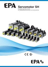
3.1 Layout and detail<br />
Name Description<br />
Connector Connector to inverter main PCB<br />
Signal Communication<br />
P 485 signal - high<br />
connection signal connection<br />
N 485 signal – low<br />
terminal terminal G 485 Ground<br />
Connect it to option<br />
connector on the<br />
Inverter.<br />
Figure 1. Layout of comm. terminal<br />
Pin # GND N P<br />
Description Ground Signal<br />
# GND: Ground for RS 485 terminal<br />
4. Installation<br />
4.1 Installation of Comm. board<br />
3<br />
<strong>MODBUS</strong>-<strong>RTU</strong> user <strong>manual</strong><br />
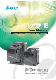
① Connect the option board to the inverter control board using each connector on the board<br />
(See the Figure 2). Check for the position of supporter. Incorrect installation results in<br />
faulty connection of option card.<br />
② Double check the board is firmly installed to the board and then apply the inverter power.<br />
③ When card installation and parameter setting are finished, turn the power off to connect the<br />
converter.<br />
④ Connect the jumper for terminating resistor when option card is connected at the end of<br />
network. (See Figure 3).<br />
GND<br />
N<br />
P<br />
Connect the<br />
supporter<br />
and fix it by nut.
4<br />
<strong>MODBUS</strong>-<strong>RTU</strong> user <strong>manual</strong><br />
⑤ When ①~④ is done correctly, set the parameters for communication according to the<br />
below table.<br />
Parameter code Display Setting Value<br />
< I – 60 > Inverter number 1~32<br />
< I – 61 > Baud-rate 1200~19200 [bps]<br />
< I – 62 > Lost command 0~2<br />
< I – 63 > TimeOut (Note 1) 0.1 sec (Factory default)<br />
Note 1) It is used for Emergency Stop when communication between inverter and master is not done<br />
properly. It is activated when communication is not made even once for the set time. It means<br />
remote controlling of inverter is not done. Set this value for safety.<br />
⑥ Turn off the inverter power before the connection of the Converter when parameter<br />
setting is finished.<br />
4.2 Installation of communication board<br />
① Follow the steps below for models <strong>SV</strong>004~008<strong>iC5</strong>.<br />
Connect it to<br />
option board<br />
connector.<br />
Remove<br />
this part<br />
using knife<br />
or driver.<br />
Supporter<br />
Figure 2. ModBus-<strong>RTU</strong> card installation
② Fix the supporter by nut.<br />
For 004/008 <strong>iC5</strong><br />
series, fix the<br />
supporter (left) with<br />
nut (right).<br />
5<br />
<strong>MODBUS</strong>-<strong>RTU</strong> user <strong>manual</strong><br />
③ There are two holes on the option board for connection of option and inverter. Use left hole<br />
for models 004/008 <strong>iC5</strong> and right for models 015/022 <strong>iC5</strong> series.<br />
④ For models <strong>SV</strong> 015/022 as shown above, loosen the bolt on the connector for Comm. Option<br />
and tighten it onto the supporter on the inverter case. Before fixing the option board, bottom<br />
cover plastic part for Comm. Option should be removed using knife or driver. The same<br />
method is used as 004/008 installation.<br />
⑤ Connect the option board to inverter and reapply the bottom cover before tightening the<br />
supporter.<br />
For 004/008 models<br />
install supporter to<br />
left side of hole.<br />
⑥ Follow the opposite order when dissembling.<br />
For 015/022 models,<br />
install supporter to<br />
right side of hole.<br />
For 015/022 series,<br />
connect the<br />
supporter to the<br />
inverter supporter<br />
using nut.
4.3 Installing RS232-485 converter<br />
6<br />
<strong>MODBUS</strong>-<strong>RTU</strong> user <strong>manual</strong><br />
Installing method is different from makers. Refer to converter <strong>manual</strong> for installation.<br />
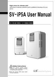
4.4 Computer, Converter and Option board connection<br />
4.4.1 System configuration<br />
232,485 converter<br />
# Max connectable inverters: 32<br />
Figure 2. System configuration<br />
# Extention Line Length: Max 1200m (Less than 700m recommended)<br />
5. Communication protocol<br />
① Use the ModBus-<strong>RTU</strong> protocol (Open).<br />
② Computer or other hosts are a Master with inverter Slaves. Inverter responds to the<br />
Read/Write request by Master.<br />
Master controller<br />
(PC, PLC etc.)<br />
5.1 Supported Function Code<br />
Function Code Name<br />
0x03 Read Hold Register<br />
0x04 Read Input Register<br />
0x06 Preset Single Register<br />
0x10 Preset Multiple Register<br />
Inverter with option<br />
board installed
5.2 Exception Code<br />
Exception Code Name<br />
0x01 ILLEGAL FUNCTION<br />
0x02 ILLEGAL DATA ADDRESS<br />
0x03 ILLEGAL DATA VALUE<br />
0x06 SLAVE DEVICE BUSY<br />
<strong>User</strong> define 0x14<br />
1. Write Disable (Address 0x0004 value is 0)<br />
2. Read Only or Not Program during Running.<br />
5.3 Baud Rate<br />
1200, 2400, 4800, 9600, 19200bps settable (default: 9600bps)<br />
6. Troubleshooting<br />
6.1 Communication is not established<br />
Checking point Diagnosis<br />
Is input power applied to converter? Apply power to the converter.<br />
7<br />
<strong>MODBUS</strong>-<strong>RTU</strong> user <strong>manual</strong><br />
Is the wiring of converter and PC correct? Refer to converter <strong>manual</strong>.<br />
Is Option card connection to the inverter<br />
incorrect?<br />
Refer to “4. Installation”.<br />
Is Master not polling? Verify that the Master is polling the inverter.<br />
Is baud rage set correctly? Refer to “4. Installation”.<br />
Is Data format of <strong>User</strong> program correct? Revise <strong>User</strong> program (Note 2).<br />
Is the wiring of converter and option board<br />
correct?<br />
Refer to “4. Installation”.<br />
Note 2) <strong>User</strong> program is <strong>User</strong>-made S/W for PC.<br />
Parameter Code (Hex)<br />
< Common area > Area accessible regardless of inverter models (Note 3)<br />
◆ Common area<br />
Address Parameter Scale Unit R/W Description<br />
0 : <strong>SV</strong>-iS3 5 :<strong>SV</strong>-iV5<br />
1 : <strong>SV</strong>-iG 6 : -<br />
0x0000 Inverter model<br />
R 2 : <strong>SV</strong>-iV 7 : <strong>SV</strong>-iG5<br />
3 : <strong>SV</strong>-iH 8 : <strong>SV</strong>-<strong>iC5</strong><br />
4 : <strong>SV</strong>-iS5 9 : <strong>SV</strong>-iP5<br />
0x0001 Inverter capacity R<br />
0: 0.75kW, 1: 1.5kW, 2: 2.2kW<br />
-1: 0.4kW (indicated as 65535)<br />
0x0002 Inverter input power<br />
R<br />
0 : 220V<br />
1 : 440V<br />
0x0003 S/W Version<br />
R<br />
(Ex) 0x0100 : Version 1.00<br />
0x0101 : Version 1.01
◆ Common area<br />
8<br />
<strong>MODBUS</strong>-<strong>RTU</strong> user <strong>manual</strong><br />
Address Parameter Scale Unit R/W Description<br />
0x0004 Parameter Read/Write enable R/W<br />
0: Parameter Lock<br />
1: Parameter Read/Write Enable<br />
0x0005 Frequency Reference 0.01 Hz R/W Starting freq ~ Max freq<br />
BIT 0 : Stop (S)<br />
BIT 1 : Forward Run (F)<br />
0x0006 Operatin command (Option)<br />
R/W<br />
BIT 2 : Reverse Run (R)<br />
BIT 3 : Fault reset (0->1)<br />
BIT 4 : Emergency stop<br />
0x0007 Accel time 0.1 sec R/W<br />
BIT 5 : Not used<br />
See function table<br />
0x0008 Decel time 0.1 sec R/W See function table<br />
0x0009 Output current 0.1 A R See function table<br />
0x000A Output frequency 0.01 Hz R See function table<br />
0x000B Output voltage 0.1 V R See function table<br />
0x000C DC Link Voltage 0.1 V R See function table<br />
0x000D Output power 0.1 kW R See function table<br />
BIT 0 : Stop<br />
BIT 1 : Forward running<br />
BIT 2 : Reverse running<br />
BIT 3 : Fault (Trip)<br />
BIT 4 : Accelerating<br />
BIT 5 : Decelerating<br />
BIT 6 : Speed arrival<br />
0x000E Status of Inverter R BIT 7 : DC Braking<br />
BIT 8 : Stopping<br />
Bit 9 : Not Used<br />
BIT 10 : Brake Open<br />
(I55: 3 or 4)<br />
0x000F Trip information R<br />
BIT13: REM. R/S<br />
BIT14: REM. Freq.<br />
BIT 0 : OCT<br />
BIT 1 : OV<br />
BIT 2 : EXT-A<br />
BIT 3 : EST<br />
BIT 4 : Option<br />
BIT 5 : GF(Ground Fault)<br />
BIT 6 : OH(Inverter overheat)<br />
BIT 7 : ETH(Motor overheat)<br />
BIT 8 : OLT(Overload trip)<br />
BIT 9 : HW-Diag<br />
BIT10: EXT-B<br />
BIT11: EEP
◆ Common area<br />
9<br />
<strong>MODBUS</strong>-<strong>RTU</strong> user <strong>manual</strong><br />
Address Parameter Scale Unit R/W Description<br />
BIT12: FAN<br />
BIT13: PO(Phase Open)<br />
BIT14 : IOLT<br />
BIT15: LV<br />
BIT 0 : P1(FX)<br />
BIT 1 : P2(RX)<br />
0x0010 Input terminal information<br />
R BIT 2 : P3(EST)<br />
BIT 3 : P4(RST)<br />
BIT 4 : P5(JOG)<br />
0x0011 output terminal information<br />
R<br />
BIT 0 : Q1 (OC1)<br />
BIT 1 : 30AC<br />
0x0012 V1 0~10V R 0 - 0xFFC0<br />
0x0013 V2 0~10V R 0 - 0xFFC0<br />
0x0014 I 0~20mA R 0 - 0xFFC0<br />
0x0015 RPM R See function table<br />
Note 3) The changed value in Common affects the current setting but returns to the previous<br />
setting when power is cycled or inverter is reset. However, changing value is immediately<br />
reflected in other parameter groups even in the case of Reset or Power On/Off.<br />
Note 4) S/W version in Common area is indicated in 16 bit with parameter area in 10 bit.<br />
◆ DRV group<br />
Address<br />
Code<br />
16 Bit 10 Bit<br />
Description Factory default Max Min<br />
8100 33024 D00 Cmd. freq 0 maxFreq 0<br />
8101 33025 D01 ACC 50 60000 0<br />
8102 33026 D02 DEC 100 60000 0<br />
8103 33027 D03 DRV 1 3 0<br />
8104 33028 D04 FRQ 0 8 0<br />
8105 33029 D05 ST 1 1000 maxFreq 0<br />
8106 33030 D06 ST 2 2000 maxFreq 0<br />
8107 33031 D07 ST 3 3000 maxFreq 0<br />
8108 33032 D08 CUR 0 1 0<br />
8109 33033 D09 RPM 0 1800 0<br />
810A 33034 D10 DCL 0 65535 0<br />
810B 33035 D11 USR 0 1 0<br />
810C 33036 D12 FLT 0 1 0<br />
810D 33037 D13 DRC 0 1 0
◆ F group<br />
Address<br />
16 Bit 10 Bit<br />
10<br />
<strong>MODBUS</strong>-<strong>RTU</strong> user <strong>manual</strong><br />
Code Description Factory default Max MinBit<br />
8201 33281 F1 Run Prohibit 0 2 0<br />
8202 33282 F2 ACC Pattern 0 1 0<br />
8203 33283 F3 DEC Pattern 0 1 0<br />
8204 33284 F4 Stop Method 0 2 0<br />
8208 33288 F8 DcBr freq 500 6000 startFreq<br />
8209 33289 F9 DcBlk time 10 6000 0<br />
820A 33290 F10 DcBr value 50 200 0<br />
820B 33291 F11 DcBr time 10 600 0<br />
820C 33292 F12 DcSt value 50 200 0<br />
820D 33293 F13 DcSt time 0 600 0<br />
820E 33294 F14 PreExTime 10 600 0<br />
8214 33300 F20 Jog Freq 1000 maxFreq 0<br />
8215 33301 F21 Max Freq 6000 Freq Limit High 4000<br />
8216 33302 F22 Base Freq 6000 Freq Limit High 3000<br />
8217 33303 F23 Start Freq 50 1000 0<br />
8218 33304 F24 Freq Limit 0 1 0<br />
8219 33305 F25 High Freq 6000 maxFreq 0<br />
821A 33306 F26 Low Freq 50 maxFreq startFreq<br />
821B 33307 F27 Trq Boost 0 1 0<br />
821C 33308 F28 Fwd Boost 50 150 0<br />
821D 33309 F29 Rev Boost 50 150 0<br />
821E 33310 F30 VF Pattern 0 2 0<br />
821F 33311 F31 <strong>User</strong> Freq1 1500 maxFreq 0<br />
8220 33312 F32 <strong>User</strong> Volt 1 25 100 0<br />
8221 33313 F33 <strong>User</strong> Freq 2 3000 maxFreq 0<br />
8222 33314 F34 <strong>User</strong> Volt 2 50 100 0<br />
8223 33315 F35 <strong>User</strong> Freq 3 4500 maxFreq 0<br />
8224 33316 F36 <strong>User</strong> Volt 3 75 100 0<br />
8225 33317 F37 <strong>User</strong> Freq 4 6000 maxFreq 0<br />
8226 33318 F38 <strong>User</strong> Volt 4 100 100 0<br />
8227 33319 F39 Volt Perc 1000 1100 400<br />
8228 33320 F40 Energy save 0 30 0<br />
8232 33330 F50 ETH select 0 1 0<br />
8233 33331 F51 ETH 1min 150 200 F52<br />
8234 33332 F52 ETH cont 100 F51 50<br />
8235 33333 F53 Motor type 0 1 0<br />
8236 33334 F54 OL level 150 150 30<br />
8237 33335 F55 OL time 100 300 0<br />
8238 33336 F56 OLT select 1 1 0<br />
8239 33337 F57 OLT level 180 200 30<br />
823A 33338 F58 OLT time 600 600 0<br />
823B 33339 F59 Stall prev. 0 7 0<br />
823C 33340 F60 Stall level 150 150 30
11<br />
<strong>MODBUS</strong>-<strong>RTU</strong> user <strong>manual</strong><br />
◆ H group<br />
Address<br />
Code<br />
16 Bit 10 Bit<br />
Description Factory default Max Min<br />
8301 33537 H1 Last Fault1 0 1 0<br />
8302 33538 H2 Last Fault2 0 1 0<br />
8303 33539 H3 Last Fault3 0 1 0<br />
8304 33540 H4 Last Fault4 0 1 0<br />
8305 33541 H5 Last Fault5 0 1 0<br />
8306 33542 H6 Fault Clear 0 1 0<br />
8307 33543 H7 Dwell freq 500 maxFreq startFreq<br />
8308 33544 H8 Dwell time 0 100 0<br />
830A 33546 H10 Jump freq 0 1 0<br />
830B 33547 H11 jump lo 1 1000 jumpHiFreq startFreq<br />
830C 33548 H12 jump Hi 1 1500 maxFreq jumpLoFreq<br />
830D 33549 H13 jump lo 2 2000 jumpHiFreq startFreq<br />
830E 33550 H14 jump Hi 2 2500 maxFreq jumpLoFreq<br />
830F 33551 H15 jump lo 3 3000 jumpHiFreq startFreq<br />
8310 33552 H16 jump Hi 3 3500 maxFreq jumpLoFreq<br />
8311 33553 H17 Curve Time 40 100 1<br />
8312 33554 H18 Curve Time1 40 100 1<br />
8313 33555 H19 Trip select 0 1 0<br />
8314 33556 H20 Power-on run 0 1 0<br />
8315 33557 H21 RST restart 0 1 0<br />
8316 33558 H22 Speed Search 0 15 0<br />
8317 33559 H23 SS Sup-Curr 100 200 80<br />
8318 33560 H24 SS P-gain 100 9999 0<br />
8319 33561 H25 SS I-gain 1000 9999 0<br />
831A 33562 H26 Retry number 0 10 0<br />
831B 33563 H27 Retry delay 10 600 0<br />
831E 33566 H30 Motor select 0 4 0<br />
831F 33567 H31 Pole number 4 12 2<br />
8320 33568 H32 Rated-Slip 200 1000 0<br />
8321 33569 H33 Rated-Curr 18 2000 10<br />
8322 33570 H34 Noload-Curr 7 200 1<br />
8324 33572 H36 Efficiency 72 100 70<br />
8325 33573 H37 Inertia rate 0 2 0<br />
8327 33575 H39 Carrier freq 30 150 10<br />
8328 33576 H40 Control Mode 0 3 0<br />
8329 33577 H41 Auto Tune 0 1 0<br />
832A 33578 H42 Rs 2500 5000 0<br />
832C 33580 H44 Lsigma 2600 30000 0<br />
832D 33581 H45 SL P-Gain 1000 32767 0<br />
832E 33582 H46 SL I-Gain 100 32767 0<br />
8332 33586 H50 PID F/B 0 1 0<br />
8333 33587 H51 PID P-gain 3000 9999 0<br />
8334 33588 H52 PID I-time 100 3200 10<br />
8335 33589 H53 PID D-time 0 3000 0<br />
8336 33590 H54 PID F-gain 0 9999 0
12<br />
<strong>MODBUS</strong>-<strong>RTU</strong> user <strong>manual</strong><br />
◆ H group<br />
Address<br />
Code<br />
16 Bit 10 Bit<br />
Description Factory default Max Min<br />
8337 33591 H55 PID limit 6000 maxFreq startFreq<br />
8346 33606 H70 Acc/Dec freq 0 1 0<br />
8347 33607 H71 Xcel T Mode 1 2 0<br />
8348 33608 H72 PowerOn disp 0 13 0<br />
8349 33609 H73 <strong>User</strong> disp 0 2 0<br />
834A 33610 H74 RPM factor 100 1000 1<br />
834F 33615 H79 S/W Version<br />
Refer to Product<br />
100 0<br />
<strong>manual</strong><br />
8351 33617 H81 2nd Acc time 50 60000 0<br />
8352 33618 H82 2nd Dec time 100 60000 0<br />
8353 33619 H83 2nd BaseFreq 6000 maxFreq 3000<br />
8354 33620 H84 2nd V/F 0 2 0<br />
8355 33621 H85 2nd F-boost 50 150 0<br />
8356 33622 H86 2nd R-boost 50 150 0<br />
8357 33623 H87 2nd Stall 150 150 30<br />
8358 33624 H88 2nd ETH 1min 150 200 50<br />
8359 33625 H89 2nd ETH cont 100 200 50<br />
835A 33626 H90 2nd R-Curr 18 200 1<br />
835D 33629 H93 Para Init 0 5 0<br />
835E 33630 H94 Password set 0 4095 0<br />
◆ I group<br />
Address<br />
Code<br />
16 Bit 10 Bit<br />
Description Factory default Max Min<br />
8401 33793 I1 VR filter 10 9999 0<br />
8402 33794 I2 VR volt x1 0 viXmax 0<br />
8403 33795 I3 VR freq y1 0 maxFreq 0<br />
8404 33796 I4 VR volt x2 1000 1000 viXmin<br />
8405 33797 I5 VR freq y2 6000 maxFreq 0<br />
8406 33798 I6 V1 filter 10 9999 0<br />
8407 33799 I7 V1 volt x1 0 viXmax 0<br />
8408 33800 I8 V1 freq y1 0 maxFreq 0<br />
8409 33801 I9 V1 volt x2 1000 1000 viXmin<br />
840A 33802 I10 V1 freq y2 6000 maxFreq 0<br />
840B 33803 I11 I filter 10 9999 0<br />
840C 33804 I12 I curr x1 400 viXmax 0<br />
840D 33805 I13 I freq y1 0 maxFreq 0<br />
840E 33806 I14 I curr x2 2000 2000 viXmin<br />
840F 33807 I15 I freq y2 6000 maxFreq 0<br />
8410 33808 I16 Wire broken 0 2 0<br />
8414 33812 I20 P1 define 0 24 0<br />
8415 33813 I21 P2 define 1 24 0<br />
8416 33814 I22 P3 define 2 24 0<br />
8417 33815 I23 P4 define 3 24 0<br />
8418 33816 I24 P5 define 4 24 0<br />
841B 33819 I27 Ti Filt Num 15 50 2
◆ I group<br />
Address<br />
16 Bit 10 Bit<br />
13<br />
<strong>MODBUS</strong>-<strong>RTU</strong> user <strong>manual</strong><br />
Code Description Factory default Max Min<br />
841E 33822 I30 ST 4 3000 maxFreq 0<br />
841F 33823 I31 ST 5 2500 maxFreq 0<br />
8420 33824 I32 ST 6 2000 maxFreq 0<br />
8421 33825 I33 ST 7 1500 maxFreq 0<br />
8422 33826 I34 Acc Time-1 30 60000 0<br />
8423 33827 I35 Dec Time-1 30 60000 0<br />
8424 33828 I36 Acc Time-2 40 60000 0<br />
8425 33829 I37 Dec Time-2 40 60000 0<br />
8426 33830 I38 Acc Time-3 50 60000 0<br />
8427 33831 I39 Dec Time-3 50 60000 0<br />
8428 33832 I40 Acc Time-4 60 60000 0<br />
8429 33833 I41 Dec Time-4 60 60000 0<br />
842A 33834 I42 Acc Time-5 70 60000 0<br />
842B 33835 I43 Dec Time-5 70 60000 0<br />
842C 33836 I44 Acc Time-6 80 60000 0<br />
842D 33837 I45 Dec Time-6 80 60000 0<br />
842E 33838 I46 Acc Time-7 90 60000 0<br />
842F 33839 I47 Dec Time-7 90 60000 0<br />
8432 33842 I50 FM mode 0 3 0<br />
8433 33843 I51 FM adjust 100 200 10<br />
8434 33844 I52 FDT freq 3000 maxFreq 0<br />
8435 33845 I53 FDT band 1000 maxFreq 0<br />
8436 33846 I54 Aux mode 1 12 17 0<br />
8437 33847 I55 Aux mode 2 17 17 0<br />
8438 33848 I56 Relay mode 2 7 0<br />
843C 33852 I60 Inv No. 1 32 1<br />
843D 33853 I61 Baud rate 3 4 0<br />
843E 33854 I62 Lost command 0 2 0<br />
843F 33855 I63 Time out 10 120 1
MEMO<br />
<strong>MODBUS</strong>-<strong>RTU</strong> user <strong>manual</strong>