IEC 309 Pin and Sleeve Devices - Revere Electric
IEC 309 Pin and Sleeve Devices - Revere Electric
IEC 309 Pin and Sleeve Devices - Revere Electric

You also want an ePaper? Increase the reach of your titles
YUMPU automatically turns print PDFs into web optimized ePapers that Google loves.
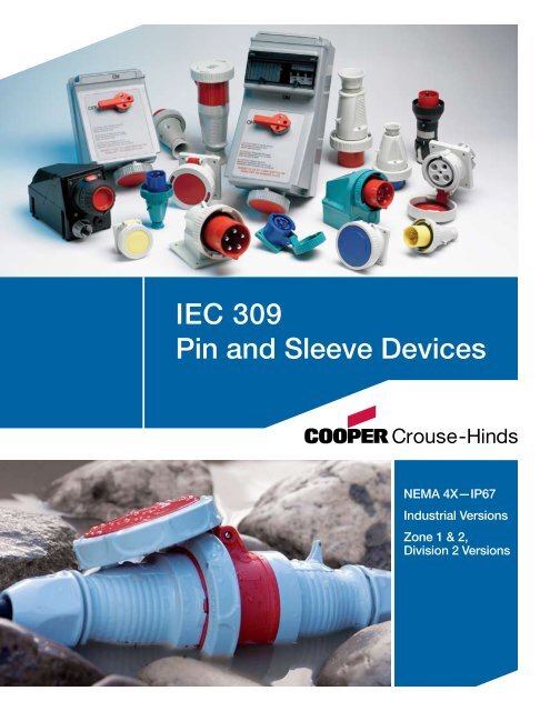
<strong>IEC</strong> <strong>309</strong><br />
<strong>Pin</strong> <strong>and</strong> <strong>Sleeve</strong> <strong>Devices</strong><br />
NEMA 4X—IP67<br />
Industrial Versions<br />
Zone 1 & 2,<br />
Division 2 Versions
Introduction <strong>IEC</strong> <strong>309</strong> Non-Metallic <strong>and</strong> Table of Plugs, Contents Receptacles & Interlocks<br />
The St<strong>and</strong>ard For<br />
Safety & Reliability<br />
The more dem<strong>and</strong>ing the environment, the likelier you<br />
are to find Cooper Crouse-Hind’s products at the very<br />
center of operations.<br />
From fittings <strong>and</strong> enclosures to control <strong>and</strong> apparatus,<br />
industrial lighting, plugs <strong>and</strong> receptacles, <strong>and</strong> signals <strong>and</strong><br />
alarms, Cooper Crouse-Hinds’ products don’t just meet<br />
safety st<strong>and</strong>ards. More often than not, they set them.<br />
<strong>IEC</strong> <strong>309</strong> <strong>Pin</strong> &<br />
<strong>Sleeve</strong> <strong>Devices</strong><br />
Cooper Crouse-Hinds has combined years of field proven<br />
Arktite ® pin <strong>and</strong> sleeve expertise with German-North<br />
American precision engineering <strong>and</strong> manufacturing to offer<br />
the world’s best <strong>IEC</strong> <strong>309</strong> plug <strong>and</strong> socket product line.<br />
Available in both watertight <strong>and</strong> hazardous area designs,<br />
this global product line features the latest technological<br />
innovations to lead the way in <strong>IEC</strong> <strong>309</strong> performance.<br />
Each Cooper Crouse-Hinds device is designed <strong>and</strong><br />
manufactured to meet <strong>IEC</strong> <strong>309</strong>-1 <strong>and</strong> <strong>309</strong>-2 st<strong>and</strong>ards<br />
<strong>and</strong> is interchangeable with all other nonhazardous,<br />
UL Listed <strong>IEC</strong> <strong>309</strong> plugs <strong>and</strong> receptacles.<br />
Table Of Contents<br />
Introduction 2<br />
<strong>IEC</strong> <strong>309</strong> Plugs, Connectors, Receptacles <strong>and</strong> Inlets 3-7<br />
Exploded View 3<br />
Materials 4<br />
Performance Specifications 5, 6<br />
Useful Tables 7<br />
<strong>IEC</strong> <strong>309</strong>-1 <strong>and</strong> <strong>309</strong>-2 Mechanical Interlocks 8-10<br />
Exploded View 8<br />
Worldwide Safety, Reliability & Interchangeability 9<br />
Performance Specifications 10<br />
Ordering Information 11-12<br />
Dimension Drawings 13-14<br />
Accessories 15<br />
Hazardous Area <strong>IEC</strong> <strong>309</strong> Plugs <strong>and</strong> Interlocks 16-19<br />
Ordering Information 18-19<br />
2
<strong>IEC</strong> <strong>309</strong> Plugs, Connectors, Receptacles <strong>and</strong> Inlets—<br />
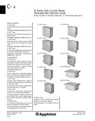
<strong>309</strong> Non-Metallic Plugs, Receptacles & Interlocks<br />
NEMA 4X, IP67, Nonmetallic<br />
Retaining Device<br />
Holds the plug<br />
in position with a<br />
connector or socketoutlet<br />
<strong>and</strong> prevents<br />
unintentional withdraw.<br />
Internal Strain Relief with<br />
“Swing-Away” Feature<br />
Designed to firmly grip outer<br />
cable jacket <strong>and</strong> internal<br />
conductors. Eliminates strain<br />
on the terminals while providing<br />
high pull-out values.<br />
Shrouded <strong>Pin</strong>s<br />
<strong>Pin</strong>s are recessed in<br />
the nylon housing <strong>and</strong><br />
protected from deforming.<br />
Eliminates touching the<br />
live contacts while the plug<br />
is partially engaged.<br />
External Cable Gl<strong>and</strong> with<br />
“Onion Ring” Neoprene Bushing<br />
The watertight compression type<br />
cable gl<strong>and</strong> serves as a secondary<br />
method of eliminating strain on<br />
the terminals <strong>and</strong> conductors.<br />
Electro Zinc<br />
Plated Steel Screws<br />
Corrosion resistant <strong>and</strong><br />
no loose parts to h<strong>and</strong>le<br />
or misplace.<br />
Terminal Identification<br />
Ground, neutral <strong>and</strong><br />
phase terminals are<br />
clearly identified.<br />
Locking Ring <strong>and</strong> Gasket<br />
Protects against intrusion of<br />
dirt, dust <strong>and</strong> moisture when<br />
devices are connected.<br />
Color Coded<br />
Avoid mismatching<br />
<strong>and</strong> confusion.<br />
Spring Loaded<br />
Gasketed Cover<br />
Protects against<br />
accidental encounter with<br />
live contacts, intrusion of<br />
dirt, dust <strong>and</strong> moisture.<br />
High Impact Thermoplastic Housing<br />
Nonconductive <strong>and</strong> nonmetallic device<br />
is corrosion resistant <strong>and</strong> enhances<br />
safety.<br />
Staggered Contacts<br />
Ground, neutral <strong>and</strong><br />
phase contacts are<br />
positioned to assure first<br />
make <strong>and</strong> last break.<br />
Recessed Contacts<br />
Contact sleeves are<br />
recessed in the narrow<br />
contact tubes providing a<br />
“fingerproof” device.<br />
Retaining Device<br />
Cooper Crouse-Hinds pin & sleeve devices are provided<br />
with a mechanical arrangement which holds a plug or<br />
connector in position when it is in proper engagement,<br />
<strong>and</strong> prevents its unintentional withdraw.<br />
Double Terminal Screws<br />
Maximum clamping pressure<br />
without damaging str<strong>and</strong>s. Double<br />
terminal screws create a large area<br />
of safe <strong>and</strong> secure contact between<br />
conductor <strong>and</strong> terminal. Screws<br />
are captive, easily accessible <strong>and</strong><br />
supplied in the open position.<br />
Solid Brass <strong>Pin</strong>s<br />
Low contact resistance <strong>and</strong><br />
high conductivity. Long lasting,<br />
reliable electrical contact.<br />
Split Contact <strong>Sleeve</strong> with<br />
Nickel Plated Steel Springs<br />
Provides optimum insertion/<br />
withdraw force <strong>and</strong> constant<br />
contact pressure.<br />
Chamfered Terminals<br />
Funnel Entry. Guides <strong>and</strong><br />
captures all wire str<strong>and</strong>s.<br />
3
<strong>IEC</strong> <strong>309</strong> Plugs, Connectors, Receptacles <strong>and</strong> Inlets—Materials<br />
Assembly Screws*<br />
Friction Ring*<br />
Gl<strong>and</strong> Cap<br />
Grommet<br />
Housing (Front <strong>and</strong> Back)<br />
Internal Cord Clamp<br />
Locking Ring<br />
<strong>Pin</strong>s (Watertight)<br />
<strong>Pin</strong>s (Splashproof)<br />
Sealing Gasket<br />
Terminal Screws<br />
Housing<br />
Locking Ring<br />
Mounting Flange<br />
<strong>Pin</strong>s (Watertight)<br />
<strong>Pin</strong>s (Splashproof)<br />
Sealing Gasket<br />
Terminal Screws<br />
PLUG<br />
INLET<br />
Type 6 Nylon<br />
Type 6 Nylon<br />
Type 6 Nylon<br />
Brass, Nickel Plated<br />
Brass<br />
* Stainless steel available upon request<br />
Steel, Electro Zinc Plated<br />
Steel, Electro Zinc Plated<br />
Polycarbonate Blend<br />
Solid Neoprene<br />
Type 6 Nylon<br />
Type 6 Nylon<br />
Type 6 Nylon<br />
Brass, Nickel Plated<br />
Brass<br />
Neoprene<br />
Steel, Nickel Plated<br />
Neoprene<br />
Steel, Nickel Plated<br />
Manufacturing pin & sleeve devices, of superior quality,<br />
can only be accomplished through the use of high<br />
grade materials. That is an important part of the<br />
Cooper Crouse-Hinds <strong>Pin</strong> & <strong>Sleeve</strong> system — quality<br />
products you can depend on.<br />
Male pins <strong>and</strong> female sleeves are made of high<br />
conductivity brass. Contacts used with watertight<br />
devices are nickel plated to prevent corrosion. The<br />
insulated housing is made from a high impact, nylon<br />
material. The nonmetallic device, while resistant to<br />
most solvents, chemicals <strong>and</strong> salt water, is also nonconductive,<br />
which enhances the safety of the product.<br />
All extracts from manufacturing, test st<strong>and</strong>ard or<br />
independent agency approvals are for informational<br />
purposes only <strong>and</strong> are not intended to be, should<br />
not be used as, nor considered to be a complete<br />
description of such. Contact customer service for a<br />
more complete version of the test st<strong>and</strong>ard or agency<br />
approval in question.<br />
Cooper Crouse-Hinds reserves the right to make<br />
technical, descriptive, <strong>and</strong> dimensional changes due to<br />
product changes <strong>and</strong>/or improvements.<br />
Assembly Screws*<br />
Cover<br />
Cover Fastener<br />
Cover Spring<br />
Friction Ring*<br />
Gl<strong>and</strong> Cap<br />
Grommet<br />
Housing (Front <strong>and</strong> Back)<br />
Internal Cord Clamp<br />
Sealing Gasket<br />
<strong>Sleeve</strong> Spring<br />
<strong>Sleeve</strong>s (Watertight)<br />
<strong>Sleeve</strong>s (Splashproof)<br />
Terminal Screws<br />
Cover<br />
Cover Fastener<br />
Cover Spring<br />
Housing<br />
Mounting Flange<br />
Sealing Gasket<br />
<strong>Sleeve</strong> Spring<br />
<strong>Sleeve</strong>s (Watertight)<br />
<strong>Sleeve</strong>s (Splashproof)<br />
Terminal Screws<br />
CONNECTOR<br />
Steel, Electro Zinc Plated<br />
Type 6 Nylon<br />
Nickel Plated Brass, Brass<br />
or Macrolon<br />
Stainless Steel (A2)<br />
Steel, Electro Zinc Plated<br />
Polycarbonate Blend<br />
Solid Neoprene<br />
Type 6 Nylon<br />
Type 6 Nylon<br />
Neoprene<br />
Steel, Nickel Plated<br />
Brass, Nickel Plated<br />
Brass<br />
RECEPTACLE<br />
Steel, Nickel Plated<br />
Type 6 Nylon<br />
Nickel Plated Brass, Brass or<br />
Macrolon<br />
Stainless Steel (A2)<br />
Type 6 Nylon<br />
Type 6 Nylon<br />
Neoprene<br />
Steel, Nickel Plated<br />
Brass, Nickel Plated<br />
Brass<br />
Steel, Nickel Plated<br />
4
<strong>IEC</strong> <strong>309</strong> Plugs, Connectors, Receptacles <strong>and</strong> Inlets—<br />
North American Performance Specifications<br />
Insulation Resistance<br />
Dielectric Voltage<br />
Withst<strong>and</strong><br />
ELECTRICAL<br />
500V for 1 min. Resistance ≥5MΩ<br />
3000V for 1 min.<br />
Ground Path Current See Table 1<br />
Endurance, Connect <strong>and</strong><br />
Disconnect Cycles<br />
Current Interrupting<br />
Overload Test<br />
(Power factor 0.75-0.80)<br />
Temperature Rise<br />
Resistance to Arcing<br />
Mold Stress Relief<br />
Humidity<br />
See Table 2<br />
Certified for current interrupting at<br />
full rated current <strong>and</strong> voltage.<br />
Tested for current interrupting at<br />
150% of the rated current <strong>and</strong> 100%<br />
of the rated voltage for 50 cycles.<br />
Maximum 30°C rise at full rated<br />
current (after overload).<br />
Continuation of overload test for<br />
an additional 200 cycles.<br />
Mechanical<br />
70°C (158°F) for 7 hours<br />
32°C (89.6°F), 93% humidity for 7<br />
days (168 hours)<br />
Cable Secureness See Table 3<br />
A device is wired with a 90"<br />
(2300mm) length of flexible cord<br />
<strong>and</strong> dropped from 30" (760mm)<br />
Impact<br />
8 times. The device is then<br />
conditioned for 6 hours at -25°C<br />
<strong>and</strong> immediately subjected to a<br />
repeated impact test.<br />
250 lbs for 1 minute. The device<br />
is then conditioned for 6 hours at<br />
Crushing<br />
-25°C <strong>and</strong> immediately subjected<br />
to a repeated crushing test.<br />
Withdrawal Force See Table 4<br />
Strength of Insulating<br />
Base <strong>and</strong> Support<br />
Polarization Integrity<br />
110% of specified tightening<br />
torque on terminal screws.<br />
Matching devices will not mate<br />
so that the ground is energized,<br />
even when polarization feature<br />
is removed <strong>and</strong> 40 lb (180 N)<br />
insertion force is applied.<br />
ENVIRONMENTAL<br />
Flammability V-2 or better per UL 94 or CSA 22.2 No. 0.6<br />
Ambient<br />
Temperature<br />
Range<br />
Resistance<br />
to Corrosion<br />
Moisture<br />
Resistance<br />
UV<br />
Resistance<br />
Minimum: -25°C (-13°F) with impact<br />
Maximum: 90°C (194°F)<br />
Ferrous parts immersed for 10 min. in a<br />
10% solution of ammonium chloride at a<br />
temperature of 20°C.<br />
Watertight (IP67): Device immersed for 24<br />
hours in water at a temp. of 25°C, the highest<br />
point of the device being 2" (5cm) below<br />
the water level. Splashproof (IP44): Device<br />
is sprayed with water for 10 minutes <strong>and</strong><br />
immediately afterwards subjected to splashing<br />
water in all directions (360°).<br />
Exposed plastic materials are UV stabilized.<br />
Table1<br />
Device<br />
Rating<br />
Amperes<br />
20<br />
30<br />
60<br />
100<br />
Minimum Ground Path Current Test<br />
Minimum Size<br />
Grounding Conductor<br />
AWG mm 2<br />
12<br />
10<br />
10<br />
8<br />
3.3<br />
5.3<br />
5.3<br />
8.4<br />
Time,<br />
Seconds<br />
A test current that far exceeds the device rating is passed through the<br />
mating devices <strong>and</strong> grounding wires.<br />
Table2<br />
Device<br />
Rating<br />
Amperes<br />
20<br />
30<br />
60<br />
100<br />
4<br />
4<br />
4<br />
4<br />
Minimum Endurance test<br />
Cycles with Load<br />
at Rated Current<br />
<strong>and</strong> Voltage<br />
5000<br />
1000<br />
1000<br />
250<br />
No-Load<br />
Cycles<br />
0<br />
1000<br />
1000<br />
250<br />
Test<br />
Current,<br />
Amperes<br />
470<br />
750<br />
750<br />
1180<br />
Sequence<br />
–<br />
Alternating<br />
Alternating<br />
Alternating<br />
The test sequence is conducted by using a no-load, followed by a load<br />
sequence. The power factor of the load is 0.75 to 0.80.<br />
Table3<br />
Device<br />
Rating<br />
Amperes<br />
20<br />
30<br />
60<br />
100<br />
Minimum Cable Secureness Test<br />
Force<br />
Torque<br />
Maximum<br />
Displacement<br />
lb. N ft-lb. N•m Inches mm<br />
30<br />
75<br />
150<br />
150<br />
133<br />
333<br />
667<br />
667<br />
0.4<br />
0.5<br />
1.0<br />
2.0<br />
0.54<br />
0.68<br />
1.4<br />
2.7<br />
3/32<br />
3/32<br />
3/32<br />
3/32<br />
2.38<br />
2.38<br />
2.38<br />
2.38<br />
The flexible cord or cable is simultaneously twisted <strong>and</strong> pulled. Values for the<br />
applied twisting torque <strong>and</strong> force of pull are shown in Table 3. In all cases the<br />
cord displacement is less than 3/32 inches.<br />
Table4<br />
Device Rating<br />
Amperes<br />
20<br />
30<br />
60<br />
100<br />
Minimum Withdrawal Forces Test<br />
Minimum Withdrawal Force<br />
lb. N Time, Min.<br />
5<br />
6<br />
15<br />
20<br />
22<br />
27<br />
67<br />
89<br />
The pressure exerted by mating contacts of a plug <strong>and</strong> connector must be<br />
sufficient to prevent unintentional withdrawal during normal use. During the<br />
test, any locking rings or retaining means are not to be engaged.<br />
R<br />
Certified<br />
1<br />
1<br />
1<br />
1<br />
These products are Listed to applicable UL<br />
St<strong>and</strong>ards <strong>and</strong> requirements by Underwriters<br />
Laboratories Inc. UL 1682,UL 1686<br />
5
<strong>IEC</strong> <strong>309</strong> Plugs, Connectors, Receptacles <strong>and</strong> Inlets—<br />
International Performance Specifications<br />
Insulation Resistance<br />
Per <strong>IEC</strong> <strong>309</strong>-1, Clause 19<br />
Dielectric Strength<br />
Per <strong>IEC</strong> <strong>309</strong>-1, Clause 19<br />
Norm. Operation, Connect<br />
& Disconnect Cycles<br />
Per <strong>IEC</strong> <strong>309</strong>-1, Clause 21<br />
Breaking Capacity<br />
Per <strong>IEC</strong> <strong>309</strong>-1, Clause 20<br />
Temperature Rise<br />
Per <strong>IEC</strong> <strong>309</strong>-1, Clause 22<br />
Cable Secureness<br />
Per <strong>IEC</strong> <strong>309</strong>, Clause 23<br />
Impact<br />
Per <strong>IEC</strong> <strong>309</strong>, Clause 24<br />
Flammability<br />
Ambient<br />
Temperature<br />
Range<br />
Moisture<br />
Resistance<br />
UV Resistance<br />
ELECTRICAL<br />
Mechanical<br />
500V for 1 min.<br />
Resistance ≥5MΩ<br />
3000V for 1 min.<br />
See Table 1<br />
Tested at 110% of the rated<br />
operating voltage <strong>and</strong> 125%<br />
of the rated current.<br />
Maximum 50 K rise at<br />
full rated current.<br />
See Table 2<br />
A device is wired with a 2.25m<br />
length of flexible cord <strong>and</strong><br />
dropped from a height of<br />
75cm, 8 times. The device is then<br />
tested for applicable degrees of<br />
protection against moisture.<br />
ENVIRONMENTAL<br />
Self-extinguishing<br />
Per <strong>IEC</strong> <strong>309</strong>-1, Clause 27<br />
Minimum: -25°C with impact<br />
Maximum: 90°C<br />
Watertight (IP67): Device immersed for<br />
24 hours in water at a temp. of 25°C, the<br />
highest point of the device being 5cm<br />
(2") below the water level.<br />
Splashproof (IP44): Device is sprayed<br />
with water for 10 minutes <strong>and</strong><br />
immediately afterwards subjected to<br />
splashing water in all directions (360°).<br />
Exposed plastic materials are UV<br />
stabilized.<br />
Table1<br />
Device<br />
Rating<br />
Amperes<br />
16<br />
32<br />
63<br />
125<br />
Minimum Connect <strong>and</strong> Disconnect Cycles<br />
Cycles with Load<br />
at Rated Current<br />
<strong>and</strong> Voltage<br />
5000 p.f of 0.6<br />
1000 p.f of 0.6<br />
1000 p.f of 0.6<br />
250 p.f of 0.7<br />
No-Load<br />
Cycles<br />
0<br />
1000<br />
1000<br />
250<br />
The test sequence is conducted by using a no-load, followed<br />
by a load sequence.<br />
Table2<br />
Device<br />
Rating<br />
Amperes<br />
16<br />
32<br />
63<br />
125<br />
Minimum Cable Secureness Test<br />
Force<br />
Torque<br />
Sequence<br />
–<br />
Alternating<br />
Alternating<br />
Alternating<br />
Maximum<br />
Displacement<br />
N N•m mm<br />
80<br />
100<br />
120<br />
200<br />
0.3500.68<br />
0.425<br />
0.8<br />
1.5<br />
The flexible cord or cable is twisted <strong>and</strong> pulled. Values for the applied twisting<br />
torque <strong>and</strong> force of pull are shown in Table 2. In all cases the cord displacement<br />
is less than 2mm.<br />
2<br />
2<br />
2<br />
2<br />
DECLARATION OF CONFORMITY<br />
Cooper Industries, Ltd.<br />
600 Travis, Ste. 5800<br />
Houston, TX 77002-1001<br />
P: 713-209-8400<br />
www.cooperindustries.com<br />
We declare, under our sole responsibility, the<br />
conformity of the following products <strong>and</strong> st<strong>and</strong>ards:<br />
Plugs <strong>and</strong> Sockets (<strong>Pin</strong> <strong>and</strong> <strong>Sleeve</strong> devices)<br />
DIN EN 60 <strong>309</strong>, T. 1/BS 4343<br />
DIN EN 60 <strong>309</strong>, T. 2<br />
This declaration of conformity is according to the<br />
EC regulations 73/23, 91/368 <strong>and</strong> 89/336 (Low<br />
Voltage Directive), module A, in consideration of<br />
DIN EN 45 014.<br />
R<br />
6
<strong>IEC</strong> <strong>309</strong> Plugs, Connectors, Receptacles <strong>and</strong> Inlets—<br />
Useful Tables<br />
MAKING A CONNECTION IS EASY<br />
A clock face is used to represent the<br />
grounding contact position for all<br />
female connectors <strong>and</strong> receptacles.<br />
With the keyway at the bottom, the<br />
female grounding contact will appear<br />
at one of the twelve hour positions.<br />
To identify the system voltage, identify<br />
the housing color <strong>and</strong> hour location of<br />
the connector or receptacle<br />
grounding contact.<br />
380-415VAC<br />
2 wire 3 pole<br />
3φ250VAC<br />
3 wire 4 pole<br />
3φY120/208VAC<br />
4 wire 5 pole<br />
480VAC 2 wire 3 pole<br />
3φ480VAC 3 wire 4 pole<br />
3φY277/480V 4 wire 5 pole<br />
380-415VAC 3 wire 4 pole<br />
220/380-240/415V 4 wire 5 pole<br />
125/250VAC 3 wire 4 pole<br />
12 1<br />
10 11 2<br />
3<br />
9<br />
8<br />
7<br />
6<br />
5<br />
4<br />
250VAC 2 wire 3 pole<br />
380V 50Hz 3 wire 4 pole<br />
440V 60Hz 3 wire 4 pole<br />
125VAC 2 wire 3 pole<br />
3φ600VAC 3 wire 4 pole<br />
3φ347/600VAC 4 wire 5 pole<br />
277VAC 2 wire 3 pole<br />
We’ve made our catalog number ordering system as easy to use as our products! Simply follow the six-part “code”:<br />
Table1<br />
CH 4 20<br />
R<br />
7 W<br />
Prefix 1st digit 2nd–4th digit<br />
1st letter<br />
Last digit Last letter<br />
CH = Crouse-Hinds<br />
W = Watertight<br />
3 = 3 pole<br />
4 = 4 pole<br />
5 = 5 pole<br />
16 = 16 Amp<br />
20 = 20 Amp<br />
30 = 30 Amp<br />
32 = 32 Amp<br />
60 = 60 Amp<br />
63 = 63 Amp<br />
100 = 100 Amp<br />
125 = 125 Amp<br />
P = Plug<br />
C = Connector<br />
R = Receptacle Straight<br />
RA = Receptacle 15° Angled<br />
RA80 = Receptacle 80º Angled<br />
B = Inlet<br />
MI = Mechanical Interlock<br />
MIB = Circuit Breaker Interlock<br />
Clock position of<br />
female grounding<br />
contact<br />
Table2<br />
Cable <strong>and</strong> Conductor Strip Length<br />
Device Rating<br />
North American 20A 30A 60A 100A<br />
Outer Jacket<br />
Strip Length<br />
Conductor<br />
Strip Length<br />
International 16A 32A 63A 125A<br />
Pilot Conductor<br />
Strip Length<br />
Table3<br />
inch<br />
mm<br />
inch<br />
mm<br />
inch<br />
mm<br />
2<br />
50<br />
1/2<br />
12<br />
2 1/2<br />
63<br />
1/2<br />
12<br />
3<br />
76<br />
3/4<br />
19<br />
7/16<br />
11<br />
Maximum Torque applied<br />
to terminal screws<br />
Device Rating<br />
4<br />
102<br />
1 1/8<br />
28<br />
5/8<br />
16<br />
North American 20A 30A 60A 100A<br />
International 16A 32A 63A 125A<br />
Torque<br />
Terminal Screw<br />
Torque<br />
Pilot Screw<br />
lb.–in.<br />
N–m<br />
lb.–in.<br />
N–m<br />
7.1<br />
0.8<br />
7.1<br />
0.8<br />
17.6<br />
2<br />
7.1<br />
0.8<br />
35.3<br />
4<br />
7.1<br />
0.8<br />
Table4<br />
METRIC <strong>and</strong> AWG/MCM<br />
conductor size equivalents<br />
Conductor Size<br />
Test Range<br />
mm 2<br />
AWG/MCM<br />
(Amperage)<br />
1,0 18 0-8<br />
1,5 16 8-12<br />
2,5 14 12-15<br />
2,5 12 15-20<br />
4,0 10 20-25<br />
6,0 10 25-32<br />
10 8 32-50<br />
16 6 50-65<br />
25 4 65-85<br />
35 3 85-100<br />
35 2 100-115<br />
50 1 115-130<br />
50 1/0 130-150<br />
70 2/0 150-175<br />
95 3/0 175-200<br />
95 4/0 200-225<br />
120 250 225-250<br />
150 300 250-275<br />
185 350 275-300<br />
185 400 300-350<br />
240 500 350-400<br />
7
<strong>IEC</strong> <strong>309</strong>-1 <strong>and</strong> <strong>309</strong>-2 Mechanical Interlocks—<br />
NEMA 4X, IP67, Nonhazardous<br />
7.2" (183mm) Max.<br />
Compliance with OSHA<br />
Lockout Requirements<br />
Cooper Crouse-Hinds<br />
Mechanical Interlock’s bright<br />
red h<strong>and</strong>le can be locked in the<br />
“OFF” position as a method of<br />
compliance with OSHA lockout<br />
requirements. The h<strong>and</strong>le can<br />
accept up to a 5/16" padlock<br />
shaft.<br />
Compact Size<br />
All versions <strong>and</strong> sizes<br />
are designed to fit within<br />
the web of an 8" column.<br />
This compact size allows<br />
the use of columns as a<br />
mounting location.<br />
Watertight NEMA 4X,<br />
12K Enclosure<br />
Cooper Crouse-Hinds<br />
Mechanical Interlocks<br />
are gasketed <strong>and</strong> rated<br />
as a Watertight NEMA<br />
4X, 12K enclosure. The<br />
nonmetallic enclosure,<br />
while abuse <strong>and</strong><br />
corrosion resistant, is<br />
also nonconductive<br />
which enhances the<br />
safety of the product.<br />
Easy Identification<br />
Catalog number, rating<br />
<strong>and</strong> certifications are<br />
indicated on the label<br />
for easy identification of<br />
mating devices.<br />
Grounding Plate<br />
Cooper Crouse-Hinds Mechanical Interlocks<br />
are supplied with a free floating grounding<br />
plate. Because of this unique method of<br />
grounding, conduit entry may be made from<br />
the top, bottom or side. No other br<strong>and</strong> offers<br />
this type of installation versatility.<br />
Color Coded<br />
Receptacle Covers<br />
Receptacle covers are<br />
color-coded by voltage<br />
in accordance with <strong>IEC</strong><br />
<strong>309</strong> st<strong>and</strong>ard.<br />
Swivel<br />
mount<br />
feet<br />
A Pre-Molded Offset Dimple<br />
Cooper Crouse-Hinds does not install<br />
a hub at the top of our mechanical<br />
interlocks, rather a pre-molded offset<br />
dimple (drill point) is provided instead<br />
of a conduit entry hole. This allows<br />
the installer to choose the size of the<br />
conduit to be used, <strong>and</strong> the location<br />
where the conduit will be attached<br />
to the enclosure (top, bottom or side<br />
entry) without the use of knockout<br />
plugs <strong>and</strong> reducers. Arranging the<br />
conduit entry hole at the dimple<br />
location will prevent condensation<br />
from falling directly on the interior<br />
electrical components, such as the<br />
switch. It will also allow for more<br />
room to pull conductors when wiring.<br />
Approximately 40% of all entry is<br />
from the bottom.<br />
Swivel Mount Feet (135°)<br />
Swivel mount feet can be used<br />
for installations where irregular or<br />
tight fit applications exist.<br />
Completely Compatible<br />
Completely compatible<br />
with not only Cooper<br />
Crouse-Hinds <strong>IEC</strong> <strong>309</strong>-1<br />
<strong>and</strong> <strong>309</strong>-2 plugs, but with<br />
any manufacturer’s plugs<br />
that conform to the <strong>IEC</strong><br />
<strong>309</strong> st<strong>and</strong>ards <strong>and</strong> color<br />
coding system anywhere<br />
in the world. When Cooper<br />
Crouse-Hinds IP67 plugs<br />
are used in conjunction<br />
with NEMA 4X rated<br />
Cooper Crouse-Hinds<br />
Mechanical Interlocks, both<br />
devices are NEMA 4X rated.<br />
Micro Switch<br />
Available upon request. May<br />
be used to transmit signal<br />
when plug is inserted or when<br />
switch is turned to the “ON”<br />
position. May also be used<br />
for indicator light to display<br />
<strong>and</strong> confirm when switch<br />
is turned “ON” or “OFF”.<br />
Consult technical service for<br />
price <strong>and</strong> delivery.<br />
8
<strong>IEC</strong> Worldwide <strong>309</strong> Non-Metallic Safety, Reliability Plugs, <strong>and</strong> Receptacles Interchangeability & Interlocks<br />
SAFETY<br />
Designed to combine a disconnect switch <strong>and</strong> a<br />
receptacle into one compact device. Mechanical<br />
interlock receptacles eliminate the possibility of<br />
making or breaking the circuit under load or making<br />
a haphazard connection. A mechanism within the<br />
enclosure prevents the switch from being turned to the<br />
“ON” position until the plug is fully engaged into the<br />
receptacle. Once inserted, the plug is locked in place<br />
when the switch is turned on <strong>and</strong> can’t be removed<br />
until the switch is turned to the “OFF” position. This<br />
prevents making or breaking the circuit under load.<br />
The integration of the switch <strong>and</strong> the receptacle in<br />
a single, compact enclosure encourages the safe<br />
operating practice of disconnecting at the switch rather<br />
than the plug <strong>and</strong> receptacle.<br />
The nonmetallic enclosure, while abuse <strong>and</strong> corrosion<br />
resistant, is also nonconductive, which enhances the<br />
safety of the product. The device can be connected<br />
to metallic conduit without interfering with the ground<br />
continuity. All mechanical interlock receptacles provide<br />
lockout protection for greater safety <strong>and</strong> comply with<br />
OSHA Lockout/Tagout requirements.<br />
RELIABILITY<br />
These horsepower rated devices are available in<br />
both splashproof <strong>and</strong> watertight versions. NEMA 4X<br />
Watertight (IP67) devices are designed for the most<br />
dem<strong>and</strong>ing environments <strong>and</strong> provide protection<br />
against corrosion, dirt, dust, splashing water <strong>and</strong><br />
hose-directed water.<br />
Splashproof (IP44) devices provide many of the heavyduty<br />
construction features found in the watertight<br />
devices, but at a more economical cost. These units<br />
are suitable <strong>and</strong> recommended for use in a variety of<br />
light industrial environments <strong>and</strong> provide protection<br />
against damaging deposits of dirt <strong>and</strong> dust, rain <strong>and</strong><br />
splashing water.<br />
Watertight <strong>and</strong> splashproof devices provide exceptional<br />
UV stability for superior outdoor performance.<br />
WORLDWIDE INTERCHANGEABILITY<br />
Mechanical interlock receptacles are built to <strong>IEC</strong><br />
<strong>309</strong>-1 <strong>and</strong> <strong>309</strong>-2 specifications <strong>and</strong> are completely<br />
compatible with not only <strong>IEC</strong> <strong>309</strong>-2 plugs, but with<br />
any manufacturer’s plugs that conform to these <strong>IEC</strong><br />
st<strong>and</strong>ards <strong>and</strong> color coding system anywhere<br />
in the world.<br />
Mechanical Interlocks, with builtin<br />
circuit breakers, incorporate an<br />
interlocking receptacle with MCB<br />
Type “C” circuit breakers in a<br />
nonmetallic enclosure that meets<br />
Type 4X (Washdown, Corrosion<br />
Resistant) requirements.<br />
This new design combines the<br />
circuit breakers, switch <strong>and</strong><br />
receptacle in a single enclosure.<br />
The Type “C” circuit breakers are<br />
mounted on DIN rail directly above<br />
the switch.<br />
Amperage<br />
20 <strong>and</strong> 30<br />
20 <strong>and</strong> 30<br />
20 <strong>and</strong> 30<br />
60 <strong>and</strong> 100<br />
60 <strong>and</strong> 100<br />
60 <strong>and</strong> 100<br />
HorsepOwer ratings<br />
Wires/<br />
Poles<br />
2W, 3P<br />
3W, 4P<br />
4W, 5P<br />
2W, 3P<br />
3W, 4P<br />
4W, 5P<br />
120VAC<br />
2<br />
2<br />
10<br />
3<br />
3<br />
15<br />
Three Phase<br />
240VAC 480VAC 600VAC<br />
5<br />
10<br />
–<br />
7.5<br />
15<br />
–<br />
10<br />
20<br />
20<br />
15<br />
25<br />
25<br />
–<br />
25<br />
25<br />
–<br />
30<br />
30<br />
Cooper Crouse-Hinds CIRCUIT-BREAKER<br />
MECHANICAL INTERLOCKS<br />
The new CIRCUIT-BREAKER Mechanical Interlock integrates a circuit breaker<br />
(which takes the place of a switch) <strong>and</strong> receptacle in a nonmetallic enclosure that<br />
meets Type 4X (Washdown, Corrosion Resistant) requirements.<br />
• Switched, Circuit Breaker Interlock Receptacles are available in 20, 30, 60<br />
<strong>and</strong> 100 Amp (North American Ratings) <strong>and</strong> 16, 32, 63 <strong>and</strong> 125 Amp<br />
(International Ratings).<br />
• UL489 Listed 22KAIC protection.<br />
9
<strong>IEC</strong> <strong>309</strong>-1 <strong>and</strong> <strong>309</strong>-2 Mechanical Interlocks—<br />
Performance Specifications<br />
Dielectric Voltage<br />
Withst<strong>and</strong><br />
Maximum Working<br />
Voltage<br />
Current Interrupting<br />
Short Circuit<br />
Withst<strong>and</strong> Rating<br />
Operations<br />
Impact<br />
Resistance<br />
Terminal<br />
Identification<br />
Product<br />
Identification<br />
Lockout/<br />
Tagout<br />
Mounting<br />
ELECTRICAL<br />
3,000 Volts<br />
600 Volts RMS (switch version)<br />
480 Volts RMS<br />
(circuit breaker version)<br />
Certified for current interrupting at full rated<br />
current <strong>and</strong> voltage.<br />
Suitable for use on a circuit capable of<br />
delivering not more than 10,000 RMS<br />
symmetrical amperes at the voltage rating<br />
of the receptacle.<br />
Mechanical: 10,000 cycles<br />
<strong>Electric</strong>al: 6,000 cycles<br />
Mechanical<br />
In accordance with UL 746C<br />
In accordance with UL, CSA <strong>and</strong><br />
international conventions.<br />
Identification, ratings <strong>and</strong> color code in accordance<br />
with UL, CSA <strong>and</strong> <strong>IEC</strong> requirements.<br />
“ON” <strong>and</strong> “OFF” lockout/tagout capability at switch<br />
h<strong>and</strong>le. Complies with OSHA Reg. 29CFR 1910.147<br />
Switch Version<br />
(Internal or external adjustable mounting feet)<br />
Compact Version<br />
(Internal mounting)<br />
Circuit Breaker Version<br />
(Internal or external adjustable mounting feet)<br />
Moisture<br />
Resistance<br />
Flammability<br />
Operating<br />
Temperatures<br />
UV Resistance<br />
Chemicals<br />
Enclosure (all exterior<br />
components)<br />
Contact Carrier<br />
Gaskets<br />
Contacts (NEMA 4X,<br />
Watertight IP67)<br />
Contacts (Splashproof<br />
(IP44)<br />
Hardware<br />
(screws & springs)<br />
ENVIRONMENTAL<br />
Watertight IP67 (Washdown)<br />
UL Type 4X Splashproof IP44<br />
UL94-5VA & V0 Classifications<br />
Maximum Continuous: 60°C (140°F)<br />
Minimum Continuous: -40°C (-40°F)<br />
UV stabilized material<br />
Resists most st<strong>and</strong>ard industrial<br />
hydrocarbons, acids, bases <strong>and</strong> solvents.<br />
MATERIALS<br />
UL94-5VA/V0, UV stabilized,<br />
impact modified Valox.<br />
Molded arc resistant UL94-V0<br />
thermoplastic<br />
Neoprene or EPDM<br />
Brass, Nickel Plated<br />
Brass<br />
Steel with zinc-plated blue chromate<br />
or nickel plating.<br />
APPROVALS & COMPLIANCES<br />
UL 508 (switch version) Motor Disconnect<br />
UL 508 (compact version) Manual Motor Controller<br />
UL 231 & UL 489 (circuit breaker version)<br />
UL1682 & 1686<br />
CSA C22.2 No. 14, 182.1<br />
<strong>IEC</strong> <strong>309</strong>-1 & <strong>IEC</strong> <strong>309</strong>-2<br />
d a<br />
d<br />
d a<br />
a<br />
l1<br />
l1<br />
e<br />
b<br />
b1<br />
e<br />
be<br />
b<br />
c<br />
n<br />
Drawing A<br />
b1<br />
b1<br />
c<br />
c<br />
n<br />
n<br />
Drawing B<br />
f<br />
f<br />
f<br />
20°<br />
20°<br />
20°<br />
DRAWINGA<br />
DRAWINGB<br />
N.A.<br />
Amps<br />
Int’l<br />
Wires<br />
<strong>and</strong><br />
Poles<br />
Unit of<br />
Measure<br />
20 16 2W3P inch<br />
mm<br />
20 16 3W4P inch<br />
mm<br />
20 16 4W5P inch<br />
mm<br />
30 32 2W3P inch<br />
mm<br />
30 32 3W4P inch<br />
mm<br />
30 32 4W5P inch<br />
mm<br />
60 63 2W3P inch<br />
mm<br />
60 63 3W4P inch<br />
mm<br />
60 63 4W5P inch<br />
mm<br />
N.A.<br />
Amps<br />
Int’l<br />
Wires<br />
<strong>and</strong><br />
Poles<br />
100 125 2W3P<br />
100 125 3W4P<br />
100 125 4W5P<br />
Unit of<br />
Measure<br />
inch<br />
mm<br />
inch<br />
mm<br />
inch<br />
mm<br />
Dimensions<br />
a b b1 c d e<br />
IP44<br />
f<br />
7.20 5.94 4.49 0.26 9.33 7.20 7.17<br />
183 151 151 6.5 237 183 182<br />
7.20 5.94 4.49 0.26 9.33 7.20 7.36<br />
183 151 151 6.5 237 183 187<br />
7.20 5.94 4.49 0.26 9.33 7.20 7.24<br />
183 151 151 6.5 237 183 184<br />
7.20 5.94 4.49 0.26 9.33 7.20 7.36<br />
183 151 151 6.5 237 183 187<br />
7.20 5.94 4.49 0.26 9.33 7.20 7.36<br />
183 151 151 6.5 237 183 187<br />
7.20 5.94 4.49 0.26 9.33 7.20 7.44<br />
183 151 151 6.5 237 183 189<br />
7.20 5.94 4.49 0.26 9.33 7.20 7.72<br />
183 151 151 6.5 237 183 196<br />
7.20 5.94 4.49 0.26 9.33 7.20 7.72<br />
183 151 151 6.5 237 183 196<br />
7.20 5.94 4.49 0.26 9.33 7.20 7.72<br />
183 151 151 6.5 237 183 196<br />
Dimensions<br />
a b b1 c d e<br />
12.44 5.94 4.96 0.26 14.57 7.20<br />
316 151 126 6.5 370 183<br />
12.44 5.94 4.96 0.26 14.57 7.20<br />
316 151 126 6.5 370 183<br />
12.44 5.94 4.96 0.26 14.57 7.20<br />
316 151 126 6.5 370 183<br />
NEMA 4X<br />
IP44<br />
f<br />
9.57<br />
243<br />
9.57<br />
243<br />
9.57<br />
243<br />
NEMA 4X<br />
IP67<br />
f<br />
7.60<br />
193<br />
7.64<br />
194<br />
7.72<br />
196<br />
7.91<br />
201<br />
7.91<br />
201<br />
7.91<br />
201<br />
8.23<br />
209<br />
8.23<br />
209<br />
8.23<br />
209<br />
IP44<br />
n<br />
10.55<br />
268<br />
10.63<br />
270<br />
10.75<br />
273<br />
11.10<br />
282<br />
11.10<br />
282<br />
11.18<br />
284<br />
11.89<br />
302<br />
11.89<br />
302<br />
11.89<br />
302<br />
NEMA 4X<br />
IP44<br />
n<br />
17.72<br />
450<br />
17.72<br />
450<br />
17.72<br />
450<br />
NEMA 4X<br />
IP67<br />
n<br />
10.63<br />
270<br />
10.71<br />
272<br />
10.91<br />
277<br />
11.22<br />
285<br />
11.22<br />
285<br />
11.38<br />
289<br />
12.17<br />
<strong>309</strong><br />
12.17<br />
<strong>309</strong><br />
12.17<br />
<strong>309</strong><br />
10
Ordering Information<br />
20A <strong>and</strong> 30A<br />
North American ratings series 2<br />
16A <strong>and</strong> 32A<br />
International ratings series 1<br />
Amps<br />
Wires<br />
<strong>and</strong><br />
Poles<br />
Configuration<br />
Recept./<br />
Conn.<br />
Plug/Inlet<br />
Voltage<br />
PIN & <strong>Sleeve</strong> ordering information*<br />
Straight<br />
Receptacle<br />
Watertight <strong>Devices</strong><br />
Angled 15°<br />
Receptacle † Plug Connector Inlet<br />
Interlock<br />
Unfused<br />
Circuit<br />
Breaker<br />
Interlock<br />
16a 2W3P 110-130 CH316R4W CH316RA4W CH316P4W CH316C4W CH316B4W CH316MI4W CH316MIB4W<br />
2W3P 220-240 CH316R6W CH316RA6W CH316P6W CH316C6W CH316B6W CH316MI6W CH316MIB6W<br />
3W4P 380-400 CH416R6W CH416RA6W CH416P6W CH416C6W CH416B6W CH416MI6W CH416MIB6W<br />
4W5P 220-380 & 240-415 CH516R6W CH516RA6W CH516P6W CH516C6W CH516B6W CH516MI6W CH516MIB6W<br />
20a 2W3P 125 CH320R4W CH320RA4W CH320P4W CH320C4W CH320B4W CH320MI4W CH320MIB4W<br />
2W3P 250 CH320R6W CH320RA6W CH320P6W CH320C6W CH320B6W CH320MI6W CH320MIB6W<br />
2W3P 480 CH320R7W CH320RA7W CH320P7W CH320C7W CH320B7W CH320MI7W CH320MIB7W<br />
3W4P 125/250 CH420R12W CH420RA12W CH420P12W CH420C12W CH420B12W CH420MI12W CH420MIB12W<br />
3W4P 3ø250 CH420R9W CH420RA9W CH420P9W CH420C9W CH420B9W CH420MI9W CH420MIB9W<br />
3W4P 3ø480 CH420R7W CH420RA7W CH420P7W CH420C7W CH420B7W CH420MI7W CH420MIB7W<br />
3W4P 3ø600 CH420R5W CH420RA5W CH420P5W CH420C5W CH420B5W CH420MI5W CH420MIB5W<br />
4W5P 3ØY120/208 CH520R9W CH520RA9W CH520P9W CH520C9W CH520B9W CH520MI9W CH520MIB9W<br />
4W5P 3ØY277/480 CH520R7W CH520RA7W CH520P7W CH520C7W CH520B7W CH520MI7W CH520MIB7W<br />
4W5P 3ØY347/600 CH520R5W CH520RA5W CH520P5W CH520C5W CH520B5W CH520MI5W CH520MIB5W<br />
30A 2W3P 125 CH330R4W CH330RA4W CH330P4W CH330C4W CH330B4W CH330MI4W CH330MIB4W<br />
2W3P 250 CH330R6W CH330RA6W CH330P6W CH330C6W CH330B6W CH330MI6W CH330MIB6W<br />
2W3P 480 CH330R7W CH330RA7W CH330P7W CH330C7W CH330B7W CH330MI7W CH330MIB7W<br />
3W4P 125/250 CH430R12W CH430RA12W CH430P12W CH430C12W CH430B12W CH430MI12W CH430MIB12W<br />
3W4P 3Ø250 CH430R9W CH430RA9W CH430P9W CH430C9W CH430B9W CH430MI9W CH430MIB9W<br />
3W4P 3Ø480 CH430R7W CH430RA7W CH430P7W CH430C7W CH430B7W CH430MI7W CH430MIB7W<br />
3W4P 3Ø600 CH430R5W CH430RA5W CH430P5W CH430C5W CH430B5W CH430MI5W CH430MIB5W<br />
4W5P 3ØY120/208 CH530R9W CH530RA9W CH530P9W CH530C9W CH530B9W CH530MI9W CH530MIB9W<br />
4W5P 3ØY277/480 CH530R7W CH530RA7W CH530P7W CH530C7W CH530B7W CH530MI7W CH530MIB7W<br />
4W5P 3ØY347/600 CH530R5W CH530RA5W CH530P5W CH530C5W CH530B5W CH530MI5W CH530MIB5W<br />
32A 2W3P 110-130 CH332R4W CH332RA4W CH332P4W CH332C4W CH332B4W CH332MI4W CH332MIB4W<br />
2W3P 220-240 CH332R6W CH332RA6W CH332P6W CH332C6W CH332B6W CH332MI6W CH332MIB6W<br />
3W4P 380-400 CH432R6W – CH432P6W CH432C6W CH432B6W CH432MI6W CH432MIB6W<br />
4w5P 220-380 & 240-415 CH532R6W CH532RA6W CH532P6W CH532C6W CH532B6W CH532MI6W CH532MIB6W<br />
* Splashproof IP44 products are also available—please consult factory. 250VDC <strong>and</strong> Barge Overflow products are also available—please consult factory.<br />
† Angled 80º receptacles are also available. To order, add suffix “80” directly after “RA” in the angled 15º receptacle catalog number. Example: CH330RA804W<br />
11
Ordering Information<br />
60A <strong>and</strong> 100A<br />
North American ratings series 2<br />
63A <strong>and</strong> 125A<br />
International ratings series 1<br />
PIN & <strong>Sleeve</strong> ordering information*<br />
Watertight <strong>Devices</strong><br />
Amps<br />
Wires<br />
<strong>and</strong><br />
Poles<br />
Configuration<br />
Recept./<br />
Conn.<br />
Plug/Inlet<br />
Voltage<br />
Straight<br />
Receptacle<br />
Angled 15°<br />
Receptacle † Plug Connector Inlet<br />
Interlock<br />
Unfused<br />
Circuit<br />
Breaker<br />
Interlock<br />
60A 2w3P 125 CH360R4W CH360RA4W CH360P4W CH360C4W CH360B4W CH360MI4W CH360MIB4W<br />
2w3P 250 CH360R6W CH360RA6W CH320P6W CH360C6W CH360B6W CH360MI6W CH360MIB6W<br />
2w3P 480 CH360R7W CH360RA7W CH360P7W CH360C7W CH360B7W CH360MI7W CH360MIB7W<br />
3w4P 125/250 CH460R12W CH460RA12W CH460P12W CH460C12W CH460B12W CH460MI12W CH460MIB12W<br />
3w4P 3ø250 CH460R9W CH460RA9W CH460P9W CH460C9W CH460B9W CH460MI9W CH460MIB9W<br />
3w4P 3Ø480 CH460R7W CH460RA7W CH460P7W CH460C7W CH460B7W CH460MI7W CH460MIB7W<br />
3w4P 3ø600 CH460R5W CH460RA5W CH460P5W CH460C5W CH460B5W CH460MI5W CH460MIB5W<br />
4w5P 3ØY120/208 CH560R9W CH560RA9W CH560P9W CH560C9W CH560B9W CH560MI9W CH560MIB9W<br />
4w5P 3ØY277/480 CH560R7W CH560RA7W CH560P7W CH560C7W CH560B7W CH560MI7W CH560MIB7W<br />
4w5P 3ØY347/600 CH560R5W CH560RA5W CH560P5W CH560C5W CH560B5W CH560MI5W CH560MIB5W<br />
63A 2w3P 220-240 CH363R6W CH363RA6W CH363P6W CH363C6W CH363B6W CH363MI6W CH363MIB6W<br />
3w4P 380-400 CH463R6W CH463RA6W CH463P6W CH463C6W CH463B6W CH463MI6W CH463MIB6W<br />
4w5P 220-380 & 240-415 CH563R6W CH563RA6W CH563P6W CH563C6W CH563B6W CH563MI6W CH563MIB6W<br />
100A 2w3P 125 CH3100R4W CH3100RA4W CH3100P4W CH3100C4W CH3100B4W ‡ CH3100MI4W CH3100MIB4W<br />
2w3P 250 CH3100R6W CH3100RA6W CH3100P6W CH3100C6W CH3100B6W ‡ CH3100MI6W CH3100MIB6W<br />
2w3P 480 CH3100R7W CH3100RA7W CH3100P7W CH3100C7W CH3100B7W ‡ CH3100MI7W CH3100MIB7W<br />
3w4P 125/250 CH4100R12W CH4100RA12W CH4100P12W CH4100C12W CH4100B12W ‡ CH4100MI12W CH4100MIB12W<br />
3w4P 3Ø250 CH4100R9W CH4100RA9W CH4100P9W CH4100C9W CH4100B9W ‡ CH4100MI9W CH4100MIB9W<br />
3w4P 3Ø480 CH4100R7W CH4100RA7W CH4100P7W CH4100C7W CH4100B7W ‡ CH4100MI7W CH4100MIB7W<br />
3w4P 3Ø600 CH4100R5W CH4100RA5W CH4100P5W CH4100C5W CH4100B5W ‡ CH4100MI5W –<br />
4w5P 3ØY120/208 CH5100R9W CH5100RA9W CH5100P9W CH5100C9W CH5100B9W ‡ CH5100MI9W CH5100MIB9W<br />
4w5P 3ØY277/480 CH5100R7W CH5100RA7W CH5100P7W CH5100C7W CH5100B7W ‡ CH5100MI7W CH5100MIB7W<br />
4w5P 3ØY347/600 CH5100R5W CH5100RA5W CH5100P5W CH5100C5W CH5100B5W ‡ CH5100MI5W –<br />
125a 2w3P 110-130 CH3125R6W CH3125RA6W CH3125P6W CH3125c6W CH3125B6W ‡ CH3125MI6W CH3125MIB6W<br />
3w4P 380-400 CH4125R6W CH4125RA6W CH4125P6W CH4125C6W CH4125B6W ‡ CH4125MI6W CH4125MIB6W<br />
4w5P 220-380 & 240-415 CH5125R6W CH5125RA6W CH5125P6W CH5125C6W CH5125B6W ‡ CH5125MI6W CH5125MIB6W<br />
* Splashproof IP44 products are also available—please consult factory. 250VDC <strong>and</strong> Barge Overflow products are also available—please consult factory.<br />
† Angled 80º receptacles are also available. To order, add suffix “80” directly after “RA” in the angled 15º receptacle catalog number. Example: CH330RA804W<br />
‡ 100A <strong>and</strong> 125A inlets are straight.<br />
12
Dimension Drawings<br />
A<br />
B<br />
WATERTIGHT PLUGS (IP67)<br />
Amps Dimensions Cord Grip Range<br />
N.A. Intl. Poles A<br />
B<br />
inch (mm) inch (mm) N. American International<br />
20 16 3 4.96 (126) 2.83 (72) 0.275-0.530 (7.0-13.5) 0.275-0.530 (7.0-13.5)<br />
20 16 4 5.20 (132) 3.19 (81) 0.395-0.825 (10.0-21.0) 0.275-0.630 (7.0-16.0)<br />
20 16 5 5.20 (132) 3.46 (88) 0.395-0.825 (10.0-21.0) 0.275-0.630 (7.0-16.0)<br />
30 32 3 6.14 (156) 3.78 (96) 0.395-0.825 (10.0-21.0) 0.395-0.825 (10.0-21.0)<br />
30 32 4 6.14 (156) 3.78 (96) 0.650-1.10 (16.5-28.0) 0.395-0.825 (10.0-21.0)<br />
30 32 5 6.14 (156) 4.06 (103) 0.650-1.10 (16.5-28.0) 0.395-0.825 (10.0-21.0)<br />
60 63 3, 4, & 5 9.57 (243) 4.33 (110) 0.650-1.50 (16.5-38.0) 0.650-1.50 (16.5-38.0)<br />
100 125 3, 4, & 5 12.40 (315) 5.12 (130) 0.950-1.90 (24.0-48.0) 0.950-1.90 (24.0-48.0)<br />
B<br />
A<br />
C<br />
WATERTIGHT CONNECTORS (IP67)<br />
Amps Dimensions Cord Grip Range<br />
N.A. Intl. Poles A B C N. American International<br />
20 16 3 inch 5.35 2.83 3.07 0.275-0.530 0.275-0.530<br />
mm 136 72 78 7.0-13.5 7.0-13.5<br />
20 16 4 inch 5.63 3.19 3.35 0.395-0.825 0.275-0.630<br />
mm 143 81 85 10.0-21.0 7.0-16.0<br />
20 16 5 inch 5.63 3.46 3.58 0.395-0.825 0.275-0.630<br />
mm 143 88 91 10.0-21.0 7.0-16.0<br />
30 32 3 inch 6.97 3.78 3.78 0.395-0.825 0.395-0.825<br />
mm 177 96 96 10.0-21.0 10.0-21.0<br />
30 32 4 inch 6.97 3.78 3.78 0.650-1.10 0.395-0.825<br />
mm 177 96 96 16.5-28.0 10.0-21.0<br />
30 32 5 inch 6.97 4.06 4.13 0.650-1.10 0.395-0.825<br />
mm 177 103 105 16.5-28.0 10.0-21.0<br />
60 63 3, 4, & 5 inch 10.0 4.33 4.61 0.650-1.50 0.650-1.50<br />
mm 255 110 117 16.5-38.0 16.5-38.0<br />
100 125 3, 4, & 5 inch 13.1 5.12 5.12 0.950-1.90 0.950-1.90<br />
mm 332 130 130 24.0-48.0 24.0-48.0<br />
F H<br />
F H<br />
G<br />
E<br />
G<br />
E<br />
5.5mm (.22") 20 <strong>and</strong><br />
30 Amp 6.5mm (.26")<br />
60 <strong>and</strong> 100 Amp<br />
G<br />
D<br />
C<br />
C<br />
B<br />
G<br />
H<br />
D<br />
H<br />
B<br />
A<br />
WATERTIGHT RECEPTACLE (IP67)—Straight<br />
Amps<br />
Dimensions<br />
N.A. Intl. Poles A B C D E F G H<br />
20 16 3 inch 2.82 2.05 1.10 1.81 2.44 2.44 1.85 1.85<br />
A<br />
mm 71.5 52 28 46 62 62 47 47<br />
20 16 4 inch 31.9 2.05 1.10 2.36 2.95 2.95 2.36 2.36<br />
mm 81 52 28 60 75 75 60 60<br />
20 16 5 inch 3.46 2.05 1.10 2.36 2.95 2.95 2.36 2.36<br />
mm 88 52 28 60 75 75 60 60<br />
30 32 3 & 4 inch 3.78 2.56 1.06 2.36 2.95 2.95 2.36 2.36<br />
mm 96 65 27 60 75 75 60 60<br />
30 32 5 inch 4.06 2.56 1.06 2.36 2.95 2.95 2.36 2.36<br />
mm 103 65 27 60 75 75 60 60<br />
60 63 3, 4, & 5 inch 4.29 3.27 2.05 3.54 3.94 4.21 3.03 3.35<br />
mm 109 83 52 90 100 107 77 85<br />
100 125 3, 4, & 5 inch 5.12 3.78 2.52 3.54 4.49 4.49 3.54 3.54<br />
mm 130 96 64 90 114 114 90 90<br />
13
Dimension Drawings<br />
F H<br />
F H<br />
G<br />
E<br />
G<br />
5.5mm (.22")<br />
20 <strong>and</strong> 30 Amp<br />
6.5mm (.26")<br />
60 <strong>and</strong> 100 Amp<br />
D<br />
F H<br />
E<br />
G<br />
A<br />
C<br />
G<br />
E<br />
5.5mm (.22")<br />
20 <strong>and</strong> 30 Amp<br />
6.2mm (.24") 60 Amp<br />
C<br />
C<br />
B<br />
15∞<br />
G<br />
H<br />
D<br />
B<br />
G<br />
D<br />
A<br />
B<br />
15∞<br />
H<br />
H<br />
WATERTIGHT RECEPTACLE (IP67)—Angled 15°<br />
Amps<br />
Dimensions<br />
N.A. Intl. Poles A B C D E F G H<br />
20 16 3 inch 2.82 1.93 1.61 2.01 2.44 2.68 1.85 1.85<br />
mm 71.5 49 41 51 62 68 47 47<br />
20 16 4 inch 31.9 2.05 1.50 2.87 3.62 3.94 3.03 3.35<br />
mm 81 52 38 73 92 100 77 85<br />
20 16 5 inch 3.46 2.05 1.50 2.87 3.62 3.94 3.03 3.35<br />
mm 88 52 38 73 92 100 77 85<br />
30 32 3 & 4 inch 3.78 2.20 1.85 2.87 3.62 3.94 3.03 3.35<br />
mm 96 56 47 73 92 100 77 85<br />
30 32 5 inch 4.06 2.36 1.85 2.87 3.62 3.94 3.03 3.35<br />
mm 103 60 47 73 92 100 77 85<br />
60 63 3, 4, & 5 inch 4.29 3.23 2.52 3.19 3.94 4.21 3.03 3.35<br />
mm 109 82 64 81 100 107 77 85<br />
100 125 3, 4, & 5 inch 5.12 3.70 2.95 3.54 4.49 4.49 3.54 3.54<br />
mm 130 94 75 90 114 114 90 90<br />
A<br />
WATERTIGHT Receptacle (IP67)—Angled 80°<br />
Amps<br />
Dimensions<br />
N.A. Intl. Poles A B C D max E F G H<br />
20 16 3 inch 2.83 3.46 4.29 1.18 2.56 2.05 2.17 1.18<br />
mm 72 88 109 30 65 52 55 30<br />
20 16 4 inch 3.19 4.25 4.84 1.50 3.15 2.60 2.68 1.57<br />
mm 81 108 123 38 80 66 68 40<br />
20 16 5 inch 3.46 4.25 4.84 1.50 3.15 2.60 2.68 1.57<br />
mm 88 108 123 38 80 66 68 40<br />
30 32 3 & 4 inch 3.78 4.76 5.71 1.73 3.54 2.95 3.07 1.77<br />
mm 96 121 145 44 90 75 78 45<br />
30 32 5 inch 4.06 4.84 5.71 1.73 3.54 2.95 3.07 1.77<br />
mm 103 123 145 44 90 75 78 45<br />
60 63 3, 4 & 5 inch 4.33 5.63 7.99 2.20 4.49 4.49 3.54 3.54<br />
mm 110 143 203 56 114 114 90 90<br />
H<br />
E<br />
G<br />
A<br />
5.5mm (.22")<br />
20 <strong>and</strong> 30 Amp<br />
6.2mm (.24")<br />
60 <strong>and</strong> 100 Amp<br />
C<br />
F<br />
B<br />
G<br />
D<br />
H<br />
WATERTIGHT INLETS (IP67)—Angled 80°<br />
Amps<br />
Dimensions<br />
N.A. Intl. Poles A B C D E F G H<br />
20 16 3 inch 2.83 3.19 3.86 1.18 2.56 2.05 2.17 1.18<br />
mm 72 81 98 30 65 52 55 30<br />
20 16 4 inch 3.19 3.90 4.33 1.50 3.15 2.60 2.68 1.57<br />
mm 81 99 110 38 80 66 68 40<br />
20 16 5 inch 3.50 4.06 4.45 1.50 3.15 2.60 2.68 1.57<br />
mm 89 103 113 38 80 66 68 40<br />
30 32 3 inch 3.78 4.45 5.12 1.73 3.54 2.95 3.07 1.77<br />
mm 96 113 130 44 90 75 78 45<br />
30 32 4 inch 3.78 4.45 5.12 1.73 3.54 2.95 3.07 1.77<br />
mm 96 113 130 44 90 75 78 45<br />
30 32 5 inch 4.02 4.61 5.12 1.73 3.54 2.95 3.07 1.77<br />
mm 102 117 130 44 90 75 78 45<br />
60 32 3, 4, & 5 inch 4.33 5.00 7.20 2.20 4.49 4.49 3.54 3.54<br />
mm 110 127 183 56 114 114 90 90<br />
F H<br />
F H<br />
G<br />
E<br />
G<br />
E<br />
G<br />
C<br />
G<br />
C<br />
B<br />
B<br />
A<br />
H<br />
WATERTIGHT Inlets (IP67)—Straight<br />
Amps<br />
Dimensions<br />
N.A. A Intl. Poles A B C D E F G H<br />
100 125 3 inch 5.12 3.70 2.20 3.54 5.12 5.12 4.09 4.09<br />
mm 130 94 56 90 130 130 104 104<br />
100 125 4 inch 5.12 3.70 2.20 3.54 5.12 5.12 4.09 4.09<br />
mm 130 94 56 90 130 130 104 104<br />
100 125 5 inch 5.12 3.70 2.20 3.54 5.12 5.12 4.09 4.09<br />
mm 130 94 56 90 130 130 104 104<br />
6.5mm (.26")<br />
60 <strong>and</strong> 100 Amp<br />
H<br />
D<br />
D<br />
14
Back Boxes <strong>and</strong> Accessories<br />
BACK BOXES—for use with straight watertight <strong>and</strong> splashproof receptacles.<br />
Dimensions (Inches)<br />
Cubic<br />
Hub<br />
Inch<br />
Cat. No. Description Size A B C D E F G Capacity<br />
BE3-B75 20° angle for 3/4" 3.34 0.97 1.12 4.12 4.00 0.25 – 20.4<br />
BE3-B100<br />
20A, 4 <strong>and</strong> 5<br />
pole receps. <strong>and</strong><br />
all 30A receps.<br />
1" 3.34 0.97 1.12 4.12 4.00 0.25 – 20.4<br />
BE6-B125 20° angle for all 1 1/4" 4.41 1.41 2.09 5.63 5.00 0.28 3.00 59.7<br />
BE6-B150 60A receptacles 1 1/2" 4.41 1.41 2.09 5.63 5.00 0.28 3.00 59.7<br />
BE10-B150 20° angle for all 1 1/2" 5.18 1.78 2.50 7.71 5.50 0.34 4.00 96.6<br />
BE10-B200 100A receptacles 2" 5.18 1.78 2.50 7.71 5.50 0.34 4.00 96.6<br />
Epoxy-coated cast aluminum junction boxes are corrosion resistant <strong>and</strong><br />
designed to pass the 500-hour salt spray test, the UL hosedown <strong>and</strong><br />
external icing tests.<br />
BACK BOX ADAPTER PLATES—for use with Hubbell back boxes.<br />
Cat. No. Receptacle For use with Hubbell Back Box<br />
CHAP20H 20A, 3 Pole BB201W, BB301W, FT202W or FT302W<br />
CHAP30H<br />
20A, 4 & 5 Pole<br />
30A, 3, 4 & 5 Pole<br />
BB201W, BB301W, FT202W or FT302W<br />
CHAP60H 60A, 3, 4 &5 Pole BB601W, BB602W or FW60/100<br />
CHAP100H 100A, 3, 4 & 5 Pole BB1001W, BB1002W or FW60/100<br />
WATERTIGHT CLOSURE CAPS—for use with watertight male plugs <strong>and</strong> inlets.<br />
Cat. No. Poles Amperage Rating Std. Pkg Qty.<br />
CHCC320<br />
CHCC3430<br />
CHCC60<br />
CHCC100<br />
CHCC420<br />
CHCC3430<br />
CHCC530<br />
CHCC60<br />
CHCC520<br />
CHCC530<br />
CHCC60<br />
CHCC100<br />
3 20A<br />
30A<br />
60A<br />
100A<br />
4 20A<br />
30A<br />
60A<br />
100A<br />
5 20A<br />
30A<br />
60A<br />
100A<br />
5<br />
5<br />
2<br />
2<br />
5<br />
5<br />
2<br />
2<br />
5<br />
5<br />
2<br />
2<br />
PRE-INSTALLED CLOSURE CAPS<br />
Closure caps provide watertight or splashproof protection to disconnected plugs<br />
<strong>and</strong> inlets. The possibility of removing or misplacing the cap can be eliminated<br />
by securing the chain or nylon strap to the inlet flange. If the closure cap will<br />
be fastened to a plug, Cooper Crouse-Hinds can pre-install the cap on the<br />
device. This factory installation assures safe <strong>and</strong> reliable utilization of the two<br />
components. Contact customer service for ordering information.<br />
15
Hazardous <strong>IEC</strong> <strong>309</strong> Non-Metallic Area <strong>IEC</strong> <strong>309</strong> Plugs, Plugs Receptacles <strong>and</strong> Interlocks— & Interlocks<br />
Class I, Zone 1 & 2, Division 2, NEMA 4X, IP66<br />
Color-coded receptacle<br />
cover <strong>and</strong> plug.<br />
Rainshedding<br />
watertight profile.<br />
Fiber-reinforced nylon type 12<br />
impact- <strong>and</strong> corrosion-resistant<br />
enclosure <strong>and</strong> plug.<br />
Molded in place<br />
mounting feet.<br />
Dual bottom entries in NPT or metric thread<br />
for cable or conduit.<br />
Locking finger seats<br />
into web pockets<br />
securing back cap in<br />
place even under heavy<br />
usage <strong>and</strong> vibration.<br />
heavy duty strain relief<br />
Offering superior pullout protection<br />
<strong>and</strong> significantly reducing the occurrence<br />
of seal failure, our external stain<br />
relief system absorbs all tensile <strong>and</strong><br />
torsional forces. In addition, an<br />
extremely long <strong>and</strong> dependable inside<br />
seal provides added protection.<br />
Nickel-plated brass<br />
contacts offer long-life<br />
corrosion protection.<br />
Compression lugs provide<br />
reliable mechanical wire<br />
termination.<br />
16
Hazardous Area <strong>IEC</strong> <strong>309</strong> Plugs <strong>and</strong> Interlocks—<br />
Class I, Zone 1 & 2, Division 2, NEMA 4X, IP66<br />
Easy to wire. Cover removes along an<br />
innovative break line that permits full<br />
access to internal switch terminations.<br />
Brass contacts with field-proven, self-cleaning<br />
multi-lam pressure b<strong>and</strong>s for smooth plug<br />
insertion, low heat rise <strong>and</strong> uniform electrical<br />
contact.<br />
Factory sealed switch provides Zone 1 & 2, Div.<br />
2 explosion protection. Receptacle is deadfront<br />
until plug is fully engaged <strong>and</strong> rotated to<br />
activate switch. Plug cannot be removed under<br />
load. Switch is horsepower, <strong>and</strong> AIC-rated.<br />
Applications<br />
<strong>IEC</strong> <strong>309</strong> explosion protected devices are used:<br />
• to supply power to portable or fixed<br />
electrical equipment<br />
• where hazardous gases may be present<br />
• in damp or wet locations<br />
• where impact <strong>and</strong> corrosion resistance are required<br />
• where compact equipment is required in tight spaces<br />
Features<br />
• mechanically interlocked plug <strong>and</strong> receptacle—<br />
plug cannot be engaged or disengaged under load<br />
• simple “insert plug <strong>and</strong> twist” design to activate<br />
internal switch<br />
• self cleaning multi-lam contacts provide reliable<br />
power connection<br />
• compact size, easy to h<strong>and</strong>le <strong>and</strong> install<br />
• OSHA lockout/tagout<br />
• dual bottom entry Zone 1 Myers ® hubs<br />
• full wiring access, saves time <strong>and</strong> money<br />
• VØ rated materials<br />
Options<br />
• auxiliary contacts for PLC or pilot light<br />
applications—add suffix [S483]<br />
St<strong>and</strong>ard Materials<br />
• enclosure: type 12 nylon<br />
• plug body: fiber-reinforced nylon<br />
• hardware: stainless steel<br />
• contacts: brass<br />
Certifications<br />
• AEx de IIc T6<br />
• Class I, Zone I, Div. 2, Groups A, B, C & D<br />
• EEx ed IIC T6<br />
• II 2G/D<br />
• UL,* cUL<br />
• PTB 99 ATEX 1039<br />
• IP66, NEMA 4X<br />
• CE<br />
• VDE<br />
R<br />
* 20A, 30A, 60A, 100A <strong>Pin</strong> Configuration to <strong>IEC</strong> <strong>309</strong>-1/2 Series 2—UL Listed<br />
16A, 32A, 63A, 125A, <strong>Pin</strong> Configuration to <strong>IEC</strong> <strong>309</strong>-1/2 Series 1—Not U.L. Listed<br />
17
Ordering <strong>IEC</strong> <strong>309</strong> Non-Metallic Information Plugs, Receptacles & Interlocks<br />
HAZARDOUS AREA PIN & SLEEVE ORDERING INFORMATION<br />
Amps<br />
Cable<br />
Gl<strong>and</strong><br />
Myers<br />
Hub<br />
Wires<br />
<strong>and</strong><br />
Poles<br />
Configuration<br />
Recept./<br />
Conn. Plug/Inlet Voltage<br />
Interlock<br />
Receptacle<br />
Plug<br />
16A M20 2W3P 110–120 GHG 511 4304 R3001 GHG 511 7304 R0001<br />
M20 2W3P 220–240 GHG 511 4306 R3001 GHG 511 7306 R0001<br />
M25 3W4P 220–240 GHG 511 4409 R3001 GHG 511 7409 R0001<br />
M25 3W4P 380–415 GHG 511 4406 R3001 GHG 511 7406 R0001<br />
M25 3W4P 500 GHG 511 4407 R3001 GHG 511 7407 R0001<br />
M25 3W4P 690 GHG 511 4405 R3001 GHG 511 7405 R0001<br />
M25 4W5P 380–415 GHG 511 4506 R3001 GHG 511 7506 R0001<br />
20A 1/2 2W3P 125 GHG 511 4304 L3001 GHG 511 7304 L0001<br />
1/2 2W3P 250 GHG 511 4306 L3001 GHG 511 7306 L0001<br />
3/4 3W4P 3ø250 GHG 511 4409 L3001 GHG 511 7409 L0001<br />
3/4 3W4P 3ø480 GHG 511 4407 L3001 GHG 511 7407 L0001<br />
3/4 3W4P 3ø600 GHG 511 4405 L3001 GHG 511 7405 L0001<br />
30A 1 3W4P 3ø250 GHG 512 4409 L3001 GHG 512 7409 L0001<br />
1 3W4P 3ø480 GHG 512 4407 L3001 GHG 512 7407 L0001<br />
1 3W4P 3ø600 GHG 512 4405 L3001 GHG 512 7405 L0001<br />
32A M32 3W4P 220–240 GHG 512 4409 R3001 GHG 512 7409 R0001<br />
M32 3W4P 380–415 GHG 512 4406 R3001 GHG 512 7406 R0001<br />
M32 3W4P 500 GHG 512 4407 R3001 GHG 512 7407 R0001<br />
M32 3W4P 690 GHG 512 4405 R3001 GHG 512 7405 R0001<br />
M32 4W5P 380–415 GHG 512 4506 R3001 GHG 512 7506 R0001<br />
60A 1 1/4 3W4P 3ø250 GHG 514 4409 L3001 GHG 514 7409 L0001<br />
1 1/4 3W4P 3ø480 GHG 514 4407 L3001 GHG 514 7407 L0001<br />
1 1/4 3W4P 3ø600 GHG 514 4405 L3001 GHG 514 7405 L0001<br />
ADDITIONAL PRODUCTS<br />
10A <strong>and</strong> 20A multi-pin interlock receptacle <strong>and</strong> plugs are available—Please see Cooper Crouse-Hinds<br />
Catalog 310 or consult factory for ordering information<br />
16A <strong>and</strong> 32A flange receptacles <strong>and</strong> connectors are available—Please see Cooper Crouse-Hinds Catalog<br />
310 or consult factory for ordering information<br />
18
Ordering Information<br />
HAZARDOUS AREA PIN & SLEEVE ORDERING INFORMATION<br />
Amps<br />
Cable<br />
Gl<strong>and</strong><br />
Myers<br />
Hub<br />
Wires<br />
<strong>and</strong><br />
Poles<br />
Configuration<br />
Recept./<br />
Conn. Plug/Inlet Voltage<br />
Interlock<br />
Receptacle<br />
63A M40 3W4P 220–240 GHG 514 4409 R3001 GHG 514 7409 R0001<br />
M40 3W4P 380–415 GHG 514 4406 R3001 GHG 514 7406 R0001<br />
M40 3W4P 500 GHG 514 4407 R3001 GHG 514 7407 R0001<br />
M40 3W4P 690 GHG 514 4405 R3001 GHG 514 7405 R0001<br />
M40 4W5P 380–415 GHG 514 4506 R3001 GHG 514 7506 R0001<br />
100A 1 1/2 3W4P 125/250 GHG 515 4412 L3001 GHG 515 7412 L0001<br />
1 1/2 3W4P 3ø250 GHG 515 4409 L3001 GHG 515 7409 L0001<br />
1 1/2 3W4P 3ø480 GHG 515 4407 L3001 GHG 515 7407 L0001<br />
1 1/2 3W4P 3ø600 GHG 515 4405 L3001 GHG 515 7405 L0001<br />
1 1/2 4W5P 230-400 GHG 515 4506 L3001 GHG 515 7506 L0001<br />
125A M63 3W4P 220–240 GHG 515 4409 R3001 GHG 515 7409 R0001<br />
M63 3W4P 380–415 GHG 515 4406 R3001 GHG 515 7406 R0001<br />
M63 3W4P 500 GHG 515 4407 R3001 GHG 515 7407 R0001<br />
M63 3W4P 690 GHG 515 4405 R3001 GHG 515 7405 R0001<br />
M63 4W5P 380–415 GHG 515 4506 R3001 GHG 515 7506 R0001<br />
Plug<br />
B<br />
X<br />
H<br />
Y<br />
L<br />
T<br />
HAZARDOUS INTERLOCK RECEPTACLE<br />
16/20A 30/32A 60/63A<br />
3P 4/5P 4/5P 4/5P<br />
100/125A<br />
B 3.5 4.3 4.7 7.9 8.9<br />
X 3.15 3.94 4.33 7.09 8.10<br />
T 4.8 5.8 6.6 8.9 10.0<br />
Y 4.53 5.31 6.7 10.87 11.90<br />
L 6.1 6.9 8.1 14.6 13.3<br />
H 8.8 9.3 11.5 18.7 21.1<br />
A<br />
B<br />
HAZARDOUS PLUG<br />
16/20A 30/32A 60/63A<br />
3P 4P 4P 4/5P 4/5P<br />
100/125A<br />
A 6.7 7.4 7.4 9.8 10.7 12.32<br />
B 2.8 3.0 3.3 3.9 4.3 5.16<br />
Cord Dia.<br />
Range (In.)<br />
.515-.827 .515-1.102 .630–1.378 .827–2.28<br />
19
For more information:<br />
If further assistance is required, please contact an authorized Cooper Crouse-Hinds Distributor,<br />
Sales Office or Customer Service Department:<br />
U.S.:<br />
Cooper Crouse-Hinds<br />
P.O. Box 4999<br />
Syracuse, NY 13221<br />
Toll Free: 866-764-5454<br />
(315) 477-5531<br />
FAX: (315) 477-5179<br />
Canada:<br />
Cooper Crouse-Hinds Canada<br />
Toll Free: 800-265-0502<br />
(905) 507-4187<br />
FAX: (905) 568-7048<br />
Mexico:<br />
Cooper Crouse-Hinds, S.A. de C.V.<br />
52-555-804-4000<br />
FAX: 52-555-804-4020<br />
Asia (Singapore):<br />
Cooper Crouse-Hinds Pte. Ltd.<br />
65-6297-4849<br />
FAX: 65-6297-4819<br />
sales@cchspore.com.sg<br />
Australia:<br />
Cooper <strong>Electric</strong>al Australia<br />
61-29-743-7000<br />
FAX: 61-29-743-7069<br />
sales@cooperelectrical.com.au<br />
Europe (Germany):<br />
Cooper Crouse-Hinds GmbH<br />
49-6271-806500<br />
FAX: 49-6271-806476<br />
Latin America/Caribbean:<br />
Cooper Crouse-Hinds<br />
(954) 764-3853<br />
FAX: (954) 764-3854<br />
Middle East (Dubai):<br />
CEAG Middle East LLC<br />
971-4-324-1519<br />
FAX: 971-4-324-1640<br />
India:<br />
Cooper Crouse-Hinds India<br />
91-22-5604-5150<br />
FAX: 91-22-2404-1811<br />
www.crouse-hinds.com<br />
crouse.customerctr@crouse-hinds.com<br />
Cooper Crouse-Hinds is a trademark of Cooper Industries, Inc.<br />
©2007 Cooper Industries, Inc.<br />
Your Authorized Cooper Crouse-Hinds Distributor is:<br />
Cooper Industries, Ltd.<br />
600 Travis, Ste. 5800<br />
Houston, TX 77002-1001<br />
P: 713-209-8400<br />
www.cooperindustries.com<br />
4738-0907<br />
Printed in USA