CBX Expansion Tanks Instruction Sheet - Taco-Hvac
CBX Expansion Tanks Instruction Sheet - Taco-Hvac
CBX Expansion Tanks Instruction Sheet - Taco-Hvac

Create successful ePaper yourself
Turn your PDF publications into a flip-book with our unique Google optimized e-Paper software.
<strong>Instruction</strong> <strong>Sheet</strong><br />
<strong>CBX</strong> <strong>Expansion</strong> <strong>Tanks</strong> 402-020<br />
SUPERSEDES: New EFFECTIVE: July 9, 2001<br />
Plant ID No. 001-1180<br />
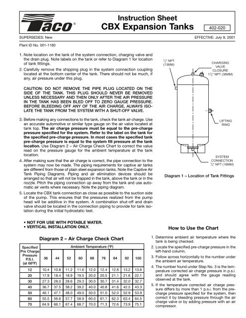
1. Note location on the tank of the system connection, charging valve and<br />
the drain plug. Note labels on the tank or refer to Diagram 1 for location<br />
of tank fittings.<br />
2. Carefully remove the shipping plug in the system connection coupling<br />
located at the bottom center of the tank. There should not be much, if<br />
any, air pressure under this plug.<br />
1 ⁄ 2 " NPT<br />
(13MM)<br />
CHARGING<br />
VALVE<br />
CLOSURE<br />
1 1 ⁄ 2 " NPT (38MM)<br />
CAUTION: DO NOT REMOVE THE PIPE PLUG LOCATED ON THE<br />
SIDE OF THE TANK. THIS PLUG SHOULD NEVER BE REMOVED<br />
UNLESS NECESSARY AND THEN ONLY AFTER THE AIR PRESSURE<br />
IN THE TANK HAS BEEN BLED OFF TO ZERO GAUGE PRESSURE.<br />
BEFORE BLEEDING OFF ANY OF THE AIR CHARGE, ALWAYS ISO-<br />
LATE THE TANK FROM THE SYSTEM WITH A SHUT-OFF VALVE.<br />
3. Before making any connections to the tank, check the tank air charge. Use<br />
an accurate automotive or similar type gauge on the air valve located at<br />
tank top. The air charge pressure must be equal to the pre-charge<br />
pressure specified for the system. Refer to the label on the tank for<br />
the specified pre-charge pressure. In most cases the specified tank<br />
pre-charge pressure is equal to the system fill pressure at the tank<br />
location. Use Diagram 2 – Air Charge Check Chart to correct the value<br />
read on the pressure gauge for the ambient temperature at the tank<br />
location.<br />
4. After making sure that the air charge is correct, the pipe connection to the<br />
system may now be made. The piping requirements for captive air tanks<br />
are different from those of plain steel expansion tanks. Note the Captive Air<br />
Tank Piping Diagrams. Piping and air elimination devices should be<br />
arranged so that air will not be trapped in the tank, above the tank or in the<br />
nozzle. Pitch the piping connection up away from the tank and use automatic<br />
air vents where necessary. Note the piping diagram.<br />
5. Locate the <strong>CBX</strong> tank connection as close as possible to the suction side<br />
of the pump. This ensures that the pressures realized from the pump<br />
head will be additive in the system. A combination shut-off and drain<br />
valve should be located in the connection piping to provide for tank isolation<br />
during the initial hydrostatic test.<br />
LIFTING<br />
RING<br />
SYSTEM<br />
CONNECTION<br />
3 ⁄ 4 " NPT (16MM)<br />
Diagram 1 – Location of Tank Fittings<br />
• NOT FOR USE WITH POTABLE WATER.<br />
• VERTICAL INSTALLATION ONLY.<br />
How to Use the Chart<br />
Specified<br />
Pre Charge<br />
Pressure<br />
P.S.I.<br />
(at 68ºF)<br />
Diagram 2 – Air Charge Check Chart<br />
36<br />
44<br />
52<br />
Ambient Temperature (ºF)<br />
60<br />
100<br />
12 10.4 10.8 11.2 11.6 12.0 12.4 12.8 13.2 13.6<br />
20 17.9 18.4 18.9 19.5 20.0 20.5 21.1 21.6 22.1<br />
30 27.3 28.0 28.6 29.3 30.0 30.7 31.4 32.0 32.7<br />
40 36.7 37.5 38.2 39.2 40.0 40.8 41.6 42.5 43.3<br />
50 46.1 47.1 48.0 49.0 50.0 51.0 52.0 52.9 53.9<br />
60 55.5 56.6 57.7 58.9 60.0 61.1 62.3 63.4 64.5<br />
70 64.9 66.1 67.4 68.7 70.0 71.3 72.6 73.9 75.1<br />
68<br />
76<br />
84<br />
92<br />
1. Determine ambient air temperature where the<br />
tank is being checked.<br />
2. Locate the specified pre-charge pressure in the<br />
left-hand column.<br />
3. Follow across horizontally to the number under<br />
the ambient air temperature.<br />
4. The number found under Step No. 3 is the temperature<br />
corrected air charge pressure in p.s.i.<br />
and should agree with the gauge reading<br />
observed at the tank.<br />
5. If the temperature corrected air charge pressure<br />
differs by more than 1 p.s.i. from the precharge<br />
pressure specified for the system, then<br />
correct it by bleeding pressure through the air<br />
charge valve or by adding pressure with an air<br />
compressor.
<strong>CBX</strong> Tank Piping Diagrams – Recommended Location<br />
<strong>CBX</strong> Tank Piping Diagrams – Alternate Locations<br />
Do it Once. Do it Right.<br />
TACO, INC., 1160 Cranston Street, Cranston, RI 02920 Telephone: (401) 942-8000 FAX: (401) 942-2360.<br />
TACO (Canada), Ltd., 6180 Ordan Drive, Mississauga, Ontario L5T 2B3. Telephone: 905/564-9422. FAX: 905/564-9436.<br />
Visit our web site at: http://www.taco-hvac.com<br />
Printed in USA<br />
Copyright 2001<br />
TACO, Inc.