

T-Rex TCJ My-Stock DB - Tube CAD Journal
T-Rex TCJ My-Stock DB - Tube CAD Journal
T-Rex TCJ My-Stock DB - Tube CAD Journal

Create successful ePaper yourself
Turn your PDF publications into a flip-book with our unique Google optimized e-Paper software.
Back John Broskie's Guide to <strong>Tube</strong> Circuit Analysis & Design Next ><br />
18 January 2005<br />
Only $19.95<br />
to keep track of your<br />
tube and part collection<br />
<strong>TCJ</strong> <strong>My</strong>-<strong>Stock</strong> <strong>DB</strong><br />
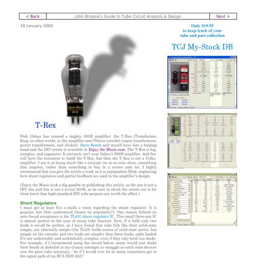
T-<strong>Rex</strong><br />
Dick Olsher has created a mighty 300B amplifier: the T-<strong>Rex</strong> (Transformer<br />
King, in other words, as the amplifier uses Plitron toroidal output transformers,<br />
power transformers, and chokes). Steve Bench and myself have lent a helping<br />
hand and the DIY article is available at Enjoy the Music.com. The T-<strong>Rex</strong> is big,<br />
complex, and expensive. It certainly isn’t your father’s 300B amplifier. And few<br />
will have the resources to build the T-<strong>Rex</strong>, but then the T-<strong>Rex</strong> is not a Volksamplifier.<br />
I see it as being much like a concept car at an auto show, something<br />
that inspires, rather than something to buy in a corner auto lot. I highly<br />
recommend that you give the article a read, as it is explanation filled, explaining<br />
how shunt regulators and partial feedback are used in the amplifier’s design.<br />
(Enjoy the Music took a big gamble in publishing this article, as the site is not a<br />
DIY site and this is not a trivial 300B, so be sure to check the article out to let<br />
them know that high-standard DIY tube projects are worth the effort.)<br />
Shunt Regulators<br />
I must get at least five e-mails a week regarding the shunt regulator. It is<br />
popular, but little understood (hence its popularity?). One reason behind its<br />
new-found acceptance is the TL431 shunt regulator IC. This small three-pin IC<br />
is almost perfect in the eyes of many tube fanciers. Now, if it held only two<br />
leads it would be perfect, as I have found that tube folk like their solid-state<br />
simple, not internally simple (the TL431 holds scores of solid-state parts), but<br />
simple on the outside; and two leads are simpler than three leads; eight leaded<br />
ICs are undesirably and unthinkably complex, even if they only hold one diode.<br />
For example, if I recommend using the circuit below, many would just shake<br />
their heads in disbelief at my clumsy attempts to smuggle in solid-state devices<br />
into the pure-tube sanctuary. "As if I would ever let so many transistors get in<br />
the signal path of my RCA NOS 2A3!"
The only problem is—albeit a small problem, but a problem nonetheless—the<br />
schematic above is the TL431's internal schematic. As great as the TL431 might<br />
be, many ask too much of it, either demanding it withstand too much voltage or<br />
draw too much current. The TL431 can only withstand 36 volts, so the circuit<br />
below is definitely a bad idea.<br />
The TL431 can only source up to 100mA, so the circuit below is equally a bad<br />
idea.<br />
<strong>TCJ</strong> <strong>My</strong>-<strong>Stock</strong> <strong>DB</strong> helps you know just what<br />
you have, what it looks like, where it is, what it<br />
will be used for, and what it's worth. <strong>TCJ</strong> <strong>My</strong>-<br />
<strong>Stock</strong> <strong>DB</strong> helps you to keep track of your heap<br />
of electronic parts. More details.<br />
Version 2 Improvements<br />
List all of your parts in one <strong>DB</strong>.<br />
Add part Images.<br />
One-click web searches for information.<br />
Vertical and horizontal grids.*<br />
Create reports as PDFs.*<br />
Graphs added 2D/3D: pie & bar.*<br />
More powerful <strong>DB</strong> search.<br />
Help system added.<br />
Editable drop-down lists for location, projects,<br />
brands, styles, vendors and more.<br />
*User definable
Download or CD ROM<br />
Windows 95/98/Me/NT/2000/XP<br />
For more information, please visit our<br />
Web site :<br />
www.glass-ware.com<br />
To purchase , please visit our Yahoo Store:<br />
http://store.yahoo.com/glassware<br />
The above table was lifted from the Fairchild TL431A PDF and it lists the limits<br />
within which the device will operate. Note, the TL431 cannot see 36 volts across<br />
its leads and draw 100mA at the same time, as that would result in 3.6 watts of<br />
dissipation, far more than the 770mW that it can withstand. (Also note that<br />
770mW limit is at a cool 30 c and must be derated for higher temperatures.)<br />
Extending the TL431’s voltage limit is easy enough, as we can cascode the<br />
TL431 with either a tube or a transistor or a MOSFET (placing a zener in series<br />
with it is neither safe nor desirable). Above we saw a tube sitting atop the Tl431;<br />
below, a high-voltage MOSFET.
The potential problem with the tube-based hybrid shunt regulator is that at<br />
turn-on the tube’s cathode is cold and not conducting, which means no voltage<br />
regulator until it is hot. Second, the triode might require a much larger negative<br />
bias voltage than the TL431’s 36 volt limit. The workaround is to use a negative<br />
power supply connection to help bias the triode.<br />
Here the triode sees a –50 volts grid-to-cathode bias voltage, while the TL431<br />
only sees a 10 volt differential. (The optimal anode-to-cathode voltage for the<br />
TL431 would equal (36V – 2.5V) / 2 + 2.5V, as it would allow the greatest<br />
cathode swing on the TL431.)<br />
Increasing the current capability of the TL431 is also easily accomplished with<br />
more parts.)
Or<br />
One common mistake is to ask the control element of a shunt regulator (the<br />
TL431 in this case) to draw too much current. For example, let’s say you have a<br />
phono preamp that draws a total of 40mA, How much current should the<br />
TL431 draw? 90% of readers will answer 40mA, but in fact, much less is<br />
needed. Consider this: the preamp only puts 1V of output signal, which into a<br />
100K potentiometer only equals 0.01mA of current variation.<br />
If the load draws a fairly steady current, as single ended circuits and class-A<br />
output stages tend to do, then the shunt regulator need only make up the delta<br />
in current draw between minimum and maximum, plus whatever wall voltage<br />
fluctuations that must be compensated. In other words, 40mA is way too much<br />
current, as a total (shunt regulator and load) current draw of 60mA would<br />
probably be more than sufficient.<br />
SRPP shunt regulators<br />
Here’s a circuit to ponder: an SRPP shunt regulator. The TL431 is cascoded
with a 12B4 triode, which in turn drives another 12B4. This regulator can<br />
source and sink current, as it comprises a shunt and series regulator.<br />
For some, the thought of letting a IC control the output of the shunt regulator is<br />
as scary as letting a IC control the sound coming out of a tube amplifier. The<br />
circuit below uses the TL431 to adjust the DC output voltage of the regulator,<br />
while the 12B4s control the AC output of the regulator.<br />
TL431-less shunt regulator<br />
What if all the TL431’s internal functions were handled by discrete devices,<br />
devices that exhibited much higher performance? Such a circuit would look<br />
much like the one below.
JRB
Back www.tubecad.com Copyright © 1999-2005 GlassWare All Rights Reserved Next >


