


You also want an ePaper? Increase the reach of your titles
YUMPU automatically turns print PDFs into web optimized ePapers that Google loves.
Back John Broskie's Guide to <strong>Tube</strong> Circuit Analysis & Design Next ><br />
09 May 2005<br />
Support the <strong>Tube</strong> <strong>CAD</strong> <strong>Journal</strong><br />
Only $19.95<br />
to keep track of your<br />
tube and part collection<br />
<strong>TCJ</strong> <strong>My</strong>-<strong>Stock</strong> <strong>DB</strong><br />
Broskie Auto-Bias Circuit<br />
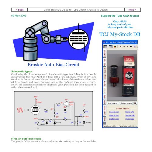
Schematic typos<br />
Considering that I had complained of a schematic typo from Siliconix, it is doubly<br />
embarrassing that that April 29's blog held a few schematic typos of my own<br />
creation: in the variation on Morgan Jones's circuit one of the resistor's values was<br />
off by a decade and, more damning, one of the OpAmp's inputs was reversed.<br />
Below, the corrected schematic is displayed. (The 4/29 blog has been updated to<br />
reflect these corrections.)<br />
First, an auto-bias recap<br />
The generic DC servo circuit (shown below) works perfectly as long as the amplifier
does not amplify asymmetrical signals and as long as the output stage’s current<br />
swings are within in the class-A window of operation.<br />
However, once the output stage jumps out of class-A into class-AB operation, the<br />
DC servo will see a net DC increase at its inverting input and it will strive to bring<br />
the amplifier back into line with its reference voltage, but at the same time the<br />
capacitor will begin to charge to higher voltage, which will throw the bias voltage<br />
off (negatively) until the input signal subsides enough to let it discharge back to its<br />
idle value, as shown in the graph below.
The graph above shows the tube's current conduction in hot pink, the grid bias<br />
voltage in blue, and the capacitor’s voltage differential in green. The signal burst<br />
excessively charges the DC servo's capacitor and its output voltage is thrown off the<br />
mark by over half a volt (602mV).<br />
The principle behind the clipping-style auto-bias circuits is also simple: monitor<br />
the tube’s current conduction while it is operating in class-A; ignore its AC<br />
conduction beyond class-A, when the tube moves into class-B. The clipping diode<br />
shorts to ground error signals greater than its forward voltage. In other words, the<br />
clipping diode's forwards voltage creates a window that extends from 0V to the<br />
cathode-to-anode voltage required to turn the diode on (silicon diodes also have<br />
cathodes).<br />
By setting the DC servo’s reference voltage to half of the diode's forwards voltage,<br />
we ensure that the window of current encompasses the extent of class-A operation<br />
that the tube(s) can undergo, without one tube cutting off, while the other conducts<br />
beyond the window’s top edge. This plan works perfectly with no input signal; well<br />
with large input signals that extend deep into class-B; not so well with input signal<br />
just beyond class-A operation of the output tubes.<br />
Broskie auto-bias circuit<br />
<strong>TCJ</strong> <strong>My</strong>-<strong>Stock</strong> <strong>DB</strong> helps you know just what<br />
you have, what it looks like, where it is, what it<br />
will be used for, and what it's worth. <strong>TCJ</strong> <strong>My</strong>-<br />
<strong>Stock</strong> <strong>DB</strong> helps you to keep track of your heap<br />
of electronic parts. More details.<br />
Version 2 Improvements<br />
List all of your parts in one <strong>DB</strong>.<br />
Add part Images.<br />
One-click web searches for part information.<br />
Vertical and horizontal grids.*<br />
Create reports as PDFs.*<br />
Graphs added 2D/3D: pie & bar.*<br />
More powerful <strong>DB</strong> search.<br />
Help system added.<br />
Editable drop-down lists for location, projects,<br />
brands, styles, vendors and more.<br />
*User definable<br />
Download or CD ROM<br />
Windows 95/98/Me/NT/2000/XP<br />
For more information, please visit:<br />
www.glass-ware.com<br />
To purchase , please visit our Yahoo Store:
What if we don’t clip the error signal What if, instead, we use it to prevent the DC<br />
servo's capacitor's excessive charging from throwing the bias voltage off Well,<br />
that’s the idea behind the Broskie auto-bias circuit.<br />
http://store.yahoo.com/glassware<br />
Broskie auto-bias circuit<br />
How does it work The triode's idle current must be great enough to establish the<br />
same voltage across the cathode resistor as the diode’s forward voltage, as this<br />
voltage is used as the servo’s reference voltage. (Imagine that the diode that<br />
attaches to the tube’s cathode has been removed from the circuit, which it<br />
effectively is at idle). The OpAmp compares the cathode voltage to its reference<br />
voltage and then establishes and maintains grid-bias voltage required to meet this<br />
compulsory idle current.<br />
Now, as long as the tube runs within the boundary of twice the diode’s forward<br />
voltage (Vd) at its cathode, the triode will operate in pure class-A and the DC servo<br />
will handle setting the bias voltage quite nicely.
Once the tube leaves the confines of class-A, however, its cathode voltage will<br />
exceed twice Vd and the diode attached to the cathode will begin to conduct,<br />
charging C2 as a result. Since capacitors C1 and C2 are equal in value, as are<br />
resistors R1 and R2, the rate of charging will be the same between both capacitors.<br />
In other words, the DC servo’s reference voltage will be thrown off in a matching<br />
way as the servo’s own capacitor is thrown off. It’s much like docking a boat to a<br />
floating dock: no matter how much the tide rises or falls, the boat will remain in the<br />
same relation to the dock.<br />
In the schematic above, we see all the part values and voltages labeled. In SPICE<br />
simulations, these values worked best (and of course, real values may differ).<br />
How well does it work<br />
Starting at a 1kHz input signal of 10 volts peak, the bias voltage is thrown off by<br />
about 3mV, the same amount of voltage that capacitors, C1 and C2, differ in change<br />
of their charge after the tone burst. With a 2V input signal, the bias voltage is off by
only 84µV. Ah, how easy it is to lie with data! Given just these two data points, we<br />
might reasonably conclude that the error grows with the magnitude of the input<br />
signal; it doesn’t. With a 1V input signal, the bias voltage is off by only 5.95mV. (An<br />
analogous example of statistical lying by omission would be to only point out that<br />
those with PhDs make less money than those with only master degrees. Therefore,<br />
the more education, the less income. But if we point out that those with master<br />
degrees make more money than those with bachelor degrees, who in turn make<br />
more than those with two year college degrees, who also in turn make more than<br />
those with only a high school diplomas …, an entirely different conclusion is<br />
reached. So, which is right Careful: a trick question.)<br />
The above graph shows the circuit’s bias voltage error in millivolts against input<br />
signal. Interestingly, the greatest departure from the desired bias voltage occurs at<br />
the 1-volt input signal. This makes sense, as the 6DJ8 is approaching the class-A<br />
boundary with this input signal and the tube undergoes a good bit of rectification;<br />
i.e. it linearity suffers because it is much easier to turn on a triode than to turn it<br />
off. This uneven handling of the sine wave ends up charging the servo’s capacitor<br />
C1, but the voltage reference’s capacitor doesn’t see any of the rectification, so it<br />
isn’t further charged.<br />
So, how good is the Broskie auto-bias circuit<br />
As it stands, not too bad. Having a small-signal triode’s bias voltage thrown off by<br />
6mV is not that bad. (Remember that the triode’s grid actually sees a slightly<br />
different DC voltage, as the coupling capacitor is biased through a large-valued<br />
resistor.)
One problem this circuit faces is that the tube’s cathode is burdened by the<br />
presence of the 1N4148 diode and the 6.4k resistor. In the act of sampling the<br />
cathode voltage, we end up influencing the tube by giving it a nonlinear cathode<br />
load. A second, and much more damning, problem is found in the relatively highvalued<br />
cathode resistor (56-ohms in this example). Ideally, we should be able to<br />
choose whether or not the triode receives a little or a lot of cathode degeneration.<br />
The workaround for the last problem is to amplify the cathode voltage before using<br />
the diode to set a voltage threshold. In the schematic below, we see an additional<br />
OpAmp that both buffers the cathode voltage from the diode and provides voltage<br />
gain, allowing us to use a much smaller-valued cathode resistor. (When the Broskie<br />
auto-bias circuit is used with MOSFETs or transistors, this feature will become<br />
much more important, because of the much lower power supply voltages used and<br />
much higher currents experienced through the output devices.)<br />
Two-OpAmp Broskie auto-bias circuit<br />
Note that a single 1M resistor is missing from the voltage reference portion of the<br />
circuit; in its stead, a 10M and 1.11M resistor are used to create a 10% voltage<br />
divider whose output impedance equals 1M, the same resistor value that the servo<br />
uses. (10M in parallel with 1.11M equals 1M.)<br />
Unfortunately, 1% resistors above 2M are hard to find. OpAmps, on the other hand,<br />
are readily available and cheap. The circuit below uses an additional OpAmp to<br />
buffer the voltage reference’s output before feeding a fairly low-impedance voltage<br />
divider. The source voltage is first amplified by 100 and the voltage-reference<br />
voltage is divided by 100.
Three-OpAmp Broskie auto-bias circuit<br />
How well does the dual-OpAmp version of the Broskie auto-bias circuit work<br />
Much better than the previous version, it turns out.<br />
Not too bad. The bias voltage is only once thrown off by more than 1mV (1.084mV,<br />
to be exact). Once again the most egregious error occurs at an input signal of 1 volt,<br />
but beyond that input level, the auto-bias circuit works admirably. So much so, in<br />
fact, that some of my friends are wondering why I didn’t apply for a patent on this<br />
circuit or sell it to some big-name audio-equipment company or, at the very least,
show them and no one else. Why did I choose none of the above Not my style, is as<br />
good a answer as any.<br />
I don’t believe in patents for circuit topologies and I don’t like the idea of only a few<br />
people benefiting from a good circuit. (I know a few of my friends are pulling their<br />
hair out as they read this: what’s the point of being a magician if you keep revealing<br />
how your tricks are done, and if you aren’t willing to make a bundle performing<br />
them)<br />
I do ask that if you use the circuit in a commercial product, give me credit for<br />
having come up with it.<br />
Simplest clipping-auto-bias circuit<br />
Are we done No, not even close, but my fingers are done for today. Next time we<br />
will look into a hybrid auto-bias circuit that uses both fixed bias (a potentiometer)<br />
and a DC servo.<br />
//JRB
Back www.tubecad.com Copyright © 1999-2005 GlassWare All Rights Reserved Next >


