Metal Samples catalog
Metal Samples catalog
Metal Samples catalog

You also want an ePaper? Increase the reach of your titles
YUMPU automatically turns print PDFs into web optimized ePapers that Google loves.
Corrosion Coupons<br />
Corrosion Monitoring<br />
Materials Evaluation<br />
Precision Machining<br />
Sales Staff<br />
About Us<br />
ISO 9001 Certified<br />
Contact Info<br />
New Products & Svcs.<br />
Catalog XI.6
<strong>Metal</strong> <strong>Samples</strong> Company is a division of Alabama Specialty Products, Inc. (ASPI) and works in association<br />
with other divisions of ASPI to provide you with a wide range of products and services.<br />
• Materials evaluation products<br />
• Corrosion monitoring products<br />
• Precision machining services<br />
• Laser cutting & welding services<br />
• Laser systems and equipment<br />
• Specialized laser R&D services<br />
• Maufacturing research<br />
• Medical equipment<br />
For more information on our company divisions, call for a product brochure or visit our corporate web site at:<br />
www.alspi.com
Business Philosophy<br />
<strong>Metal</strong> <strong>Samples</strong>, a division of Alabama Specialty Products, Inc., is committed to superior quality,<br />
quick delivery, fair pricing, and excellent service. With our rapidly-expanding physical plant, stateof-the-art<br />
equipment, ever-broadening product lines, dedicated research, and highly-skilled work<br />
force, we stand ready to meet your specific manufacturing needs.<br />
However, it takes more than buildings, equipment, and personnel to produce excellence; it takes<br />
espirit de corps. That is why our company works energetically as a whole, realizing the significance<br />
of our motto, “May the beauty of the LORD our GOD be upon us and may He establish the work<br />
of our hands.” Psalm 90:17.
About <strong>Metal</strong> <strong>Samples</strong><br />
<strong>Metal</strong> <strong>Samples</strong> specializes in manufacturing<br />
products for corrosion monitoring & materials<br />
evaluation and in providing precision machining<br />
services. Since 1980 we have supplied products<br />
and services to nuclear, medical, aerospace,<br />
chemical processing, water treating, and<br />
petroleum industries around the world.<br />
From the beginning, founder Don Johnson's goal has been to operate this business based<br />
on Christian principles. With blessings from God, <strong>Metal</strong> <strong>Samples</strong> has grown to include 200<br />
employees and continues to develop new products and technologies to meet the growing<br />
needs of our customers.
<strong>Metal</strong> <strong>Samples</strong> Contact Info<br />
Home Office:<br />
P.O. Box 8, 152 <strong>Metal</strong> <strong>Samples</strong> Rd.<br />
Munford, AL 36268<br />
Phone: (256) 358-4202<br />
Fax: (256) 358-4515<br />
E-mail: msc@alspi.com<br />
Web site: www.metalsamples.com<br />
Houston Sales Office:<br />
6327 Teal Mist Lane<br />
Fulshear, TX 77441<br />
Phone: (832) 451-6825
Alabama Specialty Products, Inc. (ASPI)<br />
Executive Staff<br />
Don Johnson<br />
ASPI CEO<br />
James Gray<br />
<strong>Metal</strong> <strong>Samples</strong> President<br />
Brad Finley<br />
Vice President<br />
<strong>Metal</strong> <strong>Samples</strong><br />
Sales & Support Staff<br />
Brenda Smith<br />
Sales Manager<br />
Cindy Maddox<br />
Int’l. Coordinator<br />
Bertha Benjamin<br />
Sales Rep.<br />
Rob Huntley<br />
Sales Rep.<br />
Andrew Abbott<br />
Sales Rep.<br />
Deborah Tinney<br />
Sales Rep.<br />
Ron Weishaar<br />
Sales Mgr. (Houston)
Terms & Delivery Services<br />
• Terms - Net 30 days (subject to credit approval)<br />
• Minimum order inside USA - $100.00<br />
• Minimum order outside USA - $300.00<br />
• Overnight delivery available for many stock items<br />
• Orders outside the USA subject to additional charges<br />
• VISA, MASTERCARD, and AMERICAN<br />
EXPRESS accepted.<br />
(Full terms & conditions at www.metalsamples.com.)<br />
Engineering / Design / CAD<br />
Our CAD department uses the latest in computer-aided drafting and design<br />
technology, including 3-D modeling software.<br />
Our engineering team has experience in corrosion, aerospace, electrical,<br />
mechnical, manufacturing, and materials engineering. These engineering<br />
capabilities, coupled with our machining expertise, allow us to help our<br />
customers find solutions to their specific application needs.<br />
Quality Assurance (ISO 9001)<br />
We emphasize high standards when it comes to the quality of your parts. To ensure the finished product will<br />
meet our customers approval, we maintain advanced training for personnel, procurement of state-of-the-art<br />
inspection equipment, and constant upgrading in our quality control area.<br />
Our quality assurance begins with the receipt of raw materials and is adhered to throughout the manufacturing<br />
process until the final product is shipped. Technicians use high-tech inspection equipment to check the accuracy<br />
of your parts. Our quality assurance program is ISO 9001 certified, guaranteeing the highest quality on all of<br />
your orders.
Corrosion Monitoring<br />
Introduction to Corrosion Monitoring<br />
Corrosion Coupons for Monitoring<br />
Electrical Resistance (ER) Monitoring<br />
Linear Polarization Resistance (LPR) Monitoring<br />
Specialized Monitoring<br />
High Pressure Access Systems<br />
Injection & Sampling Systems<br />
Accessories<br />
Return to Main menu
Introduction to Corrosion Monitoring<br />
What is Corrosion Monitoring<br />
The field of corrosion measurement, control, and prevention covers a very broad spectrum of technical<br />
activities. Within the sphere of corrosion control and prevention, there are technical options such as cathodic<br />
and anodic protection, materials selection, chemical dosing and the application of internal and external<br />
coatings. Corrosion measurement employs a variety of techniques to determine how corrosive the environment<br />
is and at what rate metal loss is being experienced. Corrosion measurement is the quantitative method<br />
by which the effectiveness of corrosion control and prevention techniques can be evaluated and provides the<br />
feedback to enable corrosion control and prevention methods to be optimized.<br />
A wide variety of corrosion measurement techniques exists, including:<br />
Non Destructive Testing<br />
Analytical Chemistry<br />
• Ultrasonic testing<br />
• pH measurement<br />
• Radiography • Dissolved gas (O 2<br />
, CO 2<br />
, H 2<br />
S)<br />
• Thermography • <strong>Metal</strong> ion count (Fe 2+ , Fe 3+ )<br />
• Eddy current/magnetic flux<br />
• Microbiological analysis<br />
• Intelligent pigs<br />
Operational Data<br />
• pH<br />
• Flow rate (velocity)<br />
• Pressure<br />
• Temperature<br />
Fluid Electrochemistry<br />
• Potential measurement<br />
• Potentiostatic measurements<br />
• Potentiodynamic measurements<br />
• A.C. impedance<br />
Corrosion Monitoring<br />
• Weight loss coupons<br />
• Electrical resistance<br />
• Linear polarization<br />
• Hydrogen penetration<br />
• Galvanic current<br />
Some corrosion measurement techniques can be used on-line, constantly exposed to the process stream,<br />
while others provide off-line measurement, such as that determined in a laboratory analysis. Some techniques<br />
give a direct measure of metal loss or corrosion rate, while others are used to infer that a corrosive<br />
environment may exist.<br />
Corrosion monitoring is the practice of measuring the corrosivity of process stream conditions by the use of<br />
“probes” which are inserted into the process stream and which are continuously exposed to the process<br />
stream condition.<br />
Corrosion monitoring “probes” can be mechanical, electrical, or electrochemical devices.
Corrosion monitoring techniques alone provide direct and online measurement of metal loss/corrosion rate in<br />
industrial process systems.<br />
Typically, a corrosion measurement, inspection and maintenance program used in any industrial facility will<br />
incorporate the measurement elements provided by the four combinations of on-line/off-line, direct/indirect<br />
measurements.<br />
• Corrosion Monitoring<br />
• Non Destructive Testing<br />
• Analytical Chemistry<br />
• Operational Data<br />
Direct, On-line<br />
Direct, Off-line<br />
Indirect, Off-line<br />
Indirect, On-line<br />
In a well controlled and coordinated program, data from each source will be used to draw meaningful<br />
conclusions about the operational corrosion rates with the process system and how these are most effectively<br />
minimized.<br />
The Need for Corrosion Monitoring<br />
The rate of corrosion dictates how long any process equipment can be usefully and safely operated. The<br />
measurement of corrosion and the action to remedy high corrosion rates permits the most cost effective<br />
plant operation to be achieved while reducing the life-cycle costs associated with the operation.<br />
Corrosion monitoring techniques can help in several ways:<br />
(1) by providing an early warning that damaging process conditions exist which may result in a corrosioninduced<br />
failure.<br />
(2) by studying the correlation of changes in process parameters and their effect on system corrosivity.<br />
(3) by diagnosing a particular corrosion problem, identifying its cause and the rate controlling parameters,<br />
such as pressure, temperature, pH, flow rate, etc.<br />
(4) by evaluating the effectiveness of a corrosion control/prevention technique such as chemical inhibition<br />
and the determination of optimal applications.<br />
(5) by providing management information relating to the maintenance requirements and ongoing condition<br />
of plant.<br />
Corrosion - 2
Corrosion Monitoring Techniques<br />
A large number of corrosion monitoring techniques exist. The following list details the most common techniques<br />
which are used in industrial applications:<br />
• Corrosion Coupons (weight loss measurements)<br />
• Electrical Resistance (ER)<br />
• Linear Polarization Resistance (LPR)<br />
• Galvanic (ZRA)<br />
• Hydrogen Penetration<br />
• Microbial<br />
• Sand/Erosion<br />
Other techniques do exist, but almost all require some expert operation, or otherwise are not sufficiently<br />
rugged or adaptable to plant applications.<br />
Of the techniques listed above, corrosion coupons, ER, and LPR form the core of industrial corrosion<br />
monitoring systems. The four other techniques are normally found in specialized applications which are<br />
discussed later.<br />
These corrosion monitoring techniques have been successfully applied and are used in an increasing range of<br />
applications because:<br />
• The techniques are easy to understand and implement.<br />
• Equipment reliability has been demonstrated in the field environment over many years of<br />
operational application.<br />
• Results are easy to interpret.<br />
• Measuring equipment can be made intrinsically safe for hazardous area operation.<br />
• Users have experienced significant economic benefit through reduced plant down time and<br />
plant life extension.<br />
Corrosion Coupons (Weight Loss)<br />
The Weight Loss technique is the best known and simplest<br />
of all corrosion monitoring techniques. The method involves<br />
exposing a specimen of material (the coupon) to a<br />
process environment for a given duration, then removing<br />
the specimen for analysis. The basic measurement which is<br />
determined from corrosion coupons is weight loss; the<br />
weight loss taking place over the period of exposure being<br />
expressed as corrosion rate.<br />
The simplicity of the measurement offered by the corrosion coupon is such that the coupon technique forms<br />
the baseline method of measurement in many corrosion monitoring programs.<br />
Corrosion - 3
The technique is extremely versatile, since weight loss coupons can be fabricated from any commercially<br />
available alloy. Also, using appropriate geometric designs, a wide variety of corrosion phenomena may be<br />
studied which includes, but is not limited to:<br />
• Stress-assisted corrosion<br />
• Bimetallic (galvanic) attack<br />
• Differential aeration<br />
• Heat-affected zones<br />
Advantages of weight loss coupons are that:<br />
• The technique is applicable to all environments - gases, liquids, solids/particulate flow.<br />
• Visual inspection can be undertaken.<br />
• Corrosion deposits can be observed and analyzed.<br />
• Weight loss can be readily determined and corrosion rate easily calculated.<br />
• Localized corrosion can be identified and measured.<br />
• Inhibitor performance can be easily assessed.<br />
In a typical monitoring program, coupons are exposed for a 90-day duration before being removed for a<br />
laboratory analysis. This gives basic corrosion rate measurements at a frequency of four times per year. The<br />
weight loss resulting from any single coupon exposure yields the “average” value of corrosion occurring<br />
during that exposure. The disadvantage of the coupon technique is that, if a corrosion upset occurs during<br />
the period of exposure, the coupon alone will not be able to identify the time of occurrence of the upset, and<br />
depending upon the peak value of the upset and its duration, may not even register a statistically significant<br />
increased weight loss.<br />
Therefore, coupon monitoring is most useful in environments where corrosion rates do not significantly<br />
change over long time periods. However, they can provide a useful correlation with other techniques such as<br />
ER and LPR measurements.<br />
Electrical Resistance (ER) Monitoring<br />
ER probes can be thought of as “electronic” corrosion coupons. Like coupons, ER probes provide a basic<br />
measurement of metal loss, but unlike coupons, the value of metal loss can be measured at any time, as<br />
frequently as required, while the probe is in-situ and permanently exposed to the process stream.<br />
In this diagram, a standard ER instrument is connected to a 40<br />
mil wire loop element which has a useful life of 10 mils. The<br />
instrument still reads close to zero because the element is new.<br />
Here the instrument reads around half-scale, indicating that the<br />
element has experienced about 5 mils of metal loss or about half<br />
of its useful life. The instrument’s reading is increasing proportionally<br />
with the resistance of the element, which increases as a<br />
result of metal loss.<br />
Here the instrument reads almost full scale, indicating that the<br />
element has experienced 10 mils of metal loss and requires<br />
replacement.<br />
Corrosion - 4
The ER technique measures the change in Ohmic resistance of a corroding metal element exposed to the<br />
process stream. The action of corrosion on the surface of the element produces a decrease in its crosssectional<br />
area with a corresponding increase in its electrical resistance. The increase in resistance can be<br />
related directly to metal loss and the metal loss as a function of time is by definition the corrosion rate.<br />
Although still a time averaged technique, the response time for ER monitoring is far shorter than that for<br />
weight loss coupons. The graph below shows typical response times.<br />
100<br />
75<br />
50<br />
25<br />
MPY<br />
5<br />
MPY<br />
12<br />
MPY<br />
25<br />
0 2 4 6 8 10 12 14<br />
Time (Days)<br />
ER probes have all the advantages of coupons, plus:<br />
• Direct corrosion rates can be obtained.<br />
• Probe remains installed in-line until operational life has been exhausted.<br />
• They respond quickly to corrosion upsets and can be used to trigger an alarm.<br />
ER probes are available in a variety of element geometries, metallurgies and sensitivities and can be<br />
configured for flush mounting such that pigging operations can take place without the necessity to remove<br />
probes. The range of sensitivities allows the operator to select the most dynamic response consistent with<br />
process requirements.<br />
Linear Polarization Resistance (LPR) Monitoring<br />
The LPR technique is based on complex electro-chemical<br />
theory. For purposes of industrial measurement applications it<br />
is simplified to a very basic concept. In fundamental terms, a<br />
small voltage (or polarization potential) is applied to an<br />
electrode in solution. The current needed to maintain a<br />
specific voltage shift (typically 10 mV) is directly related to<br />
the corrosion on the surface of the electrode in the solution.<br />
By measuring the current, a corrosion rate can be derived.<br />
The advantage of the LPR technique is that the measurement<br />
of corrosion rate is made instantaneously. This is a more powerful tool than either coupons or ER where the<br />
fundamental measurement is metal loss and where some period of exposure is required to determine<br />
corrosion rate. The disadvantage to the LPR<br />
Corrosion - 5
technique is that it can only be successfully performed in relatively clean aqueous electrolytic environments.<br />
LPR will not work in gases or water/oil emulsions where fouling of the electrodes will prevent measurements<br />
being made.<br />
Galvanic Monitoring<br />
The galvanic monitoring technique, also known as Zero Resistance Ammetry (ZRA) is another electrochemical<br />
measuring technique. With ZRA probes, two electrodes of dissimilar metals are exposed to the<br />
process fluid. When immersed in solution, a natural voltage (potential) difference exits between the electrodes.<br />
The current generated due to this potential difference relates to the rate of corrosion which is occurring<br />
on the more active of the electrode couple.<br />
Galvanic monitoring is applicable to the following electrode couples:<br />
• Bimetallic corrosion<br />
• Crevice and pitting attack<br />
• Corrosion assisted cracking<br />
• Corrosion by highly oxidizing species<br />
• Weld decay<br />
Galvanic current measurement has found its widest applications in water injection systems where dissolved<br />
oxygen concentrations are a primary concern. Oxygen leaking into such systems greatly increases galvanic<br />
currents and thus the corrosion rate of steel process components. Galvanic monitoring systems are used to<br />
provide an indication that oxygen may be invading injection waters through leaking gaskets or deaeration<br />
systems.<br />
Specialized Monitoring<br />
Biological Monitoring<br />
Biological monitoring and analysis generally seeks to identify the presence<br />
of Sulphate Reducing Bacteria - SRB’s. This is a class of anaerobic<br />
bacteria which consume sulphate from the process stream and generate<br />
sulphuric acid, a corrosive which attacks production plant materials.<br />
Sand / Erosion Monitoring<br />
These are devices which are designed to measure erosion in a flowing<br />
system. They find wide application in oil/gas production systems where particulate matter is present.<br />
Hydrogen Penetration Monitoring<br />
In acidic process environments, hydrogen is a by-product of the corrosion reaction. Hydrogen generated in<br />
such a reaction can be absorbed by steel particularly when traces of sulphide or cyanide are present. This<br />
may lead to hydrogen induced failure by one or more of several mechanisms. The concept of hydrogen<br />
probes is to detect the amount of hydrogen permeating through the steel by mechanical or electrochemical<br />
measurement and to use this as a qualitative indication of corrosion rate.<br />
Corrosion - 6
Instrumentation<br />
There exists a variety of instrument options associated with the various corrosion monitoring techniques.<br />
Three classifications are:<br />
• Portable Meters and Data Loggers<br />
• Field-Mounted Data Loggers<br />
• Field-Mounted Transmitters<br />
In some applications such as those experienced in oil/gas production and refining, instrumentation is required<br />
to be certified for use in “hazardous areas”. For portable instruments this is most often achieved by having<br />
the equipment certified as “intrinsically safe” by a recognized authority such as BASEEFA (U.K.), U.L.<br />
(U.S.A.), ITS (U.S.A.), or CENELEC (Europe). For hardwired continuous monitoring electronics, isolation<br />
barriers can be used to ensure that, in the event of a fault condition, insufficient energy is transmitted to<br />
the hazardous field area for an explosive spark to be produced.<br />
Probe Fitting Styles<br />
There are two fundamental fitting styles for corrosion probes: fixed and removable under pressure.<br />
Fixed styles of probes/sensors have typically a threaded or flanged attachment to the process plant. For<br />
fixed styles of sensors, removal can only be accomplished during system shut down or by isolation and<br />
depressurization of the sensor location.<br />
From time to time, corrosion coupons and probes require removal and replacement. It is sometimes more<br />
convenient to be able to remove and install sensors while the process system is operational. To facilitate this,<br />
there are two distinct systems which permit removal/installation under pressure.<br />
In refinery and process plant environments where pressures are normally less than 1500 psi, a Retractable<br />
System is used. This consists of a packing gland (stuffing box) and valve arrangement. For environments<br />
such as those experienced in oil/gas production where pressures of several thousand psi are experienced, a<br />
special High Pressure Access System is used. This permits the safe and easy installation/removal of corrosion<br />
monitoring devices at working pressures up to 3600 psi.<br />
Applications of Corrosion Monitoring Techniques<br />
Corrosion monitoring is typically used in the following situations:<br />
• Where risks are high - high pressure, high temperature, flammable, explosive, toxic processes.<br />
• Where process upsets can cause high corrosivity.<br />
• Where changes in operating conditions can cause significant changes in corrosion rate.<br />
Corrosion - 7
• Where corrosion inhibitors are in use.<br />
• In batch processes, where corrosive constituents are concentrated due to repeated cycling.<br />
• Where process feedstock is changed.<br />
• Where plant output or operating parameters are changed from design specifications.<br />
• In the evaluation of corrosion behavior of various alloys.<br />
• Where induced potential shifts are used to protect systems and/or structures.<br />
• Where product contamination due to corrosion is a vital concern.<br />
Corrosion monitoring may be used in virtually any industry where corrosion prevention is a primary<br />
requirement. Some examples of industries and specific areas of interest include, but are not limited to:<br />
Oil/Gas Production<br />
• Flowlines<br />
• Gathering Systems<br />
• Transport Pipelines<br />
• Water Injection Facilities<br />
• Vessels<br />
• Processing<br />
• Water Systems<br />
• Chemical Injection Systems<br />
• Drilling Mud Systems<br />
• Water Wash Systems<br />
• Desalters<br />
Utilities<br />
• Cooling Systems<br />
• Effluent Systems<br />
• Make-Up Water Systems<br />
• Boiler Water Systems<br />
Refining<br />
• Crude Overheads<br />
• Visbreakers<br />
• Vacuum Towers<br />
• Sour Water Strippers<br />
• Amine Systems<br />
• Cooling Systems<br />
Pulp and Paper<br />
• Digesters<br />
• White Liquor<br />
• Boiler Systems<br />
Petrochemicals/Chemicals/Processing<br />
• Process Systems<br />
• Cooling Systems<br />
In any corrosion monitoring system, it is common to find two or more of the techniques combined to provide<br />
a wide base for data gathering. The exact techniques which can be used depend on the actual process<br />
fluid, alloy system, and operating parameters.<br />
Corrosion monitoring offers an answer to the question of whether more corrosion is occurring today as<br />
compared to yesterday. Using this information it is possible to qualify the cause of corrosion and quantify its<br />
effect. Corrosion monitoring remains a valuable weapon in the fight against corrosion, thereby providing<br />
substantial economic benefit to the user.<br />
<strong>Metal</strong> <strong>Samples</strong> Corrosion Monitoring Systems<br />
A Division of Alabama Specialty Products, Inc.<br />
152 <strong>Metal</strong> <strong>Samples</strong> Rd., Munford, AL 36268 Phone: (256) 358-4202 Fax: (256) 358-4515<br />
E-mail: msc@alspi.com Internet: www.metalsamples.com<br />
Houston Office: 6327 Teal Mist Lane, Fulshear, TX 77441 Phone: (832) 451-6825
Corrosion Coupons<br />
Introduction to Corrosion Coupons<br />
and Weight Loss Analysis<br />
Standard Coupons<br />
Coupon Ordering and Options Available<br />
Welded Coupons<br />
Stressed Coupons<br />
Elastomeric Coupons<br />
Test Racks<br />
Coupon Holders<br />
Easy Tool Retracting System<br />
Length Calculation & Accessories for<br />
Retractable Coupon Holders<br />
Corrosion Coupons for<br />
High Pressure Access Systems<br />
Coupon Holders for<br />
High Pressure Access Systems<br />
Bypass Piping Systems<br />
Post Exposure Coupon Analysis<br />
Coupon Storage (VCI Bags)<br />
Alloys List<br />
Alloys Listed by Trademark<br />
Articles on Coupon Testing<br />
Return to Main Menu
Corrosion Coupons and Weight Loss Analysis<br />
Introduction<br />
The simplest, and longest-established, method of estimating corrosion losses in plant<br />
and equipment is weight loss analysis. A weighed sample (coupon) of the metal or<br />
alloy under consideration is introduced into the process, and later removed after a<br />
reasonable time interval. The coupon is then cleaned of all corrosion product and is<br />
reweighed. The weight loss is converted to a corrosion rate (CR) or a metal loss<br />
(ML), as follows:<br />
Corrosion<br />
Rate (CR)<br />
=<br />
Weight loss (g) * K<br />
Alloy Density (g/cm 3 ) * Exposed Area (A) * Exposure Time (hr)<br />
The constant can be varied to calculate the corrosion rate in various units:<br />
Desired Corrosion Rate Unit (CR) Area Unit (A) K-Factor<br />
mils/year (mpy) in 2 5.34 x 10 5<br />
mils/year (mpy) cm 2 3.45 x 10 6<br />
millimeters/year (mmy) cm 2 8.75 x 10 4<br />
<strong>Metal</strong><br />
Loss (ML)<br />
=<br />
Weight loss (g) * K<br />
Alloy Density (g/cm 3 ) * Exposed Area (A)<br />
Desired <strong>Metal</strong> Loss Unit (ML) Area Unit (A) K-Factor<br />
mils in 2 61.02<br />
mils cm 2 393.7<br />
millimeters cm 2 10.0<br />
The technique requires no complex equipment or procedures, merely an appropriately shaped coupon, a carrier<br />
for the coupon (coupon holder), and a reliable means of removing corrosion product without disruption of the<br />
metal substrate. Weight loss measurement is still the most widely used means of determining corrosion loss,<br />
despite being the oldest method currently in use.<br />
Weight loss determination has a number of attractive features that account for its sustained popularity:<br />
• Simple - No sophisticated instrumentation is required to obtain a result.<br />
• Direct - A direct measurement is obtained, with no theoretical assumptions or<br />
approximations.<br />
• Versatile - It is applicable to all corrosive environments, and gives information on<br />
all forms of corrosion.<br />
The method is commonly used as a calibration standard for other means of corrosion monitoring, such as Linear<br />
Polarization and Electrical Resistance. In instances where slow response and averaged data are acceptable,<br />
weight loss monitoring is the preferred technique.
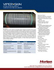
Coupon Preparation and Cleaning<br />
The choice of technique for initial preparation of the coupon surface, and for cleaning the coupon after use, is<br />
critical in obtaining useful data. Both the relevance and reproducibility of weight loss data are highly sensitive to<br />
the inherent suitability of these techniques, and to the care with which they are executed.<br />
Surface finishing methods vary across a broad range for specific<br />
applications. Blasting with glass bead, sand, or other aggregate can<br />
provide an acceptable finish for some applications. Sanding with<br />
abrasive belts, or surface or double disc grinding with abrasive stones<br />
also provides an excellent surface for evaluation.<br />
Coupon after being exposed<br />
to corrosive environment.<br />
Cleaning of specimens before weighing and exposure is critical to remove any contaminants that could affect test<br />
results.<br />
Reference should be made to NACE Recommended Practice RP-0775 and ASTM G-1 & G-4 for further<br />
detail on surface finishing and cleaning of weight-loss coupons.<br />
Coupon Position and Orientation<br />
Irrespective of the degree of care exercised in the surface preparation of coupons, many uncontrollable factors<br />
(e.g. microstructural defects) can reduce the accuracy of weight loss determinations. Therefore, using duplicate<br />
(Figure 1) or multi-replicate (Figure 2) coupon samples is considered good practice.<br />
Coupon orientation must be consistent in order to make different data sets comparable. Generally, an orientation<br />
parallel to the process flow is preferable since this more nearly reflects the true condition experienced by the<br />
vessel wall (Figure 1). <strong>Metal</strong> <strong>Samples</strong> Corrosion Monitoring Systems MH coupon holders have an automatic<br />
flow alignment feature. All other holders are marked on the top side with flow direction for manual alignment.<br />
Positioning is another critical factor in obtaining relevant information. For example, a multi-phase product may<br />
produce layered flow, giving rise to corrosion rates that vary with depth in the process stream. Such situations<br />
can be monitored with a ladder-strip coupon holder (Figure 2).<br />
Flow<br />
Figure 1. Preferred Flow Direction<br />
Figure 2. Ladder Strip Coupon Holder
Possibly the most common issue in coupon positioning arises from the fact that a true representation of the<br />
corrosion experienced by the pipe/vessel can only be established when the weight loss coupon is in the plane of<br />
the vessel/pipe wall. Only in this position can the coupon experience the same flow regime as the pipe surface<br />
being monitored. In response to this situation, the use of flush-disc coupons has become widespread (Figure 3).<br />
The general issue of coupon orientation and positioning in relation to flow regime, plant geometry, and process<br />
fluid is complex and tends to be specific to each application. However, the most common coupon configurations<br />
have been discussed above.<br />
Figure 3. Flush Disc Coupon Holder in High Pressure Access Fitting<br />
Coupon Holders<br />
Specific design of coupon holders incorporates two basic factors:<br />
• Number, style, and configuration of coupons<br />
• System entry method<br />
Fixed (Pipe Plug) Coupon Holders<br />
The simplest system entry design for coupon holders is the fixed or pipe plug coupon holder (Figure 4). This<br />
type of coupon holder is normally offered on a ¾", 1", or 2" NPT pipe-plug. The size of the plug to be used is<br />
the limiting factor as to the coupon configuration that can be used. These coupon holders are usually constructed<br />
in AISI 316L stainless steel, have a pressure rating of 3000 psi, and a temperature rating of 450°F/232°C. This<br />
design of coupon holder is recommended for use in a by-pass loop which can be isolated, or in systems having<br />
frequent and regular shut-down, since system depressurization is required during insertion and removal.<br />
Figure 4. Fixed (Pipe Plug) Coupon Holder
Retractable Coupon Holders<br />
A design that is commonly used in the refining and petrochemical industry is the retractable type coupon holder<br />
as shown in Figure 5. This coupon holder design employs a packing gland that allows insertion and removal,<br />
through a ball-valve, without system depressurization. A safety cable and safety nut are also provided to prevent<br />
blowout. Retractable coupon holders can be used up to 1500 psi and 500°F (260°C), and are constructed of<br />
AISI 316L stainless steel. Normally, a 1" FNPT packing gland is used in conjunction with either a 1", or a 1½"<br />
full port ball valve, depending on the type of coupon configuration chosen. (See the RT4000 sheet for more<br />
information.)<br />
Figure 5. Retractable Coupon Holder<br />
Retrievable Coupon Holders<br />
The oil and gas production industry generally employs retrievable coupon holders that operate with high pressure<br />
access systems. This will allow insertion/removal under pressures up to 3600 psi. <strong>Metal</strong> <strong>Samples</strong> Corrosion<br />
Monitoring Systems supplies both generic (HP) and proprietary (MH) coupon holders. (See Coupon<br />
Holders for High Pressure Access Systems.)<br />
The retrievable coupon holder is installed on to the solid plug. The assembly can then be inserted or removed<br />
from the system using a special service valve and retrieval tool.<br />
Retrievable coupon holders are generally constructed in AISI 316L stainless steel to meet the requirements of<br />
NACE standard MR-0175 for sour service use. These are available for all standard coupon configurations.<br />
Retrievable, retractable, and pipe plug style coupon holders cover the needs of most industries and applications.<br />
However, the requirement for special coupon holder designs is significant, and <strong>Metal</strong> <strong>Samples</strong> Corrosion<br />
Monitoring Systems has the facility to design and build coupon holders to any customer-supplied specification.<br />
<strong>Metal</strong> <strong>Samples</strong> Corrosion Monitoring Systems<br />
A Division of Alabama Specialty Products, Inc.<br />
152 <strong>Metal</strong> <strong>Samples</strong> Rd., Munford, AL 36268 Phone: (256) 358-4202 Fax: (256) 358-4515<br />
E-mail: msc@alspi.com Internet: www.metalsamples.com<br />
Houston Office: 6327 Teal Mist Lane, Fulshear, TX 77441 Phone: (832) 451-6825
Corrosion Coupons<br />
Accurate monitoring of corrosion rates in any environment is<br />
critical when viewed in terms of the maintenance and repair costs<br />
associated with corrosion and material failure. Test coupons provide<br />
an inexpensive means of on-line monitoring that will allow<br />
you to effectively measure the corrosivity within your system. By<br />
observing the mils-per-year corrosion rate of an exposed coupon,<br />
valuable information can be provided regarding the material’s life expectancy.<br />
<strong>Metal</strong> <strong>Samples</strong> can make coupons in any size, shape, or material you need. Coupons can be stenciled with alloy<br />
and sequence numbers for proper identification. Mill test reports, identifying element compositions of materials<br />
used, are provided on all orders. The following coupons are four of the most commonly used in corrosion<br />
testing.<br />
P/N CO100<br />
P/N CO131<br />
Shape<br />
Finish<br />
Identification<br />
Surface Area<br />
Rectangular<br />
Double disc or glass bead<br />
Stenciled (alloy, sequence)<br />
3.38 in 2<br />
Shape<br />
Finish<br />
Identification<br />
Surface Area<br />
Rectangular<br />
120 grit, glass bead, or mill<br />
Stenciled (alloy, heat no., sequence)<br />
3.47 in 2<br />
P/N CO146<br />
P/N CO220<br />
Shape<br />
Finish<br />
Identification<br />
Surface Area<br />
Rectangular<br />
Shape<br />
Glass bead or mill<br />
Finish<br />
Stenciled (alloy, sequence)<br />
Identification<br />
4.26 in 2 Surface Area<br />
Circular<br />
120 grit, glass bead, or mill<br />
Stenciled (alloy, sequence)<br />
2.72 in 2<br />
Finishes<br />
• Mill - finished as produced from mill.<br />
• Glass Bead - blasted with fine glass beads to remove mill scale.<br />
• 120 Grit - fine finish using a 120 grit belt. Commonly used in corrosion tests, such as pitting studies, where<br />
smooth surface finish is desired. Finishes up to 600 grit (extremely fine) can be provided.<br />
• Double Disc Ground - extra fine finish using an abrasive disc that leaves minimal residue. Excellent for studies<br />
where surface finish is critical. Can produce 16-32 RMS finishes on common steels and 8 RMS on carbide steels.
Coupon Ordering and Services Available<br />
When placing your order for coupons, be ready to provide the sales person with information regarding the type of<br />
material you are testing, the size coupons required, surface finish desired, and if applicable, mounting hole size and<br />
location. The following options are available:<br />
• Manufacturing on time and material basis<br />
• <strong>Samples</strong> mounted on test racks and ready<br />
for installation<br />
• Preweighing - coupons are cleaned, preweighed<br />
on an electronic scale, and individually packaged<br />
• Weight log charts provided on computer disk<br />
• Non-standard coupons<br />
• Coupon measuring<br />
• Heat-treating, sensitizing, hot dip galvanizing<br />
• Manufacturing from your material if requested<br />
• Coupons made to specific requirements for<br />
mounting hole locations, coupon welding,<br />
stressing, and packaging<br />
• Plating - nickel, nickel cadmium, cadmium,<br />
chrome, silver, gold, and others upon request<br />
• Electro-polishing, hard facing<br />
• Non-metallic coatings<br />
• Anodizing and alonizing<br />
Standard Coupons<br />
Flat Coupons<br />
P/N Size Hole Hole Location<br />
Area<br />
Sq. In.<br />
CO100 1/2" x 3" x 1/16" 3/16" 1/4" fr. end 3.38<br />
CO101 1" x 2" x 1/16" 3/16" 1/4" fr. end 4.32<br />
CO102 1/2" x 3" x 1/16" 9/64" 1/8" fr. end 3.41<br />
CO103 1/2" x 3" x 1/16" 1/4" 1/4" fr. end 3.34<br />
CO104 1/2" x 3" x 1/16" (2) 1/4" 1/2" fr. ea. end 3.24<br />
CO105 1/2" x 3" x 1/16" 3/16" 1/2" fr. end 3.38<br />
CO106 1/2" x 3" x 1/16" 1/4" 1/2" fr. end 3.34<br />
CO115 1/2" x 3" x 1/16" 1/4" 1/4" fr. end<br />
CO117 3/8" x 3" x 1/16" 9/64" 1/8" fr. end 2.64<br />
CO118 1/2" x 3" x 1/16" (2) 1/4" 1/4" & 3/4" end 3.24<br />
CO120 3/8" x 3" x 1/16" (2) 1/4" 1/4" & 3/4" end 2.48<br />
The coupons listed above are made from a variety of materials<br />
(see Alloys list).<br />
Cylindrical Coupons<br />
Area<br />
P/N Size Thread Slot Sq. In.<br />
ES200 1/4" Ø x 2 1/2" 1/4"-20 x 3/8" 1/16" 1.96<br />
Scale coupons (or deposition coupons) provide a<br />
qualitative measure of relative deposition rates in<br />
industrial water and manufacturing process systems.<br />
P/N CO115 (flat)<br />
P/N ES209<br />
(cylindrical)<br />
Mesh bio film coupons are used for quantification<br />
or identification of microorganisms.<br />
P/N COJ36<br />
ES201 1/4" Ø x 2" 1/4"-20 x 3/8" 1/16" 1.57<br />
ES202 1/4" Ø x 3" 1/4"-20 x 3/8" 1/16" 2.45<br />
ES204 1/4" Ø x 1 1/2" 1/4"-20 x 3/8" 1/16" 1.18<br />
ES209* 1/4" Ø x 3" 1/4"-20 x 3/8" 1/16"<br />
* ES209 has five 1/8" diameter scale holes.
Coupon Holders<br />
Fixed (Pipe Plug) Coupon Holders<br />
<strong>Metal</strong> <strong>Samples</strong> carries a variety of standard pipe plug coupon holders for flat and cylindrical specimens. We can<br />
design and make these assemblies to meet your specifications for size and material requirements.<br />
Pipe Plug Assemblies for Flat Coupons<br />
P/N<br />
Plug Size<br />
3" (Std.)<br />
Stem<br />
Used with<br />
Coupon P/N<br />
RC12E*100036 3/4" NPT Nylon CO102, CO117<br />
RC13E*100036 1" NPT Nylon CO102, CO117<br />
RC12Q*100036 3/4" NPT Teflon ® CO102, CO117<br />
RC13Q*100066 1" NPT Teflon ® CO102, CO117<br />
RC12E*010036 3/4" NPT Nylon CO100, CO103, CO115<br />
RC13E*010036 1" NPT Nylon CO100, CO103, CO115<br />
RC12Q*010030 3/4" NPT Teflon ® CO100, CO103, CO115<br />
RC13Q*010026 1" NPT Teflon ® CO100, CO103, CO115<br />
RC12E*030036 3/4" NPT Nylon CO118, CO120<br />
RC13E*030036 1" NPT Nylon CO118, CO120<br />
RC12Q*030036 3/4" NPT Teflon ® CO118, CO120<br />
RC13Q*030035 1" NPT Teflon ® CO118, CO120<br />
RC12E*090036 3/4" NPT Nylon CO105, CO106<br />
RC13E*090036 1" NPT Nylon CO105, CO106<br />
RC12Q*090036 3/4" NPT Teflon ® CO105, CO106<br />
RC13Q*090036 1" NPT Teflon ® CO105, CO106<br />
RC11E*010036 1/2" NPT Nylon CO100, CO103, CO115<br />
* Add "3" to part number for Carbon Steel or "C" for PVC plug.<br />
(Example: Carbon Steel 3/4" pipe plug Nylon stem = RC12E3100036.)<br />
Pipe Plug Assemblies for Cylindrical Coupons<br />
P/N Carbon Steel Plug Insert # of Stems<br />
PA2080413709 2" NPT Nylon 8<br />
PA2080413783 2" NPT Teflon ® 8<br />
RC11Q3040000 1/2" NPT Teflon ® 1<br />
RC12Q3040000 3/4" NPT Teflon ® 1<br />
RC13Q3040000 1" NPT Teflon ® 1<br />
All of these holders are used with ES2 series coupons.<br />
Bypass Piping Systems<br />
We provide conventional or custom-designed bypass systems<br />
for on-line corrosion monitoring. Commonly used in the industrial<br />
water treatment industry to determine the corrosive properties<br />
of potable or cooling water, these systems are available in<br />
PVC, carbon and stainless steels, and other materials.<br />
Bypass systems are easily installed to your existing piping.<br />
Normally, all you need is a 1" NPT male fitting on which to<br />
attach the bypass. Standard bypass systems come equipped with<br />
4 pipe plug assemblies, 4 pre-weighed mild steel coupons, and<br />
a 5-gpm flow control valve.
Adjustable Coupon Holders<br />
Low Pressure or Hand Insertable systems can be used for pressures<br />
up to 125 psi. This assembly is commonly used in the water treating<br />
industry for coupon insertion through a full port valve. An example<br />
of this is in a municipal water pumping station, where leakage during<br />
withdrawal of the test coupon would not be critical. See the SR3000<br />
for more detials.<br />
Retractable Coupon Holders<br />
Packing Gland systems are used in more demanding environments,<br />
where ratings up to 1,500 psi are required and leakage is prohibited.<br />
These systems do not require line (process) shutdown to insert or<br />
withdraw coupons. The assembly is used for coupon insertion through at<br />
least a 1" full port valve. A safety chain is provided to prevent accidental<br />
ejection. See the RT4000 for more details. Also see Length Calculation<br />
and Accessories.<br />
Retrievable Coupon Holders<br />
These coupon holders are used with High Pressure Access Systems where<br />
pressure ratings up to 3,600 psi are required. See HC Series Coupon Holders<br />
for more information.<br />
Post Exposure Coupon Analysis<br />
<strong>Metal</strong> <strong>Samples</strong> offers post exposure coupon analysis. Our trained technicians<br />
will perform weight loss analysis and determine mils per year<br />
(MPY) corrosion rates of your exposed test samples. We are in adherence<br />
to ASTM-G1 specifications for cleaning and analyzing coupons.<br />
When using this service, ensure that initial coupon weights, exposure<br />
dates, and locations are recorded for each<br />
sample. This information can be recorded<br />
on the front of a VCI coupon storage bag.<br />
Optional services include pit depth measurement and photos of the coupons before<br />
and after analysis. For additional information on post exposure coupon analysis<br />
see "Coupon Evaluation after Exposure".
Coupon Storage Bags<br />
Vapor corrosion inhibitor (VCI) bags are excellent for storage of ferrous<br />
and non-ferrous coupons. With VCI bags, coupons can be protected from<br />
corrosion for up to one year when stored under the proper environmental<br />
conditions. Pertinent data regarding coupon exposure can be recorded in<br />
the appropriate spaces on the front of the bag. Ask for P/N BG5001 when<br />
ordering these bags.<br />
Welded Coupons<br />
Corrosion rates can vary between welded and non-welded metals, therefore it is advisable to study the behavior<br />
of both conditions. Studies involve examination of the parent material, the heat-affected zone, the weld metal,<br />
and the interfaces between all metals involved. The surface effects produced by welding, heat-tint formation or<br />
oxidation, fluxing action of slag, and the deliquescence of slag can be important factors in the corrosion behavior<br />
of metals.<br />
Ideally, the coupon used should be the same thickness and welded with the same<br />
welding process as the material used in the production equipment. Usually this is not<br />
practical so a representative sample must be studied.<br />
Typical welding techniques used are Shielded <strong>Metal</strong> Arc (SMAW), Gas Tungsten<br />
Arc (GTAW), and Gas <strong>Metal</strong> Arc (GMAW). Specimens are ground smooth after<br />
welding, unless otherwise specified, so as to provide a uniform surface for microscopic<br />
investigation.<br />
Welded coupons can be prepared with or without the use of filler metal.<br />
The autogenous weld is prepared without the use of filler metal. This<br />
type of weld is the most economical method. Autogenous welds are<br />
commonly used to evaluate corrosion rates of welded materials and the<br />
usage of these materials in corrosive environments. An autogenous weld<br />
is produced by GTAW and can be used to test material weldability and<br />
gas shield usage, and to set welding parameters.<br />
Autogenous Weld Coupon<br />
Identification<br />
1/8"<br />
1"<br />
2"<br />
.375 thru<br />
Autogenous weld<br />
3/4"<br />
.375"<br />
3/8"<br />
Notes:<br />
1. 120 grit standard finish unless otherwise specified.<br />
2. 1/8" nominal thickness.<br />
3. Standard weld is autogenous weld across end (A.W.A.E.).<br />
Sanded after weld.
Stressed Coupons<br />
Stress corrosion cracking occurs when tensile stress combines with a corrosive environment to attack a material.<br />
Testing for this type of corrosion is critical in storage tanks, pressure piping, and vessels commonly used<br />
in chemical processing plants and petrochemical refineries. <strong>Metal</strong> <strong>Samples</strong> can make your stressed samples in<br />
accordance with all ASTM standards including G30, G38, G39, and G58 or to your custom specifications.<br />
P/N CS502<br />
ASTM G30<br />
P/N CS502W (Welded)<br />
ASTM G58<br />
1/2"<br />
Approximate<br />
stenciling<br />
location<br />
(if required)<br />
1/2"<br />
R (Radius)<br />
3/8" D (Hole Diameter)<br />
Centrally Located<br />
X<br />
W<br />
3/4"<br />
M<br />
L 5"<br />
T 1/16"<br />
P/N TF2445<br />
ASTM G39<br />
P/N TF2404 Stressing Frame<br />
For use with P/N TF2445<br />
P/N CO303<br />
Twist Specimen<br />
P/N CS500<br />
Tear Drop<br />
P/N CS513<br />
"C" Ring - ASTM G38
Elastomeric Coupons<br />
<strong>Metal</strong> <strong>Samples</strong> in conjunction with International Seal Co.,<br />
Inc., and DuPont Dow Elastomers offers a selection of<br />
elastomeric coupons. These coupons are used for assistance<br />
in effectively selecting materials for elastomeric testing and<br />
applications.<br />
Fluoro and Perfluoro elastomer based materials<br />
Compound<br />
V75<br />
V75BR<br />
V121<br />
V176<br />
V115<br />
V141<br />
CV75<br />
PF75<br />
Kalrez<br />
4079<br />
Descriptio n<br />
®<br />
75<br />
Durometer General Purpose black Vito n "A" based compoun d<br />
®<br />
75<br />
Durometer General Purpose brown Vito n "A" based compoun d<br />
®<br />
75<br />
Durometer improved chemical resistant Vito n "B" based compoun d<br />
®<br />
75<br />
Durometer lead free acid resistant Vito n "B"<br />
®<br />
75<br />
Durometer improved low temperature Vito n "GLT" based compoun d<br />
®<br />
75<br />
Durometer excellent chemical resistant Vito n "F" based compoun d<br />
®<br />
75<br />
Durometer "Super Chemical" resistant Vito n<br />
75 Durometer "Ultimate Chemical"<br />
temperatures up to 500°F<br />
75 Durometer "Ultimate Chemical"<br />
temperatures up to 600°F<br />
resistant Perfluoro material for<br />
resistant Perfluoro material for<br />
Ethylene Propylene elastomeric based materials<br />
E425<br />
70 Durometer high performance peroxide cured EPDM compoun d<br />
Meets ASTM D2000 4CA 715, A25, E35, C32, F19<br />
E429<br />
70 Durometer EPDM compound that meets ANSI/NSF 61<br />
Nitrile elastomer based material<br />
N470<br />
70 Durometer low compression set nitrile compoun d<br />
Meets ASTM D2000 3CH 720, A25, B14, EO16, EO36<br />
N442<br />
70 Durometer NBR compound that meets ANSI/NSF 61<br />
Viton® is a registered trademark of DuPont Dow Elastomers.
Test Racks<br />
<strong>Metal</strong> <strong>Samples</strong> offers test racks used to mount<br />
coupons and secure them directly to operating<br />
equipment or within a process system. Test racks<br />
make it easy to evaluate how corrosion would<br />
effect differing alloys and material finishes under<br />
identical conditions. Rack usage helps eliminate<br />
coupon loss which might occur if samples were<br />
individually placed in a process flow.<br />
Racks can be fabricated to meet your requirements for material and size. Typical racks are flat bar racks, spool<br />
racks, and pipeline insertion racks. Other racks include angle bar racks and outdoor exposure racks. A variety of<br />
insulators, washers, and spacers used to isolate coupons can also be ordered separately.<br />
Guidelines for Supporting Specimens<br />
Corrosive behavior of materials subjected to immersion, partial<br />
immersion, or vapor phase can have great variance. For this<br />
reason, specimens to be tested should be properly positioned.<br />
There are several important points to be considered when<br />
supporting specimens for exposure:<br />
Pipeline<br />
Insertion Rack<br />
• Each specimen location should be identified by sketch<br />
and recorded.<br />
• The corrosive media should have access to the coupons.<br />
• The test rack should have adequate corrosion resistance<br />
to endure the test.<br />
• Specimens should be electrically isolated from other<br />
metals unless galvanic effects are being studied.<br />
• Specimens should be located in easily accessible areas.<br />
Spool Rack<br />
Flat Bar Rack
Insulators, Washers, & Spacers<br />
<strong>Metal</strong> <strong>Samples</strong> makes a variety of insulators, washers, and spacers used to isolate test specimens. We also make<br />
insulator kits (P/N KR5102) that contain an assortment of washers, screws, nuts, and stems. These kits are designed<br />
for field use when a variety of insulators are needed. The chart shown here is a general guide to material<br />
applications. Call for recommendations on use in hazardous or severe environments.<br />
Material vs. Environment<br />
Material<br />
Acids Alkalies Organic<br />
Water<br />
Absorption<br />
Oxygen<br />
and High Ionizing<br />
Temperature<br />
Resistance<br />
Weak Strong Weak Strong Solvents % 24 hrs. Ozone Vacuum Radiation High Low<br />
R = Resistance A = Attacked SA = Slight Attack A-O = Attacked by Oxidizing Acids G = Good F = Fair P = Poor L = Little Change<br />
Tensile<br />
Strength<br />
lb/in<br />
Fluorocarbons<br />
TFE Inert Inert Inert Inert Inert 0.0 Inert - P 550 G-275 2,500<br />
Nylon G A R R R 1.5 SA - F 300 G-70 10,000<br />
Polyethylene<br />
(low density) R A-O R R G 0.15 A F F 140 G-80 2,000<br />
Polyethylene<br />
(high density) R A-O R R G 0.1 A F G 160 G-100 4,000<br />
Polypropylene R A-O R R R 0.01 A F G 300 P 5,000<br />
Rigid polyvinyl<br />
chloride R R R R A 0.10 R - P 150 P 6,000<br />
Phenolics SA A SA A SA 0.6 - - G 400 L 7,500<br />
Zirconia<br />
ceramics R R R R R 0.0 R - - - - -<br />
Alumina<br />
ceramics R R R R R 0.0 R - - 3180 - -<br />
Rod Insulators<br />
Crevice Washers<br />
Material P/N OD (inches) ID (inches)<br />
Teflon ® 04783004370093 .437 .250<br />
04783004370031 .437 .375<br />
04783002180015 .218 .188<br />
04783002960025 .296 .250<br />
04783003750062 .375 .250<br />
04783004060078 .406 .250<br />
04783005000062 .500 .375<br />
04783006250125 .625 .375<br />
04783006250078 .625 .470<br />
04783008750162 .875 .550<br />
Contact our sales department for the availability of insulators, washers, and spacers not listed.<br />
Dimensions (inches)<br />
Material P/N ID OD Thickness<br />
# of<br />
Slots<br />
Teflon ® CW1902783 .265 .625 .250 12<br />
CW1900783 .391 .625 .250 12<br />
CW1904783 .265 .625 .100 12<br />
Ceramic CW1902473 .265 .625 .250 12
Shoulder Washers<br />
Spacers & Flat Washers<br />
Material<br />
Ceramic<br />
Dimensions (inches)<br />
P/N L A B G F<br />
SW1402473 .050 .375 .090 .193 .250<br />
SW1425473 .050 .625 .125 .250 .375<br />
TFE Glass SW1439785 .109 .625 .094 .250 .313<br />
Teflon ® SW1419783 .109 .625 .188 .250 .375<br />
SW1400783 .109 .625 .109 .250 .313<br />
SW1402783 .063 .375 .063 .188 .250<br />
SW1403783 .125 .625 .438 .250 .406<br />
SW1406783 .234 .625 .109 .250 .375<br />
SW1407783 .109 .625 .109 .250 .375<br />
SW1413783 .063 .656 .500 .250 .406<br />
SW1418783 .125 .641 .500 .359 .453<br />
Nylon<br />
SW1420783 .188 .625 .109 .250 .375<br />
SW1421783 .125 .438 .063 .188 .297<br />
SW1423783 .055 .625 .500 .250 .531<br />
SW1424783 .063 .750 .250 .250 .500<br />
SW1425783 .050 .625 .109 .250 .375<br />
SW1426783 .050 .625 .313 .250 .375<br />
SW1427783 .313 .500 .063 .203 .313<br />
SW1443709 .125 .375 .031 .188 .250<br />
SW1427709 .313 .500 .063 .203 .313<br />
SW1444709 .047 .375 .094 .188 .250<br />
Teflon ® Dimensions (inches)<br />
Material P/N L A B<br />
ST1214783 .375 .625 .375<br />
ST1219783 .750 .750 .490<br />
ST1200783 .500 .375 .250<br />
ST1202783 .250 .375 .250<br />
ST1203783 .188 .375 .250<br />
ST1204783 .250 .625 .250<br />
ST1205783 .750 .500 .359<br />
ST1206783 .500 .500 .344<br />
ST1207783 .500 .625 .375<br />
ST1208783 .250 .625 .406<br />
ST1209783 .625 .625 .375<br />
ST1221783 .375 .500 .375<br />
ST1225783 .375 .625 .500<br />
ST1226783 1.00 .625 .265<br />
ST1231783 .125 .422 .363<br />
ST1232783 .375 .375 .250<br />
ST1253783 .062 .500 .250<br />
ST1254783 .062 .625 .250<br />
ST1255783 .125 .500 .125<br />
ST1256783 .188 .445 .250<br />
09709E1000-<br />
FW0000<br />
.047 .438 .203<br />
ST1240709 .062 .375 .203<br />
Nylon ST1239709 .062 .375 .250<br />
ST1230709 .125 .500 .313<br />
09709E2500-<br />
FW0000<br />
.094 .500 .250<br />
ST1220473 .250 .500 .375<br />
ST1240473 .062 .375 .188<br />
Ceramic ST1247473 .500 1.00 .560<br />
ST1248473 .125 .600 .394<br />
ST1249473 .125 .625 .250<br />
Fasteners<br />
We make a variety of fasteners in almost any material required, including:<br />
• Brass • HASTELLOY ® C-276<br />
• 304<br />
• Carpenter® 20Cb3<br />
• 316 • HASTELLOY ® B-2<br />
• Teflon®<br />
• Titanium<br />
• Nylon • INCONEL® alloy 600<br />
• Tantalum<br />
Teflon® is a registered trademark of DuPont. HASTELLOY® is a registered trademark of Haynes International, Inc. INCONEL® alloy 600 is a registered<br />
trademark of Special <strong>Metal</strong>s. Carpenter® 20Cb3 is a registered trademark of Carpenter Technologies.
Model SR3000<br />
Low Pressure Adjustable Coupon Insertion System<br />
I.L.*<br />
Insertion Rod<br />
3/4" or 1" Adjustable<br />
Mounting Plug<br />
Knob for Hand<br />
Insertion of System<br />
3"<br />
Coupon Adapter<br />
2" < Std. Length<br />
Safety Cable<br />
Model SR3000 coupon insertion system is an adjustable unit commonly used in the water treating<br />
industry. The system is designed to mount onto a 1” piping system, but can easily be adapted to<br />
fit your specific requirements. The system consists of an insertion rod with a coupon adapter. The<br />
standard assembly is available with 3/4” or 1” NPT threads on the mounting plug. A safety cable and<br />
safety nut are also provided to prevent blowout. Several coupon holders and lengths are available.<br />
Note: Since the adjustable mounting plug on the SR3000 is not a packing gland, some system leakage<br />
may occur if retracted or inserted into a pressurized system. Therefore, this model is suggested<br />
for use only in non-hazardous systems.<br />
*The insertion length (I.L.) shown here is based on a standard <strong>Metal</strong> <strong>Samples</strong> Corrosion Monitoring<br />
Systems part #CO118 coupon and may vary for other coupons depending on the coupon length and<br />
hole location.<br />
Specifications:<br />
Body - 316 Stainless Steel<br />
Temperature Rating - 100°F<br />
Pressure Rating - 125 PSI / 8.5 Bar (TFE Ferrule)<br />
- 1,500 PSI / 102 Bar (<strong>Metal</strong> Ferrule)<br />
Mounting - 1" Full Port Valve (Min.)<br />
Std. Length I.L. (max)<br />
18" 16.5"<br />
24" 22.5"<br />
30" 28.5"<br />
36" 34.5"<br />
42" 40.5"<br />
<strong>Metal</strong> <strong>Samples</strong> Corrosion Monitoring Systems<br />
A Division of Alabama Specialty Products, Inc.<br />
152 <strong>Metal</strong> <strong>Samples</strong> Rd., Munford, AL 36268 Phone: (256) 358-4202 Fax: (256) 358-4515<br />
E-mail: msc@alspi.com Internet: www.metalsamples.com<br />
Houston Office: 6327 Teal Mist Lane, Fulshear, TX 77441 Phone: (832) 451-6825
SR3000 Ordering Information<br />
Model<br />
SR32<br />
SR33<br />
Low Pressure Adjustable Coupon Insertion System with 3/4" NPT<br />
Low Pressure Adjustable Coupon Insertion System with 1" NPT<br />
Insertion Rod & Mounting Material<br />
22<br />
44<br />
316<br />
C276<br />
Coupon Options<br />
010<br />
030<br />
Fits P/N CO100<br />
Fits P/N CO118<br />
Length<br />
18<br />
24<br />
30<br />
36<br />
42<br />
16.5 inches max. insertion length<br />
22.5 inches max. insertion length<br />
28.5 inches max. insertion length<br />
34.5 inches max. insertion length<br />
40.5 inches max. insertion length<br />
Coupon Adapter and Insulators<br />
1<br />
2<br />
4<br />
5<br />
SR32 22 030 18 4 Example of Probe Ordering #<br />
Coupon adapter same material as rod, Teflon ® insulators<br />
Teflon ® coupon adapter, Teflon ® insulators<br />
Coupon adapter same material as rod, nylon insulators (standard)<br />
Nylon coupon adapter, nylon insulators<br />
For alloys, sizes, or other special requirements not listed, contact our sales department.
Model RT4000<br />
Coupon Insertion System<br />
Retractable with Packing Gland<br />
I.L.*<br />
Knob for Hand<br />
Insertion of Probe<br />
3"<br />
1" NPT<br />
Coupon<br />
Coupon Adapter<br />
Safety Chain<br />
2" < Std. Length<br />
Adapter for Easytool<br />
Insertion of Probe<br />
Model RT4000 coupon insertion system is a retractable unit commonly used in field and plant<br />
applications. A specially designed packing gland is used to insert or retract a coupon from a pressurized<br />
system without a process shutdown. The insertion system is designed to mount onto a 1" piping<br />
system, but can easily be adapted to fit your specific requirements. The system consists of an insertion<br />
rod with a coupon adapter, and a packing gland. A safety chain and safety nut are also provided<br />
to prevent blowout. Standard packing material in the packing gland is Teflon ® , however, grafoil<br />
packing can be provided for high temperature applications. (Special consideration must be given to<br />
the insulator material selection for high temperature applications. Contact our sales department for<br />
assistance.) Several coupon holders and lengths are available. *The insertion length (I.L.) shown<br />
here is based on a standard <strong>Metal</strong> <strong>Samples</strong> Corrosion Monitoring Systems part #CO118 coupon and<br />
may vary for other coupons depending on the coupon length and hole location.<br />
Specifications:<br />
Body - 316 Stainless Steel<br />
Temperature Rating - 500°F / 260°C - Teflon ®<br />
850°F / 454°C - Grafoil<br />
Pressure Rating - 1500 PSI / 102 Bar<br />
Mounting - 1" Full Port Valve (Min.)<br />
S td. Length I.L. (Max.)<br />
24"<br />
18.54"<br />
30"<br />
24.54"<br />
36"<br />
30.54"<br />
42"<br />
36.54"<br />
The Easy Tool is required for probe insertion or<br />
retraction in systems with pressure over 150 pounds.<br />
<strong>Metal</strong> <strong>Samples</strong> Corrosion Monitoring Systems<br />
A Division of Alabama Specialty Products, Inc.<br />
152 <strong>Metal</strong> <strong>Samples</strong> Rd., Munford, AL 36268 Phone: (256) 358-4202 Fax: (256) 358-4515<br />
E-mail: msc@alspi.com Internet: www.metalsamples.com<br />
Houston Office: 6327 Teal Mist Lane, Fulshear, TX 77441 Phone: (832) 451-6825
Model<br />
RT45<br />
RT75<br />
RT00<br />
RT4000 Ordering Information<br />
®<br />
R etractable Coupon Insertion System 1" Female NPT, Packing Gland with Teflon<br />
Retractable Coupon Insertion System 1" Female NPT, Packing Gland with Grafoil<br />
Retractable Coupon Insertion System Replacement Insertion Rod<br />
Insertion Rod & Mounting Material<br />
20 316 (when ordering only Insertion Rod - RT00)<br />
22 316<br />
40 C276 (when ordering only Insertion Rod - RT00)<br />
44 C276<br />
Coupon Options<br />
010 Fits P/N CO100<br />
030 Fits P/N CO118<br />
040 Fits P/N ES200 (Cylindrical Coupons)<br />
050 Fits P/N CO111<br />
060 Fits P/N CO220<br />
Length<br />
24 18.54 inches max. insertion length<br />
30 24.54 inches max. insertion length<br />
36 30.54 inches max. insertion length<br />
42 36.54 inches max. insertion length<br />
Coupon Adapter and Insulators<br />
®<br />
1 C oupon adapter same material as rod, Teflon insulator s<br />
® ®<br />
2 T eflon c oupon adapter, Teflo n insulator s<br />
3 Coupon adapter same material as rod, ceramic insulators<br />
4 Coupon adapter same material as rod, nylon insulators<br />
5 Nylon coupon adapter, nylon insulators<br />
6 Coupon adapter same material as rod, no insulators<br />
RT45<br />
22<br />
030<br />
24<br />
1 Example of Probe Ordering #<br />
For alloys, sizes, or other special requirements not listed, contact our sales department.
Corrosion Coupons<br />
for High Pressure Access Systems<br />
Corrosion coupons are generally used in weight loss tests. Properly<br />
selected, such coupons will provide quantitative estimates of<br />
corrosion rates as well as physical evidence of the type of corrosion<br />
occurring in the process environment. In order to provide<br />
reproducible data, selected coupons must have a uniform shape,<br />
size, surface area, and surface finish. Coupons should be fabricated<br />
of an alloy that is similar in composition to the process equipment of<br />
interest.<br />
NACE has published a Recommended Practice RP-0775 entitled Preparation and Installation of Corrosion<br />
Coupons and Interpretation of Test Data in Oil Production Practice.<br />
Strip Coupons<br />
Strip coupons are available in two standard sizes: 3" x 7/8" x 1/8" (76 mm x 22 mm x 3 mm) and 6" x 7/8"<br />
x 1/8" (152 mm x 22 mm x 3 mm). Both sizes have two mounting holes for attachment to the Strip Coupon<br />
Holder. Strip coupons are supplied complete with nylon insulation for mounting purposes. Strip coupons are<br />
typically mounted in pairs and need to be oriented such that they are parallel to the direction of flow.<br />
3" Strip<br />
(PN CO111)<br />
6" Strip<br />
(PN CO169)<br />
Flush Disc Coupons<br />
These circular coupons are most commonly used with holders that mount the coupon flush with the interior<br />
of the pipe or vessel. They have a chamfered hole which permits recessed mounting with a stainless steel<br />
flathead screw. Flush disc coupons are most frequently used where pigging would otherwise require the<br />
removal of intrusive-type coupon assemblies prior to the pigging operation; or alternatively where waterdrop<br />
out in the bottom of horizontal pipe runs gives rise to corrosion problems. The disc coupon diameter<br />
is 1¼" (32 mm) with a thickness of 1/8" (3 mm). The insulation and mounting screw is provided with the<br />
coupon holder.<br />
Flush Disc<br />
(PN CO142)
Ladder Strip Coupons<br />
These coupons are rectangular with the following dimensions: 2" x 7/8" x 1/8" (51 mm x 22 mm x 3 mm).<br />
They are designed to be mounted in pairs with three pairs of ladder strip coupons attached to a single ladder<br />
coupon holder. Ladder strip coupons are supplied with nylon insulation for mounting.<br />
2" Ladder<br />
(PN CO197)<br />
Scale Coupons<br />
Scale coupons are rectangular with a series of holes of varying sizes, and are used to determine scaling<br />
tendency. The strength of this tendency can be determined by the largest size hole that has accumulated<br />
scale. Scale coupons are typically used with strip coupon holders.<br />
3" & 6" Scale<br />
(PN CO185/196)<br />
• C1018 coupons are stamped with a sequence number. All alloy coupons are stamped with the<br />
alloy and the sequence number.<br />
• Coupons are pre-weighed and individually packaged in a vapor corrosion inhibitor (VCI) bag.<br />
• Coupons are supplied with a mill test report and a weight log chart.<br />
• Coupons are cleaned of all contaminants and have a 120 grit-blasted finish.<br />
• Nylon insulators are mounted into coupons.<br />
Coupon Holder Accessories:<br />
Part No.<br />
Description<br />
Strip Coupon Holder KR5119158 Mounting Kit - Coupon<br />
Disc Coupon Holder KR5120 Mounting Kit - Coupon<br />
Ladder Strip Coupon Holder KR5119158 Mounting Kit - Coupon<br />
<strong>Metal</strong> <strong>Samples</strong> Corrosion Monitoring Systems<br />
A Division of Alabama Specialty Products, Inc.<br />
152 <strong>Metal</strong> <strong>Samples</strong> Rd., Munford, AL 36268 Phone: (256) 358-4202 Fax: (256) 358-4515<br />
E-mail: msc@alspi.com Internet: www.metalsamples.com<br />
Houston Office: 6327 Teal Mist Lane, Fulshear, TX 77441 Phone: (832) 451-6825
HC Series Coupon Holders<br />
for High Pressure (HP TM and MH TM ) Access Systems<br />
Flush Disc 3" Strip 6" Strip Ladder<br />
Figure 1. Various coupon holder styles on HP access fittings.<br />
HC Series Coupon Holders are designed to be specifically compatible with either the HP or MH<br />
High Pressure Access Systems. The HP coupon holder can not be used with the MH system and vice<br />
versa. The HP coupon holder is attached to the solid plug assembly by means of a left-handed thread<br />
connection to ensure that it does not become loose during the retrieval procedure. The MH coupon<br />
holder is attached by means of a set screw arrangement and incorporates an orientation keyway feature<br />
to automatically align installed strip coupons parallel to the fluid flow.<br />
Coupon holders are manufactured from 316L stainless steel to meet NACE MR-0175 requirements<br />
for sour service. Mounting hardware is also manufactured from stainless steel and is supplied with<br />
coupon holders. Insulators are fabricated from Nylon and are supplied with the coupons. Coupons<br />
are ordered separately. Calculated lengths are rounded down to the nearest 1/8".<br />
Strip Coupon Holders<br />
Strip coupon holders are designed to suspend a pair of 3" or 6" coupons in a vessel or pipe.<br />
Calculating Strip Coupon Holder Length<br />
After selecting the access fitting body style to be used,<br />
determine the pipe or pressure vessel size and select the<br />
coupon length and line position where the coupon will<br />
be located. Coupon holders can be sized to monitor the<br />
top, middle, or bottom of the line. Use the following<br />
formulas to calculate the required holder length.<br />
With a non-flanged access fitting:<br />
Top-of-the-line Monitoring: L = (H + PW) - 2.5"<br />
Ordering Length<br />
Figure 2. Strip coupon holder
One half of the coupon extends into the pipe and the process environment. The other half is positioned<br />
in the access fitting body cavity and may be used to monitor the formation of gas pockets.<br />
Middle-of-the-line Monitoring: L = (H + ½OD) - (2.5" + ½CL)<br />
The coupon is centered so that ½ of the coupon is positioned on either side of the pipe’s centerline.<br />
Bottom-of-the-line Monitoring: L = (H + OD) - (2.75" + PW + CL)<br />
The coupon is positioned approximately ¼" off the bottom of the line.<br />
With a flanged access fitting:<br />
Top-of-the-line Monitoring: L = (H + FG + MH + PW) - (2.5" + ½CL)<br />
Middle-of-the-line Monitoring: L = (H + FG + MH + ½OD) - (2.5" + ½CL)<br />
Bottom-of-the-line Monitoring: L = (H + FG + MH + OD) - (2.75" + PW + CL)<br />
Where:<br />
L = Coupon holder length<br />
H = Height of the access fitting body without a thread protector<br />
(MH = 5.5"/14 cm, HP = 5.25"/13.3 cm)<br />
PW = Pipe wall thickness<br />
OD = Outside diameter of the pipe<br />
CL = Effective length of the coupon (the portion of the coupon that is actually exposed to the process environment)<br />
For a 3" coupon, CL = 1.625" (4.13 cm)<br />
For a 6" coupon, CL = 4.750" (12.07 cm)<br />
FG = Gap between mating flange faces<br />
MH = Mating flange height from face to top of pipe<br />
Disc Coupon Holders<br />
Disc coupon holders are used with flush disc type coupons for measurement in either flush or nonintrusive<br />
configurations. They are available as fixed length or adjustable assemblies. These coupon<br />
holders offer the following advantages over strip coupon holders:<br />
1) They can be mounted flush with the pipe wall so that process effects occurring at the pipe<br />
wall are closely simulated.<br />
2) Holders properly sized to the flush position prevent coupon interference with pigging operations.<br />
3) Orientation of coupons to process flow is not required.<br />
Fixed Length Flush Disc Holder<br />
The fixed length flush disc coupon holder may be sized so that<br />
the coupon is positioned flush with the pipe wall, or is extended<br />
into the line at the top, center, or bottom position.<br />
The customer must specify holder length when ordering. For<br />
MH systems, minimum fixed length disc holder length is 2.875<br />
inches (7.3 cm). For HP systems, minimum fixed length disc<br />
holder length is 2.0 inches (5.08 cm). Fixed length holders are<br />
available in increment lengths of 0.125 inches (3.2 mm).<br />
Ordering Length<br />
Figure 3. Fixed Length<br />
Flush Disc Coupon Holder<br />
Holders - 2
Adjustable Length Flush Disc Holder<br />
Disc holder lengths start at 2.75" and are available in 1/8" increments.<br />
The holder’s adjustable rod allows for a total travel<br />
length of 1.5". Example: A 3.25" holder would be adjustable<br />
from 3.25 to 4.75 inches.<br />
Figure 4. Adjustable Length<br />
Flush Disc Coupon Holder<br />
Calculating Disc Coupon Holder Length<br />
Select the access fitting body style and determine the pipe or vessel size and line position where the<br />
coupon will be located. Then use the appropriate formula below to calculate the required fixed length<br />
disc coupon holder.<br />
With a non-flanged access fitting:<br />
Flush Monitoring: L = (H + PW) - (2.5")<br />
Middle-of-the-Line Monitoring: L = (H + ½OD) - (2.375")<br />
Bottom-of-the-Line Monitoring: L = (H + OD) - (PW + 2.75")<br />
With a flanged access fitting:<br />
Flush Monitoring: L = (H + PW + FG + MH) - (2.5")<br />
Middle-of-the-Line Monitoring: L = (H + FG + MH + ½OD) - (2.375")<br />
Bottom-of-the-Line Monitoring: L = (H + FG + MH + OD) - (PW + 2.75")<br />
Where:<br />
L = Coupon holder length<br />
H = Height of the access fitting body without a thread protector<br />
(MH = 5.5"/14 cm, HP = 5.25"/13.3 cm)<br />
PW = Pipe wall thickness<br />
OD = Outside diameter of the pipe<br />
FG = Gap between mating flange faces<br />
MH = Mating flange height from face to top of pipe<br />
Ladder Strip Coupon Holders<br />
Ladder strip coupon holders are designed to simultaneously monitor<br />
corrosion at various levels in a process line. This is a technique<br />
employed in large diameter pipelines (8" O.D. and greater) where<br />
corrosion may not be uniform across the diameter of the pipe, or in<br />
systems where flow is stratified.<br />
The holder body is a single blade containing holes spaced along its<br />
length for mounting the coupons. Special strip coupons are used with<br />
ladder holders. These coupons have a mounting hole at each end for<br />
secure mounting. Coupons are arranged so that three pairs may be<br />
mounted on the holder; one pair at the top, one pair at the center, and<br />
one pair at the bottom. A minimum holder length of 26 cm (10.25")<br />
is required to mount three pairs of coupons. Mounting procedures for<br />
ladder strip coupons are the same as for standard 2-hole strip coupons.<br />
Figure 5. Ladder Strip<br />
Coupon Holder<br />
Holders - 3
Calculating Ladder Strip Coupon Holder Length<br />
The following formulas are used to calculate the required, overall length of ladder strip coupon holders.<br />
These formulas automatically provide for coupon placement.<br />
With a non-flanged access fitting:<br />
L = (H + OD) - (PW + 2.75")<br />
With a flanged access fitting:<br />
L = (H + FG + MH + OD) - (PW + 2.75")<br />
Where:<br />
L = Coupon holder length<br />
H = Height of the access fitting body without a thread protector<br />
PW = Pipe wall thickness<br />
OD = Outside diameter of the pipe<br />
FG = Gap between mating flange faces<br />
MH = Mating flange height from face to top of pipe<br />
Multiple Disc Coupon Holders<br />
Multiple Disc Coupon Holders are suitable for pipes with O.D. greater than 6.00". Multiple Disc<br />
Holders allow coupons to be placed at a specific level in multi-phase or stratified flow. The coupons<br />
are insulated from the holder rod by Delrin Shoulder Washers. Delrin Spacers are used to provide<br />
insulation between coupons. Materials of construction satisfy the requirements of NACE MR-0175.<br />
Calculating Multiple Disc Coupon Holder Length<br />
With a non-flanged access fitting:<br />
L = (H + OD) - (PW + 2.75")<br />
With a flanged access fitting:<br />
L = (H + FG + MH + OD) - (PW + 2.75")<br />
Round down to the nearest 1/8"<br />
Where:<br />
L<br />
H<br />
= Coupon holder length<br />
= Height of the access fitting body without a thread protector<br />
(MH = 5.5", HP = 5.25")<br />
PW = Pipe wall thickness<br />
OD = Outside diameter of the pipe<br />
FG = Gap between mating flange faces<br />
MH = Mating flange height from face to top of pipe<br />
Holder<br />
Length<br />
Figure 6. Multiple Disc<br />
Coupon Holder<br />
Holders - 4
High Pressure Coupon Holder Ordering Information<br />
Model<br />
HC<br />
High Pressure Coupon Holder<br />
Coupon Type<br />
1<br />
2<br />
3<br />
4<br />
5<br />
6<br />
7<br />
8<br />
C<br />
D<br />
Strip (HP)<br />
Strip (MH)<br />
Flush disc - fixed length (HP)<br />
Flush disc - adjustable (HP)<br />
Flush disc - fixed length (MH)<br />
Flush Disc - adjustable (MH)<br />
Ladder (HP)<br />
Ladder (MH)<br />
Multiple disc (HP)<br />
Multiple disc (MH)<br />
Type<br />
1<br />
2<br />
Welded<br />
Non-welded<br />
Alloy<br />
XXX<br />
Coupon holders less than 4" will<br />
automatically be non-welded.<br />
Use Code in Alloy Chart<br />
Length (Round calculated length down to the nearest 1/8")<br />
XXXX Length in inches, stated in 2 decimal place format.<br />
Length must be greater than 2" and is given in increments of 1/8"<br />
(Ex: 3 1/8" = 0312)<br />
HC 1 1 158 0312 Example of Probe Ordering #<br />
Alloy Chart<br />
Code Description UNS #<br />
158 316 SS S31600<br />
A12 C276 N10276<br />
For alloys, sizes, or other special requirements not listed, contact our sales department.<br />
<strong>Metal</strong> <strong>Samples</strong> Corrosion Monitoring Systems<br />
A Division of Alabama Specialty Products, Inc.<br />
152 <strong>Metal</strong> <strong>Samples</strong> Rd., Munford, AL 36268 Phone: (256) 358-4202 Fax: (256) 358-4515<br />
E-mail: msc@alspi.com Internet: www.metalsamples.com<br />
Houston Office: 6327 Teal Mist Lane, Fulshear, TX 77441 Phone: (832) 451-6825
Alloys<br />
UNS Material Density<br />
(g/cm 3 )<br />
Aluminum & Aluminum Alloys<br />
A03190 Al 319 2.79<br />
A03191 Al 319.1<br />
A03192 Al 319.2<br />
A03330 Al 333<br />
A03331 Al 333.1 2.70<br />
A03550 Al 355 2.71<br />
A03552 Al 355.2 2.68<br />
A03561 Al 356.1<br />
A03562 Al 356.2 2.68<br />
A03600 Al 360<br />
A03800 Al 380<br />
A03900 Al 390<br />
A04432 Al 443.2<br />
A05142 Al 514.2<br />
A05352 Al 535.2<br />
A07720 Al 772.0<br />
A91100 Al 1100 2.71<br />
A91145 Al 1145<br />
A92011 Al 2011 2.82<br />
A92014 Al 2014 2.80<br />
A92017 Al 2017<br />
A92024 Al 2024 2.77<br />
Al 2024 ALCLAD<br />
A92036 Al 2036<br />
A92090 Al 2090<br />
A92219 Al 2219<br />
A93003 Al 3003 2.73<br />
A93004 Al 3004<br />
A94043 Al 4043<br />
A95005 Al 5005 2.70<br />
A95050 Al 5050 2.69<br />
A95052 Al 5052 2.68<br />
A95083 Al 5083 2.66<br />
A95086 Al 5086 2.65<br />
A95154 Al 5154 2.66<br />
A95182 Al 5182<br />
A95254 Al 5254<br />
A95257 Al 5257<br />
A95454 Al 5454 2.68<br />
A95456 Al 5456 2.66<br />
A95652 Al 5652<br />
A96061 Al 6061 2.70<br />
A96063 Al 6063 2.70<br />
A97039 Al 7039<br />
A97050 Al 7050<br />
A97075 Al 7075 2.80<br />
Al 7075 ALCLAD<br />
A97178 Al 7178 2.82<br />
UNS Material Density<br />
(g/cm 3 )<br />
Copper & Copper Alloys<br />
C10100 CDA 101 OFE 8.89<br />
C10200 CDA 102 OFE 8.89<br />
C10300 CDA 103 8.89<br />
C11000 CDA 110 ETP 8.89<br />
C11400 CDA 114 STP 8.91<br />
C12200 CDA 122 DHP 8.94<br />
C15100 CDA 151<br />
C17200 CDA 172 8.23<br />
C17300 CDA 173<br />
C18200 CDA 182<br />
C19400 CDA 194 HSM 8.78<br />
C19500 CDA 195<br />
C22000 CDA 220 Com. Bronze 8.80<br />
C23000 CDA 230 Red Brass 8.75<br />
C26000 CDA 260 Cartridge Br. 8.53<br />
C26800 CDA 268 Yellow Brass 8.47<br />
C27200 CDA 272<br />
C27400 CDA 274<br />
C28000 CDA 280 Muntz <strong>Metal</strong> 8.39<br />
C31600 CDA 316 Leaded Bronze 8.83<br />
C33000 CDA 330<br />
C34500 CDA 345<br />
C35300 CDA 353<br />
C36000 CDA 360 FC Brass 8.49<br />
C36500 CDA 365<br />
C44300 CDA 443 Admiralty Br. 8.52<br />
C46400 CDA 464 Naval Brass 8.41<br />
C48500 CDA 485 Leaded Naval 8.44<br />
C51000 CDA 510 Phos. Bronze 8.86<br />
C51900 CDA 519<br />
C52100 CDA 521<br />
C61000 CDA 610<br />
C61300 CDA 613 8.50<br />
C61400 CDA 614 Al Bronze D 8.45<br />
C62300 CDA 623<br />
C62400 CDA 624<br />
C62500 CDA 625<br />
C63000 CDA 630 Ni Al Bronze 7.58<br />
C63200 CDA 632<br />
C64200 CDA 642 Al Bronze 7.69<br />
C65100 CDA 651<br />
C65500 CDA 655 High Silicon 8.52<br />
C67300 CDA 673<br />
C67400 CDA 674<br />
C67500 CDA 675 Mn Bronze A 8.63<br />
C68700 CDA 687 Al Brass 8.33<br />
C70600 CDA 706 (90/10) 8.94<br />
C71000 CDA 710 (80/20) 8.94<br />
C71500 CDA 715 (70/30) 8.94<br />
C72200 CDA 722<br />
C75200 CDA 752<br />
C83600 CDA 836 8.80<br />
C83800 CDA 838<br />
C84400 CDA 844<br />
C84500 CDA 845<br />
UNS Material Density<br />
(g/cm 3 )<br />
Copper & Copper Alloys (cont’d)<br />
C85200 CDA 852<br />
C85400 CDA 854 Leaded Yellow 8.45<br />
C85700 CDA 857<br />
C86200 CDA 862<br />
C86300 CDA 863 Mn Bronze 7.70<br />
C86400 CDA 864<br />
C87500 CDA 875<br />
C90300 CDA 903 Tin Bronze 8.80<br />
C90500 CDA 905 8.73<br />
C90700 CDA 907 8.80<br />
C91600 CDA 916<br />
C92200 CDA 922 8.64<br />
C92700 CDA 927 8.80<br />
C93200 CDA 932 8.91<br />
C93700 CDA 937 8.95<br />
C94400 CDA 944<br />
C95300 CDA 953<br />
C95400 CDA 954 Al Bronze 9L 7.45<br />
C95500 CDA 955 8.20<br />
C95800 CDA 958 8.80<br />
C96200 CDA 962 8.94<br />
C96400 CDA 964 8.94<br />
C97800 CDA 978 8.86<br />
Carbon & Alloy Steels<br />
G10050 C1005<br />
G10080 C1008 7.85<br />
G10090 C1009<br />
G10100 C1010 Mild Steel 7.87<br />
G10150 C1015 Mild Steel 7.87<br />
G10180 C1018 Mild Steel 7.87<br />
G10200 C1020 Mild Steel 7.87<br />
G10260 C1026 Mild Steel 7.87<br />
G10350 C1035<br />
G10400 C1040<br />
G10420 C1042<br />
G10450 C1045 7.84<br />
G10500 C1050 7.84<br />
G10600 C1060<br />
G10740 C1074<br />
G10750 C1075<br />
C1076<br />
G10800 C1080<br />
G10950 C1095<br />
G11170 C1117<br />
C11L17<br />
G11370 C1137<br />
G11410 C1141<br />
G11440 C1144<br />
G12144 C12L14<br />
G12150 C1215<br />
C15830<br />
G41300 C4130 7.85<br />
C4130X 7.85<br />
All alloys are subject to availability. For alloys not listed here, please contact our sales department. Densities listed are for general reference only.
UNS Material Density<br />
(g/cm 3 )<br />
Carbon & Alloy Steels (cont’d)<br />
C4130MOD<br />
G41400 C4140 Alloy Steel 7.85<br />
C4140C<br />
C4140D<br />
C41L40<br />
C41L50<br />
G41420<br />
G41500<br />
C4142<br />
C4150<br />
C4330V<br />
G43400 C4340 Alloy Steel 7.84<br />
C4340A<br />
C4340B<br />
G52986 C52100<br />
G86200 C8620<br />
G86300 C8630<br />
G87400 C8740<br />
G93106 C9310<br />
K01200 A179 7.85<br />
K01201 A192<br />
K01800 A516 Gr 55<br />
A213<br />
K01807 A214 7.86<br />
K02100 A516 Gr 60 7.83<br />
K02303 A572 Gr 50<br />
K02400 A537 CL1<br />
K02401 A515 Gr 60 / A283 Gr C 7.83<br />
K02504 A53 Gr A 7.84<br />
K02600 A36 7.85<br />
K02700 A516 Gr 70 7.83<br />
K02801 A285 Gr C 7.84<br />
K03000 A500 Gr B<br />
K03005 A53 Gr B 7.87<br />
K03006 A333 Gr 6 / A106 Gr B 7.84<br />
K03009 A350 Lf 1<br />
K03101 A515 G 70 7.83<br />
K03300 A455<br />
K02707 A210 Gr A1<br />
K03501 A210 Gr C<br />
K03502 A181 Gr 2<br />
K03506 A266 CL 2<br />
K11430 A588 Gr A/Cor-Ten B 7.83<br />
K11510 A242 Type1/Cor-Ten A 7.89<br />
K11547 A213 T2<br />
K11572 A182 F11(1¼Cr, ½Mo) 7.86<br />
K11597 A213 T11<br />
A513<br />
K11662 A514 Gr D<br />
K11757 A387 F12 7.87<br />
K11789 A387 F11<br />
K11804 A656 Gr 80<br />
A694 Gr 52<br />
K11820 A204 Gr A<br />
K11856 A514 Gr A<br />
K12020 A204 Gr B<br />
K12022 A302 Gr B<br />
K12023 A209 T1a<br />
K12045 A541<br />
K12521 A533 Gr A<br />
UNS Material Density<br />
(g/cm 3 )<br />
Carbon & Alloy Steels (cont’d)<br />
K12542 A202 Gr B<br />
K12766 A508 Class 2<br />
K13050 A350 Lf 5<br />
K13502 A508 CL1<br />
K20747 A710 Gr A<br />
K21590 A182 F22 (2¼ Cr, 1 Mo) 7.86<br />
K24728 A355 Gr A<br />
K31820 HY80<br />
K32018 A203 Gr E<br />
K32045 HY100<br />
HY130<br />
K41545 A387 F5<br />
K42544 A182 F5a (5 Cr, 1/2 Mo) 7.78<br />
K81340 A553<br />
A569<br />
A606<br />
A610<br />
A611 7.87<br />
K90941 A182 F9 (9 Cr, 1 Mo) 7.67<br />
N08705 HP<br />
HP50<br />
K91283 HP 9-4-30<br />
K92890 Nimark 250<br />
A120<br />
A366<br />
S50300 A182 F7 7.78<br />
S50200 A387 Gr 5<br />
Manganese Steel<br />
K44220 300M<br />
Coated, Plated or<br />
Special Conditioned Steels<br />
Aluminized Steel<br />
Chrome Plated Steel<br />
Galvanized Steel<br />
Terne Steel<br />
Tin Plated Carbon Steel<br />
Tin Plated Steel<br />
Heat & Corrosion Resistant Steels<br />
Including Stainless Steel<br />
S13800 13-8 PH Mo<br />
S15500 15-5 PH 7.80<br />
S15700 15-7 PH Mo 7.80<br />
15B30<br />
S17400 17-4 PH 7.80<br />
S17700 17-7 PH 7.80<br />
K14675 17-22A<br />
K23015 17-22AS<br />
18SR<br />
S16100 CROLOY 16-1<br />
S20100 201L 7.94<br />
S20300 203<br />
S30100 301 7.90<br />
S30200 302 7.94<br />
UNS Material Density<br />
(g/cm 3 )<br />
Heat & Corrosion Resistant Steels<br />
Including Stainless Steels (cont’d)<br />
302 HQ<br />
S30300 303 7.90<br />
303 (P-70)<br />
S30323 303Se<br />
S30400 304 7.94<br />
S30403 304L 7.94<br />
S30409 304H<br />
304 .25%B<br />
304 1%B<br />
S30451 304N<br />
S30453 304LN<br />
S30800 308 8.00<br />
S30883 308L<br />
S30900 309 7.98<br />
S30908 309S 8.00<br />
S31000 310 7.98<br />
S31008 310S 7.98<br />
S31009 310H<br />
S31600 316 7.85<br />
S31603 316L 7.98<br />
316LM 7.98<br />
S31653 316LN<br />
S31635 316Ti 7.98<br />
S31700 317 7.98<br />
S31703 317L 7.98<br />
S31725 317LM 7.98<br />
S31753 317LN 7.90<br />
317LNMo 7.98<br />
S32100 321 7.90<br />
S32900 329 7.98<br />
N08330 330 8.03<br />
N06333 333 8.24<br />
S34700 347 8.03<br />
S34800 348<br />
S40300 403 7.70<br />
S40500 405 7.80<br />
406A1<br />
406A2<br />
406A4<br />
S40900 409 7.64<br />
S41000 410 7.70<br />
S41008 410S<br />
S41600 416 7.70<br />
S41800 418<br />
S42000 420 7.70<br />
S42020 420F<br />
S42200 422<br />
S43000 430 7.72<br />
S43036 430Ti<br />
S43100 431 7.73<br />
S43700 437<br />
S43035 439 7.64<br />
S44002 440A 7.70<br />
S44004 440C 7.70<br />
S44100 441<br />
S44400 444 7.80<br />
S44600 446 7.65<br />
All alloys are subject to availability. For alloys not listed here, please contact our sales department. Densities listed are for general reference only.
UNS Material Density<br />
(g/cm 3 )<br />
Heat & Corrosion Resistant Steels<br />
Including Stainless Steels (cont’d)<br />
N08904 904L 8.00<br />
904LN<br />
S21460 XM-14 (Tenelon)<br />
S38100 XM-15<br />
S66286 A-286 7.90<br />
S35000 AM 350 7.81<br />
S35500 AM 355 7.91<br />
AM 363<br />
Maraging 250; 300; 350<br />
Nickel Alloys<br />
N99645 Colmonoy 45<br />
N99646 Colmonoy 46<br />
N13100 IN 100 7.75<br />
N06003 Nichrome 5<br />
N06004 Nichrome 60 8.31<br />
N06008 Nichrome 70<br />
Nimonic 105<br />
Nichrome 3228<br />
Pure <strong>Metal</strong>s<br />
M02XXX Barium B10<br />
L01XXX Cadmium 8.65<br />
R2XXXX Chromium 7.19<br />
R30XXX Cobalt 8.85<br />
W6XXXX Copper 8.89<br />
P00020 Gold (99.95) 18.88<br />
R02XXX Hafnium 13.10<br />
L04XXX Indium<br />
FXXXXX Iron 7.87<br />
L50050 Lead 11.35<br />
MIXXXX Magnesium 1.74<br />
M2XXXX Manganese 7.21/ 7.44<br />
R03XXX Molybdenum 10.22<br />
N02290 Nickel 8.57<br />
R04210 Niobium 8.57<br />
P03980 Palladium 12.02<br />
P04995 Platinum 21.45<br />
M3XXXX Silicon 2.33<br />
P07010 Silver 10.50<br />
R05XXX Tantalum 16.65<br />
L13008 Tin 7.30<br />
R07005 Tungsten 19.30<br />
R08XXX Vanadium<br />
Z15001 Zinc 7.13<br />
Magnesium Alloys<br />
M10410 Magnesium AS41A<br />
M11311 Magnesium AZ31B 1.83<br />
Magnesium WE43<br />
Magnesium ZC71<br />
M11910 Magnesium AZ91A<br />
M12330 Magnesium EZ33A<br />
M16400 Magnesium ZK40A<br />
M16410 Magnesium ZE41A<br />
UNS Material Density<br />
(g/cm 3 )<br />
Reactive & Refractory <strong>Metal</strong>s<br />
Colubium 85<br />
Tantaloy “60”<br />
Tantaloy “63”<br />
60/Ta-40/Co 12.10<br />
R03640 Molybdenum (TZM) 10.22<br />
R30003 Elgiloy 8.30<br />
R30035 MP35N 8.91<br />
Ti Beta 21S<br />
Ti Di-Boride<br />
R50250 Ti Gr 1 4.52<br />
R50400 Ti Gr 2 (cp) 4.52<br />
R58010 Ti 3-11-13<br />
R50700 Ti Gr 4<br />
R54521 Ti 5-2.5<br />
R56210 Ti 6-2-1-1<br />
R54620 Ti 6-2-2-4<br />
R56401 Ti 6-4ELI<br />
R56260 Ti 6-2-4-6<br />
R56400 Ti Gr 5 (6 Al, 4 V) 4.43<br />
R52400 Ti Gr 7 4.52<br />
R54810 Ti 8-1-1<br />
Ti Gr 9 4.52<br />
R52250 Ti Gr 11 4.52<br />
R53400 Ti Gr 12 4.43<br />
Ti 15-3-3-3<br />
R52402 Ti Gr 16 4.52<br />
Ti 25MO<br />
Ti Gr 444<br />
Ti Gr 450<br />
Ti Gr 479<br />
R58640 Beta C-Ti 4.82<br />
HD17 Tungsten<br />
KBI 40<br />
KBI 41<br />
Tribocor 532<br />
R60702 Zirconium 702 6.10<br />
R60704 Zirconium 704 6.52<br />
R60705 Zirconium 705 6.51<br />
R60802 Zircalloy II 6.56<br />
R60804 Zircalloy IV 6.56<br />
Solders<br />
L50113 2.5 Sn/97 Pb/.5 Ag<br />
L50750 Calcium Sn Pb<br />
L51120 Lead (Chemical)<br />
L52605 Lead with 1% Sb<br />
L52901 Lead with 4% Sb<br />
L53105 Lead with 6% Sb<br />
L54320 5 Sn/95 Pb 11.00<br />
3 Sn/97 Pb (Modine Solder)<br />
L54520 10 Sn/90 Pb 10.90<br />
L54710 20 Sn/80 Pb 10.20<br />
L54822 30 Sn/70 Pb Alloy C<br />
L54915 40 Sn/60 Pb 9.31<br />
L55030 50 Sn/50 Pb 8.89<br />
60 Sn/40 Pb 8.42<br />
70 Sn/30 Pb<br />
92.5 Sn/7 Pb/.5 Ag<br />
UNS Material Density<br />
(g/cm 3 )<br />
P07500<br />
P07501<br />
P07720<br />
Solders (cont’d)<br />
Silver Solder B AG1A<br />
Silver Solder B AG3<br />
Silver Solder B AG8<br />
Anti-Friction Babbit<br />
DZL Tin Babbit<br />
Modine<br />
Lead Babbit<br />
Tin Babbit<br />
ZAMAK 3<br />
ZAMAK 5<br />
Tool Steels<br />
T11302 M2 8.16<br />
T11304 M4<br />
M35-1<br />
T11342 M42<br />
T11350 M50<br />
M509<br />
T12001 T1 8.67<br />
T20811 H11 7.75<br />
T20812 H12<br />
T20813 H13 7.79<br />
T20821 H21<br />
T30102 A2 7.86<br />
T30106 A6<br />
T30110 A10<br />
T30402 D2 7.76<br />
T30404 D4<br />
T30407 D7<br />
T31501 O1<br />
T31502 O2<br />
T31506 O6<br />
T41901 S1<br />
T41905 S5<br />
T41906 S6<br />
T41907 S7<br />
T51620 P20<br />
T61206 L6 7.86<br />
T72301 W1<br />
CPM10V<br />
AZ<br />
CRB-7<br />
T20813 H13 7.79<br />
M73<br />
Silicon Corbide<br />
KZ-84 Carbide<br />
KZ-94 Carbide<br />
Titanium Carbide<br />
Tungsten-Carbide C-2 14.85<br />
Tungsten-Carbide 6% NI<br />
Tungsten-Carbide 8% CO<br />
Tungsten 2% TH<br />
All alloys are subject to availability. For alloys not listed here, please contact our sales department. Densities listed are for general reference only.
UNS Material Density<br />
(g/cm 3 )<br />
Non-<strong>Metal</strong>s<br />
ABS<br />
Acetal<br />
Acrylic<br />
AD85 Ceramic<br />
Buna-N<br />
Butyl Rubber<br />
Ceramic<br />
Chlorobutyl<br />
Clear Vinyl<br />
CPVC<br />
Cured Rubber<br />
Delrin<br />
Delrin Black<br />
EPDM-42<br />
EPDM-60<br />
EPDM-70 .86<br />
EPDM-80<br />
Ethylene Propylene Teropolymer<br />
FRP<br />
Graphitar 14<br />
Graphite 1.91<br />
Halar<br />
Hypalon ®<br />
Kalrez ®<br />
Kanthal A1<br />
Kanthal D<br />
Kel-F<br />
Kynar 1.75<br />
Lexan 1.20<br />
Neoprene 1.40<br />
NORYL EN-265<br />
Nylatron GS<br />
Nylon<br />
Nylon 66<br />
Nylon 101<br />
Penlon<br />
Phenolic<br />
Plexiglass<br />
Polstyrene<br />
Polyamide-Nylon<br />
Polycarbonate<br />
Polyetheretherkeytone (PEEK)<br />
Polyethylene-Crosslink<br />
Polyethylene-High density .952<br />
Polyethylene-Low density .923<br />
Polyethylene-UHMW<br />
Polyprophylene .905<br />
Polyurethane<br />
Polyvinylchoride (PVC) 1.39<br />
Porcelain CTD<br />
PVCCL<br />
Pyrex<br />
Quartz<br />
Roulon<br />
Rubber<br />
Ryton<br />
Si C Ceramic<br />
UNS Material Density<br />
(g/cm 3 )<br />
Non-<strong>Metal</strong>s (cont’d)<br />
Si C Hexaloy<br />
Silicon Lump<br />
Silicon Rubber<br />
Teflon ® 2.16<br />
Teflon ® FEP<br />
Teflon ® GL/F<br />
Teflon ® PFA<br />
Teflon ® PTFE<br />
Tefzel<br />
Ultra High Molecular Polyethlene<br />
Viton ® 1.81<br />
Viton ® A<br />
Viton ® B<br />
Miscellaneous Cast Alloys<br />
128 Gr C<br />
422<br />
ABEX-SPA<br />
ABEX-HC-250<br />
Alloyco N-3<br />
F10005 Grey Cast Iron G-2 C50<br />
F11401 Grey Cast Iron CL20<br />
F12101 Grey Cast Iron G-1 CL30<br />
F12401 Grey Cast Iron CL35 6.97<br />
F12801 Grey Cast Iron G-2 CL40<br />
F13502 Grey Cast Iron CL50<br />
F32800 Ductile Cast Iron 60-40-18<br />
F33100 Ductile Cast Iron 65-45-12<br />
F33101 Ductile Cast Iron 60-45-10<br />
Ductile Cast Iron 70-50-05<br />
F33800 Ductile Cast Iron 80-55-06<br />
F45000 A532 CLI Type A<br />
F45003 A532 CLI Type D<br />
F45009 A532 CL3<br />
F43010 A571<br />
J91309 A128 GRC<br />
J02502 A218 WCA Cast Steel<br />
J03002 A216 WCB Cast Steel<br />
J42045 A217-C5<br />
J22000 A217-WC5<br />
J03000 A27 GR60-30<br />
J03001 A27 GR65-35<br />
J02501 A27 GR70-40<br />
J03008 B STEEL<br />
J91150 CA-15 7.61<br />
J91540 CA-6NM<br />
J92110 CB-7Cu2<br />
J92200 CB-7Cu1<br />
J92600 CF-8 7.75<br />
J92602 CF-20 7.75<br />
J92700 CF-3<br />
J92701 CF-16F 7.75<br />
J92710 CF-8C 7.75<br />
J92800 CF-3M 7.75<br />
J92900 CF-8M 7.75<br />
J93000 CG-8M 7.75<br />
UNS Material Density<br />
(g/cm 3 )<br />
Miscellaneous Cast Alloys (cont’d)<br />
J93370 CD-4MCu 7.81<br />
J95150 CN-7M 8.00<br />
N06040<br />
N02100<br />
CY40<br />
CZ100<br />
CW2M<br />
N30002 CW12M 8.94<br />
CW6MC<br />
CW7M<br />
S45100<br />
J93005<br />
J93403<br />
J92603<br />
J93503<br />
J94204<br />
J94224<br />
J94605<br />
F6NM<br />
HD<br />
HE<br />
HF<br />
HH<br />
HK40<br />
HK50<br />
HT<br />
N7M<br />
N12M<br />
NI HARD I<br />
NI HARD IV<br />
NIRESIST Type 1 7.32<br />
NIRESIST Type 2<br />
NIRESIST Type 2B<br />
Miscellaneous Pipe Alloys<br />
K03006 A333 Gr 6 / A106 GrB 7.84<br />
A178<br />
API5LX-42<br />
API5LX-52<br />
API5LX-60<br />
API5LX-65<br />
API5LX-70<br />
API Gr5L (ASTM A53) 7.87<br />
C56<br />
C75<br />
C90<br />
C95<br />
J55 7.86<br />
K55 7.86<br />
L80 7.86<br />
N80 7.86<br />
P105<br />
P110<br />
Q125<br />
Zeron 100 7.80<br />
Teflon ® is a registered trademark of DuPont. Hypalon ® , Kalrez ® , and Viton ® are registered trademarks of DuPont Dow Elastomers.<br />
All alloys are subject to availability. For alloys not listed here, please contact our sales department. Densities listed are for general reference only.
Alloys Listed by Trademark<br />
UNS Material Density<br />
(g/cm 3 )<br />
Allegheny Ludlum Corporation<br />
316LXN 8.03<br />
S31725 317LX 8.03<br />
S31726 317LXN 8.03<br />
N08367 AL-6XN ® 8.06<br />
AL-6XN Plus<br />
N08904 AL-904L 7.95<br />
S15500 AL 15-5<br />
S15700 AL 15-7<br />
S17400 AL 17-4<br />
S17700 AL 17-7<br />
N08020 AL 20 8.08<br />
S32003 AL 2003 7.78<br />
AL 22-3<br />
S44735 AL 29-4C ® 7.65<br />
S20400 AL 30<br />
S24000 AL 33 7.84<br />
K93600 AL 36<br />
AL 42<br />
AL 45<br />
S20910 AL 50 7.95<br />
N14052 AL 52<br />
N02200 AL 200 8.90<br />
N02201 AL 201 8.90<br />
S20153 AL 201LN 7.86<br />
AL 216<br />
S21904 AL 219 7.85<br />
S31803 AL 2205 7.88<br />
S32550 AL 255 7.72<br />
N10276 AL 276 8.90<br />
AL 304DA 7.86<br />
AL 310L<br />
N08800 AL 332 8.03<br />
AL 344<br />
N04400 AL 400 8.83<br />
AL 403<br />
AL 409Cb 7.76<br />
S40930 AL 409HP 7.76<br />
AL 410 7.65<br />
AL 410HC<br />
AL 418 Special 7.86<br />
AL 420 7.73<br />
AL 425 Mod 7.72<br />
AL 433 7.75<br />
AL 436S 7.75<br />
S43035 AL 439HP<br />
AL 440A 7.74<br />
AL 440C<br />
AL 441 7.71<br />
AL 441HP<br />
AL 467<br />
AL 468<br />
K94800 AL 4750<br />
N06600 AL 600 8.42<br />
N06601 AL 601 8.05<br />
AL 610<br />
AL 611<br />
UNS Material Density<br />
(g/cm 3 )<br />
Allegheny Ludlum Corp. (cont’d)<br />
N06625 AL 625 8.44<br />
N08800 AL 800 8.03<br />
N08810 AL 800H 8.03<br />
N08811 AL 800AT 8.03<br />
N08825 AL 825 8.13<br />
K91470 ALFA I 7.38<br />
K91470 ALFA II 7.34<br />
N06625 ALTEMP ® 625 8.44<br />
N07718 ALTEMP ® 718 8.19<br />
S66286 ALTEMP ® A-286 7.92<br />
N06002 ALTEMP ® HX 8.22<br />
S35000 AM 350 7.81<br />
S35500 AM 355 7.91<br />
AM 362<br />
AM 363<br />
S44627 E-BRITE 26-1 ® 7.67<br />
N08700 JS 700 7.95<br />
K91470 Ohmaloy ® 30<br />
K91470 Ohmaloy ® 40<br />
K94760 Sealmet ® 4<br />
Sealmet ® 485<br />
Silectron ®<br />
Carpenter Technology Corp.<br />
N08020 20Cb3 ® 8.08<br />
N08024 20Mo4 ® 8.11<br />
N08026 20Mo6 ® 8.13<br />
N20910 22 Cr-13 NI-5 Mn 7.88<br />
S28200 18-18 PLUS ® 7.88<br />
S45000 Custom 450 ® 7.75<br />
S45500 Custom 455 ® 7.76<br />
N07716 Custom 625 PLUS ® 8.40<br />
S32950 7 Mo PLUS ® 7.75<br />
N07031 PYROMET ® 31 7.99<br />
S30430 Custom Flo 302 HQ 7.92<br />
S30300 Project 70 ® Type 303 7.83<br />
N06600 PYROMET ® 600 8.43<br />
R30605 L605 9.20<br />
S66286 CONSUMET ® A286 7.92<br />
HyMu “77”<br />
HyMu “80” ® 8.74<br />
High Permability “45”<br />
High Permability “49” ® 8.18<br />
NI MARK ® 250 8.02<br />
Temp. Compensator “30” 8.70<br />
Temp. Compensator “32” 8.12<br />
K93601 Carpenter Invar “36” ® 8.05<br />
K94610 KOVAR ® 8.36<br />
K94100 Glass Sealing “42” 8.12<br />
N14052 Glass Sealing “52”<br />
UNS Material Density<br />
(g/cm 3 )<br />
Deloro Stellite Inc.<br />
Deloro ® alloy #30<br />
Deloro alloy #40 8.20<br />
Deloro alloy #50<br />
Delchrome ® alloy W<br />
Delchrome alloy #90<br />
Delchrome alloy #93<br />
Nistelle ® alloy B-2C<br />
Nistelle alloy C-4C<br />
Nistelle alloy X<br />
NoCo TM 02<br />
Stellite ® alloy #3 8.69<br />
R30404 Stellite alloy #4 8.73<br />
R30006 Stellite alloy #6 8.46<br />
R30016<br />
STELLITE 6B (Wrought Alloy)<br />
STELLITE 6K (Wrought Alloy)<br />
R30012 Stellite alloy #12<br />
Stellite alloy #19<br />
R30021 Stellite alloy #21<br />
Stellite alloy #25<br />
R30031 Stellite alloy #31<br />
Stellite alloy #33<br />
Stellite alloy #100<br />
Stellite alloy #250<br />
R31001<br />
Stellite alloy Star J<br />
Stellite alloy #703<br />
Stellite alloy #706<br />
Stellite alloy #712<br />
Stellite alloy #720<br />
Tribaloy ® T-400 8.99<br />
Tribaloy ® T-700 8.72<br />
Tribaloy T-745<br />
Tribaloy T-800 8.64<br />
Tribaloy T-900<br />
Delta Centrifugal Corp. (Cast Steels)<br />
A436 Type 1; Type 2; Type 3<br />
A439 D2; A439 D3<br />
B407<br />
J91150 CA 15<br />
CA 40; CA40F<br />
J91540 CA6NM<br />
CB7Cu-1; CB7Cu-2<br />
J93370 CD4MCu<br />
CF3; CF3M; CG3M<br />
CF8; CF8M; CG8M; CF8C<br />
CF10SMnN<br />
CF16Fa<br />
J93790<br />
J95150<br />
N02100<br />
CG6MMN<br />
CN7M<br />
CW6MC<br />
CW12MW<br />
CY40<br />
CZ100<br />
HD; HE; HF; HH; HK; HT<br />
All alloys are subject to availability. For alloys not listed here, please contact our sales department. Densities listed are for general reference only.<br />
All TM and ® listed under company headings are trademarks or registered trademarks of that company.
UNS Material Density<br />
(g/cm 3 )<br />
Delta Centrifugal Corp. (cont’d)<br />
M25S<br />
M30C; M30H<br />
M35-1<br />
N12M<br />
C96400 70-30 CuNi<br />
C96200 90-10 CuNi<br />
C83600 85-5-5-5<br />
C85700 Naval Brass<br />
C86500 65K Mn Brz<br />
C86300 100K Mn Brz<br />
C90300 Navy G<br />
C92200 Navy M<br />
C92300 Leaded Tin Brz<br />
C93200 660 Brz<br />
C95400 9C AL Brz<br />
C95500 9D AL Brz<br />
Flowserve<br />
N30107 Durco CW6M (Chlorimet 3)9.00<br />
J92600 Durco CF8 7.76<br />
J92900 Durco CF8M 7.76<br />
N30007 Durco N-7M (Chlorimet 2) 9.22<br />
J93370 Durco CD-4MCu<br />
J93900 Durcomet 5 7.85<br />
N24135 Durco M35 8.65<br />
Durichlor 51 7.06<br />
N08007 Durimet 20 (CN-7M) 7.96<br />
Duriod 7101<br />
Duriod 7107<br />
Duriod 7201<br />
Duriod 7301<br />
Haynes International<br />
N10001 HASTELLOY ® B alloy<br />
N10665 HASTELLOY B-2 alloy 9.20<br />
N10675 HASTELLOY B-3 ® alloy 9.20<br />
N10002 HASTELLOY C alloy<br />
N06455 HASTELLOY C-4 alloy 8.60<br />
N06022 HASTELLOY C-22 ® alloy 8.60<br />
N10276 HASTELLOY C-276 alloy8.80<br />
N06200 HASTELLOY C-2000 ® 8.50<br />
N06007 HASTELLOY G 8.27<br />
N06985 HASTELLOY G-3 alloy 8.27<br />
N06030 HASTELLOY G-30 ® alloy 8.22<br />
N10004 HASTELLOY W alloy 9.00<br />
N06002 HASTELLOY X alloy 8.23<br />
N08320 HASTELLOY 20MOD<br />
HAYNES 6B alloy<br />
R30605 HAYNES 25 alloy 9.13<br />
HAYNES 75 alloy<br />
R30188 HAYNES 188 alloy 8.98<br />
N07214 HAYNES 214 alloy 8.05<br />
N06230 HAYNES 230 alloy 8.83<br />
HAYNES 242 alloy 9.06<br />
N07263 HAYNES 263 alloy 8.37<br />
R30556 HAYNES 556 alloy 8.23<br />
UNS Material Density<br />
(g/cm 3 )<br />
Haynes International (cont’d)<br />
HAYNES 617 alloy 8.36<br />
N06625 HAYNES 625 alloy 8.45<br />
N07718 HAYNES 718 alloy 8.23<br />
HAYNES D-205 alloy<br />
N12160 HAYNES ® HR-160 ® alloy 8.01<br />
N08120 HAYNES HR-120 ® alloy 8.07<br />
N07041 HAYNES R-41 alloy 8.25<br />
HAYNES Ti-3Al-2.5V<br />
N07750 HAYNES X-750 alloy 8.25<br />
R30155 MULTIMET ® alloy 8.19<br />
R31233 ULTIMET ® alloy 8.47<br />
N07001 Waspaloy alloy 8.20<br />
Kubota <strong>Metal</strong> Corporation<br />
KCR13C<br />
KCR13CA<br />
KCR13CB<br />
KCR12N<br />
KCR20N<br />
KCR8NA<br />
KCR8NB<br />
KCR8NC<br />
KCR8NMB<br />
KCR8NMC<br />
KCRD183<br />
KCRD283<br />
Outokumpu<br />
S31803 Avesta 2205 7.80<br />
S30415 Avesta 153MA<br />
S30815 Avesta 253MA<br />
S31254 Avesta 254SMO 8.00<br />
S32654 Avesta 654SMO 8.00<br />
S31726 317LMN 8.00<br />
34LN<br />
RMI Titanium<br />
R50250 Ti Gr 1 4.52<br />
R50400 Ti Gr 2 4.52<br />
R50550 Ti Gr 3 4.52<br />
R50700 Ti Gr 4<br />
R56400 Ti Gr 5 4.44<br />
R52400 Ti Gr 7 4.52<br />
R56320 Ti Gr 9 4.52<br />
R52250 Ti Gr 11 4.52<br />
R53400 Ti Gr 12 4.43<br />
R52402 Ti Gr 16 4.52<br />
R58640 Beta C Ti (ST) 4.82<br />
Beta C Ti (STA) 4.82<br />
UNS Material Density<br />
(g/cm 3 )<br />
Rolled Alloys<br />
RA17-4<br />
RA188<br />
S30815 RA 253 MA ® 7.80<br />
S35315 RA 353 MA ®<br />
S30908 RA309 7.89<br />
S30909 RA309H<br />
S31008 RA310 7.86<br />
S31009 RA310H<br />
S32100 RA321<br />
N08330 RA330 ® 7.94<br />
N06333 RA333 ® 8.14<br />
S44600 RA446 7.47<br />
RA62<br />
S30615 RA85H ® 7.59<br />
N08811 RA800H/AT<br />
N08825 RA825<br />
N06600 RA600 8.47<br />
N06601 RA601 8.11<br />
RA625<br />
RA718<br />
S32205 RA2205<br />
S32760 Zeron 100 ® 7.84<br />
Sandusky International Inc.<br />
Alloy 86 7.78<br />
Alloy EPV 7.78<br />
1N Bronze 9.02<br />
Sandvik Steel<br />
G10550 11L - (AISI 1055)<br />
13C<br />
G10740 15LM - (AISI 1074)<br />
15N2/15N2C<br />
G10950 20C - (AISI 1095)<br />
9H574<br />
15W12C1<br />
S42000 6C27 - (AISI 420)<br />
7C27Mo2<br />
12C27; 12C27 Mod.<br />
13C26<br />
19C27<br />
S30403 3R12 - (AISI 304L)<br />
S30200 12R10 - (AISI 302)<br />
S30100 12R11 - (AISI 301)<br />
S30100 11R51 - (AISI 301)<br />
9RU10 - (AISI 631)<br />
13RM19<br />
S32750 SAF 2507 8.00<br />
Special <strong>Metal</strong>s<br />
N02200 Nickel 200 8.89<br />
N02201 Nickel 201 8.89<br />
N02205 Nickel 205 8.89<br />
Nickel 212<br />
N02270 Nickel 270<br />
All alloys are subject to availability. For alloys not listed here, please contact our sales department. Densities listed are for general reference only.<br />
All TM and ® listed under company headings are trademarks or registered trademarks of that company.
UNS Material Density<br />
(g/cm 3 )<br />
Special <strong>Metal</strong>s (cont’d)<br />
BRIGHTRAY ® alloy 35 8.30<br />
N06004 BRIGHTRAY ® alloy B 8.30<br />
N06003 BRIGHTRAY ® alloy C 8.30<br />
BRIGHTRAY ® alloy F 8.30<br />
N06003 BRIGHTRAY ® alloy S 8.30<br />
Electroformed Nickel<br />
N03301 DURANICKEL ® alloy301 8.19<br />
FERRY ® alloy<br />
INCOCLAD ® 671/800HT®<br />
N08020 INCOLOY ® alloy 020 8.08<br />
N08028 INCOLOY ® alloy 028 8.03<br />
N08926 INCOLOY ® alloy 25-6MO 8.20<br />
N08330 INCOLOY ® alloy 330 8.08<br />
N08800 INCOLOY ® alloy 800 7.94<br />
N08810 INCOLOY ® alloy 800H 7.94<br />
N08811 INCOLOY ® alloy 800HT 7.94<br />
S35045 INCOLOY ® alloy 803 7.86<br />
N08825 INCOLOY ® alloy 825 8.14<br />
INCOLOY ® alloy 840 7.83<br />
S35135 INCOLOY ® alloy 864 TM 8.02<br />
N19903 INCOLOY ® alloy 903 8.30<br />
N09908 INCOLOY ® alloy 908<br />
N19909 INCOLOY ® alloy 909 8.30<br />
N09925 INCOLOY ® alloy 925 TM 8.08<br />
S66286 INCOLOY ® alloy A-286 7.94<br />
INCOLOY ® alloy DS 7.86<br />
S67956 INCOLOY ® alloy MA956 7.25<br />
N06950 INCONEL ® alloy 050 8.39<br />
N06600 INCONEL ® alloy 600 8.47<br />
N06601 INCONEL ® alloy 601 8.11<br />
INCONEL ® alloy 601GC 8.11<br />
N06617 INCONEL ® alloy 617 8.36<br />
N06022 INCONEL ® alloy 622 8.61<br />
N06625 INCONEL ® alloy 625 8.44<br />
INCONEL ® alloy625LCF 8.44<br />
N06686 INCONEL ® alloy 686 8.73<br />
N06690 INCONEL ® alloy 690 8.19<br />
N09706 INCONEL ® alloy 706 8.05<br />
N07718 INCONEL ® alloy 718 8.19<br />
N07719 INCONEL ® alloy 718SPF TM<br />
N07725 INCONEL ® alloy 725 TM 8.30<br />
N07750 INCONEL ® alloy X-750 8.28<br />
N07751 INCONEL ® alloy 751 8.22<br />
N07754 INCONEL ® alloy MA754 8.55<br />
INCONEL ® alloy MA758 8.55<br />
R30783 INCONEL ® alloy 783<br />
N10276 INCONEL ® alloy C-276 8.89<br />
N06985 INCONEL ® alloy G-3 8.14<br />
N06002 INCONEL ® alloy HX 8.22<br />
INCOTHERM TM alloy TC<br />
INCOTHERM TM alloy TG<br />
KOTHERM ® alloy KP<br />
KOTHERM ® alloy KN<br />
N04400 MONEL ® alloy 400 8.80<br />
N04405 MONEL ® alloy R-405 8.80<br />
N05500 MONEL ® alloy K-500 8.44<br />
K93600 NILO ® alloy 36 8.11<br />
NILO ® alloy 365<br />
UNS Material Density<br />
(g/cm 3 )<br />
Special <strong>Metal</strong>s (cont’d)<br />
K94100 NILO ® alloy 42 8.11<br />
NILO ® alloy 475<br />
K94800 NILO ® alloy 48 8.11<br />
K94610 NILO ® alloy K 8.16<br />
NILOMAG ® alloy 77 8.77<br />
N06075 NIMONIC ® alloy 75 8.36<br />
N07080 NIMONIC ® alloy 80A 8.19<br />
NIMONIC ® alloy 86<br />
N07090 NIMONIC ® alloy 90 8.19<br />
NIMONIC ® alloy 101<br />
NIMONIC ® alloy 105 8.01<br />
NIMONIC ® alloy 115<br />
N07263 NIMONIC ® alloy 263 8.36<br />
N09901 NIMONIC ® alloy 901 8.14<br />
NIMONIC ® alloy PE16<br />
NIMONIC ® alloy PK33<br />
NIOTHERM ® alloy NP<br />
NIOTHERM ® alloy NN<br />
N09902 NI-SPAN-C ® alloy 902 8.11<br />
RESISTOHM ® alloy 30<br />
RESISTOHM ® alloy 40<br />
N06604 RESISTOHM ® alloy 60<br />
RESISTOHM ® alloy 70<br />
RESISTOHM ® alloy 80<br />
RESISTOHM ® alloy 125<br />
RESISTOHM ® alloy 135<br />
RESISTOHM ® alloy 140<br />
RESISTOHM ® alloy 145<br />
RESISTOHM ® alloy Y<br />
K92890 UDIMAR ® alloy 250<br />
K93120 UDIMAR ® alloy 300<br />
S13800 UDIMET ® alloy 13-8Mo<br />
R30188 UDIMET ® alloy 188<br />
N07500 UDIMET ® alloy 500<br />
UDIMET ® alloy 520<br />
R30605 UDIMET ® alloy 605<br />
UDIMET ® alloy 700<br />
UDIMET ® alloy 720<br />
N09979 UDIMET ® alloy D-979<br />
N07041 UDIMET ® alloy R41<br />
Stainless Foundry & Engineering, Inc.<br />
ILLIUM 98<br />
ILLIUM 98HF<br />
ILLIUM B<br />
ILLIUM G<br />
ILLIUM P<br />
ILLIUM PD<br />
Teledyne Allvac<br />
N06110 Allvac ® Allcorr ® 8.33<br />
N13017 Allvac ® Astroloy 7.91<br />
N07041 Allvac ® Rene 41 8.24<br />
N07001 Allvac ® Waspaloy TM 8.19<br />
R56320 Allvac ® 3-2.5 4.48<br />
R54520 Allvac ® 5-2.5 4.45<br />
UNS Material Density<br />
(g/cm 3 )<br />
Teledyne Allvac (cont’d)<br />
R54620 Allvac ® 6-2-4-2 4.54<br />
R56260 Allvac ® 6-2-4-6 4.65<br />
R56400 Allvac ® 6-4 4.43<br />
R56402 Allvac ® 6-4 ELI 4.48<br />
R56620 Allvac ® 6-6-2 4.54<br />
R56700 Allvac ® 6-7 4.51<br />
R54810 Allvac ® 8-1-1 4.31<br />
R50250 Allvac ® 30, Ti CP-1 4.51<br />
R30035 Allvac ® 35N 8.41<br />
R50400 Allvac ® 40, Ti CP-2 4.51<br />
R50550 Allvac ® 50, Ti CP-3 4.51<br />
R50700 Allvac ® 70, Ti CP-4 4.51<br />
R58650 Allvac ® Ti-17 4.65<br />
R52400 Allvac ® Grade 7 4.51<br />
R53400 Allvac ® Grade 12 4.51<br />
R58153 Allvac ® Grade 15-3-3-3 4.76<br />
R58640 Allvac ® 38-644 4.81<br />
N08330 Allvac ® 330 8.00<br />
Allvac ® 520 8.22<br />
N09706 Allvac ® 706 8.08<br />
N07718 Allvac ® 718-OP ® 8.19<br />
Allvac ® 720 8.08<br />
N07252 Allvac ® M-252 8.24<br />
T11350 Allvac ® M-50 7.78<br />
S66286 Nickelvac ® A-286 7.92<br />
N06022 Nickelvac ® C 22 8.02<br />
N10276 Nickelvac ® C-276 8.89<br />
N10665 Nickelvac ® H-B-2 9.22<br />
N06002 Nickelvac ® H-X 8.22<br />
N05500 Nickelvac ® K-500 8.47<br />
R31537 Nickelvac ® TJA-1537 TM 8.30<br />
N08020 Nickelvac ® 23 8.06<br />
N07080 Nickelvac ® 80 A 8.16<br />
N04400 Nickelvac ® 400 8.83<br />
N06600 Nickelvac ® 600 8.41<br />
N06601 Nickelvac ® 601 8.05<br />
Nickelvac ® 606 8.36<br />
N06625 Nickelvac ® 625 8.44<br />
N06690 Nickelvac ® 690 8.13<br />
N08800 Nickelvac ® 800 7.94<br />
N08810 Nickelvac ® 800-H 7.94<br />
N08825 Nickelvac ® 825 8.14<br />
N09901 Nickelvac ® 901 8.22<br />
N07263 Nickelvac ® C-263 8.35<br />
N10276 Nickelvac ® HC-276 8.94<br />
N10003 Nickelvac ® H-N 8.77<br />
N10004 Nickelvac ® H-W 8.99<br />
R30605 Nickelvac ® L-605 9.22<br />
N07090 Nickelvac ® N-90 8.11<br />
S31600 Nickelvac ® R-26 8.19<br />
N07722 Nickelvac ® W-722 8.24<br />
N07750 Nickelvac ® X-750 8.30<br />
N07751 Nickelvac ® X-751 8.24<br />
S20910 Nickelvac ® XM-19 7.86<br />
S31675 REX 734 TM 7.89<br />
S41800 Vasco Greek Ascoloy 7.86<br />
K91238 Vasco ® 9-4-30 7.83<br />
G43400 Vasco ® 4340 7.83<br />
All alloys are subject to availability. For alloys not listed here, please contact our sales department. Densities listed are for general reference only.<br />
All TM and ® listed under company headings are trademarks or registered trademarks of that company.
UNS Material Density<br />
(g/cm 3 )<br />
Teledyne Allvac (cont’d)<br />
G93106 Vasco ® 9310 7.86<br />
Vasco ® X-2M 7.75<br />
K24728 Vasco ® D6AC 7.78<br />
S64152 Vasco ® Jethete M152 7.75<br />
T20811 VascoJet ® 1000 7.75<br />
K92890 Vascomax ® C-250 8.00<br />
K93120 Vascomax ® C-300 8.00<br />
Vascomax ® C-350 8.08<br />
Vascomax ® T-200 8.00<br />
Vascomax ® T-250 8.00<br />
Timken Latrobe<br />
R30035 MP35N 8.41<br />
R30159 MP159 8.36<br />
S44004 440C 7.75<br />
S42700 BG42 7.75<br />
S64152 Jethete M152 7.75<br />
410Cb 7.77<br />
S15500 15-5 PH 7.81<br />
S17400 17-4 PH 7.75<br />
S13800 PH 13-8 Mo 7.76<br />
440N-DUR 7.67<br />
CSS-42L 7.89<br />
420 Stainless 7.64<br />
422 Stainless 7.77<br />
ThyssenKrupp VDM<br />
N08926 Cronifer 1925hMo 8.10<br />
N08031 Nicrofer 3127hMo 8.10<br />
N08020 Nicrofer 3620Nb 8.05<br />
N06985 Nicrofer 4823hMo 8.30<br />
N10276 Nicrofer 5716hMoW 8.89<br />
N06059 Nicrofer 5923hMo 8.80<br />
R20033 Nicrofer 3033 7.90<br />
N06025 Nicrofer 6025HT 7.90<br />
N06045 Nicrofer 45TM 8.00<br />
N10629 Nimofer 6629 9.20<br />
N10665 Nimofer 6928 9.20<br />
Usinor Industeel<br />
4003<br />
Abroclad<br />
Creusabro ACR<br />
Creusabro ® 4000<br />
Creusabro ® 8000<br />
Creusabro ® M<br />
CLC 18.9 (H)<br />
CLC 18.9 L<br />
CLC 18.10 L<br />
CLC 18.10 Ti<br />
CLC 18.10 Nb<br />
CLC 18.10 N<br />
CLC 18.10 LN<br />
CLC 18.12.4 LN<br />
CLC 18.14.3 L<br />
UNS Material Density<br />
(g/cm 3 )<br />
Usinor Industeel (cont’d)<br />
CLC 18.15.4 L<br />
CLC 17.12.2 (H)<br />
CLC 17.12.2 L<br />
CLC 17.12.2 Ti<br />
CLC 17.12.2 Nb<br />
CLC 17.12.3 L<br />
CLC 17.13.3<br />
CLC 17.13.3 LN<br />
CLC 17.13.5 LN<br />
FAST 17.12.2.2<br />
FAST 18.10<br />
FAST 17.12.3<br />
Fora 250 bc<br />
Fora 360 bc<br />
Fora 400 bc<br />
Fora 500<br />
M 200<br />
M 250<br />
M 300<br />
NUCL 18.10<br />
NUCL 18.10 Nb<br />
NUCL 18.10 B<br />
NUCL 167 SPH<br />
SIRIUS S12<br />
SIRIUS S15<br />
SIRIUS 309 (S)<br />
SIRIUS 310 (S)<br />
SIRIUS 314<br />
SIRIUS 800 (H)<br />
SIRIUS 600<br />
Soleil A2<br />
Soleil A4<br />
Soleil B2<br />
Soleil B3<br />
Soleil B4<br />
Soleil C5<br />
SP 300<br />
SP 400<br />
SP 400 S<br />
R50250 Titanium<br />
UR 16<br />
UR 35N - 2304<br />
UR 45N - 2205<br />
UR 45N Mo - 2205 Mo<br />
UR 45N - 2306 Mo<br />
UR 47N - SAF 2507<br />
UR 51<br />
UR 52N - 2507 Cu<br />
UR 65<br />
UR 76N<br />
UR 625<br />
UR 825<br />
UR B6 (N)<br />
UR B25<br />
UR B26<br />
UR B28<br />
UR B46<br />
UR B66<br />
UNS Material Density<br />
(g/cm 3 )<br />
Usinor Industeel (cont’d)<br />
UREA 25.22.2<br />
UREA 316 L mod<br />
Virgo 39<br />
Virgo 17.4 PH<br />
Virgo 15.5 PH<br />
R60001 Zirconium<br />
Waukesha Foundry Inc.<br />
3 WM 8.85<br />
23 BIWM 8.58<br />
54C 8.58<br />
88 WM 8.58<br />
119 WM 8.58<br />
EM-27 7.75<br />
HC250 8.02<br />
All alloys are subject to availability. For alloys not listed here, please contact our sales department. Densities listed are for general reference only.<br />
All TM and ® listed under company headings are trademarks or registered trademarks of that company.
Technical Information Regarding Corrosion Testing - By A. S. Krisher<br />
Corrosion Testing, Why<br />
Corrosion tests are conducted for a number of reasons,<br />
some of which are:<br />
1. To provide an insight into corrosion mechanisms.<br />
2. To compare resistance of one alloy to another under<br />
standard conditions (in alloy development work for<br />
example).<br />
3. As a quality control test for a given heat of alloy.<br />
4. To provide a basis for estimating service life of process<br />
equipment.<br />
The discussion which follows relates primarily to reason<br />
# 4, although the same principles apply in tests conducted<br />
for other reasons.<br />
General Requirements for Coupon Tests<br />
There are a number of “good practice” requirements which<br />
apply to all coupon testing.<br />
1. The chemistry and processing history of the material in<br />
the coupon must be known.<br />
2. The coupon must be positively identified, usually by<br />
code numbers stenciled into the specimen.<br />
3. Data about the specific coupon test should be recorded<br />
in a permanent log book. Items which must be recorded<br />
are detailed information on the coupon (chemistry,<br />
mechanical properties, and processing history), dimensions<br />
of the coupon, initial weight of the coupon, and<br />
initial surface condition. Location, condition of exposure,<br />
and time of exposure must also be recorded.<br />
Type of Tests<br />
Data of value in estimating the probable service life of a<br />
piece of process equipment can be generated in a number<br />
of ways.<br />
1. Operating Experience - The most reliable information<br />
is generated by actual operating experience with equipment<br />
in identical service. In a sense the equipment is<br />
being used as a large, complex, expensive coupon. This<br />
is a costly and slow testing method, especially when<br />
data on several materials is needed.<br />
2. Model Equipment - Model equipment installed parallel<br />
with actual equipment or in a small scale (pilot plant)<br />
operation can generate information almost as reliable<br />
as full scale equipment. Care must be exercised to assure<br />
that important variables are adequately simulated.<br />
3. Coupons - Field - Coupons exposed in operating equipment<br />
are widely used. Care must be taken to install<br />
the coupons so that they are exposed to the corrosive<br />
conditions of interest.<br />
4. Coupons - Laboratory - Coupons exposed to laboratory<br />
solutions from plant operations, or less reliable<br />
synthetic solutions which approximate the chemistry of<br />
plant streams, generate useful information if the tests<br />
are properly designed and conducted. Such tests allow<br />
study of the affect of changes in process chemistry on<br />
corrosion.<br />
5. Instrumental Test Methods - Advanced methods,<br />
including electrical resistance and linear polarization<br />
scans, are valuable additions to corrosion testing<br />
methods. They can generate a continuous record of<br />
corrosion rate. They also can be used to gain insight<br />
into corrosion mechanisms. The precautions noted with<br />
regard to coupon tests also apply with these methods.<br />
Surface Condition of Coupons<br />
Surface condition for coupons is a subject of substantial<br />
debate. A typical vessel as installed in the plant will have<br />
large surface areas in original mill condition, smaller<br />
areas of weld heat-affected zone, and areas that have been<br />
ground during the fabrication process. It is possible to<br />
replicate all of these conditions on a coupon. However, in<br />
the interest of simplicity and consistency, it is fairly common<br />
to machine the coupon surface flat, leaving a standard<br />
ground surface as defined by the size grading of the<br />
grinding media. An example would be the “120 grit finish”<br />
achieved by grinding with a 120 grit belt. This leaves a flat<br />
surface with clearly detectable scratches, all in a consistent<br />
direction. Any deviation from this standard initial surface<br />
is attributable to the exposure in the environment. Any<br />
effect on corrosion due to the initial finish, or the as welded<br />
heat-affected zone finish, or the ground surface will be very<br />
temporary in a corrosive system.<br />
It is also worth noting that if the surface condition (i.e., the<br />
mill finish) does provide an improved corrosion resistance<br />
over the metal without this surface condition, such a situation<br />
will have questionable reliability in an operating system.<br />
When this surface condition is damaged mechanically<br />
or chemically, the corrosion resistance will revert to that of<br />
the parent metal without the special surface treatment.<br />
Coupon Mounting<br />
Coupons should be mounted in such a way that they are<br />
securely held and are electrically isolated from contact with<br />
all other metals (except when the purpose of the test is to<br />
study galvanic corrosion). Mounting materials (brackets,<br />
bolts, etc.) and insulating materials should be selected to be<br />
fully resistant to the environment. Failure of any of these<br />
components will lead to loss of data or loss of electrical<br />
isolation.
Time of Test<br />
In general, coupon tests should be run for a minimum of 1<br />
week. In many cases, it will be worthwhile and desirable to<br />
evaluate the effect of time of exposure which can be done<br />
by means of a controlled interval test.<br />
Economics of Corrosion Testing<br />
Corrosion testing is not cheap. More specifically, materials<br />
for a field rack with ten coupons will cost about $150<br />
with 316 hardware or $250 with Hastelloy C-276 hardware.<br />
If a field test program required ten such racks, the total<br />
cost would be $1500 to $2500 plus the direct costs (rack<br />
assembly, rack installation and removal, record keeping,<br />
evaluation, reporting, etc.) These costs should be evaluated<br />
in terms of the benefits derived from the information generated<br />
by the tests.<br />
In today’s process industry, direct maintenance costs associated<br />
with a premature corrosion failure usually run to (at<br />
least) tens of thousands of dollars, and frequently into the<br />
hundreds of thousands. The business losses associated with<br />
such failures can easily be ten times the direct maintenance<br />
costs.<br />
Considered in this fashion, it seems evident that the expenses<br />
of corrosion coupon testing can be easily justified.<br />
Coupon Evaluation after Exposure<br />
At the end of the test, observations of the coupon before<br />
cleaning should be recorded (photographically if appropriate).<br />
<strong>Samples</strong> are cleaned by various means (detailed<br />
in appropriate specifications) to remove all deposits and<br />
corrosion products from the unreacted metal. After cleaning,<br />
the coupon is weighed again and the corrosion rate is<br />
calculated from the weight loss.<br />
Corrosion<br />
Rate (CR)<br />
=<br />
The constant can be varied to calculate the corrosion rate in<br />
various units:<br />
Desired Corrosion Rate Unit (CR) Area Unit (A) K-Factor<br />
mils/year (mpy) in 2 5.34 x 10 5<br />
mils/year (mpy) cm 2 3.45 x 10 6<br />
millimeters/year (mmy) cm 2 8.75 x 10 4<br />
<strong>Metal</strong><br />
Loss (ML)<br />
Weight loss (g) * K<br />
Alloy Density (g/cm 3 ) * Exposed Area (A) * Exposure Time (hr)<br />
=<br />
Weight loss (g) * K<br />
Alloy Density (g/cm 3 ) * Exposed Area (A)<br />
Desired <strong>Metal</strong> Loss Unit (ML) Area Unit (A) K-Factor<br />
mils in 2 61.02<br />
mils cm 2 393.7<br />
millimeters cm 2 10.0<br />
Note that this calculation yields an average rate, assuming<br />
perfectly even metal loss from all surfaces. Examine<br />
coupons under low power magnification and record<br />
evidence of localized attack. End grain attack, localized<br />
weld attack, intergranular corrosion, accelerated attack<br />
in stressed area (at the stenciled numbers), and localized<br />
attack associated with the mounting hardware should be<br />
noted if present. The depth of penetration of localized<br />
attack should be determined by means of microscopic<br />
examination or metallographic examination.<br />
Advantages of Coupon Testing<br />
Coupon tests are low in cost, simple to conduct, and allow<br />
the simultaneous evaluation of numerous materials and<br />
variations of a single material. Alloy chemistry variations<br />
and metallurgical variations (ie., the effect of heat treatment,<br />
microstructure, welding and stress) can be considered.<br />
Coupon tests are easily adapted to evaluate specific<br />
types of corrosion, such as crevice corrosion and galvanic<br />
corrosion.<br />
Summary<br />
Coupon testing remains a powerful tool in the corrosion<br />
engineer’s tool kit. Intelligent and systematic use of this<br />
tool provides data which allows a knowledgeable and<br />
experienced engineer to make reliable predictions of field<br />
performance.<br />
To Dig Deeper<br />
There is a large body of literature dealing with corrosion<br />
coupon testing. The references listed below will serve as a<br />
useful introduction.<br />
1. Ailor, W.H. Ed. Handbook on Corrosion Testing and<br />
Evaluation J. Wiley, 1971.<br />
2. ASTM G1-81, “Preparing, Cleaning, and Evaluating<br />
Corrosion Test Specimens.” *<br />
3. ASTM G4-84, “Conducting Corrosion Coupon Tests in Plant<br />
Equipment.” *<br />
4. ASTM G-30.<br />
5. ASTM G31-72, “Laboratory Immersion Corrosion Testing of<br />
<strong>Metal</strong>s.” *<br />
6. ASTM G46-76, “Examination and Evaluation of Pitting Corrosion.”<br />
*<br />
7. ASTM G-58.<br />
8. ASTM G78-83, “Crevice Corrosion Testing of Iron-Base and<br />
Nickel-Base Stainless Alloys in Seawater and Other Chloride<br />
Containing Aqueous Environments.”<br />
* American Society for Testing and Materials, Philadelphia, PA.
Corrosion Coupon Testing<br />
By John E. Orth for <strong>Metal</strong> <strong>Samples</strong> Company<br />
Corrosion coupons are an inexpensive, effective method for monitoring the corrosion rate in any system<br />
or structure. However, obtaining meaningful results from these tests is not always as simple as<br />
measuring the weight loss and calculating the uniform corrosion rate. Surface finish, coupon placement,<br />
and test duration significantly affect the caliber of your data. The following is designed to be an<br />
overview of corrosion coupon testing and how to obtain the most reliable data.<br />
Corrosion coupon testing is an in-line monitoring technique; coupons are placed directly in the process<br />
stream and extracted for measurement. This monitoring technique provides a direct measurement of<br />
metal loss that allows you to calculate the general corrosion rate. Also, when using corrosion coupons,<br />
your results are not dependent on the phase of the environment in which the measurement is performed.<br />
Benefits of Corrosion Coupon Testing<br />
✓ Simple and straightforward principle<br />
✓ Provides specimens for post-test examinations<br />
✓ Allows comparison between different alloys and inhibitors<br />
✓ Assesses all forms of corrosion<br />
✓ Low cost<br />
Corrosion coupons are most frequently used to investigate general corrosion and determine the corrosion<br />
rate based on weight loss of the coupon. However, various other forms of corrosion can be examined<br />
with these coupons:<br />
✓ Crevice corrosion - Special washers/spacers are available to simulate crevices where the coupon<br />
surface is partially blocked from the liquid.<br />
✓ Pitting - This type of attack may be evaluated by visual or microscopic examination of the coupon.<br />
Use large surface area coupons since the number of initiated pits is proportional to the surface<br />
area of the specimen.<br />
✓ Galvanic corrosion -Coupons of different alloys may be placed in electrical contact.<br />
✓ Susceptibility to stress corrosion cracking - Special coupons such as C-rings and U-bends are<br />
available to investigate the occurrence of this form of corrosion.<br />
✓ Scaling - Special coupons with various hole diameters are used to visually assess the extent and<br />
severity of scaling problems.<br />
Limitations of Corrosion Coupon Testing<br />
✓ Measures only the average corrosion rate during the time of exposure.<br />
✓ Corrosion rates can only be calculated after coupon removal.<br />
✓ Short exposure periods can yield unrepresentative corrosion rates, especially for alloys that form<br />
passive films, such as stainless steels. Normal exposure periods frequently approach 90 days. For<br />
example, ASTM G31 1 recommends minimum exposure time, in hours, as:<br />
Exposure Time (hours) =<br />
2000<br />
expected corrosion rate
Therefore, if a corrosion rate of one mil per year (0.001 inches) is expected, the minimum recommended<br />
exposure time would be 2,000 hours or 83 1/3 days.<br />
Selecting Coupons and Exposure Locations<br />
Selecting the correct alloy to use as your corrosion coupon is by far the most important step in this<br />
process. If concerned with the general corrosion rate of some system or structure, designate a material<br />
that is identical, or as close as possible, to the material of construction. For example, select mild<br />
steel coupons (UNS G10100 or G10200) for use in most cooling towers and copper coupons (UNS<br />
C11000 or C12200) for service in copper heat exchangers. If unsure of the material of construction,<br />
consult your vendor. Also, test duplicate specimens to validate your results.<br />
To obtain the most meaningful results, the surface finish and stress condition of the coupon should<br />
be identical to that of the structure of interest. This is usually impossible because it is difficult to<br />
duplicate mill scale and heat treatments of large structures in individual coupons. The best advice is<br />
to be consistent in your tests and specify a particular surface finish, such as 120 grit or glass beaded.<br />
Contaminants from surface preparation may also affect the accuracy of your results. Many coupons<br />
are polished on aluminum oxide or silicon carbide abrasive paper. During polishing, these particles<br />
may become imbedded in the coupon, modifying the chemistry of the surface. A finishing technique<br />
that employs vitrified stone grinding wheels, such as double disc grinders, will minimize the contamination<br />
of the coupon surface. Frequently, coupons are sand or glass bead blasted during finishing.<br />
The blasting material penetrates the surface and remains imbedded in the coupon. This is especially<br />
true for softer metals and alloys such as aluminum or copper. Glass beading is preferred<br />
because it reduces surface damage; it is less abrasive than sand blasting. 2<br />
The location of the coupon in the process often dictates coupon size and dimensions. Obviously, if<br />
the coupon must be inserted into the process through a one inch full port valve, the coupon width<br />
must be less than one inch. Test racks allow for the simultaneous testing of multiple coupons. Be<br />
sure that the test rack can be inserted and retrieved at appropriate times. Confirm that test racks and<br />
insertion rods are resistant to corrosive attack from the test environment. Also, to eliminate any<br />
galvanic effects, check that the coupons are electrically isolated from the test rack. Broken test racks<br />
or loose coupons can destroy pumps, mixers, and tanks. For example, consider a coupon that, for<br />
whatever reason, has broken away from its test rack. The coupon drops to the bottom of the pipeline<br />
or storage tank. Galvanic corrosion and/or crevice corrosion sites can be created, resulting in the<br />
rapid attack of the pipeline or storage tank.<br />
The corrosion behavior of many alloys depends significantly on the presence of dissolved oxygen.<br />
Place corrosion coupons in locations that are representative of the degree of aeration normally encountered<br />
in the environment of interest.<br />
The accumulation of corrosion products on the test coupons, whether it is from corroding plant equipment<br />
or other coupons, can adversely influence the results. For example, the presence of cupric ions in<br />
solution, resulting from the corrosion of heat exchangers or coupons, will enhance the corrosion resistance<br />
of stainless steel coupons.<br />
Additional guidelines for selecting coupon geometries and locations are detailed in ASTM G4-84. 3
Post Exposure Inspections<br />
Test coupons should be rinsed with distilled water or a suitable solvent, air dried, and placed in a sealed<br />
bag. Plastic bags treated with vapor phase corrosion inhibitors are useful. Weigh the cleaned coupon to<br />
a tenth of a milligram. Specific cleaning and weighing procedures are outlined in ASTM G-1. 4 The<br />
formula for calculating the corrosion rate in mils per year is:<br />
Corrosion Rate (mpy) =<br />
534 * W<br />
D * A * T<br />
where W is the weight loss in milligrams, D is the density of the coupon in grams/cm 3 , A is the exposed<br />
area in square inches, and T is the exposure time in hours. 5<br />
Occasionally, users will obtain the weight loss data and then dispose of the coupon. This is unfortunate;<br />
important information may be obtained from these coupons. For example, a visual or microscopic<br />
inspection shows whether the attack was uniform or localized (pitting or crevice corrosion) in nature.<br />
Maintain a record of the condition and appearance of the coupons, especially if any coatings or films<br />
are present.<br />
Advanced Test Methods<br />
Planned Interval Tests are somewhat more involved than individual coupon analyses, but the additional<br />
information obtained justifies the additional effort. This technique identifies the accumulated<br />
effects of corrosion at several time intervals such as: the initial corrosion rate of fresh metal, the initial<br />
corrosion rate of fresh metal after long exposures; and the corrosion rate of metal after long exposures.<br />
Essentially, this technique allows you to monitor the corrosiveness of the liquid and the metal corrodibility<br />
as a function of time. It is an effective tool for monitoring inhibitor effectiveness over time. Specific<br />
guidelines and procedures for conducting planned interval tests are detailed elsewhere. 6, 7<br />
Additional Uses for Corrosion Coupon Analyses<br />
Although the primary reason for coupon testing and analyses may be to monitor corrosion rates, several<br />
other “real-world” reasons exist:<br />
• Defend yourself against the competition’s claims of inferior corrosion control program. A competitor<br />
may try to discredit the effectiveness of your corrosion control program by placing a coupon in a<br />
process that uses your inhibitors and comparing its appearance and weight loss to a coupon from a<br />
similar process that uses his chemicals. Find out where these coupons were placed in each process.<br />
It is likely that the coupon from your process was suspended from a copper wire into a high velocity<br />
turbulent location whereas your competitor’s coupon was fixed to an insulating insertion rod into a<br />
deaerated reservoir.<br />
• Oversee the effectiveness of your vendor’s corrosion control program. If you employ a vendor for<br />
corrosion control services, installing your own coupons may be a cost-effective method of evaluating<br />
their results, thus insuring that you are getting what you are paying for.<br />
• Evaluate inhibitor performance and dosing levels. Microscopic examinations of the coupon surface<br />
and weight loss data are valuable tools for evaluating the long term performance of inhibitors.<br />
• Monitor cleaning procedures and shutdowns. Inserting coupons at the beginning of cleaning or<br />
shutdown and removing them before startup identifies any corrosive damage that may have occurred<br />
during these periods.
Summary<br />
Several ASTM Standards have been referenced in this document. Recommended practices for field<br />
coupon corrosion testing and surface finish on corrosion coupons are currently being written by the<br />
National Association of Corrosion Engineers and ASTM, respectively. These standards and practices<br />
attempt to cover applications ranging from the oil patch to chemical process plants to water treatment<br />
facilities. Reviewing these documents and applying their recommendations will aid you in obtaining<br />
meaningful results from corrosion coupon testing, whatever your area of specialization.<br />
Survey your needs and requirements in your business and explore opportunities where corrosion coupon<br />
testing and analyses may be beneficial to you. When you perform coupon tests, ask “Why am I<br />
conducting these tests and what do I hope to gain from this work”, then design your experiments<br />
accordingly. Record your results in a database to assist in making accurate comparisons and recommendations<br />
for future projects.<br />
1. ASTM G31 -90, “Standard Method for Conducting Corrosion Coupon Tests in Plant Equipment”,<br />
Annual Book of ASTM Standards. Vol. 3.02, ASTM, Philadelphia, PA., 1993.<br />
2. ASTM Committee Gl: Workshop on the Effects of Surface Finish on Corrosion Testing, ASTM Fall<br />
Meeting, Dallas, TX, Nov., 1993.<br />
3. ASTM G4-84, “Standard Method for Conducting Corrosion Coupon Tests in Plant Equipment”,<br />
Annual Book of ASTM Standards. Vol. 3.02, ASTM, Philadelphia, PA., 1993.<br />
4. ASTM G1-90, “Standard Practice for Preparing, Cleaning, and Evaluating Corrosion Test Specimens”,<br />
Annual Book of ASTM Standards, Vol. 3.02, ASTM, Philadelphia, PA., 1993.<br />
5. M. Fontana, Corrosion Engineering. Third Edition, McGraw-Hill, New York, NY., 1986, p. 14.<br />
6. ASM Handbook on Corrosion(ED. Vol. 13, ASM International, <strong>Metal</strong>s Park, OH, 1992, pp 223-4.<br />
7. A. Wachter and R. Treseder, “Corrosion Testing of <strong>Metal</strong>s for Process Equipment”, Chemical<br />
EngineeringProgress, Vol. 43, 1947, pp. 315-326.
Electrical Resistance (ER) Monitoring<br />
Introduction to Electrical Resistance Monitoring<br />
ER Probes<br />
ER Instrumentation<br />
Return to Corrosion Monitoring menu
Electrical Resistance Monitoring<br />
(ER) Introduction<br />
The electrical resistance (ER) technique is an “on-line” method of monitoring the rate of corrosion<br />
and the extent of total metal loss for any metallic equipment or structure. The ER technique measures<br />
the effects of both the electrochemical and the mechanical components of corrosion such as<br />
erosion or cavitation. It is the only on-line, instrumented technique applicable to virtually all types of<br />
corrosive environments.<br />
Although universally applicable, the ER method is uniquely suited to corrosive environments having<br />
either poor or non-continuous electrolytes such as vapors, gases, soils, “wet” hydro-carbons, and<br />
nonaqueous liquids. Examples of situations where the ER approach is useful are:<br />
• Oil/gas production and transmission systems<br />
• Refinery/petrochemical process streams<br />
• External surfaces of buried pipelines<br />
• Feedwater systems<br />
• Flue gas stacks<br />
• Architectural structures<br />
An ER monitoring system consists of an instrument connected to a probe. The instrument may be<br />
permanently installed to provide continuous information, or may be portable to gather periodic data<br />
from a number of locations. The probe is equipped with a sensing element having a composition<br />
similar to that of the process equipment of interest.<br />
Principles of Operation<br />
The electrical resistance of a metal or alloy element is given by:<br />
R = r •<br />
L<br />
A<br />
where:<br />
L = Element length<br />
A = Cross sectional area<br />
r = Specific resistance<br />
Reduction (metal loss) in the element’s cross section due to corrosion will be accompanied by a<br />
proportionate increase in the element’s electrical resistance.<br />
Practical measurement is achieved using ER probes equipped with an element that is freely<br />
“exposed” to the corrosive fluid, and a “reference” element sealed within the probe body. Measurement<br />
of the resistance ratio of the exposed to reference element is made as shown in Figure 1.
Figure 1. Probe / Instrument<br />
Since temperature changes effect the resistance of both the exposed and reference element equally,<br />
measuring the resistance ratio minimizes the influence of changes in the ambient temperature.<br />
Therefore, any net change in the resistance ratio is solely attributable to metal loss from the exposed<br />
element once temperature equilibrium is established.<br />
All standard <strong>Metal</strong> <strong>Samples</strong> Corrosion Monitoring Systems ER probes incorporate a third element<br />
called the “check” element. Because the check element is also sealed within the probe body, the ratio<br />
of its resistance to that of the reference element should remain unchanged. Any significant change in<br />
this ratio indicates a loss of probe integrity.<br />
Measurement of the ER probe may either be taken periodically using a portable instrument, or on a<br />
continuous basis using a permanently installed unit. In either case, <strong>Metal</strong> <strong>Samples</strong> Corrosion Monitoring<br />
Systems ER instruments will produce a linearized signal which is proportional to the metal<br />
loss of the exposed element. The rate of change in the instrument output is a measure of the corrosion<br />
rate. Continuously monitored data is usually transmitted to a computer/data-logger and treated<br />
to give direct corrosion rate information. Manual graphing techniques are usually used to derive<br />
corrosion rate from periodically obtained data as illustrated in Figure 2.<br />
100<br />
75<br />
50<br />
25<br />
MPY<br />
5<br />
MPY<br />
12<br />
MPY<br />
25<br />
0 2 4 6 8 10 12<br />
14<br />
Time (Days)<br />
Time (Days)<br />
Figure 2. Graph plotting measurement versus time to derive corrosion rate.<br />
ER-2
ER Sensing Elements<br />
Sensing elements are available in a variety of geometric configurations, thicknesses, and alloy<br />
materials. Available element types are shown in Figure 3.<br />
Figure 3. E/R Sensing Elements<br />
Wire loop elements are the most common element available. This type of element has high sensitivity<br />
and low susceptibility to system noise, making it a good choice for most monitoring installations.<br />
Wire loops are generally glass-sealed into an endcap which is then welded to the probe body. The<br />
glass seal, which is chemically inert in most environments and has a good pressure and temperature<br />
rating, makes a good choice for most applications. Alloys commonly glass sealed are Carbon Steel,<br />
AISI 304 and 316 stainless steels. Where glass may be susceptible to corrosion problems, Teflon ® -<br />
sealed elements are also available. Probes with wire loop elements are normally equipped with a<br />
flow deflector (or velocity shield) to protect the element from floating debris in the piping system.<br />
Tube loop elements are recommended where high sensitivity is required to rapidly detect low corrosion<br />
rates. Tube loop elements are manufactured from a small bore, hollow tube formed into the<br />
above loop configuration. Carbon Steel is the alloy most commonly used. Tube loops sealed into the<br />
probe by a Teflon ® pressure seal are also available. Probes using the tubular loop element can be<br />
equipped with a flow deflector to minimize possible distortion in fast flowing systems.<br />
Strip loop elements are similar to the wire and tube loop configurations. The strip loop is a flat<br />
element formed in a loop geometry. The strip loop may be glass or epoxy sealed into the endcap<br />
depending on the required application. The strip loop is a very sensitive element. Strip loops are<br />
very fragile and should only be considered for very low flow applications.<br />
ER-3
Cylindrical elements are manufactured by welding a reference tube inside of a tube element. This<br />
element has an all welded construction which is then welded to the probe body. Because of this<br />
element’s all welded construction, exotic alloy elements can be produced relatively easily. This<br />
probe is ideally suited to harsh environments including high velocity and high temperature systems,<br />
or anywhere a glass-sealed element is not an option.<br />
Spiral loop elements consist of a thin strip of metal formed on an inert base. The element is particularly<br />
rugged and ideal for high-flow regimens. Its comparatively high resistance produces a high<br />
signal-to-noise ratio, which makes the element very sensitive.<br />
Flush mount elements are designed to be mounted flush with the vessel wall. This element is very<br />
effective at simulating the true corrosion condition along the interior surfaces of the vessel wall.<br />
Being flush, this element is not prone to damage in high velocity systems and can be used in pipeline<br />
systems that are subject to pigging operations.<br />
Surface strip elements are thin rectangular elements with a comparatively large surface area to<br />
allow more representative results in non-homogeneous corrosive environments. Strip elements are<br />
commonly used in underground probes to monitor the effectiveness of cathodic protection currents<br />
applied to the external surfaces of buried structures.<br />
Corrosion Rate Calculation<br />
When measuring the ER probe, the instrument produces a linearized signal (S) that is proportional to<br />
the exposed element’s total metal loss (M). The true numerical value being a function of the element<br />
thickness and geometry. In calculating metal loss (M), these geometric and dimensional factors are<br />
incorporated into the “probe multiplier” (P), and the metal loss is given by:<br />
M =<br />
S x P<br />
1000<br />
Both S and P are dimensionless. <strong>Metal</strong> loss is conventionally expressed in mils (0.001 inches), as is<br />
element thickness.<br />
Corrosion rate (C) is derived by:<br />
C =<br />
P x 365 (S 2<br />
- S 1<br />
)<br />
T x 1000<br />
T being the lapse time in days between instrument readings S 1<br />
and S 2<br />
.<br />
ER-4
Table 1 lists element types, thicknesses, probe life, and identification numbers. For temperature and<br />
pressure ratings see respective probe data sheets. When selecting an element type for a given application,<br />
the key parameters (apart from the fundamental constraints of temperature and pressure) in<br />
obtaining optimum results are response time and required probe life. Element thickness, geometry,<br />
and anticipated corrosion rate determine both response time and probe life. Response time, defined<br />
as the minimum time in which a measurable change takes place, governs the speed with which useful<br />
results can be obtained. Probe life, or the time required for the effective thickness of the exposed<br />
element to be consumed, governs the probe replacement schedule.<br />
Element<br />
Wire<br />
Tube<br />
Strip<br />
Type<br />
loop<br />
loop<br />
loop<br />
Cylindrical<br />
Spiral<br />
loop<br />
Flush (small)<br />
Flush (large)<br />
Surface<br />
Strip<br />
Thickness<br />
40 mil<br />
80 mil<br />
4 mil<br />
8 mil<br />
5 mil<br />
10 mil<br />
10 mil<br />
20 mil<br />
50 mil<br />
10 mil<br />
20 mil<br />
4 mil<br />
8 mil<br />
20 mil<br />
5 mil<br />
10 mil<br />
20 mil<br />
40 mil<br />
10 mil<br />
20 mil<br />
40 mil<br />
Probe<br />
Life<br />
10 mil<br />
20 mil<br />
2 mil<br />
4 mil<br />
1.25 mil<br />
2.5 mil<br />
5 mil<br />
10 mil<br />
25 mil<br />
5 mil<br />
10 mil<br />
2 mil<br />
4 mil<br />
10 mil<br />
2.5 mil<br />
5 mil<br />
10 mil<br />
20 mil<br />
5 mil<br />
10 mil<br />
20 mil<br />
Element ID<br />
WR40<br />
WR80<br />
TU04<br />
TU08<br />
SL05<br />
SL10<br />
CT10<br />
CT20<br />
CT50<br />
SP10<br />
SP20<br />
FS04<br />
FS08<br />
FS20<br />
FL05<br />
FL10<br />
FL20<br />
FL40<br />
SS10<br />
SS20<br />
SS40<br />
Table 1. Probe Life and Element ID<br />
Since probe life and response time are directly proportional, element selection is a compromise<br />
between data frequency and probe replacement frequency. The graphical relationship between corrosion<br />
rate, probe life, and response time for all elements normally available from <strong>Metal</strong> <strong>Samples</strong><br />
Corrosion Monitoring Systems is shown in Figure 4.<br />
ER-5
ER-6<br />
Figure 4. Element Selection Guide
Probe Features<br />
<strong>Metal</strong> <strong>Samples</strong> Corrosion Monitoring Systems ER probes are available in a variety of configurations<br />
and are discussed in detail in later pages of this <strong>catalog</strong>. The brief summary provided here, gives only<br />
a broad overview of probe construction.<br />
The standard material of construction for all <strong>Metal</strong> <strong>Samples</strong> Corrosion Monitoring Systems probe<br />
bodies is AISI 316L stainless steel which conforms with NACE specification MR-0175 for sour<br />
service conditions. Other materials may be available for extremely aggressive environments. Contact<br />
our sales department to discuss alternative options.<br />
The primary pressure sealing mechanism for <strong>Metal</strong> <strong>Samples</strong> Corrosion Monitoring Systems E/R<br />
probes is the element seal, which varies with the precise element specification. However, all <strong>Metal</strong><br />
<strong>Samples</strong> Corrosion Monitoring Systems process probes incorporate, at the instrument end, a glasssealed,<br />
pressure-rated, electrical connector. The connector provides a backup seal should leakage<br />
develop in the element seal.<br />
The simplest of all probe body configurations is the fixed version, shown in Figure 5. Typically<br />
equipped with an NPT pipe plug or flange connection, the fixed probe is screwed or bolted into<br />
place. Probe installation or removal can only be performed during shut-down, unless the probe is<br />
installed in a side-stream which may be isolated and depressurized. The frequency of shut-down<br />
should be a factor in the selection of probe life criteria.<br />
Shield<br />
Wire, Tube, or Strip<br />
Loop Element<br />
Figure 5. Fixed Probe<br />
Retractable probes are supplied with a 1-inch FNPT packing gland to allow probe insertion and<br />
removal through a customer-supplied ball valve, in systems with pressures not exceeding 1500 psi. A<br />
safety frame of rods and plates may be attached to the probe to prevent “backing out” in systems<br />
with high vibration. <strong>Metal</strong> <strong>Samples</strong> Corrosion Monitoring Systems requires the Easy Tool for probe<br />
insertion or retraction in systems with pressure over 150 pounds.<br />
ER-7
Retractable probes find wide applications in refinery and petrochemical industries. A typical probe is<br />
shown in Figure 6.<br />
Retrievable probes are employed in process systems operating at pressures up to 3600 psi. These<br />
probes must be used in conjunction with specially designed fittings, retrieval tools and service<br />
valves, all of which are described in the High Pressure Access Systems section. The retrievable<br />
design is the industry standard for oil production systems. A typical installation is shown in Figure 7.<br />
Safety Clamp<br />
Nipple<br />
Bleed Valve<br />
Heavy Duty<br />
Cover w/ Hole,<br />
Bleed Valve &<br />
Pressure Gauge<br />
1" Full Port<br />
Valve<br />
HP Hollow<br />
Plug Assembly<br />
HP Access<br />
Fitting<br />
Safety Nut<br />
Retrievable<br />
ER Probe<br />
Figure 6. Retractable Probe<br />
Figure 7. Retrievable Probe<br />
<strong>Metal</strong> <strong>Samples</strong> Corrosion Monitoring Systems<br />
A Division of Alabama Specialty Products, Inc.<br />
152 <strong>Metal</strong> <strong>Samples</strong> Rd., Munford, AL 36268 Phone: (256) 358-4202 Fax: (256) 358-4515<br />
E-mail: msc@alspi.com Internet: www.metalsamples.com<br />
Houston Office: 6327 Teal Mist Lane, Fulshear, TX 77441 Phone: (832) 451-6825
ER Probes<br />
ER0250 - Atmospheric Probe<br />
ER0500 - Surface Strip Element and Cylindrical<br />
Element Types<br />
ER1000 - NPT Pipe Plug & Loop Element<br />
ER2000 - Fixed Length with 3/4" NPT Pipe Plug &<br />
Loop Element<br />
ER2100 - Fixed Length with 3/4" NPT Pipe Plug & Cylindrical Element<br />
ER3000 - Adjustable Length with 3/4" NPT Pipe Plug & Loop Element<br />
ER3100 - Adjustable Length with 3/4" NPT Pipe Plug & Cylindrical Element<br />
ER3200 - Adjustable Length with 1 1/2" NPT Pipe Plug & Flush Element<br />
ER4000 - Retractable with Packing Gland & Loop Element<br />
ER4100 - Retractable with Packing Gland & Cylindrical Element<br />
ER4200 - Retractable with Packing Gland & Small Flush Element<br />
ER4210 - Retractable with Packing Gland & Large Flush Element<br />
ER6000 - Fixed Length with Flange & Loop Element<br />
ER6100 - Fixed Length with Flange & Cylindrical Element<br />
ER6200 - Fixed Length with Flange & Flush Element<br />
ER7000 - Retrievable w/ Loop Element for High Pressure Access Systems<br />
ER7100 - Retrievable w/ Cylindrical Element for High Pressure Access Systems<br />
ER7200 - Retrievable w/ Flush Element for High Pressure Access Systems<br />
ER7210 - Retrievable w/ Large Flush Element for High Pressure Access Systems<br />
ER7220 - Retrievable w/ Large Adjustable Flush Element for High Pressure Access Systems<br />
ER7300 - Retrievable Spiral Loop for High Pressure Access Systems<br />
Return to ER menu
Model ER0250<br />
Atmospheric Probe<br />
Model ER0250 is a probe used to monitor corrosion in atmospheric environments. The probe consists<br />
of an element which is mounted onto an epoxy board. One side of the element is exposed to the<br />
corrosive environment while the other side is covered, acting as a reference element. The ER0250<br />
connects to a special cable that allows it to be used with electrical resistance probe instrumentation.<br />
Replacement elements may be ordered without cable. The probe comes with a 3/16" hole for easy<br />
mounting.<br />
Specifications:<br />
Probe Body - Epoxy<br />
Temperature Rating - 250°F / 121°C<br />
Standard Element Sizes - 4 or 8 mils (useful range is half of thickness)<br />
<strong>Metal</strong> <strong>Samples</strong> Corrosion Monitoring Systems<br />
A Division of Alabama Specialty Products, Inc.<br />
152 <strong>Metal</strong> <strong>Samples</strong> Rd., Munford, AL 36268 Phone: (256) 358-4202 Fax: (256) 358-4515<br />
E-mail: msc@alspi.com Internet: www.metalsamples.com<br />
Houston Office: 6327 Teal Mist Lane, Fulshear, TX 77441 Phone: (832) 451-6825
ER0250 Ordering Information<br />
Model<br />
AP21<br />
Atmospheric Probe<br />
Element Thickness<br />
04<br />
4 mil thickness (2 mil useful probe life )<br />
08 8 mil thickness (4 mil useful probe life)<br />
Element Alloy<br />
XXX<br />
Use Code in Alloy Chart<br />
Cable Length<br />
00<br />
10<br />
20<br />
No cable<br />
10 ft cable<br />
20 ft cable<br />
AP21<br />
08<br />
375<br />
20<br />
Example of Probe Ordering #<br />
For alloys, sizes, or other special requirements not listed, contact our sales department.<br />
Code<br />
D escription<br />
UNS<br />
#<br />
Alloy Chart<br />
Code<br />
D escription<br />
UNS #<br />
375<br />
C1010<br />
G10100<br />
159<br />
316L<br />
SS<br />
S31603<br />
538<br />
5Cr<br />
1/2Mo<br />
K42544<br />
A12<br />
C276<br />
N10276<br />
541<br />
9Cr<br />
1Mo<br />
K90941<br />
602<br />
Alloy 625<br />
N06625<br />
186<br />
410<br />
SS<br />
S41000<br />
419<br />
CDA110<br />
C11000<br />
141<br />
304<br />
SS<br />
S30400<br />
434<br />
CDA443<br />
C44300<br />
Note: Not all alloys are available with all element types and seals.<br />
Atmospheric Probe Extension Cable Assembly<br />
6-Position<br />
RE Edge<br />
Connector<br />
PVC Atmospheric<br />
Probe Header<br />
6-Pin Male<br />
Amphenol Connector<br />
6-Conductor Cable<br />
20#AWG<br />
Telescoping Boot<br />
Part # : PS5602XXX<br />
where XXX = length in feet (Ex: 020 = 20 feet)
Model ER0500<br />
Electrical Resistance Probe<br />
Surface Strip Element and Cylindrical Element Types<br />
Surface Strip Element<br />
Cylindrical Element<br />
Model ER0500 probes are designed for heavy duty service conditions such as underground and<br />
structural monitoring of pipelines, vessels, above and below ground storage tanks and structures -<br />
whether cathodically protected or not. The surface strip element assembly is suited to the “construction<br />
site” environment. The cylindrical element is economical and durable. Its slim profile is convenient<br />
for locations with restricted access such as concrete bridge structures and other infrastructure<br />
applications. Both probes provide good sealing of the reference element and the check element provides<br />
confidence in the continued performance of the corrosion sensor. Either probe may or may not<br />
be connected to a cathodically protected structure. Connection of a ground cable allows the probe<br />
to measure the effectiveness of the Cathodic Protection (C.P.) System under all the operating conditions.<br />
If unconnected to the structure, the probe monitors the direct corrosivity of the soil or environment.<br />
The probes may be ordered with or without a grounding lead for a C.P. System. The lead may<br />
be installed at the probe or connector end, whichever is most convenient. In most cases, a lead at<br />
the monitoring connector end is preferred, with a separate lead running to the vessel or C.P. System.<br />
This enables connection to the C.P. System to be made as required - even after probe installation.<br />
Specifications:<br />
Surface Strip<br />
Cylindrical<br />
Probe Body Epoxy Block All Welded Element<br />
Cable Connection Heavy Duty Length Heavy Duty Length with Bonded<br />
Heat Shrink Sleeving onto Element<br />
<strong>Metal</strong> <strong>Samples</strong> Corrosion Monitoring Systems<br />
A Division of Alabama Specialty Products, Inc.<br />
152 <strong>Metal</strong> <strong>Samples</strong> Rd., Munford, AL 36268 Phone: (256) 358-4202 Fax: (256) 358-4515<br />
E-mail: msc@alspi.com Internet: www.metalsamples.com<br />
Houston Office: 6327 Teal Mist Lane, Fulshear, TX 77441 Phone: (832) 451-6825
ER0500 Ordering Information<br />
Model<br />
AP<br />
Electrical Resistance Probe<br />
Type<br />
31<br />
40<br />
61<br />
70<br />
Under ground surface strip without ground strap<br />
Under ground cylindrical with ground strap<br />
Under ground surface strip with ground strap<br />
Under ground cylindrical without ground strap<br />
Element Thickness<br />
10<br />
20<br />
40<br />
50<br />
10 mil thickness (5 mil useful probe life) - cylindrical or surface strip<br />
20 mil thickness (10 mil useful probe life) - cylindrical or surface strip<br />
40 mil thickness (20 mil useful probe life) - surface strip only<br />
50 mil thickness (25 mil useful probe life) - cylindrical only<br />
Element Alloy<br />
XXX<br />
Use Code in Alloy Chart<br />
Cable Length<br />
10<br />
20<br />
10 ft cable<br />
20 ft cable<br />
4 375<br />
20<br />
Example of Probe Ordering #<br />
AP<br />
31<br />
0<br />
For alloys, sizes, or other special requirements not listed, contact our sales department.<br />
Code<br />
D escription<br />
UNS<br />
#<br />
Alloy Chart<br />
Code<br />
D escription<br />
UNS #<br />
375<br />
C1010<br />
G10100<br />
159<br />
316L<br />
SS<br />
S31603<br />
538<br />
5Cr<br />
1/2Mo<br />
K42544<br />
A12<br />
C276<br />
N10276<br />
541<br />
9Cr<br />
1Mo<br />
K90941<br />
602<br />
Alloy 625<br />
N06625<br />
186<br />
410<br />
SS<br />
S41000<br />
419<br />
CDA110<br />
C11000<br />
141<br />
304<br />
SS<br />
S30400<br />
434<br />
CDA443<br />
C44300<br />
Note: Not all alloys are available with all element types and seals.
Model ER1000<br />
Electrical Resistance Probe<br />
with 1/2" NPT Pipe Plug and Loop Element<br />
(1 3/8") Std. Length<br />
(1.6")<br />
1/2" NPT<br />
1/2"<br />
Shield<br />
Wire, Tube or Strip<br />
Loop Element<br />
I.L.<br />
(1 1/8") 1" Min<br />
Model ER1000 is a fixed-length, electrical resistance probe with a 1/2" NPT pipe plug. The probe<br />
requires process isolation or process shutdown to install and a threaded pipe fitting to mount. With a<br />
diameter of 1/2", the probe is ideal for applications where space is limited. The probe assembly consists<br />
of an insertion rod with an element, a hermetically sealed connector, a 1/2" NPT pipe plug, and<br />
a velocity shield, which are all welded in place. The insertion length (I.L.) is calculated to the end of<br />
the shield and can be specified by the customer. For standard probes, the maximum insertion length<br />
is given in the chart below. Several standard loop elements are available to meet your specific needs.<br />
Specifications:<br />
Probe Body - 316 Stainless Steel<br />
Element Seal - Glass or Teflon ®<br />
Fill Material - Ceramic<br />
Temperature Rating - 500°F / 260°C<br />
Pressure Rating - 3000 PSI / 204 Bar<br />
Mounting - 1/2" NPT Pipe Plug<br />
S td. Length I.L. (Max.)<br />
5 "<br />
3.08"<br />
8 "<br />
6.08"<br />
12"<br />
10.08"<br />
18"<br />
16.08"<br />
<strong>Metal</strong> <strong>Samples</strong> Corrosion Monitoring Systems<br />
A Division of Alabama Specialty Products, Inc.<br />
152 <strong>Metal</strong> <strong>Samples</strong> Rd., Munford, AL 36268 Phone: (256) 358-4202 Fax: (256) 358-4515<br />
E-mail: msc@alspi.com Internet: www.metalsamples.com<br />
Houston Office: 6327 Teal Mist Lane, Fulshear, TX 77441 Phone: (832) 451-6825
ER1000 Ordering Information<br />
Model<br />
EP21<br />
Electrical Resistance 1/2" NPT Pipe Plug Probe<br />
Probe Body Material<br />
22<br />
316<br />
44 C276<br />
E/R Element Options<br />
00<br />
10<br />
20<br />
30<br />
WR40 Wire Loop - 40 mil thickness (10 mil useful probe life)<br />
WR80 Wire Loop - 80 mil thickness (20 mil useful probe life)<br />
TU04 Tube Loop - 4 mil thickness (2 mil useful probe life)<br />
TU08 Tube Loop - 8 mil thickness (4 mil useful probe life)<br />
Seal Type<br />
1<br />
2<br />
3<br />
Glass<br />
®<br />
T eflon<br />
Epoxy<br />
Length<br />
05<br />
08<br />
12<br />
18<br />
3.08 inches max. insertion length<br />
6.08 inches max. insertion length<br />
10.08 inches max. insertion length<br />
16.08 inches max. insertion length<br />
Element Alloy<br />
XXX<br />
Use Code in Alloy Chart<br />
E/R Probe Options<br />
00<br />
03<br />
No shield<br />
Shield<br />
0 375<br />
03<br />
Example of Probe Ordering #<br />
EP21<br />
22<br />
10<br />
1 8<br />
For alloys, sizes, or other special requirements not listed, contact our sales department.<br />
Code<br />
D escription<br />
UNS<br />
#<br />
Alloy Chart<br />
Code<br />
D escription<br />
UNS #<br />
375<br />
C1010<br />
G10100<br />
159<br />
316L<br />
SS<br />
S31603<br />
538<br />
5Cr<br />
1/2Mo<br />
K42544<br />
A12<br />
C276<br />
N10276<br />
541<br />
9Cr<br />
1Mo<br />
K90941<br />
602<br />
Alloy 625<br />
N06625<br />
186<br />
410<br />
SS<br />
S41000<br />
419<br />
CDA110<br />
C11000<br />
141<br />
304<br />
SS<br />
S30400<br />
434<br />
CDA443<br />
C44300<br />
Note: Not all alloys are available with all element types and seals.
Model ER2000<br />
Electrical Resistance Probe<br />
Fixed Length with 3/4" NPT Pipe Plug and Loop Element<br />
(1 1/8") Std. Length<br />
(1.6")<br />
3/4"<br />
Shield<br />
Wire, Tube or Strip<br />
Loop Element<br />
I.L.<br />
3/4" NPT<br />
(1.2") 1" Min<br />
Model ER2000 is a fixed-length, electrical resistance probe with a 3/4" NPT pipe plug. The probe<br />
requires process isolation or process shutdown to install and a threaded pipe fitting to mount. The<br />
probe assembly consists of an insertion rod with an element, a hermetically sealed connector, and a<br />
3/4" NPT pipe plug, which are all welded in place. A velocity shield can be provided if required. The<br />
insertion length (I.L.) is calculated to the end of the shield and can be specified by the customer. For<br />
standard probes, the maximum insertion length is given in the chart below. Several standard loop elements<br />
are available to meet your specific needs.<br />
Specifications:<br />
Probe Body - 316 Stainless Steel<br />
Element Seal - Glass or Teflon ®<br />
Fill Material - Ceramic or Epoxy<br />
Temperature Rating - 500°F / 260°C<br />
Pressure Rating - 3000 PSI / 204 Bar<br />
Mounting - 3/4" NPT Pipe Plug<br />
Std. Length IL (max)<br />
6" 5.13"<br />
8" 7.13"<br />
12" 11.13"<br />
18" 17.13"<br />
<strong>Metal</strong> <strong>Samples</strong> Corrosion Monitoring Systems<br />
A Division of Alabama Specialty Products, Inc.<br />
152 <strong>Metal</strong> <strong>Samples</strong> Rd., Munford, AL 36268 Phone: (256) 358-4202 Fax: (256) 358-4515<br />
E-mail: msc@alspi.com Internet: www.metalsamples.com<br />
Houston Office: 6327 Teal Mist Lane, Fulshear, TX 77441 Phone: (832) 451-6825
ER2000 Ordering Information<br />
Model<br />
ER2<br />
Electrical Resistance Fixed Length Pipe Plug Probe<br />
Pipe Plug Size<br />
2 3/4" NPT Pipe Plug<br />
3 1" NPT Pipe Plug<br />
Probe Body Material<br />
22 316<br />
44 C276<br />
E/R Element Options<br />
00 WR40 Wire Loop - 40 mil thickness (10 mil useful probe life)<br />
10 WR80 Wire Loop - 80 mil thickness (20 mil useful probe life)<br />
20 TU04 Tube Loop - 4 mil thickness (2 mil useful probe life)<br />
30 TU08 Tube Loop - 8 mil thickness (4 mil useful probe life)<br />
80 SL05 Strip Loop - 5 mil thickness (1.25 mil useful probe life)<br />
90 SL10 Strip Loop - 10 mil thickness (2.5 mil useful probe life)<br />
Seal Type<br />
1 Glass<br />
®<br />
2 T eflon<br />
3<br />
Epoxy<br />
Length<br />
06<br />
ER2<br />
2 22<br />
10<br />
1 8<br />
5.13 inches max. insertion length<br />
08<br />
12<br />
18<br />
7.13 inches max. insertion length<br />
11.13 inches max. insertion length<br />
17.13 inches max. insertion length<br />
Element Alloy<br />
XXX<br />
Use Code in Alloy Chart<br />
E/R Probe Options<br />
00<br />
03<br />
No Shield<br />
Shield<br />
0 375<br />
03<br />
Example of Probe Ordering #<br />
For alloys, sizes, or other special requirements not listed, contact our sales department.<br />
Code<br />
D escription<br />
UNS<br />
#<br />
Alloy Chart<br />
Code<br />
D escription<br />
UNS #<br />
375<br />
C1010<br />
G10100<br />
159<br />
316L<br />
SS<br />
S31603<br />
538<br />
5Cr<br />
1/2Mo<br />
K42544<br />
A12<br />
C276<br />
N10276<br />
541<br />
9Cr<br />
1Mo<br />
K90941<br />
602<br />
Alloy 625<br />
N06625<br />
186<br />
410<br />
SS<br />
S41000<br />
419<br />
CDA110<br />
C11000<br />
141<br />
304<br />
SS<br />
S30400<br />
434<br />
CDA443<br />
C44300<br />
Note: Not all alloys are available with all element types and seals.
Model ER2100<br />
Electrical Resistance Probe<br />
Fixed Length with 3/4" NPT Pipe Plug and Cylindrical Element<br />
(4 1/8") Std. Length (1.6")<br />
Shield<br />
Cylindrical<br />
Element<br />
I.L.<br />
3/4" NPT<br />
(1.2") 1"<br />
Min<br />
Model ER2100 is a fixed-length, electrical resistance probe with a 3/4" NPT pipe plug. The probe<br />
requires process isolation or process shutdown to install and a threaded pipe fitting to mount. The<br />
all-welded construction allows the probe to be used in harsh environments. The probe assembly consists<br />
of an insertion rod with an element, a hermetically sealed connector, and a 3/4" NPT pipe plug,<br />
which are all welded in place. A velocity shield can be provided if required. The insertion length<br />
(I.L.) is calculated to the end of the shield or to the end of the element if a shield is not present.<br />
Probe length can be specified by the customer. For standard probes, the maximum insertion length is<br />
given in the chart below. Several standard elements are available to meet your specific needs.<br />
Specifications:<br />
Probe Body - 316 Stainless Steel<br />
Element Seal - Welded<br />
Fill Material - Ceramic<br />
Temperature Rating - 500°F / 260°C<br />
Pressure Rating - 3000 PSI / 204 Bar<br />
Mounting - 3/4" NPT Pipe Plug<br />
S td. Length IL (max)<br />
6 "<br />
8.38"<br />
8 "<br />
10.38"<br />
12"<br />
14.38"<br />
18"<br />
20.38"<br />
<strong>Metal</strong> <strong>Samples</strong> Corrosion Monitoring Systems<br />
A Division of Alabama Specialty Products, Inc.<br />
152 <strong>Metal</strong> <strong>Samples</strong> Rd., Munford, AL 36268 Phone: (256) 358-4202 Fax: (256) 358-4515<br />
E-mail: msc@alspi.com Internet: www.metalsamples.com<br />
Houston Office: 6327 Teal Mist Lane, Fulshear, TX 77441 Phone: (832) 451-6825
Model<br />
ER2<br />
ER2100 Ordering Information<br />
Electrical Resistance Fixed Length Pipe Plug Probe<br />
Pipe Plug Size<br />
2 3/4" NPT Pipe Plug<br />
3 1" NPT Pipe Plug<br />
Probe Body Material<br />
22 316<br />
44 C276<br />
E/R Element Options<br />
500 CT10 Cylindrical - 10 mil thickness (5 mil useful probe life)<br />
600 CT20 Cylindrical - 20 mil thickness (10 mil useful probe life)<br />
700 CT50 Cylindrical - 50 mil thickness (25 mil useful probe life)<br />
Length<br />
06 8.38 inches max. insertion length<br />
08 10.38 inches max. insertion length<br />
12 14.38 inches max. insertion length<br />
18 20.38 inches max. insertion length<br />
Element Alloy<br />
XXX<br />
Use Code in Alloy Chart<br />
E/R Probe Options<br />
00 No shield<br />
03 Shield<br />
ER2<br />
2 22<br />
500<br />
08<br />
375<br />
03<br />
Example of Probe Ordering #<br />
For alloys, sizes, or other special requirements not listed, contact our sales department.<br />
Code<br />
D escription<br />
UNS<br />
#<br />
Alloy Chart<br />
Code<br />
D escription<br />
UNS #<br />
375<br />
C1010<br />
G10100<br />
159<br />
316L<br />
SS<br />
S31603<br />
538<br />
5Cr<br />
1/2Mo<br />
K42544<br />
A12<br />
C276<br />
N10276<br />
541<br />
9Cr<br />
1Mo<br />
K90941<br />
602<br />
Alloy 625<br />
N06625<br />
186<br />
410<br />
SS<br />
S41000<br />
419<br />
CDA110<br />
C11000<br />
141<br />
304<br />
SS<br />
S30400<br />
434<br />
CDA443<br />
C44300<br />
Note: Not all alloys are available with all element types and seals.
Model ER3000<br />
Electrical Resistance Probe<br />
Adjustable Length with 3/4" NPT Pipe Plug and Loop Element<br />
(1 1/8") Std. Length (1.6")<br />
Threads for Safety<br />
Shield or Safety Nut<br />
Shield<br />
Wire, Tube or Strip<br />
Loop Element<br />
I.L.<br />
3/4" NPT<br />
(2")<br />
Model ER3000 is an adjustable-length, electrical resistance probe with a 3/4" NPT compression fitting.<br />
The compression fitting allows the probe to be inserted into the process to the required length.<br />
The probe requires process isolation or process shutdown to install and a threaded pipe fitting to<br />
mount. The probe consists of an insertion rod with an element, a hermetically sealed connector, a<br />
3/4" compression fitting, and a safety nut to prevent blow out. A velocity shield can be added to the<br />
assembly if required. The insertion length (I.L.) is calculated to the end of the shield or to the end<br />
of the element if a shield is not present. Probe length can be specified by the customer. For standard<br />
probes, the maximum insertion length is given in the chart below. Several standard elements are<br />
available to meet your specific needs.<br />
Specifications:<br />
Probe Body - 316 Stainless Steel<br />
Element Seal - Glass or Teflon ®<br />
Fill Material - Ceramic<br />
Temperature Rating - 500°F / 260°C<br />
Pressure Rating - 1500 PSI / 102 Bar<br />
Mounting - 3/4" NPT Fitting<br />
S td. Length IL (max)<br />
6 "<br />
5.33"<br />
8 "<br />
7.33"<br />
12"<br />
11.33"<br />
18"<br />
17.33"<br />
<strong>Metal</strong> <strong>Samples</strong> Corrosion Monitoring Systems<br />
A Division of Alabama Specialty Products, Inc.<br />
152 <strong>Metal</strong> <strong>Samples</strong> Rd., Munford, AL 36268 Phone: (256) 358-4202 Fax: (256) 358-4515<br />
E-mail: msc@alspi.com Internet: www.metalsamples.com<br />
Houston Office: 6327 Teal Mist Lane, Fulshear, TX 77441 Phone: (832) 451-6825
ER3000 Ordering Information<br />
Model<br />
ER3<br />
Electrical Resistance Adjustable Pipe Plug Probe<br />
Pipe Plug Size<br />
2 3/4" NPT Pipe Plug<br />
3 1" NPT Pipe Plug<br />
Probe Body Material<br />
22 316<br />
44 C276<br />
E/R Element Options<br />
00 WR40 Wire Loop - 40 mil thickness (10 mil useful probe life)<br />
10 WR80 Wire Loop - 80 mil thickness (20 mil useful probe life)<br />
20 TU04 Tube Loop - 4 mil thickness (2 mil useful probe life)<br />
30 TU08 Tube Loop - 8 mil thickness (4 mil useful probe life)<br />
80 SL05 Strip Loop - 5 mil thickness (1.25 mil useful probe life)<br />
90 SL10 Strip Loop - 10 mil thickness (2.5 mil useful probe life)<br />
A0 FS04 Flush Mount Small - 4 mil thickness (2 mil useful probe life)<br />
Seal Type<br />
1 Glass<br />
®<br />
2 T eflon<br />
3<br />
Epoxy<br />
Length<br />
06<br />
ER3<br />
2 22<br />
10<br />
1 8<br />
5.33 inches max. insertion length<br />
08<br />
12<br />
18<br />
7.33 inches max. insertion length<br />
11.33 inches max. insertion length<br />
17.33 inches max. insertion length<br />
Element Alloy<br />
XXX<br />
Use Code in Alloy Chart<br />
E/R Probe Options<br />
00<br />
03<br />
No Shield<br />
Shield<br />
0 375<br />
03<br />
Example of Probe Ordering #<br />
For alloys, sizes, or other special requirements not listed, contact our sales department.<br />
Code<br />
D escription<br />
UNS<br />
#<br />
Alloy Chart<br />
Code<br />
D escription<br />
UNS #<br />
375<br />
C1010<br />
G10100<br />
159<br />
316L<br />
SS<br />
S31603<br />
538<br />
5Cr<br />
1/2Mo<br />
K42544<br />
A12<br />
C276<br />
N10276<br />
541<br />
9Cr<br />
1Mo<br />
K90941<br />
602<br />
Alloy 625<br />
N06625<br />
186<br />
410<br />
SS<br />
S41000<br />
419<br />
CDA110<br />
C11000<br />
141<br />
304<br />
SS<br />
S30400<br />
434<br />
CDA443<br />
C44300<br />
Note: Not all alloys are available with all element types and seals.
Model ER3100<br />
Electrical Resistance Probe<br />
Adjustable Length with 3/4" NPT Pipe Plug and Cylindrical Element<br />
(4 1/8") Std. Length (1.6")<br />
Shield<br />
Cylindrical<br />
Element<br />
Threads for Safety<br />
Shield or Safety Nut<br />
I.L.<br />
3/4" NPT<br />
(2")<br />
Model ER3100 is an adjustable-length, electrical resistance probe with a 3/4" NPT compression fitting.<br />
The compression fitting allows the probe to be inserted into the process to the required length.<br />
The probe requires process isolation or process shutdown to install and a threaded pipe fitting to<br />
mount. The all-welded construction allows the probe to be used in harsh environments. The probe<br />
assembly consists of an insertion rod with an element, a hermetically sealed connector welded in<br />
place, a 3/4" compression fitting, and a safety nut to prevent blow out. A velocity shield can be added<br />
to the assembly if required. The insertion length (I.L.) is calculated to the end of the shield or to the<br />
end of the element if a shield is not present. Probe length can be specified by the customer. For standard<br />
probes, the maximum insertion length is given in the chart below. Several standard elements are<br />
available to meet your specific needs.<br />
Specifications:<br />
Probe Body - 316 Stainless Steel<br />
Element Seal - Welded<br />
Fill Material - Ceramic<br />
Temperature Rating - 500°F / 260°C<br />
Pressure Rating - 1500 PSI / 102 Bar<br />
Mounting - 3/4" NPT Pipe Plug<br />
S td. Length I.L. (Max.)<br />
6 "<br />
8.58"<br />
8 "<br />
10.58"<br />
12"<br />
14.58"<br />
18"<br />
20.58"<br />
<strong>Metal</strong> <strong>Samples</strong> Corrosion Monitoring Systems<br />
A Division of Alabama Specialty Products, Inc.<br />
152 <strong>Metal</strong> <strong>Samples</strong> Rd., Munford, AL 36268 Phone: (256) 358-4202 Fax: (256) 358-4515<br />
E-mail: msc@alspi.com Internet: www.metalsamples.com<br />
Houston Office: 6327 Teal Mist Lane, Fulshear, TX 77441 Phone: (832) 451-6825
Model<br />
ER3<br />
ER3100 Ordering Information<br />
Electrical Resistance Adjustable Length Pipe Plug Probe<br />
Pipe Plug Size<br />
2 3/4" NPT Pipe Plug<br />
3 1" NPT Pipe Plug<br />
Probe Body Material<br />
22 316<br />
44 C276<br />
E/R Element Options<br />
500 CT10 Cylindrical - 10 mil thickness (5 mil useful probe life)<br />
600 CT20 Cylindrical - 20 mil thickness (10 mil useful probe life)<br />
700 CT50 Cylindrical - 50 mil thickness (25 mil useful probe life)<br />
Length<br />
06 8.58 inches max. insertion length<br />
08 10.58 inches max. insertion length<br />
12 14.58 inches max. insertion length<br />
18 20.58 inches max. insertion length<br />
Element Alloy<br />
XXX<br />
Use Code in Alloy Chart<br />
E/R Probe Options<br />
00 No shield<br />
03 Shield<br />
ER3<br />
2 22<br />
500<br />
08<br />
375<br />
03<br />
Example of Probe Ordering #<br />
For alloys, sizes, or other special requirements not listed, contact our sales department.<br />
Code<br />
D escription<br />
UNS<br />
#<br />
Alloy Chart<br />
Code<br />
D escription<br />
UNS #<br />
375<br />
C1010<br />
G10100<br />
159<br />
316L<br />
SS<br />
S31603<br />
538<br />
5Cr<br />
1/2Mo<br />
K42544<br />
A12<br />
C276<br />
N10276<br />
541<br />
9Cr<br />
1Mo<br />
K90941<br />
602<br />
Alloy 625<br />
N06625<br />
186<br />
410<br />
SS<br />
S41000<br />
419<br />
CDA110<br />
C11000<br />
141<br />
304<br />
SS<br />
S30400<br />
434<br />
CDA443<br />
C44300<br />
Note: Not all alloys are available with all element types and seals.
Model ER3200<br />
Electrical Resistance Probe<br />
Adjustable Length with 1½" NPT Pipe Plug and Flush Element<br />
Std. Length<br />
(1.6")<br />
A<br />
A<br />
I.L.<br />
1 1/2" NPT x 3/4"<br />
NPT Adapter<br />
3/4" NPT Male<br />
Connector<br />
View A - A<br />
Model ER3200 is an adjustable-length, electrical resistance probe with a 3/4" NPT compression<br />
fitting combined with a 3/4" to 1½" adapter. The compression fitting allows the probe to be inserted<br />
into the process to the required length. The probe requires process isolation or process shutdown to<br />
install and a threaded pipe fitting to mount. The probe assembly consists of an insertion rod with<br />
an element, a hermetically sealed connector welded in place, a 3/4" compression fitting, and a 3/4"<br />
to 1½" adapter. The adapter can not be removed from the compression fitting. The insertion length<br />
(I.L.) is calculated to the end of the element. Probe length can be specified by the customer. For standard<br />
probes, the maximum insertion length is given in the chart below. Several standard elements are<br />
available to meet your specific needs.<br />
Specifications:<br />
Probe Body - 316 Stainless Steel<br />
Element Seal - Epoxy<br />
Fill Material - Epoxy<br />
Temperature Rating - 500°F / 260°C<br />
Pressure Rating - 1500 PSI / 102 Bar<br />
Mounting - 1½" NPT Pipe Plug<br />
S td. Length IL (max)<br />
6 "<br />
3"<br />
8 "<br />
5"<br />
12"<br />
9"<br />
18"<br />
15"<br />
<strong>Metal</strong> <strong>Samples</strong> Corrosion Monitoring Systems<br />
A Division of Alabama Specialty Products, Inc.<br />
152 <strong>Metal</strong> <strong>Samples</strong> Rd., Munford, AL 36268 Phone: (256) 358-4202 Fax: (256) 358-4515<br />
E-mail: msc@alspi.com Internet: www.metalsamples.com<br />
Houston Office: 6327 Teal Mist Lane, Fulshear, TX 77441 Phone: (832) 451-6825
ER3200 Ordering Information<br />
For alloys, sizes, or other special requirements not listed, contact our sales department.<br />
Code<br />
D escription<br />
UNS<br />
#<br />
Alloy Chart<br />
Code<br />
D escription<br />
UNS #<br />
375<br />
C1010<br />
G10100<br />
159<br />
316L<br />
SS<br />
S31603<br />
538<br />
5Cr<br />
1/2Mo<br />
K42544<br />
A12<br />
C276<br />
N10276<br />
541<br />
9Cr<br />
1Mo<br />
K90941<br />
602<br />
Alloy 625<br />
N06625<br />
186<br />
410<br />
SS<br />
S41000<br />
419<br />
CDA110<br />
C11000<br />
141<br />
304<br />
SS<br />
S30400<br />
434<br />
CDA443<br />
C44300<br />
Note: Not all alloys are available with all element types and seals.
Model ER4000<br />
Electrical Resistance Probe<br />
Retractable with Packing Gland and Loop Element<br />
(1 1/8")<br />
Std. Length<br />
1" NPT<br />
(1.6")<br />
Shield<br />
Wire, Tube or<br />
Strip Loop<br />
Element<br />
(1.83")<br />
I.L.<br />
(5.9")<br />
Model ER4000 is a retractable, electrical resistance probe commonly used in field and plant applications.<br />
A specially designed packing gland is used with the probe for insertion into or retraction from<br />
a pressurized system without a process shutdown. Standard packing material in the packing gland<br />
is Teflon ® . Grafoil packing can be provided if requested. When the probe element requires replacement,<br />
the packing gland assembly may be reused. (Probe packing should also be replaced at this<br />
time.) The probe is designed to mount onto a 1" piping system, but can easily be adapted to fit your<br />
specific requirements. The probe assembly consists of a replaceable insertion rod with an element,<br />
a hermetically sealed connector welded in place, and a packing gland. A safety chain and safety nut<br />
are also provided to prevent blowout. A velocity shield can be added to the assembly if required. The<br />
insertion length (I.L.) is calculated to the end of the shield or to the end of the element if a shield is<br />
not present. Probe length can be specified by the customer. For standard probes, the maximum insertion<br />
length is given in the chart below. Several standard elements are available to meet your specific<br />
needs.<br />
Specifications:<br />
Probe Body - 316 Stainless Steel<br />
Element Seal - Glass or Teflon ®<br />
Fill Material - Ceramic<br />
Temperature Rating - 500° F / 260° C<br />
Pressure Rating - 1500 PSI / 102 Bar<br />
Mounting - 1" Full Port Valve (Min.)<br />
S td. Length IL (max)<br />
24"<br />
17.60"<br />
30"<br />
23.60"<br />
36"<br />
29.60"<br />
42"<br />
35.60"<br />
The Easy Tool is required for probe insertion or<br />
retraction in systems with pressure over 150 pounds.<br />
<strong>Metal</strong> <strong>Samples</strong> Corrosion Monitoring Systems<br />
A Division of Alabama Specialty Products, Inc.<br />
152 <strong>Metal</strong> <strong>Samples</strong> Rd., Munford, AL 36268 Phone: (256) 358-4202 Fax: (256) 358-4515<br />
E-mail: msc@alspi.com Internet: www.metalsamples.com<br />
Houston Office: 6327 Teal Mist Lane, Fulshear, TX 77441 Phone: (832) 451-6825
ER4000 Ordering Information<br />
Model<br />
ER45<br />
ER75<br />
ER00<br />
®<br />
E lectrical Resistance 1" Female NPT Probe, Packing Gland with Teflon<br />
Electrical Resistance 1" Female NPT Probe, Packing Gland with Grafoil<br />
Electrical Resistance Replacement Insertion Rod<br />
Probe Body Material<br />
2 316<br />
4 C276<br />
Packing Gland Material<br />
0<br />
2<br />
4<br />
N/A (replacement insertion rod)<br />
316<br />
C276<br />
E/R Element Options<br />
00<br />
10<br />
20<br />
30<br />
80<br />
90<br />
WR40 Wire Loop - 40 mil thickness (10 mil useful probe life)<br />
WR80 Wire Loop - 80 mil thickness (20 mil useful probe life)<br />
TU04 Tube Loop - 4 mil thickness (2 mil useful probe life)<br />
TU08 Tube Loop - 8 mil thickness (4 mil useful probe life)<br />
SL05 Strip Loop - 5 mil thickness (1.25 mil useful probe life)<br />
SL10 Strip Loop - 10 mil thickness (2.5 mil useful probe life)<br />
Seal Type<br />
1<br />
2<br />
3<br />
Glass<br />
®<br />
T eflon<br />
Epoxy<br />
Length<br />
24<br />
30<br />
36<br />
17.60 inches max. insertion length<br />
23.60 inches max. insertion length<br />
29.60 inches max. insertion length<br />
42 35.60 inches max<br />
Element Alloy<br />
insertion length<br />
XXX<br />
Use Code in Alloy Chart<br />
E/R Probe Options<br />
00<br />
01<br />
02<br />
03<br />
No Shield<br />
Shield, coupon adaptor (118), hardware<br />
Shield, coupon adaptor (220), hardware<br />
Shield<br />
ER45<br />
2 2 10<br />
1 36<br />
375<br />
02<br />
Example of Probe Ordering #<br />
For alloys, sizes, or other special requirements not listed, contact our sales department.<br />
Code<br />
D escription<br />
UNS<br />
#<br />
Alloy Chart<br />
Code<br />
D escription<br />
UNS #<br />
375<br />
C1010<br />
G10100<br />
159<br />
316L<br />
SS<br />
S31603<br />
538<br />
5Cr<br />
1/2Mo<br />
K42544<br />
A12<br />
C276<br />
N10276<br />
541<br />
9Cr<br />
1Mo<br />
K90941<br />
602<br />
Alloy 625<br />
N06625<br />
186<br />
410<br />
SS<br />
S41000<br />
419<br />
CDA110<br />
C11000<br />
141<br />
304<br />
SS<br />
S30400<br />
434<br />
CDA443<br />
C44300<br />
Note: Not all alloys are available with all element types and seals.
Model ER4100<br />
Electrical Resistance Probe<br />
Retractable with Packing Gland and Cylindrical Element<br />
(4 1/8") Std. Length<br />
(1.6")<br />
1" NPT<br />
Shield<br />
Cylindrical<br />
Element<br />
Threads for<br />
Safety Shield<br />
or Safety Nut<br />
(I.L.)<br />
(5.9")<br />
(1.83")<br />
Model ER4100 is a retractable, electrical resistance probe commonly used in field and plant applications.<br />
The all-welded design allows the probe to be used in harsh environments. A specially designed packing gland<br />
is used with the probe for insertion into or retraction from a pressurized system without a process shutdown.<br />
Standard packing material in the packing gland is Teflon ® , however, grafoil packing can be provided for high<br />
temperature applications*. When the probe element requires replacement, the packing gland assembly may<br />
be reused. (Probe packing should also be replaced at this time.) The probe is designed to mount onto a 1"<br />
piping system, but can easily be adapted to fit your specific requirements. The probe assembly consists of a<br />
replaceable insertion rod with an element, a hermetically sealed connector welded in place, and a packing<br />
gland. A safety chain and safety nut are also provided to prevent blowout. A velocity shield can be added<br />
to the assembly if required. The insertion length (I.L.) is calculated to the end of the shield or to the end of<br />
the element if a shield is not present. Probe length can be specified by the customer. For standard probes, the<br />
maximum insertion length is given in the chart below. Several standard elements are available to meet your<br />
specific needs.<br />
Specifications:<br />
Probe Body - 316 Stainless Steel<br />
Element Seal - Welded<br />
Fill Material - Ceramic<br />
Temperature Rating - 500°F / 260°C - Teflon ®<br />
850°F / 454°C - Grafoil*<br />
Pressure Rating - 1500 PSI / 102 Bar<br />
Mounting - 1" Full Port Valve (Min.)<br />
S td. Length IL (max)<br />
24"<br />
20.85"<br />
30"<br />
26.85"<br />
36"<br />
32.85"<br />
42"<br />
38.85"<br />
* Applications above 500°F / 260°C require the use of a high-temperature element. Contact our sales<br />
department for further details.<br />
The Easy Tool is required for probe insertion or retraction<br />
in systems with pressure over 150 pounds.<br />
<strong>Metal</strong> <strong>Samples</strong> Corrosion Monitoring Systems<br />
A Division of Alabama Specialty Products, Inc.<br />
152 <strong>Metal</strong> <strong>Samples</strong> Rd., Munford, AL 36268 Phone: (256) 358-4202 Fax: (256) 358-4515<br />
E-mail: msc@alspi.com Internet: www.metalsamples.com<br />
Houston Office: 6327 Teal Mist Lane, Fulshear, TX 77441 Phone: (832) 451-6825
ER4100 Ordering Information<br />
Model<br />
ER45<br />
®<br />
E lectrical Resistance 1" Female NPT Probe, Packing Gland with Teflon<br />
ER75 Electrical Resistance 1" Female NPT Probe, Packing Gland with Grafoil<br />
ER00 Electrical Resistance Replacement Insertion Rod<br />
Probe Body Material<br />
2 316<br />
4 C276<br />
Packing Gland Material<br />
0 N/A (replacement insertion rod)<br />
2 316<br />
4 C276<br />
E/R Element Options<br />
500 CT10 Cylindrical - 10 mil thickness (5mil useful probe life)<br />
600 CT20 Cylindrical - 20 mil thickness (10 mil useful probe life)<br />
700 CT50 Cylindrical - 50 mil thickness (25 mil useful probe life)<br />
Length<br />
24 20.85 inches max. insertion length<br />
30 26.85 inches max. insertion length<br />
36 32.85 inches max. insertion length<br />
42 38.85 inches max. insertion length<br />
Element Alloy<br />
XXX<br />
Use Code in Alloy Chart<br />
E/R Probe Options<br />
00 No shield<br />
01 Shield, coupon adaptor (118), hardware<br />
02 Shield, coupon adaptor (220), hardware<br />
03 Shield<br />
ER45<br />
2 2 700<br />
36<br />
375<br />
02<br />
Example of Probe Ordering #<br />
For alloys, sizes, or other special requirements not listed, contact our sales department.<br />
Code<br />
D escription<br />
UNS<br />
#<br />
Alloy Chart<br />
Code<br />
D escription<br />
UNS #<br />
375<br />
C1010<br />
G10100<br />
159<br />
316L<br />
SS<br />
S31603<br />
538<br />
5Cr<br />
1/2Mo<br />
K42544<br />
A12<br />
C276<br />
N10276<br />
541<br />
9Cr<br />
1Mo<br />
K90941<br />
602<br />
Alloy 625<br />
N06625<br />
186<br />
410<br />
SS<br />
S41000<br />
419<br />
CDA110<br />
C11000<br />
141<br />
304<br />
SS<br />
S30400<br />
434<br />
CDA443<br />
C44300<br />
Note: Not all alloys are available with all element types and seals.
Model ER4200<br />
Electrical Resistance Probe<br />
Retractable with Packing Gland and Small Flush Element<br />
Std. Length<br />
(1.6")<br />
I.L.<br />
(5.9")<br />
A<br />
A<br />
.75<br />
(1.88")<br />
View A - A<br />
Model ER4200 is a retractable, flush-mount, electrical resistance probe ideally suited for applications<br />
where the probe element needs to be flush with the wall of the pipe. A specially designed<br />
packing gland is used with the probe for insertion to or retraction from a pressurized system without<br />
a process shutdown. Standard packing material in the packing gland is Teflon ® . Grafoil packing can<br />
be provided if requested. The probe is designed to mount into a 1" piping system, but can easily be<br />
adapted to fit your specific requirements. The probe consists of an insertion rod with an element, a<br />
hermetically sealed connector welded in place, and a packing gland. The insertion length (I.L.) is<br />
calculated to the end of the element. Probe length can be specified by the customer. For standard<br />
probes, the maximum length is given in the chart below. Several standard elements are available to<br />
meet your specific needs.<br />
Specifications:<br />
Probe Body - 316 Stainless Steel<br />
Element Seal - Epoxy<br />
Fill Material - Epoxy<br />
Temperature Rating - 500° F / 260° C<br />
Pressure Rating - 1500 PSI / 102 Bar<br />
Mounting - 1" Full Port Valve (Min.)<br />
S td. Length IL (max)<br />
24"<br />
16.22"<br />
30"<br />
22.22"<br />
36"<br />
28.22"<br />
42"<br />
34.22"<br />
The Easy Tool is required for probe insertion or<br />
retraction in systems with pressure over 150 pounds.<br />
<strong>Metal</strong> <strong>Samples</strong> Corrosion Monitoring Systems<br />
A Division of Alabama Specialty Products, Inc.<br />
152 <strong>Metal</strong> <strong>Samples</strong> Rd., Munford, AL 36268 Phone: (256) 358-4202 Fax: (256) 358-4515<br />
E-mail: msc@alspi.com Internet: www.metalsamples.com<br />
Houston Office: 6327 Teal Mist Lane, Fulshear, TX 77441 Phone: (832) 451-6825
Model<br />
ER45<br />
ER75<br />
ER4200 Ordering Information<br />
Electrical Resistance 1" Female NPT Probe, Packing Gland with Teflon ®<br />
Electrical Resistance 1" Female NPT Probe, Packing Gland with Grafoil<br />
Probe Body Material<br />
22<br />
44<br />
316<br />
C276<br />
ER Element Options<br />
A0<br />
B0<br />
H0<br />
FS04 Flush Mount - 4 mil thickness (2 mil useful probe life)<br />
FS08 Flush Mount - 8 mil thickness (4 mil useful probe life)<br />
FS20 Flush Mount - 20 mil thickness (10 mil useful probe life)<br />
Seal Type<br />
3 Epoxy<br />
Length<br />
24<br />
30<br />
36<br />
42<br />
16.22 inches max. insertion length<br />
22.22 inches max. insertion length<br />
28.22 inches max. insertion length<br />
34.22 inches max. insertion length<br />
Element Alloy<br />
XXX Use Code in Alloy Chart<br />
ER Probe Options<br />
00 N/A<br />
ER45 22 A0 3 36 375 00 Example of Probe Ordering #<br />
For alloys, sizes, or other special requirements not listed, contact our sales department.<br />
Safety clamp must be ordered separately.<br />
Code<br />
D escription<br />
UNS<br />
#<br />
Alloy Chart<br />
Code<br />
D escription<br />
UNS #<br />
375<br />
C1010<br />
G10100<br />
159<br />
316L<br />
SS<br />
S31603<br />
538<br />
5Cr<br />
1/2Mo<br />
K42544<br />
A12<br />
C276<br />
N10276<br />
541<br />
9Cr<br />
1Mo<br />
K90941<br />
602<br />
Alloy 625<br />
N06625<br />
186<br />
410<br />
SS<br />
S41000<br />
419<br />
CDA110<br />
C11000<br />
141<br />
304<br />
SS<br />
S30400<br />
434<br />
CDA443<br />
C44300<br />
Note: Not all alloys are available with all element types and seals.
Model ER4210<br />
Electrical Resistance Probe<br />
Retractable with Packing Gland and Large Flush Element<br />
Std. Length<br />
A<br />
I.L.<br />
(5.9")<br />
(1.6")<br />
1.25"<br />
A<br />
(1.88")<br />
View A - A<br />
Model ER4210 is a retractable, flush-mount, electrical resistance probe ideally suited for applications<br />
where the probe element needs to be flush with the wall of the pipe. A specially designed packing<br />
gland is used with the probe for insertion to or retraction from a pressurized system without a<br />
process shutdown. Standard packing material in the packing gland is Teflon ® . The probe is<br />
designed to mount into a 1½" piping system, but can easily be adapted to fit larger requirements.<br />
The probe consists of an insertion rod with an element, a hermetically sealed connector welded in<br />
place, and a packing gland with a 1" to 1½" swage nipple. The insertion length (I.L.) is calculated to<br />
the end of the element. Probe length can be specified by the customer. For standard probes, the maximum<br />
length is given in the chart below. Several standard elements are available to meet your specific<br />
needs.<br />
Specifications:<br />
Probe Body - 316 Stainless Steel<br />
Element Seal - Epoxy<br />
Fill Material - Epoxy<br />
Temperature Rating - 500°F / 260°C<br />
Pressure Rating - 1500 PSI /102 bar<br />
Mounting - 1½" Full Port Valve (Min.)<br />
S td. Length IL (max)<br />
24"<br />
16.22"<br />
30"<br />
22.22"<br />
36"<br />
28.22"<br />
42"<br />
34.22"<br />
The Easy Tool is required for probe insertion or<br />
retraction in systems with pressure over 150 pounds.<br />
<strong>Metal</strong> <strong>Samples</strong> Corrosion Monitoring Systems<br />
A Division of Alabama Specialty Products, Inc.<br />
152 <strong>Metal</strong> <strong>Samples</strong> Rd., Munford, AL 36268 Phone: (256) 358-4202 Fax: (256) 358-4515<br />
E-mail: msc@alspi.com Internet: www.metalsamples.com<br />
Houston Office: 6327 Teal Mist Lane, Fulshear, TX 77441 Phone: (832) 451-6825
Model<br />
ERB<br />
ER4210 Ordering Information<br />
Electrical Resistance Pipe Plug Probe with Packing Gland & Swage Nipple<br />
Pipe Plug Size<br />
6 2" NPT Pipe Plug<br />
7 1 1/2" NPT Pipe Plug<br />
Probe Body Material<br />
22 316<br />
44 C276<br />
E/R Element Options<br />
C03 S5 Flush Mount - 5 mil thickness (2.5 mil useful probe life)<br />
D03 S10 Flush Mount - 10 mil thickness (5 mil useful probe life)<br />
E03 S20 Flush Mount - 20 mil thickness (10 mil useful probe life)<br />
F03 S40 Flush Mount - 40 mil thickness (20 mil useful probe life)<br />
Length<br />
24 11.22 inches max. insertion length<br />
30 17.22 inches max. insertion length<br />
36 23.22 inches max. insertion length<br />
42 29.22 inches max. insertion length<br />
Element Alloy<br />
XXX<br />
Use Code in Alloy Chart<br />
E/R Probe Options<br />
00<br />
N/ A<br />
ERB<br />
6 22<br />
C03<br />
24<br />
375<br />
00<br />
Example of Probe Ordering #<br />
For alloys, sizes, or other special requirements not listed, contact our sales department.<br />
Safety clamp must be ordered separately.<br />
Code<br />
D escription<br />
UNS<br />
#<br />
Alloy Chart<br />
Code<br />
D escription<br />
UNS #<br />
375<br />
C1010<br />
G10100<br />
159<br />
316L<br />
SS<br />
S31603<br />
538<br />
5Cr<br />
1/2Mo<br />
K42544<br />
A12<br />
C276<br />
N10276<br />
541<br />
9Cr<br />
1Mo<br />
K90941<br />
602<br />
Alloy 625<br />
N06625<br />
186<br />
410<br />
SS<br />
S41000<br />
419<br />
CDA110<br />
C11000<br />
141<br />
304<br />
SS<br />
S30400<br />
434<br />
CDA443<br />
C44300<br />
Note: Not all alloys are available with all element types and seals.
Model ER6000<br />
Electrical Resistance Probe<br />
Fixed Length with Flange and Loop Element<br />
(1 1/8")<br />
Std. Length<br />
(1.6")<br />
(1" Min.)<br />
Shield<br />
3/4"<br />
Wire, Tube, or Strip<br />
Loop Element<br />
Flange<br />
I.L.<br />
Model ER6000 is a fixed-length, flange-mounted, electrical resistance probe. The probe is ideally<br />
suited for use in high pressure and/or hazardous applications where threaded fittings are not available<br />
or not recommended. Process shutdown or process isolation is required for installation and inspection.<br />
The probe assembly consists of an insertion rod with an element, a hermetically sealed connector,<br />
and a flange (as specified by customer), which are all welded in place. A velocity shield can be<br />
added to the assembly if required. A mechanical seal can also be added for additional safety. Insertion<br />
length (I.L.) is calculated to the end of the shield and, in this case, is based on a 1" total flange<br />
thickness. Customers can specify any length required. For standard probes, the maximum insertion<br />
length is given in the chart below. Several standard elements and flange sizes are available to meet<br />
your specific needs.<br />
Specifications:<br />
Probe Body - 316 Stainless Steel<br />
Element Seal - Glass or Teflon ®<br />
Fill Material - Ceramic<br />
Temperature Rating - 500°F / 260°C<br />
Pressure Rating - According to Flange Rating<br />
Mounting - Mating Flange<br />
S td. Length IL (max)<br />
8 "<br />
7.125"<br />
12"<br />
11.125"<br />
18"<br />
17.125"<br />
24"<br />
23.125"<br />
<strong>Metal</strong> <strong>Samples</strong> Corrosion Monitoring Systems<br />
A Division of Alabama Specialty Products, Inc.<br />
152 <strong>Metal</strong> <strong>Samples</strong> Rd., Munford, AL 36268 Phone: (256) 358-4202 Fax: (256) 358-4515<br />
E-mail: msc@alspi.com Internet: www.metalsamples.com<br />
Houston Office: 6327 Teal Mist Lane, Fulshear, TX 77441 Phone: (832) 451-6825
Model<br />
ER6<br />
ER6000 Ordering Information<br />
Electrical Resistance Fixed Length Probe with Flange<br />
Flange Size<br />
1 1” Flange<br />
2 1 1/2” Flange<br />
3 2” Flange<br />
4 3” Flange<br />
5 4” Flange<br />
7 6” Flange<br />
Probe Body Material<br />
22 316<br />
44 C276<br />
ER Element Options<br />
0 WR40 Wire Loop - 40 mil thickness (10 mil useful probe life)<br />
1 WR80 Wire Loop - 80 mil thickness (20 mil useful probe life)<br />
2 TU04 Tube Loop - 4 mil thickness (2 mil useful probe life)<br />
3 TU08 Tube Loop - 8 mil thickness (4 mil useful probe life)<br />
8 SL05 Strip Loop - 5 mil thickness (1.25 mil useful probe life)<br />
9 SL10 Strip Loop - 10 mil thickness (2.5 mil useful probe life)<br />
Flange Pressure Rating<br />
1 150 lbs.<br />
2 300 lbs.<br />
3 600 lbs.<br />
4 1200 lbs.<br />
5 1500 lbs.<br />
6 900 lbs.<br />
Seal Type<br />
1 Glass<br />
2 Teflon ®<br />
3 Epoxy<br />
Length<br />
08 7.125 inches max. insertion length<br />
12 11.125 inches max. insertion length<br />
18 17.125 inches max. insertion length<br />
24 23.125 inches max. insertion length<br />
Element Alloy<br />
XXX Use Code in Alloy Chart<br />
ER Probe Options<br />
00 No shield<br />
01 Shield, coupon adapter (118), hardware<br />
02 Shield, coupon adapter (220), hardware<br />
03 Shield<br />
ER6 2 22 3 1 2 08 375 03 Example of Probe Ordering #<br />
For alloys, sizes, or other special requirements not listed, contact our sales department.<br />
Alloy Chart<br />
Code<br />
D escription<br />
UNS<br />
# Code<br />
D escription<br />
UNS #<br />
375<br />
C1010<br />
G10100<br />
159<br />
316L<br />
SS<br />
S31603<br />
538<br />
5Cr<br />
1/2Mo<br />
K42544<br />
A12<br />
C276<br />
N10276<br />
541<br />
9Cr<br />
1Mo<br />
K90941<br />
602<br />
Alloy 625<br />
N06625<br />
186<br />
410<br />
SS<br />
S41000<br />
419<br />
CDA110<br />
C11000<br />
141<br />
304<br />
SS<br />
S30400<br />
434<br />
CDA443<br />
C44300<br />
Note: Not all alloys are available with all element types and seals.
Model ER6100<br />
Electrical Resistance Probe<br />
Fixed Length with Flange and Cylindrical Element<br />
(4 1/8") Std. Length (1.6")<br />
Cylindrical<br />
Element<br />
Shield<br />
Flange<br />
I.L.<br />
1" Min.<br />
Model ER6100 is a fixed-length, flange-mounted, electrical resistance probe. The probe is ideally<br />
suited for use in high pressure and/or hazardous applications where threaded fittings are not available<br />
or not recommended. Process shutdown or process isolation is required to install and inspect. The<br />
all-welded construction allows the probe to be used in harsh environments. The probe assembly consists<br />
of an insertion rod with an element, a hermetically sealed connector, and a flange (as specified<br />
by customer), which are all welded in place. A mechanical seal and a velocity shield can be added if<br />
required. The insertion length (I.L.) is calculated to the end of the shield or to the end of the element<br />
if a shield is not present. Probe length can be specified by the customer. For standard probes, the<br />
maximum insertion length is given in the chart below and, in this case, is based on a 1" total flange<br />
thickness. Several standard elements are available to meet your specific needs.<br />
Specifications:<br />
Probe Body - 316 Stainless Steel<br />
Element Seal - Welded<br />
Fill Material - Ceramic<br />
Temperature Rating - 500°F / 260°C<br />
Pressure Rating - According to Flange Rating<br />
Mounting - Mating Flange<br />
S td. Length IL (max)<br />
8 "<br />
10"<br />
12"<br />
14"<br />
18"<br />
20"<br />
24"<br />
26"<br />
<strong>Metal</strong> <strong>Samples</strong> Corrosion Monitoring Systems<br />
A Division of Alabama Specialty Products, Inc.<br />
152 <strong>Metal</strong> <strong>Samples</strong> Rd., Munford, AL 36268 Phone: (256) 358-4202 Fax: (256) 358-4515<br />
E-mail: msc@alspi.com Internet: www.metalsamples.com<br />
Houston Office: 6327 Teal Mist Lane, Fulshear, TX 77441 Phone: (832) 451-6825
Model<br />
ER6<br />
ER6100 Ordering Information<br />
Electrical Resistance Fixed Length Probe with Flange<br />
Flange Size<br />
1 1” Flange<br />
2 1 1/2” Flange<br />
3 2” Flange<br />
4 3” Flange<br />
5 4” Flange<br />
7 6" Flange<br />
Probe Body Material<br />
22 316<br />
44 C276<br />
ER Element Options<br />
5 CT10 Cylindrical - 10 mil thickness (5 mil useful probe life)<br />
6 CT20 Cylindrical - 20 mil thickness (10 mil useful probe life)<br />
7 CT50 Cylindrical - 50 mil thickness (25 mil useful probe life)<br />
Flange Pressure Rating<br />
10 150 lbs.<br />
20 300 lbs.<br />
30 600 lbs.<br />
40 1200 lbs.<br />
50 1500 lbs.<br />
60 900 lbs.<br />
Length<br />
08 10 inches max. insertion length<br />
12 14 inches max. insertion length<br />
18 20 inches max. insertion length<br />
24 26 inches max. insertion length<br />
Element Alloy<br />
XXX Use Code in Alloy Chart<br />
ER Probe Options<br />
00 No shield<br />
01 Shield, coupon adapter (118), hardware<br />
02 Shield, coupon adapter (220), hardware<br />
03 Shield<br />
ER6 2 22 7 20 08 375 03 Example of Probe Ordering #<br />
For alloys, sizes, or other special requirements not listed, contact our sales department.<br />
Code<br />
D escription<br />
UNS<br />
#<br />
Alloy Chart<br />
Code<br />
D escription<br />
UNS #<br />
375<br />
C1010<br />
G10100<br />
159<br />
316L<br />
SS<br />
S31603<br />
538<br />
5Cr<br />
1/2Mo<br />
K42544<br />
A12<br />
C276<br />
N10276<br />
541<br />
9Cr<br />
1Mo<br />
K90941<br />
602<br />
Alloy 625<br />
N06625<br />
186<br />
410<br />
SS<br />
S41000<br />
419<br />
CDA110<br />
C11000<br />
141<br />
304<br />
SS<br />
S30400<br />
434<br />
CDA443<br />
C44300<br />
Note: Not all alloys are available with all element types and seals.
Model ER6200<br />
Electrical Resistance Probe<br />
Fixed Length with Flange and Flush Element<br />
Std. Length (1.6")<br />
A<br />
1.25"<br />
A<br />
Flange<br />
I.L.<br />
1" Min.<br />
View A -A<br />
Model ER6200 is a fixed-length, flange-mounted, electrical resistance probe. The probe is ideally<br />
suited for use in high pressure and/or hazardous applications where threaded fittings are not available<br />
or not recommended. Process shutdown or process isolation is required to install and inspect. The<br />
all-welded construction allows the probe to be used in harsh environments. The probe assembly consists<br />
of an insertion rod with an element, a hermetically sealed connector, and a flange (as specified<br />
by customer), which are all welded in place. A mechanical seal can be added if required. The insertion<br />
length (I.L.) is calculated to the end the element. Probe length can be specified by the customer.<br />
For standard probes, the maximum insertion length is given in the chart below and, in this case, is<br />
based on a 1" total flange thickness. Several standard elements are available to meet your specific<br />
needs.<br />
Specifications:<br />
Probe Body - 316 Stainless Steel<br />
Element Seal - Epoxy<br />
Fill Material - Epoxy<br />
Temperature Rating - 500°F / 260°C<br />
Pressure Rating - According to Flange Rating<br />
Mounting - Mating Flange<br />
S td. Length IL (max)<br />
8 "<br />
6"<br />
12"<br />
10"<br />
18"<br />
16"<br />
24"<br />
22"<br />
<strong>Metal</strong> <strong>Samples</strong> Corrosion Monitoring Systems<br />
A Division of Alabama Specialty Products, Inc.<br />
152 <strong>Metal</strong> <strong>Samples</strong> Rd., Munford, AL 36268 Phone: (256) 358-4202 Fax: (256) 358-4515<br />
E-mail: msc@alspi.com Internet: www.metalsamples.com<br />
Houston Office: 6327 Teal Mist Lane, Fulshear, TX 77441 Phone: (832) 451-6825
Model<br />
ER6<br />
ER6200 Ordering Information<br />
Electrical Resistance Fixed Length Probe with Flange<br />
Flange Size<br />
2 1 1/2” Flange<br />
3 2” Flange<br />
4 3” Flange<br />
5 4” Flange<br />
7 6” Flange<br />
Probe Body Material<br />
22 316<br />
44 C276<br />
ER Element Options<br />
C S05 Flush Mount - 5 mil thickness (2.5 mil useful probe life)<br />
D S10 Flush Mount - 10 mil thickness (5 mil useful probe life)<br />
E S20 Flush Mount - 20 mil thickness (10 mil useful probe life)<br />
F S40 Flush Mount - 40 mil thickness (20 mil useful probe life)<br />
Flange Pressure Rating<br />
13 150 lbs.<br />
23 300 lbs.<br />
33 600 lbs.<br />
43 1200 lbs.<br />
53 1500 lbs.<br />
63 900 lbs.<br />
Length<br />
08 6 inches max. insertion length<br />
12 10 inches max. insertion length<br />
18 16 inches max. insertion length<br />
24 22 inches max. insertion length<br />
Element Alloy<br />
XXX Use Code in Alloy Chart<br />
ER Probe Options<br />
00 No shield<br />
ER6 2 22 C 13 08 375 00 Example of Probe Ordering #<br />
For alloys, sizes, or other special requirements not listed, contact our sales department.<br />
Code<br />
D escription<br />
UNS<br />
#<br />
Alloy Chart<br />
Code<br />
D escription<br />
UNS #<br />
375<br />
C1010<br />
G10100<br />
159<br />
316L<br />
SS<br />
S31603<br />
538<br />
5Cr<br />
1/2Mo<br />
K42544<br />
A12<br />
C276<br />
N10276<br />
541<br />
9Cr<br />
1Mo<br />
K90941<br />
602<br />
Alloy 625<br />
N06625<br />
186<br />
410<br />
SS<br />
S41000<br />
419<br />
CDA110<br />
C11000<br />
141<br />
304<br />
SS<br />
S30400<br />
434<br />
CDA443<br />
C44300<br />
Note: Not all alloys are available with all element types and seals.
Model ER7000<br />
Electrical Resistance Probe, Retrievable with Loop Element<br />
for High Pressure (HP TM and MH TM ) Access Systems<br />
I.L. 2"<br />
1 1/8"<br />
A<br />
3/4"<br />
Shield<br />
Wire or Tube Loop<br />
Element<br />
1-14 UNS-2A (L.H.)<br />
A<br />
B<br />
Std. 6-Pin<br />
Configuration<br />
Small 6-Pin<br />
Configuration<br />
B<br />
View A-A<br />
View B-B<br />
Model ER7000 is a fixed-length, retrievable, electrical resistance probe for use with HP and<br />
MH high pressure access systems. The probe assembly consists of an insertion rod with an element,<br />
a hermetically sealed connector, and a hollow plug nut, which are all welded in place. A velocity<br />
shield can be added to the assembly if required. The hollow plug nut on the probe screws into<br />
the hollow plug of the access system. This allows the probe to be installed in the process, using a<br />
retrieval tool and service valve, without process shutdown. The insertion length (I.L.) can range from<br />
2.875" up to any length specified by the customer in 1/8" increments. Insertion length is calculated<br />
by the formula:<br />
I.L. = PD + WT + 1.75"<br />
(where PD = penetration depth, WT = wall thickness)<br />
Note: Formula valid for access fitting heights of 5.25" (HP) and 5.5" (MH).<br />
Several standard elements are available to meet your specific needs. Probe adaptors are available and<br />
must be ordered separately.<br />
Specifications:<br />
Probe Body - 316 Stainless Steel<br />
Element Seal - Glass<br />
Fill Material - Ceramic<br />
Temperature Rating - 500°F / 260°C<br />
Pressure Rating - 3600 PSI / 245 Bar<br />
Mounting - High Pressure (HP TM or MH TM ) Access System with Hollow Plug<br />
<strong>Metal</strong> <strong>Samples</strong> Corrosion Monitoring Systems<br />
A Division of Alabama Specialty Products, Inc.<br />
152 <strong>Metal</strong> <strong>Samples</strong> Rd., Munford, AL 36268 Phone: (256) 358-4202 Fax: (256) 358-4515<br />
E-mail: msc@alspi.com Internet: www.metalsamples.com<br />
Houston Office: 6327 Teal Mist Lane, Fulshear, TX 77441 Phone: (832) 451-6825
ER7000 Ordering Information<br />
Model<br />
HR<br />
Electrical Resistance Probe for High Pressure (HP TM and MH TM ) Access Systems<br />
Mounting Material<br />
2<br />
3<br />
316<br />
C276<br />
Connector Type<br />
1<br />
2<br />
Small connector<br />
Standard connector<br />
ER Element Options<br />
0<br />
1<br />
2<br />
3<br />
WR40 Wire Loop - 40 mil thickness (10 mil useful probe life)<br />
WR80 Wire Loop - 80 mil thickness (40 mil useful probe life)<br />
TU04 Tube Loop - 4 mil thickness (2 mil useful probe life)<br />
TU08 Tube Loop - 8 mil thickness (4 mil useful probe life)<br />
Seal Type<br />
1<br />
2<br />
3<br />
Glass<br />
Teflon ®<br />
Epoxy<br />
Length (Round calculated length down to the nearest 1/8")<br />
XXXX Length in inches, stated in 2 decimal place format<br />
(Ex: 6 1/8" = 0612)<br />
Element Alloy<br />
XXX Use Code in Alloy Chart<br />
ER Probe Options<br />
00<br />
01<br />
02<br />
03<br />
No shield<br />
Standard shield<br />
Hi-velocity shield<br />
Coupon holding shield<br />
HR 2 2 3 1 0612 375 03 Example of Probe Ordering #<br />
For alloys, sizes, or other special requirements not listed, contact our sales department.<br />
Code<br />
D escription<br />
UNS<br />
#<br />
Alloy Chart<br />
Code<br />
D escription<br />
UNS #<br />
375<br />
C1010<br />
G10100<br />
159<br />
316L<br />
SS<br />
S31603<br />
538<br />
5Cr<br />
1/2Mo<br />
K42544<br />
A12<br />
C276<br />
N10276<br />
541<br />
9Cr<br />
1Mo<br />
K90941<br />
602<br />
Alloy 625<br />
N06625<br />
186<br />
410<br />
SS<br />
S41000<br />
419<br />
CDA110<br />
C11000<br />
141<br />
304<br />
SS<br />
S30400<br />
434<br />
CDA443<br />
C44300<br />
Note: Not all alloys are available with all element types and seals.
Model ER7100<br />
Electrical Resistance Probe, Retrievable with Cylindrical Element<br />
for High Pressure (HP TM and MH TM ) Access Systems<br />
4 1/8"<br />
Cylindrical Element<br />
1-14 UNS-2A (L.H.)<br />
A<br />
Shield<br />
I.L.<br />
2"<br />
A<br />
Std. 6-Pin<br />
Configuration<br />
Small 6-Pin<br />
Configuration<br />
B<br />
View A - A<br />
View B - B<br />
B<br />
Model ER7100 is a fixed-length, retrievable, electrical resistance probe for use with HP and<br />
MH high pressure access systems. The all-welded construction of the element makes it ideal for<br />
harsh environments. The probe assembly consists of an insertion rod with an element, a hermetically<br />
sealed connector, and a hollow plug nut, which are all welded in place. A velocity shield can be<br />
added to the assembly if required. The hollow plug nut on the probe screws into the hollow plug of<br />
the access system. This allows the probe to be installed in the process, using a retrieval tool and service<br />
valve, without process shutdown. The insertion length (I.L.) can range from 5" up to any length<br />
specified by the customer in 1/8" increments. Insertion length is calculated by the formula:<br />
I.L. = PD + WT + 1.75"<br />
(where PD = penetration depth, WT = wall thickness)<br />
Note: Formula valid for access fitting heights of 5.25" (HP) and 5.5" (MH).<br />
Several standard elements are available to meet your specific needs. Probe adaptors are available and<br />
must be ordered separately.<br />
Specifications:<br />
Probe Body - 316 Stainless Steel<br />
Element Seal - Welded<br />
Fill Material - Ceramic<br />
Temperature Rating - 500°F / 260°C<br />
Pressure Rating - 3600 PSI / 245 Bar<br />
Mounting - High Pressure (HP TM or MH TM ) Access System with Hollow Plug<br />
<strong>Metal</strong> <strong>Samples</strong> Corrosion Monitoring Systems<br />
A Division of Alabama Specialty Products, Inc.<br />
152 <strong>Metal</strong> <strong>Samples</strong> Rd., Munford, AL 36268 Phone: (256) 358-4202 Fax: (256) 358-4515<br />
E-mail: msc@alspi.com Internet: www.metalsamples.com<br />
Houston Office: 6327 Teal Mist Lane, Fulshear, TX 77441 Phone: (832) 451-6825
Model<br />
HR<br />
ER7100 Ordering Information<br />
Electrical Resistance Probe for High Pressure (HP TM and MH TM ) Access Systems<br />
Mounting Material<br />
2<br />
3<br />
316<br />
C276<br />
Connector Type<br />
1<br />
2<br />
Small connector<br />
Standard connector<br />
ER Element Options<br />
50<br />
J0<br />
60<br />
70<br />
CT10 Cylindrical - 10 mil thickness (5 mil useful probe life)<br />
CT10 Cylindrical (2") - 10 mil thickness (5 mil useful probe life)<br />
CT20 Cylindrical - 20 mil thickness (10 mil useful probe life)<br />
CT50 Cylindrical - 50 mil thickness (25 mil useful probe life)<br />
Length (Round calculated length down to the nearest 1/8")<br />
XXXX Length in inches, stated in 2 decimal place format<br />
(Ex: 6 1/8" = 0612)<br />
Element Alloy<br />
XXX Use Code in Alloy Chart<br />
ER Probe Options<br />
00<br />
01<br />
02<br />
03<br />
No shield<br />
Standard shield<br />
Hi-velocity shield<br />
Coupon holding shield<br />
HR 2 2 60 0612 375 03 Example of Probe Ordering #<br />
For alloys, sizes, or other special requirements not listed, contact our sales department.<br />
Code<br />
D escription<br />
UNS<br />
#<br />
Alloy Chart<br />
Code<br />
D escription<br />
UNS #<br />
375<br />
C1010<br />
G10100<br />
159<br />
316L<br />
SS<br />
S31603<br />
538<br />
5Cr<br />
1/2Mo<br />
K42544<br />
A12<br />
C276<br />
N10276<br />
541<br />
9Cr<br />
1Mo<br />
K90941<br />
602<br />
Alloy 625<br />
N06625<br />
186<br />
410<br />
SS<br />
S41000<br />
419<br />
CDA110<br />
C11000<br />
141<br />
304<br />
SS<br />
S30400<br />
434<br />
CDA443<br />
C44300<br />
Note: Not all alloys are available with all element types and seals.
Model ER7200<br />
Electrical Resistance Probe, Retrievable with Small Flush Element<br />
for High Pressure (HP TM and MH TM ) Access Systems<br />
I.L.<br />
Connector<br />
D<br />
A<br />
.75 5/8"<br />
D<br />
Insertion Rod<br />
A<br />
C<br />
C<br />
Epoxy Seal<br />
Small 6-Pin<br />
Configuration<br />
Std. 6-Pin<br />
Configuration<br />
View D - D<br />
View C - C<br />
View A - A<br />
Model ER7200 is a fixed-length, flush-mount, retrievable, electrical resistance probe for use with<br />
HP and MH high pressure access systems. These probes are ideally suited for applications<br />
where the probe element needs to be flush with the wall of the pipe. The probe assembly consists<br />
of an insertion rod with an element, a hermetically sealed connector, and a hollow plug nut, which<br />
are all welded in place. The hollow plug nut on the probe screws into the hollow plug of the access<br />
system. This allows the probe to be installed in the process, using a retrieval tool and service valve,<br />
without process shutdown. The insertion length (I.L.) can range from a minimum of 1.75" up to any<br />
length specified by the customer in 1/8" increments, using the formula:<br />
I.L. = PD + WT + 1.75"<br />
(where PD = penetration depth, WT = wall thickness)<br />
For top-of-the-line, flush-mount monitoring, PD = 0.<br />
Note: Formula valid for access fitting heights of 5.25" (HP) and 5.5" (MH).<br />
Several standard elements are available to meet your specific needs. Probe adaptors are available<br />
and must be ordered separately.<br />
<strong>Metal</strong> <strong>Samples</strong> Corrosion Monitoring Systems<br />
A Division of Alabama Specialty Products, Inc.<br />
152 <strong>Metal</strong> <strong>Samples</strong> Rd., Munford, AL 36268 Phone: (256) 358-4202 Fax: (256) 358-4515<br />
E-mail: msc@alspi.com Internet: www.metalsamples.com<br />
Houston Office: 6327 Teal Mist Lane, Fulshear, TX 77441 Phone: (832) 451-6825
Specifications:<br />
Probe Body - 316 Stainless Steel<br />
Element Seal - Epoxy<br />
Fill Material - Epoxy<br />
Temperature Rating - 500°F / 260°C<br />
Pressure Rating - 3600 PSI / 245 Bar<br />
Mounting - High Pressure (HP TM or MH TM ) Access System with Hollow Plug<br />
ER7200 Ordering Information<br />
Model<br />
HR<br />
Electrical Resistance Probe for High Pressure (HP TM and MH TM ) Access Systems<br />
Mounting Material<br />
2<br />
3<br />
316<br />
C276<br />
Connector Type<br />
1<br />
2<br />
Small connector<br />
Standard connector<br />
ER Element Options<br />
A<br />
B<br />
H<br />
S4 Flush Mount - 4 mil thickness (2 mil useful probe life)<br />
S8 Flush Mount - 8 mil thickness (4 mil useful probe life)<br />
S20 Flush Mount - 20 mil thickness (10 mil useful probe life)<br />
Seal Type<br />
3 Epoxy<br />
Length (Round calculated length down to the nearest 1/8")<br />
XXXX Length in inches, stated in 2 decimal place format<br />
(Ex: 6 1/8" = 0612)<br />
Element Alloy<br />
XXX Use Code in Alloy Chart<br />
ER Probe Options<br />
00 No shield<br />
HR 2 2 B 3 0612 375 00 Example of Probe Ordering #<br />
For alloys, sizes, or other special requirements not listed, contact our sales department.<br />
Code<br />
D escription<br />
UNS<br />
#<br />
Alloy Chart<br />
Code<br />
D escription<br />
UNS #<br />
375<br />
C1010<br />
G10100<br />
159<br />
316L<br />
SS<br />
S31603<br />
538<br />
5Cr<br />
1/2Mo<br />
K42544<br />
A12<br />
C276<br />
N10276<br />
541<br />
9Cr<br />
1Mo<br />
K90941<br />
602<br />
Alloy 625<br />
N06625<br />
186<br />
410<br />
SS<br />
S41000<br />
419<br />
CDA110<br />
C11000<br />
141<br />
304<br />
SS<br />
S30400<br />
434<br />
CDA443<br />
C44300<br />
Note: Not all alloys are available with all element types and seals.
Model ER7210<br />
Electrical Resistance Probe, Retrievable with Large Flush Element<br />
for High Pressure (HP TM and MH TM ) Access Systems<br />
C<br />
1-14 UNS-2A (L.H.)<br />
B<br />
1.25"<br />
C<br />
A<br />
B<br />
I.L.<br />
(2")<br />
A<br />
Small 6-Pin<br />
Configuration<br />
Std. 6-Pin<br />
Configuration<br />
View B - B<br />
View C - C<br />
View A - A<br />
Model ER7210 is a fixed-length, flush-mount, retrievable, electrical resistance probe for use with<br />
HP and MH high pressure access systems. These probes are ideally suited for applications<br />
where the probe element needs to be flush with the wall of the pipe. The probe assembly consists<br />
of an insertion rod with an element, a hermetically sealed connector, and a hollow plug nut, which<br />
are all welded in place. The hollow plug nut on the probe screws into the hollow plug of the access<br />
system. This allows the probe to be installed in the process, using a retrieval tool and service valve,<br />
without process shutdown. The insertion length (I.L.) can range from a minimum of 1.75" up to any<br />
length specified by the customer in 1/8" increments, using the formula:<br />
I.L. = PD + WT + 1.75"<br />
(where PD = penetration depth, WT = wall thickness)<br />
For top-of-the-line, flush-mount monitoring, PD = 0.<br />
Note: Formula valid for access fitting heights of 5.25" (HP) and 5.5" (MH).<br />
Several standard elements are available to meet your specific needs. Probe adaptors are available and<br />
must be ordered separately.<br />
Specifications:<br />
Probe Body - 316 Stainless Steel<br />
Element Seal - Epoxy<br />
Fill Material - Epoxy<br />
Temperature Rating - 500°F / 260°C<br />
Pressure Rating - 3600 PSI / 245 Bar<br />
Mounting - High Pressure (HP TM or MH TM ) Access System with Hollow Plug<br />
<strong>Metal</strong> <strong>Samples</strong> Corrosion Monitoring Systems<br />
A Division of Alabama Specialty Products, Inc.<br />
152 <strong>Metal</strong> <strong>Samples</strong> Rd., Munford, AL 36268 Phone: (256) 358-4202 Fax: (256) 358-4515<br />
E-mail: msc@alspi.com Internet: www.metalsamples.com<br />
Houston Office: 6327 Teal Mist Lane, Fulshear, TX 77441 Phone: (832) 451-6825
Model<br />
HR<br />
ER7210 Ordering Information<br />
Electrical Resistance Probe for High Pressure (HP TM and MH TM ) Access Systems<br />
Mounting Material<br />
2<br />
3<br />
316<br />
C276<br />
Connector Type<br />
1<br />
2<br />
Small connector<br />
Standard connector<br />
ER Element Options<br />
C3<br />
D3<br />
E3<br />
F3<br />
S05 Flush Mount - 5 mil thickness (2.5 mil useful probe life)<br />
S10 Flush Mount - 10 mil thickness (5 mil useful probe life)<br />
S20 Flush Mount - 20 mil thickness (10 mil useful probe life)<br />
S40 Flush Mount - 40 mil thickness (20 mil useful probe life)<br />
Length (Round calculated length down to the nearest 1/8")<br />
XXXX Length in inches, stated in 2 decimal place format<br />
(Ex: 6 1/8" = 0612)<br />
Element Alloy<br />
XXX Use Code in Alloy Chart<br />
ER Probe Options<br />
00 No shield<br />
HR 2 2 C3 0612 375 00 Example of Probe Ordering #<br />
For alloys, sizes, or other special requirements not listed, contact our sales department.<br />
Code<br />
D escription<br />
UNS<br />
#<br />
Alloy Chart<br />
Code<br />
D escription<br />
UNS #<br />
375<br />
C1010<br />
G10100<br />
159<br />
316L<br />
SS<br />
S31603<br />
538<br />
5Cr<br />
1/2Mo<br />
K42544<br />
A12<br />
C276<br />
N10276<br />
541<br />
9Cr<br />
1Mo<br />
K90941<br />
602<br />
Alloy 625<br />
N06625<br />
186<br />
410<br />
SS<br />
S41000<br />
419<br />
CDA110<br />
C11000<br />
141<br />
304<br />
SS<br />
S30400<br />
434<br />
CDA443<br />
C44300<br />
Note: Not all alloys are available with all element types and seals.
Model ER7220<br />
Electrical Resistance Probe<br />
Retrievable with Large Adjustable Flush Element<br />
for High Pressure (HP TM and MH TM ) Access Systems<br />
B<br />
1-14 UNS-2A (L.H.)<br />
A<br />
B<br />
C<br />
1.25"<br />
A<br />
I.L. (2")<br />
Small 6-Pin<br />
Configuration<br />
C<br />
Std. 6-Pin<br />
Configuration<br />
View A-A<br />
View B-B<br />
Model ER7220 is an adjustable-length, flush-mount, retrievable, electrical resistance probe for use<br />
with HP and MH high pressure access systems. These probes are ideally suited for applications<br />
where the probe element needs to be flush with the wall of the pipe to prevent any obstructions. The<br />
probe assembly consists of an insertion rod with an element, a hermetically sealed connector, and<br />
a hollow plug nut, which are all welded in place. The hollow plug nut on the probe screws into the<br />
hollow plug of the access system. This allows the probe to be installed in the process, using a<br />
retrieval tool and service valve, without process shutdown. The insertion length (I.L.) can range from<br />
a minimum of 1.75" up to any length in 1" increments (specify lengths over 1.75" as 2", 3", 4", etc.)<br />
specified by the customer, using the formula below. The adjustable flush element allows for a total<br />
adjustment of 1".<br />
I.L. = PD + WT + 1.75"<br />
(where PD = penetration depth, WT = wall thickness)<br />
For top-of-the-line, flush-mount monitoring, PD = 0.<br />
View C-C<br />
Note: Formula valid for access fitting heights of 5.25" (HP) and 5.5" (MH).<br />
Several standard elements are available to meet your specific needs. Probe adaptors are available and<br />
must be ordered separately.<br />
Specifications:<br />
Probe Body - 316 Stainless Steel<br />
Element Seal - Epoxy<br />
Fill Material - Epoxy<br />
O-Ring Material - Viton (other materials available)<br />
Temperature Rating - 500°F / 260°C<br />
Pressure Rating - 3600 PSI / 245 Bar<br />
Mounting - High Pressure (HP TM or MH TM ) Access System with Hollow Plug<br />
<strong>Metal</strong> <strong>Samples</strong> Corrosion Monitoring Systems<br />
A Division of Alabama Specialty Products, Inc.<br />
152 <strong>Metal</strong> <strong>Samples</strong> Rd., Munford, AL 36268 Phone: (256) 358-4202 Fax: (256) 358-4515<br />
E-mail: msc@alspi.com Internet: www.metalsamples.com<br />
Houston Office: 6327 Teal Mist Lane, Fulshear, TX 77441 Phone: (832) 451-6825
ER7220 Ordering Information<br />
Model<br />
HR<br />
Electrical Resistance Probe for High Pressure (HP TM and MH TM ) Access Systems<br />
Mounting Material<br />
2<br />
3<br />
316<br />
C276<br />
Connector Type<br />
1<br />
2<br />
Small connector<br />
Standard connector<br />
ER Element Options<br />
C3<br />
D3<br />
E3<br />
F3<br />
S05 Flush Mount - 5 mil thickness (2.5 mil useful probe life)<br />
S10 Flush Mount - 10 mil thickness (5 mil useful probe life)<br />
S20 Flush Mount - 20 mil thickness (10 mil useful probe life)<br />
S40 Flush Mount - 40 mil thickness (20 mil useful probe life)<br />
Length (Round calculated length down to the nearest inch)<br />
XXXX Length in inches, stated in 2 decimal place format<br />
(Ex: 6" = 0600)<br />
Element Alloy<br />
XXX Use Code in Alloy Chart<br />
ER Probe Options<br />
AD No shield, adjustable<br />
HR 2 2 C3 0600 375 AD Example of Probe Ordering #<br />
For alloys, sizes, or other special requirements not listed, contact our sales department.<br />
Code<br />
D escription<br />
UNS<br />
#<br />
Alloy Chart<br />
Code<br />
D escription<br />
UNS #<br />
375<br />
C1010<br />
G10100<br />
159<br />
316L<br />
SS<br />
S31603<br />
538<br />
5Cr<br />
1/2Mo<br />
K42544<br />
A12<br />
C276<br />
N10276<br />
541<br />
9Cr<br />
1Mo<br />
K90941<br />
602<br />
Alloy 625<br />
N06625<br />
186<br />
410<br />
SS<br />
S41000<br />
419<br />
CDA110<br />
C11000<br />
141<br />
304<br />
SS<br />
S30400<br />
434<br />
CDA443<br />
C44300<br />
Note: Not all alloys are available with all element types and seals.
Model ER7300<br />
Electrical Resistance Probe, Retrievable Spiral Loop<br />
for High Pressure (HP TM and MH TM ) Access Systems<br />
I.L.<br />
A<br />
1 1/2"<br />
A<br />
Std. 6-Pin<br />
Configuration<br />
View A-A<br />
Model ER7300 spiral loop probe is a retrievable, electrical resistance probe designed for use with<br />
both the HP and MH high pressure access systems. The element is a spiral wound strip encased<br />
in epoxy. This approach to element construction offers several advantages over other element geometries:<br />
• High intrinsic resistance - provides highly stable readings with low susceptibility to noise.<br />
• High element strength - allows use in very high flow rate regimes such as a gas transmission.<br />
• Wide spacing of element loops - minimizes the risk of iron sulphide scaling and bridging.<br />
While the spiral loop probe is ideally suited to fast flowing, sour systems, its high stability makes it a<br />
suitable choice for all oil and gas systems.<br />
Insertion length (I.L.) can range from a minimum of 3.75" up to any length (in 1/8" increments)<br />
specified by the customer, using the formula:<br />
I.L. = PD + WT + 1.75"<br />
(where PD = penetration depth, WT = wall thickness)<br />
Note: Formula valid for access fitting heights of 5.25" (HP) and 5.5" (MH).<br />
Specifications:<br />
Probe Body - 316 Stainless Steel<br />
Element Seal - Epoxy<br />
Element Material - AISI 1018<br />
Temperature Rating - 250°F / 121°C<br />
Pressure Rating - 3600 PSI / 245 Bar<br />
Mounting - High Pressure (HP TM or MH TM ) Access System with Hollow Plug<br />
<strong>Metal</strong> <strong>Samples</strong> Corrosion Monitoring Systems<br />
A Division of Alabama Specialty Products, Inc.<br />
152 <strong>Metal</strong> <strong>Samples</strong> Rd., Munford, AL 36268 Phone: (256) 358-4202 Fax: (256) 358-4515<br />
E-mail: msc@alspi.com Internet: www.metalsamples.com<br />
Houston Office: 6327 Teal Mist Lane, Fulshear, TX 77441 Phone: (832) 451-6825
Model<br />
HR<br />
ER7300 Ordering Information<br />
Electrical Resistance Probe for High Pressure (HP TM and MH TM ) Access Systems<br />
Mounting Material & Connector Type<br />
22 316 stainless steel with standard connector<br />
ER Element Options<br />
K<br />
L<br />
SP10 Spiral Loop - 10 mil thickness (5 mil useful probe life)<br />
SP20 Spiral Loop - 20 mil thickness (10 mil useful probe life)<br />
Seal Type<br />
3 Epoxy<br />
Length (Round calculated length down to the nearest 1/8")<br />
XXXX Length in inches, stated in 2 decimal place format<br />
(Ex: 6 1/8" = 0612)<br />
Element Alloy<br />
XXX Use Code in Alloy Chart<br />
ER Probe Options<br />
00 No shield<br />
HR 22 K 3 0612 375 00 Example of Probe Ordering #<br />
For alloys, sizes, or other special requirements not listed, contact our sales department.<br />
Code<br />
D escription<br />
UNS<br />
#<br />
Alloy Chart<br />
Code<br />
D escription<br />
UNS #<br />
375<br />
C1010<br />
G10100<br />
159<br />
316L<br />
SS<br />
S31603<br />
538<br />
5Cr<br />
1/2Mo<br />
K42544<br />
A12<br />
C276<br />
N10276<br />
541<br />
9Cr<br />
1Mo<br />
K90941<br />
602<br />
Alloy 625<br />
N06625<br />
186<br />
410<br />
SS<br />
S41000<br />
419<br />
CDA110<br />
C11000<br />
141<br />
304<br />
SS<br />
S30400<br />
434<br />
CDA443<br />
C44300<br />
Note: Not all alloys are available with all element types and seals.
ER Instrumentation<br />
MS0500 -<br />
is a battery-powered, portable corrosion meter that is easy to operate, interprets all<br />
types of ER probes, and enables readings to be taken from a variety of different<br />
locations.<br />
MS1500E - is a hand-held, battery-powered, intrinsically safe corrosion data logger that takes<br />
ER probe measurements and stores the data to be downloaded to your computer for<br />
analysis.<br />
MS2500E - is a loop-powered ER transmitter which transmits measurements to a receiver.<br />
MS2510 Receiver<br />
Wireless Radio Option for MS2500E<br />
MS3500E - is a data logger used to continuously monitor ER probes in remote locations,<br />
automatically read the probes at selected intervals, and store the readings in its<br />
memory.<br />
MS4500E - is a high-resolution data logger which stores vast amounts of data from ER probes.<br />
Stored data can be downloaded to a PC or Flash drive via a USB port. Features<br />
non-volatile Flash memory and a backlit LCD display with on-screen charting.<br />
Return to ER menu
<strong>Metal</strong> <strong>Samples</strong><br />
Corrosion Monitoring Systems<br />
MS0500 ER Corrosion Meter<br />
The MS0500 is a battery-powered, portable<br />
corrosion meter capable of measuring all<br />
types of electrical resistance (ER) corrosion<br />
probes. Combining light weight with ease<br />
of operation, the MS0500 is a simple and<br />
effective tool for gathering corrosion data<br />
from one or many probe locations.<br />
Corrosion rate measurements are made using<br />
the electrical resistance method. Essentially,<br />
the instrument measures the resistance of the<br />
probe element which changes over time as<br />
metal loss occurs. The rate of change is<br />
directly proportional to the corrosion rate. This<br />
Probe shown in photo not<br />
included with corrosion meter<br />
method finds a wide variety of applications<br />
since it can be used in conductive and nonconductive environments, such as petroleum,<br />
chemical, water, soil, or even atmosphere.<br />
The MS0500 has a permanently attached cable assembly which mates directly to any standard<br />
ER probe. A switch is provided on the front panel of the instrument for selecting the probe type<br />
to be measured (wire loop, tube loop, cylindrical, etc.). Readings are taken using the dial and<br />
analog meter on the front panel.<br />
The MS0500 also offers a built-in battery test function, and comes in a convenient carrying case.
Technical Specifications<br />
Model<br />
MS0500 - ER Corrosion Meter (Ordering # IN0500)<br />
Physical Data<br />
Instrument Weight:<br />
Total Weight w/ Carrying Case<br />
and Accessories:<br />
Instrument Dimensions:<br />
Carrying Case Dimensions:<br />
Operating Temperature:<br />
Storage Temperature:<br />
2.38 lb. (1.08 Kg)<br />
3.6 lb. (1.63 Kg)<br />
3”H x 5”W x 6.75”D (7.62cm x 12.7cm x 17.15cm)<br />
6.0”H x 6.0”W x 8.75”D (15.24cm x 15.24cm x 22.23cm)<br />
32° to 122°F (0° to 50°C)<br />
32° to 122°F (0° to 50°C)<br />
Performance Data<br />
Measurement Type:<br />
ER measurement using any standard ER probe type (Wire Loop,<br />
Tube Loop, Cylindrical, Flush, Strip, etc.) w/ check reading.<br />
Range:<br />
0-1000 digits representing 0-100% of probe life<br />
Resolution:<br />
1 digit<br />
Electrical Data<br />
Power Requirements:<br />
Two 9V Batteries<br />
Maximum Probe Cable Distance: 100 ft (30.48 m) *<br />
Special Features<br />
• Simple user interface<br />
• Built-in battery check<br />
• Portable<br />
Accessory Items<br />
Carrying Case, 6’ Probe Cable (attached), Meter Prover, Operation Manual<br />
* May vary with element type.<br />
<strong>Metal</strong> <strong>Samples</strong> Corrosion Monitoring Systems<br />
A Division of Alabama Specialty Products, Inc.<br />
152 <strong>Metal</strong> <strong>Samples</strong> Rd., Munford, AL 36268 Phone: (256) 358-4202 Fax: (256) 358-4515<br />
E-mail: msc@alspi.com Internet: www.metalsamples.com<br />
Houston Office: 6327 Teal Mist Lane, Fulshear, TX 77441 Phone: (832) 451-6825
<strong>Metal</strong> <strong>Samples</strong><br />
Corrosion Monitoring Systems<br />
MS1500E Handheld ER Corrosion Data Logger<br />
The MS1500E is a hand-held, battery-powered,<br />
corrosion meter capable of measuring and<br />
storing data from all types of electrical resistance<br />
(ER) corrosion probes. The instrument is<br />
light weight, microprocessor-based, and features<br />
a simple, menu-driven interface using a<br />
12-key keypad and a 4-line LCD display.<br />
Corrosion rate measurements are made using<br />
the electrical resistance method. Essentially,<br />
the instrument measures the resistance of the<br />
probe element which changes over time, as<br />
metal loss occurs. The rate of change is<br />
directly proportional to corrosion rate. This<br />
Probe shown in photo not<br />
included with corrosion meter<br />
method finds a wide variety of applications since it can be used in conductive and nonconductive<br />
environments such as petroleum, chemical, water, soil, or even atmosphere.<br />
After taking a reading, the instrument displays metal loss in mils and corrosion rate in mils per<br />
year (mpy). The reading can then be stored to memory or discarded. All stored readings are<br />
automatically time and date stamped, and are protected by a lithium back-up battery. The instrument<br />
can store a maximum of 3,100 readings on up to 150 different probes.<br />
Stored data can be uploaded to any IBM compatible PC as a comma-delimited ASCII text file.<br />
Because the data is in ASCII text format, it can be imported into any standard data analysis program<br />
such as Microsoft Excel, Lotus 123, or Corel Quattro Pro. Data can also be reviewed on the<br />
instrument’s LCD display for quick reference.<br />
The MS1500E may also be used as a data transfer unit (DTU) for the MS3500E Remote Data<br />
Logger. Data may be transferred from multiple MS3500E field-based units to the MS1500E, then<br />
later transferred to a PC for analysis.
Technical Specifications<br />
Model<br />
MS1500E - Handheld ER Corrosion Data Logger (Ordering # IN1500)<br />
Physical Data<br />
Instrument Weight:<br />
Total Weight w/ Carrying Case<br />
and Accessories:<br />
Instrument Dimensions:<br />
Carrying Case Dimensions:<br />
Operating Temperature:<br />
Storage Temperature:<br />
Performance Data<br />
Measurement Type:<br />
Range:<br />
Resolution:<br />
1.4 lb. (0.64 Kg)<br />
5.26 lb. (2.39 Kg)<br />
7.63"H x 4.15"W x 2.0"D(19.38cm x 10.54cm x 5.08cm)<br />
10"H x 11.75"W x 5.4"D (25.40cm x 29.85cm x 13.72cm)<br />
32° to 122°F (0° to 50°C)<br />
-4° to 158°F (-20° to 70°C)<br />
ER measurement using any standard ER probe type (Wire<br />
Loop, Tube Loop, Cylindrical, Flush, Strip, etc.)<br />
0-1000 digits representing 0-100% of probe life<br />
1 digit<br />
Electrical Data<br />
Power Requirements:<br />
Three 1.5V AA Batteries<br />
Maximum Probe Cable Distance: 6 ft (1.83 m)<br />
Output Specifications:<br />
RS-232 Output in Comma-Delimited ASCII Text Format<br />
Optional: Class I, Division 1<br />
Intrinsic Safety<br />
Groups A, B, C, and D<br />
Temperature Code T3C<br />
Class I, Zone 0,<br />
Group IIC, T3C<br />
Conforms to ANSI/UL Std. 913<br />
Intrinsic safety option must be specified when ordering.<br />
Special Features<br />
• Microprocessor-based electronics<br />
• Data storage capacity of 3,100 readings on 150 different probes, with battery backup<br />
• Menu-driven interface using a 12-key keypad and a 4-line LCD display<br />
• Low-battery detection<br />
• Portable<br />
Accessory Items<br />
Carrying Case, 6' Probe Cable (attached), Meter Prover, Communications Cable and Connector,<br />
Operation Manual, Corrosion Data Management Software<br />
<strong>Metal</strong> <strong>Samples</strong> Corrosion Monitoring Systems<br />
A Division of Alabama Specialty Products, Inc.<br />
152 <strong>Metal</strong> <strong>Samples</strong> Rd., Munford, AL 36268 Phone: (256) 358-4202 Fax: (256) 358-4515<br />
E-mail: msc@alspi.com Internet: www.metalsamples.com<br />
Houston Office: 6327 Teal Mist Lane, Fulshear, TX 77441 Phone: (832) 451-6825
<strong>Metal</strong> <strong>Samples</strong><br />
Corrosion Monitoring Systems<br />
MS2500E Loop-Powered ER Transmitter<br />
The MS2500E is an intrinsically safe, microprocessorbased<br />
corrosion transmitter capable of measuring and<br />
transmitting data from all types of electrical resistance<br />
(ER) corrosion probes.<br />
Corrosion rate measurements are made using the<br />
electrical resistance method. Essentially, the instrument<br />
measures the resistance of the probe element<br />
which changes over time, as metal loss occurs. The<br />
rate of change is directly proportional to corrosion<br />
rate. This method finds a wide variety of applications<br />
since it can be used in conductive and nonconductive<br />
environments such as petroleum, chemical, water, soil,<br />
or even atmosphere.<br />
Probe shown in photo not<br />
included with corrosion transmitter<br />
Measurements are transmitted via 4-20mA current loop. Since current loop signals are not as<br />
sensitive to line loss as other types of data signals, the MS2500E may be located up to ten miles<br />
away from the data receiver under proper conditions.<br />
The MS2500E is completely loop-powered, so installation is simple. A two-wire connection is all<br />
that is required for both instrument power and data transmission. Setup is also simple, using a set<br />
of switches to select the probe type to be measured (wire loop, tube loop, cylindrical, etc.).<br />
The MS2500E is housed in a NEMA rated explosion-proof and weather-proof enclosure, and the<br />
probe cable is connected through a water-tight, explosion-proof cable gland. This makes the<br />
MS2500E suitable for use in almost any indoor or outdoor environment.
Technical Specifications<br />
Model<br />
MS2500E - Loop-Powered ER Transmitter (Ordering # IN2500)<br />
Physical Data<br />
Instrument Weight:<br />
Total Weight w/ Accessories:<br />
Instrument Dimensions:<br />
Case Specifications:<br />
5.02 lb. (2.28 Kg)<br />
7.08 lb. (3.21 Kg)<br />
5.81"H x 4.5"W x 4.81"D (14.76cm x 11.43cm x 12.22cm)<br />
Explosion Proof (FM, CSA, CENELEC, UL)<br />
Class I, Groups B, C, D, Class II, Groups E, F, G, Class III,<br />
CENELEC: Eexd IIC<br />
NEMA 4, 7BCD, 9EFG<br />
Mounting Specifications: 0.728"H x 1.756"W (1.85cm x 4.46cm) Bolt Pattern with 1/4-20<br />
Tapped Mounting Holes, or May Be Mounted on a 1/2" to 2" (1.27cm<br />
to 5.08cm) Pipe Using Supplied Hardware<br />
Operating Temperature:<br />
Storage Temperature:<br />
0° to 140°F (-18° to 60°C)<br />
-40° to 176°F (-40° to 80°C)<br />
Performance Data<br />
Measurement Type:<br />
Range:<br />
Resolution:<br />
Cycle Time:<br />
ER measurement using any standard ER probe type (Wire Loop, Tube<br />
Loop, Cylindrical, Flush, Strip, etc.)<br />
0-100% of probe life<br />
0.4% of Full Scale<br />
1 Minute<br />
Electrical Data<br />
Power Requirements:<br />
10 to 35 VDC<br />
Maximum Probe Cable Distance: 5 ft (1.52 m)<br />
Output Specifications:<br />
4-20mA Current Loop Output<br />
Intrinsic Safety:<br />
Certified to CAN/CSA<br />
STD E79-0-95 & E79-11-95<br />
Class I, Division 1,<br />
Groups C and D, T4<br />
Special Features<br />
• Switch selectable probe type (wire loop, tube loop, cylindrical, etc.)<br />
• Loop powered<br />
Accessory Items<br />
5' Probe Cable (attached), Meter Prover, Mounting Hardware, Operation Manual<br />
<strong>Metal</strong> <strong>Samples</strong> Corrosion Monitoring Systems<br />
A Division of Alabama Specialty Products, Inc.<br />
152 <strong>Metal</strong> <strong>Samples</strong> Rd., Munford, AL 36268 Phone: (256) 358-4202 Fax: (256) 358-4515<br />
E-mail: msc@alspi.com Internet: www.metalsamples.com<br />
Houston Office: 6327 Teal Mist Lane, Fulshear, TX 77441 Phone: (832) 451-6825
Wireless Radio Option for MS2500E/MS2500L<br />
The integrated wireless radio and I/O module eliminates cable and conduit<br />
used by the standard 4-20 mA current loop version of the MS2500E/<br />
MS2500L, making it better equipped for harsh industrial environments.<br />
The wireless radio utilizes 900-928 MHz ISM band spread spectrum,<br />
frequency-hopping technology to guarantee a license free, interference<br />
free link between remote devices and the control room.<br />
Costly cable and conduit runs on new projects, or retrofitting of existing<br />
systems, are eliminated and replaced with a maintenance free, reliable and<br />
versatile wireless solution.<br />
The set consists of an outdoor transmitter, receiver, and two antennas.<br />
Features of the Wireless Radio<br />
• Interference free, frequency-hopping, spread spectrum technology<br />
• License free 900-928 MHz band<br />
• Easy to use, wire in/wire out, no setup or programming<br />
• 180-300 m (600 to 1000 ft.) range in plant without line of sight with included antennas<br />
• Range with optional omni-directional antenna --- receiver and transmitter = 6-8 km (4-5 mi.)<br />
Electrical Data<br />
Power Requirements:<br />
Intrinsic Safety:<br />
12 to 35 VDC<br />
Class I, Division 2 approved for hazardous area<br />
600' to 1000' 3.09inUsing<br />
Supplied Antenas*<br />
Wireless<br />
Receiver<br />
MS2500E/MS2500L with<br />
Wireless Transmitter<br />
Output to<br />
DCS/SCADA<br />
12-30VDC<br />
Supply<br />
Probe<br />
*Greater distance can be achieved<br />
with the use of directional antennas.<br />
<strong>Metal</strong> <strong>Samples</strong> Corrosion Monitoring Systems<br />
A Division of Alabama Specialty Products, Inc.<br />
152 <strong>Metal</strong> <strong>Samples</strong> Rd., Munford, AL 36268 Phone: (256) 358-4202 Fax: (256) 358-4515<br />
E-mail: msc@alspi.com Internet: www.metalsamples.com<br />
Houston Office: 6327 Teal Mist Lane, Fulshear, TX 77441 Phone: (832) 451-6825
<strong>Metal</strong> <strong>Samples</strong><br />
Corrosion Monitoring Systems<br />
MS2510 Receiver<br />
The MS2510 receiver is designed to be used with<br />
MS2500 transmitters to provide a single channel<br />
stand-alone system. The MS2500 transmitter is<br />
mounted close to a corrosion monitoring probe.<br />
Only a single twisted pair cable is required to<br />
connect the transmitter to the MS2510 receiver.<br />
The color touch screen of the MS2510 receiver<br />
provides a local display of the corrosion monitoring<br />
data received from the transmitter. The transmitter/<br />
receiver system is especially useful where a process<br />
monitoring computer is not readily accessible.<br />
Transmitter-to-receiver distances up to 10,000 feet with safety barriers are possible.<br />
The MS2510 receiver is powered by 100-240 VAC and provides the 24 VDC supply for powering<br />
the MS2500 transmitter’s 4-20 mA loop. The receiver processes the 4-20 mA signal to<br />
provide a digital readout of the cumulative metal loss and the probe corrosion rate based on the<br />
monitoring period set by the user (48 hours, 7 days, 15 days or 30 days).<br />
The MS2510 also offers an integrated web server. This feature allows users to access the<br />
MS2510 from any PC on the network using a standard web browser. Through this interface<br />
users can view data and make setup changes to the MS2510.
Receiver & Transmitter System<br />
Technical Specifications<br />
Input:<br />
Maximum transmitter to<br />
receiver distance:<br />
Output:<br />
Resolution:<br />
Mounting:<br />
POWER SUPPLY<br />
Voltage:<br />
Current:<br />
SIGNAL<br />
Input:<br />
Voltage:<br />
Input Impedance:<br />
One probe<br />
10,000 feet<br />
Color touch screen;<br />
<strong>Metal</strong> loss (mils) or Corrosion Rate (mpy)<br />
+/- 0.1 mpy or 0.01 mil<br />
Panel or Rack Mount<br />
100 - 240 V AC, 1 phase, 50/60 Hz<br />
< 2 Amps<br />
4 - 20 mA current loop<br />
24V DC<br />
250 Ohms<br />
MS2510 Receiver<br />
Operating Temp: 32° to 122° F (0° to +50° C)<br />
Weight:<br />
Size:<br />
Panel cutout:<br />
4 lbs. (1.9 kg)<br />
8.25” x 10” x 6” (20.95 cm x 25.40 cm x 15.24 cm)<br />
8.25” x 10” (20.95 cm x 25.40 cm)<br />
NETWORK<br />
Use a Crossover cable to connect the instrument directly to a PC.<br />
Use a Straight cable to connect the instrument to a network switch or router.<br />
<strong>Metal</strong> <strong>Samples</strong> Corrosion Monitoring Systems<br />
A Division of Alabama Specialty Products, Inc.<br />
152 <strong>Metal</strong> <strong>Samples</strong> Rd., Munford, AL 36268 Phone: (256) 358-4202 Fax: (256) 358-4515<br />
E-mail: msc@alspi.com Internet: www.metalsamples.com<br />
Houston Office: 6327 Teal Mist Lane, Fulshear, TX 77441 Phone: (832) 451-6825
<strong>Metal</strong> <strong>Samples</strong><br />
Corrosion Monitoring Systems<br />
MS3500E Remote ER Data Logger<br />
The MS3500E is a battery-powered, intrinsically safe,<br />
remote data-logger capable of measuring and storing<br />
data from all types of electrical resistance (ER) corrosion<br />
probes. The instrument is microprocessor-based<br />
and features a simple, menu-driven interface using a<br />
2-key keypad and a 2-line LCD display.<br />
Corrosion rate measurements are made using the<br />
electrical resistance method. Essentially, the instrument<br />
measures the resistance of the probe element which<br />
changes over time, as metal loss occurs. The rate of<br />
change is directly proportional to corrosion rate. This<br />
method finds a wide variety of applications since it can be used in conductive and nonconductive environments<br />
such as petroleum, chemical, water, soil, or even atmosphere.<br />
The MS3500E takes probe readings on a user-programmable logging interval. Readings are time and date<br />
stamped as they are taken, then stored to memory. Between readings, the instrument remains in a “sleep” mode<br />
to conserve main battery power. The instrument’s memory is capable of storing 3,100 readings, and is protected<br />
by a lithium back-up battery.<br />
Stored data can be uploaded to any IBM compatible PC as a comma-delimited ASCII text file. Because the<br />
data is in ASCII text format, it can be imported into any standard data analysis program such as Microsoft<br />
Excel, Lotus 123, or Corel Quattro Pro. Data can also be reviewed on the instrument’s LCD display for quick<br />
reference.<br />
Stored data can also be uploaded to a <strong>Metal</strong> <strong>Samples</strong> model MS1500E Handheld ER Data Logger for transfer<br />
to a PC. This handy feature eliminates the need to remove the MS3500E from its site, or to bring a laptop PC<br />
to the site. This can be particularly useful when collecting data from multiple MS3500E Data Loggers. And<br />
since both the MS3500E and the MS1500E are intrinsically safe, data can be uploaded from the MS3500E to<br />
the MS1500E even in hazardous locations.<br />
The MS3500E also offers an optional 4-20mA current loop output (model MS3510E). This feature allows<br />
data from the instrument to be fed directly to any industrial process computer that accepts analog inputs.<br />
The instrument is housed in a NEMA-4 enclosure, and all external connections are weather-proof. This makes<br />
the MS3500E suitable for use in almost any indoor or outdoor environment.
Technical Specifications<br />
Model<br />
MS3500E - Remote ER Data Logger (Ordering # IN3500)<br />
MS3510E - Remote ER Data Logger w/ 4-20mA Current Loop Output (Ordering # IN3510)<br />
Physical Data<br />
Instrument Weight:<br />
Total Weight w/ Accessories:<br />
Instrument Dimensions:<br />
Case Specifications:<br />
Mounting Specifications:<br />
Operating Temperature:<br />
Storage Temperature:<br />
Performance Data<br />
Measurement Type:<br />
Range:<br />
Resolution:<br />
Cycle Time:<br />
11.94 lb. (5.42 Kg)<br />
13.64 lb. (6.19 Kg)<br />
11.50"H x 8.94"W x 4.00"D (29.21cm x 22.71cm x 10.16cm)<br />
NEMA-4<br />
10.75"H x 6"W (27.31cm x 15.24cm) Bolt Pattern<br />
0.3" (0.76cm) Diameter Bolt Holes<br />
32° to 122°F (0° to 50°C)<br />
-4° to 158°F (-20° to 70°C)<br />
ER measurement using any standard ER probe type (Wire<br />
Loop, Tube Loop, Cylindrical, Flush, Strip, etc.)<br />
0-1000 digits representing 0-100% of probe life<br />
1 digit<br />
1 Hour to 99 Days<br />
Electrical Data<br />
Power Requirements:<br />
Six 1.5V AA Batteries<br />
Maximum Probe Cable Distance: 10 ft (3.05 m)<br />
Output Specifications:<br />
RS-232 Output in Comma-Delimited ASCII Text Format<br />
4-20mA Current Loop Output (MS3510E Only)<br />
Intrinsic Safety: Class I, Division 1<br />
Groups A, B, C, and D<br />
Temperature Code T3C<br />
Class I, Zone 0,<br />
Group IIC, T3C<br />
Conforms to ANSI/UL Std. 913<br />
Special Features<br />
• Microprocessor-based electronics<br />
• Data storage capacity of 3,100 readings, with battery backup<br />
• Menu-driven interface using a 2-key keypad and a 2-line LCD display<br />
• Low-battery detection<br />
Accessory Items<br />
10' Probe Cable, Meter Prover, Communications Cable and Connector, Current Loop Connector (MS3510E<br />
only), Operation Manual, Corrosion Data Management Software<br />
<strong>Metal</strong> <strong>Samples</strong> Corrosion Monitoring Systems<br />
A Division of Alabama Specialty Products, Inc.<br />
152 <strong>Metal</strong> <strong>Samples</strong> Rd., Munford, AL 36268 Phone: (256) 358-4202 Fax: (256) 358-4515<br />
E-mail: msc@alspi.com Internet: www.metalsamples.com<br />
Houston Office: 6327 Teal Mist Lane, Fulshear, TX 77441 Phone: (832) 451-6825
<strong>Metal</strong> <strong>Samples</strong><br />
Corrosion Monitoring Systems<br />
New!<br />
MS4500E High-Resolution ER Data Logger<br />
The MS4500E is a hand-held, batterypowered,<br />
corrosion meter capable of<br />
measuring and storing data from all<br />
types of electrical resistance (ER)<br />
corrosion probes. The instrument is<br />
light weight, microprocessor-based,<br />
and features a simple, menu-driven<br />
interface using a keypad and a backlit<br />
graphical LCD display.<br />
Corrosion rate measurements are made<br />
using the electrical resistance method.<br />
Essentially, the instrument measures the<br />
resistance of the probe element which<br />
changes over time, as metal loss occurs.<br />
The rate of change is directly proportional<br />
Probe shown in photo not<br />
included with corrosion meter<br />
to corrosion rate. This method finds a wide variety of applications since it can be used in conductive<br />
and nonconductive environments such as petroleum, chemical, water, soil, or even atmosphere. The new<br />
high-resolution measurement of the MS4500E detects smaller increments of metal loss, providing faster<br />
response than traditional ER instruments.<br />
After taking a reading, the instrument displays metal loss in mils and corrosion rate in mils per year<br />
(mpy). The reading can then be stored to memory or discarded. All stored readings are automatically<br />
time and date stamped. Readings are stored to non-volatile Flash memory which retains data without the<br />
need for a battery backup.<br />
On-screen charting<br />
Transfer data directly to USB Flash drive<br />
The MS4500E can store 16,000 readings per probe on up to 250 different probes (4 million total). Stored<br />
data can be downloaded to a PC via the USB cable or downloaded directly to a USB Flash (“jump”)<br />
drive. Data can be opened and charted using the provided CDMS software, or can be imported into any<br />
standard data analysis (spreadsheet) program such as Microsoft Excel. Data can also be reviewed and<br />
charted on the instrument’s LCD display for quick reference.
Model<br />
MS4500E - Handheld ER Corrosion Data Logger<br />
Technical Specifications<br />
Physical Data<br />
Instrument Weight (w/ boot):<br />
Instrument Weight (w/o boot):<br />
Total Weight w/ Carrying Case<br />
and Accessories:<br />
Instrument Dimensions (w/ boot):<br />
Instrument Dimensions (w/o boot):<br />
Carrying Case Dimensions:<br />
Operating Temperature:<br />
Storage Temperature:<br />
Performance Data<br />
Measurement Type:<br />
Range - Standard:<br />
Range - High:<br />
Resolution - Standard:<br />
Resolution - High:<br />
Repeatability:<br />
1.00 lb. (0.45 kg)<br />
1.45 lb. (0.66 kg)<br />
6.70 lb. (3.04 kg)<br />
8.75"L x 4.50"W x 1.75"D (22.23cm x 11.43cm x 4.45cm)<br />
7.50"L x 4.00"W x 1.30"D (19.05cm x 10.16cm x 3.30cm)<br />
14.50"L x 11.38"W x 5.88"D (36.83cm x 28.89cm x 14.92cm)<br />
-4° to 130°F (-20° to 54°C)<br />
-4° to 158°F (-20° to 70°C)<br />
ER measurement using any standard ER probe types<br />
(Wire Loop, Tube Loop, Cylindrical, Flush, Strip, etc.)<br />
0 - 1,000 probe units<br />
0 - 25,000 probe units<br />
0.1% of Probe Life<br />
0.004% of Probe Life<br />
± 0.1% of Full Scale<br />
Electrical Data<br />
Power Requirements:<br />
Four AA Batteries<br />
Maximum Probe Cable Distance: 200 ft (61 m)<br />
Download Method:<br />
To PC via USB cable or directly to USB Flash drive<br />
Intrinsic Safety Certification<br />
US, CSA, ATEX<br />
Special Features<br />
• High resolution ER measurement for rapid response<br />
• Data storage capacity of 16,000 readings per probe on 250 different probes (4 million total)<br />
• Backlit graphical LCD display (320 x 240 pixel resolution)<br />
• On-screen charting<br />
• Non-volatile Flash memory<br />
• Multilingual menu (English, Spanish, Portuguese, French)<br />
• Portable<br />
Accessory Items<br />
Carrying Case, Probe Cable (1' coiled - 6' extended), USB Cable, Meter Prover, Operation Manual,<br />
Corrosion Data Management Software<br />
<strong>Metal</strong> <strong>Samples</strong> Corrosion Monitoring Systems<br />
A Division of Alabama Specialty Products, Inc.<br />
152 <strong>Metal</strong> <strong>Samples</strong> Rd., Munford, AL 36268 Phone: (256) 358-4202 Fax: (256) 358-4515<br />
E-mail: msc@alspi.com Internet: www.metalsamples.com<br />
Houston Office: 6327 Teal Mist Lane, Fulshear, TX 77441 Phone: (832) 451-6825
Linear Polarization Resistance (LPR) Monitoring<br />
Introduction to Linear Polarization Resistance Monitoring<br />
LPR Probes<br />
LPR Instrumentation<br />
Return to Corrosion Monitoring menu
Linear Polarization Resistance Monitoring<br />
(LPR) Introduction<br />
The electrochemical technique, commonly referred to as Linear Polarization Resistance, is the only<br />
corrosion monitoring method that allows corrosion rates to be measured directly, in real time. Although<br />
limited to electrolytically conducting liquids, the response time and data quality of this<br />
technique make it clearly superior, where applicable, to all other forms of corrosion monitoring.<br />
Linear polarization resistance is particularly useful as a method to rapidly identify corrosion upsets and<br />
initiate remedial action, thereby prolonging plant life and minimizing unscheduled downtime. The technique is<br />
utilized to maximum effect when installed as a continuous monitoring system.<br />
This technique has been used successfully for over thirty years, in almost all types of water-based,<br />
corrosive environments. Some of the more common applications are:<br />
• Cooling water systems<br />
• Secondary recovery system<br />
• Potable water treatment and distribution systems<br />
• Amine sweetening<br />
• Waste water treatment systems<br />
• Pickling and mineral extraction processes<br />
• Pulp and paper manufacturing<br />
• Hydrocarbon production with free water<br />
Principle of Measurement<br />
When a metal/alloy electrode is immersed in an electrolytically conducting liquid of sufficient<br />
oxidizing power, it will corrode by an electrochemical mechanism. This process involves two simultaneous<br />
complementary reactions.<br />
At anodic sites, metal will pass from the solid surface into the adjacent solution and, in so doing, leave a<br />
surplus of electrons at the metal surface. The excess electrons will flow to nearby sites, designated cathodic<br />
sites, at which they will be consumed by oxidizing species from the corrosive liquid. A simple example of<br />
iron dissolving in acidic solution is illustrated in Figure 1.<br />
SOLID METAL<br />
CORROSIVE SOLUTION<br />
ANODIC<br />
SITE<br />
Icorr<br />
2e - Fe 2+<br />
CATHODIC<br />
SITE<br />
H +<br />
H 2<br />
H + Fe Fe 2+ + 2e -<br />
2H + + 2e - H 2<br />
Figure 1.
The corrosion current (I CORR<br />
), generated by the flow of electrons from anodic to cathodic sites, could be<br />
used to compute the corrosion rate by the application of a modified version of Faraday’s Law:<br />
C =<br />
ICORR x E<br />
A x D<br />
x 128.67 (1)<br />
where:<br />
C = Corrosion rate in “mils per year” (MPY)<br />
E = Equivalent weight of the corroding metal (g)<br />
A = Area of corroding electrode (cm 2 )<br />
d = Density of corroding metal (g/cm 3 )<br />
However, anodic and cathodic sites continually shift position, and they exist within a continuously conductive<br />
surface, making direct measurement of I CORR<br />
impossible. Small, externally-imposed, potential shifts (∆E) will<br />
produce measurable current flow (∆I) at the corroding electrode. The behavior of the externally imposed<br />
current is governed, as is that of I CORR<br />
, by the degree of difficulty with which the anodic and cathodic<br />
corrosion processes take place. The greater the difficulty, the smaller the value of I CORR<br />
, and the smaller the<br />
value of ∆I for a given potential shift. In fact, at small values of ∆E, ∆I is directly proportional to I CORR<br />
, and<br />
hence to the corrosion rate. This relationship is embodied in the theoretically derived Stern-Geary equation:<br />
∆E/∆I =<br />
ba bc<br />
2.3 ICORR (ba + bc)<br />
(2)<br />
The numbers ba and bc are empirical rate constants, the Tafel constants, so the relationship can be more<br />
simply expressed as:<br />
ICORR = ∆I/ ∆E x constant (3)<br />
The value ∆E/ ∆I is known as the Polarization Resistance. In principle it is most easily measured by placing<br />
a second electrode (auxiliary) in the liquid, and connecting it to the corroding electrode (test) through an<br />
external power supply. This is illustrated in Figure 2.<br />
T<br />
R P<br />
E<br />
R s<br />
R P<br />
A<br />
R P<br />
= Polarization Resistance<br />
R S<br />
= Solution Resistance<br />
C E<br />
= Electrode Capacitance<br />
C E<br />
I<br />
C E<br />
Figure 2.<br />
LPR-2
The applied potential, in this simple type of two-electrode measurement, is required to over-come the<br />
solution resistance as well as the polarization resistance of the corrosion reactions. Consequently, the<br />
polarization resistance will be overestimated by ∆I(Rs), and the corrosion rate will be underestimated to an<br />
extent given by:<br />
C M<br />
=<br />
C A<br />
2R P<br />
2R P<br />
+ ∆I(R S<br />
)<br />
(4)<br />
where:<br />
C M<br />
= Measured corrosion rate<br />
= True corrosion rate<br />
C A<br />
<strong>Metal</strong> <strong>Samples</strong> Corrosion Monitoring Systems has largely overcome the problem of solution resistance<br />
error by using a three-electrode measurement (the PAIR technique). This uses separate circuits for the<br />
measurement of ∆I and ∆E. The circuit in which the ∆E measurement is made has an extremely high input<br />
impedance, consequently solution resistance has negligible effect on the value of potential shift applied to the<br />
test electrode. The basis of the PAIR technique is illustrated in Figure 3.<br />
10 mV<br />
E<br />
V A I<br />
Reference<br />
Test<br />
Auxiliary<br />
(R) (T) (A)<br />
Figure 3.<br />
PAIR is a trademark of <strong>Metal</strong> <strong>Samples</strong> Corrosion Monitoring Systems.<br />
LPR-3
When a measurement is made, the PAIR instrument will initially null any residual potential<br />
difference between the reference electrode (R) and the test electrode (T). After which, current will<br />
flow from the auxiliary electrode (A) onto the test electrode. The flow of current, between the<br />
auxiliary electrode and the test electrode, will increase until the test electrode potential is shifted 10<br />
mV with respect to the reference electrode. The current (∆I) required to sustain the 10 mV potential shift is<br />
proportional to the corrosion rate of the test electrode.<br />
The polarizing voltage of 10 mV, that is used in PAIR instrumentation, has been chosen as being<br />
well within the limits for which the linear relationship between I CORR<br />
and ∆E/∆I holds. Additionally, the value<br />
is sufficiently small as to cause no significant, or permanent disruption of the corrosion process, so that<br />
subsequent measurements remain valid.<br />
The instrument reading is given directly as “mils per year.” The constant of proportionality, incorporated<br />
into the PAIR instrumentation, is an empirical number determined by comparison of ∆E/∆I values<br />
with weight loss measurements for several hundred alloy/environment systems. This ensures a sound,<br />
experimental basis for instrument calibration.<br />
Individual corrosion rate measurements will show a decay characteristic, due to capacitative effects,<br />
that exist, to some degree, at all corroding electrode surfaces. This decay pattern is illustrated in<br />
Figure 4.<br />
CORROSION<br />
RATE<br />
C e<br />
T c<br />
TIME<br />
Figure 4.<br />
The true value of corrosion rate is the equilibrium value (Ce) that is established after a time interval Tc. This<br />
time lag will vary, depending on the specific characteristics of the metal/environment system, between<br />
approximately 30 seconds and several hours. Since the decay characteristic is asymptotic, even systems<br />
with extreme “capacitative inertia” will closely approach equilibrium within 15-20 minutes; so that most<br />
practical measurements can be concluded within a 0.5-20 minute duration. A variable “time cycle” feature is<br />
incorporated into most PAIR instrumentation to accommodate this capacitative time-lag.<br />
LPR-4
Probe/Electrode Selection<br />
Three-electrode probes are available with a triangular or linear-pin configuration, and in a concentric-ring,<br />
flush arrangement. When solution resistances reach extremely high values (10kΩ/cm), the choice of<br />
electrode configuration becomes important. This is due to the spreading effect produced by high resistivity<br />
on the current field between the test and auxiliary electrode that, at some point, will allow current to impinge<br />
on the reference electrode and displace its potential. The effect is illustrated in Figure 5.<br />
T<br />
TRIANGULAR<br />
A ELECTRODE<br />
CONFIGURATION<br />
R<br />
LINEAR<br />
ELECTRODE<br />
CONFIGURATION<br />
R T A<br />
FLUSH ELECTRODE<br />
CONFIGURATION<br />
REFERENCE<br />
AUXILIARY<br />
TEST<br />
Figure 5.<br />
LPR-5
Clearly, a linear-pin electrode configuration is less effected by “current spread” than is a triangular<br />
array. Concentric ring, flush, electrode configurations are essentially immune from “current spread”<br />
effects, due to mutual interference of current fields on opposite quadrants of the disc. As an approximate<br />
guide, a triangular electrode array can be used in solutions having specific resistances up to 10kΩ/cm,<br />
and the linear configuration up to 50kΩ/cm. In principle, the flush array will operate successfully as long as<br />
the environment offers some electrolytic conductance, however, 500kΩ/cm is a good guide to practical<br />
working limits. Electrode configuration is, therefore, of primary importance in selecting a probe type for a<br />
given application.<br />
Most other criteria for probe selection relate to the physical characteristics of the system, such as<br />
temperature and pressure ratings, and whether probe insertion/removal must be undertaken without<br />
system depressurization. <strong>Metal</strong> <strong>Samples</strong> Corrosion Monitoring Systems offers a wide variety of<br />
probe body styles, addressing these various needs. The simplest probe body style is the fixed length<br />
version, an example of which is shown in Figure 6.<br />
NPT Pipe Plug<br />
Figure 6. Fixed Length PAIR TM PROBE<br />
Typically equipped with an NPT bushing, the fixed PAIR probe is screwed into place. Probe<br />
installation requires system depressurization, unless an isolatable side-stream device is employed.<br />
Versions of this probe with 1" NPT, 1½" NPT, and 2" NPT entry bushing are available, with a maximum<br />
operating pressure of 3600 psi. An adjustable length version (shown in Figure 7) is also available with a<br />
movable entry bushing that will operate up to 1500 psi.<br />
1" NPT<br />
Pipe Plug<br />
Figure 7. Adjustable Length PAIR TM Probe<br />
LPR-6
Retractable probes, supplied with a 1" FNPT packing gland are available. Used in conjunction with a 1" ,<br />
full-port, ball-valve these probes can be inserted and removed without system depressurization at pressure<br />
up to 1500 psi.<br />
Retractable probes can be supplied with a safety frame that prevents probe “backout” in high vibration<br />
systems, and aids the insertion/removal process at the high end of the pressure operating range<br />
(above 150 psi).<br />
For insertion/removal at high operating pressures, <strong>Metal</strong><br />
<strong>Samples</strong> Corrosion Monitoring Systems offers the retrievable<br />
probe. This style probe can be inserted and removed, without<br />
system depressurization, at operating pressures up to 3600<br />
psi. To accomplish high-pressure retrieval, the probe is used<br />
in conjunction with a special range of fittings, plugs, tools,<br />
and valves that are discussed in the High Pressure Access<br />
Fittings section of this <strong>catalog</strong>. The retrievable installation, a<br />
standard for the oil and gas production industries, is illustrated<br />
in Figure 8.<br />
All probe body configurations discussed are for industrial<br />
use, and are constructed of AISI 316L stainless steel. As<br />
such, they meet NACE material standard MR-0175 for sour<br />
service use. Additionally, all industrial quality PAIR<br />
probes have a glass-sealed, electrical connector that has an<br />
operating pressure rating of 6000 psi, to provide a “backup” seal<br />
in the unlikely event that the primary electrode seals fail.<br />
ELECTRICAL<br />
ADAPTER<br />
HEAVY DUTY<br />
COVER<br />
HOLLOW PLUG<br />
ACCESS FITTING<br />
RETRIEVABLE<br />
PAIR ELECTRODE<br />
<strong>Metal</strong> <strong>Samples</strong> Corrosion Monitoring Systems also offers a<br />
range of laboratory PAIR probes and cells, side-stream<br />
devices, custom test-loops for laboratory investigation.<br />
Figure 8.<br />
Instrumentation<br />
<strong>Metal</strong> <strong>Samples</strong> Corrosion Monitoring Systems offers a wide range of PAIR instrumentation to suit<br />
almost any customer application. Instrument products offered include:<br />
• Handheld Meters and Data Loggers<br />
• Field-Mounted Data Loggers<br />
• Field-Mounted Transmitters<br />
LPR-7
Replacement Electrodes<br />
Replacement of electrodes by the user is a convenient feature of <strong>Metal</strong> <strong>Samples</strong> Corrosion Monitoring<br />
Systems probes. Field changes are quickly made without special tools or techniques.<br />
Comparisons of metals and alloys under operating conditions can be conveniently and economically<br />
accomplished. Substitution of identical fresh electrodes of the same material for badly corroded or<br />
contaminated electrodes is a practical approach to evaluating changes in process conditions or inhibitor<br />
effectiveness from the same starting conditions of surface quality and dimensions.<br />
The use of the replacement electrodes for weight loss measurements is an attractive possibility for<br />
many experimenters. The fact that both polarization and gravimetric measuring methods are made<br />
on the same test specimen eliminates several variables from comparative evaluations.<br />
With the 3-electrode system, surface areas of the different metals and alloys are adjusted to compensate for<br />
variations in chemical activity and density. Thus a direct mpy meter readout is obtained in each case for the<br />
electrodes listed.<br />
Electrodes are sold as a single unit. In most cases, the electrodes used will be of the same metal<br />
alloy; however, some users may wish to vary the electrodes. Each electrode is enclosed in an inhibited<br />
paper package along with a gasket. Viton ® gaskets are standard and supplied unless another<br />
material is specifically requested.<br />
Electrodes can be provided from many alloys with material supplied either by <strong>Metal</strong> <strong>Samples</strong> Corrosion<br />
Monitoring Systems or by the customer. Electrodes from the customer’s weld metal can be<br />
machined by <strong>Metal</strong> <strong>Samples</strong> Corrosion Monitoring Systems. Inquiries for electrodes of special<br />
alloys are encouraged.<br />
Viton ® is a registered trademark of DuPont Dow Elastomers.<br />
<strong>Metal</strong> <strong>Samples</strong> Corrosion Monitoring Systems<br />
A Division of Alabama Specialty Products, Inc.<br />
152 <strong>Metal</strong> <strong>Samples</strong> Rd., Munford, AL 36268 Phone: (256) 358-4202 Fax: (256) 358-4515<br />
E-mail: msc@alspi.com Internet: www.metalsamples.com<br />
Houston Office: 6327 Teal Mist Lane, Fulshear, TX 77441 Phone: (832) 451-6825
LPR Probes<br />
LP1000 - NPT Pipe Plug & 2-Electrode Endcap<br />
LP1100 - NPT Pipe Plug & 3 Electrodes<br />
LP2000 - Fixed Length with NPT Pipe Plug &<br />
2-Electrode Endcap<br />
LP2100 - Fixed Length with 1" NPT Pipe Plug & 3-Electrode Endcap<br />
LP3000 - Adjustable Length with 3/4" NPT Fitting & 2-Electrode Endcap<br />
LP3010 - Epoxy Probe<br />
LP3100 - Adjustable Length with 1" NPT Fitting & 3-Electrode Endcap<br />
LP4000 - Retractable with Packing Gland and 2-Electrode Endcap<br />
LP4100 - Retractable with Packing Gland and 3-Electrode Endcap<br />
LP6000 - Fixed Length with Flange and 2-Electrode Endcap<br />
LP6100 - Fixed Length with Flange and 3-Electrode Endcap<br />
LP7000 - Retrievable with 2-Electrode Endcap for High Pressure (HP & MH)<br />
Access Systems<br />
LP7100 - Retrievable with 3-Electrode Endcap for High Pressure (HP & MH)<br />
Access Systems<br />
LP7210 - Retrievable with Flush-Mount 3-Electrode Endcap for High Pressure<br />
(HP & MH) Access Systems<br />
TF0221 - Lazaran Ag/AgCl Half-Cell Reference Electrode<br />
TF0222/TF0220 - PAIR Laboratory Probes<br />
Return to LPR menu
Model LP1000<br />
Linear Polarization Resistance Probe<br />
with NPT Pipe Plug & 2-Electrode Endcap<br />
NPT Pipe Plug<br />
2-Electrode Endcap<br />
Model LP1000 is a linear polarization resistance probe commonly used in laboratory, bypass-loop,<br />
and field applications. The assembly consists of an NPT pipe plug (1", 1½”, or 2"), a two-electrode<br />
endcap, and a six-pin military connector mounted in place. Electrodes are ordered separately. Several<br />
standard electrodes are available to meet your specific needs.<br />
Specifications:<br />
Probe Body - 316 Stainless Steel<br />
Endcap Seal - Glass<br />
Fill Material - Epoxy<br />
Temperature Rating - 500°F / 260°C<br />
Pressure Rating - 3000 PSI / 204 Bar<br />
Mounting - 1", 1-1/2", or 2" NPT Pipe Plug<br />
<strong>Metal</strong> <strong>Samples</strong> Corrosion Monitoring Systems<br />
A Division of Alabama Specialty Products, Inc.<br />
152 <strong>Metal</strong> <strong>Samples</strong> Rd., Munford, AL 36268 Phone: (256) 358-4202 Fax: (256) 358-4515<br />
E-mail: msc@alspi.com Internet: www.metalsamples.com<br />
Houston Office: 6327 Teal Mist Lane, Fulshear, TX 77441 Phone: (832) 451-6825
Model<br />
LP13<br />
LP16<br />
LP17<br />
LP1000 Ordering Information<br />
Linear Polarization 1" NPT Pipe Plug Probe<br />
Linear Polarization 2" NPT Pipe Plug Probe<br />
Linear Polarization 1 1/2" NPT Pipe Plug Probe<br />
Probe Body Material<br />
02 316<br />
03 C.S.<br />
04 C276<br />
LP Electrode Option<br />
20100<br />
Two-electrode integral type with glass seal<br />
Options<br />
000<br />
None<br />
LP13<br />
02<br />
20100<br />
000<br />
Example of Probe Ordering #<br />
Electrode Part Number - EL400XXX2800000 (XXX - use Code in Alloy Chart)<br />
LPR probe electrodes are replaceable and sold separately. See Electrodes.<br />
Alloy Chart<br />
Code<br />
D escription<br />
UNS #<br />
375<br />
C1010<br />
G10100<br />
419<br />
CDA110<br />
C11000<br />
434<br />
CDA443<br />
C44300<br />
159<br />
316L<br />
S.S.<br />
S31603<br />
For alloys, sizes, or other special requirements not listed, contact our sales department.<br />
Note: Not all alloys are available with all element types and seals.
Model LP1100<br />
Linear Polarization Resistance Probe<br />
with NPT Pipe Plug and Three Electrodes<br />
1" NPT Pipe Plug<br />
1 1/2" or 2" NPT<br />
Pipe Plug<br />
A<br />
A<br />
A<br />
A<br />
3-Electrode Endcap<br />
1" NPT 1½" NPT 2" NPT<br />
View A - A<br />
Model LP1100 is a linear polarization resistance probe commonly used in laboratory, bypass-loop,<br />
and field applications. The assembly consists of a 1", 1½", or 2" pipe plug, and a five-pin military<br />
connector mounted in place. Replaceable mounting studs can be ordered with 1½" and 2" pipe plugs.<br />
Electrodes are ordered separately. Several standard electrodes are available to meet your specific<br />
needs.<br />
Specifications:<br />
Probe Body - 316 Stainless Steel<br />
Endcap Seal - Glass<br />
Fill Material - Epoxy<br />
Temperature Rating - 500°F / 260°C<br />
Pressure Rating - 3000 PSI / 204 Bar<br />
Mounting - 1", 1½", or 2" NPT Pipe Plug<br />
<strong>Metal</strong> <strong>Samples</strong> Corrosion Monitoring Systems<br />
A Division of Alabama Specialty Products, Inc.<br />
152 <strong>Metal</strong> <strong>Samples</strong> Rd., Munford, AL 36268 Phone: (256) 358-4202 Fax: (256) 358-4515<br />
E-mail: msc@alspi.com Internet: www.metalsamples.com<br />
Houston Office: 6327 Teal Mist Lane, Fulshear, TX 77441 Phone: (832) 451-6825
Model<br />
LP13<br />
LP16<br />
LP17<br />
LP1100 Ordering Information<br />
Linear Polarization 1” NPT Pipe Plug Probe (LP13 cannot be used with replaceable mounting studs)<br />
Linear Polarization 2” NPT Pipe Plug Probe<br />
Linear Polarization 1 1/2” NPT Pipe Plug Probe<br />
Probe Body Material<br />
02<br />
03<br />
04<br />
316<br />
C.S.<br />
C276<br />
LP Electrode Options<br />
10<br />
30<br />
Three-electrode plug type (replaceable mounting studs)<br />
Three-electrode integral type (non-replaceable mounting studs)<br />
Seal Type<br />
100 Glass<br />
Option<br />
000 None<br />
LP13 02 30 100 000 Example of Probe Ordering #<br />
Electrode Part Number - EL412XXX2800000 (XXX - use Code in Alloy Chart)<br />
LPR probe electrodes are replaceable and sold separately. See Electrodes.<br />
Alloy Chart<br />
Code Description UNS #<br />
377 C1018 G10180<br />
159 316L S.S. S31603<br />
419 CDA110 C11000<br />
434 CDA443 C44300<br />
For alloys, sizes, or other special requirements not listed, contact our sales department.<br />
Note: Not all alloys are available with all element types and seals.
Model LP2000<br />
Linear Polarization Resistance Probe<br />
Fixed Length with NPT Pipe Plug & 2-Electrode Endcap<br />
2-Electrode Endcap<br />
Std. Length<br />
3/4" NPT<br />
Pipe Plug<br />
I.L.<br />
(1.2")<br />
3/4"<br />
1" Min. (1.6")<br />
Model LP2000 is a fixed-length, linear polarization resistance probe with an NPT pipe plug. The<br />
probe requires process isolation or process shutdown to install and a threaded pipe fitting to mount.<br />
The probe assembly consists of an insertion rod with a two-electrode endcap, a hermetically sealed<br />
connector, and an NPT pipe plug which are all welded in place. The insertion length (I.L.) is calculated<br />
to the end of the electrode and can be specified by the customer. For standard probes, the maximum<br />
insertion length is given in the chart below. Electrodes are ordered separately. Several standard<br />
electrodes are available to meet your specific needs.<br />
Specifications:<br />
Probe Body - 316 Stainless Steel or C276<br />
Endcap Seal - Glass<br />
Fill Material - Epoxy<br />
Temperature Rating - 500°F / 260°C<br />
Pressure Rating - 3000 PSI / 204 Bar<br />
Mounting - 3/4" or 1" NPT Pipe Plug<br />
S td. Length IL (max)<br />
6 "<br />
5.05"<br />
8 "<br />
7.05"<br />
12"<br />
11.05"<br />
18"<br />
17.05"<br />
<strong>Metal</strong> <strong>Samples</strong> Corrosion Monitoring Systems<br />
A Division of Alabama Specialty Products, Inc.<br />
152 <strong>Metal</strong> <strong>Samples</strong> Rd., Munford, AL 36268 Phone: (256) 358-4202 Fax: (256) 358-4515<br />
E-mail: msc@alspi.com Internet: www.metalsamples.com<br />
Houston Office: 6327 Teal Mist Lane, Fulshear, TX 77441 Phone: (832) 451-6825
LP2000 Ordering Information<br />
Model<br />
LP2<br />
Linear Polarization Fixed Length Pipe Plug Probe<br />
Pipe Plug Size<br />
2 3/4" NPT<br />
3 1" NPT<br />
Probe Body Material<br />
22<br />
44<br />
316<br />
C276<br />
LP Electrode Options<br />
20<br />
Two-electrode integral type<br />
Seal Type<br />
1 Glass<br />
Length<br />
06<br />
08<br />
12<br />
18<br />
5.05" max. insertion length<br />
7.05" max. insertion length<br />
11.05" max. insertion length<br />
17.05" max. insertion length<br />
Options<br />
000<br />
None<br />
LP2<br />
2 22<br />
20<br />
1 08<br />
000<br />
Example of Probe Ordering #<br />
Electrode Part Number - EL400XXX2800000 (XXX - use Code in Alloy Chart)<br />
LPR probe electrodes are replaceable and sold separately. See Electrodes.<br />
Alloy Chart<br />
Code<br />
D escription<br />
UNS #<br />
375<br />
C1010<br />
G10100<br />
419<br />
CDA110<br />
C11000<br />
434<br />
CDA443<br />
C44300<br />
159<br />
316L<br />
S.S.<br />
S31603<br />
For alloys, sizes, or other special requirements not listed, contact our sales department.<br />
Note: Not all alloys are available with all element types and seals.
Model LP2100<br />
Linear Polarization Resistance Probe<br />
Fixed Length with 1" NPT Pipe Plug & 3-Electrode Endcap<br />
3-Electrode Endcap<br />
.90"<br />
A<br />
1" NPT<br />
Pipe Plug<br />
Std. Length<br />
5/8"<br />
A<br />
I.L.<br />
(1.325") 1" Min.<br />
2.22"<br />
VIEW A-A<br />
Model LP2100 is a fixed-length, linear polarization resistance probe with a 1" NPT pipe plug. The<br />
probe requires process isolation or process shutdown to install and a threaded pipe fitting to mount.<br />
The probe assembly consists of an insertion rod with a three-electrode endcap, a 1" NPT pipe plug,<br />
and a five-pin military connector mounted in place. The insertion length (I.L.) is calculated to the<br />
end of the electrode and can be specified by the customer. For standard probes, the maximum insertion<br />
length is given in the chart below. This maximum I.L. is based on the length of a carbon steel<br />
electrode. Electrode lengths may vary depending on the alloy. Electrodes are ordered separately.<br />
Specifications:<br />
Probe Body - 316 Stainless Steel<br />
Endcap Seal - Glass<br />
Fill Material - Epoxy<br />
Temperature Rating - 500°F / 260°C<br />
Pressure Rating - 3000 PSI / 204 Bar<br />
Mounting - 1" NPT Pipe Plug<br />
S td. Length IL (max)<br />
8 "<br />
6.92"<br />
12"<br />
10.92"<br />
18"<br />
16.92"<br />
<strong>Metal</strong> <strong>Samples</strong> Corrosion Monitoring Systems<br />
A Division of Alabama Specialty Products, Inc.<br />
152 <strong>Metal</strong> <strong>Samples</strong> Rd., Munford, AL 36268 Phone: (256) 358-4202 Fax: (256) 358-4515<br />
E-mail: msc@alspi.com Internet: www.metalsamples.com<br />
Houston Office: 6327 Teal Mist Lane, Fulshear, TX 77441 Phone: (832) 451-6825
Model<br />
LP2<br />
Linear Polarization Fixed<br />
Pipe Plug Size<br />
LP2100 Ordering Information<br />
Length Pipe Plug Probe<br />
3 1" NPT<br />
Probe Body Material<br />
22<br />
316<br />
LP Electrode Options<br />
10<br />
30<br />
Three-electrode plug type<br />
Three-electrode integral type<br />
Seal Type<br />
1 Glass<br />
Length<br />
08<br />
12<br />
18<br />
6.92" max. insertion length<br />
10.92" max. insertion length<br />
16.92" max. insertion length<br />
Options<br />
000<br />
None<br />
LP2<br />
3 22<br />
30<br />
1 08<br />
000<br />
Example of Probe Ordering #<br />
Electrode Part Number - EL412XXX2800000 (XXX - use Code in Alloy Chart)<br />
LPR probe electrodes are replaceable and sold separately. See Electrodes.<br />
Alloy Chart<br />
Code<br />
D escription<br />
UNS #<br />
377<br />
C1018<br />
G10180<br />
159<br />
316L<br />
S.S.<br />
S31603<br />
419<br />
CDA110<br />
C11000<br />
434<br />
CDA443<br />
C44300<br />
For alloys, sizes, or other special requirements not listed, contact our sales department.<br />
Note: Not all alloys are available with all element types and seals.
Model LP3000<br />
Linear Polarization Resistance Probe<br />
Adjustable Length with 3/4" NPT Fitting & 2-Electrode Endcap<br />
2-Electrode Endcap<br />
3/4" NPT<br />
Compression<br />
Fitting<br />
Std. Length<br />
3/4"<br />
I.L. (2") (1.6")<br />
Model LP3000 is a linear polarization resistance probe commonly used in laboratory, bypass-loop,<br />
and field applications. The assembly consists of a 3/4" NPT compression fitting, an insertion rod<br />
with a hermetically sealed two-electrode endcap, and a six-pin connector welded in place. The insertion<br />
length (I.L.) is calculated to the end of the electrode and can be specified by the customer. For<br />
standard probes, the maximum insertion length is given in the chart below. Electrodes are<br />
ordered separately. Several standard electrodes are available to meet your specific needs.<br />
Specifications:<br />
Probe Body - 316 Stainless Steel<br />
Endcap Seal - Glass<br />
Fill Material - Epoxy<br />
Temperature Rating - 500°F / 260°C<br />
Pressure Rating - 1500 PSI / 102 Bar<br />
Mounting - 3/4" NPT Fitting<br />
S td. Length IL (max)<br />
6 "<br />
5.25"<br />
8 "<br />
7.25"<br />
12"<br />
11.25"<br />
18"<br />
17.25"<br />
<strong>Metal</strong> <strong>Samples</strong> Corrosion Monitoring Systems<br />
A Division of Alabama Specialty Products, Inc.<br />
152 <strong>Metal</strong> <strong>Samples</strong> Rd., Munford, AL 36268 Phone: (256) 358-4202 Fax: (256) 358-4515<br />
E-mail: msc@alspi.com Internet: www.metalsamples.com<br />
Houston Office: 6327 Teal Mist Lane, Fulshear, TX 77441 Phone: (832) 451-6825
Model<br />
LP3<br />
LP3000 Ordering Information<br />
Linear Polarization Adjustable<br />
Pipe Plug Size<br />
2<br />
3<br />
Length Pipe Plug Probe<br />
3/4" NPT<br />
1" NPT<br />
Probe Body Material<br />
22<br />
316<br />
LP Electrode Options<br />
20<br />
Two-electrode integral type<br />
Seal Type<br />
1 Glass<br />
Length<br />
06 5.25" max. insertion length<br />
08 7.25" max. insertion length<br />
12 11.25" max. insertion length<br />
18 17.25" max. insertion length<br />
Options<br />
000<br />
None<br />
LP3<br />
2 22<br />
20<br />
1 08<br />
000<br />
Example of Probe Ordering #<br />
Electrode Part Number - EL400XXX2800000 (XXX - use Code in Alloy Chart)<br />
LPR probe electrodes are replaceable and sold separately. See Electrodes.<br />
Alloy Chart<br />
Code<br />
D escription<br />
UNS #<br />
375<br />
C1010<br />
G10100<br />
419<br />
CDA110<br />
C11000<br />
434<br />
CDA443<br />
C44300<br />
159<br />
316L<br />
S.S.<br />
S31603<br />
For alloys, sizes, or other special requirements not listed, contact our sales department.<br />
Note: Not all alloys are available with all element types and seals.
Model LP3010<br />
Epoxy Probe<br />
I.L.<br />
(2")<br />
0.75"<br />
3/4" NPT Nylon<br />
Fitting (Optional)<br />
(7.5") (3.219")<br />
Model LP3010 is a linear polarization resistance probe commonly used in laboratory, bypass-loop,<br />
and field applications. The probe (with additional instrumentation) can be used to monitor corrosion<br />
rates, evaluate materials, and screen corrosion inhibitors. The assembly consists of a glass epoxy<br />
probe with an optional 3/4" NPT nylon compression fitting for insertion into the system. The studs<br />
for mounting the electrodes and the six-pin connector are held in place by the epoxy fill material.<br />
The maximum insertion length (I.L.) is 6.75" when the compression fitting is used and 8.75" when<br />
the fitting is not used. Electrodes are ordered separately.<br />
Specifications:<br />
Probe Body - Glass Epoxy<br />
Endcap Seal - Epoxy<br />
Fill Material - Epoxy<br />
Temperature Rating (w/ Nylon compression fitting) - 150°F / 65°C<br />
(w/out Nylon compression fitting) - 300°F / 150°C<br />
Pressure Rating - 100 PSI / 7 Bar<br />
Mounting - 3/4" NPT Pipe Plug<br />
<strong>Metal</strong> <strong>Samples</strong> Corrosion Monitoring Systems<br />
A Division of Alabama Specialty Products, Inc.<br />
152 <strong>Metal</strong> <strong>Samples</strong> Rd., Munford, AL 36268 Phone: (256) 358-4202 Fax: (256) 358-4515<br />
E-mail: msc@alspi.com Internet: www.metalsamples.com<br />
Houston Office: 6327 Teal Mist Lane, Fulshear, TX 77441 Phone: (832) 451-6825
LP3010 Ordering Information<br />
Model<br />
LP3<br />
LP0<br />
Linear Polarization Adjustable Length PIpe Plug Probe<br />
Linear Polarization Insertion Rod<br />
Pipe Plug Size<br />
0 N/A (when ordering only Insertion Rod - LP0)<br />
2 3/4" NPT<br />
Probe Body Material<br />
7 Epoxy<br />
Mount (PIpe Plug) Material<br />
0<br />
E<br />
N/A (when ordering only Insertion Rod - LP0)<br />
Nylon<br />
LP Electrode Options<br />
20 Two-electrode integral type<br />
Seal Type<br />
3 Epoxy<br />
Length<br />
11 11"<br />
Options<br />
000 None<br />
LP3 2 7 E 20 3 11 000 Example of Probe Ordering #<br />
Electrode Part Number - EL400XXX2800000 (XXX - use Code in Alloy Chart)<br />
LPR probe electrodes are replaceable and sold separately. See Electrodes.<br />
Alloy Chart<br />
Code<br />
D escription<br />
UNS #<br />
375<br />
C1010<br />
G10100<br />
419<br />
CDA110<br />
C11000<br />
434<br />
CDA443<br />
C44300<br />
159<br />
316L<br />
S.S.<br />
S31603<br />
For alloys, sizes, or other special requirements not listed, contact our sales department.<br />
Note: Not all alloys are available with all element types and seals.
Model LP3100<br />
Linear Polarization Resistance Probe<br />
Adjustable Length with 1" NPT Fitting & 3-Electrode Endcap<br />
A<br />
.90"<br />
3-Electrode Endcap<br />
Std. Length<br />
1" NPT<br />
Pipe Plug<br />
5/8"<br />
A<br />
I.L.<br />
(3.45")<br />
2.22"<br />
View A - A<br />
Model LP3100 is a linear polarization resistance probe commonly used in laboratory, bypass-loop,<br />
and field applications. The assembly consists of a 1" NPT compression fitting, an insertion rod with<br />
a hermetically sealed three-electrode endcap, and a five-pin military connector mounted in place.<br />
The insertion length (I.L.) is calculated to the end of the electrode and can be specified by the customer.<br />
For standard probes, the maximum insertion length is given in the chart below. This maximum<br />
I.L. is based on the length of a carbon steel electrode. Electrode lengths may vary depending<br />
on the alloy. Electrodes are ordered separately.<br />
Specifications:<br />
Probe Body - 316 Stainless Steel<br />
Endcap Seal - Glass<br />
Fill Material - Epoxy<br />
Temperature Rating - 500°F / 260°C<br />
Pressure Rating - 1500 PSI / 102 Bar<br />
Mounting - 1" NPT Fitting<br />
S td. Length IL (max)<br />
8 "<br />
5.8"<br />
12"<br />
9.8"<br />
18"<br />
15.8"<br />
<strong>Metal</strong> <strong>Samples</strong> Corrosion Monitoring Systems<br />
A Division of Alabama Specialty Products, Inc.<br />
152 <strong>Metal</strong> <strong>Samples</strong> Rd., Munford, AL 36268 Phone: (256) 358-4202 Fax: (256) 358-4515<br />
E-mail: msc@alspi.com Internet: www.metalsamples.com<br />
Houston Office: 6327 Teal Mist Lane, Fulshear, TX 77441 Phone: (832) 451-6825
Model<br />
LP3<br />
LP3100 Ordering Information<br />
Linear Polarization Adjustable<br />
Pipe Plug Size<br />
3 1" NPT<br />
Length Pipe Plug Probe<br />
Probe Body Material<br />
22<br />
316<br />
LP Electrode Options<br />
10<br />
30<br />
Three-electrode plug type<br />
Three-electrode integral type<br />
Seal Type<br />
1 Glas s<br />
Length<br />
08<br />
12<br />
18<br />
5.8" max. insertion length<br />
9.8" max. insertion length<br />
15.8" max. insertion length<br />
Options<br />
000<br />
None<br />
LP3<br />
3 22<br />
30<br />
1 08<br />
000<br />
Example of Probe Ordering #<br />
Electrode Part Number - EL412XXX2800000 (XXX - use Code in Alloy Chart)<br />
LPR probe electrodes are replaceable and sold separately. See Electrodes.<br />
Code<br />
Alloy Chart<br />
D escription<br />
UNS #<br />
377<br />
C1018<br />
G10180<br />
159<br />
316L<br />
S.S.<br />
S31603<br />
419<br />
CDA110<br />
C11000<br />
434<br />
CDA443<br />
C44300<br />
For alloys, sizes, or other special requirements not listed, contact our sales department.<br />
Note: Not all alloys are available with all element types and seals.
Model LP4000<br />
Linear Polarization Resistance Probe<br />
Retractable with Packing Gland and 2-Electrode Endcap<br />
Std. Length<br />
(1.6")<br />
2-Electrode<br />
Endcap<br />
1" NPT<br />
.75"<br />
5/8"<br />
I.L.<br />
(5.9")<br />
Model LP4000 is a retractable, linear polarization resistance probe commonly used in field and plant<br />
applications. A specially designed packing gland is used with the probe for insertion into or retraction<br />
from a pressurized system without a process shutdown. The packing gland is designed to mount<br />
easily on a 1" piping system, but it can be modified for your specific mounting requirements.<br />
The probe assembly consists of a packing gland, an insertion rod with a hermetically sealed twoelectrode<br />
endcap, and a six-pin connector welded in place. A safety chain is also provided to prevent<br />
blowout. Standard packing material in the packing gland is Teflon ® , however, grafoil packing can be<br />
provided for high temperature applications. The insertion length (I.L.) is calculated to the end of the<br />
electrode and can be specified by the customer. For standard probes, the maximum insertion length is<br />
given in the chart below. Electrodes for the probe can be ordered separately. Several standard electrodes<br />
and probe lengths are available to meet your specific needs.<br />
Specifications:<br />
Probe Body - 316 Stainless Steel or C276<br />
Endcap Seal - Glass<br />
Fill Material - Epoxy<br />
Temperature Rating - 500°F / 260°C - Teflon ®<br />
Grafoil available upon request<br />
Pressure Rating - 1500 PSI / 102 Bar<br />
Mounting - 1" Full Port Valve (Min.)<br />
Std. Length IL (max)<br />
24" 17.53"<br />
30" 23.53"<br />
36" 29.53"<br />
42" 35.53"<br />
The Easy Tool is required for probe insertion or<br />
retraction in systems with pressure over 150 pounds.<br />
<strong>Metal</strong> <strong>Samples</strong> Corrosion Monitoring Systems<br />
A Division of Alabama Specialty Products, Inc.<br />
152 <strong>Metal</strong> <strong>Samples</strong> Rd., Munford, AL 36268 Phone: (256) 358-4202 Fax: (256) 358-4515<br />
E-mail: msc@alspi.com Internet: www.metalsamples.com<br />
Houston Office: 6327 Teal Mist Lane, Fulshear, TX 77441 Phone: (832) 451-6825
LP4000 Ordering Information<br />
Model<br />
LP45<br />
LP75<br />
Linear Polarization 1" Female NPT Probe, Packing Gland with Teflon ®<br />
Linear Polarization 1" Female NPT Probe, Packing Gland with Grafoil<br />
Probe Body Material<br />
22 316<br />
44 C276<br />
LP Electrode Options<br />
20 Two-electrode integral type<br />
Seal Type<br />
1 Glass<br />
Length<br />
24<br />
30<br />
36<br />
42<br />
17.53" max. insertion length<br />
23.53" max. insertion length<br />
29.53" max. insertion length<br />
35.53" max. insertion length<br />
Options<br />
000 None<br />
LP45 22 20 1 24 000 Example of Probe Ordering #<br />
Electrode Part Number - EL400XXX2800000 (XXX - use Code in Alloy Chart)<br />
LPR probe electrodes are replaceable and sold separately. See Electrodes.<br />
Alloy Chart<br />
Code<br />
D escription<br />
UNS #<br />
375<br />
C1010<br />
G10100<br />
419<br />
CDA110<br />
C11000<br />
434<br />
CDA443<br />
C44300<br />
159<br />
316L<br />
S.S.<br />
S31603<br />
For alloys, sizes, or other special requirements not listed, contact our sales department.<br />
Note: Not all alloys are available with all element types and seals.
Model LP4100<br />
Linear Polarization Resistance Probe<br />
Retractable with Packing Gland and 3-Electrode Endcap<br />
A<br />
I.L.<br />
1" NPT<br />
5.9"<br />
.90"<br />
5/8"<br />
A<br />
View A - A<br />
3-Electrode<br />
Endcap<br />
Std. Length<br />
1 1/2"<br />
Model LP4100 is a retractable, linear polarization resistance probe commonly used in field and<br />
plant applications. A specially designed packing gland is used with the probe for insertion into or<br />
retraction from a pressurized system without a process shutdown. The packing gland is designed to<br />
mount easily on a 1" piping system, but it can be modified for your specific mounting requirements.<br />
The probe assembly consists of a packing gland, an insertion rod with a hermetically sealed threeelectrode<br />
endcap, and a five-pin military connector mounted in place. A safety chain is also provided<br />
to prevent blowout. Standard packing material in the packing gland is Teflon ® , however, grafoil<br />
packing can be provided for high temperature applications. The insertion length (I.L.) is calculated to<br />
the end of the electrode and can be specified by the customer. For standard probes, the maximum<br />
insertion length is given in the chart below. This maximum I.L. is based on the length of a carbon<br />
steel electrode. Electrode lengths may vary depending on the alloy. Electrodes are ordered<br />
separately.<br />
Specifications:<br />
Probe Body - 316 Stainless Steel or C276<br />
Endcap Seal - Glass<br />
Fill Material - Epoxy<br />
Temperature Rating - 500°F / 260°C - Teflon ®<br />
Grafoil available upon request<br />
Pressure Rating - 1500 PSI / 102 Bar<br />
Mounting - 1" Full Port Valve (Min.)<br />
S td. Length IL (max)<br />
24"<br />
17.53"<br />
30"<br />
23.53"<br />
36"<br />
29.53"<br />
42"<br />
35.53"<br />
The Easy Tool is required for probe insertion or<br />
retraction in systems with pressure over 150 pounds.<br />
<strong>Metal</strong> <strong>Samples</strong> Corrosion Monitoring Systems<br />
A Division of Alabama Specialty Products, Inc.<br />
152 <strong>Metal</strong> <strong>Samples</strong> Rd., Munford, AL 36268 Phone: (256) 358-4202 Fax: (256) 358-4515<br />
E-mail: msc@alspi.com Internet: www.metalsamples.com<br />
Houston Office: 6327 Teal Mist Lane, Fulshear, TX 77441 Phone: (832) 451-6825
Model<br />
LP45<br />
LP75<br />
LPB7<br />
LPC7<br />
LP4100 Ordering Information<br />
L inear Polarization 1" Female NPT<br />
®<br />
Probe, Packing Gland w/ Teflon (for integral type)<br />
Linear Polarization 1" Female NPT Probe, Packing Gland w/ Grafoil (for integral type)<br />
L inear Polarization 1" Female NPT<br />
®<br />
Probe, Packing Gland w/ Teflon (for plug type)<br />
Linear Polarization 1" Female NPT Probe, Packing Gland w/ Grafoil (for plug type)<br />
Probe Body Material<br />
22<br />
44<br />
316<br />
C276<br />
LP Electrode Options<br />
10<br />
30<br />
Three-electrode plug type with 1 1/2" swage nipple<br />
Three-electrode integral type<br />
Seal Type<br />
1 Glas s<br />
Length<br />
24<br />
30<br />
36<br />
42<br />
17.53" max. insertion length<br />
23.53" max. insertion length<br />
29.53" max. insertion length<br />
35.53" max. insertion length<br />
Options<br />
000<br />
None<br />
LP45<br />
22<br />
30<br />
1 24<br />
000<br />
Example of Probe Ordering #<br />
Electrode Part Number - EL412XXX2800000 (XXX - use Code in Alloy Chart)<br />
LPR probe electrodes are replaceable and sold separately. See Electrodes.<br />
Code<br />
Alloy Chart<br />
D escription<br />
UNS #<br />
377<br />
C1018<br />
G10180<br />
159<br />
316L<br />
S.S.<br />
S31603<br />
419<br />
CDA110<br />
C11000<br />
434<br />
CDA443<br />
C44300<br />
For alloys, sizes, or other special requirements not listed, contact our sales department.<br />
Note: Not all alloys are available with all element types and seals.
Model LP6000<br />
Linear Polarization Resistance Probe<br />
Fixed Length with Flange & 2-Electrode Endcap<br />
Std. Length<br />
2" min.<br />
1.6"<br />
2-Electrode Endcap<br />
A<br />
3/4"<br />
5/8"<br />
A<br />
I.L.<br />
Flange<br />
View A - A<br />
Model LP6000 is a fixed-length, flange-mounted, linear polarization resistance probe. The probe<br />
is ideally suited for use in high pressure and/or hazardous applications where threaded fittings are<br />
not available or not recommended. Process shutdown or process isolation is required for installation<br />
and inspection. The probe assembly consists of an insertion rod with a two-electrode endcap, a<br />
hermetically sealed connector, and a flange (as specified by customer), which are all welded in place.<br />
Insertion length (I.L.) is calculated to the end of the electrodes and, in this case, is based on a 1” total<br />
flange thickness. Customers can specify any length required. For standard probes, the maximum<br />
insertion length is given in the chart below. Electrodes are ordered separately. Several standard<br />
electrodes are available to meet your specific needs.<br />
Specifications:<br />
Probe Body: 316 Stainless Steel or C276<br />
Endcap Seal: Glass<br />
Fill Material: Epoxy<br />
Temperature Rating: 500°F / 260°C<br />
Pressure Rating: According to Flange Rating<br />
Mounting: Mating Flange<br />
Std. Length IL (max)<br />
12" 10.12"<br />
18" 16.12"<br />
24" 22.12"<br />
<strong>Metal</strong> <strong>Samples</strong> Corrosion Monitoring Systems<br />
A Division of Alabama Specialty Products, Inc.<br />
152 <strong>Metal</strong> <strong>Samples</strong> Rd., Munford, AL 36268 Phone: (256) 358-4202 Fax: (256) 358-4515<br />
E-mail: msc@alspi.com Internet: www.metalsamples.com<br />
Houston Office: 6327 Teal Mist Lane, Fulshear, TX 77441 Phone: (832) 451-6825
LP6000 Ordering Information<br />
Model<br />
LP6 Linear Polarization Fixed Length Probe with Flange<br />
Flange Size<br />
1 1” Flange<br />
2 1 1/2” Flange<br />
3 2” Flange<br />
4 3” Flange<br />
5 4” Flange<br />
7 6” Flange<br />
8 2 1/2" Flange<br />
9 3/4" Flange<br />
Probe Body Material<br />
22 316<br />
44 C276<br />
LP Electrode Options<br />
2 Two-electrode integral type<br />
Flange Pressure Rating<br />
1 150 lbs.<br />
2 300 lbs.<br />
3 600 lbs.<br />
4 1200 lbs.<br />
5 1500 lbs.<br />
6 900 lbs.<br />
Seal Type<br />
1 Glass<br />
Length<br />
12 10.12 inches max. insertion length<br />
18 16.12 inches max. insertion length<br />
24 22.12 inches max. insertion length<br />
Options<br />
000 None<br />
LP6 2 22 2 1 1 12 000 Example of Probe Ordering #<br />
Electrode Part Number - EL400XXX2800000 (XXX - use Code in Alloy Chart)<br />
LPR probe electrodes are replaceable and sold separately. See Electrodes.<br />
Alloy Chart<br />
Code Description UNS #<br />
375 C1010 G10100<br />
419 CDA110 C11000<br />
434 CDA443 C44300<br />
159 316L S.S. S31603<br />
For alloys, sizes, or other special requirements not listed, contact our sales department.<br />
Note: Not all alloys are available with all electrode types and seals.
Model LP6100<br />
Linear Polarization Resistance Probe<br />
Fixed Length with Flange & 3-Electrode Endcap<br />
Std. Length<br />
2" min.<br />
3-Electrode Endcap<br />
A<br />
.90"<br />
5/8"<br />
A<br />
2.22"<br />
I.L.<br />
Flange<br />
View A - A<br />
Model LP6100 is a fixed-length, flange-mounted, linear polarization resistance probe. The probe<br />
is ideally suited for use in high pressure and/or hazardous applications where threaded fittings are<br />
not available or not recommended. Process shutdown or process isolation is required for installation<br />
and inspection. The probe assembly consists of an insertion rod with a three-electrode endcap, a<br />
hermetically sealed connector, and a flange (as specified by customer), which are all welded in place.<br />
Insertion length (I.L.) is calculated to the end of the electrodes and, in this case, is based on a 1" total<br />
flange thickness. Customers can specify any length required. For standard probes, the maximum<br />
insertion length is given in the chart below. Several standard electrodes are available to meet your<br />
specific needs. Electrodes are ordered separately.<br />
Specifications:<br />
Probe Body - 316 Stainless Steel<br />
Endcap Seal - Glass<br />
Fill Material - Epoxy<br />
Temperature Rating - 500°F / 260°C<br />
Pressure Rating - According to Flange Rating<br />
Mounting - Mating Flange<br />
S td. Length IL (max)<br />
12"<br />
10.25"<br />
18"<br />
16.25"<br />
24"<br />
22.25"<br />
<strong>Metal</strong> <strong>Samples</strong> Corrosion Monitoring Systems<br />
A Division of Alabama Specialty Products, Inc.<br />
152 <strong>Metal</strong> <strong>Samples</strong> Rd., Munford, AL 36268 Phone: (256) 358-4202 Fax: (256) 358-4515<br />
E-mail: msc@alspi.com Internet: www.metalsamples.com<br />
Houston Office: 6327 Teal Mist Lane, Fulshear, TX 77441 Phone: (832) 451-6825
LP6100 Ordering Information<br />
Model<br />
LP6 Linear Polarization Fixed Length Probe with Flange<br />
Flange Size<br />
1 1” Flange<br />
2 1 1/2” Flange<br />
3 2” Flange<br />
4 3” Flange<br />
5 4” Flange<br />
7 6” Flange<br />
8 2 1/2" Flange<br />
Probe Body Material<br />
22 316<br />
LP Electrode Options<br />
10 Three-electrode plug type<br />
30 Three-electrode integral type<br />
Flange Pressure Rating<br />
1 150 lbs.<br />
2 300 lbs.<br />
3 600 lbs.<br />
4 1200 lbs.<br />
5 1500 lbs.<br />
6 900 lbs.<br />
Seal Type<br />
1 Glass<br />
Length<br />
12 10.25 inches max. insertion length<br />
18 16.25 inches max. insertion length<br />
24 22.25 inches max. insertion length<br />
Options<br />
000<br />
LP6 2 22 30 1 1 18 000 Example of Probe Ordering #<br />
Electrode Part Number - EL412XXX2800000 (XXX - use Code in Alloy Chart)<br />
LPR probe electrodes are replaceable and sold separately. See Electrodes.<br />
Alloy Chart<br />
Code<br />
D escription<br />
UNS #<br />
377<br />
C1018<br />
G10180<br />
159<br />
316L<br />
S.S.<br />
S31603<br />
419<br />
CDA110<br />
C11000<br />
434<br />
CDA443<br />
C44300<br />
For alloys, sizes, or other special requirements not listed, contact our sales department.<br />
Note: Not all alloys are available with all element types and seals.
Model LP7000<br />
Linear Polarization Resistance Probe<br />
Retrievable with 2-Electrode Endcap<br />
for High Pressure (HP TM and MH TM ) Access Systems<br />
1.25"<br />
2-Electrode<br />
Endcap 3/4"<br />
1-14 UNS-2A (L.H.)<br />
A<br />
I.L.<br />
(2")<br />
A<br />
Small 6-Pin<br />
Configuration<br />
Std. 6-Pin<br />
Configuration<br />
B<br />
View B - B View A - A<br />
B<br />
Model LP7000 is a fixed-length, linear polarization resistance probe for use with HP and MH<br />
high pressure access systems. The probe assembly consists of an insertion rod with a hermetically<br />
sealed two-electrode endcap, a hollow plug nut, and a standard six-pin connector, which are all<br />
welded in place. The hollow plug nut on the probe screws into the hollow plug of the access system.<br />
This allows the probe to be installed in the process, using a retrieval tool and service valve, without<br />
process shutdown. The insertion length (I.L.) can range from 3.000" up to any length specified by<br />
the customer in 1/8" increments, using the formula below. (This includes 1.25" for the length of the<br />
electrode.)<br />
I.L. = PD + WT + 1.75"<br />
(where PD = penetration depth, WT = wall thickness)<br />
Note: Formula valid for access fitting heights of 5.25" (HP) and 5.5" (MH).<br />
Several standard electrodes are available to meet your specific needs. Probe adaptors are also available<br />
and must be ordered separately.<br />
Specifications:<br />
Probe Body - 316 Stainless Steel or C276<br />
Endcap Seal - Glass<br />
Fill Material - Epoxy<br />
Temperature Rating - 500°F / 260°C<br />
Pressure Rating - 3600 PSI / 245 Bar<br />
Mounting - High Pressure (HP TM or MH TM ) Access System with Hollow Plug<br />
<strong>Metal</strong> <strong>Samples</strong> Corrosion Monitoring Systems<br />
A Division of Alabama Specialty Products, Inc.<br />
152 <strong>Metal</strong> <strong>Samples</strong> Rd., Munford, AL 36268 Phone: (256) 358-4202 Fax: (256) 358-4515<br />
E-mail: msc@alspi.com Internet: www.metalsamples.com<br />
Houston Office: 6327 Teal Mist Lane, Fulshear, TX 77441 Phone: (832) 451-6825
Model<br />
HL<br />
LP7000 Ordering Information<br />
Linear Polarization Two-Electrode Probe for High Pressure Access System<br />
Mounting Material<br />
2 316<br />
3 C276<br />
Connector Type<br />
1 Small connector<br />
2 Standard connector<br />
LP Electrode Options<br />
0 Two-electrode integral type<br />
Seal Type<br />
0 Glass<br />
1 Epoxy<br />
Length (Round calculated length to the nearest 1/8")<br />
XXXX Length in inches, stated in 2 decimal place format<br />
(Ex: 6 1/8" = 0612)<br />
Options<br />
000 None<br />
HL 2 2 0 0 0612 000 Example of Probe Ordering #<br />
Electrode Part Number - EL400XXX2800000 (XXX - use Code in Alloy Chart)<br />
LPR probe electrodes are replaceable and sold separately. See Electrodes.<br />
Alloy Chart<br />
Code Description UNS #<br />
375 C1010 G10100<br />
419 CDA110 C11000<br />
434 CDA443 C44300<br />
159 316L S.S. S31603<br />
For alloys, sizes, or other special requirements not listed, contact our sales department.<br />
Note: Not all alloys are available with all element types and seals.
Model LP7100<br />
Linear Polarization Resistance Probe<br />
Retrievable with 3-Electrode Endcap<br />
for High Pressure (HP TM and MH TM ) Access Systems<br />
Electrode<br />
I.L. 2"<br />
C<br />
3-Electrode Endcap<br />
A<br />
.90"<br />
C<br />
Std. 6-Pin<br />
Configuration<br />
1-14 UNS-2A (L.H.)<br />
Small 6-Pin<br />
Configuration<br />
A<br />
B<br />
B<br />
View C-C<br />
View A-A<br />
View B-B<br />
Model LP7100 is a fixed-length, linear polarization resistance probe for use with HP and MH<br />
high pressure access systems. The probe assembly consists of an insertion rod with a hermetically<br />
sealed three-electrode endcap, a hollow plug nut, and a standard six-pin connector, which are all<br />
welded in place. The hollow plug nut on the probe screws into the hollow plug of the access system.<br />
This allows the probe to be installed in the process, using a retrieval tool and service valve, without<br />
process shutdown. Several standard electrodes are available to meet your specific needs. Probe<br />
adaptors are also available and must be ordered separately. The insertion length (I.L.) can range from<br />
2.000" up to any length specified by the customer in 1/8" increments, using one of the following<br />
formulas.<br />
Top-of-the-line monitoring: I.L. = WT + 1.75<br />
Middle-of-the-line monitoring: I.L. = PD + WT + 1.75 - ½EL<br />
Bottom-of-the-line monitoring: I.L. = PD + WT + 1.75 - EL<br />
(where PD = penetration depth, WT = wall thickness,<br />
EL = electrode length - see Alloy Chart on back)<br />
Note: Formula valid for access fitting heights of 5.25" (HP) and 5.5" (MH).<br />
Specifications:<br />
Probe Body - 316 Stainless Steel or C276<br />
Endcap Seal - Glass<br />
Fill Material - Epoxy<br />
Temperature Rating - 500°F / 260°C<br />
Pressure Rating - 3600 PSI / 245 Bar<br />
Mounting - High Pressure (HP TM or MH TM ) Access System with Hollow Plug<br />
<strong>Metal</strong> <strong>Samples</strong> Corrosion Monitoring Systems<br />
A Division of Alabama Specialty Products, Inc.<br />
152 <strong>Metal</strong> <strong>Samples</strong> Rd., Munford, AL 36268 Phone: (256) 358-4202 Fax: (256) 358-4515<br />
E-mail: msc@alspi.com Internet: www.metalsamples.com<br />
Houston Office: 6327 Teal Mist Lane, Fulshear, TX 77441 Phone: (832) 451-6825
LP7100 Ordering Information<br />
Model<br />
HL Linear Polarization Three-Electrode Probe for High Pressure Access System<br />
Mounting Material<br />
2 316<br />
3 C276<br />
Connector Type<br />
1 Small connector<br />
2 Standard connector<br />
LP Electrode Options<br />
1 Three-electrode integral type<br />
Seal Type<br />
0 Glass<br />
Length (Round calculated length to the nearest 1/8")<br />
XXXX Length in inches, stated in 2 decimal place format<br />
(Ex: 6 1/8" = 0612)<br />
Options<br />
000 None<br />
HL 2 2 1 0 0612 000 Example of Probe Ordering #<br />
Electrode Part Number - EL412XXX2800000 (XXX - use Code in Alloy Chart)<br />
LPR probe electrodes are replaceable and sold separately. See Electrodes.<br />
Alloy Chart<br />
Code Description UNS #<br />
375 C1010 G10100<br />
419 CDA110 C11000<br />
434 CDA443 C44300<br />
159 316L S.S. S31603<br />
For alloys, sizes, or other special requirements not listed, contact our sales department.<br />
Note: Not all alloys are available with all element types and seals.
Model LP7210<br />
Linear Polarization Resistance Probe<br />
Retrievable with Flush-Mount 3-Electrode Endcap<br />
for High Pressure (HP TM and MH TM ) Access Systems<br />
I.L.<br />
A<br />
B<br />
A<br />
3-Electrode<br />
Endcap<br />
Insertion Rod<br />
B<br />
Epoxy Seal<br />
Std. 6-Pin<br />
Configuration<br />
View A-A<br />
Flush Mount<br />
Electrode<br />
View B-B<br />
Model LP7210 is a fixed-length, flush-mount, three-electrode, retrievable, linear polarization resistance<br />
probe for use with HP and MH high pressure access systems. These probes are ideally<br />
suited for applications where the probe electrodes need to be flush with the wall of the pipe. The<br />
probe assembly consists of an insertion rod, a flush-mount three-electrode endcap, and a six-pin military<br />
connector. The hollow plug nut on the probe screws into the hollow plug of the access system.<br />
This allows the probe to be installed in the process, using a retrieval tool and service valve, without<br />
process shutdown. The probe’s three-electrode endcap is filled with an epoxy seal. Electrodes are<br />
not replaceable. The insertion length (I.L.) can range from a minimum of 1.75" up to any length<br />
specified by the customer in 1/8" increments, using the formula:<br />
I.L. = PD + WT + 1.75"<br />
(where PD = penetration depth, WT = wall thickness)<br />
For top-of-the-line, flush-mount monitoring, PD = 0.<br />
Note: Formula valid for access fitting heights of 5.25" (HP) and 5.5" (MH).<br />
Specifications:<br />
Probe Body - 316 Stainless Steel<br />
Endcap Seal - Epoxy<br />
Fill Material - Epoxy<br />
Temperature Rating - 500°F / 260°C<br />
Pressure Rating - 3600 PSI / 245 Bar<br />
Mounting - High Pressure (HP TM or MH TM ) Access System with Hollow Plug<br />
<strong>Metal</strong> <strong>Samples</strong> Corrosion Monitoring Systems<br />
A Division of Alabama Specialty Products, Inc.<br />
152 <strong>Metal</strong> <strong>Samples</strong> Rd., Munford, AL 36268 Phone: (256) 358-4202 Fax: (256) 358-4515<br />
E-mail: msc@alspi.com Internet: www.metalsamples.com<br />
Houston Office: 6327 Teal Mist Lane, Fulshear, TX 77441 Phone: (832) 451-6825
LP7210 Ordering Information<br />
Model<br />
HL<br />
Linear Polarization Three-Electrode Probe for High Pressure Access System<br />
Mounting Material<br />
2 316<br />
3 C276<br />
Connector Type<br />
2 Standard connector<br />
LP Electrode Options<br />
4<br />
6<br />
Three-electrode integral flush type<br />
Three-electrode integral flush adjustable type<br />
Seal Type<br />
1 Epoxy<br />
Length (Round calculated length to the nearest 1/8")<br />
XXXX Length in inches, stated in 2 decimal place format<br />
(Ex: 6 1/8" = 0612)<br />
Electrode Alloy<br />
XXX Use Code in Alloy Chart<br />
HL 2 2 4 1 0612 XXX Example of Probe Ordering #<br />
Alloy Chart<br />
Code Description UNS #<br />
375 C1010 G10100<br />
419 CDA110 C11000<br />
434 CDA443 C44300<br />
159 316L S.S. S31603<br />
For alloys, sizes, or other special requirements not listed, contact our sales department.<br />
Note: Not all alloys are available with all element types and seals.
Model TF0221<br />
Lazaran Ag/AgCl Half-Cell Reference Electrode<br />
The TF0221 Ag/AgCl Reference Electrode is of<br />
a specially rugged design for use in severe<br />
environmental conditions, such as high flow and<br />
pressure regimens. Its size and thread design are<br />
compatible with all <strong>Metal</strong> <strong>Samples</strong> Corrosion<br />
Monitoring Systems electrochemical probes,<br />
laboratory test cells and autoclaves systems<br />
which use the EL412 series of pin electrodes. It<br />
is unique in providing a stable reference potential<br />
in almost all industrial applications where<br />
electrochemical measurements are made.<br />
The electrode consists of a silver wire coated<br />
with silver chloride immersed in an electrolyte of<br />
saturated potassium chloride and silver chloride.<br />
The half cell and electrolyte are contained in a<br />
Teflon ® outer casing with a portion composed of<br />
25% glass filled Teflon ® . This provides the<br />
conductive bridge to the external sample. The<br />
electrode assembly is attached to the probe or<br />
extension rod by a 5 - 40 UNC internal thread to<br />
provide a mechanically strong connection.<br />
INSTALLATION<br />
Locate the pin which is attached to the “A” line<br />
connection on the industrial probe. This may be<br />
done using any continuity test between the “A”<br />
pin on the military connector of the probe and<br />
one of the outside threaded pins for attaching the<br />
electrodes.<br />
Using one (1) Viton ® or Teflon ® gasket between<br />
the probe body and the electrode, screw the<br />
TF0221 electrode firmly onto the “A” pin. A<br />
liquid-tight seal must be made at the rim of the<br />
electrode base by the gasket to prevent the silver<br />
body of the electrode from making electrical<br />
contact with the solution. The electrode must be<br />
attached to pin “A” on the probe which is the<br />
reference electrode pin. Remember to remove<br />
the vinyl boot covering from the active area of<br />
the TF0221 electrode before installing the probe<br />
into the system.<br />
When removing the TF0221 electrode from the<br />
probe, it is important that both the electrode<br />
body and the Viton ® gasket be grasped, then turn<br />
both counter-clockwise. If the electrode is<br />
removed by turning the electrode body only,<br />
then the silver internal element may be unscrewed<br />
from the electrode casing.<br />
STORAGE & REJUVENATION<br />
The TF0221 electrode is a sealed unit filled with<br />
saturated KCl electrolyte. No external reservoir<br />
for electrolyte is required. The electrode is<br />
shipped in a 2 molar KCl solution with the active<br />
area covered with a vinyl boot. This solution is<br />
not highly corrosive but excessive contact with<br />
the skin should be avoided. When stored, the<br />
electrode should be kept wet by immersion in<br />
water or a KCl solution with the vinyl boot in<br />
place. The silver body of the electrode can be<br />
protected from the storage solution by using the<br />
Teflon ® is a registered trademark of DuPont.<br />
Viton ® is a registered trademark of DuPont Dow Elastomers.
Nylon screw and Viton ® gasket provided. The<br />
internal cell should be kept filled with electrolyte<br />
with a few crystals of KCl present to ensure that<br />
the solution surrounding the silver-silver chloride<br />
element is saturated.<br />
Should the electrode dry out it can be rejuvenated<br />
by the following procedure. Remove the<br />
electrode body from the casing with a Phillips<br />
screwdriver. Wash the casing with distilled water<br />
or alternatively boil it in a concentrated solution<br />
of KCl for one hour. Shake the casing dry and<br />
add a few crystals of KCl (0.1 gram) to the<br />
cavity. Fill the casing to just below the internal<br />
thread with potassium chloride saturated with<br />
silver chloride solution. If the electrode is to be<br />
used under high pressure, the cavity must be<br />
filled completely with electrolyte. Screw the<br />
electrode body into the filled casing until the<br />
body is at or below the lip of the casing to ensure<br />
the body will be sealed with the electrode gasket<br />
when in use. A small amount of electrolyte<br />
should appear when tightening the body which<br />
confirms that the cavity is completely filled.<br />
If the electrode is compared to a commercially<br />
available Saturated Calomel electrode (glass<br />
body with porous ceramic junction) using a high<br />
impedance DC voltmeter a voltage of -0.050 to<br />
-0.055V should be obtained in tap water at 21°C.<br />
SPECIFICATIONS<br />
Electrode Potential:<br />
-0.199V vs. Std. hydrogen electrode<br />
Internal Half Cell:<br />
Silver/ Silver Chloride<br />
Operating Temperature Range:<br />
-5° C to +105° C @ 1 Atm<br />
Operating Pressure:<br />
0 to 150 psig<br />
Temperature Variation:<br />
+0.6 mV/ °C<br />
Note: The electrode has shown to provide stable<br />
readings at pressures up to 3600 psi provided the<br />
electrode cavity is completely filled with electrolyte.<br />
<strong>Metal</strong> <strong>Samples</strong> Corrosion Monitoring Systems<br />
A Division of Alabama Specialty Products, Inc.<br />
152 <strong>Metal</strong> <strong>Samples</strong> Rd., Munford, AL 36268 Phone: (256) 358-4202 Fax: (256) 358-4515<br />
E-mail: msc@alspi.com Internet: www.metalsamples.com<br />
Houston Office: 6327 Teal Mist Lane, Fulshear, TX 77441 Phone: (832) 451-6825
Model TF0222 / TF0220<br />
PAIR Laboratory Probes<br />
TF0222 Laboratory Probe<br />
Qty (3) 1/4" dia. x 10"<br />
FEP Plus Teflon®<br />
Coated Rods<br />
25% Glass Filled<br />
Teflon®<br />
Stopper<br />
45/50 Ground<br />
Glass Joint<br />
Mil. Electrical<br />
Fitting<br />
O-Ring<br />
View A - A<br />
Hole Pattern for<br />
Teflon®<br />
Stopper<br />
3 Holes on<br />
1.060" dia. B.C.<br />
500 mL Erlenmeyer Flask<br />
Each <strong>Metal</strong> <strong>Samples</strong> Corrosion Monitoring Systems laboratory probe is supplied with individual<br />
electrode extension rods which are ¼" in diameter and 11½" in length. A 5-40 thread is located at<br />
one rod end for electrode attachment. The other rod end is reduced to 1/16" diameter for connection<br />
to the supplied electrical harness. Rods have a two layer FEP coating, which is covered by plastic<br />
tubing to protect against chemical attack.<br />
A snap-on, three-wire electrical harness connects electrode extension rods to instrument cable<br />
through MIL environmental fittings. Connections are referenced by molded rubber knobs on harness<br />
fittings.<br />
The snap-on electrical harness arrangement is ideal for comparative testing of three different metals<br />
or alloys by switching test-reference-auxiliary electrode connections. Individual electrode rods are<br />
convenient for substitution of a calomel (or other) reference electrode into the PAIR system.<br />
TF0222 Laboratory Probe Assembly<br />
Model TF0222 laboratory probe is designed for insertion into a glass beaker (supplied) or retort<br />
through an easy-release tapered Teflon® stopper. The stopper is equipped with Swagelok fittings<br />
installed in three triangularly oriented ¼" diameter holes for electrode extension rods.<br />
Also included in the assembly are three electrode extension rods and one electrical harness.<br />
Size: 16" high (40 cm)<br />
Weight: 2 pounds (.9 kg)
TF0220 Lab Cell / Probe Assembly<br />
Model TF0220 consists of a one liter glass jar complete with a fitted Delrin top. The top is supplied<br />
with a series of holes, three with Swagelok fittings. The assembly also includes three coated electrode<br />
extension rods and a snap-on electrical harness.<br />
Size: 14" (36 cm) overall height<br />
Weight: 2 pounds (.9 kg)<br />
TF0220 Lab Cell<br />
11.00"<br />
8.00"<br />
Electrodes<br />
sold separately<br />
3.875"<br />
All probes will be supplied with MIL environmental electrical connectors unless specifically ordered<br />
otherwise. A wide range of replaceable electrodes (ordered separately) are available to meet your<br />
specific needs.<br />
<strong>Metal</strong> <strong>Samples</strong> Corrosion Monitoring Systems<br />
A Division of Alabama Specialty Products, Inc.<br />
152 <strong>Metal</strong> <strong>Samples</strong> Rd., Munford, AL 36268 Phone: (256) 358-4202 Fax: (256) 358-4515<br />
E-mail: msc@alspi.com Internet: www.metalsamples.com<br />
Houston Office: 6327 Teal Mist Lane, Fulshear, TX 77441 Phone: (832) 451-6825
Electrodes<br />
<strong>Metal</strong> <strong>Samples</strong> provides electrodes compatible with our<br />
various probes and instruments, as well as those of most<br />
other major manufacturers. Other electrodes not shown<br />
here are also available. Electrodes are made from a variety<br />
of materials (see Alloys list).<br />
P/N EL400<br />
Typically used for 2-electrode probes.<br />
1.250<br />
O .188<br />
P/N EL405<br />
Lapped Surface<br />
8-10 RMS<br />
one side only<br />
R .094<br />
4-40 UNC-2B Threads<br />
Surface Finish: Approx. 8 - 16 RMS Surface area: .736 in 2<br />
P/N EL410<br />
3-48 Tap<br />
P/N EL412<br />
1/16”<br />
O 5/8”<br />
or 1/8”<br />
Length & diameter vary by alloy.<br />
Typically used for 3-electrode probes.<br />
L<br />
(± .005)<br />
O ± .005<br />
Tap 5-40 NC 2B<br />
1/2”<br />
O 3/8”<br />
Centerless Grind O.D. Surface area: .700 in 2<br />
Length & diameter vary by alloy.<br />
Gaskets Commonly used with Electro-Chemical Apparatus<br />
P/N MI2616<br />
Teflon ® gasket for use with EG&G<br />
O 5/8” disc holder<br />
P/N MI2604<br />
Teflon ® compression spacer for electrochemical<br />
electrode mounting (per ASTM G5)<br />
P/N MI2605<br />
Teflon ® compression gasket for electrochemical<br />
electrode mounting (per ASTM G5)<br />
O 1/8” thru<br />
1/4”<br />
O 1/8” thru<br />
3/4”<br />
1/4”<br />
O 3/8”<br />
O 3/8”<br />
1/4”<br />
O 3/16”
LPR Instrumentation<br />
MS1000 -<br />
is a 2-electrode, hand-held corrosion meter with a zero<br />
resistance ammeter.<br />
MS1500L - is a hand-held, battery-powered, intrinsically safe corrosion data<br />
logger that takes LPR probe measurements and stores the data<br />
to be downloaded to your computer for analysis.<br />
MS2500L - is a loop-powered LPR transmitter which transmits<br />
measurements to a receiver.<br />
MS2510 Receiver<br />
Wireless Radio Option for MS2500L<br />
MS3500L - is a data logger used to continuously monitor LPR probes in<br />
remote locations, automatically read the probes at selected<br />
intervals, and store the readings in its memory.<br />
Return to LPR menu
<strong>Metal</strong> <strong>Samples</strong><br />
Corrosion Monitoring Systems<br />
MS1000 LPR Corrosion Meter<br />
The MS1000 is a hand-held, battery-powered<br />
corrosion meter. This versatile instrument<br />
measures the instantaneous corrosion rate and<br />
electrochemical current between the electrodes<br />
of any standard 2-electrode linear polarization<br />
resistance (LPR) probe.<br />
Corrosion rate measurements are made using the<br />
linear polarization resistance technique. The instrument<br />
measures the current required to polarize the<br />
electrodes of a probe to a known potential. From<br />
the polarization potential and the measured current,<br />
polarization resistance can be calculated. Then, using<br />
Faraday’s law, instantaneous corrosion rate is calculated<br />
from polarization resistance.<br />
Probe shown in<br />
photo not included<br />
with corrosion meter<br />
The MS1000 is designed to calculate the corrosion<br />
rate in mils per year (mpy) for carbon steel. Multiplication<br />
factors for several common alloys have been included on<br />
the front panel of the instrument for quick reference. Multiplication<br />
factors for other alloys can be easily calculated using the formulas supplied in the<br />
operation manual.<br />
The MS1000 also offers a high precision zero resistance ammeter (ZRA) for measuring the<br />
electrochemical current between electrodes. This function may be used to measure the galvanic<br />
current between electrodes of dissimilar alloys.<br />
The MS1000 has a simple function key interface, using a 4-key keypad and a 4-line LCD display.<br />
The instrument also offers low-battery detection and an auto-shutoff feature to conserve<br />
battery life.
Technical Specifications<br />
Model<br />
MS1000 - LPR Corrosion Meter (Ordering # IN1000)<br />
Physical Data<br />
Instrument Weight:<br />
Total Weight w/ Carrying Case<br />
and Accessories:<br />
Instrument Dimensions:<br />
Carrying Case Dimensions:<br />
Operating Temperature:<br />
Storage Temperature:<br />
0.84 lb. (0.38 Kg)<br />
5.20 lb. (2.36 Kg)<br />
7.63"H x 4.15"W x 1.3"D (19.38cm x 10.54cm x 3.30cm)<br />
10"H x 11.75"W x 5.4"D (25.40cm x 29.85cm x 13.72cm)<br />
32° to 122°F (0° to 50°C)<br />
-4° to 158°F (-20° to 70°C)<br />
Performance Data<br />
Measurement Type:<br />
2-Electrode LPR, Galvanic<br />
Range: 2-Electrode: 0-40 mpy Galvanic: 0-80 µA<br />
Resolution: 2-Electrode: 0.02 mpy Galvanic: 0.04 µA<br />
Cycle Time: Corrosion Rate: 60 sec ZRA: 30 sec<br />
Electrical Data<br />
Power Requirements:<br />
One 9V Li-Ion Rechargeable Battery (see below)<br />
Maximum Probe Cable Distance: 2000 ft (609.6 m)<br />
Special Features<br />
• Microprocessor-based electronics<br />
• Function key interface using 4-key keypad and 4-line LCD display<br />
• Low-battery detection<br />
• Portable<br />
Accessory Items<br />
Carrying Case, 10' Probe Cable, Battery Charger, Lightweight Protective Case,<br />
Meter Prover, Operation Manual<br />
New Li-Ion Rechargeable Battery<br />
Li-Ion battery charges faster & has a longer life than previous NiCad battery (400mAH as opposed to 120mAH.)<br />
Li-Ion Charger features:<br />
• Multi-voltage input for domestic & international use (100-240 VAC 50/60Hz)<br />
• Automatic cut-off when battery is charged (to prevent over-charging)<br />
• Red/Green LED’s to indicate when battery is charging/full<br />
<strong>Metal</strong> <strong>Samples</strong> Corrosion Monitoring Systems<br />
A Division of Alabama Specialty Products, Inc.<br />
152 <strong>Metal</strong> <strong>Samples</strong> Rd., Munford, AL 36268 Phone: (256) 358-4202 Fax: (256) 358-4515<br />
E-mail: msc@alspi.com Internet: www.metalsamples.com<br />
Houston Office: 6327 Teal Mist Lane, Fulshear, TX 77441 Phone: (832) 451-6825
<strong>Metal</strong> <strong>Samples</strong><br />
Corrosion Monitoring Systems<br />
MS1500L Handheld LPR Corrosion Data Logger<br />
The MS1500L is a hand-held, battery-powered,<br />
intrinsically safe corrosion meter capable of<br />
measuring and storing data from all types of 2- or<br />
3-electrode linear polarization resistance (LPR)<br />
corrosion probes. The instrument is light weight,<br />
microprocessor-based, and features a simple,<br />
menu-driven interface using a 12-key keypad and a<br />
4-line LCD display.<br />
Corrosion rate measurements are made using the<br />
linear polarization resistance technique. The<br />
instrument measures the current required to<br />
polarize the electrodes of a probe to a known<br />
potential. From the polarization potential and the<br />
measured current, polarization resistance can be<br />
calculated. Then, using Faraday’s law, the instantaneous<br />
corrosion rate can be calculated from polarization resistance.<br />
Probe shown in photo not<br />
included with corrosion meter<br />
The MS1500L incorporates a high-precision zero-resistance ammeter (ZRA) for measuring<br />
galvanic current between electrodes. It also offers a high-precision voltmeter for measuring the<br />
open-circuit potential between electrodes.<br />
After performing a measurement, the instrument displays the corrosion rate, current, or potential,<br />
depending on the mode selected. The reading can then be stored to memory or discarded. All<br />
stored readings are automatically time and date stamped, and are protected by a lithium back-up<br />
battery. The instrument can store a maximum of 3,000 readings on up to 100 different probes.<br />
Stored data can be uploaded to any IBM compatible PC as a comma-delimited ASCII text file.<br />
Because the data is in ASCII text format, it can be imported into any standard data analysis program<br />
such as Microsoft Excel, Lotus 123, or Corel Quattro Pro. Data can also be reviewed on the<br />
instrument’s LCD display for quick reference.<br />
The MS1500L may also be used as a data transfer unit (DTU) for the MS3500L Remote Data<br />
Logger. Data may be transferred from multiple MS3500L field-based units to the MS1500L, then<br />
later transferred to a PC for analysis.
Technical Specifications<br />
Model<br />
MS1500L - Handheld LPR Corrosion Data Logger (Ordering # IN1500L)<br />
Physical Data<br />
Instrument Weight:<br />
Total Weight w/ Carrying Case<br />
and Accessories:<br />
Instrument Dimensions:<br />
Carrying Case Dimensions:<br />
Operating Temperature:<br />
Storage Temperature:<br />
1.4 lb. (0.64 Kg)<br />
5.26 lb. (2.39 Kg)<br />
7.63"H x 4.15"W x 2.0"D(19.38cm x 10.54cm x 5.08cm)<br />
10"H x 11.75"W x 5.4"D (25.40cm x 29.85cm x 13.72cm)<br />
32° to 122°F (0° to 50°C)<br />
-4° to 158°F (-20° to 70°C)<br />
Performance Data<br />
Measurement<br />
Type<br />
Range<br />
Resolutio n<br />
2-Electrode<br />
0 to 200 mpy<br />
0.01 mpy<br />
3-Electrode<br />
0 to 150 mpy<br />
0.01 mpy<br />
Galvanic<br />
± 999 µ A 1 µ A<br />
Potential<br />
± 999 mV<br />
1 mV<br />
Electrical Data<br />
Power Requirements:<br />
One 9V Battery<br />
Maximum Probe Cable Distance: 6 ft (1.83 m)<br />
Output Specifications:<br />
RS-232 Output in Comma-Delimited ASCII Text Format<br />
Intrinsic Safety: Class I, Division 1<br />
Groups A, B, C, and D<br />
Temperature Code T2D<br />
Class I, Zone 0,<br />
Group IIC, T2D<br />
Conforms to ANSI/UL Std. 913<br />
Special Features<br />
• Microprocessor-based electronics<br />
• Data storage capacity of 3,000 readings on 100 different probes, with battery backup<br />
• Menu-driven interface using a 12-key keypad and a 4-line LCD display<br />
• Low-battery detection<br />
• Portable<br />
Accessory Items<br />
Carrying Case, 6' Probe Cable (attached), Meter Prover, 6 to 5-Pin Adapter, Galvanic Adapter,<br />
Communications Cable and Connector, Operation Manual, Corrosion Data Management Software<br />
<strong>Metal</strong> <strong>Samples</strong> Corrosion Monitoring Systems<br />
A Division of Alabama Specialty Products, Inc.<br />
152 <strong>Metal</strong> <strong>Samples</strong> Rd., Munford, AL 36268 Phone: (256) 358-4202 Fax: (256) 358-4515<br />
E-mail: msc@alspi.com Internet: www.metalsamples.com<br />
Houston Office: 6327 Teal Mist Lane, Fulshear, TX 77441 Phone: (832) 451-6825
<strong>Metal</strong> <strong>Samples</strong><br />
Corrosion Monitoring Systems<br />
MS2500L Loop-Powered LPR Transmitter<br />
The MS2500L is a corrosion transmitter capable of<br />
measuring and transmitting data from all types of 3-<br />
electrode linear polarization resistance (LPR) corrosion<br />
probes.<br />
Corrosion rate measurements are made using the linear<br />
polarization resistance technique. The instrument<br />
measures the current required to polarize the electrodes<br />
of a probe to a known potential. From the polarization<br />
potential and the measured current, polarization resistance<br />
can be calculated. Then, using Faraday’s law,<br />
instantaneous corrosion rate is calculated from polarization<br />
resistance.<br />
Another feature of the MS2500L is its high-precision<br />
voltmeter. This is used to measure the open-circuit<br />
potential between electrodes.<br />
Probe shown in photo not<br />
included with corrosion transmitter<br />
Measurements are transmitted via 4-20mA current loop.<br />
Since current loop signals are not as sensitive to line loss as other types of data signals, the<br />
MS2500L may be located up to ten miles away from the data receiver under proper conditions.<br />
The MS2500L is completely loop-powered, so installation is simple. A two-wire connection is all<br />
that is required for both instrument power and data transmission. Setup is also simple, using a set<br />
of switches to select the measurement function (corrosion rate or electrode potential).<br />
The MS2500L is housed in a NEMA rated explosion-proof and weather-proof enclosure, and the<br />
probe cable is connected through a water-tight, explosion-proof cable gland. This makes the<br />
MS2500L suitable for use in almost any indoor or outdoor environment.
Technical Specifications<br />
Model<br />
MS2500L - Loop-Powered LPR Transmitter (Ordering # IN2500L)<br />
Physical Data<br />
Instrument Weight:<br />
Total Weight w/ Accessories:<br />
Instrument Dimensions:<br />
Case Specifications:<br />
5.02 lb. (2.28 Kg)<br />
7.08 lb. (3.21 Kg)<br />
5.81"H x 4.5"W x 4.81"D (14.76cm x 11.43cm x 12.22cm)<br />
Explosion Proof (FM, CSA, CENELEC, UL)<br />
Class I, Groups B, C, D, Class II, Groups E, F, G, Class III,<br />
CENELEC: Eexd IIC<br />
NEMA 4, 7BCD, 9EFG<br />
Mounting Specifications: 0.728"H x 1.756"W (1.85cm x 4.46cm) Bolt Pattern with 1/4-20<br />
Tapped Mounting Holes, or May Be Mounted on a 1/2" to 2" (1.27cm<br />
to 5.08cm) Pipe Using Supplied Hardware<br />
Operating Temperature:<br />
Storage Temperature:<br />
32° to 158°F (0° to 70°C)<br />
32° to 158°F (0° to 70°C)<br />
Performance Data<br />
Measurement Type:<br />
Range:<br />
Cycle Time:<br />
3-Electrode LPR, Potential<br />
3-Electrode: 0-100 mpy Potential: ± 1V<br />
0.1 to 99.9 minutes<br />
Electrical Data<br />
Power Requirements:<br />
11 to 35 VDC<br />
Maximum Probe Cable Distance: 10 ft (3.05 m)<br />
Output Specifications:<br />
4-20mA Current Loop Output<br />
Special Features<br />
• Switch selectable measurement type and cycle time<br />
• Loop powered<br />
Accessory Items<br />
10' Probe Cable (attached), Meter Prover, Mounting Hardware, Operation Manual<br />
<strong>Metal</strong> <strong>Samples</strong> Corrosion Monitoring Systems<br />
A Division of Alabama Specialty Products, Inc.<br />
152 <strong>Metal</strong> <strong>Samples</strong> Rd., Munford, AL 36268 Phone: (256) 358-4202 Fax: (256) 358-4515<br />
E-mail: msc@alspi.com Internet: www.metalsamples.com<br />
Houston Office: 6327 Teal Mist Lane, Fulshear, TX 77441 Phone: (832) 451-6825
Wireless Radio Option for MS2500E/MS2500L<br />
The integrated wireless radio and I/O module eliminates cable and conduit<br />
used by the standard 4-20 mA current loop version of the MS2500E/<br />
MS2500L, making it better equipped for harsh industrial environments.<br />
The wireless radio utilizes 900-928 MHz ISM band spread spectrum,<br />
frequency-hopping technology to guarantee a license free, interference<br />
free link between remote devices and the control room.<br />
Costly cable and conduit runs on new projects, or retrofitting of existing<br />
systems, are eliminated and replaced with a maintenance free, reliable and<br />
versatile wireless solution.<br />
The set consists of an outdoor transmitter, receiver, and two antennas.<br />
Features of the Wireless Radio<br />
• Interference free, frequency-hopping, spread spectrum technology<br />
• License free 900-928 MHz band<br />
• Easy to use, wire in/wire out, no setup or programming<br />
• 180-300 m (600 to 1000 ft.) range in plant without line of sight with included antennas<br />
• Range with optional omni-directional antenna --- receiver and transmitter = 6-8 km (4-5 mi.)<br />
Electrical Data<br />
Power Requirements:<br />
Intrinsic Safety:<br />
12 to 35 VDC<br />
Class I, Division 2 approved for hazardous area<br />
600' to 1000' 3.09inUsing<br />
Supplied Antenas*<br />
Wireless<br />
Receiver<br />
MS2500E/MS2500L with<br />
Wireless Transmitter<br />
Output to<br />
DCS/SCADA<br />
12-30VDC<br />
Supply<br />
Probe<br />
*Greater distance can be achieved<br />
with the use of directional antennas.<br />
<strong>Metal</strong> <strong>Samples</strong> Corrosion Monitoring Systems<br />
A Division of Alabama Specialty Products, Inc.<br />
152 <strong>Metal</strong> <strong>Samples</strong> Rd., Munford, AL 36268 Phone: (256) 358-4202 Fax: (256) 358-4515<br />
E-mail: msc@alspi.com Internet: www.metalsamples.com<br />
Houston Office: 6327 Teal Mist Lane, Fulshear, TX 77441 Phone: (832) 451-6825
<strong>Metal</strong> <strong>Samples</strong><br />
Corrosion Monitoring Systems<br />
MS2510 Receiver<br />
The MS2510 receiver is designed to be used with<br />
MS2500 transmitters to provide a single channel<br />
stand-alone system. The MS2500 transmitter is<br />
mounted close to a corrosion monitoring probe.<br />
Only a single twisted pair cable is required to<br />
connect the transmitter to the MS2510 receiver.<br />
The color touch screen of the MS2510 receiver<br />
provides a local display of the corrosion monitoring<br />
data received from the transmitter. The transmitter/<br />
receiver system is especially useful where a process<br />
monitoring computer is not readily accessible.<br />
Transmitter-to-receiver distances up to 10,000 feet with safety barriers are possible.<br />
The MS2510 receiver is powered by 100-240 VAC and provides the 24 VDC supply for powering<br />
the MS2500 transmitter’s 4-20 mA loop. The receiver processes the 4-20 mA signal to<br />
provide a digital readout of the cumulative metal loss and the probe corrosion rate based on the<br />
monitoring period set by the user (48 hours, 7 days, 15 days or 30 days).<br />
The MS2510 also offers an integrated web server. This feature allows users to access the<br />
MS2510 from any PC on the network using a standard web browser. Through this interface<br />
users can view data and make setup changes to the MS2510.
Receiver & Transmitter System<br />
Technical Specifications<br />
Input:<br />
Maximum transmitter to<br />
receiver distance:<br />
Output:<br />
Resolution:<br />
Mounting:<br />
POWER SUPPLY<br />
Voltage:<br />
Current:<br />
SIGNAL<br />
Input:<br />
Voltage:<br />
Input Impedance:<br />
One probe<br />
10,000 feet<br />
Color touch screen;<br />
<strong>Metal</strong> loss (mils) or Corrosion Rate (mpy)<br />
+/- 0.1 mpy or 0.01 mil<br />
Panel or Rack Mount<br />
100 - 240 V AC, 1 phase, 50/60 Hz<br />
< 2 Amps<br />
4 - 20 mA current loop<br />
24V DC<br />
250 Ohms<br />
MS2510 Receiver<br />
Operating Temp: 32° to 122° F (0° to +50° C)<br />
Weight:<br />
Size:<br />
Panel cutout:<br />
4 lbs. (1.9 kg)<br />
8.25” x 10” x 6” (20.95 cm x 25.40 cm x 15.24 cm)<br />
8.25” x 10” (20.95 cm x 25.40 cm)<br />
NETWORK<br />
Use a Crossover cable to connect the instrument directly to a PC.<br />
Use a Straight cable to connect the instrument to a network switch or router.<br />
<strong>Metal</strong> <strong>Samples</strong> Corrosion Monitoring Systems<br />
A Division of Alabama Specialty Products, Inc.<br />
152 <strong>Metal</strong> <strong>Samples</strong> Rd., Munford, AL 36268 Phone: (256) 358-4202 Fax: (256) 358-4515<br />
E-mail: msc@alspi.com Internet: www.metalsamples.com<br />
Houston Office: 6327 Teal Mist Lane, Fulshear, TX 77441 Phone: (832) 451-6825
<strong>Metal</strong> <strong>Samples</strong><br />
Corrosion Monitoring Systems<br />
MS3500L Remote LPR Data Logger<br />
The MS3500L is a battery-powered, intrinsically safe,<br />
remote data-logger capable of measuring and storing<br />
data from all types of linear polarization resistance<br />
(LPR) corrosion probes. The instrument is<br />
microprocessor-based and features a simple,<br />
menu-driven interface using a 2-key keypad and a 2-line<br />
LCD display.<br />
Corrosion rate measurements are made using the linear<br />
polarization resistance technique. The instrument<br />
measures the current required to polarize the electrodes<br />
of a probe to a known potential. From the polarization<br />
potential and the measured current, polarization resistance can be calculated. Then, using Faraday’s law, the<br />
instantaneous corrosion rate can be calculated from polarization resistance.<br />
The MS3500L incorporates a high-precision zero-resistance ammeter (ZRA) for measuring galvanic current<br />
between electrodes. It also offers a high-precision voltmeter for measuring the open-circuit potential between<br />
electrodes.<br />
The MS3500L takes probe readings on a user-programmable logging interval. Readings are time and date<br />
stamped as they are taken, then stored to memory. Between readings, the instrument remains in a “sleep”<br />
mode to conserve main battery power. The instrument’s memory is capable of storing 3,000 readings, and<br />
is protected by a lithium back-up battery.<br />
Stored data can be uploaded to any IBM compatible PC as a comma-delimited ASCII text file. Because the<br />
data is in ASCII text format, it can be imported into any standard data analysis program such as Microsoft<br />
Excel, Lotus 123, or Corel Quattro Pro. Data can also be reviewed on the instrument’s LCD display for quick<br />
reference.<br />
Stored data can also be uploaded to a <strong>Metal</strong> <strong>Samples</strong> model MS1500L Handheld ER Data Logger for transfer<br />
to a PC. This handy feature eliminates the need to remove the MS3500L from its site, or to bring a laptop PC<br />
to the site. This can be particularly useful when collecting data from multiple MS3500L Data Loggers. And<br />
since both the MS3500L and the MS1500L are intrinsically safe, data can be uploaded from the MS3500L to<br />
the MS1500L even in hazardous locations.<br />
The MS3500L also offers an optional 4-20mA current loop output (model MS3510L). This feature allows<br />
data from the instrument to be fed directly to any industrial process computer that accepts analog inputs.<br />
The instrument is housed in a NEMA-4 enclosure, and all external connections are weather-proof. This makes<br />
the MS3500L suitable for use in almost any indoor or outdoor environment.
Technical Specifications<br />
Model<br />
MS3500L - Remote LPR Data Logger (Ordering # IN3500L)<br />
MS3510L - Remote LPR Data Logger w/ 4-20mA Current Loop Output (Ordering # IN3510L)<br />
Physical Data<br />
Instrument Weight:<br />
Total Weight w/ Accessories:<br />
Instrument Dimensions:<br />
Case Specifications:<br />
Mounting Specifications:<br />
Operating Temperature:<br />
Storage Temperature:<br />
11.94 lb. (5.42 Kg)<br />
13.64 lb. (6.19 Kg)<br />
11.50"H x 8.94"W x 4.00"D (29.21cm x 22.71cm x 10.16cm)<br />
NEMA-4<br />
10.75"H x 6"W (27.31cm x 15.24cm) Bolt Pattern<br />
0.3" (0.76cm) Diameter Bolt Holes<br />
32° to 122°F (0° to 50°C)<br />
-4° to 158°F (-20° to 70°C)<br />
Performance Data<br />
Measurement<br />
Type<br />
Range<br />
Resolutio<br />
n Cycle Time<br />
2-Electrode<br />
0 to 200 mpy<br />
0.01<br />
mpy<br />
1 min to 99 hrs<br />
3-Electrode<br />
0 to 150 mpy<br />
0.01<br />
mpy<br />
1 min to 99 hrs<br />
Galvanic<br />
± 999 µ A 1 µ A 1 min to 99 hrs<br />
Potential<br />
± 999 mV<br />
1 mV<br />
1 min to 99 hrs<br />
Electrical Data<br />
Power Requirements:<br />
Six 1.5V AA Batteries<br />
Maximum Probe Cable Distance: 10 ft (3.05 m)<br />
Output Specifications:<br />
RS-232 Output in Comma-Delimited ASCII Text Format<br />
4-20mA Current Loop Output (MS3510L Only)<br />
Intrinsic Safety: Class I, Division 1<br />
Groups A, B, C, and D<br />
Temperature Code T3<br />
Class I, Zone 0,<br />
Group IIC, T3<br />
Conforms to ANSI/UL Std. 913<br />
Special Features<br />
• Microprocessor-based electronics<br />
• Data storage capacity of 3,000 readings, with battery backup<br />
• Menu-driven interface using a 2-key keypad and a 2-line LCD display<br />
• Low-battery detection<br />
Accessory Items<br />
10' Probe Cable, Meter Prover, 6 to 5-Pin Adapter, Galvanic Adapter, Communications Cable and Connector,<br />
Current Loop Connector (MS3510L only), Operation Manual, Corrosion Data Management Software<br />
<strong>Metal</strong> <strong>Samples</strong> Corrosion Monitoring Systems<br />
A Division of Alabama Specialty Products, Inc.<br />
152 <strong>Metal</strong> <strong>Samples</strong> Rd., Munford, AL 36268 Phone: (256) 358-4202 Fax: (256) 358-4515<br />
E-mail: msc@alspi.com Internet: www.metalsamples.com<br />
Houston Office: 6327 Teal Mist Lane, Fulshear, TX 77441 Phone: (832) 451-6825
Specialized Monitoring<br />
New! Remote Corrosion Monitoring Telemetry System<br />
New! Wireless Radio Option for MS2500E/MS2500L<br />
Probes:<br />
Modular Probe System<br />
Sand (Erosion) Probe<br />
Remote Alarm Actuator / Indicator for Sand Probes<br />
Bio-Probe<br />
BIoGEORGE TM<br />
nanoCorr TM Coupled Multielectrode Sensor (CMS)<br />
Hydrogen Probe (Retractable)<br />
Hydrogen Probe (for High Pressure Access Systems)<br />
Instrumentation:<br />
MS3112<br />
is a hydrogen penetration monitoring system which provides a<br />
method for directly measuring the rate of hydrogen migration<br />
through a vessel or pipe wall.<br />
Return to Corrosion Monitoring menu
<strong>Metal</strong> <strong>Samples</strong><br />
Corrosion Monitoring Systems<br />
Remote Corrosion Monitoring<br />
Telemetry System<br />
<strong>Metal</strong> <strong>Samples</strong>’ remote telemetry system obtains<br />
real-time corrosion monitoring data via the Internet<br />
from anywhere in the world. The system features<br />
communications via Inmarsat IsatM2M satellite to a<br />
secure Web Monitor data server. With this powerful<br />
web-based back end, you can bring the data to your<br />
desk no matter where the site is located.<br />
System Benefits Include:<br />
• Eliminating costly travel to remote sites<br />
• Gathering important corrosion data at a low cost<br />
A small optional solar panel (4.5” x 6”) easily connects<br />
to the Base Station for use where no power is available.<br />
Using its internal ‘gel cell’ and charge control circuit, the<br />
unit functions in the ‘Monitor & Sleep’ mode.<br />
Remote corrosion monitoring<br />
telemetry system with solar panel<br />
Once the telemetry system is in place, just log in to the provided website to view your data.<br />
Above: Sample data as viewed on the Internet from a corrosion probe connected to the telemetry system.
Graphs of corrosion data can be viewed from<br />
the web site or can be copied into Excel for<br />
more detailed analysis.<br />
Specifications<br />
Base Station<br />
Power:<br />
Enclosure:<br />
115 / 230 VAC, 50-60 Hz or 8 - 30 volts DC or AC for ‘Always On’ Operation<br />
Optional 4.5” x 6” solar panel for autonomous ‘Monitor and Sleep’ Operation<br />
NEMA 4X case<br />
System Operating Environment<br />
Temperature: -20° to +70° C<br />
Humidity: 0 - 100% non-condensing<br />
System Features<br />
• Configurable from the website - no laptop necessary in the field<br />
• Worldwide communications<br />
• Easy-to-use web interface<br />
• Low monthly messaging costs<br />
Communications Via<br />
Skyware Inmarset ISatM2M<br />
Available Configurations<br />
Electrical Resistance Corrosion Monitor (single channel)<br />
Linear Polarization Resistance Corrosion Monitor (single channel)<br />
Sand (Erosion) Probe (4-channel)<br />
Call for special applications or configurations.<br />
<strong>Metal</strong> <strong>Samples</strong> Corrosion Monitoring Systems<br />
A Division of Alabama Specialty Products, Inc.<br />
152 <strong>Metal</strong> <strong>Samples</strong> Rd., Munford, AL 36268 Phone: (256) 358-4202 Fax: (256) 358-4515<br />
E-mail: msc@alspi.com Internet: www.metalsamples.com<br />
Houston Office: 6327 Teal Mist Lane, Fulshear, TX 77441 Phone: (832) 451-6825
Wireless Radio Option for MS2500E/MS2500L<br />
The integrated wireless radio and I/O module eliminates cable and conduit<br />
used by the standard 4-20 mA current loop version of the MS2500E/<br />
MS2500L, making it better equipped for harsh industrial environments.<br />
The wireless radio utilizes 900-928 MHz ISM band spread spectrum,<br />
frequency-hopping technology to guarantee a license free, interference<br />
free link between remote devices and the control room.<br />
Costly cable and conduit runs on new projects, or retrofitting of existing<br />
systems, are eliminated and replaced with a maintenance free, reliable and<br />
versatile wireless solution.<br />
The set consists of an outdoor transmitter, receiver, and two antennas.<br />
Features of the Wireless Radio<br />
• Interference free, frequency-hopping, spread spectrum technology<br />
• License free 900-928 MHz band<br />
• Easy to use, wire in/wire out, no setup or programming<br />
• 180-300 m (600 to 1000 ft.) range in plant without line of sight with included antennas<br />
• Range with optional omni-directional antenna --- receiver and transmitter = 6-8 km (4-5 mi.)<br />
Electrical Data<br />
Power Requirements:<br />
Intrinsic Safety:<br />
12 to 35 VDC<br />
Class I, Division 2 approved for hazardous area<br />
600' to 1000' 3.09inUsing<br />
Supplied Antenas*<br />
Wireless<br />
Receiver<br />
MS2500E/MS2500L with<br />
Wireless Transmitter<br />
Output to<br />
DCS/SCADA<br />
12-30VDC<br />
Supply<br />
Probe<br />
*Greater distance can be achieved<br />
with the use of directional antennas.<br />
<strong>Metal</strong> <strong>Samples</strong> Corrosion Monitoring Systems<br />
A Division of Alabama Specialty Products, Inc.<br />
152 <strong>Metal</strong> <strong>Samples</strong> Rd., Munford, AL 36268 Phone: (256) 358-4202 Fax: (256) 358-4515<br />
E-mail: msc@alspi.com Internet: www.metalsamples.com<br />
Houston Office: 6327 Teal Mist Lane, Fulshear, TX 77441 Phone: (832) 451-6825
Modular Probe System<br />
Replacement Sensor Inserts<br />
Electrical resistance (ER) replacement sensors are available in all standard configurations. All<br />
upper sensor bodies are constructed of AISI 316L stainless steel, while sensor elements are offered<br />
in AISI 1010 carbon steel. Teflon ® sealed wire configurations are offered with a wide range of<br />
sensor element metallurgies (consult your <strong>Metal</strong> <strong>Samples</strong> Corrosion Monitoring Systems<br />
representative); cylindrical elements are also available in AISI 316L/304L stainless steel.<br />
All replacement sensors are rated to 3600 psi and 400°F, except for the Teflon ® sealed varieties<br />
that are rated to 1000 psi and 300°F.<br />
Wire Loop Replaceable Insert<br />
Tube Loop Replaceable Insert<br />
Cylindrical Replaceable Insert<br />
Bio-probe replacement sensors, for sequential sampling of “bioactivity”,<br />
are constructed in Delrin and AISI 316L stainless steel. Bio<br />
sample elements (ordered separately) are available in either carbon<br />
steel or brass. These sensors can be used with any of the upper body<br />
modules, and are rated at 3600 psi and 400°F.<br />
Bio-probe Replaceable Insert<br />
Linear Polarization Resistance (LPR) replacement sensors are available in the pin and flush<br />
style, utilizing the three-electrode configuration. The upper sensor body is constructed of AISI<br />
316L stainless steel. The sensing elements for these units are available in AISI 1018 carbon steel<br />
only for the flush configuration; the pin type configuration utilizes “screw-on” electrodes (ordered<br />
separately), that are available in a wide range of metallurgies.<br />
Replacement galvanic sensors are also available with “screw-on” electrodes. These can be used to<br />
monitor the effect of dissimilar metal couples and changes in redox potentials.<br />
2-Electrode (Galvanic) LPR Replacement Insert<br />
(Electrodes not included)<br />
3-Electrode LPR Replacement Insert<br />
(Electrodes not included)<br />
Large Flush Replaceable Insert
Modular Probe Bodies<br />
Fixed Entry Bodies are constructed of AISI 316L stainless steel, have a ¾" NPT bushing entry,<br />
and can be used in conjunction with the full range of ER replacement sensors. Maximum operating<br />
parameters are 3600 psi and 400°F. Standard insertion lengths range from 5" to 12", any given<br />
probe length being adjustable over 1" range.<br />
Fixed Length Modular Upper Body Assembly<br />
Retractable bodies are constructed of AISI 316L stainless steel, and are designed for use in<br />
conjunction with a 1", full-port, ball-valve; attachment to the valve is effected via a 1" FNPT<br />
packing gland. These items are designed for use up to 1000 psi and 400°F. Standard probes are<br />
available with an overall length of 32" to 35" and a travel of 25" to 28", depending on the<br />
particular sensor used. The ER retractable body can be used in conjunction with the full range of<br />
electrical resistance and bio-probe sensors; the LPR retractable body can be used with the full<br />
range of LPR and bio-probe sensors.<br />
Retractable Modular Upper Body Assembly<br />
Retrievable bodies are compatible with high pressure access systems produced by most major<br />
manufacturers, including <strong>Metal</strong> <strong>Samples</strong> Corrosion Monitoring Systems proprietary (MH) and<br />
generic (HP) systems. These items are constructed from duplex stainless steel and can be used<br />
up to 3600 psi and 400°F. In conjunction with a length extender and replacement sensor, standard<br />
insertion lengths ranging from 1.5" to 11" are available, any given probe having a length<br />
adjustment over a 2" range. The ER retrievable body can be used in conjunction with the full<br />
range of electrical resistance and bio-probe sensors; the LPR retrievable body can be used with the<br />
full range of LPR and bio-probe sensors.<br />
L1 Extender<br />
High Pressure Modular<br />
Upper Body Assembly<br />
L2 Extender<br />
L3 Extender
Model HCA200<br />
Bio-probe<br />
Model HCA200 bio-probe was developed as a type of<br />
“Robbins Device”. Its purpose is to improve the sampling<br />
technique employed for assessment of biological<br />
activity. Conventional field methods for bio sampling<br />
are to take a bulk liquid sample of the process fluid<br />
and analyze this using any number of techniques in<br />
order to determine the presence of bacteria.<br />
The main problem with this approach is that most of<br />
the harmful species of bacteria (sulfate reducers) are<br />
sessile and grow as colonies on the internal surfaces of<br />
the pipeline or vessel. Bulk fluid samples only provide information on those bacteria which are “in<br />
the flow” and not apt to cause damage. Therefore to help prevent significant damage before it can<br />
occur, pipe wall monitoring is needed which can show signs of biological activity when the colonies<br />
are established.<br />
The concept of the bio-probe is to provide a series of (six) removable sample elements which are<br />
positioned via the probe body to be flush with the pipe or vessel wall. This allows a growth area<br />
for those bacteria which are going to colonize on the wall. The elements may be removed from the<br />
probe at regular intervals, and biological activity may be determined by several laboratory methods.<br />
Through regular monitoring, the operator will be alerted at the earliest stages of sessile colony<br />
growth so that treatment/actions may be taken.<br />
Actual determination of biological activity is beyond the <strong>Metal</strong> <strong>Samples</strong> scope of supply, however<br />
there are several laboratory methods used in determining biological activity. The simplest is through<br />
Serial Dilution Broth Bottles. An initial sample is obtained by transferring the deposit from the bio<br />
element (scraped with a knife blade) to bottles which contain nutrient material for bacterial growth.<br />
By diluting the sample and allowing culturing time, bacterial presence can be determined. (There are<br />
bottles specific for sulfate reducers, aerobic and anaerobic bacteria.)<br />
More sophisticated techniques include ATP Photometry and epifluorescence microscopy. These offer<br />
far better resolution than serial dilution and are more quantitative, but require expensive equipment<br />
and trained personnel - these measure the total biological activity rather than sulfate reducers only.<br />
<strong>Metal</strong> <strong>Samples</strong> Corrosion Monitoring Systems<br />
A Division of Alabama Specialty Products, Inc.<br />
152 <strong>Metal</strong> <strong>Samples</strong> Rd., Munford, AL 36268 Phone: (256) 358-4202 Fax: (256) 358-4515<br />
E-mail: msc@alspi.com Internet: www.metalsamples.com<br />
Houston Office: 6327 Teal Mist Lane, Fulshear, TX 77441 Phone: (832) 451-6825
Bio-Probe Ordering Information<br />
Part No.<br />
Description<br />
HCA2158XXXX<br />
Bio-probe Assembly with Delrin holder<br />
(XXXX = insertion length in inches, stated in 2 decimal place format)<br />
EL4383770900000 Biological Sample Elements, C.S.<br />
HA700645158 Solid Plug, MH High Pressure Access System, 316<br />
HA700644158 Solid Plug, HP High Pressure Access System, 316<br />
1<br />
2<br />
Item No.<br />
Description<br />
Material<br />
3<br />
1 Heavy duty cover<br />
Carbon steel<br />
8<br />
2 O-ring<br />
®<br />
V iton<br />
5<br />
4<br />
7<br />
3 Solid<br />
plug<br />
316<br />
4<br />
Primary packing<br />
(primary seal)<br />
5 Access<br />
fitting<br />
6 Bacteria<br />
sample holder<br />
®<br />
25% G.F. Teflon<br />
Carbon steel<br />
Delrin<br />
7 Bacteria<br />
fixtur e<br />
316<br />
(2) SET SCREW<br />
10-32 S/S<br />
9<br />
6<br />
8 O-ring<br />
9 Sample<br />
element "Bullet"<br />
®<br />
V iton<br />
Mild steel or brass<br />
(6) SET SCREW<br />
10-32 S/S
BIoGEORGE TM<br />
Biofilm Activity Monitoring System<br />
<strong>Metal</strong> <strong>Samples</strong> Corrosion Monitoring<br />
Systems in cooperation with Structural<br />
Integrity Associates, Inc., now offers the<br />
BIoGEORGE TM system - a simple,<br />
rugged, dependable system for real-time<br />
monitoring of:<br />
• Microbiologically influenced corrosion (MIC)<br />
• Biofouling of heat exchangers<br />
• Biocide effectiveness<br />
• Optimization of treatments: Selection, Timing, Concentrations<br />
The Problem<br />
Microbiologically Influenced Corrosion (MIC) is a significant degradation mechanism in nuclear and fossilfueled<br />
power plants, chemical processing, refineries, pulp and paper, oil and gas production and distribution<br />
and the armed services. Essentially all cooling water and process water applications may be susceptible to<br />
MIC. Further, biological fouling, which is always a precursor to MIC, can reduce the efficiency of heat<br />
exchangers and fluid distribution systems and can interfere with water-based processes.<br />
The most common approach to mitigation of MIC is chemical treatment. Chemical costs for a large process<br />
plant are often on the order of $1,000,000 per year. Chemical toxicity is always a concern for plant<br />
personnel and the environment. This results in close scrutiny and control of effluents and chemical inventories<br />
by regulators, environmental agencies, and plant owners.<br />
The Solution<br />
The BIoGEORGE system was developed to provide online<br />
and real-time indications of biofilm activity on typical metallic<br />
surfaces. The probe is designed and operated so that<br />
microorganisms in the environment are encouraged to settle<br />
on probe surfaces well before they settle on heat exchanger<br />
tubes or piping.<br />
Probe status is indicated on the integrated electronics<br />
enclosure by an LED display (red light/green light).<br />
By closely tracking biofilm activity on the probe, the operator<br />
is alerted to the need to treat the system, to assess the<br />
effectiveness of a treatment, to schedule maintenance<br />
activities, or to optimize chemical treatments.
The System<br />
The system consists of a probe, its integrated electronics, interconnecting cable, display software, User's<br />
manual, and product support.<br />
The probe is installed into a piping system, heat exchanger water box, cooling tower, or side stream via a 2-<br />
inch threaded connection. Special probes can also be built for "hot tap” type fittings or flow-through probes.<br />
The unit operates on a 110 or 220 VAC and has built-in battery backup.<br />
System data can be downloaded to the user's PC. Software is included with the system for analyzing the<br />
data and creating detailed trend plots.<br />
BIoGEORGE is a trademark of Structural Integrity Associates, Inc.<br />
<strong>Metal</strong> <strong>Samples</strong> Corrosion Monitoring Systems<br />
A Division of Alabama Specialty Products, Inc.<br />
152 <strong>Metal</strong> <strong>Samples</strong> Rd., Munford, AL 36268 Phone: (256) 358-4202 Fax: (256) 358-4515<br />
E-mail: msc@alspi.com Internet: www.metalsamples.com<br />
Houston Office: 6327 Teal Mist Lane, Fulshear, TX 77441 Phone: (832) 451-6825
nanoCorr TM Coupled Multielectrode Sensor (CMS)<br />
Analyzers and Probes<br />
<strong>Metal</strong> <strong>Samples</strong> Corrosion Monitoring Systems in association with<br />
Corr Instruments now offers nanoCorr TM coupled multielectrode<br />
sensor (CMS) analyzers and probesfor real-time and online localized<br />
corrosion monitoring and electrochemical studies.<br />
Used with CorrVisual TM software, a wide range of multielectrode<br />
probes, and innovative seals, Queon TM , the nanoCorr TM analyzer<br />
makes the online and real-time monitoring of localized corrosion and<br />
most types of general corrosions quick, easy and reliable in liquids,<br />
soils, concrete, and humid gases under normal temperature and<br />
pressure or high-temperature and high-pressure conditions. Our<br />
nanoCorr TM analyzers were developed on the basis of the coupled<br />
multielectrode array sensor technology patented by a major international<br />
research organization, and backed by several other U.S. and international pending patents. They are<br />
highly sensitive and reliable for all types of non-uniform corrosions including localized corrosions. They are<br />
also the only type of corrosion instruments in the world that have ever been claimed to be quantitative for<br />
monitoring localized corrosion below mill-per-year or micron-per-year levels.<br />
Principle of Coupled Multielectrode Sensor Analyzers<br />
When a metal undergoes non-uniform corrosion, particularly localized<br />
corrosion such as pitting corrosion or crevice corrosion,<br />
electrons are released from the anodic sites where the metal corrodes<br />
and travel to the cathodic sites where the metal corrodes less<br />
or does not corrode. In a coupled multielectrode sensor, there are<br />
multiple miniature electrodes made of materials identical to the<br />
engineering component of interest. Statistically, some of the electrodes<br />
have the properties that are close to the anodic sites and<br />
others have the properties that are close to the cathodic sites of the<br />
corroding metal.<br />
When the miniature electrodes are electrically isolated from each<br />
other but coupled together by connecting each of them to a common<br />
joint through an external circuit, the electrodes that have the properties<br />
close to the anodic sites simulate the anodic areas, and the electrodes that have the properties close to<br />
the cathodic sites simulate the cathodic areas of the corroding metal. The electrons released from the anodic<br />
electrodes are forced to flow through the external circuit to the cathodic electrodes. Thus there are anodic<br />
currents flowing into the more corroding electrodes and cathodic current flowing out of the less corroding or<br />
non-corroding electrodes. The resulting electrical currents are measured and the localized or non-uniform<br />
corrosion rates are determined by nanoCorrTM analyzers.
nanoCorr TM Analyzers<br />
Specifications for nanoCorr TM CMS Analyzers and<br />
Corrosion Monitoring System:<br />
• Number of independent probes for simultaneous<br />
measurements: up to 12<br />
• Number of electrodes on each probe: up to 100<br />
• Number of pH or ORP electrodes: up to 3 (S-Models<br />
only)<br />
• Number of channels to receive analog signals from other<br />
meters such as humidity, pressure or flow pressure<br />
transducers: up to 3 (S-Models only)<br />
• Corrosion current accuracy:
Model A-36: Measures up to 36 electrodes of one to four independent<br />
probes. Has six standard military connectors for different combinations of<br />
probes, an additional one channel for temperature, and four channels for the<br />
corrosion potentials of probes.<br />
Model S-36: In addition to the features of A-36, Model S-36 also measures<br />
up to three pH or three ORP probes, or three other transducers for<br />
parameters such as conductivity, humidity, flow, and pressure.<br />
Model A-50: Measures up to 50 electrodes of one to six independent<br />
probes. Has eleven standard military connectors for different combinations<br />
of probes, an additional one channel for temperature, and six channels for<br />
the corrosion potentials of probes.<br />
PittingCorr Model M-16: These analyzers are the economical version of<br />
the Coupled Multielectrode Sensor (CMS) Analyzers. Measures up to 16<br />
electrodes of one probe. Has one standard military connector for corrosion<br />
probe, one channel for temperature probe (thermocouple), and one channel<br />
for the corrosion potential of the probe (reference electrode). Corrosion<br />
rate: 1 µm/yr to 1 cm/yr (0.04 to 400 mil/yr)<br />
Coupled Multielectrode Sensor Probes<br />
CMS probes are made from user-specified sensing materials,<br />
including carbon steels, stainless steels, and nickel-, aluminum-, and<br />
copper-based alloys. They can also be made from customer supplied<br />
materials that have the same microstructure/heat treatment as<br />
the system component materials to be monitored.<br />
The size of the sensing electrode varies from 0.1 to 3 mm (0.004" to<br />
0.12") in diameter, depending on the application. Typical numbers of<br />
electrodes in a CMS probe are 9, 16 or 25 for online corrosion<br />
monitoring and vary from 8 to 100 for laboratory corrosion and<br />
electrochemical studies. Other sizes and numbers of electrodes are<br />
available.
CMS Probes with Flush Mounted Electrodes<br />
Typical Applications:<br />
Quantitative Corrosion Monitoring and Electrochemical Studies for:<br />
• Pitting corrosion<br />
• Crevice corrosion<br />
• Inhibitor evaluation<br />
• General corrosion (most types)<br />
• Cathodic/anodic protection<br />
in the following environments:<br />
• Aqueous solution<br />
• Humid gases<br />
• Soil<br />
• Oil-water mixture<br />
CMS Probes with Exposed Electrodes<br />
Typical Applications:<br />
Quantitative Corrosion Monitoring of:<br />
• Pitting corrosion<br />
• Cathodic/anodic protection effectiveness<br />
• Coating evaluation<br />
• Crevice corrosion<br />
• General corrosion (most types)<br />
in the following environments:<br />
• Aqueous solution<br />
• Soil<br />
• Oil-water mixture<br />
• Under coating<br />
Exposed electrodes increase the sensing signal for an extremely low corrosion rate and reduce the effect of<br />
crevice between the electrodes and the insulation materials. An exposed electrode can be painted with<br />
coatings and be used for undercoating corrosion monitoring.<br />
CMS Probes for High Temperatures and High Pressures<br />
Typical Applications:<br />
Quantitative or Qualitative Corrosion Monitoring of:<br />
• Pitting corrosion<br />
• Crevice corrosion<br />
• General corrosion (most types)<br />
in the following environments:<br />
• Super critical water systems<br />
• Furnaces<br />
• Steam generators<br />
• Fireside of boilers<br />
• High pressure pipelines<br />
• Flue gas stacks<br />
• High temprature and/or high pressure reactors<br />
<strong>Metal</strong> <strong>Samples</strong> Corrosion Monitoring Systems<br />
A Division of Alabama Specialty Products, Inc.<br />
152 <strong>Metal</strong> <strong>Samples</strong> Rd., Munford, AL 36268 Phone: (256) 358-4202 Fax: (256) 358-4515<br />
E-mail: msc@alspi.com Internet: www.metalsamples.com<br />
Houston Office: 6327 Teal Mist Lane, Fulshear, TX 77441 Phone: (832) 451-6825
Model SP7000<br />
Sand Probe<br />
for High Pressure (HP TM and MH TM ) Access Systems<br />
Access Fitting<br />
with Appropriate Size Tee<br />
Sand Probe Nut<br />
1/4" x 4" Nipple Sch 80<br />
(Optional)<br />
Sand Probe<br />
Pressure Gauge<br />
(Optional)<br />
Shut-Off Valve<br />
(Optional)<br />
(HP model shown here)<br />
Model SP7000 sand probes are used to detect erosion in flow lines caused by abrasive particles such<br />
as sand. One end of the probe is attached to a tee-type, high pressure access fitting with a solid plug<br />
by means of a sand probe nut. The other end is a sealed, thin-walled tube placed within the process<br />
stream to be exposed to particulate flowing through the system. (To minimize the effects of corrosion<br />
and thus more accurately detect erosion within the stream, the exposed element is made of stainless<br />
steel.) As particulate impinges on the surface of the sensing element, a hole is eventually eroded<br />
through the element. Once penetration has occurred, the system pressure then travels up the tube,<br />
into the access fitting body, and through a nipple and valve to a pressure gage assembly. The pressure<br />
gage detects that the element has been breached. If required, electronic pressure sensors can be connected<br />
to alarm systems to signal the exact moment when failure occurs. The insertion length (I.L.)<br />
can range from 3 3/8” up to any length specified by the customer in 1/8” increments.<br />
Specifications:<br />
Probe Body - Stainless Steel<br />
Temperature Rating - 500°F / 260°C<br />
Pressure Rating - 3600 PSI / 245 Bar<br />
Mounting - High Pressure (HP TM or MH TM )<br />
Access System with Solid Plug<br />
Sand Probe Parts<br />
MH Part No. HP Part No. Description<br />
See chart on back<br />
Nipple & Valve<br />
See chart on back<br />
Sand Probe Nut<br />
HA700603 HA700603 Pressure Gauge<br />
HA700645 HA700644 Solid Plug<br />
<strong>Metal</strong> <strong>Samples</strong> Corrosion Monitoring Systems<br />
A Division of Alabama Specialty Products, Inc.<br />
152 <strong>Metal</strong> <strong>Samples</strong> Rd., Munford, AL 36268 Phone: (256) 358-4202 Fax: (256) 358-4515<br />
E-mail: msc@alspi.com Internet: www.metalsamples.com<br />
Houston Office: 6327 Teal Mist Lane, Fulshear, TX 77441 Phone: (832) 451-6825
Model<br />
SP<br />
SP7000 Ordering Information<br />
Sand Probe for High Pressure (HP TM and MH TM ) Access Systems<br />
Mounting Material<br />
2<br />
4<br />
U<br />
316<br />
C276<br />
Duplex 2205<br />
Tube Material<br />
2<br />
4<br />
U<br />
316<br />
C276<br />
Duplex 2205<br />
Tube Wall Thickness<br />
1<br />
2<br />
3<br />
.016”<br />
.028”<br />
.035”<br />
Length (Round calculated length down to the nearest 1/8")<br />
XXXX Length in inches, stated in 2 decimal place format<br />
(Ex: 6 1/8" = 0612)<br />
SP 2 2 3 0612 Example of Probe Ordering #<br />
For alloys, sizes, or other special requirements not listed, contact our sales department.<br />
Sizing Formulas: Shortest length available is 3.375”.<br />
Non-Flanged Access Fitting<br />
(FH + PD/2) - (2.04 + N) = L<br />
Flanged Access Fitting<br />
(FH + PD/2 + MF) - (2.04 + N) = L<br />
FH = Access Fitting Height N = Injection Nut Length L = Injection Tube Length MF = Mating Flange Height PD = Pipe Outer Diameter<br />
Nipple & Valve Chart:<br />
Access Fitting<br />
Tee Size<br />
1/4"<br />
1/2"<br />
3/4"<br />
1"<br />
Valve<br />
316 SS<br />
Part No.<br />
HA700022158<br />
HA700023158<br />
HA700027158<br />
HA700029158<br />
Nipple, 4 in (100 mm)<br />
316 SS Sch. 80<br />
Part No.<br />
HA700018158<br />
HA700019158<br />
HA700020158<br />
HA700021158<br />
Sand Probe Nut Chart:<br />
Model Length Probe End Thread Seal Material Alloy Code<br />
IQN --- ---- X ---- ---- X ---- ---- X ---- ---- XXX<br />
1 - 1.75"<br />
2 - 2.75"<br />
3 - 3.75"<br />
4 - 4.75"<br />
5 - 5.50"<br />
6 - MH (3.50")<br />
0 - N/A<br />
1 - 1/8" - 27 NPT<br />
2 - 1/4" - 18 NPT<br />
3 - 3/8" - 18 NPT<br />
4 - 1/2" - 14 NPT<br />
5 - 3/4" - 14 NPT<br />
6 - 3/8" - 24 UNF - 2B<br />
7 - 7/16" - 20 UNF - 2B<br />
8 - 1/2" - 20 UNF - 2B<br />
9 - 9/16" - 18 UNF - 2B<br />
A - 5/8" - 18 UNF - 2B<br />
0 - N/A<br />
1 - Viton® o-ring /<br />
Teflon® backing ring<br />
2 - Ethylene propylene /<br />
Teflon® backing ring<br />
3 - Kalrez o-ring /<br />
Teflon® backing ring<br />
4 - Hydrin o-ring /<br />
Teflon® backing ring<br />
5 - Nitrile o-ring /<br />
Teflon® backing ring<br />
6 - Teflon® o-ring /<br />
Teflon® backing ring<br />
158 - 316 SS<br />
A12 - C276
Model PR6573158<br />
Remote Alarm Actuator / Indicator (RAAI)<br />
for use with Sand Probes<br />
End Knob<br />
RAAI Body<br />
Stem<br />
Input<br />
Exhaust<br />
Port<br />
RAAI<br />
Adapter Stem<br />
RAAI Body<br />
Output<br />
RAAI Adapter<br />
1/2" - 14 NPT<br />
Access<br />
Fitting<br />
1/2" x 4" Nipple<br />
Sch 80 (Optional)<br />
RAAI<br />
Adaptor<br />
Stem<br />
Exhaust<br />
Port<br />
Input<br />
RAAI<br />
Body<br />
Stem<br />
1/4" - 18 NPT<br />
Sand Probe<br />
Sand<br />
Probe<br />
Shut-Off Valve<br />
(Optional)<br />
Output End Knob<br />
RAAI Body<br />
Direct Mount<br />
Remote Mount<br />
Model PR6573158 is a remote alarm actuator / indicator (RAAI) which can be used with a sand<br />
probe to indicate when erosion penetrates the probe. The RAAI may be mounted directly on the<br />
probe or may be mounted remotely to a tee type access fitting body which is connected to the probe.<br />
As a sand probe is exposed to the flow of a system, a hole is eventually eroded through the<br />
probe’selement. Once penetration has occurred, the system pressure travels through the sand probe<br />
body andinto the RAAI Adapter Stem, which pushes out the End Knob to its extended position,<br />
revealing ared indicator on the RAAI Body Stem.<br />
To establish remote alarm activation, a control pressure must be applied at the RAAI Input connection.<br />
When the end knob is retracted, the RAAI Body Stem blocks the Input control pressure and<br />
bleeds the Output control pressure through the Exhaust Port. Various alarm components/devices<br />
maybe connected to the RAAI Output to remotely indicate when erosion penetrates the sand probe.<br />
An example of this would be a pressure switch connected to the Output which when triggered would<br />
activate a remote alarm. For a replacement seal kit order part # KR1012834.<br />
Specifications:<br />
Probe Body - 316 SS<br />
Temperature Rating - 500°F / 260°C<br />
Pressure Rating - 3600 PSI / 245 Bar<br />
Mounting - 1/2” NPT<br />
Input Control Pressure - 250 PSI max.<br />
Seals - Viton ®<br />
Viton® is a registered trademark of DuPont Dow Elastomers.<br />
<strong>Metal</strong> <strong>Samples</strong> Corrosion Monitoring Systems<br />
A Division of Alabama Specialty Products, Inc.<br />
152 <strong>Metal</strong> <strong>Samples</strong> Rd., Munford, AL 36268 Phone: (256) 358-4202 Fax: (256) 358-4515<br />
E-mail: msc@alspi.com Internet: www.metalsamples.com<br />
Houston Office: 6327 Teal Mist Lane, Fulshear, TX 77441 Phone: (832) 451-6825
Model HY4000<br />
Hydrogen Probe<br />
Retractable with Packing Gland<br />
Model HY4000 is a high pressure hydrogen<br />
probe which can be used for pressures<br />
up to 1500 psi. Hydrogen probes are<br />
commonly used for monitoring hydrogen<br />
permeation in steels, which could lead<br />
to embrittlement, blistering, and<br />
decarburization resulting in the failure<br />
of the material.<br />
The probe assembly consists of three<br />
subassemblies: the gauge assembly, the insertion<br />
rod sensing element assembly, and the<br />
packing gland assembly. The gauge assembly<br />
consists of a gauge body, a pressure gauge (0-40<br />
psi), a temperature gauge, and a bleed valve.<br />
The sensing element is about 3.5 inches long<br />
and consists of a thin-walled tube which is<br />
sealed from the process and allows nascent<br />
hydrogen to permeate.<br />
The probe can be supplied with or without<br />
the gauge assembly, which can be bought<br />
separately if required.<br />
Temperature Gauge<br />
Gauge Block/Rod Assembly<br />
Bleed Valve<br />
Pressure Gauge<br />
Packing Gland<br />
Assembly<br />
Hydrogen Element<br />
Assembly<br />
PS5589158377XX<br />
Sensing Element<br />
Specifications:<br />
Probe Body - 316 Stainless Steel<br />
Temperature Rating - 500°F / 260°C<br />
Pressure Rating - 1500 PSI / 102 Bar<br />
Mounting - 1" Full Port Valve (Min.)<br />
<strong>Metal</strong> <strong>Samples</strong> Corrosion Monitoring Systems<br />
A Division of Alabama Specialty Products, Inc.<br />
152 <strong>Metal</strong> <strong>Samples</strong> Rd., Munford, AL 36268 Phone: (256) 358-4202 Fax: (256) 358-4515<br />
E-mail: msc@alspi.com Internet: www.metalsamples.com<br />
Houston Office: 6327 Teal Mist Lane, Fulshear, TX 77441 Phone: (832) 451-6825
Model<br />
HY0030<br />
HY4532<br />
HY4000 Ordering Information<br />
Hydrogen Probe w/ Gauge Assembly<br />
Hydrogen Probe 1" NPT Female Thread with Packing Gland & Gauge<br />
Hydrogen Element Diameter<br />
20<br />
5/8"<br />
Seal Type<br />
0 All welded<br />
Length<br />
24<br />
30<br />
36<br />
42<br />
17.53" max. insertion length<br />
23.53" max. insertion length<br />
29.53" max. insertion length<br />
35.53" max. insertion length<br />
HY4532<br />
20<br />
0 24<br />
Example of Probe Ordering #<br />
For alloys, sizes, or other special requirements not listed, contact our sales department.
Model HY7000 / HY7001<br />
Hydrogen Probes<br />
for High Pressure (HP TM and MH TM ) Access Systems or Direct Mount<br />
Pressure Gauge<br />
Temperature Gauge<br />
Gauge Block/Rod<br />
Assembly<br />
Bleed Valve<br />
HY7000<br />
HY7001<br />
Non-Intrusive<br />
Hydrogen Housing<br />
HA103001XXXXX<br />
Hollow Plug<br />
Assembly<br />
Hydrogen Sensing<br />
Element<br />
HA103158377XX<br />
Model HY7000 and HY7001 are high pressure hydrogen probes which can be used for pressures up to<br />
3600 psi. Hydrogen probes are commonly used for monitoring hydrogen permeation in steels, which<br />
could lead to embrittlement, blistering, and decarburization resulting in the failure of the material.<br />
The HY7000 probe assembly consists of three subassemblies: the gauge assembly, the hollow plug assembly,<br />
and the sensing element assembly. The gauge assembly consists of a gauge body, a pressure<br />
gauge (0-40 psi), a temperature gauge, and a bleed valve. The sensing element on the HY7000 probe<br />
is about 3 inches long and consists of a thin-walled tube which is sealed from the process and allows<br />
nascent hydrogen to permeate. The minimum insertion length (I.L.) of the probe is 6 inches and can be<br />
ordered in 1 inch increments.<br />
The HY7001 housing can be machined to fit the flat surfaces of tanks or radiused to fit pipe diameters.<br />
The HY7001 consists of two subassemblies: the gauge assembly and the non-intrusive housing that can<br />
be welded directly to the exterior of the pipe wall or vessel.<br />
Specifications:<br />
Probe Body - 316 Stainless Steel<br />
Temperature Rating - 500°F / 260°C<br />
Pressure Rating - 3600 PSI / 245 Bar<br />
Mounting - High Pressure (HP TM or MH TM )<br />
Access System w/ Hollow Plug (HY7000)<br />
Direct Mount (HY7001)<br />
Gauge Assembly Parts<br />
Part No. Description<br />
PS5509 Gauge Assembly (complete) -<br />
contains all parts listed below<br />
PR6441158 Pressure Gauge<br />
PR6032 Temperature Gauge<br />
PR6034 Bleed Valve<br />
PS5603158 Gauge Block / Rod Assembly
Model<br />
HA103158377<br />
HY7000 Ordering Information<br />
High Pressure Hydrogen Probe Rod Assembly<br />
Length (Round calculated length down to the nearest 1")<br />
XX Length in inches (Ex: 6" = 06). Available in 1" increments starting at 6".<br />
HA103158377 XX Example of Probe Ordering #<br />
For alloys, sizes, or other special requirements not listed, contact our sales department.<br />
Length formula:<br />
I.L. = PD + WT + 1.75"<br />
(where PD = penetration depth, WT = wall thickness)<br />
Note: Formula valid for access fitting heights of 5.25" (HP) and 5.5" (MH).<br />
Model<br />
HA103001<br />
Non-Intrusive Hydrogen Housing<br />
Alloy<br />
377<br />
C25<br />
C1018<br />
A350 LF2<br />
Pipeline Size<br />
1<br />
2<br />
3<br />
4<br />
5<br />
6<br />
7<br />
8<br />
HY7001 Ordering Information<br />
2"<br />
3"<br />
4"<br />
6"<br />
8 - 10"<br />
12 - 18"<br />
20 - 26"<br />
Flat<br />
Gauge Block / Rod Assembly<br />
0<br />
1<br />
Not included<br />
Included<br />
HA103001 C25 1 0 Example of Housing Ordering #<br />
<strong>Metal</strong> <strong>Samples</strong> Corrosion Monitoring Systems<br />
A Division of Alabama Specialty Products, Inc.<br />
152 <strong>Metal</strong> <strong>Samples</strong> Rd., Munford, AL 36268 Phone: (256) 358-4202 Fax: (256) 358-4515<br />
E-mail: msc@alspi.com Internet: www.metalsamples.com<br />
Houston Office: 6327 Teal Mist Lane, Fulshear, TX 77441 Phone: (832) 451-6825
<strong>Metal</strong> <strong>Samples</strong><br />
Corrosion Monitoring Systems<br />
MS3112 Hydrogen Penetration Monitoring System<br />
The Hydrogen Penetration Monitoring System provides a<br />
method for directly measuring the rate of hydrogen migration<br />
through a vessel or pipe wall. This method actually measures<br />
the penetration current set up by the hydrogen as it moves<br />
through the steel. By sensing and recording this data directly<br />
from the pipe wall, this system offers valuable data which can<br />
only be indirectly inferred by other methods.<br />
The Hydrogen Patch Probe can be mounted directly to the<br />
outside of the pipe wall by simple mechanical straps tightened<br />
with a screwdriver. No welding or tapping is required. The<br />
patch probe can be installed or moved to a new location in<br />
less than one hour.<br />
Operation<br />
One of the common corrosion products of iron or steel in a neutral or acidic medium is atomic hydrogen.<br />
Normally, these highly reactive species combine with other hydrogen atoms to produce a relatively harmless<br />
molecule, hydrogen gas (H 2<br />
). In the presence of some catalysts such as sulfur, arsenic, or tin, the hydrogen<br />
atoms dissolve into the steel to a significant degree.<br />
The Hydrogen Penetration Monitoring System measures hydrogen moving through a pipe or vessel wall.<br />
Since the hydrogen produced by the corrosion reaction occurring inside the pipe or vessel often produces<br />
severe structural damage to steel, especially in highly stressed or high strength alloys, it is valuable to be<br />
able to monitor the hydrogen penetration rate.<br />
Discussion<br />
The MS3112 instrument and the HYY00330100 Hydrogen Patch Probe are quickly and easily installed at<br />
virtually any corrosion monitoring site. The pipe to be monitored is first surface cleaned. Then a transfer<br />
medium (paraffin wax) and a small piece of .010" palladium foil are placed on the pipe to be monitored.<br />
The electrochemical patch probe is then mounted over the foil. A pair of gaskets and an insert, shaped to<br />
the general contours of the pipe, provide a leak-tight seal against the foil. The cell is then filled with a<br />
suitable electrolyte. When the palladium foil is polarized by the MS3112 instrument, the foil acts as a<br />
working electrode, quantitatively oxidizing the hydrogen as it emerges from the pipe wall. After an initial<br />
pumpdown period, the current indicated by the instrument is directly equivalent to the real-time hydrogen<br />
penetration rate.<br />
Since the instrument/probe is measuring the hydrogen penetration rate, the user gets fast response to<br />
changes in the system being monitored. Significant changes can be seen in less than two hours.<br />
The instrument instantaneously measures and records penetration current from a low of 10 microamps<br />
full scale to a high of 5000 microamps full scale. Its digital recorder charts the hydrogen penetration rate onscreen<br />
and stores the data to a compact flash memory card. Data can be reviewed on-screen, and can be<br />
downloaded to a PC for printing and analysis.
Technical Specifications<br />
Model<br />
MS3112 - Hydrogen Penetration Monitoring System (Ordering # IN3112)<br />
Physical Data<br />
Instrument Weight:<br />
Total Weight w/ Accessories:<br />
Instrument Dimensions:<br />
9.5 lb. (4.31 Kg)<br />
10.5 lb. (4.76 Kg)<br />
8"H x 16"W x 9"D (20.32cm x 40.64cm x 22.86cm)<br />
Performance Data<br />
Measurement Type:<br />
Hydrogen Penetration<br />
Range: Switch Selectable Ranges from 10µA to 5000µA<br />
Electrical Data<br />
Power Requirements:<br />
Output Specifications:<br />
120VAC (240VAC - optional), 50/60 Hz<br />
> 5 years of data storage (depends on configuration)<br />
Special Features<br />
• Integrated digital recorder<br />
• Data stored to compact flash memory card (up to 2GB)<br />
• On-screen data review<br />
• Switch selectable range<br />
• Portable<br />
Accessory Items<br />
Meter Prover, AC Power Cable, Operation Manual, 2GB Compact Flash Card (card is included in accessory<br />
kit and not installed in the instrument), USB Cable, PC Software<br />
Hydrogen Patch Probe (sold separately)<br />
Hydrogen Patch Probe - HYY00330100<br />
Materials of<br />
Construction:<br />
Viton®, Polypropylene, Teflon®, Kalrez®<br />
Reference and<br />
Auxiliary Electrodes: Hastelloy C-276<br />
Working Electrode:<br />
Electrolyte:<br />
Temperature Range:<br />
Palladium foil (sold separately)<br />
96% H 2<br />
SO 4<br />
- cell volume 40 ml<br />
-10°F to +290°F<br />
Hydrogen Penetration Monitoring System and Hydrogen Patch Probe are trademarks of <strong>Metal</strong> <strong>Samples</strong> Corrosion Monitoring Systems.<br />
Teflon® is a registered trademark of Dupont. Viton® and Kalrez® are registered trademarks of DuPont Dow Elastomers.<br />
<strong>Metal</strong> <strong>Samples</strong> Corrosion Monitoring Systems<br />
A Division of Alabama Specialty Products, Inc.<br />
152 <strong>Metal</strong> <strong>Samples</strong> Rd., Munford, AL 36268 Phone: (256) 358-4202 Fax: (256) 358-4515<br />
E-mail: msc@alspi.com Internet: www.metalsamples.com<br />
Houston Office: 6327 Teal Mist Lane, Fulshear, TX 77441 Phone: (832) 451-6825
High Pressure Access Systems<br />
Introduction to High Pressure<br />
Access Systems<br />
Access Fitting Bodies (HP & MH)<br />
Plug Assemblies (HP & MH)<br />
Protective Covers<br />
Ordering Chart<br />
Retrieval Tool and Service Valve<br />
Hot Tap Tool<br />
Return to Corrosion Monitoring menu
High Pressure Access Systems<br />
System Overview<br />
High Pressure Access Systems are specialized<br />
piping arrangements which permit internal<br />
access to production plant vessels and<br />
pipework operating under full process conditions.<br />
The corrosion monitoring industry<br />
standard for such access systems is based on a<br />
2-inch nominal bore design.<br />
When operated with a Retrieval Tool and<br />
Service Valve, high pressure access systems<br />
allow the installation and retrieval of corrosion<br />
monitoring coupon holders, probes, chemical<br />
injection equipment, and other devices to be<br />
carried out safely and without plant shutdown, at<br />
working pressures up to 3600 psi.<br />
High pressure access systems are used most frequently (although not exclusively) in oil and gas<br />
production operations. This is typical of high pressure operations in which users are not prepared<br />
to shut down and depressurize process systems in order to remove or install corrosion monitoring<br />
devices.<br />
High pressure access systems consist of five basic components:<br />
• an Access Fitting Body<br />
• a Plug Assembly<br />
• a Cover<br />
• a Service Valve<br />
• a Retrieval Tool<br />
The access fitting body is the specialized pipe fitting which is permanently attached to the process<br />
plant vessel or pipework. Access fitting bodies can be welded or flange-mounted.<br />
The plug assembly is the carrier for the installed device and, depending on the type of device<br />
being used, a solid plug assembly or a hollow plug assembly is selected. The plug assembly screws<br />
into the access fitting body and seals the bore of the fitting to contain line pressure.<br />
The access fitting body together with its plug assembly, and cover (designed to protect the external<br />
thread) is known as an access fitting assembly.
The retrieval tool and service valve are the components which are required to perform the online<br />
installation and retrieval of the plug assembly. With the plug assembly removed during the retrieval<br />
procedure, the service valve is used to contain line pressure. One service valve and one retrieval tool<br />
may be used to maintain a number of access fitting assemblies.<br />
A variety of different devices have been designed for use with high pressure access systems. The<br />
following equipment can typically be installed into process lines using standard access fitting<br />
assemblies:<br />
• Corrosion Coupons<br />
• Electrical Resistance Probes<br />
• Linear Polarization Probes<br />
• Hydrogen Probes<br />
• Biological Probes<br />
• Erosion Probes<br />
• Thermowells<br />
• Sacrificial and Impressed Current Anodes<br />
Using access fitting bodies which incorporate a side-tee, the following functions can be additionally<br />
undertaken:<br />
• Chemical Injection<br />
• Process Sampling<br />
• Sand Monitoring<br />
<strong>Metal</strong> <strong>Samples</strong> Corrosion Monitoring Systems offers two different styles of high pressure access<br />
systems; the HP System and the MH System. The HP System is the generic design and is widely<br />
used throughout the world. This system is compatible and interchangeable with access fitting equipment<br />
produced by other major manufacturers.<br />
The MH System is a proprietary design of <strong>Metal</strong> <strong>Samples</strong> Corrosion Monitoring Systems and incorporates<br />
a number of unique and patented features which are an improvement to the generic HP System<br />
design:<br />
• Acme style plug threads, reducing the risk of galling<br />
• Positive alignment grooves, allowing orientation of weight-loss coupons<br />
• A metal-to-metal back-up seal to prevent leakage<br />
<strong>Metal</strong> <strong>Samples</strong> Corrosion Monitoring Systems Retrieval Tool and Service Valve are compatible with<br />
both HP and MH Access Fitting Assemblies, but plug assemblies are not interchangeable between the<br />
two systems.<br />
Access Systems - 2
Retrieval Tool<br />
Used to install and retrieve<br />
Plug Assembly together with<br />
its attached monitoring<br />
/injection device while the<br />
system is operating at<br />
pressure.<br />
Covers<br />
Designed to protect the external<br />
threads of the access fitting body.<br />
Service Valve<br />
Used to control pressure in<br />
the Retrieval Tool and to<br />
contain line pressure during<br />
retrieval operation.<br />
Access Fitting Body<br />
Specialized pipe fitting<br />
permanently attached to the<br />
process vessel or pipework.<br />
Plug Assembly<br />
Retrievable carrier for monitoring / injection<br />
devices. Seals the bore of the access fitting body<br />
during normal operation.<br />
Figure 1. High Pressure Access System<br />
Access Systems - 3
Access Fitting Bodies<br />
High Pressure Access Fitting Bodies are available in styles that may be welded (Flareweld, Socketweld,<br />
and Buttweld), threaded (NPT), or flanged (API, ANSI RF, ANSI RJ) to the pipe or vessel wall. Basic<br />
body styles are shown in the HP and MH Access Fitting Bodies sections.<br />
Flareweld bodies are the most widely used. These bodies incorporate a reinforced welding neck and<br />
also have a radius machined into the base to accommodate the curvature of the pipe or vessel to which<br />
the body is welded.<br />
Access fittings are manufactured from materials which conform to NACE MR-0175 specifications for<br />
sour service. Choice of material for the access fitting body is based on minimum operating temperature<br />
as well as process stream corrosivity. “Standard” temperature materials are suitable for use above a<br />
minimum operating temperature of -20°F (-29°C). “Low Temperature” materials should be selected for<br />
minimum operating temperatures below this value.<br />
The <strong>Metal</strong> <strong>Samples</strong> Corrosion Monitoring Systems standard material specification for Flareweld<br />
Socketweld, Buttweld, and NPT bodies is AISI 1018 for standard temperature and ASTM A350LF2<br />
for low temperature. For flanged fittings, ASTM A105 is used for standard temperature and ASTM<br />
A350LF2 for low temperature. However, all access fitting components can be made to order in any<br />
customer-specified material; carbon or stainless steel, duplex materials, or other more exotic alloys.<br />
All access fitting bodies have an external 3-inch ACME thread, which is used to attach the service valve<br />
during retrieval operations. Access fitting bodies should always be fitted with a cover which is designed<br />
to protect both external thread and also the service valve sealing surfaces.<br />
Tee Type Access Fitting Bodies<br />
Tee type access fitting bodies are available for use in applications where inlet or outlet access to the<br />
process stream is required.<br />
A side-tee port is drilled and tapped in the access fitting’s extra thick body to provide an integral<br />
connection point for a nipple and shut-off valve arrangement. Fittings with 1/4", 1/2", 3/4", or 1" FNPT<br />
side-tee ports are available as standard items.<br />
Tee type access fitting bodies are used with Chemical Injection Systems, Sampling, and Sand Monitoring<br />
Systems. If required, the side-tee port may be sealed off with a pipe plug. This would allow devices<br />
normally used with the non-tee type access fittings to be used with the tee type access fittings.<br />
NOTE: The installation and removal of the pipe plug requires the process stream to be shut down and<br />
depressurized.<br />
The materials of construction of tee type access fitting bodies is the same as the non-tee type access<br />
fitting bodies. Flanged tee type access fittings are also available upon request.<br />
Access Systems - 4
Plug Assemblies<br />
The Plug Assembly is the retrievable carrier which holds corrosion monitoring, chemical injection, or<br />
various other devices which may be installed through the access fitting. There are two distinct types of<br />
plug assemblies - the Solid Plug and the Hollow Plug (see HP and MH Plug Assemblies sections).<br />
The plug assembly screws into the bore of the access fitting body and is designed to seal the fitting<br />
against line pressure. When tee type access fittings are being used, a pipe plug or nipple and shut-off<br />
valve is additionally required to seal the fitting.<br />
The standard material of construction for the plug assembly is 316 Stainless Steel. It should be noted<br />
that when stainless steel or duplex materials are specified for the access fitting body, the plug assembly<br />
should be specified to be Nitronic 60 to prevent thread galling.<br />
All plug assemblies are individually pressure tested at the factory and are rated for operation at 3600<br />
psi. The operating temperature range for standard plug assemblies is -50°F (-45°C) to 350°F (176°C),<br />
but this range can be extended by use of alternative sealing materials.<br />
MH plug assemblies incorporate the following innovative design features which distinguish them from<br />
HP plug assemblies and plug assemblies available from other major manufacturers.<br />
• A quick stab collet to facilitate easy attachment to the retrieval tool during removal and<br />
installation of the plug.<br />
• A coarse ACME plug thread to minimize the risk of galling or plug fouling.<br />
• A keyway feature (on solid plugs) to permit reproducible accurate orientation of installed<br />
hardware, coupon equipment, and injection nozzles.<br />
• A metal-to-metal back-up seal to minimize leakage, even if access fitting assembly is<br />
subjected to high temperatures.<br />
Solid Plugs<br />
Solid plugs carry coupon holders, injection/sampling systems, sand probes, and bioprobes<br />
A set screw arrangement is used with MH solid plugs to attach these devices for operation. With HP<br />
solid plugs, the solid plug nut is unscrewed from the base of the plug and replaced by the device being<br />
installed. A left-hand thread is used to ensure that installed devices do not become loose during the<br />
retrieval procedure.<br />
Hollow Plugs<br />
Hollow plugs are used with electrical resistance (E/R) probes, linear polarization resistance (LPR)<br />
probes, and hydrogen probes.<br />
To connect these devices with HP and MH hollow plugs, the hollow plug seal nut is removed and the<br />
monitoring device is screwed into the female thread in the base of the hollow plug. A left-hand thread is<br />
used. Access is allowed through the top of the hollow plug for electrical connections to be made directly<br />
to probes for the purpose of taking readings.<br />
Access Systems - 5
Protective Covers<br />
Protective covers are designed with internal threads which mate with the access fitting body and<br />
are recommended to prevent damage to the fitting’s exterior thread. In addition, they protect the<br />
surfaces against which the service valve seals during retrieval operations.<br />
Heavy Duty Pressure Rated Covers<br />
Heavy duty pressure rated covers are manufactured as standard in AISI 1018 and are supplied<br />
with a paint coat finish suitable for the most aggressive environments. Covers are individually<br />
pressure tested for a pressure rating of 4000 psi and are available with an optional bleed valve<br />
and/or pressure gauge.<br />
Covers are available with or without a center hole. Center holes are required when an external<br />
sensor connection is required to be permanently installed. Covers with an unthreaded 1 3/8" (3.5<br />
cm) diameter center hole are required for installations where mechanical Hydrogen Probes are<br />
installed. Covers with a 1/2" NPT center hole are required where continuous monitoring of electrical<br />
probes is required. Connection of an electrical probe to a permanent monitoring instrument<br />
requires the use of a probe adapter that extends through the 1/2" hole in the cover. The probe<br />
adaptor must be ordered separately.<br />
Heavy duty pressure rated cover with 1/2" NPT<br />
center hole and with 2 ea. 1/4" NPT holes for needle<br />
valve and pressure gauge<br />
Heavy duty pressure rated cover without center hole<br />
and with 2 ea. 1/4" NPT holes for needle valve<br />
and pressure gauge<br />
Non-pressure rated cover<br />
Non-Pressure Rated Covers<br />
More economical than heavy duty pressure rated covers, non-pressure rated covers are internally<br />
threaded to protect against mechanical damage to the external access fitting threads. Nonpressure<br />
rated covers are available in plastic or metal, with the plastic version having the added<br />
advantage of being lightweight and non-sparking. They can be ordered with or without a center<br />
hole.<br />
<strong>Metal</strong> <strong>Samples</strong> Corrosion Monitoring Systems<br />
A Division of Alabama Specialty Products, Inc.<br />
152 <strong>Metal</strong> <strong>Samples</strong> Rd., Munford, AL 36268 Phone: (256) 358-4202 Fax: (256) 358-4515<br />
E-mail: msc@alspi.com Internet: www.metalsamples.com<br />
Houston Office: 6327 Teal Mist Lane, Fulshear, TX 77441 Phone: (832) 451-6825
HP TM Access Fitting Bodies<br />
Non-Tee Types<br />
Model HP1000<br />
Flareweld<br />
Model HP2000<br />
Buttweld<br />
Model HP3000<br />
Socketweld<br />
Model HP4000<br />
NPT<br />
M odel<br />
H eight (in)<br />
Weight (lbs)<br />
HP1000<br />
Flareweld<br />
5.25<br />
5. 5<br />
HP2000<br />
Buttweld<br />
5.25<br />
4. 5<br />
HP3000<br />
Socketweld<br />
6.25<br />
4. 5<br />
HP4000<br />
NPT<br />
6.25<br />
4. 5<br />
Model HP5000<br />
ANSI Flange RJ<br />
Model HP6000<br />
ANSI Flange RF<br />
Model HP7000<br />
API Flange<br />
F lange Size<br />
H eight (in)<br />
Weight (lbs)<br />
150#<br />
5.25<br />
10.50<br />
300#<br />
5.25<br />
11.50<br />
4/600#<br />
6.25<br />
15.25<br />
9/1500#<br />
6.25<br />
30.75<br />
2500#<br />
6.25<br />
40.00<br />
Temperature Rating: -20° F (28.9° C) to +350° F (176.6° C)<br />
Pressure Rating: 6000 PSI or as Flange Size<br />
<strong>Metal</strong> <strong>Samples</strong> Corrosion Monitoring Systems<br />
A Division of Alabama Specialty Products, Inc.<br />
152 <strong>Metal</strong> <strong>Samples</strong> Rd., Munford, AL 36268 Phone: (256) 358-4202 Fax: (256) 358-4515<br />
E-mail: msc@alspi.com Internet: www.metalsamples.com<br />
Houston Office: 6327 Teal Mist Lane, Fulshear, TX 77441 Phone: (832) 451-6825
Tee Types<br />
Model HP1100<br />
Flareweld<br />
Model HP2100<br />
Buttweld<br />
Model HP3100<br />
Socketweld<br />
Model HP4100<br />
NPT<br />
Height<br />
(in)<br />
1/4"<br />
T 1/2"<br />
T<br />
3/4"<br />
T<br />
1" T<br />
Weight<br />
(lbs)<br />
Height<br />
(in)<br />
Weight<br />
(lbs)<br />
Height<br />
(in)<br />
Weight<br />
(lbs)<br />
Height<br />
(in)<br />
Weight<br />
(lbs)<br />
5.25<br />
4.<br />
5 6.25<br />
5.75<br />
6.25<br />
6.<br />
5 7.25<br />
7<br />
Model HP5100<br />
ANSI Flange RJ<br />
Model HP6100<br />
ANSI Flange RF<br />
Model HP7100<br />
API Flange<br />
Model<br />
Flange<br />
Size<br />
150#<br />
Height<br />
(in)<br />
5.25<br />
1/4<br />
" T 1/2"<br />
T<br />
3/4"<br />
T<br />
1" T<br />
Weight<br />
(lbs)<br />
9.50<br />
Height<br />
(in)<br />
7.25<br />
Weight<br />
(lbs)<br />
10.00<br />
Height<br />
(in)<br />
7.25<br />
Weight<br />
(lbs)<br />
10.00<br />
Height<br />
(in)<br />
7.25<br />
Weight<br />
(lbs)<br />
10.50<br />
HP5100<br />
ANSI<br />
Flange RJ<br />
300#<br />
4/600#<br />
9/1500#<br />
5.25<br />
6.25<br />
6.25<br />
11.50<br />
12.75<br />
25.75<br />
7.25<br />
7.25<br />
8.25<br />
11.75<br />
13.00<br />
26.00<br />
7.25<br />
7.25<br />
8.25<br />
12.00<br />
13.00<br />
26.25<br />
7.25<br />
7.25<br />
8.25<br />
12.00<br />
13.00<br />
26.50<br />
2500#<br />
150#<br />
6.25<br />
5.25<br />
40.20<br />
9.75<br />
8.25<br />
7.25<br />
40.50<br />
10.00<br />
8.25<br />
7.25<br />
40.40<br />
13.00<br />
8.25<br />
7.25<br />
40.75<br />
13.00<br />
HP6100<br />
ANSI<br />
Flange<br />
RF<br />
300#<br />
4/600#<br />
9/1500#<br />
5.25<br />
6.25<br />
6.25<br />
11.50<br />
12.75<br />
25.75<br />
7.25<br />
7.25<br />
8.25<br />
11.75<br />
13.00<br />
26.00<br />
7.25<br />
7.25<br />
8.25<br />
17.00<br />
18.00<br />
38.00<br />
7.25<br />
7.25<br />
8.25<br />
17.00<br />
18.00<br />
38.00<br />
HP7100<br />
API<br />
Flange<br />
2500#<br />
2000#<br />
3/5000#<br />
10000#<br />
6.25<br />
6.25<br />
6.25<br />
6.25<br />
40.10<br />
15.75<br />
31.00<br />
40.50<br />
8.25<br />
7.25<br />
8.25<br />
8.25<br />
40.50<br />
18.00<br />
38.00<br />
45.50<br />
8.25<br />
7.25<br />
8.25<br />
8.25<br />
45.50<br />
18.00<br />
38.00<br />
45.50<br />
8.25<br />
7.25<br />
8.25<br />
8.25<br />
Temperature Rating: -20° F (28.9° C) to +350° F (176.6° C)<br />
Pressure Rating: 6000 PSI or as Flange Size<br />
45.50<br />
18.00<br />
38.00<br />
45.50
MH TM Access Fitting Bodies<br />
Non-Tee Types<br />
Model MH1000<br />
Flareweld<br />
Model MH2000<br />
Buttweld<br />
Model Height (in) Weight (lbs)<br />
MH1000 Flareweld 5.5 7<br />
MH2000 Buttweld 5.5 7<br />
Model MH5000<br />
ANSI Flange RJ<br />
Model MH6000<br />
ANSI Flange RF<br />
Model MH7000<br />
API Flange<br />
Flange Size Height (in) Weight (lbs)<br />
150# 5.5 11<br />
300# 5.5 13<br />
4/600# 5.5 14<br />
9/1500# 5.5 27<br />
2500# 6.5 42<br />
Temperature Rating: -20° F (28.9° C) to +350° F (176.6° C)<br />
Pressure Rating: 6000 PSI or as Flange Size<br />
<strong>Metal</strong> <strong>Samples</strong> Corrosion Monitoring Systems<br />
A Division of Alabama Specialty Products, Inc.<br />
152 <strong>Metal</strong> <strong>Samples</strong> Rd., Munford, AL 36268 Phone: (256) 358-4202 Fax: (256) 358-4515<br />
E-mail: msc@alspi.com Internet: www.metalsamples.com<br />
Houston Office: 6327 Teal Mist Lane, Fulshear, TX 77441 Phone: (832) 451-6825
Tee Types<br />
Model MH1100<br />
Flareweld<br />
Model MH2100<br />
Buttweld<br />
Model<br />
Height<br />
(in)<br />
1/4” T 1/2” T 3/4” T 1” T<br />
Weight<br />
(lbs)<br />
Height<br />
(in)<br />
Weight<br />
(lbs)<br />
Height<br />
(in)<br />
Weight<br />
(lbs)<br />
Height<br />
(in)<br />
MH1100 (Flareweld) 7.50 11 7.50 11 7.50 11 7.50 11<br />
MH2100 (Buttweld) 7.50 11 7.50 11 7.50 11 7.50 11<br />
Weight<br />
(lbs)<br />
Model MH5100<br />
ANSI Flange RJ<br />
Model MH6100<br />
ANSI Flange RF<br />
Model MH7100<br />
API Flange<br />
Model<br />
MH5100<br />
ANSI<br />
Flange RJ<br />
MH6100<br />
ANSI<br />
Flange RF<br />
MH7100<br />
API<br />
Flange<br />
Flange<br />
Size<br />
Height<br />
(in)<br />
1/4” T 1/2” T 3/4” T 1” T<br />
Weight<br />
(lbs)<br />
Height<br />
(in)<br />
Weight<br />
(lbs)<br />
Height<br />
(in)<br />
Weight<br />
(lbs)<br />
Height<br />
(in)<br />
Weight<br />
(lbs)<br />
150# 7.50 15 7.50 15 7.50 15 7.50 15<br />
300# 7.50 17 7.50 17 7.50 17 7.50 17<br />
4/600# 7.50 18 7.50 18 7.50 18 7.50 18<br />
9/1500# 7.50 31 7.50 31 7.50 31 7.50 31<br />
2500# 7.50 46 7.50 46 7.50 46 7.50 46<br />
150# 7.50 15 7.50 15 7.50 15 7.50 15<br />
300# 7.50 17 7.50 17 7.50 17 7.50 17<br />
4/600# 7.50 18 7.50 18 7.50 18 7.50 18<br />
9/1500# 7.50 31 7.50 31 7.50 31 7.50 31<br />
2500# 7.50 46 7.50 46 7.50 46 7.50 46<br />
2000# 7.50 18 7.50 18 7.50 18 7.50 18<br />
3/5000# 7.50 31 7.50 31 7.50 31 7.50 31<br />
10000# 8.50 46 8.50 46 8.50 46 8.50 46<br />
Temperature Rating: -20° F (28.9° C) to +350° F (176.6° C)<br />
Pressure Rating: 6000 PSI or as Flange Size
HP TM Plug Assemblies<br />
for High Pressure Access Systems<br />
PIPE PLUG<br />
HOLLOW PLUG<br />
BODY<br />
PRIMARY PACKING<br />
HOLLOW PLUG NUT<br />
SET SCREWS<br />
PROBE PACKING<br />
D escription<br />
Part<br />
No.<br />
Pipe<br />
Plug<br />
HA700167<br />
Hollow Plug Body<br />
Anti-Gall Coating<br />
HA700300158<br />
Material<br />
Plastic<br />
316 SS<br />
Primary Packing H A700266785<br />
PTFE (25% G)<br />
Hollow Plug Nut<br />
HA700302158<br />
Set Screws<br />
2 required<br />
316 SS<br />
09158E1032ST0187<br />
316 SS<br />
Probe<br />
Packing<br />
H A700277785<br />
PTFE (25% G)<br />
Hollow Plug<br />
Sealing Nut<br />
Bore<br />
HP Hollow Plug Assembly<br />
HA700952158<br />
HA700311158<br />
316 SS<br />
BORE SEAL NUT<br />
PIPE PLUG<br />
SOLID PLUG BODY<br />
O-RING<br />
PRIMARY PACKING<br />
SOLID PLUG NUT<br />
SET SCREW<br />
HP Solid Plug Assembly<br />
HA700644158<br />
D escription<br />
Part<br />
No.<br />
Pipe<br />
Plug<br />
HA700697158<br />
Solid<br />
Plug Body<br />
HA700006158<br />
O-Ring<br />
HA700600834<br />
Material<br />
316 SS<br />
316 SS<br />
®<br />
V iton<br />
Primary Packing H A700266785<br />
PTFE (25% G)<br />
Solid<br />
Plug Nut<br />
HA700210158<br />
316 SS<br />
Set<br />
Screw<br />
09158E1032ST0187<br />
316 SS<br />
<strong>Metal</strong> <strong>Samples</strong> Corrosion Monitoring Systems<br />
A Division of Alabama Specialty Products, Inc.<br />
152 <strong>Metal</strong> <strong>Samples</strong> Rd., Munford, AL 36268 Phone: (256) 358-4202 Fax: (256) 358-4515<br />
E-mail: msc@alspi.com Internet: www.metalsamples.com<br />
Houston Office: 6327 Teal Mist Lane, Fulshear, TX 77441 Phone: (832) 451-6825
MH TM Plug Assemblies<br />
for High Pressure Access Systems<br />
The MH plug assemblies incorporate the following innovative design features which distinguish<br />
them from the HP plug assemblies and plug assemblies available from other major manufacturers.<br />
• A quick stab collet to facilitate easy attachment to the retrieval tool during removal and<br />
installation of the plug.<br />
• A coarse ACME plug thread to minimize the risk of galling or plug fouling.<br />
• A keyway feature to permit reproducible accurate orientation of installed hardware,<br />
coupon equipment, and injection nozzles.<br />
• A metal-to-metal back-up seal to minimize leakage, even if the acccess fitting assembly is<br />
subjected to high temperatures.<br />
1<br />
2<br />
3<br />
4<br />
ACME Thread<br />
5<br />
Quick Stab Collet<br />
ACME Thread<br />
<strong>Metal</strong> to <strong>Metal</strong><br />
Seal<br />
Item<br />
MH Hollow Plug Assembly<br />
HA700953158<br />
D escription<br />
Part<br />
No.<br />
Hollow Plug<br />
1<br />
Body<br />
2 -Ring<br />
High Pressure<br />
3<br />
Probe Packing<br />
HA700303158<br />
O PR6280834<br />
4 Set Screw<br />
HA700277785<br />
09158E1032-<br />
ST0187<br />
HA70031115<br />
5 Bore<br />
Seal Nut<br />
8<br />
Material<br />
316 SS<br />
®<br />
V iton<br />
25% GF<br />
®<br />
T eflon<br />
316 SS<br />
316 SS<br />
Quick Stab Collet<br />
ACME Thread<br />
<strong>Metal</strong> to <strong>Metal</strong><br />
Seal<br />
ACME Thread<br />
8<br />
1<br />
2<br />
3<br />
7<br />
5<br />
6<br />
4<br />
Orientation Key<br />
Orientation<br />
Keyway<br />
Item<br />
MH Solid Plug Assembly<br />
HA700645158<br />
D escription<br />
Part<br />
No.<br />
Drive<br />
Scre HA700007159<br />
Retainer<br />
Pi PR6366159<br />
Thrust<br />
Washe PR6367783<br />
Wave<br />
Washe PR6370138<br />
1 w<br />
2 n<br />
3 r<br />
4 r<br />
5 Spirolox Pin<br />
PR6371138<br />
6 O-Ring<br />
PR6280834<br />
7<br />
Solid Plug HA700008159<br />
Mandrel<br />
8 Set Screw<br />
09158E3716-<br />
CP0750<br />
Material<br />
316 SS<br />
316 SS<br />
®<br />
T eflon<br />
SS<br />
SS<br />
®<br />
V iton<br />
316 SS<br />
316 SS
Protective Covers<br />
for High Pressure (HP TM and MH TM ) Access Systems<br />
Non-Pressure<br />
Rated Cover<br />
Heavy Duty<br />
Pressure<br />
Rated Cover*<br />
Description Application Part No. Material Weight<br />
Non-pressure rated<br />
cover without hole<br />
Non-pressure rated<br />
cover w/ 1/2" NPT hole<br />
Non-pressure rated<br />
cover without hole<br />
Non-pressure rated<br />
cover w/ 1/2" NPT hole<br />
Heavy duty pressure<br />
rated cover w/o hole<br />
Heavy duty pressure<br />
rated cover with 1/2"<br />
NPT hole<br />
Heavy duty pressure<br />
rated cover and bleed<br />
valve<br />
Heavy duty pressure<br />
rated cover, bleed valve<br />
& pressure gauge<br />
Heavy duty pressure<br />
rated cover, bleed<br />
valve, pressure gauge<br />
and 1/2" NPT hole<br />
Heavy duty pressure<br />
rated cover w/ bleed<br />
valve & 1/2" NPT hole<br />
Heavy duty pressure<br />
rated cover, w/ pressure<br />
gauge & 1/2" NPT hole<br />
Intermittent monitoring -<br />
chemical injection<br />
* Fire safe covers certified to API 6FB are also available.<br />
HA700734413 Carbon steel 2.5 lbs. (1.6 kg)<br />
Continuous monitoring HA700732413 Carbon steel 2.0 lbs. (0.9 kg)<br />
Intermittent monitoring HA700436709 Nylon 0.5 lbs. (0.2 kg)<br />
Continuous monitoring HA700435709 Nylon 0.5 lbs. (0.2 kg)<br />
Intermittent monitoring<br />
(rated for 4,000 PSI)<br />
Continuous monitoring -<br />
provides a secondary seal<br />
and allows for probe adapter<br />
(rated for 4,000 PSI)<br />
Continuous monitoring -<br />
provides a secondary seal<br />
(rated for 4,000 PSI)<br />
Continuous monitoring -<br />
provides a secondary seal<br />
(rated for 4,000 PSI)<br />
Continuous monitoring -<br />
provides a secondary seal<br />
(rated for 4,000 PSI)<br />
Continuous monitoring -<br />
provides a secondary seal<br />
(rated for 4,000 PSI)<br />
Continuous monitoring -<br />
provides a secondary seal<br />
(rated for 4,000 PSI)<br />
HA700735413 Carbon steel 9 lbs. (4.1 kg)<br />
HA700731413 Carbon steel 9 lbs. (4.1 kg)<br />
HA700480413<br />
HA700481413<br />
HA700482413<br />
HA700483413<br />
HA700484413<br />
<strong>Metal</strong> <strong>Samples</strong> Corrosion Monitoring Systems<br />
Carbon steel<br />
(cover), 316 SS<br />
(bleed valve)<br />
Carbon steel<br />
(cover), 316 SS<br />
(bleed valve &<br />
gauge)<br />
Carbon steel<br />
(cover), 316 SS<br />
(bleed valve &<br />
gauge)<br />
Carbon steel<br />
(cover), 316 SS<br />
(bleed valve)<br />
Carbon steel<br />
(cover), 316 SS<br />
(gauge)<br />
A Division of Alabama Specialty Products, Inc.<br />
152 <strong>Metal</strong> <strong>Samples</strong> Rd., Munford, AL 36268 Phone: (256) 358-4202 Fax: (256) 358-4515<br />
E-mail: msc@alspi.com Internet: www.metalsamples.com<br />
Houston Office: 6327 Teal Mist Lane, Fulshear, TX 77441 Phone: (832) 451-6825<br />
9 lbs. (4.1 kg)<br />
10 lbs. (4.5 kg)<br />
9 lbs. (4.1 kg)<br />
9 lbs. (4.1 kg)<br />
9 lbs. (4.1 kg)
HP TM and MH TM Ordering Chart<br />
Access Fitting Body Options<br />
MOUNTING OPTIONS<br />
BODY STYLE<br />
PIPELINE SIZE<br />
BODY MATERIAL<br />
1 - Flare Weld<br />
2 - Butt Weld<br />
3 - Socket Weld<br />
4 - NPT<br />
5 - 2" ANSI Flange RJ<br />
6 - 2" ANSI Flange RF<br />
7 - 2" API Flange RJ<br />
0 - Non-Tee<br />
1 - 1/4" Tee<br />
2 - 1/2" Tee<br />
3 - 3/4" Tee<br />
4 - 1" Tee<br />
5 - 1/2" 150# RF<br />
6 - 1/2" 300# RF<br />
7 - 1/2" 4/600# RF<br />
8 - 1/2" 9/1500# RF<br />
9 - 1/2" 2500# RF<br />
A - 1/2" 150# RJ<br />
B - 1/2" 300# RJ<br />
C - 1/2" 4/600# RJ<br />
D - 1/2" 9/1500# RJ<br />
E - 1/2" 2500# RJ<br />
F - 1" 9/1500# RJ<br />
G - 1" 2500# RJ<br />
H - 3/4" 9/1500# RJ<br />
J - 1" 150# RF<br />
Y - Tee 1/2" & 3/4"<br />
(for blank)<br />
Z - Misc.<br />
FLARE WELD<br />
0 - (Blank)<br />
1 - 2"<br />
2 - 3"<br />
3 - 4"<br />
4 - 6"<br />
5 - 8" - 10"<br />
6 - 12" - 18"<br />
7 - 20" - 36"<br />
8 - Flat<br />
9 - 38" - 48"<br />
ANSI<br />
FLANGE SIZE<br />
0 - N/A<br />
1 - 150#<br />
2 - 300#<br />
3 - 4/600#<br />
4 - 9/1500#<br />
5 - 2500#<br />
API<br />
FLANGE SIZE<br />
0 - N/A<br />
1 - 2000#<br />
2 - 3/5000#<br />
3 - 10,000#<br />
1 - AISI 1018 Carbon Steel<br />
2 - ASTM A105 Carbon Steel<br />
3 - ASTM A350 LF2 Carbon Steel<br />
4 - AISI 316SS<br />
5 - Duplex SS<br />
6 - ASTM A694<br />
7 - 321 SS<br />
8 - C276<br />
HP<br />
MH<br />
X X X X - X X X - X<br />
0 - Not Req'd<br />
1 - Solid<br />
2 - Hollow<br />
TYPE<br />
0 - Not Req'd<br />
1 - 316<br />
2 - 316L<br />
3 - C276<br />
4 - NIT60<br />
5 - CS<br />
ALLOY<br />
Plug Assembly Options<br />
0 - Not Required<br />
1 - Viton ® O-Ring Teflon ® Primary Packing<br />
2 - Ethylene Propylene O-Ring Vespel Primary Packing<br />
3 - Kalrez ® O-Ring Vespel Primary Packing<br />
4 - No O-Ring NIT60 Packing<br />
5 - Hydrin O-Ring Teflon ® Packing<br />
6 - Nitrile O-Ring Teflon ® Packing<br />
PACKING<br />
0 - Not Required<br />
1 - Heavy Prot. Cover w/o Hole (non-pressure rated)<br />
2 - Heavy Prot. Cover w/Hole (non-pressure rated)<br />
3 - Polycarbonate Cover w/o Hole<br />
4 - Polycarbonate Cover w/Hole<br />
5 - 4000 PSI Rated Cover w/Bleed Valve<br />
6 - 4000 PSI Rated Cover w/Bleed Valve &<br />
Pressure Gauge<br />
7 - 4000 PSI Rated Cover w/ 1/2" NPT Hole,<br />
Bleed Valve & Pressure Gauge<br />
8 - 4000 PSI Rated Cover w/o Hole<br />
9 - 4000 PSI Rated Cover w/ 1/2" NPT Hole<br />
A - 4000 PSI Rated Cover w/Pressure Gauge<br />
B - C.S. MH Cover - Fire Safe<br />
C - 4000 PSI Rated Cover w/ 1/2" NPT Hole<br />
& Pressure Gauge<br />
D - 4000 PSI Rated Cover w/ 1/2" NPT Hole<br />
& Bleed Valve<br />
Cover Options<br />
Ordering Instructions<br />
1. To order an access fitting body only, use the first four characters on the chart. Example: If a 1/4" Tee 4/600# ANSI Flange RJ fitting<br />
made of Duplex SS is required, order part # HP5135.<br />
2. To order a body with a plug assembly, use the first seven characters on the chart. Example: If a 3/4" Tee 4" Flareweld made of ASTM<br />
A105 Carbon Steel is required with a solid CS hydrin O-ring Teflon ® packing plug, order part # HP1332155.<br />
3. To order a body with a plug assembly and a cover, use all eight characters on the chart. Example: If a Non-Tee 9/1500# ANSI Flange<br />
RF fitting made of AISI 316 SS with a hollow no O-ring NIT60 packing 316 plug and polycarbonate cover with no hole is required,<br />
order part # HP60442143.
Retrieval Tool and Service Valve<br />
for High Pressure (HP TM and MH TM ) Access Systems<br />
The <strong>Metal</strong> <strong>Samples</strong> Corrosion Monitoring Systems retrieval tool and<br />
service valve can be used to insert or retrieve sensors from process<br />
systems operating under full pressure (up to 3600 psi). An HP adapter<br />
supplied with a retrieval tool can be interchanged for an MH adapter,<br />
and vice versa, so that the tool can be used with both HP and MH<br />
high pressure access system. (Each tool is supplied with one adapter.<br />
The alternate adapter must be purchased separately). The tool also<br />
works with other conventional 2" access systems.<br />
The retrieval tool and service valve system incorporates the following<br />
unique features:<br />
• Side-wheel manipulation to allow safe operation.<br />
• No telescoping parts.<br />
• Positive indication of full insertion or retrieval of<br />
plug/sensor assembly to avoid operation errors.<br />
• Compact design to allow retrieval in minimum<br />
clearance areas.<br />
• Lightweight construction for single person operation.<br />
• Full compatibility with systems manufactured by<br />
other suppliers.<br />
• Quick-stab collet latch mechanism (MH system) for<br />
rapid operation.<br />
Figure 1. Retrieval<br />
Tool / Service Valve<br />
Dimensional Schematic<br />
Stroke required = 9.5" + Length of Plug + Attachment Length<br />
solid plug = 2.5"<br />
hollow plug = 3.75"<br />
Letter<br />
A<br />
Description<br />
Retrieval Tool Overall Length -<br />
Inches<br />
Retrieval Tool and Service<br />
B<br />
Valve Overall Length to Pipe<br />
OD (includes non-tee access<br />
54<br />
62<br />
70<br />
78<br />
86<br />
94<br />
106<br />
118<br />
126<br />
fitting) - Inches<br />
C Stroke<br />
Available - Inche s 18.<br />
5 22.<br />
5 26.<br />
5 30.<br />
5 34.<br />
5 38.<br />
5 44.<br />
5 50.<br />
5 54. 5<br />
Retrieval<br />
Tool Weight - lbs. 47<br />
52<br />
57<br />
62<br />
67<br />
72<br />
83<br />
92<br />
97<br />
Case<br />
/ Tool Kit Weight - lbs. 37<br />
37<br />
40<br />
40<br />
43<br />
43<br />
48<br />
48<br />
53<br />
Total<br />
Weight - lbs.<br />
84<br />
89<br />
97<br />
102<br />
110<br />
115<br />
131<br />
140<br />
150<br />
3<br />
Total<br />
Cubage - ft<br />
2.<br />
4 2.<br />
4 2.<br />
9 2.<br />
9 3.<br />
5 3.<br />
5 4.<br />
3 4.<br />
3 4. 8<br />
Table 1. Dimensions from Schematic<br />
All retrieval tools have a body material of 316 SS and a working pressure of 3600 psi.<br />
MH is a trademark of <strong>Metal</strong> <strong>Samples</strong> Corrosion Monitoring Systems<br />
Maximum Pipeline Size<br />
4 " 8 " 12"<br />
16"<br />
20"<br />
24"<br />
30"<br />
36"<br />
40"<br />
39<br />
47<br />
55<br />
63<br />
71<br />
79<br />
91<br />
103<br />
111
Retrieval Tool<br />
The exploded view of the retrieval tool shown in Figure 3 illustrates some of the exclusive safety<br />
and convenience features available only from <strong>Metal</strong> <strong>Samples</strong> Corrosion Monitoring Systems. The<br />
retrieval tool is constructed to comply with NACE MR-0175(90) and is pressure tested at the factory<br />
to 6000 psi for a working pressure of 3600 psi. The standard tool is suitable for operation between<br />
0°F and 450°F (-18°C and 232°C). For operation below this temperature range, a low temperature<br />
version is available on request. The retrieval tool is normally<br />
supplied as a kit complete with field service case, assembly<br />
accessories and one O-ring seal kit.<br />
Tool size, or stroke, is determined by the combined maximum<br />
pipeline size and the maximum height of any access<br />
fitting assembly with which the tool will be used. The stroke<br />
is defined as the distance that the plug/sensor assembly must<br />
travel to permit the service valve to close.<br />
<strong>Metal</strong> <strong>Samples</strong> Corrosion Monitoring Systems retrieval tool<br />
part numbers for various pipeline sizes are given below. If<br />
the required pipeline size falls between two size ranges, the<br />
larger tool should be selected.<br />
Retrieval Tool Part Numbers<br />
Part # Pipeline Size<br />
HA10004X 4"<br />
HA10008X 8"<br />
HA10012X 12"<br />
HA10016X 16"<br />
HA10020X 20"<br />
HA10024X 24"<br />
HA10030X 30"<br />
HA10036X 36"<br />
HA10040X 40"<br />
Figure 2. Retrieval Tool and Service Valve<br />
X = 0 (HP adapter), 1 (MH adapter), 2 (HP adapter for low temperature)<br />
Retrieval Tool - 2
A2<br />
A6<br />
A5<br />
1A<br />
1B<br />
B2<br />
B6<br />
A3<br />
B3<br />
B4<br />
A4<br />
B3<br />
A3<br />
B5<br />
A1<br />
B1<br />
ITEM<br />
A<br />
1<br />
2<br />
3<br />
4<br />
5<br />
6<br />
B<br />
1<br />
2<br />
3<br />
4<br />
5<br />
6<br />
QTY<br />
D ESCRIPTION<br />
PART<br />
#<br />
M<br />
TM<br />
Adapter<br />
Assy<br />
PS5554158<br />
Collet<br />
Latc<br />
PR6297110<br />
M<br />
TM<br />
Spanne<br />
r<br />
PR6296158<br />
Spirol<br />
Rin<br />
PR6243158<br />
Adapter<br />
Guid<br />
PR6244158<br />
Set<br />
Scre<br />
9141E2520CP1000<br />
Spirol<br />
Pi<br />
PR6247141<br />
H<br />
TM<br />
Adapter<br />
Assy<br />
PS5552158<br />
Landing<br />
Scre<br />
PR6242159<br />
H<br />
TM<br />
Adapter<br />
Body<br />
PR6246158<br />
Spirol<br />
Rin<br />
PR6243158<br />
Adapter<br />
Guid<br />
PR6244158<br />
Sprin<br />
R6245599<br />
Spirol<br />
Pi<br />
PR6247141<br />
Hammer<br />
Unio<br />
R6290C25<br />
F ront Tub<br />
PR6264158XX*<br />
Spirol<br />
Rin<br />
PR6265138<br />
Bleed<br />
Valv<br />
PR6359158<br />
Pressure<br />
Gag<br />
PR7020158<br />
Set<br />
Scre<br />
9141E3716CP0375<br />
Gear<br />
Box Ass<br />
PS5551<br />
Hand<br />
Wheel Nu 9141E7510JN0000<br />
Lock<br />
Pi<br />
PR6291139<br />
Handwheel<br />
Bod<br />
PR6289338<br />
Shaft<br />
Retaine<br />
R6267707<br />
O-Rin<br />
PR6268834<br />
Gear<br />
Shaf<br />
PR6269110<br />
1 1 H<br />
A 1 h<br />
A 1 H<br />
A 2 g<br />
A 1 e<br />
A 1 w<br />
A 1 n<br />
1 1 P<br />
B 1 w<br />
B 1 P<br />
B 2 g<br />
B 1 e<br />
B 1 g<br />
B 2 n<br />
2 1 n<br />
3 1 e<br />
4 1 g<br />
5 2 e<br />
6 1 e<br />
7 5 w<br />
8 1 y<br />
9 1 t<br />
10<br />
1 n<br />
11<br />
1 y<br />
12<br />
1 r<br />
13<br />
1 g<br />
14<br />
1 t<br />
Table 2. Retrieval Tool Parts<br />
Figure 3. Retrieval Tool Exploded View<br />
MATERIA<br />
L<br />
s Listed<br />
ITEM<br />
* XX is 10" greater than the Retrieval Tool length; i.e. XX = 26 if Retrieval Tool length is 16".<br />
** XX is 11" greater than the Retrieval Tool length; i.e. XX = 15 if Retrieval Tool length is 4".<br />
*** XXXX is 18.56" greater than the Retrieval Tool length; i.e. XXXX = 3456 if Retrieval Tool length is 16".<br />
If replacement parts are required, use the part numbers listed above and specify length where neccessary. Viton ® is the<br />
standard O-ring material, however other materials are available. Consult your <strong>Metal</strong> <strong>Samples</strong> Corrosion Monitoring<br />
Systems representative for the options available with non-standard materials.<br />
Viton ® is a registered trademark of DuPont Dow Elastomers.<br />
Retrieval Tool - 3<br />
QTY<br />
A 15<br />
4 r<br />
17-4PH<br />
16<br />
4 g<br />
316<br />
SS<br />
17<br />
1 g<br />
316<br />
SS<br />
18<br />
1 l<br />
316<br />
SS<br />
19<br />
1 g<br />
0 SS<br />
20<br />
1 e<br />
SS<br />
21<br />
1 g<br />
As<br />
Listed<br />
22<br />
1 p<br />
316<br />
SS<br />
23<br />
1 g<br />
316<br />
SS<br />
24<br />
1 g<br />
316<br />
SS<br />
25<br />
2 w<br />
316<br />
SS<br />
26<br />
2 y<br />
P IN 600<br />
27<br />
1 g<br />
SS<br />
28<br />
2 e<br />
P A350<br />
LF2<br />
29<br />
1 e<br />
316<br />
SS<br />
30<br />
1 g<br />
SS<br />
31<br />
1 p<br />
316<br />
SS<br />
32<br />
1 k<br />
316<br />
SS<br />
33<br />
1 w<br />
0 SS<br />
34<br />
1 p<br />
Cast<br />
316L SS<br />
35<br />
1 g<br />
0 304<br />
SS<br />
36<br />
2 g<br />
SS<br />
37<br />
1 g<br />
Aluminu<br />
m 38<br />
1 g<br />
P NIT6<br />
0<br />
39<br />
1 e<br />
®<br />
V iton<br />
17-4PH<br />
D ESCRIPTION<br />
PART<br />
#<br />
Thrust<br />
Washe<br />
PR6270158<br />
O-Rin<br />
PR6271834<br />
O-Rin<br />
PR6263834<br />
Omnisea<br />
PR6251<br />
Flange<br />
Bearin<br />
PR6239<br />
Drive<br />
Tub<br />
PR6272159<br />
Thrust<br />
Bearin<br />
R6273207<br />
Bearing<br />
Ca<br />
PR6274159<br />
Sleeve<br />
Bearin<br />
PR6275<br />
O-Rin<br />
PR6293834<br />
Set<br />
Scre<br />
9141E3716CP0500<br />
Ke<br />
R6276377<br />
Drive<br />
Rin<br />
PR6277158<br />
Handl<br />
PR6278158<br />
B ack Tub<br />
PR6279158XX*<br />
*<br />
O-Rin<br />
PR6280834<br />
End<br />
Ca<br />
PR6281158<br />
S pline Rac PR6282110XXXX**<br />
*<br />
Flat<br />
Head Scre 9141E3716FH0500<br />
End<br />
Sto<br />
PR6283158<br />
O-Rin<br />
PR6284834<br />
Grease<br />
Fittin<br />
PR6427139<br />
O-Rin<br />
PR6285834<br />
O-Rin<br />
PR6286834<br />
Handwheel<br />
Handl PR6288338<br />
MATERIA L<br />
316 SS<br />
®<br />
V iton<br />
®<br />
V iton<br />
Fluorocarbo n<br />
P/M Bronze<br />
316 SS<br />
AISI 5210<br />
316 SS<br />
P/M Bronze<br />
®<br />
V iton<br />
S<br />
AISI 101<br />
316 SS<br />
316 SS<br />
316 SS<br />
®<br />
V iton<br />
316 SS<br />
17-4PH<br />
S<br />
316 SS<br />
®<br />
V iton<br />
303 SS<br />
®<br />
V iton<br />
®<br />
V iton<br />
Aluminu m<br />
P 0<br />
0 S<br />
P 8<br />
0 S
Service Valve<br />
Three ball-type service valves are available for use with <strong>Metal</strong> <strong>Samples</strong><br />
Corrosion Monitoring Systems retrieval tools: standard, low and high<br />
temperature. The female threads on this valve are industry-standard<br />
ACME threads and may be used with any <strong>Metal</strong> <strong>Samples</strong> Corrosion<br />
Monitoring Systems high pressure access fitting as well as any other 2"<br />
access fitting. The valves have a bleed valve located on the non-process<br />
side of the ball. This bleed valve may be used to drain the retrieval tool,<br />
sample process, or be used as a path for back-pressuring. All valves are<br />
NACE MR-0175 compliant for use in sour service, factory pressure<br />
tested for a working pressure of 3600 psi* W.O.G., and meet API6FA<br />
and API607 fire safe requirements.<br />
The service valve is a portable valve that is used in conjunction with a<br />
retrieval tool. The service valve is threaded onto an access fitting in<br />
preparation for retrieving a plug. Next, the retrieval tool is attached to the<br />
service valve. System pressure is then equalized in the retrieval tool by Figure 4. Service Valve<br />
unseating the plug. Occasionally deposit buildup in access fitting bodies<br />
does not allow for pressure equalization through the plug. If this occurs, the retrieval tool can be back<br />
pressured by use of a back-pressure kit (P/N - HA104000). Once pressure equalization has occurred, the<br />
plug is removed and the valve is shut. Finally, the retrieval tool is removed from the valve allowing access<br />
to the plug and its accessory. A Blanking Cap/Plug Assembly (P/N - PS5612) may be installed on the<br />
valve as an additional safety measure, if required.<br />
Service valves are supplied with a durable lightweight field service case, extension bar, tool kit, and one<br />
O-ring seal kit. Additional accessory items are listed below.<br />
Model<br />
HA101250 (Standard Temperature Valve)<br />
HA101251 (Low Temperature Valve)<br />
HA101252 (High Temperature Valve)<br />
200°F to 0°F (93°C to -18°C)<br />
200°F to -50°F (93°C to -46°C)<br />
450°F to 0°F (232°C to -18°C)<br />
Physical Data<br />
Valve Weight: 45 lbs. Case Weight: 25 lbs. Total Weight: 70 lbs.<br />
Case Dimensions: 12 3/4" x 13 3/4" x 20 1/4"<br />
Service Valve Tool Kit<br />
Part No. Description<br />
PR6961 Socket 19mm 12 Point<br />
1/2" Drive Deep Wall<br />
PR6962 8mm Allen Wrench<br />
PR6963 10 mm Allen Wrench<br />
Specifications<br />
• Complies with API6FA and API607 as a fire-safe unit<br />
• NACE MR0175<br />
• Pressure rating - 3600 PSI<br />
• Seal options available for temperature ratings up to 450°F<br />
Accessory Items<br />
Part No. Description<br />
KR1009834 Standard Temperature Seal Kit<br />
KR1010 Standard Temperature Repair Kit<br />
PR6303834 Standard Temperature Male End O-Ring<br />
HA700604834 Standard Temperature Female End O-Ring<br />
PS5612 Blanking Cap/Plug Assembly<br />
PR6358 Brass Hammer<br />
(supplied in each retrieval tool kit)<br />
* A 6000 psi model is also available. Contact our sales department for details.<br />
Retrieval Tool - 4
Handle<br />
Stem<br />
Hammer<br />
Union<br />
Lower Flange<br />
6<br />
5<br />
9<br />
8<br />
Bonnet<br />
7<br />
10<br />
1<br />
2<br />
11 4<br />
Body<br />
3<br />
Figure 5. Service Valve Parts<br />
Low Temp Standard High Temp Low Temp Standard High Temp<br />
Item Part No. Part No. Part No. Description Material Material Material Qty<br />
1* HA700604370 HA700604834 HA700604834 Viton O-Ring Buna-N Viton 70 Viton 70 1<br />
2* --- --- --- Viton O-Ring Buna-N Viton Viton 1<br />
3* PR6303370 PR6303834 PR6303834 Viton O-Ring Buna-N Viton 70 Viton 70 1<br />
4* --- --- PR6720A50 Seat SealCelcon Celcon PEEK 2<br />
5* --- --- --- Viton O-Ring Buna-N Viton Viton 1<br />
6* --- --- --- “L” Seal Buna-N Viton Viton 2<br />
7** --- --- --- Carrier 4130 4130 4130 2<br />
8* --- --- --- Stem Seal Polymyte/ Polymyte/ Polymyte/ 1<br />
Buna-N Viton Viton<br />
9* --- --- --- Ring, Back-Up Teflon Teflon Teflon 1<br />
10 --- PR6359158 --- 316 6000 PSI 316 316 316 1<br />
Bleed Valve<br />
11** --- --- --- Ball 17-4 PH SS 17-4 PH SS 17-4 PH SS 1<br />
Table 3. Descriptions of Service Valve Parts<br />
* Parts included in Seal Kit / Repair Kit.<br />
** Parts included in Repair Kit.<br />
1. Seal Kit - P/N KR1009834 (Standard Temp)<br />
2. Repair Kit - P/N KR1010 (Standard Temp)
Hot Tap Tool<br />
for High Pressure (HP and MH) Access Systems<br />
The <strong>Metal</strong> <strong>Samples</strong> Corrosion Monitoring Systems hot tap tool<br />
provides a safe and reliable method of hot tapping high pressure<br />
access fittings on pressurized pipelines or vessels.<br />
Operation<br />
A special cutter assembly is installed in the access fitting,<br />
previously welded onto the pipe. To tap a hole through the pipe<br />
wall, a service valve is installed on the fitting. This allows the cutter<br />
fitting to be isolated, if necessary. The hot tap tool is mounted<br />
on the service valve and mated to the cutter. The drive screw on the<br />
hot tap tool puts pressure on the cutter as the tool shaft is rotated to<br />
cut through the pipe wall.<br />
After the hole is cut through the pipe wall, the tool is removed<br />
from the valve and the retrieval tool is then used to pull the cutter<br />
assembly and pipe plug from the fitting. Shavings and cuttings are removed using swabs or brushes.<br />
The hot tap procedure may be expedited by use of an air operated drill motor to turn the cutter shaft.<br />
Safety is enhanced in the <strong>Metal</strong> <strong>Samples</strong> Corrosion Monitoring Systems assembly because the<br />
cutter is isolated from the atmosphere by a service valve. At any time in the procedure, the cutter<br />
drive shaft may be retracted and the fitting and its contents isolated from the atmosphere by closing<br />
the service valve.<br />
The hot tap tool is adaptable to either the MH access fitting system or the HP access fitting<br />
system, which is compatible with other major manufacturers’ access fitting systems.<br />
MH and HP are trademarks of <strong>Metal</strong> <strong>Samples</strong> Corrosion Monitoring Systems.<br />
<strong>Metal</strong> <strong>Samples</strong> Corrosion Monitoring Systems<br />
A Division of Alabama Specialty Products, Inc.<br />
152 <strong>Metal</strong> <strong>Samples</strong> Rd., Munford, AL 36268 Phone: (256) 358-4202 Fax: (256) 358-4515<br />
E-mail: msc@alspi.com Internet: www.metalsamples.com<br />
Houston Office: 6327 Teal Mist Lane, Fulshear, TX 77441 Phone: (832) 451-6825
Hot Tap Tool (HA102102)<br />
for HP High Pressure Access Systems<br />
Hot Tap Tool (HA102101)<br />
for MH High Pressure Access Systems<br />
Description Part #<br />
Bore Reamer Assembly HA102004<br />
HP Thread Chaser w/ Adapter HA102016<br />
Seat Reaming Assembly HA102018<br />
Weld and Seal Test Asy HA102017<br />
Cutter Assembly - HP 5 1/4"<br />
Nipple<br />
HA102015<br />
HP Cutter Test Assembly HA102020<br />
Bushing Insertion Tool PR6483<br />
Hot Tap and Extraction<br />
Tool Test Assembly HA102013<br />
Hot Tap Turning Handle Asy HA102007<br />
Over Shot for Cutter HA102014<br />
Adapter for Tools<br />
HA102001158<br />
Magnetic Swab Assembly HA102003<br />
3/16" Allen Wrench PR6352<br />
Spanner Wrench<br />
PR6356<br />
1 3/8" Hex Socket PR6433<br />
Snap Ring Pliers (Internal) PR6479<br />
Seal Insertion Ring<br />
PR6480<br />
Brass Hammer<br />
PR6358<br />
3/32" Allen Wrench PR6478<br />
Snap Ring Pliers (External) PR6484<br />
Quick Coupling (Female) PR6477<br />
1/2" Drive, Socket "T" Handle PR6357<br />
Case<br />
PS5604A69<br />
Seal Repair Kit<br />
KR1007<br />
Description Part #<br />
Bore Reamer Assembly HA102004<br />
MH Thread Chaser Asy HA102009<br />
Seat Reaming Assembly HA102008<br />
Weld and Seal Test Asy HA102019<br />
Cutter Assembly - MH 5 1/2"<br />
Nipple or as specified HA102010<br />
MH Cutter Test Assembly HA102012<br />
Bushing Insertion Tool PR6483<br />
Hot Tap and Extraction<br />
Tool Test Assembly HA102013<br />
Hot Tap Turning Handle HA102007<br />
Over Shot for Cutter HA102014<br />
Adapter for Tools<br />
HA102001158<br />
Magnetic Swab Assembly HA102003<br />
3/16" Allen Wrench PR6352<br />
Spanner Wrench<br />
PR6356<br />
1 3/8" Hex Socket PR6433<br />
Snap Ring Pliers (Internal) PR6479<br />
Seal Insertion Ring<br />
PR6480<br />
Brass Hammer<br />
PR6358<br />
3/32" Allen Wrench PR6478<br />
Snap Ring Pliers (External) PR6484<br />
Quick Coupling (Female) PR6477<br />
1/2" Drive, Socket "T" Handle PR6357<br />
Case<br />
PS5604A69<br />
Seal Repair Kit<br />
KR1007<br />
The above tools are furnished as standard<br />
equipment with each complete Hot Tap Tool Kit.<br />
In addition, a 3/16" punch, large crescent wrench,<br />
large screw driver, etc., are necessary.<br />
The above tools are furnished as standard<br />
equipment with each complete Hot Tap Tool Kit.<br />
In addition, a 3/16" punch, large crescent wrench,<br />
large screw driver, etc., are necessary.
Injection and Sampling Systems<br />
IP2000 - Fixed Length w/ NPT Pipe Plug<br />
IP3000 - Adjustable Length<br />
IP4000 - Retractable<br />
IP6000 - Fixed Length with Flange<br />
Injection and Sampling System<br />
for High Pressure Access Systems<br />
Return to Corrosion Monitoring menu
Model IP2000<br />
Injection & Sampling System<br />
Fixed Length with NPT Pipe Plug<br />
Raised Quill<br />
Standard<br />
Quill<br />
Insertion Rod<br />
3/4" NPT<br />
Pipe Plug<br />
Customer-specified<br />
connection<br />
Open<br />
Cap & core<br />
I.L.<br />
Std. Length<br />
1" min.<br />
.20"<br />
NPT with<br />
Nozzle<br />
Model IP2000 Injection & Sampling System is a fixed-length, 3/4" NPT pipe plug-mounted unit<br />
commonly used in field and plant applications. Process shutdown or process isolation is required<br />
for installation and inspection. The unit assembly consists of an insertion rod, a welded pipe plug,<br />
and an injection/sampling tip. The injection tip, which is threaded, welded, or machined to the end<br />
of the rod, can be either a quill, open, cap & core, or nozzle assembly type. Insertion length (I.L.) is<br />
calculated to the end of the rod and is based on a customer specified length. For standard injection<br />
systems, the maximum insertion length is given in the chart below. The standard pipe plug for the<br />
IP2000 is the 3/4" NPT pipe plug, although other options are available.<br />
Specifications:<br />
Body - 316 Stainless Steel<br />
Temperature Rating - 850°F / 454°C<br />
Pressure Rating - 3000 PSI / 204 Bar<br />
Mounting - 3/4" NPT Pipe Plug<br />
Std. Length I.L. (max)<br />
6" 3.8"<br />
8" 5.8"<br />
12" 9.8"<br />
18" 15.8"<br />
24" 21.8"<br />
<strong>Metal</strong> <strong>Samples</strong> Corrosion Monitoring Systems<br />
A Division of Alabama Specialty Products, Inc.<br />
152 <strong>Metal</strong> <strong>Samples</strong> Rd., Munford, AL 36268 Phone: (256) 358-4202 Fax: (256) 358-4515<br />
E-mail: msc@alspi.com Internet: www.metalsamples.com<br />
Houston Office: 6327 Teal Mist Lane, Fulshear, TX 77441 Phone: (832) 451-6825
IP2000 Ordering Information<br />
For alloys, sizes, or other special requirements not listed, contact our sales department.<br />
* Nozzles must be ordered separately.
Model IP3000<br />
Injection & Sampling System<br />
Adjustable Length with NPT Pipe Plug<br />
Raised Quill<br />
Standard<br />
Quill<br />
Insertion Rod<br />
3/4" NPT<br />
Compression Fitting<br />
Customer-specified<br />
connection<br />
Open<br />
Cap & core<br />
I.L.<br />
Std. Length<br />
2"<br />
.20"<br />
NPT with<br />
Nozzle<br />
Model IP3000 is an adjustable, 3/4" NPT pipe plug mounted injection & sampling system<br />
commonly used in field and plant applications. The adjustable pipe plug allows the injection/<br />
sampling system to be inserted into the process to the required length. Process shutdown or process<br />
isolation and a threaded pipe fitting is required for installation and inspection. The unit assembly<br />
consists of an insertion rod, a compression fitting, and an injection/sampling tip. The injection tip,<br />
which is threaded, welded, or machined to the end of the rod, can be either a quill, open, cap & core,<br />
or nozzle assembly type. For standard injection systems, the maximum insertion length is given in<br />
the chart below. The standard adjustable pipe plug for the IP3000 is the 3/4" NPT compression fitting,<br />
although other options are available.<br />
Specifications:<br />
Body - 316 Stainless Steel<br />
Temperature Rating - 850°F / 454°C<br />
Pressure Rating - 1500 PSI / 102 Bar<br />
Mounting - 3/4" NPT Pipe Plug<br />
<strong>Metal</strong> <strong>Samples</strong> Corrosion Monitoring Systems<br />
A Division of Alabama Specialty Products, Inc.<br />
152 <strong>Metal</strong> <strong>Samples</strong> Rd., Munford, AL 36268 Phone: (256) 358-4202 Fax: (256) 358-4515<br />
E-mail: msc@alspi.com Internet: www.metalsamples.com<br />
Houston Office: 6327 Teal Mist Lane, Fulshear, TX 77441 Phone: (832) 451-6825
IP3000 Ordering Information<br />
For alloys, sizes, or other special requirements not listed, contact our sales department.<br />
* Nozzles must be ordered separately.
Model IP4000<br />
Injection & Sampling System<br />
Retractable with Packing Gland<br />
Raised Quill<br />
Standard<br />
Quill<br />
Open<br />
Std. Length<br />
Customer-specified<br />
connection<br />
Cap & core<br />
NPT with<br />
Nozzle<br />
Std. Length<br />
This configuration is required if an<br />
Easy Tool is necessary for insertion.<br />
Easy Tool<br />
adapter<br />
(5 1/2")<br />
Model IP4000 Injection & Sampling System is a retractable unit commonly used in field and plant<br />
applications. A specially designed packing gland is used with the unit for insertion into or retraction<br />
from a pressurized system without a process shutdown. The unit is designed to mount onto a 1" piping<br />
system, but can easily be adapted to fit your specific requirements. The unit assembly consists of<br />
a packing gland and an insertion rod with an injection/sampling fitting. The fitting, which is threaded<br />
or welded to the end of the rod, can be either a quill, open, cap & core, or nozzle assembly type. A<br />
safety chain is also provided to prevent blowout. In systems with pressure over 150 psi, an adaptor<br />
for the Easy Tool may be added to the unit. Standard packing material in the packing gland is<br />
Teflon ® , however, grafoil packing can be provided for high temperature applications. Model IP4000<br />
units are available in different lengths and materials.<br />
Specifications:<br />
Body - 316 Stainless Steel<br />
Temperature Rating - 500°F / 260°C - Teflon ®<br />
850°F / 454°C - Grafoil<br />
Pressure Rating - 1500 PSI / 102 Bar<br />
Mounting - 1" Full Port Valve (Min.)<br />
Std. Length I.L. (max)<br />
24" 16"<br />
30" 22"<br />
36" 28"<br />
42" 34"<br />
The Easy Tool is required for probe insertion or<br />
retraction in systems with pressure over 150 pounds.<br />
<strong>Metal</strong> <strong>Samples</strong> Corrosion Monitoring Systems<br />
A Division of Alabama Specialty Products, Inc.<br />
152 <strong>Metal</strong> <strong>Samples</strong> Rd., Munford, AL 36268 Phone: (256) 358-4202 Fax: (256) 358-4515<br />
E-mail: msc@alspi.com Internet: www.metalsamples.com<br />
Houston Office: 6327 Teal Mist Lane, Fulshear, TX 77441 Phone: (832) 451-6825
IP4000 Ordering Information<br />
Model<br />
IP45<br />
IP75<br />
IPB7<br />
IP00<br />
Injection & Sampling System 1" NPT Female Thread, Packing Gland with Teflon®<br />
Injection & Sampling System 1" NPT Female Thread, Packing Gland with Grafoil<br />
Injection & Sampling System 1-1/2 " NPT Male Swage Nipple (used with Head, Cap, Core)<br />
Injection & Sampling System Replacement Insertion Rod<br />
Mounting Material (Packing Gland & Rod)<br />
22<br />
44<br />
316<br />
C276<br />
Injection Tip Option<br />
000<br />
010<br />
020<br />
030<br />
040<br />
050<br />
060<br />
070<br />
090<br />
N/A<br />
Quill (straight)<br />
Quill (raised)<br />
Open<br />
1/4" NPT (female) with nozzle*<br />
Head with cap and core (9/16")* -- Must use Swage Nipple.<br />
1/4" NPT (male) with nozzle*<br />
3/8" NPT (male) with nozzle*<br />
1/2" NPT (female) with nozzle*<br />
Tube Size<br />
1<br />
2<br />
3<br />
3/8"<br />
1/2"<br />
5/8"<br />
Length<br />
24<br />
30<br />
36<br />
42<br />
16” max. insertion length<br />
22” max. insertion length<br />
28” max. insertion length<br />
34” max. insertion length<br />
Dry End Mount Options<br />
01<br />
02<br />
03<br />
Blanked Off<br />
1/2" NPT<br />
3/4" NPT<br />
IP45 22 010 2 24 02 Example of Probe Ordering #<br />
For alloys, sizes, or other special requirements not listed, contact our sales department.<br />
* Nozzles must be ordered separately.
Model IP6000<br />
Injection & Sampling System<br />
Fixed Length with Flange<br />
Raised Quill<br />
Flange<br />
Standard<br />
Quill<br />
Customer-specified<br />
connection<br />
Open<br />
Cap & core<br />
NPT with<br />
Nozzle<br />
I.L.<br />
Std. Length<br />
1" min.<br />
Model IP6000 Injection & Sampling System is a fixed-length, flange-mounted unit commonly used<br />
in field and plant applications. The unit is ideally suited for use in high pressure and/or hazardous<br />
applications where threaded fittings are not available or not recommended. Process shutdown or<br />
process isolation is required for installation and inspection. The unit assembly consists of a flange<br />
and an insertion rod with an injection/sampling tip. The injection tip, which is threaded, welded,<br />
or machined to the end of the rod, can be either a quill, open, cap & core, or nozzle assembly type.<br />
Insertion length (I.L.) is calculated to the end of the rod and, in this case, is based on a 1" total flange<br />
thickness. Customers can specify any length required. For standard injection systems, the maximum<br />
insertion length is given in the chart below. Several standard injection tips and flanges are available<br />
to meet your specific needs. Model IP6000 units are available in different lengths and materials.<br />
Specifications:<br />
Body - 316 Stainless Steel<br />
Temperature Rating - 850°F / 454°C<br />
Pressure Rating - According to Flange Rating<br />
Mounting - Mating Flange<br />
Std. Length I.L. (Max)<br />
12" 10"<br />
18" 16"<br />
24" 22"<br />
30" 28"<br />
36" 34"<br />
42" 40"<br />
<strong>Metal</strong> <strong>Samples</strong> Corrosion Monitoring Systems<br />
A Division of Alabama Specialty Products, Inc.<br />
152 <strong>Metal</strong> <strong>Samples</strong> Rd., Munford, AL 36268 Phone: (256) 358-4202 Fax: (256) 358-4515<br />
E-mail: msc@alspi.com Internet: www.metalsamples.com<br />
Houston Office: 6327 Teal Mist Lane, Fulshear, TX 77441 Phone: (832) 451-6825
IP6000 Ordering Information<br />
Modelo<br />
IP6<br />
Injection & Sampling System Fixed Length with Flange<br />
Flange Size<br />
1<br />
2<br />
3<br />
4<br />
6<br />
1" Flange<br />
1 1/2" Flange<br />
2" Flange<br />
3" Flange<br />
1/2" Flange<br />
Insertion Rod Material<br />
2<br />
4<br />
316<br />
C276<br />
Mounting Material (Flange)<br />
2 316<br />
4 C276<br />
Injection Tip Options<br />
01 Quill (Straight)<br />
02 Quill (Raised)<br />
03 Open<br />
04<br />
05<br />
06<br />
1/4" NPT (Female) with Nozzle *<br />
Head with Cap & Core (9/16”)<br />
1/4" NPT (Male) with Nozzle *<br />
Flange Pressure Rating<br />
1 150 #<br />
2 300 #<br />
3<br />
5<br />
6<br />
600 #<br />
1500 #<br />
900 #<br />
Tube Size<br />
1<br />
2<br />
3<br />
3/8"<br />
1/2"<br />
5/8"<br />
Length<br />
12<br />
18<br />
24<br />
30<br />
36<br />
42<br />
10” max. insertion length<br />
16” max. insertion length<br />
22” max. insertion length<br />
28” max. insertion length<br />
34” max. insertion length<br />
40” max. insertion length<br />
Dry End Mount Options<br />
01<br />
02<br />
03<br />
09<br />
Blanked Off<br />
1/2" NPT<br />
3/4" NPT<br />
1" - 150 # RF Flange<br />
IP6 2 2 2 02 3 3 24 02 Example of Probe Ordering #<br />
For alloys, sizes, or other special requirements not listed, contact our sales department.<br />
* Nozzles must be ordered separately.
Injection and Sampling Systems<br />
for High Pressure (HP TM and MH TM ) Access Systems<br />
Protective Cover<br />
Solid Plug<br />
Access Fitting<br />
Nipple<br />
Injection Nut<br />
To Feed Pump<br />
or Sampling<br />
Cylinder<br />
Shutoff Valve<br />
Quill Open NPT w/ Nozzle Head w/ Cap & Core<br />
Figure 1<br />
Injection and Sampling systems are fundamental to corrosion control and process control programs.<br />
They are applicable to a large variety of processes in the petroleum, chemical, and water treatment<br />
industries. Injection systems are used to inject a wide range of chemicals into processes. Such<br />
chemicals include biocides, demulsifiers, corrosion inhibitors, oxygen scavengers, glycol and monoethylene<br />
glycol, dewaxers, methanol, odorizers, and product additives.<br />
Injection systems may be as simple as using an open-ended tube that allows for even distribution of<br />
the injected chemical or as complex as using a head with a cap and core to obtain precise atomization<br />
of the chemical.<br />
Sampling systems are used to take samples of the process fluid or medium. Such samples are then<br />
analyzed in the laboratory for inhibitor concentration levels, the presence of metal ions, oxygen levels,<br />
scale forming compounds, and a wide range of process parameters.
Injection Systems<br />
The art of chemical injection is a complex<br />
technology. Irrespective of the type of injection<br />
or injected fluid, several factors relative to the<br />
process system and the injection system must be<br />
considered. Principal factors are:<br />
Pressure Differential<br />
This is the difference between the injection<br />
pump pressure and the process line or vessel<br />
pressure. Ideally the pressure differential should<br />
be 100 PSI (6.8 Bar). However, varied injection<br />
rates can be achieved by changing the pressure<br />
differential.<br />
Temperature<br />
Temperature directly affects viscosity. Ideally the<br />
temperature of both the injected chemical and<br />
the line product should be about 70° F (21° C).<br />
Viscosity<br />
This is the measure of a fluid's resistance to flow.<br />
The more viscous the fluid the smaller the spray<br />
angle.<br />
Spray Angle<br />
Spray angle is affected by viscosity, spray distance,<br />
and pressure differential.<br />
Spray Coverage<br />
This is the theoretical coverage area.<br />
Specific Gravity<br />
The specific gravity of a liquid is the density<br />
ratio of the liquid to water. The flow rate of a<br />
liquid is affected by its specific gravity.<br />
Injection Rate<br />
This is the amount of chemical to be injected<br />
within a specified time and is defined as Gallons<br />
Per Hour (GPH), Liters Per Day (LPD), etc. Injection<br />
Systems are available for injection rates<br />
varying from 0.1 GPH (0.38 liters/hr) to 65.7<br />
GPH (250 liters/hr).<br />
Injection - 2<br />
Injection Point<br />
The maximum fluid velocity is usually at the<br />
center of the line. Therefore, the most effective<br />
position for injection is generally at the center of<br />
the pipe in the direction of the product flow. If<br />
the line is to be pigged, the injection point may<br />
be flush with the pipe wall. This eliminates the<br />
need to remove the injection probe before pigging<br />
operations begin. On pipelines this means<br />
that injection is perpendicular to the product<br />
flow. Top of the line may be used if the injection<br />
is required to be oblique or horizontal to the<br />
product flow.<br />
A typical Two-Inch System Injection Assembly<br />
is shown in Figure 1. A Sampling system uses<br />
the same components. The various components<br />
of the assembly are:<br />
1. An Access Fitting body with a side Tee<br />
through which the fluid transfer takes place.<br />
The Tee may be threaded or welded. Welded<br />
Tees are either flanged or buttweld nipples.<br />
Threaded Tees are based on an NPT tapped<br />
hole in the fitting body. The Tee size is rated<br />
according to the injection rate and viscosity<br />
of the injected chemical.<br />
2. A Solid Plug Assembly inside the fitting<br />
body is used to carry an injection nut that has<br />
the injection tube/nozzle assembly screwed<br />
into its base.<br />
3. An Injection/Sampling Nut is a multiple<br />
use device that replaces the nut on the end of<br />
the solid plug. It is used to direct the injected<br />
product to the injection tube or atomization<br />
device. An Injection Nut sizing chart is<br />
shown in Table 1.<br />
4. The Injection/Sampling Tube or Nozzle.<br />
a. Quill is an open-ended tube cut at a 45°<br />
angle with a slot. It utilizes the turbulence<br />
created by its unique design to achieve<br />
distribution of the injected chemical into
the product flow. Injection Tube Quills<br />
are clog proof and give extremely good<br />
dispersion of the inhibitor if the product<br />
flow is 15 ft. per second or greater. As<br />
with the Open Tube, injection rate must<br />
be controlled at the injection pump or<br />
shut-off valve.<br />
b. Open is an open tube. The natural turbulence<br />
within the pipeline is used to insure<br />
even distribution. There is essentially no<br />
pressure differential experienced at the<br />
orifice, so it is necessary to control the<br />
injection rate at the injection pump or the<br />
shut-off valve.<br />
c. NPT is similar to the Open Tube but is<br />
threaded at the dispersion end, thus allowing<br />
attachment of female nozzle assemblies.<br />
Injection may be perpendicular to<br />
the flow with the use of a straight nozzle<br />
or parallel to the flow with the use of a<br />
right angle nozzle.<br />
d. Head with Caps, Cores, and Strainers<br />
are the various devices that, when attached<br />
to the dispersion end of the Injection<br />
Tube, permit atomization of the fluid as it<br />
is injected into the product line or vessel.<br />
The assemblies can be provided in complete<br />
units that contain caps, cores, and<br />
strainers. The head has female threads<br />
to match threads on the caps, cores, and<br />
strainers, so that these attachments can<br />
easily be replaced.<br />
5. Nipples are used with threaded Tee Access<br />
Fitting bodies and are the means of connecting<br />
the shut-off valve to the Access Fitting<br />
body.<br />
6. Shut-Off Valves are required to cut off the<br />
injection flow and maintain pressure integrity<br />
through the Tee when the Solid Plug Assembly<br />
is being removed or replaced. They are<br />
also used to control the injection flow rate.<br />
A Nipple and Shut-Off Valve sizing chart is<br />
given in Table 3.<br />
7. Check Valves are optional items that may be<br />
fitted either within the Injection Tube or in<br />
the inlet line to the Access Fitting Body Tee.<br />
8. The Injection or Feed Pump must be<br />
capable of generating sufficient injection<br />
line pressure to overcome the line operating<br />
pressure and thus create the required pressure<br />
differential across the atomizing nozzle or<br />
injection tube.<br />
Materials of Construction<br />
All components are manufactured from 316 SS<br />
as standard with the exception of seals and<br />
packing. These materials comply with the<br />
requirements of NACE Standard MR-0175<br />
Recommended Materials for sulfide stress<br />
cracking environments.<br />
Injection Tube Sizing<br />
(Lengths are rounded down to the nearest 1/8".)<br />
Center of Line Non-Flange Fitting<br />
Open/Quill: (FH + PD/2) - (2.04 + N) = L<br />
Head: (FH + PD/2) - (2.04 + N) = L<br />
*NPT: (FH + PD/2) - (3.353 + N) = L<br />
Center of Line Flange Fitting<br />
Open/Quill: (FH + PD/2 + MF) - (2.04 + N) = L<br />
Head: (FH + PD/2 + MF) - (2.04 + N) = L<br />
*NPT: (FH + PD/2 + MF) - (3.353 + N) = L<br />
Flush Non-Flange Access Fitting<br />
Open/Quill: (FH + PW) - (2.04 + N) = L<br />
Head: (FH + PW) - (2.04 + N) = L<br />
*NPT: (FH + PW) - (3.353 + N) = L<br />
Flush Flange Access Fitting<br />
Open/Quill: (FH + PW + MF) - (2.04 + N) = L<br />
Head: (FH + PW + MF) - (2.04 + N) = L<br />
*NPT: (FH + PW + MF) - (3.353 + N) = L<br />
FH = Access Fitting Height<br />
PW = Pipe Wall Thickness<br />
N = Injection Nut Length<br />
L = Injection Tube Length<br />
MF = Mating Flange Height<br />
PD = Pipe Outer Diameter<br />
IL = Insertion Length into Pipe or Vessel<br />
* Length of tube is based on nozzle length of 1.313".<br />
Nozzle is sold separately.<br />
Injection - 3
How to Order<br />
A) Access Fitting Body height and Tee size may be determined from the Access Fitting literature.<br />
B) The Injection Nut size may be determined from Table 1.<br />
Model Length (Fitting type / Height) Probe End Thread Seal Material Alloy Code<br />
IQN --- ---- X ---- ---- X ---- ---- X ---- ---- XXX<br />
1 - 1.75" (HP / 5.25")<br />
2 - 2.75" (HP / 6.25")<br />
3 - 3.75" (HP / 7.25")<br />
4 - 4.75"<br />
5 - 5.50" (HP / 8.25")<br />
6 - 3.50" (MH / all heights)<br />
0 - N/A<br />
1 - 1/8" - 27 NPT<br />
2 - 1/4" - 18 NPT<br />
3 - 3/8" - 18 NPT<br />
4 - 1/2" - 14 NPT<br />
5 - 3/4" - 14 NPT<br />
6 - 3/8" - 24 UNF - 2B<br />
7 - 7/16" - 20 UNF - 2B<br />
8 - 1/2" - 20 UNF - 2B<br />
9 - 9/16" - 18 UNF - 2B<br />
A - 5/8" - 18 UNF - 2B<br />
0 - N/A<br />
1 - Viton® o-ring /<br />
Teflon® backing ring<br />
2 - Ethylene propylene /<br />
Teflon® backing ring<br />
3 - Kalrez o-ring /<br />
Teflon® backing ring<br />
4 - Hydrin o-ring /<br />
Teflon® backing ring<br />
5 - Nitrile o-ring /<br />
Teflon® backing ring<br />
6 - Teflon® o-ring /<br />
Teflon® backing ring<br />
158 - 316 SS<br />
A12 - C276<br />
Table 1<br />
C) Determine Injection Tube Thread size required. Determine the Type. Calculate the Injection<br />
Tube Length using the sizing formulas. Use this information to determine the Part # from Table 2.<br />
Model Thread Size Type Alloy Length Designation<br />
IQ --- ---- X ---- ---- XX ---- ---- XXX ---- ---- XXXX<br />
1 - 1/8" NPT<br />
2 - 1/4" NPT<br />
3 - 1/2" NPT<br />
4 - 3/4" NPT<br />
5 - 1" NPT<br />
01 - Quill<br />
02 - Open<br />
03 - NPT for a Nozzle<br />
04 - Head w/ Cap & Core<br />
158 - 316 SS<br />
A12 - C276<br />
Length in inches,<br />
stated in 2 decimal<br />
place format<br />
(Ex: 6 1/8" = 0612)<br />
Table 2<br />
D) A Nipple & Shut-Off Valve to match the Tee of the Access Fitting Body may be selected from Table 3.<br />
Access Fitting<br />
Tee Size<br />
1/4"<br />
1/2"<br />
3/4"<br />
1"<br />
Valve<br />
316 SS<br />
Part No.<br />
HA700022158<br />
HA700023158<br />
HA700027158<br />
HA700029158<br />
Table 3<br />
Nipple, 4 in (100 mm)<br />
316 SS Sch. 80<br />
Part No.<br />
HA700018158<br />
HA700019158<br />
HA700020158<br />
HA700021158<br />
E) If applicable, select a suitable Nozzle Type or Cap & Core Assembly from Table 4.<br />
Nozzle Type / Part Number<br />
1/4" FNPT Noz. 1/4" MNPT Noz. Cap & Core Assem. (9/16")<br />
Orifice<br />
Size<br />
Expected Flow Rate<br />
in GPH @ 100 PSI<br />
PR626213903<br />
PR626213904<br />
PR626213906<br />
PR609713903<br />
PR609713904<br />
PR609713906<br />
.006<br />
.012<br />
.016<br />
.48<br />
.64<br />
.96<br />
PR617613903<br />
PR617613904<br />
PR617613906<br />
Table 4<br />
<strong>Metal</strong> <strong>Samples</strong> Corrosion Monitoring Systems<br />
A Division of Alabama Specialty Products, Inc.<br />
152 <strong>Metal</strong> <strong>Samples</strong> Rd., Munford, AL 36268 Phone: (256) 358-4202 Fax: (256) 358-4515<br />
E-mail: msc@alspi.com Internet: www.metalsamples.com<br />
Houston Office: 6327 Teal Mist Lane, Fulshear, TX 77441 Phone: (832) 451-6825
Accessories<br />
Easy Tool Retracting System<br />
Probe Extension Cable Assemblies<br />
Probe Adapters<br />
Length Calculation & Accessories (Retractable Probes & Coupon Holders)<br />
Return to Corrosion Monitoring menu
Model SR2159<br />
Easy Tool Retracting System<br />
The Easy Tool Retracting System is<br />
designed for the safe insertion or retraction<br />
of the <strong>Metal</strong> <strong>Samples</strong> Corrosion Monitoring<br />
Systems series 4000 systems, including<br />
electrical resistance probes (E/R), linear<br />
polarization probes (LP), coupon insertion<br />
systems (RT), and chemical injection<br />
systems (IP). <strong>Metal</strong> <strong>Samples</strong> Corrosion<br />
Monitoring Systems requires that an Easy<br />
Tool be used when working on systems<br />
with pressures over 150 psi.<br />
The Easy Tool can insert/retrieve standard<br />
electrical resistance probes and coupon<br />
insertion systems up to 42".<br />
With a weight of under 15 pounds and a<br />
overall length of 44", the Easy Tool is one<br />
of the lightest and shortest retracting tools<br />
available on the market.<br />
The Easy Tool can be used with most<br />
standard packing glands.<br />
Ordering Part #:<br />
SR2159ER24 - Insertion length of 24"<br />
SR2159ER36 - Insertion length of 36"<br />
Split Shaft<br />
Upper Plate<br />
Lower Plate<br />
Spinner Nut<br />
Middle Plate<br />
Swing Arm<br />
<strong>Metal</strong> <strong>Samples</strong> Corrosion Monitoring Systems<br />
A Division of Alabama Specialty Products, Inc.<br />
152 <strong>Metal</strong> <strong>Samples</strong> Rd., Munford, AL 36268 Phone: (256) 358-4202 Fax: (256) 358-4515<br />
E-mail: msc@alspi.com Internet: www.metalsamples.com<br />
Houston Office: 6327 Teal Mist Lane, Fulshear, TX 77441 Phone: (832) 451-6825
Probe Extension Cable Assemblies<br />
5-Pin Probe Extension Cable Assembly<br />
6-Conductor Cable 20#AWG<br />
2X Telescoping Boot<br />
5-Pin Male<br />
Connector<br />
"L"<br />
5-Pin Female<br />
Connector<br />
Part # : PS5547XXX<br />
where XXX = Length ("L") in feet (Ex: 020 = 20 feet)<br />
6-Pin Probe Extension Cable Assembly<br />
6-Conductor Cable 20# AWG<br />
2X Telescoping Boot<br />
6-Pin Male Connector<br />
"L"<br />
6-Pin Female<br />
Connector<br />
Part # : PS5468XXX<br />
where XXX = Length ("L") in feet (Ex: 020 = 20 feet)<br />
<strong>Metal</strong> <strong>Samples</strong> Corrosion Monitoring Systems<br />
A Division of Alabama Specialty Products, Inc.<br />
152 <strong>Metal</strong> <strong>Samples</strong> Rd., Munford, AL 36268 Phone: (256) 358-4202 Fax: (256) 358-4515<br />
E-mail: msc@alspi.com Internet: www.metalsamples.com<br />
Houston Office: 6327 Teal Mist Lane, Fulshear, TX 77441 Phone: (832) 451-6825
Probe Adapters<br />
Probe to Instrument Connection<br />
Adjustable 6-Pin Male to 6-Pin Female (Standard)<br />
6-Pin Receptacle<br />
1/2" NPT<br />
Rod Assembly<br />
8"<br />
(Small)<br />
Blowout Preventer<br />
(w/Blowout)<br />
1.25"<br />
Rubber<br />
6-Pin<br />
Adapter<br />
Adjustable 5-Pin Male to 3-Pin Female (Small w/Blowout)<br />
5-Pin Receptacle<br />
1/2" NPT<br />
Rod Assembly<br />
Blowout Preventer<br />
8"<br />
1.25"<br />
Rubber<br />
3-Pin<br />
Adapter<br />
5-Pin Adapter<br />
3-Pin Adapter<br />
<strong>Metal</strong> <strong>Samples</strong> Corrosion Monitoring Systems<br />
A Division of Alabama Specialty Products, Inc.<br />
152 <strong>Metal</strong> <strong>Samples</strong> Rd., Munford, AL 36268 Phone: (256) 358-4202 Fax: (256) 358-4515<br />
E-mail: msc@alspi.com Internet: www.metalsamples.com<br />
Houston Office: 6327 Teal Mist Lane, Fulshear, TX 77441 Phone: (832) 451-6825
Adjustable 5-Pin Male to 6-Pin Female (Small w/Blowout)<br />
5-Pin Receptacle<br />
1/2" NPT<br />
Rod Assembly<br />
Blowout Preventer<br />
8"<br />
1.25"<br />
Rubber<br />
6-Pin<br />
Adapter<br />
Probe Adapter Ordering Information
Length Calculation and Accessories<br />
for Retractable Probes & Coupon Holders<br />
2"<br />
Safety Clamp<br />
(optional)<br />
6"<br />
Safety Chain<br />
L<br />
L1<br />
Nipple<br />
Bleed Valve<br />
(optional)<br />
3.6"<br />
1" Full Port Valve<br />
L2<br />
L3<br />
Velocity Shield<br />
Safety Nut<br />
4.4 L4<br />
1.25 1<br />
2<br />
5.25<br />
4<br />
Figure 1. Retractable Probe / Coupon Holder Assembly<br />
The length of a retractable probe or coupon holder assembly is calculated by adding the required<br />
lengths of its various accessories.<br />
Electrical resistance probes, two electrode linear polarization probes, and coupon holder assemblies<br />
require a 1" (minimum) full port valve and nipple for mounting. Three electrode linear polarization<br />
probes require a 1½” (minimum) full port valve and nipple for mounting.<br />
The insertion rod extends 2" above the packing gland when fully inserted.<br />
A packing gland is used with the probe for insertion or retraction from a system without process<br />
shutdown. Standard length of the packing gland is 6".<br />
Note: Installation of a probe with a packing gland requires a certified fitter.
When removed from the process environment, the end of the insertion rod retracts into the<br />
nipple. This allows the full port valve to be closed. Standard nipple length (L1) is 4", but may vary<br />
depending on the length of accessories attached to probes or the length and number of coupons<br />
attached to coupon holder assemblies.<br />
The bleed valve (optional) is used to release pressure and drain any process fluid/gas that accumulates<br />
within the nipple after the probe is retracted from the process and the port valve is closed.<br />
The length from the top of the valve to the process environment (L2) is determined by the customer.<br />
The portion of the probe or coupon holder assembly that enters the process will vary in length depending<br />
on the type of element, electrode, or coupon being used. Figure 1 shows some of the<br />
various types and their lengths.<br />
A velocity shield may be added to fit over the element at the end of an electrical resistance probe.<br />
The shield reduces fluid velocity around the element and protects the element from floating debris. If<br />
a shield (which is longer than the element it covers) is used, the nipple will need to be longer to<br />
allow for the total retraction of the probe from the process environment. The shield also provides<br />
protection against accidental blowout. If the safety chain is not hooked in place or if the chain fails,<br />
the packing gland will catch on the velocity shield preventing blowout. To ensure that this added<br />
safety feature is provided to customers who do not order shields, <strong>Metal</strong> <strong>Samples</strong> provides a safety<br />
nut with all probes which can be attached to the end of the probes in place of shields.<br />
A coupon adaptor may be attached to the threads on the end of the safety shield, allowing for the<br />
addition of coupons. The nipple length would then need to be longer to compensate for the length of<br />
the added adaptor and coupons. Example: If an adaptor with a coupon extended 2" beyond the 5"<br />
safety shield to which it was attached, the required nipple length would be 7". Figure 2 shows two<br />
coupon adaptors attached to safety shields.<br />
Figure 2. Coupon Adaptors attached to Safety Shields<br />
A safety chain is provided with every retractable probe to prevent accidental blowout of the insertion<br />
rod. Optional safety clamps may be ordered to provide additional protection against blowout.<br />
The clamps are put in place after the probe has been inserted to the required depth.<br />
A six-pin connector is mounted to the top of electrical resistance and linear polarization probes.<br />
Coupon holding probes are capped with either a mushroom knob or an Easy Tool adaptor head.<br />
The Easy Tool is required for probe insertion in systems with pressure over 150 pounds.
Materials Evaluation<br />
Corrosion Coupons<br />
Mechanical Test Specimens<br />
Test Apparatus<br />
Reference Assortment Kits<br />
Electrodes<br />
Return to Main menu
Mechanical Test Specimens<br />
Mechanical test specimens are used to evaluate the physical characteristics of materials. Assessing the strength,<br />
ductility, and hardness of an alloy gives the engineer valuable information in determining the best materials for<br />
use in industrial applications. <strong>Metal</strong> <strong>Samples</strong> machines tensile and fracture mechanics test specimens to ASTM<br />
specifications or to your requirements. Specimens in a wide variety of sizes and materials are available.<br />
Flat Tensile Specimens<br />
Tensile Specimens<br />
Round Tensile Specimens<br />
Charpy<br />
Fracture Mechanics Specimens<br />
Wedge Open Load<br />
Compact Tension<br />
P/N IS2700<br />
P/N IS2701<br />
Double Cantilevered Beam<br />
P/N IS2702<br />
P/N IS2703
Test Apparatus<br />
ASTM Engine Coolant Test Apparatus<br />
P/N TF4000 P/N TF4006 P/N TF4009<br />
ASTM D1384 corrosion test bundle for<br />
testing engine coolants in glassware.<br />
ASTM D2570 simulated service corrosion<br />
test bundle for testing engine coolants.<br />
ASTM D2847 method for evaluation of<br />
engine coolants in actual vehicle service.<br />
Engine Coolant Testing Parts<br />
P/N Description P/N Description<br />
TF4000 D1384 Test Bundle CO1464273504100* Solder Coupon (30/70)<br />
TF4006 D2570 Test Bundle CO1464270504100 Brass Coupon (CDA260)<br />
TF4009 D2847 Test Bundle CO1463780504100 Steel Coupon (C1020)<br />
TF4000A Brass Leg CO337B930504100 Grey Cast Iron Coupon (CL3500)<br />
TF4000C Insulating Sleeve (TFE) CO3373130504100 Cast Aluminum Coupon (AL319)<br />
TF4000D Steel Spacer ST1253783 1/16" Insulating Spacer (TFE)<br />
TF4000E Brass Spacer 09369E1024HN0000 10-24 Brass Nut<br />
TF4000F 3/16" Insulating Spacer (TFE) 09369E1024PH2000 2" x 10-24 Brass Pan Head Screw<br />
CO1464190504100 Copper Coupon (CDA110) 09369E1024PH2500 2 1/2" x 10-24 Brass Pan Head Screw<br />
* Solder Coupon (30/70) is solder coated brass. Please specify if you require pure solder.<br />
P/N TF2424 (Ford Test)<br />
P/N TF4005<br />
AL319 Cast Aluminum Specimen<br />
with two holes for thermocouple leads<br />
and a 600 grit finish on one side. Used<br />
in conjunction with P/N TF2424 in<br />
heat transfer corrosion testing. Other<br />
materials are available at your request.<br />
P/N TF4012<br />
ASTM G32 Vibratory<br />
Cavitation Erosion Test<br />
Buttons. These buttons are<br />
available in AL319 cast<br />
aluminum and grey cast<br />
iron.<br />
ASTM D4340 Heat Transfer Corrosion<br />
Assembly for evaluating the effectiveness of<br />
engine coolants in combating corrosion of<br />
aluminum casting alloys under heat transfer conditions.<br />
Available in 120V 60Hz or 240V 50Hz.<br />
Note: <strong>Metal</strong> <strong>Samples</strong> manufactures test apparatus in accordance with<br />
ASTM standards. <strong>Metal</strong> <strong>Samples</strong> does not conduct test procedures<br />
and therefore does not attempt to address testing considerations.<br />
Please consult ASTM standards for safety guidelines and additional<br />
information regarding testing procedures.
ASTM F-3 Test Apparatus<br />
P/N TF2436<br />
P/N TF2401<br />
ASTM F36 Test Cell for compressibility and recovery<br />
of gasket materials. Fixture shipped partially assembled.<br />
P/N TF2425<br />
ASTM F36 Test Cell with Test Panel. This is the<br />
complete assembly for the ASTM F36 test method.<br />
Assembly is ready for attachment to pressure supply.<br />
P/N TF2402<br />
ASTM F37 (Method A) Test Cell is used to evaluate<br />
the fluid sealing properties of gasket materials.<br />
P/N TF2421<br />
ASTM F37 (Method A) Test Cell with Test Panel.<br />
This is the complete assembly for the ASTM F37 (A)<br />
test method. Assembly is ready for attachment to<br />
pressure supply.<br />
P/N TF2403<br />
ASTM F37 (Method B) Test Cell is used to evaluate<br />
the gas sealability of gasket materials. This test cell<br />
can also be used for evaluating liquid sealability.<br />
ASTM F37 (Method B) Test Cell with Test Panel.<br />
This is the complete assembly for the ASTM F37 (B)<br />
test method. Assembly is ready for attachment to<br />
pressure supply.
P/N TF2406<br />
ASTM F38 Method B Test Apparatus includes<br />
all equipment necessary for Creep Relaxation testing.<br />
Yokes for the ASTM F607 Test apparatus are also<br />
available.<br />
Included with<br />
P/N Description<br />
P/N TF406<br />
FP5700 Upper Yoke<br />
FP5701 Lower Yoke<br />
FP5702 Dial Indicator •<br />
FP5703 Dowell Pins<br />
FP5704 Dial Indicator Adapter •<br />
FP5705 4140 Nut*<br />
FP5706 4140 Washer*<br />
FP5707 4140 Bolt*<br />
FP5708 4140 Platen (2)* • (5 pair)<br />
FP5713 Mounting Plate •<br />
FP5714 Custom Wrench •<br />
FP5760 Preconditioned & Calibrated • (5 sets)<br />
Bolt, Nut, and Washer*<br />
* High temperature INCONEL Alloy 718 available.<br />
ASTM G49 Test Apparatus<br />
The ASTM G49 test fixture is used to<br />
evaluate stress on a 1/8" round tensile<br />
specimen. The fixture is comprised of<br />
two assemblies, the loading fixture<br />
(P/N TF5201) and the stress frame<br />
(P/N TF2430). The stress frame is purchased<br />
separately. The test specimen is not included.<br />
P/N TF5201<br />
P/N TF2430<br />
Immersion Test Assembly<br />
The TF2443 immersion test assembly (120V 60Hz) is used to determine the corrosivity of aqueous and nonaqueous<br />
liquid waste. The asssembly is made in accordance with NACE TM-01-69 and EPA 11-10 of SW846<br />
specifications. <strong>Metal</strong> <strong>Samples</strong> can supply the complete assembly as well as test specimens and replacement<br />
parts.<br />
P/N TF2443<br />
Fluid Sealing Pressure Gasket Assembly<br />
P/N TF2408<br />
This flanged, carbon steel, pressure<br />
gasket test fixture (TF2408) is used<br />
for evaluating fluid sealing properties.<br />
The fixture meets the Fluid Sealing<br />
Association’s FSA-NMG-2040<br />
specifications. A stainless steel<br />
version of this fixture is also available.
Reference Assortment Kits<br />
Reference Kit No. KR5100<br />
<strong>Metal</strong> <strong>Samples</strong> has selected some commonly used<br />
metals for non-destructive testing. Reference<br />
Assortment Kits can be very useful in performing<br />
the Chemical Spot Test. This test method is based on<br />
electrographic extraction of metal atoms from<br />
a surface and can be verified by testing on a known<br />
alloy. An additional use of these kits is to check the<br />
element content of an alloy by examining the color<br />
intensity of a chemical spot in comparison to a<br />
standard. The reagent chemicals can be tested on a<br />
metal standard to ensure the shelf life of the chemical<br />
has not been exceeded.<br />
Another non-destructive evaluation that utilizes metal<br />
standards is the Thermoelectric Alloy Separators<br />
Test. This test measures the “EMF” generated by a<br />
heat junction of dissimilar metals. The magnitude of<br />
the “EMF” is a function of the metal’s chemistry and<br />
physical characteristics.<br />
Reference Kit No. KR5100 contains 44 different<br />
alloys and Reference Kit No. KR5101 contains 54<br />
different alloys. Additional slots are provided with<br />
the kit to expand the selection of alloys to meet your<br />
specific requirements. The chemical analysis of each<br />
alloy in the kit has been tabulated from mill test<br />
reports and certified chemical analyses. These test<br />
results are recorded on an analysis sheet that accompanies<br />
the assortment. Alloy specimen sizes can be<br />
either 1" x 2" x 1/16" or 1" x 2" x 1/8".<br />
Contents:<br />
Al1100 800H 321<br />
Al2024 825 347<br />
Al3003 400 410<br />
Al5052 20Cb3 416<br />
Al5086 G3 420<br />
Al6061 HC-276 430<br />
CDA 110 HB-3 440C<br />
CDA 260 Haynes 25 Ti Gr 2<br />
CDA 360 17-4PH F255<br />
CDA 464 303 C1010<br />
CDA 510 304 C4140<br />
CDA 706 304L C4340<br />
CDA 715 316 Mg<br />
600 316L Zinc<br />
625 317L<br />
Reference Kit No. KR5101<br />
Contents:<br />
Al1100 800H 317L<br />
Al2024 825 321<br />
Al3003 400 347<br />
Al5086 20Cb3 410<br />
Al6061 G3 430<br />
Al7075 HC-276 904L<br />
CDA 110 HB-3 F255<br />
CDA 122 HX Ti Gr 2<br />
CDA 260 Haynes 25 Ti Gr 7<br />
CDA 360 Al-6X Ti Gr 12<br />
CDA 443 E26-1 C1010<br />
CDA 464 Al29-4C C1020<br />
CDA 706 304 1 1/4Cr 1/2Mo<br />
CDA 715 304L 2 1/4Cr 1Mo<br />
200 309 5Cr 1/2Mo<br />
600 310 9Cr 1Mo<br />
625 316 C4140<br />
X750 316L C4340
Electrodes<br />
<strong>Metal</strong> <strong>Samples</strong> provides electrodes compatible with our<br />
various probes and instruments, as well as those of most<br />
other major manufacturers. Other electrodes not shown<br />
here are also available. Electrodes are made from a variety<br />
of materials (see Alloys list).<br />
P/N EL400<br />
Typically used for 2-electrode probes.<br />
1.250<br />
O .188<br />
P/N EL405<br />
Lapped Surface<br />
8-10 RMS<br />
one side only<br />
R .094<br />
4-40 UNC-2B Threads<br />
Surface Finish: Approx. 8 - 16 RMS Surface area: .736 in 2<br />
P/N EL410<br />
3-48 Tap<br />
P/N EL412<br />
1/16”<br />
O 5/8”<br />
or 1/8”<br />
Length & diameter vary by alloy.<br />
Typically used for 3-electrode probes.<br />
L<br />
(± .005)<br />
O ± .005<br />
Tap 5-40 NC 2B<br />
1/2”<br />
O 3/8”<br />
Centerless Grind O.D. Surface area: .700 in 2<br />
Length & diameter vary by alloy.<br />
Gaskets Commonly used with Electro-Chemical Apparatus<br />
P/N MI2616<br />
Teflon ® gasket for use with EG&G<br />
O 5/8” disc holder<br />
P/N MI2604<br />
Teflon ® compression spacer for electrochemical<br />
electrode mounting (per ASTM G5)<br />
P/N MI2605<br />
Teflon ® compression gasket for electrochemical<br />
electrode mounting (per ASTM G5)<br />
O 1/8” thru<br />
1/4”<br />
O 1/8” thru<br />
3/4”<br />
1/4”<br />
O 3/8”<br />
O 3/8”<br />
1/4”<br />
O 3/16”
Precision Machining<br />
Precision Machining Services<br />
Complete List of Capabilities<br />
Photo Tour of Our Company<br />
Return to Main menu
Precision Machining Services<br />
<strong>Metal</strong> <strong>Samples</strong> uses a wide variety of CNC<br />
and conventional machining equipment to<br />
offer you a one stop source for all of your<br />
manufacturing needs.<br />
We have gained extensive experience in<br />
machining materials of all kinds, including<br />
exotic and difficult alloys such as Titanium,<br />
Nickel, Zirconium, Uranium, Molybdenum,<br />
and Rhenium.<br />
Our machining services include:<br />
• Laser cutting and welding<br />
• Press brake services<br />
• EDM services<br />
• CNC milling, Lathing<br />
• Punching, Forming<br />
• Laser cladding<br />
• CNC screw machining<br />
• Tube cutting and bending<br />
• Waterjet cutting<br />
• Precision plasma cutting<br />
• Robotic welding<br />
• Grinding, Drilling<br />
• Powder coating<br />
• Electropolishing<br />
• Heat-treating, Anodizing<br />
• Prototype fabrication<br />
Screw Machining Services<br />
Our CNC Swiss-type screw machines<br />
allow turning of long length to diameter<br />
ratios. These bar-fed machines allow<br />
complete automatic manufacturing of<br />
turned components with multiple features<br />
in a single operation, eliminating the need<br />
for many secondary operations.<br />
Capabilities include milling, slotting, cross drilling and tapping, knurling,<br />
and threading.<br />
Milling Services<br />
Our vertical 4-axis CNC milling centers, coupled with a Pro-Engineer<br />
offline programming system, are able to machine with ball end tooling,<br />
using four axes simultaneously to produce very complex contours in<br />
a variety of materials. These machines are also capable of performing<br />
standard milling functions such as drilling, tapping, slotting, etc.<br />
EDM Services<br />
Our electrical discharge machining (EDM) department features the latest in technologically<br />
advanced equipment, including auto threading, 4-axis cutting, submerged<br />
machining, anti-electrolysis power supply, and small wire capabilities. Our sinker<br />
machines can EDM parts spherically and helically<br />
at the same time.<br />
These machines are used to hold exceptionally<br />
tight tolerances on exotic and other difficult-tomachine<br />
materials. They can cut material thicknesses<br />
up to 20 inches and produce finishes of<br />
12-15 RMS on steel and 8-9 RMS on carbide.
Laser Cladding - Cutting - Welding - Marking<br />
Through our sister company, Alabama Laser, we offer a full range of laser<br />
cladding, cutting, welding, marking/etching, and heat treating services.<br />
Laser cladding is emerging as a strategic technique for repairing damaged<br />
components and improving surface protection properties for better wear or<br />
corrosion resistance.<br />
For more information on our laser services, visit www.alabamalaser.com.<br />
Grinding Services<br />
We provide complete precision grinding services with a variety of surface<br />
conditions, ranging from mill finishes to mirror-like finishes of 1 to 2 RMS.<br />
Capabilities include surface, double-disc vertical and horizontal, centerless,<br />
and thread grinding. Forms and profiles in single-run or large quantity orders<br />
can be ground cost effectively.<br />
Punching & Press Brake Services<br />
Our punch press department houses several machines,<br />
including automated CNC presses with sheet loaders.<br />
Our press brakes enable accurate bending and forming<br />
on materials. One of our press brakes is a robotic<br />
system that allows for greater repeatability than could<br />
be obtained with a conventional hand-fed machine.<br />
Robotic & Conventional Welding Services<br />
Our welding department uses robotic welding systems which provide precise gas<br />
metal arc welds (GMAW) in repetitive motion applications. These systems are<br />
ideal for the automated run of repeat, large quantity parts.<br />
We also have conventional welding stations (MIG & TIG) with a skilled team of<br />
welders dedicated to meet your welding needs.<br />
Material Inventory<br />
<strong>Metal</strong> <strong>Samples</strong> stocks the largest<br />
variety of materials in the world.<br />
Exotic and conventional alloys<br />
are stocked in a number of forms,<br />
including bar, pipe, plate, rod, sheet,<br />
wire, and castings. Storing these<br />
materials in-house helps us expedite<br />
customer orders more effectively.
Machining<br />
Capabilities<br />
Laser Services<br />
30 laser systems including:<br />
CO2 lasers -- Nd:YAG lasers -- Fiber lasers -- Direct diode lasers -- Fiber-delivered, direct diode lasers<br />
• Laser Sheet Cutting -- 10 systems - sheets up to 6’ x 11’ - cut up to 3/4” on CS, 3/8” on SS & aluminum<br />
• 5-Axis Laser -- 3-D capabilities<br />
• Laser Tube Cutting -- 3 systems -- 14” diameter on round tubing, 12” side diameter on square tubing<br />
• Laser Welding<br />
• Laser Cladding / <strong>Metal</strong> Deposition<br />
• Laser Etching / Marking<br />
• Laser Heat Treating / Hardening<br />
Services — Systems — Research — Process Development<br />
Electronic Discharge Machining (EDM)<br />
• Wire EDM - 5 machines<br />
• RAM/Sinker EDM - 2 machines<br />
Tolerances: ± .0002 (wire EDM) -- Up to 20” thickness -- Intricate shapes and sizes<br />
Press Brakes / <strong>Metal</strong> Folders<br />
• Press Brakes - 6 machines (capacity up to 240 tons and lengths up to 14 feet)<br />
• Robotic Press Brake - parts formed completely automated<br />
• <strong>Metal</strong> Folders - 3 systems<br />
Tube Machining Capabilities<br />
• Tube Cutting<br />
• Tube Swaging<br />
• Tube Bending<br />
• Tube Polishing<br />
Welding - Robotic & Conventional<br />
• Robotic Welding - 4 systems<br />
• Multiple Conventional Welding Stations (MIG & TIG)<br />
Water Jet / Precision Plasma Cutting System<br />
• Water Jet Cutting - thicknesses up to 6”<br />
• Precision Plasma Cutting - thicknesses up to 3”<br />
(Handles material up to 6’ wide by 12’ long)
Punch Presses<br />
• CNC Punch Presses - punch up to 5/16” on mild steels (4 systems)<br />
• Automated Punch Press<br />
• Laserpress - Laser & Punch Press Combination<br />
• Automatic Sheet Loading Tower - automated material handling for punch presses<br />
CNC Milling<br />
Horizontal & Vertical Mills<br />
• 4-Axis CNC Mills - 7 machines -- including 30” horizontal milling center<br />
• 3-Axis CNC Mills - 5 machines<br />
CNC Lathes<br />
• 10 CNC Lathes<br />
• Additional manual lathes<br />
CNC Screw Machines<br />
• Swiss Screw Machines - 4 machines with automatic bar feeders<br />
Grinding<br />
• Disc Grinders<br />
• Surface Grinders<br />
• Thread Grinders<br />
Hones - Drills - Saws<br />
• Honing Machines<br />
• Gundrilling Machine<br />
• Spindle Drills<br />
• Cylindrical Grinders<br />
• Centerless Grinders<br />
• Vertical & Horizontal Band Saws<br />
• High-Speed Abrasive Band Saw<br />
• Automatic Downfeed Cold Saws<br />
Powder Coating / Painting<br />
• Powder Coating Line - automated transfer line thru washing booth, spray booth, and drying chamber<br />
• Painting Booths - multiple booths, including large automotive-style booth<br />
Finishing Machines<br />
• Vibro Deburr Systems<br />
• Flat Deburring Machines -- wide-belt -- can also be used to put polish or grain finishes on material<br />
• Blast Finishing Tumbler
Other Miscellaneous<br />
• Parts Straightener<br />
• Multi-Center for Stamping/Forming<br />
• Shearing<br />
• Stenciling<br />
Engineering / Design / Research<br />
• Engineering Staff (<strong>Metal</strong>lurgical, Electrical, Mechanical, Aeronautical)<br />
• CAD / Design Department<br />
• <strong>Metal</strong>lurgical Laboratory -- failure analysis, micro structural analysis and hardness measurement<br />
<strong>Metal</strong>lurgical Microscope, Micro Hardness Testing Machine<br />
• Research Labs<br />
Quality Assurance Inspection Equipment<br />
• Zeiss Precision Inspection Systems<br />
• Nikon Vision System (54 to 250X mag power)<br />
• Portable Coordinate Measuring Arm<br />
• Fabrivision - flat dimensional inspection<br />
- reverse engineering capabilities<br />
• CNC 3-axis Coordinate Measurement Machine<br />
• “Pocket-Surf” Profilometers<br />
• Optical Comparator - CNC 30"<br />
• Bore Gages<br />
• Micrometers, surface plates, etc.<br />
Alabama Specialty Products, Inc.<br />
152 <strong>Metal</strong> <strong>Samples</strong> Rd., Munford, AL 36268<br />
Phone: (256) 358-4202 Fax: (256) 358-4515<br />
E-mail: msc@alspi.com Internet: www.alspi.com<br />
ISO9001:2008 • HUBZone • Service Disabled Veteran Owned Small Business
One of our Machining Facilities<br />
Return to Menu<br />
Next
Screw Machining Services<br />
Back<br />
Next
Parts machined on Screw Machine<br />
Back<br />
Next
EDM Services<br />
Back<br />
Next
Milling Services<br />
Back<br />
Next
Milling Services (continued)<br />
Back<br />
Next
Grinding Services<br />
Back<br />
Next
Punch Press Services<br />
Back<br />
Next
Press Brake Services (Robotic & Manual )<br />
Back<br />
Next
Automated Production Tooling Center<br />
(for production stamping, forming, welding, and assembly)<br />
Back<br />
Next
Parts made on Automated Production Center<br />
Back<br />
Next
Conventional Welding Services<br />
Back<br />
Next
Robotic Welding Services<br />
Back<br />
Next
Water Jet & Precision Plasma Cutting Services<br />
Back<br />
Next
Powder Coating / Painting Services<br />
Back<br />
Next
Materials Inventory Facility<br />
Back<br />
Next
One of our Laser Machining Facilities<br />
Back<br />
Next
Laser Cutting Services<br />
Back<br />
Next
5-Axis Laser for 3-D cutting & welding<br />
Back<br />
Next
Laser Tube Cutting<br />
Back<br />
Next
Tube Bending<br />
Back<br />
Next
Laser Welding Services<br />
Back<br />
Next
Laser Cladding / <strong>Metal</strong> Deposition<br />
Back<br />
Next
Laser Etching / Marking Services<br />
Back<br />
Next
Laser Research<br />
Back<br />
Next
Quality Assurance (ISO Certified)<br />
Back<br />
Main Menu<br />
See additional services at www.metalsamples.com
New Products & Services<br />
MS4500E High-Resolution ER Data Logger<br />
Remote Corrosion Monitoring Telemetry System<br />
Wireless Radio Option for MS2500E/MS2500L<br />
MS2510 Receiver<br />
Laser Cladding Services<br />
Return to Main menu
<strong>Metal</strong> <strong>Samples</strong><br />
Corrosion Monitoring Systems<br />
New!<br />
MS4500E High-Resolution ER Data Logger<br />
The MS4500E is a hand-held, batterypowered,<br />
corrosion meter capable of<br />
measuring and storing data from all<br />
types of electrical resistance (ER)<br />
corrosion probes. The instrument is<br />
light weight, microprocessor-based,<br />
and features a simple, menu-driven<br />
interface using a keypad and a backlit<br />
graphical LCD display.<br />
Corrosion rate measurements are made<br />
using the electrical resistance method.<br />
Essentially, the instrument measures the<br />
resistance of the probe element which<br />
changes over time, as metal loss occurs.<br />
The rate of change is directly proportional<br />
Probe shown in photo not<br />
included with corrosion meter<br />
to corrosion rate. This method finds a wide variety of applications since it can be used in conductive<br />
and nonconductive environments such as petroleum, chemical, water, soil, or even atmosphere. The new<br />
high-resolution measurement of the MS4500E detects smaller increments of metal loss, providing faster<br />
response than traditional ER instruments.<br />
After taking a reading, the instrument displays metal loss in mils and corrosion rate in mils per year<br />
(mpy). The reading can then be stored to memory or discarded. All stored readings are automatically<br />
time and date stamped. Readings are stored to non-volatile Flash memory which retains data without the<br />
need for a battery backup.<br />
On-screen charting<br />
Transfer data directly to USB Flash drive<br />
The MS4500E can store 16,000 readings per probe on up to 250 different probes (4 million total). Stored<br />
data can be downloaded to a PC via the USB cable or downloaded directly to a USB Flash (“jump”)<br />
drive. Data can be opened and charted using the provided CDMS software, or can be imported into any<br />
standard data analysis (spreadsheet) program such as Microsoft Excel. Data can also be reviewed and<br />
charted on the instrument’s LCD display for quick reference.
Model<br />
MS4500E - Handheld ER Corrosion Data Logger<br />
Technical Specifications<br />
Physical Data<br />
Instrument Weight (w/ boot):<br />
Instrument Weight (w/o boot):<br />
Total Weight w/ Carrying Case<br />
and Accessories:<br />
Instrument Dimensions (w/ boot):<br />
Instrument Dimensions (w/o boot):<br />
Carrying Case Dimensions:<br />
Operating Temperature:<br />
Storage Temperature:<br />
Performance Data<br />
Measurement Type:<br />
Range - Standard:<br />
Range - High:<br />
Resolution - Standard:<br />
Resolution - High:<br />
Repeatability:<br />
1.00 lb. (0.45 kg)<br />
1.45 lb. (0.66 kg)<br />
6.70 lb. (3.04 kg)<br />
8.75"L x 4.50"W x 1.75"D (22.23cm x 11.43cm x 4.45cm)<br />
7.50"L x 4.00"W x 1.30"D (19.05cm x 10.16cm x 3.30cm)<br />
14.50"L x 11.38"W x 5.88"D (36.83cm x 28.89cm x 14.92cm)<br />
-4° to 130°F (-20° to 54°C)<br />
-4° to 158°F (-20° to 70°C)<br />
ER measurement using any standard ER probe types<br />
(Wire Loop, Tube Loop, Cylindrical, Flush, Strip, etc.)<br />
0 - 1,000 probe units<br />
0 - 25,000 probe units<br />
0.1% of Probe Life<br />
0.004% of Probe Life<br />
± 0.1% of Full Scale<br />
Electrical Data<br />
Power Requirements:<br />
Four AA Batteries<br />
Maximum Probe Cable Distance: 200 ft (61 m)<br />
Download Method:<br />
To PC via USB cable or directly to USB Flash drive<br />
Intrinsic Safety Certification<br />
US, CSA, ATEX<br />
Special Features<br />
• High resolution ER measurement for rapid response<br />
• Data storage capacity of 16,000 readings per probe on 250 different probes (4 million total)<br />
• Backlit graphical LCD display (320 x 240 pixel resolution)<br />
• On-screen charting<br />
• Non-volatile Flash memory<br />
• Multilingual menu (English, Spanish, Portuguese, French)<br />
• Portable<br />
Accessory Items<br />
Carrying Case, Probe Cable (1' coiled - 6' extended), USB Cable, Meter Prover, Operation Manual,<br />
Corrosion Data Management Software<br />
<strong>Metal</strong> <strong>Samples</strong> Corrosion Monitoring Systems<br />
A Division of Alabama Specialty Products, Inc.<br />
152 <strong>Metal</strong> <strong>Samples</strong> Rd., Munford, AL 36268 Phone: (256) 358-4202 Fax: (256) 358-4515<br />
E-mail: msc@alspi.com Internet: www.metalsamples.com<br />
Houston Office: 6327 Teal Mist Lane, Fulshear, TX 77441 Phone: (832) 451-6825
<strong>Metal</strong> <strong>Samples</strong><br />
Corrosion Monitoring Systems<br />
Remote Corrosion Monitoring<br />
Telemetry System<br />
<strong>Metal</strong> <strong>Samples</strong>’ remote telemetry system obtains<br />
real-time corrosion monitoring data via the Internet<br />
from anywhere in the world. The system features<br />
communications via Inmarsat IsatM2M satellite to a<br />
secure Web Monitor data server. With this powerful<br />
web-based back end, you can bring the data to your<br />
desk no matter where the site is located.<br />
System Benefits Include:<br />
• Eliminating costly travel to remote sites<br />
• Gathering important corrosion data at a low cost<br />
A small optional solar panel (4.5” x 6”) easily connects<br />
to the Base Station for use where no power is available.<br />
Using its internal ‘gel cell’ and charge control circuit, the<br />
unit functions in the ‘Monitor & Sleep’ mode.<br />
Remote corrosion monitoring<br />
telemetry system with solar panel<br />
Once the telemetry system is in place, just log in to the provided website to view your data.<br />
Above: Sample data as viewed on the Internet from a corrosion probe connected to the telemetry system.
Graphs of corrosion data can be viewed from<br />
the web site or can be copied into Excel for<br />
more detailed analysis.<br />
Specifications<br />
Base Station<br />
Power:<br />
Enclosure:<br />
115 / 230 VAC, 50-60 Hz or 8 - 30 volts DC or AC for ‘Always On’ Operation<br />
Optional 4.5” x 6” solar panel for autonomous ‘Monitor and Sleep’ Operation<br />
NEMA 4X case<br />
System Operating Environment<br />
Temperature: -20° to +70° C<br />
Humidity: 0 - 100% non-condensing<br />
System Features<br />
• Configurable from the website - no laptop necessary in the field<br />
• Worldwide communications<br />
• Easy-to-use web interface<br />
• Low monthly messaging costs<br />
Communications Via<br />
Skyware Inmarset ISatM2M<br />
Available Configurations<br />
Electrical Resistance Corrosion Monitor (single channel)<br />
Linear Polarization Resistance Corrosion Monitor (single channel)<br />
Sand (Erosion) Probe (4-channel)<br />
Call for special applications or configurations.<br />
<strong>Metal</strong> <strong>Samples</strong> Corrosion Monitoring Systems<br />
A Division of Alabama Specialty Products, Inc.<br />
152 <strong>Metal</strong> <strong>Samples</strong> Rd., Munford, AL 36268 Phone: (256) 358-4202 Fax: (256) 358-4515<br />
E-mail: msc@alspi.com Internet: www.metalsamples.com<br />
Houston Office: 6327 Teal Mist Lane, Fulshear, TX 77441 Phone: (832) 451-6825
Wireless Radio Option for MS2500E/MS2500L<br />
The integrated wireless radio and I/O module eliminates cable and conduit<br />
used by the standard 4-20 mA current loop version of the MS2500E/<br />
MS2500L, making it better equipped for harsh industrial environments.<br />
The wireless radio utilizes 900-928 MHz ISM band spread spectrum,<br />
frequency-hopping technology to guarantee a license free, interference<br />
free link between remote devices and the control room.<br />
Costly cable and conduit runs on new projects, or retrofitting of existing<br />
systems, are eliminated and replaced with a maintenance free, reliable and<br />
versatile wireless solution.<br />
The set consists of an outdoor transmitter, receiver, and two antennas.<br />
Features of the Wireless Radio<br />
• Interference free, frequency-hopping, spread spectrum technology<br />
• License free 900-928 MHz band<br />
• Easy to use, wire in/wire out, no setup or programming<br />
• 180-300 m (600 to 1000 ft.) range in plant without line of sight with included antennas<br />
• Range with optional omni-directional antenna --- receiver and transmitter = 6-8 km (4-5 mi.)<br />
Electrical Data<br />
Power Requirements:<br />
Intrinsic Safety:<br />
12 to 35 VDC<br />
Class I, Division 2 approved for hazardous area<br />
600' to 1000' 3.09inUsing<br />
Supplied Antenas*<br />
Wireless<br />
Receiver<br />
MS2500E/MS2500L with<br />
Wireless Transmitter<br />
Output to<br />
DCS/SCADA<br />
12-30VDC<br />
Supply<br />
Probe<br />
*Greater distance can be achieved<br />
with the use of directional antennas.<br />
<strong>Metal</strong> <strong>Samples</strong> Corrosion Monitoring Systems<br />
A Division of Alabama Specialty Products, Inc.<br />
152 <strong>Metal</strong> <strong>Samples</strong> Rd., Munford, AL 36268 Phone: (256) 358-4202 Fax: (256) 358-4515<br />
E-mail: msc@alspi.com Internet: www.metalsamples.com<br />
Houston Office: 6327 Teal Mist Lane, Fulshear, TX 77441 Phone: (832) 451-6825
<strong>Metal</strong> <strong>Samples</strong><br />
Corrosion Monitoring Systems<br />
MS2510 Receiver<br />
The MS2510 receiver is designed to be used with<br />
MS2500 transmitters to provide a single channel<br />
stand-alone system. The MS2500 transmitter is<br />
mounted close to a corrosion monitoring probe.<br />
Only a single twisted pair cable is required to<br />
connect the transmitter to the MS2510 receiver.<br />
The color touch screen of the MS2510 receiver<br />
provides a local display of the corrosion monitoring<br />
data received from the transmitter. The transmitter/<br />
receiver system is especially useful where a process<br />
monitoring computer is not readily accessible.<br />
Transmitter-to-receiver distances up to 10,000 feet with safety barriers are possible.<br />
The MS2510 receiver is powered by 100-240 VAC and provides the 24 VDC supply for powering<br />
the MS2500 transmitter’s 4-20 mA loop. The receiver processes the 4-20 mA signal to<br />
provide a digital readout of the cumulative metal loss and the probe corrosion rate based on the<br />
monitoring period set by the user (48 hours, 7 days, 15 days or 30 days).<br />
The MS2510 also offers an integrated web server. This feature allows users to access the<br />
MS2510 from any PC on the network using a standard web browser. Through this interface<br />
users can view data and make setup changes to the MS2510.
Receiver & Transmitter System<br />
Technical Specifications<br />
Input:<br />
Maximum transmitter to<br />
receiver distance:<br />
Output:<br />
Resolution:<br />
Mounting:<br />
POWER SUPPLY<br />
Voltage:<br />
Current:<br />
SIGNAL<br />
Input:<br />
Voltage:<br />
Input Impedance:<br />
One probe<br />
10,000 feet<br />
Color touch screen;<br />
<strong>Metal</strong> loss (mils) or Corrosion Rate (mpy)<br />
+/- 0.1 mpy or 0.01 mil<br />
Panel or Rack Mount<br />
100 - 240 V AC, 1 phase, 50/60 Hz<br />
< 2 Amps<br />
4 - 20 mA current loop<br />
24V DC<br />
250 Ohms<br />
MS2510 Receiver<br />
Operating Temp: 32° to 122° F (0° to +50° C)<br />
Weight:<br />
Size:<br />
Panel cutout:<br />
4 lbs. (1.9 kg)<br />
8.25” x 10” x 6” (20.95 cm x 25.40 cm x 15.24 cm)<br />
8.25” x 10” (20.95 cm x 25.40 cm)<br />
NETWORK<br />
Use a Crossover cable to connect the instrument directly to a PC.<br />
Use a Straight cable to connect the instrument to a network switch or router.<br />
<strong>Metal</strong> <strong>Samples</strong> Corrosion Monitoring Systems<br />
A Division of Alabama Specialty Products, Inc.<br />
152 <strong>Metal</strong> <strong>Samples</strong> Rd., Munford, AL 36268 Phone: (256) 358-4202 Fax: (256) 358-4515<br />
E-mail: msc@alspi.com Internet: www.metalsamples.com<br />
Houston Office: 6327 Teal Mist Lane, Fulshear, TX 77441 Phone: (832) 451-6825
<strong>Metal</strong> <strong>Samples</strong> (in association with our sister company<br />
Alabama Laser) provides laser cladding services, systems,<br />
and process development using lasers to deposit a layer of<br />
material onto a substrate.<br />
This process enhances the properties of a surface and, with<br />
the right material choice, provides good wear and corrosion<br />
resistance.<br />
• Services<br />
• Process Development<br />
Laser cladding produces minimal dilution and a small heat affected zone when compared to conventional welding.<br />
Unlike a thermal spray process where the bond is mechanical, laser cladding provides a metallurgical bond between the<br />
base material and the substrate.<br />
Materials that we Clad include:<br />
Stainless Steel<br />
IN625<br />
Tool Steel<br />
Stellite®<br />
Nickel based super alloys<br />
Tungsten Carbide<br />
Cladding/metal deposition is emerging as a strategic technique for repairing<br />
damaged components and improving the properties of base materials for surface<br />
protection.
Laser Cladding Services<br />
Hot Wire Laser Cladding<br />
Hot Wire Laser Cladding combines a<br />
solid-state laser with a wire heated by<br />
a gas metal arc welding power source.<br />
After grinding<br />
Before grinding<br />
Cylinder clad with Tungsten Carbide<br />
Our track systems allows us to clad cylinders more than<br />
60 ft. long. Cylinders with diameters from 1" up to 48"<br />
can be clad.<br />
Visit www.alabamlaser.com for our laser cladding articles in:<br />
• LIA Today (Laser Institute of America) - Dec. 2006<br />
• Welding Journal - Feb. 2008<br />
• The Fabricator - Feb. 2010<br />
Alabama Laser<br />
55 Laser Blvd. • P.O. Box 55 Munford, AL 36268<br />
Phone: (256) 358-9055 Fax (256) 358-4515<br />
E-Mail: als@alspi.com Web: www.alabamalaser.com