Download a Pump Instruction Manual
Download a Pump Instruction Manual
Download a Pump Instruction Manual
Create successful ePaper yourself
Turn your PDF publications into a flip-book with our unique Google optimized e-Paper software.
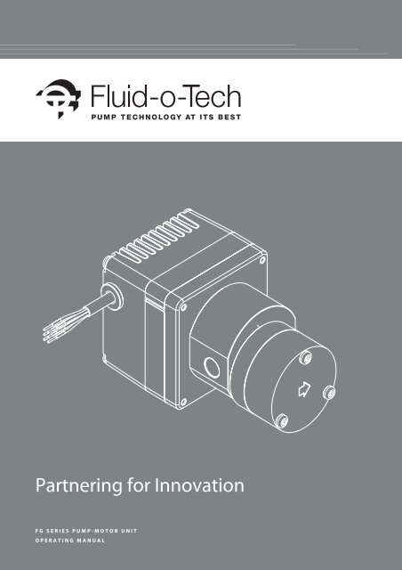
Partnering for Innovation<br />
f G S E R I E S P U M P - M O T O R U N I T<br />
O p e r a t i n g M a n u a l
Important Information:<br />
Please read the operating manual carefully before using the system.<br />
Warnings:<br />
• The pump flange must be handled with care and should not be grasped with tongs or vices, since this<br />
could cause misalignment of the magnet and damage to the pump. For food applications the pump<br />
(even when NSF listed) needs to be sterilized by circulating water at 80 °C/176 °F for at least 20 minutes.<br />
Water used for this operation must not be reused, either during the sterilization or later, but must be<br />
discharged.<br />
• In order to avoid any accidental ingress of solid matter which might damage the internal<br />
components of the pump, it is recommended removing the two protection caps placed on<br />
the inlet and outlet ports of the pump only immediately before mounting the fittings and the<br />
pipework.<br />
• Particular care must be taken when connecting the pump with fittings in order to avoid leaks<br />
• If a sealing fluid or Teflon® tape is used, do not allow any to enter the pump. It is advisable to use<br />
stainless steel or plastic fittings.<br />
• To prevent damage to the pump, do not run it dry.<br />
• Disconnect the power supply before removing the pump.<br />
• Shut down the power supply of the unit when connecting to external control equipment.<br />
• Do not let liquid enter this pump drive.<br />
Warranty:<br />
Every new pump manufactured by Fluid-o-Tech is guaranteed to be free of defects in workmanship and material<br />
when leaving the factory for a period of 18 months from the production date printed on pump label, plus a period<br />
of 6 months to cover the warehouse and transit time, or for a period of maximum 24 months from the purchasing<br />
date to the first product use. In no event shall this period exceed 24 months from date of original invoice.<br />
Fluid-o-Tech will repair or replace at our discretion part or all of the product not conforming to this warranty.<br />
Fluid-o-Tech’s responsibility under this warranty is limited to the repair or replacement of defective product<br />
returned to us on an DDP basis, providing that our analysis discloses that such part or parts were defective at<br />
the time of sale.<br />
The warranty is not recognized if:<br />
• The instructions on how to handle, install or operate the pump are disregarded.<br />
• The pump has been disassembled or modified by anyone other than a Fluid-o-Tech (or authorized by Fluid-o-Tech)<br />
engineer or repaired with non original components.<br />
• The pump has been operated dry or under cavitation.<br />
• Solid extraneous particles are found in the pump.<br />
• Obvious signs of excess pressure are evident.<br />
• The pump has been utilized for an application for which it was not intended to be used, where the operating<br />
conditions and/or the pumped liquid were incompatible with the pump itself and this application has not<br />
been specifically approved by Fluid-o-Tech.<br />
• In case of pumps equipped with a relief valve, when the operating pressure has been less than 1 bar<br />
(14.5 psi) below the relief valve setting.<br />
• Normal wear and tear is not covered by the present warranty<br />
The adjustment or replacement of defective parts made under this warranty will not extend the original<br />
warranty period.
Table of Contents<br />
Operating working conditions 4<br />
The two versions 4<br />
Pin function: version with electronic driver 5<br />
Pin function: version without electronic driver 6<br />
Motor features 7<br />
Thermal protection 8<br />
Under/over voltage protection 8<br />
Motor stall protection 8<br />
<strong>Pump</strong> operating conditions 8<br />
Assembling and disassembling the unit to replace the pump or the motor 9<br />
“C” bracket mounting 10<br />
“Frame” bracket mounting 10<br />
Certification 10
FG SERIES PUMP-MOTOR UNIT<br />
INSTRUCTION<br />
MANUAL<br />
This integrated pump-motor unit is composed by a Fluid-o-Tech mag drive gear pump and a BLDC 24V motor.<br />
The units are available in 2 different versions: with or without the integrated electronic driver.<br />
[OPERATING WORKING CONDITIONS]<br />
Nominal torque<br />
100 mNm @ 3500 rpm<br />
Speed range<br />
from 300 to 5000 rpm<br />
Direction of rotation<br />
clockwise / counterclockwise*<br />
Max ambient temperature 40°C/104°F at the maximum torque (70°C/158°F at 70 mNm torque)<br />
Max fluid temperature<br />
55°C/131°F at the maximum torque (95°C/203°F at the lower torque)<br />
Unit protection level<br />
IP52<br />
Relative humidity<br />
90% or less without condense<br />
Storage temperature - 40°C + 85°C/-104°F + 185°F<br />
* counterclockwise available only for the version without electronic driver<br />
[The two versions]<br />
Without integrated elctronic driver<br />
With integrated elctronic driver<br />
4
[PIN FUNCTION: VERSION WITH ELECTRONIC DRIVER]<br />
WIRE COLOR SYMBOL DESCRIPTION<br />
Red PWR_VCC Power supply (+24V)<br />
Black PWR_GND Power ground (0V)<br />
Orange<br />
SPEED IN<br />
Analog input speed command 0-5V<br />
Voltage Input<br />
Output (rpm)<br />
In < 0.2V 0<br />
0.3V < In < 5V 300 > Out > 5000<br />
linearity speed<br />
vs command<br />
+/- 5% with no load<br />
Brown 0V 0V speed command<br />
Yellow<br />
TACHO OUT<br />
(SPEED OUT)<br />
DC output voltage: 0-5V<br />
DC output source current: max. 5mA<br />
Output square signal frequency: max. 2.7 KHz<br />
Green NC Not connected<br />
IMPORTANT NOTE:<br />
never connect PWR GND and 0V together, otherwise the integrated elctronic board can be seriously damaged.<br />
* Speed [rpm] = Frequency [Hz] * 60/32<br />
ELCTRICAL CONNECTION:<br />
to mantain separated the two 0V reference connections<br />
82 040 001<br />
Power supply<br />
+ 24 VDC<br />
Red (PWR_VCC)<br />
Black (PWR_GND)<br />
Analog value<br />
0 - 5V<br />
Orange (SPEED_IN)<br />
Brown (0V)<br />
Green (NC)<br />
Scope<br />
Yellow (TACHO)<br />
5
POSSIBLE ALTERNATIVE CONNECTION: to NOT connect the 0V speed command<br />
(in this case the speed vs command linearity can be > 5%)<br />
82 040 001<br />
Power supply<br />
+ 24 VDC<br />
15K (1)<br />
47K (1)<br />
Red (PWR_VCC)<br />
Orange (SPEED_IN)<br />
Brown (0V)<br />
Green (NC)<br />
Scope<br />
Yellow (TACHO)<br />
Black (PWR_GND)<br />
[PIN FUNCTION: VERSION WITHOUT ELECTRONIC DRIVER]<br />
HALL PHASE ROTATION<br />
H1 H2 H3 L1 L2 L3<br />
0 1 1 + -<br />
0 0 1 + -<br />
1 0 1 - +<br />
1 0 0 - +<br />
1 1 0 - +<br />
0 1 0 + -<br />
REP<br />
6<br />
CONNECTION<br />
Hall supply (4.5 - 18V)<br />
1 Max current: 20mA<br />
Output: NPN, open collector<br />
2 GND<br />
3 Output Hall 3<br />
4 Output Hall 2<br />
5 Output Hall 1<br />
Coil 3<br />
6<br />
R = 0.65 OHM +/- 10%<br />
Coil 2<br />
7<br />
R = 0.65 OHM +/- 10%<br />
Coil 1<br />
8<br />
R = 0.65 OHM +/- 10%
[MOTOR FEATURES*]<br />
ABSOLUTE MAXIMUM RATING<br />
SYMBOL PARAMETER MIN. TYP. MAX. UNIT<br />
V PWR VCC Power supply (+24V DC) -35 24 35 V<br />
I VCC PWR_VCC current 0 2 4 A<br />
V SPEED_IN Analog input speed command -5 5 15 V<br />
FUNCTIONAL RANGE<br />
SYMBOL PARAMETER MIN. TYP. MAX. UNIT<br />
V PWR VCC Power supply (+24V DC) 20 24 29 V<br />
I VCC PWR_VCC current - - 3.5 A<br />
SPEED Speed out 300 - 5000 rpm<br />
TORQUE Torque out 0 - 100 mN.m<br />
DC CHARACTERISTICS AT 24V, AMBIENT TEMPERATURE = 25 °C<br />
SYMBOL PARAMETER MIN. TYP. MAX. UNIT<br />
Rin Input impedance - 162 - K Ω<br />
Voh High level output voltage 3.8 4.4 - V<br />
Vol Low level output voltage - 0.1 0.44 V<br />
Io Output current - - 20 mA<br />
IVCC Supply current - 60 - mA<br />
* The table is referred to the version with electonic driver<br />
6000<br />
5000<br />
4000<br />
Speed [rpm]<br />
3000<br />
2000<br />
1000<br />
0 0.5 1 1.5 2 2.5 3 3.5 4 4.5 5 5.5<br />
Vi [V]<br />
7
THERMAL PROTECTION<br />
The motor has an internal thermal protection built in the drive board.<br />
The thermal upper limit is 120°C/248°F and when this value is reached the motor is automatically stopped.<br />
To restart the system, speed input signal must be set to 0 and the internal temperature must be under 110°C/230°F.<br />
UNDER/OVER VOLTAGE PROTECTION<br />
The motor has an internal under voltage protection set at 15,5V.<br />
When this limit is reached, the motor is automatically stopped. To restart the system the power supply voltage must<br />
be over 16,5V and the speed input must be set to 0.<br />
The motor has an internal over voltage protection set at 30V.<br />
When this limit is reached the motor is automatically stopped. To restart the system the power supply voltage must<br />
be under 29V and the speed input must be set to 0.<br />
MOTOR STALL PROTECTION<br />
The motor has a motor stall protection.<br />
The motor is automatically stopped if it is not able to rotate for 1 second.<br />
To restart the system the speed input must be set to 0.<br />
[PUMP OPERATING CONDITIONS]<br />
Ensure that the pump materials are compatible with the pumped fluid.<br />
Fluid-o-Tech pumps are designed to handle clean water at ambient temperature.<br />
Any other fluid and/or operating condition need to be tested and approved by the customer and verified by<br />
Fluid-o-Tech.<br />
It is strongly recommended, especially for the inlet, using a pipe with an inner diameter sufficient to handle the<br />
pump’s capacity. This will avoid cavitation and consequent failure of the pump.<br />
The discharge pressure must not exceed 12 bar (174 psi) in any event.<br />
The piping on the discharge side should therefore be able to handle a pressure of 12 bar (174 psi).<br />
It is also recommended installing a filter before the pump capable of keeping out particles larger than 10 µm which<br />
could cause fast wear of the internal components, and with a surface area large enough not to cause hydraulic<br />
losses in the circuit. It is also important to check periodically the filter cartridge.<br />
In order to keep the filter under control, it is advisable to install a vacuum gauge after the filter.<br />
In case the vacuum increases more than 0.1 bar (1.45 psi), the cartridge should be cleaned or changed.<br />
For long pump life, the pumped fluid must not contain any solid particle.<br />
Although the magnet drive gear pumps are self-priming, they should operate under wetted conditions, as dry<br />
running will cause accelerated wear of the internal components.<br />
A dirty filter or an insufficient supply of water can cause cavitation and accelerated wear of the internal components of<br />
the pump.<br />
If the suction line is subject to low pressure or flow, it is recommended fitting a pressure/level switch before the<br />
pump in order to switch the motor off when that happens.<br />
It is also recommended to protect the system from accidental overpressure with safety devices such as a pressure<br />
relief valve or a pressure switch connected to the motor.<br />
It is not advisable to install solenoid valves in the circuit; however, if necessary, the soleinoid valve should only be<br />
installed after the pump. Solenoid valves installed before the pump should be avoided at all times.<br />
The internal diameter of the solenoid valve should be appropriately sized for the pump capacity.<br />
In order to avoid pressure spikes the solenoid valve should only be operated after the pump has stopped, allowing a<br />
few seconds to go by after the motor has been switched off.<br />
If the pump is equipped with a relief valve (bypass), it will act, in case of accidental overpressure, to limit the pressure, by<br />
means or recirculating the fluid internally.<br />
The relief valve is not a flow regulator, and should not be used as such. If used as a flow regulator, the excess fluid<br />
will recirculate within the pump, through the relief valve, and the pump may fail. The maximum differential pressure<br />
should be at least 1 bar (14.5 psi) lower than the relief valve setting in order to avoid fluid recirculation and therefore loss of<br />
capacity and ultimately failure.<br />
8
Due to magnetic coupling, the pump does not require a mechanical seal to prevent leakage.<br />
This eliminates the usual problems associated with the use of a mechanical seal.<br />
The maximun pressure varies with pump model and speed. As the differential pressure deacreses the flow rate will<br />
increase.<br />
[assembling and disassembling the unit TO REPLACE THE PUMP OR THE MOTOR]<br />
* with integrated electronic driver<br />
1) Unscrew the 4 screws on the back side of the motor<br />
2) Separate motor and pumphead<br />
3) Replace the pump or the motor as needed<br />
4) Position the plastic ring around the metal magnet cup<br />
5) Position the 2 pins inside the 2 holes in the square flange<br />
6) Assemble pumphead and motor inserting the 2 pins into the motor holes<br />
7) Tighten the 4 screws at 1 Nm +/0.2<br />
* without integrated electronic driver<br />
1) Unscrew the 4 screws on the back side of the motor<br />
2) Separate motor and pumphead<br />
3) Replace the pump or the motor as needed<br />
4) Position the plastic ring around the metal magnet cup<br />
5) Position the 2 pins inside the 2 holes in the square flange<br />
6) Assemble pumphead and motor inserting the 2 pins into the motor holes<br />
7) Tighten the 4 screws at 1 Nm +/0.2<br />
9
[“C” bracket MOUNTING]<br />
* with integrated electronic driver<br />
* without integrated electronic driver<br />
- Position the bracket on the stator (12 mm black section) and fix the unit by tighten the 2 feet with 2 M5 screws<br />
[“FRAME” bracket MOUNTING]<br />
* with integrated electronic driver<br />
* without integrated electronic driver<br />
- Fix the frame on the stator (12 mm black section) with 2 M5 set screws on the 2 sides<br />
- Use the 4 holes diameter 5 mm on the frame corners for fixing the unit by M4 screws<br />
[CErtification]<br />
<strong>Pump</strong>/Motor units are considered a machine, and therefore supplied with the “CE” mark, and will satisfy the requirements of<br />
the following Directives: 89/366/CEE relating to Electromagnetic Compatibility - EMC, 73/23/CEE relating to Electrical Materials<br />
intended to be used in potentially explosive environments - DTB and 94/9/CE relating to Equipment and Protection Devices<br />
intended to be used in potentially explosive environments - ATEX.<br />
A Fluid-o-Tech Declaration of Conformity can be requested to state compliance with the above Directives.<br />
Fluid-o-Tech reserves the right to alter the specifications indicated in this manual at any time and without prior notice.<br />
10


