

Grounded Cathode Amplifier - Tube CAD Journal
Grounded Cathode Amplifier - Tube CAD Journal
Grounded Cathode Amplifier - Tube CAD Journal

You also want an ePaper? Increase the reach of your titles
YUMPU automatically turns print PDFs into web optimized ePapers that Google loves.
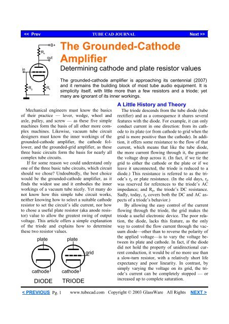
in<br />
R a<br />
B+<br />
out<br />
The <strong>Grounded</strong>-<strong>Cathode</strong><br />
<strong>Amplifier</strong><br />
Determining cathode and plate resistor values<br />
R g<br />
R k<br />
The grounded-cathode amplifier is approaching its centennial (2007)<br />
and it remains the building block of most tube audio equipment. It is<br />
simplicity itself, with little more than a few resistors and a triode; yet<br />
many are ignorant of its inner workings.<br />
Mechanical engineers must know the basics<br />
of their practice — lever, wedge, wheel and<br />
axle, pulley, and screw — as these five simple<br />
machines form the basis of all other more complex<br />
machines. Likewise, vacuum tube circuit<br />
designers must know the inner workings of the<br />
grounded-cathode amplifier, the cathode follower,<br />
and the grounded-grid amplifier, as these<br />
three basic circuits form the basis for nearly all<br />
complex tube circuits.<br />
If for some reason we could understand only<br />
one of the three basic tube circuits, which circuit<br />
should we chose Undoubtedly, the best choice<br />
would be the grounded-cathode amplifier, as it<br />
finds the widest use and it embodies the inner<br />
workings of a vacuum tube nicely. Yet many do<br />
not know how this simple tube circuit works,<br />
neither knowing how to select a suitable cathode<br />
resistor to set the circuit’s idle current, nor how<br />
to chose a useful plate resistor (aka anode resistor)<br />
value to allow the greatest swing of output<br />
voltage. This article offers a simple explanation<br />
of the triode and explains how to determine<br />
these two resistor values.<br />
plate<br />
cathode<br />
DIODE<br />
plate<br />
cathode<br />
TRIODE<br />
grid<br />
A Little History and Theory<br />
The triode descends from the tube diode (tube<br />
rectifier) and as a consequence it shares several<br />
features with the diode. For example, it can only<br />
conduct current in one direction: from its cathode<br />
to its plate (or from cathode to grid when the<br />
grid is more positive than the cathode). In addition,<br />
it offers some resistance to the flow of that<br />
current, which means that like the tube diode,<br />
the more current flowing through it, the greater<br />
the voltage drop across it. (In fact, if we tie the<br />
grid to either the cathode or the plate or if we<br />
leave it unconnected, the triode is reduced to a<br />
diode.) This resistance is referred to as the triode’s<br />
r p or plate resistance. (In the old days, r p<br />
was reserved for references to the triode’s AC<br />
impedance; and R p , the triode’s DC resistance.<br />
Sadly, today, r p covers both the DC and AC aspects<br />
of a triode’s behavior.)<br />
By allowing the easy control of the current<br />
flowing through the triode, the grid makes the<br />
triode a useful electronic device. The poor relation,<br />
the diode, lacks this feature, as the only<br />
way to control the flow current through the vacuum<br />
diode—other than to reverse the polarity of<br />
the applied voltage—is to vary the voltage between<br />
its plate and cathode. In fact, if the diode<br />
did not hold the property of unidirectional current<br />
conduction, it would be of no more use than<br />
a slow-turn resistor, with a relatively short life<br />
expectancy and poor linearity. In contrast, by<br />
simply varying the voltage on its grid, the triode’s<br />
current can be completely stopped — or<br />
increased up to complete saturation.<br />
< PREVIOUS Pg. 1<br />
www.tubecad.com Copyright © 2003 GlassWare All Rights NEXT >
In other words, the grid is like the valve in a<br />
water faucet; so much like it, in fact, that the<br />
vacuum tube is often referred to as a valve. Because<br />
turning a water faucet on and off requires<br />
so little effort, we cannot see the splendor of the<br />
stunt. So, instead, imagine a large dam and its<br />
water valve; it is a huge reservoir of potential<br />
energy, yet one individual can turn the handle<br />
(the valve) that releases a dangerous flood. The<br />
amount of work required to turn the handle is<br />
nothing compared to the water’s release and<br />
once the effort has been expended opening the<br />
valve, it remains open without any further expenditure<br />
of work on our part.<br />
In much the same way as the dam’s flood<br />
valve, the triode’s grid presents an extremely<br />
light load, considering the large resulting effect.<br />
Unlike a transistor’s low-impedance base, the<br />
grid’s input offers so great an impedance that<br />
one of the triode’s last jobs, before being replaced<br />
by solid-state devices, was as the input<br />
device on voltage meters and oscilloscopes,<br />
where its high-input impedance prevented excessive<br />
interaction with what was being measured<br />
and its ability to survive high voltage mishaps<br />
added reliably to the test instruments.<br />
Here is an example that illustrates how little<br />
current a grid conducts when it is substantially<br />
more negative than the cathode. If a 9-volt battery<br />
is connected to a triode so that its negative<br />
terminal attaches to the grid and its positive terminal<br />
attaches to its cathode, while the cathode<br />
is grounded and its plate is connected to a high<br />
voltage power supply, the battery’s life expectancy<br />
would probably prove no shorter than that<br />
of its brother still shrink-wrapped at the store.<br />
Yet, the battery is an essential part of the circuit.<br />
B+<br />
9 volts<br />
Like the amount of work required to release<br />
the dam’s flow, most of the work required to adjust<br />
the triode’s current came at the beginning.<br />
Charging a capacitor requires energy, just as filling<br />
a swimming pool requires water and pressure.<br />
In this example, this one-time connection<br />
results in an insignificant amount of work. Make<br />
and break this same connection a million times<br />
per second and the battery will be taxed and depleted,<br />
as now the recharging of the capacitance<br />
represents much more work. (Imagine what your<br />
hands would look like after turning the water on<br />
and off a million times per second.) Not all tubes<br />
would require the same amount of work, however,<br />
as each type has a differing amount of capacitance.<br />
In the battery-biased circuit shown above, the<br />
circuit without a plate resistor, the varying<br />
amounts of capacitance would be the only issue,<br />
but in an amplifier circuit, wherein the plate<br />
works into a load (such as a resistor or a transformer),<br />
the amplification realized by the triode<br />
becomes crucial to determining the amount of<br />
work required to recharge the capacitance.<br />
< PREVIOUS Pg. 2<br />
www.tubecad.com Copyright © 2003 GlassWare All Rights NEXT >
This is so because the amplification performed<br />
on the input signal also acts on the capacitance<br />
between the grid and the plate, amplifying<br />
it; thus making it much more of a burden.<br />
This is, in a nutshell, the dreaded Miller effect:<br />
the multiplying of the grid-to-plate capacitance<br />
by the gain of the triode.<br />
<strong>Cathode</strong><br />
So far we have covered only one of the triode’s<br />
three controlling elements (the grid). The<br />
cathode can also be used to control the flow of<br />
current through the triode.<br />
In fact, the cathode is slightly more effective<br />
at controlling the current flow than the grid. But<br />
unlike the grid, the cathode presents a lowimpedance<br />
input and thus requires more effort to<br />
move its voltage up or down. (When the cathode<br />
is used as the control element, i.e. as the input,<br />
the triode is being used in the grounded-grid topology.)<br />
input<br />
R<br />
10µF<br />
Ra<br />
+100V<br />
Rk<br />
B+ = +200V<br />
10k<br />
+2V<br />
<strong>Grounded</strong> Grid <strong>Amplifier</strong><br />
output<br />
1M<br />
The plate can also control the flow of current,<br />
as increasing the cathode-to-plate voltage increases<br />
the flow of current. The plate, however,<br />
is not as effective as the grid or the cathode in<br />
controlling conduction. Where the grid might<br />
need to see a 1-volt change in voltage to incur a<br />
10-mA increase in current flow, the plate might<br />
require a 100-volt change to yield the same 10-<br />
mA increase...which brings us to mu.<br />
mu, G m , and r p<br />
The ratio of the plate’s effectiveness over the<br />
grid’s effectiveness in controlling current flow<br />
from cathode to plate defines the mu or amplification<br />
factor or µ of a triode. And the measure<br />
of any controlling element’s ability to vary current<br />
conduction in response to a change in its<br />
voltage goes by the name of transconductance.<br />
Each of the triode’s three elements displays its<br />
own amount of transconductance. The most<br />
commonly specified transconductance is that of<br />
the grid, which often is labeled G m or mutual<br />
conductance and noted in micro-siemens, the<br />
siemens (S) being the unit of conductance, the<br />
inverse of resistance. The plate’s transconductance<br />
equals 1/r p ; the grid’s, mu/r p ; and the cathode’s,<br />
(mu +1)/r p .<br />
A quick review: the triode can only conduct<br />
current from its cathode to its plate (and, in<br />
some cases, to its grid); the triode offers resistance<br />
to the flow of current that results in a voltage<br />
drop across the triode, much like the voltage<br />
drop across a resistor; and both the grid and the<br />
cathode are much more effective than the plate<br />
in controlling the flow of current through the triode.<br />
Given this short explanation of the triode’s<br />
workings, we can move on to how to set a triode’s<br />
idle current with a cathode resistor.<br />
<strong>Cathode</strong> Bias<br />
In the absence of a cathode resistor, with both<br />
the grid and the cathode seeing the same voltage,<br />
the triode’s r p offers the only controlling opposition<br />
to the flow of current through the triode.<br />
This configuration can result in a great deal of<br />
current, as V p (the cathode-to-plate voltage) divided<br />
by the triode’s r p , roughly equals the<br />
amount of current. For example, a triode with an<br />
rp of 2k under a V p of 100 volts will draw 50<br />
mA of current, which against the 100 volts<br />
equals 5 watts of heat dissipation by the triode.<br />
Doubling the B+ voltage would also double the<br />
idle current and thus quadruple the dissipation,<br />
as both the current and the voltage have doubled.<br />
< PREVIOUS Pg. 3<br />
www.tubecad.com Copyright © 2003 GlassWare All Rights NEXT >
How can we alter this circuit to decrease the<br />
idle current, while retaining the same V p Two<br />
avenues present themselves. The first technique<br />
is to make the grid more negative than the cathode<br />
by connecting the grid to a negative power<br />
supply, such as the battery from the previous example.<br />
The advantage of a negative power supply<br />
is that a simple potentiometer can be used to<br />
adjust the idle current. How negative should this<br />
power supply be<br />
Consider this: because the grid is mu times<br />
more effective than the plate in controlling current,<br />
making the grid voltage equal the B+ voltage<br />
divided by the mu and made negative,<br />
should turn the triode completely off. Expressed<br />
mathematically:<br />
I q = 0 when V gk = -V b /mu.<br />
(If triodes were perfect, then “should” would<br />
have been replaced with “will.” Unfortunately,<br />
as good as triodes are, they are not perfect, particularly<br />
at the bottom of their conduction near<br />
cutoff. Still, this is a handy equation to memorize.)<br />
Thus, the negative power supply need<br />
only be 1/mu times as large as the B+ power<br />
supply to ensure a wide range of current control.<br />
<strong>Cathode</strong>-Biased Voltage Dropping Devices<br />
The second technique to decrease the idle current<br />
is to make the cathode more positive than<br />
the grid by inserting a voltage drop between the<br />
cathode and ground. We could use a battery, an<br />
LED, a zener, a solid-state diode, vacuum tube<br />
diode, or even a second power supply, but a resistor<br />
is the most common choice. The larger the<br />
cathode resistor’s value, the greater the effective<br />
negative bias voltage.<br />
So could a cathode resistor’s value ever be so<br />
great as to turn off a triode No, it never could<br />
be so large, as some current must flow to define<br />
a voltage drop across the resistor, so the triode<br />
could not be turned off.<br />
At first glance, the resistor would seem the<br />
poorest choice as, unlike most of the other devices,<br />
it does not present a fixed voltage. But in<br />
fact, the resistor’s current-dependent voltage<br />
drop is just what is needed to ensure the most<br />
consistently stable idle current.<br />
An individual triode differs from other triodes<br />
of the same type and, over time, it even differs<br />
from itself. In other words, the fixed voltage relationship<br />
between the cathode and grid that<br />
worked perfectly with one tube may not work so<br />
well with another triode of the same type or even<br />
with the same triode two years from now.<br />
By using a cathode resistor, however, we introduce<br />
a feedback mechanism into the circuit.<br />
As the triode increases in conduction, a larger<br />
voltage drop develops across the cathode resistor,<br />
which in turn makes the grid less positive<br />
relative to the cathode, reducing the triode’s<br />
conduction. Conversely, as the triode decreases<br />
in conduction, a smaller voltage drop develops<br />
across the cathode resistor, which in turn makes<br />
the grid more positive relative to the cathode,<br />
increasing the triode’s conduction. This is feedback<br />
of a truly negative sort. (In contrast to everyday<br />
speech, for most of electronic practice,<br />
negative feedback is desired and positive feedback<br />
feared, as positive feedback can lead to<br />
dangerous oscillations.) The negative feedback<br />
results in a welcome increase in consistency.<br />
Okay, cathode bias seems like a good idea,<br />
but how do we chose the right value for the cathode<br />
resistor Five approaches present themselves<br />
before the tube circuit practitioner.<br />
First, look up the value (in a book or magazine<br />
— or ask a friend). While this is the most<br />
popular method, it is the least universally applicable,<br />
as many triodes are never mentioned and<br />
of those that are, only a few bias points are<br />
given.<br />
Second, work out the value from a single<br />
simple formula. This does have a universal application,<br />
but it relies on an idealized model of<br />
the triode.<br />
Third, extrapolate the value from inspecting<br />
the triode’s plate curves. This method has the<br />
< PREVIOUS Pg. 4<br />
www.tubecad.com Copyright © 2003 GlassWare All Rights NEXT >
advantage of using the actual triode’s characteristics,<br />
but requires a good eye and some skill;<br />
worse still, not all triodes find their corresponding<br />
plate curves in print.<br />
Fourth, track down the value by actual experimentation.<br />
This requires both some physical<br />
work and some expense, as the triodes and resistors<br />
must be purchased and several triodes<br />
should be tested to preclude having a gassy or a<br />
weak triode throw off the results.<br />
And fifth, use a SPICE program to determine<br />
the value. This is actually something of a combination<br />
of the first four approaches. The limitation<br />
here is that the result is only as good as the<br />
SPICE models of the triode used and most of the<br />
models I have seen are just okay — and there<br />
are not that many of them out there (far fewer in<br />
number than the number of published plate<br />
curves) — but the models are steadily improving<br />
and growing in number.<br />
For most tube circuit designers the methods<br />
that work best are the second (working out<br />
mathematically) or third (inspecting the plate<br />
curves) because these methods quickly give reasonably<br />
accurate results. The formula for determining<br />
the cathode resistor’s value (in the absence<br />
of a plate resistor) is a simple one:<br />
R k =<br />
(V b / I q ) – r p<br />
mu + 1<br />
where, R k equals the cathode resistor; V b , the B+<br />
voltage; I q , the desired idle current; r p , the plate<br />
resistance; and mu, the triode’s amplification<br />
factor. (If the result is a negative number, then<br />
the desired idle current requires a lower r p triode.)<br />
For example, a 6SN7 (r p = 7700, mu = 20)<br />
with B+ voltage of 250 volts and a desired idle<br />
current of 9 mA will need a cathode resistor of<br />
956 ohms, which against the 9 mA idle current<br />
equals 8.6 volts and is close to the tube manual’s<br />
8 volts. In fact, in actual practice, this value<br />
would probably be close enough, or at least<br />
close enough to allow easy fine tuning. (Adding<br />
a plate resistor to the circuit will also serve to<br />
promote consistency in idle current and its value<br />
comes from the voltage drop divided by I q .)<br />
Neophytes are often<br />
horrified by 5% differences<br />
between a circuit’s<br />
actual functioning and the<br />
calculated results;<br />
whereas a seasoned circuit<br />
designer would revel<br />
in such exactitude.<br />
While vacuum tubes are much more consistent<br />
than other discrete active devices such as<br />
transistors, MOSFETs, and FETs, if you want<br />
tight tolerances, then look to passive devices, as<br />
0.01% tolerances only exist in passive components<br />
such as resistors and capacitors.<br />
Still, why so large a difference Part of the<br />
answer is found in the formula’s assumption of a<br />
perfect triode. Another part is found in the tube<br />
manual’s imprecision in stating the mu and the<br />
rp of the 6SN7 which, in this case, forms the larger<br />
part of the error. A careful inspection of the<br />
plate curves reveals that at 250 volts and 9 mA,<br />
the mu is closer to 21 and the r p is closer to 8k or<br />
9k. If we recalculate the cathode resistor’s value<br />
using these revised values, then much of the difference<br />
disappears between formula and plate<br />
curves.<br />
Aren’t a triode’s mu and rp fixed and immutable<br />
No. Unlike a tube’s dimensions and mass,<br />
its r p , mu, and G m vary, depending on plate voltage<br />
and plate current. The least varying characteristic<br />
is its mu; which is ironic, as it is the least<br />
real of the three specifiers, defining only the relation<br />
between r p and G m , not any actual physical<br />
aspect of the triode’s design. (Naming the ratio<br />
between a man’s height and the circumference<br />
of his waist “phi” might be useful for predicting<br />
heart attacks, but phi is not real in the same way<br />
that his eyes or kidneys are real.)<br />
Often, most of the blame for inaccurate results<br />
lies with the difference in cathode-to-plate voltage<br />
that the tube manual specifies versus the<br />
voltage the formula assumes. The tube manual<br />
assumes that fixed bias will be used, thus retaining<br />
the full B+ across the tube, whereas the formula<br />
accounts for the voltage lost across the<br />
cathode resistor.<br />
< PREVIOUS Pg. 5<br />
www.tubecad.com Copyright © 2003 GlassWare All Rights NEXT >
current<br />
0 voltage<br />
Extrapolation from Plate Curves<br />
The detective has fingerprints; the fortune<br />
teller, a crystal ball; and the tube amplifier designer,<br />
plate curves. Each promises to reveal secrets.<br />
Who did it What will the future bring<br />
Will it work Like the fingerprint, the tube’s<br />
plate curves individualize the tube, which helps<br />
us decide which tube should be used. Like the<br />
crystal ball, a set of plate curves helps us predict<br />
how an amplifier will function, allowing us<br />
quickly to find the required grid voltage to set a<br />
given bias point and to determine maximum<br />
voltage swings. But before we tackle the vacuum<br />
tube’s plate curves, we need to cover something<br />
much easier: simple resistances and<br />
straight lines.<br />
current<br />
1Ω<br />
10Ω<br />
We know we must start at the bottom left corner<br />
where voltage and current equals zero, as no<br />
voltage across a resistance means no current.<br />
The next point for the 1-ohm resistance would<br />
be one unit (1 volt) to the right and one unit up<br />
(1 amp); and for the 10-ohm resistance, it would<br />
be ten units to the right and one unit up. Remember,<br />
the lines continue infinitely, as the relationship<br />
between voltage and current defined by the<br />
line is constant. So if we follow the 1-ohm line<br />
out to 100 kV, we know that the current will be<br />
100 kA. Of course, no 1-ohm resistor on earth<br />
could withstand the test; but the issue here is<br />
pure resistances and not necessarily actual<br />
physical resistors.<br />
The plotting of these two resistances reveals a<br />
key feature of graphing resistances: the lower<br />
the resistance, the steeper the line defined; and<br />
the higher the resistance, the flatter the line defined.<br />
This will prove valuable when working<br />
with tubes, as this principle allows quick inspection<br />
of plate resistances. Given that both graphs<br />
share the same X-Y scales, the steeper set of<br />
plate curves belongs to the vacuum tube with the<br />
lower plate resistance.<br />
As the Ohm’s Law formula is so simple, plotting<br />
different resistance values is usually of little<br />
value. But if we place two resistances in series<br />
and set a B+ voltage, then we can graphically<br />
see the voltage division between resistances.<br />
100mA<br />
75mA<br />
2400<br />
0<br />
voltage<br />
Simple Resistances<br />
The movement from the graph’s left to its right<br />
defines increasing voltage; from its bottom to its<br />
top, increasing current. This arrangement allows<br />
us graphically to display Ohm’s Law:<br />
Resistance = Voltage / Current.<br />
For example, 1 ohm equals 1 volt divided by 1<br />
amp and 10 ohms equals 10 volts divided by 1<br />
amp. Graphing these resistances is easy.<br />
50mA<br />
31.25mA<br />
25mA<br />
0 50V 100V 150V 200V<br />
75V<br />
125V<br />
4000<br />
Two Resistances In Series<br />
When two resistances are in series (no resistance<br />
equaling zero) and are placed across a<br />
fixed voltage, one resistance will steal voltage<br />
from the other.<br />
< PREVIOUS Pg. 6<br />
www.tubecad.com Copyright © 2003 GlassWare All Rights NEXT >
If the resistances equal each other, then each<br />
will share half the available voltage. If one resistance<br />
is twice the value of the other, then it will<br />
grab 2/3 of the available voltage.<br />
Graphically plotting the voltage ratio is easy<br />
enough. We start with the resistor that connects<br />
to ground, i.e. 0 volts. Fix the first point at 0<br />
volts and 0 current and then place the second<br />
point at the intersection of the maximum voltage<br />
and the maximum current that this resistor<br />
would see at that voltage based on the formula:<br />
I = V/R.<br />
Now to plot the resistor that connects to the<br />
B+ voltage, we start at the other end of the graph<br />
at the maximum B+ voltage and zero current.<br />
(This makes sense, because if the value of the<br />
resistance were 0 ohms, then the current would<br />
be 0 mA.) Moving to the extreme left, we find<br />
the value of current this resistor would draw, if it<br />
experienced the full B+ voltage; once again, this<br />
equals I = V/R. The result of our efforts is two<br />
lines crossing each other. The intersection of the<br />
two lines defines the voltage at the connection of<br />
the two resistances and it defines the maximum<br />
current the circuit will see with the given B+<br />
voltage.<br />
r p = V/I<br />
V<br />
I<br />
g m = I/V<br />
mu = V p /V g<br />
Plate Curves<br />
Finally, we get to the triode’s curving grid<br />
lines. Each line represents the triode’s current<br />
conduction plotted across an increasing voltage,<br />
while a constant grid voltage is applied. The reason<br />
this set of curves goes by named “plate<br />
curves” is that each point on a curve reveals the<br />
triode’s plate current at that point. For example,<br />
in the graph below, we see that with a grid voltage<br />
of -6 volts and a cathode-to-plate voltage of<br />
100 volts, the triode conducts 50 mA of current.<br />
So does the rp equal 2k, as 100 / 0.05 = 2000<br />
The answer is no, as once the current climbs<br />
over 15 mA, the -6-volt grid line reflects a slope<br />
closer to 714 ohms. Yet a 714-ohm resistor<br />
would draw 140 mA at 100 volts, not just 50<br />
mA.<br />
Need an in-line stereo volume control or "passive preamp"<br />
Click here for information about our new SA-1, SA-3, and SA-1X Volume Control Boxes.<br />
Goldpoint<br />
< PREVIOUS Pg. 7<br />
www.tubecad.com Copyright © 2003 GlassWare All Rights NEXT >
100mA<br />
75mA<br />
0 -2<br />
-4<br />
-6<br />
-8<br />
-16<br />
50mA<br />
-10<br />
-12<br />
-14<br />
25mA<br />
-18<br />
0<br />
50V<br />
Why What has happened is that product of<br />
this triode’s mu (about 10) against its grid’s -6<br />
volts (-60 volts) has been added to the 100 volts<br />
to yield 40 volts as the effective plate voltage,<br />
which when divided by 714 ohms results in a<br />
current draw of 56 mA. (The grid line curves<br />
enough to make up the 6 mA difference.) Had<br />
we focused on the 0 volt grid line instead, then<br />
the plate resistance would have been much more<br />
accurately directly deduced from dividing the<br />
plate voltage by the plate current along any point<br />
on the gridline. (Once again, the lines curve<br />
enough to introduce a small error.)<br />
Determining the value of the required cathode<br />
resistor to set the idle to 50 mA at 100 volts<br />
seems obvious enough: just divide 6 volts by 50<br />
mA; unfortunately, this method gives an inaccurately<br />
high resistor value, as the full 100 volts<br />
will no longer be available to the triode once the<br />
cathode resistor displaces 6 volts of the B+ voltage.<br />
So the set of curves should be mentally<br />
shifted -6 volts to the right. For most beginners<br />
this is asking too much. The quick workaround<br />
is to take the apparent bias voltage (-6 volts, in<br />
this example) and divide it by the reciprocal of<br />
the triode’s mu (10, in this example) and then<br />
subtract this value from the apparent negative<br />
bias voltage, which when simplified and expressed<br />
as a formula becomes:<br />
100V<br />
150V<br />
V bias´ = V bias (1- 1/mu)<br />
R k = V bias´ / I q<br />
In this case, the -6 volts becomes 5.4 volts,<br />
which divided by 50 mA equals 108 ohms, the<br />
correct value. Obviously, the higher the mu, the<br />
smaller the adjustment becomes; consequently,<br />
with a high-mu tube like the 12AX7, often no<br />
workaround is sought, but it is essential with low<br />
mu triodes, such as the 2A3, 6AS7, 6BX7,<br />
6C33, 300B and 845.<br />
The previous examples relied on circuits<br />
without plate resistors. Factoring in the role<br />
played by the plate resistor only slightly increases<br />
the complexity of the task. The formula<br />
for determining the cathode resistor’s value must<br />
be modified:<br />
R k =<br />
(V b / I q ) – r p – R a<br />
mu + 1<br />
where, once again, a resulting negative value betrays<br />
that the specified idle current cannot be<br />
met under the cathode bias configuration and a<br />
lower-r p triode or a lower-valued plate resistor is<br />
required.<br />
Graphing the added plate resistor is easy<br />
enough, as it relies on the method used to plot<br />
the two resistors in series. We start at the B+<br />
voltage, which in this example we will set at 200<br />
volts, and place our first point.<br />
< PREVIOUS Pg. 8<br />
www.tubecad.com Copyright © 2003 GlassWare All Rights NEXT >
Then we find the intersection with the leftmost<br />
portion of the graph by using Ohm’s law:<br />
I = V/R.<br />
Given a plate resistor of 2k, the intersection<br />
occurs at 100 mA. The last step is to draw a line<br />
connecting both points. This line defines the<br />
range of possible idle currents and plate voltages<br />
with this plate resistor in place.<br />
For example, if we pick 25 mA as a suitable<br />
idle current, then the plate resistor will see 50<br />
volts across its leads and the triode will see 150<br />
volts minus the cathode bias voltage (about 12.5<br />
volts).<br />
Working Backwards<br />
Sometimes we are presented with an existing<br />
circuit that lists the values of the plate resistor<br />
and cathode resistor, but not the operating voltages<br />
or idle current. Fortunately, we can work<br />
backwards from the resistor values to the operating<br />
points (if the B+ voltage is specified). The<br />
mathematical approach involves rewriting the<br />
previously given formula:<br />
I q =<br />
V b<br />
(R k [mu + 1]) + r p + R a )<br />
and<br />
and<br />
V p = V b - I q ( R k + R a )<br />
V gk = I q R k<br />
While the results depend on the triode’s mu<br />
and rp having been accurately defined from<br />
some point close to the actual operating point,<br />
the results are usually close enough to get a good<br />
idea of what is going on in the circuit.<br />
Inspecting the plate curves promises greater<br />
precision, but requires a good eye. The first step<br />
is to plot the plate resistor as we did before. The<br />
second step is to plot the cathode resistor line.<br />
Be sure to resist the temptation to plot its line in<br />
the same fashion as we did in the resistor-only<br />
examples, as the cathode resistor does not see<br />
the voltage marked along the x-axis! The voltage<br />
the cathode resistor sees is the potential between<br />
ground and the cathode. Consequently, we must<br />
use the gridlines to provide the voltage needed<br />
in the formula: current = voltage / resistance.<br />
But as the gridlines curve, the cathode resistor<br />
line must also slightly curve.<br />
The first<br />
<strong>Tube</strong> <strong>CAD</strong> <strong>Journal</strong><br />
companion<br />
software program<br />
only $12.95 as a download<br />
TCJ Filter Designer lets you design a filter or crossover (passive, solid-state or tube) without<br />
having to check out thick textbooks from the library and without having to breakout the scientific<br />
calculator. This program's goal is to provide a quick and easy display not only of the frequency<br />
response, but also of the resistor and capacitor values for a passive and active filters and<br />
crossovers. <strong>Tube</strong> crossovers are a major part of this program; both buffered and un-buffered tube<br />
based filters along with mono-polar and bipolar power supply topologies are covered.<br />
For more information, read the article "<strong>Tube</strong>-Based Crossovers" in the <strong>Tube</strong> <strong>CAD</strong> <strong>Journal</strong>.<br />
To buy now, visit GlassWare's new Yahoo! Store.<br />
< PREVIOUS Pg. 9<br />
www.tubecad.com Copyright © 2003 GlassWare All Rights NEXT >
100mA<br />
2000Ω<br />
0 -2<br />
-4<br />
-6<br />
-18<br />
75mA<br />
50mA<br />
25mA<br />
100Ω<br />
-8<br />
-10<br />
-12<br />
-14<br />
-16<br />
0<br />
The first step is to find the intersecting points<br />
on the gridlines where the corresponding current<br />
equals the current draw from the cathode resistor<br />
at the gridline’s voltage (in absolute terms). This<br />
sounds complicated, but isn’t. For example, in<br />
the graph above we see the plate resistor’s line<br />
plotted from one corner to the other and we see<br />
the cathode resistor’s line stretching from the intersection<br />
with the -2 and -6 gridlines. At these<br />
two points (20 mA and 60 mA) the 100-ohm resistor<br />
will find 2 and 6 volts across its leads.<br />
Now the intersection of the cathode resistor<br />
and plate resistor lines should give us the idle<br />
current and the plate voltage — but it doesn’t.<br />
We face the same task we did before of having<br />
to shift the plate curves to the right to compensate<br />
for the voltage lost across the cathode resistor.<br />
But for most situations, the intersection is<br />
close enough.<br />
Optimal Plate Resistor Values<br />
We know how to determine the values of the<br />
plate resistor and the cathode resistor, but which<br />
values are best This question leads to another<br />
question: Best for what Do we need the greatest<br />
amount of gain or the greatest voltage swing<br />
Producing the greatest gain requires using the<br />
largest plate resistor possible and bypassing the<br />
50V 100V 150V 200V<br />
cathode resistor with a large valued capacitor, as<br />
the following formula reveals:<br />
Gain = muR a / (r p + R a )<br />
for bypassed cathode resistors and<br />
muR a<br />
Gain = r p + R a + (mu + 1)R k<br />
for unbypassed cathode resistors. There are limits,<br />
however. Unless we are willing to use an extremely<br />
high power supply—say, 1 kV—we<br />
must accept a mere trickle current to accommodate<br />
a plate resistor that equaled 20R k .<br />
The danger of such a light idle current lies in<br />
the dragging down of the high frequency response<br />
due to the circuit’s inability to charge the<br />
load (and stray) capacitance. Besides, the triode<br />
is least linear at the bottom of its conduction and<br />
the greatest amount of gain is not the same as<br />
the greatest symmetrical voltage swing.<br />
(The hidden advantage to trickle currents is<br />
that the power supply design is greatly relived<br />
by wimpy idle currents, as the power transformer<br />
and DC filtering capacitor can be made<br />
smaller, i.e. cheaper; furthermore, it greatly extends<br />
tube life. But light current is not compatible<br />
with linearity and, over time, can lead to<br />
problems like the dreaded sleeping sickness. So,<br />
as many will agree, it is better to burn-out than<br />
rust away. )<br />
< PREVIOUS Pg. 10<br />
www.tubecad.com Copyright © 2003 GlassWare All Rights NEXT >
100mA<br />
2000<br />
0 -2<br />
-4<br />
-6<br />
-18<br />
Imax<br />
50mA<br />
25mA<br />
-8<br />
-10<br />
-12<br />
-14<br />
-16<br />
0<br />
Magic Thirds and 2rp<br />
If we specify that the plate resistor, R a ,<br />
equals two times the plate resistance and set the<br />
idle current to V b /6r p , some very sweet results<br />
obtain. How<br />
We must first understand some of the limitations<br />
the triode imposes. The first is that the triode’s<br />
grid ceases to be high impedance once the<br />
grid becomes positive relative to the cathode, as<br />
it then becomes a diode’s anode that can conduct<br />
current. So if we retain the 0-volt gridline as a<br />
boundary, then certain relationships develop.<br />
(Fixed bias will be used in this example to make<br />
the concepts clearer.)<br />
Vmin 100V 150V 200V<br />
1/3 1/3 1/3<br />
For example, the intersection of the plate resistor<br />
loadline with the 0-volt gridline defines<br />
the maximum current draw that both triode and<br />
load resistor will experience. And, obviously,<br />
the least amount of current these elements can<br />
draw is 0. So by making R l = 2r p , we now know<br />
that the peak voltage swing positively and negatively<br />
will equal B+/3; we also know that the<br />
maximum current swing in either direction will<br />
equal the idle current, that the cathode-top voltage<br />
equals 2/3B+, and that the gain will equal<br />
2/3 of the mu). This 1:2 ratio cleanly divides the<br />
operating rages of current and voltage swings<br />
into thirds, as shown in the graph below.<br />
Imax<br />
2rp<br />
Vg=0<br />
}<br />
1/3<br />
Iq<br />
} 1/3<br />
} 1/3<br />
0 B+/3 2B+/3 B+<br />
< PREVIOUS Pg. 11<br />
www.tubecad.com Copyright © 2003 GlassWare All Rights NEXT >
Vg=0<br />
Imax<br />
Iq<br />
4rp<br />
0 Vmin<br />
Vq<br />
B+<br />
A lower valued plate resistor value will give<br />
smaller voltage swings, but a higher current<br />
swing; a higher plate resistor value, lower current<br />
swings, but a wider voltage swings. In the<br />
end, do all plate loads equal in results No. If<br />
you do the math, you will see that R a =2r p ratio<br />
gives the greatest power delivery into the plate<br />
load resistor (which is why this ratio is used so<br />
often in the design of SE amplifiers).<br />
What if we do not wish to abide to R a =2r p ratio<br />
What if we want to use a plate resistor =<br />
4r p <br />
To get the largest, symmetrical voltage swings<br />
with a plate resistor of our own arbitrary choosing,<br />
we must pick the optimal idle current for a<br />
given plate resistor value. Once again we need to<br />
find the range that defines the usable area of operation.<br />
With this new information, setting the<br />
optimal idle current becomes trivial. First we<br />
must find Imax, the maximum current draw the<br />
amplifier can under go without leading to positive<br />
grid current:<br />
I max = V b / (R a + r p )<br />
where V b is the B+ voltage. Next we need to set<br />
the idle current:<br />
I q = I max / 2<br />
These two formulas ensure the widest possible<br />
voltage swing with any plate resistor value,<br />
but not the greatest power delivery into the load<br />
resistance, for that, the famous “2r p ” formula reenters<br />
the picture.<br />
<strong>Tube</strong> <strong>CAD</strong><br />
<strong>Tube</strong> <strong>CAD</strong> does the hard math for you.<br />
Windows 95/98/Me/NT/2000/Xp<br />
For more information, please visit our Web site :<br />
www.glass-ware.com<br />
< PREVIOUS Pg. 12<br />
www.tubecad.com Copyright © 2003 GlassWare All Rights NEXT >
Optimal <strong>Cathode</strong> Resistor Values<br />
The previous formulas were based on using<br />
grid bias to set the idle current. Adding a cathode<br />
bias resistor complicates matters, as the<br />
voltage across the cathode resistor must first be<br />
subtracted from the B+ voltage before using the<br />
above formulas, but we don’t know the cathode<br />
resistor’s value will be until we know the idle<br />
current, which we need the voltage drop across<br />
the cathode resistor to determine. If you think<br />
this circular, you are right. Fortunately, If the<br />
cathode resistor is bypassed, the following formula<br />
yields the approximate value for the cathode<br />
resistor:<br />
R k = (R a + r p ) / (mu + 1)<br />
When the cathode resistor is not bypassed, the<br />
following formula yields the greatest symmetrical<br />
voltage swing:<br />
R k = (R a + r p ) / (mu - 1)<br />
These formulas set the cathode resistor’s value<br />
to yield the idle current that delivers the greatest<br />
symmetrical plate voltage swing by splitting the<br />
maximum current draw in half.<br />
If you are bothered by there being two formulas,<br />
when the same valued cathode resistor is<br />
used, with the same voltage drop across it, considered<br />
this: the voltage drop is the same only at<br />
idle. When the cathode resistor is bypassed, the<br />
voltage drop is fixed for all audio frequencies,<br />
but when un-bypassed, the cathode resistor’s<br />
voltage drop traces the input voltage, so that at<br />
one extreme, its voltage drop will equal 0 volts<br />
and at the other, twice the idle voltage drop.<br />
PSRR<br />
PSRR stand for “Power Supply Rejection<br />
Ratio” and it is usually expressed in decibels,<br />
dBs. As you might expect, there are two sets of<br />
formulas once again. When grid bias or a bypassed<br />
cathode resistor are used:<br />
PSRR = 20Log[r p /(r p + R a )]<br />
With an un-bypassed cathode resistor, the formula<br />
once again becomes longer:<br />
r p + (mu +1)R k<br />
PSRR = 20Log( r p + (mu +1)R k + R a<br />
)<br />
Conclusion<br />
A lot of material has been covered here and<br />
much of difficult to grasp at first, but after a little<br />
time, you will find that ground-cathode amplifier<br />
is really as simple as it looks. The best<br />
path to follow is to experiment with real tubes or<br />
with a computer program (<strong>Tube</strong> <strong>CAD</strong> or SPICE,<br />
for example) and compare the results with the<br />
theory, as knowing when the theory begins to<br />
break down is where art takes over from science<br />
//JRB<br />
Output Impedance<br />
Determining the grounded cathode amplifier’s<br />
output impedance is easy enough, when<br />
grid bias or a bypassed cathode resistor are used,<br />
as the resistor and the triode’s r p in parallel gives<br />
the output impedance:<br />
Z o = r p || R a<br />
With an un-bypassed cathode resistor, the formula<br />
becomes longer:<br />
Z o = (r p + [mu +1]R k ) || R a<br />
< PREVIOUS Pg. 13<br />
www.tubecad.com Copyright © 2003 GlassWare All Rights NEXT >


