ACTUATOR COMPAC Servo Brushless Motor Mavilor means ...
ACTUATOR COMPAC Servo Brushless Motor Mavilor means ...
ACTUATOR COMPAC Servo Brushless Motor Mavilor means ...

Create successful ePaper yourself
Turn your PDF publications into a flip-book with our unique Google optimized e-Paper software.
CONTENTS<br />
January 2005<br />
1 Introduction<br />
2 Choosing a motor<br />
By Dr. J.C. Compter. part one<br />
<strong>ACTUATOR</strong> <strong>COMPAC</strong><br />
<strong>Servo</strong> <strong>Brushless</strong> <strong>Motor</strong><br />
3 Adim Application Turkey<br />
4 Applications Infranor GmbH<br />
Wenzel Präzision<br />
5 Distributors of <strong>Mavilor</strong> <strong>Motor</strong>s.<br />
<strong>ACTUATOR</strong><br />
The Actuator is the ideal<br />
combination which uses exclusive<br />
non-cogging MAVILOR's brushless<br />
motor technology with the unique<br />
reduction system that the<br />
REDUNOR gearbox system offers.<br />
<strong>Mavilor</strong> <strong>means</strong><br />
optimized solutions<br />
LOW BACKLASH<br />
HIGH TORQUE & SPEED<br />
WIDE RANGE OF REDUCTION<br />
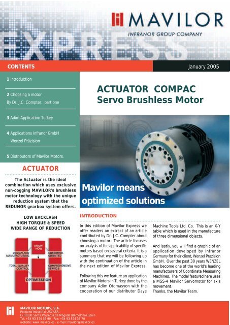
INTRODUCTION<br />
In this edition of <strong>Mavilor</strong> Express we<br />
offer readers an extract of an article<br />
contributed by Dr. J.C. Compter about<br />
choosing a motor. The article focuses<br />
on analysis of the applicability of specific<br />
motors based on several criteria. It is a<br />
summary that we will be following up<br />
with the continuation of the article in<br />
the next edition of <strong>Mavilor</strong> Express.<br />
Following this we feature an application<br />
of <strong>Mavilor</strong> <strong>Motor</strong>s in Turkey done by the<br />
company Adim Otomasyon with the<br />
cooperation of our distributor Daye<br />
Machine Tools Ltd. Co. This is an X-Y<br />
table which is used in the manufacture<br />
of three dimensional objects.<br />
And lastly, you will find a graphic of an<br />
application developed by Infranor<br />
Germany for their client, Wenzel Prazision<br />
GmbH. Over the past 30 years WENZEL<br />
has become one of the world's leading<br />
manufacturers of Coordinate Measuring<br />
Machines. The model featured here uses<br />
a MSS-4 <strong>Mavilor</strong> <strong>Servo</strong>motor for axis<br />
movement.<br />
Thanks, the <strong>Mavilor</strong> Team.<br />
MAVILOR MOTORS, S.A.<br />
Polígono Industrial URVASA,<br />
E- 08130 Santa Perpètua de Mogoda (Barcelona) Spain<br />
Tel. +34 93 574 36 90 - Fax: +34 93 574 35 70<br />
website: www.mavilor.es - e-mail: mavilor@mavilor.es
Choosing a motor. by Dr. J.C. Compter<br />
This article is a short extract of "choosing a motors" the rest of the article will be published in the next issue of <strong>Mavilor</strong><br />
Express.<br />
The process of choosing a motor is preceded by an analysis of the load ; this analysis must at<br />
least provide an answer to :<br />
1) maximum speed<br />
2) maximum torque required<br />
3) the period of time of the motor torque<br />
4) in combination with a transmission 1 :n Y/N<br />
A standpoint must also be taken<br />
as regards :<br />
1) main emphasis on<br />
operational reliability or<br />
performance<br />
2) is the cost price important<br />
and if so, what then is the<br />
budget for the complete<br />
drive, consisting of the<br />
transducers, amplifier,<br />
motor and any<br />
transmission ?<br />
3) standardisation<br />
4) preference for a brand<br />
5) space restrictions<br />
6) requirements of motor<br />
temperature and the<br />
environment<br />
7) weight restrictions<br />
8) preference for a particular<br />
type of servomotor<br />
9) a protection class<br />
desirable (splashproof,<br />
explosion-proof…)<br />
10) reliability and life<br />
11) imbalance vibrations,<br />
cogging, noise,<br />
electromagnetic radiation<br />
12) requirements of the<br />
bearings<br />
13) mounting on a frame by<br />
<strong>means</strong> of a flange, screw<br />
thread, etc.<br />
14) method of connection,<br />
integral temperature<br />
sensor.<br />
These points are not listed in any<br />
particular order ; their priority is<br />
usually determined by the<br />
application.<br />
Following this preparatory work,<br />
we can look at different motors.<br />
Analysing the aplicability of a<br />
motor is generally a timeconsuming<br />
process ; a number of<br />
suppliers have therefore<br />
developed software that can<br />
present realistic choices on the<br />
basis of a database and a<br />
questionnaire. The Motsel<br />
program is one such example.<br />
We shall now consider the criteria<br />
employed in software of this kind.<br />
Torque, speed and the area of<br />
activity<br />
As we have previously indicated,<br />
a motor is characterised by a<br />
torque-speed relationship (see Fig.<br />
6.1). Remember that this<br />
relationship goes with a particular<br />
motor temperature, because the<br />
motor resistance and K-factor are<br />
temperature-dependent.<br />
The purpose of a motor is the<br />
delivery of mechanical power ; this<br />
power is given by :<br />
With<br />
it is easy to establish that the<br />
maximum power Popt is delivered<br />
at :<br />
and then is equal to :<br />
Fig. 6.2 shows the curve of the<br />
output power as a function of the<br />
torque. The interpretation of this<br />
figure requires some explanation.<br />
Let´s say that the motor sets itself<br />
to the speed indicated under the<br />
2
<strong>Mavilor</strong> Express - Núm. 26 - January 2005<br />
influence of the load. A certain<br />
motor torque goes with it<br />
(readable via the horizontal line).<br />
Finally, an output power Pout goes<br />
with this torque.<br />
The efficiency of the drive is also<br />
a factor. If we include both a static<br />
friction Tf and a viscous friction<br />
Td =ωd, then we have :<br />
Following substitution we have :<br />
with Ts the stall torque.<br />
As shown in Fig. 6.3, a point on<br />
the torque-speed curve T-n can<br />
therefore be indicated where the<br />
motor has maximum efficiency.<br />
By way of substitutions and<br />
differentiation of the efficiency to<br />
the torque T we can prove that a<br />
maximum efficiency Pshaft/Pin is<br />
obtained at :<br />
and<br />
In choosing a motor we have to<br />
find a compromise between<br />
efficiency and output power.<br />
Giving priority to efficiency leads<br />
to a larger motor. In Fig. 6.3 a<br />
good compromise can usually be<br />
found inside the range given by<br />
the two points marked on the<br />
maximum torque-speed curve and<br />
the origin.<br />
In a servo system however the<br />
motor voltage is not fixed ; the<br />
controller will supply the motor<br />
with a varying voltage by way of<br />
the output amplifier. Fig. 6.4<br />
shows along which lines the points<br />
Popt and nopt move.<br />
Given the aforementioned<br />
compromise, the motor working<br />
point will preferably lie between<br />
the line of maximum efficiency<br />
and output in Fig. 6.4.<br />
Combining Fig. 6.4 with Fig. 3.12<br />
gives us Fig. 6.5. SOA stands for<br />
Safe Operation Area, preferably<br />
operate betweeen the Popt and<br />
hopt line to combine an<br />
acceptable efficiency and a high<br />
output power. Additionally one<br />
has to reconsider the motor<br />
chosen when the worst case<br />
operation point can be found<br />
under the T-ω line belonging to<br />
0.5 Unom (motor under loading).<br />
Within Philips on also prevents to<br />
exceed momentarily the T25-line<br />
; this is based on a questionable<br />
carefulness ; the more one knows<br />
concerning the application and<br />
motor one can shift this limitation<br />
upwards. Finally remains the area<br />
with a dashed contour as preferred<br />
operation area.<br />
Steepness<br />
Here we define the steepness of<br />
a motor as K*K/R. This is one of<br />
the most important motor<br />
parameters, because it can be<br />
found in the equations :<br />
* dissipation<br />
* mechanical time constant<br />
* speed versus torque<br />
* maximum continuous torque<br />
3
*the position of maximum<br />
efficiency<br />
When the terminals of a motor are<br />
short circuited one will notice that<br />
the motor acts as a viscous brake<br />
with S as the ratio between the<br />
torque and radial speed (prove<br />
this).<br />
For servo technology a high value<br />
of S is attractive, because it leads<br />
to less dissipation at a given<br />
torque, a lower mechanical time<br />
constant, a higher permissible<br />
torque.<br />
Load Cases<br />
Static Load<br />
If the servo loop has the task of<br />
driving load at an almost constant<br />
torque and speed (a static load),<br />
it is easy to show in fig. 6.4 where<br />
the working point of the motor is.<br />
Verification of the maximum<br />
permissible value of the torque<br />
and the speed is followed by a<br />
check on Trms, which must be less<br />
than T100. And if the point Trms/<br />
nominal speed is also between the<br />
lines of Popt and çopt, then we<br />
have a suitable motor.<br />
If this is not the case, a<br />
transmission can provide a<br />
solution. Let´s say that we have<br />
the working point 1 in Fig. 6.6. For<br />
the mechanical power we have<br />
Pout=ùload.Tload.A transmission<br />
(without losses) with a<br />
transmission ratio i leads to<br />
Tmotor= ùload/i. The result is<br />
that, depending on the value of i,<br />
a different point on the curvein<br />
Fig. 6.6 can be used.<br />
With static loads we have<br />
complete freedom to choolse such<br />
a transmission ratio that the<br />
efficiency for example is at a<br />
maximum or it is possible for<br />
example to suffice with a(n)<br />
(available) supply voltage.<br />
Dynamic Load<br />
Contrasting with this static load is<br />
the pure dynamic load, which is<br />
characterised by a load torque that<br />
is only used for the constant<br />
acceleration and deceleration of<br />
the load and motor. This <strong>means</strong><br />
that the moments of inertia of load<br />
and motor in combination with the<br />
desired accelerations determine<br />
the motor torque required. With<br />
a transmission ratio i, the torque<br />
required is as follows :<br />
The transmission ratio i largely<br />
determines what torque the motor<br />
must deliver. Since the cost price<br />
of a motor and the maximum<br />
torque are closely linked, a low<br />
torque is preferable.<br />
The question now is what<br />
transmission ratio i must be<br />
chosen in order that a minimum<br />
torque T suffices. Depending on<br />
the load, the curve of the motor<br />
torque as a function of the<br />
transmission ratio can be a flat<br />
or a strong minimum (see Fig.<br />
6.7). Differentiation of the above<br />
equation to ùmotor leads to the<br />
condition that is known as<br />
¨INERTIAL MATCH¨.<br />
With i =ωmotor/ωmotor<br />
gives us :<br />
The solution is :<br />
The fact that there<br />
is a minimum can<br />
be explained as<br />
follows : if an<br />
extremely large<br />
transmission ratio<br />
i is chosen, the<br />
term in equation<br />
(105) with the<br />
moment of intertia<br />
of the load will<br />
predominate and<br />
the torque will grow<br />
proportionately to i. This leads<br />
to an initial conclusion : reduce<br />
i. If this were to go too far, then<br />
the term in the formula<br />
4
<strong>Mavilor</strong> Express - Núm. 26 - January 2005<br />
with the motor moment of inertia<br />
would predominate. The reason<br />
is that with a low i the angular<br />
velocity of the motor is high, so<br />
that a lot of energy has to be<br />
expended on the<br />
acceleration/deceleration of the<br />
motor.<br />
The curve of the motor torque as<br />
a fuction of i is an hyperbola ( : l/i)<br />
at low values of i, which leads to<br />
the conclusion : increase i. Result_<br />
somewhere there is an optimum.<br />
Show that the motor sees as load<br />
torque T :<br />
The procedure to follow to see<br />
whether a particular motor is<br />
suitable for this dynamic load :<br />
1) Determine the<br />
transmission ratio that<br />
goes with the ¨Inertial<br />
Match¨.<br />
2) Process the moment of<br />
inertia of a suitable<br />
transmission (seen from<br />
the motor side) in the total<br />
moment of inertia and<br />
over one or more strokes<br />
see whether the ¨Inertial<br />
Match¨can be achieved in<br />
combination with the<br />
available transmissions.<br />
3) After 2) are all the<br />
working points of the<br />
motor inside the SOA ?<br />
(maximum torque,<br />
maximum speed ; this<br />
point is also called ¨Worstcase<br />
operation point¨).<br />
4) Is Trms less than T100?<br />
Since T100 falls at<br />
elevated speeds with<br />
electronically<br />
commutated motors, a<br />
safe design is obtained if<br />
the value of T100 at the<br />
maximum speed<br />
occurring in the design is<br />
compared with Trms.<br />
It is recommended that the<br />
curve of the motor torque be<br />
drawn as a function of the<br />
transmission ratio, because<br />
depending on motor<br />
moment of inertia,<br />
mechanical time<br />
constant and<br />
required acceleration<br />
for example there<br />
can be a flat area<br />
around the optimum.<br />
Analysis of the open<br />
loop transfer function<br />
of a servo system<br />
shows that an<br />
advantage can be<br />
obtained by the selection of a<br />
certain ratio between the moments<br />
of inertia of the motor and the load<br />
plus retardation. Choosing equal<br />
ratio or simply deliberately a<br />
relatively light motor also depends<br />
on the position of the sensors. The<br />
dissertation by Mr. Groenguis (TU<br />
Eindhoven) goes into this more<br />
deeply.<br />
Static/Dynamic Hybrid<br />
In a similar fashion to the one<br />
described above a method can be<br />
worked out that describes hybrids.<br />
It requires a good description of<br />
the load. Since the quantity of<br />
calculations is considerable, the<br />
use of a numerical tool is<br />
preferable, because a choice of<br />
motor and transmission ratio must<br />
be determined iteratively. The<br />
value of i that delivers a munimum<br />
torque is affected by the friction<br />
and damping present, so the<br />
¨inertial match¨ is not always the<br />
best solution.<br />
5
ADIM OTOMASYON<br />
Turkey- Istanbul application<br />
With cooperation of our Distributor in Istanbul DAYE MACHINE Ltd. Company.<br />
This Adim Otomasyon application consists of two BLT-74 + one BLT 72 +<br />
two BLT-72 with break and 4 Mesa drives MSD1-MA-3006E<br />
Net working area : 3000*2000*200 mm<br />
Working speed : 35 m/dak. Travelling speed<br />
Mechanical system : 20*20 mm rack-pinion X1-<br />
X2 and Y axis<br />
: 16*10 ball screw on the z axis<br />
: Linear guideway 25 mm for X1 and X2<br />
: Linear guideway 20 mm.for Y Z axis<br />
Router working table : Aluminum slotted vacuum<br />
ready table<br />
<strong>Motor</strong> system : 2,7 Nm nominal torque <strong>Servo</strong><br />
<strong>Motor</strong>.X1-X2 Y axis<br />
: Z axis 1,9 Nm <strong>Servo</strong> <strong>Motor</strong><br />
Control System : Motion board . 4 axis servo<br />
board NEE Controls with integrated<br />
: MHP1 Type handpad.<br />
PC Software : WinAMC HMI operator interface.<br />
For CAD/CAM program uses<br />
: that it has as output file DXF, HPGL or G Code<br />
controller.<br />
Bit cooling : Trico model mist coolant system<br />
Accuracy : +/- 20 mikron<br />
Dust Collection system : 0,75 kw motor power<br />
and dust collection head with complete<br />
: unit .<br />
Machine Body : Fully metallic construction , box<br />
type profile.<br />
6
<strong>Mavilor</strong> Express - Núm. 26 - January 2005<br />
INFRANOR GmbH Application<br />
Client: Wenzel Präzision GmbH<br />
One of the world's leading<br />
manufacturers of Coordinate<br />
Measuring Machines<br />
MSS-4 MAVILOR<br />
SERVOMOTOR for movement<br />
of the axis.<br />
Bridge Type CMM (Coordinate<br />
Measuring Machine)<br />
Wenzel Präzision GmbH<br />
7
<strong>Mavilor</strong> around the World<br />
Our Distributor<br />
Argentina +54 1142225040<br />
Australia +61 733974575<br />
Austria +43 225271110<br />
Brazil +55 152283730<br />
Chile +56 2450 4200<br />
China/Beijing +86 10 8208 0369<br />
China/Shanghai +86 21 5435 4316<br />
China/Guangzhou +86 20 8759 1568<br />
Czech Republic +420 261123187<br />
Denmark +45 43718088<br />
France +33169633515<br />
Germany +49 6181180120<br />
Greece +30 3105566239<br />
Holland +31 186 610 155<br />
Hungary +36 1265 0677<br />
India +91 222 2872211<br />
Iran +98 2139 30203<br />
Israel +972 36470471<br />
Italy +39 266200980<br />
Japan +81 3 5298 2700<br />
Korea +82 27852262<br />
Malaysia +60 52538555<br />
Mexico +55 15 3228 3730<br />
Norway +47 22335301<br />
Russia +7 095 9135161<br />
South Africa +27 114681881<br />
Spain +34 934601631<br />
Sweden +46 21 24860<br />
Switzerland +41 22 960 70 70<br />
Taiwan +886 229145767<br />
Turkey +90 216 641 6884<br />
United Kingdom +44 1522699500<br />
United States +1 2037298258