Installation Guide for Model 700 Flasher - Code 3 Public Safety ...
Installation Guide for Model 700 Flasher - Code 3 Public Safety ...
Installation Guide for Model 700 Flasher - Code 3 Public Safety ...

You also want an ePaper? Increase the reach of your titles
YUMPU automatically turns print PDFs into web optimized ePapers that Google loves.
<strong>Installation</strong> <strong>Guide</strong><br />
<strong>for</strong> <strong>Model</strong> <strong>700</strong> <strong>Flasher</strong><br />
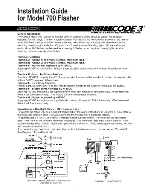
General Description<br />
The <strong>Code</strong> 3 <strong>Model</strong> <strong>700</strong> Alternating <strong>Flasher</strong> uses an electronic timing circuit to control two specially<br />
designed flasher relays. The unit is totally weather resistant and may mounted anywhere on the vehicle<br />
away from heat sources and direct water splashes, using either the mounting tabs at each end or the<br />
mounting hole through the device. Outputs 1 and 2 are capable of handling up to 100 watts (8 amps.)<br />
each. <strong>Model</strong> <strong>700</strong> flasher can be used as a Headlight <strong>Flasher</strong>, a non daytime running lights hot side<br />
switching flasher or as alightbar flasher.<br />
Terminal Functions<br />
Terminal A - Output 1: 100 watts (8 amps.) maximum load.<br />
Terminal B - Output 2: 100 watts (8 amps.) maximum load.<br />
Terminal c - <strong>Flasher</strong> On: Activated by + 12VDC.<br />
Applying +12VDC to this terminal through a user supplied switch activates the alternating flash of loads 1<br />
and 2.<br />
Terminal D - Input: To Battery Positive.<br />
Supplies +12VDC to outputs 1 and 2. A user supplied fuse should be installed to protect the outputs. Use<br />
at least 14AWG wire and 20 amp fuse.<br />
Terminal E - To Battery Negative.<br />
Provides ground <strong>for</strong> the unit. For best results connect directly to the negative terminal of the battery.<br />
Terminal F - Steady burn: Activated by +12VDC<br />
Applying +12VDC through a user supplied switch turns both outputs on simultaneously. When removed,<br />
the unit will function normally. This feature will override all other functions.<br />
Terminal G - Pause: Activated by +12VDC.<br />
Applying +12VDC through a user supplied switch turns both outputs off simultaneously. When removed,<br />
the unit will function normally.<br />
Operation as a Headlight <strong>Flasher</strong> (12v Operation 0nly)<br />
To operate the <strong>Model</strong> <strong>700</strong> as a headlight flasher, follow the wiring instructions of Diagram 1. Also, refer to<br />
the instruction chart on page 2 <strong>for</strong> wire colors and their location <strong>for</strong> a particular vehicle.<br />
To operate, apply +12VDC to terminal C through a user supplied switch. This will start the alternating<br />
flash. Now, turn on the vehicle's low beam headlights. The low beam lights should burn steadily. Now.<br />
activate the highbeam switch. High beam lights should now be on. If you do not get these results, recheck<br />
all connections listed above.<br />
If you wish the high beams to continue to flash while the low beams are on, do not connect Terminal G.<br />
See Diagram 1 <strong>for</strong> additional help.<br />
- +<br />
DIAGRAM 1: WIRING DIAGRAM FOR HEAD LIGHT<br />
FLASHER INSTALLATION<br />
DIAGRAM 2: 24v OPERATION<br />
1
Operation as a Light Bar <strong>Flasher</strong><br />
To operate the <strong>Model</strong> <strong>700</strong> as a light bar flasher, jumper Terminal C to Terminal D and connect<br />
these to +12VDC in the bar. Connect one bulb to be flashed to Terminal A and the other bulb to be<br />
flashed to Terminal B. Connect Terminal E to the frame of the light bar to provide ground.<br />
The remaining terminals may be used <strong>for</strong> special functions when switched to +12VDC. Terminal G<br />
will "pause" or turn off the lamps until power is removed. Terminal F will steady burn the bulbs <strong>for</strong><br />
use as take down or work lights until power is removed. See the wiring diagram on the bottom of<br />
the unit <strong>for</strong> further assistance.<br />
WARRANTY<br />
This product was tested and found to be operational at the time of manufacture. Provided this product is<br />
installed and operated in accordance with the manufacturer's recommendations, <strong>Public</strong> <strong>Safety</strong> Equipment<br />
guarantees all parts and components except the lamps <strong>for</strong> a period of 1 year from the date of purchase or<br />
delivery, whichever is later. Units demonstrated to be defective within the warranty period will be repaired or<br />
replaced at the factory service center at no cost.<br />
Use of a lamp or other electrical load of a wattage higher than installed or recommended by the factory,<br />
or use of inappropriate or inadequate wiring or circuit protection causes this warranty to become void. Failure<br />
or destruction of the product resulting from abuse or unusual use and/or accidents is not covered by this<br />
warranty.<br />
PSE shall in no way be liable <strong>for</strong> other damages including consequential, indirect or special damages<br />
whether loss is due to negligence or breach of warranty.<br />
PSE MAKES NO OTHER EXPRESS OR IMPLIED WARRANTY INCLUDING, WITHOUT LIMITA-<br />
TION, WARRANTIES OF FITNESS OR MERCHANTABILITY, WITH RESPECT TO THIS PRODUCT.<br />
PRODUCT RETURNS<br />
In order to provide you with faster service, if you are going to return a product <strong>for</strong> repair or replacement*,<br />
please contact our factory to obtain a Return Goods Authorization Number (RGA number) be<strong>for</strong>e you ship the<br />
product to PSE. Write the RGA number clearly on the package near the mailing label. Be sure you use<br />
sufficient packing materials to avoid damage to the product being returned while in transit.<br />
*PSE reserves the right to repair or replace product at its discretion. PSE assumes no responsibility or liability <strong>for</strong> expenses<br />
incurred <strong>for</strong> the removal and/or reinstallation of products requiring service and/or repair.<br />
<strong>Public</strong> <strong>Safety</strong> Equipment, Inc.<br />
10986 N. Warson Road<br />
St. Louis, Missouri 63114-2029—USA<br />
Ph. (314) 426-2<strong>700</strong> Fax (314) 426-1337<br />
www.code3pse.com<br />
Revision 8, 7/01- Instruction Book Part No. T01935<br />
©2001 <strong>Public</strong> <strong>Safety</strong> Equipment, Inc. Printed in USA<br />
2
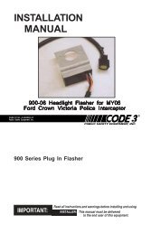
INSTALLATION<br />
& OPERATION<br />
MANUAL<br />
MODELS 710 & 711<br />
MULTIPLE MODE<br />
FLASHERS<br />
MODELS 710 & 711 MULTIPLE<br />
MODE FLASHERS<br />
Contents:<br />
Introduction ......................................................... 2<br />
Unpacking & Pre-<strong>Installation</strong> .............................. 2<br />
<strong>Installation</strong> & Mounting ....................................... 2<br />
Mounting Methods ............................................ 2<br />
Terminal Functions ........................................... 3<br />
Operation as a Headlight <strong>Flasher</strong>....................... 4<br />
Flash Mode 1 <strong>Installation</strong> .................................. 4<br />
Flash Mode 2 <strong>Installation</strong> .................................. 4<br />
Wiring Diagram ................................................... 4<br />
Testing the Circuits <strong>for</strong> <strong>Flasher</strong> Modes 1 and 2 .. 5<br />
Operation as a Lightbar <strong>Flasher</strong> ......................... 5<br />
Warranty ............................................................. 6<br />
IMPORTANT:<br />
Read all instructions and warnings be<strong>for</strong>e installing and using.<br />
INSTALLER: This manual must be delivered to the end user of this equipment.<br />
1
Introduction<br />
The <strong>Code</strong> 3 ® <strong>Model</strong> 710 and 711 multiple mode flashers use an electronic timing circuit to control two<br />
specially designed flasher relays. Both models can be used as a headlight flasher, non daytime running<br />
lights hot side switching flasher or as a light bar flasher with steady burn override capability. The units<br />
allow the user one of two different headlight flasher patterns. You may use either or both patterns<br />
depending on installation.<br />
!<br />
WARNING!<br />
The use of this or any warning device does not insure that all drivers can or will observe or<br />
react to an emergency warning signal. Never take the right-of-way <strong>for</strong> granted. It is your<br />
responsibility to be sure you can proceed safely be<strong>for</strong>e entering an intersection, driving<br />
against traffic, responding at a high rate of speed, or walking on or around traffic lanes.<br />
The effectiveness of this warning device is highly dependent upon correct mounting and<br />
wiring. Read and follow the manufacturer’s instructions be<strong>for</strong>e installing or using this<br />
device. The vehicle operator should insure daily that all features of the device operate<br />
correctly. In use, the vehicle operator should insure the projection of the warning signal is<br />
not blocked by vehicle components (i.e.: open trunks or compartment doors), people,<br />
vehicles, or other obstructions.<br />
This equipment is intended <strong>for</strong> use by authorized personnel only. It is the user’s responsibility<br />
to understand and obey all laws regarding emergency warning devices. The user<br />
should check all applicable city, state and federal laws and regulations.<br />
<strong>Public</strong> <strong>Safety</strong> Equipment, Inc., assumes no liability <strong>for</strong> any loss resulting from the use of<br />
this warning device.<br />
Proper installation is vital to the per<strong>for</strong>mance of this warning device and the safe operation<br />
of the emergency vehicle. It is important to recognize that the operator of the emergency<br />
vehicle is under psychological and physiological stress caused by the emergency situation.<br />
The warning device should be installed in such a manner as to: A) Not reduce the output<br />
per<strong>for</strong>mance of the system, B) Place the controls within convenient reach of the operator<br />
so that he can operate the system without losing eye contact with the roadway.<br />
Emergency warning devices often require high electrical voltages and/or currents. Properly<br />
protect and use caution around live electrical connections. Grounding or shorting of<br />
electrical connections can cause high current arcing, which can cause personal injury and/<br />
or severe vehicle damage, including fire. Incandescent lamps are extremely hot, allow to<br />
cool completely be<strong>for</strong>e attempting to remove.<br />
Any electronic device may create or be affected by electromagnetic interference. After<br />
installation of any electronic device operate all equipment simultaneously to insure that<br />
operation is free of interference. Never power emergency warning equipment from the<br />
same circuit or share the same grounding circuit with radio communication equipment.<br />
PROPER INSTALLATION COMBINED WITH OPERATOR TRAINING IN THE PROPER<br />
USE OF EMERGENCY WARNING DEVICES IS ESSENTIAL TO INSURE THE SAFETY<br />
OF EMERGENCY PERSONNEL AND THE PUBLIC.<br />
Unpacking & Pre-installation<br />
After unpacking your 710 or 711 Multiple Mode <strong>Flasher</strong>, carefully inspect the unit and associated parts <strong>for</strong> any<br />
damage that may have been caused in transit. Report any damage to the carrier immediately.<br />
<strong>Installation</strong> & Mounting<br />
Mounting Methods<br />
The units can be mounted using either the mounting tabs located at each end of the unit or the mounting<br />
hole through the unit.<br />
CAUTION: The units must be mounted away from heat sources and water splashes.<br />
!<br />
WARNING!<br />
Terminal Functions<br />
All devices should be mounted in accordance with the manufacturer's instructions and<br />
securely fasten to vehicle elements of sufficient strength to withstand the <strong>for</strong>ces applied to<br />
the device. Driver and/or passenger air bags (SRS) will affect the way equipment should<br />
be mounted. This device should be mounted by permanent installation and within the<br />
zones specified by the vehicle manufacturer, if any. Any device mounted in the deployment<br />
area of an air bag will damage or reduce the effectiveness of the air bag and may<br />
damage or dislodge the device. Installer must be sure that this device, its mounting<br />
hardware and electrical supply wiring does not interfere with the air bag or the SRS wiring<br />
or sensors. Front or rear grille/bumper placement must avoid interference with SRS<br />
sensors. Mounting the unit inside the vehicle by a method other than the permanent<br />
installation is not recommended as unit may become dislodged during swerving, sudden<br />
braking, or collision. Failure to follow instructions can result in personal injury.<br />
2
!<br />
WARNING!<br />
Larger wires and tight connections will provide longer service life <strong>for</strong> components. For high<br />
current wires it is highly recommended that terminal blocks or soldered connections be used<br />
with shrink tubing to protect the connections. Do not use insulation displacement<br />
connectors (e.g. 3M ® Scotchlock type connectors). Route wiring using grommets and<br />
sealant when passing through compartment walls. Minimize the number of splices to<br />
reduce voltage drop. High ambient temperatures (e.g. underhood) will significantly reduce<br />
the current carrying capacity of wires, fuses, and circuit breakers. Use "SXL" type wire in<br />
engine compartment. All wiring should con<strong>for</strong>m to the minimum wire size and other<br />
recommendations of the manufacturer and be protected from moving parts and hot<br />
surfaces. Looms, grommets, cable ties, and similar installation hardware should be used to<br />
anchor and protect all wiring.<br />
Fuses or circuit breakers should be located as close to the power takeoff points as possible<br />
and properly sized to protect the wiring and devices.<br />
Particular attention should be paid to the location and method of making electrical<br />
connections and splices to protect these points from corrosion and loss of conductivity.<br />
Ground terminations should only be made to substantial chassis components, preferably<br />
directly to the vehicle battery.<br />
The user should install a fuse sized to approximately 125% of the maximum Amp capacity<br />
in the supply line to protect against short circuits. For example, a 30 Amp fuse should<br />
carry a maximum of 24 Amps. DO NOT USE 1/4" DIAMETER GLASS FUSES AS THEY<br />
ARE NOT SUITABLE FOR CONTINUOUS DUTY IN SIZES ABOVE 15 AMPS. Circuit<br />
breakers are very sensitive to high temperatures and will "false trip" when mounted in hot<br />
environments or operated close to their capacity.<br />
Terminal A - Input: Battery Positive.<br />
Supplies Outputs 1 and 2 with +12VDC. The Unit should be fused with a user supplied 20 amp. fuse and<br />
wired with #14 AWG wire minimum.<br />
Terminal B - Mode #1: Activated by +12VDC.<br />
Begins flashing of Outputs 1 and 2 in Mode #1 when supplied with +12VDC through a user supplied<br />
switch.<br />
Terminal C - Output 1: 100 Watt (8 amps) Maximum.<br />
Terminal D - Output 2: 100 Watt (8 amps) Maximum.<br />
Terminal E - Steady Burn: Both Outputs ON.<br />
When activated by +12VDC through a user supplied switch, both outputs will turn on simultaneously. This<br />
steady burn feature will override all other features of this unit.<br />
Terminal F - Pause: Both Outputs OFF.<br />
When activated by +12VDC through a user supplied switch, both outputs will turn off simultaneously, as<br />
long as terminal F remains powered. Connect to vehicle low beam circuit to defeat flasher at night. This is<br />
an OPTIONAL connection.<br />
Terminal G - Flash Mode #2.<br />
When activated by +12VDC through a user supplied switch, the unit flashes in pattern #2. This is an<br />
OPTIONAL connection.<br />
Terminal H - To Battery Negative (-).<br />
Provides the unit with ground (earth) to complete the circuit. For best results, connect directly to the<br />
negative (-) terminal of the battery, or in light bar applications, connect to the light bar frame ground<br />
(earth).rotect all wiring.<br />
3
Operation as a Headlight <strong>Flasher</strong> (12v Operation only)<br />
Flash Mode 1 <strong>Installation</strong><br />
To operate the <strong>Model</strong> 710 or 711 as a high beam headlight flasher, refer to Figure 1 while following the<br />
steps below:<br />
NOTE: Use #14 AWG wire (minimum) <strong>for</strong> all connections.<br />
1) Mount the <strong>Flasher</strong> Unit in a convenient location away from direct heat sources or water<br />
splashes. A common location is the drivers side fenderwell. Use either mounting method<br />
mentioned under “Mounting Methods,” above.<br />
2) Connect a 20 amp. fuse and holder in-line between the positive (+) post of the battery and<br />
Terminal A of the <strong>Flasher</strong> Unit.<br />
CAUTION: Leave the fuse out of the fuse holder until ready to test the circuit.<br />
3) Install a user supplied switch in a convenient location on the instrument panel near the driver.<br />
4) Connect the user supplied switch between the positive post of the battery and Terminal B of<br />
the <strong>Flasher</strong> Unit.<br />
NOTE: Refer also to Figure 1A <strong>for</strong> Steps 5 and 6.<br />
5) Connect the left headlight high beam to Terminal C of the <strong>Flasher</strong> Unit.<br />
6) Connect the right headlight high beam to Terminal D of the <strong>Flasher</strong> Unit.<br />
7) Connect the vehicle’s high beam switch to Terminal E of the <strong>Flasher</strong> Unit.<br />
8) (OPTIONAL) Connect the vehicle’s low beam switch to Terminal F of the <strong>Flasher</strong> Unit.<br />
NOTE: For continued high beam flash while in low beam, do not connect Terminal F.<br />
9) Connect the negative (-) post of the battery, or other good ground(earth), to Terminal H of the<br />
<strong>Flasher</strong> Unit.<br />
Double check all of your connections then refer to the section on testing the circuit.<br />
Flash Mode 2 <strong>Installation</strong> (OPTIONAL)<br />
To operate the <strong>Model</strong> 710 or 711 in a high beam alternating flash pattern, per<strong>for</strong>m the following steps:<br />
1) Install a user supplied switch in a convenient location on the instrument panel near the driver.<br />
2) Connect the user supplied switch between the positive (+) post of the battery and Terminal G<br />
of the <strong>Flasher</strong> Unit.<br />
FOR CONTINUED HIGH BEAM<br />
FLASH WHILE IN LOW<br />
BEAM. DO NOT USE<br />
TERMINAL F<br />
VEHICLE'S LOW BEAM SWITCH<br />
NEGATIVE<br />
MODE #2<br />
LOW<br />
HIGH<br />
H<br />
G<br />
F<br />
E<br />
VEHICLE'S HIGH BEAM SWITCH<br />
RIGHT HIGH BEAM<br />
CUT HERE<br />
FROM VEHICLE'S<br />
HIGH BEAM SWITCH<br />
RIGHT HIGH BEAM<br />
CODE 3<br />
D<br />
C<br />
B<br />
A<br />
20 AMP<br />
FUSE<br />
FLASHER ON - MODE #1<br />
14 AWG MIN.<br />
Ñ +<br />
BATTERY<br />
LEFT HIGH BEAM<br />
FIGURE 1: WIRING DIAGRAM FOR<br />
HEADLIGHT FLASHER INSTALLATION<br />
CUT HERE<br />
LEFT HIGH BEAM<br />
FIGURE 1A: SUPPLEMENTAL DIAGRAM<br />
FOR HEADLIGHT FLASHER INSTALLATION<br />
4
Testing the Circuits <strong>for</strong> Headlight <strong>Flasher</strong> Modes 1 and 2.<br />
Mode 1 Test<br />
1) Install the 20 amp. fuse in the in-line fuse holder.<br />
2) Turn ON the switch <strong>for</strong> Mode 1 operation. The high beam headlights should flash, the<br />
pattern is dependent on flasher model.<br />
Double check all of your connections then refer to the section on testing the circuit.<br />
3) Turn ON the vehicle’s low beam headlights. The low beams should burn steady.<br />
NOTE: If you connected Terminal F, the headlight flasher will go off when you turn on the low beams. If you<br />
want the high beams to continue to flash, DO NOT connect Terminal F.<br />
4) Turn ON the vehicle’s high beams. The high beams should now be on.<br />
If the circuits do not work according to the above description, recheck all of your connections.<br />
Mode 2 Test<br />
1) Install the 20 amp. fuse in the in-line fuse holder.<br />
2) Turn ON the switch <strong>for</strong> Mode 2 operation. The headlights should flash simultaneously.<br />
If the circuits do not work according to the above description, recheck all of your connections.<br />
FIGURE2<br />
24V OPERATION<br />
Operation as a Light Bar <strong>Flasher</strong>.<br />
To operate the <strong>Model</strong> 710 or 711 as a light bar flasher, per<strong>for</strong>m the following steps:<br />
1) Jumper Terminal A to Terminal B and connect these to +12VDC in the light bar.<br />
2) Connect one bulb to be flashed to Terminal C and the other bulb to be flashed to Terminal D.<br />
3) Connect Terminal H to the frame of the light bar to provide ground (earth).<br />
NOTE: The remaining Terminals may be used <strong>for</strong> special functions when switched to +12VDC.<br />
• Terminal E will “pause” or turn OFF the lamp until power is removed.<br />
• Terminal F will steady burn the bulbs <strong>for</strong> use as takedown or work lights until power<br />
is removed. To operate as takedowns, power must be applied to +12VDC, A and B<br />
input terminals.<br />
• Terminal G flashes the bulbs in a different flash pattern until power is removed.<br />
Refer to the wiring diagram on the bottom of the unit <strong>for</strong> further assistance.<br />
5
NOTES
WARRANTY<br />
This product was tested and found to be operational at the time of manufacture. Provided this product is<br />
installed and operated in accordance with the manufacturer's recommendations, <strong>Public</strong> <strong>Safety</strong> Equipment<br />
guarantees all parts and components except the lamps <strong>for</strong> a period of 1 year from the date of purchase or<br />
delivery, whichever is later. Units demonstrated to be defective within the warranty period will be repaired or<br />
replaced at the factory service center at no cost.<br />
Use of a lamp or other electrical load of a wattage higher than installed or recommended by the factory,<br />
or use of inappropriate or inadequate wiring or circuit protection causes this warranty to become void. Failure<br />
or destruction of the product resulting from abuse or unusual use and/or accidents is not covered by this<br />
warranty.<br />
PSE shall in no way be liable <strong>for</strong> other damages including consequential, indirect or special damages<br />
whether loss is due to negligence or breach of warranty.<br />
PSE MAKES NO OTHER EXPRESS OR IMPLIED WARRANTY INCLUDING, WITHOUT LIMITA-<br />
TION, WARRANTIES OF FITNESS OR MERCHANTABILITY, WITH RESPECT TO THIS PRODUCT.<br />
PRODUCT RETURNS<br />
In order to provide you with faster service, if you are going to return a product <strong>for</strong> repair or replacement*,<br />
please contact our factory to obtain a Return Goods Authorization Number (RGA number) be<strong>for</strong>e you ship the<br />
product to PSE. Write the RGA number clearly on the package near the mailing label. Be sure you use<br />
sufficient packing materials to avoid damage to the product being returned while in transit.<br />
*PSE reserves the right to repair or replace product at its discretion. PSE assumes no responsibility or liability <strong>for</strong> expenses<br />
incurred <strong>for</strong> the removal and/or reinstallation of products requiring service and/or repair.<br />
<strong>Public</strong> <strong>Safety</strong> Equipment, Inc.<br />
10986 N. Warson Road<br />
St. Louis, Missouri 63114-2029—USA<br />
Ph. (314) 426-2<strong>700</strong> Fax (314) 426-1337<br />
www.code3pse.com<br />
Revision 9, 7/0 - Instruction Book Part No. T01973<br />
©2001 <strong>Public</strong> <strong>Safety</strong> Equipment, Inc. Printed in USA