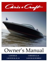
Catalina Owner's Manual - Chris Craft
Catalina Owner's Manual - Chris Craft
Catalina Owner's Manual - Chris Craft

You also want an ePaper? Increase the reach of your titles
YUMPU automatically turns print PDFs into web optimized ePapers that Google loves.
white text
Table of Contents<br />
CHAPTER 1 Introduction. . . . . . . . . . . . . . . . . . . . . . . . . . . . . . . . . . . . . . . . . . . . . . . . . . . . 1–1<br />
The Owner’s <strong>Manual</strong> . . . . . . . . . . . . . . . . . . . . . . . . . . . . . . . . . . . . . . . . . . . . . . . . . . . . . . . . . . . . . . 1–2<br />
What This <strong>Manual</strong> Covers. . . . . . . . . . . . . . . . . . . . . . . . . . . . . . . . . . . . . . . . . . . . . . . . . . . . . . . . . 1–3<br />
General Specifications . . . . . . . . . . . . . . . . . . . . . . . . . . . . . . . . . . . . . . . . . . . . . . . . . . . . . . . . . . . . . 1–4<br />
Performance . . . . . . . . . . . . . . . . . . . . . . . . . . . . . . . . . . . . . . . . . . . . . . . . . . . . . . . . . . . . . . . . . . . 1–4<br />
Engine Performance . . . . . . . . . . . . . . . . . . . . . . . . . . . . . . . . . . . . . . . . . . . . . . . . . . . . . . . . . . . . . 1–5<br />
Weight Conversions . . . . . . . . . . . . . . . . . . . . . . . . . . . . . . . . . . . . . . . . . . . . . . . . . . . . . . . . . . . . . 1–5<br />
Design Category. . . . . . . . . . . . . . . . . . . . . . . . . . . . . . . . . . . . . . . . . . . . . . . . . . . . . . . . . . . . . . . . . . 1–6<br />
Component Manufacturers. . . . . . . . . . . . . . . . . . . . . . . . . . . . . . . . . . . . . . . . . . . . . . . . . . . . . . . . . 1–13<br />
CHAPTER 2 Safety and Operations . . . . . . . . . . . . . . . . . . . . . . . . . . . . . . . . . . . . . . . . . . . 2–1<br />
Warning Placards and Labels . . . . . . . . . . . . . . . . . . . . . . . . . . . . . . . . . . . . . . . . . . . . . . . . . . . . . . . 2–4<br />
Boating Safety . . . . . . . . . . . . . . . . . . . . . . . . . . . . . . . . . . . . . . . . . . . . . . . . . . . . . . . . . . . . . . . . . . . 2–6<br />
General Safety Precautions . . . . . . . . . . . . . . . . . . . . . . . . . . . . . . . . . . . . . . . . . . . . . . . . . . . . . . . 2–7<br />
Boating Courses . . . . . . . . . . . . . . . . . . . . . . . . . . . . . . . . . . . . . . . . . . . . . . . . . . . . . . . . . . . . . . 2–8<br />
Basic Seamanship . . . . . . . . . . . . . . . . . . . . . . . . . . . . . . . . . . . . . . . . . . . . . . . . . . . . . . . . . . . . . 2–8<br />
Meeting Situations . . . . . . . . . . . . . . . . . . . . . . . . . . . . . . . . . . . . . . . . . . . . . . . . . . . . . . . . . . . 2–8<br />
Visual Obstructions . . . . . . . . . . . . . . . . . . . . . . . . . . . . . . . . . . . . . . . . . . . . . . . . . . . . . . . . . . . 2–10<br />
Propeller Safety . . . . . . . . . . . . . . . . . . . . . . . . . . . . . . . . . . . . . . . . . . . . . . . . . . . . . . . . . . . . . . 2–10<br />
Boating Regulations and Requirements. . . . . . . . . . . . . . . . . . . . . . . . . . . . . . . . . . . . . . . . . . . . . . . 2–11<br />
U.S. Coast Guard Boating Safety Hotline . . . . . . . . . . . . . . . . . . . . . . . . . . . . . . . . . . . . . . . . . . . . 2–11<br />
Supplemental Federal, State or Local Regulations . . . . . . . . . . . . . . . . . . . . . . . . . . . . . . . . . . . 2–11<br />
Alcohol and Drugs . . . . . . . . . . . . . . . . . . . . . . . . . . . . . . . . . . . . . . . . . . . . . . . . . . . . . . . . . . . . 2–12<br />
Accident Reporting . . . . . . . . . . . . . . . . . . . . . . . . . . . . . . . . . . . . . . . . . . . . . . . . . . . . . . . . . . . 2–12<br />
Rendering Assistance . . . . . . . . . . . . . . . . . . . . . . . . . . . . . . . . . . . . . . . . . . . . . . . . . . . . . . . . . 2–13<br />
Vessel Maintenance . . . . . . . . . . . . . . . . . . . . . . . . . . . . . . . . . . . . . . . . . . . . . . . . . . . . . . . . . . . . 2–13<br />
Load Capacity . . . . . . . . . . . . . . . . . . . . . . . . . . . . . . . . . . . . . . . . . . . . . . . . . . . . . . . . . . . . . . . . . 2–13<br />
<strong>Chris</strong>-<strong>Craft</strong><br />
i
Table of Contents<br />
Safety Equipment . . . . . . . . . . . . . . . . . . . . . . . . . . . . . . . . . . . . . . . . . . . . . . . . . . . . . . . . . . . . . . . 2–14<br />
Personal Flotation Devices (PFDs) . . . . . . . . . . . . . . . . . . . . . . . . . . . . . . . . . . . . . . . . . . . . . . . . . 2–15<br />
Types of PFDs . . . . . . . . . . . . . . . . . . . . . . . . . . . . . . . . . . . . . . . . . . . . . . . . . . . . . . . . . . . . . . . 2–16<br />
Foam Class PFDs . . . . . . . . . . . . . . . . . . . . . . . . . . . . . . . . . . . . . . . . . . . . . . . . . . . . . . . . . . . . 2–17<br />
Inflatable Class PFDs . . . . . . . . . . . . . . . . . . . . . . . . . . . . . . . . . . . . . . . . . . . . . . . . . . . . . . . . . 2–17<br />
Hybrid Class PFDs . . . . . . . . . . . . . . . . . . . . . . . . . . . . . . . . . . . . . . . . . . . . . . . . . . . . . . . . . . . 2–17<br />
PFD Considerations. . . . . . . . . . . . . . . . . . . . . . . . . . . . . . . . . . . . . . . . . . . . . . . . . . . . . . . . . . . 2–18<br />
Additional Equipment . . . . . . . . . . . . . . . . . . . . . . . . . . . . . . . . . . . . . . . . . . . . . . . . . . . . . . . . . . . 2–19<br />
Visual Distress Signals . . . . . . . . . . . . . . . . . . . . . . . . . . . . . . . . . . . . . . . . . . . . . . . . . . . . . . . . . . 2–20<br />
Storage . . . . . . . . . . . . . . . . . . . . . . . . . . . . . . . . . . . . . . . . . . . . . . . . . . . . . . . . . . . . . . . . . . . . 2–20<br />
Disposal . . . . . . . . . . . . . . . . . . . . . . . . . . . . . . . . . . . . . . . . . . . . . . . . . . . . . . . . . . . . . . . . . . . . 2–20<br />
Emergencies . . . . . . . . . . . . . . . . . . . . . . . . . . . . . . . . . . . . . . . . . . . . . . . . . . . . . . . . . . . . . . . . . . . 2–21<br />
Medical . . . . . . . . . . . . . . . . . . . . . . . . . . . . . . . . . . . . . . . . . . . . . . . . . . . . . . . . . . . . . . . . . . . . . . 2–21<br />
Getting Help . . . . . . . . . . . . . . . . . . . . . . . . . . . . . . . . . . . . . . . . . . . . . . . . . . . . . . . . . . . . . . . . . . 2–21<br />
Carbon Monoxide . . . . . . . . . . . . . . . . . . . . . . . . . . . . . . . . . . . . . . . . . . . . . . . . . . . . . . . . . . . . . . . . 2–22<br />
Man Overboard . . . . . . . . . . . . . . . . . . . . . . . . . . . . . . . . . . . . . . . . . . . . . . . . . . . . . . . . . . . . . . . . . 2–24<br />
Fire . . . . . . . . . . . . . . . . . . . . . . . . . . . . . . . . . . . . . . . . . . . . . . . . . . . . . . . . . . . . . . . . . . . . . . . . . . . 2–26<br />
Classes of Fires . . . . . . . . . . . . . . . . . . . . . . . . . . . . . . . . . . . . . . . . . . . . . . . . . . . . . . . . . . . . . . . 2–26<br />
Compliant Fire Extinguishers. . . . . . . . . . . . . . . . . . . . . . . . . . . . . . . . . . . . . . . . . . . . . . . . . . . . 2–26<br />
Required Number of Portable Fire Extinguishers . . . . . . . . . . . . . . . . . . . . . . . . . . . . . . . . . . . . 2–27<br />
Fire Extinguisher Maintenance and Service . . . . . . . . . . . . . . . . . . . . . . . . . . . . . . . . . . . . . . . . 2–27<br />
Safety at Sea . . . . . . . . . . . . . . . . . . . . . . . . . . . . . . . . . . . . . . . . . . . . . . . . . . . . . . . . . . . . . . . . . . . 2–28<br />
Mechanical Failures . . . . . . . . . . . . . . . . . . . . . . . . . . . . . . . . . . . . . . . . . . . . . . . . . . . . . . . . . . . . 2–28<br />
Shallow Water Dangers . . . . . . . . . . . . . . . . . . . . . . . . . . . . . . . . . . . . . . . . . . . . . . . . . . . . . . . . . 2–29<br />
Running Aground. . . . . . . . . . . . . . . . . . . . . . . . . . . . . . . . . . . . . . . . . . . . . . . . . . . . . . . . . . . . . 2–29<br />
Flooding, Sinking, and Capsizing . . . . . . . . . . . . . . . . . . . . . . . . . . . . . . . . . . . . . . . . . . . . . . . . 2–30<br />
Collisions . . . . . . . . . . . . . . . . . . . . . . . . . . . . . . . . . . . . . . . . . . . . . . . . . . . . . . . . . . . . . . . . . . . 2–30<br />
Lightning Precautions . . . . . . . . . . . . . . . . . . . . . . . . . . . . . . . . . . . . . . . . . . . . . . . . . . . . . . . . . . . 2–31<br />
Fueling . . . . . . . . . . . . . . . . . . . . . . . . . . . . . . . . . . . . . . . . . . . . . . . . . . . . . . . . . . . . . . . . . . . . . . . . 2–32<br />
CHAPTER 3 Systems. . . . . . . . . . . . . . . . . . . . . . . . . . . . . . . . . . . . . . . . . . . . . . . . . . . . . . . 3–1<br />
Helm and Breaker Configurations . . . . . . . . . . . . . . . . . . . . . . . . . . . . . . . . . . . . . . . . . . . . . . . . . . . . 3–2<br />
Boat Systems . . . . . . . . . . . . . . . . . . . . . . . . . . . . . . . . . . . . . . . . . . . . . . . . . . . . . . . . . . . . . . . . . . . . 3–9<br />
Propulsion System . . . . . . . . . . . . . . . . . . . . . . . . . . . . . . . . . . . . . . . . . . . . . . . . . . . . . . . . . . . . . . 3–9<br />
Engine Tilt and Trim. . . . . . . . . . . . . . . . . . . . . . . . . . . . . . . . . . . . . . . . . . . . . . . . . . . . . . . . . . . 3–10<br />
Tilting the Engine Up . . . . . . . . . . . . . . . . . . . . . . . . . . . . . . . . . . . . . . . . . . . . . . . . . . . . . . . . 3–11<br />
Tilting the Engine Down . . . . . . . . . . . . . . . . . . . . . . . . . . . . . . . . . . . . . . . . . . . . . . . . . . . . . . 3–11<br />
Engine Warning System . . . . . . . . . . . . . . . . . . . . . . . . . . . . . . . . . . . . . . . . . . . . . . . . . . . . . . . 3–12<br />
Engine Overheat. . . . . . . . . . . . . . . . . . . . . . . . . . . . . . . . . . . . . . . . . . . . . . . . . . . . . . . . . . . . 3–12<br />
Low Oil Pressure . . . . . . . . . . . . . . . . . . . . . . . . . . . . . . . . . . . . . . . . . . . . . . . . . . . . . . . . . . . 3–13<br />
Emergency Engine Stop Switches. . . . . . . . . . . . . . . . . . . . . . . . . . . . . . . . . . . . . . . . . . . . . . . . 3–13<br />
Engine Remote Control Lever . . . . . . . . . . . . . . . . . . . . . . . . . . . . . . . . . . . . . . . . . . . . . . . . . . . 3–14<br />
Engine Start . . . . . . . . . . . . . . . . . . . . . . . . . . . . . . . . . . . . . . . . . . . . . . . . . . . . . . . . . . . . . . . . . 3–14<br />
Engine Gauges . . . . . . . . . . . . . . . . . . . . . . . . . . . . . . . . . . . . . . . . . . . . . . . . . . . . . . . . . . . . . . 3–15<br />
Digital Tachometer . . . . . . . . . . . . . . . . . . . . . . . . . . . . . . . . . . . . . . . . . . . . . . . . . . . . . . . . . . 3–15<br />
ii<br />
<strong>Chris</strong>-<strong>Craft</strong>
Table of Contents<br />
Digital Speedometer . . . . . . . . . . . . . . . . . . . . . . . . . . . . . . . . . . . . . . . . . . . . . . . . . . . . . . . . . 3–15<br />
Fuel Systems . . . . . . . . . . . . . . . . . . . . . . . . . . . . . . . . . . . . . . . . . . . . . . . . . . . . . . . . . . . . . . . . 3–16<br />
Fuel Tanks . . . . . . . . . . . . . . . . . . . . . . . . . . . . . . . . . . . . . . . . . . . . . . . . . . . . . . . . . . . . . . . . . . 3–17<br />
Seacocks and Thru-Hulls . . . . . . . . . . . . . . . . . . . . . . . . . . . . . . . . . . . . . . . . . . . . . . . . . . . . . . . . 3–18<br />
Drain Plugs . . . . . . . . . . . . . . . . . . . . . . . . . . . . . . . . . . . . . . . . . . . . . . . . . . . . . . . . . . . . . . . . . 3–18<br />
Bilge Pumps . . . . . . . . . . . . . . . . . . . . . . . . . . . . . . . . . . . . . . . . . . . . . . . . . . . . . . . . . . . . . . . . . . 3–19<br />
General Maintenance . . . . . . . . . . . . . . . . . . . . . . . . . . . . . . . . . . . . . . . . . . . . . . . . . . . . . . . . . 3–19<br />
Electric Bilge Pumps . . . . . . . . . . . . . . . . . . . . . . . . . . . . . . . . . . . . . . . . . . . . . . . . . . . . . . . . . . 3–20<br />
Steering Systems . . . . . . . . . . . . . . . . . . . . . . . . . . . . . . . . . . . . . . . . . . . . . . . . . . . . . . . . . . . . . . 3–21<br />
Trim Tabs . . . . . . . . . . . . . . . . . . . . . . . . . . . . . . . . . . . . . . . . . . . . . . . . . . . . . . . . . . . . . . . . . . . . 3–22<br />
Theory of Operation. . . . . . . . . . . . . . . . . . . . . . . . . . . . . . . . . . . . . . . . . . . . . . . . . . . . . . . . . . . 3–23<br />
Trim Tab Control Switches . . . . . . . . . . . . . . . . . . . . . . . . . . . . . . . . . . . . . . . . . . . . . . . . . . . . . 3–23<br />
Fresh Water System . . . . . . . . . . . . . . . . . . . . . . . . . . . . . . . . . . . . . . . . . . . . . . . . . . . . . . . . . . . . 3–24<br />
Sanitizing the Fresh Water System . . . . . . . . . . . . . . . . . . . . . . . . . . . . . . . . . . . . . . . . . . . . . . . 3–25<br />
Using the Fresh Water System . . . . . . . . . . . . . . . . . . . . . . . . . . . . . . . . . . . . . . . . . . . . . . . . . . 3–26<br />
Troubleshooting Water Systems . . . . . . . . . . . . . . . . . . . . . . . . . . . . . . . . . . . . . . . . . . . . . . . . . 3–27<br />
Marine Sanitation System . . . . . . . . . . . . . . . . . . . . . . . . . . . . . . . . . . . . . . . . . . . . . . . . . . . . . . . . 3–28<br />
Optional Holding Tank . . . . . . . . . . . . . . . . . . . . . . . . . . . . . . . . . . . . . . . . . . . . . . . . . . . . . . . . . 3–29<br />
Electrical System. . . . . . . . . . . . . . . . . . . . . . . . . . . . . . . . . . . . . . . . . . . . . . . . . . . . . . . . . . . . . . . 3–30<br />
Battery System . . . . . . . . . . . . . . . . . . . . . . . . . . . . . . . . . . . . . . . . . . . . . . . . . . . . . . . . . . . . . 3–31<br />
Zinc Plate . . . . . . . . . . . . . . . . . . . . . . . . . . . . . . . . . . . . . . . . . . . . . . . . . . . . . . . . . . . . . . . . . 3–33<br />
Battery Charging. . . . . . . . . . . . . . . . . . . . . . . . . . . . . . . . . . . . . . . . . . . . . . . . . . . . . . . . . . . . 3–34<br />
Battery Powered Systems . . . . . . . . . . . . . . . . . . . . . . . . . . . . . . . . . . . . . . . . . . . . . . . . . . . . 3–35<br />
Battery Specifications . . . . . . . . . . . . . . . . . . . . . . . . . . . . . . . . . . . . . . . . . . . . . . . . . . . . . . . . 3–35<br />
DC Wiring Color Codes . . . . . . . . . . . . . . . . . . . . . . . . . . . . . . . . . . . . . . . . . . . . . . . . . . . . . . 3–35<br />
DC System Troubleshooting. . . . . . . . . . . . . . . . . . . . . . . . . . . . . . . . . . . . . . . . . . . . . . . . . . . 3–38<br />
Compass . . . . . . . . . . . . . . . . . . . . . . . . . . . . . . . . . . . . . . . . . . . . . . . . . . . . . . . . . . . . . . . . . . . . . 3–39<br />
Livewell . . . . . . . . . . . . . . . . . . . . . . . . . . . . . . . . . . . . . . . . . . . . . . . . . . . . . . . . . . . . . . . . . . . . . . 3–40<br />
Raw Water Washdown . . . . . . . . . . . . . . . . . . . . . . . . . . . . . . . . . . . . . . . . . . . . . . . . . . . . . . . . . . 3–41<br />
Fishbox Pumpout . . . . . . . . . . . . . . . . . . . . . . . . . . . . . . . . . . . . . . . . . . . . . . . . . . . . . . . . . . . . . . 3–41<br />
Windlass . . . . . . . . . . . . . . . . . . . . . . . . . . . . . . . . . . . . . . . . . . . . . . . . . . . . . . . . . . . . . . . . . . . . . 3–42<br />
CHAPTER 4 Storage and Commissioning. . . . . . . . . . . . . . . . . . . . . . . . . . . . . . . . . . . . . . 4–1<br />
Winter Storage . . . . . . . . . . . . . . . . . . . . . . . . . . . . . . . . . . . . . . . . . . . . . . . . . . . . . . . . . . . . . . . . . . . 4–2<br />
Spring Commissioning . . . . . . . . . . . . . . . . . . . . . . . . . . . . . . . . . . . . . . . . . . . . . . . . . . . . . . . . . . . . . 4–4<br />
<strong>Chris</strong>-<strong>Craft</strong><br />
iii
Table of Contents<br />
APPENDIX A Warranty Information . . . . . . . . . . . . . . . . . . . . . . . . . . . . . . . . . . . . . . . . . . . A–1<br />
APPENDIX B Coast Guard Accident Report . . . . . . . . . . . . . . . . . . . . . . . . . . . . . . . . . . . . B–1<br />
APPENDIX C Float Plan. . . . . . . . . . . . . . . . . . . . . . . . . . . . . . . . . . . . . . . . . . . . . . . . . . . . . C–1<br />
APPENDIX D Trailering . . . . . . . . . . . . . . . . . . . . . . . . . . . . . . . . . . . . . . . . . . . . . . . . . . . . . D–1<br />
APPENDIX E Maintenance Log Forms. . . . . . . . . . . . . . . . . . . . . . . . . . . . . . . . . . . . . . . . . E–1<br />
APPENDIX F Technical Drawings. . . . . . . . . . . . . . . . . . . . . . . . . . . . . . . . . . . . . . . . . . . . . F–1<br />
iv<br />
<strong>Chris</strong>-<strong>Craft</strong>
List of Figures<br />
Figure 1-1. <strong>Catalina</strong> 23 Accommodation Plan . . . . . . . . . . . . . . . . . . . . . . . . . . . . . . . . . . . . . . . . . . . . . 1–7<br />
Figure 1-2. <strong>Catalina</strong> 23 Profile. . . . . . . . . . . . . . . . . . . . . . . . . . . . . . . . . . . . . . . . . . . . . . . . . . . . . . . . . 1–8<br />
Figure 1-3. <strong>Catalina</strong> 26 Accommodation Plan . . . . . . . . . . . . . . . . . . . . . . . . . . . . . . . . . . . . . . . . . . . . . 1–9<br />
Figure 1-4. <strong>Catalina</strong> 26 Profile. . . . . . . . . . . . . . . . . . . . . . . . . . . . . . . . . . . . . . . . . . . . . . . . . . . . . . . . 1–10<br />
Figure 1-5. <strong>Catalina</strong> 29 Accommodation Plan . . . . . . . . . . . . . . . . . . . . . . . . . . . . . . . . . . . . . . . . . . . . 1–11<br />
Figure 1-6. <strong>Catalina</strong> 29 Profile. . . . . . . . . . . . . . . . . . . . . . . . . . . . . . . . . . . . . . . . . . . . . . . . . . . . . . . . 1–12<br />
Figure 2-1. <strong>Catalina</strong> Warning Labels Location . . . . . . . . . . . . . . . . . . . . . . . . . . . . . . . . . . . . . . . . . . . . 2–5<br />
Figure 2-2. Passing Port-to-Port . . . . . . . . . . . . . . . . . . . . . . . . . . . . . . . . . . . . . . . . . . . . . . . . . . . . . . . 2–9<br />
Figure 2-3. Passing Starboard-to-Starboard . . . . . . . . . . . . . . . . . . . . . . . . . . . . . . . . . . . . . . . . . . . . . . 2–9<br />
Figure 2-4. Overtaking. . . . . . . . . . . . . . . . . . . . . . . . . . . . . . . . . . . . . . . . . . . . . . . . . . . . . . . . . . . . . . . 2–9<br />
Figure 3-1. <strong>Catalina</strong> 23 Helm Station . . . . . . . . . . . . . . . . . . . . . . . . . . . . . . . . . . . . . . . . . . . . . . . . . . . 3–2<br />
Figure 3-2. <strong>Catalina</strong> 23 Breaker Panel . . . . . . . . . . . . . . . . . . . . . . . . . . . . . . . . . . . . . . . . . . . . . . . . . . 3–3<br />
Figure 3-3. <strong>Catalina</strong> 23 Battery Switch and Breaker Panel . . . . . . . . . . . . . . . . . . . . . . . . . . . . . . . . . . . 3–3<br />
Figure 3-4. <strong>Catalina</strong> 26 Helm Station . . . . . . . . . . . . . . . . . . . . . . . . . . . . . . . . . . . . . . . . . . . . . . . . . . . 3–4<br />
Figure 3-5. <strong>Catalina</strong> 26 Breaker Panel . . . . . . . . . . . . . . . . . . . . . . . . . . . . . . . . . . . . . . . . . . . . . . . . . . 3–5<br />
Figure 3-6. <strong>Catalina</strong> 26 Battery Switch and Breaker Panel . . . . . . . . . . . . . . . . . . . . . . . . . . . . . . . . . . . 3–5<br />
Figure 3-7. <strong>Catalina</strong> 29 Helm Station . . . . . . . . . . . . . . . . . . . . . . . . . . . . . . . . . . . . . . . . . . . . . . . . . . . 3–6<br />
Figure 3-8. <strong>Catalina</strong> 29 Breaker Panel . . . . . . . . . . . . . . . . . . . . . . . . . . . . . . . . . . . . . . . . . . . . . . . . . . 3–7<br />
Figure 3-9. <strong>Catalina</strong> 29 Battery Switch and Breaker Panel . . . . . . . . . . . . . . . . . . . . . . . . . . . . . . . . . . . 3–7<br />
Figure 3-10. Switch Identification (Typical) . . . . . . . . . . . . . . . . . . . . . . . . . . . . . . . . . . . . . . . . . . . . . . . 3–8<br />
Figure 3-11. Engine Emergency Shut-off Switch. . . . . . . . . . . . . . . . . . . . . . . . . . . . . . . . . . . . . . . . . . 3–14<br />
Figure 3-12. Fuel Tank Fill Deck Plate . . . . . . . . . . . . . . . . . . . . . . . . . . . . . . . . . . . . . . . . . . . . . . . . . 3–17<br />
Figure 3-13. Garboard Drain . . . . . . . . . . . . . . . . . . . . . . . . . . . . . . . . . . . . . . . . . . . . . . . . . . . . . . . . . 3–18<br />
Figure 3-14. Bilge Pumps . . . . . . . . . . . . . . . . . . . . . . . . . . . . . . . . . . . . . . . . . . . . . . . . . . . . . . . . . . . 3–19<br />
Figure 3-15. Trim Tab . . . . . . . . . . . . . . . . . . . . . . . . . . . . . . . . . . . . . . . . . . . . . . . . . . . . . . . . . . . . . . 3–22<br />
Figure 3-16. Trim Tab Control Switches . . . . . . . . . . . . . . . . . . . . . . . . . . . . . . . . . . . . . . . . . . . . . . . . 3–23<br />
<strong>Chris</strong>-<strong>Craft</strong><br />
v
List of Figures<br />
Figure 3-17. Tecma Flush Buttons . . . . . . . . . . . . . . . . . . . . . . . . . . . . . . . . . . . . . . . . . . . . . . . . . . . . 3–28<br />
Figure 3-18. Holding Tank Arrangement . . . . . . . . . . . . . . . . . . . . . . . . . . . . . . . . . . . . . . . . . . . . . . . . 3–29<br />
Figure 3-19. Battery Switch Compartment . . . . . . . . . . . . . . . . . . . . . . . . . . . . . . . . . . . . . . . . . . . . . . 3–30<br />
Figure 3-20. Battery Access . . . . . . . . . . . . . . . . . . . . . . . . . . . . . . . . . . . . . . . . . . . . . . . . . . . . . . . . . 3–32<br />
Figure 3-21. Batteries . . . . . . . . . . . . . . . . . . . . . . . . . . . . . . . . . . . . . . . . . . . . . . . . . . . . . . . . . . . . . . 3–33<br />
Figure 3-22. Sacrificial Zinc Plate . . . . . . . . . . . . . . . . . . . . . . . . . . . . . . . . . . . . . . . . . . . . . . . . . . . . . 3–33<br />
Figure 3-23. Outboard Zinc Sacrificial Anode . . . . . . . . . . . . . . . . . . . . . . . . . . . . . . . . . . . . . . . . . . . . 3–34<br />
Figure 3-24. Battery Charger. . . . . . . . . . . . . . . . . . . . . . . . . . . . . . . . . . . . . . . . . . . . . . . . . . . . . . . . . 3–34<br />
Figure 3-25. Compass . . . . . . . . . . . . . . . . . . . . . . . . . . . . . . . . . . . . . . . . . . . . . . . . . . . . . . . . . . . . . . 3–39<br />
Figure 3-26. Livewell Tank . . . . . . . . . . . . . . . . . . . . . . . . . . . . . . . . . . . . . . . . . . . . . . . . . . . . . . . . . . 3–40<br />
Figure 3-27. Anchor. . . . . . . . . . . . . . . . . . . . . . . . . . . . . . . . . . . . . . . . . . . . . . . . . . . . . . . . . . . . . . . . 3–42<br />
Figure 3-28. Windlass . . . . . . . . . . . . . . . . . . . . . . . . . . . . . . . . . . . . . . . . . . . . . . . . . . . . . . . . . . . . . . 3–43<br />
Technical Drawings<br />
<strong>Catalina</strong> 23 & 26 Head Plumbing Routing<br />
<strong>Catalina</strong> 23 & 26 Deck Drainage<br />
<strong>Catalina</strong> 23 & 26 Raw Water Plumbing<br />
<strong>Catalina</strong> 23 & 26 Bait Station Plumbing<br />
<strong>Catalina</strong> 23 & 26 Deck Hardware (Head Area)<br />
<strong>Catalina</strong> 23 & 26 Breaker Panel<br />
<strong>Catalina</strong> 23 & 26 Upper Helm Panel<br />
<strong>Catalina</strong> 23 & 26 Thru-Hull Locations<br />
<strong>Catalina</strong> 23 Battery Switch Panel<br />
<strong>Catalina</strong> 23 Bilge System<br />
<strong>Catalina</strong> 23 Bridge Height Dimensions<br />
<strong>Catalina</strong> 23 Deck Hardware<br />
<strong>Catalina</strong> 23 Fuel System<br />
<strong>Catalina</strong> 23 Helm Switch Panel<br />
<strong>Catalina</strong> 26 Bilge System<br />
<strong>Catalina</strong> 26 Bridge Height Dimensions<br />
<strong>Catalina</strong> 26 Control Systems<br />
<strong>Catalina</strong> 26 Deck Hardware<br />
<strong>Catalina</strong> 26 Fresh Water Plumbing<br />
<strong>Catalina</strong> 26 Fuel System<br />
<strong>Catalina</strong> 26 Helm Switch Panel<br />
<strong>Catalina</strong> 26 Porta Potti with Pumpout<br />
<strong>Catalina</strong> 26 Steering System<br />
<strong>Catalina</strong> 26 Tecma Toilet Plumbing<br />
<strong>Catalina</strong> 26 Thru-Hull Locations<br />
<strong>Catalina</strong> 26 & 29 Battery Switch Panel<br />
<strong>Catalina</strong> 29 Bait Station Plumbing<br />
<strong>Catalina</strong> 29 Bilge Accessory Board<br />
<strong>Catalina</strong> 29 Bilge System<br />
<strong>Catalina</strong> 29 Breaker Panel<br />
vi<br />
<strong>Chris</strong>-<strong>Craft</strong>
List of Figures<br />
<strong>Catalina</strong> 29 Bridge Height Dimensions<br />
<strong>Catalina</strong> 29 Control Systems<br />
<strong>Catalina</strong> 29 Deck Drainage<br />
<strong>Catalina</strong> 29 Deck Hardware<br />
<strong>Catalina</strong> 29 Deck Hardware (Head Area)<br />
<strong>Catalina</strong> 29 Fish Box Plumbing<br />
<strong>Catalina</strong> 29 Fresh Water Plumbing<br />
<strong>Catalina</strong> 29 Fuel System<br />
<strong>Catalina</strong> 29 Grey Water Plumbing<br />
<strong>Catalina</strong> 29 Helm Switch Panel<br />
<strong>Catalina</strong> 29 Porta Potti with Pumpout<br />
<strong>Catalina</strong> 29 Raw Water Plumbing<br />
<strong>Catalina</strong> 29 Steering System<br />
<strong>Catalina</strong> 29 Tecma Toilet Plumbing<br />
<strong>Catalina</strong> 29 Thru-Hull Locations<br />
<strong>Catalina</strong> 29 Upper Helm Panel<br />
Electrical Technical Drawings<br />
<strong>Catalina</strong> 23 Electrical Schematic Sheet 1<br />
<strong>Catalina</strong> 23 Electrical Schematic Sheet 2<br />
<strong>Catalina</strong> 23 Electrical Schematic Sheet 3<br />
<strong>Catalina</strong> 26 Electrical Schematic Sheet 1<br />
<strong>Catalina</strong> 26 Electrical Schematic Sheet 2<br />
<strong>Catalina</strong> 26 Electrical Schematic Sheet 3<br />
<strong>Catalina</strong> 26 Electrical Schematic Sheet 4<br />
<strong>Catalina</strong> 29 Electrical Schematic Sheet 1<br />
<strong>Catalina</strong> 29 Electrical Schematic Sheet 2<br />
<strong>Catalina</strong> 29 Electrical Schematic Sheet 3<br />
<strong>Catalina</strong> 29 Electrical Schematic Sheet 4<br />
<strong>Chris</strong>-<strong>Craft</strong><br />
vii
List of Figures<br />
viii<br />
<strong>Chris</strong>-<strong>Craft</strong>
List of Tables<br />
Table 1-1. General Specifications . . . . . . . . . . . . . . . . . . . . . . . . . . . . . . . . . . . . . . . . . . . . . . . . . . . . . . 1–4<br />
Table 1-2. Maximum Persons Capacities . . . . . . . . . . . . . . . . . . . . . . . . . . . . . . . . . . . . . . . . . . . . . . . . 1–4<br />
Table 1-3. Bridge Clearance . . . . . . . . . . . . . . . . . . . . . . . . . . . . . . . . . . . . . . . . . . . . . . . . . . . . . . . . . . 1–4<br />
Table 1-4. Weight Conversions . . . . . . . . . . . . . . . . . . . . . . . . . . . . . . . . . . . . . . . . . . . . . . . . . . . . . . . . 1–5<br />
Table 1-5. Vendor Directory . . . . . . . . . . . . . . . . . . . . . . . . . . . . . . . . . . . . . . . . . . . . . . . . . . . . . . . . . 1–13<br />
Table 2-1. Minimum Required Safety Equipment . . . . . . . . . . . . . . . . . . . . . . . . . . . . . . . . . . . . . . . . . 2–14<br />
Table 2-2. Types of PFDs . . . . . . . . . . . . . . . . . . . . . . . . . . . . . . . . . . . . . . . . . . . . . . . . . . . . . . . . . . . 2–16<br />
Table 2-3. PFD Minimum Buoyancy Requirements – Foam . . . . . . . . . . . . . . . . . . . . . . . . . . . . . . . . . 2–17<br />
Table 2-4. PFD Minimum Buoyancy Requirements – Inflatable . . . . . . . . . . . . . . . . . . . . . . . . . . . . . . 2–17<br />
Table 2-5. PFD Minimum Buoyancy Requirements – Hybrid . . . . . . . . . . . . . . . . . . . . . . . . . . . . . . . . 2–17<br />
Table 2-6. Visual Distress Signals. . . . . . . . . . . . . . . . . . . . . . . . . . . . . . . . . . . . . . . . . . . . . . . . . . . . . 2–20<br />
Table 2-7. Class of Fire and Extinguisher Types. . . . . . . . . . . . . . . . . . . . . . . . . . . . . . . . . . . . . . . . . . 2–27<br />
Table 2-8. Minimum Portable Fire Extinguishers Required . . . . . . . . . . . . . . . . . . . . . . . . . . . . . . . . . . 2–27<br />
Table 3-1. Bilge Pumps . . . . . . . . . . . . . . . . . . . . . . . . . . . . . . . . . . . . . . . . . . . . . . . . . . . . . . . . . . . . . 3–20<br />
Table 3-2. Water Troubleshooting Chart . . . . . . . . . . . . . . . . . . . . . . . . . . . . . . . . . . . . . . . . . . . . . . . . 3–27<br />
Table 3-3. Battery Specifications. . . . . . . . . . . . . . . . . . . . . . . . . . . . . . . . . . . . . . . . . . . . . . . . . . . . . . 3–35<br />
Table 3-4. DC Wiring Codes . . . . . . . . . . . . . . . . . . . . . . . . . . . . . . . . . . . . . . . . . . . . . . . . . . . . . . . . . 3–36<br />
Table 3-5. DC Electrical Troubleshooting Chart . . . . . . . . . . . . . . . . . . . . . . . . . . . . . . . . . . . . . . . . . . 3–38<br />
<strong>Chris</strong>-<strong>Craft</strong><br />
vii
List of Tables<br />
viii<br />
<strong>Chris</strong>-<strong>Craft</strong>
CHAPTER 1<br />
Introduction<br />
A <strong>Chris</strong>-<strong>Craft</strong> is a blend of the best of classic design, distinctive styling and superb naval engineering<br />
focused on producing truly seaworthy boats. <strong>Chris</strong>-<strong>Craft</strong>'s dedication to craftsmanship and quality totally<br />
differentiates its boats from others and represents the company's enduring devotion to its proud past.<br />
America's best naval architects, designers, boat builders and furniture makers are committed to continuous<br />
new product development and technology and maintaining <strong>Chris</strong>-<strong>Craft</strong> as America's only premium boat<br />
brand, thus setting standards beyond perfection.<br />
<strong>Chris</strong>-<strong>Craft</strong> 1–1
Introduction<br />
The Owner’s <strong>Manual</strong><br />
This manual is written to meet the recommendations of Technical Information Report T-24, Owner’s<br />
<strong>Manual</strong>s, published by the American Boat and Yacht Council (ABYC) and the International Standard ISO<br />
10240: Small <strong>Craft</strong> – Owner’s <strong>Manual</strong>.<br />
In the United States, the American Boat and Yacht Council is a marine industry-based standards organization<br />
that publishes Standards and Recommended Practices for Small <strong>Craft</strong>. The book is an extensive collection<br />
of construction and design standards for small craft that is used as a guide by boat builders<br />
throughout the world. For more information contact:<br />
American Boat & Yacht Council<br />
3069 Solomon's Island Rd.<br />
Edgewater, MD 21037-1416<br />
Ph (410) 956-1050 Fax (410) 956-2737<br />
This manual is compiled to aid in the operation of the <strong>Chris</strong>-<strong>Craft</strong> line of boats in a safe and enjoyable<br />
manner. It contains information on the systems, equipment operation, and general maintenance on each<br />
model of boat. Many of the systems in the <strong>Chris</strong>-<strong>Craft</strong> line are similar among the various models, where<br />
differences do occur, they will be pointed out and explained.<br />
This manual provides up-to-date information on various systems at the time this vessel was manufactured.<br />
Specifications of engines and other components are all subject to change without notice. The data contained<br />
herein is subservient to the manufacturers’ manuals of the numerous components, installed in this<br />
vessel. If a discrepancy exists between this manual and the component manual, the component manual<br />
takes precedence.<br />
This owner’s manual is not a course on boating safety or seamanship. If this is your first craft, or if you are<br />
changing to a type of craft you are not familiar with, for your own comfort and safety, please ensure that<br />
you obtain handling and operating experience before assuming command of the craft.<br />
Always use trained and competent people for maintenance, repair, or modifications. The boat builder cannot<br />
be held responsible for modifications he has not approved.<br />
Any craft, no matter how strong it may be, can be severely damaged if not used properly. This is not compatible<br />
with safe boating. Always adjust the speed and direction of the craft to the sea conditions. Ensure<br />
that the anticipated wind and sea conditions corresponds to the design category of your craft, and that you<br />
and your crew are able to handle the craft in these conditions.<br />
All persons should wear suitable buoyancy aid (life jacket/personal flotation device) when operating your<br />
boat.<br />
It is incumbent upon the owner/operator to stay informed of any changes and/or modifications<br />
that affect any component of this vessel and/or the safety of the vessel.<br />
KEEP THIS MANUAL IN A SECURE PLACE, AND HAND IT OVER TO THE NEW<br />
OWNER WHEN YOU SELL THE CRAFT.<br />
1–2 <strong>Chris</strong>-<strong>Craft</strong>
Introduction<br />
<strong>Chris</strong>-<strong>Craft</strong> boats are proudly manufactured in the United States of America by the <strong>Chris</strong>-<strong>Craft</strong> Corporation.<br />
<strong>Chris</strong>-<strong>Craft</strong> Corporation<br />
8161 15th Street East<br />
Sarasota, FL 34243<br />
Phone: (941) 351-4900<br />
Fax: (941) 358-3776<br />
What This <strong>Manual</strong> Covers<br />
The features and specifications discussed in this manual are subject<br />
to change without notice. <strong>Chris</strong>-<strong>Craft</strong> reserves the right to discontinue<br />
any model and make changes, at any time, in colors,<br />
equipment, specifications, materials, and prices. <strong>Chris</strong>-<strong>Craft</strong> is not<br />
obligated to make, or provide, similar changes to any model previously<br />
sold.<br />
This manual covers the following <strong>Chris</strong>-<strong>Craft</strong> models:<br />
• <strong>Catalina</strong> 23<br />
• <strong>Catalina</strong> 26<br />
• <strong>Catalina</strong> 29<br />
Each of these models share common components which are discussed in this manual. If significant differences<br />
occur between models these differences are discussed.<br />
Each model offers various upgrades and options. When you take possession of your <strong>Chris</strong>-<strong>Craft</strong> you<br />
receive the appropriate manuals associated with options you may have chosen, consequently options and<br />
upgrades are not discussed in this manual.<br />
As the owner/operator it is your responsibility to familiarize yourself with the specific<br />
characteristics of your boat.<br />
<strong>Chris</strong>-<strong>Craft</strong> 1–3
Introduction<br />
General Specifications<br />
Performance<br />
Performance is based upon the type of options you selected for your <strong>Chris</strong>-<strong>Craft</strong>. When you take possession<br />
of your boat you receive the appropriate books for your boat. As the owner/operator it is your responsibility<br />
to familiarize yourself with the performance specifications and maintenance requirements of your<br />
engine.<br />
Table 1-1. General Specifications<br />
Model <strong>Catalina</strong> 23 <strong>Catalina</strong> 26 <strong>Catalina</strong> 29<br />
Overall Length 23’ 6” 7.16 m 26’ 6” 8.1 m 29’ 5” 8.9 m<br />
Beam 8’ 4” 2.54 m 8’ 6” 2.6 m 10’ 2” 3.1 m<br />
Dry Weight<br />
With T-Top 4,484 lbs 2,034 kg 6,079 lbs 2,757 kg 8,200 lbs 3,719 kg<br />
Without T-Top 4,136 lbs 1,876 kg 5,900 lbs 2,676 kg N/A N/A<br />
With Std Engine(s) 4,136 lbs 1,876 kg 5,900 lbs 2,676 kg 8,200 lbs 3,719 kg<br />
Without Engine(s) 3,532 lbs 1,602 kg 4,950 lbs 2,245 kg 6,700 lbs 3,039 kg<br />
Deadrise 21 deg 21 deg 21 deg 21 deg 21 deg 21 deg<br />
Hull Draft 16” 40.6 cm 18” 45 cm 21” 53 cm<br />
Fuel Capacity 103 gal 390 L 154 gal 583 L 220 gal 832.8 L<br />
Water Capacity 13 gal 49.2 L 20 gal 76 L 31 gal 117 L<br />
Holding Tank (opt) N/A N/A 10.5 gal 39.75 L 10.5 gal 39.75 L<br />
Table 1-2. Maximum Persons Capacities<br />
Model <strong>Catalina</strong> 23 <strong>Catalina</strong> 26 <strong>Catalina</strong> 29<br />
U.S. Standard 8 * *<br />
CE Standard 7 8 9<br />
Table 1-3. Bridge Clearance<br />
Model <strong>Catalina</strong> 23 <strong>Catalina</strong> 26 <strong>Catalina</strong> 29<br />
Bridge Clearance 5’ 1” 5’ 4” 9’ 1”<br />
Bridge Clearance (w/ optional T-Top 8’ 8” 9’ 6” N/A<br />
1–4 <strong>Chris</strong>-<strong>Craft</strong>
Introduction<br />
Engine Performance<br />
Engine performance is based upon the type of engine option you selected for your <strong>Chris</strong>-<strong>Craft</strong>. When you<br />
take possession of your boat you receive the appropriate engine books for your boat. As the owner/operator<br />
it is your responsibility to familiarize yourself with the performance specifications and maintenance<br />
requirements of your engine.<br />
Weight Conversions<br />
Weight and loading attributes are important for safe boating. Use the following table to approximate the<br />
weights of liquids carried aboard the boat.<br />
Table 1-4. Weight Conversions<br />
Item<br />
For Pounds per Gallon Multiply<br />
Number of Gallons by:<br />
For Kilograms Multiply Pounds by:<br />
Gasoline 6.1 0.4536<br />
#2 Diesel Fuel 7.05 0.4536<br />
Potable Water 8.33 0.4536<br />
1 gallon of gasoline = 6.1 pounds<br />
1 gallon of #2 Diesel Fuel = 7.05 pounds<br />
1 gallon Potable Water = 8.33 pounds<br />
1 pound = 0.4536 kilograms<br />
<strong>Chris</strong>-<strong>Craft</strong> 1–5
Introduction<br />
Design Category<br />
Every boat built, regardless of manufacturer, falls within a specific design category applicable to that<br />
model. Currently there are four (4) categories designated by the ISO 10240 Standard. They are:<br />
• Category A – Ocean: <strong>Craft</strong> designed to operate in winds that may exceed wind force 8* (34-40 knots/39-46<br />
mph) and in significant wave heights of 4 meters (13 feet) and above. These vessels are largely self-sufficient.<br />
Abnormal conditions such as hurricanes are excluded. Such conditions may be encountered on extended voyages,<br />
such as ocean crossings or inshore when unsheltered from the wind and waves for several hundred nautical<br />
miles.<br />
• Category B – Offshore: <strong>Craft</strong> designed to operate in winds up to, and including, wind force 8* (34-40 knots/39-<br />
46 mph) and in significant wave heights up to, and including, 4 meters (13 feet). Such conditions may be<br />
encountered on offshore voyages of sufficient length or on coastal waters when unsheltered from the wind and<br />
waves for several dozens of nautical miles. These conditions may also be experienced on inland seas of sufficient<br />
size for the wave height to be generated.<br />
• Category C: <strong>Craft</strong> designed to operate in winds up to, and including, wind force 6* (22-27 knots/25-31 mph) and<br />
in wave heights up to, and including, 2 meters (7 feet). Such conditions may be encountered in exposed inland<br />
waters, in estuaries, and in coastal waters in moderate weather conditions.<br />
• Category D: <strong>Craft</strong> designed to operate in winds up to, and including, wind force 4* (11-16 knots/13-18 mph) and<br />
in wave heights up to, and including, 0.3 meters (1 foot) with occasional waves of 0.5 meters (2 feet) maximum<br />
height. Such conditions may be encountered in sheltered inland waters and in coastal waters in fine weather.<br />
* Wind force is based upon the Beaufort Scale.<br />
For categories A, B, and C, the significant wave height is the average height of the highest one-third of the<br />
waves, which approximately corresponds to the wave height estimated by an experienced observer. Some<br />
waves will double this height.<br />
The boats addressed in this manual are certified as follows:<br />
BOAT<br />
<strong>Catalina</strong> 23<br />
<strong>Catalina</strong> 26<br />
<strong>Catalina</strong> 29<br />
CATAGORY<br />
C<br />
C<br />
B<br />
1–6 <strong>Chris</strong>-<strong>Craft</strong>
Introduction<br />
Figure 1-1. <strong>Catalina</strong> 23 Accommodation Plan<br />
<strong>Chris</strong>-<strong>Craft</strong> 1–7
Introduction<br />
Figure 1-2. <strong>Catalina</strong> 23 Profile<br />
1–8 <strong>Chris</strong>-<strong>Craft</strong>
Introduction<br />
Figure 1-3. <strong>Catalina</strong> 26 Accommodation Plan<br />
<strong>Chris</strong>-<strong>Craft</strong> 1–9
Introduction<br />
Figure 1-4. <strong>Catalina</strong> 26 Profile<br />
1–10 <strong>Chris</strong>-<strong>Craft</strong>
Introduction<br />
Figure 1-5. <strong>Catalina</strong> 29 Accommodation Plan<br />
<strong>Chris</strong>-<strong>Craft</strong> 1–11
Introduction<br />
Figure 1-6. <strong>Catalina</strong> 29 Profile<br />
1–12 <strong>Chris</strong>-<strong>Craft</strong>
Introduction<br />
Component Manufacturers<br />
<strong>Chris</strong>-<strong>Craft</strong> uses numerous vendors in the manufacturer of their boats. Each major component comes with<br />
an owner’s or operation manual which provides information on component operation, troubleshooting and<br />
warnings.<br />
Table 1-5 contains a list of vendors that provide components for <strong>Chris</strong>-<strong>Craft</strong>.<br />
Table 1-5. Vendor Directory<br />
Battery Charger<br />
Professional Mariner, LLC<br />
PO Box 968<br />
Rye, NH 03870<br />
Phone: (603) 433-4440<br />
Fax: (603) 433-4442<br />
Gauges<br />
Yamaha<br />
1270 Chastain Rd.<br />
Kennesaw, GA 30144<br />
Phone: (866) 894-1626<br />
Fax: (770) 420-6106<br />
www.pmariner.com<br />
www.yamaha-motor.com<br />
Rule Industries<br />
Cape Ann Industrial Park<br />
HK Research Corp.<br />
P.O. Box 1809<br />
Bilge Pumps<br />
Gloucester, MA 01930<br />
Phone: (978) 281-0440<br />
Fax: (978) 283-2619<br />
Gelcoat<br />
Hickory, NC 28603<br />
Phone: (800) 334-5975<br />
Fax: (828) 328-1721<br />
www.rule-industries.com<br />
www.hkresearch.com<br />
Canvas<br />
Ameritex Technologies<br />
2111 58th Avenue East<br />
Bradenton, FL 34203<br />
Phone: (941) 751-6131<br />
Fax: (941) 751-0791<br />
Hoses<br />
Marine Products International<br />
29603 Hall St.<br />
Solon, OH 44139<br />
Phone: (440) 519-1750<br />
Toll Free: (800) 845-5255<br />
Fax: (440) 519-1754<br />
www.ameritex-tech.com<br />
www.marinehose.com<br />
Electronic Equipment<br />
Raymarine<br />
Contact information is based upon<br />
dealer and region. Visit website for<br />
contact information.<br />
Phone: (603) 881-5200<br />
Fax: (603) 864-4756<br />
Refrigerator/<br />
Cooling Unit<br />
Vitrifigo<br />
2200 NW 32nd St<br />
Suite 1200<br />
Pampano Beach, FL 33069<br />
Phone: (954) 979-7737<br />
Fax: (954) 979-7740<br />
www.raymarine.com<br />
www.vfamerica.com<br />
Yamaha<br />
1270 Chastain Rd.<br />
Uflex USA Inc.<br />
6422 Parkland Drive<br />
Engines<br />
Kennesaw, GA 30144<br />
Phone: (866) 894-1626<br />
Fax: (770) 420-6106<br />
Steering Helm<br />
Assembly<br />
Sarasota, FL 34243<br />
Phone: (941) 351-2628<br />
Fax: (941) 360-9171<br />
www.yamaha-motor.com<br />
www.uflexusa.com<br />
<strong>Chris</strong>-<strong>Craft</strong> 1–13
Introduction<br />
Table 1-5. Vendor Directory (Continued)<br />
Stereo Components<br />
Teak<br />
(Cockpits, Swim<br />
Platforms, and Deck<br />
Rails)<br />
Throttle/Shift Control<br />
and Cables<br />
Tristar Distributing<br />
58263 Charlotte Ave<br />
Elkhart, IN 46515<br />
Phone: (574)294-2684<br />
www.tristardistributing.com<br />
Teak Decking Systems<br />
7061 15th Street East<br />
Sarasota, FL 34243<br />
Phone: (941) 756-0600<br />
Fax: (941) 756-0406<br />
www.teakdecking.com<br />
Yamaha<br />
1270 Chastain Rd.<br />
Kennesaw, GA 30144<br />
Phone: (866) 894-1626<br />
Fax: (770) 420-6106<br />
www.yamaha-motor.com<br />
Trim Tabs<br />
Water Pump<br />
Windshield<br />
Lenco Marine<br />
4700 SE Municipal Ct.<br />
Stuart, FL 34997<br />
Phone: (772) 288-2662<br />
Fax: (772) 288-2566<br />
www.lencomarine.com<br />
SHURflo, LLC<br />
5900 Katella Ave.<br />
Cypress, CA 90630<br />
Phone: (562) 795-5200<br />
Phone: (800) 854-3218<br />
Fax: (562) 795-7564<br />
www.shurflo.com<br />
Taylor Made Systems New<br />
York<br />
93 South Boulevard<br />
Gloversville, NY 12078<br />
Phone: (518) 773-0636<br />
Fax: (518) 773-2919<br />
www.taylormarine.com<br />
(For additional contact numbers<br />
and plant addresses, see the<br />
Taylormarine website.)<br />
1–14 <strong>Chris</strong>-<strong>Craft</strong>
CHAPTER 2<br />
Safety and Operations<br />
As the owner/operator of your <strong>Chris</strong>-<strong>Craft</strong>, it is your responsibility to be safety conscious at all times.<br />
This includes, but is not limited to:<br />
• Know and understand the limitations of both yourself and your vessel.<br />
• Understand and follow the “rules of the road”.<br />
• Understand the potential hazards of boating.<br />
• Deliberately stay out of weather conditions that exceed the operator’s capability.<br />
• Keeping your passenger’s safety in mind at all times.<br />
• Operate the vessel in a proper manner when encountering limited visibility, rough water, and other weather or<br />
people induced factors.<br />
• Understanding how to administer first aid, including CPR.<br />
• Know how to treat hypothermia.<br />
• Be ready for emergencies.<br />
This chapter addresses numerous safety and responsibility topics which you need to be familiar with. It is<br />
not all-inclusive, but rather provides a starting point for your boating knowledge.<br />
There are numerous WARNINGS, CAUTIONS, and NOTICES presented in this manual and the manufacturers’<br />
supplied literature.<br />
As the owner/operator, it is your responsibility to replace any label that becomes illegible. Replacement<br />
labels may be obtained from <strong>Chris</strong>-<strong>Craft</strong>.<br />
<strong>Chris</strong>-<strong>Craft</strong> 2–1
Safety and Operations<br />
The safety signs and warnings in this manual conform to American Boat & Yacht Council Standard T-5,<br />
Safety Signs and Labels. Each of the labels are illustrated below with an explanation of the hazard level.<br />
This manual is not all inclusive, and does not constitute all of the<br />
Warnings, Cautions, and Notices that should be recognized and<br />
practiced. This manual does not incorporate all the safety practices<br />
you should use in boating.<br />
Immediate hazards that WILL result in severe personal injury or death if<br />
the warning is ignored.<br />
Hazards or unsafe practices that COULD result in severe personal injury<br />
or death if the warning is ignored.<br />
Hazards or unsafe practices that could result in injury, product, or property<br />
damage if the warning is ignored.<br />
Notice is used to notify people of installation, operation, or maintenance<br />
information, which is important, but not hazard related.<br />
2–2 <strong>Chris</strong>-<strong>Craft</strong>
Safety and Operations<br />
The following symbols are used in conjunction with the Warning statements to indicate a hazardous condition<br />
exists and that precautions must be followed to prevent injury or death.<br />
Explosion<br />
The rapidly expanding symbol shows that the material may explode if subjected to high<br />
temperature, sources of ignition, or high pressure.<br />
Chemical or Hot Water Hazard<br />
The symbol represents a hazard to skin. The appropriate type of gloves shall be worn to<br />
protect skin.<br />
Eye Protection<br />
The symbol of a person wearing goggles indicates that the material will injure the eyes.<br />
Fire<br />
The fire symbol indicates that the material may ignite and cause burns.<br />
Poison<br />
The skull and crossbones symbol indicates the material is poisonous or a danger to life.<br />
Vapor<br />
The symbol of a human figure in a cloud shows that material vapors present a danger to<br />
life or health.<br />
<strong>Chris</strong>-<strong>Craft</strong> 2–3
Safety and Operations<br />
Warning Placards and Labels<br />
Each model of boat has warning placards and labels that you must become familiar with. These warnings<br />
indicate a condition that, if not followed, may result in injury and/or damage to the boat.<br />
If a warning placard/label becomes unreadable, Federal Law dictates that it must be replaced with a new<br />
one. To obtain a replacement warning placard, contact <strong>Chris</strong>-<strong>Craft</strong> directly.<br />
2–4 <strong>Chris</strong>-<strong>Craft</strong>
Safety and Operations<br />
Figure 2-1. <strong>Catalina</strong> Warning Labels Location<br />
<strong>Chris</strong>-<strong>Craft</strong> 2–5
Safety and Operations<br />
Boating Safety<br />
Operating your <strong>Chris</strong>-<strong>Craft</strong> without proper experience and/or without<br />
full understanding of the boat and its systems can cause serious<br />
injury. The owner/operator must read and understand this manual<br />
and the manufacturers’ manuals supplied with it before operating<br />
the vessel. Do not operate the boat if existing or anticipated conditions<br />
are beyond your level of experience.<br />
Boating safety cannot be overemphasized. Understand the rules of the road and operate your vessel in a<br />
safe manner. Understand the potential hazards of boating. Be prepared for emergencies.<br />
For additional information contact the United States Power Squadron and the United States Coast Guard<br />
Auxiliary at:<br />
United States Coast Guard Auxiliary Flotilla<br />
800-336-BOAT(2628)<br />
As the owner/operator, it is your responsibility to become completely familiar with the <strong>Chris</strong>-<strong>Craft</strong> before<br />
operating the vessel. Read and understand this manual and various manufacturers’ manuals accompanying<br />
this manual.<br />
If you have any questions regarding your <strong>Chris</strong>-<strong>Craft</strong> or the factory installed equipment, contact your<br />
dealer or <strong>Chris</strong>-<strong>Craft</strong> at (941) 351-4900.<br />
2–6 <strong>Chris</strong>-<strong>Craft</strong>
Safety and Operations<br />
General Safety Precautions<br />
Boating is a great recreation activity. However, emergencies on the water do happen and as the owner/<br />
operator it is your responsibility to be prepared for them.<br />
This safety list is general in nature and not all-inclusive. Common sense is always the best route to follow<br />
when boating.<br />
• Mechanical safety.<br />
– When working around operating machinery, such as the engines, always wear hearing protection. Eye<br />
protection is always a good idea.<br />
– Understand operating machinery becomes hot. Wear proper protection such as gloves.<br />
– Take all proper precautions when working around moving parts. Wear tight fitting clothes as loose<br />
clothing may get caught in moving parts.<br />
– Beware of toxic gases. What you don’t see and/or smell can kill you.<br />
– Understand all the safety precautions associated with mechanical maintenance.<br />
• Know the limits.<br />
– Understand your own limits.<br />
– Understand the limits of your boat. Don’t overload the vessel. Distribute weight evenly.<br />
– Follow your checklists to ensure you don’t miss an important item.<br />
• If you don’t know how, learn to swim. Many Red Cross chapters offer swim courses that you can take advantage<br />
of.<br />
• Keep the boat free of oil and grease. A fall on a slippery deck or ladder can have very serious consequences.<br />
• When cruising, monitor the weather. Weather at sea can change rapidly. Be prepared.<br />
• Be ready for emergencies. This chapter is a good starting point for understanding how to handle common emergencies.<br />
• Carry the proper safety equipment. Carry a set of tools for emergency repairs. Keep extra batteries for flashlights<br />
and other battery-operated equipment.<br />
Best Defense – Common Sense.<br />
<strong>Chris</strong>-<strong>Craft</strong> 2–7
Safety and Operations<br />
Boating Courses<br />
Operating a boat requires a greater skill than operating a car or truck. To enjoy a pleasurable and safe boating<br />
experience you must acquire these skills. Some recommendations are:<br />
• Take a Coast Guard, United States Power Squadron boating safety course. For information call: 800-336-BOAT<br />
(2628), or<br />
• Take a boating safety course offered by local colleges or boating clubs.<br />
• Obtain “hands-on” training from qualified personnel on how to operate your vessel.<br />
Boating courses help you to gain knowledge and experience in such areas as, but is not limited to: navigation,<br />
seamanship, rules of the road, weather, safety at sea, survival, first aid, communications, and pollution<br />
control.<br />
Basic Seamanship<br />
As the owner/operator it is your responsibility to learn the “rules-of-the-road” and understand<br />
basic seamanship rules and standards, as only rudimentary information is repeated<br />
here.<br />
In practical terms boats that are less maneuverable have the right-of-way over more agile vessels. In general<br />
a power-driven vessel must give way to the following:<br />
• A sailing vessel under sail only (engine(s) not running).<br />
– When the sailboat is under engine power, it is considered a power-driven vessel.<br />
• Vessels propelled by oars or paddles.<br />
• A commercial fishing vessel engaged in fishing.<br />
– This does not apply to sportfishers or party boats.<br />
• Vessels with restricted maneuverability, such as:<br />
– Tow boats.<br />
– A vessel engaged in dredging activities or work that restricts it to a specific area.<br />
– A vessel engaged in the transfer of supplies from one vessel to another.<br />
• A vessel not under command, broken down.<br />
Meeting Situations<br />
When meeting in various situations the give-way vessel must take action to avoid a collision and maintain<br />
a safe distance. The stand-on vessel should maintain course and speed.<br />
If it becomes apparent that a collision is possible and the give-way vessel is not taking corrective<br />
action, it is your responsibility to take action and avoid a collision.<br />
Meeting Head-On<br />
When two boats meet head-on neither boat has the right-of-way. Both boats should reduce speed and pass<br />
port-to-port (Figure 2-2).<br />
2–8 <strong>Chris</strong>-<strong>Craft</strong>
Safety and Operations<br />
Figure 2-2. Passing Port-to-Port<br />
If it is not possible to pass port-to-port due to some obstruction or other boat traffic, you should sound two<br />
short blasts to indicate that you are intending to pass starboard-to-starboard (Figure 2-3). Ensure the other<br />
boat understands your intentions before proceeding.<br />
Crossing<br />
When engaged in a crossing situation, where two vessels are approaching at right angles (or close to) and a<br />
risk of collision exists, the vessel on the right is the stand-on vessel and must hold course and speed. The<br />
give-way vessel must maneuver in such a way as to keep clear of the stand-on vessel. The give-way vessel<br />
must pass to the stern of the stand-on vessel. The give-way vessel shall slow, stop, or reverse to allow the<br />
stand-on vessel to pass.<br />
Overtaking<br />
Figure 2-3. Passing Starboard-to-Starboard<br />
If one boat wishes to overtake (pass) another boat, the vessel astern must initiate the signal indicating his<br />
desire to pass. The vessel being passed (overtaken) is the stand-on vessel. The boat doing the passing<br />
(overtaking) is the give-way vessel (Figure 2-4).<br />
Figure 2-4. Overtaking<br />
To pass on the port side you should signal two (2) short blasts. To pass on the starboard side you should<br />
signal one (1) short blast.<br />
<strong>Chris</strong>-<strong>Craft</strong> 2–9
Safety and Operations<br />
Visual Obstructions<br />
When piloting the boat, the operator’s vision may be obstructed by high trim angles and the sea state. Other<br />
factors that can affect operator vision include, but may not be limited to:<br />
• Acceleration • Obstruction in Field of Vision<br />
• Darkness • Propulsion-Engine Trim Angles<br />
• Fog • Rain and Weather<br />
• Interior Lights • Speed<br />
• Load Distribution • Obstruction in Field of Vision<br />
Propeller Safety<br />
The propeller is the mechanical component that drives your boat through the water and as a moving piece<br />
of equipment is dangerous. As the owner/operator, you are required to understand propeller safety and the<br />
steps necessary to prevent injuries to you and your passengers.<br />
At a minimum:<br />
• RECOGNIZE that propellers are dangerous and can cause injury and/or death.<br />
• ALWAYS stop the engine(s) before entering or exiting the water. Ensure the propeller(s) has come to a complete<br />
stop.<br />
• NEVER start the engine(s) when someone is near and/or around the propeller(s). Injury to the individual may<br />
result.<br />
• ALWAYS supervise individuals who are swimming near and/or around the propeller(s). Ensure they understand<br />
the dangers of propellers.<br />
• NEVER work on propeller while the engine(s) is running.<br />
• NEVER attempt to clear debris from the engine(s) water intake while the motor is running.<br />
The above are the minimum steps you should take to prevent propeller strikes and injury. For additional<br />
information contact a qualified safety boating program and/or the U.S. Coast Guard.<br />
As the owner/operator, you are responsible for disseminating propeller safety to your passengers<br />
and ensuring they understand and follow all propeller safety procedures.<br />
2–10 <strong>Chris</strong>-<strong>Craft</strong>
Safety and Operations<br />
Boating Regulations and Requirements<br />
In the United States, Federal law mandates that as the owner/operator you have a responsibility to yourself<br />
and your passengers to always operate your vessel in a safe manner. As the owner/operator, you should<br />
always check the regulatory procedures and/or requirements for the country of registration as regulations<br />
and responsibilities may changed from country to country.<br />
As the owner/operator, you are responsible for any documentation or registration required. All undocumented<br />
vessels equipped with propulsion machinery must be registered in the State or country of principal<br />
use. A certificate of number is issued upon registering the vessel. These numbers must be displayed on<br />
your vessel. The owner/operator of a vessel must carry a valid certificate whenever the vessel is in use. In<br />
the United States if the vessel is moved to a new State of principal use, the certificate is valid for 60 days.<br />
Some states require all vessels to be numbered. Requirements in other countries may vary.<br />
Some vessels may be documented. The certificate of documentation MUST be on board a documented<br />
vessel at all times.<br />
In the United States further questions may be directed to the United States Coast Guard Boating Safety<br />
Hotline.<br />
U.S. Coast Guard Boating Safety Hotline<br />
The U.S. Coast Guard Boating Safety Hotline is 800-368-5647.<br />
Call Toll-Free for information regarding:<br />
• Information on boating safety recalls.<br />
• To comment on U.S.C.G. boarding procedures.<br />
• For answers to boating safety questions.<br />
• For boating safety literature.<br />
Supplemental Federal, State or Local Regulations<br />
It is the owner/operator’s responsibility to be aware of any other Federal, State or local regulations that<br />
may be in effect. Examples include, but are not limited to:<br />
Discharge of Oil<br />
Solid Waste Disposal<br />
(Marpol Treaty)<br />
The Federal Water Pollution Control Act prohibits the discharge of oil or oily waste into or<br />
upon the navigable waters of the United States or the waters of the contiguous zone if<br />
such discharge causes a film or sheen upon or discoloration of the surface of the water or<br />
causes a sludge or emulsion beneath the surface of the water. Violators are subject to a<br />
penalty of $5000.<br />
The Act to Prevent Pollution from Ships places limitations on the discharge of garbage<br />
from vessels. It is illegal to dump plastic trash anywhere in the ocean or navigable waters<br />
of the United States, including the Great Lakes. The discharge of other types of garbage is<br />
permitted outside of specific distance offshore as determined by the nature of that<br />
garbage. See Federal Requirements and Safety Tips for Recreational Boats for more<br />
detail.<br />
<strong>Chris</strong>-<strong>Craft</strong> 2–11
Safety and Operations<br />
Other Waste<br />
Marine Sanitation<br />
Speed<br />
Wake<br />
The Refuse Act of 1899 prohibits throwing discharging or depositing any refuse matter of<br />
any kind (including trash, garbage, oil and other liquid pollutants) into the waters of the<br />
United States.<br />
All recreational boats with installed toilet facilities must have an operable marine sanitation<br />
device (MSD) aboard. Vessels 65 feet and under may use a Type I, II, or III MSD. All<br />
installed MSD's must be Coast Guard certified. The Holding Tank installed in the <strong>Chris</strong>-<br />
<strong>Craft</strong> is certified by definition under the regulations and is not specifically labeled.<br />
Local speed laws are often posted to prevent wake damage to shore side facilities, to slow<br />
boaters in crowded or confined situations, and to preserve wildlife and wildlife habitats.<br />
Penalties for violations are often very high.<br />
No wake zones are usually posted to prevent damage to shore side facilities. It is the<br />
operator's responsibility to operate the boat at a speed that does not produce a damaging<br />
wake, even if the speed is below a posted speed limit.<br />
Alcohol and Drugs<br />
Operating your <strong>Chris</strong>-<strong>Craft</strong> under the influence of alcohol and/or<br />
drugs may cause serious injury. Do not drink alcohol and/or take<br />
drugs and operate the vessel.<br />
It is the responsibility of the owner/operator to ensure that the vessel operator is not under the influence of<br />
drugs and/or alcohol. In the United States, boating while intoxicated (BWI) became a Federal offense January<br />
13, 1988. If the Blood Alcohol Content (BAC) is 0.10% (0.08% in some States) or higher for operators<br />
of recreational vessels being used only for pleasure, violators are subject to a civil penalty not to<br />
exceed $1000 or criminal penalty not to exceed $5000 or both. Other State or local penalties may apply.<br />
Accident Reporting<br />
In the United States, all boating accidents must be reported by the operator or owner of the vessel to the<br />
proper marine law enforcement authority for the State in which the accident occurred.<br />
Accidents involving more then $500 damage or complete loss of the vessel must have a formal report filed<br />
within 10 days. Accidents involving death or disappearance must be reported immediately. Accidents<br />
involving injury requiring more than first aid must have a report filed within 48 hours.<br />
2–12 <strong>Chris</strong>-<strong>Craft</strong>
Safety and Operations<br />
If you need further information regarding accident reporting, please call:<br />
United States Coast Guard Boating Safety Hotline<br />
800-368-5647<br />
It is the owner/operator’s responsibility to determine the regulations in effect in areas outside the United<br />
States.<br />
Rendering Assistance<br />
The master or person in charge of a vessel is obligated by law to provide assistance that can be safely provided<br />
to any individual or vessel in distress, as long as his vessel is not endangered in the process. The<br />
master or person in charge is subject to a fine and/or imprisonment for failure to do so (CFR Title 46).<br />
Vessel Maintenance<br />
As the owner/operator, you are responsible for keeping your vessel in a safe operating condition. Regularly<br />
scheduled maintenance is mandatory for this to occur.<br />
Load Capacity<br />
Loading and capacity refers to the weight of:<br />
• People<br />
• Fuel<br />
• Gear<br />
• Any item carried aboard the boat.<br />
When loading the boat keep the following in mind:<br />
• Overloading violates existing regulations. NEVER carry more weight than authorized for the class of boat.<br />
• Improper loading and/or distribution of weight is a significant cause of accidents.<br />
Capacity limits and weight distribution apply to moderate weather conditions. If the weather changes and<br />
seas become rough, the load distribution of the boat will affect its handling characteristics.<br />
For additional information on load capacities and weight distribution, refer to a good boating course and/or<br />
the U.S. Coast Guard.<br />
As the owner/operator, you are responsible for the safe loading and weight distribution of<br />
your boat.<br />
<strong>Chris</strong>-<strong>Craft</strong> 2–13
Safety and Operations<br />
Safety Equipment<br />
In the United States the operator of a vessel is responsible for the minimum safety equipment required by<br />
the U.S. Coast Guard. Safety equipment should be maintained on a regular basis and must be stowed where<br />
it is accessible in a reasonable amount of time in an emergency. Some safety equipment must be Coast<br />
Guard approved. “Coast Guard Approved Equipment” has been determined to be in compliance with<br />
USCG specifications and regulations relating to performance, construction or materials.<br />
As the owner/operator, you should always check the safety procedures and/or requirements for the country<br />
of registration as regulations and responsibilities may changed from country to country.<br />
A complete list of required equipment, Federal rules and regulations and other valuable links can be found<br />
on the United States Coast Guard Boating Safety web page: www.uscgboating.org<br />
A Quick Reference Chart of the Federal Requirements for recreational boats can be found at:<br />
http://www.uscgboating.org/safety/fedreqs/equ_refchart.htm<br />
Read and understand all pamphlets and brochures supplied with safety equipment. Become familiar with<br />
how the equipment operates and stow all safety equipment properly.<br />
At a minimum you should have the following safety equipment available (Table 2-1):<br />
Table 2-1. Minimum Required Safety Equipment<br />
Vessel Length (in Feet)<br />
Equipment<br />
16–25 26–39<br />
<br />
<br />
Life Jackets (PFDs)<br />
Requirement<br />
(a) One Type I, II, III, or V wearable PFD for each<br />
person on board. (USCG approved)<br />
(b) In addition to paragraph (a), must carry One<br />
Type IV (throwable) PFD.<br />
<br />
<br />
Visual Distress Signal (VDS)<br />
(a) One electric distress light or Three combination<br />
(day/night) red flares. (Note: only required to be<br />
carried on board when operating between sunset<br />
and sunrise.)<br />
(b) One orange distress flag and One electric distress<br />
light - or -Three hand-held or floating<br />
orange smoke signals and One electric distress<br />
light - or - Three combination (day/night) red<br />
flares: hand-held, meteor or parachute type.<br />
<br />
(a) One B-I (when enclosed compartment)<br />
<br />
Fire Extinguishers<br />
(b) One B-II or Two B-I. (Note: Fixed system equals<br />
One B-I.)<br />
(c) One B-II and One B-I or Three B-I. (Note: Fixed<br />
system equals One B-I or Two B-II.)<br />
Backfire Flame Arrestor<br />
Navigation Lights<br />
Required on all gasoline engines except<br />
outboard motors.<br />
Required to be displayed from sunset to<br />
sunrise and in or near areas of reduced<br />
visibility.<br />
Table courtesy of the U.S. Coast Guard.<br />
2–14 <strong>Chris</strong>-<strong>Craft</strong>
Safety and Operations<br />
Personal Flotation Devices (PFDs)<br />
Federal regulations require that you have at least one Coast Guard-approved Personal Flotation Device<br />
(PFD) for each occupant in a recreational boat. All PFDs must be in serviceable condition, readily accessible,<br />
and legibly marked with the Coast Guard approval number. Each PFD must be of the appropriate type<br />
and size for each individual occupying the boat.<br />
The Coast Guard recommends, and many states require, wearing the appropriate PFD when:<br />
• Water-skiing and other towed activities.<br />
• While operating personal watercraft (PWC).<br />
• During white water boating activities.<br />
• While sailboarding (under Federal law sailboards are not boats).<br />
Laws governing the use of a particular type of PFD for a particular activity varies from state-to-state. Some<br />
states require that children wear a PFD at all times. For clarification on any state requirement, check with<br />
the state boating safety officials.<br />
There are three kinds of PFDs: Foam, Inflatable, and Hybrid.<br />
Within these three kinds there are five classes, known as Types, of PFDs, four wearable and one throwable.<br />
Only Type I is designed to turn an unconscious person’s face upward, out of the water.<br />
The best PFD is the one that you wear. When boating always wear your PFD.<br />
<strong>Chris</strong>-<strong>Craft</strong> 2–15
Safety and Operations<br />
Types of PFDs<br />
There are five types of PFDs:<br />
Table 2-2. Types of PFDs<br />
Type Description Illustration<br />
I<br />
Offshore:<br />
Provides most buoyancy. Designed for remote or rough waters<br />
where rescue may take awhile. Keeps head out of water in faceup<br />
position. Comes in two sizes: adult and child.<br />
II<br />
Near-Shore:<br />
Intended for calm and inland waters where rescue may be quick.<br />
May turn unconscious wearer face-up. Not as efficient as Type I.<br />
III<br />
Flotation Aids:<br />
Vest or full-sleeved jacket style. Intended for calm waters. Not<br />
recommended for rough waters as they may not keep individual<br />
face-up. Generally used for water sports. Most comfortable for<br />
continuous wear. Some Type III’s are designed to inflate when<br />
you enter the water.<br />
IV<br />
V<br />
Throwable Devices:<br />
Cushion, horseshoe, or ring buoy style. Designed to be thrown to<br />
someone in the water. Not designed as a personal flotation<br />
device that can be constantly worn. Should be attached to a<br />
polypropylene rope. For emergency use only.<br />
Special Use Device:<br />
Designed for specific activities such as kayaking or water skiing.<br />
Varieties include deck suits, work vests, board sailing vests, and<br />
hybrid types. If counted as a minimum PFD requirement, it must<br />
be worn and used in accordance with their label.<br />
Hybrid Inflatable:<br />
Least bulky of all PFD types. Has both foam and an inflatable<br />
chamber. Performance equal to Type I, II, or III PFDs when<br />
inflated. To be acceptable, hybrid PFDs must be worn when<br />
underway.<br />
2–16 <strong>Chris</strong>-<strong>Craft</strong>
Safety and Operations<br />
Foam Class PFDs<br />
Foam type PFDs are inherently buoyant and are used for:<br />
• Adult, Youth, Child, and Infants<br />
• Swimmers, poor swimmers, and non-swimmers<br />
Table 2-3. PFD Minimum Buoyancy Requirements – Foam<br />
Wearable Size Type Inherent Buoyancy (Foam)<br />
Adult<br />
Youth<br />
I<br />
II & III<br />
V<br />
II & III<br />
V<br />
22 pounds<br />
15.5 pounds<br />
15.5 to 22 pounds<br />
11 pounds<br />
11 to 15.5 pounds<br />
Child and Infant II 7 pounds<br />
Throwable:<br />
Cushion<br />
IV<br />
Ring Buoy<br />
The throwable PFD is only available in the Foam class.<br />
20 pounds<br />
16.5 & 32 pounds<br />
Inflatable Class PFDs<br />
The inflatable PFD may be more comfortable to wear but may not be used by children under 16 years of<br />
age. Each inflatable PFD must have an operational gas cylinder and the individual must be knowledgeable<br />
in its use and the condition of the PFD. Inflatable PFDs may not satisfy the requirement to carry PFDs, as<br />
established by Federal Regulations.<br />
Table 2-4. PFD Minimum Buoyancy Requirements – Inflatable<br />
Wearable Size Type Inherent Buoyancy<br />
Adult<br />
I & II<br />
III<br />
V<br />
34 pounds<br />
22.5 pounds<br />
22.5 to 34 pounds<br />
Hybrid Class PFDs<br />
Hybrid PFDs are both foam filled and are inflatable.<br />
Table 2-5. PFD Minimum Buoyancy Requirements – Hybrid<br />
Wearable Size Type Inherent Buoyancy Inflated Total Buoyancy<br />
Adult<br />
Youth<br />
II & III<br />
V<br />
II & III<br />
V<br />
10 pounds<br />
7.5 pounds<br />
9 pounds<br />
7.5 pounds<br />
22 pounds<br />
22 pounds<br />
15 pounds<br />
15 pounds<br />
Child II 7 pounds 12 pounds<br />
<strong>Chris</strong>-<strong>Craft</strong> 2–17
Safety and Operations<br />
PFD Considerations<br />
To obtain the best benefit from a PFD:<br />
• Children, non and poor swimmers should wear a PFD at all times.<br />
• Keep all PFDs in an accessible location.<br />
• Ensure the PFD comfortably fits the individual, both in and out of the water.<br />
• Practice using the PFD in the water. This will provide insight and confidence in its use.<br />
• Teach all children how to put on and wear the PFD.<br />
PFD Care:<br />
• Do not store in plastic bags, locked in a compartment, or stowed beneath other gear.<br />
• Do not store when wet. Allow to dry thoroughly. Do not use a radiator or heater to dry.<br />
• Store in a well-ventilated area.<br />
• Keep PFDs away from sharp objects. Do not puncture.<br />
• Inspect on a regular basis. Replace any damaged PFD. Ensure inflatable PFDs have no leaks.<br />
2–18 <strong>Chris</strong>-<strong>Craft</strong>
Safety and Operations<br />
Additional Equipment<br />
Safety equipment recommended by the Coast Guard should be considered the absolute minimum requirements.<br />
Your inventory of safety related devices depends on where you operate your boat and your personal<br />
desired degree of self-sufficiency. Other equipment to consider includes, but is not limited to:<br />
Anchor and Sea Anchor<br />
Binoculars<br />
Boat hook<br />
Emergency Position Indicating Radio beacon (EPIRB)<br />
Extra clothing<br />
First Aid Kit<br />
Flashlights<br />
Food and water<br />
Hand Pump<br />
Spare Fuel<br />
Sunglasses<br />
Throwable device<br />
Tool kit<br />
VHF Radio<br />
Visual Distress Signals<br />
Whistle or bell (sound device)<br />
Tools:<br />
Adjustable wrench<br />
Duct tape<br />
Electricians’ tape<br />
Hammer<br />
Jackknife/Pocket knife<br />
Lubricating oil<br />
Pliers (various types)<br />
Prop wrench<br />
Screwdrivers (various sizes)<br />
Spark plug wrench<br />
Spare Parts:<br />
Extra bulbs<br />
Extra drain plug<br />
Extra fuses<br />
Extra prop nut/washer<br />
Spare propeller<br />
Spare wire<br />
Spark plugs<br />
<strong>Chris</strong>-<strong>Craft</strong> 2–19
Safety and Operations<br />
Visual Distress Signals<br />
As the owner/operator, you are responsible for any visual distress requirements (signals) that you may be<br />
required to carry. It is the owner/operator’s responsibility to provide proper storage, understand how to<br />
handle, and know how to dispose of these devices. These requirements can be found at:<br />
http://www.uscgboating.org/safety/fedreqs/equ_vds.htm<br />
There are two types of Visual Distress Signals in use:<br />
• Pyrotechnic type<br />
• Non-Pyrotechnic type<br />
Table 2-6 lists the types of Visual Distress Signals available which are Coast Guard approved.<br />
Table 2-6. Visual Distress Signals<br />
Pyrotechnic Visual Distress Signals<br />
Description Use CG Approval Number<br />
Hand-Held Flare Day/Night 160.021<br />
Floating Orange Smoke Day Only 160.022<br />
Pistol Parachute Red Flare Day/Night 160.024<br />
Hand-Held Parachute Red Flare Day/Night 160.036<br />
Hand-Held Orange Smoke Day Only 160.037<br />
Floating Orange Smoke Day Only 160.057<br />
Red Aerial Pyrotechnic Flare Day/Night 160.066<br />
Non-Pyrotechnic Visual Distress Signals<br />
Distress Flag Day Only 160.072<br />
Electric SOS Distress Light Night Only 161.013<br />
Storage<br />
Store all VDS devices in a cool, dry place. Ensure they are protected from children, rain, sea spray, and<br />
high humidity. By law these devices must be readily accessible, where they can be reach quickly regardless<br />
of the operating conditions.<br />
Disposal<br />
Pyrotechnics are valid for 42 months from date of manufacture. Each pyrotechnic has a date stamp indicating<br />
its expiration date. Any VDS that is damaged or wet may not perform in the intended manner, posing a<br />
hazard to the user and must be disposed of. To dispose of expired or damaged pyrotechnics, contact the<br />
nearest law enforcement agency or fire department.<br />
2–20 <strong>Chris</strong>-<strong>Craft</strong>
Safety and Operations<br />
Emergencies<br />
As the owner/operator of your vessel, you are responsible to know how to react to various emergencies.<br />
This section lists a few of the emergencies you may come across, but is not all-inclusive of the type of incidents<br />
you may encounter.<br />
Medical<br />
Medical emergencies, both major and minor, are rare among boaters, but they do occur, and help is not<br />
always immediately available. Depending upon your situation and circumstances, at least two people<br />
should be CPR certified and have taken a first aid course. Your vessel should also be equipped with a quality<br />
first aid kit.<br />
Some of the major medical emergencies you could encounter consist of, but are not limited to:<br />
• Drowning<br />
• Near drowning<br />
• Hypothermia<br />
• Carbon Monoxide poisoning<br />
• Trauma from falling<br />
Some of the minor emergencies you could encounter consist of, but are not limited to:<br />
• Seasickness<br />
• Heat illness<br />
• Sunburns<br />
• Skin burns (touching hot machinery)<br />
• Minor fall (bruises, tissue injury)<br />
Use caution when swimming where jellyfish are in concentration. Never swim where sewage contamination<br />
exists.<br />
Getting Help<br />
When at sea do not expect to receive help immediately if you have a medical emergency. You must rely<br />
upon yourself and your ability. Be prepared. Obtain and keep aboard, a good, quality book on first aid.<br />
Obtain basic first aid skills. Learning CPR is always a good idea for both sea and shore activities. CPR<br />
courses are available at your local school, hospital or Red Cross.<br />
Being prepared for medical emergencies is always the best course of action to take.<br />
<strong>Chris</strong>-<strong>Craft</strong> 2–21
Safety and Operations<br />
Carbon Monoxide<br />
Carbon Monoxide is an odorless, colorless, tasteless gas. Carbon<br />
Monoxide can kill you. Ensure there is adequate ventilation when<br />
running engines, generators, and other fuel burning equipment.<br />
When the vessel is docked, anchored, or moored, open all doors,<br />
windows, and hatches to distribute fresh air and provide adequate<br />
air circulation. If Carbon Monoxide poisoning is suspected, obtain<br />
medical attention immediately.<br />
Carbon Monoxide (CO) is produced when a carbon-based fuel – gasoline, diesel, propane, charcoal, oil,<br />
etc. – burns. On a boat, sources of CO may include, but is not limited to:<br />
• Engines<br />
• Barbecues<br />
It is the owner/operator’s responsibility to recognize CO poisoning. Symptoms include, but may not be<br />
limited to:<br />
• Dizziness • Weakness<br />
• Irritated eyes • Ears ringing<br />
• Headaches • Nausea<br />
• Unconsciousness<br />
2–22 <strong>Chris</strong>-<strong>Craft</strong>
Safety and Operations<br />
Early symptoms of CO poisoning are often confused with seasickness or intoxication, thus those individuals<br />
affected may not receive adequate medical attention. As the owner/operator, you must be aware of Carbon<br />
Monoxide concentrations and its effects on passengers and crew. Dangerous concentrations of Carbon<br />
Monoxide may be present if:<br />
• There is leakage in the engine exhaust system.<br />
• There is insufficient fresh air circulation.<br />
• Fumes move from the aft section of the vessel.<br />
• Exhaust gas becomes trapped in enclosed places.<br />
• Exhaust outlets become blocked.<br />
• A back draft or “station wagon effect” occurs.<br />
• Your vessel is situated next to, and receives exhaust from, the neighboring vessel.<br />
• Your vessel is slow, idling, or stopped.<br />
Carbon Monoxide is colorless, odorless, and tasteless.<br />
To protect yourself and passengers from CO poisoning:<br />
• Maintain sufficient ventilation at all times.<br />
• Operate all fuel-burning appliances in a location where fresh air can circulate.<br />
• Keep all passengers away from exhaust outlets.<br />
• If fumes are detected, CO is present. Take steps to ventilate the area.<br />
• Symptoms of seasickness could be CO poisoning. Get the affected person to fresh air. Seek medical attention,<br />
unless you are positive it is NOT Carbon Monoxide poisoning.<br />
• Review the Coast Guard pamphlet included with the boats documentation.<br />
• Get a vessel safety check.<br />
Current and archived carbon monoxide alerts may be found at:<br />
http://www.uscgboating.org/alerts/alertsview.aspx?id=8<br />
<strong>Chris</strong>-<strong>Craft</strong> 2–23
Safety and Operations<br />
Man Overboard<br />
If a person falls overboard, you may have only minutes to perform a successful rescue.<br />
This manual cannot address every man overboard situation, therefore it is incumbent upon the owner/operator<br />
to learn man overboard rescue techniques. Practicing man overboard techniques is an excellent way to<br />
prepare for an actual emergency.<br />
Water temperature is a major component in a rescue attempt due to the danger of hypothermia. If the water<br />
temperature is below 21° C (70° F), hypothermia can quickly set in, incapacitate, and kill an individual.<br />
Cold water removes body heat 25 times faster than air, therefore it is imperative to rescue the victim as<br />
quickly as possible.<br />
Water rescue consists of three phases:<br />
• Returning to the victim<br />
• Making contact with the victim<br />
• Getting the victim back aboard the vessel<br />
If an individual falls overboard it is imperative to locate and return to the victim. If at night, use all available<br />
light sources to locate the individual. Locating and returning to the individual include, but may not be<br />
limited to:<br />
1. Make everyone aware of the incident.<br />
2. Visually locate and keep the victim in sight.<br />
3. Slow the vessel when heading towards the victim.<br />
4. When in range, throw a life preserver, even if the victim is wearing a flotation device. This provides and serves<br />
as another marker.<br />
Employ the following steps when making contact with the victim:<br />
1. Use a circling procedure and attempt the approach by heading into the wind or into the waves. This allows the<br />
victim to drift towards the boat.<br />
2. Maintain a constant visual of the victim.<br />
3. When close to the victim, alongside, stop the engine to prevent the propeller from windmilling.<br />
2–24 <strong>Chris</strong>-<strong>Craft</strong>
Safety and Operations<br />
Do not enter the water except as a last resort. If you must enter the<br />
water, ensure you wear a personal flotation device (PFD) and a<br />
safety line attached to the vessel. Use extra protection/precautions if<br />
the water temperature is cold.<br />
When retrieving the victim:<br />
• Attempt to reach the victim with a pole, rope, or life preserver.<br />
• Help the individual back into the vessel.<br />
– It is very difficult to pull a victim back into the boat via the sides. The most effective recovery is at the<br />
swim platform located at the stern.<br />
• If the person is injured, going into the water may be the only recourse. Wear a personal flotation device (PFD)<br />
and attach yourself to the vessel with a rope.<br />
• Handle the victim with care. Be aware of spinal injuries.<br />
• If required, treat the victim for hypothermia.<br />
• If required, obtain medical attention as rapidly as possible.<br />
<strong>Chris</strong>-<strong>Craft</strong> 2–25
Safety and Operations<br />
Fire<br />
When fighting fires:<br />
• If possible, throw burning materials over the side.<br />
• Never use water, or water-type extinguishers on gasoline, oil, grease, or electrical fire. Water spreads the<br />
flames and acts as a conductor for electricity.<br />
• Pull the safety pin and aim the fire extinguisher at the base of the flames. Squeeze the handle and use a left-toright<br />
sweeping motion to extinguish the flames.<br />
• Signal for help using an appropriate signaling device.<br />
• If required, abandon ship, but only as a last resort.<br />
To help reduce the possibility of fire, store flammable materials in an approved shipboard<br />
storage container.<br />
Classes of Fires<br />
In the United States there are four classes of fire of which you should be familiar with. They are:<br />
• Class A – Wood, paper, textiles, trash, and other ordinary combustibles<br />
• Class B – Flammable liquids, oils, solvents, paints, grease, fuels, etc.<br />
• Class C – Electrical, energized electrical equipment<br />
• Class D – Combustible metals (magnesium, titanium, potassium, etc.)<br />
Dry Powder type extinguishers are used on Class D (combustible<br />
metals) type fires. This type of fire is rare on a boat of this type and<br />
therefore not discussed.<br />
Compliant Fire Extinguishers<br />
Fire fighting extinguishers have been developed to combat the various classes of fires. These are:<br />
• Water<br />
• Carbon Dioxide<br />
• Multipurpose Dry Chemical<br />
• Foam<br />
Some extinguishers are classified as multipurpose, meaning they can be used on more than one type of fire.<br />
For this reason you should equip the vessel with at least two different types of fire extinguishers, one for<br />
general purpose (such as Carbon Dioxide) and another for fuel (such as Multipurpose Dry Chemical or<br />
Foam). Table 2-7 indicates which type of extinguisher works best for which class of fire.<br />
2–26 <strong>Chris</strong>-<strong>Craft</strong>
Safety and Operations<br />
Table 2-7. Class of Fire and Extinguisher Types<br />
Extinguisher Type<br />
Class of Fire<br />
Water Carbon Dioxide<br />
Multipurpose Dry<br />
Chemical<br />
Foam<br />
A Best Good Good Good<br />
B Good Best Best<br />
C<br />
Best<br />
It is essential that you have, maintain, and regularly inspect fire extinguishers. As the owner/operator, it is<br />
imperative that you learn the differences between the different types of fires that can occur aboard your<br />
boat. With this knowledge you can quickly extinguish fires with the proper type of fire extinguisher.<br />
Required Number of Portable Fire Extinguishers<br />
The overall length of the boat determines the minimum number of portable fire extinguishers required.<br />
Also, vessels with an approved fixed fire fighting system require fewer extinguishers, as explained in<br />
Table 2-8.<br />
Table 2-8. Minimum Portable Fire Extinguishers Required<br />
Vessel Length<br />
No Fixed System<br />
((Qty) and Type)<br />
With Approved Fixed System<br />
((Qty) and Type)<br />
Less than 7.9m (26 ft) (1) B-I 0<br />
7.9m (26 ft) to less than 12.2m (40<br />
ft)<br />
(2) B-I or (1) B-II (1) B-I<br />
Fire Extinguisher Maintenance and Service<br />
The boat owner/operator shall:<br />
• Have fire-fighting equipment checked at the intervals indicated on the equipment.<br />
• Replace portable fire extinguishers, if expired or discharged, by devices of identical fire fighting capacity.<br />
• Have fixed system systems refilled or replaced when expired or discharged.<br />
Any fire extinguisher that does not satisfy the maintenance requirements must be replaced, or recharged. If<br />
recharging a fire extinguisher, be sure to use a qualified fire extinguisher servicing company.<br />
<strong>Chris</strong>-<strong>Craft</strong> 2–27
Safety and Operations<br />
Safety at Sea<br />
Hitting underwater objects, or boating in dangerous conditions can<br />
cause serious injury or death. Always know where you are going,<br />
where the hazards are, and avoid them. If you find yourself in<br />
uncharted waters, boat very slowly and post a lookout.<br />
As the owner/operator, it is your responsibility to know where obstructions are, recognize shallow water,<br />
and avoid unnavigable conditions such as dangerous currents. To achieve this you must be familiar with,<br />
and know how to read, nautical charts. Nautical charts, and navigation data, are available from the National<br />
Oceanic and Atmospheric Administration (NOAA – web address: www.noaa.gov).<br />
As the owner/operator, you must observe and understand all navigational aids, be aware of tide times<br />
(where appropriate), and acquaint yourself with new technologies that can help you navigate your vessel<br />
safely.<br />
If you find yourself in unfamiliar waters, and without knowledge of the hazards, proceed slowly and post a<br />
lookout – someone to watch for hazards.<br />
Mechanical Failures<br />
If your vessel breaks down due to mechanical failure, perform the following procedures:<br />
1. If necessary, set the anchor or sea anchor to avoid drifting.<br />
2. Investigate and troubleshoot the cause of the breakdown.<br />
3. If available, refer to the specific systems manual for additional information.<br />
4. If possible, correct the problem.<br />
5. If necessary, seek assistance from any nearby vessels and/or signal for help using an appropriate signaling<br />
device.<br />
If you experience propulsion failure some items you may initially investigate are (not all inclusive):<br />
1. Check fuel level.<br />
2. Check for clogged fuel filters.<br />
3. Check for a plugged tank vent.<br />
4. Check for obstructions in the fuel lines.<br />
2–28 <strong>Chris</strong>-<strong>Craft</strong>
Safety and Operations<br />
Shallow Water Dangers<br />
The minimum depth of water you are able to run your boat is determined by several factors. The draft is<br />
affected by the loading of the boat including the fore and aft trim, the propeller size and even by the salinity<br />
of the water. When your boat is fully loaded, measure the maximum depth from the waterline to the<br />
deepest point and note the number. It is the owner/operator’s responsibility to maintain a comfortable margin<br />
over the bottom.<br />
Should you run aground, visually check for water intrusion. If serious damage has occurred, it may be prudent<br />
to stay aground until the damage can be assessed and controlled. After re-floating, check the running<br />
gear for damage and feel for any unusual vibration. Perform a thorough inspection after trailering the boat.<br />
Running Aground<br />
Engine cooling intakes are located under the boat. Ensure intakes<br />
are free and clear of debris. Do not start the engines if intakes are<br />
plugged.<br />
If you encounter shallow water and run aground:<br />
1. Immediately place the engines in neutral.<br />
2. Ensure everyone has, and is wearing, a PFD.<br />
3. Perform a head count. Confirm everyone is present and accounted for.<br />
4. If possible, inspect the hull, propulsion, and steering systems for damage.<br />
5. Inspect for flooding and/or leaks.<br />
6. If the vessel is undamaged, decide on an appropriate course of action:<br />
– Determine the water depth and the type of obstruction you are lodged on: sand, mud, rock, etc.<br />
– Is it possible to dislodge the vessel?<br />
– Do you need to lighten the load by removing passengers or equipment?<br />
– Is it possible to push the vessel off the obstruction?<br />
– Is it possible to use reverse thrust to free the craft?<br />
– Determine tide, current, and wind velocity. Will they help or hurt your situation?<br />
7. If necessary, seek assistance from any nearby vessels and/or signal for help using an appropriate signaling<br />
device.<br />
8. If damaged it may be safer to leave the vessel aground and seek professional help.<br />
<strong>Chris</strong>-<strong>Craft</strong> 2–29
Safety and Operations<br />
Flooding, Sinking, and Capsizing<br />
If the vessel encounters flooding, swamping, or is in danger of capsizing you should, as a general measure:<br />
1. Ensure everyone has, and is wearing, a PFD.<br />
2. Perform a head count. Confirm everyone is present and accounted for.<br />
3. Seek assistance from any nearby vessels.<br />
If your vessel encounters flooding and/or hull leaks, in addition to the general measures:<br />
1. Bring the boat to a complete stop.<br />
2. Identify the source of the leak/flooding.<br />
3. If possible stop or reduce leaking by using plugs, a hull patch kit, towels, rags, or any other available material.<br />
4. Engage the bilge pump(s).<br />
5. Assist the bilge pump(s) by removing the water with buckets or some other suitable device.<br />
6. Abandon the vessel only as a last resort.<br />
If the boat is in danger of capsizing, or has capsized, in addition to the general measures:<br />
1. If you are far from shore and the vessel is not fully submerged, stay with it.<br />
2. Climb onto the overturned hull to remove you and your passengers from the water. This helps you retain body<br />
heat and reduces the possibility of hypothermia.<br />
3. Signal for help with an appropriate signaling device.<br />
Collisions<br />
If your vessel is involved in a collision and depending upon the severity of the collision, perform the following<br />
tasks:<br />
• Ensure everyone has, and is wearing, a PFD.<br />
• Perform a head count. Confirm everyone is present and accounted for.<br />
• If injuries have occurred render appropriate first aid.<br />
• Inspect the boat for damage, flooding, and/or leakage. If necessary engage the bilge pump(s).<br />
• Attempt to stop any leaks by using plugs, a hull patch kit, towels, rags, or other available material.<br />
• If necessary, seek assistance from any nearby vessels and/or signal for help using an appropriate signaling<br />
device.<br />
If you are involved in a collision, you are required to file an accident report. Contact the nearest state<br />
enforcement agency or Coast Guard office. If boating outside territorial waters, consult the nation you are<br />
visiting for accident reporting requirements.<br />
2–30 <strong>Chris</strong>-<strong>Craft</strong>
Safety and Operations<br />
Lightning Precautions<br />
A vessel at sea may be susceptible to lightning strikes. If the vessel is struck by lightning check for injuries<br />
and apply any first aid as may be required. Also:<br />
• Check all electrical components, including compasses to determine if damage or a change in calibration has<br />
occurred.<br />
• Check the vessel for physical damage, system integrity, and continuity to ground.<br />
If caught in a lightning storm, the minimum precautions that shall be applied are:<br />
• All occupants shall remain inside the boat.<br />
• Occupants shall not enter the water. Arms and legs shall not dangle in the water.<br />
• Occupants shall refrain from making contact with components in such a way as to become an electrical bridge<br />
between such items.<br />
• Avoid contact with any metal components that could conduct electrical current.<br />
It is the owner/operator’s responsibility to become familiar with the dangers of lightning and learn all the<br />
precautions necessary to protect the crew, passengers, and vessel in the event of a lightning storm.<br />
<strong>Chris</strong>-<strong>Craft</strong> 2–31
Safety and Operations<br />
Fueling<br />
Gasoline is very flammable and explosive. The precautions and procedures<br />
in this section are the minimum steps that should be carefully<br />
and fully observed each time the boat is fueled.<br />
Always follow the manufacturer’s recommendations for grades of<br />
fuel and oil used in your engine. Using improper products may<br />
cause damage to the engine and void your warranty.<br />
General Procedures:<br />
• NEVER smoke or use any flame or ignition device when fueling or around fuel.<br />
• If possible, always fuel during daylight hours.<br />
• Always use fresh fuel. Old fuel can form gum and varnish which may affect engine performance.<br />
• Keep a fire extinguisher nearby.<br />
• All persons not directly involved with the fuel operation should stand clear.<br />
• Ensure engines are stopped and all electrical equipment turned OFF.<br />
• If appropriate, close all hatches, ports, doors, and windows to prevent fumes from entering the cabin.<br />
Think! Have an escape route planned before fueling.<br />
Fueling the boat:<br />
1. Remove the deck plate.<br />
2. Keep the nozzle in contact with the grounded deck plate while filling. This helps prevent static electricity from<br />
creating sparks.<br />
3. Do not over fill. Fuel flowing from the fuel tank vent may spill overboard. Fuel spills violate government regulations<br />
and may result in citations. Allow for fuel expansion.<br />
4. NEVER leave the boat during the fueling process.<br />
2–32 <strong>Chris</strong>-<strong>Craft</strong>
Safety and Operations<br />
After fueling:<br />
1. Replace the fuel deck plate. Make sure the cap is tight to prevent water from leaking into the fuel tank.<br />
2. Wipe up any spilled fuel on the deck and surrounding area. Dispose of rags properly.<br />
3. If appropriate, open any hatches, ports, doors, and windows to ventilate the cabin.<br />
4. Investigate for leaks and drips. Make any corrections necessary.<br />
The fuel deck plate cap is fitted with an O-ring that over time may<br />
become worn and/or damaged. Inspect the cap on a regular basis<br />
and replace as necessary.<br />
<strong>Chris</strong>-<strong>Craft</strong> 2–33
Safety and Operations<br />
2–34 <strong>Chris</strong>-<strong>Craft</strong>
CHAPTER 3<br />
Systems<br />
There are several systems and components associated with your <strong>Chris</strong>-<strong>Craft</strong>. This chapter provides an<br />
overview and functional description of these systems. However, it is not, nor intended to be, a replacement<br />
or substitute for the component manuals that accompany your boat.<br />
At the time of this writing, the information contained in this chapter is current and up to date. However,<br />
specifications are subject to change without notice. If there is a discrepancy between the information in this<br />
chapter and a component manual, the component manual takes precedence.<br />
It is the owner/operator’s responsibility to remain current on any changes that may affect<br />
the operation and safety of the boat.<br />
<strong>Chris</strong>-<strong>Craft</strong> 3–1
Systems<br />
Helm and Breaker Configurations<br />
There are numerous switches you should be aware of when operating your boat. This section identifies<br />
these switches.<br />
Figure 3-1. <strong>Catalina</strong> 23 Helm Station<br />
3–2 <strong>Chris</strong>-<strong>Craft</strong>
Systems<br />
Figure 3-2. <strong>Catalina</strong> 23 Breaker Panel<br />
Figure 3-3. <strong>Catalina</strong> 23 Battery Switch and Breaker Panel<br />
<strong>Chris</strong>-<strong>Craft</strong> 3–3
Systems<br />
Figure 3-4. <strong>Catalina</strong> 26 Helm Station<br />
3–4 <strong>Chris</strong>-<strong>Craft</strong>
Systems<br />
Figure 3-5. <strong>Catalina</strong> 26 Breaker Panel<br />
Figure 3-6. <strong>Catalina</strong> 26 Battery Switch and Breaker Panel<br />
<strong>Chris</strong>-<strong>Craft</strong> 3–5
Systems<br />
Figure 3-7. <strong>Catalina</strong> 29 Helm Station<br />
3–6 <strong>Chris</strong>-<strong>Craft</strong>
Systems<br />
Figure 3-8. <strong>Catalina</strong> 29 Breaker Panel<br />
Figure 3-9. <strong>Catalina</strong> 29 Battery Switch and Breaker Panel<br />
<strong>Chris</strong>-<strong>Craft</strong> 3–7
Systems<br />
Figure 3-10. Switch Identification (Typical)<br />
3–8 <strong>Chris</strong>-<strong>Craft</strong>
Systems<br />
Boat Systems<br />
Most of the systems discussed are common to the boats covered in<br />
this manual. Where major differences occur between models those<br />
differences are highlighted.<br />
The systems/components discussed in this chapter are:<br />
• Propulsion System<br />
• Seacocks and Thru-Hulls<br />
• Bilge Pumps<br />
• Fuel Systems<br />
• Steering Systems<br />
• Trim Tabs<br />
• Fresh Water System<br />
• Marine Sanitation System<br />
• Electrical System<br />
• Compass<br />
• Entertainment and Convenience Equipment<br />
• Windlass<br />
Propulsion System<br />
The propulsion system of the <strong>Catalina</strong> consists of the engines and the engine trim system. When you take<br />
possession of the boat you are provided a set of engine manuals which provides detailed information about<br />
the engines and engine maintenance, appropriate to your model. As the owner it is your responsibility to<br />
become familiar with these manuals as only rudimentary information common to all engine models is presented<br />
here.<br />
Each model of the <strong>Catalina</strong> comes equipped with Yamaha outboard engines. The model of engine is determined<br />
by the model of boat you purchased. The <strong>Catalina</strong> 23 comes equipped with a single engine and the<br />
<strong>Catalina</strong> 26 and 29 models are equipped with twin engines. Your boat will either have a single engine<br />
throttle or a dual engine throttle system associated with it.<br />
Yamaha refers to the throttle system as the “remote control lever”. To prevent confusion<br />
between this manual and the Yamaha engine manual, this documentation will refer to the<br />
throttle system as the remote control lever(s).<br />
<strong>Chris</strong>-<strong>Craft</strong> 3–9
Systems<br />
Engine Tilt and Trim<br />
Never tilt the engine up with the motor running. Severe damage may<br />
occur from overheating due to lack of cooling water.<br />
When you trailer the boat, it is critical you tilt the engine(s) up to prevent damage to the motor. When running<br />
on the water you trim the engine(s) for optimum performance. The engine(s) can be trimmed and<br />
tilted in two ways:<br />
• Switch(es) located on the remote control lever<br />
• A switch located on the engine itself on the bottom of the engine cowling<br />
NEVER use the engine cowling trim switch when the engine is operating<br />
and/or the boat is moving. Serious injury or death may occur<br />
should the operator fall overboard and interact with the propeller.<br />
When using the engine trim, keep the following in mind:<br />
• Avoid a bow-down condition. This is known as “plowing” which can result in unintentional consequences.<br />
Readjust trim to correct this condition.<br />
• Avoid a bow-up condition. This is known as “porpoising” or “propeller ventilation.” This condition creates an<br />
unsafe propeller speed which may damage the engine(s). Reduce engine RPM and readjust trim to correct this<br />
situation.<br />
• When attempting to come up on plane, always start with the engines down.<br />
Pressing the trim switch UP trims the engine up. Holding the trim switch in the UP position tilts the motor<br />
up for trailering. Pressing the trim switch DOWN tilts the motor down and trims the engine down.<br />
3–10 <strong>Chris</strong>-<strong>Craft</strong>
Systems<br />
Tilting the Engine Up<br />
Ensure all people are clear of the engine(s) when securing the<br />
engine in the tilted up position. Keep all body parts away from moving<br />
components to prevent serious injury.<br />
To tilt the engine up:<br />
1. Ensure the remote control lever is in the NEUTRAL position.<br />
2. Press the power trim switch to UP position and hold until the motor has tilted up completely. Then release the<br />
power trim switch.<br />
3. Secure the engine in the tilted up position by adjusting the tilt support lever, located on the engine, so that it supports<br />
the weight of the engine.<br />
If your engine model is equipped with trim rods, refer to the engine Owner’s <strong>Manual</strong> for additional information<br />
when securing the engine.<br />
Tilting the Engine Down<br />
Ensure all people are clear of the engine(s) when putting the engine<br />
in the down position. Keep all body parts away from moving components<br />
to prevent serious injury.<br />
To place the engine in the down position:<br />
1. Ensure the remote control lever is in the NEUTRAL position.<br />
2. Press the power trim switch to the UP position so that the tilt support lever becomes free. Adjust the tilt support<br />
lever, located on the engine, so that the engine can move down.<br />
3. Press the power trim switch DOWN position to lower the engine to the desired position.<br />
<strong>Chris</strong>-<strong>Craft</strong> 3–11
Systems<br />
Engine Warning System<br />
There is no fire alarm or built-in fire extinguishing system associated with the engine. Coast Guard regulations<br />
require an appropriate hand-held fire extinguisher be on board when operating the boat. Ensure your<br />
fire extinguisher is current and capable of extinguishing any type of fire.<br />
You should frequently check the fire extinguisher for the correct pressure. If the pressure is below specification,<br />
have the unit serviced. You should also weigh the cylinder (less the bracket) for proper weight. If<br />
the gross weight has deviated from the specification label, service or replace the fire bottle. Weigh the cylinder<br />
at least twice a year.<br />
Do not operate an engine if an engine warning indication has activated.<br />
Correct the discrepancy before using the engine. Failure to<br />
correct a malfunction may result in serious engine damage. DO NOT<br />
try to correct the problem with the motor running, serious injury<br />
may result.<br />
If a low oil pressure warning exists, do not operate the engine any<br />
longer than absolutely necessary. Serious engine damage may<br />
occur.<br />
The <strong>Catalina</strong> engine(s) have the following warning systems installed:<br />
• Overheat warning<br />
• Low oil pressure warning<br />
If either of these conditions exist, the warning system activates and a buzzer sounds. Shut down the engine<br />
immediately and investigate the cause of the malfunction. If the cause of the problem cannot be found and<br />
corrected, contact the appropriate dealer for assistance.<br />
Engine Overheat<br />
Should the engine overheat the engine speed automatically drops to approximately 2,000 rpm. An overheat<br />
warning indicator will illuminate or blink and a buzzer sounds.<br />
On dual engine models should one engine overheat the affected engine slows down but the unaffected<br />
engine also slows down, causing the warning indicator to illuminate and the buzzer to sound. To turn off<br />
the warning system for the unaffected engine, shut down and turn off the main switch to the overheating<br />
engine. This action cancels the alarm to the unaffected engine.<br />
One of the primary reasons for engine overheating is lack of cooling water through the engine. Inspect the<br />
cooling water inlet for debris and clogging. Clean as needed. If the cooling water inlet was clogged, allow<br />
the engine to cool down before attempting a restart. If the engine still overheats, shut it down until the<br />
cause of the malfunction can be discovered and corrected.<br />
3–12 <strong>Chris</strong>-<strong>Craft</strong>
Systems<br />
Low Oil Pressure<br />
If the oil pressure drops to an unsafe pre-determined level, the engine speed automatically drops to approximately<br />
2,000 rpm and the low oil pressure warning indicator will illuminate or blink. A buzzer also<br />
sounds providing an audible warning.<br />
Stop the engine as soon as practical and check the oil level. Add oil as needed. If the oil level is correct and<br />
the warning indictor does not disengage, contact the appropriate dealer for assistance. Do not start the<br />
engine until the cause of the problem has been found and corrected.<br />
Emergency Engine Stop Switches<br />
DO NOT remove the safety clip from the end of the lanyard. The<br />
safety clip allows the engine(s) to shut down in the event the operator<br />
becomes incapacitated or falls overboard.<br />
When driving the boat, attach the lanyard to your person and keep<br />
attached at all times. Failure to do so will not allow the engine(s) to<br />
stop should the driver fall overboard.<br />
Do not use the emergency stop switch to shut down the engines<br />
during normal operation. Damage to the engine(s) may result.<br />
Each boat is configured with an emergency engine shut-off switch (Figure 3-11). The switch is springloaded<br />
to the closed position and requires a safety clip, attached to the end of a lanyard, to keep open. The<br />
other end of the lanyard should be attached to the driver at all times. The engine will not start unless the<br />
safety clips are properly installed, keeping the shut-off switch in an open position.<br />
To keep the switch in an open position, simply pull the switch out and insert the clip in such a position as<br />
to keep the switch from closing. The lanyard should:<br />
• Be attached to the driver at all times when operating the boat. Do not allow it to become entangled at any time,<br />
in any way.<br />
• Be long enough to prevent inadvertent engine deactivation and still allow driver free movement.<br />
<strong>Chris</strong>-<strong>Craft</strong> 3–13
Systems<br />
Engine Remote Control Lever<br />
There is one remote control lever for each engine. The lever(s) controls the engine(s) speed which dictates<br />
the speed of the boat through the water. Moving the lever forward increases the engine speed until full forward<br />
power is reached. Moving the lever aft puts the boat in reverse. Continued aft movement of the lever<br />
increases engine speed until full power is reached. The middle detent is the NEUTRAL position. The<br />
engines will not start unless the lever(s) are in the NEUTRAL position.<br />
Engine Start<br />
Figure 3-11. Engine Emergency Shut-off Switch<br />
Do not start the engines without some type of cooling water circulating<br />
through the engine(s). Damage to the engine(s) will result.<br />
There is one ignition switch for each engine. The switch(es) are generally located on, or near the control<br />
panel at the helm. In order for the engines to start the emergency shut-off switch must be set to OPEN.<br />
To start the engines:<br />
1. Turn on the Red Master Battery Switch and/or engage any other circuit breaker(s) that may be required for<br />
engine start.<br />
2. Confirm that the emergency shut-off switch and lanyard are installed.<br />
3. Ensure no one is around the propeller(s), and that they are free of obstacles.<br />
4. Place the remote control lever(s) in NEUTRAL.<br />
5. Start the engine(s).<br />
3–14 <strong>Chris</strong>-<strong>Craft</strong>
Systems<br />
6. Gauge readings – Normal<br />
7. Ensure you have an adequate supply of cooling water circulating through the engine.<br />
8. Verify that cooling water is flowing from the engine after starting.<br />
Ensure someone is at the controls at all times. DO NOT leave the helm unattended with<br />
the engine(s) running.<br />
To stop the engine(s):<br />
1. Turn the ignition switch(es) to OFF.<br />
2. Turn off any battery switch to prevent a restart.<br />
Do not approach the propeller(s) until the engine(s) have come to a complete stop and<br />
there is no chance that the engine will restart.<br />
Engine Gauges<br />
The <strong>Catalina</strong> models do not offer traditional engine gauges but instead the engine readings are condensed<br />
into two electronic units: a digital tachometer unit and the speedometer/fuel meter unit.<br />
Digital Tachometer<br />
The digital tachometer has the following functions:<br />
• Tachometer<br />
• Trim meter<br />
• Hour meter<br />
• Low oil pressure indicator<br />
• Overheat warning indicator<br />
Two buttons control which function is active:<br />
• Set button<br />
• Mode button<br />
Refer to the engine Owner’s <strong>Manual</strong> for detailed instructions on how to use this function.<br />
Digital Speedometer<br />
The digital speedometer/fuel meter has the following functions:<br />
• Speedometer<br />
• Fuel gauge<br />
• Trip meter/clock/voltmeter<br />
• Warning indicators<br />
The speedometer can display any of the following readings as set by user preference:<br />
• km/h<br />
• mph<br />
• knots<br />
Refer to the engine Owner’s <strong>Manual</strong> for detailed instructions on how to use this function.<br />
<strong>Chris</strong>-<strong>Craft</strong> 3–15
Systems<br />
Fuel Systems<br />
Leaking fuel is a fire and explosion hazard. Inspect the system on a<br />
regular basis. Inspect all fittings, valves, filters, hoses, and connections<br />
for leaks. Do not operate the engine(s) if any fuel leak is<br />
present.<br />
Do not store fuel or flammable liquids in a closed area. Explosive<br />
vapors may accumulate.<br />
The fuel system is installed and tested in accordance with American<br />
Boat and Yacht Council (ABYC) Standard H-33 and H-24. Only qualified<br />
persons familiar with the practices established in this standard<br />
should make repairs or modifications to the fuel system.<br />
The fuel system is comprised of the following components:<br />
• Fuel Tank and Routing Lines<br />
• Fuel Gauges/Sending Units<br />
• Fuel Shut-off Valve(s)<br />
• Fill Deck Plate<br />
• Fuel Tank Vent(s)<br />
• Fuel Filter(s)<br />
• Fuel Fill Hose<br />
• Fuel Tank Vent Hose<br />
• Engine Fuel Feed Hose<br />
3–16 <strong>Chris</strong>-<strong>Craft</strong>
Systems<br />
Fuel Tanks<br />
Fuel capacities are approximate measures. Always allow for adequate<br />
reserve of fuel when operating the boat.<br />
The 26 and 29 <strong>Catalina</strong> models have aluminum fuel tanks with varying capacities. The <strong>Catalina</strong> 23 has a<br />
plastic fuel tank. Usable fuel will be less than capacity rating and depends upon trim conditions. Good seamanship<br />
calls for an adequate fuel reserve in all boating activities.<br />
DO NOT put fuel in the water tank or water in the fuel tank.<br />
The fuel fill deck plate (Figure 3-12) is located on either the starboard or port gunnel of the boat. Actual<br />
location, and physical appearance may vary between models but the cap is clearly labeled.<br />
The fuel tank connects to the following items:<br />
• Fuel Fill Hose<br />
• Fuel Tank Vent Hose<br />
• Engine Fuel Feed Hose<br />
• Sending Unit<br />
• Anti-Syphon Shut-off Valve(s)<br />
Figure 3-12. Fuel Tank Fill Deck Plate<br />
<strong>Chris</strong>-<strong>Craft</strong> 3–17
Systems<br />
Seacocks and Thru-Hulls<br />
Each boat has thru-hulls associated with it. Depending upon the model and option selected your boat may<br />
also include one or more seacocks which allows for waste discharge.<br />
Discharge solid waste only in approved waters.<br />
The appendix provides CAD drawings for each boat model, including seacock and thru-hull locations. It is<br />
your responsibility to become familiar with those drawings appropriate for your boat.<br />
Most seacocks are equipped with a shut-off feature, normally in the form of a ball-valve. Each seacock<br />
should be exercised periodically to ensure proper function and to prevent corrosion accumulation.<br />
Seawater strainers, attached to seacocks, protects the system from foreign objects that may enter the seacock.<br />
These strainers should be periodically cleaned and inspected for effective operation.<br />
Drain Plugs<br />
Ensure you re-install the drain plug BEFORE putting the boat back<br />
into the water. Failure to do so will result in flooding of the boat.<br />
Garboard Drain plugs (Figure 3-13) allows water to drain from the boat when trailered. After the boat is<br />
pulled from the water, open the drain plug so as to allow accumulated water to drain. When feasible, and if<br />
applicable, rinse the area with fresh water to prevent salt buildup and corrosion.<br />
If the boat will not be operated for more than a month, the engine should be prepared for extended storage.<br />
Figure 3-13. Garboard Drain<br />
3–18 <strong>Chris</strong>-<strong>Craft</strong>
Systems<br />
Bilge Pumps<br />
The additional weight of water in the boat can adversely affect handling characteristics creating an unsafe<br />
condition. In addition, sloshing water may be corrosive to the boat’s systems.<br />
Since water is heavy (over 8 pounds per gallon) it must not be allowed to accumulate within the vessel.<br />
It is highly recommended there be at least one hand operated pump on the vessel in the<br />
event of a bilge pump failure.<br />
General Maintenance<br />
On a regular basis you should:<br />
1. Inspect the bilge pump intake and keep it free of dirt or material, which may impede the flow of water through<br />
the pump.<br />
– To remove the pump strainer, depress the lock tabs on both sides of the pump and lift the pump motor.<br />
2. Check the bilge pump float switch by moving it manually.<br />
– The float switch should move freely without sticking or binding. If it doesn’t, service or replace the switch<br />
before using the boat.<br />
3. The bilge pump should start when the float switch is raised and should stop when lowered.<br />
– If the pump does not start, reset the circuit breaker(s). If the pump still fails to start, replace the float switch<br />
before using the boat.<br />
– If you have to remove the float switch, verify proper operation of the new switch.<br />
4. After inspection reinstall the unit.<br />
Figure 3-14. Bilge Pumps<br />
<strong>Chris</strong>-<strong>Craft</strong> 3–19
Systems<br />
Electric Bilge Pumps<br />
It is illegal to discharge oily bilge water into the waters of the United<br />
States. Bilge oil spills must be mopped up and the oil and rags properly<br />
disposed of.<br />
There are two (2) bilge pumps in the <strong>Catalina</strong> 23 and 26 and three (3) bilge pumps in the <strong>Catalina</strong> 29.<br />
Table 3-1. Bilge Pumps<br />
Model Bilge Pump Location<br />
23 1000 gph Forward, under the head<br />
23 2000 gph Bilge area<br />
26 1000 gph Forward, under the head<br />
26 2000 gph Bilge area<br />
29 1000 gph Forward, under the head<br />
29 2000 gph Bilge area<br />
29 2000 gph Bilge area, designed as an emergency pump<br />
The bilge pumps may be operated in the “manual” mode by placing the bilge pump switch, located on the<br />
helm control panel, to the ON position. The indicator light on the switch illuminates indicating the pump is<br />
energized. One bilge pump is a high-water pump and engages automatically when the float switch is<br />
tripped.<br />
Do not run a bilge pump for an extended period of time in a dry environment. Damage<br />
and/or premature wear to the pump may result.<br />
The bilge pumps are wired directly to the HOUSE battery for operation in the automatic mode. In automatic<br />
mode, the bilge pump starts pumping as the water level reaches the bilge pump float switch. The<br />
switch on the dash illuminates if an auto-float switch activates the pump.<br />
If a bilge pump automatically activates, inspect the area immediately.<br />
Because the pumps are wired directly to the battery the pumps can activate regardless of the Red Master<br />
Battery Switch setting. However the bilge pumps are protected by circuit breakers located on the Breaker<br />
Panel. Placing these breakers to the OFF position, or if they trip to the OFF position, de-energizes the<br />
pump.<br />
The bilge pump is normally held in place with clips for easy removal and cleaning. Use care when removing<br />
and reinstalling the bilge pump. If you remove the pump for cleaning, perform a systems test to ensure<br />
proper operation after reinstalling.<br />
Should a bilge pump fail to operate, check the fuse and wiring connections. If the pump operates but fails<br />
to discharge water, inspect for clogs or kinks in the discharge line.<br />
3–20 <strong>Chris</strong>-<strong>Craft</strong>
Systems<br />
Steering Systems<br />
Steering is provided by the engine assembly itself eliminating the need of a rudder. A hydraulic power<br />
steering system is used to make operating the boat easier.<br />
A steering system owner’s manual is delivered as part of the documentation package you receive when you<br />
take possession of your boat. It is your responsibility to become familiar with the contents of the manual<br />
and how the system operates, as only rudimentary information is repeated here.<br />
A hydraulic pump, with built-in reservoir provides power steering for the boat. Turning the wheel pumps<br />
hydraulic fluid to the steering cylinder, which is attached to the outboard assembly. This fluid moves a<br />
tiller arm hydraulic cylinder(s), which in turn moves the outboard in the desired direction.<br />
As part of the regular maintenance cycle, ensure the hydraulic steering reservoir contains the proper<br />
amount of fluid. Verify with your dealer the type of steering/hydraulic fluid your boat uses. Use only the<br />
recommended brand and type of fluid recommended for your boat.<br />
Location of the steering system components can be found in the technical drawings.<br />
<strong>Chris</strong>-<strong>Craft</strong> 3–21
Systems<br />
Trim Tabs<br />
Ensure trim tabs are completely retracted when backing the boat.<br />
Damage to the trim tabs may result otherwise.<br />
Hydraulic Trim tabs (Figure 3-15) help adjust the vessel trim for weather, cross-winds, and water current<br />
conditions. In addition they are used to adjust for listing due to uneven loading and propeller torque.<br />
The trim tab system consists of:<br />
• Electromechanical Actuators<br />
• Stainless Steel Trim Tabs<br />
• Tactile Control Switches<br />
A trim tab operators manual accompanies the documentation package you receive with the boat. It is your<br />
responsibility to become aware of it’s contents and the proper operation of the trim tab system. Remember<br />
that it will take practice to understand how the various trim characteristics will affect your boat.<br />
Figure 3-15. Trim Tab<br />
3–22 <strong>Chris</strong>-<strong>Craft</strong>
Systems<br />
Theory of Operation<br />
Trim tabs are used to modify the running angle of the boat. The <strong>Chris</strong>-<strong>Craft</strong> is designed to plane at a particular<br />
speed and weight distribution. As weight increases and/or speed decreases, the stern settles creating an<br />
inefficient, untrimmed condition. In this bow-high position, visibility is limited, fuel economy is poor and<br />
wake is large. Additionally the hull bottom may be pounded by waves. Trim tabs allows the vessel to plane<br />
at heavier loads and slower speeds than the designed planing speed.<br />
Increased trim may improve the ride in a head sea by allowing the bow to cleave the waves, rather than<br />
pound over them. In a following sea, the tabs should be fully retracted for maximum steering response. A<br />
listing condition may be corrected by applying more trim on one side. Too much trim will increase the drag<br />
and cause the bow to “dig in” allowing wave action to veer the boat.<br />
As the owner/operator, it is you responsibility to understand how trim tabs affect the characteristics of the<br />
boat. The Trim Tab Owner’s <strong>Manual</strong> that accompanies this vessel provides additional operating and safety<br />
instructions, which is not repeated here. However at a minimum:<br />
• Use trim tabs only at cruising speeds.<br />
• Do not use more tab than is actually needed for good performance.<br />
• Do not reduce the running angle less than 2°.<br />
• Do not use the trim tabs when backing or running an inlet. Damage to the actuators and tabs my result.<br />
• Fully retract the trim tabs when trailering the boat or if leaving the boat to sit in the water for any extended length<br />
of time.<br />
• Spend time getting familiar with how the trim tabs affect the vessel.<br />
• Improper use of the trim tabs can cause an accident and/or injury.<br />
Trim Tab Control Switches<br />
There is a trim tab switch for each trim tab (Figure 3-16) and are generally located on or near the helm.<br />
When pressed, the switch activates the pressure pump that moves the trim tab in the desired direction.<br />
Actual location of the switches may vary from model to model.<br />
To correct for a listing condition you must lower the trim tab on the listed (lower) side by pushing the top<br />
half of the rocker switch in a half second burst until the boat is righted.<br />
If the stern of the boat is highly loaded, use both switches to operate both tabs, which lowers the bow when<br />
the boat is on plane.<br />
Figure 3-16. Trim Tab Control Switches<br />
<strong>Chris</strong>-<strong>Craft</strong> 3–23
Systems<br />
Fresh Water System<br />
The water tank fill deck plate is located on the opposite side of the<br />
fuel fill deck plate. DO NOT put fuel in the water tank or water in the<br />
fuel tank.<br />
All <strong>Chris</strong>-<strong>Craft</strong> <strong>Catalina</strong>s are equipped with a pressurized fresh water system. The freshwater tank and<br />
pump are located beneath the aft access hatch in the machinery compartment. The pump is equipped with a<br />
strainer that should be inspected and cleaned regularly. The freshwater fill is located on the port transom.<br />
Care should be exercised to be certain the system is filled only with potable water from a reliable source.<br />
To activate the system, turn the ‘Fresh Water’ switch on the helm switch panel to ‘on’. This will provide<br />
water to the aft port hose fitting identified as ‘Fresh Water’. On the <strong>Catalina</strong> 29 water will also be available<br />
at the head and bait station sinks. Water will also be supplied to the electric toilet if so equipped.<br />
The components of the water system consists of:<br />
• Water Tank<br />
• Water Filter<br />
• Pressure Pump<br />
• Water Fill Plate<br />
• Vent<br />
• Piping<br />
• Cockpit Sink<br />
• Head Sink<br />
• Shower<br />
A fresh water deck fill is located on the side of the boat and clearly marked WATER. Actual location and<br />
physical appearance of the fill plate may vary from model to model, but it is clearly labeled.<br />
The water pressure pump is a pressure-demand type pump. When energized the pump immediately pressurizes<br />
the water system. When the operating pressure is reached the pump shuts off until it senses a loss of<br />
pressure, such as a faucet being opened, at which time it is automatically re-energized.<br />
If the pump cycles on and off without a faucet being opened it may indicate a pressure leak in the system or<br />
excessive air in the system. Bleed the system of air by opening all faucets until only water is flowing from<br />
each. If a leak is present, or suspected, find and repair the leak.<br />
A fresh water filter is attached to the pump and should be replaced seasonally (every 6 to 12 months) or<br />
when taste and/or odor problems return. The pump and filter is located in the aft bilge compartment. Actual<br />
orientation of the pump and filter may vary from model to model.<br />
A switch on the helm energizes the pump. The system is protected by a circuit breaker located on the<br />
breaker panel.<br />
3–24 <strong>Chris</strong>-<strong>Craft</strong>
Systems<br />
Sanitizing the Fresh Water System<br />
Sanitizing solution contains bleach. Do not drink. Tag all faucets to<br />
notify that the system is being sanitized.<br />
You should always sanitize the fresh water system under the following conditions:<br />
• Before using it the first time.<br />
• After winter storage.<br />
• When the system has not been used for an extended period.<br />
To sanitize the water system:<br />
1. Ensure the water tank is empty before beginning this process.<br />
2. You will need approximately one (1) gallon of weak bleach solution for each fifteen (15) gallons of tank water.<br />
3. In an appropriate size bucket, make a solution bleach and water using ¼ cup of household, unscented bleach<br />
per gallon of fresh water.<br />
4. Dump water into water tank. Fill the remainder of the tank with fresh water.<br />
5. Activate the water pump and allow air to bleed from the system. Ensure the sanitizing solution is in all parts of<br />
the water system.<br />
6. Allow treated water solution to remain in the system for three to four hours.<br />
7. Drain treated water solution from lines and empty tank.<br />
8. Flush entire system with fresh water, ensuring that all air bled from the system.<br />
9. Empty the system completely, refill, and bleed of air. The system is now ready to use.<br />
If fresh water has an excessive chlorine taste after sanitizing the system:<br />
1. Pour a solution of 1 quart (0.95 liter) of vinegar and 5 gallons (19 liters) of fresh water into the water tank.<br />
2. Allow the solution to stand for three days.<br />
3. Drain the entire system and thoroughly flush with fresh water.<br />
<strong>Chris</strong>-<strong>Craft</strong> 3–25
Systems<br />
Using the Fresh Water System<br />
The water tank fill deck plate may be located in the general vicinity<br />
of the fuel fill deck plate. DO NOT put fuel in the water tank or water<br />
in the fuel tank.<br />
Always keep the fresh water tank full. A full water tank helps keep the water potable. To fill the water<br />
tank:<br />
1. Ensure the water supply is suitable for drinking. If filling from the dock check with the dockmaster to verify the<br />
water is potable.<br />
2. Remove the filler cap and fill the tank until water flows from the vent.<br />
3. Secure the filler cap.<br />
You will need to start the system whenever the tank is empty and air is in the supply lines. To start/use the<br />
fresh water system:<br />
1. Sanitize the system as previously described.<br />
2. Fill the water tank with potable water.<br />
3. Energize the pressure pump.<br />
– The boat must have electrical power to energize the pressure pump. This can be the batteries, or if so<br />
equipped, an external power source.<br />
– Turn on the water pressure switch on the salon circuit breaker panel.<br />
4. Starting with the cold water faucet furthest from the pump, open each faucet until you see a steady stream of<br />
water from each faucet. Close the faucets.<br />
5. Open the faucet(s) and run until you see a steady stream of water from each faucet. Close the faucets.<br />
6. Refill the water tank and turn off the pressure pump.<br />
3–26 <strong>Chris</strong>-<strong>Craft</strong>
Systems<br />
Troubleshooting Water Systems<br />
Use the following procedure to help troubleshoot any water problem.<br />
Table 3-2. Water Troubleshooting Chart<br />
Problem Probable Cause Solution<br />
Sea water pressure low<br />
Water sputters from faucet<br />
Fresh water pump cycles on<br />
and off<br />
No water when faucet is<br />
opened<br />
Pump does not run<br />
Seacock valve partially closed<br />
Seacock strainer clogged<br />
Water tank empty<br />
Air in system<br />
Leak in the water system<br />
Pump breaker off<br />
Water tank empty<br />
Blocked water lines<br />
Defective pump pressure switch<br />
Pump breaker OFF<br />
Loose electrical connections<br />
Defective pump pressure switch<br />
Defective pump<br />
Open valve<br />
Clean strainer<br />
Fill water tank<br />
Open faucet to exhaust air, close<br />
faucet when steady stream of water<br />
flows<br />
Find and repair leak<br />
Switch breaker to ON<br />
Fill water tank<br />
Find and clear obstruction<br />
Replace switch<br />
Switch breaker to ON<br />
Check connections, tighten as needed<br />
Replace switch<br />
Refer to dealer for service<br />
<strong>Chris</strong>-<strong>Craft</strong> 3–27
Systems<br />
Marine Sanitation System<br />
Waste in the holding tank can form methane, an explosive gas. Keep<br />
vent open and clear of obstructions. Keep fire and flame away when<br />
maintaining the system.<br />
It is illegal to dump plastic trash anywhere in the ocean or navigable<br />
waters of the United States, including the Great Lakes. The discharge<br />
of other types of garbage is permitted outside of specific distance<br />
offshore as determined by the nature of that garbage.<br />
All recreational boats with installed toilet facilities must have an<br />
operable Marine Sanitation Device (MSD) aboard. Vessels 65 feet<br />
and under may use a Type I, II, or III MSD. All installed MSD's must<br />
be Coast Guard certified. The Holding Tank installed in the <strong>Chris</strong>-<br />
<strong>Craft</strong> is certified by definition under the regulations and is not specifically<br />
labeled. Do not flush foreign objects down the MSD. Damage<br />
to the system may result.<br />
The <strong>Catalina</strong> models use a porta potti system as the standard Marine Sanitation System. A Tecma system is<br />
available as an option on the <strong>Catalina</strong> 26 and 29 models. The Marine Toilet Owner’s <strong>Manual</strong> that comes in<br />
your documentation package addresses the use, maintenance, and troubleshooting of the waste system. It is<br />
your responsibility to become familiar with its contents.<br />
The optional Tecma units utilizes a grinding system that grinds all waste before it enters the pump. This<br />
system virtually eliminates clogging while consuming very little water. To use, press the “Add Water” button<br />
(Figure 3-17) to send a specific quantity of water into the bowl. Press the “Flush” button to begin the<br />
automatic flushing cycle. This leaves the water closet clean and dry. The cycle is completely automatic and<br />
works on a 12/24 VDC electrical system.<br />
Figure 3-17. Tecma Flush Buttons<br />
3–28 <strong>Chris</strong>-<strong>Craft</strong>
Systems<br />
Optional Holding Tank<br />
The <strong>Catalina</strong> 26 and 29 models offer an optional holding tank (Figure 3-18) with a Tecma head and/or the<br />
gray water option. The tank is located in the forward storage area in the deck.<br />
Figure 3-18. Holding Tank Arrangement<br />
<strong>Chris</strong>-<strong>Craft</strong> 3–29
Systems<br />
Electrical System<br />
Turning off the ‘Constant Main” breaker causes the bilge pumps to<br />
be inoperable.<br />
When working on the electrical system NEVER:<br />
• Work on the system while the system is energized.<br />
• Modify the craft’s electrical system or relevant drawings: installation, alterations,<br />
and maintenance should be performed by a competent marine electrical technician.<br />
• Alter or modify the rated current amperage of over-current protective devices.<br />
• Install or replace electrical devices with components exceeding the rated current<br />
amperage of the circuit.<br />
• Leave the craft unattended with the electrical system energized, except automatic<br />
bilge pumps.<br />
Electricity can be very dangerous and hazardous. It is incumbent upon the owner/operator to understand<br />
basic electrical safety before working on any electrical system associated with the vessel.<br />
The Electrical system is installed and tested in accordance with American Boat & Yacht<br />
Council Standard E-11 and/or ISO 10133. Only persons familiar with the practices established<br />
in this standard should make repairs or modifications to the system.<br />
The DC Battery Switch Compartment (Figure 3-19) allows access to the Battery Switch Panel. Each master<br />
red switch engages or disengages a specific battery. The small breaker switches energizes and protects<br />
specific circuits/components attached to this panel. Some components are constantly powered ON, while<br />
others require the appropriate red master switch to be turned ON.<br />
Figure 3-19. Battery Switch Compartment<br />
3–30 <strong>Chris</strong>-<strong>Craft</strong>
Systems<br />
Battery System<br />
Explosive hydrogen gas is given off by charging batteries. Batteries<br />
will explode if an open flame or spark ignites the hydrogen gas.<br />
Never use an open flame in the battery area. Do not strike sparks<br />
near the batteries.<br />
Working on engine starting circuits or alternators with battery<br />
cables connected can cause severe injury or death. Battery cables<br />
should be disconnected from the batteries before working on the<br />
engine starting circuits or the alternator.<br />
If any circuit breaker should trip, do not activate the system until the<br />
cause of the malfunction has been determined and corrected.<br />
The DC electrical system is a 12VDC system and is composed of the following components:<br />
• Batteries<br />
• Battery Charging System<br />
• Circuit Breakers<br />
• Battery Distribution Panel<br />
The batteries are normally charged through an engine-driven alternator or via a shore cord connected to a<br />
battery charger. The number of batteries depends on the number of engines. There is a dedicated battery<br />
for:<br />
• The Port Engine<br />
• The Starboard Engine<br />
There is also a dedicated House battery for running electrical components. Access to the batteries are through an<br />
access port located in the head facility (Figure 3-20).<br />
<strong>Chris</strong>-<strong>Craft</strong> 3–31
Systems<br />
Figure 3-20. Battery Access<br />
Never disconnect battery cables when the engine is running. Damage<br />
to the electrical system may result.<br />
The batteries (Figure 3-21) are used to supply DC power to the boat. All marine batteries provide high<br />
capacity current plus cold cranking performance. The batteries are not maintenance free thus requiring<br />
periodic maintenance. To keep your batteries in good condition at a minimum you should:<br />
• Maintain the water level in the battery cells.<br />
• Keep the terminals clean.<br />
• Keep the case clean.<br />
• Keep the battery charged.<br />
Many variables affect the life of a battery. Some of these are, but not limited to:<br />
• Usage<br />
• Temperature<br />
• Charging<br />
• Age<br />
Always inspect the condition of the battery. When inspecting ALWAYS utilize proper safety precautions.<br />
A low water level may cause the batteries to fail or possibly explode. Therefore take corrective<br />
action immediately. If you must replace one battery, replace them all.<br />
3–32 <strong>Chris</strong>-<strong>Craft</strong>
Systems<br />
Figure 3-21. Batteries<br />
Zinc Plate<br />
The DC system must be grounded in order to function properly. The <strong>Catalina</strong> use a cathodic bond system<br />
to connect all underwater components and through-hull fittings. A sacrificial zinc plate is mounted on the<br />
centerline of the transom and helps protect these fittings from corrosion. This plate should be inspected and<br />
replaced at regular maintenance intervals to ensure corrosion protection.<br />
Figure 3-22. Sacrificial Zinc Plate<br />
In addition there is a zinc anode (Figure 3-23) on the bottom of the outboard drive(s) which should be<br />
inspected regularly and replaced when necessary.<br />
<strong>Chris</strong>-<strong>Craft</strong> 3–33
Systems<br />
Figure 3-23. Outboard Zinc Sacrificial Anode<br />
Battery Charging<br />
Each engine has an alternator which not only charges the batteries but also provides DC electrical power to<br />
the boat. In addition, a fully automatic AC battery charger (Figure 3-24) is included in the <strong>Catalina</strong> 26 and<br />
29 models and consumes shore power to recharge all three batteries. A standard 120V power cord plugs<br />
into a battery charger inlet. The battery charger inlet is located on the port aft side of the cockpit on the<br />
<strong>Catalina</strong> 26 and on the starboard side on the <strong>Catalina</strong> 29.<br />
A manufacturer’s operation booklet is supplied with the vessel and contains additional information which<br />
you should become familiar with. The charger is protected by circuit breakers on the Battery Switch Panel.<br />
Figure 3-24. Battery Charger<br />
3–34 <strong>Chris</strong>-<strong>Craft</strong>
Systems<br />
Battery Powered Systems<br />
The Battery Switch Panel controls how battery power is distributed. Some DC systems are constantly powered<br />
while others require the Master Battery Switches be turned ON. The following systems are under constant<br />
power regardless of the Master Switch setting:<br />
• Bilge Pumps<br />
• Audio/Video Memory<br />
• Battery Charger<br />
Each of these systems may be disengaged by turning the “Constant Main” breaker to OFF.<br />
An optional DC powered fuse block is also installed on the boat. This fuse block permits the owner to<br />
install additional and/or aftermarket components to the boat. To power the fuse block the House battery<br />
must be energized and the “Electronics Box” circuit breaker on the Breaker Panel turned ON.<br />
Battery Specifications<br />
Table 3-3 provides an overview of the batteries cranking power.<br />
Table 3-3. Battery Specifications<br />
Type Battery Group CCA<br />
Reserve<br />
(Minutes)<br />
Volts<br />
Cranking Port Engine 27 800 180 12V<br />
Cranking Starboard Engine 27 800 180 12V<br />
Deep Cycle House 27 600 160 12V<br />
DC Wiring Color Codes<br />
Color codes identify wiring throughout the boat. The color codes for the DC system is as follows:<br />
• Red – Source Conductors<br />
– Positive 12VDC. All current carrying conductors between the batteries and battery switch or circuit<br />
breaker in a circuit.<br />
• Yellow – Negative Conductors<br />
– All current carrying DC negatives that terminate at the batteries or accessory components.<br />
• Green – All Ground Conductors<br />
– Non-current carrying grounding/bonding conductors.<br />
There are several additional basic colors and color combinations for different circuits used beyond the battery<br />
switch. Some of these colors can serve more than one type of circuit. Table 3-4 illustrates the color<br />
codes, circuit numbers, and their functions.<br />
<strong>Chris</strong>-<strong>Craft</strong> 3–35
Systems<br />
Table 3-4. DC Wiring Codes<br />
Wire # Function Color<br />
100 PORT ENGINE RED<br />
100A PORT BATTERY RED<br />
105 STBD ENGINE RED<br />
105A STBD BATTERY RED<br />
116 IGNITION VIOLET<br />
118 BATTERY ISOLATOR RED<br />
121 PORT CHARGER RED<br />
122 HOUSE CHARGER RED<br />
123 STBD CHARGER RED<br />
150 CONSTANT RED<br />
171 12V OUTLET RED<br />
182A HOUSE BATTERY RED<br />
184 ELECTRONICS BOX RED<br />
195 WINDLASS RED<br />
195-1 WINDLASS DIRECTION WHITE<br />
195-2 WINDLASS DIRECTION WHITE<br />
198 WINDLASS UP RED/BLUE<br />
199 WINDLASS DOWN RED/GREEN<br />
200 FWD AUTO BILGE BROWN/RED<br />
201 FWD MANUAL BILGE BROWN<br />
205 AFT AUTO BILGE BROWN/RED<br />
206 AFT MANUAL BILGE BROWN<br />
210 HIGH WATER BILGE BROWN/RED<br />
211 HIGH WATER ALARM RED<br />
270 MACERATOR BROWN/VIOLET<br />
272 FISH BOX PUMP BROWN/VIOLET<br />
280 WATER PUMP BROWN/BLUE<br />
282 RAW WATER PUMP BROWN/BLK<br />
295 TRIM TABS ORANGE<br />
296 PORT TRIM TAB RED<br />
297 STBD TRIM TAB GREEN<br />
300 VHF ORANGE<br />
301 CHART PLOTTER RED<br />
303 DIGITAL SOUNDER VIOLET<br />
305 HORN ORANGE<br />
325 TANK COMMON GRAY<br />
3–36 <strong>Chris</strong>-<strong>Craft</strong>
Systems<br />
Table 3-4. DC Wiring Codes (Continued)<br />
Wire # Function Color<br />
326 WATER TANK WHITE/BLUE<br />
327 HOLDING TANK WHITE/GREEN<br />
328 HEAD COMMON GREEN<br />
340 HEAD RED<br />
372 STEREO MEMORY RED/YELLOW<br />
374 STEREO POWER RED<br />
384 FWD PORT SPKR+ WHITE/RED<br />
385 FWD PORT SPKR- WHITE/YELLOW<br />
386 FWD STBD SPKR + WHITE/GREEN<br />
387 FWD STBD SPKR- WHITE/BLK<br />
388 AFT PORT SPKR + WHITE/RED<br />
389 AFT PORT SPKR - WHITE/YELLOW<br />
390 AFT STBD SPKR + WHITE/GREEN<br />
391 AFT STBD SPKR - WHITE/BLK<br />
425 HEAD LT BLUE<br />
450 NAVIGATION LT GRAY<br />
455 ANCHOR LT GRAY<br />
460 BACKLT BLUE<br />
470 BILGE LT BLUE/YELLOW<br />
475 COCKPIT LT BLUE/RED<br />
476 WHITE T-TOP LT BLUE/WHITE<br />
477 RED T-TOP LT BLUE/RED<br />
478 SPREADER LT BLUE/YELLOW<br />
490 BAITWELL LT BLUE/GREEN<br />
520 FUEL SENDER PINK<br />
550 REFRIGERATOR RED/BLK<br />
611 RAW WATER BONDING GREEN<br />
650 FUEL TANK BONDING GREEN<br />
651 FUEL FILL BONDING GREEN<br />
660 WASTE C-COCK BONDING GREEN<br />
815 BATTERY CHARGER WHITE<br />
<strong>Chris</strong>-<strong>Craft</strong> 3–37
Systems<br />
DC System Troubleshooting<br />
Disconnect battery cables before performing all inspections,<br />
checks, troubleshooting, and repairs to avoid possible personal<br />
injury and damage to equipment.<br />
Table 3-5. DC Electrical Troubleshooting Chart<br />
Problem Cause Solution<br />
No power to 12V equipment<br />
Battery disconnect switch to OFF<br />
Battery selector switch turned to OFF<br />
Weak or dead battery<br />
Turn switch ON.<br />
Switch selector switch ON for port (1)<br />
or starboard (2) battery.<br />
Recharge battery. Replace if<br />
necessary.<br />
Engine running, battery not<br />
charging<br />
Engine alternator belt loose<br />
Tighten belt.<br />
Battery not holding a charge Bad battery Replace battery.<br />
12V device not working<br />
Circuit breaker for device is OFF<br />
Weak or dead battery<br />
Faulty electrical connection<br />
Switch breaker to ON.<br />
Change battery selection switch<br />
position (if available); charge battery.<br />
Check 12V connections. Tighten or<br />
repair as needed.<br />
3–38 <strong>Chris</strong>-<strong>Craft</strong>
Systems<br />
Compass<br />
A compass is installed on each boat to aid in navigation. A magnetic compass is often deflected by iron,<br />
magnets, or electrical current from nearby wiring and must be adjusted to compensate for these influences.<br />
Only a qualified technician should perform compass adjusting/compensation. Since it is seldom possible to<br />
correct compass deviation to zero, a deviation card is created to indicate the correct heading that must be<br />
utilized when navigating by compass. Keep this card near the helm and refer to it as necessary.<br />
Figure 3-25. Compass<br />
<strong>Chris</strong>-<strong>Craft</strong> 3–39
Systems<br />
Livewell<br />
Most <strong>Chris</strong>-<strong>Craft</strong> <strong>Catalina</strong>s are equipped with a livewell system (Figure 3-26) that keeps bait fish alive by<br />
circulating raw water into the tank. A seacock and raw water pump are primary components of this system<br />
and are located in the machinery area beneath the aft access hatch. A raw water directional control valve is<br />
located on the port forward side of the bait station on the 23 & 26 foot models. This valve is located behind<br />
the forward access door of the 29 <strong>Catalina</strong> bait station.<br />
Operation<br />
1. Move the seacock handle to the open position so that the handle is inline (parallel) with the seacock housing.<br />
The seacock must be in the open position prior to activating the raw water pump.<br />
2. Set the raw water directional control valve to ‘Livewell’.<br />
3. Place the overflow tube into the livewell drain. This allows the livewell to fill to the proper level. Excess water will<br />
flow through the screened top of this overflow tube and drain overboard via a thru-hull fitting.<br />
4. Locate the ‘Raw Water’ switch on the helm switch panel. Pushing up on this switch will provide continuous<br />
pump operation. Pushing down on the switch will cycle the pump on and off in one minute increments. The cycle<br />
time can be adjusted if desired. More detailed information is available in the owner’s packet.<br />
5. The livewell is also equipped with a light, switched at the helm to allow for ease of use during dark hours.<br />
To Deactivate the System:<br />
1. Turn the ‘Raw Water’ switch to off.<br />
2. Close the seacock valve, handle positioned at a right angle to the housing.<br />
3. Remove the overflow tube and the remaining water will drain overboard.<br />
Figure 3-26. Livewell Tank<br />
3–40 <strong>Chris</strong>-<strong>Craft</strong>
Systems<br />
Raw Water Washdown<br />
Most <strong>Chris</strong>-<strong>Craft</strong> <strong>Catalina</strong>s are equipped with a raw water washdown system. A seacock and raw water<br />
pump are primary components of this system and are located in the machinery area beneath the aft access<br />
hatch. A raw water directional control valve and hose connection fitting are located on the port forward<br />
side of the bait station on the 23 & 26 foot models. This valve is located behind the forward access door of<br />
the 29 <strong>Catalina</strong> bait station and a hose with spray nozzle are coiled in a housing on the starboard side of the<br />
bait station.<br />
Operation<br />
1. Move the seacock handle to the open position so that the handle is inline (parallel) with the seacock housing.<br />
The seacock must be in the open position prior to activating the raw water pump.<br />
2. Set the raw water directional control valve to ‘Washdown’.<br />
3. Activate the ‘Raw Water’ switch on the helm switch panel by pushing the top of the switch for continuous operation.<br />
To Deactivate the System:<br />
1. Turn the ‘Raw Water’ switch to off (centered).<br />
2. Close the seacock valve, handle positioned at a right angle to the housing.<br />
Fishbox Pumpout<br />
All <strong>Chris</strong>-<strong>Craft</strong> <strong>Catalina</strong>s are equipped with a fishbox pumpout system. This includes a selector valve and<br />
a macerator pump that is specifically designed for fishbox evacuations. Both of these components are<br />
located beneath the aft access hatch in the machinery compartment.<br />
Operation<br />
1. Locate the ‘Y’ selector valve and position to evacuate and macerate the port or starboard fishbox contents.<br />
2. Press and hold the ‘Fishbox’ switch on the helm switch panel until the fishbox is satisfactorily clean. Repeat the<br />
operation for the remaining fishbox cleanout. The ‘Y’ selector valve may remain in either position.<br />
<strong>Chris</strong>-<strong>Craft</strong> 3–41
Systems<br />
Windlass<br />
If equipped, the anchor windlass is located directly under the bow locker. The windlass gives you a<br />
mechanical means of raising and lowering the anchor.<br />
The anchor windlass is controlled by a switch located on the port side of the helm, The switch is a momentary<br />
type switch which means that there must be constant pressure applied to the switch to operate the<br />
anchor windlass. Power is controlled by a ON/OFF “WINDLASS” switch located on the dash switch and<br />
gauge panel. There is also a handle in the owners packet that can be used to raise and lower the anchor<br />
manually in case the power to the anchor windlass is lost. A safety lanyard secures the anchor when stowed<br />
and the boat is underway. Remove from chain before lowering the anchor. Replace when the anchor is in<br />
the stowed position.<br />
Figure 3-27. Anchor<br />
• Operating From the Helm<br />
– Push the windlass power switch to the ON position.<br />
– LOWERING – Pushing the top part of the control switch down will power the anchor windlass DOWN.<br />
Make certain that the safety lanyard is detached from the chain and is clear of any moving parts of the<br />
anchor windlass.<br />
– RAISING – Pushing the lower part of the control switch will power the anchor windlass UP. Once the<br />
anchor and rode is secure in the UP position attach the safety lanyard to the rode.<br />
• Operating The Windlass <strong>Manual</strong>ly<br />
– In the event that there is a loss of power to the windlass the anchor can be raised and/or lowered<br />
manually by using the emergency handle located in the owners packet.<br />
– If there is a loss of power to the windlass, check the “WINDLASS” circuit breaker located on the<br />
Breaker Panel located in the console. If the breaker is tripped, reset the breaker by pushing the lever<br />
up. If the breaker continues to trip, have the anchor windlass system checked by a qualified marine<br />
electrician.<br />
3–42 <strong>Chris</strong>-<strong>Craft</strong>
Systems<br />
• <strong>Manual</strong> Operation<br />
– There are two star sockets on the top of the windlass used for manual deployment of the anchor.<br />
Inserting the emergency handle into the center socket and turning it counter-clockwise will loosen the<br />
anchor windlass chainwheel. The star socket located off-center is used for retrieving and lowering the<br />
anchor. Turning the handle counter-clockwise will allow you to lower the anchor, while turning it<br />
clockwise will raise it.<br />
– When operation is complete, insert the handle into the center star socket and tighten the windlass<br />
chainwheel by rotating the handle clockwise. Safety the lanyard when the anchor is stowed in the bow.<br />
Figure 3-28. Windlass<br />
<strong>Chris</strong>-<strong>Craft</strong> 3–43
Systems<br />
3–44 <strong>Chris</strong>-<strong>Craft</strong>
CHAPTER 4<br />
Storage and Commissioning<br />
In climates where freezing occurs, it is important to prepare the boat for storage. This procedure is called<br />
winterizing.<br />
Winterizing is the procedure of removing all water from the boat that might otherwise freeze and damage<br />
plumbing and components. In those areas where water cannot be removed, anti-freeze is added to prevent<br />
freezing and damage.<br />
The procedures in this chapter are general in nature and not all inclusive. Additionally<br />
you must consult individual component manuals for instructions on how to winterize any<br />
specific component.<br />
<strong>Chris</strong>-<strong>Craft</strong> 4–1
Storage and Commissioning<br />
Winter Storage<br />
When you prepare your boat for winter storage, you should also prepare the trailer.<br />
General<br />
_______<br />
_______<br />
_______<br />
_______<br />
_______<br />
_______<br />
_______<br />
_______<br />
_______<br />
_______<br />
_______<br />
_______<br />
_______<br />
_______<br />
Completely wash and wax the boat, both inside and out. Remove all marine growth and scum.<br />
Inspect all sections of the boat for damage and paint wear.<br />
Inspect all underwater gear, including propellers for wear and/or damage.<br />
Remove cushions and other fabric-type items and store in a clean, dry area. For those items that<br />
cannot be removed, leave a chemical dehumidifier or mildew inhibitor under the cover.<br />
Clean and store all PFDs in a clean, dry environment.<br />
Clean all cupboards, cabinets, and drawers with mild soap and water. Dry completely. Remove<br />
any item that may cause mildew.<br />
Lubricate all hatch and locker hinges. Leave open if possible.<br />
Remove all electronics and store in a dry, secure area.<br />
Store the boat in a bow high attitude.<br />
Drain and dry all sections of the bilge. Remove all drain plugs and store in a plastic bag. Secure<br />
plug(s) to the throttle level.<br />
Position the cover to prevent the pooling of water.<br />
Ventilate to prevent mildew and allow air flow.<br />
Slacken tiedowns to reduce strain on the hull.<br />
Inspect the boat regularly during storage.<br />
Fresh Water Systems<br />
_______<br />
Turn on the pressure water pump, open all faucets and drain the system completely. Leave all<br />
faucets open. Ensure the storage tank is completely empty.<br />
It is not recommended that you leave water in the fresh water system. If you choose to leave water in the fresh<br />
water system during winter storage you must add non-toxic antifreeze. Winterize in accordance with the following<br />
steps.<br />
_______<br />
_______<br />
_______<br />
_______<br />
Fill the water tank with a solution of fresh water and non-toxic antifreeze.<br />
Open the faucet furthest away from the water pump. Energize the water pump and run until<br />
antifreeze solution flows from the faucet.<br />
Open other faucets and run until antifreeze solution appears. Close all faucets.<br />
Disengage water pump breaker.<br />
4–2 <strong>Chris</strong>-<strong>Craft</strong>
Storage and Commissioning<br />
Engines and Fuel Tank<br />
_______<br />
_______<br />
_______<br />
Refer to the engine owner’s manual for detailed winterization instructions.<br />
Gasoline Engines – Fill tank and add a gas stabilizer and conditioner.<br />
Diesel Engines – Fill tank and add biocide and/or petroleum distillate additive.<br />
Batteries<br />
_______<br />
_______<br />
_______<br />
Remove the batteries from the boat and clean both batteries and battery terminals.<br />
Properly store batteries in a cool, dry place. Do not store on concrete.<br />
Place on a regulated trickle charge.<br />
Marine Sanitation Device<br />
_______<br />
Prepare in accordance with manufacturer’s directions.<br />
Trailer<br />
_______<br />
_______<br />
_______<br />
_______<br />
_______<br />
_______<br />
_______<br />
Repack all wheel bearings.<br />
Inspect tires for wear. Replace as required.<br />
Inspect and lubricate hitch coupler, rollers, tongue jack, and winch.<br />
Inspect lights and electrical system. Inspect for corrosion, loose bulbs, and frayed wires.<br />
Inspect all tiedowns for frays and wear.<br />
Inspect for metal fatigue, corrosion, and cracks. Repair as necessary.<br />
Inspect for and replace any worn rollers and bunks.<br />
<strong>Chris</strong>-<strong>Craft</strong> 4–3
Storage and Commissioning<br />
Spring Commissioning<br />
General<br />
_______<br />
_______<br />
_______<br />
_______<br />
_______<br />
_______<br />
_______<br />
_______<br />
_______<br />
_______<br />
Clean all sections of the boat as necessary.<br />
Inspect all thru-hull openings. Ensure they are clean and open.<br />
Check running gear. Replace propellers if removed.<br />
Check all life saving gear. Replace as necessary.<br />
Cycle all seacocks and valves to ensure proper and free movement. Leave open appropriate<br />
valves. Check hoses and clamps. Re-install all drain plugs.<br />
Inspect the electrical system completely.<br />
Inspect navigation lights and check for proper operation.<br />
Check all switches for proper operation.<br />
Ensure engine compartment blower is operating properly. Make sure exhaust vent(s) are not<br />
obstructed.<br />
Inspect, and if necessary replace, anchor lines and gear.<br />
Fuel System<br />
_______<br />
_______<br />
Thoroughly check each fitting and hose in the fuel system. Ensure it is fuel and vapor tight.<br />
Open any valves closed for winterization.<br />
Engines<br />
_______<br />
_______<br />
Refer to the engine owner’s manual for detailed recommissioning instructions.<br />
Ensure fluids are at proper levels.<br />
Batteries<br />
_______<br />
_______<br />
Ensure batteries are clean and corrosion-free before installing.<br />
Ensure batteries are properly secured in their mounts.<br />
Fresh Water Systems<br />
_______<br />
_______<br />
_______<br />
Connect any water lines that may have been removed or disconnected.<br />
Energize pressure pump and check for leaks.<br />
Sanitize the system. Flush the system completely. If necessary drain and re-flush. Ensure all<br />
contaminants are removed from the system.<br />
4–4 <strong>Chris</strong>-<strong>Craft</strong>
Storage and Commissioning<br />
Fresh Water Systems (Continued)<br />
_______<br />
_______<br />
Bleed all air from the system.<br />
Close all faucets as required.<br />
Bilge Pumps<br />
_______<br />
Check bilge pump operation in both automatic and manual mode.<br />
<strong>Chris</strong>-<strong>Craft</strong> 4–5
Storage and Commissioning<br />
4–6 <strong>Chris</strong>-<strong>Craft</strong>
APPENDIX A<br />
Warranty Information<br />
CHRIS-CRAFT LIMITED WARRANTY<br />
This document is your Warranty Registration Certificate and Statement of Warranty.<br />
WARRANTY EXCEPTIONS: THIS LIMITED WARRANTY DOES NOT COVER THE FOLLOW-<br />
ING:<br />
(a)<br />
(b)<br />
(c)<br />
(d)<br />
(e)<br />
(f)<br />
(g)<br />
(h)<br />
(i)<br />
(j)<br />
(k)<br />
Engines and power train, which come with their own warranty, metal plating or finishes, windshield breakage, and<br />
leakage due to seal and / or caulk shrinkage or wear and tear; fading and deterioration of paints, timber, canvas,<br />
vinyl, upholstery and fabrics;<br />
Gel coat or painted surfaces including, but not limited to, fading, chalking, osmotic blistering as a result of environmental<br />
conditions, or discoloration except as noted below;<br />
Accessories and items which were not part of the boat when shipped from the <strong>Chris</strong>-<strong>Craft</strong> factory, and/or any damage<br />
caused thereby;<br />
Damage caused by misuse, accident, galvanic corrosion, negligence, lack of proper maintenance, or improper<br />
trailering, blocking or lifting;<br />
Any boat used for competition or racing, or used for rental, business or commercial purposes;<br />
Any boat operated contrary to any instructions furnished by <strong>Chris</strong>-<strong>Craft</strong>, or operated in violation of any federal,<br />
state, Coast Guard or other governmental agency laws, rules, or regulations;<br />
The limited warranty is void if unauthorized alterations have been made to the boat;<br />
All costs of transportation of boat or parts to and/or from the CHRIS-CRAFT factory or service location;<br />
Travel time or haul outs, loss of time or inconvenience;<br />
Any published or announced performance characteristics of speed, fuel and oil consumption, and static or<br />
dynamic transportation in the water;<br />
Any boat that has been repowered beyond <strong>Chris</strong>-<strong>Craft</strong> power recommendations;<br />
<strong>Chris</strong>-<strong>Craft</strong> A–1
Warranty Information<br />
(l)<br />
Water damage to, dry rot to, condensation to, or absorption by interior surfaces, wood structures or polyurethane<br />
foam; interior wood including, but not limited to, bleeding and/or discoloration as a result of condensation or moisture<br />
or water continually contacting the plywood causing staining to upholstery, carpet or other interior surfaces;<br />
WHAT IS COVERED: This Limited Warranty applies to <strong>Chris</strong>-<strong>Craft</strong> boats and yachts beginning with<br />
model year 2008.<br />
FIVE YEAR LIMITED STRUCTURAL HULL AND DECK WARRANTY: <strong>Chris</strong>-<strong>Craft</strong> warrants to the<br />
original retail purchaser of this boat if purchased from an authorized <strong>Chris</strong>-<strong>Craft</strong> dealer that the selling<br />
dealer or <strong>Chris</strong>-<strong>Craft</strong> will repair or replace the fiberglass hull and deck, including stringers, floor, motor<br />
mounts, and transom for a period of five (5) years from the date of in-service delivery if it is found to be<br />
structurally defective in material or workmanship. This limited warranty is subject to all limitations and<br />
conditions explained below.<br />
TWO YEAR LIMITED WARRANTY: <strong>Chris</strong>-<strong>Craft</strong> warrants to the original retail purchaser of this boat if<br />
purchased from an authorized <strong>Chris</strong>-<strong>Craft</strong> dealer that the selling dealer or <strong>Chris</strong>-<strong>Craft</strong> will repair or replace<br />
any:<br />
• Upholstery defects in factory materials or workmanship within two (2) years of the date of delivery. This limited<br />
warranty is subject to all limitations and conditions explained below.<br />
ONE YEAR LIMITED WARRANTY: <strong>Chris</strong>-<strong>Craft</strong> warrants to the original purchaser of this boat if purchased<br />
from an authorized <strong>Chris</strong>-<strong>Craft</strong> dealer that the selling dealer or <strong>Chris</strong>-<strong>Craft</strong> will repair or replace<br />
any:<br />
• Gel coat or painted surface of the hull or deck that has laminate blisters, crazing, air voids or stress cracks<br />
which occurred as a result of defects in factory material and workmanship within one (1) year of the date of<br />
delivery, provided that the original factory gel coat surface has not been altered in any way such as accident<br />
repair, application of a coating, or from improper surface preparation for paint, (i.e., excessive sanding or sandblasting,<br />
etc.), any of which will void this warranty. This limited warranty is subject to all limitations and conditions<br />
explained below.<br />
• any parts not already covered by other warranties that are found to be defective in factory materials or workmanship<br />
for a period of one (1) year from the date of delivery, subject to all exceptions, limitations and conditions<br />
contained herein.<br />
All warranty work is to be performed at a <strong>Chris</strong>-<strong>Craft</strong> dealership or other location authorized by a <strong>Chris</strong>-<br />
<strong>Craft</strong> Customer Service Manager after it is established to <strong>Chris</strong>-<strong>Craft</strong>’s satisfaction that there is a defect in<br />
material or workmanship.<br />
CUSTOMER OBLIGATIONS: The following are conditions precedent to the availability of any benefits<br />
under these limited warranties:<br />
(a) The purchaser must sign and submit to <strong>Chris</strong>-<strong>Craft</strong> the “WARRANTY REGISTRATION FORM” within ten (10)<br />
days of the date of delivery. THIS FORM IS NOT A WARRANTY AND MAY NOT BE USED TO MODIFY OR<br />
CONFLICT WITH ANY TERMS OF THE LIMITED WARRANTIES EXPLAINED HEREIN.<br />
(b)<br />
(c)<br />
(d)<br />
The purchaser must first notify the dealer from whom the boat was purchased of any claim under this warranty<br />
within the applicable warranty period and within a reasonable period of time (not to exceed thirty (30) days) after<br />
the defect is or should have been discovered.<br />
<strong>Chris</strong>-<strong>Craft</strong> will not be responsible to repair any condition or replace any part, (1) if the use of the boat is continued<br />
after the defect is or should have been discovered; and (2) if such continued use causes other or additional damage<br />
to the boat or component parts of the boat.<br />
Based on the dealer’s knowledge of the <strong>Chris</strong>-<strong>Craft</strong> warranty policy and/or consultations with <strong>Chris</strong>-<strong>Craft</strong>, the<br />
dealer will accept the claim and arrange for appropriate repairs to be performed, or deny the claim if it is not within<br />
the warranty.<br />
A–2 <strong>Chris</strong>-<strong>Craft</strong>
Warranty Information<br />
(e)<br />
(f)<br />
(g)<br />
The dealer will contact the <strong>Chris</strong>-<strong>Craft</strong> boat owner regarding instructions for delivery of boat or part for warranty<br />
repair if it is covered by the limited warranty. All costs to transport the boat for repairs are the responsibility of the<br />
owner.<br />
If the <strong>Chris</strong>-<strong>Craft</strong> boat owner believes a claim has been denied in error or the dealer has performed the warranty<br />
work in an unsatisfactory manner, the owner must notify the <strong>Chris</strong>-<strong>Craft</strong> Customer Service Department in writing<br />
within thirty (30) days of the repair attempt at the address listed for further consideration. <strong>Chris</strong>-<strong>Craft</strong> will then<br />
review the claim and take appropriate follow-up action.<br />
The operation, maintenance, and care of the boat and component parts covered under the warranty are the<br />
owner’s responsibility. The owner must keep records of all maintenance services performed. This record of proper<br />
maintenance may be required to determine warranty coverage on certain repairs and should be transferred to<br />
each subsequent owner. Please refer to the owners manuals that came with your boat for the proper maintenance<br />
procedures.<br />
TRANSFERABILITY<br />
The unexpired term of this limited warranty may be transferred once to a subsequent new owner, provided<br />
that the transfer occurs during the first two (2) years after the date of in-service delivery. The new owner<br />
must register the transfer of limited warranty within 60 days of purchase, by sending a written request to<br />
CHRIS-CRAFT, 8161 Fifteenth Street, East. Sarasota, FL 34243 USA and accompanied by the payment to<br />
CHRIS-CRAFT of two hundred dollars ($250.00).<br />
IMPORTANT: SEE ADDITIONAL TERMS, CONDITIONS, DISCLAIMERS AND ARBITRA-<br />
TION CLAUSE ON NEXT PAGE<br />
NO WAIVER OF THESE TERMS: The terms, conditions, limitations and disclaimers contained herein<br />
cannot be waived except by the Customer Service Manager of <strong>Chris</strong>-<strong>Craft</strong>. Any such waiver shall be in<br />
writing. Neither the dealer, nor the customer, nor any service, sales and/or warranty representative of<br />
<strong>Chris</strong>-<strong>Craft</strong> is authorized to waive and/or modify these conditions, limitations and/or disclaimers.<br />
DISCLAIMER OF IMPLIED WARRANTIES AND EXCLUSIONS OF CONSEQUENTIAL AND<br />
INCIDENTAL DAMAGES<br />
GENERAL PROVISIONS: ALL GENERAL, SPECIAL, INDIRECT, INCIDENTAL AND/OR CONSE-<br />
QUENTIAL DAMAGES ARE EXCLUDED FROM THIS WARRANTY AND ARE TOTALLY DIS-<br />
CLAIMED BY CHRIS-CRAFT. IT IS IN THE INTEREST OF THE PARTIES THAT THE OWNER’S<br />
SOLE AND EXCLUSIVE REMEDY IS THE REPAIR OR REPLACEMENT OF THE VESSEL OR ITS<br />
ALLEGEDLY DEFECTIVE COMPONENT PARTS AND THAT NO OTHER LEGAL OR EQUITABLE<br />
REMEDIES SHALL BE AVAILABLE TO SAID OWNER. SOME STATES DO NOT ALLOW THE<br />
EXCLUSION OF INCIDENTAL OR CONSEQUENTIAL DAMAGES SO THE EXCLUSION OF INCI-<br />
DENTAL OR CONSEQUENTIAL DAMAGES MAY NOT APPLY TO YOU. THIS IS A LIMITED<br />
WARRANTY; CHRIS-CRAFT MAKES NO WARRANTY, OTHER THAN CONTAINED HEREIN<br />
AND NO DECALS, PROMOTIONAL LITERATURE, WEBSITE MATERIALS, PRE-DELIVERY<br />
SERVICE INSPECTION RECORDS/FORMS AND/OR BROCHURES SHALL BE CONSTRUED AS<br />
ANY ADDITIONAL OR SEPARATE WARRANTY; TO THE EXTENT ALLOWED BY LAW ANY<br />
WARRANTIES OF MERCHANTABILITY OR FITNESS FOR A PARTICULAR PURPOSE ARISING<br />
IN STATE LAW ARE EXPRESSLY EXCLUDED TO THE EXTENT ALLOWED BY LAW, ANY<br />
IMPLIED WARRANTY OF MERCHANTABILITY, FITNESS FOR A PARTICULAR PURPOSE AND/<br />
OR WORKSMANSHIP IS LIMITED TO THE DURATION OF THIS LIMITED WARRANTY. AN<br />
IMPLIED WARRANTY GENERALLY MEANS THE BOAT IS FIT FOR THE ORDINARY PURPOSE<br />
FOR WHICH SUCH BOATS ARE GENERALLY USED. ALL OBLIGATIONS OF CHRIS-CRAFT<br />
ARE SPECIFICALLY SET FORTH HEREIN. CHRIS-CRAFT DOES NOT AUTHORIZE ANY PER-<br />
SON OR DEALER TO ASSUME ANY LIABILITY IN CONNECTION WITH CHRIS-CRAFT BOATS.<br />
<strong>Chris</strong>-<strong>Craft</strong> A–3
Warranty Information<br />
Some states do not allow limitations on how long an implied warranty lasts, so the above limitation may<br />
not apply to you. <strong>Chris</strong>-<strong>Craft</strong>’s obligation with respect to this warranty is limited to making repairs to or<br />
replacing the defective parts and no claim for breach of warranty shall be cause for cancellation or rescission<br />
of the contract or sale for any boat manufactured by <strong>Chris</strong>-<strong>Craft</strong>.<br />
<strong>Chris</strong>-<strong>Craft</strong> will discharge its obligations under this warranty as rapidly as possible, but cannot guarantee<br />
any specific completion date due to the different nature of claims which may be made and services which<br />
may be required. <strong>Chris</strong>-<strong>Craft</strong> reserves the right to change or improve the design of its boats without obligation<br />
to modify any boat previously manufactured. This limited warranty gives you specific legal rights, and<br />
you may also have other rights which may vary from state to state. <strong>Chris</strong>-<strong>Craft</strong> shall in no way be responsible<br />
for any repairs not PRE-AUTHORIZED by a <strong>Chris</strong>-<strong>Craft</strong> Customer Service Manager or repairs performed<br />
by a repair shop not PRE-AUTHORIZED by a <strong>Chris</strong>-<strong>Craft</strong> Customer Service Manager.<br />
ARBITRATION OF DISPUTES AND WAIVER OF JURY TRIAL<br />
EXCEPT AS SPECIFICALLY EXCLUDED IN THIS LIMITED WARRANTY, PURCHASER, CHRIS-<br />
CRAFT AND DEALER AGREE TO SUBMIT ANY AND ALL CONTROVERSIES, CLAIMS OR DIS-<br />
PUTES ARISING OUT OF OR RELATING TO THE BOAT AND THIS LIMITED WARRANTY AND<br />
ALL OTHER AGREEMENTS EXECUTED BY PURCHASER RELATED TO THE BOAT TO BIND-<br />
ING ARBITRATION. IT IS THE EXPRESS INTENT OF PURCHASER, CHRIS-CRAFT AND<br />
DEALER THAT THIS ARBITRATION PROVISION APPLIES TO ALL DISPUTES, INCLUDING<br />
CONTRACT DISPUTES, TORT CLAIMS, FRAUD CLAIMS AND FRAUD-IN-THE-INDUCEMENT<br />
CLAIMS, STATUTORY CLAIMS AND REGULATORY CLAIMS RELATING IN ANY MANNER<br />
TO THE BOAT AND THIS LIMITED WARRANTY. IF ANY CONTROVERSY OR CLAIM<br />
DESCRIBED IN THIS ARBITRATION PROVISION IS DETERMINED FOR ANY REASON TO BE<br />
INELIGIBLE FOR ARBITRATION, AND FOR ANY CONTROVERSIES, CLAIMS, OR DISPUTES<br />
SPECIFICALLY EXEMPTED FROM ARBITRATION, THEN THOSE CONTROVERSIES, CLAIMS<br />
OR DISPUTES SHALL INSTEAD BE DECIDED BY A JUDGE OF A COURT OF COMPETENT<br />
JURISDICTION, IN MANATEE COUNTY, FLORIDA, WITHOUT A JURY. PURCHASER, CHRIS-<br />
CRAFT AND DEALER KNOWINGLY AND VOLUNTARILY WAIVE THE RIGHT TO A TRIAL BY<br />
JURY FOR ALL SUCH CONTROVERSIES, CLAIMS AND DISPUTES. PURCHASER, CHRIS-<br />
CRAFT AND DEALER UNDERSTAND THAT THERE SHALL BE NO JURY TRIAL, WHETHER<br />
THE CONTROVERSY OR CLAIM IS DECIDED BY ARBITRATION OR BY TRIAL BEFORE A<br />
JUDGE. NOTWITHSTANDING THE PROVISIONS OF THIS ARBITRATION AGREEMENT, WITH<br />
REGARD TO CONTROVERSIES AND/OR ENTITLEMENT TO POSSESSION OF EITHER THE<br />
BOAT OR ANY TRADE-IN, ANY PARTY HERETO MAY RESORT TO A JUDICIAL DETERMINA-<br />
TION (BY A JUDGE AND NOT A JURY), OF SUCH CONTROVERSIES, DISPUTES OR CLAIMS<br />
WITHOUT WAIVING ANY RIGHT TO DEMAND ARBITRATION WITH RESPECT TO ALL<br />
OTHER CONTROVERSIES, DISPUTES OR CLAIMS BETWEEN THE PARTIES AS MORE SPECIF-<br />
ICALLY SET FORTH IN THIS ARBITRATION PROVISION.<br />
ALL ARBITRATIONS SHALL PROCEED THROUGH THE AMERICAN ARBITRATION ASSOCIA-<br />
TION AND BE SUBJECT TO ITS COMMERCIAL ARBITRATION RULES, EXCEPT AS SET<br />
FORTH HEREIN. THE ARBITRATORS SHALL HAVE THE AUTHORITY TO AWARD ANY FORM<br />
OF RELIEF THAT COULD BE PROPERLY AWARDED IN A CIVIL ACTION IN THE STATE OF<br />
FLORIDA FOR THE TYPE OF CLAIMS PRESENTED, SUBJECT HOWEVER, TO ALL LIMITA-<br />
TIONS, PREDICATES, AND CONDITION COVERING SUCH REMEDIES OR RELIEF UNDER<br />
FLORIDA LAW. THE PURCHASER, CHRIS-CRAFT OR DEALER MAY DEMAND ARBITRATION<br />
OF A CLAIM BY FILING A WRITTEN DEMAND FOR ARBITRATION, ALONG WITH A STATE-<br />
MENT OF THE MATTER IN CONTROVERSY WITH THE AMERICAN ARBITRATION ASSOCIA-<br />
A–4 <strong>Chris</strong>-<strong>Craft</strong>
Warranty Information<br />
TION, AND SIMULTANEOUSLY SERVING A COPY UPON THE OTHER PARTY. PURCHASER,<br />
CHRIS-CRAFT AND DEALER AGREE THAT THE ARBITRATION PROCEEDING SHALL BE<br />
CONDUCTED IN MANATEE COUNTY, FLORIDA UNLESS OTHERWISE AGREED BY THE PAR-<br />
TIES. EACH PARTY AGREES TO BEAR THEIR OWN ATTORNEY FEES AND COSTS. THE FIL-<br />
ING FEES AND ALL OTHER THIRD-PARTY COSTS FOR THE ARBITRATION, INCLUDING THE<br />
ARBITRATOR’S FEE SHALL BE PAID BY THE FILING PARTY INITIATING THE ARBITRATION.<br />
THE PREVAILAING PARTY SHALL BE ENTITLED TO REIMBURSEMENT OF THEIR REASON-<br />
ABLE ATTORNEY FEES AND REASONABLE EXPENSES FROM THE NON-PREVAILING PARTY.<br />
<strong>Chris</strong>-<strong>Craft</strong> A–5
Warranty Information<br />
A–6 <strong>Chris</strong>-<strong>Craft</strong>
APPENDIX B<br />
Coast Guard Accident Report<br />
This appendix contains a copy of the Coast Guard Accident Report currently in use. If you are involved<br />
in an accident, ensure you verify that you are using the latest form available.<br />
<strong>Chris</strong>-<strong>Craft</strong> B–1
Coast Guard Accident Report<br />
B–2 <strong>Chris</strong>-<strong>Craft</strong>
APPENDIX C<br />
Float Plan<br />
Float plans detail your intentions. It describes your course, itinerary, vessel description, expected date of<br />
arrival at your destination, and your expected return time. Leave the plan with a friend or relative, who in<br />
turn can notify the Coast Guard in the event you fail to return.<br />
This appendix contains an example of a float plan, currently in use, that you can copy and utilize.<br />
<strong>Chris</strong>-<strong>Craft</strong> C–1
Float Plan<br />
C–2 <strong>Chris</strong>-<strong>Craft</strong>
APPENDIX D<br />
Trailering<br />
A properly selected trailer supports the boat, makes towing safer, and loading and unloading easier.<br />
Improper trailering can cause serious traffic accidents and is a major cause of boat damage. It is your<br />
responsibility to familiarize yourself with proper towing procedures before towing your boat on the road.<br />
When selecting a trailer keep the following in mind:<br />
• Trailer must match the boat and load.<br />
• Check the requirements for brakes, lights, emergency breakaway system, and registration in your area.<br />
• The towing vehicle must have adequate power, cooling, transmission, tires, brakes, wheelbase, and suspension<br />
to tow the boat.<br />
• The boat and trailer must not exceed the gross vehicle weight rating and towing capacity of the towing vehicle.<br />
<strong>Chris</strong>-<strong>Craft</strong> D–1
Trailering<br />
HITCH<br />
Overloading can cause hitch failure leading to injury-causing accidents.<br />
Total weight of the loaded trailer must not exceed the capacity<br />
marker on the hitch of the tow vehicle.<br />
Hitches are divided into classes that specify the gross trailer weight and maximum tongue weight for each<br />
class. Always use a hitch with the same class number as the trailer.<br />
There are two basic hitch types:<br />
• Weight-Carrying – This simple relatively inexpensive bumper hitch supports the entire trailer tongue weight at<br />
the hitch. It is adequate for some light boats and trailers but may be banned in some areas.<br />
• Weight-Distributing – This hitch distributes the load to all wheels of both the tow vehicle and the trailer. It can<br />
handle heavier loads with less wear on the tow vehicle. Some hitches have anti-sway bars to improve control by<br />
minimizing trailer fishtailing.<br />
Ensure that the hitch ball matches the trailer coupler. When latched the coupler should fit snugly on the<br />
ball.<br />
SAFETY CHAINS<br />
Safety chains ensure that the trailer will not become completely separated from the towing vehicle while<br />
being towed. Crisscross the chains under the trailer tongue to prevent the tongue from dropping to the road<br />
if the trailer separates from the hitch ball.<br />
BRAKES<br />
The boat trailer should be equipped with a braking system to help relieve stress on the tow vehicle when<br />
braking. Ensure the trailer brakes are operational and in good condition.<br />
TOWING A TRAILER<br />
When towing a trailer be aware that the trailer will track in a wider turn than the tow vehicle. When turning<br />
be careful that the trailer does not strike another vehicle or object. Turns should be made at an appropriate<br />
speed.<br />
You should always practice backing a trailer before you get into a confined launch site. Get accustomed to<br />
working with a trailer. Understand how backing a trailer is different than backing a car. The more you practice<br />
the more confident you become with your trailer.<br />
D–2 <strong>Chris</strong>-<strong>Craft</strong>
Trailering<br />
LAUNCHING YOUR BOAT<br />
For common courtesy prepare your boat for launch away from the ramp. This includes removing tiedowns,<br />
securing loose gear, loading personal gear, and making sure the drain plugs are installed.<br />
When handling cable to launch or retrieve a boat, always wear gloves.<br />
CHECKLIST<br />
When preparing your outing you should always use a checklist to ensure you address those items that will<br />
ensure a pleasant outing.<br />
PRE-TOW CHECKLIST<br />
_________<br />
_________<br />
_________<br />
_________<br />
_________<br />
_________<br />
_________<br />
_________<br />
_________<br />
_________<br />
_________<br />
_________<br />
_________<br />
_________<br />
_________<br />
_________<br />
_________<br />
Check trailer tire pressures<br />
Trailer wheel bearings greased<br />
Trailer and tow vehicle lights and brakes – operating<br />
Boat steering mechanism – lubricated<br />
Tiedowns – secured<br />
Winch line – taut<br />
Winch anti-reverse gear – engaged<br />
Motor(s) – in traveling position<br />
Coupler – tight<br />
Hitch ball – lightly greased to reduce friction<br />
Safety chains – properly installed and secured<br />
Tongue jack – raised<br />
Spring bars – adjusted<br />
Boat canvas – down and secured<br />
Boat cover – secured<br />
Boating gear – secured<br />
Registration, proof of insurance, other documentation – present<br />
<strong>Chris</strong>-<strong>Craft</strong> D–3
Trailering<br />
PRE-LAUNCH CHECKLIST<br />
_________<br />
_________<br />
_________<br />
_________<br />
_________<br />
_________<br />
_________<br />
_________<br />
_________<br />
_________<br />
_________<br />
_________<br />
_________<br />
Drain plugs – installed (first visual check)<br />
Boat cover – removed<br />
Wheel chocks – available<br />
Equipment – loaded for proper trim<br />
Bow and stern lines – fastened<br />
Tiedowns – removed<br />
Fuel tanks – full<br />
Outboard or stern drive – tilted up and engine support removed (if applicable)<br />
Check boat systems (engine room blower, bilge pumps, lights, etc.) – operational<br />
Electrical connection to tow vehicle – unplugged<br />
Trailer wheel bearings – cool<br />
Ramp conditions, water depth, current – checked<br />
Drain plugs – installed (second visual check)<br />
LAUNCHING CHECKLIST<br />
_________<br />
_________<br />
_________<br />
_________<br />
_________<br />
_________<br />
_________<br />
_________<br />
_________<br />
_________<br />
_________<br />
_________<br />
Station someone to help direct.<br />
Back straight down the ramp.<br />
Stop with trailer wheels at waters edge.<br />
Secure tow vehicle with parking brake and wheel chocks.<br />
Station helper to hold bow and stern lines from the ramp.<br />
Tighten winch brake and release anti-reverse lock. Do not disconnect winch cable.<br />
If equipped release tilt latch.<br />
Allow boat to slide off trailer.<br />
Unhook winch cable from bow and rewind or secure trailer.<br />
Pull boat to appropriate location and secure.<br />
Return trailer tilt to horizontal and lock.<br />
Remove chocks and drive tow vehicle and trailer from ramp.<br />
When you are on the boat lower the engine(s) into the water. If necessary turn on engine room blower for a<br />
few minutes to clear the engine compartment of fumes. Start the engine and allow to warm up. Depart the<br />
area slowly.<br />
When returning to the loading ramp prepare the boat before approaching the ramp.<br />
D–4 <strong>Chris</strong>-<strong>Craft</strong>
Trailering<br />
BOAT RETRIEVAL<br />
_________<br />
_________<br />
_________<br />
_________<br />
_________<br />
_________<br />
_________<br />
_________<br />
_________<br />
_________<br />
_________<br />
_________<br />
_________<br />
_________<br />
_________<br />
Tilt the outboard or stern drive(s) up.<br />
Back trailer down ramp and into the water. Do not submerge the trailer too deep.<br />
Secure the tow vehicle with the parking brake and chocks.<br />
Guide the boat onto the trailer. Use bow and stern lines to help.<br />
Hook winch cable to boat stem eye.<br />
Pull boat onto the trailer and temporarily secure the boat.<br />
Remove tow vehicle from ramp and drive to the securing area.<br />
Remove drain plug and drain the bilge.<br />
If in salt water wash hull and trailer with fresh water as soon as possible.<br />
Inspect the propeller for nicks or damage.<br />
Inspect the hull for damage.<br />
Wipe hull to prevent water spots and to keep the hull clean.<br />
If desired at this time clean the boat and prepare for next outing.<br />
Properly secure the boat for road travel.<br />
Reconnect trailer lights and ensure they are operational.<br />
<strong>Chris</strong>-<strong>Craft</strong> D–5
Trailering<br />
D–6 <strong>Chris</strong>-<strong>Craft</strong>
APPENDIX E<br />
Maintenance Log Forms<br />
This appendix contains a maintenance log which you can copy and use to document maintenance actions<br />
performed on this vessel.<br />
It is not mandatory that you use this specific log to document maintenance actions, as you may have a preference<br />
for a certain style of maintenance log available on the open market. It is, however, important that<br />
you keep some type of maintenance log which documents every maintenance action taken on the vessel.<br />
The log may serve as an excellent indicator of potential problems as well as a record of service required by<br />
warranties and service agreements.<br />
<strong>Chris</strong>-<strong>Craft</strong> E–1
Maintenance Log Forms<br />
E–2 <strong>Chris</strong>-<strong>Craft</strong>
MAINTENANCE LOG<br />
DATE<br />
ENGINE<br />
HOURS<br />
MAINTENANCE ACTION<br />
COMPANY/<br />
TECHNICIAN<br />
COST<br />
3
MAINTENANCE LOG<br />
DATE<br />
ENGINE<br />
HOURS<br />
MAINTENANCE ACTION<br />
COMPANY/<br />
TECHNICIAN<br />
COST<br />
4
APPENDIX F<br />
Technical Drawings<br />
This appendix contains technical drawings for the models discussed in this manual. You should become<br />
acquainted with those drawings applicable to your boat.<br />
<strong>Chris</strong>-<strong>Craft</strong> F–1
Technical Drawings<br />
F–2 <strong>Chris</strong>-<strong>Craft</strong>
<strong>Chris</strong>-<strong>Craft</strong> Technical Drawings<br />
<strong>Catalina</strong> 23 & 26 Head Plumbing Routing
<strong>Chris</strong>-<strong>Craft</strong> Technical Drawings<br />
<strong>Catalina</strong> 23 & 26 Deck Drainage
<strong>Chris</strong>-<strong>Craft</strong> Technical Drawings<br />
<strong>Catalina</strong> 23 & 26 Raw Water Plumbing
<strong>Chris</strong>-<strong>Craft</strong> Technical Drawings<br />
<strong>Catalina</strong> 23 & 26 Bait Station Plumbing
<strong>Chris</strong>-<strong>Craft</strong> Technical Drawings<br />
<strong>Catalina</strong> 23 & 26 Deck Hardware (Head Area)
<strong>Chris</strong>-<strong>Craft</strong> Technical Drawings<br />
<strong>Catalina</strong> 23 & 26 Thru-Hull Locations
<strong>Chris</strong>-<strong>Craft</strong> Technical Drawings<br />
<strong>Catalina</strong> 23 Battery Switch Panel
<strong>Chris</strong>-<strong>Craft</strong> Technical Drawings<br />
<strong>Catalina</strong> 23 Bilge System
<strong>Chris</strong>-<strong>Craft</strong> Technical Drawings<br />
<strong>Catalina</strong> 23 Bridge Height Dimensions
<strong>Chris</strong>-<strong>Craft</strong> Technical Drawings<br />
<strong>Catalina</strong> 23 Deck Hardware
<strong>Chris</strong>-<strong>Craft</strong> Technical Drawings<br />
<strong>Catalina</strong> 23 Fuel System
<strong>Chris</strong>-<strong>Craft</strong> Technical Drawings<br />
<strong>Catalina</strong> 26 Bilge System
<strong>Chris</strong>-<strong>Craft</strong> Technical Drawings<br />
<strong>Catalina</strong> 26 Bridge Height Dimensions
<strong>Chris</strong>-<strong>Craft</strong> Technical Drawings<br />
<strong>Catalina</strong> 26 Control Systems
<strong>Chris</strong>-<strong>Craft</strong> Technical Drawings<br />
<strong>Catalina</strong> 26 Deck Hardware
<strong>Chris</strong>-<strong>Craft</strong> Technical Drawings<br />
<strong>Catalina</strong> 26 Fresh Water Plumbing
<strong>Chris</strong>-<strong>Craft</strong> Technical Drawings<br />
<strong>Catalina</strong> 26 Fuel System
<strong>Chris</strong>-<strong>Craft</strong> Technical Drawings<br />
<strong>Catalina</strong> 26 Helm Switch Panel
<strong>Chris</strong>-<strong>Craft</strong> Technical Drawings<br />
<strong>Catalina</strong> 26 Porta Potti with Pumpout
<strong>Chris</strong>-<strong>Craft</strong> Technical Drawings<br />
<strong>Catalina</strong> 26 Steering System
<strong>Chris</strong>-<strong>Craft</strong> Technical Drawings<br />
<strong>Catalina</strong> 26 Tecma Toilet Plumbing
<strong>Chris</strong>-<strong>Craft</strong> Technical Drawings<br />
<strong>Catalina</strong> 26 Thru-Hull Locations
<strong>Chris</strong>-<strong>Craft</strong> Technical Drawings<br />
<strong>Catalina</strong> 26 & 29 Battery Switch Panel
<strong>Chris</strong>-<strong>Craft</strong> Technical Drawings<br />
<strong>Catalina</strong> 29 Bait Station Plumbing
<strong>Chris</strong>-<strong>Craft</strong> Technical Drawings<br />
<strong>Catalina</strong> 29 Bilge Accessory Board
<strong>Chris</strong>-<strong>Craft</strong> Technical Drawings<br />
<strong>Catalina</strong> 29 Bilge System
<strong>Chris</strong>-<strong>Craft</strong> Technical Drawings<br />
<strong>Catalina</strong> 29 Breaker Panel
<strong>Chris</strong>-<strong>Craft</strong> Technical Drawings<br />
<strong>Catalina</strong> 29 Bridge Height Dimensions
<strong>Chris</strong>-<strong>Craft</strong> Technical Drawings<br />
<strong>Catalina</strong> 29 Control Systems
<strong>Chris</strong>-<strong>Craft</strong> Technical Drawings<br />
<strong>Catalina</strong> 29 Deck Drainage
<strong>Chris</strong>-<strong>Craft</strong> Technical Drawings<br />
<strong>Catalina</strong> 29 Deck Hardware
<strong>Chris</strong>-<strong>Craft</strong> Technical Drawings<br />
<strong>Catalina</strong> 29 Deck Hardware (Head Area)
<strong>Chris</strong>-<strong>Craft</strong> Technical Drawings<br />
<strong>Catalina</strong> 29 Fish Box Plumbing
<strong>Chris</strong>-<strong>Craft</strong> Technical Drawings<br />
<strong>Catalina</strong> 29 Fresh Water Plumbing
<strong>Chris</strong>-<strong>Craft</strong> Technical Drawings<br />
<strong>Catalina</strong> 29 Fuel System
<strong>Chris</strong>-<strong>Craft</strong> Technical Drawings<br />
<strong>Catalina</strong> 29 Grey Water Plumbing
<strong>Chris</strong>-<strong>Craft</strong> Technical Drawings<br />
<strong>Catalina</strong> 29 Helm Switch Panel
<strong>Chris</strong>-<strong>Craft</strong> Technical Drawings<br />
<strong>Catalina</strong> 29 Porta Potti with Pumpout
<strong>Chris</strong>-<strong>Craft</strong> Technical Drawings<br />
<strong>Catalina</strong> 29 Raw Water Plumbing
<strong>Chris</strong>-<strong>Craft</strong> Technical Drawings<br />
<strong>Catalina</strong> 29 Steering System
<strong>Chris</strong>-<strong>Craft</strong> Technical Drawings<br />
<strong>Catalina</strong> 29 Tecma Toilet Plumbing
<strong>Chris</strong>-<strong>Craft</strong> Technical Drawings<br />
<strong>Catalina</strong> 29 Thru-Hull Locations
<strong>Chris</strong>-<strong>Craft</strong> Technical Drawings<br />
<strong>Catalina</strong> 29 Upper Helm Panel
SPREADER LT<br />
FRESH WATER PUMP<br />
RAW WATER PUMP<br />
7<br />
8<br />
7<br />
8<br />
7<br />
8<br />
1<br />
2 3<br />
2 3<br />
2 3<br />
475<br />
475A<br />
476<br />
490<br />
490A<br />
478<br />
478A<br />
460<br />
476A<br />
198-1<br />
198A<br />
199-1<br />
450<br />
450A<br />
455<br />
305<br />
305A<br />
282<br />
282A<br />
280<br />
280A<br />
171-1<br />
171G-1<br />
272<br />
272A<br />
201<br />
201A<br />
206<br />
206A<br />
1<br />
2<br />
3<br />
4<br />
5<br />
6<br />
7<br />
8<br />
9<br />
10<br />
11<br />
12<br />
13<br />
14<br />
15<br />
16<br />
17<br />
18<br />
19<br />
20<br />
21<br />
22<br />
23<br />
24<br />
25<br />
26<br />
27<br />
28<br />
29<br />
30<br />
31<br />
CONNECTOR "SP"<br />
TO CONSOLE HARNESS<br />
P/N: WIRE-2330<br />
STEREO MEMORY<br />
10A<br />
450A<br />
425A<br />
475A<br />
490A<br />
340-2<br />
374<br />
476A<br />
478A<br />
305A<br />
198A<br />
198B<br />
200<br />
205<br />
372<br />
201A<br />
206A<br />
272A<br />
295<br />
280A<br />
282A<br />
270A<br />
301<br />
300<br />
303<br />
171<br />
1<br />
2<br />
3<br />
4<br />
5<br />
6<br />
7<br />
8<br />
9<br />
10<br />
11<br />
12<br />
13<br />
14<br />
15 CONNECTOR "BK1"<br />
16 TO CONSOLE HARNESS<br />
17 P/N: WIRE-2330<br />
18<br />
19<br />
20<br />
21<br />
22<br />
23<br />
24<br />
25<br />
26<br />
27<br />
28<br />
29<br />
30<br />
31<br />
BAITWELL LT<br />
ACCESSORY<br />
DIMMER<br />
COCKPIT LTS<br />
7<br />
8<br />
7<br />
8<br />
7<br />
8<br />
1<br />
2 3<br />
2 3<br />
2 3<br />
DIGITAL<br />
TIMER<br />
DIGITAL<br />
DIMMER<br />
AFT AUTO BILGE<br />
FWD AUTO BILGE<br />
HEAD LT<br />
SPREADER LTS<br />
T-TOP LTS<br />
BAITWELL LT<br />
COCKPIT LTS<br />
NAVIGATION LTS<br />
15A<br />
5A<br />
3A<br />
10A<br />
5A<br />
3A<br />
5A<br />
5A<br />
340-1<br />
184<br />
150-1<br />
182A-1<br />
182B-1<br />
182C-1<br />
182D-1<br />
R<br />
S<br />
T<br />
U<br />
V<br />
W<br />
X<br />
Y<br />
Z<br />
CONNECTOR "BK2"<br />
TO CONSOLE HARNESS<br />
P/N: WIRE-2330<br />
HORN<br />
NAVIGATION LTS<br />
7<br />
8<br />
7<br />
8<br />
4<br />
1<br />
2 3<br />
5 6<br />
2 3<br />
MACERATOR<br />
RAW WATER PUMP<br />
FRESH WATER PUMP<br />
20A<br />
15A<br />
10A<br />
AFT BILGE PUMP<br />
FWD BILGE PUMP<br />
7<br />
8<br />
7<br />
8<br />
2 3<br />
2 3<br />
FISH BOX PUMP<br />
AFT BILGE PUMP<br />
FWD BILGE PUMP<br />
25A<br />
15A<br />
5A<br />
FISH BOX PUMP<br />
WINDLASS<br />
7<br />
8<br />
7<br />
8<br />
1<br />
2 3<br />
2 3<br />
SPARE<br />
HEAD<br />
TRIM TABS<br />
30A<br />
20A<br />
T-TOP LT<br />
7<br />
8<br />
2 3<br />
WINDLASS SWITCH<br />
12V OUTLETS<br />
3A<br />
15A<br />
12V OUTLET<br />
HORN<br />
SPARE<br />
10A<br />
HELM SWITCH PANEL<br />
P/N: PNL-2328<br />
STEREO<br />
ELECTRONICS BOX<br />
3A<br />
30A<br />
DIGITAL SOUNDER<br />
10A<br />
VHF RADIO<br />
10A<br />
CHART PLOTTER<br />
15A<br />
BREAKER PANEL<br />
P/N: PNL-2327<br />
<strong>Catalina</strong> 23 Electrical Schematic Sheet 1
FUEL<br />
SENDER<br />
COCKPIT<br />
LIGHT<br />
1<br />
2 475G-3<br />
HULL<br />
ANCHOR<br />
LIGHT<br />
1<br />
2 455G-1<br />
HULL<br />
FWD PORT<br />
SPEAKER<br />
FWD STBD<br />
SPEAKER<br />
AFT STBD<br />
SPEAKER<br />
AFT PORT<br />
SPEAKER<br />
450G-1<br />
450-1<br />
CHARGER 1<br />
20A<br />
CHARGER 2<br />
20A<br />
CONSTANT MAIN<br />
30A<br />
WINDLASS<br />
80A<br />
SWITCHED MAIN<br />
50A<br />
B1<br />
BATTERIES<br />
COM<br />
B2<br />
BATTERY SWITCH PANEL<br />
P/N: PNL-2329<br />
NAVIGATION<br />
LIGHTS<br />
AFT BILGE PUMP<br />
& FLOAT SW<br />
BLK<br />
BRN<br />
BLK<br />
1<br />
2<br />
3<br />
4<br />
205G<br />
AFT<br />
1<br />
2 272G<br />
FISH BOX<br />
PUMP<br />
HULL<br />
1<br />
2 280G<br />
WATER<br />
PUMP<br />
HULL<br />
1<br />
2 282G<br />
RAW WATER<br />
PUMP<br />
HULL<br />
FWD BILGE PUMP<br />
& FLOAT SW<br />
BLK<br />
BRN<br />
BLK<br />
1<br />
2<br />
3<br />
4<br />
BAITWELL<br />
LIGHT<br />
1 490-1<br />
2 490G-1<br />
1<br />
2<br />
PORT TRIM<br />
TAB 1<br />
2<br />
STBD TRIM<br />
TAB 1<br />
2<br />
TO ENGINE BATTERY<br />
ISOLATOR<br />
FUEL FILL<br />
651<br />
RAW WATER<br />
C-COCK<br />
611<br />
HULL GROUND BUS<br />
100GA<br />
HULL HARNESS<br />
P/N: WIRE-2323<br />
182A-1<br />
182B-1<br />
182C-1<br />
182D-1<br />
150-1<br />
121<br />
122<br />
118<br />
A<br />
B<br />
C<br />
D<br />
E<br />
F<br />
G<br />
H<br />
A<br />
CONNECTOR "BS1"<br />
TO CONSOLE HARNESS<br />
P/N: WIRE-2330<br />
CONNECTOR "BS2"<br />
TO CONSOLE HARNESS<br />
P/N: WIRE-2330<br />
FUSE BLOCK IN<br />
ELECTRONICS BOX<br />
SPREADER<br />
LIGHT<br />
478-1<br />
478G-1<br />
ANCHOR<br />
LIGHT<br />
455-1G<br />
SPREADER<br />
LIGHT<br />
478-2<br />
478G-2<br />
T-TOP<br />
LIGHT<br />
476G<br />
T-TOP HARNESS<br />
P/N: WIRE-2326<br />
WINDLASS<br />
SOLENOID<br />
184<br />
184G<br />
E-BOX HARNESS<br />
P/N: WIRE-0023<br />
184G-1<br />
455-2<br />
476<br />
478<br />
A<br />
A<br />
A<br />
B<br />
C<br />
520<br />
520G<br />
475-3<br />
455-1<br />
384<br />
385<br />
386<br />
387<br />
388<br />
389<br />
390<br />
391<br />
198-1<br />
199-1<br />
450<br />
450G<br />
205<br />
206<br />
272<br />
280<br />
282<br />
200<br />
201<br />
200G<br />
490<br />
490G<br />
198B<br />
296<br />
296G<br />
297<br />
297G<br />
1<br />
2<br />
3<br />
4<br />
5<br />
6<br />
7<br />
8<br />
9<br />
10<br />
11<br />
12<br />
13<br />
14<br />
15 CONNECTOR "BK1"<br />
16 TO CONSOLE HARNESS<br />
17 P/N: WIRE-2330<br />
18<br />
19<br />
20<br />
21<br />
22<br />
23<br />
24<br />
25<br />
26<br />
27<br />
28<br />
29<br />
30<br />
31<br />
118<br />
CONNECTOR "BS2"<br />
A TO BATTERY SW PANEL<br />
P/N: PNL-2329<br />
100<br />
BATTERIES SWITCH "B1"<br />
TO BATTERY SW PANEL<br />
P/N: PNL-2329<br />
195<br />
WINDLASS BREAKER<br />
TO BATTERY SW PANEL<br />
P/N: PNL-2329<br />
100G TO CONSOLE<br />
195G MAIN GROUND BUS<br />
CONNECTOR "TT1"<br />
TO CONSOLE HARNESS<br />
P/N: WIRE-2330<br />
TO CONSOLE GROUND BUS<br />
CONNECTOR "TT2"<br />
TO CONSOLE HARNESS<br />
P/N: WIRE-2330<br />
CONNECTOR "TT3"<br />
TO CONSOLE HARNESS<br />
P/N: WIRE-2330<br />
<strong>Catalina</strong> 23 Electrical Schematic Sheet 2
SPEEDOMETER/<br />
FUEL GAUGE<br />
STEREO<br />
TRIM TAB<br />
MODULE<br />
MEM<br />
PWR<br />
GND<br />
AMP<br />
FL+<br />
FL-<br />
FR+<br />
FR-<br />
RL+<br />
RL-<br />
RR+<br />
RR-<br />
1<br />
2<br />
3<br />
4<br />
5<br />
6<br />
7<br />
8<br />
9<br />
10<br />
11<br />
12<br />
1<br />
2<br />
CON<br />
374G<br />
116A TO ENGINE<br />
116B IGNITION SW<br />
520G-1<br />
COM<br />
CON<br />
520<br />
520G<br />
475-3<br />
455-1<br />
384<br />
385<br />
386<br />
387<br />
388<br />
389<br />
390<br />
391<br />
198-1<br />
199-1<br />
450<br />
450G<br />
205<br />
206<br />
272<br />
280<br />
282<br />
200<br />
201<br />
200G<br />
490<br />
490G<br />
198B<br />
296<br />
296G<br />
297<br />
297G<br />
184<br />
1<br />
2<br />
3<br />
4<br />
5<br />
6<br />
7<br />
8<br />
9<br />
10<br />
11<br />
12<br />
13<br />
14<br />
15 CONNECTOR "BK1"<br />
16 TO CONSOLE HARNESS<br />
17 P/N: WIRE-2330<br />
18<br />
19<br />
20<br />
21<br />
22<br />
23<br />
24<br />
25<br />
26<br />
27<br />
28<br />
29<br />
30<br />
31<br />
A<br />
CONNECTOR "TT1"<br />
TO CONSOLE HARNESS<br />
P/N: WIRE-2330<br />
CHART<br />
PLOTTER<br />
301G<br />
CON<br />
VHF RADIO<br />
DIGITAL<br />
SOUNDER<br />
300G<br />
CON<br />
303G<br />
CON<br />
1<br />
2<br />
12V OUTLET<br />
171G-2<br />
1<br />
2 295G<br />
CON<br />
HEAD LIGHT<br />
SWITCH<br />
COM<br />
425<br />
425G<br />
1<br />
2<br />
HEAD<br />
LIGHT<br />
COCKPIT<br />
LIGHT<br />
COCKPIT<br />
LIGHT<br />
COMPASS<br />
N<br />
W S E<br />
305G<br />
CON<br />
1 475-1<br />
2 475G-1<br />
1 475-2<br />
2 475G-2<br />
1<br />
2 460G<br />
CON<br />
HORN<br />
CON<br />
CON<br />
CON<br />
184G-1<br />
455-2<br />
476<br />
478<br />
A<br />
A<br />
B<br />
C<br />
CONNECTOR "TT2"<br />
TO CONSOLE HARNESS<br />
P/N: WIRE-2330<br />
CONNECTOR "TT3"<br />
TO CONSOLE HARNESS<br />
P/N: WIRE-2330<br />
CON<br />
171-2<br />
182B-1<br />
182C-1<br />
182D-1<br />
150-1<br />
182A-1<br />
184<br />
150-1<br />
182A-1<br />
182B-1<br />
182C-1<br />
182D-1<br />
301<br />
300<br />
303<br />
171<br />
372<br />
201A<br />
206A<br />
272A<br />
295<br />
280A<br />
282A<br />
374<br />
476A<br />
478A<br />
305A<br />
198A<br />
198B<br />
200<br />
205<br />
450A<br />
425A<br />
475A<br />
490A<br />
CON<br />
476A<br />
198-1<br />
198A<br />
199-1<br />
450<br />
450A<br />
455<br />
305<br />
305A<br />
282<br />
282A<br />
280<br />
280A<br />
171-1<br />
171G-1<br />
272<br />
272A<br />
201<br />
201A<br />
206<br />
206A<br />
490<br />
490A<br />
478<br />
478A<br />
460<br />
475<br />
475A<br />
476<br />
H G F E D C B A<br />
CONNECTOR "BS1"<br />
TO BATTERY SWITCH PANEL<br />
P/N: PNL-2329<br />
Z Y X W V U T<br />
S R<br />
CONNECTOR "BK2"<br />
TO BREAKER PANEL<br />
P/N: PNL-2327<br />
31302928272625242322212019181716151413121110 9<br />
CONNECTOR "BK1"<br />
TO BREAKER PANEL<br />
P/N: PNL-2327<br />
8 7 6 5 4 3 2 1<br />
31302928272625242322212019181716151413121110<br />
9 8 7 6 5 4 3 2 1<br />
CONNECTOR "SP"<br />
TO HELM SWITCH PANEL<br />
P/N: PNL-2328<br />
CONSOLE GROUND BUS<br />
"CON"<br />
CONSOLE HARNESS<br />
P/N: WIRE-2330<br />
<strong>Catalina</strong> 23 Electrical Schematic Sheet 3
7<br />
8<br />
7<br />
8<br />
7<br />
8<br />
7<br />
8<br />
7<br />
8<br />
7<br />
8<br />
7<br />
8<br />
7<br />
8<br />
7<br />
8<br />
7<br />
8<br />
7<br />
8<br />
7<br />
8<br />
7<br />
8<br />
1<br />
1<br />
4<br />
1<br />
1<br />
5<br />
2<br />
6<br />
3<br />
SPREADER LT<br />
FRESH WATER PUMP<br />
RAW WATER PUMP<br />
BAITWELL LT<br />
ACCESSORY<br />
DIMMER<br />
COCKPIT LTS<br />
HORN<br />
NAVIGATION LTS<br />
AFT BILGE PUMP<br />
FWD BILGE PUMP<br />
FISH BOX PUMP<br />
WINDLASS<br />
T-TOP LT<br />
12V OUTLET<br />
CHARGER 1<br />
CHARGER 2<br />
CHARGER 3<br />
CONSTANT MAIN<br />
WINDLASS<br />
SWITCHED MAIN<br />
HOUSE BATTERY<br />
ENGINE BATTERIES<br />
COM<br />
20A<br />
20A<br />
20A<br />
30A<br />
80A<br />
50A<br />
B1<br />
B2<br />
2 3<br />
2 3<br />
2 3<br />
2 3<br />
2 3<br />
2 3<br />
2 3<br />
2 3<br />
2 3<br />
2 3<br />
2 3<br />
2 3<br />
DIGITAL<br />
TIMER<br />
DIGITAL<br />
DIMMER<br />
HELM SWITCH PANEL<br />
P/N: PNL-2650<br />
BATTERY SWITCH PANEL<br />
P/N: PNL-2904<br />
475<br />
475A<br />
476<br />
490<br />
490A<br />
478<br />
478A<br />
460<br />
476A<br />
198-1<br />
198A<br />
199-1<br />
450<br />
450A<br />
455<br />
305<br />
305A<br />
282<br />
282A<br />
280<br />
280A<br />
171-1<br />
171G-1<br />
272<br />
272A<br />
201<br />
201A<br />
206<br />
206A<br />
182A-1<br />
182B-1<br />
182C-1<br />
182D-1<br />
150-1<br />
121<br />
122<br />
123<br />
118<br />
1<br />
2<br />
3<br />
4<br />
5<br />
6<br />
7<br />
8<br />
9<br />
10<br />
11<br />
12<br />
13<br />
14<br />
15<br />
16<br />
17<br />
18<br />
19<br />
20<br />
21<br />
22<br />
23<br />
24<br />
25<br />
26<br />
27<br />
28<br />
29<br />
30<br />
31<br />
A<br />
B<br />
C<br />
D<br />
E<br />
F<br />
G<br />
H<br />
A<br />
CONNECTOR "SP"<br />
TO CONSOLE HARNESS<br />
WIRE-2603<br />
CONNECTOR "BS1"<br />
TO CONSOLE HARNESS<br />
WIRE-2603<br />
CONNECTOR "BS2"<br />
TO CONSOLE HARNESS<br />
WIRE-2603<br />
<strong>Catalina</strong> 26 Electrical Schematic Sheet 1
STEREO MEMORY<br />
AFT AUTO BILGE<br />
FWD AUTO BILGE<br />
HEAD LT<br />
SPREADER LTS<br />
T-TOP LTS<br />
BAITWELL LT<br />
COCKPIT LTS<br />
NAVIGATION LTS<br />
MACERATOR<br />
RAW WATER PUMP<br />
FRESH WATER PUMP<br />
FISH BOX PUMP<br />
AFT BILGE PUMP<br />
FWD BILGE PUMP<br />
SPARE<br />
HEAD<br />
TRIM TABS<br />
WINDLASS SWITCH<br />
12V OUTLETS<br />
HORN<br />
SPARE<br />
STEREO<br />
ELECTRONICS BOX<br />
DIGITAL SOUNDER<br />
VHF RADIO<br />
CHART PLOTTER<br />
FUSE BLOCK IN<br />
ELECTRONICS BOX<br />
SPREADER<br />
LIGHT<br />
478-1<br />
478G-1<br />
ANCHOR<br />
LIGHT<br />
455-1G<br />
SPREADER<br />
LIGHT<br />
478-2<br />
478G-2<br />
10A<br />
15A<br />
5A<br />
3A<br />
10A<br />
5A<br />
3A<br />
5A<br />
5A<br />
20A<br />
15A<br />
10A<br />
25A<br />
15A<br />
5A<br />
30A<br />
20A<br />
3A<br />
15A<br />
10A<br />
3A<br />
30A<br />
10A<br />
10A<br />
15A<br />
BREAKER PANEL<br />
P/N: PNL-2327<br />
T-TOP HARNESS<br />
P/N: WIRE-2326<br />
E-BOX HARNESS<br />
P/N: WIRE-0023<br />
T-TOP<br />
LIGHT<br />
476G<br />
184<br />
184G<br />
A<br />
CONNECTOR "TT1"<br />
TO CONSOLE HARNESS<br />
P/N: WIRE-2603<br />
TO CONSOLE GROUND BUS<br />
184G-1<br />
CONNECTOR "TT2"<br />
A TO CONSOLE HARNESS<br />
P/N: WIRE-2603<br />
455-2<br />
476<br />
478<br />
A CONNECTOR "TT3"<br />
B TO CONSOLE HARNESS<br />
C P/N: WIRE-2603<br />
450A<br />
425A<br />
475A<br />
490A<br />
340-2<br />
374<br />
476A<br />
478A<br />
305A<br />
198A<br />
198B<br />
200<br />
205<br />
372<br />
201A<br />
206A<br />
272A<br />
295<br />
280A<br />
282A<br />
270A<br />
301<br />
300<br />
303<br />
171<br />
340-1<br />
184<br />
150-1<br />
182A-1<br />
182B-1<br />
182C-1<br />
182D-1<br />
1<br />
2<br />
3<br />
4<br />
5<br />
6<br />
7<br />
8<br />
9<br />
10<br />
11<br />
12<br />
13<br />
14<br />
15<br />
16<br />
17<br />
18<br />
19<br />
20<br />
21<br />
22<br />
23<br />
24<br />
25<br />
26<br />
27<br />
28<br />
29<br />
30<br />
31<br />
CONNECTOR "BK1"<br />
TO CONSOLE HARNESS<br />
WIRE-2603<br />
R<br />
S<br />
T<br />
U<br />
V<br />
W<br />
X<br />
Y<br />
Z<br />
CONNECTOR "BK2"<br />
TO CONSOLE HARNESS<br />
WIRE-2603<br />
<strong>Catalina</strong> 26 Electrical Schematic Sheet 2
<strong>Catalina</strong> 26 Electrical Schematic Sheet 3
STEREO<br />
TRIM TAB<br />
MODULE<br />
CHART<br />
PLOTTER<br />
DIGITAL<br />
SOUNDER<br />
CONSOLE GROUND BUS<br />
"CON"<br />
MEM<br />
PWR<br />
GND<br />
AMP<br />
FL+<br />
FL-<br />
FR+<br />
FR-<br />
RL+<br />
RL-<br />
RR+<br />
RR-<br />
1<br />
2<br />
3<br />
4<br />
5<br />
6<br />
7<br />
8<br />
9<br />
10<br />
11<br />
12<br />
301G<br />
CON<br />
VHF RADIO<br />
300G<br />
CON<br />
303G<br />
CON<br />
1<br />
2<br />
1<br />
2<br />
CON<br />
374G<br />
1<br />
2 295G<br />
CON<br />
116A TO ENGINE<br />
116B IGNITION SW<br />
460G<br />
CON<br />
HEAD<br />
LIGHT<br />
1<br />
2<br />
COMPASS<br />
N<br />
W S E<br />
1 425<br />
2 425G<br />
COM<br />
HEAD LIGHT<br />
SWITCH<br />
HORN<br />
305G<br />
CON<br />
WASTE<br />
MACERATOR<br />
SWITCH<br />
SPEEDOMETER/<br />
FUEL GAUGE<br />
COCKPIT<br />
LIGHT<br />
COCKPIT<br />
LIGHT<br />
520G-1<br />
COM<br />
1 475-1<br />
2 475G-1<br />
COM<br />
1 475-2<br />
2 475G-2<br />
COM<br />
118<br />
282<br />
272<br />
280<br />
205<br />
121<br />
122<br />
123<br />
206<br />
296<br />
296G<br />
297<br />
297G<br />
325-2<br />
326<br />
475-3<br />
455-1<br />
520<br />
388<br />
389<br />
390<br />
391<br />
490<br />
200<br />
201<br />
270<br />
384<br />
385<br />
386<br />
387<br />
198B<br />
198-2<br />
199-2<br />
450<br />
325-2<br />
326<br />
340-2<br />
340-1<br />
184<br />
1<br />
2<br />
3<br />
4<br />
5<br />
6<br />
7<br />
8<br />
CONNECTOR "CC1"<br />
9<br />
TO AFT HULL HARNESS<br />
10<br />
11<br />
P/N: WIRE-2601<br />
12<br />
13<br />
14<br />
15<br />
16<br />
17<br />
18<br />
1<br />
2<br />
3<br />
4<br />
5<br />
6<br />
7<br />
8<br />
9<br />
10<br />
11<br />
12<br />
A<br />
B<br />
C<br />
D<br />
E<br />
F<br />
G<br />
H<br />
J<br />
K<br />
L<br />
M<br />
N<br />
P<br />
R<br />
S<br />
T<br />
U<br />
V<br />
W<br />
X<br />
A<br />
A<br />
CONNECTOR "CC2"<br />
TO AFT HULL HARNESS<br />
P/N: WIRE-2601<br />
CONNECTOR "CC3"<br />
TO FWD HULL HARNESS<br />
P/N: WIRE-2600<br />
CONNECTOR "CC4"<br />
TO FWD HULL HARNESS<br />
P/N: WIRE-2600<br />
CONNECTOR "TT1"<br />
TO E-BOX HARNESS<br />
P/N: WIRE-0023<br />
CON<br />
12V OUTLET<br />
171G-2<br />
171-2<br />
CON<br />
184G-1<br />
455-2<br />
476<br />
478<br />
A<br />
A<br />
B<br />
C<br />
CONNECTOR "TT2"<br />
TO T-TOP HARNESS<br />
P/N: WIRE-2326<br />
CONNECTOR "TT3"<br />
TO T-TOP HARNESS<br />
P/N: WIRE-2326<br />
WINDLASS<br />
SOLENOID<br />
184<br />
150-1<br />
182A-1<br />
182B-1<br />
182C-1<br />
182D-1<br />
340-1<br />
372<br />
201A<br />
206A<br />
272A<br />
295<br />
280A<br />
282A<br />
270A<br />
301<br />
300<br />
303<br />
171<br />
340-2<br />
374<br />
476A<br />
478A<br />
305A<br />
198A<br />
198B<br />
200<br />
205<br />
450A<br />
425A<br />
475A<br />
490A<br />
195<br />
118<br />
182B-1<br />
182C-1<br />
182D-1<br />
150-1<br />
121<br />
122<br />
123<br />
182A-1<br />
CON<br />
476A<br />
198-1<br />
198A<br />
199-1<br />
450<br />
450A<br />
455<br />
305<br />
305A<br />
282<br />
282A<br />
280<br />
280A<br />
171-1<br />
171G-1<br />
272<br />
272A<br />
201<br />
201A<br />
206<br />
206A<br />
490<br />
490A<br />
478<br />
478A<br />
460<br />
475<br />
475A<br />
476<br />
CONSOLE HARNESS<br />
P/N: WIRE-2603<br />
Z Y X W V U T S R<br />
CONNECTOR "BK2"<br />
TO BREAKER PANEL<br />
PNL-2327<br />
31302928272625242322212019181716151413121110 9<br />
CONNECTOR "BK1"<br />
TO BREAKER PANEL<br />
PNL-2327<br />
8 7 6 5 4 3 2 1<br />
A H G F E D C B A<br />
CONNECTOR "BS1&2"<br />
TO BATTERY<br />
SWITCH PANEL<br />
PNL-2904<br />
31302928272625242322212019181716151413121110<br />
9 8 7 6 5 4 3 2 1<br />
CONNECTOR "SP"<br />
TO HELM SWITCH PANEL<br />
PNL-2650<br />
<strong>Catalina</strong> 26 Electrical Schematic Sheet 4
7<br />
8<br />
7<br />
8<br />
7<br />
8<br />
7<br />
8<br />
7<br />
8<br />
7<br />
8<br />
7<br />
8<br />
7<br />
8<br />
7<br />
8<br />
7<br />
8<br />
7<br />
8<br />
7<br />
8<br />
7<br />
8<br />
7<br />
8<br />
1<br />
1<br />
4<br />
1<br />
1<br />
1<br />
5<br />
2<br />
6<br />
3<br />
HIGH WATER ALARM<br />
SPREADER LT<br />
FRESH WATER PUMP<br />
RAW WATER PUMP<br />
BAITWELL LT<br />
BILGE LT<br />
DIMMER<br />
COCKPIT LTS<br />
HORN<br />
NAVIGATION LTS<br />
AFT BILGE PUMP<br />
FWD BILGE PUMP<br />
FISH BOX PUMP<br />
WINDLASS<br />
T-TOP LTS<br />
12V OUTLET<br />
CHARGER 1<br />
CHARGER 2<br />
CHARGER 3<br />
CONSTANT MAIN<br />
WINDLASS<br />
SWITCHED MAIN<br />
HOUSE BATTERY<br />
ENGINE BATTERIES<br />
COM<br />
20A<br />
20A<br />
20A<br />
30A<br />
80A<br />
50A<br />
B1<br />
B2<br />
2 3<br />
2 3<br />
2 3<br />
2 3<br />
2 3<br />
2 3<br />
2 3<br />
2 3<br />
2 3<br />
2 3<br />
2 3<br />
2 3<br />
2 3<br />
DIGITAL<br />
TIMER<br />
DIGITAL<br />
DIMMER<br />
HELM SWITCH PANEL<br />
P/N: PNL-2902<br />
BATTERY SWITCH PANEL<br />
P/N: PNL-2904<br />
475<br />
475A<br />
470<br />
470A<br />
490<br />
490A<br />
478<br />
478A<br />
460<br />
211<br />
476A<br />
198-1<br />
198A<br />
199-1<br />
450<br />
450A<br />
455<br />
305<br />
305A<br />
282<br />
282A<br />
280<br />
280A<br />
171-1<br />
171G-1<br />
272<br />
272A<br />
201<br />
201A<br />
206<br />
206A<br />
476<br />
477<br />
182A-1<br />
182B-1<br />
182C-1<br />
182D-1<br />
150-1<br />
121<br />
122<br />
123<br />
118<br />
1<br />
2<br />
3<br />
4<br />
5<br />
6<br />
7<br />
8<br />
9<br />
10<br />
11<br />
12<br />
13<br />
14<br />
15<br />
16<br />
17<br />
18<br />
19<br />
20<br />
21<br />
22<br />
23<br />
24<br />
25<br />
26<br />
27<br />
28<br />
29<br />
30<br />
31<br />
1<br />
2<br />
A<br />
B<br />
C<br />
D<br />
E<br />
F<br />
G<br />
H<br />
A<br />
CONNECTOR "SP1"<br />
TO CONSOLE HARNESS<br />
P/N: WIRE-2905<br />
CONNECTOR "SP2"<br />
TO CONSOLE HARNESS<br />
P/N: WIRE-2905<br />
CONNECTOR "BS1"<br />
TO CONSOLE HARNESS<br />
P/N: WIRE-2905<br />
CONNECTOR "BS2"<br />
TO CONSOLE HARNESS<br />
P/N: WIRE-2905<br />
<strong>Catalina</strong> 29 Electrical Schematic Sheet 1
STEREO MEMORY<br />
10A<br />
HIGH WATER BILGE<br />
15A<br />
AFT AUTO BILGE<br />
15A<br />
FWD AUTO BILGE<br />
5A<br />
SPREADER LTS<br />
10A<br />
T-TOP LTS<br />
5A<br />
BILGE LTS<br />
3A<br />
BAITWELL LT<br />
3A<br />
COCKPIT LTS<br />
5A<br />
NAVIGATION LTS<br />
5A<br />
MACERATOR<br />
20A<br />
RAW WATER PUMP<br />
15A<br />
FRESH WATER PUMP<br />
10A<br />
FISH BOX PUMP<br />
25A<br />
AFT BILGE PUMP<br />
15A<br />
FWD BILGE PUMP<br />
5A<br />
HEAD<br />
30A<br />
TRIM TABS<br />
20A<br />
REFRIGERATOR<br />
5A<br />
WINDLASS SWITCH<br />
3A<br />
12V OUTLETS<br />
15A<br />
HORN<br />
10A<br />
SPARE<br />
STEREO<br />
3A<br />
ELECTRONICS BOX<br />
30A<br />
DIGITAL SOUNDER<br />
10A<br />
VHF RADIO<br />
10A<br />
CHART PLOTTER<br />
15A<br />
CONNECTOR "TT1"<br />
1<br />
2<br />
TO T-TOP HARNESS<br />
3<br />
P/N: WIRE-2925<br />
4<br />
CONNECTOR "TT2" A<br />
TO T-TOP HARNESS B<br />
P/N: WIRE-2925 C<br />
FUSE BLOCK IN<br />
ELECTRONICS BOX<br />
SPREADER<br />
LIGHT<br />
478-1<br />
478G-1<br />
ANCHOR<br />
LIGHT<br />
455-1G<br />
SPREADER<br />
LIGHT<br />
478-2<br />
478G-2<br />
BREAKER PANEL<br />
P/N: PNL-2903<br />
T-TOP<br />
LIGHT<br />
FRAME HARNESS<br />
P/N: WIRE-2926<br />
A<br />
B<br />
C<br />
476-2<br />
477-2<br />
476G-2<br />
T-TOP HARNESS<br />
P/N: WIRE-2925<br />
T-TOP<br />
LIGHT<br />
A<br />
B<br />
C<br />
TRUMPET<br />
HORN<br />
476-1<br />
477-1<br />
476G-1<br />
305G<br />
450A<br />
425A<br />
475A<br />
490A<br />
470A<br />
340-2<br />
374<br />
476A<br />
478A<br />
305A<br />
198A<br />
198B<br />
200<br />
205<br />
210<br />
372<br />
201A<br />
206A<br />
272A<br />
295<br />
280A<br />
282A<br />
270A<br />
301<br />
300<br />
303<br />
171<br />
550<br />
340-1<br />
184<br />
150-1<br />
182A-1<br />
182B-1<br />
182C-1<br />
182D-1<br />
1<br />
2<br />
3<br />
4<br />
5<br />
6<br />
7<br />
8<br />
9<br />
10<br />
11<br />
12<br />
13<br />
14<br />
15<br />
16<br />
17<br />
18<br />
19<br />
20<br />
21<br />
22<br />
23<br />
24<br />
25<br />
26<br />
27<br />
28<br />
29<br />
30<br />
31<br />
R<br />
S<br />
T<br />
U<br />
V<br />
W<br />
X<br />
Y<br />
Z<br />
476<br />
477<br />
478<br />
479G<br />
455<br />
305<br />
455G<br />
184<br />
184G<br />
476<br />
477<br />
478<br />
479G<br />
455<br />
305<br />
455G<br />
CONNECTOR "BK1"<br />
TO CONSOLE HARNESS<br />
P/N: WIRE-2903<br />
CONNECTOR "BK2"<br />
TO CONSOLE HARNESS<br />
P/N: WIRE-2903<br />
1<br />
2<br />
3<br />
4<br />
5<br />
6<br />
7<br />
8<br />
A<br />
A<br />
CONNECTOR "FR1"<br />
TO CONSOLE HARNESS<br />
P/N: WIRE-2905<br />
CONNECTOR "FR2"<br />
TO CONSOLE HARNESS<br />
P/N: WIRE-2905<br />
CONNECTOR "FR3"<br />
TO CONSOLE HARNESS<br />
P/N: WIRE-2905<br />
1<br />
CONNECTOR "TT1"<br />
2<br />
TO FRAME HARNESS<br />
3<br />
4<br />
P/N: WIRE-2926<br />
A CONNECTOR "TT2"<br />
B TO FRAME HARNESS<br />
C P/N: WIRE-2926<br />
<strong>Catalina</strong> 29 Electrical Schematic Sheet 2
<strong>Catalina</strong> 29 Electrical Schematic Sheet 3
STEREO<br />
TRIM TAB<br />
MODULE<br />
CHART<br />
PLOTTER<br />
DIGITAL<br />
SOUNDER<br />
MEM<br />
PWR<br />
GND<br />
AMP<br />
FL+<br />
FL-<br />
FR+<br />
FR-<br />
RL+<br />
RL-<br />
RR+<br />
RR-<br />
303G<br />
CONSOLE GROUND BUS<br />
"CON"<br />
1<br />
2<br />
3<br />
4<br />
5<br />
6<br />
7<br />
8<br />
9<br />
10<br />
11<br />
12<br />
1<br />
2<br />
1<br />
2<br />
301G<br />
CON<br />
VHF RADIO<br />
300G<br />
CON<br />
CON<br />
374G<br />
1<br />
2 295G<br />
116A TO ENGINE<br />
116B IGNITION SW<br />
CON<br />
CON<br />
460G<br />
1<br />
2<br />
COMPASS<br />
N<br />
W S E<br />
COM<br />
425G<br />
1<br />
2<br />
HEAD<br />
LIGHT<br />
SPEEDOMETER/<br />
FUEL GAUGE<br />
COCKPIT<br />
LIGHT<br />
COCKPIT<br />
LIGHT<br />
520G-1<br />
COM<br />
1 475-1<br />
2 475G-1<br />
COM<br />
1 475-2<br />
2 475G-2<br />
COM<br />
118<br />
282<br />
272<br />
280<br />
205<br />
121<br />
122<br />
123<br />
206<br />
210<br />
211<br />
550<br />
296<br />
296G<br />
297<br />
297G<br />
325-2<br />
326<br />
475-3<br />
520<br />
388<br />
389<br />
390<br />
391<br />
470-1<br />
490<br />
470-2<br />
200<br />
425A<br />
201<br />
270A<br />
425<br />
384<br />
385<br />
386<br />
387<br />
198B<br />
198-2<br />
199-2<br />
450<br />
325-2<br />
326<br />
340-2<br />
340-1<br />
1<br />
2<br />
3<br />
4<br />
5<br />
6<br />
7<br />
8<br />
CONNECTOR "CC1"<br />
9<br />
TO AFT HULL HARNESS<br />
10<br />
11<br />
P/N: WIRE-2901<br />
12<br />
13<br />
14<br />
15<br />
16<br />
17<br />
18<br />
1<br />
2<br />
3<br />
4<br />
5<br />
6<br />
7<br />
8<br />
9<br />
10<br />
11<br />
12<br />
A<br />
B<br />
C<br />
D<br />
E<br />
F<br />
G<br />
H<br />
J<br />
K<br />
L<br />
M<br />
N<br />
P<br />
R<br />
S<br />
T<br />
U<br />
V<br />
W<br />
X<br />
A<br />
CONNECTOR "CC2"<br />
TO AFT HULL HARNESS<br />
P/N: WIRE-2901<br />
CONNECTOR "CC3"<br />
TO FWD HULL HARNESS<br />
P/N: WIRE-2902<br />
CONNECTOR "CC4"<br />
TO FWD HULL HARNESS<br />
P/N: WIRE-2902<br />
CON<br />
12V OUTLET<br />
171-2<br />
171G-2<br />
CON<br />
CON<br />
CON<br />
476<br />
477<br />
478<br />
479G<br />
455<br />
305<br />
455G<br />
184<br />
184G<br />
1<br />
2<br />
3<br />
4<br />
5<br />
6<br />
7<br />
8<br />
A<br />
A<br />
CONNECTOR "FR1"<br />
TO FRAME HARNESS<br />
P/N: WIRE-2926<br />
CONNECTOR "FR2"<br />
TO FRAME HARNESS<br />
P/N: WIRE-2926<br />
CONNECTOR "FR3"<br />
TO FRAME HARNESS<br />
P/N: WIRE-2926<br />
WINDLASS<br />
SOLENOID<br />
CON<br />
CONSOLE HARNESS<br />
P/N: WIRE-2903<br />
475<br />
475A<br />
470<br />
470A<br />
490<br />
490A<br />
478<br />
478A<br />
460<br />
211<br />
476A<br />
198-1<br />
198A<br />
199-1<br />
450<br />
450A<br />
455<br />
305<br />
305A<br />
282<br />
282A<br />
280<br />
280A<br />
171-1<br />
171G-1<br />
272<br />
272A<br />
201<br />
201A<br />
206<br />
206A<br />
476<br />
477<br />
182A-1<br />
182B-1<br />
182C-1<br />
182D-1<br />
150-1<br />
121<br />
122<br />
123<br />
118<br />
195<br />
450A<br />
425A<br />
475A<br />
490A<br />
470A<br />
340-2<br />
374<br />
476A<br />
478A<br />
305A<br />
198A<br />
198B<br />
200<br />
205<br />
210<br />
372<br />
201A<br />
206A<br />
272A<br />
295<br />
280A<br />
282A<br />
270A<br />
301<br />
300<br />
303<br />
171<br />
550<br />
340-1<br />
184<br />
150-1<br />
182A-1<br />
182B-1<br />
182C-1<br />
182D-1<br />
Z Y X W V U T S R<br />
CONNECTOR "BK"<br />
TO BREAKER PANEL<br />
PNL-2903<br />
31302928272625242322212019181716151413121110 9<br />
CONNECTOR "BK1"<br />
TO BREAKER PANEL<br />
PNL-2903<br />
8 7 6 5 4 3 2 1<br />
A H G F E D C B A<br />
CONNECTOR "BS1&2"<br />
TO BATTERY SWITCH PANEL<br />
PNL-2904<br />
2 1<br />
31302928272625242322212019181716151413121110<br />
9 8 7 6 5 4 3 2 1<br />
CONNECTOR "SP1&2"<br />
TO HELM SWITCH PANEL<br />
PNL-2902<br />
<strong>Catalina</strong> 29 Electrical Schematic Sheet 4