USB cable schematic pinout - KMZ Software & Hardware
USB cable schematic pinout - KMZ Software & Hardware
USB cable schematic pinout - KMZ Software & Hardware

Create successful ePaper yourself
Turn your PDF publications into a flip-book with our unique Google optimized e-Paper software.
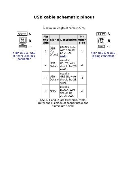
4 pin <strong>USB</strong> A / <strong>USB</strong><br />
B / mini-<strong>USB</strong> jack<br />
connector<br />
<strong>USB</strong> <strong>cable</strong> <strong>schematic</strong> <strong>pinout</strong><br />
Maximum length of <strong>cable</strong> is 5 m.<br />
Pin<br />
one<br />
side<br />
1<br />
Signal Description<br />
<strong>USB</strong><br />
Vcc<br />
(Vbus)<br />
2 <strong>USB</strong><br />
Data -<br />
3 <strong>USB</strong><br />
Data +<br />
4 GND<br />
usually RED,<br />
wire should<br />
be 20-28<br />
AWG<br />
usually<br />
WHITE, wire<br />
should be 28<br />
AWG<br />
usually<br />
GREEN, wire<br />
should be 28<br />
AWG<br />
usually<br />
BLACK, wire<br />
should be<br />
20-28 AWG<br />
Pin<br />
other<br />
side<br />
<strong>USB</strong> D+ and D- are twisted in <strong>cable</strong>.<br />
Outer shell is made of copper braid and<br />
aluminium shield.<br />
1<br />
2<br />
3<br />
4<br />
4 pin <strong>USB</strong> A or <strong>USB</strong><br />
B plug connector
4 pin <strong>USB</strong> A or <strong>USB</strong> B plug connector<br />
at the peripherals<br />
<strong>USB</strong> <strong>pinout</strong><br />
4 pin <strong>USB</strong> A / <strong>USB</strong> B / mini-<strong>USB</strong> jack<br />
connector<br />
at the controller<br />
The Universal Serial Bus is host controlled and there can be only one host per<br />
bus. An <strong>USB</strong> system consist of a host controller and multiple devices connected<br />
in a tree-like fashion using special hub devices. Hubs may be cascaded, up to 5<br />
levels. Up to 127 devices may be connected to a single host controller. <strong>USB</strong><br />
interface aimed to remove the need for adding expansion cards into the<br />
computer's PCI or PCI-E bus, and improve plug-and-play capabilities by allowing<br />
devices to be hot swapped or added to the system without rebooting the<br />
computer. When the new device first plugs in, the host enumerates it and loads<br />
the device driver necessary to run it. The loading of the appropriate driver is<br />
done using a PID/VID (Product ID/Vendor ID) combination supplied by attached<br />
hardware. The <strong>USB</strong> host controllers has their own specifications: UHCI (Universal<br />
Host Controller Interface) and OHCI (Open Host Controller Interface) are used<br />
with <strong>USB</strong> 1.1, EHCI (Enhanced Host Controller Interface) is used with <strong>USB</strong> 2.0
Pin Name<br />
Cable<br />
color<br />
Description<br />
1 VCC Red +5 VDC<br />
2 D- White Data -<br />
3 D+ Green Data +<br />
4 GND Black Ground<br />
Pin x of mini-<strong>USB</strong> connector may be not connected, connected to GND or used as<br />
attachment identification at some portable devices.<br />
<strong>USB</strong> <strong>pinout</strong> signals<br />
<strong>USB</strong> is a serial bus. It uses 4 shielded wires: two for power (+5v & GND) and two<br />
for differential data signals (labelled as D+ and D- in <strong>pinout</strong>). NRZI (Non Return<br />
to Zero Invert) encoding scheme used to send data with a sync field to<br />
synchronise the host and receiver clocks. In <strong>USB</strong> data <strong>cable</strong> Data+ and Data-<br />
signals are transmitted on a twisted pair. No termination needed. Half-duplex<br />
differential signaling helps to combat the effects of electromagnetic noise on<br />
longer lines. Contrary to popular belief, D+ and D- operate together; they are not<br />
separate simplex connections.<br />
<strong>USB</strong> transfer modes<br />
Univeral serial bus supports Control, Interrupt, Bulk and Isochronous transfer<br />
modes.<br />
<strong>USB</strong> transfer rates: Low Speed, Full Speed, Hi-speed.<br />
<strong>USB</strong> supports three data rates: Low Speed (1.5 Mbit per second) that is mostly<br />
used for Human Input Devices (HID) such as keyboards, mice, joysticks and often<br />
the buttons on higher speed devices such as printers or scanners; Full Speed (12<br />
Mbit per second) which is widely supported by <strong>USB</strong> hubs, assumes that devices<br />
divide the <strong>USB</strong> bandwidth between them in a first-come first-serve basis - it"s<br />
easy to run out of bandwidth with several devices; Hi-Speed (480 Mbit per<br />
second) was added in <strong>USB</strong> 2.0 specification. Not all <strong>USB</strong> 2.0 devices are Hi-<br />
Speed. A <strong>USB</strong> device must indicate its speed by pulling either the D+ or D- line<br />
high to 3.3 volts. These pull up resistors at the device end will also be used by<br />
the host or hub to detect the presence of a device connected to its port. Without<br />
a pull up resistor, <strong>USB</strong> assumes there is nothing connected to the bus.<br />
In order to help user to identify maximum speed of device, <strong>USB</strong> device often<br />
specify it's speed on it's cover with one of <strong>USB</strong> special marketing logos.<br />
<strong>USB</strong> Hi-speed devices<br />
Hi-Speed devices should fall back to the slower data rate of Full Speed when<br />
plugged into a Full Speed hub. Hi-Speed hubs have a special function called the<br />
Transaction Translator that segregates Full Speed and Low Speed bus traffic from<br />
Hi-Speed traffic.
<strong>USB</strong> powered devices<br />
The <strong>USB</strong> connector provides a single 5 volt wire from which connected <strong>USB</strong><br />
devices may power themselves. A given segment of the bus is specified to<br />
deliver up to 500 mA. This is often enough to power several devices, although<br />
this budget must be shared among all devices downstream of an unpowered<br />
hub. A bus-powered device may use as much of that power as allowed by the<br />
port it is plugged into. Bus-powered hubs can continue to distribute the bus<br />
provided power to connected devices but the <strong>USB</strong> specification only allows for a<br />
single level of bus-powered devices from a bus-powered hub. This disallows<br />
connection of a bus-powered hub to another bus-powered hub. Many hubs<br />
include external power supplies which will power devices connected through<br />
them without taking power from the bus. Devices that need more than 500 mA<br />
or higher than 5 volts must provide their own power. When <strong>USB</strong> devices<br />
(including hubs) are first connected they are interrogated by the host controller,<br />
which enquires of each their maximum power requirements. However, seems<br />
that any load connected to <strong>USB</strong> port may be treated by operating system as<br />
device. The host operating system typically keeps track of the power<br />
requirements of the <strong>USB</strong> network and may warn the computer's operator when a<br />
given segment requires more power than is available and may shut down<br />
devices in order to keep power consumption within the available resource.<br />
<strong>USB</strong> power usage:<br />
Bus-powered hubs: Draw Max 100 mA at power up and 500 mA normally.<br />
Self-powered hubs: Draw Max 100 mA, must supply 500 mA to each port.<br />
Low power, bus-powered functions: Draw Max 100 mA.<br />
High power, bus-powered functions: Self-powered hubs: Draw Max 100 mA,<br />
must supply 500 mA to each port.<br />
Self-powered functions: Draw Max 100 mA.<br />
Suspended device: Max 0.5 mA<br />
<strong>USB</strong> voltage:<br />
Supplied voltage by a host or a powered hub ports is between 4.75 V and 5.25 V.<br />
Maximum voltage drop for bus-powered hubs is 0.35 V from it's host or hub to<br />
the hubs output port. All hubs and functions must be able to send configuration<br />
data at 4.4 V, but only low-power functions need to be working at this voltage.<br />
Normal operational voltage for functions is minimum 4.75 V.<br />
<strong>USB</strong> <strong>cable</strong> shielding:<br />
Shield should only be connected to Ground at the host. No device should connect<br />
Shield to Ground.<br />
<strong>USB</strong> <strong>cable</strong> wires:<br />
Shielded:<br />
Data: 28 AWG twisted; Power: 28 AWG - 20 AWG non-twisted<br />
Non-shielded:<br />
Data: 28 AWG non-twisted; Power: 28 AWG - 20 AWG non-twisted
Power Gauge Max length<br />
28 0.81 m<br />
26 1.31 m<br />
24 2.08 m<br />
22 3.33 m<br />
20 5.00 m
mini-<strong>USB</strong> connector <strong>pinout</strong><br />
<strong>USB</strong> (Universal Serial Bus) designed to connect peripherals and exist in a wide<br />
variety of digital devices.<br />
5 pin mini-<strong>USB</strong> plug<br />
connector<br />
at the peripherals<br />
5 pin mini-<strong>USB</strong> jack<br />
connector<br />
at the controller<br />
Pin Name Cable<br />
color<br />
<strong>USB</strong> <strong>pinout</strong> signals<br />
Description<br />
1 VCC Red +5 VDC<br />
2 D- White Data -<br />
3 D+ Green Data +<br />
X ID May be N/C,<br />
GND or used<br />
as an<br />
attached<br />
device<br />
presence<br />
indicator<br />
(shorted to<br />
GND with<br />
resistor)<br />
4 GND Black Ground<br />
<strong>USB</strong> is a serial bus. It uses 4 shielded wires: two for power<br />
(+5v & GND) and two for differential data signals (labelled<br />
as D+ and D- in <strong>pinout</strong>). NRZI (Non Return to Zero Invert)<br />
encoding scheme used to send data with a sync field to<br />
synchronise the host and receiver clocks. In <strong>USB</strong> data <strong>cable</strong><br />
Data+ and Data- signals are transmitted on a twisted pair.<br />
No termination needed. Half-duplex differential signaling<br />
helps to combat the effects of electromagnetic noise on<br />
longer lines. Contrary to popular belief, D+ and D- operate<br />
together; they are not separate simplex connections.<br />
<strong>USB</strong> <strong>cable</strong> wires:<br />
Shielded:<br />
Data: 28 AWG twisted; Power: 28 AWG-20 AWG non-twisted<br />
Non-shielded:<br />
Data: 28 AWG non-twisted<br />
Power: 28 AWG - 20 AWG non-twisted
Power Gauge Max length<br />
28 0.81 m<br />
26 1.31 m<br />
24 2.08 m<br />
22 3.33 m<br />
20 5.00 m