Non Magnetic Capacitors - Temex Ceramics
Non Magnetic Capacitors - Temex Ceramics
Non Magnetic Capacitors - Temex Ceramics

Create successful ePaper yourself
Turn your PDF publications into a flip-book with our unique Google optimized e-Paper software.
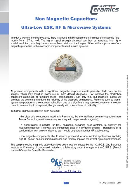
<strong>Non</strong> <strong>Magnetic</strong> <strong>Capacitors</strong>Ultra-Low ESR, RF & Microwave SystemsII. EXPERIMENTAL SETUPII.1. MagnetometerMeasurements were taken using a Quantum Design magnetometer, model MPMS-5. The MPMSprovides solutions for a unique class of sensitive magnetic measurements in key areas such as hightemperaturesuperconductivity, biochemistry and magnetic recording media. This began developingsignificantly in 1988 with the discovery of a new class of superconducting materials. While the basicapplication has not changed greatly, its use has expanded to more than 530 installations worldwide.The modular MPMS design integrates a SQUID detection system - Superconducting QuantumInterference Device, a precision temperature control unit residing in the bore of a high fieldsuperconducting magnet, and a sophisticated computer operating system:- Maximum Sample Size: 9 mm;- Field Uniformity: 0.01% over 4 cm;- Temperature Range: 1.9-400 K;- Sensitivity of 10 -7 emu-CGS.TEMEX CERAMICS reserves the right to modify herein specifications and information at any time when necessary to provide optimum performance and cost.5MR_<strong>Capacitors</strong>.doc - Ed.03
<strong>Non</strong> <strong>Magnetic</strong> <strong>Capacitors</strong>Ultra-Low ESR, RF & Microwave SystemsII.2. Superconducting Quantum Interference DeviceThe main components of a SQUID (see Fig. 1) magnetometer are: (a) a superconducting magnet; (b)a superconducting detection coil which is coupled inductively to the sample; (c) a SQUID connected tothe detection coil; (d) a superconducting magnetic shield. A description of each one is given below:II.2.1. Superconducting MagnetFig. 1A superconducting magnet is a solenoid made of superconducting wires (see Fig. 2). The solenoidmust be kept at liquid helium temperature in a liquid-helium medium. The uniform magnetic field isproduced along the axial cylindrical bore of the coil. Superconducting solenoids that produce magneticfields in the range 5-18 Tesla are now commercially available. A superconducting magnet requires anappropriate programmable bipolar power supply for operation.Fig. 2TEMEX CERAMICS reserves the right to modify herein specifications and information at any time when necessary to provide optimum performance and cost.6MR_<strong>Capacitors</strong>.doc - Ed.03
<strong>Non</strong> <strong>Magnetic</strong> <strong>Capacitors</strong>Ultra-Low ESR, RF & Microwave SystemsII.2.2. Superconducting Detection CoilThis is a single piece of superconducting wire, configured as a second-order gradiometer (see Fig. 3).This pick-up coil system is placed in the uniform magnetic field region of the solenoidalsuperconducting magnet.II.2.3. SQUIDFig. 3High sensitivity is possible because this device responds to a fraction of the flux quantum. The SQUIDdevice is usually a thin film that functions as an extremely sensitive current-to-voltage-converter. Ameasurement is taken in this equipment by moving the sample through the second-order gradiometer.Hence, the magnetic moment of the sample induces an electric current in the pick-up coil system. Achange in the magnetic flux in these coils modifies the persistent current in the detection circuit. Thecurrent change in the detection coils then produces a variation in the SQUID output voltageproportional to the magnetic moment of the sample.II.2.4. Superconducting <strong>Magnetic</strong> ShieldThis is used to shield the SQUID sensor from the fluctuations of the ambient magnetic field in themagnetometer’s location and from the large magnetic field produced by the superconducting magnet.II.2.5. ApplicationsThis kind of equipment can be used to measure: (a) the real and imaginary components of the ACmagnetic susceptibility as a function of frequency, temperature, AC magnetic field amplitude and DCmagnetic field value; (b) the DC magnetic moment as a function of temperature, DC magnetic field,and time.TEMEX CERAMICS reserves the right to modify herein specifications and information at any time when necessary to provide optimum performance and cost.7MR_<strong>Capacitors</strong>.doc - Ed.03
<strong>Non</strong> <strong>Magnetic</strong> <strong>Capacitors</strong>Ultra-Low ESR, RF & Microwave SystemsII.3. Capsule MagnetizationThe sample under testing has to be placed in a small capsule of 5-mm diameter and 8-mm length.Submitted to a magnetic field, the sample acquires a magnetization. The capsule is then placed in a 6-cm tube which results in a field strength variation. This is then measured in the SQUID and convertedinto a magnetization (uem-CGS unit in our case). Thin paper is used to secure the sample in placeinside the capsule.Measurements were made with a controlled temperature (298.0±0.1K) and in the 0 to 3.5T range(35’000 Oe) as the magnetic field declined.The first step before measuring any sample is to define the magnetization of the sample carrier, i.e.the capsule with some thin paper. Then, as the samples are measured, all the magnetization valuesare corrected using the pattern below:Magnetization Mg (uem.CGS/g)0.00040.00020.0000-0.0002-0.0004-0.0006-0.0008-0.0010-0.0012-0.0014-0.0016Applied Field H (Oe)0 5 000 10 000 15 000 20 000 25 000 30 000 35 000 40 000CapsuleCapsule + PaperThe signal from the capsule is diamagnetic and very weak. The signal from the capsule +the paperassembly is more complex to determine, combining a strong diamagnetic signal and a smallferromagnetic contribution (impurities in the paper material).A constant corrective factor was then applied on all the measurements as a first approximation.TEMEX CERAMICS reserves the right to modify herein specifications and information at any time when necessary to provide optimum performance and cost.8MR_<strong>Capacitors</strong>.doc - Ed.03
<strong>Non</strong> <strong>Magnetic</strong> <strong>Capacitors</strong>Ultra-Low ESR, RF & Microwave SystemsIII. LABORATORY MEASUREMENTSThe aim of this study is to define a range of magnetization values within which electronic componentsmay be considered as non-magnetic and suitable for critical medical and high RF power applications.Several components were therefore tested to define a spectrum as wide as possible. For instance, ifwe consider the high-Q multilayer ceramic capacitor: we started with the chip alone, without even itsterminations, adding a new variable - such as copper or silver-palladium or nickel terminations, silverribbons and finally laser marking - at each subsequent stage. Using this protocol, it is easy to see theeffect of each variable on the final magnetization.The magnetization in the charts below is given per gram. Each sample - or set of samples - is thenweighed before the test run. The following designs were tested:Designation Number of Samples Weight (mg) Batch Number501 CHB 4R7 3 155.1 C706527501 CHB 4R7 BC 1 61.5 C649212501 CHB 4R7 BC1L 1 133.6 C649212-0501 CHB 4R7 BAL 1 57.5 52196501 CHB 4R7 BS 1 61.2 C645208-2silver leads type 1 2 55.4 CK/6297silver leads type 2 2 57.2 CK/BC/2205AT9401 1 58.6 OT0041006PAT9402 1 60.8 OT0111206PAT9410 2 194.0 OT0020806PThe descriptions of the samples used are as follows:501 CHB 4R7 B size (1111) capacitor, 4.7pF, no termination501 CHB 4R7 BC B size (1111) capacitor, 4.7pF, copper termination501 CHB 4R7 BC1L B size (1111) capacitor, 4.7pF, copper termination, leads501 CHB 4R7 BAL B size (1111) capacitor, 4.7pF, silver-palladium termination501 CHB 4R7 BS B size (1111) capacitor, 4.7pF, nickel terminationsilver leads type 1silver leads type 2AT9401AT9402AT9410silver leads used with B size capacitorssilver leads currently undergoing qualificationceramic trimmer capacitor, 0.6 to 2.0pF, gold terminationceramic trimmer capacitor, 1.0 to 5.0pF, gold terminationceramic trimmer capacitor, 4.0 to 18pF, gold terminationTEMEX CERAMICS reserves the right to modify herein specifications and information at any time when necessary to provide optimum performance and cost.9MR_<strong>Capacitors</strong>.doc - Ed.03
<strong>Non</strong> <strong>Magnetic</strong> <strong>Capacitors</strong>Ultra-Low ESR, RF & Microwave SystemsIII.1. DUT: 501 CHB 4R7Applied Field H (Oe)Magnetization Mg (uem.CGS/g)0.00350.00300.00250.00200.00150.00100.00050.0000-0.0005-0.00100 5 000 10 000 15 000 20 000 25 000 30 000 35 000 40 000501 CHB 4R7This sample shows a slightly paramagnetic behavior. Its magnetic susceptibility χ g is around 10 -7uem.CGS/g which is a very low value.III.2. DUT: 501 CHB 4R7 BCMagnetization Mg (uem.CGS/g)0.00400.00350.00300.00250.00200.00150.00100.00050.0000-0.0005-0.0010Applied Field H (Oe)0 5 000 10 000 15 000 20 000 25 000 30 000 35 000 40 000501 CHB 4R7 BCThis sample has a slightly paramagnetic behavior. Its magnetic susceptibility χ g is around 10 -7uem.CGS/g which is a very low value.TEMEX CERAMICS reserves the right to modify herein specifications and information at any time when necessary to provide optimum performance and cost.10MR_<strong>Capacitors</strong>.doc - Ed.03
<strong>Non</strong> <strong>Magnetic</strong> <strong>Capacitors</strong>Ultra-Low ESR, RF & Microwave SystemsIII.3. DUT: 501 CHB 4R7 BSMagnetization Mg (uem.CGS/g)0.70000.60000.50000.40000.30000.20000.10000.0000-0.1000Applied Field H (Oe)0 5 000 10 000 15 000 20 000 25 000 30 000 35 000 40 000501 CHB 4R7 BSThis sample exhibits a very strong magnetic behavior with a magnetization around 0.6 uem.CGS/g.III.4. DUT: 501 CHB 4R7 BALMagnetization Mg (uem.CGS/g)0.00900.00800.00700.00600.00500.00400.00300.00200.00100.0000-0.0010-0.0020Applied Field H (Oe)0 5 000 10 000 15 000 20 000 25 000 30 000 35 000 40 000501 CHB 4R7 BALThis sample has paramagnetic behavior with a magnetic susceptibility χ g around 2.3×10 -7 uem.CGS/g.TEMEX CERAMICS reserves the right to modify herein specifications and information at any time when necessary to provide optimum performance and cost.11MR_<strong>Capacitors</strong>.doc - Ed.03
<strong>Non</strong> <strong>Magnetic</strong> <strong>Capacitors</strong>Ultra-Low ESR, RF & Microwave SystemsIII.5. DUT: 501 CHB 4R7 BC1LApplied Field H (Oe)Magnetization Mg (uem.CGS/g)0.00180.00160.00140.00120.00100.00080.00060.00040.00020.00000 5 000 10 000 15 000 20 000 25 000 30 000 35 000 40 000501 CHB 4R7 BC1LThis sample shows a paramagnetic behavior with a magnetic susceptibility χ g around 0.4×10 -7 uem.CGS/g.III.6. DUT: Silver LeadsMagnetization Mg (uem.CGS/g)0.00100.0000-0.0010-0.0020-0.0030-0.0040-0.0050-0.0060Applied Field H (Oe)0 5 000 10 000 15 000 20 000 25 000 30 000 35 000 40 000Type 1 Type 2These two samples exhibit very similar diamagnetic behavior. The magnetic susceptibility χ g is in bothcases around -1.6×10 -7 uem.CGS/g.TEMEX CERAMICS reserves the right to modify herein specifications and information at any time when necessary to provide optimum performance and cost.12MR_<strong>Capacitors</strong>.doc - Ed.03
<strong>Non</strong> <strong>Magnetic</strong> <strong>Capacitors</strong>Ultra-Low ESR, RF & Microwave SystemsIII.7. DUT: AT9401Magnetization Mg (uem.CGS/g)0.02500.02000.01500.01000.00500.0000-0.0050Applied Field H (Oe)0 5 000 10 000 15 000 20 000 25 000 30 000 35 000 40 000AT9401This sample has a paramagnetic behavior with a relatively high magnetic susceptibility χ g , around7.1×10 -7 uem.CGS/g.III.8. DUT: AT9402Magnetization Mg (uem.CGS/g)0.00100.0000-0.0010-0.0020-0.0030-0.0040-0.0050-0.0060Applied Field H (Oe)0 5 000 10 000 15 000 20 000 25 000 30 000 35 000 40 000AT9402This sample has a paramagnetic behavior with a relatively low magnetic susceptibility χ g around 10 -7uem.CGS/g.TEMEX CERAMICS reserves the right to modify herein specifications and information at any time when necessary to provide optimum performance and cost.13MR_<strong>Capacitors</strong>.doc - Ed.03
<strong>Non</strong> <strong>Magnetic</strong> <strong>Capacitors</strong>Ultra-Low ESR, RF & Microwave SystemsIII.9. DUT: AT9410Magnetization Mg (uem.CGS/g)0.00250.00200.00150.00100.00050.0000-0.0005-0.0010-0.0015Applied Field H (Oe)0 5 000 10 000 15 000 20 000 25 000 30 000 35 000 40 000AT9410This sample has a paramagnetic behavior with a relatively low magnetic susceptibility χ g around 10 -7uem.CGS/g.TEMEX CERAMICS reserves the right to modify herein specifications and information at any time when necessary to provide optimum performance and cost.14MR_<strong>Capacitors</strong>.doc - Ed.03
<strong>Non</strong> <strong>Magnetic</strong> <strong>Capacitors</strong>Ultra-Low ESR, RF & Microwave SystemsIV. ANALYSISIV.1. Influence Of LeadsMagnetization Mg(uem.CGS/g)0.00600.00400.00200.0000-0.0020-0.0040-0.0060-0.0080Applied Field H (Oe)0 10 000 20 000 30 000 40 000501 CHB 4R7 501 CHB 4R7 BCSilver LeadFrom the above chart, the following points may be deduced:501 CHB 4R7 BC1L- the copper termination slightly increases the magnetic susceptibility of the chip but the totalvalue remains very low and the paramagnetic behavior is suitable for non-magneticapplications;- as the ribbon shows strong paramagnetic behavior, the assembly made with the capacitorand the leads has an even lower magnetic susceptibility than the chip alone. This means thatfor a very strong requirement for non-magnetic criteria, the assembly made of capacitor andleads is better than the capacitor itself;- in theory, it should be possible to decrease the magnetic susceptibility of the assembly –capacitor and leads – still further to reach a nearly a nil value, by using thicker or longer silverleads. These would also improve the heat transfer and therefore allow higher working power.TEMEX CERAMICS reserves the right to modify herein specifications and information at any time when necessary to provide optimum performance and cost.15MR_<strong>Capacitors</strong>.doc - Ed.03
<strong>Non</strong> <strong>Magnetic</strong> <strong>Capacitors</strong>Ultra-Low ESR, RF & Microwave SystemsIV.2. Influence Of TerminationsIV.2.1. Copper Versus Nickel TerminationsMagnetization Mg (uem.CGS/g)1.00000.10000.01000.00100.0001Applied Field H (Oe)0 5 000 10 000 15 000 20 000 25 000 30 000 35 000 40 000501 CHB 4R7 BC 501 CHB 4R7 BSFrom the above chart, the following points may be deduced:- we are comparing here a magnetic termination – nickel barrier one – and a non-magnetictermination – copper barrier one. Naturally, the nickel termination cannot be used for nonmagneticapplications but it enables us to define a limit above which a termination should notbe classified as non-magnetic;- as we are using a logarithmic axis, the best magnetization value to consider for this limitseems to be around 0.10 uem.CGS/g;- both copper and silver-palladium terminations are below this theoretical limit of 0.10uem.CGS/g and can therefore be considered as non-magnetic.TEMEX CERAMICS reserves the right to modify herein specifications and information at any time when necessary to provide optimum performance and cost.16MR_<strong>Capacitors</strong>.doc - Ed.03
<strong>Non</strong> <strong>Magnetic</strong> <strong>Capacitors</strong>Ultra-Low ESR, RF & Microwave SystemsVI.2.2. Copper Versus Silver-Palladium TerminationsMagnetization Mg (uem.CGS/g)0.00900.00800.00700.00600.00500.00400.00300.00200.00100.0000-0.0010-0.0020Applied Field H (Oe)0 5 000 10 000 15 000 20 000 25 000 30 000 35 000 40 000501 CHB 4R7 501 CHB 4R7 BC 501 CHB 4R7 BALFrom the above chart, the following points may be deduced:- the copper or silver-palladium terminations slightly increase the magnetic susceptibility of thechip but the total value remains very low and the paramagnetic behavior is suitable for nonmagneticapplications;- the capacitor with silver-palladium terminations exhibits a magnetic susceptibility around threetimes higher than that of the capacitor with copper terminations. This means that for a verystrong requirement for non-magnetic criteria, the copper terminations are better than the silverpalladiumones;- both these terminations are suitable for non-magnetic applications as their magnetization isalways below 0.10 uem.CGS/g.TEMEX CERAMICS reserves the right to modify herein specifications and information at any time when necessary to provide optimum performance and cost.17MR_<strong>Capacitors</strong>.doc - Ed.03
<strong>Non</strong> <strong>Magnetic</strong> <strong>Capacitors</strong>Ultra-Low ESR, RF & Microwave SystemsIV.3. Trimmer <strong>Capacitors</strong>On the basis of the 0.10 uem.CGS/g limit previously discussed, the behavior of ceramic trimmercapacitors could also be studied.Magnetization Mg (uem.CGS/g)0.02500.02000.01500.01000.00500.0000-0.0050-0.0100Applied Field H (Oe)0 5 000 10 000 15 000 20 000 25 000 30 000 35 000 40 000AT9401 AT9402 AT9410From the above chart, the following points may be deduced:- these three ceramic trimmer capacitors are all suitable for non-magnetic applications, as theirmagnetization is always below 0.10 uem.CGS/g;- the AT9402 and AT9410 exhibit very good paramagnetic behavior and are therefore recommendedfor applications with a very strong non-magnetic requirement.TEMEX CERAMICS reserves the right to modify herein specifications and information at any time when necessary to provide optimum performance and cost.18MR_<strong>Capacitors</strong>.doc - Ed.03
<strong>Non</strong> <strong>Magnetic</strong> <strong>Capacitors</strong>Ultra-Low ESR, RF & Microwave SystemsIV.4. PermeabilityIV.4.1. DefinitionsSome engineers prefer to define the magnetic behavior of a component using its permeability.Therefore, an empirical limit above which components are not suitable for non-magnetic applicationsseems to have been set at 1.0005 for the relative permeability µ R .This relative permeability could be deduced from our measurements using the following method:- mass susceptibility χ g is given by the slope of the M g = f (H) curve- volume susceptibility χ v is equal to: χ g × [density]- relative permeability is finally equal to: 1 + χ vIV.4.2. ExamplesLet’s consider the 501 CHB 4R7 BC we measured previously. From the experimental curve, we find amass susceptibility χ g of 10 -7 uem.CGS. As our components exhibit a density around 4, the volumesusceptibility χ v is then equal to 4×10 -7 uem.CGS. Finally, permeability µ R is then equal to 1.0000004,which is well below the theoretical limit of 1.0005Even if there is no mass susceptibility χ g for a magnetic component – except at very low fields butcustomer’s applications are far above this range – we can run the exercise for the 501 CHB 4R7 BSstudied previously. From the first two dots on the experimental curve, we find a mass susceptibility χ gof 0.5×10 -3 uem.CGS. As our components exhibit a density around 4, the volume susceptibility χ v isthen equal to 2×10 -3 uem.CGS. Finally, permeability µ R is then equal to 1.002, which is, as expected,well above the theoretical limit of 1.0005TEMEX CERAMICS reserves the right to modify herein specifications and information at any time when necessary to provide optimum performance and cost.19MR_<strong>Capacitors</strong>.doc - Ed.03
<strong>Non</strong> <strong>Magnetic</strong> <strong>Capacitors</strong>Ultra-Low ESR, RF & Microwave SystemsV. CONCLUSIONSC.N.R.S. and <strong>Temex</strong> <strong>Ceramics</strong> have conducted a comprehensive study of the non-magnetic behaviorof electronic components. This document describes the results of that study on multilayer porcelaincapacitors and ceramic trimmer capacitors.It flags up the following points:- the measurements made on magnetic and non-magnetic components enable us to define afirst limit for magnetization of around 0.10 uem.CGS/g above which components can no longerbe rated as non-magnetic;- all our non-magnetic components – both porcelain capacitors and ceramic trimmer capacitors– are below this limit and are therefore Magnetism-free Rated. To enable R&D engineers toquickly distinguish in the <strong>Temex</strong> <strong>Ceramics</strong> portfolio which components are guaranteed for nonmagneticapplications, the following specific logo will be added to specific series in ourApplication datasheets:MR certified®- the above logo certifies that a specific electronic component is Magnetism-free Rated;- concerning non-magnetic applications - mainly medical systems -, the best solution to obtaina very low magnetization ceramic capacitor is to use one with copper terminations;- the silver leads, made from pure silver, are completely non-magnetic;- concerning standard applications – like telecom, industrial, military or space systems, - as anysystem induces a magnetic field, the use of non-magnetic components would rule out magneticlosses and therefore improve the overall performances, particularly in switch-mode operations.TEMEX CERAMICS reserves the right to modify herein specifications and information at any time when necessary to provide optimum performance and cost.20MR_<strong>Capacitors</strong>.doc - Ed.03