


Create successful ePaper yourself
Turn your PDF publications into a flip-book with our unique Google optimized e-Paper software.
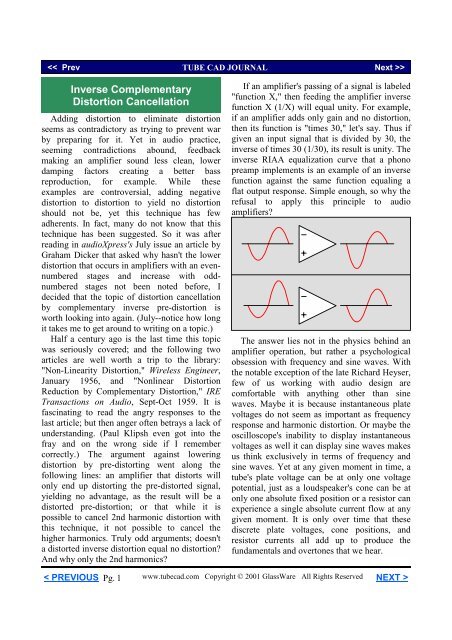
When a cathode follower shares the sametriode and load resistance and plate voltage andidle current as the grounded-cathode amplifierthat precedes it, the cathode follower undoesmuch of the distortion of the first stage. Thishappens because the cathode follower isretracing the curves that the grounded-cathodeamplifier traced. As the first stage's platesluggishly swings positive, its cathode-to-platevoltage increases and its conduction decreases;as the cathode follower's cathode swingspositive, its cathode-to-plate voltageaggressively decreases and its conductionincreases. Inversely, when first stage's plateaggressively swings negative, the cathodefollower's cathode-to-plate voltage sluggishlyincreases and its conduction decreases.To the degree that a triode is consistentlyinconsistent, this circuit will make use of inversepre-distortion to yield a lower distortion thaneither sub-circuit used independently. If thistechnique seems too optimistic, consider whatgoes on a multiple stage line amplifier withfeedback; the penultimate gain stage delivers tothe last stage an inverse pre-distorted signal thatundoes the distortion that the last would imposein the absence of feedback. The feedbackcreated this inverse pre-distorted signal preciselyfor the output device, as it is the output devicethat terminates the feedback loop. (It isinteresting to compare a non-feedback amplifierto one with feedback. In the non-feedbackamplifier, distortion grows larger at eachproceeding stage from the input. In the feedbackamplifier, distortion is largest at the input stageand grows cleaner with each proceeding stage tothe output.) But feedback is not the only meansto creating an inverse pre-distorting signal.How do we use this trick to make a poweramplifier? First of all, we must use the sametriode type for both the driver tube and theoutput tube. Second, we must use same cathodeto-platevoltages, load impedances, and idlecurrents for both triodes. Third, we must cascadea grounded-cathode amplifier into a cathodefollower output stage.input+650vdc+400vdc1k470k5k50mAEL34+37vdc7413k.5µF1002k470kbias VEL345k{+800vdc+400vdcAt first glance, it looks like we will have tolose half of the potential power output in orderto reduce the distortion complementarily, as thefirst stage will have to work into the same loadas will the output stage. For example, if the asingle 2A3 output tube sees a load of 2500ohms, then the 2A3 driver tube will also have towork into a 2500 ohm load; since both tubesundergo the same voltage and current swing,both tubes will deliver the same power into theirloads. But as only one of these loads createssound, half of the potential efficiency is lost.Considering that the average triode based SEamplifier is only about 20% efficient, we do nothave much efficiency to throw away.But if we increase the number of outputdevices used in parallel, we effectively increasethe efficiency. For example, if we design asingle-ended 300B power amplifier that usesthree 300B output tubes in parallel, then onlyone 300B power tube is needed to provide thecomplementary inverse pre-distortion. So weend up throwing away only a quarter of ourpotential watts, rather than half. (Of course, themore output tubes in parallel, the better theefficiency.)50mACCDC power amplifier100+37vdc1684< PREVIOUSPg. 3www.tubecad.com Copyright © 2001 GlassWare All Rights Reserved NEXT >
www.glass-ware.com10mA36.3k+300vdc30k+150vdc3005965.5µF300+153vdc5965 +2.8vdc1M 560 30k+662.5vdc3.75k+400vdc1k470k70mA+62vdc300B886.5µF100k17202k}5vdc300B300B+62vdc1250{210mA+52vdcBartolucci 2247300B+800vdc+400vdc1684GND}5vdcwww.glass-ware.comIn the above schematic, you see an 300Bbased cathode follower output stage beingdriven by an 300B based grounded-cathodeamplifier, whose plate resistor is three timesgreater (3750 ohms) than the reflectedimpedance on the output transformer's secondary(1250 ohms; the 247 ohm biasing resistor's valuewill have to be added to the primary impedance,if this resistor is not bypassed). The key featureis that the grounded-cathode amplifier stage'sidle current and cathode-to-plate voltagematches that of each output tube.The extra power supply voltage comes from avoltage doubler circuit, as shown below. Lestthose who posses all-knowledge-of-all-that-isworth-knowing-about-tube-electronics(asurprisingly small amount, it turns out, no morethan can fill a few <strong>article</strong>s from the audiophilepress and the odd rec.tube thread) lose theircomposure over the unseemly use of solid-statediodes, a tube rectifier can be easily used for the400 vdc power supply voltage and, with somework, tube rectifiers could be used for the 800volts power supply as well.600vac CT250mA+800vdc+400vdcThe 300B-based driver tube must realize avoltage swing large enough to drive the parallelcathode followers to full power output. Since theneeded swing is not symmetrical, the potentialswing need not be either. As configured, thedriver stage can potentially swing down morevoltage than up, which is what the output stageneeds to see. This is the result of the trioderequiring more voltage to turn it off than itrequires to increase its conduction.< PREVIOUSPg. 4www.tubecad.com Copyright © 2001 GlassWare All Rights Reserved NEXT >
So when the driver tube sees an input swingof +62/-62 volts, its plate will swing -221/+195volts, which in turn this imbalance will counterthe imbalance that the output tubes will forceonto the its output voltage swing, as it is theinverse of the output stage's imbalance.The unfortunate feature of this amplifier isthat because the 300B mu is low, the outputstage never realizes it full potential output, as thecathode follower output stage's low gain requiresa much greater voltage swing at its grid to bringout the full output power that the 300B can give.Thus a better choice for an output tube might betriode connected 8417 or EL34. In the schematicbelow, we see an EL34-based output stage. Thisamplifier would provide about 15W of relativelyinexpensive, clean, pure single-ended power.The power amplifier's input stage also usescomplementary inverse pre-distortion to lowerthis stage's contribution to the amplifier's finaldistortion figure by not adding excessivedistortion to the mix. Thus the same principle ofinverse-complementary-distortion cancellationthat lowers the output stage's distortion is usedto in the input stage. The same triode, the samecathode-to-plate voltage, the same load resistorvalue--all are used to inverse symmetricallycancel the distortion from the input stage.The end result of all these techniques is anamplifier with a low output impedance and lowdistortion and wide bandwidth, an amplifier thatdoes not use feedback (at least not a globalfeedback loop). The cathode follower outputstage deserves some comments. This circuitemploys 100% cathode degeneration of theoutput signal to keep the output in inline with itsinput. If the cathode fails to move as positive asthe grid moves, then the grid effectivelybecomes more positive and the tube's conductionincreases, which will force the cathode to agreater positive voltage. Conversely, if thecathode falls less negatively as the grid falls,then the grid effectively becomes more negativeand the tube's conduction decreases, whichresults in the cathode's voltage to collapse. Inother words, the cathode follower output stageuses all of the output tube's transconductance toforce the output to follow the input signal. Thisshort, quick feedback mechanism also brings theoutput impedance down and extends thebandwidth. It also serves to lower thetransformer's distortion contribution, as outputtransformers distort least with low impedanceinput sources. This is an import advantage ofthis output stage, as the transformer is notenclosed in a distortion lowering feedback loop.10mA35k+650vdc5k2.5k100 100 100+800vdc+400vdc30k+300vdc50mA.5µF2k100kEL34 EL34 EL34+37vdc+150vdc30059653005965+153vdc+2.8vdc.5µF+400vdc1001kEL34+37vdc150mAOne Electron UBT-11684GND1M56030k470k74185< PREVIOUSPg. 5www.glass-ware.comwww.tubecad.com Copyright © 2001 GlassWare All Rights Reserved NEXT >
A true 32-bit Windows program,GlassWare <strong>Tube</strong> Manual is both userfriendly and powerful. It's all here: platecurves, mu, rp, Gm, Vh, Ih, base and outlineschematics, and essential characteristics formany of the tubes. Powerful search andfiltering tools give control over this tubemanual's large library of tubes (11,000).Look up your favorite tubes (6SN7, KT88,2A3, and 6922) and discover other greattubes you didn't know existed. With the aidof easy-to-use editing tools, tubes can beadded or subtracted to the database. Keeptrack of your own tube collection with yourpersonal tube database. Like all GlassWareprograms, GlassWare <strong>Tube</strong> Manual allowsyou to print the results. Hard copies of allthe tubes in in this tube manual are a buttonclick away. And tube substitutions are givenfor over 2000 tube types.Click on image to see enlargementWindows 95 / 98 / Me / NTPlate Curves Datasheets User's own stock DB<strong>Tube</strong> Substitutions <strong>Tube</strong> Outlines <strong>Tube</strong> Basing Complex DB FilteringLive Curves for over 40 tubesDatabase editorFor more information, please visit ourWeb site or write us at:GlassWarePO Box 2Santa Cruz CA 95063 USAwww.glass-ware.com< PREVIOUSPg. 6www.tubecad.com Copyright © 2001 GlassWare All Rights Reserved NEXT >
Push-Pull?If a push-pull version were made, it wouldDoubling the SE circuit and adding a splitloadhave be run in strict Class-A mode to ensure thatphase splitter to the input of the amplifier, the inverse distortion cancellation took hold.as the circuit below shows, could also easily Note the common, un-bypassed cathode resistormake a push-pull version.that works to mimic the output tube crosscoupling+650vdc3kin the output transformer. (Actually,+800vdcthis circuit would probably work best with an+400vdcinterstage coupling transformer.)+input-input+400vdc1k470k470k1k5k+400vdc+650vdc50mAEL34+37vdc370+37vdcEL345k50mA100100.5µF.5µF2k470k470k2k3kEL3450mA10k primary50mAEL34100+37vdc+37vdc1001684+400vdc+800vdcRealizing Full OutputThe problem we face is that in order torealize the full potential power output of eithersingle-ended or the push-pull topology, theoutput stage requires a drive signal in excess ofthe drive signal available from the driver stage.One way out of this problem is to use a slightlyhigher value for the driver stage plate-loadresistor, which would increase the potentialpower output at the expense of a slightly higheroutput distortion. How much larger should thisresistor be? The math is simple enough:Ra' = Ra + RkIn the example just given, the plate resistorwould be increased to 5741 ohms. What thisvalue does is add the absolute value of the biasvoltage to the peak output voltage swing of thedriver stage, which compensates for the voltagegain lost by the output stage.Your Volume Controlmakes a difference.Low Noise · 24 Position Stepped AttenuatorPrecision Control · Long Lasting Contacts10K - 25K - 50K - 100K - 250KArn Roatcap, Inc.1248 Valerian Court #4 Phone: (408) 737-3920Sunnyvale, CA 94086-9155 E-mail: info@goldpt.comhttp://www.goldpt.com< PREVIOUSPg. 7www.tubecad.com Copyright © 2001 GlassWare All Rights Reserved NEXT >
<strong>Tube</strong> Headphone AmplifierA smaller scale use of this distortioncanceling technique might be a designing aheadphone amplifier. The principle remains thesame, but the output wattage is greatly reduced.The two most popular high-end headphonebrands are Sennheiser and Grado. Both of thesecompanies make excellent headphones in the$100 to $600 range. I own a pair of SennheiserHD-580 headphones and I can attest to theirclean, smooth, tube-compatible sound. The HD-580 has been replaced by the HD-600, whichsounds even better. Both Sennheiser headphonesshare a 300-ohm impedance. While thisimpedance is ten times greater than the Grado's,it is still quite a severe load for a vacuum tube.Used as a plate resistor value, 300 ohms wouldyield only a gain of 2.75 and a distorted outputfrom a 6DJ8-based grounded-cathode amplifier.The same tube and load impedance in a cathodefollower yields a gain of 0.73 and a stilldistorted output. How do we drive the 300-ohmload without using an output transformer?The circuit below shows an complementaryinverse pre-distortion cancellation headphoneamplifier. As configured, this headphoneamplifier will deliver slightly higher than unitygain and a fairly low output distortion. However,there is plenty of room for improvement.input2001M+103vdc300+100vdc56873929.7k200+4vdc5687+104vdc10.5k+200vdc40µFInv-distortion tube headphone amplifier300Increasing the number of output triode tothree increases the gain and lowers the outputimpedance and distortion.input2001M+109vdc900+100vdc56873922009.1k+4vdc568730mA+104vdc3.3k+200vdc5687 568740µFInv-distortion tube headphone amplifier300The use of three output tubes effectivelyincreases the 300 ohm load by threefold for eachoutput tube, which in turn demands the use of a900 ohm plate resistor for the input stage. Thegain of this revised tube headphone amplifier is3.6; the output impedance, 42 ohms; themaximum output voltage swing +/-8.5 volts. Allin all, a very buffed headphone amplifier, buthow good is it as a linestage amplifier?The problem with the inverse pre-distortiontechnique is that the circuit is optimized for onlyone specific load impedance, thus limiting itsuniversality. Unlike conventional lineamplifiers, whose distortion decreases withunloading, somewhat paradoxically, theunloading of the circuit increases its distortion.One solution is to switch into place a 300-ohmload, when the headphones are removed. Thiswould be easy to implement, as jacks with builtin switches are readily available. The alternateapproach is to switch out the shunting capacitorat the junction of the pr and the 9.1k voltagedroppingresistor. The 900 and 9.1k resistorscombine to form a 10k resistor, which is threetimes the value of the cathode follower loadresistor (3.3k). In other words, we now have ahigher gain and lower distortion linestage.< PREVIOUSPg. 9www.tubecad.com Copyright © 2001 GlassWare All Rights Reserved NEXT >
Switching the shunting capacitor in and outof the circuit will cause loud popping noises, asthis capacitor will have to be charged anduncharged. Placing a 1M resistor in series withthe capacitor and ground keeps the capacitorconstantly charged.input1M1M200+109vdc+100vdc56879002009.1k+4vdc568730mA392 3.3k+200vdcX3Headphone/linestage amplifier thatswitches plate resistors to adjust to the task.Driving Grado HeadphonesThe Grado headphone's brutally lowimpedance (about 30 ohms) can follow the sameprocedure as the Sennheiser headphones. Wherethe 300-ohm loads required a 900-ohm plateresistor values, the 30 ohms load requires a 90-ohm load. But with a 90-ohm plate resistor and a5687 input tube, the final gain is only 0.2,hardily enough. Increasing the gain can beaccomplished by adding an additional gain stageor more output tubes, but a better choice mightbe to use an output transformer with this circuit.Still, keeping the output stage transformerless isworth pursuing. Increasing the number ofparallel output triodes to seven would demand asevenfold increase of the plate resistor's nominalvalue of 30 ohms (210 ohms). This value ofplate resistor yields a final gain of 0.7, which ismuch more usable. The added bonus is thecorresponding decrease in output impedancedown to 18 ohms. Finally, 5687s are so cheapand reliable that few would balk at the price of are-tubing every 5 years.The first<strong>Tube</strong> <strong>CAD</strong> <strong>Journal</strong>companionsoftware programTCJ Filter Designer lets you design a filter or crossover (passive, solid-state or tube) withouthaving to check out thick textbooks from the library and without having to breakout the scientificcalculator. This program's goal is to provide a quick and easy display not only of the frequencyresponse, but also of the resistor and capacitor values for a passive and active filters andcrossovers. <strong>Tube</strong> crossovers are a major part of this program; both buffered and unbuffered tubebased filters along with mono-polar and bipolar power supply topologies are covered.For more information, read the <strong>article</strong> "<strong>Tube</strong>-Based Crossovers" in the <strong>Tube</strong> <strong>CAD</strong> <strong>Journal</strong>.To buy now, visit GlassWare's new Yahoo! Store.< PREVIOUSPg. 10www.tubecad.com Copyright © 2001 GlassWare All Rights Reserved NEXT >
But eight 5687s will require a truly robustpower supply, as the heaters alone consume 45watts of power and 20 watts of power will beneeded to supply the rest of the circuit; trulyextravagant. But maybe that is what is requiredto make the world’s finest tube-based OTLsingle-ended headphone amplifier.Push-Pull HeadphoneAmplifier With InversePre-distortion CancellationThis circuit makes use of a specially designedsplit-load phase splitter that uses a variation onthe inverse pre-distortion cancellation technique.In the circuit below, we find a grounded-cathodeamplifier cascading into a 50% voltage divider.Yes, this means half of the first stage's gain isbeing thrown away, but it is purposely beingthrown away. The voltage divider then cascadesinto a split-load phase splitter whose plateresistor and cathode resistor values combine toequal the grounded-cathode amplifier's plateresistor value.In addition, when the first stage sees itsplate current drop by 5 mA, the phase splittersees its plate current increase by 5 mA; incontrast, when the first stage sees its platecurrent rise by 5 mA, the phase splitter sees itsplate current fall by 5 mA. Without the 50%voltage divider bridging the first triode to thesecond, no juggling of plate and cathode resistorvalues would yield this perfectly anti-phasecathode-to-plate voltage and plate currentoperation. (If you conceder that the split-loadphase splitter effectively has a gain of 2 and notunity because of the two outputs, then thevoltage divider function is more obvious.)The result is a phase splitter that with a finalgain of 6 and very little distortion. Now all thatis needed is a Class-A push-pull output stagethat is strong enough to drive 30 ohm loads.5k+200vdc20mA+250vdc+200vdc5k200k10k5k+146vdc.22µF+146vdc200k5687+100vdc100k100k5687input300+50vdc 5687+54vdc100k.22µF+54vdc5k100k56872105687+4vdc1M3925k100kIn other words, both the grounded-cathodeamplifier and the split-load phase splitterundergo the same cathode-plate voltage swingand current swing, but in anti-phase. Forexample, if the first stage sees its plate voltageclimb up by 50 volts, the phase splitter sees itscathode-to-plate fall by 50 volts.The circuit above includes the Class-A pushpulloutput stage. Both output tubes function ascathode followers, as the capacitor that bridgesthe phase splitter and output serves to return allof the bottom triode's gain back to its grid. Theoutput stage has an idle current of 20 mA andthus can deliver twice that amount into a 300 or20 ohm load impedance. (One point toremember is that a 30 ohm load requires a 265µF output coupling capacitor.)< PREVIOUSPg. 11www.tubecad.com Copyright © 2001 GlassWare All Rights Reserved NEXT >
+250vdc5k5k20mA+200vdc+200vdc10k5k200k+100vdc300100k+50vdc+146vdc.22µF300200k5687+129vdc4µF56875687300500µF1M10mA392100k+54vdc5k.22µF100k5687210Shown above is the complete tube headphoneamplifier. The amplifier provides a clean outputsignal and low output impedance without aglobal feedback loop. And yes, 6H30 triodescould be instead. And no, I will not provide thecathode resistor values for the 6H30 tube, as onthe www.glass-ware.com site there is a link to afree download of the Live Curves program forthis tube and determining the resistor values isan excellent homework assignment.www.glass-ware.comConclusionWhile we only scratched the surface, we hadto start someplace. What was left out wascircuits like phono preamps and electrostaticdirect drive amplifiers. (We could try to createan inverse pre-distortion signal by loading thedriver stage with an inductance in series with aplate resistor, as the output would be loaded by acapacitance in parallel with a plate resistor.)As always, if you build any of these circuits,please give us some feedback on your results.//JRB< PREVIOUSPg. 12www.tubecad.com Copyright © 2001 GlassWare All Rights Reserved NEXT >


