

Active Crossovers and Filters - Tube CAD Journal
Active Crossovers and Filters - Tube CAD Journal
Active Crossovers and Filters - Tube CAD Journal

You also want an ePaper? Increase the reach of your titles
YUMPU automatically turns print PDFs into web optimized ePapers that Google loves.
<strong>Active</strong> <strong>Crossovers</strong> <strong>and</strong> <strong>Filters</strong><br />
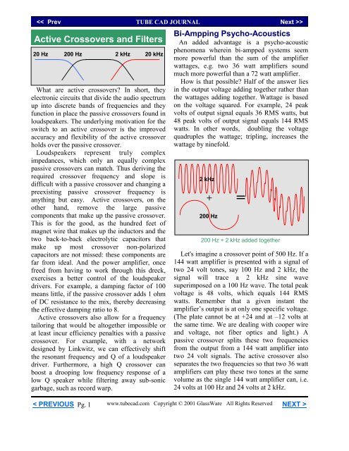
20 Hz 200 Hz<br />
2 kHz 20 kHz<br />
What are active crossovers? In short, they<br />
electronic circuits that divide the audio spectrum<br />
up into discrete b<strong>and</strong>s of frequencies <strong>and</strong> they<br />
function in place the passive crossovers found in<br />
loudspeakers. The underlying motivation for the<br />
switch to an active crossover is the improved<br />
accuracy <strong>and</strong> flexibility of the active crossover<br />
holds over the passive crossover.<br />
Loudspeakers represent truly complex<br />
impedances, which only an equally complex<br />
passive crossovers can match. Thus deriving the<br />
required crossover frequency <strong>and</strong> slope is<br />
difficult with a passive crossover <strong>and</strong> changing a<br />
preexisting passive crossover frequency is<br />
anything but easy. <strong>Active</strong> crossovers, on the<br />
other h<strong>and</strong>, remove the large passive<br />
components that make up the passive crossover.<br />
This is for the good, as the hundred feet of<br />
magnet wire that makes up the inductors <strong>and</strong> the<br />
two back-to-back electrolytic capacitors that<br />
make up most crossover non-polarized<br />
capacitors are not missed: these components are<br />
far from ideal. And the power amplifier, once<br />
freed from having to work through this dreck,<br />
exercises a better control of the loudspeaker<br />
drivers. For example, a damping factor of 100<br />
means little, if the passive crossover adds 1 ohm<br />
of DC resistance to the mix, thereby decreasing<br />
the effective damping ratio to 8.<br />
<strong>Active</strong> crossovers also allow for a frequency<br />
tailoring that would be altogether impossible or<br />
at least incur efficiency penalties with a passive<br />
crossover. For example, with a network<br />
designed by Linkwitz, we can effectively shift<br />
the resonant frequency <strong>and</strong> Q of a loudspeaker<br />
driver. Furthermore, a high Q crossover can<br />
boost a drooping low frequency response of a<br />
low Q speaker while filtering away sub-sonic<br />
garbage, such as record warp.<br />
< PREVIOUS<br />
Pg. 1<br />
Bi-Ampping Psycho-Acoustics<br />
An added advantage is a psycho-acoustic<br />
phenomena wherein bi-ampped systems seem<br />
more powerful than the sum of the amplifier<br />
wattages, e.g. two 36 watt amplifiers sound<br />
much more powerful than a 72 watt amplifier.<br />
How is that possible? Half of the answer lies<br />
in the output voltage adding together rather than<br />
the wattages adding together. Wattage is based<br />
on the voltage squared. For example, 24 peak<br />
volts of output signal equals 36 RMS watts, but<br />
48 peak volts of output signal equals 144 RMS<br />
watts. In other words, doubling the voltage<br />
quadruples the wattage; tripling, increases the<br />
wattage by ninefold.<br />
2 kHz<br />
+ =<br />
200 Hz<br />
200 Hz + 2 kHz added together<br />
Let's imagine a crossover point of 500 Hz. If a<br />
144 watt amplifier is presented with a signal of<br />
two 24 volt tones, say 100 Hz <strong>and</strong> 2 kHz, the<br />
signal will trace a 2 kHz sine wave<br />
superimposed on a 100 Hz wave. The total peak<br />
voltage is 48 volts, which equals 144 RMS<br />
watts. Remember that a given instant the<br />
amplifier’s output is at only one specific voltage.<br />
(The plate cannot be at +24 <strong>and</strong> at –12 volts at<br />
the same time. We are dealing with cooper wire<br />
<strong>and</strong> voltage, not fiber optics <strong>and</strong> light.) A<br />
passive crossover splits these two frequencies<br />
from the output from a 144 watt amplifier into<br />
two 24 volt signals. The active crossover also<br />
separates the two frequencies so that two 36 watt<br />
amplifiers can play these two tones at the same<br />
volume as the single 144 watt amplifier can, i.e.<br />
24 volts at 100 Hz <strong>and</strong> 24 volts at 2 kHz.<br />
www.tubecad.com Copyright © 2001 GlassWare All Rights Reserved NEXT >
Of course, if both tones had been at<br />
frequencies below the 500 Hz crossover point,<br />
say 100 <strong>and</strong> 300 Hz, one 36 watt amplifier<br />
would clip its output while the second amplifier<br />
sat idle. While this seems to limit the power<br />
increasing effect, this indirectly leads to second<br />
power increasing effect.<br />
300 Hz<br />
< PREVIOUS<br />
+ =<br />
100 Hz<br />
100 Hz + 300 Hz added together <strong>and</strong> clipped<br />
The ear is most sensitive at about 3 kHz<br />
(roughly, the resonate frequency of the ear<br />
canal). As the frequency falls from this<br />
frequency, so does our sensitivity to it. So if a<br />
bi-ampped system sees a signal that only clips<br />
the woofer amplifier, the ear will not complain<br />
as much as it would if the tweeter amplifier had<br />
clipped. A further reason is that woofers are<br />
slow heavy devices that cannot reproduce the<br />
harsh high harmonic of the clipped low<br />
frequency waveform. So while a low frequency<br />
amplifier may clip repeatedly, the woofer will<br />
not readily betray that fact. And since it is<br />
usually the low frequencies the dem<strong>and</strong> the<br />
greatest share of power, the two 36 watt<br />
amplifiers may even seem more powerful than a<br />
144 watt amplifier as long as the high frequency<br />
amplifier has not clipped. (This might help<br />
explain why a 3 watt tube SE amplifier can<br />
sound as powerful as a 30 watt solid-state<br />
amplifier: the ear hears clipping as the limit to<br />
power. Transformer coupled, feedback free<br />
amplifiers have the softest clipping<br />
characteristics of any amplifier, as the<br />
transformers limit the transfer of high<br />
frequencies <strong>and</strong> the absence of feedback means<br />
the driver stage will not try force a sharper slope<br />
on the output tube’s flattened waveform.)<br />
Pg. 2<br />
One last argument in favor of active<br />
crossovers: headphone listening can be superb,<br />
but it suffers from the lack of a visceral<br />
component; the floor just doesn’t shake with<br />
headphones…but it can. For over two decades<br />
my preferred way of listening to headphones has<br />
been to use them with powered subwoofers.<br />
With a high frequency limit of 80 Hz the<br />
subwoofers seldom even move with pop music,<br />
but with Mahler’s 3rd symphony, they work<br />
overtime. (The missing octave is filled in <strong>and</strong> yet<br />
your neighbors have a hard time locating you as<br />
the source of the low growls, as the ear has a<br />
hard time localizing ultra-low frequencies.)<br />
Filter Types<br />
What is the difference between a crossover<br />
<strong>and</strong> filter? A crossover is specifically meant to<br />
work with loudspeakers <strong>and</strong> it is usually made<br />
up of several filters. In other words, a filter is the<br />
more general term, which suits a circuit that has<br />
such a wide application. Almost all electronic<br />
devices employ some filters. The radio <strong>and</strong> TV<br />
set are filters of sorts, as they select only a<br />
narrow b<strong>and</strong> of frequencies at a time. A filter<br />
can be made out of as little a single capacitor or<br />
inductor (<strong>and</strong> a load resistance). A filter can also<br />
consist of twenty resistors <strong>and</strong> twenty capacitors<br />
<strong>and</strong> many amplifiers.<br />
<strong>Filters</strong><br />
Analog Digital<br />
Passive <strong>Active</strong><br />
Lowpass Lowpass<br />
B<strong>and</strong>pass B<strong>and</strong>pass<br />
Notch Notch<br />
Highpass Highpass<br />
In all filters, however, some frequencies are<br />
allowed to pass, while others are attenuated. The<br />
portion that is allowed to pass is named the<br />
passb<strong>and</strong> <strong>and</strong> the portion that is excluded is<br />
named the stopb<strong>and</strong> <strong>and</strong> the portion of overlap<br />
between these two b<strong>and</strong>s is named the<br />
transitional-b<strong>and</strong>.<br />
www.tubecad.com Copyright © 2001 GlassWare All Rights Reserved NEXT >
Lowpass B<strong>and</strong>pass Notch Highpass<br />
If only low frequencies are passed, we call this<br />
filter a low-pass filter, as that is what it passes. If<br />
only high frequencies are passed, we call this<br />
filter a high-pass filter. If only a b<strong>and</strong> of<br />
frequencies, say 500 to 5000 Hz, are passed, we<br />
call this filter a b<strong>and</strong>-pass filter. If all frequency<br />
are passed save for a very narrow b<strong>and</strong> of<br />
frequencies, we call this filter a notch filter.<br />
Beyond these four basic divisions, a further<br />
classification is applied based the steepness of<br />
the rejection of undesired frequencies.<br />
Since the slope’s steepness is marked by the<br />
“order” in a filter’s design. (The number of poles<br />
is also sometimes used as a short h<strong>and</strong><br />
description of the steepness.) For example, a<br />
single order filter, also called a single pole filter,<br />
has a crossover slope of -20 dB per decade,<br />
which equals -6 dB per octave. Thus a second<br />
order filter attenuates at –12 dB per octave; a<br />
third order filter, -18 dB per octave; a fourth<br />
order filter, -24 dB per octave; a fifth order<br />
filter, -30 dB per octave; <strong>and</strong> a sixth order<br />
filter, -36 dB per octave.<br />
0<br />
-3<br />
-20<br />
< PREVIOUS<br />
Pg. 3<br />
F 10F<br />
4th<br />
2nd<br />
The next taxonomic division is made based on<br />
the filters alignment. The alignment is based on<br />
the relative position of the poles in the filter,<br />
which in turn gives rise to the different shapes<br />
each filter exhibits across its frequency range.<br />
Some filters offer a sharp transition from<br />
passb<strong>and</strong> to stopb<strong>and</strong>, but at the cost of some<br />
ripple <strong>and</strong> even ringing in the frequency<br />
response. Other filters offer a soft transition that<br />
droops at the transition frequency that is ripple<br />
free. In short, an analog filter’s design hopes to<br />
optimize one or two parameters, but always at<br />
the cost of some other parameters.<br />
3rd<br />
1st<br />
The most common filter alignments are the<br />
Butterworth <strong>and</strong> the Bessel (AKA Thomson).<br />
Less common alignments are the Gaussian,<br />
Chebyshev <strong>and</strong> the elliptic (AKA Cauer). A<br />
recent addition to the palette of filters is the<br />
Linkwitz-Riley alignment (AKA Butterworth<br />
squared), which was specifically designed for<br />
use as loudspeakers crossover (More on this type<br />
of filter to follow.).<br />
Common Audio Filter Types<br />
The Butterworth filter is the most commonly<br />
used filter type in audio applications. It has a<br />
fairly flat time response, a fairly crisp transition<br />
shape <strong>and</strong> the flattest passb<strong>and</strong> response. In<br />
contrast, the Bessel filter offers a flatter time<br />
response, but not as sharp a transition shape or<br />
flat a passb<strong>and</strong> response. The Chebyshev <strong>and</strong> the<br />
elliptic filter are seldom used in everyday audio<br />
gear, as these filters bring too many undesirable<br />
characteristics such as ripples in the passb<strong>and</strong> or<br />
wild phase shifts.<br />
The Linkwitz-Riley filter improves on the<br />
Butterworth when feeding loudspeakers. Odd<br />
order crossovers (6 dB <strong>and</strong> 18 dB per octave<br />
filters) are marked by of 90 degree multiples in<br />
phase differences between outputs. The sum of<br />
two 90 degree equal amplitude signals is +3 dB<br />
boost in output. Thus the –3 dB point of the<br />
filter works to yield a flat transition region.<br />
Even-order crossovers (12 dB <strong>and</strong> 24 dB per<br />
octave filters) are marked by 180 degree<br />
multiples of phase differences between outputs.<br />
The sum of two 180 degree phase shifted, but<br />
equal amplitude, signals is a deep null in the<br />
output. The solution is to reverse the phase of<br />
one of the loudspeaker drivers to eliminate the<br />
phase difference at the crossover frequency.<br />
However, when two loudspeakers play the exact<br />
same signal (no amplitude or phase differences),<br />
the result is a twofold increase (+6 dB boost) in<br />
volume. So if we wish to reconstruct the outputs<br />
of one lowpass <strong>and</strong> one highpass filter, we must<br />
tailor the attenuation at the crossover frequency<br />
to match the intended summing device.<br />
www.tubecad.com Copyright © 2001 GlassWare All Rights Reserved NEXT >
Thus, when using loudspeakers that see the<br />
same phase <strong>and</strong> amplitude signal, we cannot use<br />
a –3 dB down point, as it would yield +3 dB;<br />
thus, we need a –6 dB attenuation at the<br />
crossover frequency in order to ensure a flat<br />
frequency response. The same phase is the key<br />
point here. If a Butterworth second or fourth or<br />
sixth order crossover is used, the frequency<br />
response will display a bump at the crossover<br />
frequency. On the other h<strong>and</strong>, using a Linkwitz-<br />
Riley 2nd or fourth order crossover will yield a<br />
flat frequency response at the crossover<br />
frequency.<br />
Well at least that is the theory. Complications<br />
arise: the distance between drivers, the<br />
frequency response of each driver, the front-toback<br />
spacing of the driver’s voicecoils. If the<br />
distance between drivers exceeds the wavelength<br />
of the crossover frequency, or if one or both<br />
drivers droop at the crossover frequency, or if<br />
the tweeter acoustic center is substantially in<br />
front of the woofers, then the Butterworth<br />
aligned crossover might actually prove flatter.<br />
Do not falsely imagine that an even order<br />
crossover is phase flat; it isn’t. The actual phase<br />
relation between 2nd order lowpass <strong>and</strong><br />
highpass filters is a constant 180 degrees phase<br />
difference, which when one driver's connection<br />
is inverted, yields a constant phase relation<br />
between drivers, but not a flat phase response.<br />
180°<br />
0°<br />
-180°<br />
Fc/10 Fc 10xFc<br />
Phase differences between 2nd order Butterworth<br />
high-pass filter (white line) <strong>and</strong> its low-pass<br />
complement (yellow line)<br />
< PREVIOUS<br />
Pg. 4<br />
A Phase Flat Loudspeaker<br />
One interesting loudspeaker configuration<br />
was created by Philips. An ostensibly two-way<br />
loudspeaker was designed using a second order<br />
Butterworth crossover, but without the tweeter’s<br />
phase reversal. Yes this resulted in a deep suckout.<br />
The suck-out was then filled in by using a<br />
b<strong>and</strong>pass filter (-6 dB slopes) feeding a fullrange<br />
driver. This extra speaker saw only the<br />
crossover frequency unattenuated, as all the<br />
frequencies below or above this frequency were<br />
attenuated at –6 dB per octave. The sum of all<br />
three driver’s output equaled a phase-coherent<br />
flat frequency response. In this speaker system,<br />
the woofer was prevented from going too high,<br />
while the tweeter is protected from low<br />
frequencies, while fullrange driver filled in the<br />
hole. Unfortunately, this solution, like most<br />
speaker innovations, disappeared long ago.<br />
0<br />
-3<br />
Crossover Testing<br />
Evaluating active crossovers under actual use<br />
is difficult. Which component is making the<br />
biggest difference? The active crossover itself or<br />
the extra amplifiers <strong>and</strong> speaker cables? A<br />
listening test I have used is to take a pair of<br />
fullrange conventional loudspeakers <strong>and</strong> apply<br />
the crossover under test using my present<br />
amplifier <strong>and</strong> cables. This means there is no<br />
worry about relative efficiencies <strong>and</strong> frequency<br />
response limitations.<br />
The procedure is simple enough; place one<br />
speaker on top of the other <strong>and</strong> set the crossover<br />
frequency to some value between 300-700 Hz<br />
(too high a frequency will result in lobbing<br />
effects due to greater than wavelength spacing<br />
between drivers). This test requires a mono<br />
signal source <strong>and</strong> I recommend any of the mono<br />
Verve recordings of Ella Fitzgerald.<br />
www.tubecad.com Copyright © 2001 GlassWare All Rights Reserved NEXT >
First listen to just the loudspeaker on top<br />
(fullrange, without the active crossover in other<br />
words). It takes some time to get used to mono,<br />
so play about 30 minutes worth. Next introduce<br />
the active crossover <strong>and</strong> feed the highpass signal<br />
to the top loudspeaker. Now listen to the same<br />
30 minutes of music.<br />
500 Hz<br />
500 Hz<br />
General crossover test setup<br />
If the crossover is working well, the sound<br />
should be very similar to that from the single<br />
loudspeaker. The usual result is that the sound is<br />
much better than that from the sole speaker.<br />
Why? The power increasing effect is part of the<br />
reason. The rest of the answer is found in the<br />
reduction in distortion that results from freeing<br />
the top loudspeaker from the onerous task of<br />
reproducing low frequencies. In other words,<br />
the top loudspeaker is less likely to mechanically<br />
clip. Furthermore, there is a large reduction in a<br />
seldom mentioned distortion: frequency<br />
modulation distortion, FMD.<br />
FMD<br />
This distortion is related to Doppler<br />
distortion: the phenomenon of frequencies<br />
increasing in pitch as a sound producing object<br />
nears us <strong>and</strong> the sound decreasing in pitch as the<br />
object retreats. The sound of a race car<br />
approaching <strong>and</strong> passing is the usually given<br />
example. RRRRR R R R R R R R R R R.<br />
< PREVIOUS<br />
Pg. 5<br />
Loudspeaker diaphragms move in response to<br />
signals <strong>and</strong> the large diaphragm movements<br />
caused by low frequencies raise the high<br />
frequencies while the driver’s cone moves<br />
toward us <strong>and</strong> then lower the high frequencies<br />
when the cone moves away from us.<br />
Consequently, in absolute terms, it is impossible<br />
for anyone driver to reproduce more than one<br />
pure tone at a time. This is one reason why<br />
electrostatic <strong>and</strong> planer speakers sound as good<br />
as they do; the large surface areas do not need to<br />
move very far to produce high sound levels.<br />
Three-way, four-way, five-way, <strong>and</strong> six-way<br />
loudspeaker also greatly reduce this distortion,<br />
while admittedly adding huge crossover<br />
problems. And the worst offenders are small<br />
fullrange single driver based loudspeakers.<br />
Bi-Ampped Identical Loudspeakers<br />
I once heard something like the test setup with<br />
four large Advent loudspeaker from the early<br />
80’s. A friend bought four speakers for<br />
quadraphonic use <strong>and</strong> instead used all four in a<br />
stereophonic setup with a active crossover set at<br />
100 Hz. The improvement in midrange clarity<br />
<strong>and</strong> bass definition was markedly better. In fact,<br />
it sounded much better than it should seem<br />
possible. (A similar experience occurred when I<br />
heard a speaker setup that consisted of eight high<br />
quality mini-monitors configured as two<br />
speakers. No crossover was used <strong>and</strong> four<br />
speaker enclosures were stacked on each other<br />
per side, with only one facing the listener. The<br />
resulting impedance was identical to that of a<br />
single speaker, as they were wired in seriesparallel.<br />
Because each speaker saw half of the<br />
available output voltage from the power<br />
amplifier, its response was down 6 dB; but as the<br />
radiating area had increased fourfold, the output<br />
response gained +12 dB of gain, which in the<br />
end, yielded +6 dB of gain.)<br />
www.tubecad.com Copyright © 2001 GlassWare All Rights Reserved NEXT >
In same vein, if you are pleased with your<br />
present loudspeakers, but wish that they<br />
provided a little more headroom or clarity at<br />
high volumes, then this doubling of<br />
loudspeakers might be the best way to go.<br />
<strong>Active</strong> crossovers are certainly nice, but not<br />
strictly necessary, as one choke <strong>and</strong> one<br />
capacitor are all that is needed to make a passive<br />
single order crossover. My recommendation is to<br />
select a crossover frequency that is the<br />
geometric mean of the lowest <strong>and</strong> highest<br />
frequencies produced by your loudspeakers. For<br />
example, 600 Hz for speakers that extend down<br />
to 20 Hz <strong>and</strong> up to 20 kHz; 1400 Hz for that<br />
only extend down to 100 Hz (mini-monitors).<br />
Fgeometric = √(Flow x Fhigh)<br />
I also recommend using the shunt arrangement<br />
rather than the series, as it provides better<br />
damping. (The shunt arrangement attenuates the<br />
stopb<strong>and</strong> by shunting the driver with an ever<br />
decreasing impedance; where the series<br />
arrangement attenuates the stopb<strong>and</strong> by<br />
presenting the driver with an ever increasing<br />
impedance.) Of course, with a passive crossover,<br />
none of the power increasing effects are<br />
bestowed.<br />
+<br />
-<br />
Choosing Crossover Slopes<br />
In theory, nothing beats a simple 1st order<br />
crossover. It results in a flat, time coherent<br />
frequency response. Actual practice differs. The<br />
1st order filter provides a shallow attenuation<br />
slope that is too gradual to protect fragile<br />
tweeters from brutal low frequencies <strong>and</strong> too<br />
gradual to keep woofers from working up into<br />
< PREVIOUS<br />
Pg. 6<br />
+<br />
+<br />
their high frequency limits, as a two to three<br />
octave overlap is recommended to make this<br />
filter work well. However, as the number of<br />
crossover points increase, the more likely it is<br />
that this gentle filter slope will provide sufficient<br />
protection.<br />
On the other h<strong>and</strong>, if you are adding a powered<br />
subwoofer to an existing fullrange loudspeaker,<br />
the 1st order highpass filter is a good choice for<br />
the fullrange speaker <strong>and</strong> a 3rd order filter for<br />
the subwoofer. This combination seems to work<br />
well in terms of amplitude response. It also has a<br />
minimalist aspect that is gratifying: the<br />
subwoofer contributes only its low frequency<br />
heft <strong>and</strong> then quickly gets out of the way of the<br />
lower midrange; the satellite loudspeaker sees a<br />
very gentle highpass slope that allows it extend<br />
down into the deep bass as it very slowly falls<br />
off in volume with decrease frequency.<br />
100 Hz<br />
1st 3rd<br />
Those using zero feedback tube amplifiers,<br />
will find a preexisting 1st order highpass filter in<br />
their power amplifiers. The coupling capacitor<br />
that connects to the grids of the output tubes<br />
defines a highpass filter that is usually set to<br />
some very low frequency, such as 1 to 5 Hz.<br />
Decreasing the value of this capacitor raises the<br />
crossover frequency. By choosing the right<br />
value, we can forgo the need for an external<br />
crossover. The formula is an easy one:<br />
C = 159155/Fc/R,<br />
Where Fc equals the desired crossover<br />
frequency, C equals the value of the coupling<br />
capacitor in µF, <strong>and</strong> R equals the value of the<br />
grid resistor. Truly minimalist. One trick I have<br />
wanted to try for some time now is using a<br />
satellite loudspeaker (a sealed box with a Q of 1)<br />
along with a 1st order filter, which comes with a<br />
Q of 0.707 (set to the Fo of the enclosure).<br />
www.tubecad.com Copyright © 2001 GlassWare All Rights Reserved NEXT >
The Qs are multiplied against each other,<br />
which will give the loudspeaker an effective Q<br />
of 0.707. The advantage of this arrangement lies<br />
in the smaller enclosure needed for a higher Q<br />
loudspeaker alignment <strong>and</strong> the natural 2nd order<br />
highpass filter function of the sealed box<br />
enclosure adding to 1st order filter to make a 3rd<br />
order highpass filter with a -3 dip at the<br />
crossover frequency.<br />
To work best this 1st order filter must come<br />
before the power amplifier, as using a capacitor<br />
in series with the loudspeaker will not work due<br />
to the impedance spike at the speaker’s<br />
resonance. The subwoofer's lowpass filter should<br />
be actively realized with an active 3rd order<br />
Butterworth filter. A further refinement would<br />
be to add an active 2nd order or 4th order<br />
highpass filter whose cutoff frequency would<br />
equal the Fs of the subwoofer. This would both<br />
work to protect the satellite speaker from<br />
excessive low frequency cone excursions <strong>and</strong><br />
work to bring both subwoofer <strong>and</strong> satellite into<br />
the same phase relationships, as the subwoofer’s<br />
own box resonance defines a highpass filter (2nd<br />
order for sealed boxes <strong>and</strong> 4th order for bassreflex<br />
enclosures.)<br />
2nd<br />
3rd<br />
30 Hz<br />
< PREVIOUS<br />
1st 3rd<br />
Pg. 7<br />
100 Hz<br />
Using the speaker's own effective filters to complete<br />
a crossover . Here the speaker's 2nd order function<br />
is added to a 1st order filter to yield an effective 3rd<br />
order slope.<br />
For most drivers that suffer from either<br />
limited power h<strong>and</strong>ling or limited frequency<br />
response, sharper cutoffs are needed. The 2nd,<br />
3rd, <strong>and</strong> 4th order slopes both protect <strong>and</strong> isolate<br />
the drivers. Many audiophiles, however, distrust<br />
higher order filters, fearing the signal’s phase<br />
reversals <strong>and</strong> complexity of the crossovers. Yet<br />
they do not realize that the speakers themselves<br />
bring phase aberrations because of resonances<br />
driver breakup at higher frequencies. For<br />
example, most tweeters have a resonant<br />
frequency between 800 to 2 kHz <strong>and</strong> all cone<br />
<strong>and</strong> dome drivers must flex once the<br />
circumference of the diaphragm becomes larger<br />
than the twice the wavelength of the frequency<br />
being reproduced. (Strictly speaking, for<br />
example, we should not let an 8 inch woofer<br />
extend beyond 1400 Hz; but we do so regularly.)<br />
Here is where active filters shine. As has been<br />
mentioned, the problem with using passive<br />
filters with loudspeakers is that they seldom<br />
function entirely to plan <strong>and</strong> this poor<br />
performance is due to the passive components<br />
falling short of their ideals.<br />
Inductors (chokes) are made up of long<br />
lengths of wire, which adds resistance. Capacitor<br />
also carry an ESR (effective series resistance)<br />
that upsets inter-relations within the filter. And<br />
loudspeaker drivers are anything but pure<br />
resistances. All of these failings add up to a filter<br />
that does not match its textbook model. On the<br />
other h<strong>and</strong>, the active filter can match its<br />
textbook template easily. Additionally, active<br />
filters can make do with only resistors <strong>and</strong><br />
capacitors to define their poles. Doing without<br />
inductors is a relief in terms of money <strong>and</strong> space,<br />
as the lower the frequency, the bigger the<br />
inductor. And because the active filter presents<br />
an almost infinite input impedance to the<br />
frequency tailoring parts, high valued resistors<br />
can be used, which only require small valued<br />
capacitors to match. For example, an 8 ohm<br />
loudspeaker driver crossing over at 1 kHz<br />
requires a 20 µF capacitor, whereas a 10k<br />
resistor only needs a .0159 µF capacitor. In other<br />
words, active filters present a win, win situation.<br />
www.tubecad.com Copyright © 2001 GlassWare All Rights Reserved NEXT >
Mix <strong>and</strong> Match<br />
<strong>Active</strong> filters can be cascaded to yield a<br />
degree of frequency tailoring that is all but<br />
impossible with passive filters. The passive filter<br />
works best with known, fixed input <strong>and</strong><br />
terminating impedances, which a cascading<br />
passive filter cannot readily do.<br />
For example, two active 3rd order filters<br />
cascaded equals a 6th order filter. An active<br />
highpass <strong>and</strong> a lowpass filter cascaded can yield<br />
b<strong>and</strong>pass filter; <strong>and</strong> these same filters fed into a<br />
mixer can yield a notch filter.<br />
Conclusion<br />
In this article we have looked into the why<br />
bother with active crossovers <strong>and</strong> filters? We<br />
have seen that active crossovers <strong>and</strong> active<br />
filters in general offer some real advantages over<br />
their passive brethren, as they are more accurate,<br />
flexible, <strong>and</strong> easy to implement. In the next<br />
article, we will look into designing tube<br />
crossovers.<br />
//JRB<br />
Suggested Readings<br />
<strong>Active</strong> Filter Cookbook<br />
By Don Lancaster, 1975, 95, 96<br />
IC based active filters explained in detail. A<br />
classic that is readily available new <strong>and</strong> used.<br />
Audio/Radio H<strong>and</strong>book<br />
By National Semiconductor, 1980<br />
This book has a chapter whimsically named<br />
“Floobydust,” which covers some interesting<br />
active crossovers, including asymmetrical filters.<br />
Passive <strong>and</strong> <strong>Active</strong> <strong>Filters</strong><br />
By Wai-Kai Chen, 1986<br />
The book to own, if you are serious about filters.<br />
A classic, but not for those fearful of math.<br />
Underst<strong>and</strong>ing Electronic <strong>Filters</strong><br />
By Owen Bishop, 1996<br />
This book is the best place for the novice to<br />
start. Should be read from start to finish.<br />
< PREVIOUS<br />
Pg. 8<br />
Antique Electronic Supply<br />
<strong>Tube</strong>s<br />
Kits & Power Supplies<br />
Sockets<br />
Guitar Items<br />
Transformers<br />
Tools & Chemicals<br />
Capacitors<br />
Books<br />
Other Parts & Supplies<br />
Software<br />
Restoration Products<br />
Over 10,000 square feet of:<br />
<strong>Tube</strong>s, books, transformers, sockets, friendly<br />
folks, capacitors, resistors, literature,<br />
cabinet restoration materials, friendly folks,<br />
wire, grill cloth, gifts, tools, information...<br />
<strong>and</strong> did we mention the friendly folks?<br />
68 pages of products<br />
<strong>and</strong> information (most<br />
of which are also<br />
available on our Web<br />
site). It's all here!<br />
Get our 2001 catalog<br />
absolutely free!<br />
www.tubecad.com Copyright © 2001 GlassWare All Rights Reserved NEXT >


