A PENETRATOR FOR THE JUPITER GANYMEDE ORBITER MISSION
A PENETRATOR FOR THE JUPITER GANYMEDE ORBITER MISSION
A PENETRATOR FOR THE JUPITER GANYMEDE ORBITER MISSION

Create successful ePaper yourself
Turn your PDF publications into a flip-book with our unique Google optimized e-Paper software.
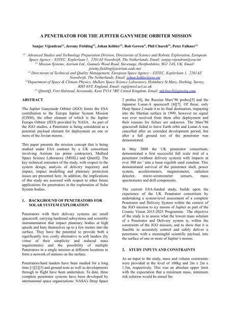
A <strong>PENETRATOR</strong> <strong>FOR</strong> <strong>THE</strong> <strong>JUPITER</strong> <strong>GANYMEDE</strong> <strong>ORBITER</strong> <strong>MISSION</strong><br />
Sanjay Vijendran (1) , Jeremy Fielding (2) , Johan Köhler (3) , Rob Gowen 4) , Phil Church (5) , Peter Falkner (1)<br />
(1) Advanced Studies and Technology Preparation Division, Directorate of Science and Robotic Exploration, European<br />
Space Agency – ESTEC, Keplerlaan 1, 2201AZ Noordwijk, The Netherlands, Email: sanjay.vijendran@esa.int<br />
(2) Mission Systems, Astrium Ltd., Gunnels Wood Road, Stevenage, Hertfordshire, SG1 2AS, UK, Email:<br />
jeremy.fielding@astrium.eads.net<br />
(3) Directorate of Technical and Quality Management, European Space Agency – ESTEC, Keplerlaan 1, 2201AZ<br />
Noordwijk, The Netherlands, Email: johan.kohler@esa.int<br />
(4) Department of Space & Climate Physics, Mullars Space Science Laboratory, Holmbury St Mary, Dorking, Surrey,<br />
RH5 6NT, England, Email: rag@mssl.ucl.ac.uk<br />
(5) QinetiQ, Fort Halstead, Sevenoaks, Kent TN14 7BP, United Kingdom, Email: pdchurch@qinetiq.com<br />
ABSTRACT<br />
The Jupiter Ganymede Orbiter (JGO) forms the ESA<br />
contribution to the Europa Jupiter System Mission<br />
(EJSM), the other element of which is the Jupiter<br />
Europa Orbiter (JEO) provided by NASA. As part of<br />
the JGO studies, a Penetrator is being considered as a<br />
potential payload element for deployment on one or<br />
more of the Jovian moons.<br />
This paper presents the mission concept that is being<br />
studied under ESA contract by a UK consortium<br />
involving Astrium (as prime contractor), Mullard<br />
Space Science Laboratory (MSSL) and QinetiQ. The<br />
key technical outcomes of the study, with respect to the<br />
system design, analysis of delivery trajectory and<br />
impact, impact modelling and planetary protection<br />
issues are presented here. In addition, the implications<br />
of this study are assessed with respect to other future<br />
applications for penetrators in the exploration of Solar<br />
System bodies.<br />
1. BACKGROUND OF <strong>PENETRATOR</strong>S <strong>FOR</strong><br />
SOLAR SYSTEM EXPLORATION<br />
Penetrators with their delivery systems are small<br />
spacecraft, carrying hardened subsystems and scientific<br />
instrumentation that impact planetary bodies at high<br />
speeds and bury themselves up to a few metres into the<br />
surface. They have the potential to provide both a<br />
significantly less costly alternative to soft landers (by<br />
virtue of their simplicity and reduced mass<br />
requirements) and the possibility of multiple<br />
Penetrators in a single mission at different locations to<br />
form a network of stations on the surface.<br />
Penetrators/hard landers have been studied for a long<br />
time [1][2][3] and ground tests as well as developments<br />
through to flight have been undertaken. To date, three<br />
complete penetrator systems have been developed by<br />
international space organizations: NASA’s Deep Space<br />
2 probes [4], the Russian Mars’96 probes[5] and the<br />
Japanese Lunar-A spacecraft [6][7]. Of these, only<br />
Deep Space 2 made it to its final destination, impacting<br />
into the Martian surface in 1999, however no signal<br />
was ever received from them after deployment and<br />
their reasons for failure are unknown. The Mars’96<br />
spacecraft failed to leave Earth orbit and Lunar-A was<br />
cancelled after an extended development period, but<br />
after a full ground test of the penetrator was<br />
demonstrated.<br />
In May 2008 the UK penetrator consortium,<br />
demonstrated a first successful full scale trial of a<br />
penetrator (without delivery system) with impacts at<br />
over 300 ms -1 into a lunar regolith sand simulant. This<br />
demonstrated survival of the penetrator shell, power<br />
system, accelerometers, magnetometer, radiation<br />
detector, micro-seismometer sensors, mass<br />
spectrometer and drill components.<br />
The current ESA-funded study, builds upon the<br />
experience of the UK Penetrator consortium by<br />
undertaking a system-level assessment of a complete<br />
Penetrator and Delivery System within the context of<br />
the JGO mission to icy moons of Jupiter as part of the<br />
Cosmic Vision 2015-2025 Programme. The objective<br />
of the study is to assess what the lowest mass solution<br />
of a Penetrator and Delivery system is, within the<br />
constraints of the JGO mission, and to show that it is<br />
feasible to accurately control and safely deliver a<br />
penetrator, with a meaningful scientific payload, into<br />
the surface of one or more of Jupiter’s moons.<br />
2. STUDY INPUTS AND CONSTRAINTS<br />
As an input to the study, mass and volume constraints<br />
were provided at the level of 100kg and 2m x 2m x<br />
1.5m, respectively. This was an absolute upper limit<br />
with the expectation that a minimum mass, minimum<br />
risk solution would be aimed for.
The other strong constraint for the study was to only<br />
consider solutions utilising technologies that would be<br />
at a Technology Readiness Level (TRL) of 5 by end<br />
2012 in order to be compatible with the schedule of the<br />
JGO mission, planned for launch in 2020.<br />
3. SCIENTIFIC CASE <strong>FOR</strong> <strong>PENETRATOR</strong>S<br />
ON <strong>THE</strong> JOVIAN ICY MOONS<br />
The deployment of Penetrators on the surface of the<br />
Jovian icy moons would add ‘ground truth’ to the<br />
orbital data acquired by the Orbiters of the EJSM<br />
mission as well as enable significant unique<br />
measurements to help answer key scientific questions<br />
about the origin, internal structure and habitability of<br />
these moons. The main science drivers of a landed<br />
element are to:<br />
• Enable direct geophysical investigation<br />
including detection of any sub-surface ocean<br />
(surface, mantle and internal body structures,<br />
crustal and internal seismic activity).<br />
• Enable direct subsurface chemical and<br />
mineralogical inventory.<br />
• Enable direct astrobiological investigation.<br />
• Enable comparison of surface element data<br />
with orbital studies and with other moons<br />
4. OVERVIEW OF <strong>THE</strong> <strong>JUPITER</strong> <strong>GANYMEDE</strong><br />
<strong>ORBITER</strong> <strong>MISSION</strong><br />
JGO is one of the candidates (referred to as ‘Laplace’)<br />
for the “L1” launch slot in the ESA Cosmic Vision<br />
plan, with a foreseen launch in 2020. All three<br />
currently studied L mission concepts (Laplace, IXO<br />
and LISA) are undergoing parallel studies with a<br />
down-selection at the end of 2010, when two mission<br />
concepts will be selected for definition studies,<br />
extending to the end of 2012. Eventually, the first L<br />
mission will be adopted for flight with an industrial<br />
implementation being planned for start in 2013.<br />
According to the current baseline mission profile, JGO<br />
would be launched in 2020 on a Venus-Earth-Earth-<br />
Gravity-Assist trajectory to Jupiter. The inter-planetary<br />
transfer will take about 5.9 years. The initial Jovian<br />
orbit will be 13×245 RJ, followed by a total of four<br />
Ganymede and Callisto swing-by manoeuvres<br />
(GCGC). JGO will then be injected into a 2:3 resonant<br />
orbit around Callisto, which allows for 19 flybys at an<br />
altitude of 200 km, providing good surface coverage.<br />
Through another swing-by sequence (CGG), the orbiter<br />
will be injected into an elliptical orbit around<br />
Ganymede (200×6000 km), which will be circularized<br />
later in the mission, reaching a 200 km altitude orbit.<br />
The whole mission duration in the Jovian environment<br />
will last 3 years.<br />
5. JGO-<strong>PENETRATOR</strong> <strong>MISSION</strong><br />
ARCHITECTURE<br />
For the JGO-Penetrator mission concept currently<br />
being studied by ESA, the Penetrator would make use<br />
of the JGO to ‘hitch a ride’ to the Jovian system. The<br />
JGO spacecraft cannot however deliver the Penetrator<br />
to the surface of a moon as required. A separate<br />
Penetrator Delivery System (PDS) is therefore needed<br />
to carry the Penetrator from JGO through to a<br />
controlled impact. The PDS, being a mini-spacecraft in<br />
its own right, is an area that has not been studied<br />
previously in much detail and turns out to be the<br />
largest contributor to the total system mass and is<br />
therefore a major design driver (to minimise mass) for<br />
the Penetrator mission.<br />
The Penetrator Descent Module (PDM) incorporating<br />
both Penetrator and PDS, must separate from JGO at<br />
some allotted point in the mission. This separation<br />
could occur either early (on initial hyperbolic approach<br />
to the Jovian system), mid-mission (on hyperbolic<br />
approach to Ganymede from Jupiter), or late (from a<br />
stable orbit around Ganymede).<br />
Of the latter case, two additional sub-cases are possible<br />
based on the JGO mission; release from either an<br />
elliptical or a (final) circular orbit. Both elliptical and<br />
circular release scenarios are shown in Fig. 1 and Fig. 2<br />
respectively. In these cases, the PDM must perform<br />
manoeuvres to achieve the trajectory represented by<br />
the dotted line.<br />
G<br />
Figure 1: Elliptical Orbit Release Option
Figure 2: Circular Orbit Release<br />
5.1 Deployment Trade-offs<br />
G<br />
Releasing the PDM from JGO during the hyperbolic<br />
approach to the Jovian system is attractive in terms of<br />
spacecraft propellant, and operational simplicity. By<br />
adopting this approach, JGO could reduce its<br />
propellant load due to the lower mass which would<br />
need to be ‘slowed down’ for the Jupiter capture<br />
manoeuvre (around 8kms -1 ).<br />
Unfortunately the PDM would have to take on board<br />
an additional propellant mass comparable to the mass<br />
saved by the spacecraft. In fact, it is expected that the<br />
large bi-propellant main engine on the spacecraft<br />
would be more efficient than the smaller thrusters<br />
needed by the PDS, therefore there would not be an<br />
overall mass saving by releasing the Penetrator early.<br />
Furthermore, the complex Guidance, Navigation and<br />
Control (GNC) system onboard JGO will allow it to<br />
perform accurate gravity-assist manoeuvres, improving<br />
its efficiency further. It is considered unlikely that the<br />
PDS could achieve this level of control over such<br />
duration (in such a small package).<br />
Release during the intermediate hyperbolic approach<br />
from Jupiter (around 3kms -1 ) shares similar weightings,<br />
and while the gravity-assist benefit is increasingly<br />
expired as the mission progresses, the main engine<br />
remains the more efficient option.<br />
All possible release scenarios and target Jovian moons<br />
were considered during the early trade-offs but<br />
ultimately the lowest delta-v (and hence<br />
propellant/system mass) option was to target<br />
Ganymede with a release of the Penetrator from the<br />
final circular orbit of JGO as shown in Table 1.<br />
Therefore, the Ganymede scenario was considered in<br />
more detail in the rest of the study.<br />
Table 1: Release scenario Delta-Vs<br />
Release Location towards<br />
Ganymede<br />
Impulsive DeltaV<br />
(m/s)<br />
Hyperbolic Ganymede Pre-capture 7698<br />
Callisto Callisto Pseudo orbit tour 3192<br />
Ganymede Elliptical orbit 2474<br />
Ganymede Final Circular orbit 1955<br />
Once JGO has been captured into a Ganymede orbit,<br />
the delta-V required to bring the PDM to a stop and<br />
freefall, is considerably lower than the values for the<br />
hyperbolic cases (around 2kms -1 ).<br />
In both the elliptical case, and the circular case, it is<br />
envisaged that the PDM would be released from JGO<br />
close to the apocentre of the transfer orbit (dotted line<br />
in Fig. 1 and Fig. 2.). A small retro firing (around 10-<br />
30 ms -1 ) would be performed in order to lower the<br />
pericentre of this transfer orbit to around 32km.<br />
At pericentre, the PDM would then perform a large deorbit<br />
manoeuvre in the order of a 2kms -1 to bring the<br />
PDM to a standstill. The PDM would then enter a freefall<br />
phase, reorienting itself during the descent, before<br />
impacting on the surface of Ganymede at around<br />
300ms -1 .<br />
The selection of Circular or Elliptical release is mainly<br />
driven by operational capability. In the elliptical case,<br />
only limited locations on the surface of Ganymede are<br />
accessible. This follows since the elliptical orbit is<br />
generally unstable, and relatively short lived.<br />
Ganymede rotates beneath this orbit by one complete<br />
revolution in around seven days. Variation in<br />
pericentre in both the longitude and latitude reflect the<br />
accessible areas. Communications coverage back to<br />
the spacecraft is challenging since the orbit has<br />
progressed around the moon relative to the Penetrator.<br />
In the circular orbit case, the polar orbit remains stable<br />
for some months. This allows selection of an impact<br />
site at any longitude. There is also less discrimination<br />
between latitudes, since a release at any point in the<br />
orbit will be at 200km altitude regardless.<br />
Communications availability in the circular case is<br />
more regular since JGO will be visible at least once<br />
every 3.5 Earth days (half a Ganymede day) given one<br />
ascending and one descending pass. The duration of<br />
these communications sessions will vary depending on<br />
the Penetrator antenna beamwidth, and the latitude.
Based on the trade-offs described above, a baseline<br />
scenario for the Penetrator mission to the Jovian<br />
system was established, targeting a single Penetrator,<br />
deployed from JGO, for a near-Polar landing site on<br />
Ganymede.<br />
5.2 Baseline Scenario<br />
JGO carries the PDM into the final Ganymede polar<br />
orbit of 200km. The velocity of JGO (and the<br />
additional mass of the PDM) is reduced considerably<br />
from the initial hyperbolic approach velocity. This<br />
reduction is achieved using a series of gravity assist<br />
manoeuvres, and orbit insertion firings using the JGO<br />
main engine. After a suitable period in orbit around<br />
Ganymede, allowing ranging to establish an accurate<br />
set of orbital parameters, and once Ganymede has<br />
rotated to the desired longitude; the PDM can be<br />
released.<br />
The PDS carries the Penetrator to its target in around<br />
two hours. This allows several simplifications to be<br />
made to the system (compared to a conventional<br />
spacecraft), including passive thermal control, relaxed<br />
GNC integration error tolerance, and battery power.<br />
Line-of-sight communications to JGO is maintained<br />
throughout the descent phase until the point of impact.<br />
The Penetrator is released from the PDS prior to<br />
impact to avoid damage or contamination from the<br />
propellant. To ensure stability it is spun-up to around<br />
100 rpm prior to separation. The PDS performs a flyaway<br />
manoeuvre to ensure it impacts away from the<br />
Penetrator.<br />
The Penetrator then performs around two weeks of<br />
science operations on the surface, driven by the science<br />
requirements for seismic data, and limited by the<br />
available battery power.<br />
5.3 Science Payload and Scientific Objectives<br />
The foci for the scientific investigations of Ganymede<br />
were identified as geophysics and geochemistry, with<br />
the following specific topics to be addressed:<br />
1. Confirmation of existence and determination of ice<br />
depth to the subsurface ocean (High priority)<br />
2. Determination of additional constraints to the<br />
internal structure (High priority)<br />
3. Characterisation of the surface physical properties,<br />
and if possible their variation with depth (High<br />
priority)<br />
4. Chemical composition of surface ice and regolith<br />
(Medium priority)<br />
5. Astrobiology of surface and subsurface (Low<br />
priority)<br />
For Ganymede, the science priority of geological<br />
investigations was rated higher than those for<br />
assessment of surface chemistry or astrobiological<br />
potential. Of course, if Europa were the target body, the<br />
scientific focus would include measurements of<br />
biological potential as a high priority together with the<br />
geophysics.<br />
Based on the high priority topics, the consolidated<br />
model payload for the JGO Penetrator is therefore<br />
heavily weighted towards those instruments required<br />
for the geophysical investigation of the Ganymede<br />
surface and internal structure, as shown in . The<br />
scientific topics listed above that are specifically<br />
addressed by each instrument are also given in the<br />
table. As the investigation of astrobiological potential<br />
for Ganymede was of a low priority and due to the<br />
unknown effects on the shell integrity of apertures in<br />
the outer shell, astrobiological and chemical sensors<br />
which required direct sampling of surface material<br />
were excluded from the model payload.<br />
Table 2: Proposed JGO-Penetrator payload<br />
Instrument Purpose Science<br />
Micro-<br />
seismometer<br />
Accelerometer<br />
Magnetometer<br />
Thermal Sensor<br />
Microphone<br />
Descent Camera<br />
topic(s)<br />
addressed<br />
Seismic activity 1, 2, 3<br />
Mechanical properties<br />
of the regolith<br />
Magnetic field at the<br />
surface, presence of<br />
internal ocean<br />
Temperature of the<br />
ice and regolith<br />
Acoustic vibrations<br />
from cracking of<br />
surface ice<br />
Geological context of<br />
impact site and Public<br />
Relations<br />
3<br />
1, 2<br />
Heritage<br />
In develop-<br />
ment for<br />
Moonlite,<br />
Exomars<br />
DS-2 and<br />
used in<br />
defense<br />
applications<br />
New<br />
technology<br />
3 Lunar - A<br />
2, 3 Huygens<br />
3 Beagle 2
6. PDM CONSOLIDATED DESIGN<br />
An overview image of the concept PDM is shown in<br />
Fig. 3. The main sub-systems can be seen, comprising<br />
the propulsion, Reaction Control System (RCS)<br />
module, and structure, along with the Penetrator itself,<br />
and the spacecraft interface panel.<br />
6.1 Propulsion<br />
Figure 3: PDM Overview<br />
The primary challenge for the propulsion system is to<br />
deliver sufficient delta-V with the minimum mass. To<br />
provide the total delta-V of around 2055ms -1 requires a<br />
propellant loading which almost matches the dry mass<br />
of the PDM (depending on the technology used). In<br />
this case a blow-down bi-propellant system is found to<br />
be optimal. This selection makes certain assumptions<br />
however, and this does not hold true for every<br />
Penetrator mission – as the delta-V requirement and<br />
system mass vary, so other technologies become more<br />
or less favourable.<br />
Benefits of the blow-down system in this case include<br />
a high Isp (over 300s), limited dry mass (no regulators<br />
or pressurant tank) and the ability to modulate the<br />
output thrust.<br />
Alternative approaches may adopt a solid rocket motor<br />
for the de-orbit, combined with a cold-gas, or monopropellant<br />
system to provide control during other<br />
phases. These approaches were found to be less mass<br />
efficient for this baseline mission scenario.<br />
The propulsion system is the only system available to<br />
assert control during the descent and as such must<br />
perform several functions as follows: attitude control,<br />
pericentre lowering manoeuvre, de-orbit, reorientation,<br />
and spin-up/down.<br />
To provide all of these control capabilities, four of the<br />
thrusters are canted away from the Z-axis (the long<br />
axis). This enables a torque element to be imparted<br />
through the use of various combinations of thrusters,<br />
allowing 3-axis control, but with minimal geometric<br />
losses during the main de-orbit burn, which otherwise<br />
requires the thrusters to be aligned to the z-axis. Fig. 3<br />
shows the PDM, with the propulsion system,<br />
represented by two large spherical tanks, and six 31N<br />
thrusters.<br />
6.2 Thermal<br />
Thermal control of the Penetrator after impact, as well<br />
as the PDM prior to and following release have their<br />
own challenges. Multi-layer insulation (MLI) on the<br />
outer surface of the Penetrator was avoided to mitigate<br />
the risk of obscuring communications following<br />
impact. Consequently, exposing the Penetrator shell to<br />
the solar flux at close range (~1AU) causes it to heat up<br />
rapidly.<br />
This imposes an operational constraint on the<br />
spacecraft to avoid long periods of Sun-pointing during<br />
the early phases following launch.<br />
In the cold case, when the PDM is pointing away from<br />
the Sun however, the Penetrator is inclined to cool.<br />
This is limited by adopting a polished metal surface on<br />
the Penetrator – this is also the natural finish.<br />
Heat-loss from the PDM is important in the later<br />
phases, as power becomes less plentiful further from<br />
the Sun. This is managed using conventional<br />
spacecraft design methodology.<br />
The main thermal challenge is that the Penetrator is in<br />
intimate contact with the target material, which is<br />
largely water ice at temperatures reaching as low as<br />
70K. The associated heat-flow is large when compared<br />
to radiative coupling in conventional spacecraft.<br />
Adopting highly insulative materials such as aerogel<br />
would still be inadequate to provide the required<br />
isolation of the sensitive sub-systems such as the<br />
battery, from the outside environment. Shock<br />
resilience is also problematic for such materials.<br />
The proposed thermal solution for the Penetrator<br />
makes use of a vacuum flask concept, whereby the<br />
inner bay structure is held away from the outer wall,<br />
meaning that the main heat flow mechanism becomes<br />
radiative, as depicted in Fig. 4. The gold-plated<br />
vacuum chamber transfers less that 0.5W at the worst<br />
case operating temperature differential. Other<br />
conductive losses remain due to structure and electrical<br />
interfaces, but these must be strictly managed.
Bay 1<br />
0.2 W<br />
-29°C<br />
Shell at -190°C<br />
Bay 2<br />
0.2 W<br />
-27.0°C<br />
Total radiative loss of the<br />
bays: 0.5 W<br />
Bay 3<br />
0.2 W<br />
-27.0°C<br />
Conductive loss: 0.3<br />
W<br />
Bay 4<br />
0.2 W<br />
-29°C<br />
Figure 4: Penetrator Thermal Model<br />
Adopting an RHU to provide heating has been<br />
considered, but this adds additional risk due to the<br />
unknown parameters of the target material, and the<br />
extent of coupling between the surface and the<br />
Penetrator. This makes the RHU difficult to size,<br />
leading to either an overheated or frozen Penetrator.<br />
Additional control mechanisms are also to be avoided<br />
due to the shock environment.<br />
6.3 Guidance, Navigation and Control<br />
The GNC system of the PDM is provided its orbital<br />
parameters by the JGO spacecraft just prior to release.<br />
The PDM is then released from JGO and tumbles<br />
slowly away, initially implementing no control.<br />
The PDM drifts away for about 1000s to a safe<br />
distance away from JGO. The GNC system now<br />
performs a lost-in-space attitude acquisition, and reorientates<br />
the PDM ready for the PLM.<br />
This requires either a star-tracker (STR), inertial<br />
measurement unit (IMU), or other combination of<br />
sensors. Given the prior attitude knowledge from the<br />
spacecraft, the IMU is able to propagate the heading at<br />
this point. This is redundant however, and a micro-star<br />
camera is used for this purpose. The STR is essential<br />
later in the descent phase due to IMU integration<br />
deterioration (a high-accuracy device is too massive to<br />
consider adopting on the PDS).<br />
The PLM is performed, and attitude is maintained<br />
using the STR throughout the transfer orbit.<br />
The PDS is now aligned for the de-orbit burn – the<br />
STR remains able to calibrate the IMU. The burn is<br />
performed, propagating the IMU data throughout. At<br />
the end of the manoeuvre, the STR re-acquires the<br />
attitude (calibrating the IMU), before re-orientating the<br />
PDM, and spinning-up to 100rpm. The IMU remains<br />
operational during the short free-fall descent (while the<br />
STR is inactive).<br />
An alternative passive approach has been considered,<br />
but the risks to the spacecraft and the lack of accuracy<br />
in terms of the impact angle are unacceptable once a<br />
comprehensive error budget has been assembled.<br />
6.4 Penetrator design<br />
The Penetrator shell design was consolidated around<br />
stainless steel because of the extensive heritage of<br />
impact survival within the defence sector, additionally<br />
supported by specific impact modelling into the<br />
anticipated Ganymede ice impact materials. The inner<br />
structure is compartmentalised in order to aid AIV.<br />
Each compartment (bay) is mounted (stacked) within<br />
the outer shell body (150mm outer diameter and<br />
400mm long), being held away from the outer shell<br />
structure by a series of precisely placed snubbers. The<br />
snubbers provide both a low thermal conductance path<br />
and excellent shock absorbing properties (deforming at<br />
the point of impact and returning to normal length<br />
fractions of a second later). The snubbers also provide<br />
a means of preventing the build up of charge within the<br />
Penetrator inner systems, which would otherwise lead<br />
to a possible electro-static discharge event and<br />
corresponding instrument failure. Fig. 5 shows an<br />
illustration of the final JGO Penetrator design.<br />
Figure 5: JGO Penetrator illustrating outer shell and<br />
internal instrument bays<br />
Excellent radiation protection is provided by the<br />
stainless steel body of Penetrator (5mm outer shell wall<br />
plus 4mm inner bay wall), enabling access to a more<br />
comprehensive range of components/equipments than<br />
might otherwise be expected.<br />
Each compartment bay holds a set of Penetrator<br />
equipment (batteries, scientific instruments and<br />
communications) with some overlap in order to<br />
improve packaging efficiency. Compartments have<br />
been configured in order to control the Penetrator CoG<br />
to minimise deviation of the Penetrator from its<br />
nominal impact trajectory during impact.
Figure 6: Penetrator compartment. Micro-D Metal<br />
connectors can be seen extending through packing<br />
material (electronics components are visible)<br />
Compartment bay interconnections (electrical) are<br />
made via Micro-D Metal connectors, providing an<br />
efficient stacked solution (concept successfully verified<br />
during the Pendine trials 2008) and preventing the need<br />
for electrical harnesses (copper mass and thermal<br />
shunting issues).<br />
The Penetrator has been designed to include all the<br />
scientific payload instruments defined in Table 2, and<br />
will operate for a period of two Ganymede days<br />
(approximately 2 weeks). Instrument operation has<br />
been carefully considered in order to reduce power<br />
demands over this period. Electrical power is provided<br />
by Li-SOCI2 primary batteries, mounted in the nose<br />
section of Penetrator. Battery ageing/self-discharge<br />
(during a 9 year cruise phase) has been accounted for<br />
in the design margin.<br />
On-board management of the Penetrator is provided by<br />
a bespoke data processing unit, comprising a low<br />
power consumption SPARC microprocessor (90MIPS),<br />
FRAM memory and operating in a wishbone-type<br />
architecture, providing superior flexibility in terms of<br />
power and re-configuration. The DPU regulates the<br />
internal thermal environment of the Penetrator through<br />
switching of electrical heaters, sequences instrument<br />
activity, collects and processes instrument data<br />
(including data compression), manages on-board data<br />
during orbiter out of contact periods (
The Penetrator will generate up to 200 Mbits of data<br />
over the course of its descent phase and 2 weeks of<br />
surface operations. This data will be transmitted to the<br />
orbiter over the course of a number of discrete contact<br />
periods, each separated by 3.5 days. Data will be<br />
prioritised prior to transmission as far as possible in<br />
order to control risk.<br />
Based on the coverage graph, and the UHF data rate; a<br />
target latitude of greater than 75° is selected. Lower<br />
latitudes are unable to support an acceptable data<br />
volume based on the given instrument compliment,<br />
transmitter power, anticipated surface attenuation, and<br />
antenna gain. This will vary for other missions, but<br />
with similar issues.<br />
It should be noted that higher latitudes become less<br />
attractive due to falling surface temperatures, despite<br />
the possible improvement in communications.<br />
6.6 Mass budgets<br />
The final JGO-Penetrator mass budgets for the PDM<br />
are as presented in Table 3.<br />
Table 3: Mass budgets for PDM<br />
Item Mass (kg)<br />
Payload < 1<br />
Penetrator 15.4<br />
PDS (dry) 27.2<br />
PDM (dry) 42.6<br />
PDM (wet) 85.0<br />
As Table 3 shows, the Penetrator itself only forms a<br />
small part (about 20%) of the total PDM system mass.<br />
The propellant mass itself for the Ganymede<br />
application accounts for half of the total mass. Clearly,<br />
such a mission scenario, with the large Vs involved<br />
(and hence propellant requirements), greatly limits the<br />
possibility of deploying very low mass Penetrator<br />
systems.<br />
7. DESCENT AND IMPACT TRAJECTORY<br />
The trajectory is primarily optimised for minimum<br />
propellant mass whilst maintaining visibility to JGO.<br />
The ideal impulsive case is not practical due to the<br />
relatively low thrust to mass ratio (180N / 85kg).<br />
To ensure visibility throughout the final descent, the<br />
PDM must catch up to the spacecraft which has moved<br />
ahead due to the pericentre lowering manoeuvre which<br />
slowed the PDM by around 30ms -1 .<br />
By selecting a lower pericentre, the PDM moves faster<br />
through its orbit, catching up, and overtaking JGO. A<br />
safe minimum altitude is imposed, limiting this to 8km.<br />
The de-orbit burn starts shortly after pericentre, with an<br />
off-track thrust component to ensure that the PDM<br />
ends the burn at 32km altitude, ready for the free-fall<br />
acceleration to 300ms -1 . This final impact velocity was<br />
chosen as it represents both a survivable impact speed<br />
as well as ensuring sufficient (of the order of a few<br />
metres depending on the surface material hardness),<br />
penetration into the surface to provide a predictable<br />
final configuration of the Penetrator. This is important<br />
to allow the desired communications geometry<br />
between Penetrator and JGO to be achieved.<br />
Various combinations of thrusts and angles can be<br />
explored for a given mass. The 180N case baselined<br />
here proves to be optimal for this scenario, but is likely<br />
to be adapted for other scenarios including different<br />
targets or mass.<br />
Fig. 8 outlines the descent trajectory, starting at the<br />
PLM on the left, and ending at impact. Both<br />
manoeuvres are identified by the thick dotted lines.<br />
The lower line represents PDM altitude, starting at<br />
200km, and falling to 8km before recovery to 32km.<br />
The upper line represents PDM speed, and starting at<br />
around 2kms-1, initially increases towards pericentre,<br />
before rapidly reducing during the main burn, and<br />
finally accelerating again during the free-fall.<br />
speed (m/s)<br />
2500<br />
2000<br />
1500<br />
1000<br />
500<br />
Pericentre<br />
Lowering<br />
Manoeuvre<br />
0<br />
0<br />
0 1000 2000 3000 4000 5000 6000<br />
time (secs)<br />
De-Orbit<br />
Figure 8: Descent Trajectory<br />
An overview of the descent timing is provided in Table<br />
4.<br />
250<br />
200<br />
150<br />
100<br />
50<br />
Altitude (km)<br />
speed<br />
altitude
Table 4: Descent Timing<br />
Event Start Time<br />
[s]<br />
Duration<br />
[s]<br />
Altitude<br />
[km]<br />
Release & Drift 0.0 1000 200<br />
Attitude Capture 1000 200 200<br />
Pericentre reduction burn 1200 17 200<br />
Transfer 1217 4532 8<br />
De-orbit burn 5749 691 32<br />
Re-orientation 6440 20 31<br />
3-axis free-fall descent 6460 60 27<br />
Spin-up & Separation 6520 80 14<br />
PDS fly-away manoeuvre 6600 50 0<br />
Penetrator freefall 6600 50 0<br />
Impact 6650 0 0<br />
8. IMPACT MODELLING<br />
The impact modelling was performed by QinetiQ, UK,<br />
utilising the DYNA3D Lagrangian hydrocode and was<br />
intended to assess the proposed design for impact<br />
survivability into water ice at -10°C. Little data exists<br />
in the literature of the structural properties of ice at the<br />
temperatures expected at Ganymede (-170°C), so a first<br />
iteration of the modelling was done using data at the<br />
lowest temperature available. The general approach in<br />
designing the Penetrator employed a combination of<br />
hydrocode modelling and finite element strength of<br />
design analysis as well as the general experience and<br />
heritage of QinetiQ built on 40 years work for the UK<br />
Ministry of Defence on penetrators for ballistic<br />
applications.<br />
An Equation of State using a physics-based approach<br />
due to Porter-Gould [8] and constitutive model was<br />
constructed for ice assuming a compressive strength of<br />
10MPa and validated against data as shown in Fig. 9.<br />
Validated material models were used for the Penetrator<br />
shell material [9].<br />
5<br />
4<br />
Stress (GPa)<br />
3<br />
2<br />
1<br />
0<br />
Ice Ih<br />
Ice VI<br />
Ice VII<br />
model<br />
0.5 0.6 0.7 0.8 0.9 1 1.1<br />
S p e c i f i c V o l u m e ( c c / g )<br />
Figure 9: Prediction of Porter-Gould equation-of-state<br />
with experiment for water ice<br />
Scoping simulations were performed to identify the<br />
peak longitudinal and lateral loads on the Penetrator.<br />
These were input into the finite element (FE) analysis<br />
to produce a design within the specified mass and<br />
volume constraints. This analysis suggested that an<br />
EN24 steel Penetrator should achieve this objective.<br />
The analysis also suggested that a shorter L/D<br />
Penetrator would be less prone to deformation than a<br />
longer L/D Penetrator. The payload for this work was<br />
assumed to be a constant density polymer using a<br />
validated high strain rate material model. The shorter<br />
L/D Penetrator also allows some of the payload to be<br />
put in the nose. The final Penetrator shell mass was<br />
about 6kg, with a length of about 350mm and max<br />
diameter of 150mm, with an ogive nose.<br />
Simulations were then performed to assess the<br />
survivability of the design for the specified impact<br />
condition. The results demonstrated that the Penetrator<br />
would survive the impact with < 1mm of permanent<br />
deformation of the Penetrator shell along its length.<br />
The simulations also demonstrated that the Penetrator<br />
would survive impact into a much higher compressive<br />
strength ice. However, the Penetrator was predicted to<br />
move off-axis as shown in Fig. 10.<br />
Figure 10: Predicted Penetrator path in ice<br />
This is largely due to the asymmetric loading of the<br />
Penetrator but it can be corrected by moving the CoG<br />
further forward, however this requires further<br />
investigation. The average deceleration was of the<br />
order 6000Gs, although the peak transient loads were<br />
much higher but of short duration. Further<br />
investigation is required to quantify the effect of these<br />
transient loads on the payload instruments and subsystems,<br />
which can be achieved by a programme of<br />
integrated modelling and small-scale experiments.<br />
Experience in the defence field suggests that these<br />
transients do not necessarily damage the components<br />
but is dependent on the frequency response of the<br />
component, which can be modified by suitable<br />
mounting techniques and use of mitigant materials.
9. PLANETARY PROTECTION<br />
An important aspect of any mission that will come into<br />
contact with planetary surfaces with astrobiological<br />
potential (Mars, Jovian moons, etc) is Planetary<br />
Protection (PP). Even for orbiter missions, PP has to be<br />
considered carefully due to the risk of inadvertent<br />
contact/crash onto the target body during interplanetary<br />
cruise or science operations phases.<br />
The PP aspects of a Penetrator mission to the Jovian<br />
system have so far been considered in this study only<br />
for Ganymede as a target body. However, the COSPAR<br />
categorization for a lander on Ganymede is currently<br />
only a Category II+ (denoting a body that is of interest<br />
to chemical evolution and the origin of life, but whose<br />
potential to support living organisms is<br />
undecided[10]). Therefore, no significant mitigation<br />
measures (e.g. Dry Heat Microbial Reduction) are<br />
required at the hardware level for the Penetrator (or for<br />
JGO for that matter, which will end its life in a<br />
controlled impact onto the surface of Ganymede).<br />
Furthermore, the relatively shallow penetration depth<br />
of the Penetrator (of the order of a few metres)<br />
compared to the much greater anticipated depth of any<br />
subsurface ocean effectively eliminates any risk of<br />
transferring biomaterial into any possible lifesustaining<br />
region of the moon. Therefore, the impact of<br />
PP constraints on manufacture, integration and test of<br />
the Penetrator will be minimal, principally comprising<br />
a PP reporting process as outlined in the COSPAR PP<br />
Policy Document [11].<br />
Alternative targets, in particular Europa, would<br />
necessarily require a re-evaluation of the PP<br />
categorisation for the Penetrator mission and associated<br />
PP requirements.<br />
10. RISKS<br />
The main risks associated with the Penetrator element<br />
of the mission can be broken down into several groups<br />
as outlined below.<br />
10.1 Target Material and topography unknowns<br />
The level of characterisation for the surface materials<br />
on Ganymede is limited due to the limited exploration<br />
of the Jovian system performed thus far. Despite<br />
analysis of the available data, it is inevitable that the<br />
resolution of data will remain inadequate due to the<br />
scale of the Penetrator and the impact area (the highest<br />
resolution data available of the Ganymede surface is<br />
>50m/pixel). The nature of the Penetrator means that it<br />
is intimately dependent on the surface parameters<br />
which affect impact survivability, penetration depth,<br />
thermal losses and RF attenuation.<br />
Important parameters which are difficult to define are:<br />
• Surface Hardness<br />
• RF attenuation (dielectric permeability)<br />
• Local features – rocks, extreme slopes, etc<br />
• Temperature and heat flow<br />
Specifically, one of the major risks to the success of the<br />
Penetrator mission is penetrating too deep into the<br />
surface (due to the material being much softer than<br />
anticipated) and thus being unable to communicate<br />
back to the Orbiter due to the attenuation of the UHF<br />
signal.<br />
Another significant risk is that the local slope at the<br />
point of impact is too steep to permit controlled<br />
penetration into the surface, but rather causes a<br />
ricochet of the shell along the surface, or high impact<br />
loads transverse to the long axis of the Penetrator<br />
(which is the strengthened axis).<br />
It is conceivable that the design of the Penetrator itself,<br />
and to some extent the mission profile may to some<br />
extent allow increasing the robustness of the impact<br />
conditions to uncertain surface parameters, however<br />
some of these risks will still not be able to be<br />
eliminated or reduced to a very low level.<br />
10.2 Development<br />
New developments of hardware will be needed to<br />
support the unique requirements of the Penetrator<br />
mission. This is mainly due to the high-shock loading<br />
which must be survived, or the challenging thermal<br />
needs of the impacted system. The main sub-systems<br />
requiring development are expected to be:<br />
• Penetrator Battery<br />
• Thermal Concept<br />
• Interfaces and Interlocks<br />
• All electronic sub-systems for shock<br />
In general, the requirement to achieve TRL 5 at 2012<br />
has been adopted. This mitigates most development<br />
risks, but also constrains the possible choices of<br />
technology significantly. In turn, this is a main design<br />
driver for the Penetrator system, e.g. in terms of<br />
external access to the ice and surface material, and<br />
subsystem miniaturisation.<br />
10.3 Conventional Risks<br />
Besides the risks associated especially with the<br />
Penetrator development and operations, there remain<br />
more conventional spacecraft type risks including:<br />
• Component & Sub-system failures
• Failure management<br />
• Redundancy philosophy<br />
• Delivery error management<br />
The redundancy philosophy is particularly sensitive<br />
since the propellant loading is heavily dependent on<br />
dry-mass, leading to an inclination away from<br />
redundancy for the heavier items such as thrusters and<br />
the larger GNC components.<br />
11. SUMMARY AND CONCLUSIONS<br />
A system assessment study of the use of a Penetrator<br />
for in-situ science as part of the JGO mission to<br />
Ganymede has been undertaken. A low-mass,<br />
technically feasible solution was sought, in order to be<br />
compatible with accommodation on the JGO<br />
spacecraft, which is currently being studied for a<br />
mission to the Jovian system in 2020 as part of the<br />
Cosmic Vision programme. However, the large delta-<br />
Vs involved in reducing landing speeds to survivable<br />
levels (even for a hardened Penetrator system), results<br />
in a design with a total system mass of Penetrator and<br />
delivery system approaching 100kg, for a 15kg<br />
Penetrator on the surface with a less than 1kg payload<br />
complement. This is particularly the case for landing<br />
on airless bodies such as the Jovian moons due to the<br />
unavailability of atmospheric braking capabilities,<br />
which could otherwise reduce the mass of the PDS by a<br />
significant amount.<br />
The other important issue highlighted in the study is<br />
the sensitivity of the design of a Penetrator mission to<br />
knowledge of the target material and topography. The<br />
relatively unknown surface properties of Ganymede<br />
(e.g. in terms of material hardness, thermal<br />
conductivity and RF properties) results in significant<br />
risks to the Penetrator mission that cannot be easily<br />
mitigated without considerable growth in the design<br />
complexity, mass and cost. In contrast, the somewhat<br />
better characterised properties of the surface of Mars<br />
offer a less-demanding (softer material, warmer<br />
environment) and less risky target. In this sense, it<br />
appears that in general, if very low-mass and low-risk<br />
Penetrator systems are desired, they may be best<br />
employed on targets where considerable knowledge of<br />
the surface properties already exists.<br />
12. REFERENCES<br />
1. Velasco, T., Renton, D., Alonso, J., Falkner, P.<br />
(2005) The Europa Microprobe Mission (EMPIE),<br />
2005 ESLAB Symposium "Trends in Space Science<br />
and Cosmic Vision 2020", at ESA-ESTEC, Noordwijk<br />
April-2005.<br />
2. Jupiter Orbiter Microprobe Analysis (JEOMA), ESA<br />
Technology Reference Study Final Report<br />
http://jupitereuropa.cesr.fr/documents/050322_Atzei_JME_RefStud<br />
y.pdf<br />
3. Ball, A. J., Garry, J. R. C., Lorenz, R. D. and<br />
Kerzhanovich, V. V., Planetary Landers and Entry<br />
Probes. Cambridge University Press, 2007.<br />
4 . Smrekar, S.E., Catling, D., Lorenz, R., Magalhaes,<br />
J., Meyer, M., Moersch, J., Morgan, P., Murphy, J.,<br />
Murray, B., Presley-Holloway, M., Yen, A., Zent, A.,<br />
1999. The DS-2 Mars Microprobe Mission, Journal of<br />
Geophysical Research 104 (E11), 27,013–27,030.<br />
5 . Yu A. Surkov, R. S. Kremnev, Mars-96 mission:<br />
Mars exploration with the use of penetrators, Planetary<br />
and Space Science, Volume 46, Issues 11-12, Second<br />
Italian Meeting on Celestial Mechanics, November-<br />
December 1998, Pages 1689-1696, ISSN 0032-0633,<br />
DOI: 10.1016/S0032-0633(98)00071-3.<br />
6. Mizutani, H., Fujimura, A., Hayakawa, M., Tanaka,<br />
S. and Shiraishi, H. (2001), Lunar-A penetrator: its<br />
science and instruments., Penetrometry in<br />
the Solar System. Kömle, N. I., Kargl, G., Ball, A. J.<br />
and Lorenz, R.D. (eds.), Vienna: Austrian Academy of<br />
Sciences Press, pp. 125–136.<br />
7. Mizutani, H., Fujimura, A., Tanaka, S., Shiraishi, H.,<br />
Nakjima, T., Lunar-A mission: outline and current<br />
status. J. Earth Syst. Sci. 114(6), 763–768 (2005)<br />
8. ‘Preparation, Development And Preliminary<br />
Application Of Novel Equations Of State For<br />
Geological Materials And Ice’, P Church, D Porter, I<br />
Cullis, R Townlsey, D Fishpool, E Taylor, Cratering in<br />
the Solar System, ESTEC, May 2006<br />
9. Church, P., Goldthorpe, B., Andrews, T., ‘A<br />
Review Of Constitutive Model Development Within<br />
DERA’, ASME 1999 conference, Boston, USA<br />
10. Report from COSPAR Workshop on ‘Planetary<br />
Protection for Outer Planet Satellites and Small Solar<br />
System Bodies’ (Vienna, Austria, 15-17 April 2009)<br />
11. Rummel, J. D., Stabekisb, P. D., Devincenzic, D. L.<br />
and Barengoltzd, J. B., COSPAR's planetary protection<br />
policy: A consolidated draft , Advances in Space<br />
Research, Volume 30, Issue 6, 2002, Pages 1567-1571