
You also want an ePaper? Increase the reach of your titles
YUMPU automatically turns print PDFs into web optimized ePapers that Google loves.
1st Edition<br />
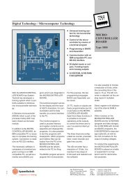
<strong>Motor</strong> <strong>Control</strong> <strong>Gear</strong>
© hps SystemTechnik<br />
Lehr- + Lernmittel GmbH<br />
Altdorfer Strasse 16<br />
88276 Berg / Germany<br />
Phone: + 49 751 /5607580<br />
Telefax: + 49 751 /5607517<br />
Internet: http://www.hps-systemtechnik.com<br />
E-mail: export@hps-systemtechnik.com<br />
Order no.: V 0082<br />
All rights reserved. No part of this publication may be reproduced, transmitted, stored in a retrieval system, nor translated<br />
into any human or computer language, in any form or by any means, electronic, mechanical, magnetic, optical, chemical,<br />
manual or otherwise, without the prior permission of hps SystemTechnik.<br />
0.12.0
V 0082 Content I<br />
Contents<br />
Circuit symbols to DIN 40713 and DIN 40703 and examples ................................. 4<br />
Extract from DIN 40714 and DIN 40715 ................................................ 9<br />
Connection and conductor references in installations conforming IEC 445 and DIN 42 400. ...........11<br />
Code letters to designate the nature of apparatus according to DIN 40 719, sheet 2 Table 1 ..........12<br />
Code letters to designate general functions according to DIN 40 719, sheet 2 Table 2 ...............14<br />
Table of boards for experiments 1.1 to 2.20 in Manual V 0082 ................................15<br />
1 <strong>Control</strong>s with switches ........................................18<br />
1.1 <strong>Motor</strong> protection switch .....................................................18<br />
1.2 On/off switch .............................................................22<br />
1.3 Reversing switch ..........................................................26<br />
1.4 Star-delta switch ..........................................................30<br />
1.5 Star-delta reversing switch ...................................................34<br />
1.6 Dahlander pole-changing switch ...............................................38<br />
1.7 Pole-changing switch for motor with separate windings ..............................42<br />
1.8 Instrument selector switch ...................................................46<br />
2 <strong>Control</strong>s with contactors .......................................52<br />
2.1 Presentation of circuit diagrams ...............................................52<br />
2.2 Simple contactor circuit with self-holding and overcurrent relay .........................54<br />
2.3 Simple contactor circuit with self-holding, overcurrent relay and fault signalling .............59<br />
2.4 Contactor circuit with auxiliary contactor (stored fault signal). ..........................64<br />
2.5 Contactor circuit with time relay, delayed pick-up .................................. 70<br />
2.6 Contactor circuit with time relay, drop-out delay ................................... 75<br />
2.8 Limiting control with limit switch (mechanical) ..................................... 85
II Content V 0082<br />
2.9 Limiting control with limit switches (proximity type) ................................. 90<br />
2.9.a. Open-circuit principle<br />
2.9.b Closed-circuit principle<br />
2.10 Reversing contactor control with contactor interlocking .............................. 99<br />
2.11 Reversing contactor control with interlocking via contactor and pushbutton ...............105<br />
2.12 Star-delta switching .......................................................111<br />
2.13 Automatic star-delta switching. ...............................................117<br />
2.14 Automatic star-delta switching for two directions of rotation. ..........................122<br />
2.15 Pole-changing for two speeds (Dahlander). ......................................128<br />
2.16 Pole-changing circuit for two speeds (for motor with two separate windings) ..............135<br />
2.17 Automatic control of a three-stage rotor starter. ...................................141<br />
2.18 Current-impulse-operated contactor circuit .......................................148<br />
2.19 <strong>Control</strong> of an installation for reactive current compensation. ..........................153<br />
2.20 Counter-current braking (‘plugging’) with brake monitor. .............................163<br />
3 Bibliography ...............................................168