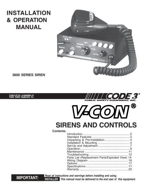
V-Con Siren Installation Guide - Code 3 Public Safety Equipment
V-Con Siren Installation Guide - Code 3 Public Safety Equipment
V-Con Siren Installation Guide - Code 3 Public Safety Equipment

You also want an ePaper? Increase the reach of your titles
YUMPU automatically turns print PDFs into web optimized ePapers that Google loves.
Wireless Mesh Networks (WMNs) WMNs consist of wireless routers, whichprovide the wireless backbone, and accesspoints for mobile clients Nodes of WMNs are mostly static,although the clients may be mobile Communication is usually through multiplehops in the wireless medium WMNs are being increasingly deployedacross enterprises, universities and evencities
Unpacking & Pre-installation!WARNING!All devices should be mounted in accordance with the manufacturer’s instructions andsecurely fastened to vehicle elements of sufficient strength to withstand the forces applied tothe device. Ease of operation and convenience to the operator should be the primeconsideration when mounting the siren and controls. Adjust the mounting angle to allowmaximum operator visibility. Do not mount the <strong>Con</strong>trol Head Module in a location that willobstruct the drivers view. Mount the microphone clip in a convenient location to allow theoperator easy access. Devices should be mounted only in locations that conform to theirSAE identification code as described in SAE Standard J1849. For example, electronicsdesigned for interior mounting should not be placed underhood, etc.<strong>Con</strong>trols should be placed within convenient reach* of the driver or if intended for twoperson operation the driver and/or passenger. In some vehicles, multiple control switchesand/or using methods such as “horn ring transfer” which utilizes the vehicle horn switch totoggle between siren tones may be necessary for convenient operation from two positions.* <strong>Con</strong>venient reach is defined as the ability of the operator of the siren systems to manipulatethe controls from his normal driving/riding position without excessive movement away fromthe seat back or loss of eye contact with theroadway.After unpacking your 3690 series siren, carefully inspect the unitand associated parts for any damage that may have been causedin transit. Report any damage to the carrier immediately.<strong>Installation</strong> & MountingThe 3690 series siren may be mounted above the dash, below thedash, on a tunnel or in a rack with the mounting bracket (bail) andthe hardware supplied (see Fig. 2). Ease of operation andconvenience to the operator should be the prime considerationwhen mounting the siren and controls.Install the siren on the bail bracket using the 1/4-20 x 1/2" bolts and 1/4" flat washers supplied. Longer boltswill prevent removal of the chassis from the coverand may damage internal components. See Figure 2for assembly and positioning details.Figure 2NOTE: Set-ups and adjustments will be made in subsequent steps, depending upon the model andoptions purchased, that may require access to the rear area of the unit. Plan the installation andwiring accordingly.Amplifier <strong>Con</strong>nections<strong>Siren</strong> Amplifier <strong>Con</strong>nector - As a standard feature, the <strong>Siren</strong> and Auxiliary sections (L4 models)of your unit come equipped with a screw terminal block. To terminate the wires, strip approximately1/4" of insulation from the end of each wire and insert it in the appropriate terminal. Tighten thescrew and proceed to the next connection.4
Terminal Block <strong>Con</strong>nections8 Position Terminal Block- ( see wiring diagram page 16 )S1 - +12VDC, connect to a positive +12 volt DC source. It is recommended that the user protectthis wire with a 20 Amp fuse or circuit breaker located at the source. Use #14 gauge wire.S2 - GROUND, connect to the negative terminal of the battery. This supplies ground (earth) to thesiren. Use #14 gauge wire.S3 - Speaker Common, connect to one of the wires from speaker.S4 - 58W Speaker, connect to the remaining speaker lead for 58W speaker only.S5 - 100/200W Speaker, connect to the remaining speaker lead for 100/200W operation (1-100W,11 ohm speaker or 2-100W, 11 ohm speakers connected in parallel).S6 - Remote input (Horn ring or foot switch) can be configured for either ground (earth) or positivesignals. Unit is configured for a ground ( earth ) at the factory. See DETAIL A for further informationon configuring for a +12V input.S7 - RRB, connect to one side of the two-way radio speaker.S8 - RRB, connect to the second side of the two-way radio speaker.!WARNING!Larger wires and tight connections will provide longer service life for components. For highcurrent wires it is highly recommended that terminal blocks or soldered connections be usedwith shrink tubing to protect the connections. Do not use insulation displacement connectors(e.g. 3M ® ) Scotchlock type connectors). Route wiring using grommets and sealant whenpassing through compartment walls. Minimize the number of splices to reduceHigh ambient temperatures (e.g. underhood) will significantly reduce thecapacity of wires, fuses, and circuit breakers. Use "SXL" type wire inwiring should conform to the minimum wire size and othermanufacturer and be protected from moving partsvoltage drop.current carryingengine compartment. Allrecommendations of theand hot surfaces. Looms, grommets, cableties, and similiar installation hardwareshould be used to anchor and protect all wiring.Fuses or circuit breakers should be located as close to the power takeoff points as possibleand properly sized to protect the wiring and devices. Particular attention should be paid to thelocation and method of making electrical connections and splices to protect these points fromcorrosion and loss of conductivity. Ground (Earth)terminations should only be made tosubstantial chassis components, preferably directly to the vehicle battery.The user should install a circuit breaker sized to approximately 125% of the maximum Ampcapacity in the supply line to protect against short circuits. For example, a 30 Amp circuitbreaker should carry a maximum of 24 Amps.DO NOT USE 1/4" DIAMETER GLASS FUSES AS THEY ARE NOT SUITABLE FORCONTINUOUS DUTY IN SIZES ABOVE 15 AMPS. Circuit breakers are very sensitive to hightemperatures and will "false trip" when mounted in hot environments or operated close to theircapacity.5
!WARNING!The speaker's sound projecting opening should be pointed forward, parallel to the ground, andnot obstructed or muffled by structural components of the vehicle. <strong>Con</strong>cealed or under-hoodmountings in some cases will result in a dramatic reduction in performance. To minimize thisreduction, mount the speaker so the sound emitted is projected directly forward and obstructionby vehicle components such as hoses, brackets, grille, etc. is minimized.Electromechanical sirens and electronic siren speakers should be mounted as far from theoccupants as possible using acoustically insulated compartments and isolation mountings tominimize the transmission of sound into the vehicle. It may be helpful to mount the device onthe front bumper, engine cowl or fender; heavily insulate the passenger compartment; andoperate the siren only with the windows closed.Each of these approaches may cause significant operational problems, including loss of sirenperformance from road slush, increased likelihood of damage to the siren in minor collisions,and the inability to hear the sirens on other emergency vehicles.APPROPRIATE TRAINING OF VEHICLE OPERATORS IS RECOMMENDED TO ALERTTHEM TOTHESE PROBLEMS AND MINIMIZE THE EFFECT OF THESE PROBLEMSDURING OPERATIONS.Power Distribution <strong>Con</strong>nections ("L4" Models)A #8 stud is provided on the rear of the unit and is intended for use ONLY as a convenient ground(earth) " tie-point " for the light bar wiring. It is not an adequate ground (earth) for the siren orthe light bar. It is recommended all ground (earth) wires attached here be terminated with acrimp-on ring terminal.11-Position Terminal Block - Lighting <strong>Con</strong>trol - (See Wiring Diagram page 16)IMPORTANT!Remember auxillary outputs A, B & D on L4 models can supply a maximum of 20 Amps eachfor a combined total of 30 Amps. Install appropriate fuses in each output wire as close to thesiren as possible.T1 - SW C COM - Common or power feed for Auxiliary Switch "C". Terminals are a SPDT circuitthat may be connected as a momentary (or latching depending on the switch ordered) ignitioncontrolled circuit, or used for switching auxiliary circuits. It will Handle 10 Amps, and should beprotected with a fuse at the battery if individually fed.T2 - SW C NC - <strong>Con</strong>nect to the load to be controlled by the normally-closed contact on AuxiliarySwitch "C".T3 - SW C NO - <strong>Con</strong>nect to the load to be controlled by the normally-open contact on AuxiliarySwitch "C".T4 - AUXILIARY SW A, connect to the load to be controlled by Auxiliary Switch "A".T5 - AUXILIARY SW B - <strong>Con</strong>nect to the load to be controlled by Auxiliary Switch "B".T6- AUXILIARY SW D - <strong>Con</strong>nect to the load to be controlled by Auxiliary Switch "D".IMPORTANT!The total combined current for the auxillary outputs A,B & D Must not exceed 30 Amps total.6
T7 - +12VDC - <strong>Con</strong>nect to the positive terminal of the battery with 30 Amp circuit protection.Locate the fuse or circuit breaker at the battery and use size 10 AWG wire minimum. This terminalpowers switches A,B & D only.T8 - LEVEL 1, connect to the first level of warning lights (Green LED) position "1" on level switch.T9 - LEVEL 2, connect to the second level of warning lights (Yellow LED) position "2" on levelswitch.T10 - LEVEL 3, connect to the third level of warning lights (Red LED) position "3" on level switch.T11 - +12VDC - <strong>Con</strong>nect to the positive terminal of the battery with 30 Amp circuit protection.Locate the fuse or circuit breaker at the battery and use size 10 AWG wire minimum. This terminalpowers the 3-Level lighting control switch only.NOTE: LEVEL 1, LEVEL 2, LEVEL 3, switch progressively. Switch position 1 provides +12volts at terminal T8. Switch position 2 provides +12 volts at terminals T8 & T9. Switchposition 3 provides +12 volts at terminals T8, T9 & T10.SET-UP AND ADJUSTMENTMake these adjustments and position the set-up switches prior to final mounting.Audio AdjustmentsPA/RRB Volume Adjustment - This is the main volume control located on the right side of the frontpanel. This control sets the PA and RRB volume. Set the front panel volume control to the pointthat the PA volume from the siren speaker is such that there is no feedback and the PA audio isintelligible.Radio Rebroadcast Adjustment - Place the selector switch in the RADIO position. The MAX RRBtrimmer located on the rear panel of the siren and is accessible through the small hole labeled RRB.This control sets the maximum RRB level that will reach with the front panel volume control. Toadjust properly, set the volume knob fully clockwise and adjust the RRB trimmer such that with thetwo-way radio volume inside the vehicle set to it's normal level, the the desired volume level isproduced outside the vehicle by the siren speaker.Remote InputJUMPER INSTALLATION FORPOSITIVE REMOTE ENABLEJUMPER INSTALLATION FORNEGATIVE REMOTE ENABLEDETAIL A7
The remote input can be configured to accept either a positive +12V or negative GND ( Earth )signal for actuation. All 3690 series sirens are shipped set-up to accept the GND (Earth) signalfrom the vehicle HORN Switch present on most vehicles. To reconfigure the Remote input toaccept a +12V signal, remove the cover and locate the Horn Ring Polarity jumper on the left rear ofthe coner of the amplifier board. Place both jumpers towards the "+ " position. Refer to DETAIL "A"for a complete illustration.<strong>Con</strong>figuration SwitchesReferring to DETAIL B below, gently set the Hit & Go, LightAlert and <strong>Siren</strong>Lock set-up switchesto the desired position. These switches are present even if the options were not purchased. If the<strong>Siren</strong>Lock option was purchased and is switched on, all of the tones except AIR HORN, aredisabled until the 3-Level Warning Light Switch is moved to either the Level-2 or the Level-3positions.Hit & Go - Slide the switch (#4) forward to allow the feature to operate, to the rear to defeat it.LightAlert - Slide the switch (#2) forward to allow the feature to operate, to the rear to defeat it.This switch has no effect on the flashing LED indicator. When in the OFF position, disables theLightAlert tone, which alerts the operator audibly when any lighting switch is activated.<strong>Siren</strong>Lock - The <strong>Siren</strong>Lock option, when not defeated by means of the internal switches, allowssiren tones (Wail, Yelp, and Hi-Lo) to be produced only when the 3-Level Warning Light Switch is inthe Lighting Level 2 (Green and Yellow LED's) or Lighting Level 3 (Green, Yellow, and Red LED's)position. Air Horn, Radio Rebroadcast, and <strong>Public</strong> Address are unaffected by this option.TO DEFEAT INDICATOR LED (ANDLIGHTALERT) FOR ANY AUXILLARYSWITCH, BREAK FOIL CORRESPOND-ING TO SWITCH1SIRENLOCK - OFFONADBC2LIGHT LEVEL - 3 ONLY 2 & 33LIGHTALERT - OFFON4HIT & GO - OFFONDETAIL BSlide the switch (#1) forward to allow the feature to operate, to the rear to defeat the feature.To select <strong>Siren</strong>Lock in level 3 only, slide the level select switch (#2) toward the rear of the siren;slide it toward the front of the siren to enable siren tones operation in both Levels 2 and 3.8
OperationRotary Function Selector SwitchRADIO - In the RADIO position, the audio from the 2-way radio is rebroadcast over the siren speaker. Thesiren tones (Wail, Yelp, & Hi-Lo) do not operate in this position.STANDBY - This is the standby mode. If the MANUAL button is depressed , the Manual wail tone will rampup until it reaches a peak then ramp down when released. If the AIR HORN button is depressed, the Air Hornsound will be produced.WAIL - This position produces the Wail tone. Depressing the MANUAL button will now produce the Yelp tonefor 7 seconds. Depressing the AIR HORN button will produce the Air Horn sound and when released willreturn siren to Wail tone.!WARNING!"Wail" and "Yelp" tones are in some cases (such as in the state of California) the only recognizedsiren tones for calling for the right of way. Ancillary tones such as "Air Horn", "Hi-Lo","Hyperyelp", and "Hyperlo" in some cases do not provide as high a sound pressure level. It isrecommended that these tones beused in a secondary mode to alert motorists to the presence ofan emergency vehicle.YELP - This position produces the Yelp tone. Pushing the MANUAL button will continue to produce the Yelptone. If the AIRHORN button is pushed, the Airhorn sound will be produced and when released will return thesiren to Yelp.HI-LO - This position produces the Hi-Lo tone. Pushing the MANUAL button will now produce the Yelp tonefor 7 seconds. If the AIRHORN button is pushed, the Airhorn sound will be produced and when released willreturn siren to Hi-Lo.P.A. VOLUME Knob - This control adjusts the level of the P.A. audio produced when keying the microphoneand speaking into it. This control also controls the Radio Re-broadcast level when in the " Radio " position(see SET-UP, Radio Rebroadcast Adjustment).Push-to-Talk (PTT) Microphone Switch - Keying the microphone will automatically override whatever modethe siren is in and broadcast public address messages over the siren speaker. PTT operates in all positionsof the Selector switch.MANUAL Pushbutton Momentary Switch -Has no effect when the selector switch is in RADIO, producesthe effects described above for each selector position.AIR HORN Pushbutton Momentary Switch (Models 3692, 3694, 3692L4 & 3694L4 only) - Produces theAir Horn tone in all selector switch settings except RADIO.SLIDE SWITCH (Models 3692, 3694, 3692L4 & 3694L4 only) - The slide switch located between the AIRHORN and MANUAL buttons selects the function for the REMOTE (external switch) circuitry. When theswitch is to the right, the Horn Ring circuitry remotely "depresses" the AIR HORN button and generate theAIR HORN tone. When the slide switch is to the left, it allows the REMOTE circuitry to remotely "depress"the MANUAL pushbutton and generate the MANUAL tone.9
Lighting <strong>Con</strong>trols (For L4 Models Only)WARNING LIGHTS 3-LEVEL PROGRESSIVE SLIDE SWITCH:POSITION 1 - Supplies power to Lighting Level 1. Illuminates Green LED. Activates LightAlert if suppliedPOSITON 2 - Supplies power to Lighting Levels 1 & 2. Illuminates Green and Yellow LED's. ActivatesLightAlert and <strong>Siren</strong>Lock options if supplied.Position 3- Supplies power to Lighting Levels 1,2, & 3. Illuminates Green, Yellow, AND Red LED's.Activates LightAlert and <strong>Siren</strong>Lock if supplied.Auxiliary Switches:AUXILIARY SWITCH "A" - Supplies power to the load connected to terminal SW A.AUXILIARY SWITCH "B" - Supplies power to the load connected to terminal SW B.AUXILIARY SWITCH "C" - Operates circuit connected to terminals SWC NO, SWC NC, SWC COM.Functions as a latching or momentary output, depending on the type of switch installed.AUXILIARY SWITCH "D" - Supplies power to the load connected to terminal SW D.<strong>Siren</strong>Lock - The <strong>Siren</strong>Lock option, when not defeated by means of the internal switches, allows siren tones(Wail, Yelp, and Hi-Lo) to be produced only when the Warning Light Switch is in the Lighting Level 2 (Greenand Yellow LED's) or Lighting Level 3 (Green, Yellow, and Red LED's) position. Air Horn, RadioRebroadcast, and <strong>Public</strong> Address are unaffected by this option.SPLICEFORCE 4 STINGRAYGREY WIREORANGE WIRE20GREY WIRETO LOAD85308687a87RELAYBATTERYInterClear ® (Optional) wiring methods10
InterClear ® (Optional) - <strong>Con</strong>nect to the device or circuit that is to be activated by the InterClear feature.TheInterClear output circuit is internally current limited to .5 Amp. Should your application require higher current,you can use an external relay for increased current capacity.MAINTENANCEYour <strong>Code</strong> 3 ® 3690 series siren has been designed to provide trouble free service. In case of difficulty, seeTroubleshooting (page 14,15 ). Also check for shorted or open wires. The primary cause of short circuits hasbeen found to be wires passing through firewalls, roofs, etc. If further difficulty persists, contact the factory fortroubleshooting advice or return instructions. <strong>Public</strong> <strong>Safety</strong> <strong>Equipment</strong>, Inc. maintains a complete partsinventory and service facility at the factory and will repair or replace (at the factory's option) any unit found tobe defective under normal use and in warranty. Any attempt to service a unit in warranty by anyone elseother than a factory authorized technician without express written consent by the factory, will void thewarranty.Units out of warranty can be repaired at the factory for a nominal charge on either a flat rate or parts andlabor basis. <strong>Con</strong>tact the factory for details and return instructions. <strong>Public</strong> <strong>Safety</strong> <strong>Equipment</strong>, Inc. is not liablefor any incidental charges related to the repair or replacement of a unit unless otherwise expressly agreed toin writing by the factory.11
TROUBLESHOOTING(Refer to wiring diagram page 20)PROBLEM PROBABLE CAUSE REMEDYNO SIREN OUTPUT.A. SHORTED SPEAKER ORSPEAKER WIRES. SIREN IN OVERCURRENT PROTECTION MODE.A. CHECKCONNECTIONSEXTERNAL 20AFUSE BLOWS.NO OUTPUT FROMSPEAKER, TONESHEARD INSIDEAMP. MODULE.SIREN TONESVOLUME TOOLOW/GARBLED.HIGH RATE OFSPEAKER FAILURE.SIREN CONTINUESTO OPERATE FOR7 SEC. AFTERMANUAL BUTTON/HORN RING ISRELEASED.INTERCLEAR WILL NOTPOWER AUXILIARYDEVICES.P.A. VOLUME LOW ORNO P.A. AT ALL.VOLUME CONTROLFULLY CLOCKWISE.A. AMPLIFIER POWER WIRESREVERSED POLARITYA. SPEAKER NOT CONNECTED/OPEN CIRCUIT IN SPEAKERWIRINGB. DEFECTIVE SPEAKERSA. LOW VOLTAGE TO SIRENAMPLIFIERB. HIGH RESISTANCE IN WIRING/DEFECTIVE SPEAKERC. SPEAKERS PHASEDIMPROPERLYA. VEHICLE BATTERY VOLTAGETOO HIGHB. 58 WATT SPEAKER CONNECTEDTO 100 WATT TERMINAL.A. "HIT-N-GO" FEATURE ENGAGED.NORMAL OPERATIONA. THERE IS A SHORT IN THEWIRING, OR THE LOAD ISGREATER THAN 1 A.A. DEFECTIVE MICROPHONEB. MICROPHONE NOTCOMPLETELY PLUGGED IN.C. COMMON MICROPHONECIRCUIT NOT PROPERLY WIRED.D. INCORRECT MICROPHONE.A. CHECK POLARITYB. REPLACESPEAKER(S)A. CHECK SPEAKERWIRINGB. REPLACESPEAKER(S)A. CHECK WIRING FORBAD CONNECTIONS/CHECK VEHICLECHARGING SYSTEMB. CHECK SPEAKER(S)WIRING/REPLACESPEAKER(S)C. REFER TO PAGE 5FOR PROPERPHASINGA. CHECK VEHICLECHARGING SYSTEMB. USE CORRECTSPEAKERC. CHECK TERMINALSA. CHECK FORSHORTS. INSTALLINTERCLEARBOOSTER KIT (PART#INTBS)A. REPLACEMICROPHONEB. PLUG MICROPHONEIN SECURELYC. CHECK WIRINGD. CALL PSE FOR LISTOF ADAPTABLEMICROPHONES12
TROUBLESHOOTING(Refer to wiring diagram page 20)PROBLEM PROBABLE CAUSE REMEDYRRB VOLUME LOW, ORNO RRB AT ALL.VOLUME CONTROLFULLY CLOCKWISE.A. MAXIMUM RADIOREBROADCAST TRIMMER MIS-ADJUSTEDB. RRB WIRES NOT CONNECTEDTO TWO-WAY RADIO EXTERNALSPEAKERA. REFER TO SET-UPAND ADJUSTMENTSECTIONB. CHECK RRBCONNECTIONSSIREN SOUNDS BYITSELFPOWER DISTRIBUTIONSECTION NOTWORKINGSIREN RUNSPROPERLY BUTSHUTS DOWN WHILERUNNING, THENSTARTS RUNNINGAGAIN AFTER A FEWMINUTESA. REMOTE SWITCH (HORN RING)WIRING FROM TERMINAL REMOTESHORTING TO POSITIVE OR TOGROUND (EARTH).A. SUPPLY FUSE OPENB. SIREN TERMINAL NEGATIVE NOTGROUNDEDA. VEHICLE CIRCUIT BREAKERSNOT RATED PROPERLY, AND AREOVERHEATING, OR ARE NOTFUNCTIONING PROPERLYA. CHECK WIRING FORANY SHORTING.A. REPLACE FUSE.B. RECONNECTTERMINAL NEGATIVETO GROUND.A. REFER TOSPECIFICATIONSSECTION, PAGE 18.USE A BREAKER WITH1.25x THE AMPERAGERATING FOR THEWATTAGE BEINGUSED.13
Parts ListRef No. Description Part No. Qty.1 MS, 6-32 X 3/16", RND HD T01030 42 TINNERMAN NUT, 6-32 T01058 43 SWITCH ACTUATOR (PUSH BUTTON) T01095 24 INSULATOR PAD T06363 25 MS, 6-32 X 3/8", PAN HD, ZINC T10290 26 SPACER, HEAT SINK S71651 17 E-TRAY, 3690 SERIES SIREN, INSERTED T50022 18 FLAT WASHER, 3/8" X 0.02" T00667 39 NUT, 3/8-32 X 1/2" X .090 T01082 310 NUT, KEPS, 4-40 T00393 111 NUT, KEPS, 8-32 T00674 212 FACEPLATE LABEL 1MODEL 3672MODEL 3672L4MODEL 3692MODEL 3692L4MODEL 3694MODEL 3694L4T01900T01901T01337T01449T01410T0145313 MS, #4-40 x 3/8", FLAT HD PHIL, BLK OXIDE T01101 214 KNOB, SELECTOR T01097 115 KNOB, VOLUME CONTROL T01098 116 MS, 8-32 X 5/8, HEX HD T00763 117 SWITCH, 4-POSITION, LEVER T01116 118 MS, 4-40 X 1/4, RND HD, BLK OXIDE T01128 519 QUICKSLIDE, STUD MTG., 1/4", 45 DEG T11109 120 LIGHT CONT BD SUPPORT BRACKET T08640 121 4 BUTTON AUX SWITCH BD T50056 122 V-CON LIGHT CONTROL PCB T50057 123 SMS, #6 x .75 pan hd phil T01169 224 SMS, PAN HD PHIL, #6 X 3/8" T01031 325 CASE, V-CON SIREN T07630 126 MS, 8-32 X 1/4", HEX WASHER HD T05798 227 BAIL BRACKET, 7 SLOT T05389 128 AIR BAG DEPLOYMENT WARNING LABEL T09937 129 LABEL SET, WIRING, 3690 SERIES SIREN T01454 130 MICROPHONE, 1HARD WIRED (STANDARD)PLUGGABLE, (0PTIONAL)T07311T0730914
EXPLODED VIEW15
10 GA.12 GA.20 A.12 GA.20 A.S-1S-212 GA.12 GA.OPTIONAL 2nd 100WSPEAKER FOR 200WS-3S-5HORN RINGCIRCUIT S-62-WAY RADIOSPEAKERS-7S-8INTERCLEARCIRCUIT (OPTIONAL)30 A.10 GA.T-1T-7T-11LIGHT BAR CABLE GROUNDT-3, ACCESSORY CT-4, ACCESSORY AT-5, ACCESSORY BT-6, ACCESSORY DT-8, LIGHTING LEVEL 1T-9, LIGHTING LEVEL 2T-10, LIGHTING LEVEL 3RRB ADJUSTMENT6 WIRE, SHIELDED CABLE (COMMON MIC ONLY)BREAK MIC HI, MIC LO, & PTT WIRES INRADIO CONTROL HEAD TO TRANSMITTERCABLE AND RECONNECT AS SHOWN ABOVE.16
OptionsLightAlert TM (L4 Models Only)- An audible alarm pulse that indicates that either the primary warning systemor one of the auxiliary control circuits is on. User defeatable.<strong>Siren</strong>Lock TM (L4 and L6 Models Only)- An interlock circuit between the siren and the light control circuits thatpermits automatic siren tones only when the progressive switch is in Level 3 or in Level 2 or 3 (userselectable - works in conjunction with the horn transfer relay). This feature is used in jurisdictions thatrequire warning lights to be on before the siren is activated.InterClear ® This unique feature can be used to activate additional warning lights for 7 seconds when in anHit-N-Go override or " scrolling " by pushing a single button or the vehicle horn ring, thus allowing anadditional level of warning in situations such as intersections without the operator having to take his hands offthe wheel or his eyes off the road.Pluggable Microphone - A plug-in microphone jack in lieu of the standard wired-in microphone may bespecified. A plug-in noise-canceling microphone must be ordered seperately if needed.Specifications<strong>Siren</strong> SectionInput Voltage -10 to 16 VDC, negative ground (earth).(Note: Operation above 14 VDC for an extended period of time may result in speaker damage.)Operating Current: 5 Amps @ 13.6V with 19-ohm load ( 58 W Spkr )8 Amps @ 13.6V with 11-ohm load ( 1 - 100 W Spkr )16Amps @ 13.6V with 5.5-ohm load ( 2 - 100 W Spkrs )Standby Current:18 mA excluding backlightingCycle Rate: WAIL - 11 cycles/minute.YELP - 200 cycles/minute.Voltage Output ( approx. )64 V peak-to-peakAudio SectionAudio Response: 3 dB down points - 500 to 3000 hz.1000 hz. 0 dB ReferenceAudio Distortion: 10% or less below clipping.Lighting Section ("L4" Models Only)Warning Light <strong>Con</strong>trol: Progressive switching, 3 levels30 Amps. maximum combined total for Levels 1,2 & 3Level 1Level 230A maximumGreen LED Indication30A maximum17
Yellow LED IndicationLevel 3Auxiliary <strong>Con</strong>trolsomentary30A maximumRed LED indication.A, B, C, D switchesA,B, C & D switches are latching, Push-on/off (standard), may be ordered asIndependent circuits30 Amps. maximum combined total for switches A,B & D20 Amps. maximum load for any single output A,B, C, or DAudible alarm (optional)TING LEVEL 2TROLS HORNTRANSFERTO TERMINAL S-687TO VEHICLE HORN863085TO TERMINAL T-9/LIGHTING LEVEL-2HORN RINGNG DIAGRAM, CODE 3 HORNTR, HORN RINGTRANSFER KITACCESSORY SWITCH"C" CONTROLS HORNRING TRANSFERHORN RINGTO BATTERYT-1T-7VEHICLE HORNT-2T-3S-6ALTERNATE HORN RING TRANSFER METHOD18
NOTES19
WARRANTY<strong>Code</strong> 3, Inc.'s emergency devices are tested and found to be operational at the time ofmanufacture. Provided they are installed and operated in accordance with manufacturer'srecommendations, <strong>Code</strong> 3, Inc. guarantees all parts and components except the lamps to a periodof 1 year (unless otherwise expressed) from the date of purchase or delivery, whichever is later.Units demonstrated to be defective within the warranty period will be repaired or replaced at thefactory service center at no cost.Use of lamp or other electrical load of a wattage higher than installed or recommended bythe factory, or use of inappropriate or inadequate wiring or circuit protection causes this warrantyto become void. Failure or destruction of the product resulting from abuse or unusual use and/or accidents is not covered by this warranty. <strong>Code</strong> 3, Inc. shall in no way be liable for otherdamages including consequential, indirect or special damages whether loss is due to negligenceor breach of warranty.CODE 3, INC. MAKES NO OTHER EXPRESS OR IMPLIED WARRANTY INCLUDING,WITHOUT LIMITATION, WARRANTIES OF FITNESS OR MERCHANTABILITY, WITHRESPECT TO THIS PRODUCT.PRODUCT RETURNSIf a product must be returned for repair or replacement*, please contact our factory toobtain a Return Goods Authorization Number (RGA number) before you ship the product to<strong>Code</strong> 3, Inc. Write the RGA number clearly on the package near the mailing label. Be sure youuse sufficient packing materials to avoid damage to the product being returned while in transit.*<strong>Code</strong> 3, Inc. reserves the right to repair or replace at its discretion. <strong>Code</strong> 3, Inc. assumes no responsibility or liability for expenses incurred forthe removal and /or reinstallation of products requiring service and/or repair.; nor for the packaging, handling, and shipping: nor for the handling ofproducts return to sender after the service has been rendered.PROBLEMS OR QUESTIONS? CALL OUR TECHNICAL ASSISTANCE HOTLINE (314) 996-2800<strong>Code</strong> 3, Inc.10986 N. Warson RoadSt. Louis, Missouri 63114-2029—USAPh. (314) 426-2700 Fax (314) 426-1337www.code3pse.com<strong>Code</strong> 3 is a registered trademark of <strong>Code</strong> 3, Inc. a subsidiary of <strong>Public</strong> <strong>Safety</strong> <strong>Equipment</strong>, Inc.Revision 6, 11/05 - Instruction Book Part No. T01466©2005 <strong>Public</strong> <strong>Safety</strong> <strong>Equipment</strong>, Inc. Printed in USA