FPL Design for Lumber Dry Kiln Using Solar - Forest Products ...
FPL Design for Lumber Dry Kiln Using Solar - Forest Products ...
FPL Design for Lumber Dry Kiln Using Solar - Forest Products ...

Create successful ePaper yourself
Turn your PDF publications into a flip-book with our unique Google optimized e-Paper software.
United States<br />
Department of<br />
Agriculture <strong>FPL</strong><br />
<strong>Forest</strong> Service<br />
<strong>Forest</strong><br />
<strong>Products</strong><br />
Laboratory<br />
General<br />
Technloal<br />
<strong>FPL</strong>-44<br />
<strong>Design</strong> <strong>for</strong><br />
<strong>Lumber</strong> <strong>Dry</strong> <strong>Kiln</strong> <strong>Using</strong><br />
<strong>Solar</strong>/Wood Energy<br />
in Tropical Latitudes<br />
John L. Tschernitz<br />
William T. Simpson
Developing countries with a timber resource that can<br />
be manufactured into finished products either <strong>for</strong> local<br />
use or export often lack the capital to build high-cost<br />
dry kilns. Many of these countries are in the tropics<br />
where solar radiation and ambient temperatures are<br />
high. The low-cost solar/wood energy lumber dry kiln<br />
described in this report was designed and tested by the<br />
<strong>Forest</strong> <strong>Products</strong> Laboratory (<strong>FPL</strong>) <strong>for</strong> such countries<br />
where solar dry kilns can be built and operated at low<br />
cost.<br />
The <strong>FPL</strong> design is <strong>for</strong> a 6,000-fbm capacity kiln having<br />
an insulated drying compartment, an external<br />
horizontal solar collector, and a furnace room<br />
containing a wood burner. Capacities larger or smaller<br />
than 6,000 fbm are also possible. This design allows<br />
collector and wood burner sizing to match the energy<br />
demands of the dryer. The design also incorporates<br />
low-cost controls that allow unattended drying when<br />
operated as a solar-only dryer. Manual firing is<br />
necessary when the wood-burning system is supplying<br />
the energy.<br />
This kiln design is the final, commercial-size version<br />
established after years of testing several 1,000-fbm<br />
capacity prototypes. In December 1984 a kiln of this<br />
design was built in Sri Lanka at a factory that<br />
manufactures furniture and laminated beams from<br />
rubber and coconut wood.<br />
Keywords: <strong>Solar</strong>, solar drying, wood energy, dry kiln,<br />
tropics, dryer.<br />
April 1985<br />
Tschernitz, John L.; Simpson, William T. <strong>FPL</strong> design <strong>for</strong> lumber dry kiln<br />
using solar/wood energy in tropical Iatitudes. Gen. Tech. Rep. <strong>FPL</strong>-44.<br />
Madison, Wl: U.S. Department of Agriculture, <strong>Forest</strong> Service, <strong>Forest</strong><br />
<strong>Products</strong> Laboratory; 1985.17 p.<br />
A limited number of free copies of this publication are available to the<br />
public from the <strong>Forest</strong> <strong>Products</strong> Laboratory, P.O. Box 5130, Madison, WI<br />
53705. Laboratory publications are sent to over 1,000 libraries in the<br />
United States and elsewhere.<br />
The Laboratory is maintained in cooperation with the University of<br />
Wisconsin.
<strong>FPL</strong> <strong>Design</strong> <strong>for</strong><br />
<strong>Lumber</strong> <strong>Dry</strong> <strong>Kiln</strong><br />
<strong>Using</strong><br />
<strong>Solar</strong>/Wood Energy<br />
in Tropical<br />
Latitudes<br />
John L. Tschernitz, Chemical Engineer<br />
William T. Simpson, Supervisory Research <strong>Forest</strong><br />
<strong>Products</strong> Technologist<br />
<strong>Forest</strong> <strong>Products</strong> Laboratory, Madison, WI<br />
Introduction<br />
In 1975 the <strong>Forest</strong> <strong>Products</strong> Laboratory (<strong>FPL</strong>) began<br />
designing and testing low-cost solar dry kilns <strong>for</strong> smallto<br />
medium-sized production facilities in tropical<br />
developing countries. Several kiln designs were<br />
proposed, and one was selected from which three<br />
small-capacity prototypes were built and tested <strong>for</strong><br />
operation and durability. This design was ultimately<br />
optimized so that a commercial-size kiln design could<br />
be proposed, a detailed description of which is<br />
contained in this report.<br />
The project began when the U.S. Agency <strong>for</strong><br />
International Development (USAID) asked <strong>FPL</strong> to<br />
investigate the use of solar energy to improve the<br />
drying practices of small- and medium-scale producers<br />
in developing countries, and to propose a kiln design if<br />
the technology was feasible, which it was (Tschernitz<br />
and Simpson 1977). We built a 1,000-fbm prototype at<br />
Madison, Wis. in 1977 (Simpson and Tschernitz 1984,<br />
Tschernitz and Simpson 1979) and tested it every<br />
summer since.<br />
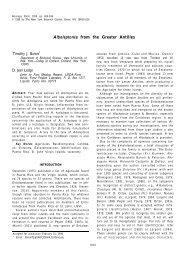
In 1981 we assisted in building a 1,000-fbm prototype<br />
funded by USAID, SRI LANKA, at a furniture factory in<br />
Sri Lanka, and it has been operating successfully since<br />
then (Simpson and Tschernitz 1982). In 1982 we<br />
assisted in installing another solar kiln of the same<br />
design funded by the United Nations Food and<br />
Agriculture Organization (UNFAO) at the <strong>Forest</strong><br />
Research Institute at Yezin, Burma (fig. 1).<br />
The design described in this report, along with the<br />
existing prototype, will provide the full kiln-drying<br />
needs of the furniture factory located near Horana in<br />
the southwestern quarter of Sri Lanka, 7° N latitude.<br />
While the size chosen matches the factory’s needs, the<br />
design can be built in smaller or larger versions. In<br />
early 1984 <strong>FPL</strong> signed an agreement with Borwood Ltd.<br />
of Colombo, Sri Lanka, with funding from the United<br />
Nations Development Program (UNDP), to provide the<br />
design details and technical consultation <strong>for</strong><br />
construction, startup, and operation of the kiln, which<br />
was completed in December 1984.<br />
A schematic diagram of the prototype kiln is shown in<br />
figure A-1. The caption is keyed to labeled kiln<br />
components in enough detail to illustrate the general<br />
operation of the kiln.<br />
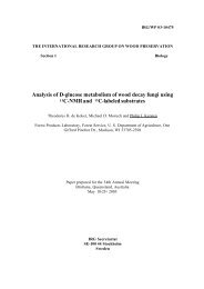
Figure 1.— 1,000-fbm (2.4-m 3<br />
) capacity solar kiln<br />
at <strong>Forest</strong> Research Institute, Yezin, Burma.<br />
(M152096-1)
Description of the <strong>Dry</strong>er<br />
General Principles of Operation<br />
A schematic of the proposed dryer design is shown in<br />
figure A-2. It differs from the prototype in several ways:<br />
1) the capacity is increased from 1,000 fbm (2.4 m 3<br />
) to<br />
approximately 6,000 fbm (14 m 3<br />
) of 1-inch- (25-mm) thick<br />
lumber with 3/4-inch (19-mm) stickers; 2) four collectors,<br />
instead of one, are located side-by-side delivering air<br />
into one large drying chamber; and 3) a wood residue<br />
burner has been added to allow drying 24 hours per day<br />
independent of solar insolation levels.<br />
Air circulates through two intersecting loops, one<br />
through the collectors and/or residue burner, and the<br />
other through the wood package (fig. A-2). The wood<br />
package handles twice the flow volume of the<br />
collectors, which are two independent pairs of two<br />
parallel collectors. Airflow in each half of a collector<br />
pair is counter to the flow in the other half so that only<br />
one duct (C-fig. A-4) is necessary to carry air from the<br />
paired collectors to the manifold (D-fig. A-2). The four<br />
exhausters (K-fig. A-2) remove air (containing<br />
evaporated water) from the kiln at the leaving-air side<br />
(high humidity) of the wood package. The makeup air<br />
from outside enters the system at four points (J-fig. A-2)<br />
through the collectors (B-fig. A-2). This is done <strong>for</strong><br />
three reasons: 1) the cooler ambient air lowers the<br />
temperature in the collector, and thus heat losses are<br />
decreased; 2) after the solar energy input no longer<br />
maintains the collector above dryer temperatures, the<br />
stored energy (collector above ambient temperature)<br />
can be used to preheat the incoming air; 3) the ambient<br />
temperature of the outside air with its lower humidity<br />
can purge the collector of high-humidity dryer air and<br />
thereby prevent or reduce condensation within the<br />
collector, particularly at night, which will increase its<br />
efficiency (energy is required to re-evaporate water at<br />
the beginning of the next diurnal cycle).<br />
Heated air from the collectors is pulled into the dryer<br />
by two blowers (C-fig. A-2) and discharged (D-fig. A-2)<br />
directly into four overhead fans (E-fig. A-2) that<br />
circulate air through the stacked lumber.<br />
Automatic control of the solar dryer is desirable, at the<br />
least possible cost, in order to accommodate 1) the<br />
intermittent delivery of solar energy to the collector;<br />
2) variable relative humidities (RH) within the drying<br />
chamber, which will depend upon the ambient humidity<br />
and temperature in the chamber; and 3) the variable<br />
rate of drying of the wood. Without such controls,<br />
almost continuous manual observation would be<br />
needed to approach the quality and efficiency of drying<br />
attainable with automatic control. Controls include<br />
1) two differential thermal comparators (F c,F d-fig. A-2)<br />
to sense the difference between dryer and collector<br />
temperatures and turn the solar blowers (C-fig. A-2) on<br />
and off accordingly; 2) a humidistat (RH1-fig. A-2) to<br />
allow automatic venting as needed because controlled<br />
venting increases thermal efficiency and also permits<br />
scheduling high RH’s early in drying and low RH’s later<br />
2<br />
on; 3) a second humidistat (RH2-fig. A-2) to establish a<br />
maximum RH above which the dryer will shut down.<br />
This might happen during long periods of low-solar<br />
input and high humidities, i.e. rainy periods, and is<br />
particularly important when the wood is below<br />
20 percent moisture content; and 4) a third humidistat<br />
(RH3-fig. A-2) has two functions: a) control the<br />
humidifier (G-fig. A-2) <strong>for</strong> conditioning at the end of the<br />
drying run, and b) raise the relative humidity in the<br />
drying chamber in order to prevent or reduce degrade in<br />
refractory woods at intermediate moisture contents.<br />
A low-cost combustion system fueled by wood has<br />
been incorporated in the solar dryer design. A simple<br />
burner is located in a furnace chamber on the opposite<br />
side of the drying compartment from the solar collector<br />
(A-fig. A-2). The furnace can operate either<br />
simultaneously or separately from the solar collector.<br />
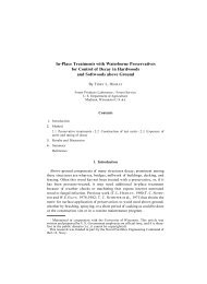
Construction Details of the <strong>Dry</strong>er<br />
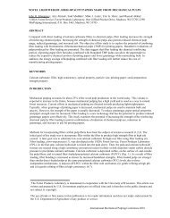
Figures A-3 through A-8 provide a description of the<br />
important construction details of the kiln:<br />
Figure A-3 - Plan view of entire kiln<br />
Figure A-4 - Section view of entire kiln<br />
Figure A-5 - Section view of solar collector ducts<br />
Figure A-6 - Section view of solar collector<br />
Figure A-7 - Elevation view of furnace room<br />
Figure A-8 - Wiring diagram of control system<br />
<strong>Solar</strong> collector (fig. A-6). —The colIector is external to<br />
the drying compartment so that collector area and<br />
orientation are not limited by the geometry of the dryer.<br />
The collector is horizontal (except <strong>for</strong> a 1/2 degree<br />
north-south drainage tilt) and is built into the ground<br />
<strong>for</strong> ease and low cost of construction. The horizontal<br />
orientation is particularly effective near the equator.<br />
Figure A-6 is an end cross section of one of the two<br />
pairs of collectors. A foundation of concrete blocks or<br />
poured concrete <strong>for</strong>m the perimeter of the collector. A<br />
12-inch- (0.3-m) deep excavation is filled with gravel to<br />
approximately 6 inches (0.15 m) of the top of the block<br />
or concrete foundation. A layer of charcoal pieces<br />
sized to 0.5-1 inch (1.3-2.5 cm), about 2-3 inches<br />
(5.1-7.6 cm) thick, covers the gravel. Charcoal is an<br />
inexpensive energy-absorbing surface and heat-transfer<br />
medium and a good insulator that reduces heat loss to<br />
the ground. The interior surfaces of the foundation are<br />
painted flat black. The collector cover spans the 4 feet<br />
between sections of the foundation.
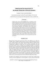
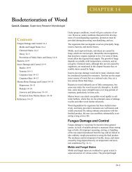
Figure 2.—Glass collector cover on prototype<br />
kiln. Wood sills shown in this photo are not<br />
included in the design of the 6,000-fbm kiln.<br />
(M830178-8)<br />
Experience with the prototype indicates that common<br />
window glass will be the most cost effective collector<br />
cover, particularly in areas without access to rigid<br />
plastic cover material. The sections of glass making<br />
up the cover are installed to overlap (0.5 inch, 1.3 cm)<br />
as shingles do (fig. 2). Butyl sealant tape and silicone<br />
sealant are used to seal the glass directly to the block<br />
or concrete, foundation. One feature of this<br />
construction method is avoidance of the expense and<br />
possible decay of wood frames <strong>for</strong> the glass.<br />
Individual sections of glass are replaceable simply by<br />
cutting the sealant around the edges.<br />
The collector is 50 feet (15 m) long, and each section is<br />
approximately 4 feet (1.2 m) wide. Because of overlap<br />
at the edges, the effective collector area is<br />
approximately 1,500 square feet (136 m 3<br />
). The ratio of<br />
lumber capacity to collector area is 4 fbm per square<br />
foot (0.1 m 3<br />
/m 2<br />
). In each of the four collectors air is<br />
drawn from the drying compartment and/or fresh air<br />
intakes (J-fig. A-2), travels the length of one side of the<br />
collector, crosses over to the other side through the<br />
4-foot-long gap at the end, and then travels down that<br />
side fo the collector and back into the drying<br />
compartment through the ducts shown in figure A-5.<br />
Blowers (C-fig. A-2) induce airflow through the collector<br />
and into the drying compartment to the manifold that<br />
discharges the heated air just behind fans <strong>for</strong> internal<br />
circulation. The collector is under negative pressure so<br />
that any leakage is into the system.<br />
<strong>Dry</strong>ing compartment. —The inside dimensions of the<br />
drying compartment are approximately 10 by 34 by<br />
11 feet high (3 by 10.4 by 3.3 m). The kiln is track<br />
loaded and is designed <strong>for</strong> a 5-foot-wide load of lumber<br />
(fig. A-4). The walls are of 12- by 12- by 24-inch<br />
concrete block, hollow and filled with loose insulation.<br />
The ceiling of the drying compartment consists of<br />
2- by 4-inch (50- by 100-mm) boards on edge (figs.<br />
A-4, A-5). This provides good insulation and a solid<br />
ceiling <strong>for</strong> attachment of fans and other kiln<br />
components. Above the 2 by 4 ceiling is a built-up roof<br />
with sealed surfaces and space <strong>for</strong> insulation. Above<br />
that an open-pitched shed-type roof of corrugated metal<br />
painted black serves the dual role of providing <strong>for</strong><br />
water runoff and as a pre-heater <strong>for</strong> makeup air<br />
entering the solar collector<br />
(figs. A-2, A-4).<br />
Wood residue burner. —Wood residue is burned in a<br />
simple, low-cost burner housed in a furnace chamber<br />
on the side of the drying compartment opposite the<br />
solar collector (figs. A-3, A-4, A-7). The burner consists<br />
of two double-wall 55-gallon steel drums mounted on a<br />
framework. One drum-is the combustion chamber. The<br />
other, along with the chimney, serve as additional heat<br />
transfer surfaces. The burner operates at 65 percent<br />
efficiency and can produce up to 80,000 Btu/hour<br />
(23 kW) (Anonymous 1981). A blower (fig. A-4)<br />
discharges kiln air into the furnace chamber, and<br />
<strong>for</strong>ces heated air from the furnace room back through a<br />
duct into the drying compartment. When humidity<br />
control is necessary, a humidistat (RH3-fig. A-2)activated<br />
water spray can release water into the<br />
furnace chamber <strong>for</strong> mixing with air going to the drying<br />
compartment. A manifold within the drying<br />
compartment distributes heated air into the internal<br />
circulating air.<br />
Table 1 lists the major building materials <strong>for</strong> the kiln.<br />
Table 1 .—List of major building materials <strong>for</strong> solar/wood<br />
energy kiln<br />
Item<br />
Poured concrete <strong>for</strong> foundations<br />
Amount<br />
and footings 26 yd 3<br />
(20 m 3<br />
Concrete blocks—12 x 8 x 24 in.<br />
)<br />
(0.31 x 0.20 x 0.62 m)<br />
Roof-decking boards—2 in. x 4 in.<br />
1,200 blocks<br />
x 11 ft (0.051 x 0.102 x 3.35 m) 205 boards<br />
Loose-fill insulation 625 ft 3<br />
(17.7 m 3<br />
)<br />
<strong>Kiln</strong> coating 1,400 ft 2<br />
(130 m 2<br />
) coverage<br />
Plastic film (black) <strong>for</strong> collector 1,600 ft 2<br />
(149 m 2<br />
)<br />
Charcoal<br />
14 yd<br />
Gravel<br />
No. 5 concrete-rein<strong>for</strong>cing bar<br />
Steel l-beam <strong>for</strong> furnace room<br />
roof (W8 x 24)<br />
Glass (3/16 in. (4.7 mm) thick)<br />
Corrugated roof<br />
Steel<br />
Asbestos<br />
55-gallon drums<br />
Butyl automotive sealant<br />
Silicone sealant<br />
Steel header<br />
Angle iron<br />
Sheet metal<br />
<strong>Lumber</strong><br />
Fasteners<br />
3<br />
(10.7 m 3<br />
)<br />
9 vd 3<br />
(6.9 m 3<br />
)<br />
150 ft (45.7 m)<br />
8.5 ft (2.6 m)<br />
1,485 ft 2<br />
(138 m 2<br />
)<br />
532 ft 2<br />
(49.4 m 2<br />
)<br />
280 ft 3<br />
(26.0 m 2<br />
)<br />
2<br />
1,200 ft (366 m)<br />
120 tubes<br />
30 ft (9.1 m)<br />
as needed<br />
as needed<br />
as needed<br />
as needed<br />
3
Energy Supply and Demand<br />
Energy supply and demand estimates can be made on<br />
an annual basis <strong>for</strong> the 6,000-fbm kiln <strong>for</strong> drying<br />
1-inch-thick rubberwood in Sri Lanka, as summarized in<br />
tables 2 and 3. Table 2 summarizes a 7-day drying<br />
schedule, and table 3 contrasts a slower 10-day<br />
schedule where proportionately more solar than wood<br />
energy can be used. There are also many other<br />
possible similar schedules. In each schedule there are<br />
three sources of energy supply: solar (based on<br />
1,500 ft 2<br />
of collector operating at 50 pct efficiency),<br />
wood residue (one burner rated at 80,000 Btu/hr), and<br />
electrical energy from the fan and blower motors.<br />
Assuming that the normal mode of operation will make<br />
maximum use of solar energy <strong>for</strong> a given schedule and<br />
supplement with wood residue to supply the rest, the<br />
7-day schedule will use 41 percent solar, 46 percent<br />
wood residue, and 13 percent electric; the 10-day<br />
schedule will use 62 percent solar, 18 percent wood<br />
residue, and 20 percent electric. Thus, if one is willing<br />
to increase drying time, use of wood residue can be<br />
reduced. If one needs to minimize drying time, then<br />
proportionally more wood residue energy can be used.<br />
Electric energy might be reduced by not operating two<br />
of the four fans late in drying when air circulation<br />
requirements are reduced.<br />
Table 2.—Energy supply and demand estimates (average<br />
annual basis) <strong>for</strong> solarfwood energy dry kiln <strong>for</strong> operation in<br />
southwestern Sri Lanka, drying 6,000 fbm of 1-inch-thick<br />
rubberwood from 60 to 13 percent using a 7-day (168-h)<br />
schedule<br />
Schedule 1 1<br />
Energy at times of<br />
2<br />
168 h (pct) 24 h 3<br />
12 h 4<br />
1 h<br />
supply<br />
<strong>Solar</strong> (1,500 ft 2<br />
collector at<br />
50 pct efficiency) 6.09 (41) 0.87 0.87 0.250<br />
Wood residue burner<br />
5<br />
13.44 (46) 1.92 0.96 0.080<br />
Electric (fan/blower motor) 1.99 (13) 0.28 0.14 0.012<br />
Total 21.52 3.07 1.97 0.342<br />
Demand<br />
Maximum — 3.21 1.60 0.133<br />
Average <strong>for</strong> 168 hours 15.01 (100) 2.14 1.07 0.089<br />
1<br />
Moisture content (pct) temperature (°F) relative humidity (pct)<br />
60-50 110 80<br />
50-30 120 50<br />
30-15 130 30<br />
15-13 140 30<br />
2<br />
Total drying time to 13 pct moisture content.<br />
3<br />
Daylight hours.<br />
4<br />
Maximum hourly rate at solar noon.<br />
5<br />
If the full 6.09 x 10 6<br />
Btu of net available solar energy is<br />
utilized, then the net wood residue is 6.93 x 10 6<br />
Btu.<br />
Table 3.—Energy supply and demand estimates (average<br />
annual basis) <strong>for</strong> solar/wood energy dry kiln <strong>for</strong> operation in<br />
southwestern Sri Lanka, drying 6,000 fbm of 1-inch. thick<br />
rubberwood from 60 to 12 percent using a 10-day (240-h)<br />
schedule<br />
Schedule 2 1<br />
supply<br />
<strong>Solar</strong> (1,500 ft 2<br />
collector at<br />
50 pct efficiency)<br />
Wood residue burner<br />
Electric (fan/blower motor)<br />
Total<br />
Demand<br />
Maximum<br />
Average <strong>for</strong> 240 hours<br />
Energy at times of<br />
2<br />
240 h (pct) 24 h 3<br />
12 h 4<br />
1 h<br />
1<br />
Moisture content (pct) temperature (°F) relative humidity (pct)<br />
2<br />
Total drying time to 12 pct moisture content.<br />
3<br />
Daylight hours.<br />
4<br />
Maximum hourly rate at solar noon.<br />
5<br />
If the full 8.70 x 10 6<br />
Btu of net available solar energy is<br />
utilized, then the net wood residue is 2.53 x 10 6<br />
Btu.
Control and Operation of the <strong>Kiln</strong><br />
The kiln is designed to operate automatically except <strong>for</strong><br />
the burner that must be charged manually. A range of<br />
operating variables can be changed by manipulating<br />
set points. This provides a means to control drying<br />
according to a schedule.<br />
<strong>Solar</strong>-Only Operation<br />
Daily Control Sequence<br />
A description of events in a typical 24-hour control<br />
sequence will illustrate how the dryer operates.<br />
Following that, a detailed description of the control<br />
equipment and a wiring diagram of the control circuit<br />
will be presented.<br />
0000-0800 hours. -The timer (fig. A-8) opens the control<br />
relay, and the kiln is turned off.<br />
0800 hours. -The timer closes the control relay<br />
(R1-fig. A-8) if the RH in the dryer is below the RH2 set<br />
point (the upper limit of RH set by RH2 in fig. A-2). The<br />
internal fans are on. The power vents (K-fig. A-2) are on<br />
if the RH in the dryer is above RH1 set point.<br />
0800-2200 hours. —The solar blowers (C-fig. A-2, fig. A-8)<br />
start when the temperature in the collector (F-fig. A-2)<br />
is above the temperature in the drying chamber<br />
(F d-fig. A-2) (Deko Lab control-fig. A-8). Simultaneous<br />
with the solar blower operation, the dampers (H-fig. A-2,<br />
fig. A-8) open to permit continuous circulation of air<br />
from the dryer through the collector and back into the<br />
dryer through the duct (D-fig. A-2) behind the fans (E-fig.<br />
A-2). When the solar blowers are off, the duct that<br />
takes air from the drying chamber into the collectors<br />
must be dampered. Dampering prevents the loss of<br />
energy through induced circulation, by fan head, of<br />
warm air from the drying chamber through the cool<br />
collector. The electrical input to the solar blowers is in<br />
front of the control relay (R1-fig. A-8) so that the solar<br />
blowers (C-fig. A-2, fig. A-8) can be activated if they<br />
have been shut off by high RH (RH2-fig. A-2, fig. A-8).<br />
This is important because when sufficient solar energy<br />
becomes available to heat the air in the collector, it<br />
lowers the RH of the air entering the drying chamber.<br />
When the RH falls below the set point (RH2) the dryer<br />
turns on automatically.<br />
The differential temperature controls (F C/F d-fig. A-2,<br />
Deko Lab control-fig. A-8) activate the solar blowers<br />
intermittently throughout the drying day (times between<br />
0800 and 2200, or other time as set by the timer)<br />
whenever the temperature in the collector is higher<br />
than the drying chamber. When the solar blowers are<br />
OFF, the fans and exhaust blowers will continue to<br />
operate. <strong>Dry</strong>ing can proceed without solar heat input<br />
into the collector because of energy storage in the<br />
wood/dryer system, the drying capacity of the ambient<br />
air, and the stored energy in the collectors. The stored<br />
energy can be recovered by preheating, i.e., scavenging<br />
of the collector with the vent air entry induced by the<br />
exhaust blowers.<br />
If the RH falls below set point RH1 (some time between<br />
0800 and 2200, or other time as set by the timer), the<br />
humidifier (G-fig. A-2, fig. A-8) is activated by its own<br />
humidistat (RH3) to increase the RH.<br />
2200-2400 hours. —The dryer will normally stop<br />
operation. Since the dampers (H-fig. A-2, fig. A-8) are<br />
closed (solar blowers have been off) the drying chamber<br />
will be isolated from the collectors and overnight heat<br />
loss is minimized. A thermostat is located in parallel<br />
with the timer/relay circuit (fig. A-8). If at 2200 hours (or<br />
other time set by the timer) the temperature in the<br />
chamber is greater than 90 °F (32 °C), or other variable<br />
setting, the drying will continue until the temperature<br />
drops below 90 °F (32 °C) or the humidity rises above<br />
set point RH2. The cycle will be repeated again at<br />
0800 hours the next day.<br />
Operating Controls<br />
Timer. —The set points, ON and OFF time <strong>for</strong> any<br />
24-hour day, can be changed to meet local solar drying<br />
conditions. The timer can also be bypassed manually<br />
(switch S5-fig. A-8).<br />
Differential temperature switch—Deko Lab. —The solar<br />
blowers can be controlled manually by the bypass<br />
switches (S7,S8-fig. A-8). The Deko Lab controls will<br />
activate the solar blowers at collector temperatures in<br />
the difference range of 2 to 20 °F (1.1 to 11 °C)<br />
(difference between F C and F d in fig. A-2, as adjusted by<br />
setscrew) above the dryer temperature. For dryer<br />
operation the differential should be about 5 °F (2.8 °C).<br />
(Trial/error set-screw selection).<br />
Relative humidity control. —All set point selection is<br />
manual with the dryer. The set point of RH1 can be<br />
changed continuously from 0 to 100 percent RH. This<br />
switch is closed above set point and controls the<br />
exhaust blower (an arbitrary scale that can be<br />
calibrated <strong>for</strong> higher accuracy). At temperatures above<br />
120 °F (49 °C), a slight temperature shift in this scale<br />
will be noted. Customarily, the set point will be high<br />
initially and low in the final stages of drying,<br />
particularly <strong>for</strong> refractory woods.<br />
RH2 is similar to RH1, except the switch is open (OFF)<br />
above set point. The switch controls the power relay.<br />
This control is used to maintain humidities below a<br />
certain maximum level, which may be necessary during<br />
a series of cloudy days in order to prevent the moisture<br />
increase in the already low-moisture wood.<br />
5
RH3 operates the humidifier (compressor-spray nozzles)<br />
and is similar to RH1, except the switch is open (OFF)<br />
above set point. The drying chamber can be controlled<br />
to maintain the humidity above a minimum level by<br />
means of this humidifier. In order to humidify, the<br />
switch (S4-fig. A-8) must be closed to activate RH3 <strong>for</strong><br />
control of the humidifier and solenoid water valve. The<br />
control point on RH3 can be varied over a wide range.<br />
If drying stresses are present at the end of the drying<br />
run, the humidifier can be used to accomplish a<br />
conditioning stress relief period. At RH’s in the<br />
chamber greater than 85 percent and temperatures in<br />
excess of 110 °F, stress relief can be accomplished in<br />
1 to 3 days (solar) depending upon the wood properties,<br />
thickness, and/or degree of stress.<br />
Table 4.–Electric switches (refer to fig. A-8)<br />
S5B<br />
S7, S8<br />
Switch<br />
S12, S13, S14, S15<br />
S16, S17<br />
S5<br />
S5A<br />
S6<br />
S4<br />
S4A<br />
S9<br />
S3<br />
S18<br />
S19<br />
S10<br />
RH1 1<br />
RH2 1<br />
RH3 1<br />
Function<br />
Thermostat cutoff (timer bypass)<br />
Line bypass of Deko Lab controls <strong>for</strong> solar<br />
blower<br />
Manual ON/OFF <strong>for</strong> internal fans<br />
Manual ON/OFF <strong>for</strong> solar blowers<br />
Timer bypass<br />
ON/OFF timer contact<br />
Bypass RH2<br />
Manual ON/OFF <strong>for</strong> humidifier<br />
Bypass RH3<br />
Manual ON/OFF <strong>for</strong> exhaust<br />
Bypass RH1<br />
1<br />
Located within solar dryer.<br />
Furnace blower ON (Position 1) or<br />
controlled by RH3 (Position 2)<br />
ON/OFF kiln lights<br />
Main disconnect<br />
Honeywell humidistat H404 A 1003<br />
Closes on rise of RH above set point<br />
Honeywell humidistat H404 C 1019<br />
Opens on rise of RH above set point<br />
Honeywell humidistat H404 C 1019<br />
Opens on rise of RH above set point<br />
Table 5.–Control panel operational modes (refer to fig. A-8)<br />
S5B<br />
S7, S8<br />
Switch Automatic mode Manual mode<br />
S12, S13, S14, S15<br />
S16, S17<br />
S5<br />
S5A<br />
S6<br />
S4<br />
S4A<br />
S9<br />
S3<br />
S18<br />
1<br />
Closed—power ON.<br />
2<br />
0pen —power OFF<br />
Closed 1<br />
Position 6<br />
Closed<br />
Closed<br />
Open<br />
Closed<br />
Open<br />
Closed or open<br />
Open<br />
Closed<br />
Open<br />
Position 2<br />
Open 2<br />
Position 5<br />
Closed<br />
Closed<br />
Closed<br />
Open<br />
Closed<br />
Closed<br />
Closed or open<br />
Closed or open<br />
Closed<br />
Position 1 or 2<br />
Air circulation. —Four single-speed fans are controlled<br />
by the timer, RH2, thermostat, and manual switches<br />
(S12-15-fig. A-8). The fans can be operated together or<br />
separately, and in the later stages of drying when air<br />
circulation requirements decrease, it will be<br />
economical to switch two of the four fans off <strong>for</strong><br />
reduced energy consumption.<br />
Control of Various Components<br />
Timer— variable ON/OFF by time of day, or manual<br />
switch (S5A-fig. A-8).<br />
<strong>Solar</strong> blower— Deko Lab TC-3 thermal switch or<br />
manual switches (S7,S8-fig. A-8).<br />
Fans— Timer, RH2, or manually (switches S12-15-fig.<br />
A-8).<br />
Exhaust vents— RH1, timer, RH2, or manual switch<br />
(S9-fig. A-8).<br />
Humidifier— RH3 or manual switch (S4-fig. A-8).<br />
Dampers— Deko Lab thermal switch or manual<br />
switch (switches S7, S8-fig. A-8).<br />
Furnace blower— RH3 or manual switch (S18-fig. A-8).<br />
Table 4 summarizes the electric switches in the control<br />
system (with reference to fig. A-8). Table 5 summarizes<br />
switch positions <strong>for</strong> automatic or manual operation.<br />
Table 6 is a list of required electrical equipment.
Table 6.—Electrical equipment Iist<br />
Figure 3 Item Quantity<br />
C <strong>Solar</strong> blower, 18-1/8-inch wheel diameter,<br />
3,750 CFM free air delivery at 467 RPM,<br />
1 hp, 220 V*, 50 Hz, totally enclosed fancooled<br />
motor.<br />
2<br />
E Internal fans, 30-inch-diameter blades,<br />
11,000 CFM free air delivery at 690 RPM,<br />
1 hp, 220 V*, 50 Hz, totally enclosed fancooled<br />
motor.<br />
K Exhaust ventilators, 12-inch-diameter<br />
blade, 940 CFM free air delivery at 1,500<br />
RPM, 1/10 hp, 110 V, 60 Hz, sealed<br />
motor.<br />
Step down auto trans<strong>for</strong>mer 220-115 V,<br />
1.7 kVA (<strong>for</strong> exhaust ventilators).<br />
Furnace blower, direct drive, 9-inch<br />
wheel diameter, 1,390 CFM at 1-1/2-inch<br />
static pressure and 1,725 RPM, 1 hp ★<br />
,<br />
220 V, 50 Hz, totally enclosed fan-cooled<br />
motor.<br />
H Honeywell damper motor model<br />
M346A1140, 230 V, 50 Hz.<br />
RH1 Humidistat that switches OFF when<br />
humidity falls to set point, 220 V.<br />
RH2, RH3 Humidistat that switches ON when<br />
humidity falls to set point, 220 V.<br />
F c, F d<br />
Differential temperature controller,<br />
230 V, 50 Hz.<br />
Timer (24 hr), 230 V, 50 Hz.<br />
Relay (R2-fig. A-8), 1-1/2 hp, 230 V, 50 Hz.<br />
Contacter (R1-fig. A-8), 7-1/2 hp, 230 V,<br />
50 Hz.<br />
Solenoid valve (fig. A-8), 230 V, 50-60 Hz.<br />
Compressor <strong>for</strong> humidifier, 1/2 hp,<br />
230 V, 50 Hz, 4-1/2-gallon tank.<br />
Thermostat, remote sensing, SPDT,<br />
range should cover at least 30 to 90 °F.<br />
★<br />
Optional 440V, 3ø<br />
4<br />
4<br />
1<br />
1<br />
4<br />
1<br />
2<br />
2<br />
1<br />
1<br />
1<br />
1<br />
1<br />
1<br />
Supplemental Wood Fuel Operation<br />
A simple wood waste fuel combustion system has been<br />
incorporated into the solar drying system. It consists<br />
of two 55-gallon steel drums, mounted on a framework,<br />
as the combustion chamber and heat transfer surfaces<br />
(figs. A-2, A-3,A-4, and A-7). The purpose of this adjunct<br />
system is to increase the drying throughput of the kiln<br />
by operating 1) at night, 2) on cloudy days, and<br />
3) during rainy periods. The auxiliary furnace can<br />
operate simultaneously with the solar collector in the<br />
following way. The solar blower is only activated when<br />
the collector is warmer than the kiln chamber. Thus, if<br />
the furnace has heated the drying chamber higher than<br />
the discharge temperature of the collector, the solar<br />
blower will stop and the dampers (H-fig. A-2) will close.<br />
Two events then follow: 1) When the RH1 control calls<br />
<strong>for</strong> venting, fresh air is drawn through the collector to<br />
be preheated (J, B-fig. A-2), thereby recovering any solar<br />
energy accumulating in the collector when the blower<br />
is off, even though the collector is now at a lower<br />
temperature than the dryer. 2) At low vent rates the<br />
collector temperature may again rise above the kiln<br />
“control” temperature, and the solar blower will start.<br />
The energy input from the furnace will be varied<br />
manually from the maximum to lower levels by damper<br />
control of combustion air to the drum and with the<br />
amount and quality of fuel charged to the furnace.<br />
Observation of temperature in the furnace house and/or<br />
the kiln will guide the operator in the manual firing of<br />
the combustion chamber. If <strong>for</strong> some reason the<br />
temperature in the kiln rises to levels felt injurious to<br />
the wood, a discharge vent (furnace heat bypass-fig.<br />
A-4) can be opened to cool the system.<br />
The steel drums will probably need to be replaced<br />
frequently because corrosion will per<strong>for</strong>ate the drum<br />
wall. This compromise is made with the assumption<br />
that steel drums are readily available, and that even<br />
with frequent replacement the cost will be less than<br />
with a more durable but more expensive burner. If a<br />
different combustion unit is substituted, the operation<br />
of the blockhouse furnace chamber (A-fig. A-2) would<br />
still be maintained.<br />
If it is necessary to raise the humidity at certain stages<br />
of the drying cycle (RH3 control), a pneumatic atomizer<br />
(G-fig. A-2, fig. A-8) has been installed in the furnace<br />
chamber to spray water onto the heated drums. The<br />
evaporated water is then introduced along with the<br />
heated air into the kiln. If the furnace is not in<br />
operation when it is necessary to raise the humidity in<br />
the dryer, the atomizer is still activated by RH3. In<br />
addition, when switch S18 (fig. A-8) is in the correct<br />
position, the furnace blower will also be activated by<br />
RH3 so that the humidified air is circulated from the<br />
furnace room to the drying chamber.<br />
Waste wood fuel should be inventoried in order to<br />
provide <strong>for</strong> air drying and thus more efficient<br />
combustion and higher heat release from the lower<br />
moisture content wood. It may be desirable to use the<br />
solar dryer itself to predry fuel between wood charges<br />
should the inventory of air-dried fuel be low.<br />
7
Construction of <strong>Kiln</strong> Summary<br />
In August 1984 kiln control equipment (fans, blowers,<br />
motors, various sensors, etc.), and special sealants <strong>for</strong><br />
the glass collector, were shipped from the United<br />
States to Sri Lanka. Concurrently, the staff of<br />
Borwood, Ltd. began construction of the kiln structure<br />
using local building materials. In early November, the<br />
authors arrived in Sri Lanka to help in final<br />
construction details and assure proper operation. The<br />
kiln was completed in early December. Figure 3 shows<br />
the kiln shortly be<strong>for</strong>e completion.<br />
8<br />
The <strong>FPL</strong> design <strong>for</strong> the solar/wood energy dry kiln<br />
described in this report is the culmination of a project<br />
that included design, construction, and testing of<br />
several small prototype kilns. Observation of prototype<br />
per<strong>for</strong>mance suggested several design changes. The<br />
final design is commercial size (<strong>for</strong> small-medium size<br />
operations in tropical developing countries) and<br />
incorporates design improvements suggested by<br />
prototype per<strong>for</strong>mance.<br />
The specific design is <strong>for</strong> 6,000 fbm (14 m 3<br />
) capacity,<br />
although within practical limits the design is modular<br />
in 3,000 fbm (7 m 3<br />
) increments. The kiln consists of<br />
three major components: 1) a glass-covered collector<br />
built horizontally into the ground; 2) a separate drying<br />
compartment; and 3) a furnace room housing a wood<br />
residue burner. The basic design philosophy was to<br />
provide as much automatic control as practical using<br />
low-cost industrial controls. The combination of solar<br />
and wood waste energy allows 24 hours per day drying<br />
regardless of weather.<br />
The design was intended specifically <strong>for</strong> a furniture<br />
laminated beam factory near Colombo, Sri Lanka. The<br />
kiln was built in December 1984, and is now<br />
operational.
Literature Cited Acknowledgment<br />
Anonymous. The return of the wood stove. Consumer<br />
Reports. 46(10); 1981.<br />
Simpson, W. T.; Tschernitz, J. L. <strong>Solar</strong> dry kiln gets trial<br />
in Sri Lanka. World Wood. 23(1): 13; 1982.<br />
Simpson, W. T.; Tschernitz, J. L. <strong>Solar</strong> dry kiln <strong>for</strong><br />
tropical latitudes. <strong>Forest</strong> <strong>Products</strong> Journal. 34(5): 25-34;<br />
1984.<br />
Tschernitz, J. L.; Simpson, W. T. <strong>Solar</strong> kilns: Feasibility<br />
of utilizing solar energy <strong>for</strong> drying lumber in developing<br />
countries. USAID <strong>FPL</strong>-AID-PASA TA (AG 02-75).<br />
Washington, DC: U.S. Department of Agriculture, <strong>Forest</strong><br />
Service; 1977.<br />
Tschernitz, J. L.; Simpson, W. T. <strong>Solar</strong>-heated, <strong>for</strong>ced-air<br />
lumber dryer <strong>for</strong> tropical latitudes. <strong>Solar</strong> Energy.<br />
22: 563-566; 1979.<br />
We thank the following staff at <strong>FPL</strong> Tedd Mianowski,<br />
technician; Doug Hall and Dennis Rose, electricians;<br />
and Mike Statz, draftsman, <strong>for</strong> their valuable<br />
contributions to this project.<br />
In particular, we wish to acknowledge Hope Todd,<br />
Director of Borwood, Ltd., <strong>for</strong> his interest in this project<br />
as well as his management of the financing and<br />
construction of the solar kiln at Horana; and<br />
C. Dassanayake, Engineer at Borwood, <strong>for</strong> his effective<br />
ef<strong>for</strong>ts in directing the technical details of<br />
construction.<br />
9
10<br />
Appendix<br />
Schematics (figs. A-1 through A-8)
Figure A-4.—Section view of solar/wood residue kiln. (ML845652)
Figure A-5.—Section view of solar collector ducts. (ML845654)
Figure A-7.—Elevation view of furnace room. (ML845655)<br />
REAR ELEVATION : FURNACE ROOM
Figure A-8.— Wiring diagram of control system. (ML845650)<br />
✩ U. S. GOVERNMENT PRINTING OFFICE: 1993-546-037/80013<br />
2.0-4/85<br />
17
The <strong>Forest</strong> <strong>Products</strong><br />
Laboratory (USDA <strong>Forest</strong><br />
Service) has served as the<br />
national center <strong>for</strong> wood<br />
utilization research since<br />
1910. The Laboratory, on the<br />
University of Wisconsin-<br />
Madison campus, has<br />
achieved worldwide<br />
recognition <strong>for</strong> its<br />
contribution to the knowledge<br />
and better use of wood.<br />
Early research at the<br />
Laboratory helped establish<br />
U.S. industries that produce<br />
pulp and paper, lumber,<br />
structural beams, plywood,<br />
particleboard and wood<br />
furniture, and other wood<br />
products. Studies now in<br />
progress provide a basis <strong>for</strong><br />
more effective management<br />
and use of our timber<br />
resource by answering critical<br />
questions on its basic<br />
characteristics and on its<br />
conversion <strong>for</strong> use in a variety<br />
of consumer applications.<br />
Unanswered questions remain<br />
and new ones will arise<br />
because of changes in the<br />
timber resource and<br />
increased use of wood<br />
products. As we approach the<br />
21st Century, scientists at the<br />
<strong>Forest</strong> <strong>Products</strong> Laboratoy<br />
will continue to meet the<br />
challenge posed by these<br />
questions.