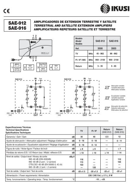
SAE-912 SAE-916
SAE-912 SAE-916
SAE-912 SAE-916
- No tags were found...

Create successful ePaper yourself
Turn your PDF publications into a flip-book with our unique Google optimized e-Paper software.
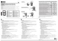
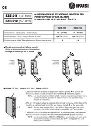
TV + IFReturnIFAT.0 - 18 dBReturnTV + IFTV + IFIFEQ.0 - 12 dBIFAT.0 - 18 dBIFEQ.0 - 12 dBTEST(Return)-20dBTEST(TV + IF)-20dBTEST(Return)-20dB(TV + IF)-20dBReturnAT. (dB)9 6 0 3TVEQ.0 - 12 dBTVEQ.0 - 12 dBReturn5 65TVAT.0 - 18 dBTVAT.0 - 18 dBMHzReturn TVIF5 35 45 862 950 2150MHz1 -FIJACION MURAL Y CONEXION A TIERRAASEGURAMIENTO DEL CABLE DE RED: Antes de proceder a la fijación mural, insertar el cablede red en el amplificador y sujetarlo en la parte posterior como indica la figura de aquí a la derecha.El amplificador se fija a la pared utilizando los dos tirafondos Ø3,9x25 suministrados:1. Colocar T1 en la pared, sin apretar. Colgar la caja por la oreja superior.2. Colocar derecha la caja y atornillar T2 ajustándolo a la oreja de abajo.3. Apretar T1.Para conexión a tierra la caja dispone de un tornillo en la parte inferior (T3). El cable deconexión se conecta de la forma que se indica.( )1 -WALL FIXING AND GROUNDINGFASTENING THE MAINS LEAD: Prior to wall fixing, insert the mains lead(in the amplifier and fasten it on the back as indicated in the picture above. )The amplifier is fixed using the two Ø3.9x25 screws provided:1. Place T1 on the wall, not tightening. Hang the housing through the upper holder.2. Put straight the housing and tighten T2 fitting it to the internal side of the lowerholder.3. Tighten T1.To ground the housing use the T3 screw at the lower side. The grounding cable isconnected as indicated in the picture.1 -FIXATION AU MUR ET MISE À LA TERREASSUJETTISSEMENT DU CORDON SECTEUR : Avant la fixation au mur, insérer le cordon(secteur dans l'amplificateur et le fixer à l'arrière comme indiqué dans la figure en haut. )L'amplificateur se fixe au mur au moyen des deux vis Ø3,9x25 fournies :1. Placer T1 sur le mur, sans le serrer. Pendre le boîtier par l’ouïe supérieure.2. Poser droit le boîtier et serrer T2 en l’ajustant à la partie interne de l’ouïe inférieure.3. Serrer T1.Pour la mise à la terre du boîtier utiliser la vis située au côté inférieur (T3). Le câble deterre est connecté comme indiqué.T2T3T1<strong>SAE</strong>-<strong>912</strong> Ref. 3500Ultra Broadband Amplifier2 -APERTURA DE LA CAJASoltar con una llave Allen nº 4 el tornillo central y levantar la tapa. Enla parte posterior de la misma se aloja un eje de ajuste, así como, enel modelo <strong>SAE</strong>-<strong>916</strong>, tres pequeños puentes enchufables para laselección de atenuación de la señal de retorno.2 -OPENING THE HOUSINGUnscrew the central screw with the help of a number 4 Allen spannerand put the cover up. One setting shaft is fitted on the back side ofthis cover. In the <strong>SAE</strong>-<strong>916</strong> model three small plug-in links forselecting the return signal attenuation are also fitted.2 -OUVERTURE DU BOÎTIERAu moyen d’une clé Allen numéro 4 dévisser complètement la viscentrale et soulever le couvercle. Au derrière de ce couvercle estlogé un axe de réglage ainsi que, pour le modèle <strong>SAE</strong>-<strong>916</strong>, troispetits ponts enfichables pour la sélection de l’atténuation du signalde retour.puentes enchufablesplug-in linksponts enfichableseje de ajustesetting shaftaxe de réglageReturn TESTTV + IF<strong>SAE</strong>-<strong>912</strong> Ref. 3500Ultra Broadband AmplifierTV IF86 862 950 21503 -CONEXIONES RF Y ALIMENTACIONConectar los cables coaxiales de entrada y salida.Conectar a la red alterna 230/240 VAC. Deberá encenderse el indicador led.3 -RF AND POWER CONNECTIONSConnect the input and output coaxial cables.Connect to the mains (230/240 VAC). The indicator led must light up green.3 -RACCORDEMENTS HF ET ALIMENTATIONRaccorder les câbles coaxiaux d’entrée et sortie.Raccorder au secteur 230/240 VCA. La led doit s’illuminer verte.led199654
<strong>SAE</strong>-<strong>912</strong> Ref. 3500Ultra Broadband AmplifierTV + IFReturnIFAT.0 - 18 dBReturnTV + IFIFEQ.0 - 12 dBTEST(Return)-20dBTEST(TV + IF)-20dBReturnAT. (dB)9 6 0 3TVEQ.0 - 12 dB<strong>SAE</strong>-<strong>912</strong><strong>SAE</strong>-<strong>912</strong> Ref. 3500Ultra Broadband AmplifierTVAT.0 - 18 dBReturn TVIF5 65 86 862 950 2150MHzTV + IFReturnIFAT.0 - 18 dBIFEQ.0 - 12 dBReturnTV + IFTEST-20dB(Return)TEST-20dB(TV + IF)ReturnAT. (dB)9 6 0 3TVEQ.0 - 12 dBTVAT.0 - 18 dBReturn TV IF5 65 86 862 950 2150 MHz1 96 5<strong>SAE</strong>-<strong>912</strong>Ref. 3500Ultra Broadband AmplifierTV + IFReturnIFAT.0 - 18 dBReturnTV + IFIFEQ.0 - 12 dBTEST(Return)-20dBTEST(TV + IF)-20dBReturnAT. (dB)9 6 0 3TVEQ.0 - 12 dBReturn5 65TVAT.0 - 18 dBTVIF86 862 950 2150MHz1996551996554 -AJUSTE DE LAS SEÑALES DE SALIDA TV Y FIConectar la puerta "TEST (TV + IF)" al medidor de nivel.Utilizando el eje suministrado, ajustar las señales TV yFI actuando sobre los potenciómentros de atenuación yecualización que se identifican en el amplificador.4 -ADJUSTMENT OF TV AND IF OUTPUT SIGNALSConnect the "TEST (TV + IF)" port to the level meter.Then, by using the shaft supplied, set the TV and IFsignals by operating on the attenuation and equalizationpotentiometers that are identified in the amplifier.4 -REGLAGE DES SIGNAUX DE SORTIE TV ET BISRelier le port "TEST (TV+IF)" au mesureur de niveau. Enutilisanr l’axe fourni, régler les signaux TV et BIS enagissant sur les potentiomètres d’atténuation etégalisation qui sont identifiés dans l’amplificateur.<strong>SAE</strong>-<strong>916</strong>Atenuaciones seleccionables para Señal de RetornoSelectable attenuations for Return SignalAtténuations sélectionnables pour Signal de Retour5 -CONTROL Y AJUSTE DE LA SEÑAL DE SALIDA RETORNOConectar la puerta "TEST (Return)" al medidor de nivel. Si el amplificadores el modelo <strong>SAE</strong>-<strong>916</strong>, puede seleccionarse la atenuación de señal deretorno insertando 1, 2 ó 3 puentes en los pines existentes en la aberturaReturn. Ver aquí abajo el mapa de atenuaciones seleccionables y lascorrespondientes posiciones de los puentes.5 -CONTROL AND ADJUSTMENT OF RETURN OUTPUT SIGNALConnect the "TEST (Return)" port to the level meter. If the amplifier is the<strong>SAE</strong>-<strong>916</strong> model, the attenuation for return signal can be selected byplugging 1, 2 or 3 links onto the existing pins at the Return opening. Seebelow the map of selectable attenuations and the corresponding positionsof the plug-in links.5 -CONTRÔLE ET REGLAGE DU SIGNAL DE SORTIE RETOURRelier le port "TEST (Retour)" au mesureur de niveau. Si l’amplificateurest le modèle <strong>SAE</strong>-<strong>916</strong>, l'atténuation du signal de retour peut êtresélectionnée en insérant 1, 2 ou 3 ponts sur les broches existantes àl'ouverture Return. Voir ici bas la carte d'atténuations sélectionnables etles positions correspondantes des ponts.ReturnAT. (dB)9 6 0 3puente enchufableplug-in linkpont enfichable0 dB 1 dB3 dB5 dB6 dB7 dB 9 dB10 dB11 dBEjemplo de aplicación / Application example / Exemple d'application«UDV»DistribuidorSplitterRépartiteurCabeceraHeadendTête45-2150 MHz<strong>SAE</strong>-<strong>912</strong><strong>SAE</strong>-<strong>912</strong>«UDL»DerivadoresTapsDérivateurs<strong>SAE</strong>-<strong>912</strong><strong>SAE</strong>-<strong>912</strong> Ref. 3500Ultra Broadband Amplifier
IKUSI — Angel Iglesias, S.A.Paseo Miramón, 170 - 20009 San Sebastián - SPAIN Tel.: +34 943 44 88 00 Fax: +34 943 44 88 11 www.ikusi.com120479A