Alfa Romeo 159 Montage- und Betriebsanleitung ... - Westfalia
Alfa Romeo 159 Montage- und Betriebsanleitung ... - Westfalia
Alfa Romeo 159 Montage- und Betriebsanleitung ... - Westfalia

Create successful ePaper yourself
Turn your PDF publications into a flip-book with our unique Google optimized e-Paper software.
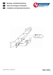
Installation instructions:<br />
1.) Disassemble the rear bumper and the reinforcement (foam part). Disassemble the silencer <strong>und</strong> the rear heat<br />
protection sheets. Remove the boot floor cover.<br />
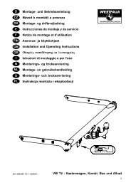
2.) Attach the side parts 4 and 5 to the base part 1 at point “a” using the M10x35 bolts, 10.5x25x3 washers and<br />
M10 nuts with a tightening torque of 10 Nm.<br />
Hold the pre-assembled towing device against the vehicle. Position the side parts 4 and 5 <strong>und</strong>erneath the<br />
chassis beam and the bore holes “b” <strong>und</strong>erneath the rear transverse beam. Position the nose pieces “c” at<br />
the rear panel and symmetrically align the towing device to the vehicle. Now transfer / mark the bore holes<br />
“b”, “d” and “e” onto the vehicle body.<br />
Remove the pre-assembled towing device and drill the transferred bore holes “b”, “d” and “e” ø12 mm and<br />
deburr them.<br />
Vertically transfer / mark the bore holes “b” onto the upper bar of the rear transverse beam. Drill the<br />
transferred bore holes “b” ø12 mm and deburr them.<br />
Vertically transfer / mark the bore holes “d” onto the floor of the boot. Drill the transferred bore holes “d” ø22<br />
mm and deburr them.<br />
3.) Insert the spacer tubes 9 (21x4x65) into the rear transverse beam at point “b”, place the plate 6 onto the rear<br />
transverse beam and insert the M10x140 bolts through the plate 6, the rear transverse beam and the spacer<br />
tubes 9.<br />
Hold the pre-assembled towing device and the receiver 2 against the vehicle and loosely attach them at point<br />
“b” using the 10.5x25x3 washers and the M10 nuts.<br />
Insert the shackles 8 through the lower apertures in the chassis beam and loosely attach the side parts 4 and<br />
5 using the M10x35 bolts and 10.5x25x3 washers.<br />
Insert the spacer tubes 10 (21x4x58) into the chassis beam at point “d”, place the shackles 7 over them and<br />
insert the M10x90 bolts. Now loosely attach the side parts 4 and 5 using the 10.5x25x3 washers and M10<br />
nuts.<br />
4.) Align the towing device and tighten all the nuts and bolts.<br />
Tightening torque for M10 at point “a”, “b”, “d” and “e” = 40 Nm<br />
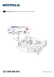
5.) Saw the hatched area out of the <strong>und</strong>erside of the bumper reinforcement (foam part) as indicated on diagram<br />
X. Assemble the bumper reinforcement in the rear transverse beam.<br />
6.) Saw the hatched area out of the <strong>und</strong>erside of the bumper as indicated on the supplied template 22. Place and<br />
fix the template on the inside of the bumper for this task. The line “Y0” corresponds to the middle of the<br />
vehicle. Now assemble the bumper to the vehicle.<br />
Assemble the silencer and the rear heat protection sheets at the vehicle. Attach the boot floor cover.<br />
Subject to alteration.<br />
31