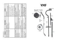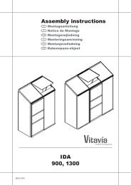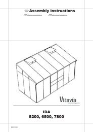
HERA 9000 Assembly instructions - OPJ Handel A/S
HERA 9000 Assembly instructions - OPJ Handel A/S
HERA 9000 Assembly instructions - OPJ Handel A/S

Erfolgreiche ePaper selbst erstellen
Machen Sie aus Ihren PDF Publikationen ein blätterbares Flipbook mit unserer einzigartigen Google optimierten e-Paper Software.
4<br />
SICHERHEITSVORKEHRUNGEN<br />
Safety Warning<br />
1. PLEASE READ THESE INSTRUCTIONS CAREFULLY AND COMPLETELY BEFORE ASSEMBLING YOUR GREENHOUSE.<br />
2. Sharp edges and corners can cause injury. Always wear protective glasses, gloves, shoes and headgear when handling the aluminium profi les, glass<br />
and polycarbonate sheets. Broken glass is a safety hazard – always clear up immediately and dispose of with care.<br />
3. The product you have purchased is intended only for the growing of plants and should only be used for this purpose. When used for other purposes we<br />
will take no responsibility.<br />
4. It is recommended that this greenhouse be assembled by at least two people.<br />
5. When using a step ladder one person should steady it at all times whilst the other works.<br />
6. Should you encounter diffi culties constructing this house, or in positioning the glass or polycarbonate sheets, please contact your retailer<br />
– do not use force!<br />
SITE SELECTION<br />
Always try to select a sunny location, sheltered<br />
from the wind as much as possible.<br />
IMPORTANT<br />
Before assembling your new greenhouse,<br />
please check that all parts in the provided list<br />
are included. Please take each bundle out of<br />
the packaging in order to identify the parts<br />
better.<br />
It is important that the opened bundles do not<br />
get mixed with one another.<br />
If something is missing please contact your<br />
retailer.<br />
NECESSARY TOOLS<br />
Screw drivers (Normal and Crosshead PH2),<br />
10mm and 17mm spanner or wrench, 10 mm<br />
combination spanner, 1.8m Step ladder, Craft<br />
knife, measuring stick, spirit level, Accu-drill<br />
with adjustable torque<br />
MAINTENANCE<br />
The greenhouse should be thoroughly washed<br />
with a gentle detergent occasionally. Please<br />
check that the detergent used does not react<br />
aggressively with aluminium or plastic.<br />
Ensure that the door tracks are cleaned regularly<br />
to avoid a build up of debris<br />
0. BASE<br />
Important! The base must be level. A zinccoated<br />
steel base is available as an accessory<br />
for all greenhouse models.<br />
(Attention! Only when the greenhouse has to<br />
be located in a very windy and unprotected<br />
location: Drill through both the profi le at the<br />
base of the greenhouse and the steel base,<br />
and connect them with nuts and bolts.)<br />
If you would rather construct your own stone<br />
or concrete foundation, please follow the<br />
<strong>Assembly</strong> Instructions<br />
dimensions specifi ed in diagram 0.<br />
Treated wooden beams at least 18mm high<br />
and not more then 32mm wide should be positioned<br />
between the stone/concrete foundation<br />
and the aluminium frame(A-A). On the side<br />
where the door will be located use a treated<br />
wooden beam not more then 52mm wide<br />
(B-B). Connect the wooden beams to the foundation<br />
with 50mm long bolts (not provided).<br />
Foundations must extend down below the frost<br />
level.<br />
Diagrams in a single frame show the view<br />
from inside the greenhouse. Those enclosed<br />
in a double frame show the view from<br />
outside the greenhouse.<br />
1. SIDE ELEMENTS<br />
Lay all of the parts on the fl oor and connect<br />
them loosely. (1.1) to (1.6)<br />
Note: All bolt heads must slide into the bolt<br />
channels in each vertical bar.<br />
Repeat for the other 4 plain sides.<br />
2. SIDE ELEMENT - DOOR<br />
Lay all of the parts on the fl oor and connect<br />
them loosely, (2.1) to (2.6).<br />
3. CONNECTING THE SIDE ELEMENTS<br />
Bolt the six side elements together using<br />
corner plates 1092, (3.1) to (3.3).<br />
Now position your frame on the prepared<br />
base/foundation and connect loosely. (Please<br />
only tighten these bolts after the building is<br />
glazed.)<br />
Adjust the frame until it is square and vertical<br />
and tighten the bolts connecting the sides.<br />
Please do not over tighten.<br />
4A. ROOF<br />
Lay all roof bars (6093) on the ground and<br />
accurately mark them with a pencil as shown,<br />
(4.1). These marks are important to ensure the<br />
glazing panes fi t later.<br />
Connect the assembly help disc (6098) to the<br />
hexagonal cone (6095) using bolt (3001) and<br />
nut (3002) (4.2).<br />
Assemble roof bars (6093) onto cone (6095)<br />
(4.3) (4.4).<br />
Note: the straight cut edge of (6093) should<br />
touch disc (6098) (4.3).<br />
Tighten all bolts.<br />
Connect ring beam (6097) with the joining<br />
point edge on the mark (1055 mm) (4.5) (4.6).<br />
4B. ROOF<br />
Two people should now lift the assembly onto<br />
the roof.<br />
Connect roof bars (6093) onto each corner<br />
(4.7).<br />
Using the step ladder connect roof middle<br />
bars (6094) to hexagonal cone (6095) (4.8),<br />
ring beam (6097) (4.9) and eave angle (6091 /<br />
6096) (4.10). Tighten all bolts.<br />
Assemble the outer cone (6036) with bolt<br />
(6052), washer (6061), spacer (1010) and nut<br />
(3002) and lift into place.<br />
Note: bolt (3001) and nut (3002) connecting<br />
disc (6098) must be removed at this point.<br />
Inside connect bolt extension (6038) to bolt<br />
(6052) and then connect cover (6099) to<br />
(6038) using washer (6061) and bolt (6059)<br />
(4.11).<br />
5L & R. DOORS<br />
Lay vertical door bars (6023) on the ground<br />
and prepare 6 bolts (3001) in the bolt channels<br />
in each.<br />
011.02.1001