Montage-anleitung - HMS Umwelttechnik
Montage-anleitung - HMS Umwelttechnik
Montage-anleitung - HMS Umwelttechnik

Erfolgreiche ePaper selbst erstellen
Machen Sie aus Ihren PDF Publikationen ein blätterbares Flipbook mit unserer einzigartigen Google optimierten e-Paper Software.
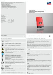
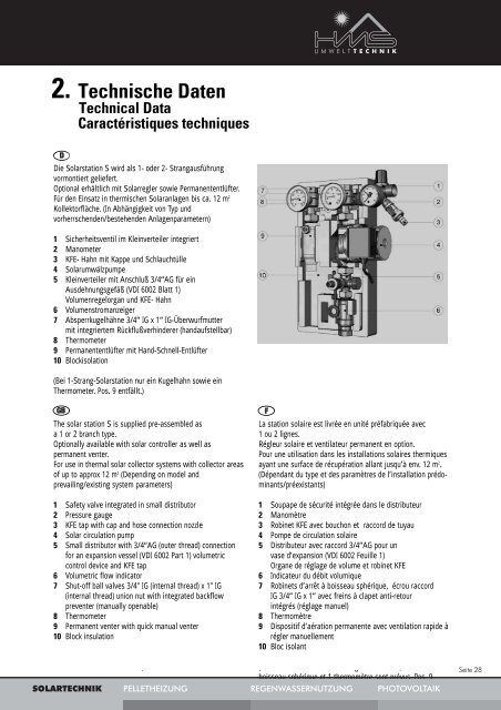
2. Technische Daten<br />
Technical Data<br />
Caractéristiques techniques<br />
Die Solarstation S wird als 1- oder 2- Strangausführung<br />
vormontiert geliefert.<br />
Optional erhältlich mit Solarregler sowie Permanententlüfter.<br />
Für den Einsatz in thermischen Solaranlagen bis ca. 12 m2 D<br />
Kollektorfläche. (In Abhängigkeit von Typ und<br />
vorherrschenden/bestehenden Anlagenparametern)<br />
1 Sicherheitsventil im Kleinverteiler integriert<br />
2 Manometer<br />
3 KFE- Hahn mit Kappe und Schlauchtülle<br />
4 Solarumwälzpumpe<br />
5 Kleinverteiler mit Anschluß 3/4“AG für ein<br />
Ausdehnungsgefäß (VDI 6002 Blatt 1)<br />
Volumenregelorgan und KFE- Hahn<br />
6 Volumenstromanzeiger<br />
7 Absperrkugelhähne 3/4“ IG x 1“ IG-Überwurfmutter<br />
mit integriertem Rückflußverhinderer (handaufstellbar)<br />
8 Thermometer<br />
9 Permanententlüfter mit Hand-Schnell-Entlüfter<br />
10 Blockisolation<br />
(Bei 1-Strang-Solarstation nur ein Kugelhahn sowie ein<br />
Thermometer. Pos. 9 entfällt.)<br />
GB<br />
The solar station S is supplied pre-assembled as<br />
a 1 or 2 branch type.<br />
Optionally available with solar controller as well as<br />
permanent venter.<br />
For use in thermal solar collector systems with collector areas<br />
of up to approx 12 m 2 (Depending on model and<br />
prevailing/existing system parameters)<br />
1 Safety valve integrated in small distributor<br />
2 Pressure gauge<br />
3 KFE tap with cap and hose connection nozzle<br />
4 Solar circulation pump<br />
5 Small distributor with 3/4“AG (outer thread) connection<br />
for an expansion vessel (VDI 6002 Part 1) volumetric<br />
control device and KFE tap<br />
6 Volumetric flow indicator<br />
7 Shut-off ball valves 3/4" IG (internal thread) x 1" IG<br />
(internal thread) union nut with integrated backflow<br />
preventer (manually openable)<br />
8 Thermometer<br />
9 Permanent venter with quick manual venter<br />
10 Block insulation<br />
(One ball valve only in 1 branch solar station as well as one<br />
thermometer Item 9 omitted.)<br />
F<br />
La station solaire est livrée en unité préfabriquée avec<br />
1 ou 2 lignes.<br />
Régleur solaire et ventilateur permanent en option.<br />
Pour une utilisation dans les installations solaires thermiques<br />
ayant une surface de récupération allant jusqu’à env. 12 m 2 .<br />
(Dépendant du type et des paramètres de l’installation prédominants/préexistants)<br />
1 Soupape de sécurité intégrée dans le distributeur<br />
2 Manomètre<br />
3 Robinet KFE avec bouchon et raccord de tuyau<br />
4 Pompe de circulation solaire<br />
5 Distributeur avec raccord 3/4“AG pour un<br />
vase d’expansion (VDI 6002 Feuille 1)<br />
Organe de réglage de volume et robinet KFE<br />
6 Indicateur du débit volumique<br />
7 Robinets d’arrêt à boisseau sphérique, écrou raccord<br />
IG 3/4“ IG x 1“ avec freins à clapet anti-retour<br />
intégrés (réglage manuel)<br />
8 Thermomètre<br />
9 Dispositif d’aération permanente avec ventilation rapide à<br />
régler manuellement<br />
10 Bloc isolant<br />
(Pour les stations solaires à 1 ligne seulement, 1 robinet à<br />
boisseau sphérique et 1 thermomètre sont prévus. Pos. 9<br />
supprimée)<br />
SOLARTECHNIK PELLETHEIZUNG REGENWASSERNUTZUNG PHOTOVOLTAIK<br />
Seite 28