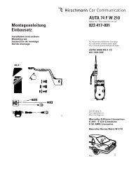
Fig. 2 2 50° Fig. 3 Fig. 4 495 750-305 blank bare non-traité Fig. 4 Fig. 5 Fig. 4 Fig. 6 Fig. 4 Fig. 7 Fig. 4 Fig. 8 Fig. 4 Fig. 9 Fig. 4 Fig. 10
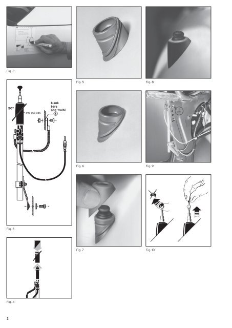
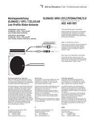
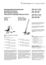
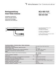
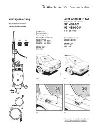
D GB F Einbauanleitung Der Einbau der Versenkantenne <strong>AUTA</strong> <strong>4000</strong> F <strong>410</strong> L erfolgt bei den angegebenen Mercedes-Benz-Modellen in den linken hinteren Kotflügel. • Im Kofferraum die linksseitige Auskleidung entfernen. Bei Wagen mit Anhängervorrichtung vorher die Strebe abschrauben. Für Kabelverlegung hintere Sitzbank und -kissen ausbauen. • An der Einbaustelle nach Fig. 1 bzw. 2 die beiliegende Schablone anlegen, das Karosserieloch anzeichnen und maßhaltig einarbeiten (Toleranz ±0,2 mm). Zum Schutz des Lackes vorher mit Klebeband abkleben. Die Bohrung entgraten, zum Schutz gegen Korrosion die blanke Kante mit Grundlack bestreichen und trocknen lassen. • In der Zwischenzeit das Antennenkabel zusammen mit dem bereits verlegten Leitungssatz durch die Mehrfachtülle unter die Rücksitzbank, von dort unter der linken Einstiegsleiste, im Kabelkanal bis zum Fahrersitz nach vorne und von dort zum Empfänger verlegen und einstecken (evt. Durchziehdraht verwenden). • Das Antennenkabel ist geräteseitig mit einem abwinkelbaren Stecker versehen. Dadurch kann der Stecker je nach Bedarf gerade oder als Winkelstecker verwendet werden. Das Abbiegen über den Führungsrücken bitte nur von Hand durchführen, damit Kabel und Stecker nicht verletzt werden (Fig. 3). • Die Dichttülle von oben in das Karosserieloch einsetzen (Fig. 4 und 5). Dies muss am unteren Einstich der Dichttülle erfolgen. Der obere Einstich liegt gut sichtbar über der Karosserie (Fig. 4 und 6). • Das Antennenkabel an der Antenne festschrauben, den Kugelstutzen mit etwas Antennenfett bestreichen (<strong>AUTA</strong> 115) und die Antenne von unten in die bereits eingesetzte Dichttülle eindrücken (Fig. 4). Die Antenne mit Halter am Schutzrohr gegen das vorhandene Langloch am Karosseriesteg anschrauben (Fig. 3 und 9). • Teleskop ausziehen, Neigung kontrollieren; danach Schrauben am Halter fest anziehen. • Die Kappe von oben auf die Dichttülle aufsetzen, leicht nachdrücken, bis sie einrastet und an der Karosserieoberfläche gleichmäßig anliegt (Fig. 4, 7 und 8). • Das Masseband an vorhandenem Loch an der Verstrebung festschrauben, Anlagefläche vorher blank schaben und einfetten (Fig. 3 und 9). • Auskleidung im Kofferraum und Rücksitz wieder einbauen. • Das Teleskop ist mit einem Stülpknopf (720 978-002) ausgerüstet (Fig. 3) und kann von Hand gegriffen und ausgezogen werden. Mit abgenommenem Stülpknopf kann das Teleskop vollständig versenkt und nur mit dem Schlüssel ausgezogen werden (Fig. 10). • Achten Sie bitte darauf, dass nach dem Einbau der Antenne der Empfänger nachgetrimmt wird. Am Antenneneingang des Gerätes ist ein von außen bedienbarer Trimmer eingebaut. Installation instructions Installation of the retractable antenna <strong>AUTA</strong> <strong>4000</strong> F <strong>410</strong> L left-side in the rear wing of the stated Mercedes-Benz cars. • Remove left-side lining in the luggageboot. For cars with trailer coupling, unscrew previously the support. For cable laying detach the back seat, too. • Apply the attached drilling template and mark the installation point acc. to fig. 1 or 2, resp., cover the paintwork with protective tape, and drill a hole (tolerance ±0,2 mm). Remove the burr, spread the bare edge with primer to protect against corrosion and allow to dry. • In the meantime pass the antenna cable through the multiple grommet under the back seat, then along the left edge in the cable tunnel to the front and plug-in to the radio receiver (if necessary use a draw wire). • At the radio end the antenna cable is fitted with a plug that can be angled, so it can be used straight or, if necessary, as an angled plug. Please bend by hand only to avoid any damage of cable or plug (fig. 3). • Insert the sealing sleeve from top into the car body hole (fig. 4 and 5). Take care that the lower recess of the sleeve fits to the body sheet, so the upper recess should be clearly visible above the car body (fig. 4 and 6). • Tighten the antenna cable to the antenna case, spread the spherical antenna head with some special grease (<strong>AUTA</strong> 115) and push the antenna from below through the sleeve inserted before (fig. 4). Fix the antenna with bracket at the protective tube to the existing oblong hole in the car body bar (fig. 3 and 9). • Extend the telescope, check the angle, then tighten the screws at the bracket. • Apply the cap on top of the sleeve and press until snapping-on and fitting tightly to the car body surface (fig. 4, 7 and 8). • Fix the earthing tape to the existing hole at the brace. Previously bare the connecting surface and spread with grease (fig. 3 and 9). • Replace lining and back seat. • On top the telescope is provided with a plastic knob (720 978-002) as shown in fig. 3, that can be extended by hand. If this knob is detached, the telescope can – after retraction – only be extended by a special key (fig. 10). • Please make sure that the radio will be tuned again after the antenna has been installed. On the antenna input of the receiver there is an incorporated trimmer that can be operated from outside. • With antenna fully extended select a weak station in the medium wave band (approx. 1100 kHz or acc. to the instructions of the manufacturer of the radio) and set the maximum volume by means of the trimmer. • The lowest tube must be always fully extended in order to ensure a good reception. Instruction de montage L'installation de l'antenne escamotable <strong>AUTA</strong> <strong>4000</strong> F <strong>410</strong> L se fait dans les modèles indiqués de Mercedes-Benz sur l'aile arrière gauche. • Enlever le revêtement du côté gauche du coffre. Seulement pour les véhicules possédant un dispositif pour remorque, dévisser auparavant l'entretoise. Démonter la banquette et coussin arrière pour la pose des câbles. • A l'emplacement du montage, placer le gabarit joint selon la fig. 1 resp. 2 marquer le perçage de la carrosserie et percer selon les dimensions prescriptes (tolérance ±0,2 mm). Pour protéger la laque, coller auparavant un ruban adhésif. Supprimer les bavures du perçage, enduire le bord mis à nu de laque de fond pour protéger contre la corrosion et laisser sécher. • Entre-temps, poser le câble d'antenne avec le jeu de câble déjà mis par le passecâble multiple sous la banquette arrière, de là, vers l'avant sous le rebord d'accès gauche en tunnel de câble jusque devant le siège du conducteur et à partir de là, au récepteur et enficher (au besoin utiliser du fil déroulable). • Le câble d'antenne est pourvu sur le côté de l'appareil d'une connection à fiche pliable. De ce fait, le connecteur peut être utilisé si besoin est, droit ou comme fiche coudée. Veuillez ne le tordre que manuellement par dessus le tube conducteur, afin que câble et fiche ne soit pas endommagés (fig. 3). • Placer la manchette d'en haut dans le perçage de la carrosserie (fig. 4 et 5). Ceci doit être effectué à l'encoche inférieure de la manchette. La fente supérieure est bien visible au-dessus de la carrosserie (fig. 4 et 6). • Visser à fond le câble d'antenne à l'antenne, enduire d'un peu de graisse le joint à bille (<strong>AUTA</strong> 115) et appuyer l'antenne du dessous dans la manchette déjà placée (fig. 4). Visser l'antenne avec le support au tube contre le trou longitudinal existant à la travers de carrosserie (fig. 3 et 9). • Sortir le télescope, contrôler l'inclinaison; ensuite serrer à fond les vis au support. • Mettre le capuchon d'en haut sur la manchette, appuyer légèrement, jusqu'à ce qu'il s'encliquetique et se trouve bien placé (fig. 4, 7 et 8). • Visser à fond la bande de mise à la masse au perçage existant à l'entroise, gratter à nu avant la surface et graisser (fig. 3 et 9). • Remettre le revêtement du coffre et la banquette arrière. • Le télescope est équipé d'un bouton à retournement (720 978-002) (fig. 3) et peut être manipulé et sorti manuellement. Le télescope peut être complètement noyé avec le bouton à retournement enlevé et être seulement sorti avec la clé (fig. 10). • Veuillez faire attention à ce que le récepteur soit réadapté, après la pose de l'antenne. 3