Druckwächter, Druckbegrenzer - FEMA Honeywell
Druckwächter, Druckbegrenzer - FEMA Honeywell
Druckwächter, Druckbegrenzer - FEMA Honeywell

Sie wollen auch ein ePaper? Erhöhen Sie die Reichweite Ihrer Titel.
YUMPU macht aus Druck-PDFs automatisch weboptimierte ePaper, die Google liebt.
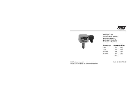
Montage- und<br />
Bedienungsanleitung<br />
<strong>Druckwächter</strong>,<br />
<strong>Druckbegrenzer</strong><br />
Grundtypen<br />
Zusatzfunktionen<br />
DWR… …-203 …-574<br />
DGM… …-205 …-575<br />
Ex-DWR… …-206 …-576<br />
Ex-DGM… …-213 …-577<br />
…-513<br />
® U.S. Registered Trademark MU2B-0264GE51 R0712B<br />
Copyright © 2012 <strong>Honeywell</strong> Inc. • Alle Rechte vorbehalten
Eigenschaften<br />
Eigenschaften<br />
Anwendung<br />
Dampf- und Heißwasser-Anlagen nach<br />
TRD604 sowie DIN EN 12828,<br />
Brenngase, Luft und Abgase, Gase nach<br />
DVGW, Arbeitsblatt G260,<br />
Flüssige Brennstoffe, z.B. Heizöle<br />
Prüfgrundlagen (DWR)<br />
VdTÜV Druck 100, EN 12952-11,<br />
EN 12953-9<br />
DIN EN 764-7 mit Bezug auf EN 161 für<br />
Medienkompatibilität<br />
EN 13611, DIN EN 1854<br />
EU/97/23/EC (PED)<br />
EU/94/9/EC (ATEX)<br />
EU/2009/142/EC (GAD)<br />
Prüfgrundlage (DGM)<br />
EN 13611, DIN EN 1854<br />
EU/2009/142/EC (GAD)<br />
EU/94/9/EC (ATEX)<br />
Funktion<br />
<strong>Druckwächter</strong> und <strong>Druckbegrenzer</strong> (mit<br />
interner oder externer Verriegelung) für<br />
Maximal- oder Minimaldrucküberwachung.<br />
Fühler<br />
Besondere Bauart für 2 Mio. Schaltzyklen<br />
2 MU2B-0264GE51 R0712B
Typenschlüssel<br />
Grundausführung<br />
DWR<br />
XXX<br />
Ausführung<br />
mit Zusatzfunktion<br />
DWR<br />
XXX-YYY<br />
Ex-Ausführung<br />
Ex-DWR<br />
XXX<br />
DWR Kennzeichnung für<br />
Baureihe<br />
XXX Kennzeichnung für<br />
Druckbereich<br />
YYY Kennzeichnung für<br />
Zusatzfunktionen<br />
Ex- Kennzeichnung für Ex-<br />
Ausführung<br />
Der Typenschlüssel gilt sinngemäß auch<br />
für DGM…<br />
Typenschlüssel<br />
Ausführung der Schaltgehäuse<br />
DWR XXX Steckeranschlußgehäuse<br />
(200) nach<br />
DWR XXX-2…<br />
DIN EN 175301<br />
DWR XXX-5… Klemmenanschlußgehäuse<br />
(500)<br />
Ex-DWR… Ex Schaltgerät (700)<br />
Wichtiger Hinweis<br />
Die Druckschalter sind Präzisionsgeräte,<br />
die im Werk eingestellt und justiert<br />
werden. Das Gerät deshalb nicht<br />
öffnen, die verlackten Justierschrauben<br />
nicht verstellen. Die<br />
Schaltpunkte würden sich verändern –<br />
neue Justierung wäre erforderlich.<br />
MU2B-0264GE51 R0712B 3
Wichtige Sicherheitsinformation<br />
Wichtige Sicherheitsinformation<br />
Bitte vor Installation und Inbetriebnahme durchlesen!<br />
Installation und Inbetriebnahme<br />
Druckschalter dürfen nur von für den<br />
Anwendungsbereich ausgebildeten<br />
Fachkräften (elektrisch/hydraulisch/<br />
mechanisch) unter Beachtung der<br />
Montageanweisung und der örtlichen<br />
gesetzlichen Bestimmungen montiert<br />
werden.<br />
Installation (mechanische, druckseitige<br />
Verbindung) der Geräte darf<br />
nur auf elektrochemisch gleichwertigen<br />
Materialien erfolgen, sonst droht<br />
Zerstörung des unedleren Metalls<br />
durch Kontaktkorrosion und damit<br />
verbunden ein Stabilitätsverlust und<br />
Undichtigkeit.<br />
Vorsicht beim Berühren –<br />
Verbrennungsgefahr. Gerät kann je<br />
nach Temperatur des Mediums bis zu<br />
70 °C heiß werden. Beim Betrieb mit<br />
Medien bis zu –20 °C besteht<br />
Festfriergefahr.<br />
Gerät nicht unter Spannung öffnen<br />
und Klemmen nicht unter Spannung<br />
lösen.<br />
4 MU2B-0264GE51 R0712B
Sicherheitshinweise<br />
Geräte der Serie DWR sind konstruiert<br />
für den Einsatz als <strong>Druckwächter</strong><br />
für Gase nach DVGW<br />
Arbeitsblatt G260 und für dünnflüssige<br />
Brennstoffe (z.B. Heizöl EL)<br />
sowie für Dampf und Heißwasser in<br />
Anlagen nach TRD 604 und<br />
DIN EN 12828.<br />
Geräte der Serie DGM sind konstruiert<br />
und zugelassen für den Einsatz<br />
als <strong>Druckwächter</strong> für Gase nach<br />
DVGW Arbeitsblatt G260.<br />
Das Gerät darf nur innerhalb der im<br />
Datenblatt festgelegten elektrischen,<br />
hydraulischen und thermischen<br />
Grenzen betrieben werden.<br />
Sicherheitshinweise<br />
Induktive Lasten können Kontaktabbrand<br />
oder Verschmelzen der Kontakte<br />
verursachen. Maßnahmen zur<br />
Verhinderung müssen bauseitig vorgesehen<br />
werden, z.B. durch Verwendung<br />
geeigneter RC-Glieder.<br />
Bei der Ausführung mit ZF1979 (ölund<br />
fettfrei) ist zu beachten, daß vom<br />
Öffnen der Verpackung bis zur vollständigen<br />
Montage eine Wiederverschmutzung<br />
der medienberührten<br />
Oberflächen vermieden wird!<br />
Generell wird keine Haftung für ölund<br />
fettfrei übernommen.<br />
MU2B-0264GE51 R0712B 5
Sicherheitshinweise<br />
Medienberührte Sensorteile aus<br />
hochwertigen Edelstählen erlauben<br />
den Einsatz in Verbindung mit den<br />
verschiedensten Medien. Jedoch ist<br />
vor der Auswahl die Prüfung auf<br />
Medienbeständigkeit zwingend<br />
erforderlich.<br />
Der Einsatz für Säuren und andere<br />
aggressive Medien, wie z.B. Flußsäure,<br />
Kupferchlorid, Königswasser<br />
oder Wasserstoffperoxyd ist nicht<br />
zulässig.<br />
Der Einsatz in Anlagen mit instabilen<br />
Gasen und Fluiden, wie z.B. Cyanwasserstoff,<br />
gelöstes Acetylen oder<br />
NOx ist nicht zulässig.<br />
Geräte müssen vor Sonneneinstrahlung<br />
und Regen geschützt werden.<br />
Druckschalter sind Präzisionsgeräte,<br />
die werksseitig justiert werden.<br />
Deshalb darf das Gerät niemals<br />
geöffnet sowie verlackte Justierschrauben<br />
nicht verstellt werden.<br />
Vibrationen am Druckschalter<br />
vermeiden, z.B. durch mechanische<br />
Entkopplung oder andere<br />
Schwingungsdämpfungsmaßnahmen.<br />
Stark verschmutzte Medien können<br />
ein Zusetzen des Sensors und damit<br />
Fehl- bzw. Nichtfunktion bewirken.<br />
Falls die Geräte dafür verwendet<br />
werden sollen, müssen geeignete<br />
Druckmittler vorgeschaltet werden.<br />
6 MU2B-0264GE51 R0712B
Druckschalter und Druckmittler bilden<br />
eine Funktionseinheit und dürfen im<br />
Feld niemals voneinander getrennt<br />
werden.<br />
Vor Demontage (Entfernen des<br />
Druckschalters von der Anlage) ist<br />
das Gerät spannungsfrei zu schalten<br />
sowie die Anlage zu entleeren. Unfallverhütungsvorschriften<br />
beachten.<br />
Druckschalter niemals als Steighilfe<br />
in der Anlage mißbrauchen.<br />
Keine Haftung durch <strong>Honeywell</strong><br />
GmbH bei Zuwiderhandlungen.<br />
Sicherheitshinweise<br />
Funktionale Sicherheit<br />
Falls das Gerät in einem sicherheitsgerichteten<br />
Schaltkreis zum<br />
Einsatz kommt, sind die dafür<br />
notwendigen Daten aus dem SIL-<br />
Zertifikat zu beachten.<br />
MU2B-0264GE51 R0712B 7
Inhaltsübersicht<br />
Inhaltsübersicht<br />
Typenkennzeichnung*<br />
1. Grundausführung DWR XXX<br />
1.1 Technische Daten<br />
1.2 Elektrischer Anschluß<br />
1.3 Druckanschluß<br />
1.4 Einstellung des Schaltdrucks<br />
1.5 Elektrische Verriegelung im Schaltschrank<br />
2. <strong>Druckwächter</strong> mit einstellbarer Schaltdifferenz DWR XXX-203<br />
3. <strong>Druckbegrenzer</strong> mit mechanischer Verriegelung des<br />
Schaltzustands (Wiedereinschaltsperre)<br />
DWR XXX-205<br />
DWR XXX-206<br />
4. <strong>Druckwächter</strong> mit vergoldeten Kontakten DWR XXX-213<br />
5. <strong>Druckwächter</strong> in eigensicheren Steuerstromkreisen (Ex-i) DWR XXX-513<br />
6. <strong>Druckwächter</strong> in eigensicheren Steuerstromkreisen mit DWR XXX-574-577<br />
Leitungsbruch- und Kurzschlußüberwachung (Ex-i)<br />
7. <strong>Druckwächter</strong> in Ex-Ausführung Ex- DWR XXX<br />
* Die Typenkennzeichnung gilt sinngemäß auch für DGM...<br />
8 MU2B-0264GE51 R0712B
1. Grundausstattung der <strong>Druckwächter</strong> DWR…/DGM…<br />
1. Grundausstattung der <strong>Druckwächter</strong> DWR…/DGM…<br />
Kapitel 1 beschreibt die Grundausstattung und die Montage der <strong>Druckwächter</strong><br />
DWR/DGM XXX (ohne jegliche Zusatzfunktion). Varianten und Zusatzfunktionen<br />
behandeln die Kapitel 2 – 7.<br />
1.1 Technische Daten (Grundausstattung)<br />
Grundjustage<br />
Je nach Typenreihe und Hauptverwendungszweck werden <strong>FEMA</strong>-Druckschalter<br />
entweder steigend oder fallend grundjustiert. Die Tabelle zeigt die Grundjustage der<br />
verschiedenen Geräte und deren Varianten.<br />
Steigend justiert<br />
Fallend justiert<br />
Grundgerät<br />
DWR<br />
Ex-DWR…<br />
DGM…,<br />
EX-DGM…<br />
n/a<br />
n/a<br />
Varianten<br />
DWR...-203, -205, -213, -301,-303, -305,<br />
-313, -351, -353, -363, -513, -563, -576, -577<br />
DGM...-205, -213, -301, -305,-313, -351,<br />
-363, -513, -563,-576, -577<br />
DWR...206, -306, -574, -575<br />
DGM...206, -306, -574, -575<br />
MU2B-0264GE51 R0712B 9
1. Grundausstattung der <strong>Druckwächter</strong> DWR…/DGM…<br />
Für Grundjustierung steigend gilt:<br />
Wird der Maximalwert des Einstellbereichs<br />
als Schaltpunkt gesetzt, ist der<br />
Rückschaltpunkt um den Wert der<br />
mittleren Schaltdifferenz niedriger.<br />
(z.B. DWR6: Einstellbereich 0,5 – 6 bar,<br />
Schaltpunkt 6 bar,<br />
Rückschaltpunkt 5,8 bar).<br />
Wird der Minimalwert des Einstellbereichs<br />
genutzt, gilt der unterste Einstellwert als<br />
Rückschaltpunkt<br />
Der Schaltpunkt muß um den Wert der<br />
mittleren Schaltdifferenz höher gesetzt<br />
werden<br />
(z.B. DWR6: Einstellbereich 0,5 – 6 bar,<br />
Schaltpunkt 0,7 bar,<br />
Rückschaltpunkt 0,5 bar).<br />
Für Grundjustierung fallend gilt:<br />
Wird der Minimalwert des Einstellbereichs<br />
genutzt, gilt der unterste Einstellwert als<br />
Schaltpunkt. Der Rückschaltpunkt muß<br />
um den Wert der mittleren Schaltdifferenz<br />
höher gesetzt werden<br />
(z.B. DWR6-206:<br />
Einstellbereich 0,5 – 6 bar,<br />
Schaltpunkt 0,5 bar,<br />
Rückschaltpunkt 0,8 bar).<br />
Wird der Maximalwert des Einstellbereichs<br />
genutzt, gilt der oberste Wert des<br />
Einstellbereiches als Rückschaltpunkt.<br />
Der Schaltpunkt muß demnach um den<br />
Wert der mittleren Schaltdifferenz<br />
niedriger gesetzt werden<br />
(z.B. DWR6-206: Einstellbereich<br />
0,5 – 6 bar, Schaltpunkt 5,7 bar,<br />
Rückschaltpunkt 6 bar).<br />
10 MU2B-0264GE51 R0712B
Grundsätzlich gilt:<br />
Alle Schalt- und Rückschaltpunkte<br />
müssen sich innerhalb der Grenzen des<br />
in den technischen Datenblättern beschriebenen<br />
Einstellbereichs befinden.<br />
Schalter<br />
Einpolig umschaltend<br />
Schaltleistung<br />
8 (5) A, 250 V AC<br />
Einbaulage<br />
Senkrecht nach oben und waagerecht<br />
Max. Umgebungstemperatur<br />
–25 bis 70 °C (DWR…)<br />
–25 bis 60 °C (DGM…)<br />
Max. Temperatur des Mediums<br />
70 °C (60 °C bei DGM). Höhere Temperaturen<br />
des Mediums sind möglich,<br />
wenn durch geeignete Maßnahmen (z.B.<br />
1. Grundausstattung der <strong>Druckwächter</strong> DWR…/DGM…<br />
Wassersackrohr) obige Grenzwerte am<br />
Schaltgerät nicht überschritten werden.<br />
Bei Umgebungstemperaturen unter 0 °C<br />
ist dafür zu sorgen, daß im Sensor und im<br />
Schaltgerät kein Kondenswasser entstehen<br />
kann.<br />
Schaltdifferenz<br />
Werte siehe Datenblatt<br />
Druckanschluß<br />
Außengewinde G ½” A (Manometeranschluß)<br />
nach DIN 16288 und<br />
Innengewinde G ¼” nach ISO 228, Teil 1.<br />
Für Gasanwendungen ab 4 bar nur<br />
Flachdichtungen verwenden. Dichtung im<br />
Gewinde ist nur bis 4 bar zulässig.<br />
Schaltgerät<br />
Stabiles Gehäuse aus seewasserbeständigem<br />
Aluminium-Druckguß mit Stecker-<br />
(200) oder Klemmenanschluß (300).<br />
MU2B-0264GE51 R0712B 11
1. Grundausstattung der <strong>Druckwächter</strong> DWR…/DGM…<br />
Schutzart nach EN60529<br />
IP 54 (Gehäuse 200)<br />
IP 65 (Gehäuse 300, 500 und 700)<br />
Werkstoffe<br />
Siehe Datenblatt<br />
1.2 Elektrischer Anschluß<br />
Anschlußplan<br />
Verdrahtung<br />
ACHTUNG: Spannung abschalten.<br />
Die Verdrahtung erfolgt am Winkelstecker.<br />
Der Kabelausgang ist in jeweils 4<br />
um 90° gegeneinander versetzten<br />
Positionen möglich.<br />
Schraube herausdrehen.<br />
Den Schraubendreher in den Schlitz<br />
einführen und nach unten drücken.<br />
l<br />
Abb. 1. Anschlußplan<br />
Bei steigendem Druck<br />
3–1 öffnet, 3–2 schließt<br />
Bei fallendem Druck<br />
3–2 öffnet, 3–1 schließt<br />
Abb. 2. Verdrahtung<br />
Bei Klemmenanschlußgehäusen ist die<br />
Klemmleiste nach Abnahme des Deckels<br />
zugänglich.<br />
12 MU2B-0264GE51 R0712B
1.3 Druckanschluß<br />
Montage<br />
Direkt auf die Rohrleitung mit Manometeranschluß<br />
G ½” oder Innengewinde G ¼”<br />
Anziehen ausschließlich am dem<br />
Druckanschluß nächstliegenden<br />
Sechskant! Niemals am Gehäuse oder<br />
einer anderen Stelle des Sensors!<br />
Gehäuse oder Stecker nie als Hebelarm<br />
benutzen.<br />
Alternative Befestigung des Gerätes mit<br />
2 Schrauben Ø 4 mm auf einer ebenen<br />
Anlagefläche.<br />
1. Grundausstattung der <strong>Druckwächter</strong> DWR…/DGM…<br />
Außengewinde<br />
Innengewinde<br />
Abb. 3 Anschluß<br />
Außengewinde G ½"<br />
Bei Verwendung von Flachdichtungen<br />
Zentrierschraube eindrehen<br />
(Tiefe A ca. 0,3 – 0,5 mm)<br />
Innengewinde G ¼"<br />
Bei Gasanwendung: Dichtung im<br />
Gewinde nur bis 4 bar. Bei höherem<br />
Druck Flachdichtung verwenden.<br />
MU2B-0264GE51 R0712B 13
1. Grundausstattung der <strong>Druckwächter</strong> DWR…/DGM…<br />
1.4 Einstellen des Schaltdrucks<br />
Abb. 4. Einstellen des Schaltdrucks<br />
ACHTUNG: Spannung abschalten.<br />
Die Einstellung des Schaltdrucks erfolgt<br />
an der Stellspindel. Vor Verstellung ist die<br />
oberhalb der Skala liegende Sicherungsschraube<br />
um max. 2 Umdrehungen zu<br />
lösen und nach der Einstellung wieder<br />
anzuziehen.<br />
Der Skalenwert entspricht dem Schaltpunkt<br />
(bei steigendem Druck).<br />
Der Rückschaltpunkt ist um die Schaltdifferenz<br />
niedriger. Die Skala dient als<br />
Richtwertskala, für genaue Einstellungen<br />
ist ein Manometer erforderlich.<br />
Bei Klemmenanschlußgehäusen ist die<br />
Einstellschraube nach Abnahme des<br />
Deckels zugänglich.<br />
14 MU2B-0264GE51 R0712B
1.5 Elektrische Verriegelung im<br />
Schaltschrank (Schaltungsbeispiele)<br />
Ein <strong>Druckwächter</strong> kann auch als Begrenzer<br />
eingesetzt werden, wenn eine<br />
elektrische Verriegelung nachgeschaltet<br />
ist. Bei Druckbegrenzung in Dampf- und<br />
Heißwasserkesseln ist die externe Verriegelung<br />
nur zulässig, wenn sichergestellt<br />
ist, daß der <strong>Druckwächter</strong><br />
„besonderer Bauart“ ist.<br />
Bei der Errichtung von Verriegelungsschaltungen<br />
sind in jedem Fall die<br />
Bestimmungen der DIN EN 50156 /<br />
VDE 0116-1 bzw. die Anforderungen aus<br />
deren aktuellen Ausgaben sowie<br />
Forderungen aktueller Richtlinien zu<br />
berücksichtigen!<br />
1. Grundausstattung der <strong>Druckwächter</strong> DWR…/DGM…<br />
MU2B-0264GE51 R0712B 15
1. Grundausstattung der <strong>Druckwächter</strong> DWR…/DGM…<br />
Maximaldruckbegrenzung mit externer<br />
Verriegelung<br />
Minimaldruckbegrenzung mit externer<br />
Verriegelung<br />
Abb. 5. Maximaldruckbegrenzung<br />
DW = <strong>Druckwächter</strong><br />
T1 = STOP<br />
T2 = START<br />
Abb. 6. Minimaldruckbegrenzung<br />
S = Signal (bei Bedarf)<br />
K1 = Relais mit Selbsthaltung<br />
SC = Sicherheitsstromkreis<br />
16 MU2B-0264GE51 R0712B
2. <strong>Druckwächter</strong> mit einstellbarer Schaltdifferenz DWR…-203 (Gilt nicht für DGM)<br />
2. <strong>Druckwächter</strong> mit einstellbarer<br />
Schaltdifferenz DWR…-<br />
203 (Gilt nicht für DGM)<br />
2.1 Technische Daten wie 1.1<br />
2.2 Elektrischer Anschluß wie 1.2<br />
2.3 Druckanschluß wie 1.3<br />
2.4 Einstellung (z.B. Schalten bei<br />
steigendem Druck)<br />
Für die Einstellung des Schaltdrucks und<br />
der Schaltdifferenz steht je eine Einstellspindel<br />
zur Verfügung. Beide Spindeln<br />
sind zentrisch angeordnet. Die äußere<br />
Spindel mit größerem Durchmesser beeinflußt<br />
den Schaltpunkt, mit der kleinen,<br />
innen liegenden Schraube wird die<br />
Schaltdifferenz und damit der Rückschaltpunkt<br />
verändert.<br />
Die Wirkungsrichtung ist durch die<br />
Pfeilrichtung angegeben.<br />
Abb. 7. Wirkungsrichtung<br />
Reihenfolge bei der Einstellung<br />
Schaltpunkt (bei steigendem Druck)<br />
an großer Spindel nach Skala oder<br />
Manometer einstellen<br />
Mit kleiner, innen liegender, Schraube<br />
Schaltdifferenz (x d ) und damit den<br />
Rückschaltpunkt einstellen.<br />
MU2B-0264GE51 R0712B 17
2. <strong>Druckwächter</strong> mit einstellbarer Schaltdifferenz DWR…-203 (Gilt nicht für DGM)<br />
Bei Änderung der Schaltdifferenz bleibt<br />
der Schaltpunkt unverändert, der Rückschaltpunkt<br />
wird um die Schaltdifferenz x d<br />
verschoben .<br />
RSP = SP – x d<br />
Auch hier gilt:<br />
Abb. 8. Anschlußplan<br />
Bei steigendem Druck<br />
3–1 öffnet, 3–2 schließt<br />
Bei fallendem Druck<br />
3–2 öffnet, 3–1 schließt<br />
Abb. 9. Steigender Druck:<br />
SP = Schaltpunkt<br />
RSP = Rückschaltpunkt<br />
x d = Schaltdifferenz (Hysterese)<br />
p = Druck<br />
18 MU2B-0264GE51 R0712B
3. <strong>Druckbegrenzer</strong> mit<br />
mechanischer Verriegelung<br />
des Schaltzustands<br />
(Gilt für DWR und sinngemäß für DGM)<br />
3. <strong>Druckbegrenzer</strong> mit mechanischer Verriegelung des Schaltzustands<br />
Abb. 10. Mechanische Verriegelung<br />
Anstelle des Mikroschalters mit selbsttätiger<br />
Rückstellung ist in den Begrenzern<br />
ein „bi-stabiler“ Mikroschalter eingebaut.<br />
Erreicht der Druck den an der Skala<br />
eingestellten Wert, schaltet der Mikroschalter<br />
um und bleibt in dieser Stellung.<br />
Die Sperre ist durch Eindrücken der Entriegelungstaste<br />
(an der Skalenseite des<br />
Schaltgeräts durch roten Punkt gekennzeichnet)<br />
wieder zu lösen. Die Entriegelung<br />
kann erst dann erfolgen, wenn<br />
der Druck um einen bestimmten Wert<br />
abgesenkt bzw. bei Verriegelung bei<br />
fallendem Druck wieder angehoben<br />
wurde.<br />
Je nach Ausführung kann die<br />
Verriegelung bei steigendem Druck<br />
(DWR…-205) oder bei fallendem Druck<br />
(DWR…-206) wirksam sein.<br />
3.1 Technische Daten wie 1.1<br />
MU2B-0264GE51 R0712B 19
3. <strong>Druckbegrenzer</strong> mit mechanischer Verriegelung des Schaltzustands<br />
3.2 Elektrischer Anschluß<br />
Maximaldruckbegrenzung<br />
Minimaldruckbegrenzung<br />
Abb. 11. DWR…-205<br />
Umschaltung und Verriegelung bei<br />
steigendem Druck<br />
Zusatzfunktion (…-205).<br />
Anschluß Steuerstromkreis an Klemme 1<br />
und 3.<br />
Abb. 12. DWR…-206<br />
Umschaltung und Verriegelung bei<br />
fallendem Druck<br />
Zusatzfunktion (...-206).<br />
Anschluß Steuerstromkreis an Klemme 2<br />
und 3.<br />
20 MU2B-0264GE51 R0712B
3.3 Druckanschluß wie 1.3<br />
3.4 Einstellung wie 1.4<br />
Bitte beachten<br />
Bei Maximaldruckbegrenzern (...-205)<br />
entspricht der Skalenwert dem oberen<br />
Schaltpunkt, bei Minimaldruckbegrenzern<br />
(...-206) dem unteren Schaltpunkt.<br />
4. <strong>Druckwächter</strong> mit vergoldeten Kontakten DWR…-213, DGM…-213<br />
4. <strong>Druckwächter</strong> mit<br />
vergoldeten Kontakten<br />
DWR…-213, DGM…-213<br />
Vergoldete Kontakte werden ausschließlich<br />
im Niederspannungsbereich angewendet,<br />
um die Übergangswiderstände<br />
an den Kontakten gering zu halten.<br />
4.1 Technische Daten wie 1.1<br />
Schaltleistung max. 24 V DC<br />
max. 100 mA<br />
min. 5 V DC<br />
min. 2 mA<br />
Bei höheren Spannungen und Strömen<br />
wird die Goldschicht an den Kontakten<br />
beschädigt.<br />
Alle übrigen Daten entsprechen der<br />
Grundausstattung.<br />
MU2B-0264GE51 R0712B 21
5. <strong>Druckwächter</strong> als “einfaches elektrisches Betriebsmittel” in eigensicheren Stromkreisen (Ex-i)<br />
5. <strong>Druckwächter</strong> als “einfaches<br />
elektrisches Betriebsmittel” in<br />
eigensicheren Stromkreisen<br />
(Ex-i)<br />
Nach Abschnitt 5.7 “Einfache<br />
elektrische Betriebsmittel” der<br />
EN 60079-11:2007<br />
l<br />
Abb. 13. Anschlußplan<br />
Vergoldete Kontakte, einpolig umschaltend.<br />
Schaltdifferenz nicht einstellbar.<br />
Der Anschlußplan gilt für Maximaldrucküberwachung.<br />
Bei steigendem<br />
Druck öffnet Kontakt 3-1 und schließt<br />
Kontakt 3-2. Nur einsetzbar in Verbindung<br />
mit einem geeigneten und EGbaumustergeprüften<br />
Trennschaltverstärker.<br />
Der Trennschaltverstärker<br />
muß außerhalb der Ex-Zone installiert<br />
werden. Der dem Trennschaltverstärker<br />
beiliegende Anschlußplan ist zu<br />
beachten. Die gültigen Installationsvorschriften<br />
für die Verdrahtung eigensicherer<br />
Stromkreise müssen eingehalten<br />
werden.<br />
Max. Schaltleistung: 24 VDC, 50 mA<br />
Min. Schaltleistung: 5 VDC, 2 mA<br />
Das Gerät darf nur innerhalb der genannten<br />
Spezifikation betrieben werden. Bei<br />
der Auswahl des Trennschaltverstärkers<br />
und der Leitungslänge müssen u. g.<br />
Werte berücksichtigt werden:<br />
U i = max. 24 VDC L i vernachlässigbar<br />
I K = max. 50 mA C i vernachlässigbar<br />
Zündschutzart<br />
II 1/2G Ex ia IIC T6 Ga/Gb<br />
II 1/2D Ex ta/tb IIIC T80°C<br />
22 MU2B-0264GE51 R0712B
6. <strong>Druckwächter</strong> mit Widerstandskombination in eigensicheren Stromkreisen (Ex-i)<br />
6. <strong>Druckwächter</strong> mit Widerstandskombination<br />
in eigensicheren<br />
Stromkreisen (Ex-i)<br />
Nach Abschnitt 5.7 “Einfache<br />
elektrische Betriebsmittel” der<br />
EN 60079-11<br />
Abb. 14. Anschlußpläne<br />
Die <strong>Druckwächter</strong> entsprechen in allen<br />
technischen Daten den o. g. Baureihen.<br />
Zusätzlich ist eine Widerstandskombination<br />
im Schaltgerät vorhanden,<br />
die zusammen mit einem geeigneten<br />
Trennschaltverstärker die elektrischen<br />
Leitungen zwischen Trennschaltverstärker<br />
und <strong>Druckwächter</strong> auf<br />
Kurzschluß und Leitungsbruch überwacht.<br />
Ein Leitungsbruch führt zu einer<br />
Abschaltung des Systems zur sicheren<br />
Seite. Der Trennschaltverstärker muß<br />
gemäß seiner geprüften Bestimmung<br />
außerhalb der Ex-Zone installiert werden.<br />
Dem Trennschaltverstärker beiliegende<br />
Anschlußpläne sowie die für die Verdrahtung<br />
eigensicherer Stromkreise gültigen<br />
Normen und Richtlinien müssen<br />
beachtet werden.<br />
Bemessungsspannung<br />
Max. 20 VDC<br />
Elektrische Daten für Widerstandskombination<br />
1,5 k / 0,35 W; 10,0 k / 0,35 W<br />
MU2B-0264GE51 R0712B 23
7. <strong>Druckwächter</strong> in Ex-d -Ausführung Ex-DWR…, Ex-DGM…<br />
Verdrahtungsparameter<br />
U i = < 20 VDC<br />
P i = 0,35 W<br />
L i vernachlässigbar<br />
C i vernachlässigbar<br />
Temperaturklasse T6<br />
Zündschutzart<br />
Gas: II 1/2G Ex ia IIC T6 Ga/Gb<br />
Staub: II 1/2D Ex ta/tb IIIC T85°C<br />
ACHTUNG<br />
<strong>Druckwächter</strong> mit Widerstandskombination<br />
niemals ohne Trennschaltverstärker<br />
installieren – Überhitzungsund<br />
Brandgefahr bei Überlastung der<br />
Widerstandskombination.<br />
7. <strong>Druckwächter</strong> in Ex-d -<br />
Ausführung Ex-DWR…, Ex-<br />
DGM…<br />
<strong>Druckwächter</strong> in Ex-Ausführung können<br />
nur in der baumustergeprüften Ausführung<br />
geliefert werden. Varianten und<br />
Zusatzfunktionen sind grundsätzlich nicht<br />
möglich.<br />
7.1 Technische Daten der Ex-<br />
Schaltgeräte<br />
Zündschutzart<br />
0035 II 2G Ex d e IIC T6 Gb<br />
0035 II 1/2D Ex ta/tb IIIC T80°C<br />
Ex-Zulassung<br />
siehe Zertifikat<br />
Ex-Zone<br />
Geeignet für Zonen 1, 2, 21 und 22<br />
24 MU2B-0264GE51 R0712B
Schutzart<br />
IP 65 (bei senkrechter Einbaulage)<br />
Umgebungstemperatur<br />
–20 bis +60 °C<br />
Max. Temperatur am Schaltgerät<br />
60 °C. Höhere Mediumstemperaturen in<br />
der Anlage sind möglich, wenn durch<br />
geeignete Maßnahmen (z.B. Wassersackrohr)<br />
sichergestellt ist, daß die<br />
Grenzwerte am Druckschalter nicht überschritten<br />
werden.<br />
Kabeleinführung<br />
M16 x 1,5, nur für feste Verlegung<br />
Schaltdifferenz<br />
Nicht einstellbar, ungefähre Werte siehe<br />
Datenblatt<br />
Einbaulage<br />
Senkrecht nach oben<br />
7. <strong>Druckwächter</strong> in Ex-d -Ausführung Ex-DWR…, Ex-DGM…<br />
7.2 Elektrische Daten<br />
Anschlußplan<br />
Die Klemmenleiste ist nach Abnahme des<br />
Klemmenkastendeckels und der<br />
Klemmenschutzkappe zugänglich. Nach<br />
Anschluß der Zuleitungen die Klemmenschutzkappe<br />
wieder anbringen.<br />
Abb. 15. Anschlußplan<br />
Bei steigendem Druck wird Kontakt 3-1<br />
unterbrochen und 3-2 geschlossen.<br />
Bemessungswerte<br />
Bemessungsspannung<br />
bis 250 VAC<br />
MU2B-0264GE51 R0712B 25
7. <strong>Druckwächter</strong> in Ex-d -Ausführung Ex-DWR…, Ex-DGM…<br />
Bemessungsstrom AC<br />
250 VAC: 3 A (ohmisch), 3 A (induktiv)<br />
30 VAC: 3 A (ohmisch), 3 A (induktiv)<br />
Bemessungsstrom DC<br />
250 VDC:<br />
0,25 A (ohmisch), 0,03 A (induktiv)<br />
125 VDC:<br />
0,5 A (ohmisch), 0,06 A (induktiv)<br />
75 VDC: 1 A (ohmisch), 1 A (induktiv)<br />
30 VDC: 3 A (ohmisch), 3 A (induktiv)<br />
Anschlußklemmen<br />
Bemessungsspannung bis 440 V<br />
Bemessungsstrom max. 23 A<br />
Anzugsdrehmoment max. 0,4 Nm<br />
Leiterquerschnitt max. 2,5 mm 2<br />
Erdungsanschluß max. 4 mm 2<br />
7.3 Druckanschluß wie 1.3<br />
7.4 Schaltpunkteinstellung<br />
Der Schaltpunkt ist im Rahmen der im<br />
Datenblatt angegebenen Bereiche an der<br />
Stellspindel mit einem Schraubendreher<br />
einstellbar. Dazu ist der Klemmenkastendeckel<br />
abzunehmen (4 Innensechskantschrauben<br />
M4 lösen). Zuvor ist die kleine<br />
Feststellschraube an der Frontseite<br />
(oberhalb der Skala) zu lösen und nach<br />
der Schaltpunkteinstellung wieder<br />
anzuziehen.<br />
Rechtsdrehung an der Stellspindel<br />
bedeutet niedriger Schaltpunkt, Linksdrehung<br />
bedeutet höheren Schaltpunkt.<br />
Die Skala dient als Richtwertskala, für<br />
genaue Einstellungen ist ein Manometer<br />
erforderlich.<br />
26 MU2B-0264GE51 R0712B
7. <strong>Druckwächter</strong> in Ex-d -Ausführung Ex-DWR…, Ex-DGM…<br />
1. Potentialausgleich<br />
2. Klemmenschutzkappe (abnehmbar)<br />
3. Anschlußklemmen<br />
4. Ex-Kabelverschraubung M16 x 1,5<br />
nur für feste Verlegung zugelassen!<br />
5. Schaltpunkteinstellung<br />
6. Feststellschraube für Einstellspindel<br />
7. Schutzleiteranschluß<br />
Abb. 16.<br />
Schaltpunkteinstellung<br />
MU2B-0264GE51 R0712B 27
7.5 Serien-Nummer<br />
Alle Schaltgeräte und die dazugehörigen<br />
Klemmenkastendeckel sind mit der<br />
Typenbezeichnung und einer Seriennummer<br />
gekennzeichnet.<br />
Bei der Montage ist darauf zu achten,<br />
daß die Klemmenkastendeckel nicht<br />
vertauscht werden.<br />
Wichtig<br />
Bei der Montage und Inbetriebnahme der<br />
Ex-Schaltgeräte sind die anerkannten<br />
Regeln der Technik und die Richtlinien für<br />
Installationen in Ex-Bereichen zu<br />
beachten.<br />
Die Ex-Kabelverschraubung (4) ist nur für<br />
feste Verlegung zugelassen.<br />
Hergestellt für und im Auftrag des Geschäftsbereichs Environmental and Combustion Controls der <strong>Honeywell</strong><br />
Technologies Sàrl, Rolle, Z.A. La Pièce 16, Schweiz in Vertretung durch:<br />
<strong>Honeywell</strong> GmbH<br />
<strong>FEMA</strong> Regelgeräte<br />
Böblinger Straße 17<br />
71101 Schönaich<br />
Germany<br />
Tel.: 07031/637-02<br />
Fax: 07031/637-850<br />
MU2B-0264GE51 R0712B<br />
www.fema.biz
Assembly and Operating<br />
Instructions<br />
Pressure Switch,<br />
Pressure Limiter<br />
Basic models Additional functions<br />
DWR… …-203 …-574<br />
DGM… …-205 …-575<br />
Ex-DWR… …-206<br />
…-576<br />
Ex-DGM… …-213<br />
…-577<br />
…-513<br />
® U.S. Registered Trademark MU2B-0264GE51 R0712B<br />
Copyright © 2012 <strong>Honeywell</strong> Inc. • All rights reserved
Characteristics<br />
Application<br />
Steam, hot water, according to TRD604<br />
and DIN EN 12828<br />
Fuel gases, according to DVGW<br />
worksheet G260<br />
Liquid fuels, e.g., fuel oil<br />
Testing standards for DWR<br />
VdTÜV Druck 100, EN 12952-11,<br />
EN 12953-9<br />
DIN EN 764-7 with relation to EN 161 for<br />
media compatibility<br />
EN 13611, DIN EN 1854<br />
EU 97/23 EC (PED)<br />
EU 94/9 EC (ATEX)<br />
Characteristics<br />
Testing standards for DGM<br />
EN 13611, DIN EN 1854<br />
EU/2009/142/EC (GAD)<br />
EU/94/9/EC (ATEX)<br />
Function<br />
Pressure monitor and limiter (with internal<br />
or external interlock)<br />
For maximum and minimum switch action<br />
Sensor<br />
Special construction with 2 million<br />
switching cycles<br />
30 MU2B-0264GE51 R0712B
Type code<br />
Basic<br />
version<br />
DWR<br />
XXX<br />
DWR<br />
Version with<br />
additional<br />
function<br />
DWR<br />
XXX-YYY<br />
Ex<br />
version<br />
Ex-DWR<br />
XXX<br />
Identification for series<br />
XXX Identification for pressure<br />
range<br />
YYY Identification for additional<br />
function<br />
Ex- Identification for Ex version<br />
The type code also roughly applies for<br />
series DGM…<br />
Switch housings<br />
DWR XXX<br />
DWR XXX-2…<br />
Type code<br />
Plug connection<br />
housing (200)<br />
(Plug connection to<br />
DIN EN 175301)<br />
DWR XXX-5… Terminal connection<br />
housing (500)<br />
Ex-DWR… Ex switching device<br />
(700)<br />
Important note<br />
Pressure switches are precision<br />
instruments, set and adjusted at the<br />
factory. Therefore do not open the<br />
device, do not change the adjustment<br />
of the varnished adjustment screws.<br />
The switching points would change –<br />
readjustment would be necessary.<br />
MU2B-0264GE51 R0712B 31
Important safety information<br />
Please read this before installation and comissioning<br />
Important safety information<br />
Installation and commissioning<br />
Pressure switches may be installed<br />
only by personnel trained in this<br />
application area (electric/hydraulic/<br />
mechanical) in accordance with the<br />
installation instructions and local legal<br />
requirements.<br />
The devices must be installed<br />
(mechanical, pressure-side connection)<br />
only on electro-chemically<br />
matched materials; otherwise, there<br />
is a risk of damage to base metals<br />
through contact corrosion, which can<br />
result in leakage and loss of stability.<br />
Caution when touching the device –<br />
risk of burns. Device can reach a<br />
medium temperature of up to 70 °C.<br />
Risk of freezing when working with<br />
media up to –20 °C.<br />
Do not open wiring box or plug and<br />
do not remove terminal screws before<br />
the device is de-energized.<br />
32 MU2B-0264GE51 R0712B
Safety instructions<br />
Devices of the DWR series are designed<br />
for use as pressure monitors<br />
for gases in accordance with DVGW<br />
worksheet G260 for liquid fuels (e.g.,<br />
heating oil EL) and for steam and hot<br />
water systems in accordance with<br />
TRD 604 and DIN 4751, part 2.<br />
Devices of the DGM series are designed<br />
and approved for gases in<br />
accordance with DVGW worksheet<br />
G260.<br />
The device must be used only within<br />
the electric, hydraulic and thermal<br />
limits specified in the data sheet.<br />
Safety instructions<br />
Inductive loads can cause contact<br />
burns or fuse the contacts. Preventive<br />
measures must be implemented by<br />
the customer, e.g., by using suitable<br />
RC elements.<br />
When using the version ZF 1979 (oil<br />
and grease-free), take care to avoid<br />
recontamination of surfaces that are<br />
in contact with the media, right<br />
through from opening the packaging<br />
to completed installation. Generally,<br />
no liability will be assumed for the oil<br />
and grease-free version.<br />
High quality stainless-steel sensor<br />
parts coming in contact with media<br />
enable the devices to be used with a<br />
variety of media. However, a<br />
chemical resistance test MUST be<br />
carried out before selection.<br />
MU2B-0264GE51 R0712B 33
Use with acids and other aggressive<br />
media, such as hydrofluoric acid,<br />
copper chloride, aqua regia, or<br />
hydrogen peroxide is not permitted.<br />
Use in systems with unstable gases<br />
and liquids such as hydrogen<br />
cyanide, dissolved acetylene or NOx<br />
is not permitted.<br />
Devices must be protected from solar<br />
radiation and rain.<br />
Pressure switches are precision<br />
devices, which are calibrated in the<br />
factory. Never open the device and<br />
do not change the adjustment of the<br />
varnished calibration screws.<br />
Protect the pressure switch against<br />
excessive vibrations, e.g., by means<br />
of mechanical isolation or other<br />
vibration damping measures.<br />
Safety instructions<br />
Heavily contaminated media can clog<br />
the sensor and cause errors and/or<br />
malfunction. If the equipment is being<br />
used for this purpose, suitable<br />
chemical seals must be connected.<br />
Pressure switches and chemical<br />
seals form a functional unit and must<br />
not be disconnected from each other<br />
in the field.<br />
Before disassembly (removing the<br />
pressure switch from the system), the<br />
device must be disconnected from<br />
the power supply and the system<br />
must be emptied. Observe the<br />
Accident Prevention Regulations.<br />
Never use the pressure switches as a<br />
climbing aid.<br />
<strong>Honeywell</strong> GmbH accepts no liability<br />
for non-compliance.<br />
34 MU2B-0264GE51 R0712B
Functional Safety<br />
If the device is installed in a<br />
Functional Safety related circuit, the<br />
relevant data of the SIL certificate<br />
must be observed.<br />
Safety instructions<br />
MU2B-0264GE51 R0712B 35
Contents<br />
Type<br />
identification*<br />
1. Basic version DWR XXX<br />
1.1 Technical data<br />
1.2 Electrical connection<br />
1.3 Pressure connection<br />
1.4 Setting the switching pressure<br />
1.5 Electrical interlock in the switchgear cabinet<br />
2. Pressure monitors with adjustable switching difference DWR XXX-203<br />
3. Pressure limiters with mechanical interlock of the switching<br />
state (restart lockout)<br />
DWR XXX-205<br />
DWR XXX-206<br />
4. Pressure monitors with gold plated contacts DWR XXX-213<br />
5. Pressure monitors in intrinsically safe control circuits (Ex-i) DWR XXX-513<br />
6. Maximum pressure monitors in intrinsically safe control<br />
circuits with open-circuit and short-circuit monitoring (Ex-i)<br />
DWR XXX-574-<br />
577<br />
7. Pressure monitors in Ex version Ex- DWR XXX<br />
*The type identification also roughly corresponds to series DGM...<br />
Contents<br />
36 MU2B-0264GE51 R0712B
1. Basic equipment of the pressure monitors / pressure limiters<br />
1. Basic equipment of the pressure monitors / pressure limiters<br />
Chapter 1 describes the basic equipment and the installation of the pressure monitors<br />
DWR/DGM XXX (without any additional functions). Further chapters deal with versions<br />
and additional functions.<br />
1.1 Technical data (basic equipment)<br />
Basic calibration<br />
Depending on series and intended purpose, <strong>FEMA</strong> pressure switches are either<br />
calibrated under falling or rising pressure. The table shows the calibration of the various<br />
devices and their versions.<br />
Calibrated under<br />
rising pressure<br />
Calibrated under<br />
falling pressure<br />
Basic device<br />
DWR<br />
Ex-DWR…<br />
DGM…,<br />
EX-DGM…<br />
n/a<br />
n/a<br />
Versions<br />
DWR...-203, -205, -213, -301,-303, -305,<br />
-313, -351, -353, -363, -513, -563, -576, -577<br />
DGM...-205, -213, -301, -305,-313, -351,<br />
-363, -513, -563,-576, -577<br />
DWR...206, -306, -574, -575<br />
DGM...206, -306, -574, -575<br />
MU2B-0264GE51 R0712B 37
For devices calibrated under rising<br />
pressure, the following applies<br />
If the maximum value of the setting range<br />
is set as the switching point, the reset<br />
point is lower by the value of the average<br />
switching differential.<br />
(e.g., DWR6: setting range 0.5 – 6 bar,<br />
switching point 6 bar, reset point 5.8 bar)<br />
If the minimum value of the setting range<br />
is used, then the lowest setting value is<br />
also the reset point.<br />
The switching point must be set higher by<br />
the value of the average switching<br />
differential (e.g., DWR6: 0.5-6 bar,<br />
switching point 0.7 bar,<br />
reset point 0.5 bar).<br />
1. Basic equipment of the pressure monitors / pressure limiters<br />
For devices calibrated under falling<br />
pressure, the following applies<br />
If the minimum value of the setting range<br />
is used, then the lowest setting value is<br />
also the switching point. The reset point<br />
must be set higher by the value of the<br />
average switching differential<br />
(e.g., DWR6-206: 0.5 – 6 bar, switching<br />
point 0.5 bar, reset point 0.8 bar).<br />
If the maximum value of the setting range<br />
is used, then the highest value of the<br />
setting range is also the reset point.<br />
The reset point must be set higher by the<br />
value of the average switching differential<br />
(e.g., DWR6-206: setting range 0.5-6 bar,<br />
reset point 6 bar, switching point 5.7 bar).<br />
38 MU2B-0264GE51 R0712B
The following applies to all switches:<br />
All switching and reset points must be<br />
within the limits of the specified setting<br />
range given in the technical data sheet.<br />
Switch<br />
Single-pole changeover<br />
Switching capacity<br />
8 (5) A, 250 V AC<br />
Installation position<br />
Vertical to the top and horizontal<br />
Max. ambient temperature<br />
–25 to 70 °C (DWR…)<br />
–25 to 60 °C (DGM…)<br />
Max. medium temperature<br />
70 °C (60 °C on DGM). Higher medium<br />
temperatures are possible if the above<br />
limiting values at the switching device are<br />
not exceeded by suitable measures (e.g.,<br />
1. Basic equipment of the pressure monitors / pressure limiters<br />
water pocket tube). At ambient temperatures<br />
below 0 °C, ensure that no<br />
water condensation will occur in the<br />
sensor and in the switching device.<br />
Switching differential<br />
Values see data sheet<br />
Pressure connection<br />
External thread G ½” A (pressure gauge<br />
connection) according to DIN 16288 and<br />
internal thread G ¼” according to<br />
ISO 228, Part 1.<br />
For gas applications internal thread<br />
permissible only up to 4 bar. Use flat<br />
gasket ring for pressure > 4 bar.<br />
Switching box<br />
Sturdy housing made of seawater-resistant<br />
aluminum die casting with plug connection<br />
(200) or terminal connection<br />
(300, 500) and Ex-housing (700).<br />
MU2B-0264GE51 R0712B 39
Degree of protection according<br />
EN60529<br />
IP 54 (housing 200)<br />
IP 65 (housing 300, 500 and 700)<br />
Materials<br />
See data-sheet<br />
1.2 Electrical connection<br />
Connection layout<br />
1. Basic equipment of the pressure monitors / pressure limiters<br />
Wiring<br />
CAUTION: Switch off voltage.<br />
Wiring is on the angled plug. The cable<br />
outlet can be in any of 4 positions, which<br />
are at 90° in relation to each other.<br />
Remove screw.<br />
Insert the screwdriver in the slot and<br />
press downwards.<br />
l<br />
Fig. 1. Connection layout<br />
With rising pressure<br />
3–1 opens, 3–2 closes<br />
With falling pressure<br />
3–2 opens, 3–1 closes<br />
Fig. 2. Wiring<br />
On devices with terminal connection<br />
housing, the terminal board is accessible<br />
after removing the terminal box lid.<br />
40 MU2B-0264GE51 R0712B
1.3 Pressure connection<br />
Installation<br />
Directly on the pipeline (pressure gauge<br />
connection G ½” or G ¼” internal thread)<br />
Tighten the device only at the hexagon<br />
which is located closest to the pressure<br />
gauge connection. Never tighten device<br />
at housing or other area of sensor parts.<br />
Never use housing or plug as a lever arm.<br />
Alternative mounting is possible with<br />
2 screws Ø 4 mm on a flat surface area.<br />
1. Basic equipment of the pressure monitors / pressure limiters<br />
External thread<br />
Internal thread<br />
Fig. 3 Pressure switch<br />
External thread G ½"<br />
(Pressure gauge connection)<br />
When using flat seals, turn in the centering<br />
screw (depth A approx. 0.3 – 0.5 mm)<br />
Internal thread G ¼"<br />
In gas applications, internal thread is permissible<br />
only up to pressures of 4 bar.<br />
Use flat gasket ring for pressure > 4 bar.<br />
MU2B-0264GE51 R0712B 41
1.4 Setting the switching pressure<br />
Fig. 4.<br />
Setting the switching pressure<br />
1. Basic equipment of the pressure monitors / pressure limiters<br />
CAUTION: Switch off voltage.<br />
The switching pressure is set using the<br />
setting spindle. Before setting, loosen the<br />
setscrew located above the scale by<br />
approx. 2 turns and tighten it again after<br />
setting.<br />
The scale value corresponds to the<br />
switching point (for rising pressure).<br />
The reset point is lower by the value of<br />
the switching differential.<br />
The scale is used for an approximate<br />
value; a pressure gauge is required for an<br />
accurate setting.<br />
On terminal connection housings, the<br />
setting screw is accessible after removing<br />
the cover.<br />
42 MU2B-0264GE51 R0712B
1.5 External electrical interlock in<br />
the switchgear cabinet (circuit<br />
samples)<br />
A pressure monitor can also be used as a<br />
limiter if an electrical interlock is connected<br />
in series. For pressure limitation in<br />
steam and hot water boilers, the external<br />
interlock is permissible only if it is assured<br />
that the pressure monitor is of “special<br />
construction”.<br />
For electrical interlock, design circuits as<br />
described in DIN EN 50156 / VDE 0116-1<br />
or refer to local standards and law!<br />
1. Basic equipment of the pressure monitors / pressure limiters<br />
MU2B-0264GE51 R0712B 43
Maximum pressure limitation with<br />
external interlock<br />
1. Basic equipment of the pressure monitors / pressure limiters<br />
Minimal pressure limitation with<br />
external interlock<br />
Fig. 5. Maximum pressure limitation<br />
DW = pressure monitor<br />
T1 = STOP<br />
T2 = START<br />
Fig. 6. Minimum pressure limitation<br />
S = signal (as required)<br />
K1 = relay with self-hold<br />
SC = safety circuit<br />
44 MU2B-0264GE51 R0712B
2. Pressure monitors with adjustable switching differential DWR…-203 (not for DGM)<br />
2. Pressure monitors with<br />
adjustable switching<br />
differential DWR…-203<br />
(not for DGM)<br />
2.1 Technical data as for 1.1<br />
2.2 Electrical connection as for 1.2<br />
2.3 Pressure connection as for 1.3<br />
2.4 Setting (i.e., Switching at rising<br />
pressure)<br />
One spindle is available for each setting:<br />
the switching pressure and the switching<br />
differential. Both spindles are arranged<br />
concentrically. The outer spindle with<br />
larger diameter adjusts the switching<br />
point. The switching differential and thus<br />
the reset-point is changed with the small<br />
screw located internally.<br />
The action direction is indicated by the<br />
arrow.<br />
Fig. 7. Action direction<br />
Setting sequence<br />
Switching point (i.e., with rising<br />
pressure), with outer spindle,<br />
according to scale or pressure gauge<br />
Small, internal screw, adjusts<br />
switching differential and thus also the<br />
reset-point.<br />
MU2B-0264GE51 R0712B 45
2. Pressure monitors with adjustable switching differential DWR…-203 (not for DGM)<br />
When the switching differential is<br />
changed, the upper switching point SP<br />
remains unchanged, while the lower<br />
switching point is shifted by the<br />
switching differential x d.<br />
<br />
In general:<br />
RSP = SP – x d<br />
Fig. 8. Connection layout<br />
With rising pressure<br />
3–1 opens, 3–2 closes<br />
With falling pressure<br />
3–2 opens, 3–1 closes<br />
Fig. 9. Rising pressure RSP = SP – x d<br />
SP = switching point<br />
RSP = Re-set point<br />
x d = switching differential (hysteresis)<br />
p = pressure<br />
46 MU2B-0264GE51 R0712B
3. Pressure limiters with<br />
mechanical interlock of<br />
switching state<br />
(applies for DWR and roughly for<br />
DGM)<br />
3. Pressure limiters with mechanical interlock of switching state<br />
preset on the scale, the microswitch<br />
switches over and remains in this<br />
position. The catch can be released by<br />
pressing in the unlocking button (marked<br />
on the scale side of the switching device<br />
by a red dot). The limiter cannot be<br />
unlocked until the pressure has<br />
decreased by a certain amount or, in<br />
case of interlocking at the lower switching<br />
point, is increased again.<br />
Depending on the version, the interlock<br />
can be effective for a rising (DWR…-205)<br />
or a falling value (DWR…-206).<br />
Fig. 10. Mechanical interlock<br />
Instead of the microswitch with automatic<br />
reset, a “bi-stable” microswitch is installed<br />
in the limiters.<br />
When the pressure reaches the value<br />
3.1 Technical data as for 1.1<br />
MU2B-0264GE51 R0712B 47
3. Pressure limiters with mechanical interlock of switching state<br />
3.2 Electrical connection<br />
Maximum pressure limiting<br />
Minimum pressure limiting<br />
Fig. 11. DWR…-205<br />
Switching over and interlocking on rising<br />
pressure<br />
Additional function (…-205).<br />
Connection of control circuit to<br />
terminal 1 and 3.<br />
Fig. 12. DWR…-206<br />
Switching over and interlocking on falling<br />
pressure<br />
Additional function (...-206).<br />
Connection of control circuit to<br />
terminal 2 and 3.<br />
48 MU2B-0264GE51 R0712B
3.3 Pressure connection as for 1.3<br />
3.4 Setting as for 1.4<br />
Please note<br />
For maximum pressure limiters (…-205),<br />
the scale value corresponds to the upper<br />
switching point, for minimum pressure<br />
limiters (…-206) to the lower switching<br />
point.<br />
4. Pressure limiters with gold-plated contact DWR…-213, DGM…-213<br />
4. Pressure limiters with goldplated<br />
contact DWR…-213,<br />
DGM…-213<br />
Gold-plated contacts are used exclusively<br />
in the low voltage range in order to keep<br />
the transfer resistance at the contacts<br />
low.<br />
4.1 Technical Data as for 1.1<br />
Switching capacity max. 24 V DC<br />
max. 100 mA<br />
min. 5 V DC<br />
min. 2 mA<br />
At higher voltages and currents, the gold<br />
layer on the contacts will be damaged.<br />
All other data correspond to the basic<br />
equipment.<br />
MU2B-0264GE51 R0712B 49
5. Pressure monitors in intrinsically<br />
safe control circuits<br />
(Ex-i)<br />
according to chapter 5.7 of EN 60079-<br />
11:2007, “Simple electrical apparatus”<br />
l<br />
Fig. 13. Connection layout<br />
Gold contacts SPDT<br />
Switching differential not adjustable.<br />
Wiring diagram valid for maximum<br />
pressure monitoring.<br />
At rising pressure, contact 1–3 opens and<br />
2–3 closes.<br />
Installation only in combination with a<br />
suitable EC-type tested switching<br />
5. Pressure monitors in intrinsically safe control circuits (Ex-i)<br />
amplifier. Amplifier must be installed<br />
outside the Ex-zone. Wiring diagram of<br />
switching amplifier and valid installation<br />
guidelines for Ex-I circuits must be<br />
observed.<br />
Maximum switching load: 24 VDC, 50 mA<br />
Minimum switching load: 5 VDC, 2 mA<br />
Operation of pressure switch only within<br />
allowed specification limits! During<br />
selection of suitable switching amplifier<br />
and planning of wiring lengths, the<br />
following parameters must be observed:<br />
U i = max. 24 VDC L i = negligible<br />
I K = max. 50 mA C i = negligible<br />
Type of Ex-protection<br />
II 1/2G Ex ia IIC T6 Ga/Gb<br />
II 1/2D Ex ta/tb IIIC T80°C<br />
50 MU2B-0264GE51 R0712B
6. Pressure monitors in<br />
intrinsically safe circuits (Ex-i)<br />
according to ch. 5.7 of EN 60079-11,<br />
“Simple electrical apparatus”<br />
Fig. 14. Connection layout<br />
The pressure monitors correspond in all<br />
technical data to the Type DWR (DGM).<br />
In addition, a resistor-combination is<br />
included in the switching device, which,<br />
together with a suitable Ex-proof switching<br />
amplifier, monitors the wires between<br />
isolating amplifier and pressure monitor<br />
for cable break and short circuit. In case<br />
of cable break or short circuit, the system<br />
switches off towards the safe side.<br />
6. Pressure monitors in intrinsically safe circuits (Ex-i)<br />
According to its approval, the switching<br />
amplifier must be installed outside of the<br />
Ex-zone.<br />
Wiring of switching amplifier only according<br />
to its mounting and wiring instructions<br />
and valid standards and guidelines for<br />
intrinsic safe circuitry.<br />
Voltage rating<br />
Max. 20 VDC<br />
Electrical data of resistor combination<br />
1.5 k / 0.35 W; 10.0 k / 0.35 W<br />
Wiring parameters<br />
Max. voltage U i < 20 VDC<br />
Electrical load P i 0.35 W<br />
Inductivity L i negligible<br />
Capacity C i negligible<br />
Temperature class T6<br />
Type of Ex-protection<br />
MU2B-0264GE51 R0712B 51
Gas: II 1/2G Ex ia IIC T6 Ga/Gb<br />
Dust: II 1/2D Ex ta/tb IIIC T85°C<br />
CAUTION:<br />
Never operate pressure monitors with<br />
resistor combinations without suitable<br />
switching amplifier. Device can overheat<br />
and burn caused by overload of resistor<br />
combination.<br />
7. Pressure monitors in Ex-d version Ex-DWR…, Ex-DGM…<br />
7. Pressure monitors in Ex-d<br />
version Ex-DWR…, Ex-DGM…<br />
Ex-proof pressure monitors must be<br />
supplied in the form which has been type<br />
test approved according to ATEX.<br />
Versions and additional functions are<br />
herewith not possible.<br />
7.1 Technical data of the Ex<br />
pressure switches<br />
Type of Ex-protection<br />
0035 II 2G Ex d e IIC T6 GB<br />
0035 II 1/2D Ex Ta/tb IIIC T80°C<br />
Ex approval<br />
see certificate<br />
Ex-Zone<br />
For zones 1, 2, 21 and 22<br />
Type of protection<br />
IP 65 (vertical position)<br />
52 MU2B-0264GE51 R0712B
Ambient temperature<br />
–20 to +60 °C<br />
Max. medium temperature for pressure<br />
switches<br />
60 °C. Higher medium temperatures are<br />
possible if the appropriate measures<br />
(e.g., installed siphon) are taken, so that<br />
permissible ranges are not exceeded on<br />
the switch.<br />
Cable type<br />
M16 x 1.5, for fixed installation, only<br />
Switching differential<br />
Not adjustable, approximate values see<br />
data sheet<br />
Fitting position<br />
Vertically upwards<br />
7. Pressure monitors in Ex-d version Ex-DWR…, Ex-DGM…<br />
7.2 Electrical data<br />
Connection plan<br />
The terminal board can be accessed after<br />
the protective casing has been removed.<br />
After connecting the supply lines, the<br />
protective casing always must be<br />
reattached.<br />
Fig. 15. Connection layout<br />
With increasing pressure 3–1 will be<br />
interrupted and 3–2 will be closed.<br />
Electrical ratings of micro-switch<br />
Voltage rating<br />
Up to 250 VAC<br />
MU2B-0264GE51 R0712B 53
Current rating AC<br />
250 VAC: 3 A (resistive), 3 A (inductive)<br />
30 VAC: 3 A (resistive), 3 A (inductive)<br />
Current rating DC<br />
250 VDC:<br />
0.25 A (resistive), 0.03 A (inductive)<br />
125 VDC:<br />
0.5 A (resistive), 0.06 A (inductive)<br />
75 VDC: 1 A (resistive), 1 A (inductive)<br />
30 VDC: 3 A (resistive), 3 A (inductive)<br />
Electrical rating of screw terminals<br />
Voltage rating up to 440 VAC<br />
Current rating AC max. 23 A<br />
Tightening torque max. 0.4 Nm<br />
Wire cross section max. 2.5 mm 2<br />
Earthing connection max. 4 mm 2<br />
7.3 Pressure connection as for 1.3<br />
7. Pressure monitors in Ex-d version Ex-DWR…, Ex-DGM…<br />
7.4 Setting of the switching point<br />
The switching point can be set within the<br />
range given in the datasheet by using a<br />
screwdriver on the setting spindle.<br />
Additionally, you should remove the<br />
terminal board casing (with 4 hexagon<br />
screws M 4). The affixing screw on the<br />
front end (above the scale) must be<br />
removed and should be reattached after<br />
setting the switching point.<br />
Turning the setting spindle clockwise<br />
results in a lower switching point, turning<br />
anticlockwise results in a higher switching<br />
point.<br />
The scale can be used as a guide; for<br />
more exact settings you should use a<br />
manometer.<br />
54 MU2B-0264GE51 R0712B
7. Pressure monitors in Ex-d version Ex-DWR…, Ex-DGM…<br />
1. Potential equalization<br />
2. Protective casing for terminals<br />
(removable)<br />
3. Connection terminals<br />
4. Cable inlet M16 x 1.5<br />
For fixed installation only!<br />
5. Switching point adjustment<br />
6. Locking bolt for setting spindle<br />
7. Connection of conductive connection<br />
Fig. 16. Setting of the switching point<br />
MU2B-0264GE51 R0712B 55
7.5 Serial numbers<br />
All switching units and their respective<br />
terminal board casings are marked with a<br />
serial number.<br />
When installing, make sure that the<br />
terminal board casings are not mixed up.<br />
Important notice<br />
When installing the Ex-proof switch units<br />
and setting them up for operation, comply<br />
with the recognized rules and guidelines<br />
for installation in Ex-areas.<br />
For fixed installation, use only Ex-cable<br />
gland (4).<br />
Manufactured for and on behalf of the Environmental and Combustion Controls Division of <strong>Honeywell</strong> Technologies Sàrl,<br />
Rolle, Z.A. La Pièce 16, Switzerland by its Authorized Representative:<br />
<strong>Honeywell</strong> GmbH<br />
<strong>FEMA</strong> Controls<br />
Böblinger Strasse 17<br />
71101 Schönaich<br />
Germany<br />
Phone: 07031/637-02<br />
Fax: 07031/637-850<br />
MU2B-0264GE51 R0712B<br />
www.fema.biz