Applikationshinweis - Lenord+Bauer
Applikationshinweis - Lenord+Bauer
Applikationshinweis - Lenord+Bauer

Sie wollen auch ein ePaper? Erhöhen Sie die Reichweite Ihrer Titel.
YUMPU macht aus Druck-PDFs automatisch weboptimierte ePaper, die Google liebt.
Lenord, Bauer & Co. GmbH<br />
Dohlenstrasse 32<br />
46145 Oberhausen, GERMANY<br />
Phone: 0208 9963-0<br />
Fax: 0208 676292<br />
www.lenord.de<br />
Application Note<br />
Shielding conception for MiniCoders<br />
GEL 2442/2443/2444 <br />
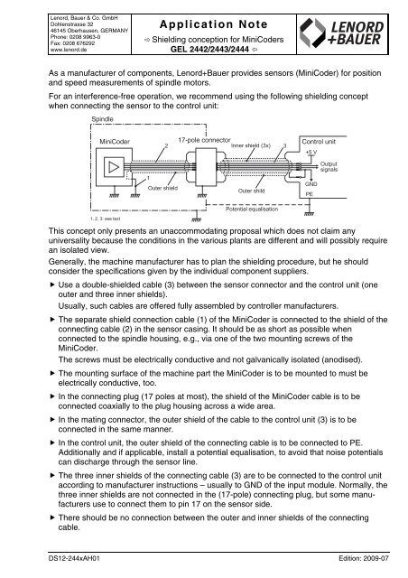
As a manufacturer of components, <strong>Lenord+Bauer</strong> provides sensors (MiniCoder) for position<br />
and speed measurements of spindle motors.<br />
For an interference-free operation, we recommend using the following shielding concept<br />
when connecting the sensor to the control unit:<br />
Spindle<br />
MiniCoder<br />
2<br />
17-pole connector<br />
Inner shield (3x)<br />
3<br />
Control unit<br />
+5 V<br />
Output<br />
signals<br />
1<br />
Outer shield<br />
Outer shild<br />
GND<br />
PE<br />
Potential equalisation<br />
1, 2, 3: see text<br />
This concept only presents an unaccommodating proposal which does not claim any<br />
universality because the conditions in the various plants are different and will possibly require<br />
an isolated view.<br />
Generally, the machine manufacturer has to plan the shielding procedure, but he should<br />
consider the specifications given by the individual component suppliers.<br />
Use a double-shielded cable (3) between the sensor connector and the control unit (one<br />
outer and three inner shields).<br />
Usually, such cables are offered fully assembled by controller manufacturers.<br />
The separate shield connection cable (1) of the MiniCoder is connected to the shield of the<br />
connecting cable (2) in the sensor casing. It should be as short as possible when<br />
connected to the spindle housing, e.g., via one of the two mounting screws of the<br />
MiniCoder.<br />
The screws must be electrically conductive and not galvanically isolated (anodised).<br />
The mounting surface of the machine part the MiniCoder is to be mounted to must be<br />
electrically conductive, too.<br />
In the connecting plug (17 poles at most), the shield of the MiniCoder cable is to be<br />
connected coaxially to the plug housing across a wide area.<br />
In the mating connector, the outer shield of the cable to the control unit (3) is to be<br />
connected in the same manner.<br />
In the control unit, the outer shield of the connecting cable is to be connected to PE.<br />
Additionally and if applicable, install a potential equalisation, to avoid that noise potentials<br />
can discharge through the sensor line.<br />
The three inner shields of the connecting cable (3) are to be connected to the control unit<br />
according to manufacturer instructions – usually to GND of the input module. Normally, the<br />
three inner shields are not connected in the (17-pole) connecting plug, but some manufacturers<br />
use to connect them to pin 17 on the sensor side.<br />
There should be no connection between the outer and inner shields of the connecting<br />
cable.<br />
DS12-244xAH01 Edition: 2009-07