ACHTUNG! - Helios Ventilatoren GmbH + Co KG
ACHTUNG! - Helios Ventilatoren GmbH + Co KG
ACHTUNG! - Helios Ventilatoren GmbH + Co KG

Erfolgreiche ePaper selbst erstellen
Machen Sie aus Ihren PDF Publikationen ein blätterbares Flipbook mit unserer einzigartigen Google optimierten e-Paper Software.
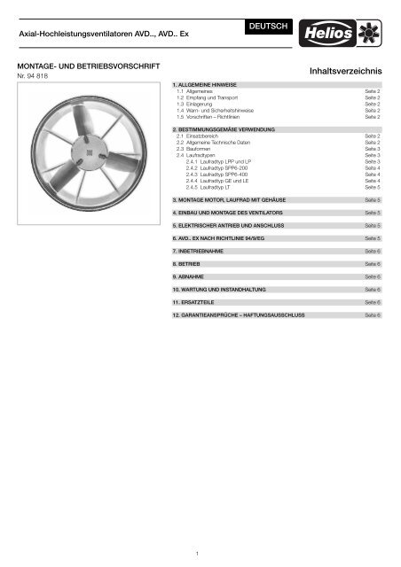
Axial-Hochleistungsventilatoren AVD.., AVD.. Ex<br />
MONTAGE- UND BETRIEBSVORSCHRIFT<br />
Nr. 94 818<br />
Inhaltsverzeichnis<br />
1. ALLGEMEINE HINWEISE<br />
1.1 Allgemeines Seite 2<br />
1.2 Empfang und Transport Seite 2<br />
1.3 Einlagerung Seite 2<br />
1.4 Warn- und Sicherheitshinweise Seite 2<br />
1.5 Vorschriften – Richtlinien Seite 2<br />
2. BESTIMMUNGSGEMÄßE VERWENDUNG<br />
2.1 Einsatzbereich Seite 2<br />
2.2 Allgemeine Technische Daten Seite 2<br />
2.3 Bauformen Seite 3<br />
2.4 Laufradtypen Seite 3<br />
2.4.1 Laufradtyp LPP und LP Seite 3<br />
2.4.2 Laufradtyp SPP6-200 Seite 4<br />
2.4.3 Laufradtyp SPP6-400 Seite 4<br />
2.4.4 Laufradtyp GE und LE Seite 4<br />
2.4.5 Laufradtyp LT Seite 5<br />
3. MONTAGE MOTOR, LAUFRAD MIT GEHÄUSE Seite 5<br />
4. EINBAU UND MONTAGE DES VENTILATORS Seite 5<br />
5. ELEKTRISCHER ANTRIEB UND ANSCHLUSS Seite 5<br />
6. AVD.. EX NACH RICHTLINIE 94/9/EG Seite 5<br />
7. INBETRIEBNAHME Seite 6<br />
8. BETRIEB Seite 6<br />
9. ABNAHME Seite 6<br />
10. WARTUNG UND INSTANDHALTUNG Seite 6<br />
11. ERSATZTEILE Seite 6<br />
12. GARANTIEANSPRÜCHE – HAFTUNGSAUSSCHLUSS Seite 6<br />
1<br />
DEUTSCH
Axial-Hochleistungsventilatoren AVD.., AVD.. Ex<br />
1. ALLGEMEINE HINWEISE<br />
1.1 ALLGEMEINES<br />
Die Montage- und Betriebsvorschrift ist Bestandteil<br />
der Ventilatorlieferung. Sie sollte stets in der Nähe<br />
des Ventilators aufbewahrt werden.<br />
Zur Sicherstellung einer einwandfreien Funktion<br />
und zur eigenen Sicherheit sind alle nachstehenden<br />
Vorschriften genau durchzulesen und zu beachten.<br />
Für Schäden und Betriebsstörungen, die aus der<br />
Nichtbeachtung der Montage- und Betriebsvorschrift<br />
resultieren, übernehmen wir keine Haftung, es entfällt<br />
unsere Gewährleistung und die Behandlung auf Kulanz!<br />
Das selbe gilt für Arbeiten, die über den in dieser<br />
Montage- und Betriebsvorschrift beschriebenen<br />
Umfang hinausgehen und ohne Rücksprache und<br />
Freigabe durch die Firma <strong>Helios</strong> ausgeführt werden!<br />
Der Gebrauch von Zubehörteilen, die nicht von <strong>Helios</strong><br />
empfohlen oder angeboten werden, ist nicht statthaft.<br />
Eventuell auftretende Schäden unterliegen nicht<br />
der Gewährleistung.<br />
Bei Sonderausführungen der <strong>Ventilatoren</strong> gelten<br />
zusätzlich zu dieser Montage- und Betriebsvorschrift<br />
die besonderen vertraglichen Vereinbarungen<br />
und technischen Unterlagen wie z.B. Zeichnung,<br />
Kennlinie usw.<br />
Die Montage- und Betriebsvorschrift beinhaltet gleichzeitig<br />
die Betriebsanleitung der Laufradtypen LPP,<br />
SPP, LP, GE, LE, LT; je nach Ausführung sind die entsprechenden<br />
Passagen gültig.<br />
Wenden Sie sich bitte mit allen technischen Fragen<br />
an unser Werk:<br />
<strong>Helios</strong> <strong>Ventilatoren</strong> <strong>GmbH</strong> + <strong>Co</strong><br />
Lupfenstraße 8<br />
D-78056 Villingen-Schwenningen<br />
Tel.: +49 (0) 7720/606-0<br />
Fax: +49 (0) 7720/606-166<br />
E-Mail: info@heliosventilatoren.de<br />
1.2 EMPFANG UND TRANSPORT<br />
Die Sendung muss sofort bei Anlieferung auf Schäden<br />
überprüft werden; falls solche vorliegen umgehend<br />
Schadensmeldung unter Hinzuziehung des<br />
Transportunternehmens veranlassen. Die Vollständigkeit<br />
der Lieferung ist beim Empfang zu überprüfen.<br />
Fehlende Teile und oder Transportschäden sind sofort<br />
schriftlich zu melden. Bei nicht fristgerechter Reklamation<br />
gehen evtl. Ansprüche verloren. Für den<br />
Baustellentransport des Ventilators, muss ein Gabelstapler<br />
mit ausreichend langer Gabel oder ein Kran,<br />
bzw. ein geeignetes Hebemittel verwendet werden<br />
(siehe Abb. 1).<br />
Abb. 1<br />
Bei Weiterversand (vor allem über längere Distanzen)<br />
ist zu prüfen, ob die Verpackung für Transportart und<br />
-weg geeignet ist. Schäden, deren Ursprung in unsachgemäßen<br />
Transport, Einlagerung oder Inbetriebnahme<br />
liegen, sind nachweisbar und unterliegen<br />
nicht der Gewährleistung.<br />
1.3 EINLAGERUNG<br />
Bei Einlagerung über einen längeren Zeitraum sind<br />
zur Verhinderung schädlicher Einwirkungen folgende<br />
Maßnahmen zu treffen: Versiegelung der blanken Teile<br />
mit Korrosionsschutz, Schutz des Motors durch<br />
trockene luft- und staubdichte Verpackung (Kunststoffbeutel<br />
mit Trockenmittel und Feuchtigkeitsindikatoren).<br />
Der Lagerort muss erschütterungsfrei sein.<br />
Bei mehrjähriger Lagerung bzw. Motorstillstand muss<br />
vor Inbetriebnahme eine Inspektion der Lager mit<br />
evtl. Erneuerung der Fettfüllung und eine Isolationsprüfung<br />
erfolgen. Die Prüfung der Motoren ist nach<br />
Instandsetzung, Änderung oder Reparatur nach VDE<br />
0701 durchzuführen. Bei Ex-Motoren gelten spezielle<br />
Vorschriften. Diese sind aus der Betriebsanleitung<br />
des Motors zu entnehmen.<br />
�<br />
1.4 WARN- UND SICHERHEITSHINWEISE<br />
<strong>ACHTUNG</strong>! Grundsätzlich sind beim Einbau und<br />
Betrieb alle geltenden Normen und Sicherheitsvorschriften<br />
(auch Länderspezifisch) einzuhalten.<br />
Dies betrifft vor allem auch Vorschriften über den<br />
Berührungsschutz, für deren Einhalten der Anlagenbauer<br />
und später dann der Betreiber verantwortlich<br />
ist!<br />
- Der Ventilator wird betriebssicher ausgeliefert. Eigenmächtige<br />
Veränderungen, welche die Betriebssicherheit<br />
beeinträchtigen, sind nicht zulässig.<br />
- Der Ventilator darf nur im Rahmen der festgelegten<br />
Bedingungen eingesetzt und betrieben werden.<br />
- Der Ventilatorantrieb darf nur von autorisierten, ausgebildeten<br />
und eingewiesenen Fachpersonal installiert,<br />
in Betrieb genommen, bedient, gewartet und<br />
ggf. instandgesetzt werden.<br />
- Vor Beginn von Installations- oder Wartungsarbeiten<br />
ist der Ventilator allpolig vom Netz zu<br />
trennen!<br />
- Typenschilder, Leistungsschilder, Drehrichtungs-,<br />
Förderrichtungspfeile, angebrachte Hinweise müssen<br />
beachtet werden und müssen frei von Farbe<br />
und Schmutz sein. Beschädigte oder nicht lesbare<br />
Schilder sind zu ersetzen.<br />
- Der Luftspalt zwischen Laufradblattspitze und<br />
Gehäuse ist ab Werk mindestens 0,5% vom Nenndurchmesser.<br />
Bei <strong>Ventilatoren</strong> in explosionsgeschützter<br />
Ausführung ist der Luftspalt mindestens<br />
1% vom Nenndurchmesser und bei größeren <strong>Ventilatoren</strong><br />
Ø 2000 - Ø 4000 mm mindestens 20 mm.<br />
Der Luftspalt ist zu überprüfen, ggf. ist Rücksprache<br />
mit unserem Werk zu halten.<br />
- Wenn während des Betriebes eine Veränderung<br />
des Schwingverhaltens und des Betriebsgeräusches<br />
festgestellt wird, ist der Ventilator sofort<br />
außer Betrieb zu setzen und auf Beschädigungen<br />
oder Verschmutzungen zu überprüfen.<br />
- Für den Ventilatorantrieb ist zusätzlich die Betriebsanleitung<br />
des Motorherstellers zu beachten.<br />
- Ist der Ventilator in einer Anlage oder in einem Gerät<br />
verbaut, so müssen die in dieser Montage- und Betriebsvorschrift<br />
enthaltenen Vorschriften, Hinweise<br />
und Beschreibungen in dessen Betriebsanleitung<br />
aufgenommen werden.<br />
- Bei Einsatz des Ventilators in wichtiger versorgungstechnischer<br />
Funktion ist die Anlage so zu<br />
konzipieren, dass bei Ventilatorausfall automatisch<br />
ein Notbetrieb garantiert ist. Geeignete Lösungen<br />
sind z.B.: Parallelbetrieb von zwei leistungsschwächeren<br />
Geräten mit getrennten Stromkreis,<br />
Standby-Ventilator bzw. Ersatzventilator sowie Alarmeinrichtungen<br />
und Notlüftungssysteme.<br />
1.5 VORSCHRIFTEN – RICHTLINIEN<br />
Bei ordnungsgemäßer Installation und bestimmungsgemäßem<br />
Betrieb entspricht das Gerät den zum Zeitpunkt<br />
seiner Herstellung gültigen Vorschriften und<br />
CE-Richtlinien.<br />
2<br />
2. BESTIMMUNGSGEMÄßE VERWENDUNG<br />
2.1 EINSATZBEREICH<br />
Die <strong>Ventilatoren</strong> sind für den stationären Einsatz zur<br />
Förderung von normaler oder leicht staubhaltiger,<br />
wenig aggressiver und feuchter Luft, bei normalen<br />
Temperaturen und im Bereich ihrer Leistungskennlinie<br />
geeignet. Für den Einsatz in explosionsgefährdeten<br />
Bereichen ist eine spezielle Ausführung erforderlich.<br />
Bei Betrieb unter erschwerten Bedingungen, wie<br />
z.B. hohe Feuchtigkeit, längere Stillstandszeiten,<br />
starke Verschmutzung, übermäßige Beanspruchung<br />
durch klimatische, technische, elektronische Einflüsse<br />
ist Rückfrage und Einsatzfreigabe erforderlich. Ein<br />
bestimmungsfremder Einsatz ist nicht statthaft.<br />
Die <strong>Ventilatoren</strong> dürfen nur in dem oben genanntem<br />
Einsatzbereich betrieben werden. Sie dürfen nicht<br />
außerhalb der festgelegten Leistungsgrenzen betrieben<br />
werden. Zur Erreichung der erwarteten Ventilatorleistung<br />
ist eine Zu- und Abluftführung Voraussetzung.<br />
Abweichende Betriebsbedingungen bedürfen<br />
der Freigabe durch <strong>Helios</strong> und müssen vertraglich<br />
vereinbart werden!<br />
2.2 ALLGEMEINE TECHNISCHE DATEN<br />
Das Typenschild des Ventilators und das Leistungsschild<br />
am Antrieb enthält die wichtigsten technischen<br />
Daten. Diese Daten und die vertraglichen Vereinbarungen<br />
legen die Grenzen des bestimmungsgemäßen<br />
Gebrauchs fest.<br />
Beispiel: Typenschild Ventilator<br />
Zeichenschlüssel Typenschild Ventilator:<br />
AVD Bauart<br />
AVD (Axial-Ventilator-Drehstrom)<br />
DK Gehäuseausführung:<br />
DK (Düse kurz)<br />
DL (Düse lang)<br />
RK (Rohr kurz)<br />
RL (Rohr lang)<br />
RA (Rohr Auflagering)<br />
1250 Gehäuseinnendurchmesser des<br />
Ventilators<br />
6 Polzahl des Motors (bei Getriebemotoren<br />
und Sonderventilatoren<br />
wird diese Position weggelassen)<br />
5 Flügelblattanzahl des Laufrad<br />
GE Laufradtyp:<br />
LPP, SPP, LP, GE, LE, LT<br />
SV Laufradnabenausführung:<br />
SV (Stahl verzinkt)<br />
AL (Aluminium)<br />
NS Position der Wellennabe am Laufrad<br />
NS (Laufradnabe saugseitig)<br />
ND (Laufradnabe druckseitig)<br />
V Laufrad in verstärkter Ausführung<br />
Ex Gerät hergestellt nach 94/9/EG<br />
(ATEX) nur bei Ex-<strong>Ventilatoren</strong><br />
25° Flügelblattanstellwinkel<br />
Art.Nr., SNR (Seriennummer) und PC (Produktionscode)<br />
Nummer identifizieren den Ventilator eindeutig.
Axial-Hochleistungsventilatoren AVD.., AVD.. Ex<br />
Leistungsschild des Antriebs:<br />
Das Leistungsschild des Antriebs ist von Motorhersteller<br />
zu Motorhersteller unterschiedlich aufgebaut.<br />
Standardmäßig ist die Phasenzahl, die Schaltart, die<br />
Bemessungsspannung, -strom, -frequenz, -drehzahl,<br />
-leistung, die Betriebsart, der Leistungsfaktor, die<br />
Schutzart und die Wärmeklasse angegeben.<br />
Abb. 2<br />
Ventilatorleistung:<br />
Die Ventilatorleistungen wurden auf einem Prüfstand<br />
entspr. DIN 24163, Teil 2 ermittelt. Sie gilt für Normbedingungen<br />
(r = 1,2 kg/m 3 ), Nenndrehzahl und Normalausführung<br />
bei Verwendung einer Einströmdüse,<br />
ohne Schutzgitter, bei ungehinderter An- und Abströmung.<br />
Hiervon abweichende Ausführungen und<br />
ungünstige Einbau- und Betriebsbedingungen können<br />
zu einer Reduzierung der Förderleistung führen.<br />
Geräuschwerte:<br />
Die Werte beziehen sich auf das saugseitig abgestrahlte<br />
Geräusch unter Voraussetzung der ungestörten<br />
Zu- und Abströmung und entsprechen DIN<br />
45635 T.1,2. Davon abweichende Einbaubedingungen<br />
und gestörte Zuströmung können zu erheblichen<br />
Geräuscherhöhungen führen. Das bedeutet, das das<br />
Geräusch von den Einbaugegebenheiten , vom Absorptionsvermögen<br />
des Raumes, der Raumgröße,<br />
den baulichen Begebenheiten im Freien u.a. Faktoren<br />
stark abhängig ist.<br />
Abb. 3<br />
2.3 BAUFORMEN<br />
Die <strong>Ventilatoren</strong> der Bauform AVD.. sind standardmäßig<br />
in folgenden Ausführungen fertigbar (siehe<br />
Abb. 3).<br />
Auf Anfrage und nach vertraglich festgelegten Vereinbarungen<br />
sind auch Sondertypen erhältlich. Für Sonderausführungen<br />
wird eine Zeichnung erstellt, die Bestandteil<br />
der Montage- und Betriebsvorschrift ist.<br />
Größere <strong>Ventilatoren</strong> werden zum einfacheren Transport<br />
in zwei Teilen hergestellt. Am Aufstellort müssen<br />
die beiden Teile verschraubt werden. Bei größeren<br />
Laufrädern werden im Werk so viele Laufradblätter<br />
demontiert bis das Laufrad transportabel ist. Die<br />
Blätter werden lose beigelegt. Sie müssen anschließend<br />
vor Ort anhand der Montage- und Betriebsvorschrift<br />
montiert werden.<br />
2.4 LAUFRADTYPEN<br />
Für unterschiedliche Anwendungs- und Einsatzfälle<br />
werden von der Firma <strong>Helios</strong> verschiedene Laufradtypen<br />
vorgeschlagen. Die Auswahl erfolgt nach dem<br />
Betriebspunkt, der Belastung, der Temperatur und<br />
des Einsatzortes usw.<br />
Die Laufräder können in der Ausführung ND oder NS<br />
ausgeführt sein:<br />
- ND = die Position der Wellennabe am Laufrad ist<br />
druckseitig<br />
- NS = die Position der Welennabe am Laufrad ist<br />
saugseitig.<br />
Die Wellennabe ist mit der Laufradnabe verschraubt<br />
oder direkt an die Laufradnabe angegossen. Sie<br />
dient zur Aufnahme der Motorwelle und zur Kraftübertragung<br />
auf das Laufrad.<br />
Im Werk werden die Laufräder nach der Wuchtgüte<br />
Q 6.3 gemäß VDI 2060 ausgewuchtet. Die bei der<br />
Auswuchtung angebrachten Ausgleichsgewichte,<br />
sind mit farbigem Schraubensicherungslack versehen<br />
und dürfen auf keinen Fall entfernt werden. Bei<br />
Entfernung der Wuchtgewichte, wird das Laufrad un-<br />
3<br />
wuchtig und darf nicht in Betrieb genommen werden.<br />
Bei der werkseitigen Endkontrolle wird die tatsächliche<br />
Restunwucht erfasst und in einem Wuchtprotokoll<br />
festgehalten. Auf Anfrage erhalten Sie dieses für<br />
Ihre Unterlagen.<br />
Vor der Montage sind alle Teile auf evtl. Transportschäden<br />
genau zu überprüfen. Sollten Sie Beschädigungen<br />
entdecken, dürfen Sie diese Teile nicht mehr<br />
einbauen. Bitte wenden Sie sich in diesem Fall an die<br />
Firma <strong>Helios</strong>. Ausbesserungen sind nur nach Rücksprache<br />
mit <strong>Helios</strong> zulässig (Festigkeit, Unwucht<br />
etc.).<br />
Größere Laufräder werden aus Transportgründen demontiert<br />
angeliefert. Die lose beigelegten Laufradblätter<br />
müssen dann noch montiert werden. Das<br />
Laufradblatt und die Nabenscheibe sind durch Nummern<br />
gekennzeichnet.<br />
Beispiel: 36/5 = Lfd. Laufrad-Nummer 36, lfd. Laufradblatt-Nummer<br />
5. Ist die Blattaufnahme z.B. mit<br />
36/1 gekennzeichnet, so kommt nur das mit der<br />
Nummer 36/1 bezeichnete Laufradblatt zur Montage.<br />
Es folgen dann die Bezeichnungen 36/2, 36/3,<br />
36/4 usw.<br />
HINWEIS! Benutzte Schrauben und Muttern dürfen<br />
nicht weiter verwendet werden. Sie müssen<br />
durch neue ersetzt werden.<br />
Bei Mehrfachverwendung der Schauben werden die<br />
Sperrzähne durch die verzinkten Oberflächen der<br />
Gehäuse bzw. Laufradteile mit Zink zugeschmiert.<br />
D.h. die Schraubensicherung und die Betriebssicherheit<br />
des Ventilators durch Mehrfachverwendung ist<br />
nicht mehr gewährleistet.<br />
Ersatz beziehen Sie über den <strong>Helios</strong> Kundendienst.
Axial-Hochleistungsventilatoren AVD.., AVD.. Ex<br />
2.4.1 LAUFRADTYP LPP UND LP<br />
Aufbau:<br />
Die Wellennabe ist mit der feuerverzinkten Laufradnabenscheibe<br />
verschraubt. Auf der Laufradnabenscheibe<br />
sind Lagerböcke aufgesetzt. Sie sind mit Spiral-<br />
Spannstiften positioniert. Die Spannstifte dürfen nicht<br />
entfernt werden. Das in den Lagerbock eingelegte<br />
Laufradblatt wird mittels Befestigungsmanschette,<br />
Befestigungsbügel und Verbus-Ripp-Mutter befestigt.<br />
Der Lagerbock ist an der Außenseite mit einer<br />
Gradeinteilung oder einer Markierung versehen. Diese<br />
dient zur Einstellung des Anstellwinkels der Laufradblätter<br />
bei demontierter Anlieferung. Der in der<br />
Auftragsbestätigung genannte Anstellwinkel entspricht<br />
der Gradanzeige am Lagerbock sowie dem<br />
Winkel am äußersten Profil (Nenndurchmesser).<br />
Abb. 4<br />
Montage Laufrad:<br />
Die Montage des Laufradblattes am Lagerbock erfolgt<br />
durch die mitgelieferten Teile: Befestigungsmanschette,<br />
Befestigungsbügel, Verbus-Ripp-Mutter. In<br />
der Abb. 4 ist die Einbaulage des Laufradblattes ersichtlich.<br />
Auf die Dreh- und Förderrichtung ist zu achten.<br />
Das Laufradblatt wird mit Hilfe der Markierung<br />
am Blatt und der Gradeinteilung bzw. Markierung am<br />
Lagerbock mit den leicht angezogenen Befestigungsteilen<br />
auf den Anstellwinkel gestellt. Dieser Arbeitsgang<br />
kann auch mit Hilfe einer Winkelwasserwaage<br />
an der Flügelspitze (Außendurchmesser) des<br />
Laufrades erfolgen. Vor dem Festziehen der Muttern<br />
ist zu prüfen, ob das Laufradblatt im Lagerbock an<br />
der Anlagefläche liegt. Ebenfalls müssen alle Blätter<br />
den gleichen Anstellwinkel haben.<br />
Die vorgeschriebenen Anziehdrehmomente der am<br />
Laufrad verwendeten Schrauben und Muttern sind<br />
einzuhalten:<br />
M6 M8 M10 M12 M14 M16<br />
19 Nm 42 Nm 85 Nm 130 Nm 230 Nm 330 Nm<br />
Angaben für Schrauben und Muttern der Güteklasse 10.9<br />
Nur wenn alle Punkte bei der Montage beachtet wurden,<br />
ist ein einwandfreier und ruhiger Lauf gewährleistet.<br />
Andere Anstellwinkel sind nur nach Freigabe<br />
und Rücksprache mit <strong>Helios</strong> zulässig.<br />
Bei einem Verstellen des Anstellwinkels müssen die<br />
Verbus-Ripp-Muttern gelöst und durch neue Muttern<br />
ausgetauscht werden. Nur so ist die Sicherung gewährleistet.<br />
Bei leicht angezogenen Muttern kann<br />
das Laufradblatt in den gewünschten Anstellwinkel<br />
verdreht werden. Anschließend wird wie oben beschrieben<br />
vorgegangen.<br />
HINWEIS! Wir empfehlen bei einer Blattverstellung<br />
ein erneutes Auswuchten des Laufrades.<br />
2.4.2 LAUFRADTYP SPP6-200<br />
(Ø 900 bis Ø 1800 mm)<br />
Aufbau:<br />
Die Wellennabe ist Teil des Laufradnabenhalbteils. Mit<br />
dem anderem Nabenhalbteil werden die Laufradblätter<br />
eingespannt. Die Klemmung der Laufradblätter<br />
erfolgt durch zwei Innensechskantschrauben M6 pro<br />
Laufradblatt im äußeren Bereich, sowie vier Verbus-<br />
Ripp-Schrauben M12 im inneren Bereich der Laufradnabe.<br />
Montage Laufrad:<br />
Vor der Montage des kompletten Laufrades auf der<br />
Motorwelle ist der Wasserschutzdeckel von der Nabenhälfte<br />
abzuschrauben. Nach erfolgter Montage<br />
auf der Motorwelle ist der Deckel wieder anzuschrauben.<br />
(siehe Abb. 5)<br />
Abb. 5<br />
Bei demontierter Anlieferung muss die Einbaulage<br />
des Laufradblattes beachtet werden.<br />
Sie ist auf der Abb. 6 und Abb. 6.1 ersichtlich.<br />
(Bitte beachten Sie die Dreh- und Förderrichtung).<br />
Abb. 6<br />
4<br />
Abb. 6.1<br />
Zusätzlich müssen die Laufradblätter in die richtige<br />
Position zwischen die Laufradnaben-Halbteile gelegt<br />
werden und mit den mitgelieferten Schraubenmaterial<br />
leicht angezogen werden. In die offenen Einlegepositionen<br />
müssen die beigefügten Kunststoffdeckel<br />
zwischen die Laufradnabenhälfte zur Schmutzabdeckung<br />
eingelegt werden. Die Laufradblätter müssen<br />
sich noch von Hand drehen lassen. In der Laufradnabenhälfte<br />
sind Zahlen eingegossen. Diese<br />
stehen für die Einlegepositionen für ein 4-, 5-, 6-, 7-,<br />
8- und 10-Blatt-Laufrad. Für ein 4-Blatt-Laufrad<br />
muss überall wo die Ziffer 4 steht ein Laufradblatt eingelegt<br />
werden.<br />
Nach dem leichten Anziehen der Schrauben, wird mit<br />
Hilfe einer Winkelwasserwaage der gewünschte Anstellwinkel<br />
eingestellt. Das Messen des Winkels erfolgt<br />
außerhalb der abgesägten Endkante, in der Mitte<br />
des Laufradblattes.<br />
Die Schrauben und Muttern müssen dann mit folgenden<br />
Anziehdrehmomenten angezogen werden:<br />
- M6 Güteklasse A 70 = 7,0 Nm<br />
- M12 Güteklasse 10.9 = 130 Nm.<br />
Die vorgegebenen Drehmomente der Schraubenverbindungen<br />
sind unbedingt einzuhalten. Es dürfen<br />
nur die mitgelieferten Schrauben in dieser Güteklasse<br />
eingesetzt werden.<br />
�<br />
<strong>ACHTUNG</strong>! Bei überhöhter Anziehdrehmomente<br />
der Schrauben bzw. Muttern können die<br />
Nabenhälften beschädigt werden.<br />
Bei Verstellen des Anstellwinkels müssen die Muttern<br />
leicht gelöst werden, bis die Flügelblätter von Hand<br />
verstellbar sind. Anschließend kann der gewünschte<br />
Anstellwinkel eingestellt und die Schrauben und Muttern<br />
mit den vorgeschrieben Anziehdrehmomente<br />
angezogen werden. Andere Anstellwinkel sind nur<br />
nach Freigabe und Rücksprache mit <strong>Helios</strong> zulässig.<br />
HINWEIS: Wir empfehlen bei einer Blattverstellung<br />
ein erneutes Auswuchten desLaufrades.<br />
2.4.3 LAUFRADTYP SPP6-400<br />
(Ø 2000 bis Ø 4000 mm)<br />
Aufbau:<br />
Die Wellennabe ist an die feuerverzinkte Laufradnabe<br />
angeschraubt.<br />
Auf die Laufradnabe sind Lagerböcke aufgesetzt. Sie<br />
sind mit Spiral-Spannstifte positioniert. Die Spannstifte<br />
dürfen nicht entfernt werden. Das in den Lagerbock<br />
eingelegte Laufradblatt wird mittels Befesti-
Axial-Hochleistungsventilatoren AVD.., AVD.. Ex<br />
gungsmanschette, Befestigungsbügel und Verbus-<br />
Ripp-Mutter befestigt. An der Außenseite des Lagerbock<br />
ist eine Markierung bzw. eine Gradeinteilung<br />
von 10° bis 30° aufgestempelt. Diese dient zur Einstellung<br />
des Anstellwinkels der Laufradblätter, bei demontierter<br />
Anlieferung. Der in der Auftragsbestätigung<br />
genannte Anstellwinkel entspricht der Gradanzeige<br />
am Lagerbock sowie dem Winkel in der Mitte<br />
des Laufradblattes außerhalb der abgesägten<br />
Endkanten.<br />
Montage Laufrad:<br />
Die Montage des Laufradblattes am Lagerbock erfolgt<br />
durch die mitgelieferten Teile Befestigungsmanschette,<br />
Befestigungsbügel, Verbus-Ripp-Mutter. In<br />
Abb. 7 ist die Einbaulage des Laufradblattes ersichtlich.<br />
Auf die Dreh- und Förderrichtung ist zu achten.<br />
Das Laufradblatt wird nun mit Hilfe der Markierung<br />
am Blatt und der Gradeinteilung bzw. Markierung am<br />
Lagerbock mit den leicht angezogenen Befestigungsteilen<br />
auf den Anstellwinkel gestellt. Der Anstellwinkel<br />
sollte dann mit Hilfe einer Winkelwasserwaage<br />
in der Mitte des Laufradblattes außerhalb der<br />
abgesägten Endkanten überprüft werden.<br />
Vor dem Festziehen der Muttern ist zu prüfen, ob das<br />
Laufradblatt im Lagerbock an der Anlagefläche liegt.<br />
Ebenfalls müssen alle Blätter den gleichen Anstellwinkel<br />
haben.<br />
Die vorgeschriebenen Anziehdrehmomente der am<br />
Laufrad verwendeten Schrauben und Muttern sind<br />
einzuhalten:<br />
M6 M8 M10 M12 M14 M16<br />
19 Nm 42 Nm 85 Nm 130 Nm 230 Nm<br />
Angaben für Schrauben und Muttern der Güteklasse 10.9<br />
Sind alle Punkte bei der Montage beachtet worden,<br />
ist ein einwandfreier und ruhiger Lauf gewährleistet.<br />
Andere Anstellwinkel sind nur nach Freigabe und<br />
Rücksprache mit <strong>Helios</strong> zulässig.<br />
Abb. 7<br />
330 Nm<br />
Bei einem Verstellen des Anstellwinkel müssen die<br />
Muttern gelöst und durch gleiche und neue Muttern<br />
ausgetauscht werden. Nur dann ist die Sicherung gewährleistet.<br />
Bei leicht angezogenen Muttern kann<br />
das Laufradblatt in den gewünschten Anstellwinkel<br />
verdreht werden. Anschließend wird wie oben beschrieben<br />
vorgegangen.<br />
HINWEIS: Wir empfehlen bei einer Blattverstellung<br />
ein erneutes Auswuchten des Laufrades.<br />
2.4.4 LAUFRADTYP GE UND LE<br />
Aufbau:<br />
Die Wellennabe ist mit der aus Stahlblech geschweißten<br />
und feuerverzinkten Laufradnabe verschraubt.<br />
Die Laufradblätter werden am Fuß des<br />
Laufradblattes mit einem zweiteiligen Spannring an<br />
dem Aufnahmeflansch der Laufradnabe befestigt. Die<br />
Spannringhalbteile sind mit einer Gradeinteilung von<br />
0° bis 30° versehen, welche zur Einstellung des Anstellwinkels<br />
der Laufradblätter dient.<br />
Die Gradanzeige am Spannring entspricht dem Winkel<br />
am äußersten Profil (Nenndurchmesser). Die<br />
Spannringe sind bei der verstärkten Ausführung des<br />
Laufrades gedreht bzw. bei der einfachen Ausführung<br />
aus Blech geprägt. Ist das Laufrad verstärkt,<br />
so ist der Schaufelfuß mit einem Zapfen ausgeführt.<br />
Dieser wird zusätzlich mit einem Scherstift gesichert.<br />
(siehe Abb. 8)<br />
Abb. 8<br />
Montage Laufrad:<br />
Die Einbaulage der Laufradblätter ist aus der Abb. 9<br />
zu entnehmen.<br />
Abb. 9<br />
NS<br />
ND<br />
5<br />
Bei demontierter Anlieferung müssen die Laufradblätter<br />
nach dem Nummernsystem, wie in 2.4 beschrieben,<br />
in die richtige Position der Laufradnabe montiert<br />
werden. Nach dem Einlegen eines Laufradblattes<br />
muss der Schaufelfuß bei verstärkter Ausführung mit<br />
dem Scherstift gesichert werden. Anschließend können<br />
die Laufradblätter mit Hilfe der Spannringe, sowie<br />
der Schrauben und Muttern an die Laufradnabe<br />
geschraubt werden. Bevor die Schrauben und Muttern<br />
mit dem vorgeschriebenen Anziehdrehmoment<br />
angezogen werden, muss der in der Auftrags-bestätigung<br />
angegebene Anstellwinkel des Laufradblattes<br />
mit Hilfe der Skala auf dem Spannring eingestellt<br />
werden. Anziehdrehmomente sind:<br />
M6 M8 M10 M12 M14 M16<br />
19 Nm 42 Nm 85 Nm 130 Nm 230 Nm 330 Nm<br />
Angaben für Schrauben und Muttern der Güteklasse 10.9<br />
Andere Anstellwinkel sind nur nach Freigabe und<br />
Rücksprache mit <strong>Helios</strong> zulässig.<br />
HINWEIS: Wir empfehlen bei einer Blattverstellung<br />
ein erneutes Auswuchten des Laufrades.<br />
2.4.5 LAUFRADTYP LT<br />
Aufbau:<br />
Der Laufradtyp LT wird nur als komplettes Laufrad<br />
mit nicht verstellbaren Laufradblätter gebaut. Nach<br />
der Auslegung wird der Anstellwinkel festgelegt, und<br />
die Laufradblätter werden im Werk mit der Laufradnabe<br />
verbohrt und gesichert. Das Laufrad kann in<br />
der Ausführung ND oder NS ausgeführt sein. Die<br />
Abb. 10 zeigt das Laufrad in NS Ausführung:<br />
Abb. 10<br />
Die Montage des Laufrades erfolgt über die Befestigungsteile,<br />
Schraube, Federring und Blockscheibe.<br />
Der Wasserschutzdeckel in der Laufradnabenmitte<br />
muss erst abgenommen, und nach erfolgter Montage<br />
des Laufrades wieder montiert werden.<br />
3. MONTAGE MOTOR, LAUFRAD MIT GEHÄUSE<br />
Wird der Ventilator in einzelnen Baugruppen, wie Motor,<br />
Laufrad, und Gehäuse angeliefert, müssen diese<br />
Baugruppen montiert werden. Als erstes ist der Motorflansch<br />
und die Anlagefläche am Gehäuse von<br />
eventuellen Schmutzpartikeln zu reinigen. Der Motor<br />
muss anschließend in den dafür vorgesehenen Einpaß<br />
senkrecht zur Anlagefläche des Gehäuses eingesetzt<br />
und anschließend mit den vorgeschriebenen<br />
Anziehdrehmomenten verschraubt werden.<br />
Bei größeren, auf Montagekonsolen stehenden <strong>Ventilatoren</strong><br />
werden Getriebemotoren in Fußausführung<br />
verwendet. Diese müssen bei demontierter Anlieferung<br />
entsprechen der Ventilatorbezeichnung montiert<br />
werden.<br />
Wurde das Laufrad unter Beachtung sämtlicher<br />
Punkte, wie in der Montage- und Betriebsvorschrift<br />
beschrieben montiert, kann der Zusammenbau mit<br />
dem Antrieb und dem Gehäuse erfogen.
Axial-Hochleistungsventilatoren AVD.., AVD.. Ex<br />
Die entsprechenden Schrauben, Sicherungen,<br />
Scheiben sind zu verwenden. Anschließend müsssen<br />
die Luftspalte zwischen Gehäuse und Blattspitze<br />
überprüft werden (siehe Kapitel 1.4).<br />
4. EINBAU UND MONTAGE DES VENTILATORS<br />
Das Gebäude bzw. die Anlage muss vor dem Einbau<br />
des Ventilators auf ausreichend stabile und steife Statik<br />
untersucht werden. Eine sichere Befestigung und<br />
Verankerung des Ventilators ist sicherzustellen. Der<br />
Einbau und die Montage des Ventilators darf nur von<br />
Fachpersonal durchgeführt werden.<br />
Beim Einbau sind die gültigen Arbeitsschutz- und Unfallverhütungsvorschriften<br />
zu beachten.<br />
Der Kontakt mit rotierenden Teilen muss verhindert<br />
werden. Es ist sicherzustellen, dass sich im Ansaugbereich<br />
keine ansaugbaren Stoffe befinden.<br />
Bestimmte Ventilatortypen werden serienmäßig mit<br />
Schutzgitter geliefert. Der Berührungsschutz ist jedoch<br />
generell bauseits zu überprüfen und sicherzustellen!<br />
(siehe EN 294). In Abhängigkeit der Einbauverhältnisse<br />
können diverse Schutzgitter als Zubehör<br />
geliefert werden.<br />
<strong>Ventilatoren</strong>, die durch ihre Einbauweise (z.B. Einbau<br />
in Lüftungskanäle oder geschlossene Aggregate geschützt<br />
sind, benötigen kein Schutzgitter, wenn die<br />
Anlage die gleiche Sicherheit bietet (siehe DIN 31001<br />
und 24167). Es wird darauf hingewiesen, dass der Installateur<br />
für Unfälle infolge fehlender Schutzeinrichtung<br />
haftbar gemacht werden kann. Die Vorschriften<br />
des Berührungsschutzes müssen auch bei einer<br />
Laufradlieferung eingehalten werden.<br />
Beim Einbau ist auf Unterbindung von Körperschallübertragung<br />
zu achten. Hierzu, z.B. beim Zwischensetzen<br />
in Rohrleitungen flexible Verbindungsstücke<br />
(Segeltuchstutzen) verwenden. Beim Einbau in Beton-<br />
und Leichtbauwänden oder Holzpaneelen, zu<br />
starkes Anziehen der Befestigungsschrauben vermeiden.<br />
Gegen Lockerung geeignete Schraubensicherung<br />
verwenden.<br />
� <strong>ACHTUNG</strong>!<br />
Bei <strong>Ventilatoren</strong>, die aufgrund der Einbaulage und<br />
des Schwerpunktes ein Kippmoment verursachen,<br />
muss das Zubehör wie flexible Verbindungsstücke<br />
(Segeltuchstutzen), Schwingungsdämpfer,<br />
VR, ASD, Montagekonsolen richtig<br />
ausgewählt und korrekt angebaut werden.<br />
(siehe Abb. 11)<br />
Abb. 11<br />
falsch montiertes Zubehör<br />
richtig<br />
montiertes Zubehör<br />
Werden Zubehörteile falsch montiert, so können diese<br />
durch den falschen Einbau beschädigt werden.<br />
Für Schäden, die von einer falschen Montage der Zubehörteile<br />
resultieren übernimmt die Firma <strong>Helios</strong> keine<br />
Gewährleistung. Bei kritischen Einbausituationen<br />
ist Rücksprache mit <strong>Helios</strong> zu führen.<br />
Damit der Ventilator gleichmäßig und richtig angeströmt<br />
wird bzw. abströmt, muss folgendes beachtet<br />
werden:<br />
- Zur ungehinderten Zu- und Abluftströmung sollte<br />
der freie Abstandsraum saug- bzw. druckseitig zum<br />
Ventilator mindestens 1,5 x dem Ventilatordurchmesser<br />
sein.<br />
- Die Saugseite sollte mit einer Einströmdüse versehen<br />
sein.<br />
- Ein richtig ausgelegter Ausblasdiffusor kann energiesparend<br />
wirken.<br />
- Bei <strong>Ventilatoren</strong>, die in eine Rohr- oder Kanalleitung<br />
eingebaut werden, müssen angepasste und notwendige<br />
Radien bzw. Abstände von Anschlussteilen<br />
wie z.B. 90° Umlenkungen, Filter, Rohrschalldämpfer<br />
zum Ventilator eingehalten werden.<br />
Ein nicht beachten kann bei ungünstigen Betriebsbedingungen<br />
zur erheblicher Leistungsminderung und<br />
zu erhöhten Schallwerten führen!<br />
5. ELEKTRISCHER ANTRIEB UND ANSCHLUSS<br />
Standardmäßig werden die <strong>Ventilatoren</strong> mit Motoren<br />
in der Betriebsart S1, der Schutzart IP 54 und Isolationsklasse<br />
F nach IEC 60034 ausgeführt. Die Motoren<br />
sind normalerweise mit Kaltleitern als Motorschutz<br />
ausgerüstet.<br />
Motorschutz<br />
a) Motoren ohne eingebaute Temperaturwächter (Thermokontakte<br />
oder Kaltleiter): Absicherung durch Motorschutzschalter.<br />
Alle drei Strombahnen zur gleichmäßigen<br />
Erwärmung des Bimetalls anschließen. Bei<br />
mehrtourigen Motoren ist jede Drehzahl separat abzusichern.<br />
Motorschutzschalter ca. 10-15% über<br />
dem auf dem Ventilatorleistungsschild angegebenen<br />
Strom einstellen. Auslösefunktion des Schalters durch<br />
Einschalten testen. Schutzschalter sollte innerhalb 60<br />
Sekunden auslösen.<br />
�<br />
<strong>ACHTUNG</strong>! Diese Absicherung ist nicht für<br />
drehzahlgesteuerten Betrieb geeignet und<br />
schützt den Motor nicht bei zu hoher Fördermitteltemperatur<br />
oder mangelnder Kühlung.<br />
b) <strong>Ventilatoren</strong> mit eingebauten Thermokontakten: Diese<br />
tragen auf dem Motordatenschild die ergänzende<br />
Typenbezeichnung . . . TK. Zum Anschluss werden<br />
die speziell entwickelten Motorvollschutzgeräte<br />
MW = für 230 V ~<br />
MD = für 400 V/3~, 1-tourig<br />
M 2 = für 2-tourige getrennte Wicklung 400 V/3~<br />
M 3 = für 2-tourige Dahlander-Wicklung 400 V<br />
M 4 = für 2-tourige Y/∆-Schaltung 400 V/3~<br />
empfohlen.<br />
c) <strong>Ventilatoren</strong> mit eingebauten Kaltleitern: Diese sind<br />
mit einem PTC-Aufkleber versehen bzw. durch einen<br />
Hinweis im Klemmenkasten gekennzeichnet.<br />
�<br />
<strong>ACHTUNG</strong>! Die max. Prüfspannung für<br />
Kaltleiter (PTC) von 2,5 V darf nicht überschritten<br />
werden, da sonst Kaltleiter und Motorwicklung<br />
zerstört werden!<br />
Zur Motorüberwachung nur speziell für Kaltleiter geeigneten<br />
Motorvollschutz-Schalter MSA verwenden.<br />
Sondermotoren für Sonderspannungen, Frequenzen,<br />
höhere Schalthäufigkeiten, Sonderlackierungen, spezielle<br />
Schutzarten, VIK-Ausführungen, besonderer<br />
Feuchteschutz und Außenaufstellung müssen speziell<br />
6<br />
angefragt werden.<br />
Der elektrische Anschluss darf nur von einer Elektrofachkraft<br />
ausgeführt werden. Netzspannung und Frequenz<br />
müssen mit den Angaben des Motorleistungsschild<br />
übereinstimmen. Bei der Sonderfrequenz von<br />
z.B. 60 Hz und gleicher Laufradblattanstellung erhöht<br />
sich der Volumenstrom um das 1,2-fache, der Förderdruck<br />
um das 1,44-fache und die erforderliche<br />
Antriebsleistung auf das 1,73-fache. Dies muss bei<br />
der Ventilatorauslegung berücksichtigt werden!<br />
� <strong>ACHTUNG</strong>!<br />
Vor Beginn von Installations- oder Wartungsarbeiten<br />
ist der Ventilator allpolig vom Netz zu trennen!<br />
Die einschlägigen Sicherheits- und Installationsvorschriften<br />
sind zu beachten.<br />
Zwingend vorgeschrieben sind:<br />
- ein allpoliger Netztrennschalter<br />
- Ein geeignetes Schutzgerät für jeden Ventilator<br />
bzw. jede Drehzahl (bei mehrtourigen <strong>Ventilatoren</strong>)<br />
Bei Anschluss an Kunststoff-Klemmenkästen dürfen<br />
keine Kabelverschraubungen aus Metall verwendet<br />
werden. Die Einführung der Zuleitung so vornehmen,<br />
dass bei Wasserbeaufschlagung kein Eindringen entlang<br />
der Leitung ermöglicht wird. Leitung dürfen nicht<br />
über scharfe Kanten geführt werden. Anschluss und<br />
Anordnung der Schaltbügel/Brücken nach dem entsprechenden<br />
Schaltbild aus der Betriebsanleitung<br />
des Motor vornehmen. Schutzleiter an Erdungsklemme<br />
anschließen. Für Servicearbeiten einen allpolig<br />
abschaltenden Reparaturschalter in unmittelbarer<br />
Nähe des Ventilators vorsehen. Weitere Arbeitsgänge<br />
siehe unter Abschnitt "Inbetriebnahme".<br />
Werden Motoren zum Ventilator beigestellt, so haftet<br />
der Beisteller für die Motorauswahl und den Motor<br />
selbst. <strong>Helios</strong> gibt hierfür lediglich eine Motorempfehlung<br />
ab.<br />
6. AVD.. EX NACH RICHTLINIE 94/9/EG<br />
Für Einsatz, Anschluss und Betrieb gelten besondere<br />
Bestimmungen, z.B. die Normreihe 60079. Sollten<br />
Zweifel auftreten, wenden Sie sich an <strong>Helios</strong>. Explosionsgeschützte<br />
<strong>Ventilatoren</strong> der Fa. <strong>Helios</strong> entsprechen<br />
den Anforderungen der ATEX (Richtlinie<br />
94/9/EG-Gerätesicherheitsgesetz). Zur Bewertung<br />
der explosionsgefährdeter Bereiche ist eine Einteilung<br />
durch den Betreiber in Zonen erforderlich. Es dürfen<br />
nur <strong>Ventilatoren</strong> mit entsprechender, für die jeweilige<br />
Zone zugelassener Gerätekategorie, verwendet werden.<br />
Weitere Informationen sind den einschlägigen<br />
Normen und Gesetzestexten zu entnehmen. Drehzahlregelung<br />
und häufiges Ein-/Ausschalten ist nicht<br />
zulässig. Es erfordert eine spezielle Ausführung des<br />
Ventilators.<br />
Die auf dem Motorleistungsschild angegebene Temperaturklasse<br />
des Motors muss mit der Temperaturklasse<br />
des möglicherweise auftretenden Luft-Gasgemisches<br />
übereinstimmen. Jedem Motor (bei polumschaltbaren<br />
jede Drehzahl) muss ein Motorschutzschalter<br />
vorgeschaltet sein, der auf den Motorennennstrom<br />
einzustellen ist und bei festgebremstem<br />
Laufrad innerhalb der aus dem Motorleistungsschild<br />
angegebenen Zeit tE auslöst. Die Funktion ist anhand<br />
der dem Schutzschalter beiliegender Auslöskennlinie<br />
zu überprüfen.<br />
Wird der Ventilator in einer geschlossenen Anlage mit<br />
Eintritts- und Austrittsleitung betrieben, so muss der<br />
Ventilator bauseits mit einem Schutzgitter (IP20) nach<br />
EN 60529 bzw. mit Gitterabstand von max. 12 mm<br />
gegen das Eindringen von Fremdkörpern geschützt<br />
werden. Bei <strong>Ventilatoren</strong> ohne Eintritts- oder Austrittsleitung,<br />
müssen Eintritts- und/oder Austrittsgitter<br />
angebaut sein, welche mindestens die Anforderungen<br />
von ISO 12499 und EN 294 erfüllen.
Axial-Hochleistungsventilatoren AVD.., AVD.. Ex<br />
Der ungehemmte Lauf des Laufrades und die Leichtgängigkeit<br />
der Lager sind mindestens einmal jährlich<br />
zu überprüfen. Reparaturen müssen von <strong>Helios</strong>-<br />
Werkstätten durchgeführt oder von einem amtlich anerkannten<br />
Sachverständigen abgenommen werden.<br />
Der Luftspalt zwischen Laufradblattspitze und Gehäuse<br />
ist in regelmäßigen Abständen zu überprüfen<br />
(siehe Kapitel 1.4).<br />
Ergänzende Hinweise:<br />
Gerät hergestellt nach Richtlinie 94/9/EG (ATEX)<br />
Der Ventilator erfüllt die Sicherheitsanforderungen der<br />
Europäischen Richtlinie 94/9/EG für Geräte und<br />
Schutzsysteme in explosionsgefährdeten Bereichen.<br />
Unsere EG-Konformitätserklärung ist beigefügt.<br />
Reparaturen<br />
Der Ventilator darf nur von im Explosionsschutz sachkundigen<br />
Fachkräften repariert werden. Wir empfehlen,<br />
den Ventilator für alle Reparaturen an unser Werk<br />
zu schicken.<br />
Pflichten des Errichters und Betreibers<br />
Wir weisen darauf hin, dass bei der Montage und im<br />
Betrieb des Ventilators, zusätzliche Sicherheitsbestimmungen<br />
z.B. nach der Europäischen Richtlinie<br />
1999/92/EG, einzuhalten sind<br />
Ventilatorauslegung<br />
Um einen stabilen Betrieb zu gewährleisten, sollte eine<br />
ausreichende Druckreserve zwischen Betriebspunkt<br />
und Abrisspunkt eingehalten werden.<br />
Schwingungsüberwachung<br />
Wir empfehlen eine Schwingungsüberwachung, welche<br />
die Abschaltgrenzen nach ISO 14694 erfüllt!<br />
7. INBETRIEBNAHME<br />
Bei komplett montiertem Ventilator sind bei der Inbetriebnahme<br />
folgende Punkte zu beachten:<br />
- Der Ventilator verlässt die Firma <strong>Helios</strong> frei von Verschmutzungen.<br />
Ist der Ventilator durch den Transport,<br />
oder durch längere Einlagerungen verschmutzt,<br />
so muss er wie in Kapitel „Wartung und<br />
Instandhaltung“ beschrieben, vor der Inberiebnahme<br />
gereinigt werden.<br />
- Bestimmungsgemäßen Einsatz des Ventilators<br />
überprüfen.<br />
- Luftspalt zwischen Laufradblattspitze und Gehäuse<br />
prüfen (siehe Kapitel 1.4).<br />
- In kalten Jahreszeiten ist sicherzustellen, dass Laufrad<br />
und Gehäuse eisfrei sind. Eine Inbetriebnahme<br />
im vereisten Zustand ist nicht zulässig und kann zu<br />
Schäden des Ventilators führen.<br />
- Die Anstellung des Laufradblattes ist vor der Inbetriebnahme<br />
zu überprüfen. Aus der Auftragsbestätigung<br />
ist die Anstellung des Laufradblattes zu entnehmen.<br />
Sie muss bei allen Laufradblätter gleich<br />
sein.<br />
- Ist ein Getriebemotor als Antrieb eingesetzt, so<br />
muss vor der Inbetriebnahme der Ölstand kontrolliert<br />
und ggf. Öl nachgefüllt werden. Bei Getriebemotoren<br />
mit Entlüftungsventilen muss die Transportsicherung<br />
entfernt werden. Ist am Getriebe ein<br />
Be-und Entlüftungsfilter vorgesehen, muss dieser<br />
angebaut werden.<br />
- Die Betriebsanleitung des Motor- und Getriebemotorherstellers<br />
ist vor der Inbetriebnahme durchzulesen<br />
und zu beachten.<br />
- Netzspannung mit Typenschildangabe vergleichen.<br />
- Schutzleiteranschluss prüfen.<br />
- Abdichtung des Anschlusskabels und festen Klemmsitz<br />
der Adern prüfen.<br />
- Einbaulage der Kondenswasseröffnungen prüfen<br />
ggf. öffnen.<br />
- Ventilator auf solide Befestigung prüfen.<br />
- Alle Teile, insbesondere Schrauben, Muttern und<br />
Schutzgitter auf festen Sitz überprüfen.<br />
- Freilauf des Laufrades prüfen.<br />
- Der Berührungsschutz des Laufrades muss sichergestellt<br />
sein (siehe EN 294).<br />
- Beim Anlauf muss auf Dreh- und Förderrichtung geachtet<br />
werden, ggf. müssen die elektrischen Anschlüsse<br />
gewechselt werden. Die Dreh- und Förderrichtungspfeile,<br />
die am Gehäuse angebracht<br />
sind, müssen übereinstimmen.<br />
- Bei Antrieben mit Rücklaufsperre muss die Drehrichtung<br />
durch manuelles Durchdrehen der Antriebsseite<br />
des Motors vor der Inbetriebnahme kontrolliert<br />
werden. Ist ein Getriebemotor eingesetzt, so<br />
kann die Drehrichtung durch drehen des Motorkühlrades<br />
festgestellt werden.<br />
- Wird der Ventilator mit einem Frequenzumrichter<br />
betrieben, so müssen höhere Beschleunigungen<br />
positiv wie negativ vermieden werden. Wir empfehlen<br />
eine Überwachung des Motors über Kaltleiter<br />
(PTC) und Frequenzmurichter (FUS bzw. FUG) aus<br />
unserem Programm.<br />
- Generell müssen die EMV-Bestimmungen bzw.<br />
Richtlinien eingehalten werden.<br />
- Ist die Anlage in Betrieb, müssen die Motorleistungsdaten<br />
überprüft werden (siehe Typenschild<br />
des Motorherstellers, Drehzahl, Strom und Leistung).<br />
- Motorschutzeinrichtung auf Funktion testen.<br />
- Zubehörteile die nicht von <strong>Helios</strong> angeboten werden,<br />
muss der Betreiber eigenverantwortlich überprüfen.<br />
Sollten nach richtiger Montage und Inbetriebnahme<br />
dennoch eine starke Unwucht, eine zu große Leistungsaufnahme,<br />
oder außergewöhnliche Geräusche<br />
auftreten, so muss der Ventilator nochmals wie in dieser<br />
Montage- und Betriebsvorschrift beschrieben,<br />
überprüft werden. Wurden dennoch keine Fehler<br />
festgestellt, so darf der Ventilator nicht in Betrieb genommen<br />
werden. Es ist Rücksprache mit dem Werk<br />
zu halten.<br />
8. BETRIEB<br />
Während des Betriebes ist der Ventilator auf veränderte<br />
Geräusche, starke Vibrationen, starke Schwingungen,<br />
bei Getriebemotoren mögliche Ölleckagen<br />
und überhöhte Betriebstemperaturen zu kontrollieren.<br />
Zur dauerhaften Überwachung des Ventilators<br />
empfehlen wir den Einbau eines Schwingungswächters.<br />
Damit können Schäden die aus nicht vorhersehbarer<br />
Unwucht entstehen vermieden werden.<br />
Werden während des Betriebes Unregelmäßigkeiten<br />
festgestellt, ist der Ventilator sofort auszuschalten!<br />
Kann die Ursache nicht als eine der im Kapitel Wartung<br />
angegebenen Gründe festgestellt werden, bzw.<br />
besteht keine Möglichkeit der Instandsetzung mit eigenen<br />
Mitteln, muss mit unserem Kundendienst Kontakt<br />
aufgenommen werden.<br />
Wird die Drehzahl des Ventilators durch einen Frequenzumrichter<br />
geregelt, muss auf Eigenfrequenzen<br />
geachtet werden. Ein dauerhafter Betrieb in Bereichen<br />
der Eigenfrequenzen ist nicht erlaubt. Dies würde<br />
unweigerlich zu Schäden am Ventilator führen. Die<br />
Drehzahlbereiche in denen Eigenfrequenzen auftreten,<br />
sollten rasch überfahren werden. Ein häufiges<br />
Überfahren von Eigenfrequenzen sollte vermieden<br />
werden.<br />
�<br />
<strong>ACHTUNG</strong>! Bei polumschaltbaren Motoren<br />
ist ein direktes Umschalten von großer auf kleine<br />
Drehzahl nicht zulässig!<br />
Das Antriebsmoment würde sich beim Umschalten<br />
auf die kleinere Drehzahl kurzzeitig und ruckartig umkehren<br />
und zu Schäden am Ventilatorlaufrad führen.<br />
Die kleine Drehzahl darf deshalb erst im ruhenden<br />
Zustand des Ventilators eingeschaltet werden.<br />
7<br />
9. ABNAHME<br />
Sind gewisse Abnahmen und Zulassungen des Ventilators<br />
bzw. des Motors erforderlich, so ist dies im<br />
Vorfeld bei der Anfrage mit der Fa. <strong>Helios</strong> abzuklären.<br />
10. WARTUNG UND INSTANDHALTUNG<br />
�<br />
<strong>ACHTUNG</strong>! Vor allen Installations- und Wartungsarbeiten<br />
ist das Gerät allpolig vom Netz zu<br />
trennen! Der elektrische Anschluss darf nur von<br />
einer autorisierten Elektrofachkraft ausgeführt<br />
werden.<br />
Übermäßige Ablagerungen von Schmutz, Staub, Fetten<br />
u.a.m., auf Laufrad, Motor, Schutzgitter und vor<br />
allem zwischen Gehäuse und Laufrad sind unzulässig<br />
und durch periodische Reinigung zu unterbinden.<br />
Anbackungen am Laufrad führen zu unzulässigen<br />
Unwuchten und sind daher unverzüglich zu entfernen.<br />
Um eine ausreichende Kühlung zu gewährleisten<br />
ist der Motor von Ablagerungen frei zu halten.<br />
Besondere Aufmerksamkeit ist auf die Laufradnabe<br />
zu legen. Hier können sich evtl. Schmutzrückstände,<br />
wie Laub, Staub, Dreckkrusten o. ä. absetzen. Diese<br />
Rückstände müssen entfernt werden.<br />
Beim Einsatz in kalten Jahreszeiten ist der Ventilator<br />
inkl. Zubehör eisfrei zu halten.<br />
Durch Eisansatz können starke Unwuchten auftreten,<br />
welche zu erhebliche Schäden am Ventilatorgehäuse,<br />
Laufrad sowie Antriebsmotor führen kann.<br />
Der komplette Ventilator ist in regelmäßigen Abständen<br />
auf Beschädigungen durch Korrosion, Abrasion<br />
und chemische Einflüsse zu untersuchen. Insbesondere<br />
beim Betrieb unter ungünstigen Umgebungsbedingungen<br />
(hohe Feuchte, abrasive oder aggressive<br />
Medien) ist diese Überprüfung durchzuführen. Laufrad<br />
und Gehäuse sind halbjährlich auf festen Sitz zu<br />
kontrollieren und ggf. mit dem vorgeschriebenem Anziehdrehmoment<br />
nachzuziehen.<br />
Motoren sind entsprechend der Bedienungsanleitung<br />
des Motorenherstellers zu warten; vor allem bei Getriebemotoren<br />
sind die Ölstände zu überwachen und<br />
die Ölwechselintervalle einzuhalten. Nachhaltig beschädigte<br />
Teile sind erst nach Rücksprache mit<br />
<strong>Helios</strong> zu reparieren bzw. auszutauschen.<br />
11. ERSATZTEILE<br />
Ersatz- und Verschleißteile können bei unserem Kundendienst<br />
angefragt werden. Größere <strong>Ventilatoren</strong><br />
und Sondermotoren mit entsprechender Spezifikationen<br />
sind nicht bevorratet und müssen von uns im<br />
einzelnen gefertigt bzw. der Motor beim Motorhersteller<br />
angefragt werden. Die Lieferzeiten sind im<br />
Werk zu erfragen. Komplette Baugruppen wie z.B.<br />
Laufräder sind nach Absprache mit dem Kundendienst<br />
ebenfalls erhältlich. Bei einer Ersatzteilbestellung<br />
bitten wir Sie, falls bekannt, folgende Daten die<br />
auf dem Typenschild zu finden sind, anzugeben:<br />
- Auftragsnummer<br />
- Artikelnummer<br />
- Typenbezeichnung<br />
- Baujahr<br />
- Motordaten<br />
- Anstellwinkel bei Laufräder<br />
- Seriennummer<br />
- Produktionscode<br />
HELIOS-KUNDENDIENST:<br />
<strong>Helios</strong> <strong>Ventilatoren</strong> <strong>GmbH</strong> + <strong>Co</strong><br />
Lupfenstraße 8 D-78056 Villingen-Schwenningen<br />
Tel.: +49 (0) 7720/606-0<br />
Fax: +49 (0) 7720/606-217<br />
E-Mail: info@heliosventilatoren.de
Axial-Hochleistungsventilatoren AVD.., AVD.. Ex<br />
12. GARANTIEANSPRÜCHE –<br />
HAFTUNGSAUSSCHLUSS<br />
Wenn die vorausgehenden Ausführungen nicht<br />
beachtet werden, entfällt unsere Gewährleistung<br />
und Behandlung auf Kulanz. Gleiches gilt für abgeleitete<br />
Produkthaftpflichtansprüche an den Hersteller.<br />
Wir weisen darauf hin, dass wir nur für die von uns<br />
gelieferten Original-Ersatzteile eine Gewährleistung<br />
übernehmen. Für Schäden, die durch nicht Orginal-Ersatzteile<br />
und Zubehör entstehen, übernimmt<br />
<strong>Helios</strong> keine Haftung und Gewährleistung.<br />
Service und Information<br />
D HELIOS <strong>Ventilatoren</strong> <strong>GmbH</strong> & <strong>Co</strong> · Lupfenstraße 8 · 78056 VS-Schwenningen F HELIOS Ventilateurs · Z.I. La Fosse à la Barbière · 2, rue Louis Saillant · 93605 Aulnay sous Bois Cedex<br />
CH HELIOS <strong>Ventilatoren</strong> AG · Steinackerstraße 36 · 8902 Urdorf / Zürich GB HELIOS Ventilation Systems Ltd. · 5 Crown Gate · Wyncolls Road · Severalls Industrial Park ·<br />
A HELIOS <strong>Ventilatoren</strong> · Postfach 854 · Siemensstraße 15 · 6023 Innsbruck <strong>Co</strong>lchester · Essex · CO4 9HZ<br />
Druckschrift-Nr. 94818/ 03.08
Axial-flow Fans AVD.., AVD.. Ex<br />
OPERATION AND INSTALLATION INSTRUCTION<br />
N0. 94 818<br />
9<br />
ENGLISH<br />
Index of contents<br />
1. GENERAL INSTRUCTIONS<br />
1.1 Preface page 2<br />
1.2 Receipt and Transport page 2<br />
1.3 Storage page 2<br />
1.4 Warning and saftey information page 2<br />
1.5 Standards and Regulations page 2<br />
2. INTENDED USE<br />
2.1 Range of use page 2<br />
2.2 General technical data page 2<br />
2.3 Design page 3<br />
2.4 Impeller types page 3<br />
2.4.1 Impeller type LPP and LP page 3<br />
2.4.2 Impeller type SPP6-200 page 4<br />
2.4.3 Impeller type SPP6-400 page 4<br />
2.4.4 Impeller type GE and LE page 4<br />
2.4.5 Impeller type LT page 5<br />
3. ASSEMBLY OF MOTOR, IMPELLER WITH CASING page 5<br />
4. INSTALLATION AND FITTING OF THE FAN page 5<br />
5. ELECTRIC DRIVE AND CONNECTION page 5<br />
6. AVD.. EX COMPLYING WITH DIRECTIVE 94/9/EG page 5<br />
7. PUTTING INTO OPERATION page 6<br />
8. OPERATION page 6<br />
9. TECHNICAL APPROVAL page 6<br />
10. MAINTENANCE AND REPAIR page 6<br />
11. SPARE PARTS page 6<br />
12. WARRANTY – EXCLUSION OF LIABILITY page 6
Axial-flow Fans AVD.., AVD.. Ex<br />
1. GENERAL INSTRUCTIONS<br />
1.1 PREFACE<br />
The operation and installation instruction is part of the<br />
fan consignment. It should always be kept close to<br />
the fan.<br />
For safety it is absolutely necessary that the following<br />
instructions thoroughly be read and observed.<br />
If damages and malfunctions result of the disregard<br />
of the operation and installation instruction, all warranty<br />
claims and accommodation treatments are<br />
excluded. This also applies to any liability claims extended<br />
to the manufacturer.<br />
The same applies to procedures, which surpass the<br />
extent described in this operation and installation instruction<br />
and are carried out without consultation and<br />
release by <strong>Helios</strong>! The use of accessories not offered<br />
or recommended by <strong>Helios</strong> is not permitted. Potential<br />
damages are not liable for warranty.<br />
For fans in special execution additionally the special<br />
stipulation and technical information apply to<br />
this operation and installation instruction e.g.<br />
drawings, performance curves etc..<br />
The operation and installation instruction contains<br />
coexistent the operating instructions of the impeller<br />
types LPP, SPP, LP, GE, LE, LT; depending upon the<br />
execution the appropriate passages are valid.<br />
For all technical questions please contact us:<br />
<strong>Helios</strong> <strong>Ventilatoren</strong> <strong>GmbH</strong> + <strong>Co</strong><br />
Lupfenstraße 8<br />
D-78056 Villingen-Schwenningen<br />
Tel. +49(0) 7720/606-0<br />
Fax +49(0) 7720/606-166<br />
E-Mail: info@heliosventilatoren.de<br />
1.2 RECEIPT AND TRANSPORT<br />
Please check delivery immediately on receipt for accuracy,<br />
completeness and damage; if damaged,<br />
please notify carrier immediately. Missing parts and/<br />
or damage during shipment are to be notified immediately<br />
in writing. In case of delayed notification, any<br />
possible claim may be void. For the transportation of<br />
the fan to the lot a fork lift piler with a long enough<br />
fork, a crane or a suitable lifting equipment must be<br />
used (see pic.1).<br />
pic. 1<br />
Eyebolts<br />
fork lift piler<br />
Crane<br />
suitable lifting length<br />
Rope<br />
Please check with reshipment (primarily over longer<br />
distances), if the packing is suitable for the mode and<br />
the route of transportation. Damages, whose origin<br />
lie in inappropriate transport, storage or starting, are<br />
verifiable and are not liable for warranty.<br />
1.3 STORAGE<br />
When storing for a prolonged time the following steps<br />
are to be taken to avoid damaging influences: Sealing<br />
of the bare parts with anticorrosion agent, protection<br />
of motor by dry, air- and dustproof packing<br />
(plastic bags with drying agent and moisture indica-<br />
tors). The storage place must be vibration-free.<br />
When storing for several years or non-rotation of motor<br />
an inspection of the bearings with possible relubrication<br />
and an electrical inspection are absolutely<br />
necessary before starting operation. The inspections<br />
of the motors are to be carried out after service, modification<br />
or repair according to VDE 0701. Special<br />
regulations apply to explosion proof motors. These<br />
are to be seen in the motor's instruction manual.<br />
�<br />
1.4 WARNING AND SAFETY INFORMATION<br />
ATTENTION! Fundamentally all valid standards<br />
and safety regulations (also country specific) are<br />
to be adhered to with the installation and operation.<br />
This concerns mainly also regulations concerning<br />
protection against accidental contact for<br />
their adherence the plant constructor and later<br />
the operator is responsible!<br />
- The fan is delivered safe to operate. Arbitrary changes,<br />
which affect the operating safety, are not permitted.<br />
- The fan may be used and operated only within the<br />
defined conditions.<br />
- The fan drive may be installed, put into operation,<br />
operated, serviced and repaired if necessary only<br />
by authorized, trained and instructed qualified personnel.<br />
- Before installation or maintenance make sure<br />
that power supply is interrupted (all pole circuit<br />
breaker)!<br />
- Type plates, power rating plates, arrows for direction<br />
of rotation and air flow, labelled remarks must<br />
be observed and must be free of paint and dirt. Damaged<br />
and nonreadable plates are to be replaced.<br />
- The gap between impeller blade top and casing is<br />
ex works at least 0,5% of the nominal diameter. For<br />
fans in explosion proof execution the gap is at least<br />
1% of the nominal diameter and for bigger fans Ø<br />
2000 - Ø 4000 mm it is at least 20 mm. The gap is<br />
to be checked, if necessary please contact <strong>Helios</strong>.<br />
- Should there be a strong unbalance and noise after<br />
starting operation, stop the fan immediately and<br />
check for damages or dirt.<br />
- Additionally for the fan drive the operation instruction<br />
of the motor manufacturer is to be adhered to.<br />
- If the fan is installed in a system or in a device, the<br />
regulations, remarks and instructions contained in<br />
this operation and installation instruction must be<br />
integrated into his operation instruction.<br />
- With the operation of the fan in important supplytechnical<br />
function, the system is to be designed in<br />
such a way that with fan malfunction automatically<br />
an emergency operation is guaranteed. Suitable<br />
solutions are e.g. parallel operation of two underperforming<br />
fans with separate circuits, stand-by fan<br />
or replacement fan as well as alarm installations<br />
and emergency ventilation systems.<br />
1.5 STANDARDS AND REGULATIONS<br />
If the product is installed correctly and used to its intended<br />
purpose, it conforms to all applicable Regulations<br />
and European Standards at its date of manufacture.<br />
2. INTENDED USE<br />
2.1 RANGE OF USE<br />
The fans are suitable for moving normal or slightly dusty,<br />
almost non-aggressive and slightly humid air at<br />
normal temperatures and in the range of their performance<br />
characteristic curve. For use in explosive<br />
areas a special execution is required. For operation<br />
under difficult conditions e.g. high humidity, longer<br />
period of standstill, high pollution, excessive working<br />
conditions through climatic, technical or electronic influences,<br />
further inquiry and operation release is ne-<br />
10<br />
cessary. The fan may only be used according to its<br />
intended purpose. They may not be used beyond<br />
specified capacity. To reach the estimated fan capacity<br />
an intake and extract air duct is required. Different<br />
operating conditions require a release by <strong>Helios</strong><br />
and must be agreed upon contract!<br />
2.2 GENERAL TECHNICAL DATA<br />
The type plate of the fan and power rating plate of the<br />
motor contain the most important technical data.<br />
These data and the stipulations determine the range<br />
of the intended use.<br />
Example: Type plate of fan<br />
Index of symbols / Type plate of fan<br />
AVD Design<br />
AVD (Axial - fan - 3-phase)<br />
DK Casing design:<br />
DK (Inlet cone, short)<br />
DL (Inlet cone, long)<br />
RK (Duct, short)<br />
RL (Duct, long)<br />
RA (Duct, support ring)<br />
1250 Inside diameter of fan casing<br />
6 Number of poles (with gear motors and<br />
fans in special execution this position is<br />
omitted)<br />
5 Number of impeller blades<br />
GE Impeller design:<br />
LPP, SPP, LP, GE, LE, LT<br />
SV Impeller hub design :<br />
SV (Steel, galvanised)<br />
AL (Aluminium)<br />
NS Execution of shaft hub at impeller<br />
NS (Shaft hub and drive on the suction<br />
side of the impeller)<br />
ND (Shaft hub and drive on the pressure<br />
side of the impeller)<br />
V Impeller in reinforced design<br />
Ex Unit manufactured according to 94/9/<br />
EC (ATEX) only for explosion proof fans<br />
25° Impeller pitch angle<br />
Ref.no., SNR (serial number) and PC (production code)<br />
number identify the fan definitely.<br />
Power rating plate of the drive:<br />
The power rating plate is structured differently from<br />
motor manufacturer to motor manufacturer. According<br />
to standard the number of phases, the winding<br />
connection, the rated voltage, -current, -frequency, -<br />
speed, -power, the operation mode, the power factor,<br />
the IP-class and motor isolation class are specified.<br />
pic. 2<br />
Fan power:<br />
The fan power rating was determined on a test bench<br />
according to DIN 24163, part 2. They apply to standard<br />
conditions (r = 1,2 kg/m³), rated speed and
Axial-flow Fans AVD.., AVD.. Ex<br />
standard design with inlet cone, without safety guard,<br />
with unimpeded approach and downstream<br />
flow. Hereof deviating designs and unfavourable installation<br />
- and operating conditions can lead to reduction<br />
of the air flow volume.<br />
Sound levels:<br />
The values refer to the sound level emitted at intake<br />
side under the condition of unhindered approach and<br />
downstream flow and according to DIN 45635 T.1,2.<br />
Hereof deviating installation conditions and faulty approach<br />
flow can lead to significant sound increase.<br />
This means that the sound level is heavily dependent<br />
on the installation conditions, the absorption of the<br />
room, the room size, the structural incident considerably<br />
depending outside and other factors.<br />
2.3 DESIGN<br />
The fans with design AVD.. can be manufactured<br />
normally in the following execution (see pic.3). On inquiry<br />
and according to the stipulated arrangements<br />
fans in special execution are also available. With fans<br />
in special execution a drawing will be provided, which<br />
is part of the installation and operation instructions.<br />
Bigger fans will be manufactured in two parts for better<br />
transport. At the installation place both parts must<br />
be screwed together. If the impeller is too big as<br />
many impeller blades as necessary are dismounted<br />
until the impeller is transportable. The blades are added<br />
loose. Afterwards they must be mounted locally<br />
according to the installation and operation instruction.<br />
2.4 IMPELLER TYPES<br />
For different applications and operations different impeller<br />
types are suggested by <strong>Helios</strong>. The selection<br />
occurs according to the working point, the load, the<br />
temperature, the installation place etc..<br />
The impellers can be designed in the execution ND<br />
or NS:<br />
pic. 3<br />
Air flow direction<br />
- ND = Shaft hub and drive on the pressure side of<br />
the impeller<br />
- NS = Shaft hub and drive on the suction side of<br />
the impeller<br />
The shaft hub is screwed to the impeller hub or is<br />
cast on directly to the impeller hub. It serves to take<br />
up the driving shaft and to transmit power to the impeller.<br />
All impellers are balanced in our factory (min.<br />
balance quality Q 6.3 acc. to VDI 2060). The balancing<br />
weights fixed during balancing to the hub disc<br />
are secured by coloured markings and must by no<br />
means be removed, as otherwise unbalance is provided<br />
and the impeller may not be put into operation.<br />
See also the balancing report and the diagram concerning<br />
admissible unbalance, which is made during<br />
the final inspection. On request you receive these for<br />
your documents.<br />
Before mounting all parts are to be checked accurately<br />
on possible transport damage. If you should discover<br />
damages you may not install those parts anymore.<br />
In this case please contact <strong>Helios</strong>. Repair is<br />
only permitted after consulting <strong>Helios</strong> (stability, unbalance,<br />
etc.).<br />
Bigger impellers are delivered dismounted due to<br />
transportation reasons. Then the loosely added impeller<br />
blades must be installed. Numbers mark the<br />
impeller blade and the hub disc.<br />
For example: 36/5 = serial impeller number 36, serial<br />
impeller blade number 5. If the blade holding fixture<br />
is marked e.g. with 36/1 then only impeller blade<br />
marked with 36/1 can be installed there. Numbers<br />
36/2, 36/3, 36/4, etc. follow.<br />
NOTE! Used screws and screw nuts may not be<br />
used anymore and must be replaced by new<br />
ones. If used multiple the ratchets are clogged with<br />
zinc because of zinc surfaces by casing and impeller<br />
blades, i.e. the screw locking and the safety of the<br />
fan would not be ensured anymore. For replacement<br />
please contact <strong>Helios</strong> service department.<br />
11<br />
2.4.1 IMPELLER TYPE LPP AND LP<br />
Assembly:<br />
The shaft hub is screwed to the galvanized impeller<br />
hub disc. The pillow blocks, which are placed to the<br />
impeller hub disc are fixed by means of spiral pins.<br />
The spiral pins must not be removed. The impeller<br />
blade, which is inserted in the pillow block, is fastened<br />
by means of a fastening collar, fastening<br />
clamp and Verbus-Ripp nut. The outside of the pillow<br />
block is equipped with a graduation from 10° to 30°<br />
or a marking, suitable for the adjustment of the impeller<br />
blades in case of delivery of dismounted impellers.<br />
The pitch angle mentioned in the order confirmation<br />
corresponds to the graduation on the pillow<br />
block as well as the angle at the outer profile (nominal<br />
diameter).<br />
pic. 4<br />
Spiral<br />
pin<br />
Pitch angle<br />
Impeller blade<br />
Fastening<br />
clamp<br />
Fastening<br />
collar Bearing<br />
surface<br />
Impeller<br />
hub<br />
Numbering at dismounted delivery<br />
Air flow direction<br />
Shaft hub<br />
Marking<br />
Pitch angle<br />
Drive side<br />
Pillow<br />
block<br />
Direction of rotation<br />
Installation of impeller:<br />
The installation of the impeller blade at the pillow<br />
block is carried out via the provided parts: fastening<br />
collar, fastening clamp, Verbus-Ripp nut. In pic.4 the<br />
installation position of the impeller blade is shown.<br />
Please observe the direction of rotation and discharge.<br />
The impeller blade can be adjusted with the<br />
slightly tightened fastening parts to the desired pitch<br />
angle by means of the marking on the blade and the<br />
graduation on the pillow block.<br />
This operation, however, can also be carried out by<br />
using a water level for angles at the top (outer diameter)<br />
of the impeller blade (angle a). Before tightening<br />
the screws, please check whether the impeller blade<br />
fits closely to the bearing surface in the pillow block.<br />
All the blades must have the same pitch angle.<br />
The specified tightening moments of the screws<br />
and nuts to be used on the impeller are to be adhered<br />
to:<br />
M6 M8 M10 M12 M14 M16<br />
19 Nm 42 Nm 85 Nm 130 Nm 230 Nm<br />
Data for screws and nuts for grade 10.9<br />
Verbus-Ripp<br />
nut<br />
Balancing weights<br />
330 Nm
Axial-flow Fans AVD.., AVD.. Ex<br />
Only if all points of the assembly instructions have carefully<br />
been observed we can guarantee optimum<br />
and smooth running. Other pitch angles require a release<br />
by <strong>Helios</strong>.<br />
If the pitch angle is to be changed, the Verbus-Ripp<br />
nuts on the fastening clamp must be loosened and<br />
must be replaced by new nuts. Thus a safety is guaranteed.<br />
With slightly tightened nuts the impeller blade<br />
can be turned to the desired pitch angle. Then<br />
proceed as described above.<br />
NOTE! We recommend after an adjustment of the<br />
pitch angle a balancing of the impeller again.<br />
2.4.2 IMPELLER TYPE SPP6-200<br />
(Ø 900 to Ø 1800 mm)<br />
Assembly:<br />
The shaft hub is part of the impeller hub half. With the<br />
other hub half the impeller blades are clamped. The<br />
clamping of the impeller blades takes place via two<br />
hexagon socket screws M6 per impeller blade in the<br />
outer range, as well as four Verbus-Ripp screws M12<br />
in the inner range of the impeller hub.<br />
Installation of impeller:<br />
Before installing the complete impeller on the motor<br />
shaft the water protection cover is to be unscrewed<br />
from the hub half. After installation on the motor shaft<br />
the cover is to be screwed on again. (see pic. 5)<br />
pic. 5<br />
Protection<br />
cap against<br />
incress of water<br />
Fixing screw<br />
for<br />
protection cap<br />
In case of delivery of dismounted impellers the installation<br />
position of the impeller blades must be considered.<br />
Please see pic. 6 and pic. 6.1. (Please observe direction<br />
of rotation and discharge).<br />
pic. 6<br />
Impeller hub<br />
Drive on pressure side (ND)<br />
Air flow direction<br />
Direction of rotation<br />
Drive Side<br />
Impeller<br />
blade<br />
Clamp screw<br />
pic. 6.1<br />
In addition the impeller blades must be placed in the<br />
correct position between the impeller hub halves and<br />
must be slightly tightened with the delivered screws.<br />
Close the remaining radial-sided holes (insertion positions<br />
originating from the impeller hub halves) by inserting<br />
the enclosed plastic blind plugs for protection<br />
against dirt. The impeller blades must be still turntable<br />
by hand. Numbers are cast-in in the impeller hub<br />
halves. They stand for the insertion positions for a 4-,<br />
5-, 6-, 7-, 8-, and 10- blade impeller. For a 4 - blade<br />
impeller, an impeller blade must be inserted everywhere<br />
the number 4 is written.<br />
After the slightly tightening of the screws, the desired<br />
pitch angle is adjusted by means of a water level.<br />
Measuring takes place at the sawed off outside edge,<br />
in the centre of the impeller blade.<br />
Then the screws and nuts must be tightened with the<br />
following tightening moments:<br />
- M6 grade A 70 = 7,0 Nm<br />
- M12 grade 10.9 = 130 Nm<br />
The given torques of the screwed joints are absolutely<br />
to be adhered to. Only the provided screws may<br />
be used in this grade.<br />
�<br />
Drive on suction side (NS)<br />
Air flow direction<br />
Direction of rotation<br />
Drive Side<br />
ATTENTION! If the torques of the screws or<br />
nuts are too high the nut halves can be damaged.<br />
If the pitch angle is to be changed, the nuts must be<br />
loosened slightly until the impeller blades can be turned<br />
by hand. Now the impeller blade can be adjusted<br />
to the desired pitch angle and the screws and nuts<br />
can be tightened with the specified torques. Other<br />
pitch angles require a release by <strong>Helios</strong>.<br />
Note! We recommend after an adjustment of the<br />
pitch angle a balancing of the impeller again.<br />
2.4.3 IMPELLER TYPE SPP6-400<br />
(Ø 2000 to Ø 4000 mm)<br />
Assembly:<br />
The shaft hub is screwed to the galvanized impeller<br />
hub. The pillow blocks, which are placed to the impeller<br />
hub disc are fixed by means of spiral pins. The<br />
spiral pins must not be removed. The impeller blade,<br />
which is inserted in the pillow block, is fastened by<br />
means of a fastening collar, fastening clamp and Verbus-Ripp<br />
nut. The outside of the pillow block is<br />
equipped with a graduation from 10° to 30° or a marking,<br />
suitable for the adjustment of the impeller blades<br />
in case of delivery of dismounted impellers. The<br />
pitch angle mentioned in the order confirmation corresponds<br />
to the graduation on the pillow block as<br />
12<br />
well as the angle in the centre of the impeller blade at<br />
the sawed off outside edge.<br />
Installation of impeller:<br />
The installation of the impeller blade at the pillow<br />
block is carried out via the provided parts: fastening<br />
collar, fastening clamp, Verbus-Ripp nut. In pic.7 the<br />
installation position of the impeller blade is shown.<br />
Please observe the direction of rotation and discharge.<br />
The impeller blade can be adjusted with the<br />
slightly tightened fastening parts to the desired pitch<br />
angle by means of the marking on the blade and the<br />
graduation on the pillow block.<br />
This operation, however, can also be checked by<br />
using a water level for the angle in the centre of the<br />
impeller blade at the sawed off outside edge.<br />
Before tightening the screws, please check whether<br />
the impeller blade fits closely to the bearing surface<br />
in the pillow block. All the blades must have the same<br />
pitch angle.<br />
The specified tightening moments of the screws and<br />
nuts to be used on the impeller are to be adhered to:<br />
M6 M8 M10 M12 M14 M16<br />
19 Nm 42 Nm 85 Nm 130 Nm 230 Nm<br />
Data for screws and nuts for grade 10.9<br />
Only if all points of the assembly instructions have carefully<br />
been observed we can guarantee optimum<br />
and smooth running. Other pitch angles require a release<br />
by <strong>Helios</strong>.<br />
pic. 7<br />
Pitch angle<br />
Impeller blade<br />
Marking<br />
Pitch angle<br />
Air flow direction<br />
330 Nm<br />
Fastening Fastening<br />
collar clamp Bearing<br />
surface<br />
Spiral<br />
pin<br />
Direction of rotation<br />
Pillow<br />
block<br />
Numbering at dismounted delivery<br />
Shaft hub<br />
Drive side<br />
Impeller<br />
hub<br />
Verbus-Ripp<br />
nut<br />
Balancing weights<br />
If the pitch angle is to be changed, the Verbus-Ripp<br />
nuts on the fastening clamp must be loosened and<br />
must be replaced by new nuts. Thus safety is guaranteed.<br />
With slightly tightened nuts the impeller blade<br />
can be turned to the desired pitch angle. Then<br />
proceed as described above.<br />
NOTE! We recommend after an adjustment of the<br />
pitch angle a balancing of the impeller again.
Axial-flow Fans AVD.., AVD.. Ex<br />
2.4.4 IMPELLER TYPE GE AND LE<br />
Assembly:<br />
The shaft hub is screwed to the welded and galvanized<br />
impeller hub, which is made of sheet steel. The<br />
impeller blades are fastened at the root of the impeller<br />
blade with a two-piece clamping ring to the support<br />
of the impeller hub. The clamping ring halves are<br />
equipped with a graduation from 0° to 30°, suitable<br />
for the adjustment of the impeller blades.<br />
The pitch angle set on the graduation of the clamping<br />
ring corresponds to the angle at the outer profile (nominal<br />
diameter). The clamping rings for the reinforced<br />
execution of the impeller are turned or for the regular<br />
execution formed from sheet metal. If the impeller is<br />
reinforced, the blade root is provided with a journal.<br />
Additionally the journal is locked with a shear pin.<br />
(see pic. 8)<br />
Installation of impeller:<br />
The installation position is seen in pic. 9<br />
.<br />
pic. 8<br />
pic. 9<br />
Impeller in regular<br />
execution<br />
Air flow direction<br />
Air flow direction<br />
Shaft hub<br />
Blade root<br />
with journal<br />
NS<br />
ND<br />
Shear pin<br />
Impeller in reinforced<br />
execution<br />
Two piece<br />
clamping ring<br />
Direction of rotation<br />
Direction of rotation<br />
Impeller<br />
blade<br />
In case of dismantled delivery the impeller blades<br />
must be installed in the correct position of the impeller<br />
hub according to the numbering system, as in 2.4<br />
described. After inserting an impeller blade the blade<br />
root in reinforced execution must be locked with a<br />
shear pin. Now the impeller blades can be screwed<br />
to the impeller hub by means of the clamping rings<br />
as well as the screws and nuts. Before the screws<br />
and nuts are tightened with the specified torque the<br />
pitch angle of the impeller blade mentioned in the order<br />
confirmation must be adjusted by means of the<br />
graduation on the clamping ring. Tightening moments<br />
are as follows:<br />
M6 M8 M10 M12 M14 M16<br />
19 Nm 42 Nm 85 Nm 130 Nm 230 Nm<br />
Data for screws and nuts for grade 10.9<br />
Other pitch angles require a release by <strong>Helios</strong>.<br />
NOTE! We recommend after an adjustment of the<br />
pitch angle a balancing of the impeller again<br />
2.4.5 IMPELLER TYPE LT<br />
Assembly:<br />
The impeller type LT is manufactured only as a complete<br />
impeller with non-adjustable impeller blades. After<br />
the layout the pitch angle is determined and the<br />
impeller blades with the impeller hub are match-drilled<br />
and locked ex factory. The impeller can be produced<br />
in execution ND or NS. Impeller in execution NS<br />
is shown in pic.10:<br />
pic. 10<br />
Air flow direction Direction of rotation<br />
The installation of the impeller is carried out via fastening<br />
parts, screw, lock washer and sheave. The<br />
water protection cover in the centre of impeller hub<br />
must be removed first and be installed after installation<br />
of the impeller again.<br />
3. 3. ASSEMBLY OF MOTOR, IMPELLER WITH<br />
CASING<br />
If the fan is delivered in separate assembly groups like<br />
motor, impeller and casing these assembly groups<br />
must be mounted. First the motor flange and the<br />
bearing surface at the casing are to be cleaned from<br />
dirt particles. Now, the motor must be fixed to the fit<br />
in the casing vertically to the bearing surface and<br />
then be tightened with the specified tightening moments.<br />
With larger fans standing on mounting feet gear motors<br />
are used in foot-mounted execution. In case of<br />
dismounted delivery these must be mounted according<br />
to the fan description.<br />
If the impeller is installed, as described in the installation<br />
and operation instruction, the assembly with the<br />
drive and the casing can be carried out.<br />
Suitable screws, locking devices, washers are to be<br />
used. Now the gap between the casing and blade tip<br />
must be checked (see chapter 1.4.).<br />
4. INSTALLATION AND FITTING OF THE FAN<br />
The building and the ventilation system respectively<br />
must be examined before installation of the fan for<br />
sufficiently stable and rigid statics. A safe mounting<br />
and bracing of the fan is to be guaranteed. Specially<br />
trained personnel may only carry out the installation<br />
and the mounting of the fan. When installing observe<br />
the valid regulations for labour protection and accident<br />
prevention. Any contact with rotating parts must<br />
be avoided. Make sure that no materials, which could<br />
13<br />
330 Nm<br />
Water protection cover<br />
Impeller blade<br />
match-drilled and locked<br />
be sucked in, are close to the suction area of the fan.<br />
Certain fans are delivered serially with a protection<br />
grille. The protection against accidental contact is to<br />
be examined and guaranteed however generally by<br />
others (see EN 294). Depending on the installation<br />
conditions diverse safety grilles can be delivered as<br />
accessories. Fans protected by their installation in<br />
ventilation channels or closed aggregates do not<br />
need a protection grille, if the installation guarantees<br />
the same protection (see DIN 31001 and 24167). We<br />
emphasize that the installer will be held responsible<br />
for accidents occurring as a result of missing protection<br />
devices. The regulations of the protection against<br />
accidental contact must be adhered to also in case<br />
of an impeller delivery.<br />
When installing heed to obviate body sound transmission,<br />
e.g. by using flexible connectors when installing<br />
in ducts (see accessories). When installing in<br />
concrete and lightweight constructed walls and<br />
wood panels avoid tightening the fixing screws too<br />
tightly. To prevent loosening secure screws accordingly.<br />
� ATTENTION!<br />
With fans which cause a tilting moment due to<br />
the installation position and centre of gravity the<br />
accessories like flexible connectors, anti vibration<br />
mounts, extension duct, bell mouth, mounting<br />
feet must be selected properly and installed correctly<br />
(see pic. 11).<br />
pic. 11<br />
wrong assembled accessories<br />
right<br />
assembled accessories<br />
If accessories are installed incorrectly they can be damaged<br />
due to the wrong installation. For damages<br />
due to a wrong assembly of the accessories all warranty<br />
claims against <strong>Helios</strong> are excluded. For critical<br />
installation situations please contact <strong>Helios</strong>.<br />
The fan performance can only be achieved if unhindered<br />
suction and discharge is provided. Therefore it<br />
must be considered the following:<br />
- For unhindered suction and/or discharge the free<br />
space area to the fan (suction side and/or pressure<br />
side) should be at least 1,5 times the fan diameter<br />
in length.<br />
- On the suction side an inlet cone (bell mouth)<br />
should be installed.<br />
- A correctly laid out discharge diffuser can help to<br />
save energy<br />
- With fans which are installed in duct adapted and<br />
required radii and/or distances from connecting
Axial-flow Fans AVD.., AVD.. Ex<br />
parts like 90°-bend, filter, circular attenuators to the<br />
fan must be observed.<br />
In case of unfavourable conditions non-observance<br />
can lead to serious loss of efficiency and increased<br />
noise<br />
5. ELECTRIC DRIVE AND CONNECTION<br />
As standard fans with motors in duty S1, protection<br />
class IP 54, isolation class F, are executed according<br />
to IEC 60034. Normally the motors are provided with<br />
PTC-resistors for motor protection.<br />
Motor protection<br />
a) For motors without built-in automatic temperature<br />
controller (thermal contact or PTC-resistor): Protection<br />
by motor-protection switch. <strong>Co</strong>nnect all 3 current<br />
paths to ensure proportionate heating of the bimetal.<br />
For motors with more than 1 speed each<br />
speed must be protected separately. Adjust motorprotection<br />
switch approximately 10-15% higher than<br />
the current noted on the fan rating plate. Test release<br />
function of the switch by turning on the fan and<br />
blocking the impeller. The motor-protection switch<br />
should break the circuit within 60 seconds.<br />
�<br />
ATTENTION! This protection is not suitable for<br />
speed controlled operation and does not protect<br />
the motor at high air-flow temperature or lacking<br />
cooling.<br />
Fans with built-in thermal contacts: These have<br />
theadditionaltypedesignationTK. For connecting we<br />
recommend these especially developed motor-protection<br />
devices:<br />
MW – for 230 V~<br />
MD – for 400 V/3~, one speed<br />
M 2 – for 2 speed separated winding 400 V/3~<br />
M 3 – for 2 speed Dahlander winding 400 V/3~<br />
M 4 – for 2 speed Y/D connection circuit 400/3<br />
~ phase<br />
c) Fans with built-in PTC-resistors: marked with PTClabel<br />
or information in terminal box.<br />
� ATTENTION!<br />
Test voltages higher than 2,5 V can damage the<br />
PTC and in addition destroy the electric coil.<br />
For thermal overload protection of the motor use the<br />
full motor protection unit MSA .<br />
Special motors for alternative voltages, frequencies,<br />
higher switching frequencies, special coatings, special<br />
protection classes, special protection against humidity<br />
and outdoor use must be requested especially.<br />
Specially trained personnel may only carry out electrical<br />
connection. Power supply voltage and frequency<br />
must correspond to the data on the motor rating plate.<br />
With the alternative frequency of e.g. 60 Hz and<br />
the same pitch angle of the impeller blade the air flow<br />
volume increases by 1,2- times, the pressure by<br />
1,44- times and the required power by 1,73- times.<br />
This must be considered along with the fan layout.<br />
� ATTENTION!<br />
All work only in dead state. All relevant security<br />
and installation regulations are to be observed.<br />
Peremptory regulations are:<br />
- an all-pole mains switch<br />
- a suitable protection device for each fan and/or<br />
each speed (for fans with more than one<br />
speed).<br />
When connecting to plastic terminal box no metal<br />
screw-type conduit fittings may be used. The introduction<br />
of the power cable must be done such that<br />
in case of water an entry along the power-supply<br />
cable is impossible. <strong>Co</strong>nnection and arrangement of<br />
the switch bridges according to wiring diagram of the<br />
operating instructions of the motor. <strong>Co</strong>nnect protective<br />
conductor to grounding terminal. For maintenance<br />
an all-pole disconnecting isolator should be installed<br />
directly by the fan. For further working processes<br />
see "Putting into operation". If motors are provided to<br />
fan, then the provider is responsible for the motor selection<br />
and for the motor itself.<br />
For this <strong>Helios</strong> give only a motor recommendation.<br />
6. AVD.. EX EX COMPLYING<br />
WITH DIRECTIVE 94/9 EC<br />
Use, connection and operation underlie special regulations,<br />
e.g. EN 60079. In case of doubt, please<br />
contact <strong>Helios</strong>. Explosion proof fans by <strong>Helios</strong> are in<br />
accordance with the specification ATEX (directive<br />
94/9/EC - equipment safety law). For the evaluation<br />
of the explosive area an allocation into zones is necessary<br />
by the operator. Only fans with adequate, for<br />
the respective zone certified product category may<br />
be used. For further information see the relevant<br />
standards and wordings of law. Speed control and<br />
continuous turning on and off is not permitted. This<br />
requires a special execution of the fan.<br />
The temperature class of the motor noted on the motor<br />
rating plate has to correspond to the temperature<br />
class of the possibly occurring air-gas mixture. Every<br />
motor (pole-changeable motors = every speed) must<br />
have a motor protection device, connected in series<br />
which is to be adjusted to the rated current of the<br />
motor and which trips within the given time tE provided<br />
the impeller is blocked. The function is to be tested<br />
on the basis of the tripping characteristic line enclosed<br />
with the protection switch.<br />
If the fan is used in a closed ventilation system with<br />
suction- and discharge conduit then the fan must be<br />
protected with a safety guard (IP 20; not supplied by<br />
<strong>Helios</strong>) according to EN 60529 and/or with a mesh<br />
width of not more than 12 mm against the entering of<br />
foreign substances. Fans without suction- or discharge<br />
conduit, safety guards must be installed on the<br />
suction and/or discharge side, which at least comply<br />
with the requirements of ISO 12499 and EN 294.<br />
The unhindered running of the impeller and smooth<br />
running of the bearings has to be checked at least<br />
once a year. Repairs must be carried out by <strong>Helios</strong><br />
workshops or be approved by an authority.<br />
The gap between impeller blade top and casing is to<br />
be checked in regular intervals (see chapter 1.4).<br />
Additional remarks:<br />
Manufactured equipment complying with directive<br />
94/9/EC (ATEX).<br />
The fan complies with the safety regulations given in<br />
the European Directive 94/9/EC (ATEX) for equipment<br />
and protective systems in potentially explosive atmospheres.<br />
The EC declaration of conformity for the<br />
fan is attached.<br />
Repairs<br />
Approved specialists may only repair the explosion<br />
proof fan. We recommend sending the fans for all repairs<br />
to our factory.<br />
Duties of contractor and operator<br />
We point out that with installation and operation of<br />
the fan additional safety regulations e.g. European Directive<br />
1999/92/EC are to be adhered to.<br />
Fan layout<br />
In order to ensure a stable operation, a sufficient<br />
pressure reserve between working point and stalling<br />
point should be kept.<br />
14<br />
Vibration monitoring<br />
We recommend a vibration monitoring, which then<br />
fulfils the shutdown limits according to ISO 14694.<br />
7. PUTTING INTO OPERATION<br />
With completely assembled fan the following points<br />
are to be considered before start-up:<br />
- Leaving the <strong>Helios</strong> factory the fan is free from dirt. If<br />
the fan is dirty due to transportation or storing for a<br />
longer period it must be cleaned before start-up as<br />
described in chapter " Maintenance and Repair".<br />
- Check for operation according to the intended purpose<br />
of the fan<br />
- Check gap between impeller blade top and casing<br />
(see chapter 1.4).<br />
- In cold seasons it is to be guaranteed that impeller<br />
and casing are free from ice. Putting into operation<br />
in iced up condition is not permitted and can lead<br />
to damage of the fan.<br />
- The pitch angle of the impeller blade is to be<br />
checked before start-up and to be seen in the order<br />
confirmation. It must be alike with all impeller<br />
blades.<br />
- If a gear motor is used as drive, then the oil level<br />
must be controlled before start-up and if necessary<br />
oil must be refilled. With gear motors with bleed valves<br />
the transportation lock must be removed.<br />
- If a ventilating filter is planned at the transmission,<br />
this must be attached.<br />
- The operating instructions of the motor and gear<br />
manufacturer are to be read before start-up and are<br />
to be observed.<br />
- <strong>Co</strong>mpare power supply voltage with data on the rating<br />
plate.<br />
- Test protective conductor connection.<br />
- Check sealing of the connection cable and tight<br />
clamp of the cable wires.<br />
- Check placement of condenser-water openings.<br />
- Check if fan is tightly mounted.<br />
- Check all parts especially screws, nuts and grilles<br />
for tight fit.<br />
- Test unhindered running of the impeller.<br />
- A protection against accidental contact with impeller<br />
must be guaranteed (see EN 294).<br />
- With start-up please pay attention to direction of rotation<br />
and air flow direction; if necessary, the electrical<br />
connections must be switched. Direction of<br />
rotation and air flow direction arrows which are labelled<br />
to the casing must correspond.<br />
- With drives with backstop the direction of rotation<br />
must be checked by manual turning of the drive side<br />
of the motor before the start-up. If a gear motor<br />
is used, the direction of rotation can be determined<br />
by turning the impeller of the fan-cooled motor.<br />
- If the fan is operated with a frequency inverter then<br />
higher accelerations must be avoided positively as<br />
well as negatively. We recommend a monitoring of<br />
the motor via PTC- resistors and frequency inverter<br />
(FUS or FUG) from our sales programme.<br />
- The EMV regulations or directives must be adhered<br />
to generally.<br />
- If the ventilation system is in operation the motor<br />
performance data have to be checked (see rating<br />
plate of motor manufacturer, speed, current and<br />
power).<br />
- Test functioning of motor protection device.<br />
- The use of accessories not offered by <strong>Helios</strong> must<br />
be checked by the operator's own authority.<br />
Should a strong unbalance, too high power consumption<br />
or unusual noises still occur after correct<br />
assembly and start-up, the fan must be checked<br />
again as described in the installation and operation<br />
instructions. If still no faults were diagnosed the fan<br />
may not be put into operation. Please confer with<br />
<strong>Helios</strong>.
Axial-flow Fans AVD.., AVD.. Ex<br />
8. OPERATION<br />
During operation the fan is to be checked for unusual<br />
noises, strong vibrations and oscillations, with gear<br />
motors on eventual oil leakage and increased operation<br />
temperature. For a durable supervision of the fan<br />
we recommend the installation of a vibration monitor.<br />
Damages, which result from unforeseeable unbalance,<br />
can be avoided therewith.<br />
If irregularities are determined during operation the<br />
fan has to be stopped immediately! If the cause cannot<br />
be found as one of the reasons indicated in chapter<br />
"maintenance" or there is no possibility of repair<br />
with means of one's own our service department<br />
must be contacted.<br />
If the speed of the fan is controlled by a frequency inverter,<br />
it must be paid attention to natural frequencies.<br />
A permanent operation in areas of natural frequencies<br />
is not permitted. This would lead inevitably<br />
to damages to the fan. The rpm-ranges in which natural<br />
frequencies occur should be passed rapidly. A<br />
frequent passing of natural frequencies should be<br />
avoided.<br />
� ATTENTION!<br />
With pole-switching motors a direct switching<br />
from high to low speed is not permitted!<br />
The drive torque would reverse after switching to a<br />
lower speed temporarily and jerkily and lead to damages<br />
to the fan impeller. Therefore the lower speed<br />
may be started only in stationary condition of the fan.<br />
9. TECHNICAL APPROVAL<br />
If certain certifications and approvals of the fan or<br />
motor are necessary, then this is to be clarified in advance<br />
with the inquiry with <strong>Helios</strong>.<br />
10. MAINTENANCE AND REPAIR<br />
� ATTENTION!<br />
All servicing in dead state. Specially trained personnel<br />
may only carry out electrical connection.<br />
Excessive deposit of dirt, dust, grease and other materials<br />
on the impeller, motor and protection grille especially<br />
between casing and impeller is to be avoided<br />
and has to be prevented by periodical cleansing. Material<br />
caking on the impeller leads to improper unbalance<br />
and is therefore to be removed immediately. To<br />
guarantee a sufficient cooling the motor is to be kept<br />
free of deposits. Special attention is to be put on the<br />
impeller hub. Possible dirt built-up like leaves, dust or<br />
the like can deposit here. These deposits must be removed.<br />
If operated in cold seasons the fan including accessories<br />
have to be kept free of ice. In case of ice builtup<br />
strong unbalance can occur which can lead to serious<br />
damages at the fan casing, the impeller as well<br />
as the motor.<br />
The complete fan is to be examined in regular interval<br />
on damages by corrosion, abrasion and chemical influences.<br />
In particular with the operation under unfavourable<br />
ambient conditions (high humidity, abrasive<br />
or aggressive media) this examination is to be carried<br />
out. Impeller and casing are to be checked every 6<br />
months on tight fit and to be tightened with the specified<br />
torque, if necessary.<br />
Motors are to be maintained according to the operation<br />
instructions of the motor manufacturer; particularly<br />
with gear motors the oil levels are to be supervised<br />
and the oil change intervals are to be kept.<br />
Enduring damaged parts are to be repaired or replaced<br />
only after consulting <strong>Helios</strong>.<br />
11. SPARE PARTS<br />
Spare and wear parts can be requested at our service<br />
department. Larger fans and special motors with<br />
adequate specifications are not in stock and must be<br />
manufactured in details by us or the motor must be<br />
requested at the motor manufacturer. Ask for time of<br />
delivery in the factory.<br />
<strong>Co</strong>mplete assembly groups e.g. impellers are also<br />
available upon consultation with the service department.<br />
In case of an order of spare parts we kindly ask<br />
you, if possible, to give us the following data, which<br />
you find on the type plate:<br />
- Order number<br />
- Reference number<br />
- Article<br />
- Year of manufacture<br />
- Motor data<br />
- Pitch angle<br />
- Serial number<br />
- Production code<br />
HELIOS SERVICE DEPARTMENT:<br />
<strong>Helios</strong> <strong>Ventilatoren</strong> <strong>GmbH</strong> + <strong>Co</strong><br />
Lupfenstraße 8 D-78056 Villingen-Schwenningen<br />
Phone: +49(0)7720/606-0<br />
Fax: +49(0)7720/606-217<br />
E-Mail: info@heliosventilatoren.de<br />
12. WARRANTY - EXCLUSION OF LIABILITY<br />
If the preceding instructions have not been observed<br />
all warranty claims and fair dealing are excluded. This<br />
also allies to any liability claims extended to the manufacturer.<br />
We point out that we take over a guarantee<br />
only for the original spare parts supplied by us.<br />
For damages, which result from not original spare<br />
parts and accessories, <strong>Helios</strong> liability and warranty<br />
will be void.<br />
15
Axial-flow Fans AVD.., AVD.. Ex<br />
Service and information<br />
D HELIOS <strong>Ventilatoren</strong> <strong>GmbH</strong> & <strong>Co</strong> · Lupfenstraße 8 · 78056 VS-Schwenningen F HELIOS Ventilateurs · Z.I. La Fosse à la Barbière · 2, rue Louis Saillant · 93605 Aulnay sous Bois Cedex<br />
CH HELIOS <strong>Ventilatoren</strong> AG · Steinackerstraße 36 · 8902 Urdorf / Zürich GB HELIOS Ventilation Systems Ltd. · 5 Crown Gate · Wyncolls Road · Severalls Industrial Park ·<br />
A HELIOS <strong>Ventilatoren</strong> · Postfach 854 · Siemensstraße 15 · 6023 Innsbruck <strong>Co</strong>lchester · Essex · CO4 9HZ<br />
Druckschrift-Nr. 94818/ 03.08