1 - ToolVendor
1 - ToolVendor
1 - ToolVendor

Sie wollen auch ein ePaper? Erhöhen Sie die Reichweite Ihrer Titel.
YUMPU macht aus Druck-PDFs automatisch weboptimierte ePaper, die Google liebt.
Vybrané typické přesnosti otvorů po opracování vrtákem<br />
Typical hole quality characteristics<br />
Ausgewählte, typische Bohrungsqualitäten<br />
5<br />
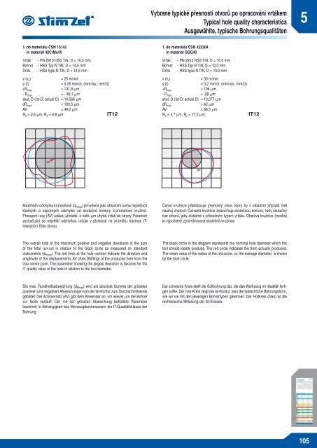
1. do materiálu ČSN 15142<br />
in material 42CrMo4V<br />
Vrták - PN 2913 HSS TiN, D = 14,5 mm<br />
Bohrer - HSS Typ N TiN, D = 14,5 mm<br />
Drills - HSS type N TiN, D = 14,5 mm<br />
v (v c )<br />
= 25 m/min<br />
s (f)<br />
= 0,25 mm/ot. (mm/rev.; mm/U)<br />
+R max = 131,8 μm<br />
- R max = - 49,1 μm<br />
skut. D (Ist-D; actual D) = 14,566 μm<br />
dR max<br />
= 103,5 μm<br />
AV<br />
= 49,2 μm<br />
R a = 2,6 μm, R z = 6,8 μm<br />
IT12<br />
1. do materiálu ČSN 422304<br />
in material GGG40<br />
Vrták - PN 2913 HSS TiN, D = 10,0 mm<br />
Bohrer - HSS Typ N TiN, D = 10,0 mm<br />
Drills - HSS type N TiN, D = 10,0 mm<br />
v (v c )<br />
= 30 m/min<br />
s (f)<br />
= 0,2 mm/ot. (mm/rev.; mm/U)<br />
+R max = 106 μm<br />
- R max = -28 μm<br />
skut. D (Ist-D; actual D) = 10,077 μm<br />
dR max<br />
= 42 μm<br />
AV<br />
= 68,5 μm<br />
R a = 3,7 μm, R z = 17,2 μm<br />
IT12<br />
Maximální odchylka kruhovitosti (d Rmax ) je tvořena jako absolutní suma největších<br />
kladných a záporných odchylek od skutečné kontury k průměrové kružnici.<br />
Přesazení osy (AV) udává uživateli, o kolik μm uhýbá vrták do strany. Parametr<br />
vyznačující se největší odchylkou určuje v závislosti na průměru nástroje ITtoleranční<br />
třídu otvoru.<br />
Černá kružnice představuje jmenovitý otvor, který by v ideálním případě měl<br />
nástroj zhotovit. Červená kružnice znázorňuje skutečnou konturu, tedy skutečný<br />
tvar otvoru, jaký získáme s příslušným typem vrtáku. Obalová kružnice (modrá)<br />
je výpočetně zprůměrovaná skutečná kružnice.<br />
The overall total of the maximum positive and negative deviations is the sum<br />
of the total run-out in relation to the black circle as measured on standard<br />
instruments (d Rmax ). The red lines at the hole centres indicate the direction and<br />
amplitude of the displacements AV (Axis Shifting) of the produced hole from the<br />
true centre point. The parameter showing the largest deviation is decisive for the<br />
IT quality class of the hole in relation to the tool diameter.<br />
The black circle in the diagram represents the nominal hole diameter which the<br />
tool should ideally produce. The red circle indicates the form actually produced.<br />
The mean value of the radius of the red circle, i.e. the average diameter, is shown<br />
by the blue circle.<br />
Die max. Rundheitsabweichung (d Rmax ) wird als absolute Summe der grössten<br />
positiven und negativen Abweichungen von der Ist-Kontur zum Durchschnittskreis<br />
gebildet. Der Achsversatz (AV) gibt dem Anwender an, um wieviel μm der Bohrer<br />
zur Seite verläuft. Der mit der grössten Abweichung behaftete Parameter<br />
bestimmt in Abhängigkeit des Werzeugdurchmessers die IT-Qualitätsklasse der<br />
Bohrung.<br />
Der schwarze Kreis stellt die Sollbohrung dar, die das Werkzeug im Idealfall fertigen<br />
sollte. Der rote Kreis zeigt die Ist-Kontur, also die tatsächliche Bohrungsform,<br />
wie wir sie mit den jeweiligen Bohrertypen gewinnen. Der Hüllkreis (blau) ist die<br />
rechnerische Mitteilung der Ist-Kreises.<br />
105