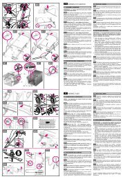
DDLE LCD 18 DDLE LCD 18/21/24 DDLE LCD 27 Elektronisch - AEG
DDLE LCD 18 DDLE LCD 18/21/24 DDLE LCD 27 Elektronisch - AEG
DDLE LCD 18 DDLE LCD 18/21/24 DDLE LCD 27 Elektronisch - AEG

Sie wollen auch ein ePaper? Erhöhen Sie die Reichweite Ihrer Titel.
YUMPU macht aus Druck-PDFs automatisch weboptimierte ePaper, die Google liebt.
• Never replace the pressure limiter when using a thermostatic valve.<br />
• Never use the shut-off valve in the cold water supply (22) to reduce the flow rate.<br />
3.7 Power supply<br />
• Connect the power cable to the terminal strip (see wiring diagram I ).<br />
STB = High limit safety cut-out<br />
AP3 = Safety pressure limiter<br />
Important information:<br />
• The protection level IP 25 (hoseproof) is only assured if the cable grommet is fitted correctly ( G or. K )<br />
and if the cable sheath is sealed correctly.<br />
• Connect the equipment to earth.<br />
• For supply cables > 6 mm², increase the hole in the cable grommet.<br />
3.8 Completing the installation<br />
Click the lower part of the back panel ( E 3) into place.<br />
3.9 Commissioning (only by a qualified contractor)<br />
1 Fill and vent the equipment. Please note: Boil-dry risk.<br />
Open and close all connected taps several times, until all air<br />
has been vented from the pipework and the equipment.<br />
Air - see "2.3 Important information".<br />
2 Activate the safety pressure limiter AP 3.<br />
The instantaneous water heater is delivered with the safety<br />
pressure limiter triggered (press the reset button).<br />
3 Push the temperature selector cable plug onto the<br />
electronic PCB.<br />
4 Fit and audibly let the device cap click into place.<br />
Check the firm seat of the device cap on the back panel.<br />
5 Switch on the mains power.<br />
6 Turn the temperature selector as far as possible clockwise<br />
and anti-clockwise, which calibrates the temperature.<br />
7 Check the instantaneous water heater function.<br />
Optional displays of the “traffic light” indicators ( A 9), see also<br />
“7. Troubleshooting”):<br />
red illuminates in case of faults<br />
yellow illuminates when the equipment is heating water<br />
green flashing - equipment is supplied with mains power<br />
Equipment handover<br />
Explain the equipment function to the user and familiarise the<br />
user with its operation.<br />
Important information:<br />
• Make the user aware of possible dangers (scalding).<br />
• Hand over these instructions to the user for safe-keeping.<br />
1<br />
4<br />
5<br />
6<br />
2<br />
For contractors<br />
3<br />
C26_02_02_0834<br />
29