Download Datasheet
Download Datasheet
Download Datasheet
- Keine Tags gefunden...

Sie wollen auch ein ePaper? Erhöhen Sie die Reichweite Ihrer Titel.
YUMPU macht aus Druck-PDFs automatisch weboptimierte ePaper, die Google liebt.
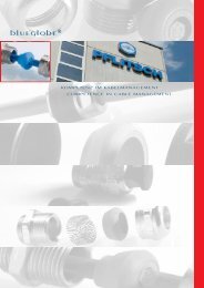
lueglobe ®Kompetenz im Kabelmanagement · Competence in cable management
Die neue Kompetenzim KabelmanagementThe new competencein cable management2 · blueglobe ® 03.2012
Seit über 90 Jahren steht PFLITSCH für innovative,praxisorientierte und sichere Produktlösungenrund um die industrielle Kabel füh rung.Dabei überzeugt unser Unternehmen die Anwenderin verschiedenen Branchen immer wiederdurch frische Denkansätze unddialogorientiertes Handeln.Made in Germany für den WeltmarktPFLITSCH-Kabelverschraubungen und Kabelkanälestehen überall auf der Welt für „QualitätMade in Germany“ – deutlich gekennzeichnetdurch das sechseckige Markenzeichen mit seinencharakteristischen 12 Riefen. Als Spezialistfür industrielles Kabelmanagement schaffen wirStandards und bieten unserem wachsendenKundenkreis in aller Welt zukunftsorientierteSystemlösungen.Systembauteile für mehr IndividualitätÜber 13.000 Systembauteile mit hohem Nutzwertkombinieren wir mit einem Dienstleistungsangebot,das von der Planung bis zureinbaufertigen Baugruppe reicht. Damit lassensich Arbeitsabläufe optimieren, die Betriebs -sicherheit erhöhen und Gesamtkosten reduzieren.Unterm Strich sind PFLITSCH-Produktepreiswert im wahrsten Sinne des Wortes. Dennstatt auf Billiglösungen zu setzen, bieten wirSystemkomponenten, die ihren Preis wert sind.Und das über eine lange Betriebsdauer.Damit aus Ideen und Anforderungen des Marktesschnell ein perfektes Serienprodukt wird,arbeiten Konstruktion, Werkzeugbau, Prototypen-Fertigung,Testlabor und Produktion Handin Hand – natürlich nach internationalen Qua -litäts- und Kundennormen.PFLITSCH has been convincing with innovative,practice-oriented and reliable product solutionsall about industrial cable routeing for more than90 years. Here our company is constantly persuadingusers in various branches with fresh approachesand dialogue-oriented action.Made in Germany for the world marketPFLITSCH-cable glands and cable trunking standfor "Quality Made in Germany" throughout theworld – clearly identified by the hexagonalbrand mark with its characteristic 12 grooves.As specialists for industrial cable management,we create standards and offer our growing circleof customers around the world future-orientedsystem solutions.System components for more individualityWe combine over 13,000 system componentsof a high benefit value with a range of servicesvarying from planning to ready-for-installationassemblies. This enables us to optimise operationalprocedures, increase operational reliabilityand safety as well as reduce overall costs.The bottom line shows unequivocally thatPFLITSCH-products are, in the truest sense ofthe word, value for money. This has to do withthe fact that instead of relying on cheap solutions,we offer system components well worththeir price. And this for a long service life.This has led to ideas and market requirementsquickly generating a perfect serial product –with Design and Construction, Tool Shop, PrototypeProduction, Test Laboratory and Productionworking hand in hand – naturally inaccordance with international quality and customerstandards.123Abb. 1: SpritzgusswerkzeugFig. 1: Injection moulding toolAbb. 2: BauteilvermessungFig. 2: Workpiece measurementAbb. 3: Messing-DrehereiFig. 3: Brass turning shopblueglobe ® 03.2012 · 3
InhaltSeiteInformationenInhaltIndexPFLITSCH – Die neue Kompetenz im Kabelmanagement 2– 3Die innovative blueglobe ® 7– 9Unsere beste Kabeleinführung 10 –11Das macht blueglobe ® einzigartig 12 –13Verschraubungsvariantenblueglobe ® Kunststoff 14blueglobe ® Messing 15blueglobe ® Edelstahl 1.4305 16blueglobe ® Edelstahl 1.4571 17blueglobe HT ® 18blueglobe CLEAN ® 19 –22blueglobe TRI ® 23 –26blueglobe TRI ® HT 27blueglobe AC ® 28blueglobe HT ® AC 29blueglobe EMV ® mit Selektivschirmanbindung 30blueglobe ® Messing Ex-e II 32+34blueglobe ® Edelstahl Ex-e II 32, 35+36blueglobe HT ® Ex-e II 33+37blueglobe TRI ® Ex-e II 38blueglobe TRI ® HT Ex 39blueglobe AC ® Ex-e II 40blueglobe HT ® AC Ex-e II 41ZubehörReduktion Polyamid 44Reduktion Messing 44Erweiterung Polyamid 45Erweiterung Messing 45Gegenmutter Polyamid 46Gegenmutter Messing 46Gegenmutter EMV 47Gegenmutter Edelstahl 48Dichtring 48blueglobe ® Verschlussbolzen 49Blindscheiben 49DAE Druckausgleichseinsatz 50Erdungslasche 50Steckschlüssel 51Montageschlüssel variabel 52Technische DatenAnschlussmaße 54Anzugsmomente 54Rückhaltevermögen und Zugentlastung 55IP-Schutzartprüfungen 55Schlagprüfung 55Montageabstände Kabelverschraubungen – metrisch 56Baumaße/Systemmaße 57Werkstoffübersicht 58 –61Normen/Zertifizierungen 62Montageanleitung blueglobe CLEAN ® 63Montageanleitung blueglobe ® Standard 64Montageanleitung blueglobe TRI ® 65Montageanleitung blueglobe EMV ® 66Montageanleitung blueglobe AC ® 674 · blueglobe ® 03.2012
IndexPageInformationPFLITSCH – The new competence in cable management 2– 3The innovative blueglobe ® 7– 9Our best cable-gland 10 –11What makes blueglobe ® unique 12 –13Cable gland variantsblueglobe ® Plastic 14blueglobe ® Brass 15blueglobe ® Stainless steel AISI 303 16blueglobe ® Stainless steel AISI 316Ti 17blueglobe HT ® 18blueglobe CLEAN ® 19 –22blueglobe TRI ® 23 –26blueglobe TRI ® HT 27blueglobe AC ® 28blueglobe HT ® AC 29blueglobe EMC ® with selective screen connection 30blueglobe ® Brass Ex-e II 32+34blueglobe ® Stainless steel Ex-e II 32, 35+36blueglobe HT ® Ex 33+37blueglobe TRI ® Ex-e II 38blueglobe TRI ® HT Ex-e II 39blueglobe AC ® Ex-e II 40blueglobe HT ® AC Ex-e II 41AccessoriesReduction polyamide 44Reduction brass 44Extensions polyamide 45Extensions brass 45Lock nut polyamide 46Lock nut brass 46Lock nut EMC 47Lock nut stainless steel 48Sealing ring 48blueglobe ® Sealing plugs 49Blind disk 49DAE Pressure balance plug in 50Earth tag 50Socket wrench 51Mounting spanner variable 52Technical dataConnection dimension 54Tightening torques 54Retention and strain relief 55IP Protection class tests 55Impact testing 55Mounting distances Cable Glands – metric 56System dimensions 57Material 58 -61Standards/Certifications 62Assembly instruction blueglobe CLEAN ® 63Assembly instruction blueglobe ® Standard 64Assembly instruction blueglobe TRI ® 65Assembly instruction blueglobe EMC ® 66Assembly instruction blueglobe AC ® 67InhaltIndexblueglobe ® 03.2012 · 5
6 · blueglobe ® 03.2012
lueglobe ®blueglobe ® 03.2012 · 7
Die innovative blueglobe ®The innovative blueglobe ® 1800750700650600550500450N4003503002502001501005002M16, Ø 8 mmM16, Ø 8 mmM20, Ø 9 mmM20, Ø 9 mmM25, Ø 16 mmM25, Ø 16 mmM32, Ø 20 mmM32, Ø 20 mm< 4 4-8 8-11 11-16 16-23 23-31 31-43 43-55 54-65 64-77DurchmesserDiameterM40, Ø 27 mmM40, Ø 30 mmM50, Ø 35 mmM50, Ø 36 mmM63, Ø 43 mmM63, Ø 43 mmM85, Ø 70 mm8 · blueglobe ® 03.2012
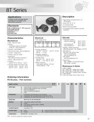
Bessere Zugentlastung als die Marktstandardsblueglobe ® ist deutlich besser als der Marktstandard.Die Auszugskräfte nach EN 50262Klasse B werden teils um mehr als 150 % übertroffen.Durch den guten Kraftschluss zwischenKabel und Dichteinsatz werden große statischeund dynamische Kräfte aufgenommen, ohnedie verwendeten Kabel schädigend einzuschnüren.blueglobe ® -Verschrau bun gen sind langlebigund zuverlässig.Einmalig: Der kugelförmige DichteinsatzKernstück der blueglobe ® ist der kugelförmigeDichteinsatz aus einem spezialmodifizierten TPE-Kunststoff. Beim Anziehen der Druckschraubezentriert er die Summe der Kräfte optimal aufdas durchgeführte Kabel und umschließt esgroßflächig. Der Dichteinsatz steckt unverlierbarin der Druckschraube und erzielt Druckdichtigkeitenvon IP 68 (bis 15 bar). Gleichzeitig erreichtdas großflächige Dichtprinzip eine bis zu100 % bessere Zugentlastung nach EN 50262Klasse B. Der hochwertige Kunststoff des Seriendichteinsatzesist ausgelegt für Betriebstemperaturenzwischen -40 °C und +130 °C; mitSilikon-Einsätzen sind zwischen -60 °C und+180 °C möglich. Hier sind verschiedene Größenin Vorbereitung (Abb. 1-3). Die optimierteKraftverteilung verhindert zuverlässig die bei Lamellensystemenauftretende Kerbwirkung. Beschädigungendes Kabelmantels durch dieblueglobe ® -Verschraubungen sind somit ausgeschlossen.Better strain relief than market standardsblueglobe ® is clearly better than the marketstandards. The extraction forces as perEN 50262 Class B are in part surpassed by morethan 150 %. The good non-positive connectionbetween the cable and sealing insert enableslarge static and dynamic forces to be taken upwithout the used cables being constricted anddamaged. blueglobe ® glands are durable andreliable.Unique: The spherical sealing insertThe above-average characteristics are possiblethrough the spherical sealing insert made of aspecially modified TPE plastic. When the pressurescrew is tightened, it centres the sum ofthe forces optimally onto the inserted cable andencloses it over a large surface. The sealinginsert is stuck in the pressure screw so that itcannot become detached and attains a pressureimpermeability of IP 68 (up to 15 bar).At the same time, the large-surface sealingprinciple attains by up to 100 % better strainrelief in accordance with EN 50262 Class B. Thehigh-grade plastic of the serial sealing insert isdesigned for operating temperatures between-40 °C and +130 °C; with silicone inserts from-60 °C to +180 °C is possible. Different sizes inpreparation (Fig. 1-3). The optimised distributionof forces reliably prevents the stress concentrationoccurring with lamellar system.Damage to cable sheats is therefore excludedwhen using blueglobe ® .3Abb. 1: blueglobe ® PAFig. 1: blueglobe ® PAAbb. 2: blueglobe ® ZugentlastungFig. 2: blueglobe ® strain reliefAbb. 3: blueglobe ® PA (Anschlussgewinde-Seite)Fig. 3: blueglobe ® PA (connection thread side)blueglobe ® 03.2012 · 9
Unsere besteKabeleinführungOur best cable gland1Sehr große SpannbereicheLarge clamping rangesM85M75M63M50M40GewindeThreadM32M25M20M16M12PA max. 7,5 mmM100 2 4 6 8 10 12 14 16 18 20 22 24 26 28 30 32 34 36 38 40 42 44 46 48 50 52 54 56 58 60 62 64 66 68 70 72 74 76 78 802mit Inletwith inletohne Inletwithout inletSpannbereicheClamping rangesAbb. 1: blueglobe ® VAFig. 1: blueglobe ® VAAbb. 2: blueglobe ® SpannbereicheFig. 2: blueglobe ® clamping ranges10 · blueglobe ® 03.2012
Größere Dichtbereiche reduzieren BauteilvielfaltMit der blueglobe ® haben die PFLITSCH-Entwicklereine Kabelverschraubung geschaffen,die anspruchsvollste Kunden mit Sicherheit,Funktionalität und optimaler Kosten-/Nutzenrelationüberzeugt. Große Dichtbereiche, höchsteDichtigkeit, beste Zugentlastung und eine einmaligeKennzeichnung: Das sind die Merkmaleder blueglobe ® , die PFLITSCH in Messing,Kunststoff und Edelstahl in den Größen M10bis M85 mit Kabeldurchmessern von 1,5 mmbis 77 mm anbietet. Ein Vorteil: Drei Typen(M16, M25 und M40) reichen aus, um alle Kabeldurchmesservon 4 mm bis 32 mm sicherabzudichten. Herkömmliche Verschraubungenbenötigen dafür bis zu fünf Größen. Im oberenBereich erreicht die blueglobe ® M25 nahezu dieWerte einer nächstgrößeren, handelsüblichenM32. Heraustrennbare Inlets sorgen für bisherunerreicht große Dichtbereiche. Das spart demAnwender Kosten und Platz.Eindeutige KennzeichnungDie blueglobe ® unterscheidet sich auch durchihre eindeutige Kennzeichnung von anderenKabelverschraubungen. Das ermöglicht eineschnelle und sichere Produktidentifizierung beiMontage und Lagerhaltung. Neben der Kennzeichnungauf der Druckschraube sind auf demsechseckigen globemarker ® an der Einsatzdichtungdie verwendbaren Kabeldurchmesser bzw.Dichtbereiche bezeichnet. Die Druckschraubeweist den Hersteller, den Werkstoff, dasAnschlussgewinde und die CE-Kennzeichnungaus. Mit dieser umfangreichen Kennzeichnungergibt sich in der Praxis eine eindeutige Zuordnungder blueglobe ® zu den Einsatzbedingungen.Die Dichteinsätze sind ab M20 mit dem globemarker® versehen, der den Dichtbereich angibt.So werden Fehler vermieden, der Dichtbereichist direkt ablesbar und überprüfbar.Hochwertige Werkstoffe – Lebenslangdicht auch unter Extrem bedingungenDurch die verwendeten Materialien erreicht dieblueglobe ® eine gute Ozon- und UV-Beständigkeit.Die TPE-Dichteinsätze sind langzeitstabilund gasen nicht aus. Daher eignet sich die Kabelverschraubungauch für den Einsatz im Außenbereichund der chemischen Industrie.Die Dichteinsätze bestehen aus TPE bzw. Silikon,die Verschraubungskörper sind aus Messing,Edelstahl oder Kunststoff (PA). DieVerschraubungen sind RoHS-konform (also freivon Schwermetallen) und erfüllen damit die aktuellenEU-Anfor derungen. Selbstverständlichsind sie auch halogenfrei.Durch die hochwertigen Werkstoffe sind dieblueglobe ® beständig gegen viele Me dien, wiezum Beispiel native Öle.Larger sealing ranges reduce componentmultiplicityWith blueglobe ® , PFLITSCH developers havecreated a cable gland that convinces the mostdemanding customers with safety, functionalityand optimum cost/benefit relation. Large sealingranges, maximum impermeability, beststrain relief and unique identification – theseare the characteristics of blueglobe ® , whichPFLITSCH offers in brass, plastic and stainlesssteel in the sizes M10 to M85 up to cable diametersfrom 1,5 mm to 77 mm. In this innovation,for example: Three types (M16, M25 andM40) are adequate to reliably seal all cable diametersfrom 4 mm to 32 mm, while conventionalglands need up to five sizes for this. In theupper range, blueglobe ® M25 practically reachesthe values of the next larger, commercialM32. Detachable inlets make for hitherto unattained,large sealing ranges. This saves the userspace and costs.Unique identificationblueglobe ® is also different from other cableglands in its unequivocal identification. This enablesproducts to be identified quickly and reliablyin assembly and stockkeeping. Apart fromthe identification on the pressure screw, theusable cable diameters or sealing ranges aremarked on the hexagonal globemarker ® on theinsert sealing. The pressure screw displays themanufacturer, the material, the connectionthread and CE identification. With this extensiveidentification, blueglobe ®`s unambiguous allocationto the practical conditions of applicationis ensured.The sealing inserts are provided with the globemarker® as of M20 that specifies the sealingrange. This avoids any mistakes, since the sealingrange can be read off and checked directly.High-grade materials – Life-long sealedeven under extreme conditionsblueglobe ® reaches good ozone and UV-resistancethrough the materials used. The TPEsealing inserts are long-term-stable and donot outgas. This is why this cable gland is alsosuitable for applications outside and in thechemical industry.The sealing inserts consist of TPE and silicone,the gland bodies brass, stainless steel or plastic(PA). The glands comply with RoHS (wich meansfree of heavy metals) and thus meet current EUrequirements. They are – it goes without saying– halogen-free.Through these high-grade materials,blueglobe ® is also resistant to many media,such as native oils.345globemarker ®Abb. 3: globemarker ®Fig. 3: globemarker ®Abb. 4: blueglobe ® PAnFig. 4: blueglobe ® PAnAbb. 5: blueglobe TRI ® msFig. 5: blueglobe TRI ® msblueglobe ® 03.2012 · 11
Das macht blueglobe ®einzigartigThis is why blueglobe ®is uniqueABWerkstoffe:Materials:blueglobe ® -Verschraubungskörperblueglobe ® gland body- Messing, galv. vernickelt- Brass, nickel plated- 1.4305 und 1.4571- AISI 303 and AISI 316Ti- Polyamid- Polyamide (PA)- Metrisches Gewinde- Metric connection thread- RoHS konform- RoHS conformityRein elastischer DichteinsatzPure elastic sealing insert- TPE, blau: Temperaturbereich -40 °C bis +130 °C- TPE, blue: Temperature range -40 °C up to +130 °C- Silikon, schwarz: Temperaturbereich -60 °C bis +180 °C- Silicone, black: Temperature range -60 °C up to +180 °C- Halogen- und weichmacherfrei- Halogen and plasticiser free- Hohe UV-Stabilität- High UV-stability- UL 94 HB- UL 94 HB- RoHS konform- RoHS conformityGCSehr hohe Dichtigkeit IP 68 bis 15 barund darüber hinausHigh protection rate IP 68 up to 15 bar and moreACBEDDRadialsymmetrische, großflächige undelastische DichtungRadial symmetric, large area andelastic sealing- Weiche Quetschung durch „globe“-Dichtsystem- Soft pressing by patented “globe” sealing system- Keine Kabelschäden durch Einschnürungen- No cable damages by strangling- Keine Faltenbildung in den Dichtungen beikleinen Kabeldurchmessern- No folding of the sealing in case of small diametersFEGroßer DichtbereichLarge sealing range- TPE: Heraustrennbares Inlet- TPE: Inlet removable- Silikon: Zweiteiliger Dichteinsatz- Silicone: Two-part inletFO-RingO-ring- Kautschuk (NBR)- Rubber (NBR)- Silikon- SiliconeBei Metall: vorgelagerte O-Ring-Nut, eingelassenin eine große SchlüsselflächeBei PA: selbstdichtende SchlüsselflächeBrass: O-ring groove located at an outer positionPA: Self tightening area metric connection thread1GSehr hohe Auszugskräfte (EN 50262 Klasse B)High strain relief (EN 50262 class B)Abb. 1: Werkstoff Messing (Ms)Fig. 1: Material brassAlle Angaben geprüft nach EN 50262All information are proved per EN 5026212 · blueglobe ® 03.2012
Nutgeführter, vorgelagerter O-RingAlle blueglobe ® Messing- und Edelstahlverschraubungenhaben vorgelagerte O-Ringe,die bei Einschraub ge winden und Durchgangslöchernfür einen Toleranzausgleich sorgen.Durch die Nut führung bleiben sie zuverlässig inihrer Position und können sich weder ins Bohr -loch noch nach außen quetschen. So sorgen siefür eine dauerhaft sichere und verschleißfreieAbdichtung zwischen Ver schraubungen undGehäusen.Schonende Kabelfixierung für mehrBe triebssicherheitVibrationen und Kabelbewegungen führen oftzu Kabelbrüchen im Bereich der Kabelfixierung.Die einzigartigen blueglobe ® -Dichteinsätze sorgenfür eine sichere und schonende Kabelfixierung.Sie verhindern, dass Kabel in denVerschraubungen beschädigt werden und Adernabbrechen – die Betriebssicherheit wird erhöht.Verschleißfreie Abdich tungAlle blueglobe ® -Kunststoffver schrau bun genverfügen über optimal geformte, ringförmigeKontaktflächen am Bund, die mit und ohneFlachdichtungen für her vor ragende Dichtigkeitsorgen.So bleiben Staub und Feuchtigkeit zuverlässigdraußenblueglobe ® erfüllen die Schutzart IP 68. Die Verschraubungensind absolut staubdicht und wasserdichtbis 150 m (15 bar).Prüflinge aus PA, Ms und VA haben den IP 69K-Test nach DIN 40050 Teil 9 bei 100 bar Wasserdruck,+80 °C über 2 Minuten im PFLITSCH-Prüflabor bestanden.Slotted, prelodged O-ringAll blueglobe ® brass and stainless-steel glandshave prelodged O-rings, which make for tolerancecompensation with screw-in threads andfeedthroughs.The slotting makes them remain reliably in theirposition and they cannot squeeze into the boreholenor outwards. They thus ensure permanentlysecure and wear-free sealing betweenthe glands and enclosures.Gentle cable fixing for more operationalsafetyVibrations and cable movements frequently leadto cable breaks in the area the cable is fixed in.The unique blueglobe ® sealing inserts ensure reliableand gentle cable fixing. They prevent cablesbeing damaged in the glands and wiressnapping, operational safety being increased.Wear-free sealingAll blueglobe ® plastic glands have optimally designed,ring-shaped contact surfaces on the collar,making for outstanding impermeability withand without flat sealings.This means dust and moisture remain quitecertainly outsideblueglobe ® complies with protection classIP 68. The glands are absolutely dust-proof andwater-proof down to 150 m (15 bar).Test samples made of PA, brass and stainlesssteel passed the IP 69K test in accordance withDIN 40050 Part 9 at 100 bar water pressure,+80 °C for 2 minutes in the PFLITSCH testing laboratory.23WettbewerbsproduktCompetitor’s product4EinschnürungDamageblueglobe ®Weiche QuetschungSoft pinchingIhre Vorteile· Sehr hohe Zugentlastung Klasse B,EN 50262· Schutzart IP 68 bis 15 bar· IP 69K· Sehr große Spannbereiche· Eindeutige KennzeichnungYour advantages· High strain relief class B, EN 50262· Protection class IP 68 up to 15 bar· IP 69K· Large clamping ranges· Unique identificationAbb. 2: blueglobe ® VA ATEX-Ausführung mit SilikonringFig. 2: blueglobe ® VA ATEX version with silicon ringAbb. 3+4:blueglobe ® Druckschraube im Vergleich miteinem WettbewerbsproduktFig. 3+4: blueglobe ® pressure screw in comparsion to acompetitor´s productblueglobe ® 03.2012 · 13
lueglobe ® – Kunststoffblueglobe ® – plasticAbb. 1Fig. 1Abb. 2Fig. 2VerschraubungskörperGland bodyWerkstoff Temperaturbereich min./max. FarbeBestellschlüsselMaterial Temperature range min./max. Colour Art.-No. supplementPA -20 °C / +120 °C grau (RAL 7035) -PA -20 °C / +120 °C grey (RAL 7035) -schwarz (RAL 9011) nblack (RAL 9011) nPolyamid, mit M-Gewinde gemäß EN 60423Schutzart IP 68 bis 15 barGrundlage für technische Angaben: EN 50262Polyamide, metric connection thread as per EN 60423Type of protection IP 68 up to 15 barBase for technical data: EN 50262blueglobei® erfüllt und übertrifft teilweise, gemäß PFLITSCH-Prüflabor,alle Prüfkriterien der EN 50262.blueglobe ® reaches/exceeds partly the test requirements of EN 50262,as per PFLITSCH laboratory.DichteinsätzeSealing insertsWerkstoffMaterialFarbeColourTPE blau (RAL 5012)TPE blue (RAL 5012)Anschlussgewinde/-länge Artikel-Nr. Dichtbereich Dichtbereich Dichtbereich Schlüsselweiteohne Inlet mit InletConnection thread/length Art.-No. Sealing range Sealing range Sealing range Spanner widthAusführung bitte ergänzenwithout inlet with inletPlease supplement executionAbb. 3: mit InletFig. 3: with inletA D grau/grey = - max./min. ø max./min. ø max./min. ø C SW 1 x E 1mm schwarz/black = n mm mm mm mm mmM12x1,5 8,0 bg 212PA 7,5 – 2,0 7,5 – 5,0 5,0 – 2,0 24 17x18,9 50M16x1,5 9,0 bg 216PA 11,0 – 4,0 11,0 – 7,0 7,0 – 4,0 27 20x22,2 50M20x1,5 9,0 bg 220PA 14,0 – 5,0 14,0 – 9,0 9,0 – 5,0 33 24x26,5 50M25x1,5 9,0 bg 225PA 20,0 – 11,0 20,0 – 16,0 16,0 – 11,0 34 30x33 50M32x1,5 11,0 bg 232PA 25,0 – 15,0 25,0 – 20,0 20,0 – 15,0 35 36x39,5 25M40x1,5 12,0 bg 240PA 32,0 – 20,0 32,0 – 26,0 26,0 – 20,0 38 45x48 10M50x1,5 15,0 bg 250PA 41,0 – 31,0 41,0 – 35,0 35,0 – 31,0 47 57x61 5M63x1,5 15,0 bg 263PA 53,0 – 41,0 53,0 – 46,0 46,0 – 41,0 49 70x75 5Anschlussgewinde-Variante 15 mmConnection thread variant 15 mmAnschlussgewinde/-länge Artikel-Nr. Dichtbereich Dichtbereich Dichtbereich Schlüsselweiteohne Inlet mit InletConnection thread/length Art.-No. Sealing range Sealing range Sealing range Spanner widthAusführung bitte ergänzenwithout inlet with inletPlease supplement executionC USFile No.: E216848A D grau/grey = - max./min. ø max./min. ø max./min. ø C SW 1 x E 1mm schwarz/black = n mm mm mm mm mmM16x1,5 15,0 bg 816PA 11 – 4,0 11 – 7,0 7,0 – 4,0 27,0 20x22,2 50M20x1,5 15,0 bg 820PA 14 – 5,0 14 – 9,0 9,0 – 5,0 33,0 24x26,5 50M25x1,5 15,0 bg 825PA 20 – 11,0 20 – 16,0 16,0 – 11,0 34,0 30x33 50M32x1,5 15,0 bg 832PA 25 – 15,0 25 – 20,0 20,0 – 15,0 35,0 36x39,5 25M40x1,5 15,0 bg 840PA 32 – 20,0 32 – 26,0 26,0 – 20,0 38,0 45x48 10iAnzugsmomente s. Seite 54.Tightening torques see page 54.IP 69K***siehe technischer Anhang Seite 62.see technical attachment on page 62.*nur in Verbindung mit TPE-Dichtring(s. S. 48) separat bestellen.*only in combination with TPE-flat-ring(page 48) order separate.**M50/M63 ohne Zulassung**M50/M63 without certificate14 · blueglobe ® 03.2012
lueglobe ® – Messingblueglobe ® – brassAbb. 1Fig. 1VerschraubungskörperGland bodyWerkstoffMaterialMsBrassAbb. 2Fig. 2AusführungExecutiongalv. vernickeltgalv. nickel platedMs vernickelt, mit M-Gewinde gemäß EN 60423Schutzart IP 68 bis 15 barGrundlage für technische Angaben: EN 50262Brass nickel plated, metric connection thread as per EN 60423Type of protection IP 68 up to 15 barBase for technical data: EN 50262blueglobei® erfüllt und übertrifft teilweise, gemäß PFLITSCH-Prüflabor,alle Prüfkriterien der EN 50262.blueglobe ® reaches/exceeds partly the test requirements of EN 50262,as per PFLITSCH laboratory.DichteinsätzeSealing insertsWerkstoff Temperaturbereich min./max. FarbeMaterial Temperature range min./max. ColourTPE -40 °C / +130 °C blau (RAL 5012)TPE -40 °C / +130 °C blue (RAL 5012)Anschlussgewinde/-länge Artikel-Nr. Dichtbereich Dichtbereich Dichtbereich Schlüsselweiteohne Inlet mit InletConnection thread/length Art.-No. Sealing range Sealing range Sealing rangewithout inlet with inletSpanner widthAbb. 3: mit InletFig. 3: with inletA D max./min. ø max./min. ø max./min. ø C SW x Emm mm mm mm mm mmM10x1 6,0 bg 210ms 6,0 – 1,5 6,0 – 3,0 3,0 – 1,5 20 13x14,2 50M12x1,5 5,0 bg 212ms 8,0 – 2,0 8,0 – 5,0 5,0 – 2,0 21 17x18,9 50M16x1,5 6,0 bg 216ms 11,0 – 4,0 11,0 – 7,0 7,0 – 4,0 25 20x22,2 50M20x1,5 6,5 bg 220ms 14,0 – 5,0 14,0 – 9,0 9,0 – 5,0 29 24x26,5 50M25x1,5 7,5 bg 225ms 20,0 – 11,0 20,0 – 16,0 16,0 – 11,0 30 30x33 50M32x1,5 8,0 bg 232ms 25,0 – 15,0 25,0 – 20,0 20,0 – 15,0 32 36x39,5 25M40x1,5 8,0 bg 240ms 32,0 – 20,0 32,0 – 26,0 26,0 – 20,0 35 45x48 10M50x1,5 10,0 bg 250ms 42,0 – 31,0 42,0 – 35,0 35,0 – 31,0 39 57x61 5M63x1,5 10,0 bg 263ms 54,0 – 41,0 54,0 – 46,0 46,0 – 41,0 40 68x72 5M75x1,5 15,0 bg 275ms 65,0 – 54,0 65,0 – 58,0 58,0 – 54,0 47 81x87 5M85x2 15,0 bg 285ms 77,0 – 65,0 77,0 – 70,0 70,0 – 65,0 49 95x102 1Anschlussgewinde-Variante 15 mmConnection thread variant 15 mmAnschlussgewinde/-länge Artikel-Nr. Dichtbereich Dichtbereich Dichtbereich Schlüsselweiteohne Inlet mit InletConnection thread/length Art.-No. Sealing range Sealing range Sealing rangewithout inlet with inletSpanner widthC USFile No.: E216848IP 69KA D max./min. ø max./min. ø max./min. ø C SW x Emm mm mm mm mm mmM12x1,5 15,0 bg 812ms 8,0 – 2,0 8,0 – 5,0 5,0 – 2,0 21 17x18,9 50M16x1,5 15,0 bg 816ms 11,0 – 4,0 11,0 – 7,0 7,0 – 4,0 25 20x22,2 50M20x1,5 15,0 bg 820ms 14,0 – 5,0 14,0 – 9,0 9,0 – 5,0 29 24x26,5 50M25x1,5 15,0 bg 825ms 20,0 – 11,0 20,0 – 16,0 16,0 – 11,0 30 30x33 50M32x1,5 15,0 bg 832ms 25,0 – 15,0 25,0 – 20,0 20,0 – 15,0 32 36x39,5 25M40x1,5 15,0 bg 840ms 32,0 – 20,0 32,0 – 26,0 26,0 – 20,0 35 45x48 10M50x1,5 15,0 bg 850ms 42,0 – 31,0 42,0 – 35,0 35,0 – 31,0 39 57x61 5M63x1,5 15,0 bg 863ms 54,0 – 41,0 54,0 – 46,0 46,0 – 41,0 40 68x72 5iM10 mit modifizierter O-Ring-NutM10 with modified O-ring-grooveAnzugsmomente s. Seite 54.Tightening torques see page 54.siehe technischer Anhang Seite 62.see technical attachment on page 62.blueglobe ® 03.2012 · 15
lueglobe ® – Edelstahlblueglobe ® – stainless steelAbb. 1Fig. 1VerschraubungskörperGland bodyWerkstoffMaterialAbb. 2Fig. 2AusführungExecutionVA 1.4305 (auf Anfrage elektropoliert)VA AISI 303 (electro polished on request)Edelstahl/1.4305, mit M-Gewinde gemäß EN 60423Schutzart IP 68 bis 15 barGrundlage für technische Angaben: EN 50262Stainless steel AISI 303, metric connection thread as per EN 60423Type of protection IP 68 up to 15 barBase for technical data: EN 50262blueglobei® erfüllt und übertrifft teilweise, gemäß PFLITSCH-Prüflabor,alle Prüfkriterien der EN 50262.blueglobe ® reaches/exceeds partly the test requirements of EN 50262,as per PFLITSCH laboratory.DichteinsätzeSealing insertsWerkstoff Temperaturbereich min./max. FarbeMaterial Temperature range min./max. ColourTPE -40 °C / +130 °C blau (RAL 5012)TPE -40 °C / +130 °C blue (RAL 5012)Anschlussgewinde/-länge Artikel-Nr. Dichtbereich Dichtbereich Dichtbereich Schlüsselweiteohne Inlet mit InletConnection thread/length Art.-No. Sealing range Sealing range Sealing range Spanner widthwithout inlet with inletAbb. 3: mit InletFig. 3: with inletA D max./min. ø max./min. ø max./min. ø C SW x Emm mm mm mm mm mmM12x1,5 5,0 bg 212VA 8,0 – 2,0 8,0 – 5,0 5,0 – 2,0 21,0 17x18,9 50M16x1,5 6,0 bg 216VA 11,0 – 4,0 11,0 – 7,0 7,0 – 4,0 25,0 20x22,2 50M20x1,5 6,5 bg 220VA 14,0 – 5,0 14,0 – 9,0 9,0 – 5,0 29,0 24x26,5 50M25x1,5 7,5 bg 225VA 20,0 – 11,0 20,0 – 16,0 16,0 – 11,0 30,0 30x33 50M32x1,5 8,0 bg 232VA 25,0 – 15,0 25,0 – 20,0 20,0 – 15,0 32,0 36x39,5 25M40x1,5 8,0 bg 240VA 32,0 – 20,0 32,0 – 26,0 26,0 – 20,0 35,0 45x48 10M50x1,5 10,0 bg 250VA 42,0 – 31,0 42,0 – 35,0 35,0 – 31,0 39,0 57x60 5M63x1,5 10,0 bg 263VA 54,0 – 41,0 54,0 – 46,0 46,0 – 41,0 40,0 68x72 5M75x1,5 15,0 bg 275VA 65,0 – 54,0 65,0 – 58,0 58,0 – 54,0 47,0 81x87 5M85x2 15,0 bg 285VA 77,0 – 65,0 77,0 – 70,0 70,0 – 65,0 49,0 95x102 1Anschlussgewinde-Variante 15 mmConnection thread variant 15 mmAnschlussgewinde/-länge Artikel-Nr. Dichtbereich Dichtbereich Dichtbereich Schlüsselweiteohne Inlet mit InletConnection thread/length Art.-No. Sealing range Sealing range Sealing range Spanner widthwithout inlet with inletC USFile No.: E216848IP 69KA D max./min. ø max./min. ø max./min. ø C SW x Emm mm mm mm mm mmM12x1,5 15,0 bg 812VA 8,0 – 2,0 8,0 – 5,0 5,0 – 2,0 21,0 17x18,9 50M16x1,5 15,0 bg 816VA 11,0 – 4,0 11,0 – 7,0 7,0 – 4,0 25,0 20x22,2 50M20x1,5 15,0 bg 820VA 14,0 – 5,0 14,0 – 9,0 9,0 – 5,0 29,0 24x26,5 50M25x1,5 15,0 bg 825VA 20,0 – 11,0 20,0 – 16,0 16,0 – 11,0 30,0 30x33 50M32x1,5 15,0 bg 832VA 25,0 – 15,0 25,0 – 20,0 20,0 – 15,0 32,0 36x39,5 25M40x1,5 15,0 bg 840VA 32,0 – 20,0 32,0 – 26,0 26,0 – 20,0 35,0 45x48 10M50x1,5 15,0 bg 850VA 42,0 – 31,0 42,0 – 35,0 35,0 – 31,0 39,0 57x60 5M63x1,5 15,0 bg 863VA 54,0 – 41,0 54,0 – 46,0 46,0 – 41,0 40,0 68x72 5iAnzugsmomente s. Seite 54.Tightening torques see page 54.siehe technischer Anhang Seite 62.see technical attachment on page 62.16 · blueglobe ® 03.2012
lueglobe ® – Edelstahlblueglobe ® – stainless steelAbb. 1Fig. 1VerschraubungskörperGland bodyWerkstoffMaterialAbb. 2Fig. 2AusführungExecutionV4A 1.4571 (auf Anfrage elektropoliert)V4A AISI 316Ti (electro polished on request)Edelstahl/1.4571, mit M-Gewinde gemäß EN 60423Schutzart IP 68 bis 15 barGrundlage für technische Angaben: EN 50262Stainless steel AISI 316Ti, metric connection thread as per EN 60423Type of protection IP 68 up to 15 barBase for technical data: EN 50262blueglobei® erfüllt und übertrifft teilweise, gemäß PFLITSCH-Prüflabor,alle Prüfkriterien der EN 50262.blueglobe ® reaches/exceeds partly the test requirements of EN 50262,as per PFLITSCH laboratory.DichteinsätzeSealing insertsWerkstoff Temperaturbereich min./max. FarbeMaterial Temperature range min./max. ColourTPE -40 °C / +130 °C blau (RAL 5012)TPE -40 °C / +130 °C blue (RAL 5012)Anschlussgewinde/-länge Artikel-Nr. Dichtbereich Dichtbereich Dichtbereich SchlüsselweiteConnection thread/length Art.-No. Sealing range ohne Inlet mit Inlet Spanner widthSealing range Sealing rangewithout inlet with inletAbb. 3: mit InletFig. 3: with inletA D max./min. ø max./min. ø max./min. ø C SW x Emm mm mm mm mm mmM12x1,5 5,0 bg 212V4A 8,0 – 2,0 8,0 – 5,0 5,0 – 2,0 21 17x18,9 50M16x1,5 6,0 bg 216V4A 11,0 – 4,0 11,0 – 7,0 7,0 – 4,0 25 20x22,2 50M20x1,5 6,5 bg 220V4A 14,0 – 5,0 14,0 – 9,0 9,0 – 5,0 29 24x26,5 50M25x1,5 7,5 bg 225V4A 20,0 – 11,0 20,0 – 16,0 16,0 – 11,0 30 30x33 50M32x1,5 8,0 bg 232V4A 25,0 – 15,0 25,0 – 20,0 20,0 – 15,0 32 36x39,5 25M40x1,5 8,0 bg 240V4A 32,0 – 20,0 32,0 – 26,0 26,0 – 20,0 35 45x48 10M50x1,5 10,0 bg 250V4A 42,0 – 31,0 42,0 – 35,0 35,0 – 31,0 39 57x60 5M63x1,5 10,0 bg 263V4A 54,0 – 41,0 54,0 – 46,0 46,0 – 41,0 40 68x72 5M75x1,5 15,0 bg 275V4A 65,0 – 54,0 65,0 – 58,0 58,0 – 54,0 47 81x87 5M85x2 15,0 bg 285V4A 77,0 – 65,0 77,0 – 70,0 70,0 – 65,0 49 95x102 1Anschlussgewinde-Variante 15 mmConnection thread variant 15 mmAnschlussgewinde/-länge Artikel-Nr. Dichtbereich Dichtbereich Dichtbereich SchlüsselweiteConnection thread/length Art.-No. Sealing range ohne Inlet mit Inlet Spanner widthSealing range Sealing rangewithout inlet with inletC USFile No.: E216848IP 69KA D max./min. ø max./min. ø max./min. ø C SW x Emm mm mm mm mm mmM12x1,5 15,0 bg 812V4A 8,0 – 2,0 8,0 – 5,0 5,0 – 2,0 21 17x18,9 50M16x1,5 15,0 bg 816V4A 11,0 – 4,0 11,0 – 7,0 7,0 – 4,0 25 20x22,2 50M20x1,5 15,0 bg 820V4A 14,0 – 5,0 14,0 – 9,0 9,0 – 5,0 29 24x26,5 50M25x1,5 15,0 bg 825V4A 20,0 – 11,0 20,0 – 16,0 16,0 – 11,0 30 30x33 50M32x1,5 15,0 bg 832V4A 25,0 – 15,0 25,0 – 20,0 20,0 – 15,0 32 36x39,5 25M40x1,5 15,0 bg 840V4A 32,0 – 20,0 32,0 – 26,0 26,0 – 20,0 35 45x48 10M50x1,5 15,0 bg 850V4A 42,0 – 31,0 42,0 – 35,0 35,0 – 31,0 39 57x60 5M63x1,5 15,0 bg 863V4A 54,0 – 41,0 54,0 – 46,0 46,0 – 41,0 40 68x72 5iAnzugsmomente s. Seite 54.Tightening torques see page 54.siehe technischer Anhang Seite 62.see technical attachment on page 62.blueglobe ® 03.2012 · 17
lueglobe HT ® – für Hochtemperaturbereicheblueglobe HT ® – for high temperature rangesAbb. 1Fig. 1Abb. 2Fig. 2Ms vernickelt, mit M-Gewinde gemäß EN 60423Schutzart IP 68 bis 15 barGrundlage für technische Angaben: EN 50262Brass nickel plated, metric connection thread as per EN 60423Type of protection IP 68 up to 15 barBase for technical data: EN 50262blueglobei® erfüllt alle Prüfkriterien der EN 50262(gemäß PFLITSCH-Prüflabor).blueglobe ® reaches the test requirements of EN 50262,as per PFLITSCH laboratory.VerschraubungskörperGland bodyWerkstoff*Material*MsBrass* Edelstahl auf Anfrage* Stainless steel on requestAusführungExecutiongalv. vernickeltgalv. nickel platedDichteinsätzeSealing insertsWerkstoff Temperaturbereich min./max. FarbeMaterial Temperature range min./max. ColourSilikon -60 °C/+180 °C schwarzSilicone -60 °C/+180 °C blackAnschlussgewinde/-länge Artikel-Nr. Dichtbereich Dichtbereich Dichtbereich Schlüsselweiteohne Inlet mit InletConnection thread/length Art.-No. Sealing range Sealing range Sealing range Spanner widthwithout inlet with inletA D max./min. ø max./min. ø max./min. ø C SW x Emm mm mm mm mm mmM16x1,5 6,0 bg 216msHT 11,0 – 4,0 11,0 – 7,0 7,0 – 4,0 25 20x22,2 50M20x1,5 6,5 bg 220msHT 14,0 – 5,0 14,0 – 9,0 9,0 – 5,0 29 24x26,5 50M25x1,5 7,5 bg 225msHT 20,0 – 11,0 20,0 – 16,0 16,0 – 11,0 29 30x33 50M32x1,5 8,0 bg 232msHT 25,0 – 15,0 25,0 – 20,0 20,0 – 15,0 32 36x39,5 25M40x1,5 8,0 bg 240msHT 32,0 – 20,0 32,0 – 26,0 26,0 – 20,0 35 45x48 10Abb. 3: mit InletFig. 3: with inletAnschlussgewinde-Variante 15mmConnection thread variant 15mmAnschlussgewinde/-länge Artikel-Nr. Dichtbereich Dichtbereich Dichtbereich Schlüsselweiteohne Inlet mit InletConnection thread/length Art.-No. Sealing range Sealing range Sealing range Spanner widthwithout inlet with inletsiehe technischer Anhang Seite 62.see technical attachment on page 62.A D max./min. ø max./min. ø max./min. ø C SW x Emm mm mm mm mm mmM16x1,5 15,0 bg 816msHT 11,0 – 4,0 11,0 – 7,0 7,0 – 4,0 25 20x22,2 50M20x1,5 15,0 bg 820msHT 14,0 – 5,0 14,0 – 9,0 9,0 – 5,0 29 24x26,5 50M25x1,5 15,0 bg 825msHT 20,0 – 11,0 20,0 – 16,0 16,0 – 11,0 29 30x33 50M32x1,5 15,0 bg 832msHT 25,0 – 15,0 25,0 – 20,0 20,0 – 15,0 32 36x39,5 25M40x1,5 15,0 bg 840msHT 32,0 – 20,0 32,0 – 26,0 26,0 – 20,0 35 45x48 10iiAnzugsmomente s. Seite 54.Tightening torques see page 54.Bei HT-Dichteinsätzen ist vor dem Anziehen der Druckschraube das Inlet exakt zu positionieren.Pay attention to exact adjustment of inlet before tightening the pressure screw.18 · blueglobe ® 03.2012
lueglobe CLEAN ®blueglobe ® 03.2012 · 19
HygieneverschraubungHygienic gland12Abb. 1-3: blueglobe CLEAN ®Fig. 1-3: blueglobe CLEAN ®20 · blueglobe ® 03.2012
Hygienetechnisch optimierte Lösungen fürLebensmittel, Aseptik, Pharmazie + ChemieDie Anforderungen der Nahrungs- und Genussmittelindustriesind sehr hoch. So schreibt dieDIN EN 1672-2:2009 beispielsweise vor, dassdas Kontaminationsriskio reduziert werdenmuss. Das heißt, dass keine Hohlräume, Spaltenund außenliegenden Gewinde an Nahrungsmittelmaschinen,-anlagen und -komponenten vorhandensein dürfen, um dadurch die Bildungvon Bakteriennestern zu minimieren.PFLITSCH-Lösung:Die PFLITSCH-blueglobe CLEAN ® besitzt glatteOberflächen, eine gerundete Schlüsselflächeund sanfte Übergänge durch die Abdichtungdes Gewindeganges mit einem Elastomermantel.Werkstoffe:Die Reinigbarkeit der Komponenten mit teilweiseaggressiven Medien erfordert hohe chemischeund thermische Beständigkeiten. Durchden Einsatz von Edelstählen der WerkstoffreiheAISI 300 bzw. höherwertigere können diese Beständigkeitenerfüllt werden. Die Werkstoffe –einschließlich der Dichtungen – haben sich seitJahren in der Lebensmittelindustrie, z. B. bei derVerarbeitung von Fruchtsäften, bewährt.Sie sind resistent gegen die in der Lebensmittelindustrieeingesetzten Reinigungs- und Desinfektionsmittel,Säuren und Laugen sowieKondenswasser.Größen:Die blueglobe CLEAN ® ist in den AnschlussgewindegrößenM16 bis M40 erhältlich.Oberfläche:Die glatte Oberfläche mit einer OberflächenrauigkeitRa < 0,8 µm ermöglicht eine leichteReinigung der Verschraubung.Hygiene technically optimised solutions forfood, aseptic, pharmaceutical + chemicalThe requirements of the food and beverage industryare extremely high. The risk of contaminationhas to be reduced according to theDIN EN 1672-2:2009. In order to minimise theformation of bacterial colonies within the foodprocessing industry cavities, gaps and exteriorthreads have to be avoided on machinery,plants and components.PFLITSCH solution:The PFLITSCH blueglobe CLEAN ® comes withsmooth surfaces, a rounded spanner flat and agentle transition by sealing the thread with anelastomer part.Material:The cleanability of components with aggressivemediums requires high chemical and thermalresistance. By the use of stainless steel of AISI300 material classification or an even highergrade these resistances can be achieved. Thematerials – including the seals – have beentime-tested in the food industry, e. g. in processingfruit juices.They are resistant to normal cleaning products,disinfectants, acids, alkalis and condensateswhich are used in the food industry.Sizes:The blueglobe CLEAN ® is available for connectionthreads M16 to M40.Surface:The smooth surface with a surface roughnessRa < 0.8 µm allows to clean the gland easily.Seals:All seals are made of elastomers according tothe EG Directives 2002/72/EG and 2008/39/EG.Dichtungen:Alle Dichtungen sind aus Elastomeren gefertigt,die mit den EG-Richtlinien 2002/72/EG und2008/39/EG übereinstimmen.Fazit:Durch glatte Oberflächen werden Ansammlungenvon Flüssigkeiten sowie das Festsetzen vonSchädlingen an Maschinen verhindert.Eine schnellere und effektivere Reinigung derAnlagen, bedingt durch die optimierte Bauweise,reduziert die Betriebskosten und verhindertdie Bildung von Mikroorganismen. Mitdem Einsatz der blueglobe CLEAN ® wird ein reibungsloserProzessablauf in der Nahrungs- undGenussmittelindustrie gewährleistet.Conclusion:The smooth surfaces avoid accumulations of liquidsas well as adherences of pests on machinery.A faster and more effective plantcleaning, due to the optimised construction,reduces operating costs and prevents the formationof microorganisms. A smooth run ofprocess in the food and beverage industry isensured by using the blueglobe CLEAN ® .Ingress protection types:IP 66IP 68 up to 15 bar3FESchutzarten:IP 66IP 68 bis 15 barblueglobe ® 03.2012 · 21
lueglobe CLEAN ®blueglobe CLEAN ® Edelstahl/1.4404, mit M-Gewinde gemäß EN 60423Schutzart IP 68 bis 15 barGrundlage für technische Angaben: EN 50262Stainless steel/AISI 316L, metric connection thread as per EN 60423Type of protection IP 68 up to 15 barBase for technical data: EN 50262Abb. 1Fig. 1Abb. 2Fig. 2VerschraubungskörperGland bodyWerkstoffMaterialAusführungExecutionVA 1.4404VAAISI 316LDichteinsatzsealing insertWerkstoff Temperaturbereich min./max. FarbeMaterial Temperature range min./max. ColourTPU -40 °C / +85 °C blau (RAL 5010)TPU -40 °C / +85 °C blue (RAL 5010)FAnschlussgewinde/-länge Artikel-Nr. Dichtbereich* Bauhöhe SchlüsselweiteConnection thread/length Art.-No. Sealing range* Height Spanner widthA D max./min. ø C max. SW 1 / SW 2 x E 2 **mm mm mm mmM16x1,5 6,5 bg 216VA clean 9,0 – 7,0 28 14/20x23,0 5M20x1,5 6,5 bg 220VA clean 12,0 – 9,0 36 17/24x27,4 5M25x1,5 7,5 bg 225VA clean 18,0 – 15,0 37 24/31x34,4 5M32x1,5 8,0 bg 232VA clean 23,0 – 20,0 39 30/36x39,8 5M40x1,5 8,0 bg 240VA clean 29,0 – 26,0 43 36/45x49,3 4E* Weitere Dichtbereiche sind in Vorbereitung.* Further sealing ranges are in preparation.** Verpackung im Karton** Packaged in cardboard box22 · blueglobe ® 03.2012
lueglobe EMV ®blueglobe EMC ® blueglobe ® 03.2012 · 23
lueglobe TRI ® – entkoppeltSchirmkontaktierung vonAbdichtungblueglobe TRI ® – decouplesshield bonding from sealing1Abb. 1: blueglobe TRI ®Fig. 1: blueglobe TRI ®24 · blueglobe ® 03.2012
Mit der neuen blueglobe TRI ® bietet PFLITSCHerstmals eine EMV-Kabelverschraubung, diein Sachen Schirmkontaktierung und Dämpfungswerteneue Maßstäbe setzt – besondersfür Anwendungen mit hochwertiger Doppelschirmung.PFLITSCH-Kabelverschraubungen mit derUNI IRIS ® -Ringfeder bewähren sich schonseit Jahren in Anwendungen, in denenherkömmliche EMV-Kabelverschraubungen anihre Grenzen stoßen. Die innovative EMV-Lösungblueglobe TRI ® mit der Triangel-Kontaktfederbietet noch mehr und kombinierthervorragende HF-Dämpfungswerte und leichteMontage mit den anderen Systemmerkmalender blueglobe ® , die deutlich über der EN-Norm50262 liegen. Lieferbar ist die neue EMV-Variantein den Größen M12 bis M85 für Kabeldurchmesservon 5 mm bis 77 mm.Ist das Schirmgeflecht freigelegt, lässt sich dasKabel einfach durch die blueglobe TRI ® schieben,wobei sich die Triangelfeder sofort sicherum das Schirmgeflecht legt, ohne dass dieDruckschraube angezogen werden muss. Inherkömmlichen EMV-Kabelverschraubungenbesteht dagegen das Risiko, beim Anpressender Dichtung mechanischen Druck auf dasSchirmgeflecht auszuüben. Dies kann zu Veränderungenin der Schirmwirkung führen. Dieblueglobe TRI ® erreicht Dämpfungswerte von>80 dB bis 100 MHz und selbst imFrequenzbereich bis 2,5 GHz typischerweisenoch min. 50 dB. Durch die Bauform der Federist ein Verhaken im Geflecht bei der Demontageausgeschlossen.Standardmäßig setzt das am Markt einzigartigeKonzept der blueglobe ® mit dem kugelförmigenDichteinsatz bereits Maßstäbe: Die Kabelverschraubungenerreichen im Vergleich zugängigen Produkten sehr große Dichtbereiche,ausgezeichnete Dichtigkeiten bis IP 68/IP 69Kund beste Zugentlastung bei gleichzeitig schonenderAbdichtung, die das Kabel nicht irreversibeleinschnürt. Ein Beispiel: In den beidenTypen M25 und M32 lassen sich alle Kabeldurchmesservon 11 mm bis 25 mm sicherabdichten, während herkömmliche Verschraubungenbis zu vier Größen benötigen. Das reduziertden Aufwand von der Bestellung überdie Lagerhaltung bis zur Montage und Ersatzteilbeschaffung.With the new blueglobe TRI ® , PFLITSCH is offeringfor the first time an EMC cable gland thatsets new standards in terms of shield bondingand dampening values – precisely for applicationswith high-grade double shielding.For years, PFLITSCH cable glands with theUNI IRIS ® annular spring have been provingtheir value in applications where conventionalEMC cable glands reach their limits. The newEMC solution blueglobe TRI ® with the triangularcontact spring offers even more and combinesoutstanding HF dampening values and easyassembly with the other system characteristicsof blueglobe ® that are clearly above theEN standard 50262. This new TRI variantinitially in the sizes M12 to M85 for cable diametersfrom 5 mm to 77 mm.Once the sheathing is uncovered, the cable canbe simply pushed through the blueglobe TRI ® ,whereby the triangular spring reliably encompassesthe sheathing straightaway without thepressure screw having to be tightened up. Withconventional EMC cable glands, on the otherhand, there is the risk of exercising mechanicalpressure on the sheathing when the sealing ispressed, which may lead to changes in theshielding effect. blueglobe TRI ® attains dampeningvalues of >80 dB up to 100 MHz and inthe frequency range up to 2,5 GHz with valuesof 50 dB minimum. Because of the configurationof the spring catching in the meshworkwhile dismounting it is impossible.blueglobe ®`s unique concept with the sphericalsealing insert is already setting standards:Compared to conventional products, thesecable glands attain large sealing ranges, excellenttightness of up to IP 68/IP 69K and thebest strain relief – with simultaneously gentlesealing not irreversibly constricting the cable. Inthe two types M25 and M32, for example, allcable diameters from 11 mm to 25 mm can besecurely sealed, while conventional glands needup to four sizes. This reduces the outlay for orderingand storage right up to assembly andspare-parts procurement.blueglobe ® 03.2012 · 25
lueglobe TRI ® Kabelverschraubungblueglobe TRI ® cable glandMs vernickelt, mit M-Gewinde gemäß EN 60423Schutzart IP 68 bis 15 barGrundlage für technische Angaben: EN 50262brass nickel plated, with metric thread as per EN 60423Type of protection IP 68 up to 15 barBase for technical data: EN 50262Abb. 1Fig. 1VerschraubungskörperGland bodyWerkstoff*Material*MsBrassAbb. 2Fig. 2AusführungExecutiongalv. vernickeltgalv. nickel platediDichteinsätzeSealing insertsblueglobe TRI ® werden nur komplett geliefert!blueglobe TRI ® only delivered completely!Werkstoff Temperaturbereich min./max. FarbeMaterial Temperature range min./max. ColourTPE -40 °C / +130 °C blau (RAL 5012)TPE -40 °C / +130 °C blue (RAL 5012)* Edelstahl auf Anfrage* Stainless steel on requestAnschlussgewinde/-länge Artikel-Nr. Dichtbereich Dichtbereich Dichtbereich Schirmbereich Schlüsselweiteohne Inlet mit InletConnection thread/length Art.-No. Sealing range Sealing range Sealing range Clamping range Spanner widthwithout inlet with inletA D max./min. ø max./min. ø max./min. ø max./min. ø C SW x Emm mm mm mm mm mm mmAbb. 3Fig. 3M12x1,5 5,0 bg 212mstri – 8,0 – 5,0 – 5,0 – 3,0 21 17x18,9 50M16x1,5 6,0 bg 216mstri – 11,0 – 7,0 – 9,0 – 5,0 25 20x22,2 50M20x1,5 6,5 bg 220mstri – 14,0 – 9,0 – 12,0 – 7,0 29 24x26,5 50M25x1,5 7,5 bg 225mstri 20,0 – 11,0 20,0 – 16,0 16,0 – 11,0 16,0 – 10,0 30 30x33 50M32x1,5 8,0 bg 232mstri 25,0 – 15,0 25,0 – 20,0 20,0 – 15,0 20,0 – 13,0 32 36x39,5 25M40x1,5 15,0 bg 240mstri 32,0 – 20,0 32,0 – 26,0 26,0 – 20,0 28,0 – 20,0 35 45x48 10M50x1,5 15,0 bg 250mstri 42,0 – 31,0 42,0 – 35,0 35,0 – 31,0 37,0 – 28,0 39 57x61 5M63x1,5 20,0 bg 263mstri 54,0 – 41,0 54,0 – 46,0 46,0 – 41,0 46,0 – 37,0 40 68x72 5M75x1,5 20,0 bg 275mstri 65,0 – 54,0 65,0 – 58,0 58,0 – 54,0 58,0 – 46,0 47 81x87 5M85x2 20,0 bg 285mstri 77,0 – 65,0 77,0 – 70,0 70,0 – 65,0 65,0 – 58,0 49 95x102 1Anschlussgewinde mit 15 mm Länge für M12 bis M32 auf Anfrage.Long connection thread 15 mm for M12 to M32 on request.IP 69Ki- M12 bis M20 werden ohne Inlet ausgeliefert!M25 bis M50: gekürztes Inlet!- M12 up to M20 are supplied without inlet!M25 up to M50: shorted inlet!- blueglobe ® erfüllt und übertrifft teilweise, gemäß PFLITSCH-Prüflabor,alle Prüfkriterien der EN 50262.- blueglobe ® reaches/exceeds partly the test requirements of EN 50262,as per PFLITSCH laboratory.siehe technischer Anhang Seite 62.see technical attachment on page 62.- Anzugsmomente s. Seite 54.- Tightening torques see page 54.26 · blueglobe ® 03.2012
lueglobe TRI ® HTblueglobe TRI ® HTAbb. 1Fig. 1VerschraubungskörperGland bodyWerkstoff*Material*MsBrassAbb. 2Fig. 2AusführungExecutiongalv. vernickeltgalv. nickel platedMs vernickelt, mit M-Gewinde gemäß EN 60423Schutzart IP 68 bis 15 barGrundlage für technische Angaben: EN 50262Brass nickel plated, metric connection thread as per EN 60423Type of protection IP 68 up to 15 barBase for technical data: EN 50262iblueglobe TRI ® HT werden nur komplett geliefert!blueglobe TRI ® HT only delivered completely!DichteinsätzeSealing insertsWerkstoff Temperaturbereich min./max. FarbeMaterial Temperature range min./max. ColourSilikon -60 °C/+180 °C schwarzSilicone -60 °C/+180 °C black* Edelstahl auf Anfrage* Stainless steel on requestAnschlussgewinde/-länge Artikel-Nr. Dichtbereich Dichtbereich Dichtbereich Schirmbereich Schlüsselweiteohne Inlet mit InletConnection thread/length Art.-No. Sealing range Sealing range Sealing range Clamping range Spanner widthwithout inlet with inletA D max./min. ø max./min. ø max./min. ø max./min. ø C SW x Emm mm mm mm mm mm mmM12x1,5 5,0 bg 212mstriHT – 8,0 – 5,0 – 5,0 – 3,0 21 17x18,9 50M16x1,5 6,0 bg 216mstriHT – 11,0 – 7,0 – 9,0 – 5,0 25 20x22,2 50M20x1,5 6,5 bg 220mstriHT – 14,0 – 9,0 – 12,0 – 7,0 29 24x26,5 50M25x1,5 7,5 bg 225mstriHT 20,0 – 11,0 20,0 – 16,0 16,0 – 11,0 16,0 – 10,0 30 30x33 50M32x1,5 8,0 bg 232mstriHT 25,0 – 15,0 25,0 – 20,0 20,0 – 15,0 20,0 – 13,0 32 36x39,5 25M40x1,5 15,0 bg 240mstriHT 32,0 – 20,0 32,0 – 26,0 26,0 – 20,0 28,0 – 20,0 35 45x48 10Abb. 3Fig. 3Anschlussgewinde mit 15 mm Länge für M12 bis M32 auf Anfrage.Long connection thread 15 mm for M12 to M32 on request.i- M12 bis M20 werden ohne Inlet ausgeliefert!M25 bis M40: gekürztes Inlet!- M12 up to M20 are supplied without inlet!M25 up to M40: shorted inlet!- blueglobe ® erfüllt und übertrifft teilweise, gemäß PFLITSCH-Prüflabor,alle Prüfkriterien der EN 50262.- blueglobe ® reaches/exceeds partly the test requirements of EN 50262,as per PFLITSCH laboratory.siehe technischer Anhang Seite 62.see technical attachment on page 62.- Anzugsmomente s. Seite 54.- Tightening torques see page 54.blueglobe ® 03.2012 · 27
lueglobe AC ® Kabelverschraubung (für stahlarmierte Kabel)blueglobe AC ® Cable gland (for armoured cables)Ms vernickelt mit M-Gewinde gemäß EN 60423Schutzart IP 68 bis 15 barGrundlage für technische Angaben: EN 50262Brass nickel plated, with metric thread EN 60423Type of protection IP 68 up to 15 barBase for technical data: EN 50262Abb. 1Fig. 1VerschraubungskörperGland bodyWerkstoff*Material*MsBrassAusführungExecutiongalv. vernickeltgalv. nickel platedDichteinsätzeSealing insertsWerkstoff Temperaturbereich min./max. FarbeMaterial Temperature range min./max. ColourTPE -40 °C / +130 °C blau (RAL 5012)TPE -40 °C / +130 °C blue (RAL 5012)* Edelstahl auf Anfrage* Stainless steel on requestAnschlussgewinde/-länge Artikel-Nr. Dichtbereich Dichtbereich Dichtbereich Klemmbereich Schlüsselweiteohne Inlet mit Inlet FConnection thread/length Art.-No. Sealing range Sealing range Sealing range Clamping range Spanner widthwithout inlet with inlet FA D max./min. ø max./min. ø max./min. ø max./min. ø C SW x Emm mm mm mm mm mm mmAbb. 2Fig. 2siehe technischer Anhang Seite 62.see technical attachment on page 62.M20x1,5 6,5 220bg220msAC13 – 14,0 – 9,0 – 13,0 – 9,0 51 24x26,5 25220bg225msAC15 20,0 – 11,0 20,0 – 16,0 16,0 – 11,0 15,0 – 10,0 51 30x33 25M25x1,5 7,5 225bg225msAC17 – 20,0 – 16,0 – 17,0 – 14,0 52 30x33 25M32x1,5 8,0 232bg232msAC23 – 25,0 – 20,0 – 23,0 – 19,0 59 36x39,5 10232bg240msAC27 32,0 – 20,0 32,0 – 26,0 26,0 – 20,0 27,0 – 23,0 62 45x48 10M40x1,5 8,0 240bg240msAC31 – 32,0 – 26,0 – 31,0 – 28,0 62 45x48 10M50x1,5 10,0 250bg250msAC36 42,0 – 31,0 42,0 – 35,0 35,0 – 31,0 36,0 – 30,0 65 57x61 5250bg250msAC40 – 42,0 – 35,0 – 40,0 – 34,0 65 57x61 5M63x1,5 10,0 263bg263msAC46 54,0 – 41,0 54,0 – 46,0 46,0 – 41,0 46,0 – 39,0 67 68x72 5263bg263msAC51 – 54,0 – 46,0 – 51,0 – 45,0 70 68x72 5M75x1,5 15,0 275bg275msAC61 65,0 – 54,0 65,0 – 58,0 58,0 – 54,0 61,0 – 50,0 86 81x87 5M85x2 15,0 285bg285msAC70 77,0 – 65,0 77,0 – 70,0 70,0 – 65,0 70,0 – 60,0 89 95x102 115,0 285bg285msAC78 77,0 – 65,0 77,0 – 70,0 70,0 – 65,0 74,0 – 70,0 89 95x102 1Anschlussgewinde mit 15 mm Länge auf AnfrageLong connection thread 15 mm on requestiAnzugsmomente s. Seite 54.Tightening torques see page 54.iBeschreibung DescriptionAbb. 3Fig. 3Abb. 4Fig. 4AC (Armoured Cable) Kabelverschraubung zum Anschluss von stahlarmiertenKabeln und Leitungen.Bauart:Die blueglobe AC ® ist eine Kabelverschraubung aus vernickeltem Messingmit der Kabelabdichtung der bewährten blueglobe ® .Sie gewährleistet die Schutzart IP 68, kombiniert mit der Schirm auflage -möglichkeit für „Armoured Cables“ nach British Standard.Die Kontaktierung der Kabelarmierung erfolgt durch einen Messing -klemmring, der von außen gegen die Armierung drückt. Dadurch verkürzt sichdie Montagezeit erheblich, da ein streng definiertes Ablängen und Aufspleißender Armierung sowie deren Einfädeln zwischen Erdungskonen entfällt.Die blueglobe AC ® gibt es mit metrischem Anschlussgewinde.Produktvorteile:- Leichte Montage- Lückenlose Abdeckung für Kabelaußendurchmesserzwischen 9 mm und 77 mm- Hohe SchutzartAnwendungen:- Hochspannungskabel- Starkstromkabel- Frei verlegte Leitungen- Lieferung nach VereinbarungAC (armoured cable) gland for connecting steel armoured cablesand leads.Design:The blueglobe AC ® is a nickel-plated brass cable gland, with thecable seal of the proven blueglobe ® , which guarantees IP 68 typeof protection, combined with shield cover options for armouredcables to the British Standard. The cable armouring is contacted bymeans of a brass clamping ring which presses against the armouringfrom outside. This considerably reduces installation time, as cuttingto a precisely defined length, fanning out of the armouringand threading between earthing cones are not necessary.The blueglobe AC ® is available with metric connection threads.Advantages:- Easy fitting- Complete covering for outer cable diameter between9 mm and 77 mm- High protection rateApplications:- High-tension cables- High-voltage cables- Outdoor cables- Delivery on request28 · blueglobe ® 03.2012
lueglobe HT ® AC Kabelverschraubung (für stahlarmierte Kabel)blueglobe HT ® AC Cable gland (for armoured cables)Ms vernickelt mit M-Gewinde gemäß EN 60423Schutzart IP 68 bis 15 barGrundlage für technische Angaben: EN 50262Brass nickel plated, with metric thread EN 60423Type of protection IP 68 up to 15 barBase for technical data: EN 50262Abb. 1Fig. 1VerschraubungskörperGland bodyWerkstoff*Material*MsBrassAusführungExecutiongalv. vernickeltgalv. nickel platedDichteinsätzeSealing insertsWerkstoff Temperaturbereich min./max. FarbeMaterial Temperature range min./max. ColourSilikon -60 °C/+180 °C schwarzSilicone -60 °C/+180 °C black* Edelstahl auf Anfrage* Stainless steel on requestAnschlussgewinde/-länge Artikel-Nr. Dichtbereich Dichtbereich Dichtbereich Klemmbereich Schlüsselweiteohne Inlet mit Inlet FConnection thread/length Art.-No. Sealing range Sealing range Sealing range Clamping range Spanner widthwithout inlet with inlet FA D max./min. ø max./min. ø max./min. ø max./min. ø C SW x Emm mm mm mm mm mm mmM20x1,5 6,5 220bg220msHTAC13 – 14,0 – 9,0 – 13,0 – 9,0 51 24x26,5 25220bg225msHTAC15 20,0 – 11,0 20,0 – 16,0 16,0 – 11,0 15,0 – 10,0 51 30x33 25M25x1,5 7,5 225bg225msHTAC17 – 20,0 – 16,0 – 17,0 – 14,0 52 30x33 25M32x1,5 8,0 232bg232msHTAC23 – 25,0 – 20,0 – 23,0 – 19,0 59 36x39,5 10232bg240msHTAC27 32,0 – 20,0 32,0 – 26,0 26,0 – 20,0 27,0 – 23,0 62 45x48 10M40x1,5 8,0 240bg240msHTAC31 – 32,0 – 26,0 – 31,0 – 28,0 62 45x48 10Abb. 2Fig. 2Anschlussgewinde mit 15 mm Länge auf AnfrageLong connection thread 15 mm on requestiAnzugsmomente s. Seite 54.Tightening torques see page 54.iBeschreibung Descriptionsiehe technischer Anhang Seite 62.see technical attachment on page 62.Abb. 3Fig. 3AC (Armoured Cable) Kabelverschraubung zum Anschluss von stahlarmiertenKabeln und Leitungen.Bauart:Die blueglobe AC ® ist eine Kabelverschraubung aus vernickeltem Messingmit der Kabelabdichtung der bewährten blueglobe ® .Sie gewährleistet die Schutzart IP 68, kombiniert mit der Schirm auflage -möglichkeit für „Armoured Cables“ nach British Standard.Die Kontaktierung der Kabelarmierung erfolgt durch einen Messing -klemmring, der von außen gegen die Armierung drückt. Dadurch verkürzt sichdie Montagezeit erheblich, da ein streng definiertes Ablängen und Aufspleißender Armierung sowie deren Einfädeln zwischen Erdungskonen entfällt.Die blueglobe AC ® gibt es mit metrischem Anschlussgewinde.Produktvorteile:- Leichte Montage- Lückenlose Abdeckung für Kabelaußendurchmesserzwischen 9 mm und 77 mm- Hohe SchutzartAnwendungen:- Hochspannungskabel- Starkstromkabel- Frei verlegte Leitungen- Lieferung nach VereinbarungAC (armoured cable) gland for connecting steel armoured cablesand leads.Design:The blueglobe AC ® is a nickel-plated brass cable gland, with thecable seal of the proven blueglobe ® , which guarantees IP 68 typeof protection, combined with shield cover options for armouredcables to the British Standard. The cable armouring is contacted bymeans of a brass clamping ring which presses against the armouringfrom outside. This considerably reduces installation time, as cuttingto a precisely defined length, fanning out of the armouringand threading between earthing cones are not necessary.The blueglobe AC ® is available with metric connection threads.Advantages:- Easy fitting- Complete covering for outer cable diameter between9 mm and 77 mm- High protection rateApplications:- High-tension cables- High-voltage cables- Outdoor cables- Delivery on requestblueglobe ® 03.2012 · 29
lueglobe EMV ® mit Selektivschirmanbindungblueglobe EMC ® with selective screen connectionMs vernickelt, mit M-Gewinde gemäß EN 60423Schutzart IP 68 bis 15 barGrundlage für technische Angaben: EN 50262Brass nickel plated, with metric thread as per EN 60423Type of protection IP 68 up to 15 barBase for technical data: EN 50262Abb. 1Fig. 1VerschraubungskörperGland bodyWerkstoff AusführungMaterial ExecutionMs galv. vernickeltBrass galv. nickel platediDichteinsätzeSealing insertsblueglobe EMV ® Selektiv werden nur komplett geliefert!blueglobe EMC ® selective only delivered completely!Werkstoff Temperaturbereich min./max. FarbeMaterial Temperature range min./max. ColourTPE -40 °C / +130 °C blau (RAL 5012)TPE -40 °C / +130 °C blue (RAL 5012)Anschlussgewinde/-länge Artikel-Nr. Dichtbereich Klemmbereich Klemmbereich SchlüsselweiteDichtung Gesamtschirm SelektivschirmConnection thread/length Art.-No. Sealing range Clamping range Clamping range Spanner widthSeal Total screen Selective screenA D max./min. ø max./min. ø max./min. ø C SW x Emm mm mm mm mm mmAbb. 2Fig. 2M20x1,5 6,5 bgSS 220ms11-7 14 – 5 11,0 – 7,0 3,5 – 1,5 29 24x26,5 10M25x1,5 7,5 bgSS 225ms12-10 20 – 11 12,0 – 10,0 5,0 – 2,0 30 30x33 10bgSS 225ms16-12 20 – 11 16,0 – 12,0 5,0 – 2,0 30 30x33 10M32x1,5 8,0 bgSS 232ms16-12 25 – 15 16,5 – 12,5 5,0 – 2,0 32 36x39,5 10bgSS 232ms20-16 25 – 15 20,5 – 16,5 5,0 – 2,0 32 36x39,5 10blueglobe ® erfüllt und übertrifft teilweise, gemäß PFLITSCH-Prüflabor, alle Prüfkriterien der EN 50262.blueglobe ® reaches/exceeds partly the test requirements of EN 50262, as per PFLITSCH laboratory.iAnzugsmomente s. Seite 54.Tightening torques see page 54.i Beschreibung DescriptionEMV-Kabelverschraubung zum Anschluss von Leitungen mit einem Gesamtschirmund bis zu zwei zusätzlichen Einzelschirmen.EMC cable gland for connecting lines with a total screen and up totwo additional individual screens.Abb. 3Fig. 3Bauart:Zwei Schirmspiralhälften aus Edelstahl kontaktieren zum einen denGesamtschirm, zum anderen bieten sie zusätzlich die Möglichkeit,zwei einzelne Adern separat mit ihrem Schirm zu erden. Die Befestigungerfolgt mittels einer Schraube.Produktvorteile:- Reproduzierbare Schirmqualität- Leichte Montage- Einfache Aufrüstung von Standard- zur EMV-VerschraubungDesign:Two screen spiral halves made of stainless steel bond, on the onehand, the total screen, on the other, they additionally offer the possibilityof earthing two individual wires separately with their screen.Attachment is with a screw.Advantages:- Reproducible screen quality- Simple installation- Simple upgrading for the EMC glandIP 69KAnwendungen:- Frequenzumrichterleitungen- Motorleitungen- Busleitungen mit Selektivschirmen- ServoleitungenApplications:- Frequency converter cables- Motor cables- Bus cables with selective screen- Servo cablessiehe technischer Anhang Seite 62.see technical attachment on page 62.30 · blueglobe ® 03.2012
lueglobe ® Explosionsschutzblueglobe ® Explosion proofblueglobe ® 03.2012 · 31
lueglobe ® – Ex-e IIblueglobe ® – Ex-e IIMs vernickelt und Edelstahl, mit metrischem Gewinde gemäß EN 60423Schutzart IP 68 bis 15 barBrass nickel plated and stainless steel, metric connection thread as per EN 60423Type of protection IP 68 up to 15 barAbb. 1Fig. 1Abb. 2Fig. 2WerkstoffVerschraubung: Ms galv. vernickeltVA 1.4305/1.4571Dichteinsatz: TPE Farbe: blau (RAL 5012)O-Ring: LSR Farbe: rotMaterialGland: Brass galv. nickel platedVAAISI 303/AISI 316TiSealing insert: TPE colour: blue (RAL 5012)O-ring LSR colour: rediExplosionsschutzZündschutzart: Gas Explosionsgeschützt – eStaub Schutz durch Gehäuse – tD (A)Schutzart EN 60529: IP 68 bis 15 barGerätegruppe/Kategorie: II 2 G/DEinsetzbar in:Zone 1, Zone 2, Zone 21 und 22 (leitender Staub)Normen: EN 60079-0, EN 60079-7EN 61241-0, EN 61241-1EG-Baumusterprüfbescheinigungs-Nr.:PTB 06 ATEX 1036 X und ErgänzungeniExplosion protectionIgnition protection class: gas explosion protected – edust protection through enclosure – tD (A)protection class EN 60529: IP 68 up to 15 barEquipment group/category: II 2 G/DApplicable in:Zone 1, Zone 2, Zones 21 and 22 (conductive dust)Standards: EN 60 079-0, EN 60 079-7EN 61 241-0, EN 61 241-1EC design test certificateNo.:PTB 06 ATEX 1036 X and supplementsKennzeichnung Gas:Kennzeichnung Staub:Kennzeichnung extremkleiner Bauteile:II 2G Ex-e II PTB 06 ATEX 1036 XGewindeart und -Größe, CE0102II 2D Ex tD A21 IP 68IP 68, Gewindeart und Größe, CE0102Designation gas: II 2G, Ex-e II PTB 06 ATEX 1036 X,Thread type and size, CE0102Designation dust:II 2D Ex tD A21 IP 68Designation of extremelysmall components:IP 68, Thread type and size, CE0102Die Kabelverschraubung blueglobe ® Ex-e II steht für die unterschiedlichstenAnwendungsfälle in verschiedenen Ausführungen als Komplettverschraubungzur Verfügung:Zertifizierter Temperaturbereich des Dichteinsatzes:TPE -40 °C bis +115 °CDie Ex-Kabelverschraubung ist mit verschiedenen Anschlussgewindelängenwählbar:Anschlussgewinde:Anschlussgewindelänge:M-Gewinde, Standard, EN 60423 gemäß TabelleM-Gewinde, Lang, EN 60423 Länge 15 mmWichtiger Hinweis:Die Verschraubungen sind nur für den Anschluss von festverlegten Kabelnund Leitungen zugelassen. Der Betreiber muss eine entsprechende Zugentlastunggewährleisten. Die Kabelverschraubungen sind so anzubringen,dass sie vor mechanischer Beschädigung geschützt sind (Grad dermechanischen Gefahr „hoch“ – Schlagenergie: 7 Joule – nach EN 60079-0).Cable gland blueglobe ® Ex-e II is available for the most varied fieldsof application in different executions as a complete gland:Temperature range of the sealing insert as certified:TPE -40 °C up to +115 °CThe Ex cable gland can be selected with different connection threadlengths:Connection thread:Connection thread length:M-Thread, standard, EN 60423 see tableM-Thread, long, EN 60423 length 15 mmImportant pointer:The glands are only admissible for the connection of rigid-laid lines andcables. The operator must ensure corresponding strain relief. The cableglands are to be mounted so that they are protected against mechanicaldamage (degree of the mechanical risk “high” – impact energy: 7 Joule– as per EN 60079-0).32 · blueglobe ® 03.2012
lueglobe HT ® – Ex-e IIblueglobeHT ® – Ex-e IIMs vernickelt und Edelstahl, mit metrischem Gewinde gemäß EN 60423Schutzart IP 66, IP 68 bis 15 barBrass nickel plated and stainless steel, metric connection thread as per EN 60423Type of protection IP 66, IP 68 up to 15 barAbb. 1Fig. 1Abb. 2Fig. 2WerkstoffVerschraubung: Ms galv. vernickeltVA 1.4305/1.4571Dichteinsatz: Silikon Farbe: schwarzO-Ring: LSR Farbe: rotMaterialGland: Brass galv. nickel platedVAAISI 303/AISI 316TiSealing insert: Silicone colour: blackO-ring LSR colour: rediExplosionsschutzZündschutzart: Gas Explosionsgeschützt – eStaub Geräte-Staubexplosionsschutz durch Gehäuse „t“Schutzart EN 60529: IP 66, IP 68 bis 15 barGerätegruppe/Kategorie: II 2 G/DEinsetzbar in:Zone 1, Zone 2, Zone 21 und 22 (leitender Staub)Normen: EN 60079-0, EN 60079-7EN 60079-31EG-Baumusterprüfbescheinigungs-Nr.:PTB 11 ATEX 1007 XiExplosion protectionIgnition protection class: gas explosion protected – edust equipment dust ignition protection by enclosure „t“protection class EN 60529: IP 66, IP 68 up to 15 barEquipment group/category: II 2 G/DApplicable in:Zone 1, Zone 2, Zones 21 and 22 (conductive dust)Standards: EN 60079-0, EN 60079-7EN 60079-31EC design test certificateNo.:PTB 11 ATEX 1007 XKennzeichnung Gas:II 2G Ex e IIC GbDesignation gas:II 2G Ex e IIC GbKennzeichnung Staub:II 2 D Ex tb IIIC Db IP 66/68Designation dust:II 2 D Ex tb IIIC Db IP 66/68Kennzeichnung extremkleiner Bauteile:IP 66/68 xx CE0102Designation of extremelysmall components:IP 66/68 xx CE0102Die Kabelverschraubung blueglobe ® Ex-e II steht für die unterschiedlichstenAnwendungsfälle in verschiedenen Ausführungen als Komplettverschraubungzur Verfügung:Zertifizierter Temperaturbereich des Dichteinsatzes:Silikon -55 °C bis +160 °CDie Ex-Kabelverschraubung ist mit verschiedenen Anschlussgewindelängenwählbar:Anschlussgewinde:Anschlussgewindelänge:M-Gewinde, Standard, EN 60423 gemäß TabelleM-Gewinde, Lang, EN 60423 Länge 15 mmWichtiger Hinweis:Die Verschraubungen sind nur für den Anschluss von festverlegten Kabelnund Leitungen zugelassen. Der Betreiber muss eine entsprechende Zugentlastunggewährleisten. Die Kabelverschraubungen sind so anzubringen,dass sie vor mechanischer Beschädigung geschützt sind (Grad dermechanischen Gefahr „hoch“ – Schlagenergie: 7 Joule – nach EN 60079-0).Cable gland blueglobe ® Ex-e II is available for the most varied fieldsof application in different executions as a complete gland:Temperature range of the sealing insert as certified:Silicone -55 °C up to +160 °CThe Ex cable gland can be selected with different connection threadlengths:Connection thread:Connection thread length:M-Thread, standard, EN 60423 see tableM-Thread, long, EN 60423 length 15 mmImportant pointer:The glands are only admissible for the connection of rigid-laid lines andcables. The operator must ensure corresponding strain relief. The cableglands are to be mounted so that they are protected against mechanicaldamage (degree of the mechanical risk “high” – impact energy: 7 Joule– as per EN 60079-0).blueglobe ® 03.2012 · 33
lueglobe ® Ex-e II – ATEX Messingblueglobe ® Ex-e II – ATEX brassMs vernickelt, mit M-Gewinde gemäß EN 60423Schutzart IP 68 bis 15 barBrass nickel plated, metric connection thread as per EN 60423Type of protection IP 68 up to 15 barAbb. 1Fig. 1VerschraubungskörperGland bodyWerkstoffMaterialMsBrassAbb. 2Fig. 2AusführungExecutiongalv. vernickeltgalv. nickel platedDichteinsätzeSealing insertsWerkstoff Temperaturbereich min./max. FarbeMaterial Temperature range min./max. ColourTPE -40 °C / +115 °C blau (RAL 5012)TPE -40 °C / +115 °C blue (RAL 5012)Anschlussgewinde/-länge Artikel-Nr. Dichtbereich Dichtbereich Dichtbereich Schlüsselweiteohne Inlet mit InletConnection thread/length Art.-No. Sealing range Sealing range Sealing rangewithout inlet with inletSpanner widthAbb. 3: mit InletFig. 3: with inletA D max./min. ø max./min. ø max./min. ø C SW x Emm mm mm mm mm mmM12x1,5 5,0 bg 212msex 8,0 – 3,0 8,0 – 5,0 5,0 – 3,0 21 17x18,9 50M16x1,5 6,0 bg 216msex 11,0 – 5,0 11,0 – 7,0 7,0 – 5,0 25 20x22,2 50M20x1,5 6,5 bg 220msex 14,0 – 6,0 14,0 – 9,0 9,0 – 6,0 29 24x26,5 50M25x1,5 7,5 bg 225msex 20,0 – 12,0 20,0 – 16,0 16,0 – 12,0 29 30x33 50M32x1,5 8,0 bg 232msex 25,0 – 16,0 25,0 – 20,0 20,0 – 16,0 32 36x39,5 25M40x1,5 8,0 bg 240msex 32,0 – 21,0 32,0 – 26,0 26,0 – 21,0 35 45x48 10M50x1,5 10,0 bg 250msex 42,0 – 32,0 42,0 – 35,0 35,0 – 32,0 35 57x61 5M63x1,5 10,0 bg 263msex 54,0 – 42,0 54,0 – 46,0 46,0 – 42,0 38 68x72 5M75x1,5 15,0 bg 275msex 65,0 – 55,0 65,0 – 58,0 58,0 – 55,0 48 81x87 5M85x2 15,0 bg 285msex 77,0 – 66,0 77,0 – 70,0 70,0 – 66,0 49 95x102 10102ATEXAnschlussgewinde-Variante 15 mmConnection thread variant 15 mmAnschlussgewinde/-länge Artikel-Nr. Dichtbereich Dichtbereich Dichtbereich Schlüsselweiteohne Inlet mit InletConnection thread/length Art.-No. Sealing range Sealing range Sealing rangewithout inlet with inletSpanner widthA D max./min. ø max./min. ø max./min. ø C SW x Emm mm mm mm mm mmM12x1,5 15,0 bg 812msex 8,0 – 3,0 8,0 – 5,0 5,0 – 3,0 21 17x18,9 50M16x1,5 15,0 bg 816msex 11,0 – 5,0 11,0 – 7,0 7,0 – 5,0 25 20x22,2 50M20x1,5 15,0 bg 820msex 14,0 – 6,0 14,0 – 9,0 9,0 – 6,0 29 24x26,5 50M25x1,5 15,0 bg 825msex 20,0 – 12,0 20,0 – 16,0 16,0 – 12,0 29 30x33 50M32x1,5 15,0 bg 832msex 25,0 – 16,0 25,0 – 20,0 20,0 – 16,0 32 36x39,5 25M40x1,5 15,0 bg 840msex 32,0 – 21,0 32,0 – 26,0 26,0 – 21,0 35 45x48 10M50x1,5 15,0 bg 850msex 42,0 – 32,0 42,0 – 35,0 35,0 – 32,0 35 57x61 5M63x1,5 15,0 bg 863msex 54,0 – 42,0 54,0 – 46,0 46,0 – 42,0 38 68x72 5siehe technischer Anhang Seite 62.see technical attachment on page 62.iAnzugsmomente s. Seite 54.Tightening torques see page 54.34 · blueglobe ® 03.2012
luelobe ® Ex-e II – ATEX Edelstahlblueglobe ® Ex-e II – ATEX stainless steelEdelstahl/1.4305, mit M-Gewinde gemäß EN 60423Schutzart IP 68 bis 15 barStainless steel AISI 303, metric connection thread as per EN 60423Type of protection IP 68 up to 15 barAbb. 1Fig. 1VerschraubungskörperGland bodyWerkstoffMaterialAbb. 2Fig. 2AusführungExecutionVA 1.4305 auf Anfrage elektropoliertVA AISI 303 electro polished on requestDichteinsätzeSealing insertsWerkstoff Temperaturbereich min./max. FarbeMaterial Temperature range min./max. ColourTPE -40 °C / +115 °C blau (RAL 5012)TPE -40 °C / +115 °C blue (RAL 5012)Anschlussgewinde/-länge Artikel-Nr. Dichtbereich Dichtbereich Dichtbereich Schlüsselweiteohne Inlet mit InletConnection thread/length Art.-No. Sealing range Sealing range Sealing rangewithout inlet with inletSpanner widthAbb. 3: mit InletFig. 3: with inletA D max./min. ø max./min. ø max./min. ø C SW x Emm mm mm mm mm mmM12x1,5 5,0 bg 212VAex 8,0 – 3,0 8,0 – 5,0 5,0 – 3,0 21 17x18,9 50M16x1,5 6,0 bg 216VAex 11,0 – 5,0 11,0 – 7,0 7,0 – 5,0 25 20x22,2 50M20x1,5 6,5 bg 220VAex 14,0 – 6,0 14,0 – 9,0 9,0 – 6,0 29 24x26,5 50M25x1,5 7,5 bg 225VAex 20,0 – 12,0 20,0 – 16,0 16,0 – 12,0 29 30x33 50M32x1,5 8,0 bg 232VAex 25,0 – 16,0 25,0 – 20,0 20,0 – 16,0 32 36x39,5 25M40x1,5 8,0 bg 240VAex 32,0 – 21,0 32,0 – 26,0 26,0 – 21,0 35 45x48 10M50x1,5 10,0 bg 250VAex 42,0 – 32,0 42,0 – 35,0 35,0 – 32,0 35 57x60 5M63x1,5 10,0 bg 263VAex 54,0 – 42,0 54,0 – 46,0 46,0 – 42,0 38 68x72 5M75x1,5 15,0 bg 275VAex 65,0 – 55,0 65,0 – 58,0 58,0 – 55,0 48 81x87 5M85x2 15,0 bg 285VAex 77,0 – 66,0 77,0 – 70,0 70,0 – 66,0 49 95x102 10102ATEXAnschlussgewinde-Variante 15 mmConnection thread variant 15 mmAnschlussgewinde/-länge Artikel-Nr. Dichtbereich Dichtbereich Dichtbereich Schlüsselweiteohne Inlet mit InletConnection thread/length Art.-No. Sealing range Sealing range Sealing rangewithout inlet with inletSpanner widthA D max./min. ø max./min. ø max./min. ø C SW x Emm mm mm mm mm mmM12x1,5 15,0 bg 812VAex 8,0 – 3,0 8,0 – 5,0 5,0 – 3,0 21 17x18,9 50M16x1,5 15,0 bg 816VAex 11,0 – 5,0 11,0 – 7,0 7,0 – 5,0 25 20x22,2 50M20x1,5 15,0 bg 820VAex 14,0 – 6,0 14,0 – 9,0 9,0 – 6,0 29 24x26,5 50M25x1,5 15,0 bg 825VAex 20,0 – 12,0 20,0 – 16,0 16,0 – 12,0 29 30x33 50M32x1,5 15,0 bg 832VAex 25,0 – 16,0 25,0 – 20,0 20,0 – 16,0 32 36x39,5 25M40x1,5 15,0 bg 840VAex 32,0 – 21,0 32,0 – 25,0 26,0 – 21,0 35 45x48 10M50x1,5 15,0 bg 850VAex 42,0 – 32,0 42,0 – 35,0 35,0 – 32,0 35 57x60 5M63x1,5 15,0 bg 863VAex 54,0 – 42,0 54,0 – 46,0 46,0 – 42,0 38 68x72 5siehe technischer Anhang Seite 62.see technical attachment on page 62.iAnzugsmomente s. Seite 54.Tightening torques see page 54.blueglobe ® 03.2012 · 35
luelobe ® Ex-e II – ATEX Edelstahlblueglobe ® Ex-e II – ATEX stainless steelEdelstahl/1.4571, mit M-Gewinde gemäß EN 60423Schutzart IP 68 bis 15 barStainless steel AISI 316Ti, metric connection thread as per EN 60423Type of protection IP 68 up to 15 barAbb. 1Fig. 1VerschraubungskörperGland bodyWerkstoffMaterialAbb. 2Fig. 2AusführungExecutionV4A 1.4571 auf Anfrage elektropoliertV4A AISI 316Ti electro polished on requestDichteinsätzeSealing insertsWerkstoff Temperaturbereich min./max. FarbeMaterial Temperature range min./max. ColourTPE -40 °C / +115 °C blau (RAL 5012)TPE -40 °C / +115 °C blue (RAL 5012)Anschlussgewinde/-länge Artikel-Nr. Dichtbereich Dichtbereich Dichtbereich Schlüsselweiteohne Inlet mit InletConnection thread/length Art.-No. Sealing range Sealing range Sealing range Spanner widthwithout inlet with inletAbb. 3: mit InletFig. 3: with inletA D max./min. ø max./min. ø max./min. ø C SW x Emm mm mm mm mm mmM12x1,5 5,0 bg 212V4Aex 8,0 – 3,0 8,0 – 5,0 5,0 – 3,0 21 17x18,9 50M16x1,5 6,0 bg 216V4Aex 11,0 – 5,0 11,0 – 7,0 7,0 – 5,0 25 20x22,2 50M20x1,5 6,5 bg 220V4Aex 14,0 – 6,0 14,0 – 9,0 9,0 – 6,0 29 24x26,5 50M25x1,5 7,5 bg 225V4Aex 20,0 – 12,0 20,0 – 16,0 16,0 – 12,0 29 30x33 50M32x1,5 8,0 bg 232V4Aex 25,0 – 16,0 25,0 – 20,0 20,0 – 16,0 32 36x39,5 25M40x1,5 8,0 bg 240V4Aex 32,0 – 21,0 32,0 – 26,0 26,0 – 21,0 35 45x48 10M50x1,5 10,0 bg 250V4Aex 42,0 – 32,0 42,0 – 35,0 35,0 – 32,0 35 57x60 5M63x1,5 10,0 bg 263V4Aex 54,0 – 42,0 54,0 – 46,0 46,0 – 42,0 38 68x72 5M75x1,5 15,0 bg 275V4Aex 65,0 – 55,0 65,0 – 58,0 58,0 – 55,0 48 81x87 5M85x2 15,0 bg 285V4Aex 77,0 – 66,0 77,0 – 70,0 70,0 – 66,0 49 95x102 10102ATEXAnschlussgewinde-Variante 15 mmConnection thread variant 15 mmAnschlussgewinde/-länge Artikel-Nr. Dichtbereich Dichtbereich Dichtbereich Schlüsselweiteohne Inlet mit InletConnection thread/length Art.-No. Sealing range Sealing range Sealing range Spanner widthwithout inlet with inletA D max./min. ø max./min. ø max./min. ø C SW x Emm mm mm mm mm mmM12x1,5 15,0 bg 812V4Aex 8,0 – 3,0 8,0 – 5,0 5,0 – 3,0 21 17x18,9 50M16x1,5 15,0 bg 816V4Aex 11,0 – 5,0 11,0 – 7,0 7,0 – 5,0 25 20x22,2 50M20x1,5 15,0 bg 820V4Aex 14,0 – 6,0 14,0 – 9,0 9,0 – 6,0 29 24x26,5 50M25x1,5 15,0 bg 825V4Aex 20,0 – 12,0 20,0 – 16,0 16,0 – 12,0 29 30x33 50M32x1,5 15,0 bg 832V4Aex 25,0 – 16,0 25,0 – 20,0 20,0 – 16,0 32 36x39,5 25M40x1,5 15,0 bg 840V4Aex 32,0 – 21,0 32,0 – 25,0 26,0 – 21,0 35 45x48 10M50x1,5 15,0 bg 850V4Aex 42,0 – 32,0 42,0 – 35,0 35,0 – 32,0 35 57x60 5M63x1,5 15,0 bg 863V4Aex 54,0 – 42,0 54,0 – 46,0 46,0 – 42,0 38 68x72 5siehe technischer Anhang Seite 62.see technical attachment on page 62.iAnzugsmomente s. Seite 54.Tightening torques see page 54.36 · blueglobe ® 03.2012
lueglobe HT ® Ex-e IIblueglobe HT ® Ex-e IIMs vernickelt, mit M-Gewinde gemäß EN 60423Schutzart IP 66, IP 68 bis 15 barBrass nickel plated, metric connection thread as per EN 60423Type of protection IP 66, IP 68 up to 15 barAbb. 1Fig. 1VerschraubungskörperGland bodyWerkstoff*Material*MsBrassAbb. 2Fig. 2AusführungExecutiongalv. vernickeltgalv. nickel platedDichteinsätzeSealing insertsWerkstoff Temperaturbereich min./max. FarbeMaterial Temperature range min./max. ColourSilikon -55 °C/+160 °C schwarzSilicone -55 °C/+160 °C black* Edelstahl auf Anfrage* Stainless steel on requestAnschlussgewinde/-länge Artikel-Nr. Dichtbereich Dichtbereich Dichtbereich Schlüsselweiteohne Inlet mit InletConnection thread/length Art.-No. Sealing range Sealing range Sealing rangewithout inlet with inletSpanner widthA D max./min. ø max./min. ø max./min. ø C SW x Emm mm mm mm mm mmM16x1,5 6,0 bg 216msHTex 11,0 – 4,0 11,0 – 7,0 7,0 – 4,0 25 20x22,2 50M20x1,5 6,5 bg 220msHTex 14,0 – 5,0 14,0 – 9,0 9,0 – 5,0 29 24x26,5 50M25x1,5 7,5 bg 225msHTex 20,0 – 11,0 20,0 – 16,0 16,0 – 11,0 29 30x33 50M32x1,5 8,0 bg 232msHTex 25,0 – 15,0 25,0 – 20,0 20,0 – 15,0 32 36x39,5 25M40x1,5 8,0 bg 240msHTex 32,0 – 20,0 32,0 – 26,0 26,0 – 20,0 35 45x48 10Abb. 3: mit InletFig. 3: with inletAnschlussgewinde-Variante 15 mmConnection thread variant 15 mmAnschlussgewinde/-länge Artikel-Nr. Dichtbereich Dichtbereich Dichtbereich Schlüsselweiteohne Inlet mit InletConnection thread/length Art.-No. Sealing range Sealing range Sealing rangewithout inlet with inletSpanner width0102ATEXA D max./min. ø max./min. ø max./min. ø C SW x Emm mm mm mm mm mmM16x1,5 15,0 bg 816msHTex 11,0 – 4,0 11,0 – 7,0 7,0 – 4,0 25 20x22,2 50M20x1,5 15,0 bg 820msHTex 14,0 – 5,0 14,0 – 9,0 9,0 – 5,0 29 24x26,5 50M25x1,5 15,0 bg 825msHTex 20,0 – 11,0 20,0 – 16,0 16,0 – 11,0 29 30x33 50M32x1,5 15,0 bg 832msHTex 25,0 – 15,0 25,0 – 20,0 20,0 – 15,0 32 36x39,5 25M40x1,5 15,0 bg 840msHTex 32,0 – 20,0 32,0 – 26,0 26,0 – 20,0 35 45x48 10iiAnzugsmomente s. Seite 54.Tightening torques see page 54.Bei HT-Dichteinsätzen ist vor dem Anziehen der Druckschraube das Inlet exakt zu positionieren.Pay attention to exact adjustment of inlet before tightening the pressure screw.siehe technischer Anhang Seite 62.see technical attachment on page 62.blueglobe ® 03.2012 · 37
lueglobe TRI ® Ex-e IIblueglobe TRI ® Ex-e IIMs vernickelt, mit M-Gewinde gemäß EN 60423Schutzart IP 68 bis 15 barbrass nickel plated, with metric thread as per EN 60423Type of protection IP 68 up to 15 barAbb. 1Fig. 1VerschraubungskörperGland bodyWerkstoff*Material*MsBrassAbb. 2Fig. 2AusführungExecutiongalv. vernickeltgalv. nickel platediblueglobe TRI ® Ex-e werden nur komplett geliefert!blueglobe TRI ® Ex-e only delivered completely!DichteinsätzeSealing insertsWerkstoff Temperaturbereich min./max. FarbeMaterial Temperature range min./max. ColourTPE -40 °C / +115 °C blau (RAL 5012)TPE -40 °C / +115 °C blue (RAL 5012)*Edelstahl auf Anfrage*Stainless steel on requestAnschlussgewinde/-länge Artikel-Nr. Dichtbereich Dichtbereich Dichtbereich Schirmbereich Schlüsselweiteohne Inlet mit InletConnection thread/length Art.-No. Sealing range Sealing range Sealing range Clamping range Spanner widthwithout inlet with inletA D max./min. ø max./min. ø max./min. ø max./min. ø C SW x Emm mm mm mm mm mm mmAbb. 3Fig. 3M12x1,5 5,0 bg 212mstriex – 8,0 – 5,0 – 5,0 – 3,0 21 17x18,9 50M16x1,5 6,0 bg 216mstriex – 11,0 – 7,0 – 9,0 – 5,0 25 20x22,2 50M20x1,5 6,5 bg 220mstriex – 14,0 – 9,0 – 12,0 – 7,0 29 24x26,5 50M25x1,5 7,5 bg 225mstriex 20,0 – 12,0 20,0 – 16,0 16,0 – 12,0 16,0 – 10,0 29 30x33 50M32x1,5 8,0 bg 232mstriex 25,0 – 16,0 25,0 – 20,0 20,0 – 16,0 20,0 – 13,0 32 36x39,5 25M40x1,5 15,0 bg 240mstriex 32,0 – 21,0 32,0 – 26,0 26,0 – 21,0 28,0 – 20,0 35 45x48 10M50x1,5 15,0 bg 250mstriex 42,0 – 32,0 42,0 – 35,0 35,0 – 32,0 37,0 – 28,0 38 57x61 5M63x1,5 20,0 bg 263mstriex 54,0 – 42,0 54,0 – 46,0 46,0 – 42,0 46,0 – 37,0 38 68x72 5M75x1,5 20,0 bg 275mstriex 65,0 – 55,0 65,0 – 58,0 58,0 – 55,0 58,0 – 46,0 48 81x87 5M85x2 20,0 bg 285mstriex 77,0 – 66,0 77,0 – 70,0 70,0 – 66,0 65,0 – 58,0 49 95x102 1Anschlussgewinde mit 15 mm Länge für M12-M32 auf AnfrageLong connection thread 15 mm for M12-M32 on request0102ATEXsiehe technischer Anhang Seite 62.see technical attachment on page 62.i- M12 bis M20 werden ohne Inlet ausgeliefert!M25 bis M50: gekürztes Inlet!- M12 up to M20 are supplied without inlet!M25 up to M50: shorted inlet!- blueglobe ® erfüllt und übertrifft teilweise, gemäß PFLITSCH-Prüflabor,alle Prüfkriterien der EN 50262.- blueglobe ® reaches/exceeds partly the test requirements of EN 50262,as per PFLITSCH laboratory.- Anzugsmomente s. Seite 54.- Tightening torques see page 54.38 · blueglobe ® 03.2012
lueglobe TRI ® HT Ex-e IIblueglobe TRI ® HT Ex-e IIMs vernickelt, mit M-Gewinde gemäß EN 60423Schutzart IP 66, IP 68 bis 15 barBrass nickel plated, metric connection thread as per EN 60423Type of protection IP 66, IP 68 up to 15 barAbb. 1Fig. 1VerschraubungskörperGland bodyWerkstoff*Material*MsBrass*Edelstahl auf Anfrage*Stainless steel on requestAbb. 2Fig. 2AusführungExecutiongalv. vernickeltgalv. nickel platediblueglobe TRI ® HT Ex-e werden nur komplett geliefert!blueglobe TRI ® HT Ex-e only delivered completely!DichteinsätzeSealing insertsWerkstoff Temperaturbereich min./max. FarbeMaterial Temperature range min./max. ColourSilikon -55 °C/+160 °C schwarzSilicone -55 °C/+160 °C blackAnschlussgewinde/-länge Artikel-Nr. Dichtbereich Dichtbereich Dichtbereich Schirmbereich Schlüsselweiteohne Inlet mit InletConnection thread/length Art.-No. Sealing range Sealing range Sealing range Clamping range Spanner widthwithout inlet with inletA D max./min. ø max./min. ø max./min. ø max./min. ø C SW x Emm mm mm mm mm mm mmM16x1,5 6,0 bg 216mstriHTex – 11,0 – 7,0 – 9,0 – 5,0 25 20x22,2 50M20x1,5 6,5 bg 220mstriHTex – 14,0 – 9,0 – 12,0 – 7,0 29 24x26,5 50M25x1,5 7,5 bg 225mstriHTex 20,0 – 11,0 20,0 – 16,0 16,0 – 11,0 16,0 – 10,0 29 30x33 25M32x1,5 8,0 bg 232mstriHTex 25,0 – 15,0 25,0 – 20,0 20,0 – 15,0 20,0 – 13,0 32 36x39,5 25M40x1,5 15,0 bg 240mstriHTex 32,0 – 20,0 32,0 – 26,0 26,0 – 20,0 28,0 – 20,0 35 45x48 10Anschlussgewinde mit 15 mm Länge für M16-M32 auf AnfrageLong connection thread 15 mm for M16-M32 on requestAbb. 3Fig. 3i- M16 und M20 werden ohne Inlet ausgeliefert!- M25 bis M40: mit Inlet!- M16 and M20 are supplied without inlet!- M25 up to M40: with inlet!0102ATEXiiAnzugsmomente s. Seite 54.Tightening torques see page 54.Bei HT-Dichteinsätzen ist vor dem Anziehen der Druckschraube das Inlet exakt zu positionieren.Pay attention to exact adjustment of inlet before tightening the pressure screw.siehe technischer Anhang Seite 62.see technical attachment on page 62.blueglobe ® 03.2012 · 39
lueglobe AC ® Kabelverschraubung Ex-e II (für stahlarmierte Kabel)blueglobe AC ® Cable gland Ex-e II (for armoured cables)Messing vernickelt, mit M-Gewinde gemäß EN 60423Schutzart nach EN 60529, IP 68Brass nickel plated, with metric thread EN 60423Type of protection EN 60529, IP 68Abb. 1Fig. 1VerschraubungskörperGland bodyWerkstoffMaterialMsBrassAusführungExecutiongalv. vernickeltgalv. nickel platedDichteinsätzeSealing insertsWerkstoff Temperaturbereich min./max. FarbeMaterial Temperature range min./max. ColourTPE -40 °C / +115 °C blau (RAL 5012)TPE -40 °C / +115 °C blue (RAL 5012)Anschlussgewinde/-länge Artikel-Nr. Dichtbereich Dichtbereich Dichtbereich Klemmbereich Schlüsselweiteohne Inlet mit Inlet FConnection thread/length Art.-No. Sealing range Sealing range Sealing range Clamping range Spanner widthwithout inlet with inlet FA D max./min. ø max./min. ø max./min. ø max./min. ø C SW x Emm mm mm mm mm mm mmAbb. 2Fig. 2M20x1,5 6,5 220bg220msAC13ex – 14,0 – 9,0 13,0 – 9,0 51 24x26,5 25220bg225msAC15ex 20,0 – 12,0 20,0 – 16,0 16,0 – 12,0 15,0 – 10,0 51 30x33 25M25x1,5 7,5 225bg225msAC17ex – 20,0 – 16,0 – 17,0 – 14,0 52 30x33 25M32x1,5 8,0 232bg232msAC23ex – 25,0 – 20,0 – 23,0 – 19,0 59 36x39,5 10232bg240msAC27ex 32,0 – 21,0 32,0 – 26,0 26,0 – 21,0 27,0 – 23,0 62 45x48 10M40x1,5 8,0 240bg240msAC31ex – 32,0 – 26,0 – 31,0 – 28,0 62 45x48 10M50x1,5 10,0 250bg250msAC36ex 42,0 – 32,0 42,0 – 35,0 35,0 – 32,0 36,0 – 30,0 65 57x61 5250bg250msAC40ex – 42,0 – 35,0 – 40,0 – 34,0 65 57x61 5M63x1,5 10,0 263bg263msAC46ex 54,0 – 42,0 54,0 – 46,0 46,0 – 42,0 46,0 – 39,0 67 68x72 5263bg263msAC51ex – 54,0 – 46,0 – 51,0 – 45,0 70 68x72 5Anschlussgewinde mit 15 mm Länge auf AnfrageLong connection thread 15 mm on requestiAnzugsmomente s. Seite 54.Tightening torques see page 54.iBeschreibung DescriptionAC (Armoured Cable) Kabelverschraubung Ex-e zum Anschluss vonstahlarmierten Kabeln und LeitungenAC (armoured cable) gland Ex-e for connecting steel armouredcables and leadsAbb. 3Fig. 30102ATEXBauart:Die blueglobe AC ® ist eine Kabelverschraubung aus vernickeltemMessing mit der Kabelabdichtung der bewährten blueglobe ® .Sie gewährleistet die Schutzart IP 68, kombiniert mit der Schirm -auflage möglichkeit für „Armoured Cables“ nach British Standard.Die Kontaktierung der Kabelarmierung erfolgt durch einen Messing -klemmring, der von außen gegen die Armierung drückt.Dadurch verkürzt sich die Montagezeit erheblich, da ein strengdefiniertes Ablängen und Aufspleißen der Armierung sowie derenEinfädeln zwischen Erdungskonen entfällt. Die blueglobe AC ® gibt esmit metrischem Anschlussgewinde.Produktvorteile:- Leichte Montage- Lückenlose Abdeckung für Kabelaußendurchmesserzwischen 9 mm und 54 mm- Hohe SchutzartDesign:The blueglobe AC ® is a nickel-plated brass cable gland, with thecable seal of the proven blueglobe ® , which guarantees IP 68 typeof protection, combined with shield cover options for armouredcables to the British Standard. The cable armouring is contactedby means of a brass clamping ring which presses against the armouringfrom outside. This considerably reduces installation time,as cutting to a precisely defined length, fanning out of the armouringand threading between earthing cones are not necessary.The blueglobe AC ® is available with metric connection threads.Advantages:- Easy fitting- Complete covering for outer cable diameter from between9 mm and 54 mm- High protection rateAnwendungen:- Hochspannungskabel- Starkstromkabel- Frei verlegte LeitungenApplications:- High-tension cables- High-voltage cables- Outdoor cables- Lieferung nach Vereinbarung- Delivery on requestsiehe technischer Anhang Seite 62.see technical attachment on page 62.40 · blueglobe ® 03.2012
lueglobe HT ® AC Kabelverschraubung Ex-e II (für stahlarmierte Kabel)blueglobe HT ® AC Cable gland Ex-e II (for armoured cables)Ms vernickelt, mit M-Gewinde gemäß EN 60423Schutzart IP 66, IP 68 bis 15 barBrass nickel plated, metric connection thread as per EN 60423Type of protection IP 66, IP 68 up to 15 barAbb. 1Fig. 1VerschraubungskörperGland bodyWerkstoffMaterialMsBrassAusführungExecutiongalv. vernickeltgalv. nickel platedDichteinsätzeSealing insertsWerkstoff Temperaturbereich min./max. FarbeMaterial Temperature range min./max. ColourSilikon -55 °C/+160 °C schwarzSilicone -55 °C/+160 °C blackAnschlussgewinde/-länge Artikel-Nr. Dichtbereich Dichtbereich Dichtbereich Klemmbereich Schlüsselweiteohne Inlet mit Inlet FConnection thread/length Art.-No. Sealing range Sealing range Sealing range Clamping range Spanner widthwithout inlet with inlet FA D max./min. ø max./min. ø max./min. ø max./min. ø C SW x Emm mm mm mm mm mm mmM20x1,5 6,5 220bg220msHTAC13ex – 14,0 – 9,0 – 13,0 – 9,0 51 24x26,5 25220bg225msHTAC15ex 20,0 – 11,0 20,0 – 16,0 16,0 – 11,0 15,0 – 10,0 51 30x33 25M25x1,5 7,5 225bg225msHTAC17ex – 20,0 – 16,0 – 17,0 – 14,0 52 30x33 25M32x1,5 8,0 232bg232msHTAC23ex – 25,0 – 20,0 – 23,0 – 19,0 59 36x39,5 10232bg240msHTAC27ex 32,0 – 20,0 32,0 – 26,0 26,0 – 21,0 27,0 – 23,0 62 45x48 10M40x1,5 8,0 240bg240msHTAC31ex – 32,0 – 26,0 – 31,0 – 28,0 62 45x48 10Anschlussgewinde mit 15 mm Länge auf AnfrageLong connection thread 15 mm on requestAbb. 2Fig. 2iiAnzugsmomente s. Seite 54.Tightening torques see page 54.Bei HT-Dichteinsätzen ist vor dem Anziehen der Druckschraube das Inlet exakt zu positionieren.Pay attention to exact adjustment of inlet before tightening the pressure screw.iBeschreibung DescriptionAC (Armoured Cable) Kabelverschraubung Ex-e zum Anschluss vonstahlarmierten Kabeln und LeitungenAC (armoured cable) gland Ex-e for connecting steel armouredcables and leadsAbb. 3Fig. 30102ATEXBauart:Die blueglobe AC ® ist eine Kabelverschraubung aus vernickeltemMessing mit der Kabelabdichtung der bewährten blueglobe ® .Sie gewährleistet die Schutzart IP 68, kombiniert mit der Schirm -auflage möglichkeit für „Armoured Cables“ nach British Standard.Die Kontaktierung der Kabelarmierung erfolgt durch einen Messing -klemmring, der von außen gegen die Armierung drückt.Dadurch verkürzt sich die Montagezeit erheblich, da ein strengdefiniertes Ablängen und Aufspleißen der Armierung sowie derenEinfädeln zwischen Erdungskonen entfällt. Die blueglobe AC ® gibt esmit metrischem Anschlussgewinde.Produktvorteile:- Leichte Montage- Lückenlose Abdeckung für Kabelaußendurchmesserzwischen 9 mm und 54 mm- Hohe SchutzartAnwendungen:- Hochspannungskabel- Starkstromkabel- Frei verlegte LeitungenDesign:The blueglobe AC ® is a nickel-plated brass cable gland, with thecable seal of the proven blueglobe ® , which guarantees IP 68 typeof protection, combined with shield cover options for armouredcables to the British Standard. The cable armouring is contactedby means of a brass clamping ring which presses against the armouringfrom outside. This considerably reduces installation time,as cutting to a precisely defined length, fanning out of the armouringand threading between earthing cones are not necessary.The blueglobe AC ® is available with metric connection threads.Advantages:- Easy fitting- Complete covering for outer cable diameter from between9 mm and 54 mm- High protection rateApplications:- High-tension cables- High-voltage cables- Outdoor cablessiehe technischer Anhang Seite 62.see technical attachment on page 62.- Lieferung nach Vereinbarung- Delivery on requestblueglobe ® 03.2012 · 41
42 · blueglobe ® 03.2012
lueglobe ® Zubehörblueglobe ® Accessoriesblueglobe ® 03.2012 · 43
K17. Reduktion 6kt. Pg- auf M-GewindeK17. Reduction hexagonal, Pg to M-threadPolyamid-GFK, Farbe: RAL 7035 (hellgrau) mit Pg-Anschlussgewinde und M-Innengewinde gemäß EN 60423Schutzart IP 54Gebrauch: -40 °C bis +100 °CArt.-Gruppe: K17.Polyamide-GFK, Colour: RAL 7035 (light grey), Pg connection thread and metric inner thread as per EN 60423Type of protection IP 54Temperature range: -40 °C up to +100 °CArt.-group: K17.Abb. 1Fig. 1Nenngröße Artikel-Nr. SchlüsselweiteRated size Art.-No. Spanner widthA 1 außen D A 2 innen ohne O-Ring C SW x EA 1 outside mm A 2 inside without O-ring mm mmAbb. 2Fig. 2Pg 29 12 M32x1,5 RED 29/232 7 42x45 25Pg 36 14 M40x1,5 RED 36/240 7 53x59 10Pg 42 14 M40x1,5 RED 42/240 7 60x67 10Pg 48 14 M50x1,5 RED 48/250 7 60x67 10K15. Reduktion 6kt. Pg- auf M-GewindeK15. Reduction hexagonal, Pg to M-threadMs vernickelt, mit Pg-Anschlussgewinde und M-Innen-Gewinde gemäß EN 60423Schutzart IP 68 bis 10 barVariante: ohne O-Ring, Schutzart IP 54Art.-Gruppe: K15.Brass nickel plated, Pg connection thread and metric inner thread as per EN 60423Type of protection IP 68 up to 10 barVariant: without O-ring, type of protection IP 54Art.-group: K15Abb. 1: mit O-RingFig. 1: with O-ringNenngröße Artikel-Nr. SchlüsselweiteRated size Art.-No. Spanner widthA 1 außen D A 2 innen mit O-Ring ohne O-Ring C SW x EA 1 outside mm A 2 inside with O-ring without O-ring mm mmAbb. 2Fig. 2Pg 7 6,0 M10x1 80.07/210 8.07/210 3,0 14x15,5 50Pg 9 6,0 M10x1 80.09/210 8.09/210 3,0 17x18,9 50M12x1,5 80.09/212 8.09/212Pg 11 6,0 M12x1,5 80.11/212 8.11/212 3,0 20x22,2 50Pg 13,5 6,5 M12x1,5 80.13/212 8.13/212 3,0 24x26,7 50M16x1,5 80.13/216 8.13/216Pg 16 6,5 M20x1,5 80.16/220 8.16/220 3,0 24x26,7 50Pg 21 7,0 M16x1,5 80.21/216 8.21/216 3,5 30x33,5 25M25x1,5 80.21/225 8.21/225Pg 29 8,0 M25x1,5 80.29/225 8.29/225 4,0 40x43,5 25M32x1,5 80.29/232 8.29/232Pg 36 9,0 M32x1,5 80.36/232 8.36/232 5,0 50x54 25M40x1,5 80.36/240 8.36/240 5,0 50x54 10Pg 42 10,0 M32x1,5 80.42/232 8.42/232 4,0 57x61 10M40x1,5 80.42/240 8.42/240M50x1,5 80.42/250 8.42/250Pg 48 10,0 M50x1,5 80.48/250 8.48/250 5,5 64x89 1044 · blueglobe ® 03.2012
K12. Erweiterung 6kt. Pg- auf M-GewindeK12. Extension hexagonal, Pg to M threadPolyamid-GFK, Farbe: RAL 7035 (hellgrau) mit Pg-Anschlussgewinde und M-Innengewinde gemäß EN 60423Schutzart IP 54Gebrauch: -40 °C bis +100 °CArt.-Gruppe: K12.Polyamide-GFK, Colour: RAL 7035 (light grey)Pg connection thread and metric inner thread as per EN 60423Type of protection IP 54Temperature range: -40 °C up to +100 °CArt.-group: K12.Abb. 1Fig. 1Nenngröße Artikel-Nr. SchlüsselweiteRated size Art.-No. Spanner widthA 1 außen D A 2 innen C E SW x EA 1 outside mm A 2 inside mm mm mmAbb. 2Fig. 2Pg 7 9 M12x1,5 EW 07212 18 5,5 16x18 50M16x1,5 EW 07216 20x22Pg 9 9 M12x1,5 EW 09212 18 9,5 20x22 50M16x1,5 EW 09216M20x1,5 EW 09220 18 9,5 24x27 50Pg 11 9 M16x1,5 EW 11216 18 12,5 22x24 50M20x1,5 EW 11220 18 12,5 24x27 50M25x1,5 EW 11225 18 12,5 29x32 50Pg 13,5 10 M16x1,5 EW 13216 18 13,5 24x27 50M20x1,5 EW 13220 18 13,5 24x27 50M25x1,5 EW 13225 18 13,5 29x32 50Pg 16 10 M20x1,5 EW 16220 18 16,5 27x29 50M25x1,5 EW 16225 18 16,5 29x32 50M32x1,5 EW 16232 18 16,5 36x40 50Pg 21 12 M25x1,5 EW 21225 18 21,5 33x36 50M32x1,5 EW 21232 18 21,5 36x40 50M40x1,5 EW 21240 18 21,5 46x51 25Pg 29 12 M40x1,5 EW 29240 18 30,0 46x51 25M50x1,5 EW 29250 18 30,0 55x61 10Pg 36 14 M50x1,5 EW 36250 18 40,5 55x61 10M63x1,5 EW 36263 18 40,5 68x75 10Pg 42 14 M50x1,5 EW 42250 18 47,5 60x67 10M63x1,5 EW 42263 18 47,5 68x75 10Pg 48 15 M63x1,5 EW 48263 18 52,0 68x75 10K11. Erweiterung 6kt. Pg- auf M-GewindeK11. Extension hexagonal, Pg to M threadMs vernickelt, mit Pg-Anschlussgewinde gemäß DIN 46320 und M-Innengewinde nach EN 60423Schutzart IP 68 bis 10 barArt.-Gruppe: K11.Brass nickel plated, Pg connection thread as per DIN 46320and metric inner thread as per EN 60423Type of protection IP 68 up to 10 barArt.-group: K11.Abb. 1: mit O-RingFig. 1: with O-ringNenngröße Artikel-Nr. SchlüsselweiteRated size Art.-No. Spanner widthA 1 außen D A 2 innen C E SW x EA 1 outside mm A 2 inside mm mm mmAbb. 2Fig. 2Pg 9 6 M16x1,5 809216 10,0 10,0 18x20 50Pg 11 6 M20x1,5 811220 10,0 13,5 22x24,4 50Pg 13,5 6 M20x1,5 813220 10,0 13,5 22x24,4 50Pg 16 6 M25x1,5 816225 10,0 16,0 28x31,2 50Pg 21 7 M32x1,5 821232 12,5 22,5 35x38,5 50Pg 29 8 M40x1,5 829240 14,5 29,5 43x47,3 25Pg 36 8 M50x1,5 836250 14,5 38,0 54x58 10blueglobe ® 03.2012 · 45
K19. Gegenmutter – PolyamidK19. Lock nut – polyamidePolyamid-GFK, Farbe: RAL 7035 (hellgrau) mit metrischem Gewinde gemäß EN 60423Gebrauch: -40 °C bis +100 °CArt.-Gruppe: K19.Polyamide-GFK, Colour: RAL 7035 (light grey) with metric thread as per EN 60423Temperature range: -40 °C up to +100 °CArt.-group: K19.Abb. 1Fig. 1Nenngröße Artikel-Nr. SchlüsselweiteRated size Art.-No. Spanner widthA C SW x EmmmmAbb. 2Fig. 2M12x1,5 1420/212 5 17x19 50M16x1,5 1420/216 5 22x25 50M20x1,5 1420/220 6 26x29 50M25x1,5 1420/225 6 32x36 50M32x1,5 1420/232 7 41x46 50M40x1,5 1420/240 7 50x54 25M50x1,5 1420/250 8 60x67 10M63x1,5 1420/263 8 75x82 10K18. GegenmutterK18. Lock nutMs vernickelt, mit metrischem Gewinde nach EN 60423Art.-Gruppe: K18.Brass nickel plated, metric thread as per EN 60423Art.-group: K18Abb. 1Fig. 1Abb. 2Fig. 2Nenngröße Artikel-Nr. SchlüsselweiteRated size Art.-No. Spanner widthA C SW x EmmmmM10x1 210/5 2,8 14x15,5 50M12x1,5 212/5 2,8 15x16,6 50M16x1,5 216/5 2,8 19x21 50M20x1,5 220/5 3 24x26,7 50M25x1,5 225/5 3,5 30x33,5 50M32x1,5 232/5 4 36x39 50M40x1,5 240/5 5 46x50 25M50x1,5 250/5 5 55x60 10M63x1,5 263/5 6 70x78 10M75x1,5 GMM 75 8 81x87 10M85x2 GMM 85 8 95x102 546 · blueglobe ® 03.2012
U40.5.1. Gegenmutter für PotentialausgleichU40.5.1. Lock nut for equipotential bondingMs vernickelt, mit metrischem Gewinde nach EN 60423Art.-Gruppe: U40.5.1.Brass nickel plated, metric thread acc. to EN 60423Art.-group: U40.5.1.Abb. 1Fig. 1Nenngröße Artikel-Nr. SchlüsselweiteRated size Art.-No. Spanner widthA C SW x EmmmmM12x1,5 GMM 212/7 PA 3,3 17x18,9 50M16x1,5 GMM 216/7 PA 3,5 22x24,4 50M20x1,5 GMM 220/7 PA 3,7 24x26,7 50M25x1,5 GMM 225/7 PA 4,5 30x33,5 50M32x1,5 GMM 232/7 PA 5,5 40x43,5 50M40x1,5 GMM 240/7 PA 5,7 50x54 50M50x1,5 GMM 250/7 PA 6,2 60x65 25M63x1,5 GMM 263/7 PA 6,7 81x87 10M75x1,5 GMM 275 PA 8 81x87 10M85x2 GMM 285 PA 8 95x102 10Abb. 1Fig. 1iBeschreibung DescriptionGegenmuttern für den Potentialausgleich und fürEMV-AnwendungenLock nuts for equipotential bonding and forEMC applicationsLackierte oder pulverbeschichtete Metall-Gehäuse lassen sich nichtohne Vorbe handlung der Anschlussstellen in den Potentialausgleicheinbeziehen. Bei der Verwendung von normalen Gegenmutternmuss die Kontaktfläche blank gemacht werden.Diese zusätzliche Arbeit entfällt mit der Verwendung der GegenmutterU40.5.1.Die Zähne der Gegenmutter durchreiben beim Anziehen die Isolierschichtenvon Nass- oder Pulverlackierungen und schaffen einen leitendenKontakt. Der Übergangswiderstand zwischenKabelverschraubung und Gehäuse muss niederohmig sichergestelltsein. Die Gegenmuttern U40.5.1 eig nen sich besonders gut für die Befestigungvon EMV-Kabel verschraubungen in Durchgangslöchern vonGehäusen.Bei der Leitungseinführung in Gehäuse mit Durchgangslöchern sollte,im Rahmen von EMV-Maßnahmen, immer eine Gegenmutter mit Zähnenverwendet werden.Die Gegenmutter ist auch geeignet für eine vibrationsfeste Befestigungvon Kabelver schraubungen.Painted or powder-coated metal housings cannot be included inequipotential bonding without the connection points being pretreated.Should regular lock nuts be used, the contact surface mustbe polished.This additional work is no longer applicable if lock nuts with teethare used – U40.5.1.When tightened, the teeth of the lock nut fray the insulating layersof paint or powder coatings, creating a conductive contact. The contactresistance between the cable gland and housing must be of verylow-impedance. Lock nuts U40.5.1 are particularly suitable for attachingEMC cable glands in the through holes of housings.When leading cables into housings, a lock nut with teeth should alwaysbe implemented with through holes within the framework ofelectromagnetic compatibility measures.This lock nut is also suitable for vibration-resistant attachment ofcable glands.blueglobe ® 03.2012 · 47
K18. Gegenmutter – EdelstahlK18. Lock nut – stainless steelVA 1.4305, blank, mit metrischem Gewinde gemäß EN 60423Art.-Gruppe: K18.VA AISI 303, bright, metric thread as per EN 60423Art.-group: K18.Abb. 1Fig. 1Nenngröße Artikel-Nr. SchlüsselweiteRated size Art.-No. Spanner widthA C SW x EmmmmAbb. 2Fig. 2M10x1 210/5stv 2,8 14x15,5 50M12x1,5 212/5stv 2,8 17x19 50M16x1,5 216/5stv 3,0 19x21 50M20x1,5 220/5stv 3,0 24x26,7 50M25x1,5 225/5stv 4,0 27x29,5 50M32x1,5 232/5stv 5,0 36x39 50M40x1,5 240/5stv 5,0 46x50 25M50x1,5 250/5stv 5,0 55x60 25M63x1,5 263/5stv 5,5 68x72 10M75x1,5 GMM 75VA 8,0 81x87 10M85x2 GMM 85VA 8,0 95x102 5blueglobe ® Dichtring – flachblueglobe ® Sealing ring – flatTPE, asbestfrei, Farbe: schwarzFür metrische AnschlussgewindeTemperaturbereich: -40 °C bis +130 °CTPE, asbestos-free, colour: blackFor connection thread: metricTemperature range: -40 °C up to +130 °CAbb. 1Fig. 1NenngrößeRated sizeArtikel-Nr.Art.-No.D 1 D 2 dmm mm mmM12x1,5 DRF 212 18 12 2 50M16x1,5 DRF 216 21 16 2 50M20x1,5 DRF 220 25 20 2 50M25x1,5 DRF 225 31 25 2 50M32x1,5 DRF 232 37 32 2 50M40x1,5 DRF 240 46 40 2 5048 · blueglobe ® 03.2012
U7.3. VerschlussbolzenU7.3. Sealing plugsFarbe: schwarzTemperaturbereich: -40 °C bis +110 °CArt.-Gruppe: U7.3.Colour: blackTemperature range: -40 °C up to +110 °CArt.-group: U7.3.Abb. 1: VerschlussbolzenFig. 1: Sealing plugAbb. 2: Beispiel: blueglobe ® mit VerschlussbolzenFig. 2: Example: blueglobe ® with sealing plugNenngröße passend zu Artikel-Nr. Schaft Kopf LängeRated size applicable to Art.-No. Shaft Head LengthA ø ømm mm mmAbb. 3: Verschlussbolzen mitblueglobe ® -DichteinsatzFig. 3: Sealing plug with blueglobe ®sealing insertM12x1,5 bg mit Inlet (with inlet) BObg 212/ 5 X 5,3 11 17,2 50M16x1,5 bg mit Inlet (with inlet) BObg 216/ 7X 7,3 13 19,9 50M20x1,5 bg mit Inlet (with inlet) BObg 220/ 9X 9,3 17 22,5 50M25x1,5 bg mit Inlet (with inlet) BObg 225/16X 16,3 23 22,9 50M32x1,5 bg mit Inlet (with inlet) BObg 232/20X 20,3 28 24,4 50M40x1,5 bg mit Inlet (with inlet) BObg 240/26X 26,3 35 25,4 50K10. BlindscheibenK10. Blind diskPolyamid, Farbe: transparentnur verwendbar als Staub- und Feuchtigkeitsschutz während der BauphaseArt.-Gruppe: K10.Polyamide, colour: transparent, only use during the installation for dust and waterprotectionArt.-group: K10.Abb. 1Fig. 1Nenngröße Artikel-Nr. passend zuRated size Art.-No. applicable toMetrischMetric blueglobeM12x1,5 BS 7 bg 212… 500M16x1,5 BS 9 bg 216… 500M20x1,5 BS 11 bg 220… 500M25x1,5 BS 22 bg 225… 500M32x1,5 BS 27 bg 232… 500M40x1,5 BS 29 bg 240… 500M50x1,5 BS 36 bg 250… 50M63x1,5 BS 48 bg 263… 50blueglobe ® 03.2012 · 49
K99.3. DAE DruckausgleichseinsatzK99.3. DAE pressure balance plug inPolyamid, Farbe: schwarzSchutzarten IP 66 und IP 69KTemperaturbereich: -30 °C bis +100 °CArt.-Gruppe: K99.Polyamid, Colour: blackType of protection IP 66 and IP 69KTemperature range: -30 °C up to +100 °CArt.-group: K99.Abb. 1Fig. 1Artikel-Nr.Art.-No.D 1 D 2 HØ/mm Ø/mm mmDAE-E12 14 12 25 50Abb. 2Fig. 2Passend zu blueglobe ® -Kabelverschraubungen mit einem Klemmbereich von 12 mmSuitable for blueglobe ® cable glands with clamping area of 12 mmWerkstoff Farbe (RAL) BestellschlüsselMaterial Colour (RAL) Art.-No. supplementMs, vernickelt – msBrass, nickel plated – msVA 1.4305 blank VAAISI 303 blanc VAPA grau (9035) PAPA grey (9035) PAPA n schwarz (9011) PAnPA n black (9011) PAnAbb. 1Fig. 1Anschluss- Dichtbereich Artikel-Nr. Schlüsselweitegewinde/-längeConnection Sealing range Art.-No. Spanner widththread/lengthAusführung bitte ergänzenplease supplement executionMs/Brass = msVA 1.4305/AISI 303 = VAD max./min. ø PA = PA C SW x EA mm mm PA n = PAn mm mmM20x1,5 6,5 14 – 9 (ohne Inlet/without inlet) bg220 29 24x26,5 50M25x15 7,5 20 – 11 (mit Inlet/with inlet) bg225 29 30x33 50K5. ErdungslascheK5. Earth tagMessing, vernickeltArt.-Gruppe: K5.Brass, nickel platedArt.-group: K5.Abb. 1Fig. 1GrößeSizeArtikel-Nr.Art.-No.M16 ETMM-16 50M20 ETMM-20 50M25 ETMM-25 50M32 ETMM-32 25M40 ETMM-40 25M50 ETMM-50 10M63 ETMM-63 10M75 ETMM-75 1050 · blueglobe ® 03.2012
M28. SteckschlüsselM28. Socket wrenchStahl/verzinkt, gehärtetArt.-Gruppe: M28.Steel/galvanized, hardenedArt.-group: M28.Abb. 1Fig. 1iSpezial-Steckschlüssel:Fachgerechte Installation vonVerschraubungen und Gegenmutternaus Ms/VA/PA/PVDFauf engstem Raum, auch mitinstalliertem Kabel, bedingtdurch Aussparung einerSchlüsselfläche.Special socket wrench:Professional installation in veryconfined spaces of cableglands and lock nuts made ofbrass/stainless steel/PA/PVDF.As well cables installed by acutout at one of the key face.Schlüsselweite Artikel-Nr. Kabelverschraubung Gegenmutter Gewichtmetrisches GewindeSpanner width Art.-No. Cable gland Lock nut Weightmetric connection threadblueglobe ® Ms/VA PA kgmm Brass/VA PA kg13 SSG 13 g M10 – – 0,12514 SSG 14 g – M10 – 0,13115 SSG 15 g – M12 – 0,13417 SSG 17 g M12 M12 M12 0,14319 SSG 19 g – M16 – 0,16120 SSG 20 g M16 – – 0,16222 SSG 22 g – – M16 0,16124 SSG 24 g M20 M20 – 0,18926 SSG 26 g – – M20 0,19727 SSG 27 g – M25 – 0,20130 SSG 30 g M25 M25 – 0,22432 SSG 32 g – – M25 0,22436 SSG 36 g M32 M32 – 0,26441 SSG 41 g – – M32 0,39345 SSG 45 g M40 – – 0,40646 SSG 46 g – M40 – 0,40150 SSG 50 g – – M40 0,57455 SSG 55 g – M50 – 0,63057 SSG 57 g M50 – – 0,77760 SSG 60 g – – M50 0,80168 SSG 68 g M63 M63 – 0,86470 SSG 70 g M63 M63 – 0,90075 SSG 75 g – – M63 1,06481 SSG 81 g M75 M75 – 1,638blueglobe ® 03.2012 · 51
M29. Variabler MontageschlüsselM29. Variable mounting spannerSpannbügel, Klemmbacken und Stellschraube aus MetallGriff aus schlagfestem Polyamid mit griffiger Oberflächenstruktur(RAL 5015)Art.-Gruppe: M29.Tension bracket, clamping jaw and regulating screw made of metal.Housing made of shock-resistant polyamide with a handy grip surface(RAL 5015)Art.-group: M29.Abb. 1Fig. 1Artikel-Nr. Schlüsselweite L GewichtArt.-No. Spanner width Weightmm mm kgVMS 11-24 11,0 → 24,0 190 0,245 1VMS 24-36 24,0 → 36,0 204 0,277 160‰SpannbügelTension bracketKlemmbackeClamping jawLStellschraubeRegulating screw‰21‰1829,2Abb. 2Fig. 2Abb. 3Fig. 3Abb. 4Fig. 4iBeschreibung Description– Stufenlose Einstellung der SchlüsselweitenSW 11 bis SW 24SW 24 bis SW 36– Ratschenfunktion beim Festschrauben und Lösen:Kein Absetzen und erneutes Ansetzen desMontageschlüssels notwendig– Praxisgerecht:Montage und Demontage auch bei hoher Packungsdichteund über mehrere Verschraubungsreihen hinweg– Ergonomische Form:Liegt gut in der Hand– Adjustable spanner widthSW 11 until SW 24SW 24 until SW 36– Ratchet function to tight and untight:No take off and new placing necessary– Practice orientated:Assembly and disassembly byhaving lots of glands and as wellseveral glands in lines– Ergonomic designTool has a good grip52 · blueglobe ® 03.2012
Technische DatenTechnical datablueglobe ® 03.2012 · 53
Anschlussmaße Kabelverschraubungen blueglobe ® –MConnection dimension cable glands blueglobe ® –MMetrische Gewinde gemäß EN 6042390 °Metric thread as per EN 60423d2Abb. 1Fig. 1Abb. 2: Bis auf Gewindeaußen-Ø (d2) ausgesenktFig. 2: Up to major diameters of thread countersunk (d2)Metr. Gewinde Kerndurchmesser Nennmaß Steigung Durchgangsbohrungmetric thread Core diameter Nominal size Pitch Bore throughEN 60423 d1 Ø A P Ø d2mm mm mm (0/+0,3mm)M10x1 8,128 10 1,0 10,0M12x1,5 10,128 12 1,5 12,0M16x1,5 14,128 16 1,5 16,0M20x1,5 18,128 20 1,5 20,0M25x1,5 23,128 25 1,5 25,0M32x1,5 30,128 32 1,5 32,0M40x1,5 38,128 40 1,5 40,0M50x1,5 48,128 50 1,5 50,0M63x1,5 61,128 63 1,5 63,0M75x1,5 73,128 75 1,5 75,0M85x2 83,128 85 2,0 85,0Anzugsmomente von KabelverschraubungenTightening torques of cable glandsHerstellerangaben für Anzugsmomente von Kabelverschraubungen gemäß EN 50262Für Wandungen mit Innengewinde und bei Durchgangsbohrungen mit GegenmutterManufacturer guideline for tightening torques of cable glands as per EN 50262Into a housing with inner thread or in case of through holes into the lock nutblueglobe ® Metrischblueglobe ® metricGewindegrößen Metall KunststoffThread size metric Metal PlasticM10 3 Nm –M12 5 Nm 1,5 NmM16 8 Nm 4,5 NmM20 10 Nm 8,0 NmM25 15 Nm 10,0 NmDruckschraube anziehen, bis Dichteinsatz und Druckschraube auf einer Höhe sind.Tighten pressure screw visual until pressure screw and sealing insert are at the same level.M32 15 Nm 12,0 NmM40 20 Nm 14,0 NmM50 30 Nm 25,0 NmM63 35 Nm 30,0 NmM75 80 Nm –M85 100 Nm –iTabellenwerte sind allgemeine Vorgaben. Das Drehmoment hängt vomverwendeten Kabel und der Einsatzdichtung ab, sollte aber die in derTabelle angegebenen Werte nicht überschreiten.Table figures are general terms of reference. The torque depends on the cableused and the insert sealing; it should not, however, exceed the figures stated inthe table.54 · blueglobe ® 03.2012
Rückhaltevermögen und Zugentlastung (gemäß EN 50262)Retention and strain relief (as per EN 50262)blueglobe ® Ms/VA – Dichtbereiche/mmblueglobe ® brass/VA – sealing ranges/mmGewinde Rückhaltevermögen Zugentlastung A Zugentlastung BThread Retention Strain relief A Strain relief BM10 1,5 – 3 4 – 6 –M12 2 3 – 4 5 – 8M16 4 5 – 11M20 5 6 – 14M25 11 12 – 20M32 15 16 – 25M40 20 21 – 32M50 31 32 – 42M63 41 42 – 54blueglobe ® PA – Dichtbereiche/mmblueglobe ® PA – sealing ranges/mmGewinde Rückhaltevermögen Zugentlastung A Zugentlastung BThread Retention Strain relief A Strain relief BM12 2 – 3 4 –7,5M16 4 5 6 – 11M20 5 6 – 14M25 11 12 13 – 20M32 15 16 – 25M40 20 21 – 32iDurch Kaltfluss kann es im jeweils kleinsten Dichtbereich bei extremenTemperaturbelastungen zu reduzierten Ergebnissen kommen (siehe auchSchlagprüfung).For the smallest cable diameters there could be some reduced result due to coldflow (see also impact testing).IP-Schutzartprüfungen (gemäß EN 60529)IP Protection class tests (as per EN 60529)blueglobe ® Ms/VA – Dichtbereiche/mmblueglobe ® brass/VA – sealing ranges/mmGewinde 5 bar 10 bar 15 barThread 5 bar 10 bar 15 barM10 _ – 1,5 – 6M12 2 3 4 – 8M16 4 5 – 11M20 5 6 – 14M25 11 12 – 20M32 15 16 – 25M40 20 21 – 32M50 31 32 – 42M63 41 –42 43 – 54blueglobe ® PA – Dichtbereiche/mmblueglobe ® PA – sealing ranges/mmGewinde 5 bar 10 bar 15 barThread 5 bar 10 bar 15 barM12 2 – 3 4 – 7,5M16 4 5 – 11M20 5 6 – 14M25 11 12 – 20M32 15 16 – 25M40 20 21 – 32M50 – –M63 – –iDurch Kaltfluss kann es im jeweils kleinsten Dichtbereich bei extremenTemperaturbelastungen zu reduzierten Ergebnissen kommen (siehe auchSchlagprüfung).For the smallest cable diameters there could be some reduced result due to coldflow (see also impact testing).Schlagprüfung – blueglobe ® -KabelverschraubungenImpact testing – blueglobe ® cable glandsDie EN 50262 unterscheidet beim Kälteschlag insgesamt 8 Kategorien für Fallenergien zwischen 0,2 bis 20 Joule.Die Mindestanforderungen an die Prüfumgebungstemperatur beträgt -20 °C. Die blueglobe ® wurde nach Kategorie 3 und 6 bei Ms und VAbei -40 °C und Kategorie 3 bei PA mit -20 °C zertifiziert, wobei der Dichtbereich im kleinsten Durchmesser um 1 mm eingeschränkt wurde.Bei PA-Verschraubungen wurden Flachdichtungen verwendet.In the case of cold shock, EN 50262 differentiates between a total of 8 categories for drop energies between 0.2 to 20 Joule.The minimum requirements on the test ambient temperature is -20 °C. blueglobe ® was certified in accordance with Categories 3 and 6 with brass and stainlesssteel at -40 °C and Category 3 with PA at -20 °C, whereby the sealing range in the smallest diameter was limited by 1 mm.Flat sealings were used with PA glands.blueglobe ® Ms/VA – Dichtbereiche/mmblueglobe ® brass/VA – sealing ranges/mmGewinde Kälteschlag -40 °C KategorieThread Cold shock -40 °C CategoryM10 2 – 6 1M12 3 – 8 3M16 5 – 11 6M20 6 – 14 6M25 12 – 20 6M32 16 – 25 6M40 21 – 32 6M50 32 – 42 6M63 42 – 54 6blueglobe ® PA – Dichtbereiche/mmblueglobe ® PA – sealing ranges/mmGewinde Kälteschlag -20 °C KategorieThread Cold shock -20 °C CategoryM12 3 – 7,5 3M16 5 – 11 3M20 6 – 14 3M25 12 – 20 3M32 16 – 25 3M40 21 – 32 3iBei Verwendung von Kunststoffverschraubungen im Minus-Temperaturbereichsind Flachdichtungen zu verwenden.When using plastic glands in the minus temperature range, flat sealings are tobe implemented.blueglobe ® 03.2012 · 55
Montageabstände Kabelverschraubungen – metrischMounting distances Cable glands – metric1)Montageabstände KabelverschraubungenMetrisches Gewinde EN 60423Gewindebohrung, ohne Gegenmutter, FrontmontageWerkstoffe:Ms, VA, PA1) Montage-Werkzeug: Steckschlüsselreihe SSG odervariabler Montageschlüssel VMSMounting distances cable glandsMetric thread EN 60423Threaded hole, without lock nut, front mountingMaterials:Brass, VA, PA1) Mounting tool: socket wrench range SSG orvariable mounting wrench VMSAbb. 1Fig. 1blueglobe ® Verschraubungen aus Messing (CuZn39Pb3), Edelstahl (1.4305 und 1.4571) und PAblueglobe ® cable glands made of brass (CuZn39Pb3), stainless steel (AISI 303 und AISI 316Ti) and PAM10 M12 M16 M20 M25 M32 M40 M50 M63 M63PA M75 M85*mm SWxE 13x14,2 17x18,9 20x22,2 24x26,5 30x33 36x39,5 45x48 57x61 68x72 70x75 81x87 95x102M10 13x14,2 17,3 20,3 22,0 24,9 29,2 32,9 38,1 47,8 54,2 55,3 62,3 -M12 17x18,9 20,3 22,7 24,4 27,3 31,6 35,3 40,5 50,2 56,6 57,7 64,7 -M16 20x22,2 22,0 24,4 26,0 28,9 33,2 36,9 42,1 51,8 58,2 59,3 66,3 -M20 24x26,5 24,9 27,3 28,9 31,1 35,4 39,1 44,3 54,0 60,4 61,5 68,5 -M25 30x33 29,2 31,6 33,2 35,4 38,6 42,3 47,5 57,2 63,6 64,7 71,7 -M32 36x39,5 32,9 35,3 36,9 39,1 42,3 45,6 50,8 60,5 66,9 68,0 75,0 -M40 45x48 38,1 40,5 42,1 44,3 47,5 50,8 55,0 64,7 71,1 72,2 79,2 -M50 57x61 47,8 50,2 51,8 54,0 57,2 60,5 64,7 71,2 77,6 78,7 85,7 -M63 68x72 54,2 56,6 58,2 60,4 63,6 66,9 71,1 77,6 83,1 84,2 91,2 -M63PA 70x75 55,3 57,7 59,3 61,5 64,7 68,0 72,2 78,7 84,2 85,7 92,7 -M75 81x87 62,3 64,7 66,3 68,5 71,7 75,0 79,2 85,7 91,2 92,7 98,7 -M85* 95x102 - - - - - - - - - - - -SW = Schlüsselweite/E = EckenmaßSW = Spanner width/E = width across corners* = kein Steckschlüssel verfügbar* = no socket wrench available56 · blueglobe ® 03.2012
Baumaße blueglobe ®System dimensions blueglobe ®FEAbb. 1Fig. 1Abb. 2Fig. 2Abb. 3Fig. 3blueglobe ® -Verschraubungen aus Messing (CuZn39Pb3) + Edelstahl (1.4305/1.4571)blueglobe ® cable glands made of brass (CuZn39Pb3) and stainless steel (AISI 303/AISI 316Ti)blueglobe TRI ® Verschraubungen aus Messing und Edelstahlblueglobe TRI ® cable glands made of brass and stainless steelA SWxE D C E Fmm mm mm mmM12x1,5 17x18,9 5,0 21,0 8,2 8,2M16x1,5 20x22,2 6,0 25,0 11,3 11,2M20x1,5 24x26,5 6,5 29,0 14,3 14,3+14,2*M25x1,5 30x33 7,5 30,0 20,3 20,2M32x1,5 36x39,5 8,0 32,0 25,3 25,2M40x1,5 45x48 8,0 35,0 32,3 32,3M50x1,5 57x61 10,0 39,0 42,3 42,3M63x1,5 68x72 10,0 40,0 54,3 54,3M75x1,5 81x87 15,0 47,0 65,4 65,5M85x2,0 95x102 15,0 49,0 77,5 77,5* = VA* = Stainless steelA SWxE D C E Fmm mm mm mmM12x1,5 17x18,9 5,0 21,0 5,2 8,2M16x1,5 20x22,2 6,0 25,0 9,3 11,2M20x1,5 24x26,5 6,5 29,0 12,3 14,3+14,2*M25x1,5 30x33 7,5 30,0 16,3 20,2M32x1,5 36x39,5 8,0 32,0 21,3 25,2M40x1,5 45x48 15,0 35,0 28,5 32,3M50x1,5 57x61 15,0 39,0 37,3 42,3M63x1,5 68x72 20,0 40,0 47,5 54,3M75x1,5 81x87 20,0 47,0 58,4 65,5M85x2,0 95x102 20,0 49,0 67,5 77,5blueglobe ® Verschraubungen aus PAblueglobe ® cable glands made of PAblueglobe CLEAN ® Verschraubungen aus Edelstahl (1.404)blueglobe CLEAN ® cable glands made of stainless steel (AISI 316L)A SWxE D C E Fmm mm mm mmM12x1,5 17x18,9 8,0 24,0 7,6 8,2M16x1,5 20x22,2 9,0 27,0 11,3 11,2M20x1,5 24x26,5 9,0 33,0 14,4 14,2M25x1,5 30x33 9,0 34,0 20,3 20,2M32x1,5 36x39,5 11,0 35,0 25,3 25,2M40x1,5 45x48 12,0 38,0 32,3 32,3M50x1,5 57x61 15,0 47,0 42,3 42,1M63x1,5 70x75 15,0 49,0 54,3 54,0A SW 1 / SW 2 x E 2 D C E Fmm mm mm mmM16 14/20x23,0 6,0 28,0 11,2 11,3M20 17/24x27,4 6,5 36,0 14,1 14,3M25 24/31x34,4 7,5 37,0 20,0 20,3M32 30/36x39,8 8,0 39,0 25,2 25,3M40 36/45x49,3 8,0 43,0 33,0 32,3blueglobe ® 03.2012 · 57
WerkstoffeMaterialsAbb. 1 Fig. 1 Abb. 2Fig. 2MsMessing 2.0401 (Ms 58/1)CuZn39Pb3Kupfer/Zink LegierungOberfläche: galv. vern.Auf Wunsch:blank/chromatiert:blau, schwarz, oliv,gelbMsBrass 2.0401(Ms 58/1)CuZn39Pb3Copper/zinc alloySurface: galv. nickel platedOn request: bare/chromated:blue, black, olive,yellowVAEdelstahl 1.4305X8CrNiS18-9Oberfläche: DrehqualitätVAStainless steel AISI 303X8CrNiS18-9Surface: Lathe qualityMessing ist eine Legierung desKupfers mit Zink. Grundsätzlichunterscheidet man reines (binäres)Messing und Sonder-Messing.Der Werkstoff CuZn39Pb3 ist dieHauptlegierung für die spanendeBearbeitung und besonders geeignetfür die Bearbeitung auf Automaten.Korrosionsverhalten:Messing besitzt eine gute Beständigkeitgegen Wasser, Wasserdampf,verschiedene Salzlösun genund viele organische Flüssigkeiten,jedoch nicht gegenüber oxidierendenSäuren. Unter bestimmten Bedingungen(Wasser mit hohemCI-Gehalt, geringer Karbonhärteund geringen Strömungsgeschwindigkeiten)kann es zur Korrosionin Form von Entzinkungkommen.Oberflächenveredelung:Galv. vern., Nickelniederschlägeeignen sich wegen ihrer besonderenmechanischen und chemischenEigenschaften für denVerschleiß- und Korrosionsschutz.Nickel ist gut polierbar und magnetisch.Brass is an alloy of copper withzinc. Basically differentiation ismade between pure (binary) brassand special brass.The material CuZn39Pb3 is theprincipal alloy for metal-cuttingand particularly suited for workingon automatic machines.Corrosion behaviour:Brass possesses good resistance towater, steam, various saline solutionsand many organic liquids,however, not to oxidising acids.Under certain conditions (waterwith high Cl content, low carbonhardness and low flow rates), corrosionmay be incurred in the formof dezincification.Surface refinement:Galv. nickel plated. Due to theirspecial mechanical and chemicalproperties, nickel deposits are suitablefor protection against wearand corrosion. Nickel can be polishedwell and is magnetic.Edelstahl 1.4305 ist eine Legierungaus:10 = 0,12% Kohlenstoff18 = 18% Chrom9 = 9% NickelKorrosionsverhalten:Die Korrosionsbeständigkeit dernichtrostenden Stähle ist nur beimetallisch sauberer Oberfläche gegeben.Dazu müssen Zunderschichtenund Anlauffarben, diebei der Warmformgebung, Wärmebehandlungoder Schweißungentstanden sind, vor dem Gebrauchentfernt werden. Fertigteileaus Stählen mit ≤ 13%Chrom verlangen zur Erzielungihrer höchsten Rostbeständigkeitzusätzlich besten Oberflächenzustand.Chemikalienresistenz:Obwohl sich Stähle seit Jahrzehntenvielfach bewährt haben, ist esschwierig, über ihre chemische Beständigkeitzahlenmäßige Angabenzu machen. Der Einsatz dernichtrostenden Edelstähle, u. a. inder Haushalts- und Nahrungsmittelindustrie,der Chemie und imKraftzeugbau, bescheinigt jedocheine ausgezeichnete Beständigkeitgegen chemisch angreifendeStoffe.Stainless steel AISI 303 is analloy made of:10 = 0,12% carbon18 = 18% chrome9 = 9% nickelCorrosion behaviour:Stainless steels only possess corrosionresistance with a metallicallyclean surface. To this end, layersof scale and tarnished paints,incurred in thermoforming, thermaltreatment or welding, mustbe removed prior to use. To attaintheir maximum rust resistance,assembly units made of steel with≤ 13 % of chrome additionally demandthe best surface condition.Chemical resistance:Despite the fact that steels haveproven themselves in a multitudeof applications for decades now, itis difficult to provide figures abouttheir chemical resistance. However,application of special stainlesssteels, including in the householdand food industries, in chemicalsand automotive construction, confirmsexcellent resistance to chemicallycorroding substances.Inscription on pressure screw:– 1 –Beschriftung Druckschraube:– 1 –58 · blueglobe ® 03.2012
WerkstoffeMaterialsAbb. 3Fig. 3Abb. 4Fig. 4V4AEdelstahl 1.4571X6CrNiMoTi17-12-2Oberfläche: DrehqualitätNIROSTA ® ist nicht polierbarVA Edelstahl nachDIN 17440/EN 10088-2V4AStainless steel AISI 316 TiX6CrNiMoTi17-12-2Surface: Lathe qualityNIROSTA ® steel cannot bepolishedVA stainless steel as perDIN 17440/EN 10088-2TPEThermoplastischesElastomerFarbe: blau – RAL 5012dauernd:-40 °C bis +130 °CTPEThermoplastic elastomerColour: blue – RAL 5012permanently:-40 ºC up to +130 ºCEdelstahl 1.4571 ist eine Legierungaus ca.:0,06% Kohlenstoff17 % Chrom12 % Nickel2 % Molybdän0,7 % TitanKorrosionsverhalten:Nichtrostende Stähle zeichnen sichdurch besondere Beständigkeitgegen chemisch angreifendewässrige Medien aus. Ein Chromgehaltvon ca. > 12 % Massenanteilerlaubt die Bildung einerPassivschicht und unterdrückt dieRostbildung bei üblicher atmosphärischerKorrosionsbeanspruchung.Chemikalienresistenz:Höhere Chromanteile und Zulegierungvon Molybdän und weiterenLegierungselementen dehnt dieBeständigkeit auf wesentlich aggressivereMedien aus. Ein optimalerSchutz vor chemischem Angriffsetzt möglichst glatte und vonVerunreinigungen aller Art freieOberflächen voraus.Beschriftung Druckschraube:– 2 –Stainless steel AISI 316 Ti is analloy made of approx.:0.06% carbon17 % chrome12 % nickel2 % molybdenum0.7 % titaniumCorrosion behaviour:Stainless steels are characterisedby special resistance to chemicallycorroding watery media. Chromecontent of approx. > 12 % bymass enables a passive layer toform and rusting to be suppressedwith the usual atmospheric corrosionload.Chemical resistanceHigher chrome fractions and alloyadditives of molybdenum andother alloying elements extend resistanceto considerably more aggressivemedia. Optimumprotection against chemical corrosionpresupposes as smooth a surfaceas possible free of any kind ofcontaminants.Inscription on pressure screw:– 2 –TPE Thermoplastische Elastomereverbinden die besonderen hochelastischenEigenschaften der Elastomeremit den Möglichkeitender Verarbeitung von Thermoplasten.Es sind vielseitige Materialien,die in ihrer Bandbreite füreine breite Palette von Anwendungsmöglichkeiteneingesetztwerden können.Eigenschaften:- Gute Abriebfestigkeit- Hohe Zugfestigkeit- Hervorragende Ozon- undWitterungsbeständigkeit- Gute Chemikalienbeständigkeit,besonders gegen wässrigeFlüssigkeiten, Öle undKohlenwasserstoffe- Halogenfrei- RoHs, WEEE-konformChemikalienresistenz:- Wässrige Lösungen von Säuren- Kohlenwasserstoffe- ÖleStarker Angriff,starke Quellungen bei:- Servolenkflüssigkeiten- CyclohexanBrandverhalten:UL 94, HBTPE thermoplastic elastomerscombine the special highly elasticproperties of the elastomers withthe processing possibilities of thermoplasts.They are multi-purposematerials, wich are suitable for alarge range of application possibilities.Properties:- Good abrasion resistance- High tensile strength- Excellent ozone and weatheringresistance- Good chemical resistance, particularlyto aqueous liquids, oilsand carbons- Halogen-free- RoHs, WEEE-conformChemical resistance:- Aqueous solutions of acids- Carbons- OilsSevere attack, considerablemoisture expansion with:- Servo steering liquids- Cyclic alkaneFire behaviour:UL 94, HBblueglobe ® 03.2012 · 59
WerkstoffeMaterialsAbb. 5Fig. 5Abb. 6Fig. 6PA 6 teilkristallinSpezialpolyamidFarben: grau – RAL 7035schwarz – RAL 9011-20 °C bis +120 °Ckurzzeitig bis +200 °CPA 6 part-crystallineSpecial polyamideColours: grey – RAL 7035black – RAL 9011-20 °C up to +120 °Cshort time up to +200 °CV4AEdelstahl 1.4404X2CrNiMo17-12-2Oberfläche: DrehqualitätNIROSTA ® ist nicht polierbarVA Edelstahl nachDIN 17440/EN 10088-2V4AStainless steel AISI 316LAISI 316L = X2CrNiMo17-12-2Surface: Lathe qualityNIROSTA ® cannot be polishedVA stainless steel as perDIN 17440/EN 10088-2PA 6 vereinigt eine Vielzahl vonmechanischen und thermischenEigenschaften:- Hohe Schlagzähigkeit- Gute Wärmeformbeständigkeit- Hohe Formsteifigkeit- Physiologisch unbedenklich- Hohe Druckfestigkeit- Hohe Kriechstromfestigkeit- RoHS-konform- Halogenfrei- Phosphorfrei- Hitzestabil, flammgeschützt undselbstverlöschendAusgezeichnete Chemikalienresistenz:- Mineralische Öle- Benzin, Diesel, Bremsflüssigkeit- Ester- SalzlösungenBedingte Chemikalienresistenz:- Verdünnte MineralsäurenBrandverhalten:- Zertifiziert nach UL 94 VO- Glühdrahtentflammbarkeitstemperatur:+960 °CPA 6 combines a host of mechanicaland thermal properties:- High impact resistance- Good thermoforming resistance- High inherent stability- Physiologically recognisedas safe- High pressure resistance- High creep resistance- RoHS conformity- Halogen-free- Phosphorus-free- Heat-stable, flameproof and selfextinguishingOutstanding chemicalresistance:- Mineral oils- Petrol, diesel, brake fluid- Esters- Salt solutionsLimited resistance:- Dilute mineral acidsFire behaviour:- Certified acc. to UL 94 VO- Glow wire flammability temperature:+960 °CEdelstahl 1.4404 ist eine Legierungaus ca.:0,02 % Kohlenstoff17 % Chrom10 % Nickel2 % MolybdänKorrosionsverhalten:Nichtrostende Stähle zeichnen sichdurch besondere Beständigkeitgegen chemisch angreifendewässrige Medien aus. Ein Chromgehaltvon ca. > 12 % Massenanteilerlaubt die Bildung einerPassivschicht und unterdrückt dieRostbildung bei üblicher atmosphärischerKorrosionsbeanspruchung.Chemikalienresistenz:Höhere Chromanteile und Zulegierungvon Molybdän und weiterenLegierungselementen dehnt dieBeständigkeit auf wesentlich aggressivereMedien aus. Ein optimalerSchutz vor chemischem Angriffsetzt möglichst glatte und vorVerunreinigungen aller Art freieOberflächen voraus.Beschriftung Druckschraube:– 3 –Stainless steel AISI 316L is analloy made of approx.:0.02 % carbon17 % chrome10 % nickel2 % molybdenumCorrosion behaviour:Stainless steels are characterisedby special resistance to chemicallycorroding watery media. Chromecontent of approx. > 12 % bymass enables a passive layer toform and rusting to be suppressedwith the usual atmospheric corrosionload.Chemical resistanceHigher chrome fractions and alloyadditives of molybdenum andother alloying elements extend resistanceto considerably more aggressivemedia. Optimumprotection against chemical corrosionpresupposes as smooth a surfaceas possible free of any kind ofcontaminants.Inscription on pressure screw:– 3 –60 · blueglobe ® 03.2012
WerkstoffeMaterialsAbb. 7Fig. 7Abb. 8Fig. 8TPUPolyurethanFarbe: blauTPUPolyurethanColour: blueELASTOSIL ®SilikonFarbe: schwarzELASTOSIL ®SiliconeColour: black-40 °C bis +85 °C-40 °C up to +85 °C-40 °C bis +200 °Ckurzzeitig: -55 °C bis +300 °C-40 °C to +200 °Cshort time: -55 °C to +300 °CTPU vereinigt eine Vielzahl vonmechanischen und thermischenEigenschaften:- RoHS-konform- Halogenfrei- Konformität EG-Richtlinie2002/72/EG- Konformität EN 71- FDA konform/FDA21CFR§177.2600Gute Chemikalienresistenz:- Öle- Benzine- Fette- Viele wässrige SubstanzenTPU combines a host of mechanicaland thermal properties:- RoHS conformity- Halogen-free- Conforms with EU Directive2002/72/EC- Conforms with EN 71- Complies withFDA/FDA21CFR§177.2600Outstanding chemicalresistance:- Oils- Benzines- Grease- Many aqueous substancesSilikon ist in entsprechender Einstellungbzw. Verarbeitung physiologisch/lebensmittelrechtlichunbedenklich sowie geruchs- undgeschmacksneutral. Silikon hatausgezeichnete Isolationseigenschaften.Da allerdings bisher nicht geklärtist, ob Diffusions und Kriecheffekteeine Rolle spielen, denen zufolgenach längerer Verweildauerweitere oligomere Siloxane an dieOberfläche gelangen, raten wirsicherheitshalber, keine Artikel ausSilikongummi in Lackierhallen anzubringen.Silicone – when appropriatelyprocessed – is harmless physiologicallyand with foods, as well asbeing aroma and taste-neutral.Silicone has excellent insulationproperties.Since it has, however, not beenclarified to date as to whetherdiffusion and creep effects are ofimportance, according to whichafter a protracted dwell timefurther oligomeric siloxane arriveat the surface, we would advise,as a precaution, not to apply anyarticles made of silicone rubber inpaint shops.Produkt-Charakteristik Dichteinsatzund Flachdichtung:- Sehr gute chemische Reinigungsbeständigkeit- Gute Waschbeständigkeit- Extrem gute Hydrolyse- undMikrobenbeständigkeitProdukt-Charakteristik Membrane:- Sehr gute chemische Reinigungsbeständigkeit- Sehr gute Waschbeständigkeit- Extrem gute Hydrolyse- undMikrobenbeständigkeitProduct characteristics of thesealing insert and seal:- Very good resistance to chemicalcleaning systems- Good wash resistance- Extremely good resistance tohydrolysis and microbesProduct characteristics of themembranes- Very good resistance to chemicalcleaning systems- Very good wash resistance- Extremely good resistance tohydrolysis and microbesChemikalienresistenz:- Witterungseinflüsse: sehr gut- Ozon: gut- Öl: befriedigendBedingt oder nicht chemikalienresistent:- Diverse Öle- Treibstoffe- Benzin- WasserdampfBrandverhalten:- UL 94, HBChemical resistant:- Weathering influences –very good- Ozone – good- Oil – satisfactoryLimited or non-chemical resistant:- Diverse oils- Fuels- Benzene- SteamBrandverhalten:- UL 94, HBblueglobe ® 03.2012 · 61
Normen/Zertifizierungen blueglobe ®Standards/Certification blueglobe ®DichtbereichSealing rangeAusführungExecutionIP 68 bis 15 bar gemäß EN 60529IP 68 up to 15 bar as per EN 60529iRückhaltekraft und Zugentlastung sind abhängig vom verwendetenKabel und müssen vom Anwender geprüft werden.Retaining power and strain relief are dependent on theused cables and must be checked by the user.ZugentlastungsbereichAreas of strain reliefNormAusführungStandardExecutionEN 50262 Rückhaltevermögen bis 70 NZugentlastung „Ausführung A“ bis 115 NZugentlastung „Ausführung B“ bis 450 NEN 50262 retaining power up to 70 Nstrain relief test „Version A“ up to 115 Nstrain relief test „Version B“ up to 450 NUL/UR Zugentlastung 159 NUL/UR strain relief 159 NAnschlussgewinde Art.-Nr. Dichtbereich Zugentlastung nach ULConnection thread Art.-No. Sealing range Strain relief as per ULmax./min. ømax./min. øMs + VAbrass + VAM12x1,5 bg 212ms, bg 212VA 8 – 5/ 5 – 2M16x1,5 bg 216ms, bg 216VA, 11 – 7/ 7 – 4 11 –9bg 816ms, bg 816VAM20x1,5 bg 220ms, bg 220VA, 14 – 9/ 9 – 5 14 – 9bg 820ms, bg 820VAM25x1,5 bg 225ms, bg 225VA, 20 – 16/ 16 – 11 20 – 16bg 825ms, bg 825VAM32x1,5 bg 232ms, bg 232VA, 25 – 20/ 20 – 15 25 – 20bg 832ms, bg 832VAM40x1,5 bg 240ms, bg 240VA, 32 – 26/ 26 – 20 32 – 23bg 840ms, bg 840VAM50x1,5 bg 250ms, bg 250VA, 42 – 35/ 35 – 31 42 – 33bg 850ms, bg 850VAM63x1,5 bg 263ms, bg 263VA, 54 – 46/ 46 – 41 54 – 43bg 863ms, bg 863VAPAPAM12x1,5 bg 212PA 7,5 – 5/ 5 – 2M16x1,5 bg 216PA 11 – 7/ 7 – 4M20x1,5 bg 220PA 14 – 9/ 9 – 5 14 – 9M25x1,5 bg 225PA 20 – 16/ 16 – 11 20 – 16M32x1,5 bg 232PA 25 – 20/ 20 – 15 25 – 20M40x1,5 bg 240PA 32 – 26/ 26 – 20M50x1,5 bg 250PA 42 – 35/ 35 – 31M63x1,5 bg 263PA 54 – 46/ 46 – 41Zertifizierungen für blueglobe ®Certifications of blueglobe ® C USWerkstoffMaterialMsBrassVAstainless steelPAPAx x x xx x x xx x x x62 · blueglobe ® 03.2012
lueglobe CLEAN ® – Montageanleitungblueglobe CLEAN ® – Assembly instructionExplosionszeichnung ZusammenbauExploded view of assembly1 B. Montage des Doppelnippels (DN) mit Gegenmutter1 A. Montage des Doppelnippels (DN) ohne Gegenmutter1 A. Attachment of double nipple (DN) without counter nut to tightening torque M DN 1 A. Attachment of double nipple (DN) with counter nut to tightening torque M DNmit Anzugsmoment M DNmit Anzugsmoment M DN2 A. Montage der Druckschraube (DS)2 A. Attachment of pressure screw (DS)2 B. Montage der Druckschraube (DS)2 B. Attachment of pressure screw (DS)SW 2XE 2 SW 2XE 23. Montage der Druckschraube (DS) mit Anzugsmoment M DS3. Attachment of pressure screw (DS) to tightening torque M DSAbmessungen und DrehmomenteDimensions and torquesMetrisches Gewinde D Artikel-Nr. Dichtbereich Bauhöhe C SW 1 SW 2 xE 2 Drehmoment Drehmoment Nennmaß*Metric Thread Art.-No. Sealing range Height Nominal torque Nominal torqueEN 60423 mm max./min. mm mm mm mm M DN M DS Ø/mm (0/+0,3)M16x1,5 6,0 bg 216VA clean 9 - 7 28 16 20x23 12 7 16,0M20x1,5 6,5 bg 220VA clean 12 - 9 36 20 24x27,4 15 10 20,0M25x1,5 7,5 bg 225VA clean 18 - 15 37 26 30x34,3 15 10 25,0M32x1,5 8,0 bg 232VA clean 23 - 20 39 32 36x39,8 20 15 32,0M40x1,5 8,0 bg 240VA clean 29 - 25 43 41 45x49,3 20 15 40,0* ohne Durchgangsbohrungblueglobe ® 03.2012 · 63
lueglobe ® – Montageblueglobe ® – Installationblueglobe ® mit kleinem KabeldurchmesserBei IP 68 Installationen globemarker ® außenliegendblueglobe ® with small cable diameterWith IP 68 installations globemarker ® on the outsideAbb. 1Fig. 1blueglobe ® mit kleinem Kabeldurchmesseroder globemarker ® entfernenblueglobe ® with small cable diameteror removing globemarker ®Abb. 2Fig. 2blueglobe ® mit großem KabeldurchmesserBei großem Kabeldurchmesser Inlet ent fernen: Schraubendrehersenkrecht in Trennnaht einstechenblueglobe ® with large cable diameterWith a large cable diameter – remove inlet. Insert screwdriververtically into separating seamAbb. 3Fig. 3blueglobe ® mit großem KabeldurchmesserInlet aushebelnblueglobe ® with large cable diameterLift out the inletAbb. 4Fig. 464 · blueglobe ® 03.2012
➞blueglobe TRI ® – Montageanleitungblueglobe TRI ® – Assembly instructionÜbersicht BestandteileOverview componentsDoppelnippel (A), Feder (B), Globe-Dichteinsatz (C), Druckschraube (D)Double nipple (A), spring (B), globe-sealing insert (C), pressure screw (D)Schritt 1 – Vorbereitung der MontageStep 1 – Prepare installationLeitung abmanteln, Geflecht mit Isolierband schützenDismantle wire, protect braidDA➞B➞C➞➞Variante 1Variant 1Variante 2Variant 2➞min. a + 5 mm (siehe Tabelle unten)min. a + 5mm (see table)Schritt 2 – MontageStep 2 – InstallationKabel mit leichter Drehung einführenInstall cable with slight turnSchritt 3 – MontageStep 3 – InstallationMarkieren, wenn der Kabelmantel die Feder berührtMark when cable sheath touches springSchritt 4 – MontageStep 4 – InstallationKabel gemäß Maß a zurückziehen (siehe Tabelle unten)Withdraw cable acc. size a (see table)Schritt 5 – MontageStep 5 – InstallationDruckschraube mit Drehmoment festziehen (siehe Tabelle unten)Fix pressure screw with nominal torque (see table)TabelleTableArtikel a/mm Nenndrehmoment/NmArticle a/mm Nominal torque/Nmbg 212mstri 7 5bg 216mstri 8 8bg 220mstri 9 10bg 225mstri 10 15bg 232mstri 11 15bg 240mstri 13 20bg 250mstri 15 30bg 263mstri 15 35bg 275mstri 15 80bg 285mstri 15 100blueglobe ® 03.2012 · 65
➞blueglobe EMV ® – Montageanleitungblueglobe EMC ® – Assembly instructionSchritt 1 Vorbereitung der MontageStep 1 Prepare installationLeitung abmanteln, Schirme (A + B) freilegen.Dismantle wire and bare screens (A + B)A➞B➞> 25 ➞10➞➞Schritt 2 MontageStep 2 installationDruckschraube mit Dichteinsatz (blueglobe ® – C) und Verschraubungskörper (D) auf den Kabelmantel auffädeln.Push pressure screw with sealing insert and gland body onto the cable sheath.D➞C➞➞➞A➞➞BKontaktierung der SelektivschirmeContacting selective screensSchritt 3 MontageStep 3 installation➞Kontaktierung des GesamtschirmsContacting outer screensSchirmanschlussbleche (E) aufschieben, so dass (bei Kabeln mit 2 Selektivschirmen) einer der Innenschirme links, der andere rechts der mittigenSchraube (F) zum Liegen kommt; Anzugsdrehmomente siehe Tabelle 1.Install screen connection plates (E) that one of the inner screens is left and the other is right of the central screw (F) (valid for cables with 2 selective screens);tightening torques see table 1.E➞F➞E➞D➞Innenschirm 1Inner screen 1➞D➞C➞➞Innenschirm 2Inner screen 2Schritt 4 MontageStep 4 installationDie Leitung unter leichtem Drehen im Uhrzeigersinn so weit zurückziehen, bis das Schirmanschlusselement (E) in den Verschraubungskörper (D) eintaucht.Druckschraube (C) anziehen; Anzugsmomente siehe Tabelle 2.Pull back wire (E) while slightly turning clockwise until screen connection unit is fully fixed in double nipple (D). Fix pressure screw (C); tightening torques see table 2.Tabelle 1Table 1Artikel Schraube (F) Nenndrehmoment/NmArticle Screw (F) Nominal torque/NmbgSS 220ms M2 0,7bgSS 225ms M3 0,8bgSS 232ms M3 0,8Tabelle 2Table 2Artikel Druckschraube (C) Nenndrehmoment/NmArticle Pressure screw (C) Nominal torque/NmbgSS 220ms M20 max. 10bgSS 225ms M25 max. 15bgSS 232ms M32 max. 1566 · blueglobe ® 03.2012
➞➞➞blueglobe AC ® – Montageanleitungblueglobe AC ® – Assembly instructionÜbersicht BestandteileOverview componentsAdapter mit O-Ring , Klemmring , Druckring , Dichtung und Standard - blueglobe ®Adapter with O-Ring , Clamping ring , Pressure ring , scaling , and Standard - blueglobe ®1 2 3 4 51 2 3 4 5523➞4➞➞LA➞1➞➞Schritt 1 – Vorbereitung der MontageStep 1 – Prepare installation1. Leitung abmanteln, Armierung kürzen gemäß Tabelle 1 (siehe unten)1. Dismantle wire, cut armour according table 1 (see below)2. Adapter 1 mit Nenndrehmoment 1 gemäß Tabelle (siehe unten) einschrauben (Komplettverschraubung AC nicht öffnen).2. Fix adapter 1 with torque 1 according table 1 (see below) (do not open complete AC gland)1➞DoppelnippelDouble nipple5 . 1➞DruckschraubePressure screw5 .2➞LA➞X ➞Schritt 2 – MontageStep 2 – Installation1. Kabel mit Länge X einführen, gemäß Tabelle 1 (siehe unten)1. Install cable with length X according table (see below)2. Doppelnippel mit Nenndrehmoment 1 gemäß Tabelle 1 (siehe unten) anziehen zum Kontaktieren.2. Fix double nipple with torque according table 1 (see below) for contact3. Druckschraube mit Nenndrehmoment 2 gemäß Tabelle 1 (siehe unten) anziehen zur Abdichtung.3. Fix pressure screw with torque 2 according table 1 (see below) for tightness5 . 15 . 15 .25 .2Tabelle 1Table 1Artikel LA/mm X/mm Drehmoment 1/Nm Drehmoment 2/NmArticle LA/mm X/mm Torque 1/Nm Torque 2/Nm[min] für/for 1 + für/for220bg220msAC13 20 35 15 10220bg225msAC15 22 37 15 15225bg225msAC17 22 37 15 15232bg232msAC23 26 40 25 15232bg240msAC27 28 43 40 15240bg240msAC31 28 43 20 20250bg250msAC36 32 49 50 30250bg250msAC40 32 49 50 30263bg263msAC46 32 50 50 35263bg263msAC51 32 50 50 35275bg275msAC61 36 62 80 80285bg285msAC70 38 64 100 100285bg285msAC78 38 64 100 1005 . 15 .2AdapterAdapter1↔➞DruckschraubeDoppelnippelPressure screwDouble nipple➞➞➞➞5 . 15 .2LA ➞ X➞blueglobe ® 03.2012 · 67
PFLITSCH GmbH & Co. KGErnst-Pflitsch-Straße 1 F Nord 1D-42499 HückeswagenTelefon: +49 2192 911-0Fax: +49 2192 911-220E-Mail: info@pflitsch.deInternet: www.pflitsch.dePFLITSCH blueglobe 03.12 D/6PRINTED IN GERMANYKonzept, Text, Layout, Satz: PFLITSCH, LutzFotografie: PFLITSCH, SeutheDruck: J. C. C. Bruns Betriebs-GmbHblueglobe_D_GB_03_12/Stand: 06.03.2012 · PFLITSCH GmbH & Co. KGIrrtümer und technische Änderungen vorbehalten.E&OE. We reserve the right to make technical modifications.