Optics - LD DIDACTIC
Optics - LD DIDACTIC
Optics - LD DIDACTIC

Create successful ePaper yourself
Turn your PDF publications into a flip-book with our unique Google optimized e-Paper software.
P5.4.5.1 <strong>LD</strong> Physics Leaflets<br />
Apparatus<br />
1 Pockels cell . . . . . . . . . . . . . . . . . 472 90<br />
1 High-voltage power supply, 10 kV . . . . . 521 70<br />
1 He-Ne laser, linearly polarized . . . . . . . 471 480<br />
1 Lens in holder, f = 5 mm . . . . . . . . . . 460 01<br />
1 Lens in holder, f = 50 mm . . . . . . . . . . 460 02<br />
1 Polarization filter . . . . . . . . . . . from 472 40<br />
1 Optical bench, 1 m, standard cross-section 460 32<br />
5 <strong>Optics</strong> riders, H = 60 mm, W = 36 mm . . . 460 353<br />
1 Translucent screen . . . . . . . . . . . . . 441 53<br />
1 Saddle base . . . . . . . . . . . . . . . . . 300 11<br />
1 Safety connection lead, red . . . . . . . . 500 641<br />
1 Safety connection lead, blue . . . . . . . . 500 642<br />
1 Safety connection lead, 10 cm . . . . . . . 500 604<br />
The dark lines of the interference image are caused by light<br />
rays for which the difference between the optical paths of the<br />
extraordinary and the ordinary partial beam in the crystal is an<br />
integral multiple of the wavelength. These light rays retain their<br />
original linear polarization after passage through the crystal,<br />
and are extinguished in the analyzer. The light rays reaching<br />
the center of the interference image are normally incident on<br />
the surface of the crystal. For these rays, the path difference<br />
between the extraordinary and the ordinary partial beam is<br />
� = d ⋅ (no − ne), (I)<br />
where d = 20 is the thickness of the crystal in the direction of<br />
the beam. The path difference corresponds to approximately<br />
2800 wavelengths of the laser light used. however, � is not<br />
usually precisely a whole multiple of �, but rather lies between<br />
two values, �m = m ⋅ � and �m+1 = (m + 1) ⋅ �. The dark lines<br />
in the first hyperbola set thus correspond to the path differences<br />
�m+1, �m+2, �m+3, etc., and those of the second set to<br />
�m, �m−1, �m−2, etc. (Fig. 3). The position of the dark lines, or<br />
better their distance from the center, depends on the magnitude<br />
of the difference between � and m ⋅ �.<br />
Safety note<br />
The He-Ne laser fulfills the German technical standard<br />
“Safety Requirements for Teaching and Training Equipment<br />
– Laser, DIN 58126, Part 6” for class 2 lasers. When<br />
the precautions described in the Instruction Sheet are<br />
observed, experimenting with the He-Ne laser is not<br />
dangerous.<br />
Never look directly into the direct or reflected laser<br />
beam.<br />
Do not exceed the glare limit (i.e. no observer should<br />
feel dazzled).<br />
2<br />
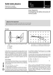
Fig. 3: Interference pattern in the conoscopic beam path with the<br />
optical axis of the crystal in the direction of the arrow. The<br />
numbers represent the path difference between the ordinary<br />
and the extraordinary partial beam. Thus for example<br />
the lines with the value +1(−1) have the path difference<br />
�m+1 (�m−1)<br />
The Pockels effect magnifies or reduces the difference of the<br />
main refractive indices n o – n e, depending on the sign of the<br />
applied voltage. This in turn alters the difference � – m ⋅ �, and<br />
thus the position of the dark interference lines. If the so-called<br />
half-wave voltage U � is applied, the value of � is changed by<br />
one-half wavelength. The dark interference lines shift to the<br />
positions of the bright lines, and vice versa. This process<br />
repeats itself each time the voltage is increased by U �.<br />
Setup<br />
Notes:<br />
Carry out all measurements in a darkened room.<br />
Do not insert the rods of the optical components all the way in<br />
the optics riders, so that subsequent fine adjustment of the<br />
height can be carried out.<br />
Fig. 4 shows the experiment setup; the position of the left edge<br />
of each optics rider is given in cm.<br />
Setting up the optical components:<br />
– Mount the He-Ne laser, the 5-mm lens (a) and the 50-mm<br />
lens (b). Carefully turn the laser and the 5-mm lens and<br />
adjust their heights so that optimum illumination of the<br />
50-mm lens is achieved.<br />
– Set up the translucent screen at a suitable distance, and<br />
attach a piece of white paper to the screen.