Three-Winding Autotransformer Fault Study and Impact on ...
Three-Winding Autotransformer Fault Study and Impact on ...
Three-Winding Autotransformer Fault Study and Impact on ...

Create successful ePaper yourself
Turn your PDF publications into a flip-book with our unique Google optimized e-Paper software.
impedance XS is negative. While seemingly strange, it is not uncomm<strong>on</strong> to see the negative<br />
impedance in the three-winding transformer equivalent circuit, which is mainly due to<br />
arrangement of the windings <str<strong>on</strong>g>and</str<strong>on</strong>g> coupling of the flux am<strong>on</strong>g the windings.<br />
The negative impedance in the T model can provide some interesting phenomena for fault study.<br />
The zero-sequence current is affected by the negative impedance branch. The following secti<strong>on</strong><br />
will discuss the fault study of the three winding autotransformer.<br />
Ⅲ. FAULT STUDY OF THREE-WINDING AUTOTRANSFORMER<br />
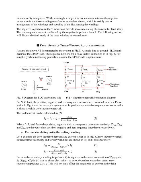
Assume the above AT is c<strong>on</strong>nected to the system as Fig.3. A single-line-to-ground (SLG) fault<br />
occurs at the 345kV side. The sequence network for a SLG fault is c<strong>on</strong>nected as in Fig. 4. For<br />
simplicity while not losing generality, assume the 345kV side is open-circuit.<br />
Assume HV side open-circuit<br />
Fig. 3 Diagram for SLG <strong>on</strong> primary side Fig. 4 Sequence network c<strong>on</strong>necti<strong>on</strong> diagram<br />
For SLG fault, the positive, negative <str<strong>on</strong>g>and</str<strong>on</strong>g> zero-sequence network are c<strong>on</strong>nected in series. Please<br />
notice in Fig. 4 that the tertiary is open-circuit in positive <str<strong>on</strong>g>and</str<strong>on</strong>g> negative sequence networks <str<strong>on</strong>g>and</str<strong>on</strong>g> it<br />
is short-circuit in zero sequence network.<br />
The fault current can be calculated as (2)<br />
� � � � � � � � �<br />
�.� ��<br />
��.�����.�����.��<br />
Where I1, I 2 <str<strong>on</strong>g>and</str<strong>on</strong>g> I0 are the positive, negative <str<strong>on</strong>g>and</str<strong>on</strong>g> zero-sequence current respectively; Z1.eq, Z2.eq<br />
<str<strong>on</strong>g>and</str<strong>on</strong>g> Z0.eq are the equivalent positive, negative <str<strong>on</strong>g>and</str<strong>on</strong>g> zero sequence impedance respectively.<br />
a. Current circulating inside the tertiary winding<br />
Let’s examine the zero-sequence network <str<strong>on</strong>g>and</str<strong>on</strong>g> current closer as in Fig. 5. Zero-sequence current<br />
in transformer sec<strong>on</strong>dary <str<strong>on</strong>g>and</str<strong>on</strong>g> tertiary windings are shown in (3) <str<strong>on</strong>g>and</str<strong>on</strong>g> (4) respectively:<br />
� �.� �<br />
��<br />
������.��������<br />
(2)<br />
� � � (3)<br />
��.� � �����.����<br />
� �� (4)<br />
������.��������<br />
Because the sec<strong>on</strong>dary winding impedance ZS is negative in this case, summati<strong>on</strong> of ZSYS1.0 <str<strong>on</strong>g>and</str<strong>on</strong>g><br />
ZS (ZSYS1.0+ZS) in (4) can be either plus, minus, or zero, dependent up<strong>on</strong> the system zerosequence<br />
impedance ZSYS1.0. This will not <strong>on</strong>ly affect the magnitude of current in the delta